JP7537499B2 - Image analysis device, image analysis method, and program - Google Patents
Image analysis device, image analysis method, and program Download PDFInfo
- Publication number
- JP7537499B2 JP7537499B2 JP2022538515A JP2022538515A JP7537499B2 JP 7537499 B2 JP7537499 B2 JP 7537499B2 JP 2022538515 A JP2022538515 A JP 2022538515A JP 2022538515 A JP2022538515 A JP 2022538515A JP 7537499 B2 JP7537499 B2 JP 7537499B2
- Authority
- JP
- Japan
- Prior art keywords
- icons
- image processing
- screen
- image
- icon
- Prior art date
- Legal status (The legal status is an assumption and is not a legal conclusion. Google has not performed a legal analysis and makes no representation as to the accuracy of the status listed.)
- Active
Links
- 238000010191 image analysis Methods 0.000 title claims description 64
- 238000003703 image analysis method Methods 0.000 title claims description 7
- 238000004458 analytical method Methods 0.000 claims description 168
- 238000000034 method Methods 0.000 claims description 107
- 230000008569 process Effects 0.000 claims description 101
- 230000005856 abnormality Effects 0.000 claims description 55
- 238000001514 detection method Methods 0.000 claims description 43
- 238000011156 evaluation Methods 0.000 claims description 27
- 230000008859 change Effects 0.000 claims description 10
- 230000006870 function Effects 0.000 description 31
- 238000010586 diagram Methods 0.000 description 15
- 238000000605 extraction Methods 0.000 description 9
- 238000007405 data analysis Methods 0.000 description 5
- 230000004044 response Effects 0.000 description 4
- 230000006399 behavior Effects 0.000 description 3
- 238000003384 imaging method Methods 0.000 description 2
- 230000000717 retained effect Effects 0.000 description 2
- 230000005540 biological transmission Effects 0.000 description 1
- 238000010276 construction Methods 0.000 description 1
- 238000005516 engineering process Methods 0.000 description 1
- 230000006872 improvement Effects 0.000 description 1
- 238000011835 investigation Methods 0.000 description 1
- 238000010801 machine learning Methods 0.000 description 1
- 238000004519 manufacturing process Methods 0.000 description 1
- 239000007787 solid Substances 0.000 description 1
Images


Classifications
-
- G—PHYSICS
- G06—COMPUTING; CALCULATING OR COUNTING
- G06V—IMAGE OR VIDEO RECOGNITION OR UNDERSTANDING
- G06V20/00—Scenes; Scene-specific elements
- G06V20/50—Context or environment of the image
- G06V20/52—Surveillance or monitoring of activities, e.g. for recognising suspicious objects
-
- G—PHYSICS
- G06—COMPUTING; CALCULATING OR COUNTING
- G06F—ELECTRIC DIGITAL DATA PROCESSING
- G06F3/00—Input arrangements for transferring data to be processed into a form capable of being handled by the computer; Output arrangements for transferring data from processing unit to output unit, e.g. interface arrangements
- G06F3/01—Input arrangements or combined input and output arrangements for interaction between user and computer
- G06F3/048—Interaction techniques based on graphical user interfaces [GUI]
- G06F3/0481—Interaction techniques based on graphical user interfaces [GUI] based on specific properties of the displayed interaction object or a metaphor-based environment, e.g. interaction with desktop elements like windows or icons, or assisted by a cursor's changing behaviour or appearance
- G06F3/04817—Interaction techniques based on graphical user interfaces [GUI] based on specific properties of the displayed interaction object or a metaphor-based environment, e.g. interaction with desktop elements like windows or icons, or assisted by a cursor's changing behaviour or appearance using icons
-
- G—PHYSICS
- G06—COMPUTING; CALCULATING OR COUNTING
- G06F—ELECTRIC DIGITAL DATA PROCESSING
- G06F3/00—Input arrangements for transferring data to be processed into a form capable of being handled by the computer; Output arrangements for transferring data from processing unit to output unit, e.g. interface arrangements
- G06F3/01—Input arrangements or combined input and output arrangements for interaction between user and computer
- G06F3/048—Interaction techniques based on graphical user interfaces [GUI]
- G06F3/0484—Interaction techniques based on graphical user interfaces [GUI] for the control of specific functions or operations, e.g. selecting or manipulating an object, an image or a displayed text element, setting a parameter value or selecting a range
- G06F3/04847—Interaction techniques to control parameter settings, e.g. interaction with sliders or dials
-
- G—PHYSICS
- G06—COMPUTING; CALCULATING OR COUNTING
- G06T—IMAGE DATA PROCESSING OR GENERATION, IN GENERAL
- G06T1/00—General purpose image data processing
-
- G—PHYSICS
- G06—COMPUTING; CALCULATING OR COUNTING
- G06T—IMAGE DATA PROCESSING OR GENERATION, IN GENERAL
- G06T7/00—Image analysis
-
- G—PHYSICS
- G06—COMPUTING; CALCULATING OR COUNTING
- G06V—IMAGE OR VIDEO RECOGNITION OR UNDERSTANDING
- G06V10/00—Arrangements for image or video recognition or understanding
- G06V10/70—Arrangements for image or video recognition or understanding using pattern recognition or machine learning
- G06V10/77—Processing image or video features in feature spaces; using data integration or data reduction, e.g. principal component analysis [PCA] or independent component analysis [ICA] or self-organising maps [SOM]; Blind source separation
- G06V10/776—Validation; Performance evaluation
-
- G—PHYSICS
- G06—COMPUTING; CALCULATING OR COUNTING
- G06V—IMAGE OR VIDEO RECOGNITION OR UNDERSTANDING
- G06V10/00—Arrangements for image or video recognition or understanding
- G06V10/70—Arrangements for image or video recognition or understanding using pattern recognition or machine learning
- G06V10/87—Arrangements for image or video recognition or understanding using pattern recognition or machine learning using selection of the recognition techniques, e.g. of a classifier in a multiple classifier system
-
- G—PHYSICS
- G06—COMPUTING; CALCULATING OR COUNTING
- G06V—IMAGE OR VIDEO RECOGNITION OR UNDERSTANDING
- G06V10/00—Arrangements for image or video recognition or understanding
- G06V10/94—Hardware or software architectures specially adapted for image or video understanding
- G06V10/945—User interactive design; Environments; Toolboxes
-
- G—PHYSICS
- G06—COMPUTING; CALCULATING OR COUNTING
- G06V—IMAGE OR VIDEO RECOGNITION OR UNDERSTANDING
- G06V10/00—Arrangements for image or video recognition or understanding
- G06V10/98—Detection or correction of errors, e.g. by rescanning the pattern or by human intervention; Evaluation of the quality of the acquired patterns
-
- G—PHYSICS
- G06—COMPUTING; CALCULATING OR COUNTING
- G06V—IMAGE OR VIDEO RECOGNITION OR UNDERSTANDING
- G06V40/00—Recognition of biometric, human-related or animal-related patterns in image or video data
- G06V40/10—Human or animal bodies, e.g. vehicle occupants or pedestrians; Body parts, e.g. hands
-
- G—PHYSICS
- G06—COMPUTING; CALCULATING OR COUNTING
- G06V—IMAGE OR VIDEO RECOGNITION OR UNDERSTANDING
- G06V2201/00—Indexing scheme relating to image or video recognition or understanding
- G06V2201/07—Target detection
Landscapes
- Engineering & Computer Science (AREA)
- Theoretical Computer Science (AREA)
- Physics & Mathematics (AREA)
- General Physics & Mathematics (AREA)
- General Engineering & Computer Science (AREA)
- Multimedia (AREA)
- Human Computer Interaction (AREA)
- Software Systems (AREA)
- Computer Vision & Pattern Recognition (AREA)
- Computing Systems (AREA)
- Databases & Information Systems (AREA)
- Evolutionary Computation (AREA)
- General Health & Medical Sciences (AREA)
- Medical Informatics (AREA)
- Health & Medical Sciences (AREA)
- Artificial Intelligence (AREA)
- Quality & Reliability (AREA)
- User Interface Of Digital Computer (AREA)
- Image Analysis (AREA)
- Closed-Circuit Television Systems (AREA)
Description
本発明は、画像分析装置、画像分析方法及びプログラムに関する。 The present invention relates to an image analysis device , an image analysis method, and a program.
画像分析を支援する装置やシステムとして、例えば特許文献1~4に記載の技術が提案されている。 As devices and systems that support image analysis, the technologies described in Patent Documents 1 to 4, for example, have been proposed.
特許文献1に記載の医用画像処理装置は、医用画像診断装置から医用画像を取得する画像取得部と、取得した医用画像について所定の画像処理を行う画像処理部と、操作者の入力部を有する。そして、当該医用画像処理装置は、画像処理部で画像処理された医用画像に対して入力部による操作者の指摘に基づいて画像処理部での画像処理をやり直すように構成される。The medical image processing device described in Patent Document 1 has an image acquisition unit that acquires medical images from a medical image diagnostic device, an image processing unit that performs predetermined image processing on the acquired medical images, and an input unit for an operator. The medical image processing device is configured to redo image processing in the image processing unit based on an operator's indication via the input unit for a medical image that has been image-processed in the image processing unit.
特許文献2に記載の医療用画像処理システムは、ネットワークに接続された専用のハードウェアとソフトウェアを持つサーバーと、クライアント端末上の専用アプリケーションを用いて、CT画像の一連の画質改善処理をネットワーク上で分担させ、リアルタイムに連携させる。The medical image processing system described in Patent Document 2 uses a server with dedicated hardware and software connected to a network, and a dedicated application on a client terminal, to share a series of image quality improvement processes for CT images over the network and link them in real time.
特許文献3に記載の画像認識エンジン連携装置は、画像認識エンジンおよび画像認識エンジンとは異なる画像解析手法により画像中の被写体の認識を行う異種エンジンであるバーコード検出エンジンを含む複数のエンジンへの問い合わせ処理と、問い合わせ処理に応じた認識結果の受け付け処理とを含むエンジン連携処理を実行する連携処理部を有する。連携処理部は、エンジン連携処理を連携シナリオとして管理する。The image recognition engine cooperation device described in Patent Document 3 has a cooperation processing unit that executes engine cooperation processing including query processing to multiple engines including an image recognition engine and a barcode detection engine, which is a heterogeneous engine that recognizes a subject in an image using an image analysis method different from that of the image recognition engine, and receiving processing of the recognition result in response to the query processing. The cooperation processing unit manages the engine cooperation processing as a cooperation scenario.
特許文献4に記載の解析エンジン制御装置は、解析エンジン毎に解析処理の内容と解析処理結果の特性とを記憶した解析エンジンメタ情報テーブルと、解析処理の内容と解析処理結果の条件とが設定された解析処理要求に応じて、解析処理結果の条件を満たして解析処理の内容に対応する解析処理を実行する複数の解析エンジンを選定しプロセスフローを生成するプロセスフロー生成手段と、生成されたプロセスフローに基づいて解析処理を実行する解析処理実行手段とを備える。プロセスフロー生成手段は、実行された実際の解析処理結果に応じて解析処理結果の条件を満たして解析処理の内容に対応する解析処理を実行するよう、プロセスフローを解析エンジンメタ情報テーブルに基づいて修正する。 The analytical engine control device described in Patent Literature 4 includes an analytical engine meta-information table that stores analytical processing content and analytical processing result characteristics for each analytical engine, a process flow generation means that selects a plurality of analytical engines that execute analytical processing corresponding to the analytical processing content by satisfying the analytical processing result conditions in response to an analytical processing request in which the analytical processing content and analytical processing result conditions are set, and generates a process flow, and an analytical processing execution means that executes the analytical processing based on the generated process flow. The process flow generation means modifies the process flow based on the analytical engine meta-information table so as to execute analytical processing corresponding to the analytical processing content by satisfying the analytical processing result conditions in response to the executed actual analytical processing result.
一般的に、画像データの分析では、複数の機能を備えた画像処理エンジンが準備され、予め準備された画像処理エンジンの中から、分析の目的に応じて適切な画像処理エンジンを選定する必要がある。また、複数のカメラの各々で撮影された画像データを分析する場合、画像データの各々に対して選定した画像処理エンジンを対応付けて構成する必要がある。すなわち、画像データの分析では、画像データの入力から分析結果の出力に至るまで、複数の画像処理エンジンを適切に接続して、それらを構成する必要がある。 In general, when analyzing image data, image processing engines with multiple functions are prepared, and an appropriate image processing engine must be selected from the prepared image processing engines depending on the purpose of the analysis. Furthermore, when analyzing image data captured by multiple cameras, it is necessary to configure each image data by corresponding to the selected image processing engine. In other words, when analyzing image data, it is necessary to appropriately connect and configure multiple image processing engines from the input of image data to the output of analysis results.
このような画像データの分析において、画像データの入力から、画像処理エンジンによる画像処理を介して、適切な分析結果が得られるまでの全体を適切に構成するには、画像分析に関する高度に専門的な知識や経験が必要になることが多い。そのため、画像分析に関する専門的な知識を有していない非技術者が、画像データの分析処理の全体を適切に構成することは、現状では困難である。 In analyzing such image data, highly specialized knowledge and experience in image analysis are often required to properly configure the entire process, from inputting the image data through image processing by the image processing engine to obtaining appropriate analysis results. For this reason, it is currently difficult for non-technical personnel who do not have specialized knowledge in image analysis to properly configure the entire analysis process of image data.
特許文献1~4に記載の技術は、専門的な知識や経験を有する技術者が画像データの分析を行うことを前提としており、非技術者がこれらの技術を参照したとしても、画像データの分析処理の全体を適切に構成することは、依然として困難であると考えられる。 The techniques described in Patent Documents 1 to 4 are based on the premise that image data analysis is performed by a technician with specialized knowledge and experience. Even if a non-technical person refers to these techniques, it is still considered difficult to properly configure the entire image data analysis process.
本発明は、上述の事情に鑑みてなされたもので、画像データの分析処理の全体を適切に構成することを容易に行うことが可能な画像分析装置などを提供することを目的とする。 The present invention has been made in consideration of the above-mentioned circumstances, and aims to provide an image analysis device and the like that can easily configure the entire analysis processing of image data appropriately.
上記目的を達成するため、本発明の第1の観点に係る画像分析装置は、
分析の対象となる画像データの入力元を示す複数の入力元アイコン、前記画像データに対する画像処理エンジンを示す複数の画像処理アイコン、画像処理エンジンによる処理結果の出力先を示す少なくとも1つの出力先アイコンを含む複数のアイコンを画面に配置するための指示を受け付け、当該指示に基づいて前記複数のアイコンを画面に配置するアイコン配置手段と、
前記画面に配置されたアイコン間を接続するための接続指示を受け付ける接続手段と、
前記接続指示に基づいて、前記アイコン間のデータの流れを設定して前記画面に表示するデータフロー設定手段とを備え、
前記画面に配置された画像処理アイコンが選択されると、当該選択された画像処理アイコンに対応する前記画像処理エンジンに適用するパラメータに対する設定値を受け付けるパラメータ設定手段とを備え、
前記パラメータ設定手段は、
前記画面に配置された画像処理アイコンが選択されると、当該選択された画像処理アイコンに対応する前記画像処理エンジンに適用する前記パラメータに対する設定値の候補を、前記画像データの少なくとも一部に基づいて求めるパラメータ推定手段と、
前記求められた候補を前記画面に表示させるパラメータ候補表示手段と、
前記パラメータの設定値を受け付けるパラメータ受付手段とを含む。
上記目的を達成するため、本発明の第2の観点に係る画像分析装置は、
分析の対象となる画像データの入力元を示す複数の入力元アイコン、前記画像データに対する画像処理エンジンを示す複数の画像処理アイコン、画像処理エンジンによる処理結果の出力先を示す少なくとも1つの出力先アイコンを含む複数のアイコンを画面に配置するための指示を受け付け、当該指示に基づいて前記複数のアイコンを画面に配置するアイコン配置手段と、
前記画面に配置されたアイコン間を接続するための接続指示を受け付ける接続手段と、
前記接続指示に基づいて、前記アイコン間のデータの流れを設定して前記画面に表示するデータフロー設定手段と、
前記画面に配置された画像処理アイコンが選択されると、当該選択された画像処理アイコンに対応する前記画像処理エンジンに適用するパラメータに対する設定値を受け付けるパラメータ設定手段と、
前記画像データに対して、前記画面に配置された複数のアイコン及び当該複数のアイコンの接続関係に従った分析処理を実行する分析手段とを備え、
前記パラメータ設定手段は、前記画面に配置された複数のアイコンの各々に対応付けられた設定値から構成される複数組の設定値を受け付け、
前記分析手段は、前記設定値の各組について、前記画面に配置された複数のアイコンの接続関係に従って前記画像データに対する分析処理を実行する。
In order to achieve the above object, an image analysis apparatus according to a first aspect of the present invention comprises:
an icon arranging means for receiving an instruction to arrange a plurality of icons on a screen, the plurality of icons including a plurality of input source icons indicating an input source of image data to be analyzed, a plurality of image processing icons indicating an image processing engine for the image data, and at least one output destination icon indicating an output destination of a processing result by the image processing engine, and arranging the plurality of icons on the screen based on the instruction;
a connection means for receiving a connection instruction for connecting icons arranged on the screen;
a data flow setting means for setting a data flow between the icons based on the connection instruction and displaying the data flow on the screen ;
a parameter setting means for receiving, when an image processing icon arranged on the screen is selected, a setting value for a parameter to be applied to the image processing engine corresponding to the selected image processing icon ;
The parameter setting means
a parameter estimation means for, when an image processing icon arranged on the screen is selected, determining candidates for setting values for the parameters to be applied to the image processing engine corresponding to the selected image processing icon based on at least a part of the image data;
a parameter candidate display means for displaying the obtained candidates on the screen;
The parameter receiving means receives a set value of the parameter .
In order to achieve the above object, an image analysis apparatus according to a second aspect of the present invention comprises:
an icon arranging means for receiving an instruction to arrange a plurality of icons on a screen, the plurality of icons including a plurality of input source icons indicating an input source of image data to be analyzed, a plurality of image processing icons indicating an image processing engine for the image data, and at least one output destination icon indicating an output destination of a processing result by the image processing engine, and arranging the plurality of icons on the screen based on the instruction;
a connection means for receiving a connection instruction for connecting icons arranged on the screen;
a data flow setting means for setting a data flow between the icons based on the connection instruction and displaying the data flow on the screen;
a parameter setting means for receiving, when an image processing icon arranged on the screen is selected, a setting value for a parameter to be applied to the image processing engine corresponding to the selected image processing icon;
an analysis unit that executes an analysis process on the image data in accordance with a plurality of icons arranged on the screen and a connection relationship of the plurality of icons ;
the parameter setting means receives a plurality of sets of setting values each corresponding to a plurality of icons arranged on the screen;
The analysis means executes an analysis process on the image data for each set of setting values in accordance with a connection relationship between a plurality of icons arranged on the screen.
上記目的を達成するため、本発明の第3の観点に係る画像分析方法は、
コンピュータが、
分析の対象となる画像データの入力元を示す複数の入力元アイコン、前記画像データに対する画像処理エンジンを示す複数の画像処理アイコン、画像処理エンジンによる処理結果の出力先を示す少なくとも1つの出力先アイコンを含む複数のアイコンを画面に配置するための指示を受け付け、当該指示に基づいて前記複数のアイコンを画面に配置すること、
前記画面に配置されたアイコン間を接続するための接続指示を受け付けることと、
前記接続指示に基づいて、前記アイコン間のデータの流れを設定して前記画面に表示することと、
前記画面に配置された画像処理アイコンが選択されると、当該選択された画像処理アイコンに対応する前記画像処理エンジンに適用するパラメータに対する設定値を受け付けることとを含み、
前記画像処理エンジンに適用するパラメータに対する設定値を受け付けることでは、
前記画面に配置された画像処理アイコンが選択されると、当該選択された画像処理アイコンに対応する前記画像処理エンジンに適用する前記パラメータに対する設定値の候補を、前記画像データの少なくとも一部に基づいて求め、
前記求められた候補を前記画面に表示させ、
前記パラメータの設定値を受け付ける。
上記目的を達成するため、本発明の第4の観点に係る画像分析方法は、
コンピュータが、
分析の対象となる画像データの入力元を示す複数の入力元アイコン、前記画像データに対する画像処理エンジンを示す複数の画像処理アイコン、画像処理エンジンによる処理結果の出力先を示す少なくとも1つの出力先アイコンを含む複数のアイコンを画面に配置するための指示を受け付け、当該指示に基づいて前記複数のアイコンを画面に配置すること、
前記画面に配置されたアイコン間を接続するための接続指示を受け付けることと、
前記接続指示に基づいて、前記アイコン間のデータの流れを設定して前記画面に表示することと、
前記画面に配置された画像処理アイコンが選択されると、当該選択された画像処理アイコンに対応する前記画像処理エンジンに適用するパラメータに対する設定値を受け付けることと、
前記画像データに対して、前記画面に配置された複数のアイコン及び当該複数のアイコンの接続関係に従った分析処理を実行することとを含み、
前記画像処理エンジンに適用するパラメータに対する設定値を受け付けることでは、前記画面に配置された複数のアイコンの各々に対応付けられた設定値から構成される複数組の設定値を受け付け、
前記分析処理を実行することでは、前記設定値の各組について、前記画面に配置された複数のアイコンの接続関係に従って前記画像データに対する分析処理を実行する。
In order to achieve the above object, an image analysis method according to a third aspect of the present invention comprises:
The computer
receiving an instruction to arrange a plurality of icons on a screen, the plurality of icons including a plurality of input source icons indicating an input source of image data to be analyzed, a plurality of image processing icons indicating an image processing engine for the image data, and at least one output destination icon indicating an output destination of a processing result by the image processing engine, and arranging the plurality of icons on the screen based on the instruction;
receiving a connection instruction for connecting icons arranged on the screen;
setting a data flow between the icons based on the connection instruction and displaying the data flow on the screen ;
receiving, when an image processing icon arranged on the screen is selected, setting values for parameters to be applied to the image processing engine corresponding to the selected image processing icon ;
In the step of receiving a setting value for a parameter to be applied to the image processing engine,
when an image processing icon arranged on the screen is selected, candidates for setting values for the parameters to be applied to the image processing engine corresponding to the selected image processing icon are obtained based on at least a part of the image data;
Displaying the obtained candidates on the screen;
The setting value of the parameter is accepted .
In order to achieve the above object, an image analysis method according to a fourth aspect of the present invention comprises:
The computer
receiving an instruction to arrange a plurality of icons on a screen, the plurality of icons including a plurality of input source icons indicating an input source of image data to be analyzed, a plurality of image processing icons indicating an image processing engine for the image data, and at least one output destination icon indicating an output destination of a processing result by the image processing engine, and arranging the plurality of icons on the screen based on the instruction;
receiving a connection instruction for connecting icons arranged on the screen;
setting a data flow between the icons based on the connection instruction and displaying the data flow on the screen;
when an image processing icon arranged on the screen is selected, accepting setting values for parameters to be applied to the image processing engine corresponding to the selected image processing icon;
performing an analysis process on the image data in accordance with a plurality of icons arranged on the screen and a connection relationship of the plurality of icons;
The receiving of setting values for parameters to be applied to the image processing engine includes receiving a plurality of sets of setting values each corresponding to a plurality of icons arranged on the screen;
In executing the analysis process, for each set of setting values, analysis is performed on the image data in accordance with the connection relationships of a plurality of icons arranged on the screen.
上記目的を達成するため、本発明の第5の観点に係るプログラムは、
コンピュータに、
分析の対象となる画像データの入力元を示す複数の入力元アイコン、前記画像データに対する画像処理エンジンを示す複数の画像処理アイコン、画像処理エンジンによる処理結果の出力先を示す少なくとも1つの出力先アイコンを含む複数のアイコンを画面に配置するための指示を受け付け、当該指示に基づいて前記複数のアイコンを画面に配置すること、
前記画面に配置されたアイコン間を接続するための接続指示を受け付けることと、
前記接続指示に基づいて、前記アイコン間のデータの流れを設定して前記画面に表示することと、
前記画面に配置された画像処理アイコンが選択されると、当該選択された画像処理アイコンに対応する前記画像処理エンジンに適用するパラメータに対する設定値を受け付けることとを実行させ、
前記画像処理エンジンに適用するパラメータに対する設定値を受け付けることでは、
前記画面に配置された画像処理アイコンが選択されると、当該選択された画像処理アイコンに対応する前記画像処理エンジンに適用する前記パラメータに対する設定値の候補を、前記画像データの少なくとも一部に基づいて求め、
前記求められた候補を前記画面に表示させ、
前記パラメータの設定値を受け付けるためのプログラムである。
上記目的を達成するため、本発明の第6の観点に係るプログラムは、
コンピュータに、
分析の対象となる画像データの入力元を示す複数の入力元アイコン、前記画像データに対する画像処理エンジンを示す複数の画像処理アイコン、画像処理エンジンによる処理結果の出力先を示す少なくとも1つの出力先アイコンを含む複数のアイコンを画面に配置するための指示を受け付け、当該指示に基づいて前記複数のアイコンを画面に配置すること、
前記画面に配置されたアイコン間を接続するための接続指示を受け付けることと、
前記接続指示に基づいて、前記アイコン間のデータの流れを設定して前記画面に表示することと、
前記画面に配置された画像処理アイコンが選択されると、当該選択された画像処理アイコンに対応する前記画像処理エンジンに適用するパラメータに対する設定値を受け付けることと、
前記画像データに対して、前記画面に配置された複数のアイコン及び当該複数のアイコンの接続関係に従った分析処理を実行することとを実行させ、
前記画像処理エンジンに適用するパラメータに対する設定値を受け付けることでは、前記画面に配置された複数のアイコンの各々に対応付けられた設定値から構成される複数組の設定値を受け付け、
前記分析処理を実行することでは、前記設定値の各組について、前記画面に配置された複数のアイコンの接続関係に従って前記画像データに対する分析処理を実行するためのプログラムである。
In order to achieve the above object, a program according to a fifth aspect of the present invention comprises:
On the computer,
receiving an instruction to arrange a plurality of icons on a screen, the plurality of icons including a plurality of input source icons indicating an input source of image data to be analyzed, a plurality of image processing icons indicating an image processing engine for the image data, and at least one output destination icon indicating an output destination of a processing result by the image processing engine, and arranging the plurality of icons on the screen based on the instruction;
receiving a connection instruction for connecting icons arranged on the screen;
setting a data flow between the icons based on the connection instruction and displaying the data flow on the screen ;
when an image processing icon arranged on the screen is selected, receiving setting values for parameters to be applied to the image processing engine corresponding to the selected image processing icon ;
In the step of receiving a setting value for a parameter to be applied to the image processing engine,
when an image processing icon arranged on the screen is selected, candidates for setting values for the parameters to be applied to the image processing engine corresponding to the selected image processing icon are obtained based on at least a part of the image data;
Displaying the determined candidates on the screen;
This is a program for receiving the setting values of the parameters .
In order to achieve the above object, a program according to a sixth aspect of the present invention comprises:
On the computer,
receiving an instruction to arrange a plurality of icons on a screen, the plurality of icons including a plurality of input source icons indicating an input source of image data to be analyzed, a plurality of image processing icons indicating an image processing engine for the image data, and at least one output destination icon indicating an output destination of a processing result by the image processing engine, and arranging the plurality of icons on the screen based on the instruction;
receiving a connection instruction for connecting icons arranged on the screen;
setting a data flow between the icons based on the connection instruction and displaying the data flow on the screen;
when an image processing icon arranged on the screen is selected, accepting setting values for parameters to be applied to the image processing engine corresponding to the selected image processing icon;
executing an analysis process on the image data in accordance with a plurality of icons arranged on the screen and a connection relationship of the plurality of icons;
The receiving of setting values for parameters to be applied to the image processing engine includes receiving a plurality of sets of setting values each corresponding to a plurality of icons arranged on the screen;
The program for executing the analysis process is for executing an analysis process on the image data in accordance with the connection relationships of a plurality of icons arranged on the screen for each set of setting values.
本発明によれば、画像データの分析処理の全体を適切に構成することを容易に行うことが可能になる。 According to the present invention, it becomes possible to easily configure the entire analysis process of image data appropriately.
以下、本発明の一実施の形態について、図面を参照しつつ説明する。全図を通じて同一の要素には同一の符号を付す。なお、すべての図面において、同様な構成要素には同様の符号を付し、適宜説明を省略する。 One embodiment of the present invention will now be described with reference to the drawings. The same elements are designated by the same reference numerals throughout the drawings. Note that similar components are designated by the same reference numerals throughout the drawings, and descriptions thereof will be omitted where appropriate.
<本実施の形態に係る画像分析システムの機能的構成>
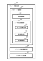
本発明の一実施の形態に係る画像分析システム100は、分析対象領域を撮影した画像データに対して画像処理を行うことによって、目的とする分析結果を得るためのシステムである。本実施の形態に係る画像分析システム100は、図1に示すように、3台のカメラ101a,101b,101cと、画像分析装置102とを備える。
<Functional configuration of the image analysis system according to the present embodiment>
An
カメラ101a,101b,101cの各々は、分析対象領域を撮影するための撮像装置の例である。以下において、カメラ101a,101b,101cの各々を特に区別しない場合、単に、カメラ101とも表記する。Each of the
本実施の形態に係るカメラ101は、分析対象領域としての店舗Sの内部を上方から見た図である図2に示すように、分析対象領域としての店舗S内の概ね全体を撮影するように設置される。The camera 101 in this embodiment is installed so as to capture approximately the entire interior of store S as the area to be analyzed, as shown in Figure 2, which is a top view of the interior of store S as the area to be analyzed.
詳細には、カメラ101aは、店舗S内の領域Aを撮影し、カメラ101bは、店舗S内の領域Bを撮影し、カメラ101cは、店舗S内の領域Cを撮影するように設置されている。店舗S内の概ね全体を撮影できるようにするため、領域A、領域B、領域Cは、一部が互いに重なり合っている。In detail,
このようなカメラ101によって例えば、図2に示すように、出入口Eを通じて店舗Sに入った顧客A~Cが、商品が陳列される棚MS1,MS2,MS3やレジスタ装置Rの近傍を通過して、出入口Eから出るまでの移動する様子が撮影される。For example, as shown in FIG. 2, such a camera 101 captures the movement of customers A to C who enter store S through entrance/exit E, pass near shelves MS1, MS2, MS3 on which products are displayed and cash register R, and then exit through entrance/exit E.
図2の実線で示す移動経路M_Aは、店舗Sにおける顧客Aの移動経路であり、点線で示す移動経路M_Bは、店舗Sにおける顧客Bの移動経路であり、一点鎖線で示す移動経路M_Cは、店舗Sにおける顧客Cの移動経路を示す。 The movement route M_A shown by a solid line in Figure 2 is the movement route of customer A in store S, the movement route M_B shown by a dotted line is the movement route of customer B in store S, and the movement route M_C shown by a dotted line is the movement route of customer C in store S.
なお、本実施の形態では、画像分析システム100による画像分析が、店舗Sのような小売店における人の行動分析に適用される例を説明する。しかし、画像分析システム100による画像分析は、その他の人の行動分析、人探し、熟練者の技術の分析などに適用することもできる。その他の人の行動分析の例としては、行政、都市計画、交通、輸送を目的とする画像分析を挙げることができる。人探しの例としては、捜査、監視、迷子探しなどを目的とする画像分析を挙げることができる。熟練者の技術の分析の例としては、製造や加工現場における熟練工、建設現場の作業員、スポーツ選手、教育者などの技術の習得を目的とした画像分析を挙げることができる。そして、分析対象領域には、画像分析の目的に応じて、例えば、建物、施設、設備、道路などが設定されるとよい。In this embodiment, an example will be described in which image analysis by the
なお、本実施の形態では、カメラ101a,101b,101cが設置される台数は、2台以上であればよく、カメラ101a,101b,101cの各々は、静止画像を撮影してもよい。In this embodiment, the number of
画像分析装置102は、機能的には図1に示すように、入力部103と、表示部104と、表示制御部105と、画像取得部106と、アイコン配置部107と、アイコン記憶部108と、アイコン-処理記憶部109と、接続部110と、データフロー設定部111と、パラメータ設定部112と、分析部113と、コンポーネント作成部114と、コンポーネント記憶部115とを備える。As shown in FIG. 1, the
入力部103は、ユーザが入力するためのキーボード、マウス、タッチパネルなどである。
The
表示部104は、画面を表示する液晶ディスプレイなどである。
The
表示制御部105は、表示部104に画面を表示させる。The
画像取得部106は、分析の対象となる画像データを取得する。
The
アイコン配置部107は、複数のアイコンを画面に配置するための指示を入力部103から受け付け、当該指示に基づいて複数のアイコンを画面に配置する。The
アイコン記憶部108は、アイコン画像を含むアイコンデータを保持するための記憶部である。アイコンデータは、詳細には例えば、アイコンの種別を識別するためのアイコン種別情報と、アイコンの画像情報とを対応付けるデータである。The
アイコンには、例えば、入力元アイコン、画像処理アイコン、出力先アイコンなどを含む。 Icons include, for example, input source icons, image processing icons, output destination icons, etc.
入力元アイコンは、分析の対象となる画像データの入力元を示すアイコンである。画像処理アイコンは、画像データに対する画像処理エンジンを示すアイコンである。出力先アイコンは、画像処理エンジンによる処理結果の出力先を示すアイコンである。 The input source icon is an icon that indicates the input source of the image data to be analyzed. The image processing icon is an icon that indicates the image processing engine for the image data. The output destination icon is an icon that indicates the output destination of the processing results by the image processing engine.
アイコン-処理記憶部109は、処理エンジンを含む処理エンジンデータを保持するための記憶部である。処理エンジンデータは、詳細には例えば、アイコン識別情報と、処理エンジンと、設定されるべきパラメータとを対応付けるデータである。
The icon-
処理エンジンには、例えば、分析の対象となる画像データの入力処理を行う入力エンジン、画像データに対して各種の画像処理を行う画像処理エンジン、処理結果の出力処理を行う出力エンジンなどが含まれる。 Processing engines include, for example, an input engine that performs input processing of the image data to be analyzed, an image processing engine that performs various image processing on the image data, and an output engine that performs output processing of the processing results.
入力エンジンは、画像データをカメラ101から概ねリアルタイムで入力するリアルタイム入力エンジンである。リアルタイム入力エンジンのパラメータは、例えば、リアルタイム入力エンジンではその生成元となるカメラ101のネットワークアドレスである。 The input engine is a real-time input engine that inputs image data from the camera 101 in roughly real time. The parameters of the real-time input engine are, for example, the network address of the camera 101 from which the real-time input engine is generated.
なお、入力エンジンは、記憶部に保存された画像データを入力する保持データ入力エンジンであってもよく、保持データ入力エンジンのパラメータは例えば、画像データの保存場所を示す情報である。 In addition, the input engine may be a retained data input engine that inputs image data stored in a memory unit, and the parameters of the retained data input engine are, for example, information indicating the storage location of the image data.
画像処理エンジンは、例えば、検出エンジン、追跡エンジン、特徴量抽出エンジン、検索エンジン、再特定エンジンを含む。 Image processing engines include, for example, detection engines, tracking engines, feature extraction engines, search engines, and re-identification engines.
検出エンジンは、物体や人などの検出対象を画像データから検出するための画像処理エンジンである。 The detection engine is an image processing engine for detecting targets such as objects and people from image data.
追跡エンジンは、物体や人などの追跡対象を画像データにおいて追跡するための画像処理エンジンである。 The tracking engine is an image processing engine for tracking targets such as objects and people in image data.
特徴量抽出エンジンは、画像データにおける特徴量を抽出するための画像処理エンジンである。 The feature extraction engine is an image processing engine for extracting features from image data.
検索エンジンは、物体や人などの検索対象を画像データから検索するための画像処理エンジンである。 A search engine is an image processing engine that searches image data for search targets such as objects and people.
再特定エンジンは、物体や人などの追跡対象を複数の画像データにまたがって追跡するための画像処理エンジンである。 The re-identification engine is an image processing engine for tracking targets such as objects and people across multiple image data.
これらの画像処理エンジンは、機械学習によって学習済みのモデルが好適に採用され、この場合のパラメータは、学習済みのモデルを調整するためのパラメータである。1つの画像処理エンジンが画像処理を実行するために、複数のパラメータに対する値の設定が必要とされてもよいが、本実施の形態では、画像処理エンジンの各々が画像処理を行うためのパラメータは、1つであるとする。These image processing engines preferably employ models that have been trained by machine learning, and the parameters in this case are parameters for adjusting the trained model. In order for one image processing engine to perform image processing, it may be necessary to set values for multiple parameters, but in this embodiment, each image processing engine is assumed to have one parameter for performing image processing.
また、画像処理アイコンのうち、検出エンジン、追跡エンジン、特徴量抽出エンジン、検索エンジン、再特定エンジンに対応付けられるアイコンを区別する場合、それぞれ、検出アイコン、追跡アイコン、特徴量抽出アイコン、検索アイコン、再特定アイコンと称する。 In addition, when distinguishing between the image processing icons corresponding to the detection engine, tracking engine, feature extraction engine, search engine, and re-identification engine, they are referred to as the detection icon, tracking icon, feature extraction icon, search icon, and re-identification icon, respectively.
出力エンジンは、画面に処理結果を出力するエンジンである。出力エンジンのパラメータは、例えば、出力先となる画面を識別するための情報である。 An output engine is an engine that outputs the processing results to a screen. The parameters of an output engine are, for example, information for identifying the screen to which the output is to be sent.
なお、出力先となる画面が複数である場合、複数の画面が1つのディスプレイ装置に表示されてもよく、複数のディスプレイのそれぞれに表示されてもよい。複数のディスプレイに出力される場合、出力エンジンのパラメータは、ディスプレイの各々を識別するための情報であってもよい。In addition, when there are multiple screens to be output, the multiple screens may be displayed on a single display device, or may be displayed on each of the multiple displays. When output is to multiple displays, the parameters of the output engine may be information for identifying each of the displays.
接続部110は、画面に配置されたアイコン間を接続するための接続指示を入力部103から受け付ける。The
データフロー設定部111は、接続部110によって受け付けられた接続指示に基づいて、アイコン間のデータの流れを設定して画面に表示する。The data
詳細には、データフロー設定部111は、図3に示すように、禁則処理部116と、禁則記憶部117と、適正フロー設定部118とを含む。In detail, as shown in FIG. 3, the data
禁則処理部116は、接続部110によって接続指示が受け付けられた場合に、接続指示に関わるアイコン間の接続が禁則データに含まれるか否かを判定し、判定の結果に基づいて禁則処理を行う。When a connection instruction is received by the
禁則データは、アイコン間の接続に関する禁則を示すデータであって、これを保持するための禁則記憶部117に予め設定される。The prohibition data is data indicating prohibitions regarding connections between icons, and is set in advance in the
禁則データには、禁止されるアイコン間の接続関係が禁則として含まれる。 The prohibited data includes prohibited connection relationships between icons as prohibited rules.
接続関係とは、アイコン間の接続に関する関係であり、接続されるアイコンに対応する処理エンジン間でのデータの流れを含む。通常行われないアイコン間の接続関係には、典型的には、アイコン間の接続順が逆である場合があり、例えば、他のアイコンから入力元アイコンへデータが流れる接続関係、出力先アイコンから他のアイコンへデータが流れる接続関係が含まれる。A connection relationship is a relationship related to the connection between icons, and includes the flow of data between the processing engines corresponding to the connected icons. An unusual connection relationship between icons typically involves the connection order between icons being reversed, and includes, for example, a connection relationship in which data flows from another icon to an input source icon, and a connection relationship in which data flows from an output destination icon to another icon.
なお、検出エンジンの1種である顔検出エンジン及び特徴量抽出エンジンの1種である色抽出エンジンが採用される場合には、顔検出エンジンと色抽出エンジンとは通常接続されないため、禁則は、これらに対応するアイコンの接続が含まれてもよい。 In addition, when a face detection engine, which is a type of detection engine, and a color extraction engine, which is a type of feature extraction engine, are adopted, the face detection engine and the color extraction engine are not normally connected, so the prohibitions may include connecting the icons corresponding to them.
より詳細には、禁則処理部116は、接続指示に関わるアイコン間の接続が禁則データに含まれないと判定した場合には、当該接続指示に従ってデータの流れを設定して画面に表示する。これに対して、接続指示に関わるアイコン間の接続が禁則データに含まれると判定した場合には、禁則処理部116は、禁則処理を行う。
More specifically, if the
禁則処理は、接続関係を設定しないこと、接続指示を予め定められた方法で修正した接続関係を設定すること、接続指示に関わるアイコン間の接続が禁止されている旨を報知すること、の少なくとも1つを含む。The prohibition processing includes at least one of the following: not setting a connection relationship, setting a connection relationship in which the connection instruction is modified in a predetermined manner, and notifying that a connection between icons related to the connection instruction is prohibited.
適正フロー設定部118は、接続部110によって受け付けられる接続指示に従って、アイコン間のデータの流れを設定して画面に表示するThe appropriate
図1を再び参照する。
パラメータ設定部112は、画面に配置された各アイコンに対応付けられるパラメータの設定値を受け付ける。パラメータ設定部112は、画面に配置されたアイコンが選択されると、当該選択されたアイコンに対応する処理エンジンに適用されるパラメータの設定値を受け付け、当該選択されたアイコンに当該受け付けた設定値を設定する。
Referring again to FIG.
The
詳細には、パラメータ設定部112は、図4に示すように、パラメータに対する設定値の候補を求めるパラメータ推定部119と、候補を画面に表示させるパラメータ候補表示部120と、パラメータの設定値を受け付けるパラメータ受付部121とを含む。In detail, as shown in FIG. 4, the
パラメータ推定部119は、画面に配置された画像処理アイコンが選択されると、画像データの少なくとも一部に基づいて、パラメータに対する設定値の候補を求める。When an image processing icon arranged on the screen is selected, the
ここで、パラメータに対する設定値の候補とは、選択された画像処理アイコンに対応する画像処理エンジンに適用するパラメータに対する設定値の候補であり、候補は、値や数値範囲などで求められる。候補を求めるために参照される画像データは、当該候補を求めるための処理負荷を軽減するために、画像データの一部であることが望ましい。 Here, the candidate setting values for the parameters are candidates for the setting values for the parameters to be applied to the image processing engine corresponding to the selected image processing icon, and the candidates are determined by values, numerical ranges, etc. It is desirable that the image data referenced to determine the candidates is a part of the image data in order to reduce the processing load for determining the candidates.
より詳細には、パラメータ推定部119は、図4に示すように、ユーザの支援を受けずに自身で候補を推定する自動推定部122と、ユーザの支援を受けて候補を推定するユーザ支援推定部123とを含む。
More specifically, as shown in FIG. 4, the
自動推定部122は、選択された画像処理アイコンに対応する画像処理エンジンに適用するパラメータに対する設定値の候補を自動的に推定する。The
ユーザ支援推定部123は、選択された画像処理アイコンに対応する画像処理エンジンに適用するパラメータに対する設定値の候補を、ユーザの評価を参照して推定する。ユーザ支援推定部123は、サンプル表示部124と、評価受付部125と、候補取得部126とを含む。The user
サンプル表示部124は、画面に配置された画像処理アイコンが選択されると、当該選択された画像処理アイコンに対応付けられた画像処理エンジンによる処理を画像データの少なくとも一部に対して実行する。サンプル表示部124は、当該処理を実行することによって得られる1つ又は複数のサンプル画像を画面に表示させる。When an image processing icon arranged on the screen is selected, the
評価受付部125は、1つ又は複数のサンプル画像に対する評価を入力部103から受け付ける。The
候補取得部126は、評価受付部125によって受け付けられた評価に基づいて、設定値の候補を求める。The
パラメータ候補表示部120は、パラメータ推定部119によって求められた候補を画面に表示させる。The parameter
パラメータ受付部121は、パラメータの設定値を、選択された画像処理アイコンに対応付けて受け付ける。すなわち、ユーザは、画面に表示された候補を参照して、パラメータの設定値を設定することができる。The
分析部113は、画像データに対して、画面に設定された分析構成に従った分析処理を実行し、表示制御部105を介して分析処理の結果を画面に表示させる。画面に設定された分析構成とは、画像データを分析するための処理構成であって、画面に配置された複数のアイコン及び当該複数のアイコンの接続関係を含む。The
詳細には、分析部113は、図5に示すように、分析実行部127と、異常予想部128と、分析中断部129と、異常検出部130と、異常報知部131と、結果出力部132とを含む。In detail, as shown in FIG. 5, the
分析実行部127は、画面に設定された分析構成に従った分析処理を実行する。
The
異常予想部128は、分析実行部127による分析処理を監視し、分析処理の結果に異常が発生するか否かを予想する。分析中断部129は、異常予想部128によって異常が発生すると予想された場合に、設定値の変更を促すための報知をする。The
異常検出部130は、分析実行部127による分析処理の結果に異常が含まれるか否かを判定する。異常報知部131は、異常が含まれると判定された場合に、設定値の変更を促すための報知をする。The
ここで、異常とは、例えば、画面に配置された画像処理アイコンに対応付けられた画像処理エンジンが人物を識別する機能を含む場合に、画像データを構成するフレーム画像に含まれる複数の人物が同一人物であると分析されることである。Here, an abnormality occurs when, for example, an image processing engine associated with an image processing icon arranged on the screen includes a function for identifying people, and multiple people included in frame images constituting the image data are analyzed as being the same person.
また例えば、異常とは、分析の対象が、店舗S内のような連続する空間の異なる領域A~Cを撮影することによって得られた複数の画像データである場合に、当該複数の画像データの間で同一人物と分析される人物の数が閾値よりも少ないことである。この例についても、画面に配置された画像処理アイコンに対応付けられた画像処理エンジンが人物を識別する機能を含む場合が対象となる。 For example, an abnormality occurs when the number of people analyzed as the same person in multiple image data is less than a threshold value when the subject of analysis is multiple image data obtained by photographing different areas A to C in a continuous space such as the inside of a store S. This example also applies to cases where the image processing engine associated with the image processing icon arranged on the screen includes a function for identifying people.
報知は、表示制御部105を介してメッセージを表示することや、図示しないスピーカなどから音を発することなどである。The notification may be made by displaying a message via the
結果出力部132は、異常予想部128によって異常の発生が予想されず、かつ、異常検出部130によって異常が検出されずに分析処理を終了することができた場合に、分析構成に従った分析処理の結果を画面に表示させる。The
ここで、分析処理を実行するには、1つの分析構成に含まれる処理エンジンのすべてのパラメータに対して設定された設定値から構成される1組の設定値が必要である。すなわち、画面に配置された複数のアイコンの対応するすべてのパラメータに設定値が設定される必要があり、設定値の組は、当該すべてのパラメータに対する設定値から構成されるものとする。Here, to execute the analysis process, a set of setting values consisting of the setting values set for all parameters of the processing engine included in one analysis configuration is required. In other words, setting values must be set for all parameters corresponding to multiple icons arranged on the screen, and the set of setting values consists of the setting values for all of the parameters.
例えば本実施の形態では、上述した通り、画像処理エンジンの各々が画像処理を行うためのパラメータは1つであり、入力元アイコン及び出力先アイコンの各々のパラメータも1つである。そのため、本実施の形態に係る設定値の組は、画面に配置された複数のアイコンの各々に対応付けられた1つの設定値から構成される。For example, in this embodiment, as described above, each image processing engine has one parameter for performing image processing, and each input source icon and output destination icon also has one parameter. Therefore, the set of setting values in this embodiment is composed of one setting value associated with each of the multiple icons arranged on the screen.
本実施の形態に係るパラメータ設定部112では、画面に配置された画像処理エンジンの一部又は全部に対応付けられるパラメータについて、複数の設定値を受け付けてもよく、この場合、画面に設定された分析構成に対して複数組の設定値を受け付けることになる。
In this embodiment, the
このように複数組の設定値が設定された場合、分析部113は、設定値の各組について、画面に設定された分析構成に従って画像データに対する分析処理を実行する。言い換えると、分析部113は、設定された設定値のすべての組み合わせについて分析処理を実行する。そして、分析部113は、設定値の各組についての分析処理が終了するたびに、表示制御部105を介して当該分析処理の結果を画面に表示させる。When multiple sets of setting values are set in this manner, the
コンポーネント作成部114は、画面に配置されて接続された複数のアイコンの一部又は全部に対する選択を受け付けて、当該選択された複数のアイコン及び当該複数のアイコン間の接続関係を含むコンポーネントデータを生成してコンポーネント記憶部115に保持させる。The
コンポーネント記憶部115は、コンポーネント作成部114によって作成されたコンポーネントデータを保持するための記憶部である。コンポーネントデータは、コンポーネントを示すデータであり、コンポーネントは、複数のアイコン及び当該複数のアイコン間の接続関係から構成される。The
コンポーネント記憶部115に保持されたコンポーネントは、アイコン配置部107によって参照されて、アイコンと同様に分析構成を作成するための1つの要素として配置される。The components stored in the
<本実施の形態に係る画像分析装置の物理的構成>
ここから、本実施の形態に係る画像分析装置102の物理的構成の例について、図を参照して説明する。
<Physical configuration of the image analysis device according to this embodiment>
Next, an example of the physical configuration of the
画像分析装置102は物理的には、図6に示すように、バス1010、プロセッサ1020、メモリ1030、ストレージデバイス1040、ネットワークインタフェース1050、ユーザインタフェース1060を有する。Physically, as shown in FIG. 6, the
バス1010は、プロセッサ1020、メモリ1030、ストレージデバイス1040、ネットワークインタフェース1050、及びユーザインタフェース1060が、相互にデータを送受信するためのデータ伝送路である。ただし、プロセッサ1020などを互いに接続する方法は、バス接続に限定されない。The
プロセッサ1020は、CPU(Central Processing Unit)やGPU(Graphics Processing Unit)などで実現されるプロセッサである。
メモリ1030は、RAM(Random Access Memory)などで実現される主記憶装置である。
ストレージデバイス1040は、HDD(Hard Disk Drive)、SSD(Solid State Drive)、メモリカード、又はROM(Read Only Memory)などで実現される補助記憶装置である。
ストレージデバイス1040は、画像分析装置102の記憶部(アイコン記憶部108、アイコン-処理記憶部109、コンポーネント記憶部115)を実現する。
The
また、ストレージデバイス1040は、画像分析装置102の各機能部(表示制御部105、画像取得部106、アイコン配置部107、接続部110、データフロー設定部111、パラメータ設定部112、分析部113、コンポーネント作成部114)を実現するためのプログラムモジュールを記憶している。プロセッサ1020がこれら各プログラムモジュールをメモリ1030上に読み込んで実行することで、そのプログラムモジュールに対応する各機能部が実現される。The
ネットワークインタフェース1050は、有線、無線又はこれらを組み合わせて構成されるネットワークに画像分析装置102を接続するためのインタフェースである。本実施の形態に係る画像分析装置102は、ネットワークインタフェース1050を通じてネットワークに接続されることによって、カメラ101と通信する。The
ユーザインタフェース1070は、ユーザから情報が入力されるインタフェース及びユーザに情報を提示するインタフェースであり、例えば、入力部103としてのマウス、キーボード、タッチセンサなど、表示部104としての液晶ディスプレイなどを含む。The user interface 1070 is an interface through which information is input by the user and an interface that presents information to the user, and includes, for example, a mouse, keyboard, touch sensor, etc. as the
このように画像分析装置102の機能は、ソフトウェアプログラムを物理的な各構成要素が協働して実行することによって実現することができる。そのため、本発明は、ソフトウェアプソフトウェアプログラムグラム」ともいう。)として実現されてもよく、そのプログラムが記録された非一時的な記憶媒体として実現されてもよい。In this way, the functions of the
<本実施の形態に係る画像分析処理>
ここから、本実施の形態に係る画像分析処理について、図を参照して説明する。
<Image Analysis Processing According to the Present Embodiment>
From here, the image analysis process according to this embodiment will be described with reference to the drawings.
図7A及び7Bは、本実施の形態に係る画像分析処理の一例を示すフローチャートである。 Figures 7A and 7B are flowcharts showing an example of an image analysis process related to this embodiment.
画像分析処理は、画像を分析するための分析構成を作成し、当該作成した分析構成によって画像を分析する処理であり、例えば、ユーザの開始の指示を入力部103から受け付けて開始される。
Image analysis processing is a process of creating an analysis configuration for analyzing an image and analyzing the image using the created analysis configuration, and is started, for example, when a user's instruction to start is received from the
図7Aに示すように、アイコン配置部107、接続部110、データフロー設定部111及びパラメータ設定部112は、分析構成を作成するための処理を行う(S101)。As shown in FIG. 7A, the
詳細には図8に示すように、アイコン配置部107は、入力部103からのユーザの指示に基づいて、アイコンを画面に配置する(ステップS201)。In detail, as shown in FIG. 8, the
ステップS201によって、画面に配置されたアイコンの例を図9に示す。例えば、ユーザは、画面内の図示しない領域に予め表示される各種のアイコンから、所望のアイコンを選択して、所望の位置に配置することを繰り返して、複数のアイコンは画面に配置される。An example of icons arranged on the screen by step S201 is shown in Figure 9. For example, a user repeatedly selects a desired icon from various icons displayed in advance in an area of the screen (not shown) and arranges the icon in a desired position, until multiple icons are arranged on the screen.
ここで、図9に示すように、アイコンは、対応付けられた処理エンジンの機能に応じて、形状、模様、外枠(一重又は二重)の組み合わせが異なっている。特に、画像処理エンジンでは、画像処理エンジンの機能ごとに、形状、模様、外枠(一重又は二重)の組み合わせが異なっている。Here, as shown in FIG. 9, the icons have different combinations of shape, pattern, and outer frame (single or double) depending on the function of the associated processing engine. In particular, for image processing engines, the combinations of shape, pattern, and outer frame (single or double) differ for each function of the image processing engine.
このようにアイコンは、対応付けられた処理エンジンの機能に応じて、形状、色、模様、外形線の態様(線の太さ、数、色など)の少なくとも1つが異なることによって、ユーザは、視覚的にアイコンの違いを認識して、分析構成を作成することができる。従って、適切な分析構成の作成を容易に行うことが可能になる。 In this way, icons differ in at least one of the following aspects according to the function of the associated processing engine: shape, color, pattern, and outline mode (thickness, number, color, etc.), allowing the user to visually recognize the differences between icons and create an analysis configuration. This makes it easy to create an appropriate analysis configuration.
また、図9に示す各アイコンに含まれる点線の四角は、当該アイコンに設定されるパラメータの設定欄を示す。ステップS201にて配置されたアイコンでは、パラメータは未設定であるため、図9では、すべての設定欄が空白になっている。なお、適宜の初期値が設定されていてもよいことはもちろんである。 The dotted squares in each icon shown in Figure 9 indicate the setting fields for the parameters to be set for that icon. Since no parameters have been set for the icon placed in step S201, all setting fields are blank in Figure 9. Of course, appropriate initial values may be set.
接続部110は、画面に配置されたアイコン間に対する接続指示を入力部103から受け付ける(ステップS202)。The
例えば、入力部103としてのマウスを利用して入力元アイコンと検出アイコンとに対する接続指示を与える場合、図10に示すように、画面に表示されたポインタをポインタ位置P1に位置付けて予め定められた操作をすることによって、接続関係の起点が設定される。ポインタ位置P1は、入力元アイコンの外縁を指すポインタの位置である。
For example, when a connection instruction is given between an input source icon and a detection icon using a mouse as the
そして、ポインタ位置P2に位置付けて予め定められた操作をすることによって、接続関係の終点が設定される。ポインタ位置P2は、検出アイコンの外縁を指すポインタの位置である。Then, the end point of the connection relationship is set by positioning the pointer at position P2 and performing a predetermined operation. Pointer position P2 is the position of the pointer pointing to the outer edge of the detected icon.
データフロー設定部111は、ステップS202にて受け付けられた接続指示に基づいて、アイコン間のデータの流れを設定して画面に表示する(ステップS203)。Based on the connection instruction received in step S202, the data
より詳細には図11に示すように、禁則処理部116は、ステップS202にて指示された接続関係が禁則に含まれるか否かを判定する(ステップS301)。
More specifically, as shown in FIG. 11, the
禁則に含まれないと判定された場合(ステップS301;No)、適正フロー設定部118は、ステップS202にて指示された接続関係に従って、アイコン間のデータの流れを示す接続関係を設定し、設定した画面に表示させる(適正フロー設定処理;ステップS302)。If it is determined that the icons are not prohibited (step S301; No), the appropriate
ここで、アイコン間のデータの流れとは、アイコンに対応付けられた処理エンジン間のデータの流れに対応する。 Here, the flow of data between icons corresponds to the flow of data between the processing engines associated with the icons.
例えば、図10を参照して上述した接続指示に応じたデータの流れ、すなわち、入力エンジンから出力されて検出エンジンへ入力される画像データの流れは、通常行われることであるため、禁則には含まれていないとする。For example, the flow of data in response to the connection instruction described above with reference to Figure 10, i.e., the flow of image data output from the input engine and input to the detection engine, is normally performed and is therefore not included in the prohibitions.
この場合、禁則処理部116は禁則に含まれないと判定し、適正フロー設定部118は、図12に示すように、受け付けられた接続指示に従って、入力元アイコンから検出アイコンへ向かう矢印によって、これらのアイコンを接続する。つまり、アイコン間を接続する矢印の方向は、矢印によって接続されたアイコンに対応する処理エンジン間において画像データが流れる方向に対応している。In this case, the
禁則に含まれると判定した場合(ステップS301;Yes)、禁則処理部116は、ステップS202にて指示された接続関係が該当する禁則に応じて、予め定められた禁則処理を行う(ステップS303)。If it is determined that the connection relationship indicated in step S202 is included in a prohibition rule (step S301; Yes), the
例えば、ステップ202にて、図13に示すような接続指示、すなわち検出アイコンの外縁を指すポインタ位置P3を起点として、入力元アイコンの外縁を指すポインタ位置P4を終点とする接続指示が受け付けられたとする。この接続指示に従えば、検出アイコンから入力元アイコンへ向かう矢印で、これらのアイコン間を接続することになる。For example, suppose that a connection instruction as shown in Fig. 13 is received in step 202, that is, a connection instruction starting from pointer position P3 pointing to the outer edge of the detection icon and ending at pointer position P4 pointing to the outer edge of the input source icon. According to this connection instruction, an arrow pointing from the detection icon to the input source icon will connect these icons.
しかし、入力エンジンへ画像データを入力する処理は、通常行われない。そのため、入力アイコンへ向かう矢印を設定する接続指示、すなわち、入力アイコンの外縁を終点とする接続指示が、禁則に含まれているとする。However, the process of inputting image data into the input engine is not normally performed. Therefore, the connection instruction that sets an arrow pointing to the input icon, i.e., the connection instruction that ends at the outer edge of the input icon, is considered to be included in the prohibitions.
このような場合、禁則処理部116は例えば、図14A又は図14Bに示す禁則処理を行う。In such a case, the
図14Aは、禁則処理の第1の例を示しており、受け付けられた接続指示を予め定められた方法で修正した接続関係を設定して画面上に表示するとともに、接続指示を修正した旨を画面表示によって報知する禁則処理の例を示す。入力元アイコンは、通常、矢印の起点となるため、この例では、受け付けられた接続指示に係る起点と終点とを入れ替えることによって修正した接続関係を設定している。 Figure 14A shows a first example of prohibition processing, in which a connection relationship is set by modifying an accepted connection instruction in a predetermined manner and displayed on the screen, and the fact that the connection instruction has been modified is notified by a screen display. Since the input source icon is usually the starting point of an arrow, in this example, the modified connection relationship is set by swapping the starting point and the end point of the accepted connection instruction.
図14Bは、禁則処理の第2の例を示しており、接続指示を設定せずに、接続指示に関わるアイコン間の接続が禁止されている旨を画面表示によって報知する禁則処理の例を示す。 Figure 14B shows a second example of prohibition processing, which shows an example of prohibition processing in which, without setting a connection instruction, a screen display notifies the user that a connection between icons related to a connection instruction is prohibited.
このような禁則処理を行うことによって、分析構成の作成に不慣れな者や非技術者が、アイコン間を誤って接続するために適切な分析構成を作成できなくなる可能性を低減することができる。従って、適切な分析構成の作成を容易に行うことが可能になる。 By implementing this type of prohibition processing, it is possible to reduce the possibility that a person who is unfamiliar with creating analysis configurations or a non-technical person will be unable to create an appropriate analysis configuration due to incorrectly connecting icons. This makes it easier to create an appropriate analysis configuration.
このようなデータフロー設定処理(ステップS203)を、画面に配置された複数のアイコンのうち、所望のアイコンの各対に対して繰り返すことによって、図15に例示するようなアイコン間の複数の接続関係が設定されて画面上に表示される。By repeating this data flow setting process (step S203) for each desired pair of icons among the multiple icons arranged on the screen, multiple connection relationships between icons such as those illustrated in Figure 15 are set and displayed on the screen.
なお、ここでは、複数のアイコンをすべて配置した後に、複数のアイコンにおけるすべての接続関係を設定し、すべてのアイコンのパラメータ設定を順に行う例を説明した。しかし、例えば一部のアイコンの配置及び接続関係の設定をした後に、他のアイコンの配置及び接続関係の設定を繰り返し、その後に、パラメータ設定が行われるなど、アイコンの配置、接続、パラメータ設定は、適宜の順序で行われてよい。Here, an example has been described in which all of the icons are arranged, then all of the connections among the icons are set, and parameters for all of the icons are set in sequence. However, the arrangement, connection, and parameter setting of the icons may be performed in any order, for example, after the arrangement and connection settings of some icons are performed, the arrangement and connection settings of other icons are repeated, and then parameter settings are performed.
図8を再び参照する。
パラメータ設定部112は、ステップS201にて画面に配置された各アイコンに対応付けられるパラメータの設定値を受け付け、当該受け付けた設定値を各アイコンに設定する(ステップS204)。
Referring again to FIG.
The
なお、画面に配置されたアイコンの中に、パラメータが不要な処理エンジンに対応付けられたアイコンがある場合、そのようなアイコンに対してステップS204の処理は行われなくてよい。 In addition, if there is an icon among the icons arranged on the screen that corresponds to a processing engine that does not require parameters, the processing of step S204 does not need to be performed for such an icon.
パラメータ設定処理の詳細な例を図16A及び16Bに示す。
図16Aに示すように、自動推定部122は、画面に配置された画像処理アイコンが選択されると、当該選択された画像処理アイコンに対応付けられた画像処理エンジンが人物識別機能を含むか否かを判定する(ステップS401)。
A detailed example of the parameter setting process is shown in Figures 16A and 16B.
As shown in FIG. 16A, when an image processing icon arranged on the screen is selected, the
人物識別機能とは、画像から人物を識別する機能である。 The person recognition function is the function of identifying a person from an image.
例えば、検出エンジン一種である人を検出するエンジンは、人を画像から検出する。これには、通常、画像中の人の異同を区別することが必要になるため、人を検出するエンジンは、人物識別機能を含む。また例えば、特定の人を検索するエンジンは、特定の人を画像から検索するので、人物識別機能を含む。さらに例えば、複数の画像データにまたがって移動する人を再特定する再特定エンジンでは、人を画像から検索するので、人物識別機能を含む。 For example, a person detection engine, which is a type of detection engine, detects people from images. This usually requires distinguishing between similar and different people in the image, so a person detection engine includes a person recognition function. Also, for example, an engine that searches for a specific person searches for a specific person from an image, so it includes a person recognition function. Furthermore, for example, a re-identification engine that re-identifies people moving across multiple image data searches for people from images, so it includes a person recognition function.
人物識別機能を含むと判定した場合(ステップS401;Yes)、自動推定部122は、画像取得部106を介して画像データを取得し、当該取得した画像データに含まれるフレーム画像に対して、自動推定処理を行う(ステップS402)。If it is determined that the image data includes a person recognition function (step S401; Yes), the
自動推定処理は、パラメータの候補を自動的に推定する処理であり、このとき参照される画像データには、少なくとも1つのフレーム画像が含まれていればよい。ここで、フレーム画像は、画像データが動画像を示す場合には、動画像を構成する各静止画像であり、画像データが静止画像を示す場合には、当該静止画像である。The automatic estimation process is a process for automatically estimating parameter candidates, and the image data referenced at this time needs to include at least one frame image. Here, the frame images are the still images that make up the moving image when the image data represents a moving image, and are the still images when the image data represents a still image.
自動推定処理では例えば、各フレーム画像において、複数の人物を同一と識別することがないパラメータの値又は数値範囲が、ステップS401にて選択されたアイコンに対応付けられた処理エンジンに対するパラメータの候補として求められる。In the automatic estimation process, for example, parameter values or numerical ranges that do not identify multiple people as the same in each frame image are obtained as candidate parameters for the processing engine associated with the icon selected in step S401.
すなわち、自動推定部122は、ステップS401にて選択されたアイコンに対応する処理エンジンによる処理において、フレーム画像に含まれる人物がすべて異なる人物であると分析されるように、当該処理エンジンに対するパラメータの候補を求める。That is, the
続けて、ユーザ支援推定部123は、第1ユーザ支援推定処理を行う(ステップS403)。Next, the user
詳細には、サンプル表示部124は、ステップS401にて選択された画像処理アイコンに対応付けられた画像処理エンジンを制御する。このとき、サンプル表示部124は、ステップS402にて求められたパラメータの候補を適用させる。そして、サンプル表示部124は、当該画像処理エンジンにサンプル画像を選定させ、選定されたサンプル画像を画面に表示させる(第1サンプル表示処理;ステップS403a)。In detail, the
ここで、サンプル画像は、ステップS402にて取得された画像データに含まれるフレーム画像のうち、同一の人物が含まれると分析された異なるフレーム画像であり、このとき選定されるフレーム画像は、2つ以上であればよい。 Here, the sample images are different frame images among those included in the image data acquired in step S402 that have been analyzed to contain the same person, and the number of frame images selected at this time may be two or more.
なお、サンプル画像は、複数のフレーム画像のうち、同一と分析された人物部分又はその近傍を拡大した画像であってもよい。 The sample image may be an enlarged image of a person or its vicinity that has been analyzed as being identical among multiple frame images.
評価受付部125は、ステップS403aにて表示されたサンプル画像に対するユーザの評価を入力部103から受け付ける(第1評価受付処理;ステップS403b)。The
例えば、ユーザは、ステップS403aにて表示された複数のサンプル画像を参照して、複数のサンプル画像において同一であると分析されている人物が、実際に同一であれば、正しいと評価し、実際には異なっていれば、誤りであると評価する。そして、ユーザは、このような複数のサンプル画像に含まれる人物が同一か否かに関する評価の結果を入力部103によって入力する。For example, the user refers to the multiple sample images displayed in step S403a and evaluates the person analyzed to be the same in the multiple sample images as correct if they are actually the same, and evaluates the person as incorrect if they are actually different. The user then inputs the result of the evaluation as to whether the people included in such multiple sample images are the same or not through the
候補取得部126は、ステップS403bにて受け付けた評価に基づいて、設定値の候補を求める(第1候補取得処理;ステップS403c)。The
候補取得部126は、例えば、ステップS403bにて正しいとの評価を受け付けたサンプル画像でのパラメータの設定値を含めるように候補を求める。また例えば、候補取得部126は、ステップS403bにて誤りであるとの評価を受け付けたサンプル画像でのパラメータの設定値を除外した候補を求める。
The
ここで、ステップS403aにて説明したように、ステップS402にて求められたパラメータの候補が、候補を求めるための画像処理エンジンに適用される。そのため、ステップS403cで求められる候補は、ステップS402にて求められた候補を加味したものである。Here, as described in step S403a, the parameter candidates found in step S402 are applied to the image processing engine for finding candidates. Therefore, the candidates found in step S403c take into account the candidates found in step S402.
このように、自動推定処理(ステップS402)と、ユーザの支援を受けて候補を推定するユーザ支援推定処理(ステップS403)とを、共通の処理エンジンに適用することによって、より適切な候補を絞り込んで求めることができる。In this way, by applying the automatic estimation process (step S402) and the user-assisted estimation process (step S403), which estimates candidates with the assistance of the user, to a common processing engine, it is possible to narrow down and find more appropriate candidates.
なお、自動推定処理(ステップS402)で求められた候補と、ユーザの支援を受けて候補を推定するユーザ支援推定処理(ステップS403)で求められた候補とが、独立に求められて、自動推定部122、候補取得部126のそれぞれに保持されてもよい。In addition, the candidates obtained by the automatic estimation process (step S402) and the candidates obtained by the user-assisted estimation process (step S403), in which candidates are estimated with the assistance of a user, may be obtained independently and stored in each of the
人物識別機能を含まないと判定した場合(ステップS401;No)、又はステップS403の後に、サンプル表示部124は、ステップS401にて選択された画像処理アイコンに対応付けられた画像処理エンジンが検出機能を含むか否かを判定する(ステップS404)。
If it is determined that the image processing engine does not include the person recognition function (step S401; No), or after step S403 , the
検出機能とは、画像から検出対象を検出する機能である。 The detection function is the function of detecting a target object from an image.
ここで、本実施の形態では、人を検出する検出エンジンについては、ステップS403にてパラメータの候補が求められるため、ステップS401での検出対象は、鞄、ペットなどの物でよい。 Here, in this embodiment, for the detection engine that detects people, parameter candidates are obtained in step S403, so the detection target in step S401 may be an object such as a bag or a pet.
検出機能を含むと判定した場合(ステップS404;Yes)、ユーザ支援推定部123は、図16Bに示すように、第2ユーザ支援推定処理を行う(ステップS405)。If it is determined that the detection function is included (step S404; Yes), the user
詳細には、サンプル表示部124は、画像取得部106を介して画像データを取得し、当該取得した画像データに含まれるフレーム画像に対して第2サンプル表示処理を行う(ステップS405a)。In detail, the
例えば、サンプル表示部124は、ステップS404での判定対象となった画像処理エンジンを制御し、フレーム画像に対して、検出対象たる対象物を検出するための分析を行わせる。そして、サンプル表示部124は、分析の結果、検出された対象物を含むフレーム画像をサンプル画面として画面に表示させる。For example, the
ここで、サンプル画像は、ステップS405aにて取得した画像データに含まれるフレーム画像のうち、対象物が含まれるフレーム画像であり、このとき選定されるフレーム画像は、1つ以上であればよい。Here, the sample image is a frame image that includes the target object among the frame images included in the image data acquired in step S405a, and the number of frame images selected at this time may be one or more.
なお、サンプル画像は、フレーム画像のうち、対象物と分析された部分又はその近傍を拡大した画像であってもよい。 The sample image may be an enlarged image of the part of the frame image that has been analyzed as the object or its vicinity.
評価受付部125は、ステップS405aにて表示されたサンプル画像に対するユーザの評価を入力部103から受け付ける(第2評価受付処理;ステップS405b)。The
例えば、ユーザは、ステップS405aにて表示されたサンプル画像を参照して、サンプル画像において検出対象であると示される対象物が、実際に対象物に該当する物であれば、正しいと評価し、実際には対象物に該当する物でなければ、誤りであると評価する。そして、ユーザは、このような対象物が正しく検出されているか否かに関する評価の結果を入力部103によって入力する。For example, the user refers to the sample image displayed in step S405a, and if the object shown to be the detection target in the sample image actually corresponds to the target, the user evaluates it as correct, and if the object does not actually correspond to the target, the user evaluates it as incorrect. The user then inputs the result of the evaluation as to whether or not such an object has been detected correctly through the
候補取得部126は、ステップS405bにて受け付けた評価に基づいて、設定値の候補を求める(第2候補取得処理;ステップS405c)。The
候補取得部126は、例えば、ステップS405bにて正しいとの評価を受け付けたサンプル画像でのパラメータの設定値を含めるように候補を求める。また例えば、候補取得部126は、ステップS405bにて誤りであるとの評価を受け付けたサンプル画像でのパラメータの設定値を除外した候補を求める。
The
検出機能を含まないと判定した場合(ステップS404;No)、又はステップS405の後に、パラメータ候補表示部120は、ステップS402、S403又はS405で求められた候補を画面に表示させる(ステップS406)。If it is determined that the detection function is not included (step S404; No), or after step S405, the parameter
ここで、図17は、検出アイコンが選択され、当該選択された検出アイコンに対応付けられる検出エンジンに適用されるパラメータに対する設定値の候補を表示する例を示す。検出アイコンは、例えば、ポインタPで指し示した後に、予め定められた操作(例えば、マウスのボタンのダブルクリック)が行われることによって選択される。同図に示すように、候補は、選択された検出アイコンに対応付けて表示されるとよい。 17 shows an example in which a detection icon is selected and candidates for setting values for parameters to be applied to a detection engine associated with the selected detection icon are displayed. A detection icon is selected, for example, by pointing at the icon with a pointer P and then performing a predetermined operation (for example, double-clicking a mouse button). As shown in the figure, the candidates may be displayed in association with the selected detection icon .
また、ステップS406では、ステップS402、S403又はS405で候補が求められた場合に、当該求められた候補が表示されればよく、候補が求められていない場合、ステップS406の処理は、何も表示されずに終了すればよい。 In addition, in step S406, if candidates are requested in step S402, S403 or S405, the requested candidates may be displayed, and if no candidates are requested, the processing in step S406 may end without displaying anything.
例えば図17において、3つの入力元アイコンのそれぞれに、「映像A」「映像B」「映像C」が設定されている。例えば、映像Aは、ネットワークにおけるカメラ101aのアドレスであり、入力データは、カメラ101aによって撮影される画像データであるとする。入力元アイコンに対応付けられる入力エンジンは、人物識別機能、検出機能のいずれの機能も含まないため、本実施の形態では、入力元アイコンに対応付けられる候補は求められない。従って、入力元アイコンに設定されたパラメータの値を設定する際に、ステップS406では、候補が表示されない。
For example, in Fig . 17 , "Image A", "Image B", and "Image C" are set for three input source icons, respectively. For example, Image A is the address of
なお、入力元アイコンに対応付けて、例えばネットワークに接続されたカメラ101のアドレスが候補として表示されてもよい。また、カメラ101で実際に撮影されている画像がサンプル画像として画面に表示され、そのサンプル画像を参照してパラメータの設定値が設定されてもよい。In addition, for example, the address of the camera 101 connected to the network may be displayed as a candidate in association with the input source icon. Also, an image actually captured by the camera 101 may be displayed on the screen as a sample image, and the parameter setting value may be set by referring to the sample image.
パラメータ受付部121は、画面に配置された各アイコンに対応付けられるパラメータの設定値を受け付けて設定する(ステップS407)。The
パラメータ受付部121は、例えば図18に示すように、各アイコンの設定欄に入力される値を設定値として受け付けて、各アイコンと対応付けて設定値を保持する。アイコンに対応付けられた設定値は、当該アイコンに対応する処理エンジンに適用されるパラメータの設定値である。
As shown in Fig. 18, for example, the
ここで、本実施の形態では、各種の処理エンジンに適用されるパラメータが1つである例を説明している。しかし、図18に示す例では、追跡アイコンの各々に2つの設定値が設定されている(例えば、図18にて一番上の追跡アイコンには「b11」、「b12」の2つの設定値が設定されている。)。また、検索エンジンの1つ(図18にて上方の検索アイコン)にも2つの設定値が設定されている。このように、処理エンジンでの処理に必要なパラメータに対して、複数の設定値が設定されてもよい。このように設定された複数の設定値の利用方法については、後述する。 Here, in this embodiment, an example is described in which one parameter is applied to each type of processing engine. However, in the example shown in FIG. 18, two setting values are set for each of the tracking icons (for example, the top tracking icon in FIG. 18 has two setting values, "b11" and "b12" set). In addition, two setting values are set for one of the search engines (the upper search icon in FIG. 18). In this way, multiple setting values may be set for parameters required for processing in the processing engine. The method of using the multiple setting values set in this way will be described later.
候補が表示された場合、ユーザは、候補を参照してパラメータを設定することができるので、適切なパラメータの設定を容易にすることが可能になる。従って、適切な分析構成の作成を容易に行うことが可能になる。 When candidates are displayed, the user can refer to the candidates to set the parameters, making it easier to set appropriate parameters. This makes it easier to create an appropriate analysis configuration.
図7Aを再び参照する。 Refer again to Figure 7A.
分析部113は、分析開始の指示を受け付けたか否かを判定する(ステップS102)。The
分析開始の指示を受け付けていないと判定された場合(ステップS102;No)、これまで説明した分析構成作成処理(ステップS101)が継続して実行される。 If it is determined that an instruction to start analysis has not been received (step S102; No), the analysis configuration creation process (step S101) described above continues to be executed.
分析開始の指示を受け付けたと判定した場合、分析部113は、設定値のすべての組について、ステップS104~S110の処理を繰り返す(ステップS103)。If it is determined that an instruction to start analysis has been received, the
ここで、図18に示す分析構成の例では、14個のアイコンが配置されており、本実施の形態では上述の通り、すべての処理エンジンに対して1つのパラメータの設定値が設定される。そのため、図18に示す分析構成の例では、1組の設定値は、各アイコンに対応付けられた14個の設定値から構成される。Here, in the example of the analysis configuration shown in FIG. 18, 14 icons are arranged, and in this embodiment, as described above, one parameter setting value is set for all processing engines. Therefore, in the example of the analysis configuration shown in FIG. 18, one set of setting values is composed of 14 setting values associated with each icon.
そして、図18に示す分析構成の例では、上述した通り、3つの追跡アイコンと1つの検索アイコンとの各々には、2つの異なる設定値が設定されている。そのため、図18に示す分析構成の例では、16(=24)組の設定値が設定されていることになる。ステップS103の処理によって、このような設定値の組のすべてについて分析処理が行われる。 In the example of the analysis configuration shown in Fig. 18, as described above, two different setting values are set for each of the three tracking icons and one search icon. Therefore, in the example of the analysis configuration shown in Fig. 18, 16 (=2 4 ) sets of setting values are set. The process of step S103 performs analysis processing on all of these sets of setting values.
分析実行部127は、分析の対象となる画像データを画像取得部106を介して取得し、ステップS101にて作成された分析構成に従って、分析処理を実行する(ステップS104)。The
詳細には、分析実行部127は、処理エンジンデータに基づいて、画面に配置されたアイコンに対応する処理エンジンを取得して、当該処理エンジンに処理を実行させる。分析実行部127は、その処理結果である画像データを保持し、接続関係によって接続された次のアイコンに対応する処理エンジンを取得して、保持している画像データに対する処理を当該取得した処理エンジンに実行させる。このような処理を分析構成に従って実行する。In detail, the
異常予想部128は、分析実行部127による分析処理の結果に異常の発生が予想されるか否かを判定する(ステップS105)。The
例えば、各処理エンジンの処理に適宜の処理単位を予め設定し、ステップS103にて処理単位の処理が終了するたびに、異常予想部128は、異常の発生が予想されるか否かを判定する。For example, an appropriate processing unit is set in advance for the processing of each processing engine, and each time the processing of a processing unit is completed in step S103, the
異常の発生が予想されないと判定された場合(ステップS105;No)、分析実行部127は、1組の設定値についての分析処理が終了したか否かを判定する(ステップS106)。If it is determined that no abnormality is expected to occur (step S105; No), the
1組の設定値についての分析処理が終了していないと判定した場合(ステップS106;No)、分析実行部127は、分析処理(ステップS104)を継続して実行する。If it is determined that the analysis process for one set of setting values has not been completed (step S106; No), the
異常の発生が予想されると判定された場合(ステップS105;Yes)、分析中断部129は、図7Bに示すように、分析処理を中断させて異常を報知し(ステップS107)、画像分析処理を終了させる。If it is determined that an abnormality is expected to occur (step S105; Yes), the
ステップS107での異常報知は、設定値の変更を促すための報知であり、分析中断部129は例えば、異常の発生が予想された処理に関わる処理エンジンのパラメータに対する設定値を変更する旨のメッセージを画面に表示させる。このとき、分析中断部129は、異常の発生が予想された画像を画面に表示させてもよい。The abnormality notification in step S107 is a notification to prompt a change of a setting value, and the
異常予想部128によって予想される異常とは、例えば、ステップS104で実行中の画像処理エンジンが人物識別機能を含む場合に、当該画像処理エンジンによって、フレーム画像において複数の人物が同一人物であると分析されることである。An abnormality predicted by the
また例えば、ステップS104で実行中の画像処理エンジンが再特定エンジンである場合に、複数の画像データの間で同一人物と分析される人物の数が閾値よりも少ないこと、複数の画像データの間で連続的に検出されるべき人物が検出されないことなどである。 For example , when the image processing engine running in step S104 is a re-identification engine, the number of people analyzed as the same person among multiple image data may be less than a threshold value, or a person who should be detected continuously among multiple image data may not be detected.
このような異常発生の予想に基づく異常報知処理(ステップS107)を行うことで、すべての組み合わせについての分析処理が完了する前に、ユーザは、処理エンジンの構成、パラメータの設定値などが適切であるかどうかを検討することができる。これにより、すべての組み合わせについての分析処理が完了する前に、処理エンジンの構成、パラメータの設定値などを修正することができる。従って、適切な分析構成の作成及びパラメータの設定を迅速に行うことが可能になる。 By performing such an abnormality notification process (step S107) based on a prediction of an abnormality occurrence, the user can consider whether the processing engine configuration, parameter settings, etc. are appropriate before the analysis process for all combinations is completed. This allows the processing engine configuration, parameter settings, etc. to be modified before the analysis process for all combinations is completed. This makes it possible to quickly create an appropriate analysis configuration and set parameters.
なお、分析中断部129は、ステップS107での報知の後に、画像分析処理を強制的に終了させず、入力部103からの指示に従って画像分析処理の終了と継続とのいずれかを選択してもよい。In addition, after the notification in step S107, the
図7Aを再び参照する。
1組の設定値についての分析処理が終了したと判定された場合(ステップS106;Yes)、異常検出部130は、図7Bに示すように、当該設定値の組を適用した分析実行部127による分析処理の結果に異常が含まれるか否かを判定する(ステップS108)。
Referring again to FIG. 7A.
If it is determined that the analysis process for one set of setting values has been completed (step S106; Yes), the
異常が含まれると判定された場合(ステップS108;Yes)、異常報知部131は、分析処理を中断させて、異常を報知し(ステップS109)、画像分析処理を終了させる。If it is determined that an abnormality is included (step S108; Yes), the
ステップS109での異常報知は、設定値の変更を促すための報知であり、異常報知部131は、例えば、異常が含まれると判定された画像に関わる処理エンジンのパラメータに対する設定値を変更する旨のメッセージを画面に表示させる。このとき、異常報知部131は、異常が含まれると判定された画像を画面に表示させてもよい。The abnormality notification in step S109 is a notification to prompt a change of a setting value, and the
異常報知部131によって検出される異常とは、例えば、人物識別機能を含む画像処理エンジンがステップS104で実行された分析構成に含まれる場合に、分析の結果に含まれるフレーム画像において複数の人物が同一人物であると分析されることである。An abnormality detected by the
また例えば、分析構成が再特定エンジンを含む場合に、分析の結果において同一人物と分析される人物の数が閾値よりも少ないこと、分析の結果において連続的に検出されるべき人物が検出されないことなどである。 For example , when the analysis configuration includes a re-identification engine, the number of people analyzed as the same person in the analysis results may be less than a threshold, or people who should be detected consecutively may not be detected in the analysis results.
このような異常検出に基づく異常報知処理(ステップS109)を行うことで、すべての組み合わせについての分析処理が完了する前に、ユーザは、処理エンジンの構成、パラメータの設定値などが適切であるかどうかを検討することができる。これにより、すべての組み合わせについての分析処理が完了する前に、処理エンジンの構成、パラメータの設定値などを修正することができる。従って、適切な分析構成の作成及びパラメータの設定を迅速に行うことが可能になる。 By performing such anomaly notification processing based on anomaly detection (step S109), the user can consider whether the processing engine configuration, parameter setting values, etc. are appropriate before the analysis processing for all combinations is completed. This allows the processing engine configuration, parameter setting values, etc. to be modified before the analysis processing for all combinations is completed. This makes it possible to quickly create an appropriate analysis configuration and set parameters.
なお、異常報知部131は、ステップS109での報知の後に、画像分析処理を強制的に終了させず、入力部103からの指示に従って画像分析処理の終了と継続とのいずれかを選択してもよい。In addition, after the notification in step S109, the
異常が含まれないと判定された場合(ステップS108;No)、結果出力部132は、当該分析処理の結果を画面に表示させる(ステップS110)。If it is determined that no abnormality is present (step S108; No), the
処理結果の一例は、図2に示すような店舗S内を上方から見て、予め定められた条件で検索された顧客A~Cの各々の移動経路を示す画面である。 An example of the processing result is a screen showing the movement routes of each of customers A to C searched under predetermined conditions while looking from above inside the store S as shown in FIG .
図7A及び7Bに示すように、ステップS110は、1つの設定値の組についての分析処理が終了するたびに行われるので、ユーザは、設定値の各組についての分析処理の結果が適切であるかどうかを検討することができる。 As shown in Figures 7A and 7B, step S110 is performed each time the analysis process for one set of setting values is completed, allowing the user to consider whether the results of the analysis process for each set of setting values are appropriate.
検討の結果、不適切と判断した場合には、すべての組み合わせについての分析処理が完了する前に、処理エンジンの構成、パラメータの設定値などを修正することができる。また、検討の結果、適切と判断した場合には、すべての組み合わせについての分析処理が完了する前に、処理エンジンの構成、パラメータの設定値などを決定することもできる。従って、適切な分析構成の作成及びパラメータの設定を迅速に行うことが可能になる。 If, after careful consideration, it is determined that the analysis is inappropriate, the processing engine configuration, parameter settings, etc. can be modified before analysis processing for all combinations is completed. Also, if, after careful consideration, it is determined that the analysis is appropriate, the processing engine configuration, parameter settings, etc. can be determined before analysis processing for all combinations is completed. This makes it possible to quickly create an appropriate analysis configuration and set parameters.
なお、異常の発生が予想された場合(ステップS105;Yes)や、異常が検出された場合(ステップS108;Yes)であっても、入力部103からの指示に従って画像分析処理を継続し、分析処理を終了することができることがある。このような場合は、結果出力部132は、当該分析処理の結果を画面に表示させてもよい。Even if an abnormality is predicted (step S105; Yes) or an abnormality is detected (step S108; Yes), the image analysis process may be continued and the analysis process may be terminated according to instructions from the
分析実行部127は、異なる設定値の組について、ステップS104~S110の処理を続けて実行し、設定値のすべての組についてステップS104~S110の処理を完了すると、画像分析処理を終了する。The
<本実施の形態に係るコンポーネント作成処理>
ここから、本実施の形態に係るコンポーネント作成処理について、図を参照して説明する。
<Component Creation Process According to the Present Embodiment>
From here, the component creation process according to this embodiment will be described with reference to the drawings.
図19は、本実施の形態に係るコンポーネント作成処理の一例を示すフローチャートである。コンポーネント作成処理は、分析構成の作成中、又は分析構成の作成後に実行される。 Figure 19 is a flowchart showing an example of a component creation process according to this embodiment. The component creation process is performed during or after the analysis configuration is created.
コンポーネント作成部114は、コンポーネント作成指示を受け付けたか否かを判定する(ステップS501)。The
コンポーネント作成指示は、コンポーネントに含めるアイコン群及び接続関係を選択し、当該選択されたアイコン群及び接続関係を含むコンポーネントを作成する指示である。コンポーネント作成部114は、例えば、ユーザによる入力部103の操作に基づいて、コンポーネント作成指示を受け付ける。A component creation instruction is an instruction to select a group of icons and connection relationships to be included in a component, and to create a component that includes the selected group of icons and connection relationships. The
図20は、図18に示す分析構成の中から、矩形の点線CMPで囲まれたアイコン群及び接続関係が選択された例を示す。 Figure 20 shows an example in which a group of icons and connection relationships surrounded by a rectangular dotted line CMP are selected from the analysis configuration shown in Figure 18.
コンポーネント作成指示を受け付けていないと判定した場合(ステップS501;No)、コンポーネント作成部114は、コンポーネント作成処理を終了する。
If it is determined that a component creation instruction has not been received (step S501; No), the
コンポーネント作成指示を受け付けたと判定した場合(ステップS501;Yes)、コンポーネント作成部114は、コンポーネントデータをコンポーネント記憶部115に記憶させ(ステップS502)、コンポーネント作成処理を終了する。If it is determined that a component creation instruction has been received (step S501; Yes), the
コンポーネントデータは、ステップS501にて受け付けたコンポーネント作成指示に係るアイコン群及び接続関係から構成されるコンポーネントと、コンポーネントを識別するための情報とを対応付けて示すデータである。 The component data is data that indicates, in association with each other , a component constituted by a group of icons and connection relationships related to the component creation instruction received in step S501, and information for identifying the component.
このようなコンポーネントを作成することによって、アイコン配置部107は、コンポーネントデータに含まれるコンポーネントを、アイコンと同様に配置することができる。図21は、図20にて選択されたコンポーネントが「広域特定」というコンポーネントとして、分析構成を作成するための画面に配置される例を示す。すなわち、図21に示す分析構成と、図15に示す分析構成は、同じ内容である。
By creating such a component, the
このようにコンポーネントを作成することによって、適切な分析構成の一部又は全部を容易に再利用して新たな分析構成を作成することができる。従って、適切な分析構成の作成を容易に行うことが可能になる。 By creating components in this way, it is possible to easily reuse part or all of an appropriate analysis configuration to create a new analysis configuration. This makes it easy to create an appropriate analysis configuration.
なお、本実施の形態では、コンポーネントは、アイコン群及び接続関係から構成されるものとし、パラメータの設定値を含まない例を説明したが、コンポーネントがさらにパラメータの設定値を含んでもよい。In this embodiment, the component is assumed to be composed of a group of icons and connection relationships, and an example has been described in which the component does not include parameter setting values, but the component may also include parameter setting values.
これまで、本発明の一実施の形態について説明した。So far, we have described one embodiment of the present invention.
本実施の形態によれば、アイコン配置部107によって、複数の入力元アイコン、複数の画像処理アイコン、少なくとも1つの出力先アイコンを含む複数のアイコンが、画面に配置するための指示に基づいて画面に配置される。そして、接続部110が接続指示を受け付けると、接続指示に基づいて、アイコン間のデータの流れが設定されて画面に表示される。
これにより、ユーザは、画面の表示によって画像データの分析処理の内容を認識しながら、分析構成を作成すること(すなわち、画像データの分析処理の全体を構成すること)ができる。従って、画像データの分析処理の全体を適切に構成することを容易に行うことが可能になる。
According to this embodiment, a plurality of icons including a plurality of input source icons, a plurality of image processing icons, and at least one output destination icon are arranged on the screen based on an instruction for arranging the icons on the screen by the
This allows the user to create an analysis configuration (i.e., configure the entire image data analysis process) while recognizing the contents of the image data analysis process from the display on the screen. Therefore, it becomes possible to easily configure the entire image data analysis process appropriately.
以上、本発明の実施の形態及び変形例について説明したが、本発明は、これらに限られるものではない。例えば、本発明は、これまで説明した実施の形態及び変形例の一部又は全部を適宜組み合わせた形態、その形態に適宜変更を加えた形態をも含む。 Although the embodiments and variations of the present invention have been described above, the present invention is not limited to these. For example, the present invention also includes forms that appropriately combine some or all of the embodiments and variations described so far, and forms that appropriately modify those forms.
上記の実施の形態の一手段または全手段は、以下の付記のようにも記載されうるが、以下に限られない。 Some or all of the means of the above-mentioned embodiments may also be described as follows, but are not limited to the following:
1.分析の対象となる画像データの入力元を示す複数の入力元アイコン、前記画像データに対する画像処理エンジンを示す複数の画像処理アイコン、画像処理エンジンによる処理結果の出力先を示す少なくとも1つの出力先アイコンを含む複数のアイコンを画面に配置するための指示を受け付け、当該指示に基づいて前記複数のアイコンを画面に配置するアイコン配置手段と、
前記画面に配置されたアイコン間を接続するための接続指示を受け付ける接続手段と、
前記接続指示に基づいて、前記アイコン間のデータの流れを設定して前記画面に表示するデータフロー設定手段とを備える
画像分析装置。
1. An icon arrangement means for receiving an instruction to arrange a plurality of icons on a screen, the plurality of icons including a plurality of input source icons indicating an input source of image data to be analyzed, a plurality of image processing icons indicating an image processing engine for the image data, and at least one output destination icon indicating an output destination of a processing result by the image processing engine, and arranging the plurality of icons on the screen based on the instruction;
a connection means for receiving a connection instruction for connecting icons arranged on the screen;
a data flow setting means for setting a data flow between the icons based on the connection instruction and displaying the data flow on the screen.
2.前記画面に配置された画像処理アイコンが選択されると、当該選択された画像処理アイコンに対応する前記画像処理エンジンに適用するパラメータに対する設定値を受け付けるパラメータ設定手段をさらに備える
上記1に記載の画像分析装置。
2. The image analysis device according to claim 1, further comprising a parameter setting means for accepting, when an image processing icon arranged on the screen is selected, setting values for parameters to be applied to the image processing engine corresponding to the selected image processing icon.
3.前記パラメータ設定手段は、
前記画面に配置された画像処理アイコンが選択されると、当該選択された画像処理アイコンに対応する前記画像処理エンジンに適用する前記パラメータに対する設定値の候補を、前記画像データの少なくとも一部に基づいて求めるパラメータ推定手段と、
前記求められた候補を前記画面に表示させるパラメータ候補表示手段と、
前記パラメータの設定値を受け付けるパラメータ受付手段とを含む
上記2に記載の画像分析装置。
3. The parameter setting means
a parameter estimation means for, when an image processing icon arranged on the screen is selected, determining candidates for setting values for the parameters to be applied to the image processing engine corresponding to the selected image processing icon based on at least a part of the image data;
a parameter candidate display means for displaying the obtained candidates on the screen;
3. The image analysis device according to claim 2, further comprising: a parameter receiving means for receiving a setting value of the parameter.
4.前記パラメータ推定手段は、
前記画面に配置された画像処理アイコンが選択されると、当該選択された画像処理アイコンに対応付けられた画像処理エンジンが人物を識別する機能を含む場合に、当該画像処理エンジンによる処理において、前記画像データの少なくとも一部を構成するフレーム画像に含まれる人物がすべて異なる人物であると分析されるように前記設定値の候補を求める
上記3に記載の画像分析装置。
4. The parameter estimation means
The image analysis device described in claim 3, wherein when an image processing icon arranged on the screen is selected and an image processing engine corresponding to the selected image processing icon includes a function for identifying people, candidates for the setting value are obtained so that, in processing by the image processing engine, people included in frame images constituting at least a part of the image data are all analyzed as different people.
5.前記パラメータ推定手段は、
前記画面に配置された画像処理アイコンが選択されると、当該選択された画像処理アイコンに対応付けられた画像処理エンジンによる処理を前記画像データの少なくとも一部に対して実行することによって得られる1つ又は複数のサンプル画像を前記画面に表示させるサンプル表示手段と、
前記1つ又は複数のサンプル画像に対するユーザの評価を受け付ける評価受付手段と、
前記処理結果に基づいて、前記設定値の候補を求める候補取得手段とを含む
上記3又は4に記載の画像分析装置。
5. The parameter estimation means
a sample display means for displaying, when an image processing icon arranged on the screen is selected, one or more sample images obtained by executing processing by an image processing engine corresponding to the selected image processing icon on at least a part of the image data; and
an evaluation receiving means for receiving an evaluation by a user for the one or more sample images;
and a candidate acquisition means for acquiring candidates for the setting value based on a result of the processing .
6.前記サンプル表示手段は、前記1つ又は複数のサンプル画像から構成される複数のサンプルセットを表示させ、
前記評価受付手段は、前記複数のサンプルセットの各々に対するユーザの評価を受け付ける
上記5に記載の画像分析装置。
6. The sample display means displays a plurality of sample sets each composed of the one or more sample images;
The image analysis device according to claim 5, wherein the evaluation receiving means receives a user's evaluation of each of the plurality of sample sets.
7.前記サンプル表示手段は、前記画面に配置された画像処理アイコンが選択されると、当該選択された画像処理アイコンに対応付けられた画像処理エンジンが、前記画像データに含まれる検出対象を検出する機能を含む場合に、前記検出された検出対象を示す前記1つ又は複数のサンプル画像を表示させ、
前記評価受付手段は、前記1つ又は複数のサンプル画像にて前記検出対象が正しく検出されているか否かを、前記評価として受け付ける
上記6に記載の画像分析装置。
7. When an image processing icon arranged on the screen is selected, if an image processing engine associated with the selected image processing icon has a function of detecting a detection target included in the image data, the sample display means displays the one or more sample images showing the detected detection target,
7. The image analysis device according to claim 6, wherein the evaluation receiving means receives, as the evaluation, whether or not the detection target has been correctly detected in the one or more sample images.
8.前記サンプル表示手段は、前記画面に配置された画像処理アイコンが選択されると、当該選択された画像処理アイコンに対応付けられた画像処理エンジンが人物を識別する機能を含む場合に、人物を含む複数の前記サンプル画像を表示させ、
前記評価受付手段は、前記複数のサンプル画像に含まれる人物が同一か否かを、前記評価として受け付ける
上記6又は7に記載の画像分析装置。
8. When an image processing icon arranged on the screen is selected, the sample display means displays a plurality of the sample images including people when an image processing engine associated with the selected image processing icon includes a function of identifying people;
8. The image analysis device according to claim 6 or 7, wherein the evaluation receiving means receives, as the evaluation, whether or not the people included in the plurality of sample images are the same.
9.前記画像データに対して、前記画面に配置された複数のアイコン及び当該複数のアイコンの接続関係に従った分析処理を実行する分析手段をさらに備え、
前記パラメータ設定手段は、前記画面に配置された複数のアイコンの各々に対応付けられた設定値から構成される複数組の設定値を受け付け、
前記分析手段は、前記設定値の各組について、前記画面に配置された複数のアイコンの接続関係に従って前記画像データに対する分析処理を実行する
上記2から8のいずれか1つに記載の画像分析装置。
9. The image data further includes an analysis unit that performs an analysis process on the image data according to a plurality of icons arranged on the screen and a connection relationship of the plurality of icons,
the parameter setting means receives a plurality of sets of setting values each corresponding to a plurality of icons arranged on the screen;
9. The image analysis device according to any one of claims 2 to 8, wherein the analysis means executes an analysis process on the image data for each set of the setting values in accordance with a connection relationship between a plurality of icons arranged on the screen.
10.前記分析手段は、前記設定値の各組について、前記画面に配置された複数のアイコンの接続関係に従って前記画像データに対する分析処理が終了するたびに、当該分析処理の結果を前記画面に表示させる
上記9に記載の画像分析装置。
10. The image analysis device according to claim 9, wherein the analysis means displays a result of the analysis process on the screen each time an analysis process for the image data is completed in accordance with a connection relationship between a plurality of icons arranged on the screen for each set of the setting values.
11.前記分析手段は、
前記分析処理の結果に異常が発生するか否かを予想する異常予想手段と、
前記異常が発生すると予想された場合に、前記設定値の変更を促すための報知をする分析中断手段とを含む
上記9又は10に記載の画像分析装置。
11. The analysis means
an abnormality prediction means for predicting whether an abnormality will occur in the result of the analysis processing;
11. The image analyzing device according to claim 9 or 10, further comprising: an analysis interruption means for issuing a notification to prompt a user to change the setting value when the occurrence of the abnormality is predicted.
12.前記分析手段は、
前記分析処理の結果に異常が含まれるか否かを判定する異常検出手段と、
前記異常が含まれると判定された場合に、前記設定値の変更を促すための報知をする異常報知手段とを含む
上記9から11のいずれか1項に記載の画像分析装置。
12. The analysis means
an anomaly detection means for determining whether or not the result of the analysis process includes an anomaly;
12. The image analyzing apparatus according to any one of claims 9 to 11, further comprising: an abnormality notification means for, when it is determined that the abnormality is included, issuing a notification to prompt a user to change the setting value.
13.前記異常は、
前記画面に配置された画像処理アイコンに対応付けられた画像処理エンジンが人物を識別する機能を含む場合に、前記画像データを構成するフレーム画像に含まれる複数の人物が同一人物であると分析されることと、
前記画面に配置された画像処理アイコンに対応付けられた画像処理エンジンが人物を識別する機能を含み、かつ、前記分析の対象が、連続する空間の異なる領域を撮影することによって得られた複数の画像データである場合に、当該複数の画像データの間で同一人物と分析される人物の数が閾値より少ないこと、との少なくとも1つである
上記11又は12に記載の画像分析装置。
13. The abnormality is
When an image processing engine associated with an image processing icon arranged on the screen includes a function for identifying a person, a plurality of people included in frame images constituting the image data are analyzed to be the same person;
The image analysis device described in 11 or 12 above, which has at least one of the following characteristics: an image processing engine corresponding to an image processing icon arranged on the screen includes a function for identifying people, and when the subject of the analysis is a plurality of image data obtained by photographing different areas of a continuous space, the number of people analyzed as the same person among the plurality of image data is less than a threshold value.
14.前記画面に配置されて接続された複数のアイコンの一部又は全部に対する選択を受け付けて、当該選択された複数のアイコン及び当該複数のアイコン間の接続関係を、コンポーネントとして保持させるコンポーネント作成手段をさらに備える
上記1から13のいずれか1つに記載の画像分析装置。
14. The image analysis device according to any one of 1 to 13 above, further comprising a component creation means for accepting a selection of some or all of a plurality of icons arranged and connected on the screen, and causing the selected plurality of icons and connection relationships between the plurality of icons to be held as a component.
15.前記画像処理アイコンは、
画像データから検出対象を検出するための画像処理エンジンである検出エンジンに対応付けられる検出アイコンと、
画像データにおいて追跡対象を追跡するための画像処理エンジンである追跡エンジンに対応付けられる追跡アイコンと、
画像データにおける特徴量を抽出するための画像処理エンジンである特徴量抽出エンジンに対応付けられる特徴量抽出アイコンと、
画像データから検索対象を検索するための画像処理エンジンである検索エンジンに対応付けられる検索アイコンと、
複数の画像データにまたがって追跡対象を追跡するための画像処理エンジンである再特定エンジンに対応付けられる再特定アイコンと、の少なくとも1つを含む
上記1から14のいずれか1つに記載の画像分析装置。
15. The image processing icon is
A detection icon associated with a detection engine, which is an image processing engine for detecting a detection target from image data;
a tracking icon associated with a tracking engine, which is an image processing engine for tracking a tracking target in image data;
a feature extraction icon corresponding to a feature extraction engine which is an image processing engine for extracting features from image data;
A search icon associated with a search engine, which is an image processing engine for searching for a search target from image data;
and a re-identification icon associated with a re-identification engine, which is an image processing engine for tracking a tracking target across multiple image data.
16.前記データフロー設定手段は、
前記接続手段によって接続指示が受け付けられた場合に、当該接続指示に関わる前記アイコン間の接続が、前記アイコン間の接続に関する禁則を示す禁則データに含まれるか否かを判定し、判定の結果に基づいて禁則処理を行う禁則処理手段と、
前記接続指示及び前記禁則処理に従って、前記アイコン間のデータの流れを設定して前記画面に表示する適正フロー設定手段とを含む
上記1から15のいずれか1つに記載の画像分析装置。
16. The data flow setting means
a prohibition processing means for, when a connection instruction is received by the connection means, determining whether or not the connection between the icons related to the connection instruction is included in prohibition data indicating prohibitions regarding the connection between the icons, and performing prohibition processing based on a result of the determination;
16. The image analyzing device according to any one of claims 1 to 15, further comprising: a proper flow setting means for setting a data flow between said icons in accordance with said connection instruction and said prohibition processing and displaying the set data flow on said screen.
17.前記禁則処理は、前記接続指示に従った接続関係を生成しないこと、前記接続指示を予め定められた方法で修正すること、前記接続指示に関わる前記アイコン間の接続が禁止されている旨を報知すること、の少なくとも1つを含む
上記16に記載の画像分析装置。
17. The image analysis device according to claim 16, wherein the prohibition processing includes at least one of: not generating a connection relationship according to the connection instruction, correcting the connection instruction in a predetermined manner, and notifying that a connection between the icons related to the connection instruction is prohibited.
18.前記画像処理エンジンは、画像処理に関する異なる機能を備えた処理エンジンを含み、
前記画像処理アイコンは、前記画像処理エンジンの機能ごとに、形状、色、模様、外形線の態様の少なくとも1つが異なる
上記1から17のいずれか1つに記載の画像分析装置。
18. The image processing engine includes a processing engine having different functions related to image processing;
18. The image analysis device according to any one of 1 to 17, wherein the image processing icon has at least one different shape, color, pattern, and outline mode for each function of the image processing engine.
19.上記1から18のいずれか1つに記載の画像分析装置と、
前記画像データを得るための複数の撮像装置とを備える
画像分析システム。
19. An image analysis device according to any one of 1 to 18 above,
and a plurality of imaging devices for obtaining said image data.
20.分析の対象となる画像データの入力元を示す複数の入力元アイコン、前記画像データに対する画像処理エンジンを示す複数の画像処理アイコン、画像処理エンジンによる処理結果の出力先を示す少なくとも1つの出力先アイコンを含む複数のアイコンを画面に配置するための指示を受け付け、当該指示に基づいて前記複数のアイコンを画面に配置すること、
前記画面に配置されたアイコン間を接続するための接続指示を受け付けることと、
前記接続指示に基づいて、前記アイコン間のデータの流れを設定して前記画面に表示することを含む
画像分析方法。
20. Accepting an instruction to arrange a plurality of icons on a screen, including a plurality of input source icons indicating an input source of image data to be analyzed, a plurality of image processing icons indicating an image processing engine for the image data, and at least one output destination icon indicating an output destination of a processing result by the image processing engine, and arranging the plurality of icons on the screen based on the instruction;
receiving a connection instruction for connecting icons arranged on the screen;
setting a data flow between the icons based on the connection instruction and displaying the data flow on the screen.
21.コンピュータに、
分析の対象となる画像データの入力元を示す複数の入力元アイコン、前記画像データに対する画像処理エンジンを示す複数の画像処理アイコン、画像処理エンジンによる処理結果の出力先を示す少なくとも1つの出力先アイコンを含む複数のアイコンを画面に配置するための指示を受け付け、当該指示に基づいて前記複数のアイコンを画面に配置すること、
前記画面に配置されたアイコン間を接続するための接続指示を受け付けることと、
前記接続指示に基づいて、前記アイコン間のデータの流れを設定して前記画面に表示することを実行させるためのプログラム。
21. To the computer:
receiving an instruction to arrange a plurality of icons on a screen, the plurality of icons including a plurality of input source icons indicating an input source of image data to be analyzed, a plurality of image processing icons indicating an image processing engine for the image data, and at least one output destination icon indicating an output destination of a processing result by the image processing engine, and arranging the plurality of icons on the screen based on the instruction;
receiving a connection instruction for connecting icons arranged on the screen;
A program for executing the steps of: setting a data flow between the icons and displaying the data flow on the screen based on the connection instruction.
100 画像分析システム
101a,101b,101c カメラ
102 画像分析装置
103 入力部
104 表示部
105 表示制御部
106 画像取得部
107 アイコン配置部
108 アイコン記憶部
109 アイコン-処理記憶部
110 接続部
111 データフロー設定部
112 パラメータ設定部
113 分析部
114 コンポーネント作成部
115 コンポーネント記憶部
116 禁則処理部
117 禁則記憶部
118 適正フロー設定部
119 パラメータ推定部
120 パラメータ候補表示部
121 パラメータ受付部
122 自動推定部
123 ユーザ支援推定部
124 サンプル表示部
125 評価受付部
126 候補取得部
127 分析実行部
128 異常予想部
129 分析中断部
130 異常検出部
131 異常報知部
132 結果出力部
100
Claims (10)
前記画面に配置されたアイコン間を接続するための接続指示を受け付ける接続手段と、
前記接続指示に基づいて、前記アイコン間のデータの流れを設定して前記画面に表示するデータフロー設定手段と、
前記画面に配置された画像処理アイコンが選択されると、当該選択された画像処理アイコンに対応する前記画像処理エンジンに適用するパラメータに対する設定値を受け付けるパラメータ設定手段とを備え、
前記パラメータ設定手段は、
前記画面に配置された画像処理アイコンが選択されると、当該選択された画像処理アイコンに対応する前記画像処理エンジンに適用する前記パラメータに対する設定値の候補を、前記画像データの少なくとも一部に基づいて求めるパラメータ推定手段と、
前記求められた候補を前記画面に表示させるパラメータ候補表示手段と、
前記パラメータの設定値を受け付けるパラメータ受付手段とを含む
画像分析装置。 an icon arranging means for receiving an instruction to arrange a plurality of icons on a screen, the plurality of icons including a plurality of input source icons indicating an input source of image data to be analyzed, a plurality of image processing icons indicating an image processing engine for the image data, and at least one output destination icon indicating an output destination of a processing result by the image processing engine, and arranging the plurality of icons on the screen based on the instruction;
a connection means for receiving a connection instruction for connecting icons arranged on the screen;
a data flow setting means for setting a data flow between the icons based on the connection instruction and displaying the data flow on the screen ;
a parameter setting means for receiving, when an image processing icon arranged on the screen is selected, a setting value for a parameter to be applied to the image processing engine corresponding to the selected image processing icon ;
The parameter setting means
a parameter estimation means for, when an image processing icon arranged on the screen is selected, determining candidates for setting values for the parameters to be applied to the image processing engine corresponding to the selected image processing icon based on at least a part of the image data;
a parameter candidate display means for displaying the obtained candidates on the screen;
a parameter receiving means for receiving a set value of the parameter.
Image analysis equipment.
前記画面に配置された画像処理アイコンが選択されると、当該選択された画像処理アイコンに対応付けられた画像処理エンジンが人物を識別する機能を含む場合に、当該画像処理エンジンによる処理において、前記画像データの少なくとも一部を構成するフレーム画像に含まれる人物がすべて異なる人物であると分析されるように前記設定値の候補を求める
請求項1に記載の画像分析装置。 The parameter estimation means
2. The image analysis device according to claim 1, wherein, when an image processing icon arranged on the screen is selected, if an image processing engine corresponding to the selected image processing icon has a function of identifying people, candidates for the setting value are obtained so that, in processing by the image processing engine, people included in frame images constituting at least a part of the image data are analyzed as all different people.
前記画面に配置された画像処理アイコンが選択されると、当該選択された画像処理アイコンに対応付けられた画像処理エンジンによる処理を前記画像データの少なくとも一部に対して実行することによって得られる1つ又は複数のサンプル画像を前記画面に表示させるサンプル表示手段と、
前記1つ又は複数のサンプル画像に対するユーザの評価を受け付ける評価受付手段と、
前記処理結果に基づいて、前記設定値の候補を求める候補取得手段とを含む
請求項1又は2に記載の画像分析装置。 The parameter estimation means
a sample display means for displaying, when an image processing icon arranged on the screen is selected, one or more sample images obtained by executing processing by an image processing engine corresponding to the selected image processing icon on at least a part of the image data; and
an evaluation receiving means for receiving an evaluation by a user for the one or more sample images;
The image analysis device according to claim 1 , further comprising: a candidate acquisition means for acquiring candidates for the setting value based on the processing result.
前記画面に配置されたアイコン間を接続するための接続指示を受け付ける接続手段と、
前記接続指示に基づいて、前記アイコン間のデータの流れを設定して前記画面に表示するデータフロー設定手段と、
前記画面に配置された画像処理アイコンが選択されると、当該選択された画像処理アイコンに対応する前記画像処理エンジンに適用するパラメータに対する設定値を受け付けるパラメータ設定手段と、
前記画像データに対して、前記画面に配置された複数のアイコン及び当該複数のアイコンの接続関係に従った分析処理を実行する分析手段とを備え、
前記パラメータ設定手段は、前記画面に配置された複数のアイコンの各々に対応付けられた設定値から構成される複数組の設定値を受け付け、
前記分析手段は、前記設定値の各組について、前記画面に配置された複数のアイコンの接続関係に従って前記画像データに対する分析処理を実行する
画像分析装置。 an icon arranging means for receiving an instruction to arrange a plurality of icons on a screen, the plurality of icons including a plurality of input source icons indicating an input source of image data to be analyzed, a plurality of image processing icons indicating an image processing engine for the image data, and at least one output destination icon indicating an output destination of a processing result by the image processing engine, and arranging the plurality of icons on the screen based on the instruction;
a connection means for receiving a connection instruction for connecting icons arranged on the screen;
a data flow setting means for setting a data flow between the icons based on the connection instruction and displaying the data flow on the screen ;
a parameter setting means for receiving, when an image processing icon arranged on the screen is selected, a setting value for a parameter to be applied to the image processing engine corresponding to the selected image processing icon;
an analysis unit that executes an analysis process on the image data in accordance with a plurality of icons arranged on the screen and a connection relationship of the plurality of icons ;
the parameter setting means receives a plurality of sets of setting values each corresponding to a plurality of icons arranged on the screen;
The analysis means executes an analysis process for the image data according to a connection relationship between a plurality of icons arranged on the screen for each set of the setting values.
Image analysis equipment.
前記分析処理の結果に異常が発生するか否かを予想する異常予想手段と、
前記異常が発生すると予想された場合に、前記設定値の変更を促すための報知をする分析中断手段とを含む
請求項4に記載の画像分析装置。 The analysis means includes:
an abnormality prediction means for predicting whether an abnormality will occur in the result of the analysis processing;
5. The image analyzing apparatus according to claim 4 , further comprising an analysis interruption means for issuing a notification to prompt a user to change the set value when the occurrence of the abnormality is predicted.
前記分析処理の結果に異常が含まれるか否かを判定する異常検出手段と、
前記異常が含まれると判定された場合に、前記設定値の変更を促すための報知をする異常報知手段とを含む
請求項4又は5に記載の画像分析装置。 The analysis means includes:
an anomaly detection means for determining whether or not the result of the analysis process includes an anomaly;
The image analyzing device according to claim 4 or 5, further comprising an abnormality notifying means for notifying the user to change the set value when it is determined that the abnormality is present.
分析の対象となる画像データの入力元を示す複数の入力元アイコン、前記画像データに対する画像処理エンジンを示す複数の画像処理アイコン、画像処理エンジンによる処理結果の出力先を示す少なくとも1つの出力先アイコンを含む複数のアイコンを画面に配置するための指示を受け付け、当該指示に基づいて前記複数のアイコンを画面に配置すること、
前記画面に配置されたアイコン間を接続するための接続指示を受け付けることと、
前記接続指示に基づいて、前記アイコン間のデータの流れを設定して前記画面に表示することと、
前記画面に配置された画像処理アイコンが選択されると、当該選択された画像処理アイコンに対応する前記画像処理エンジンに適用するパラメータに対する設定値を受け付けることとを含み、
前記画像処理エンジンに適用するパラメータに対する設定値を受け付けることでは、
前記画面に配置された画像処理アイコンが選択されると、当該選択された画像処理アイコンに対応する前記画像処理エンジンに適用する前記パラメータに対する設定値の候補を、前記画像データの少なくとも一部に基づいて求め、
前記求められた候補を前記画面に表示させ、
前記パラメータの設定値を受け付ける
画像分析方法。 The computer
receiving an instruction to arrange a plurality of icons on a screen, the plurality of icons including a plurality of input source icons indicating an input source of image data to be analyzed, a plurality of image processing icons indicating an image processing engine for the image data, and at least one output destination icon indicating an output destination of a processing result by the image processing engine, and arranging the plurality of icons on the screen based on the instruction;
receiving a connection instruction for connecting icons arranged on the screen;
setting a data flow between the icons based on the connection instruction and displaying the data flow on the screen ;
receiving, when an image processing icon arranged on the screen is selected, setting values for parameters to be applied to the image processing engine corresponding to the selected image processing icon ;
In the step of receiving a setting value for a parameter to be applied to the image processing engine,
when an image processing icon arranged on the screen is selected, candidates for setting values for the parameters to be applied to the image processing engine corresponding to the selected image processing icon are obtained based on at least a part of the image data;
Displaying the obtained candidates on the screen;
Accept the setting value of the parameter
Image analysis methods.
分析の対象となる画像データの入力元を示す複数の入力元アイコン、前記画像データに対する画像処理エンジンを示す複数の画像処理アイコン、画像処理エンジンによる処理結果の出力先を示す少なくとも1つの出力先アイコンを含む複数のアイコンを画面に配置するための指示を受け付け、当該指示に基づいて前記複数のアイコンを画面に配置すること、
前記画面に配置されたアイコン間を接続するための接続指示を受け付けることと、
前記接続指示に基づいて、前記アイコン間のデータの流れを設定して前記画面に表示することと、
前記画面に配置された画像処理アイコンが選択されると、当該選択された画像処理アイコンに対応する前記画像処理エンジンに適用するパラメータに対する設定値を受け付けることと、
前記画像データに対して、前記画面に配置された複数のアイコン及び当該複数のアイコンの接続関係に従った分析処理を実行することとを含み、
前記画像処理エンジンに適用するパラメータに対する設定値を受け付けることでは、前記画面に配置された複数のアイコンの各々に対応付けられた設定値から構成される複数組の設定値を受け付け、
前記分析処理を実行することでは、前記設定値の各組について、前記画面に配置された複数のアイコンの接続関係に従って前記画像データに対する分析処理を実行する
画像分析方法。 The computer
receiving an instruction to arrange a plurality of icons on a screen, the plurality of icons including a plurality of input source icons indicating an input source of image data to be analyzed, a plurality of image processing icons indicating an image processing engine for the image data, and at least one output destination icon indicating an output destination of a processing result by the image processing engine, and arranging the plurality of icons on the screen based on the instruction;
receiving a connection instruction for connecting icons arranged on the screen;
setting a data flow between the icons based on the connection instruction and displaying the data flow on the screen ;
when an image processing icon arranged on the screen is selected, accepting setting values for parameters to be applied to the image processing engine corresponding to the selected image processing icon;
performing an analysis process on the image data in accordance with a plurality of icons arranged on the screen and a connection relationship of the plurality of icons ;
The receiving of setting values for parameters to be applied to the image processing engine includes receiving a plurality of sets of setting values each corresponding to a plurality of icons arranged on the screen;
In the execution of the analysis process, for each set of setting values, analysis is performed on the image data in accordance with a connection relationship between a plurality of icons arranged on the screen.
Image analysis methods.
分析の対象となる画像データの入力元を示す複数の入力元アイコン、前記画像データに対する画像処理エンジンを示す複数の画像処理アイコン、画像処理エンジンによる処理結果の出力先を示す少なくとも1つの出力先アイコンを含む複数のアイコンを画面に配置するための指示を受け付け、当該指示に基づいて前記複数のアイコンを画面に配置すること、
前記画面に配置されたアイコン間を接続するための接続指示を受け付けることと、
前記接続指示に基づいて、前記アイコン間のデータの流れを設定して前記画面に表示することと、
前記画面に配置された画像処理アイコンが選択されると、当該選択された画像処理アイコンに対応する前記画像処理エンジンに適用するパラメータに対する設定値を受け付けることとを実行させ、
前記画像処理エンジンに適用するパラメータに対する設定値を受け付けることでは、
前記画面に配置された画像処理アイコンが選択されると、当該選択された画像処理アイコンに対応する前記画像処理エンジンに適用する前記パラメータに対する設定値の候補を、前記画像データの少なくとも一部に基づいて求め、
前記求められた候補を前記画面に表示させ、
前記パラメータの設定値を受け付けるためのプログラム。 On the computer,
receiving an instruction to arrange a plurality of icons on a screen, the plurality of icons including a plurality of input source icons indicating an input source of image data to be analyzed, a plurality of image processing icons indicating an image processing engine for the image data, and at least one output destination icon indicating an output destination of a processing result by the image processing engine, and arranging the plurality of icons on the screen based on the instruction;
receiving a connection instruction for connecting icons arranged on the screen;
setting a data flow between the icons based on the connection instruction and displaying the data flow on the screen ;
when an image processing icon arranged on the screen is selected, receiving setting values for parameters to be applied to the image processing engine corresponding to the selected image processing icon ;
In the step of receiving a setting value for a parameter to be applied to the image processing engine,
when an image processing icon arranged on the screen is selected, candidates for setting values for the parameters to be applied to the image processing engine corresponding to the selected image processing icon are obtained based on at least a part of the image data;
Displaying the obtained candidates on the screen;
A program for accepting the setting values of the parameters .
分析の対象となる画像データの入力元を示す複数の入力元アイコン、前記画像データに対する画像処理エンジンを示す複数の画像処理アイコン、画像処理エンジンによる処理結果の出力先を示す少なくとも1つの出力先アイコンを含む複数のアイコンを画面に配置するための指示を受け付け、当該指示に基づいて前記複数のアイコンを画面に配置すること、
前記画面に配置されたアイコン間を接続するための接続指示を受け付けることと、
前記接続指示に基づいて、前記アイコン間のデータの流れを設定して前記画面に表示することと、
前記画面に配置された画像処理アイコンが選択されると、当該選択された画像処理アイコンに対応する前記画像処理エンジンに適用するパラメータに対する設定値を受け付けることと、
前記画像データに対して、前記画面に配置された複数のアイコン及び当該複数のアイコンの接続関係に従った分析処理を実行することとを実行させ、
前記画像処理エンジンに適用するパラメータに対する設定値を受け付けることでは、前記画面に配置された複数のアイコンの各々に対応付けられた設定値から構成される複数組の設定値を受け付け、
前記分析処理を実行することでは、前記設定値の各組について、前記画面に配置された複数のアイコンの接続関係に従って前記画像データに対する分析処理を実行するためのプログラム。 On the computer,
receiving an instruction to arrange a plurality of icons on a screen, the plurality of icons including a plurality of input source icons indicating an input source of image data to be analyzed, a plurality of image processing icons indicating an image processing engine for the image data, and at least one output destination icon indicating an output destination of a processing result by the image processing engine, and arranging the plurality of icons on the screen based on the instruction;
receiving a connection instruction for connecting icons arranged on the screen;
setting a data flow between the icons based on the connection instruction and displaying the data flow on the screen ;
when an image processing icon arranged on the screen is selected, accepting setting values for parameters to be applied to the image processing engine corresponding to the selected image processing icon;
executing an analysis process on the image data in accordance with a plurality of icons arranged on the screen and a connection relationship of the plurality of icons ;
The receiving of setting values for parameters to be applied to the image processing engine includes receiving a plurality of sets of setting values each corresponding to a plurality of icons arranged on the screen;
The program for executing the analysis process executes an analysis process on the image data in accordance with a connection relationship between a plurality of icons arranged on the screen for each set of the setting values .
Priority Applications (1)
| Application Number | Priority Date | Filing Date | Title |
|---|---|---|---|
| JP2024066652A JP2024099635A (en) | 2020-07-20 | 2024-04-17 | Image analysis device, image analysis method, and program |
Applications Claiming Priority (1)
| Application Number | Priority Date | Filing Date | Title |
|---|---|---|---|
| PCT/JP2020/028159 WO2022018809A1 (en) | 2020-07-20 | 2020-07-20 | Image analysis device, image analysis system, image analysis method, and program |
Related Child Applications (1)
| Application Number | Title | Priority Date | Filing Date |
|---|---|---|---|
| JP2024066652A Division JP2024099635A (en) | 2020-07-20 | 2024-04-17 | Image analysis device, image analysis method, and program |
Publications (3)
| Publication Number | Publication Date |
|---|---|
| JPWO2022018809A1 JPWO2022018809A1 (en) | 2022-01-27 |
| JPWO2022018809A5 JPWO2022018809A5 (en) | 2023-03-27 |
| JP7537499B2 true JP7537499B2 (en) | 2024-08-21 |
Family
ID=79729122
Family Applications (2)
| Application Number | Title | Priority Date | Filing Date |
|---|---|---|---|
| JP2022538515A Active JP7537499B2 (en) | 2020-07-20 | 2020-07-20 | Image analysis device, image analysis method, and program |
| JP2024066652A Pending JP2024099635A (en) | 2020-07-20 | 2024-04-17 | Image analysis device, image analysis method, and program |
Family Applications After (1)
| Application Number | Title | Priority Date | Filing Date |
|---|---|---|---|
| JP2024066652A Pending JP2024099635A (en) | 2020-07-20 | 2024-04-17 | Image analysis device, image analysis method, and program |
Country Status (3)
| Country | Link |
|---|---|
| US (1) | US12080057B2 (en) |
| JP (2) | JP7537499B2 (en) |
| WO (1) | WO2022018809A1 (en) |
Citations (5)
| Publication number | Priority date | Publication date | Assignee | Title |
|---|---|---|---|---|
| JP2007317032A (en) | 2006-05-26 | 2007-12-06 | Kyocera Mita Corp | Apparatus for supporting development of user application for image forming apparatus |
| JP2011002930A (en) | 2009-06-17 | 2011-01-06 | Ricoh Co Ltd | Image editing device, image editing method, and program |
| JP2013114457A (en) | 2011-11-29 | 2013-06-10 | Fuji Mach Mfg Co Ltd | System construction device for image processing device |
| JP2015087940A (en) | 2013-10-30 | 2015-05-07 | キヤノン株式会社 | Information processing device, information processing method and program |
| WO2020110933A1 (en) | 2018-11-28 | 2020-06-04 | 株式会社トラスト・テクノロジー | Programming device and program |
Family Cites Families (13)
| Publication number | Priority date | Publication date | Assignee | Title |
|---|---|---|---|---|
| JP3415009B2 (en) * | 1997-11-14 | 2003-06-09 | 沖電気工業株式会社 | Program development device and recording medium |
| JP4573729B2 (en) * | 2005-08-24 | 2010-11-04 | イーストマン コダック カンパニー | Digital camera and image sharing method |
| WO2010006367A1 (en) * | 2008-07-16 | 2010-01-21 | Imprezzeo Pty Ltd | Facial image recognition and retrieval |
| WO2012108125A1 (en) | 2011-02-09 | 2012-08-16 | 日本電気株式会社 | Analysis engine control device |
| US9282296B2 (en) * | 2011-12-07 | 2016-03-08 | Siemens Aktiengesellschaft | Configuration tool for video analytics |
| WO2014182898A1 (en) * | 2013-05-09 | 2014-11-13 | Siemens Aktiengesellschaft | User interface for effective video surveillance |
| JP6128468B2 (en) * | 2015-01-08 | 2017-05-17 | パナソニックIpマネジメント株式会社 | Person tracking system and person tracking method |
| JP2016106312A (en) | 2016-01-27 | 2016-06-16 | 株式会社根本杏林堂 | Medical image processing network system |
| EP3312762B1 (en) * | 2016-10-18 | 2023-03-01 | Axis AB | Method and system for tracking an object in a defined area |
| JP6807268B2 (en) | 2017-04-18 | 2021-01-06 | 日本電信電話株式会社 | Image recognition engine linkage device and program |
| US10395385B2 (en) * | 2017-06-27 | 2019-08-27 | Qualcomm Incorporated | Using object re-identification in video surveillance |
| JP2019054896A (en) | 2017-09-20 | 2019-04-11 | 株式会社日立製作所 | Medical image processing device, medical image processing method, and processing program for use in the same |
| GB2574670A (en) * | 2018-06-15 | 2019-12-18 | The Face Recognition Company Ltd | Method of and system for recognising a human face |
-
2020
- 2020-07-20 WO PCT/JP2020/028159 patent/WO2022018809A1/en active Application Filing
- 2020-07-20 JP JP2022538515A patent/JP7537499B2/en active Active
- 2020-07-20 US US18/015,903 patent/US12080057B2/en active Active
-
2024
- 2024-04-17 JP JP2024066652A patent/JP2024099635A/en active Pending
Patent Citations (5)
| Publication number | Priority date | Publication date | Assignee | Title |
|---|---|---|---|---|
| JP2007317032A (en) | 2006-05-26 | 2007-12-06 | Kyocera Mita Corp | Apparatus for supporting development of user application for image forming apparatus |
| JP2011002930A (en) | 2009-06-17 | 2011-01-06 | Ricoh Co Ltd | Image editing device, image editing method, and program |
| JP2013114457A (en) | 2011-11-29 | 2013-06-10 | Fuji Mach Mfg Co Ltd | System construction device for image processing device |
| JP2015087940A (en) | 2013-10-30 | 2015-05-07 | キヤノン株式会社 | Information processing device, information processing method and program |
| WO2020110933A1 (en) | 2018-11-28 | 2020-06-04 | 株式会社トラスト・テクノロジー | Programming device and program |
Also Published As
| Publication number | Publication date |
|---|---|
| WO2022018809A1 (en) | 2022-01-27 |
| JPWO2022018809A1 (en) | 2022-01-27 |
| US20230267727A1 (en) | 2023-08-24 |
| JP2024099635A (en) | 2024-07-25 |
| US12080057B2 (en) | 2024-09-03 |
Similar Documents
| Publication | Publication Date | Title |
|---|---|---|
| US20210372939A1 (en) | Information processing apparatus, information processing method and program | |
| JP6159179B2 (en) | Image processing apparatus and image processing method | |
| JP6841608B2 (en) | Behavior detection system | |
| US20150262370A1 (en) | Image processing device, image processing method, and image processing program | |
| WO2020110766A1 (en) | Information processing device, information processing method, and program | |
| JP2016224919A (en) | Data browsing device, data browsing method, and program | |
| JP6910208B2 (en) | Information processing equipment, information processing methods and programs | |
| CN108139387A (en) | For from the method and apparatus that disposable detection kit is used to collect test data | |
| JP2021144752A (en) | Imaging device, control method of imaging device, and program | |
| JP2019176378A (en) | Control device, monitoring system, and monitoring camera control method | |
| CN112667212A (en) | Buried point data visualization method and device, terminal and storage medium | |
| JP2021060831A (en) | Inspection support system and inspection support method | |
| JP2015130105A (en) | Operator monitoring control device and operator monitoring control method | |
| JP6399096B2 (en) | Information processing apparatus, display method, and computer program | |
| JP7537499B2 (en) | Image analysis device, image analysis method, and program | |
| JP2007293399A (en) | Image exchange device, image exchange method, and image exchange program | |
| JP6765877B2 (en) | Image processing equipment, image processing methods and programs | |
| TWI754520B (en) | Machine learning method and information processing device for machine learning | |
| JP7069076B2 (en) | Information processing equipment, information processing systems, and programs | |
| CN110244924B (en) | Image sensor, system, data generating method thereof, and recording medium | |
| JP2018125587A (en) | Information processing device, information processing method, and program | |
| US20150327758A1 (en) | Corneal endothelial cell analysis method and corneal endothelial cell analysis apparatus | |
| US10475221B2 (en) | Image processing device, image processing method and program for detected objects | |
| CN111736748A (en) | Data processing method and device based on map information and electronic equipment | |
| JP2021085838A (en) | Bar arrangement inspection system, bar arrangement inspection method and bar arrangement inspection program |
Legal Events
| Date | Code | Title | Description |
|---|---|---|---|
| A521 | Request for written amendment filed |
Free format text: JAPANESE INTERMEDIATE CODE: A523 Effective date: 20230111 |
|
| A621 | Written request for application examination |
Free format text: JAPANESE INTERMEDIATE CODE: A621 Effective date: 20230111 |
|
| A131 | Notification of reasons for refusal |
Free format text: JAPANESE INTERMEDIATE CODE: A131 Effective date: 20240220 |
|
| A521 | Request for written amendment filed |
Free format text: JAPANESE INTERMEDIATE CODE: A523 Effective date: 20240417 |
|
| TRDD | Decision of grant or rejection written | ||
| A01 | Written decision to grant a patent or to grant a registration (utility model) |
Free format text: JAPANESE INTERMEDIATE CODE: A01 Effective date: 20240709 |
|
| A61 | First payment of annual fees (during grant procedure) |
Free format text: JAPANESE INTERMEDIATE CODE: A61 Effective date: 20240722 |
|
| R150 | Certificate of patent or registration of utility model |
Ref document number: 7537499 Country of ref document: JP Free format text: JAPANESE INTERMEDIATE CODE: R150 |