JP7536799B2 - Torque Amplifier - Google Patents
Torque Amplifier Download PDFInfo
- Publication number
- JP7536799B2 JP7536799B2 JP2021572655A JP2021572655A JP7536799B2 JP 7536799 B2 JP7536799 B2 JP 7536799B2 JP 2021572655 A JP2021572655 A JP 2021572655A JP 2021572655 A JP2021572655 A JP 2021572655A JP 7536799 B2 JP7536799 B2 JP 7536799B2
- Authority
- JP
- Japan
- Prior art keywords
- socket
- extensible
- moment arms
- torque
- ball
- Prior art date
- Legal status (The legal status is an assumption and is not a legal conclusion. Google has not performed a legal analysis and makes no representation as to the accuracy of the status listed.)
- Active
Links
Images


Classifications
-
- B—PERFORMING OPERATIONS; TRANSPORTING
- B25—HAND TOOLS; PORTABLE POWER-DRIVEN TOOLS; MANIPULATORS
- B25G—HANDLES FOR HAND IMPLEMENTS
- B25G1/00—Handle constructions
- B25G1/06—Handle constructions reversible or adjustable for position
-
- F—MECHANICAL ENGINEERING; LIGHTING; HEATING; WEAPONS; BLASTING
- F16—ENGINEERING ELEMENTS AND UNITS; GENERAL MEASURES FOR PRODUCING AND MAINTAINING EFFECTIVE FUNCTIONING OF MACHINES OR INSTALLATIONS; THERMAL INSULATION IN GENERAL
- F16M—FRAMES, CASINGS OR BEDS OF ENGINES, MACHINES OR APPARATUS, NOT SPECIFIC TO ENGINES, MACHINES OR APPARATUS PROVIDED FOR ELSEWHERE; STANDS; SUPPORTS
- F16M11/00—Stands or trestles as supports for apparatus or articles placed thereon ; Stands for scientific apparatus such as gravitational force meters
- F16M11/20—Undercarriages with or without wheels
- F16M11/2007—Undercarriages with or without wheels comprising means allowing pivoting adjustment
- F16M11/2035—Undercarriages with or without wheels comprising means allowing pivoting adjustment in more than one direction
- F16M11/2078—Undercarriages with or without wheels comprising means allowing pivoting adjustment in more than one direction with ball-joint
-
- B—PERFORMING OPERATIONS; TRANSPORTING
- B25—HAND TOOLS; PORTABLE POWER-DRIVEN TOOLS; MANIPULATORS
- B25B—TOOLS OR BENCH DEVICES NOT OTHERWISE PROVIDED FOR, FOR FASTENING, CONNECTING, DISENGAGING OR HOLDING
- B25B17/00—Hand-driven gear-operated wrenches or screwdrivers
- B25B17/02—Hand-driven gear-operated wrenches or screwdrivers providing for torque amplification
-
- B—PERFORMING OPERATIONS; TRANSPORTING
- B25—HAND TOOLS; PORTABLE POWER-DRIVEN TOOLS; MANIPULATORS
- B25B—TOOLS OR BENCH DEVICES NOT OTHERWISE PROVIDED FOR, FOR FASTENING, CONNECTING, DISENGAGING OR HOLDING
- B25B23/00—Details of, or accessories for, spanners, wrenches, screwdrivers
- B25B23/0007—Connections or joints between tool parts
- B25B23/0014—Screwdriver- or wrench-heads provided with cardan joints or the like
-
- B—PERFORMING OPERATIONS; TRANSPORTING
- B25—HAND TOOLS; PORTABLE POWER-DRIVEN TOOLS; MANIPULATORS
- B25G—HANDLES FOR HAND IMPLEMENTS
- B25G1/00—Handle constructions
- B25G1/10—Handle constructions characterised by material or shape
-
- B—PERFORMING OPERATIONS; TRANSPORTING
- B25—HAND TOOLS; PORTABLE POWER-DRIVEN TOOLS; MANIPULATORS
- B25G—HANDLES FOR HAND IMPLEMENTS
- B25G3/00—Attaching handles to the implements
- B25G3/02—Socket, tang, or like fixings
- B25G3/12—Locking and securing devices
- B25G3/20—Locking and securing devices comprising clamping or contracting means acting concentrically on the handle or socket
-
- F—MECHANICAL ENGINEERING; LIGHTING; HEATING; WEAPONS; BLASTING
- F16—ENGINEERING ELEMENTS AND UNITS; GENERAL MEASURES FOR PRODUCING AND MAINTAINING EFFECTIVE FUNCTIONING OF MACHINES OR INSTALLATIONS; THERMAL INSULATION IN GENERAL
- F16M—FRAMES, CASINGS OR BEDS OF ENGINES, MACHINES OR APPARATUS, NOT SPECIFIC TO ENGINES, MACHINES OR APPARATUS PROVIDED FOR ELSEWHERE; STANDS; SUPPORTS
- F16M13/00—Other supports for positioning apparatus or articles; Means for steadying hand-held apparatus or articles
- F16M13/02—Other supports for positioning apparatus or articles; Means for steadying hand-held apparatus or articles for supporting on, or attaching to, an object, e.g. tree, gate, window-frame, cycle
- F16M13/022—Other supports for positioning apparatus or articles; Means for steadying hand-held apparatus or articles for supporting on, or attaching to, an object, e.g. tree, gate, window-frame, cycle repositionable
-
- A—HUMAN NECESSITIES
- A61—MEDICAL OR VETERINARY SCIENCE; HYGIENE
- A61B—DIAGNOSIS; SURGERY; IDENTIFICATION
- A61B90/00—Instruments, implements or accessories specially adapted for surgery or diagnosis and not covered by any of the groups A61B1/00 - A61B50/00, e.g. for luxation treatment or for protecting wound edges
- A61B90/50—Supports for surgical instruments, e.g. articulated arms
Landscapes
- Engineering & Computer Science (AREA)
- Mechanical Engineering (AREA)
- General Engineering & Computer Science (AREA)
- Pivots And Pivotal Connections (AREA)
- Details Of Spanners, Wrenches, And Screw Drivers And Accessories (AREA)
- Endoscopes (AREA)
Description
本発明は、取付装置、より具体的には機器用の取付装置に関する。 The present invention relates to a mounting device, and more specifically to a mounting device for equipment.
さまざまなレジャー活動や専門的な手順では、特に複数のデバイスが使用されている場合、個人が機器を同時に操作および構築するのが面倒な場合がある。外科手術の例では、腹腔鏡、内視鏡、および他のタイプの低侵襲外科手術は、外科手術が行われる患者の内部領域への外科器具の経皮導入に依存することが多い。外科医は、外傷を最小限に抑え、患者の回復時間を短縮するために、より小さなアクセス切開を利用することが望ましいと考えている。 In various leisure activities and professional procedures, it can be tedious for an individual to simultaneously operate and configure the equipment, especially when multiple devices are being used. In the example of surgery, laparoscopy, endoscopic, and other types of minimally invasive surgery often rely on the percutaneous introduction of surgical instruments into the internal areas of the patient where the surgery is to be performed. Surgeons find it desirable to utilize smaller access incisions to minimize trauma and reduce patient recovery time.
外科医は、手術を支援するために、観察スコープまたは他の外科器具を通過させることができる追加の小さな切開を行う。スコープを見る場合、助手が外科医のためにスコープを操作し及び/又は固定位置に保持し、これにより、外科医が低侵襲手術を実行するために、スコープによって取得された画像をモニター画面上で見ることができる。助手の代わりに器具ホルダーを用いることにより、観察スコープ(これに限定されない)等の外科器具を位置決めし保持することができる。 The surgeon makes additional small incisions through which a viewing scope or other surgical instruments can be passed to aid in the procedure. When viewing the scope, an assistant manipulates and/or holds the scope in a fixed position for the surgeon, allowing the surgeon to view images acquired by the scope on a monitor screen to perform the minimally invasive procedure. An instrument holder can be used instead of the assistant to position and hold surgical instruments, such as, but not limited to, a viewing scope.
他の業界でも、1つまたは複数の機器または機器ホルダーを正確にかつ調整可能に取り付けることができるようにしたいという要求を抱えている。機器ホルダーは当業者に知られているが、機械的機能が強化された容易に調整可能なマウントはそれほど普及していない。したがって、様々な機器を調整可能に取り付けるために、増幅されたトルクを提供する取付装置を装備することが望ましいであろう。 Other industries also have a need for precise and adjustable mounting of one or more instruments or instrument holders. While instrument holders are known to those skilled in the art, easily adjustable mounts with enhanced mechanical features are less common. It would therefore be desirable to provide a mounting device that provides amplified torque for adjustably mounting a variety of instruments.
トルク増幅装置が開示されている。このトルク増幅装置は、第1ソケットと、前記第1ソケットに結合され突出可能なモーメントアームを有する第2ソケットと、を備えている。
トルク増幅装置はさらに、前記ソケットと前記第2ソケットの間に回転可能に保持されたボールを備えている。
A torque multiplier is disclosed that includes a first socket and a second socket coupled to the first socket and having an extensible moment arm.
The torque multiplier further includes a ball rotatably retained between the socket and the second socket.
トルク増幅装置はまた、2つまたは4つの突出可能なモーメントアームを含んでいてもよい。これら突出可能なモーメントアームは、前記第1ソケットと前記第2ソケットを互いに対して動かすための機械的利点を提供するように構成されている。 The torque multiplier may also include two or four extensible moment arms configured to provide a mechanical advantage for moving the first and second sockets relative to one another.
別のトルク増幅装置が開示されている。このトルク増幅装置は、第1ソケットと、前記第1ソケットに結合され4つの突出可能なモーメントアームを有する第2ソケットと、を備えている。このトルク増幅装置はさらに、前記第1ソケットと前記第2ソケットとの間に回転可能に保持されたボールを備えている。 Another torque amplifier is disclosed. The torque amplifier includes a first socket and a second socket coupled to the first socket and having four extensible moment arms. The torque amplifier further includes a ball rotatably held between the first socket and the second socket.
明確にするためにそして適切であると思われる場合に、参照番号が対応するフィーチャを示すために図で繰り返されていること、およびフィーチャをより良く示すために図面の種々の構成要素が必ずしも一定の縮尺で描かれているわけではないこと、を理解されたい。 It will be understood that for clarity and where considered appropriate, reference numerals have been repeated in the figures to indicate corresponding features, and that the various components of the drawings have not necessarily been drawn to scale to better illustrate the features.
図1Aは、トルク増幅装置を上方から見た斜視図である。トルク増幅装置10を表すこの図は、円盤状の第2ソケット12を示している。円盤状の第2ソケットは、この図には示されていない第1ソケットとねじを介して接合されている。第1ソケットおよび第1ソケットと第2ソケット12との間の接合の詳細については、後で説明する。円盤状の第2ソケット12の縁部は、丸みを帯びたスカラップ形状の数個の窪み14を有しており、これら窪み14は、人間工学的フィーチャとして機能し、改良された人間工学的グリップを構成している。同様の装置の他の実施形態では、他の形状、向き、サイズの窪みを有していてもよい。格納位置(retracted position;後退位置)で示されている4つの突出可能な(extendable;展開可能な)モーメントアーム16、18、20、22は、それらのピボット32、34、36、38を介して第2ソケット12に回動可能に結合され、実質的に第2ソケット12の外周の内側の位置に格納可能である。各突出可能なモーメントアーム16、18、20、22は、リテーナ40、42、44、46を画成する。各リテーナは、保持フィーチャ又はバイアス制限体とも呼ばれる。なぜならリテーナは、第2ソケット12のフランジ48の対応するフィーチャ(ここ図には見えないが、後で示す)に対してバイアスをかけるように構成され、それによって、このバイアスされた保持力が打ち負かされてモーメントアーム16、18、20、22が意図的に突出されるまで、各突出可能なモーメントアーム16、18、20、22を格納位置に保持するからである。第2ソケット12により画成された中央のソケット凹部24内にはボール26が保持されている。このボール26は、取付アーム28に結合されている。取付アーム28は、135度の角度で曲げられており、スタブないしはコネクタ30が、取付アーム28においてボール26の反対側の端部に配置されている。コネクタ30は、代替の実施形態または構造における別のボール、固定された器具、または他の装置のための潜在的な取付ポイントとなる。取付アーム28のいずれかの端部は、ねじ、溶接結合、または当業者に知られている他の取付手段を有することができる。取付アーム28の代替の実施形態では、真っ直ぐでもよいし、器具または装置の特定の用途に有利なように他の角度で曲げられていてもよいし、特定の使用または用途に適した様々な長さを有していてもよい。ボールは、第2ソケット12と第1ソケット(この図には示されていないが、後で説明する)との間に拘束されて保持される。ボール26、ひいては取付アーム28および取付アームに固定された任意の器具またはアタッチメントは、第1ソケットと第2ソケット12が互いに対して緩められたときに移動可能である。ボール26、ひいては取付アーム28および取付アームに固定された任意の器具またはアタッチメントは、取付アーム28が所望の位置に配置され、第1ソケットと第2ソケット12が互いに対して締め付けられたときに、固定位置に保持される。図1Aの格納位置に示されているように、トルク増幅装置は、すべての使用者にとって締め付けが難しい場合がある。またはより重い器具が取付アーム28に取り付けられていて、より高い締め付け力を必要とする場合がある。さらに、取付アーム28に取り付けられ、トルク増幅装置10によって締め付けられた器具が、手順または操作の間に可能な限り動かないで維持されることが、これら手順または操作にとって非常に重要なこともある。トルク増幅装置の他の実施形態は、1つの突出可能なモーメントアームのみ、または様々な形状または向きを有する4つを超える突出可能なモーメントアームを有してもよい。2つの対向する対は、突出可能なモーメントアーム16、20の第1の対と、突出可能なモーメントアーム18、22の第2の対を含む。図示のように、突出可能なモーメントアームの両対は、実質的に対称であるか、または突出か格納に拘わらず対称的な形状を形成する。代替の実施形態では、突出可能なモーメントアームが非対称の配置であってもよい。
1A is a perspective view of the torque multiplier device from above. This view of the
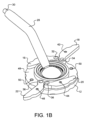
図1Bは、図1Aのトルク増幅装置の斜視図であり、2つのモーメントアームが突出した状態を示す。2つの突出可能なモーメントアーム18、22が、第2ソケット12内の格納位置(図1Aに示された位置)から外側に旋回した突出位置にある。トルク増幅装置10の第2ソケット12のフランジ48に配置された4つの凹部50のうちの2つも示されている。これらの凹部50は、突出可能なモーメントアーム16、18、20、22のリテーナ40、42、44、46にそれぞれ対応し、これらリテーナと係合することにより、突出可能なモーメントアーム16、18、20、22を、ユーザーがトルク増幅装置を締めたり緩めたりするのを支援する必要が生じるまで、その位置で保持するようになっている。一対の突出可能なモーメントアーム18、22を回転させるための最小の力を加えることによって、リテーナ42、46に打ち勝ち、アーム18、22が突出位置へと回わる。この突出された構成では、2つの突出可能なモーメントアーム18、22は、モーメントアーム18、22が円盤状の第2ソケット12の中心点に対して格納された第2ソケットの半径と比較して、操作者によって付与される力の接触点での、より大きな半径を提供する。したがって、突出可能なモーメントアーム18、22が突出されたときには、第2ソケット12を時計回り方向により小さな入力で回すことにより、同等の出力を得ることができる。この増加した接触点の半径、それ故に減じられた力により、ユーザーは、トルク増幅装置10を締めたり緩めたりするために、増幅したトルクを付与することができる。
Figure 1B is a perspective view of the torque amplifier of Figure 1A, showing the two moment arms extended. The two
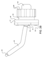
図2Aは、図1Aのトルク増幅装置の組立工程を示す分解図である。第2ソケット12は、第2ソケットの下側部分52、フランジ48、およびフランジ48に回動可能に結合された4つの突出可能なモーメントアーム18、20を画成する。円盤状の第2ソケット12は、この第2ソケットを貫通する中央のソケット凹部24を画成する。中央のソケット凹部24は、この図には示されていないが内ネジを画成する。取付アーム28の接続端部またはコネクタ30は、第2ソケット24の中央のソケット凹部24に挿通される。第2ソケット12の中央ソケット凹部24は、アーム28が中央ソケット凹部24を通過すると、取付アーム28のボール26エンドを受け取って回動可能に拘束するように構成されている。ボール26の直径は、中央のソケット凹部24の直径よりも大きいため、第2ソケット12を完全に通過することはできない。中央のソケット凹部24はまた、この図には示されていないが、ねじを有する内壁と、外壁を画成する。第1ソケット54は、トルク増幅装置10をベース、クランプ、または他の静止物体に取り付けるために構成されたソケットマウント58を画成する。刻み60が第1ソケット54によって画成されている。この刻み60は、第1ソケット54をベースまたはクランプに締め付ける(取り付ける)ための人間工学的グリップを提供する。他の実施形態では、固定具、溶接、接着剤、または当業者に知られている他の適切な方法によって、ベースまたはクランプに取り付けてもよい。第1ソケット54は結合凹部56を有する。この結合凹部56は、第2ソケット12の中央ソケット凹部24のねじと噛み合うねじ(この図にも示されていない)を内壁に有している。ボール26の直径が中央のソケット凹部24の形状の直径よりも大きいので、第2ソケット12と第1ソケット54が螺合されて締められると、ボール26を第2ソケット12と第1ソケット54との間で拘束することができる。第1ソケット54は、取付アーム28のボール26に被さるようにして配置され、第2ソケット12にねじ込まれる。第1ソケット54と第2ソケット12の螺合を締めると、ボール26が閉じ込められ、ボール26の動きが禁止され、取付アーム28およびそれより先のアタッチメントの旋回運動が制限される。さらに締めると、ボール26はさらに閉じ込められ、取付アーム28は動かなくなる。第1ソケット54の結合凹部56は、取付アーム28のボール26を拘束して保持するように構成されている。図2Bは、図1Aのトルク増幅装置の側面図であり、 図2Aの組立工程の結果を示す。
2A is an exploded view showing the assembly process of the torque multiplier device of FIG. 1A. The
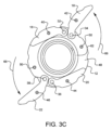
図3A~3Cは、図1Aのトルク増幅装置の上面図であり、4つのモーメントアームのすべてが格納された状態、一対のモーメントアームが突出した状態、別の一対のモーメントアームが突出した状態を、それぞれ示す。図3Aに示されるトルク増幅装置10の実施形態は、第2ソケット12を上から見下ろすようにして示されている。図3A~3Cでは、第2ソケットの機能をより明確に示すために、ボールと取付アームの図示を省略している。トルク増幅装置10の4つの突出可能なモーメントアーム16、18、20、22は全て格納位置にある。突出可能なモーメントアームのうちの2つのモーメントアームは、締め付け用の突出可能なモーメントアーム16、20であり、突出可能なモーメントアームのうちの2つは、緩め用の突出可能なモーメントアーム18、22である。4つの突出可能なモーメントアーム16、18、20、22の各々は、ピボットピン32、34、36、38で第2ソケットに保持されている。これらピボットピンは、突出可能なモーメントアームの外側への旋回を許容する。4つの突出可能なモーメントアーム16、18、20、22の各々はまた、バイアス拘束手段ないしはリテーナ40、42、44、46を有している。この実施形態では、リテーナはバネの力で第2ソケット12のフランジ48に向かって付勢されるピンであり、各突出可能なモーメントアーム16、18、20、22を格納位置に拘束するように構成されている。各モーメントアーム16、18、20、22を外側に突出するためには、各バイアス拘束手段ないしはリテーナ40、42、44、46に打ち勝つのに十分な力を加える必要がある。この実施形態では、一対の緩め用の突出可能なモーメントアーム16、20と一対の締め付け用の突出可能なモーメントアーム18、22が第2ソケット12の外周の内側に格納された状態で示されており、第1ソケット54と第2ソケット12を互いに締め付けるための機械的利点を提供する。代替の実施形態は、突出可能なモーメントアームの他の配置および向きを有することができ、重なり合ったり重ならなかったりすることができ、格納位置と突出位置との間で前後にスライドすることができ、第2ソケットにスライド可能に取り付けることができ、取り外し可能にすることができ、またはそれらの組み合わせとすることもできる。図3Bは、図3Aのトルク増幅装置を示し、2つの締め付け用の突出可能なモーメントアーム16、20が突出され、2つの緩め用の突出可能なモーメントアーム18、22が格納された状態を示す。ここで、トルク増幅装置10は、取付アーム28のボール26を第1ソケット54と第2ソケット12との間で締め付けるために、時計方向64に回わされる。付与される力は、突出可能なモーメントアーム16,20が格納された状態で第1ソケット54と第2ソケット12が締め付けられる場合と比較して、減じられる。図3Cは、図3Aのトルク増幅装置を示し、2つの緩め用の突出可能なモーメントアーム18、22が突出し、2つの締め付け用の突出可能なモーメントアーム16、20が格納された状態を示す。この状態は、第1ソケット54と第2ソケット12を互いに対して緩めるための機械的利点を提供する。トルク増幅装置10は、第1ソケット54と第2ソケット12との間の取付アーム28のボール26を緩めるために、反時計回り方向66に回わされる。付与される力は、緩め用の突出可能なモーメントアーム18、22が格納された場合と比較して、減じられる。トルク増幅装置の代替の実施形態では、時計回りの回転が第1、第2ソケットを互いに対して緩め、反時計回りの回転が第1、第2ソケットを互いに対して締め付けるようにしてもよい。
3A-3C are top views of the torque multiplier of FIG. 1A with all four moment arms retracted, one pair of moment arms extended, and another pair of moment arms extended, respectively. The embodiment of the
上述したように、外科用機器ホルダーの様々な利点を論じた。本明細書で論じられる実施形態は、本明細書の例として記述されている。前述の詳細な開示は、例としてのみ提示されることを意図しており、限定するものではないことは、当業者には明らかであろう。本明細書に明示的に記載されていないが、様々な変更、改善、および修正を当業者は意図するであろう。一例として、論じてきたエンドエフェクタはしばしばスコープの使用に焦点を合わせていたが、このシステムは他のタイプの手術器具を位置決めするために用いることができる。本明細書で明示的に述べられていないが、様々な変更、改善、および修正が当業者に意図されるであろう。これらの変更、改善、および修正は、ここに示唆されることを意図しており、クレームされた発明の精神および範囲内にある。図面は必ずしも縮尺通りではない。さらに、要素の処理またはシーケンスの記載された順序、または数字、文字、または他の指定は、したがって、特許請求の範囲で指定されている場合を除き、請求項を任意の順序に限定することを意図しない。したがって、本発明は、以下の特許請求の範囲およびその均等物よってのみ限定される。
As discussed above, various advantages of the surgical instrument holder have been discussed. The embodiments discussed herein are described as examples herein. Those skilled in the art will appreciate that the foregoing detailed disclosure is intended to be presented by way of example only, and not by way of limitation. Although not expressly described herein, various changes, improvements, and modifications will be contemplated by those skilled in the art. As an example, while the end effectors discussed have often focused on the use of a scope, the system can be used to position other types of surgical instruments. Although not expressly described herein, various changes, improvements, and modifications will be contemplated by those skilled in the art. These changes, improvements, and modifications are intended to be suggested herein and are within the spirit and scope of the claimed invention. The drawings are not necessarily to scale. Furthermore, the described order of processing or sequence of elements, or any numerical, letter, or other designation, is not intended to limit the claims to any order, unless otherwise specified in the claims. The present invention is therefore limited only by the following claims and equivalents thereof.
Claims (6)
前記第1ソケットに結合された第2ソケットと、
前記第1ソケットと前記第2ソケットの間に回転可能に保持され、取付アームに連結されたボールと、
を備え、
前記ボールは、前記第1ソケットと前記第2ソケットが互いに対して緩められたときに移動可能であり、前記第1ソケットと前記第2ソケットが互いに対して締め付けられたときに固定位置に保持され、
前記第2ソケットは、4つの突出可能なモーメントアームを有し、前記4つの突出可能なモーメントアームの各々が、格納位置と突出位置との間で移動可能であり、前記4つの突出可能なモーメントアームの各々が、前記第1ソケットと前記第2ソケットを互いに対して動かすための機械的利点を提供するように構成され、前記4つの突出可能なモーメントアームのうちの第1の組の2つが、前記第1ソケットと前記第2ソケットを互いに対して締め付けるためだけの機械的利点を提供するように構成され、前記4つの突出可能なモーメントアームのうちの第2の組の2つが、前記第1ソケットと前記第2ソケットを互いに対して緩めるためだけの機械的利点を提供するように構成される、トルク増幅装置。 A first socket;
a second socket coupled to the first socket;
a ball rotatably held between the first socket and the second socket and coupled to a mounting arm ;
Equipped with
the ball is movable when the first and second sockets are loosened relative to one another and is held in a fixed position when the first and second sockets are tightened relative to one another;
a torque amplifying device, the second socket having four extensible moment arms, each of the four extensible moment arms movable between a retracted position and an extended position, each of the four extensible moment arms configured to provide a mechanical advantage for moving the first and second sockets relative to one another, a first set of two of the four extensible moment arms configured to provide a mechanical advantage only for tightening the first and second sockets relative to one another, and a second set of two of the four extensible moment arms configured to provide a mechanical advantage only for loosening the first and second sockets relative to one another.
Applications Claiming Priority (3)
| Application Number | Priority Date | Filing Date | Title |
|---|---|---|---|
| US201962860563P | 2019-06-12 | 2019-06-12 | |
| US62/860,563 | 2019-06-12 | ||
| PCT/US2020/037430 WO2020252258A1 (en) | 2019-06-12 | 2020-06-12 | Torque enhancing apparatus |
Publications (3)
| Publication Number | Publication Date |
|---|---|
| JP2022536319A JP2022536319A (en) | 2022-08-15 |
| JPWO2020252258A5 JPWO2020252258A5 (en) | 2022-08-22 |
| JP7536799B2 true JP7536799B2 (en) | 2024-08-20 |
Family
ID=73781552
Family Applications (1)
| Application Number | Title | Priority Date | Filing Date |
|---|---|---|---|
| JP2021572655A Active JP7536799B2 (en) | 2019-06-12 | 2020-06-12 | Torque Amplifier |
Country Status (5)
| Country | Link |
|---|---|
| US (3) | US11852283B2 (en) |
| EP (1) | EP3972782A4 (en) |
| JP (1) | JP7536799B2 (en) |
| CA (1) | CA3141264A1 (en) |
| WO (1) | WO2020252258A1 (en) |
Families Citing this family (1)
| Publication number | Priority date | Publication date | Assignee | Title |
|---|---|---|---|---|
| WO2020252258A1 (en) * | 2019-06-12 | 2020-12-17 | Lsi Solutions, Inc. | Torque enhancing apparatus |
Citations (2)
| Publication number | Priority date | Publication date | Assignee | Title |
|---|---|---|---|---|
| US20030079575A1 (en) | 2001-10-25 | 2003-05-01 | Blanco Guajardo Brenda Erica | Torque multiplier |
| US20190113072A1 (en) | 2016-03-31 | 2019-04-18 | Quest Engineering Pty Ltd | Multi-Directional Mounting Bracket |
Family Cites Families (18)
| Publication number | Priority date | Publication date | Assignee | Title |
|---|---|---|---|---|
| DE3071014D1 (en) * | 1980-06-25 | 1985-09-26 | Khartli Inc | TORQUE MULTIPLIER ASSEMBLY |
| JP2843507B2 (en) | 1994-08-09 | 1999-01-06 | 三鷹光器株式会社 | Articulated instrument holding arm |
| JPH0942253A (en) * | 1995-08-01 | 1997-02-10 | Inax Corp | Nut |
| SE509414C2 (en) * | 1997-05-26 | 1999-01-25 | Ingvar Hejninger | Hand tools with support arm and locking mechanism and a method for loosening fasteners |
| JP4131052B2 (en) | 1998-07-17 | 2008-08-13 | ソニー株式会社 | Imaging device |
| US6055889A (en) * | 1999-01-11 | 2000-05-02 | Beere Precision Medical Instruments, Inc. | Hand manipulated torque transmitting tool |
| US6599240B2 (en) | 2000-12-20 | 2003-07-29 | Genzyme Corporation | Segmented arm assembly for use with a surgical retractor and instruments and methods related thereto |
| AU2007304428B2 (en) | 2006-10-06 | 2013-03-21 | Orion Surgical Gmbh | Lockable joint |
| TW200942366A (en) * | 2008-04-14 | 2009-10-16 | Jyun-Wun Liao | Torque sleeve |
| CA2786706C (en) * | 2010-01-12 | 2018-09-18 | Crewe-Tech Pty Ltd | A multi-bit tool |
| US8808176B2 (en) | 2012-02-02 | 2014-08-19 | Tedan Surgical Innovations, LLC. | Surgical process for anterior hip replacement |
| US9855643B2 (en) * | 2015-01-20 | 2018-01-02 | The Boeing Company | Torque-wrench apparatuses and methods of assembling the same |
| CA2980725A1 (en) | 2015-03-27 | 2016-10-06 | Sonitrack Systems, Inc. | Rapidly repositionable powered support arm |
| US11864958B2 (en) | 2017-05-03 | 2024-01-09 | Lsi Solutions, Inc. | Surgical equipment holder |
| USD920507S1 (en) | 2018-10-15 | 2021-05-25 | Lsi Solutions, Inc. | Surgical equipment holder |
| WO2020252258A1 (en) * | 2019-06-12 | 2020-12-17 | Lsi Solutions, Inc. | Torque enhancing apparatus |
| USD949331S1 (en) | 2020-02-26 | 2022-04-19 | Lsi Solutions, Inc. | Dock for surgical equipment holder |
| USD949333S1 (en) | 2020-02-26 | 2022-04-19 | Lsi Solutions, Inc. | Dock for surgical equipment holder |
-
2020
- 2020-06-12 WO PCT/US2020/037430 patent/WO2020252258A1/en not_active Ceased
- 2020-06-12 EP EP20821648.1A patent/EP3972782A4/en active Pending
- 2020-06-12 CA CA3141264A patent/CA3141264A1/en active Pending
- 2020-06-12 JP JP2021572655A patent/JP7536799B2/en active Active
- 2020-06-12 US US17/617,362 patent/US11852283B2/en active Active
-
2023
- 2023-11-15 US US18/510,243 patent/US12222060B2/en active Active
-
2025
- 2025-02-07 US US19/048,415 patent/US20250277557A1/en active Pending
Patent Citations (2)
| Publication number | Priority date | Publication date | Assignee | Title |
|---|---|---|---|---|
| US20030079575A1 (en) | 2001-10-25 | 2003-05-01 | Blanco Guajardo Brenda Erica | Torque multiplier |
| US20190113072A1 (en) | 2016-03-31 | 2019-04-18 | Quest Engineering Pty Ltd | Multi-Directional Mounting Bracket |
Also Published As
| Publication number | Publication date |
|---|---|
| CA3141264A1 (en) | 2020-12-17 |
| JP2022536319A (en) | 2022-08-15 |
| EP3972782A1 (en) | 2022-03-30 |
| US12222060B2 (en) | 2025-02-11 |
| EP3972782A4 (en) | 2023-01-04 |
| US20240084957A1 (en) | 2024-03-14 |
| US11852283B2 (en) | 2023-12-26 |
| US20250277557A1 (en) | 2025-09-04 |
| WO2020252258A1 (en) | 2020-12-17 |
| US20220252212A1 (en) | 2022-08-11 |
Similar Documents
| Publication | Publication Date | Title |
|---|---|---|
| JP7528190B2 (en) | Dock for surgical equipment holder | |
| US11931019B2 (en) | Surgical retractor having clamping mechanism | |
| US20240090971A1 (en) | Surgical equipment holder | |
| US20250134599A1 (en) | Universal tool adapter | |
| US9237933B2 (en) | Universal arm system | |
| JP2003088532A (en) | Operation instrument | |
| JP7536799B2 (en) | Torque Amplifier | |
| JP2024516846A (en) | Medical Device Systems | |
| US11103126B2 (en) | Surgical equipment holder | |
| JP6067866B2 (en) | Instrument holder for attaching medical devices to the joint arm | |
| US20230301745A1 (en) | Surgical assembly with a locking mechanism and clamp device | |
| US11051852B2 (en) | Fixturing device for medical instruments | |
| US20070225743A1 (en) | Mountable Top-Loading Surgical Retractor |
Legal Events
| Date | Code | Title | Description |
|---|---|---|---|
| A521 | Request for written amendment filed |
Free format text: JAPANESE INTERMEDIATE CODE: A523 Effective date: 20220112 |
|
| A521 | Request for written amendment filed |
Free format text: JAPANESE INTERMEDIATE CODE: A523 Effective date: 20220805 |
|
| A621 | Written request for application examination |
Free format text: JAPANESE INTERMEDIATE CODE: A621 Effective date: 20230515 |
|
| A977 | Report on retrieval |
Free format text: JAPANESE INTERMEDIATE CODE: A971007 Effective date: 20240308 |
|
| A131 | Notification of reasons for refusal |
Free format text: JAPANESE INTERMEDIATE CODE: A131 Effective date: 20240326 |
|
| A521 | Request for written amendment filed |
Free format text: JAPANESE INTERMEDIATE CODE: A523 Effective date: 20240617 |
|
| TRDD | Decision of grant or rejection written | ||
| A01 | Written decision to grant a patent or to grant a registration (utility model) |
Free format text: JAPANESE INTERMEDIATE CODE: A01 Effective date: 20240730 |
|
| A61 | First payment of annual fees (during grant procedure) |
Free format text: JAPANESE INTERMEDIATE CODE: A61 Effective date: 20240807 |
|
| R150 | Certificate of patent or registration of utility model |
Ref document number: 7536799 Country of ref document: JP Free format text: JAPANESE INTERMEDIATE CODE: R150 |