JP7536070B2 - Method for aspirating by pipetting and pipetting device - Patents.com - Google Patents
Method for aspirating by pipetting and pipetting device - Patents.com Download PDFInfo
- Publication number
- JP7536070B2 JP7536070B2 JP2022204142A JP2022204142A JP7536070B2 JP 7536070 B2 JP7536070 B2 JP 7536070B2 JP 2022204142 A JP2022204142 A JP 2022204142A JP 2022204142 A JP2022204142 A JP 2022204142A JP 7536070 B2 JP7536070 B2 JP 7536070B2
- Authority
- JP
- Japan
- Prior art keywords
- time
- working fluid
- pressure
- parameter
- aspiration
- Prior art date
- Legal status (The legal status is an assumption and is not a legal conclusion. Google has not performed a legal analysis and makes no representation as to the accuracy of the status listed.)
- Active
Links
- 238000000034 method Methods 0.000 title claims description 52
- 239000012530 fluid Substances 0.000 claims description 69
- 238000012360 testing method Methods 0.000 claims description 57
- 239000007788 liquid Substances 0.000 claims description 44
- 238000004458 analytical method Methods 0.000 claims description 42
- 230000001419 dependent effect Effects 0.000 claims description 21
- 230000000694 effects Effects 0.000 claims description 19
- 238000004891 communication Methods 0.000 claims description 4
- 238000004519 manufacturing process Methods 0.000 claims description 3
- 230000000977 initiatory effect Effects 0.000 description 7
- 238000001514 detection method Methods 0.000 description 4
- 238000010586 diagram Methods 0.000 description 4
- 238000004364 calculation method Methods 0.000 description 3
- 238000012544 monitoring process Methods 0.000 description 3
- 238000012795 verification Methods 0.000 description 3
- 230000001960 triggered effect Effects 0.000 description 2
- 230000001133 acceleration Effects 0.000 description 1
- 239000000654 additive Substances 0.000 description 1
- 230000000996 additive effect Effects 0.000 description 1
- 238000007654 immersion Methods 0.000 description 1
- 238000007620 mathematical function Methods 0.000 description 1
- 238000012797 qualification Methods 0.000 description 1
- 230000001105 regulatory effect Effects 0.000 description 1
Images


Classifications
-
- F—MECHANICAL ENGINEERING; LIGHTING; HEATING; WEAPONS; BLASTING
- F04—POSITIVE - DISPLACEMENT MACHINES FOR LIQUIDS; PUMPS FOR LIQUIDS OR ELASTIC FLUIDS
- F04B—POSITIVE-DISPLACEMENT MACHINES FOR LIQUIDS; PUMPS
- F04B49/00—Control, e.g. of pump delivery, or pump pressure of, or safety measures for, machines, pumps, or pumping installations, not otherwise provided for, or of interest apart from, groups F04B1/00 - F04B47/00
- F04B49/06—Control using electricity
-
- B—PERFORMING OPERATIONS; TRANSPORTING
- B01—PHYSICAL OR CHEMICAL PROCESSES OR APPARATUS IN GENERAL
- B01L—CHEMICAL OR PHYSICAL LABORATORY APPARATUS FOR GENERAL USE
- B01L3/00—Containers or dishes for laboratory use, e.g. laboratory glassware; Droppers
- B01L3/02—Burettes; Pipettes
- B01L3/021—Pipettes, i.e. with only one conduit for withdrawing and redistributing liquids
- B01L3/0217—Pipettes, i.e. with only one conduit for withdrawing and redistributing liquids of the plunger pump type
- B01L3/0237—Details of electronic control, e.g. relating to user interface
-
- F—MECHANICAL ENGINEERING; LIGHTING; HEATING; WEAPONS; BLASTING
- F04—POSITIVE - DISPLACEMENT MACHINES FOR LIQUIDS; PUMPS FOR LIQUIDS OR ELASTIC FLUIDS
- F04B—POSITIVE-DISPLACEMENT MACHINES FOR LIQUIDS; PUMPS
- F04B51/00—Testing machines, pumps, or pumping installations
-
- G—PHYSICS
- G01—MEASURING; TESTING
- G01N—INVESTIGATING OR ANALYSING MATERIALS BY DETERMINING THEIR CHEMICAL OR PHYSICAL PROPERTIES
- G01N1/00—Sampling; Preparing specimens for investigation
- G01N1/02—Devices for withdrawing samples
- G01N1/10—Devices for withdrawing samples in the liquid or fluent state
- G01N1/14—Suction devices, e.g. pumps; Ejector devices
-
- G—PHYSICS
- G01—MEASURING; TESTING
- G01N—INVESTIGATING OR ANALYSING MATERIALS BY DETERMINING THEIR CHEMICAL OR PHYSICAL PROPERTIES
- G01N35/00—Automatic analysis not limited to methods or materials provided for in any single one of groups G01N1/00 - G01N33/00; Handling materials therefor
- G01N35/00584—Control arrangements for automatic analysers
- G01N35/00594—Quality control, including calibration or testing of components of the analyser
- G01N35/00613—Quality control
- G01N35/00623—Quality control of instruments
-
- G—PHYSICS
- G01—MEASURING; TESTING
- G01N—INVESTIGATING OR ANALYSING MATERIALS BY DETERMINING THEIR CHEMICAL OR PHYSICAL PROPERTIES
- G01N35/00—Automatic analysis not limited to methods or materials provided for in any single one of groups G01N1/00 - G01N33/00; Handling materials therefor
- G01N35/10—Devices for transferring samples or any liquids to, in, or from, the analysis apparatus, e.g. suction devices, injection devices
- G01N35/1009—Characterised by arrangements for controlling the aspiration or dispense of liquids
- G01N35/1016—Control of the volume dispensed or introduced
-
- B—PERFORMING OPERATIONS; TRANSPORTING
- B01—PHYSICAL OR CHEMICAL PROCESSES OR APPARATUS IN GENERAL
- B01L—CHEMICAL OR PHYSICAL LABORATORY APPARATUS FOR GENERAL USE
- B01L2200/00—Solutions for specific problems relating to chemical or physical laboratory apparatus
- B01L2200/14—Process control and prevention of errors
- B01L2200/143—Quality control, feedback systems
-
- B—PERFORMING OPERATIONS; TRANSPORTING
- B01—PHYSICAL OR CHEMICAL PROCESSES OR APPARATUS IN GENERAL
- B01L—CHEMICAL OR PHYSICAL LABORATORY APPARATUS FOR GENERAL USE
- B01L2300/00—Additional constructional details
- B01L2300/06—Auxiliary integrated devices, integrated components
- B01L2300/0627—Sensor or part of a sensor is integrated
-
- G—PHYSICS
- G01—MEASURING; TESTING
- G01N—INVESTIGATING OR ANALYSING MATERIALS BY DETERMINING THEIR CHEMICAL OR PHYSICAL PROPERTIES
- G01N11/00—Investigating flow properties of materials, e.g. viscosity, plasticity; Analysing materials by determining flow properties
- G01N11/02—Investigating flow properties of materials, e.g. viscosity, plasticity; Analysing materials by determining flow properties by measuring flow of the material
- G01N11/04—Investigating flow properties of materials, e.g. viscosity, plasticity; Analysing materials by determining flow properties by measuring flow of the material through a restricted passage, e.g. tube, aperture
- G01N11/08—Investigating flow properties of materials, e.g. viscosity, plasticity; Analysing materials by determining flow properties by measuring flow of the material through a restricted passage, e.g. tube, aperture by measuring pressure required to produce a known flow
-
- G—PHYSICS
- G01—MEASURING; TESTING
- G01N—INVESTIGATING OR ANALYSING MATERIALS BY DETERMINING THEIR CHEMICAL OR PHYSICAL PROPERTIES
- G01N1/00—Sampling; Preparing specimens for investigation
- G01N1/02—Devices for withdrawing samples
- G01N1/10—Devices for withdrawing samples in the liquid or fluent state
- G01N1/14—Suction devices, e.g. pumps; Ejector devices
- G01N2001/1418—Depression, aspiration
Landscapes
- Engineering & Computer Science (AREA)
- Chemical & Material Sciences (AREA)
- Health & Medical Sciences (AREA)
- Life Sciences & Earth Sciences (AREA)
- Pathology (AREA)
- Analytical Chemistry (AREA)
- Biochemistry (AREA)
- General Health & Medical Sciences (AREA)
- General Physics & Mathematics (AREA)
- Immunology (AREA)
- Physics & Mathematics (AREA)
- Quality & Reliability (AREA)
- Human Computer Interaction (AREA)
- Clinical Laboratory Science (AREA)
- Chemical Kinetics & Catalysis (AREA)
- Mechanical Engineering (AREA)
- General Engineering & Computer Science (AREA)
- Hydrology & Water Resources (AREA)
- Sampling And Sample Adjustment (AREA)
- Feeding, Discharge, Calcimining, Fusing, And Gas-Generation Devices (AREA)
- Measuring Fluid Pressure (AREA)
- Automatic Analysis And Handling Materials Therefor (AREA)
- Devices For Use In Laboratory Experiments (AREA)
Description
この発明は、ピペット操作によって1用量の(a dose of)液体を吸引する方法、および記載された(addressed)吸引方法を含む1用量の液体を製造する方法に関する。 The invention relates to a method for aspirating a dose of liquid by pipetting, and a method for producing a dose of liquid, including an addressed aspirating method.
ピペット操作によって1用量の液体を吸引するために、一旦ピペットの先端がその吸引位置にあるとともに吸引される液体の中に浸漬されるべきであるならば、吸引源による吸引の動作または効果が、ピペットの内部空間に適用される。 To aspirate a dose of liquid by pipetting, once the tip of the pipette is in its aspiration position and should be immersed in the liquid to be aspirated, the action or effect of aspiration by the suction source is applied to the internal space of the pipette.
吸引の動作または効果は、作動流体によって、吸引源からピペットの先端に伝えられる。作動流体は、液体のセクションまたはカラムから、気体の流体セクションから、または、間に気体のセクションを備えた液体のセクションから、および/または、一端または両端に気体のセクションを備えた液体のセクションから成ることができる。吸引される(being aspired)液体が作動流体の液体の構成要素と接触することを回避するために、気体の流体を吸引するときに液体と接触する作動流体のそのセクションを少なくとも選択することは一般的なことである。作動流体の液体のセクションがピペットにおいておよびその先端まで(down to)利用されることが、この発明の枠組みで排除されないという事実にもかかわらず、この発明は、具体的には、ピペット操作装置のピペット・アプリケータ配置と同様にピペットにおいておよびその先端まで気体の作動流体セクションを扱うものである。 The aspiration action or effect is transmitted from the aspiration source to the tip of the pipette by means of a working fluid. The working fluid can consist of a liquid section or column, a gaseous fluid section, or a liquid section with a gaseous section in between and/or a liquid section with a gaseous section at one or both ends. In order to avoid the liquid being aspired coming into contact with the liquid components of the working fluid, it is common to select at least that section of the working fluid that comes into contact with the liquid when aspirating the gaseous fluid. Despite the fact that it is not excluded within the framework of this invention that a liquid section of the working fluid is utilized in the pipette and down to its tip, this invention specifically deals with a gaseous working fluid section in the pipette and down to its tip as well as a pipette-applicator arrangement of a pipetting device.
一旦、吸引動作が始められ、吸引動作によって調節され、それに依存する(dependent therefrom)と、パラメーター、つまり、例えば圧力、流量、重量などのようなピペット操作装置での物理的実体(entity)が、ピペット操作装置の中に取り上げられる添加材により変化する。 Once the aspiration action is initiated and regulated by and dependent therefrom, parameters, i.e. physical entities in the pipetting device such as pressure, flow rate, weight, etc., change with the additive taken up into the pipetting device.
概して(generically spoken)、吸引動作の効果に依存する(depend from)、上記の(addressed above)ようなパラメーターに対する基準を確立することによって、正確さ(つまり受容性)、あるいは非正確さ(つまり非受容性)のために吸引サイクルをチェックすることは広く知られている。受け入れ可能であると考えられる、吸引サイクルの間でのそれぞれ主だった(prevailing)パラメーターによって当該基準が満たされなければならない。 It is generally spoken of to check the aspiration cycle for accuracy (i.e. acceptability) or inaccuracy (i.e. non-acceptability) by establishing criteria for the parameters addressed above, which depend from the effectiveness of the aspiration action. The criteria must be met for each prevailing parameter during the aspiration cycle to be considered acceptable.
この発明は、吸引するための、改善された方法および装置を提供することを目的とする。 The present invention aims to provide an improved method and apparatus for suction.
これは、
a) 吸引位置に作動流体を含むピペットを移動する移動ステップと、
b) ある時点で作動流体に対して吸引動作を開始する開始ステップと、
を備える吸引サイクルでのピペット操作によって1用量の液体を吸引する方法、または該吸引方法を含む1用量の液体を製造する方法によって達成される。
this is,
a) moving a pipette containing a working fluid to an aspiration position;
b) an initiation step of initiating a suction action on the working fluid at a certain point in time;
This is achieved by a method of aspirating a dose of liquid by pipetting in an aspiration cycle comprising:
我々がこの明細書およびクレームを通して「ある時点」を述べるとき、用語「ポイント」は、形状的な定義による「ポイント」として理解されるべきではなく、それぞれ記載された(addressed)技術的な動作を行なうのにちょうど必要な短い時間間隔として理解されることになっている。 When we speak of "a point in time" throughout this specification and the claims, the term "point" is not to be understood as a "point" in any geometrical definition, but rather as just the brief interval of time necessary to perform the technical action addressed in each.
方法は、
c) 第1のタイムスパン内でおよび記載された(addressed)開始ステップに後続して、吸引動作の効果または結果に依存する(dependent from)、少なくとも1つの主だった第1パラメーターを分析する分析ステップを、さらに備える。
The method is:
c) within the first time span and subsequent to the addressed initiation step, further comprising an analysis step of analyzing at least one primary first parameter dependent from the effect or outcome of the suction action.
この分析ステップでは、少なくとも1つの主だった第1パラメーターが評価される。複数の主だった第1パラメーターが評価されることができる。 In this analysis step, at least one primary first parameter is evaluated. Multiple primary first parameters can be evaluated.
方法は、
d) 分析ステップの少なくとも1つの結果に応じて(independency of)少なくとも1つのテスト基準を決定する決定ステップをさらに備える。
The method is:
d) a determining step for determining at least one test criterion in dependence of at least one result of the analyzing step.
分析ステップは、複数の結果をもたらすことができる。1つのテスト基準は、単一の分析結果、または分析結果の組み合わせに依存することができる。複数のテスト基準は、単一の分析結果に応じて、または分析結果のそれぞれの組み合わせに応じて決定されることができる。 The analysis step can result in multiple results. A test criterion can depend on a single analytical result, or on a combination of analytical results. Multiple test criteria can be determined depending on a single analytical result, or on respective combinations of analytical results.
少なくとも1つのテスト基準の決定ステップは、例えば、少なくとも1つの分析結果と少なくとも1つのテスト基準との間で陽の(explicit)数学関数(例えば比例)が存在するならば、計算によって、または、分析結果(場合により、その組み合わせ)がそれぞれのテスト基準に起因するルックアップテーブルによって、行われることができる。 The step of determining the at least one test criterion can be performed by calculation, for example if there is an explicit mathematical function (e.g. proportionality) between the at least one analytical result and the at least one test criterion, or by means of a look-up table in which the analytical result (possibly a combination thereof) is attributed to the respective test criterion.
方法は、
e) 少なくとも1つの主だった第2パラメーターが少なくとも1つのテスト基準を満たすか満たさないかにより、記載された決定ステップに後続する第2のタイムスパン内で、吸引動作の効果または結果に依存する、少なくとも1つの主だった第2パラメーターをチェックするチェックステップをさらに備える。
The method is:
e) further comprising a checking step of checking at least one predominant second parameter, which depends on the effect or outcome of the suction operation, within a second time span subsequent to the described decision step, depending on whether the at least one predominant second parameter satisfies or does not satisfy the at least one test criterion.
我々が「タイムスパン内」での動作を行なうことを述べるとき、これは、該動作がタイムスパンの時間帯内で1回または複数回で行なわれることを、あるいはタイムスパン全体に沿って行なわれることを意味する。 When we say that we perform an action "within a timespan," this means that the action is performed one or more times within the time span, or along the entire timespan.
方法は、
f) チェックステップの結果に応じて受け入れ可能なものとしてまたは受け入れ不可なものとして、吸引サイクルを同定する同定ステップをさらに備える。
The method is:
f) An identification step of identifying the suction cycle as acceptable or unacceptable depending on the result of the checking step.
我々が「吸引動作の効果」のことを述べるとき、吸引動作を開始および維持することによって引き起こされる吸引効果を理解する。該効果は、一旦開始されると、ピペットでの吸引動作の効果に依存するのと同様に、それ自体吸引動作の挙動に依存する(dependent from)。 When we speak of the "effect of the aspiration action", we understand the aspiration effect caused by initiating and maintaining the aspiration action, which, once initiated, is itself dependent from the behavior of the aspiration action, in the same way that the effect of the aspiration action in a pipette is dependent.
発明者は、以下のことを見出している。
a) 吸引動作の効果または結果を決定する複数の条件およびそれらの組み合わせは、吸引動作の開始ステップに後続する第1のタイムスパンの間に少なくとも1つの主だった第1パラメーターの同じ挙動ヘ導く。
The inventors have discovered the following.
a) A plurality of conditions and combinations thereof determining the effect or outcome of the aspiration operation lead to the same behavior of at least one primary first parameter during a first time span following the initiation step of the aspiration operation.
吸引動作の効果(effect)または結果を決定する条件は、例えば、吸引サイクルの異なるフェーズにおける吸引ポンプの加速および減速、吸引される液体の量、吸引が開始されるときの作動流体の開始圧力、吸引される液体の粘性および密度、ピペットの内部空間の体積及び形状、ピペットフィルタの有無、ピペットオリフィスの形状およびサイズ、吸引される液体の中へのピペットチップの浸漬深さなどの条件であり、それらは、場合により知られている。前もって知られている該条件のほかに、公差のような該条件の変形例は、通常知られていない。 The conditions that determine the effect or result of the aspiration operation are sometimes known, such as, for example, the acceleration and deceleration of the aspiration pump in different phases of the aspiration cycle, the amount of liquid being aspirated, the starting pressure of the working fluid when aspiration begins, the viscosity and density of the liquid being aspirated, the volume and shape of the internal space of the pipette, the presence or absence of a pipette filter, the shape and size of the pipette orifice, the immersion depth of the pipette tip into the liquid being aspirated, etc. Besides the conditions that are known in advance, variations of the conditions, such as tolerances, are usually not known.
b) 上述されるような条件および場合によってはそれらの組み合わせから大部分独立している、少なくとも1つの主だった第1パラメーターの初期の挙動は、全体的な吸引サイクルの受容性に関して決定するために少なくとも1つの主だった第2パラメーターに適用される、少なくとも1つのそれぞれ選択されたテスト基準によって考慮に入れられることができる。 b) The initial behavior of at least one main first parameter, largely independent of the conditions as described above and possibly combinations thereof, can be taken into account by at least one respectively selected test criterion applied to at least one main second parameter to make a decision regarding the acceptability of the overall suction cycle.
したがって、テスト基準をセットする目標で吸引効果に影響を及ぼす条件を知ることが必要である。吸引効果の初期化に後続するタイムスパンの間に主だった第1パラメーターであれば、その挙動を知ることで十分である。 Therefore, it is necessary to know the conditions that affect the attraction effect with the goal of setting test criteria. It is sufficient to know the behavior of the primary parameter if it is the dominant one during the time span following the initialization of the attraction effect.
これは、吸引サイクルの間でのシステムの挙動をチェックするために考慮されるために、実体の数、記載された条件およびそれらの組み合わせを著しく減らすことを可能にする。例えば、分析結果をテスト基準に関連付けるルックアップテーブルにおけるデータの量は、すべての影響を及ぼす条件およびその組み合わせを別々に考慮する必要がある場合、インストールされなければならないルックアップテーブルと比較して、著しく低減されることができる。 This makes it possible to significantly reduce the number of entities, described conditions and their combinations to be taken into account for checking the system's behavior during the suction cycle. For example, the amount of data in a look-up table relating the analysis results to the test criteria can be significantly reduced compared to a look-up table that would have to be installed if all influencing conditions and their combinations had to be considered separately.
簡単な例として、例えば、条件の2つのセットまたは組み合わせが考慮されなければならない場合、等しいかまたは異なることができる2つのテスト基準が確立されなければならない。この発明によれば、条件の2つのセットが初めに主だった第1パラメーターの同じ挙動に結びつくと認められて、少なくとも1つのテスト基準のセッティングには決定的なものとしてこの挙動が得られる場合、条件用の2つのデータセットの代わりに、第1パラメーター挙動用の1つのデータセットだけが前もって知られていて、それぞれ保存されなければならない。 As a simple example, if, for example, two sets or combinations of conditions have to be considered, two test criteria, which can be equal or different, have to be established. According to the invention, if two sets of conditions are initially recognized as leading to the same behavior of the predominant first parameter and this behavior is obtained as determinative for the setting of at least one test criterion, then instead of two data sets for the conditions, only one data set for the first parameter behavior has to be known in advance and stored respectively.
この発明に係る方法の変形例では、少なくとも1つの主だった第1パラメーターは、作動流体での少なくとも1つの圧力および少なくとも1つの主だった圧力に依存する流量、液体である作動流体、または少なくとも1つの気体のセクションを少なくとも備えることの少なくとも1つを備える(comprises at least one of at least one pressure and of a flow dependent from at least one prevailing pressure in the work fluid, the work fluid being a liquid or at least comprising at least one a gaseous section)。 In a variant of the method according to the invention, the at least one predominant first parameter comprises at least one of at least one pressure and of a flow dependent from at least one prevailing pressure in the work fluid, the work fluid being a liquid or at least comprising at least one a gaseous section.
我々が「少なくとも1つの圧力」のことを述べるとき、これは、例えば2つの圧力値の差を含むものとする。 When we speak of "at least one pressure", this is intended to include, for example, the difference between two pressure values.
この発明に係る方法の変形例では、少なくとも1つの主だった第1パラメーターは、作動流体の少なくとも1つの圧力および流量、液体である作動流体、または少なくとも1つの気体のセクションを少なくとも備えることの少なくとも1つである(is at least one of at least one pressure and of a flow of the work fluid, the work fluid being a liquid or at least comprising at least one gaseous section)。 In a variant of the method according to the invention, the at least one predominant first parameter is at least one of at least one pressure and of a flow of the work fluid, the work fluid being a liquid or at least comprising at least one gaseous section.
この発明に係る方法の変形例では、少なくとも1つの主だった第2パラメーターは、作動流体での少なくとも1つの圧力および少なくとも1つの主だった圧力に依存する流量、液体である作動流体、または少なくとも1つの気体のセクションを少なくとも備えることの少なくとも1つを備える。 In a variant of the method according to the invention, the at least one predominant second parameter comprises at least one of a pressure in the working fluid and a flow rate dependent on the at least one predominant pressure, the working fluid being liquid, or having at least one gas section.
この発明に係る方法の変形例では、少なくとも1つの主だった第2パラメーターは、作動流体の少なくとも1つの圧力および流量、液体である作動流体、または少なくとも1つの気体のセクションを少なくとも備えることの少なくとも1つである。 In a variant of the method according to the invention, the at least one predominant second parameter is at least one of the pressure and flow rate of the working fluid, the working fluid being liquid, or having at least one gas section.
この発明に係る方法の変形例では、少なくとも1つの主だった第1パラメーターは、作動流体での少なくとも1つの圧力および少なくとも1つの主だった圧力に少なくとも依存する流量、液体である作動流体、または少なくとも1つの気体のセクションを少なくとも備えることの少なくとも1つを備えるとともに、少なくとも1つの主だった第2パラメーターは、作動流体での少なくとも1つの圧力および少なくとも1つの主だった圧力に少なくとも依存する流量の少なくとも1つを備える。 In a variant of the method according to the invention, the at least one primary first parameter comprises at least one of at least one pressure in the working fluid and a flow rate at least dependent on the at least one primary pressure, the working fluid being liquid, or having at least one gas section, and the at least one primary second parameter comprises at least one of at least one pressure in the working fluid and a flow rate at least dependent on the at least one primary pressure.
この発明に係る方法の変形例では、
・少なくとも1つの主だった第1パラメーターは、作動流体の少なくとも1つの圧力および流量、液体である作動流体、または少なくとも1つの気体のセクションを少なくとも備えることの少なくとも1つである、および、
・少なくとも1つの主だった第2パラメーターは、作動流体の少なくとも1つの圧力および流量の少なくとも1つである。
In a variant of the method according to the invention,
the at least one primary first parameter is at least one of a pressure and a flow rate of the working fluid, the working fluid being liquid, or at least comprising at least one gas section; and
The at least one predominant secondary parameter is at least one of the pressure and the flow rate of the working fluid.
この発明に係る方法の変形例では、分析ステップは、少なくとも1つの主だった第1パラメーターの経時的な(over time)少なくとも1つの第1の特性を分析することを備える。 In a variation of the method of the present invention, the analyzing step comprises analyzing at least one first characteristic over time of at least one primary first parameter.
この発明に係る方法の変形例では、分析ステップは、少なくとも1つの主だった第1パラメーターの経時的な少なくとも1つの第1の特性を分析することを備える。
・前記少なくとも1つの主だった第1パラメーターは、前記作動流体での少なくとも1つの圧力および少なくとも1つの主だった圧力に少なくとも依存する流量、液体である前記作動流体、または少なくとも1つの気体のセクションを少なくとも備えることの少なくとも1つを備えること、
・前記少なくとも1つの主だった第1パラメーターは、作動流体の少なくとも1つの圧力および流量、液体である前記作動流体または少なくとも1つの気体のセクションを少なくとも備えることの少なくとも1つであること、
・前記少なくとも1つの主だった第2パラメーターは、前記作動流体での少なくとも1つの圧力および少なくとも1つの主だった圧力に少なくとも依存する流量、液体である前記作動流体、または少なくとも1つの気体のセクションを少なくとも備えることの少なくとも1つを少なくとも備えること、
の少なくとも1つが優先する(there prevail)。
In a variant of the method according to the invention, the analyzing step comprises analyzing at least one first characteristic over time of at least one primary first parameter.
the at least one predominant first parameter comprises at least one of: at least one pressure on the working fluid and a flow rate at least dependent on the at least one predominant pressure, the working fluid being liquid, or at least one gas section;
the at least one primary first parameter is at least one of a pressure and a flow rate of a working fluid, the working fluid being liquid or at least one gas section;
the at least one predominant second parameter comprises at least one of: at least one pressure on the working fluid and a flow rate at least dependent on the at least one predominant pressure, the working fluid being liquid, or at least one gas section;
At least one of the following takes precedence:
前記少なくとも1つの主だった第2パラメーターは、作動流体の少なくとも1つの圧力および流量、液体である前記作動流体、または少なくとも1つの気体のセクションを少なくとも備えることの少なくとも1つである。 The at least one predominant second parameter is at least one of the pressure and flow rate of the working fluid, the working fluid being liquid, or having at least one gas section.
この発明に係る方法の変形例では、少なくとも1つのテスト基準を決定するステップは、前記少なくとも1つの主だった第2パラメーターについて経時的な、少なくとも1つの定格の(rated)第2の特性を決定することを備える。 In a variation of the method of the present invention, the step of determining at least one test criterion comprises determining at least one rated second characteristic over time for the at least one primary second parameter.
この発明に係る方法の1つの変形例では、少なくとも1つのテスト基準を決定するステップは、少なくとも1つの主だった第2パラメーターについての経時的な、少なくとも1つの定格の第2の特性を決定することを備える。そして、
・前記少なくとも1つの主だった第1パラメーターは、前記作動流体での少なくとも1つの圧力および少なくとも1つの主だった圧力に少なくとも依存する流量、液体である前記作動流体、または少なくとも1つの気体のセクションを少なくとも備えることの少なくとも1つを少なくとも備えること、
・前記少なくとも1つの主だった第1パラメーターは、作動流体の少なくとも1つの圧力および流量、液体である前記作動流体、または少なくとも1つの気体のセクションを少なくとも備えることの少なくとも1つであること、
・前記少なくとも1つの主だった第2パラメーターは、前記作動流体での少なくとも1つの圧力および少なくとも1つの主だった圧力に少なくとも依存する流量、液体である前記作動流体、または少なくとも1つの気体のセクションを少なくとも備えることの少なくとも1つを少なくとも備えること、
・前記少なくとも1つの主だった第2パラメーターは、作動流体の少なくとも1つの圧力および流量、液体である前記作動流体、または少なくとも1つの気体のセクションを少なくとも備えることの少なくとも1つであること、
・分析ステップは、前記少なくとも1つの主だった第1パラメーターの経時的な少なくとも1つの第1の特性を決定するステップを備えること、
の少なくとも1つが優先する。
In one variant of the method according to the invention, the step of determining at least one test criterion comprises determining a second characteristic of the at least one rating over time for at least one primary second parameter; and
the at least one predominant first parameter comprises at least one of: at least one pressure on the working fluid and a flow rate at least dependent on the at least one predominant pressure, the working fluid being liquid, or at least one gas section;
the at least one primary first parameter comprises at least one of a pressure and a flow rate of a working fluid, the working fluid being a liquid, or at least one gas section;
the at least one predominant second parameter comprises at least one of: at least one pressure on the working fluid and a flow rate at least dependent on the at least one predominant pressure, the working fluid being liquid, or at least one gas section;
the at least one predominant second parameter is at least one of a pressure and a flow rate of a working fluid, the working fluid being a liquid, or at least one gas section;
the analyzing step comprises determining at least one first characteristic of said at least one primary first parameter over time;
At least one of the following takes precedence.
この発明に係る方法の1つの変形例では、分析ステップは、少なくとも1つの圧力、および、前記吸引動作の前記効果に依存する流量の少なくとも1つの第1の時間微分を分析することを備える。 In one variation of the method of the present invention, the analyzing step comprises analyzing at least one first time derivative of at least one of the pressure and the flow rate dependent on the effect of the suction operation.
この発明に係る方法の1つの変形例では、前記分析ステップは、少なくとも1つの圧力、および、前記吸引動作の前記効果に依存する流量の少なくとも1つの第1の時間微分を分析することを備える。そして、
・作動流体は、液体であるかまたは少なくとも1つの気体のセクションを少なくとも備えること、
・少なくとも1つの主だった第1パラメーターは、作動流体の少なくとも1つの圧力および流量、液体である作動流体、または少なくとも1つの気体のセクションを少なくとも備えることの少なくとも1つであること、
・少なくとも1つの主だった第2パラメーターは、作動流体での少なくとも1つの圧力および少なくとも1つの主だった圧力に少なくとも依存する流量、液体である作動流体、または少なくとも1つの気体のセクションを少なくとも備えることの少なくとも1つを少なくとも備えること、
・少なくとも1つの主だった第2パラメーターは、作動流体の少なくとも1つの圧力および流量、液体である作動流体、または少なくとも1つの気体のセクションの少なくとも1つであること、
・分析ステップは、少なくとも1つの主だった第1パラメーターの経時的な少なくとも1つの第1の特性を決定するステップを備えること、
・少なくとも1つのテスト基準を決定するステップは、少なくとも1つの主だった第2パラメーターの経時的な、少なくとも1つの定格の第2の特性を決定することを備えること、
の少なくとも1つが優先する。
In one variant of the method according to the invention, the analyzing step comprises analyzing a first time derivative of at least one of the pressure and the flow rate dependent on the effect of the aspiration; and
The working fluid is liquid or comprises at least one gas section;
the at least one primary parameter is at least one of a pressure and a flow rate of a working fluid, the working fluid being liquid, or at least one gas section;
the at least one predominant second parameter comprises at least one of: at least one pressure in the working fluid and a flow rate at least dependent on the at least one predominant pressure, the working fluid being liquid, or at least one gas section;
the at least one predominant second parameter being at least one of a pressure and a flow rate of the working fluid, the working fluid being a liquid, or at least one gas section;
the analyzing step comprises determining at least one first characteristic of at least one primary first parameter over time;
the step of determining the at least one test criterion comprises determining a second characteristic of the at least one rating over time of at least one primary second parameter;
At least one of the following takes precedence.
この発明に係る方法の1つの変形例では、分析ステップは、少なくとも1つの圧力、および、前記吸引動作の前記効果に依存する流量の少なくとも1つの第1の時間微分を分析することを備える。少なくとも1つの圧力、あるいは流量は、以下の主だった時間経過(time course)を有して、
・第1の時間微分は、或る瞬間で生じる極値に向かう時点の後に変化して、前記瞬間の後に或る程度まで戻る。決定ステップは、時点と瞬間と(後者を含む(latter inclusive))の間のタイムスパン内で行なわれる。
In one variant of the method according to the invention, the analyzing step comprises analyzing a first time derivative of at least one of the pressure and the flow rate dependent on said effect of said aspiration, said at least one pressure or flow rate having the following main time course:
The first time derivative changes after a time point towards an extreme value occurring at a certain instant and then back to some extent after said instant, the determining step being performed within a time span between the time points and the instant (latter inclusive).
この発明に係る方法の1つの変形例では、前記分析ステップは、少なくとも1つの圧力、および、前記吸引動作の前記効果に依存する流量の少なくとも1つの第1の時間微分を分析することを備え、前記少なくとも1つの圧力または前記流量が、以下の主だった時間経過を有する、
・第1の時間微分は、或る瞬間に生じる極値に向かう時点の後に変化して、前記瞬間の後に或る程度まで戻る。決定ステップは、時点と瞬間と(後者を含む)の間のタイムスパン内で行なわれる。そして、
・前記少なくとも1つの主だった圧力または流量は、それぞれ前記作動流体の圧力または流量であり、前記作動流体が、液体であるかまたは少なくとも1つの気体のセクションを少なくとも備えること、
・前記少なくとも1つの主だった第2パラメーターは、前記作動流体での少なくとも1つの圧力および少なくとも1つの主だった圧力に少なくとも依存する流量の少なくとも1つを少なくとも備え、前記作動流体が液体であるかまたは少なくとも1つの気体のセクションの少なくとも備えること、
・前記少なくとも1つの主だった第2パラメーターは、作動流体の少なくとも1つの圧力および流量、液体である作動流体、または少なくとも1つの気体のセクションの少なくとも1つを少なくとも備えること、
・前記分析ステップは、少なくとも1つの圧力、および、前記吸引動作の前記効果に依存する流量の少なくとも1つの第1の時間微分を分析することを備えること、
・前記少なくとも1つのテスト基準を決定するステップは、前記少なくとも1つの主だった第2パラメーターの経時的な、少なくとも1つの定格の特性を決定することを備えること、
・前記チェックは、前記瞬間に続いて同時に(at a time)行なわれること、
の少なくとも1つが優先する。
In one variant of the method according to the invention, the analysis step comprises analyzing a first time derivative of at least one of the pressures and of the flow rate depending on the effect of the aspiration, the at least one pressure or the flow rate having the following predominant time course:
the first time derivative changes after a time point towards an extreme value occurring at a certain instant and back to some extent after said instant, the determining step being performed within a time span between the time points and the instant (inclusive); and
said at least one predominant pressure or flow rate is a pressure or flow rate, respectively, of said working fluid, said working fluid being liquid or comprising at least one gas section;
the at least one predominant second parameter comprises at least one of at least one pressure on the working fluid and at least one flow rate dependent on the at least one predominant pressure, the working fluid being liquid or comprising at least one gas section;
the at least one primary second parameter comprises at least one of a pressure and a flow rate of a working fluid, the working fluid being a liquid, or at least one gas section;
the analyzing step comprises analyzing a first time derivative of at least one of a pressure and a flow rate dependent on the effect of the aspiration;
the step of determining the at least one test criterion comprises determining at least one rating characteristic over time of the at least one primary secondary parameter;
- said check is performed at a time subsequent to said moment;
At least one of the following takes precedence.
もし矛盾しなければ既に記載されたあらゆる変形例と結合することができるこの発明に係る方法の変形例では、分析ステップは、
・少なくとも1つの圧力値、
・少なくとも1つの流量値、
・圧力コースの第1の時間微分の少なくとも1つの値、
・流量コースの第1の時間微分の少なくとも1つの値、
・圧力コースの第2の時間微分の少なくとも1つの値、
・流量コースの第2の時間微分の少なくとも1つの値、
の少なくとも1つを評価するステップを備える。
In a variant of the method according to the invention, which can be combined with any variant already described unless inconsistent, the analysis step comprises:
at least one pressure value;
At least one flow rate value;
at least one value of a first time derivative of the pressure course;
At least one value of a first time derivative of the flow course;
at least one value of a second time derivative of the pressure course;
At least one value of a second time derivative of the flow rate course;
The method includes evaluating at least one of the following:
もし矛盾しなければ既に記載されたあらゆる変形例と結合することができるこの発明に係る方法の変形例では、少なくとも1つのテスト基準は、
・圧力値、
・流量値、
・圧力コースの第1の時間微分、
・流量コースの第1の時間微分、
・圧力コースの第2の時間微分、
・流量コースの第2の時間微分、
の少なくとも1つに対する範囲を備える。
In a variant of the method according to the invention, which can be combined with any variant already described if not inconsistent, at least one test criterion is
- pressure value,
Flow rate value,
- the first time derivative of the pressure course;
- the first time derivative of the flow course;
the second time derivative of the pressure course,
- the second time derivative of the flow course;
The range includes at least one of the following:
もし矛盾しなければ既に記載されたあらゆる変形例と結合することができるこの発明に係る方法の変形例では、分析ステップは、
・少なくとも1つの圧力値、
・少なくとも1つの流量値、
・圧力コースの第1の時間微分の少なくとも1つの値、
・流量コースの第1の時間微分の少なくとも1つの値、
・圧力コースの第2の時間微分の少なくとも1つの値、
・流量コースの第2の時間微分の少なくとも1つの値、
の少なくとも1つを評価するステップを備えるとともに、
前記少なくとも1つのテスト基準は、
・圧力値、
・流量値、
・圧力コースの第1の時間微分、
・流量コースの第1の時間微分、
・圧力コースの第2の時間微分、
・流量コースの第2の時間微分、
の少なくとも1つに対する範囲を備える。
In a variant of the method according to the invention, which can be combined with any variant already described unless inconsistent, the analysis step comprises:
at least one pressure value;
At least one flow rate value;
at least one value of a first time derivative of the pressure course;
At least one value of a first time derivative of the flow course;
at least one value of a second time derivative of the pressure course;
At least one value of a second time derivative of the flow rate course;
and evaluating at least one of
The at least one test criterion is
- pressure value,
Flow rate value,
- the first time derivative of the pressure course;
- the first time derivative of the flow course;
the second time derivative of the pressure course,
- the second time derivative of the flow course;
The range includes at least one of the following:
もし矛盾しなければ既に記載されたあらゆる変形例と結合することができるこの発明に係る方法の変形例では、前記テスト基準が範囲であり、前記チェックステップは、主だった第2パラメーターが第1の時間に対する前記範囲に入った後に行われる。 In a variant of the method according to the invention, which can be combined with any variant already described unless inconsistent, the test criterion is a range and the checking step is performed after the predominant second parameter falls within said range for a first time.
例えば、信号ノイズおよび時間/信号値のスケーリングに応じて、極値の検出がシャープではないことがあるので、我々は、「時点で」の極値というよりも、「瞬間で」の極値の発生を扱っている(address)。 For example, depending on signal noise and time/signal value scaling, the detection of extrema may not be sharp, so we address the occurrence of extrema "at a moment" rather than "at a point in time".
総括的なポイントの扱い:
この発明に係る方法は、主だった吸引サイクルが受け入れ可能か否かをチェックする、唯一の手順ではないことがあると考えられなければならない。例えば、我々は、ピペットが吸引位置に移動されると記載している。この位置で、ピペットの先端が、吸引される液体に浸漬されるか否かは、例えば、ピペットでの主だった圧力コースから瞬間的に認識される。吸引動作は、先端が液体に浸漬されるときよりもはるかに小さく変化する作動流体の主だった圧力をもたらすであろう。これは、この発明に係る方法を利用せずに、吸引サイクルを開始した直後に検出されることができる。したがって、この実施例から分かるように、受け入れ時に吸引サイクルをチェックするために、追加のテストを行うことができる。
General points treatment:
It must be considered that the method according to the invention may not be the only procedure for checking whether the main aspiration cycle is acceptable or not. For example, we describe that the pipette is moved to the aspiration position. Whether or not the tip of the pipette is immersed in the liquid to be aspirated in this position can be recognized instantaneously, for example, from the main pressure course at the pipette. The aspiration action will result in the main pressure of the working fluid varying much less than when the tip is immersed in the liquid. This can be detected immediately after starting the aspiration cycle without making use of the method according to the invention. Thus, as can be seen from this example, additional tests can be performed to check the aspiration cycle on acceptance.
上述されるようなテスト基準の範囲は、一定であることができ、またはその幅および/またはその平均値に関して経時的に(over time)変化することができる。 The range of the test criteria as described above can be constant or can vary over time in terms of its width and/or its average value.
それらが矛盾しない場合、この発明に係る方法の全ての変形例(それらは記載された)が、組み合わせられることができる。 All variants of the method according to the invention, which are described, can be combined, if they are not inconsistent.
この発明は、少なくとも1つのピペットに対するピペット・アプリケータ配置と、ピペット・アプリケータ配置の内部空間と流れ連通する吸引源と、内部空間に作動的に接続されているセンサ配置と、を備え、センサ配置の出力が吸引サイクルのテストユニットに作動的に接続されているピペット操作装置に関する。吸引サイクルのテストユニットは、
・ピペット・アプリケータ配置が吸引位置に到達していることを表す(representative for)制御信号を受け取る受取ステップと、
・前記制御信号に基づいて、或る時点で前記吸引源によって吸引動作を前記内部空間に適用することを開始する開始ステップと、
・前記開始ステップに続いて前記センサ配置の出力信号に依存する信号を分析する分析ステップと、
・前記分析ステップの結果に応じて(in dependency of)少なくとも1つのテスト基準を決定する決定ステップと、
・前記決定ステップに続いて、前記センサ配置の出力信号に依存する信号が、前記少なくとも1つのテスト基準を満たすか否かを、第2のタイムスパンにおいてチェックするチェックステップと、
・前記チェックステップの結果に応じて前記吸引サイクルが受け入れ可能か否かの表示を生成する生成ステップと、を実行するように構成される。
The present invention relates to a pipetting device comprising a pipette-applicator arrangement for at least one pipette, a suction source in flow communication with an interior space of the pipette-applicator arrangement, and a sensor arrangement operatively connected to the interior space, the output of the sensor arrangement being operatively connected to an aspiration cycle test unit, the aspiration cycle test unit comprising:
- receiving a control signal representative for the pipette applicator arrangement reaching an aspiration position;
- initiating the application of suction by the suction source to the interior space at a certain time based on the control signal;
- an analysis step subsequent to said starting step, of analyzing a signal dependent on the output signal of said sensor arrangement;
a determination step of determining at least one test criterion in dependency of the result of said analysis step;
- following said determining step, a checking step of checking, in a second time span, whether a signal dependent on an output signal of the sensor arrangement satisfies said at least one test criterion;
- a generating step of generating an indication of whether the aspiration cycle is acceptable or not depending on the result of the checking step.
この発明に係る装置の一実施形態は、この発明に係る方法を行なうように、または、その変形例の1つまたは複数の方法を行なうように構成される。 One embodiment of the device of the present invention is configured to perform the method of the present invention or one or more method variations thereof.
この発明は、図面の助けを借りてさらに例示される。 The invention is further illustrated with the aid of the drawings.
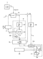
図1は、機能-ブロック/信号-流量の図によって、この発明の原理を最も模式的に示す。 Figure 1 shows the principle of this invention most diagrammatically through a function-block/signal-flow diagram.
スタート信号STARTによって、ピペット配置101上のポンプ設備100によって吸引動作が開始される。センサ配置103は、吸引動作を開始して維持する、ピペット配置101での効果に依存する少なくとも1つの主だった第1パラメーターP1stを感知する。ポンプ設備100、ピペット配置101、センサ配置103は、図1のハードウェア・ブロック104に表わされる。吸引設備、吸引される液体、およびピペットにおける(as of)複数の条件CONは、吸引動作を開始して維持する効果に影響を及ぼす。少なくとも1つの主だった第1パラメーターP1stは、分析段階106において分析される。少なくとも1つの分析結果RAが、センサ配置103で感知された少なくとも1つの第2パラメーターP2ndに対する少なくとも1つのテスト基準TCを決定段階108において決定する。テスト基準が決定された後に主だった少なくとも1つの第2パラメーターP2ndは、それが少なくとも1つのテスト基準TCを満たすかどうかを、チェック段階110においてチェックされる。少なくとも1つの主だった第2パラメーターP2ndが、少なくとも1つのテスト基準TCを満たす場合、吸引サイクルは受け入れ可能であると考えられ、少なくとも1つの主だった第2パラメーターP2ndが少なくとも1つのテスト基準TCを満たさない場合、吸引サイクルは受け入れられない。これは、図1においてa/naで表わされる。
With a start signal START, an aspiration operation is initiated by the
図2は、信号流量/機能ブロックの図によって、この発明に係る方法の、およびこの発明の該実施例に係る装置の構造の、さらに具体的な実施例を、最も模式的に且つ単純化して示す。 Figure 2 shows, in a most schematic and simplified manner, a more specific embodiment of the method according to the invention and of the structure of the device according to this embodiment of the invention, in a signal flow/function block diagram.
ピペット1は、ピペット・アプリケータ配置3に取り付けられる。ピペット・アプリケータ配置3は、1つまたは複数のピペット1を受け入れるために適合されることができる。1つまたは複数のピペット1と通じているピペット・アプリケータ配置3の内部空間2は、プランジャー・ポンプとして図2に示された吸引設備あるいは吸引源5と動作的に流れ連通状態にある。吸引源5は、例えば、吸引サイクルが開始されるとき、スタート信号STを生成するドライブ7によって制御されて駆動される。
The pipette 1 is attached to a
ピペット・アプリケータ3は、両方向矢印Zで示されるように上下に、そして、x/y平面において慣習的に追加的に、ドライブ9によって制御されて駆動される。
The
図2の実施形態によれば、ピペット・アプリケータ配置3の内部空間2は、気体の作動流体セクションで、特にエアで満たされる。
According to the embodiment of FIG. 2, the
圧力センサ配置11は、ピペット1上で動作するピペット・アプリケータ3の内部空間2における圧力p(t)をモニターする。圧力センサ配置の代わりに、あるいは、圧力センサ配置に加えて、流量センサ配置が設けられることができる(図2には示されない)。圧力センサ配置11の出力11oでは、信号S(p(t))が生成される。信号S(p(t))は、例えば作動流体の気体のセクションにおける主だった圧力p(t)を表わすデジタル信号である。圧力センサ配置11の出力11oは、分析段階13にまず動作的に供給される。スイッチングユニット15によって模式的に示されるように、これは、例えば、タイマー段階17によって、ピペットチップが吸引位置に到達したとき、例えば、ドライブ7で生成されたスタート信号STによってトリガーされて、開始される。
The
タイムスパンτ1内で、信号S(p(t))および圧力p(t)の時間経過が、ピペット・アプリケータ配置3での作動流体におけるこのタイムスパンτ1の間で優勢である、主だった第1パラメーターとして、分析される。
Within a time span τ 1 , the time course of the signal S(p(t)) and the pressure p(t) are analyzed as the primary parameters prevailing during this time span τ 1 in the working fluid at the
分析段階13における分析結果が作動流体におけるτ1の間で優勢であるとき、分析段階13における分析結果は、圧力p(t)の時間経過の1つまたは複数の特性値である。
The analysis result in the
当該特性値は、例えば、
・選択されたタイムスパンにわたって平均された可能性がある(possibly averaged)それぞれ選択された瞬間での、1つまたは複数の圧力値、
・選択されたタイムスパンにわたって平均された可能性がある圧力の極値の圧力値、
・圧力が極値を達成するときの時間または時間帯、
・選択されたタイムスパンにわたって平均された可能性がある、それぞれ選択された瞬間での圧力の時間経過の第1の時間微分の1つまたは複数の値、
・圧力の時間経過の第1の時間微分の極値、
・圧力の第1の時間微分が極値を達成するときの時間または時間帯、
・選択されたタイムスパンにわたって平均された可能性がある、それぞれ選択された瞬間での圧力の時間経過の第2の時間微分の1つまたは複数の値、
・特定の特性値が生じる時間系列など、である。
The characteristic value is, for example,
one or more pressure values at each selected instant in time, possibly averaged over a selected time span;
- pressure values of possible pressure extremes averaged over a selected time span;
- the time or period when the pressure reaches its extreme value;
one or more values of the first time derivative of the time course of the pressure at each selected instant in time, possibly averaged over a selected time span;
the extremum of the first time derivative of the pressure over time,
the time or time period when the first time derivative of the pressure achieves an extreme value;
one or more values of the second time derivative of the time course of the pressure at each selected instant in time, possibly averaged over a selected time span;
- The time sequence in which a particular characteristic value occurs, etc.
吸引のスタートで開始されたタイムスパンτ1は、選択ユニット18によって図2に示されるような所定の期間、または、主だった圧力p(t)の主だった時間経過の選択された挙動によって、例えば、後で説明される実施例における(as of)主だった圧力p(t)の主だった時間経過の第1の時間微分の極値の発生によってセットされるτ1の終端(end)、のいずれかを有する。このように、τ1の終端は、E(τ1)で図2において破線で示されるように、分析段階13における分析結果によってトリガーされることができる。タイムスパンτ1の終端において、分析が終了する。
The time span τ 1 , which begins with the start of aspiration, has either a predefined duration, as shown in Fig. 2, by the
分析段階13における分析プロセスの結果データは、図2においてVnで記載される。結果データは、決定段階19に供給される。決定段階19において、1つまたは複数のテスト基準Cmは、分析段階13の分析の1つまたは複数の結果値Vnに応じて決定される。決定段階19によって決定されたテスト基準の数mは、分析ステップの結果値の数nから独立している。
The result data of the analysis process in the
テスト基準は、例えば、
・吸引サイクルの1つまたは複数のタイムスパンにおける圧力値に対する1つまたは複数の範囲(それによって該範囲はそれぞれのタイムスパンにわたって一定であることができる)は、それぞれのタイムスパンに沿って幅において変化することがある、および/または、範囲の平均値に関して変化することができる、
・吸引サイクルの1つまたは複数のタイムスパンにおける圧力の時間経過の第1の時間微分および/または第2の時間微分に対する1つまたは複数の範囲(それによって該範囲はそれぞれのタイムスパンにわたって一定であることができる)は、それぞれのタイムスパンに沿って幅において変化することができる、および/または、範囲の平均値に関して変化することができる、
とすることができる。
Test criteria may include, for example:
one or more ranges for pressure values in one or more time spans of an aspiration cycle (whereby the ranges may be constant over the respective time spans) may vary in width along the respective time spans and/or may vary about an average value of the ranges;
one or more ranges for the first time derivative and/or the second time derivative of the pressure time course in one or more time spans of the aspiration cycle (whereby the ranges can be constant over the respective time spans) can vary in width along the respective time spans and/or can vary with respect to an average value of the ranges;
It can be said that:
分析の単一の結果値V1から、1つのテスト基準C1または複数のテスト基準C1,C2…は、決定段階19によって決定されることができる。
From a single result value V 1 of the analysis, a test criterion C 1 or several test criteria C 1 , C 2 . . . can be determined by a
他方で、分析段階13における分析の複数の結果値V1,V2...は、単一のテスト基準Cx(V1,V2...)を決定するために決定段階19によって組み合わせられることができる。
On the other hand, multiple result values V 1 , V 2 ... of the analysis in the
テスト基準を決定するステップは、計算によって、またはルックアップテーブルの利用によって、行なわれることができる。分析結果Vnおよびその組み合わせの可能性およびそれぞれのテスト基準Cmは、互いに照合される。 The step of determining the test criteria can be performed by calculation or by using a look-up table.The analysis results Vn and their combination possibilities and the respective test criteria Cm are matched against each other.
タイムスパンτ1を分析した後およびテスト基準が決定されている後、センサ配置11の出力信号S(p(t))は、スイッチングユニット15で模式的に示されるように、主だった第2パラメーターとして、チェック段階21への入力として供給される。テスト基準Cmも、チェック段階21への入力である。
After analysing the time span τ 1 and after the test criterion has been determined, the output signal S(p(t)) of the
チェック段階21によって、主だった圧力p(t)の主だった時間経過は、それがテスト基準Cmを満たすかどうかをチェックされる。
By means of a
より一般的な考察下で、分析される第1パラメーター、および、図1におけるチェックされる第2パラメーターは、同じパラメーターとすることができることが明白になる。 Under more general consideration, it becomes clear that the first parameter to be analyzed and the second parameter to be checked in FIG. 1 can be the same parameter.
テスト基準が決定段階21によって確立されていることに依存して、それぞれの主だった特性は、モニタリング段階20において、信号S(p(t))に応じて、主だった圧力の主だった時間経過でモニターされる。したがって、例えば、1つのテスト基準が圧力の時間経過の第1の時間微分に関するならば、該テスト基準に基づいてチェック操作を行なう前に、圧力の主だった時間経過での主だった第1の時間微分は、モニタリング段階20でモニターされる。
Depending on which test criterion has been established by the
分析ステップの完了直後に、τ1の終了直後に、及び段階19で1つまたは複数のテスト基準を決定することが完了した直後に、チェック操作が開始されることができるが、チェックが重要であると考えられる瞬間またはタイムスパンは、別個に考慮されるべきである。
The check operation can be started immediately after the completion of the analysis step, immediately after the end of τ 1 , and immediately after the completion of determining one or more test criteria in
図2に示されるように、チェック結果RCは、最初に検証段階23に渡される(passed to)。検証段階23は、制御されたスイッチのように働く。制御信号Scを検証段階23に適用した後にまたは適用する間に、チェック結果RCは、その受容性または非受容性に関して吸引サイクルの有効な資格(valid qualification)とみなされる。
As shown in FIG. 2, the check result RC is first passed to a
制御信号Scは、例えば、吸引サイクルの所定の瞬間でおよび/または所定のタイムスパンの間に、例えば、タイマー段階17によって制御されるとき、または、例えばテスト基準のうちの1つが、満たされるとき、例えば例示されるように最初に満たされるときに生成されることができる。
The control signal Sc can be generated, for example, at a predetermined instant of the suction cycle and/or during a predetermined time span, for example as controlled by a
一旦、チェック結果RCが、吸引サイクルの有効表示として有効になれば、受容性y/nは表示段階25で表示される。
Once the check result RC is valid as a valid indication of the suction cycle, the acceptability y/n is displayed in
圧力値として図2の実施形態に例示されている第1パラメーターおよび/または第2パラメーターは、流量値で実現されることができることに留意すること。これは後続の考察に有効である。 Note that the first and/or second parameters illustrated in the embodiment of FIG. 2 as pressure values can also be realized as flow rate values. This is valid for the following discussion.
実施例:
この発明の方法および装置は、図3に係る変形例および実施形態、および図4から図6に係る特性によってさらに例示されている。
Working Example:
The method and device of the present invention are further illustrated by the variants and embodiments according to FIG. 3 and the characteristics according to FIGS.
図3は図2と同様の表現である。同じ参照番号は、図2に照らして既に記載された部分に使用される。 Figure 3 is a representation similar to Figure 2. The same reference numbers are used for parts already described with reference to Figure 2.
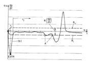
スタート信号STに基づいて、タイマー段階17は、スイッチングユニット15によって図式化されるように、信号S(p(t))を分析段階13に切り替える。圧力p(t)は、図4に定性的に示すように、破線の特性(a)によって低下する。
Based on the start signal ST, the
分析段階13は、S(p(t))の第1の時間微分が計算される、微分(differentiating)段階131を備える。(a)における低下圧力に起因するこの第1の時間微分は、特性(b)で図4に示される。
The
図4から図6におけるスケーリングが、任意の単位であることに留意すること。 Please note that the scaling in Figures 4 to 6 is in arbitrary units.
分析段階13は、極値検出段階132をさらに備える。極値検出段階132は、第1の時間微分の極値EXTRの発生を検出する。制御信号E(τ1)で示されるように、極値EXTRの検出は、タイムスパンτ1の終了を制御する。一旦極値EXTRが検出されれば、第1の時間微分の極値は分析結果V1として決定される。このとき、関連する分析結果V1(つまりEXTRの値)は、制御信号C132およびスイッチングユニット133で模式的に示されるように、決定段階191に供給される。さらに、スイッチングユニット15で模式的に示されるように、信号S(pt)は、分析段階13への入力から切り離される。
The
V1に応じて、決定段階191は、圧力の時間経過の第1の時間微分の値に対する範囲R(dp/dt)を、テスト基準C1として決定する。この範囲は、最大限Ruおよび最小限Rlの特性によって図4に示される。 Depending on V1 , the decision step 191 determines a range R(dp/dt) for the value of the first time derivative of the pressure over time as test criterion C1 . This range is illustrated in FIG. 4 by the characteristics of maximum Ru and minimum Rl .
この実施形態または変形例において、分析のタイムスパンτ1の終了が、圧力の時間経過の第1の時間微分の極値EXTRの検出によって制御されているが、スイッチングユニット15およびスイッチングユニット134を介して模式的に表されるように、信号S(p(t))がモニタリング段階20に供給されることは、決定段階191によってテスト基準C1が決定された後である。この実施形態では、信号S(p(t))の第1の時間微分が、第2パラメーターとしてモニターされる。
In this embodiment or a variant, the end of the analysis time span τ 1 is controlled by the detection of an extremum EXTR of the first time derivative of the pressure time course, as represented diagrammatically via switching
例えば計算でまたはルックアップテーブルの使用で、分析結果V1に依存して決定されたテスト基準C1は、図2のチェック段階21に従って、コンパレーター段階136に供給される。それは、主だった圧力の主だった時間経過の主だった第1の時間微分と比較される。
A test criterion C1 determined depending on the analysis result V1 , for example by calculation or by use of a look-up table, is supplied to a
比較結果RCは、コンパレーター段階136の出力nおよび出力yによって図4に表わされる。圧力の主だった時間経過の主だった第1の時間微分が、テスト範囲R(dp/dt)内にあるならば、信号は、出力yで生成され、そうでなければ出力nで生成される。
The comparison result RC is represented in FIG. 4 by the output n and output y of the
図3の検証段階23によれば、出力yが初めて(for the first time)作動するとき、つまり、主だった時間微分が第1の時間の間に(for the first time)範囲R(dp/dt)に入るとき、信号Scは、単安定ユニットとして作動するユニット138をトリガーする。そして、この瞬間からおよび図4に示される後続のタイムスパンτ2の間に、コンパレーター段階136の出力が、実際の吸引サイクルが有効である(-y-)か、または無効である(-n-)かを、インジケータ段階25で表示することに有効であるとみなされる。図4から分かるように、圧力p(t)の第1の時間微分の時間経過は、タイムスパンτ2の間に範囲R(dp/dt)内のままであり、したがって受け入れ可能であるとみなされる。
According to the
図5は、図4と同じ表現であり且つ同じスケーリングで、異なる吸引サイクルの特性を示す。吸引は、図4の実施例よりも著しく速く、つまり、極値EXTRの値は、図4のそれより著しく大きい。テスト基準R(dp/dt)は、より大きな分析結果に依存して(dependent from)、より大きい。 Figure 5 shows the characteristics of a different suction cycle with the same representation and scaling as Figure 4. The suction is significantly faster than in the embodiment of Figure 4, i.e. the value of the extreme EXTR is significantly larger than that of Figure 4. The test criterion R(dp/dt) is larger, depending from the larger analytical results.
図5に示される吸引サイクルは、受け入れ可能でもある。 The suction cycle shown in Figure 5 is also acceptable.
図6は、さらなる吸引サイクルの特性を示す。拡大して示されるが、スケーリングは図4および図5のそれと一致する。 Figure 6 shows the characteristics of a further suction cycle. It is shown at an enlarged scale, but the scaling is consistent with that of Figures 4 and 5.
EXTRの値は、図4におけるそれよりも低い。そして、それに依存する範囲R(dp/dt)は小さい。理解されるように、圧力p(t)の第1の時間微分の時間経過は、瞬間Aで、定格特性、すなわちテスト基準の範囲をτ2内に残す(leave)。その時間経過は、ピペットの閉塞に起因する。図6における吸引サイクルは、受け入れ可能でないと考えられる。 The value of EXTR is lower than in Fig. 4, and the range R(dp/dt) depending on it is smaller. As can be seen, the time course of the first time derivative of the pressure p(t) leaves the nominal characteristic, i.e. the range of the test criteria, within τ2 at the instant A. The time course is due to the occlusion of the pipette. The aspiration cycle in Fig. 6 is considered to be unacceptable.
したがって、およびこの発明によれば、吸引サイクルでのピペット操作によって1用量の液体を吸引する方法、または該吸引方法を含む1用量の液体を製造する方法、及びピペット操作装置が、考え出される。それらによって、自動的に、吸引サイクルは、初めに分析されて、分析結果に応じて(in dependency of)受け入れ時にチェックされる。吸引サイクルのテスト基準を支配している(governing)実体の数が、大幅に減少して、該実体の未知の変化が自動的に考慮される。 Therefore, and according to the invention, a method for aspirating a dose of liquid by pipetting in an aspiration cycle or a method for producing a dose of liquid including said aspiration method and a pipetting device are conceived, whereby the aspiration cycle is automatically analysed at the outset and checked on acceptance in dependency of the analysis results. The number of entities governing the test criteria of the aspiration cycle is significantly reduced and unknown variations of said entities are automatically taken into account.
Claims (6)
a)作動流体を含むピペットが吸引位置に到達した後、
b)或る時点で前記作動流体に対する吸引動作を開始する開始ステップと、
c)前記吸引動作の影響に依存する、少なくとも1つの主だった第1パラメータをセンサ配置によって検知する検知ステップであって、前記第1パラメータは、前記作動流体中の圧力の時間経過または前記作動流体中の流量の時間経過である、検知ステップと、
前記吸引動作が開始された後の第1のタイムスパン内に、少なくとも1つの主だった前記第1パラメータを分析する分析ステップであって、前記分析は、主だった前記第1パラメータの第1の時間微分の極値(EXTR)の発生を検出し、前記第1の時間微分の極値を前記分析の少なくとも1つの結果として決定することを含む、分析ステップと、
d)前記分析の少なくとも1つの結果に依存して、少なくとも1つのテスト基準を決定する決定ステップであって、前記テスト基準は、前記作動流体中の圧力の時間経過または前記作動流体中の流量の時間経過の第1の時間微分の値の範囲(R)であり、前記範囲(R)は、前記極値(EXTR)に依存して決定される、決定ステップと、
e)少なくとも1つの主だった第2パラメータをチェックするチェックステップであって、主だった前記第2パラメータは、前記範囲の決定後の第2のタイムスパンにおいて、前記作動流体中の圧力の時間経過または前記作動流体中の流量の時間経過のモニタされた前記第1の時間微分であり、前記第2パラメータである前記第1の時間微分の値が第2のタイムスパン中に前記範囲(R)内に留まるかどうかをチェックする、チェックステップと、
f)前記チェックステップの結果に応じて受け入れ可能または受け入れ不可として、前記吸引サイクルを同定する同定ステップと、
を含む、方法。 1. A method for aspirating a dose of liquid by pipetting in an aspiration cycle or a method for producing a dose of liquid comprising said aspirating method, comprising the steps of:
a) after the pipette containing the working fluid reaches the aspiration position;
b) starting a suction operation on the working fluid at a certain time;
c) detecting at least one primary parameter dependent on the effect of the suction action by a sensor arrangement, said primary parameter being a pressure over time in said working fluid or a flow rate over time in said working fluid ;
an analysis step of analyzing at least one predominant first parameter within a first time span after the aspiration operation is initiated, the analysis including detecting an occurrence of an extreme value (EXTR) of a first time derivative of the predominant first parameter and determining the extreme value of the first time derivative as at least one result of the analysis ;
d) determining at least one test criterion depending on at least one result of said analysis, said test criterion being a range (R) of values of a first time derivative of the time course of the pressure in said working fluid or of the time course of the flow rate in said working fluid, said range (R) being determined depending on said extreme value (EXTR);
e) a check step of checking at least one predominant second parameter, the predominant second parameter being the monitored first time derivative of the pressure over time in the working fluid or of the flow rate over time in the working fluid during a second time span after the determination of the range , checking whether the value of the first time derivative of the second parameter remains within the range (R) during the second time span;
f) an identification step of identifying said suction cycle as acceptable or unacceptable depending on the result of said checking step ;
A method comprising:
・前記第1の時間微分は、前記時点以降、瞬間に発生する極値に向かって変化し、前記時点以降、ある程度まで戻り、
・前記決定は、前記時点と前記瞬間との間のタイムスパン(後者を含む)で実行される、
上記の主だった時間経過を有する、請求項1に記載の方法。 At least one of the pressure or the flow rate is
the first time derivative changes toward an extreme value occurring at an instant after the time point and then changes back to some extent after the time point;
The determination is performed in a time span between the time point and the instant in time (including the latter);
The method of claim 1 having the above-mentioned predominant time course.
・吸引位置に到達したピペット・アプリケータ配置を代表する制御信号を受信することと、
・前記吸引源による前記内部空間への吸引動作をある時点で開始させることと、
を実現するように構成され、
前記吸引サイクル試験装置は、請求項1から5のいずれか一項に記載の前記方法を実行するように構成されている、ピペッティング装置。 A pipetting device comprising a pipette applicator arrangement (3) for at least one pipette (1), a suction source (5) in fluid communication with an internal space (2) of said pipette applicator arrangement, and a sensor arrangement (11, 103) operatively connected to said internal space, the output of said sensor arrangement being operatively connected to an aspiration cycle test device (13, 15, 17, 18, 19, 20, 21, 23, 25, 106, 108, 110),
receiving a control signal representative of a pipette applicator arrangement reaching an aspiration position;
- starting a suction operation by the suction source into the internal space at a certain point in time;
The present invention is configured to achieve the above.
A pipetting device, wherein the aspiration cycle test device is configured to perform the method according to any one of claims 1 to 5.
Applications Claiming Priority (3)
| Application Number | Priority Date | Filing Date | Title |
|---|---|---|---|
| US15/420,693 US10859592B2 (en) | 2017-01-31 | 2017-01-31 | Method of aspirating by pipetting and pipetting apparatus |
| US15/420,693 | 2017-01-31 | ||
| JP2018013631A JP2018134631A (en) | 2017-01-31 | 2018-01-30 | Method of sucking by pipetting and pipetting device |
Related Parent Applications (1)
| Application Number | Title | Priority Date | Filing Date |
|---|---|---|---|
| JP2018013631A Division JP2018134631A (en) | 2017-01-31 | 2018-01-30 | Method of sucking by pipetting and pipetting device |
Publications (2)
| Publication Number | Publication Date |
|---|---|
| JP2023029407A JP2023029407A (en) | 2023-03-03 |
| JP7536070B2 true JP7536070B2 (en) | 2024-08-19 |
Family
ID=60569758
Family Applications (2)
| Application Number | Title | Priority Date | Filing Date |
|---|---|---|---|
| JP2018013631A Pending JP2018134631A (en) | 2017-01-31 | 2018-01-30 | Method of sucking by pipetting and pipetting device |
| JP2022204142A Active JP7536070B2 (en) | 2017-01-31 | 2022-12-21 | Method for aspirating by pipetting and pipetting device - Patents.com |
Family Applications Before (1)
| Application Number | Title | Priority Date | Filing Date |
|---|---|---|---|
| JP2018013631A Pending JP2018134631A (en) | 2017-01-31 | 2018-01-30 | Method of sucking by pipetting and pipetting device |
Country Status (4)
| Country | Link |
|---|---|
| US (1) | US10859592B2 (en) |
| EP (1) | EP3355067B1 (en) |
| JP (2) | JP2018134631A (en) |
| CN (2) | CN113958493B (en) |
Families Citing this family (1)
| Publication number | Priority date | Publication date | Assignee | Title |
|---|---|---|---|---|
| US20230366904A1 (en) | 2022-05-11 | 2023-11-16 | Perkinelmer Health Sciences, Inc. | Pipetting apparatus and methods |
Citations (3)
| Publication number | Priority date | Publication date | Assignee | Title |
|---|---|---|---|---|
| JP2711215B2 (en) | 1993-11-29 | 1998-02-10 | アロカ株式会社 | Automatic dispensing device |
| JP2011519035A (en) | 2008-04-23 | 2011-06-30 | シーメンス・ヘルスケア・ダイアグノスティックス・インコーポレイテッド | Distinguishing between abnormal viscosity and pipette clogging of samples during aspiration |
| US20160273951A1 (en) | 2013-06-24 | 2016-09-22 | Seyonic S.A. | Method for controlling pipetting operations |
Family Cites Families (28)
| Publication number | Priority date | Publication date | Assignee | Title |
|---|---|---|---|---|
| US3766747A (en) * | 1972-01-06 | 1973-10-23 | Lennox Ind Inc | Liquid sensor for reciprocating refrigerant compressor |
| JPS4912401A (en) * | 1972-05-17 | 1974-02-02 | ||
| FR2633719B1 (en) * | 1988-06-30 | 1991-04-19 | Inst Francais Du Petrole | MEASURING METHOD AND DEVICE FOR DETERMINING A PUMPING CHARACTERISTIC OR A PARAMETER OF A FLUID |
| DE4237904C2 (en) * | 1992-11-10 | 1995-10-05 | Tuchenhagen Otto Gmbh | Method and device for regulating the flow of a flowable substance to be metered |
| US5537880A (en) * | 1995-06-07 | 1996-07-23 | Abbott Laboratories | Automatic pipetting apparatus with leak detection and method of detecting a leak |
| JPH0915248A (en) * | 1995-06-29 | 1997-01-17 | Nissho Corp | Dispensing operation determination device and method |
| KR100633873B1 (en) * | 1997-05-26 | 2006-10-13 | 마틴 레흐만 | Leak test method and device |
| US6370942B1 (en) * | 2000-05-15 | 2002-04-16 | Dade Behring Inc. | Method for verifying the integrity of a fluid transfer |
| ES2250644T3 (en) * | 2001-03-09 | 2006-04-16 | Hamilton Bonaduz Ag | PROCEDURE AND DEVICE FOR EVALUATING A LIQUID DOSAGE PROCESS. |
| DE10234630A1 (en) * | 2002-07-29 | 2004-04-08 | Wilo Ag | Method for determining the flow rate of a fluid through a pump |
| CN1311913C (en) * | 2004-10-28 | 2007-04-25 | 博奥生物有限公司 | A micro-liquid injection system |
| ITRM20050373A1 (en) * | 2005-07-13 | 2007-01-14 | Seko Bono Exacta S P A | PILOT DEVICE FOR A PUMP OPERATING ELECTROMAGNET, AND RELATED DOSING ELECTROMAGNETIC PUMP. |
| EP1745851B1 (en) * | 2005-07-22 | 2015-02-25 | Tecan Trading AG | Process, device and computerprogramm product for the classification of a liquid |
| US8715573B2 (en) * | 2006-10-13 | 2014-05-06 | Accuri Cytometers, Inc. | Fluidic system for a flow cytometer with temporal processing |
| AT9241U3 (en) * | 2007-02-05 | 2007-12-15 | Avl List Gmbh | METHOD AND DEVICE FOR CONTINUOUS MEASUREMENT OF DYNAMIC FLUID CONSUMPTION |
| JP4966913B2 (en) * | 2007-05-15 | 2012-07-04 | 株式会社日立ハイテクノロジーズ | Liquid dispensing device |
| EP2009449A1 (en) * | 2007-06-06 | 2008-12-31 | Hamilton Bonaduz AG | Method of controlling a pipetting process |
| EP2031403B1 (en) * | 2007-08-27 | 2016-02-17 | Roche Diagnostics GmbH | Method for monitoring a fluid transfer process |
| EP2302397A1 (en) * | 2009-09-25 | 2011-03-30 | bioMérieux S.A. | Method, computer program, and apparatus for detecting pipetting errors |
| KR101398705B1 (en) * | 2010-02-23 | 2014-06-19 | 아르테미스 인텔리전트 파워 리미티드 | Fluid-working machine and method of operating a fluid-working machine |
| JP5624825B2 (en) * | 2010-07-29 | 2014-11-12 | 株式会社日立ハイテクノロジーズ | Liquid chromatograph pump and liquid chromatograph |
| FR2977317B1 (en) * | 2011-06-28 | 2013-08-02 | Gilson Sas | METHOD FOR DETECTING ANOMALIES WHEN FILLING A LIQUID ASSAY DEVICE AND LIQUID ASSAY DEVICE |
| DE102012206041A1 (en) * | 2012-04-13 | 2013-10-17 | Zf Friedrichshafen Ag | Apparatus and method for driving an auxiliary pump of a transmission |
| US9962067B2 (en) * | 2012-05-31 | 2018-05-08 | Siemens Healthcare Diagnostics Inc. | Real time detection of aspiration short shots using pressure signal |
| EP2904370B1 (en) * | 2012-10-04 | 2023-08-16 | Siemens Healthcare Diagnostics Inc. | Methods and apparatus for measuring aspiration pressure at low aspiration volumes |
| GB2521148B (en) * | 2013-12-10 | 2016-06-08 | Kind Consumer Ltd | Airflow testing apparatus |
| CN103852437B (en) * | 2014-03-22 | 2016-05-04 | 中国科学院合肥物质科学研究院 | A kind of mid-infrared light spectral measurement system and method for greenhouse gas emission flux |
| DE102014222390A1 (en) * | 2014-11-03 | 2016-05-04 | Continental Automotive Gmbh | Method for creating a characteristic field of a fluid pump, use of a limited valve, use of a stepped valve and control unit for a fluid delivery system |
-
2017
- 2017-01-31 US US15/420,693 patent/US10859592B2/en active Active
- 2017-12-01 EP EP17205020.5A patent/EP3355067B1/en active Active
-
2018
- 2018-01-30 JP JP2018013631A patent/JP2018134631A/en active Pending
- 2018-01-31 CN CN202111216012.4A patent/CN113958493B/en active Active
- 2018-01-31 CN CN201810094460.3A patent/CN108374783B/en active Active
-
2022
- 2022-12-21 JP JP2022204142A patent/JP7536070B2/en active Active
Patent Citations (3)
| Publication number | Priority date | Publication date | Assignee | Title |
|---|---|---|---|---|
| JP2711215B2 (en) | 1993-11-29 | 1998-02-10 | アロカ株式会社 | Automatic dispensing device |
| JP2011519035A (en) | 2008-04-23 | 2011-06-30 | シーメンス・ヘルスケア・ダイアグノスティックス・インコーポレイテッド | Distinguishing between abnormal viscosity and pipette clogging of samples during aspiration |
| US20160273951A1 (en) | 2013-06-24 | 2016-09-22 | Seyonic S.A. | Method for controlling pipetting operations |
Also Published As
| Publication number | Publication date |
|---|---|
| CN108374783A (en) | 2018-08-07 |
| CN108374783B (en) | 2021-10-29 |
| EP3355067A1 (en) | 2018-08-01 |
| JP2018134631A (en) | 2018-08-30 |
| US10859592B2 (en) | 2020-12-08 |
| CN113958493A (en) | 2022-01-21 |
| CN113958493B (en) | 2024-08-27 |
| EP3355067B1 (en) | 2022-09-28 |
| US20180214862A1 (en) | 2018-08-02 |
| JP2023029407A (en) | 2023-03-03 |
Similar Documents
| Publication | Publication Date | Title |
|---|---|---|
| JP7536070B2 (en) | Method for aspirating by pipetting and pipetting device - Patents.com | |
| JP2009002944A (en) | Method for controlling pipetting process | |
| JP7372245B2 (en) | Device and method for automatic liquid transfer optimized dispensing | |
| US8287073B2 (en) | Method for detecting an operating state of a fluid chamber of an inkjet print head | |
| EP3144678A1 (en) | Automated analysis device | |
| JP2014044174A (en) | Automatic analyzer | |
| US20150362514A1 (en) | Automatic analyzer | |
| JP2021508827A5 (en) | ||
| CN110179163A (en) | The control method and electronic cigarette of electronic cigarette | |
| US20070177986A1 (en) | Method and apparatus for evaluating a dosing operation | |
| EP2574884A2 (en) | Mass flow controller monitoring | |
| EP2480898B1 (en) | Method, computer program, and apparatus for detecting pipetting errors | |
| EP2485030A1 (en) | Device for detetcting gas leaks, particualrly for joints of pipes and the like | |
| US12038417B2 (en) | Liquid sending system for liquid chromatograph | |
| CN111060383A (en) | Push piece dyeing machine and push piece control method thereof | |
| US12007373B2 (en) | Liquid chromatograph | |
| JP2018134631A5 (en) | ||
| EP1812163B1 (en) | Method for checking the condition of a sample when metering liquid | |
| CN111122148B (en) | Method for detecting blood by prejudging working state of electromagnetic valve based on hemorheometer | |
| JP2006300843A (en) | How to check the suction status | |
| CN119076075A (en) | Liquid aspiration with volume compensation | |
| HK1106827B (en) | Method for checking the condition of a sample when metering liquid |
Legal Events
| Date | Code | Title | Description |
|---|---|---|---|
| A521 | Request for written amendment filed |
Free format text: JAPANESE INTERMEDIATE CODE: A523 Effective date: 20221221 |
|
| A621 | Written request for application examination |
Free format text: JAPANESE INTERMEDIATE CODE: A621 Effective date: 20221221 |
|
| A131 | Notification of reasons for refusal |
Free format text: JAPANESE INTERMEDIATE CODE: A131 Effective date: 20231121 |
|
| A601 | Written request for extension of time |
Free format text: JAPANESE INTERMEDIATE CODE: A601 Effective date: 20240216 |
|
| A521 | Request for written amendment filed |
Free format text: JAPANESE INTERMEDIATE CODE: A523 Effective date: 20240416 |
|
| TRDD | Decision of grant or rejection written | ||
| A01 | Written decision to grant a patent or to grant a registration (utility model) |
Free format text: JAPANESE INTERMEDIATE CODE: A01 Effective date: 20240709 |
|
| A61 | First payment of annual fees (during grant procedure) |
Free format text: JAPANESE INTERMEDIATE CODE: A61 Effective date: 20240806 |
|
| R150 | Certificate of patent or registration of utility model |
Ref document number: 7536070 Country of ref document: JP Free format text: JAPANESE INTERMEDIATE CODE: R150 |