JP7534026B2 - Fiber optic adapters, fiber optic connector plugs, connector assemblies, and communication devices - Google Patents
Fiber optic adapters, fiber optic connector plugs, connector assemblies, and communication devices Download PDFInfo
- Publication number
- JP7534026B2 JP7534026B2 JP2023513574A JP2023513574A JP7534026B2 JP 7534026 B2 JP7534026 B2 JP 7534026B2 JP 2023513574 A JP2023513574 A JP 2023513574A JP 2023513574 A JP2023513574 A JP 2023513574A JP 7534026 B2 JP7534026 B2 JP 7534026B2
- Authority
- JP
- Japan
- Prior art keywords
- adapter
- locking structure
- fiber optic
- connector plug
- optical fiber
- Prior art date
- Legal status (The legal status is an assumption and is not a legal conclusion. Google has not performed a legal analysis and makes no representation as to the accuracy of the status listed.)
- Active
Links
Images


Classifications
-
- G—PHYSICS
- G02—OPTICS
- G02B—OPTICAL ELEMENTS, SYSTEMS OR APPARATUS
- G02B6/00—Light guides; Structural details of arrangements comprising light guides and other optical elements, e.g. couplings
- G02B6/24—Coupling light guides
- G02B6/36—Mechanical coupling means
- G02B6/38—Mechanical coupling means having fibre to fibre mating means
- G02B6/3807—Dismountable connectors, i.e. comprising plugs
- G02B6/381—Dismountable connectors, i.e. comprising plugs of the ferrule type, e.g. fibre ends embedded in ferrules, connecting a pair of fibres
- G02B6/3825—Dismountable connectors, i.e. comprising plugs of the ferrule type, e.g. fibre ends embedded in ferrules, connecting a pair of fibres with an intermediate part, e.g. adapter, receptacle, linking two plugs
-
- G—PHYSICS
- G02—OPTICS
- G02B—OPTICAL ELEMENTS, SYSTEMS OR APPARATUS
- G02B6/00—Light guides; Structural details of arrangements comprising light guides and other optical elements, e.g. couplings
- G02B6/24—Coupling light guides
- G02B6/36—Mechanical coupling means
- G02B6/38—Mechanical coupling means having fibre to fibre mating means
- G02B6/3807—Dismountable connectors, i.e. comprising plugs
- G02B6/3869—Mounting ferrules to connector body, i.e. plugs
- G02B6/387—Connector plugs comprising two complementary members, e.g. shells, caps, covers, locked together
-
- G—PHYSICS
- G02—OPTICS
- G02B—OPTICAL ELEMENTS, SYSTEMS OR APPARATUS
- G02B6/00—Light guides; Structural details of arrangements comprising light guides and other optical elements, e.g. couplings
- G02B6/24—Coupling light guides
- G02B6/36—Mechanical coupling means
- G02B6/38—Mechanical coupling means having fibre to fibre mating means
- G02B6/3807—Dismountable connectors, i.e. comprising plugs
- G02B6/3873—Connectors using guide surfaces for aligning ferrule ends, e.g. tubes, sleeves, V-grooves, rods, pins, balls
- G02B6/3881—Connectors using guide surfaces for aligning ferrule ends, e.g. tubes, sleeves, V-grooves, rods, pins, balls using grooves to align ferrule ends
-
- G—PHYSICS
- G02—OPTICS
- G02B—OPTICAL ELEMENTS, SYSTEMS OR APPARATUS
- G02B6/00—Light guides; Structural details of arrangements comprising light guides and other optical elements, e.g. couplings
- G02B6/24—Coupling light guides
- G02B6/36—Mechanical coupling means
- G02B6/38—Mechanical coupling means having fibre to fibre mating means
- G02B6/3807—Dismountable connectors, i.e. comprising plugs
- G02B6/389—Dismountable connectors, i.e. comprising plugs characterised by the method of fastening connecting plugs and sockets, e.g. screw- or nut-lock, snap-in, bayonet type
- G02B6/3893—Push-pull type, e.g. snap-in, push-on
-
- G—PHYSICS
- G02—OPTICS
- G02B—OPTICAL ELEMENTS, SYSTEMS OR APPARATUS
- G02B6/00—Light guides; Structural details of arrangements comprising light guides and other optical elements, e.g. couplings
- G02B6/24—Coupling light guides
- G02B6/36—Mechanical coupling means
- G02B6/38—Mechanical coupling means having fibre to fibre mating means
- G02B6/3807—Dismountable connectors, i.e. comprising plugs
- G02B6/3833—Details of mounting fibres in ferrules; Assembly methods; Manufacture
- G02B6/3847—Details of mounting fibres in ferrules; Assembly methods; Manufacture with means preventing fibre end damage, e.g. recessed fibre surfaces
- G02B6/3849—Details of mounting fibres in ferrules; Assembly methods; Manufacture with means preventing fibre end damage, e.g. recessed fibre surfaces using mechanical protective elements, e.g. caps, hoods, sealing membranes
-
- G—PHYSICS
- G02—OPTICS
- G02B—OPTICAL ELEMENTS, SYSTEMS OR APPARATUS
- G02B6/00—Light guides; Structural details of arrangements comprising light guides and other optical elements, e.g. couplings
- G02B6/44—Mechanical structures for providing tensile strength and external protection for fibres, e.g. optical transmission cables
- G02B6/4439—Auxiliary devices
- G02B6/444—Systems or boxes with surplus lengths
- G02B6/44528—Patch-cords; Connector arrangements in the system or in the box
Landscapes
- Physics & Mathematics (AREA)
- General Physics & Mathematics (AREA)
- Optics & Photonics (AREA)
- Mechanical Coupling Of Light Guides (AREA)
- Light Guides In General And Applications Therefor (AREA)
Description
[0001] 本願は、2020年8月31日付で中国国家知識産権局に出願された「光ファイバー・アダプタ、光ファイバー・コネクタ・プラグ、コネクタ・アセンブリ、及び通信デバイス」と題する中国特許出願第202010901757.3号に対する優先権を主張するものであり、同出願はその全体において参照により本件に援用される。 [0001] This application claims priority to Chinese Patent Application No. 202010901757.3, entitled "Fiber Optic Adapter, Fiber Optic Connector Plug, Connector Assembly, and Communication Device," filed on August 31, 2020, with the State Intellectual Property Office of the People's Republic of China, which is incorporated herein by reference in its entirety.
[0002] 技術分野
本件は、光通信技術の分野に関連し、特に、光ファイバー・アダプタ、光ファイバー・コネクタ・プラグ、コネクタ・アセンブリ、及び通信デバイスに関連する。
TECHNICAL FIELD [0002] This case relates to the field of optical communication technologies, and in particular to fiber optic adapters, fiber optic connector plugs, connector assemblies, and communication devices.
[0003] 通信技術の発達に伴い、光ファイバー伝送は、ファイバー・トゥ・ザ・ホーム(fiber to the home,FTTH)に代表されるアクセス・ネットワークにおいて、大きな帯域幅及び小さな電磁干渉のような独特の優れた特性に起因して、次第に広く適用されつつある。ファイバー・トゥ・ザ・ホーム・ネットワークの構築中に、セントラル・オフィス(central office, CO)と通信する光配信ケーブルは、ファイバー分割ボックス内で、ユーザー端末デバイスと通信するドロップ光ケーブルに接続され、光信号を伝送することができる。 [0003] With the development of communication technology, optical fiber transmission is gradually being widely applied in access networks represented by fiber to the home (FTTH) due to its unique and excellent characteristics such as large bandwidth and small electromagnetic interference. During the construction of a fiber to the home network, an optical distribution cable communicating with a central office (CO) is connected to a drop optical cable communicating with a user terminal device in a fiber splitter box, so that optical signals can be transmitted.
[0004] ドロップ光ケーブルは、光配信ケーブルやユーザー端末デバイスに確実に接続されるだけでなく、複雑で変化しやすい屋外環境に適応する必要もあることを考慮して、光ファイバー事前接続製品が、ファイバー・トゥ・ザ・ホーム・システムで徐々に適用されつつある。光ファイバー事前接続製品は、ドロップ光ケーブルの終端が工場内で実行されることを意味する。具体的には、光ファイバー・コネクタ・プラグがドロップ光ケーブルの両端に準備され、光性能試験、機械的性能試験、環境性能試験などが実行される。また、光ファイバー・コネクタ・プラグに整合する光ファイバー・アダプタも、ドロップ光ケーブルに接続されるデバイス上に準備される。 [0004] Considering that the drop optical cable needs not only to be reliably connected to the optical distribution cable and the user terminal device, but also to adapt to the complex and changeable outdoor environment, the fiber optic pre-connected products are gradually applied in the fiber-to-the-home system. The fiber optic pre-connected products mean that the termination of the drop optical cable is performed in the factory. Specifically, the fiber optic connector plugs are prepared on both ends of the drop optical cable, and the optical performance test, the mechanical performance test, the environmental performance test, etc. are performed. And the fiber optic adapters matching the fiber optic connector plugs are also prepared on the device to be connected to the drop optical cable.
[0005] 現在、光ファイバー・アダプタと光ファイバー・コネクタ・プラグをロックする方法では、比較的大きな作業スペースが必要とされる。従って、スペースが限られている一部の状況で作業を実行することは困難である [0005] Currently, the methods for locking fiber optic adapters and fiber optic connector plugs require a relatively large working space. Therefore, it is difficult to perform the work in some situations where space is limited.
[0006] 本件の実施形態は、スペースが限られている状況での設定に良く適合し、且つ強力な実用性と幅広い適用範囲を達成するために、光ファイバー・アダプタ、光ファイバー・コネクタ・プラグ、コネクタ・アセンブリ、及び通信デバイスを提供する。 [0006] The present embodiments provide fiber optic adapters, fiber optic connector plugs, connector assemblies, and communication devices that are well suited for space-constrained settings and achieve strong utility and broad range of applications.
[0007] 第1の態様によれば、本件は光ファイバー・アダプタを提供する。光ファイバー・アダプタは:
アダプタ本体であって、アダプタ本体に第1のスロットが設けられており、第1のスロットは光ファイバー・コネクタ・プラグを差し込むように構成されている、アダプタ本体;
第1のロッキング構造であって、第1のロッキング構造は、アダプタ本体に配置されており、且つ光ファイバー・コネクタ・プラグの第2のロッキング構造と協働して、光ファイバー・アダプタを光ファイバー・コネクタ・プラグに固定するように構成されている、第1のロッキング構造;及び
押圧部材であって、押圧部材はアダプタ本体に接続されており、押圧部材は、アダプタ本体に対してスライドすることが可能であり、且つ第1のロッキング構造を、第2のロッキング構造から解放されるように動かすように構成されている、押圧部材を含む。
[0007] According to a first aspect, the present invention provides an optical fiber adapter, the optical fiber adapter comprising:
an adapter body, the adapter body having a first slot, the first slot configured to receive a fiber optic connector plug;
a first locking structure, the first locking structure disposed on the adapter body and configured to cooperate with a second locking structure of the fiber optic connector plug to secure the fiber optic adapter to the fiber optic connector plug; and a pressing member, the pressing member connected to the adapter body, the pressing member slidable relative to the adapter body and configured to move the first locking structure to be released from the second locking structure.
[0008] 第1のロッキング構造が配置され、その結果、第1のロッキング構造は、光ファイバー・コネクタ・プラグの第2のロッキング構造と直接的に接触し、互いに協働して光ファイバー・コネクタ・プラグを光ファイバー・アダプタに固定し、それによって、光ファイバー・コネクタ・プラグと光ファイバー・アダプタのロッキングを実現する。更に、押圧部材が配置され、その結果、押圧力に基づいて、第1のロッキング構造を、光ファイバー・コネクタ・プラグの第2のロック構造から解放されるように動かすことができ、それによって、光ファイバー・コネクタ・プラグを光ファイバー・アダプタからロック解除することを実現する。 [0008] A first locking structure is disposed so that the first locking structure is in direct contact with the second locking structure of the optical fiber connector plug and cooperates with each other to fix the optical fiber connector plug to the optical fiber adapter, thereby realizing locking of the optical fiber connector plug and the optical fiber adapter. Further, a pressing member is disposed so that the first locking structure can be moved to be released from the second locking structure of the optical fiber connector plug based on a pressing force, thereby realizing unlocking of the optical fiber connector plug from the optical fiber adapter.
[0009] 従って、光ファイバー・コネクタ・プラグ及び光ファイバー・アダプタに関し、真っ直ぐなプラグ挿入及びプレス式ロッキングック方式が使用されている。比較的大きな作業スペースが必要とされる従来の回転式ロック方式と比較して、光ファイバー・コネクタ・プラグ及び光ファイバー・アダプタの組立及び分解に必要とされる作業スペースは、大幅に削減されることが可能になり、スペースが限られた状況での設置に良く適応し、強力な実用性と幅広い適用範囲を達成することができる。また、ロッキング及び分解の際に、作業者は直線的なプラグ挿入及び押圧作業を行うことを必要とするだけであり、作業はシンプルで時間の節約になり、従来の回転式ロッキング方式のような複数の回転部を回転させることを必要としない。このように、作業者の手作業の締め付け力のばらつきに起因する、ロッキング効果の一貫性に乏しいことや長期間の振動の後の緩みやすさの問題を、効果的に回避することができ、強力な接続信頼性が達成される。 [0009] Therefore, a straight plug insertion and press locking method is used for the optical fiber connector plug and the optical fiber adapter. Compared with the conventional rotary locking method that requires a relatively large working space, the working space required for the assembly and disassembly of the optical fiber connector plug and the optical fiber adapter can be greatly reduced, which is well adapted to the installation in the space-limited situation, and can achieve strong practicality and wide application range. In addition, during locking and disassembly, the operator only needs to perform linear plug insertion and pressing operations, which is simple and time-saving, and does not require rotating multiple rotating parts as in the conventional rotary locking method. In this way, the problems of poor consistency of the locking effect and loosening after long-term vibration caused by the variation of the tightening force of the operator's manual work can be effectively avoided, and strong connection reliability is achieved.
[0010] 可能な実装において、アダプタ本体に取り付け溝が設けられており、取り付け溝は、アダプタ本体の外面及び内面を貫通し、且つ第1のスロットに通じており;及び
取り付け溝は、アダプタ本体の軸方向において互いに対向して配置された第1の溝壁と第2の溝壁を含み、第1の溝壁は、第1のスロットのプラグ・インターフェースに、第2の溝壁よりも近接して配置されており、第1のロッキング構造は、弾性を有し且つ第1の溝壁に弾力的に接続されている。
[0010] In a possible implementation, the adapter body includes a mounting groove extending through an outer surface and an inner surface of the adapter body and communicating with the first slot; and the mounting groove includes a first groove wall and a second groove wall disposed opposite each other in an axial direction of the adapter body, the first groove wall being disposed closer to the plug interface of the first slot than the second groove wall, and the first locking structure is resilient and resiliently connected to the first groove wall.
[0011] 第1のロッキング構造は、弾性を有する弾性構造であるので、第1のロッキング構造は、弾性変形により、第2のロッキング構造にロックされるように、又は第2のロッキング構造からロック解除されるように、第1の溝壁に弾力的に接続されることが可能である、ということを理解することができる。例えば、2つの第1のロッキング構造が存在してもよく、2つの第1のロッキング構造は対称的に配置される。従って、緊密なロッキング力をより均等に分布させることが可能であり、光ファイバー・コネクタ・プラグが、光ファイバー・アダプタから外れてしまうことを防止することができる。更に、第1のロッキング構造は、代替的に、アダプタ本体と一体化されてもよい。一体化設計は、プロセス・ステップを減らし、光ファイバー・アダプタの全体的な強度を保証することができる。 [0011] It can be understood that since the first locking structure is an elastic structure having elasticity, the first locking structure can be elastically connected to the first groove wall so as to be locked to or unlocked from the second locking structure by elastic deformation. For example, there may be two first locking structures, and the two first locking structures are arranged symmetrically. Thus, the tight locking force can be more evenly distributed, and the optical fiber connector plug can be prevented from being dislodged from the optical fiber adapter. Furthermore, the first locking structure may alternatively be integrated with the adapter body. The integrated design can reduce process steps and ensure the overall strength of the optical fiber adapter.
[0012] 代替的に、第1のロッキング構造は、取り付け溝を貫通し、第1のロッキング構造は、アダプタ本体の半径方向において取り付け溝に相対的に動くことが可能である。 [0012] Alternatively, the first locking structure extends through the mounting groove and is capable of moving relative to the mounting groove in a radial direction of the adapter body.
[0013] 可能な実装において、第1のロッキング構造は第1のパートと第2のパートを含み、この場合において、
第1のパートは、第1の溝壁に弾力的に接続され、且つアダプタ本体の軸方向に延びており、第2のパートは、第1のパートのうちの第1の溝壁から遠い側の一端の方に曲がって接続されており、第2のパートは、第1のスロットの内側に向かって延びており、且つ第1のパートとともに開先角を形成しており、第2のパートの少なくとも一部分は第1のスロットの内側に位置しており;及び
第2の溝壁に面する第2のパートの表面は第1の適合面であり、第1の適合面は、第2のロッキング構造の第2の適合面に対して隣接するように構成されている。
[0013] In a possible implementation, the first locking structure includes a first part and a second part, where:
The first part is resiliently connected to the first groove wall and extends in the axial direction of the adapter body, the second part is bent and connected to an end of the first part remote from the first groove wall, the second part extends toward the inside of the first slot and forms an included angle with the first part, at least a portion of the second part is located inside the first slot; and a surface of the second part facing the second groove wall is a first mating surface, the first mating surface configured to abut against a second mating surface of the second locking structure.
[0014] 具体的には、第1のパートは、第1の溝壁に接続され、且つ軸方向に延びており、第2のパートは、第1のパートのうちの第1の溝壁から遠い側の一端の方に曲がって接続されており、第2のパートは、第1のスロットの内部に向かって延び、第1のパートとともに開先角を形成する。言い換えると、第2のパートは、軸方向に対して傾斜した方向に延びている。例えば、第1のパートと第2のパートは鈍角に配置されており、その結果、第1のロッキング構造は中国文字「 [0014] Specifically, the first part is connected to the first groove wall and extends in the axial direction, and the second part is bent and connected to one end of the first part that is far from the first groove wall, and the second part extends toward the inside of the first slot and forms an included angle with the first part. In other words, the second part extends in a direction inclined with respect to the axial direction. For example, the first part and the second part are arranged at an obtuse angle, so that the first locking structure is formed in the shape of the Chinese character "
」(chang)のような形状を呈している。この形状の配置構成は、押圧部材が、第1のロッキング構造を、弾性変形するように動かすことに役立ち、それによって省力化を促す。
This shape arrangement helps the pressing member to move the first locking structure to elastically deform, thereby facilitating energy saving.
[0015] 更に、第2のパートの少なくとも一部は、第1のスロット内に配置される。この場合において、光ファイバー・コネクタ・プラグが光ファイバー・アダプタ内に延びる場合に、第2のパートの一部分は、光ファイバー・コネクタ・プラグの第2のロッキング構造と、より接触しやすくなり、それにより、光ファイバー・アダプタと光ファイバー・コネクタ・プラグとをロックすることができる。更に、押圧部材がスライドするように動かされる場合に、押圧部材は、第1のロッキング構造に力を加えて、第1のロッキング構造を第2のロッキング構造から分離し、それにより、光ファイバー・アダプタを光ファイバー・コネクタ・プラグから解放することができる。 [0015] Furthermore, at least a portion of the second part is disposed within the first slot. In this case, when the fiber optic connector plug extends into the fiber optic adapter, the portion of the second part is more likely to come into contact with the second locking structure of the fiber optic connector plug, thereby locking the fiber optic adapter and the fiber optic connector plug. Furthermore, when the pressing member is moved to slide, the pressing member applies a force to the first locking structure to separate the first locking structure from the second locking structure, thereby releasing the fiber optic adapter from the fiber optic connector plug.
[0016] 可能な実装において、第1のロッキング構造は、可動パートと接触パートを含み、接触パートは、可動パートの一端の方に曲がって接続されており;
可動パートは、取り付け溝を貫通し、且つアダプタ本体の半径方向において、取り付け溝に相対的に動くことが可能であり、接触パートは、押圧部材に隣接するように構成されており;及び
フェルール・スリーブに面する可動パートの表面は第1の適合面であり、第1の適合面は、第2のロッキング構造の第2の適合面に対して隣接するように構成されている。
[0016] In a possible implementation, the first locking structure includes a movable part and a contact part, the contact part being bent and connected towards one end of the movable part;
The movable part passes through the mounting groove and is movable relative to the mounting groove in a radial direction of the adapter body, the contact part is configured to abut the pressing member; and a surface of the movable part facing the ferrule sleeve is a first mating surface, the first mating surface being configured to abut against a second mating surface of the second locking structure.
[0017] 可動パートは、第1のロッキング構造の一部分であって、取り付け溝を貫通する部分であること、可動パートは半径方向に延びていること、可動パートは半径方向において取り付け溝に対して相対的に滑動し、光ファイバー・コネクタ・プラグの第2のロッキング構造に対して隣接し又は取り外されることが可能である、ということが理解されるであろう。接触パートは、第1のロッキング構造の一部分であって、アダプタ本体の外側に位置し、滑動アセンブリ及び押圧部材に対して隣接することが可能な部分であり;接触パートは軸方向に延びている。従って、第1のロッキング構造は、大まかに言えば、反転した「L」字形状を呈している可能性がある。例えば、第1のロッキング構造は、取り付け溝を貫通するロッキング舌状部であって、取り付け溝に対して軸方向にスライドすることが可能な舌状部であるとすることが可能である。 [0017] It will be understood that the movable part is a portion of the first locking structure that passes through the mounting groove, the movable part extends radially, the movable part slides radially relative to the mounting groove, and can be adjacent to or removed from the second locking structure of the optical fiber connector plug. The contact part is a portion of the first locking structure that is located outside the adapter body and can be adjacent to the sliding assembly and the pressing member; the contact part extends axially. Thus, the first locking structure can be roughly inverted "L" shape. For example, the first locking structure can be a locking tongue that passes through the mounting groove and can slide axially relative to the mounting groove.
[0018] 可能な実装において、第1の適合面はアダプタ本体の軸方向に対して傾斜しているか、又は、第1の適合面はアダプタ本体の軸方向に対して垂直である。 [0018] In a possible implementation, the first mating surface is inclined relative to the axial direction of the adapter body, or the first mating surface is perpendicular to the axial direction of the adapter body.
[0019] 従って、第1の適合面の配置形態は、第1のロッキング構造の具体的な設計に基づいて具体的に選択され、それによって、強い柔軟性及び幅広い適用範囲を達成することができる。 [0019] Therefore, the arrangement of the first fitting surface is specifically selected based on the specific design of the first locking structure, thereby achieving strong flexibility and a wide range of applications.
[0020] 可能な実装において、押圧部材は、スリーブ状にされており、且つアダプタ本体の内面に対して滑動可能に接続されており;及び
押圧部材は、押圧パートと滑動パートを含み、滑動パートは押圧パートの一端に接続されており、押圧パートはアダプタ本体の外側に位置し、滑動パートは、第1のスロットに対してスライドして第2のロッキング構造に圧力をかけ、第2のロッキング構造を開くように動かすことが可能である。
[0020] In a possible implementation, the pressing member is sleeve-shaped and slidably connected to an inner surface of the adapter body; and the pressing member includes a pressing part and a sliding part, the sliding part is connected to one end of the pressing part, the pressing part is located outside the adapter body, and the sliding part is capable of sliding against the first slot to apply pressure to the second locking structure and move the second locking structure to open.
[0021] 押圧部材は、アダプタ本体の外側に位置する部分であって、作業者が力を加えるために使用できる部分であることを、理解することができる。作業者がこの部分に力を加えると、押圧部材は力を受けることが可能であり、その結果、押圧部材の全体が第1のスロットの中でスライドする。滑動パートは、アダプタ本体の内側にする部分であって、第1のスロットの中で第1のスロットに対してスライドすることが可能な部分である。この部分は、押圧パートに印加される押圧力の作用の下で、第1のスロット内で、収容スペースに向かって動かして、第1のロッキング構造に対して圧力をかけ、第1のロッキング構造を、外方に開くように弾性変形させ、第2のロッキング構造から取り外し、第2のロッキング構造から解放されるようにすることができる。 [0021] It can be understood that the pressing member is a part located on the outside of the adapter body and can be used by an operator to apply force. When an operator applies force to this part, the pressing member can receive the force, so that the entire pressing member slides in the first slot. The sliding part is a part located on the inside of the adapter body and can slide in the first slot relative to the first slot. This part can be moved in the first slot toward the receiving space under the action of a pressing force applied to the pressing part, exerting pressure against the first locking structure, elastically deforming the first locking structure to open outward, and detaching and releasing it from the second locking structure.
[0022] 可能な実装において、アダプタ本体に第1の停止構造が設けられており、滑動パートに第2の停止構造が設けられており、第1の停止構造は、第2の停止構造と協働して、押圧部材が、アダプタ本体から、アダプタ本体の一端であって第1のスロットのプラグ・インターフェースが配置されている一端から、取り外されることを防止する。 [0022] In a possible implementation, a first stop structure is provided on the adapter body and a second stop structure is provided on the sliding part, and the first stop structure cooperates with the second stop structure to prevent the pressing member from being removed from the adapter body from one end of the adapter body where the plug interface of the first slot is located.
[0023] 従って、押圧部材がアダプタ本体から外れることを防止するために、押圧部材をアダプタ本体において停止させることができ、これにより、押圧部材とアダプタ本体との間の接続信頼性を向上させることができる。例えば、第1の停止構造は、クランプ穴であり、第2の停止構造でクランプされるように構成されてもよい。 [0023] Therefore, in order to prevent the pressing member from coming off the adapter body, the pressing member can be stopped at the adapter body, thereby improving the reliability of the connection between the pressing member and the adapter body. For example, the first stop structure may be a clamp hole and configured to be clamped by the second stop structure.
[0024] 可能な実装において、光ファイバー・アダプタは滑動アセンブリを更に含み、滑動アセンブリは、アダプタ本体の外面に滑動可能に接続され、滑動アセンブリは:滑動アセンブリがアダプタ本体に対してスライドしない場合には、第1のロッキング構造が第2のロッキング構造から解放されることを防止する、ように構成されている。 [0024] In a possible implementation, the fiber optic adapter further includes a sliding assembly, the sliding assembly slidably connected to an outer surface of the adapter body, the sliding assembly configured to: prevent the first locking structure from disengaging from the second locking structure when the sliding assembly does not slide relative to the adapter body.
[0025] 従って、滑動アセンブリがアダプタ本体に対してスライドしない場合、滑動アセンブリは、第1のロッキング構造に対して常に隣接することが可能であり、その結果、第1のロッキング構造が第2のロッキング構造から外れる可能性は、滑動アセンブリを使用して第1のロッキング構造を緊密に押圧することによって効果的に最小限に減らし、それによって、強い信頼性を達成することができる。 [0025] Thus, when the sliding assembly does not slide relative to the adapter body, the sliding assembly can always be adjacent to the first locking structure, so that the possibility of the first locking structure disengaging from the second locking structure is effectively minimized by tightly pressing the first locking structure using the sliding assembly, thereby achieving strong reliability.
[0026] 可能な実装において、滑動アセンブリは、滑動スリーブと弾性素子を含み、滑動スリーブは、アダプタ本体の周辺でスリーブ状にされており、且つ押圧部材に隣接しており、滑動スリーブは、押圧部材の推進力の作用の下で、押圧部材から遠ざかる方向において、アダプタ本体に対してスライドするように構成されており、滑動スリーブとアダプタ本体は、共に、弾性素子を収容する収容スペースを形成し、弾性素子は、収容スペース内に収容され、且つ滑動スリーブとアダプタ本体に弾力的に隣接している。 [0026] In a possible implementation, the sliding assembly includes a sliding sleeve and an elastic element, the sliding sleeve being sleeved around the adapter body and adjacent to the pressing member, the sliding sleeve being configured to slide relative to the adapter body in a direction away from the pressing member under the action of a thrust force of the pressing member, the sliding sleeve and the adapter body together forming an accommodation space for accommodating the elastic element, the elastic element being accommodated within the accommodation space and elastically adjacent to the sliding sleeve and the adapter body.
[0027] 従って、第1のロッキング構造の信頼性を更に確保することができる。 [0027] This further ensures the reliability of the first locking structure.
[0028] 可能な実装において、滑動スリーブの内面に、接触領域と接触領域につながる窪み領域とが設けられており、窪み領域は、押圧部材に面する滑動スリーブの一端に位置しており、接触領域は、滑動スリーブがアダプタ本体に対してスライドしない場合に、第2のロッキング構造に強く圧力をかけるように構成されており、窪み領域は:滑動スリーブが、押圧部材から遠ざかる方向において、アダプタ本体に対してスライドする場合に、弾性変形を生じさせるためのスペースを、第2のロッキング構造に提供するように構成されている。 [0028] In a possible implementation, the inner surface of the sliding sleeve is provided with a contact area and a recessed area connected to the contact area, the recessed area being located at one end of the sliding sleeve facing the pressing member, the contact area being configured to apply strong pressure to the second locking structure when the sliding sleeve does not slide relative to the adapter body, and the recessed area being configured to provide the second locking structure with space to undergo elastic deformation when the sliding sleeve slides relative to the adapter body in a direction away from the pressing member.
[0029] 滑動スリーブがアダプタ本体に対してスライドしない状態では、接触領域が第1のロッキング構造を強く押圧し、窪み領域が第1のロッキング構造に整合しておらす、第1のロッキング構造が弾性力を受けるのを防いでいることが理解されるであろう。滑動スリーブがアダプタ本体に対してスライドしない状態は、光ファイバー・コネクタ・プラグが光ファイバー・アダプタに差し込まれない状態であるかもしれないし、或いは、光ファイバー・コネクタ・プラグと光ファイバー・アダプタが適所に組み立てられている状態であるかもしれない。滑動スリーブがアダプタ本体に対してスライドする状態では、接触領域が第1のロッキング構造と整合しておらず、窪み領域が第1のロッキング構造の上を移動し、弾性変形を生じさせるためのスペースを、第1のロッキング構造に提供して、第1のロッキング構造を、第2のロッキング構造から外すことができる。例えば、滑動スリーブがアダプタ本体に対してスライドすることは、滑動スリーブが、アダプタ本体に対して相対的に、押圧部材から遠ざかる方向にスライドすることであってもよい。 [0029] It will be understood that in a state where the sliding sleeve does not slide relative to the adapter body, the contact area presses hard against the first locking structure, and the recessed area is not aligned with the first locking structure, preventing the first locking structure from receiving an elastic force. The state where the sliding sleeve does not slide relative to the adapter body may be a state where the fiber optic connector plug is not inserted into the fiber optic adapter, or a state where the fiber optic connector plug and the fiber optic adapter are assembled in place. In a state where the sliding sleeve slides relative to the adapter body, the contact area is not aligned with the first locking structure, and the recessed area moves over the first locking structure, providing space for the first locking structure to undergo elastic deformation, so that the first locking structure can be disengaged from the second locking structure. For example, the sliding sleeve slides relative to the adapter body may be a sliding sleeve slides in a direction away from the pressing member relative to the adapter body.
[0030] 可能な実装において、押圧部材の内面に弾性構造が配置されており、光ファイバー・コネクタ・プラグに停止ブロックが配置されており、弾性構造は:停止ブロックの作用の下で、押圧部材を、アダプタ本体に近づく方向にスライドさせ、滑動スリーブを、アダプタ本体に対して相対的にスライドするように動かすように構成されている。 [0030] In a possible implementation, an elastic structure is disposed on an inner surface of the pressing member and a stop block is disposed on the optical fiber connector plug, the elastic structure being configured to: under the action of the stop block, slide the pressing member in a direction toward the adapter body and move the sliding sleeve to slide relative to the adapter body.
[0031] 従って、光ファイバー・コネクタ・プラグが光ファイバー・アダプタに差し込まれると、光ファイバー・コネクタ・プラグの停止ブロックが最初に弾性構造に接触して弾性構造を駆動し、押圧部材全体を、アダプタ本体の方向に或る距離だけスライドするように動かす。また、押圧部材は滑動スリーブに当接するので、押圧部材が動くように駆動されると、推進力が滑動スリーブに加えられ、滑動スリーブを、アダプタ本体に対して相対的に、押圧部材から遠ざかる方向にスライドさせることが可能である。 [0031] Thus, when the fiber optic connector plug is inserted into the fiber optic adapter, the stop block of the fiber optic connector plug first contacts and drives the elastic structure to move the entire pressing member to slide a certain distance toward the adapter body. Also, because the pressing member abuts against the sliding sleeve, when the pressing member is driven to move, a driving force is applied to the sliding sleeve, enabling the sliding sleeve to slide in a direction away from the pressing member relative to the adapter body.
[0032] 可能な実装において、滑動アセンブリ及び押圧部材の双方はスリーブ状にされており、且つアダプタ本体の外面に滑動可能に接続されており、滑動アセンブリ及び押圧部材は、アダプタ本体の軸方向において第1のロッキング構造の両側に配置されており、且つ双方とも第1のロッキング構造に対して隣接しており、押圧部材の一端はアダプタ本体に対して突出しており、押圧部材は、第2のロッキング構造を、アダプタ本体の半径方向に動かして、第1のロッキング構造から外れるように構成されている。 [0032] In a possible implementation, both the sliding assembly and the pressing member are sleeve-shaped and slidably connected to the outer surface of the adapter body, the sliding assembly and the pressing member are disposed on either side of the first locking structure in the axial direction of the adapter body, and both are adjacent to the first locking structure, one end of the pressing member protrudes relative to the adapter body, and the pressing member is configured to move the second locking structure radially of the adapter body to disengage from the first locking structure.
[0033] 従って、ロック解除動作はシンプルであり且つ実用的であり、比較的狭いスペースで光ファイバー・コネクタ・プラグの挿抜動作を実行することができる。 [0033] Therefore, the unlocking operation is simple and practical, and the insertion and removal of the optical fiber connector plug can be performed in a relatively small space.
[0034] 可能な実装において、アダプタ本体の外面にバッフル・プレートが配置されており、滑動アセンブリは弾性素子と滑動スリーブを含み、弾性素子は、アダプタ本体の外面においてスリーブ状にされており、滑動スリーブは、アダプタ本体の外面及び弾性素子の周囲においてスリーブ状にされており、且つ弾性素子の少なくとも一部分を収容しており;及び
弾性素子は、バッフル・プレート及び滑動スリーブに弾力的に隣接しており、滑動スリーブはバッフル・プレートに向かう又はそこから遠ざかるようにスライドすることが可能である。
[0034] In a possible implementation, a baffle plate is disposed on an outer surface of the adapter body, and the sliding assembly includes a resilient element and a sliding sleeve, the resilient element being sleeved on the outer surface of the adapter body, the sliding sleeve being sleeved around the outer surface of the adapter body and the resilient element and containing at least a portion of the resilient element; and the resilient element is resiliently adjacent to the baffle plate and the sliding sleeve, the sliding sleeve being capable of sliding toward or away from the baffle plate.
[0035] 可能な実装において、押圧部材に面する接触パートの表面は第1の接触面であり、第1の接触面はアダプタ本体の軸方向に対して傾斜しており、第1の接触面は押圧部材の表面に適合する斜面を形成するように構成されており;及び/又は
滑動スリーブに面する接触パートの表面は第2の接触面であり、第2の接触面はアダプタ本体の軸方向に対して傾斜しており、第2の接触面は滑動スリーブの表面に適合する斜面を形成するように構成されている。
[0035] In a possible implementation, the surface of the contact part facing the pressing member is a first contact surface, the first contact surface being inclined with respect to the axial direction of the adapter body, the first contact surface being configured to form a slope matching the surface of the pressing member; and/or the surface of the contact part facing the sliding sleeve is a second contact surface, the second contact surface being inclined with respect to the axial direction of the adapter body, the second contact surface being configured to form a slope matching the surface of the sliding sleeve.
[0036] 傾斜した表面の適合が構成され、その結果、第1のロッキング構造と押圧部材との間、及び、第1のロッキング構造と滑動アセンブリとの間で、迅速な整合を実現できる、ということを理解することが可能である。これは、相互接続の困難性を軽減するだけでなく、第1のロッキング構造と押圧部材との間、及び、第1のロッキング構造と滑動アセンブリとの間の接触面積を増加させ、それにより相互接続の緊密性を更に向上させる。例えば、第1の接触面と第2の接触面は両方とも平面であってもよいし、両方とも弧状の面であってもよいし、或いは、平面及び弧状面の組み合わせであってもよい。 [0036] It can be seen that the matching of the inclined surfaces is configured so that quick alignment can be achieved between the first locking structure and the pressing member and between the first locking structure and the sliding assembly. This not only reduces the difficulty of the interconnection but also increases the contact area between the first locking structure and the pressing member and between the first locking structure and the sliding assembly, thereby further improving the tightness of the interconnection. For example, the first contact surface and the second contact surface may both be flat surfaces, both may be arcuate surfaces, or may be a combination of flat surfaces and arcuate surfaces.
[0037] 可能な実装において、ガイド・キーが、第1のスロットの内壁に配置され、ガイド・キーは、アダプタ本体の軸方向に延びており、ガイド・キーは、光ファイバー・コネクタ・プラグのガイド構造と協働して、光ファイバー・コネクタ・プラグが光ファイバー・アダプタに対して回転することを防止するように構成される。 [0037] In a possible implementation, a guide key is disposed on an inner wall of the first slot, the guide key extends axially of the adapter body, and the guide key is configured to cooperate with a guide structure of the fiber optic connector plug to prevent the fiber optic connector plug from rotating relative to the fiber optic adapter.
[0038] 可能な実装において、光ファイバー・アダプタは、フェルール・スリーブを更に含み、フェルール・スリーブは、アダプタ本体の内部に固定され、第1のスロットに通じており、フェルール・スリーブは、光ファイバー・コネクタ・プラグのフェルールを収容するように構成されている。 [0038] In a possible implementation, the fiber optic adapter further includes a ferrule sleeve secured within the adapter body and communicating with the first slot, the ferrule sleeve configured to receive a ferrule of the fiber optic connector plug.
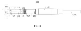
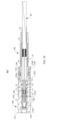
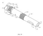
[0039] 第2の態様によれば、本件は光ファイバー・コネクタ・プラグを提供し、光ファイバー・コネクタ・プラグは、ハウジングとハウジング内に収容されたフェルール・アセンブリとを含み、フェルール・アセンブリはフェルール(ferrule)を含み;
ハウジングはメイン・シャフトを含み、メイン・シャフトはシャフト本体と第2のロッキング構造とを含み、シャフト本体の軸方向に延びるスルー・ホールがシャフト本体内側に配置されており、スルー・ホールは光ファイバーが通ることを許容するように構成されており、フェルールは光ファイバーのファイバー・コアに接続されるように構成されており;及び
第2のロッキング構造はシャフト本体の外面に位置し、第2のロッキング構造は、上述した光ファイバー・アダプタの第1のロッキング構造と協働して、光ファイバー・コネクタ・プラグを光ファイバー・アダプタに固定するように構成されており、且つ、光ファイバー・アダプタの押圧部材の作用の下で、第1のロッキング構造から解放され、その結果、光ファイバー・コネクタ・プラグは光ファイバー・アダプタから外れるように更に構成されている。
[0039] According to a second aspect, the present invention provides an optical fiber connector plug, the optical fiber connector plug including a housing and a ferrule assembly housed within the housing, the ferrule assembly including a ferrule;
The housing includes a main shaft, the main shaft including a shaft body and a second locking structure, a through hole extending axially of the shaft body is disposed inside the shaft body, the through hole is configured to allow an optical fiber to pass therethrough, and the ferrule is configured to be connected to a fiber core of the optical fiber; and the second locking structure is located on an outer surface of the shaft body, the second locking structure is configured to cooperate with the first locking structure of the above-mentioned optical fiber adapter to fix the optical fiber connector plug to the optical fiber adapter, and is further configured to be released from the first locking structure under the action of a pressing member of the optical fiber adapter, so that the optical fiber connector plug is removed from the optical fiber adapter.
[0040] 第2のロッキング構造は、シャフト本体の外面に配置され、その結果、第2のロッキング構造は、光ファイバー・アダプタの第1のロッキング構造と直接的に接触し、互いに協働して光ファイバー・コネクタ・プラグを光ファイバー・アダプタに固定することができる、ということを理解することが可能である。従って、シャフト本体の外面は、光ファイバー・コネクタ・プラグの外面を直接的に形成することが可能である。ハンドル・スリーブが光ファイバー・コネクタ・プラグのメイン・シャフトの外側でスリーブ状にされていることに起因して、従来の光ファイバー・コネクタ・プラグが、比較的大きな外形を有している場合と比較すると、光ファイバー・コネクタ・プラグの外径を相応に小さくすることができる。これに対応して、光ファイバー・コネクタ・プラグに適合する光ファイバー・アダプタの外径は更に小さくされる。換言すれば、この構成に基づいて、光ファイバー・コネクタ・プラグ及び光ファイバー・アダプタにより占められるスペースのサイズを効果的に小さくすることができる。この場合、従来の設計と比較して、光ファイバー・アダプタを差し込んで固定するための、より多くのジャックを、光ファイバー・アダプタが適用される通信デバイスの限られたスペース内に配置することが可能である。換言すれば、光ファイバー接続ポートとして機能する、より多くの光ファイバー・アダプタを配置することが可能になり、その結果、通信デバイスの不十分なスペース・レイアウトの中で、光ファイバー接続ポートの数量を更に増加させ、また、通信デバイスの高性能化及び小型化の要求も満たすことができ、これにより、強力な実用性と幅広い適用範囲を達成することができる。 [0040] It can be seen that the second locking structure is disposed on the outer surface of the shaft body, so that the second locking structure is in direct contact with the first locking structure of the fiber optic adapter and can cooperate with each other to fix the fiber optic connector plug to the fiber optic adapter. Thus, the outer surface of the shaft body can directly form the outer surface of the fiber optic connector plug. Due to the handle sleeve being sleeved on the outside of the main shaft of the fiber optic connector plug, the outer diameter of the fiber optic connector plug can be correspondingly reduced compared to the case where the conventional fiber optic connector plug has a relatively large outer diameter. Correspondingly, the outer diameter of the fiber optic adapter that fits the fiber optic connector plug is further reduced. In other words, based on this configuration, the size of the space occupied by the fiber optic connector plug and the fiber optic adapter can be effectively reduced. In this case, compared to the conventional design, more jacks for inserting and fixing the fiber optic adapter can be arranged in the limited space of the communication device to which the fiber optic adapter is applied. In other words, it becomes possible to arrange more optical fiber adapters to function as optical fiber connection ports, so as to further increase the number of optical fiber connection ports in the insufficient space layout of the communication device, and also meet the requirements for high performance and miniaturization of the communication device, thereby achieving strong practicability and wide application range.
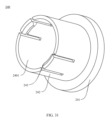
[0041] 可能な実装において、第2のロッキング構造は、シャフト本体の円周方向におけるシャフト本体の外面周辺に配置された環状の突起であるか;又は
第2のロッキング構造は、シャフト本体の円周方向におけるシャフト本体の外面周辺に配置された弧状の突起である。
[0041] In possible implementations, the second locking structure is an annular protrusion disposed about the outer surface of the shaft body in the circumferential direction of the shaft body; or the second locking structure is an arcuate protrusion disposed about the outer surface of the shaft body in the circumferential direction of the shaft body.
[0042] 従って、第2のロッキング構造が、シャフト本体の円周方向におけるシャフト本体の外面上に配置された弧状のボスである場合、弧状のボスは、シャフト本体の外面の周囲に部分的に配置される。例えば、2つの第2のロッキング構造が存在し、2つの第2のロッキング構造は対称的に配置される。対称的な配置形態は、良好な力の均一性と良好なバランスをもたらす。 [0042] Thus, when the second locking structure is an arcuate boss disposed on the outer surface of the shaft body in the circumferential direction of the shaft body, the arcuate boss is disposed partially around the outer surface of the shaft body. For example, there are two second locking structures, and the two second locking structures are symmetrically disposed. The symmetrical arrangement provides good force uniformity and good balance.
[0043] 2つの第2のロッキング構造は、楕円の2つの弧状屈曲部に対称的に配置され、その結果、各々の第2のロッキング構造は弧状ボスの形状を呈していてもよい。この場合、各々の弧状形状のボスに対応する中心角度は、180°未満である。代替的に、2つの第2のロッキング構造は、楕円の2つの軸に対称的に配置されてもよく、その結果、各々の第2のロッキング構造は、楕円体の弧状ボスの形状を呈していてもよい。 [0043] The two second locking structures may be arranged symmetrically about two arcuate bends of an ellipse, so that each second locking structure has the shape of an arcuate boss. In this case, the central angle corresponding to each arcuate boss is less than 180°. Alternatively, the two second locking structures may be arranged symmetrically about two axes of an ellipse, so that each second locking structure has the shape of an arcuate boss of an ellipsoid.
[0044] これに基づいて、第2のロッキング構造は、弧状形状のボスとして配置され、その結果、第2のロッキング構造は、シャフト本体の外面の円筒形状に適合することが可能である。このように、処理を実行することは比較的シンプルであり、光ファイバー・アダプタの第1のロッキング構造と協働することが可能な第2のロッキング構造を、より多くの材料を消費することなく形成することができる。これにより、材料コストを効果的に削減し、生産効率を向上させることができる。 [0044] Based on this, the second locking structure is arranged as an arc-shaped boss, so that the second locking structure can fit the cylindrical shape of the outer surface of the shaft body. In this way, it is relatively simple to carry out the process, and the second locking structure capable of cooperating with the first locking structure of the optical fiber adapter can be formed without consuming more material. This can effectively reduce the material cost and improve the production efficiency.
[0045] 可能な実装において、フェルールから離れる向きにある第2のロッキング構造の表面に突起が配置されており、突起は第2の適合面を含み、第2の適合面は、フェルールから離れる向きにある第2のロッキング構造の表面に接続されており、第2の適合面と、フェルールから離れる向きにある第2のロッキング構造の表面との間で、開先角が形成され、第2の適合面は、第2のロッキング構造の第1の適合面に隣接するように構成されている。 [0045] In a possible implementation, a protrusion is disposed on a surface of the second locking structure facing away from the ferrule, the protrusion includes a second mating surface, the second mating surface is connected to the surface of the second locking structure facing away from the ferrule, an included angle is formed between the second mating surface and the surface of the second locking structure facing away from the ferrule, and the second mating surface is configured to abut the first mating surface of the second locking structure.
[0046] 外側フレーム・スリーブから遠い側に面する第2のロッキング構造の表面は、軸方向に垂直に配置されており、第2の整合面と、外側フレーム・スリーブから遠い側に面する第2のロッキング構造の表面との間に、開先角が形成されることが理解されるであろう。換言すれば、第2の整合面は、軸方向に対して傾斜している。換言すれば、第2の整合面は、外側フレーム・スリーブから離れる向きにある第2のロッキング構造の表面に対して傾斜した傾斜面である。これに対応して、光ファイバー・アダプタの第1のロッキング構造の第1の適合面も、斜めに配置された傾斜面である。従って、第2の適合面と第1の適合面との間の適合関係は、傾斜した表面の適合関係である。傾斜した表面適合関係が構成され、その結果、第2のロッキング構造と第1のロッキング構造との間で迅速なアライメントを実施することができる。これは、第2のロッキング構造と第1のロッキング構造との間の相互接続の困難性を低減するだけでなく、第2のロッキング構造と第1のロッキング構造との間の接触面積を増加させることにもなり、これにより相互接続の緊密性を更に向上させる。 [0046] It will be understood that the surface of the second locking structure facing away from the outer frame sleeve is disposed perpendicular to the axial direction, and an included angle is formed between the second alignment surface and the surface of the second locking structure facing away from the outer frame sleeve. In other words, the second alignment surface is inclined with respect to the axial direction. In other words, the second alignment surface is an inclined surface inclined with respect to the surface of the second locking structure facing away from the outer frame sleeve. Correspondingly, the first matching surface of the first locking structure of the optical fiber adapter is also an inclined surface disposed obliquely. Thus, the matching relationship between the second matching surface and the first matching surface is a matching relationship of inclined surfaces. An inclined surface matching relationship is configured, so that a quick alignment can be performed between the second locking structure and the first locking structure. This not only reduces the difficulty of interconnecting the second locking structure with the first locking structure, but also increases the contact area between the second locking structure and the first locking structure, thereby further improving the tightness of the interconnection.
[0047] 可能な実装において、フェルールから離れる向きにある第2のロッキング構造の表面は第2の適合面であり、第2の適合面はシャフト本体の軸方向に対して垂直であり、第2の適合面は第1のロッキング構造の第1の適合面に対して隣接するように構成されている。 [0047] In a possible implementation, the surface of the second locking structure facing away from the ferrule is a second mating surface, the second mating surface being perpendicular to the axial direction of the shaft body, and the second mating surface being configured to abut against the first mating surface of the first locking structure.
[0048] 従って、第2の適合面が傾斜面であるか又は非傾斜面であるかどうかは、実際の状況に基づいて選択されることが可能であり、これにより、強力な柔軟性と幅広い適用範囲を達成することができる。 [0048] Therefore, whether the second matching surface is an inclined surface or a non-inclined surface can be selected based on the actual situation, thereby achieving strong flexibility and a wide range of application.
[0049] 可能な実装において、ハウジングは外側フレーム・スリーブを更に含む。外側フレーム・スリーブは、フェルールの周辺でスリーブ状にされており、フェルールに対向するメイン・シャフトの一端に固定され、メイン・シャフトに対向する外側フレーム・スリーブの端面は、メイン・シャフトの端面に接続され、その結果、外側フレーム・スリーブの外面とメイン・シャフトの外面とはつながれて、光ファイバー・コネクタ・プラグの外面を形成する。メイン・シャフトの外面は、シャフト本体の外面である。 [0049] In a possible implementation, the housing further includes an outer frame sleeve. The outer frame sleeve is sleeved around the ferrule and secured to one end of the main shaft opposite the ferrule, and an end face of the outer frame sleeve opposite the main shaft is connected to an end face of the main shaft, such that the outer surface of the outer frame sleeve and the outer surface of the main shaft are joined to form the outer surface of the fiber optic connector plug. The outer surface of the main shaft is the outer surface of the shaft body.
[0050] 従って、外側フレーム・スリーブの外面とメイン・シャフトの外面とはつながれて、光ファイバー・コネクタ・プラグの外面を形成する。なお、外側フレーム・スリーブの外面とメイン・シャフトの外面とがつながれるケースは、外側フレーム・スリーブの外面が、メイン・シャフトの外面に隙間なく接続されるケースを含む可能性があり、或いは、外側フレーム・スリーブの外面とメイン・シャフトの外面とがそれらの間に僅かな隙間を伴って互いに近接しているケースを含む可能性がある。外側フレーム・スリーブの外面がメイン・シャフトの外面に隙間なく接続される場合、メイン・シャフトに対向する外側フレーム・スリーブの端面は、メイン・シャフトの端面に接続され、その結果、外側フレーム・スリーブの外面はメイン・シャフトの外面に隙間なく接続され、これにより良好な信頼性及び著しい審美性を達成する。 [0050] Thus, the outer surface of the outer frame sleeve and the outer surface of the main shaft are connected to form the outer surface of the optical fiber connector plug. The case where the outer surface of the outer frame sleeve and the outer surface of the main shaft are connected may include a case where the outer surface of the outer frame sleeve is connected to the outer surface of the main shaft without any gap, or may include a case where the outer surface of the outer frame sleeve and the outer surface of the main shaft are close to each other with a small gap between them. When the outer surface of the outer frame sleeve is connected to the outer surface of the main shaft without any gap, the end surface of the outer frame sleeve facing the main shaft is connected to the end surface of the main shaft, and as a result, the outer surface of the outer frame sleeve is connected to the outer surface of the main shaft without any gap, thereby achieving good reliability and remarkable aesthetics.
[0051] 可能な実装において、ハウジングにガイド構造が設けられ、ここで、ガイド構造はハウジングの軸方向に延在し、且つ光ファイバー・アダプタのガイド・キーと協働するように構成される。 [0051] In a possible implementation, the housing is provided with a guide structure, where the guide structure extends axially through the housing and is configured to cooperate with a guide key of the fiber optic adapter.
[0052] 従って、ガイド構造は、光ファイバー・コネクタ・プラグを光ファイバー・アダプタに差し込むプロセスにおいて案内する機能を果たし、光ファイバー・コネクタ・プラグを光ファイバー・アダプタにスムーズに差し込むように案内することができる。例えば、第1のガイド構造は、フロント・フレーム・スリーブの前端面から、フロント・フレーム・スリーブの後端面まで延びていてもよい。 [0052] Thus, the guide structure serves to guide the fiber optic connector plug in the process of inserting the fiber optic connector plug into the fiber optic adapter, and can guide the fiber optic connector plug to be smoothly inserted into the fiber optic adapter. For example, the first guide structure may extend from the front end surface of the front frame sleeve to the rear end surface of the front frame sleeve.
[0053] 可能な実装において、メイン・シャフトから遠い側の外側フレーム・スリーブの一端は、外側フレーム・スリーブの前端部であり、フェルール・ベースから遠い側のフェルールの一端は、フェルールの前端部であり;フェルールの前端部は、外側フレーム・スリーブの前端部の中に格納される。 [0053] In a possible implementation, one end of the outer frame sleeve remote from the main shaft is the front end of the outer frame sleeve, and one end of the ferrule remote from the ferrule base is the front end of the ferrule; the front end of the ferrule is housed within the front end of the outer frame sleeve.
[0054] 従って、外側フレーム・スリーブの前端部はフェルール・アセンブリの前端部に対して突出しており、換言すれば、外側フレーム・スリーブの前端面は、軸方向において、フェルール・アセンブリの前端面に対して突出しており;フェルール・アセンブリの前端面は、外側フレーム・スリーブの内面に囲まれている。これに基づいて、外側フレーム・スリーブは、光ファイバー・アダプタの回転、搬送、プラグ挿抜のプロセスにおいて、フェルール・アセンブリの前端面を保護することができ、その結果、フェルール・アセンブリは、バンピング、クラッシュ、ダスト障害から、外側フレーム・スリーブにより保護されることが可能であり、また、それ自体の清潔性や安全性を保つことができる。このようにして、フェルール・アセンブリが、以後、対向するコネクタ・プラグのフェルール・アセンブリに差し込まれる場合に、2つのフェルール・アセンブリの間で光信号の安定した信頼性のある伝送が保証される。 [0054] Thus, the front end of the outer frame sleeve protrudes relative to the front end of the ferrule assembly, in other words, the front end face of the outer frame sleeve protrudes relative to the front end face of the ferrule assembly in the axial direction; the front end face of the ferrule assembly is surrounded by the inner surface of the outer frame sleeve. Based on this, the outer frame sleeve can protect the front end face of the ferrule assembly in the process of rotating, transporting, plugging and unplugging the optical fiber adapter, so that the ferrule assembly can be protected by the outer frame sleeve from bumping, crushing and dust damage, and can also keep its own cleanliness and safety. In this way, when the ferrule assembly is subsequently plugged into the ferrule assembly of the opposing connector plug, a stable and reliable transmission of optical signals between the two ferrule assemblies is guaranteed.
[0055] 代替的に、フェルールの前端部の端面は、外側フレーム・スリーブの前端部の端面と同一平面になっている。 [0055] Alternatively, the end face of the front end of the ferrule is flush with the end face of the front end of the outer frame sleeve.
[0056] 可能な実装において、ガイド構造は、ハウジングの外面が内側に凹型にされた後に形成される溝構造であり、溝構造は、ハウジングの内面を貫通していない。 [0056] In a possible implementation, the guide structure is a groove structure formed after the outer surface of the housing is inwardly concave, and the groove structure does not penetrate through the inner surface of the housing.
[0057] 従って、ガイド構造は、光ファイバー・アダプタのガイド・キーとともに埋め込まれることが可能であり、光ファイバー・アダプタの対応する構造を支持するための特定のベアリング能力を有する。更に、ガイド構造は、ガイド構造に差し込まれる光ファイバー・アダプタを案内して、ハウジングが回転することを防止し、これによって、光ファイバー・コネクタ・プラグが、光ファイバー・アダプタに対して相対的に回転することを防止する。 [0057] Thus, the guide structure can be embedded with the guide key of the fiber optic adapter and has a specific bearing capacity to support the corresponding structure of the fiber optic adapter. Furthermore, the guide structure guides the fiber optic adapter plugged into the guide structure to prevent the housing from rotating, thereby preventing the fiber optic connector plug from rotating relative to the fiber optic adapter.
[0058] 代替的に、溝構造は、ハウジングの内面及び外面を貫通している。 [0058] Alternatively, the groove structure penetrates the inner and outer surfaces of the housing.
[0059] 可能な実装において、ガイド構造は、第1のガイド構造と第2のガイド構造を含み、第1のガイド構造は、外側フレーム・スリーブ上に配置され、第2のガイド構造は、メイン・シャフトに配置され、第1のガイド構造と第2のガイド構造は、光ファイバー・アダプタのガイド・キーとともに協働するように互いに接続される。 [0059] In a possible implementation, the guide structure includes a first guide structure and a second guide structure, the first guide structure being disposed on the outer frame sleeve and the second guide structure being disposed on the main shaft, the first guide structure and the second guide structure being connected to each other to cooperate with a guide key of the fiber optic adapter.
[0060] 従って、光ファイバー・アダプタ内での光ファイバー・コネクタ・プラグの回転を制限することができる。 [0060] Thus, rotation of the fiber optic connector plug within the fiber optic adapter can be limited.
[0061] 可能な実装において、第2のガイド構造から離れる向きにある第1のガイド構造の一端、及び/又は第1のガイド構造に対向する第2のガイド構造の一端は、面取り部を形成し、その面取り部は、光ファイバー・アダプタのガイド・キーに、案内する機能を提供するように構成される。 [0061] In a possible implementation, an end of the first guide structure facing away from the second guide structure and/or an end of the second guide structure facing the first guide structure form a chamfer configured to provide a guiding function for a guide key of the fiber optic adapter.
[0062] 第1のガイド構造及び/又は第2のガイド構造の外側端部(1つ/複数)は、面取り部を使用することによって、トランペット状の口広がり形状を形成することが可能である。第1のガイド構造の外端部は、外側フレーム・スリーブの前端面に近い第1のガイド構造の端部である。従って、面取り部が配置され、その結果、第1のガイド構造に特定のフォールト・トレランス空間を設けることができる。光ファイバー・アダプタの対応する構造が、第1のガイド構造の中心に位置合わせされていない場合でさえ、対応する構造は、面取り部のガイド機能を使用することにより、第1のガイド構造の中にスライドすることが可能である。作業者が光ファイバー・コネクタ・プラグを光ファイバー・アダプタに差し込む場合に、第1のガイド構造もまた、面取り部のガイド機能を利用することにより、光ファイバー・アダプタの対応する構造に位置合わせさせられることが可能である。これは、プラグ挿入効率を更に改善し、プラグ挿入成功率を増加させ、光ファイバー・コネクタ・プラグを、損傷からより効果的に保護することができる。 [0062] The outer end(s) of the first guide structure and/or the second guide structure can form a trumpet-like flared shape by using a chamfer. The outer end of the first guide structure is the end of the first guide structure close to the front end face of the outer frame sleeve. Thus, the chamfer is arranged, so that the first guide structure can be provided with a certain fault tolerance space. Even if the corresponding structure of the optical fiber adapter is not aligned with the center of the first guide structure, the corresponding structure can slide into the first guide structure by using the guiding function of the chamfer. When an operator inserts the optical fiber connector plug into the optical fiber adapter, the first guide structure can also be aligned with the corresponding structure of the optical fiber adapter by utilizing the guiding function of the chamfer. This can further improve the plug insertion efficiency, increase the plug insertion success rate, and more effectively protect the optical fiber connector plug from damage.
[0063] 例えば、面取り部は直角の面取り部であってもよい。直角面取り部の構造加工は、よりシンプルで便利であり、トランペット状の口広がりの外側端部開口は、比較的大きく設定されることが可能であり、これによりガイド範囲を更に拡大することができる。例えば、片側面取り部の傾斜角の角度範囲は、0°-90°であってもよい。例えば、片側面取り部の傾斜角は、10°,15°、又は30°に設定されてもよい。傾斜角の角度選択は、実際の要求に基づいて調整されることが可能である。これは、この実施形態において厳密には限定されるものではない。 [0063] For example, the chamfered portion may be a right-angled chamfered portion. The structural processing of the right-angled chamfered portion is simpler and more convenient, and the outer end opening of the trumpet-shaped flared mouth can be set relatively large, which can further expand the guide range. For example, the angle range of the inclination angle of the one-sided chamfered portion may be 0°-90°. For example, the inclination angle of the one-sided chamfered portion may be set to 10°, 15°, or 30°. The angle selection of the inclination angle can be adjusted based on actual requirements. This is not strictly limited in this embodiment.
[0064] 代替的に、面取り部はフィレット形状であってもよく、フィレット形状はエッジを有しておらず、その表面はより滑らかである。これは、光ファイバー・アダプタの対応する構造における摩耗を効果的に防止することができ、それによって、強力な安全を達成することができる。 [0064] Alternatively, the chamfer may be a fillet shape, which has no edge and its surface is smoother. This can effectively prevent wear on the corresponding structure of the optical fiber adapter, thereby achieving strong safety.
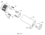
[0065] 可能な実装において、光ファイバー・コネクタ・プラグは、固定スリーブを更に含み、ここで、固定スリーブは、外側フレーム・スリーブとフェルール・アセンブリとの間に配置され、フェルール・アセンブリの一部を収容しており;
フェルール・アセンブリは、フェルール・ベースを更に含み、ここで、フェルールはフェルール・ベースの一端で固定されており;及び
固定スリーブの一端は外側フレーム・スリーブに固定され、固定スリーブの他端はフェルール・ベースに固定される。
[0065] In a possible implementation, the fiber optic connector plug further includes a retention sleeve, where the retention sleeve is disposed between the outer frame sleeve and the ferrule assembly and receives a portion of the ferrule assembly;
The ferrule assembly further includes a ferrule base, wherein the ferrule is secured at one end of the ferrule base; and one end of the fixing sleeve is secured to the outer frame sleeve, and the other end of the fixing sleeve is secured to the ferrule base.
[0066] 従って、固定スリーブは、フェルールとフェルール・ベースの一部とを収容し、それにより、設置の最中にフェルール・アセンブリの安定性及び信頼性を更に確保することができる。更に、固定スリーブは、フェルール・アセンブリに固定的に接続されることができ、また、外側フレーム・スリーブにも固定的に接続されることが可能であり、その結果、固定スリーブの接続を通じて、外側フレーム・スリーブとフェルール・アセンブリとを比較的固定することができる。これは、フェルール・アセンブリが、円周方向に回転したり、外側フレーム・スリーブ内で軸方向に移動したりことを効果的に防止する。従って、固定スリーブを配置することは、多様なシナリオの要求に適応することが可能であり、それにより、強力な実用性と広範な適用範囲を達成する。 [0066] Thus, the fixing sleeve can accommodate the ferrule and a part of the ferrule base, thereby further ensuring the stability and reliability of the ferrule assembly during installation. Furthermore, the fixing sleeve can be fixedly connected to the ferrule assembly and also fixedly connected to the outer frame sleeve, so that the outer frame sleeve and the ferrule assembly can be relatively fixed through the connection of the fixing sleeve. This effectively prevents the ferrule assembly from rotating in the circumferential direction or moving axially within the outer frame sleeve. Thus, the arrangement of the fixing sleeve can be adapted to the requirements of various scenarios, thereby achieving strong practicality and a wide range of application.
[0067] 可能な実装において、フェルール・アセンブリは、弾性素子を更に含み、フェルールとフェルール・ベースとの間にギャップが形成され、そのギャップ内に弾性素子が位置しており、弾性素子の一端はフェルールに当接し、弾性素子の他端はフェルール・ベースに当接する。 [0067] In a possible implementation, the ferrule assembly further includes a resilient element, a gap is formed between the ferrule and the ferrule base, the resilient element is positioned within the gap, one end of the resilient element abuts the ferrule and the other end of the resilient element abuts the ferrule base.
[0068] 従って、弾性素子はフェルールとフェルール・ベースとの間で弾力的に当接し、その結果、弾性素子の弾性力の作用下で、フェルールとフェルール・ベースとは張力を保つことができ、フェルールとフェルール・ベースとは、たとえそれらが長時間の振動にさらされたとしても緩みにくい。これは、フェルール・アセンブリの長期的な信頼性を高めることに役立つ。 [0068] Therefore, the elastic element elastically abuts between the ferrule and the ferrule base, so that the ferrule and the ferrule base can maintain tension under the action of the elastic force of the elastic element, and the ferrule and the ferrule base are unlikely to loosen even if they are exposed to vibration for a long time. This helps to improve the long-term reliability of the ferrule assembly.
[0069] 可能な実装において、クランプ穴又はクランプ溝が外側フレーム・スリーブの内面に設けられ、固定スリーブの外面にクランプ・フックが設けられ、クランプ・フックは、クランプ穴又はクランプ溝と協働して、固定スリーブを外側フレーム・スリーブに固定的に接続する。このようにして、固定スリーブとフェルール・アセンブリとの間の接続関係を使用することによって、軸方向におけるフェルール・アセンブリの移動及び円周方向におけるフェルール・アセンブリの回転を制限することができ、それによってフェルール・アセンブリの接続の安定性及び信頼性を確保することができる。例えば、2つのクランプ・フックが存在し、2つのクランプ・フックは対称的に配置され、各クランプ・フックは、外側フレーム・スリーブの1つのクランプ穴(又は1つのクランプ溝)で協調してクランプされる。 [0069] In a possible implementation, a clamp hole or clamp groove is provided on the inner surface of the outer frame sleeve, and a clamp hook is provided on the outer surface of the fixing sleeve, which cooperates with the clamp hole or clamp groove to fixedly connect the fixing sleeve to the outer frame sleeve. In this way, the connection relationship between the fixing sleeve and the ferrule assembly can be used to limit the movement of the ferrule assembly in the axial direction and the rotation of the ferrule assembly in the circumferential direction , thereby ensuring the stability and reliability of the connection of the ferrule assembly. For example, there are two clamp hooks, the two clamp hooks are arranged symmetrically, and each clamp hook is clamped cooperatively in one clamp hole (or one clamp groove) of the outer frame sleeve.
[0070] 可能な実装において、メイン・シャフトに対向する固定スリーブの端面と、メイン・シャフトに対向する外側フレーム・スリーブの端面とは同一平面にあり、一緒に アバットメント面を形成し、アバットメント面はメイン・シャフトの端面に接続される。 [0070] In a possible implementation, the end face of the fixing sleeve facing the main shaft and the end face of the outer frame sleeve facing the main shaft are flush with each other and together form an abutment surface, which is connected to the end face of the main shaft.
[0071] 従って、固定スリーブはメイン・シャフトに正確に接続されることが可能であるので、固定スリーブがメイン・シャフトに適合し、メイン・シャフトへの接続の締めつけを向上させることを保証することが可能である。 [0071] Thus, the fixing sleeve can be precisely connected to the main shaft, ensuring that the fixing sleeve fits the main shaft and improving the tightness of the connection to the main shaft.
[0072] 可能な実装において、フェルール・アセンブリから離れたメイン・シャフトの一端は、メイン・シャフトのテール端部であり、光ファイバー・コネクタ・プラグは、更に、光ファイバーと、光ファイバー上でスリーブ状にされている光ファイバー固定素子とを含み、光ファイバー固定素子は、光ファイバーをスルー・ホールに差し込むために、メイン・シャフトのテール・エンドに固定される。 [0072] In a possible implementation, one end of the main shaft remote from the ferrule assembly is a tail end of the main shaft, and the fiber optic connector plug further includes an optical fiber and an optical fiber fixing element sleeved over the optical fiber, the optical fiber fixing element secured to the tail end of the main shaft for inserting the optical fiber into the through hole.
[0073] 緩みがないことを保証するために、光ファイバーはメイン・シャフトに堅く接続される必要があること、及び、メイン・シャフトのヘッド端部がフロント・フレーム・スリーブに固定されることを考慮すると、光ファイバー固定素子は、メイン・シャフトのテール端部に固定されて、光ファイバーとメイン・シャフトの保持安定性及び信頼性を更に保証し、光ファイバー・コネクタ・プラグの構造的配置の適切性を向上させる、ということを理解することが可能である。 [0073] Considering that the optical fiber needs to be tightly connected to the main shaft to ensure that there is no loosening, and the head end of the main shaft is fixed to the front frame sleeve, it can be seen that the optical fiber fixing element is fixed to the tail end of the main shaft to further ensure the holding stability and reliability of the optical fiber and the main shaft, and improve the appropriateness of the structural arrangement of the optical fiber connector plug.
[0074] 可能な実装において、メイン・シャフトの外面及び内面を貫通し、且つスルー・ホールにつながる接着剤充填孔が、メイン・シャフトのテール端部に配置され、接着剤充填孔は、メイン・シャフトを光ファイバーに固定する接着剤の注入のために使用される。 [0074] In a possible implementation, an adhesive fill hole that penetrates the outer and inner surfaces of the main shaft and connects to the through hole is located at the tail end of the main shaft, and the adhesive fill hole is used to inject adhesive that secures the main shaft to the optical fiber.
[0075] 従って、メイン・シャフトと光ファイバー間の接続の信頼性と安定性を更に確保することができる。 [0075] This further ensures the reliability and stability of the connection between the main shaft and the optical fiber.
[0076] 可能な実装において、光ファイバー固定素子は、固定ベースと、熱収縮チューブと、テール・スリーブとを含み、固定ベースは、スリーブ状にされ、メイン・シャフトのテール端部に固定され、熱収縮チューブは、スリーブ状にされ、メイン・シャフトのテール端部と光ファイバーにオーバーラップし、熱収縮チューブは接着剤充填孔を封印し、テール・スリーブは、熱収縮チューブの周囲でスリーブ状にされており、テール・スリーブの一端は、固定ベースに固定される。 [0076] In a possible implementation, the optical fiber fixation element includes a fixation base, a heat shrink tube, and a tail sleeve, the fixation base is sleeved and secured to the tail end of the main shaft, the heat shrink tube is sleeved and overlaps the tail end of the main shaft and the optical fiber, the heat shrink tube seals the adhesive fill hole, the tail sleeve is sleeved around the heat shrink tube, and one end of the tail sleeve is secured to the fixation base.
[0077] 従って、光ファイバー固定素子は、光ファイバーとメイン・シャフトとの間の接続の安定性と信頼性を効果的に保証することができる。 [0077] Therefore, the optical fiber fixing element can effectively ensure the stability and reliability of the connection between the optical fiber and the main shaft.
[0078] 可能な実装において、光ファイバーは、ファイバー・コアと、ファイバー・コアの周囲に巻き付けられたクラッド層と、クラッド層の周囲に巻き付けられた外層とを含み、ファイバー・コアの一部は、フェルールに接続されるようにクラッド層の外側に延び、外側の層の一部は、複数のスリットを有する補強セクションを形成し、複数のスリットは、接着剤充填孔を介して注入された接着剤が流れることを可能にするために使用され、その結果、接着剤は補強セクションをメイン・シャフトに固定する。 [0078] In a possible implementation, the optical fiber includes a fiber core, a cladding layer wrapped around the fiber core, and an outer layer wrapped around the cladding layer, with a portion of the fiber core extending outside the cladding layer to be connected to the ferrule, and a portion of the outer layer forming a reinforcement section having a plurality of slits, the plurality of slits being used to allow adhesive injected through the adhesive fill hole to flow so that the adhesive secures the reinforcement section to the main shaft.
[0079] ファイバー・コアの一部は、フェルールに対する接続のために、クラッド層から延びていることが理解されるであろう。外側の層の一部は、複数のスリットを有する補強セクションを形成し、複数のスリットを有する補強セクションは、柵の形状を呈しており且つクラッド層の周囲に配置される。複数のスリットは、接着剤充填孔を通って注入された接着剤が流れることを可能にするために使用され、その結果、接着剤は補強セクションをメイン・シャフトの内面に固定し、これにより光ファイバー・コネクタ・プラグの引張強度を向上させる。例えば、補強セクションは、アラミド、鋼線、又は繊維強化ポリマー/プラスチック(Fiber Reinforced Polymer/Plastic,FRP)で作成されてもよい。 [0079] It will be appreciated that a portion of the fiber core extends from the cladding layer for connection to the ferrule. A portion of the outer layer forms a reinforcement section having a plurality of slits, the reinforcement section having a shape of a fence and disposed around the cladding layer. The plurality of slits are used to allow the flow of adhesive injected through the adhesive fill hole so that the adhesive secures the reinforcement section to the inner surface of the main shaft, thereby improving the tensile strength of the fiber optic connector plug. For example, the reinforcement section may be made of aramid, steel wire, or Fiber Reinforced Polymer/Plastic (FRP).
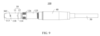
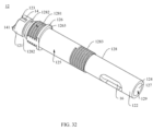
[0080] 可能な実装において、 光ファイバー・コネクタ・プラグは、防塵キャップを更に含み、防塵キャップは、フェルールの外側でスリーブ状にされており、且つメイン・シャフトに着脱可能に接続される。 [0080] In a possible implementation, the fiber optic connector plug further includes a dust cap that is sleeved over the ferrule and removably connected to the main shaft.
[0081] 着脱可能な接続部が構築されている構造はシンプルであり、その結果、防塵キャップは、専用ツールを使用することなく、メイン・シャフトから速やかに取り外されたり取り付けられたりすることが可能であり、これにより、防塵キャップをメイン・シャフトに接続する際の効率を効果的に向上させることができる。 [0081] The structure in which the detachable connection is constructed is simple, and as a result, the dust cap can be quickly removed from and attached to the main shaft without using a dedicated tool, which effectively improves the efficiency of connecting the dust cap to the main shaft.
[0082] 従って、光ファイバー・コネクタ・プラグが光ファイバー・アダプタに接続されていない場合、即ち、光ファイバー・コネクタ・プラグが折り返されていたり、運搬であったり、又はその他の場合に、防塵キャップをメイン・シャフトに接続することが可能であり、その結果、防塵キャップは、光ファイバー・コネクタ・プラグと光ファイバー・アダプタとの接合部を閉じて覆い、外側フレーム・スリーブとメイン・シャフトを保護することが可能である。これは、外来異物、水分、ゴミ等が光ファイバー・コネクタ・プラグ内に入り込み、光ファイバー・コネクタにダメージを与えることを防ぎ、その結果、光ファイバー・コネクタ・プラグと光ファイバー・アダプタとの間の接合部を清潔に保つことができ、これによりIP68保護レベルに到達することができる。光ファイバー・コネクタ・プラグが光ファイバー・アダプタに接続されることを必要とする場合、防塵キャップはメイン・シャフトから外されることが可能である。 [0082] Therefore, when the fiber optic connector plug is not connected to the fiber optic adapter, i.e., when the fiber optic connector plug is folded back, during transportation, or otherwise, the dust cap can be connected to the main shaft, so that the dust cap can close and cover the joint between the fiber optic connector plug and the fiber optic adapter, and protect the outer frame sleeve and the main shaft. This prevents foreign objects, moisture, dust, etc. from entering the fiber optic connector plug and damaging the fiber optic connector, so that the joint between the fiber optic connector plug and the fiber optic adapter can be kept clean, and thus the IP68 protection level can be reached. When the fiber optic connector plug needs to be connected to the fiber optic adapter, the dust cap can be removed from the main shaft.
[0083] 可能な実装において、光ファイバー・コネクタ・プラグは、密閉リングを更に含み、密閉リングは、メイン・シャフトにおいてスリーブ状にされ、密閉リングは、防塵キャップを封印するように構成されており、及び/又は密閉リングは、光ファイバー・アダプタを密閉するように構成されている。 [0083] In a possible implementation, the fiber optic connector plug further includes a sealing ring, the sealing ring being sleeved on the main shaft, the sealing ring being configured to seal the dust cap, and/or the sealing ring being configured to seal the fiber optic adapter.
[0084] 従って、防塵キャップがメイン・シャフトに接続されている場合、密閉リングは、防塵キャップとメイン・シャフトとの間に挟まれて防塵キャップを密閉することができ、その結果、防塵キャップとメイン・シャフトとの間の密閉性が良くなる。また、光ファイバー・コネクタ・プラグが光ファイバー・アダプタに接続される場合、密閉リングが、光ファイバー・コネクタ・プラグと光ファイバー・アダプタとの間に挟まれて、光ファイバー・アダプタを密閉し、その結果、光ファイバー・コネクタ・プラグと光ファイバー・アダプタとの間の密閉性が良くなる。従って、密閉リングは、防塵キャップ及び光ファイバー・アダプタの二重の密閉性の機能を有することが可能であり、強力な実用性と幅広い用途範囲を達成することができる。 [0084] Therefore, when the dust cap is connected to the main shaft, the sealing ring can be sandwiched between the dust cap and the main shaft to seal the dust cap, so that the sealing between the dust cap and the main shaft is good. Also, when the optical fiber connector plug is connected to the optical fiber adapter, the sealing ring can be sandwiched between the optical fiber connector plug and the optical fiber adapter to seal the optical fiber adapter, so that the sealing between the optical fiber connector plug and the optical fiber adapter is good. Therefore, the sealing ring can have the double sealing function of the dust cap and the optical fiber adapter, and can achieve strong practicality and a wide range of applications.
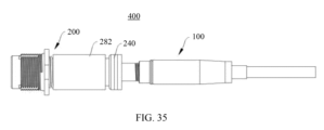
[0085] 第3の態様によれば、本件はコネクタ・アセンブリを提供する。コネクタ・アセンブリは、上述の光ファイバー・コネクタ・プラグと上述の光ファイバー・アダプタとを含み、光ファイバー・コネクタ・プラグは、光ファイバー・アダプタにプラグ挿入される。 [0085] According to a third aspect, the present invention provides a connector assembly. The connector assembly includes the above-described optical fiber connector plug and the above-described optical fiber adapter, and the optical fiber connector plug is plugged into the optical fiber adapter.
[0086] 第4の態様によれば、本件は通信デバイスを提供する。通信デバイスは、ハウジングと、上述の光ファイバー・アダプタとを含み、ハウジングにはジャックが設けられており、光ファイバー・アダプタは、ジャックの位置に配置されて、ハウジングに接続される。 [0086] According to a fourth aspect, the present application provides a communication device. The communication device includes a housing and the above-mentioned optical fiber adapter, the housing is provided with a jack, and the optical fiber adapter is disposed at the jack position and connected to the housing.
[0087] 可能な実装において、複数のジャックが存在し、複数のジャックは行に配置され、光ファイバー・アダプタの数量はジャックの数量と同じであり、複数の光ファイバー・アダプタもまた存在し、複数のジャックの位置それぞれに光ファイバー・アダプタが配置される。 [0087] In a possible implementation, there are a plurality of jacks, the plurality of jacks are arranged in rows, the quantity of fiber optic adapters is the same as the quantity of jacks, and there are also a plurality of fiber optic adapters, with a fiber optic adapter disposed at each of the locations of the plurality of jacks.
[0088] 可能な実装において、複数のジャックが存在し、複数のジャックはハウジング上で少なくとも2行に配置され、光ファイバー・アダプタの数量はジャックの数量と同じであり、複数の光ファイバー・アダプタも存在し、複数のジャックの位置それぞれに光ファイバー・アダプタが配置される。 [0088] In a possible implementation, there are a plurality of jacks, the plurality of jacks are arranged in at least two rows on the housing, the quantity of fiber optic adapters is equal to the quantity of jacks, and there are also a plurality of fiber optic adapters, with a fiber optic adapter disposed at each of the positions of the plurality of jacks.
[0089] 可能な実装において、通信デバイスは、上述の光ファイバー・コネクタ・プラグを更に含み、光ファイバー・コネクタ・プラグは、光ファイバー・アダプタに挿入されるように構成される。 [0089] In a possible implementation, the communication device further includes the fiber optic connector plug described above, the fiber optic connector plug configured to be inserted into the fiber optic adapter.
[0126] 以下、添付図面を参照して本件の具体的な実装を明確に説明する。 [0126] The specific implementation of this invention will be explained below with reference to the attached drawings.
[0127] 本件の実施形態は通信デバイスを提供する。通信デバイスは、FFTxシステムに適用されてもよい。FFTxシステムは、FFTH(ファイバー・トゥ・ザ・ホーム,Fiber to the Home)システム、FTTC(ファイバー・トゥ・ザ・カーブ,Fiber to the Curb)システム、FTTP(ファイバー・トゥ・ザ・プレミス,Fiber to the Promise)システム、FTTN(ファイバー・トゥ・ザ・ノード又はネイバーフッド,Fiber to the Node or Node)システム、FTTO(ファイバー・トゥ・ザ・オフィス,Fiber to the Office)システム、及びFTISA(ファイバー・トゥ・ザ・サービス・エリア,fiber to the service area)システムを含む可能性があるが、これらに限定されない。 [0127] The present embodiment provides a communication device. The communication device may be applied to an FFTx system. The FFTx system may include, but is not limited to, an FFTH (Fiber to the Home) system, an FTTC (Fiber to the Curb) system, an FTTP (Fiber to the Premise) system, an FTTN (Fiber to the Node or Neighborhood) system, an FTTO (Fiber to the Office) system, and an FTISA (Fiber to the service area) system.
[0128] 本件のこの実施形態では、通信デバイスがファイバー・トゥ・ザ・ホーム(fiber to the home,FTTH)システムに適用される例が説明のために使用される。図1を参照されたい。ファイバー・トゥ・ザ・ホーム・システムは、セントラル・オフィス機器室内デバイス(optical line terminal,OLT)と、ユーザー端末デバイス(optical network terminal,ONT)と、光配信ネットワーク(optical distribution network,ODN)とを含む。 [0128] In this embodiment of the present application, an example in which the communication device is applied to a fiber to the home (FTTH) system is used for illustration. Please refer to FIG. 1. The fiber to the home system includes a central office equipment room device (optical line terminal, OLT), a user terminal device (optical network terminal, ONT), and an optical distribution network (optical distribution network, ODN).
[0129] ファイバー・トゥ・ザ・ホーム・システムの重要な部分として、光配信ネットワークは、線路等る・オフィス機器室内デバイスとユーザー端末デバイスとの間の光伝送用の物理チャネルである。光配線ネットワークは、光ファイバー・ケーブル、光コネクタ、光スプリッタ、及び光ファイバー配信デバイスを、これらの素子を設置して接続するように含むことが可能である。具体的には、光配信ネットワークは、フィーダー光ケーブル、光ケーブル配信ポイント、配信光ケーブル、ユーザー・アクセス・ポイント、ドロップ光ケーブルを含む。光配信ネットワークの基幹光ケーブルとして、フィーダー光ケーブルが、セントラル・オフィス機器室内デバイスと光ケーブル配信ポイントとの間に接続されて、光信号の長距離カバレッジを実現している。配信光ケーブルは、光ケーブル配信ポイントとユーザー・アクセス・ポイントとの間に接続されており、その結果、フィーダー光ケーブルのユーザー領域の近傍で経路沿いに光ファイバーを配信することができる。ドロップ光ケーブルは、ユーザー・アクセス・ポイントとユーザー端末デバイスとの間に接続され、ファイバー・トゥ・ザ・ホームを実現する。 [0129] As an important part of the fiber-to-the-home system, the optical distribution network is a physical channel for optical transmission between the central office equipment indoor devices and the user terminal devices. The optical distribution network can include optical fiber cables, optical connectors, optical splitters, and optical fiber distribution devices to install and connect these elements. Specifically, the optical distribution network includes a feeder optical cable, an optical cable distribution point, a distribution optical cable, a user access point, and a drop optical cable. As the backbone optical cable of the optical distribution network, the feeder optical cable is connected between the central office equipment indoor devices and the optical cable distribution point to realize the long-distance coverage of the optical signal. The distribution optical cable is connected between the optical cable distribution point and the user access point, so that the optical fiber can be distributed along the path in the vicinity of the user area of the feeder optical cable. The drop optical cable is connected between the user access point and the user terminal device to realize the fiber-to-the-home.
[0130] ドロップ光ケーブルは、ユーザー・アクセス・ポイントのノード・デバイスとユーザー端末デバイスとの間に接続され、配線光ケーブルへの接続を実現してファイバー・トゥ・ザ・ホームを実現していることを理解することができる。実際の状況では、コストを考慮して、屋外光ファイバー・アダプタがユーザー・アクセス・ポイントのノード・デバイスに事前に構成されており、且つ屋外光ファイバー・コネクタ・プラグがドロップ光ケーブルの端部に事前に構成されている、屋外事前接続ソリューションが、ファイバー・トゥ・ザ・ホームに徐々に適用されつつある。従って、ドロップ光ケーブルの光ファイバー・コネクタ・プラグが、ユーザー・アクセス・ポイントのノード・デバイスで光ファイバー・アダプタに挿入されて、プラグ・アンド・プレイ光ファイバー事前接続製品をともに形成することだけを必要とする。 [0130] It can be understood that the drop optical cable is connected between the node device of the user access point and the user terminal device, realizing the connection to the distribution optical cable to realize fiber to the home. In practical situations, considering the cost, an outdoor pre-connection solution is gradually applied to fiber to the home, in which an outdoor fiber optic adapter is pre-configured in the node device of the user access point, and an outdoor fiber optic connector plug is pre-configured on the end of the drop optical cable. Therefore, it only needs that the fiber optic connector plug of the drop optical cable is inserted into the fiber optic adapter at the node device of the user access point to form a plug-and-play fiber optic pre-connection product together.
[0131] これに基づいて、光ファイバー事前接続製品は、ユーザー・アクセス・ポイントのノード・デバイスのボックス本体を開けることなく、また、比較的長い時間を要する融着接続機を用いることによるドロップ光ケーブルでの融着接続を実行することなく、ドロップ光ケーブルの敷設を簡便かつ迅速に完了することができる。このように、ドロップ光ケーブルと配信光ケーブルとの間、及び、ドロップ光ケーブルとユーザー端末デバイスとの間の信頼性の高い接続を実現することができ、操作がシンプルであり、施工困難性は比較的低い。更に、光ファイバーの事前接続製品は、複雑で変化する屋外環境に適合し得るので、光ファイバー・ネットワークの設計、構築、及び使用の際に光ファイバー・リンクに生じる様々な不確実な要因に起因するダメージや安全上の影響を最大限に除去することができる。これは、ファイバー・トゥ・ザ・ホーム・システムの安全性を十分に確保し、現場での施工に要する時間及び材料コストを削減する。 [0131] Based on this, the optical fiber pre-connection product can easily and quickly complete the laying of the drop optical cable without opening the box body of the node device of the user access point and without performing fusion splicing on the drop optical cable by using a fusion splicer, which requires a relatively long time. In this way, a reliable connection between the drop optical cable and the distribution optical cable and between the drop optical cable and the user terminal device can be realized, the operation is simple, and the construction difficulty is relatively low. In addition, the optical fiber pre-connection product can adapt to the complex and changing outdoor environment, so that the damage and safety impact caused by various uncertain factors occurring in the optical fiber link during the design, construction, and use of the optical fiber network can be maximized. This fully ensures the safety of the fiber-to-the-home system and reduces the time and material costs required for on-site construction.
[0132] 本願のこの実施形態では、通信デバイスは、光ファイバー事前接続製品の使用パフォーマンスを有し、操作が容易であり、比較的短時間しか費さず、屋外のアプリケーション・シナリオにおいてプラグ・アンド・プレイを実現することができる。以下、通信デバイスが光配信ネットワークにおけるユーザー・アクセス・ポイントのノード・デバイスである例を用いて詳細な説明を行う。通信デバイスは、ファイバー・アクセス端末(fiber access terminal,FAT)又は分割&スプライシング・クロージャ(splitting and splicing closure,SSC)のようなODNデバイスであってもよいが、これらに限定されない。 [0132] In this embodiment of the present application, the communication device has the use performance of optical fiber pre-connected products, is easy to operate, consumes a relatively short time, and can realize plug-and-play in outdoor application scenarios. Hereinafter, a detailed description is given using an example in which the communication device is a node device of a user access point in an optical distribution network. The communication device may be, but is not limited to, an ODN device, such as a fiber access terminal (FAT) or a splitting and splicing closure (SSC).
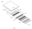
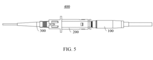
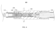
[0133] 図2及び図3を参照されたい。通信デバイス1000は、ハウジング1100、アダプタ・アセンブリ1200、屋内コネクタ・アセンブリ1300、及び屋外コネクタ・アセンブリ1400を含む。アダプタ・アセンブリ1200は、ハウジング1100に固定され、屋内コネクタ・アセンブリ1300は、ハウジング1100内に収容され、屋外コネクタ・アセンブリ1400は、ハウジング1100の外側に位置し、屋外コネクタ・アセンブリ1400と屋内コネクタ・アセンブリ1300とは、アダプタ・アセンブリ1200の接続を介して互いにプラグ挿入され、それによって光信号伝送を実行することができる。
[0133] Please refer to Figures 2 and 3. The
[0134] 屋内コネクタ・アセンブリ1300と屋外コネクタ・アセンブリ1400との間の相違は、それらが異なるシナリオで使用される点にある、ということが理解されるべきである。室内コネクタ・アセンブリ1300は、ハウジング1100内に配置され、相対的に閉鎖的な空間内に配置され、外の塵埃や水分などを効果的に隔離することができる。屋外コネクタ・アセンブリ1400は、ハウジング1100の外に位置し、相対的に開放的な空間に配置される可能性があり、複雑で変化する外部環境に対処するために、比較的良好な環境適応性を有することを必要とする。
[0134] It should be understood that the difference between the
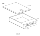
[0135] 具体的には、ハウジング1100は、ボックス本体1110と、ボックス本体1110を覆う上部カバー1120とを含み、ハウジング1100には、並んで配置されるように複数のジャック1130が設けられており、ジャック1130は、ボックス本体1110又は上部カバー1120内で1行に配置されていてもよいし、或いは、ジャック1130は、ボックス本体1110又は上部カバー1120内で、或いは、ボックス本体1110及び上部カバー1120内で、複数の行に配置されていてもよい。例えば、ジャック1130は、ボックス本体1110内で1行に配置されていてもよいし;或いは、ジャック1130は、2行に配置されていてもよく、2行のうちの一方がボックス本体1110に配置され、2行のうちの他方が上部カバー1120に配置されていてもよい。
[0135] Specifically, the
[0136] アダプタ・アセンブリ1200は、複数の光ファイバー・アダプタ200を含む。光ファイバー・アダプタ200の数量は、ジャック1130の数量と同じであり、各々の光ファイバー・アダプタ200は、1つのジャック1130を介してボックス本体1110に固定され、ボックス本体1110内に部分的に収容され、部分的にボックス本体1110の外に配置される。従って、各々の光ファイバー・アダプタ200は、対応するジャック1130の位置に対応して配置されることが可能であり、その結果、1つの光ファイバー・アダプタ200と1つのジャック1130とが対応して配置されることが可能である。
[0136] The
[0137] 屋内コネクタ・アセンブリ1300は、複数の対向コネクタ・プラグ300を含み、複数の対向コネクタ・プラグ300は、全て、ハウジング1100内に収容される。更に、対向コネクタ・プラグ300の数量は、光ファイバー・アダプタ200の数量と同じであり、その結果、各々の対向コネクタ・プラグ300は、対応する光ファイバー・アダプタ200の一部であって、ボックス本体1110の内側に配置される部分に挿入されることが可能である。
[0137] The
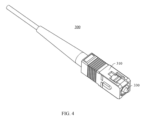
[0138] 屋外コネクタ・アセンブリ1400は、複数の光ファイバー・コネクタ・プラグ100を含み、光ファイバー・コネクタ・プラグ100の数量は、光ファイバー・アダプタ200の数量と同じであり、その結果、各々の光ファイバー・コネクタ・プラグ100は、ハウジング1100の外側から、対応する光ファイバー・アダプタ200の部分であってハウジング1100の外に位置する部分に、挿入されることが可能である。
[0138] The
[0139] 対向コネクタ・プラグ300に合致する開口部と光ファイバー・コネクタ・プラグ100に合致する開口部とはそれぞれ光ファイバー・アダプタ200の2つの端部に配置されており、対向コネクタ・プラグ300と光ファイバー・コネクタ・プラグ100はそれぞれ光ファイバー・アダプタ200の2つの開口部に挿入される、ということが理解されるであろう。このようにして、光ファイバー・コネクタ・プラグ100及び対向コネクタ・プラグ300のフェルールが、光ファイバー・アダプタ200において互いに接続されており、換言すれば、互いに接続されることを必要とする2つの光ファイバーの端面が互いに接続され、その結果、伝送光ファイバーにより出力される光信号は、受信光ファイバーに最大限つながることが可能である。
[0139] It will be understood that the openings corresponding to the
[0140] 従って、各々の対向コネクタ・プラグ300及び各々の光ファイバー・コネクタ・プラグ100は、それぞれ、ハウジング1100の内側及び外側から、ハウジング1100に固定された各々の光ファイバー・アダプタ200に差し込まれることが可能であり、その結果、各々の対向コネクタ・プラグ300は、対応する光ファイバー・コネクタ・プラグ100に差し込まれることが可能である。言い換えると、1つの光ファイバー・コネクタ・プラグ100、1つの光ファイバー・アダプタ200、及び1つの対向コネクタ・プラグ300は、一緒にコネクタ・アセンブリ400を形成して、光信号のリンク伝送を実現することができる。
[0140] Thus, each of the counter connector plugs 300 and each of the optical fiber connector plugs 100 can be plugged into each of the
[0141] 図4、図5、図6を参照されたい。具体的には、対向コネクタ・プラグ300は、プラグ本体310と、プラグ本体310に収容されるフェルール・アセンブリ320とを含む。フェルール・アセンブリ320は、相互接続を実現するように構成されたフェルール330、及び、プラグ本体310とフェルール330との間に弾力的に当接するスプリング340を含む。対向コネクタ・プラグ300の具体的な構造は、本件のこの実施形態では厳密には限定されない。
[0141] Please refer to Figures 4, 5 and 6. Specifically, the
[0142] 全ての光ファイバー・コネクタ・プラグ100のアーキテクチャは同じであり、全ての光ファイバー・アダプタ200のアーキテクチャは同じであるので、以下、1つの光ファイバー・コネクタ・プラグ100、及び、光ファイバー・コネクタ・プラグ100と協働する光ファイバー・アダプタ200の各々の3つの異なる構造の特定の実施形態を使用することによって、本件の技術的解決策における詳細なアーキテクチャを説明する。
[0142] Since the architecture of all the optical fiber connector plugs 100 is the same and the architecture of all the
[0143] 第1の実施形態:
[0144] 第1の実施形態で提供される光ファイバー・コネクタ・プラグ100の詳細な説明は、以下の通りである:
[0145] 図7ないし図10を参照されたい。光ファイバー・コネクタ・プラグ100は、ハウジング10と、フェルール・アセンブリ20と、固定スリーブ30と、光ファイバー40と、光ファイバー固定素子50とを含む。フェルール・アセンブリ20は、ハウジング10の内側に配置され、ハウジング10の端部の近くに配置され、光信号のカップリングを実現するために対向コネクタ・プラグ300に接続されるように構成される。固定スリーブ30は、ハウジング10とフェルール・アセンブリ20との間に配置され、フェルール・アセンブリ20をハウジング10にしっかりと固定するように構成される。これは、軸方向におけるフェルール・アセンブリ20の移動及び円周方向におけるフェルール・アセンブリ20の回転を制限して、フェルール・アセンブリ20の接続の安定性及び信頼性を確実にする。光ファイバー40の本体は、ハウジング10の外側に配置され、配線接続ベースの光ネットワーク伝送を実行する。光ファイバー40の端部は、ハウジング10内に延びて、フェルール・アセンブリ20に接続され、光信号の以後の伝送に備える。このように、光ファイバー40及びその他の光ファイバー40は、光ファイバー・コネクタ・プラグ100の接続機能を用いることにより、接続、直通、発散、プロテクション等の機能を実現することができる。光ファイバー固定素子50は、ハウジング10の外側でスリーブ状にされており、光ファイバー40をハウジング10にしっかり固定して、振動に起因して光ファイバー40がハウジング10から外れてしまうケースを避けることができ、これにより、光ファイバー40の設置安定性を向上させるように構成されている。
[0143] First embodiment:
[0144] A detailed description of the optical
[0145] Please refer to Figures 7 to 10. The optical
[0146] 理解を容易にするために、この実施形態における光ファイバー・コネクタ・プラグ100に対する関連技術用語を以下に説明及び記述しておく。
[0146] To facilitate understanding, the relevant technical terms for the optical
[0147] 軸方向:これは、光ファイバー・コネクタ・プラグ100の中心軸が位置する方向であって、フェルール・アセンブリ20及び光ファイバー40の延びる方向、即ち、ハウジング10内に位置する光ファイバー40のテール端部が光ファイバー40のフロント端部の方に延びる方向であって、フェルール・アセンブリ20の前端部の方に延び続ける方向と同等であり、ハウジング10の延長方向と等価である、と理解されてもよい。
[0147] Axial direction: This may be understood as the direction in which the central axis of the optical
[0148] 円周方向:光ファイバー・コネクタ・プラグ100の中心軸を中心とする円周方向として理解することができる。
[0148] Circumferential direction: can be understood as the circumferential direction around the central axis of the optical
[0149] 半径方向:軸方向に垂直な方向。 [0149] Radial direction: The direction perpendicular to the axial direction.
[0150] スリーブ形状:固定又は接続を保護及び強化するために長いストリップ状の物体の外面においてスリーブ状にされており;スリーブ形状の素子は、円筒状(又はチューブ状)のハウジングを含み、ハウジング内に中空の空間が存在し、円筒状(又はチューブ状)のハウジングの両端面に開口部が設けられており、長いストリップ状の物体は、2つの開口部を通ってスリーブ形状の素子内に入るか又は通過することができる。スリーブ形状の素子は、2つの端面と、2つの端面の間に接続された外面(周辺面とも呼ばれる)とを含む。スリーブ形状の素子の軸方向は、スリーブ形状の素子の一端面から他端面に延びる方向である。スリーブ状素子の円周方向は、外面を包囲する方向である。スリーブ形状素子の半径方向は、スリーブ形状素子の内面からその外面へ垂直に延びる方向であり、スリーブ形状素子の軸方向に垂直であると理解することができる。 [0150] Sleeve-shaped: sleeved on the outer surface of a long strip-shaped object to protect and strengthen the fastening or connection; the sleeve-shaped element includes a cylindrical (or tubular) housing, in which there is a hollow space, and openings are provided on both end faces of the cylindrical (or tubular) housing, and the long strip-shaped object can enter or pass through the two openings into the sleeve-shaped element. The sleeve-shaped element includes two end faces and an outer surface (also called a peripheral surface) connected between the two end faces. The axial direction of the sleeve-shaped element is the direction extending from one end face of the sleeve-shaped element to the other end face. The circumferential direction of the sleeve-shaped element is the direction surrounding the outer surface. The radial direction of the sleeve-shaped element is the direction extending perpendicularly from the inner surface of the sleeve-shaped element to its outer surface, and can be understood as perpendicular to the axial direction of the sleeve-shaped element.
[0151] 図7を参照されたい。ハウジング10は、外側フレーム・スリーブ11とメイン・シャフト12とを含む。外側フレーム・スリーブ11は、メイン・シャフト12の一端に固定されており、外側フレーム・スリーブ11の外面116とメイン・シャフト12の外面128とが接合されてハウジング10の外面、即ち、光ファイバー・コネクタ・プラグ100の外面を形成している。なお、外側フレーム・スリーブ11の外面116とメイン・シャフト12の外面128とが接合されるケースは、外側フレーム・スリーブ11の外面116が、メイン・シャフト12の外面128と隙間なく接続されるケースを含んでもよいし、或いは、外側フレーム・スリーブ11の外面116とメイン・シャフト12の外面128とがそれらの間の僅かな隙間とともに互いに近接しているケースを含んでもよい、ということが理解されるであろう。外側フレーム・スリーブ11の外面116がメイン・シャフト12の外面128に隙間なく接続される場合、外側フレーム・スリーブ11のメイン・シャフト12に対向する端面がメイン・シャフト12の端面に接続され、その結果、外側フレーム・スリーブ11の外面116がメイン・シャフト12の外面128に隙間なく接続され、これにより高い信頼性及び優れた美観を達成する。
[0151] Please refer to FIG. 7. The
[0152] 図8、図10、及び図11を参照されたい。外側フレーム・スリーブ11はスリーブ形状におけるものであり、前端部111及び後端部112を含む。外側フレーム・スリーブ11の前端部111は、メイン・シャフト12から離れた側の外側フレーム・スリーブ11の端部であり、ハウジング10の前端でもある。外側フレーム・スリーブ11の後端部112は、メイン・シャフト12に対向する外側フレーム・スリーブ11の一端であって、メイン・シャフト12に接続される。例えば、外側フレーム・スリーブ11の後端部112にはクランプ溝119が配置され、外側フレーム・スリーブ11に対向するメイン・シャフト12の一端には位置決めブロック(図示せず)が配置される。位置決めブロックはクランプ溝119にクランプされて、外側フレーム・スリーブ11とメイン・シャフト12との間での固定接続を実現し、外側フレーム・スリーブ11とメイン・シャフト12とを円周方向において位置決めし、外側フレーム・スリーブ11が、メイン・シャフト12に対して回転することを防止する。
[0152] Please refer to Figures 8, 10, and 11. The
[0153] 外側フレーム・スリーブ11の前端部111の端面113(以下、外側フレーム・スリーブ11の前端面113と称する)には開口部1131が設けられており、開口部1131はフェルール・アセンブリ20を露出させて、フェルール・アセンブリ20を、対向するコネクタ・プラグ300のフェルール・アセンブリ20に以後に差し込むことを促す。フェルール・アセンブリ20を露出させるということは、作業者が、外側フレーム・スリーブ11の前端面113を直接対峙して眺める場合に、フェルール・アセンブリ20の少なくとも部分的な構造を見ることが可能である、ということを意味する。
[0153] An
[0154] 可能な実施形態において、図8に示されるように、外側フレーム・スリーブ11の前端部111は、フェルール・アセンブリ20の前端部に対して突出しており、言い換えれば、外側フレーム・スリーブ11の前端面113は、軸方向においてフェルール・アセンブリ20の前端面に対して突出している。フェルール・アセンブリ20の前端面は、外側フレーム・スリーブ11の内面115によって囲まれる。従って、外側フレーム・スリーブ11は、光ファイバー・アダプタ200の回転、輸送、プラグ挿抜のプロセスにおいて、フェルール・アセンブリ20の前端面を保護することが可能であり、その結果、フェルール・アセンブリ20は、衝突、クラッシュ、及びダスト障害から外側フレーム・スリーブ11によって保護されることが可能であり、また、それ自体の清浄性及び安全性を維持することができる。このようにして、フェルール・アセンブリ20が、その後に、対向コネクタ・プラグ300のフェルール・アセンブリ20に差し込まれる場合に、2つのフェルール・アセンブリ20の間の光信号の安定した信頼性のある伝送が保証される。
[0154] In a possible embodiment, as shown in FIG. 8, the
[0155] 別の可能な実装において、外側フレーム・スリーブ11の前端面113は、フェルール・アセンブリ20の前端面と同一平面にある。
[0155] In another possible implementation, the
[0156] 図8及び図11を参照されたい。可能な実装において、外側フレーム・スリーブ11の前端面113には、ノッチ117が設けられている。ノッチ117は、外側フレーム・スリーブ11の前端面113から、メイン・シャフト12の方向に延びており、また、ノッチ117は、外側フレーム・スリーブ11の内面115及び外面116を半径方向に貫通している。従って、外側フレーム・スリーブ11の前端面113は、閉じていない環状形状を呈している。更に、図8に示されるように、外側フレーム・スリーブ11の前端部111は、概ね、鏡像の「C」形状を示すことが可能である。
[0156] Please refer to Fig. 8 and Fig. 11. In a possible implementation, the
[0157] 外側フレーム・スリーブ11のフロント・エンド111は、光ファイバー・コネクタ・プラグ100の前端部であり、外側フレーム・スリーブ11の前端部111には切り欠き117が設けられているので、光ファイバー・コネクタ・プラグ100の前端部は、差し込みに適した凹凸形状を呈することが可能である。このように、光ファイバー・コネクタ・プラグ100が光ファイバー・アダプタ200に差し込まれる場合、光ファイバー・コネクタ・プラグ100の前端部の平坦な形状と比較して、凹凸形状は、光ファイバー・アダプタ200の内部空間に、より良好に適合させることが可能である。これは、光ファイバー・アダプタ200の内部空間の制限に起因して引き起こされる接続のゆるみを回避し、差し込みの安定性及び信頼性を改善し、それにより、強力な実用性及び幅広い適用範囲を達成する。例えば、2つのノッチ117が存在し、2つのノッチ117は、外側フレーム・スリーブ11の前端部111に対称的に配置される。対称的な配置形態に起因して、差し込み中に外側フレーム・スリーブに作用する力は比較的均一でバランスが取れたものになる可能性があり、外側フレーム・スリーブ11の全体的な強度は高い。これは、アンバランスな力に起因して生じる接続不良の可能性が最小限にすることができる。
[0157] The
[0158] 別の可能な実装において、外側フレーム・スリーブ11の前端面113は、閉じた環状形状を呈している。例えば、外側フレーム・スリーブ11の前端面113は、円形の環状形状を呈していてもよい。
[0158] In another possible implementation, the
[0159] 図9、図10、及び図11を参照されたい。外側フレーム・スリーブ11の内面115には、クランプ穴118(又はクランプ溝)が設けられており、クランプ穴118(又はクランプ溝)は、固定スリーブ30の外面でクランプ・フック303と協働して、固定スリーブ30を外側フレーム・スリーブ11に固定するように構成されている。このように、軸方向におけるフェルール・アセンブリ20の移動と円周方向におけるフェルール・アセンブリ20の回転は、固定スリーブ30とフェルール・アセンブリ20との間の接続関係を使用することによって制限され、それにより、フェルール・アセンブリ20の接続の安定性及び信頼性を保証する。例えば、2つのクランプ穴118(又はクランプ溝)が存在し、2つのクランプ穴118(又はクランプ溝)は対称的に配置され、各クランプ穴118(又は各クランプ溝)は、外側フレーム・スリーブ11の内面115及び外面を貫通する貫通孔(又は貫通溝)である。
[0159] Please refer to FIG. 9, FIG. 10, and FIG. 11. The
[0160] なお、クランプ穴118(又はクランプ溝)は、外側フレーム・スリーブ11の中間位置にあり;中間位置は、前端面113と後端面114との間の位置であり、前端面113と後端面114との間の中心位置を示していてもよいし、前端面113に近い位置を示していてもよいし、或いは、後端面114に近い位置を示していてもよいことに留意すべきである。クランプ穴118(又はクランプ溝)は、外側フレーム・スリーブ11の中央位置に配置され、その結果、外側フレーム・スリーブ11の後端部112の位置が、相応に閉じた構造として設計されることが可能である。外側フレーム・スリーブ11の後端部112の構造が、外側フレーム・スリーブ11の後端部112の比較的長いノッチ117の設計に起因して、閉じていない構造であるので、外側フレーム・スリーブ11の構造が相対的に緩んでしまうという従来の設計上の問題点は、効果的に回避することが可能であり、外側フレーム・スリーブ11の一体性を効果的に強化することができる。また、外側フレーム・スリーブ11の中央位置には、クランプ穴118(又はクランプ溝)が配置されている。クランプ構造の利便性及び中間位置の安定性に起因して、クランプ穴118(又はクランプ溝)のサイズは、クランプ穴118(又はクランプ溝)が固定スリーブ30によってクランプされるという要件を充足することを必要とするだけである。換言すれば、クランプ穴118(又はクランプ溝)のサイズは、比較的小さく設計されることが可能であり、その結果、外側フレーム・スリーブ11の強度及び強靱性を保証することができ、それによって、取付け中の破損を回避することができる。
[0160] It should be noted that the clamping hole 118 (or clamping groove) is located at the middle position of the
[0161] 図11を参照されたい。外側フレーム・スリーブ11の外面116には、第1のガイド構造13が設けられ、第1のガイド構造13は、軸方向に延び、第1のガイド構造13は、光ファイバー・コネクタ・プラグ100を光ファイバー・アダプタ200に差し込むプロセスにおいてガイド機能を発揮して、光ファイバー・コネクタ・プラグ100を、光ファイバー・アダプタ200にスムーズに差し込めるように案内することができる。
[0161] Please refer to FIG. 11. The
[0162] 可能な実装において、図11に示すように、第1のガイド構造13は、外側フレーム・スリーブ11の前端面113から外側フレーム・スリーブ11の後端面114まで延びていてもよい。
[0162] In a possible implementation, as shown in FIG. 11, the
[0163] 別の可能な実施形態において、第1のガイド構造13は、外側フレーム・スリーブ11の前端面113から、外側フレーム・スリーブ11の外面116上の任意の位置まで延在していてもよい。任意の位置は、外側フレーム・スリーブ11の外面116上にある中間位置であって、外側フレーム・スリーブ11の前端面113と外側フレーム・スリーブ11の後端面114との間にある中間位置であってもよいし、外側フレーム・スリーブ11の外面116上にある位置であって、外側フレーム・スリーブ11の前端面113に近い位置であってもよいし、或いは、外側フレーム・スリーブ11の外面116上にある位置であって、外側フレーム・スリーブ11の後端面114に近い位置であってもよい。これはこの実施形態で厳密に限定されるものではない。
[0163] In another possible embodiment, the
[0164] この実施形態では、第1のガイド構造13は、外側フレーム・スリーブ11の外面116上に凹状に配置された溝構造であってもよいし、或いは、第1のガイド構造13は、外側フレーム・スリーブ11の外面116上に凸状に配置されたボス構造であってもよい。1つの第1のガイド構造13が存在していてもよいし、複数の(2つ以上の)第1のガイド構造13が存在していてもよい。第1のガイド構造13の構造形態及び第1のガイド構造13の数量は、実際の状況に基づいて設計されることが可能であり、それにより、強力な柔軟性及び幅広い適用範囲を達成する。以下、第1のガイド構造13が、外側フレーム・スリーブ11の外面116上で凹状に配置された溝構造である例を用いて説明を行う。
[0164] In this embodiment, the
[0165] 可能な実装において、図11に示すように、第1のガイド構造13は、外側フレーム・スリーブ11の外面116が内側に凹状にされた後に形成された溝構造であり、第1のガイド構造13は、外側フレーム・スリーブ11の内面115を貫通していない。第1のガイド構造13は、光ファイバー・アダプタ200の対応する構造(例えば、光ファイバー・アダプタ200のガイド・キー290)とともに組み込まれることが可能であり、光ファイバー・アダプタ200の対応する構造を支持する特定のベアリング能力を有している。更に、第1のガイド構造13は、第1のガイド構造13に差し込まれる光ファイバー・アダプタ200の対応する構造を案内し、外側フレーム・スリーブ11が回転することを防止し、それによって、光ファイバー・コネクタ・プラグ100が、光ファイバー・アダプタ200に対して回転するのを防止することができる。例えば、第1のガイド構造13のスロットは、前端面113のノッチ117につながることが可能であり、それによって、光ファイバー・コネクタ・プラグ100の差し込みに、顕著な喚起機能を更に提供することができる。
[0165] In a possible implementation, as shown in FIG. 11, the
[0166] 別の可能な実装において、第1のガイド構造13は、外側フレーム・スリーブ11の内面115及び外面116を貫通している。
[0166] In another possible implementation, the
[0167] 上述の説明に基づいて、第1のガイド構造13が配置され、その結果、外側フレーム・スリーブ11は顕著な喚起機能及びガイド機能を有することが可能になり、それによって、光ファイバー・コネクタ・プラグ100と光ファイバー・アダプタ200との間の位置合わせを促進することができる。このようにして、光ファイバー・コネクタ・プラグ100を光ファイバー・アダプタ200に差し込む成功率は高くなり、問題であって、光ファイバー・コネクタ・プラグ100の不適切な差し込みに起因して、フェルール・アセンブリ20が複数回衝突させられることが原因で、光ファイバー・コネクタ・プラグ100のフェルール・アセンブリ20がダメージを受けたり不具合を起こしたりする問題は回避され、光ファイバー・コネクタ・プラグ100の耐用年数は事実上延長される。
[0167] Based on the above description, the
[0168] 更に図11を参照されたい。光ファイバー・アダプタ200の対応する構造と第1のガイド構造13との整合性を促進するために、第1のガイド構造13の外端部に面取り部131が形成されてもよく、その結果、第1のガイド構造13の外端部が、トランペット状の口広がりの形状を形成する。第1のガイド構造13の外端部は、外側フレーム・スリーブ11の前端面113に近い第1のガイド構造13の端部である。従って、面取り部131が配置され、その結果、第1のガイド構造13に特定のフォールト・トレランス空間を設けることができる。光ファイバー・アダプタ200の対応する構造が、第1のガイド構造13の中心にたとえ整合していなかったとしても、対応する構造は、面取り部131のガイド機能を使用することによって、第1のガイド構造13の中にスライドすることが可能である。作業者が光ファイバー・コネクタ・プラグ100を光ファイバー・アダプタ200に差し込む場合に、面取り部131のガイド機能を使用することにより、第1のガイド構造13を、光ファイバー・アダプタ200の対応する構造に整合させることができる。これは、差し込み効率を更に改善し、差し込みの成功率を増加させることができ、光ファイバー・コネクタ・プラグ100がダメージを受けてしまうことを効果的に保護することができる。
[0168] Please refer to FIG. 11 further. In order to facilitate the matching between the corresponding structure of the
[0169] 可能な実装において、図11に示すように、面取り部131は直角の面取り部であってもよい。直角面取り部の構造加工は、よりシンプルであり、より便利であり、トランペット状の口広がり形状の外端部開口は、比較的大きく設定されることが可能であり、それによって、ガイド範囲を更に広くすることができる。例えば、片側面取り部131の傾斜角の角度範囲は、0°-90°であってもよい。例えば、片側面取り部131の傾斜角は、10°、15°又は30°に設定されてもよい。傾斜角の角度選択は、実際の要求に基づいて調整されることが可能である。これはこの実施形態で厳密に限定されるものではない。
[0169] In a possible implementation, as shown in FIG. 11, the chamfered
[0170] 別の可能な実装において、面取り部131は、代替的に、フィレット状であってもよく、フィレットは、エッジを有しておらず、その表面は、より滑らかである。これは、光ファイバー・アダプタ200の対応する構造の摩耗を効果的に防ぐことができ、それにより、強力な安全性を達成することができる。
[0170] In another possible implementation, the
[0171] 上述の説明に基づいて、本実施形態における外側フレーム・スリーブ11の前端面113は、フェルール・アセンブリ20の前端面を保護することができ、外側フレーム・スリーブ11の内面115は、固定スリーブ30との接続を介してフェルール・アセンブリ20を制限することができる。外側フレーム・スリーブ11の外面116には、第1のガイド構造13が設けられており、光ファイバー・アダプタ200の対応する構造と協働して、光ファイバー・コネクタ・プラグ100の回転を制限することができる。外側フレーム・スリーブ11の後端面114は、メイン・シャフト12の端面に接続することが可能であり、その結果、外側フレーム・スリーブ11の後端面114とメイン・シャフト12の端面とを互いに位置決めすることができる。従って、外側フレーム・スリーブ11の構造配置は、多様化したシナリオの要求に適応することができ、それによって、強力な実用性と幅広い適用範囲を達成することができる。更に、外側フレーム・スリーブ11の外面116は、光ファイバー・コネクタ・プラグ100の外観構造を直接的に形成する。これは、光ファイバー・コネクタ・プラグ100の部品数を効果的に削減することができ、それによって光ファイバー・コネクタ・プラグ100の小型化を促進することができる。
[0171] Based on the above description, the
[0172] 以上、ハウジング10の外側フレーム・スリーブ11を詳細に説明した。以下、ハウジング10の他のコア構成要素、即ちメイン・シャフト12を詳細に説明する。
[0172] Above, the
[0173] 図7、図8、図10、及び図12を参照されたい。この実施形態では、メイン・シャフト12は、スリーブ形状におけるものであり、ヘッド・エンド121及びテール・エンド122を含む。メイン・シャフト12のヘッド端部121は、外側フレーム・スリーブ11に対向する一方端であり、外側フレーム・スリーブ11の後端部112に固定される。具体的には、メイン・シャフト12のヘッド端部121の端面123は、外側フレーム・スリーブ11の後端面114に接続される。メイン・シャフト12のテール端部122は、外側フレーム・スリーブ11から離れた側の端部であり、ハウジング10の最後端部でもあり、光ファイバー40に固定的に接続されることが可能である。
[0173] Please refer to Figures 7, 8, 10, and 12. In this embodiment, the
[0174] 具体的には、メイン・シャフト12は、シャフト本体125と第2のロッキング構造126とを含む。説明の便宜上、本実施形態で定められるメイン・シャフト12のヘッド端部121は、シャフト本体125のヘッド端部と同等であり、メイン・シャフト12のテール端部122は、シャフト本体125のテール端部と同等である。また、本実施形態で定められるメイン・シャフト12の内面127は、シャフト本体125の内面であり、メイン・シャフト12の外面128は、第2のロッキング構造126を支える面、即ち、シャフト本体125の外面であり、第2のロッキング構造126の外面ではない。
[0174] Specifically, the
[0175] 図12及び図13を参照されたい。軸方向に延びるスルー・ホール129がメイン・シャフト12に配置されており、スルー・ホール129は、メイン・シャフト12のヘッド端部121の端面123、及び、メイン・シャフト125のテール端部122の端面124を貫通する。スルー・ホール129は、固定スリーブ30、フェルール・アセンブリ20、及び光ファイバー40を収容するように構成され、コンパクトな空間設計によって光ファイバー・コネクタ・プラグ100の適切なレイアウト及び小型化を実現することができる。
[0175] Please refer to Figures 12 and 13. An axially extending through
[0176] メイン・シャフト12の内面127には、第1の制限構造1271が設けられている。第1の制限構造1271は、フェルール・アセンブリ20の第2の制限構造と協働し、フェルール・アセンブリ20の軸方向の移動を制限して、フェルール・アセンブリ20がメイン・シャフト12から外れることを防止するように構成されている。
[0176] The
[0177] 例えば、第1の制限構造1271は、スルー・ホール129の孔壁によって形成されるシャフト・ショルダー(shaft shoulder)であってもよい。具体的には、スルー・ホール129は、同軸である第1のスルー・ホール1291と第2のスルー・ホール1292を含んでいてもよい。第1のスルー・ホール1291は、メイン・シャフト12のヘッド端部121の端面123から、メイン・シャフト12のテール端部122の端面124まで延びる孔状構造であり、第2のスルー・ホール1292は、メイン・シャフト12のテール端部122の端面124から、メイン・シャフト12のヘッド端部121の端面123まで延びる孔状構造であり、第2のスルー・ホール1292と第1のスルー・ホール1291は互いにつながっている。更に、第2のスルー・ホール1292の開口サイズは、第1のスルー・ホール1291の開口サイズよりも大きい。従って、第1のスルー・ホール1291と第2のスルー・ホール1292との間の接合部において、第2のスルー・ホール1292と第1のスルー・ホール1291との間の開口サイズの相違に起因して、第1の制限構造1271は、第2の制限構造222によって当接させられるように形成することができる。第1の制限構造1271の存在に起因して、メイン・シャフト12は、追加的な構成要素を加えることなく、フェルール・アセンブリ20を位置決めして取り付けるために使用されることが可能であり、それによって、シンプルな動作及び信頼性のある接続を実現する。
[0177] For example, the first limiting
[0178] 図12、図13、及び図14を参照されたい。第2のロッキング構造126は、シャフト本体125の外面、即ち、メイン・シャフト12の外面128に配置されている。第2のロッキング構造126は、光ファイバー・アダプタ200の第1のロッキング構造230と協働して、光ファイバー・コネクタ・プラグ100を光ファイバー・アダプタ200に固定するように構成されている。
[0178] Please refer to Figures 12, 13, and 14. The
[0179] 第2のロッキング構造126は、シャフト本体125の外面に配置され、その結果、第2のロッキング構造126は、光ファイバー・アダプタ200の第1のロッキング構造230と直接的に接触し、互いに協働して、光ファイバー・コネクタ・プラグ100を光ファイバー・アダプタ200に固定することができる。従って、シャフト本体125の外面は、光ファイバー・コネクタ・プラグ100の外面を直接的に形成することが可能である。従来の光ファイバー・コネクタ・プラグは、ハンドル・スリーブが光ファイバー・コネクタ・プラグのメイン・シャフトの外側でスリーブ状にされるので、比較的大きな外径を有しているケースと比較すると、光ファイバー・コネクタ・プラグ100の外径を相応に小さくすることができる。これに対応して、更に、光ファイバー・コネクタ・プラグ100に適合する光ファイバー・アダプタ200の外径も小さくされる。換言すれば、この構成に基づいて、光ファイバー・コネクタ・プラグ100及び光ファイバー・アダプタ200によって占有されるスペースのサイズを、効果的に低減することができる。この場合、従来の設計と比較して、光ファイバー・アダプタ200を差し込んで固定するためのより多くのジャック1130を、光ファイバー・アダプタ200が適用される通信デバイス1000の限られたスペースの中に配置することができる。換言すれば、光ファイバー接続ポートとして機能する、より多くの光ファイバー・アダプタ200を配置することができ、その結果、通信デバイス1000の不十分なスペース・レイアウトの中で、光ファイバー接続ポートの数量を更に増加させることができ、また、通信デバイス1000の高性能化及び小型化の要求も満たすことができ、それにより、強力な実用性と幅広い適用範囲を達成することができる。
[0179] The
[0180] 第2のロッキング構造126は、光ファイバー・アダプタ200の第1のロッキング構造230と協働することを必要とするので、第2のロッキング構造126は、光ファイバー・コネクタ・プラグ100の一部分であって、光ファイバー・アダプタ200に差し込まれる部分に配置される、ということが理解されるであろう。換言すれば、第2のロッキング構造126は、メイン・シャフト12のヘッド端部121に配置される。メイン・シャフト12の差し込みを容易にし、第2のロッキング構造126を、光ファイバー・アダプタ200の第1のロッキング構造230と滑らかに協働させるために、メイン・シャフトにおける位置であって第2のロッキング構造126が設けられる位置での断面形状は、光ファイバー・アダプタ200の断面形状と整合していることを必要とする。例えば、光ファイバー・アダプタ200の断面形状は、ほぼ楕円形であるので、メイン・シャフト12上の位置であって第2のロッキング構造126が設けられる位置での断面形状も、ほぼ楕円形である可能性がある。
[0180] It will be appreciated that since the
[0181] 可能な実装において、第2のロッキング構造126は、シャフト本体125の円周方向においてシャフト本体の外面に配置された弧状のボスであり、弧状のボスは、シャフト本体125の外面周囲に部分的に配置されている。例えば、2つの第2のロッキング構造126が存在し、2つの第2のロッキング構造126は対称的に配置される。対称的な配置形態は、良好な力の均一性と良好なバランスをもたらす。
[0181] In a possible implementation, the
[0182] 2つの第2のロッキング構造126は、楕円の2つの円弧状屈曲部に対称的に配置されてもよく、その結果、各々の第2のロッキング構造126は弧状のボス形状を呈する可能性がある。この場合、各々の弧状のボスに対応する中心角度は、180°未満である。代替的に、2つの第2のロッキング構造126は、楕円の2つの直線に対称的に配置されてもよく、その結果、それぞれの第2のロッキング構造126は楕円弧状ボスの形状を呈する可能性がある。
[0182] The two
[0183] 従って、第2のロッキング構造126は、弧状のボスとして配置され、その結果、第2のロッキング構造126はシャフト本体125の外面の円筒形状に適合することが可能である。このようにして、処理を行うことは比較的シンプルであり、光ファイバー・アダプタ200の第1のロッキング構造230と協働することが可能な第2のロッキング構造126は、より多くの材料を消費することなく形成されることが可能である。これは、材料コストを効果的に削減し、生産効率を向上させることができる。
[0183] Thus, the
[0184] 別の可能な実装において、第2のロッキング構造126は、シャフト本体125の円周方向におけるシャフト本体125の外面周囲に配置された環状ボスである。例えば、環状ボスは楕円状ボスであってもよい。
[0184] In another possible implementation, the
[0185] 上記の説明に基づいて、メイン・シャフト12上の位置であって第2のロッキング構造126が設けられた位置における断面形状は、光ファイバー・アダプタ200の断面形状と十分に合致することが可能である。この場合、光ファイバー・コネクタ・プラグ100が光ファイバー・アダプタ200に差し込まれる際に、光ファイバー・コネクタ・プラグ100と光ファイバー・アダプタ200との間の接続の安定性と信頼性を向上させることができる。
[0185] Based on the above description, the cross-sectional shape at the position on the
[0186] 図12、図13、及び図15を参照すると、本実施形態では、突起1262が、外側フレーム・スリーブ11から離れる向きにある第2のロッキング構造126の表面1261に配置され、突起1262は、第2の適合面1263を含む。第2の適合面1263は、外側フレーム・スリーブ11から離れる向きにある第2のロッキング構造126の表面1261に接続され、開先角が、第2の適合面1263と、外側フレーム・スリーブ11から離れる向きにある第2のロッキング構造126の表面1261との間に形成される。第2の適合面1263は、第1のロッキング構造230の第1の適合面233に当接するように構成される。例えば、第2の適合面1263と外側フレーム・スリーブ11から離れる向きにある第2のロッキング構造126の表面1261との間に形成される開先角は鈍角である。
[0186] Referring to Figures 12, 13, and 15, in this embodiment, a
[0187] 第2のロッキング構造126の外側フレーム・スリーブ11から離れる向きにある表面1261は、軸方向に垂直に配置され、第2の適合面1263と、外側フレーム・スリーブ11から離れる向きにある第2のロッキング構造126の表面1261との間に、開先角が形成される。換言すれば、第2の適合面1263は、軸方向に対して傾斜している。換言すれば、第2の適合面1263は、外側フレーム・スリーブ11から離れる向きにある第2のロッキング構造126の表面1261に対して傾斜した傾斜面である。これに対応して、光ファイバー・アダプタ200の第1のロッキング構造230の第1の適合面233も、斜めに配置された傾斜面である。従って、第2の適合1263と第1の適合面233との間の適合は、傾斜した表面の適合である。傾斜した表面の適合が形成され、その結果、第2のロッキング構造126と第1のロッキング構造230との間で迅速なアライメントを実現することができる。これは、第2のロッキング構造126と第1のロッキング構造230との間の相互接続の困難性を低減するだけでなく、第2のロッキング構造126と第1のロッキング構造230との間の接触面積を増加させ、それによって、相互接続の緊密性を更に向上させる。
[0187] The
[0188] 可能な実装において、光ファイバー・アダプタ200に接続されていない場合に、メイン・シャフト12のヘッド端部121及び外側フレーム・スリーブ11はともに開放状態にあり、外部環境に直接露出しているので、外部ダスト、水分等が光ファイバー・コネクタ・プラグ100に入ることを防止するため、及び、図16に示されるように、メイン・シャフト12のヘッド端部121及び外側フレーム・スリーブ11が光ファイバー・アダプタ200に接続されている場合に、外部ダスト、水分等が光ファイバー・アダプタ200に入ることを防止するために、光ファイバー・コネクタ・プラグ100は、防塵キャップ60を更に含む可能性がある。防塵キャップ60は、外側フレーム・スリーブ11の外側及びメイン・シャフト12のヘッド端部121においてスリーブ状にされており、メイン・シャフト12に着脱自在に接続される。着脱可能な接続部が構成されている構造はシンプルであり、その結果、専用ツールを使用することなく、防塵キャップ60をメイン・シャフト12から迅速に分解されたり取り付けられたりことが可能であり、これにより、防塵キャップ60をメイン・シャフト12に接続する効率を効果的に向上させることができる。
[0188] In a possible implementation, when not connected to the
[0189] 従って、光ファイバー・コネクタ・プラグ100が光ファイバー・アダプタ200に接続されていない場合、即ち、光ファイバー・コネクタ・プラグ100が回転、運搬中、又はその他の状況にあるに場合に、防塵キャップ60をメイン・シャフト12に接続することが可能であり、その結果、防塵キャップ60は、光ファイバー・コネクタ・プラグ100と光ファイバー・アダプタ200との間の接合部を閉じて覆い、外側フレーム・スリーブ11とメイン・シャフト12を保護することができる。これは、外部の異物、水分、塵埃などが光ファイバー・コネクタ・プラグ100に侵入して、光ファイバー・コネクタ・プラグ100にダメージを生じさせることを防止することができ、その結果、光ファイバー・コネクタ・プラグ100と光ファイバー・アダプタ200との接合部を清潔に保ち、それにより、IP68の保護レベルを達成する。光ファイバー・コネクタ・プラグ100が光ファイバー・アダプタ200に接続されることを必要とする場合、防塵キャップ60は、メイン・シャフト12から取り外されることが可能である。
[0189] Therefore, when the fiber
[0190] 例えば、防塵キャップ60の内面に内ねじ61が配置されてもよく、メイン・シャフト12の外面128に外ねじ1281が配置されてもよい。外ねじ1281は、メイン・シャフト12のヘッド端部121に配置され、その結果、防塵キャップ60はメイン・シャフト12にねじ接続される。ねじ接続構造は、シンプルであり、また比較的強いロッキング性能を有しており、その結果、防塵キャップ60は、メイン・シャフト12にしっかりと接続することができる。更に、外ねじ1281は、シャフト本体125の第2のロッキング構造126に近接して配置されてもよい。外ねじ1281がシャフト本体125の第2のロッキング構造126に近接して配置されることは、外ねじ1281がシャフト本体125の第2のロッキング構造126に間隙なく接続されるケースを含んでもよいし、或いは、シャフト本体の第2のロッキング構造126と外ねじ1281との間に僅かな隙間が存在するケースを含んでいてもよい。従って、防塵キャップ60がメイン・シャフト12に接続される場合に、防塵キャップ60は、外側フレーム・スリーブ11に面する第2のロッキング構造126の表面1264に当接していてもよく、それによって、防塵キャップ60の接続の安定性及び信頼性を更に向上させる。
[0190] For example, the inner thread 61 may be disposed on the inner surface of the
[0191] 可能な実装において、メイン・シャフト12の外面128には、密閉溝1282が設けられ、密閉溝1282は、メイン・シャフト12の外面128を包囲する弧状の溝構造である。光ファイバー・コネクタ・プラグ100は、更に、密閉リング70を含み、密封リング70は、密封溝1282においてスリーブ状にされている。防塵キャップ60がメイン・シャフト12に接続された場合、防塵キャップ60とメイン・シャフト12との間に密閉リング70が挟まれて、防塵キャップ60を密閉することができ、その結果、防塵キャップ60とメイン・シャフト12との間に良好な密閉性が存在する。更に、光ファイバー・コネクタ・プラグ100が光ファイバー・アダプタ200に接続されている場合には、密閉リング70が、光ファイバー・コネクタ・プラグ100と光ファイバー・アダプタ200との間に挟まれて、光ファイバー・アダプタ200を密閉することが可能になり、その結果、光ファイバー・コネクタ・プラグ100と光ファイバー・アダプタ200との間に良好な密閉性が存在するようになる。従って、密閉リング70は、防塵キャップ60と光ファイバー・アダプタ200とを密閉する二重の機能を有する可能性があり、それにより、強力な実用性と幅広い適用範囲を達成することができる。
[0191] In a possible implementation, the
[0192] 図7及び図12を参照されたい。第2のガイド構造14が、メイン・シャフト12の外面128に配置され、第2のガイド構造14は、軸方向に延びている。第2のガイド構造14と第1のガイド構造13は、互いに接続されて、ハウジング10の外面に配置されたガイド構造15を形成し、且つ、光ファイバー・アダプタ200の対応する構造(例えば、光ファイバー・アダプタ200のガイド・キー290)とともに協働して、光ファイバー・アダプタ200内での光ファイバー・コネクタ・プラグ100の回転を制限するように構成されている。換言すれば、第2のガイド構造14は、光ファイバー・コネクタ・プラグ100を光ファイバー・アダプタ200に差し込むプロセスにおいて、ガイド機能を果たし、光ファイバー・コネクタ・プラグ100が光ファイバー・アダプタ200にスムーズに差し込まれるように案内することができる。
[0192] Please refer to FIG. 7 and FIG. 12. The
[0193] 可能な実装において、第2のガイド構造14は、メイン・シャフト12のヘッド端部121の端面123から、密閉溝1282まで延びていてもよく、密閉溝1282から分離されている。
[0193] In a possible implementation, the
[0194] この実施形態では、第2のガイド構造14は、メイン・シャフト12の外面128上で凹状に配置された溝構造であってもよいし、或いは、第2のガイド構造14は、メイン・シャフト12の外面128上で凸状に配置されたボス構造であってもよい。1つの第2のガイド構造14が存在してもよいし、或いは、複数の(2つ以上の)第2のガイド構造14が存在してもよい。第2のガイド構造14の構造形態及び第2のガイド構造14の数量は、実際の状況に基づいて設計することが可能であり、それにより、強力な柔軟性と幅広い適用範囲を達成することができる。以下、第2のガイド構造14が、メイン・シャフト12の外面128上で凹状に配置された溝構造である例を用いて説明を行う。
[0194] In this embodiment, the
[0195] 可能な実装において、第2のガイド構造14は、メイン・シャフト12の外面128が内側で凹状にされた後に形成された溝構造であり、第2のガイド構造14は、メイン・シャフト12の内面127を貫通していない。第2のガイド構造14は、光ファイバー・アダプタ200の対応する構造(例えば、光ファイバー・アダプタ200のガイド・キー290)とともに組み込まれることが可能であり、光ファイバー・アダプタ200の対応する構造を支持する特定のベアリング能力を有する。更に、第2のガイド構造14は、光ファイバー・アダプタ200の対応する構造が、第2のガイド構造14に差し込まれることを案内し、メイン・シャフト12が回転するのを防止し、それによって、光ファイバー・コネクタ・プラグ100が光ファイバー・アダプタ200に対して回転するのを防止することが可能である。例えば、第2のガイド構造14のスロットは、第1のガイド構造13につながっている可能性があり、それにより、光ファイバー・コネクタ・プラグ100を差し込むために、際立った注意喚起機能を更に提供する。
[0195] In a possible implementation, the
[0196] 別の可能な実装において、第2のガイド構造14は、メイン・シャフト12の内面127及び外面128を貫通する。
[0196] In another possible implementation, the
[0197] 上述の説明に基づいて、第2のガイド構造14が配置され、その結果、メイン・シャフト12は著しい注意喚起及びガイド機能を有することが可能になり、それにより、光ファイバー・コネクタ・プラグ100と光ファイバー・アダプタ200との間の位置合わせを容易にする。このようにして、光ファイバー・コネクタ・プラグ100を光ファイバー・アダプタ200に差し込む成功率は高くなり、問題であって、光ファイバー・コネクタ・プラグ100の不適切な差し込みに起因して、フェルール・アセンブリ20が複数回衝突させられることが原因で、光ファイバー・コネクタ・プラグ100のフェルール・アセンブリ20がダメージを受けたり不具合を起こしたりする問題は回避され、光ファイバー・コネクタ・プラグ100の耐用年数は事実上延長される。
[0197] Based on the above description, the
[0198] 光ファイバー・アダプタ200の対応する構造と第2のガイド構造14との整合性を促すために、第2のガイド構造14の外側端部に面取り部141が形成されてもよく、その結果、第2のガイド構造14の外端部はトランペット状の口広がり形状を形成している。第2のガイド構造14の外端部は、外側フレーム・スリーブ11の後端面114に近い第2のガイド構造14の端部である。従って、面取り部141は、特定のフォールト・トレランス空間を第2のガイド構造14に提供できるように配置される。光ファイバー・アダプタ200の対応する構造が、第2のガイド構造14の中心にたとえ整合していなかったとしても、対応する構造は、面取り部141のガイド機能を使用することによって、第2のガイド構造14内にスライドすることができる。作業者が、光ファイバー・コネクタ・プラグ100を光ファイバー・アダプタ200に差し込むと、第2のガイド構造14は、面取り部141のガイド機能を使用することにより、光ファイバー・アダプタ200の対応する構造と位置合わせされることが可能である。これは、差し込み効率を更に改善し、差し込み成功率を増加させることができ、光ファイバー・コネクタ・プラグ100を損傷からより効果的に保護することができる。
[0198] To facilitate the alignment of the corresponding structure of the
[0199] 可能な実装において、図12に示すように、面取り部141は直角の面取り部であってもよい。直角の面取り部の構造加工は、よりシンプルであり、より便利であり、トランペット状の口広がり形状の外端部開口は、比較的大きく設定されることが可能であり、それによって、ガイド範囲を更に広くすることができる。例えば、片側面取り部141の傾斜角の角度範囲は、0°-90°であってもよい。例えば、片側面取り部141の傾斜角は、10°、15°又は30°に設定されてもよい。傾斜角の角度選択は、実際の要求に基づいて調整されることが可能である。これはこの実施形態で厳密に限定されるものではない。
[0199] In a possible implementation, as shown in FIG. 12, the chamfered
[0200] 別の可能な実装において、面取り部141は代替的にフィレット形状であってもよく、フィレット形状はエッジを有しておらず、その表面はより滑らかである。これは、光ファイバー・アダプタ200の対応する構造における摩耗を効果的に防止することができ、それによって、強力な安全を達成することができる。
[0200] In another possible implementation, the
[0201] 更に図8及び図12を参照すると、メイン・シャフト12の外面128には、メイン・シャフト12の外面128及び内面127を貫通する接着剤充填孔16が更に設けられている。接着剤充填孔16は、メイン・シャフト12のテール端部122に配置され、メイン・シャフト12を光ファイバー40に固定するための接着剤の注入に使用される。メイン・シャフト12のテール端部122は、更に、光ファイバー固定素子50に固定されることが可能である。このように、光ファイバー固定素子50がメイン・シャフト12のテール端部122に固定され、接着剤充填孔16上に巻き付けられと、接着剤充填孔16を密閉することができ、これにより、メイン・シャフト12が良好な密閉性能を有することを保証する。また、メイン・シャフト12と光ファイバー固定素子50との間の固定接続に起因して、メイン・シャフト12は、光ファイバー固定素子50の接続機能を利用することにより、光ファイバー40に更にしっかりと固定されることが可能になる。
[0201] Further referring to FIG. 8 and FIG. 12, the
[0202] 例えば、メイン・シャフトの外面128に外ねじ1283が配置され、光ファイバー固定素子50の内面に内ねじ511が配置され、その結果、光ファイバー固定素子50はメイン・シャフト12にねじ接続される。ねじ接続構造は、シンプルであり、また比較的強いロッキング性能を有しており、その結果、メイン・シャフト12は、光ファイバー固定素子50にしっかりと接続することができる。
[0202] For example, an
[0203] 従って、第1の制限構造1271は、メイン・シャフト12のヘッド端部121からメイン・シャフト12のテール端部122に至る方向において、メイン・シャフト12の内面127に配置される。第2のガイド構造14と、密閉溝1282と、防塵キャップ60に接続するための外ねじ1281と、第2のロッキング構造126と、光ファイバー固定部材50に接続するための外ねじ1283と、接着剤充填孔16とが、シャフト本体125の外面に順次配置されている。
[0203] Thus, the first limiting
[0204] 上記の説明に基づいて、本実施形態におけるメイン・シャフト12のヘッド端部121の端面123は、外側フレーム・スリーブ11に接続されることが可能であり;メイン・シャフト12の内面127は、固定スリーブ30、フェルール・アセンブリ20、及び光ファイバー40を収容することが可能であり、フェルール・アセンブリ20の第1の制限構造1271と第2の制限構造222との協働により、フェルール・アセンブリ20を更に制限することが可能であり;光ファイバー・コネクタ・プラグ100の回転を制限するために外側フレーム・スリーブ11の第1のガイド構造13と協働することが可能な第2のガイド構造14と、防塵キャップ60又は光ファイバー・アダプタ200が良好な密閉性能を有することを可能にする密閉溝1282と、防塵キャップ60に着脱可能に接続することが可能な外ねじ1281と、光ファイバー・アダプタ200の第1のロッキング構造230にロックされることが可能な第2のロッキング構造126と、光ファイバー固定素子50を固定することが可能な外ねじ1283と、メイン・シャフト12を光ファイバー40に固定する接着剤を注入するために使用することが可能な接着剤充填孔16とが、メイン・シャフト12の外面に設けられている。従って、メイン・シャフト12の構造配置は、多様なシナリオの要求に適応させることが可能であり、それによって、強力な実用性と広範な適用範囲を達成することができる。更に、メイン・シャフト12の外面128は、光ファイバー・コネクタ・プラグ100の外観構造を直接的に形成している。これは、光ファイバー・コネクタ・プラグ100の部品数を効果的に削減することができ、それによって光ファイバー・コネクタ・プラグ100の小型化を促進することができる。
[0204] Based on the above description, the
[0205] この実施形態では、外側フレーム・スリーブ11は、ハウジング10の前端部に配置され、メイン・シャフト12は、ハウジング10の後端部に配置される。外側フレーム・スリーブ11とメイン・シャフト12との間の協働により、ハウジング10は、洗練された外観構造を呈することができ、更に、フェルール・アセンブリ20、固定スリーブ30、及び光ファイバー40を収容することができる。以下、フェルール・アセンブリ20、固定スリーブ30、及び光ファイバー40の具体的な構造を順次詳細に説明する。
[0205] In this embodiment, the
[0206] 図10及び図13を参照すると、フェルール・アセンブリ20は、フェルール21、フェルール・ベース22、及び弾性素子23を含む。フェルール21は、フェルール・ベース22の一端に固定され、フェルール・ベース22とともに間隙24を形成し、弾性部品23は間隙24に配置され、弾性部品23の一端はフェルール21に当接し、弾性素子23の他端はフェルール・ベース22に当接する。換言すれば、弾性素子23は、フェルール21とフェルール基部22との間で弾性的に当接しており、その結果、弾性素子23の弾性力の作用の下で、フェルール21とフェルール・ベース22は張力を保持することができ、フェルール21とフェルール・ベース22は、たとえ長時間の振動を受けたとしても、容易には緩まない。これは、フェルール・アセンブリ20の長期的な信頼性を高めるのに役立つ。
[0206] Referring to Figs. 10 and 13, the
[0207] フェルール21及び弾性素子23は、外側フレーム・スリーブ11に収容され、フェルール・ベース22は、外側フレーム・スリーブ11に部分的に収容され、メイン・シャフト12に部分的に収容される。従って、フェルール・アセンブリ20全体はハウジング10の前端部に配置され、光信号伝送を実行するために、反対側のコネクタ・プラグ300のフェルール・アセンブリ20に差し込まれることが可能である。
[0207] The
[0208] 図8、図13、図17を参照されたい。具体的には、フェルール21は、順次接続される前セクション211、中央セクション212、後セクション213を含む。前セクション211、中央セクション212、及び後セクション213は全て概ね円柱状である。例えば、前セクション211は、円筒形状と切頭円錐形状の組み合わせであり、中央部212と後部213は両方とも円筒形である。
[0208] See Figures 8, 13, and 17. Specifically, the
[0209] 中央セクション212から離れた前セクション211の表面は、フェルール21の前端面214であり、上述のフェルール・アセンブリ20の前端面でもある。従って、フェルール21の前端面214は、外側フレーム・スリーブ11によって、衝突から保護されることが可能である。更に、作業者は、切り欠き117を備えた外側フレーム・スリーブ11の外面116に直接的に対峙して眺める場合に、少なくともフェルール21の先端面214を見ることができる。これに基づいて、光ファイバー・コネクタ・プラグ100を光ファイバー・アダプタ200に接続する際に、作業者はフェルール21の位置を見ることができ、その結果、フェルール21を光ファイバー・アダプタ200と位置合わせすることにより、フェルール21の前端面214と反対側のコネクタ・プラグ300のフェルール330の端面とを互いに接続することができる。このようにして、光ファイバー・コネクタ・プラグ100と反対側のコネクタ・プラグ300との間の光信号伝送が実現され、その結果、差し込みの成功率が高められ、フェルール21は、不適切な挿入に起因して複数回衝突させられることから防止され、フェルール21が損傷を被ることを防止する。
[0209] The surface of the
[0210] 中央セクション212の一部分であって、固定スリーブ30に緊密に当接する最大外径に対応する部分は、固定スリーブ30に対して緊密に隣接し、中央セクション212と固定スリーブ30との間の接続の安定性及び信頼性を高め、その結果、中央セクション212は固定スリーブ30に緊密に固定されることが可能である。
[0210] A portion of the
[0211] ファイバー・コア固定孔215が後セクション213に配置されている。ファイバー・コア固定孔215は、中央セクション212から遠い側の後セクション213の表面に形成され、軸方向に延びており、且つ、光ファイバー40のファイバー・コア41を差し込んで、フェルール21をファイバー・コア41に接続するように構成されている。更に、中央セクション212から遠い側の後セクション213の一端は、フェルール・ベース22に更に固定され、その結果、フェルール21はフェルール・ベース22に柔軟に接続されることが可能である。
[0211] A fiber
[0212] 中央セクション212から離れた、フェルール21の後セクション213の一端は、フェルール・ベース22に固定されているので、フェルール21とフェルール・ベース22との間の隙間24は、フェルール・ベース22とフェルール21の中央セクション212との間に形成される、ということが理解されるであろう。弾性素子23は、隙間24の中に配置されることが可能であり、フェルール21とフェルール・ベース22に当接する。例えば、弾性素子23はスプリングであってもよく、スプリングはフェルール21の後セクション213上でスリーブ状にされており、フェルール21の中央セクション212とフェルール・ベース22との間で弾力的に当接している。
[0212] It will be appreciated that one end of the
[0213] 図10、図13及び図18を参照すると、フェルール・ベース22はスリーブ形状におけるものであり、外ねじ221及び第2の制限構造222がフェルール・ベース22の外面に順次配置されている。外ねじ221は、フェルール21に近いフェルール・ベース22の一端に配置され、固定用の固定スリーブ30の内ねじ31と協働して、軸方向におけるフェルール・アセンブリ20の移動、及び円周方向におけるフェルール・アセンブリ20の回転、を制限するように固定するように構成されている。
[0213] Referring to Figures 10, 13 and 18, the
[0214] 第2の制限構造222は、メイン・シャフト12の第1の制限構造1271と協働して、軸方向におけるフェルール・アセンブリ20の移動を制限して、フェルール・アセンブリ20がメイン・シャフト12から外れることを防止するように構成されている。例えば、第2の制限構造222は、フェルール・ベース22の外面において突出するフランジであってもよく、フランジは、フェルール21から離れたフェルール・ベース22の一端に配置され、第1の制限構造1271に当接する。フランジの存在に起因して、フェルール・ベース22は、追加的な素子を加えることなく、フェルール・アセンブリ20を位置決めして取り付けるために使用されることが可能であり、それによって、シンプルな操作と信頼性の高い接続を実現することができる。
[0214] The second limiting
[0215] 前述の説明に基づいて、フェルール・アセンブリ20のフェルール21は、光信号伝送を実現するために、反対側のコネクタ・プラグ300のフェルール330に接続されることが可能である。フェルール・アセンブリ20の弾性素子23は、フェルール21とフェルール・ベース22との間で弾力的に当接することが可能であり、その結果、フェルール・アセンブリ20は過剰に緩んでしまうことなく、フェルール・アセンブリ20の完全性が改善される。フェルール・アセンブリ20のフェルール・ベース22は、フェルール21を固定することが可能であり、また、メイン・シャフト12と協働して、軸方向におけるフェルール・アセンブリ20の移動を制限し、それにより、フェルール・アセンブリ20がメイン・シャフト12から外れないことを保証することが可能である。従って、フェルール・アセンブリ20の構造形態は、多様化されたシナリオの要求に適合することができ、それによって、強力な実用性と広範な適用範囲を達成することができる。
[0215] Based on the above description, the
[0216] 図11、図13、図17、図19、及び図20を参照すると、固定スリーブ30は、スリーブ形状におけるものであり、外側フレーム・スリーブ11とフェルール・アセンブリ20との間に配置され、外側フレーム・スリーブ11とフェルール・アセンブリ20との両方に固定的に接続され、フェルール・アセンブリ20の一部を収容することが可能である。
[0216] Referring to Figures 11, 13, 17, 19, and 20, the fixing
[0217] 具体的には、フェルール21、固定スリーブ30、外側フレーム・スリーブ11は半径方向に順次積み重ねられ、外側フレーム・スリーブ11は、固定スリーブ30の周辺でスリーブ状にされている。固定スリーブ30はフェルール21の中央セクション212にスリーブ状にされており、その結果、フェルール21の後セクション213は固定スリーブ30の内側に位置し、フェルール21の前セクション211は固定スリーブ30の外側に延びている。この構成は、固定スリーブ30がフェルール21の前端面214を閉塞させたり邪魔したりすることを防止し、その結果、フェルール21の前端面214が外側フレーム・スリーブ11において露出させられることを可能にし、更に反対側のコネクタ・プラグ300に接続されることを可能にし、それによって接続精度を確保することができる。
[0217] Specifically, the
[0218] 固定スリーブ30はスリーブ形状におけるものであり、前端部301及び後端部302を含む。固定スリーブ30の前端部301は、フェルール21に接続される一端であり、固定スリーブ30の前端面303は、後部213から離れた、フェルール21の中央セクション212の表面と同一平面上にある。固定スリーブ30の後端部302は、メイン・シャフト12に対向する一端である。固定スリーブ30の後端面304は、外側フレーム・スリーブ11の後端面114と同一平面上にあり、ともに接触面Aを形成する。接触面Aは、メイン・シャフト12のヘッド端部121の端面123に接続される。従って、固定スリーブ30は、メイン・シャフト12に正確に接続され、固定スリーブ30がメイン・シャフト12に適合することを保証し、メイン・シャフト12への接続の締め付け性を向上させることができる。
[0218] The fixing
[0219] クランプ・フック305が、固定スリーブ30の外面に突出しており、クランプ・フック305は、固定スリーブ30の前端部301に位置し、外側フレーム・スリーブ11のクランプ穴118(又はクランプ溝)と協働して、固定スリーブ30の前端部301を外側フレーム・スリーブ11に固定するように構成されている。このようにして、固定スリーブ30とフェルール・アセンブリ20との間の接続関係を使用することによって、軸方向におけるフェルール・アセンブリ20の移動及び円周方向におけるフェルール・アセンブリ20の回転を制限することができ、それにより、フェルール・アセンブリ20の接続の安定性及び信頼性を保証することができる。例えば、2つのクランプ・フック305が存在し、2つのクランプ・フック305は対称的に配置され、各々のクランプ・フック305は、外側フレーム・スリーブ11の1つのクランプ穴118(又は1つのクランプ溝)と協調する仕方でクランプされる。
[0219] A
[0220] 内ねじ306は、固定スリーブ30の内面に配置され、内ねじ306は、固定スリーブ30の後端部302に位置し、フェルール・ベース22の外ねじ1283と協働して、固定スリーブ30の後端部302をフェルール・ベース22に固定するように構成される。これは、軸方向におけるフェルール・アセンブリ20の移動、及び円周方向におけるフェルール・アセンブリ20の回転が制限する。
[0220] The
[0221] 上述の説明に基づいて、固定スリーブ30は、フェルール21及びフェルール・ベース22の一部を収容することができ、それにより、取付け中のフェルール・アセンブリ20の安定性及び信頼性を更に確保する。更に、固定スリーブ30は、フェルール・アセンブリ20に固定的に接続することが可能であり、また、外側フレーム・スリーブ11に固定的に接続することも可能であり、その結果、外側フレーム・スリーブ11とフェルール・アセンブリ20は、固定スリーブ30の接続を介して相対的に固定することが可能である。これは、フェルール・アセンブリ20が円周方向に回転したり、外側フレーム・スリーブ11の軸方向に移動したりすることを効果的に防止する。従って、固定スリーブ30の配置は、多様化するシナリオの要求に適応させることができ、それにより、強力な実用性と幅広い適用範囲を達成することができる。
[0221] Based on the above description, the fixing
[0222] 図13、図17、図21を参照されたい。光ファイバー40は、半径方向に順次配置されるファイバー・コア41、クラッド層42、及び外層43を含む。クラッド層42は、ファイバー・コア41の周囲に巻き付けられており、外層43は、クラッド層42の周囲に巻き付けられており、それによって、多層構造の光ファイバー40が形成されている。光ファイバー40は、メイン・シャフト12のスルー・ホール129に差し込まれることが可能である。
[0222] Please refer to Figures 13, 17, and 21. The
[0223] ファイバー・コア41の一部は、フェルール21に接続するため、具体的にはフェルール21の後セクション213のファイバー・コア固定孔215に接続するために、クラッド層42から延びていることが理解されるであろう。外層43の一部は、複数のスリットを有する補強セクション44を形成し、複数のスリットを有する補強セクション44は、フェンス形状を呈しており、クラッド層42の周囲に配置される。複数のスリットは、接着剤充填孔16を介して注入された接着剤が流れるようにするために使用され、その結果、接着剤は、補強セクション44をメイン・シャフト12の内面127に固定し、それにより、光ファイバー40をメイン・シャフト12に固定し、光ファイバー・コネクタ・プラグ100の張力強度を改善する。例えば、補強セクション44は、アラミド、スチール・ワイヤ、又は繊維強化ポリマー/プラスチック(Fiber Reinforced Polymer/Plastic,FRP)で作成することが可能である。
[0223] It will be appreciated that a portion of the
[0224] 光ファイバー40は、緩みが存在しないことを保証するように、メイン・シャフト12にきつく接続されることを必要としていることを考慮して、本実施形態では、光ファイバー固定素子50がメイン・シャフト12の後端部122に固定され、光ファイバー40及びメイン・シャフト12の保持の安定性及び信頼性を更に保証する。
[0224] Considering that the
[0225] 図10、図13、図20を参照すると、光ファイバー固定素子50は、固定ベース51と、熱収縮チューブ52と、テール・スリーブ53とを含んでいる。固定ベース51は、スリーブ形状におけるものであり、固定ベース51の内面には、内ねじ511が設けられている。内ねじ511は:固定ベース51がメイン・シャフト12のテール端部122においてスリーブ状にされている場合に、メイン・シャフト12のテール端部122において外ねじ1283と協働して、固定ベース51をメイン・シャフト12のテール端部122に固定するように構成されている。従って、固定ベース51は、スリーブ状にされ、メイン・シャフト12のテール端部122に固定されることが可能である。
[0225] Referring to Figs. 10, 13 and 20, the optical
[0226] 熱収縮チューブ52は、スリーブ形状におけるものであり、スリーブ状にされ、メイン・シャフト12のテール端部122と光ファイバー40にオーバーラップすることが可能であり、固定ベース51に対向する熱収縮チューブ52の一端は、固定ベース51に当接することが可能である。更に、熱収縮チューブ52は、接着剤充填孔16を密閉するために、接着剤充填孔16上で更に被覆されてもよい。
[0226] The
[0227] テール・スリーブ53は、スリーブ形状におけるものであり、熱収縮チューブ52及び固定ベース51の周囲に対してスリーブ状にされることが可能であり、テール・スリーブ53の一端は固定ベース51に固定されることが可能である。これは、光ファイバー・コネクタ・プラグ100のテール端部において、光ファイバー40を効果的に固定することができる。例えば、固定ベース51にはクランプ溝512が設けられており、テール・スリーブ53の一端はクランプ溝512に弾力的にクランプされ、テール・スリーブ53を固定ベース51に固定し、テール・スリーブ53が軸方向に動かないようにしている。
[0227] The
[0228] 可能な実装において、マーク(図示されていない)がテール・スリーブ53の外面に配置されて、ポート識別及び経路管理を行ってもよい。例えば、マークは、刻印又はレーザー・マーキングのような技術を用いて刻まれた1次元バーコードであってもよい。従って、用紙ラベルの記録を実行し、テール・スリーブ53の外面に用紙ラベルを貼り付けることによって生じる手作業の負担を、大幅に軽減することができ、人件費を効果的に削減することができる。更に、異なる光ファイバー40及びODNデバイスのポートを迅速に区別することができ、誤り率が比較的低くなり、データは時間どおりに更新されることが化膿になり、運用及び保守の効率が高まる。更に、刻印された1次元バーコードは、容易にはダメージを受けず、また、経時的に簡単にぼやけてしまうこともない。これは、ODNデバイスの管理及び保守の複雑さを軽減し、品質の保守及び検出の効率を改善する。
[0228] In a possible implementation, a mark (not shown) may be disposed on the outer surface of the
[0229] 上述の説明に基づいて、光ファイバー固定素子50は、光ファイバー40とメイン・シャフト12との間の接続の安定性及び信頼性を効果的に保証することができる。
[0229] Based on the above description, the optical
[0230] 第1の実施形態で提供される光ファイバー・コネクタ・プラグ100の構造は十分に上記で説明されており、以下、第1の実施形態で提供される光ファイバー・アダプタ200を詳細に説明する。
[0230] The structure of the optical
[0231] 図14、図22、図23、及び図24を参照されたい。光ファイバー・アダプタ200は、アダプタ本体210、フェルール・スリーブ220、第1のロッキング構造230、及び押圧部材240を含む。アダプタ本体210は、光ファイバー・コネクタ・プラグ100の一部分と、反対側のコネクタ・プラグ300の一部分とを収容するように構成されている。フェルール・スリーブ220は、アダプタ本体210に収容され、光ファイバー・コネクタ・プラグ100のフェルール21が、フェルール・スリーブ220内の反対側のコネクタ・プラグ300のフェルール330に接続されて、光信号伝送を実現できるように構成されている。第1のロッキング構造230は、アダプタ本体210上に配置され、光ファイバー・コネクタ・プラグ100の第2のロッキング構造126と協働して、光ファイバー・アダプタ200を光ファイバー・コネクタ・プラグ100に固定するように構成される。押圧部材240は、アダプタ本体210の内面2103に接続され、押圧部材240は、アダプタ本体210に対してスライドすることが可能であり、押圧力に基づいて、第1のロッキング構造230を第2のロッキング構造126から解放される動きを行うように構成される。換言すれば、押圧部材240は、アダプタ本体210に滑動可能に接続される。
[0231] Please refer to FIG. 14, FIG. 22, FIG. 23, and FIG. 24. The
[0232] 理解を容易にするために、この実施形態における光ファイバー・アダプタ200に対する関連技術用語を以下に説明及び記述しておく。
[0232] To facilitate understanding, the following explains and describes technical terms related to the
[0233] 軸方向:これは、光ファイバー・アダプタ200の中心軸が位置する方向であって、アダプタ本体210、フェルール・スリーブ220、及び押圧部材240の延在方向と同等な方向として理解されてもよい。
[0233] Axial direction: This may be understood as the direction in which the central axis of the
[0234] 円周方向:光ファイバー・アダプタ200の中心軸を中心とする円周方向として理解することができる。
[0234] Circumferential direction: can be understood as the circumferential direction around the central axis of the
[0235] 半径方向:軸方向に垂直な方向。 [0235] Radial direction: The direction perpendicular to the axial direction.
[0236] スリーブ形状:固定又は接続を保護及び強化するために長いストリップ状の物体の外面においてスリーブ状にされており;スリーブ形状の素子は、円筒状(又はチューブ状)のハウジングを含み、ハウジング内に中空の空間が存在し、円筒状(又はチューブ状)のハウジングの両端面に開口部が設けられており、長いストリップ状の物体は、2つの開口部を通ってスリーブ形状の素子内に入るか又は通過することができる。スリーブ形状の素子は、2つの端面と、2つの端面の間に接続された外面(周辺面とも呼ばれる)とを含む。スリーブ形状の素子の軸方向は、スリーブ形状の素子の一端面から他端面に延びる方向である。スリーブ状素子の円周方向は、外面を包囲する方向である。スリーブ形状素子の軸方向は、スリーブ形状素子の内面からその外面へ垂直に延びる方向であり、スリーブ形状素子の軸方向に垂直であると理解することができる。 [0236] Sleeve-shaped: Sleeved on the outer surface of a long strip-shaped object to protect and strengthen the fastening or connection; the sleeve-shaped element includes a cylindrical (or tubular) housing, in which there is a hollow space, and openings are provided on both end faces of the cylindrical (or tubular) housing, and the long strip-shaped object can enter or pass through the two openings into the sleeve-shaped element. The sleeve-shaped element includes two end faces and an outer surface (also called a peripheral surface) connected between the two end faces. The axial direction of the sleeve-shaped element is the direction extending from one end face of the sleeve-shaped element to the other end face. The circumferential direction of the sleeve-shaped element is the direction surrounding the outer surface. The axial direction of the sleeve-shaped element is the direction extending perpendicularly from the inner surface of the sleeve-shaped element to its outer surface, and can be understood as perpendicular to the axial direction of the sleeve-shaped element.
[0237] 図14、図22、図23、図24及び図25を参照すると、アダプタ本体210は、スリーブ形状におけるものであり、フェルール・スリーブ220を収容するための収容スペース2105を内部に備えている。アダプタ本体210は、互いに対向して配置される第1の端面2101及び第2の端面2102と、第1の端面2101及び第2の端面2102に接続される内面2103及び外面2104とを含む。光ファイバー・コネクタ・プラグ100に適合する第1のスロット2106は、第1の端面2101において凹状に配置され、第1のスロット2106は、収容スペース2105につながっている。反対側のコネクタ・プラグ300に適合する第2のスロット2107は、第2の端面2102において凹状に配置され、第2のスロット2107は、収容スペース2105につながっている。従って、アダプタ本体210内のスペースは、3つの領域(第1のスロット2106、収容スペース2105、及び第2のスロット2107)に分割されることが理解されるべきである。3つの領域は互いにつながっており、光ファイバー・コネクタ・プラグ100、フェルール・スリーブ220、及び反対側のコネクタ・プラグ300を収容するためにそれぞれ使用される。
14, 22, 23, 24 and 25, the
[0238] 可能な実装において、ガイド・キー290はアダプタ本体210の内面2103において突出している。ガイド・キー290は、軸方向に延びている。ガイド・キー290は、光ファイバー・コネクタ・プラグ100のガイド構造15と協働するように構成されている。従って、光ファイバー・コネクタ・プラグ100が光ファイバー・アダプタ200に差し込まれると、ガイド・キー290は、それに応じて、光ファイバー・コネクタ・プラグ100のガイド構造15に差し込まれることが可能である。これは、光ファイバー・コネクタ・プラグ100が、光ファイバー・アダプタ200に対して回転するのを防止し、差し込み中に、光ファイバー・コネクタ・プラグ100及び光ファイバー・アダプタ200の安定性を確保できるようにすることが可能である。例えば、ガイド・キー290は、第1のスロット2106の内側スロット壁において突出している。
[0238] In a possible implementation, the
[0239] バッフル・プレート250、取り付け溝260、及び第1の停止構造270が、アダプタ本体210の外面2104に配置されている。バッフル・プレート250は、円周方向において、アダプタ本体210の外面2104上で突出している。バッフル・プレート250は、ハウジング1100のボックス本体1110に固定されるように構成され、停止機能を有し、その結果、光ファイバー・アダプタ200は、部分的にボックス本体1110内に配置され、部分的にボックス本体1110外に配置されることが可能である。例えば、バッフル・プレート250は、アダプタ本体210の外面2104を包囲する環状バッフル・プレートであってもよいし、或いは、バッフル・プレート250は、アダプタ本体210の外面2104を部分的に包囲する弧状バッフル・プレートであってもよい。
[0239] The
[0240] 取り付け溝260は、アダプタ本体210の内面2103及び外面2104を貫通し、第1のスロット2106につながっている。取り付け溝260は、第1のロッキング構造230のために、取り付けスペースを提供することができる。具体的には、取り付け溝260は、軸方向に互いに対向して配置される第1の溝壁2601及び第2の溝壁2602を含み、第1の溝壁2601は、第2の溝壁2602よりも、第1のスロット2106のプラグ・インターフェース2109に近接して配置される。第1の溝壁2601は、第1のロッキング構造230への接続に使用される。
[0240] The mounting
[0241] 第1の停止構造270は、アダプタ本体210の外面に配置された穴状構造であり、第1の停止構造270は、アダプタ本体210の外面2104及び内面2103を貫通し、第1のスロット2106に通じている。第1の停止構造270は、押圧部材240の第2の停止構造243と協働するように構成され、押圧部材240が、アダプタ本体210から、アダプタ本体210の一端であって第1のスロット2106のプラグ・インターフェース2109が配置される一端から、外れることを防止する。このようにして、押圧部材240はアダプタ本体210上で停止させられ、押圧部材240がアダプタ本体210から外れることを防止し、それによって押圧部材240とアダプタ本体210との間の接続の信頼性を向上させることができる。例えば、第1の停止構造270は、クランプ穴であり、第2の停止構造243でクランプされるように構成されてもよい。
[0241] The
[0242] 例えば、2つの取り付け溝260及び2つの第1の停止構造270が存在し、2つの取り付け溝260は、それぞれ2つの第1のロッキング構造230に接続されるように対称的に配置され、アダプタ本体210の力の均一性及びバランスを改善する。また、2つの第1の停止構造270は、それぞれ2つの第2の停止構造243と協働するように対称的に配置され、アダプタ本体210と押圧部材240との間の接続の信頼性を改善する。取り付け溝260及び第1の停止構造270は、異なる平面上に配置されていることが理解されるべきである。具体的には、アダプタ本体210の外側表面2104は、連続的に接続される4つの表面を含み、4つの表面のうちの2つがそれぞれ1つのグループを形成し、互いに対向して配置される。2つの取り付け溝260は、それぞれ、2つのグループのうちの一方にある2つの表面であって、互いに対向して配置されたものの上に配置され、2つの第1の停止構造270は、2つのグループのうちの他方にある2つの表面であって、互いに対向して配置されたものの上に配置されている。このように、各々の取り付け溝260及び1つの第1の停止構造270は、アダプタ本体210の各々の構造のレイアウトの妥当性を保証するために、異なる平面上に配置されている。
[0242] For example, there are two mounting
[0243] フェルール・スリーブ220はスリーブ形状におけるものであり、アダプタ本体210内の収容スペース2105に固定されることが可能である。フェルール・スリーブ220の両端の開口部は、光ファイバー・コネクタ・プラグ100のフェルール21と、反対側のコネクタ・プラグ300のフェルール330とを、それぞれ通過させることが可能であり、その結果、光ファイバー・コネクタ・プラグ100のフェルール21と、反対側のコネクタ・プラグ300のフェルール330とが、フェルール・スリーブ220内で互いに接続され、換言すれば、互いに接続されることを必要とする2つの光ファイバーの端面が互いに接続される。このようにして、反対側のコネクタ・プラグ300に接続された光ファイバーの光信号は、光ファイバー・コネクタ・プラグ100に接続された光ファイバー40に最大限に結合されることができ、それによって光信号の結合効率を改善することができる。例えば、フェルール・スリーブ220は、セラミック又は青銅で作成することが可能であり、フェルール・スリーブ220は、超音波溶接によって収容スペース2105内に固定され、収容スペース2105内のフェルール・スリーブ220の安定性を改善することができる。
[0243] The
[0244] 第1のロッキング構造230は、光ファイバー・コネクタ・プラグ100の第2のロッキング構造126と協働して、光ファイバー・アダプタ200を光ファイバー・コネクタ・プラグ100に固定するように構成される。具体的には、第1のロッキング構造230は、弾性を有する弾性構造であり、第1のロッキング構造230は、第1の溝壁2601に弾力的に接続され、弾性変形によって、第2のロッキング構造126にロックされたり又はロック解除されたりすることが可能である。例えば、2つの第1のロッキング構造230が存在してもよく、2つの第1のロッキング構造230は対称的に配置される。従って、ロッキング力をより均等に分布させることができ、光ファイバー・コネクタ・プラグ100が、光ファイバー・アダプタ200から外れることを防止することができる。更に、第1のロッキング構造230は代替的にアダプタ本体210と一体化されてもよい。一体化の設計は、プロセス・ステップを削減し、光ファイバー・アダプタ200の全体的な強度を保証することができる。
[0244] The
[0245] 図14、図23、及び図24を参照されたい。第1のロッキング構造230は、第1のパート231及び第2のパート232を含む。第1のパート231は、第1のロッキング構造230全体をアダプタ本体210に接続することが可能な部分である。第2のパート232は、第2のロッキング構造126に当接することが可能な部分であり、第2のパート232もまた、押圧部材240の押圧力の作用の下で、第1のロッキング構造230全体を弾性変形させることが可能な部分である。
[0245] Please refer to Figures 14, 23, and 24. The
[0246] 具体的には、第1のパート231は、第1の溝壁2601に接続され、軸方向に延在し、第2のパート232は、第1の溝壁2601から離れて第1のパート231の一端の方に曲がって接続され、第2のパート232は、第1のスロット2106の内部に向かって延び、第1のパート231とともに開先角を形成する。換言すれば、第2のパート232は、軸方向に対して傾斜した方向に延びている。例えば、第1のパート231と第2のパート232は鈍角に配置され、その結果、第1のロッキング構造230は、中国文字「
[0246] Specifically, the
」(chang)のような形状を呈している。この形状の配置構成は、押圧部材240が、第1のロッキング構造230を、弾性変形するように動かすことに役立ち、それによって省力化を促す。
This shape arrangement helps the
[0247] 更に、第2のパート232の少なくとも一部は、第1のスロット2106内に配置される。この場合において、光ファイバー・コネクタ・プラグ100が光ファイバー・アダプタ200内に延びる場合に、第2のパート232の一部分は、光ファイバー・コネクタ・プラグ100の第2のロッキング構造126と、より接触しやすくなり、それにより、光ファイバー・アダプタ200と光ファイバー・コネクタ・プラグ100とをロックすることができる。更に、押圧部材240がスライドするように動かされる場合に、押圧部材240は、第1のロッキング構造230に力を加えて、第1のロッキング構造230を第2のロッキング構造126から分離し、それにより、光ファイバー・アダプタ200を光ファイバー・コネクタ・プラグ100から解放することができる。
[0247] Furthermore, at least a portion of the
[0248] 引き続き図14、図23、及び図24を参照されたい。第2の溝壁2602に面する第2のパート232の表面は、第1の適合面233であり、第1の適合面233は、第2のロッキング構造126の第2の適合面1263に当接するように構成される。第1の適合233が第2の適合面1263に当接して、第1のロッキング構造230と第2のロッキング構造126の固定を実現し、更に、光ファイバー・アダプタ200と光ファイバー・コネクタ・プラグ100の固定を実現することができるように、第1の適合面233は配置される。表面-対-表面の接触形態では、第1のロッキング構造230と第2のロッキング構造126との間の接触面積を増加させることができ、それに応じて接触応力を減少させることができる。
[0248] Please continue to refer to FIG. 14, FIG. 23, and FIG. 24. The surface of the
[0249] 第1の適合233は、第2の適合面1263に当接する必要があり、第2の適合面1263は、軸方向に対して傾斜しているので、第1の適合面233も軸方向に対して傾斜している。換言すれば、第2の適合面1263は、第1の適合面233と平行に配置される。従って、第1の適合面233と第2の適合面1263との間の適合は、傾斜した表面の適合である。傾斜した表面の適合が構成され、その結果、第1のロッキング構造230と第2のロッキング構造126との間で、迅速なアライメントを実現することができる。これは、第1のロッキング構造230と第2のロッキング構造126との間の相互接続の困難性を低減するだけでなく、第1のロッキング構造230と第2のロッキング構造126との間の接触面積を増加させ、それにより相互接続の緊密性を更に向上させる。
[0249] The
[0250] 第2の溝壁2602から離れる向きにある第2のパート232の表面は、隣接面234であり、隣接面234は、第2の部分232の表面であって押圧部材240に接触することになる表面である。光ファイバー・コネクタ・プラグ100の第2のロッキング構造126が隣接面234に接触すると、作用力が第2のパート232に加えられ、その結果、第1のロッキング構造230全体が弾性変形して開かれるように動かされることが可能である。この場合、第2のロッキング構造126は、第1のロッキング構造230の上を滑らかに通過し、フェルール・スリーブ220の方向に移動し、更に、第1のロッキング構造230は、弾性力によってリセットするようにリバウンドし、第2のロッキング構造126に接触してロックされる。押圧部材240が隣接面234に接触すると、第2のパート232に作用力が加えられ、その結果、第1のロッキング構造230全体が弾性変形するように動かされ、第1のロッキング構造230と第2のロッキング構造126が互いに接触しているロック状態から、第1のロッキング構造230と第2のロッキング構造126が互いに分離しているロック解除状態へ、切り替えられる。
[0250] The surface of the
[0251] 可能な実装において、隣接面234は軸方向に対して傾斜している。従って、押圧部材240が隣接面234に接触する場合に、隣接面234は傾斜面として配置されているので、押圧部材240と隣接面234との間の接触部分は相対的に小さく、隣接面234についての力を受ける面積は比較的小さい。従って、押圧部材240は、特定の押圧力に基づいて、第2のパート232に明らかな弾性変形を生じさせることができ、第1のロッキング構造230と第2のロッキング構造126は、より便利かつ正確に、互いから分離されて互いからロック解除されることが可能である。
[0251] In a possible implementation, the
[0252] 別の可能な実装において、隣接面234は、軸方向に垂直であり、換言すれば、隣接面234は、半径方向に平行である。
[0252] In another possible implementation, the
[0253] 上述の説明に基づいて言えば、第1のロッキング構造230は弾性を有するので、光ファイバー・コネクタ・プラグ100が光ファイバー・アダプタ200に差し込まれ、光ファイバー・コネクタ・プラグ100が光ファイバー・アダプタ200から抜かれる場合に、第1のロッキング構造230は弾性変形するように押圧される。従って、第1のロッキング構造230は、第2のロッキング構造126に当接するための、又は第2のロッキング構造126から分離されるための、第1のロッキング構造230の弾性変形を当てにすることを必要とするだけであり、それによって、シンプルな動作、時間の節約、及び高い信頼性を達成する。
[0253] Based on the above description, since the
[0254] 図23及び図24を参照すると、押圧部材240は、スリーブ形状におけるものであり、押圧パート241及び滑動パート242を含む。滑動パート242は、押圧パート241の一端に接続され、滑動パート242の中心線は、押圧パート241の中心線と共線となっている。
[0254] Referring to Figures 23 and 24, the pressing
[0255] 押圧パート241は、アダプタ本体210の外側に位置する部分であって、力を加えるために作業者が使用できる部分である、ということが理解されるであろう。作業者がこの部分に力を加えると、押圧部材240は力を受けることができ、その結果、押圧部材240全体が第1のスロット2106の中で滑動する。滑動パート242は、アダプタ本体210の内側に位置する部分であって、第1のスロット2106の中で第1のスロット2106に対して活動することが可能な部分である。換言すれば、滑動パート242は、アダプタ本体210に対して活動することができる。押圧パート241に加えられる押圧力の作用の下で、この部分は、第1のスロット2106内で収容スペース2105に向かって移動し、第1のロッキング構造230を押圧し、第1のロッキング構造230が外側に開かれるように弾性変形させ、第2のロッキング構造126から取り外されて、第2のロッキング構造126からロック解除されるように、駆動されることが可能である。
[0255] It will be understood that the
[0256] 例えば、押圧パート241の外径は、滑動パート242の外径よりも大きい。このようにして、より広い接触面積を設けることができ、これは作業者にとって力を加える際に便利である。また、滑動パート242が第1のスロット2106に滑動可能に接続される場合、停止効果が存在する可能性があり、その結果、押圧部材240がアダプタ本体210内に完全にはスライドせず、光ファイバー・コネクタ・プラグ100の構成要素に対する妨げとなることを回避することができる。従って、押圧部材240は、便利な力の印加及び停止の2重のパフォーマンスを有し、それによって、強力な実用性及び幅広い応用範囲を達成する。
[0256] For example, the outer diameter of the
[0257] 具体的には、押圧パート241の外径は、第1のスロット2106のプラグ・インターフェース2109の外径より大きく、押圧パート241の外形の形状は、第1のスロット2106のプラグ・インターフェース2109の形状に一致する。この場合、押圧パート241は、アダプタ本体210の外側に制限されることが可能であり、滑動パート242のみがアダプタ本体210の内側に配置される。滑動パート242は、アダプタ本体210に対して滑動する可能性があるので、滑動パート242全体がアダプタ本体210内側に配置されてもよいし、或いは、滑動パート242の一部分のみがアダプタ本体210内側に配置されてもよい、ということが理解されるべきである。滑動パート242の外径は、第1のスロット2106のプラグ・インターフェース2109の外径よりも小さく、押圧パート241の外的な輪郭形状は、第1のスロット2106のプラグ・インターフェース2109の形状に一致する。この場合、押圧パート241は、アダプタ本体210内でスライドすることが可能である。
[0257] Specifically, the outer diameter of the
[0258] 引き続き図23及び図24を参照されたい。滑動パート242には、第2の停止構造243が設けられている。第2の停止構造243は、押圧パート241から離れた滑動パート242の一端に位置し、また、第1の停止構造270と協働して、押圧部材240が、アダプタ本体210から、アダプタ本体210の一端であって第1のスロット2106のプラグ・インターフェース2109が配置される一端から、外されることを防止するように構成されてもよい。このように、押圧部材240はアダプタ本体210において停止させられ、押圧パート240がアダプタ本体210から取り外されることを防止し、それによって、押圧部材240とアダプタ本体210との間の接続信頼性を向上させることができる。例えば、第2の停止構造243は、弾性クランプ・フックであってもよく、第1の停止構造270とともにクランプされるように構成されてもよい。
23 and 24. The sliding
[0259] 上述の説明に基づいて言えば、第1のロッキング構造230に力を加えることによって、押圧部材240は、第1のロッキング構造230を、第2のロッキング構造126から取り外すことを可能にし、それによって、光ファイバー・コネクタ・プラグ100を光ファイバー・アダプタ200からロック解除する。このように、動作はシンプルであり、小さな動作スペースが必要とされており、光ファイバー・アダプタ200は、スペースが制限されているシナリオの設定に完全に適応することができる。
[0259] Based on the above description, by applying force to the
[0260] 第1の実施形態で提供される光ファイバー・コネクタ・プラグ100及び光ファイバー・アダプタ200の構造は十分に説明されている。前述の説明を参照すると、光ファイバー・コネクタ・プラグ100と光ファイバー・アダプタ200は、互いに着脱可能に接続されていることが理解されるべきである。具体的には、光ファイバー・コネクタ・プラグ100は光ファイバー・アダプタ200に差し込まれ、その結果、光ファイバー・コネクタ・プラグ100と光ファイバー・アダプタ200は互いに協働して互いにロックされるようにすることが可能であり;或いは、光ファイバー・コネクタ・プラグ100は光ファイバー・アダプタ200から取り外され、その結果、光ファイバー・コネクタ・プラグ100と光ファイバー・アダプタ200は互いに分離されて互いからロック解除されるようにすることが可能である。
[0260] The structures of the fiber
[0261] 第1の実施形態で提供される光ファイバー・コネクタ・プラグ100及び光ファイバー・アダプタ200のロック及びロック解除の原理を、図14を参照しながら以下において詳細で説明する。説明を簡単にするために、以下で説明されるアプリケーション・シナリオは、反対側のコネクタ・プラグ300が既に光ファイバー・アダプタ200に接続されているものである。この場合、反対側のコネクタ・プラグ300のフェルール330は、フェルール・スリーブ220に既に差し込まれている。
[0261] The principle of locking and unlocking of the fiber
[0262] 光ファイバー・コネクタ・プラグ100が、光ファイバー・アダプタ200に配置された第1のスロット2106のプラグ・インターフェース2109から、第1のスロット2106に挿入されただけである場合、光ファイバー・コネクタ・プラグ100の第2のロッキング構造126と光ファイバー・アダプタ200の第1のロッキング構造230と、互いに接触していない。光ファイバー・コネクタ・プラグ100の差し込みが続くと、第2のロッキング構造126は、第1のロッキング構造230に力を連続的に加えることができる。従って、第1のロッキング構造230は、外力を受けることによって弾性変形することが可能であり、換言すれば、第1のロッキング構造230は、外方に開かれて、第2のロッキング構造126から取り外されることが可能である。従って、光ファイバー・コネクタ・プラグ100の差し込みは、光ファイバー・コネクタ・プラグ100のフェルール21が、フェルール・スリーブ220内に差し込まれて、反対側のコネクタ・プラグ300のフェルール330に接続されるように、継続することが可能である。この場合、第1のロッキング構造230はリセットのために自動的にリバウンドすることが可能であり、なぜなら、第1のロッキング構造230は、第2のロッキング構造126からの外力を受けず、また、光ファイバー・コネクタ・プラグ100のフェルール21は、反対側のコネクタ・プラグ300のフェルール330の作用力を受けることに起因して、特定の距離だけ引き戻されるからである。この場合、第2のロッキング構造126は、第1のロッキング構造230に当接し、第1のロッキング構造230と協働して、光ファイバー・コネクタ・プラグ100と光ファイバー・アダプタ200をロックする。従って、光ファイバー・コネクタ・プラグ100は、光ファイバー・アダプタ200に差し込まれてロックされる。
[0262] When the fiber
[0263] 光ファイバー・コネクタ・プラグ100のフェルール21と、反対側のコネクタ・プラグ300のフェルール330とが適所に組み立てられると、それらは互いに接続され、特定の量の衝突が発生することが理解されるべきである。幾らかの衝突に起因して、光ファイバー・コネクタ・プラグ100のフェルール21と反対側のコネクタ・プラグ300のフェルール330は、それぞれ反対方向(各フェルールが差し込まれる方向とは反対方向)に動こうとする。従って、光ファイバー・コネクタ・プラグ100の弾性素子23と反対側のコネクタ・プラグ300のスプリング340との両方を圧縮することができる。圧縮された状態にある光ファイバー・コネクタ・プラグ100の弾性素子23は、特定の作用力を、光ファイバー・コネクタ・プラグ100のフェルール21に連続的に加えることが可能であり、圧縮された状態にある反対側のコネクタ・プラグ300のスプリング340は、特定の作用力を、反対側のコネクタ・プラグ300のフェルール330に連続的に加えることも可能である。2つの作用力は、光ファイバー・コネクタ・プラグ100のフェルール21と反対側のコネクタ・プラグ300のフェルール330とが、互いに強固に接続されることを可能にし、光ファイバー・コネクタ・プラグ100のフェルール21と反対側のコネクタ・プラグ300のフェルール330との間に相互作用力が生成される。相互作用力は、光ファイバー・コネクタ・プラグ100のフェルール21によって、反対側のコネクタ・プラグ300のフェルール330に加えられる接続力と、反対側のコネクタ・プラグ300のフェルール330によって、光ファイバー・コネクタ・プラグ100のフェルール21に加えられる接続力である。これら2つの力は、大きさが等しく反対方向である。
[0263] It should be understood that when the
[0264] 光ファイバー・アダプタ200の押圧部材240が第1のスロット2106において押圧部材240をスライドさせるように押圧されると、加圧部材240は第1のロッキング構造230に徐々に近づく。押圧部材240が第1のスロット2106内で連続的にスライドする場合、押圧部材240は第1のロッキング構造230に連続的に力を加えることができる。従って、第1のロッキング構造230は、外力を受けることに起因して弾性変形することが可能であり、換言すれば、第1のロッキング構造230は、第2のロッキング構造126から取り外されるように、外側に開かれることが可能である。この場合、光ファイバー・コネクタ・プラグ100は、反対側のコネクタ・プラグ300の作用力を受けることに起因して、特定の距離だけ引っ込められる。従って、第1のロッキング構造230と第2のロッキング構造126は、光ファイバー・コネクタ・プラグ100を光ファイバー・アダプタ200からロック解除するために、互いに完全に取り外されることが可能である。この場合、光ファイバー・コネクタ・プラグ100をスムーズに抜き取ることができ、第1のロッキング構造230はリセットのために自動的にリバウンドする。従って、光ファイバー・コネクタ・プラグ100は、光ファイバー・アダプタ200から取り外されてロック解除される。
[0264] When the
[0265] 押圧部材240が、第1のロッキング構造230を開いて第2のロッキング構造126から取り外されるように動かす場合、光ファイバー・コネクタ・プラグ100のフェルール21は、最早、反対側のコネクタ・プラグ300のフェルール330に接続力を加えないことが理解されるべきである。従って、反対側のコネクタ・プラグ300のスプリング340は、リバウンドすることができ、リバウンドによって生じた弾性力は、光ファイバー・コネクタ・プラグ100に作用する。この場合、光ファイバー・コネクタ・プラグ100は、特定の距離だけ引き戻され、第1のロッキング構造230を第2のロッキング構造126から完全に分離させ、光ファイバー・コネクタ・プラグ100を引き抜くことができる。
[0265] It should be understood that when the
[0266] 第2の実施形態:
[0267] 第2の実施形態で提供される光ファイバー・コネクタ・プラグ100の詳細な説明は、以下の通りである:
[0268] 本実施形態では、第1の実施形態の光ファイバー・コネクタ・プラグ100と同様な内容は再度説明されず、以下、第1の実施形態の光ファイバー・コネクタ・プラグ100とは異なる部分を説明する:
[0269] 図26ないし図29を参照されたい。外側フレーム・スリーブ11から離れる向きにある第2のロッキング構造126の表面は、第2の適合面1263であり、第2の適合面1263は、軸方向に垂直であり、即ち、第2の適合面1263は、半径方向に平行である。第2の適合面1263は、第1のロッキング構造230の第1の適合面233に当接して、第2のロッキング構造126を第1のロッキング構造230に固定するように構成される。
[0266] Second embodiment:
[0267] A detailed description of the optical
[0268] In this embodiment, the same contents as those of the optical
[0269] See Figures 26-29. The surface of the
[0270] 更に、この実施形態では、停止ブロック1284がシャフト本体125の外面に配置されており、即ち、停止ブロック1284はメイン・シャフト12の外面128で突出している。具体的には、停止ブロック1284は、第2のロッキング構造126に隣接して配置される。停止ブロック1284は、光ファイバー・コネクタ・プラグ100が光ファイバー・アダプタ200に丁度差し込まれると、光ファイバー・アダプタ200の押圧部材240の弾性構造243に当接することが可能である。光ファイバー・アダプタ200のプラグを連続的に差し込むことによって、押圧部材240は、アダプタ本体210に近づく方向にスライドするように動かされる。従って、シンプルな弾性クランプ関係に基づいて、光ファイバー・コネクタ・プラグ100が光ファイバー・アダプタ200に、連続的な差し込みにより、差し込まれると、押圧部材240は特定の距離を移動するように自然に動かされることが可能である。これは、その後に、第1のロッキング構造230を第2のロッキング構造126に固定し、また、第1のロッキング構造230を第2のロッキング構造126から取り外すことに役立ち、それによって、シンプルな構造と確固な接続を達成する。
[0270] Furthermore, in this embodiment, the
[0271] 可能な実装において、停止ブロック1284は、第2のロッキング構造126において突出している。例えば、2つの停止ブロック1284が存在し、2つの停止ブロック1284は、対称的に配置され、それぞれ2つの弾性構造243と協働するように構成される。
[0271] In a possible implementation, the
[0272] 以上、第2の実施形態で提供される光ファイバー・コネクタ・プラグ100の構造は十分に説明されており、以下、第2の実施形態で提供される光ファイバー・アダプタ200を詳細に説明する。
[0272] The structure of the optical
[0273] 本実施形態では、第1の実施形態の光ファイバー・アダプタ200と同様な内容は再度説明されず、以下、第1の実施形態の光ファイバー・アダプタ200とは異なる部分を説明する:
[0274] 図27、図28、及び図30を参照すると、第1のロッキング構造230の第1の適合面233が軸方向に対して傾斜している第1の実施形態のケースとは異なり、本実施形態では、第1のロッキング構造230の第1の適合面233は、軸方向に対して垂直である。換言すれば、第1の適合面233は、半径方向に平行である。
[0273] In this embodiment, the same contents as those of the
27, 28 and 30, unlike the case in the first embodiment where the
[0275] 第1のロッキング構造230と第2のロッキング構造126との間の接続の安定性を考慮して、第1のロッキング構造230は、力を受ける場合に反発しないことを確実にする必要がある。従って、本実施形態では、光ファイバー・アダプタ200は、滑動アセンブリ280を更に備え、滑動アセンブリ280は、アダプタ本体210の外面2104に滑動可能に接続され、第1のロッキング構造230をカバーする。換言すれば、滑動アセンブリ280は、アダプタ本体210の外面2104に接続され、滑動アセンブリ280は、アダプタ本体210に対してスライドすることができる。換言すれば、滑動アセンブリ280は、アダプタ本体210に滑動可能に接続される。滑動アセンブリ280がアダプタ本体210に対してスライドしない場合、滑動アセンブリ280は、第1のロッキング構造230の上で常に圧力を受けることが可能であり、その結果、力を受けることに起因して第1のロッキング構造230が弾性変形することが原因で、第1のロッキング構造230が第2のロッキング構造126から外れる可能性は、滑動アセンブリ280を用いて第1のロッキング構造230を緊密に押すことにより、効果的に最小限に削減されることが可能であり、これにより、強力な実用性を達成する。
[0275] Considering the stability of the connection between the
[0276] 具体的には、滑動アセンブリ280は、弾性素子281及び滑動スリーブ282を含む。滑動スリーブ282は、アダプタ本体210の外面2104においてスリーブ状にされ、押圧部材240の押圧パート241に当接し、アダプタ本体210に対してスライドすることができる。例えば、滑動スリーブ282は、押圧部材240の推進力の作用下で、押圧部材240から離れる方向においてアダプタ本体210に対してスライドすることができる。
[0276] Specifically, the sliding
[0277] 可能な実装において、弾性素子281はスプリングである。
[0277] In a possible implementation, the
[0278] 図27、図28、及び図30を参照すると、滑動スリーブ282の内面2821は、接触領域2822と、接触領域2822につながる凹部領域2823とを備える。接触領域2822は、滑動スリーブ282の内面2821の領域であって、アダプタ本体210の外面2104に接触することが可能な領域である。凹部領域2823は、滑動スリーブ282の内面2821の領域であって、アダプタ本体210の外面2104に接触しない領域であり、凹部領域2823は、押圧部材240に面する滑動スリーブ282の一端に配置される。接触領域2822は、凹部領域2823に接続され、見た目には、階段状構造を形成することができる
[0279] スライド・スリーブ282がアダプタ本体210に対してスライドしない状態では、接触領域2822は第1のロッキング構造230をしっかりと押圧し、凹部領域2823は第1のロッキング構造230と整合しておらず、第1のロッキング構造230が、反発力を受けることを防止している、ということが理解されるであろう。スライド・スリーブ282がアダプタ本体210に対してスライドしない状態は、光ファイバー・コネクタ・プラグ100が光ファイバー・アダプタ200に差し込まれない状態である可能性があり、或いは、光ファイバー・コネクタ・プラグ100と光ファイバー・アダプタ200が適所に組み立てられた状態である可能性がある。スライド・スリーブ282がアダプタ本体210に対してスライドする状態では、接触領域2822は、第1のロッキング構造230と位置合わせされておらず、凹部領域2823は、第1のロッキング構造230の上を移動し、第1のロッキング構造230のために弾性変形を生じるためのスペースを提供し、第1のロッキング構造230を第2のロッキング構造126から分離させることができる。例えば、スライド・スリーブ282がアダプタ本体210に対してスライドすることは、スライド・スリーブ282が押圧部材240から離れる方向においてアダプタ本体210に対してスライドすることであってもよい。
27, 28 and 30, an
It will be appreciated that in a state in which the sliding
[0280] アダプタ本体210の外面2104は、第1の収容溝(図示せず)を形成するために内方に凹んでおり、第1の収容溝は、バッフル・プレート250の近くに配置され、第1の収容溝は、弾性素子281を取り付けるように構成されている。滑動スリーブ282の内面2821は、第2の収容溝(図示せず)を形成するために外方に凹んでおり、第1の収容溝と協働して、弾性素子281を収容するための収容スペースBを形成することができる。例えば、第1の収容溝は2つ存在し、2つの第1の収容溝は対称的に配置される。
[0280] The
[0281] 滑動アセンブリ280及びアダプタ本体210が適所に組み立てられると、弾性素子281は、第1の収容溝内に部分的に配置され、第2の収容溝内に部分的に配置され、その結果、弾性素子281は、アダプタ本体210と滑動スリーブ282との間に弾力的に当接することができることが理解されるべきである。従って、押圧部材240が、滑動スリーブ282を、押圧部材240から離れる方向に移動するように動かす場合に、弾性素子281は圧縮されることが可能である。押圧部材240が滑動スリーブ282から取り外されると、弾性素子281は、それに応じて、リセット力を提供することができ、その結果、滑動スリーブ282は、弾性素子281のリセット力の作用の下でリセットされることが可能である。この構造は、追加の構成要素なしに、滑動スリーブ282のリセットを実現することができ、その接続はシンプルであり、信頼性がある。
[0281] It should be understood that when the sliding
[0282] 図27、図28、図31を参照すると、弾性構造243は、押圧部材240の内面2401に配置され、弾性構造243は、押圧パート241から離れた滑動パート242の一端に配置されてもよい。光ファイバー・コネクタ・プラグ100が光ファイバー・アダプタ200に差し込まれると、光ファイバー・コネクタ・プラグ100の停止ブロック1284が最初に弾性構造243に接触して弾性構造243を駆動し、押圧部材240全体を、アダプタ本体210の方向に或る距離だけスライドさせる。更に、押圧部材240は滑動スリーブ282に当接するので、押圧部材240が動くように駆動されると、推進力が、滑動スリーブ282に加えられて滑動スリーブ282をプッシュし、押圧部材240から離れる方向においてアダプタ本体210に対してスライドさせることができる。
[0282] Referring to Figs. 27, 28 and 31, the
[0283] 第1の実施形態における対応する説明と相違する部分であって、第2の実施形態で提供される光ファイバー・コネクタ・プラグ100及び光ファイバー・アダプタ200の構造による部分は、上記で十分に説明されている。前述の説明を参照すると、光ファイバー・コネクタ・プラグ100と光ファイバー・アダプタ200は、互いに着脱可能に接続されることが理解されるべきである。具体的には、光ファイバー・コネクタ・プラグ100を光ファイバー・アダプタ200に差し込むことが可能であり、その結果、光ファイバー・コネクタ・プラグ100と光ファイバー・アダプタ200は互いにロックされるように互いに協働し;或いは、光ファイバー・コネクタ・プラグ100を光ファイバー・アダプタ200から取り外すことが可能であり、その結果、光ファイバー・コネクタ・プラグ100と光ファイバー・アダプタ200は互いにロック解除されるように互いから分離される。
[0283] The parts that differ from the corresponding description in the first embodiment and are due to the structures of the optical
[0284] 第2の実施形態で提供される光ファイバー・コネクタ・プラグ100及び光ファイバー・アダプタ200のロック及びロック解除の原理を、図27及び図28を参照しながら以下において詳細に説明する。説明を簡単にするために、以下で説明されるアプリケーション・シナリオは、反対側のコネクタ・プラグ300が既に光ファイバー・アダプタ200に接続されているものである。この場合、反対側のコネクタ・プラグ300のフェルール330は、フェルール・スリーブ220に既に差し込まれている(反対側のコネクタ・プラグ300の具体的な構造的特徴については、図14を参照されたい)。
[0284] The principle of locking and unlocking of the fiber
[0285] 光ファイバー・コネクタ・プラグ100が、光ファイバー・アダプタ200に配置された第1のスロット2106のプラグ・インターフェース2109から、第1のスロット2106に差し込まれ、光ファイバー・コネクタ・プラグ100の停止ブロック1284が、押圧部材240の弾性構造243と接触することが許容される場合、停止ブロック1284は、弾性構造243を駆動して、押圧部材240全体をアダプタ本体210の方向に或る距離だけスライドさせ、スライド・スリーブ282をプッシュして、押圧部材240から離れる方向においてアダプタ本体210に対してスライドさせる。従って、滑動スリーブ282の接触領域2822は、第1のロッキング構造230の上部から離れて動かされる。光ファイバー・コネクタ・プラグ100の差し込みが続くと、スライド・スリーブ282の凹部領域2823は、第1のロッキング構造230の上方に配置され、その結果、第2のロッキング構造126は、第1のロッキング構造230を駆動して、第2のロッキング構造126から取り外されるように外方に開かれる。第2のロッキング構造126が第1のロッキング構造230を通過すると、第1のロッキング構造230はリセットのために自動的にリバウンドすることができ、なぜなら、第1のロッキング構造230は第2のロッキング構造126からの外力を受けず、光ファイバー・コネクタ・プラグ100のフェルール21は、反対側のコネクタ・プラグ300のフェルール330の作用力を受けることに起因して、特定の距離だけ引っ込められるからである。この場合、第2のロッキング構造126は、第1のロッキング構造230に当接し、第1のロッキング構造230と協働して、光ファイバー・コネクタ・プラグ100と光ファイバー・アダプタ200をロックする。滑動スリーブ282は、弾性素子281のリセット力の作用下でリセットされ、その結果、滑動スリーブの接触領域2822は、第1のロッキング構造230が跳ね返らないように、第1のロッキング構造230を再び強く押圧する。従って、光ファイバー・コネクタ・プラグ100は、光ファイバー・アダプタ200に差し込まれてロックされる。
[0285] When the fiber
[0286] 光ファイバー・コネクタ・プラグ100のフェルール21と、反対側のコネクタ・プラグ300のフェルール330とが適所に組み立てられると、それらは互いに接続され、特定量の衝突が発生することが理解されるべきである。幾らかの衝突に起因して、光ファイバー・コネクタ・プラグ100のフェルール21と反対側のコネクタ・プラグ300のフェルール330は、それぞれ反対方向(各フェルールが差し込まれる方向とは反対方向)に動こうとする。従って、光ファイバー・コネクタ・プラグ100の弾性素子23と反対側のコネクタ・プラグ300のスプリング340との両方を圧縮することができる。圧縮された状態にある光ファイバー・コネクタ・プラグ100の弾性素子23は、特定の作用力を、光ファイバー・コネクタ・プラグ100のフェルール21に連続的に加えることが可能であり、圧縮された状態にある反対側のコネクタ・プラグ300のスプリング340は、特定の作用力を、反対側のコネクタ・プラグ300のフェルール330に連続的に加えることも可能である。2つの作用力は、光ファイバー・コネクタ・プラグ100のフェルール21と反対側のコネクタ・プラグ300のフェルール330とが、互いに強固に接続されることを可能にし、光ファイバー・コネクタ・プラグ100のフェルール21と反対側のコネクタ・プラグ300のフェルール330との間に相互作用力が生成される。相互作用力は、光ファイバー・コネクタ・プラグ100のフェルール21によって、反対側のコネクタ・プラグ300のフェルール330に加えられる接続力と、反対側のコネクタ・プラグ300のフェルール330によって、光ファイバー・コネクタ・プラグ100のフェルール21に加えられる接続力である。これら2つの力は、大きさが等しく反対方向である。
[0286] It should be understood that when the
[0287] 光ファイバー・アダプタ200の押圧部材240が押圧されると、押圧部材240は、スライド・スリーブ282を、押圧部材240から離れる方向においてアダプタ本体210に対してスライドさせる。従って、滑動スリーブ282の接触領域2822は、第1のロッキング構造230のトップから離れて動かされ、その結果、凹部領域2823は、第1のロッキング構造230の上方に位置する。従って、押圧部材240を第1のスロット2106内でスライドさせ続けるように、押圧部材240が押圧される場合、押圧部材240は第1のロッキング構造230に徐々に近づく。押圧部材240が第1のスロット2106内で連続的にスライドする場合、押圧部材240は第1のロッキング構造230に連続的に力を加えることができる。従って、第1のロッキング構造230は、外力を受けることに起因して弾性変形することが可能であり、換言すれば、第1のロッキング構造230は、第2のロッキング構造126から取り外されるように、外側に開かれることが可能である。この場合、光ファイバー・コネクタ・プラグ100は、反対側のコネクタ・プラグ300の作用力を受けることに起因して、特定の距離だけ引っ込められる。従って、第1のロッキング構造230と第2のロッキング構造126は、光ファイバー・コネクタ・プラグ100を光ファイバー・アダプタ200からロック解除するために、互いに完全に取り外されることが可能である。この場合、光ファイバー・コネクタ・プラグ100をスムーズに抜き取ることができ、第1のロッキング構造230はリセットのために自動的にリバウンドする。次いで、滑動スリーブ282は、弾性素子281のリセット力の作用の下でリセットされ、その結果、滑動スリーブ282の接触領域2822は、第1のロッキング構造230を再び強く押圧し、第1のロッキング構造230が跳ね返ることを防止する。従って、光ファイバー・コネクタ・プラグ100は、光ファイバー・アダプタ200から取り外されてロック解除される。
[0287] When the
[0288] 押圧部材240が、第1のロッキング構造230を開いて第2のロッキング構造126から取り外されるように動かす場合、光ファイバー・コネクタ・プラグ100のフェルール21は、最早、反対側のコネクタ・プラグ300のフェルール330に接続力を加えないことが理解されるべきである。従って、反対側のコネクタ・プラグ300のスプリング340は、リバウンドすることができ、リバウンドによって生じた弾性力は、光ファイバー・コネクタ・プラグ100に作用する。この場合、光ファイバー・コネクタ・プラグ100は、特定の距離だけ引き戻され、第1のロッキング構造230を第2のロッキング構造126から完全に分離させ、光ファイバー・コネクタ・プラグ100を引き抜くことができる。
[0288] It should be understood that when the
[0289] 第3の実施形態:
[0290] 第3の実施形態で提供される光ファイバー・コネクタ・プラグ100の詳細な説明は、以下の通りである:
[0292] 本実施形態では、第1の実施形態の光ファイバー・コネクタ・プラグ100と同様な内容は再度説明されず、以下、第1の実施形態の光ファイバー・コネクタ・プラグ100とは異なる部分を説明する:
[0292] 図32を参照されたい。外側フレーム・スリーブ11から離れる向きにある第2のロッキング構造126の表面は、第2の適合面1263であり、第2の適合面1263は、軸方向に垂直であり、即ち、第2の適合面1263は、半径方向に平行である。第2の適合面1263は、第1のロッキング構造230の第1の適合面233に当接して、第2のロッキング構造126を第1のロッキング構造230に固定するように構成される。
[0289] Third embodiment:
[0290] A detailed description of the optical
[0292] In this embodiment, the same contents as those of the optical
[0292] See Figure 32. The surface of the
[0293] 第3の実施形態で提供される光ファイバー・コネクタ・プラグ100の構造は上記で十分に説明されており、以下、第3の実施形態で提供される光ファイバー・アダプタ200を詳細に説明する。
[0293] The structure of the optical
[0294] 本実施形態では、第1の実施形態の光ファイバー・アダプタ200と同様な内容は再度説明されず、以下、第1の実施形態の光ファイバー・アダプタ200とは異なる部分を説明する:
[0295] 図33を参照されたい。第1のロッキング構造230の一部分は、取り付け溝260を通過し、第1のロッキング構造230は、取り付け溝260に対して移動することが可能である。光ファイバー・アダプタ200は、更に、押圧部材240と滑動アセンブリ280とを含み、押圧部材240と滑動アセンブリ280は、スリーブ状にされており、アダプタ本体210の周囲に滑動可能に接続される。換言すれば、滑動アセンブリ280は、アダプタ本体210の外面2104に接続され、滑動アセンブリ280は、アダプタ本体210に対して滑動することが可能である。押圧部材240は、アダプタ本体210の外面2104に接続され、押圧部材240は、アダプタ本体210に対して滑動することが可能である。換言すれば、滑動アセンブリ280及び押圧部材240の両方が、アダプタ本体210に滑動可能に接続される。
[0294] In this embodiment, the same contents as those of the
[0295] Please refer to FIG. 33. A portion of the
[0296] 更に、押圧部材240及び滑動アセンブリ280は、第1のロッキング構造230の両側にそれぞれ配置され、両方とも第1のロッキング構造230に当接して、第1のロッキング構造230の接続信頼性を保証する。
[0296] Furthermore, the pressing
[0297] 第1のロッキング構造230、押圧部材240、及び滑動アセンブリ280の特定の構造を、順に詳細に説明する。
[0297] The specific structures of the
[0298] 図34、図35、及び図36を参照されたい。具体的には、第1のロッキング構造230は、可動パート235と接触部236とを含み、接触パート236は、可動部235の一端の方に曲がって接続されている。可動パート235は、第1のロッキング構造230の一部分であって、取り付け溝260を通過する部分であり、可動パート235は半径方向に延びており、可動パート235は、半径方向において取り付け溝260に対してスライドして、光ファイバー・コネクタ・プラグ100の第2のロッキング構造126に当接するか又は取り外されることが可能である。接触パート236は、第1のロッキング構造230の部分であって、アダプタ本体210の外側に位置し、且つ、滑動アセンブリ280と押圧部材240に当接することが可能な部分であり;接触パート236は軸方向に延びている。従って、第1のロッキング構造は、大まかに言えば、反転した「L」字形状を呈している可能性がある。例えば、第1のロッキング構造は、取り付け溝260を貫通するロッキング舌状部であって、取り付け溝に対して軸方向にスライドすることが可能なロッキング舌状部であるとすることが可能である。
[0298] Please refer to Figures 34, 35, and 36. Specifically, the
[0299] 可動パート235は、半径方向に延びる第1の適合面233を含む。第1の適合面233は、第2の溝壁2602に面する表面、即ち、フェルール・スリーブ220に面する表面である。第1の適合面233は、第2のロッキング構造126の第2の適合面1263に当接して、第1のロッキング構造230を第2のロッキング構造126に固定するように構成される。
[0299] The
[0300] 接触パート236は、軸方向に対して双方とも傾斜した第1の接触面237及び第2の接触面238を有し、第1の接触面237及び第2の接触面238は互いにずれており、第2の接触面238は、第1の適合面233に接続されている。
[0300] The
[0301] 接触パート236が滑動アセンブリ280と押圧部材240に当接している場合、第1の接触面237は、押圧部材240に対向する表面であり、押圧部材240の表面に適合する傾斜面を形成するように構成される。換言すれば、第1の接触面237と、押圧部材240の表面であって第1の接触面237に接触する面との両方が、傾斜面である。第2の接触面238は、滑動アセンブリ280に対向する表面であり、滑動アセンブリ280の表面に適合する傾斜面を形成するように構成される。換言すれば、第2の接触面238と、滑動アセンブリ280の表面であって第2の接触面238に接触する表面との両方が、傾斜面である。傾斜した表面の適合が構成され、その結果、第1のロッキング構造230と押圧部材240との間、及び、第1のロッキング構造230と滑動アセンブリ280との間で、迅速なアライメントを実現することができる。これは、相互接続の困難性を低減するだけでなく、第1のロッキング構造230と押圧部材240との間、及び、第1のロッキング構造230と滑動アセンブリ280との間の接触面積を増加させ、それにより相互接続の緊密性を更に向上させる。例えば、第1の接触面237と第2の接触面238は、両方とも平面であってもよいし、両方とも弧状面であってもよいし、或いは、平面と弧状面の組み合わせであってもよい。
[0301] When the
[0302] 第1のロッキング構造230は、光ファイバー・コネクタ・プラグ100の第2のロッキング構造126の押圧の下で、半径方向においてアダプタ本体210の外側に移動することが可能であり、また、押下部材240の押圧の下で、半径方向においてアダプタ本体210の内側に移動することも可能である、ということが理解されるべきである。従って、第1のロッキング構造230は、取り付け溝260に対して半径方向に移動することができる。
[0302] It should be understood that the
[0303] この実施形態では、押圧部材240は、スリーブ形状におけるものであり、アダプタ本体210の外面2104に対してスリーブ状にされており、第1のロッキング構造230を駆動して、アダプタ本体210の軸方向に垂直な方向に移動させ、第2のロッキング構造126からロック解除されるように構成される。具体的には、押圧部材240の一端がアダプタ本体210に対して突出しており、作業者による力の印加を容易にする。押圧部材240の他端は、第1のロッキング構造230に当接して、推進力を、第1のロッキング構造230に、より好都合に提供する。
[0303] In this embodiment, the pressing
[0304] 滑動アセンブリ280は、弾性素子281及び滑動スリーブ282を含み、弾性素子281は、アダプタ本体210の外面2104においてスリーブ状にされ、滑動スリーブ282は、弾性素子281及びアダプタ本体210の外面2104においてスリーブ状にされ、弾性素子281の少なくとも一部を収容する。可能な実装において、弾性素子281はスプリングである。
[0304] The sliding
[0305] 具体的には、弾性素子281は、バッフル・プレート250と滑動スリーブ282との間で弾力的に当接し、状態を変えることによって滑動スリーブ282のためにリセット力を提供することができる。更に、弾性素子281は、バッフル・プレート250と滑動スリーブ282との間に配置されるので、滑動スリーブ282は、弾性素子281の弾性力の作用の下で、第1のロッキング構造230にしっかりと当接することができる。従って、滑動スリーブ282及び第1のロッキング構造230は、たとえそれらが長時間の振動にさらされたとしても緩みにくく、それにより、光ファイバー・アダプタ200の長期的な信頼性を保証することができる。
[0305] Specifically, the
[0306] 滑動スリーブ282がアダプタ本体210に対してスライドしない場合、弾性素子281から離れた滑動スリーブ282の一端部が、押圧部材240に当接することが可能である。滑動スリーブ282が第1のロッキング構造230の推進力を受けると、滑動スリーブ282はバッフル・プレート250の方へスライドすることができる。この場合、弾性素子281は圧縮される。弾性素子281が圧縮された状態から解放されると、滑動スリーブ282にリセット力を与えることができ、その結果、滑動スリーブ282はバッフル・プレート250から離れる方向にスライドする。従って、滑動スリーブ282は、バッフル・プレート250に向かって又はそこから離れるようにスライドすることができる。
[0306] When the sliding
[0307] 第1の実施形態における対応する説明と相違する部分であって、第3の実施形態で提供される光ファイバー・コネクタ・プラグ100及び光ファイバー・アダプタ200の構造による部分は、上記で十分に説明されている。前述の説明を参照すると、光ファイバー・コネクタ・プラグ100と光ファイバー・アダプタ200は、互いに着脱可能に接続されることが理解されるべきである。具体的には、光ファイバー・コネクタ・プラグ100を光ファイバー・アダプタ200に差し込むことが可能であり、その結果、光ファイバー・コネクタ・プラグ100と光ファイバー・アダプタ200は互いにロックされるように互いに協働し;或いは、光ファイバー・コネクタ・プラグ100を光ファイバー・アダプタ200から取り外すことが可能であり、その結果、光ファイバー・コネクタ・プラグ100と光ファイバー・アダプタ200は互いにロック解除されるように互いから分離される。
[0307] The parts that differ from the corresponding description in the first embodiment and are due to the structures of the optical
[0308] 第3の実施形態で提供される光ファイバー・コネクタ・プラグ100及び光ファイバー・アダプタ200のロック及びロック解除の原理を、図36を参照しながら以下において詳細に説明する。説明を簡単にするために、以下で説明されるアプリケーション・シナリオは、反対側のコネクタ・プラグ300が既に光ファイバー・アダプタ200に接続されているものである。この場合、反対側のコネクタ・プラグ300のフェルール330は、フェルール・スリーブ220に既に差し込まれている(反対側のコネクタ・プラグ300の具体的な構造的特徴については、図14を参照されたい)。
[0308] The principle of locking and unlocking of the fiber
[0309] 光ファイバー・コネクタ・プラグ100が、光ファイバー・アダプタ200に配置された第1のスロット2106のプラグ・インターフェース2109から、第1のスロット2106に挿入された場合、光ファイバー・コネクタ・プラグ100の第2のロッキング構造126は、光ファイバー・アダプタ200の第1のロッキング構造230に徐々に近づく。光ファイバー・コネクタ・プラグ100の差し込みが続くと、第2のロッキング構造126は、軸方向において第1のロッキング構造230を押すことが可能である。従って、第1のロッキング構造230は、外力を受けることによって、半径方向においてアダプタ本体210の外側に動くことが可能であり、換言すれば、第1のロッキング構造230は、第2のロッキング構造126から取り外されることが可能である。第1のロッキング構造230が半径方向にアダプタ本体210の外側に移動するプロセスにおいて、第1のロッキング構造230は、滑動スリーブ282をバッフル・プレート250に向かってスライドさせるようにプッシュすることができ、その結果、光ファイバー・コネクタ・プラグ100の差し込みを継続することができる。このように、光ファイバー・コネクタ・プラグ100のフェルール21は、フェルール・スリーブ220に差し込まれ、反対側のコネクタ・プラグ300のフェルール330に接続されることが可能である。この場合、滑動スリーブ282は、リセットのための弾性素子281のリセット力の作用の下で、バッフル・プレート250からスライドし、第1のロッキング構造230を駆動して、アダプタ本体210の内部に向かって半径方向に移動させる。光ファイバー・コネクタ・プラグ100のフェルール21は、反対側のコネクタ・プラグ300のフェルール330の作用力を受けることに起因して、特定の距離だけ引っ込められる。この場合、第2のロッキング構造126は、第1のロッキング構造230に当接し、第1のロッキング構造230と協働して、光ファイバー・コネクタ・プラグ100と光ファイバー・アダプタ200をロックする。従って、光ファイバー・コネクタ・プラグ100は、光ファイバー・アダプタ200に差し込まれてロックされる。
[0309] When the fiber
[0310] 光ファイバー・コネクタ・プラグ100のフェルール21と、反対側のコネクタ・プラグ300のフェルール330とが適所に組み立てられると、それらは互いに接続され、特定の量の衝突が発生することが理解されるべきである。幾らかの衝突に起因して、光ファイバー・コネクタ・プラグ100のフェルール21と反対側のコネクタ・プラグ300のフェルール330は、それぞれ反対方向(各フェルールが差し込まれる方向とは反対方向)に動こうとする。従って、光ファイバー・コネクタ・プラグ100の弾性素子23と反対側のコネクタ・プラグ300のスプリング340との両方を圧縮することができる。圧縮された状態にある光ファイバー・コネクタ・プラグ100の弾性素子23は、特定の作用力を、光ファイバー・コネクタ・プラグ100のフェルール21に連続的に加えることが可能であり、圧縮された状態にある反対側のコネクタ・プラグ300のスプリング340は、特定の作用力を、反対側のコネクタ・プラグ300のフェルール330に連続的に加えることも可能である。2つの作用力は、光ファイバー・コネクタ・プラグ100のフェルール21と反対側のコネクタ・プラグ300のフェルール330とが、互いに強固に接続されることを可能にし、光ファイバー・コネクタ・プラグ100のフェルール21と反対側のコネクタ・プラグ300のフェルール330との間に相互作用力が生成される。相互作用力は、光ファイバー・コネクタ・プラグ100のフェルール21によって、反対側のコネクタ・プラグ300のフェルール330に加えられる接続力と、反対側のコネクタ・プラグ300のフェルール330によって、光ファイバー・コネクタ・プラグ100のフェルール21に加えられる接続力である。これら2つの力は、大きさが等しく反対方向である。
[0310] It should be understood that when the
[0311] 光ファイバー・アダプタ200の押圧部材240が押圧されると、押圧部材240は、第1のロッキング構造230を軸方向にプッシュし、その結果、第1のロッキング構造230は半径方向においてアダプタ本体210の外側に移動することができる。このようにして、第1のロッキング構造230は、滑動スリーブ282をバッフル・プレート250に向かってスライドさせるようにプッシュし、第1のロッキング構造230は、第2のロッキング構造126から取り外される。この場合、光ファイバー・コネクタ・プラグ100は、反対側のコネクタ・プラグ300の作用力を受けることに起因して、特定の距離だけ引っ込められる。従って、第1のロッキング構造230と第2のロッキング構造126は、光ファイバー・コネクタ・プラグ100を光ファイバー・アダプタ200からロック解除するために、互いから完全に取り外されることが可能である。この場合、光ファイバー・コネクタ・プラグ100をスムーズに抜き取ることができる。次いで、滑動スリーブ282は、リセットのための弾性素子281のリセット力の作用の下で、バッフル・プレート250から離れるようにスライドし、第1のロッキング構造230を駆動して、アダプタ本体210の内部に向かって半径方向に移動させ、それにより、第1のロッキング構造230をリセットする。従って、光ファイバー・コネクタ・プラグ100は、光ファイバー・アダプタ200から取り外されてロック解除される。
[0311] When the
[0312] 押圧部材240が、第1のロッキング構造230を駆動して、第2のロッキング構造126から取り外されるように動かす場合、光ファイバー・コネクタ・プラグ100のフェルール21は、最早、反対側のコネクタ・プラグ300のフェルール330に接続力を加えないことが理解されるべきである。従って、反対側のコネクタ・プラグ300のスプリング340は、リバウンドすることができ、リバウンドによって生じた弾性力は、光ファイバー・コネクタ・プラグ100に作用する。この場合、光ファイバー・コネクタ・プラグ100は、特定の距離だけ引き戻され、第1のロッキング構造230を第2のロッキング構造126から完全に分離させ、光ファイバー・コネクタ・プラグ100を抜き取ることができる。
[0312] It should be understood that when the
[0313] 前述の3つの具体的な実施形態を参照すると、本件の実施形態で提供される光ファイバー・コネクタ・プラグ100及び光ファイバー・アダプタ200に関し、直線的なプラグ・アンド・プレス式のロッキング方式が使用されていることが理解されるべきである。比較的大きな作業スペースが必要とされる従来の回転式ロッキング方式と比較して、光ファイバー・コネクタ・プラグ100及び光ファイバー・アダプタ200の組立及び分解に必要とされる作業スペースは、大幅に小さくすることが可能であり、スペースが限られたシナリオの設定に良く適合し、強力な実用性と幅広い適用範囲を達成することができる。また、ロッキング及び解体の際に、作業者は直線的なプラグ・アンド・プレス作業を行うことだけを必要とし、作業はシンプルであり且つ時間の節約になり、従来の回転式ロッキング方式のように複数のターンを回転させる必要もない。このように、作業者の手作業による不均一な締め付け力に起因して生じる、貧弱なロッキング効果一貫性及び長期的振動の後に緩みやすいという問題を効果的に回避することができ、強力な接続信頼性が達成される。
[0313] With reference to the above three specific embodiments, it should be understood that a linear plug-and-press locking manner is used for the optical
[0314] 本件の実施形態は上記で詳細に説明されている。本件の原理と実装は、具体例を通じて本明細書で説明されている。前述の実施形態に関する説明は、単に、本件の方法及び中心的アイディアの理解を支援するためのものであるに過ぎない。更に、当業者は、本件のアイディアに従って、具体的な実装及び適用範囲の観点から変形を施すことが可能である。結論として、本明細書の内容は、本件に対する限定として解釈されないものとする。
[0314] The embodiments of the present application have been described in detail above. The principles and implementations of the present application are described herein through specific examples. The description of the above embodiments is merely to assist in understanding the method and central idea of the present application. Furthermore, those skilled in the art can make modifications according to the ideas of the present application in terms of specific implementation and application scope. In conclusion, the contents of this specification should not be construed as limitations on the present application.
Claims (22)
アダプタ本体であって、前記アダプタ本体に第1のスロットが設けられており、前記第1のスロットは光ファイバー・コネクタ・プラグを差し込むように構成されている、アダプタ本体;
第1のロッキング構造であって、前記第1のロッキング構造は、前記アダプタ本体に配置されており、且つ前記光ファイバー・コネクタ・プラグの第2のロッキング構造と協働して、前記光ファイバー・アダプタを前記光ファイバー・コネクタ・プラグに固定するように構成されている、第1のロッキング構造;
押圧部材であって、前記押圧部材は前記アダプタ本体に接続されており、前記押圧部材は、前記アダプタ本体に対してスライドすることが可能であり、且つ前記第1のロッキング構造を駆動して前記第2のロッキング構造から解放されるように構成されている、押圧部材;及び
滑動アセンブリ;
を含み、前記滑動アセンブリは、前記アダプタ本体の外面に滑動可能に接続され、前記滑動アセンブリは、前記滑動アセンブリが前記アダプタ本体に対してスライドしない場合には、前記第1のロッキング構造が前記第2のロッキング構造から解放されることを防止するように構成されている、光ファイバー・アダプタ。 1. A fiber optic adapter, comprising:
an adapter body, the adapter body having a first slot, the first slot configured to receive a fiber optic connector plug;
a first locking structure disposed on the adapter body and configured to cooperate with a second locking structure of the fiber optic connector plug to secure the fiber optic adapter to the fiber optic connector plug ;
a pressing member, the pressing member connected to the adapter body, the pressing member slidable relative to the adapter body and configured to actuate the first locking structure to release from the second locking structure; and
Slide assembly;
the sliding assembly is slidably connected to an outer surface of the adapter body, the sliding assembly configured to prevent the first locking structure from disengaging from the second locking structure when the sliding assembly does not slide relative to the adapter body.
前記取り付け溝は、前記アダプタ本体の軸方向において互いに対向して配置された第1の溝壁と第2の溝壁を含み、前記第1の溝壁は、前記第1のスロットのプラグ・インターフェースに、前記第2の溝壁よりも近接して配置されており、前記第1のロッキング構造は、弾性を有し且つ前記第1の溝壁に接続されているか;又は
前記第1のロッキング構造は、前記取り付け溝を貫通し、前記第1のロッキング構造は、前記取り付け溝に相対的に、前記アダプタ本体の半径方向に動くことが可能である、光ファイバー・アダプタ。 2. The fiber optic adapter of claim 1, wherein an outer surface of the adapter body has a mounting groove, the mounting groove extending through the outer and inner surfaces of the adapter body and communicating with the first slot; and the mounting groove includes a first groove wall and a second groove wall disposed opposite each other in an axial direction of the adapter body, the first groove wall being disposed closer to a plug interface of the first slot than the second groove wall, and the first locking structure is resilient and connected to the first groove wall; or the first locking structure extends through the mounting groove, and the first locking structure is movable in a radial direction of the adapter body relative to the mounting groove.
前記第1のパートは、前記第1の溝壁に弾力的に接続され、且つ前記アダプタ本体の前記軸方向に延びており、前記第2のパートは、前記第1の溝壁から遠い側の前記第1のパートの一端の方に曲がって接続されており、前記第2のパートは、前記第1のスロットの内側に向かって延びており、且つ前記第1のパートとともに開先角を形成しており、前記第2のパートの少なくとも一部分は前記第1のスロットの内側に位置しており;及び
前記第2の溝壁に面する前記第2のパートの表面は第1の適合面であり、前記第1の適合面は、前記第2のロッキング構造の第2の適合面に隣接するように構成されている、光ファイバー・アダプタ。 3. The fiber optic adapter of claim 2, wherein the first locking structure includes a first part and a second part;
the first part is resiliently connected to the first groove wall and extends in the axial direction of the adapter body, the second part is bent toward an end of the first part remote from the first groove wall, the second part extends toward the inside of the first slot and forms an included angle with the first part, at least a portion of the second part is located inside the first slot; and a surface of the second part facing the second groove wall is a first mating surface, the first mating surface configured to abut a second mating surface of the second locking structure.
前記可動パートは、前記取り付け溝を貫通し、且つ前記アダプタ本体の前記半径方向において、前記取り付け溝に相対的に動くことが可能であり、前記接触パートは、前記押圧部材に隣接するように構成されており;及び
フェルール・スリーブに面する前記可動パートの表面は第1の適合面であり、前記第1の適合面は、前記第2のロッキング構造の第2の適合面に隣接するように構成されている、光ファイバー・アダプタ。 3. The fiber optic adapter of claim 2, wherein the first locking structure includes a movable part and a contact part, the contact part being bent and connected to one end of the movable part;
the movable part extends through the mounting groove and is movable relative to the mounting groove in the radial direction of the adapter body, the contact part is configured to abut the pressing member; and a surface of the movable part facing a ferrule sleeve is a first mating surface, the first mating surface being configured to abut a second mating surface of the second locking structure.
前記押圧部材は、押圧パートと滑動パートを含み、前記滑動パートは前記押圧パートの一端に接続されており、前記押圧パートは前記アダプタ本体の外側に位置し、前記滑動パートは、前記アダプタ本体に対してスライドして前記第2のロッキング構造に圧力をかけ、前記第2のロッキング構造を開くように動かすことが可能である、光ファイバー・アダプタ。 4. The fiber optic adapter of claim 3, wherein the pressing member is sleeve-shaped and slidably connected to the inner surface of the adapter body; and the pressing member includes a pressing part and a sliding part, the sliding part being connected to one end of the pressing part, the pressing part being located outside the adapter body, and the sliding part is capable of sliding relative to the adapter body to apply pressure to the second locking structure and move to open the second locking structure.
前記弾性素子は、前記バッフル・プレート及び前記滑動スリーブに弾力的に隣接しており、前記滑動スリーブは前記バッフル・プレートに向かう又はそこから遠ざかるようにスライドすることが可能である、光ファイバー・アダプタ。 12. The fiber optic adapter of claim 11 , wherein a baffle plate is disposed on the outer surface of the adapter body, and the sliding assembly includes a resilient element and a sliding sleeve, the resilient element being sleeved on the outer surface of the adapter body, the sliding sleeve being sleeved around the outer surface of the adapter body and the resilient element and containing at least a portion of the resilient element; and the resilient element is resiliently adjacent to the baffle plate and the sliding sleeve, the sliding sleeve being capable of sliding toward and away from the baffle plate.
前記滑動スリーブに面する前記接触パートの表面は第2の接触面であり、前記第2の接触面は前記アダプタ本体の前記軸方向に対して傾斜しており、前記第2の接触面は前記滑動スリーブの表面に適合する斜面を形成するように構成されている、光ファイバー・アダプタ。 13. The optical fiber adapter of claim 12 , wherein a surface of the contact part facing the pressing member is a first contact surface, the first contact surface being inclined with respect to the axial direction of the adapter body, and the first contact surface being configured to form a slope matching the surface of the pressing member; and/or a surface of the contact part facing the sliding sleeve is a second contact surface, the second contact surface being inclined with respect to the axial direction of the adapter body, and the second contact surface being configured to form a slope matching the surface of the sliding sleeve.
前記ハウジングはメイン・シャフトを含み、前記メイン・シャフトはシャフト本体と第2のロッキング構造とを含み、前記シャフト本体の軸方向に延びるスルー・ホールが前記シャフト本体内側に配置されており、前記スルー・ホールは光ファイバーが通ることを許容するように構成されており、前記フェルールは前記光ファイバーのファイバー・コアに接続されるように構成されており;及び
前記第2のロッキング構造は前記シャフト本体の外面に位置し、前記第2のロッキング構造は、請求項1ないし13のうちの何れか1項に記載の光ファイバー・アダプタの第1のロッキング構造と協働して、前記光ファイバー・コネクタ・プラグを前記光ファイバー・アダプタに固定するように構成されており、且つ、前記光ファイバー・アダプタの押圧部材の作用の下で、前記第1のロッキング構造から解放され、その結果、前記光ファイバー・コネクタ・プラグは前記光ファイバー・アダプタから外れるように更に構成されている、光ファイバー・コネクタ・プラグ。 a fiber optic connector plug, the fiber optic connector plug including a housing and a ferrule assembly received within the housing, the ferrule assembly including a ferrule;
14. The optical fiber connector plug of claim 1, further comprising: a housing including a main shaft, the main shaft including a shaft body and a second locking structure, an axially extending through hole disposed inside the shaft body, the through hole configured to allow an optical fiber to pass therethrough, and the ferrule configured to be connected to a fiber core of the optical fiber; and the second locking structure located on an outer surface of the shaft body, the second locking structure configured to cooperate with a first locking structure of the optical fiber adapter of claim 1 to fix the optical fiber connector plug to the optical fiber adapter, and further configured to be released from the first locking structure under the action of a pressing member of the optical fiber adapter, so that the optical fiber connector plug is disengaged from the optical fiber adapter.
前記第2のロッキング構造は、前記シャフト本体の円周方向における前記シャフト本体の前記外面周辺に配置された環状の突起であるか;又は
前記第2のロッキング構造は、前記シャフト本体の円周方向における前記シャフト本体の前記外面周辺に配置された弧状の突起である、光ファイバー・コネクタ・プラグ。 15. The fiber optic connector plug of claim 14 ,
a second locking structure being an annular protrusion disposed about the outer surface of the shaft body in a circumferential direction of the shaft body; or a second locking structure being an arcuate protrusion disposed about the outer surface of the shaft body in a circumferential direction of the shaft body.
Applications Claiming Priority (3)
| Application Number | Priority Date | Filing Date | Title |
|---|---|---|---|
| CN202010901757.3 | 2020-08-31 | ||
| CN202010901757.3A CN112051644B (en) | 2020-08-31 | 2020-08-31 | Optical fiber adapter, optical fiber connector plug, connector assembly and communication equipment |
| PCT/CN2021/082462 WO2022041708A1 (en) | 2020-08-31 | 2021-03-23 | Optical fiber adapter, optical fiber connector plug, connector assembly, and communication device |
Publications (2)
| Publication Number | Publication Date |
|---|---|
| JP2023539259A JP2023539259A (en) | 2023-09-13 |
| JP7534026B2 true JP7534026B2 (en) | 2024-08-14 |
Family
ID=73606666
Family Applications (1)
| Application Number | Title | Priority Date | Filing Date |
|---|---|---|---|
| JP2023513574A Active JP7534026B2 (en) | 2020-08-31 | 2021-03-23 | Fiber optic adapters, fiber optic connector plugs, connector assemblies, and communication devices |
Country Status (5)
| Country | Link |
|---|---|
| US (1) | US12487411B2 (en) |
| EP (1) | EP4194912B1 (en) |
| JP (1) | JP7534026B2 (en) |
| CN (1) | CN112051644B (en) |
| WO (1) | WO2022041708A1 (en) |
Families Citing this family (24)
| Publication number | Priority date | Publication date | Assignee | Title |
|---|---|---|---|---|
| CN112068257B (en) | 2020-08-27 | 2025-08-15 | 华为技术有限公司 | Optical fiber connector plug, optical fiber adapter, connector assembly and communication equipment |
| CN112051644B (en) | 2020-08-31 | 2022-12-30 | 华为技术有限公司 | Optical fiber adapter, optical fiber connector plug, connector assembly and communication equipment |
| CN113093346A (en) * | 2021-03-01 | 2021-07-09 | 华为技术有限公司 | Optical cable assembly and optical fiber connector |
| CN113866902B (en) * | 2021-09-30 | 2023-01-31 | 烽火通信科技股份有限公司 | Device for realizing automatic optical fiber wiring and control method thereof |
| CN114690331A (en) * | 2022-03-08 | 2022-07-01 | 华为技术有限公司 | Optical fiber adapter, optical distribution device and optical communication system |
| CN114911010A (en) * | 2022-04-29 | 2022-08-16 | 深圳市埃立康科技有限公司 | Single-core optical fiber adapter and optical fiber quick-connection assembly |
| WO2023207025A1 (en) * | 2022-04-29 | 2023-11-02 | 深圳市埃立康科技有限公司 | Single-core optical fiber adapter and optical fiber quick-connection assembly |
| CN114815081B (en) * | 2022-05-27 | 2023-05-02 | 深圳市达富光通信有限公司 | Optical fiber connector and optical fiber connector assembly |
| EP4296736A1 (en) * | 2022-06-24 | 2023-12-27 | Acon Optics Communications Inc. | Optical-fiber connector with a protective cap and standard connector |
| US12174429B2 (en) * | 2022-06-24 | 2024-12-24 | Acon Optics Communications Inc. | Optical-fiber connector with a protective cap and standard connector |
| CN115421251B (en) * | 2022-09-01 | 2023-09-19 | 烽火通信科技股份有限公司 | Optical cable connector and processing method thereof |
| CN115421252B (en) * | 2022-09-01 | 2023-08-11 | 烽火通信科技股份有限公司 | Adapter, connector and optical fiber connection box |
| CN115437078B (en) * | 2022-09-01 | 2023-08-11 | 烽火通信科技股份有限公司 | Optical fiber connector plug, adapter and connector assembly |
| CN116338869B (en) * | 2023-03-20 | 2026-01-02 | 中航光电科技股份有限公司 | A sleeve protection structure and a connector using the sleeve protection structure |
| CN116256267B (en) * | 2023-05-15 | 2023-08-01 | 微网优联科技(成都)有限公司 | Induction type complete machine testing device |
| CN117092760B (en) * | 2023-09-04 | 2025-09-05 | 深圳市爱德泰科技股份有限公司 | Fiber optic connection components |
| WO2025137144A1 (en) * | 2023-12-19 | 2025-06-26 | Smiths Interconnect Canada Inc. | Systems and methods for vibration damping in multi-fiber connectors |
| CN120539880A (en) * | 2024-02-23 | 2025-08-26 | 华为技术有限公司 | Connector Assemblies, Pre-Connected Cables, and Communication Equipment |
| CN118295078B (en) * | 2024-06-06 | 2024-08-23 | 深圳市鹏大光电技术有限公司 | Adapting assembly of optical fiber connector |
| CN118732177A (en) * | 2024-06-24 | 2024-10-01 | 中航光电科技股份有限公司 | A connection assembly between an optical fiber connector and an adapter |
| US20260093076A1 (en) * | 2024-09-30 | 2026-04-02 | Corning Research & Development Corporation | Fiber optic couplers |
| CN120255089B (en) * | 2025-05-22 | 2025-09-26 | 江苏田信塑料光纤有限公司 | Optical fiber connector |
| CN120539882B (en) * | 2025-06-10 | 2026-01-02 | 南通欧悦光电通讯设备有限公司 | An optical connector assembly |
| CN120447147A (en) * | 2025-06-24 | 2025-08-08 | 南通欧悦光电通讯设备有限公司 | Optical fiber connector and optical fiber connector assembly |
Citations (5)
| Publication number | Priority date | Publication date | Assignee | Title |
|---|---|---|---|---|
| US20080175542A1 (en) | 2007-01-24 | 2008-07-24 | Yu Lu | Hardened fiber optic adapter |
| US20090046981A1 (en) | 2007-08-13 | 2009-02-19 | Illum Technologies, Inc. | High density fiber optic interconnect system with push-release mechanism and method for using same |
| JP2010152084A (en) | 2008-12-25 | 2010-07-08 | Sanwa Denki Kogyo Co Ltd | Optical fiber connector |
| JP2011007839A (en) | 2009-06-23 | 2011-01-13 | Fujitsu Telecom Networks Ltd | Optical adaptor |
| US20110194828A1 (en) | 2010-02-05 | 2011-08-11 | Panduit Corp. | Block-Out Device for Fiber Optic Adapter |
Family Cites Families (13)
| Publication number | Priority date | Publication date | Assignee | Title |
|---|---|---|---|---|
| US5537501A (en) * | 1989-11-24 | 1996-07-16 | Nippon Telegraph And Telephone Corporation | Optical connector |
| JP3307846B2 (en) * | 1997-01-24 | 2002-07-24 | ヒロセ電機株式会社 | connector |
| JP4304213B2 (en) * | 2007-01-17 | 2009-07-29 | 本多通信工業株式会社 | Optical connector plug |
| US7785018B2 (en) * | 2008-08-29 | 2010-08-31 | Corning Cable Systems Llc | Fiber optic adapters with integrated shutter |
| GB2463332B (en) * | 2009-02-26 | 2011-05-25 | Advanced Fiber Products Ltd | Fibre optic connector assembly |
| KR101912411B1 (en) | 2013-11-12 | 2018-10-26 | 후아웨이 테크놀러지 컴퍼니 리미티드 | Optical fibre joint, optical fibre adaptor and optical fibre connector |
| EP3452854A4 (en) * | 2016-05-02 | 2020-04-08 | Commscope Technologies LLC | OPTICAL CONNECTOR AND ADAPTER |
| EP3646092B1 (en) | 2017-06-28 | 2021-11-24 | Corning Research & Development Corporation | Compact fiber optic connectors |
| CN108490551B (en) * | 2017-11-14 | 2020-12-01 | 烽火通信科技股份有限公司 | An optical fiber connector, an optical fiber connector base and an optical fiber connector assembly |
| CN110389411B (en) * | 2018-06-28 | 2021-06-29 | 中航光电科技股份有限公司 | A connector assembly and its connector |
| US11237339B2 (en) * | 2018-12-20 | 2022-02-01 | Us Conec, Ltd. | Secure MT ferrule latching with MPO adapter |
| CN110824628B (en) * | 2019-12-19 | 2021-12-07 | 武汉邮埃服光电科技有限公司 | Optical fiber connector and assembly thereof |
| CN112051644B (en) * | 2020-08-31 | 2022-12-30 | 华为技术有限公司 | Optical fiber adapter, optical fiber connector plug, connector assembly and communication equipment |
-
2020
- 2020-08-31 CN CN202010901757.3A patent/CN112051644B/en active Active
-
2021
- 2021-03-23 EP EP21859557.7A patent/EP4194912B1/en active Active
- 2021-03-23 JP JP2023513574A patent/JP7534026B2/en active Active
- 2021-03-23 WO PCT/CN2021/082462 patent/WO2022041708A1/en not_active Ceased
-
2023
- 2023-02-28 US US18/176,424 patent/US12487411B2/en active Active
Patent Citations (5)
| Publication number | Priority date | Publication date | Assignee | Title |
|---|---|---|---|---|
| US20080175542A1 (en) | 2007-01-24 | 2008-07-24 | Yu Lu | Hardened fiber optic adapter |
| US20090046981A1 (en) | 2007-08-13 | 2009-02-19 | Illum Technologies, Inc. | High density fiber optic interconnect system with push-release mechanism and method for using same |
| JP2010152084A (en) | 2008-12-25 | 2010-07-08 | Sanwa Denki Kogyo Co Ltd | Optical fiber connector |
| JP2011007839A (en) | 2009-06-23 | 2011-01-13 | Fujitsu Telecom Networks Ltd | Optical adaptor |
| US20110194828A1 (en) | 2010-02-05 | 2011-08-11 | Panduit Corp. | Block-Out Device for Fiber Optic Adapter |
Also Published As
| Publication number | Publication date |
|---|---|
| US20230280542A1 (en) | 2023-09-07 |
| CN112051644A (en) | 2020-12-08 |
| JP2023539259A (en) | 2023-09-13 |
| EP4194912A4 (en) | 2024-01-24 |
| CN112051644B (en) | 2022-12-30 |
| EP4194912A1 (en) | 2023-06-14 |
| US12487411B2 (en) | 2025-12-02 |
| WO2022041708A1 (en) | 2022-03-03 |
| EP4194912B1 (en) | 2026-05-06 |
Similar Documents
| Publication | Publication Date | Title |
|---|---|---|
| JP7534026B2 (en) | Fiber optic adapters, fiber optic connector plugs, connector assemblies, and communication devices | |
| US11822142B2 (en) | Low cost hardened fiber optic connection system | |
| US8374478B2 (en) | Fiber optic dust cap and connector for terminating multi-fiber optical cables | |
| JP4524277B2 (en) | Durable fiber optic connector assembly | |
| US6293710B1 (en) | Optical connector having a one-piece housing | |
| EP1782114B1 (en) | Fiber optic receptacle and plug assemblies with alignment and keying features | |
| US8678666B2 (en) | Hybrid fiber/copper connector system and method | |
| US12481104B2 (en) | Fiber connector plug, fiber adapter, connector assembly, and communications device | |
| JPH09329724A (en) | Optical connector with fixed ferrule | |
| JP2023538689A (en) | Fiber connector plugs, fiber adapters, connector assemblies, and communication devices | |
| US20080131055A1 (en) | Keyed push-pull type fiber optic connection system | |
| CN114488417A (en) | Optical fiber connector and optical fiber connector | |
| EP0927896A1 (en) | Receptacle and associated method for permitting the selective withdrawal of a ferrule | |
| WO2020101851A1 (en) | Parking components for fiber optic connectors, and fiber optic assemblies including the same | |
| WO2025157164A1 (en) | Optical cable connector and connecting box | |
| CN115437080A (en) | Optical cable node connecting device | |
| JP2022174738A (en) | Optical communications connectors |
Legal Events
| Date | Code | Title | Description |
|---|---|---|---|
| A521 | Request for written amendment filed |
Free format text: JAPANESE INTERMEDIATE CODE: A523 Effective date: 20230327 |
|
| A621 | Written request for application examination |
Free format text: JAPANESE INTERMEDIATE CODE: A621 Effective date: 20230327 |
|
| A977 | Report on retrieval |
Free format text: JAPANESE INTERMEDIATE CODE: A971007 Effective date: 20240322 |
|
| A131 | Notification of reasons for refusal |
Free format text: JAPANESE INTERMEDIATE CODE: A131 Effective date: 20240409 |
|
| A521 | Request for written amendment filed |
Free format text: JAPANESE INTERMEDIATE CODE: A523 Effective date: 20240618 |
|
| TRDD | Decision of grant or rejection written | ||
| A01 | Written decision to grant a patent or to grant a registration (utility model) |
Free format text: JAPANESE INTERMEDIATE CODE: A01 Effective date: 20240702 |
|
| A61 | First payment of annual fees (during grant procedure) |
Free format text: JAPANESE INTERMEDIATE CODE: A61 Effective date: 20240726 |
|
| R150 | Certificate of patent or registration of utility model |
Ref document number: 7534026 Country of ref document: JP Free format text: JAPANESE INTERMEDIATE CODE: R150 |