JP7531723B2 - Stators, motors and fans - Google Patents

Stators, motors and fans Download PDF

Info

Publication number
JP7531723B2
JP7531723B2 JP2023544965A JP2023544965A JP7531723B2 JP 7531723 B2 JP7531723 B2 JP 7531723B2 JP 2023544965 A JP2023544965 A JP 2023544965A JP 2023544965 A JP2023544965 A JP 2023544965A JP 7531723 B2 JP7531723 B2 JP 7531723B2
Authority
JP
Japan
Prior art keywords
magnetic flux
electric motor
stator
stator core
motor according
Prior art date
Legal status (The legal status is an assumption and is not a legal conclusion. Google has not performed a legal analysis and makes no representation as to the accuracy of the status listed.)
Active
Application number
JP2023544965A
Other languages
Japanese (ja)
Other versions
JPWO2023032188A1 (en
JPWO2023032188A5 (en
Inventor
和慶 土田
諒伍 ▲高▼橋
大輔 森下
貴也 下川
隆徳 渡邉
Current Assignee (The listed assignees may be inaccurate. Google has not performed a legal analysis and makes no representation or warranty as to the accuracy of the list.)
Mitsubishi Electric Corp
Original Assignee
Mitsubishi Electric Corp
Priority date (The priority date is an assumption and is not a legal conclusion. Google has not performed a legal analysis and makes no representation as to the accuracy of the date listed.)
Filing date
Publication date
Application filed by Mitsubishi Electric Corp filed Critical Mitsubishi Electric Corp
Publication of JPWO2023032188A1 publication Critical patent/JPWO2023032188A1/ja
Publication of JPWO2023032188A5 publication Critical patent/JPWO2023032188A5/ja
Application granted granted Critical
Publication of JP7531723B2 publication Critical patent/JP7531723B2/en
Active legal-status Critical Current
Anticipated expiration legal-status Critical

Links

Images

Classifications

    • HELECTRICITY
    • H02GENERATION; CONVERSION OR DISTRIBUTION OF ELECTRIC POWER
    • H02KDYNAMO-ELECTRIC MACHINES
    • H02K1/00Details of the magnetic circuit
    • H02K1/04Details of the magnetic circuit characterised by the material used for insulating the magnetic circuit or parts thereof

Landscapes

  • Engineering & Computer Science (AREA)
  • Power Engineering (AREA)
  • Iron Core Of Rotating Electric Machines (AREA)

Description

本開示は、固定子、電動機及び送風機に関する。 The present disclosure relates to stators, electric motors and blowers.

電動機の固定子において、固定子鉄心のティースの軸方向の端面上に、複数枚の板材からなる延長部を配置する構成が知られている。例えば、特許文献1を参照。 In a known configuration for an electric motor stator, an extension portion made of multiple plates is arranged on the axial end faces of the teeth of the stator core. For example, see Patent Document 1.

特開2014-124007号公報(例えば、図1を参照)JP 2014-124007 A (see, for example, FIG. 1)

しかしながら、電動機の回転中に、延長部が振動する場合がある。例えば、延長部は、回転子の磁力によって振動する場合もある。また、固定子の巻線に電流が印加されることで、回転子と固定子との間に磁気的な吸引力及び反発力が発生した場合、延長部は振動する。そのため、当該振動によって発生する固定子における騒音を低減する必要がある。However, the extension may vibrate while the motor is rotating. For example, the extension may vibrate due to the magnetic force of the rotor. Also, when a current is applied to the stator windings, magnetic attraction and repulsion are generated between the rotor and stator, causing the extension to vibrate. For this reason, it is necessary to reduce the noise in the stator caused by this vibration.

本開示は、固定子における騒音を低減することを目的とする。 The present disclosure aims to reduce noise in the stator.

本開示の一態様に係る固定子は、複数のティースを有する固定子鉄心と、複数の磁束取込部材と、前記複数の磁束取込部材を、前記複数のティースの前記固定子鉄心の軸方向の端面にそれぞれ固定する樹脂部とを有し、前記複数の磁束取込部材のうちの前記固定子鉄心の周方向に隣り合う磁束取込部材は、前記周方向に第1の間隔を開けて配置され、前記樹脂部は、前記第1の間隔を埋めている。
本開示の他の態様に係る電動機は、固定子と、前記固定子より内側に配置された回転子本体と、前記回転子本体に取り付けられた回転軸と、前記回転軸の負荷側を支持する第1の軸受と、前記回転軸の反負荷側を支持する第2の軸受とを有し、前記固定子は、複数のティースを有する固定子鉄心と、複数の磁束取込部材と、前記複数の磁束取込部材を、前記複数のティースの前記固定子鉄心の軸方向の端面にそれぞれ固定する樹脂部とを有し、前記複数の磁束取込部材のうちの前記固定子鉄心の周方向に隣り合う磁束取込部材は、前記周方向に第1の間隔を開けて配置され、前記樹脂部は、前記第1の間隔を埋めていて、前記軸方向における前記第1の軸受と前記第2の軸受との間の距離は、前記回転子本体の前記軸方向の長さ以上である。
A stator according to one embodiment of the present disclosure has a stator core having a plurality of teeth, a plurality of magnetic flux take-up members, and a resin portion fixing the plurality of magnetic flux take-up members to the axial end faces of the plurality of teeth of the stator core, wherein adjacent magnetic flux take-up members among the plurality of magnetic flux take-up members in the circumferential direction of the stator core are arranged with a first gap therebetween, and the resin portion fills the first gap.
An electric motor according to another aspect of the present disclosure has a stator, a rotor body arranged inwardly from the stator, a rotating shaft attached to the rotor body, a first bearing supporting the load side of the rotating shaft, and a second bearing supporting the anti-load side of the rotating shaft, wherein the stator has a stator core having a plurality of teeth, a plurality of magnetic flux take-up members, and a resin part fixing the plurality of magnetic flux take-up members to the axial end faces of the stator core of the plurality of teeth, wherein adjacent magnetic flux take-up members among the plurality of magnetic flux take-up members in the circumferential direction of the stator core are arranged with a first interval in the circumferential direction, the resin part fills the first interval, and the distance between the first bearing and the second bearing in the axial direction is greater than or equal to the axial length of the rotor body.

本開示によれば、固定子における騒音を低減することができる。 According to the present disclosure, noise in the stator can be reduced.

実施の形態1に係る送風機の構成を概略的に示す部分断面図である。1 is a partial cross-sectional view illustrating a schematic configuration of a blower according to a first embodiment. 実施の形態1に係る電動機の固定子の構成の一部を示す斜視図である。2 is a perspective view showing a part of the configuration of a stator of the electric motor according to the first embodiment; FIG. 図1及び2に示される電動機の固定子の一部を、シャフトの軸線を中心とする周方向に延びる曲面で切断した断面図である。3 is a cross-sectional view of a portion of the stator of the electric motor shown in FIGS. 1 and 2, cut along a curved surface extending in a circumferential direction about the axis of a shaft. FIG. 図1に示される電動機の固定子の構成の一部を示す拡大断面図である。2 is an enlarged cross-sectional view showing a part of the configuration of the stator of the electric motor shown in FIG. 1 . (A)から(C)は、実施の形態1に係る固定子の構成の他の例を示す断面図である。5A to 5C are cross-sectional views showing other examples of the configuration of the stator according to the first embodiment. (A)及び(B)は、実施の形態1に係る固定子の構成の更なる他の例を示す断面図である。13A and 13B are cross-sectional views showing still another example of the configuration of the stator according to the first embodiment. (A)は、図4に示される樹脂部の構成の他の例を示す断面図である。(B)から(E)は、図4に示される樹脂部の構成の更なる他の例を示す断面図である。5A is a cross-sectional view showing another example of the configuration of the resin portion shown in Fig. 4. Figs. 5B to 5E are cross-sectional views showing still another example of the configuration of the resin portion shown in Fig. 4. 実施の形態1の変形例に係る電動機の構成を概略的に示す断面図である。10 is a cross-sectional view illustrating a schematic configuration of an electric motor according to a modified example of the first embodiment. FIG. 実施の形態2に係る電動機の構成の一部を概略的に示す断面図である。11 is a cross-sectional view showing a schematic configuration of a portion of an electric motor according to a second embodiment of the present invention. (A)は、実施の形態3に係る電動機の回転子の構成を概略的に示す部分断面図である。(B)は、比較例に係る電動機の回転子の構成を概略的に示す部分断面図である。1A is a partial cross-sectional view showing a schematic configuration of a rotor of an electric motor according to a third embodiment, and FIG. 1B is a partial cross-sectional view showing a schematic configuration of a rotor of an electric motor according to a comparative example. 実施の形態4に係る固定子の構成を示す斜視図である。FIG. 13 is a perspective view showing a configuration of a stator according to a fourth embodiment. 図11に示される固定子鉄心及びインシュレータの構成を示す斜視図である。FIG. 12 is a perspective view showing the configuration of a stator core and an insulator shown in FIG. 11 . (A)は、図11に示される磁束取込部材の構成を示す平面図である。(B)から(D)は、実施の形態4の磁束取込部材の構成の他の例を示す平面図である。12A is a plan view showing the configuration of the magnetic flux take-up member shown in Fig. 11. Figs. 12B to 12D are plan views showing other examples of the configuration of the magnetic flux take-up member according to the fourth embodiment. (A)は、実施の形態4の変形例1に係る固定子の磁束取込部材の構成を示す平面図である。(B)は、実施の形態4の変形例1の磁束取込部材の構成の他の例を示す平面図である。13A is a plan view showing a configuration of a magnetic flux take-in member of a stator according to a first modification of embodiment 4. FIG. 13B is a plan view showing another example of the configuration of a magnetic flux take-in member of the first modification of embodiment 4. 実施の形態4の変形例2に係る固定子の磁束取込部材の構成を示す平面図である。FIG. 13 is a plan view showing a configuration of a magnetic flux take-up member of a stator according to a second modification of the fourth embodiment.

以下に、本開示の実施の形態に係る固定子、電動機及び送風機を、図面を参照しながら説明する。以下の実施の形態は、例にすぎず、本開示の範囲内で種々の変更が可能である。The stator, motor, and blower according to the embodiments of the present disclosure will be described below with reference to the drawings. The following embodiments are merely examples, and various modifications are possible within the scope of the present disclosure.

図面相互の関係を理解し易くするために、各図には、xyz直交座標系が示されている。z軸は、電動機の回転子のシャフトの軸線に平行な座標軸である。x軸は、z軸に直交する座標軸である。y軸は、x軸及びz軸の両方に直交する座標軸である。To facilitate understanding of the relationships between the drawings, an xyz Cartesian coordinate system is shown in each figure. The z-axis is a coordinate axis parallel to the axis of the motor rotor shaft. The x-axis is a coordinate axis perpendicular to the z-axis. The y-axis is a coordinate axis perpendicular to both the x-axis and the z-axis.

〈送風機150の構成〉
図1は、実施の形態1に係る送風機150の構成を概略的に示す部分断面図である。図1に示されるように、送風機150は、電動機100と、羽根車(「翼」又は「ファン」とも呼ぶ。)110とを有する。羽根車110は、電動機100によって駆動されることにより、気流を生成する。
Configuration of the Blower 150
Fig. 1 is a partial cross-sectional view that shows a schematic configuration of a blower 150 according to embodiment 1. As shown in Fig. 1, the blower 150 has an electric motor 100 and an impeller (also called a "blade" or a "fan") 110. The impeller 110 is driven by the electric motor 100 to generate an airflow.

〈電動機100の構成〉
電動機100は、固定子1と、回転子2とを有する。なお、固定子1の構成については、後述する。
Configuration of the electric motor 100
The electric motor 100 includes a stator 1 and a rotor 2. The configuration of the stator 1 will be described later.

回転子2は、回転軸としてのシャフト21と、回転子本体としての永久磁石22と、第1の軸受23と、第2の軸受24とを有する。回転子2は、シャフト21の軸線Aを中心に回転可能である。シャフト21は、固定子1から+z軸側に突出している。なお、以下の説明では、シャフト21の軸線Aを中心とする円の円周に沿った方向を「周方向C」と呼ぶ。また、z軸方向を「軸方向」、軸方向に直交する方向を「径方向」とも呼ぶ。また、シャフト21の突出側(すなわち、+z軸側)を「負荷側」、シャフト21の負荷側に対する反対側(すなわち、-z軸側)を「反負荷側」と呼ぶ。The rotor 2 has a shaft 21 as a rotating shaft, a permanent magnet 22 as a rotor body, a first bearing 23, and a second bearing 24. The rotor 2 can rotate around the axis A of the shaft 21. The shaft 21 protrudes from the stator 1 to the +z axis side. In the following description, the direction along the circumference of a circle centered on the axis A of the shaft 21 is called the "circumferential direction C". The z axis direction is also called the "axial direction", and the direction perpendicular to the axial direction is also called the "radial direction". The protruding side of the shaft 21 (i.e., the +z axis side) is called the "load side", and the opposite side of the shaft 21 to the load side (i.e., the -z axis side) is called the "anti-load side".

永久磁石22は、固定子1より内側に配置されている。永久磁石22は、シャフト21に取り付けられている。図1に示す例では、永久磁石22は、z軸方向に長い円筒状の磁石である。永久磁石22の外周面22aには、N極とS極とが交互に形成されている。なお、回転子2の回転子本体は、シャフト21に固定された回転子鉄心と、回転子鉄心に取り付けられた永久磁石とによって構成されていてもよい。 The permanent magnet 22 is disposed inside the stator 1. The permanent magnet 22 is attached to the shaft 21. In the example shown in FIG. 1, the permanent magnet 22 is a cylindrical magnet that is long in the z-axis direction. The outer peripheral surface 22a of the permanent magnet 22 has alternating north and south poles. The rotor body of the rotor 2 may be composed of a rotor core fixed to the shaft 21 and a permanent magnet attached to the rotor core.

第1の軸受23は、シャフト21の負荷側を支持する軸受である。第1の軸受23は、金属ブラケット3によって、保持されている。第2の軸受24は、シャフト21の反負荷側を支持する軸受である。第2の軸受24は、固定子1に備えられた後述する軸受保持部72に保持されている。第1の軸受23及び第2の軸受24はそれぞれ、転がり軸受である。 The first bearing 23 is a bearing that supports the load side of the shaft 21. The first bearing 23 is held by a metal bracket 3. The second bearing 24 is a bearing that supports the anti-load side of the shaft 21. The second bearing 24 is held by a bearing holder 72 (described later) provided on the stator 1. The first bearing 23 and the second bearing 24 are each a rolling bearing.

〈固定子1の構成〉
次に、固定子1の構成について説明する。固定子1は、固定子鉄心10と、巻線20と、磁束取込部材31、32と、樹脂部50とを有する。
Configuration of Stator 1
Next, a description will be given of the configuration of the stator 1. The stator 1 has a stator core 10, a winding 20, magnetic flux intake members 31 and 32, and a resin portion 50.

図2は、図1に示される電動機100の固定子1の構成の一部を示す斜視図である。図2に示されるように、固定子鉄心10は、周方向Cに延びるヨーク11と、複数のティース12とを有する。複数のティース12は、周方向Cに予め決められた間隔で配置されている。複数のティース12のうちの周方向Cに隣接する2つのティース12の間には、巻線20(図1参照)が収容される空間であるスロット13が設けられている。 Figure 2 is a perspective view showing a part of the configuration of the stator 1 of the electric motor 100 shown in Figure 1. As shown in Figure 2, the stator core 10 has a yoke 11 extending in the circumferential direction C and a plurality of teeth 12. The plurality of teeth 12 are arranged at predetermined intervals in the circumferential direction C. Between two of the plurality of teeth 12 adjacent to each other in the circumferential direction C, there is provided a slot 13, which is a space in which the winding 20 (see Figure 1) is housed.

複数のティース12は、回転子2(図1参照)と径方向に対向している。複数のティース12の各ティース12は、ティース本体部12aと、ティース先端部12bとを有する。ティース本体部12aは、ヨーク11から径方向の内側に延びている。ティース先端部12bは、ティース本体部12aより径方向の内側に配置されていて、且つティース本体部12aより周方向Cに幅広である。The multiple teeth 12 face the rotor 2 (see FIG. 1) in the radial direction. Each of the multiple teeth 12 has a teeth main body portion 12a and a teeth tip portion 12b. The teeth main body portion 12a extends radially inward from the yoke 11. The teeth tip portion 12b is positioned radially inward from the teeth main body portion 12a and is wider in the circumferential direction C than the teeth main body portion 12a.

図1に示されるように、固定子鉄心10は、軸方向の一方の端面である第1の端面(具体的には、+z軸方向を向く端面)10aと、他方の端面である第2の端面(具体的には、-z軸方向を向く端面)10bとを有する。また、上述した永久磁石22は、軸方向の一方の端面である第3の端面(具体的には、+z軸方向を向く端面)22aと、他方の端面である第4の端面(具体的には、-z軸方向を向く端面)22bとを有する。1, the stator core 10 has a first end face 10a (specifically, the end face facing the +z-axis direction) which is one end face in the axial direction, and a second end face 10b (specifically, the end face facing the -z-axis direction) which is the other end face. The permanent magnet 22 described above has a third end face 22a (specifically, the end face facing the +z-axis direction) which is one end face in the axial direction, and a fourth end face 22b (specifically, the end face facing the -z-axis direction) which is the other end face.

固定子鉄心10のz軸方向の長さである第1の長さ(以下、「軸長」とも呼ぶ)をL1、永久磁石22のz軸方向の長さである第2の長さをL2としたとき、長さL1は長さL2より短い。すなわち、長さL1及び長さL2は、以下の式(1)を満たす。
L1<L2 (1)
ここで、固定子鉄心10は、z軸方向に積層された複数の電磁鋼板(図示しない)を有する。長さL1が長さL2より短いことによって、固定子鉄心10に備えられる電磁鋼板の数が少なくなるため、固定子鉄心10のコストを低減することができる。よって、電動機100のコストを低減することができる。
When a first length (hereinafter also referred to as "axial length") which is the length of the stator core 10 in the z-axis direction is L1 and a second length which is the length of the permanent magnet 22 in the z-axis direction is L2, the length L1 is shorter than the length L2. In other words, the lengths L1 and L2 satisfy the following formula (1).
L1<L2 (1)
Here, the stator core 10 has a plurality of electromagnetic steel sheets (not shown) stacked in the z-axis direction. Since the length L1 is shorter than the length L2, the number of electromagnetic steel sheets provided in the stator core 10 is reduced, and the cost of the stator core 10 can be reduced. Therefore, the cost of the electric motor 100 can be reduced.

図1に示す例では、固定子鉄心10の第1の端面10a及び第2の端面10bは、永久磁石22の第3の端面22cと第4の端面22dとの間に配置されている。なお、第1の端面10a及び第2の端面10bのうちの少なくとも一方の端面が、永久磁石22の第3の端面22cと第4の端面22dとの間に配置されていればよい。例えば、固定子鉄心10の第2の端面10bが、永久磁石22の第4の端面22dより軸方向の外側に位置していてもよい。In the example shown in Fig. 1, the first end face 10a and the second end face 10b of the stator core 10 are disposed between the third end face 22c and the fourth end face 22d of the permanent magnet 22. It is sufficient that at least one of the first end face 10a and the second end face 10b is disposed between the third end face 22c and the fourth end face 22d of the permanent magnet 22. For example, the second end face 10b of the stator core 10 may be located axially outward of the fourth end face 22d of the permanent magnet 22.

上述したように、電動機100では、固定子鉄心10のz軸方向の長さL1は、永久磁石22のz軸方向の長さL2より短い。一般的に、固定子鉄心のz軸方向の長さが回転子本体(実施の形態1では、永久磁石22)のz軸方向の長さより短い場合、回転子本体のうち固定子鉄心と径方向に対向していないz軸方向の端部(以下、「オーバハング部」とも呼ぶ。)で発生する磁束が固定子鉄心及び巻線に流れ難くなる。このように、回転子本体から固定子鉄心及び巻線に流れる磁束の磁束量が低下する場合、電動機の出力及び効率が低下するおそれがある。As described above, in the electric motor 100, the z-axis length L1 of the stator core 10 is shorter than the z-axis length L2 of the permanent magnet 22. In general, when the z-axis length of the stator core is shorter than the z-axis length of the rotor body (in the first embodiment, the permanent magnet 22), the magnetic flux generated at the end of the rotor body in the z-axis direction that is not radially opposed to the stator core (hereinafter also referred to as the "overhanging portion") is less likely to flow to the stator core and windings. In this way, when the amount of magnetic flux flowing from the rotor body to the stator core and windings decreases, the output and efficiency of the electric motor may decrease.

実施の形態1では、固定子1は、永久磁石22の磁束を取り込む磁性体からなる磁束取込部材31、32を有する。これにより、永久磁石22のオーバハング部で発生する磁束が磁束取込部材31、32を介して固定子鉄心10及び巻線20に流れ易くなる。よって、実施の形態1によれば、電動機100のコストを低減しつつ、電動機100の出力及び効率の低下を防止することができる。そのため、電動機100の回転子2において、永久磁石22として、安価な低磁力の磁石(例えば、フェライト磁石)が用いられた場合であっても、磁束取込部材31、32が当該磁石の磁束を取り込むため、固定子鉄心10の軸長及び巻線20のz軸方向の高さを大きくする必要が無い。よって、電動機100では、永久磁石22として安価な低磁力の磁石が用いられた場合であっても、電動機100のコストを低減しつつ、電動機100の出力及び効率の低下を防止することができる。In the first embodiment, the stator 1 has magnetic flux intake members 31 and 32 made of a magnetic material that takes in the magnetic flux of the permanent magnet 22. This makes it easier for the magnetic flux generated at the overhanging portion of the permanent magnet 22 to flow to the stator core 10 and the winding 20 through the magnetic flux intake members 31 and 32. Therefore, according to the first embodiment, it is possible to prevent a decrease in the output and efficiency of the electric motor 100 while reducing the cost of the electric motor 100. Therefore, even if an inexpensive low-magnetic magnet (e.g., a ferrite magnet) is used as the permanent magnet 22 in the rotor 2 of the electric motor 100, the magnetic flux intake members 31 and 32 take in the magnetic flux of the magnet, so there is no need to increase the axial length of the stator core 10 and the height of the winding 20 in the z-axis direction. Therefore, even if an inexpensive low-magnetic magnet is used as the permanent magnet 22 in the electric motor 100, it is possible to prevent a decrease in the output and efficiency of the electric motor 100 while reducing the cost of the electric motor 100.

次に、磁束取込部材31、32の構成の詳細について説明する。磁束取込部材31、32は、例えば、金属から形成された金属片である。具体的には、磁束取込部材31、32は、鉄から形成された鉄片である。Next, the configuration of the magnetic flux intake members 31 and 32 will be described in detail. The magnetic flux intake members 31 and 32 are, for example, metal pieces made of metal. Specifically, the magnetic flux intake members 31 and 32 are iron pieces made of iron.

複数の磁束取込部材31、32は、周方向Cに互いに間隔を開けて配置されている。具体的には、磁束取込部材31は、ティース12の+z軸方向を向く端面12cに配置され、磁束取込部材32は、ティース12の-z軸方向を向く端面12dに配置されている。なお、後述する図8に示されるように、固定子1は、磁束取込部材32を有していなくても実現することができる。The multiple magnetic flux intake members 31, 32 are arranged at intervals from each other in the circumferential direction C. Specifically, the magnetic flux intake member 31 is arranged on the end face 12c of the tooth 12 facing the +z axis direction, and the magnetic flux intake member 32 is arranged on the end face 12d of the tooth 12 facing the -z axis direction. As shown in Figure 8 described later, the stator 1 can be realized even if it does not have the magnetic flux intake member 32.

図2に示されるように、磁束取込部材31、32は、ティース12のティース先端部12bに配置されている。これにより、磁束取込部材31、32がティース本体部12aに配置される構成と比較して、磁束取込部材31、32が永久磁石22(図1参照)に近接して配置されるため、永久磁石22の磁束が磁束取込部材31、32に取り込まれ易くなる。2, the magnetic flux intake members 31, 32 are disposed at the tooth tip portions 12b of the teeth 12. As a result, compared to a configuration in which the magnetic flux intake members 31, 32 are disposed at the tooth main body portions 12a, the magnetic flux intake members 31, 32 are disposed closer to the permanent magnets 22 (see FIG. 1), making it easier for the magnetic flux of the permanent magnets 22 to be taken in by the magnetic flux intake members 31, 32.

また、z軸方向に見たときの磁束取込部材31、32のそれぞれの形状は、例えば、径方向の内向きの凹面31a、32aを有する湾曲形状(例えば、円弧形状)である。なお、z軸方向に見たときの磁束取込部材31、32のそれぞれの形状は、長方形状であってもよい。The shape of each of the magnetic flux intake members 31 and 32 when viewed in the z-axis direction is, for example, a curved shape (for example, an arc shape) having radially inward concave surfaces 31a and 32a. The shape of each of the magnetic flux intake members 31 and 32 when viewed in the z-axis direction may be rectangular.

ここで、磁束取込部材31、32は、永久磁石22の磁力によって振動する場合がある。例えば、電動機100の回転中に永久磁石22の磁力によって、磁束取込部材31、32が周方向Cに振動する場合がある。また、巻線20(図1参照)に電流が印加され、回転子2と固定子1との間に磁気的な吸引力及び反発力が発生することで、電動機100は回転する。このような巻線20への通電によって発生する磁気的な吸引力及び反発力も、電動機100を構成する構成部品の1つである磁束取込部材31、32の振動源となる。よって、永久磁石22の磁力又は巻線20への通電時に発生する磁気的な力によって磁束取込部材31、32が振動することを抑制する必要がある。Here, the magnetic flux intake members 31, 32 may vibrate due to the magnetic force of the permanent magnet 22. For example, the magnetic flux intake members 31, 32 may vibrate in the circumferential direction C due to the magnetic force of the permanent magnet 22 while the electric motor 100 is rotating. In addition, when a current is applied to the winding 20 (see FIG. 1), magnetic attraction and repulsion are generated between the rotor 2 and the stator 1, causing the electric motor 100 to rotate. Such magnetic attraction and repulsion generated by energizing the winding 20 also become a source of vibration for the magnetic flux intake members 31, 32, which are one of the components that make up the electric motor 100. Therefore, it is necessary to suppress the vibration of the magnetic flux intake members 31, 32 due to the magnetic force of the permanent magnet 22 or the magnetic force generated when current is applied to the winding 20.

また、図1に示す例では、電動機100の回転駆動力を伝達するために、シャフト21は、固定子1から+z軸方向に突出している。この場合、シャフト21のうち永久磁石22から負荷側(すなわち、+z軸側)に突出している突出部、すなわち、動力伝達部である先端部21aを含む部分がねじれることによる騒音の発生が懸念される。1, the shaft 21 protrudes from the stator 1 in the +z-axis direction to transmit the rotational driving force of the electric motor 100. In this case, there is a concern that noise may be generated due to twisting of the protruding portion of the shaft 21 that protrudes from the permanent magnet 22 to the load side (i.e., the +z-axis side), i.e., the portion including the tip portion 21a which is the power transmission portion.

具体的には、実施の形態1では、シャフト21の先端部21aに取り付けられている羽根車110の翼部の外径D2は、固定子鉄心10の外径D1より大きい。この場合、羽根車110が持つイナーシャが大きいため、シャフト21の突出部がねじれやすい。また、シャフト21及び羽根車110のそれぞれ自重によって、シャフト21が撓むことによる振動の発生も懸念される。このようなシャフト21のねじれと撓みによる振動成分が、上述した永久磁石22の磁力等による振動成分と共振した場合、電動機100において、大きな騒音が発生する。 Specifically, in the first embodiment, the outer diameter D2 of the blade portion of the impeller 110 attached to the tip 21a of the shaft 21 is larger than the outer diameter D1 of the stator core 10. In this case, the inertia of the impeller 110 is large, so the protruding portion of the shaft 21 is likely to twist. There is also concern that vibrations will be generated due to bending of the shaft 21 due to the weight of the shaft 21 and the impeller 110. If the vibration components caused by such twisting and bending of the shaft 21 resonate with the vibration components caused by the magnetic force of the permanent magnet 22 described above, etc., the electric motor 100 will generate loud noise.

以下では、磁束取込部材31、32の振動を抑制するための構成について説明する。図3は、図1に示される固定子1の一部を、周方向Cに延びる曲面で切断した断面図である。図3において、複数の磁束取込部材31を31u、31v、複数の磁束取込部材32を32u、32v、複数のティース12を12u、12vと表記する。また、図3において、周方向Cに隣り合う磁束取込部材31u、31vの間の間隔及び周方向Cに隣り合う磁束取込部材32u、32vの間の間隔をまとめて、「第1の間隔W1」と表記し、周方向Cに隣り合うティース12u、12vの間の間隔を「第2の間隔W2」と表記する。 The following describes a configuration for suppressing vibration of the magnetic flux intake members 31 and 32. Figure 3 is a cross-sectional view of a portion of the stator 1 shown in Figure 1 cut by a curved surface extending in the circumferential direction C. In Figure 3, the multiple magnetic flux intake members 31 are represented as 31u and 31v, the multiple magnetic flux intake members 32 are represented as 32u and 32v, and the multiple teeth 12 are represented as 12u and 12v. In Figure 3, the spacing between the magnetic flux intake members 31u and 31v adjacent to each other in the circumferential direction C and the spacing between the magnetic flux intake members 32u and 32v adjacent to each other in the circumferential direction C are collectively represented as the "first spacing W1", and the spacing between the teeth 12u and 12v adjacent to each other in the circumferential direction C is represented as the "second spacing W2".

樹脂部50は、複数の磁束取込部材31u、31v、32u、32vを複数のティース12u、12vにそれぞれ固定する。これにより、永久磁石22の磁力などの磁気的な力による磁束取込部材31u、31v、32u、32vの周方向Cの振動を抑制することができる。実施の形態1では、樹脂部50は、複数の磁束取込部材30を複数のティース12のz軸方向の端面12c、12dに固定するように囲んでいる。The resin part 50 fixes the multiple magnetic flux intake members 31u, 31v, 32u, 32v to the multiple teeth 12u, 12v, respectively. This makes it possible to suppress vibration of the magnetic flux intake members 31u, 31v, 32u, 32v in the circumferential direction C caused by magnetic forces such as the magnetic force of the permanent magnet 22. In the first embodiment, the resin part 50 surrounds the multiple magnetic flux intake members 30 so as to fix them to the end faces 12c, 12d of the multiple teeth 12 in the z-axis direction.

樹脂部50は、第1の間隔W1を埋めている。これにより、磁束取込部材31u、31v、32u、32vが周方向Cに移動し難くなるため、上述した磁気的な力(例えば、永久磁石22の磁力及び巻線20への通電時に発生する磁気的な力)が磁束取込部材31u、31v、32u、32vに作用した場合であっても磁束取込部材31u、31v、32u、32vの振動を抑制することができる。したがって、固定子1における騒音、言い換えれば、電動機100における騒音を低減することができる。The resin part 50 fills the first gap W1. This makes it difficult for the magnetic flux intake members 31u, 31v, 32u, and 32v to move in the circumferential direction C, so that vibration of the magnetic flux intake members 31u, 31v, 32u, and 32v can be suppressed even when the above-mentioned magnetic forces (e.g., the magnetic force of the permanent magnet 22 and the magnetic force generated when current is applied to the winding 20) act on the magnetic flux intake members 31u, 31v, 32u, and 32v. Therefore, noise in the stator 1, in other words, noise in the electric motor 100, can be reduced.

図3に示す例では、樹脂部50は、第1の間隔W1に限らず、周方向Cに隣り合うティース12u、12vの間の第2の間隔W2も埋めている。これにより、電動機100の回転中におけるティース12u、12vの振動を抑制することができる。In the example shown in Figure 3, the resin part 50 fills not only the first gap W1 but also the second gap W2 between the teeth 12u, 12v adjacent to each other in the circumferential direction C. This makes it possible to suppress vibration of the teeth 12u, 12v while the electric motor 100 is rotating.

また、図3に示す例では、第1の間隔W1が、第2の間隔W2より大きい。すなわち、第1の間隔W1及び第2の間隔W2は、以下の式(2)を満たす。
W1>W2 (2)
第1の間隔W1及び第2の間隔W2が式(2)を満たすことにより、第1の間隔W1を埋める樹脂部50の量が増えるため、磁束取込部材31u、31v、32u、32vをティース12u、12vのz軸方向の端面12c、12dに一層強固に固定することができる。よって、回転子2と固定子1との間に発生する磁気的な力によって、磁束取込部材31u、31v、32u、32vが振動することを一層抑制することができる。したがって、固定子1における騒音を一層低減することができる。また、磁束取込部材31u、31v、32u、32vは、ティース12u、12vより振動し易いため、式(2)に示されるように、第1の間隔W1を第2の間隔W2より大きくすることが好ましい。なお、第1の間隔W1は、第2の間隔W2と同じであってもよい。すなわち、第1の間隔W1は、第2の間隔W2以上であればよい。
3, the first interval W1 is greater than the second interval W2. That is, the first interval W1 and the second interval W2 satisfy the following formula (2).
W1>W2 (2)
By making the first interval W1 and the second interval W2 satisfy the formula (2), the amount of the resin portion 50 filling the first interval W1 increases, so that the magnetic flux intake members 31u, 31v, 32u, and 32v can be more firmly fixed to the end faces 12c and 12d of the teeth 12u and 12v in the z-axis direction. Therefore, the magnetic flux intake members 31u, 31v, 32u, and 32v can be more effectively prevented from vibrating due to the magnetic force generated between the rotor 2 and the stator 1. Therefore, the noise in the stator 1 can be further reduced. In addition, since the magnetic flux intake members 31u, 31v, 32u, and 32v are more likely to vibrate than the teeth 12u and 12v, it is preferable to make the first interval W1 larger than the second interval W2 as shown in the formula (2). The first interval W1 may be the same as the second interval W2. In other words, the first interval W1 only needs to be equal to or greater than the second interval W2.

また、図2及び3に示されるように、磁束取込部材31、32の周方向Cの幅は、ティース先端部12bの周方向Cの幅より狭い。これにより、磁束取込部材31、32の表面積(言い換えれば、体積)が小さくなるため、当該磁束取込部材31、32を通過する磁束の磁束量が少なくなる。よって、磁束取込部材31、32における磁気的な力が小さくなるため、磁束取込部材31、32の振動を一層抑制することができる。なお、以下の説明において、磁束取込部材31、32を区別する必要が無い場合は、磁束取込部材31、32をまとめて、「磁束取込部材30」と呼ぶ。2 and 3, the width in the circumferential direction C of the magnetic flux take-up members 31, 32 is narrower than the width in the circumferential direction C of the tooth tip portion 12b. This reduces the surface area (in other words, the volume) of the magnetic flux take-up members 31, 32, and therefore the amount of magnetic flux passing through the magnetic flux take-up members 31, 32 is reduced. This reduces the magnetic force in the magnetic flux take-up members 31, 32, and therefore the vibration of the magnetic flux take-up members 31, 32 can be further suppressed. In the following description, when there is no need to distinguish between the magnetic flux take-up members 31, 32, the magnetic flux take-up members 31, 32 will be collectively referred to as the "magnetic flux take-up member 30."

図4は、図1に示される電動機100の固定子1の構成の一部を示す拡大断面図である。図4に示されるように、磁束取込部材30の径方向の厚みを第1の厚みt1、ティース12の径方向の厚みを第2の厚みt2としたとき、第1の厚みt1は、第2の厚みt2より薄い。すなわち、第1の厚みt1及び第2の厚みt2は、以下の式(3)を満たす。
t1<t2 (3)
これにより、磁束取込部材30の体積が小さくなるため、当該磁束取込部材30を通過する磁束の磁束量が少なくなる。よって、磁束取込部材30に作用する磁気的な力が小さくなるため、磁束取込部材30における振動を抑えることができる。よって、固定子1における騒音の発生を一層低減することができる。
Fig. 4 is an enlarged cross-sectional view showing a part of the configuration of the stator 1 of the electric motor 100 shown in Fig. 1. As shown in Fig. 4, when the radial thickness of the magnetic flux intake member 30 is a first thickness t1 and the radial thickness of the teeth 12 is a second thickness t2, the first thickness t1 is thinner than the second thickness t2. In other words, the first thickness t1 and the second thickness t2 satisfy the following formula (3).
t1<t2 (3)
This reduces the volume of the magnetic flux take-in member 30, thereby reducing the amount of magnetic flux passing through the magnetic flux take-in member 30. This reduces the magnetic force acting on the magnetic flux take-in member 30, thereby suppressing vibration in the magnetic flux take-in member 30. This makes it possible to further reduce noise generation in the stator 1.

次に、樹脂部50の構成について説明する。図1、3及び4に示されるように、樹脂部50は、インシュレータ60と、モールド樹脂部70とを有する。Next, the configuration of the resin part 50 will be described. As shown in Figures 1, 3 and 4, the resin part 50 has an insulator 60 and a molded resin part 70.

インシュレータ60は、巻線20と固定子鉄心10とを絶縁する絶縁部材である。インシュレータ60は、例えば、PPS(Poly Phenylene Sulfide)、PBT(Poly Butylene Terephthalate)などの熱可塑性樹脂から形成されている。The insulator 60 is an insulating member that insulates the windings 20 from the stator core 10. The insulator 60 is formed from a thermoplastic resin such as PPS (Poly Phenylene Sulfide) or PBT (Poly Butylene Terephthalate).

図1及び4に示されるように、インシュレータ60は、第1の絶縁部分61と、第2の絶縁部分62と、第3の絶縁部分としての延在部63とを有する。As shown in Figures 1 and 4, the insulator 60 has a first insulating portion 61, a second insulating portion 62, and an extension portion 63 as a third insulating portion.

第1の絶縁部分61は、インシュレータ60のうち巻線20より径方向の内側に設けられていてティース12を覆う部分である。第1の絶縁部分61は、磁束取込部材30の+z軸方向を向く端面30a及び径方向の外向きの面30bを覆っている。これにより、磁束取込部材30を固定子鉄心10に一層強固に固定することができる。よって、磁気的な力による磁束取込部材30の振動が抑制され、固定子1における騒音を一層低減することができる。 The first insulating portion 61 is a portion of the insulator 60 that is provided radially inward from the windings 20 and covers the teeth 12. The first insulating portion 61 covers the end face 30a facing the +z axis direction and the radially outward face 30b of the magnetic flux take-in member 30. This allows the magnetic flux take-in member 30 to be fixed more firmly to the stator core 10. Therefore, vibration of the magnetic flux take-in member 30 due to magnetic forces is suppressed, and noise in the stator 1 can be further reduced.

第2の絶縁部分62は、インシュレータ60のうち巻線20より径方向の外側に設けられていてヨーク11を覆う部分である。延在部63は、インシュレータ60のうち第1の絶縁部分61と第2の絶縁部分62とを連結する部分である。延在部63は、第1の絶縁部分61の-z軸側の端部から径方向の外向きに延びている。なお、後述する図7(B)に示されるように、インシュレータ60は、第2の絶縁部分62を有していなくても実現することができる。 The second insulating portion 62 is a portion of the insulator 60 that is provided radially outward from the winding 20 and covers the yoke 11. The extension portion 63 is a portion of the insulator 60 that connects the first insulating portion 61 and the second insulating portion 62. The extension portion 63 extends radially outward from the end of the first insulating portion 61 on the -z axis side. As shown in Figure 7 (B) described below, the insulator 60 can be realized even if it does not have the second insulating portion 62.

図4において、インシュレータ60の径方向の厚みを第3の厚みt3としたとき、第3の厚みt3は、第1の厚みt1より厚い。すなわち、第1の厚みt1及び第3の厚みt3は、以下の式(4)を満たす。
t3>t1 (4)
一般的に、音の透過率は、音が透過する物質の厚みで変化する。そのため、上述した図3に示される第1の間隔W1を埋めている樹脂部50(例えば、インシュレータ60)の径方向の厚み(すなわち、第3の厚みt3)を磁束取込部材30の径方向の厚み(すなわち、第1の厚みt1)より厚くすることによって、磁束取込部材30の振動を一層抑制することができる。
4, when the radial thickness of the insulator 60 is defined as a third thickness t3, the third thickness t3 is thicker than the first thickness t1. That is, the first thickness t1 and the third thickness t3 satisfy the following formula (4).
t3>t1 (4)
Generally, the transmittance of sound varies with the thickness of the material through which the sound passes. Therefore, by making the radial thickness (i.e., third thickness t3) of the resin part 50 (e.g., insulator 60) filling the first gap W1 shown in Fig. 3 thicker than the radial thickness (i.e., first thickness t1) of the magnetic flux intake member 30, it is possible to further suppress vibration of the magnetic flux intake member 30.

モールド樹脂部70は、例えば、熱硬化性樹脂から形成されている。モールド樹脂部70は、例えば、射出成形により成形される。また、モールド樹脂部70は、一体成形によって、固定子鉄心10、巻線20、磁束取込部材30及びインシュレータ60と一体化されている。The molded resin part 70 is formed, for example, from a thermosetting resin. The molded resin part 70 is molded, for example, by injection molding. The molded resin part 70 is also integrated with the stator core 10, the windings 20, the magnetic flux intake member 30, and the insulator 60 by integral molding.

モールド樹脂部70は、巻線20を覆っている。言い換えれば、モールド樹脂部70は、巻線20を固定子鉄心10に固定している。これにより、通電時に巻線20が磁気的な力又はローレンツ力によって振動することが抑制されるため、固定子1における騒音を一層低減することができる。The molded resin part 70 covers the windings 20. In other words, the molded resin part 70 fixes the windings 20 to the stator core 10. This prevents the windings 20 from vibrating due to magnetic forces or Lorentz forces when current is applied, thereby further reducing noise in the stator 1.

図1に示されるように、モールド樹脂部70は、開口部71と、軸受保持部72と、固定部73とを有する。開口部71には、負荷側の第1の軸受23を支持する金属ブラケット3が固定されている。金属ブラケット3は、例えば、圧入によって開口部71に固定されている。1, the molded resin part 70 has an opening 71, a bearing holding part 72, and a fixing part 73. A metal bracket 3 that supports the first bearing 23 on the load side is fixed to the opening 71. The metal bracket 3 is fixed to the opening 71 by, for example, press fitting.

軸受保持部72は、モールド樹脂部70における第2の軸受24が保持される凹部である。モールド樹脂部70のうち軸受保持部72より-z軸側の部分には、回路基板5が埋め込まれている。回路基板5には、巻線20に電力を供給するための電源リード線(図示せず)が接続されている。回路基板5は、巻線20に接続された巻線用端子4を介してインシュレータ60に固定されている。固定部73は、電動機100のうち、取付対象物の支持部(例えば、室外機に備えられたモータサポート部)に取り付けられる部分である。固定部73は、モールド樹脂部70の反負荷側の端部から径方向の外側に延びている。固定部73は、締結部材(例えば、ボルト)が挿通される挿通孔73aを有する。The bearing holding portion 72 is a recess in the molded resin portion 70 in which the second bearing 24 is held. A circuit board 5 is embedded in the molded resin portion 70 in a portion on the -z axis side of the bearing holding portion 72. A power supply lead wire (not shown) for supplying power to the winding 20 is connected to the circuit board 5. The circuit board 5 is fixed to the insulator 60 via a winding terminal 4 connected to the winding 20. The fixing portion 73 is a portion of the electric motor 100 that is attached to a support portion of an object to be attached (e.g., a motor support portion provided in an outdoor unit). The fixing portion 73 extends radially outward from the end of the molded resin portion 70 on the anti-load side. The fixing portion 73 has an insertion hole 73a through which a fastening member (e.g., a bolt) is inserted.

〈固定子1の他の例〉
図5(A)から(C)は、実施の形態1に係る固定子1の構成の他の例を示す断面図である。図5(A)において、磁束取込部材31u、31vの周方向Cの中心の位置である第1の中心位置をP1、ティース12u、12vの周方向Cの中心の位置である第2の中心位置をP2とする。図5(A)から(C)に示されるように、第1の中心位置P1は、第2の中心位置P2に対して周方向C(図2参照)にずれて配置されていてもよい。これにより、スキュー効果によって、電動機100のトルク変動が抑制されるため、騒音を一層低減することができる。
<Another example of stator 1>
5A to 5C are cross-sectional views showing another example of the configuration of the stator 1 according to the first embodiment. In FIG. 5A, a first center position P1 is the center position of the magnetic flux intake members 31u and 31v in the circumferential direction C, and a second center position P2 is the center position of the teeth 12u and 12v in the circumferential direction C. As shown in FIG. 5A to 5C, the first center position P1 may be shifted in the circumferential direction C (see FIG. 2) from the second center position P2. This suppresses torque fluctuations of the electric motor 100 due to the skew effect, thereby further reducing noise.

図6(A)及び(B)は、実施の形態1に係る固定子1の構成の更なる他の例を示す断面図である。図6(A)に示されるように、インシュレータ60は、磁束取込部材30の周方向C(図2参照)を向く側面30cの一部を覆い、モールド樹脂部70は、磁束取込部材30の+z軸方向を向く端面30a及び当該側面30cの一部を覆っていてもよい。すなわち、インシュレータ60は、磁束取込部材30の+z軸方向を向く端面30aを覆っていなくても実現することができる。これにより、図3に示される構成と比較して、インシュレータ60を小型化することができる。よって、熱硬化性樹脂より高価な熱可塑性樹脂の量が低減されるため、電動機100のコストを一層低減することができる。6A and 6B are cross-sectional views showing yet another example of the configuration of the stator 1 according to the first embodiment. As shown in FIG. 6A, the insulator 60 covers a part of the side surface 30c of the magnetic flux intake member 30 facing the circumferential direction C (see FIG. 2), and the molded resin part 70 may cover the end surface 30a of the magnetic flux intake member 30 facing the +z axis direction and a part of the side surface 30c. That is, the insulator 60 can be realized even if it does not cover the end surface 30a of the magnetic flux intake member 30 facing the +z axis direction. This allows the insulator 60 to be made smaller than the configuration shown in FIG. 3. Therefore, the amount of thermoplastic resin, which is more expensive than thermosetting resin, is reduced, and the cost of the electric motor 100 can be further reduced.

図6(B)に示されるように、インシュレータ60は、磁束取込部材30の+z軸方向を向く端面30aの一部を覆い、モールド樹脂部70は、当該端面30a及び磁束取込部材30の周方向C(図2参照)を向く側面30cを覆っている。すなわち、インシュレータ60は、磁束取込部材30の周方向Cを向く側面30cを覆っていなくても実現することができる。これにより、図3に示される構成と比較して、高価な熱可塑性樹脂の量が低減されるため、電動機100のコストを一層低減することができる。As shown in Figure 6 (B), the insulator 60 covers a portion of the end face 30a of the magnetic flux intake member 30 facing the +z axis direction, and the molded resin part 70 covers the end face 30a and the side face 30c facing the circumferential direction C (see Figure 2) of the magnetic flux intake member 30. In other words, the insulator 60 can be realized even if it does not cover the side face 30c facing the circumferential direction C of the magnetic flux intake member 30. This reduces the amount of expensive thermoplastic resin compared to the configuration shown in Figure 3, thereby further reducing the cost of the electric motor 100.

次に、図7(A)から(E)を用いて、樹脂部50のインシュレータ60の形状の他の例について説明する。なお、図7(A)から(E)では、巻線20の図示が省略されている。Next, other examples of the shape of the insulator 60 of the resin part 50 will be described with reference to Figures 7(A) to (E). Note that the windings 20 are omitted from Figures 7(A) to (E).

図7(A)は、図4に示される樹脂部50の構成の他の例を示す断面図である。図7(A)に示されるように、インシュレータ60は、磁束取込部材30の径方向の外向きの面30bの一部を覆い、モールド樹脂部70が磁束取込部材30の+z軸方向を向く端面30aを覆っている。すなわち、インシュレータ60は、磁束取込部材30の+z軸方向を向く端面30aを覆っていなくても実現できる。 Figure 7 (A) is a cross-sectional view showing another example of the configuration of the resin part 50 shown in Figure 4. As shown in Figure 7 (A), the insulator 60 covers a part of the radially outward surface 30b of the magnetic flux take-up member 30, and the molded resin part 70 covers the end surface 30a of the magnetic flux take-up member 30 facing the +z axis direction. In other words, the insulator 60 can be realized even if it does not cover the end surface 30a of the magnetic flux take-up member 30 facing the +z axis direction.

図7(B)から(E)は、図4に示される樹脂部50の構成の更なる他の例を示す断面図である。図7(B)に示す例では、インシュレータ60は、第1の絶縁部分61と、第1の絶縁部分61の固定子鉄心10側の端部から径方向の外側に延びる延在部63とを有する。すなわち、インシュレータ60は、図4に示される第2の絶縁部分62を有していなくても実現することができる。7(B) to (E) are cross-sectional views showing yet another example of the configuration of the resin part 50 shown in Fig. 4. In the example shown in Fig. 7(B), the insulator 60 has a first insulating part 61 and an extension part 63 extending radially outward from the end of the first insulating part 61 on the stator core 10 side. In other words, the insulator 60 can be realized even if it does not have the second insulating part 62 shown in Fig. 4.

また、図7(C)に示されるように、インシュレータ60及びモールド樹脂部70の両方が、磁束取込部材30の+z軸方向を向く端面30aを覆っていてもよい。 Also, as shown in Figure 7 (C), both the insulator 60 and the molded resin part 70 may cover the end face 30a of the magnetic flux capture member 30 facing the +z axis direction.

また、図7(D)に示されるように、モールド樹脂部70が、磁束取込部材30の径方向の外向きの面30b及び+z軸方向を向く端面30aを覆っていてもよい。図7(D)に示す例では、インシュレータ60は、磁束取込部材30の径方向の外向きの面30bと径方向に間隔を開けて配置されており、当該間隔にモールド樹脂部70が埋められている。これにより、インシュレータ60を小型化することができる。 Also, as shown in Fig. 7(D), the molded resin part 70 may cover the radially outward surface 30b and the end surface 30a facing the +z axis direction of the magnetic flux capture member 30. In the example shown in Fig. 7(D), the insulator 60 is disposed with a radial gap between it and the radially outward surface 30b of the magnetic flux capture member 30, and the molded resin part 70 is filled in the gap. This allows the insulator 60 to be made smaller.

また、図7(E)に示されるように、磁束取込部材30が、インシュレータ60の第1の絶縁部分61の径方向の内向きの面61aに設けられた凹部61bに取り付けられていてもよい。言い換えれば、磁束取込部材30は、固定子鉄心10の+z軸方向を向く端面に樹脂部50(ここでは、インシュレータ60)を挟んで配置されていてもよい。7(E), the magnetic flux intake member 30 may be attached to a recess 61b provided on a radially inward surface 61a of the first insulating portion 61 of the insulator 60. In other words, the magnetic flux intake member 30 may be arranged on the end surface of the stator core 10 facing the +z axis direction with the resin portion 50 (here, the insulator 60) sandwiched therebetween.

〈巻線20〉
次に、図1に戻って巻線20の構成について説明する。巻線20は、固定子鉄心10のティース12に巻き付けられている。巻線20は、例えば、銅線より安価なアルミ線である。よって、電動機100のコストを低減することができる。上述した通り、電動機100では、固定子鉄心10の軸長(すなわち、長さL1)は、永久磁石22の軸長(すなわち、長さL2)より短い。この場合、巻線20の周長も短くなるため、巻線20の抵抗値も小さくなる。これにより、銅線より導電率の低いアルミ線が巻線20に適用された場合であっても、抵抗値の上昇を抑制しつつ、電動機100のコストを低減することができる。
<Winding 20>
Next, returning to FIG. 1 , the configuration of the winding 20 will be described. The winding 20 is wound around the teeth 12 of the stator core 10. The winding 20 is, for example, an aluminum wire, which is cheaper than a copper wire. This allows the cost of the motor 100 to be reduced. As described above, in the motor 100, the axial length of the stator core 10 (i.e., length L1) is shorter than the axial length of the permanent magnet 22 (i.e., length L2). In this case, the circumferential length of the winding 20 is also shortened, and the resistance value of the winding 20 is also reduced. As a result, even if an aluminum wire, which has a lower conductivity than a copper wire, is used for the winding 20, the cost of the motor 100 can be reduced while suppressing an increase in the resistance value.

一方で、アルミ線の引張強度は、銅線の引張強度より低い。そのため、巻線20がアルミ線である場合、固定子鉄心10に対する巻線20の巻き付け作業時における引張強度が低くなり、固定子鉄心10に対する巻線20の固定力が小さくなる。この場合、巻線20に電流が印加されたときに巻線20が振動し易くなる。実施の形態1では、樹脂部50(具体的には、モールド樹脂部70)が巻線20を覆っている。これにより、アルミ線からなる巻線20に電流が印加された場合であっても、巻線20の振動を抑制することができる。よって、巻線20がアルミ線であって、当該巻線20がモールド樹脂部70で覆われていることによって、固定子1のコストを一層低減しつつ、固定子1における騒音を一層低減することができる。なお、騒音を更に低減するために、巻線20は、アルミ線より大きい引張強度を持つアルミ合金線であってもよい。On the other hand, the tensile strength of aluminum wire is lower than that of copper wire. Therefore, when the winding 20 is made of aluminum wire, the tensile strength during the winding 20 winding operation around the stator core 10 is lower, and the fixing force of the winding 20 around the stator core 10 is smaller. In this case, the winding 20 is more likely to vibrate when a current is applied to the winding 20. In the first embodiment, the resin part 50 (specifically, the molded resin part 70) covers the winding 20. This makes it possible to suppress the vibration of the winding 20 even when a current is applied to the winding 20 made of aluminum wire. Therefore, by making the winding 20 an aluminum wire and covering the winding 20 with the molded resin part 70, the cost of the stator 1 can be further reduced while the noise in the stator 1 can be further reduced. In order to further reduce noise, the winding 20 may be an aluminum alloy wire having a tensile strength greater than that of an aluminum wire.

〈第1の軸受23及び第2の軸受24〉
次に、第1の軸受23及び第2の軸受24の構成について説明する。仮に、第1の軸受23及び第2の軸受24が滑り軸受である場合、当該滑り軸受とシャフト21の外周面との間には隙間が生じている。そのため、電動機100の回転中において、シャフト21が径方向に動き易く、永久磁石22と固定子1との間のエアギャップが変化し易い。よって、第1の軸受23及び第2の軸受24が滑り軸受である場合、電動機100の回転時に、永久磁石22と固定子1との間のエアギャップの大きさが軸方向においてアンバランスになり易く、磁束取込部材30の振動が発生し易くなる。
<First bearing 23 and second bearing 24>
Next, the configuration of the first bearing 23 and the second bearing 24 will be described. If the first bearing 23 and the second bearing 24 are sliding bearings, a gap is generated between the sliding bearings and the outer circumferential surface of the shaft 21. Therefore, during rotation of the electric motor 100, the shaft 21 is likely to move in the radial direction, and the air gap between the permanent magnet 22 and the stator 1 is likely to change. Therefore, if the first bearing 23 and the second bearing 24 are sliding bearings, the size of the air gap between the permanent magnet 22 and the stator 1 is likely to become unbalanced in the axial direction during rotation of the electric motor 100, and vibration of the magnetic flux intake member 30 is likely to occur.

シャフト21を支持する第1の軸受23及び第2の軸受24は、転がり軸受である。この場合、第1の軸受23及び第2の軸受24は、シャフト21に圧入される内輪と、軸受保持部に固定される外輪と、内輪と外輪との間に配置された転動体とを有する。これにより、電動機100の回転中において、シャフト21は径方向に動き難い。そのため、永久磁石22と固定子1との間のエアギャップが変化し難い。The first bearing 23 and the second bearing 24 that support the shaft 21 are rolling bearings. In this case, the first bearing 23 and the second bearing 24 have an inner ring that is pressed into the shaft 21, an outer ring that is fixed to the bearing holder, and rolling elements arranged between the inner ring and the outer ring. This makes it difficult for the shaft 21 to move radially while the electric motor 100 is rotating. Therefore, the air gap between the permanent magnet 22 and the stator 1 is difficult to change.

〈実施の形態1の効果〉
以上に説明した実施の形態1によれば、固定子鉄心10のz軸方向の長さL1は、永久磁石22のz軸方向の長さL2より短い。これにより、固定子鉄心10に用いられる電磁鋼板の数が少なくなるため、固定子1のコストを低減することができる。よって、電動機100のコストを低減することができる。
Effects of the First Embodiment
According to the above-described first embodiment, the length L1 of the stator core 10 in the z-axis direction is shorter than the length L2 of the permanent magnet 22 in the z-axis direction. This reduces the number of electromagnetic steel sheets used in the stator core 10, thereby reducing the cost of the stator 1. Thus, the cost of the electric motor 100 can be reduced.

また、実施の形態1によれば、固定子1は、永久磁石22の磁束を取り込む磁性体からなる磁束取込部材30を有する。これにより、永久磁石22のオーバハング部で発生する磁束が、磁束取込部材30を介して固定子鉄心10及び巻線20に流れる。よって、永久磁石22から固定子1に流れる磁束の磁束量の低下を抑制することができる。したがって、電動機100の出力及び効率の低下を抑制することができる。 Furthermore, according to the first embodiment, the stator 1 has a magnetic flux intake member 30 made of a magnetic material that takes in the magnetic flux of the permanent magnet 22. This allows the magnetic flux generated in the overhanging portion of the permanent magnet 22 to flow through the stator core 10 and the windings 20 via the magnetic flux intake member 30. This makes it possible to suppress a decrease in the amount of magnetic flux flowing from the permanent magnet 22 to the stator 1. This makes it possible to suppress a decrease in the output and efficiency of the electric motor 100.

また、実施の形態1によれば、樹脂部50が、複数の磁束取込部材30のうちの周方向Cに隣接する磁束取込部材30の間の間隔である第1の間隔W1を埋めている。これにより、磁束取込部材30が周方向Cに移動し難くなる。よって、上述した磁気的な力(例えば、永久磁石22の磁力及び巻線20への通電時に発生する磁気的な力)が磁束取込部材30に作用した場合であっても、当該磁束取込部材30の振動を抑制することができる。したがって、固定子1における騒音を低減することができる。このように、電動機100では、コストを低減し、出力及び効率の低下を抑制しつつ、騒音も低減することができる。 In addition, according to the first embodiment, the resin portion 50 fills the first gap W1, which is the gap between adjacent magnetic flux take-up members 30 in the circumferential direction C among the multiple magnetic flux take-up members 30. This makes it difficult for the magnetic flux take-up members 30 to move in the circumferential direction C. Therefore, even if the above-mentioned magnetic force (for example, the magnetic force of the permanent magnet 22 and the magnetic force generated when current is applied to the winding 20) acts on the magnetic flux take-up member 30, the vibration of the magnetic flux take-up member 30 can be suppressed. Therefore, the noise in the stator 1 can be reduced. In this way, the electric motor 100 can reduce noise while reducing costs and suppressing a decrease in output and efficiency.

また、実施の形態1によれば、周方向Cに隣接する磁束取込部材30の間の第1の間隔W1は、周方向Cに隣接するティース12の間の第2の間隔W2より長い。これにより、周方向Cに隣接する磁束取込部材30の間で作用する磁気的な力によって、当該磁束取込部材30が振動することを抑制できる。よって、固定子1における騒音を一層低減することができる。Furthermore, according to the first embodiment, the first interval W1 between adjacent magnetic flux intake members 30 in the circumferential direction C is longer than the second interval W2 between adjacent teeth 12 in the circumferential direction C. This makes it possible to suppress vibration of the magnetic flux intake members 30 due to the magnetic force acting between adjacent magnetic flux intake members 30 in the circumferential direction C. This makes it possible to further reduce noise in the stator 1.

また、実施の形態1によれば、磁束取込部材30の径方向の厚みは、ティース12の径方向の厚みより薄い。これにより、磁束取込部材30の体積が小さくなるため、当該磁束取込部材30を通過する磁束の磁束量が少なくなる。よって、磁束取込部材30に作用する磁気的な力が小さくなるため、磁束取込部材30における振動を抑えることができる。よって、固定子1における騒音を一層低減することができる。 Furthermore, according to embodiment 1, the radial thickness of the magnetic flux take-in member 30 is thinner than the radial thickness of the teeth 12. This reduces the volume of the magnetic flux take-in member 30, and therefore the amount of magnetic flux passing through the magnetic flux take-in member 30 is reduced. This reduces the magnetic force acting on the magnetic flux take-in member 30, and therefore vibration in the magnetic flux take-in member 30 can be suppressed. This allows the noise in the stator 1 to be further reduced.

また、実施の形態1によれば、第1の間隔W1を埋めている樹脂部50の径方向の厚みは、磁束取込部材30の径方向の厚みより厚い。これにより、磁束取込部材30の振動が一層抑制され、固定子1における騒音を一層低減することができる。 In addition, according to the first embodiment, the radial thickness of the resin portion 50 filling the first gap W1 is greater than the radial thickness of the magnetic flux intake member 30. This further suppresses vibration of the magnetic flux intake member 30, and further reduces noise in the stator 1.

また、実施の形態1によれば、磁束取込部材30の周方向Cの幅は、ティース12の周方向Cの幅より狭い。これにより、磁束取込部材30の表面積(言い換えれば、体積)が小さくなるため、当該磁束取込部材30を通過する磁束の磁束量が少なくなる。よって、磁束取込部材30における磁気的な力が小さくなるため、磁束取込部材30の振動が一層抑制され、固定子1における騒音を一層低減することができる。 Furthermore, according to embodiment 1, the width of the magnetic flux take-up member 30 in the circumferential direction C is narrower than the width of the teeth 12 in the circumferential direction C. This reduces the surface area (in other words, the volume) of the magnetic flux take-up member 30, and therefore the amount of magnetic flux passing through the magnetic flux take-up member 30 is reduced. As a result, the magnetic force in the magnetic flux take-up member 30 is reduced, and therefore vibration of the magnetic flux take-up member 30 is further suppressed, and noise in the stator 1 can be further reduced.

また、実施の形態1によれば、樹脂部50は、磁束取込部材30の+z軸方向を向く端面30a及び径方向の外向きの面30bを覆っている。これにより、磁束取込部材30をティース12に一層強固に固定することができる。よって、磁気的な力による磁束取込部材30の振動が抑制され、固定子1における騒音を一層低減することができる。 Furthermore, according to the first embodiment, the resin portion 50 covers the end face 30a of the magnetic flux take-in member 30 facing the +z axis direction and the radially outward face 30b. This allows the magnetic flux take-in member 30 to be fixed more firmly to the teeth 12. This suppresses vibration of the magnetic flux take-in member 30 due to magnetic forces, and further reduces noise in the stator 1.

また、実施の形態1によれば、回転子2において、シャフト21を支持する第1の軸受23及び第2の軸受24は、転がり軸受である。これにより、第1の軸受23及び第2の軸受24が滑り軸受である構成と比較して、電動機100の回転中において、回転子2と固定子1との間のエアギャップが変化し難い。よって、磁束取込部材30の振動が一層抑制され、固定子1における騒音を一層低減することができる。 Furthermore, according to embodiment 1, in the rotor 2, the first bearing 23 and the second bearing 24 that support the shaft 21 are rolling bearings. As a result, the air gap between the rotor 2 and the stator 1 is less likely to change during rotation of the motor 100, compared to a configuration in which the first bearing 23 and the second bearing 24 are sliding bearings. Therefore, vibration of the magnetic flux intake member 30 is further suppressed, and noise in the stator 1 can be further reduced.

《実施の形態1の変形例》
図8は、実施の形態1の変形例に係る電動機100Aの概略的な構成を示す断面図である。図8において、図1に示される構成要素と同一又は対応する構成要素には、図1に示される符号と同じ符号が付される。実施の形態1の変形例に係る電動機100Aの固定子1Aは、磁束取込部材32を有していない点で、実施の形態1に係る電動機100の固定子1と相違する。これ以外の点については、実施の形態1の変形例に係る電動機100Aは、実施の形態1に係る電動機100と同じである。そのため、以下の説明では、図1及び2を参照する。
Variation of the First Embodiment
Fig. 8 is a cross-sectional view showing a schematic configuration of an electric motor 100A according to a modification of the first embodiment. In Fig. 8, components that are the same as or correspond to those shown in Fig. 1 are given the same reference numerals as those shown in Fig. 1. A stator 1A of the electric motor 100A according to the modification of the first embodiment differs from the stator 1 of the electric motor 100 according to the first embodiment in that it does not have a magnetic flux intake member 32. In other respects, the electric motor 100A according to the modification of the first embodiment is the same as the electric motor 100 according to the first embodiment. Therefore, in the following description, Figs. 1 and 2 will be referred to.

図8に示されるように、電動機100Aは、固定子1Aと、回転子2とを有する。As shown in FIG. 8, the electric motor 100A has a stator 1A and a rotor 2.

固定子1Aは、固定子鉄心10と、巻線20と、磁束取込部材31Aと、樹脂部50とを有する。実施の形態1の変形例では、固定子1Aに備えられる磁束取込部材が磁束取込部材31Aのみである。これにより、電動機100Aにおける部品点数が削減され、且つ電動機100Aの組立工程を簡易化することができる。The stator 1A has a stator core 10, a winding 20, a magnetic flux intake member 31A, and a resin part 50. In a modification of the first embodiment, the only magnetic flux intake member provided in the stator 1A is the magnetic flux intake member 31A. This reduces the number of parts in the electric motor 100A and simplifies the assembly process of the electric motor 100A.

図8に示す例では、固定子鉄心10は、永久磁石22のz軸方向の中央部より反負荷側(すなわち、第2の軸受24側)に配置されている。また、磁束取込部材31Aのz軸方向の長さは、固定子鉄心10のz軸方向の長さL1(図1参照)より長い。これにより、固定子1が1つの磁束取込部材31Aを有している場合であっても、永久磁石22の磁束が磁束取込部材31Aを介して固定子鉄心10及び巻線20に流れ易くなる。よって、電動機100Aの効率の低下を防止することができる。 In the example shown in Figure 8, the stator core 10 is arranged on the anti-load side (i.e., the second bearing 24 side) of the center of the permanent magnet 22 in the z-axis direction. Furthermore, the length of the magnetic flux intake member 31A in the z-axis direction is longer than the length L1 (see Figure 1) of the stator core 10 in the z-axis direction. This makes it easier for the magnetic flux of the permanent magnet 22 to flow to the stator core 10 and windings 20 via the magnetic flux intake member 31A, even when the stator 1 has one magnetic flux intake member 31A. This makes it possible to prevent a decrease in the efficiency of the electric motor 100A.

〈実施の形態1の変形例の効果〉
以上に説明した実施の形態1の変形例によれば、電動機100Aの固定子1Aに備えられる磁束取込部材は、磁束取込部材31Aのみである。これにより、電動機100Aを構成する部品点数を削減することができ、電動機100Aにおける組立工程を簡易化することができる。
Effects of the Modification of the First Embodiment
According to the modification of the first embodiment described above, the magnetic flux take-in member provided in the stator 1A of the electric motor 100A is only the magnetic flux take-in member 31A, which makes it possible to reduce the number of parts constituting the electric motor 100A and to simplify the assembly process of the electric motor 100A.

《実施の形態2》
図9は、実施の形態2に係る電動機200の構成の一部を概略的に示す断面図である。図9において、図1に示される構成要素と同一又は対応する構成要素には、図1に示される符号と同じ符号が付される。実施の形態2に係る電動機200は、固定子201の構成の点で、実施の形態1に係る電動機100と相違する。これ以外の点については、実施の形態2に係る電動機200は、実施の形態1に係る電動機100と同じである。そのため、以下の説明では、図2を参照する。
Second Embodiment
Fig. 9 is a cross-sectional view that shows a schematic view of a part of the configuration of an electric motor 200 according to the second embodiment. In Fig. 9, components that are the same as or correspond to those shown in Fig. 1 are given the same reference numerals as those shown in Fig. 1. The electric motor 200 according to the second embodiment differs from the electric motor 100 according to the first embodiment in the configuration of the stator 201. In other respects, the electric motor 200 according to the second embodiment is the same as the electric motor 100 according to the first embodiment. Therefore, Fig. 2 will be referred to in the following description.

電動機200は、固定子201と、回転子2とを有する。 The electric motor 200 has a stator 201 and a rotor 2.

固定子201は、固定子鉄心10と、巻線20と、磁束取込部材230と、樹脂部50とを有する。The stator 201 has a stator core 10, a winding 20, a magnetic flux intake member 230, and a resin part 50.

磁束取込部材230は、永久磁石22からの磁束を取り込む。磁束取込部材230は、固定子鉄心10のティース12(図2参照)の軸方向の端面上に配置されている。磁束取込部材230のうち永久磁石22を向く面、すなわち、径方向の内向きの面230dは、固定子鉄心10の内周面10cより径方向の外側に位置している。The magnetic flux intake member 230 takes in magnetic flux from the permanent magnet 22. The magnetic flux intake member 230 is disposed on the axial end face of the teeth 12 (see FIG. 2) of the stator core 10. The surface of the magnetic flux intake member 230 facing the permanent magnet 22, i.e., the radially inward surface 230d, is located radially outward from the inner peripheral surface 10c of the stator core 10.

図9において、永久磁石22の外周面22aと固定子鉄心10の内周面10cとの間の間隔を第1のエアギャップE1、永久磁石22の外周面22aと磁束取込部材230の径方向の内向きの面230dとの間の間隔を第2のエアギャップE2とする。第2のエアギャップE2は第1のエアギャップE1より大きい。すなわち、第1のエアギャップE1及び第2のエアギャップE2は、以下の式(5)を満たす。
E1>E2 (5)
これにより、磁束取込部材230は、永久磁石22の磁力の影響を受け難くなるため、当該磁力による磁束取込部材230の振動を抑制することができる。よって、固定子201における騒音を低減することができる。
9, the gap between the outer peripheral surface 22a of the permanent magnet 22 and the inner peripheral surface 10c of the stator core 10 is defined as a first air gap E1, and the gap between the outer peripheral surface 22a of the permanent magnet 22 and the radially inward surface 230d of the magnetic flux intake member 230 is defined as a second air gap E2. The second air gap E2 is larger than the first air gap E1. That is, the first air gap E1 and the second air gap E2 satisfy the following formula (5).
E1>E2 (5)
This makes it possible for magnetic flux take-in member 230 to be less susceptible to the magnetic force of permanent magnet 22, thereby suppressing vibration of magnetic flux take-in member 230 caused by the magnetic force, thereby reducing noise in stator 201.

樹脂部50は、磁束取込部材230を固定子鉄心10に固定する。樹脂部50のうちモールド樹脂部70は、磁束取込部材230の径方向の内向きの面230dに接している。これにより、図4に示される構成と比較して、磁束取込部材230に接する樹脂部50の面積が増加するため、固定子鉄心10に対する磁束取込部材230の固定強度が一層増加する。よって、磁束取込部材230の一層振動を抑制することができる。なお、磁束取込部材230の径方向の内向きの面230dには、インシュレータ60が接していてもよい。The resin part 50 fixes the magnetic flux take-up member 230 to the stator core 10. The molded resin part 70 of the resin part 50 is in contact with the radially inward surface 230d of the magnetic flux take-up member 230. As a result, compared to the configuration shown in FIG. 4, the area of the resin part 50 in contact with the magnetic flux take-up member 230 is increased, and the fixing strength of the magnetic flux take-up member 230 to the stator core 10 is further increased. Therefore, vibration of the magnetic flux take-up member 230 can be further suppressed. Note that the insulator 60 may be in contact with the radially inward surface 230d of the magnetic flux take-up member 230.

図12において、モールド樹脂部70のうち磁束取込部材230より径方向の内側に位置する部分の径方向の厚みをt30とする。ここで、厚みt30は、第2のエアギャップE2から第1のエアギャップE1を減算した値に相当する。厚みt30が厚くなるほど、磁束取込部材230は、永久磁石22の磁束を取り込み難くなり、電動機200の出力が低下し、且つ効率も低下する。そのため、実施の形態2では、厚みt30は、樹脂部50のうち磁束取込部材230より径方向の外側に位置する部分(例えば、インシュレータ60)の径方向の厚みより薄い。これにより、電動機200の出力及び効率の低下を防止することができる。よって、実施の形態2では、磁束取込部材230の振動を抑制しつつ、電動機200の出力及び効率の低下を防止することができる。12, the radial thickness of the molded resin part 70 located radially inward from the magnetic flux intake member 230 is t30. Here, the thickness t30 corresponds to the value obtained by subtracting the first air gap E1 from the second air gap E2. The thicker the thickness t30, the more difficult it becomes for the magnetic flux intake member 230 to take in the magnetic flux of the permanent magnet 22, and the output of the motor 200 decreases and the efficiency also decreases. Therefore, in the second embodiment, the thickness t30 is thinner than the radial thickness of the part of the resin part 50 located radially outward from the magnetic flux intake member 230 (for example, the insulator 60). This makes it possible to prevent a decrease in the output and efficiency of the motor 200. Therefore, in the second embodiment, it is possible to prevent a decrease in the output and efficiency of the motor 200 while suppressing the vibration of the magnetic flux intake member 230.

〈実施の形態2の効果〉
以上に説明した実施の形態2によれば、永久磁石22の外周面22aと磁束取込部材230の径方向の内向きの面230dとの間の第2のエアギャップE2が、永久磁石22の外周面230aと固定子鉄心10の内周面10cとの間の第1のエアギャップE1より大きい。これにより、磁束取込部材230は、永久磁石22の磁力の影響を受け難くなるため、当該磁力による磁束取込部材230の振動を抑制することができる。よって、固定子201における騒音、すなわち、電動機200における騒音を低減することができる。
Effects of the Second Embodiment
According to the second embodiment described above, the second air gap E2 between the outer circumferential surface 22a of the permanent magnet 22 and the radially inward surface 230d of the magnetic flux take-in member 230 is larger than the first air gap E1 between the outer circumferential surface 230a of the permanent magnet 22 and the inner circumferential surface 10c of the stator core 10. This makes the magnetic flux take-in member 230 less susceptible to the influence of the magnetic force of the permanent magnet 22, thereby making it possible to suppress vibration of the magnetic flux take-in member 230 caused by the magnetic force. This makes it possible to reduce noise in the stator 201, i.e., noise in the electric motor 200.

また、実施の形態2によれば、樹脂部50のうち磁束取込部材230より径方向の内側に配置されたモールド樹脂部70の厚みt30が、樹脂部50の磁束取込部材230より径方向の外側に位置する部分の径方向の厚みより薄い。これにより、騒音を低減しつつ、電動機200の出力及び効率の低下を防止することができる。Furthermore, according to the second embodiment, the thickness t30 of the molded resin portion 70 of the resin portion 50 located radially inward of the magnetic flux intake member 230 is thinner than the radial thickness of the portion of the resin portion 50 located radially outward of the magnetic flux intake member 230. This makes it possible to prevent a decrease in the output and efficiency of the electric motor 200 while reducing noise.

《実施の形態3》
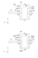
図10(A)は、実施の形態3に係る電動機の回転子302の構成を示す部分断面図である。図10(A)において、図1に示される構成要素と同一又は対応する構成要素には、図1に示される符号と同じ符号が付される。実施の形態3に係る電動機は、回転子302において、第1の軸受23と第2の軸受24との間の距離と永久磁石322の軸方向の長さとの関係の点で、実施の形態1に係る電動機100と相違する。それ以外の点については、実施の形態3に係る電動機300は、実施の形態1に係る電動機100と同じである。そのため、以下の説明では、図1を参照する。
Third Embodiment
Fig. 10(A) is a partial cross-sectional view showing the configuration of a rotor 302 of an electric motor according to embodiment 3. In Fig. 10(A), components identical to or corresponding to those shown in Fig. 1 are given the same reference numerals as those shown in Fig. 1. The electric motor according to embodiment 3 differs from the electric motor 100 according to embodiment 1 in the relationship between the distance between the first bearing 23 and the second bearing 24 and the axial length of the permanent magnet 322 in the rotor 302. In other respects, the electric motor 300 according to embodiment 3 is the same as the electric motor 100 according to embodiment 1. Therefore, Fig. 1 will be referred to in the following description.

図10(A)に示されるように、回転子302は、シャフト21と、永久磁石322と、第1の軸受23と、第2の軸受24とを有する。As shown in FIG. 10(A), the rotor 302 has a shaft 21, a permanent magnet 322, a first bearing 23, and a second bearing 24.

永久磁石322は、シャフト21に取り付けられている。永久磁石322は、+z軸方向を向く端面322cに設けられた第1の凹部322eと、-z軸方向を向く端面322dに設けられた第2の凹部322fとを有する。The permanent magnet 322 is attached to the shaft 21. The permanent magnet 322 has a first recess 322e provided on the end face 322c facing the +z axis direction and a second recess 322f provided on the end face 322d facing the -z axis direction.

図10(A)において、永久磁石322のz軸方向の長さをL2、第1の軸受23と第2の軸受24との間の距離をL3としたとき、距離L3は、長さL2と同じである。なお、距離L3は、長さL2より長くてもよい。すなわち、距離L3及び長さL2は、以下の式(6)を満たしていればよい。
L3≧L2 (6)
10A , when the length of the permanent magnet 322 in the z-axis direction is L2 and the distance between the first bearing 23 and the second bearing 24 is L3, the distance L3 is the same as the length L2. Note that the distance L3 may be longer than the length L2. In other words, it is sufficient that the distance L3 and the length L2 satisfy the following formula (6).
L3≧L2 (6)

次に、距離L3及び長さL2が式(6)を満たすことによる効果について、比較例と対比しながら説明する。図10(B)は、比較例に係る電動機の回転子302Aの構成を示す部分断面図である。比較例の回転子302Aにおいて、シャフト21の負荷側を支持する第1の軸受23とシャフト21の反負荷側を支持する第2の軸受24との間の距離L30は、長さL2より短い。この場合、電動機の回転中に負荷側の第1の軸受23に作用する力が大きくなるため、当該第1の軸受23が摩耗し易くなる。ここで、軸受の摩耗とは、当該第1の軸受23の内輪と外輪の摩耗である。内輪及び外輪に摩耗が発生すると、内輪と外輪との間の隙間が大きくなる。これにより、回転中に、シャフト21の負荷側の部分及び反負荷側の部分のうちの一方が径方向に動き易くなる。よって、回転子302Aから+z軸側の磁束取込部材31(図1参照)に流れる磁束と、回転子302Aから-z軸側の磁束取込部材32(図1参照)に流れる磁束との間に磁気アンバランスが生じ、当該磁気アンバランスによる振動の発生が懸念される。Next, the effect of the distance L3 and the length L2 satisfying the formula (6) will be described in comparison with the comparative example. FIG. 10(B) is a partial cross-sectional view showing the configuration of the rotor 302A of the electric motor according to the comparative example. In the rotor 302A of the comparative example, the distance L30 between the first bearing 23 supporting the load side of the shaft 21 and the second bearing 24 supporting the anti-load side of the shaft 21 is shorter than the length L2. In this case, the force acting on the first bearing 23 on the load side during rotation of the electric motor becomes large, so that the first bearing 23 becomes more likely to wear. Here, the wear of the bearing refers to the wear of the inner and outer rings of the first bearing 23. When the inner and outer rings wear, the gap between the inner and outer rings becomes larger. As a result, one of the load side and anti-load side parts of the shaft 21 becomes more likely to move radially during rotation. Therefore, a magnetic imbalance occurs between the magnetic flux flowing from the rotor 302A to the magnetic flux intake member 31 (see Figure 1) on the +z-axis side and the magnetic flux flowing from the rotor 302A to the magnetic flux intake member 32 (see Figure 1) on the -z-axis side, and there is a concern that vibrations may occur due to this magnetic imbalance.

また、シャフト21の負荷側に、例えば、図1に示される羽根車110が取り付けられた場合、回転中にシャフト21が撓むことによる振動及び騒音が発生する。このシャフト21の撓みに基づく振動成分と上述した磁気アンバランスに基づく振動成分とが共振すると、更に大きな騒音が発生することが懸念される。1 is attached to the load side of the shaft 21, vibrations and noise are generated due to the bending of the shaft 21 during rotation. If the vibration component due to the bending of the shaft 21 resonates with the vibration component due to the magnetic imbalance described above, there is a concern that even greater noise will be generated.

実施の形態3では、上述した式(6)に示される通り、負荷側の第1の軸受23と反負荷側の第2の軸受24との間の距離L3は、永久磁石322の軸方向の長さL2以上である。これにより、実施の形態3に係る電動機の回転中に、第1の軸受23及び第2の軸受24に作用する力が低減される。よって、第1の軸受23及び第2の軸受24の摩耗が抑制されるため、電動機の回転中にシャフト21が径方向に動き難くなる。したがって、回転子302から+z軸側の磁束取込部材31(図1参照)に流れる磁束と、回転子302から-z軸側の磁束取込部材32(図1参照)に流れる磁束との間の磁気アンバランスを低減することができ、当該磁気アンバランスによる振動を一層抑制することができる。In the third embodiment, as shown in the above-mentioned formula (6), the distance L3 between the first bearing 23 on the load side and the second bearing 24 on the counter-load side is equal to or greater than the axial length L2 of the permanent magnet 322. This reduces the force acting on the first bearing 23 and the second bearing 24 during the rotation of the electric motor according to the third embodiment. Therefore, wear of the first bearing 23 and the second bearing 24 is suppressed, and the shaft 21 is less likely to move radially during the rotation of the electric motor. Therefore, the magnetic imbalance between the magnetic flux flowing from the rotor 302 to the magnetic flux intake member 31 (see FIG. 1) on the +z axis side and the magnetic flux flowing from the rotor 302 to the magnetic flux intake member 32 (see FIG. 1) on the -z axis side can be reduced, and vibration due to the magnetic imbalance can be further suppressed.

〈実施の形態3の効果〉
以上に説明した実施の形態3によれば、シャフト21の負荷側の第1の軸受23と反負荷側の第2の軸受24との間の距離L3は、永久磁石322の軸方向の長さL2以上である。これにより、実施の形態3に係る電動機における騒音を一層低減することができる。
Effects of the Third Embodiment
According to the third embodiment described above, the distance L3 between the first bearing 23 on the load side of the shaft 21 and the second bearing 24 on the anti-load side is equal to or greater than the axial length L2 of the permanent magnet 322. This makes it possible to further reduce noise in the electric motor according to the third embodiment.

《実施の形態4》
図11は、実施の形態4に係る電動機の固定子401の構成を示す斜視図である。図12は、図11に示される固定子鉄心10及びインシュレータ460の構成を示す斜視図である。図11及び12において、図1に示される構成要素と同一又は対応する構成要素には、図1に示される符号と同じ符号が付される。実施の形態4に係る電動機は、固定子401の磁束取込部材430の形状の点で、実施の形態1に係る電動機100と相違する。これ以外の点については、実施の形態4に係る電動機は、実施の形態1に係る電動機100と同じである。そのため、以下の説明では、図1を参照する。
Fourth Embodiment
Fig. 11 is a perspective view showing the configuration of a stator 401 of an electric motor according to embodiment 4. Fig. 12 is a perspective view showing the configuration of a stator core 10 and an insulator 460 shown in Fig. 11. In Figs. 11 and 12, components that are the same as or correspond to those shown in Fig. 1 are given the same reference numerals as those shown in Fig. 1. The electric motor according to embodiment 4 differs from the electric motor 100 according to embodiment 1 in the shape of the magnetic flux intake member 430 of the stator 401. In other respects, the electric motor according to embodiment 4 is the same as the electric motor 100 according to embodiment 1. Therefore, Fig. 1 will be referred to in the following description.

固定子401は、固定子鉄心10と、巻線20(図1参照)と、磁束取込部材430と、樹脂部450とを有する。The stator 401 has a stator core 10, a winding 20 (see Figure 1), a magnetic flux intake member 430, and a resin part 450.

磁束取込部材430は、回転子2からの磁束を取り込む。磁束取込部材430は、固定子鉄心10のティース12のz軸方向の端面12c、12d上に配置されている。The magnetic flux intake member 430 takes in magnetic flux from the rotor 2. The magnetic flux intake member 430 is arranged on the end faces 12c and 12d of the teeth 12 of the stator core 10 in the z-axis direction.

磁束取込部材430は、径方向の内向きの凹面431aを有する。z軸方向に見たときの磁束取込部材430の形状は、例えば、円弧形状である。これにより、z軸方向に見たときの磁束取込部材の形状が長方形状である構成と比較して、固定子鉄心10と磁束取込部材430との接触面積が増大するため、磁束取込部材430の固定強度を向上させることができる。The magnetic flux take-in member 430 has a radially inward concave surface 431a. The shape of the magnetic flux take-in member 430 when viewed in the z-axis direction is, for example, an arc shape. This increases the contact area between the stator core 10 and the magnetic flux take-in member 430 compared to a configuration in which the magnetic flux take-in member has a rectangular shape when viewed in the z-axis direction, thereby improving the fixing strength of the magnetic flux take-in member 430.

樹脂部450は、固定子鉄心10と巻線とを絶縁するインシュレータ460と、図示しないモールド樹脂部とを有する。The resin part 450 has an insulator 460 that insulates the stator core 10 from the windings, and a molded resin part (not shown).

インシュレータ460は、ティース12と巻線20とを絶縁する第1の絶縁部分461を有する。磁束取込部材430は、インシュレータ460の第1の絶縁部分461に当接している。これにより、磁束取込部材430の位置決めが容易となる。The insulator 460 has a first insulating portion 461 that insulates the teeth 12 from the winding 20. The magnetic flux intake member 430 abuts against the first insulating portion 461 of the insulator 460. This makes it easy to position the magnetic flux intake member 430.

図13(A)は、図11に示される磁束取込部材430の構成を示す平面図である。図13(A)に示されるように、磁束取込部材430は、径方向の外向きの面431bに備えられた複数の凸部441を有する。 Figure 13 (A) is a plan view showing the configuration of the magnetic flux capture member 430 shown in Figure 11. As shown in Figure 13 (A), the magnetic flux capture member 430 has a plurality of protrusions 441 provided on the radially outward surface 431b.

図13(A)に示す例では、凸部441は、径方向の外向きの面431bの周方向Cの両側の端部から永久磁石22(図1参照)から離れる方向(すなわち、径方向の外向き)に突出している。また、図13(A)に示す例では、凸部441は、磁束取込部材430が周方向Cに幅広となるように、径方向の外向きに突出している。これにより、回転中に永久磁石22と磁束取込部材430との間に磁気吸引力が発生した場合であっても、磁束取込部材430が脱落し難くなる。よって、電動機の信頼性を向上させることができる。In the example shown in FIG. 13(A), the convex portion 441 protrudes in a direction away from the permanent magnet 22 (see FIG. 1) (i.e., radially outward) from both ends in the circumferential direction C of the radially outward surface 431b. Also, in the example shown in FIG. 13(A), the convex portion 441 protrudes radially outward so that the magnetic flux intake member 430 is wider in the circumferential direction C. This makes it difficult for the magnetic flux intake member 430 to fall off even if a magnetic attraction force is generated between the permanent magnet 22 and the magnetic flux intake member 430 during rotation. This improves the reliability of the motor.

図13(A)において、磁束取込部材430の周方向Cの幅をW3、上述した図12において、ティース先端部12bの周方向Cの幅をW4としたとき、幅W3は幅W4より狭い。すなわち、幅W3及び幅W4は、以下の式(7)を満たす。
W3<W4 (7)
これにより、周方向Cに隣接する2つの磁束取込部材430の干渉を防止することができる。
13A, the width in the circumferential direction C of magnetic flux intake member 430 is W3, and in the above-described FIG. 12, the width in the circumferential direction C of tooth tip portion 12b is W4, width W3 is narrower than width W4. In other words, width W3 and width W4 satisfy the following formula (7).
W3 < W4 (7)
This makes it possible to prevent interference between two magnetic flux intake members 430 adjacent in the circumferential direction C.

また、図11及び12に示されるように、凸部441は、インシュレータ460の径方向の内向きの面に備えられた凹部461aに嵌合している。これにより、磁束取込部材430の固定強度が向上する。よって、磁気的な力(例えば、永久磁石22の磁力及び巻線20への通電時に発生する磁気的な力)が磁束取込部材430に作用した場合であっても、当該磁束取込部材430の振動を抑制することができる。したがって、固定子における騒音を低減することができる。11 and 12, the convex portion 441 fits into a concave portion 461a provided on the radially inward surface of the insulator 460. This improves the fixing strength of the magnetic flux take-in member 430. Therefore, even if a magnetic force (for example, the magnetic force of the permanent magnet 22 and the magnetic force generated when current is applied to the winding 20) acts on the magnetic flux take-in member 430, the vibration of the magnetic flux take-in member 430 can be suppressed. Therefore, noise in the stator can be reduced.

図13(B)から(D)は、実施の形態4に係る磁束取込部材430の構成の他の例を示す平面図である。凸部441は、磁束取込部材430の周方向Cの両側の端部から径方向の外向きに突出していなくても実現することができる。例えば、図13(B)に示されるように、凸部441は、径方向の外向きの面431bの周方向Cの一方の端部から径方向の外向きに突出していてもよい。また、図13(C)に示されるように、磁束取込部材430は、凸部441を有していなくても実現することができ、磁束取込部材430の径方向の厚みt4が周方向Cにおいて均一であってもよい。これにより、永久磁石22(図1参照)の磁束を取り込むために必要な磁束取込部材430の大きさを最小限にすることができる。更に、図13(D)に示されるように、凸部441は、磁束取込部材430の径方向の外向きの面431bの周方向Cの中央部に備えられていてもよい。これにより、凸部441と、周方向Cに隣接する他の磁束取込部材430との干渉を防止することができる。13B to 13D are plan views showing other examples of the configuration of the magnetic flux capture member 430 according to the fourth embodiment. The convex portion 441 can be realized even if it does not protrude radially outward from both ends of the magnetic flux capture member 430 in the circumferential direction C. For example, as shown in FIG. 13B, the convex portion 441 may protrude radially outward from one end of the radially outward surface 431b in the circumferential direction C. Also, as shown in FIG. 13C, the magnetic flux capture member 430 can be realized even if it does not have the convex portion 441, and the radial thickness t4 of the magnetic flux capture member 430 may be uniform in the circumferential direction C. This makes it possible to minimize the size of the magnetic flux capture member 430 required to capture the magnetic flux of the permanent magnet 22 (see FIG. 1). 13D, the protrusion 441 may be provided at the center in the circumferential direction C of the radially outward surface 431b of the magnetic flux capture member 430. This makes it possible to prevent interference between the protrusion 441 and another magnetic flux capture member 430 adjacent in the circumferential direction C.

〈実施の形態4の効果〉
以上に説明した実施の形態4によれば、磁束取込部材430は、径方向の内向きの凹面431aを有する。z軸方向に見たときの磁束取込部材430の形状は、例えば、円弧形状である。これにより、z軸方向に見たときの磁束取込部材の形状が長方形状である構成と比較して、固定子鉄心10と磁束取込部材430との接触面積が増大するため、磁束取込部材430の固定強度を向上させることができる。
Effects of the Fourth Embodiment
According to the fourth embodiment described above, magnetic flux take-up member 430 has a concave surface 431a facing inward in the radial direction. The shape of magnetic flux take-up member 430 when viewed in the z-axis direction is, for example, an arc shape. This increases the contact area between stator core 10 and magnetic flux take-up member 430 compared to a configuration in which the shape of the magnetic flux take-up member when viewed in the z-axis direction is rectangular, thereby improving the fixing strength of magnetic flux take-up member 430.

また、実施の形態4によれば、磁束取込部材430は、径方向の外向きの面431bに備えられた凸部441を有する。これにより、固定子鉄心10と磁束取込部材430との接触面積が一層増大するため、磁束取込部材430の固定強度を一層向上させることができる。また、磁束取込部材430をインシュレータ460に固定する際の当該磁束取込部材430の位置決めを容易にすることができる。 According to the fourth embodiment, the magnetic flux take-up member 430 has a protrusion 441 provided on the radially outward surface 431b. This further increases the contact area between the stator core 10 and the magnetic flux take-up member 430, thereby further improving the fixing strength of the magnetic flux take-up member 430. In addition, the magnetic flux take-up member 430 can be easily positioned when fixed to the insulator 460.

また、実施の形態4によれば、凸部441は、磁束取込部材430の径方向の外向きの面431bから径方向の外向きに突出し、当該凸部441は、インシュレータ460の径方向の内向きの面に備えられた凹部461aに嵌合している。これにより、磁束取込部材430の固定強度が向上する。よって、磁気的な力(例えば、永久磁石22の磁力及び巻線20への通電時に発生する磁気的な力)が磁束取込部材430に作用した場合であっても、当該磁束取込部材430の振動を抑制することができる。したがって、固定子における騒音を低減することができる。 According to the fourth embodiment, the protrusion 441 protrudes radially outward from the radially outward surface 431b of the magnetic flux intake member 430, and the protrusion 441 fits into the recess 461a provided on the radially inward surface of the insulator 460. This improves the fixing strength of the magnetic flux intake member 430. Therefore, even if a magnetic force (for example, the magnetic force of the permanent magnet 22 and the magnetic force generated when current is applied to the winding 20) acts on the magnetic flux intake member 430, the vibration of the magnetic flux intake member 430 can be suppressed. Therefore, the noise in the stator can be reduced.

《実施の形態4の変形例1》
図14(A)は、実施の形態4の変形例1に係る固定子の磁束取込部材430Aの構成を示す平面図である。図14(A)において、図13(A)に示される構成要素と同一又は対応する構成要素には、図13(A)に示される符号と同じ符号が付される。実施の形態4の変形例1に係る固定子は、磁束取込部材430Aの形状の点で、実施の形態4に係る固定子401と相違する。これ以外の点については、実施の形態4の変形例1に係る固定子は、実施の形態4に係る固定子と同じである。そのため、以下の説明では、図11などを参照する。
First Modification of Fourth Embodiment
Fig. 14(A) is a plan view showing the configuration of a magnetic flux intake member 430A of a stator according to a first modification of the fourth embodiment. In Fig. 14(A), components that are the same as or correspond to those shown in Fig. 13(A) are given the same reference numerals as those shown in Fig. 13(A). The stator according to the first modification of the fourth embodiment differs from the stator 401 according to the fourth embodiment in terms of the shape of the magnetic flux intake member 430A. In other respects, the stator according to the first modification of the fourth embodiment is the same as the stator according to the fourth embodiment. Therefore, Fig. 11 and the like will be referred to in the following description.

図14(A)に示されるように、磁束取込部材430Aは、径方向の外向きの面431bの周方向Cの両側の端部に備えられた複数の凸部441Aを有する。As shown in FIG. 14(A), the magnetic flux capture member 430A has a plurality of protrusions 441A provided at both ends in the circumferential direction C of the radially outward surface 431b.

凸部441Aは、径方向の外向きの面431bの周方向Cの端部から、磁束取込部材430Aの周方向Cの幅W31が一定となるように突出している。これにより、複数の磁束取込部材430Aが複数のティース12(図11参照)のそれぞれに配置される場合に、周方向Cに隣接する2つの磁束取込部材430Aの干渉を防止することができる。よって、実施の形態4の変形例1では、磁束取込部材430の周方向Cの幅W31をティース12のティース先端部12bの周方向Cの幅W4まで広くすることができる。したがって、磁束取込部材430Aは、永久磁石22(図1参照)のオーバハング部で発生した磁束を取り込み易くなる。なお、図14(A)において、磁束取込部材430Aの周方向Cの幅W31は、磁束取込部材430Aの周方向Cの両側の側面442の間の最短距離である。The protrusion 441A protrudes from the end of the radially outward surface 431b in the circumferential direction C so that the width W31 of the magnetic flux intake member 430A in the circumferential direction C is constant. This makes it possible to prevent interference between two adjacent magnetic flux intake members 430A in the circumferential direction C when multiple magnetic flux intake members 430A are arranged on each of multiple teeth 12 (see FIG. 11). Therefore, in the first modified example of the fourth embodiment, the width W31 of the magnetic flux intake member 430 in the circumferential direction C can be widened to the width W4 of the tooth tip 12b of the tooth 12 in the circumferential direction C. Therefore, the magnetic flux intake member 430A can easily take in the magnetic flux generated at the overhanging portion of the permanent magnet 22 (see FIG. 1). In FIG. 14(A), the width W31 of the magnetic flux intake member 430A in the circumferential direction C is the shortest distance between the side surfaces 442 on both sides of the magnetic flux intake member 430A in the circumferential direction C.

図14(B)は、実施の形態4の変形例1に係る固定子の磁束取込部材430Aの構成の他の例を示す平面図である。図14(B)に示されるように、磁束取込部材430Aの凸部441Aは、径方向の内向きの凹面431aから永久磁石22(図1参照)に近づく方向、すなわち、径方向の内向きに突出していてもよい。図14(B)に示す例では、インシュレータ又はモールド樹脂部などが凹面431aを覆うことによって、回転子2(図1参照)と固定子401(図11参照)との間に発生する磁気的な力による磁束取込部材430Aの脱落を防止することができる。 Figure 14 (B) is a plan view showing another example of the configuration of the stator magnetic flux intake member 430A according to the first modified example of the fourth embodiment. As shown in Figure 14 (B), the convex portion 441A of the magnetic flux intake member 430A may protrude in a direction approaching the permanent magnet 22 (see Figure 1) from the radially inward concave surface 431a, that is, inward in the radial direction. In the example shown in Figure 14 (B), the insulator or molded resin part covers the concave surface 431a, thereby preventing the magnetic flux intake member 430A from falling off due to the magnetic force generated between the rotor 2 (see Figure 1) and the stator 401 (see Figure 11).

〈実施の形態4の変形例1の効果〉
以上に説明した実施の形態4の変形例1によれば、凸部441Aは、磁束取込部材430Aの周方向Cの幅W31が一定となるように、径方向の外向きの面431b又は径方向の内向きの凹面431aから突出している。これにより、周方向Cに隣接する2つの磁束取込部材430Aの干渉を防止することができる。よって、磁束取込部材430Aの周方向Cの幅W3をティース12のティース先端部12bの周方向Cの幅W2まで広くすることができる。したがって、磁束取込部材430Aは、永久磁石22のオーバハング部で発生した磁束を取り込み易くなる。
<Effects of Modification 1 of Fourth Embodiment>
According to the first modification of the fourth embodiment described above, the convex portion 441A protrudes from the radially outward surface 431b or the radially inward concave surface 431a so that the width W31 in the circumferential direction C of the magnetic flux take-up member 430A is constant. This makes it possible to prevent interference between two magnetic flux take-up members 430A adjacent to each other in the circumferential direction C. Thus, the width W3 in the circumferential direction C of the magnetic flux take-up member 430A can be widened to the width W2 in the circumferential direction C of the tooth tip portion 12b of the tooth 12. This makes it easier for the magnetic flux take-up member 430A to take in magnetic flux generated in the overhanging portion of the permanent magnet 22.

《実施の形態4の変形例2》
図15は、実施の形態4の変形例2に係る固定子の磁束取込部材430Bの構成を示す平面図である。図15において、図13(A)に示される構成要素と同一又は対応する構成要素には、図13(A)に示される符号と同じ符号が付される。実施の形態4の変形例2に係る固定子は、磁束取込部材430Bの形状の点で、実施の形態4に係る固定子と相違する。これ以外の点については、実施の形態4の変形例2に係る固定子は、実施の形態4に係る固定子と同じである。そのため、以下の説明では、図11などを参照する。
<<Modification 2 of the Fourth Embodiment>>
Fig. 15 is a plan view showing the configuration of a stator magnetic flux intake member 430B according to the second modification of the fourth embodiment. In Fig. 15, components that are the same as or correspond to those shown in Fig. 13(A) are given the same reference numerals as those shown in Fig. 13(A). The stator according to the second modification of the fourth embodiment differs from the stator according to the fourth embodiment in the shape of the magnetic flux intake member 430B. In other respects, the stator according to the second modification of the fourth embodiment is the same as the stator according to the fourth embodiment. Therefore, Fig. 11 and the like will be referred to in the following description.

図15に示されるように、磁束取込部材430Bは、径方向の外向きの面431bに備えられた凸部441Bを有する。凸部441Bは、径方向の外向きの面431bの周方向Cの中央部から径方向の外向きに突出している。これにより、複数の磁束取込部材430Bが複数のティース12(図11参照)のそれぞれに配置される場合に、周方向Cに隣接する2つの磁束取込部材430Bが干渉することを防止することができる。15, the magnetic flux intake member 430B has a protrusion 441B provided on the radially outward surface 431b. The protrusion 441B protrudes radially outward from the center of the radially outward surface 431b in the circumferential direction C. This makes it possible to prevent interference between two magnetic flux intake members 430B adjacent in the circumferential direction C when multiple magnetic flux intake members 430B are arranged on each of multiple teeth 12 (see FIG. 11).

また、実施の形態4の変形例2では、凸部441Bは、径方向の外向きの面431bから離れるほど幅広である。具体的には、凸部441Bの周方向Cを向く側面443は、径方向の外向きの面431bから離れるほど、凸部441Bが幅広となるように周方向Cに傾斜しながら延びている。インシュレータ又はモールド樹脂部が側面443を覆うことで、磁束取込部材430Bの固定強度が向上するため、回転子2(図1参照)と固定子401(図11参照)との間に発生する磁気的な力による磁束取込部材430Bの脱落を防止することができる。 In addition, in the second modification of the fourth embodiment, the convex portion 441B is wider as it moves away from the radially outward surface 431b. Specifically, the side surface 443 of the convex portion 441B facing the circumferential direction C extends while inclining in the circumferential direction C so that the convex portion 441B becomes wider as it moves away from the radially outward surface 431b. By covering the side surface 443 with an insulator or molded resin portion, the fixing strength of the magnetic flux intake member 430B is improved, and it is possible to prevent the magnetic flux intake member 430B from falling off due to the magnetic force generated between the rotor 2 (see FIG. 1) and the stator 401 (see FIG. 11).

〈実施の形態4の変形例2の効果〉
以上に説明した実施の形態4の変形例2によれば、磁束取込部材430Bの凸部441Bは、径方向の外向きの面431bから離れるほど幅広である。これにより、樹脂部に対する磁束取込部材430Bの固定強度が向上するため、回転子2と固定子401との間に発生する磁気的な力による磁束取込部材430Bの脱落を防止することができる。
Effects of Modification 2 of Fourth Embodiment
According to the second modification of the fourth embodiment described above, the convex portion 441B of the magnetic flux take-up member 430B becomes wider as it moves away from the radially outward surface 431b. This improves the fixing strength of the magnetic flux take-up member 430B to the resin part, thereby preventing the magnetic flux take-up member 430B from falling off due to the magnetic force generated between the rotor 2 and the stator 401.

1、1A、201、401 固定子、 2、302 回転子、 10 固定子鉄心、 12 ティース、 12c、12d 端面、 20 巻線、 21 シャフト、 22、322 永久磁石、 23 第1の軸受、 24 第2の軸受、 30、31、31u、31v、32、32u、32v、430、430A、430B 磁束取込部材、 31a、431a 径方向の内向きの面、 50 樹脂部、 60、460 インシュレータ、 70 モールド樹脂部、 100、100A、200 電動機、 110 羽根車、 150 送風機、 431b 径方向の外向きの面、 441、441A、441B 凸部、 461a 凹部、 D1、D2 外径、 E1 第1のエアギャップ、 E2 第2のエアギャップ、 L1、L2 長さ、 L3 距離、 P1 第1の中心位置、 P2 第2の中心位置、 t1、t2、t3、t4、t30 厚み、 W1 第1の間隔、 W2 第2の間隔。1, 1A, 201, 401 Stator, 2, 302 Rotor, 10 Stator core, 12 Teeth, 12c, 12d End surface, 20 Winding, 21 Shaft, 22, 322 Permanent magnet, 23 First bearing, 24 Second bearing, 30, 31, 31u, 31v, 32, 32u, 32v, 430, 430A, 430B Magnetic flux intake member, 31a, 431a Radial inward surface, 50 Resin part, 60, 460 Insulator, 70 Molded resin part, 100, 100A, 200 Motor, 110 Impeller, 150 Blower, 431b Radial outward surface, 441, 441A, 441B convex portion, 461a concave portion, D1, D2 outer diameter, E1 first air gap, E2 second air gap, L1, L2 length, L3 distance, P1 first center position, P2 second center position, t1, t2, t3, t4, t30 thickness, W1 first spacing, W2 second spacing.

Claims (17)

固定子と、
前記固定子より内側に配置された回転子本体と、
前記回転子本体に取り付けられた回転軸と、
前記回転軸の負荷側を支持する第1の軸受と、
前記回転軸の反負荷側を支持する第2の軸受と
を有し、
前記固定子は、
複数のティースを有する固定子鉄心と、
複数の磁束取込部材と、
前記複数の磁束取込部材を、前記複数のティースの前記固定子鉄心の軸方向の端面にそれぞれ固定する樹脂部と
を有し、
前記複数の磁束取込部材のうちの前記固定子鉄心の周方向に隣り合う磁束取込部材は、前記周方向に第1の間隔を開けて配置され、
前記樹脂部は、前記第1の間隔を埋めていて、
前記軸方向における前記第1の軸受と前記第2の軸受との間の距離は、前記回転子本体の前記軸方向の長さ以上である
電動機
A stator;
A rotor body disposed inside the stator;
A rotating shaft attached to the rotor body;
a first bearing supporting a load side of the rotating shaft;
a second bearing supporting the anti-load side of the rotating shaft;
having
The stator includes:
a stator core having a plurality of teeth;
A plurality of magnetic flux capture members;
a resin portion that fixes the plurality of magnetic flux intake members to end faces of the plurality of teeth in the axial direction of the stator core,
Among the plurality of magnetic flux take-in members, adjacent magnetic flux take-in members in a circumferential direction of the stator core are disposed at a first interval in the circumferential direction,
the resin portion fills the first gap ,
A distance between the first bearing and the second bearing in the axial direction is equal to or greater than a length of the rotor body in the axial direction.
Electric motor .
前記第1の間隔は、前記複数のティースのうちの前記周方向に隣り合うティースの間の間隔である第2の間隔以上である
請求項1に記載の電動機
The electric motor according to claim 1 , wherein the first interval is equal to or greater than a second interval that is an interval between adjacent teeth in the circumferential direction among the plurality of teeth.
前記複数の磁束取込部材の各磁束取込部材の前記周方向の幅は、前記複数のティースの各ティースの前記周方向の幅より狭い
請求項1又は2に記載の電動機
The electric motor according to claim 1 or 2, wherein a width in the circumferential direction of each of the plurality of magnetic flux take-in members is narrower than a width in the circumferential direction of each of the plurality of teeth.
前記磁束取込部材の前記周方向の中心の位置である第1の中心位置は、前記ティースの前記周方向の中心の位置である第2の中心位置に対してずれて配置されている
請求項1から3のいずれか1項に記載の電動機
The electric motor according to claim 1 , wherein a first central position, which is a circumferential center position of the magnetic flux intake member, is shifted with respect to a second central position, which is a circumferential center position of the teeth.
前記磁束取込部材の前記固定子鉄心の径方向の厚みである第1の厚みは、前記ティースの前記径方向の厚みである第2の厚みより薄い
請求項1から4のいずれか1項に記載の電動機
The electric motor according to claim 1 , wherein a first thickness, which is a radial thickness of the magnetic flux intake member of the stator core, is smaller than a second thickness, which is a radial thickness of the teeth.
前記樹脂部の前記径方向の厚みである第3の厚みは、前記第1の厚みより厚い
請求項5に記載の電動機
The electric motor according to claim 5 , wherein a third thickness which is a thickness of the resin portion in the radial direction is greater than the first thickness.
前記樹脂部は、前記複数の磁束取込部材を前記複数のティースの前記軸方向の端面に固定するように前記複数の磁束取込部材を囲んでいる
請求項1から6のいずれか1項に記載の電動機
The electric motor according to claim 1 , wherein the resin portion surrounds the plurality of magnetic flux take-in members so as to fix the plurality of magnetic flux take-in members to end faces of the plurality of teeth in the axial direction.
前記複数の磁束取込部材は、前記複数のティースの前記軸方向の端面に前記樹脂部を挟んで配置されている
請求項1から7のいずれか1項に記載の電動機
The electric motor according to claim 1 , wherein the plurality of magnetic flux intake members are arranged on end faces of the plurality of teeth in the axial direction with the resin portion sandwiched therebetween.
前記磁束取込部材は、前記固定子鉄心の径方向の外向きの面又は前記径方向の内向きの面に備えられた凸部を有する
請求項1に記載の電動機
The electric motor according to claim 1 , wherein the magnetic flux intake member has a protrusion provided on a radially outward surface or a radially inward surface of the stator core.
前記凸部は、前記磁束取込部材の前記径方向の外向きの面から前記径方向の外向きに突出し、
前記樹脂部は、前記径方向の内向きの面に備えられた凹部を有し、
前記凸部は、前記凹部に嵌合している
請求項9に記載の電動機
the protrusion protrudes radially outward from a radially outward surface of the magnetic flux intake member,
The resin portion has a recess provided on an inner surface facing in the radial direction,
The electric motor according to claim 9 , wherein the protrusion is fitted into the recess.
前記固定子は、前記固定子鉄心に巻き付けられた巻線を更に有し、
前記樹脂部は、
前記固定子鉄心と前記巻線とを絶縁するインシュレータと、
前記巻線を覆うモールド樹脂部と
を有する
請求項1から10のいずれか1項に記載の電動機
The stator further includes a winding wound around the stator core,
The resin portion is
an insulator that insulates the stator core from the windings;
The electric motor according to claim 1 , further comprising: a molded resin portion covering the winding.
前記巻線は、アルミ線である
請求項11に記載の電動機
The electric motor according to claim 11, wherein the winding is made of aluminum wire.
前記固定子鉄心の前記軸方向の長さである第1の長さは、前記回転子本体の前記軸方向の前記長さである第2の長さより短い
請求項1から12のいずれか1項に記載の電動機。
The electric motor according to claim 1 , wherein a first length which is the axial length of the stator core is shorter than a second length which is the axial length of the rotor body.
前記回転子本体と前記磁束取込部材との間の間隔である第1のエアギャップは、前記回転子本体と前記固定子鉄心との間の間隔である第2のエアギャップより広い
請求項1から13のいずれか1項に記載の電動機。
14. The electric motor according to claim 1, wherein a first air gap, which is a gap between the rotor body and the magnetic flux intake member, is wider than a second air gap, which is a gap between the rotor body and the stator core.
前記樹脂部は、前記磁束取込部材のうち前記回転子本体を向く面を覆っている
請求項1から14のいずれか1項に記載の電動機。
The electric motor according to claim 1 , wherein the resin portion covers a surface of the magnetic flux intake member that faces the rotor body.
請求項1から15のいずれか1項に記載の電動機と、
前記電動機によって駆動する羽根車と
を有する
送風機。
An electric motor according to any one of claims 1 to 15 ;
and an impeller driven by the electric motor.
前記羽根車の外径は、前記固定子鉄心の外径より大きい
請求項16に記載の送風機。
The blower of claim 16 , wherein an outer diameter of the impeller is greater than an outer diameter of the stator core.
JP2023544965A 2021-09-06 2021-09-06 Stators, motors and fans Active JP7531723B2 (en)

Applications Claiming Priority (1)

Application Number Priority Date Filing Date Title
PCT/JP2021/032612 WO2023032188A1 (en) 2021-09-06 2021-09-06 Stator, electric motor, and blower

Publications (3)

Publication Number Publication Date
JPWO2023032188A1 JPWO2023032188A1 (en) 2023-03-09
JPWO2023032188A5 JPWO2023032188A5 (en) 2023-11-28
JP7531723B2 true JP7531723B2 (en) 2024-08-09

Family

ID=85411072

Family Applications (1)

Application Number Title Priority Date Filing Date
JP2023544965A Active JP7531723B2 (en) 2021-09-06 2021-09-06 Stators, motors and fans

Country Status (3)

Country Link
JP (1) JP7531723B2 (en)
CN (1) CN117882270A (en)
WO (1) WO2023032188A1 (en)

Citations (2)

* Cited by examiner, † Cited by third party
Publication number Priority date Publication date Assignee Title
JP2006129688A (en) 2004-09-29 2006-05-18 Denso Corp Magnet-type generator
JP2012205421A (en) 2011-03-25 2012-10-22 Panasonic Corp Motor, pump, and apparatus

Family Cites Families (1)

* Cited by examiner, † Cited by third party
Publication number Priority date Publication date Assignee Title
JP2888142B2 (en) * 1993-11-08 1999-05-10 三菱電機株式会社 Rotary motor and method of manufacturing the same

Patent Citations (2)

* Cited by examiner, † Cited by third party
Publication number Priority date Publication date Assignee Title
JP2006129688A (en) 2004-09-29 2006-05-18 Denso Corp Magnet-type generator
JP2012205421A (en) 2011-03-25 2012-10-22 Panasonic Corp Motor, pump, and apparatus

Also Published As

Publication number Publication date
JPWO2023032188A1 (en) 2023-03-09
CN117882270A (en) 2024-04-12
WO2023032188A1 (en) 2023-03-09

Similar Documents

Publication Publication Date Title
US6166468A (en) Rotary electric machine and bearing structure thereof
US5925964A (en) Rotor for a rotating electric machine
US11588360B2 (en) Brushless motor and stator therefor
KR100252393B1 (en) Structure of reclaimed magnet type rotor
JP2008035616A (en) Motor
US7239057B2 (en) Single phase induction motor
JPWO2012090295A1 (en) Stator and rotating electric machine including the stator
JPWO2012011273A1 (en) Brushless motor for washing machine, drum-type washing machine including the same, and method for manufacturing brushless motor for washing machine
JPWO2022019074A5 (en)
JP2015065789A (en) Brushless motor and washing machine including the same
JP7541848B2 (en) Inner rotor type brushless motor
CN110679062B (en) Stator for an electric machine
JP7531723B2 (en) Stators, motors and fans
JP2018133948A (en) motor
KR101010836B1 (en) Motor for driving fan
KR101463817B1 (en) Electric motor and fan-motor assembly
JPWO2022137890A5 (en)
WO2023203633A1 (en) Stator, electric motor, and air blower
JP2002136051A (en) Rotating machine and rotor thereof
JP2865091B2 (en) Alternator and method of manufacturing the same
WO2022180724A1 (en) Electric motor
JP3015644B2 (en) Outer rotor type brushless DC motor
US20230352994A1 (en) Magnetic geared rotary electric machine
JP2020129880A (en) Electric motor, electric blower using the same, and electric vacuum cleaner using the same
WO2023148953A1 (en) Rotor, electric motor, air blower, air conditioning device, and method for producing electric motor

Legal Events

Date Code Title Description
A521 Request for written amendment filed

Free format text: JAPANESE INTERMEDIATE CODE: A523

Effective date: 20230901

A621 Written request for application examination

Free format text: JAPANESE INTERMEDIATE CODE: A621

Effective date: 20230901

TRDD Decision of grant or rejection written
A01 Written decision to grant a patent or to grant a registration (utility model)

Free format text: JAPANESE INTERMEDIATE CODE: A01

Effective date: 20240702

A61 First payment of annual fees (during grant procedure)

Free format text: JAPANESE INTERMEDIATE CODE: A61

Effective date: 20240730

R150 Certificate of patent or registration of utility model

Ref document number: 7531723

Country of ref document: JP

Free format text: JAPANESE INTERMEDIATE CODE: R150