JP7530833B2 - Arthroscopic devices and methods - Google Patents
Arthroscopic devices and methods Download PDFInfo
- Publication number
- JP7530833B2 JP7530833B2 JP2020560789A JP2020560789A JP7530833B2 JP 7530833 B2 JP7530833 B2 JP 7530833B2 JP 2020560789 A JP2020560789 A JP 2020560789A JP 2020560789 A JP2020560789 A JP 2020560789A JP 7530833 B2 JP7530833 B2 JP 7530833B2
- Authority
- JP
- Japan
- Prior art keywords
- cutting
- sleeve
- inner sleeve
- window
- probe
- Prior art date
- Legal status (The legal status is an assumption and is not a legal conclusion. Google has not performed a legal analysis and makes no representation as to the accuracy of the status listed.)
- Active
Links
Images


Classifications
-
- A—HUMAN NECESSITIES
- A61—MEDICAL OR VETERINARY SCIENCE; HYGIENE
- A61B—DIAGNOSIS; SURGERY; IDENTIFICATION
- A61B18/00—Surgical instruments, devices or methods for transferring non-mechanical forms of energy to or from the body
- A61B18/04—Surgical instruments, devices or methods for transferring non-mechanical forms of energy to or from the body by heating
- A61B18/12—Surgical instruments, devices or methods for transferring non-mechanical forms of energy to or from the body by heating by passing a current through the tissue to be heated, e.g. high-frequency current
- A61B18/14—Probes or electrodes therefor
-
- A—HUMAN NECESSITIES
- A61—MEDICAL OR VETERINARY SCIENCE; HYGIENE
- A61B—DIAGNOSIS; SURGERY; IDENTIFICATION
- A61B17/00—Surgical instruments, devices or methods
- A61B17/16—Instruments for performing osteoclasis; Drills or chisels for bones; Trepans
- A61B17/1613—Component parts
- A61B17/1615—Drill bits, i.e. rotating tools extending from a handpiece to contact the worked material
- A61B17/1617—Drill bits, i.e. rotating tools extending from a handpiece to contact the worked material with mobile or detachable parts
-
- A—HUMAN NECESSITIES
- A61—MEDICAL OR VETERINARY SCIENCE; HYGIENE
- A61B—DIAGNOSIS; SURGERY; IDENTIFICATION
- A61B17/00—Surgical instruments, devices or methods
- A61B17/16—Instruments for performing osteoclasis; Drills or chisels for bones; Trepans
- A61B17/1637—Hollow drills or saws producing a curved cut, e.g. cylindrical
-
- A—HUMAN NECESSITIES
- A61—MEDICAL OR VETERINARY SCIENCE; HYGIENE
- A61B—DIAGNOSIS; SURGERY; IDENTIFICATION
- A61B17/00—Surgical instruments, devices or methods
- A61B17/32—Surgical cutting instruments
- A61B17/320016—Endoscopic cutting instruments, e.g. arthroscopes, resectoscopes
- A61B17/32002—Endoscopic cutting instruments, e.g. arthroscopes, resectoscopes with continuously rotating, oscillating or reciprocating cutting instruments
-
- A—HUMAN NECESSITIES
- A61—MEDICAL OR VETERINARY SCIENCE; HYGIENE
- A61B—DIAGNOSIS; SURGERY; IDENTIFICATION
- A61B90/00—Instruments, implements or accessories specially adapted for surgery or diagnosis and not covered by any of the groups A61B1/00 - A61B50/00, e.g. for luxation treatment or for protecting wound edges
- A61B90/03—Automatic limiting or abutting means, e.g. for safety
-
- A—HUMAN NECESSITIES
- A61—MEDICAL OR VETERINARY SCIENCE; HYGIENE
- A61B—DIAGNOSIS; SURGERY; IDENTIFICATION
- A61B17/00—Surgical instruments, devices or methods
- A61B17/16—Instruments for performing osteoclasis; Drills or chisels for bones; Trepans
- A61B17/1613—Component parts
- A61B17/1628—Motors; Power supplies
-
- A—HUMAN NECESSITIES
- A61—MEDICAL OR VETERINARY SCIENCE; HYGIENE
- A61B—DIAGNOSIS; SURGERY; IDENTIFICATION
- A61B18/00—Surgical instruments, devices or methods for transferring non-mechanical forms of energy to or from the body
- A61B18/04—Surgical instruments, devices or methods for transferring non-mechanical forms of energy to or from the body by heating
- A61B18/12—Surgical instruments, devices or methods for transferring non-mechanical forms of energy to or from the body by heating by passing a current through the tissue to be heated, e.g. high-frequency current
- A61B18/1206—Generators therefor
-
- A—HUMAN NECESSITIES
- A61—MEDICAL OR VETERINARY SCIENCE; HYGIENE
- A61B—DIAGNOSIS; SURGERY; IDENTIFICATION
- A61B17/00—Surgical instruments, devices or methods
- A61B2017/00017—Electrical control of surgical instruments
- A61B2017/00022—Sensing or detecting at the treatment site
- A61B2017/00039—Electric or electromagnetic phenomena other than conductivity, e.g. capacity, inductivity, Hall effect
-
- A—HUMAN NECESSITIES
- A61—MEDICAL OR VETERINARY SCIENCE; HYGIENE
- A61B—DIAGNOSIS; SURGERY; IDENTIFICATION
- A61B17/00—Surgical instruments, devices or methods
- A61B17/32—Surgical cutting instruments
- A61B2017/320004—Surgical cutting instruments abrasive
-
- A—HUMAN NECESSITIES
- A61—MEDICAL OR VETERINARY SCIENCE; HYGIENE
- A61B—DIAGNOSIS; SURGERY; IDENTIFICATION
- A61B17/00—Surgical instruments, devices or methods
- A61B17/32—Surgical cutting instruments
- A61B17/320016—Endoscopic cutting instruments, e.g. arthroscopes, resectoscopes
- A61B17/32002—Endoscopic cutting instruments, e.g. arthroscopes, resectoscopes with continuously rotating, oscillating or reciprocating cutting instruments
- A61B2017/320024—Morcellators, e.g. having a hollow cutting tube with an annular cutter for morcellating and removing tissue
-
- A—HUMAN NECESSITIES
- A61—MEDICAL OR VETERINARY SCIENCE; HYGIENE
- A61B—DIAGNOSIS; SURGERY; IDENTIFICATION
- A61B17/00—Surgical instruments, devices or methods
- A61B17/32—Surgical cutting instruments
- A61B17/320016—Endoscopic cutting instruments, e.g. arthroscopes, resectoscopes
- A61B17/32002—Endoscopic cutting instruments, e.g. arthroscopes, resectoscopes with continuously rotating, oscillating or reciprocating cutting instruments
- A61B2017/320028—Endoscopic cutting instruments, e.g. arthroscopes, resectoscopes with continuously rotating, oscillating or reciprocating cutting instruments with reciprocating movements
-
- A—HUMAN NECESSITIES
- A61—MEDICAL OR VETERINARY SCIENCE; HYGIENE
- A61B—DIAGNOSIS; SURGERY; IDENTIFICATION
- A61B18/00—Surgical instruments, devices or methods for transferring non-mechanical forms of energy to or from the body
- A61B2018/00571—Surgical instruments, devices or methods for transferring non-mechanical forms of energy to or from the body for achieving a particular surgical effect
- A61B2018/00589—Coagulation
-
- A—HUMAN NECESSITIES
- A61—MEDICAL OR VETERINARY SCIENCE; HYGIENE
- A61B—DIAGNOSIS; SURGERY; IDENTIFICATION
- A61B18/00—Surgical instruments, devices or methods for transferring non-mechanical forms of energy to or from the body
- A61B2018/00571—Surgical instruments, devices or methods for transferring non-mechanical forms of energy to or from the body for achieving a particular surgical effect
- A61B2018/00595—Cauterization
-
- A—HUMAN NECESSITIES
- A61—MEDICAL OR VETERINARY SCIENCE; HYGIENE
- A61B—DIAGNOSIS; SURGERY; IDENTIFICATION
- A61B18/00—Surgical instruments, devices or methods for transferring non-mechanical forms of energy to or from the body
- A61B2018/00571—Surgical instruments, devices or methods for transferring non-mechanical forms of energy to or from the body for achieving a particular surgical effect
- A61B2018/00601—Cutting
-
- A—HUMAN NECESSITIES
- A61—MEDICAL OR VETERINARY SCIENCE; HYGIENE
- A61B—DIAGNOSIS; SURGERY; IDENTIFICATION
- A61B18/00—Surgical instruments, devices or methods for transferring non-mechanical forms of energy to or from the body
- A61B2018/00571—Surgical instruments, devices or methods for transferring non-mechanical forms of energy to or from the body for achieving a particular surgical effect
- A61B2018/00607—Coagulation and cutting with the same instrument
-
- A—HUMAN NECESSITIES
- A61—MEDICAL OR VETERINARY SCIENCE; HYGIENE
- A61B—DIAGNOSIS; SURGERY; IDENTIFICATION
- A61B18/00—Surgical instruments, devices or methods for transferring non-mechanical forms of energy to or from the body
- A61B18/04—Surgical instruments, devices or methods for transferring non-mechanical forms of energy to or from the body by heating
- A61B18/12—Surgical instruments, devices or methods for transferring non-mechanical forms of energy to or from the body by heating by passing a current through the tissue to be heated, e.g. high-frequency current
- A61B18/14—Probes or electrodes therefor
- A61B2018/1405—Electrodes having a specific shape
- A61B2018/1422—Hook
-
- A—HUMAN NECESSITIES
- A61—MEDICAL OR VETERINARY SCIENCE; HYGIENE
- A61B—DIAGNOSIS; SURGERY; IDENTIFICATION
- A61B90/00—Instruments, implements or accessories specially adapted for surgery or diagnosis and not covered by any of the groups A61B1/00 - A61B50/00, e.g. for luxation treatment or for protecting wound edges
- A61B90/08—Accessories or related features not otherwise provided for
- A61B2090/0807—Indication means
- A61B2090/0811—Indication means for the position of a particular part of an instrument with respect to the rest of the instrument, e.g. position of the anvil of a stapling instrument
-
- A—HUMAN NECESSITIES
- A61—MEDICAL OR VETERINARY SCIENCE; HYGIENE
- A61B—DIAGNOSIS; SURGERY; IDENTIFICATION
- A61B2217/00—General characteristics of surgical instruments
- A61B2217/002—Auxiliary appliance
- A61B2217/005—Auxiliary appliance with suction drainage system
-
- A—HUMAN NECESSITIES
- A61—MEDICAL OR VETERINARY SCIENCE; HYGIENE
- A61B—DIAGNOSIS; SURGERY; IDENTIFICATION
- A61B90/00—Instruments, implements or accessories specially adapted for surgery or diagnosis and not covered by any of the groups A61B1/00 - A61B50/00, e.g. for luxation treatment or for protecting wound edges
- A61B90/90—Identification means for patients or instruments, e.g. tags
Landscapes
- Health & Medical Sciences (AREA)
- Surgery (AREA)
- Life Sciences & Earth Sciences (AREA)
- Engineering & Computer Science (AREA)
- Molecular Biology (AREA)
- Public Health (AREA)
- Veterinary Medicine (AREA)
- Biomedical Technology (AREA)
- Heart & Thoracic Surgery (AREA)
- Medical Informatics (AREA)
- Nuclear Medicine, Radiotherapy & Molecular Imaging (AREA)
- Animal Behavior & Ethology (AREA)
- General Health & Medical Sciences (AREA)
- Orthopedic Medicine & Surgery (AREA)
- Oral & Maxillofacial Surgery (AREA)
- Dentistry (AREA)
- Pathology (AREA)
- Physics & Mathematics (AREA)
- Plasma & Fusion (AREA)
- Otolaryngology (AREA)
- Surgical Instruments (AREA)
Description
関連出願への相互参照
この出願は、2018年4月30日に提出された(米国)仮出願第62/664,692(代理人整理番号:41879-741.101)の利益を主張する2019年4月29日に出願された米国特許出願第16/397,742号(代理人整理番号:41879-741.201)の優先権を主張する。その完全な開示は参照により本明細書に組み込まれる。
CROSS-REFERENCE TO RELATED APPLICATIONS This application claims priority to U.S. Patent Application No. 16/397,742 (Attorney Docket No. 41879-741.201), filed April 29, 2019, which claims the benefit of (U.S.) Provisional Application No. 62/664,692 (Attorney Docket No. 41879-741.101), filed April 30, 2018, the complete disclosure of which is incorporated herein by reference.
本発明は、機械的切断および電気外科的切断、切除および凝固手順の両方のために構成されたモータ駆動管状カッターまたは関節鏡シェーバーの変形例を含む医療システムに関する。 The present invention relates to a medical system that includes a variation of a motor-driven tubular cutter or arthroscopic shaver configured for both mechanical and electrosurgical cutting, ablation and coagulation procedures.
肩峰下減圧術、ノッチ形成術を含む前十字靭帯再建術、および肩鎖関節の関節鏡視下切除を含む内視鏡的および他の外科的処置において、骨および軟組織の切断および除去が必要である。現在、外科医は、回転切断面を有する関節鏡シェーバーおよびバリを使用して、そのような手順で硬組織を除去している。 Bone and soft tissue cutting and removal is necessary in endoscopic and other surgical procedures, including subacromial decompression, anterior cruciate ligament reconstruction including notch plasty, and arthroscopic resection of the acromioclavicular joint. Currently, surgeons use arthroscopic shavers and burrs with rotating cutting surfaces to remove hard tissue in such procedures.
効率を促進するために、いくつかの内視鏡ツールシステムは、再利用可能なハンドピースおよび異なる作業端を有する交換可能なツールプローブの選択を含む。そのような作業端はそれぞれ、軟組織除去および硬組織切除などの2つ以上の機能を有し得るので、そのようなツールシステムは、多数の特定の機能を提供し、大きな柔軟性を提供することができる。大きな柔軟性を提供する一方で、多種多様な外科的処置と解剖学的な違いにより、多数の特定のツール機能が必要になる。 To promote efficiency, some endoscopic tool systems include a selection of reusable handpieces and interchangeable tool probes with different working ends. Because each such working end may have two or more functions, such as soft tissue removal and hard tissue resection, such tool systems can provide multiple specific functions and provide great flexibility. While providing great flexibility, the wide variety of surgical procedures and anatomical differences necessitate multiple specific tool functions.
したがって、本発明の目的は、モータ駆動の電気外科装置が、関節または他の部位からの骨または軟組織を選択的に切断および除去するために提供される改善された関節鏡組織カッティングプローブおよび除去システムなど、追加の交換可能な他のツールプローブおよびそれらの使用方法を提供することである。軟組織と硬組織の両方の機械的および電気外科的に強化された切断の両方が可能な単一の関節鏡カッティングプローブまたは他のハンドヘルドデバイスを提供することは、さらなる発明の目的である。これらの目的の少なくともいくつかは、本明細書に記載の発明によって満たされるであろう。 It is therefore an object of the present invention to provide additional interchangeable other tool probes and methods of their use, such as improved arthroscopic tissue cutting probes and removal systems in which a motor-driven electrosurgical device is provided for selectively cutting and removing bone or soft tissue from a joint or other site. It is a further object of the invention to provide a single arthroscopic cutting probe or other handheld device capable of both mechanically and electrosurgically enhanced cutting of both soft and hard tissue. At least some of these objects will be met by the inventions described herein.
関連する一般所有の特許および公開された出願には、次のものが含まれる:米国特許第8,221,404号;第8,323,280号;第9,204,918号;第9,277,954号;第9,247,983号;第9,592,085号;第9,585,675号;第9,603,656号;第9,681,913号;第9,855,675号;第10,028,767号; 第10,052,149号;第9,795,434号;および第10,022,140号;ならびに米国特許出願公開第2016-0113706号;第2016-0157916号;第2017-0128083号;第2017-0172648号;第2017-0258519号;第2017-0258512号;第2017-0290602号;第2017-0303990号;第2017-0252099;第2018-0000534号;第2018-0161088号;第2018-0008334号;第2018-0093391号;第2019-0015151号;第2018-0263649号;第2019-0083121号;第2019-0008538号;第2018-0303509号;第2018-0317957号;第2019-0021788号;第2019-0059983号;および第2019-0008541号(その完全な開示は参照により本明細書に組み込まれる)。 Related commonly owned patents and published applications include: U.S. Patent Nos. 8,221,404; 8,323,280; 9,204,918; 9,277,954; 9,247,983; 9,592,085; 9,585,675; 9,603,656; 9,681,913; 9,855,675; 10,028,767; Nos. 10,052,149; 9,795,434; and 10,022,140; and U.S. Patent Application Publication Nos. 2016-0113706; 2016-0157916; 2017-0128083; 2017-0172648; 2017-0258519; 2017-0258512; 2017-0290602; 2017-0303990; 2017-0252099; 2018-0000534; 201 Nos. 8-0161088; 2018-0008334; 2018-0093391; 2019-0015151; 2018-0263649; 2019-0083121; 2019-0008538; 2018-0303509; 2018-0317957; 2019-0021788; 2019-0059983; and 2019-0008541, the complete disclosures of which are incorporated herein by reference.
本発明は、関節鏡検査および他の外科的処置において組織を切除するための改善された装置および方法を提供する。特に、本発明は、典型的には関節鏡カッティングプローブの形態で、機械的および電気外科的強化の両方で組織を切除することができる単一のツールを提供する。該ツールは、好ましくは、外側スリーブおよび回転する内側スリーブを備えた管状カッターからなり、各スリーブは、典型的には、その遠位端またはその近くに形成されたカッティングウィンドウを有する。アクティブ電極は通常、内側スリーブまたは管状カッターの遠位外面に配置され、外側管状スリーブの外側カッティングウィンドウと位置合わせされたときに組織に電気外科電流を適用できるようにする。リターン電極は、通常、外側スリーブの外面の少なくとも一部に沿って提供されるが(双極設計)、他の例では、それは、通常、患者の体の外側、通常は腰に配置された接地パッドの形態で、カッティングプローブまたは他のツールとは別に提供され得る(単極設計)。 The present invention provides improved devices and methods for resecting tissue in arthroscopy and other surgical procedures. In particular, the present invention provides a single tool, typically in the form of an arthroscopic cutting probe, capable of resecting tissue with both mechanical and electrosurgical enhancement. The tool preferably consists of a tubular cutter with an outer sleeve and a rotating inner sleeve, each sleeve typically having a cutting window formed at or near its distal end. An active electrode is typically disposed on the distal outer surface of the inner sleeve or tubular cutter, allowing application of electrosurgical current to tissue when aligned with the outer cutting window of the outer tubular sleeve. A return electrode is typically provided along at least a portion of the outer surface of the outer sleeve (bipolar design), although in other instances it may be provided separately from the cutting probe or other tool, typically in the form of a ground pad located outside the patient's body, typically on the lower back (monopolar design).
本発明の第1の態様では、関節鏡カッティングプローブは、長手方向ボアを有する外側スリーブと、該外側スリーブの遠位端に外側カッティングウィンドウとを備える。内側スリーブは、外側スリーブの長手方向ボア内に回転的に配置され、内側スリーブは、遠位端、近位端、長手方向通路、およびその遠位端近くの内側スリーブの円筒形壁を通して配置された内側カッティングウィンドウを有する。外側スリーブと内側スリーブの両方は、通常、中心軸に沿って同軸に整列された同心管状スリーブを含む。管状スリーブは、通常、以下により詳細に説明するように、金属または他の導電性材料で少なくとも部分的に構成され、通常、同じく以下により詳細に説明するように、モータドライブユニットとインターフェースできる近位ハブに接続される。 In a first aspect of the invention, an arthroscopic cutting probe includes an outer sleeve having a longitudinal bore and an outer cutting window at a distal end of the outer sleeve. An inner sleeve is rotationally disposed within the longitudinal bore of the outer sleeve, the inner sleeve having a distal end, a proximal end, a longitudinal passageway, and an inner cutting window disposed through a cylindrical wall of the inner sleeve near its distal end. Both the outer sleeve and the inner sleeve typically include concentric tubular sleeves coaxially aligned along a central axis. The tubular sleeves are typically constructed at least in part of a metal or other conductive material, as described in more detail below, and typically connected to a proximal hub that can interface with a motor drive unit, also described in more detail below.
本発明の関節鏡カッティングプローブは、通常、内側スリーブの外面、典型的には円筒形壁の遠位端の近くに配置されたアクティブ電極をさらに含む。外側スリーブに対する内側スリーブの回転により、内側カッティングウィンドウが外側カッティングウィンドウを越えて回転し、それらのカッティングウィンドウが互いに通過するときにそれらのカッティングウィンドウを通して受け取った組織を切除する。アクティブ電極は、内側スリーブが回転するときにアクティブ電極も外側カッティングウィンドウを通り過ぎるように、内側スリーブ上に配置される。さらに、アクティブ電極は、以下に説明するように、特定の回転方向で内側スリーブの回転を停止することによって、外側カッティングウィンドウ内で選択的に整列させることができる。 The arthroscopic cutting probe of the present invention further includes an active electrode typically disposed on an outer surface of the inner sleeve, typically near the distal end of the cylindrical wall. Rotation of the inner sleeve relative to the outer sleeve rotates the inner cutting window past the outer cutting window to ablate tissue received through the cutting windows as they pass each other. The active electrode is positioned on the inner sleeve such that as the inner sleeve rotates, the active electrode also passes the outer cutting window. Additionally, the active electrode can be selectively aligned within the outer cutting window by stopping rotation of the inner sleeve at a particular rotational orientation, as described below.
特定の実施形態では、アクティブ電極は、内側スリーブの円筒形壁の曲率に一致する曲面を有する。特定の例では、アクティブ電極は誘電体インサートによって囲まれ、該誘電体インサートは、アクティブ電極を内部スリーブ、特に印加電流を伝導する内部スリーブの金属部分から電気的に絶縁する。いくつかの実施形態では、アクティブ電極の外面は、内側スリーブの遠位端の円筒形エンベロープと同一平面になる。他の実施形態では、アクティブ電極の外面は、内側スリーブの遠位端の円筒形エンベロープ内に全体的または部分的に凹んでいてもよい。 In certain embodiments, the active electrode has a curved surface that matches the curvature of the cylindrical wall of the inner sleeve. In certain instances, the active electrode is surrounded by a dielectric insert that electrically insulates the active electrode from the inner sleeve, particularly the metallic portion of the inner sleeve that conducts the applied current. In some embodiments, the outer surface of the active electrode is flush with the cylindrical envelope of the distal end of the inner sleeve. In other embodiments, the outer surface of the active electrode may be fully or partially recessed into the cylindrical envelope of the distal end of the inner sleeve.
さらに別の特定の実施形態では、開口は、アクティブ電極と、アクティブ電極に隣接する内側スリーブの円筒形壁の領域のうち少なくとも1つを通して配置される。内側スリーブの遠位端は、通常、内側カッティングウィンドウおよび開口を除いて密封され、その結果、内側スリーブの長手方向通路の近位端に加えられた負圧は、内側カッティングウィンドウまたは開口のいずれかを通して吸引することができる。これは、どちらが外側カッティングウィンドウと位置合わせされているかによって異なる。内側カッティングウィンドウが外側カッティングウィンドウと位置合わせされるとき、開口は、通常、外側スリーブの内壁に対して配置され、吸引から遮断されることが理解される。逆に、開口が外側カッティングウィンドウを通して露出している場合、内側カッティングウィンドウの少なくとも一部が外側スリーブの壁で覆われ、吸引が遮断される。 In yet another specific embodiment, the aperture is disposed through at least one of the active electrode and the region of the cylindrical wall of the inner sleeve adjacent to the active electrode. The distal end of the inner sleeve is typically sealed except for the inner cutting window and the aperture, so that negative pressure applied to the proximal end of the longitudinal passage of the inner sleeve can be aspirated through either the inner cutting window or the aperture, depending on which is aligned with the outer cutting window. It is understood that when the inner cutting window is aligned with the outer cutting window, the aperture is typically disposed against the inner wall of the outer sleeve and is blocked from aspiration. Conversely, when the aperture is exposed through the outer cutting window, at least a portion of the inner cutting window is covered by the wall of the outer sleeve and is blocked from aspiration.
特定の例では、誘電体インサートは、セラミック材料、ガラス材料、ポリマー、またはそれらの組み合わせのいずれか1つを含み得る。アクティブ電極および誘電体インサートは、内側カッティングウィンドウの反対側の内側スリーブの円筒形壁の側に配置することができ、外側スリーブは、アクティブ電極と共に機能するリターン電極を提供することができる金属体を含み得る。 In certain examples, the dielectric insert may include any one of a ceramic material, a glass material, a polymer, or a combination thereof. The active electrode and the dielectric insert may be disposed on a side of the cylindrical wall of the inner sleeve opposite the inner cutting window, and the outer sleeve may include a metallic body that may provide a return electrode that functions in conjunction with the active electrode.
本発明のさらに別の特定の実施形態では、内側スリーブの長手方向通路は、負圧源に結合されるように構成され得る。このようにして、内側カッティングウィンドウまたは開口が外側カッティングウィンドウと位置合わせされているときに、内側カッティングウィンドウまたは開口のいずれかを介した吸引を行うことができる。 In yet another specific embodiment of the present invention, the longitudinal passage of the inner sleeve may be configured to be coupled to a negative pressure source. In this manner, suction may be applied through either the inner cutting window or the opening when the inner cutting window or opening is aligned with the outer cutting window.
さらに他の特定の例では、外側スリーブは、球形の遠位先端を備えた弾丸形状の遠位端を有し得る。外側カッティングウィンドウは、球形の遠位先端上に形成することができる。同様に、内側スリーブの遠位端は、内側カッティングウィンドウがその上に形成された弾丸形状を有することができる。このようにして、内側カッティングウィンドウは、それらが整列しているときに外側カッティングウィンドウに入れ子になり得る。同様に、アクティブ電極は、アクティブ電極が整列しているときに、外側カッティングウィンドウに入れ子になり得る。 In yet another particular example, the outer sleeve may have a bullet-shaped distal end with a spherical distal tip. An outer cutting window may be formed on the spherical distal tip. Similarly, the distal end of the inner sleeve may have a bullet shape with an inner cutting window formed thereon. In this manner, the inner cutting window may nest into the outer cutting window when they are aligned. Similarly, the active electrode may nest into the outer cutting window when the active electrodes are aligned.
本発明の第2の態様では、関節鏡カッティングシステムは、一般に上記のように、関節鏡カッティングプローブを含む。関節鏡カッティングシステムは、少なくともモータドライブユニットおよび無線周波数(RF)電源をさらに含む。モータドライブユニットは、外側スリーブに対して内側スリーブを回転させることができるように、関節鏡カッティングプローブの内側スリーブに結合されるように構成される。このようにして、内側および外側のカッティングスリーブを互いに回転させて、それらが整列に出入りするときにカッティングウィンドウに受け取られた組織を切除することができる。RF電源は、アクティブ電極およびリターン電極に結合されるように構成され、該リターン電極は、カッティングプローブの外部に、あるいは、腰などの患者の皮膚に配置される分散パッドとして形成することができる。 In a second aspect of the invention, an arthroscopic cutting system includes an arthroscopic cutting probe, generally as described above. The arthroscopic cutting system further includes at least a motor drive unit and a radio frequency (RF) power source. The motor drive unit is configured to be coupled to the inner sleeve of the arthroscopic cutting probe such that the inner sleeve can be rotated relative to the outer sleeve. In this manner, the inner and outer cutting sleeves can be rotated relative to one another to ablate tissue received in the cutting window as they move in and out of alignment. The RF power source is configured to be coupled to the active electrode and the return electrode, which can be formed as a dispersive pad that is placed on the exterior of the cutting probe or on the patient's skin, such as on the lower back.
本発明の関節鏡カッティングシステムは、典型的には、少なくとも3つの異なる動作モードのうちのいずれか1つで関節鏡カッティングシステムを動作させるために使用することができるコントローラをさらに備える。第1に、コントローラは、RF電源が作動されていない間に、モータドライブユニットを作動させて内側カッティングウィンドウを外側カッティングウィンドウを越えて回転させるように事前にプログラムまたはプログラム可能であり得る。このように、関節鏡カッターは、剪断によって純粋に機械的な方法で組織を切除することができる。 The arthroscopic cutting system of the present invention typically further comprises a controller that can be used to operate the arthroscopic cutting system in any one of at least three different operating modes. First, the controller can be pre-programmed or programmable to activate the motor drive unit to rotate the inner cutting window past the outer cutting window while the RF power source is not activated. In this manner, the arthroscopic cutter can resect tissue in a purely mechanical manner by shearing.
第2の動作モードでは、コントローラは、RF電源からアクティブ電極に電流を供給して強化された切断、切除、または凝固電流を提供することにより、関節鏡カッティングプローブに機械的剪断と電気外科的強化とを組み合わせるように事前にプログラムされるか、またはプログラム可能であり得る。 In a second mode of operation, the controller may be preprogrammed or programmable to provide the arthroscopic cutting probe with combined mechanical shear and electrosurgical enhancement by supplying current from the RF power source to the active electrode to provide an enhanced cutting, ablation, or coagulation current.
第3の動作モードでは、コントローラは、RF電流をアクティブ電極に供給している間、モータドライブを静止状態に保つように事前にプログラムまたはプログラム可能であり得る。アクティブ電極は、外側カッティングウィンドウを通して露出され、機械的剪断がない場合に、切断電流、切除電流、または凝固電流のいずれか1つを組織に選択的に送達することができる。 In a third mode of operation, the controller may be preprogrammed or programmable to hold the motor drive stationary while supplying RF current to the active electrode. The active electrode is exposed through the outer cutting window and can selectively deliver either one of a cutting current, an ablation current, or a coagulation current to tissue in the absence of mechanical shear.
本発明の関節鏡カッティングシステムは、典型的には、内側スリーブの長手方向通路に結合して、上記の第1のモードまたは第2のモードのいずれかで動作するときに、互いに通過するときに組織をカッティングウィンドウを通して引き込むことができる負圧源をさらに含む。あるいは、カッティングシステムが第3のモードで動作しているときに、開口を通して負圧を加えることができる。典型的には、コントローラは、負圧源からの負圧の送達を、本明細書に記載の組み合わせのいずれか1つにおける内側スリーブの回転およびRF電流の送達と調整するように事前にプログラムまたはプログラム可能であり得る。 The arthroscopic cutting system of the present invention typically further includes a negative pressure source coupled to the longitudinal passage of the inner sleeve to draw tissue through the cutting window as they pass each other when operating in either the first or second modes described above. Alternatively, negative pressure can be applied through the opening when the cutting system is operating in the third mode. Typically, the controller can be preprogrammed or programmable to coordinate the delivery of negative pressure from the negative pressure source with the rotation of the inner sleeve and the delivery of RF current in any one of the combinations described herein.
本発明の第3の態様では、組織を切除するための方法は、一般に上記のように関節鏡視下カッティングプローブを提供することを含む。関節鏡カッティングプローブの外側カッティングウィンドウは組織対して係合され、内側スリーブの回転およびアクティブ電極への電流の供給はそれぞれ独立して制御され、少なくとも3つの異なる操作上のカッティングおよび組織処理モードのいずれかを達成する。第1のモードでは、外側カッティングウィンドウが、アクティブ電極に高周波(RF)電流を供給せずに、組織に対して係合している間に、内側カッティングウィンドウを外側カッティングウィンドウを越えて回転させ、それらのカッティングウィンドウが互いに通過するときにそれらのカッティングウィンドウを通して受け取った組織を切除する。第2の動作モードでは、機械的剪断と電気外科的治療の両方の組み合わせを達成するために、アクティブ電極へのRF電流の同時供給を伴って、カッティングウィンドウが今説明したように動作する。第3の動作モードでは、切断、切除、および組織焼灼のうちの少なくとも1つを達成するために、内側スリーブが外側スリーブに対して静止状態に保たれ、RF電流がアクティブ電極に供給される。 In a third aspect of the invention, a method for resecting tissue includes providing an arthroscopic cutting probe as generally described above. An outer cutting window of the arthroscopic cutting probe is engaged against tissue, and rotation of the inner sleeve and supply of current to the active electrode are each independently controlled to achieve one of at least three different operational cutting and tissue processing modes. In a first mode, the inner cutting window is rotated past the outer cutting window while the outer cutting window is engaged against tissue without supplying radio frequency (RF) current to the active electrode to resect tissue received through the outer cutting window as they pass each other. In a second mode of operation, the cutting window operates as just described with simultaneous supply of RF current to the active electrode to achieve a combination of both mechanical shearing and electrosurgical treatment. In a third mode of operation, the inner sleeve is held stationary relative to the outer sleeve and RF current is supplied to the active electrode to achieve at least one of cutting, ablation, and tissue cauterization.
本明細書の方法の特定の態様では、内側カッティングウィンドウは、第1の機械的切除モードでアクティブ電極にRF電流を加えることなく、少なくともいくつかの期間中に回転させることができる。他の例では、第2の電気外科的動作モードで電極にRF電流を印加しながら、少なくとも他の期間中に内側カッティングウィンドウを回転させることができる。さらに他の例では、第3の電気外科的動作モードでアクティブ電極にRF電流を印加している間、内側カッティングウィンドウを静止状態に保つことができる。 In certain aspects of the methods herein, the inner cutting window can be rotated during at least some periods without application of RF current to the active electrode in the first mechanical ablation mode. In other examples, the inner cutting window can be rotated during at least other periods while applying RF current to the electrode in the second electrosurgical mode of operation. In yet other examples, the inner cutting window can be held stationary while applying RF current to the active electrode in the third electrosurgical mode of operation.
さらに他の例では、本発明の方法は、内側スリーブの長手方向通路に負圧をさらに加えて、それらが互いに通過するときにカッティングウィンドウを通して組織を引き込むか、あるいは、内側スリーブの長手方向通路に負圧を加えて、内側スリーブが静止している間に、開口を通して組織を引き込む。 In yet another example, the method of the present invention further includes applying negative pressure to the longitudinal passages of the inner sleeve to draw tissue through the cutting windows as they pass each other, or applying negative pressure to the longitudinal passages of the inner sleeve to draw tissue through the openings while the inner sleeve is stationary.
次に、本発明の様々な実施形態を、添付の図面を参照して説明する。図面は、本発明の典型的な実施形態のみを描写しており、したがって、範囲を限定すると見なされるべきではないことを理解されたい。 Various embodiments of the present invention will now be described with reference to the accompanying drawings. It should be understood that the drawings depict only typical embodiments of the invention and therefore should not be considered limiting in scope.
本発明は、骨切断および組織除去デバイスならびに関連する使用方法に関する。次に、本発明のいくつかの変形例を説明して、本明細書に開示されるデバイスの形態、機能、および使用方法の原理の全体的な理解を提供する。一般に、本開示は、骨、軟組織、半月板組織を切断するため、およびRF切除および凝固のために適合された関節鏡ツールの変形例を提供する。関節鏡ツールは、通常、使い捨てであり、モータ駆動コンポーネントを運ぶ使い捨て不可能なハンドピースへの取り外し可能な結合用に構成されている。本発明の一般原理のこの説明は、添付の特許請求の範囲における本発明の概念を限定することを意味するものではない。 The present invention relates to bone cutting and tissue removal devices and related methods of use. Several variations of the invention are now described to provide an overall understanding of the principles of form, function, and method of use of the devices disclosed herein. In general, the present disclosure provides variations of arthroscopic tools adapted for cutting bone, soft tissue, meniscal tissue, and for RF ablation and coagulation. The arthroscopic tools are typically disposable and configured for removable coupling to a non-disposable handpiece carrying the motorized components. This description of the general principles of the invention is not meant to limit the inventive concepts in the appended claims.
図1に示される1つの変形例では、本発明の関節鏡システム100は、モータドライブ105を備えたハンドピース104と、ハンドピース104のレシーバーまたはボア122によって受容され得る近位ハブ120を備えた使い捨てシェーバーアセンブリまたはプローブ110とを提供する。一態様において、プローブ110は、肩、膝、腰、手首、足首および脊椎の骨の治療を含むがこれらに限定されない、多くの関節鏡手術用途で使用するように構成された高速回転カッターを運ぶ作業端112を有する。
In one variation shown in FIG. 1, the arthroscopic system 100 of the present invention provides a
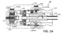
図1、2Aおよび3Aを参照すると、プローブ110は、長手方向軸128に沿って延びるシャフト125を有し、長手方向軸128は、外側スリーブ140およびその中に回転可能に配置された内側スリーブ142を含み、内側スリーブ142は、遠位セラミックカッティングスリーブ145を保持する(図3A)。シャフト125は、近位ハブ120から延在し、ここで、外側スリーブ140は、例えば、その中に成形された外側スリーブ140インサートを備えた射出成形プラスチックであり得るハブ120に固定された方法で結合される。内側スリーブ142は、モータドライブユニット105の回転モータシャフト151に結合するように構成されたドライブカップリング150、より具体的には、軟組織を切断するためのウィンドウ154の反対側152aおよび152bに鋭いカッティングエッジを有するセラミック材料で製造される回転可能なカッティングスリーブ145である。モータドライブ105は、セラミックカッターに動作可能に結合されて、1000rpmから20,000rpmの範囲の速度でカッティングスリーブを回転させる。図3Bを参照すると、カッティングスリーブ145はまた、ウィンドウ154に対向する表面にRF電極155を保持することが分かる。カッティングスリーブ145は、回転し、外側スリーブ140の歯付き開口またはウィンドウ158(図3A)で組織を剪断する。図1に示されるタイプのプローブは、本参照によりその全体が本明細書に組み込まれる、「関節鏡装置および方法」と題された2017年1月31日に出願された同時係属および共有特許出願第15/421,264号(代理人整理番号:41879-714.201)にさらに詳細に記載されている。
1, 2A and 3A, the probe 110 has a
図1に示されるように、プローブ110は、ハンドピース104への取り外し可能な結合のために2つの方向で示されている。より具体的には、ハブ120は、「UP」で示される上向き方向および「DN」で示される下向き方向でハンドピース104に結合され得る。っこで、方向は、互いに180°反対である。医師が組織にアクセスするためにハンドピースを360°操作する必要なしに、カッティングスリーブ145を標的組織と全方向にインターフェースできるようにするために、作業端112をハンドピース104に対して上向きまたは下向きに向けるために上向きおよび下向きの向きが必要であることが理解され得る。
As shown in FIG. 1, the probe 110 is shown in two orientations for removable coupling to the
図1を参照すると、ハンドル104は、電気ケーブル160によって、モータドライブユニット105を制御するコントローラ165に動作可能に結合されていることが分かる。ハンドル104上のアクチュエータボタン166a、166bまたは166cを使用して、セラミックカッティングスリーブ145の様々な回転モードなどの動作モードを選択することができる。1つの変形例では、ジョイスティック168を前後に動かして、セラミックカッティングスリーブ145の回転速度を調整することができる。カッターの回転速度は、連続的に調整可能であるか、または最大20,000rpmまで増分的に調整可能である。液晶画面170は、カッティングスリーブRPM、動作モードなどなどの動作パラメータを表示するためにハンドピースに提供される。
With reference to FIG. 1, it can be seen that the
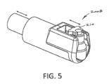
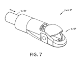
図1を参照すると、システム100およびハンドピース104は、様々な異なる機能および手順のために設計することができる様々な使い捨てプローブと共に使用するように適合されていることが分かる。例えば、図4は、セラミックカッティングスリーブ205が外側スリーブ206から遠位に延在し、カッティングスリーブが骨を切断するためのバリエッジ208を有することを除いて、図3Aおよび3Bのプローブ110の作動端112と同様のプローブ作動端200Aの異なる変形例を示している。図4のプローブは、「関節鏡装置および方法」と題された2016年9月20日に出願された共同係属中の共有特許出願第15/271,184号(代理人整理番号:41879-728.201)により詳細に説明されている。図5は、「関節鏡装置および方法」と題された2017年1月19日に出願された同時係属中の共有特許出願第15/410,723号(代理人整理番号:41879-713.201)に詳細に記載されているタイプのプローブにおける往復電極210を備えたプローブ作動端200Bの異なる変形例を示す。別の例では、図6は、「関節鏡装置および方法」と題された2017年3月9日に出願された同時係属中の共有特許出願第15/454,342号(代理人整理番号:41879-715.201)により詳細に説明されたタイプのプローブにおける伸長後退式フック電極210を備えたプローブ作動端200Cの更なる変形例を示す。さらに別の例では、図7は、「関節鏡装置および方法」と題された2017年4月10日に出願された同時係属中の共有特許出願第15/483,940号(代理人整理番号:41879-721.201)により詳細に記載されているように、半月板組織または他の組織をトリミングするために往復スリーブ218によって作動される開閉可能なジョー構造215を有するプローブタイプの作動端200Dの変形例を示す。図4-7のすべてのプローブは、図1の同じハンドピース104に結合するための図1のプローブ110のハブ120と同様のハブを有することができる。ここで、いくつかのプローブ(図5-7を参照)は、回転運動を直線運動に変換するためのハブ機構を有する。この段落で特定されたすべての特許出願は、この参照により本明細書に組み込まれる。
1, it can be seen that the system 100 and
図1はさらに、システム100が、ハンドピース104内の流路224と連絡し、図1-3B、4、5および6のプローブ110、200A、200Bまたは200Cのいずれかと協働することができる吸引チューブ222に結合された負圧源220も含むことを示す。図1を参照すると、システム100は、図1-3B、4、5および6のプローブ110、200A、200B、または200Cのいずれかの電極構成に接続することができるRF源225を含むことも分かる。コントローラ165およびその中のマイクロプロセッサは、制御アルゴリズムとともに、任意のプローブ作動端110、200A、200Bまたは200Cのモータ駆動コンポーネントを動かすためのモータドライブ105の制御、ならびに流体および組織破片を収集リザーバ230に吸引することができる負圧源220およびRF源225および負圧源220の制御を含む、すべての機能を操作および制御するために提供される。
Figure 1 further shows that the system 100 also includes a negative pressure source 220 coupled to an aspiration tube 222 that communicates with a flow path 224 in the
システム100およびハンドピース104の上記の説明から理解できるように、コントローラ165およびコントローラアルゴリズムは、システム機能を提供するために多くのタスクを実行および自動化するように構成する必要がある。第1の態様では、コントローラアルゴリズムがデバイスの識別に必要であり、その結果、図1および図4-7の異なるプローブタイプ110、200A、200B、200Cまたは200Dのいずれかが、ハンドピース104に結合されたとき、コントローラ165は、プローブタイプを認識し、次に、特定のプローブに必要とされるように、モータドライブ105、RF源225および負圧源220を操作するためのアルゴリズムを選択する。第2の態様では、コントローラは、プローブがハンドピースに対して上向きまたは下向きのどちらの向きでハンドピース104に結合されているかを識別するアルゴリズムで構成され、各向きは、動作アルゴリズムの異なるサブセットを必要とする。別の態様では、コントローラは、プローブタイプごとに別個の制御アルゴリズムを有し、一部のプローブは回転可能なカッターを有し、他のプローブは往復電極またはジョー構造を有する。別の態様では、すべてではないにしてもほとんどのプローブ110、200A、200B、200Cおよび200D(図1、4-7)は、モータ駆動コンポーネントが、作業端内に特定の方向で停止されるデフォルトの「停止」位置を必要とする。例えば、電極155を備えた回転可能なカッター145は、電極を、図3Bに示されるようなデフォルト位置で、外側スリーブウィンドウ158内の中心に置く必要がある。次に、これらのシステム、アルゴリズム、および使用方法のいくつかについて説明する。
As can be seen from the above description of the system 100 and
図1、2Aおよび2Bに示されるように、ハンドピース104は、プローブ110のハブ120を受容する受容通路122に隣接するハンドピース104の遠位領域に第1のホール効果センサー240を保持することが分かる。図2Aは、「UP」で示された上向き状態の図1のプローブ110および作業端112に対応する。図2Bは、「DN」で示された下向き状態の図1のプローブ110および作業端112に対応する。ハンドピース104は、プローブ110の回転可能なドライブカップリング150に隣接する第2のホール効果センサー245を保持する。プローブ110は、ホール効果センサー240、245と相互作用して、(i)ハンドピースに結合されたプローブのタイプの識別、(ii)ハンドピース104に対するプローブハブ120の上方または下方の向き、および(iii)回転または往復運動するモータ駆動部品の位置を決定することができる回転駆動カラー150の回転速度および速度を含むコントローラアルゴリズムと協力して複数の制御機能を提供する、後述する複数の磁石を保持する。
1, 2A and 2B, the
図2Aおよび2Bの断面図は、プローブ110のハブ120が、その表面部分に第1および第2の磁石250aおよび250bを保持することを示している。ハンドピース104のホールセンサー240は、プローブハブ120が上向き(図1および2A)または下向き(図1および2B)でハンドピース104に結合されている場合、磁石250aまたは250bのいずれかと軸方向に整列している。上で概説した一態様では、磁石250aおよび250bとホールセンサー240の組み合わせを使用して、プローブタイプを識別することができる。例えば、製品ポートフォリオは、図1、4-7に示されるような2から10またはそれ以上のタイプのプローブを有し得る。そのような各プローブタイプは、特定の異なる磁場強度を有する磁石250a、250bを保持することができる。次に、ホールセンサー240およびコントローラアルゴリズムを適合させて、プローブ内の特定の磁石の磁場強度を読み取ることができ、これは、特定のプローブタイプに対応する磁場強度のライブラリと比較することができる。次に、ホール識別信号を生成するか、さもなければコントローラ165に提供して、識別されたプローブを動作させるためのコントローラアルゴリズムを選択することができ、これは、プローブタイプに必要とされ得るモータドライブ105、負圧源220および/またはRF源225を動作させるためのパラメータを含み得る。図1、2A、および2Bに示されるように、プローブハブ120は、磁石250a、250bの北(N)および南(S)極がプローブ軸128に対して反転される、上向きおよび下向きの向きでハンドピース104に結合され得る。したがって、ホールセンサー240および関連するアルゴリズムは、プローブタイプを識別するために、極性に関係なく磁場強度を探す。
2A and 2B show that the
図1、2A、2B、3Aおよび3Bでは、ハブ120の長手方向軸128に対して北(N)極および南(S)極の異なる向きを有する第1および第2の磁石250aおよび250bもまた、ハブ120および作業端112の上向きUPまたは下向きDNの向きを識別するために使用される。使用中、上記のように、医師は、自分の好みおよび標的組織に基づいて、作業端112が上向きまたは下向きになるように、プローブ110をハンドピースの受容通路122に結合することができる。作業端112の外側スリーブ104のウィンドウ158内のカッティングスリーブ145の回転を停止するように適合されたコントローラアルゴリズムは、ハンドピースおよびホールセンサー240に対するカッティングスリーブ145の方向または回転が180°異なるために、作業端が上向きか下向きかを「学習」する必要があることが理解できる。ホールセンサー240は、コントローラアルゴリズムとともに、磁石250aまたは250bのいずれかの北(N)または南(S)極が上向きであり、ホールセンサー240に近接しているかどうかを感知することによって、上向きまたは下向きDNを決定することができる。
1, 2A, 2B, 3A and 3B, first and second magnets 250a and 250b having different orientations of north (N) and south (S) poles relative to the
本発明の別の態様では、プローブ110(図1)および他のプローブにおいて、図1、3A、および3Bの作動端112の回転カッター145などの作動端のモータ駆動コンポーネントは、外側スリーブ140の切り欠き開口またはウィンドウ158に対して選択された回転位置で停止する必要がある。他のプローブタイプは、上記のような往復スリーブまたはジョー構造を有し得、これも図7のジョー構造および図5、6の軸方向移動電極などの、選択された位置での移動コンポーネントの移動を停止するためのコントローラアルゴリズムを必要とする。すべてのプローブにおいて、モータドライブ105は、回転するドライブカップリング150に結合し、したがって、ドライブカップリング150の回転位置を感知することを使用して、作動端におけるモータ駆動コンポーネントの方向を決定することができる。より具体的には、図1、2Aおよび2Bにおいて、ドライブカップリング150は、第3および第4の磁石255aまたは255bを保持し、磁石255aまたは255bの北極(N)および南極(S)は、プローブ軸128に対して反転されている。したがって、ホールセンサー245は、各磁石が回転するとホールセンサーを通過することを感知し、それによって、その各回転で2回(各磁石255a、255bに対して1回)、ドライブカップリング150の正確な回転位置を決定する。その後、クロックを使用するコントローラタコメータアルゴリズムは、ドライブカップリング150、例えば、図3Aのカッティングスリーブ145のRPMを決定し、任意選択で表示することができる。
In another aspect of the invention, in probe 110 (FIG. 1) and other probes, the motor-driven components at the working end, such as the
本発明の別の態様では、ホールセンサー245および磁石255aおよび255b(図1および2A)は、動作端のモータ駆動コンポーネント、例えば、事前に選択された回転位置にある図1、3A、および3Bのカッティングスリーブ145の回転を停止するためのコントローラアルゴリズムのセットで使用される。図3Aでは、内側スリーブ142と、カッティングスリーブ145およびその中のウィンドウ154の「第1の側」が停止し、外側スリーブ140のウィンドウ158の中央に配置されていることが分かる。図3Aのカッティングスリーブ145およびウィンドウ154の静止位置は、プローブを通る最大の流体流出を可能にするために、作業スペースの洗浄またはフラッシングに使用することができる。
In another aspect of the invention, the
図3Bは、内側スリーブ142と、外側スリーブ140のウィンドウ158の中心線の周りに配置されたカッティングスリーブ145の「第2の側」とを示す。図3Bのカッティングスリーブ145の静止位置または停止位置は、RF電極155を使用して組織を切除または凝固させるために必要である。外側スリーブ140は、典型的にはリターン電極260を含むので、電極155が外側スリーブウィンドウ158の中心線に沿って維持されることが重要である。図3Bの電極155の位置は、本明細書では「中心線のデフォルト位置」と呼ばれる。カッティングスリーブ145および電極155が、外側スリーブ140のウィンドウ158のエッジ262aまたは262bに近くなるように回転された場合、RF電流は、電極155と260との間でアーク放電し、潜在的に、プローブを無効にする短絡を引き起こす可能性がある。したがって、次に説明する堅牢で信頼性の高い停止メカニズムが必要である。
3B shows the
図1、図2Aおよび2Bに示されるように、コントローラ165は、ドライブカップリング150の回転位置を常にリアルタイムで決定することができ、それによって、セラミックカッティングスリーブ145および電極155の角度または回転位置を決定することができる。ホールセンサー245は、ドライブカップリング150内の磁石255aまたは255bが電極155を中心線のデフォルト位置から離れて回転させるので、コントローラアルゴリズムは、中心線のデフォルト位置から離れた電極155の回転角度をさらに計算することができる。各磁石には指定された既知の強度があり、アルゴリズムはルックアップテーブルを使用して、デフォルト位置からの回転角度に対応するフィールド強度を一覧表示できる。したがって、磁石255aまたは255bの回転位置に応答するホール信号が、中心線のデフォルト位置の既知のピーク値から指定された量だけ低下する場合、それは、電極155がウィンドウ158の中心から離れて移動したことを意味する。一変形例では、電極155が、電極へのRFエネルギー供給中に中心線位置から選択された回転角度を移動する場合、アルゴリズムは、RF電流を即座にオフにし、ハンドピース104および/またはコントローラコンソール(図示せず)の画面上のLCD画面170上の警告などの聴覚的および/または視覚的信号によって医師に警告する。したがって、RF電流供給の終了は、電極155と外側スリーブ電極260との間の電気アークの電位を防止する。
1, 2A and 2B, the controller 165 can constantly determine the rotational position of the
使用中、電極155が図3Bに示される位置にあるとき、医師は、組織を切除または凝固させるために、エネルギーを与えられた電極を組織上で動かし得ることを理解することができる。そのような使用中に、カッティングスリーブ145および電極155は、電極155をデフォルトの中心線位置から不注意に回転させる組織に係合または引っ掛かることができる。したがって、システムは、本明細書で「アクティブ電極監視」アルゴリズムと呼ばれるコントローラアルゴリズムを提供し、コントローラは、切除モードおよび凝固モードの両方でRFエネルギー供給中にホールセンサー245によって生成された位置信号を継続的に監視して、電極155および内側スリーブ142は中心線位置から外れているかどうかを決定する。別の変形例では、コントローラアルゴリズムは、次に、モータドライブ105を再アクティブ化して、電極155が中心線位置から外れている場合に、内側スリーブ142および電極155をデフォルトの中心線位置スリーブに戻すように構成することができる。別の変形例では、コントローラアルゴリズムは、RF電極155がデフォルトの中心線位置に戻されたときに、RF電極155に再び自動的にRF電流を供給するように構成することができる。あるいは、コントローラ165は、RF電極155が中心線位置に戻されたときに、RF電極155へのRF電流の供給を手動で再開することを医師に要求することができる。本発明の一態様では、ドライブカップリング150、つまり磁石255aおよび255bは、長手方向軸128に対して所定の角度関係で内側スリーブ142およびカッティングスリーブ145に取り付けられ、その結果、ホールセンサーは、磁石255a、255bに応答する信号を生成し、プローブタイプ内のすべてのプローブで同じであるため、コントローラアルゴリズムが正しく機能する。
In use, when the electrode 155 is in the position shown in FIG. 3B, the physician can understand that the energized electrode may be moved over tissue to ablate or coagulate the tissue. During such use, the cutting
ここで、作動端112のモータ駆動コンポーネントの動きを停止するための停止機構またはアルゴリズムに目を向ける。図8は、停止メカニズムのアルゴリズムおよびステップを概略的に示している。一変形例では、図8に示すように、本発明に対応する停止機構は、(i)発電制動方法およびアルゴリズムを使用して、内部スリーブ142およびカッティングスリーブ145(図1、3Aおよび3B)の回転を初期位置で停止し、その後(ii)二次チェックアルゴリズムは、発電制動アルゴリズムで達成された初期停止位置をチェックするために使用され、必要に応じて、停止アルゴリズムは、モータドライブ105を再活性化して、カッティングスリーブ145および電極155を中心線位置内に、または目標の中心線デフォルト位置の0°から5°以内に配置するために必要な程度に内側スリーブ142およびドライブカップリング150の回転をわずかに逆転(または前進)させることができる。発電制動については、以下にさらに説明する。図8は、カッティングスリーブの回転速度を制御し、カッティングスリーブ145をデフォルトの中心線位置で停止させるためのコントローラアルゴリズムの様々な態様を概略的に示している。
We now turn to the stopping mechanism or algorithm for stopping the movement of the motor-driven components of the working
図8を参照すると、コントローラ165が、「設定速度」で図1、3Aおよび3Bのプローブ110を操作していることが理解できる。この設定速度は、PID制御の一方向の連続回転モードであり得るか、またはモータドライブ105がカッティングスリーブ145を一方向に回転させ、次いでその技術分野において既知のように回転を逆転させる振動モードであり得る。1,000RPMから20,000RPMなどのより高い回転速度では、停止アルゴリズムを適用するために、ドライブカップリング150内の磁石255aまたは255bの位置を示す信号をホールセンサー245から取得することは実用的または実行可能ではない。図8に示されるように、医師がアクチュエータボタンまたはフットペダルの作動を解放することによってプローブ110による切断を停止すると、モータドライブ105への電流がオフになる。その後、コントローラアルゴリズムは、ホールセンサー245を使用して、より遅いRPMに到達するまで、駆動カップリング150および内部スリーブ142の回転の減速を監視する。減速期間は10ミリ秒から1秒であり得、典型的には約100ミリ秒である。本明細書で「検索速度」と呼ばれる適切なより遅いRPMに達すると(図8を参照)、コントローラ165は、モータドライブ105を再起動して、駆動カップリングを10RPMから1,000RPMの範囲(1つの変形例では、50RPMから250RPMの間である)低速で回転させる。PIDコントローラが選択した検索速度でRPMを安定させることができるように、50ミリ秒から500ミリ秒の範囲の初期「検索遅延」期間が提供される。その後、コントローラアルゴリズムは、磁石強度のホール位置信号を監視し、磁石パラメータが所定の閾値に達したとき、例えば、電極155およびドライブカップリング150の回転位置が3Bの中心線のデフォルト位置に対応するとき、制御アルゴリズムは、発電制動を適用して、モータ駆動シャフト151、駆動カップリング150、およびプローブのモータ駆動コンポーネントの回転を即座に停止する。図8はさらに、コントローラが、制動および停止ステップの後に磁石/ドライブカップリング150の位置をチェックできることを示している。ホール位置信号が、モータ駆動コンポーネントが目標のデフォルト位置から外れていることを示す場合、モータドライブ105を再起動してモータ駆動コンポーネントを移動させ、その後、上記のようにブレーキを再度かけることができる。
8, it can be seen that the controller 165 operates the probe 110 of FIGS. 1, 3A and 3B at a "set speed". This set speed can be a PID controlled continuous rotation mode in one direction, or an oscillating mode in which the motor drive 105 rotates the cutting
図8に概略的に示されるような発電制動は、通常、目標停止位置の最大約0°-15°の変動でドライブカップリング150の回転を停止することができるが、これは、異なるタイプの組織が切断され、カッティングスリーブ145の回転を妨げる場合、およびモータドライブが非アクティブ化されたときに、医師が組織インターフェースからカッティングスリーブを完全に外したかどうかによっても、異なり得る。したがって、発電制動だけでは、デフォルト位置または停止位置が目的の変動内にあることを保証できない場合がある。
Dynamic braking, as shown diagrammatically in FIG. 8, can typically stop rotation of the
背景として、発電制動の概念は、以下の文献に記載されている:https://www.ab.com/support/abdrives/documentation/techpapers/RegenOverview01.pdfおよびhttp://literature.rockwellautomation.com/idc/groups/literature/documents/wp/drives-wp004_-en-p.pdf。基本的に、発電制動システムは、回生電気エネルギーを熱エネルギーに変換する電力抵抗を供給するAC PWMドライブのDCバス上にチョッパートランジスタを提供する。熱エネルギーは地域の環境に放散される。このプロセスは一般に、チョッパートランジスタと関連する制御およびチョッパーモジュールと呼ばれるコンポーネントと発電制動抵抗器と呼ばれる電力抵抗器を備えた発電制動と呼ばれる。発電制動抵抗器を備えたチョッパーモジュールのアセンブリ全体は、発電制動モジュールと呼ばれることもある。発電制動抵抗器により、その回路の寄生インダクタンスに蓄積された磁気エネルギーを、チョッパートランジスタのターンオフ中に安全に放散させることができる。 By way of background, the concept of dynamic braking is described in the following publications: https://www.ab.com/support/abdrives/documentation/techpapers/RegenOverview01.pdf and http://literature.rockwellautomation.com/idc/groups/literature/documents/wp/drives-wp004_en-p.pdf. Essentially, a dynamic braking system provides a chopper transistor on the DC bus of an AC PWM drive that feeds a power resistor that converts the regenerative electrical energy into thermal energy. The thermal energy is dissipated to the local environment. This process is commonly referred to as dynamic braking, with the chopper transistor and associated control and components called a chopper module and a power resistor called a dynamic braking resistor. The entire assembly of a chopper module with a dynamic braking resistor is sometimes referred to as a dynamic braking module. The dynamic braking resistor allows magnetic energy stored in the parasitic inductance of its circuit to be safely dissipated during the turn-off of the chopper transistor.
負荷が減速するにつれて、適用できるブレーキトルクの量が動的に変化するため、この方法は発電制動と呼ばれる。言い換えれば、ブレーキエネルギーは回転質量の運動エネルギーの関数であり、それが減少するにつれて、ブレーキ能力も減少する。したがって、回転が速いほど、または慣性が大きいほど、ブレーキをかけるのは難しくなるが、遅くなると、収穫逓減の法則にぶつかり、ある時点でブレーキ力がなくなる。 This method is called dynamic braking because the amount of braking torque you can apply changes dynamically as the load decelerates. In other words, braking energy is a function of the kinetic energy of the rotating mass, and as that decreases, so does your braking ability. So the faster it spins, or the more inertia it has, the harder it is to brake, but as you slow down, you run into the law of diminishing returns and at some point there's no braking power left.
本発明の別の態様では、上記の位置決めアルゴリズムのコンポーネントである停止機構の精度を高めるための方法が開発された。単回使用プローブの各磁石は、指定された強度とわずかに異なる場合があることがわかっている。上記のように、位置決めアルゴリズムは、ホール効果センサー245を使用して、ドライブカップリング150が回転するときに磁石255aおよび255bの磁場強度を継続的に監視し、アルゴリズムは、磁場強度に基づいて磁石およびドライブカップリングの回転位置を決定する。磁石がホールセンサーを通過して回転すると、電界強度が上下するす。したがって、磁石がセンサー245に隣接している場合、ピークホール信号から離れる回転の程度に正確に対応する電界強度のライブラリをアルゴリズムが有することが重要である。このため、位置決めアルゴリズムの最初のステップは、コントローラが磁石255aおよび255bの実際の磁場強度を学習することを可能にする「学習」ステップを含む。ここで、磁石255aおよび255bの実際の磁場強度は、指定された強度とは異なる場合がある。新しい単回使用プローブ110(図1)がハンドピース104に結合された後、およびモータドライブ105の作動後、位置決めアルゴリズムは、ドライブカップリングを少なくとも180°、より頻繁には少なくとも360°回転させる。この間に、ホールセンサー245は、特定のプローブの磁石255aおよび255bの磁場強度を定量化する。次に、位置決めアルゴリズムは、最大および最小のホール信号(北極と南極に対応)を保存し、磁石がホールセンサーに隣接している場合に、ホールの最小-最大信号位置から離れるさまざまな回転角度に対応する電界強度のライブラリを較正する。
In another aspect of the invention, a method was developed to increase the accuracy of the stopping mechanism, a component of the positioning algorithm described above. It has been found that each magnet in a single-use probe may vary slightly from the specified strength. As described above, the positioning algorithm uses the
一般に、学習アルゴリズムに関連する使用方法は、ハンドピースにモータドライブ、コントローラ、およびハンドピースへの取り外し可能な結合のために構成された近位ハブを備えたプローブを提供することを含み、モータドライブは、ハブ内の回転するドライブカップリングに結合するように構成され、ドライブカップリングは、北極と南極が前記軸に対して異なる位置にある第1および第2の磁石を保持し、ハブをハンドピースに結合し、モータドライブを作動させてドライブカップリングと磁石を少なくとも180°回転させ、ハンドピースセンサーを使用して各磁石の強度を検出し、検出された磁石の強度を使用して、回転中の磁石のさまざまな強度を検出するセンサーに応答する位置決めアルゴリズムの較正を行い、それにより、ドライブカップリング150の回転位置を計算する際の精度を高める。
In general, a method of use associated with the learning algorithm includes providing a handpiece with a motor drive, a controller, and a probe with a proximal hub configured for removably coupling to the handpiece, the motor drive configured to couple to a rotating drive coupling in the hub, the drive coupling holding first and second magnets with north and south poles at different positions relative to said axis, coupling the hub to the handpiece, actuating the motor drive to rotate the drive coupling and magnets at least 180°, detecting the strength of each magnet using a handpiece sensor, and using the detected magnet strengths to calibrate a positioning algorithm responsive to the sensor detecting the varying strengths of the magnets during rotation, thereby increasing accuracy in calculating the rotational position of the
本発明の別の態様は、図1および図3Bの作動端112などの、電極を備えたプローブ作動端を使用する拡張された使用方法に関する。上記のように、位置決めアルゴリズムを使用して、図3Bのデフォルトの中心線位置で電極155の回転を停止する。追加の「わずかな振動」アルゴリズムを使用して、電極155へのRF電流、特に組織切除のためのRF切断波形と同時にモータドライブ105を作動させる。したがって、わずかな振動は、振動するRF切除の形態を提供する。わずかな振動アルゴリズムは、電極155を一方向に所定の回転度まで回転させ、これは、コントローラアルゴリズムがホール位置信号から決定する。次に、ホール位置信号が電極のデフォルトの中心線位置から離れた反対方向に所定の回転角が達成されたことを示すまでに、アルゴリズムは、モータドライブの方向を逆にして反対方向に回転させる。所定の角運動の程度は、外側スリーブウィンドウの寸法に適した任意の適切な回転であり得、一変形形態では、中心線のデフォルト位置から離れる各方向に1°から30°である。多くの場合、所定の角運動の程度は、中心線のデフォルトから離れた各方向で5°から15°である。わずかな振動アルゴリズムは、適切なPID制御のモータシャフト速度を使用することができ、1つの変形例では、モータシャフト速度は50RPM~5,000RPMであり、多くの場合、100RPM~1,000RPMである。別の言い方をすれば、発振周波数は20Hzから2,000Hzで、通常は40Hzから400Hzである。
Another aspect of the invention relates to an expanded method of use using a probe working end with an electrode, such as the working
わずかな振動アルゴリズムの上記の説明は、図3Bの回転するカッティングスリーブ145上の電極155を参照して提供されるが、図6の作動端200Cに示されるような往復電極212をわずかな振動で作動させることを理解すべきである。換言すれば、図6のフック形状電極212には、20Hz~2000Hzの範囲、通常は40Hz~400Hzの範囲の振動周波数を提供することができる。
The above description of the slight vibration algorithm is provided with reference to the electrode 155 on the
図9Aおよび9Bは、往復電極210を有する図5の作業断200Bに対応するプローブハブ120’の長手方向の断面図である。図9Aおよび9Bには、ハンドピース104およびホール効果センサー240および245は、異なるタイプのプローブに対してハンドピース104に変化がないので、もちろん上記と同じである。図9Aおよび9Bのプローブハブ120’は、図2Aおよび2Bのハブ120と非常に類似している。ここで、第1および第2の識別/配向磁石250aおよび250bは同じである。第3および第4の回転位置磁石255aおよび255bも同じであり、ドライブカップリング150’によって保持される。図9Aおよび9Bのプローブハブ120’は、ドライブカップリング150が、内側スリーブ142’に動作可能に結合されたカム機構で回転して、回転運動を直線運動に変換して、図5の作動端200B内の電極210を往復させるという点でのみ異なる。回転運動を直線運動に変換するための同様のハブが、図6および7の作動端200Cおよび200Dに提供される。作動端Cおよび200Dはそれぞれ、作業端に往復運動コンポーネント(212、218)を持っている。
9A and 9B are longitudinal cross-sectional views of the probe hub 120' corresponding to the working end 200B of FIG. 5 with the
図10、11A-11Cには、細長いシャフトアセンブリ405に結合された近位ハブ402を有する管状カッターを含む図1、3A、および3Bのものと幾分類似している関節鏡シェーバーまたは切除プローブ400の別の変形例が示されている。シャフトアセンブリは、軸418に沿って作動端420まで延びる外側スリーブ410および同心内側スリーブ415を備える。ハブ402はまた、内側スリーブ415を回転させ、ウィンドウが閉じた位置やウィンドウが開いた位置などの選択された回転位置で内側スリーブ415を停止するための前の実施形態で説明したような特徴を有するコントローラおよびコントローラアルゴリズムによって動作するモータドライブおよびハンドピースに結合するように適合される。作業端420はまた、組織に係合して切除するために内側スリーブウィンドウ425と協働する外側スリーブウィンドウ422を有する。
10, 11A-11C show another variation of an arthroscopic shaver or
図10、11A-11Cに示された変形例では、シャフトアセンブリ405は、外側スリーブ410が、外側ウィンドウ422が配置される誘電体またはハウジング440を含む遠位端部分を有するという点で異なる。一変形例では、ハブ402から延びる外側スリーブ410の内側部分426bおよび近位部分426aは、ステンレス鋼などの薄い壁の導電性金属管428を備える。以下にさらに説明するように、金属管の近位部分または内側部分は、図10の430に示される電極として機能する。典型的な変形例では、誘電体ハウジング440は、セラミック材料、ガラス材料、ポリマー材料、またはそれらの組み合わせを含む。いくつかの変形例では、誘電体ハウジング440は、誘電体ハウジング440の下または部分的に周囲に延びる金属外管428の金属支持部分442内に搭載することができる。
10, 11A-11C, the shaft assembly 405 differs in that the
図11Aは、外側ウィンドウ422が内側スリーブ415から分離された外側スリーブ410の作動端436を示している。通路またはボア444が、同心の内側スリーブ415が回転して配置される誘電体ハウジング440および外側スリーブ410を通って延びることが分かる。
FIG. 11A shows the working end 436 of the
図11Bは、第1の位置にある図11Aの外側スリーブ410から分離された内側スリーブ415の作動端438を示す。第1の位置では、内側スリーブウィンドウ425が上向きになっている。図11Cは、内側スリーブウィンドウ425が下を向くように180°回転した同じ内側スリーブ415を示している。図11Bおよび11Cに示されるように、内側スリーブ415は、ステンレス鋼などの導電性材料の薄壁金属管を含み、これは、450で示される電極として機能することができる。したがって、内側ウィンドウ425を保持する内側スリーブ415の作動端438は、誘電体ハウジング440のボア444に密接に回転フィットするように構成された電極450を含み、その結果、オプションの歯を備えた内側ウィンドウエッジ456、およびエッジ458外側スリーブウィンドウは、以下にさらに説明するように、機械的または電気外科的に組織を剪断または切除するためのはさみのように機能する。図11Aおよび11Bに示されるように、内側スリーブ415は、熱収縮チューブまたはパリレンコーティングなどの絶縁ポリマーの薄層470であり、内側スリーブ415の外面を金属外スリーブ428の内面から電気的に絶縁する。
11B shows the working
本発明の別の態様では、図10および11Cに示されるように、内側スリーブウィンドウ425に対向する内側スリーブ415の裏側472は、内側スリーブ415が外側スリーブ410に対して回転してウィンドウが閉じられる位置にあるときに、そこを通って流体が流出するために提供される少なくとも1つの開口475を有する(図1を参照)。
In another aspect of the invention, as shown in Figures 10 and 11C, the backside 472 of the
図12は、ファントムビューでの外側スリーブ415を備えた誘電体またはセラミックハウジング440を示している。誘電体ハウジング440は、外側スリーブ410の遠位端477が誘電体ハウジング440を取り囲み、支持する凹部476を有することが分かる。ウィンドウ422の周りの誘電体ハウジングの壁の厚さは、約0.05インチ~0.20インチの範囲であり得る。
Figure 12 shows the dielectric or
図13は、作業端420のウィンドウが閉じた位置を示す図10-11Cのプローブの作動端420の長手方向の断面図である。内側スリーブ415の作業端438は、外側スリーブおよび誘電体ハウジング440のボア444と厳密な公差にあり、その結果、内側スリーブ415の回転は、内側スリーブおよび外側スリーブのウィンドウ422、425によって係合される組織を剪断できることが分かる。図13はさらに、セラミックハウジング440の下に延びる金属外部スリーブ428の支持部分442を示している。図13はまた、内側スリーブ415を取り囲んで内側スリーブを金属外側スリーブ428から電気的に絶縁する薄い絶縁層470を示している。
Figure 13 is a longitudinal cross-sectional view of the working
図13に示されるように、RF源480は、電気外科機能を提供するために、内側スリーブ410および外側スリーブ415の両方に結合されている。RF源480は、平均で少なくとも100W、または少なくとも200W、または少なくとも300Wまたは少なくとも400Wを供給して、図10に示されるようなウィンドウ閉鎖位置において内部スリーブ415の露出した外面または外面482上でプラズマの点火を可能にすることができる。通常、ウィンドウが閉じた位置にある内側スリーブ415の外面482は、15mm2未満、10mm2未満、または8mm2未満である。したがって、動作中、第1の動作モードでの外側スリーブ410の内側スリーブ415の回転は、ウィンドウ422および425によって係合される組織を機械的に剪断することができ、または第2の動作モードで組織を電気外科的に切除できることが理解され得る。すなわち、内側スリーブは、組織を回転させて同時に剪断することができ、同時にRF源480は、カッティング電流を内側スリーブに供給して、組織を剪断するプラズマを生成するか、または組織を剪断するのを助けることができる内側スリーブウィンドウ425のエッジにエネルギーを与える。
As shown in Fig. 13, an
一般に、本発明に対応する切除プローブまたは治療装置は、外側スリーブ410と、外側スリーブのボア444に同軸に受け入れられた回転可能な内側スリーブ415とを有するシャフトアセンブリ405を含み、内側スリーブおよび外側スリーブは、それぞれの内側および外側カッティングウィンドウ422および425を有し、その遠位部分に協働するカッティングエッジを有し、カッティングウィンドウ422を保持する外側スリーブの遠位部分は、誘電体ハウジング440を備え、内側カッティングウィンドウ425を保持する内側スリーブ415の遠位作動端438は、RF電極450を備える。
In general, an ablation probe or treatment device according to the present invention includes a shaft assembly 405 having an
この変形例では、誘電体ハウジングの誘電体材料は、セラミック、ガラス、およびポリマーのうちの少なくとも1つを含むことができる。例えば、セラミック材料は、アルミナ、ジルコニア、窒化ケイ素、イットリア安定化ジルコニア、マグネシア安定化ジルコニア、セリア安定化ジルコニア、およびジルコニア強化アルミナからなる群から選択することができる。 In this variation, the dielectric material of the dielectric housing can include at least one of a ceramic, a glass, and a polymer. For example, the ceramic material can be selected from the group consisting of alumina, zirconia, silicon nitride, yttria-stabilized zirconia, magnesia-stabilized zirconia, ceria-stabilized zirconia, and zirconia-toughened alumina.
図10のプローブは、高周波(RF)源480が電極に結合された状態で、第1および第2の回転方向に内側スリーブ内で選択的に回転するように構成されたモータを備える。さらに、コントローラは、モータおよびRF源に動作可能に結合されている。
The probe of FIG. 10 includes a motor configured to selectively rotate within the inner sleeve in first and second rotational directions with a radio frequency (RF)
一般に、コントローラは、モータを停止して、内側スリーブをウィンドウが閉じた位置またはウィンドウが開いた位置に配置するためのアルゴリズムを含む。さらに、コントローラは、(i)組織を機械的に切断するために通電されていないRF電極でモータが内側スリーブを回転または振動させる第1のモード;(ii)組織を電気外科的に切断するためにRF電極が通電された状態でモータが内側スリーブを回転または振動させる第2のモード;(iii)内側スリーブが、ウィンドウが閉じた位置で静止しており、RF電極がエネルギーを与えられて組織に凝固または切除エネルギーを適用する第3のモード;(iv)内側スリーブが、ウィンドウが開いた位置で静止しており、組織に凝固または切除エネルギーを適用するためにRF電極が通電される第4のモードで選択的に動作するように構成される。。 In general, the controller includes an algorithm for stopping the motor and placing the inner sleeve in a window closed position or a window open position. Additionally, the controller is configured to selectively operate in (i) a first mode in which the motor rotates or vibrates the inner sleeve with the RF electrode not energized to mechanically cut tissue; (ii) a second mode in which the motor rotates or vibrates the inner sleeve with the RF electrode energized to electrosurgically cut tissue; (iii) a third mode in which the inner sleeve is stationary in the window closed position and the RF electrode is energized to apply coagulation or ablation energy to tissue; and (iv) a fourth mode in which the inner sleeve is stationary in the window open position and the RF electrode is energized to apply coagulation or ablation energy to tissue. .
図14は、外側スリーブ505と、外側スリーブのボア512内で回転するように適合された内側スリーブ510とを含む、作業端500の別の変形例を示している。この変形例では、外側スリーブ505は、図10および図11Aの前の変形例のように、セラミックハウジングのない導電性金属管を含む。この変形例では、導電性内側スリーブ510を導電性外側スリーブから分離する誘電体コンポーネントは、内側スリーブ510の遠位端522上の誘電体コーティングまたは層520と、内側スリーブ510の近位部分および内側部分上のポリマーコーティング528とを含む。内側スリーブの遠位端522の誘電体材料520は、鋭いエッジ532で構成されて、外側スリーブウィンドウ535のエッジ534と協働するための鋭くて耐久性のある鋭いエッジ532を提供することができる、セラミックまたはガラス材料であり得る。他のすべての点において、図14の変形例は、図10-13に記載された変形例と同じ方法で動作することができる。
Figure 14 shows another variation of the working end 500, including an outer sleeve 505 and an
図15は、図11Bおよび11Cと同様のモータ駆動の回転する内側スリーブの作動端の斜視図である。ここでは、骨を研磨するための研磨切断機能または鋭いエッジ536が備えられている。したがって、別の動作モードは、通常、RF電流が電極表面に印加されることなく、内部スリーブを高速で回転させて、研磨機能536を使用して骨を切断または研磨することであり得る。いくつかの方法では、硬組織を研磨したり焼灼したりしながら、RF電流を電極表面に印加することができる。 Figure 15 is a perspective view of the working end of a motor-driven rotating inner sleeve similar to Figures 11B and 11C, but now equipped with an abrasive cutting feature or sharp edge 536 for abrading bone. Thus, another mode of operation may be to rotate the inner sleeve at high speeds to cut or abrade bone using the abrasive feature 536, typically without RF current being applied to the electrode surface. In some methods, RF current may be applied to the electrode surface while abrading or cauterizing hard tissue.
図16は、図10の変形例と同様の原理の下で動作する作動端540の別の変形例を示している。ここで、外側スリーブ545は、遠位誘電体またはセラミックハウジング550を保持し、カッティングエッジ556を備えた同心の内側スリーブ555は、誘電体ハウジング550内の外側スリーブウィンドウ560に対して移動するように適合される。しかし、この変形例では、内側スリーブ555は、回転ではなく往復運動するようになっている。他の点では、内側スリーブ555のカッティングエッジ556は、誘電体ハウジング550のボア564にぴったりと合うように構成され、その結果、内側スリーブカッティングエッジ556および外側スリーブウィンドウ560のエッジ568は、ウィンドウ560によって係合された組織を剪断する。前の実施形態で説明したように、RF源480は、電気外科的切断を可能にするために、内側および外側スリーブ545および555の両方に動作可能に結合されている。したがって、使用中、内側スリーブの往復運動は、上記のように機械的または電気外科的に組織を切除することができる。
16 shows another variation of the working
図17は、図14および図15のそれと同様である作業端580の別の変形例を示している。この変形例では、外側スリーブ585は、その中にウィンドウ588を備えた薄壁導電性金属を含む。内側スリーブ590は、絶縁性ポリマー592に包まれた金属スリーブと、電気絶縁体として機能し、カッティングエッジ596を提供する遠位セラミックまたはガラス部分595とを備える。この変形例では、内側スリーブ590は、再び往復運動するように適合されている。この場合も、RF源480は、電気外科的切断を可能にするために、内側スリーブ585および外側スリーブ585および590の両方に動作可能に結合されている。使用中、内側スリーブの往復運動は、したがって、上記のように機械的または電気外科的に組織を切除することができる。
17 shows another variation of the working end 580 that is similar to that of FIGS. 14 and 15. In this variation, the outer sleeve 585 comprises a thin-walled conductive metal with a window 588 therein. The inner sleeve 590 comprises a metal sleeve encased in an insulating polymer 592 and a distal ceramic or glass portion 595 that acts as an electrical insulator and provides a cutting edge 596. In this variation, the inner sleeve 590 is again adapted to reciprocate. Again, the
図18、19Aおよび19Bに示されるように、本発明による関節鏡シェーバーまたは切除プローブの別の変形例は、図18に示されるように、作動端608を有する細長いシャフトアセンブリ605に結合された近位ハブ602を有する管状カッター600を含む。シャフトアセンブリ605は、第1または内側スリーブ610および第2または外側スリーブ615を備える。スリーブ105および110は、ハブ602から作動端608まで長手方向軸618上で同心または同軸に延びる。近位ハブ602は、図10に示されるタイプのハブと類似または同一であってもよく、典型的には、内側スリーブ610を回転させ、選択された回転位置(例えば、図19Aに示されるようなウィンドウが閉じられた位置または図19Bに示されるようなウィンドウ開放位置)で内側スリーブ610を停止するための前の実施形態に記載された特徴を有するコントローラおよびコントローラアルゴリズムによって動作されるハンドピースおよびモータドライブへの結合に適合される。作業端608は、組織に係合して切除するために、第2または外側スリーブウィンドウ625と整列して回転し、または整列から外れて回転する第1または内側スリーブウィンドウ622を有する。図18、19A、19Bの実施形態では、内側スリーブ610および外側スリーブ615の両方が導電性であり、典型的には金属の全体または一部が形成され、一般に、市販の関節鏡シェーバーと同様の作業端を提供するように構成される。
As shown in Figures 18, 19A and 19B, another variation of an arthroscopic shaver or resection probe according to the present invention includes a
図19Aおよび19Bに示されるように、細長いシャフトアセンブリ605および作業端608は、内側スリーブ610が、内部管腔652を有する薄壁導電性スリーブ632と、その遠位端またはその近くの薄壁導電性スリーブの壁に配されたアクティブ電極640を保持する誘電体インサート635を含むという点で、本明細書に記載した前の実施形態とは異なる。電気リード644(図19A)は、RF源650から、内側スリーブ610の内部管腔652を通って(図19B)、アクティブ電極640まで延びる。
19A and 19B, the
一変形形態では、リターン電極655は、細長いシャフトアセンブリ605上に、またはその一体部分として形成され得る。場合によっては、外側スリーブ615は、内側スリーブ610から絶縁されてもよく、図19Aおよび19Bに示されるように、外側スリーブの外面は、リターン電極を提供し得る。他の例では、内側スリーブ610および外側スリーブ615は、電気的に結合され得、リターン電極655を備えることができる。
In one variation, the return electrode 655 may be formed on or as an integral part of the
図19Aを参照すると、1つまたは複数の開口658が、アクティブ電極640に隣接して、または部分的にその下に形成され得る。そのような開口658は、外側スリーブウィンドウ625に対する内側スリーブウィンドウ622の回転方向に関係なく、連続的にプローブの作動端608を通って生理食塩水が流れることを可能にするように適合される。すなわち、図19Aに示すように、内側スリーブ610を回転させて、外側スリーブウィンドウ625と内側スリーブウィンドウ622の両方を閉じる場合でも、開口658は、以下に説明するように、負圧が内部管腔の近位端に加えられると、生理食塩水が内部スリーブ610内の内部管腔652に流入することを可能にする。
19A, one or more openings 658 may be formed adjacent to or partially below the
したがって、プローブは、RF電流を供給せずに機械的に組織を切断するために、内側スリーブ610が外側スリーブ615内で回転して、内側スリーブウィンドウ622および外側スリーブウィンドウ625を互いに通過させて回転させる第1の動作モードで使用することができる。任意選択で、内側スリーブウィンドウは、少なくともその周辺の軸方向に配向された部分に形成された切断歯または他の切除要素623で構成され得る。そのような切除要素は、外側ウィンドウ625の周囲に形成された周辺表面626に対して剪断することができる。
The probe can thus be used in a first mode of operation in which the
第2の動作モードでは、内側スリーブ610は、RF源650が活性化された状態で回転して、アクティブ電極640にエネルギーを与え、組織切断を強化することができる。すなわち、内側および外側のウィンドウ622および625の回転によって引き起こされる組織の機械的剪断は継続し、RF組織の適用、典型的には切断または切除電流の適用によって強化される。他の例では、RF凝固電流は、同時の機械的切除および電気外科的凝固を提供するために、内側および外側のウィンドウ622および625を回転させながら、電極640を通して印加され得る。
In a second mode of operation, the
第3の動作モードでは、コントローラおよびコントローラアルゴリズムを使用して、図19Aのウィンドウが閉じた位置で内側スリーブ610の回転を停止することができ、電極640は、同時の機械的剪断なしに組織を凝固または切除するために活性化され得る。組織の切除は、RF切断または切除電流を適用することによって実施することができ、凝固は、RF凝固電流を適用することによって実施することができる。
In a third mode of operation, the controller and controller algorithms can be used to stop rotation of the
本発明の特定の実施形態は上で詳細に説明されてきたが、この説明は単に例示の目的であり、本発明の上記の説明は網羅的ではないことが理解される。本発明の特定の特徴は、他の図面ではなくいくつかの図面に示され、これは便宜上のものであり、任意の特徴を本発明に従って別の特徴と組み合わせることができる。当業者には、いくつかの変形および代替が明らかになるであろう。そのような代替および変形は、特許請求の範囲内に含まれることが意図されている。従属項に提示されている特定の特徴を組み合わせて、本発明の範囲に含めることができる。本発明はまた、従属項が他の独立項を参照して複数の従属項フォーマットで代替的に書かれたかのように実施形態を包含する。 Although certain embodiments of the present invention have been described in detail above, it will be understood that this description is for illustrative purposes only and that the above description of the present invention is not exhaustive. Certain features of the present invention are shown in some drawings and not in others, and this is for convenience only, and any feature may be combined with another feature in accordance with the present invention. Certain variations and alternatives will become apparent to those skilled in the art. Such alternatives and variations are intended to be included within the scope of the claims. Certain features presented in the dependent claims may be combined and included within the scope of the present invention. The present invention also encompasses embodiments as if the dependent claims were written in the multiple dependent claim format in the alternative with reference to other independent claims.
他の変形は、本発明の精神の範囲内である。したがって、本発明は様々な修正および代替構造の影響を受けやすいが、その特定の例示された実施形態が図面に示され、上で詳細に説明されている。しかしながら、本発明を開示された特定の形態に限定する意図はないことを理解されたいが、その意図は、添付の特許請求の範囲で定義されるように、発明の精神および範囲内であるすべての変形、代替構造、および同等物を含む。 Other variations are within the spirit of the invention. Accordingly, while the invention is susceptible to various modifications and alternative constructions, certain illustrated embodiments thereof are shown in the drawings and have been described above in detail. It is to be understood, however, that there is no intention to limit the invention to the particular forms disclosed, but the intention is to include all modifications, alternative constructions, and equivalents within the spirit and scope of the invention as defined by the appended claims.
本発明を説明する文脈での(特に、以下の特許請求の範囲の文脈での)用語「a」および「an」および「the」および同様の指示対象の使用は、本書に別段の記載がない限り、または文脈によって明確に矛盾しない限り、単数形および単数形の両方を含むと解釈されるべきである。「含む」、「有する」、「備える」、および「含有する」という用語は、特に明記しない限り、制限のない用語(すなわち、「含むが、これらに限定されない」を意味する)として解釈されるべきである。「接続された」という用語は、何かが介在している場合でも、部分的または全体的に含まれている、接続されている、または結合されていると解釈される。本明細書の値の範囲の列挙は、本明細書に別段の記載がない限り、範囲内にある各個別の値を個別に参照する簡略化された方法として役立つことを単に意図し、各個別の値は、本明細書に個別に記載されているかのように仕様に組み込まれる。本明細書に記載されるすべての方法は、本明細書に別段の指示がない限り、または文脈によって明らかに矛盾しない限り、任意の適切な順序で実行することができる。本明細書で提供されるありとあらゆる例、または例示的な言語(例えば、「など」)の使用は、単に本発明の実施形態をよりよく明らかにすることを意図し、別段の請求がない限り、本発明の範囲に制限を課さない。明細書のいかなる文言も、クレームされていない要素が本発明の実施に不可欠であることを示すと解釈されるべきではない。 Use of the terms "a" and "an" and "the" and similar referents in the context of describing the present invention (particularly in the context of the claims below) should be construed to include both the singular and the singular, unless otherwise stated herein or clearly contradicted by context. The terms "comprise", "have", "comprise", and "contain" should be construed as open-ended terms (i.e., meaning "including, but not limited to"), unless otherwise stated. The term "connected" is to be construed as partially or wholly contained, connected, or coupled, even if there is something intervening. The recitation of ranges of values herein is merely intended to serve as a shorthand method of individually referring to each individual value falling within the range, unless otherwise stated herein, and each individual value is incorporated into the specification as if it were individually set forth herein. All methods described herein can be performed in any suitable order, unless otherwise stated herein or clearly contradicted by context. Any and all examples provided herein, or the use of exemplary language (e.g., "etc.") are intended merely to better illuminate embodiments of the invention and do not impose limitations on the scope of the invention unless otherwise claimed. No language in the specification should be construed as indicating any non-claimed element as essential to the practice of the invention.
本発明の好ましい実施形態は、本発明を実施するために発明者に知られている最良のモードを含めて、本明細書に記載されている。それらの好ましい実施形態の変形は、前述の説明を読むと、当業者に明らかになり得る。本発明者らは、当業者がそのような変形を適切に使用することを期待し、本発明者らは、本明細書に具体的に記載されている以外の方法で本発明を実施することを意図している。したがって、本発明は、適用法によって許可されるように、本明細書に添付された特許請求の範囲に列挙された主題のすべての変形および同等物を含む。さらに、そのすべての可能な変形における上記の要素の任意の組み合わせは、本明細書に別段の指示がない限り、または文脈によって明らかに矛盾しない限り、本発明に含まれる。 Preferred embodiments of the invention are described herein, including the best mode known to the inventors for carrying out the invention. Variations of those preferred embodiments may become apparent to those of ordinary skill in the art upon reading the foregoing description. The inventors expect that such variations will be utilized by those of ordinary skill in the art as appropriate, and the inventors do not intend to practice the invention otherwise than as specifically described herein. Accordingly, this invention includes all modifications and equivalents of the subject matter recited in the claims appended hereto as permitted by applicable law. Moreover, any combination of the above-described elements in all possible variations thereof is included in the invention unless otherwise indicated herein or clearly contradicted by context.
本明細書で引用される刊行物、特許出願、および特許を含むすべての参考文献は、各参考文献が参照により組み込まれることが個別にかつ具体的に示され、その全体が本明細書に記載される場合と同程度に参照により本明細書に組み込まれる。 All references cited in this specification, including publications, patent applications, and patents, are hereby incorporated by reference to the same extent as if each reference was individually and specifically indicated to be incorporated by reference and was set forth in its entirety herein.
602 近位ハブ
605 シャフトアセンブリ
608 作業端
610 内側スリーブ
615 外側スリーブ
618 長手方向軸
622 内側スリーブウィンドウ
625 外側スリーブウィンドウ
635 誘電体インサート
640 アクティブ電極
650 RF源
655 リターン電極
602
Claims (13)
長手方向ボアと、遠位端に外側カッティングウィンドウと、を有する外側スリーブと、
前記外側スリーブの前記長手方向ボア内に回転的に配置された内側スリーブであって、遠位端、近位端、長手方向通路、および該内側スリーブの遠位端近くの前記内側スリーブの円筒形壁を通して配置された内側カッティングウィンドウを有する、内側スリーブと、
を備え、
前記内側カッティングウィンドウを前記外側カッティングウィンドウを越えて回転させ、それらのカッティングウィンドウが互いに通過するときに該カッティングウィンドウを通して受け取られた組織を切除するように、前記内側スリーブは、モータドライブユニットに結合するように構成されたドライブカップリングに結合され、前記外側スリーブに対して前記内側スリーブを回転させ、
前記内側スリーブは、薄壁導電性スリーブ部材である第1の部分と、前記内側スリーブの前記遠位端又はその近傍において前記薄壁導電性スリーブ部材の壁内に配置された誘電体インサートである第2の部分とを備え、前記誘電体インサートは、前記内側カッティングウィンドウとは反対側の前記内側スリーブの前記円筒形壁の側に配置され、前記誘電体インサートは、前記誘電体インサートがアクティブ電極を前記薄壁導電性スリーブ部材から電気的に絶縁するように、前記誘電体インサートによって囲まれた前記アクティブ電極を保持し、
前記アクティブ電極は、前記内側スリーブの前記円筒形壁の曲率に一致する曲面を有し、
前記アクティブ電極は、前記内側スリーブが前記外側スリーブ内で回転するときに、前記外側カッティングウィンドウ内に選択的に配置することができ、
前記薄壁導電性スリーブ部材及び前記外側スリーブは、金属で形成され、
前記アクティブ電極と、前記アクティブ電極に隣接する前記内側スリーブの前記円筒形壁のうち少なくとも1つとを通して配置された開口を有する、関節鏡視下カッティングプローブ。 1. An arthroscopic cutting probe, comprising:
an outer sleeve having a longitudinal bore and an outer cutting window at a distal end;
an inner sleeve rotationally disposed within the longitudinal bore of the outer sleeve, the inner sleeve having a distal end, a proximal end, a longitudinal passageway, and an inner cutting window disposed through a cylindrical wall of the inner sleeve near its distal end;
Equipped with
the inner sleeve is coupled to a drive coupling configured to couple to a motor drive unit and rotate the inner sleeve relative to the outer sleeve to rotate the inner cutting window past the outer cutting window and resect tissue received therethrough as the cutting windows pass one another;
the inner sleeve comprises a first portion being a thin walled conductive sleeve member and a second portion being a dielectric insert disposed within a wall of the thin walled conductive sleeve member at or near the distal end of the inner sleeve, the dielectric insert being disposed on a side of the cylindrical wall of the inner sleeve opposite the inner cutting window, the dielectric insert holding the active electrode surrounded by the dielectric insert such that the dielectric insert electrically insulates the active electrode from the thin walled conductive sleeve member;
the active electrode has a curved surface that matches the curvature of the cylindrical wall of the inner sleeve;
the active electrode may be selectively positioned within the outer cutting window as the inner sleeve rotates within the outer sleeve;
the thin walled conductive sleeve member and the outer sleeve are formed of metal;
an arthroscopic cutting probe having an opening disposed through the active electrode and through at least one of the cylindrical walls of the inner sleeve adjacent the active electrode;
請求項1から請求項3及び請求項5から請求項9の何れか1項に記載の関節鏡視下カッティングプローブと、
前記内側スリーブに結合されて、前記外側スリーブに対して前記内側スリーブを回転させるように構成されたモータドライブユニットと、
前記アクティブ電極およびリターン電極に結合されるように構成された無線周波数(RF)電源と、
前記モータドライブユニットと前記RF電源を制御するように構成されたコントローラと、
を備え、
前記外側スリーブは、前記リターン電極を含む金属体を備える、関節鏡視下切断システム。 1. An arthroscopic cutting system comprising:
An arthroscopic cutting probe according to any one of claims 1 to 3 and claims 5 to 9 ;
a motor drive unit coupled to the inner sleeve and configured to rotate the inner sleeve relative to the outer sleeve;
a radio frequency (RF) power source configured to be coupled to the active electrode and the return electrode;
a controller configured to control the motor drive unit and the RF power source;
Equipped with
The outer sleeve comprises a metallic body containing the return electrode .
前記モータドライブユニットが作動して前記内側カッティングウィンドウを、前記外側カッティングウィンドウを越えて回転させ、RF供給は作動しない、機械的組織切断の第1のモード、
機械的および電気外科的組織切断の組み合わせのための第2のモードであって、前記モータドライブユニットを作動させて前記内側カッティングウィンドウを、前記外側カッティングウィンドウを越えて回転させ、前記RF電源を作動させて切断電流、切除、または凝固電流を前記アクティブ電極に供給する、第2のモード、および
前記モータドライブユニットが前記アクティブ電極を前記外側カッティングウィンドウ内で静止状態に保ち、前記RF電源を作動させて、カッティング電流、切除電流、または凝固電流を前記アクティブ電極に供給する、第3のモード
のそれぞれにおいて前記モータドライブユニットおよび前記RF電源を動作させるように構成される、請求項10に記載の関節鏡視下切断システム。 The controller:
a first mode of mechanical tissue cutting, in which the motor drive unit is activated to rotate the inner cutting window past the outer cutting window and RF delivery is not activated;
11. The arthroscopic cutting system of claim 10, configured to operate the motor drive unit and the RF power source in each of: a second mode for combined mechanical and electrosurgical tissue cutting, where the motor drive unit is actuated to rotate the inner cutting window past the outer cutting window and the RF power source is actuated to supply a cutting, ablation, or coagulation current to the active electrode; and a third mode, where the motor drive unit holds the active electrode stationary within the outer cutting window and actuates the RF power source to supply a cutting, ablation, or coagulation current to the active electrode.
Priority Applications (1)
| Application Number | Priority Date | Filing Date | Title |
|---|---|---|---|
| JP2024007375A JP7738688B2 (en) | 2018-04-30 | 2024-01-22 | Arthroscopic devices and methods |
Applications Claiming Priority (5)
| Application Number | Priority Date | Filing Date | Title |
|---|---|---|---|
| US201862664692P | 2018-04-30 | 2018-04-30 | |
| US62/664,692 | 2018-04-30 | ||
| US16/397,742 | 2019-04-29 | ||
| US16/397,742 US11617596B2 (en) | 2018-04-30 | 2019-04-29 | Arthroscopic devices and methods |
| PCT/US2019/029927 WO2019213090A1 (en) | 2018-04-30 | 2019-04-30 | Arthroscopic devices and methods |
Related Child Applications (1)
| Application Number | Title | Priority Date | Filing Date |
|---|---|---|---|
| JP2024007375A Division JP7738688B2 (en) | 2018-04-30 | 2024-01-22 | Arthroscopic devices and methods |
Publications (2)
| Publication Number | Publication Date |
|---|---|
| JP2021522884A JP2021522884A (en) | 2021-09-02 |
| JP7530833B2 true JP7530833B2 (en) | 2024-08-08 |
Family
ID=68291920
Family Applications (2)
| Application Number | Title | Priority Date | Filing Date |
|---|---|---|---|
| JP2020560789A Active JP7530833B2 (en) | 2018-04-30 | 2019-04-30 | Arthroscopic devices and methods |
| JP2024007375A Active JP7738688B2 (en) | 2018-04-30 | 2024-01-22 | Arthroscopic devices and methods |
Family Applications After (1)
| Application Number | Title | Priority Date | Filing Date |
|---|---|---|---|
| JP2024007375A Active JP7738688B2 (en) | 2018-04-30 | 2024-01-22 | Arthroscopic devices and methods |
Country Status (5)
| Country | Link |
|---|---|
| US (2) | US11617596B2 (en) |
| EP (1) | EP3787472B1 (en) |
| JP (2) | JP7530833B2 (en) |
| CN (1) | CN112367901A (en) |
| WO (1) | WO2019213090A1 (en) |
Families Citing this family (12)
| Publication number | Priority date | Publication date | Assignee | Title |
|---|---|---|---|---|
| US11617596B2 (en) * | 2018-04-30 | 2023-04-04 | RELIGN Corporation | Arthroscopic devices and methods |
| US11504181B2 (en) | 2019-07-01 | 2022-11-22 | RELIGN Corporation | Arthroscopic devices and methods |
| US11497551B2 (en) | 2019-11-26 | 2022-11-15 | RELIGN Corporation | Arthroscopic devices and methods |
| EP3915605A1 (en) * | 2020-05-27 | 2021-12-01 | Medela Holding AG | Transport device for bodily fluid |
| EP3939527B1 (en) * | 2020-07-15 | 2025-03-12 | Relign Corporation | Arthroscopic devices |
| GB2598332B (en) | 2020-08-26 | 2024-07-24 | Gyrus Medical Ltd | Electrosurgical instrument |
| CN113116285A (en) * | 2021-04-19 | 2021-07-16 | 北京天星博迈迪医疗器械有限公司 | Arthroscopic surgery system and host |
| GB2614052B (en) * | 2021-12-15 | 2024-07-24 | Gyrus Medical Ltd | Electrosurgical instrument |
| GB2622409B (en) * | 2022-09-14 | 2025-01-08 | Gyrus Medical Ltd | Rotary shaver arrangement for a surgical instrument |
| CN116763421B (en) * | 2023-08-18 | 2023-11-24 | 西南石油大学 | A medical planing blade with hemostatic function |
| US20250134544A1 (en) * | 2023-10-27 | 2025-05-01 | Arthrex, Inc | Surgical cutting blade and control for multi-application procedures |
| CN117297709B (en) * | 2023-11-30 | 2024-02-02 | 苏州新云医疗设备有限公司 | Tissue removal instrument |
Citations (6)
| Publication number | Priority date | Publication date | Assignee | Title |
|---|---|---|---|---|
| US20040102772A1 (en) | 2000-03-09 | 2004-05-27 | Baxter Jeffrey W. | Apparatus and method for minimally invasive surgery using rotational cutting tool |
| JP2005144142A (en) | 2003-11-19 | 2005-06-09 | Jon C Garito | Electrosurgical electrode for treating tissue |
| US20130296847A1 (en) | 2011-11-04 | 2013-11-07 | Arqos Surgical, Inc. | Tissue extraction devices and methods |
| US20160346036A1 (en) | 2015-04-21 | 2016-12-01 | RELIGN Corporation | Arthroscopic devices and methods |
| WO2017136414A1 (en) | 2016-02-04 | 2017-08-10 | RELIGN Corporation | Arthroscopic devices and methods |
| WO2017185097A1 (en) | 2016-04-22 | 2017-10-26 | RELIGN Corporation | Arthroscopic devices and methods |
Family Cites Families (26)
| Publication number | Priority date | Publication date | Assignee | Title |
|---|---|---|---|---|
| US6770071B2 (en) | 1995-06-07 | 2004-08-03 | Arthrocare Corporation | Bladed electrosurgical probe |
| ATE357882T1 (en) * | 2002-02-12 | 2007-04-15 | Oratec Interventions Inc | RADIO FREQUENCY ABLATION DEVICE FOR ARTHROSCOPY |
| US6610059B1 (en) | 2002-02-25 | 2003-08-26 | Hs West Investments Llc | Endoscopic instruments and methods for improved bubble aspiration at a surgical site |
| US8221404B2 (en) | 2005-03-24 | 2012-07-17 | Arqos Surgical, Inc. | Electrosurgical ablation apparatus and method |
| US8323280B2 (en) | 2011-03-21 | 2012-12-04 | Arqos Surgical, Inc. | Medical ablation system and method of use |
| US9204918B2 (en) | 2011-09-28 | 2015-12-08 | RELIGN Corporation | Medical ablation system and method of use |
| US9247983B2 (en) | 2011-11-14 | 2016-02-02 | Arqos Surgical, Inc. | Medical instrument and method of use |
| US8702702B1 (en) | 2012-10-05 | 2014-04-22 | Gyrus Acmi, Inc. | Surgical cutting instrument with electromechanical cutting |
| JP6814746B2 (en) | 2015-04-29 | 2021-01-20 | シーラス テクノロジーズ リミテッド | Medical ablation device and usage |
| US9603656B1 (en) | 2015-10-23 | 2017-03-28 | RELIGN Corporation | Arthroscopic devices and methods |
| US9585675B1 (en) | 2015-10-23 | 2017-03-07 | RELIGN Corporation | Arthroscopic devices and methods |
| US10052149B2 (en) | 2016-01-20 | 2018-08-21 | RELIGN Corporation | Arthroscopic devices and methods |
| WO2017156335A1 (en) | 2016-03-10 | 2017-09-14 | RELIGN Corporation | Arthroscopic devices and methods |
| WO2017156343A1 (en) | 2016-03-11 | 2017-09-14 | RELIGN Corporation | Arthroscopic devices and methods |
| US10595889B2 (en) | 2016-04-11 | 2020-03-24 | RELIGN Corporation | Arthroscopic devices and methods |
| US11172953B2 (en) | 2016-04-11 | 2021-11-16 | RELIGN Corporation | Arthroscopic devices and methods |
| EP3478197A4 (en) | 2016-07-01 | 2020-04-29 | Relign Corporation | ARTHROSCOPY DEVICES. |
| US20180161088A1 (en) | 2016-07-25 | 2018-06-14 | RELIGN Corporation | Arthroscopic devices and methods |
| US10028767B2 (en) | 2016-09-20 | 2018-07-24 | RELIGN Corporation | Arthroscopic devices and methods |
| US9855675B1 (en) | 2016-09-20 | 2018-01-02 | RELIGN Corporation | Arthroscopic devices and methods |
| US11426231B2 (en) | 2017-01-11 | 2022-08-30 | RELIGN Corporation | Arthroscopic devices and methods |
| US11065023B2 (en) | 2017-03-17 | 2021-07-20 | RELIGN Corporation | Arthroscopic devices and methods |
| US11207092B2 (en) | 2017-03-27 | 2021-12-28 | RELIGN Corporation | Arthroscopic devices and methods |
| US20190008538A1 (en) | 2017-05-09 | 2019-01-10 | RELIGN Corporation | Arthroscopic devices and methods |
| CN111629645A (en) | 2017-08-28 | 2020-09-04 | 锐凌公司 | Arthroscopic devices and methods |
| US11617596B2 (en) | 2018-04-30 | 2023-04-04 | RELIGN Corporation | Arthroscopic devices and methods |
-
2019
- 2019-04-29 US US16/397,742 patent/US11617596B2/en active Active
- 2019-04-30 CN CN201980044011.0A patent/CN112367901A/en active Pending
- 2019-04-30 JP JP2020560789A patent/JP7530833B2/en active Active
- 2019-04-30 EP EP19797009.8A patent/EP3787472B1/en active Active
- 2019-04-30 WO PCT/US2019/029927 patent/WO2019213090A1/en not_active Ceased
-
2023
- 2023-01-16 US US18/097,363 patent/US20230200832A1/en active Pending
-
2024
- 2024-01-22 JP JP2024007375A patent/JP7738688B2/en active Active
Patent Citations (6)
| Publication number | Priority date | Publication date | Assignee | Title |
|---|---|---|---|---|
| US20040102772A1 (en) | 2000-03-09 | 2004-05-27 | Baxter Jeffrey W. | Apparatus and method for minimally invasive surgery using rotational cutting tool |
| JP2005144142A (en) | 2003-11-19 | 2005-06-09 | Jon C Garito | Electrosurgical electrode for treating tissue |
| US20130296847A1 (en) | 2011-11-04 | 2013-11-07 | Arqos Surgical, Inc. | Tissue extraction devices and methods |
| US20160346036A1 (en) | 2015-04-21 | 2016-12-01 | RELIGN Corporation | Arthroscopic devices and methods |
| WO2017136414A1 (en) | 2016-02-04 | 2017-08-10 | RELIGN Corporation | Arthroscopic devices and methods |
| WO2017185097A1 (en) | 2016-04-22 | 2017-10-26 | RELIGN Corporation | Arthroscopic devices and methods |
Also Published As
| Publication number | Publication date |
|---|---|
| JP2024045279A (en) | 2024-04-02 |
| US11617596B2 (en) | 2023-04-04 |
| CN112367901A (en) | 2021-02-12 |
| WO2019213090A1 (en) | 2019-11-07 |
| US20190328417A1 (en) | 2019-10-31 |
| EP3787472A4 (en) | 2021-12-08 |
| JP2021522884A (en) | 2021-09-02 |
| EP3787472B1 (en) | 2025-10-29 |
| US20230200832A1 (en) | 2023-06-29 |
| JP7738688B2 (en) | 2025-09-12 |
| EP3787472A1 (en) | 2021-03-10 |
Similar Documents
| Publication | Publication Date | Title |
|---|---|---|
| JP7738688B2 (en) | Arthroscopic devices and methods | |
| US11793563B2 (en) | Arthroscopic devices and methods | |
| US12178497B2 (en) | Arthroscopic devices and methods | |
| US11937843B2 (en) | Arthroscopic devices and methods | |
| US11883053B2 (en) | Arthroscopic devices and methods | |
| US11712291B2 (en) | Arthroscopic devices and methods | |
| US11672593B2 (en) | Arthroscopic devices and methods | |
| US11723681B2 (en) | Arthroscopic devices and methods | |
| JP7425754B2 (en) | Arthroscopy device and method | |
| US20210093371A1 (en) | Medical devices and method |
Legal Events
| Date | Code | Title | Description |
|---|---|---|---|
| A621 | Written request for application examination |
Free format text: JAPANESE INTERMEDIATE CODE: A621 Effective date: 20220413 |
|
| A977 | Report on retrieval |
Free format text: JAPANESE INTERMEDIATE CODE: A971007 Effective date: 20230317 |
|
| A131 | Notification of reasons for refusal |
Free format text: JAPANESE INTERMEDIATE CODE: A131 Effective date: 20230404 |
|
| RD03 | Notification of appointment of power of attorney |
Free format text: JAPANESE INTERMEDIATE CODE: A7423 Effective date: 20230421 |
|
| A521 | Request for written amendment filed |
Free format text: JAPANESE INTERMEDIATE CODE: A523 Effective date: 20230630 |
|
| RD04 | Notification of resignation of power of attorney |
Free format text: JAPANESE INTERMEDIATE CODE: A7424 Effective date: 20230623 |
|
| A02 | Decision of refusal |
Free format text: JAPANESE INTERMEDIATE CODE: A02 Effective date: 20230926 |
|
| A521 | Request for written amendment filed |
Free format text: JAPANESE INTERMEDIATE CODE: A523 Effective date: 20240122 |
|
| A911 | Transfer to examiner for re-examination before appeal (zenchi) |
Free format text: JAPANESE INTERMEDIATE CODE: A911 Effective date: 20240405 |
|
| TRDD | Decision of grant or rejection written | ||
| A01 | Written decision to grant a patent or to grant a registration (utility model) |
Free format text: JAPANESE INTERMEDIATE CODE: A01 Effective date: 20240709 |
|
| A61 | First payment of annual fees (during grant procedure) |
Free format text: JAPANESE INTERMEDIATE CODE: A61 Effective date: 20240729 |
|
| R150 | Certificate of patent or registration of utility model |
Ref document number: 7530833 Country of ref document: JP Free format text: JAPANESE INTERMEDIATE CODE: R150 |