JP7526558B2 - High-precision syringe with removable pump unit - Google Patents
High-precision syringe with removable pump unit Download PDFInfo
- Publication number
- JP7526558B2 JP7526558B2 JP2019129773A JP2019129773A JP7526558B2 JP 7526558 B2 JP7526558 B2 JP 7526558B2 JP 2019129773 A JP2019129773 A JP 2019129773A JP 2019129773 A JP2019129773 A JP 2019129773A JP 7526558 B2 JP7526558 B2 JP 7526558B2
- Authority
- JP
- Japan
- Prior art keywords
- plunger shaft
- syringe
- sensor
- plunger
- housing
- Prior art date
- Legal status (The legal status is an assumption and is not a legal conclusion. Google has not performed a legal analysis and makes no representation as to the accuracy of the status listed.)
- Active
Links
- 238000006073 displacement reaction Methods 0.000 claims description 29
- 238000005259 measurement Methods 0.000 claims description 12
- 238000004891 communication Methods 0.000 claims description 10
- 239000003550 marker Substances 0.000 claims description 9
- 238000012377 drug delivery Methods 0.000 claims description 8
- 239000007788 liquid Substances 0.000 claims description 8
- 238000005096 rolling process Methods 0.000 claims description 6
- 238000003825 pressing Methods 0.000 claims description 4
- 230000000881 depressing effect Effects 0.000 claims description 3
- 238000001514 detection method Methods 0.000 claims description 3
- 239000003814 drug Substances 0.000 description 27
- 229940079593 drug Drugs 0.000 description 26
- 238000005086 pumping Methods 0.000 description 14
- 229920001971 elastomer Polymers 0.000 description 9
- 239000012530 fluid Substances 0.000 description 9
- 238000000034 method Methods 0.000 description 9
- 210000003811 finger Anatomy 0.000 description 8
- 230000007246 mechanism Effects 0.000 description 8
- 230000008569 process Effects 0.000 description 7
- 210000003813 thumb Anatomy 0.000 description 7
- 235000001674 Agaricus brunnescens Nutrition 0.000 description 6
- 239000000853 adhesive Substances 0.000 description 6
- 230000001070 adhesive effect Effects 0.000 description 6
- 238000010586 diagram Methods 0.000 description 5
- 229920000642 polymer Polymers 0.000 description 5
- 230000009471 action Effects 0.000 description 4
- 230000008859 change Effects 0.000 description 4
- 210000005069 ears Anatomy 0.000 description 4
- 230000006870 function Effects 0.000 description 4
- 239000000463 material Substances 0.000 description 4
- 238000012544 monitoring process Methods 0.000 description 4
- 239000004020 conductor Substances 0.000 description 3
- 230000000694 effects Effects 0.000 description 3
- 238000002347 injection Methods 0.000 description 3
- 239000007924 injection Substances 0.000 description 3
- 239000000126 substance Substances 0.000 description 3
- 239000003990 capacitor Substances 0.000 description 2
- 239000000806 elastomer Substances 0.000 description 2
- 239000011521 glass Substances 0.000 description 2
- 230000036512 infertility Effects 0.000 description 2
- 238000001990 intravenous administration Methods 0.000 description 2
- 239000002184 metal Substances 0.000 description 2
- 238000012986 modification Methods 0.000 description 2
- 230000004048 modification Effects 0.000 description 2
- 230000003287 optical effect Effects 0.000 description 2
- -1 polypropylene Polymers 0.000 description 2
- 230000004044 response Effects 0.000 description 2
- 238000007789 sealing Methods 0.000 description 2
- 238000001228 spectrum Methods 0.000 description 2
- 239000012815 thermoplastic material Substances 0.000 description 2
- 239000004698 Polyethylene Substances 0.000 description 1
- 239000004743 Polypropylene Substances 0.000 description 1
- 238000010521 absorption reaction Methods 0.000 description 1
- 238000009825 accumulation Methods 0.000 description 1
- 230000003213 activating effect Effects 0.000 description 1
- 230000004913 activation Effects 0.000 description 1
- 230000004888 barrier function Effects 0.000 description 1
- 230000008901 benefit Effects 0.000 description 1
- 239000003638 chemical reducing agent Substances 0.000 description 1
- 239000003795 chemical substances by application Substances 0.000 description 1
- 230000002301 combined effect Effects 0.000 description 1
- 230000006835 compression Effects 0.000 description 1
- 238000007906 compression Methods 0.000 description 1
- 238000010276 construction Methods 0.000 description 1
- 238000011109 contamination Methods 0.000 description 1
- 239000002872 contrast media Substances 0.000 description 1
- 230000008878 coupling Effects 0.000 description 1
- 238000010168 coupling process Methods 0.000 description 1
- 238000005859 coupling reaction Methods 0.000 description 1
- 238000012864 cross contamination Methods 0.000 description 1
- 230000001186 cumulative effect Effects 0.000 description 1
- 238000013461 design Methods 0.000 description 1
- 238000001647 drug administration Methods 0.000 description 1
- 239000013536 elastomeric material Substances 0.000 description 1
- 238000005516 engineering process Methods 0.000 description 1
- 238000001914 filtration Methods 0.000 description 1
- 238000011900 installation process Methods 0.000 description 1
- 238000010253 intravenous injection Methods 0.000 description 1
- 238000012423 maintenance Methods 0.000 description 1
- 238000000691 measurement method Methods 0.000 description 1
- 239000007769 metal material Substances 0.000 description 1
- 239000004033 plastic Substances 0.000 description 1
- 229920003023 plastic Polymers 0.000 description 1
- 229920000573 polyethylene Polymers 0.000 description 1
- 229920001155 polypropylene Polymers 0.000 description 1
- 238000002360 preparation method Methods 0.000 description 1
- 230000009467 reduction Effects 0.000 description 1
- 239000007787 solid Substances 0.000 description 1
Images


Classifications
-
- A—HUMAN NECESSITIES
- A61—MEDICAL OR VETERINARY SCIENCE; HYGIENE
- A61M—DEVICES FOR INTRODUCING MEDIA INTO, OR ONTO, THE BODY; DEVICES FOR TRANSDUCING BODY MEDIA OR FOR TAKING MEDIA FROM THE BODY; DEVICES FOR PRODUCING OR ENDING SLEEP OR STUPOR
- A61M5/00—Devices for bringing media into the body in a subcutaneous, intra-vascular or intramuscular way; Accessories therefor, e.g. filling or cleaning devices, arm-rests
- A61M5/14—Infusion devices, e.g. infusing by gravity; Blood infusion; Accessories therefor
- A61M5/142—Pressure infusion, e.g. using pumps
- A61M5/145—Pressure infusion, e.g. using pumps using pressurised reservoirs, e.g. pressurised by means of pistons
- A61M5/1452—Pressure infusion, e.g. using pumps using pressurised reservoirs, e.g. pressurised by means of pistons pressurised by means of pistons
- A61M5/14546—Front-loading type injectors
-
- A—HUMAN NECESSITIES
- A61—MEDICAL OR VETERINARY SCIENCE; HYGIENE
- A61M—DEVICES FOR INTRODUCING MEDIA INTO, OR ONTO, THE BODY; DEVICES FOR TRANSDUCING BODY MEDIA OR FOR TAKING MEDIA FROM THE BODY; DEVICES FOR PRODUCING OR ENDING SLEEP OR STUPOR
- A61M5/00—Devices for bringing media into the body in a subcutaneous, intra-vascular or intramuscular way; Accessories therefor, e.g. filling or cleaning devices, arm-rests
- A61M5/14—Infusion devices, e.g. infusing by gravity; Blood infusion; Accessories therefor
- A61M5/142—Pressure infusion, e.g. using pumps
- A61M5/145—Pressure infusion, e.g. using pumps using pressurised reservoirs, e.g. pressurised by means of pistons
- A61M5/1452—Pressure infusion, e.g. using pumps using pressurised reservoirs, e.g. pressurised by means of pistons pressurised by means of pistons
- A61M5/1458—Means for capture of the plunger flange
-
- A—HUMAN NECESSITIES
- A61—MEDICAL OR VETERINARY SCIENCE; HYGIENE
- A61M—DEVICES FOR INTRODUCING MEDIA INTO, OR ONTO, THE BODY; DEVICES FOR TRANSDUCING BODY MEDIA OR FOR TAKING MEDIA FROM THE BODY; DEVICES FOR PRODUCING OR ENDING SLEEP OR STUPOR
- A61M5/00—Devices for bringing media into the body in a subcutaneous, intra-vascular or intramuscular way; Accessories therefor, e.g. filling or cleaning devices, arm-rests
- A61M5/178—Syringes
- A61M5/31—Details
- A61M5/315—Pistons; Piston-rods; Guiding, blocking or restricting the movement of the rod or piston; Appliances on the rod for facilitating dosing ; Dosing mechanisms
- A61M5/31533—Dosing mechanisms, i.e. setting a dose
- A61M5/31545—Setting modes for dosing
- A61M5/31548—Mechanically operated dose setting member
- A61M5/31556—Accuracy improving means
-
- A—HUMAN NECESSITIES
- A61—MEDICAL OR VETERINARY SCIENCE; HYGIENE
- A61M—DEVICES FOR INTRODUCING MEDIA INTO, OR ONTO, THE BODY; DEVICES FOR TRANSDUCING BODY MEDIA OR FOR TAKING MEDIA FROM THE BODY; DEVICES FOR PRODUCING OR ENDING SLEEP OR STUPOR
- A61M5/00—Devices for bringing media into the body in a subcutaneous, intra-vascular or intramuscular way; Accessories therefor, e.g. filling or cleaning devices, arm-rests
- A61M5/14—Infusion devices, e.g. infusing by gravity; Blood infusion; Accessories therefor
- A61M5/168—Means for controlling media flow to the body or for metering media to the body, e.g. drip meters, counters ; Monitoring media flow to the body
- A61M5/16831—Monitoring, detecting, signalling or eliminating infusion flow anomalies
-
- A—HUMAN NECESSITIES
- A61—MEDICAL OR VETERINARY SCIENCE; HYGIENE
- A61M—DEVICES FOR INTRODUCING MEDIA INTO, OR ONTO, THE BODY; DEVICES FOR TRANSDUCING BODY MEDIA OR FOR TAKING MEDIA FROM THE BODY; DEVICES FOR PRODUCING OR ENDING SLEEP OR STUPOR
- A61M5/00—Devices for bringing media into the body in a subcutaneous, intra-vascular or intramuscular way; Accessories therefor, e.g. filling or cleaning devices, arm-rests
- A61M5/178—Syringes
- A61M5/20—Automatic syringes, e.g. with automatically actuated piston rod, with automatic needle injection, filling automatically
-
- A—HUMAN NECESSITIES
- A61—MEDICAL OR VETERINARY SCIENCE; HYGIENE
- A61M—DEVICES FOR INTRODUCING MEDIA INTO, OR ONTO, THE BODY; DEVICES FOR TRANSDUCING BODY MEDIA OR FOR TAKING MEDIA FROM THE BODY; DEVICES FOR PRODUCING OR ENDING SLEEP OR STUPOR
- A61M5/00—Devices for bringing media into the body in a subcutaneous, intra-vascular or intramuscular way; Accessories therefor, e.g. filling or cleaning devices, arm-rests
- A61M5/178—Syringes
- A61M5/31—Details
- A61M5/315—Pistons; Piston-rods; Guiding, blocking or restricting the movement of the rod or piston; Appliances on the rod for facilitating dosing ; Dosing mechanisms
- A61M5/31565—Administration mechanisms, i.e. constructional features, modes of administering a dose
- A61M5/31566—Means improving security or handling thereof
- A61M5/31573—Accuracy improving means
-
- A—HUMAN NECESSITIES
- A61—MEDICAL OR VETERINARY SCIENCE; HYGIENE
- A61M—DEVICES FOR INTRODUCING MEDIA INTO, OR ONTO, THE BODY; DEVICES FOR TRANSDUCING BODY MEDIA OR FOR TAKING MEDIA FROM THE BODY; DEVICES FOR PRODUCING OR ENDING SLEEP OR STUPOR
- A61M5/00—Devices for bringing media into the body in a subcutaneous, intra-vascular or intramuscular way; Accessories therefor, e.g. filling or cleaning devices, arm-rests
- A61M5/14—Infusion devices, e.g. infusing by gravity; Blood infusion; Accessories therefor
- A61M5/142—Pressure infusion, e.g. using pumps
- A61M2005/14208—Pressure infusion, e.g. using pumps with a programmable infusion control system, characterised by the infusion program
-
- A—HUMAN NECESSITIES
- A61—MEDICAL OR VETERINARY SCIENCE; HYGIENE
- A61M—DEVICES FOR INTRODUCING MEDIA INTO, OR ONTO, THE BODY; DEVICES FOR TRANSDUCING BODY MEDIA OR FOR TAKING MEDIA FROM THE BODY; DEVICES FOR PRODUCING OR ENDING SLEEP OR STUPOR
- A61M5/00—Devices for bringing media into the body in a subcutaneous, intra-vascular or intramuscular way; Accessories therefor, e.g. filling or cleaning devices, arm-rests
- A61M5/14—Infusion devices, e.g. infusing by gravity; Blood infusion; Accessories therefor
- A61M5/142—Pressure infusion, e.g. using pumps
- A61M5/14244—Pressure infusion, e.g. using pumps adapted to be carried by the patient, e.g. portable on the body
- A61M2005/14268—Pressure infusion, e.g. using pumps adapted to be carried by the patient, e.g. portable on the body with a reusable and a disposable component
-
- A—HUMAN NECESSITIES
- A61—MEDICAL OR VETERINARY SCIENCE; HYGIENE
- A61M—DEVICES FOR INTRODUCING MEDIA INTO, OR ONTO, THE BODY; DEVICES FOR TRANSDUCING BODY MEDIA OR FOR TAKING MEDIA FROM THE BODY; DEVICES FOR PRODUCING OR ENDING SLEEP OR STUPOR
- A61M5/00—Devices for bringing media into the body in a subcutaneous, intra-vascular or intramuscular way; Accessories therefor, e.g. filling or cleaning devices, arm-rests
- A61M5/14—Infusion devices, e.g. infusing by gravity; Blood infusion; Accessories therefor
- A61M5/142—Pressure infusion, e.g. using pumps
- A61M5/145—Pressure infusion, e.g. using pumps using pressurised reservoirs, e.g. pressurised by means of pistons
- A61M2005/14506—Pressure infusion, e.g. using pumps using pressurised reservoirs, e.g. pressurised by means of pistons mechanically driven, e.g. spring or clockwork
-
- A—HUMAN NECESSITIES
- A61—MEDICAL OR VETERINARY SCIENCE; HYGIENE
- A61M—DEVICES FOR INTRODUCING MEDIA INTO, OR ONTO, THE BODY; DEVICES FOR TRANSDUCING BODY MEDIA OR FOR TAKING MEDIA FROM THE BODY; DEVICES FOR PRODUCING OR ENDING SLEEP OR STUPOR
- A61M5/00—Devices for bringing media into the body in a subcutaneous, intra-vascular or intramuscular way; Accessories therefor, e.g. filling or cleaning devices, arm-rests
- A61M5/178—Syringes
- A61M5/20—Automatic syringes, e.g. with automatically actuated piston rod, with automatic needle injection, filling automatically
- A61M2005/2006—Having specific accessories
-
- A—HUMAN NECESSITIES
- A61—MEDICAL OR VETERINARY SCIENCE; HYGIENE
- A61M—DEVICES FOR INTRODUCING MEDIA INTO, OR ONTO, THE BODY; DEVICES FOR TRANSDUCING BODY MEDIA OR FOR TAKING MEDIA FROM THE BODY; DEVICES FOR PRODUCING OR ENDING SLEEP OR STUPOR
- A61M2205/00—General characteristics of the apparatus
- A61M2205/02—General characteristics of the apparatus characterised by a particular materials
- A61M2205/0216—Materials providing elastic properties, e.g. for facilitating deformation and avoid breaking
-
- A—HUMAN NECESSITIES
- A61—MEDICAL OR VETERINARY SCIENCE; HYGIENE
- A61M—DEVICES FOR INTRODUCING MEDIA INTO, OR ONTO, THE BODY; DEVICES FOR TRANSDUCING BODY MEDIA OR FOR TAKING MEDIA FROM THE BODY; DEVICES FOR PRODUCING OR ENDING SLEEP OR STUPOR
- A61M2205/00—General characteristics of the apparatus
- A61M2205/10—General characteristics of the apparatus with powered movement mechanisms
- A61M2205/103—General characteristics of the apparatus with powered movement mechanisms rotating
-
- A—HUMAN NECESSITIES
- A61—MEDICAL OR VETERINARY SCIENCE; HYGIENE
- A61M—DEVICES FOR INTRODUCING MEDIA INTO, OR ONTO, THE BODY; DEVICES FOR TRANSDUCING BODY MEDIA OR FOR TAKING MEDIA FROM THE BODY; DEVICES FOR PRODUCING OR ENDING SLEEP OR STUPOR
- A61M2205/00—General characteristics of the apparatus
- A61M2205/18—General characteristics of the apparatus with alarm
-
- A—HUMAN NECESSITIES
- A61—MEDICAL OR VETERINARY SCIENCE; HYGIENE
- A61M—DEVICES FOR INTRODUCING MEDIA INTO, OR ONTO, THE BODY; DEVICES FOR TRANSDUCING BODY MEDIA OR FOR TAKING MEDIA FROM THE BODY; DEVICES FOR PRODUCING OR ENDING SLEEP OR STUPOR
- A61M2205/00—General characteristics of the apparatus
- A61M2205/33—Controlling, regulating or measuring
- A61M2205/3317—Electromagnetic, inductive or dielectric measuring means
-
- A—HUMAN NECESSITIES
- A61—MEDICAL OR VETERINARY SCIENCE; HYGIENE
- A61M—DEVICES FOR INTRODUCING MEDIA INTO, OR ONTO, THE BODY; DEVICES FOR TRANSDUCING BODY MEDIA OR FOR TAKING MEDIA FROM THE BODY; DEVICES FOR PRODUCING OR ENDING SLEEP OR STUPOR
- A61M2205/00—General characteristics of the apparatus
- A61M2205/33—Controlling, regulating or measuring
- A61M2205/3327—Measuring
-
- A—HUMAN NECESSITIES
- A61—MEDICAL OR VETERINARY SCIENCE; HYGIENE
- A61M—DEVICES FOR INTRODUCING MEDIA INTO, OR ONTO, THE BODY; DEVICES FOR TRANSDUCING BODY MEDIA OR FOR TAKING MEDIA FROM THE BODY; DEVICES FOR PRODUCING OR ENDING SLEEP OR STUPOR
- A61M2205/00—General characteristics of the apparatus
- A61M2205/33—Controlling, regulating or measuring
- A61M2205/3331—Pressure; Flow
- A61M2205/3334—Measuring or controlling the flow rate
-
- A—HUMAN NECESSITIES
- A61—MEDICAL OR VETERINARY SCIENCE; HYGIENE
- A61M—DEVICES FOR INTRODUCING MEDIA INTO, OR ONTO, THE BODY; DEVICES FOR TRANSDUCING BODY MEDIA OR FOR TAKING MEDIA FROM THE BODY; DEVICES FOR PRODUCING OR ENDING SLEEP OR STUPOR
- A61M2205/00—General characteristics of the apparatus
- A61M2205/33—Controlling, regulating or measuring
- A61M2205/3331—Pressure; Flow
- A61M2205/3355—Controlling downstream pump pressure
-
- A—HUMAN NECESSITIES
- A61—MEDICAL OR VETERINARY SCIENCE; HYGIENE
- A61M—DEVICES FOR INTRODUCING MEDIA INTO, OR ONTO, THE BODY; DEVICES FOR TRANSDUCING BODY MEDIA OR FOR TAKING MEDIA FROM THE BODY; DEVICES FOR PRODUCING OR ENDING SLEEP OR STUPOR
- A61M2205/00—General characteristics of the apparatus
- A61M2205/50—General characteristics of the apparatus with microprocessors or computers
- A61M2205/502—User interfaces, e.g. screens or keyboards
-
- A—HUMAN NECESSITIES
- A61—MEDICAL OR VETERINARY SCIENCE; HYGIENE
- A61M—DEVICES FOR INTRODUCING MEDIA INTO, OR ONTO, THE BODY; DEVICES FOR TRANSDUCING BODY MEDIA OR FOR TAKING MEDIA FROM THE BODY; DEVICES FOR PRODUCING OR ENDING SLEEP OR STUPOR
- A61M2205/00—General characteristics of the apparatus
- A61M2205/50—General characteristics of the apparatus with microprocessors or computers
- A61M2205/52—General characteristics of the apparatus with microprocessors or computers with memories providing a history of measured variating parameters of apparatus or patient
-
- A—HUMAN NECESSITIES
- A61—MEDICAL OR VETERINARY SCIENCE; HYGIENE
- A61M—DEVICES FOR INTRODUCING MEDIA INTO, OR ONTO, THE BODY; DEVICES FOR TRANSDUCING BODY MEDIA OR FOR TAKING MEDIA FROM THE BODY; DEVICES FOR PRODUCING OR ENDING SLEEP OR STUPOR
- A61M2205/00—General characteristics of the apparatus
- A61M2205/60—General characteristics of the apparatus with identification means
- A61M2205/6063—Optical identification systems
- A61M2205/6072—Bar codes
-
- A—HUMAN NECESSITIES
- A61—MEDICAL OR VETERINARY SCIENCE; HYGIENE
- A61M—DEVICES FOR INTRODUCING MEDIA INTO, OR ONTO, THE BODY; DEVICES FOR TRANSDUCING BODY MEDIA OR FOR TAKING MEDIA FROM THE BODY; DEVICES FOR PRODUCING OR ENDING SLEEP OR STUPOR
- A61M2205/00—General characteristics of the apparatus
- A61M2205/82—Internal energy supply devices
- A61M2205/8206—Internal energy supply devices battery-operated
-
- A—HUMAN NECESSITIES
- A61—MEDICAL OR VETERINARY SCIENCE; HYGIENE
- A61M—DEVICES FOR INTRODUCING MEDIA INTO, OR ONTO, THE BODY; DEVICES FOR TRANSDUCING BODY MEDIA OR FOR TAKING MEDIA FROM THE BODY; DEVICES FOR PRODUCING OR ENDING SLEEP OR STUPOR
- A61M5/00—Devices for bringing media into the body in a subcutaneous, intra-vascular or intramuscular way; Accessories therefor, e.g. filling or cleaning devices, arm-rests
- A61M5/14—Infusion devices, e.g. infusing by gravity; Blood infusion; Accessories therefor
- A61M5/168—Means for controlling media flow to the body or for metering media to the body, e.g. drip meters, counters ; Monitoring media flow to the body
- A61M5/16804—Flow controllers
-
- A—HUMAN NECESSITIES
- A61—MEDICAL OR VETERINARY SCIENCE; HYGIENE
- A61M—DEVICES FOR INTRODUCING MEDIA INTO, OR ONTO, THE BODY; DEVICES FOR TRANSDUCING BODY MEDIA OR FOR TAKING MEDIA FROM THE BODY; DEVICES FOR PRODUCING OR ENDING SLEEP OR STUPOR
- A61M5/00—Devices for bringing media into the body in a subcutaneous, intra-vascular or intramuscular way; Accessories therefor, e.g. filling or cleaning devices, arm-rests
- A61M5/14—Infusion devices, e.g. infusing by gravity; Blood infusion; Accessories therefor
- A61M5/168—Means for controlling media flow to the body or for metering media to the body, e.g. drip meters, counters ; Monitoring media flow to the body
- A61M5/172—Means for controlling media flow to the body or for metering media to the body, e.g. drip meters, counters ; Monitoring media flow to the body electrical or electronic
-
- A—HUMAN NECESSITIES
- A61—MEDICAL OR VETERINARY SCIENCE; HYGIENE
- A61M—DEVICES FOR INTRODUCING MEDIA INTO, OR ONTO, THE BODY; DEVICES FOR TRANSDUCING BODY MEDIA OR FOR TAKING MEDIA FROM THE BODY; DEVICES FOR PRODUCING OR ENDING SLEEP OR STUPOR
- A61M5/00—Devices for bringing media into the body in a subcutaneous, intra-vascular or intramuscular way; Accessories therefor, e.g. filling or cleaning devices, arm-rests
- A61M5/178—Syringes
- A61M5/28—Syringe ampoules or carpules, i.e. ampoules or carpules provided with a needle
- A61M5/281—Syringe ampoules or carpules, i.e. ampoules or carpules provided with a needle using emptying means to expel or eject media, e.g. pistons, deformation of the ampoule, or telescoping of the ampoule
- A61M5/283—Syringe ampoules or carpules, i.e. ampoules or carpules provided with a needle using emptying means to expel or eject media, e.g. pistons, deformation of the ampoule, or telescoping of the ampoule by telescoping of ampoules or carpules with the syringe body
Landscapes
- Health & Medical Sciences (AREA)
- Vascular Medicine (AREA)
- Engineering & Computer Science (AREA)
- Anesthesiology (AREA)
- Biomedical Technology (AREA)
- Heart & Thoracic Surgery (AREA)
- Hematology (AREA)
- Life Sciences & Earth Sciences (AREA)
- Animal Behavior & Ethology (AREA)
- General Health & Medical Sciences (AREA)
- Public Health (AREA)
- Veterinary Medicine (AREA)
- Infusion, Injection, And Reservoir Apparatuses (AREA)
Description
(関連出願の相互参照)
本願は、2018年7月13日に出願された米国仮出願第62/697,632号と、2019年1月31日に出願された米国仮出願第62/799,475号の利益を主張し、これらを共に参照により本明細書に援用する。
CROSS-REFERENCE TO RELATED APPLICATIONS
This application claims the benefit of U.S. Provisional Application No. 62/697,632, filed July 13, 2018, and U.S. Provisional Application No. 62/799,475, filed January 31, 2019, both of which are incorporated herein by reference.
本発明は、医療の目的の為に使用されるシリンジに関し、詳細には、向上した精度を提供するシリンジに関する。 The present invention relates to syringes used for medical purposes, and more particularly to syringes that provide improved precision.
医薬品又は造影剤等の薬剤を一定期間に渡って患者に投与する為のシリンジが知られている。かかるシリンジは、シリンジ筒内を摺動するプランジャを含んでいる。プランジャは、シリンジ筒の内面に密着して嵌合するピストン状の封止体を含む。このプランジャの移動により、シリンジ筒内においてプランジャ封止体とシリンジ筒の出口との間に含まれる容積が減少して、容積式のポンピング作用が提供される。 Syringes are known for administering a drug or agent, such as a contrast agent, to a patient over a period of time. Such syringes include a plunger that slides within the syringe barrel. The plunger includes a piston-like seal that fits tightly against the inner surface of the syringe barrel. Movement of the plunger reduces the volume contained within the syringe barrel between the plunger seal and the outlet of the syringe barrel, providing a positive displacement pumping action.
シリンジを使用した医薬品送出の制御は、シリンジ筒に印刷された目盛によって提供される。かかる目盛は読み取りも解釈も困難であり得、所与の投与量が必要とされる場合、医療従事者がその目盛上のシリンジの開始位置を記憶し、終了位置を計算する必要がある。 Control of drug delivery using a syringe is provided by scales printed on the syringe barrel. Such scales can be difficult to read and interpret, requiring the medical practitioner to memorize the start position of the syringe on the scale and calculate the end position when a given dose is required.
実験室で使用する為に「デジタルシリンジ」というものがあり、これを用いると、シリンジを正確に読み取るという問題の多くが解消される。かかるデジタルシリンジは、高精密ガラス管を利用出来る容量の小さい高精度シリンジと、計器を装備した操作器とを組み合わせたものであり、ユーザがこの操作器を押してプランジャを動かすと同時に、その動きが電子的に測定されてデジタル計器に表示され得る。上記シリンジプランジャは、緩み及び誤差を排除する為に操作器に取り付ける為の特別な継手を有し得、精密金属構成部品から製造され得る。かかるシリンジは、洗浄され再使用される為のものであり、コスト、滅菌性、及び薬剤の交差汚染の理由から、医療環境では実用的ではない。 For laboratory use, "digital syringes" are available that eliminate many of the problems of accurately reading syringes. These combine a small-volume, high-precision syringe that can utilize high-precision glass tubing with an instrumented actuator that allows the user to press the actuator to move the plunger, whose movement is electronically measured and displayed on the digital instrument. The syringe plunger may have special fittings to attach to the actuator to eliminate loosening and error, and may be manufactured from precision metal components. Such syringes are intended to be washed and reused, and are not practical in a medical environment for reasons of cost, sterility, and drug cross-contamination.
本発明は、医療環境において実用的であるように、従来の使い捨てポリマーシリンジ構造体と共に使用され得るデジタルシリンジを提供する。シリンジの容量の大きさ(大きいほどプランジャ位置の小さな誤差が増幅する)とポリマープランジャの可撓性及び寸法のばらつきとに関連する誤差が、モータ位置の間接的な測定やシリンジプランジャ位置の推測ではなく、シリンジプランジャ位置の直接的な測定によって吸収される。この直接的な測定によって、プランジャの移動に対するモータ、ギア列、及び送りねじの機械的公差(「累積公差」)と、プランジャの可撓性によって悪化する影響と、例えば薬剤が異なる場合やシリンジが冷蔵される場合等におけるシリンジの抵抗力及び薬剤の粘性の変動とが排除される。上記デジタルシリンジは、更なる汎用性を提供する為に、モータユニットと組み合わせられ得る。 The present invention provides a digital syringe that can be used with conventional disposable polymer syringe structures to be practical in a medical environment. Errors associated with the size of the syringe volume (the larger the volume, the more amplified small errors in plunger position) and the flexibility and dimensional variations of the polymer plunger are accommodated by a direct measurement of the syringe plunger position, rather than an indirect measurement of the motor position or an inference of the syringe plunger position. This direct measurement eliminates the mechanical tolerances of the motor, gear train, and lead screw on the plunger movement ("tolerance stackup"), the effects of the plunger flexibility that are exacerbated, and the variations in syringe resistance and drug viscosity, for example, with different drugs or when the syringe is refrigerated. The digital syringe can be combined with a motor unit to provide further versatility.
具体的には、一実施形態では、本発明は、ニードルアダプタで終端する管状の筒を有するタイプのシリンジからの、測定による液体薬剤送出の為のセンサシステムにおいて、上記管状の筒が、それに密着して嵌合する、プランジャ作動式のエラストマーピストンを含む、センサシステムであって、ハウジングにおいて、そこから1つの軸に沿って延びる上記管状の筒を取り外し可能に受けるハウジングと、上記エラストマーピストンの動きに対応して上記ハウジング内部で上記軸に沿って移動するように摺動可能に受けられるプランジャと、上記プランジャの移動を示す電子信号を提供する為に、上記ハウジングに対する上記軸に沿った上記プランジャの移動の直接的な測定を提供するように、上記ハウジングに対して固定式に取り付けられた、センサ素子を感知する電子センサと、を備えるセンサシステムを提供する。 Specifically, in one embodiment, the present invention provides a sensor system for measured liquid drug delivery from a syringe of the type having a tubular barrel terminating in a needle adapter, the tubular barrel including a plunger-actuated elastomeric piston that fits closely therewith, the sensor system comprising: a housing for removably receiving the tubular barrel extending therefrom along an axis; a plunger slidably received within the housing for movement along the axis in response to movement of the elastomeric piston; and an electronic sensor fixedly mounted relative to the housing to sense a sensor element to provide a direct measurement of movement of the plunger along the axis relative to the housing to provide an electronic signal indicative of movement of the plunger.
従って、本発明の少なくとも1つの実施形態の特徴は、プランジャ位置の直接的なデジタル読取値を提供し、それによって標準的な使い捨てシリンジの使用を可能にする医療用シリンジを提供することである。 Thus, a feature of at least one embodiment of the present invention is to provide a medical syringe that provides a direct digital readout of plunger position, thereby enabling the use of standard disposable syringes.
上記プランジャの一部分は、そのプランジャ部分を押すことによって上記シリンジを手動で操作する為に、上記ハウジングから延び得る。 A portion of the plunger may extend from the housing for manually operating the syringe by pressing the plunger portion.
従って、本発明の少なくとも1つの実施形態の特徴は、薬剤の送出量の累積測定を提供しつつも、シリンジの手動操作を可能にすることである。 Thus, a feature of at least one embodiment of the present invention is to allow manual operation of the syringe while still providing a cumulative measurement of drug delivery.
上記プランジャ部分を押すことを支援する為に、上記ハウジングは、上記使用者の指と係合する外向きに延びるフランジを提供し得る。 To assist in pushing the plunger portion, the housing may provide an outwardly extending flange that engages the user's finger.
従って、本発明の少なくとも1つの実施形態の特徴は、取り付けられた管状の筒及びエラストマーピストンに対して、プランジャを手動で押し付け易くすることである。 Thus, a feature of at least one embodiment of the present invention is to facilitate manual compression of the plunger against the attached tubular barrel and elastomeric piston.
上記プランジャを駆動体の回転によって上記軸に沿って移動させる為に、ノブが、上記駆動体を上記プランジャの表面と転動接触して回転させ得る。 A knob may rotate the driver in rolling contact with a surface of the plunger to move the plunger along the axis by rotation of the driver.
従って、本発明の少なくとも1つの実施形態の特徴は、モータ無しで正確な量の液体薬剤を送出する為に、プランジャの精細に制御された動きを可能にすることである。 Thus, a feature of at least one embodiment of the present invention is that it allows for precisely controlled movement of the plunger to deliver precise amounts of liquid medication without a motor.
ディスプレイが、上記ハウジングによって支持され得、上記エラストマーピストンの変位の示度を表示する為に上記センサと通信し得る。 A display may be supported by the housing and in communication with the sensor to display an indication of the displacement of the elastomeric piston.
従って、本発明の少なくとも1つの実施形態の特徴は、理解しやすい分注量表示を医療専門家に提供することである。 Thus, a feature of at least one embodiment of the present invention is to provide medical professionals with an easy-to-understand display of dispensed volume.
上記ディスプレイは、上記管状の筒の断面の所定の寸法に基づいて、容積の単位を提供し得る。 The display may provide units of volume based on a predetermined dimension of the cross section of the tubular barrel.
従って、本発明の少なくとも1つの実施形態の特徴は、送出が経時的に制御され得、送出されるべき残量が確認され得るように、有用な容量変化情報を医療専門家に提供することである。 Thus, a feature of at least one embodiment of the present invention is to provide useful volume change information to medical professionals so that delivery can be controlled over time and the remaining volume to be delivered can be ascertained.
モータユニットが、モータの動きによって上記プランジャを移動させる為に、上記プランジャと係合し得る。 A motor unit may engage the plunger to move the plunger with motor movement.
従って、本発明の少なくとも1つの実施形態の特徴は、人的ミス及び医薬品流用のリスクを招く人の介在無しで、正確に送出する為の液体薬剤の自動送出を提供することである。 Accordingly, a feature of at least one embodiment of the present invention is to provide automated delivery of liquid medication for accurate delivery without human intervention that introduces the risk of human error and drug diversion.
コントローラが、所望の送出速度に基づいた上記シリンジプランジャの所望の変位量を示すコマンド信号を受信すること、上記シリンジプランジャの実際の変位量を示す変位信号を受信すること、及び、上記コマンド信号と上記変位信号との差を示す制御偏差信号を生成する為に上記変位信号を上記コマンド信号と比較すること、を行うようにメモリ内に格納された格納プログラムを実行し得る。上記制御偏差信号に基づいて電気モータを制御する為に、上記モータユニットは上記コントローラと通信し得る。 A controller may execute a stored program stored in memory to receive a command signal indicative of a desired displacement of the syringe plunger based on a desired delivery rate, receive a displacement signal indicative of an actual displacement of the syringe plunger, and compare the displacement signal to the command signal to generate a control deviation signal indicative of a difference between the command signal and the displacement signal. The motor unit may communicate with the controller to control an electric motor based on the control deviation signal.
従って、本発明の少なくとも1つの実施形態の特徴は、機械的公差の累積を排除するようにモータが自動的に動作することを可能にするフィードバック制御システムを提供することである。 Accordingly, a feature of at least one embodiment of the present invention is to provide a feedback control system that allows the motor to operate automatically to eliminate mechanical tolerance accumulation.
上記ハウジングは上記モータユニットを解放可能に受け得る。上記モータユニットは自己完結型のバッテリを含み得る。 The housing may releasably receive the motor unit. The motor unit may include a self-contained battery.
従って、本発明の少なくとも1つの実施形態の特徴は、上記センサユニットを、手動薬剤投与とモータユニットの自動運転と間で簡単に切り替えることを可能にすることである。 Thus, a feature of at least one embodiment of the present invention is that the sensor unit allows for easy switching between manual drug administration and automatic operation of the motor unit.
上記ハウジングは電気コネクタを更に含み得、上記電気コネクタは、上記モータユニットが上記ハウジングによって受けられた時に、上記モータユニットと上記ハウジングを接続する。 The housing may further include an electrical connector that connects the motor unit to the housing when the motor unit is received by the housing.
従って、本発明の少なくとも1つの実施形態の特徴は、モータユニットのポンピング動作に関する情報を感知システムのコントローラに自動的に伝達することであり、上記情報は更に、寿命期間追跡の為に医療従事者に提供される。 Accordingly, a feature of at least one embodiment of the present invention is to automatically communicate information regarding the pumping action of the motor unit to a controller of the sensing system, which information is further provided to medical personnel for lifetime tracking.
上記プランジャを駆動体の回転によって上記軸に沿って移動させる為に、上記モータユニットは、上記駆動体を上記プランジャの表面と転動接触して回転させる電気モータを含み得る。上記駆動体はピニオンギアであり得、上記シリンジプランジャを上記軸に沿って移動させる為に、上記ピニオンギアは、上記シリンジプランジャ上で軸方向に延びるギアラックと係合する。 The motor unit may include an electric motor that rotates the driver in rolling contact with a surface of the plunger to move the plunger along the axis by rotation of a driver. The driver may be a pinion gear that engages with an axially extending gear rack on the syringe plunger to move the syringe plunger along the axis.
従って、本発明の少なくとも1つの実施形態の特徴は、プランジャの機械的撓みの影響を低減するプランジャ及びピストンの直接的な駆動を提供することである。 Thus, a feature of at least one embodiment of the present invention is to provide direct actuation of the plunger and piston, which reduces the effects of mechanical deflection of the plunger.
解放レバーが、第1の位置で上記モータを上記シリンジプランジャと係合させ、第2の位置で上記モータと上記シリンジプランジャを係合解除するように可動式であり得る。 A release lever may be movable to engage the motor with the syringe plunger in a first position and to disengage the motor from the syringe plunger in a second position.
従って、本発明の少なくとも1つの実施形態の特徴は、上記チューブから空気が除去され得るように、プランジャを自在に移動可能にさせることである。 Thus, a feature of at least one embodiment of the present invention is to allow the plunger to move freely so that air can be removed from the tube.
上記プランジャは電子的に読み取り可能な1組の目盛を含み得、上記目盛は、上記センサの近傍を通過するときに、上記センサによって測定される。 The plunger may include a set of electronically readable graduations that are measured by the sensor as the plunger passes near the sensor.
従って、本発明の少なくとも1つの実施形態の特徴は、プランジャシャフトの移動の直接的な感知を提供することである。 Thus, a feature of at least one embodiment of the present invention is to provide direct sensing of the movement of the plunger shaft.
上記プランジャとエラストマーピストンの内の少なくとも一方が、上記センサによって検出可能な少なくとも1つのマーカを含み得、これは上記センサと上記マーカの間の相対位置を判定する為であり、上記少なくとも1つのマーカが上記ピストンにあり、上記センサが、上記ピストンの経路に隣接して、上記軸に沿って延びる1組の感知要素を提供する。長手方向のアームが、上記1組の感知要素を支持する為に、上記ハウジングから延び、上記管状の筒の両側に位置し得る。上記センサは少なくとも1つの容量性センサであり得る。 At least one of the plunger and elastomeric piston may include at least one marker detectable by the sensor to determine a relative position between the sensor and the marker, the at least one marker being on the piston, and the sensor providing a pair of sensing elements extending along the axis adjacent the path of the piston. Longitudinal arms may extend from the housing and be located on either side of the tubular barrel to support the pair of sensing elements. The sensor may be at least one capacitive sensor.
従って、本発明の少なくとも1つの実施形態の特徴は、管状の筒に沿ったエラストマーピストンの移動の直接的な感知を提供することである。 Thus, a feature of at least one embodiment of the present invention is to provide direct sensing of the movement of the elastomeric piston along the tubular barrel.
上記管状の筒は、解放可能なツイストロックによって、上記ハウジングに取り付けられ得る。 The tubular barrel can be attached to the housing by a releasable twist lock.
従って、本発明の少なくとも1つの実施形態の特徴は、様々な異なる事前装填シリンジ筒及びエラストマーピストンと共に、感知システムを使用することを可能にすることである。 Thus, a feature of at least one embodiment of the present invention is that it enables the sensing system to be used with a variety of different pre-loaded syringe barrels and elastomeric pistons.
本発明は、その用途において、本明細書に記載の構成要素の構造及び配置の詳細に限定されないと理解されたい。本発明は他の実施形態が可能であり、様々な方法で実施又は実行され得る。こういった変形形態及び修正形態は本発明の範囲に含まれる。本明細書に開示、定義される発明は、言及されている或いは本文及び/又は図面から明らかである個々の特徴の内の2つ以上から成る代替組合せ形態の全てに及ぶことも理解されよう。これらの様々な組合せ形態の全てが、本発明の様々な代替態様を構成する。本明細書に記載の実施形態は、本発明を実施する為に知られている最良の形態を説明しており、当業者が本発明を利用することを可能にするであろう。 It is to be understood that the invention is not limited in its application to the details of construction and arrangement of the components described herein. The invention is capable of other embodiments and can be practiced or carried out in various ways. Such variations and modifications are within the scope of the invention. It is also to be understood that the invention disclosed and defined herein extends to all alternative combinations of two or more of the individual features mentioned or apparent from the text and/or drawings. All of these various combinations constitute various alternative aspects of the invention. The embodiments described herein describe the best mode known for carrying out the invention and will enable one skilled in the art to utilize the invention.
第1の実施形態
ここで図1を参照すると、本発明のシリンジポンプ10がシリンジユニット12を使用し得、シリンジユニット12は、それが軸20に略沿って延びるように、ポンプ本体18の側壁16に取り付けられる近位端14を有する。
First Embodiment Referring now to FIG. 1, a
シリンジユニット12は、典型的な皮下注射器と同様のものであり得、シリンジ筒22を有する。シリンジ筒22は、近位端14がプランジャシャフト24(図1のシリンジ筒22を透かして部分的に確認出来る)を受けるように開口しており、プランジャシャフト24は、近位端14からポンプ本体18内へと延びる。シリンジ筒22は、ポリプロピレン等の射出成形された不活性、非反応性のシリンジポリマーで作られ得、プランジャシャフト24は、ポリエチレン等の射出成形された不活性、非反応性のシリンジポリマーで作られ得る。シリンジ筒22の内部にあるプランジャシャフト24の端部はプランジャピストン26に連結され、プランジャピストン26は例えば、ゴム等のエラストマー材料(図1のシリンジ筒22を透かして部分的に確認出来る)又はポリマーであり、シリンジ筒22の容積に密着して嵌合する。シリンジ筒22は、10mm~30mmの外径を有し得、典型的には10mL~70mLの容積を保持し得る。
The
近位端14の反対側にあるシリンジ筒22の遠位端28は、例えばルアーコネクタ32等によってチューブ30に連結して、そのチューブと、プランジャピストン26の遠位側にあるシリンジ筒22の内部によって表される容積との間に連続的な通路を提供する。
The
ポンプ本体18は、プランジャシャフト24の長さに略等しい距離だけ、シリンジユニット12から軸20に沿って延び得、これは、プランジャピストン26がその完全引込み位置にある場合に、プランジャシャフト24がポンプ本体18の内部に完全に収容され得るようになっている。プランジャピストン26の完全引込み位置とは、シリンジユニット12がその最大量の薬剤を保持する位置である。ポンプ本体18の上壁34が、解放レバー36を提供し得る。この解放レバー36は持ち上げられ得るが、これによって、プランジャシャフト24からポンプ10の内部機構(以下に説明する)が部分的に係合解除され、そのプランジャシャフト24の移動に対する抵抗が低減する。この移動は、スライドボタン38を使用することによって可能になるが、スライドボタン38もやはり、ポンプ本体18の上壁34に露出しており、プランジャシャフト24と内部で係合している。スライドボタン38は、シリンジユニット12の内部にあるプランジャシャフト24の位置を手動で調節する為に、軸方向のスロット40に沿って手動で移動させられ得る。
The
次に図2も参照すると、ポンプ本体18は、シリンジユニット12の近位端に、ツイストロックの鍔41によって取り付けられ得る。ツイストロックの鍔41は、シリンジ筒22の近位端上で側方に対向して延びる鍔の両耳42を受ける。ツイストロックの鍔41は、シリンジ筒22を軸20の周りに1/4回転させると、これらの耳42を受ける。ツイストロックの鍔41は、解放可能であるが確実な連結を提供する為に楔面を提供し得、この楔面は、耳42と係合し、シリンジ筒22の回転に伴ってそれらを圧迫する。
2, the
同様のツイストロック27が、プランジャピストン26にプランジャシャフト24を取り付け得、それによって、プランジャピストン26がシリンジ筒22内にあっても、そのプランジャピストン26にプランジャシャフト24を解放可能に連結することが可能になる。このようにして、プランジャシャフト24は、様々な異なる事前装填済みのシリンジ筒22及びプランジャピストン26と共に機能するように、ポンプ本体18に組み込まれ得る。プランジャピストン26とプランジャシャフト24の間にこのツイストロック(又はバヨネットロック)があることで更に、プランジャシャフト24を誤って圧迫してシリンジ筒22から流体が放出される可能性が排除されることから、シリンジユニット12を輸送する際の安全性が向上する。
A
シリンジプランジャシャフト24は、消耗品であるはずの典型的なシリンジシャフトによって提供される構造よりも、堅牢な構造を提供し得る。例えば、シリンジプランジャシャフト24は、剛性及び耐クリープ性を向上させる為にガラス充填熱可塑性材料、又は金属材料を含み得る。
The
一実施形態では、シリンジプランジャシャフト24は、軸方向垂直に延びるビーム43を提供し、ビーム43は、略軸20に沿って延びるギアラック46を保持する前面44を有する。シリンジユニット12とは反対側のビーム43の後端が、図1に関して既に説明したスライドボタン38に取り付けられ、後方の範囲がストッパ45によって制限されている。ストッパ45は、プランジャシャフト24の位置を較正する為の基準点として働き得る。
In one embodiment, the
クラッチ機能付きギア列50によって支持されたピニオンギア48がギアラック46と係合し得、この係合は、ピニオンギア48の回転に伴ってギアラック46が移動し、シリンジプランジャシャフト24を軸20に沿って制御可能に移動させるようになっている。図1に関して既に説明したレバー36はクラッチ機能付きギア列50と連絡し得、その連絡は、内部のクラッチを係合解除するように行われ、それによって、ピニオンギア48が自在に回転することが可能になり(既に説明したように手動でプランジャシャフト24を容易に移動させることが可能になる)、或いは、上記連絡は、上記内部のクラッチを係合するように行われ、それによって、ピニオンギア48がクラッチ機能付きギア列50(ギア減速機として機能する)を介してステッピングモータ52に接続することが可能になる。このようにして、レバー36が上向きになっている第1のモードでは、プランジャシャフト24は自在に移動可能になり得、これは例えば静脈路チューブ30から空気を除去する等の為に行われ、レバー36が下向きになった第2のモードでは、プランジャシャフト24は自動制御の為にステッピングモータ52と係合し得る。
A
ステッピングモータ52は、制御部マイクロコントローラ56と通信し得、制御部マイクロコントローラ56は例えば、マイクロコントローラと、以下に説明するようにプログラムを保持するメモリを含む。制御部マイクロコントローラ56はまた、ディスプレイ画面58に情報を提供する為に、そのディスプレイ画面58と通信し得る。ディスプレイ画面58は、ポンプ本体18の前面に露出している。制御部マイクロコントローラ56はまた、様々な入力ボタン60と通信し得、これによって、例えば投与量、流量、タイミング等の制御パラメータを当技術分野において周知の技術に従って入力することが可能になる。
The
制御部マイクロコントローラ56はまた、パワーパック59と通信し得、パワーパック59は、充電式電池と、図1のポンプ本体18の後面を介して外部から充電する為のUSBジャック62と連絡する充電回路とを備える。
The
次に図3を参照すると、制御部マイクロコントローラ56はまた、変位感知システム65と通信し得、変位感知システム65は例えば、移動可能なシリンジプランジャシャフト24のパターンマーク等の複数のセンサ素子を感知する固定された単一のセンサ、或いは、図5を簡単に参照すると、金属製の導体リング等の移動可能なシリンジプランジャシャフト24又はプランジャピストン26の単一のセンサ素子を感知する、固定された複数のセンサを提供する。
Referring now to FIG. 3, the
一実施形態では、容量性センサ64が、ポンプ本体18に対して固定され、ビーム43の後面68に取り付けられた移動可能な容量性プレートパターン66の変位を読み取り、それによって軸20に沿ったビーム43の移動の正確な測定が提供される。この感知システム65は、例えば参照により本明細書に援用される米国特許第4,586,260号及び米国特許第9,714,846号に記載されているように、高精度のデジタルノギスで使用されるものと同様の回路を使用し得る。
In one embodiment, a
本発明は、線形可変変位変圧器、ポテンショメータ、レゾルバ型光学システム、及びそれらに匹敵する精度を有する他の周知の線形変換器を含む、他の同様の感知システムも使用され得ることを企図している。 The present invention contemplates that other similar sensing systems may also be used, including linear variable displacement transformers, potentiometers, resolver-type optical systems, and other well-known linear transducers having comparable accuracy.
プランジャシャフト24の動きを直接的に測定することで、以下に説明するフィードバックシステムにより、ラック46、ピニオンギア48、ギア列50、及びステッピングモータ52における機械的公差の累積が実質上排除され得る。更に、プランジャシャフト24に取り付けられたラック46に直接的な駆動装置を使用することによって、プランジャシャフト24の機械的撓みの影響が低減される。この機械的撓みは、シリンジユニット12とは反対側のプランジャシャフト24の遠位端のみに力が加えられた場合に生じるはずのものであり、特に、よりコンプライアンス性を有する材料で構成された標準的なシリンジを使用している時に生じるものである。直接的な感知は、プランジャシャフト24を動かす為の機械装置類又はそういった機械装置類自体の寸法とは独立した、感知システムの一部分としてのプランジャシャフト24の動きの感知を提供することは理解出来よう。
By directly measuring the movement of the
次に図4を参照すると、感知システム65は、加算点72で受信される変位信号70を提供し得、この加算点72は、制御部マイクロコントローラ56のプロセッサによって実行されるメモリ内のソフトウェアを介して実装される。加算点72はまた、コマンド信号74も受信し、コマンド信号74は例えば、使用者からの入力によって提供され、そこに所望の投与速度、投与量、又はタイミングが記述されている。加算点72からの出力が、制御偏差信号76をステッピングモータコントローラ80に提供し、ステッピングモータコントローラ80は、ステッピングモータ52を駆動してプランジャシャフト24を移動させる。こうして、ステッピングモータ52とラック46の間における機械的要素の撓み及び公差が直接的に排除される。上記制御偏差信号はフィードバックを提供し、このフィードバックによって、モータ及びギア列50の動作を精密に監視する必要性がなくなる。
4, the
次に図5を参照すると、一代替実施形態では、プランジャピストン26の位置の感知が直接的に行われ得、それによって精度が更に向上し、公差の累積が排除される。かかる感知は、シリンジユニット12のシリンジ筒22の両側面上において、軸20に対して略平行に延びる、対向するアーム90及び92によって行われ得る。これらのアーム90及び92はそれぞれ、軸20に沿って隔置された複数の素子94を有する電荷結合素子光検出器アレイと、それに対応する照明用LEDアレイとを保持し得、シリンジユニット12を通過した光を検出する。このようにしてアーム90及び92は、シリンジ筒22の透明又は半透明の壁を介して、プランジャピストン26の位置を正確に検出し得る。
5, in an alternative embodiment, sensing of the position of the
或いは、シリンジ筒22を挟んで、アーム90及び92に対向して隔置された1組のコンデンサプレートが、プランジャピストン26に埋め込まれた金属導体リングを介して緩和された結合を測定し得る。従って、プランジャピストン26は、アーム90及びアーム92の各プレートからなる1組のプレートによって形成されたコンデンサの間隔を低減する。この事例では、シリンジ筒22は、導電性を有さない熱可塑性材料であることが望ましい。
Alternatively, a pair of capacitor plates spaced apart facing
制御部マイクロコントローラ56はまた、シリンジポンプ10のデータ交換を可能にする1つ又は複数のポートと連絡し得、これは例えば、シリンジポンプ10をプログラミングする、シリンジポンプ10及びその構成要素に関するメンテナンスデータを受信する、シリンジポンプ10による薬剤送出に対するコンプライアンスデータを受信する、等の為のものである。上記ポートは、USB、Wi-Fi、NFC等を含むがこれらに限定されず、シリンジポンプ10が集中型ポンプステーション若しくはサーバ又は他のポンプ若しくはデバイスと通信することを可能にする。
The
第2の実施形態
次に図6及び7を参照すると、ポンプ10の第2の実施形態は、特記しない限り第1の実施形態の機能的要素を使用し、自己完結型シリンジホルダ100を有する取り外し可能なシリンジユニット12を提供し得る。シリンジホルダ100は、その正面側にツイストロックの鍔41を含み、ツイストロックの鍔41は、第1の実施形態で既に説明したように、シリンジ筒22を受け得る。前述と同様に、シリンジ筒22は、静脈路30に取り付けられるルアーコネクタ32を提供し得る。
6 and 7, a second embodiment of
シリンジホルダ100は、それを貫通してプランジャシャフト24を摺動可能に受け得、ラック46又はそれと同様の係合機構を提供し得る。これは、以下に説明するように取り外し可能なモータユニットが作用している状態で、内部のピニオンギア48(図示しないが第1の実施形態によるギア)によってプランジャシャフト24を動かすことを可能にする為である。
The
プランジャシャフト24の遠位端が、医療従事者による手動操作用の親指ボタン102を提供し得、医療従事者は、シリンジホルダ100の後面からそれぞれ上向きと下向きに外側に向かって延びる把持フランジ110及び112によって、それぞれ人差し指106と中指108を安定させながら、親指104で親指ボタン102を押し得る。このようにして、医療従事者は、取り外し可能なモータユニット(以下に説明する)を必要とせずに、親指104による手の圧力によって、プランジャシャフト24を手動で操作して、シリンジ筒22の中でそこに収容されたプランジャピストン26を移動させ得る。
The distal end of the
このプランジャピストン26の移動の間、プランジャシャフト24の動きが監視され得る。この監視は例えば、図3に関して既に説明した容量性センサ、又は線形変位測定について知られている光学的感知、磁気的感知等を含むやはり既に説明した代替センサを使用する。マイクロコントローラ及びバッテリ等を含む内部制御回路が、LCDディスプレイ114と通信し得、これは、ピストン26の変位量を容積単位で表示する為である。使用者が選択することによって、例えばディスプレイ114の裏面にある制御機構によって、使用準備としてシリンジ筒22から空気を除去する時に、ディスプレイ114はゼロにセットされ得る。その時点から、ディスプレイ114は、シリンジ筒22から放出された薬剤の量を表示し得る。或いは、ディスプレイ114はポンピング前に含まれている容積を示し得、物質が放出されるにつれてカウントダウンし得る。この点に関して、ディスプレイ114は薬剤の送出量をすぐに表示し、シリンジ筒22に印刷された目盛から容積の変化を手動で計算する必要が無い。第1の実施形態に関して既に説明したように、プランジャシャフト24の動きが直接的に測定されることから、高い精度が実現される。
During this movement of the
次に図6及び7を参照すると、図6のシリンジユニット12は、モータユニット120に任意選択で取り外し可能に取り付けられ得る。モータユニット120は、電気モータ52(図示しないが第1の実施形態のものと同様である)と、図2に関して既に説明したピニオンギア48で終端するギア列を含む。この平歯車48は、以下に説明するようにシリンジユニット12がモータユニット120に取り付けられた場合に、シリンジホルダ100の下面に取り付けられたギアカバー122に収容されたリングギア(図示せず)と連絡し得る。シリンジユニット12がモータユニット120から取り外されている場合は、シリンジは、既に説明したようにシャフト24の親指ボタン102を押すことによって、又はノブ101を回すことによって、手動で操作され得る。ノブ101は、ポンピング量を精細に制御する為のラック46の駆動ギアと、直接的に又は減速ギア列を介して連絡している。ラック46の駆動ギアは、ギア48によっても駆動される。
6 and 7, the
従って、シリンジを手動で使用する場合、ピストンの移動は、プランジャの端を手で押すことによって粗く制御することも、或いはプランジャを駆動してゆっくり移動させるノブを回すことによって、精細に制御することも出来る。ピストンの変位(従って、容積変化)は絶えず監視され得る。一実施形態では、この容積変化情報は、内蔵のディスプレイ画面上で読み取られ得る、或いは、ポンプに又は直にリモートサーバに、無線で送信され得る。 Thus, when using the syringe manually, the movement of the piston can be coarsely controlled by manually pushing the end of the plunger, or finely controlled by turning a knob that drives the plunger to move slowly. The piston displacement (and therefore the volume change) can be constantly monitored. In one embodiment, this volume change information can be read on a built-in display screen or transmitted wirelessly to the pump or directly to a remote server.
上記に関しては、下側の把持フランジ112の後面が、後方に開口するフォーク124を提供し得、フォーク124は、モータユニット120のハウジングの内部で水平に延びるピン126を受ける。ツイストロックの鍔41の下側部分が、ピン126を中心に旋回して、モータユニット120のハウジングの上向きに開口した部分を通って、下向きに揺動し得る。このとき、ツイストロックの鍔41の下端にあるノッチ130が、ばね荷重式のキャッチ132によって受けられ、保持され得る。そのように配置されると、シリンジ筒22は、モータユニット120の略矩形のハウジングの上面と略平行になる。この係合位置で、フォーク124と係合しているピン126と、ばね134によってばね荷重され、ノッチ130と係合しているキャッチ132との組み合わせ効果によって、シリンジユニット12はモータユニット120にロックされる。キャッチ132は、図8に示されているように、外部からアクセス可能なロック解除レバー136を含み、このレバーは、使用者がシリンジユニット12の解放を望んだ時に手動で操作することが出来る。
In this regard, the rear surface of the lower
シリンジユニット12がモータユニット120にロックされると、第1の実施形態に関して既に説明したように、平歯車48がプランジャシャフト24を駆動し得る(シリンジホルダ100の内部にある中間のギア列を介す)。ツイストロックの鍔41の下端にある電気コネクタ137が、モータユニット120内の対応するコネクタと係合する。これは、内部のマイクロコントローラ56が、モータ起動信号を提供し、分注された薬剤の量を示すセンサ信号を受信する第1の実施形態で既に説明したように、シリンジユニット12を制御する為である。シリンジホルダ100は、その累積動作時間をモータユニット120に伝達し得、モータユニット120もまた、それ自体の動作時間を追跡し得る。これは、所定の寿命で動作を無効にし、かかる寿命を超えた時の故障の可能性を低減する為である。この寿命及び警告は、ディスプレイ114又はモータユニット120上の同様のディスプレイを介して使用者に表示され得る。
When the
従って、センサが一体化された携帯型シリンジホルダの場合、シリンジホルダの消耗品の寿命が、ポンプによって監視され得る。使用者はシリンジホルダそれ自体をチェックすることが出来、シリンジホルダが使用可能な状態である、又はその寿命に達したという情報を、ディスプレイ(又はLEDインジケータ)が使用者に提供し得る。 Thus, in the case of a portable syringe holder with an integrated sensor, the consumable life of the syringe holder can be monitored by the pump. The user can check the syringe holder itself, and a display (or LED indicator) can provide the user with information that the syringe holder is ready for use or has reached the end of its life.
モータユニット120は、バッテリ等の自己完結型の電源を有し得、或いは電気/データUSBコネクタ140を介して電力を受け取り得る。USBコネクタ140は、モータユニット120に電力供給し、ポンピング動作に関する出力データを受信する為に使用され得る。
The
この点に関して、シリンジユニット12内部にあるコントローラ56は、ポンピング済みの物質の量及び近距離場センサ等の他のセンサからのデータに関する情報を、メモリ内に格納し、更には例えば送信器を介して無線等で伝達し得る。近距離場センサは、シリンジ筒22上にあるタグ(以下に説明する)を読み取るように動作し得、送出中の医薬品のタイプ及びその量と、薬剤を受け取る患者の識別表示等のその他のデータを読み取る。上記タグは、薬剤師から医療従事者への情報の提供、並びに、患者への投与及び残った物質の安全な最終処分を含む投与サイクル全体に渡る、薬剤管理の監視に使用され得る。
In this regard, the
シリンジユニット12がモータユニット120に取り付けられた後、ロック解除レバー136を作動させると、図7に示されているように、シリンジユニット12をモータユニット120から上向きに旋回ピン126を中心に旋回させることが可能になり、取り出しレバー146に取り付けられた補助キャッチ144が、更なる上向きの傾斜と、ピン126からの完全な係合解除を防止する。この部分的な上向き旋回位置により、シリンジホルダ100をモータユニット120から分離することなく、シリンジユニット12を取り外し、交換することが可能になる。取り出しレバー146を下向きに押すと(図8に示されているように時計回り)、シリンジユニット12は更に上向きに旋回することが可能になり、その結果、モータユニット120から完全に係合解除され得る。シリンジユニット12の取り付け時、キャッチ144は、シリンジユニット12がモータユニット120と完全に係合するまで、図7に示されているように反時計回りの方向の位置に自然に回転する。その際、キャッチ144は、上記で説明した部分的な旋回を実現する為に、ばね150の作用を受けてフランジ112の端を越えて滑る。
After the
図8を再び参照すると、シリンジユニット12がポンプモータユニット120と係合し、プランジャシャフト24がそのポンプモータユニット120によって駆動される時は、シリンジ筒22をシリンジユニット12内の定位置にロックする為のロック機構が存在することが理解されよう。このロック機構は、シリンジ筒22の鍔41のタブの両側に位置しそのシリンジ筒22の回転運動を防止する、ポンプモータユニット120のハウジングの上部121と、プランジャシャフト24の両側に位置しそのプランジャシャフト24の回転を防止する、上向きに延びる指状部123との、干渉であり得る。ギア48(図7に示す)とシリンジユニット12の内部機構との係合は、プランジャシャフト24のその軸に沿った手動の動きに抵抗する。モータ52もやはり、必要な量(即ち投与量)の医薬品のポンピング完了時に、薬剤の過剰投与を防止する為に、手動で動かないようプランジャシャフト24を自動的にロックし得る。
8, it will be seen that when the
シリンジ12がモータポンプユニット120から解放されると、シリンジの交換の為に、シリンジ筒22は回転させられ得る(取り外し可能なプランジャシャフト24と共に)。
Once the
既に説明したように、ロック解除レバー136(図7に示す)は、ポンプモータユニット120に対してシリンジユニット12をロックする。シリンジユニット12は解放されると、ポンプモータユニット120から取り外されることが出来、シリンジユニット12がそのように取り外されると、シリンジの手動操作が可能になる。
As previously described, the unlock lever 136 (shown in FIG. 7) locks the
このシリンジユニット12とモータユニット120との分離可能性によって、医療従事者が薬剤の手動投与を一定の期間提供してから、モータユニット120によって提供される自動運転を起動することが可能になる。一般に、モータユニット120は、ディスプレイ画面58及び制御ボタン60を有し得、上記以外の点では自動ポンピング機能を提供する為の第1の実施形態に関して説明した方法で動作する。
This separability of the
次に図9を参照すると、使い捨て静脈注射キットが、ルアー32及び連結用ダイアフラム要素152を有するチューブ30を含み得、ダイアフラム要素152は、モータユニット120のハウジングの前面にスナップ等を介して取り付けられ得る。そのように取り付けられると、ダイアフラム要素152の後部にある薄いダイアフラム(図示せず)が、静脈路チューブ30の内部圧力を測定する為の高感度圧力センサと係合しつつ、静脈路30内の液体をその圧力センサと接触しないよう隔離する。
9, a disposable IV kit may include
次に図10を参照すると、上記圧力センサは圧力信号154を提供し得、圧力信号154は、圧力が閉塞レベル156まで上昇した場合に静脈路チューブ30の閉塞を検出する為、次いで圧力がポンプ作動レベル158を超えて上昇しない場合にポンプ故障を検出する為に使用され得る。圧力信号154は、例えばモータユニット120のコントローラ56によりアルゴリズム的に実装された帯域通過フィルタリングシステムによって患者の心拍信号160を抽出する為に、更に処理され得る。この心拍信号160は、静脈路チューブ30が実際に患者に接続されていることを確認し、そうでない場合、警報状態を提供する為に使用され得る。
10, the pressure sensor may provide a
次に図11を参照すると、処理ブロック162で示すように、コントローラ56は上記の点に関して圧力信号を受信し得、処理ブロック164において、図10に関して既に説明した限界値156及び158を観察しながら、所望のポンピングスケジュールを提供するように、モータ52(図2に示す)を制御し得る。処理ブロック166で示すように、抽出した心拍信号160が監視され、判断ブロック168に従って、患者の検出心拍によって患者が検出された場合、プログラムは判断ブロック170に進み、必要な量の医薬品がポンピングされたかどうかを判断する。判断ブロック168において患者の心拍信号が検出されない場合、処理ブロック172で示すように、警報状態に入る。この場合、ポンピングが停止され、患者への針が外れていないことを確認する為に、医療従事者が呼び出される。
11, the
判断ブロック170において、限度量に達していない場合、プログラムは処理ブロック162に戻る。そうでない場合、処理ブロック174で示すように、プログラムは従来通りポンピングを停止させる。
If, at
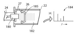
次に図12を参照すると、追加の実施形態において、ピストン26と係合するシャフト24の端部が、音響変換器180を提供し得、この音響変換器180は、ピストン26の薄いダイアフラム壁183を介して、シリンジ筒22内に収容されている液体薬剤182に、音を伝達し得る(送信及び受信)。シリンジ筒22内に形成される空洞の固有共振周波数が、スペクトル184を提供するように処理され得、そのピークが、ポンピングされた量を直接的に測定する為の上記空洞の各種寸法、従って、その空洞の実際の容積を決定する為に、分析され得る。高精度を求めて、シリンジ筒22の既知の寸法及びピストン26の線形変位から容積を推定するのではなく、容積の直接的な測定を提供する為に、容量性感知等に注目したものを含むその他の直接的な容積測定技術も企図され得る。
12, in an additional embodiment, the end of the
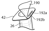
次に図13も参照すると、シリンジ筒22内のピストン26をプランジャシャフト24のツイストロックコネクタ27から取り外すことが出来ることによって、シリンジ筒22に医薬品を事前充填し、そのシリンジ筒22を、輸送後、図6に示されているツイストロックの鍔41を使用してシリンジユニット12に取り付けることが可能になる。シリンジ筒22を充填し、ピストン26を取り付けた後、接着カバー190が、漏れ防止及び不正開封に対する保護を提供する為に、シリンジ筒22の開口端にある鍔42に接着され得る。接着カバー190は、それが開かれた時に、例えば裂けること又は再接着拒否等によって、不正開封の跡がすぐ分かるようなものであり得、人が読み取ることも、機械で読み取ることも(例えば近距離場RFID技術を使用)可能な形式で薬剤及び/又は患者を示す、ラベル192を含み得る。このようにしてシリンジ筒22の内容、適した患者、及び投与量情報が、既に説明したように薬剤送出の制御に使用する為に、シリンジホルダ100に、最終的にはモータユニット120及びコネクタ140に、電子的に伝達され得る。
13, the ability to remove the
一実施形態では、ラベル192は、シリンジ筒22に貼り付けられる部分192aと、シリンジの使用時に取り外されるように接着カバー190に貼り付けられる部分192bを有し得る。未使用のシリンジの存在を確認する為に、ラベル192とシリンジ筒22を組み立てたものに対して最初のスキャンが実行され得る。ラベル192が取り外され廃棄された後は、スキャンをすればそのシリンジが以前に使用されたことが判明し、これは投与過誤又は医薬品流用をなくすのに役立つ。シリンジ筒22上に残っているラベル192aの部分は、シリンジの処分の確認又は後の薬剤識別表示の確認に使用され得る。
In one embodiment, the label 192 may have a
従って、1つ又は複数の封止ラベルが、滅菌バリア及び情報担持体として働くように、シリンジプランジャシャフトが取り外し可能なシリンジに、貼り付けられ得る。このラベルは、筒体を封止する為にシリンジの開口部に貼り付けられ得、薬剤情報をバーコードの形で担持し得る。上記封止ラベルを取り外すと、バーコードを有する部分が、使用者による且つ/又はポンプによる薬剤識別の為にシリンジ上に残され得る。ポンプは、シリンジからバーコード情報を読み取り、又はシリンジ上のRFIDから情報を読み取り、そのポンプを注入用に設定し得る。 Thus, one or more sealing labels may be affixed to a syringe from which the syringe plunger shaft is removable to act as a sterility barrier and information carrier. The label may be affixed to the opening of the syringe to seal the barrel and may carry drug information in the form of a barcode. When the sealing label is removed, a portion bearing the barcode may be left on the syringe for drug identification by the user and/or by the pump. The pump may read the barcode information from the syringe or read the information from the RFID on the syringe and configure the pump for injection.
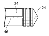
次に図14及び15を参照すると、プランジャシャフト24は通常、比較的剛性を有するポリマー材料で構成され、ピストン26は、ゴム状の性質を有するエラストマーで構成される。本発明は、例えばピストン26の後側を完全に支持する空間充填キノコ部分200を使用することによって、プランジャシャフト24の端部とピストン26の後面との間に空間充填アタッチメントを提供する。これは、シリンジから一定の排出量があったと誤って解釈され得るような、プランジャシャフト24によって圧力が加えられた時のピストン26の初期変形をなくす為である。この点に関して、シリンジ使用時のピストン26の間隙又は初期変形を取り除く為に、ツイストロック要素27が、ピストン26の側壁の後方への予荷重による引き延ばしを提供し得る。一代替構成では、キノコ部分200は、硬質プラスチックで構成され、ピストン26に接着されるか又は他の空間充填手段によって取り付けられ得る。この場合、キノコ部分200は、シャフト24に対して剛性を有するツイストロックを提供し得る(図示せず)。
14 and 15, the
要約すると、精度を向上させる為に、ピストン26は薬剤送出中の変化を最小にするように最適化され得る。具体的な手段は以下の通りであり得る。
In summary, to improve accuracy, the
A.ピストン26とピストンシャフト24の支持部分の間に空間があれば取り除く。任意選択で、ピストン26のゴムがピストンシャフト24の中実端に接着され得る。或いは、汚染や材料の適合性の懸念から接着剤を使用すべきでない場合は、ピストン26のゴム製ドームが、図15に示されているキノコ部分200と密着して係合するような「キノコ形」のソケット(図15に示されている通り)を有し得る。(従来、ゴム製ドームとシャフト24の構造体の間には間隙が存在する、或いはピストンの先端が仕切られ得、それによって、流体を送出出来るようになるまでピストン26のゴム製のドームが変形するように若干の空間が残されている)。
A. Remove any space between the
B.ピストン26をその取付先のシャフト24の端部に組み込んだ時点で、そのピストン26のゴム層に張力が加わるように予荷重をかける。それによって、ゴム先端部の可撓性と静脈路の圧力変化に起因する、流体の送出量の変化を引き起こすピストン26の加圧下の変化が低減される。
B. When the
次に図16を参照すると、上記に加えて又はその代わりに、初期の「ワインドアップ」が検出され得る。ワインドアップでは、シャフト24は動いていても、シリンジからの医薬品の正味の流れが存在しない。この原因には、例えばギア48とラック46の間等の機械的な間隙の吸収や、ピストン26の初期の撓み(既に説明済み)、例えば静脈チューブの膨張等を含むその他のコンプライアンス機構がある。このワインドアップの検出は、例えば既に説明した感知システム65を使用して検出されるシリンジシャフトの動きに対して、既に説明した圧力センサを使用してシリンジ圧力を監視することによって行われる。不感帯202とコンプライアンス帯204を識別する為に、信号154がモータユニット120内のコントローラ56によって分析され得る。不感帯202では、シャフト24の動きが、圧力の欠落によって示される実際の流体のポンピングに対応しておらず、コンプライアンス帯204では、流体をポンピングしているが、その流体はシリンジシャフト24の動きによって示されるよりも少なく、これらは実験的に測定され得る。これらの不感帯202とコンプライアンス帯204の両方を使用して、ポンピング量のより正確な測定値をディスプレイ114又は58上に提供する為に、計算ポンピング量の減算を行う。
16, in addition or instead of the above, an incipient "wind-up" may be detected. In wind-up, the
プランジャヘッドが完全に係合され「真の」流体の送出が開始されたかどうかを判定する為にモータ電流信号が監視され得るという点から、上記実施形態は、送出の精度を向上させる方法を提供する。真の流体送出をもたらさない初期のモータ動作を考慮に入れることによって、注入プログラムにおける計算はより正確になり得る。この初期変動は小さいが、それを補償すると、システムがより正確になり得る。 The above embodiment provides a way to improve delivery accuracy in that the motor current signal can be monitored to determine if the plunger head is fully engaged and "true" fluid delivery has begun. By taking into account the initial motor motion that does not result in true fluid delivery, calculations in the injection program can be more accurate. Although this initial variation is small, compensating for it can result in a more accurate system.
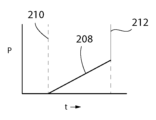
次に図17及び18を参照すると、追加の実施形態において、ピストン26と係合するシャフト24の端部が、圧力センサ206を提供し得、この圧力センサ206は、ピストン26とシャフト24との係合の、係合時210における検出に使用され得る圧力信号208を伝達し得る。係合時210とは、シャフト24がシリンジ筒22を通って一定の速度で前進するにつれて、圧力がゼロ(ピストン26とシャフト24が係合解除状態)から増加関数になる時である。圧力センサ206はまた、閉塞時212における静脈路チューブ30の閉塞も検出し得る。閉塞時212とは、シャフト24がシリンジ筒22を通って前進するにつれて圧力が急激に増加して(スパイク)、高圧の立ち上がりが生じる時である。圧力センサ206は、歪みゲージ又は圧電センサにし得、ピストン26と、シリンジ筒22内部の流体とによる、シャフト24に対する圧力を示す。
17 and 18, in an additional embodiment, the end of the
本明細書では特定の用語を参照の目的でのみ使用しており、従って、限定することを意図していない。例えば、「上」、「下」、「上」、「下」等の用語は、参照図面中の方向を示す。「前面」、「背面」、「後面」、「底面」、「側面」等の用語は、一貫した任意の基準系に含まれる構成要素の各部分の向きを述べる。この任意の基準系は、検討中の構成要素を説明しているテキスト及び関連する図面を参照することによって明らかになる。かかる用語は、上記で具体的に言及された単語、それらの派生語、及び類似の意味の単語を含み得る。同様に、用語「第1」、「第2」及び構造体を示す他のかかる数字用語は、文脈によって明確に示されない限り、配列も順序も意味しない。 Certain terms are used herein for reference purposes only and are not intended to be limiting. For example, terms such as "top", "bottom", "upper", "lower" and the like refer to directions in the referenced drawings. Terms such as "front", "back", "rear", "bottom", "side" and the like describe the orientation of portions of a component within any consistent frame of reference that will become clear by reference to the text and associated drawings describing the component under consideration. Such terms may include the words specifically mentioned above, their derivatives, and words of similar meaning. Similarly, the terms "first", "second" and other such numerical terms designating structures do not imply any arrangement or order unless clearly indicated by the context.
本明細書の開示及び例示的な実施形態の要素又は特徴を導入する場合、冠詞「ある(a)」、「ある(an)」、「上記(the)」及び「前記(said)」は、かかる要素又は特徴が1つ又は複数存在することを意味することを意図している。用語「備える」、「含む」及び「有する」は包括的であることを意図しており、具体的に記載されたもの以外の追加の要素又は特徴が存在し得ることを意味する。更に、本明細書に記載の方法ステップ、プロセス、及び動作は、特に実行順序として特定されていない限り、説明又は例示した特定の順序でそれらを必ず実行する必要があると解釈すべきではないことを理解されたい。また、追加又は代替のステップが使用され得ることも理解されたい。 When introducing elements or features of the disclosures and exemplary embodiments herein, the articles "a," "an," "the," and "said" are intended to mean that there are one or more of such elements or features. The terms "comprise," "include," and "have" are intended to be inclusive and mean that there may be additional elements or features other than those specifically recited. Furthermore, it should be understood that the method steps, processes, and operations described herein should not be construed as necessarily requiring them to be performed in the particular order described or illustrated, unless specifically identified as such. It should also be understood that additional or alternative steps may be used.
「一マイクロプロセッサ」及び「一プロセッサ」又は「上記マイクロプロセッサ」及び「上記プロセッサ」への言及は、独立型及び/又は分散型環境で通信し得、従って、有線又は無線通信を介して他のプロセッサと通信するように構成され得る1つ又は複数のマイクロプロセッサを含むと理解出来よう。その場合、かかる1つ又は複数のプロセッサは、それと類似又は異なるデバイスとし得る1つ又は複数のプロセッサ制御デバイス上で動作するよう構成され得る。更に、特に指定しない限り、メモリへの言及は、1つ又は複数のプロセッサ読み取り可能且つアクセス可能なメモリ要素及び/又は構成要素を含み得、これらのメモリ要素及び/又は構成要素は、プロセッサ制御装置の内部、プロセッサ制御装置の外部にあり得、有線又は無線ネットワークを介してアクセスされ得る。 References to "a microprocessor" and "a processor" or "the microprocessor" and "the processor" may be understood to include one or more microprocessors that may communicate in an independent and/or distributed environment and thus may be configured to communicate with other processors via wired or wireless communication. In that case, such one or more processors may be configured to operate on one or more processor-controlled devices, which may be similar or different devices. Furthermore, unless otherwise specified, references to memory may include one or more processor-readable and accessible memory elements and/or components, which may be internal to the processor-controlled device, external to the processor-controlled device, and may be accessed via a wired or wireless network.
本発明は、本明細書に含まれる実施形態及び例示に限定されないことを特に意図しており、特許請求の範囲は、それらの実施形態の一部分、及び以下の特許請求の範囲内に入る様々な実施形態の要素の組み合わせを含む、それらの実施形態の修正形態を含むと理解すべきである。特許及び非特許刊行物を含む、本明細書に記載の刊行物は全て、その全体が参照により本明細書に援用される。
〔付記1〕
ニードルアダプタで終端する管状の筒を有するタイプのシリンジからの、測定による液体薬剤送出の為のセンサシステムにおいて、前記管状の筒が、それに密着して嵌合する、プランジャ作動式のエラストマーピストンを含む、センサシステムであって、
ハウジングにおいて、そこから1つの軸に沿って延びる前記管状の筒を取り外し可能に受けるハウジングと、
前記エラストマーピストンの動きに対応して前記ハウジング内部で前記軸に沿って移動するように摺動可能に受けられるプランジャと、
前記プランジャの移動を示す電子信号を提供する為に、前記ハウジングに対する前記軸に沿った前記プランジャの移動の直接的な測定を提供するように、前記ハウジングに対して固定式に取り付けられた、前記プランジャのセンサ素子を感知する電子センサと、を備えるセンサシステム。
〔付記2〕
前記プランジャの一部分が、そのプランジャ部分を押すことによって前記シリンジを手動で操作する為に、前記ハウジングから延びる、付記1に記載のセンサシステム。
〔付記3〕
前記プランジャ部分を押すことを支援する為に、前記ハウジングが、前記使用者の指と係合する外向きに延びるフランジを提供する、付記2に記載のセンサシステム。
〔付記4〕
前記プランジャを駆動体の回転によって前記軸に沿って移動させる為に、前記駆動体を前記プランジャの表面と転動接触して回転させるノブを更に備える、付記2に記載のセンサシステム。
〔付記5〕
前記エラストマーピストンの変位の示度を表示する為に前記センサと通信する、前記ハウジングによって支持されたディスプレイを更に含む、付記1に記載のセンサシステム。
〔付記6〕
前記ディスプレイが、前記管状の筒の断面の所定の寸法に基づいて、容積の単位を提供する、付記5に記載のセンサシステム。
〔付記7〕
モータの動きによって前記プランジャを移動させる為に、前記プランジャと係合するモータユニットを更に含む、付記1に記載のセンサシステム。
〔付記8〕
付記7に記載のセンサシステムであって、
所望の送出速度に基づいた前記シリンジプランジャの所望の変位量を示すコマンド信号を受信すること、
前記シリンジプランジャの実際の変位量を示す変位信号を受信すること、及び、
前記コマンド信号と前記変位信号との差を示す制御偏差信号を生成する為に前記変位信号を前記コマンド信号と比較すること、を行うようにメモリ内に格納された格納プログラムを実行するコントローラを更に備える、センサシステム。
〔付記9〕
前記制御偏差信号に基づいて電気モータを制御する為に、前記モータユニットが前記コントローラと通信する、付記8に記載のセンサシステム。
〔付記10〕
前記ハウジングが前記モータユニットを解放可能に受ける、付記7に記載のセンサシステム。
〔付記11〕
前記ハウジングが電気コネクタを更に含み、前記電気コネクタは、前記モータユニットが前記ハウジングによって受けられた時に、前記モータユニットと前記ハウジングを接続する、付記10に記載のセンサシステム。
〔付記12〕
前記プランジャを駆動体の回転によって前記軸に沿って移動させる為に、前記モータユニットが、前記駆動体を前記プランジャの表面と転動接触して回転させる電気モータを含む、付記7に記載のセンサシステム。
〔付記13〕
前記駆動体がピニオンギアであり、前記シリンジプランジャを前記軸に沿って移動させる為に、前記ピニオンギアが、前記シリンジプランジャ上で軸方向に延びるギアラックと係合する、付記12に記載のセンサシステム。
〔付記14〕
前記モータユニットが自己完結型のバッテリを含む、付記7に記載のセンサシステム。
〔付記15〕
第1の位置で前記モータを前記シリンジプランジャと係合させ、第2の位置で前記モータと前記シリンジプランジャを係合解除するように可動式になっている、解放レバーを更に備える、付記7に記載のセンサシステム。
〔付記16〕
前記プランジャが、電子的に読み取り可能な1組の目盛を含み得、前記目盛は、前記センサの近傍を通過するときに、前記センサによって測定される、付記1に記載のセンサシステム。
〔付記17〕
前記プランジャとエラストマーピストンの内の少なくとも一方が、前記センサによって検出可能な少なくとも1つのマーカを含み、これは前記センサと前記マーカの間の相対位置を判定する為であり、前記少なくとも1つのマーカが前記ピストンにあり、前記センサが、前記ピストンの経路に隣接して、前記軸に沿って延びる1組の感知要素を提供する、付記1に記載のセンサシステム。
〔付記18〕
前記1組の感知要素を支持する為に、前記ハウジングから延び、前記管状の筒の両側に位置する、長手方向のアームを更に備える、付記17に記載のセンサシステム。
〔付記19〕
前記センサが少なくとも1つの容量性センサである、付記17に記載のセンサシステム。
〔付記20〕
前記管状の筒が、解放可能なツイストロックによって、前記ハウジングに取り付けられる、付記1に記載のセンサシステム。
It is specifically intended that the present invention is not limited to the embodiments and examples contained herein, and the claims are to be understood to include portions of those embodiments, as well as modifications of those embodiments, including combinations of elements of the various embodiments that fall within the scope of the following claims. All publications mentioned herein, including patent and non-patent publications, are incorporated herein by reference in their entirety.
[Appendix 1]
1. A sensor system for measured liquid drug delivery from a syringe of the type having a tubular barrel terminating in a needle adapter, the tubular barrel including a plunger actuated elastomeric piston that fits closely therewith, comprising:
a housing for removably receiving the tubular barrel extending along an axis therefrom;
a plunger slidably received within the housing for movement along the axis in response to movement of the elastomeric piston;
and an electronic sensor fixedly mounted relative to the housing for sensing a sensor element of the plunger to provide a direct measurement of movement of the plunger along the axis relative to the housing to provide an electronic signal indicative of movement of the plunger.
[Appendix 2]
2. The sensor system of claim 1, wherein a portion of the plunger extends from the housing for manually operating the syringe by depressing the plunger portion.
[Appendix 3]
3. The sensor system of claim 2, wherein the housing provides an outwardly extending flange that engages a finger of the user to assist in depressing the plunger portion.
[Appendix 4]
3. The sensor system of claim 2, further comprising a knob for rotating the driver in rolling contact with a surface of the plunger to move the plunger along the axis by rotation of the driver.
[Appendix 5]
2. The sensor system of claim 1, further comprising a display supported by the housing in communication with the sensor to display an indication of the displacement of the elastomeric piston.
[Appendix 6]
6. The sensor system of claim 5, wherein the display provides units of volume based on a predetermined dimension of a cross-section of the tubular barrel.
[Appendix 7]
2. The sensor system of claim 1, further comprising a motor unit engaging the plunger to move the plunger by motor motion.
[Appendix 8]
8. The sensor system of claim 7,
receiving a command signal indicating a desired amount of displacement of the syringe plunger based on a desired delivery rate;
receiving a displacement signal indicative of an actual displacement of the syringe plunger;
and comparing the displacement signal to the command signal to generate a control deviation signal indicative of a difference between the command signal and the displacement signal.
[Appendix 9]
9. The sensor system of claim 8, wherein the motor unit is in communication with the controller to control an electric motor based on the control error signal.
[Appendix 10]
8. The sensor system of claim 7, wherein the housing releasably receives the motor unit.
[Appendix 11]
11. The sensor system of
[Appendix 12]
8. The sensor system of claim 7, wherein the motor unit includes an electric motor that rotates the driver in rolling contact with a surface of the plunger to move the plunger along the axis by rotation of a driver.
[Appendix 13]
13. The sensor system of
[Appendix 14]
8. The sensor system of claim 7, wherein the motor unit includes a self-contained battery.
[Appendix 15]
8. The sensor system of claim 7, further comprising a release lever movable to engage the motor with the syringe plunger in a first position and to disengage the motor from the syringe plunger in a second position.
[Appendix 16]
2. The sensor system of claim 1, wherein the plunger may include a set of electronically readable markings that are measured by the sensor as the plunger passes in proximity to the sensor.
[Appendix 17]
2. The sensor system of claim 1, wherein at least one of the plunger and the elastomeric piston includes at least one marker detectable by the sensor for determining a relative position between the sensor and the marker, the at least one marker being on the piston, and the sensor providing a set of sensing elements extending along the axis adjacent to a path of the piston.
[Appendix 18]
18. The sensor system of claim 17, further comprising longitudinal arms extending from the housing and positioned on either side of the tubular barrel for supporting the pair of sensing elements.
[Appendix 19]
18. The sensor system of claim 17, wherein the sensor is at least one capacitive sensor.
[Appendix 20]
2. The sensor system of claim 1, wherein the tubular barrel is attached to the housing by a releasable twist lock.
10 シリンジポンプ
12 シリンジユニット
14 シリンジユニットの近位端
16 ポンプ本体の側壁
18 ポンプ本体
20 軸
22 シリンジ筒
24 プランジャシャフト
26 プランジャピストン
27 ツイストロック
28 シリンジ筒の遠位端
30 静脈路チューブ
32 ルアーコネクタ
34 ポンプ本体の上壁
36 解放レバー
38 スライドボタン
40 スロット
41 ツイストロックの鍔
42 鍔の耳
43 ビーム
44 ビームの前面
45 ストッパ
46 ギアラック
48 ピニオンギア
50 ギア列
52 ステッピングモータ
56 制御部マイクロコントローラ
58 ディスプレイ画面
59 パワーパック
60 入力ボタン
62 USBジャック
65 変位感知システム
66 容量性プレートパターン
68 ビームの後面
70 変位信号
72 加算点
74 コマンド信号
80 ステッピングモータコントローラ
90 アーム
92 アーム
94 光検出器の素子
100 シリンジホルダ
101 ノブ
102 親指ボタン
104 親指
106 人差し指
108 中指
110 把持フランジ
112 把持フランジ
114 LCDディスプレイ
120 ポンプモータユニット
121 ハウジングの上部
122 ギアシュラウド
123 指状部
124 フォーク
126 ピン
130 ノッチ
132 キャッチ
134 ばね
136 ロック解除レバー
137 電気コネクタ
140 USBコネクタ
144 補助キャッチ
146 取り出しレバー
150 ばね
152 ダイアフラム要素
154 圧力信号
156 圧力の閉塞レベル
158 ポンプ作動レベル
160 患者の心拍信号
180 音響変換器
182 液体薬剤
183 ダイアフラム壁
184 スペクトル
190 接着カバー
192 ラベル
200 キノコ部分
202 不感帯
204 コンプライアンス帯
206 圧力センサ
208 圧力信号
LIST OF SYRINGE PUMP 12 Syringe unit 14 Proximal end of syringe unit 16 Pump body side wall 18 Pump body 20 Shaft 22 Syringe barrel 24 Plunger shaft 26 Plunger piston 27 Twist lock 28 Distal end of syringe barrel 30 Intravenous line tubing 32 Luer connector 34 Top wall of pump body 36 Release lever 38 Slide button 40 Slot 41 Twist lock collar 42 Collar ears 43 Beam 44 Front face of beam 45 Stopper 46 Gear rack 48 Pinion gear 50 Gear train 52 Stepper motor 56 Control microcontroller 58 Display screen 59 Power pack 60 Input button 62 USB jack 65 Displacement sensing system 66 Capacitive plate pattern 68 Rear face of beam 70 Displacement signal 72 Summing point 74 Command signal 80 Stepper motor controller 90 Arm 92 Arm 94 Photodetector element 100 Syringe holder 101 Knob 102 Thumb button 104 Thumb 106 Index finger 108 Middle finger 110 Gripping flange 112 Gripping flange 114 LCD display 120 Pump motor unit 121 Top of housing 122 Gear shroud 123 Finger 124 Fork 126 Pin 130 Notch 132 Catch 134 Spring 136 Unlock lever 137 Electrical connector 140 USB connector 144 Auxiliary catch 146 Ejection lever 150 Spring 152 Diaphragm element 154 Pressure signal 156 Pressure Occlusion Level 158 Pump Operation Level 160 Patient Heart Rate Signal 180 Acoustic Transducer 182 Liquid Drug 183 Diaphragm Wall 184 Spectrum 190 Adhesive Cover 192 Label 200 Mushroom 202 Dead Zone 204 Compliance Zone 206 Pressure Sensor 208 Pressure Signal
Claims (12)
ハウジングにおいて、そこから1つの軸に沿って延びる前記管状の筒を取り外し可能に受けるハウジングと、
前記管状の筒の内部で前記軸に沿って移動するように摺動可能に受けられる単一片のプランジャシャフトであって、当該プランジャシャフトの端部に前記エラストマーピストンが連結され、当該プランジャシャフトの一側面に駆動体と接触する部分が設けられると共に、当該プランジャシャフトの他側面にセンサの検出範囲が設けられる、プランジャシャフトと、
前記プランジャシャフトの移動を示す電子信号を提供する為に、前記ハウジングに対する前記軸に沿った前記プランジャシャフトの移動の直接的な測定を提供するように、前記ハウジングに対して固定式に取り付けられた、前記プランジャシャフトのセンサ素子を感知する電子センサと、
モータの動きによって前記プランジャシャフトを移動させる為に、前記プランジャシャフトと係合するモータユニットと、
コントローラであって、
所望の送出速度に基づいた前記プランジャシャフトの所望の変位量を示すコマンド信号を受信すること、
前記プランジャシャフトの実際の変位量を示す変位信号を前記電子センサから受信すること、及び、
前記コマンド信号と前記変位信号との差を示す制御偏差信号を生成する為に前記変位信号を前記コマンド信号と比較すること、を行うようにメモリ内に格納された格納プログラムを実行するコントローラと、
第1の位置で前記モータを前記プランジャシャフトと係合させ、第2の位置で前記モータと前記プランジャシャフトを係合解除するように可動式になっている、解放レバーと、
を備え、
前記プランジャシャフトを前記駆動体の回転によって前記軸に沿って移動させる為に、前記モータユニットが、前記駆動体を前記プランジャシャフトの表面と転動接触して回転させる電気モータを含み、
前記駆動体がピニオンギアであり、前記プランジャシャフトを前記軸に沿って移動させる為に、前記ピニオンギアが、前記プランジャシャフト上で軸方向に延びるギアラックと係合し、
前記センサ素子は、電子的に読み取り可能な1組の目盛を含み、前記目盛は、前記プランジャシャフトに固定され、且つ前記センサの検出範囲全体にわたって前記プランジャシャフトの長さに沿って分離された別個の位置に分布されると共に、前記目盛が通過するときに、前記電子センサによって測定され、
前記モータユニットは、電気モータを備えると共に、前記制御偏差信号に基づいて前記電気モータを制御する為に、前記コントローラと通信し、
前記管状の筒が、解放可能なツイストロックによって、前記ハウジングに取り付けられる、
センサシステム。 1. A sensor system for measured liquid drug delivery from a syringe of the type having a tubular barrel terminating in a needle adapter, the tubular barrel including a plunger actuated elastomeric piston that fits closely therewith, comprising:
a housing for removably receiving the tubular barrel extending along an axis therefrom;
a single-piece plunger shaft slidably received within the tubular barrel for movement along the axis, the elastomeric piston being connected to an end of the plunger shaft, a portion that contacts a driver being provided on one side of the plunger shaft, and a sensor detection range being provided on the other side of the plunger shaft;
an electronic sensor fixedly mounted relative to the housing for sensing a sensor element on the plunger shaft to provide a direct measurement of movement of the plunger shaft along the axis relative to the housing to provide an electronic signal indicative of movement of the plunger shaft ;
a motor unit engaging the plunger shaft for moving the plunger shaft by motor motion;
A controller,
receiving a command signal indicating a desired amount of displacement of the plunger shaft based on a desired delivery rate;
receiving a displacement signal from the electronic sensor indicative of an actual displacement of the plunger shaft ; and
a controller executing a stored program stored in a memory to compare the displacement signal with the command signal to generate a control error signal indicative of a difference between the command signal and the displacement signal;
a release lever movable to engage the motor with the plunger shaft in a first position and to disengage the motor from the plunger shaft in a second position;
Equipped with
the motor unit includes an electric motor for rotating the driver in rolling contact with a surface of the plunger shaft to move the plunger shaft along the axis by rotation of the driver;
the driver is a pinion gear, the pinion gear engaging an axially extending gear rack on the plunger shaft to move the plunger shaft along the axis;
the sensor element includes a set of electronically readable graduations fixed to the plunger shaft and distributed at separate, distinct positions along the length of the plunger shaft throughout a sensing range of the sensor and measured by the electronic sensor as the graduations pass;
the motor unit includes an electric motor and is in communication with the controller to control the electric motor based on the control deviation signal;
the tubular barrel is attached to the housing by a releasable twist lock;
Sensor system.
Applications Claiming Priority (4)
| Application Number | Priority Date | Filing Date | Title |
|---|---|---|---|
| US201862697632P | 2018-07-13 | 2018-07-13 | |
| US62/697,632 | 2018-07-13 | ||
| US201962799475P | 2019-01-31 | 2019-01-31 | |
| US62/799,475 | 2019-01-31 |
Publications (2)
| Publication Number | Publication Date |
|---|---|
| JP2020036876A JP2020036876A (en) | 2020-03-12 |
| JP7526558B2 true JP7526558B2 (en) | 2024-08-01 |
Family
ID=67253805
Family Applications (1)
| Application Number | Title | Priority Date | Filing Date |
|---|---|---|---|
| JP2019129773A Active JP7526558B2 (en) | 2018-07-13 | 2019-07-12 | High-precision syringe with removable pump unit |
Country Status (4)
| Country | Link |
|---|---|
| US (1) | US11660388B2 (en) |
| EP (1) | EP3593838A1 (en) |
| JP (1) | JP7526558B2 (en) |
| CN (1) | CN110711293A (en) |
Families Citing this family (12)
| Publication number | Priority date | Publication date | Assignee | Title |
|---|---|---|---|---|
| US10842941B2 (en) * | 2017-06-22 | 2020-11-24 | Wisconsin Alumni Research Foundation | Syringe attachment device and methods |
| US11679205B2 (en) | 2018-07-13 | 2023-06-20 | Zyno Medical Llc | High precision syringe with removable pump unit |
| CN111249577B (en) * | 2020-03-01 | 2021-11-19 | 杭州丽脂医疗科技有限公司和兴路医疗美容门诊部 | Autologous fat transplantation needle for improving survival rate of fat cells |
| CN111249580B (en) * | 2020-03-01 | 2021-12-07 | 宁波珈禾整形专科医院有限公司 | High-precision pressure propeller for autologous fat |
| EP4117754A4 (en) * | 2020-03-10 | 2024-03-27 | Zyno Medical, Llc | High precision syringe with removable pump unit |
| EP4210790A4 (en) * | 2020-05-21 | 2024-06-19 | DataDose, LLC | MANAGEMENT PLATFORM FOR SMART INJECTION DEVICES |
| CN112755332B (en) * | 2020-12-29 | 2022-06-03 | 查维祎 | Fluid infusion system |
| IL303651A (en) | 2020-12-31 | 2023-08-01 | Regeneron Pharma | Auto-injector and related methods of use |
| WO2023043513A1 (en) * | 2021-09-15 | 2023-03-23 | Certus Critical Care, Inc. | Devices, systems, and methods for fluid delivery |
| US12496404B2 (en) * | 2022-09-02 | 2025-12-16 | Donald Russell Peterson | Syringe hand grip adapter |
| CN115779191A (en) * | 2023-01-05 | 2023-03-14 | 深圳力工智能有限公司 | A precise and intelligent liquid pushing device |
| CN119344911A (en) * | 2024-10-23 | 2025-01-24 | 合肥拉塞特机器人科技有限公司 | A needle-free syringe with arbitrarily replaceable expansion modules and a method of using the same |
Citations (5)
| Publication number | Priority date | Publication date | Assignee | Title |
|---|---|---|---|---|
| JP2005533568A (en) | 2002-07-24 | 2005-11-10 | デカ・プロダクツ・リミテッド・パートナーシップ | Optical deflection sensor for injection devices. |
| US20080152507A1 (en) | 2006-12-21 | 2008-06-26 | Lifescan, Inc. | Infusion pump with a capacitive displacement position sensor |
| US20100057014A1 (en) | 2006-11-16 | 2010-03-04 | CANE' S.P.A. -Socio Unico | Syringe plunger and syringe incorporating the plunger |
| US20150379900A1 (en) | 2014-04-17 | 2015-12-31 | University Of Pittsburgh-Of The Commonwealth System Of Higher Education | Modular, wireless, drug simulant injection sensor system and methods of employing |
| JP2018507087A (en) | 2015-02-24 | 2018-03-15 | 410 メディカル, インク.410 Medical, Inc. | Device and kit for fluid injection |
Family Cites Families (24)
| Publication number | Priority date | Publication date | Assignee | Title |
|---|---|---|---|---|
| US4586260A (en) | 1984-05-29 | 1986-05-06 | The L. S. Starrett Company | Capacitive displacement measuring instrument |
| CA2129284C (en) | 1993-11-24 | 1999-03-09 | Kenneth J. Niehoff | Controlling plunger drives for fluid injection in animals |
| US5672155A (en) * | 1996-06-14 | 1997-09-30 | Riley; Robert Q. | Fluid transfer apparatus |
| DE19643813A1 (en) * | 1996-09-26 | 1998-04-02 | Schreiber Hans | Kit for controlled injection of drugs |
| US5868710A (en) * | 1996-11-22 | 1999-02-09 | Liebel Flarsheim Company | Medical fluid injector |
| EP2319564B1 (en) * | 2001-12-13 | 2013-07-17 | Panasonic Corporation | Administration instrument for medical use |
| US8016744B2 (en) * | 2005-02-24 | 2011-09-13 | Ethicon Endo-Surgery, Inc. | External pressure-based gastric band adjustment system and method |
| US8840586B2 (en) * | 2006-08-23 | 2014-09-23 | Medtronic Minimed, Inc. | Systems and methods allowing for reservoir filling and infusion medium delivery |
| ATE519513T1 (en) * | 2005-07-08 | 2011-08-15 | Novo Nordisk As | INJECTION DEVICE |
| US20070062251A1 (en) * | 2005-09-19 | 2007-03-22 | Lifescan, Inc. | Infusion Pump With Closed Loop Control and Algorithm |
| WO2008153985A1 (en) | 2007-06-11 | 2008-12-18 | Numia Medical Technology, Llc | Syringe infusion pump |
| US8105332B2 (en) * | 2007-10-30 | 2012-01-31 | Novartis Ag | Lens delivery system |
| US8403883B2 (en) * | 2008-09-18 | 2013-03-26 | Becton, Dickinson And Company | Medical injector with dose knob activation for automated reconstitution |
| WO2013095459A1 (en) * | 2011-12-21 | 2013-06-27 | Deka Products Limited Partnership | System, method, and apparatus for electronic patient care |
| DK2510960T3 (en) * | 2011-04-12 | 2017-09-18 | Hoffmann La Roche | Infusion pump device with cylinder piston metering unit and optical piston position detection |
| CN106975118B (en) * | 2011-05-12 | 2020-09-08 | 拜耳医药保健有限公司 | Fluid injection system with different systems for controlling an injection procedure |
| US9539389B2 (en) * | 2012-02-08 | 2017-01-10 | Stmicroelectronics, Inc. | Wireless flow sensor using present flow rate data |
| US9623191B2 (en) * | 2013-03-01 | 2017-04-18 | Bayer Healthcare Llc | Information sensing syringe |
| US10322227B2 (en) * | 2013-03-15 | 2019-06-18 | 410 Medical, Inc. | Apparatus, kits and related methods for fluid infusion |
| CN203609721U (en) | 2013-12-04 | 2014-05-28 | 吴海斌 | Automatic injecting device driving sliding table with speed correcting function |
| CN203620002U (en) * | 2013-12-16 | 2014-06-04 | 天津市天堰医教科技开发有限公司 | Micro-motion injector |
| US9714846B2 (en) | 2013-12-31 | 2017-07-25 | Chicago Dial Indicator Company | Displacement measuring device with capacitive sensing |
| US10493204B2 (en) * | 2016-11-11 | 2019-12-03 | Imam Abdulrahman Bin Faisal University | Aspirator syringe with blood detector |
| US10894272B2 (en) * | 2018-06-29 | 2021-01-19 | Sulzer Mixpac Ag | Dispensing control system |
-
2019
- 2019-07-11 EP EP19185830.7A patent/EP3593838A1/en active Pending
- 2019-07-12 US US16/509,701 patent/US11660388B2/en active Active
- 2019-07-12 JP JP2019129773A patent/JP7526558B2/en active Active
- 2019-07-15 CN CN201910635379.6A patent/CN110711293A/en active Pending
Patent Citations (5)
| Publication number | Priority date | Publication date | Assignee | Title |
|---|---|---|---|---|
| JP2005533568A (en) | 2002-07-24 | 2005-11-10 | デカ・プロダクツ・リミテッド・パートナーシップ | Optical deflection sensor for injection devices. |
| US20100057014A1 (en) | 2006-11-16 | 2010-03-04 | CANE' S.P.A. -Socio Unico | Syringe plunger and syringe incorporating the plunger |
| US20080152507A1 (en) | 2006-12-21 | 2008-06-26 | Lifescan, Inc. | Infusion pump with a capacitive displacement position sensor |
| US20150379900A1 (en) | 2014-04-17 | 2015-12-31 | University Of Pittsburgh-Of The Commonwealth System Of Higher Education | Modular, wireless, drug simulant injection sensor system and methods of employing |
| JP2018507087A (en) | 2015-02-24 | 2018-03-15 | 410 メディカル, インク.410 Medical, Inc. | Device and kit for fluid injection |
Also Published As
| Publication number | Publication date |
|---|---|
| US11660388B2 (en) | 2023-05-30 |
| CN110711293A (en) | 2020-01-21 |
| EP3593838A1 (en) | 2020-01-15 |
| JP2020036876A (en) | 2020-03-12 |
| US20200016331A1 (en) | 2020-01-16 |
Similar Documents
| Publication | Publication Date | Title |
|---|---|---|
| JP7526558B2 (en) | High-precision syringe with removable pump unit | |
| US11679205B2 (en) | High precision syringe with removable pump unit | |
| JP6715761B2 (en) | High performance adapter for injection devices | |
| JP7389158B2 (en) | Device and method for detecting executable actuation operations in a medical device | |
| JP5711156B2 (en) | Drug delivery system | |
| DK2182456T3 (en) | Method for monitoring the operation of a drug delivery device, an electronic module, and a drug delivery system | |
| JP7132272B2 (en) | Flow sensor system with connection assembly | |
| CN104717991A (en) | Fluid delivery system and method | |
| CN114096293B (en) | Systems and methods for measuring fluid flow from a syringe | |
| WO2021183489A1 (en) | High precision syringe with removable pump unit | |
| HK1164763B (en) | Drug delivery system | |
| HK40034018A (en) | Drug delivery system | |
| HK1214984B (en) | Drug delivery management systems and methods | |
| HK1201223B (en) | Drug delivery management systems |
Legal Events
| Date | Code | Title | Description |
|---|---|---|---|
| A621 | Written request for application examination |
Free format text: JAPANESE INTERMEDIATE CODE: A621 Effective date: 20220414 |
|
| A131 | Notification of reasons for refusal |
Free format text: JAPANESE INTERMEDIATE CODE: A131 Effective date: 20230221 |
|
| A977 | Report on retrieval |
Free format text: JAPANESE INTERMEDIATE CODE: A971007 Effective date: 20230222 |
|
| A521 | Request for written amendment filed |
Free format text: JAPANESE INTERMEDIATE CODE: A523 Effective date: 20230426 |
|
| A131 | Notification of reasons for refusal |
Free format text: JAPANESE INTERMEDIATE CODE: A131 Effective date: 20230711 |
|
| A521 | Request for written amendment filed |
Free format text: JAPANESE INTERMEDIATE CODE: A523 Effective date: 20231006 |
|
| A02 | Decision of refusal |
Free format text: JAPANESE INTERMEDIATE CODE: A02 Effective date: 20231226 |
|
| A521 | Request for written amendment filed |
Free format text: JAPANESE INTERMEDIATE CODE: A523 Effective date: 20240417 |
|
| A521 | Request for written amendment filed |
Free format text: JAPANESE INTERMEDIATE CODE: A523 Effective date: 20240404 |
|
| A911 | Transfer to examiner for re-examination before appeal (zenchi) |
Free format text: JAPANESE INTERMEDIATE CODE: A911 Effective date: 20240521 |
|
| TRDD | Decision of grant or rejection written | ||
| A01 | Written decision to grant a patent or to grant a registration (utility model) |
Free format text: JAPANESE INTERMEDIATE CODE: A01 Effective date: 20240702 |
|
| A61 | First payment of annual fees (during grant procedure) |
Free format text: JAPANESE INTERMEDIATE CODE: A61 Effective date: 20240722 |
|
| R150 | Certificate of patent or registration of utility model |
Ref document number: 7526558 Country of ref document: JP Free format text: JAPANESE INTERMEDIATE CODE: R150 |