JP7523976B2 - Information processing device - Google Patents
Information processing device Download PDFInfo
- Publication number
- JP7523976B2 JP7523976B2 JP2020115863A JP2020115863A JP7523976B2 JP 7523976 B2 JP7523976 B2 JP 7523976B2 JP 2020115863 A JP2020115863 A JP 2020115863A JP 2020115863 A JP2020115863 A JP 2020115863A JP 7523976 B2 JP7523976 B2 JP 7523976B2
- Authority
- JP
- Japan
- Prior art keywords
- remaining amount
- prediction
- information
- consumable
- predicted
- Prior art date
- Legal status (The legal status is an assumption and is not a legal conclusion. Google has not performed a legal analysis and makes no representation as to the accuracy of the status listed.)
- Active
Links
Images


Classifications
-
- G—PHYSICS
- G03—PHOTOGRAPHY; CINEMATOGRAPHY; ANALOGOUS TECHNIQUES USING WAVES OTHER THAN OPTICAL WAVES; ELECTROGRAPHY; HOLOGRAPHY
- G03G—ELECTROGRAPHY; ELECTROPHOTOGRAPHY; MAGNETOGRAPHY
- G03G15/00—Apparatus for electrographic processes using a charge pattern
- G03G15/55—Self-diagnostics; Malfunction or lifetime display
- G03G15/553—Monitoring or warning means for exhaustion or lifetime end of consumables, e.g. indication of insufficient copy sheet quantity for a job
- G03G15/556—Monitoring or warning means for exhaustion or lifetime end of consumables, e.g. indication of insufficient copy sheet quantity for a job for toner consumption, e.g. pixel counting, toner coverage detection or toner density measurement
-
- G—PHYSICS
- G03—PHOTOGRAPHY; CINEMATOGRAPHY; ANALOGOUS TECHNIQUES USING WAVES OTHER THAN OPTICAL WAVES; ELECTROGRAPHY; HOLOGRAPHY
- G03G—ELECTROGRAPHY; ELECTROPHOTOGRAPHY; MAGNETOGRAPHY
- G03G15/00—Apparatus for electrographic processes using a charge pattern
- G03G15/50—Machine control of apparatus for electrographic processes using a charge pattern, e.g. regulating differents parts of the machine, multimode copiers, microprocessor control
- G03G15/5075—Remote control machines, e.g. by a host
- G03G15/5079—Remote control machines, e.g. by a host for maintenance
Landscapes
- Physics & Mathematics (AREA)
- General Physics & Mathematics (AREA)
- Engineering & Computer Science (AREA)
- Microelectronics & Electronic Packaging (AREA)
- Control Or Security For Electrophotography (AREA)
- Accessory Devices And Overall Control Thereof (AREA)
- Facsimiles In General (AREA)
- Management, Administration, Business Operations System, And Electronic Commerce (AREA)
Description
本発明は、情報処理装置に関する。 The present invention relates to an information processing device .
従来、画像形成装置に備えられる交換部品の交換時期を管理する情報処理装置が知られている。画像形成装置は、トナーや紙などのほか、画像形成プロセスで用いられる感光体などの交換部品(消耗品とも呼ばれる)を備える。例えば感光体は、トナーや紙粉による汚染や摩耗が原因で所望の性能を発揮できなくなる。そのため、情報処理装置は感光体の交換時期を当該感光体の残使用量に関する情報に基づいて判定することが知られている。このほか、給紙ローラや現像装置なども消耗品に該当する。 Conventionally, information processing devices that manage the replacement timing of replacement parts equipped in image forming devices are known. In addition to toner and paper, image forming devices are equipped with replacement parts (also called consumables) such as photoconductors used in the image formation process. For example, photoconductors can no longer perform as desired due to contamination from toner or paper dust or wear. For this reason, information processing devices are known to determine when to replace a photoconductor based on information about the remaining amount of use of the photoconductor. Other consumables include paper feed rollers and developing devices.
特許文献1では、ある画像形成装置の消耗品が交換されるまでの使用履歴に関する情報をサーバが受信し、当該サーバと通信可能な別の画像形成装置の消耗品の交換時期を前記情報に基づいて予測する技術が開示されている。具体的に述べると、特許文献1のシステムは、ある画像形成装置の感光体の膜厚の変化に基づいて別の画像形成装置の感光体の膜厚の摩耗速度を推定し、当該摩耗速度に基づいて感光体の交換時期を予測している。 Patent Document 1 discloses a technology in which a server receives information about the usage history of a consumable item of an image forming device up until the item is replaced, and predicts the replacement time of the consumable item of another image forming device that can communicate with the server based on the information. Specifically, the system of Patent Document 1 estimates the wear rate of the film thickness of the photoconductor of one image forming device based on the change in the film thickness of the photoconductor of another image forming device, and predicts the replacement time of the photoconductor based on the wear rate.
しかしながら、特許文献1の方法では、交換時期にならないと交換の通知がされないので、任意のタイミングでの消耗品の消耗度(残量)の予測結果を求めることができなかった。 However, with the method of Patent Document 1, a notification for replacement is not given until the time for replacement arrives, so it is not possible to obtain a prediction result for the degree of wear (remaining amount) of a consumable at any time.
そこで、本発明は、任意のタイミングでの消耗品の消耗度合(残量)の予測結果を求めることを目的とする。 Therefore, the present invention aims to obtain a prediction result of the degree of consumption (remaining amount) of a consumable at any time.
上記目的を達成するために本発明は、画像形成装置と通信する情報処理装置であって、前記画像形成装置の消耗品の残量に関する残量情報を受信する受信手段と、指定日に関する日付情報を入力する入力手段と、前記指定日の前記消耗品の残量に関する予測残量情報を、前記残量情報に基づき出力する出力手段と、を有し、前記出力手段は、前記指定日の前記消耗品の残量に関する第1予測量情報を、前記指定日よりも過去の第1の日数分の前記残量情報に基づき出力し、前記出力手段は、前記指定日の前記消耗品の残量に関する第2予測量情報を、前記指定日よりも過去の前記第1の日数と異なる第2の日数分の前記残量情報に基づき出力することを特徴とする。 In order to achieve the above-mentioned object, the present invention provides an information processing device that communicates with an image forming device, comprising a receiving means for receiving remaining amount information regarding the remaining amount of consumables in the image forming device, an input means for inputting date information regarding a specified date, and an output means for outputting predicted remaining amount information regarding the remaining amount of the consumables on the specified date based on the remaining amount information, wherein the output means outputs first predicted amount information regarding the remaining amount of the consumables on the specified date based on the remaining amount information for a first number of days prior to the specified date, and the output means outputs second predicted amount information regarding the remaining amount of the consumables on the specified date based on the remaining amount information for a second number of days prior to the specified date that is different from the first number of days .
本発明によれば、任意のタイミングでの消耗品の消耗度合(残量)の予測結果を求めることができる。 According to the present invention, it is possible to obtain a prediction result of the degree of consumption (remaining amount) of a consumable at any time.
以下、図面を参照して本発明の実施の形態を説明する。 The following describes an embodiment of the present invention with reference to the drawings.
(第1の実施の形態)
図1は、本発明の第1の実施の形態に係る情報処理装置が適用される消耗品管理システムのブロック図である。この消耗品管理システムは、情報処理装置としての予測システム201と、画像形成装置101とが通信可能に接続されて構成される。予測システム201と画像形成装置101とは例えば、通信ネットワークにより接続されるが、通信接続の形態は問わない。また、予測システム201に接続される画像形成装置101の数は問わない。
(First embodiment)
1 is a block diagram of a consumables management system to which an information processing device according to a first embodiment of the present invention is applied. This consumables management system is configured by connecting a
予測システム201は、画像形成装置101における消耗品の消耗度(残量)を予測し、適切な交換時期を判断するシステムである。予測システム201は、CPU209、受信部202、第1記憶部203、予測処理部204、入力部205、表示制御部206、管理画面207、閾値入力部208を有する。これらの各機能は、CPU209と、RAM、ROM(いずれも不図示)、各種インターフェイスの少なくともいずれかとの協働により実現される。従って、予測システム201の各部はCPU209によって統括的に制御される。画像形成装置101は、集計部180、第2記憶部181、送信部182を有する。これらの各機能は、各種インターフェイスや、いずれも不図示のCPU、RAM、ROMの協働により実現される。画像形成装置101における各部はCPUによって統括的に制御される。
The
画像形成装置101において、集計部180は、消耗度に関する情報として、消耗度情報(残量情報)を収集すべきタイミングになると、各消耗品の消耗度情報(残量情報)を収集する。消耗度情報は、各消耗品の寿命に関わる値であり、例えば消耗度合(ないし残量)である。消耗度情報は、例えば、消耗品の残量、当該消耗品が画像形成装置101に装着されてから画像形成装置101が画像を印刷した頁数、消耗品の累積駆動回数、累積駆動時間、累積駆動距離であってもよい。
In the
本実施の形態では、消耗度合は、新品時を0%とした場合の新品時からの消耗進行割合とするが、新品時を100%とした場合の残寿命(残量)であるとしてもよい。第2記憶部181は、収集された各消耗品の消耗度情報を記憶する。送信部182は、消耗度情報を予測システム201に対して送信する。画像形成装置101は、複数の消耗品を有する。図2で後述するように、複数の消耗品として、給紙ローラ153、感光体111、現像装置114、定着部160が例示されるが、これらに限定されない。
In this embodiment, the degree of wear is the rate of wear from when the product is new, where 0% is the degree of wear, but it may be the remaining life (remaining amount) where 100% is the degree of wear. The
予測システム201において、受信手段としての受信部202は、画像形成装置101から消耗度情報を受信することにより取得する。送信されてくる消耗度情報には、画像形成装置および消耗品を特定する付随情報が対応付けられている。第1記憶部203は、消耗度情報に上記付随情報を対応付けて記憶する。入力部205は、部品交換の予定時期として、部品交換のためにサービスマンがユーザ先を訪れる予定日(以下、訪問予定日と呼ぶ)を受け付けることにより取得する。入力部205を介した訪問予定日の入力は通常、サービスマンが行う。なお、訪問予定日は、指定された日付に関する日付情報の一例である。便宜上、訪問予定日という用語を用いるが、指定された日付は、必ずしも訪問する日でなくてもよい。従って、サービスマンは、消耗度を推定・決定する対象となる日など想定して、任意に日付を入力してもよい。予測処理部204は、消耗品の過去の消耗度から未来の日の消耗度を予測するための予測式(生成条件)をはじめとする各種演算式を生成すると共に記憶している。
In the
閾値入力部208は、まとめ交換閾値をサービスマン等から受け付けるための入力部である。まとめ交換閾値は消耗品ごとに設定され、第1記憶部203に記憶される。まとめ交換閾値は、訪問予定日における各消耗品の交換の要否を判定するための閾値である。管理画面207は、表示画面であり、表示制御部206による制御によって、各消耗品の予測された消耗度などを表示する。
The
図2は、画像形成装置101の概略構成を示す断面図である。画像形成装置101は、一例として電子写真方式を用いたカラー画像形成装置である。画像形成装置101は、4色の画像形成部を並べて配置した、タンデム方式の画像形成装置である。4色の画像形成部で形成されたトナー像は、中間転写ベルトユニット102を介して、紙搬送部150を搬送される記録材であるシートSに転写される。
Figure 2 is a cross-sectional view showing the schematic configuration of the
シートSは、収納部151内のリフトアップ装置152上に積載される形で収納されており、給紙ローラ153により画像形成タイミングに合わせて給紙される。給紙方式は問わない。給紙ローラ153により送り出されたシートSは、給紙搬送パス154を通過し、レジストローラ155へと搬送される。レジストローラ155において斜行補正やタイミング補正が行われた後、シートSは二次転写部へと送られる。二次転写部は、互いに対向する駆動ローラ2および外ローラ156により形成される転写ニップ部である。
The sheets S are stored in a stacked manner on a lift-up
二次転写部までのシートSの搬送プロセスに対して、タイミングを合わせて実行される画像形成プロセスについて説明する。画像形成部110Y、110M、110C、110Kはそれぞれ、イエロー(Y)、マゼンタ(M)、シアン(C)ブラック(BK)のトナーにより画像を形成する。各画像形成部は、用いるトナーの色が異なる以外は同様の構成であるため、代表して画像形成部110Yの構成を説明する。
The image forming process, which is executed in synchronization with the transport process of the sheet S to the secondary transfer unit, will be described.
画像形成部110Yは、感光体111を有する。感光体111の周囲に、帯電器112、露光部113、現像装置114、一次転写ローラ115および感光体クリーナ116が配置される。感光体111は、図中矢印mの方向に回転する。帯電器112は、感光体111の表面を一様に帯電させる。スキャナユニット117からは、不図示の画像コントローラから送信された画像ピクセル情報に応じて変調されたレーザ光が出力される。このレーザ光が折り返しミラーで反射し、帯電された感光体111を露光部113が露光することで、静電潜像が形成される。感光体111上に形成された静電潜像は、現像装置114でトナーによって現像され、感光体111上にトナー像が形成される。
The
その後、一次転写ローラ115により所定の加圧力および静電的負荷バイアスが加えられることにより、中間転写ベルト1上にイエローのトナー像が転写される。感光体111上に残った転写残トナーは感光体クリーナ116により回収され、再び次の画像形成に備える。以上のプロセスが画像形成部110M、C、Bkでも実行され、中間転写ベルト1に4色のトナー像が重ね合わせられる。
Then, a predetermined pressure and electrostatic load bias are applied by
次に、中間転写ベルトユニット102について説明する。中間転写ベルト1は、駆動ローラ2、テンションローラ3および転写前ローラ4によって張架されている。中間転写ベルト1は図中矢印Vの方向へと搬送駆動される。中間転写ベルト1の搬送方向Vに対して転写前ローラ4は駆動ローラ2の上流側に配置され、テンションローラ3は駆動ローラ2の下流に配置されている。テンションローラ3と転写前ローラ4との間には一次転写ローラ115が配置されている。テンションローラ3および転写前ローラ4は中間転写ベルト1の搬送に従動して回転する。
Next, the intermediate
テンションローラ3に対して、中間転写ベルト1を挟んで対向側に中間転写クリーナ50が配置される。中間転写クリーナ50は、中間転写ベルト1に残ったトナーを除去する。画像形成部110Y,110M,110C,110Kにより並列処理される各色の画像形成プロセスは、中間転写ベルト1上に一次転写された上流色のトナー像上に重ね合わせるタイミングで行われる。その結果、最終的にはフルカラーのトナー像が中間転写ベルト1上に形成され、二次転写部へと搬送される。二次転写部にて所定の加圧力と静電的負荷バイアスが与えられることで、中間転写ベルト1上のトナー像がシートS上に転写される。
An
その後、シートSに転写されたトナー像は、定着部160にて、熱と圧力によって定着される。なお、両面印刷の場合は、反転搬送路を用いて、シートSの第2面に対して上記画像形成プロセスおよび定着部160での処理が実行される。定着部160で画像を定着されたシートSは、機外へ搬出される。
The toner image transferred to the sheet S is then fixed by heat and pressure in the fixing
次に、消耗品の消耗度(消耗度合)について説明する。まず、給紙ローラ153と感光体111の消耗度の予測方法を説明する。給紙ローラ153はシートSを搬送することによって摩耗する。給紙ローラ153は摩耗することにより、搬送力が低下し、給紙不良やシートSの搬送速度の低下を引き起こす。そのため、予め給紙ローラ153の寿命を予測して、給紙ローラ153を交換する必要がある。一般にローラ部材は素材やプロセス速度ごとに寿命枚数が決まっている。給紙ローラの消耗度Lr[%]は、給紙ローラ153を交換してからのシートの積算枚数PVt[枚]、給紙ローラ153が寿命となる枚数PVr[枚]を用いて、式1で予測できる。
Lr=(PVt×100)/PVr…(1)
Next, the degree of wear (degree of wear) of consumables will be described. First, a method for predicting the degree of wear of the
Lr=(PVt×100)/PVr…(1)
一方、感光体111が回転すると、感光体クリーナ116との機械的な摺擦によって、感光体111の表面の膜が摩耗する。感光体111の走行距離Xd[mm]は、プロセス速度Ps[mm/s]、感光体回転時間Sd[s]を用いて、式2で予測できる。感光体回転時間Sdは、前回転時間、作像時間および後回転時間の総和である。
Xd=Ps×Sd…(2)
On the other hand, when the
Xd=Ps×Sd…(2)
本実施の形態では、プロセス速度PSは300[mm/s]、前回転時間は5[s]、後回転時間は5[s]を想定している。また、作像時間は、1度に5枚印刷するジョブの場合は7[s]、1度に1枚印刷するジョブの場合は1[s]を想定している。感光体削れ量Tt[mm]、感光体消耗度Lt[%]は、走行距離Xd[mm]、感光体削れ量変換係数α、寿命時の感光体削れ量Tm[mm]を用いて、式3、4で予測することができる。感光体削れ量変換係数αは例えば、1.0×10-7であるとする。
Tt=α/Xd…(3)
Lt=(Tt×100)/Tm…(4)
In this embodiment, the process speed PS is assumed to be 300 [mm/s], the pre-rotation time to be 5 [s], and the post-rotation time to be 5 [s]. The image creation time is assumed to be 7 [s] for a job that prints five sheets at a time, and 1 [s] for a job that prints one sheet at a time. The photoconductor wear amount Tt [mm] and the photoconductor wear rate Lt [%] can be predicted by
Tt=α/Xd…(3)
Lt=(Tt×100)/Tm…(4)
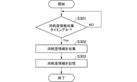
次に、画像形成装置101において、各消耗品の消耗度情報を予測システム201に送信する流れを説明する。図3は、消耗度情報記憶処理を示すフローチャートである。図4は、消耗度情報送信処理を示すフローチャートである。これらの処理は、画像形成装置101が備えるROM等の記憶部に格納されたプログラムを画像形成装置101が備えるCPUが読み出して実行することにより実現される。これらの処理は、画像形成装置101の電源が入れられると定期的に開始され、両処理は並行して実行される。
Next, the flow of the
ステップS301で、CPU(集計部180)は、消耗度情報を収集するタイミングになるまで待機する。消耗度情報を収集するタイミングは、例えば、画像形成処理の準備段階で行われるウォーミングアップ処理や画像形成後に行われる後処理のタイミングである。そして、消耗度情報を収集するタイミングになると、CPU(集計部180)は、ステップS302で各消耗品の消耗度情報を収集し、ステップS303で消耗度情報を第2記憶部181に記憶させる。各消耗品には、上述したように給紙ローラ153、感光体111、現像装置114などが挙げられる。その後、図3に示す処理は終了する。
In step S301, the CPU (counting unit 180) waits until it is time to collect wear level information. The wear level information is collected, for example, during warm-up processing performed in preparation for image formation processing or during post-processing performed after image formation. When it is time to collect wear level information, the CPU (counting unit 180) collects wear level information for each consumable in step S302, and stores the wear level information in the
図4のステップS401では、CPU(送信部182)は、第2記憶部181に記憶されている消耗品の消耗度情報が更新されるまで待機する。そして、消耗品の消耗度情報が更新されると、送信部182は、消耗度情報の送信タイミングとなったか否かを判別する。消耗度情報の送信タイミングは、定期的なタイミング、もしくは特定のイベントが発生したタイミングである。特定のイベントとは、例えば、消耗品の残量が指定の残量に達したタイミングや、消耗品の交換が行われたタイミングを指す。消耗度情報の送信タイミングとなっていない場合は、送信部182は、処理をステップS401に戻す。しかし、消耗度情報の送信タイミングとなった場合は、CPU(送信部182)は、ステップS403で、更新された消耗品情報を予測システム201に対して送信し、図4に示す処理を終了する。
In step S401 in FIG. 4, the CPU (transmission unit 182) waits until the consumption level information of the consumable stored in the
次に、予測システム201が消耗度情報を受け取り、予測された消耗度情報をサービスマンが確認するまでの流れを説明する。図5は、消耗度管理処理を示すフローチャートである。この処理は、CPU209が、予測システム201のROMに格納されたプログラムを予測システム201のRAMに展開して実行することにより実現される。この処理は、例えば、予測システム201の電源が入れられると定期的に実行される。
Next, a flow from when the
ステップS501で、CPU209(受信部202)は、消耗度情報を受信するまで待機し、消耗度情報を受信すると、ステップS502で、消耗度情報を上記付随情報と対応付けて第1記憶部203に記憶させる。
In step S501, the CPU 209 (receiving unit 202) waits until it receives wear level information, and when it receives the wear level information, in step S502, it associates the wear level information with the associated information and stores it in the
ステップS503では、CPU209(入力部205)は、サービスマンから、画像形成装置101のユーザを訪れる訪問予定日の入力があるまで待機する。なお、訪問予定日の受け付けは随時行ってもよい。そして、訪問予定日の入力があると、ステップS504で、CPU209(予測処理部204)は、後述する消耗度合予測処理(図6で後述する)を実行する。この消耗度合予測処理は、日付情報、対象の画像形成装置の各消耗品の消耗度情報から、訪問予定日における各消耗品の消耗度合を決定・推定する処理である。なお、各消耗品の消耗度は独立して推定される。ステップS505では、CPU209(表示制御部206)は、図8で後述するように、各消耗品の予測された消耗度を管理画面207に表示させ、図5に示す処理を終了する。
In step S503, the CPU 209 (input unit 205) waits until the serviceman inputs the planned date of the visit to the user of the
図6は、図5のステップS504で実行される消耗度合予測処理を示すフローチャートである。図7(a)は、経過日数に対する消耗品の消耗度の遷移を示す図である、図7(b)は、1日ごとの消耗度の進行度の推移を示す図である。図7(a)において、第1記憶部203に記憶されている消耗度を実線で示し、未来の予測による消耗度を点線で示している。点線で示す部分は、消耗品の消耗度の将来の変化を示し、これは予測処理部204により予測式を用いて生成される。
Fig. 6 is a flow chart showing the wear level prediction process executed in step S504 in Fig. 5. Fig. 7(a) is a diagram showing the transition of the wear level of the consumable with respect to the number of days elapsed, and Fig. 7(b) is a diagram showing the transition of the progress of the wear level per day. In Fig. 7(a), the wear level stored in the
第1記憶部203に記憶されている消耗度は現在(つまり予測実施日)における消耗度であり、これを現在消耗度L[%]とする。前日の消耗度を前日消耗度Lz[%]とする。1日ごとの消耗度の進行度を進行度Ld[%]とする。ステップS601で、CPU209(予測処理部204)は、1日ごとの消耗度の進行度Ldを、式5により算出する。
Ld=L-Lz…(5)
The degree of wear stored in the
Ld=L−Lz…(5)
ステップS602で、CPU209(予測処理部204)は、過去N日分の消耗進行度から、1日あたりの消耗進行度の平均Ld_ave[%]を式6により算出する。この例ではN=30とし、過去30日のデータを用いるものとする。式6で、(Σ[i=1→N]Ld)は、1からNまでの進行度Ldの総和である。
Ld_ave=(Σ[i=1→N]Ld)/N…(6)
In step S602, the CPU 209 (prediction processing unit 204) calculates the average wear progress level per day Ld_ave [%] from the wear progress levels for the past N days using Equation 6. In this example, N=30, and data for the past 30 days is used. In Equation 6, (Σ[i=1→N]Ld) is the sum of the wear progress levels Ld from 1 to N.
Ld_ave=(Σ[i=1→N]Ld)/N...(6)
入力部205に入力された訪問予定日と現在との日数差(現在から方訪問予定日までの期間)をD[日]とする。ステップS603では、CPU209(予測処理部204)は、訪問予定日における予測消耗度Lf[%]を式7により算出する。これにより、予測消耗度Lfが決定・推定される。その後、図6に示す処理は終了する。
Lf=L+Ld_ave×D…(7)
The difference in number of days between the planned visit date input to the
Lf=L+Ld_ave×D…(7)
言い換えると、式7は、現在からの経過期間と訪問予定日における消耗度合との関係を規定する予測式である。特に、平均Ld_aveは、消耗度情報として受信された過去の所定期間(N日間)における消耗履歴(消耗度)の移動平均である。なお、N日やD日の値は例示した値に限定されない。このように、生成された将来の変化と取得された日付情報とに基づいて、指定された日付(訪問予定日)における消耗品の消耗度が決定される。 In other words, Equation 7 is a prediction equation that specifies the relationship between the period of time that has elapsed from the present and the degree of wear on the scheduled visit date. In particular, the average Ld_ave is the moving average of the wear history (wear) over a specified period of time (N days) in the past that is received as wear information. Note that the values for N days and D days are not limited to the values shown in the example. In this way, the wear of the consumable on the specified date (scheduled visit date) is determined based on the generated future changes and the acquired date information.
図8は、図5のステップS505で表示される管理画面207の例を示す図である。図5、図6に示す処理は消耗品ごとに実行される。管理画面207は、サービスマンが視認可能なように常に表示され、ステップS505の処理の度に更新される。管理画面207では、サービスマンが指定した訪問予定日における予測消耗度が消耗品ごとに表示される。また、配送の要否、つまり交換の要否が消耗品ごとに判定され、表示される。
Figure 8 is a diagram showing an example of the
表示制御部206は、消耗品ごとに、第1記憶部203に記憶されたまとめ交換閾値と、訪問予定日の予測消耗度とを比較し、予測消耗度がまとめ交換閾値を下回る消耗品については、配送が「要」であると判定する。サービスマンは、予定訪問日に訪問した際に、配送が「要」となっている消耗品だけを交換すればよい。従って、判断が容易で、無駄な交換も回避できる。
The
本実施の形態によれば、取得された消耗度合(現在消耗度L)に基づいて、消耗品ごとに、訪問予定日おける消耗度合(予測消耗度Lf)が推定される。すなわち、消耗品の消耗度に関する情報に基づいて、消耗度の将来の変化が生成され、将来の変化と指定された日付に関する日付情報とに基づいて、指定された日付の消耗品の消耗度が決定される。これにより、任意のタイミングでの消耗品の消耗度合(残量)の予測結果を求めることができる。ひいては、消耗品の不要な交換を抑制することができる。 According to this embodiment, the degree of consumption (predicted degree of consumption Lf) on the planned visit date is estimated for each consumable based on the acquired degree of consumption (current degree of consumption L). That is, future changes in the degree of consumption are generated based on information about the degree of consumption of the consumable, and the degree of consumption of the consumable on the specified date is determined based on the future changes and date information about the specified date. This makes it possible to obtain a prediction result of the degree of consumption (remaining amount) of the consumable at any timing. Ultimately, it is possible to prevent unnecessary replacement of the consumable.
また、複数の消耗品を対象とする場合、サービスマンにとっては、同じタイミングで複数の消耗品を同時に交換する「まとめ交換」ができれば効率的である。しかし、予定日に交換を行うべきかどうかを消耗品ごとに判断することは容易でない。推定された消耗度合と消耗品ごとのまとめ交換閾値とに基づいて、消耗品ごとに、訪問予定日における交換の要否が判定される。判定結果は消耗品ごとに報知される。これにより、効率的な「まとめ交換」を実現しつつも、予定したタイミングで交換を行うべきかどうかを消耗品ごとに判断することが容易となる。 In addition, when multiple consumables are involved, it is efficient for a service technician to be able to perform "bulk replacement," in which multiple consumables are replaced at the same time. However, it is not easy to determine for each consumable whether replacement should be performed on the scheduled date. Based on the estimated degree of wear and the bulk replacement threshold for each consumable, a determination is made for each consumable as to whether replacement is required on the scheduled visit date. The determination result is notified for each consumable. This makes it possible to achieve efficient "bulk replacement," while also making it easy to determine for each consumable whether replacement should be performed at the scheduled time.
(第2の実施の形態)
図9は、本発明の第2の実施の形態における消耗品管理システムのブロック図である。本実施の形態では、第1の実施の形態に対して、予測システム201が、予測処理部204に代えて予測式自動切り替えシステム501を有する点が異なる。第1の実施の形態と同様の構成についての説明は省略する。
Second Embodiment
9 is a block diagram of a consumables management system according to a second embodiment of the present invention. This embodiment is different from the first embodiment in that the
詳細は後述するが、主な処理を概説する。第1の実施の形態では、過去N日の移動平均を用いた単一の予測式(式7)を用いて、訪問予定日における消耗品の消耗度合を推定した。これに対し、本実施の形態では、過去N日を複数種類設定して複数の予測式を選択肢として生成し、そのうち1つの予測式を、消耗度合の推定に用いる。 Details will be given later, but the main process will be outlined below. In the first embodiment, a single prediction formula (Formula 7) using a moving average of the past N days was used to estimate the degree of consumption of the consumable on the planned visit date. In contrast, in this embodiment, multiple types of prediction formulas are set for the past N days, and multiple prediction formulas are generated as options, and one of these prediction formulas is used to estimate the degree of consumption.
予測式自動切り替えシステム501は、予測処理部502、予測成績判定部503、予測式切り替え部504を有する。予測処理部502は、消耗品ごとに複数の予測式を生成し、保持する。予測処理部502は、訪問予定日に応じて選択した1つの予測式を用いて、消耗度合に基づいて、訪問予定日における消耗品の消耗度合を決定・推定する。予測成績判定部503は、どの予測式の精度が高いかを示す成績を生成する。予測式切り替え部504は、訪問予定日に基づいて、あるいは予測成績判定部503により生成された成績と訪問予定日とに基づいて、訪問予定日において最も予測精度が高い予測式を選択し、表示制御部206に通知する。予測処理部502は、予測式切り替え部504によって選択された予測式を用いて消耗品の消耗度合を推定する。
The prediction formula
図10~図12は、経過日数と消耗品の消耗度との関係を例示する図である。各図において、予測日は、予測式を生成した日である。 Figures 10 to 12 are diagrams illustrating the relationship between the number of days elapsed and the degree of consumption of consumables. In each diagram, the predicted date is the date on which the prediction formula was generated.
上述したように、第1の実施の形態では、現在から訪問予定日までの日数差Dによらず1つの予測式を用いた。例えば、図10に示すように「現在」が150日目であって、消耗度情報Lが22[%]、過去30日間の平均Ld_aveが0.21[%]であるとする。「現在」から30日後である180日目の予測消耗度Lfは、式7から、Lf=22+0.21×30=28.3[%]となる。同様に、「現在」から60日後である210日目の予測消耗度Lfは、式7から、Lf=22+0.21×60=34.6[%]となる。 As described above, in the first embodiment, one prediction formula is used regardless of the difference in the number of days D from the present to the planned visit date. For example, as shown in FIG. 10, assume that the "present" is the 150th day, the wear level information L is 22 [%], and the average Ld_ave for the past 30 days is 0.21 [%]. The predicted wear level Lf for the 180th day, which is 30 days from the "present", is calculated from formula 7 as Lf = 22 + 0.21 x 30 = 28.3 [%]. Similarly, the predicted wear level Lf for the 210th day, which is 60 days from the "present", is calculated from formula 7 as Lf = 22 + 0.21 x 60 = 34.6 [%].
図11に示すように、180日目まで経過し、仮に150日目から180日目までの30日間の1日当たりの実績の平均Ld_aveが、予測に用いた平均消耗度Ld_aveと同じ0.21[%]であったとする。つまり、予測通りに消耗が進行したとする。この場合、180日目での実際の消耗度は予測消耗度Lfと一致する。 As shown in FIG. 11, let us assume that the 180th day has passed and the average daily actual results Ld_ave for the 30 days from the 150th day to the 180th day is 0.21% which is the same as the average wear level Ld_ave used in the prediction. In other words, let us assume that wear has progressed as predicted. In this case, the actual wear level on the 180th day matches the predicted wear level Lf.
一方、図12に示すように、その後、180日目から210日目までの30日間の1日当たりの実績の平均Ld_aveが、予測に用いた平均消耗度Ld_aveとは異なる0.05[%]であったとする。つまり、予測通りに消耗が進行しなかったとする。この場合、210日目での実際の消耗度は予測消耗度Lfと一致しない。 On the other hand, as shown in FIG. 12, suppose that the average daily actual wear level Ld_ave for the 30 days from the 180th day to the 210th day is 0.05% different from the average wear level Ld_ave used in the prediction. In other words, the wear level does not progress as predicted. In this case, the actual wear level on the 210th day does not match the predicted wear level Lf.
そこで、本実施の形態では、予測式自動切り替えシステム501は、「基準時点(第1時点)」を基準として互いに異なる長さの複数の過去の期間における消耗品の消耗履歴に基づいて、予測式を複数生成する。ここでいう消耗品の消耗履歴は、受信された消耗品の消耗度に関する情報に該当する。
In this embodiment, the automatic prediction
図13~図15は、消耗度に、複数の予測式による予測消耗度を併せて示す図である。各図において、予測日は、過去N日を複数種類設定した場合の基準時点である。 13 to 15 are diagrams showing the wear-out degree together with the predicted wear-out degree according to a plurality of prediction formulas. In each diagram, the predicted date is a reference time point when a plurality of types of wear-out degrees are set for the past N days.
図13に示すように、予測式自動切り替えシステム501は、150日目を基準時点とし、基準時点からの過去N日として、30日、60日、90日、150日の1日あたりの消耗進行度の平均Ld_ave[%]を、式6により求める。過去30日分、60日分、90日分、150日分のそれぞれに対応する移動平均である平均Ld_aveを、Ld_ave030、Ld_ave060、Ld_ave090、Ld_ave150と記す。
As shown in FIG. 13, the automatic prediction-
平均Ld_ave030、Ld_ave060、Ld_ave090、Ld_ave150をそれぞれ適用した式7に相当する予測式を、予測式030、060、090、150と記す。予測式030、060、090、150によって導かれる予測消耗度Lfを、それぞれ、予測消耗度Lf030、060、090、150と記す。予測式030、060、090、150は、次のように示される。
Lf030=L+Ld_ave030×D
Lf060=L+Ld_ave060×D
Lf090=L+Ld_ave090×D
Lf150=L+Ld_ave150×D
Prediction equations corresponding to equation 7 to which the averages Ld_ave030, Ld_ave060, Ld_ave090, and Ld_ave150 are respectively applied are denoted as
Lf030=L+Ld_ave030×D
Lf060=L+Ld_ave060×D
Lf090=L+Ld_ave090×D
Lf150=L+Ld_ave150×D
仮に、150日目の消耗度Lが22%、平均Ld_ave030、Ld_ave060、Ld_ave090、Ld_ave150がそれぞれ0.21、0.13、0.10、0.15[%]であったとする。すると、基準時点から30日後である180日目の予測消耗度Lfは、各予測式から次のように算出される。
Lf030=L+Ld_ave030×30=22+0.21×30=28.3[%]
Lf060=L+Ld_ave060×30=22+0.13×30=25.9[%]
Lf090=L+Ld_ave090×30=22+0.10×30=25.0[%]
Lf150=L+Ld_ave150×30=22+0.15×30=26.5[%]
Suppose that the wear level L on the 150th day is 22%, and the averages Ld_ave030, Ld_ave060, Ld_ave090, and Ld_ave150 are 0.21, 0.13, 0.10, and 0.15%, respectively. Then, the predicted wear level Lf on the 180th day, which is 30 days after the reference point in time, is calculated from each prediction formula as follows:
Lf030=L+Ld_ave030×30=22+0.21×30=28.3[%]
Lf060=L+Ld_ave060×30=22+0.13×30=25.9[%]
Lf090=L+Ld_ave090×30=22+0.10×30=25.0[%]
Lf150=L+Ld_ave150×30=22+0.15×30=26.5[%]
図13~図15において、予測式030、060、090、150による予測消耗度Lfの算出結果を、それぞれ、30、60、90、150点平均予測線として示している。これらの予測線は、各予測式を用いた場合における消耗品の消耗度の将来の変化を示している。
In Figures 13 to 15, the calculation results of the predicted wear level Lf using
図14を用いて180目での誤差を考察する。基準時点から180日目まで経過し、この30日間の1日当たりの実績の平均Ld_aveが0.21[%]であったとする。150日目の消耗度Lは22%であるとする。180日目での実際の消耗度は28.3であるとする。この場合、各予測式による予測消耗度Lfと実際の消耗度との誤差の絶対値ΔLfは次のようになる。
|ΔLf030|=|28.3-28.3|=0.0[%]
|ΔLf060|=|25.9-28.3|=2.4[%]
|ΔLf090|=|25.0-28.3|=3.3[%]
|ΔLf150|=|26.5-28.3|=1.8[%]
従って、予測式030を用いた場合に誤差が最も小さいことがわかる。
The error at the 180th day will be considered using Fig. 14. It is assumed that the 180th day has passed since the reference time point, and the average Ld_ave of the actual results per day for these 30 days is 0.21%. The wear level L on the 150th day is 22%. The actual wear level on the 180th day is 28.3. In this case, the absolute value ΔLf of the error between the predicted wear level Lf according to each prediction formula and the actual wear level is as follows:
|ΔLf030|=|28.3-28.3|=0.0[%]
|ΔLf060|=|25.9-28.3|=2.4[%]
|ΔLf090|=|25.0-28.3|=3.3[%]
|ΔLf150|=|26.5-28.3|=1.8[%]
Therefore, it can be seen that the error is smallest when prediction formula 030 is used.
次に、図15を用いて210目での誤差を考察する。仮に、150日目の消耗度Lが22%、平均Ld_ave030、Ld_ave060、Ld_ave090、Ld_ave150がそれぞれ0.21、0.13、0.10、0.15[%]であったとする。210日目での実際の消耗度は29.6%であるとする。この場合、各予測式による予測消耗度Lfと実際の消耗度との誤差の絶対値ΔLfは次のようになる。
|ΔLf030|=|22+0.21×60-29.6|=5.0[%]
|ΔLf060|=|22+0.13×60-29.6|=0.2[%]
|ΔLf090|=|22+0.10×60-29.6|=1.6[%]
|ΔLf150|=|22+0.15×60-29.6|=1.4[%]
従って、予測式060を用いた場合に誤差が最も小さいことがわかる。
Next, the error at the 210th day will be considered using Fig. 15. It is assumed that the wear level L on the 150th day is 22%, and the averages Ld_ave030, Ld_ave060, Ld_ave090, and Ld_ave150 are 0.21, 0.13, 0.10, and 0.15%, respectively. The actual wear level on the 210th day is 29.6%. In this case, the absolute value ΔLf of the error between the predicted wear level Lf according to each prediction formula and the actual wear level is as follows:
|ΔLf030|=|22+0.21×60-29.6|=5.0[%]
|ΔLf060|=|22+0.13×60-29.6|=0.2[%]
|ΔLf090|=|22+0.10×60-29.6|=1.6[%]
|ΔLf150|=|22+0.15×60-29.6|=1.4[%]
Therefore, it can be seen that the error is smallest when prediction formula 060 is used.
図16(a)は、消耗度に、複数の予測式による予測消耗度を併せて示す図である。図16(b)は、基準時点からの経過日数と、各予測式による誤差の絶対値ΔLf、すなわち予測誤差との対応関係を例示する図である。図16(b)に示す予測誤差は、言い換えると、予測式の各々により求められた基準時点より後の消耗度合と、基準時点より後の消耗品の消耗度合の実績と、の合致度を示している。経過に対応する合致度を示す曲線として、30、60、90、150点平均予測誤差が示されている。予測誤差が高いほど合致度は低い。 Figure 16(a) shows the degree of wear, together with the predicted degree of wear using multiple prediction formulas. Figure 16(b) shows an example of the correspondence between the number of days elapsed from a reference point in time and the absolute value ΔLf of the error using each prediction formula, i.e., the prediction error. In other words, the prediction error shown in Figure 16(b) indicates the degree of match between the degree of wear after the reference point in time calculated using each prediction formula and the actual degree of wear of the consumable after the reference point in time. Average prediction errors of 30, 60, 90, and 150 points are shown as curves indicating the degree of match corresponding to the progress. The higher the prediction error, the lower the degree of match.
図14、図15では、基準時点から30、60日目での誤差の絶対値ΔLfを考察した。図16(b)では、基準時点から150日間における日ごとの誤差の絶対値ΔLfが示されている。この例において4つの予測式を比べると、基準時点から50日後では150点平均予測式で誤差が最も小さく、100日後では90点平均予測式で誤差が最も小さい。
Figures 14 and 15 consider the absolute value of the error ΔLf on the 30th and 60th days from the reference point. Figure 16(b) shows the absolute value of the error ΔLf for each day over a 150-day period from the reference point. Comparing the four prediction formulas in this example, the 150-point average prediction formula has the
予測式の生成から選択までの動作は次のようになる。予測処理部502は、基準時点(第1時点)を基準として互いに異なる長さの複数の過去の期間における予測式として、消耗品ごとに、予測式030、060、090、150を生成し、保持する。なお、予測処理部502は、例えば、予測式を生成するために使用されるデータの範囲(予測条件)が管理画面207に入力されると、当該範囲のデータから予測式を生成してもよい。予測式を生成するために使用されるデータの範囲(予測条件)は、例えば、過去N日を示す数Nである。予測式切り替え部504は、予測式ごとに、基準時点よりも、現在から訪問予定日までの期間(D)と同じ長さだけ後の「第2時点」における合致度を求める。例えば、日数差Dが50日であれば、図16(b)では、この第2時点には、基準時点から50日目が該当し、合致度には、50日目における予測式ごとの予測誤差が該当する。図16(b)の例では、50日目では、150点平均予測誤差が最も小さい(合致度が高い)。従って、予測式切り替え部504は、訪問予定日において最も予測精度が高い予測式として、予測式150を選択する。
The operation from generation to selection of a prediction formula is as follows. The
また、第2時点が基準時点から100日目である場合は、90点平均予測誤差が最も小さい(合致度が高い)。従って、予測式切り替え部504は、訪問予定日において最も予測精度が高い予測式として、予測式090を選択する。予測処理部502は、予測式切り替え部504によって選択された予測式を用いて消耗品の消耗度合を推定する。
In addition, when the second time point is the 100th day from the reference time point, the 90-point average prediction error is the smallest (the degree of agreement is high). Therefore, the prediction
なお、各消耗品の予測された消耗度や交換の要否を報知する処理(図8)は、第1の実施の形態と同様に実行される。 The process of notifying the predicted wear level of each consumable item and whether or not replacement is required (Figure 8) is executed in the same manner as in the first embodiment.
本実施の形態によれば、任意のタイミングでの消耗品の消耗度合(残量)の予測結果を求めることに関し、第1の実施の形態と同様の効果を奏することができる。 According to this embodiment, it is possible to obtain the same effect as the first embodiment in obtaining the predicted result of the degree of consumption (remaining amount) of a consumable at any timing.
図17~図21を用いて、本実施の形態における変形例を説明する。本実施の形態では、複数の予測式における基準時点は1つであった。変形例では、異なる基準時点を複数設定し、複数の予測式を、設定した基準時点の数だけ生成する。 A modified version of this embodiment will be described using Figures 17 to 21. In this embodiment, there is one reference time point for multiple prediction formulas. In this modified version, multiple different reference time points are set, and multiple prediction formulas are generated for the number of reference time points that have been set.
図17(a)、(b)~図20(a)、(b)は、図16(a)、(b)に対応する図である。図17(a)、図18(a)、図19(a)、図20(a)に示す各例における基準時点は、180、210、240、270日目である。 Figures 17(a), (b) to 20(a), (b) correspond to Figures 16(a) and (b). The reference time points in the examples shown in Figures 17(a), 18(a), 19(a), and 20(a) are the 180th, 210th, 240th, and 270th days.
図16(a)の例で用いた予測式群(予測式030、060、090、150)を、第1予測式群と呼ぶ。同様に、図17(a)、図18(a)、図19(a)、図20(a)の各例で用いる予測式群を、第2、第3、第4、第5予測式群と呼ぶ。 The prediction formula group (prediction formulas 030, 060, 090, 150) used in the example of FIG. 16(a) is called the first prediction formula group. Similarly, the prediction formula groups used in the examples of FIG. 17(a), FIG. 18(a), FIG. 19(a), and FIG. 20(a) are called the second, third, fourth, and fifth prediction formula groups.
基準時点よりも、現在から訪問予定日までの期間(D)と同じ長さだけ後の「第2時点」における合致度について比較する。例えば、上述したように、第2時点が50日目の場合、第1予測式群(図16(a)、(b))の中では、150点平均予測誤差が最も小さい(合致度が高い)。図17~図20を参照すると、第2、第3、第4、第5予測式群においても、150点平均予測誤差が最も小さい。 The degree of agreement at the "second time point" that is a length of time later than the reference time point that is equal to the period (D) from the present to the planned visit date is compared. For example, as described above, when the second time point is the 50th day, the 150-point average prediction error is the smallest (highest degree of agreement) among the first group of prediction formulas (FIGS. 16(a) and (b)). With reference to FIG. 17 to FIG. 20, the 150-point average prediction error is also the smallest among the second, third, fourth, and fifth groups of prediction formulas.
また、第2時点が100日目の場合、第1予測式群(図16)の中では、150点平均予測誤差が最も小さい。第2予測式群(図17)においては、150点平均予測誤差が最も小さい。第3予測式群(図18)においては、60点平均予測誤差が最も小さい。第4予測式群(図19)においては、150点平均予測誤差が最も小さい。第5予測式群(図20)においては、60点平均予測誤差が最も小さい。 When the second time point is the 100th day, the 150-point average prediction error is the smallest in the first prediction formula group (Figure 16). The 150-point average prediction error is the smallest in the second prediction formula group (Figure 17). The 60-point average prediction error is the smallest in the third prediction formula group (Figure 18). The 150-point average prediction error is the smallest in the fourth prediction formula group (Figure 19). The 60-point average prediction error is the smallest in the fifth prediction formula group (Figure 20).
このように、基準時点と第2時点との採り方によって、予測誤差が最も小さい予測式は異なる。第1~第5予測式群の中の複数の予測式の精度を個別に評価するために、成績を算出する。 In this way, the prediction formula with the smallest prediction error differs depending on how the base time point and the second time point are taken. In order to individually evaluate the accuracy of multiple prediction formulas in the first to fifth prediction formula groups, the results are calculated.
図21は、予測式030、060、090、150の、基準時点後における日ごとの予測精度の成績を示す図である。横軸には、基準時点からの経過日数、つまり第2の時点をとり、縦軸には、成績をとっている。成績は、予測式群の各々について、予測式030、060、090、150のうち、ある日において最も誤差の小さい予測式に1ポイント付与し、その他にはポイントを付与しないで、ポイントを合算した値である。なお、第1位だけにポイントを付与するのではなく、各予測式に、順位に応じて重み付けしたポイントを付与してもよい。図21の例では、第2時点が50日目の場合、第1~第5予測式群のいずれにおいても、150点平均予測誤差が最も小さい(1位であった)ので、予測式150に5ポイントが付与されている。
Figure 21 is a diagram showing the results of prediction accuracy for
図21に示す例では、訪問予定日における消耗度を予測する際、現在から訪問予定日までの日数差Dが50日である場合、5ポイントを有する予測式150を選択するのがよい。また、現在から訪問予定日までの日数差Dが65日である場合、予測式150は2ポイント有し、予測式060は3ポイント有する。従って、予測式060を選択するのがよい。
In the example shown in FIG. 21, when predicting the wear level on the scheduled visit date, if the difference in the number of days D from the present to the scheduled visit date is 50 days, it is advisable to select
このように、予測成績判定部503は、基準時点(第1時点)を複数設定し、基準時点からの経過日数と予測誤差との対応関係を、予測式ごとに且つ基準時点ごとに求める(図17(b)~図20(b))。そして、予測成績判定部503は、どの予測式の精度が高いかを示す成績を生成する(図21)。予測式切り替え部504は、成績と訪問予定日とから、訪問予定日において最も予測精度が高い予測式を選択する。
In this way, the prediction
従って、一層高い精度で、消耗品の不要な交換を回避することができる。 This allows for greater precision and avoids unnecessary replacement of consumables.
なお、第2の実施の形態およびその変形例においては、消耗度合を予測する対象となる消耗品は1つでもよい。 In the second embodiment and its modified examples, the number of consumable items for which the degree of wear is predicted may be one.
なお、上記各実施の形態において、経過期間と消耗度合との関係を規定する予測式は、関数に限定されず、テーブルやマップ等であってもよい。消耗度合(残量)を予測するために使用される予測式(又はテーブル)は、消耗品の消耗度(残量)の将来の変化を生成する生成条件である。 In each of the above embodiments, the prediction formula that defines the relationship between the elapsed time and the degree of consumption is not limited to a function, and may be a table, a map, or the like. The prediction formula (or table) used to predict the degree of consumption (remaining amount) is a generating condition that generates future changes in the degree of consumption (remaining amount) of the consumable.
なお、訪問予定日や経過日数については日を単位として説明したが、これに限らず、所定の時間を単位としてもよい。 Note that while the planned visit date and the number of days passed have been described in units of days, this is not limiting and a specific amount of time may be used as the unit.
また、上記各実施の形態において訪問予定日が入力されるケースが例示されているが、任意の日付(あるいは時間)を指定することで当該指定日(指定時間)の消耗度(残量)が決定される構成としてもよい。 In addition, although the above embodiments show an example in which the planned visit date is input, the configuration may also be such that the consumption level (remaining amount) for the specified date (specified time) is determined by specifying any date (or time).
なお、消耗度予測の対象となる消耗品を有する機器は、画像形成装置に限定されない。 Note that devices that have consumables that are the subject of wear prediction are not limited to image forming devices.
以上、本発明をその好適な実施形態に基づいて詳述してきたが、本発明はこれら特定の実施形態に限られるものではなく、この発明の要旨を逸脱しない範囲の様々な形態も本発明に含まれる。上述の実施形態の一部を適宜組み合わせてもよい。 The present invention has been described in detail above based on preferred embodiments, but the present invention is not limited to these specific embodiments, and various forms within the scope of the gist of the invention are also included in the present invention. Parts of the above-mentioned embodiments may be combined as appropriate.
202 受信部
203 第1記憶部
204 予測処理部
205 入力部
209 CPU
202
Claims (8)
前記画像形成装置の消耗品の残量に関する残量情報を受信する受信手段と、
指定日に関する日付情報を入力する入力手段と、
前記指定日の前記消耗品の残量に関する予測残量情報を、前記残量情報に基づき出力する出力手段と、を有し、
前記出力手段は、前記指定日の前記消耗品の残量に関する第1予測量情報を、前記指定日よりも過去の第1の日数分の前記残量情報に基づき出力し、
前記出力手段は、前記指定日の前記消耗品の残量に関する第2予測量情報を、前記指定日よりも過去の前記第1の日数と異なる第2の日数分の前記残量情報に基づき出力することを特徴とする情報処理装置。 An information processing device that communicates with an image forming device,
a receiving unit for receiving remaining amount information relating to a remaining amount of a consumable item of the image forming apparatus;
an input means for inputting date information relating to a specified date;
and an output unit for outputting predicted remaining amount information on the remaining amount of the consumables on the specified date based on the remaining amount information,
the output means outputs first predicted amount information regarding the remaining amount of the consumable on the specified date based on the remaining amount information for a first number of days prior to the specified date;
The information processing device is characterized in that the output means outputs second predicted amount information regarding the remaining amount of the consumable on the specified date based on the remaining amount information for a second number of days prior to the specified date that is different from the first number of days .
前記画像形成装置の消耗品の残量に関する残量情報を受信する受信手段と、
指定日に関する日付情報を入力する入力手段と、
前記指定日の前記消耗品の残量に関する予測残量情報を、前記残量情報に基づき出力する出力手段と、を有し、
前記出力手段は、ある時点を基準として互いに異なる長さの複数の過去の期間における前記残量情報に基づき複数の予測残量情報を決定し、前記複数の予測残量情報から前記指定日に基づき前記予測残量情報を決定するために用いる期間を選択する選択部を含むことを特徴とする情報処理装置。 An information processing device that communicates with an image forming device,
a receiving unit for receiving remaining amount information relating to a remaining amount of a consumable item of the image forming apparatus;
an input means for inputting date information relating to a specified date;
and an output unit configured to output predicted remaining amount information on the remaining amount of the consumables on the specified date based on the remaining amount information,
The information processing device is characterized in that the output means determines multiple pieces of predicted remaining amount information based on the remaining amount information for multiple past periods of different lengths based on a certain point in time, and includes a selection unit that selects a period to be used to determine the predicted remaining amount information based on the specified date from the multiple pieces of predicted remaining amount information.
Priority Applications (3)
| Application Number | Priority Date | Filing Date | Title |
|---|---|---|---|
| JP2020115863A JP7523976B2 (en) | 2020-07-03 | 2020-07-03 | Information processing device |
| US17/363,523 US11474468B2 (en) | 2020-07-03 | 2021-06-30 | Information processing apparatus that determines replacement time of replacement components |
| US17/941,247 US11733633B2 (en) | 2020-07-03 | 2022-09-09 | Information processing apparatus that determines replacement time of replacement components |
Applications Claiming Priority (1)
| Application Number | Priority Date | Filing Date | Title |
|---|---|---|---|
| JP2020115863A JP7523976B2 (en) | 2020-07-03 | 2020-07-03 | Information processing device |
Publications (3)
| Publication Number | Publication Date |
|---|---|
| JP2022013358A JP2022013358A (en) | 2022-01-18 |
| JP2022013358A5 JP2022013358A5 (en) | 2023-07-10 |
| JP7523976B2 true JP7523976B2 (en) | 2024-07-29 |
Family
ID=79166728
Family Applications (1)
| Application Number | Title | Priority Date | Filing Date |
|---|---|---|---|
| JP2020115863A Active JP7523976B2 (en) | 2020-07-03 | 2020-07-03 | Information processing device |
Country Status (2)
| Country | Link |
|---|---|
| US (2) | US11474468B2 (en) |
| JP (1) | JP7523976B2 (en) |
Families Citing this family (1)
| Publication number | Priority date | Publication date | Assignee | Title |
|---|---|---|---|---|
| JP7794023B2 (en) * | 2022-03-01 | 2026-01-06 | 株式会社リコー | Electronic devices, ordering methods, and programs |
Citations (6)
| Publication number | Priority date | Publication date | Assignee | Title |
|---|---|---|---|---|
| JP2009199596A (en) | 2008-02-19 | 2009-09-03 | Toshiba Corp | Maintenance scheduling system, maintenance scheduling method, and image forming apparatus |
| JP2017226197A (en) | 2016-06-24 | 2017-12-28 | ブラザー工業株式会社 | Computer program for control device and control device |
| JP2018116374A (en) | 2017-01-16 | 2018-07-26 | キヤノン株式会社 | Information processing system and control method thereof |
| JP2020095148A (en) | 2018-12-12 | 2020-06-18 | キヤノン株式会社 | Device, control method for device, and program |
| US20200201227A1 (en) | 2018-12-20 | 2020-06-25 | Toshiba Tec Kabushiki Kaisha | Image forming apparatus and image forming method |
| JP2020101682A (en) | 2018-12-21 | 2020-07-02 | キヤノン株式会社 | Image forming apparatus and image forming apparatus control method |
Family Cites Families (9)
| Publication number | Priority date | Publication date | Assignee | Title |
|---|---|---|---|---|
| JPH08221480A (en) * | 1995-02-17 | 1996-08-30 | Fuji Xerox Co Ltd | Maintenance management device |
| JP5287219B2 (en) | 2008-12-22 | 2013-09-11 | 富士ゼロックス株式会社 | Consumables replacement time prediction system and management device |
| JP5434425B2 (en) * | 2009-09-18 | 2014-03-05 | 富士ゼロックス株式会社 | Management system, management device, and program |
| US9046854B2 (en) * | 2013-06-27 | 2015-06-02 | Xerox Corporation | Estimating accuracy of a remaining useful life prediction model for a consumable using statistics based segmentation technique |
| JP6330729B2 (en) * | 2015-05-28 | 2018-05-30 | 京セラドキュメントソリューションズ株式会社 | Image forming apparatus and replacement time management program |
| JP2017037547A (en) * | 2015-08-12 | 2017-02-16 | 富士ゼロックス株式会社 | Information processing device, apparatus management system and program |
| JP7065624B2 (en) * | 2018-01-30 | 2022-05-12 | キヤノン株式会社 | Image forming device, control method of image forming device |
| JP7229726B2 (en) * | 2018-10-31 | 2023-02-28 | キヤノン株式会社 | IMAGE FORMING APPARATUS, IMAGE FORMING APPARATUS CONTROL METHOD, AND COMPUTER PROGRAM |
| JP7258543B2 (en) * | 2018-12-21 | 2023-04-17 | キヤノン株式会社 | image forming device |
-
2020
- 2020-07-03 JP JP2020115863A patent/JP7523976B2/en active Active
-
2021
- 2021-06-30 US US17/363,523 patent/US11474468B2/en active Active
-
2022
- 2022-09-09 US US17/941,247 patent/US11733633B2/en active Active
Patent Citations (6)
| Publication number | Priority date | Publication date | Assignee | Title |
|---|---|---|---|---|
| JP2009199596A (en) | 2008-02-19 | 2009-09-03 | Toshiba Corp | Maintenance scheduling system, maintenance scheduling method, and image forming apparatus |
| JP2017226197A (en) | 2016-06-24 | 2017-12-28 | ブラザー工業株式会社 | Computer program for control device and control device |
| JP2018116374A (en) | 2017-01-16 | 2018-07-26 | キヤノン株式会社 | Information processing system and control method thereof |
| JP2020095148A (en) | 2018-12-12 | 2020-06-18 | キヤノン株式会社 | Device, control method for device, and program |
| US20200201227A1 (en) | 2018-12-20 | 2020-06-25 | Toshiba Tec Kabushiki Kaisha | Image forming apparatus and image forming method |
| JP2020101682A (en) | 2018-12-21 | 2020-07-02 | キヤノン株式会社 | Image forming apparatus and image forming apparatus control method |
Also Published As
| Publication number | Publication date |
|---|---|
| US11733633B2 (en) | 2023-08-22 |
| US11474468B2 (en) | 2022-10-18 |
| US20230004113A1 (en) | 2023-01-05 |
| JP2022013358A (en) | 2022-01-18 |
| US20220004137A1 (en) | 2022-01-06 |
Similar Documents
| Publication | Publication Date | Title |
|---|---|---|
| US12025938B2 (en) | Information processing apparatus, method of controlling information processing apparatus, and image forming apparatus | |
| US11747761B2 (en) | Information processing apparatus and control method for an image forming apparatus | |
| JP2018155837A (en) | Image forming apparatus, film thickness difference estimation method, and management system | |
| JP5375501B2 (en) | Image forming apparatus and image forming method | |
| JP2021071657A (en) | Image forming system and maintenance support device | |
| JP7523976B2 (en) | Information processing device | |
| JP2017167266A (en) | Image forming apparatus and control program | |
| JP2012147049A (en) | Failure prediction apparatus, image forming apparatus and program | |
| US10613464B2 (en) | Image forming apparatus determining a film scraping amount of a photoreceptor, method and program for controlling the apparatus | |
| JP7510538B2 (en) | Information processing device and method for controlling information processing device | |
| JP7834463B2 (en) | Image forming apparatus, information processing apparatus | |
| JP7551386B2 (en) | Image forming apparatus, control method, program, and management system for image forming apparatus | |
| JP2012103371A (en) | Recording material conveyance failure prediction device, image forming apparatus, and state management system | |
| JP2020015580A (en) | Parts management server, parts management system, and program | |
| JP6624866B2 (en) | Image forming apparatus and control method thereof | |
| JP2019101215A (en) | Image formation device | |
| JP2022164361A (en) | Image forming apparatus and notification method | |
| JP2023063753A (en) | Management system | |
| JP2022142331A (en) | Image forming apparatus, control method for image forming apparatus, and program | |
| JP2013222149A (en) | Image forming device | |
| JP2012252106A (en) | Image forming apparatus, and control program |
Legal Events
| Date | Code | Title | Description |
|---|---|---|---|
| A521 | Request for written amendment filed |
Free format text: JAPANESE INTERMEDIATE CODE: A523 Effective date: 20230629 |
|
| A621 | Written request for application examination |
Free format text: JAPANESE INTERMEDIATE CODE: A621 Effective date: 20230629 |
|
| A977 | Report on retrieval |
Free format text: JAPANESE INTERMEDIATE CODE: A971007 Effective date: 20240305 |
|
| A131 | Notification of reasons for refusal |
Free format text: JAPANESE INTERMEDIATE CODE: A131 Effective date: 20240402 |
|
| A521 | Request for written amendment filed |
Free format text: JAPANESE INTERMEDIATE CODE: A523 Effective date: 20240530 |
|
| TRDD | Decision of grant or rejection written | ||
| A01 | Written decision to grant a patent or to grant a registration (utility model) |
Free format text: JAPANESE INTERMEDIATE CODE: A01 Effective date: 20240618 |
|
| A61 | First payment of annual fees (during grant procedure) |
Free format text: JAPANESE INTERMEDIATE CODE: A61 Effective date: 20240717 |
|
| R150 | Certificate of patent or registration of utility model |
Ref document number: 7523976 Country of ref document: JP Free format text: JAPANESE INTERMEDIATE CODE: R150 |