JP7523924B2 - A light-emitting device for projecting the illuminated surfaces of at least two collectors. - Google Patents
A light-emitting device for projecting the illuminated surfaces of at least two collectors. Download PDFInfo
- Publication number
- JP7523924B2 JP7523924B2 JP2020044441A JP2020044441A JP7523924B2 JP 7523924 B2 JP7523924 B2 JP 7523924B2 JP 2020044441 A JP2020044441 A JP 2020044441A JP 2020044441 A JP2020044441 A JP 2020044441A JP 7523924 B2 JP7523924 B2 JP 7523924B2
- Authority
- JP
- Japan
- Prior art keywords
- light
- collector
- emitting device
- light source
- optical axis
- Prior art date
- Legal status (The legal status is an assumption and is not a legal conclusion. Google has not performed a legal analysis and makes no representation as to the accuracy of the status listed.)
- Active
Links
- 230000003287 optical effect Effects 0.000 claims description 99
- 238000005286 illumination Methods 0.000 claims description 50
- 230000009131 signaling function Effects 0.000 claims description 13
- 230000001419 dependent effect Effects 0.000 claims 1
- 230000006870 function Effects 0.000 description 31
- 230000011664 signaling Effects 0.000 description 6
- 238000010586 diagram Methods 0.000 description 4
- 239000004697 Polyetherimide Substances 0.000 description 2
- 201000009310 astigmatism Diseases 0.000 description 2
- 239000004417 polycarbonate Substances 0.000 description 2
- 229920001601 polyetherimide Polymers 0.000 description 2
- 238000007788 roughening Methods 0.000 description 2
- 230000004075 alteration Effects 0.000 description 1
- 230000000295 complement effect Effects 0.000 description 1
- 150000001875 compounds Chemical class 0.000 description 1
- 239000012141 concentrate Substances 0.000 description 1
- 238000001816 cooling Methods 0.000 description 1
- 238000009826 distribution Methods 0.000 description 1
- 230000000694 effects Effects 0.000 description 1
- 230000005670 electromagnetic radiation Effects 0.000 description 1
- 239000011521 glass Substances 0.000 description 1
- 238000004519 manufacturing process Methods 0.000 description 1
- 239000000463 material Substances 0.000 description 1
- 238000000034 method Methods 0.000 description 1
- 230000003071 parasitic effect Effects 0.000 description 1
- 239000012994 photoredox catalyst Substances 0.000 description 1
- 229920000515 polycarbonate Polymers 0.000 description 1
- 239000004065 semiconductor Substances 0.000 description 1
- 238000010408 sweeping Methods 0.000 description 1
- 229920001059 synthetic polymer Polymers 0.000 description 1
Images


Classifications
-
- F—MECHANICAL ENGINEERING; LIGHTING; HEATING; WEAPONS; BLASTING
- F21—LIGHTING
- F21S—NON-PORTABLE LIGHTING DEVICES; SYSTEMS THEREOF; VEHICLE LIGHTING DEVICES SPECIALLY ADAPTED FOR VEHICLE EXTERIORS
- F21S41/00—Illuminating devices specially adapted for vehicle exteriors, e.g. headlamps
- F21S41/10—Illuminating devices specially adapted for vehicle exteriors, e.g. headlamps characterised by the light source
- F21S41/14—Illuminating devices specially adapted for vehicle exteriors, e.g. headlamps characterised by the light source characterised by the type of light source
- F21S41/141—Light emitting diodes [LED]
- F21S41/147—Light emitting diodes [LED] the main emission direction of the LED being angled to the optical axis of the illuminating device
-
- F—MECHANICAL ENGINEERING; LIGHTING; HEATING; WEAPONS; BLASTING
- F21—LIGHTING
- F21S—NON-PORTABLE LIGHTING DEVICES; SYSTEMS THEREOF; VEHICLE LIGHTING DEVICES SPECIALLY ADAPTED FOR VEHICLE EXTERIORS
- F21S41/00—Illuminating devices specially adapted for vehicle exteriors, e.g. headlamps
- F21S41/30—Illuminating devices specially adapted for vehicle exteriors, e.g. headlamps characterised by reflectors
- F21S41/32—Optical layout thereof
- F21S41/33—Multi-surface reflectors, e.g. reflectors with facets or reflectors with portions of different curvature
- F21S41/331—Multi-surface reflectors, e.g. reflectors with facets or reflectors with portions of different curvature the reflector consisting of complete annular areas
-
- B—PERFORMING OPERATIONS; TRANSPORTING
- B60—VEHICLES IN GENERAL
- B60Q—ARRANGEMENT OF SIGNALLING OR LIGHTING DEVICES, THE MOUNTING OR SUPPORTING THEREOF OR CIRCUITS THEREFOR, FOR VEHICLES IN GENERAL
- B60Q1/00—Arrangement of optical signalling or lighting devices, the mounting or supporting thereof or circuits therefor
- B60Q1/02—Arrangement of optical signalling or lighting devices, the mounting or supporting thereof or circuits therefor the devices being primarily intended to illuminate the way ahead or to illuminate other areas of way or environments
- B60Q1/04—Arrangement of optical signalling or lighting devices, the mounting or supporting thereof or circuits therefor the devices being primarily intended to illuminate the way ahead or to illuminate other areas of way or environments the devices being headlights
-
- F—MECHANICAL ENGINEERING; LIGHTING; HEATING; WEAPONS; BLASTING
- F21—LIGHTING
- F21S—NON-PORTABLE LIGHTING DEVICES; SYSTEMS THEREOF; VEHICLE LIGHTING DEVICES SPECIALLY ADAPTED FOR VEHICLE EXTERIORS
- F21S41/00—Illuminating devices specially adapted for vehicle exteriors, e.g. headlamps
- F21S41/10—Illuminating devices specially adapted for vehicle exteriors, e.g. headlamps characterised by the light source
- F21S41/14—Illuminating devices specially adapted for vehicle exteriors, e.g. headlamps characterised by the light source characterised by the type of light source
- F21S41/141—Light emitting diodes [LED]
- F21S41/147—Light emitting diodes [LED] the main emission direction of the LED being angled to the optical axis of the illuminating device
- F21S41/148—Light emitting diodes [LED] the main emission direction of the LED being angled to the optical axis of the illuminating device the main emission direction of the LED being perpendicular to the optical axis
-
- F—MECHANICAL ENGINEERING; LIGHTING; HEATING; WEAPONS; BLASTING
- F21—LIGHTING
- F21S—NON-PORTABLE LIGHTING DEVICES; SYSTEMS THEREOF; VEHICLE LIGHTING DEVICES SPECIALLY ADAPTED FOR VEHICLE EXTERIORS
- F21S41/00—Illuminating devices specially adapted for vehicle exteriors, e.g. headlamps
- F21S41/20—Illuminating devices specially adapted for vehicle exteriors, e.g. headlamps characterised by refractors, transparent cover plates, light guides or filters
- F21S41/25—Projection lenses
- F21S41/265—Composite lenses; Lenses with a patch-like shape
-
- F—MECHANICAL ENGINEERING; LIGHTING; HEATING; WEAPONS; BLASTING
- F21—LIGHTING
- F21S—NON-PORTABLE LIGHTING DEVICES; SYSTEMS THEREOF; VEHICLE LIGHTING DEVICES SPECIALLY ADAPTED FOR VEHICLE EXTERIORS
- F21S41/00—Illuminating devices specially adapted for vehicle exteriors, e.g. headlamps
- F21S41/20—Illuminating devices specially adapted for vehicle exteriors, e.g. headlamps characterised by refractors, transparent cover plates, light guides or filters
- F21S41/25—Projection lenses
- F21S41/275—Lens surfaces, e.g. coatings or surface structures
-
- F—MECHANICAL ENGINEERING; LIGHTING; HEATING; WEAPONS; BLASTING
- F21—LIGHTING
- F21S—NON-PORTABLE LIGHTING DEVICES; SYSTEMS THEREOF; VEHICLE LIGHTING DEVICES SPECIALLY ADAPTED FOR VEHICLE EXTERIORS
- F21S41/00—Illuminating devices specially adapted for vehicle exteriors, e.g. headlamps
- F21S41/20—Illuminating devices specially adapted for vehicle exteriors, e.g. headlamps characterised by refractors, transparent cover plates, light guides or filters
- F21S41/285—Refractors, transparent cover plates, light guides or filters not provided in groups F21S41/24 - F21S41/2805
-
- F—MECHANICAL ENGINEERING; LIGHTING; HEATING; WEAPONS; BLASTING
- F21—LIGHTING
- F21S—NON-PORTABLE LIGHTING DEVICES; SYSTEMS THEREOF; VEHICLE LIGHTING DEVICES SPECIALLY ADAPTED FOR VEHICLE EXTERIORS
- F21S41/00—Illuminating devices specially adapted for vehicle exteriors, e.g. headlamps
- F21S41/30—Illuminating devices specially adapted for vehicle exteriors, e.g. headlamps characterised by reflectors
- F21S41/32—Optical layout thereof
- F21S41/321—Optical layout thereof the reflector being a surface of revolution or a planar surface, e.g. truncated
-
- F—MECHANICAL ENGINEERING; LIGHTING; HEATING; WEAPONS; BLASTING
- F21—LIGHTING
- F21S—NON-PORTABLE LIGHTING DEVICES; SYSTEMS THEREOF; VEHICLE LIGHTING DEVICES SPECIALLY ADAPTED FOR VEHICLE EXTERIORS
- F21S41/00—Illuminating devices specially adapted for vehicle exteriors, e.g. headlamps
- F21S41/30—Illuminating devices specially adapted for vehicle exteriors, e.g. headlamps characterised by reflectors
- F21S41/32—Optical layout thereof
- F21S41/36—Combinations of two or more separate reflectors
- F21S41/365—Combinations of two or more separate reflectors successively reflecting the light
-
- F—MECHANICAL ENGINEERING; LIGHTING; HEATING; WEAPONS; BLASTING
- F21—LIGHTING
- F21S—NON-PORTABLE LIGHTING DEVICES; SYSTEMS THEREOF; VEHICLE LIGHTING DEVICES SPECIALLY ADAPTED FOR VEHICLE EXTERIORS
- F21S43/00—Signalling devices specially adapted for vehicle exteriors, e.g. brake lamps, direction indicator lights or reversing lights
- F21S43/10—Signalling devices specially adapted for vehicle exteriors, e.g. brake lamps, direction indicator lights or reversing lights characterised by the light source
- F21S43/13—Signalling devices specially adapted for vehicle exteriors, e.g. brake lamps, direction indicator lights or reversing lights characterised by the light source characterised by the type of light source
- F21S43/14—Light emitting diodes [LED]
-
- F—MECHANICAL ENGINEERING; LIGHTING; HEATING; WEAPONS; BLASTING
- F21—LIGHTING
- F21S—NON-PORTABLE LIGHTING DEVICES; SYSTEMS THEREOF; VEHICLE LIGHTING DEVICES SPECIALLY ADAPTED FOR VEHICLE EXTERIORS
- F21S43/00—Signalling devices specially adapted for vehicle exteriors, e.g. brake lamps, direction indicator lights or reversing lights
- F21S43/40—Signalling devices specially adapted for vehicle exteriors, e.g. brake lamps, direction indicator lights or reversing lights characterised by the combination of reflectors and refractors
-
- F—MECHANICAL ENGINEERING; LIGHTING; HEATING; WEAPONS; BLASTING
- F21—LIGHTING
- F21V—FUNCTIONAL FEATURES OR DETAILS OF LIGHTING DEVICES OR SYSTEMS THEREOF; STRUCTURAL COMBINATIONS OF LIGHTING DEVICES WITH OTHER ARTICLES, NOT OTHERWISE PROVIDED FOR
- F21V13/00—Producing particular characteristics or distribution of the light emitted by means of a combination of elements specified in two or more of main groups F21V1/00 - F21V11/00
- F21V13/02—Combinations of only two kinds of elements
- F21V13/04—Combinations of only two kinds of elements the elements being reflectors and refractors
-
- F—MECHANICAL ENGINEERING; LIGHTING; HEATING; WEAPONS; BLASTING
- F21—LIGHTING
- F21V—FUNCTIONAL FEATURES OR DETAILS OF LIGHTING DEVICES OR SYSTEMS THEREOF; STRUCTURAL COMBINATIONS OF LIGHTING DEVICES WITH OTHER ARTICLES, NOT OTHERWISE PROVIDED FOR
- F21V5/00—Refractors for light sources
- F21V5/04—Refractors for light sources of lens shape
-
- F—MECHANICAL ENGINEERING; LIGHTING; HEATING; WEAPONS; BLASTING
- F21—LIGHTING
- F21V—FUNCTIONAL FEATURES OR DETAILS OF LIGHTING DEVICES OR SYSTEMS THEREOF; STRUCTURAL COMBINATIONS OF LIGHTING DEVICES WITH OTHER ARTICLES, NOT OTHERWISE PROVIDED FOR
- F21V7/00—Reflectors for light sources
- F21V7/04—Optical design
-
- F—MECHANICAL ENGINEERING; LIGHTING; HEATING; WEAPONS; BLASTING
- F21—LIGHTING
- F21W—INDEXING SCHEME ASSOCIATED WITH SUBCLASSES F21K, F21L, F21S and F21V, RELATING TO USES OR APPLICATIONS OF LIGHTING DEVICES OR SYSTEMS
- F21W2102/00—Exterior vehicle lighting devices for illuminating purposes
-
- F—MECHANICAL ENGINEERING; LIGHTING; HEATING; WEAPONS; BLASTING
- F21—LIGHTING
- F21W—INDEXING SCHEME ASSOCIATED WITH SUBCLASSES F21K, F21L, F21S and F21V, RELATING TO USES OR APPLICATIONS OF LIGHTING DEVICES OR SYSTEMS
- F21W2102/00—Exterior vehicle lighting devices for illuminating purposes
- F21W2102/10—Arrangement or contour of the emitted light
- F21W2102/13—Arrangement or contour of the emitted light for high-beam region or low-beam region
- F21W2102/135—Arrangement or contour of the emitted light for high-beam region or low-beam region the light having cut-off lines, i.e. clear borderlines between emitted regions and dark regions
- F21W2102/155—Arrangement or contour of the emitted light for high-beam region or low-beam region the light having cut-off lines, i.e. clear borderlines between emitted regions and dark regions having inclined and horizontal cutoff lines
-
- F—MECHANICAL ENGINEERING; LIGHTING; HEATING; WEAPONS; BLASTING
- F21—LIGHTING
- F21W—INDEXING SCHEME ASSOCIATED WITH SUBCLASSES F21K, F21L, F21S and F21V, RELATING TO USES OR APPLICATIONS OF LIGHTING DEVICES OR SYSTEMS
- F21W2103/00—Exterior vehicle lighting devices for signalling purposes
- F21W2103/10—Position lights
-
- F—MECHANICAL ENGINEERING; LIGHTING; HEATING; WEAPONS; BLASTING
- F21—LIGHTING
- F21W—INDEXING SCHEME ASSOCIATED WITH SUBCLASSES F21K, F21L, F21S and F21V, RELATING TO USES OR APPLICATIONS OF LIGHTING DEVICES OR SYSTEMS
- F21W2103/00—Exterior vehicle lighting devices for signalling purposes
- F21W2103/20—Direction indicator lights
-
- F—MECHANICAL ENGINEERING; LIGHTING; HEATING; WEAPONS; BLASTING
- F21—LIGHTING
- F21W—INDEXING SCHEME ASSOCIATED WITH SUBCLASSES F21K, F21L, F21S and F21V, RELATING TO USES OR APPLICATIONS OF LIGHTING DEVICES OR SYSTEMS
- F21W2103/00—Exterior vehicle lighting devices for signalling purposes
- F21W2103/55—Daytime running lights [DRL]
-
- F—MECHANICAL ENGINEERING; LIGHTING; HEATING; WEAPONS; BLASTING
- F21—LIGHTING
- F21W—INDEXING SCHEME ASSOCIATED WITH SUBCLASSES F21K, F21L, F21S and F21V, RELATING TO USES OR APPLICATIONS OF LIGHTING DEVICES OR SYSTEMS
- F21W2107/00—Use or application of lighting devices on or in particular types of vehicles
- F21W2107/10—Use or application of lighting devices on or in particular types of vehicles for land vehicles
Landscapes
- Engineering & Computer Science (AREA)
- General Engineering & Computer Science (AREA)
- Physics & Mathematics (AREA)
- Microelectronics & Electronic Packaging (AREA)
- Optics & Photonics (AREA)
- Mechanical Engineering (AREA)
- Non-Portable Lighting Devices Or Systems Thereof (AREA)
- Lighting Device Outwards From Vehicle And Optical Signal (AREA)
- Measurement Of Optical Distance (AREA)
- Lenses (AREA)
Description
本発明は、発光による照明や合図の分野、より特定的には自動車両の分野に関する。 The present invention relates to the field of light-emitting lighting and signaling, and more particularly to the field of motor vehicles.
特許文献1(FR 3 047 541 A1)は、向い合って配置される2つの光学モジュールを備えた照明装置を開示している。これら2つの光学モジュールはそれぞれ本質的に、光源と、反射面を有した集光器とを備えている。これら2つの光源は、共通保持体の両側の2面上に配置されている。それぞれの反射面は、光源の共通保持体によって境界付けられた半分の空間内における回転面である。かくして2つの反射面は、互いに向い合った2つの半殻体を成している。2つの光学モジュールの一方は、いわゆるロービームに相当する、平坦なカットオフを含んだ照明ビームを形成するように構成されている。これを為すために当該装置は、「カットオフ」縁部と呼ばれる縁部を有した反射面を備え、当該縁部が反射面の焦点のところに位置している。カットオフ縁部の後方で当該面に当たった光線が投射レンズの上方部分に向かって反射されるのに対して、当該縁部の前方を通過する光線は逸らされることなく当該レンズの下方部分に当たる。この効果によって、ビームの本質的に平坦なカットオフが保証される。2つの光学モジュールの他方は、本質的に同様に機能するが、唯一の例外は反射面の焦点がカットオフ縁部の前方に位置していることである。2番目の光学モジュールによって作り出されるビームは、1番目の系のビームと組み合わされてハイビーム(即ち、平坦なカットオフを伴わないビーム)を生じさせる。この構成は、カットオフを含んだビームを利用してハイビームを生じさせるという点において有利である。
そのような発光装置は、偏向器とカットオフ縁部との位置決めに高い精度を必要とする欠点を有している。かくして投射レンズは、その短い焦点距離ゆえに厚いレンズでなければならず、これにより、その重量が増大すると共に(特にヒケの点で)製造を困難にしてしまう。また、集光器は相当の高さを有し、それに伴って相当の高さ方向の体積を有している。 Such a light-emitting device has the disadvantage that the positioning of the deflector and the cut-off edge requires high precision. Thus, the projection lens must be thick due to its short focal length, which increases its weight and makes it difficult to manufacture (especially in terms of sink marks). Furthermore, the collector has a considerable height and therefore a considerable volume in the vertical direction.
本発明の目的は、上述した先行技術における欠点の少なくとも1つを軽減することである。より特定的には、本発明の目的は、複数の照明および/または合図機能を遂行することのできる、コンパクトで、より経済的に製造される発光装置を提供することである。 The object of the present invention is to alleviate at least one of the drawbacks of the prior art mentioned above. More specifically, the object of the present invention is to provide a compact and more economically manufactured light emitting device capable of performing multiple lighting and/or signaling functions.
本発明の主題は、特に自動車両用の発光装置であって、それぞれが光線を放出することのできる第1光源および第2光源と、第1光源および第2光源によって放出された光線をそれぞれ集光して反射するように構成される反射面を各自有した第1集光器および第2集光器と、第1集光器および第2集光器の反射面によって反射された光線を投射して、それぞれ当該装置の光軸に沿った第1光ビームおよび第2光ビームとするように構成された光学系とを備えた発光装置において、光学系は、第1集光器および第2集光器それぞれの反射面の発光像を形成するように構成されており、第1光ビームおよび第2光ビームのそれぞれが、当該第1および第2ビームの他の照明または合図機能とは別個の照明または合図機能の一部ないし全部を形成する、という点において注目すべき発光装置である。 The subject of the invention is a light-emitting device, particularly for motor vehicles, comprising a first light source and a second light source, each capable of emitting a light beam, a first collector and a second collector, each having a reflective surface configured to collect and reflect the light beams emitted by the first and second light sources, respectively, and an optical system configured to project the light beams reflected by the reflective surfaces of the first and second collectors into a first light beam and a second light beam, respectively, along the optical axis of the device, the optical system being configured to form an illuminating image of the reflective surfaces of the first and second collectors, respectively, each of the first and second light beams forming part or all of a lighting or signaling function separate from other lighting or signaling functions of the first and second beams.
当該発光装置は、その構成要素(例えば、各光源、各集光器、および光学系など)のそれぞれが、その他の構成要素に対して、特に特定の保持体(詳述せず)を介して不動に固定され、かくして、その他の構成要素に対して光学的に定置される、という点においてスタンドアローンの組立体を形成している。かくして、必要な規定の照明および合図機能の全てを(適切な場合には、組み合わせて)遂行するために、ヘッドランプのケーシング内に1つないし複数の発光装置を配置してもよい。 The light-emitting device forms a stand-alone assembly in that each of its components (e.g., the light sources, the collectors, and the optical system) is immovably fixed relative to the other components, in particular via a specific holder (not described in detail), and thus optically fixed relative to the other components. Thus, one or more light-emitting devices may be arranged within the headlamp casing in order to perform all of the required prescribed lighting and signaling functions (in combination, if appropriate).
第1集光器および第1光源が、第2集光器および第2光源に対して次のように配置されていることが有利である。即ち、第1集光器の反射面の発光像が、光軸に関して、第2集光器の反射面の発光像に対して反転しされるようにである。 Advantageously, the first collector and the first light source are arranged relative to the second collector and the second light source such that the light emission image of the reflecting surface of the first collector is inverted relative to the light emission image of the reflecting surface of the second collector with respect to the optical axis.
本発明の有利な一実施形態によれば、第1集光器と第2集光器の少なくとも一方は、当該集光器の反射面の後方部分によって反射された光線が光軸と平行であるか、または鉛直面内において当該軸に対して25°以下、好ましくは10°以下の傾斜角度を有するように構成されている。 According to an advantageous embodiment of the invention, at least one of the first and second collectors is configured such that the light rays reflected by the rear portion of the reflecting surface of the collector are parallel to the optical axis or have an inclination angle to said axis in the vertical plane of less than 25°, preferably less than 10°.
本発明の有利な一実施形態によれば、第1光源および第2光源は、光軸に垂直な主方向、または当該光軸に垂直な方向に対して25°以下の角度だけ傾いた主方向へ放出するように構成されている。第1集光器および第2集光器の反射面は、楕円状または放物線状のプロファイルを有しているのが有利である。その反射面は、当該プロファイルの回転面であることが好ましい。回転は、光軸と平行であるのが有利な軸線回りのものである。一変形例によれば反射面は、自由曲面やスィープ面や非対称面である。その面はまた、複数の部分を含んでいてもよい。 According to an advantageous embodiment of the invention, the first and second light sources are arranged to emit in a main direction perpendicular to the optical axis or inclined at an angle of less than or equal to 25° to the direction perpendicular to the optical axis. The reflecting surfaces of the first and second collectors advantageously have an elliptical or parabolic profile. The reflecting surfaces are preferably surfaces of revolution of said profile. The rotation is about an axis which is advantageously parallel to the optical axis. According to a variant, the reflecting surface is a free-form, swept or asymmetric surface. The surface may also include a plurality of portions.
本発明の有利な一実施形態によれば、光学系は、軸方向で第1集光器の反射面における前方境界の後方に位置した第1焦点、および/または軸方向で第2集光器の反射面における前方境界の後方に位置した第2焦点を有している。 According to an advantageous embodiment of the invention, the optical system has a first focus located axially behind the forward boundary of the reflecting surface of the first collector and/or a second focus located axially behind the forward boundary of the reflecting surface of the second collector.
本発明の有利な一実施形態によれば、光学系は、第1光ビームのための第1入光面と第2光ビームのための第2入光面とを有したレンズである。 According to an advantageous embodiment of the invention, the optical system is a lens having a first entrance surface for the first light beam and a second entrance surface for the second light beam.
本発明の有利な一実施形態によれば、第1および第2入光面は、光軸に対して垂直な方向に整列させられている。 According to an advantageous embodiment of the present invention, the first and second light entrance faces are aligned in a direction perpendicular to the optical axis.
本発明の有利な一実施形態によれば、レンズは、第1および第2入光面に共通の出光面を有している。 According to one advantageous embodiment of the invention, the lens has a common light exit surface for the first and second light entrance surfaces.
本発明の有利な一実施形態によれば、第1集光器および第1光源がそれぞれ光軸に対して第2集光器および第2光源とは反対の側にあるか、または一方の第1集光器および第1光源と、他方の第2集光器および第2光源とが横並びで配置されている。 According to an advantageous embodiment of the invention, the first collector and the first light source are located on the opposite side of the optical axis from the second collector and the second light source, respectively, or the first collector and the first light source on one side and the second collector and the second light source on the other side are arranged side by side.
本発明の有利な一実施形態によれば、第1集光器と第2集光器の少なくとも一方の反射面は、凹形であると共に、対応する光ビームの全体的な伝播方向に対しての前方縁部と後方縁部とを有しており、当該縁部同士が反対方向で、対応する発光像を境界付けている。 According to an advantageous embodiment of the invention, the reflecting surface of at least one of the first and second collectors is concave and has front and rear edges relative to the general propagation direction of the corresponding light beam, which edges bound the corresponding light emission image in opposite directions.
本発明の有利な一実施形態によれば、第1集光器および第1光源は、当該装置が機能する姿勢に定位されたときに光軸の上方に位置し、第1ビームは、第1集光器の反射面における後方縁部によって形成される平坦な上方カットオフを含んだ照明ビームである。 According to an advantageous embodiment of the invention, the first collector and the first light source are located above the optical axis when the device is oriented in a functional position, and the first beam is an illumination beam that includes a flat upper cutoff formed by the rear edge of the reflective surface of the first collector.
本発明の有利な一実施形態によれば、当該発光装置は、第1および第2光源の少なくとも一方と、対応する第1集光器および/または第2集光器の反射面との虚像を形成するように構成された反射鏡を更に備えている。 According to an advantageous embodiment of the invention, the light emitting device further comprises a reflector configured to form a virtual image of at least one of the first and second light sources and a corresponding reflective surface of the first collector and/or the second collector.
本発明の有利な一実施形態によれば、反射鏡が、対応する集光器の反射面の延長箇所にあるか、または反射鏡が光軸上にある。 According to an advantageous embodiment of the invention, the reflector is located in the extension of the reflecting surface of the corresponding collector or the reflector is on the optical axis.
本発明の有利な一実施形態によれば、第1集光器および第1光源は、当該装置が機能する姿勢に定位されたときに光軸の下方に位置し、第1ビームは、第1集光器の反射面における後方縁部によって形成される平坦な上方カットオフを含んだ照明ビームである。 According to an advantageous embodiment of the invention, the first collector and the first light source are located below the optical axis when the device is oriented in a functional position, and the first beam is an illumination beam that includes a flat upper cutoff formed by the rear edge of the reflective surface of the first collector.
本発明の有利な一実施形態によれば、第2集光器および第2光源は、当該装置が機能する姿勢に定位されたときに光軸の上方に位置し、第2ビームは、第2集光器の反射面の前方部分によって形成される、平坦なカットオフを伴わない上方部分を有した照明ビームである。 According to an advantageous embodiment of the invention, the second collector and the second light source are located above the optical axis when the device is oriented in a functional position, and the second beam is an illumination beam having an upper portion without a flat cutoff, formed by a front portion of the reflecting surface of the second collector.
本発明の有利な一実施形態によれば、第1光ビームは、平坦な上方カットオフを伴うか、または平坦な上方カットオフを伴わない照明ビームであり、第2光ビームは合図ビームであり、光学系は、第2光ビームを散乱させるように構成された粗面化加工屈折面を備えている。 According to an advantageous embodiment of the invention, the first light beam is an illumination beam with or without a flat upper cutoff, the second light beam is a signal beam, and the optical system comprises a roughened refractive surface configured to scatter the second light beam.
本発明の有利な一実施形態によれば、粗面化加工屈折面は、第2入光面上に形成されている。 According to an advantageous embodiment of the present invention, the roughened refractive surface is formed on the second light entrance surface.
本発明の有利な一実施形態によれば、レンズは主レンズであり、光学系は粗面化加工屈折面を有した中間レンズを備えており、当該レンズは光学的に、第2集光器の反射面と主レンズとの間に配置されている。 According to an advantageous embodiment of the invention, the lens is a primary lens and the optical system comprises an intermediate lens having a roughened refractive surface, the intermediate lens being optically arranged between the reflecting surface of the second collector and the primary lens.
本発明の有利な一実施形態によれば、第1光源と第2光源とが共通のプラテン上に配置されている。 According to an advantageous embodiment of the present invention, the first light source and the second light source are arranged on a common platen.
本発明の手段は、複数の別個の照明または合図機能の全部ないし一部を同じ装置で遂行することを可能とし、その装置が、種々の構成要素の向きを合わせるのに必要な精度が先行技術におけるものよりも低いという点においてコンパクト性や組立ての容易性の利点を有している、という有利さがある。より特定的には、照らされた反射面それぞれの像を作り出すことは、これらの反射面の後方縁部付近における光の集中を、それらの像が含んでおり、かくして水平な軸線上に光を集中させることを可能としているという事実のために有利なのである。 The means of the invention have the advantage that they make it possible to perform all or part of several separate lighting or signaling functions with the same device, which has the advantages of compactness and ease of assembly in that the precision required to orient the various components is less than in the prior art. More particularly, the creation of images of each illuminated reflective surface is advantageous due to the fact that these images include a concentration of light near the rear edge of these surfaces, thus making it possible to concentrate the light on a horizontal axis.
本発明のその他の特徴および利点は、明細書および図面によってもっと理解が深まることとなる。 Other features and advantages of the present invention will become better understood from the specification and drawings.
以下の説明において、光軸の「上方」および「下方」の概念は、発光装置が機能する姿勢にあるときの(即ち、その装置がそれに合わせて設計されているところの向きに相当した向きでの)当該発光装置に対するものであると理解されたい。同様に、「前方」および「後方」の概念は、発光装置が機能する姿勢にあるときの当該発光装置の光軸に沿った光の全体的な方向に対するものであると理解されたい。 In the following description, the concepts of "above" and "below" the optical axis should be understood to be relative to the light emitting device when it is in its functional orientation (i.e., in an orientation corresponding to the orientation for which it is designed). Similarly, the concepts of "forward" and "backward" should be understood to be relative to the general direction of light along the optical axis of the light emitting device when it is in its functional orientation.
図1から図4は、本発明による発光装置の第1実施形態を示している。 Figures 1 to 4 show a first embodiment of a light emitting device according to the present invention.
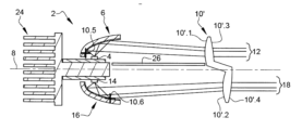
図1は、当該発光装置と、その作動原理との模式的表現である。発光装置2は本質的に、第1光源4と、当該装置の光軸8に沿った第1光ビーム12を形成するために第1光源によって放出された光線を反射することのできる集光器6と、当該ビームを投射するためのレンズ10とを備えている。投射レンズ以外の投射用の光学系、特に1つないし複数の反射鏡などが想定可能である。発光装置2は更に、光軸8に対して第1光源4とは反対の側にある第2光源14と、やはり第1集光器6とは反対の側にある第2集光器16とを備えている。その第2集光器16は、当該装置の光軸8に沿った第2光ビーム18を形成するために第2光源14によって放出された光線を反射することのできるものである。
Figure 1 is a schematic representation of the light-emitting device and its principle of operation. The light-
光源4および14は、半導体光源、特に発光ダイオードであることが有利である。光源4および14のそれぞれは、当該光源の主面によって境界付けられる半分の空間内において、図示例では当該面と光軸8とに垂直な主方向へ光線を放出する。本発明によれば、放出の主方向は或いは、光軸に垂直な方向に対して25°以下の角度だけ傾けられることとなる。
The
集光器6および16のそれぞれは、殻体ないしキャップの形状の保持体6.1および16.1と、保持体6.1および16.1の内面上の反射面6.2および16.2とを備えている。反射面6.2および16.2は、楕円状ないし放物線状のプロファイルを有しているのが有利である。それらの反射面の少なくとも一方は、光軸と平行な軸線周りの回転面であることが有利である。或いは、それは自由曲面やスィープ面や非対称面の問題であってもよい。その面はまた、複数の部分を含んでいてもよい。殻体ないしキャップの形状の集光器6および16は、優れた耐熱性を有する材料から、例えばガラス、またはポリカーボネートPCやポリエーテルイミドPEIなどの合成高分子化合物で作られているのが有利である。表現「放物線状」は一般的には、自らの表面が単一の焦点を有している反射器、即ち光線同士が集束する1つの部位(即ち、この集束の部位に配置された光源によって放出された光線が、当該表面から反射された後に長大な距離まで投射されるような1つの部位)を有している反射器に当てはまる。長大な距離まで投射されるとは、これらの光線が、反射器の寸法の少なくとも10倍の所に位置した部位へ向かっては集束しないことを意味する。換言すれば、反射された光線同士が、ある1つの集束の部位に向かって集束しないか、或いは集束するとしても、この集束の部位が反射器の寸法の10倍以上の距離に位置しているのである。従って放物線状の表面は、放物線状の部分を含んでいてもいなくてもよい。そのような表面を有する反射器は、一般的には単独で光ビームを作り出すのに用いられる。或いは、その反射器は、楕円状反射器と関連付けられる投射面として用いられてもよい。この場合は、放物線状反射器の光源が、楕円状反射器によって反射される光線の集束の部位なのである。
Each of the
光源4および14のそれぞれは、自らの光線が集められて光軸8に沿って反射されるように、対応する反射面6.2および16.2の焦点の所に配置されている。これらの反射された光線の少なくとも一部は、鉛直面内で当該軸に対して25°以下、好ましくは10°以下の傾斜角度αを有している。それは、無非点収差(即ち、投射された像の鮮明性)が得られることを可能とする所謂ガウス条件のもとにあるようにである。それは、反射面6.2および16.2の後方部分によって反射された光線の問題であることが有利である。
Each of the
投射レンズ10は、第1光ビーム12に対応した光線のための第1入光面10.1、第2光ビーム18に対応した光線のための第2入光面10.2、第1光ビーム12のための第1出光面10.3、および第2光ビーム18のための第2出光面10.4を有している。第1および第2出光面10.3および10.4は、2つの入光面10.1および10.2に共通の出光面を出光面を形成しているのが有利である。レンズ10は、薄いもの、例えば装置の光軸に沿って7mm未満の厚さのものであると考えられる。それは特に、その低いレンズ高と長い焦点距離とが理由である。レンズ10は、第1焦点10.5および第2焦点10.6を有していてよい。その第1焦点10.5はレンズ10の上方部分に対応し、第2焦点10.6はレンズ10の下方部分に対応している。当該の第1および第2焦点10.5および10.6のそれぞれは、対応する第1ないし第2集光器6/16の反射面6.2/16.2と、対応する第1ないし第2光源4/14との間に位置した区域6.3および16.3内に置かれているのが有利である(これらの区域は破線で示されている)。この場合、少なくとも一方の焦点は、対応する第1ないし第2集光器6/16の反射面6.2/16.2上に位置していてもよい。この焦点は、その近傍(好ましくは、10mm未満、できれば5mm未満の範囲内)にあれば、反射面6.2/16.2の後方や前方に位置させることもできる、ということに留意されたい。
The
反射面は、それが楕円状である場合には、レンズ10の前方に位置して光軸8から距離の置かれた第2の焦点を有している。この焦点は、レンズの近傍にあるのであれば、レンズの入光面上でのビームの幅を減少させるよう、レンズの後方および/または光軸上に位置させることもできる、ということに留意されたい。
If the reflecting surface is elliptical, it has a second focus located in front of the
再び図1を参照すると、一方の第1光源4および第1集光器6と、他方の第2光源14および第2集光器16とが光軸8に対して反対の側にあること分かるであろう。特に、第1光源4は第1プラテン20上に配置され、第2光源14は、第1プラテン20から隔てられた別個の第2プラテン22上に配置されている。第1および第2光源4および16には、ヒートシンク24が、第1および第2プラテン20および22の保持体の役目をする部分24.1を介して熱的に結合されている。ヒートシンク24は、冷却フィン群を有した放散部分24.2をも備えている。この構成は、熱的な観点から特に有利である。但し、第1および第2光源を共通のプラテンの両面上に配置することもできる、ということを理解されたい。
1, it can be seen that the first
発光装置は、第1および第2集光器6および16とレンズ10との間に位置して光軸8上に広がる吸収スクリーン26を備えていることが有利である。それは、そのスクリーン26に当たる如何なる光線をも吸収することで、寄生反射を防止するようにである。
The light emitting device advantageously comprises an absorbing
再び図1を参照すると、第1光ビーム12は、平坦な上方カットオフを含んだ照明ビーム(即ち、ロービーム)であることが有利である。また、第2光ビーム18は、カットオフlを伴わないビーム(即ち、第1光ビーム12との組合せにおけるハイビーム)であることが有利である。
Referring again to FIG. 1, the
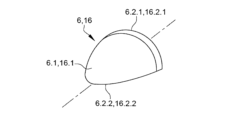
図2は、図1の発光装置2における第1および第2集光器6および16の一方の(但し、第1集光器のような向きでの)後方斜視図である。保持体6.1/16.1の殻体ないしキャップの形状と、反射面(図示せず)が前方縁部6.2.1/16.2.1および後方縁部6.2.2/16.2.2を有しているという事実とが分かるであろう。保持体6.1/16.1が、従って反射面6.2/16.2が、平面によって境界付けられた、好適には対称な回転面の殻体を形成しているという事実のために、当該の平面が後方縁部6.2.2/16.2.2を含んでいるのである。後方縁部は、この平面内において、回転の軸線の両側で左右へ伸びている。反射面6.2/16.2に光源から光が当てられたときには、その表面の全体が照らされるが、当該表面は、前方縁部6.2.1/16.2.1と後方縁部6.2.2/16.2.2とによって境界付けられているのである。
2 is a rear perspective view of one of the first and
図3は、光軸に沿って外側から見た第1集光器の反射面6.2上における光強度を表現したものである。具体的には、それは表面の放射照度、即ち、当該表面の方向に垂直な電磁放射の入射における、W/m2で表される単位面積当たりの仕事率の問題である。表面の大部分に及ぶ暗い区域がより低い放射照度に対応するのに対して、もっと明るい中央区域はより高い放射照度に対応している。暗い区域が縁部6.2.1および6.2.2によって明瞭に境界付けられているのが分かるであろう。換言すれば、被照射面6.2は本来、この面を映し出す投射照明ビーム内にカットオフを形成することのできる明瞭な縁部を有しているのである。同じ論法が第2集光器に当てはまるが、唯一の相違は光強度分布が光軸回りに180°回転されることである。 Figure 3 represents the light intensity on the reflecting surface 6.2 of the first collector, seen from the outside along the optical axis. In particular, it is a matter of the irradiance of the surface, i.e. the power per unit area expressed in W/ m2 , at the incidence of electromagnetic radiation perpendicular to the direction of said surface. The dark areas covering most of the surface correspond to lower irradiance, whereas the lighter central areas correspond to higher irradiance. It can be seen that the dark areas are clearly delimited by the edges 6.2.1 and 6.2.2. In other words, the illuminated surface 6.2 has in itself clear edges that can form cut-offs in the projection illumination beam that images this surface. The same reasoning applies to the second collector, the only difference being that the light intensity distribution is rotated 180° around the optical axis.
図4は、図1の発光装置によって投射される像の図式的表現である。水平軸線Hと鉛直軸線Vとが発光装置の光軸上で交差している。実線が第1光ビーム12に対応し、破線が第2光ビーム18に対応している。これらの曲線は等照度曲線、即ちルクスで表される輝度が同じである光ビームの部位に対応した曲線である。中央部の曲線は、周縁部よりも高い輝度レベルに対応している。
Figure 4 is a schematic representation of the image projected by the light-emitting device of Figure 1. A horizontal axis H and a vertical axis V intersect on the optical axis of the light-emitting device. The solid line corresponds to the
図4では、第1光ビーム12が、本質的に水平軸線Hと同じ高さにある平坦な上方カットオフを含んでいることが分かるであろう。カットオフは完全に真っ直ぐではなく、かくして作り出される像の収差に対応した湾曲を有している。いずれにしても平坦なカットオフは、第1集光器6の反射面6.2の後方縁部(図2)であるところの縁部6.2.2(図3)によって作り出されるものである。この目的のためには、この縁部6.2.2(図3)の近傍、即ち第1光源4の後方に、レンズ10の第1焦点10.5(図1)が位置しているのが有利である。作り出される照明ビームが、前方縁部6.2.1に対応した明瞭な輪郭を水平軸線の下方に有していることも分かるであろう。
In FIG. 4, it can be seen that the
これもまた図4において、第2光ビーム18は、本質的に第1光ビーム12の上下反転版に相当し、第1光ビーム12を完全なものとするように水平軸線H上と当該軸線の上方とに光を集めるものであることが分かるであろう。この第2ビームの最大部分における光の集中は、反射面16.2における後方縁部16.2.2近傍の部分を通じて成し遂げられる。この目的のためには、レンズ10の第2焦点10.6(図1)が後方縁部16.2.2(図2)の近傍に位置していてよい。
図5は、本発明の第1実施形態(即ち、図1に示した実施形態)の発光装置2における一変形例の模式的表現である。この変形例は、レンズ10’がもはや共通の出光面は有しておらず、むしろ別々の出光面を有している点で図1とは異なっている。この場合、第2入光面10’.2および第2出光面10’.4は、第1入光面10’.1および第1出光面10’.3に対して軸方向に偏位されていることが分かるであろう。より特定的には、この偏位は、第2入光面10’.2および第2出光面10’.4が、第1入光面10’.1および第1出光面10’.3よりも第1および第2集光器6および16から遠く離れているようなものである。これにより、特に容積上の制約を満たすことが可能となる。
It can also be seen in Fig. 4 that the
Figure 5 is a schematic representation of a variant of the
図6は、本発明の第2実施形態による発光装置の模式図である。対応したり同一であったりする要素を示すのに第1実施形態の参照符号が用いられているが、これらの符号の数字は100だけ増やされている。更に、これら要素の第1実施形態の文脈でなされた説明が援用される。この実施形態に特有の要素を示すのに、100から200の間に含まれる特有の符号が用いられている。 Figure 6 is a schematic diagram of a light emitting device according to a second embodiment of the present invention. The reference numerals of the first embodiment are used to indicate corresponding or identical elements, but these numerals are incremented by 100. Furthermore, the explanations given in the context of the first embodiment of these elements are incorporated herein. Specific numerals between 100 and 200 are used to indicate elements specific to this embodiment.
この発光装置102において、第2光源114および第2集光器116は、もはや装置の光軸に対して第1光源104および第1集光器106と反対の側にはなく、代わりに後者の光源および集光器の隣に位置している。第1光源104および第1集光器106は、第2光源114および第2集光器116の裏側に位置しているので見えていない。発光装置102は更に、集光器116の反射面116.2の延長箇所に配置された反射鏡126を備えている。反射鏡126は、保持体126.1と、保持体126.1上に形成された平坦な反射面126.2とを備えている。その保持体126.1は、集光器116の保持体116.1と連なっていても、或いは隣接していてもよい。光源114は、その光線が集められて反射鏡126へ向かって反射されるように、集光器116における反射面116.2の焦点の所に配置されている。反射鏡126は、投射レンズ110に向かって、反射面116.2の虚像116.2、第2集光器116の虚像116、および光源114の虚像114を反射する(これらの虚像は、図6に破線で示されている)。第1実施形態と同様、反射鏡126によって反射されたこれらの光線の少なくとも一部は、鉛直面内で前記軸に対して25°以下、好ましくは10°以下の傾斜角度αを有している。それは、無非点収差(即ち、投射された像の鮮明性)が得られることを可能とする所謂ガウス条件のもとにあるようにである。それは、第2集光器116の反射面116.2の後方部分によって反射された光線の問題であることが有利である。
In this light-emitting
そしてレンズ110は、第1および第2光ビーム112および118のための2つの別個の部分を備えている。これら2つの部分同士は、横並びで配置されており、もはや第1実施形態のように光軸の両側にあるわけではない。そしてレンズ110は、第1ビーム112を形成するための第1入光面110.1および第1出光面110.3と、第2ビーム118を形成するための第2入光面110.2および第2出光面110.4とを有している。但し、2つの出光面110.3および110.4が、図1のように共通の出光面を形成していたり、図5のように寧ろ別個の、軸方向に偏位し合うこともあり得る出光面を形成していたりしてもよい、ということに留意されたい。
The
レンズの第2部分、即ち第2入光および出光面110.2および110.4がある部分は、両凸型であって、光軸108の上方に位置した虚光軸(virtual optical axis)108(一点鎖線)に関して対称であることが有利である、ということにも留意されたい。レンズのこの部分は、この虚光軸上において集光器の虚像の反射面における後方縁部の近傍に位置した焦点110.6を有している。これにより、レンズ110のこの部分が、本発明の第1実施形態と同様に、第2集光器116の被照射面を映し出すことが可能となる。
It should also be noted that the second part of the lens, i.e. the part with the second entrance and exit faces 110.2 and 110.4, is advantageously biconvex and symmetrical about a virtual optical axis 108 (dashed-dotted line) located above the
ここまで説明してきた構成は、特に下方への容積上の制約を有している用途に対して有利である。 The configuration described so far is particularly advantageous for applications that have downward volume constraints.
図7は、本発明の第2実施形態(即ち、図6に示した実施形態)の発光装置102における一変形例の模式的表現である。この変形例による発光装置102’は、光軸108回りに回転されているのがもはや第2光源114および第2集光器116ではなく寧ろ第1光源104および第1集光器106である点において図6とは異なっている。同様に、光源104は、その光線が集められて反射鏡126へ向かって反射されるように、第1集光器106における反射面106.2の焦点の所に配置されている。反射鏡126は、投射レンズ110に向かって、第1集光器106の反射面106.2の虚像106.2および光源104の虚像104を反射する(これらの虚像は、図6に破線で示されている)。換言すれば、この発明は、同じ向きを有した光源同士から2つの相反する光ビーム(12&18)が得られることを可能とするのである。かくして第1光源104および第1集光器106は、回転にもかかわらず、図4に示す第1実施形態の第1光ビーム12と同様の光ビーム、即ち自らの上方部分における(この場合、水平軸線と同じ高さの)光の集中を伴ったビームを作り出し得るのである。
Fig. 7 is a schematic representation of a variant of the
レンズ110’の第1入光および出光面110’.1および110’.3は見えるであろうが、第2入光および出光面110’.3および110’.4は見えていない。そして、レンズ110’の第1部分は、図6のレンズの第2部分と同様、両凸型であって、光軸108の下方に位置した虚光軸(一点鎖線)に関して対称であることが有利である。レンズのこの部分は、この虚光軸上において集光器の虚像の反射面における後方縁部の近傍に位置した焦点110’.6を有している。
The first entrance and exit faces 110'.1 and 110'.3 of the lens 110' will be visible, but the second entrance and exit faces 110'.3 and 110'.4 will not be visible. And the first part of the lens 110', like the second part of the lens of FIG. 6, is advantageously biconvex and symmetrical about a virtual optical axis (dashed line) located below the
同様に、ここまで説明してきた構成は、特に上方への容積上の制約を有している用途に対して有利である。 Similarly, the configurations described thus far are particularly advantageous for applications that have upward volume constraints.
図8は、本発明の第3実施形態による発光装置の模式図である。対応したり同一であったりする要素を示すのに第1および第2実施形態の参照符号が用いられているが、これらの符号の数字はそれぞれ200および100だけ増やされている。更に、これら要素の第1および第2実施形態の文脈でなされた説明が援用される。この実施形態に特有の要素を示すのに、200から300の間に含まれる特有の符号が用いられている。 Figure 8 is a schematic diagram of a light emitting device according to a third embodiment of the present invention. Reference numerals from the first and second embodiments are used to indicate corresponding or identical elements, but these numerals are incremented by 200 and 100, respectively. Furthermore, the descriptions of these elements made in the context of the first and second embodiments are incorporated herein. Specific numerals between 200 and 300 are used to indicate elements specific to this embodiment.
この第3実施形態は、次の点において第2実施形態(図6)と同様である。即ち、この発光装置202において、第2光源214および第2集光器216は、もはや装置の光軸に対して第1光源204および第1集光器206と反対の側にはなく、代わりに後者の光源および集光器の隣に位置している。第1光源204および第1集光器206は、第2光源214および第2集光器216の裏側に位置しているので見えていない。装置202は、保持体226.1と反射面226.2とが設けられた反射鏡226を備えている。その反射面226.2は、平坦であるのが有利である。反射鏡226、より特定的には反射面226.2が光軸208上にある。それらは当該軸と平行であることが有利であるが、僅かに(例えば、20°または10°までの傾斜で)傾いている変形例を構想し得る、ということを理解されたい。第2集光器216の反射面216.2は、第2光源214によって放出された光線を反射面226.2に向かって反射するように構成されている。そして反射面226.2は、これらの光線を、第2光源214の虚像214および第2集光器216の反射面216.2の虚像216.2を形成するように反射する。これらの虚像(破線)は、光軸208の下方に位置している。換言すれば当該装置202は、第2集光器216の被照射面の反転した発光像(これは、第2集光器216の虚像216(破線)に対応し、主に水平軸線の上方に位置している)を作り出しつつ、当該軸線と同じ高さの下方部分における光の集中を達成することとなる。
This third embodiment is similar to the second embodiment (FIG. 6) in that in this
そして第2実施形態と同様に、レンズ210は、第1および第2光ビーム212および218のための2つの別個の部分を備えている。これら2つの部分同士は、横並びで配置されており、もはや第1実施形態のように光軸の両側にあるわけではない。そしてレンズ210は、第1ビーム212を形成するための第1入光面210.1および第1出光面210.3と、第2ビーム218を形成するための第2入光面210.2および第2出光面210.4とを有している。但し、2つの出光面210.3および210.4が、図1のように共通の出光面を形成していたり、図5のように寧ろ別個の、軸方向に偏位し合うこともあり得る出光面を形成していたりしてもよい、ということに留意されたい。
And like the second embodiment, the
レンズの第2部分、即ち第2入光および出光面210.2および210.4がある部分は、両凸型であって、光軸208の下方に位置した虚光軸(一点鎖線)に関して対称であることが有利である、ということにも留意されたい。レンズのこの部分は、この虚光軸208上において集光器の虚像の反射面における後方縁部の近傍に位置した焦点210.6を有している。これにより、レンズ210のこの部分が、本発明の第1実施形態と同様に、第2集光器216の被照射面を映し出すことが可能となる。
It should also be noted that the second part of the lens, i.e. the part with the second entrance and exit faces 210.2 and 210.4, is advantageously biconvex and symmetrical about a virtual optical axis (dashed-dotted line) located below the
図9は、本発明の第3実施形態(即ち、図8に示した実施形態)の発光装置202における一変形例の模式的表現である。この変形例による発光装置202’は、光軸208回りに回転されているのがもはや第2光源214および第2集光器216ではなく寧ろ第1光源204および第1集光器206である点において図8とは異なっている。同様に、第1集光器の反射面206.2は、第1光源204によって放出された光線を反射スクリーン226の(平面であるのが有利な)反射面226.2に向かって反射するように構成されている。この反射面206.2はそして、レンズ210’に向かって、より正確にはレンズ210’の第1入光および出光面210’.1および210’.3に対応した第1部分に向かって光線を反射する。かくして、破線で描かれた集光器の虚像206および虚光源204によって作り出されたかのような発光像の反転を生じさせる。換言すれば、この反転によって、第1光源204および第1集光器206を下向きに裏返したことで生じる反転を相殺することが可能となるのである。かくして第1光源204および第1集光器206は、回転にもかかわらず、図4に示す第1実施形態の第1光ビーム12と同様の光ビーム、即ち自らの上方部分における(この場合、水平軸線と同じ高さの)光の集中を伴ったビームを作り出し得るのである。
Figure 9 is a schematic representation of a variant of the light-emitting
レンズ210’の第1入光および出光面210’.1および210’.3は見えるであろうが、第2入光および出光面210’.3および210’.4は見えていない。そして、レンズ210’の第1部分は、図8のレンズの第2部分と同様、両凸型であって、光軸208の上方に位置した虚光軸208(一点鎖線)に関して対称であることが有利である。レンズのこの部分は、この虚光軸上において集光器の虚像の反射面における後方縁部の近傍に位置した焦点210’.5を有している。
The first entrance and exit faces 210'.1 and 210'.3 of the lens 210' will be visible, but the second entrance and exit faces 210'.3 and 210'.4 will not be visible, and the first portion of the lens 210', like the second portion of the lens of Figure 8, is advantageously biconvex and symmetrical about a virtual optical axis 208 (dashed-dotted line) located above the
同様に、ここまで説明してきた構成は、特に上方への容積上の制約を有している用途に対して有利である。 Similarly, the configurations described thus far are particularly advantageous for applications that have upward volume constraints.
図10は、本発明の第4実施形態による発光装置の模式図である。対応したり同一であったりする要素を示すのに第1実施形態の参照符号が用いられているが、これらの符号の数字は300だけ増やされている。更に、これら要素の第1実施形態の文脈でなされた説明が援用される。この実施形態に特有の要素を示すのに、300から400の間に含まれる特有の符号が用いられている。 Figure 10 is a schematic diagram of a light emitting device according to a fourth embodiment of the present invention. The reference numerals of the first embodiment are used to indicate corresponding or identical elements, but these numerals are incremented by 300. Furthermore, the explanations given in the context of the first embodiment of these elements are incorporated herein. Specific numerals between 300 and 400 are used to indicate elements specific to this embodiment.
図10の発光装置302は本質的に、光ビームのうちの一方が合図用光ビームである点において図1における第1実施形態の発光装置と異なっている。具体的には、第1実施形態においては第1および第2光ビーム12および18が照明ビームであって、実際には平坦なカットオフを含んだビーム(ロービーム機能)およびカットオフを含んでいないビーム(ハイビーム機能)であるという有利性がある。図10の場合には、第1光ビーム312が合図用光ビームとなっている。この目的のために、レンズの第1入光面310.1上に粗面化加工が施されている。かくして第1光源304と、第1集光器306と、第1入光および出光面310.1および310.3に対応するレンズ310の第1部分とによって、第1の拡散光ビーム312が形成される。第2光源、第2集光器、およびレンズの第2部分は、第1、第2、および第3実施形態のうちの1つにおけるものと同様である。かくして、第2光ビームはカットオフを含んでいてもいなくてもよく、第2光源および第2集光器は光軸308の上方に位置していても下方に位置していてもよい、ということを理解されたい。
The
図11は、図10の第4実施形態の第1変形例を示している。この変形例による発光装置302’は、対応するレンズの入光面上に代えて、中間レンズ328の入光および出光面328.1および328.2の少なくとも一方の上に位置した粗面化加工を有している。その中間レンズ328は、光学的に第1集光器306と主レンズ310との間に位置している。第1集光器306の反射面306.1によって反射された各光線は、中間レンズを通過してから主レンズ10へ到達する。それらの光線が、中間レンズの粗面化加工された出光面328.2によって形成される屈折面を通じて散乱させられる有利性があるのである。
Figure 11 shows a first variant of the fourth embodiment of Figure 10. The light emitting device 302' according to this variant has a roughening located on at least one of the entrance and exit surfaces 328.1 and 328.2 of an
図12は、図10の第4実施形態の第2変形例を示している。この変形例による発光装置302”は、完全に、即ち光軸308の一側(この場合は、光軸の上方)に第1光源304および第1集光器306を、光軸の他側(この場合は、光軸の下方)に第2光源314および第2集光器316を伴って示されている。図11の第1変形例と同様に、中間レンズ328が設けられている。この場合、その中間レンズは、光学的に第2集光器316と主レンズ310”との間に配置されている。もっと具体的には、中間レンズ328は、第2集光器316の近傍に、いずれにしても主レンズ310”から距離を置いて配置されている。それは、第2光ビームを、レンズ310の第2入光面310”.3の方だけではなく、第1入光面310”.1の方へも散乱させるようにである。かくして拡散した第2光ビーム318が、第1光ビーム312(この場合は、平坦なカットオフを含んでいるのが好ましい照明ビーム)と重ね合わされる。
Figure 12 shows a second variant of the fourth embodiment of Figure 10. The
これら種々の実施形態や、それらの変形例を考慮すれば、所与の発光装置において照明および/または合図用光ビームの種々の組合せが可能である、ということを理解されたい。特に、光源および対応する集光器の数は、2つには限定されない。具体的には、もっと多くの光源や、もっと多くの対応した集光器を設けることが構想され得る。上述した諸実施形態で既に強調してきたように、様々な光源と集光器との対によって作り出される種々の光ビーム同士を、並べ、および/または重ね合わせてもよい。図12の、第3実施形態の変形例においては、光軸の下方に位置した光源および集光器によって作り出される第2ビーム(当該ビームはこの場合、拡散している)が、少なくとも部分的に第1光ビームと重ね合わされている。更に、第1および第2光源(並びに、任意に追加される各光源)のそれぞれが、対応した集光器に向かって光線を放出する随意に点灯可能な複数の発光部位で構成されていてもよい。 In view of these various embodiments and their variants, it should be understood that various combinations of illumination and/or signaling light beams are possible in a given light-emitting device. In particular, the number of light sources and corresponding collectors is not limited to two. In particular, it is conceivable to provide more light sources and more corresponding collectors. As already highlighted in the above embodiments, the various light beams produced by the various light source-collector pairs may be aligned and/or overlapped. In a variant of the third embodiment of FIG. 12, a second beam (which is in this case divergent) produced by a light source and collector located below the optical axis is at least partially overlapped with the first light beam. Furthermore, each of the first and second light sources (as well as each optional additional light source) may consist of a number of light-emitting sites that can be optionally activated, emitting light rays towards the corresponding collector.
網羅している訳ではないが、特にもっと多くの数の集光器および当該集光器に関連付けられる光源が設けられている場合には、所与の発光装置において以下の様々な組合せが可能である。 Although not exhaustive, various combinations of the following are possible in a given lighting device, especially when a larger number of collectors and associated light sources are provided:
- 第1照明機能の一部を成す平坦なカットオフを含んだ第1照明ビームの形態をとる第1光ビーム、同じ第1照明機能の別の一部を成す湾曲したカットオフを伴った第2照明ビームの形態をとる第2光ビーム、第2照明機能の全部ないし一部を成すカットオフを伴わない第3照明ビームの形態をとる第3光ビーム。
例えば、第1照明ビームがロービーム機能の一部を成す平坦なカットオフを含んだビームであって、第2照明ビームがロービーム機能の第2の部分を成す湾曲したカットオフを伴ったビームであって、第1照明ビームと第2照明ビームとの重ね合わせによってロービーム機能が成されていてもよい。第3照明ビームは、第1および第2照明ビームと重ね合わされたときにハイビーム機能を成す、補完ハイビーム機能と称されるハイビーム機能の一部を成していてもよい。
或いは第3光ビームは、第2照明機能の一部を成す光輝セグメントの形態をとる第3照明ビームであってもよく、発光装置は、この第2照明機能の一部を成す光輝セグメントの形態をとる複数の補助光ビームを放出し、それぞれの光輝セグメントが選択的に点灯可能となっている。
例えば、第3照明ビームによって形成される光輝セグメント同士がハイビーム機能の一部を成し、第3照明ビームと補助光ビームとによって形成される全ての光輝セグメントの、第1および第2照明ビームとの重ね合わせが、ハイビーム機能を成す。
上記代替案のそれぞれにおいて、発光装置2;102;202;302は、照明または合図ビームの形態をとる追加的な光ビームをも放出してよい。
a first light beam in the form of a first illumination beam including a flat cut-off forming part of a first illumination function, a second light beam in the form of a second illumination beam with a curved cut-off forming another part of the same first illumination function, a third light beam in the form of a third illumination beam without a cut-off forming all or part of the second illumination function.
For example, the first illumination beam may be a beam including a flat cutoff that forms part of a low beam function and the second illumination beam may be a beam with a curved cutoff that forms a second part of the low beam function, the low beam function being formed by superposition of the first and second illumination beams. The third illumination beam may be part of a high beam function, referred to as a complementary high beam function, that forms the high beam function when superimposed with the first and second illumination beams.
Alternatively, the third light beam may be a third illumination beam in the form of a bright segment that is part of the second illumination function, and the light emitting device emits a plurality of auxiliary light beams in the form of bright segments that are part of this second illumination function, each bright segment being selectively illuminable.
For example, the bright segments formed by the third illumination beam form part of the high beam function, and the superposition of all the bright segments formed by the third illumination beam and the auxiliary light beam with the first and second illumination beams forms the high beam function.
In each of the above alternatives, the light-emitting
- 第1照明機能を成すカットオフを伴わない照明ビームの形態をとる第1光ビーム、および合図機能を成す合図ビームの形態をとる第2光ビーム。
例えば、照明ビームがハイビーム機能を成し、合図ビームが、方向指示機能、デイタイムランニングライト(昼間走行灯)機能、およびポジションライト(車幅灯)機能の中から選択された合図機能を成していてよい。
或いは、第1光ビームが、第1照明機能の一部を成す平坦なカットオフを含んだ第1照明ビームの形態をとっていてもよく、同じ第1照明機能の別の一部を成す湾曲したカットオフを伴った第2照明ビームの形態をとる第3光ビームを放出してもよい。
例えば、第1照明ビームがロービーム機能の一部を成す平坦なカットオフを含んだビームであって、第2照明ビームがロービーム機能の第2の部分を成す湾曲したカットオフを伴ったビームであって、第1照明ビームと第2照明ビームとの重ね合わせによってロービーム機能が成されていてもよい。
そして発光装置2;102;202;302は、平坦なカットオフを含んだビーム、湾曲したカットオフを含んだビーム、および合図ビームを放出する。
それぞれの代替案において、発光装置2;102;202;302が、第2の合図ビームの形態をとる追加的な光ビームを放出するようにすることも可能である。例えば、この第2の合図ビームは、方向指示機能、デイタイムランニングライト機能、およびポジションライト機能の中から選択された合図機能を成していてよい。
a first light beam in the form of an illumination beam without cut-off, which performs a first illumination function, and a second light beam in the form of a signaling beam, which performs a signaling function.
For example, the illumination beam may perform a high beam function and the signal beam may perform a signal function selected from among a turn signal function, a daytime running light function, and a position light function.
Alternatively, the first light beam may take the form of a first illumination beam including a flat cutoff that forms part of a first illumination function, and a third light beam may be emitted in the form of a second illumination beam with a curved cutoff that forms another part of the same first illumination function.
For example, the first illumination beam may be a beam including a flat cutoff that forms part of the low beam function, and the second illumination beam may be a beam with a curved cutoff that forms a second part of the low beam function, with the low beam function being achieved by superposition of the first and second illumination beams.
And the
In each alternative, it is also possible for the
また、一方では光源同士が、他方では関連した集光器同士が横並びで配置されていてもよい。或いは、各光源と、それらの関連する集光器との一部が、光軸に対して、各光源と、それらの関連する集光器との別の一部とは反対の側にあってもよい。 Alternatively, the light sources may be arranged side-by-side on one side and the associated collectors on the other side, or a portion of each light source and its associated collector may be on an opposite side of the optical axis from another portion of each light source and its associated collector.
一変形例によれば、全ての集光器同士が横並びで配置されることへの備えがなされていてもよい。 According to one variant, provision may be made for all collectors to be arranged side-by-side.
例えば、かくして発光装置は、自らの機能する姿勢において、平坦なカットオフを含んだ照明ビームの形成に関与する集光器と、湾曲したカットオフを伴ったビームの形成に関与する集光器と、ハイビーム機能の一部を成す光ビームの形成に関与する集光器とを備え、これらの集光器同士が横並びで配置されていてよい。 For example, the light emitting device may thus comprise, in its functional position, a collector responsible for forming an illumination beam with a flat cutoff, a collector responsible for forming a beam with a curved cutoff and a collector responsible for forming a light beam that is part of the high beam function, the collectors being arranged side-by-side.
別の変形例によれば、第1および第2集光器とそれぞれ関連付けられる第1および第2光源であって、第3光源および第3光源の関連付けられる第3集光器とは光軸に対して反対の側にある第1および第2光源を有することが可能である。 According to another variation, it is possible to have a first and second light source associated with a first and second collector, respectively, on the opposite side of the optical axis from the third light source and the third collector with which it is associated.
例えば、自らの機能する姿勢において発光装置は、光軸の上方で平坦なカットオフを含んだ照明ビームおよび湾曲したカットオフを伴ったビームの形成にそれぞれ関与する第1および第2集光器と、光軸の下方でハイビーム機能の一部を成す光ビームの形成に関与する第3集光器とを備えていてよい。 For example, in its functional position, the light emitting device may have a first and a second collector involved in forming an illumination beam with a flat cutoff and a beam with a curved cutoff above the optical axis, respectively, and a third collector involved in forming a light beam below the optical axis that is part of the high beam function.
別の例では、かくして発光装置は、自らの機能する姿勢において、光軸の上方で照明機能および合図機能の成立にそれぞれ関与する第1および第2集光器と、光軸の下方で合図機能の全部ないし一部を成立させる光ビームの形成に関与する第3集光器とを備えていてもよい。 In another example, the light-emitting device may thus have, in its functional position, first and second collectors above the optical axis which are involved in achieving the illumination function and the signaling function, respectively, and a third collector below the optical axis which is involved in forming a light beam which achieves all or part of the signaling function.
別の変形例によれば、第1集光器と関連付けられる第1光源であって、第2光源および第2光源と関連付けられる第2集光器とは、第1集光器と共に光軸に対して反対の側に位置した第1光源を有することが可能である。 According to another variant, the first light source associated with the first collector may be located on the opposite side of the optical axis from the first collector, the second light source, and the second collector associated with the second light source.
例えば、かくして発光装置は、自らの機能する姿勢において、光軸の上方で第1照明ビームを形成するカットオフを伴わない照明ビームの形成に関与する第1集光器と、光軸の下方で合図ビームの形成に関与する第2集光器とを備えていてよい。 For example, the light-emitting device may thus have, in its functional position, a first collector involved in forming an illumination beam without cut-off forming a first illumination beam above the optical axis, and a second collector involved in forming a signal beam below the optical axis.
Claims (20)
- それぞれが光線を放出することのできる第1光源(4;104;204;304)および第2光源(14;114;214;314)と、
- 前記第1光源(4;104;204;304)および前記第2光源(14;114;214;314)によって放出された光線をそれぞれ集光して反射するように構成される反射面(6.2,16.2;106.2,116.2;206.2,216.2;306.2,316.2)を各自有した第1集光器(6;106;206;306)および第2集光器(16;116;216;316)と、
- 前記第1集光器(6;106;206;306)および前記第2集光器(16;116;216;316)の前記反射面(6.2,16.2;106.2,116.2;206.2,216.2;306.2,316.2)によって反射された光線を投射して、それぞれ当該発光装置の光軸(8;108;208;308)に沿った第1光ビーム(12;112;212;312)および第2光ビーム(18;118;218;318)とするように構成された光学系(10;110;210;310)と、
を備えた発光装置(2;102;202;302)において、
前記光学系(10;110;210;310)は、前記第1集光器(6;106;206;306)および前記第2集光器(16;116;216;316)それぞれの前記反射面(6.2,16.2;106.2,116.2;206.2,216.2;306.2,316.2)の発光像を形成するように構成されており、
前記光学系(10;110;210;310)は、軸方向で前記第1集光器(6;106;206;306)の前記反射面(6.2;106.2;206.2;306.2)における前方境界の後方に位置した第1焦点(10.5;110.5;210.5;310.5)と、軸方向で前記第2集光器(16;116;216;316)の前記反射面(16.2;116.2;216.2;316.2)における前方境界の後方に位置した第2焦点(10.6;110.6;210.6;310.6)とを有しており、
前記第1光ビーム(12;112;212;312)および前記第2光ビーム(18;118;218;318)のそれぞれが、当該第1および第2光ビームの他の照明または合図機能とは別個の照明または合図機能の一部ないし全部を形成する、発光装置(2;102;202;302)。 A lighting device (2; 102; 202; 302) for a motor vehicle , comprising
a first light source (4; 104; 204; 304) and a second light source (14; 114; 214; 314) each capable of emitting a light beam,
a first collector (6; 106; 206; 306) and a second collector (16; 116; 216; 316), each having a reflecting surface (6.2, 16.2; 106.2, 116.2; 206.2, 216.2; 306.2, 316.2) adapted to collect and reflect the light beams emitted by said first light source (4; 104; 204; 304) and said second light source (14; 114; 214; 314), respectively;
an optical system (10; 110; 210; 310) configured to project the light rays reflected by the reflecting surfaces (6.2, 16.2; 106.2, 116.2; 206.2, 216.2; 306.2, 316.2) of the first collector (6; 106; 206; 306) and the second collector (16; 116; 216; 316) into a first light beam (12; 112; 212; 312) and a second light beam (18; 118; 218; 318), respectively, along the optical axis (8; 108; 208; 308) of the light-emitting device;
In a light emitting device (2; 102; 202; 302) comprising
the optical system (10; 110; 210; 310) is configured to form an illuminating image of the reflecting surface (6.2, 16.2; 106.2, 116.2; 206.2, 216.2; 306.2, 316.2) of each of the first collector (6; 106; 206; 306) and the second collector (16; 116; 216; 316),
The optical system (10; 110; 210; 310) has a first focus (10.5; 110.5; 210.5; 310.5) located in the axial direction behind the front boundary of the reflecting surface (6.2; 106.2; 206.2; 306.2) of the first collector (6; 106; 206; 306) and a second focus (10.6; 110.6; 210.6; 310.6) located in the axial direction behind the front boundary of the reflecting surface (16.2; 116.2; 216.2; 316.2) of the second collector (16; 116; 216; 316),
A light emitting device (2; 102; 202; 302), wherein each of the first light beam (12; 112; 212; 312) and the second light beam (18; 118; 218; 318) forms some or all of a lighting or signaling function that is separate from other lighting or signaling functions of the first and second light beams.
Applications Claiming Priority (2)
| Application Number | Priority Date | Filing Date | Title |
|---|---|---|---|
| FR1902618 | 2019-03-14 | ||
| FR1902618A FR3093789B1 (en) | 2019-03-14 | 2019-03-14 | LIGHT DEVICE IMAGING THE ILLUMINATED SURFACES OF AT LEAST TWO COLLECTORS |
Publications (2)
| Publication Number | Publication Date |
|---|---|
| JP2020149975A JP2020149975A (en) | 2020-09-17 |
| JP7523924B2 true JP7523924B2 (en) | 2024-07-29 |
Family
ID=68072505
Family Applications (1)
| Application Number | Title | Priority Date | Filing Date |
|---|---|---|---|
| JP2020044441A Active JP7523924B2 (en) | 2019-03-14 | 2020-03-13 | A light-emitting device for projecting the illuminated surfaces of at least two collectors. |
Country Status (8)
| Country | Link |
|---|---|
| US (1) | US11022266B2 (en) |
| EP (2) | EP3708904B1 (en) |
| JP (1) | JP7523924B2 (en) |
| KR (1) | KR20200110221A (en) |
| CN (1) | CN111692567B (en) |
| FR (1) | FR3093789B1 (en) |
| PL (1) | PL3708904T3 (en) |
| RS (1) | RS64733B1 (en) |
Families Citing this family (12)
| Publication number | Priority date | Publication date | Assignee | Title |
|---|---|---|---|---|
| FR3084728B1 (en) | 2018-07-31 | 2021-03-19 | Valeo Vision | LIGHT MODULE IMAGING THE ILLUMINATED SURFACE OF A COLLECTOR |
| FR3118125B1 (en) * | 2020-12-17 | 2022-12-30 | Valeo Vision | LIGHT MODULE IMAGING THE ILLUMINATED SURFACE OF A COLLECTOR WITH A BLOCKER OF INTERFERENCE RAYS |
| FR3118124B1 (en) | 2020-12-18 | 2022-12-30 | Valeo Vision | BI-FUNCTION AUTOMOTIVE LIGHT MODULE WITH LENS ILLUMINATION OF AN INACTIVE LIGHT MODULE |
| FR3118122B1 (en) * | 2020-12-18 | 2023-02-24 | Valeo Vision | Light module of a motor vehicle lighting device |
| FR3119440B1 (en) * | 2021-01-29 | 2024-01-12 | Valeo Vision | Road lighting device for a motor vehicle |
| FR3123415A1 (en) * | 2021-05-27 | 2022-12-02 | Valeo Vision | Light module comprising a light-absorbing element |
| DE102021113978B4 (en) | 2021-05-31 | 2023-03-16 | HELLA GmbH & Co. KGaA | Lighting module and lighting method for generating two different luminous images |
| FR3126029B1 (en) * | 2021-08-04 | 2023-08-11 | Valeo Vision | Light module for a motor vehicle and method of assembling such a light module |
| FR3126747B1 (en) * | 2021-09-03 | 2023-11-17 | Valeo Vision | Lighting device of a motor vehicle |
| FR3133901B1 (en) * | 2022-03-28 | 2024-03-01 | Valeo Vision | LIGHT MODULE IMAGING THE ILLUMINATED SURFACE OF A COLLECTOR WITH EXTRUDED PARASITIC RAY BLOCKER |
| FR3139375A1 (en) | 2022-09-06 | 2024-03-08 | Valeo Vision | Road lighting module with light source directed upwards |
| FR3141988A1 (en) | 2022-11-14 | 2024-05-17 | Valeo Vision | MULTIFUNCTION LIGHTING MODULE WITH OPTICAL PROJECTION DEVICE WITH ILLUMINATED APPEARANCE |
Citations (4)
| Publication number | Priority date | Publication date | Assignee | Title |
|---|---|---|---|---|
| JP2007109493A (en) | 2005-10-13 | 2007-04-26 | Koito Mfg Co Ltd | Lamp unit of vehicle headlight |
| JP2010153270A (en) | 2008-12-26 | 2010-07-08 | Toyoda Gosei Co Ltd | Light-emitting device |
| JP2014107048A (en) | 2012-11-26 | 2014-06-09 | Koito Mfg Co Ltd | Head light for vehicle |
| JP2017016819A (en) | 2015-06-30 | 2017-01-19 | 市光工業株式会社 | Vehicular head lamp |
Family Cites Families (15)
| Publication number | Priority date | Publication date | Assignee | Title |
|---|---|---|---|---|
| FR2847655B1 (en) * | 2002-11-21 | 2005-03-04 | Valeo Vision | ELLIPTICAL PROJECTOR FOR A MOTOR VEHICLE EMITTING DIFFERENT LIGHTING BEAMS |
| FR2858042B1 (en) * | 2003-07-24 | 2005-09-23 | Valeo Vision | LUMINAIRE-FREE ELLIPTICAL LIGHTING MODULE COMPRISING A CUT-OFF LIGHTING BEAM AND PROJECTOR COMPRISING SUCH A MODULE |
| EP1762776B1 (en) * | 2005-09-09 | 2015-04-15 | Valeo Vision | Method for the manufacturing of a module or a vehicle headlamp |
| JP2009184410A (en) * | 2008-02-04 | 2009-08-20 | Koito Mfg Co Ltd | Vehicular lighting fixture |
| JP5607634B2 (en) * | 2008-09-18 | 2014-10-15 | コーニンクレッカ フィリップス エヌ ヴェ | Lighting unit and vehicle headlamp |
| JP5323449B2 (en) * | 2008-10-30 | 2013-10-23 | 株式会社小糸製作所 | Vehicle lamp unit and vehicle lamp |
| JP2011100583A (en) * | 2009-11-04 | 2011-05-19 | Koito Mfg Co Ltd | Optical unit |
| FR2979594B1 (en) * | 2011-09-05 | 2013-09-13 | Valeo Vision | PROJECTOR FOR MOTOR VEHICLE |
| FR2979688A1 (en) * | 2011-09-05 | 2013-03-08 | Valeo Vision | OPTICAL MODULE FOR SIGNALING AND / OR LIGHTING DEVICE |
| DE102014112937B4 (en) * | 2014-09-09 | 2018-05-24 | HELLA GmbH & Co. KGaA | Lighting device for vehicles |
| JP6519353B2 (en) * | 2015-06-29 | 2019-05-29 | 市光工業株式会社 | Vehicle headlights |
| FR3038695A1 (en) * | 2015-07-10 | 2017-01-13 | Valeo Vision | LUMINOUS MODULE FOR LIGHTING AND / OR SIGNALING OF A MOTOR VEHICLE |
| FR3047541B1 (en) | 2015-12-10 | 2019-10-04 | Valeo Vision | AUTOMOTIVE LIGHTING MODULE WITH COMBINED CODE AND ROAD FUNCTIONS AND ADJUSTABLE LIGHT SOURCE |
| FR3050011A1 (en) * | 2016-04-11 | 2017-10-13 | Valeo Vision | MODULE FOR TRANSMITTING A LUMINOUS BEAM FOR MOTOR VEHICLE PROJECTOR |
| FR3058105B1 (en) * | 2016-10-28 | 2021-04-02 | Valeo Vision | OPTICAL MODULE FOR PROJECTING A CUT-OFF LIGHT BEAM WITH HORIZONTAL FOCUSING MEANS |
-
2019
- 2019-03-14 FR FR1902618A patent/FR3093789B1/en active Active
-
2020
- 2020-02-21 RS RS20230852A patent/RS64733B1/en unknown
- 2020-02-21 EP EP20158870.4A patent/EP3708904B1/en active Active
- 2020-02-21 EP EP23174455.8A patent/EP4235024A3/en active Pending
- 2020-02-21 PL PL20158870.4T patent/PL3708904T3/en unknown
- 2020-03-12 KR KR1020200030808A patent/KR20200110221A/en unknown
- 2020-03-13 CN CN202010175992.7A patent/CN111692567B/en active Active
- 2020-03-13 JP JP2020044441A patent/JP7523924B2/en active Active
- 2020-05-14 US US15/931,974 patent/US11022266B2/en active Active
Patent Citations (4)
| Publication number | Priority date | Publication date | Assignee | Title |
|---|---|---|---|---|
| JP2007109493A (en) | 2005-10-13 | 2007-04-26 | Koito Mfg Co Ltd | Lamp unit of vehicle headlight |
| JP2010153270A (en) | 2008-12-26 | 2010-07-08 | Toyoda Gosei Co Ltd | Light-emitting device |
| JP2014107048A (en) | 2012-11-26 | 2014-06-09 | Koito Mfg Co Ltd | Head light for vehicle |
| JP2017016819A (en) | 2015-06-30 | 2017-01-19 | 市光工業株式会社 | Vehicular head lamp |
Also Published As
| Publication number | Publication date |
|---|---|
| EP3708904B1 (en) | 2023-06-28 |
| EP4235024A3 (en) | 2023-09-13 |
| RS64733B1 (en) | 2023-11-30 |
| PL3708904T3 (en) | 2024-01-08 |
| EP3708904A1 (en) | 2020-09-16 |
| FR3093789A1 (en) | 2020-09-18 |
| CN111692567B (en) | 2024-08-20 |
| KR20200110221A (en) | 2020-09-23 |
| US20210010653A1 (en) | 2021-01-14 |
| JP2020149975A (en) | 2020-09-17 |
| US11022266B2 (en) | 2021-06-01 |
| EP4235024A2 (en) | 2023-08-30 |
| CN111692567A (en) | 2020-09-22 |
| FR3093789B1 (en) | 2022-05-27 |
Similar Documents
| Publication | Publication Date | Title |
|---|---|---|
| JP7523924B2 (en) | A light-emitting device for projecting the illuminated surfaces of at least two collectors. | |
| US11719406B2 (en) | Luminous module that images the illuminated surface of a collector | |
| JP4921372B2 (en) | LED collimator element with semi-parabolic reflector | |
| JP4047185B2 (en) | Vehicle headlamp and light emitting module | |
| JP7515276B2 (en) | A light-emitting device that projects a virtual image of the irradiated surface of the concentrator | |
| US20050141227A1 (en) | Lamp unit for vehicle | |
| JP6999064B2 (en) | Automobile floodlight | |
| JP4044352B2 (en) | head lamp | |
| JP7109681B2 (en) | headlight module and headlight device | |
| JP2023553725A (en) | Powered vehicle headlamp with multiple lighting modules on an inclined common plate | |
| JP4527621B2 (en) | Vehicle lighting | |
| JP2019050101A (en) | Lighting fixture for vehicle | |
| JP5445049B2 (en) | Vehicle lighting | |
| JP5152563B2 (en) | Vehicle headlamp | |
| JP2023553723A (en) | A light-emitting module with a parasitic ray blocker that reflects the irradiated surface of the condenser | |
| JP5446757B2 (en) | Vehicle lighting | |
| JP2022554315A (en) | Automotive headlight modularizable between right-hand drive and left-hand drive vehicles | |
| JP2018198165A (en) | Collimator lens, light irradiation device, and vehicular lighting fixture | |
| JP2013026119A (en) | Vehicle lamp | |
| CN116648579A (en) | Dual function lighting device with rotating lens | |
| JPH01221802A (en) | Headlamp for vehicle |
Legal Events
| Date | Code | Title | Description |
|---|---|---|---|
| A621 | Written request for application examination |
Free format text: JAPANESE INTERMEDIATE CODE: A621 Effective date: 20230307 |
|
| A977 | Report on retrieval |
Free format text: JAPANESE INTERMEDIATE CODE: A971007 Effective date: 20231130 |
|
| A131 | Notification of reasons for refusal |
Free format text: JAPANESE INTERMEDIATE CODE: A131 Effective date: 20231205 |
|
| A601 | Written request for extension of time |
Free format text: JAPANESE INTERMEDIATE CODE: A601 Effective date: 20240305 |
|
| A521 | Request for written amendment filed |
Free format text: JAPANESE INTERMEDIATE CODE: A523 Effective date: 20240306 |
|
| TRDD | Decision of grant or rejection written | ||
| A01 | Written decision to grant a patent or to grant a registration (utility model) |
Free format text: JAPANESE INTERMEDIATE CODE: A01 Effective date: 20240621 |
|
| A61 | First payment of annual fees (during grant procedure) |
Free format text: JAPANESE INTERMEDIATE CODE: A61 Effective date: 20240717 |
|
| R150 | Certificate of patent or registration of utility model |
Ref document number: 7523924 Country of ref document: JP Free format text: JAPANESE INTERMEDIATE CODE: R150 |