JP7522016B2 - Unmanned delivery system and unmanned delivery method - Google Patents
Unmanned delivery system and unmanned delivery method Download PDFInfo
- Publication number
- JP7522016B2 JP7522016B2 JP2020198526A JP2020198526A JP7522016B2 JP 7522016 B2 JP7522016 B2 JP 7522016B2 JP 2020198526 A JP2020198526 A JP 2020198526A JP 2020198526 A JP2020198526 A JP 2020198526A JP 7522016 B2 JP7522016 B2 JP 7522016B2
- Authority
- JP
- Japan
- Prior art keywords
- robot
- self
- propelled
- unit
- propelled robot
- Prior art date
- Legal status (The legal status is an assumption and is not a legal conclusion. Google has not performed a legal analysis and makes no representation as to the accuracy of the status listed.)
- Active
Links
Images


Landscapes
- Manipulator (AREA)
Description
本発明は、無人配送システム及び無人配送方法に関する。 The present invention relates to an unmanned delivery system and an unmanned delivery method.
従来、ドローンを用いた配送システムが知られている。例えば、特許文献1に開示された配送システムでは、車両によって目的地の近辺まで荷物を輸送し、そこから目的地までドローンによって荷物を輸送する。
Conventionally, delivery systems using drones are known. For example, in the delivery system disclosed in
上記従来の配送システムでは、最終的に無人の飛行体によって荷物を目的地に届けるので、現行の車両とそのドライバーによる宅配システムと比べると、受取人に対する荷物の受け渡しを円滑に行うことが難しい。 In the conventional delivery system described above, the parcel is ultimately delivered to its destination by an unmanned aerial vehicle, making it more difficult to smoothly deliver the parcel to the recipient than in current home delivery systems using vehicles and their drivers.
本発明は上記のような課題を解決するためになされたもので、受取人に対する荷物の受け渡しを円滑に行うことが可能な配送システム及び配送方法を提供することを目的としている。 The present invention has been made to solve the above problems, and aims to provide a delivery system and delivery method that enables smooth delivery of packages to recipients.
上記目的を達成するために、本開示のある形態(aspect)に係る無人配送システムは、自走ロボットと、荷物を届ける途中の地点まで当該荷物を輸送するための無人航空機と、を備え、前記自走ロボットは、前記途中の地点に降ろされた前記荷物を前記届け先に届けるよう、当該自走ロボットを制御するよう構成されたロボット制御器を備える。 To achieve the above objective, an unmanned delivery system according to one aspect of the present disclosure includes a self-propelled robot and an unmanned aerial vehicle for transporting a package to a location along the way to deliver the package, and the self-propelled robot includes a robot controller configured to control the self-propelled robot to deliver the package that has been dropped off at the location along the way to the destination.
また、本開示の他の形態(aspect)に係る無人配送システムは、自走ロボットと、荷物を届ける途中の地点まで当該荷物及び前記自走ロボットを輸送するための無人航空機と、を備え、前記自走ロボットは、前記途中の地点に降ろされた前記荷物を前記届け先に届けるよう、当該自走ロボットを制御するよう構成されたロボット制御器を備える。 An unmanned delivery system according to another aspect of the present disclosure includes a self-propelled robot and an unmanned aerial vehicle for transporting the luggage and the self-propelled robot to a location along the way to deliver the luggage, and the self-propelled robot includes a robot controller configured to control the self-propelled robot to deliver the luggage that has been dropped off at the location along the way to the destination.
また、本開示のさらなる他の形態(aspect)に係る無人配送方法は、無人航空機によって、荷物を届ける途中の地点まで当該荷物を輸送することと、自走ロボットによって、前記途中の地点に降ろされた前記荷物を前記届け先に届けることを、含む。 An unmanned delivery method according to yet another aspect of the present disclosure includes transporting the package to an intermediate location along the way by an unmanned aerial vehicle, and delivering the package, which has been dropped off at the intermediate location, to the destination by a self-propelled robot.
また、本開示のさらなる他の形態(aspect)に係る無人配送方法は、無人航空機によって、荷物を届ける途中の地点まで当該荷物及び自走ロボットを輸送することと、前記自走ロボットによって、前記途中の地点に降ろされた前記荷物を前記届け先に届けることと、を含む。 An unmanned delivery method according to yet another aspect of the present disclosure includes transporting the luggage and a self-propelled robot to a location along the way to deliver the luggage by an unmanned aerial vehicle, and delivering the luggage, which has been dropped off at the location along the way, to the destination by the self-propelled robot.
本発明は、受取人に対する荷物の受け渡しを円滑に行うことが可能な配送システム及び配送方法を提供できるという効果を奏する。 The present invention has the effect of providing a delivery system and delivery method that enables smooth delivery of packages to recipients.
本開示のある形態(aspect)に係る無人配送システムは、自走ロボットと、荷物を届ける途中の地点まで当該荷物を輸送するための無人航空機と、を備え、前記自走ロボットは、前記途中の地点に降ろされた前記荷物を前記届け先に届けるよう、当該自走ロボットを制御するよう構成されたロボット制御器を備える。ここで、「無人航空機」とは、人が搭乗しない航空機を意味し、ドローン(drone)の通称で呼ばれることがあり。「航空機」として、飛行機、ヘリコプターが例示される。飛行機は、通常の滑走により離着陸するものの他、VTOL機(Vertical Take-Off and Landing aircraft、垂直離着陸機)を含む。 An unmanned delivery system according to an aspect of the present disclosure includes a self-propelled robot and an unmanned aerial vehicle for transporting a package to a midway point along the way to deliver the package, and the self-propelled robot includes a robot controller configured to control the self-propelled robot so that the package, which has been dropped off at the midway point, is delivered to the destination. Here, the term "unmanned aerial vehicle" refers to an aircraft that does not carry a human, and is sometimes referred to as a drone. Examples of "aircraft" include airplanes and helicopters. Aircraft include aircraft that take off and land by normal runways, as well as VTOL aircraft (Vertical Take-Off and Landing aircraft).
この構成によれば、自走ロボットは、地上走行し、且つ、荷物を扱うことができるので、受取人に対する荷物の受け渡しを円滑に行うことができる。 With this configuration, the self-propelled robot can move on the ground and handle luggage, allowing for smooth delivery of luggage to recipients.
本開示の他の形態(aspect)に係る無人配送システムは、自走ロボットと、荷物を届ける途中の地点まで当該荷物及び前記自走ロボットを輸送するための無人航空機と、を備え、前記自走ロボットは、前記途中の地点に降ろされた前記荷物を前記届け先に届けるよう、当該自走ロボットを制御するよう構成されたロボット制御器を備える。 An unmanned delivery system according to another aspect of the present disclosure includes a self-propelled robot and an unmanned aerial vehicle for transporting the luggage and the self-propelled robot to a location along the way to deliver the luggage, and the self-propelled robot includes a robot controller configured to control the self-propelled robot to deliver the luggage that has been dropped off at the location along the way to the destination.
この構成によれば、自走ロボットは、地上走行し、且つ、荷物を扱うことができるので、受取人に対する荷物の受け渡しを円滑に行うことができる。さらに、自走ロボットを荷物と一緒に無人航空機によって荷物を届ける途中の地点まで輸送するので、自走ロボットが配置されていない場所を含む広範囲な地域に荷物を無人で届けることができる。 With this configuration, the self-propelled robot can travel on the ground and handle luggage, allowing for smooth delivery of luggage to recipients. Furthermore, the self-propelled robot is transported together with the luggage by an unmanned aerial vehicle to a location along the way to deliver the luggage, making it possible to deliver luggage unmanned to a wide range of areas, including places where self-propelled robots are not deployed.
前記ロボット制御器は、前記自走ロボットを、自律運転と遠隔運転との間で切り替えて制御するよう構成されていてもよい。 The robot controller may be configured to control the self-propelled robot by switching between autonomous operation and remote operation.
この構成によれば、比較的容易な業務を自立運転で行うとともに比較的難しい作業務を遠隔運転で行うことにより、無人配送をより容易に行うことができる。 With this configuration, relatively easy tasks can be performed autonomously while relatively difficult tasks can be performed remotely, making unmanned delivery easier.
前記無人配送システムは、複数の前記自走ロボットと、前記複数の自走ロボットを遠隔操作するためのロボット操作器と、を備え、前記複数の自走ロボット及び前記ロボット操作器は、1つのロボット操作器によって、前記複数の自走ロボットを操作することが可能なように構成されていてもよい。 The unmanned delivery system may include a plurality of the self-propelled robots and a robot controller for remotely controlling the plurality of self-propelled robots, and the plurality of self-propelled robots and the robot controller may be configured such that the plurality of self-propelled robots can be operated by a single robot controller.
この構成によれば、効率良く無人配送を行うことができる。 This configuration allows for efficient unmanned delivery.
前記無人航空機は、搭載した物体を地上に降下させ且つ地上の物体を搭載することが可能な昇降装置を備えており、前記ロボット制御器は、前記自走ロボットが、自身を前記昇降装置に固定するとともに自身が固定されたことを確認するよう構成されていてもよい。 The unmanned aerial vehicle may be equipped with a lifting device capable of lowering a loaded object to the ground and loading an object on the ground, and the robot controller may be configured to cause the self-propelled robot to secure itself to the lifting device and to confirm that it has been secured.
この構成によれば、自走ロボットを安全に無人飛行機に搭載することができる。 This configuration allows the self-propelled robot to be safely mounted on an unmanned aircraft.
前記ロボット制御器は、前記自走ロボットが前記無人航空機に搭載されたら、前記自走ロボットが所定の格納姿勢を取り、且つ、自身の蓄電器を無人航空機によって充電するように当該自走ロボットを制御するよう構成されていてもよい。 The robot controller may be configured to control the self-propelled robot so that, when the self-propelled robot is loaded onto the unmanned aerial vehicle, the self-propelled robot assumes a predetermined storage posture and charges its own battery via the unmanned aerial vehicle.
この構成によれば、自走ロボットが所定の格納姿勢を取ることによって荷物の収容スぺースを増加させることができ、且つ、自身の蓄電器を無人航空機によって充電することによって、自走ロボットを確実に動作させることができる。 With this configuration, the self-propelled robot can increase the storage space for luggage by adopting a specified storage posture, and the self-propelled robot can operate reliably by charging its own battery using the unmanned aerial vehicle.
前記自走ロボットは、ロボットアーム部と、ベースユニットと、前記自走ロボットを移動させる移動部と、の3つの組み立てユニットを備え、前記ベースユニットの上面に前記ロボットアーム部が取り付けられ、前記ベースユニットの側面に前記移動部が取り付けられていてもよい。 The self-propelled robot may have three assembly units: a robot arm unit, a base unit, and a moving unit that moves the self-propelled robot, and the robot arm unit may be attached to the top surface of the base unit, and the moving unit may be attached to the side of the base unit.
この構成によれば、自走ロボットを、簡単に組み立てることが可能である。 This configuration makes it easy to assemble a self-propelled robot.
前記ベースユニットは、上面に、前記ベースユニットの上面から垂直に延びる胴部を含む第1ロボットアーム部と、前記ベースユニットの上面に直接取り付けられ、前記ベースユニットの上面に近接して沿うように延びることが可能な第2ロボットアーム部と、を選択的に取り付けることが可能であり、且つ、側面に、前記自走ロボットを走行させる走行部と、前記自走ロボットを高所歩行させる脚部と、を選択的に取り付けることが可能であるように構成されていてもよい。 The base unit may be configured so that a first robot arm section including a torso section extending vertically from the upper surface of the base unit and a second robot arm section that is attached directly to the upper surface of the base unit and can extend close to and along the upper surface of the base unit can be selectively attached to the upper surface, and a running section that causes the self-propelled robot to run and legs that cause the self-propelled robot to walk at high altitudes can be selectively attached to the sides.
この構成によれば、ベースユニットの上面に第1ロボットアーム部を取り付けるとともにベースユニットの側面に走行部を取り付けることによって、例えば、配送用の自走ロボットを構成できる。また、ベースユニットの上面に第2ロボットアーム部を取り付けるとともにベースユニットの側面に脚部を取り付けることによって、例えば、高層構造物のメンテナンス用の高所歩行ロボットを構成できる。 According to this configuration, by attaching a first robot arm part to the top surface of the base unit and a running part to the side of the base unit, it is possible to configure, for example, a self-propelled robot for delivery. Also, by attaching a second robot arm part to the top surface of the base unit and attaching legs to the side of the base unit, it is possible to configure, for example, a high-altitude walking robot for maintenance of high-rise structures.
本開示のさらなる他の形態(aspect)に係る無人配送方法は、無人航空機によって、荷物を届ける途中の地点まで当該荷物を輸送することと、自走ロボットによって、前記途中の地点に降ろされた前記荷物を前記届け先に届けることを、含む。 An unmanned delivery method according to yet another aspect of the present disclosure includes transporting the package to an intermediate location along the way by an unmanned aerial vehicle, and delivering the package, which has been dropped off at the intermediate location, to the destination by a self-propelled robot.
この構成によれば、受取人に対する荷物の受け渡しを円滑に行うことができる。 This configuration allows for smooth delivery of the package to the recipient.
本開示のさらなる他の形態(aspect)に係る無人配送方法は、無人航空機によって、荷物を届ける途中の地点まで当該荷物及び自走ロボットを輸送することと、前記自走ロボットによって、前記途中の地点に降ろされた前記荷物を前記届け先に届けることと、を含む。 An unmanned delivery method according to yet another aspect of the present disclosure includes transporting the luggage and a self-propelled robot to a location along the way to deliver the luggage by an unmanned aerial vehicle, and delivering the luggage, which has been dropped off at the location along the way, to the destination by the self-propelled robot.
この構成によれば、受取人に対する荷物の受け渡しを円滑に行うことができる。また、自走ロボットが配置されていない場所を含む広範囲な地域に荷物を無人で届けることができる。 This configuration allows smooth delivery of packages to recipients. It also allows packages to be delivered unmanned to a wide range of areas, including places where self-propelled robots are not deployed.
以下、本開示の具体的な実施形態を、図面を参照しながら説明する。なお、以下では全ての図面を通じて同一又は相当する要素には同一の参照符号を付して、その重複する説明を省略する。また、以下の図は、本開示を説明するための図であるので、本開示に無関係な要素が省略される場合、誇張等のために寸法が正確でない場合、簡略化される場合、複数の図において互いに対応する要素の形態が一致しない場合等がある。また、本開示は、以下の実施形態に限定されない。 Specific embodiments of the present disclosure will be described below with reference to the drawings. Note that, hereinafter, identical or corresponding elements throughout all drawings will be given the same reference symbols, and duplicated descriptions will be omitted. In addition, since the following drawings are for explaining the present disclosure, elements unrelated to the present disclosure may be omitted, dimensions may be inaccurate due to exaggeration, or may be simplified, and the shapes of corresponding elements in multiple drawings may not match. In addition, the present disclosure is not limited to the following embodiments.
(実施形態1)
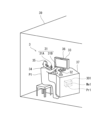
図1は、本開示の実施形態1に係る無人配送システム100の概略の構成の一例を示す模式図である。
(Embodiment 1)
FIG. 1 is a schematic diagram showing an example of a general configuration of an
[ハードウェアの構成]
図1を参照すると、実施形態1の無人配送システム100は、無人航空機(以下、ドローンと呼ぶ)1と、自走ロボット2と、操作ユニット3と、を含む。
[Hardware configuration]
Referring to FIG. 1 , an
無人配送システム100は、ドローン1によって、荷物を集配拠点5から届け先4に至る配送経路の途中の地点(荷物を届ける途中の地点)まで当該荷物を輸送し、自走ロボット2によって、この途中の地点に降ろされた荷物を届け先4に届けるよう、構成されている。なお、以下では、簡略化のために、「自走ロボット」を単に「ロボット」と呼ぶ場合がある。
The
以下、これらの構成要素を詳しく説明する。 These components are explained in more detail below.
<ドローン1>
図1を参照すると、ドローン1は、配送する荷物と自走ロボット2を輸送することができるものであればよい。ドローン1として、飛行機、ヘリコプターが例示される。飛行機は、通常の滑走により離着陸するものの他、VTOL機(Vertical Take-Off and Landing aircraft、垂直離着陸機)を含む。ドローン1は、ここでは、VTOL機で構成される。
<
Referring to Fig. 1, the
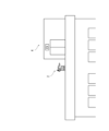
このドローン1は、内部に格納庫16(図8C参照)が形成されている。図8Cを参照すると、格納庫16には、中央空間を囲むように荷置き棚17が配置されている。格納庫16は、この中央空間に自走ロボット2が格納され、且つ、自走ロボット2が荷置き棚17への荷物の出し入れ作業を行えるように構成されている。
This
ドローン1の後部の側壁には、下端部を支点に前後方向に回動して開閉する搬出入扉13が設けられている(図8A参照)。搬出入扉13の内面は平坦に形成されていて、搬出入扉13は、開いて先端が着地すると、荷物G等の搬出入経路になる。また、ドローン1には、昇降装置11が設けられている(図8B参照)。昇降装置11は、ここでは、ウインチで構成されている(以下、ウインチ11と表記する)。このウインチ11のために、ドローン1の底壁には、下方に向かって左右に開閉する昇降扉15が設けられていて、物体をウインチ11で昇降させる場合には、この昇降扉15が開放される。なお、ドローン1には、ドローン制御器101が配置されている。ドローン制御器101は、プロセッサPr3及びメモリMe3を備える。
The rear side wall of the
<操作ユニット3>
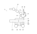
図2は図1の操作ユニット3の詳細な構成の一例を示す斜視図である。図3は、図1の自走ロボット2の構成の一例を示す側面図である。
<
Fig. 2 is a perspective view showing an example of a detailed configuration of the
図2を参照すると、例えば、操作室39に操作ユニット3が配置されている。操作ユニット3の配置場所は特に限定されない。操作ユニット3は、自走ロボット2を操作するロボット操作器31と、ドローン1を操作するドローン操作器32と、操作者用表示器33と、操作者マイク34と、操作者スピーカ35と、操作者カメラ36と、を備える。
2 , for example, the
図1乃至図3を参照すると、ロボット操作器31は、自走ロボット2の走行部(台車)21を操作する走行部操作器31Aと、自走ロボット2のロボットアーム22を操作するアーム操作器31Bとを含む。このアーム操作器31Bには、顧客用表示器23を支持する表示器ロボットアーム27を操作するための操作部(不図示)が設けられている。ロボット操作器31は、種々の操作器で構成され得る。ここでは、例えば、ジョイスティックで構成される。ロボット操作器31は机37の上に配置される。
With reference to Figures 1 to 3, the
ドローン操作器32は、例えば、航空機を操縦する各種の操縦桿で構成される。ここでは、ドローン操作器32は、ジョイスティック状の操縦桿で構成される。ドローン操作器32には、ドローン1を操縦するための各種の操作部(不図示)が設けられている。ドローン操作器32は、机37の上に配置されている。
The
操作者用表示器33は、例えば、液晶ディスプレイで構成される。操作者用表示器33には、操作者P1に提示することが必要な情報を含む画像が表示される。そのような画像として、自走ロボット2の視界カメラ26で撮像された画像、ドローン1の視界カメラ(不図示)で撮像された視界画像、ドローン1を操縦するのに必要な情報(位置、速度、燃料量等)、ナビゲーション画像等が例示される。
The
操作者用表示器33は机37の上に配置される。
The
操作者スピーカ35は、操作者P1に必要な音声情報を提供する。操作者スピーカ35は、ここでは、ヘッドフォンで構成されているが、他の形態に構成されていてもよい。
The
操作者マイク34は、操作者P1の音声を取得する。操作者マイク34は、ここでは、ヘッドフォン35に設けられているが、他の形態に構成されていてもよい。
The
操作者カメラ36は、操作者P1を撮像する。操作者カメラ36は、ここでは、操作者用表示器33に設けられているが、他の場所に設けられてもよい。
The
机37には、操作ユニット制御器301が配置されている。操作ユニット制御器301は、プロセッサPr1及びメモリMe1を備える。
An
操作者P1は、例えば、ドローン1の飛行時には、右手でドローン操作器32を操作して、ドローン1を操縦し、自走ロボット2の動作時には、左右の手で、それぞれ、走行部操作器31A及びアーム操作器31Bを操作して、自走ロボット2を操作する。操作者P1は、例えば、宅配業者(宅配担当者)である。操作者P1は、宅配担当者ではなく、専用のオペレータであってもよい。
For example, when
<自走ロボット2>
図3を参照すると、ロボット(自走ロボット)2は、自力で走行可能で且つ荷物を扱うことが可能なロボットであればよい。ロボット2は、ここでは、自力で走行可能な走行部(台車)21と走行部21の上に設けられたロボットアーム22とを備える。なお、荷物を扱う構成要素は、必ずしもロボットアームでなくてよい。図3のロボット2は、図面左方向及び右方向が、それぞれ、走行方向における前方向及び後方向である。
<Self-propelled
3, the robot (self-propelled robot) 2 may be any robot capable of traveling under its own power and handling luggage. Here, the
図3には、ロボット2が簡略化されて示されている。実際には、ロボット2のロボットアーム22は、実施形態2のロボット2Aの双腕のロボットアーム22と同様に構成されている(図9A及び9B参照)。つまり、ロボット2のロボットアーム22は、双腕の垂直多関節型のロボットアームである。但し、実施形態2のロボット2Aのロボットアーム22は、4軸の垂直関節型のロボットアームであるが、図3のロボット2のロボットアーム22は、5軸の垂直多関節型のロボットアームである。図9A及び9Bを参照すると、一対のロボットアーム22の先端には、それぞれ、3本爪222を有する把持部221(手首部)が設けられていて、一対のロボットアーム22は、これらの一対の把持部221によって、荷物Gを把持する。
In FIG. 3, the
図3を参照すると、ロボット2の走行部は、実際には、直方体状の車体フレーム(不図示)を備えていて、この車体フレームに荷物収容部212が前後方向に移動可能に設けられている。この車体フレームは、適宜なケースによって覆われていて、このケースの前面に荷物収容部212が出入りするための開口部が設けられて。荷物収容部212は、上面が開放された矩形の箱状に形成されていて、非荷物出し入れ時には、前端面が、このケースと面一になる後退位置に位置し、荷物出し入れ時には、前側の所定部分が前方に突出する前進位置に位置するように構成されている。
Referring to FIG. 3, the running section of the
走行部21の底部には、一対の前輪211,211と一対の後輪211,211が設けられている。例えば、一対の前輪211,211及び一対の後輪211,211のいずれかが操舵輪であり、また、例えば、一対の前輪211,211及び一対の後輪211,211のいずれかが駆動輪である。走行部21には、蓄電池28とモータ(不図示)とが搭載されていて、蓄電池28を電源としてモータが駆動輪を駆動する。また、上述の荷物収容部212も所定の駆動機構によって、前後に摺動駆動される。
A pair of
さらに、走行部21のロボットアーム22の後方には、表示器ロボットアーム27が設けられている。表示器ロボットアーム27の先端には、顧客用表示器23が取り付けられている。顧客用表示器23の適所に、顧客マイク24、顧客スピーカ25、及び視界カメラ26が設けられている。表示器ロボットアーム27は、例えば、垂直多関節型のロボットアームで構成されていて、任意の姿勢を取ることが可能であり、顧客用表示器23、顧客マイク24、顧客スピーカ25、及び視界カメラ26を任意の方向に向けることが可能である。
Furthermore, a
顧客用表示器23は、例えば、液晶ディスプレイで構成される。顧客用表示器23には、受取人P2(図8F参照)に提示することが必要な情報を含む画像が表示される。そのような画像として、操作者カメラ36で撮像された画像等が例示される。
The
顧客スピーカ25は、受取人P2に必要な音声情報(例えば、操作者マイク34で取得された操作者P1の声)を提供する。
The
操作者マイク34は、操作者P1の音声を取得する。操作者マイク34は、ここでは、ヘッドフォン35に設けられているが、他の形態に構成されていてもよい。
The
操作者カメラ36は、操作者P1を撮像する。操作者カメラ36は、ここでは、操作者用表示器33に設けられているが、他の場所に設けられてもよい。
The
さらに、走行部21には、ロボット制御器201が設けられている。ロボット制御器201は、プロセッサPr2及びメモリMe2を備える。
Furthermore, the traveling
このように構成されたロボット2は、ロボット制御器201によって、自律運転又は遠隔運転するよう制御され、ロボットアーム22によって荷物Gを扱い、且つ、走行部21によって、所望の方向に移動することができる。
The
[制御系統の構成]
図4は、図1の無人配送システム100の制御系統の構成の一例を示す機能ブロック図である。
[Control system configuration]
FIG. 4 is a functional block diagram showing an example of the configuration of a control system of the
図4を参照すると、無人配送システム100は、操作ユニット制御器301と、ロボット制御器201と、ドローン制御器101と、を備える。
Referring to FIG. 4, the
操作ユニット制御器301は、ロボット操作信号生成部302、ドローン操作信号生成部303、表示制御部304、マイクIF305、ヘッドフォンIF306、操作ユニット通信部307、及びカメラ制御部308を含む。
The
操作ユニット通信部307は、データ通信可能な通信器で構成される。操作ユニット制御器301は、ロボット操作信号生成部302、ドローン操作信号生成部303、表示制御部304、マイクIF305、ヘッドフォンIF306、及びカメラ制御部308は、プロセッサPr1とメモリMe1とを有する演算器で構成される。これらは、この演算器において、メモリMe1に格納された制御プログラムをプロセッサPr1が実行することによって実現される機能ブロックである。この演算器は、具体的には、例えば、マイクロコントローラ、MPU、FPGA(Field Programmable Gate Array)、PLC(Programmable Logic Controller)等で構成される。これらは、集中制御を行う単独の演算器で構成されてもよく、分散制御を行う複数の演算器で構成されてもよい。 ロボット操作信号生成部62は、ロボット操作器31の操作に応じて、ロボット操作信号を生成する。ドローン操作信号生成部303は、ドローン操作器32の操作に応じてドローン操作信号を生成する。表示制御部304は、操作ユニット通信部307から送信される画像信号に応じた画像を操作者用表示器33に表示させる。マイクIF305は、操作者マイク34で取得された音声を適宜な音声信号に変換する。ヘッドフォンIF306は、操作ユニット通信部307から送信される音声信号に応じ音声を操作者スピーカに放出させる。カメラ制御部308は、操作者カメラ36で撮像された画像の画像信号を生成する。
The operation
操作ユニット通信部307は、ロボット操作信号生成部302から送信されるロボット操作信号、ドローン操作信号生成部303から送信されるドローント操作信号、マイクIF305から送信される音声信号、及びカメラ制御部308から送信される画像信号を無線通信信号に変換して無線送信する。また、操作ユニット通信部307は、ロボット通信部202から送信される無線通信信号を受信して画像信号又は音声信号に変換し、画像信号を表示制御部304に送信し、音声信号をマイクIF305に送信する。また、操作ユニット通信部307は、ドローン通信部102から送信される無線通信信号を受信して、情報信号に変換し、これを表示制御部304に送信する。
The operation
ロボット制御器201は、ロボット通信部202、ロボット制御部203、及び記憶部204を含む。ロボット通信部202は、データ通信可能な通信器で構成される。ロボット制御部203及び記憶部204は、プロセッサPr2とメモリMe2とを有する演算器で構成される。ロボット制御部203及び記憶部204は、この演算器において、メモリMe2に格納された制御プログラムをプロセッサPr2が実行することによって実現される機能ブロックである。この演算器は、具体的には、例えば、マイクロコントローラ、MPU、FPGA(Field Programmable Gate Array)、PLC(Programmable Logic Controller)等で構成される。これらは、集中制御を行う単独の演算器で構成されてもよく、分散制御を行う複数の演算器で構成されてもよい。
The
ロボット通信部202は、操作ユニット通信部307から送信される無線通信信号を受信して、ロボット操作信号、画像信号、又は音声信号に変換し、これらの信号をロボット制御部203に送信する。ロボット制御部203は、ロボット操作信号に応じて、ロボット2の動作を制御し、画像信号に応じた画像を顧客用表示器23に表示させ、且つ、音声信号に応じた音声を顧客スピーカに放出させる。
The
ドローン制御器101は、ドローン通信部102及びドローン制御部103を含む。ドローン通信部102はデータ通信可能な通信器で構成される。ドローン制御部103は、プロセッサPr3とメモリとMe3を有する演算器で構成される。ドローン制御部103は、この演算器において、メモリMe3に格納された制御プログラムをプロセッサPr3が実行することによって実現される機能ブロックである。この演算器は、具体的には、例えば、マイクロコントローラ、MPU、FPGA(Field Programmable Gate Array)、
PLC(Programmable Logic Controller)等で構成される。これらは、集中制御を行う単独の演算器で構成されてもよく、分散制御を行う複数の演算器で構成されてもよい。
The
The
ドローン通信部102は、操作ユニット通信部65から送信される無線通信信号を受信してドローン操作信号に変換し、これをドローン制御部103に送信する。また、ドローン通信部102は、ドローン制御部103から送信される情報信号を無線通信信号に変換し、これを無線送信する。 The drone communication unit 102 receives a wireless communication signal transmitted from the operation unit communication unit 65, converts it into a drone operation signal, and transmits it to the drone control unit 103. The drone communication unit 102 also converts an information signal transmitted from the drone control unit 103 into a wireless communication signal, and transmits it wirelessly.
ドローン制御部103は、ドローン側通信部82から送信されるドローン操作信号に応じて、ドローン1のドローン本体12及び昇降装置11の動作を制御する。ドローン制御部03は、ドローン1の視界カメラ(不図示)で撮像された視界画像、ドローン1を操縦するのに必要な情報(位置、速度、燃料量等)、ナビゲーション画像等を情報信号としてドローン通信部102に送信する。
The drone control unit 103 controls the operation of the
ここで、本明細書で開示する要素の機能は、開示された機能を実行するよう構成又はプログラムされた汎用プロセッサ、専用プロセッサ、集積回路、ASIC(Application Specific Integrated Circuits)、従来の回路、及び/又は、それらの組み合わせ、を含む回路又は処理回路を使用して実行できる。プロセッサは、トランジスタやその他の回路を含むため、処理回路又は回路と見なされる。本開示において、「器」又は「部」は、列挙された機能を実行するハードウェアであるか、又は、列挙された機能を実行するようにプログラムされたハードウェアである。ハードウェアは、本明細書に開示されているハードウェアであってもよいし、あるいは、列挙された機能を実行するようにプログラム又は構成されているその他の既知のハードウェアであってもよい。ハードウェアが回路の一種と考えられるプロセッサである場合、「器」又は「部」は、ハードウェアとソフトウェアの組み合わせであり、ソフトウェアは、ハードウェア及び/又はプロセッサの構成に使用される
。
Here, the functions of the elements disclosed herein can be performed using circuits or processing circuits, including general purpose processors, special purpose processors, integrated circuits, ASICs (Application Specific Integrated Circuits), conventional circuits, and/or combinations thereof, configured or programmed to perform the disclosed functions. A processor is considered a processing circuit or circuit because it includes transistors and other circuits. In this disclosure, a "device" or "part" is hardware that performs the recited functions or hardware that is programmed to perform the recited functions. The hardware may be hardware disclosed herein or other known hardware that is programmed or configured to perform the recited functions. In the case of a processor, where the hardware is considered a type of circuit, the "device" or "part" is a combination of hardware and software, and the software is used to configure the hardware and/or the processor.
<配送用データ>
図5は、ロボット制御器201の記憶部204に格納された配送用データDの一例を示す模式図である。
<Delivery data>
FIG. 5 is a schematic diagram showing an example of the delivery data D stored in the
図5を参照すると、配送用データDは、例えば、配達先住所データD1、認証用顔画像データD2、及び地図データD3を含む。配達先住所データD1は、配達先住所のリストである。認証用顔画像データD2は、配達先の受取人P2の顔画像データであり、配達を受任する際に配達依頼主から取得され、ロボット制御器201の記憶部204に格納される。この認証用顔画像データは、配達先住所データD1と対応させて格納される。地図データD3は、ロボット2による配送に利用される。
Referring to FIG. 5, the delivery data D includes, for example, delivery address data D1, authentication facial image data D2, and map data D3. The delivery address data D1 is a list of delivery addresses. The authentication facial image data D2 is facial image data of the delivery recipient P2, and is obtained from the delivery requester when accepting the delivery, and is stored in the
<自律運転/遠隔運転切替制御>
ロボット制御器201のロボット制御部203は、ロボット2を、自律運転と遠隔運転との間で切り替えて、制御する。遠隔運転は、ロボット操作器31の操作(ロボット操作信号)に従った運転を意味する。
<Autonomous operation/remote operation switching control>
The robot control unit 203 of the
図6は、この自律運転/遠隔運転切替制御の内容の一例を示すフローチャートである。図6を参照すると、自律運転/遠隔運転切替制御が開始されると、ロボット制御部203は、ロボット2に自律動作(自律運転)をさせる(ステップS1)。
Figure 6 is a flowchart showing an example of the contents of this autonomous operation/remote operation switching control. Referring to Figure 6, when the autonomous operation/remote operation switching control is started, the robot control unit 203 causes the
次いで、ロボット制御部203は、遠隔指令が入力された否かを判定する(ステップS2)。遠隔指令は、ロボット操作信号に含まれている。 Next, the robot control unit 203 determines whether a remote command has been input (step S2). The remote command is included in the robot operation signal.
遠隔指令が入力された場合(ステップS2でYES)、ロボット制御部203は、ロボット2に遠隔動作(遠隔運転)をさせる(ステップS5)。
If a remote command is input (YES in step S2), the robot control unit 203 causes the
一方、遠隔指令が入力されない場合(ステップS2でNO)、ロボット制御部203は、所定条件が満たされるか否かを判定する(ステップS3)。この所定条件は、例えば、荷物の届け先4までの道程が悪路6(図8F参照)であること、又は、人がロボット2に接近したことである。
On the other hand, if no remote command is input (NO in step S2), the robot control unit 203 judges whether a predetermined condition is satisfied (step S3). The predetermined condition is, for example, that the route to the
所定条件が満たされる場合(ステップS3でYES)、ロボット制御部203は、ロボット2に遠隔動作(遠隔運転)をさせる(ステップS5)。
If the specified condition is met (YES in step S3), the robot control unit 203 causes the
一方、所定条件がみたされない場合(ステップS3でNO)、ロボット制御部203は、終了指令が入力された否かを判定する(ステップS4)。終了指令はロボット操作信号に含まれている。 On the other hand, if the predetermined condition is not met (NO in step S3), the robot control unit 203 determines whether an end command has been input (step S4). The end command is included in the robot operation signal.
終了指令が含まれていない場合(ステップS4でNO)、ロボット制御部203は、本制御をステップS1に戻す。 If an end command is not included (NO in step S4), the robot control unit 203 returns the control to step S1.
一方、終了指令が含まれている場合、ロボット制御部203は、本制御を終了する。 On the other hand, if an end command is included, the robot control unit 203 ends this control.
上述のように、ステップSで遠隔動作(遠隔運転)が行われると、ロボット制御部203は、自律指令が入力されたか否かを判定する(ステップS6)。自律指令は、ロボット操作信号に含まれている。 As described above, when a remote operation (remote driving) is performed in step S, the robot control unit 203 determines whether an autonomous command has been input (step S6). The autonomous command is included in the robot operation signal.
自律指令が含まれている場合(ステップS6でYES)、ロボット制御部203は、本制御をステップS1に戻す。 If an autonomous command is included (YES in step S6), the robot control unit 203 returns the control to step S1.
一方、自律指令が入力されない場合、ロボット制御部203は、認証指令が入力されたか否かを判定する(ステップS7)。認証指令は、ロボット操作信号に含まれている。 On the other hand, if an autonomous command is not input, the robot control unit 203 determines whether an authentication command is input (step S7). The authentication command is included in the robot operation signal.
認証指令が含まれている場合(ステップS7でYES)、ロボット制御部203は、顔認証を行う(ステップS8)。顔認証は、ロボット制御部203が、記憶部204に格納された顔画像データと視界カメラ26で撮像された受取人P2の画像を照合することによって行われる。顔認証は周知の方法を用いることができる。それ故、その説明を省略する。
If an authentication command is included (YES in step S7), the robot control unit 203 performs face authentication (step S8). Face authentication is performed by the robot control unit 203 comparing the face image data stored in the
顔認証が終了すると、ロボット制御部203は、ロボット2を遠隔動作に戻す(ステップS5)。なお、この場合、顔認証が成立した場合、荷物の受け渡しが行われ、顔認証が成立しない場合、操作者P1と受取人P2との対話により、適宜、処理される。
When the facial authentication is completed, the robot control unit 203 returns the
一方、認証指令が入力されなかった場合(ステップS7でNO)、ロボット制御部203は、終了指令が入力された否かを判定する(ステップS9)。 On the other hand, if an authentication command has not been input (NO in step S7), the robot control unit 203 determines whether an end command has been input (step S9).
終了指令が含まれていない場合(ステップS9でNO)、ロボット制御部203は、本制御をステップS5に戻す。 If an end command is not included (NO in step S9), the robot control unit 203 returns the control to step S5.
一方、終了指令が含まれている場合、ロボット制御部203は、本制御を終了する。 On the other hand, if an end command is included, the robot control unit 203 ends this control.
このようにして、自律運転/遠隔運転切替制御が行われる。 In this way, autonomous operation/remote operation switching control is performed.
<人の回避制御>
次に、人の回避制御について説明する。ロボット制御部203は、視界カメラ26で撮像された画像を画像処理して、当該画像内に人が存在するか否かを判定する。画像処理によって、画像内の人を抽出する方法は周知であるので、ここでは、その説明を省略する。ロボット制御部203は、視界カメラ26で撮像された画像から抽出された人の画像が視界カメラに接近する場合には、ロボット2を当該人の画像と反対方向に移動させる。人の画像が視界カメラに接近するか否かは、例えば、当該人の画像の大きさ及びその拡大速度によって判定される。
<Human avoidance control>
Next, the person avoidance control will be described. The robot control unit 203 processes the image captured by the field of
[無人配送システム100の動作(無人配送方法)]
次に、以上のように構成された無人配送システム100の動作(無人配送方法)を、図1乃至図8Lを用いて説明する。図7は、図1の無人配送システム100の動作の一例を示すフローチャートである。図8A乃至図8Lは、図1の無人配送システム100の動作の一例を順に示す模式図である。この無人配送システム100の動作では、ドローン1は、操作者P1によって操作され、ロボット2は、ロボット制御器201のロボット制御部203によって、自律運転又は遠隔運転される。
[Operation of the unmanned delivery system 100 (unmanned delivery method)]
Next, the operation of the
図7及び図8A乃至8Cを参照すると、まず、集配拠点5において、荷積みが行われる(ステップS11)。この荷積みには、3つの態様がある。 Referring to Figures 7 and 8A to 8C, first, loading is performed at the collection and delivery base 5 (step S11). There are three modes of this loading.
第1態様では、図8Aに示すように、操作者P1によりドローン1の搬出入扉13が開かれ、この搬出入扉13を通って、搬送車14により荷物Gがドローン1に搬入される。この場合、ロボット2は、搬出入扉13を通ってドローン1に搭乗する。
In the first mode, as shown in FIG. 8A, the loading/unloading
第2態様では、荷物Gは、第1態様と同様に、搬送車14によりドローン1に搬入される。ロボット2は、図8Bに示すように、ウインチ11によって、ドローン1に搭載される。この場合、ドローン1はホバリング状態(停止飛行状態)にされ、昇降扉15が開放される。ロボット2の走行部21の上面の4隅には、ウインチ11のワイヤの先端のフック(不図示)を掛ける掛け部(不図示)が設けられている。ウインチ11のワイヤが降下されると、ロボット2は、自律運転され、ワイヤの先端のフックを自ら上記掛け部に掛ける。また、ロボット2は、所定の格納姿勢を取る(図8B参照)。ここで、ロボット2の走行部21の上記4つの掛け部にはセンサが設けられていて、ロボット制御部203は、ワイヤの先端のフックが上記掛け部に掛けられたことをセンサからの信号によって確認知する。そして、その旨の信号を操作ユニット通信部307に送信する。すると、この情報が操作者用表示器33に表示される。操作者P1は、ウインチ11を巻き上げてロボット2をドローン1に搭載する。その後、昇降扉15が閉止される。
In the second mode, the baggage G is carried into the
第3態様では、ロボット2が荷物Gを収容部212に収容して、第2態様と同様に、ウインチ11によって、
図8Cを参照すると、ロボット2は、遠隔運転により、格納庫16内において、搬入された荷物Gを荷置き棚17に置く。第3態様で自身の荷物収容部212に荷物Gを収容している場合には、収容部212から荷物Gを取り出して荷置き棚17に置く。
In the third mode, the
8C , the
作業が終了したら、ロボット2は、自律運転により、ドローン1から蓄電池28を充電し、その後、格納庫16に適宜な手段で自らを固定し、上記所定の格納姿勢を取る。
When the work is completed, the
図7を参照すると、次いで、荷物G及びロボット2が空輸される(ステップS12)。ここでは、図8Dに示すように、複数の届け先4に荷物Gが届けられる。
7, the package G and the
次に、以下、届け先4が郊外部の場合と都市部の場合とに分けて、説明する。
Next, the following will explain the case where the
<届け先4が郊外部の場合>
図7を参照すると、届け先4までの途中の地点で荷降ろしが行われる(ステップS13)。図8Eを参照すると、この荷降ろしは、ドローン1をホバリング状態にして、ロボット2をウインチ11で降下させることによって行われる。この降下は、操作者P1が、操作者用表示器33に表示される、ローン1の視界カメラで撮像された視界画像で地上の様子を確認しながら行う。安全性を確保するためである。また、この場合、ドローン1の高度は所定以上とされる。所定高度は適宜設定されるが、例えば、20mとされる。
この場合、ロボット2は、自律運転によって格納姿勢を解いた後、遠隔運転により、これから配送すべき荷物Gを荷物収容部212に収容する。
<If
Referring to Fig. 7, unloading is performed at a point on the way to the destination 4 (step S13). Referring to Fig. 8E, this unloading is performed by putting the
In this case, the
そして、ロボット2は、地上に降下された後、自律運転により、ウインチ11のワイヤの先端のフックを掛け部から外す。
After the
図7を参照すると、荷物Gがロボット2によって届け先4まで地上輸送される(ステップS14)。ドローン1は、上空でロボット2の帰還を待機する。
7, the package G is transported on the ground by the
図8Fを参照すると、この場合、ロボット2は、自律運転により、地図データを参照しながら、郊外部の道路を走行する。そして、途中で、悪路6に遭遇すると、遠隔運転に切り替わり、操作者P1の操作に従って、走行する。
Referring to FIG. 8F, in this case, the
図7を参照すると、ロボット2が届け先4に到着すると、荷物Gの受け渡しが行われる(ステップS15)。図8Gを参照すると、この場合、ロボット2は、操作者P1の操作により遠隔運転に切り替わり、届け先4のインタホンを押す等して、受取人(顧客)P2が現れると、ロボット2は、顔認証を行う。そして、受取人P2が近づいたらロボット2は、自動的に停止し、トリガが無い限り動かない。そこからロボット2は、自動的に遠隔運転に切り替わり、荷物Gを受取人P2に渡す。この際、ロボット2は、図8Hに示すように、自動的に所定の荷物差出姿勢を取る。もし、受取人P2が接近し過ぎたら、ロボット2は、自動的に受取人P2と反対方向に移動する。この場合、ロボット2は、受取人P2と対話する。具体的には、ロボット制御部203は、操作者マイク34で取得された操作者P1の声を顧客スピーカ25に放出させ、操作者カメラ36で撮像された操作者P1の画像を顧客用表示器23に表示させ、且つ、顧客マイク24で取得された受取人P2の声を操作者スピーカ35に放出させ、視界カメラ26で撮像された受取人P2の画像を顧客用表示器23に表示させ、それによって、受取人P2と操作者P1とを対話させる。この対話は、例えば、以下のようなものである。
Referring to FIG. 7, when the
操作者P1が「お届けに参りました」と言い、受取人P2が「ありがとうね。とっても助かります」と言い、操作者P1が「またのご利用をお待ちしております。」と言う。 Operator P1 says, "I'm here to deliver the item," recipient P2 says, "Thank you very much. That's a great help," and operator P1 says, "We look forward to serving you again."
図7を参照すると、ロボット2は、往路と同様にして、荷降ろし地点に戻る(ステップS16)。そして、ロボット2が待機していたドローン1に搭載される(ステップS17)。ロボット2の搭載の態様は、ステップS11における荷積みの第2態様と同じである。
Referring to FIG. 7, the
<届け先4が都市部の場合>
図8Iを参照すると、この場合、例えば、届け先4が高層マンションの一室である。ドローン1は、高層マンションの上空に到達すると、ロボット2を屋上に降下させる。この降下の態様は2つある。第1降下態様は、届け先4が郊外部の場合と同じである。第2降下態様では、ドローン1が屋上に着陸し、ロボット2が開放された搬出入扉13から屋上に降りる。
<If
Referring to Fig. 8I, in this case, for example, the
図7を参照すると、荷物Gがロボット2によって届け先4までマンション内を輸送される(地上輸送される)(ステップS14)。ドローン1は、上空でロボット2の帰還を待機する。この場合、ロボット2は遠隔運転される。図8Kを参照すると、ロボット2は、高層マンションのエレベータを使って目的の階まで降りる。この場合、ロボット2の無線でエレベータのドアを開閉する。
7, the package G is transported (transported on the ground) within the apartment building to the
図8Kを参照すると、ロボット2は、届け先4である目的の部屋の近くまで来たら、操作者の操作で遠隔運転に切り替わる。この後の受け渡しは、届け先4が郊外部の場合と同じであり、その説明を省略する。
8K, when the
ロボット2は、適宜な遠隔運転を挟む自律運転により屋上に到着する。そして、ロボット2が待機していたドローン1に搭載される(ステップS17)。ロボット2の搭載の態様は、ステップS11における荷積みの第2態様と同じである。
The
<次の届け先4への配送及び帰還>
1つの届け先4への配達業務が終了すると、次の届け先4への配達業務が上記と同様に行われ、全ての届け先4への配達業務が終了すると、ドローン1は、集配拠点5に帰還する(ステップS18,19)。
<Delivery to
When delivery to one
{変形例1}
変形例1では、ロボット2が上述の届け先4までの途中の地点に配置されている。この場合、ロボット2は、現地にとどまってもよいし、ドローン1に回収されてもよい。
{Modification 1}
In the first modification, the
以上に説明した実施形態1によれば、受取人P2に対する荷物Gの受け渡しを円滑に行うことができる。
According to the
(実施形態2)
実施形態2の無人配送システムは、実施形態1のロボット2に代えてロボット2Aが用いられる点で、実施形態1の無人配送システム100と異なり、その他の点は実施形態1の無人配送システム100と同じである。
(Embodiment 2)
The unmanned delivery system of
図9Aは、本開示の実施形態2に係る無人配送システムに用いられるロボット2Aの構成の一例を示す側面図である。図9Bは、本開示の実施形態2に係る無人配送システムに用いられるロボット2Aの構成の一例を示す平面図である。
Figure 9A is a side view showing an example of the configuration of a
図9A及び9Bを参照すると、ロボット2Aは、走行部(台車)21と走行部21の上に設けられた一対のロボットアーム22とを備える。一対のロボットアーム22は、それぞれ、4軸の垂直多関節型のロボットアームで構成されている。すなわち、各ロボットアーム22は、垂直な第1回動軸線Ax1の周りに回動可能な第1リンクL1を有する。この第1リンクL1は双方のロボットアーム22に共通である。第1リンクL1の先端部に第2リンクL2の基端部が第1回動軸線Ax1に垂直な第2回動軸線Ax2の周りに回動可能に設けられている。第2リンクL2の先端部に第3リンクL3の基端部が第2回動軸線Ax2に垂直な第3回動軸線Ax3の周りに回動可能に設けられている。第3リンクL3の先端部に第4リンクL4の基端部が第3回動軸線Ax3に垂直な第4回動軸線Ax4の周りに回動可能に設けられている。そして、第4リンクL4の先端に3本爪222を有する把持部221(手首部)が設けられている。一対のロボットアーム22は、これらの一対の把持部221によって、荷物Gを把持する。
9A and 9B, the
ロボット2の走行部21は、台車状に形成されていて、前端部に荷物収容部212が設けられている。荷物収容部212は、底壁212aと側壁212bとを有する上面が開放された矩形の箱状に形成されている。なお、荷物収容部212の後側の側壁部は、上部が切り欠かれていて、一対のロボットアーム22がこの切り欠き部分から荷物収容部に荷物Gを入れることが可能になっている。走行部21の底部には、一対の前輪211,211と一対の後輪211,211が設けられている。例えば、一対の前輪211,211及び一対の後輪211,211のいずれかが操舵輪であり、また、例えば、一対の前輪211,211及び一対の後輪211,211のいずれかが駆動輪である。走行部21には、蓄電池28とモータ(不図示)とが搭載されていて、蓄電池28を電源としてモータが駆動輪を駆動する。さらに、走行部21の中央部の両側には、一対のアウトトリガ213が設けられている。このアウトトリガ213は、走行部21の内部に収容可能に構成されている。アウトトリガ213は、ロボット2Aが停止して荷物Gの積み降ろしを行う時に、走行部21から左右に突出して地面に着地し、走行部21の移動を阻止する。
The running
さらに、走行部21のロボットアーム22の後方には、表示器ロボットアーム27が設けられている。この表示器ロボットアーム27は、実施形態1のものと同じであるので、その説明を省略する。
Furthermore, a
このような実施形態2の無人配送システムによれば、実施形態1の無人配送システム100と同様の効果が得られる。
The unmanned delivery system of
(実施形態3)
実施形態3では、実施形態1又は実施形態2において、操作者P1が複数のロボット2を操作することができる。その他の点は、実施形態1又は実施形態2と同様である。
(Embodiment 3)
In the third embodiment, the operator P1 in the first or second embodiment can operate a plurality of
具体的には、図4を参照すると、実施形態3の無人配送システムは、複数のロボット2を備える。これらの複数のロボット2には、それぞれ、識別記号が付与されている。ロボット操作器31には、操作したいロボット2を指定する操作部(不図示)が設けられている。ロボット操作信号生成部302は、この操作部の操作に応じて、ロボット操作信号に指定されたロボット2の識別記号を付す。各ロボット2のロボット制御部203は、ロボット操作信号が、自身の属するロボット2の識別記号を含む場合に、当該ロボット操作信号に基づいてロボット2を制御する。
Specifically, referring to FIG. 4, the unmanned delivery system of
これにより、操作者P1が、1つのロボット操作器31によって、複数の自走ロボット2を操作することができる。
This allows the operator P1 to operate multiple self-propelled
このような実施形態3によれば、効率良く無人配送を行うことができる。
According to this
(実施形態4)
実施形態4の無人配送システムは、実施形態1のロボット2に代えてロボット2Bが用いられる点で、実施形態1の無人配送システム100と異なり、その他の点は実施形態1の無人配送システム100と同じである。
(Embodiment 4)
The unmanned delivery system of
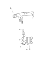
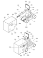
図10は、本開示の実施形態4に係る無人配送システムに用いられる移動ロボット1000の構成の一例を示す分解図である。図11は、図10の移動ロボット1000がデリバリロボットとして構成された自走ロボット2Bの第1構成及び使用態様を示す斜視図である。図12は、図10の移動ロボット1000がデリバリロボットとして構成された自走ロボット2Bの第2構成及び使用態様を示す斜視図である。図13は、図10の移動ロボット1000がデリバリロボットとして構成された自走ロボット2Bの第3構成及び使用態様を示す斜視図である。図14は、図10の移動ロボット1000がメンテナンスロボットとして構成された高所歩行ロボット2000の第1構成及び使用態様を示す斜視図である。図15は、図10の移動ロボット1000がメンテナンスロボットとして構成された高所歩行ロボット2000の第2構成及び使用態様を示す斜視図である。
Figure 10 is an exploded view showing an example of the configuration of a
図10を参照すると、移動ロボット1000は、配送に特化したデリバリロボットである自走ロボット2Bと、高層構造物のメンテナンスに特化したメンテナンスロボットである高所歩行ロボット2000とに構成され得る。このことを、以下、詳しく説明する。
Referring to FIG. 10, the
移動ロボット1000は、ベースユニット310と、ロボットアーム部320,330と、移動部340,350と、を備える。図10においては、中央部にベースユニット310が示され、左上部にロボットアーム部320及び運搬車360が示され、左下部に移動部340が示され、右上部にロボットアーム部330が示され、右下部に移動部350が示されている。
The
ベースユニット310の上面にロボットアーム部320が取り付けられ、ベースユニット310の両端部の側面に移動部340が取り付けられることによって、デリバリロボットである自走ロボット2Bが構成され(図11-13参照)、ベースユニット310の上面にロボットアーム部330が取り付けられ、ベースユニット310の両端部の側面に移動部350が取り付けられることによって、メンテナンスロボットである高所歩行ロボット2000が構成される(図14-15参照)。
A
<ベースユニット310>
ベースユニット310は、移動ロボット1000のボディ及びシャーシを構成する部分であり、略一定の厚みを有し、且つ長手方向の両端部に細幅部を有する形状に形成されている。ベースユニット310は、
ベースユニット310の中央部の上面に、ロボットアーム部320,330が取り付けられるロボットアーム部取り付け部311が設けられている。ロボットアーム部取り付け部311は、例えば、短円柱状に形成され、図示されないモータによって、ベースユニット310の中央部の上面に垂直な回動軸線A300の周りに回動可能にベースユニット310の本体に設けられている。ロボットアーム部取り付け部311は、その上面がベースユニット310の中央部の上面と面一になるように設けられている。
<
The
A robot
また、ベースユニット310の各端部の細幅部の各側面に、移動部取り付け部312が設けられ、この移動部取り付け部312に開口部が形成されている。この開口部に、移動部340,350が連結される車軸の端部313が露出している。
Movement
ベースユニット310の両端部の細幅部に対応する2対の車軸の内の一方の車軸が操舵可能に構成されており、また、当該2対の車軸の内の一方の車軸が、図示されない駆動源によって駆動される駆動車軸であり、他方の車軸が従動車軸である。なお、双方の車軸を駆動車軸としてもよい。この駆動源は、例えば、モータで構成される。
One of the two pairs of axles corresponding to the narrow portions at both ends of the
ベースユニット310には、バッテリ328及びロボット制御器1201が搭載されている。バッテリ328は、移動ロボット1000を動作させるための電力を供給する。ロボット制御器1201は、実施形態1のロボット制御器201と同様に構成されている。
The
なお、ベースユニット310に、移動部340Cとしてクローラが取り付けられる場合、ベースユニット310は全長に渡って、細幅に形成され、且つ、ロボットアーム部取り付け部311は本体と一体(回動不能)に形成される。また、一対の車軸は、非操舵車軸とされる。なお、この場合にも、ロボットアーム部取り付け部311を回動可能とし、ロボットアーム部320を、当該ロボットアーム部取り付け部311に取り付け可能な構造に構成してもよい。
When a crawler is attached to the
また、ベースユニット310は、移動部取り付け部312に移動部350が取り付けられる場合には、各車軸が、ロボットアームの基端リンクとして、個別に、モータによって位置制御されながら駆動される。
When the
<ロボットアーム部(第1ロボットアーム部)320>
ロボットアーム部320は、自走ロボット2Bを構成するロボットアーム部である。配送される荷物を扱うためには、荷物をある程度の高さに持ち上げる必要があることから、ロボットアーム部320は、ロボットアーム部取り付け部311の上面に垂直に上方に延びる胴部321を備える。この胴部321の上端部に一対のロボットアーム322,322が設けられている。各ロボットアーム322は、多関節のロボットアーム(ここでは、多関節アーム)で構成されている。なお、ロボットアームの構成は特に限定されず、垂直多関節のアームのほか水平多関節アーム(いわゆるスカラアーム)としてもよい。ロボットアーム322の先端にはハンド322aが取り付けられている。ハンド322aの構成は特に制限されない。ハンド322aは、ここでは、対象物を真空吸着する吸着ハンドで構成されている。ハンド322aが、例えば、対象物を両側から挟持するハンドで構成されてもよい。
<Robot arm unit (first robot arm unit) 320>
胴部321の上端には、顧客用表示器323が設けられている。顧客用表示器323には、顧客マイク324、顧客スピーカ325、視界カメラ326が設けられている。顧客用表示器323、顧客マイク324、顧客スピーカ325、及び視界カメラ326は、それぞれ、実施形態1の顧客用表示器23、顧客マイク24、顧客スピーカ25、及び視界カメラ26と同様に構成されている。これらによって、自走ロボット2Bと配送先の受取人(顧客)P2との対話が可能になる。
A
自走ロボット2Bは、配送時に、配送される荷物を収容する運搬車360と連結される(図11-13参照)。運搬車360は、自走せずに、自走ロボット2Bに押されて又は引かれて走行する。以下では、運搬車360の走行方向における前後方向を運搬車360の前後方向と呼ぶ。運搬車360は、直方体状の箱体からなる本体361を備える。この本体361の内部空間が配送される荷物の収容空間となっている。
At the time of delivery, self-propelled
本体361は、後端面の下部に前方に引っ込んだ段差部365を有する。本体361の後面の段差部365の上側部分に、開閉扉364が設けられている。この開閉扉364は、本体361の荷物収容空間に、配送する荷物を出し入れするためのものである。
The
本体361の底部の4隅には、車輪362がそれぞれ設けられている。
本体361の両側面に突部からなる一対の連結部361aが設けられている。一対の連結部361aの後端面には、それぞれ、自走ロボット2Bの一対のハンド332aを受け入れる有底孔からなる連結孔(不図示)が形成されている。自走ロボット2Bは、一対のハンド332aをこれらの一対の連結孔に挿入し、当該連結孔の底面を吸着することによって、運搬車360と連結される。なお、連結部361aとハンド322aとの連結構造は、これに限定されない。当該連結構造は、連結部361aとハンド322aとを連結可能であればよく、例えば、連結部361aとハンド322aとに互いの係合部を設け、それによって、両者を連結してもよい。
A pair of connecting
運搬車360は、さらに、バッテリ363を備える。連結部361aには、バッテリ363と電気的に接続された第1電気接点(不図示)が設けられ、且つ、自走ロボット2Bのハンド322aにバッテリ328に電気的に接続された第2電気接点(不図示)が設けられている。自走ロボット2Bが運搬車360と連結されたときに、第1電気接点と第2電気接点とが接触して電気的に導通し、自走ロボット2Bのバッテリ328が、運搬車360のバッテリ363によって充電される。この充電は、ベースユニット310のロボット制御器1201の制御により、必要に応じて、適切に実行される。これにより、自走ロボット2Bの走行可能距離が、運搬車360がバッテリ363を備えない場合に比べて、長くなる。
<移動部340>
移動部340は、移動ロボット1000を走行させる3種類の走行部で構成される。
<Moving
The moving
第1移動部340Aは、第1走行部としての屋内用タイヤで構成される。屋内用タイヤは、例えば、トレッド(走行面)の凹凸が比較的小さく形成されている。屋内用タイヤは、その回転軸がベースユニット310の移動部取り付け部312の車軸の端部313に連結されるようにして、ベースユニット310に取り付けられる。
The first moving
第2移動部340Bは、第2走行部としての屋外用タイヤで構成される。屋外用タイヤは、トレッド(走行面)の凹凸が比較的大きく形成されている。また、タイヤにサスペンションが取り付けられている。屋外タイヤは、その回転軸がベースユニット310の移動部取り付け部312の車軸の端部313に連結されるようにして、ベースユニット310に取り付けられる。また、サスペンションが、適宜、ベースユニット310に連結される。
The second moving
第3移動部340Cは、第3走行部としてのクローラ(キャタピラ)で構成される。クローラは、その駆動機構がベースユニット310の移動部取り付け部312の車軸の端部313に連結されるようにして、ベースユニット310に取り付けられる。
The third moving
<ロボットアーム部(第2ロボットアーム部)330>
ロボットアーム部330は、高所歩行ロボット2000を構成するロボットアーム部である。ロボットアーム部330は、一対のロボットアーム331,331を含む。各ロボットアーム331は、多関節のロボットアーム(ここでは、6軸ロボットアーム)で構成されている。ロボットアーム331の先端にはハンド331aが取り付けられている。ハンド331aの構成は特に制限されない。ハンド331aは、ここでは、対象物を真空吸着する吸着ハンドで構成されている。ハンド331aが、例えば、対象物を挟持するハンドで構成されてもよい。
<Robot arm unit (second robot arm unit) 330>
The
ロボットアーム部330は、高所でメンテナンスを行うためには、水平方向に伸びる長い腕が必要であることから、2つのロボットアーム331,331が、直接、それぞれ、ベースユニット310のロボットアーム部取り付け部311に取り付けられる。これにより、2つのロボットアーム331,331が、ベースユニット310の上面に近接して沿うように延びることができる。また、高所歩行ロボット2000を、高所に運び上げる必要があることから、ロボットアーム部330は、ロボットアーム331をコンパクトに折りたためるように構成されている(図14及び15参照)。
Since the
ロボットアーム部330は、さらに、視界カメラ326を含む。視界カメラ326も、直接、ベースユニット310のロボットアーム部取り付け部311に取り付けられる。視界カメラ326は、実施形態1の視界カメラ26と同様に構成されている。その他、現地作業員との連携や、周辺情報収集のためのマイク、スピーカを設けるようにしてもよい。
The
<移動部350>
移動部350は、移動ロボット1000を高所歩行させる2種類の脚部で構成される。
<Moving
The moving
第4移動部350Aは、第1脚部としてのショートレッグで構成される。ショートレッグは、例えば、5軸ロボットアームで構成される。この5軸ロボットアームは、基端リンク354が脚部の付け根部に相当し、先端部352が脚部の足部に相当する。基端リンク354は、ベースユニット310の移動部取り付け部312の車軸の端部313に連結される。先端部352は、連結先のリンクに対し捩り回転可能に構成されている。この先端部352は、対象物に吸着するように構成されている。ここでは、先端部352は、電磁石を備えていて、電磁石をONさせることによって、先端部352を磁性の対象物に吸着させ、電磁石をOFFさせることによって、先端部352を磁性の対象物から解放させるように構成されている。従って、先端部352の捩り回転軸線が基端リンク354の回転軸線に平行な状態で先端部352を対象物に吸着固定し、先端部352の捩じり回転をコンプライアンス制御した状態で、基端リンク354を回転させると、ベースユニット310が当該回転方向と反対方向に移動する。これにより、後述するように、高所歩行ロボット2000が尺取虫状に歩行することが可能になる。
The fourth moving
第4移動部350Aは、さらに、中空の固定カバー部材353を含む。固定カバー部材353は、基端リンク354を回動自在に貫通せしめるようにしてベースユニット310の移動部取り付け部312に固定される。これにより、ショートレッグがベースユニット310に取り付けられる。
The fourth moving
第5移動部350Bは、第2脚部としてのロングレッグで構成される。ロングレッグは、例えば、7軸ロボットアームで構成される。これ以外の構成は、第4移動部350Aと同様である。
The fifth moving
<自走ロボット2Bの第1構成及び使用態様>
図11を参照すると、自走ロボット2Bの第1構成では、ベースユニット310のロボットアーム部取り付け部311にロボットアーム部320が取り付けられ、ベースユニット310の各移動部取り付け部312に第1移動部340Aの屋内用タイヤが取り付けられる。これにより、自走ロボット2Bの第1構成として、屋内走行用のデリバリロボットが構成される。
<First configuration and usage mode of self-running
11 , in the first configuration of self-propelled
この自走ロボット2Bは、例えば、集配拠点(集配センター)5で、荷物を運搬するのに使用される。この場合、自走ロボット2Bは、例えば、以下のような集配作業を行う。
This self-propelled
まず、自走ロボット2Bは、一対のロボットアーム322の一対のハンド322aを運搬車360の一対の連結部361aの連結孔に挿入し、連結孔の底面をハンド322aで吸着することによって、運搬車360を自身と連結する。この時、自走ロボット2Bのバッテリ328が運搬車360のバッテリ363によって充電される。また、自走ロボット2Bの前端部が、運搬車360の後面の段差部365に位置して、自走ロボット2Bが運搬車360に近接して連結される。
First, self-propelled
次いで、自走ロボット2Bは、運搬車360を押したり引いたりしながら荷物置場まで自走する。次いで、自走ロボット2Bは、一対のハンド322aの吸着を停止し、当該一対のハンド322aを運搬車360の一対の連結部361aの連結孔から抜いて、運搬車360を自身から切り離す。次いで、自走ロボット2Bは、自ら荷物を運搬車360に積み込む。すなわち、荷物を運ぶロボットと荷物を積み降ろしするロボットとが同じである。具体的には、自走ロボット2Bは、一対のロボットアーム322によって、運搬車360の開閉扉364を開け、荷物置場に置かれている荷物(図11には不図示)を一対のロボットアーム322の一対のハンド322aで保持し、それを運搬車360の収容空間に置く。この際、自走ロボット2Bは、必要に応じて、胴部321を回転させながら、当該作業を行う。自走ロボット2Bは、所要の荷物を運搬車360に収容したら、開閉扉364を閉じ、運搬車360を自身と連結して、所定の場所まで自走する。
Next, self-propelled
そして、自走ロボット2Bは、必要であれば、上記と逆の順に作業することによって、運搬車360を自身と切り離し、運搬車360から荷物を取り出す。
Then, if necessary, the self-propelled
自走ロボット2Bは、上記作業において、必要に応じて、顧客用表示器323、顧客マイク324、顧客スピーカ325、及び視界カメラ326によって、人と対話する。
During the above operations, the self-propelled
<自走ロボット2Bの第2構成及び使用態様>
図12を参照すると、自走ロボット2Bの第2構成では、ベースユニット310のロボットアーム部取り付け部311にロボットアーム部320が取り付けられ、ベースユニット310の各移動部取り付け部312に第2移動部340Bの屋外用タイヤが取り付けられる。これにより、自走ロボット2Bの第2構成として、屋外走行用のデリバリロボットが構成される。
<Second configuration and usage of self-running
12, in the second configuration of self-propelled
この第2構成の自走ロボット2Bは、屋外用のタイヤを備えるので、荷物を最終的に届け先4に届ける配送用の自走ロボットとして好適に使用される。これ以外は、第1構成の自走ロボット2Bと同様である。
Self-propelled
<自走ロボット2Bの第3構成及び使用態様>
図13を参照すると、自走ロボット2Bの第3構成では、ベースユニット310のロボットアーム部取り付け部311にロボットアーム部320が取り付けられ、ベースユニット310の各移動部取り付け部312に第3移動部340Cのクローラが取り付けられる。これにより、自走ロボット2Bの第3構成として、悪路走行用のデリバリロボットが構成される。
<Third configuration and usage of self-running
13, in the third configuration of self-propelled
この第3構成の自走ロボット2Bは、クローラを備えるので、悪路を走行して、荷物を最終的に届け先4に届ける悪路配送用の自走ロボットとして好適に使用される。これ以外は、第1構成の自走ロボット2Bと同様である。悪路として、例えば、災害時の道路、不整地等が例示される。なお、第2構成の自走ロボット2Bは、片側のクローラの速度を落とす又は停止させる等して、方向を変える。
Self-propelled
<高所歩行ロボット2000の第1構成及び使用態様>
図14を参照すると、高所歩行ロボット2000の第1構成では、ベースユニット310のロボットアーム部取り付け部311にロボットアーム部330が取り付けられる。具体的には、例えば、ベースユニット310のロボットアーム部取り付け部311に、回動軸線A300に対称に位置するように、一対のロボットアーム331が、取り付けられる。そして、視界カメラ326が、一対のロボットアーム331の中央の前方に位置するように、ロボットアーム部取り付け部311に取り付けられる。また、現地作業員との連携や、周辺情報収集のためのマイク、スピーカが設けられる場合には、これらが、適宜、ロボットアーム部取り付け部311及び又は視界カメラ326に取り付けられる。そして、ベースユニット310の各移動部取り付け部312に第4移動部350Aのショートレッグが取り付けられる。これにより、高所歩行ロボット2000の第1構成として、高所を歩行してメンテナンスを行うメンテナンスロボットが構成される。
<First Configuration and Usage of High-
14, in the first configuration of the high-
この第1構成の高所歩行ロボット2000は、例えば、以下のように使用される。
The high-
高所歩行ロボット2000は、例えば、実施形態1のドローンによって、高層建造物(例えば、鉄塔)のメンテナンス現場に輸送される。そして、例えば、高層構造物に、足場となる磁性の部材(以下、足場部材という)371(例えば、鉄塔の水平な梁部材)が存在する場合、高所歩行ロボット2000は、各ショートレッグの先端部352を足場部材371の側面に吸着させる。そして、視界カメラ326で作業対象物(例えば線材)372を確認しながら、当該作業対象物を一対のロボットアーム331の一対のハンド331aで吸着保持して、所要のメンテナンスを行う。
The high-
この場合、高所歩行ロボット2000は、以下のようにして歩行する。
In this case, the high-
高所歩行ロボット2000は、例えば、足場部材371に対し、少し隙間を有した状態で、各ショートレッグの先端部352の捩り回転軸線が基端リンク354の回転軸線に平行な状態で先端部352を足場部材371に吸着させ、先端部352の捩じり回転をコンプライアンス制御した状態で、基端リンク354を後方に回転させる。すると、ベースユニット310が「平行リンク」の原理で、前方且つ下方に移動する。ベースユニット310が足場部材371に接触したら、高所歩行ロボット2000は、2対のショートレッグの先端部352を前方に移動させて、上記と同様に吸着固定させる。そして、上記と同様にして、基端リンク354を後方に回転させると、ベースユニット310が前方に移動しながら、上方に移動した後、下方に移動して、足場部材371に接触する。以降、この動作を繰り返すことによって、高所歩行ロボット2000が尺取虫状に歩行する。
For example, the high-
なお、足場部材371が水平でない場合、高所歩行ロボット2000は、4つのショートレッグを、いわゆる「3点支持」の状態を維持しながら、順に前方に移動させることによって、尺取虫状に歩行することができる。
When the
<高所歩行ロボット2000の第2構成及び使用態様>
図15を参照すると、高所歩行ロボット2000の第2構成では、ベースユニット310のロボットアーム部取り付け部311にロボットアーム部330が、上記と同様に取り付けられる。そして、ベースユニット310の各移動部取り付け部312に第5移動部350Bのロングレッグが取り付けられる。これにより、高所歩行ロボット2000の第2構成として、高所を歩行してメンテナンスを行うメンテナンスロボットが構成される。
<Second configuration and usage mode of high-
15, in the second configuration of the high-
第2構成の高所歩行ロボット2000は、ショートレッグに比べて長く且つ太いロングレッグを有するので、より広範なメンテナンス作業を行うことができる。
The high-
上記説明から、当業者にとっては、多くの改良や他の実施形態が明らかである。従って、上記説明は、例示としてのみ解釈されるべきである。 Many modifications and other embodiments will be apparent to those skilled in the art from the above description. Therefore, the above description should be interpreted as illustrative only.
本発明の配送システム及び配送方法は、受取人に対する荷物の受け渡しを円滑に行うことが可能な配送システム及び配送方法として有用である。 The delivery system and delivery method of the present invention are useful as a delivery system and delivery method that allows smooth delivery of packages to recipients.
1 無人航空機(ドローン)
2 自走ロボット(ロボット)
3 操作ユニット
4 届け先
5 集配拠点
31 ロボット操作器
32 ドローン操作器
101 ドローン制御器
201 ロボット制御器
301 操作ユニット制御器
310 ベースユニット
320 ロボットアーム部
330 ロボットアーム部
340 移動部
350 移動部
360 運搬車
1. Unmanned aerial vehicles (drones)
2. Self-propelled robot (robot)
3
Claims (8)
荷物を届ける途中の地点まで当該荷物を輸送するための無人航空機と、を備え、
前記自走ロボットは、前記途中の地点に降ろされた前記荷物を前記届け先に届けるよう、当該自走ロボットを制御するよう構成されたロボット制御器を備え、
前記自走ロボットは、ロボットアーム部と、ベースユニットと、前記自走ロボットを移動させる移動部と、の3つの組み立てユニットを備え、
前記ベースユニットの上面に前記ロボットアーム部が取り付けられ、前記ベースユニットの側面に前記移動部が取り付けられ、
前記ベースユニットは、上面に、前記ベースユニットの上面から垂直に延びる胴部を含む第1ロボットアーム部と、前記ベースユニットの上面に直接取り付けられ、前記ベースユニットの上面に近接して沿うように延びることが可能な第2ロボットアーム部と、を選択的に取り付けることが可能であり、且つ、側面に、前記自走ロボットを走行させる走行部と、前記自走ロボットを高所歩行させる脚部と、を選択的に取り付けることが可能であるように構成されている、無人配送システム。 Self-propelled robots and
and an unmanned aerial vehicle for transporting the baggage to a location along the way to deliver the baggage;
the self-propelled robot includes a robot controller configured to control the self-propelled robot to deliver the package dropped off at the intermediate point to the destination;
the self-propelled robot includes three assembly units: a robot arm unit, a base unit, and a movement unit that moves the self-propelled robot;
The robot arm unit is attached to an upper surface of the base unit, and the moving unit is attached to a side surface of the base unit,
An unmanned delivery system configured such that the base unit can selectively have attached to its upper surface a first robot arm section including a torso extending vertically from the upper surface of the base unit, and a second robot arm section that is attached directly to the upper surface of the base unit and can extend close to and along the upper surface of the base unit, and also has selectively attached to its sides a running section that causes the self-propelled robot to travel, and legs that cause the self-propelled robot to walk at high altitudes.
荷物を届ける途中の地点まで当該荷物及び前記自走ロボットを輸送するための無人航空機と、を備え、
前記自走ロボットは、前記途中の地点に降ろされた前記荷物を前記届け先に届けるよう、当該自走ロボットを制御するよう構成されたロボット制御器を備え、
前記無人航空機は、搭載した物体を地上に降下させ且つ地上の物体を搭載することが可能な昇降装置を備えており、
前記ロボット制御器は、前記自走ロボットが、自身を前記昇降装置に固定するとともに自身が固定されたことを確認するよう構成されている、無人配送システム。 Self-propelled robots and
an unmanned aerial vehicle for transporting the luggage and the self-propelled robot to a location along the way to deliver the luggage;
the self-propelled robot includes a robot controller configured to control the self-propelled robot to deliver the package dropped off at the intermediate point to the destination;
The unmanned aerial vehicle is equipped with an elevator capable of lowering a loaded object to the ground and loading an object on the ground,
An unmanned delivery system , wherein the robot controller is configured to cause the self-propelled robot to secure itself to the lifting device and to confirm that it has been secured.
荷物を届ける途中の地点まで当該荷物及び前記自走ロボットを輸送するための無人航空機と、を備え、
前記自走ロボットは、前記途中の地点に降ろされた前記荷物を前記届け先に届けるよう、当該自走ロボットを制御するよう構成されたロボット制御器を備え、
前記ロボット制御器は、前記自走ロボットが前記無人航空機に搭載されたら、前記自走ロボットが所定の格納姿勢を取り、且つ、自身の蓄電器を前記無人航空機によって充電するように当該自走ロボットを制御するよう構成されている、無人配送システム。 Self-propelled robots and
an unmanned aerial vehicle for transporting the luggage and the self-propelled robot to a location along the way to deliver the luggage;
the self-propelled robot includes a robot controller configured to control the self-propelled robot to deliver the package dropped off at the intermediate point to the destination;
An unmanned delivery system, wherein the robot controller is configured to control the self-propelled robot so that, when the self-propelled robot is loaded onto the unmanned aerial vehicle, the self-propelled robot takes a predetermined storage posture and has its own capacitor charged by the unmanned aerial vehicle.
荷物を届ける途中の地点まで当該荷物及び前記自走ロボットを輸送するための無人航空機と、を備え、
前記自走ロボットは、前記途中の地点に降ろされた前記荷物を前記届け先に届けるよう、当該自走ロボットを制御するよう構成されたロボット制御器を備え、
前記自走ロボットは、ロボットアーム部と、ベースユニットと、前記自走ロボットを移動させる移動部と、の3つの組み立てユニットを備え、
前記ベースユニットの上面に前記ロボットアーム部が取り付けられ、前記ベースユニットの側面に前記移動部が取り付けられ、
前記ベースユニットは、上面に、前記ベースユニットの上面から垂直に延びる胴部を含む第1ロボットアーム部と、前記ベースユニットの上面に直接取り付けられ、前記ベースユニットの上面に近接して沿うように延びることが可能な第2ロボットアーム部と、を選択的に取り付けることが可能であり、且つ、側面に、前記自走ロボットを走行させる走行部と、前記自走ロボットを高所歩行させる脚部と、を選択的に取り付けることが可能であるように構成されている、無人配送システム。 Self-propelled robots and
an unmanned aerial vehicle for transporting the luggage and the self-propelled robot to a location along the way to deliver the luggage;
the self-propelled robot includes a robot controller configured to control the self-propelled robot to deliver the package dropped off at the intermediate point to the destination;
the self-propelled robot includes three assembly units: a robot arm unit, a base unit, and a movement unit that moves the self-propelled robot;
The robot arm unit is attached to an upper surface of the base unit, and the moving unit is attached to a side surface of the base unit,
An unmanned delivery system configured such that the base unit can selectively have attached to its upper surface a first robot arm section including a torso extending vertically from the upper surface of the base unit, and a second robot arm section that is attached directly to the upper surface of the base unit and can extend close to and along the upper surface of the base unit, and also has selectively attached to its sides a running section that causes the self-propelled robot to travel, and legs that cause the self -propelled robot to walk at high altitudes.
前記複数の自走ロボットを遠隔操作するためのロボット操作器と、を備え、
前記複数の自走ロボット及び前記ロボット操作器は、1つのロボット操作器によって、前記複数の自走ロボットを操作することが可能なように構成されている、請求項1乃至5のいずれかに記載の無人配送システム。 A plurality of the self-propelled robots;
a robot controller for remotely controlling the plurality of self-propelled robots,
6. The unmanned delivery system according to claim 1, wherein the plurality of self-propelled robots and the robot operator are configured such that the plurality of self-propelled robots can be operated by a single robot operator.
前記自走ロボットによって、自身を前記昇降装置に固定するとともに自身が固定されたことを確認することと、
前記自走ロボットによって、前記途中の地点に降ろされた前記荷物を前記届け先に届けることと、を含む、無人配送方法。 Transporting the luggage and the self-propelled robot to a location along the way to deliver the luggage by an unmanned aerial vehicle having a lifting device capable of lowering the loaded object to the ground and loading the object on the ground ;
fastening the self-propelled robot to the lifting device and confirming that the self-propelled robot has been fastened;
delivering the package dropped off at the intermediate point to the destination by the self-propelled robot.
前記自走ロボットが前記無人航空機に搭載されたら、前記自走ロボットによって、自身の所定の格納姿勢を取り、且つ、自身の蓄電器を前記無人航空機によって充電することと、When the self-propelled robot is mounted on the unmanned aerial vehicle, the self-propelled robot takes a predetermined storage posture and charges its own capacitor by the unmanned aerial vehicle;
前記自走ロボットによって、前記途中の地点に降ろされた前記荷物を前記届け先に届けることと、を含む、無人配送方法。delivering the package dropped off at the intermediate point to the destination by the self-propelled robot.
Priority Applications (5)
| Application Number | Priority Date | Filing Date | Title |
|---|---|---|---|
| PCT/JP2021/038766 WO2022091910A1 (en) | 2020-10-30 | 2021-10-20 | Unmanned delivery system and unmanned delivery method |
| CN202180074109.8A CN116472143A (en) | 2020-10-30 | 2021-10-20 | Unmanned delivery system and unmanned delivery method |
| KR1020237014894A KR102941286B1 (en) | 2020-10-30 | 2021-10-20 | Unmanned delivery system and unmanned delivery method |
| EP21886029.4A EP4238708A4 (en) | 2020-10-30 | 2021-10-20 | UNMANNED DELIVERY SYSTEM AND METHOD |
| US18/034,092 US12515795B2 (en) | 2020-10-30 | 2021-10-20 | Unmanned delivery system and unmanned delivery method |
Applications Claiming Priority (2)
| Application Number | Priority Date | Filing Date | Title |
|---|---|---|---|
| JP2020183351 | 2020-10-30 | ||
| JP2020183351 | 2020-10-30 |
Publications (2)
| Publication Number | Publication Date |
|---|---|
| JP2022073837A JP2022073837A (en) | 2022-05-17 |
| JP7522016B2 true JP7522016B2 (en) | 2024-07-24 |
Family
ID=81604005
Family Applications (1)
| Application Number | Title | Priority Date | Filing Date |
|---|---|---|---|
| JP2020198526A Active JP7522016B2 (en) | 2020-10-30 | 2020-11-30 | Unmanned delivery system and unmanned delivery method |
Country Status (1)
| Country | Link |
|---|---|
| JP (1) | JP7522016B2 (en) |
Families Citing this family (3)
| Publication number | Priority date | Publication date | Assignee | Title |
|---|---|---|---|---|
| JP7737669B2 (en) * | 2022-04-27 | 2025-09-11 | 株式会社大一商会 | gaming machines |
| JP7737671B2 (en) * | 2022-04-27 | 2025-09-11 | 株式会社大一商会 | gaming machines |
| CN119374604B (en) * | 2024-12-27 | 2025-05-09 | 山东大学 | Large-scale steel structure air-ground collaborative automatic inspection path planning method and inspection system |
Citations (3)
| Publication number | Priority date | Publication date | Assignee | Title |
|---|---|---|---|---|
| US20140254896A1 (en) | 2011-07-18 | 2014-09-11 | Tiger T G Zhou | Unmanned drone, robot system for delivering mail, goods, humanoid security, crisis negotiation, mobile payments, smart humanoid mailbox and wearable personal exoskeleton heavy load flying machine |
| JP2019023020A (en) | 2017-07-24 | 2019-02-14 | 株式会社熊谷組 | Receiving equipment |
| JP2019534814A (en) | 2016-09-28 | 2019-12-05 | フェデラル エクスプレス コーポレイション | System and method for monitoring internal cargo contents of a cargo hangar using one or more internal monitor drones |
-
2020
- 2020-11-30 JP JP2020198526A patent/JP7522016B2/en active Active
Patent Citations (3)
| Publication number | Priority date | Publication date | Assignee | Title |
|---|---|---|---|---|
| US20140254896A1 (en) | 2011-07-18 | 2014-09-11 | Tiger T G Zhou | Unmanned drone, robot system for delivering mail, goods, humanoid security, crisis negotiation, mobile payments, smart humanoid mailbox and wearable personal exoskeleton heavy load flying machine |
| JP2019534814A (en) | 2016-09-28 | 2019-12-05 | フェデラル エクスプレス コーポレイション | System and method for monitoring internal cargo contents of a cargo hangar using one or more internal monitor drones |
| JP2019023020A (en) | 2017-07-24 | 2019-02-14 | 株式会社熊谷組 | Receiving equipment |
Also Published As
| Publication number | Publication date |
|---|---|
| JP2022073837A (en) | 2022-05-17 |
Similar Documents
| Publication | Publication Date | Title |
|---|---|---|
| JP7522007B2 (en) | Unmanned delivery system and unmanned delivery method | |
| JP7522016B2 (en) | Unmanned delivery system and unmanned delivery method | |
| US11939084B2 (en) | Landing pad with charging and loading functionality for unmanned aerial vehicle | |
| EP3728030B1 (en) | Methods and systems for door-enabled loading and release of payloads in an unmanned aerial vehicle (uav) | |
| JP2019507075A (en) | Multi-level distribution center for unmanned aerial vehicles | |
| KR102922967B1 (en) | Working system and working method | |
| JP2017109294A (en) | Robot for construction work | |
| CN119284245A (en) | Methods and systems for using unmanned aerial vehicles (UAVs) | |
| JP7553336B2 (en) | Work system and work method | |
| CN111003183A (en) | Ground operation for picking from autonomous objects | |
| EP3944930A1 (en) | Unmanned ground-based hygiene maintenance vehicle and method for improving hygiene conditions | |
| WO2022091910A1 (en) | Unmanned delivery system and unmanned delivery method | |
| KR102941286B1 (en) | Unmanned delivery system and unmanned delivery method | |
| CN116472143A (en) | Unmanned delivery system and unmanned delivery method | |
| US12559254B2 (en) | Commodities airlifting system and method of airlifting commodities | |
| KR102941284B1 (en) | Unmanned delivery system and unmanned delivery method | |
| JP7237394B1 (en) | flying object | |
| CN116490323A (en) | Operating system and operating method | |
| CN118434633A (en) | Package coupling device with attachment plate for securing a package to a UAV and method of securing a package for delivery | |
| US20250282273A1 (en) | Autonomous vehicle with active wheel positioning for suspension and load manipulation | |
| US20250178747A1 (en) | Apparatus and method for moving aircraft | |
| KR20250068071A (en) | Agv for transporting aircraft | |
| JPH03256678A (en) | Three-dimensional moving device |
Legal Events
| Date | Code | Title | Description |
|---|---|---|---|
| A521 | Request for written amendment filed |
Free format text: JAPANESE INTERMEDIATE CODE: A523 Effective date: 20201210 |
|
| A521 | Request for written amendment filed |
Free format text: JAPANESE INTERMEDIATE CODE: A523 Effective date: 20211209 |
|
| A621 | Written request for application examination |
Free format text: JAPANESE INTERMEDIATE CODE: A621 Effective date: 20230928 |
|
| A131 | Notification of reasons for refusal |
Free format text: JAPANESE INTERMEDIATE CODE: A131 Effective date: 20240430 |
|
| A521 | Request for written amendment filed |
Free format text: JAPANESE INTERMEDIATE CODE: A523 Effective date: 20240625 |
|
| TRDD | Decision of grant or rejection written | ||
| A01 | Written decision to grant a patent or to grant a registration (utility model) |
Free format text: JAPANESE INTERMEDIATE CODE: A01 Effective date: 20240709 |
|
| A61 | First payment of annual fees (during grant procedure) |
Free format text: JAPANESE INTERMEDIATE CODE: A61 Effective date: 20240711 |
|
| R150 | Certificate of patent or registration of utility model |
Ref document number: 7522016 Country of ref document: JP Free format text: JAPANESE INTERMEDIATE CODE: R150 |