JP7520249B2 - Apparatus, system and method for energy-dispersed ion beams - Patents.com - Google Patents
Apparatus, system and method for energy-dispersed ion beams - Patents.com Download PDFInfo
- Publication number
- JP7520249B2 JP7520249B2 JP2023560384A JP2023560384A JP7520249B2 JP 7520249 B2 JP7520249 B2 JP 7520249B2 JP 2023560384 A JP2023560384 A JP 2023560384A JP 2023560384 A JP2023560384 A JP 2023560384A JP 7520249 B2 JP7520249 B2 JP 7520249B2
- Authority
- JP
- Japan
- Prior art keywords
- energy
- ion
- electrode assembly
- ion beam
- bundled
- Prior art date
- Legal status (The legal status is an assumption and is not a legal conclusion. Google has not performed a legal analysis and makes no representation as to the accuracy of the status listed.)
- Active
Links
Images


Classifications
-
- H—ELECTRICITY
- H01—ELECTRIC ELEMENTS
- H01J—ELECTRIC DISCHARGE TUBES OR DISCHARGE LAMPS
- H01J37/00—Discharge tubes with provision for introducing objects or material to be exposed to the discharge, e.g. for the purpose of examination or processing thereof
- H01J37/02—Details
- H01J37/04—Arrangements of electrodes and associated parts for generating or controlling the discharge, e.g. electron-optical arrangement or ion-optical arrangement
- H01J37/147—Arrangements for directing or deflecting the discharge along a desired path
- H01J37/1472—Deflecting along given lines
- H01J37/1474—Scanning means
-
- C—CHEMISTRY; METALLURGY
- C23—COATING METALLIC MATERIAL; COATING MATERIAL WITH METALLIC MATERIAL; CHEMICAL SURFACE TREATMENT; DIFFUSION TREATMENT OF METALLIC MATERIAL; COATING BY VACUUM EVAPORATION, BY SPUTTERING, BY ION IMPLANTATION OR BY CHEMICAL VAPOUR DEPOSITION, IN GENERAL; INHIBITING CORROSION OF METALLIC MATERIAL OR INCRUSTATION IN GENERAL
- C23C—COATING METALLIC MATERIAL; COATING MATERIAL WITH METALLIC MATERIAL; SURFACE TREATMENT OF METALLIC MATERIAL BY DIFFUSION INTO THE SURFACE, BY CHEMICAL CONVERSION OR SUBSTITUTION; COATING BY VACUUM EVAPORATION, BY SPUTTERING, BY ION IMPLANTATION OR BY CHEMICAL VAPOUR DEPOSITION, IN GENERAL
- C23C14/00—Coating by vacuum evaporation, by sputtering or by ion implantation of the coating forming material
- C23C14/22—Coating by vacuum evaporation, by sputtering or by ion implantation of the coating forming material characterised by the process of coating
- C23C14/48—Ion implantation
-
- H—ELECTRICITY
- H01—ELECTRIC ELEMENTS
- H01J—ELECTRIC DISCHARGE TUBES OR DISCHARGE LAMPS
- H01J37/00—Discharge tubes with provision for introducing objects or material to be exposed to the discharge, e.g. for the purpose of examination or processing thereof
- H01J37/02—Details
- H01J37/04—Arrangements of electrodes and associated parts for generating or controlling the discharge, e.g. electron-optical arrangement or ion-optical arrangement
- H01J37/05—Electron or ion-optical arrangements for separating electrons or ions according to their energy or mass
-
- H—ELECTRICITY
- H01—ELECTRIC ELEMENTS
- H01J—ELECTRIC DISCHARGE TUBES OR DISCHARGE LAMPS
- H01J37/00—Discharge tubes with provision for introducing objects or material to be exposed to the discharge, e.g. for the purpose of examination or processing thereof
- H01J37/02—Details
- H01J37/04—Arrangements of electrodes and associated parts for generating or controlling the discharge, e.g. electron-optical arrangement or ion-optical arrangement
- H01J37/08—Ion sources; Ion guns
-
- H—ELECTRICITY
- H01—ELECTRIC ELEMENTS
- H01J—ELECTRIC DISCHARGE TUBES OR DISCHARGE LAMPS
- H01J37/00—Discharge tubes with provision for introducing objects or material to be exposed to the discharge, e.g. for the purpose of examination or processing thereof
- H01J37/30—Electron-beam or ion-beam tubes for localised treatment of objects
- H01J37/3002—Details
- H01J37/3007—Electron or ion-optical systems
-
- H—ELECTRICITY
- H01—ELECTRIC ELEMENTS
- H01J—ELECTRIC DISCHARGE TUBES OR DISCHARGE LAMPS
- H01J37/00—Discharge tubes with provision for introducing objects or material to be exposed to the discharge, e.g. for the purpose of examination or processing thereof
- H01J37/30—Electron-beam or ion-beam tubes for localised treatment of objects
- H01J37/304—Controlling tubes by information coming from the objects or from the beam, e.g. correction signals
-
- H—ELECTRICITY
- H01—ELECTRIC ELEMENTS
- H01J—ELECTRIC DISCHARGE TUBES OR DISCHARGE LAMPS
- H01J37/00—Discharge tubes with provision for introducing objects or material to be exposed to the discharge, e.g. for the purpose of examination or processing thereof
- H01J37/30—Electron-beam or ion-beam tubes for localised treatment of objects
- H01J37/317—Electron-beam or ion-beam tubes for localised treatment of objects for changing properties of the objects or for applying thin layers thereon, e.g. for ion implantation
- H01J37/3171—Electron-beam or ion-beam tubes for localised treatment of objects for changing properties of the objects or for applying thin layers thereon, e.g. for ion implantation for ion implantation
-
- H—ELECTRICITY
- H01—ELECTRIC ELEMENTS
- H01J—ELECTRIC DISCHARGE TUBES OR DISCHARGE LAMPS
- H01J37/00—Discharge tubes with provision for introducing objects or material to be exposed to the discharge, e.g. for the purpose of examination or processing thereof
- H01J37/32—Gas-filled discharge tubes
- H01J37/32009—Arrangements for generation of plasma specially adapted for examination or treatment of objects, e.g. plasma sources
- H01J37/32082—Radio frequency generated discharge
-
- H—ELECTRICITY
- H01—ELECTRIC ELEMENTS
- H01J—ELECTRIC DISCHARGE TUBES OR DISCHARGE LAMPS
- H01J2237/00—Discharge tubes exposing object to beam, e.g. for analysis treatment, etching, imaging
- H01J2237/04—Means for controlling the discharge
- H01J2237/047—Changing particle velocity
-
- H—ELECTRICITY
- H01—ELECTRIC ELEMENTS
- H01J—ELECTRIC DISCHARGE TUBES OR DISCHARGE LAMPS
- H01J2237/00—Discharge tubes exposing object to beam, e.g. for analysis treatment, etching, imaging
- H01J2237/245—Detection characterised by the variable being measured
- H01J2237/24571—Measurements of non-electric or non-magnetic variables
- H01J2237/24585—Other variables, e.g. energy, mass, velocity, time, temperature
-
- H—ELECTRICITY
- H01—ELECTRIC ELEMENTS
- H01J—ELECTRIC DISCHARGE TUBES OR DISCHARGE LAMPS
- H01J2237/00—Discharge tubes exposing object to beam, e.g. for analysis treatment, etching, imaging
- H01J2237/30—Electron or ion beam tubes for processing objects
- H01J2237/304—Controlling tubes
- H01J2237/30472—Controlling the beam
-
- H—ELECTRICITY
- H10—SEMICONDUCTOR DEVICES; ELECTRIC SOLID-STATE DEVICES NOT OTHERWISE PROVIDED FOR
- H10P—GENERIC PROCESSES OR APPARATUS FOR THE MANUFACTURE OR TREATMENT OF DEVICES COVERED BY CLASS H10
- H10P30/00—Ion implantation into wafers, substrates or parts of devices
- H10P30/20—Ion implantation into wafers, substrates or parts of devices into semiconductor materials, e.g. for doping
Landscapes
- Chemical & Material Sciences (AREA)
- Analytical Chemistry (AREA)
- Engineering & Computer Science (AREA)
- Physics & Mathematics (AREA)
- Plasma & Fusion (AREA)
- Materials Engineering (AREA)
- Chemical Kinetics & Catalysis (AREA)
- Mechanical Engineering (AREA)
- Metallurgy (AREA)
- Organic Chemistry (AREA)
- Particle Accelerators (AREA)
- Measurement Of Radiation (AREA)
- Analysing Materials By The Use Of Radiation (AREA)
- Physical Vapour Deposition (AREA)
- Electron Sources, Ion Sources (AREA)
Description
[0001]本開示は、概して、イオン注入装置に関し、より具体的には、高エネルギービームラインイオン注入装置に関する。 [0001] This disclosure relates generally to ion implanters, and more specifically to high energy beamline ion implanters.
[0002]現在、絶縁ゲートバイポーラトランジスタ(IGBT)、CMOSイメージセンサ、及びその他の半導体デバイスなどの特定のデバイスは、複数のイオン注入を用いて製造されている。複数のイオン注入を使用することで、半導体基板内の深さの関数としての目標の形状を有する滑らかなドーパントプロファイルを生成することが容易になる。このアプローチは、比較的深いイオン注入プロファイルに特に有用である。現在のプラクティスでは、この目標形状は、様々なイオンエネルギーで比較的少量のイオンを注入することによって達成することが可能である。例えば、CMOSイメージセンサ(CIS)デバイスの現在の技術水準では、500keVから10MeV超までの範囲の20の離散的なエネルギーを、1E10から1E12/cm2の線量で使用することがあるが、自動車や他の用途に必要とされているより短い波長のセンシングでは、注入ステップの回数が倍又はそれ以上となり得る。 [0002] Currently, certain devices such as insulated gate bipolar transistors (IGBTs), CMOS image sensors, and other semiconductor devices are fabricated using multiple ion implants. The use of multiple ion implants facilitates the creation of smooth dopant profiles with a target shape as a function of depth into a semiconductor substrate. This approach is particularly useful for relatively deep ion implantation profiles. In current practice, this target shape can be achieved by implanting relatively small amounts of ions at a variety of ion energies. For example, the current state of the art for CMOS image sensor (CIS) devices may use 20 discrete energies ranging from 500 keV to over 10 MeV with doses of 1E10 to 1E12/ cm2 , while shorter wavelength sensing required for automotive and other applications may require double or more implant steps.
[0003]所与のイオン注入動作でイオンエネルギーの拡散を発生させるために、複数の注入を用いるのではなく、鋸歯状吸収フィルタを使用することが提案されている。しかし、このアプローチには汚染、粒子、フィルタ寿命のリスクが伴い、これらのリスクが、実際的な生産環境においてこのアプローチを制限する恐れがある。 [0003] Rather than using multiple implants, it has been proposed to use a sawtooth absorbing filter to generate a spread in ion energy for a given ion implant run. However, this approach carries risks of contamination, particles, and filter life that may limit this approach in a practical production environment.
[0004]本開示は、上記の考察及びその他の考察に関連して提示される。 [0004] This disclosure is presented with respect to these and other considerations.
[0005]一実施形態では、イオン注入装置は、連続イオンビームを生成するように構成されたイオン源、連続イオンビームを加速させるDC加速システム、及び連続イオンビームを受信し、束ねられたイオンビームを出力するAC線形加速器を含み得る。イオン注入装置は、束ねられたイオンビームを受信し、束ねられたイオンビームの局所的な伝搬方向に沿って、エネルギー拡散電極アセンブリの複数の電極間にRF電圧を印加するエネルギー拡散電極アセンブリをさらに含み得る。 [0005] In one embodiment, the ion implanter may include an ion source configured to generate a continuous ion beam, a DC acceleration system to accelerate the continuous ion beam, and an AC linear accelerator to receive the continuous ion beam and output a bundled ion beam. The ion implanter may further include an energy spreading electrode assembly to receive the bundled ion beam and to apply an RF voltage between a plurality of electrodes of the energy spreading electrode assembly along a local propagation direction of the bundled ion beam.
[0006]別の実施形態では、イオン注入装置が提供されており、イオン注入装置は、イオンビームを連続イオンビームとして生成するイオン源、及び連続イオンビームを束ねて、イオンビームを束ねられたイオンビームとして出力する線形加速器を含む。イオン注入装置は、第1の方向に沿って伝搬する、束ねられたイオンビームを受信し、第1の方向に対して垂直な第2の方向に沿って束ねられたイオンビームを走査するように構成されたスキャナを含み得る。イオン注入装置は、スキャナの下流に配置されたコリメータであって、束ねられたイオンビームを受信し、束ねられたイオンビームをリボンビームとして出力するコリメータをさらに含み得る。イオン注入装置は、線形加速器の下流に配置されたエネルギー拡散電極アセンブリであって、リボンビームの伝搬の局所的な方向に沿って、エネルギー拡散電極アセンブリの複数の電極間にAC電圧を印加するように構成されたエネルギー拡散電極アセンブリをさらに含み得る。 [0006] In another embodiment, an ion implanter is provided, the ion implanter including an ion source generating an ion beam as a continuous ion beam, and a linear accelerator bundling the continuous ion beam and outputting the ion beam as a bundled ion beam. The ion implanter may include a scanner configured to receive the bundled ion beam propagating along a first direction and scan the bundled ion beam along a second direction perpendicular to the first direction. The ion implanter may further include a collimator disposed downstream of the scanner, the collimator receiving the bundled ion beam and outputting the bundled ion beam as a ribbon beam. The ion implanter may further include an energy dispersing electrode assembly disposed downstream of the linear accelerator, the energy dispersing electrode assembly configured to apply an AC voltage between a plurality of electrodes of the energy dispersing electrode assembly along a local direction of propagation of the ribbon beam.
[0007]別の実施形態では、ビーム調整装置は、第1の方向に沿って伝搬する、束ねられたイオンビームを受信し、第1の方向に対して垂直な第2の方向に沿ってイオンビームを走査するように構成されたスキャナをさらに含み得る。ビーム調整装置は、スキャナの下流に配置されたコリメータであって、束ねられたイオンビームを受信し、束ねられたイオンビームをリボンビームとして出力するコリメータをさらに含み得る。ビーム調整装置は、線形加速器の下流に配置されたエネルギー拡散電極アセンブリであって、リボンビームの伝搬の局所的な方向に沿って、エネルギー拡散電極アセンブリの複数の電極間にAC電圧を印加するように構成されたエネルギー拡散電極アセンブリをさらに含み得る。ビーム調整装置は、スキャナ及びエネルギー拡散電極アセンブリを制御して、リボンビームの局所的な伝搬方向に垂直な方向に沿った、リボンビームの幅にわたって、リボンビームの均一なエネルギー拡散を発生させるように構成されたコントローラを追加的に含み得る。 [0007] In another embodiment, the beam conditioning device may further include a scanner configured to receive the bundled ion beam propagating along a first direction and scan the ion beam along a second direction perpendicular to the first direction. The beam conditioning device may further include a collimator disposed downstream of the scanner, the collimator receiving the bundled ion beam and outputting the bundled ion beam as a ribbon beam. The beam conditioning device may further include an energy spreading electrode assembly disposed downstream of the linear accelerator, the energy spreading electrode assembly configured to apply an AC voltage between a plurality of electrodes of the energy spreading electrode assembly along a local direction of propagation of the ribbon beam. The beam conditioning device may additionally include a controller configured to control the scanner and the energy spreading electrode assembly to generate a uniform energy spread of the ribbon beam across a width of the ribbon beam along a direction perpendicular to the local direction of propagation of the ribbon beam.
[0012]図面は必ずしも縮尺どおりではない。図面は、単なる表現であり、本開示の特定のパラメータを表すことを意図していない。図面は、本開示の例示的な実施形態を示すことが意図されており、したがって、範囲を限定するものと見なすべきではない。図面では、同様の番号が同様の要素を表す。 [0012] The drawings are not necessarily to scale. The drawings are merely representational and are not intended to represent specific parameters of the present disclosure. The drawings are intended to illustrate exemplary embodiments of the present disclosure and therefore should not be considered limiting in scope. In the drawings, like numbers represent like elements.
[0013]ここで、本開示に係る装置、システム、及び方法を、システム及び方法の実施形態が示された添付の図面を参照しながら、以下により十分に説明する。システム及び方法は、多くの異なる形態で具現化されてよく、ここで提示された実施形態に限定されると解釈されるべきではない。その代わりに、これらの実施形態は、本開示が詳細かつ完全であり、システム及び方法の範囲を当業者に十分に伝えるように提供されている。 [0013] Apparatus, systems, and methods according to the present disclosure will now be described more fully hereinafter with reference to the accompanying drawings, in which embodiments of the systems and methods are shown. The systems and methods may be embodied in many different forms and should not be construed as limited to the embodiments set forth herein. Instead, these embodiments are provided so that this disclosure will be thorough and complete, and will fully convey the scope of the systems and methods to those skilled in the art.
[0014]本明細書では、「上部(top)」、「底部(bottom)」、「上方(upper)」、「下方(lower)」、「垂直方向(vertical)」、「水平方向(horizontal)」、「横方向(lateral)」、及び「縦方向(longitudinal)」といった用語は、図に見られるような半導体製造デバイスの構成要素の形状寸法および配向に対して、これらの構成要素及びこれらを構成する部分の相対的な配置及び配向を説明するために使用され得る。用語には、具体的に言及された単語、その派生語、及び同様の趣旨の単語が含まれ得る。 [0014] As used herein, terms such as "top," "bottom," "upper," "lower," "vertical," "horizontal," "lateral," and "longitudinal" may be used to describe the relative placement and orientation of components and their constituent parts with respect to the geometry and orientation of the components of a semiconductor manufacturing device as seen in the figures. The terms may include the specifically mentioned words, derivatives thereof, and words of similar import.
[0015]ここでは、単数形で記載された、「1つ」又は「ある」(a、an)という文言に続く要素又は操作は、複数の要素又は操作も潜在的に含むものとして理解される。さらに、本開示の「一実施形態(one embodiment)」への言及は、記載された特徴も組み込む追加的な実施形態の存在を除外するものと解釈されることを意図しない。 [0015] As used herein, elements or operations described in the singular following the words "a" or "an" are understood to potentially include a plurality of elements or operations. Furthermore, references to "one embodiment" in the present disclosure are not intended to be interpreted as excluding the existence of additional embodiments that also incorporate the recited features.
[0016]ここでは、ビームラインアーキテクチャに基づく、改善されたイオン注入システム及び構成要素、具体的には、線形加速器に基づくイオン注入装置などの高エネルギーイオン注入装置のためのアプローチが提供される。簡潔性のために、本明細書ではイオン注入システムが「イオン注入装置」とも呼ばれ得る。様々な実施形態には、線形加速器又はLINACにおける処理のための束ねられたリボンイオンビームを生成する新規なアプローチが伴う。 [0016] Provided herein are approaches for improved ion implantation systems and components based on beamline architecture, specifically for high energy ion implanters such as linear accelerator based ion implanters. For simplicity, ion implantation systems may also be referred to herein as "ion implanters." Various embodiments involve novel approaches to generating bunched ribbon ion beams for processing in a linear accelerator or LINAC.
[0017]様々な実施形態では、電極アセンブリは、LINACの下流に設けられており、高周波で電極アセンブリに供給されるAC信号を使用して、束ねられたイオンビームのエネルギーを修正する。基板を処理するために基板及び/又はイオンビームの走査が行われる様々な実施形態では、エネルギー変動の周波数が基板の走査よりも遙かに速く設定されることがあり、その結果、電極アセンブリによって発生するエネルギー変動が、制御されかつ反復可能なエネルギー拡散として基板上の各点に現れる。 [0017] In various embodiments, the electrode assembly is downstream of the LINAC and uses an AC signal supplied to the electrode assembly at high frequency to modify the energy of the bundled ion beam. In various embodiments where the substrate and/or ion beam is scanned to process the substrate, the frequency of the energy variation may be set much faster than the substrate scan, so that the energy variation generated by the electrode assembly appears as a controlled and repeatable energy spread at each point on the substrate.
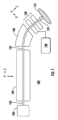
[0018]図1は、本開示の実施形態に係るイオン注入装置100を示す。イオン注入装置100は、イオンビーム120として示される連続イオンビームを生成するように構成されたイオン源102を含む。イオン注入装置100は、イオンビーム120を受信するようにイオン源102の下流に配置された、線形加速器104と表されるAC線形加速器を含み得る。線形加速器104は、束ねられたイオンビーム122が生成されるようにイオンビーム120を修正するために、当該技術分野で知られているバンチャー(別途図示せず)を含み得る。様々な非限定的な実施形態によれば、線形加速器104の複数の段階では、束ねられたイオンビーム122のエネルギーを、1MeV、2MeV、5MeV、又は他の適切なイオンエネルギーなどの目標イオンエネルギーまで増加させることができる。
1 illustrates an
[0019]本開示の幾つかの非限定的な実施形態によれば、イオン注入装置100は、束ねられたイオンビーム122を成形、コリメート、フィルタリング、若しくは走査するか、又はこれらの操作の任意の組合せを実行するための、線形加速器104の下流に配置された追加の構成要素を含み得る。これらの追加の構成要素は、下流構成要素106によって示されており、この構成要素は、線形加速器104とエネルギー拡散電極アセンブリ108との中間に配置されている。エネルギー拡散電極アセンブリ108は、束ねられたイオンビーム122を受信し、束ねられたイオンビーム122のエネルギーを変調し、エネルギー拡散イオンビーム124を基板110へ出力するように構成されている。
[0019] According to some non-limiting embodiments of the present disclosure, the
[0020]様々な実施形態では、エネルギー拡散電極アセンブリ108にわたって高周波電圧を印加することによって、束ねられたイオンビーム122のエネルギーを変調することが可能である。この電圧は、図示のデカルト座標系でZ軸として表される束ねられたイオンビーム122の伝搬方向に沿って、対応する高周波電界を生成し得る。具体的には、本実施形態及び後に続く他の実施形態では、エネルギー拡散電極アセンブリ108は、伝播方向に沿って高周波電界を印加しながら、束状イオンビーム122を導電する中空電極として構成され得る。このようにして、可変エネルギーが、エネルギー拡散電極アセンブリを通過する間、束ねられたイオンビーム122に印加され得る。例えば、RF電源130を利用して、1MHzを超えるような適切な周波数で、エネルギー拡散電極アセンブリ108内における種々の電極間でAC電圧信号(ここで使用される用語「AC電圧」又は「AC電圧信号」は、1kHz、1MHzなどを含む任意の適切な周波数範囲を包含し得る)を発生させることができる。様々な非限定的な実施形態では、線形加速器の加速段及びエネルギー拡散電極アセンブリ108を駆動させる適切な加速周波数の例としては、13.56MHzと40MHzの間の周波数が挙げられる。
[0020] In various embodiments, it is possible to modulate the energy of the
[0021]本開示の様々な実施形態によれば、エネルギー拡散電極アセンブリ108に供給されるAC電圧は、基板110に供給されるエネルギー拡散イオンビーム124内に目標エネルギー拡散を発生させるのに適した振幅を有し得る。例えば、幾つかの非限定的な実施形態によれば、エネルギー拡散イオンビーム124は、1%の公称イオンビームエネルギー、2%の公称エネルギー、5%の公称エネルギー、10%の公称エネルギー、又は20%の公称エネルギーに等しい半値全幅(full width at half maximum:FWHM)を有するエネルギー分布を有し得る。したがって、公称イオンビームエネルギーは、異なる実施形態では、500keV超、1MeV超、2MeV超、5MeV超であり得る。このようにして、所与の公称イオンビームエネルギーにおいて、エネルギー拡散イオンビーム124は、同じ公称イオンビームエネルギーを有する単一エネルギーイオンビームによって発生する注入プロファイルに比べてより広い注入プロファイルをもたらすように、基板110に注入され得る。
[0021] According to various embodiments of the present disclosure, the AC voltage supplied to the energy spreading
[0022]図2は、本開示の追加の実施形態に係るイオン注入装置200を示す。イオン注入装置100の場合と同様に、イオン注入装置200は、イオン源102、及びイオン源102の下流に配置された線形加速器104を含む。
[0022] FIG. 2 illustrates an
[0023]イオン注入装置200は、線形加速器104の下流に配置され、スキャナ202、コリメータ204、及びエネルギー拡散電極アセンブリ208を含むビーム調整装置220を含み得る。
[0023] The
[0024]線形加速器104は、イオンビーム120から束ねられたイオンビーム122を生成するバンチャー(図示せず)を含んでもよい。このイオンビームは、連続イオンビームとして線形加速器104に入り得る。スキャナ202は、束ねられたイオンビーム122(塗りつぶされた楕円によって表されるイオン束として概略的に示される)を受信するように構成され、かつ、スキャン周期によって規定されるように、スキャン信号を供給するよう構成されており、第1のビームライン側と第2のビームライン側との間の束ねられたイオンビーム122を走査する。この実施例では、束ねられたイオンビーム122は、ペンシルビーム又はスポットイオンビームであってもよく、束ねられたイオンビーム122は、図示のX-Z平面内で走査される。例えば、走査発生器230は、幾つかの非限定的な実施形態によれば、振動電圧などの走査信号を、(1kHz、2kHz、5kHzなどのkHz範囲の)走査周波数で振動電界を発生させる一対の電極板に供給し得る。したがって、所与の走査周波数に対して、走査発生器230の周期よりも長い時間尺度にわたって平均化された場合、走査された束ねられたイオンビームは、X軸に沿って細長い断面を形成するように扇状に展開し得る。本実施形態では、エネルギー拡散電極アセンブリ208は、束ねられたイオンビーム122の所望のエネルギー拡散を実現するよう適切な位相を選択するために、束ねられたイオンビーム122の走査位置の情報を使用する位相制御システムに連結された一連のAC電極を含む。
[0024] The
[0025]コリメータ204は、スキャナ202の下流に配置されており、この場合、扇状のビームの形で束ねられたイオンビーム122を受信する。コリメータ204は、束ねられたイオンビーム122を、X軸に沿って伸長したリボンビーム222として成形かつ出力するように構成され得る。図2にさらに示すように、エネルギー拡散電極アセンブリ208は、コリメータ204の下流に配置され、リボンビーム222を受信する。以下に詳述するように、エネルギー拡散電極アセンブリ208は、エネルギー拡散を発生させるために、リボンビームの伝搬方向に沿って複数の電極間にRF電圧を印加するように構成される。
[0025] The
[0026]図2の実施例では、エネルギー拡散電極アセンブリ208は、第1の接地電極212及び第2の接地電極216を含み、2つの接地電極の間に給電された電極214が配置されている。RF電源234は、適切な周波数でRF電力信号を給電された電極214へ供給し得る。例えば、RF電源234は、RF電圧信号を給電された電極214へ供給する共振器(別途図示せず)へRF信号を誘導し得る。したがって、RF電圧が、給電された電極214と第1の接地電極212及び第2の接地電極216との間に発生する。そして、RF電圧は、RF電圧信号の周波数に対応する周波数を有する、リボンビーム222の伝搬方向のZ軸に沿った振動電界を発生させる。
2, the energy dissipating
[0027]本開示の様々な実施形態によれば、エネルギー拡散電極アセンブリ208は、リボンビーム222を包含するように設計された(X軸に沿った)細長い断面を有する一連の複数の中空導電性円筒として構成されてもよい。このように、エネルギー拡散電極アセンブリ208は、線形加速器においてイオンビームを束ねたり又は加速させたりするために使用される既知のドリフトチューブアセンブリの幾つかの特徴を示し得る。リボンビーム222がエネルギー拡散電極アセンブリの所与の中空電極を通過する際に、リボンビーム222は、電界が存在しない中空電極内でドリフト領域に遭遇することになる。第1の接地電極212と給電された電極214との間に振動電界が発生するが、給電された電極214と第2の接地電極216との間にも振動電界が発生する。このようにして、エネルギー拡散電極アセンブリ208は、2つの加速ギャップに特徴付けられた、いわゆるダブルギャップ構成を画定し得る。本開示の様々な実施形態によれば、イオンエネルギー拡散という所望の作用効果を得るために、幾つかの要因を考慮して、エネルギー拡散電極アセンブリ208に印加される振動電圧の周波数及び位相が選択される。これらの要因には、イオンの速度、イオン束における位相の拡散、及びダブルギャップ構成の2つのギャップ間の長さが含まれる。
[0027] According to various embodiments of the present disclosure, the energy
[0028]リボンビーム222がエネルギー拡散電極アセンブリ208内の加速ギャップに進入する際には、リボンビーム222の所与のイオン束の進入のタイミングが、イオンがギャップにわたってどのように加速又は減速するかに影響を与える。例えば、正弦波RF電圧信号が給電された電極214に印加される場合があり、この場合、加速ギャップにわたって正弦波電界が発生する。イオンが加速ギャップを横切るときの電界の瞬間的な振幅と徴候によって、イオンは、多かれ少なかれ、加速されたり減速されたりする。したがって、加速ギャップを通過する所与のイオン束では、束の先端のイオンが、束の後端のイオンとは異なる程度で加速又は減速するので、エネルギー拡散電極アセンブリ208を通過する間にリボンビーム222のイオンエネルギーの拡散がもたらされることになる。
[0028] As the
[0029]本開示の実施形態によれば、エネルギー拡散電極アセンブリ208は、所望の範囲のイオンエネルギーを有するエネルギー拡散イオンビーム224(エネルギー拡散を示すためにより伸長した塗りつぶされた楕円として示される)を基板110に供給するため、リボンビーム222のエネルギーを目標量だけ広げたり拡散させたりすることができる。例えば、ある事例では、線形加速器104が1MeVのイオンエネルギーをリボンビーム222に付与する一方で、80keVの振幅のRF電圧信号が給電された電極214に供給される。リボンビーム222が初期的に単一エネルギーであると仮定すると、80kVの信号により、エネルギー拡散イオンビーム224が、1MeVの平均エネルギー及び最大160keVのFWHMで基板110に衝突し得る。
[0029] According to an embodiment of the present disclosure, the energy spreading
[0030]本開示の様々な非限定的な実施形態によれば、エネルギー拡散電極アセンブリは、1Meから10MeVの範囲の初期イオンエネルギーに対して、イオンエネルギー(FWHM)を1%から30%拡散させるように、イオンビームを処理することができる。上述したように、リボンビーム222は、互いに時間と空間において分離された、束ねられたイオンビーム(すなわち、離散された一連のイオンパケット又はイオン束)としてエネルギー拡散電極アセンブリに進入する。この束ねる作業は、ドリフトチューブ装置によって行われる。ドリフトチューブ装置は、一連のドリフトチューブ電極における少なくとも1つの給電された電極にRF信号が印加されるエネルギー拡散電極アセンブリ108の動作と同様に動作し得る。バンチャーのこれらのドリフトチューブアセンブリは、2つ以上の加速ギャップを生成することになる。この2つ以上の加速ギャップは、RF電界が加速ギャップにわたって振動する際に種々のイオンが加速ギャップを通過するタイミングによって、イオンビーム中の種々のイオンをそれぞれ異なるように加速又は減速させる傾向がある。さらに、本開示の様々な実施形態によれば、束ねられたイオンビーム(リボンビーム222)は、RF電源234によって出力される拡散周波数(spreading frequency)に等しい束周波数(bunch frequency)で束ねられ得る。このようにして、リボンビーム222のイオン束の到着のタイミングは、エネルギー拡散電極アセンブリ208にわたって発生する電界と同期し得る。
[0030] According to various non-limiting embodiments of the present disclosure, the energy diffusion electrode assembly can process the ion beam to spread the ion energy (FWHM) by 1% to 30% for an initial ion energy in the range of 1 Me to 10 MeV. As described above, the
[0031]特定の実施形態では、エネルギー拡散電極アセンブリ208の拡散周波数(例えば、数MHz又は数十MHz程度)が、スキャナ202の走査周波数(例えば、1kHz程度)よりも遙かに高速であり得る場合、エネルギー拡散が、均一かつ反復可能に、エネルギー拡散イオンビーム224の種々の束にもたらされ得る。例えば、リボンビーム222が伝搬方向(Z軸)に垂直な横方向(X軸)に沿って伸長している間、エネルギー拡散電極アセンブリ208は、X軸に沿った束ねられたリボンビームの幅にわたる種々のイオン束について、束ねられたリボンビーム(リボンビーム222)に均一なエネルギー拡散をもたらすことができる。このエネルギー拡散の均一性は、RF電源234からエネルギー拡散電極アセンブリ208へ出力されるRF信号と、リボンビームにおける束群の到達時間との位相関係を一定に保つことによって達成することができる。
[0031] In certain embodiments, where the spreading frequency of the energy spreading electrode assembly 208 (e.g., on the order of several MHz or tens of MHz) can be much faster than the scanning frequency of the scanner 202 (e.g., on the order of 1 kHz), energy spreading can be uniformly and repeatably provided to the various bundles of the energy spreading
[0032]一実施形態では、イオン注入装置200は、検出器210、及びリボンビーム222のイオン束の位相をエネルギー拡散電極アセンブリ208への入口で測定するための位相測定構成要素232を含み得る。イオン注入装置200は、図2に示すように、この位相情報をRF電源234と同期させるコントローラ236をさらに含み得る。代替的に、コントローラ236は、走査発生器230から信号を取得又は受信して、リボンビーム222のイオン束の(X軸に沿った)瞬間的な走査位置を決定することができる。イオン束の瞬間的な走査位置を知ることにより、RF電源234によって生成されるRF信号の同期が可能となり、確実に所与のイオン束が適切な間隔でエネルギー拡散電極アセンブリ208を通過し、目標とするエネルギー拡散が発生する。
[0032] In one embodiment, the
[0033]図3は、本開示のさらなる実施形態に従って構成されたイオン注入装置300を示す。イオン注入装置100及びイオン注入装置200の場合にように、イオン注入装置300は、イオン源102、及びイオン源102の下流に配置された線形加速器104を含む。この実施形態(並びに図1、図2、及び図4の実施形態の変形例)では、イオン注入装置は、線形加速器104でイオンビームのさらなる加速が行われる前に、幾つかの非限定的な実施形態によれば、イオンビーム120を250keVから500keVなどの適切なエネルギーまで加速するためのDC加速システム103をさらに含み得る。
3 illustrates an
[0034]本実施形態では、エネルギー拡散装置は、エネルギー拡散電極アセンブリ310に連結された電源を含み得る。この場合、エネルギー拡散電極アセンブリ310は、上流電極312及び下流電極314を含むダイオードセットとして具体化される。幾つかの実施形態によれば、AC電圧が、上流電極312と下流電極314の間に印加され得る。図3に示すように、ビームラインの上流部分322は、ビームラインの下流部分324から電気的に絶縁されている。異なる実施形態によれば、基板110を収容するエンドステーション(図示せず)を含め、ビームラインの上流部分322が電気的に浮遊してもよく、又は下流部分324が電気的に浮遊してもよい。このアプローチの利点を挙げると、この実施例では、エネルギー拡散電極アセンブリ310が、線形加速器104に印加されるRF電圧と同じ周波数に設定されたRF電圧信号を受信する必要がないことである。図3の実施形態では、エネルギー拡散電極アセンブリ310にギャップが1つしかなく、かつ、他の問題を引き起こすことなく、エネルギー発振の周波数をかなり広い範囲から自由に選択することができるので、幾つかの態様において図2の実施形態よりも単純化されている。しかしながら、図3の実施形態は、より複雑な機械的な設計を有しており、接地電位から大型アセンブリを分離し、アセンブリを絶縁体に取り付ける必要がある。
[0034] In this embodiment, the energy dispersing device may include a power supply coupled to the energy dispersing
[0035]上流電極312と下流電極314との間にAC電圧が印加される実施形態では、線形加速器104(バンチャーを含む)に印加されるRF電圧の走査周波数及び/又は束周波数とAC電圧とのエイリアシングを回避するために、AC電圧周波数を注意深く選択する必要がある。線形加速器104の複数の段で印加される束周波数は数MHz超であると推定されるので、スキャナ202の走査周波数は、1kHz以下の範囲であってもよい。幾つかの実施形態によれば、100kHz以下の範囲(例えば、50kHzから500kHzの範囲)のAC電圧周波数が、エネルギー拡散電極アセンブリ310に用いられてもよい。図3の実施形態に示されるように、第1の電源332が上流部分322に連結されるか、又は代替的に電源334が下流部分324に連結されてもよく、各電源がコントローラ330に連結されてもよい。後者の周波数は、線形加速器104の束周波数よりも遙かに低い(10倍以下又はそれ以上)場合があるため、エネルギー拡散電極アセンブリ310を通過するイオンの各束は、実質的にDC加速又は減速を経ることになる。別の言い方をすれば、例えば13.56MHzの周波数で束ねられたイオン束の場合、エネルギー拡散電極アセンブリ310を通るイオン束の長さ、ひいては移動時間が十分に短いので、エネルギー拡散磁界周波数が遙かに低い(100kHz以下)ことに起因してその束が経験する有効磁界は準一定(quasi-constant)に見える。
[0035] In embodiments where an AC voltage is applied between the
[0036]図4は、本開示のさらなる実施形態に従って構成されたイオン注入装置400を示す。イオン注入装置100、イオン注入装置200、及びイオン注入装置300の場合と同様に、イオン注入装置300は、イオン源102、及びイオン源102の下流に配置された線形加速器104を含む。図2及び図3の実施形態とは異なり、本実施形態では、イオン注入装置400は、ペンシルビーム(又はスポットビーム)を生成し、基板110へ方向付ける。
[0036] Figure 4 illustrates an
[0037]上述の実施形態のように、様々な非限定的な実施形態によれば、線形加速器104の複数の段階では、束ねられたイオンビーム122を生成し、1MeV、2MeV、5MeV、又は他の適切なイオンエネルギーなどの目標イオンエネルギーまで加速させることができる。上述の実施形態とは異なり、基板110に衝突する前に、束ねられたイオンビーム122を目標値のイオンエネルギーを有するスポットビームとして処理するために、エネルギー選択磁石404などの構成要素が設けられ得る。エネルギー選択磁石404(「最終エネルギー磁石」と呼ばれることもある)は、ビームラインのそのポイントにおけるイオンのエネルギーを個別に測定する役割を負う。イオン注入装置400は、高周波電源412として具現化されたエネルギー拡散装置、及びエネルギー拡散電極アセンブリ406をさらに備えている。簡略化のため、エネルギー拡散電極アセンブリ406は、2つの電極として示される。しかしながら、異なる実施形態によれば、エネルギー拡散電極アセンブリ406は、エネルギー拡散電極アセンブリ208と同様に、ダブルギャップドリフトチューブアセンブリとして具現化されてもよく、又は代替的に、2つの接地電極の間に2つの給電された電極が設けられたトリプルギャップ電極アセンブリとして具現化されてもよい。したがって、高周波電源412は、電源アセンブリ410が線形加速器104のバンチャー及び様々な段にRF電圧を供給するのと同じ周波数でRF電圧を生成することができる。図4の構造の利点は、線形加速器からエネルギー拡散電極アセンブリ406までの束ねられたイオンビーム122のイオンの経路長が一定であるため、両者の間の位相関係も一定であることである。一連のイオン束の所望の及び反復性の加速又は減速を実現するためには、加速又は減速するAC磁界の位相が、AC磁界が作用するイオン束の到着時間に一致する必要がある。言い換えれば、エネルギー拡散電極アセンブリ406に到着するそれぞれの連続的なイオン束は、印加されたAC磁界と同じ振幅と位相を経験するはずである。したがって、電源アセンブリ410によって生成された束状信号、及び高周波電源412によって送信された拡散信号と同じ周波数を確立し、束状信号と拡散信号を適切に同期することにより、所与のイオン経路に沿ったそれぞれの連続的なイオン束が、同じようにエネルギー拡散電極アセンブリからの印加されたAC磁界によって処理されることになる。図2の構成では、この位相関係は、所定の時点の走査角度に応じて種々のイオン経路の経路長が変化するにつれて変化するが、図4の構成では、経路長を変化させる高速走査はない。したがって、コントローラ414は、線形加速器104を通過する束ねられたイオンビーム122の加速と、エネルギー拡散電極アセンブリ406によって実行されるエネルギー拡散とをより容易に同期させることができる。
[0037] As in the above-described embodiment, according to various non-limiting embodiments, the multiple stages of the
[0038]図4に示すように、イオン注入装置400は、基板110をZ軸の周りで回転させるとともに、基板をX軸などの垂直軸に沿って移動させるように構成された基板ステージ408を含み得る。このようにして、束ねられたイオンビーム122は、所定の段階では基板110の一部だけを照射し得るが、基板110の全体又はその任意の目標部分は、基板110が適切に回転及び/又は並進することにより、エネルギー拡散イオンビーム420に曝露され得る。
[0038] As shown in FIG. 4, the
[0039]上記に鑑みて、本明細書に開示される実施形態によって、少なくとも以下の利点が達成される。本実施形態のイオン注入装置によってもたらされる第1の利点は、既知の単一エネルギーの高エネルギー注入装置を使用した場合よりも、所与の注入プロセス内でより広範な注入プロファイルを達成する能力である。さらなる利点は、エネルギー拡散構成要素に印加される電圧を単に調整することにより、注入プロファイルの幅を容易に調整できる能力である。 [0039] In view of the above, at least the following advantages are achieved by the embodiments disclosed herein: A first advantage provided by the ion implanter of the present embodiment is the ability to achieve a wider range of implantation profiles within a given implantation process than is possible using known single-energy high-energy implanters. A further advantage is the ability to easily adjust the width of the implantation profile by simply adjusting the voltage applied to the energy spreading component.
[0040]本開示の特定の実施形態が本明細書に記載されているが、本開示はこれらに限定されない。なぜなら、本開示は、当該技術分野が許す限り範囲が広く、本明細書も同様に解することができるからである。したがって、上記の記載は限定として解釈するべきではない。当業者は、本明細書に添付された特許請求の範囲及び本質の範囲内での他の変更を想定するであろう。
[0040] Although specific embodiments of the present disclosure are described herein, the present disclosure is not limited thereto, as the present disclosure is as broad as the art will permit, and the specification can be interpreted accordingly. Therefore, the above description should not be interpreted as limiting. Those skilled in the art will envision other modifications within the scope and spirit of the claims appended hereto.
Claims (20)
連続イオンビームを生成するように構成されたイオン源、
前記連続イオンビームを加速させるDC加速システム、
前記連続イオンビームを受信し、束ねられたイオンビームを出力するAC線形加速器、及び
前記束ねられたイオンビームを受信し、前記束ねられたイオンビームの局所的な伝搬方向に沿って、エネルギー拡散電極アセンブリの複数の電極間にRF電圧を印加する前記エネルギー拡散電極アセンブリ
を備えているイオン注入装置。 1. An ion implantation apparatus comprising:
an ion source configured to generate a continuous ion beam;
a DC acceleration system for accelerating the continuous ion beam;
an AC linear accelerator that receives the continuous ion beam and outputs a bundled ion beam; and an energy dispersing electrode assembly that receives the bundled ion beam and applies an RF voltage between a plurality of electrodes of the energy dispersing electrode assembly along a local propagation direction of the bundled ion beam.
前記スキャナの下流に配置されたコリメータであって、前記束ねられたイオンビームを受信し、前記束ねられたイオンビームを、束ねられたリボンビームとして前記エネルギー拡散電極アセンブリへ出力するコリメータ
をさらに備えている、請求項1に記載のイオン注入装置。 10. The ion implanter of claim 1, further comprising: a scanner configured to receive the bundled ion beam propagating along a first direction and scan the bundled ion beam along a second direction perpendicular to the first direction; and a collimator disposed downstream of the scanner configured to receive the bundled ion beam and output the bundled ion beam as a bundled ribbon beam to the energy dispersing electrode assembly.
前記スキャナが、前記束ねられたイオンビームを束ねられたリボンビームとして生成し、
前記コントローラが、前記束ねられたリボンビームの瞬間的な走査位置を決定することによって、前記一定の位相関係を維持するように構成されている、請求項4に記載のイオン注入装置。 a scanner configured to receive the focused ion beam propagating along a first direction and scan the focused ion beam along a second direction perpendicular to the first direction;
the scanner generating the focused ion beam as a focused ribbon beam;
5. The ion implanter of claim 4, wherein said controller is configured to maintain said constant phase relationship by determining an instantaneous scan position of said bundled ribbon beams.
イオンビームを連続イオンビームとして生成するイオン源、
前記連続イオンビームを束ねて、前記連続イオンビームを束ねられたイオンビームとして出力する線形加速器、
第1の方向に沿って伝搬する、前記束ねられたイオンビームを受信し、前記第1の方向に対して垂直な第2の方向に沿って前記束ねられたイオンビームを走査するように構成されたスキャナ、
前記スキャナの下流に配置されたコリメータであって、前記束ねられたイオンビームを受信し、前記束ねられたイオンビームを束ねられたリボンビームとして出力するコリメータ、並びに
前記線形加速器の下流に配置されたエネルギー拡散電極アセンブリであって、前記リボンビームの伝搬の局所的な方向に沿って、当該エネルギー拡散電極アセンブリの複数の電極間にAC電圧を印加するように構成されたエネルギー拡散電極アセンブリ
を備えているイオン注入装置。 1. An ion implantation apparatus comprising:
an ion source for generating the ion beam as a continuous ion beam;
a linear accelerator for bundling the continuous ion beam and outputting the continuous ion beam as a bundled ion beam;
a scanner configured to receive the focused ion beam propagating along a first direction and scan the focused ion beam along a second direction perpendicular to the first direction;
a collimator disposed downstream of the scanner, the collimator configured to receive the bundled ion beam and output the bundled ion beam as a bundled ribbon beam; and an energy dispersing electrode assembly disposed downstream of the linear accelerator, the energy dispersing electrode assembly configured to apply an AC voltage across a plurality of electrodes of the energy dispersing electrode assembly along a local direction of propagation of the ribbon beam.
第1の方向に沿って伝搬する、束ねられたイオンビームを受信し、前記第1の方向に対して垂直な第2の方向に沿って前記束ねられたイオンビームを走査するように構成されたスキャナ、
前記スキャナの下流に配置されたコリメータであって、前記束ねられたイオンビームを受信し、前記束ねられたイオンビームをリボンビームとして出力するコリメータ、
前記コリメータの下流に配置されたエネルギー拡散電極アセンブリであって、前記リボンビームの伝搬の局所的な方向に沿って、前記エネルギー拡散電極アセンブリの複数の電極間にAC電圧を印加するように構成されたエネルギー拡散電極アセンブリ、並びに
前記スキャナ及び前記エネルギー拡散電極アセンブリを制御して、前記リボンビームの前記局所的な伝搬方向に垂直な方向に沿った、前記リボンビームの幅にわたって、前記リボンビームの均一なエネルギー拡散を発生させるように構成されたコントローラ
を備えているビーム調整装置。 A beam adjustment device, comprising:
a scanner configured to receive a bundled ion beam propagating along a first direction and scan the bundled ion beam along a second direction perpendicular to the first direction;
a collimator disposed downstream of the scanner to receive the bundled ion beam and output the bundled ion beam as a ribbon beam;
an energy spreading electrode assembly disposed downstream of the collimator, the energy spreading electrode assembly configured to apply an AC voltage between a plurality of electrodes of the energy spreading electrode assembly along a local direction of propagation of the ribbon beam; and a controller configured to control the scanner and the energy spreading electrode assembly to generate a uniform energy spread of the ribbon beam across a width of the ribbon beam along a direction perpendicular to the local direction of propagation of the ribbon beam.
The beam conditioning apparatus of claim 18 , wherein the controller maintains the constant phase relationship by determining an instantaneous scan position of the ribbon beam.
Priority Applications (1)
| Application Number | Priority Date | Filing Date | Title |
|---|---|---|---|
| JP2024110122A JP7703084B2 (en) | 2021-04-02 | 2024-07-09 | Apparatus, system and method for energy-dispersed ion beams - Patents.com |
Applications Claiming Priority (3)
| Application Number | Priority Date | Filing Date | Title |
|---|---|---|---|
| US17/221,033 US11569063B2 (en) | 2021-04-02 | 2021-04-02 | Apparatus, system and method for energy spread ion beam |
| US17/221,033 | 2021-04-02 | ||
| PCT/US2022/015959 WO2022211910A1 (en) | 2021-04-02 | 2022-02-10 | Apparatus, system and method for energy spread ion beam |
Related Child Applications (1)
| Application Number | Title | Priority Date | Filing Date |
|---|---|---|---|
| JP2024110122A Division JP7703084B2 (en) | 2021-04-02 | 2024-07-09 | Apparatus, system and method for energy-dispersed ion beams - Patents.com |
Publications (2)
| Publication Number | Publication Date |
|---|---|
| JP2024512671A JP2024512671A (en) | 2024-03-19 |
| JP7520249B2 true JP7520249B2 (en) | 2024-07-22 |
Family
ID=83448334
Family Applications (2)
| Application Number | Title | Priority Date | Filing Date |
|---|---|---|---|
| JP2023560384A Active JP7520249B2 (en) | 2021-04-02 | 2022-02-10 | Apparatus, system and method for energy-dispersed ion beams - Patents.com |
| JP2024110122A Active JP7703084B2 (en) | 2021-04-02 | 2024-07-09 | Apparatus, system and method for energy-dispersed ion beams - Patents.com |
Family Applications After (1)
| Application Number | Title | Priority Date | Filing Date |
|---|---|---|---|
| JP2024110122A Active JP7703084B2 (en) | 2021-04-02 | 2024-07-09 | Apparatus, system and method for energy-dispersed ion beams - Patents.com |
Country Status (6)
| Country | Link |
|---|---|
| US (2) | US11569063B2 (en) |
| JP (2) | JP7520249B2 (en) |
| KR (2) | KR102885121B1 (en) |
| CN (1) | CN117203736A (en) |
| TW (2) | TW202403820A (en) |
| WO (1) | WO2022211910A1 (en) |
Families Citing this family (3)
| Publication number | Priority date | Publication date | Assignee | Title |
|---|---|---|---|---|
| US11825590B2 (en) * | 2021-09-13 | 2023-11-21 | Applied Materials, Inc. | Drift tube, apparatus and ion implanter having variable focus electrode in linear accelerator |
| US11812539B2 (en) * | 2021-10-20 | 2023-11-07 | Applied Materials, Inc. | Resonator, linear accelerator configuration and ion implantation system having rotating exciter |
| US20260018378A1 (en) * | 2024-07-12 | 2026-01-15 | Applied Materials, Inc. | Ion implanter, control system, and techniques for tuning ion implanter |
Citations (2)
| Publication number | Priority date | Publication date | Assignee | Title |
|---|---|---|---|---|
| US20190371562A1 (en) | 2018-06-01 | 2019-12-05 | Varian Semiconductor Equipment Associates, Inc. | Compact high energy ion implantation system |
| WO2020229638A2 (en) | 2019-05-15 | 2020-11-19 | mi2-factory GmbH | Device and method for implanting particles into a substrate |
Family Cites Families (18)
| Publication number | Priority date | Publication date | Assignee | Title |
|---|---|---|---|---|
| JPS6324536A (en) * | 1986-01-29 | 1988-02-01 | イ−トン コ−ポレ−シヨン | Apparatus and method for ion implantation |
| JPH06324536A (en) | 1993-05-13 | 1994-11-25 | Ricoh Co Ltd | Color image forming device |
| JPH08212956A (en) * | 1995-02-02 | 1996-08-20 | Hitachi Ltd | Particle beam equipment |
| US5504341A (en) * | 1995-02-17 | 1996-04-02 | Zimec Consulting, Inc. | Producing RF electric fields suitable for accelerating atomic and molecular ions in an ion implantation system |
| US6055460A (en) | 1997-08-06 | 2000-04-25 | Advanced Micro Devices, Inc. | Semiconductor process compensation utilizing non-uniform ion implantation methodology |
| US6229148B1 (en) | 1997-08-11 | 2001-05-08 | Micron Technology, Inc. | Ion implantation with programmable energy, angle, and beam current |
| GB2395354B (en) * | 2002-11-11 | 2005-09-28 | Applied Materials Inc | Ion implanter and a method of implanting ions |
| US7348576B2 (en) | 2005-03-16 | 2008-03-25 | Varian Semiconductor Equipment Associates, Inc. | Technique for ion beam angle process control |
| KR20090029209A (en) | 2006-06-13 | 2009-03-20 | 세미이큅, 인코포레이티드 | Ion beam device and method for ion implantation |
| US7727866B2 (en) | 2008-03-05 | 2010-06-01 | Varian Semiconductor Equipment Associates, Inc. | Use of chained implants in solar cells |
| EP2964003A4 (en) | 2013-02-28 | 2016-10-05 | Mitsubishi Electric Corp | METHOD FOR MANUFACTURING HIGH FREQUENCY ACCELERATOR, HIGH FREQUENCY ACCELERATOR, AND CIRCULAR ACCELERATOR SYSTEM |
| JP6086819B2 (en) | 2013-05-29 | 2017-03-01 | 住友重機械イオンテクノロジー株式会社 | High energy ion implanter |
| US9218941B2 (en) | 2014-01-15 | 2015-12-22 | Axcelis Technologies, Inc. | Ion implantation system and method with variable energy control |
| DE102016106119B4 (en) | 2016-04-04 | 2019-03-07 | mi2-factory GmbH | Energy filter element for ion implantation systems for use in the production of wafers |
| DE102017119571B4 (en) | 2017-08-25 | 2024-03-14 | Infineon Technologies Ag | ION IMPLANTATION METHOD AND ION IMPLANTATION DEVICE |
| US10128084B1 (en) | 2017-09-18 | 2018-11-13 | Axcelis Technologies, Inc. | Wafer temperature control with consideration to beam power input |
| JP6933962B2 (en) * | 2017-11-22 | 2021-09-08 | 住友重機械イオンテクノロジー株式会社 | Ion implanter and control method of ion implanter |
| JP7548839B2 (en) * | 2021-02-09 | 2024-09-10 | 住友重機械イオンテクノロジー株式会社 | Ion implantation apparatus and ion implantation method |
-
2021
- 2021-04-02 US US17/221,033 patent/US11569063B2/en active Active
-
2022
- 2022-02-10 KR KR1020237037898A patent/KR102885121B1/en active Active
- 2022-02-10 JP JP2023560384A patent/JP7520249B2/en active Active
- 2022-02-10 KR KR1020257037481A patent/KR20250161680A/en active Pending
- 2022-02-10 WO PCT/US2022/015959 patent/WO2022211910A1/en not_active Ceased
- 2022-02-10 CN CN202280025332.8A patent/CN117203736A/en active Pending
- 2022-02-16 TW TW112137986A patent/TW202403820A/en unknown
- 2022-02-16 TW TW111105623A patent/TWI821912B/en active
-
2023
- 2023-09-29 US US18/478,826 patent/US12592359B2/en active Active
-
2024
- 2024-07-09 JP JP2024110122A patent/JP7703084B2/en active Active
Patent Citations (2)
| Publication number | Priority date | Publication date | Assignee | Title |
|---|---|---|---|---|
| US20190371562A1 (en) | 2018-06-01 | 2019-12-05 | Varian Semiconductor Equipment Associates, Inc. | Compact high energy ion implantation system |
| WO2020229638A2 (en) | 2019-05-15 | 2020-11-19 | mi2-factory GmbH | Device and method for implanting particles into a substrate |
Also Published As
| Publication number | Publication date |
|---|---|
| TW202240642A (en) | 2022-10-16 |
| KR102885121B1 (en) | 2025-11-13 |
| KR20250161680A (en) | 2025-11-17 |
| JP7703084B2 (en) | 2025-07-04 |
| TW202403820A (en) | 2024-01-16 |
| US12592359B2 (en) | 2026-03-31 |
| JP2024512671A (en) | 2024-03-19 |
| KR20230164177A (en) | 2023-12-01 |
| WO2022211910A1 (en) | 2022-10-06 |
| US11569063B2 (en) | 2023-01-31 |
| CN117203736A (en) | 2023-12-08 |
| TWI821912B (en) | 2023-11-11 |
| JP2024167175A (en) | 2024-12-03 |
| US20220319806A1 (en) | 2022-10-06 |
| US20240029997A1 (en) | 2024-01-25 |
Similar Documents
| Publication | Publication Date | Title |
|---|---|---|
| JP7703084B2 (en) | Apparatus, system and method for energy-dispersed ion beams - Patents.com | |
| JP7034378B2 (en) | New equipment and technology for generating bunched ion beams | |
| KR102306266B1 (en) | Ion implanting device and ion implanting method | |
| US9412561B2 (en) | Ion implantation method and ion implantation apparatus | |
| KR20140113301A (en) | System for changing energy of ribbon ion beam and ion implantation system | |
| US6521895B1 (en) | Wide dynamic range ion beam scanners | |
| JP6453756B2 (en) | Ion beam processing equipment | |
| TW202429960A (en) | Apparatus having novel electrode configuration for quadrupole focusing, linear accelerator and ion implanter | |
| US11217427B1 (en) | System, apparatus and method for bunched ribbon ion beam | |
| TWI787739B (en) | Ion implantation system | |
| KR101778515B1 (en) | Method for improving implant uniformity during photoresist outgassing | |
| RU143673U1 (en) | ELECTRON BEAM DEVELOPMENT DEVICE | |
| TW202240629A (en) | Ion implantation device and ion implantation method | |
| KR20040097335A (en) | A method of implanting a substrate and an ion implanter for performing the method | |
| JP2013047616A (en) | Electron beam irradiation apparatus and electron beam irradiation system | |
| RU2799053C2 (en) | Device for generating electronic radiation and 3d printing device | |
| JPH0821355B2 (en) | High energy ion implanter | |
| TWI509665B (en) | Method for improving implant uniformity during photoresist outgassing |
Legal Events
| Date | Code | Title | Description |
|---|---|---|---|
| A621 | Written request for application examination |
Free format text: JAPANESE INTERMEDIATE CODE: A621 Effective date: 20231124 |
|
| TRDD | Decision of grant or rejection written | ||
| A01 | Written decision to grant a patent or to grant a registration (utility model) |
Free format text: JAPANESE INTERMEDIATE CODE: A01 Effective date: 20240611 |
|
| A61 | First payment of annual fees (during grant procedure) |
Free format text: JAPANESE INTERMEDIATE CODE: A61 Effective date: 20240709 |
|
| R150 | Certificate of patent or registration of utility model |
Ref document number: 7520249 Country of ref document: JP Free format text: JAPANESE INTERMEDIATE CODE: R150 |