JP7513402B2 - Battery control unit and battery system - Google Patents
Battery control unit and battery system Download PDFInfo
- Publication number
- JP7513402B2 JP7513402B2 JP2020017186A JP2020017186A JP7513402B2 JP 7513402 B2 JP7513402 B2 JP 7513402B2 JP 2020017186 A JP2020017186 A JP 2020017186A JP 2020017186 A JP2020017186 A JP 2020017186A JP 7513402 B2 JP7513402 B2 JP 7513402B2
- Authority
- JP
- Japan
- Prior art keywords
- battery
- batteries
- control unit
- voltage
- reached
- Prior art date
- Legal status (The legal status is an assumption and is not a legal conclusion. Google has not performed a legal analysis and makes no representation as to the accuracy of the status listed.)
- Active
Links
Images


Classifications
-
- Y—GENERAL TAGGING OF NEW TECHNOLOGICAL DEVELOPMENTS; GENERAL TAGGING OF CROSS-SECTIONAL TECHNOLOGIES SPANNING OVER SEVERAL SECTIONS OF THE IPC; TECHNICAL SUBJECTS COVERED BY FORMER USPC CROSS-REFERENCE ART COLLECTIONS [XRACs] AND DIGESTS
- Y02—TECHNOLOGIES OR APPLICATIONS FOR MITIGATION OR ADAPTATION AGAINST CLIMATE CHANGE
- Y02E—REDUCTION OF GREENHOUSE GAS [GHG] EMISSIONS, RELATED TO ENERGY GENERATION, TRANSMISSION OR DISTRIBUTION
- Y02E60/00—Enabling technologies; Technologies with a potential or indirect contribution to GHG emissions mitigation
- Y02E60/10—Energy storage using batteries
Landscapes
- Charge And Discharge Circuits For Batteries Or The Like (AREA)
- Secondary Cells (AREA)
Description
本発明は、電池制御ユニットおよび電池システム、に関する。 The present invention relates to a battery control unit and a battery system.
複数の電池を直列に接続して構成される電池システムがある。複数の電池は、例えば製造時のバラツキや動作環境のバラツキに起因して、劣化がばらつく。例えば、熱源に近い電池は早く劣化してしまうが、熱源から離れた電池は劣化が遅い。 There is a battery system that consists of multiple batteries connected in series. The deterioration of multiple batteries varies due to, for example, variations during manufacturing or variations in the operating environment. For example, batteries close to a heat source deteriorate quickly, while batteries farther away from the heat source deteriorate slowly.
このため、充放電時に劣化の進んだ電池が最初に充電終止電圧に達してしまう。この場合、他の電池に余力が残っていたとしても充電を停止しなければならず、電池容量を使いきることができない。そこで、充電終止電圧に達した電池をバイパスして充電から切り離し、充電終止電圧に達していない電池の充電を継続させるシステムが提案されている(特許文献1) As a result, the most degraded battery reaches the end-of-charge voltage first during charging and discharging. In this case, charging must be stopped even if other batteries still have capacity, and the battery capacity cannot be fully used. Therefore, a system has been proposed that bypasses batteries that have reached the end-of-charge voltage and disconnects them from charging, while continuing to charge batteries that have not yet reached the end-of-charge voltage (Patent Document 1).
ところで、例えば、充電終止電圧を4V、放電終止電圧を3Vとする。充電終止電圧、放電終止電圧に達した電池のバイパスを行うと、そのたびに電池パックとしての総電圧が3Vもしくは4Vずつ低下する。電池パックと負荷又は充電器との間にDC/DCコンバータが設けられている場合があり、その場合、電池パックの電圧がDC/DC変換されて負荷に供給され、充電器からの充電電圧がDC/DC変換された負荷に供給される。このため、DC/DCコンバータとしては広範囲の電圧変換が可能なものを用いる必要がある。しかしながら、広範囲な電圧変換が可能なDC/DCコンバータは、高効率変換領域が限られる。そのため、電池パックの総電圧が大きく変動すると、DC/DCコンバータの変換効率が高い範囲から外れる、という問題があった。 For example, the charge cut-off voltage is 4V and the discharge cut-off voltage is 3V. When a battery that has reached the charge cut-off voltage or discharge cut-off voltage is bypassed, the total voltage of the battery pack drops by 3V or 4V each time. A DC/DC converter may be provided between the battery pack and the load or charger. In this case, the battery pack voltage is converted into DC/DC and supplied to the load, and the charging voltage from the charger is converted into DC/DC and supplied to the load. For this reason, it is necessary to use a DC/DC converter that can convert a wide range of voltages. However, DC/DC converters that can convert a wide range of voltages have a limited high-efficiency conversion range. For this reason, if the total voltage of the battery pack fluctuates significantly, the DC/DC converter falls outside the high conversion efficiency range.
本発明は、上述した事情に鑑みてなされたものであり、その目的は、電池パックの総電圧の変動範囲を抑制することができる電池制御ユニットおよび電池ユニットすることにある。 The present invention has been made in consideration of the above-mentioned circumstances, and its purpose is to provide a battery control unit and a battery unit that can suppress the fluctuation range of the total voltage of the battery pack.
前述した目的を達成するために、本発明に係る電池制御ユニットおよび電池ユニットは、下記[1]~[3]を特徴としている。
[1]
直列に接続された複数の電池毎に設けられ、対応する前記電池を負荷又は充電器に接続可能とする接続状態と、対応する前記電池を前記負荷又は前記充電器に接続不可とする非接続状態と、に切り替える切替部と、
前記切替部を制御して前記複数の電池のうち少なくとも1つを前記接続状態とし、前記接続状態の前記電池が終止電圧に達したか否かを判定し、前記終止電圧に達したと判定すると、前記接続状態とする前記電池を、他の前記電池に切り替える制御部と、
前記電池と前記負荷又は前記充電器との間に設けられたDC/DCコンバータと、を備えた、電池制御ユニットにおいて、
前記制御部は、前記接続状態とする電池の数が、前記切り替え前と前記切り替え後とで2以上の同じ数になるように切り替え、
前記接続状態にある前記電池の電圧の総和である総電圧が、前記DC/DCコンバータが有する電圧-効率特性において所定の効率以上となる電圧の範囲内で、変動する、
電池制御ユニットであること。
In order to achieve the above-mentioned object, a battery control unit and a battery unit according to the present invention are characterized by the following [1] to [3].
[1]
a switching unit provided for each of a plurality of batteries connected in series, the switching unit switching between a connection state in which the corresponding battery can be connected to a load or a charger and a non-connection state in which the corresponding battery cannot be connected to the load or the charger;
a control unit that controls the switching unit to place at least one of the plurality of batteries in the connected state, determines whether the battery in the connected state has reached an end voltage, and when it is determined that the battery has reached the end voltage, switches the battery in the connected state to another battery;
A battery control unit including a DC/DC converter provided between the battery and the load or the charger,
the control unit switches the number of batteries to be connected such that the number of batteries to be connected before and after the switching is the same number, which is two or more ;
a total voltage, which is the sum of the voltages of the batteries in the connected state, fluctuates within a voltage range in which the efficiency is equal to or greater than a predetermined efficiency in the voltage-efficiency characteristics of the DC/DC converter;
It is a battery control unit.
[2]
直列に接続された複数の電池毎に設けられ、対応する前記電池を負荷又は充電器に接続可能とする接続状態と、対応する前記電池を前記負荷又は前記充電器に接続不可とする非接続状態と、に切り替える切替部と、
前記切替部を制御して前記複数の電池のうち少なくとも1つを前記接続状態とし、前記接続状態の前記電池が終止電圧に達したか否かを判定し、前記終止電圧に達したと判定すると、前記接続状態とする前記電池を、他の前記電池に切り替える制御部と、
前記電池と前記負荷又は前記充電器との間に設けられたDC/DCコンバータと、を備えた、電池制御ユニットにおいて、
前記複数の電池を、総電圧が予め定めた範囲内となる複数のグループに分け、
前記制御部が、
前記接続状態において対応する前記電池を前記負荷に接続する場合、前記複数のグループのうち最も少ない電池数のグループを前記接続状態とし、前記接続状態の前記電池が放電終止電圧に達したか否かを判定し、前記放電終止電圧に達したと判定すると、前記接続状態とする前記グループを、他の前記グループのうち最も少ない電池数の前記グループに切り替え、
前記接続状態において対応する前記電池を前記充電器に接続する場合、前記複数のグループのうち最も多い電池数のグループを前記接続状態とし、前記接続状態の前記電池が充電終止電圧に達したか否かを判定し、前記充電終止電圧に達したと判定すると、前記接続状態とする前記グループを、他の前記グループのうち最も多い電池数の前記グループに切り替える、
電池制御ユニットであること。
[ 2 ]
a switching unit provided for each of a plurality of batteries connected in series, the switching unit switching between a connection state in which the corresponding battery can be connected to a load or a charger and a non-connection state in which the corresponding battery cannot be connected to the load or the charger;
a control unit that controls the switching unit to place at least one of the plurality of batteries in the connected state, determines whether the battery in the connected state has reached an end voltage, and when it is determined that the battery has reached the end voltage, switches the battery in the connected state to another battery;
A battery control unit including a DC/DC converter provided between the battery and the load or the charger,
Dividing the plurality of batteries into a plurality of groups whose total voltage falls within a predetermined range;
The control unit:
when connecting the corresponding battery in the connected state to the load, the group having the smallest number of batteries among the plurality of groups is set to the connected state, and it is determined whether the battery in the connected state has reached a discharge end voltage, and when it is determined that the battery has reached the discharge end voltage, the group to be set to the connected state is switched to the group having the smallest number of batteries among the other groups;
when connecting the corresponding battery in the connected state to the charger, the group with the largest number of batteries among the plurality of groups is set to the connected state, and it is determined whether the battery in the connected state has reached a charge end voltage, and if it is determined that the battery has reached the charge end voltage, the group in the connected state is switched to the group with the largest number of batteries among the other groups;
It is a battery control unit.
[3]
直列に接続された複数の電池と、
[1]又は[2]に記載の電池制御ユニットと、を備えた、
電池システムであること。
[ 3 ]
A plurality of batteries connected in series ;
[1] or [2] , and a battery control unit according to the present invention.
It is a battery system.
上記[1]及び[3]の構成の電池制御ユニット及び電池ユニットによれば、制御部が、複数の電池の少なくとも1つを接続状態とし、接続状態の電池が終止電圧に達したか否かを判定し、終止電圧に達したと判定すると、接続状態とする電池を、他の電池に切り替える。これにより、負荷又は充電器に接続される電池は、複数の電池のうち一部となるため、電池パックの総電圧の変動範囲を抑制することができる。これにより、電池パックの総電圧の変動範囲を抑制することができ、電池パックの総電圧がDC/DCコンバータの高効率変換領域から外れるのを抑制することができる。 According to the battery control unit and the battery unit having the configurations of [1] and [ 3 ] above, the control unit connects at least one of the multiple batteries, determines whether the connected battery has reached its end voltage, and when it determines that the end voltage has been reached, switches the connected battery to another battery. As a result, the battery connected to the load or charger is only a part of the multiple batteries, and the fluctuation range of the total voltage of the battery pack can be suppressed. As a result, the fluctuation range of the total voltage of the battery pack can be suppressed, and the total voltage of the battery pack can be prevented from falling outside the high-efficiency conversion region of the DC/DC converter.
更に、上記[1]及び[3]の構成の電池制御ユニット及び電池ユニットによれば、制御部は、接続状態とする電池の数が、切り替え前と切り替え後とで同じになるように切り替える。これにより、負荷又は充電器に接続される電池の数は、常時同じとなるため、より一層、電池パックの総電圧の変動範囲を抑制することができる。 Furthermore, in the battery control unit and battery unit configured as in [1] and [3] above, the control unit switches the number of connected batteries so that it is the same before and after the switching. This ensures that the number of batteries connected to the load or charger is always the same, further reducing the fluctuation range of the total voltage of the battery pack.
上記[2]の構成の電池制御ユニットによれば、制御部が、複数の電池を総電圧が予め定めた範囲内となる複数のグループに分ける。制御部が、複数のグループの1つを接続状態とし、接続状態の電池が終止電圧に達したか否かを判定し、終止電圧に達したと判定すると、接続状態とするグループを、他のグループに切り替える。これにより、負荷又は充電器に接続される電池の総電圧が予め定めた範囲内となるため、より一層、電池パックの総電圧の変動範囲を抑制することができる。 According to the battery control unit having the configuration of [ 2 ] above, the control unit divides the batteries into a plurality of groups whose total voltage is within a predetermined range. The control unit sets one of the groups in a connected state, determines whether the connected batteries have reached their end voltage, and when it determines that the end voltage has been reached, switches the group in the connected state to another group. This brings the total voltage of the batteries connected to the load or charger into a predetermined range, thereby further suppressing the fluctuation range of the total voltage of the battery pack.
本発明によれば、電池パックの総電圧の変動範囲を抑制することができる電池制御ユニットおよび電池ユニットを提供することができる。 The present invention provides a battery control unit and a battery unit that can suppress the range of variation in the total voltage of the battery pack.
以上、本発明について簡潔に説明した。更に、以下に説明される発明を実施するための形態(以下、「実施形態」という。)を添付の図面を参照して通読することにより、本発明の詳細は更に明確化されるであろう。 The present invention has been briefly described above. The details of the present invention will become clearer by reading the following description of the embodiment of the invention (hereinafter referred to as "embodiment") with reference to the attached drawings.
(第1実施形態)
本発明に関する具体的な実施形態について、各図を参照しながら以下に説明する。
First Embodiment
Specific embodiments of the present invention will be described below with reference to the accompanying drawings.
まず、第1実施形態について説明する。図1に示す電池システム1は、例えば劣化が進んだ電池を再利用して電力を供給する装置である。
First, the first embodiment will be described. The
同図に示すように、電池システム1は、電池パック2と、電池制御ユニット3と、DC/DCコンバータ4と、充電器5と、負荷6と、を備えている。電池システム1は、電池パック2からの電力をDC/DCコンバータ4を介して電圧変換した後、負荷6に供給している。また、電池システム1は、充電器5からの電力をDC/DCコンバータ4を介して電圧変換した後、電池パック2に供給して、充電している。
As shown in the figure, the
電池パック2は、図2に示すように、複数の電池21~2N(Nは2以上の整数)を有している。複数の電池21~2Nは各々、充放電可能な蓄電池であり、1つのセルから構成されていてもよいし、複数のセルから構成されていてもよい。
As shown in FIG. 2, the
電池制御ユニット3は、複数の切替部311~31Nと、複数の電圧計測部321~32Nと、制御部33と、を備えている。複数の切替部311~31Nは、複数の電池21~2Nに各々対応して設けられている。複数の切替部311~31Nは、互いに同じ構成である。
The
切替部311~31Nは、対応する電池21~2Nを充電器5又は負荷6に接続可能とする接続状態と、対応する電池21~2Nを充電器5又は負荷6に接続不可とする非接続状態と、の間で切り替える。即ち、接続状態の電池21~2Nは、電池パック2に設けられた一対の端子T1、T2間に電気的に接続され、非接続状態の電池21~2Nは、一対の端子T1、T2間から切り離される。よって、電池パック2の端子T1、T2を充電器5又は負荷6に接続すると、接続状態の電池21~2Nが充電器5又は負荷6に接続され、非接続状態の電池21~2Nが充電器5又は負荷6から切り離される。
The switching units 311-31N switch between a connected state in which the corresponding batteries 21-2N can be connected to the
切替部311は、電池21に直列接続された第1スイッチSW11と、電池21及び第1スイッチSW11に並列接続された第2スイッチSW21と、から構成されている。第1スイッチSW11は、一端T11が電池21の一極(例えば正極)に接続されている。第2スイッチSW21は、一端T21が電池21の他極(例えば負極)に接続され、他端T22が第1スイッチSW11の他端T12に接続されている。切替部312~31Nについては、上述した切替部311についての説明中の「311」を「312」~「31N」、「SW11」を「SW12」~「SW1N」、「SW21」を「SW22」~「SW2N」にそれぞれ置き換えて説明することができ、詳細な説明を省略する。
The
また、第1スイッチSW12の他端T12は、電池21の負極に接続され、第1スイッチSW13の他端T12は、電池22の負極に接続されている。即ち、互いに隣接する電池21-電池22間、電池22-電池23、…、電池2N-1-電池2N間にそれぞれ、第1スイッチSW12~SW1Nが接続されている。
The other end T12 of the first switch SW12 is connected to the negative electrode of
以上の構成によれば、第2スイッチSW21~SW2Nをオフし、第1スイッチSW11~SW1Nをオンすると、対応する電池21~2Nが接続状態となる。また、第1スイッチSW11~SW1Nをオフすると対応する電池21~2Nが非接続状態となる。このとき、第2スイッチSW21~SW2Nをオンするとバイパス経路が形成され、接続状態となっている電池21~2Nのみが端子T1、T2間に接続される。
According to the above configuration, when the second switches SW21 to SW2N are turned off and the first switches SW11 to SW1N are turned on, the corresponding
複数の電圧計測部321~32Nは、対応する電池21~2Nの両端電圧を測定して、その測定結果を後述する制御部33に対して出力する。
The multiple voltage measurement units 321-32N measure the voltage across the corresponding batteries 21-2N and output the measurement results to the
制御部33は、周知のCPU、ROM、RAMから構成され、電池システム1全体の制御を司る。制御部33は、各電池21~2Nの両端電圧に基づいて第1スイッチSW11~S1N及び第2スイッチSW21~SW2Nをオンオフ制御する。
The
DC/DCコンバータ4は、電池パック2と充電器5又は負荷6との間に設けられる。充電器5及び負荷6は、DC/DCコンバータ4を介して電池パック2に接続されている。
The DC/
次に、上述した電池システム1の動作の概要について説明する。制御部33は、電池21~2Nを充放電する際、電池21~2Nを1つずつ端子T1、T2に接続する。具体的に説明すると、今全ての電池21~2Nが充電終止電圧、放電終止電圧に達していないとする。このとき、例えば、充放電の最初は電池21のみを端子T1、T2間に接続し、電池22、23はバイパスさせておく。電池21を充放電した結果、充電終止電圧、放電終止電圧に達したら、電池21をバイパスし、電池22のみを端子T1、T2間に接続する。電池22を充放電した結果、充電終止電圧、放電終止電圧に達したら、電池22をバイパスし、電池23のみを端子T1、T2間に接続し、これを繰り返す。繰り返した結果、全ての電池21~2Nが、充電終止電圧、放電終止電圧に達したら、充放電完了となる。
Next, an overview of the operation of the
このように、複数の電池21~2Nを直列接続して使わずに、電池21~2Nを1つずつ使用することで、電池パック2の総電圧(入出力端子T1、T2間の電圧)の変動範囲を狭めることができる。これにより、DC/DCコンバータ4の高効率変換領域から総電圧が外れないようにすることができる。
In this way, by using the
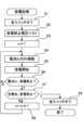
次に、上述した電池システム1の動作の詳細について、図3及び図4を参照して以下説明する。図3は、第1実施形態における図1に示す制御部33の充電処理手順を示すフローチャートである。
Next, the operation of the
制御部33は、放電命令を受信すると、図3に示す放電処理を開始する。まず、制御部33は、全第1スイッチSW11~SW1N、全第2スイッチSW21~SW2Nをオフにする(ステップS1)。その後、制御部33は、放電終止電圧の設定を行う(ステップS2)。本実施形態では、制御部33は、3Vを放電終止電圧として設定する。次に、制御部33は、n=1に設定する(ステップS3)。その後、制御部33は、切替部311~31Nを制御して、電池2nのみを接続状態とし、電池2n以外を非接続状態とする(ステップS4)。
When the
次に、制御部33は、電池パック2の端子T1、T2に充電器5を接続して充電を開始する(ステップS5)。その後、制御部33は、接続状態である電池2nが放電終止電圧に達したか否かを判定する(ステップS6)。電池2nが放電終止電圧に達していなければ(ステップS6でN)、制御部33は、ステップS4に戻り、電池2nの放電を継続させる。一方、電池2nが放電終止電圧に達していれば(ステップS6でY)、制御部33は、全電池21~2Nが放電終止電圧に達したか否かを判定する(ステップS7)。全電池21~2Nが放電終止電圧に達していなければ(ステップS7でN)、制御部33は、nをインクリメントした後(ステップS8)、ステップS4に戻る。これにより、接続状態となる電池が電池2nから電池2n+1に切り替わる。
Next, the
これに対して、全電池21~2Nが放電終止電圧に達すると(ステップS7でY)、制御部33は全第1スイッチSW11~SW1N、全第2スイッチSW21~SW2Nをオフして(ステップS9)、処理を終了する。
In contrast, when all
また、制御部33は、充電命令を受信すると、充電処理を開始する。充電処理については、上述した放電処理についての説明中の「放電」を「充電」に、「3V」を「4V」に、「充電器5」を「負荷6」に置き換えて説明することができ、詳細な説明を省略する。
When the
上述した実施形態によれば、制御部33が、複数の電池21~2Nの1つを接続状態とし、接続状態の電池2nが終止電圧に達したか否かを判定し、終止電圧に達したと判定すると、接続状態とする1つの電池2nを、他の電池2n+1に切り替える。これにより、充電器5又は負荷6に接続される電池21~2Nは常時、1つとなるため、電池パック2の総電圧の変動範囲を抑制することができる。また、電池パック2の総電圧の変動範囲を抑制することができ、電池パック2の総電圧がDC/DCコンバータ4の高効率変換領域から外れるのを抑制することができる。
According to the embodiment described above, the
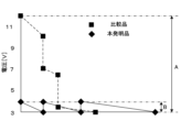
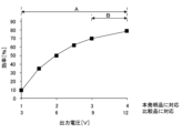
次に、上述した本実施形態の電池システム1の効果の詳細について図4及び図5を参照して説明する。図4は、比較品及び本発明の電池パック2の総電圧のタイムチャートであり、図5は、DC/DCコンバータ4の電圧-効率特性を示す。上記比較品は、最初に全ての電池21~23を直列に端子T1及びT2間に接続し、終止電圧に達した電池21~2Nについてはバイパスさせるものである。本発明品は、上述した図1~図3に示す電池システム1であり、N=3としている。
Next, the effect of the
また、放電終止電圧を3Vとし、充電終止電圧を4Vとし、電池21~23は、いずれも満充電(充電終止電圧=4V)であり、電池21>電池22>電池23の順に劣化しているものとする。放電開始時は、比較品の電池パック2は、電池21~23の全てが直列接続され、総電圧は12V(4V×3)である。充電中、比較品の総電圧は、徐々に減少し、最も劣化している電池21が最初に放電終止電圧に達すると、電池21がバイパスされ、総電圧が3V一気に下がる。その後、同様に電池22がバイパスされた後、最も劣化していない電池23が放電終止電圧に達すると、そのときの比較品の総電圧は3Vとなる。即ち、比較品の総電圧は、12V~3Vの範囲Aで変動する。
The discharge end voltage is 3V, the charge end voltage is 4V, batteries 21-23 are all fully charged (charge end voltage = 4V), and the order of deterioration is
これに対して、本発明品の電池パック2は、放電開始時は、電池21のみが接続され、総電圧は4Vである。充電中、比較品の総電圧は、徐々に減少し、電池21が放電終止電圧に達すると、3Vとなる。その後、電池21がバイパスされて、電池22が接続すると比較品の総電圧は、4Vに上昇し、これを繰り返す。即ち、本発明品の総電圧は、4V~3Vの範囲Bで変動する。
In contrast, when the
よって、比較品は12V~3Vの広範囲で変換できるDC/DCコンバータ4を用いても、効率70%以上の高効率範囲は12V~9Vの間であるため、総電圧9V以下は高効率範囲から外れてしまう。これに対して、本発明品は4V~1Vの狭範囲で変換できるDC/DCコンバータ4を用いても、効率70%以上の高効率範囲を4V~3Vであるため、総電圧が高効率範囲から外れることがない。
Thus, even if the comparative product uses a DC/
(第2実施形態)
次に、第2実施形態について説明する。上述した第1実施形態においては、電池21~2Nのうち1つだけを接続状態に制御していたが、これに限ったものではなく、2以上の電池21~2Nを接続状態にしてもよい。接続状態とする電池21~2Nの数が常に一定であれば、第1実施形態と同様に、電池21~2Nの総電圧の変動を抑えて、総電圧が、DC/DCコンバータ4の高効率範囲から外れることがない。
Second Embodiment
Next, a second embodiment will be described. In the first embodiment described above, only one of the
上述した第2実施形態における電池システム1の詳細について、説明する。第2実施形態における電池システム1の構成は、上述した第1実施形態と同様であるため、ここでは詳細な説明を省略する。ただし、本実施形態では、電池システム1が、N≧4以上としている。
The
上記第2実施形態における電池システム1の動作について、図6を参照して説明する。図6は、第2実施形態における図1に示す制御部33の充電処理手順を示すフローチャートである。
The operation of the
制御部33は、放電命令を受信すると、図6に示す放電処理を開始する。制御部33は、全第1スイッチSW11~SW1N、第2スイッチSW21~SW2Nをオフにする(ステップS10)。その後、制御部33は、放電終止電圧の設定を行う(ステップS11)。次に、制御部33は、n=1に設定する(ステップS13)。その後、制御部33は、切替部311~31Nを制御して、電池2n、2n+1のみを接続状態とし、電池2n、2n+1以外を非接続状態とする(ステップS14)。
When the
次に、制御部33は、充電を開始する(ステップS15)。その後、制御部33は、接続状態である電池2n又は2n+1が放電終止電圧に達したか否かを判定する(ステップS16)。電池2n、2n+1の何れかが放電終止電圧に達していなければ(ステップS16でN)、制御部33は、ステップS14に戻り、電池2n、2n+1の放電を継続させる。一方、電池2n、2n+1が放電終止電圧に達していれば(ステップS16でY)、制御部33は、全電池21~2Nの放電が完了したか否か(n+1=Nか)判定する(ステップS17)。全電池21~2Nが放電していなければ(ステップS17でN)、制御部33は、nに2を加算した後(ステップS18)、ステップS14に戻る。これにより、接続状態となる電池が、電池2n、2n+1から電池2n+2、2n+3に切り替わる。
Next, the
これに対して、全電池21~2Nの放電が完了すると(ステップS17でY)、制御部33は全第1スイッチSW11~SW1N、全第2スイッチSW21~SW2Nをオフして(ステップS19)、処理を終了する。また、充電については、上述した放電処理についての説明中の「放電」を「充電」に置き換えて説明することができる。
In contrast, when discharging of all batteries 21-2N is complete (Y in step S17), the
上述した第2実施形態によれば、常時、2つの電池21~2Nが接続状態となるため、電池21~2Nの総電圧の変動を抑えることができる。
According to the second embodiment described above, two
なお、上述した第2実施形態によれば、2つの電池21~2Nを接続状態としていたが、これに限ったものではない。3つ以上の電池21~2Nを接続状態とするようにしてもよい。
In the second embodiment described above, two
(第3実施形態)
次に、第3実施形態について説明する。上述した第1、2実施形態においては、接続状態とする電池21~2Nの数を常に一定にしていたが、これに限ったものではない。電池21~2Nの総電圧が、DC/DCコンバータ4の高効率範囲内になるような組み合わせの電池21~23を接続状態としてもよい。
Third Embodiment
Next, a third embodiment will be described. In the first and second embodiments described above, the number of
上述した第2実施形態における電池システム1の詳細について、説明する。第3実施形態における電池システム1の構成は、上述した第2実施形態と同様であるため、ここでは詳細な説明を省略する。
Details of the
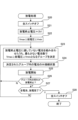
上記第3実施形態における電池システム1の動作について、図7を参照して説明する。図7は、第3実施形態における図1に示す制御部33の放電処理手順を示すフローチャートである。
The operation of the
制御部33は、放電命令を受信すると、図7に示す放電処理を開始する。制御部33は、全第1スイッチSW11~SW1N、第2スイッチSW21~SW2Nをオフにする(ステップS20)。その後、制御部33は、放電終止電圧の設定を行う(ステップS21)。次に、制御部33は、放電終止電圧に達していない電池21~2Nをグループに分ける(ステップS22)。このとき、各グループの総電圧が、Vmax以下、Vmin以上となるように、グループ分けする。Vmax、Vminは、例えばDC/DCコンバータ4の放電方向における高効率範囲の最大値、最小値に設定されている。
When the
その後、制御部33は、ステップS22で分けられたグループのうち、最も少ない電池数のグループを決定する(ステップS23)。少ない電池数のグループほど、グループを構成する1個、1個の電池21~2Nの両端電圧が高いとみなすことができる。なお、ステップS23において、制御部33は、最も少ない電池数のグループが複数グループあった場合、総電圧がVmaxに最も近いグループに決定するようにしてもよい。また、グループ内の最小、最大の電圧差が小さいものを選んで決定するようにしてもよい。次に、制御部33は、決定されたグループ内の電池21~2Nのみ接続状態として、その他の電池21~2Nを非接続状態とする(ステップS24)。
Then, the
その後、制御部33は、充電を開始する(ステップS25)。次に、制御部33は、接続状態であるグループ内の電池21~2Nの何れかが放電終止電圧に達したか否かを判定する(ステップS26)。グループ内の電池21~2Nの何れかが放電終止電圧に達していなければ(ステップS26でN)、制御部33は、ステップS23に戻る。一方、グループ内の電池21~2Nの何れか1つでも放電終止電圧に達していれば(ステップS26でY)、制御部33は、全電池21~2Nが放電したか否かを判定する(ステップS27)。全電池21~2Nが放電していなければ(ステップS27でN)、制御部33はステップS23に戻る。
Then, the
これに対して、全電池21~2Nが放電していれば(ステップS27でY)、制御部33は全第1スイッチSW11~SW1N、全第2スイッチSW21~SW2Nをオフして(ステップS28)、処理を終了する。また、充電については、上述した放電処理についての説明中の「放電」を「充電」に置き換え、ステップS21の「放電終了電圧=3V」を「充電終了電圧=4V」に置き換え、「Vmax」を「Vmax´」に、「Vmin」を「Vmin´」に置き換えて説明することができる。双方向のDC/DCコンバータ4では、充電方向と放電方向とで高効率範囲が異なることがあるので、VmaxとVmax´、VminとVmin´は、異なる値に設定されていてもよい。
On the other hand, if all the batteries 21-2N are discharged (Y in step S27), the
ただし、ステップS23においては、制御部33は、ステップS22で分けられたグループのうち、最も多い電池数のグループを決定する。多い電池数のグループほど、グループを構成する1個、1個の電池21~2Nの両端電圧が低いとみなすことができる。なお、充電時のステップS23において、制御部33は、最も多い電池数のグループが複数グループあった場合、総電池がVmin´に最も近いグループに決定するようにしてもよい。また、グループ内の最小、最大の電圧差が小さいものを選んで決定するようにしてもよい。
However, in step S23, the
上述した第3実施形態によれば、総電圧がDC/DCコンバータ4の高効率範囲内になるような組み合わせの電池21~23を接続状態とする。これにより、電池パック2の総電圧がDC/DCコンバータ4の高効率変換領域から外れるのを抑制することができる。
According to the third embodiment described above, the
なお、本発明は、上述した実施形態に限定されるものではなく、適宜、変形、改良、等が可能である。その他、上述した実施形態における各構成要素の材質、形状、寸法、数、配置箇所、等は本発明を達成できるものであれば任意であり、限定されない。 The present invention is not limited to the above-described embodiment, and can be modified, improved, etc. as appropriate. In addition, the material, shape, size, number, location, etc. of each component in the above-described embodiment are arbitrary as long as they can achieve the present invention, and are not limited.
上述した実施形態によれば、切替部311~31Nとしては、2つの第1スイッチSW11~SW1N、第2スイッチSW21~SW2Nとから構成されていたが、これに限ったものではない。切替部311~31Nとしては、電池21~2Nと、電池21~2Nに並列接続されたバイパス回路と、の何れかを選択する切替スイッチから構成されていてもよい。 In the above-described embodiment, the switching units 311-31N are configured with two first switches SW11-SW1N and two second switches SW21-SW2N, but this is not limited to the above. The switching units 311-31N may also be configured with a changeover switch that selects either the batteries 21-2N or a bypass circuit connected in parallel to the batteries 21-2N.
ここで、上述した本発明に係る電池制御ユニットおよび電池システムの実施形態の特徴をそれぞれ以下[1]~[4]に簡潔に纏めて列記する。
[1]
複数の電池(21~2N)毎に設けられ、対応する前記電池(21~2N)を負荷(6)又は充電器(5)に接続可能とする接続状態と、対応する前記電池(21~2N)を前記負荷(6)又は前記充電器(5)に接続不可とする非接続状態と、に切り替える切替部(311~31N)と、
前記切替部(311~31N)を制御して前記複数の電池(21~2N)のうち少なくとも1つを前記接続状態とし、前記接続状態の前記電池(21~2N)が終止電圧に達したか否かを判定し、前記終止電圧に達したと判定すると、前記接続状態とする前記電池(21~2N)を、他の前記電池(21~2N)に切り替える制御部(33)と、
前記電池(21~2N)と前記負荷(6)又は前記充電器(5)との間に設けられたDC/DCコンバータ(4)と、を備えた、
電池制御ユニット(3)。
[2]
[1]に記載の電池制御ユニット(3)において、
前記制御部(33)は、前記接続状態とする電池(21~2N)の数が、前記切り替え前と前記切り替え後とで同じになるように切り替える、
電池制御ユニット(3)。
[3]
[1]に記載の電池制御ユニット(3)において、
前記複数の電池(21~2N)を、総電圧が予め定めた範囲内となる複数のグループに分け、
前記制御部(33)が、前記複数のグループの1つを前記接続状態とし、前記接続状態の前記電池(21~2N)が終止電圧に達したか否かを判定し、前記終止電圧に達したと判定すると、前記接続状態とする前記グループを、他の前記グループに切り替える、
電池制御ユニット(3)。
[4]
複数の電池(21~2N)と、
[1]~[3]何れか1項に記載の電池制御ユニット(3)と、を備えた、
電池システム(1)。
Here, the features of the embodiments of the battery control unit and the battery system according to the present invention described above will be briefly summarized and listed in the following [1] to [4].
[1]
a switching unit (311 to 31N) provided for each of a plurality of batteries (21 to 2N), for switching between a connection state in which the corresponding battery (21 to 2N) can be connected to a load (6) or a charger (5) and a non-connection state in which the corresponding battery (21 to 2N) cannot be connected to the load (6) or the charger (5);
a control unit (33) that controls the switching units (311-31N) to place at least one of the plurality of batteries (21-2N) in the connected state, determines whether or not the battery (21-2N) in the connected state has reached an end voltage, and when it determines that the end voltage has been reached, switches the battery (21-2N) that is to be placed in the connected state to another battery (21-2N);
A DC/DC converter (4) provided between the battery (21 to 2N) and the load (6) or the charger (5),
Battery control unit (3).
[2]
In the battery control unit (3) according to [1],
the control unit (33) performs the switching so that the number of the batteries (21 to 2N) to be in the connected state is the same before and after the switching.
Battery control unit (3).
[3]
In the battery control unit (3) according to [1],
Divide the plurality of batteries (21 to 2N) into a plurality of groups whose total voltage falls within a predetermined range;
the control unit (33) sets one of the plurality of groups to the connected state, determines whether or not the batteries (21 to 2N) in the connected state have reached an end voltage, and when it determines that the end voltage has been reached, switches the group set to the connected state to another group.
Battery control unit (3).
[4]
A plurality of batteries (21 to 2N);
[1] to [3] A battery control unit (3) according to any one of
Battery system (1).
1 電池システム
3 電池制御ユニット
4 DC/DCコンバータ
5 充電器
6 負荷
21~2N 電池
311~31N 切替部
REFERENCE SIGNS
Claims (3)
前記切替部を制御して前記複数の電池のうち少なくとも1つを前記接続状態とし、前記接続状態の前記電池が終止電圧に達したか否かを判定し、前記終止電圧に達したと判定すると、前記接続状態とする前記電池を、他の前記電池に切り替える制御部と、
前記電池と前記負荷又は前記充電器との間に設けられたDC/DCコンバータと、を備えた、電池制御ユニットにおいて、
前記制御部は、前記接続状態とする電池の数が、前記切り替え前と前記切り替え後とで2以上の同じ数になるように切り替え、
前記接続状態にある前記電池の電圧の総和である総電圧が、前記DC/DCコンバータが有する電圧-効率特性において所定の効率以上となる電圧の範囲内で、変動する、
電池制御ユニット。 a switching unit provided for each of a plurality of batteries connected in series, the switching unit switching between a connection state in which the corresponding battery can be connected to a load or a charger and a non-connection state in which the corresponding battery cannot be connected to the load or the charger;
a control unit that controls the switching unit to place at least one of the plurality of batteries in the connected state, determines whether the battery in the connected state has reached an end voltage, and when it is determined that the battery has reached the end voltage, switches the battery in the connected state to another battery;
A battery control unit including a DC/DC converter provided between the battery and the load or the charger,
the control unit switches the number of batteries to be connected such that the number of batteries to be connected before and after the switching is the same number that is two or more ;
a total voltage, which is the sum of the voltages of the batteries in the connected state, fluctuates within a voltage range in which the efficiency is equal to or greater than a predetermined efficiency in the voltage-efficiency characteristics of the DC/DC converter;
Battery control unit.
前記切替部を制御して前記複数の電池のうち少なくとも1つを前記接続状態とし、前記接続状態の前記電池が終止電圧に達したか否かを判定し、前記終止電圧に達したと判定すると、前記接続状態とする前記電池を、他の前記電池に切り替える制御部と、
前記電池と前記負荷又は前記充電器との間に設けられたDC/DCコンバータと、を備えた、電池制御ユニットにおいて、
前記複数の電池を、総電圧が予め定めた範囲内となる複数のグループに分け、
前記制御部が、
前記接続状態において対応する前記電池を前記負荷に接続する場合、前記複数のグループのうち最も少ない電池数のグループを前記接続状態とし、前記接続状態の前記電池が放電終止電圧に達したか否かを判定し、前記放電終止電圧に達したと判定すると、前記接続状態とする前記グループを、他の前記グループのうち最も少ない電池数の前記グループに切り替え、
前記接続状態において対応する前記電池を前記充電器に接続する場合、前記複数のグループのうち最も多い電池数のグループを前記接続状態とし、前記接続状態の前記電池が充電終止電圧に達したか否かを判定し、前記充電終止電圧に達したと判定すると、前記接続状態とする前記グループを、他の前記グループのうち最も多い電池数の前記グループに切り替える、
電池制御ユニット。 a switching unit provided for each of a plurality of batteries connected in series, the switching unit switching between a connection state in which the corresponding battery can be connected to a load or a charger and a non-connection state in which the corresponding battery cannot be connected to the load or the charger;
a control unit that controls the switching unit to place at least one of the plurality of batteries in the connected state, determines whether the battery in the connected state has reached an end voltage, and when it is determined that the battery has reached the end voltage, switches the battery in the connected state to another battery;
A battery control unit including a DC/DC converter provided between the battery and the load or the charger,
Dividing the plurality of batteries into a plurality of groups whose total voltage falls within a predetermined range;
The control unit:
when connecting the corresponding battery in the connected state to the load, the group having the smallest number of batteries among the plurality of groups is set to the connected state, and it is determined whether the battery in the connected state has reached a discharge end voltage, and when it is determined that the battery has reached the discharge end voltage, the group to be set to the connected state is switched to the group having the smallest number of batteries among the other groups;
when connecting the corresponding battery in the connected state to the charger, the group with the largest number of batteries among the plurality of groups is set to the connected state, and it is determined whether the battery in the connected state has reached a charge end voltage, and if it is determined that the battery has reached the charge end voltage, the group in the connected state is switched to the group with the largest number of batteries among the other groups;
Battery control unit.
請求項1又は2に記載の電池制御ユニットと、を備えた、
電池システム。 A plurality of batteries connected in series;
The battery control unit according to claim 1 or 2,
Battery system.
Priority Applications (1)
| Application Number | Priority Date | Filing Date | Title |
|---|---|---|---|
| JP2020017186A JP7513402B2 (en) | 2020-02-04 | 2020-02-04 | Battery control unit and battery system |
Applications Claiming Priority (1)
| Application Number | Priority Date | Filing Date | Title |
|---|---|---|---|
| JP2020017186A JP7513402B2 (en) | 2020-02-04 | 2020-02-04 | Battery control unit and battery system |
Publications (2)
| Publication Number | Publication Date |
|---|---|
| JP2021125948A JP2021125948A (en) | 2021-08-30 |
| JP7513402B2 true JP7513402B2 (en) | 2024-07-09 |
Family
ID=77459712
Family Applications (1)
| Application Number | Title | Priority Date | Filing Date |
|---|---|---|---|
| JP2020017186A Active JP7513402B2 (en) | 2020-02-04 | 2020-02-04 | Battery control unit and battery system |
Country Status (1)
| Country | Link |
|---|---|
| JP (1) | JP7513402B2 (en) |
Citations (12)
| Publication number | Priority date | Publication date | Assignee | Title |
|---|---|---|---|---|
| JP2002320339A (en) | 2001-04-20 | 2002-10-31 | Hitachi Ltd | Discharge method of assembled battery, discharge circuit of assembled battery, and power storage device |
| JP2005020866A (en) | 2003-06-25 | 2005-01-20 | Ntt Power & Building Facilities Inc | Battery charger |
| JP2008148486A (en) | 2006-12-12 | 2008-06-26 | Nippon Telegr & Teleph Corp <Ntt> | Charging method and charging circuit |
| JP2009142071A (en) | 2007-12-06 | 2009-06-25 | Honda Motor Co Ltd | Charge control device and cell voltage equalization device |
| JP2009296820A (en) | 2008-06-06 | 2009-12-17 | Toyota Motor Corp | Charge controller and charge controlling method for secondary battery, and electric vehicle |
| JP2010068558A (en) | 2008-09-08 | 2010-03-25 | Nippon Telegr & Teleph Corp <Ntt> | Apparatus and method for charging |
| WO2011142369A2 (en) | 2010-05-11 | 2011-11-17 | 国立大学法人徳島大学 | Power supply device and charge circuit |
| JP2012070487A (en) | 2010-09-21 | 2012-04-05 | Sumitomo Electric Ind Ltd | Secondary cell charge and discharge device and power storage system |
| JP2012156025A (en) | 2011-01-27 | 2012-08-16 | Hitachi Ltd | Secondary battery system |
| JP2013090525A (en) | 2011-10-21 | 2013-05-13 | Sanyo Electric Co Ltd | Power storage device, power supply, electric vehicle, mobile, and controller |
| JP2016119788A (en) | 2014-12-22 | 2016-06-30 | トヨタ自動車株式会社 | Battery system |
| JP2016146748A (en) | 2010-04-09 | 2016-08-12 | ザ リージェンツ オブ ユニバーシティー オブ ミシガン | A dynamically reconfigurable framework for large-scale battery systems |
Family Cites Families (1)
| Publication number | Priority date | Publication date | Assignee | Title |
|---|---|---|---|---|
| JP3674144B2 (en) * | 1996-04-30 | 2005-07-20 | ヤマハ発動機株式会社 | Electric vehicle power supply method and apparatus |
-
2020
- 2020-02-04 JP JP2020017186A patent/JP7513402B2/en active Active
Patent Citations (12)
| Publication number | Priority date | Publication date | Assignee | Title |
|---|---|---|---|---|
| JP2002320339A (en) | 2001-04-20 | 2002-10-31 | Hitachi Ltd | Discharge method of assembled battery, discharge circuit of assembled battery, and power storage device |
| JP2005020866A (en) | 2003-06-25 | 2005-01-20 | Ntt Power & Building Facilities Inc | Battery charger |
| JP2008148486A (en) | 2006-12-12 | 2008-06-26 | Nippon Telegr & Teleph Corp <Ntt> | Charging method and charging circuit |
| JP2009142071A (en) | 2007-12-06 | 2009-06-25 | Honda Motor Co Ltd | Charge control device and cell voltage equalization device |
| JP2009296820A (en) | 2008-06-06 | 2009-12-17 | Toyota Motor Corp | Charge controller and charge controlling method for secondary battery, and electric vehicle |
| JP2010068558A (en) | 2008-09-08 | 2010-03-25 | Nippon Telegr & Teleph Corp <Ntt> | Apparatus and method for charging |
| JP2016146748A (en) | 2010-04-09 | 2016-08-12 | ザ リージェンツ オブ ユニバーシティー オブ ミシガン | A dynamically reconfigurable framework for large-scale battery systems |
| WO2011142369A2 (en) | 2010-05-11 | 2011-11-17 | 国立大学法人徳島大学 | Power supply device and charge circuit |
| JP2012070487A (en) | 2010-09-21 | 2012-04-05 | Sumitomo Electric Ind Ltd | Secondary cell charge and discharge device and power storage system |
| JP2012156025A (en) | 2011-01-27 | 2012-08-16 | Hitachi Ltd | Secondary battery system |
| JP2013090525A (en) | 2011-10-21 | 2013-05-13 | Sanyo Electric Co Ltd | Power storage device, power supply, electric vehicle, mobile, and controller |
| JP2016119788A (en) | 2014-12-22 | 2016-06-30 | トヨタ自動車株式会社 | Battery system |
Also Published As
| Publication number | Publication date |
|---|---|
| JP2021125948A (en) | 2021-08-30 |
Similar Documents
| Publication | Publication Date | Title |
|---|---|---|
| EP3859936B1 (en) | Battery control unit and battery system | |
| JP7051776B2 (en) | Battery control unit and battery system | |
| JP5659649B2 (en) | DC power supply device and power storage system | |
| JP5656154B2 (en) | Power system | |
| US20130015817A1 (en) | Charge and discharge balancing circuit for storage battery set | |
| JP2009247145A (en) | Power system | |
| JP7534058B2 (en) | Backup Power Supply | |
| WO2021215282A1 (en) | Uninterruptible power supply device | |
| KR20140052525A (en) | Circuit for charging battery and boosting voltage of battery and method for charging battery | |
| JP7601563B2 (en) | Battery control unit and battery system | |
| JP5609476B2 (en) | Secondary battery charge / discharge device and power storage system | |
| KR20140029017A (en) | Secondary battery | |
| JP7513402B2 (en) | Battery control unit and battery system | |
| JP7295750B2 (en) | Battery control unit and battery system | |
| JP3713470B2 (en) | Secondary battery charge / discharge controller | |
| JP5609477B2 (en) | Secondary battery charge / discharge device and power storage system | |
| JP5609478B2 (en) | Secondary battery charge / discharge device and power storage system | |
| JP7323745B2 (en) | Secondary battery system | |
| JP7764973B2 (en) | Discharge control device and storage battery system | |
| RU2819295C1 (en) | Guaranteed power supply device with controlled structure | |
| US20240421611A1 (en) | Equalization device | |
| TWM566405U (en) | DC synchronous charging balance system | |
| KR100649658B1 (en) | Charge / discharge voltage control device of large capacity storage battery | |
| JP2012023896A (en) | Secondary battery charge / discharge device and power storage system | |
| WO2020202849A1 (en) | Battery module including balancer |
Legal Events
| Date | Code | Title | Description |
|---|---|---|---|
| A621 | Written request for application examination |
Free format text: JAPANESE INTERMEDIATE CODE: A621 Effective date: 20230116 |
|
| A977 | Report on retrieval |
Free format text: JAPANESE INTERMEDIATE CODE: A971007 Effective date: 20231107 |
|
| A131 | Notification of reasons for refusal |
Free format text: JAPANESE INTERMEDIATE CODE: A131 Effective date: 20231121 |
|
| A521 | Request for written amendment filed |
Free format text: JAPANESE INTERMEDIATE CODE: A523 Effective date: 20240109 |
|
| A131 | Notification of reasons for refusal |
Free format text: JAPANESE INTERMEDIATE CODE: A131 Effective date: 20240402 |
|
| A521 | Request for written amendment filed |
Free format text: JAPANESE INTERMEDIATE CODE: A523 Effective date: 20240527 |
|
| TRDD | Decision of grant or rejection written | ||
| A01 | Written decision to grant a patent or to grant a registration (utility model) |
Free format text: JAPANESE INTERMEDIATE CODE: A01 Effective date: 20240625 |
|
| A61 | First payment of annual fees (during grant procedure) |
Free format text: JAPANESE INTERMEDIATE CODE: A61 Effective date: 20240627 |
|
| R150 | Certificate of patent or registration of utility model |
Ref document number: 7513402 Country of ref document: JP Free format text: JAPANESE INTERMEDIATE CODE: R150 |