JP7513232B2 - Portable earphone case and earphone drying system - Google Patents
Portable earphone case and earphone drying system Download PDFInfo
- Publication number
- JP7513232B2 JP7513232B2 JP2019187293A JP2019187293A JP7513232B2 JP 7513232 B2 JP7513232 B2 JP 7513232B2 JP 2019187293 A JP2019187293 A JP 2019187293A JP 2019187293 A JP2019187293 A JP 2019187293A JP 7513232 B2 JP7513232 B2 JP 7513232B2
- Authority
- JP
- Japan
- Prior art keywords
- duct
- air
- intake
- earphone case
- portable earphone
- Prior art date
- Legal status (The legal status is an assumption and is not a legal conclusion. Google has not performed a legal analysis and makes no representation as to the accuracy of the status listed.)
- Active
Links
Images


Classifications
-
- H—ELECTRICITY
- H04—ELECTRIC COMMUNICATION TECHNIQUE
- H04R—LOUDSPEAKERS, MICROPHONES, GRAMOPHONE PICK-UPS OR LIKE ACOUSTIC ELECTROMECHANICAL TRANSDUCERS; ELECTRIC HEARING AIDS; PUBLIC ADDRESS SYSTEMS
- H04R1/00—Details of transducers, loudspeakers or microphones
- H04R1/10—Earpieces; Attachments therefor ; Earphones; Monophonic headphones
-
- H—ELECTRICITY
- H04—ELECTRIC COMMUNICATION TECHNIQUE
- H04R—LOUDSPEAKERS, MICROPHONES, GRAMOPHONE PICK-UPS OR LIKE ACOUSTIC ELECTROMECHANICAL TRANSDUCERS; ELECTRIC HEARING AIDS; PUBLIC ADDRESS SYSTEMS
- H04R25/00—Electric hearing aids
Landscapes
- Physics & Mathematics (AREA)
- Engineering & Computer Science (AREA)
- Acoustics & Sound (AREA)
- Signal Processing (AREA)
- Health & Medical Sciences (AREA)
- General Health & Medical Sciences (AREA)
- Neurosurgery (AREA)
- Otolaryngology (AREA)
- Disinfection, Sterilisation Or Deodorisation Of Air (AREA)
- Battery Mounting, Suspending (AREA)
- Charge And Discharge Circuits For Batteries Or The Like (AREA)
Description
本発明は、イヤホンを収容する携帯用イヤホンケース、及びイヤホン乾燥システムに関する。 The present invention relates to a portable earphone case that houses earphones, and an earphone drying system.
従来より、補聴器を乾燥させる補聴器用乾燥ケースが知られている(例えば、特許文献1参照。)。この補聴器用乾燥ケースは、補聴器の水分を吸着する吸着剤と、吸着剤を加熱して吸着剤に吸着された水分を放出させるヒータとを備えている。 Hearing aid drying cases that dry hearing aids have been known for some time (see, for example, Patent Document 1). This hearing aid drying case includes an adsorbent that adsorbs moisture from the hearing aid, and a heater that heats the adsorbent to release the moisture adsorbed by the adsorbent.
特許文献1に記載の補聴器用乾燥ケースは、補聴器の水分を吸着するための多量の吸着剤が必要となり、かつ吸着剤を加熱するヒータを備えるためサイズが大きく、かつ重くなる。そのため、ユーザが携帯することが困難であった。また、ユーザは小型の補聴器ケースに補聴器を入れて携帯した場合、補聴器ケースに補聴器を入れて持ち歩いた後、帰宅して上述の補聴器用乾燥ケースに補聴器を入れ替えて乾燥させる必要がある。そのため、補聴器を乾燥させるのに手間が掛かるという、不都合があった。
The hearing aid drying case described in
本発明の目的は、携帯することが容易であって、かつイヤホンを乾燥させることが容易な携帯用イヤホンケース、及びイヤホン乾燥システムを提供することである。 The object of the present invention is to provide a portable earphone case and an earphone drying system that are easy to carry and that make it easy to dry earphones.
本発明に係る携帯用イヤホンケースは、イヤホンを収納する収納部と、外部から空気を受け入れる吸気口と、前記吸気口から受け入れられた空気を排気する排気口とを備え、前記収納部は、前記空気の流路に設けられている。 The portable earphone case according to the present invention comprises a storage section for storing earphones, an air intake port for receiving air from the outside, and an exhaust port for exhausting the air received through the air intake port, and the storage section is provided in the air flow path.
この構成によれば、収納部にイヤホンを収納すると、吸気口で受け入れられた空気の流路にイヤホンが位置する。従って、吸気口で受け入れられた空気がイヤホンに当たってイヤホンを乾燥させることができる。この場合、携帯用イヤホンケースに多量の吸着剤やヒータを備える必要がない。従って、携帯用イヤホンケースを小型、軽量にすることが容易である。その結果、携帯することが容易な携帯用イヤホンケースを容易に作製でき、携帯用イヤホンケースを携帯することが容易となる。また、この携帯用イヤホンケースは、イヤホンを乾燥器に入れ替えることなく、イヤホンを携帯用イヤホンケースに収納したまま外部から吸気口に空気を供給するだけでイヤホンを乾燥させることができるので、イヤホンを乾燥させることが容易である。 According to this configuration, when the earphones are stored in the storage section, the earphones are positioned in the flow path of the air received at the air intake port. Therefore, the air received at the air intake port hits the earphones and dries them. In this case, there is no need to provide a large amount of adsorbent or heater in the portable earphone case. Therefore, it is easy to make the portable earphone case small and lightweight. As a result, it is easy to manufacture a portable earphone case that is easy to carry, and it is easy to carry the portable earphone case. In addition, with this portable earphone case, the earphones can be dried simply by supplying air from the outside to the air intake port while the earphones are stored in the portable earphone case, without transferring the earphones to a dryer, so that it is easy to dry the earphones.
また、二次電池と、前記二次電池を非接触充電するための電力を受電する受電コイルとをさらに備えることが好ましい。 It is also preferable to further include a secondary battery and a receiving coil that receives power for contactlessly charging the secondary battery.
この構成によれば、携帯用イヤホンケースが備える二次電池を非接触で充電することができる。 This configuration allows the secondary battery in the portable earphone case to be charged contactlessly.
また、前記吸気口から前記収納部の一方の側まで延びる吸気側ダクトをさらに備え、前記受電コイルは、前記空気の流路における前記収納部の上流で前記吸気側ダクト内に配設されていることが好ましい。 It is also preferable that the device further includes an intake side duct extending from the intake port to one side of the storage unit, and the power receiving coil is disposed in the intake side duct upstream of the storage unit in the air flow path.
この構成によれば、吸気口で受け入れられた空気が、吸気側ダクトによって、受電コイルを介してイヤホンに供給される。その結果、受電コイルを冷却することができると共に、受電コイルで加熱された空気をイヤホンに供給することができるので、イヤホンの乾燥効果を増大することができる。 With this configuration, the air received at the air intake is supplied to the earphone via the power receiving coil by the air intake duct. As a result, the power receiving coil can be cooled and air heated by the power receiving coil can be supplied to the earphone, increasing the drying effect of the earphone.
また、前記吸気側ダクトは、前記吸気口から受け入れられた空気の流れを前記受電コイルに向ける変向部をさらに備えることが好ましい。 It is also preferable that the intake duct further includes a deflector that directs the air flow received from the intake port toward the receiving coil.
この構成によれば、受電コイルに風が当たる確実性が増大するので、受電コイルの冷却効果及び空気を加熱することによるイヤホンの乾燥効果が得られる確実性が増大する。 This configuration increases the certainty that the wind will hit the receiving coil, increasing the certainty that the cooling effect on the receiving coil and the drying effect on the earphones by heating the air will be achieved.
また、前記受電コイルは、前記吸気側ダクトの内壁と接触していることが好ましい。 It is also preferable that the receiving coil is in contact with the inner wall of the intake duct.
この構成によれば、受電コイルの熱が、吸気側ダクトに熱伝導するので、受電コイルの冷却効果が増大する。また、吸気側ダクトの温度が上昇するので、吸気側ダクトを通って収納部に供給される空気の温度が上昇する。その結果、イヤホンの乾燥効果を増大させることができる。 With this configuration, the heat of the power receiving coil is thermally conducted to the intake duct, increasing the cooling effect of the power receiving coil. In addition, the temperature of the intake duct rises, so the temperature of the air supplied to the storage section through the intake duct rises. As a result, the drying effect of the earphones can be increased.
また、前記吸気口から前記収納部の一方の側まで延びる吸気側ダクトをさらに備え、前記受電コイルは、前記吸気側ダクトの外壁と接触していることが好ましい。 It is also preferable that the device further includes an intake duct extending from the intake port to one side of the storage section, and that the power receiving coil is in contact with the outer wall of the intake duct.
この構成によれば、受電コイルの熱を吸気側ダクトに熱伝導させることによって、受電コイルを冷却することができる。また、熱伝導により吸気側ダクトの温度が上昇するので、吸気側ダクトを通って収納部に供給される空気の温度が上昇する。その結果、イヤホンの乾燥効果を増大させることができる。 With this configuration, the power receiving coil can be cooled by thermally conducting the heat of the power receiving coil to the intake duct. In addition, the temperature of the intake duct rises due to thermal conduction, and the temperature of the air supplied to the storage section through the intake duct also rises. As a result, the drying effect of the earphones can be increased.
また、前記吸気側ダクトは、高熱伝導率の材料を用いて構成されていることが好ましい。 It is also preferable that the intake duct is constructed using a material with high thermal conductivity.
この構成によれば、受電コイルの熱を、吸気側ダクトに熱伝導させる効率が増大する。 This configuration increases the efficiency of heat transfer from the power receiving coil to the intake duct.
また、前記高熱伝導率の材料は、熱伝導率が5(W・m-1・K-1)以上であることが好ましい。 The high thermal conductivity material preferably has a thermal conductivity of 5 (W·m −1 ·K −1 ) or more.
熱伝導率が5(W・m-1・K-1)以上の材料は、吸気側ダクトの材料として適している。 Materials with a thermal conductivity of 5 (W·m −1 ·K −1 ) or more are suitable for use as materials for the intake duct.
また、前記高熱伝導率の材料は、ポリブチレンテレフタレート(PBT)、ポリカーボネート(PC)、MXD6PA、ポリアミド6(PA6)、ポリアミド66(PA66)、ポリアミド10T(PA10T)、ポリフェニレンサルファイド(PPS)、ジルコニア、アルミナ、金属材料、及び、アルミシートを用いた放熱材のうち少なくとも一つを含むことが好ましい。 The high thermal conductivity material preferably includes at least one of polybutylene terephthalate (PBT), polycarbonate (PC), MXD6PA, polyamide 6 (PA6), polyamide 66 (PA66), polyamide 10T (PA10T), polyphenylene sulfide (PPS), zirconia, alumina, metal material, and a heat dissipation material using an aluminum sheet.
これらの材料は、吸気側ダクトの材料として適している。 These materials are suitable for the intake duct.
また、前記収納部の他方の側から前記排気口まで延びる排気側ダクトと、前記吸気側ダクトと前記排気側ダクトとを、前記収納部と隣接する位置で連通させる連通ダクトをさらに備え、前記連通ダクトには、前記収納部との間で空気を出入りさせる複数の空気孔が形成されていることが好ましい。 It is also preferable that the device further includes an exhaust side duct extending from the other side of the storage unit to the exhaust port, and a communication duct that connects the intake side duct and the exhaust side duct at a position adjacent to the storage unit, and that the communication duct has a plurality of air holes formed therein to allow air to flow in and out between the storage unit and the communication duct.
この構成によれば、収納部内の位置による乾燥効果のバラツキを低減することができる。 This configuration reduces variation in the drying effect depending on the position within the storage area.
また、前記複数の空気孔は、前記吸気側ダクトから離れるほど大きいことが好ましい。 It is also preferable that the air holes are larger the further away they are from the intake duct.
この構成によれば、吸気側ダクトから離れた下流側の空気孔からも、空気を吐出し易くなる。 This configuration makes it easier to discharge air from the downstream air hole away from the intake duct.
また、前記収納部には、殺菌灯が配設されていることが好ましい。 It is also preferable that the storage section is equipped with a germicidal lamp.
この構成によれば、収納部内のイヤホンを殺菌することができる。 This configuration allows the earphones inside the storage compartment to be sterilized.
また、本発明に係るイヤホン乾燥システムは、上述の携帯用イヤホンケースと、前記携帯用イヤホンケースを着脱可能なベースユニットとを備え、前記ベースユニットは、前記携帯用イヤホンケースを支持する支持部と、前記支持部によって支持された前記携帯用イヤホンケースの前記吸気口へ空気を送風する送風部とを備える。 The earphone drying system according to the present invention includes the portable earphone case described above and a base unit to which the portable earphone case can be attached and detached, and the base unit includes a support section that supports the portable earphone case and a blower section that blows air into the air intake of the portable earphone case supported by the support section.
この構成によれば、携帯用イヤホンケースをベースユニットに取り付けて支持部によって携帯用イヤホンケースを支持させた状態で、送風部から吸気口へ空気を送風することによって、収納部のイヤホンを乾燥させることができる。 With this configuration, the portable earphone case is attached to the base unit and supported by the support section, and air is blown from the blower section to the air intake, thereby drying the earphones in the storage section.
このような構成の携帯用イヤホンケース、及びイヤホン乾燥システムは、携帯用イヤホンケースを携帯することが容易であって、かつイヤホンを乾燥させることが容易である。 A portable earphone case and earphone drying system configured in this way makes it easy to carry the portable earphone case and easy to dry the earphones.
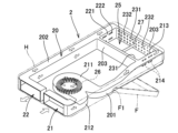
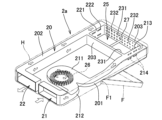
以下、本発明に係る実施形態を図面に基づいて説明する。なお、各図において同一の符号を付した構成は、同一の構成であることを示し、その説明を省略する。図1は、本発明の一実施形態に係る携帯用イヤホンケース2を含むイヤホン乾燥システム1の構成の一例を示す正面図である。図2は、図1に示すイヤホン乾燥システム1のII-II線断面図である。図3は、図1に示す携帯用イヤホンケース2の内部を透視した透視図である。図3では、ダクト20の構造を主に示している。
Hereinafter, an embodiment of the present invention will be described with reference to the drawings. Note that components with the same reference numerals in each drawing are the same, and their description will be omitted. Fig. 1 is a front view showing an example of the configuration of an
図1,図2に示すイヤホン乾燥システム1は、携帯用イヤホンケース2と、ベースユニット3とを備えている。携帯用イヤホンケース2の内部構造を破線で、ベースユニット3の内部構造を一点鎖線で示している。図1,図2では、ダクト20の記載を省略している。
The
ベースユニット3は、携帯用イヤホンケース2を着脱可能とされている。ベースユニット3は、いわゆるクレードルであってもよい。携帯用イヤホンケース2は、扁平な略直方体形状のハウジングHを備えている。ベースユニット3は、大略的に、基台部31と、支持部32,33とを備えている。支持部32,33は、携帯用イヤホンケース2のハウジングHを両側から挟み込むように互いに間隔を空けて、基台部31から上方に延びるように立設されている。
The
基台部31には、ファン34(送風部)と、ファン34の風を携帯用イヤホンケース2の後述する吸気口21へ送り込む送風ダクト35とが設けられている。支持部32の、支持部33と対向する面には、携帯用イヤホンケース2の後述する二次電池24を非接触充電するためのベース側送電コイル36が配設されている。支持部33の、支持部32と対向する面には、携帯用イヤホンケース2を支持部32側へ押圧し、ベース側送電コイル36を後述する受電コイル26と密着させるためのバネ37(押圧部材)が取り付けられている。
The
なお、ベースユニット3は、例えば送風ダクト35内にヒータを備えてもよい。ヒータで加熱された空気を吸気口21へ送り込むことによって、携帯用イヤホンケース2に収納されたイヤホンE1,E2の乾燥効果を増大させることができる。
The
携帯用イヤホンケース2は、ダクト20、吸気口21、排気口22、送電コイル23、二次電池24、受電コイル26、殺菌灯27、収納部25、制御回路28、及びこれらを収容するハウジングHを備えている。
The
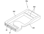
図4は、図1に示す携帯用イヤホンケース2の外観を示す斜視図である。ハウジングHの一端部側には、支持軸F1によって蓋Fが取り付けられている。蓋Fは、支持軸F1を中心に揺動することによって、開閉可能にされている。蓋Fを開いた状態では、二つのイヤホンE1,E2を収納可能な空間である収納部25が露出するようになっている。蓋Fを開くことによって、ユーザが、イヤホンE1,E2を携帯用イヤホンケース2に収納したり、イヤホンE1,E2を携帯用イヤホンケース2から取り出したり出来るようになっている。
Figure 4 is a perspective view showing the appearance of the
イヤホンE1,E2は、例えば補聴器であってもよく、例えば外部機器と無線通信可能なワイヤレスイヤホンであってもよく、その他の種々のイヤホンであってもよい。イヤホンE1,E2は、非接触充電用のイヤホン側受電コイルECを備えている。イヤホンE1,E2は図略の二次電池を備えている。イヤホン側受電コイルECによって受電された電力でイヤホンE1,E2の二次電池が充電される。 The earphones E1 and E2 may be, for example, hearing aids, wireless earphones capable of wireless communication with an external device, or various other types of earphones. The earphones E1 and E2 are equipped with an earphone-side receiving coil EC for non-contact charging. The earphones E1 and E2 are equipped with a secondary battery (not shown). The secondary battery of the earphones E1 and E2 is charged with the power received by the earphone-side receiving coil EC.
収納部25の略中央部には、例えば紫外線等の殺菌作用を有する光を発する殺菌灯27が配設されている。収納部25で、空気の流路に沿って、殺菌灯27の上流側にイヤホンE1が、殺菌灯27の下流側にイヤホンE2が収納される。これにより、収納部25に収納された一対のイヤホンE1,E2に対し、殺菌灯27から発せられた光を効率よく照射してこれらイヤホンE1,E2を殺菌することができる。
A
二つの送電コイル23は、収納部25の、蓋Fとは反対側の底部に配設されている(図3では上方側に位置し、図示が省略されている)。各送電コイル23は、収納部25に収納されたイヤホンE1,E2のイヤホン側受電コイルECと対向配置される。この状態で、各送電コイル23によって各イヤホン側受電コイルECに送電し、イヤホンE1,E2を充電することができる。
The two power transmission coils 23 are disposed at the bottom of the
図3を参照して、ダクト20は、吸気側ダクト201、排気側ダクト202、及び連通ダクト203を含む。ダクト20は、高熱伝導率の材料によって構成されている。高熱伝導率の材料としては、熱伝導率が5(W・m-1・K-1)以上のものが好ましい。高熱伝導率の材料としては、例えば、放熱樹脂、アルミシートに微細構造を形成したメタマテリアル放熱材、セラミックス成形品、或いはアルミなどの金属等を用いることができ、あるいはこれらの材料を組み合わせて用いることができる。
3, the
放熱樹脂としては、ポリブチレンテレフタレート(PBT)、ポリカーボネート(PC)、MXD6PA、ポリアミド6(PA6)、ポリアミド66(PA66)、ポリアミド10T(PA10T)、ポリフェニレンサルファイド(PPS)等を用いることができる。 Examples of heat dissipating resins that can be used include polybutylene terephthalate (PBT), polycarbonate (PC), MXD6PA, polyamide 6 (PA6), polyamide 66 (PA66), polyamide 10T (PA10T), polyphenylene sulfide (PPS), etc.
セラミックス成形品としては、ジルコニア、又はアルミナ等を用いた素材を用いることができる。 Materials using zirconia, alumina, etc. can be used as ceramic molded products.
吸気側ダクト201は、吸気口21から収納部25の一方の側まで延びている。そして、ベースユニット3のファン34によって送風され、吸気口21から取り込まれた空気が、吸気側ダクト201内を、収納部25に向かって流れる。吸気側ダクト201の、吸気口21から収納部25に至る途中の中間部には、受電コイル26を収容するべく膨らんだ膨出部211が形成されている。膨出部211内に、受電コイル26が配置されている。受電コイル26は、膨出部211内で、吸気側ダクト201(膨出部211)の内壁と接触している。
The
また、吸気側ダクト201の、受電コイル26より上流側には、吸気口21から受け入れられた空気の流れを受電コイル26に向けて曲げる変向部212が設けられている。これにより、吸気口21から受け入れられた空気が受電コイル26に当たり易くなり、受電コイル26の冷却効果が増大する。
In addition, upstream of the
排気側ダクト202は、収納部25の他方の側から排気口22まで延びる。連通ダクト203は、吸気側ダクト201と排気側ダクト202とを、収納部25と隣接する位置で連通させる。より具体的には、収納部25を両側から挟むように延びる一対の連通ダクト203が設けられている。
The
吸気側ダクト201と収納部25との境界には、壁213が設けられている。壁213には、イヤホンE1,E2よりも小さい空気孔214が形成されている。これにより、イヤホンE1,E2が吸気側ダクト201に入り込むことを防止しつつ、空気孔214からイヤホンE1,E2に向けて空気を吐出することができる。
A
排気側ダクト202と収納部25との境界には、壁221が設けられている。壁221には、イヤホンE1,E2よりも小さい空気孔222が形成されている。これにより、イヤホンE1,E2が排気側ダクト202に入り込むことを防止しつつ、収納部25の下流側で空気孔222から空気を排気することができる。
A
一対の連通ダクト203における、収納部25に面する壁231には、イヤホンE1,E2よりも小さい複数の空気孔232が形成されている。空気孔232は、一対の連通ダクト203と収納部25との間で空気を出入りさせる。空気孔232は、吸気側ダクト201の壁213から離れるほど大きい。すなわち空気孔232は、空気の流路に沿って、上流から下流に向かうほど大きい。
A
壁213,221,231,231で囲まれた領域が、収納部25とされている。
The area surrounded by
制御回路28は、例えばマイクロコンピュータ及びその周辺回路等を用いて構成されている。制御回路28は、ベース側送電コイル36から受電コイル26へ送電された電力を二次電池24に充電する。また、制御回路28は、二次電池24から供給された電力を送電コイル23からイヤホン側受電コイルECへ送電させて、イヤホンE1,E2を充電させる。また、制御回路28は、二次電池24から供給された電力によって殺菌灯27を点灯させる。
The
携帯用イヤホンケース2は、二次電池24を備えているので、ベースユニット3に取り付けられていなくても、二次電池24の電力によってイヤホンE1,E2を充電することができる。従ってユーザは、携帯用イヤホンケース2を携帯していれば、イヤホンE1,E2が電池切れになった場合であっても、携帯用イヤホンケース2にイヤホンE1,E2を収納することによって、イヤホンE1,E2を充電することができる。
The
次に、上述のように構成されたイヤホン乾燥システム1の動作について説明する。まず、一対のイヤホンE1,E2が収納部25に収納された携帯用イヤホンケース2を、ベースユニット3に取り付ける。
Next, the operation of the
そして、例えばユーザが図略のスイッチを操作したり、図略の検出回路によって携帯用イヤホンケース2がベースユニット3に取り付けられたことが検出されたりすると、ベースユニット3のベース側送電コイル36から携帯用イヤホンケース2の受電コイル26へ電力が送電され、その電力が制御回路28によって二次電池24に充電される。このとき、受電コイル26に電流が流れて受電コイル26が発熱する。
For example, when a user operates a switch (not shown) or when a detection circuit (not shown) detects that the
さらに、制御回路28は、二次電池24から送電コイル23へ電力を供給させ、送電コイル23からイヤホンE1,E2のイヤホン側受電コイルECへ電力が供給され、この電力によりイヤホンE1,E2の図略の二次電池が充電される。さらに、制御回路28は、二次電池24から殺菌灯27へ電力を供給させて殺菌灯27を点灯させる。
The
また、ベースユニット3では、ベース側送電コイル36による送電と並行して、ファン34による送風が開始され、送風ダクト35を介して携帯用イヤホンケース2の吸気口21へ空気が送り込まれる。
In addition, in the
吸気口21へ送り込まれた空気は、吸気側ダクト201内を流れる。ここで、受電コイル26は、吸気側ダクト201内の膨出部211に配置され、すなわち空気の流路に配置されているので、発熱する受電コイル26の熱が、流れる空気によって奪われる。さらに、変向部212によって、空気の流れが受電コイル26に向けられるので、受電コイル26を冷却する効率が向上する。このようにして、受電コイル26を冷却することができる。
The air sent into the
また、受電コイル26を冷却し、すなわち受電コイル26によって加熱された空気が、吸気側ダクト201によって収納部25の上流まで運ばれる。
In addition, the air that cools the
収納部25の上流まで運ばれた空気の一部は、空気孔214から収納部25へ吹き出し、残りの空気は、一対の連通ダクト203を流れる。一対の連通ダクト203を流れる空気は、その一部がイヤホンE1の上流側で空気孔232から収納部25へ吹き出す。
Part of the air that is transported upstream of the
空気孔214から収納部25へ吹き出した空気、及びイヤホンE1の上流側で空気孔232から収納部25へ吹き出した空気は、イヤホンE1にあたり、イヤホンE1を乾燥させる。このとき、空気は、上流の受電コイル26で加熱された後にイヤホンE1を乾燥させるので、乾燥効果が増大する。
The air blown out from
また、イヤホンE1より下流側で連通ダクト203の空気孔232から収納部25へ吹き出した空気は、イヤホンE2にあたってイヤホンE2を乾燥させる。このとき、空気は、上流の受電コイル26で加熱された後にイヤホンE2を乾燥させるので、乾燥効果が増大する。
In addition, air blown out from the
ここで、携帯用イヤホンケース2は、連通ダクト203を備えず、吸気側ダクト201の空気孔214から吹き出した空気によって、イヤホンE1,E2が乾燥されてもよい。
Here, the
しかしながら、連通ダクト203を備えない場合、イヤホンE2は、イヤホンE1を乾燥させて湿度が上昇した空気によって乾燥されることになる。その結果、イヤホンE1に比べてイヤホンE2が乾燥しにくくなる。一方、連通ダクト203を備えた場合、湿度上昇していない空気をイヤホンE2に当てて乾燥させることができる。従って、イヤホンE1,E2の乾燥バラツキを低減することができる点で、連通ダクト203を備えることがより好ましい。
However, if the
また、連通ダクト203に設けられた空気孔232は、全て同じ大きさであってもよい。しかしながら、吸気側ダクト201の壁213から離れるほど空気孔232を大きくすることによって、連通ダクト203からイヤホンE2へ吹き出す空気の量を、連通ダクト203からイヤホンE1へ吹き出す空気の量よりも増大させることができる。その結果、イヤホンE1,E2の乾燥バラツキを低減する効果がさらに増大する点で、吸気側ダクト201の壁213から離れるほど空気孔232を大きくすることがより好ましい。
Also, all of the air holes 232 provided in the
また、受電コイル26は吸気側ダクト201の内壁と接触しているので、受電コイル26の発熱がダクト20に熱伝導し、かつダクト20内を流れる空気によってダクト20が冷却される。その結果、受電コイル26の冷却効果を増大することができる。また、受電コイル26の発熱が吸気側ダクト201に熱伝導することによって、吸気側ダクト201の温度が上昇する。その結果、吸気側ダクト201を通って収納部25に供給される空気の温度が上昇するので、イヤホンE1,E2の乾燥効果を増大させることができる。
In addition, because the
ここで、ダクト20が高熱伝導率の材料で構成されていることによって、受電コイル26から吸気側ダクト201への熱伝導が増大する。その結果、受電コイル26の冷却効果、及びイヤホンE1,E2の乾燥効果をさらに増大させることができる。
Here, since the
なお、少なくとも吸気側ダクト201が高熱伝導率の材料で構成されていればよく、ダクト20全体が高熱伝導率の材料で構成されている例に限られない。
Note that it is sufficient that at least the
また、ダクト20は高熱伝導率の材料で構成されていなくてもよい。しかしながら、少なくとも吸気側ダクト201が高熱伝導率の材料で構成されていれば、受電コイル26の冷却効果、及びイヤホンE1,E2の乾燥効果をさらに増大させることができる点で、より好ましい。
The
また、受電コイル26は吸気側ダクト201の内壁と接触していなくてもよい。しかしながら、受電コイル26は吸気側ダクト201の内壁と接触していることによって、受電コイル26の冷却効果、及びイヤホンE1,E2の乾燥効果をさらに増大させることができる点で、より好ましい。
Furthermore, the
また、例えば図5に示す携帯用イヤホンケース2aのように、受電コイル26は吸気側ダクト201の外部に配置され、受電コイル26が吸気側ダクト201(膨出部211)の外壁に接触する構成であってもよい。この場合、受電コイル26の熱が吸気側ダクト201に熱伝導することによって、受電コイル26が冷却される。
Also, for example, as in the
また、送電コイル23は、収納部25に配設される例に限らない。例えば、ソレノイドコイル(棒状コイル)から構成された送電コイルが、送電コイル23として収納部25の外周に配設される構成であってもよい。
Furthermore, the
また、図3に示すように吸気口21と排気口22とが携帯用イヤホンケース2,2aの幅方向に隣接する例に限らない。例えば図6に示すように吸気口21と排気口22とが携帯用イヤホンケース2,2aの厚み方向に隣接する構成であってもよい。
Furthermore, the example is not limited to the example in which the
また、携帯用イヤホンケース2,2aは、ダクト20,20aを備えていなくてもよい。携帯用イヤホンケースは、収納部25、吸気口21、及び排気口22を備え、収納部25が空気の流路に設けられていれば、イヤホンE1,E2を乾燥させることができる。
The
上述のように構成された携帯用イヤホンケース2,2aは、特許文献1に記載の補聴器用乾燥ケースのように、多量の吸着剤やヒータを備える必要がない。従って、携帯用イヤホンケース2,2aは、小型、軽量にすることが容易である。その結果、携帯することが容易な携帯用イヤホンケース2,2aを容易に作製でき、携帯用イヤホンケースを携帯することが容易となる。
The
また、上述のように構成された携帯用イヤホンケース2,2aは、イヤホンE1,E2を乾燥器に入れ替えることなく、イヤホンE1,E2が収納された携帯用イヤホンケース2,2aごとベースユニット3に取り付けてイヤホンE1,E2を乾燥させることができるので、イヤホンを乾燥させることが容易である。
In addition, the
1 イヤホン乾燥システム
2,2a 携帯用イヤホンケース
3 ベースユニット
20,20a ダクト
21 吸気口
22 排気口
23 送電コイル
24 二次電池
25 収納部
26 受電コイル
27 殺菌灯
28 制御回路
31 基台部
32,33 支持部
34 ファン(送風部)
35 送風ダクト
36 ベース側送電コイル
37 バネ
201 吸気側ダクト
202 排気側ダクト
203 連通ダクト
211 膨出部
212 変向部
213,221,231,231 壁
214,222,232 空気孔
E1,E2 イヤホン
EC イヤホン側受電コイル
F 蓋
F1 支持軸
H ハウジング
Claims (11)
外部から空気を受け入れる吸気口と、
前記吸気口から受け入れられた空気を排気する排気口と、
二次電池と、
前記二次電池を非接触充電するための電力を受電する受電コイルと、
前記吸気口から前記収納部の一方の側まで延びる吸気側ダクトとを備え、
前記収納部は、前記空気の流路に設けられ、
前記受電コイルは、前記空気の流路における前記収納部の上流で前記吸気側ダクト内に配設されている携帯用イヤホンケース。 A storage section for storing earphones;
An intake port for receiving air from the outside;
an exhaust port for exhausting the air received from the intake port;
A secondary battery;
a power receiving coil that receives power for contactlessly charging the secondary battery;
an intake side duct extending from the intake port to one side of the storage section,
The storage section is provided in the air flow path ,
The portable earphone case , wherein the receiving coil is disposed within the intake duct upstream of the storage section in the air flow path .
前記受電コイルは、前記吸気側ダクトの外壁と接触している請求項1記載の携帯用イヤホンケース。 An intake side duct extending from the intake port to one side of the storage section is further provided,
2. The portable earphone case according to claim 1 , wherein the power receiving coil is in contact with an outer wall of the intake duct.
前記吸気側ダクトと前記排気側ダクトとを、前記収納部と隣接する位置で連通させる連通ダクトをさらに備え、
前記連通ダクトには、前記収納部との間で空気を出入りさせる複数の空気孔が形成されている請求項1~7のいずれか1項に記載の携帯用イヤホンケース。 an exhaust side duct extending from the other side of the storage section to the exhaust port;
a communication duct that communicates the intake side duct and the exhaust side duct at a position adjacent to the storage section,
The portable earphone case according to any one of claims 1 to 7 , wherein the communication duct is formed with a plurality of air holes for allowing air to flow in and out between the communication duct and the storage section.
前記携帯用イヤホンケースを着脱可能なベースユニットとを備え、
前記ベースユニットは、
前記携帯用イヤホンケースを支持する支持部と、
前記支持部によって支持された前記携帯用イヤホンケースの前記吸気口へ空気を送風する送風部とを備えるイヤホン乾燥システム。 A portable earphone case according to any one of claims 1 to 10 ,
A base unit to which the portable earphone case can be attached and detached,
The base unit includes:
A support part for supporting the portable earphone case;
an air blowing unit that blows air to the air intake of the portable earphone case supported by the support unit.
Priority Applications (2)
| Application Number | Priority Date | Filing Date | Title |
|---|---|---|---|
| JP2019187293A JP7513232B2 (en) | 2019-10-11 | 2019-10-11 | Portable earphone case and earphone drying system |
| PCT/JP2020/037544 WO2021070742A1 (en) | 2019-10-11 | 2020-10-02 | Portable earphone case and earphone drying system |
Applications Claiming Priority (1)
| Application Number | Priority Date | Filing Date | Title |
|---|---|---|---|
| JP2019187293A JP7513232B2 (en) | 2019-10-11 | 2019-10-11 | Portable earphone case and earphone drying system |
Publications (2)
| Publication Number | Publication Date |
|---|---|
| JP2021064845A JP2021064845A (en) | 2021-04-22 |
| JP7513232B2 true JP7513232B2 (en) | 2024-07-09 |
Family
ID=75438166
Family Applications (1)
| Application Number | Title | Priority Date | Filing Date |
|---|---|---|---|
| JP2019187293A Active JP7513232B2 (en) | 2019-10-11 | 2019-10-11 | Portable earphone case and earphone drying system |
Country Status (2)
| Country | Link |
|---|---|
| JP (1) | JP7513232B2 (en) |
| WO (1) | WO2021070742A1 (en) |
Citations (2)
| Publication number | Priority date | Publication date | Assignee | Title |
|---|---|---|---|---|
| US20180064224A1 (en) | 2016-09-06 | 2018-03-08 | Apple Inc. | Inductively chargeable earbud case |
| CN108146868A (en) | 2017-12-04 | 2018-06-12 | 深圳市紫光康众生物消毒科技有限公司 | Hearing aid storage box with sterilizing and functions/drying |
-
2019
- 2019-10-11 JP JP2019187293A patent/JP7513232B2/en active Active
-
2020
- 2020-10-02 WO PCT/JP2020/037544 patent/WO2021070742A1/en not_active Ceased
Patent Citations (2)
| Publication number | Priority date | Publication date | Assignee | Title |
|---|---|---|---|---|
| US20180064224A1 (en) | 2016-09-06 | 2018-03-08 | Apple Inc. | Inductively chargeable earbud case |
| CN108146868A (en) | 2017-12-04 | 2018-06-12 | 深圳市紫光康众生物消毒科技有限公司 | Hearing aid storage box with sterilizing and functions/drying |
Also Published As
| Publication number | Publication date |
|---|---|
| WO2021070742A1 (en) | 2021-04-15 |
| JP2021064845A (en) | 2021-04-22 |
Similar Documents
| Publication | Publication Date | Title |
|---|---|---|
| CN215899070U (en) | Drying apparatus | |
| US7736792B2 (en) | Battery cooling system | |
| US20100044367A1 (en) | Induction heating device | |
| EP2031326A3 (en) | Cargo container for transporting temperature sensitive items | |
| CN106367934B (en) | A kind of microwave dryer | |
| KR102381050B1 (en) | Oven for food transport that can be installed especially on motorcycles | |
| JP2004109356A (en) | Cooling device for image forming device | |
| JP7513232B2 (en) | Portable earphone case and earphone drying system | |
| KR102529948B1 (en) | Organic Moisture Evaporator Having A Structure That Can Increase Drying Efficiency Even In A Narrow Space | |
| JP7168244B2 (en) | high efficiency wireless hair dryer | |
| CN215227381U (en) | Hot air device and dish washing machine | |
| JP2015102644A (en) | Air-supply device, holder therefor, paper-discharge device, and image forming apparatus | |
| CN113573609B (en) | Drying apparatus | |
| KR100865865B1 (en) | Hair irons with blower fan | |
| WO2023151147A1 (en) | Drying apparatus and electrode sheet drying device | |
| JP4348865B2 (en) | Induction heating cooker | |
| CN213908942U (en) | Electric hair drier | |
| CN114543199B (en) | Base station and cleaning system | |
| KR101728755B1 (en) | Air heating apparatus and drier having the same | |
| CN101354522B (en) | projection device | |
| JP7598182B1 (en) | dryer | |
| CN215532298U (en) | Wireless electric hair drier | |
| CN111811141B (en) | Heater | |
| CN114788608A (en) | Drying apparatus | |
| CN206308510U (en) | A microwave dryer |
Legal Events
| Date | Code | Title | Description |
|---|---|---|---|
| A621 | Written request for application examination |
Free format text: JAPANESE INTERMEDIATE CODE: A621 Effective date: 20220902 |
|
| RD04 | Notification of resignation of power of attorney |
Free format text: JAPANESE INTERMEDIATE CODE: A7424 Effective date: 20221214 |
|
| A131 | Notification of reasons for refusal |
Free format text: JAPANESE INTERMEDIATE CODE: A131 Effective date: 20231031 |
|
| A601 | Written request for extension of time |
Free format text: JAPANESE INTERMEDIATE CODE: A601 Effective date: 20231228 |
|
| A521 | Request for written amendment filed |
Free format text: JAPANESE INTERMEDIATE CODE: A523 Effective date: 20240227 |
|
| TRDD | Decision of grant or rejection written | ||
| A01 | Written decision to grant a patent or to grant a registration (utility model) |
Free format text: JAPANESE INTERMEDIATE CODE: A01 Effective date: 20240521 |
|
| A61 | First payment of annual fees (during grant procedure) |
Free format text: JAPANESE INTERMEDIATE CODE: A61 Effective date: 20240612 |
|
| R150 | Certificate of patent or registration of utility model |
Ref document number: 7513232 Country of ref document: JP Free format text: JAPANESE INTERMEDIATE CODE: R150 |