JP7507253B2 - Non-rotating AC generator - Google Patents
Non-rotating AC generator Download PDFInfo
- Publication number
- JP7507253B2 JP7507253B2 JP2022568956A JP2022568956A JP7507253B2 JP 7507253 B2 JP7507253 B2 JP 7507253B2 JP 2022568956 A JP2022568956 A JP 2022568956A JP 2022568956 A JP2022568956 A JP 2022568956A JP 7507253 B2 JP7507253 B2 JP 7507253B2
- Authority
- JP
- Japan
- Prior art keywords
- field
- phase
- armature
- core member
- power generating
- Prior art date
- Legal status (The legal status is an assumption and is not a legal conclusion. Google has not performed a legal analysis and makes no representation as to the accuracy of the status listed.)
- Active
Links
Images


Classifications
-
- H—ELECTRICITY
- H02—GENERATION; CONVERSION OR DISTRIBUTION OF ELECTRIC POWER
- H02K—DYNAMO-ELECTRIC MACHINES
- H02K99/00—Subject matter not provided for in other groups of this subclass
- H02K99/10—Generators
-
- H—ELECTRICITY
- H02—GENERATION; CONVERSION OR DISTRIBUTION OF ELECTRIC POWER
- H02K—DYNAMO-ELECTRIC MACHINES
- H02K1/00—Details of the magnetic circuit
- H02K1/04—Details of the magnetic circuit characterised by the material used for insulating the magnetic circuit or parts thereof
-
- H—ELECTRICITY
- H02—GENERATION; CONVERSION OR DISTRIBUTION OF ELECTRIC POWER
- H02M—APPARATUS FOR CONVERSION BETWEEN AC AND AC, BETWEEN AC AND DC, OR BETWEEN DC AND DC, AND FOR USE WITH MAINS OR SIMILAR POWER SUPPLY SYSTEMS; CONVERSION OF DC OR AC INPUT POWER INTO SURGE OUTPUT POWER; CONTROL OR REGULATION THEREOF
- H02M1/00—Details of apparatus for conversion
- H02M1/12—Arrangements for reducing harmonics from AC input or output
- H02M1/126—Arrangements for reducing harmonics from AC input or output using passive filters
-
- H—ELECTRICITY
- H01—ELECTRIC ELEMENTS
- H01F—MAGNETS; INDUCTANCES; TRANSFORMERS; SELECTION OF MATERIALS FOR THEIR MAGNETIC PROPERTIES
- H01F27/00—Details of transformers or inductances, in general
- H01F27/24—Magnetic cores
- H01F27/26—Fastening parts of the core together; Fastening or mounting the core on casing or support
- H01F27/263—Fastening parts of the core together
-
- H—ELECTRICITY
- H01—ELECTRIC ELEMENTS
- H01F—MAGNETS; INDUCTANCES; TRANSFORMERS; SELECTION OF MATERIALS FOR THEIR MAGNETIC PROPERTIES
- H01F27/00—Details of transformers or inductances, in general
- H01F27/28—Coils; Windings; Conductive connections
- H01F27/32—Insulating of coils, windings, or parts thereof
- H01F27/324—Insulation between coil and core, between different winding sections, around the coil; Other insulation structures
-
- H—ELECTRICITY
- H01—ELECTRIC ELEMENTS
- H01F—MAGNETS; INDUCTANCES; TRANSFORMERS; SELECTION OF MATERIALS FOR THEIR MAGNETIC PROPERTIES
- H01F27/00—Details of transformers or inductances, in general
- H01F27/33—Arrangements for noise damping
-
- H—ELECTRICITY
- H01—ELECTRIC ELEMENTS
- H01F—MAGNETS; INDUCTANCES; TRANSFORMERS; SELECTION OF MATERIALS FOR THEIR MAGNETIC PROPERTIES
- H01F3/00—Cores, Yokes, or armatures
- H01F3/10—Composite arrangements of magnetic circuits
-
- H—ELECTRICITY
- H01—ELECTRIC ELEMENTS
- H01F—MAGNETS; INDUCTANCES; TRANSFORMERS; SELECTION OF MATERIALS FOR THEIR MAGNETIC PROPERTIES
- H01F3/00—Cores, Yokes, or armatures
- H01F3/10—Composite arrangements of magnetic circuits
- H01F3/12—Magnetic shunt paths
-
- H—ELECTRICITY
- H01—ELECTRIC ELEMENTS
- H01F—MAGNETS; INDUCTANCES; TRANSFORMERS; SELECTION OF MATERIALS FOR THEIR MAGNETIC PROPERTIES
- H01F30/00—Fixed transformers not covered by group H01F19/00
- H01F30/06—Fixed transformers not covered by group H01F19/00 characterised by the structure
- H01F30/12—Two-phase, three-phase or polyphase transformers
-
- H—ELECTRICITY
- H02—GENERATION; CONVERSION OR DISTRIBUTION OF ELECTRIC POWER
- H02K—DYNAMO-ELECTRIC MACHINES
- H02K1/00—Details of the magnetic circuit
- H02K1/06—Details of the magnetic circuit characterised by the shape, form or construction
-
- H—ELECTRICITY
- H02—GENERATION; CONVERSION OR DISTRIBUTION OF ELECTRIC POWER
- H02K—DYNAMO-ELECTRIC MACHINES
- H02K1/00—Details of the magnetic circuit
- H02K1/06—Details of the magnetic circuit characterised by the shape, form or construction
- H02K1/12—Stationary parts of the magnetic circuit
- H02K1/14—Stator cores with salient poles
-
- H—ELECTRICITY
- H02—GENERATION; CONVERSION OR DISTRIBUTION OF ELECTRIC POWER
- H02K—DYNAMO-ELECTRIC MACHINES
- H02K15/00—Processes or apparatus specially adapted for manufacturing, assembling, maintaining or repairing of dynamo-electric machines
- H02K15/10—Applying solid insulation to windings, stators or rotors, e.g. applying insulating tapes
-
- H—ELECTRICITY
- H02—GENERATION; CONVERSION OR DISTRIBUTION OF ELECTRIC POWER
- H02K—DYNAMO-ELECTRIC MACHINES
- H02K3/00—Details of windings
- H02K3/32—Windings characterised by the shape, form or construction of the insulation
- H02K3/34—Windings characterised by the shape, form or construction of the insulation between conductors or between conductor and core, e.g. slot insulation
-
- H—ELECTRICITY
- H02—GENERATION; CONVERSION OR DISTRIBUTION OF ELECTRIC POWER
- H02K—DYNAMO-ELECTRIC MACHINES
- H02K99/00—Subject matter not provided for in other groups of this subclass
-
- H—ELECTRICITY
- H02—GENERATION; CONVERSION OR DISTRIBUTION OF ELECTRIC POWER
- H02M—APPARATUS FOR CONVERSION BETWEEN AC AND AC, BETWEEN AC AND DC, OR BETWEEN DC AND DC, AND FOR USE WITH MAINS OR SIMILAR POWER SUPPLY SYSTEMS; CONVERSION OF DC OR AC INPUT POWER INTO SURGE OUTPUT POWER; CONTROL OR REGULATION THEREOF
- H02M5/00—Conversion of AC power input into AC power output, e.g. for change of voltage, for change of frequency, for change of number of phases
- H02M5/02—Conversion of AC power input into AC power output, e.g. for change of voltage, for change of frequency, for change of number of phases without intermediate conversion into DC
- H02M5/04—Conversion of AC power input into AC power output, e.g. for change of voltage, for change of frequency, for change of number of phases without intermediate conversion into DC by static converters
- H02M5/10—Conversion of AC power input into AC power output, e.g. for change of voltage, for change of frequency, for change of number of phases without intermediate conversion into DC by static converters using transformers
- H02M5/18—Conversion of AC power input into AC power output, e.g. for change of voltage, for change of frequency, for change of number of phases without intermediate conversion into DC by static converters using transformers for conversion of waveform
-
- H—ELECTRICITY
- H02—GENERATION; CONVERSION OR DISTRIBUTION OF ELECTRIC POWER
- H02M—APPARATUS FOR CONVERSION BETWEEN AC AND AC, BETWEEN AC AND DC, OR BETWEEN DC AND DC, AND FOR USE WITH MAINS OR SIMILAR POWER SUPPLY SYSTEMS; CONVERSION OF DC OR AC INPUT POWER INTO SURGE OUTPUT POWER; CONTROL OR REGULATION THEREOF
- H02M7/00—Conversion of AC power input into DC power output; Conversion of DC power input into AC power output
- H02M7/003—Constructional details, e.g. physical layout, assembly, wiring or busbar connections
-
- H—ELECTRICITY
- H02—GENERATION; CONVERSION OR DISTRIBUTION OF ELECTRIC POWER
- H02M—APPARATUS FOR CONVERSION BETWEEN AC AND AC, BETWEEN AC AND DC, OR BETWEEN DC AND DC, AND FOR USE WITH MAINS OR SIMILAR POWER SUPPLY SYSTEMS; CONVERSION OF DC OR AC INPUT POWER INTO SURGE OUTPUT POWER; CONTROL OR REGULATION THEREOF
- H02M7/00—Conversion of AC power input into DC power output; Conversion of DC power input into AC power output
- H02M7/42—Conversion of DC power input into AC power output without possibility of reversal
- H02M7/44—Conversion of DC power input into AC power output without possibility of reversal by static converters
- H02M7/48—Conversion of DC power input into AC power output without possibility of reversal by static converters using discharge tubes with control electrode or semiconductor devices with control electrode
-
- H—ELECTRICITY
- H02—GENERATION; CONVERSION OR DISTRIBUTION OF ELECTRIC POWER
- H02P—CONTROL OR REGULATION OF ELECTRIC MOTORS, ELECTRIC GENERATORS OR DYNAMO-ELECTRIC CONVERTERS; CONTROLLING TRANSFORMERS, REACTORS OR CHOKE COILS
- H02P9/00—Arrangements for controlling electric generators for the purpose of obtaining a desired output
- H02P9/02—Details of the control
Landscapes
- Engineering & Computer Science (AREA)
- Power Engineering (AREA)
- Chemical & Material Sciences (AREA)
- Composite Materials (AREA)
- Manufacturing & Machinery (AREA)
- Permanent Field Magnets Of Synchronous Machinery (AREA)
- Synchronous Machinery (AREA)
- Water Treatment By Electricity Or Magnetism (AREA)
- Processing Of Meat And Fish (AREA)
- Permanent Magnet Type Synchronous Machine (AREA)
Description
本発明は交流発電機に関するもので、特に非回転式発電機からなる複数の発電ユニットを備え、高効率で交流を生成することができるようになった非回転式交流発電装置に関する。 The present invention relates to an AC generator, and in particular to a non-rotating AC generating device that has multiple generating units consisting of non-rotating generators and is capable of generating AC with high efficiency.
また、本発明は交流発電装置に関するもので、特に非回転式で構成されたと共に、三相交流を含む多相交流を生成することができるようになった非回転式交流発電装置に関する。 The present invention also relates to an AC power generating device, and in particular to a non-rotating AC power generating device that is non-rotating and capable of generating polyphase AC, including three-phase AC.
発電機(Electric generator)は主に力学的エネルギーを電気エネルギーに変換する装置を称するもので、その動作方式や動作原理によって直流発電機、同期発電機、誘導発電機などに分けて称することもある。発電機は基本的に、電流が生成されて出力される電機子と磁界を生成する界磁を備える。発電機は通常、界磁に直流電源を供給して磁界を形成しながら、界磁に対して電機子を回転させるか、又は電機子に対して界磁を回転させる方式で電機子に電流の流れを生成する。この時、電機子を回転させる方式を回転電機子型と称し、界磁を回転させる方式を回転界磁型と称する。このような回転式発電機において、電機子または界磁の回転駆動は別々のエネルギー源によって行われる。エネルギー源としては、その使用用途によって適切なものを採用するが、一般的には、水力、風力、潮力などの自然エネルギーや、タービン、エンジン、モータなどの駆動手段を使用する。 An electric generator is a device that converts mechanical energy into electrical energy, and may be divided into DC generators, synchronous generators, induction generators, etc., depending on the operating method and principle. A generator basically has an armature that generates and outputs current, and a field magnet that generates a magnetic field. A generator usually generates a current flow in the armature by supplying DC power to the field magnet to form a magnetic field, and then rotating the armature relative to the field magnet or rotating the field magnet relative to the armature. In this case, the method of rotating the armature is called the rotating armature type, and the method of rotating the field magnet is called the rotating field magnet type. In such a rotary generator, the armature or field magnet is rotated by separate energy sources. The appropriate energy source is selected depending on the application, but generally, natural energy such as water power, wind power, and tidal power, and driving means such as turbines, engines, and motors are used.
一般に、直流は電気を容易に貯蔵することができるという長所がある反面、昇圧を含んで高電力化が困難であるという短所がある。これに対して、交流は貯蔵性が非常に低い反面、昇圧及び高電力化が容易であるという長所がある。発電機の1つの好ましい適用方式として、バッテリなどの貯蔵された直流電源や他の交流電源を用いて界磁や電機子を回転させることで、様々な交流電力を生成するように構成されたシステムがある。このような電力システムまたは電力変換システムは病院や工場などのように、高電力が要求される産業体における非常用電力供給手段として多く使用される。また、このような電力システムは電気をエネルギー源として使用しながら、状況によって様々な駆動トルクの生成が要求される電気自動車などに非常に有用に採用できる。 In general, DC has the advantage that electricity can be easily stored, but the disadvantage that it is difficult to increase the power, including boosting the voltage. In contrast, AC has the advantage that it is very poorly storable, but is easy to boost and increase the power. One preferred application method of a generator is a system configured to generate various AC powers by rotating a field magnet or an armature using a stored DC power source such as a battery or other AC power source. Such power systems or power conversion systems are often used as emergency power supply means in industrial organizations that require high power, such as hospitals and factories. In addition, such power systems can be very usefully adopted in electric vehicles that use electricity as an energy source and are required to generate various driving torques depending on the situation.
前述した従来の発電機は基本的に電機子や界磁の回転駆動が要求される。このような構成的特徴は必然的に、発電機の構造的、機械的複雑さに加えて、その製造コストの増加をもたらす。特に、前述した構成的特徴は電機子や界磁が回転する際に機械的摩擦などにより多量のエネルギー損失が発生する。そのため、発電機の発電効率及び電力変換効率を高めることに限界がある。 The conventional generators described above basically require the rotational drive of the armature and field magnet. Such structural features inevitably lead to increased manufacturing costs in addition to structural and mechanical complexity of the generator. In particular, the structural features described above cause a large amount of energy loss due to mechanical friction when the armature and field magnet rotate. As a result, there are limitations to increasing the power generation efficiency and power conversion efficiency of the generator.
特許文献1(韓国特許登録第10-1913746号公報、名称:周波数及び電圧調整が可能な交流電力発生器)、特許文献2(韓国特許公開第10-2014-0078732号公報、名称:電力変換装置)、特許文献3(日本特開2000-353627号公報、名称:絶縁コンバータトランス及びスイッチング電源回路)などには電機子や界磁を回転させずに電力変換を行うようになった装置やシステムが紹介されている。ここで、特許文献1は特に注目すべきである。この特許は電機子と界磁を交互に繰り返し積層し、界磁に供給される直流電源のパルス幅をデューティ制御することで、電機子から得られる交流電源の周波数及び電源を容易に調整できるようにしたものである。
Patent Document 1 (Korean Patent Registration No. 10-1913746, name: AC power generator capable of adjusting frequency and voltage), Patent Document 2 (Korean Patent Publication No. 10-2014-0078732, name: Power conversion device), Patent Document 3 (Japanese Patent Publication No. 2000-353627, name: Insulated converter transformer and switching power supply circuit), and other documents introduce devices and systems that perform power conversion without rotating the armature or field magnet. Here,
本発明は電機子や界磁を回転させることなく交流電源を生成することができるようになった非回転式交流発電ユニットを備えて、高効率で交流電源を生成することができるようになった交流発電装置を提供することにその技術的目的がある。 The technical objective of the present invention is to provide an AC power generation device that is equipped with a non-rotating AC power generation unit that can generate AC power without rotating the armature or field magnet, and that can generate AC power with high efficiency.
また、本発明は電機子や界磁を回転させることなく交流電源を生成すると共に、三相交流を含む多相交流を生成することができるようになった非回転式交流発電装置を提供することに他の技術的目的がある。 Another technical objective of the present invention is to provide a non-rotating AC power generating device that can generate AC power without rotating the armature or field magnet, and can generate polyphase AC, including three-phase AC.
前述の目的を実現するための本発明に係る非回転式交流発電装置は、交流電流を生成する非回転式交流発電装置において、互いに隣接して配置される2つ以上の発電ユニットを備え、前記発電ユニットは、棒状のコア部材;電気線路が巻き取られると共に中央部分に第1中空部が形成され、第1中空部を通じて前記コア部材の外側に配置される界磁;及び電気線路が巻き取られると共に中央部分に第2中空部が形成され、第1中空部を通じて前記コア部材の外側に配置される電機子を備え、前記界磁と電機子との間には磁極片が備えられ、前記界磁と磁極片との間と、前記電機子と磁極片との間には絶縁板が配置され、前記発電ユニットは入力端と出力端に対して互いに直列または並列に結線されることを特徴とする。 The non-rotating AC generator according to the present invention for achieving the above-mentioned object is a non-rotating AC generator that generates an AC current and includes two or more generating units arranged adjacent to each other, the generating units including a rod-shaped core member; a field magnet around which an electric line is wound and a first hollow portion is formed in the center, the field magnet being arranged outside the core member through the first hollow portion; and an armature around which an electric line is wound and a second hollow portion is formed in the center, the armature being arranged outside the core member through the first hollow portion, a magnetic pole piece is provided between the field magnet and the armature, insulating plates are provided between the field magnet and the magnetic pole piece and between the armature and the magnetic pole piece, and the generating units are connected in series or parallel to each other at the input end and the output end.
また、前述の目的を実現するための本発明の第1観点に係る非回転式交流発電装置は、互いに位相差を有するR相とS相及びT相の交流を生成する交流発電装置において、R相交流を生成するための第1発電ユニット、S相交流を生成するための第2発電ユニット、及びT相交流を生成するための第3発電ユニットを備え、前記第1乃至第3発電ユニットは第1出力端が中性線に結合されると共に、第2出力端を通じてそれぞれR相、S相またはT相交流を出力し、前記第1乃至第3発電ユニットは、棒状のコア部材;電気線路が巻き取られると共に中央部分に第1中空部が形成され、第1中空部を通じて前記コア部材の外側に配置される界磁;及び電気線路が巻き取られると共に中央部分に第2中空部が形成され、第1中空部を通じて前記コア部材の外側に配置される電機子を備え、前記界磁と電機子との間には磁極片が備えられ、前記界磁と磁極片との間と、前記電機子と磁極片との間には絶縁板が配置され、前記第1乃至第3発電ユニットの各界磁には互いに位相差を有する界磁電流が供給されることを特徴とする。 In addition, a non-rotating AC generator according to a first aspect of the present invention for achieving the above-mentioned object is an AC generator that generates AC of R phase, S phase, and T phase having a phase difference from each other, and includes a first generating unit for generating R phase AC, a second generating unit for generating S phase AC, and a third generating unit for generating T phase AC, and the first to third generating units have first output terminals connected to a neutral line and output R phase, S phase, or T phase AC through second output terminals, respectively, and the first to third generating units are connected to a rod-shaped core A member; a field magnet in which an electric line is wound and a first hollow portion is formed in the center, and the field magnet is arranged outside the core member through the first hollow portion; and an armature in which an electric line is wound and a second hollow portion is formed in the center, and the armature is arranged outside the core member through the first hollow portion, and a magnetic pole piece is provided between the field magnet and the armature, and insulating plates are arranged between the field magnet and the magnetic pole piece and between the armature and the magnetic pole piece, and the field magnets of the first to third generating units are supplied with field currents having a phase difference with each other.
本発明に係る非回転式交流発電装置は複数の発電ユニットを備え、各発電ユニットは互いに隣接して配置されると共に、入力側と出力側がそれぞれ直列または並列に結合される。各発電ユニットは界磁と電機子が積層配置される構造を有し、各発電ユニットは他の発電ユニットと同期して動作して複数の発電ユニットが一つの発電ユニットとして機能するようになる。本発明の交流発電装置は一つの発電ユニットで生成される磁場が他の発電ユニットに作用して相乗作用をすることで、優れた発電効率を提供する。 The non-rotating AC generator of the present invention comprises a plurality of generating units, each of which is arranged adjacent to the other, with the input side and output side connected in series or parallel. Each generating unit has a structure in which a field magnet and an armature are arranged in a stacked manner, and each generating unit operates in synchronization with the other generating units, so that the multiple generating units function as a single generating unit. The AC generator of the present invention provides excellent power generation efficiency by having the magnetic field generated by one generating unit act on the other generating units, creating a synergistic effect.
また、本発明に係る非回転式交流発電装置はR相とS相及びT相の交流を生成するための第1乃至第3発電ユニットを備え、これらの発電ユニットに対して位相差を有する界磁電流を供給するだけで三相交流を生成できるようになる。また、本発明では第1乃至第3発電ユニットに供給する界磁電流の位相を調整することで、R相とS相及びT相交流との位相差を任意に調整することができ、更に各発電ユニットの界磁と電機子の巻線比を調整する方法などで、R相とS相及びT相交流の電圧を適切に設定できるようになる。 The non-rotary AC generator according to the present invention includes first to third generating units for generating R-phase, S-phase, and T-phase AC, and can generate three-phase AC simply by supplying field currents having a phase difference to these generating units. In addition, the present invention can adjust the phase difference between the R-phase, S-phase, and T-phase AC as desired by adjusting the phase of the field currents supplied to the first to third generating units, and furthermore, it can appropriately set the voltage of the R-phase, S-phase, and T-phase AC by adjusting the winding ratio of the field and armature of each generating unit.
本明細書に添付した図面は本発明の技術的構成を効率的に説明するためのものである。図面において一部の構成は本発明を効率的に理解するために簡略化するか、または誇張して描写できる。 The drawings attached to this specification are intended to efficiently explain the technical configuration of the present invention. Some components in the drawings may be simplified or exaggerated in order to efficiently understand the present invention.
前述の目的を実現するための本発明に係る非回転式交流発電装置は、交流電流を生成する非回転式交流発電装置において、互いに隣接して配置される2つ以上の発電ユニットを備え、前記発電ユニットは、棒状のコア部材;電気線路が巻き取られると共に中央部分に第1中空部が形成され、第1中空部を通じて前記コア部材の外側に配置される界磁;及び電気線路が巻き取られると共に中央部分に第2中空部が形成され、第1中空部を通じて前記コア部材の外側に配置される電機子を備え、前記界磁と電機子との間には磁極片が備えられ、前記界磁と磁極片との間と、前記電機子と磁極片との間には絶縁板が配置され、前記発電ユニットは入力端と出力端に対して互いに直列または並列に結線されることを特徴とする。 The non-rotating AC generator according to the present invention for achieving the above-mentioned object is a non-rotating AC generator that generates an AC current and includes two or more generating units arranged adjacent to each other, the generating units including a rod-shaped core member; a field magnet around which an electric line is wound and a first hollow portion is formed in the center, the field magnet being arranged outside the core member through the first hollow portion; and an armature around which an electric line is wound and a second hollow portion is formed in the center, the armature being arranged outside the core member through the first hollow portion, a magnetic pole piece is provided between the field magnet and the armature, insulating plates are provided between the field magnet and the magnetic pole piece and between the armature and the magnetic pole piece, and the generating units are connected in series or parallel to each other at the input end and the output end.
また、前述の目的を実現するための本発明の第1観点に係る非回転式交流発電装置は、互いに位相差を有するR相とS相及びT相の交流を生成する交流発電装置において、R相交流を生成するための第1発電ユニットと、S相交流を生成するための第2発電ユニットと、T相交流を生成するための第3発電ユニットとを備え、前記第1乃至第3発電ユニットは第1出力端が中性線に結合されると共に、第2出力端を通じてそれぞれR相、S相またはT相交流を出力し、前記第1乃至第3発電ユニットは、棒状のコア部材;電気線路が巻き取られると共に中央部分に第1中空部が形成され、第1中空部を通じて前記コア部材の外側に配置される界磁;及び電気線路が巻き取られると共に中央部分に第2中空部が形成され、第1中空部を通じて前記コア部材の外側に配置される電機子を備え、前記界磁と電機子との間には磁極片が備えられ、前記界磁と磁極片との間と、前記電機子と磁極片との間には絶縁板が配置され、前記第1乃至第3発電ユニットの各界磁には互いに位相差を有する界磁電流が供給されることを特徴とする。 In addition, a non-rotating AC generator according to a first aspect of the present invention for achieving the above-mentioned object is an AC generator that generates AC of R phase, S phase, and T phase having a phase difference from each other, and includes a first generating unit for generating R phase AC, a second generating unit for generating S phase AC, and a third generating unit for generating T phase AC, and the first to third generating units have first output terminals connected to a neutral line and output R phase, S phase, or T phase AC through second output terminals, respectively, and the first to third generating units are connected to a rod-shaped core A member; a field magnet in which an electric line is wound and a first hollow portion is formed in the center, and the field magnet is arranged outside the core member through the first hollow portion; and an armature in which an electric line is wound and a second hollow portion is formed in the center, and the armature is arranged outside the core member through the first hollow portion, and a magnetic pole piece is provided between the field magnet and the armature, and insulating plates are arranged between the field magnet and the magnetic pole piece and between the armature and the magnetic pole piece, and the field magnets of the first to third generating units are supplied with field currents having a phase difference with each other.
また、前記コア部材の中央部分は長手方向に沿って中空を備えることを特徴とする。
また、前記コア部材と第1または第2中空部との間に絶縁材が更に配置されることを特徴とする。
また、前記絶縁板は高弾性材質で構成されることを特徴とする。
また、コア部材または磁極片は純鉄で構成されると共に、熱処理が行われることを特徴とする。
また、前記発電ユニットは他の発電ユニットと磁極片が一体に構成されることを特徴とする。
また、前記発電ユニットは他の発電ユニットと絶縁板が一体に構成されることを特徴とする。
また、前記界磁と電機子は複数が備えられ、界磁と電機子は互いに交互に配置されることを特徴とする。
また、前記複数の電機子は互いに直列に結線されることを特徴とする。
The central portion of the core member is also characterized by having a hollow space along the longitudinal direction.
The present invention is also characterized in that an insulating material is further disposed between the core member and the first or second hollow portion.
The insulating plate is also characterized by being made of a highly elastic material.
The core member or pole piece is also characterized in that it is constructed of pure iron and is heat treated.
The power generating unit is also characterized in that the magnetic pole pieces of the power generating unit are integrally formed with other power generating units.
The power generating unit is characterized in that the insulating plate is integrally formed with another power generating unit.
The present invention is also characterized in that a plurality of the field magnets and armatures are provided, and the field magnets and armatures are arranged alternately with each other.
The multiple armatures are connected in series with each other.
また、前記複数の界磁は第1界磁群と第2界磁群に分割され、前記第1界磁群と第2界磁群は互いに交互に駆動されて、第1磁場と第2磁場をそれぞれ形成し、前記第1磁場と第2磁場は互いに対向する方向を有することを特徴とする。 The multiple field magnets are divided into a first field magnet group and a second field magnet group, and the first field magnet group and the second field magnet group are alternately driven to form a first magnetic field and a second magnetic field, respectively, and the first magnetic field and the second magnetic field have directions opposite to each other.
また、前記発電ユニットのうち少なくとも一方は他の発電ユニットと異なる大きさを有することを特徴とする。 Furthermore, at least one of the power generating units has a different size from the other power generating units.
また、本発明の第2観点に係る非回転式交流発電装置は、互いに位相差を有する多相交流を生成する交流発電装置において、互いに異なる位相の交流をそれぞれ生成するための複数の発電ユニットを備え、前記発電ユニットは、棒状のコア部材;電気線路が巻き取られると共に中央部分に第1中空部が形成され、第1中空部を通じて前記コア部材の外側に配置される界磁;及び電気線路が巻き取られると共に中央部分に第2中空部が形成され、第1中空部を通じて前記コア部材の外側に配置される電機子を備え、前記界磁と電機子との間には磁極片が備えられ、前記界磁と磁極片との間と、前記電機子と磁極片との間には絶縁板が配置され、前記複数の発電ユニットの各界磁には互いに位相差を有する界磁電流が供給されることを特徴とする。 The non-rotating AC generator according to the second aspect of the present invention is an AC generator that generates multiple phase AC with mutually different phases, and includes a plurality of generating units for generating AC with mutually different phases, and the generating units include a rod-shaped core member; a field around which an electric line is wound and a first hollow section is formed in the center, and the field current is arranged outside the core member through the first hollow section; and an armature around which an electric line is wound and a second hollow section is formed in the center, and the field current is arranged outside the core member through the first hollow section, and a magnetic pole piece is provided between the field magnet and the armature, and insulating plates are arranged between the field magnet and the magnetic pole piece and between the armature and the magnetic pole piece, and the field magnets of the plurality of generating units are supplied with field currents having mutually different phases.
以下、図面を参照して本発明の実施形態を説明する。ただし、以下に説明する実施形態は本発明の好ましい具現例を例示的に示すものであり、そのような実施形態の例示は本発明の権利範囲を制限するためのものではない。本発明はその技術的思想から逸脱しない範囲内で多様に変形して実施できる。 Hereinafter, an embodiment of the present invention will be described with reference to the drawings. However, the embodiment described below is merely an illustrative example of a preferred embodiment of the present invention, and the illustration of such an embodiment is not intended to limit the scope of the present invention. The present invention can be implemented in various modifications without departing from the technical concept thereof.
また、本発明はR相とS相及びT相の三相交流を含んで多相交流を生成する交流発電装置に同様に適用することができる。ただし、以下では説明の便宜上、本発明を三相交流発電装置に適用した場合を例に説明する。 The present invention can also be applied to an AC power generation device that generates a multi-phase AC including three-phase AC of R, S, and T phases. However, for the sake of convenience, the following description will be given using an example in which the present invention is applied to a three-phase AC power generation device.
図1乃至図3は本発明の第1実施形態に係る非回転式交流発電装置の構成例を示す斜視図である。本発明に係る交流発電装置は複数の発電ユニット100:100-1~100-nを備えて構成される。図1乃至図3はそれぞれ本発明の一つ具現例であって、図1は発電ユニット100-1、100-2が二つ、図2は発電ユニット100-1~100-3が三つ、図3は発電ユニット100-1~100-4が4つの場合を示す図である。本発明における発電ユニット100の数は特定の値に限定されない。各発電ユニット100は好ましくは、円柱状に構成される。ただし、発電ユニット100の形状は特定のものに限定されない。発電ユニット100は三角形または四角形などを含む多角形の柱状に構成することができる。これらの発電ユニット100は好ましくは、相互に漏電や火花が発生しない範囲内で、できるだけ隣接して配置される。そして、図面には具体的に示していないが、発電ユニット100は入力端と出力端が電気的に直列または並列に結線される。各発電ユニット100には入力端を通じて直流の界磁電流が供給され、発電ユニット100はこれに基づいて交流電力を生成して出力する。
1 to 3 are perspective views showing an example of the configuration of a non-rotary AC power generating device according to a first embodiment of the present invention. The AC power generating device according to the present invention is configured with a plurality of power generating units 100: 100-1 to 100-n. Each of FIGS. 1 to 3 shows an embodiment of the present invention, in which FIG. 1 shows two power generating units 100-1 and 100-2, FIG. 2 shows three power generating units 100-1 to 100-3, and FIG. 3 shows four power generating units 100-1 to 100-4. The number of
図4は前記発電ユニット100の一構成例を示す正面図であり、図5はその分離斜視図である。図において、発電ユニット100はベース部材30と、このベース部材30の中央部分に結合される棒状のコア部材40を備える。そして、コア部材40にはその外周面に沿って界磁10:10-1、10-2と電機子20:20-1、20-2、20-3が交互に積層または結合されて、発電ユニット100は全体的に1つの非回転式発電機を構成する。
Figure 4 is a front view showing one configuration example of the
コア部材40は長手方向に延びる中空41を備えることが好ましい。この中空41は、コア部材40の内側を通じて空気が円滑に流動できるようにすることで、コア部材40に不適切に熱エネルギーが蓄積されることを防止するためのものである。
The
界磁10及び電機子20はそれぞれ絶縁材が被覆された導電性線路11、21が巻き取られて構成される。ここで、導電性線路としては、例えば、ポリウレタン(Polyurethane)銅線、ポリエステル(Polyester)銅線、ポリアミドイミド(PAI:Polyamide imide)銅線、ポリエステルイミド(Polyester imide)銅線などが好ましく採用できる。界磁10は界磁電流を供給するための入力端12:12-1、12-2を備える。電機子20は出力端22a、22bに対して直列に結合され、出力端22a、22bから誘導電流、即ち電機子20で生成される交流電流が引き出される。または、電機子20は第1及び第2出力端22a、22bに対して直列に結合され、出力端22a、22bから誘導電流、即ち電機子20で生成されるR相、S相またはT相の交流電流が引き出される。界磁10と電機子20の巻線比は界磁電力と出力電力によって設定され得る。更に、本発明の他の具現例として、電機子20は出力端22a、22bに対して並列に結合されるか、または直列と並列の混合方式で結線されることができる。発電ユニット100の入力端12と出力端22a、22bのための結線方式は特定の方式に限定されない。
The
界磁10と電機子20は全体的に、中央部分に中空部13、23を備える円柱状に形成される。この時、界磁10-1,10-2と電機子20-1~20-3の内周面には好ましくは、それぞれ絶縁材130、230が被覆される。この絶縁材130、230は界磁10-1、10-2及び電機子20-1~20-3とこれらの中空部13、23を通して挿入されるコア部材40との間により確実な絶縁を達成するために採用する。界磁10及び電機子20の形状は特定のものに限定されない。例えば、界磁10及び電機子20は楕円形または多角形の形状に構成することができる。なお、界磁10及び電機子20の中空部13、23の形状及びコア部材40の形状は特定のものに限定されない。これらは互いに対応する形状になって、コア部材40と界磁10及び電機子20を最大限に近接して配置できるように構成される。
The
第1界磁10-1と第2界磁10-2は互いに対向する方向の磁場を生成する。例えば、第1界磁10-1は第1磁場を生成し、第2界磁10-2は第2磁場を生成するように構成または結線される。このために、第1界磁10-1と第2界磁10-2は線路11の巻き取り方向が互いに反対方向になっている。更に、他の好ましい具現例で、第1界磁10-1と第2界磁10-2は線路11の巻き取り方向を含んで実質的に同一の構成からなる。第1界磁10-1の入力端12-1に供給される界磁電流と第2界磁10-2の入力端12-2に供給される界磁電流の電流方向は互いに反対方向に設定される。第1及び第2界磁10-1、10-2に界磁電流を供給する電流源としては同一のものを採用してもよいし、異なるものを採用してもよい。
The first field 10-1 and the second field 10-2 generate magnetic fields in opposing directions. For example, the first field 10-1 is configured or wired to generate a first magnetic field, and the second field 10-2 is configured or wired to generate a second magnetic field. For this purpose, the first field 10-1 and the second field 10-2 have the winding directions of the
第1乃至第3電機子20-1~20-3は実質的に互いに同一の構成からなると共に、互いに直列または並列に結合されて全体的には1つの電機子として機能するようになる。本例において第1乃至第3電機子20-1~20-3はいずれも線路11が同一方向に巻き取られ、第1電機子20-1の一方の出力端が連結線201を通じて第2電機子20-2の他方の出力端に電気的に連結され、第1電機子20-1の他方の出力端は連結線202を通じて第3電機子20-3の一方の出力端に電気的に連結される。より明確に、第1乃至第3電機子20-1~20-3は同一方向の磁場に対して全て同一方向に誘導電流の流れが発生するように構成及び結合される。そして、第2電機子20-2の一方の出力端22aと第3電機子20-3の他方の出力端22bが発電ユニット100の出力端又は第1及び第2出力端を構成するようになる。
The first to third armatures 20-1 to 20-3 are substantially identical in configuration and are connected in series or parallel to each other to function as a single armature as a whole. In this example, the first to third armatures 20-1 to 20-3 all have the
界磁10と電機子20との間にはそれぞれ磁極片80が備えられる。また、好ましくは、最上側及び最下側に設けられた電機子または界磁、即ち、本例においては、第2電機子20-2の上側及び第3電機子20-3の下側にもそれぞれ磁極片80が備えられる。そして、磁極片80と界磁10との間と、磁極片80と電機子20との間にはそれぞれ絶縁板90が備えられる。この時、磁極片80の横断面形状及び大きさは界磁10-1、10-2及び電機子20-1~20-3のものと同様に設定される。なお、図面には具体的に示していないが、絶縁板90の横断面形状及び大きさは安定した絶縁のために界磁10及び電機子20よりも大きく設定される。
A
絶縁板90の材質は特定のものに限定されない。界磁10で生成される磁場を電機子20に最も有効に作用させるためには界磁10と電機子20との離隔距離を最小限に縮小するか、または好ましくはそれらを密着させる必要がある。絶縁板90は界磁10又は電機子20と磁極片80との間、又は界磁10と電機子20との間に漏れ電流が発生したり、火花が発生したりすることを防止し、界磁10と電機子20をできるだけ近接させるようにする。
The material of the insulating
また、本発明の好ましい具現例において、絶縁板90の材質としては、例えばPET(Polyethylene terephthalate)などのように、弾性係数が高く耐衝撃性に優れた材質が採用される。後述するように、コア部材40と磁極片80は界磁10で生成される磁場の磁路を提供して、界磁10で生成される磁場が電機子20を全体的に鎖交しながら循環するようにする。
In addition, in a preferred embodiment of the present invention, the insulating
前述したように、第1界磁10-1と第2界磁10-2はそれぞれ互いに対向する方向を有する第1磁場及び第2磁場を生成する。従って、このような第1及び第2磁場がコア部材40と磁極片80を通じて循環する際、コア部材40と磁極片80は磁化及び脱磁が交互に、且つ繰り返し行われるようになる。そして、このような磁化及び脱磁はコア部材40、特に磁極片80に衝撃を与えて磁極片80に微細な振れや振動などを誘発する恐れがある。コア部材40と磁極片80に振動などが発生すると、これを通じて循環する磁路に瞬間的な変形や歪みが発生して電機子20-1~20-3に鎖交する磁場に変化が発生する。これは結果的に、電機子20-1~20-3で生成される誘導電流に望まない変化を発生する恐れがある。絶縁板90は高弾性で磁極片80の振れや振動を相殺してこれを最小化することで、電機子20-1~20-3を通じて生成される交流電流の流れが不要に歪むことを防止するようになる。
As described above, the first field magnet 10-1 and the second field magnet 10-2 generate the first magnetic field and the second magnetic field, respectively, which are directed in opposite directions. Therefore, when the first and second magnetic fields circulate through the
前述したように、コア部材40と磁極片80は界磁10で生成される磁場の円滑な流れのために提供される。コア部材40及び/または磁極片80の材質としては、強磁性材料、好ましくは透磁率が高く、保磁力の低いシリコン鋼を採用することができる。ただし、ケイ素鋼は電気伝導度が比較的低く、外部から加えられる光や熱によって内部抵抗値が容易に増加する。コア部材40と磁極片80はこれを通じて磁路が形成される際、磁場の変動に対応して自体的に電流の流れが発生する恐れがある。この時、コア部材40と磁極片80の電気伝導度に反比例して熱が発生する。即ち、界磁10で生成される磁気エネルギーが熱エネルギーに失われる問題が生じる。
As described above, the
本発明の他の好ましい具現例において、コア部材40及び/または磁極片80の材料としては純鉄、より好ましくは熱処理された純鉄が採用される。純鉄は透磁率が高く電気伝導度に優れるのに対し、保磁力が比較的高い。コア部材40と磁極片80には第1界磁10-1及び第2界磁10-2で生成される第1及び第2磁場が交互に加えられるため、その材質としてはなるべく速い脱磁時間、即ち低い保磁力を有することが要求される。本発明者が研究したところによれば、純鉄を一定温度以上に加熱した後、徐々に冷却させると、その冷却時間に対応して脱磁時間(demagnetization time)が短縮される。図6は純鉄の冷却時間による脱磁時間の特性を示すグラフである。研究の結果、一定温度以上に加熱された純鉄の温度を10時間以上の十分な時間の間に徐々に冷却させると、その脱磁時間を1/450(秒)以下に短縮できることを確認した。また、これと共に純鉄の冷却時間を遅らせると、透磁率と電気伝導度がより向上する付随的な効果が得られる。
In another preferred embodiment of the present invention, the
本発明では、まず、純鉄を用いてコア部材40と磁極片80を製造した後、熱処理を行う。熱処理は例えば、黒炭や白炭などの固体燃料、好ましくは白炭を用いて行われる。即ち、熱処理時にはコア部材40と磁極片80を白炭と共に窯に入れ、白炭を燃焼させてコア部材40と磁極片80を1000~1300度以上に加熱する。そして、コア部材40と磁極片80をそのまま一緒に常温で放置して、白炭が自然に燃焼及び消火される。その後、コア部材40及び磁極片80が白炭と共に自然に冷却されるようになる。このようにすると、白炭が燃焼及び消火される過程でコア部材40及び磁極片80の温度が徐々に降下する。その後、白炭の潜熱によりコア部材40及び磁極片80が常温に冷却されるまで相当な時間が掛かる。図7は前述した方法で熱処理されるコア部材40と磁極片80との時間による冷却特性曲線を示すグラフである。そして、熱処理が終了した後にはコア部材40及び磁極片80から白炭材などの不純物を除去し、最終的にはオイルなどでさび止め処理を行うようになる。
In the present invention, the
図4及び図5において、発電ユニット100を組み立てる場合には、まずベース部材30にコア部材40を締結する。続いて、コア部材40の外側に磁極片80と絶縁板90を挿入しながら、順次電機子20-1~20-3と界磁10-1、10-2を交互に積層する。その後、蓋60と締結部材70を結合するようになる。そして、最終的に連結線201,202を用いて第1及び第2界磁10-1,10-2と第1乃至第3電機子20-1~20-3との間に結線を行うことで、発電ユニット100を完成するようになる。
In Figures 4 and 5, when assembling the
前記発電ユニット100は界磁電流を供給するための第1及び第2入力端12-1、12-2と、交流が出力される出力端22a、22bを備える。本発電ユニット100を駆動する場合には、前記第1及び第2入力端12-1,12-2を通じて交互に第1及び第2界磁電流を供給して第1界磁10-1と第2界磁10-2を選択的に、且つ交互に駆動するようになる。第1または第2界磁10-1、10-2の線路11を通じて界磁電流が流れると、その線路11の巻き取り方向または電流の流れ方向に対応して垂直方向に磁場が形成される。第1界磁10-1によって生成される磁場を第1磁場、第2界磁10-2によって生成される磁場を第2磁場とする時、第1磁場と第2磁場はその磁場方向が互いに対向するようになる。磁場が形成される方向はアンペアの右ねじの法則(Ampere’s right hand screw rules)で定義することができる。
The generating
図8は発電ユニット100で形成される磁場の形態や第1または第2磁場を模式的に示す図である。発電ユニット100で第1または第2界磁10-1、10-2を通じて界磁電流が流れると、前記アンペアの法則によって第1または第2界磁10-1、10-2で磁場が形成される。このようにして形成された磁場は磁極片80とコア部材40を通じて流れるようになる。これにより、第1または第2磁場は図8に示したように、発電ユニット100の上下側を全体的に貫通しながら流れるようになる。第1及び第2磁場は電機子20-1~20-3の線路21に対して垂直方向に鎖交する。そして、電機子20-1~20-3の線路21には磁場の方向と線路21の巻き取り方向に対応して一定方向に電流の流れが発生する。この時、誘導電流の大きさは磁場の強度とその変化量に対応するようになる。第1磁場と第2磁場が交番する度に、電機子20-1~20-3線路には第1又は第2磁場が鎖交するようになり、誘導電流の流れは第1及び第2磁場が交番することに対応して、その方向が変更される。電機子20-1~20-3の出力端22から引き出される交流電源の周波数は界磁電流の交互周期によって決定される。
Figure 8 is a schematic diagram showing the shape of the magnetic field formed by the generating
図9は発電ユニット100に供給する界磁電流と、それに応じて発電ユニット100から出力される交流電流の一例を示す波形図である。図9において、Aは第1入力端12-1に供給される第1界磁電流、Bは第2入力端12-2に供給される第2界磁電流の一例を示し、Oは発電ユニット100の出力端22a、22bを通じて出力される出力交流電流の一例を示す。図9において出力交流電流Oの波形は交流発電機から出力される交流出力の1つの典型的な一例を示したもので、その出力波形は第1及び第2界磁電流A、Bの電流大きさ及びパルス幅によって様々な形態に変形されるようになる。
Figure 9 is a waveform diagram showing an example of the field current supplied to the
図1乃至図3において、本発明に係る非回転式交流発電装置は複数の発電ユニット100-1~100-nを備えて構成される。前述したように、発電ユニット100-1~100-nの各入力端12-1、12-2には界磁電流が供給され、発電ユニット100-1~100-nの出力端22a、22bは互いに直列または並列に結合される。発電ユニット100には界磁電流を供給するために1つ以上の電流源が結合される。発電ユニット100-1~100-nに備えられる第1界磁10-1及び第2界磁10-2は直流源に直列又は並列に結合される。また、第1界磁10-1と第2界磁10-2の交互駆動とその交互周期の調整のために、例えばIGBT(Insulated gate bipolar transistor)などのスイッチング手段を備えることができ、界磁電流のパルス幅制御ために、PWM(Pulse Width Modulation)制御手段を備えることができる。スイッチング手段及びPWM制御手段を通じた第1及び第2界磁電流の供給及び制御については特許文献1に詳細に記載されている。
In Figures 1 to 3, the non-rotating AC power generating device according to the present invention is configured to include a plurality of power generating units 100-1 to 100-n. As described above, a field current is supplied to each input terminal 12-1, 12-2 of the power generating units 100-1 to 100-n, and the
発電ユニット100-1~100-nは同期して駆動される。即ち、各発電ユニット100の第1界磁10-1と第2界磁10-2は同一の交互周期を有して駆動される。もちろん、1つの発電ユニット100と他の発電ユニット100は同一の駆動周期内で界磁10を駆動するためのデューティ比が互いに異なるように設定されることができる。
The generating units 100-1 to 100-n are driven synchronously. That is, the first field 10-1 and the second field 10-2 of each generating
図10は非回転式交流発電装置で生成される全体的な磁場の流れを模式的に示す図であり、これは図1に対応するものである。この図において、第1発電ユニット100-1と第2発電ユニット100-2が同期して駆動される。即ち、第1発電ユニット100-1の第1界磁10-1と第2発電ユニット100-2の第1界磁10-1は同一の駆動区間を有し、第1発電ユニット100-1の第2界磁10-2と第2発電ユニット100-2の第2界磁10-2は同一の駆動区間を有する。これにより、第1発電ユニット100-1と第2発電ユニット100-2で生成される磁場は同一の磁路を有するようになる。前述したように、第1及び第2発電ユニット100-1、100-2は隣接して配置される。従って、第1発電ユニット100-1で発生する第1または第2磁場と第2発電ユニット100-2で生成される第1または第2磁場は互いに重畳されて、第1発電ユニット100-1と第2発電ユニット100-2は、全体的に1つの発電ユニットとして機能するようになる。 Figure 10 is a schematic diagram showing the overall flow of the magnetic field generated by a non-rotary AC generating device, which corresponds to Figure 1. In this figure, the first generating unit 100-1 and the second generating unit 100-2 are driven synchronously. That is, the first field 10-1 of the first generating unit 100-1 and the first field 10-1 of the second generating unit 100-2 have the same driving section, and the second field 10-2 of the first generating unit 100-1 and the second field 10-2 of the second generating unit 100-2 have the same driving section. As a result, the magnetic fields generated by the first generating unit 100-1 and the second generating unit 100-2 have the same magnetic path. As described above, the first and second generating units 100-1, 100-2 are arranged adjacent to each other. Therefore, the first or second magnetic field generated by the first power generation unit 100-1 and the first or second magnetic field generated by the second power generation unit 100-2 are superimposed on each other, so that the first power generation unit 100-1 and the second power generation unit 100-2 function as a single power generation unit as a whole.
個別の発電ユニット100はそれ自体的に備える第1または第2界磁10-1、10-2によって生成される磁場に対応する誘導電流を生成するようになる。ところで、図1及び図10のように、同期的に駆動される第1発電ユニット100-1と第2発電ユニット100-2を隣接して配置すると、第1又は第2発電ユニット100-1、100-2はそれぞれ隣接した発電ユニットで生成される磁場によって追加的に誘導電流が生成されるようになる。即ち、個別に設けられた第1及び第2発電ユニット100-1、100-2で生成される電流量に比べて隣接して配置される第1及び第2発電ユニット100-1、100-2で生成される誘導電流量がより大きくなる。このような誘導電流の増加は図2及び図3のように、発電ユニット100の数が増加するにつれて大きくなる。
Each generating
図11は発電ユニット100の他の構成例を示す正面図である。本実施形態においては、ベース部材30にコア部材40が締結され、コア部材40には複数の界磁10-1~10-nと複数の電機子20-0~20-nが絶縁板90と磁極片80を介して交互に積層結合される。この時、電機子20-0~20-nは図4と同様に、同一の磁場に対して同一方向の誘導電流を生成できるように構成及び結合される。
Figure 11 is a front view showing another example of the configuration of the
これに対して、界磁10-1~10-nはn個の界磁のうち、n/2個の界磁が第1界磁群を構成し、残りのn/2個の界磁が第2界磁群を構成する。好ましくは、奇数番目の界磁10-1、10-3、…、10-(n-1)が第1界磁群を構成し、偶数番目の界磁10-2、10-4、…、10-nが第2界磁群を構成する。この時、各界磁群の構成は前述したように各界磁を構成する線路の巻き取り方向を適切に設定するか、またはこれらの界磁に供給される界磁電流の結線方法を適切に設定する方法によって行うことができる。第1界磁群と第2界磁群はそれぞれ同期して駆動され、第1界磁群と第2界磁群は互いに交互に駆動されることで、全体的に界磁10-1~10-nは互いに対向する方向の第1磁場と第2磁場を形成するようになる。第1界磁群と第2界磁群を構成する界磁は様々な方式で結線されることができる。第1界磁群及び第2界磁群はそれぞれ入力端が互いに直列に結線され、第1界磁群及び第2界磁群はそれぞれ1つの界磁電流入力に対して直列に結線されることができる。また、第1界磁群及び第2界磁群はそれぞれ1つの界磁電流入力に対して並列に結線されることができる。そして、界磁10-1~10-nに界磁電流を供給するために複数の電流源を備え、この電流源に対応して第1または第2界磁群が複数のサブ界磁群に分割され、それぞれのサブ界磁群は電流源に対してそれぞれ直列または並列に結合されることができる。界磁10-1~10-nの結線方式とそのための電流源の数は特定されず、交流発電機を通じて生成しようとする出力電力量によって適宜選択することができる。 In contrast, of the n fields 10-1 to 10-n, n/2 of the n fields constitute the first field group, and the remaining n/2 fields constitute the second field group. Preferably, the odd-numbered fields 10-1, 10-3, ..., 10-(n-1) constitute the first field group, and the even-numbered fields 10-2, 10-4, ..., 10-n constitute the second field group. At this time, the configuration of each field group can be performed by appropriately setting the winding direction of the lines constituting each field as described above, or by appropriately setting the connection method of the field current supplied to these fields. The first field group and the second field group are driven synchronously, and the first field group and the second field group are driven alternately, so that the fields 10-1 to 10-n form the first magnetic field and the second magnetic field in opposing directions as a whole. The fields constituting the first and second field groups can be connected in various ways. The input ends of the first and second field groups can be connected in series with each other, and the first and second field groups can be connected in series to one field current input. The first and second field groups can be connected in parallel to one field current input. A plurality of current sources are provided to supply field current to the fields 10-1 to 10-n, and the first or second field group is divided into a plurality of sub-field groups corresponding to the current sources, and each sub-field group can be connected in series or in parallel to the current source. The connection method of the fields 10-1 to 10-n and the number of current sources therefor are not specified, and can be appropriately selected depending on the amount of output power to be generated through the AC generator.
本実施形態は界磁10-1~10-nと電機子20-0~20-nを複数備え、必要に応じて様々な交流電力を生成できるようにしたものである。なお、その他の部分は前述した実施形態と実質的に同一であるため、前述した実施形態と同一部分には同一の参照番号を付し、その具体的な説明を省略する。 This embodiment is equipped with multiple field magnets 10-1 to 10-n and armatures 20-0 to 20-n, and is capable of generating various types of AC power as required. Note that other parts are substantially the same as in the previously described embodiment, so the same reference numbers are used for the same parts as in the previously described embodiment, and detailed descriptions thereof will be omitted.
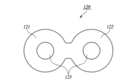
図12は本発明の第2実施形態に係る非回転式交流発電装置の構成を示す正面図である。本実施形態において、複数の発電ユニット100、本例では第1発電ユニット100-1と第2発電ユニット100-2は下部が単一のベース部材30に結合されると共に、上部は磁極片120によって互いに結合される。即ち、交流発電装置を構成する複数の発電ユニット100は磁極片120を通じて一体的に結合される。
Figure 12 is a front view showing the configuration of a non-rotating AC generator according to a second embodiment of the present invention. In this embodiment, a plurality of generating
図13は図1の交流発電装置に採用される磁極片120の構成を示す平面図である。図において、磁極片120は第1発電ユニット100-1のための第1磁極片部121と第2発電ユニット100-2のための第2磁極片部122が一体に結合されて構成され、第1磁極片部121と第2磁極片部122の中央部分にはそれぞれ第1及び第2発電ユニット100-1、100-2のコア部材40が挿入される貫通孔123が備えられる。
Figure 13 is a plan view showing the configuration of the
また、図14は図2の交流発電装置に採用される磁極片140の構成を示す平面図である。図14において、磁極片140は第1発電ユニット100-1のための第1磁極片部141と、第2発電ユニット100-2のための第2磁極片部142、及び第3発電ユニット100-3のための第3磁極片部143が一体に結合されて構成され、第1乃至第3磁極片部141~143の中央部分はそれぞれ第1乃至第3発電ユニット100-1~100-3のコア部材40が挿入される貫通孔123を備える。
In addition, FIG. 14 is a plan view showing the configuration of the
本実施形態において磁極片120、140の形状は特定されず、交流発電装置の構成によって適宜変更することができる。本実施形態において交流発電装置を構成する複数の発電ユニットは磁極片を通じて互いに結合される。従って、外部に振動や衝撃が加えられる場合に発電ユニットが流動することを最小限に抑えることができる。また、磁極片120、140は各発電ユニット100の間空間を通じて互いに結合されるので、磁極片120、140は発電ユニット100の間空間を通じた磁場の流れをより安定化する効果を提供することができる。なお、その他の部分は前述した実施形態と実質的に同一である。
In this embodiment, the shapes of the
図16は本発明に係る非回転式交流発電装置の構成例を示す正面図である。図において非回転式交流発電装置は第1乃至第3発電ユニット100-1~100-3を備える。これらの発電ユニット100-1~100-3はそれぞれR相、S相及びT相の交流を生成するためのものである。発電ユニット100-1~100-3はそれぞれ第1及び第2入力端12-1、12-2と第1及び第2出力端22a、22bを備える。この時、第1及び第2入力端12-1、12-2は直流源に適宜結合される。発電ユニット100-1~100-3と直流源との結合についてはより具体的に後述する。また、発電ユニット100-1~100-3の第1出力端22aは中性線Nに結合され、第2出力端22bからそれぞれR相、S相及びT相の交流が出力される。
Figure 16 is a front view showing an example of the configuration of a non-rotary AC generator according to the present invention. In the figure, the non-rotary AC generator includes first to third generating units 100-1 to 100-3. These generating units 100-1 to 100-3 are for generating R-phase, S-phase, and T-phase AC, respectively. The generating units 100-1 to 100-3 include first and second input terminals 12-1, 12-2 and first and
図16において非回転式交流発電装置はそれぞれR相、S相及びT相の交流を生成するための第1乃至第3発電ユニット100-1~100-3を備える。これらの発電ユニット100-1~100-3は互いに異なる位相を有する界磁電流または界磁パルスによって駆動される。図18は第1乃至第3発電ユニット100-1~100-3に供給される界磁電流と、交流発電装置から出力される三相交流の一例を示す波形図であって、図18(a)は三相交流のうちR相の交流を生成する第1発電ユニット100-1、図18(b)はS相の交流を生成する第2発電ユニット100-2、図18(c)はT相の交流を生成する第3発電ユニット100-3に供給される界磁電流の一例を示すものである。なお、図においてRA、SA及びTAは第1界磁10-1に印加される界磁電流を示し、RB、SB及びTBは第2界磁10-2に供給される界磁電流を示す。図18(d)に示したように、三相交流はR相とS相及びT相を有する3つの交流を含み、これらは互いに120度の位相差を有するようになる。前述したように、本発明において発電ユニット100は入力される界磁電流、または界磁パルスによって駆動される。この時、発電ユニット100で生成される交流電流の周波数と位相は界磁パルスの周期及び位相によって決定される。従って、図18に示したように、第1乃至第3発電ユニット100-1~100-3に対して相互に120度の位相差を有する界磁パルスをそれぞれ供給すると、第1乃至第3発電ユニット100-1~100-3を通じてRST三相交流を生成することができるようになる。
In FIG. 16, the non-rotating AC generator includes first to third generating units 100-1 to 100-3 for generating R-phase, S-phase, and T-phase AC, respectively. These generating units 100-1 to 100-3 are driven by field currents or field pulses having different phases from each other. FIG. 18 is a waveform diagram showing an example of the field current supplied to the first to third generating units 100-1 to 100-3 and the three-phase AC output from the AC generator, where FIG. 18(a) shows an example of the field current supplied to the first generating unit 100-1 that generates the R-phase AC of the three-phase AC, FIG. 18(b) shows an example of the field current supplied to the second generating unit 100-2 that generates the S-phase AC, and FIG. 18(c) shows an example of the field current supplied to the third generating unit 100-3 that generates the T-phase AC. In the figure, RA, SA, and TA indicate the field currents applied to the first field 10-1, and RB, SB, and TB indicate the field currents supplied to the second field 10-2. As shown in FIG. 18(d), the three-phase AC includes three ACs having R, S, and T phases, which have a phase difference of 120 degrees from each other. As described above, in the present invention, the
前述した実施形態においては、R相とS相及びT相の交流を生成するための第1乃至第3発電ユニット100-1~100-3を備える。そして、これらのユニット1から生成される交流電流の位相はこれらの発電ユニットに供給される界磁電流または界磁パルスの位相を調整することで適切に設定できるようになる。また、前述した実施形態において、各発電ユニット100-1~100-3は界磁10と電機子20の巻線比を調整する方式を通じて、その発電ユニット100-1~100-3から出力される交流の電圧を適切に設定するできるようになる。
In the above-described embodiment, the system includes first to third generating units 100-1 to 100-3 for generating R-phase, S-phase, and T-phase AC. The phase of the AC current generated from these
図17は発電ユニット100と直流源110との結線方式の一例を示す構成図である。図において、第1界磁10-1は第1入力端12-1の一方が直流源110の正(+)端に結合されると共に、他方が第1スイッチング部120を通じて直流源110の負(-)端に結合され、第2界磁10-2は第2入力端12-2の他方が直流源110の正(+)端に結合されると共に、一方が第2スイッチング部130を通じて直流源110の負(-)端に結合される。即ち、第1界磁10-1と第2界磁10-2は直流源110に逆方向に結合される。従って、第1界磁10-1と第2界磁10-2には逆方向に界磁電流が供給される。これにより、第1界磁10-1と第2界磁10-2で生成される磁場は互いに対向する方向に形成される。前記第1及び第2スイッチング部120、130はPWM(Pulse Width Modulation)制御部140により制御される。PWM制御部140は第1及び第2スイッチング部120、130を交互に駆動して第1界磁10-1と第2界磁10-2を交互に駆動すると共に、第1界磁10-1及び第2界磁10-2に対する界磁電流のパルス幅、即ちデューティ比を制御することで、発電ユニット100の交流出力を制御するようになる。
Figure 17 is a configuration diagram showing an example of a wiring method between the generating
PWM制御部140が第1または第2スイッチング部120、130を駆動して第1または第2界磁10-1、10-2の線路11を通じて界磁電流が流れると、その線路11の電流の流れ方向に対応して垂直方向に磁場が形成される。第1界磁10-1によって生成される磁場を第1磁場、第2界磁10-2によって生成される磁場を第2磁場とする時、第1磁場と第2磁場はその磁場方向が互いに対向するようになる。磁場が形成される方向はアンペアの右ねじの法則(Ampere’s right hand screw rules)で定義することができる。
When the
以上、本発明に係る実施形態について説明した。しかし、本発明は前記実施形態に限定されず、多様に変形して実施することができる。例えば、前述した実施形態においては発電ユニット100を構成する界磁10と電機子20が1つずつ順次交互に設けられることについて説明した。しかしながら、本発明は例えば、2つの連続した界磁と1つの電機子を交互に設けるなど、様々な方式で変形して実施することができる。
The above describes an embodiment of the present invention. However, the present invention is not limited to the above embodiment and can be modified in various ways. For example, in the above embodiment, the
また、前述した実施形態においては交流発電装置が同一の大きさ及び構成を有する複数の発電ユニットを組み合わせて構成することについて説明した。しかし、本発明は図15に示したように、互いに異なる大きさを有する第1及び第2発電ユニット150、151を組み合わせて構成することも好ましく適用して実施することができる。
In the above-described embodiment, the AC power generation device is configured by combining multiple power generation units having the same size and configuration. However, the present invention can also be preferably applied and implemented by combining first and second
また、前述した実施形態においては複数の発電ユニット100を磁極片120、140を通じて結合することについて説明した。しかし、発電ユニット100は磁極片120、140の以外に、絶縁板90や上蓋60を通じて結合する方式も好ましく採用できる。
In the above embodiment, multiple
また、前述した実施形態においてR相とS相及びT相の交流を生成する各発電ユニット100-1~100-3は複数の発電ユニットで構成することができる。そして、この時複数の発電ユニットはその第1及び第2出力端22a、22bが互いに直列または並列に結合されるようになる。
In addition, in the above-mentioned embodiment, each of the power generating units 100-1 to 100-3 that generate R-phase, S-phase, and T-phase AC can be composed of a plurality of power generating units. In this case, the first and
また、前述した実施形態においては本発明を三相交流発電装置について説明したが、本発明は多相多線式の交流発電装置に対して同様に適用して実施することができる。 In addition, in the above-described embodiment, the present invention has been described as a three-phase AC power generation device, but the present invention can be similarly applied and implemented to a multi-phase, multi-wire AC power generation device.
本発明に係る非回転式交流発電装置は複数の発電ユニットを備え、各発電ユニットは互いに隣接して配置されると共に、入力側と出力側がそれぞれ直列または並列に結合される。各発電ユニットは界磁と電機子が積層配置される構造を有し、各発電ユニットは他の発電ユニットと同期して動作して複数の発電ユニットが一つの発電ユニットとして機能するようになる。本発明の交流発電装置は一つの発電ユニットで生成される磁場が他の発電ユニットに作用して相乗作用をすることで、優れた発電効率を提供する。 The non-rotating AC generator of the present invention comprises a plurality of generating units, each of which is arranged adjacent to the other, with the input side and output side connected in series or parallel. Each generating unit has a structure in which a field magnet and an armature are arranged in a stacked manner, and each generating unit operates in synchronization with the other generating units, so that the multiple generating units function as a single generating unit. The AC generator of the present invention provides excellent power generation efficiency by having the magnetic field generated by one generating unit act on the other generating units, creating a synergistic effect.
また、本発明に係る非回転式交流発電装置はR相とS相及びT相の交流を生成するための第1乃至第3発電ユニットを備え、これらの発電ユニットに対して位相差を有する界磁電流を供給するだけで三相交流を生成できるようになる。また、本発明では第1乃至第3発電ユニットに供給する界磁電流の位相を調整することで、R相とS相及びT相交流との位相差を任意に調整することができ、更に各発電ユニットの界磁と電機子の巻線比を調整する方法などで、R相とS相及びT相交流の電圧を適切に設定できるようになる。 The non-rotary AC generator according to the present invention includes first to third generating units for generating R-phase, S-phase, and T-phase AC, and can generate three-phase AC simply by supplying field currents having a phase difference to these generating units. In addition, the present invention can adjust the phase difference between the R-phase, S-phase, and T-phase AC as desired by adjusting the phase of the field currents supplied to the first to third generating units, and furthermore, it can appropriately set the voltage of the R-phase, S-phase, and T-phase AC by adjusting the winding ratio of the field and armature of each generating unit.
Claims (12)
互いに隣接して配置される2つ以上の発電ユニットを備え、
前記発電ユニットは、
棒状のコア部材;
電気線路が巻き取られると共に中央部分に第1中空部が形成され、第1中空部を通じて前記コア部材の外側に配置される界磁;及び
電気線路が巻き取られると共に中央部分に第2中空部が形成され、第1中空部を通じて前記コア部材の外側に配置される電機子を備え、
前記界磁と電機子との間には磁極片が備えられ、
前記界磁と磁極片との間と、前記電機子と磁極片との間には絶縁板が配置され、
前記発電ユニットは入力端と出力端に対して互いに直列または並列に結線され、前記発電ユニットは他の発電ユニットと磁極片が一体に構成され、
前記発電ユニットは他の発電ユニットと絶縁板が一体に構成される
ことを特徴とする非回転式交流発電装置。 1. A non-rotating AC generating apparatus for generating an AC current, comprising:
Two or more power generating units disposed adjacent to each other,
The power generation unit comprises:
A rod-shaped core member;
The electric line is wound around the core member, and a first hollow portion is formed in the central portion of the core member, and a field magnet is disposed outside the core member through the first hollow portion; and an armature is wound around the electric line, and a second hollow portion is formed in the central portion of the core member, and a stator is disposed outside the core member through the first hollow portion.
A pole piece is provided between the field magnet and the armature;
Insulating plates are disposed between the field magnet and the pole piece and between the armature and the pole piece;
The power generating units are connected in series or parallel to each other at the input end and the output end, and the power generating units are integrally formed with other power generating units by using magnetic pole pieces ;
The power generating unit is integrally formed with other power generating units by insulating plates.
A non-rotating AC power generating device.
R相交流を生成するための第1発電ユニット、
S相交流を生成するための第2発電ユニット、及び、
T相交流を生成するための第3発電ユニットを備え、
前記第1乃至第3発電ユニットは第1出力端が中性線に結合されると共に、第2出力端を通じてそれぞれR相、S相またはT相交流を出力し、
前記第1乃至第3発電ユニットは、
棒状のコア部材;
電気線路が巻き取られると共に中央部分に第1中空部が形成され、第1中空部を通じて前記コア部材の外側に配置される界磁;及び、
電気線路が巻き取られると共に中央部分に第2中空部が形成され、第1中空部を通じて前記コア部材の外側に配置される電機子を備え、
前記界磁と電機子との間には磁極片が備えられ、
前記界磁と磁極片との間と、前記電機子と磁極片との間には絶縁板が配置され、
前記第1乃至第3発電ユニットの各界磁には互いに位相差を有する界磁電流が供給され、
前記第1乃至第3発電ユニットにおいて各発電ユニットは他の発電ユニットと磁極片が一体に構成される
ことを特徴とする非回転式交流発電装置。 In an AC power generating device that generates AC currents of R phase, S phase, and T phase having a phase difference from one another,
a first generating unit for generating an R-phase alternating current;
a second generating unit for generating a S-phase alternating current; and
a third generating unit for generating a T-phase AC current;
The first to third power generating units each have a first output terminal connected to a neutral line and output an R-phase, S-phase, or T-phase AC current through a second output terminal,
The first to third power generation units include:
A rod-shaped core member;
The electric line is wound and a first hollow portion is formed in the central portion, and a field magnet is disposed outside the core member through the first hollow portion; and
an armature having an electric line wound therearound and a second hollow portion formed in a central portion thereof, the armature being disposed outside the core member through the first hollow portion;
A pole piece is provided between the field magnet and the armature;
Insulating plates are disposed between the field magnet and the pole piece and between the armature and the pole piece;
The first to third generating units are supplied with field currents having a phase difference therebetween,
2. A non-rotating AC generating apparatus, wherein each of said first to third generating units has a magnetic pole piece integrally formed with the other generating units.
請求項1または2に記載の非回転式交流発電装置。 3. A non-rotating AC generator according to claim 1, wherein a central portion of the core member is hollow along a longitudinal direction.
請求項1または2に記載の非回転式交流発電装置。 3. The non-rotating AC generator according to claim 1, further comprising an insulating material disposed between the core member and the first or second hollow portion.
請求項1または2に記載の非回転式交流発電装置。 3. A non-rotating AC generator according to claim 1, wherein the insulating plate is made of a highly elastic material.
請求項1または2に記載の非回転式交流発電装置。 3. A non-rotating alternating current generator as claimed in claim 1 or 2, wherein the core members or pole pieces are constructed of pure iron and are heat treated.
請求項1に記載の非回転式交流発電装置。 2. The non-rotating AC power generating apparatus according to claim 1, wherein a plurality of the field magnets and armatures are provided, and the field magnets and armatures are arranged alternately with each other.
請求項2に記載の非回転式交流発電装置。 3. The non-rotating AC power generating device according to claim 2, wherein a plurality of said field magnets and armatures are provided, and the field magnets and armatures are arranged alternately with each other.
請求項7または8に記載の非回転式交流発電装置。 The armatures are connected in series with each other.
9. A non-rotating AC generator according to claim 7 or 8 .
前記第1界磁群と第2界磁群は互いに交互に駆動されて、第1磁場と第2磁場をそれぞれ形成し、
前記第1磁場と第2磁場は互いに対向する方向を有する
請求項7または8に記載の非回転式交流発電装置。 The plurality of field magnets are divided into a first field magnet group and a second field magnet group,
The first and second field groups are alternately driven to form a first magnetic field and a second magnetic field, respectively;
The first magnetic field and the second magnetic field have mutually opposing directions.
9. A non-rotating AC generator according to claim 7 or 8 .
請求項1に記載の非回転式交流発電装置。 2. The non-rotating alternating current generator of claim 1, wherein at least one of said generating units has a different size than the other generating units.
互いに異なる位相の交流をそれぞれ生成するための複数の発電ユニットを備え、
前記発電ユニットは、
棒状のコア部材;
電気線路が巻き取られると共に中央部分に第1中空部が形成され、第1中空部を通じて前記コア部材の外側に配置される界磁;及び、
電気線路が巻き取られると共に中央部分に第2中空部が形成され、第1中空部を通じて前記コア部材の外側に配置される電機子を備え、
前記界磁と電機子との間には磁極片が備えられ、
前記界磁と磁極片との間と、前記電機子と磁極片との間には絶縁板が配置され、
前記複数の発電ユニットの各界磁には互いに位相差を有する界磁電流が供給され、
前記複数の発電ユニットにおいて各発電ユニットは他の発電ユニットと磁極片が一体に構成され、
前記発電ユニットは他の発電ユニットと絶縁板が一体に構成される
ことを特徴とする非回転式交流発電装置。 2. An AC power generating device for generating multi-phase AC having a phase difference between each other,
A power generating system includes a plurality of power generating units each for generating alternating currents of different phases,
The power generation unit comprises:
A rod-shaped core member;
The electric line is wound and a first hollow portion is formed in the central portion, and a field magnet is disposed outside the core member through the first hollow portion; and
a second hollow portion is formed in a central portion of the coil, and an armature is disposed outside the core member through the first hollow portion;
A pole piece is provided between the field magnet and the armature;
Insulating plates are disposed between the field magnet and the pole piece and between the armature and the pole piece;
A field current having a phase difference with each other is supplied to each of the plurality of generating units,
In the plurality of power generating units, each power generating unit has a pole piece integrally formed with the other power generating units ,
The power generating unit is integrally formed with other power generating units by insulating plates.
A non-rotating AC power generating device.
Applications Claiming Priority (5)
| Application Number | Priority Date | Filing Date | Title |
|---|---|---|---|
| KR1020200057044A KR102452610B1 (en) | 2020-05-13 | 2020-05-13 | Non-Rotation Type AC Electric Generator |
| KR10-2020-0057048 | 2020-05-13 | ||
| KR1020200057048A KR102447626B1 (en) | 2020-05-13 | 2020-05-13 | Non-rotating alternator |
| KR10-2020-0057044 | 2020-05-13 | ||
| PCT/KR2021/004152 WO2021230496A1 (en) | 2020-05-13 | 2021-04-02 | Non-rotating alternating current generating device |
Publications (2)
| Publication Number | Publication Date |
|---|---|
| JP2023525344A JP2023525344A (en) | 2023-06-15 |
| JP7507253B2 true JP7507253B2 (en) | 2024-06-27 |
Family
ID=78524852
Family Applications (1)
| Application Number | Title | Priority Date | Filing Date |
|---|---|---|---|
| JP2022568956A Active JP7507253B2 (en) | 2020-05-13 | 2021-04-02 | Non-rotating AC generator |
Country Status (9)
| Country | Link |
|---|---|
| US (1) | US12176799B2 (en) |
| EP (1) | EP4152583A4 (en) |
| JP (1) | JP7507253B2 (en) |
| CN (1) | CN115552778A (en) |
| AU (1) | AU2021272685B2 (en) |
| IL (1) | IL298139B1 (en) |
| SA (1) | SA522441283B1 (en) |
| WO (1) | WO2021230496A1 (en) |
| ZA (1) | ZA202213228B (en) |
Citations (9)
| Publication number | Priority date | Publication date | Assignee | Title |
|---|---|---|---|---|
| JP2000353627A (en) | 1999-06-10 | 2000-12-19 | Sony Corp | Insulation converter transformer and switching power supply circuit |
| KR20030037745A (en) | 2001-11-05 | 2003-05-16 | 유준 | electric device of disk type rotator |
| JP2011243830A (en) | 2010-05-20 | 2011-12-01 | Tdk Corp | Powder magnetic core and method for manufacturing the same |
| JP2012532815A (en) | 2009-07-10 | 2012-12-20 | オーチス エレベータ カンパニー | Elevator machine with outer rotor and motor in traction sheave |
| JP2013115837A (en) | 2011-11-24 | 2013-06-10 | Toshiba Corp | Power conversion apparatus |
| JP2014230347A (en) | 2013-05-21 | 2014-12-08 | パナソニック株式会社 | Electric blower and electric cleaner |
| JP2016135054A (en) | 2015-01-21 | 2016-07-25 | 株式会社東芝 | Power converter |
| JP2017143250A (en) | 2016-01-13 | 2017-08-17 | ザ・ボーイング・カンパニーThe Boeing Company | Multi-pulse electromagnetic device including linear magnetic core configuration |
| KR101913746B1 (en) | 2017-08-28 | 2018-10-31 | 박찬희 | Electric Power Generator managing frequency and voltage |
Family Cites Families (5)
| Publication number | Priority date | Publication date | Assignee | Title |
|---|---|---|---|---|
| CA945611A (en) * | 1971-05-28 | 1974-04-16 | Albert L. De Graffenried | High density flux magnetic circuit |
| BE785906A (en) * | 1971-07-12 | 1973-01-08 | High Voltage Power Corp | ELECTROMAGNETIC INDUCTION DEVICE |
| JPS5970160A (en) * | 1982-10-15 | 1984-04-20 | Toshiba Corp | Field pole for salient-pole rotary electric machine |
| JP3431364B2 (en) * | 1995-09-12 | 2003-07-28 | 株式会社東芝 | Salient pole mass rotor |
| JP4800451B1 (en) * | 2011-06-10 | 2011-10-26 | 株式会社精電製作所 | High frequency transformer |
-
2021
- 2021-04-02 WO PCT/KR2021/004152 patent/WO2021230496A1/en not_active Ceased
- 2021-04-02 EP EP21803663.0A patent/EP4152583A4/en active Pending
- 2021-04-02 CN CN202180037464.8A patent/CN115552778A/en active Pending
- 2021-04-02 AU AU2021272685A patent/AU2021272685B2/en active Active
- 2021-04-02 JP JP2022568956A patent/JP7507253B2/en active Active
- 2021-04-02 US US17/925,134 patent/US12176799B2/en active Active
-
2022
- 2022-11-10 SA SA522441283A patent/SA522441283B1/en unknown
- 2022-11-11 IL IL298139A patent/IL298139B1/en unknown
- 2022-12-06 ZA ZA2022/13228A patent/ZA202213228B/en unknown
Patent Citations (9)
| Publication number | Priority date | Publication date | Assignee | Title |
|---|---|---|---|---|
| JP2000353627A (en) | 1999-06-10 | 2000-12-19 | Sony Corp | Insulation converter transformer and switching power supply circuit |
| KR20030037745A (en) | 2001-11-05 | 2003-05-16 | 유준 | electric device of disk type rotator |
| JP2012532815A (en) | 2009-07-10 | 2012-12-20 | オーチス エレベータ カンパニー | Elevator machine with outer rotor and motor in traction sheave |
| JP2011243830A (en) | 2010-05-20 | 2011-12-01 | Tdk Corp | Powder magnetic core and method for manufacturing the same |
| JP2013115837A (en) | 2011-11-24 | 2013-06-10 | Toshiba Corp | Power conversion apparatus |
| JP2014230347A (en) | 2013-05-21 | 2014-12-08 | パナソニック株式会社 | Electric blower and electric cleaner |
| JP2016135054A (en) | 2015-01-21 | 2016-07-25 | 株式会社東芝 | Power converter |
| JP2017143250A (en) | 2016-01-13 | 2017-08-17 | ザ・ボーイング・カンパニーThe Boeing Company | Multi-pulse electromagnetic device including linear magnetic core configuration |
| KR101913746B1 (en) | 2017-08-28 | 2018-10-31 | 박찬희 | Electric Power Generator managing frequency and voltage |
Also Published As
| Publication number | Publication date |
|---|---|
| EP4152583A4 (en) | 2023-11-08 |
| BR112022023195A2 (en) | 2022-12-20 |
| EP4152583A1 (en) | 2023-03-22 |
| IL298139B1 (en) | 2026-02-01 |
| CN115552778A (en) | 2022-12-30 |
| ZA202213228B (en) | 2024-03-27 |
| AU2021272685A1 (en) | 2023-01-19 |
| US20230198368A1 (en) | 2023-06-22 |
| JP2023525344A (en) | 2023-06-15 |
| SA522441283B1 (en) | 2025-01-13 |
| WO2021230496A1 (en) | 2021-11-18 |
| US12176799B2 (en) | 2024-12-24 |
| IL298139A (en) | 2023-01-01 |
| AU2021272685B2 (en) | 2024-01-11 |
Similar Documents
| Publication | Publication Date | Title |
|---|---|---|
| KR102452616B1 (en) | Power Converting Apparatus | |
| CN100574049C (en) | Stator coil arrangement for axial air gap electrical arrangement comprising low loss material | |
| KR102534308B1 (en) | Non-Rotation Type AC Electric Generator | |
| KR102587050B1 (en) | Non-rotation type AC Electric Generator With Non-rotation type Core Member | |
| TW201251283A (en) | Automated power generator | |
| JP7507253B2 (en) | Non-rotating AC generator | |
| KR102332747B1 (en) | Non-rotation type DC Electric Generator | |
| JP7750933B2 (en) | Non-rotating DC current generator | |
| KR102534309B1 (en) | Non-Rotation Type AC Electric Generator | |
| KR102669441B1 (en) | Non-rotation Type DC Electric Generator | |
| KR102344370B1 (en) | Non-rotation Type AC Generator With High-elasticity Insulation Plate | |
| KR20210122369A (en) | Non-rotation Type AC Electric Generator | |
| KR20230043305A (en) | Non-rotation Type AC Electric Generator | |
| KR20240007866A (en) | Non-rotation type power converting apparatus | |
| BR112022023195B1 (en) | NON-ROTATING ALTERNATING CURRENT (AC) GENERATING DEVICE FOR GENERATING AN AC CURRENT, IN WHICH ALTERNATING CURRENT OF PHASE R, PHASE S AND PHASE T ARE GENERATED WITH MUTUAL PHASE DIFFERENCE | |
| KR102395915B1 (en) | Non-Rotation Type Alternating Current Generator |
Legal Events
| Date | Code | Title | Description |
|---|---|---|---|
| A621 | Written request for application examination |
Free format text: JAPANESE INTERMEDIATE CODE: A621 Effective date: 20221111 |
|
| A131 | Notification of reasons for refusal |
Free format text: JAPANESE INTERMEDIATE CODE: A131 Effective date: 20231031 |
|
| A601 | Written request for extension of time |
Free format text: JAPANESE INTERMEDIATE CODE: A601 Effective date: 20240125 |
|
| A601 | Written request for extension of time |
Free format text: JAPANESE INTERMEDIATE CODE: A601 Effective date: 20240329 |
|
| A521 | Request for written amendment filed |
Free format text: JAPANESE INTERMEDIATE CODE: A523 Effective date: 20240430 |
|
| TRDD | Decision of grant or rejection written | ||
| A01 | Written decision to grant a patent or to grant a registration (utility model) |
Free format text: JAPANESE INTERMEDIATE CODE: A01 Effective date: 20240528 |
|
| A61 | First payment of annual fees (during grant procedure) |
Free format text: JAPANESE INTERMEDIATE CODE: A61 Effective date: 20240617 |