JP7503750B2 - Object detection system and object detection method - Google Patents
Object detection system and object detection method Download PDFInfo
- Publication number
- JP7503750B2 JP7503750B2 JP2022532459A JP2022532459A JP7503750B2 JP 7503750 B2 JP7503750 B2 JP 7503750B2 JP 2022532459 A JP2022532459 A JP 2022532459A JP 2022532459 A JP2022532459 A JP 2022532459A JP 7503750 B2 JP7503750 B2 JP 7503750B2
- Authority
- JP
- Japan
- Prior art keywords
- distance
- object information
- optical sensor
- unit
- sections
- Prior art date
- Legal status (The legal status is an assumption and is not a legal conclusion. Google has not performed a legal analysis and makes no representation as to the accuracy of the status listed.)
- Active
Links
- 238000001514 detection method Methods 0.000 title claims description 113
- 230000003287 optical effect Effects 0.000 claims description 130
- 238000012545 processing Methods 0.000 claims description 77
- 238000000034 method Methods 0.000 claims description 61
- 238000005259 measurement Methods 0.000 claims description 53
- 230000008569 process Effects 0.000 claims description 40
- 239000002131 composite material Substances 0.000 claims description 34
- 230000008859 change Effects 0.000 claims description 7
- 230000005484 gravity Effects 0.000 description 23
- 238000010586 diagram Methods 0.000 description 22
- 230000010365 information processing Effects 0.000 description 16
- 230000015654 memory Effects 0.000 description 11
- 238000012986 modification Methods 0.000 description 7
- 230000004048 modification Effects 0.000 description 7
- 238000004364 calculation method Methods 0.000 description 4
- 238000001914 filtration Methods 0.000 description 4
- 238000003384 imaging method Methods 0.000 description 4
- 238000012937 correction Methods 0.000 description 3
- 239000000284 extract Substances 0.000 description 3
- 230000006870 function Effects 0.000 description 3
- 238000002372 labelling Methods 0.000 description 3
- 230000015572 biosynthetic process Effects 0.000 description 2
- 238000004891 communication Methods 0.000 description 2
- 238000004590 computer program Methods 0.000 description 2
- 238000003786 synthesis reaction Methods 0.000 description 2
- 238000002366 time-of-flight method Methods 0.000 description 2
- 230000001419 dependent effect Effects 0.000 description 1
- 238000013461 design Methods 0.000 description 1
- 230000000694 effects Effects 0.000 description 1
- 238000005401 electroluminescence Methods 0.000 description 1
- 238000000605 extraction Methods 0.000 description 1
- 229910052736 halogen Inorganic materials 0.000 description 1
- 150000002367 halogens Chemical class 0.000 description 1
- 239000004973 liquid crystal related substance Substances 0.000 description 1
- 239000011159 matrix material Substances 0.000 description 1
- 230000000877 morphologic effect Effects 0.000 description 1
- 238000000513 principal component analysis Methods 0.000 description 1
- 238000003672 processing method Methods 0.000 description 1
- 230000009467 reduction Effects 0.000 description 1
- 239000004065 semiconductor Substances 0.000 description 1
- 230000036962 time dependent Effects 0.000 description 1
Images


Classifications
-
- G—PHYSICS
- G01—MEASURING; TESTING
- G01S—RADIO DIRECTION-FINDING; RADIO NAVIGATION; DETERMINING DISTANCE OR VELOCITY BY USE OF RADIO WAVES; LOCATING OR PRESENCE-DETECTING BY USE OF THE REFLECTION OR RERADIATION OF RADIO WAVES; ANALOGOUS ARRANGEMENTS USING OTHER WAVES
- G01S17/00—Systems using the reflection or reradiation of electromagnetic waves other than radio waves, e.g. lidar systems
- G01S17/88—Lidar systems specially adapted for specific applications
- G01S17/93—Lidar systems specially adapted for specific applications for anti-collision purposes
- G01S17/931—Lidar systems specially adapted for specific applications for anti-collision purposes of land vehicles
-
- G—PHYSICS
- G01—MEASURING; TESTING
- G01C—MEASURING DISTANCES, LEVELS OR BEARINGS; SURVEYING; NAVIGATION; GYROSCOPIC INSTRUMENTS; PHOTOGRAMMETRY OR VIDEOGRAMMETRY
- G01C3/00—Measuring distances in line of sight; Optical rangefinders
- G01C3/02—Details
- G01C3/06—Use of electric means to obtain final indication
-
- G—PHYSICS
- G01—MEASURING; TESTING
- G01S—RADIO DIRECTION-FINDING; RADIO NAVIGATION; DETERMINING DISTANCE OR VELOCITY BY USE OF RADIO WAVES; LOCATING OR PRESENCE-DETECTING BY USE OF THE REFLECTION OR RERADIATION OF RADIO WAVES; ANALOGOUS ARRANGEMENTS USING OTHER WAVES
- G01S17/00—Systems using the reflection or reradiation of electromagnetic waves other than radio waves, e.g. lidar systems
- G01S17/02—Systems using the reflection of electromagnetic waves other than radio waves
- G01S17/06—Systems determining position data of a target
- G01S17/08—Systems determining position data of a target for measuring distance only
- G01S17/10—Systems determining position data of a target for measuring distance only using transmission of interrupted, pulse-modulated waves
- G01S17/18—Systems determining position data of a target for measuring distance only using transmission of interrupted, pulse-modulated waves wherein range gates are used
-
- G—PHYSICS
- G01—MEASURING; TESTING
- G01S—RADIO DIRECTION-FINDING; RADIO NAVIGATION; DETERMINING DISTANCE OR VELOCITY BY USE OF RADIO WAVES; LOCATING OR PRESENCE-DETECTING BY USE OF THE REFLECTION OR RERADIATION OF RADIO WAVES; ANALOGOUS ARRANGEMENTS USING OTHER WAVES
- G01S17/00—Systems using the reflection or reradiation of electromagnetic waves other than radio waves, e.g. lidar systems
- G01S17/02—Systems using the reflection of electromagnetic waves other than radio waves
- G01S17/50—Systems of measurement based on relative movement of target
-
- G—PHYSICS
- G01—MEASURING; TESTING
- G01S—RADIO DIRECTION-FINDING; RADIO NAVIGATION; DETERMINING DISTANCE OR VELOCITY BY USE OF RADIO WAVES; LOCATING OR PRESENCE-DETECTING BY USE OF THE REFLECTION OR RERADIATION OF RADIO WAVES; ANALOGOUS ARRANGEMENTS USING OTHER WAVES
- G01S17/00—Systems using the reflection or reradiation of electromagnetic waves other than radio waves, e.g. lidar systems
- G01S17/66—Tracking systems using electromagnetic waves other than radio waves
-
- G—PHYSICS
- G01—MEASURING; TESTING
- G01S—RADIO DIRECTION-FINDING; RADIO NAVIGATION; DETERMINING DISTANCE OR VELOCITY BY USE OF RADIO WAVES; LOCATING OR PRESENCE-DETECTING BY USE OF THE REFLECTION OR RERADIATION OF RADIO WAVES; ANALOGOUS ARRANGEMENTS USING OTHER WAVES
- G01S17/00—Systems using the reflection or reradiation of electromagnetic waves other than radio waves, e.g. lidar systems
- G01S17/88—Lidar systems specially adapted for specific applications
- G01S17/89—Lidar systems specially adapted for specific applications for mapping or imaging
- G01S17/894—3D imaging with simultaneous measurement of time-of-flight at a 2D array of receiver pixels, e.g. time-of-flight cameras or flash lidar
-
- G—PHYSICS
- G01—MEASURING; TESTING
- G01S—RADIO DIRECTION-FINDING; RADIO NAVIGATION; DETERMINING DISTANCE OR VELOCITY BY USE OF RADIO WAVES; LOCATING OR PRESENCE-DETECTING BY USE OF THE REFLECTION OR RERADIATION OF RADIO WAVES; ANALOGOUS ARRANGEMENTS USING OTHER WAVES
- G01S7/00—Details of systems according to groups G01S13/00, G01S15/00, G01S17/00
- G01S7/48—Details of systems according to groups G01S13/00, G01S15/00, G01S17/00 of systems according to group G01S17/00
- G01S7/483—Details of pulse systems
- G01S7/486—Receivers
- G01S7/4865—Time delay measurement, e.g. time-of-flight measurement, time of arrival measurement or determining the exact position of a peak
Landscapes
- Physics & Mathematics (AREA)
- Engineering & Computer Science (AREA)
- Electromagnetism (AREA)
- General Physics & Mathematics (AREA)
- Radar, Positioning & Navigation (AREA)
- Remote Sensing (AREA)
- Computer Networks & Wireless Communication (AREA)
- Optical Radar Systems And Details Thereof (AREA)
- Measurement Of Optical Distance (AREA)
- Length Measuring Devices By Optical Means (AREA)
Description
本開示は、物体検知システム及び物体検知方法に関し、より詳細には、対象物までの距離についての情報を処理する物体検知システム及び物体検知方法に関する。The present disclosure relates to an object detection system and an object detection method, and more particularly to an object detection system and an object detection method that process information about the distance to an object.
特許文献1は、撮像装置により取り込まれる一連の画像データにおいて、撮像視野内の侵入物体や移動物体を検出し、それらの物体を含む一連の画像データを記録する画像監視装置を開示する。この画像監視装置は、監視区域を撮像し量子化された画像データを入力する撮像手段と、前記画像データを記憶する入力画像記憶手段と、監視区域の背景画像を記憶する基準画像記憶手段と、入力画像と基準画像の差分画像を出力する差分演算手段と、前記差分画像について1フレーム前の物体位置との比較により移動物体を検出し、同時に移動物体を除く領域の画素を入力画像の値で更新する動物体検出手段と、入力画像を表示し移動物体の検出結果を通報する表示手段と、を備える。
特許文献2は、精度の高いトラッキングを継続する情報処理装置を開示する。この情報処理装置は、複数の時点における、物体の縦方向の位置と、横方向の位置と、奥行方向の位置とが対応付けられた情報を取得する取得部と、前記取得部により以前に取得された前記情報における前記所定の物体の位置に基づき、前記取得部により今回取得された前記情報における前記所定の物体の位置を予測する予測部と、今回の前記情報から、前記所定の物体の位置に応じた所定の条件を満たす複数の物体を抽出し、前記複数の物体の各画像と、前記所定の物体の画との類似度に基づいて、今回の前記情報における前記複数の物体のうち、以前の前記情報における前記所定の物体と同一の物体を抽出する抽出部と、を備える。
本開示は、高速に物体を検知する物体検知システム及び物体検知方法を提供することを目的とする。 The present disclosure aims to provide an object detection system and an object detection method that can detect objects at high speed.
上記目的を達成するために、本開示の一形態における物体検知システムは、光を出射する発光部と、前記光が対象空間における測距可能範囲で反射された反射光を受光する光センサと、前記発光部及び前記光センサを制御する制御部と、前記光センサで生成される電気信号で示される情報を処理する信号処理部とを備え、前記制御部は、前記測距可能範囲を区分して構成される複数の距離区間について、前記光センサに含まれる複数の画素のうちで前記光を受け取った画素からの信号である距離区間信号が前記光センサから出力されるように、前記発光部及び前記光センサを制御し、前記信号処理部は、それぞれが対応する前記距離区間について出力された前記距離区間信号に基づいて対象物の特徴を示す対象物情報を生成する並列動作可能な複数の生成部を有し、かつ、前記光センサから出力される前記距離区間信号に基づいて、前記複数の距離区間について、前記光センサによって検出された対象物の特徴を示す対象物情報をそれぞれ生成する対象物情報生成部と、前記対象物情報生成部が生成した前記複数の距離区間に対応する前記対象物情報を記憶する記憶部と、前記複数の距離区間に対応する前記対象物情報を出力する出力部とを備え、前記対象物情報生成部は、前記複数の距離区間について、前記記憶部に記憶された過去の前記対象物情報と、前記光センサによって検出された現在の前記対象物の特徴とを比較することで、前記対象物情報を生成し、前記複数の生成部の各々は、前記並列動作として、前記距離区間信号が入力されると、他の生成部での処理の完了を待たずに、直ちに処理を開始する。 In order to achieve the above object, an object detection system according to one embodiment of the present disclosure includes a light-emitting unit that emits light, an optical sensor that receives light reflected from the light in a distance measurement range in a target space, a control unit that controls the light-emitting unit and the optical sensor, and a signal processing unit that processes information indicated by an electrical signal generated by the optical sensor, wherein the control unit controls the light-emitting unit and the optical sensor so that a distance section signal, which is a signal from a pixel that receives the light among a plurality of pixels included in the optical sensor, is output from the optical sensor for a plurality of distance sections formed by dividing the distance measurement range, and the signal processing unit includes a plurality of generation units operable in parallel, each of which generates object information indicating a feature of an object based on the distance section signal output for the corresponding distance section. and comprising an object information generation unit that generates object information indicating characteristics of the object detected by the optical sensor for each of the multiple distance intervals based on the distance interval signal output from the optical sensor, a memory unit that stores the object information corresponding to the multiple distance intervals generated by the object information generation unit, and an output unit that outputs the object information corresponding to the multiple distance intervals, wherein the object information generation unit generates the object information for the multiple distance intervals by comparing the past object information stored in the memory unit with the current characteristics of the object detected by the optical sensor, and each of the multiple generation units starts processing immediately upon input of the distance interval signal as the parallel operation, without waiting for completion of processing by the other generation units.
上記目的を達成するために、本開示の一形態における物体検知方法は、光を出射する発光部と、前記光が対象空間における測距可能範囲で反射された反射光を受光する光センサとを備える物体検知システムによる物体検知方法であって、前記発光部及び前記光センサを制御する制御ステップと、前記光センサで生成される電気信号で示される情報を処理する信号処理ステップとを含み、前記制御ステップでは、前記測距可能範囲を区分して構成される複数の距離区間について、前記光センサに含まれる複数の画素のうちで前記光を受け取った画素からの信号である距離区間信号が前記光センサから出力されるように、前記発光部及び前記光センサを制御し、前記信号処理ステップでは、それぞれが対応する前記距離区間について出力された前記距離区間信号に基づいて対象物の特徴を示す対象物情報を生成する並列動作可能な複数の生成部により、前記光センサから出力される前記距離区間信号に基づいて、前記複数の距離区間について、前記光センサによって検出された対象物の特徴を示す対象物情報をそれぞれ生成する対象物情報生成サブステップと、前記対象物情報生成サブステップで生成した前記複数の距離区間に対応する前記対象物情報を記憶部に記憶させる記憶サブステップと、前記複数の距離区間に対応する前記対象物情報を出力する出力サブステップとを含み、前記対象物情報生成サブステップでは、前記複数の距離区間について、前記記憶部に記憶された過去の対象物情報と、前記光センサによって検出された現在の対象物の特徴とを比較することで、前記対象物情報を生成し、前記複数の生成部の各々は、前記並列動作として、前記距離区間信号が入力されると、他の生成部での処理の完了を待たずに、直ちに処理を開始する。 In order to achieve the above object, an object detection method according to one embodiment of the present disclosure is an object detection method using an object detection system including a light-emitting unit that emits light and an optical sensor that receives light reflected from the light in a measurable range in a target space, the method including a control step of controlling the light-emitting unit and the optical sensor, and a signal processing step of processing information indicated by an electrical signal generated by the optical sensor, the control step controlling the light-emitting unit and the optical sensor so that a distance section signal, which is a signal from a pixel that receives the light among a plurality of pixels included in the optical sensor, is output from the optical sensor for a plurality of distance sections formed by dividing the measurable range, and the signal processing step includes a plurality of parallel-operable devices that generate object information indicating a feature of an object based on the distance section signal output for each corresponding distance section. The method includes an object information generation substep in which a plurality of generation units generate object information indicating characteristics of the object detected by the optical sensor for each of the plurality of distance intervals based on the distance interval signal output from the optical sensor, a storage substep in which the object information corresponding to the plurality of distance intervals generated in the object information generation substep is stored in a storage unit, and an output substep in which the object information corresponding to the plurality of distance intervals is output. In the object information generation substep, the object information is generated by comparing past object information stored in the storage unit with characteristics of the current object detected by the optical sensor for each of the plurality of distance intervals, and each of the plurality of generation units starts processing immediately upon input of the distance interval signal as the parallel operation, without waiting for completion of processing in the other generation units.
本開示における物体検知システム及び物体検知方法は、高速に物体を検知することが可能である。The object detection system and object detection method disclosed herein are capable of detecting objects at high speed.
以下、図面を参照しながら、実施の形態を詳細に説明する。但し、必要以上に詳細な説明は省略する場合がある。例えば、既によく知られた事項の詳細説明、又は、実質的に同一の構成に対する重複説明を省略する場合がある。これは、以下の説明が必要以上に冗長になるのを避け、当業者の理解を容易にするためである。 Below, the embodiments will be described in detail with reference to the drawings. However, more detailed explanation than necessary may be omitted. For example, detailed explanations of matters that are already well known, or duplicate explanations of substantially identical configurations may be omitted. This is to avoid making the following explanation unnecessarily redundant and to make it easier for those skilled in the art to understand.
なお、添付図面及び以下の説明は、当業者が本開示を十分に理解するために提供されるのであって、これらにより請求の範囲に記載の主題を限定することを意図していない。The accompanying drawings and the following description are provided to enable those skilled in the art to fully understand the present disclosure, and are not intended to limit the subject matter described in the claims.
以下、図1~図11を用いて、実施の形態を説明する。 Below, the embodiment will be explained using Figures 1 to 11.
[1.構成]
[1-1.物体検知システムの構成]
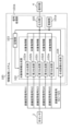
図1は、実施形態に係る物体検知システム200の構成を示す図である。なお、図1には、物体検知システム200と通信路を介して接続される外部装置5も合わせて図示されている。図1に示すように、物体検知システム200は、情報処理システム100と、発光部1と、光センサ2と、提示部4とを備える。物体検知システム200は、直接TOF(Time of Flight)方式を利用して複数の距離区間の各々について物体を検知するシステムである。外部装置5は、半導体メモリ等の記憶装置、コンピュータ装置、ディスプレイ等である。
[1. Configuration]
[1-1. Configuration of Object Detection System]
Fig. 1 is a diagram showing a configuration of an
発光部1は、制御部101aによる制御の下で対象物に測定光を出射するための光源を備える。測定光は、パルス状の光である。TOF方式を利用した距離測定において、測定光は、単一波長であり、パルス幅が比較的短く、ピーク強度が比較的高いことが好ましい。また、物体検知システム200(より厳密には、光センサ2)を市街地等で利用することを考慮して、測定光の波長は、人間の視感度が低く、太陽光からの外乱光の影響を受けにくい近赤外帯の波長域であることが好ましい。本実施形態では、光源は、例えばレーザーダイオードで構成されており、パルスレーザを出力する。光源が出力するパルスレーザの強度は、レーザ製品の安全基準(JIS C 6802)のクラス1又はクラス2の基準を満たしている。なお、光源は、上記の構成に限らず、発光ダイオード(LED:Light Emitting Diode)、面発光レーザ(VCSEL:Vertical Cavity Surface Emitting LASER)、ハロゲンランプ等であってもよい。また、測定光は、近赤外帯とは異なる波長域であってもよい。The
光センサ2は、測定光が対象空間における測距可能範囲で反射された反射光を受光するセンサであり、複数の画素を含む画素部を備える。各画素には、アバランシェフォトダイオードが配置されている。各画素に他の光検出素子が配置されても良い。各画素は、反射光を受光する露光状態と、反射光を受光しない非露光状態とを制御部101aによる制御の下で切り替え可能に構成されている。光センサ2は、露光状態において各画素で受光した反射光に基づく電荷を出力する。The
情報処理システム100は、発光部1及び光センサ2を制御する制御部101aと、光センサ2で生成される電気信号で示される情報を処理する信号処理部101bとを備える。制御部101aは、測距可能範囲を区分して構成される複数の距離区間の各々について、光センサ2に含まれる複数の画素のうちで光を受け取った画素からの信号である距離区間信号が光センサ2から出力されるように、発光部1及び光センサ2を制御する(つまり、制御ステップを実行する)。The
信号処理部101bは、光センサ2で生成される電気信号で示される情報を処理する(つまり、信号処理ステップを実行する)。そのために、信号処理部101bは、光センサ2から出力される距離区間信号に基づいて、複数の距離区間の各々において光センサ2によって検出された対象物の特徴を示す対象物情報を生成する(つまり、対象物情報生成サブステップを実行する)並列処理可能な複数の生成部(第1生成部~第5生成部)を有する対象物情報生成部102と、光センサ2から出力される複数の距離区間に対応する複数の距離区間信号から合成画像を生成する(つまり、合成画像生成サブステップを実行する)合成画像生成部104と、対象物情報生成部102が生成した複数の距離区間の各々に対応する対象物情報を記憶する(つまり、記憶サブステップを実行する)記憶部103と、複数の距離区間の各々に対応する対象物情報及び合成画像を外部装置5に出力する出力部105とを備える。対象物情報生成部102は、複数の距離区間の各々について、記憶部103に記憶された過去の対象物情報と、光センサ2によって検出された現在の対象物の特徴とを比較することで、対象物情報を生成する。The
物体検知システム200では、各距離区間について、測定光の発光及び光センサ2の各画素の露光動作からなる受光を一回以上行い、各画素は、受光動作のうちで光を受け取った回数分に相当する電気信号を出力する。受光動作を行う回数(受光回数)は、特に限定されないが、一例において50回程度であっても良い。In the
[1-2.距離測定の概要]
図2は、実施形態に係る物体検知システム200による対象物までの距離の測定方法の概略を示す図である。
[1-2. Overview of distance measurement]
FIG. 2 is a diagram showing an outline of a method for measuring a distance to an object by an
物体検知システム200は、図1に示すように、発光部1から出射される測定光が対象物で反射された光を利用して、対象物までの距離を測定する。物体検知システム200は、例えば、自動車に搭載され障害物を検知する車載物体検知システム、物体あるいは人等を検知する監視カメラ、セキュリティカメラ等に利用することができる。As shown in Fig. 1, the
物体検知システム200は、対象空間の測距可能範囲FRに存在する対象物までの距離を測定する。測距可能範囲FRは、制御部101aによる制御の下で、発光部1が測定光を出射してから、光センサ2が露光動作を最後に行うまでの時間(設定時間)に応じて決まる。測距可能範囲FRは特に限定されないが、一例として、数十cm~数十mである。物体検知システム200では、測距可能範囲FRが固定であっても良いし、可変に設定可能であっても良い。ここでは、可変に設定可能であるものとする。
The
より詳細には、対象物情報生成部102は、測距可能範囲FRに含まれる、1つ以上(ここでは例として5つ)の距離区間R1~R5の各々において、対象物の存在の有無を判定する。また、対象物情報生成部102は、対象物が存在すると判定された距離区間については、この対象物の特徴量に関する情報である対象物情報を生成する。複数の距離区間R1~R5は、発光部1が測定光を出射した時点からの経過時間の違いに応じて、測距可能範囲FRを切り取った区間である。つまり、測距可能範囲FRは、複数の距離区間R1~R5で構成されている。ここでは、複数の距離区間R1~R5は、同じ長さとする。特に限定されないが、一例として、複数の距離区間R1~R5の各々は数cm~数mである。なお、複数の距離区間R1~R5は、必ずしも同じ長さである必要はなく、距離区間の数も特に限定されない。距離区間の数は、典型的には1~15の中から選択されうる。さらに、距離区間間の間隔も特に限定されない。例えば、ある距離区間と、隣接する距離区間との間隔を数m空けて、該間隔を測距しないという設定にしても良く、いくつかの距離区間の一部が重なるように設定しても良い。ここでは、例として距離区間間の間隔はなく、重なりもないものとする。
More specifically, the object
制御部101aは、例えば、発光部1が測定光を出射してから、複数の距離区間R1~R5のうちで対象とする距離区間の最近点までの距離の2倍に対応する時間の経過時点で、光センサ2での画素の露光を開始するように、発光部1及び光センサ2を制御する。また、制御部101aは、この距離区間の最遠点までの距離の2倍に対応する時間の経過時点で、光センサ2での画素の露光を終了する(露光動作の終了)ように、光センサ2を制御する。このように光センサ2を動作させれば、対象とする距離区間内に対象物が存在する場合には、光センサ2の複数の画素のうちで、対象物の、物体検知システム200の光軸と垂直な平面内での位置に対応する領域の画素で、光が受光される。これにより、対象物情報生成部102は、対象とする距離区間において、対象物の存在の有無及び対象物の2次元位置についての情報を得ることができる。また、対象物情報生成部102は、複数の画素の各々に対して、光を受け取ったか否かに応じて「1」又は「0」の値を割り当てることで、対象とする距離区間において対象物が存在する二次元位置を示す二値画像(距離区間画像)を生成することができる。
The
なお、制御部101aは、各距離区間での測定において、測定光の発光及び光センサ2の各画素の露光動作からなる受光を、複数回行ってもよい。この場合には、対象物情報生成部102は、各画素において光を受け取った回数(受光回数)が閾値を超えると、この画素に対応する位置に対象物があると判定してもよい。受光動作を複数回行うことで、ノイズ等の影響が軽減されうる。
The
対象物情報生成部102は、複数の距離区間R1~R5の各々で上記の動作を行うことで、各距離区間での対象物の存在の有無の判定、対象物情報の取得を行うことが可能となる。By performing the above operations in each of the multiple distance sections R1 to R5, the object
図2の例を用いて、上記の物体検知システム200の動作をより詳細に説明する。図2の例では、複数の距離区間R1~R5の各々に、対象物が存在している。距離区間R1には対象物として木が存在し、距離区間R2には対象物として電柱が存在し、距離区間R3には対象物として人が存在し、距離区間R4には対象物として木が存在し、距離区間R5には対象物としてフェンスが存在している。以下では便宜上、物体検知システム200から距離区間R1までの距離をD0、距離区間R1~R5の長さをそれぞれD1~D5とする。なお、物体検知システム200から距離区間R1の最遠点までの距離はD0+D1に相当する。また、D0は、例として0mとする。また、測距可能範囲FRの奥行の幅は、D0+D1+D2+D3+D4+D5で表わされる。
The operation of the
例えば、距離区間R1での対象物の存在の有無を判定する場合、物体検知システム200では、制御部101aによる制御の下で、発光部1が測定光を出射してから、時間(2×(D0+D1)/c)が経過した時点で光センサ2の露光を終了する。ここで、cは光速である。図2に示すように、距離区間R1では、対象物としての人が、光センサ2の複数の画素のうちで下側の画素の領域に対応する位置に存在している。そのため、光センサ2では、人の存在位置に対応する領域の画素では、光を受け取った受光回数が閾値を超え、その他の画素では受光回数が閾値を超えない。これにより、対象物情報生成部102により、距離区間R1については、距離区間R1に存在する対象物を示す画像として、図2に示す距離区間画像Im1が得られる。For example, when determining whether or not an object is present in distance section R1, in the
距離区間R2~R5についても同様にして、対象物情報生成部102により、図2に示す距離区間画像Im3~Im5がそれぞれ得られる。Similarly, for distance intervals R2 to R5, the object
なお、例えば距離区間R4に存在する対象物である木の一部は、実際にはそれより物体検知システム200に近い距離区間R3に存在する対象物である人によって隠される。ただし、図2では、簡単のため、距離区間画像Im4において実際の木の形状を示している。他の距離区間画像についても、同様である。For example, a part of a tree, which is an object present in distance section R4, is actually hidden by a person, which is an object present in distance section R3, which is closer to the
合成画像生成部104は、さらに、複数の距離区間R1~R5について得られた複数の距離区間画像Im1~Im5を合成することで、合成画像の一例として、測距可能範囲FRについての距離画像Im100を生成する。具体的には、合成画像生成部104は、複数の距離区間画像Im1~Im5のうちで、対象物に対応する領域の画素に、距離区間R1~R5ごとに異なる重みを付与して、複数の距離区間画像Im1~Im5を重ね合わせる。これにより、例えば図2に示す距離画像Im100が生成される。距離画像Im100は、合成画像生成部104によって生成される合成画像の一例であり、二値画像である複数の距離区間画像が重みづけて合成された画像である。なお、複数の距離区間画像の合成では、距離区間R1~R5ごとに異なる重みを付与することは、必ずしも必須ではなく、同じ重みによる合成であってもよいし、同じ画素位置における論理和等であってもよい。The composite
合成画像生成部104は、合成画像として、距離画像Im100の生成に加えて、輝度画像の生成も行う。つまり、合成画像生成部104は、さらに、複数の距離区間R1~R5について、それぞれ1回以上の露光動作を実行して得られた電気信号を、画素毎に加算する。これにより、例えば、各画素の輝度を8ビットで示す輝度画像が生成される。輝度画像は、合成画像生成部104によって生成される合成画像の他の一例であり、各画素の輝度を示す情報から構成される画像である。In addition to generating the distance image Im100 as a composite image, the composite
本実施形態の物体検知システム200では、上述のような動作で、距離区間画像Im1~Im5、距離画像Im100及び輝度画像を生成することが可能となる。In the
なお、物体検知システム200は、必ずしも距離区間画像Im1~Im5を生成しなくてよく、距離区間画像Im1~Im5を生成しうる情報(信号)を生成すればよい。例えば、受光回数に関する情報を画素毎に保有した画像を、「距離区間画像Im1~Im5を生成しうる情報」として、生成してもよい。距離画像Im100及び輝度画像についても同様である。
Note that the
[1-3.情報処理システムの構成]
図1に示すように、情報処理システム100は、制御部101aと、信号処理部101bと、出力部105と、提示部4と、を備える。制御部101a及び信号処理部101bは、例えば、1以上のプロセッサと1以上のメモリとを含むコンピュータシステムにより実現され得る。つまり、1以上のプロセッサが1以上のメモリに記憶された1以上のプログラムを実行することで、制御部101a及び信号処理部101bとして機能する。プログラムは、ここではメモリに予め記録されているが、インターネット等の電気通信回路を通じて、又はメモリカード等の非一時的な記憶媒体に記録されて提供されても良い。
[1-3. Configuration of information processing system]
As shown in Fig. 1, the
制御部101aは、発光部1及び光センサ2の制御を行うように構成される。
The
発光部1については、制御部101aは、発光部1の光源から測定光を出力させるタイミング(発光タイミング)、発光部1の光源から出力される測定光のパルス幅等を制御する。With regard to the light-emitting
光センサ2については、制御部101aは、光センサ2の各画素を露光状態にするタイミング(露光タイミング)、露光期間、電気信号の読み出しタイミング等を制御する。With regard to the
制御部101aは、例えば、内部に記憶されたタイミングに基づいて、発光部1での発光タイミング及び光センサ2での各動作タイミングを制御する。The
制御部101aは、測距可能範囲FRを構成する複数の距離区間R1~R5について、順次、距離の測定を行う。すなわち、制御部101aは、まず、物体検知システム200に最も近い距離区間R1について、発光部1の発光及び光センサ2の露光を行うことで、光センサ2から、距離区間R1に関する距離区間信号Si1を生成させる。次に、制御部101aは、物体検知システム200に二番目に近い距離区間R2について、発光部1の発光及び光センサの露光を行うことで、光センサ2から、距離区間R2に関する距離区間信号Si2を生成させる。制御部101aは、距離区間R3~R5についても、順次、光センサ2から、距離区間信号Si3~Si5を生成させる。制御部101aは、光センサ2に対して、このような距離区間信号Si1~Si5を生成させることを繰り返し行う。The
信号処理部101bは、光センサ2から出力される電気信号を受信する。電気信号は、距離区間信号Si1~Si5のいずれかを含む。信号処理部101bが受信した電気信号は、信号処理部101bで処理される。The
図3Aは、実施の形態における物体検知システム200に含まれる情報処理システム100の構成を示す図である。なお、本図では、情報処理システム100の外にある光センサ2及び提示部4も合わせて図示されている。情報処理システム100は、制御部101a及び信号処理部101b(対象物情報生成部102、合成画像生成部104、記憶部103、及び出力部105)を備える。
Figure 3A is a diagram showing the configuration of an
対象物情報生成部102は、複数の距離区間R1~R5の各々に存在する対象物の特徴量に関する情報である対象物情報を、光センサ2で生成される電気信号のうちで対象とする距離区間に関連する距離区間信号に基づいて生成する。The object
対象物情報生成部102は、例えば距離区間の数(ここでは5つ)に応じた並列動作可能な生成部(第1生成部102a~第5生成部102e)を備えている。第1生成部102aは、光センサ2から距離区間信号Si1を受け取る。第1生成部102aは、距離区間R1に存在する対象物に関する対象物情報を、この距離区間R1に関連する電気信号である距離区間信号Si1に基づいて生成する。同様に、第2生成部102bは、距離区間R2に存在する対象物に関する対象物情報を、この距離区間R2に関連する電気信号である距離区間信号Si2に基づいて生成する。第3生成部102cは、距離区間R3に存在する対象物に関する対象物情報を、この距離区間R3に関連する電気信号である距離区間信号Si3に基づいて生成する。第4生成部102dは、距離区間R4に存在する対象物に関する対象物情報を、この距離区間R4に関連する電気信号である距離区間信号Si4に基づいて生成する。第5生成部102eは、距離区間R5に存在する対象物に関する対象物情報を、この距離区間R5に関連する電気信号である距離区間信号Si5に基づいて生成する。The object
なお、及び上記の説明では、単に分かりやすさのためだけに、複数の距離区間信号Si1~Si5が、異なる経路を通じて対象物情報生成部102に入力され、対象物情報生成部102における異なる要素(第1生成部102a~第5生成部102e)で処理されているとしている。しかしながら、これに限らず、複数の距離区間信号Si1~Si5は、同一の経路で対象物情報生成部102に入力されて同一の要素で処理されてもよい。
Note that, and in the above explanation, merely for the sake of clarity, it is assumed that the multiple distance interval signals Si1 to Si5 are input to the object
[2.動作]
次に、以上のように構成された本実施の形態における物体検知システム200の動作について説明する。
[2. motion]
Next, the operation of the
[2-1.情報処理システムの動作]
図3Bは、本実施の形態における物体検知システム200に含まれる情報処理システム100の処理を示すタイミングチャートである。ここでは、第1生成部102a~第5生成部102eの並列動作の一例を示すタイミングチャートが示されている。本図において、「距離区間」は、各フレームを構成する5つのサブフレーム(距離区間R1~R5)の並びを示し、「発光」は、発光部1が測定光を発するタイミングを示し、「露光」は、光センサ2が反射光を受光する期間を示し、「第1生成部」~「第5生成部」は、それぞれ、第1生成部102a~第5生成部102eが対象物情報を生成する処理期間を示す。ここでは、発光及び露光の1対ごとに対象物情報が生成される例が示されている。
[2-1. Operation of Information Processing System]
FIG. 3B is a timing chart showing the processing of the
図3Bに示されるように、距離区間R1のサブフレームにおいて、距離区間R1のための発光及び露光が行われた後に第1生成部102aによる距離区間R1での対象物情報の生成が開始され、続いて、距離区間R2のサブフレームにおいて、距離区間R2のための発光及び露光が行われた後に第2生成部102bによる距離区間R2での対象物情報の生成が開始され、以下、同様にして、距離区間R3、距離区間R4、及び、距離区間R5のサブフレームでの処理が順次行われる。As shown in FIG. 3B, in a subframe of distance section R1, light emission and exposure for distance section R1 are performed, and then the
第1生成部102a~第5生成部102eのそれぞれは、他の生成部への信号(距離区間信号)の入力及び他の生成部での処理の完了を待たずに、信号(距離区間信号)が入力されると直ちに処理を開始する。つまり、第1生成部102a~第5生成部102eは、並列に動作する。これにより、5つの距離区間のそれぞれに対応する対象物情報の生成は、並列に動作する第1生成部102a~第5生成部102eにより、高速化が図られている。Each of the first to
なお、図3Bでは、第1生成部102a~第5生成部102eの処理は、一部が時間的に重なっているが、時間的に重なるか否かは、処理負荷に依存するものであり、必ずしも時間的に重なる必要はない。例えば、処理負荷によっては、第1生成部102a~第5生成部102eの処理は、対応する距離区間のサブフレーム内に終了してもよい。
In FIG. 3B, the processing of the first to
[2-2.対象物情報生成部の動作]
次に、本実施形態における物体検知システム200の対象物情報生成部102による対象物情報の生成方法について、説明する。図4は、本実施形態における物体検知システム200の対象物情報生成部102が行う処理の流れを示すフローチャートである。
[2-2. Operation of Object Information Generator]
Next, a description will be given of a method for generating object information by the object
なお、以下では、図2における、距離区間R3に関する動作に着目して説明を行うが、他の距離区間の場合の動作についても同様である。 Note that the following explanation focuses on the operation for distance section R3 in Figure 2, but the operation is similar for other distance sections.
対象物情報生成部102の第3生成部102cは、まず、複数の距離区間R1~R5のうち対象とする距離区間R3に関連する距離区間信号Si3を光センサ2から受け取り、受け取った距離区間信号Si3に対し、事前に取得して記憶部103に保存しておいた参照画像Im101を利用して距離区間画像生成処理を行う(図4のS1)。The
図5は、本実施形態における物体検知システム200の対象物情報生成部102が行う距離区間画像生成処理の一例を説明する図である。ここでは、参照画像Im101(図5の上段)及び距離画像Im102(図5の下段)の例が示されている。参照画像Im101(図5の上段)は、事前に物体検知システム200で取得して記憶部103に保存された距離画像である(図5の上段)。距離画像Im102(図5の下段)は、対象物情報生成部102に入力される距離区間信号Si1~Si5を示している。このような例では、第3生成部102cは、距離区間画像生成処理において、受け取った距離区間信号Si3のうち、参照画像Im101に含まれる対象物と同等の距離に、同等の対象物が存在すると判定する場合、位置情報を、対象物が存在しないという情報に書き換える。上記の処理により、距離区間信号Si3に含まれる対象物のうち、参照画像Im101に含まれる対象物以外だけに着目することができる。図5の上段の例(参照画像Im101)に基づいた、図5の下段の例(距離画像Im102)において、参照画像Im101の取得時に、距離区間R3に人が存在していないので、第3生成部102cは、上記の距離区間画像生成処理を行った場合、距離区間画像Im3として、人に由来する信号を生成する(人の領域において「1」が格納された画像を生成する)。なお、他の距離区間画像Im1、Im2、Im4、Im5として、それぞれの対象物に由来する信号が生成されない(すべての領域において「0」が格納された画像を生成する)。このようにして、対象物情報生成部102は、記憶部103に記憶された参照画像Im101に対応する距離区間に関連する距離区間信号と参照画像Im101とを比較することで、それらの差分を示す距離区間画像を、対象物情報の一つとして生成する。
Figure 5 is a diagram illustrating an example of the distance interval image generation process performed by the object
ただし、参照画像Im101及び距離区間画像生成処理の方法は、このような処理に特に限定されない。また、参照画像Im101は、物体検知システム200の動作中に不変であっても良いし、更新されるものであっても良い。例えば、参照画像Im101を、1フレーム前の距離区間信号Si3として常に更新し、第3生成部102cは、距離区間画像生成処理において、オプティカルフローを算出し、参照画像Im101に含まれる対象物が、現在の距離区間信号Si3においてどれだけ移動したかを判定し、対象物の移動量が閾値を超えた場合に、対象物が存在すると判定し、距離区間画像を生成してもよい。However, the reference image Im101 and the method of the distance interval image generation process are not particularly limited to such processes. In addition, the reference image Im101 may be unchanged or updated during the operation of the
上記処理で生成された距離区間画像は、対象物が存在する領域の画素には「1」の値、対象物が存在しない領域の画素には「0」の値を割り当てた二値画像である。The distance interval image generated by the above process is a binary image in which pixels in areas where an object exists are assigned a value of "1" and pixels in areas where an object does not exist are assigned a value of "0."
ここで、第3生成部102cは、一般的な画像処理におけるノイズフィルタ処理を行っても良い。例えば、第3生成部102cは、モルフォロジー演算、あるいはメディアンフィルタを適用しても良い(図4のS2)。これにより、ノイズを低減し、その後の処理時間を短縮する可能性がある。Here, the
また、第3生成部102cは、距離区間画像を、データ量を削減可能な方法で符号化しても良い。例えば、ランレングス符号化を用いて圧縮しても良い。The
次に、第3生成部102cは、ラベリング処理を行う(図4のS3)。ラベリング処理では、「1」が割り当てられた領域が、互いに隣接する画素同士で連結している場合に、この連結画素の塊を1つの物体であると判定し、物体毎に異なるラベルを付与する。なお、「1」が割り当てられた画素が存在しない場合、対象とする距離区間には対象物が存在しないと判定される。Next, the
ラベリング処理の後、第3生成部102cは、特徴量生成処理を行う(図4のS4)。特徴量生成処理では、1つの対象物に対応するとみなされた連続する画素の領域に基づいて、対象物の特徴量を生成する。特徴量の種類は、特に限定されないが、ここでは例として、付与されたラベル、距離区間を示す情報、対象物の面積、周囲長、1次モーメント、重心、及び重心の世界座標系での位置とする。世界座標系は、対象空間に相当する仮想空間における3次元直交座標系である。対象物の重心の世界座標系での位置を示す情報は、対象物の3次元空間上の位置に関する対象物位置情報の一例である。After the labeling process, the
第3生成部102cは、特徴量生成処理の後、対象物フィルタ処理を行う(図4のS5)。対象物フィルタ処理では、各対象物の特徴量を参照し、規定の条件を満たす対象物以外を消去する。規定の条件は、特に限定されないが、例えば、対象物の面積(画素数)が、100画素以上であること、とする。上記の対象物フィルタ処理により、注目したい物体以外を消去し、後の処理時間を短縮しうる。After the feature generation process, the
次に、第3生成部102cは、記憶部103に記憶された過去の対象物情報を利用し、物体リンク処理を行う(図4のS6)。物体リンク処理では、複数の距離区間を対象として、現在の対象物と、過去の対象物とが、類似するほど値が大きくなる類似度を定義し、過去の対象物の中で最も類似度が大きくなる対象物を、自身と同一対象物であると判定し、リンクさせる。この時、リンクさせる過去の同一対象物を後に検索可能なように、リンクさせる過去の対象物のラベルを、リンカとして、現在の対象物の特徴量に追加する。過去の対象物のうち、類似度を算出し、リンクさせる候補として選ぶものは、典型的には1フレーム前の対象物であるが、2フレーム以上前の対象物を候補としてもよい。なお、類似度の定義は特に限定されず、例えば重心同士の距離と、1次モーメントと、面積が寄与する関数として定義しうる。リンクさせるべき過去の対象物が存在しない場合は、リンクさせる対象物が存在しないことを示す特定の値を、特徴量の1つとして追加する。なお、リンクさせるべき過去の対象物が存在しない場合は、例えば現在の対象物自身のラベルを、リンカとして、特徴量に追加しても良い。Next, the
次に、第3生成部102cは、対象物の移動速度を生成する速度生成処理を実行する(図4のS7)。前記物体リンク処理を行ったことにより、第3生成部102cは、対象物とリンクした過去の対象物へと遡ることができる。また、遡った、過去の対象物にも、さらに過去の対象物へと遡るリンカが記憶されているため、対象物が初めて測距可能範囲FRに現れた時刻まで遡ることが可能である。速度生成処理では、例えばN秒前の同一対象物へと遡り、各時刻における対象物位置情報を参照することで、現在に至るまでの重心の世界座標系での移動軌跡から、移動距離を算出し、経過時間(N秒)で割って速さを算出し、特徴量の1つとして追加する。このようにして、対象物情報生成部102(ここでは、第3生成部102c)は、複数の距離区間の前記距離区間信号を用いて対象物の3次元空間上の位置に関する対象物位置情報を生成し、現在の対象物と同一の過去の対象物の対象物位置情報を利用して、対象物の移動速度を算出する。Next, the
なお、速さを算出するためにどこまで遡るかについての定義は特に限定されず、Nフレーム前などと定義しても良い。例えば、第3生成部102cが距離区間画像を生成するフレームレートが可変であった場合、Nフレーム前などと定義すれば、速さを算出する際に、遡るフレーム数が固定となり、フレームレートに依存しないノイズによる、重心位置の算出誤差の影響を低減する可能性がある。また、速さの算出方法は特に限定されず、例えば、計算の簡単化のために、N秒前の重心の世界座標系位置と、現在の重心の世界座標系位置の直線距離から算出しても良い。
The definition of how far back to calculate the speed is not particularly limited, and may be defined as N frames back, etc. For example, if the frame rate at which the
速度生成処理では、対象物の移動方向を推定する。図6は、本実施の形態における物体検知システム200の対象物情報生成部102(ここでは、第3生成部102c)による対象物の移動方向を生成する方法の一例を説明する図である。移動方向の推定方法は、特に限定されないが、ここでは、対象物の、世界座標系における軌跡の、円弧近似を利用する方法を採用する。例えば、N秒間の対象物の移動経路を利用する場合、世界座標系における、N秒前から現在までの、対象物の重心の集合を利用する。各行に対象物の重心の座標を格納した行列に対し、主成分分析を適用し、第3主成分ベクトルを法線とする平面を、重心の軌跡によく当てはまる平面であると推定する。次に、前記平面において、N秒前と、N/2秒前と、現在の重心位置の3点から等距離にある点を、重心の軌跡の、仮想的な回転中心とする。ここで、N/2秒前の重心位置は、N/2-1秒前と、N/2秒前と、N/2+1秒前と、の重心位置の平均で更新する。対象物は、前記回転中心を中心として、N秒間円弧を描く運動を行うものと仮定する。前記回転中心を中心とし、現在の重心位置を通る円弧71の、現在の重心位置における接線に沿い、対象物のN秒前の重心位置から遠ざかる向きを対象物の移動方向とする。上記のように、対象物の移動軌跡を簡単な曲線で近似することで、ノイズ等を原因として発生する重心位置の誤差が速度ベクトル72の誤差に影響しにくくなる。このように、対象物情報生成部102(ここでは、第3生成部102c)は、現在の対象物と同一の対象物が過去に移動した軌跡を曲線で近似することにより、対象物の移動速度を算出する。なお、上記の速度ベクトル72の算出方法において、利用する特徴量は必ずしも重心である必要はなく、対象物に付与した外接矩形の左上点など、世界座標系における対象物の位置に関する他の特徴量でもよい。In the speed generation process, the moving direction of the object is estimated. FIG. 6 is a diagram for explaining an example of a method for generating the moving direction of the object by the object information generation unit 102 (here, the
第3生成部102cは、前記対象物の速さと移動方向を、対象物の速度ベクトル72とし、特徴量の1つとして追加する。
The
次に、第3生成部102cは、対象物の速度から、移動先予測処理を実行する(図4のS8)。前記速度生成処理を実行したことにより、第3生成部102cは、対象物が近い未来に移動する位置の推測が可能である。移動先予測処理の方法は、特に限定されないが、例えば、N秒後の移動先を予測する場合、前記速度にNを乗じただけの距離を、前記移動方向に直線移動すると予測する。前記移動先予測処理を実行した移動先の予測位置を、特徴量の1つとして追加する。このようにして対象物情報生成部102(ここでは、第3生成部102c)は、対象物の移動速度から、対象物の未来の予測位置を生成する。Next, the
図7は、本実施の形態における物体検知システム200の対象物情報生成部102(ここでは、第3生成部102c)によって生成され得る対象物情報の一例を示す図である。本図に示される対象物情報には、時刻tで検出された2つの物体O1及びO2、並びに、時刻t+1で検出された2つの物体O3及びO4に関する各種特徴量(中心座標、面積、アスペクト比、速度、リンカ)が含まれている。この例では、時刻t+1で検出された物体O3の特徴量の一つであるリンカは時刻tで検出された物体O2を指しているので、異なる時刻に検出された物体O2と物体O3とは同一対象物と判定されていることが分かる。同様に、時刻t+1で検出された物体O4の特徴量の一つであるリンカは時刻tで検出された物体O1を指しているので、異なる時刻に検出された物体O1と物体O4とは同一対象物と判定されていることが分かる。このようにして、対象物情報には、同一対象物の追跡情報が含まれている。7 is a diagram showing an example of object information that can be generated by the object information generating unit 102 (here, the
図8は、本実施の形態における物体検知システム200の対象物情報生成部102による測距の設定変更の一例を説明する図である。つまり、本図は、対象物情報に基づいて制御部101aに記憶された設定を変更する方法の一例を説明する図である。対象物情報生成部102は、上述した移動先予測処理の後、移動先の予測位置81が含まれる距離区間を抽出し、その前後の距離区間を含めた3つの距離区間だけを測距するように、制御部101aに記憶された設定を変更する。例えば、図2の例で、距離区間R3で検知された人の、移動先の予測位置81が距離区間R4であった場合(図8の(a))、制御部101aは、上記設定変更により、次のフレームからは、距離区間R1とR2を無視し、距離区間R3~R5のみを測距するように、発光タイミングと露光タイミングを制御する(図8の(b))。その後、例えばその人の移動先の予測位置81が距離区間R3となった場合、測距する範囲を距離区間R2~R4に変更する。そして、制御部101aによる制御の下で、対象物情報生成部102は、変更後の距離区間だけを対象として対象物情報を生成する。このように、制御部101aは、距離区間の数、及び、対象物情報を生成する対象となる距離区間が変わるように、発光部1及び光センサ2への制御信号を変更する。より詳しくは、制御部101aは、複数の距離区間のうち、対象物の予測位置を含まない距離区間に対応する距離区間信号(図8の(b)では、距離区間R1及びR2の距離区間信号)が光センサ2から出力されないように、発光部1及び光センサ2への制御信号を変更する。8 is a diagram for explaining an example of a setting change of the distance measurement by the object
上記のように、検知された対象物の特徴量から、測距する範囲を絞ることで、対象物を検知する処理を短縮することが可能になる。なお、測距する範囲を変更するために利用する特徴量は特に限定されず、例えば現在の重心位置が含まれる距離区間とその前後の距離区間を測距するという方法でも良い。また、測距する範囲を変更した後に、測距する距離区間の数は特に限定されない。As described above, by narrowing down the range of distance measurement from the feature quantities of the detected object, it is possible to shorten the process of detecting the object. Note that the feature quantities used to change the range of distance measurement are not particularly limited, and for example, a method of measuring the distance interval including the current center of gravity position and the distance intervals before and after it may be used. In addition, the number of distance intervals to be measured after changing the range of distance measurement is not particularly limited.
最後に、出力部105は、対象物の前記特徴量を、対象物情報として提示部4あるいは外部装置5に出力する(図4のS9)。出力部105は、全ての距離区間での測定の終了を待つことなく、対象物情報生成部102(より詳しくは、第1生成部102a~第5生成部102eの各々)の処理が終了して生成された対象物情報を順次出力する。出力部105は、対象物情報のみでなく、例えば輝度画像、距離画像あるいは距離区間画像を出力しても良い。出力部105は、無線信号の形で情報を出力しても良い。Finally, the
提示部4は、出力部105から出力された情報を可視化する。提示部4は、例えば液晶ディスプレイ、有機ELディスプレイ等の二次元ディスプレイを備えていても良い。提示部4は、距離画像を3次元表示するための3次元ディスプレイを備えていても良い。The
図9Aは、本実施形態における物体検知システム200の提示部4で表示される画像91の例である。画面内に写る移動体である車両に、検知されたことを示す矩形(検知枠)が表示され、対象物情報に含まれる、奥行距離(「Depth27.0m」)と、速さ(「Speed45.9km/h」)と、速度ベクトルの向き(図中の矢印)が示されている。
Figure 9A is an example of an
なお、対象物情報生成部102は、このように検知された物体の奥行距離、速さ及び速度ベクトルを算出する際に、合成画像の一つである輝度画像を用いて、対象物情報の一つである物体の中心座標を補正する。図9Bは、対象物情報生成部102による輝度画像を用いた物体の中心座標の補正を説明する図である。図9Bの(a)は、時刻tにおいて対象物情報生成部102によって検知された物体の枠(「検知枠」)の例を示し、図9Bの(b)は、時刻tにおいて合成画像生成部104で生成された輝度画像の例を示し、図9Bの(c)は、時刻t+1において対象物情報生成部102によって検知された同一の物体の枠(「検知枠」)の例を示し、図9Bの(d)は、時刻t+1における対象物情報生成部102による物体の中心座標の補正例を示す。In addition, when calculating the depth distance, speed, and velocity vector of the object detected in this way, the object
時刻tにおいて、図9Bの(a)に示すように、対象物情報生成部102は、ある距離区間画像において、検知した物体を囲む矩形を検知枠として特定し、検知枠の中心を、検知した物体の中心座標(「物体中心」)として特定する。時刻t+1において、図9Bの(c)に示すように、対象物情報生成部102は、その距離区間画像又は他の距離区間画像において、時刻tで検知した物体と同一の物体を囲む矩形を検知枠として特定し、検知枠の中心を物体の暫定的な中心座標(「物体中心」)として特定する。そして、対象物情報生成部102は、時刻tにおける物体の輝度画像をテンプレート(つまり、基準画像)として用いることで時刻t+1における距離区間画像における物体の座標シフト量を算出し、算出した座標シフト量の分だけ暫定的な中心座標を逆方向にシフトさせる。これにより、精度の高い輝度画像を用いて、物体の中心座標が補正されるので、距離区間画像だけを用いる場合に比べ、高い精度で、物体の中心座標が特定される。このように特定された物体の中心座標は、物体の奥行距離、速さ及び速度ベクトルを算出するのに用いられる。At time t, as shown in (a) of FIG. 9B, the object
なお、補正される特徴量は、物体の中心座標に限定されない。例えば、物体の外接矩形そのものや、外接矩形の右上のコーナー点などの特定の点の位置、あるいは物体のシルエットの位置を補正するものであってもよい。The feature to be corrected is not limited to the central coordinates of the object. For example, the feature may be the circumscribing rectangle of the object itself, the position of a specific point such as the upper right corner point of the circumscribing rectangle, or the position of the silhouette of the object.
また、対象物情報生成部102は、検知された物体の奥行距離を算出する際に、複数の距離区間の距離区間信号(あるいは、距離区間画像)を用いて、対象物情報の一つである物体の奥行距離を補正する(つまり、高い精度で奥行距離を算出する)。図9Cは、対象物情報生成部102による複数の距離区間の距離区間信号を用いた物体の奥行距離の算出方法を説明する図である。ここでは、5つの距離区間のそれぞれで検知された点群で構成される物体が検知枠内に示されている。例えば、8個の白丸は、1.5mの距離区間で検知された点であり、15個の黒丸は、3.0mの距離区間で検知された点であり、2個の三角は、4.5mの距離区間で検知された点であり、1個の四角は、21.0mの距離区間で検知された点であり、1個の×は、22.5mの距離区間で検知された点である。このようなケースにおいて、対象物情報生成部102は、検知枠内の物体の奥行距離として、点群それぞれの距離を個数で重み付けして得られる平均距離、つまり、(8×1.5m+15×3.0m+2×4.5m+1×21.0m+1×22.5m)/(8+15+2+1+1)≒4.05mと、特定する。これにより、複数の距離区間の距離区間信号を用いて、物体の距離が算出されるので、一つの距離区間信号だけを用いる場合に比べ、高い精度で、物体の奥行を考慮した現実的な距離が算出される。なお、用いられる複数の距離区間信号は、対象物情報生成部102での処理後における複数の距離区間画像であってもよい。また、前記対象物情報は、合成画像生成部104において、合成画像として生成された距離画像の一部または全部を利用して補正されるものであってもよい。In addition, when calculating the depth distance of a detected object, the object
なお、物体の奥行距離の前記計算方法は特に限定されない。例えば、最も多くの点が検知された距離区間に対応する重みが最も重くなるように、重みつき平均を計算してもよい。例えば、図9Cの例において、前記最も多くの点が検出された3.0mを中心に、距離区間が1.5m離れるほど、重みが1/2倍されるような重み付き平均、つまり、(8×1.5m/2+15×3.0m+2×4.5m/2+1×21.0m/4096+1×22.5m/8192)/(8+15+2+1+1)≒2.06mを、物体の奥行距離と特定する。前記重み付き平均による方法は、対象物に対応する点群にノイズが混在していた場合の、正確な奥行距離計算に有効に働く可能性がある。前記図9Cの例では、3.0mの距離区間の次に1.5mの距離区間で検知された点が多いことから、21mおよび22.5mの距離区間で検知された点はノイズである可能性があり、奥行距離は1.5mと3.0mとの間と特定するのが尤もらしい。 The method of calculating the depth distance of an object is not particularly limited. For example, a weighted average may be calculated so that the weight corresponding to the distance section in which the most points are detected is the heaviest. For example, in the example of FIG. 9C, the weighted average is determined as the depth distance of an object by multiplying the weight by 1/2 as the distance section moves 1.5 m away from the 3.0 m where the most points are detected, that is, (8×1.5 m/2+15×3.0 m+2×4.5 m/2+1×21.0 m/4096+1×22.5 m/8192)/(8+15+2+1+1)≒2.06 m. The weighted average method may be effective for accurate calculation of depth distance when noise is mixed in the point cloud corresponding to the object. In the example of Figure 9C, since the number of points detected in the 1.5 m distance section is next highest after the 3.0 m distance section, the points detected in the 21 m and 22.5 m distance sections are likely to be noise, and it is likely that the depth distance is determined to be between 1.5 m and 3.0 m.
以上説明したように、本実施形態の物体検知システム200によれば、1つ以上の距離区間の各々に存在する対象物に関する、時間依存特徴量を含む対象物情報の生成と、対象物の追跡を、対象とする距離区間に関連する距離区間信号に基づいて生成される。As described above, according to the
図10は、本実施の形態における物体検知システム200内での処理の順番の一例を示すタイミングチャートである。つまり、本図は、光センサ2による受光動作(「測定」)、第1生成部102a~第5生成部102eによる対象物情報の生成動作(「情報生成」)、出力部105による対象物の出力動作(「データ出力」)、合成画像生成部104による距離画像の生成動作(「画像合成」)の間の、時間関係の概略を示す。より詳しくは、図10において、「測定」の段は、距離区間R1~R5のうちで、光センサ2が距離の測定を行った距離区間を示す。「情報生成」の段は、距離区間信号Si1~Si5のうちで、対象物情報生成部102が距離区間信号の処理を行って対象物情報を生成したタイミングを示す。「データ出力」の段は、対象物情報のうちで、出力部105が出力したタイミングを示す。「画像合成」の段は、合成画像生成部104が距離画像Im102を生成するタイミングを示す。また、図では、各段の矢印の始点が処理の開始時点を示し、矢印の終点が処理の終了時点を示す。
Figure 10 is a timing chart showing an example of the order of processing in the
上記説明したように、距離区間信号のそれぞれは、第1生成部102a~第5生成部102eのそれぞれによって、他の距離区間信号の処理を待たずに処理され、対象物情報が生成されるため、処理時間の短縮を図ることが可能となる。なお、図10では、第1生成部102a~第5生成部102eによる処理は、順に(つまり、異なる時間帯)に行われているが、「情報生成」の負荷が大きい場合等においては、第1生成部102a~第5生成部102eのそれぞれの処理時間が重なってもよい(つまり、並列処理が行われてもよい)。As described above, each of the distance section signals is processed by the first to
さらに、本実施形態の物体検知システム200では、物体検知システム200内で対象物情報の生成と対象物の追跡とが行われるので、外部装置5へ距離画像を出力し、外部装置5にて対象物情報の生成と対象物の追跡を行う場合に比べて、外部装置5へ出力される情報のデータ量を大幅に圧縮することが可能である。出力するデータ量の低減によっても、処理速度の向上を図ることが可能となる。Furthermore, in the
なお、複数の距離区間の各々に対応する対象物情報の少なくとも一つが所定の条件を満たす場合に、対象物情報生成部102は、当該対象物情報のさらなる生成若しくは当該対象物情報を記憶部103に記憶させることを中止する、又は、出力部105は、当該対象物情報の出力を中止する。例えば、対象物情報生成部102は、検出した対象物と、人の型を示すひな型との外形パターンのマッチングを行うことで、検出した対象物が人であるか否かを判断し、人でないと判断した場合に、当該対象物情報は重要ではないと判断し、当該対象物情報のさらなる生成若しくは当該対象物情報を記憶部103に記憶させることを中止する。あるいは、出力部105は、当該対象物情報の出力を中止する。これにより、検知対象として人に絞って詳細な対象物情報を生成する物体検知システムが実現される。
If at least one of the object information corresponding to each of the multiple distance sections satisfies a predetermined condition, the object
以上のように、物体検知システム200であって、光を出射する発光部1と、光が対象空間における測距可能範囲で反射された反射光を受光する光センサ2と、発光部1及び光センサ2を制御する制御部101aと、光センサ2で生成される電気信号で示される情報を処理する信号処理部101bとを備え、制御部101aは、測距可能範囲を区分して構成される複数の距離区間の各々について、光センサ2に含まれる複数の画素のうちで光を受け取った画素からの信号である距離区間信号が光センサ2から出力されるように、発光部1及び光センサ2を制御し、信号処理部101bは、並列動作可能な複数の生成部(第1生成部102a~第5生成部102e)を有し、かつ、光センサ2から出力される距離区間信号に基づいて、複数の距離区間について、光センサ2によって検出された対象物の特徴を示す対象物情報をそれぞれ生成する対象物情報生成部102と、対象物情報生成部102が生成した複数の距離区間の各々に対応する対象物情報を記憶する記憶部103と、複数の距離区間の各々に対応する対象物情報を出力する出力部105とを備え、対象物情報生成部102は、複数の距離区間の各々について、記憶部103に記憶された過去の対象物情報と、光センサ2によって検出された現在の対象物の特徴とを比較することで、対象物情報を生成する。As described above, the
これにより、対象物情報生成部102は、並列動作可能な複数の生成部(第1生成部102a~第5生成部102e)を有し、かつ、複数の距離区間について、光センサ2によって検出された対象物の特徴を示す対象物情報をそれぞれ生成するので、高速に物体を検知する物体検知システム200が実現される。As a result, the object
また、物体検知システム200は、光センサ2から出力される複数の距離区間に対応する複数の距離区間信号から合成画像を生成する合成画像生成部104を備え、出力部105は、合成画像生成部104で生成された合成画像を出力する。これにより、複数の距離区間の各々に関する情報(つまり、対象物情報)だけでなく、複数の距離区間の全体にわかる情報(つまり、合成画像)も得られる。The
また、記憶部103は、少なくとも複数の距離区間の一つに対応する参照画像を記憶し、対象物情報生成部102は、記憶部103に記憶された参照画像に対応する距離区間に関連する距離区間信号と参照画像とを比較することで、対象物情報を生成する。これにより、参照画像と同一又は異なる点を示す対象物情報が生成されるので、例えば、参照画像として、過去の画像を用いることで、変化があった箇所だけを即座に知ることができる。
The
また、対象物情報生成部102は、合成画像を用いて対象物情報の補正を行う。これにより、距離区間の各々に対応する対象物情報が、複数の距離区間にわたる全体的な情報をもつ合成画像を用いて補正されるので、各距離区間に対応する対象物情報の精度が向上される。例えば、検出される対象物の中心座標の精度が向上される。
In addition, the object
また、対象物情報生成部102は、複数の距離区間の距離区間信号を用いて対象物情報の補正を行う。これにより、距離区間の各々に対応する対象物情報が、複数の距離区間の距離区間信号を用いて補正されるので、複数の距離区間にわたって存在する3次元形状をもつ対象物についての対象物情報の精度が向上される。例えば、3次元形状をもつ対象物までの奥行距離の精度が向上される。
The object
また、対象物情報生成部102は、複数の距離区間の距離区間信号を用いて、対象物の3次元空間上の位置に関する対象物位置情報を生成し、現在の対象物と同一の過去の対象物の対象物位置情報を利用して、対象物の移動速度を算出する。これにより、3次元空間における対象物の移動速度が得られる。In addition, the object
また、対象物情報生成部102は、現在の対象物と同一の対象物が過去に移動した軌跡を曲線で近似することにより、対象物の移動速度を算出する。これにより、直線近似に比べ、より高い精度で対象物の移動速度が算出される。In addition, the object
また、対象物情報生成部102は、移動速度から、対象物情報として、対象物の未来の予測位置81を生成する。これにより、対象物の未来の予測位置81が事前に判明する。In addition, the object
また、制御部101aは、距離区間の数、距離区間の距離幅又は対象物情報を生成する対象となる距離区間が変わるように、発光部1と及び光センサ2への制御信号を変更する。例えば、制御部101aは、複数の距離区間のうち、対象物の予測位置81を含まない距離区間に対応する距離区間信号が光センサ2から出力されないように、発光部1及び光センサ2への制御信号を変更する。これにより、測定対象の距離区間を対象物が含まれる重要な距離区間だけに絞ることで、無駄な距離区間に対する処理が回避され、処理全体の高速化及び消費電力の削減が図られる。
Furthermore, the
また、複数の距離区間の各々に対応する対象物情報の少なくとも一つが所定の条件を満たす場合に、対象物情報生成部102は、当該対象物情報のさらなる生成若しくは当該対象物情報を記憶部103に記憶させることを中止する、又は、出力部105は、当該対象物情報の出力を中止する。これにより、無駄な対象物情報のさらなる処理が回避され、処理全体の高速化及び消費電力の削減が図られる。Furthermore, when at least one of the pieces of object information corresponding to each of the multiple distance sections satisfies a predetermined condition, the object
また、上記実施の形態に係る物体検知方法は、光を出射する発光部1と、光が対象空間における測距可能範囲で反射された反射光を受光する光センサ2とを備える物体検知システム200による物体検知方法であって、発光部1及び光センサ2を制御する制御ステップと、光センサ2で生成される電気信号で示される情報を処理する信号処理ステップとを含み、制御ステップでは、測距可能範囲を区分して構成される複数の距離区間の各々について、光センサ2に含まれる複数の画素のうちで光を受け取った画素からの信号である距離区間信号が光センサ2から出力されるように、発光部1及び光センサ2を制御し、信号処理ステップでは、並列動作可能な複数の生成部(第1生成部102a~第5生成部102e)により、光センサ2から出力される距離区間信号に基づいて、複数の距離区間において光センサ2によって検出された対象物の特徴を示す対象物情報をそれぞれ生成する対象物情報生成サブステップと、光センサ2から出力される複数の距離区間に対応する複数の距離区間信号から合成画像を生成する合成画像生成サブステップと、対象物情報生成サブステップで生成した複数の距離区間の各々に対応する対象物情報を記憶部103に記憶させる記憶サブステップと、複数の距離区間の各々に対応する対象物情報及び合成画像を出力する出力サブステップとを含み、対象物情報生成サブステップでは、複数の距離区間の各々について、記憶部103に記憶された過去の対象物情報と、光センサ2によって検出された現在の対象物の特徴とを比較することで、対象物情報を生成する。The object detection method according to the above embodiment is an object detection method using an
これにより、対象物情報生成サブステップでは、並列動作可能な複数の生成部(第1生成部102a~第5生成部102e)により、光センサ2から出力される距離区間信号に基づいて、複数の距離区間において光センサ2によって検出された対象物の特徴を示す対象物情報がそれぞれ生成されるので、高速に物体を検知する物体検知方法が実現される。As a result, in the object information generation substep, multiple generation units (
[3.変形例]
上述の実施形態は、本開示の様々な実施形態の1つに過ぎない。上述の実施形態は、本開示の目的を達成できれば、設計等に応じて種々の変更が可能である。また、上記実施形態に係る情報処理システム100と同様の機能は、コンピュータプログラム、又はコンピュータプログラムを記録した非一時的記憶媒体等で具現化されても良い。
3. Modifications
The above-described embodiment is merely one of various embodiments of the present disclosure. The above-described embodiment can be modified in various ways depending on the design, etc., as long as the object of the present disclosure can be achieved. In addition, functions similar to those of the
一態様に係るプログラムは、1以上のプロセッサに、上記の情報処理方法を実行させるためのプログラムである。プログラムは、コンピュータ可読な媒体に記録されて提供されても良い。以下、上述の実施形態の変形例を列挙する。以下に説明する変形例は、上述の実施形態と適宜組み合わせて適用可能である。 A program according to one aspect is a program for causing one or more processors to execute the above-mentioned information processing method. The program may be provided in a form recorded on a computer-readable medium. Below, variations of the above-mentioned embodiment are listed. The variations described below can be applied in appropriate combination with the above-mentioned embodiment.
一変形例において、対象物情報生成部102は、対象物の特徴量を利用して制御部101aに記憶された設定を変更する際に、上述の実施形態のように測距する距離区間を減らす方法でなく、対象物の重心位置あるいは移動先の予測位置81の周囲を、距離区間の幅を細かくして測距しても良い。図11は、実施の形態の変化例における対象物情報生成部102による測距の一例を説明する図である。例えば、図11の(a)に示されるように、距離区間R1~R5のうち、人が距離区間R3で検知されたとき、図11の(b)に示されるように、次のフレームから、直前のフレームにおける3つの距離区間R2~R4を5つに分割した区間群を、新しく距離区間R1~R5に設定し、測距しても良い。これにより、制御部101aは、距離区間の距離幅が変わるように、発光部1及び光センサ2への制御信号を変更する。より詳しくは、制御部101aは、測距可能範囲を、対象物の予測位置が含まれる距離幅に縮小し、かつ、複数の距離区間の各々の距離幅が短くなるように、発光部1及び光センサ2への制御信号を変更する。上記の変形例では、測定距離の分解能が向上され、対象物情報の精度が向上する可能性を有する。In one modified example, when changing the settings stored in the
一変形例において、対象物情報生成部102は、一定の時間間隔で、測距可能範囲FRを広げて対象物検知を行なっても良い。上記の変形例によれば、すでに検知された対象物から、遠く離れた位置に現れる対象物を発見することが可能になる。In one modified example, the object
一変形例において、物体検知システム200は、実施の形態のような直接TOFではなく、間接TOFの方式で距離区間信号を生成しても良い。In one variant, the
一変形例において、対象物情報生成部102は、区間間情報生成部を備えても良い。区間間情報生成部は、複数の異なる距離区間信号のそれぞれにおける対象物情報を生成したのち、異なる距離区間で生成された対象物情報を比較することで、互いに同一物体を示すものか否かを判定し、同一物体であると判定された場合に、一つの対象物として対象物情報を生成し直し、記憶部103と出力部105に出力する。In one modified example, the object
以上、本開示の物体検知システム200及び物体検知方法について、実施の形態及び変形例に基づいて説明したが、本開示は、これらの実施の形態及び変形例に限定されるものではない。本開示の主旨を逸脱しない限り、当業者が思いつく各種変形を本実施の形態及び変形例に施したものや、実施の形態及び変形例における一部の構成要素を組み合わせて構築される別の形態も、本開示の範囲内に含まれる。
The
本開示は、複数の距離区間の各々について物体を検知する物体検知システムとして、特に、高速に物体を検知する物体検知システムとして、例えば、自動車に搭載され障害物を検知する車載物体検知システム、物体あるいは人等を検知する監視カメラ、セキュリティカメラ等に利用することができる。The present disclosure can be used as an object detection system that detects objects in each of multiple distance intervals, and in particular as an object detection system that detects objects at high speed, for example, in an in-vehicle object detection system that is installed in an automobile and detects obstacles, and in a surveillance camera or security camera that detects objects or people, etc.
1 発光部
2 光センサ
4 提示部
5 外部装置
71 円弧
72 速度ベクトル
81 予測位置
91 画像
100 情報処理システム
101a 制御部
101b 信号処理部
102 対象物情報生成部
102a 第1生成部
102b 第2生成部
102c 第3生成部
102d 第4生成部
102e 第5生成部
103 記憶部
104 合成画像生成部
105 出力部
200 物体検知システム
Im1~Im5 距離区間画像
Im100、Im102 距離画像
Im101 参照画像
REFERENCE SIGNS
Claims (15)
前記光が対象空間における測距可能範囲で反射された反射光を受光する光センサと、
前記発光部及び前記光センサを制御する制御部と、
前記光センサで生成される電気信号で示される情報を処理する信号処理部とを備え、
前記制御部は、前記測距可能範囲を区分して構成される複数の距離区間について、前記光センサに含まれる複数の画素のうちで前記光を受け取った画素からの信号である距離区間信号が前記光センサから出力されるように、前記発光部及び前記光センサを制御し、
前記信号処理部は、
それぞれが対応する前記距離区間について出力された前記距離区間信号に基づいて対象物の特徴を示す対象物情報を生成する並列動作可能な複数の生成部を有し、かつ、前記光センサから出力される前記距離区間信号に基づいて、前記複数の距離区間について、前記光センサによって検出された対象物の特徴を示す対象物情報をそれぞれ生成する対象物情報生成部と、
前記対象物情報生成部が生成した前記複数の距離区間に対応する前記対象物情報を記憶する記憶部と、
前記複数の距離区間に対応する前記対象物情報を出力する出力部とを備え、
前記対象物情報生成部は、前記複数の距離区間について、前記記憶部に記憶された過去の前記対象物情報と、前記光センサによって検出された現在の前記対象物の特徴とを比較することで、前記対象物情報を生成し、
前記複数の生成部の各々は、前記並列動作として、前記距離区間信号が入力されると、他の生成部での処理の完了を待たずに、直ちに処理を開始する、
物体検知システム。 A light emitting unit that emits light;
an optical sensor that receives reflected light of the light reflected within a distance measurement range in the target space;
A control unit that controls the light emitting unit and the optical sensor;
a signal processing unit that processes information represented by an electrical signal generated by the optical sensor;
the control unit controls the light emitting unit and the optical sensor so that a distance section signal, which is a signal from a pixel that receives the light among a plurality of pixels included in the optical sensor, is output from the optical sensor for a plurality of distance sections configured by dividing the distance measurable range;
The signal processing unit includes:
an object information generating unit having a plurality of generating units operable in parallel, each generating object information indicating a feature of an object based on the distance section signal output for the corresponding distance section, and generating object information indicating a feature of an object detected by the optical sensor for each of the plurality of distance sections based on the distance section signal output from the optical sensor;
a storage unit that stores the object information corresponding to the plurality of distance sections generated by the object information generation unit;
an output unit that outputs the object information corresponding to the plurality of distance sections;
the object information generation unit generates the object information by comparing the past object information stored in the storage unit with features of the current object detected by the optical sensor for the plurality of distance sections;
each of the plurality of generating units, when the distance section signal is input, immediately starts processing without waiting for completion of processing in the other generating units, as the parallel operation;
Object detection system.
前記光が対象空間における測距可能範囲で反射された反射光を受光する光センサと、
前記発光部及び前記光センサを制御する制御部と、
前記光センサで生成される電気信号で示される情報を処理する信号処理部とを備え、
前記制御部は、前記測距可能範囲を区分して構成される複数の距離区間について、前記光センサに含まれる複数の画素のうちで前記光を受け取った画素からの信号である距離区間信号が前記光センサから出力されるように、前記発光部及び前記光センサを制御し、
前記信号処理部は、
それぞれが対応する前記距離区間について出力された前記距離区間信号に基づいて対象物の特徴を示す対象物情報を生成する並列動作可能な複数の生成部を有する対象物情報生成部と、
前記対象物情報生成部が生成した前記複数の距離区間に対応する前記対象物情報を記憶する記憶部とを備え、
前記対象物情報生成部は、前記複数の距離区間について、前記記憶部に記憶された過去の前記対象物情報と、前記光センサによって検出された現在の前記対象物の特徴とを比較することで、前記対象物情報を生成し、
前記複数の生成部の各々は、前記並列動作として、前記距離区間信号が入力されると、他の生成部での処理の完了を待たずに、直ちに処理を開始する、
物体検知システム。 A light emitting unit that emits light;
an optical sensor that receives reflected light of the light reflected within a distance measurement range in the target space;
A control unit that controls the light emitting unit and the light sensor;
a signal processing unit that processes information represented by an electrical signal generated by the optical sensor;
the control unit controls the light emitting unit and the optical sensor so that a distance section signal, which is a signal from a pixel that receives the light among a plurality of pixels included in the optical sensor, is output from the optical sensor for a plurality of distance sections configured by dividing the distance measurable range;
The signal processing unit includes:
an object information generating unit including a plurality of generating units operable in parallel, each generating object information indicating a feature of an object based on the distance interval signal output for the corresponding distance interval;
a storage unit that stores the object information corresponding to the plurality of distance sections generated by the object information generation unit,
the object information generation unit generates the object information by comparing the past object information stored in the storage unit with features of the current object detected by the optical sensor for the plurality of distance sections;
each of the plurality of generating units, when the distance section signal is input, immediately starts processing without waiting for completion of processing in the other generating units, as the parallel operation;
Object detection system.
前記出力部は、前記合成画像生成部で生成された前記合成画像を出力する、
請求項1に記載の物体検知システム。 a synthetic image generating unit that generates a synthetic image from a plurality of distance section signals corresponding to the plurality of distance sections output from the optical sensor,
The output unit outputs the composite image generated by the composite image generation unit.
The object detection system of claim 1 .
前記対象物情報生成部は、前記記憶部に記憶された前記参照画像に対応する距離区間に関連する前記距離区間信号と前記参照画像とを比較することで、前記対象物情報を生成する、
請求項1から3のいずれかに記載の物体検知システム。 the storage unit stores a reference image corresponding to at least one of the plurality of distance sections;
the object information generating unit generates the object information by comparing the distance interval signal associated with the distance interval corresponding to the reference image stored in the storage unit with the reference image;
The object detection system according to any one of claims 1 to 3.
請求項3に記載の物体検知システム。 The object information generation unit corrects the object information by using the composite image.
The object detection system of claim 3 .
請求項1から5のいずれかに記載の物体検知システム。 the object information generation unit corrects the object information by using the distance section signals of the plurality of distance sections.
6. An object detection system according to claim 1.
請求項1から6のいずれかに記載の物体検知システム。 the object information generation unit generates object position information regarding a position of the object in a three-dimensional space by using the distance section signals of the plurality of distance sections, and calculates a moving speed of the object by using the object position information of a past object that is the same as the current object.
The object detection system according to any one of claims 1 to 6.
請求項1から7のいずれかに記載の物体検知システム。 the control unit changes the control signals to the light emitting unit and the optical sensor so as to change the number of the distance sections, the distance width of the distance sections, or the distance sections for which the object information is to be generated.
The object detection system according to any one of claims 1 to 7.
請求項8に記載の物体検知システム。 the control unit changes the control signals to the light emitting unit and the optical sensor so that a distance section signal corresponding to a distance section that does not include a future predicted position of an object among the plurality of distance sections is not output from the optical sensor.
The object detection system of claim 8.
請求項8に記載の物体検知システム。 the control unit reduces the distance measurement range to a distance width that includes a future predicted position of the object, and changes a control signal to the light emitting unit and the optical sensor so that the distance widths of the plurality of distance sections become shorter.
The object detection system of claim 8.
請求項1に記載の物体検知システム。 When at least one of the object information corresponding to the plurality of distance sections satisfies a predetermined condition, the object information generation unit stops further generation of the object information or storing the object information in the storage unit, or the output unit stops outputting the object information.
The object detection system of claim 1 .
前記発光部及び前記光センサを制御する制御ステップと、
前記光センサで生成される電気信号で示される情報を処理する信号処理ステップとを含み、
前記制御ステップでは、前記測距可能範囲を区分して構成される複数の距離区間について、前記光センサに含まれる複数の画素のうちで前記光を受け取った画素からの信号である距離区間信号が前記光センサから出力されるように、前記発光部及び前記光センサを制御し、
前記信号処理ステップでは、
それぞれが対応する前記距離区間について出力された前記距離区間信号に基づいて対象物の特徴を示す対象物情報を生成する並列動作可能な複数の生成部により、前記光センサから出力される前記距離区間信号に基づいて、前記複数の距離区間について、前記光センサによって検出された対象物の特徴を示す対象物情報をそれぞれ生成する対象物情報生成サブステップと、
前記対象物情報生成サブステップで生成した前記複数の距離区間に対応する前記対象物情報を記憶部に記憶させる記憶サブステップと、
前記複数の距離区間に対応する前記対象物情報を出力する出力サブステップと、
を含み、
前記対象物情報生成サブステップでは、前記複数の距離区間について、前記記憶部に記憶された過去の対象物情報と、前記光センサによって検出された現在の対象物の特徴とを比較することで、前記対象物情報を生成し、
前記複数の生成部の各々は、前記並列動作として、前記距離区間信号が入力されると、他の生成部での処理の完了を待たずに、直ちに処理を開始する、
物体検知方法。 1. An object detection method using an object detection system including a light emitting unit that emits light and an optical sensor that receives reflected light of the light reflected within a distance measurement range in a target space, comprising:
a control step of controlling the light emitting unit and the optical sensor;
and a signal processing step of processing information represented by the electrical signal generated by the optical sensor;
In the control step, the light emitting unit and the optical sensor are controlled so that a distance section signal, which is a signal from a pixel that receives the light among a plurality of pixels included in the optical sensor, is output from the optical sensor for a plurality of distance sections formed by dividing the distance measurement range;
In the signal processing step,
an object information generating sub-step of generating object information indicating characteristics of an object detected by the optical sensor for each of the distance sections based on the distance section signal output from the optical sensor by a plurality of generating units operable in parallel, each generating object information indicating characteristics of an object based on the distance section signal output for the corresponding distance section;
a storage sub-step of storing the object information corresponding to the plurality of distance sections generated in the object information generating sub-step in a storage unit;
an output sub-step of outputting the object information corresponding to the plurality of distance intervals;
Including,
In the object information generating sub-step, the object information is generated by comparing past object information stored in the storage unit with features of a current object detected by the optical sensor for the plurality of distance sections;
each of the plurality of generating units, when the distance section signal is input, immediately starts processing without waiting for completion of processing in the other generating units, as the parallel operation;
Object detection methods.
前記発光部及び前記光センサを制御する制御ステップと、
前記光センサで生成される電気信号で示される情報を処理する信号処理ステップとを含み、
前記制御ステップでは、前記測距可能範囲を区分して構成される複数の距離区間について、前記光センサに含まれる複数の画素のうちで前記光を受け取った画素からの信号である距離区間信号が前記光センサから出力されるように、前記発光部及び前記光センサを制御し、
前記信号処理ステップでは、
並列動作可能な複数の生成部により、それぞれが対応する前記距離区間について出力された前記距離区間信号に基づいて対象物の特徴を示す対象物情報を生成する対象物情報生成サブステップと、
前記対象物情報生成サブステップで生成した前記複数の距離区間に対応する前記対象物情報を記憶部に記憶させる記憶サブステップと、
を含み、
前記対象物情報生成サブステップでは、前記複数の距離区間について、前記記憶部に記憶された過去の対象物情報と、前記光センサによって検出された現在の対象物の特徴とを比較することで、前記対象物情報を生成し、
前記複数の生成部の各々は、前記並列動作として、前記距離区間信号が入力されると、他の生成部での処理の完了を待たずに、直ちに処理を開始する、
物体検知方法。 1. An object detection method using an object detection system including a light emitting unit that emits light and an optical sensor that receives reflected light of the light reflected within a distance measurement range in a target space, comprising:
a control step of controlling the light emitting unit and the optical sensor;
and a signal processing step of processing information represented by the electrical signal generated by the optical sensor;
In the control step, the light emitting unit and the optical sensor are controlled so that a distance section signal, which is a signal from a pixel that receives the light among a plurality of pixels included in the optical sensor, is output from the optical sensor for a plurality of distance sections configured by dividing the distance measurement range;
In the signal processing step,
an object information generating sub-step of generating object information indicating features of an object based on the distance section signals output for the corresponding distance sections by a plurality of generating units operable in parallel;
a storage sub-step of storing the object information corresponding to the plurality of distance sections generated in the object information generating sub-step in a storage unit;
Including,
In the object information generating sub-step, the object information is generated by comparing, for the plurality of distance sections, past object information stored in the storage unit with features of a current object detected by the optical sensor;
each of the plurality of generating units, when the distance section signal is input, immediately starts processing without waiting for completion of processing in the other generating units, as the parallel operation;
Object detection methods.
請求項12又は13記載の物体検知方法。 The control step changes a control signal to the light emitting unit and the optical sensor so as to change the number of the distance sections, the distance width of the distance sections, or the distance sections for which the object information is to be generated.
The object detection method according to claim 12 or 13.
Applications Claiming Priority (3)
| Application Number | Priority Date | Filing Date | Title |
|---|---|---|---|
| JP2020106125 | 2020-06-19 | ||
| JP2020106125 | 2020-06-19 | ||
| PCT/JP2021/020469 WO2021256223A1 (en) | 2020-06-19 | 2021-05-28 | Object detection system and object detection method |
Publications (2)
| Publication Number | Publication Date |
|---|---|
| JPWO2021256223A1 JPWO2021256223A1 (en) | 2021-12-23 |
| JP7503750B2 true JP7503750B2 (en) | 2024-06-21 |
Family
ID=79267889
Family Applications (1)
| Application Number | Title | Priority Date | Filing Date |
|---|---|---|---|
| JP2022532459A Active JP7503750B2 (en) | 2020-06-19 | 2021-05-28 | Object detection system and object detection method |
Country Status (4)
| Country | Link |
|---|---|
| US (1) | US20230053841A1 (en) |
| JP (1) | JP7503750B2 (en) |
| CN (1) | CN115552280A (en) |
| WO (1) | WO2021256223A1 (en) |
Citations (5)
| Publication number | Priority date | Publication date | Assignee | Title |
|---|---|---|---|---|
| JP2002228750A (en) | 2001-02-05 | 2002-08-14 | Mitsubishi Heavy Ind Ltd | Laser radar device and image pickup method using the same |
| JP2006322795A (en) | 2005-05-18 | 2006-11-30 | Olympus Corp | Image processing device, image processing method and image processing program |
| JP2010008093A (en) | 2008-06-24 | 2010-01-14 | Toshiba Corp | Infrared imaging apparatus and infrared imaging method |
| JP2010145255A (en) | 2008-12-19 | 2010-07-01 | Calsonic Kansei Corp | Apparatus and method for creating vehicle-use distance image data |
| CN102736085A (en) | 2012-06-21 | 2012-10-17 | 中国科学院半导体研究所 | Image target seeking laser imaging distance measurement method and device |
Family Cites Families (1)
| Publication number | Priority date | Publication date | Assignee | Title |
|---|---|---|---|---|
| US8988662B1 (en) * | 2012-10-01 | 2015-03-24 | Rawles Llc | Time-of-flight calculations using a shared light source |
-
2021
- 2021-05-28 CN CN202180034295.2A patent/CN115552280A/en active Pending
- 2021-05-28 WO PCT/JP2021/020469 patent/WO2021256223A1/en active Application Filing
- 2021-05-28 JP JP2022532459A patent/JP7503750B2/en active Active
-
2022
- 2022-11-07 US US17/982,104 patent/US20230053841A1/en active Pending
Patent Citations (5)
| Publication number | Priority date | Publication date | Assignee | Title |
|---|---|---|---|---|
| JP2002228750A (en) | 2001-02-05 | 2002-08-14 | Mitsubishi Heavy Ind Ltd | Laser radar device and image pickup method using the same |
| JP2006322795A (en) | 2005-05-18 | 2006-11-30 | Olympus Corp | Image processing device, image processing method and image processing program |
| JP2010008093A (en) | 2008-06-24 | 2010-01-14 | Toshiba Corp | Infrared imaging apparatus and infrared imaging method |
| JP2010145255A (en) | 2008-12-19 | 2010-07-01 | Calsonic Kansei Corp | Apparatus and method for creating vehicle-use distance image data |
| CN102736085A (en) | 2012-06-21 | 2012-10-17 | 中国科学院半导体研究所 | Image target seeking laser imaging distance measurement method and device |
Also Published As
| Publication number | Publication date |
|---|---|
| US20230053841A1 (en) | 2023-02-23 |
| CN115552280A (en) | 2022-12-30 |
| WO2021256223A1 (en) | 2021-12-23 |
| JPWO2021256223A1 (en) | 2021-12-23 |
Similar Documents
| Publication | Publication Date | Title |
|---|---|---|
| CN110084895B (en) | Method and equipment for marking point cloud data | |
| US20230177819A1 (en) | Data synthesis for autonomous control systems | |
| US10145951B2 (en) | Object detection using radar and vision defined image detection zone | |
| CN111324115B (en) | Obstacle position detection fusion method, obstacle position detection fusion device, electronic equipment and storage medium | |
| US11568654B2 (en) | Object recognition method and object recognition device performing the same | |
| US20180267142A1 (en) | Signal processing apparatus, signal processing method, and program | |
| TW201721514A (en) | Generating a distance map based on captured images of a scene | |
| US20170243358A1 (en) | Detection system | |
| CN114254696A (en) | Visible light, infrared and radar fusion target detection method based on deep learning | |
| CN107966155B (en) | Object positioning method, object positioning system and electronic equipment | |
| US20210174474A1 (en) | Machine-learned depth dealiasing | |
| US11257237B2 (en) | Optimized exposure control for improved depth mapping | |
| US11092690B1 (en) | Predicting lidar data using machine learning | |
| CN117274749B (en) | Fused 3D target detection method based on 4D millimeter wave radar and image | |
| US20230177818A1 (en) | Automated point-cloud labelling for lidar systems | |
| US20220300681A1 (en) | Devices, systems, methods, and media for point cloud data augmentation using model injection | |
| CN114037972B (en) | Target detection method, device, equipment and readable storage medium | |
| US11303817B2 (en) | Active sensor, object identification system, vehicle and vehicle lamp | |
| US20230057655A1 (en) | Three-dimensional ranging method and device | |
| JP7503750B2 (en) | Object detection system and object detection method | |
| Khalil et al. | Licanext: Incorporating sequential range residuals for additional advancement in joint perception and motion prediction | |
| CN118661194A (en) | Depth map completion in visual content using semantic and three-dimensional information | |
| WO2021199225A1 (en) | Information processing system, sensor system, information processing method, and program | |
| US20190391703A1 (en) | Systems and methods for providing an interactive user interface using a film, visual projector, and infrared projector | |
| US20210389460A1 (en) | Image processing device, control program, and image processing method |
Legal Events
| Date | Code | Title | Description |
|---|---|---|---|
| A621 | Written request for application examination |
Free format text: JAPANESE INTERMEDIATE CODE: A621 Effective date: 20220914 |
|
| A131 | Notification of reasons for refusal |
Free format text: JAPANESE INTERMEDIATE CODE: A131 Effective date: 20230606 |
|
| A521 | Request for written amendment filed |
Free format text: JAPANESE INTERMEDIATE CODE: A523 Effective date: 20230623 |
|
| A131 | Notification of reasons for refusal |
Free format text: JAPANESE INTERMEDIATE CODE: A131 Effective date: 20230919 |
|
| A521 | Request for written amendment filed |
Free format text: JAPANESE INTERMEDIATE CODE: A523 Effective date: 20231020 |
|
| A131 | Notification of reasons for refusal |
Free format text: JAPANESE INTERMEDIATE CODE: A131 Effective date: 20240109 |
|
| A521 | Request for written amendment filed |
Free format text: JAPANESE INTERMEDIATE CODE: A523 Effective date: 20240220 |
|
| A131 | Notification of reasons for refusal |
Free format text: JAPANESE INTERMEDIATE CODE: A131 Effective date: 20240402 |
|
| A521 | Request for written amendment filed |
Free format text: JAPANESE INTERMEDIATE CODE: A523 Effective date: 20240419 |
|
| TRDD | Decision of grant or rejection written | ||
| A01 | Written decision to grant a patent or to grant a registration (utility model) |
Free format text: JAPANESE INTERMEDIATE CODE: A01 Effective date: 20240507 |
|
| A61 | First payment of annual fees (during grant procedure) |
Free format text: JAPANESE INTERMEDIATE CODE: A61 Effective date: 20240527 |