JP7486435B2 - Electrolytic gas generator combining lead terminals and gas port terminals - Google Patents
Electrolytic gas generator combining lead terminals and gas port terminals Download PDFInfo
- Publication number
- JP7486435B2 JP7486435B2 JP2020564179A JP2020564179A JP7486435B2 JP 7486435 B2 JP7486435 B2 JP 7486435B2 JP 2020564179 A JP2020564179 A JP 2020564179A JP 2020564179 A JP2020564179 A JP 2020564179A JP 7486435 B2 JP7486435 B2 JP 7486435B2
- Authority
- JP
- Japan
- Prior art keywords
- current collector
- gas generator
- extension
- electrically conductive
- electrolytic
- Prior art date
- Legal status (The legal status is an assumption and is not a legal conclusion. Google has not performed a legal analysis and makes no representation as to the accuracy of the status listed.)
- Active
Links
- 239000012528 membrane Substances 0.000 claims description 83
- XLYOFNOQVPJJNP-UHFFFAOYSA-N water Substances O XLYOFNOQVPJJNP-UHFFFAOYSA-N 0.000 claims description 45
- 239000005518 polymer electrolyte Substances 0.000 claims description 38
- 239000011148 porous material Substances 0.000 claims description 18
- 238000005304 joining Methods 0.000 claims description 7
- 230000008878 coupling Effects 0.000 claims description 6
- 238000010168 coupling process Methods 0.000 claims description 6
- 238000005859 coupling reaction Methods 0.000 claims description 6
- 239000000376 reactant Substances 0.000 claims description 6
- 239000007789 gas Substances 0.000 description 231
- 239000000463 material Substances 0.000 description 37
- 239000003054 catalyst Substances 0.000 description 29
- QVGXLLKOCUKJST-UHFFFAOYSA-N atomic oxygen Chemical compound [O] QVGXLLKOCUKJST-UHFFFAOYSA-N 0.000 description 27
- 239000001301 oxygen Substances 0.000 description 27
- 229910052760 oxygen Inorganic materials 0.000 description 27
- 239000004020 conductor Substances 0.000 description 20
- 230000006870 function Effects 0.000 description 18
- 238000005260 corrosion Methods 0.000 description 14
- 230000007797 corrosion Effects 0.000 description 14
- 239000012530 fluid Substances 0.000 description 14
- MYMOFIZGZYHOMD-UHFFFAOYSA-N Dioxygen Chemical compound O=O MYMOFIZGZYHOMD-UHFFFAOYSA-N 0.000 description 13
- UFHFLCQGNIYNRP-UHFFFAOYSA-N Hydrogen Chemical compound [H][H] UFHFLCQGNIYNRP-UHFFFAOYSA-N 0.000 description 13
- 229910001882 dioxygen Inorganic materials 0.000 description 13
- 239000007943 implant Substances 0.000 description 13
- 239000002245 particle Substances 0.000 description 12
- RTAQQCXQSZGOHL-UHFFFAOYSA-N Titanium Chemical compound [Ti] RTAQQCXQSZGOHL-UHFFFAOYSA-N 0.000 description 11
- 238000009792 diffusion process Methods 0.000 description 11
- 239000010411 electrocatalyst Substances 0.000 description 11
- 238000000034 method Methods 0.000 description 11
- 229920000642 polymer Polymers 0.000 description 11
- 239000010936 titanium Substances 0.000 description 11
- 229910052719 titanium Inorganic materials 0.000 description 11
- UQSQSQZYBQSBJZ-UHFFFAOYSA-N fluorosulfonic acid Chemical compound OS(F)(=O)=O UQSQSQZYBQSBJZ-UHFFFAOYSA-N 0.000 description 9
- 238000005868 electrolysis reaction Methods 0.000 description 8
- 239000006260 foam Substances 0.000 description 8
- 239000001257 hydrogen Substances 0.000 description 8
- 229910052739 hydrogen Inorganic materials 0.000 description 8
- 229910052751 metal Inorganic materials 0.000 description 8
- 239000002184 metal Substances 0.000 description 8
- 229920001343 polytetrafluoroethylene Polymers 0.000 description 8
- 239000004810 polytetrafluoroethylene Substances 0.000 description 8
- -1 but not limited to Substances 0.000 description 7
- 229920001971 elastomer Polymers 0.000 description 7
- OKTJSMMVPCPJKN-UHFFFAOYSA-N Carbon Chemical compound [C] OKTJSMMVPCPJKN-UHFFFAOYSA-N 0.000 description 6
- 239000007788 liquid Substances 0.000 description 6
- 239000005060 rubber Substances 0.000 description 6
- 239000004033 plastic Substances 0.000 description 5
- 229920003023 plastic Polymers 0.000 description 5
- 238000007789 sealing Methods 0.000 description 5
- 238000005476 soldering Methods 0.000 description 5
- 239000007787 solid Substances 0.000 description 5
- 239000004696 Poly ether ether ketone Substances 0.000 description 4
- 239000002041 carbon nanotube Substances 0.000 description 4
- 229910021393 carbon nanotube Inorganic materials 0.000 description 4
- 238000004891 communication Methods 0.000 description 4
- 239000003814 drug Substances 0.000 description 4
- 238000011065 in-situ storage Methods 0.000 description 4
- 229920000554 ionomer Polymers 0.000 description 4
- 238000004519 manufacturing process Methods 0.000 description 4
- VNWKTOKETHGBQD-UHFFFAOYSA-N methane Chemical class C VNWKTOKETHGBQD-UHFFFAOYSA-N 0.000 description 4
- 229910052758 niobium Inorganic materials 0.000 description 4
- 239000010955 niobium Substances 0.000 description 4
- GUCVJGMIXFAOAE-UHFFFAOYSA-N niobium atom Chemical compound [Nb] GUCVJGMIXFAOAE-UHFFFAOYSA-N 0.000 description 4
- 230000035699 permeability Effects 0.000 description 4
- 229920002530 polyetherether ketone Polymers 0.000 description 4
- 229920002379 silicone rubber Polymers 0.000 description 4
- 239000004945 silicone rubber Substances 0.000 description 4
- 125000006850 spacer group Chemical group 0.000 description 4
- QCWXUUIWCKQGHC-UHFFFAOYSA-N Zirconium Chemical compound [Zr] QCWXUUIWCKQGHC-UHFFFAOYSA-N 0.000 description 3
- 239000011230 binding agent Substances 0.000 description 3
- 238000003486 chemical etching Methods 0.000 description 3
- 229920001940 conductive polymer Polymers 0.000 description 3
- 238000005530 etching Methods 0.000 description 3
- 150000002739 metals Chemical class 0.000 description 3
- 238000001259 photo etching Methods 0.000 description 3
- 229940124597 therapeutic agent Drugs 0.000 description 3
- 229910052726 zirconium Inorganic materials 0.000 description 3
- QGZKDVFQNNGYKY-UHFFFAOYSA-N Ammonia Chemical compound N QGZKDVFQNNGYKY-UHFFFAOYSA-N 0.000 description 2
- CURLTUGMZLYLDI-UHFFFAOYSA-N Carbon dioxide Chemical compound O=C=O CURLTUGMZLYLDI-UHFFFAOYSA-N 0.000 description 2
- 229920000544 Gore-Tex Polymers 0.000 description 2
- CPELXLSAUQHCOX-UHFFFAOYSA-N Hydrogen bromide Chemical compound Br CPELXLSAUQHCOX-UHFFFAOYSA-N 0.000 description 2
- MHAJPDPJQMAIIY-UHFFFAOYSA-N Hydrogen peroxide Chemical compound OO MHAJPDPJQMAIIY-UHFFFAOYSA-N 0.000 description 2
- MWUXSHHQAYIFBG-UHFFFAOYSA-N Nitric oxide Chemical compound O=[N] MWUXSHHQAYIFBG-UHFFFAOYSA-N 0.000 description 2
- RAHZWNYVWXNFOC-UHFFFAOYSA-N Sulphur dioxide Chemical compound O=S=O RAHZWNYVWXNFOC-UHFFFAOYSA-N 0.000 description 2
- 229920006362 Teflon® Polymers 0.000 description 2
- 206010067584 Type 1 diabetes mellitus Diseases 0.000 description 2
- 150000001412 amines Chemical group 0.000 description 2
- 238000004873 anchoring Methods 0.000 description 2
- 238000005349 anion exchange Methods 0.000 description 2
- 230000008901 benefit Effects 0.000 description 2
- 239000002775 capsule Substances 0.000 description 2
- 229910052799 carbon Inorganic materials 0.000 description 2
- 239000002134 carbon nanofiber Substances 0.000 description 2
- 125000003178 carboxy group Chemical group [H]OC(*)=O 0.000 description 2
- 238000005341 cation exchange Methods 0.000 description 2
- 230000000295 complement effect Effects 0.000 description 2
- 230000006835 compression Effects 0.000 description 2
- 238000007906 compression Methods 0.000 description 2
- OSVXSBDYLRYLIG-UHFFFAOYSA-N dioxidochlorine(.) Chemical compound O=Cl=O OSVXSBDYLRYLIG-UHFFFAOYSA-N 0.000 description 2
- 208000037265 diseases, disorders, signs and symptoms Diseases 0.000 description 2
- 238000003487 electrochemical reaction Methods 0.000 description 2
- 229920000295 expanded polytetrafluoroethylene Polymers 0.000 description 2
- 238000001125 extrusion Methods 0.000 description 2
- 229920001973 fluoroelastomer Polymers 0.000 description 2
- 125000000524 functional group Chemical group 0.000 description 2
- LELOWRISYMNNSU-UHFFFAOYSA-N hydrogen cyanide Chemical compound N#C LELOWRISYMNNSU-UHFFFAOYSA-N 0.000 description 2
- 238000002513 implantation Methods 0.000 description 2
- 239000002923 metal particle Substances 0.000 description 2
- 238000012986 modification Methods 0.000 description 2
- 230000004048 modification Effects 0.000 description 2
- BASFCYQUMIYNBI-UHFFFAOYSA-N platinum Chemical compound [Pt] BASFCYQUMIYNBI-UHFFFAOYSA-N 0.000 description 2
- 229920005597 polymer membrane Polymers 0.000 description 2
- 239000000843 powder Substances 0.000 description 2
- 230000008569 process Effects 0.000 description 2
- 239000000725 suspension Substances 0.000 description 2
- 150000003512 tertiary amines Chemical class 0.000 description 2
- 230000035899 viability Effects 0.000 description 2
- RRZIJNVZMJUGTK-UHFFFAOYSA-N 1,1,2-trifluoro-2-(1,2,2-trifluoroethenoxy)ethene Chemical compound FC(F)=C(F)OC(F)=C(F)F RRZIJNVZMJUGTK-UHFFFAOYSA-N 0.000 description 1
- NWUYHJFMYQTDRP-UHFFFAOYSA-N 1,2-bis(ethenyl)benzene;1-ethenyl-2-ethylbenzene;styrene Chemical compound C=CC1=CC=CC=C1.CCC1=CC=CC=C1C=C.C=CC1=CC=CC=C1C=C NWUYHJFMYQTDRP-UHFFFAOYSA-N 0.000 description 1
- LSNNMFCWUKXFEE-UHFFFAOYSA-M Bisulfite Chemical compound OS([O-])=O LSNNMFCWUKXFEE-UHFFFAOYSA-M 0.000 description 1
- 229920000049 Carbon (fiber) Polymers 0.000 description 1
- UGFAIRIUMAVXCW-UHFFFAOYSA-N Carbon monoxide Chemical compound [O+]#[C-] UGFAIRIUMAVXCW-UHFFFAOYSA-N 0.000 description 1
- ZAMOUSCENKQFHK-UHFFFAOYSA-N Chlorine atom Chemical compound [Cl] ZAMOUSCENKQFHK-UHFFFAOYSA-N 0.000 description 1
- 239000004155 Chlorine dioxide Substances 0.000 description 1
- RYGMFSIKBFXOCR-UHFFFAOYSA-N Copper Chemical compound [Cu] RYGMFSIKBFXOCR-UHFFFAOYSA-N 0.000 description 1
- 206010056340 Diabetic ulcer Diseases 0.000 description 1
- RWSOTUBLDIXVET-UHFFFAOYSA-N Dihydrogen sulfide Chemical compound S RWSOTUBLDIXVET-UHFFFAOYSA-N 0.000 description 1
- 229920002449 FKM Polymers 0.000 description 1
- VEXZGXHMUGYJMC-UHFFFAOYSA-N Hydrochloric acid Chemical compound Cl VEXZGXHMUGYJMC-UHFFFAOYSA-N 0.000 description 1
- 241001465754 Metazoa Species 0.000 description 1
- CBENFWSGALASAD-UHFFFAOYSA-N Ozone Chemical compound [O-][O+]=O CBENFWSGALASAD-UHFFFAOYSA-N 0.000 description 1
- 229920005830 Polyurethane Foam Polymers 0.000 description 1
- 206010072170 Skin wound Diseases 0.000 description 1
- 208000003028 Stuttering Diseases 0.000 description 1
- 229910021529 ammonia Inorganic materials 0.000 description 1
- 230000004888 barrier function Effects 0.000 description 1
- 230000000975 bioactive effect Effects 0.000 description 1
- 239000006229 carbon black Substances 0.000 description 1
- 229910002092 carbon dioxide Inorganic materials 0.000 description 1
- 239000001569 carbon dioxide Substances 0.000 description 1
- 239000004917 carbon fiber Substances 0.000 description 1
- 229910002091 carbon monoxide Inorganic materials 0.000 description 1
- 230000003915 cell function Effects 0.000 description 1
- 230000003833 cell viability Effects 0.000 description 1
- 238000006243 chemical reaction Methods 0.000 description 1
- 239000000460 chlorine Substances 0.000 description 1
- 229910052801 chlorine Inorganic materials 0.000 description 1
- 235000019398 chlorine dioxide Nutrition 0.000 description 1
- 238000010276 construction Methods 0.000 description 1
- 238000007334 copolymerization reaction Methods 0.000 description 1
- 229910052802 copper Inorganic materials 0.000 description 1
- 239000010949 copper Substances 0.000 description 1
- 238000013461 design Methods 0.000 description 1
- 238000011161 development Methods 0.000 description 1
- 201000010099 disease Diseases 0.000 description 1
- 208000035475 disorder Diseases 0.000 description 1
- 238000009826 distribution Methods 0.000 description 1
- 239000002079 double walled nanotube Substances 0.000 description 1
- 229940079593 drug Drugs 0.000 description 1
- 238000001035 drying Methods 0.000 description 1
- 239000000806 elastomer Substances 0.000 description 1
- 239000012777 electrically insulating material Substances 0.000 description 1
- 239000003792 electrolyte Substances 0.000 description 1
- 238000005538 encapsulation Methods 0.000 description 1
- 230000007613 environmental effect Effects 0.000 description 1
- 230000008713 feedback mechanism Effects 0.000 description 1
- 230000035876 healing Effects 0.000 description 1
- 230000036541 health Effects 0.000 description 1
- 150000002431 hydrogen Chemical class 0.000 description 1
- 229910000042 hydrogen bromide Inorganic materials 0.000 description 1
- 229910000041 hydrogen chloride Inorganic materials 0.000 description 1
- IXCSERBJSXMMFS-UHFFFAOYSA-N hydrogen chloride Substances Cl.Cl IXCSERBJSXMMFS-UHFFFAOYSA-N 0.000 description 1
- 229910000037 hydrogen sulfide Inorganic materials 0.000 description 1
- 230000028993 immune response Effects 0.000 description 1
- 238000000338 in vitro Methods 0.000 description 1
- 238000001727 in vivo Methods 0.000 description 1
- 238000007912 intraperitoneal administration Methods 0.000 description 1
- 239000003456 ion exchange resin Substances 0.000 description 1
- 229920003303 ion-exchange polymer Polymers 0.000 description 1
- 210000004153 islets of langerhan Anatomy 0.000 description 1
- 230000007774 longterm Effects 0.000 description 1
- 238000007726 management method Methods 0.000 description 1
- 239000003094 microcapsule Substances 0.000 description 1
- 239000000203 mixture Substances 0.000 description 1
- 238000012544 monitoring process Methods 0.000 description 1
- 239000002048 multi walled nanotube Substances 0.000 description 1
- 239000002070 nanowire Substances 0.000 description 1
- 239000012811 non-conductive material Substances 0.000 description 1
- 239000000615 nonconductor Substances 0.000 description 1
- 235000015097 nutrients Nutrition 0.000 description 1
- 210000000496 pancreas Anatomy 0.000 description 1
- 239000011236 particulate material Substances 0.000 description 1
- 229910052697 platinum Inorganic materials 0.000 description 1
- 229920001296 polysiloxane Polymers 0.000 description 1
- 239000011496 polyurethane foam Substances 0.000 description 1
- 239000002994 raw material Substances 0.000 description 1
- 238000006722 reduction reaction Methods 0.000 description 1
- 238000011160 research Methods 0.000 description 1
- 150000003839 salts Chemical class 0.000 description 1
- 238000000926 separation method Methods 0.000 description 1
- 229920006268 silicone film Polymers 0.000 description 1
- 229910052709 silver Inorganic materials 0.000 description 1
- 239000004332 silver Substances 0.000 description 1
- 239000002109 single walled nanotube Substances 0.000 description 1
- 238000010301 surface-oxidation reaction Methods 0.000 description 1
- 229920003051 synthetic elastomer Polymers 0.000 description 1
- 239000005061 synthetic rubber Substances 0.000 description 1
- BFKJFAAPBSQJPD-UHFFFAOYSA-N tetrafluoroethene Chemical group FC(F)=C(F)F BFKJFAAPBSQJPD-UHFFFAOYSA-N 0.000 description 1
- 238000002054 transplantation Methods 0.000 description 1
- 210000005166 vasculature Anatomy 0.000 description 1
Images


Classifications
-
- C—CHEMISTRY; METALLURGY
- C25—ELECTROLYTIC OR ELECTROPHORETIC PROCESSES; APPARATUS THEREFOR
- C25B—ELECTROLYTIC OR ELECTROPHORETIC PROCESSES FOR THE PRODUCTION OF COMPOUNDS OR NON-METALS; APPARATUS THEREFOR
- C25B1/00—Electrolytic production of inorganic compounds or non-metals
- C25B1/01—Products
- C25B1/02—Hydrogen or oxygen
- C25B1/04—Hydrogen or oxygen by electrolysis of water
-
- C—CHEMISTRY; METALLURGY
- C25—ELECTROLYTIC OR ELECTROPHORETIC PROCESSES; APPARATUS THEREFOR
- C25B—ELECTROLYTIC OR ELECTROPHORETIC PROCESSES FOR THE PRODUCTION OF COMPOUNDS OR NON-METALS; APPARATUS THEREFOR
- C25B13/00—Diaphragms; Spacing elements
- C25B13/02—Diaphragms; Spacing elements characterised by shape or form
-
- C—CHEMISTRY; METALLURGY
- C25—ELECTROLYTIC OR ELECTROPHORETIC PROCESSES; APPARATUS THEREFOR
- C25B—ELECTROLYTIC OR ELECTROPHORETIC PROCESSES FOR THE PRODUCTION OF COMPOUNDS OR NON-METALS; APPARATUS THEREFOR
- C25B9/00—Cells or assemblies of cells; Constructional parts of cells; Assemblies of constructional parts, e.g. electrode-diaphragm assemblies; Process-related cell features
- C25B9/01—Electrolytic cells characterised by shape or form
- C25B9/015—Cylindrical cells
-
- C—CHEMISTRY; METALLURGY
- C25—ELECTROLYTIC OR ELECTROPHORETIC PROCESSES; APPARATUS THEREFOR
- C25B—ELECTROLYTIC OR ELECTROPHORETIC PROCESSES FOR THE PRODUCTION OF COMPOUNDS OR NON-METALS; APPARATUS THEREFOR
- C25B9/00—Cells or assemblies of cells; Constructional parts of cells; Assemblies of constructional parts, e.g. electrode-diaphragm assemblies; Process-related cell features
- C25B9/60—Constructional parts of cells
- C25B9/65—Means for supplying current; Electrode connections; Electric inter-cell connections
-
- C—CHEMISTRY; METALLURGY
- C25—ELECTROLYTIC OR ELECTROPHORETIC PROCESSES; APPARATUS THEREFOR
- C25B—ELECTROLYTIC OR ELECTROPHORETIC PROCESSES FOR THE PRODUCTION OF COMPOUNDS OR NON-METALS; APPARATUS THEREFOR
- C25B9/00—Cells or assemblies of cells; Constructional parts of cells; Assemblies of constructional parts, e.g. electrode-diaphragm assemblies; Process-related cell features
- C25B9/70—Assemblies comprising two or more cells
- C25B9/73—Assemblies comprising two or more cells of the filter-press type
- C25B9/77—Assemblies comprising two or more cells of the filter-press type having diaphragms
-
- A—HUMAN NECESSITIES
- A61—MEDICAL OR VETERINARY SCIENCE; HYGIENE
- A61M—DEVICES FOR INTRODUCING MEDIA INTO, OR ONTO, THE BODY; DEVICES FOR TRANSDUCING BODY MEDIA OR FOR TAKING MEDIA FROM THE BODY; DEVICES FOR PRODUCING OR ENDING SLEEP OR STUPOR
- A61M5/00—Devices for bringing media into the body in a subcutaneous, intra-vascular or intramuscular way; Accessories therefor, e.g. filling or cleaning devices, arm-rests
- A61M2005/006—Devices for bringing media into the body in a subcutaneous, intra-vascular or intramuscular way; Accessories therefor, e.g. filling or cleaning devices, arm-rests for gases, e.g. CO2
-
- A—HUMAN NECESSITIES
- A61—MEDICAL OR VETERINARY SCIENCE; HYGIENE
- A61M—DEVICES FOR INTRODUCING MEDIA INTO, OR ONTO, THE BODY; DEVICES FOR TRANSDUCING BODY MEDIA OR FOR TAKING MEDIA FROM THE BODY; DEVICES FOR PRODUCING OR ENDING SLEEP OR STUPOR
- A61M5/00—Devices for bringing media into the body in a subcutaneous, intra-vascular or intramuscular way; Accessories therefor, e.g. filling or cleaning devices, arm-rests
- A61M5/14—Infusion devices, e.g. infusing by gravity; Blood infusion; Accessories therefor
- A61M5/142—Pressure infusion, e.g. using pumps
- A61M2005/14204—Pressure infusion, e.g. using pumps with gas-producing electrochemical cell
-
- A—HUMAN NECESSITIES
- A61—MEDICAL OR VETERINARY SCIENCE; HYGIENE
- A61M—DEVICES FOR INTRODUCING MEDIA INTO, OR ONTO, THE BODY; DEVICES FOR TRANSDUCING BODY MEDIA OR FOR TAKING MEDIA FROM THE BODY; DEVICES FOR PRODUCING OR ENDING SLEEP OR STUPOR
- A61M2202/00—Special media to be introduced, removed or treated
- A61M2202/02—Gases
- A61M2202/0208—Oxygen
-
- A—HUMAN NECESSITIES
- A61—MEDICAL OR VETERINARY SCIENCE; HYGIENE
- A61M—DEVICES FOR INTRODUCING MEDIA INTO, OR ONTO, THE BODY; DEVICES FOR TRANSDUCING BODY MEDIA OR FOR TAKING MEDIA FROM THE BODY; DEVICES FOR PRODUCING OR ENDING SLEEP OR STUPOR
- A61M5/00—Devices for bringing media into the body in a subcutaneous, intra-vascular or intramuscular way; Accessories therefor, e.g. filling or cleaning devices, arm-rests
- A61M5/14—Infusion devices, e.g. infusing by gravity; Blood infusion; Accessories therefor
- A61M5/142—Pressure infusion, e.g. using pumps
- A61M5/14244—Pressure infusion, e.g. using pumps adapted to be carried by the patient, e.g. portable on the body
- A61M5/14276—Pressure infusion, e.g. using pumps adapted to be carried by the patient, e.g. portable on the body specially adapted for implantation
-
- Y—GENERAL TAGGING OF NEW TECHNOLOGICAL DEVELOPMENTS; GENERAL TAGGING OF CROSS-SECTIONAL TECHNOLOGIES SPANNING OVER SEVERAL SECTIONS OF THE IPC; TECHNICAL SUBJECTS COVERED BY FORMER USPC CROSS-REFERENCE ART COLLECTIONS [XRACs] AND DIGESTS
- Y02—TECHNOLOGIES OR APPLICATIONS FOR MITIGATION OR ADAPTATION AGAINST CLIMATE CHANGE
- Y02E—REDUCTION OF GREENHOUSE GAS [GHG] EMISSIONS, RELATED TO ENERGY GENERATION, TRANSMISSION OR DISTRIBUTION
- Y02E60/00—Enabling technologies; Technologies with a potential or indirect contribution to GHG emissions mitigation
- Y02E60/30—Hydrogen technology
- Y02E60/36—Hydrogen production from non-carbon containing sources, e.g. by water electrolysis
Landscapes
- Chemical & Material Sciences (AREA)
- Engineering & Computer Science (AREA)
- Chemical Kinetics & Catalysis (AREA)
- Electrochemistry (AREA)
- Materials Engineering (AREA)
- Metallurgy (AREA)
- Organic Chemistry (AREA)
- Health & Medical Sciences (AREA)
- Inorganic Chemistry (AREA)
- Anesthesiology (AREA)
- Vascular Medicine (AREA)
- Biomedical Technology (AREA)
- Heart & Thoracic Surgery (AREA)
- Hematology (AREA)
- Life Sciences & Earth Sciences (AREA)
- Animal Behavior & Ethology (AREA)
- General Health & Medical Sciences (AREA)
- Public Health (AREA)
- Veterinary Medicine (AREA)
- Electrolytic Production Of Non-Metals, Compounds, Apparatuses Therefor (AREA)
Description
関連出願の相互参照
本願は、米国特許法第119条(e)項に基づき、2018年5月17日出願の発明者Melissa N.Schwenkらの米国仮特許出願第62/672,784号の優先権を主張するものであり、この仮出願の開示は参照により全体として本明細書に組み込まれる。
CROSS-REFERENCE TO RELATED APPLICATIONS This application claims priority under 35 U.S.C. §119(e) to U.S. Provisional Patent Application No. 62/672,784, filed May 17, 2018, to inventors Melissa N. Schwenk et al., the disclosure of which is incorporated herein by reference in its entirety.
連邦政府が後援する研究又は開発
本発明は、国立衛生研究所によって授与されたR44 DK100999及びR43 DK113536の下で政府の支援を受けてなされたものである。政府は本発明に一定の権利を有する。
FEDERALLY SPONSORED RESEARCH OR DEVELOPMENT This invention was made with Government support under R44 DK100999 and R43 DK113536 awarded by the National Institutes of Health. The Government has certain rights in the invention.
本発明は、概して電解ガス発生装置に関するものであり、より具体的には、新規な電解ガス発生装置、並びに電解ガス発生装置に用いるための電気リードターミナル(電気リード端部)及びガスポートターミナル(ガスポート端部)の組み合わせに関する。 The present invention relates generally to electrolytic gas generators, and more specifically to novel electrolytic gas generators and combination electrical lead terminals and gas port terminals for use in electrolytic gas generators.
使用場所において1種以上のガスを制御して発生させることは、多くの産業及び医療用途にとって重要である。電気分解は、このようなガスを発生させるための一般的な手法であり、通常、電流を用いて原料(多くの場合、低コストで安定した反応物)を有用な商品(多くの場合、高コスト又は不安定な生成物)に変換することを伴う。電気分解は、その高いプロセス効率、その生成物選択性、及び印加電流を制御することによって生成速度を制御するその固有の能力により、生成技術として好まれている。電気分解を用いて1種以上のガスを発生するように設計された装置は、電解ガス発生装置と呼ばれることもある。例えば、水素生成用の電解ガス発生装置は、分析実験室において、ガスクロマトグラフのキャリアガス及び検出器ガスとして用いるための高純度水素をオンデマンドで供給するために頻繁に用いられている。酸素生成用の電解ガス発生装置は、例えば、皮膚の傷にin situで酸素を生成して、重度の火傷や糖尿病性潰瘍の治癒過程を改善するために用いられてきた。このような電解ガス発生装置は、通常、性能及び安全性を管理するためにいくつかの基本的なシステムの構成要素を必要とし、これらの基本的なシステムの構成要素には、一般に、電流制御(例えば、発生速度及び電圧効率を維持するための直流(DC)電源)、下流圧力及びガス純度の監視(例えば、プロセス及び環境の安全性のためのもの)、及び流体管理(例えば、水反応物供給ポンプ及び気液分離ユニット)が含まれる。しかしながら、理解できるように、このような構成要素は、システム全体のサイズ、コスト、及び複雑さを増大させ、システム全体の維持をより困難にする可能性がある。また、水素及び酸素は電解ガス発生装置によって生成されるより一般的なガスのうちの2つであるが、電解ガス発生装置は、二酸化炭素、塩素、オゾン、過酸化水素、二酸化塩素、酸化窒素、二酸化硫黄、硫化水素、一酸化炭素、アンモニア、塩化水素、臭化水素、及びシアン化水素などの、しかしこれらに限定されない他のガスを生成するために用いることもできる。 The controlled generation of one or more gases at the point of use is important for many industrial and medical applications. Electrolysis is a common technique for generating such gases and typically involves the conversion of raw materials (often low-cost, stable reactants) to useful commodities (often high-cost or unstable products) using an electric current. Electrolysis is the preferred production technique due to its high process efficiency, its product selectivity, and its inherent ability to control the rate of production by controlling the applied current. Devices designed to generate one or more gases using electrolysis are sometimes referred to as electrolytic gas generators. For example, electrolytic gas generators for hydrogen production are frequently used in analytical laboratories to provide on-demand high-purity hydrogen for use as carrier and detector gas in gas chromatographs. Electrolytic gas generators for oxygen production have been used, for example, to generate oxygen in situ in skin wounds to improve the healing process of severe burns and diabetic ulcers. Such electrolytic gas generators typically require several basic system components to manage performance and safety, which generally include current control (e.g., direct current (DC) power to maintain generation rate and voltage efficiency), downstream pressure and gas purity monitoring (e.g., for process and environmental safety), and fluid management (e.g., water reactant supply pumps and gas-liquid separation units). However, as can be appreciated, such components can increase the size, cost, and complexity of the overall system, making it more difficult to maintain. Also, while hydrogen and oxygen are two of the more common gases produced by electrolytic gas generators, electrolytic gas generators can also be used to produce other gases, such as, but not limited to, carbon dioxide, chlorine, ozone, hydrogen peroxide, chlorine dioxide, nitric oxide, sulfur dioxide, hydrogen sulfide, carbon monoxide, ammonia, hydrogen chloride, hydrogen bromide, and hydrogen cyanide.
in situでのガス発生の新たな医療用途は、皮膚の下に位置するか、又は皮下インプラント装置の一部として含まれる細胞及び/又は組織へのガス状酸素の供給におけるものである。皮下インプラント装置は、様々な疾患、障害、及び/又は症状の治療のために、治療薬を必要とする患者への治療薬のin situでの発生及び散布のための有用な器具である。典型的には、そのようなインプラント装置は、適切なインプラント可能な容器内にカプセル化された細胞及び/又は組織を含む。インプラント可能な容器は、典型的には、細胞及び/又は組織が所望の治療薬を生成できるようにし、同時に免疫反応を抑えながら、生成された治療薬を患者に散布することができるように設計されている。理解できるように、必須ガス(例えば、酸素)及び栄養素のインプラント装置への送達は、インプラント装置内に含まれている細胞及び/又は組織の生存性及び機能にとって重要である。 An emerging medical application of in situ gas generation is in the delivery of gaseous oxygen to cells and/or tissues located under the skin or contained as part of a subdermal implant device. Subdermal implant devices are useful tools for the in situ generation and distribution of therapeutic agents to patients in need thereof for the treatment of various diseases, disorders, and/or conditions. Typically, such implant devices include cells and/or tissues encapsulated within a suitable implantable container. The implantable container is typically designed to allow the cells and/or tissues to produce the desired therapeutic agent and to simultaneously distribute the generated therapeutic agent to the patient while suppressing an immune response. As can be appreciated, the delivery of essential gases (e.g., oxygen) and nutrients to the implant device is critical to the viability and function of the cells and/or tissues contained within the implant device.
2002年4月9日に発行され、参照により全体として本明細書に組み込まれる、発明者Coltonらの特許文献1には、水を電気分解することによって細胞に酸素を送達する方法が開示されている。特許文献1によれば、水を酸素と水素に電気分解する酸素発生装置で酸素を生成することによって、酸素は、インビトロ又はインビボで細胞に供給される。アノード層とカソード層とによって挟まれたプロトン交換膜を有する多層電解装置シート(multilayer electrolyzer sheet)を用いて、実質的に遊離水素を発生することなく、酸素を発生させることができる。酸素発生装置は、培養プレート、培養フラスコ、マイクロタイタープレート又は体外回路によって含まれている細胞、又は選択した構成要素のチャンバへの出入りを可能にする半透過性バリア層で囲まれた免疫隔離チャンバなどの体内にインプラントするためのカプセル化チャンバ内の細胞に酸素を供給するために用いることができる。それらの細胞と共に生物活性分子が存在する場合がある。腹腔内空間の細胞含有マイクロカプセルの近くに酸素発生装置をインプラントすることによって、又は細胞を含む免疫隔離チャンバの近くに酸素発生装置を含むシステムをインプラントすることによって、酸素を体内の細胞にin situで送達することができる。酸素発生装置は、電流制御回路及び電源に接続され得る。 US Patent No. 5,399,313, issued April 9, 2002, and incorporated herein by reference in its entirety, discloses a method for delivering oxygen to cells by electrolyzing water. According to the patent, oxygen is provided to cells in vitro or in vivo by generating oxygen with an oxygen generator that electrolyzes water into oxygen and hydrogen. A multilayer electrolyzer sheet having a proton exchange membrane sandwiched between an anode layer and a cathode layer can be used to generate oxygen without generating substantially free hydrogen. The oxygen generator can be used to provide oxygen to cells contained by a culture plate, culture flask, microtiter plate, or extracorporeal circuit, or cells in an encapsulation chamber for implantation in the body, such as an immunoisolation chamber surrounded by a semi-permeable barrier layer that allows selected components to enter and leave the chamber. Bioactive molecules may be present with the cells. Oxygen can be delivered in situ to cells in the body by implanting an oxygen generator near the cell-containing microcapsules in the intraperitoneal space, or by implanting a system including an oxygen generator near an immunoisolation chamber containing the cells. The oxygen generator can be connected to a current control circuit and a power source.
2019年3月19日に発行され、参照により全体として本明細書に組み込まれる、発明者Tempelmanらの特許文献2には、細胞インプラントのガス処理のためのシステムが開示されている。特許文献2によれば、このシステムは、ヒト向け又は動物向けの薬物に用いるための細胞インプラント、特に細胞密度の高い細胞インプラントの生存性及び機能を強化する。このシステムは、インプラント全体のサイズを最小に抑えながら、インプラント可能な免疫隔離された細胞収容サブシステム内の細胞に酸素及び/又は水素を継続的に供給して、高い細胞密度での細胞の生存性及び機能を助ける小型の電気化学ガス発生装置サブシステムを使用している。細胞収容サブシステムは、インプラント可能な細胞収容サブシステム内において多孔質管又はガスのみを透過可能な内部ガスコンパートメントを介したガスの送達を可能にする機能を装備している。さらに、ガス発生装置サブシステムは、インプラントされたときに電気分解のための水へのアクセスを可能にし、それによりガス発生装置サブシステムを長期にわたるインプラント性を促す構成要素を含む。このシステムの用途は、バイオ人工膵臓と見なされる、I型糖尿病(T1D)治療用の膵島(又は膵島類似体)インプラントである。 In U.S. Patent No. 5,233,639, issued March 19, 2019, and incorporated herein by reference in its entirety, inventor Tempelman et al. discloses a system for gassing cell implants. According to U.S. Patent No. 5,233,639, the system enhances the viability and function of cell implants, particularly cell implants with high cell densities, for use in human or animal drugs. The system uses a compact electrochemical gas generator subsystem that continuously supplies oxygen and/or hydrogen to cells in an implantable immunoisolated cell containment subsystem to aid in cell viability and function at high cell densities while minimizing the overall size of the implant. The cell containment subsystem is equipped with features that allow for the delivery of gas through a porous tube or an internal gas compartment that is only permeable to gas within the implantable cell containment subsystem. Additionally, the gas generator subsystem includes components that allow access to water for electrolysis when implanted, thereby facilitating the long-term implantability of the gas generator subsystem. An application of the system is a pancreatic islet (or islet analog) implant for the treatment of type I diabetes (T1D), considered a bioartificial pancreas.
皮下インプラント装置で従来使用されている種類の電解ガス発生装置に関して本発明者によって特定された1つの不都合は、多くのそのような電解ガス発生装置が、発生したガスを軸方向に、すなわち電解ガス発生装置の長手軸に沿って運ぶように構成されていることである。この種類の構造は、皮下インプラント装置全体の厚さを増大させる可能性があるため、不利になる可能性がある。容易に理解できるように、多くの場合において、皮下インプラント装置の厚さを最小化することが望ましい。 One disadvantage identified by the present inventors with electrolytic gas generators of the type conventionally used in subdermal implant devices is that many such electrolytic gas generators are configured to deliver the generated gas axially, i.e., along the longitudinal axis of the electrolytic gas generator. This type of construction can be disadvantageous because it can increase the overall thickness of the subdermal implant device. As can be readily appreciated, in many cases it is desirable to minimize the thickness of the subdermal implant device.
本発明の目的は、新規な電解ガス発生装置を提供することにある。 The object of the present invention is to provide a novel electrolytic gas generator.
本発明の一態様によれば、反応物を電気分解して少なくとも第1のガスを発生させるための電解ガス発生装置が提供される。電解ガス発生装置は、(a)対向する第1の面及び第2の面を有するポリマー電解質膜と、(b)ポリマー電解質膜の第1の面に電気的に結合されている第1の電極と、(c)ポリマー電解質膜の第2の面に電気的に結合されている第2の電極と、(d)第1の電極に電気的に結合されており、導電性リードを取り付ける際に使用するための第1の電気伝導性延長部を備え、第1の電極で発生したガスを側方方向に運ぶためのガス導管をさらに備える第1の集電体と、(e)第2の電極に電気的に結合されている第2の集電体と、(f)電流源と、(g)第1の集電体を電流源に電気的に結合する第1の導電性リードであって、第1の電気伝導性延長部に固定された第1の端部を備える第1の導電性リードと、(h)第2の集電体を電流源に電気的に結合する第2の導電性リードと、を備える。 According to one aspect of the present invention, an electrolytic gas generator is provided for electrolyzing a reactant to generate at least a first gas. The electrolytic gas generator includes: (a) a polymer electrolyte membrane having opposing first and second surfaces; (b) a first electrode electrically coupled to the first surface of the polymer electrolyte membrane; (c) a second electrode electrically coupled to the second surface of the polymer electrolyte membrane; (d) a first current collector electrically coupled to the first electrode, the first current collector including a first electrically conductive extension for use in attaching a conductive lead, and further including a gas conduit for lateral transport of gas generated at the first electrode; (e) a second current collector electrically coupled to the second electrode; (f) a current source; (g) a first conductive lead electrically coupling the first current collector to the current source, the first conductive lead including a first end fixed to the first electrically conductive extension; and (h) a second conductive lead electrically coupling the second current collector to the current source.
本発明のより詳細な特徴において、電解ガス発生装置は、水電解槽であってもよい。 In a more detailed feature of the present invention, the electrolytic gas generator may be a water electrolytic cell.
本発明のより詳細な特徴において、ガス導管の少なくとも一部は、第1の電気伝導性延長部の少なくとも一部を通過し得る。 In a more detailed feature of the invention, at least a portion of the gas conduit may pass through at least a portion of the first electrically conductive extension.
本発明のより詳細な特徴において、ガス導管の少なくとも一部は、第1の電気伝導性延長部の全体を通過し得る。 In a more detailed feature of the invention, at least a portion of the gas conduit may pass entirely through the first electrically conductive extension.
本発明のより詳細な特徴において、第1の集電体は上部部材と下部部材とを備え、上部部材と下部部材とは、互いに結合され、ガス導管を共に画定し得る。 In a more detailed feature of the invention, the first current collector comprises an upper member and a lower member, the upper member and the lower member being coupled to one another and together defining a gas conduit.
本発明のより詳細な特徴において、第1の集電体は上部部材と下部部材とを備え、上部部材と下部部材とは、互いに結合され、ガス導管及び第1の電気伝導性延長部を共に画定し得る。 In a more detailed feature of the invention, the first current collector comprises an upper member and a lower member that are coupled to one another and together define a gas conduit and a first electrically conductive extension.
本発明のより詳細な特徴において、ガス導管は、上部部材及び下部部材の少なくとも一方における1つ以上のエッチングによって形成され得る。 In a more detailed feature of the invention, the gas conduit may be formed by one or more etches in at least one of the upper and lower members.
本発明のより詳細な特徴において、ガス導管は、上部部材及び下部部材の双方における1つ以上のエッチングによって形成され得る。 In a more detailed feature of the invention, the gas conduits may be formed by one or more etches in both the upper and lower members.
本発明のより詳細な特徴において、ガス導管は、下部部材の貫通孔と上部部材上の細長い凹部とによって形成され得、細長い凹部は、下部部材の貫通孔と整合した第1の端部と、上部部材の周囲の第2の端部とを有し得る。 In a more detailed feature of the invention, the gas conduit may be formed by a through hole in the lower member and an elongated recess on the upper member, the elongated recess having a first end aligned with the through hole in the lower member and a second end around the periphery of the upper member.
本発明のより詳細な特徴において、上部部材及び下部部材の双方が電気伝導性であってもよい。 In a more detailed feature of the invention, both the upper and lower members may be electrically conductive.
本発明のより詳細な特徴において、下部部材は電気伝導性であってもよく、上部部材は非電気伝導性であってもよい。 In a more detailed feature of the invention, the lower member may be electrically conductive and the upper member may be non-electrically conductive.
本発明のより詳細な特徴において、第1の集電体は、導電性リードを取り付ける際に用いるための第2の電気伝導性延長部をさらに備え得る。 In a more detailed feature of the invention, the first current collector may further include a second electrically conductive extension for use in attaching the conductive lead.
本発明のより詳細な特徴において、第1の電気伝導性延長部と第2の電気伝導性延長部とは、互いに約180度離隔され得る。 In a more detailed feature of the invention, the first electrically conductive extension and the second electrically conductive extension may be spaced apart from each other by approximately 180 degrees.
本発明のより詳細な特徴において、第1の電気伝導性延長部は、比較的幅の広い近位部分と比較的幅の狭い遠位部分とを有し得る。 In a more detailed feature of the invention, the first electrically conductive extension may have a relatively wide proximal portion and a relatively narrow distal portion.
本発明のより詳細な特徴において、第1の電気伝導性延長部は、略均一な幅を有し得る。 In a more detailed feature of the invention, the first electrically conductive extension may have a substantially uniform width.
本発明のより詳細な特徴において、第2の集電体は、導電性リードを取り付ける際に用いるための第1の電気伝導性延長部を備え、第2の集電体は、第2の電極で発生したガスを側方方向に運ぶためのガス導管をさらに備え得る。 In a more detailed feature of the invention, the second current collector includes a first electrically conductive extension for use in attaching a conductive lead, and the second current collector may further include a gas conduit for conveying gas generated at the second electrode in a lateral direction.
本発明のより詳細な特徴において、第2の集電体のガス導管の少なくとも一部は、第2の集電体の第2の電気伝導性延長部の少なくとも一部を通過し得る。 In a more detailed feature of the invention, at least a portion of the gas conduit of the second current collector may pass through at least a portion of the second electrically conductive extension of the second current collector.
本発明のより詳細な特徴において、第2の集電体は上部部材と下部部材とを備え、上部部材と下部部材とは、互いに結合され、第2の集電体のガス導管を共に画定し得る。 In a more detailed feature of the invention, the second current collector comprises an upper member and a lower member that are coupled to one another and together define a gas conduit for the second current collector.
本発明のより詳細な特徴において、第2の集電体は上部部材と下部部材とを備え、上部部材と下部部材とは、互いに結合され、第2の集電体のガス導管及び第2の集電体の第1の電気伝導性延長部を共に画定し得る。 In a more detailed feature of the invention, the second current collector may include an upper member and a lower member that are coupled to one another and together define a gas conduit of the second current collector and a first electrically conductive extension of the second current collector.
本発明のより詳細な特徴において、電解ガス発生装置は、第1の電極と第1の集電体との間に挿入されたダイアフラムをさらに備えることができ、ダイアフラムは、電気伝導性であり、ダイアフラムが第1の集電体を第1の電極に電気的に結合する第1の状態と、第1の集電体が第1の電極から少なくとも部分的に切断される第2の状態との間で可逆的に変形可能であり得る。 In a more detailed feature of the invention, the electrolytic gas generator may further include a diaphragm interposed between the first electrode and the first current collector, the diaphragm being electrically conductive and reversibly deformable between a first state in which the diaphragm electrically couples the first current collector to the first electrode and a second state in which the first current collector is at least partially disconnected from the first electrode.
本発明のより詳細な特徴において、ダイアフラムは、第1の電極で発生したガスを通過させるための開口を有することができ、開口は第1の電極と電気的に接触しない位置でダイアフラムの周囲に近接して配置され得る。 In a more detailed feature of the invention, the diaphragm can have an opening for passing gas generated at the first electrode, and the opening can be located close to the periphery of the diaphragm in a position that is not in electrical contact with the first electrode.
本発明の別の態様によれば、反応物を電気分解して少なくとも第1のガスを発生させるための電解ガス発生装置が提供される。電解ガス発生装置は、(a)対向する第1の面及び第2の面を有するポリマー電解質膜と、(b)ポリマー電解質膜の第1の面に電気的に結合されている第1の電極と、(c)ポリマー電解質膜の第2の面に電気的に結合されている第2の電極と、(d)第1の集電体アセンブリであって、(i)導電性リードを取り付ける際に使用するための第1の電気伝導性延長部を備え、第1の電極で発生したガスを側方方向に運ぶためのガス導管をさらに備える第1の集電体と、(ii)非電気伝導性であるフレームと、(iii)第1の集電体とフレームとの間に固定され、電気伝導性であり、第1の集電体が第1の電極に電気的に結合されている第1の状態と、第1の集電体が第1の電極から少なくとも部分的に電気的に切断されている第2の状態との間で可逆的に変形可能であるダイアフラムと、を備える第1の集電体アセンブリと、(e)電気伝導性であり、第2の電極に電気的に結合されている第2の集電体と、(f)電流源と、(g)第1の集電体を電流源に電気的に結合する第1の導電性リードであって、第1の電気伝導性延長部に固定された第1の端部を備える第1の導電性リードと、(h)第2の集電体を電流源に電気的に結合する第2の導電性リードと、を備える。 According to another aspect of the present invention, an electrolytic gas generator is provided for electrolyzing reactants to generate at least a first gas. The electrolytic gas generator includes: (a) a polymer electrolyte membrane having opposing first and second surfaces; (b) a first electrode electrically coupled to the first surface of the polymer electrolyte membrane; (c) a second electrode electrically coupled to the second surface of the polymer electrolyte membrane; (d) a first current collector assembly including: (i) a first current collector having a first electrically conductive extension for use in attaching a conductive lead, and further including a gas conduit for conveying gas generated at the first electrode in a lateral direction; (ii) a frame that is electrically non-conductive; and (iii) a second current collector secured between the first current collector and the frame that is electrically conductive and includes a first electrode. The device comprises: a first current collector assembly including a diaphragm that is reversibly deformable between a first state in which the first current collector is electrically coupled to the first electrode and a second state in which the first current collector is at least partially electrically disconnected from the first electrode; (e) a second current collector that is electrically conductive and electrically coupled to the second electrode; (f) a current source; (g) a first conductive lead that electrically couples the first current collector to the current source, the first conductive lead having a first end fixed to the first electrically conductive extension; and (h) a second conductive lead that electrically couples the second current collector to the current source.
本発明のより詳細な特徴において、ダイアフラムは、第1の電極で発生したガスを通過させるための開口を有することができ、開口は第1の電極と電気的に接触しない位置でダイアフラムの周囲に近接して配置され得る。 In a more detailed feature of the invention, the diaphragm can have an opening for passing gas generated at the first electrode, and the opening can be located close to the periphery of the diaphragm in a position that is not in electrical contact with the first electrode.
本発明のより詳細な特徴において、第1の集電体は環状部分をさらに備えることができ、第1の電気伝導性延長部は、環状部分から半径方向外方に延在し得る。 In a more detailed feature of the invention, the first current collector may further include an annular portion, and the first electrically conductive extension may extend radially outward from the annular portion.
本発明のより詳細な特徴において、第1の集電体の環状部分は、その下面の環状凹部を備えることができ、環状凹部内にはガス導管への入口が配置され得、ダイアフラムの開口は、第1の集電体の環状凹部と整合され得る。 In a more detailed feature of the invention, the annular portion of the first current collector may include an annular recess in its underside, the inlet to the gas conduit may be disposed within the annular recess, and the opening in the diaphragm may be aligned with the annular recess in the first current collector.
本発明のより詳細な特徴において、フレームは環状であり、フレームはその上面に環状凹部を備え得、フレームは開口を有することができ、フレームの開口はフレームの環状凹部内に配置され得、フレームの環状凹部は、ダイアフラムの開口と整合され得る。 In a more detailed feature of the invention, the frame is annular, the frame may have an annular recess in its upper surface, the frame may have an opening, the opening of the frame may be disposed within the annular recess of the frame, and the annular recess of the frame may be aligned with the opening of the diaphragm.
本発明のより詳細な特徴において、第1の集電体は上部部材と下部部材とを備え、上部部材と下部部材とは、互いに結合され、ガス導管を共に画定し得る。 In a more detailed feature of the invention, the first current collector comprises an upper member and a lower member, the upper member and the lower member being coupled to one another and together defining a gas conduit.
本発明のより詳細な特徴において、第1の集電体は上部部材と下部部材とを備え、上部部材と下部部材とは、互いに結合され、ガス導管及び第1の電気伝導性延長部を共に画定し得る。 In a more detailed feature of the invention, the first current collector comprises an upper member and a lower member that are coupled to one another and together define a gas conduit and a first electrically conductive extension.
本発明のより詳細な特徴において、電解ガス発生装置は、第1の集電体と係合して、第1の集電体を第1の状態に向けて付勢する弾性圧縮可能部材をさらに備え得る。 In a more detailed feature of the invention, the electrolytic gas generator may further include a resilient compressible member that engages the first current collector and biases the first current collector toward the first condition.
本発明の別の目的は新規な集電体を提供することにある。 Another object of the present invention is to provide a novel current collector.
本発明の一態様によれば、電解ガス発生装置で用いるための集電体が提供され、集電体は、(a)電気伝導性の本体と、(b)本体から側方方向に延在し、本体に電気的に結合された電気伝導性の表面を備える延長部と、を備え、(c)本体と延長部とが、本体内に第1の端部を有し、かつ延長部内に第2の端部を有するガス導管を共に画定する。 According to one aspect of the invention, a current collector for use in an electrolytic gas generator is provided, the current collector comprising: (a) an electrically conductive body; (b) an extension extending laterally from the body and having an electrically conductive surface electrically coupled to the body; and (c) the body and extension together define a gas conduit having a first end within the body and a second end within the extension.
本発明のより詳細な特徴において、本体は円盤状とすることができ、延長部は本体から半径方向に延在し得る。 In a more detailed feature of the invention, the body may be disk-shaped and the extension may extend radially from the body.
本発明のより詳細な特徴において、ガス導管の第1の端部は、本体の貫通孔で終了し得る。 In a more detailed feature of the invention, the first end of the gas conduit may terminate in a through hole in the body.
本発明のより詳細な特徴において、ガス導管の第1の端部は、本体の下面の開口部で終了し得る。 In a more detailed feature of the invention, the first end of the gas conduit may terminate at an opening in the underside of the body.
本発明のより詳細な特徴において、ガス導管の第2の端部は、延長部の遠位端に配置され得る。 In a more detailed feature of the invention, the second end of the gas conduit may be disposed at the distal end of the extension.
本発明のより詳細な特徴において、ガス導管の第2の端部は、延長部の遠位端から近位方向に一定距離離隔されていてもよい。 In a more detailed feature of the invention, the second end of the gas conduit may be spaced a fixed distance proximally from the distal end of the extension.
本発明のより詳細な特徴において、本体は環状とすることができ、延長部は本体から半径方向に延在し得る。 In a more detailed feature of the invention, the body may be annular and the extension may extend radially from the body.
本発明のより詳細な特徴において、本体及び延長部は、上部部材と下部部材とを接合することによって形成され得、上部部材と下部部材とは、互いに結合され、ガス導管を共に画定し得る。 In a more detailed feature of the invention, the body and extension may be formed by joining an upper member and a lower member, which may be coupled to one another and together define a gas conduit.
本発明のより詳細な特徴において、本体及び延長部は、上部部材と下部部材とを接合することによって形成され得、上部部材と下部部材とは、互いに結合され、ガス導管及び延長部を共に画定し得る。 In a more detailed feature of the invention, the body and extension may be formed by joining an upper member and a lower member, which may be coupled to one another and together define the gas conduit and the extension.
本発明のより詳細な特徴において、ガス導管は、上部部材及び下部部材の少なくとも一方における1つ以上のエッチングによって形成され得る。 In a more detailed feature of the invention, the gas conduit may be formed by one or more etches in at least one of the upper and lower members.
本発明のより詳細な特徴において、ガス導管は、上部部材及び下部部材の双方における1つ以上のエッチングによって形成され得る。 In a more detailed feature of the invention, the gas conduits may be formed by one or more etches in both the upper and lower members.
本発明のより詳細な特徴において、本体は、1つ以上の細孔をさらに含み得る。 In a more detailed feature of the invention, the body may further include one or more pores.
本明細書及び特許請求の範囲では、本発明を所定の向きに配置したか、又は所定の向きから見た場合の当該発明を説明するために、「上」、「下」、「近位」、「遠位」、「上側」、「下側」、「前」、及び「後」などの様々な関係語を用いることがある。本発明の向きを変えることにより、それに応じて特定の関係語を調整する必要がある可能性があることを理解されたい。 In this specification and claims, various relative terms such as "top," "bottom," "proximal," "distal," "upper," "lower," "anterior," and "posterior" may be used to describe the invention when positioned or viewed in a particular orientation. It is understood that changing the orientation of the invention may require that certain relative terms be adjusted accordingly.
本発明の追加の目的、並びに態様、特徴及び利点は、一部は以下の説明に記載されており、また一部は説明から明らかであるか、又は本発明の実施によって学習され得る。説明では、その一部をなし、本発明を実施するための様々な実施形態が例示として示されている添付図面が参照される。実施形態は、当業者が本発明を実施可能なように十分に詳細に説明され、また他の実施形態を用いてもよく、本発明の範囲から逸脱することなく、構造上の変更を行うことができることを理解されたい。したがって、以下の詳細な説明は、限定的な意味で解釈されるべきではなく、本発明の範囲は、添付の特許請求の範囲によって最もよく定義される。 Additional objects, as well as aspects, features and advantages of the present invention will be set forth in part in the description which follows, and in part will be apparent from the description, or may be learned by the practice of the invention. In the description, reference is made to the accompanying drawings, which form a part hereof, and in which are shown by way of illustration various embodiments for carrying out the invention. The embodiments are described in sufficient detail to enable those skilled in the art to practice the invention, and it is to be understood that other embodiments may be utilized and structural changes may be made without departing from the scope of the present invention. Therefore, the following detailed description is not to be taken in a limiting sense, and the scope of the present invention is best defined by the appended claims.
本明細書に組み込まれ、本明細書の一部を構成する添付の図面は、本発明の様々な実施形態を示し、説明と共に、本発明の原理を説明するのに役立つ。これらの図面は必ずしも一定の縮尺で描かれているわけではなく、説明のために、特定の構成要素の寸法が過度に小さかったり大きかったりする場合がある。図面では、同様の符号は同様の部品を表す。 The accompanying drawings, which are incorporated in and constitute a part of this specification, illustrate various embodiments of the present invention and, together with the description, serve to explain the principles of the invention. The drawings are not necessarily drawn to scale and, for purposes of illustration, dimensions of certain components may be unduly undersized or oversized. In the drawings, like reference numerals represent like parts.
本発明は、一部では新規の電解ガス発生装置に関し、また一部では電解ガス発生装置に用いるための電気リードターミナルとガスポートターミナルとの組み合わせに関する。 The present invention relates in part to a novel electrolytic gas generator and in part to a combination electrical lead terminal and gas port terminal for use in an electrolytic gas generator.
一実施形態によれば、本発明は、エンドプレート上のねじ込み継手の必要性を排除する薄型の電解ガス発生装置のインプラントを可能にする。本発明の好ましい態様によれば、ガスを捕捉し、そのガスを内側空間を通して側方方向に送るターミナルが提供され、ターミナルは、目的地に直接接続されるか、又はガスを他の場所に送るためにターミナルに取り付けられた管を有することができる。本発明は、インプラント可能な装置に限定されるものではなく、水平方向の空間が限られているか、又はシステムの簡素化が望まれる任意のシステムに適用することができる。 According to one embodiment, the present invention allows for the implantation of a low profile electrolytic gas generator that eliminates the need for threaded joints on the end plates. In accordance with a preferred aspect of the present invention, a terminal is provided that captures gas and routes it laterally through an interior space, which may be connected directly to a destination or have a tube attached to it to route the gas elsewhere. The present invention is not limited to implantable devices, but may be applied to any system where horizontal space is limited or where system simplification is desired.
本発明の1つの特徴によれば、ガスを運び、電流を流すための装置が提供される。装置は、電気伝導性材料の内側空間を通るガスの流路を備える。電気伝導性材料は、用途に応じて、様々な形状にエッチングされるか、又は他の方法で形成されることが可能であり、内側空間の形状は、所望の末端に応じて変更され得る。 In accordance with one aspect of the present invention, an apparatus for conveying gas and electrical current is provided. The apparatus includes a gas flow path through an interior space of an electrically conductive material. The electrically conductive material can be etched or otherwise formed into a variety of shapes depending on the application, and the shape of the interior space can be altered depending on the desired termination.
ここで図1~図3を参照すると、電解ガス発生装置の第1の実施形態の様々な図が示されている。電解ガス発生装置は、本発明の教示に従って構築されており、全体を符号11によって表されている。本出願の他の箇所で議論されているか、又は本発明の理解に重要ではない電解ガス発生装置11の詳細は、図1~図3の1つ以上から、若しくは本明細書の付随する説明から省略されたり、又は簡略化された形で、図1~図3の1つ以上に示されたり、かつ/若しくは本明細書に記載されたりする場合がある。例えば、電解ガス発生装置11を動作させるために用いることができるバッテリなどの電流源は、図1~図3には示されていない。
Referring now to Figures 1-3, various views of a first embodiment of an electrolytic gas generator are shown. The electrolytic gas generator is constructed in accordance with the teachings of the present invention and is generally designated by the numeral 11. Details of the
電解ガス発生装置11は、水電解槽の形態であってもよく、特にインプラント可能な水電解槽の形態であってもよい。電解ガス発生装置11は、膜電極アセンブリ(membrane electrode assembly:MEA)13、アノード支持体15、カソード支持体17、アノード集電体アセンブリ19、及びカソード集電体アセンブリ21を備え得る。
The
図4(a)及び図4(b)にも個別に示した膜電極アセンブリ13は、固体ポリマー電解質膜(PEM)23を備え得る。ポリマー電解質膜23は、好ましくは、非多孔質であり、イオン伝導性であり、非電気伝導性であり、液体透過性であり、かつ実質的にガス不透過性の膜である。ポリマー電解質膜23は、均質なパーフルオロスルホン酸(perfluorosulfonic acid:PFSA)ポリマーからなるか、又はそれを含み得る。当該PFSAポリマーは、テトラフルオロエチレンとパーフルオロビニルエーテルスルホン酸との共重合によって形成され得る。例えば、1966年11月1日に発行された発明者Connollyらの米国特許第3,282,875号、1984年9月11日に発行された発明者Ezzellらの米国特許第4,470,889号、1984年10月23日に発行された発明者Ezzellらの米国特許第4,478,695号、及び2002年12月10日に発行された発明者Cisarの米国特許第6,492,431号を参照されたい。これらの特許文献は、参照により全体として本明細書に組み込まれる。PFSAポリマー電解質膜の商業的実施形態は、The Chemours Company FC,LLC(ノースカロライナ州ファイエットビル)によって、NAFION(商標)押出キャストPFSAポリマー膜として製造されている。
The
ポリマー電解質膜23は、連続したフィルム又はシートの形態である略平面の単一構造とすることができる。本実施形態では、上又は下から見た場合、ポリマー電解質膜23は、略円形を有し得る。また、電解ガス発生装置11の全体形状は、上又は下から見た場合、ポリマー電解質膜23の形状に略一致し得る。しかしながら、ポリマー電解質膜23、及び電解ガス発生装置11は、全体として、略円形に限定されるものではなく、略矩形又は他の適切な形状を有してもよいことが理解されるべきである。
The
膜電極アセンブリ13は、アノード電極触媒層25及びカソード電極触媒層27をさらに備え得る。アノード電極触媒層25は、ポリマー電解質膜23と直接接触させて配置することができ、本実施形態では、ポリマー電解質膜23の上面の一部に対して中心に、かつ真上に、接触して配置されるように示されている。アノード電極触媒層25は、電解ガス発生装置11のアノードの電気化学的に活性な領域を画定し、好ましくは、高反応率の表面酸化反応を維持するのに十分に、多孔質であり、電気伝導性であり、イオン伝導性である。アノード電極触媒層25は、PEMベースの水電解槽で従来用いられている種類のアノード電極触媒層であってもよく、高反応率の電気化学反応を維持することができる、微粉化された耐食性で電気伝導性(かつ場合によりイオン伝導性)の材料(例えば、金属粉末)の形態にある電極触媒粒子を含み得る。機械的な固着を提供するために、電極触媒粒子を、好ましくはイオン伝導性であるバインダーと共に、アノード電極触媒層25内に分散させることができる。
The
カソード電極触媒層27は、ポリマー電解質膜23と直接接触させて配置することができ、本実施形態では、ポリマー電解質膜23の下面の一部に対して中心に、かつ真下に、接触して配置されるように示されている。カソード電極触媒層27は、電解ガス発生装置11のカソードの電気化学的に活性な領域を画定し、好ましくは、高反応率の表面還元反応を維持するのに十分に多孔性であり、電気伝導性であり、イオン伝導性である。カソード電極触媒層27は、PEMベースの水電解槽で従来用いられている種類のカソード電極触媒層であってもよく、高反応率の電気化学反応を維持することができる微粉化された耐食性で電気伝導性(かつ場合によりイオン伝導性)の材料(例えば、金属粉末)の形態にある電極触媒粒子を含み得る。機械的な固着を提供するために、電極触媒粒子を、好ましくはイオン伝導性であるバインダーと共に、カソード電極触媒層27内に分散させることができる。
The
アノード支持体15は、PEMベースの水電解槽で従来使用されている種類のアノード支持体であってもよく、例えば、多孔質チタン(又は類似の適切な多孔質で、耐食性であり、電気伝導性の材料)のフィルム又はシートとすることができ、アノード電極触媒層25の上に直接接触して配置され得る。好ましくは、アノード支持体15は、ガスがアノード支持体15を通って容易に拡散するのに十分に多孔質である。この目的のために、アノード支持体15は、例えば、約0.0005~0.5mmのオーダーの細孔サイズを有し得る。アノード支持体15はまた、ガス拡散をさらに支援するために、例えば、0.1~10mmのオーダーの巨視的なチャネル構造(channel features)を備えてもよい。さらに、アノード支持体15は、アノード電極触媒層25と以下で議論するアノード側集電体との間の電気的接続性を提供するために電気伝導性であり、アノード支持体15はまた、好ましくは非イオン伝導性である。アノード支持体15は、アノード電極触媒層25と直接接触させて配置することができ、本実施形態では、アノード電極触媒層25がポリマー電解質膜23とアノード支持体15との間に挟まれて、ポリマー電解質膜23及びアノード支持体15と接触し得るように、アノード電極触媒層25の上に直接に配置されるように示されている。アノード支持体15は、アノード電極触媒層25を全体的に覆うような寸法に形成されてよく、アノード支持体15は、好ましくは、アノード電極触媒層25のフットプリントに略一致するような寸法に形成されている。これにより、アノード支持体15及びアノード電極触媒層25は、電解ガス発生装置11のアノードとして一体的に機能し得る。支持ガスケット29は、ゴム、軟質プラスチック、又は例えばVITON(登録商標)合成ゴム材料(The Chemours Company FC,LLC、ノースカロライナ州ファイエットビル)などのフッ素エラストマーゴム材料といった、可撓性でコンプライアントな(規格に準拠した)非多孔質材料で作製されてもよい。支持ガスケット29は、アノード支持体15の周囲を取り囲み、アノード支持体15を流体的に封止し、電気的に絶縁することができる。好ましくは、支持ガスケット29は、その周囲がポリマー交換膜23の周囲と略一致するような寸法に形成されている。
The
カソード支持体17は、PEMベースの水電解槽で従来使用されている種類のカソード支持体であってもよく、例えば、多孔質炭素(又は類似の適切な多孔質で、耐食性の電気伝導性材料)のフィルム又はシートとすることができ、カソード電極触媒層27の下に直接接触して配置され得る。好ましくは、カソード支持体17は、ガスがカソード支持体17を通って容易に拡散するのに十分に多孔質である。この目的のために、カソード支持体17は、例えば、約0.005~0.5mmのオーダーの細孔サイズを有し得る。カソード支持体17はまた、ガス拡散をさらに支援するために、例えば、0.1~10mmのオーダーの巨視的なチャネル構造を備えてもよい。さらに、カソード支持体17は、カソード電極触媒層27と以下で議論するカソード側集電体との間の電気的接続性を提供するために電気伝導性であり、カソード支持体17はまた、好ましくは非イオン伝導性である。カソード支持体17は、カソード電極触媒層27と直接接触させて配置することができ、本実施形態では、カソード電極触媒層27がポリマー電解質膜23とカソード支持体17との間に挟まれて、ポリマー電解質膜23及びカソード支持体17と接触し得るように、カソード電極触媒層27の真下にカソード電極触媒層27と接触して配置されるように示されている。カソード支持体17は、カソード電極触媒層27を全体的に覆うような寸法に形成されてよく、カソード支持体17は、好ましくは、カソード電極触媒層27のフットプリントに略一致するような寸法に形成されている。これにより、カソード支持体17及びカソード電極触媒層27は、電解ガス発生装置11のカソードとして一体的に機能し得る。支持ガスケット31は、ゴム、軟質プラスチック、又は例えばフッ素エラストマーゴム材料などの可撓性でコンプライアントな非多孔質材料で作製されてもよく、カソード支持体17の周囲を取り囲み、カソード支持体17を流体的に封止し、電気的に絶縁することができる。好ましくは、支持ガスケット31は、その周囲がポリマー交換膜23の周囲と略一致するような寸法に形成されている。
The
図5(a)及び図5(b)にも個別に示したアノード集電体アセンブリ19は、アノード集電体41と、一定長さの管43とを備え得る。
The
図6(a)及び図6(b)にも個別に示したアノード集電体41は、アノード支持体15及び支持ガスケット29の上に直接接触して配置され得る。
The anode
以下でさらに議論するように、アノード集電体41は、2つの異なる機能を果たすように、すなわち、(1)アノード支持体15からアノード集電体41に(例えば、はんだ付けにより)導電的に取り付けられた電気導電性リード45(図5(a)に想像線で図示)に電流を伝導し、(2)アノード電極触媒層25で発生され、アノード支持体15を通過するガス(例えば、O2)を管43に沿って案内するように構築され得る。
As discussed further below, the anode
本実施形態では、アノード集電体41は、円盤部分47を含むような形状に形成され得る。円盤部分47は、アノード支持体15及び支持ガスケット29が組み合わされたフットプリントに略一致するような寸法に形成され得、入口49を含むような形状に形成され得る。電解ガス発生装置11のアノードで発生したガス(例えば、O2)を受け入れるために用いられ得る入口49には、円盤部分47の下面からアクセスすることができる。本実施形態では、入口49は、円盤部分47の中央に位置するものとして示されているが、入口49は、中央に配置される必要はなく、アノード支持体15のある部分に配置されているだけでよい。
In this embodiment, the anode
アノード集電体41は、さらに第1の延長部53を含むような形状に形成され得る。第1の延長部53は、円盤部分47から半径方向外方に一定距離にわたって延在し得る。本実施形態では、第1の延長部53は、比較的幅の広い近位部分55と、比較的幅の狭い遠位部分57とを含むような形状に形成され得る。これにより、管43は、第1の延長部53の遠位部分57上に同軸的に取り付けることができ、バッテリ又はそれに類似の適切な電流源に電気的に結合され得る導電性リード45は、第1の延長部53の近位部分55に取り付けることができる。換言すると、第1の延長部53の遠位部分57は、管43を受け入れるための継手として機能することができ、第1の延長部53の近位部分55は、導電性リード45のための接触面として機能することができる。必要に応じて、導電性リード45は、管43とほぼ平行の向きで近位部分55に取り付けることができるが、このような平行な配向は必須ではない。また、第1の延長部53は、幅が異なる部分を有する必要はなく、代わりに、その全長にわたって一定の幅を有してもよいことを理解されたい。
The anode
内側空間59が、アノード集電体41内に設けられ、入口49から第1の延長部53の遠位端61まで連続的に延在することができ、内側空間59は、遠位端61で出口63において終了する。これにより、以下でさらに説明するように、電解ガス発生装置11のアノードで発生する酸素などのガスは、入口49を通ってアノード集電体41に進入し、内側空間59を通って移動し、出口63から出ることができる。したがって、入口49から出口63に及ぶ流体経路は、アノード集電体41を介してガスを側方方向に運ぶためのガス導管として機能する。
An
アノード集電体41は、さらに第2の延長部65を含むような形状に形成され得る。第2の延長部65は、円盤部分47から半径方向外方に一定距離にわたって延在することができ、導電性リード45を取り付けるための代わりの場所として機能し得る。本実施形態では、第1の延長部53と第2の延長部65とは、円盤部分47の周囲で約180度の角度で互いに離隔され得る。このように離隔させることは、例えば、アノード集電体アセンブリ19とカソード集電体アセンブリ21とを互いに対して180度の角度に向け、それでも導電性リードは実質的に同じ方向に延在させたい場合に望ましい可能性がある。このように離隔させることは、本実施形態の場合のように、アノード集電体アセンブリ19及びカソード集電体アセンブリ21を実質的に同じ方向に向けたいが、導電性リードは反対方向に延ばしたい場合にも望ましいことがある。理解できるように、そのような機能が望まれない場合には、第2の延長部65は省略されてもよい。
The anode
本実施形態では、アノード集電体41は、上部部材71と下部部材73との接合によって形成することができ、上部部材71と下部部材73とは、略一致するフットプリントを有する(しかしながら、代わりに、アノード集電体41を単一の材料片から作ることも可能である)。図7にも個別に示した上部部材71は、円形の第1の凹部77を有する下面75を含むような形状に形成され得る。図8にも個別に示した下部部材73は、対応する寸法に形成され配置された貫通孔79を含むような形状に形成され得る。これにより、整合された凹部77と貫通孔79とが、入口49を共に画定し得る。上部部材71の下面75は、さらに凹部77からタブ85の遠位端83まで延在する径方向溝又は径方向凹部81を含むような形状に形成され得、溝81と下部部材73とが、内側空間59を共に画定し得る。本実施形態では、上部部材71は溝81を含み、下部部材73は溝81と同様の構造を含まないが、上部部材71及び下部部材73のいずれか一方又は双方が、内側空間を形成する際に用いるために、溝81と同様の構造を含んでもよいことを理解されたい。
In this embodiment, the anode
本実施形態では、上部部材71及び下部部材73のそれぞれを硬質の電気伝導性プレートとすることができる。上部部材71及び/又は下部部材73としての使用に適した材料の例には、チタン、ニオブ、及びジルコニウムなどの様々な導電性かつ耐食性の金属が含まれ得る。他の例には、電気伝導性ポリマー又は電気伝導性粒子を分散させたポリマーが含まれ得る。上部部材71及び下部部材73がチタン又は類似の導電性かつ耐食性の材料で形成されている場合、上部部材71と下部部材73とは、拡散接合又は他の任意の適切な技術によって接合され得る。さらに、上部部材71及び下部部材73がチタン又は類似の導電性かつ耐食性の材料で形成されている場合、凹部77、貫通孔79及び溝81は、エッチング(例えば、フォトエッチング、化学エッチング)又は任意の他の適切な技術によって形成され得る。好ましくは、上部部材71及び下部部材73のそれぞれは、非多孔性かつ実質的にガス不透過性である材料で作製されている。これにより、アノード集電体41を通って案内される実質的にすべてのガスは、入口49を通って進入し、内側空間59を通って移動し、出口63を通って出ることができる。
In this embodiment, each of the
上部部材71及び下部部材73の双方が電気伝導性であってもよいが、電気伝導性材料から下部部材73を作製し、非電気伝導性材料から上部部材71を作製することもできる。しかしながら、このような場合には、導電性リード45は下部部材73に取り付けなければならない。
Both the
管43は、ポリエーテルエーテルケトン(PEEK)などのポリマー、又は好ましくはガス不透過性であるか、若しくは非常に限られたガス透過性である任意の他の適切な材料で作製された円筒管を含み得る。本実施形態では、管43は延長部53上に取り付けられているが、管43を内側空間59内に挿入することもできることを理解されたい。
図9(a)及び図9(b)にも個別に示したカソード集電体アセンブリ21は、カソード集電体91と、一定長さの管93とを備え得る。
The
図10(a)及び図10(b)にも個別に示したカソード集電体91は、カソード支持体17及び支持ガスケット31の下に直接接触して配置され得る。以下でさらに議論するように、カソード集電体91は、2つの異なる機能を果たすように、すなわち、(1)カソード支持体17からカソード集電体91に(例えば、はんだ付けにより)導電的に取り付けられた電気導電性リード95(図9(a)に想像線で図示)に電流を伝導し、(2)カソード電極触媒層27で発生し、カソード支持体17を通過するガス(例えば、H2)を管93に沿って案内するように構築され得る。
10(a) and 10(b), may be positioned beneath and in direct contact with the
本実施形態では、カソード集電体91は、多くの点でアノード集電体41と類似し得る。したがって、カソード集電体91は、円盤部分97を含むような形状に形成され得る。円盤部分97は、カソード支持体17と支持ガスケット31との組み合わされたフットプリントに略一致するような寸法に形成され得る。円盤部分97は、入口99を含むような形状に形成され得る。入口99は、電解ガス発生装置11のカソードで発生したガスを受け入れるために用いられ得る。本実施形態では、入口99は、円盤部分47の厚さ全体に延在する貫通孔として示されているが、入口99は、貫通孔である必要はなく、代わりに、円盤部分97の上面から円盤部分97の厚さの一部のみを通って延在する開口部であってもよいことを理解されたい。また、本実施形態では、入口99は、円盤部分97の中央に位置するものとして示されているが、入口99は、中央に配置される必要はなく、カソード支持体17のある部分の上に配置されているだけでよい。
In this embodiment, the cathode
円盤部分97はまた、円盤部分97の厚さ全体に延在する複数の細孔100を含むような形状に形成され得る。細孔100を用いて、水蒸気を上方に通過させ、MEA13に送達して、水蒸気が電気分解されるようにすることができる。
The
カソード集電体91は、さらに第1の延長部103を含むような形状に形成され得る。第1の延長部103は、円盤部分97から半径方向外方に一定距離にわたって延在し得る。本実施形態では、第1の延長部103は、比較的幅の広い近位部分105と、比較的幅の狭い遠位部分107とを含むような形状に形成され得る。これにより、以下で明らかとなる目的のために、管93を第1の延長部103の遠位部分107上に同軸的に取り付けることができ、バッテリ(導電性リード45が電気的に結合されているのと同じバッテリの反対側のターミナルなど)又は別の類似の適切な電流源に電気的に結合され得る導電性リード95を第1の延長部103の近位部分105に取り付けることができる。換言すると、第1の延長部103の遠位部分107は、管93を受け入れるための継手として機能することができ、第1の延長部103の近位部分105は、導電性リード95のための接触面として機能することができる。必要に応じて、導電性リード95は、管93とほぼ平行の向きで近位部分105上に取り付けることができるが、このように平行な配向は必須ではない。また、第1の延長部103は、幅が異なる部分を有する必要はなく、代わりに、その全長にわたって一定の幅を有してもよいことを理解されたい。
The cathode
内側空間109が、カソード集電体91内に設けられ、入口99から第1の延長部103の遠位端111まで連続的に延在することができ、内側空間109は、遠位端111で出口113において終了する。これにより、以下でさらに説明するように、電解ガス発生装置11のカソードで発生する水素などのガスは、入口99を通ってカソード集電体91に進入し、内側空間109を通って移動し、出口113から出ることができる。したがって、入口99から出口113に及ぶ流体経路は、カソード集電体91を介してガスを側方方向に運ぶためのガス導管として機能する。
An
カソード集電体91は、さらに第2の延長部115を含むような形状に形成され得る。第2の延長部は、円盤部分97から半径方向外方に一定距離にわたって延在することができ、導電性リード95を取り付けるための代わりの場所として機能し得る。本実施形態では、第1の延長部103及び第2の延長部115は、円盤部分97の周囲で約180度の角度で互いに離隔され得る。このように離隔させることは、例えば、カソード集電体アセンブリ21及びアノード集電体アセンブリ19を互いに対して180度の角度に向け、それでも導電性リードは実質的に同じ方向に延ばしたい場合に望ましい可能性がある。このように離隔させることは、本実施形態の場合のように、カソード集電体アセンブリ21及びアノード集電体アセンブリ19を実質的に同じ方向に向けたいが、導電性リードは反対方向に延ばしたい場合にも望ましい可能性がある。理解できるように、そのような機能が望まれない場合には、第2の延長部115は省略されてもよい。
The cathode
本実施形態では、カソード集電体91は、上部部材121と下部部材123との接合によって形成することができ、上部部材121と下部部材123とが略一致するフットプリントを有する(しかしながら、代わりに、カソード集電体91を単一の材料片から作ることも可能である)。図11にも個別に示した上部部材121は、大きな貫通孔127と、一連の小さな貫通孔128とを含むような形状に形成することができ、図12にも個別に示した下部部材123は、大きな貫通孔129と、一連の小さな貫通孔130とを含むような形状に形成することができる。これにより、整合された貫通孔127と貫通孔129とが、入口99を共に画定することができ、また整合された小さな貫通孔128と小さな貫通孔130とが、細孔100を共に画定することができる。上部部材121の下面132は、さらに貫通孔127からタブ135の遠位端134まで延在する径方向溝又は径方向凹部133を含むような形状に形成することができ、溝133と下部部材123とが、内側空間109を共に画定する。本実施形態では、上部部材121は溝133を含み、下部部材123は溝133と同様の構造を含まないが、上部部材121及び下部部材123のいずれか一方又は双方が、内側空間を形成する際に用いるために、溝133と同様の構造を含んでもよいことを理解されたい。
In this embodiment, the cathode
本実施形態では、上部部材121及び下部部材123のそれぞれを硬質の電気伝導性プレートとすることができる。上部部材121及び/又は下部部材123としての使用に適した材料の例には、チタン、ニオブ、及びジルコニウムなどの様々な導電性かつ耐食性の金属が含まれ得る。他の例には、電気伝導性ポリマー又は電気伝導性粒子を分散させたポリマーが含まれ得る。上部部材121及び下部部材123がチタン又は類似の導電性かつ耐食性の材料で形成されている場合、上部部材121と下部部材123とは、拡散接合又は他の任意の適切な技術によって接合され得る。さらに、上部部材121及び下部部材123がチタン又は類似の導電性かつ耐食性の材料で形成されている場合、貫通孔127、128、129、及び130、並びに溝133は、エッチング(例えば、フォトエッチング、化学エッチング)又は他の適切な技術によって形成され得る。好ましくは、上部部材121及び下部部材123のそれぞれは、非多孔性かつ実質的にガス不透過性である材料で作製されている。これにより、カソード集電体91を通って案内される実質的にすべてのガスは、入口99を通って進入し、内側空間99を通って移動し、出口113を通って出ることができる。
In this embodiment, each of the
上部部材121及び下部部材123の双方が電気伝導性であってもよいが、上部部材121を電気伝導性材料から作製し、下部部材123を非電気伝導性材料から作製することもできる。しかしながら、そのような場合には、導電性リード95は、上部部材121に取り付けられなければならない。
Both the
管93は、ポリエーテルエーテルケトン(PEEK)などのポリマー、又は好ましくはガス不透過性であるか、若しくは非常に限られたガス透過性である任意の他の適切な材料で作製された円筒管を含み得る。本実施形態では、管93は延長部103上に取り付けられているが、管93を内側空間109内に挿入することができることを理解されたい。
電解ガス発生装置11は、ハウジングベース151及びハウジングカバー153をさらに備えることができ、ハウジングベース151とハウジングカバー153とは、電解ガス発生装置11の他の構成要素の多くを保持するために用いられ得るハウジングを共に画定する。硬質で耐久性のある材料で作製された単一構造とすることができるハウジングベース151は、下壁155、側壁157、及び開放した上部を含むような形状に形成され得る。下壁155は、液体の水などの流体がハウジングの内部に進入することができるように設計された1つ以上の開口部159を含むような形状に形成され得る。側壁157は、延長部53及び103が通過できるように設計された第1の開口部161を含むような形状に形成され、また延長部65及び115が通過できるように設計された第2の開口部163を含むような形状に形成され得る。硬質で耐久性のある材料で作製された単一構造とすることができるハウジングカバー153は、上部部分165及び下部部分167を含むような形状に形成され得る。上部部分165は、ハウジングベース151のフットプリントに略一致するような形状に形成され、側壁157の上面の上に直接着座するように設計された下面を有し得る。下部部分167は、ハウジングベース151の内径に略一致するフットプリントを有するような形状に形成され、ハウジング内に積み重ねられた構成要素を圧縮するのを助けるために用いられ得る。これにより、ハウジングベース151及びハウジングカバー153は、電解ガス発生装置11の構成要素のためのハウジングを提供するように機能するだけでなく、エンドプレートとしても機能する。
The
ハウジングベース151は、好ましくは、非電気伝導性材料で作製されている。ハウジングカバー153は、電気伝導性材料で作製されていてもよいし、又は非電気伝導性材料で作製されていてもよい。本実施形態のように、ハウジングカバー153が電気伝導性材料で作製されている場合には、電解ガス発生装置11は、ハウジングカバー153をアノード集電体アセンブリ19から電気的に絶縁するための電気絶縁体171を追加で備え得る。
The
電解ガス発生装置11は、水制御膜181及び182をさらに備え得る。水制御膜181及び182は、カソード集電体アセンブリ21とハウジングベース151の下壁155との間に配置され得る。本実施形態では、水制御膜181は、安定で首尾一貫した水蒸気源を促進するために生物付着を防止する生体適合性膜とすることができる。水制御膜181として用いるのに適し得る材料の例は、少なくともいくつかの細孔が直径3μm以上であり、好ましい厚さの範囲が30~50μmである延伸PTFEである。水制御膜181の直上に配置され得る水制御膜182は、蒸気輸送膜の形態であってもよい。水制御膜182としての使用に適した材料の例には、ZITEX(登録商標)多孔質ポリテトラフルオロエチレン、GORE-TEX(登録商標)延伸ポリテトラフルオロエチレン、シリコーンゴム、PTFE、及びTEFLON(登録商標)ポリテトラフルオロエチレンが含まれ得るが、これらに限定されるものではない。Oリング183は、水制御膜181とハウジング151の下壁155との間に配置され得る。
The
電解ガス発生装置11は、ガス拡散層191をさらに備え得る。ガス拡散層191は、炭素紙又は類似の材料で作製することができ、水制御膜182とカソード集電体アセンブリ21との間に配置することができる。ガスケット193は、ゴム又は軟質プラスチックなどの可撓性でコンプライアントな非多孔質材料で作製され得る。ガスケット193は、ガス拡散層191の周囲を取り囲み、ガス拡散層191を流体的に封止し、電気的に絶縁することができる。
The
使用中、電解ガス発生装置11は、水が存在する環境(ヒト又は非ヒト動物の体内の適切な場所などであるが、これに限定されない)に配置することができ、導電性リード45及び95は、バッテリ又は類似の電流源(これもヒト又は非ヒト動物の体内に存在し得るが、そうである必要はない)に結合され得る。水は開口部159を通ってハウジングに進入することができ、そのような水が液体の形態にある限り、そのような水は水蒸気として水制御膜181及び182を通過することができる。水蒸気は、次にガス拡散層191を通過し、次に細孔100(及び入口99)を通過し、次に膜電極アセンブリ13に到達することができ、すると水蒸気は電気分解されて、アノード電極触媒層25で酸素ガスを生成し、カソード電極触媒層27で水素ガスを生成し得る。アノード電極触媒層25で生成された酸素ガスは、アノード支持体15を通過し、次いで入口49を通ってアノード集電体41の内側空間59に進入し得る。酸素ガスは、次に出口63を通って内側空間59から出て、管43を使用して案内され得る。これにより、例えば、管43の遠位端が、インプラントされた細胞カプセルなどに結合されている場合、酸素ガスが細胞カプセルに供給され得る。カソード電極触媒層27で生成された水素ガスは、カソード支持体17を通過し、次いで入口99を通ってカソード集電体91の内側空間109に進入することができる(いくらかの水素ガスが、カソード集電体91の厚さを完全に通過し得る限り、細孔100を介するか、入口99を介するか、又はそれらの双方を介するかは、重要ではない)。水素ガスは、次に、出口113を通ってカソード集電体91の内側空間109から出て、管93を使用して案内され得る。管93の遠位端は、水素ガスが息の吐き出し中に放出され得るようにネイティブな脈管構造の近くに配置されてもよいし、又は2018年11月8日に公開された発明者Ferranteらの米国特許出願公開第2018/0318566A1号及び2018年5月17日に公開された発明者Ferranteらの米国特許出願公開第2018/0133383A1号に開示されている種類のガス拡散装置に結合されてもよく、水素は上記特許文献の教示に従って放出され得る。上記特許文献は双方とも、参照により全体として本明細書に組み込まれる。
In use, the
理解できるように、電解ガス発生装置11の1つの利点は、従来のガス発生装置と比較して、その薄型設計にあり、これは、一つには、発生したガスが軸方向に導出されるのではなく半径方向に導出され得ることに起因し、一つには、リード線を結合するため、及びガスを案内するための別個の構成要素が排除され得ることに起因する。また、電解ガス発生装置11は、発生したガスを運ぶための複雑なマニホールドシステムを必要としない。さらに、電解ガス発生装置11は、その集電体に導電性リードの容易な結合を可能にする。
As can be appreciated, one advantage of the
ここで図13(a)及び図13(b)を参照すると、アノード集電体41とは別のアノード集電体の実施形態の様々な図が示されている。別のアノード集電体は、本発明の教示に従って構築されており、全体を符号201によって表されている。
13(a) and 13(b), various views of an alternative anode current collector embodiment to anode
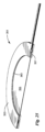
アノード集電体201は、多くの点でアノード集電体41と類似し得る。アノード集電体201とアノード集電体41との相違の1つは、アノード集電体41が第1の延長部53を備えることができるのに対して、アノード集電体201は、代わりに第1の延長部203を備えることができることであり得る。第1の延長部203は、多くの点で第1の延長部53と類似し得る。しかしながら、第1の延長部203と第1の延長部53との相違の1つは、第1の延長部203が近位部分207に凹部205を備えることができることであり得る。凹部205は、導電性リード又はワイヤの一端を受け入れ、導電性リード又はワイヤの近位部分207へのはんだ付け又は他の固定を容易にするために用いられ得る。第1の延長部203と第1の延長部53との間の別の相違は、第1の延長部53が、均一の形状で且つ出口63で終了し得る遠位部分57を備えることができるのに対して、第1の延長部203は、その遠位端213から近位方向にわずかな距離離隔された円盤状部分211を含み得る遠位部分209を備えることができ、遠位端213は開放されていても閉鎖されていてもよいことであり得る。円盤状部分211は、上方に向いた出口215を含むような形状に形成することができ、出口215は、入口219から通じている内側空間217と流体連通することができる。したがって、出口215のまわりの円盤状部分211上には、Oリング(図示せず)又は他の類似の封止装置を取り付けてもよく、そのような封止装置は、圧縮の影響を受けて、管継手又はマニホールド(いずれも図示せず)などの隣接する流体要素への流体連通に対する封止をもたらすことができる。これに代わって、ガス透過性が非常に限られているか、又はガス透過性が全くない、一定長さのL字状の管などの一定長さの管(図示せず)を、相補的な出口215に挿入するか、又は当該遠位端213が開放している場合には遠位端213上に同軸的に取り付けてもよい。
The anode
アノード集電体41と同様に、アノード集電体201は、2つの部材を共に接合することによって形成され得る。ここで図14及び15を参照すると、アノード集電体201を形成するために用いることができる下部部材221の上面図及び上部部材223の下面図がそれぞれ示されている。
Like the anode
図16(a)及び図16(b)を参照すると、カソード集電体91とは別のカソード集電体の実施形態の様々な図が示されている。別のカソード集電体は、本発明の教示に従って構築されており、全体を符号251によって表されている。
16(a) and 16(b), various views of an alternative cathode current collector embodiment to cathode
カソード集電体251は、多くの点でカソード集電体91と類似し得る。カソード集電体251とカソード集電体91との間の相違の1つは、カソード集電体91が第1の延長部103を備えることができるのに対して、カソード集電体251は代わりに第1の延長部253を備えることができることであり得る。第1の延長部253は、多くの点で第1の延長部103と類似し得る。しかしながら、第1の延長部253と第1の延長部103との間の相違の1つは、第1の延長部253が近位部分257に凹部255を備えることができることであり得る。凹部255は、導電性リード又はワイヤの一端を受け入れ、導電性リード又はワイヤの近位部分257へのはんだ付け又は他の固定を容易にするために用いられ得る。第1の延長部253と第1の延長部103との間の別の相違は、第1の延長部103が、均一の形状で且つ出口113で終了し得る遠位部分107を備えることができるのに対して、第1の延長部253は、その遠位端263から近位方向にわずかな距離離隔された円盤状部分261を含み得る遠位部分259を備えることができ、遠位端263は開放されていても閉鎖されていてもよいことである。円盤状部分261は、上方に向いた出口265を含むような形状に形成することができ、出口265は、入口269から通じている内側空間267と流体連通することができる。したがって、出口265のまわりの円盤状部分261上にはOリング(図示せず)又は他の類似の封止装置を取り付けてもよく、そのような封止装置は、圧縮の影響を受けて、管継手又はマニホールド(いずれも図示せず)などの隣接する流体要素への流体連通に対する封止をもたらすことができる。これに代わって、ガス透過性が非常に限られているか、又はガス透過性が全くない、一定長さのL字状の管などの一定長さの管(図示せず)を、相補的な出口265に挿入するか、又は当該遠位端263が開放している場合には遠位端263上に同軸的に取り付けてもよい。
The cathode
カソード集電体91と同様に、カソード集電体251は、2つの部材を共に接合することによって形成され得る。ここで図17及び図18を参照すると、カソード集電体251を形成するために用いることができる下部部材271の上面図及び上部部材273の下面図がそれぞれ示されている。
Similar to the cathode
図19~図21を参照すると、電解ガス発生装置の第2の実施形態の様々な図が示されている。電解ガス発生装置は、本発明の教示に従って構築されており、全体を符号311によって表されている。本出願の他の場所で議論されているか、又は本発明の理解に重要ではない電解ガス発生装置311の詳細は、図19~図21の1つ以上、若しくは本明細書の付随する説明から省略される場合もあるし、又は簡略化された形で、図19~図21の1つ以上に示されたり、かつ/若しくは本明細書に記載されたりする場合もある。例えば、図19~図21には、アノード集電体及びカソード集電体からガスを案内するための一定長さの管は示されておらず、電解ガス発生装置311を動作させるために用いられる導電性リード及び電流源も示されていない。
19-21, various views of a second embodiment of an electrolytic gas generator are shown. The electrolytic gas generator is constructed in accordance with the teachings of the present invention and is generally designated by the numeral 311. Details of the
電解ガス発生装置311は、水電解槽の形態であってもよく、特に、インプラント可能な水電解槽の形態であってもよい。電解ガス発生装置311は、膜電極アセンブリ(MEA)313を備え得る。
The
膜電極アセンブリ313は、電解ガス発生装置11の膜電極アセンブリ13と同一であってよく、ポリマー電解質膜323と、ポリマー電解質膜323の一方の面上のアノード電極触媒層325と、ポリマー電解質膜323の反対側の面上のカソード電極触媒層(図示せず)とを備え得る。本実施形態では、上又は下から見た場合、ポリマー電解質膜323は、略円形を有し得る。また、電解ガス発生装置311の全体形状は、上又は下から見た場合、ポリマー電解質膜323の形状に略一致し得る。しかしながら、ポリマー電解質膜323及び電解ガス発生装置311は、全体として、略円形に限定されるものではなく、略矩形又は他の適切な形状を有してもよいことが理解されるべきである。
The
電解ガス発生装置311はまた、膜電極アセンブリ313の真上に膜電極アセンブリ313と接触して配置され得るアノード支持アセンブリ331も備え得る。図22及び図23にも個別に示したアノード支持アセンブリ331は、アノード支持ガスケット333及びアノード支持体335を備え得る。アノード支持ガスケット333は、電解ガス発生装置11の支持ガスケット29と類似の構成であってよく、支持ガスケット29の形状と概ね類似する環形を有し得る。アノード支持体335は、電解ガス発生装置11のアノード支持体15と類似の構成であってよいが、アノード支持ガスケット333の下に配置される下側部分337と、アノード支持ガスケット333の上に配置される上側部分339と、支持ガスケット29の開口を通って延在する中間部分341とを含むボタン形状を有し得る。ゴム又は軟質プラスチックなどの可撓性でコンプライアントな非多孔質材料から構成されたガスケット343は、アノード支持体335の周囲を取り囲み、アノード支持体335を流体的に封止し、電気的に絶縁することができる。ガスケット343は、膜電極アセンブリ313の外径と略一致する外径を有するような寸法に形成され得る。
The
電解ガス発生装置311はまた、膜電極アセンブリ313の真下に膜電極アセンブリ313と接触して配置され得るカソード支持体345も備え得る。カソード支持体345は、電解ガス発生装置11のカソード支持体17と類似し得る。電解ガス発生装置11の支持ガスケット31と類似し得る支持ガスケット347は、カソード支持体345の周囲を取り囲み、カソード支持体345を流体的に封止し、電気的に絶縁し得る。
The
電解ガス発生装置311は、アノード集電体アセンブリ351をさらに備え得る。図24、図25、図26(a)及び図26(b)にも個別に示したアノード集電体アセンブリ351は、アノード支持体335及びガスケット343の上に直接接触して配置され得る。以下でさらに議論するように、アノード集電体アセンブリ351は、3つの異なる機能を果たすように、すなわち、(1)アノード支持体335から、アノード集電体アセンブリ351の構成要素に(例えば、はんだ付けにより)導電的に取り付けられた電気導電性リードに電流を伝導し、(2)アノード電極触媒層325で発生し、アノード支持体335を通過するガス(例えば、O2)をアノード集電体351に結合され得る一定長さの管に沿って案内し、(3)膜電極アセンブリ313のアノード側のガス圧が大きくなりすぎると、電解ガス発生装置311の電気分解機能を低下させるか、又は完全に停止させるように構築され得る。
The
本実施形態では、アノード集電体アセンブリ351は、アノード集電体353、ダイアフラム355、及びフレーム357を備え得る。ダイアフラム355は、集電体353とフレーム357との間に直接積み重ねられる。図27(a)~図27(c)にも個別に示したアノード集電体353は、開口363の周囲を囲む環状部分361を含むような形状に形成され得る。環状部分361は、ガスケット343の外径と略一致する外径を有するような寸法に形成され得る。環状部分361は、環状部分361の下面に設けられた環状溝365を含むような形状に形成され得、さらに環状溝内365内に配置された入口367を含むような形状に形成され得る。以下でさらに議論するように、入口367は、電解ガス発生装置311のアノードで発生したガス(例えば、O2)を受け入れるために用いられ得る。
In this embodiment, the anode
アノード集電体353は、さらに第1の延長部369を含むような形状に形成され得る。第1の延長部369は、一定距離にわたって環状部分361から半径方向外方に延在し得る。これにより、以下で明らかとなる目的のために、一定長さの流体案内管を第1の延長部369上に同軸的に取り付けることができる。加えて、バッテリ又は他の適切な電流源に電気的に結合され得る導電性リードを第1の延長部369に取り付けることができる。換言すると、第1の延長部369は、流体案内管を受け入れるための継手と、導電性リードのための接触面との双方として機能し得る。必要に応じて、流体案内管及び導電性リードを、第1の延長部369の異なる部分に取り付けてもよい。第1の延長部369は、その長さに沿って均一な幅を有するものとして本実施形態に示されているが、第1の延長部369は、電解ガス発生装置11の第1の延長部53のような形状に形成することもできる。
The anode
内側空間371がアノード集電体353内に設けられ、入口367から第1の延長部369の遠位端373まで連続的に延在することができ、内側空間371は、遠位端373で出口375において終了する。これにより、以下でさらに説明するように、電解ガス発生装置311のアノードで発生する酸素などのガスは、入口367を通ってアノード集電体353に進入し、内側空間371を通って移動し、出口375から出ることができる。
An
本実施形態では、アノード集電体353は、上部部材381と下部部材383との接合によって形成され得る。上部部材381と下部部材383とは、略一致する輪郭を有する(しかし、代わりに、アノード集電体353を単一の材料片から作ることも可能である)。図28にも個別に示した上部部材381は、凹部387を有する下面385を含むような形状に形成され得る。図29(a)及び図29(b)にも個別に示した下部部材383は、貫通孔391を含むような形状に形成され得る。これにより、整合された上部部材381の凹部387と下部部材383の貫通孔391とが、入口367を共に画定することができる。上部部材381の下面385は、さらに、凹部387からタブ397の遠位端395まで延在する径方向溝又は径方向凹部393を含むような形状に形成され得る。下部部材383の上面399は、貫通孔391からタブ405の遠位端403まで延在する径方向溝401を含むような形状に形成され得る。これにより、上部部材381の溝393と下部部材383の溝401とが、内側空間371を共に画定することができる。本実施形態では、上部部材381は溝393を含み、下部部材383は溝401を含むが、上部部材381及び下部部材383のうちの一方のみにおける溝によって内側空間371を形成することもできる。
In this embodiment, the anode
本実施形態では、上部部材381及び下部部材383のそれぞれを硬質の電気伝導性プレートとすることができる。上部部材381及び/又は下部部材383としての使用に適した材料の例には、チタン、ニオブ、及びジルコニウムなどの様々な導電性かつ耐食性の金属が含まれ得る。他の例には、電気伝導性ポリマー又は電気伝導性粒子を分散させたポリマーが含まれ得る。上部部材381及び下部部材383がチタン又は類似の導電性かつ耐食性の材料で形成されている場合、上部部材381及び下部部材383は、拡散接合又は他の任意の適切な技術によって接合され得る。さらに、上部部材381及び下部部材383がチタン又は類似の材料で形成される場合、凹部387、貫通孔391、溝393及び401は、エッチング(例えば、フォトエッチング、化学エッチング)又は他の任意の適切な技術によって形成され得る。好ましくは、上部部材381及び下部部材383のそれぞれは、非多孔性かつ実質的にガス不透過性である材料で作製されている。これにより、アノード集電体353を通って案内される実質的にすべてのガスは、入口367を通って進入し、内側空間371を通って移動し、出口375を通って出ることができる。
In this embodiment, each of the
上部部材381及び下部部材383の双方が電気伝導性であってもよいが、下部部材383を電気伝導性材料から作製し、上部部材381を非電気伝導性材料から作製することもできる。しかしながら、そのような場合には、導電性リードは、下部部材383に取り付けられなければならない。
Both the
ダイアフラム355は、(例えば、ガス圧を受けたときに)略平面状態から膨らんだ状態又は膨張状態に可逆的に変形することができる連続したフィルム又はシートの形態にある電気伝導性で可撓性の単一構造体とすることができる。ダイアフラム355は、その周囲がアノード集電体353の環状部分361の外周と略一致するような寸法に形成され得る。
The
本実施形態では、以下に具体的に規定されている範囲を除いて、ダイアフラム355は非多孔性である。さらに、本実施形態では、ダイアフラム355は、好ましくは弾性であるが、弾性である必要はない。一実施形態によれば、ダイアフラム355はまた、実質的にガス不透過性であってもよい。これに代わって、別の実施形態によれば、ダイアフラム355は、ガス透過性であってもよい。ダイアフラム355としての使用に適し得る材料の例には、金属(例えば、銀)又は他の電気伝導性粒子が内部に分散された非多孔質シリコーンフィルム又はシート、Cho-Seal 1215エラストマー(シリコーンバインダー中の銀メッキされた銅フィルムで作製された導電性材料、マサチューセッツ州ウォブムのParker Chomericsの製品)、2017年3月14日に発行され、参照により全体として本明細書に組み込まれる、発明者Mittelsteadtらの米国特許第9,595,727B2号に開示されている種類の、非多孔質の、電気伝導性で、液体透過性であり、実質的にガス不透過性の膜が含まれるが、これらに限定されるものではない。
In this embodiment, except to the extent specifically provided below, the
より具体的には、前述の特許(以下「‘727特許」と記載)によれば、そのような非多孔質の、電気伝導性で、液体透過性であり、実質的にガス不透過性の膜は、例えば、電気伝導性材料が内部に分散された固体ポリマー電解質を含み得る。固体ポリマー電解質としての使用に適した材料の例には、(i)金属塩を含有するポリマー組成物、(ii)電解質を含有するポリマーゲル、及び(iii)イオン交換樹脂が含まれ得る。より具体的には、固体ポリマー電解質は、例えば、カチオン交換基を-SO3 -、-SO2NH+、-PO3 2-、又は-CO2 -とすることができるが、これらに限定されないカチオン交換アイオノマー膜であってもよいし、又は例えば、アニオン交換基を-NH2 +とすることができるが、これに限定されないアニオン交換アイオノマー膜であってもよい。固体ポリマー電解質として用いるための好ましい材料は、The Chemours Company FC,LLC(ノースカロライナ州ファイエットビル)によってNAFION(商標)押出キャストPFSAポリマー膜として製造されているようなパーフルオロスルホン酸(PFSA)膜であることがある。NAFION(商標)PFSAの代わりに使用できる他の材料の例は、2011年5月24日に発行された発明者Mittelsteadtらの米国特許第7,947,405B2号に開示されており、この特許文献は参照により全体として本明細書に組み込まれる。 More specifically, according to the aforementioned patent (hereinafter referred to as the "'727 patent"), such a non-porous, electrically conductive, liquid permeable, substantially gas impermeable membrane may, for example, comprise a solid polymer electrolyte having an electrically conductive material dispersed therein. Examples of materials suitable for use as the solid polymer electrolyte may include (i) a polymer composition containing a metal salt, (ii) a polymer gel containing an electrolyte, and (iii) an ion exchange resin. More specifically, the solid polymer electrolyte may be, for example, a cation exchange ionomer membrane, the cation exchange group of which may be, but is not limited to, -SO 3 - , -SO 2 NH + , -PO 3 2- , or -CO 2 - , or an anion exchange ionomer membrane, the anion exchange group of which may be, but is not limited to, -NH 2 + , for example. A preferred material for use as the solid polymer electrolyte may be a perfluorosulfonic acid (PFSA) membrane, such as that manufactured by The Chemours Company FC, LLC (Fayetteville, NC) as NAFION™ extrusion cast PFSA polymer membrane. Examples of other materials that can be used in place of NAFION™ PFSA are disclosed in U.S. Patent No. 7,947,405 B2, issued May 24, 2011 to inventors Mittelsteadt et al., which is incorporated herein by reference in its entirety.
上記の膜の分散された電気伝導性材料としての使用に適し得る材料の例には、カーボンナノチューブ、カーボンナノファイバー、金属ナノワイヤー又はそれらの組み合わせなどの、アスペクト比が高く電気伝導性の非粒子材料が含まれ得る。膜での使用に適し得るカーボンナノチューブは、約0.20nm~約100nmの直径を有し、約0.50μm~約200μmの長さを有し、約5~約1,000,000の範囲にあるアスペクト比(すなわち、長さ/直径)を有し得る。加えて、膜での使用に適し得るカーボンナノチューブは、官能化されていなくてもよいし、又は-COOH、-PO4 -、-SO3H、-SH、-NH2、第三級アミン、第四級アミン、-CHO、-OH、-NO2、及び-PO3 2-などの、しかしこれらに限定されない1つ以上の官能基を含んでいてもよい。また、膜での使用に適し得るカーボンナノチューブには、単層カーボンナノチューブ、二層カーボンナノチューブ、多層カーボンナノチューブ、又はそれらの組み合わせが含まれ得る。 Examples of materials that may be suitable for use as the dispersed electrically conductive material in the membranes described above may include high aspect ratio, electrically conductive non-particulate materials such as carbon nanotubes, carbon nanofibers, metal nanowires, or combinations thereof. Carbon nanotubes that may be suitable for use in the membranes may have a diameter of about 0.20 nm to about 100 nm, a length of about 0.50 μm to about 200 μm, and an aspect ratio (i.e., length/diameter) ranging from about 5 to about 1,000,000. In addition, carbon nanotubes that may be suitable for use in the membranes may be unfunctionalized or may include one or more functional groups such as, but not limited to, -COOH, -PO 4 - , -SO 3 H, -SH, -NH 2 , tertiary amines, quaternary amines, -CHO, -OH, -NO 2 , and -PO 3 2- . Additionally, carbon nanotubes that may be suitable for use in the membrane may include single-walled carbon nanotubes, double-walled carbon nanotubes, multi-walled carbon nanotubes, or combinations thereof.
膜での使用に適し得るカーボンナノファイバーは、官能化されていなくてもよいし、又は-COOH、-PO4 -、-SO3H、-SH、-NH2、第三級アミン、第四級アミン、-CHO、-OH、-NO2、及び-PO3 2-などの、しかしこれらに限定されない1つ以上の官能基を含んでいてもよい。分散された非粒子状の電気伝導性材料を含むことに加えて、又はそのような材料の代わりに、膜は、カーボンブラック、金属粒子(例えば、ニオブ粒子、プラチナ粒子、チタン粒子、又はそれらの組み合わせ)、担持金属粒子、又はそれらの組み合わせなどの分散された電気伝導性の耐食性粒子を含んでいてもよい。 Carbon nanofibers that may be suitable for use in the membrane may be unfunctionalized or may include one or more functional groups such as, but not limited to, -COOH, -PO 4 - , -SO 3 H, -SH, -NH 2 , tertiary amines, quaternary amines, -CHO, -OH, -NO 2 , and -PO 3 2- . In addition to or in place of including a dispersed non-particulate electrically conductive material, the membrane may include dispersed electrically conductive corrosion resistant particles such as carbon black, metal particles (e.g., niobium particles, platinum particles, titanium particles, or combinations thereof), supported metal particles, or combinations thereof.
上述した膜は、アイオノマーが懸濁液の形態にある間に、アイオノマーに電気伝導性の耐食性材料を添加し、次いで懸濁液を乾燥させることによって調製することができる。 The membranes described above can be prepared by adding an electrically conductive, corrosion resistant material to the ionomer while the ionomer is in the form of a suspension and then drying the suspension.
ダイアフラム355は、その周囲に近接する貫通孔407を備え得る。以下でさらに説明するように、貫通孔407は、酸素などのアノードで発生したガスがダイアフラム355を上方に通過するのを可能にし、それによりガスはアノード集電体353の入口367に進入することができる。この目的のために、貫通孔407は、好ましくは、アノード集電体353の環状溝365と整合される。
The
図30にも個別に示したフレーム357は、適切なプラスチックなどの硬質の非電気伝導性材料で作製された環状構造体とすることができる。フレーム357は、好ましくは、アノード集電体353の内径及び外径と略一致する内径及び外径を有し、好ましくは、アノード集電体353の開口363の直径と略一致する開口410を有する。フレーム357の上面413上には環状溝411を形成することができ、環状溝411内には貫通孔415が配置され得る。フレーム357の環状溝411は、好ましくは、ダイアフラム355の貫通孔407と整合される。これにより、アノードで発生したガスは、貫通孔415を介してフレーム357を上方に通過することができる。次に、そのようなガスは、ダイアフラム355の貫通孔407に到達するまで、フレーム357の環状溝411の周りを移動することによって、ダイアフラム355を通過することができる。貫通孔407を移動した後、そのようなガスは、次に、入口367に到達するまで、アノード集電体353の環状溝365の周りを移動することができる(ダイアフラム355がフレーム357の開口410を完全に覆うため、ガスがフレーム357からアノード集電体353まで取ることができる唯一の経路は、開口410に対して半径方向外方に位置するダイアフラム355の貫通孔407を通過することによるものである)。
The
例えば、炭素繊維紙などであってよいスペーサ421は、フレーム357の貫通孔415の近くの(しかし貫通孔415を覆わない)位置で、フレーム357とガスケット343との間に配置されて、アノードで発生したガスが貫通孔415に到達できるようにすることができる。
A
アノード支持体335は、好ましくは、ダイアフラムが平面状態にあるときにダイアフラム355と接触するように、フレーム357の開口410を通って延在するような寸法に形成されている。ダイアフラム355が、アノード支持体335とアノード集電体353との間の唯一の電気的接続を提供するため、ダイアフラム355を用いて、電解ガス発生装置311の動作を調節することができる。より具体的には、ダイアフラム355が平面状態にあるとき、電解ガス発生装置311は、閉電気回路を形成し、電気分解のための動作(すなわち「オン」)状態にある。水が電気分解されている場合、アノードでは酸素ガスが発生し、カソードでは水素ガスが発生する。このように発生した酸素ガスは、次に、出口375を通って電解ガス発生装置311を出ることができる。酸素ガスが電解ガス発生装置311を出ることができる速度が、電解ガス発生装置311によって酸素ガスが発生する速度を上回るか、又はそのような速度とほぼ等しい場合には、アノード支持体335とダイアフラム355との間に蓄積する酸素ガスは、あるとしてもごくわずかである可能性があり、ダイアフラム355に加えられる上向きのガス圧は、ダイアフラム355に加えられる下向きの機械的圧力よりも小さくなり得る。結果として、ダイアフラム355とアノード支持体335との間の電気的接触を維持することができ、ガスの発生が継続され得る。
The
一方で、酸素ガスが電解ガス発生装置311を出ることができる速度が、電解ガス発生装置311によって酸素ガスが発生する速度を下回る場合には、酸素ガスは、アノード支持体335とダイアフラム355との間に蓄積する可能性があり、最終的には、ダイアフラム355に加えられる上向きのガス圧は、ダイアフラム355に加えられる下向きの機械的圧力よりも大きくなり得る。結果として、ダイアフラム355は、アノード集電体353の開口363を通ってアノード支持体335から離れるように屈曲又は膨張し、それにより、アノード支持体335とダイアフラム355との間の電気的接触が遮断されるか、又は減少させられ得る。結果として、電解ガス発生装置311は、この装置の水の電気分解を低減するか、又はこの装置の水の電気分解を完全に停止させることができる。その後、アノード支持体335とダイアフラムとの間に蓄積した酸素ガスの少なくとも一部は、ダイアフラム355がアノード支持体335と接触した状態に戻るのに十分なほどアノード支持体335とダイアフラム355との間のガス圧が低下するまで、出口375を通って電解ガス発生装置311から出ることができ、それにより電気分解を再開させたり、又は全能力に戻したりすることができる。
On the other hand, if the rate at which oxygen gas can leave the
理解できるように、前述のシナリオは、電解ガス発生装置311によって生成された酸素が、管によって、インプラントされた細胞及び/又は組織を保持する密閉容器へ案内される細胞移植システムの状況において行われ得る。インプラントされた細胞及び/又は組織が、細胞及び/又は組織に送達される酸素を、発生した酸素が送達される速度を超えるか、又はそのような速度に略等しい速度で消費できない場合、又は出口375の下流に流れるのに何らかの制限がある場合には、酸素が上述したように電解ガス発生装置311内に蓄積する可能性がある。電解ガス発生装置311内に蓄積する酸素の量が、所定の閾値を超える圧力を生じるのに十分である場合には、電解ガス発生装置311は、酸素の発生を停止するか、又は酸素の産出量を低下させる。これにより、電解ガス発生装置311は、自己調節式であると見なすことができる。理解できるように、そのような自己調節式電解ガス発生装置は、少なくとも装置が外部センサ又はフィードバック機構を必要としないという理由で有利である。この種類の自己調節式動作に関するさらなる情報は、2018年5月17日に公開され、参照により全体として本明細書に組み込まれる、発明者Stoneらの米国特許出願公開第US2018/0135948A1号に見られる。
As can be appreciated, the above scenario may take place in the context of a cell transplantation system in which oxygen generated by the
電解ガス発生装置311は、弾性圧縮可能部材431をさらに備え得る。弾性圧縮可能部材431は、ダイアフラム355とアノード支持体335との間のガス圧が特定の閾値ガス圧を超えたときには、ダイアフラム355がアノード支持体335との接触から離れるようにアノード支持体335から上方に変形又は膨張できるようにし、ダイアフラム355とアノード支持体335との間のガス圧が特定の閾値ガス圧未満に低下したときには、ダイアフラム355をアノード支持体335と接触した状態に戻るように平坦化させるか若しくは下方に収縮させるか、又はそのように付勢するように設計された構造体とすることができる。弾性圧縮可能部材431がダイアフラム355をアノード支持体335から離れるように屈曲できるようにし得る閾値ガス圧力と、弾性圧縮可能部材431がダイアフラム355をアノード支持体335と接触した状態に戻るように屈曲させ得る閾値ガス圧力とは、同一であってもよいし、異なっていてもよい。場合によっては、弾性圧縮可能部材431がダイアフラム355をアノード支持体335から離れるように屈曲させる閾値ガス圧力が、弾性圧縮可能部材431がダイアフラム355をアノード支持体335と接触した状態に戻るように屈曲させる閾値ガス圧力よりも有意に大きいことが有利であることがある。したがって、そのような場合には、電解ガス発生装置311の動作がいったん停止すると、ダイアフラム355とアノード支持体335との間のガス圧が有意に低下するまで、電解ガス発生装置311は再開しないであろう。これにより、電解ガス発生装置311が、その動作状態とオフ状態との間での、望ましくない繰り返しの切り替わり(stuttering back and forth)を防ぐことができる。
The
本実施形態では、弾性圧縮可能部材431は、発泡体などの電気絶縁材料のブロック又は円盤を備え得る。そのような発泡体は、独立気泡発泡体であってよいし、連続気泡発泡体であってもよい。適切な発泡体の例には、ポリウレタン発泡体、及び連続気泡シリコーンゴム発泡体などのシリコーンゴム発泡体が含まれ得るが、これらに限定されるものではない。本実施形態では、弾性圧縮可能部材431は発泡体のブロックとすることができるが、弾性圧縮可能部材431は、それに限定されるものではなく、コイルばね、皿ばね、密閉型ガスポケット、外部から参照可能なガス充填ポートを備えたガスポケット、又はこれらの組み合わせなどの、しかしこれらに限定されない任意の種類の弾性圧縮性構造体であってもよい。
In this embodiment, the elastic
電解ガス発生装置311は、封止スペーサ433をさらに備え得る。封止スペーサ433は、凹状中央部分を有した可撓性部材とすることができ、弾性圧縮可能部材431とアノード集電体353との間に配置され得る。封止スペーサ433は、アノード集電体353とハウジングとの間に必要とされ得る付加的な空間を補うために用いることができる。これは、例えば、弾性圧縮可能部材431が予想よりも厚く、ハウジング内に追加の空間を作る必要がある場合に当てはまる可能性がある。
The
電解ガス発生装置311は、カソード集電体441をさらに備え得る。図31(a)及び図31(b)に個別に示したカソード集電体441は、電解ガス発生装置11のカソード集電体91と多くの点で類似し得る。カソード集電体441とカソード集電体91との相違の1つは、カソード集電体91が、比較的幅の広い近位部分105及び比較的幅の狭い遠位部分107を有する第1の延長部103を含むことができるのに対して、カソード集電体441は、略均一な幅を有する第1の延長部443を含むことができることであり得る。カソード集電体441とカソード集電体91との間の別の相違は、カソード集電体91が第2の延長部115を有することができるのに対し、カソード集電体441は第2の延長部を省略してもよいことであり得る。カソード集電体441とカソード集電体91との間のさらに別の相違は、カソード集電体91がより大きな直径の中央貫通孔99とより小さな直径の多数の細孔100とを有することができるのに対し、カソード集電体441は、中央貫通孔445と少数の細孔447とを備えることができ、貫通孔445及び細孔447は略同じ直径を有することができることであり得る。
The
カソード集電体91に類似して、カソード集電体441は、延長部443の遠位端において出口449を有し、貫通孔445から出口449まで延在する内側空間451を有し得る。カソード集電体441は、カソード集電体91に類似して機能し得る。この目的のために、カソード集電体441は、好ましくは、カソード集電体441を通って案内される実質的にすべてのガスが入口445を通って進入し、内側空間451を通って移動し、出口449を通って出ることができるように、十分に非多孔性でガス不透過性である材料で作製されている。
Similar to the cathode
電解ガス発生装置311は、ハウジングベース451及びハウジングカバー453をさらに備えることができ、ハウジングベース451とハウジングカバー453とが、電解ガス発生装置311の他の構成要素の多くを保持するために用いられ得るハウジングを共に画定する。硬質で耐久性のある非電気伝導性材料で作製された単一構造とすることができるハウジングベース451は、下壁455、側壁457、及び開放した上部を含むような形状に形成され得る。下壁455は、液体の水などの流体がハウジングの内部に進入することができるように設計された1つ以上の開口部459を含むような形状に形成され得る。側壁457は、延長部369及び443が通過できるように設計された第1の開口部461を含むような形状に形成され得る。硬質で耐久性のある非電気伝導性材料で作製された単一構造とすることができるハウジングカバー453は、上部部分465及び下部部分467を含むような形状に形成され得る。複数の貫通孔468は、上部部分465及び下部部分467を通って延在することができる。貫通孔468は、外部(すなわち、ハウジングに対する)周囲圧力を電解ガス発生装置311の基準圧力として利用できるようにするために用いられ得る。換言すると、電解ガス発生装置311が体内にインプラントされる場合には、身体の圧力は、ダイアフラム355を押し付ける基準圧力として利用されるであろう。上部部分465は、ハウジングベース451のフットプリントに略一致するような形状に形成され、側壁457の上面の上に直接着座するように設計された下面を有し得る。下部部分467は、ハウジングベース451の内径に略一致するフットプリントを有するような形状に形成され、ハウジング内に積み重ねられた構成要素を圧縮するのを助けるために用いられ得る。これにより、ハウジングベース451及びハウジングカバー453は、電解ガス発生装置311の構成要素のためのハウジングを提供するように機能するだけでなく、エンドプレートとしても機能する。
The
電解ガス発生装置311は、水制御膜481及び482をさらに備え得る。水制御膜481及び482は、カソード集電体アセンブリ441とハウジングベース451の下壁455との間に配置され得る。本実施形態では、水制御膜481は、安定で首尾一貫した水蒸気源を促進するために生物付着を防止する生体適合性膜とすることができる。水制御膜481としての使用に適し得る材料の例は、少なくともいくつかの細孔が直径3μm以上であり、好ましい厚さ範囲が30~50μmである延伸PTFEである。水制御膜482は、蒸気輸送膜の形態であってもよい。水制御膜482としての使用に適した材料の例には、ZITEX(登録商標)多孔質ポリテトラフルオロエチレン、GORE-TEX(登録商標)延伸ポリテトラフルオロエチレン、シリコーンゴム、PTFE、及びTEFLON(登録商標)ポリテトラフルオロエチレンが含まれ得るが、これらに限定されるものではない。
The
電解ガス発生装置311は、上述した方法で用いることができる。
The
上記の本発明の実施形態は、単に例示であることが意図されており、当業者は、本発明の精神から逸脱することなく、本発明の実施形態に多くの変形及び修正をなすことができるものとする。そのようなすべての変形及び修正は、添付の特許請求の範囲で定義される本発明の範囲内にあることが意図されている。 The above-described embodiments of the present invention are intended to be merely illustrative, and it is understood that one of ordinary skill in the art may make many variations and modifications to the embodiments of the present invention without departing from the spirit of the invention. All such variations and modifications are intended to be within the scope of the present invention, as defined in the appended claims.
Claims (41)
(a)対向する第1の面及び第2の面を有するポリマー電解質膜と、
(b)前記ポリマー電解質膜の第1の面に電気的に結合されている第1の電極と、
(c)前記ポリマー電解質膜の第2の面に電気的に結合されている第2の電極と、
(d)前記第1の電極に電気的に結合されており、導電性リードを取り付ける際に使用するための第1の電気伝導性延長部を備え、前記第1の電極で発生したガスを側方方向に運ぶためのガス導管をさらに備える第1の集電体と、
(e)前記第2の電極に電気的に結合されている第2の集電体と、
(f)電流源と、
(g)前記第1の集電体を前記電流源に電気的に結合する第1の導電性リードであって、前記第1の電気伝導性延長部に固定された第1の端部を備える第1の導電性リードと、
(h)前記第2の集電体を前記電流源に電気的に結合する第2の導電性リードと、
を備える、電解ガス発生装置。 1. An electrolytic gas generator for generating at least a first gas by electrolyzing a reactant, the electrolytic gas generator comprising:
(a) a polymer electrolyte membrane having opposing first and second surfaces;
(b) a first electrode electrically coupled to a first surface of the polymer electrolyte membrane;
(c) a second electrode electrically coupled to a second side of the polymer electrolyte membrane; and
(d) a first current collector electrically coupled to the first electrode, the first current collector comprising a first electrically conductive extension for use in attaching a conductive lead, and further comprising a gas conduit for lateral transport of gas generated at the first electrode;
(e) a second current collector electrically coupled to the second electrode;
(f) a current source; and
(g) a first conductive lead electrically coupling the first current collector to the current source, the first conductive lead having a first end secured to the first electrically conductive extension;
(h) a second conductive lead electrically coupling the second current collector to the current source;
An electrolytic gas generator comprising:
(a)対向する第1の面及び第2の面を有するポリマー電解質膜と、
(b)前記ポリマー電解質膜の第1の面に電気的に結合されている第1の電極と、
(c)前記ポリマー電解質膜の第2の面に電気的に結合されている第2の電極と、
(d)第1の集電体アセンブリであって、
導電性リードを取り付ける際に使用するための第1の電気伝導性延長部を備え、前記第1の電極で発生したガスを側方方向に運ぶためのガス導管をさらに備える第1の集電体と、
非電気伝導性であるフレームと、
ダイアフラムであって、前記第1の集電体と前記フレームとの間に固定され、電気伝導性であり、前記ダイアフラムが平面でかつ前記第1の集電体が前記第1の電極に電気的に結合されている第1の状態と、前記第1の集電体が前記第1の電極から少なくとも部分的に電気的に切断されるように前記ダイアフラムが前記第1の電極から離れるよう膨張する第2の状態との間で可逆的に変形可能である、ダイアフラムと、
を備える第1の集電体アセンブリと、
(e)電気伝導性であり、前記第2の電極に電気的に結合されている第2の集電体と、
(f)電流源と、
(g)前記第1の集電体を前記電流源に電気的に結合する第1の導電性リードであって、前記第1の電気伝導性延長部に固定された第1の端部を備える第1の導電性リードと、
(h)前記第2の集電体を前記電流源に電気的に結合する、第2の導電性リードと、
を備える電解ガス発生装置。 1. An electrolytic gas generator for generating at least a first gas by electrolyzing a reactant, the electrolytic gas generator comprising:
(a) a polymer electrolyte membrane having opposing first and second surfaces;
(b) a first electrode electrically coupled to a first surface of the polymer electrolyte membrane;
(c) a second electrode electrically coupled to a second side of the polymer electrolyte membrane; and
(d) a first current collector assembly,
a first current collector having a first electrically conductive extension for use in attaching a conductive lead thereto and further comprising a gas conduit for conveying gas generated at said first electrode in a lateral direction;
a frame that is non-electrically conductive;
a diaphragm secured between the first current collector and the frame, the diaphragm being electrically conductive and reversibly deformable between a first state in which the diaphragm is planar and the first current collector is electrically coupled to the first electrode and a second state in which the diaphragm expands away from the first electrode such that the first current collector is at least partially electrically disconnected from the first electrode; and
a first current collector assembly comprising:
(e) a second current collector that is electrically conductive and electrically coupled to the second electrode; and
(f) a current source; and
(g) a first conductive lead electrically coupling the first current collector to the current source, the first conductive lead having a first end secured to the first electrically conductive extension;
(h) a second conductive lead electrically coupling the second current collector to the current source;
An electrolytic gas generator comprising:
(a)電気伝導性である本体と、
(b)前記本体から側方方向に延在し、前記本体に電気的に結合された電気伝導性の表面を備える延長部と、
を備え、
(c)前記本体と前記延長部とは、前記本体に第1の端部を有し、前記延長部に第2の端部を有するガス導管を共に画定する、
集電体。 1. A current collector for use in an electrolytic gas generator, the current collector comprising:
(a) a body that is electrically conductive;
(b) an extension extending laterally from the body and having an electrically conductive surface electrically coupled to the body;
Equipped with
(c) the body and the extension together define a gas conduit having a first end in the body and a second end in the extension;
Current collector.
Applications Claiming Priority (3)
| Application Number | Priority Date | Filing Date | Title |
|---|---|---|---|
| US201862672784P | 2018-05-17 | 2018-05-17 | |
| US62/672,784 | 2018-05-17 | ||
| PCT/US2019/032990 WO2019222704A1 (en) | 2018-05-17 | 2019-05-17 | Electrolytic gas generator with combined lead and gas port terminals |
Publications (2)
| Publication Number | Publication Date |
|---|---|
| JP2021523981A JP2021523981A (en) | 2021-09-09 |
| JP7486435B2 true JP7486435B2 (en) | 2024-05-17 |
Family
ID=68541037
Family Applications (1)
| Application Number | Title | Priority Date | Filing Date |
|---|---|---|---|
| JP2020564179A Active JP7486435B2 (en) | 2018-05-17 | 2019-05-17 | Electrolytic gas generator combining lead terminals and gas port terminals |
Country Status (6)
| Country | Link |
|---|---|
| US (1) | US11773496B2 (en) |
| EP (1) | EP3793642A4 (en) |
| JP (1) | JP7486435B2 (en) |
| CN (1) | CN112384267B (en) |
| CA (1) | CA3100192C (en) |
| WO (1) | WO2019222704A1 (en) |
Families Citing this family (1)
| Publication number | Priority date | Publication date | Assignee | Title |
|---|---|---|---|---|
| CN214572271U (en) * | 2020-09-14 | 2021-11-02 | 氢牛科技(东莞)有限公司 | Electrolytic cell press-fitting jig |
Citations (4)
| Publication number | Priority date | Publication date | Assignee | Title |
|---|---|---|---|---|
| JP2001011680A (en) | 1999-06-30 | 2001-01-16 | Shinko Pantec Co Ltd | Electrolytic cell of hydrogen/oxygen generator and electrode plate therefor |
| US20070015015A1 (en) | 2005-07-12 | 2007-01-18 | Koji Hoshino | Solid oxide fuel cell |
| WO2008044429A1 (en) | 2006-10-05 | 2008-04-17 | Murata Manufacturing Co., Ltd. | Solid electrolyte fuel battery support structure and solid electrolyte fuel battery module having same |
| US20130040223A1 (en) | 2010-06-23 | 2013-02-14 | Honda Motor Co., Ltd. | Fuel cell |
Family Cites Families (112)
| Publication number | Priority date | Publication date | Assignee | Title |
|---|---|---|---|---|
| US150995A (en) | 1874-05-19 | Improvement ifs | ||
| US3005943A (en) | 1957-04-10 | 1961-10-24 | Electric Storage Battery Co | Sealed storage cell using liquid electrolyte |
| US3282875A (en) | 1964-07-22 | 1966-11-01 | Du Pont | Fluorocarbon vinyl ether polymers |
| US3453086A (en) | 1965-10-12 | 1969-07-01 | Gen Electric | Self-regulating gas generator |
| US3373057A (en) | 1965-10-24 | 1968-03-12 | Texas Instruments Inc | Battery having an automatic circuit breaker therein |
| US3783868A (en) | 1971-05-06 | 1974-01-08 | Gulf Oil Corp | Percutaneous implant |
| US3933526A (en) | 1974-09-09 | 1976-01-20 | Motorola, Inc. | Housing for battery cell with protection for pressure and temperature |
| US4057479A (en) | 1976-02-26 | 1977-11-08 | Billings Energy Research Corporation | Solid polymer electrolyte cell construction |
| IT1118243B (en) | 1978-07-27 | 1986-02-24 | Elche Ltd | MONOPOLAR ELECTROLYSIS CELL |
| US4193860A (en) | 1978-08-30 | 1980-03-18 | The United States Of America As Represented By The United States Department Of Energy | Liquid-permeable electrode |
| US4233146A (en) | 1979-03-09 | 1980-11-11 | Allied Chemical Corporation | Cell flow distributors |
| US4214958A (en) | 1979-05-14 | 1980-07-29 | General Electric Company | Electrolysis of alkali metal halides in a three-compartment cell with a pressurized buffer compartment |
| US4212714A (en) | 1979-05-14 | 1980-07-15 | General Electric Company | Electrolysis of alkali metal halides in a three compartment cell with self-pressurized buffer compartment |
| IT1122699B (en) | 1979-08-03 | 1986-04-23 | Oronzio De Nora Impianti | RESILIENT ELECTRIC COLLECTOR AND SOLID ELECTROLYTE ELECTROCHEMISTRY INCLUDING THE SAME |
| US4470889A (en) | 1980-06-11 | 1984-09-11 | The Dow Chemical Company | Electrolytic cell having an improved ion exchange membrane and process for operating |
| US4478695A (en) | 1980-06-11 | 1984-10-23 | The Dow Chemical Company | Sulfonic acid electrolytic cell membranes and use thereof in the electrolysis of sodium chloride |
| DE3235714A1 (en) | 1982-09-27 | 1984-03-29 | Siemens AG, 1000 Berlin und 8000 München | METHOD AND DEVICE FOR ADJUSTING CONTACT SPRINGS IN A RELAY |
| DE3240184C1 (en) | 1982-10-29 | 1984-03-22 | Siemens AG, 1000 Berlin und 8000 München | Electromagnetic relay |
| DE3240215C1 (en) | 1982-10-29 | 1984-03-22 | Siemens AG, 1000 Berlin und 8000 München | Electromagnetic relay |
| ATE119569T1 (en) | 1988-02-29 | 1995-03-15 | Du Pont | DEVICE FOR DELIVERING SUBSTANCES INTO CELLS AND TISSUES IN A NON-LETHAL MANNER. |
| US5011472A (en) | 1988-09-06 | 1991-04-30 | Brown University Research Foundation | Implantable delivery system for biological factors |
| US5026615A (en) | 1990-08-06 | 1991-06-25 | Eveready Battery Company, Inc. | Electrochemical cell with disconnect switch device |
| US6773458B1 (en) | 1991-07-24 | 2004-08-10 | Baxter International Inc. | Angiogenic tissue implant systems and methods |
| US5338662A (en) | 1992-09-21 | 1994-08-16 | Bio-Preserve Medical Corporation | Organ perfusion device |
| US5362622A (en) | 1993-03-11 | 1994-11-08 | Board Of Regents, The University Of Texas System | Combined perfusion and oxygenation apparatus |
| US5356771A (en) | 1993-03-11 | 1994-10-18 | Board Of Regents, The University Of Texas System | Combined perfusion and oxygenation organ preservation apparatus |
| DE4342728A1 (en) | 1993-12-15 | 1995-06-22 | Thomae Gmbh Dr K | Aq. isotonic soln. for perfusion and preservation of explanted liver |
| US5586438A (en) | 1995-03-27 | 1996-12-24 | Organ, Inc. | Portable device for preserving organs by static storage or perfusion |
| US5788682A (en) | 1995-04-28 | 1998-08-04 | Maget; Henri J.R. | Apparatus and method for controlling oxygen concentration in the vicinity of a wound |
| US6060640A (en) | 1995-05-19 | 2000-05-09 | Baxter International Inc. | Multiple-layer, formed-in-place immunoisolation membrane structures for implantation of cells in host tissue |
| US5965433A (en) | 1996-05-29 | 1999-10-12 | Trans D.A.T.A. Service, Inc. | Portable perfusion/oxygenation module having mechanically linked dual pumps and mechanically actuated flow control for pulsatile cycling of oxygenated perfusate |
| JPH1136092A (en) * | 1997-07-18 | 1999-02-09 | Shinko Pantec Co Ltd | Electrolytic cell for hydrogen oxygen generator and its gasket |
| US5951538A (en) | 1997-08-07 | 1999-09-14 | Ceramatec, Inc. | Gas generating device for delivering beneficial agents to a body cavity |
| US6495209B1 (en) | 1998-02-20 | 2002-12-17 | Lynntech, Inc. | Process of making a composite membrane |
| US6368592B1 (en) | 1998-07-17 | 2002-04-09 | Massachusetts Institute Of Technology | Method of delivering oxygen to cells by electrolyzing water |
| US6010317A (en) * | 1998-09-01 | 2000-01-04 | Baxter International Inc. | Electrochemical cell module having an inner and an outer shell with a nested arrangement |
| US6673594B1 (en) | 1998-09-29 | 2004-01-06 | Organ Recovery Systems | Apparatus and method for maintaining and/or restoring viability of organs |
| US6977140B1 (en) | 1998-09-29 | 2005-12-20 | Organ Recovery Systems, Inc. | Method for maintaining and/or restoring viability of organs |
| US6171368B1 (en) | 1998-11-06 | 2001-01-09 | Med-E-Cell | Gas extraction from closed containers |
| US6365032B1 (en) | 1998-12-31 | 2002-04-02 | Proton Energy Systems, Inc. | Method for operating a high pressure electrochemical cell |
| US6413238B1 (en) | 1999-09-17 | 2002-07-02 | Baxter International Inc | Fluid dispenser with stabilized fluid flow |
| JP4439646B2 (en) * | 1999-12-15 | 2010-03-24 | パナソニック株式会社 | Conductive separator, polymer electrolyte fuel cell, and method for producing polymer electrolyte fuel cell |
| IL134009A (en) | 2000-01-12 | 2011-07-31 | Bo2 Technologies Ltd | Implantable device |
| US8012500B2 (en) | 2000-01-01 | 2011-09-06 | Beta-O2 Technologies Ltd. | Implantable device |
| US6492103B1 (en) | 2000-01-31 | 2002-12-10 | Organ Recovery Systems, Inc. | System for organ and tissue preservation and hypothermic blood substitution |
| US6824915B1 (en) | 2000-06-12 | 2004-11-30 | The Gillette Company | Air managing systems and methods for gas depolarized power supplies utilizing a diaphragm |
| USD453828S1 (en) | 2000-08-25 | 2002-02-19 | Organ Recovery Systems, Inc. | Organ perfusion apparatus |
| DE10045683C2 (en) | 2000-09-15 | 2002-09-05 | Draegerwerk Ag | Electrochemical oxygen concentrator |
| US6475716B1 (en) | 2001-03-06 | 2002-11-05 | Biobank Co., Ltd. | Method for preserving mammalian organs |
| WO2002084768A1 (en) | 2001-04-10 | 2002-10-24 | California Institute Of Technology | Actuatable and reversible pressure generation based on fuel cell operation |
| US6677150B2 (en) | 2001-09-14 | 2004-01-13 | Organ Transport Systems, Inc. | Organ preservation apparatus and methods |
| US6852441B2 (en) | 2001-12-17 | 2005-02-08 | Giner Electrochemical Systems, Llc | Reinforcement of multiple electrochemical cell frames for high-pressure operation |
| US7201991B2 (en) | 2002-03-04 | 2007-04-10 | Mitsubishi Materials Corporation | Solid oxide fuel cell and separator |
| US20030207161A1 (en) * | 2002-05-01 | 2003-11-06 | Ali Rusta-Sallehy | Hydrogen production and water recovery system for a fuel cell |
| US6811905B1 (en) | 2002-05-21 | 2004-11-02 | Giner Electro Chemical Systems, Llc | Direct organic fuel cell having a vapor transport member |
| US7572622B2 (en) | 2002-08-14 | 2009-08-11 | Transmedic, Inc. | Heart preservation chamber |
| US7504201B2 (en) | 2004-04-05 | 2009-03-17 | Organ Recovery Systems | Method for perfusing an organ and for isolating cells from the organ |
| US7316857B1 (en) | 2004-06-28 | 2008-01-08 | Swanson Steven T | Miniature electrochemical gas generator and power source |
| US7947405B2 (en) | 2004-09-29 | 2011-05-24 | Giner Electrochemical Systems, Llc | Solid polymer electrolyte composite membrane comprising porous ceramic support |
| NZ591524A (en) | 2004-10-07 | 2012-09-28 | Transmedics Inc | Method for timing pulsatile flow of normothermic perfusate to the heart in ex-vivo organ care |
| SE0402471D0 (en) * | 2004-10-12 | 2004-10-12 | Anders Lundblad | Electrochemical device |
| WO2006052133A2 (en) | 2004-11-12 | 2006-05-18 | Doorzand Airdrive B.V. | Composition for cold preservation and perfusion of organs |
| US20060182722A1 (en) | 2005-02-11 | 2006-08-17 | Hering Bernhard J | Methods and materials for isolating isogenic islet cells |
| NL1028848C2 (en) | 2005-04-22 | 2006-10-24 | Doorzand Airdrive B V | Device for transporting an organ. |
| BRPI0609094B8 (en) | 2005-05-10 | 2021-06-22 | Ogenix Corp | device to deliver oxygen and remove exudates for treating a skin wound |
| US9078428B2 (en) | 2005-06-28 | 2015-07-14 | Transmedics, Inc. | Systems, methods, compositions and solutions for perfusing an organ |
| US20090209031A1 (en) | 2006-01-26 | 2009-08-20 | Tyco Healthcare Group Lp | Medical device package |
| US20080226750A1 (en) | 2006-04-20 | 2008-09-18 | Fred Hutchinson Cancer Research Center | Methods, Compositions and Articles of Manufacture for Treating Shock and Other Adverse Conditions |
| TW200806392A (en) | 2006-06-20 | 2008-02-01 | Lynntech Inc | Microcartridge hydrogen generator |
| CA2671094C (en) | 2006-11-28 | 2015-02-17 | Beta O2 Technologies Ltd. | Oxygen supply for cell transplant and vascularization |
| US20100196439A1 (en) | 2006-12-22 | 2010-08-05 | Medtronic, Inc. | Angiogenesis Mechanism and Method, and Implantable Device |
| AU2008214423A1 (en) | 2007-02-02 | 2008-08-14 | Converge Biotech Inc. | Therapeutic hybrid implantable devices |
| CN101981744A (en) | 2007-04-03 | 2011-02-23 | 新空能量公司 | Electrochemical system, apparatus, and method to generate renewable hydrogen and sequester carbon dioxide |
| US8083821B2 (en) | 2007-04-13 | 2011-12-27 | Giner, Inc. | System for modifying the atmosphere within an enclosed space and incubator system including the same |
| WO2009023409A1 (en) * | 2007-07-24 | 2009-02-19 | Rovcal, Inc. | On-demand hydrogen gas generation device with pressure-regulating switch |
| WO2009031154A2 (en) | 2007-09-07 | 2009-03-12 | Beta O2 Technologies Ltd. | Air gap for supporting cells |
| US8287506B2 (en) | 2007-10-26 | 2012-10-16 | Electrochemical Oxygen Concepts, Inc. | Apparatus and methods for controlling tissue oxygenation for wound healing and promoting tissue viability |
| US8100672B2 (en) | 2008-01-11 | 2012-01-24 | California Institute Of Technology | Autonomous electrochemical actuation of microfluidic circuits |
| US8420380B2 (en) | 2008-01-31 | 2013-04-16 | Transmedics, Inc. | Systems and methods for ex vivo lung care |
| US8338170B2 (en) | 2008-04-21 | 2012-12-25 | Viacyte, Inc. | Methods for purifying endoderm and pancreatic endoderm cells derived from human embryonic stem cells |
| WO2010049996A1 (en) | 2008-10-28 | 2010-05-06 | 株式会社レゾナンスクラブ | Method of preserving mammalian organ |
| US20100108534A1 (en) * | 2008-10-30 | 2010-05-06 | Mti Micro Fuel Cells, Inc. | Electrochemical actuator |
| CA2743641C (en) | 2008-11-14 | 2024-03-26 | Viacyte, Inc. | Encapsulation of pancreatic cells derived from human pluripotent stem cells |
| US8043271B2 (en) * | 2008-11-26 | 2011-10-25 | Beta 02 Technologies Ltd. | Apparatus for transportation of oxygen to implanted cells |
| US8349151B2 (en) | 2008-12-23 | 2013-01-08 | Giner Electrochemical Systems, Llc | Universal cell frame for high-pressure water electrolyzer and electrolyzer including the same |
| WO2010091074A2 (en) | 2009-02-03 | 2010-08-12 | Purdue Research Foundation | Method and apparatus for improving local hypoxicity for enhanced therapy |
| US8702915B2 (en) * | 2009-03-28 | 2014-04-22 | M & R Consulting Services, Inc. | Electrochemical gas generator and cell assembly |
| US10091985B2 (en) | 2009-06-18 | 2018-10-09 | Giner, Inc. | Perfusing an organ with an in situ generated gas |
| US9357764B2 (en) | 2009-06-18 | 2016-06-07 | Giner, Inc. | System for fluid perfusion of biological matter comprising tissue |
| US8784389B2 (en) | 2009-08-31 | 2014-07-22 | Beta-O2 Technologies Ltd. | Oxygen supply for implantable medical device |
| EP2480069A1 (en) | 2009-09-25 | 2012-08-01 | Board of Regents, The University of Texas System | Fluidics based pulsatile perfusion preservation device and method |
| EP2555810B1 (en) | 2010-04-08 | 2018-08-22 | Healionics Corporation | Implantable medical devices having microporous surface layers and method for reducing foreign body response to the same |
| JP5804535B2 (en) | 2010-06-18 | 2015-11-04 | マイエフシー アクチエボラグMyfc Ab | Electrochemical actuation valve |
| GB201015265D0 (en) | 2010-09-13 | 2010-10-27 | Inotec Amd Ltd | Oxygen concentrator and method |
| US9595727B2 (en) | 2010-11-16 | 2017-03-14 | Giner, Inc. | Electrochemical device comprising an electrically-conductive, selectively-permeable membrane |
| JP2012167331A (en) | 2011-02-15 | 2012-09-06 | Honda Motor Co Ltd | Method for operating differential pressure water electrolysis apparatus |
| US9433557B2 (en) | 2011-02-21 | 2016-09-06 | Viacyte, Inc. | Loading system for an encapsulation device |
| US20150004522A1 (en) * | 2011-12-22 | 2015-01-01 | Aleksandr S. Lipilin | Modified planar cell (MPC) and electrochemical device battery (stack) based on MPC, manufacturing method for planar cell and battery, and planar cell embodiments |
| JP6234485B2 (en) | 2013-03-07 | 2017-11-22 | ヴィアサイト インコーポレイテッド | 3D large capacity cell encapsulation device assembly |
| AU2014326794B2 (en) | 2013-09-24 | 2019-03-21 | Giner, Inc. | System for gas treatment of a cell implant |
| US11020345B2 (en) | 2016-03-14 | 2021-06-01 | The Regents of the University of California The Board of Trustees of the Leland Stanford Junior University Stanford | Nanostraw devices and methods of fabricating and using the same |
| US20190125937A1 (en) | 2016-04-04 | 2019-05-02 | Beta-O2 Technologies Ltd. | Implantable Device for Implantation of Cells Having Anti-Inflammatory and Vascularization Capabilities and Methods of Making Thereof |
| US20190119462A1 (en) | 2016-06-14 | 2019-04-25 | The Regents Of The University Of California | Porous Polymer Scaffolds, and Methods of Making and Using the Same |
| CN116919648A (en) | 2016-11-03 | 2023-10-24 | 代表亚利桑那大学的亚利桑那董事会 | System of stacked tissue encapsulation devices with or without oxygen delivery |
| CN110121312A (en) | 2016-11-03 | 2019-08-13 | 代表亚利桑那大学的亚利桑那董事会 | With or without the system of the containment device with oxygen sensor of external source oxygen conveying |
| CN110139605A (en) | 2016-11-03 | 2019-08-16 | 代表亚利桑那大学的亚利桑那董事会 | For improving the method, system and implantable device of blood glucose-control |
| US11746318B2 (en) | 2016-11-03 | 2023-09-05 | Arizona Board Of Regents On Behalf Of The University Of Arizona | Methods and systems for real-time assessment of cells in encapsulation devices pre-and post-transplantation |
| BR112019009712A2 (en) | 2016-11-15 | 2019-08-13 | Giner Life Sciences Inc | percutaneous gas diffusion device suitable for use with a subcutaneous implant |
| BR112019009761A2 (en) | 2016-11-15 | 2019-08-13 | Giner Life Sciences Inc | self-regulating electrolytic gas generator and implant system comprising the same |
| JP7199632B2 (en) | 2017-05-04 | 2023-01-06 | ガイナー,インク. | Robust Implantable Gas Delivery Device and Methods, Systems and Devices Containing The Same |
| US20200263196A1 (en) | 2017-09-27 | 2020-08-20 | Sigilon Therapeutics, Inc. | Methods, compositions, and implantable elements comprising active cells |
| WO2019089943A1 (en) | 2017-11-06 | 2019-05-09 | Theranova, Llc | Methods and devices for delivering pancreatic islet function to a body |
-
2019
- 2019-05-17 JP JP2020564179A patent/JP7486435B2/en active Active
- 2019-05-17 CN CN201980045927.8A patent/CN112384267B/en active Active
- 2019-05-17 US US16/415,977 patent/US11773496B2/en active Active
- 2019-05-17 WO PCT/US2019/032990 patent/WO2019222704A1/en active Application Filing
- 2019-05-17 EP EP19803611.3A patent/EP3793642A4/en active Pending
- 2019-05-17 CA CA3100192A patent/CA3100192C/en active Active
Patent Citations (4)
| Publication number | Priority date | Publication date | Assignee | Title |
|---|---|---|---|---|
| JP2001011680A (en) | 1999-06-30 | 2001-01-16 | Shinko Pantec Co Ltd | Electrolytic cell of hydrogen/oxygen generator and electrode plate therefor |
| US20070015015A1 (en) | 2005-07-12 | 2007-01-18 | Koji Hoshino | Solid oxide fuel cell |
| WO2008044429A1 (en) | 2006-10-05 | 2008-04-17 | Murata Manufacturing Co., Ltd. | Solid electrolyte fuel battery support structure and solid electrolyte fuel battery module having same |
| US20130040223A1 (en) | 2010-06-23 | 2013-02-14 | Honda Motor Co., Ltd. | Fuel cell |
Also Published As
| Publication number | Publication date |
|---|---|
| JP2021523981A (en) | 2021-09-09 |
| CN112384267B (en) | 2022-08-09 |
| WO2019222704A1 (en) | 2019-11-21 |
| US20190368056A1 (en) | 2019-12-05 |
| CN112384267A (en) | 2021-02-19 |
| EP3793642A4 (en) | 2022-03-16 |
| EP3793642A1 (en) | 2021-03-24 |
| US11773496B2 (en) | 2023-10-03 |
| CA3100192C (en) | 2023-03-14 |
| CA3100192A1 (en) | 2019-11-21 |
Similar Documents
| Publication | Publication Date | Title |
|---|---|---|
| US20200348113A1 (en) | Self-regulating electrolytic gas generator and implant system comprising the same | |
| JP5932798B2 (en) | Oxygen concentrator and method | |
| US10106899B2 (en) | Oxygen generation apparatus and method | |
| Kerzenmacher et al. | Energy harvesting by implantable abiotically catalyzed glucose fuel cells | |
| AU762290B2 (en) | Electrochemical cell module for use in liquid dispensing devices | |
| WO2009014785A4 (en) | Oxygen generation for battlefield applications | |
| JP7486435B2 (en) | Electrolytic gas generator combining lead terminals and gas port terminals | |
| JPWO2008143020A1 (en) | Polymer electrolyte fuel cell | |
| WO2022064816A1 (en) | Compression device | |
| KR101946046B1 (en) | Electrolyzed Hydrogen water generating Device | |
| JPH0888013A (en) | Thin film electrolyte for normal temperature fuel cell and normal temperature fuel cell using it |
Legal Events
| Date | Code | Title | Description |
|---|---|---|---|
| A621 | Written request for application examination |
Free format text: JAPANESE INTERMEDIATE CODE: A621 Effective date: 20220513 |
|
| A131 | Notification of reasons for refusal |
Free format text: JAPANESE INTERMEDIATE CODE: A131 Effective date: 20230207 |
|
| A601 | Written request for extension of time |
Free format text: JAPANESE INTERMEDIATE CODE: A601 Effective date: 20230425 |
|
| A601 | Written request for extension of time |
Free format text: JAPANESE INTERMEDIATE CODE: A601 Effective date: 20230706 |
|
| A521 | Request for written amendment filed |
Free format text: JAPANESE INTERMEDIATE CODE: A523 Effective date: 20230807 |
|
| A131 | Notification of reasons for refusal |
Free format text: JAPANESE INTERMEDIATE CODE: A131 Effective date: 20231017 |
|
| A521 | Request for written amendment filed |
Free format text: JAPANESE INTERMEDIATE CODE: A523 Effective date: 20240109 |
|
| A711 | Notification of change in applicant |
Free format text: JAPANESE INTERMEDIATE CODE: A711 Effective date: 20240125 |
|
| A521 | Request for written amendment filed |
Free format text: JAPANESE INTERMEDIATE CODE: A523 Effective date: 20240328 |
|
| TRDD | Decision of grant or rejection written | ||
| A01 | Written decision to grant a patent or to grant a registration (utility model) |
Free format text: JAPANESE INTERMEDIATE CODE: A01 Effective date: 20240409 |
|
| A61 | First payment of annual fees (during grant procedure) |
Free format text: JAPANESE INTERMEDIATE CODE: A61 Effective date: 20240507 |
|
| R150 | Certificate of patent or registration of utility model |
Ref document number: 7486435 Country of ref document: JP Free format text: JAPANESE INTERMEDIATE CODE: R150 |