JP7484397B2 - Storage location management system - Google Patents
Storage location management system Download PDFInfo
- Publication number
- JP7484397B2 JP7484397B2 JP2020081813A JP2020081813A JP7484397B2 JP 7484397 B2 JP7484397 B2 JP 7484397B2 JP 2020081813 A JP2020081813 A JP 2020081813A JP 2020081813 A JP2020081813 A JP 2020081813A JP 7484397 B2 JP7484397 B2 JP 7484397B2
- Authority
- JP
- Japan
- Prior art keywords
- luggage
- information
- storage
- storage area
- detection unit
- Prior art date
- Legal status (The legal status is an assumption and is not a legal conclusion. Google has not performed a legal analysis and makes no representation as to the accuracy of the status listed.)
- Active
Links
- 238000001514 detection method Methods 0.000 claims description 75
- 238000010586 diagram Methods 0.000 description 10
- 239000003550 marker Substances 0.000 description 8
- 238000007689 inspection Methods 0.000 description 5
- 239000000284 extract Substances 0.000 description 2
- 238000012986 modification Methods 0.000 description 2
- 230000004048 modification Effects 0.000 description 2
- 230000003190 augmentative effect Effects 0.000 description 1
- 238000004040 coloring Methods 0.000 description 1
- 230000000694 effects Effects 0.000 description 1
- 239000000463 material Substances 0.000 description 1
Images


Landscapes
- Warehouses Or Storage Devices (AREA)
Description
本発明は、保管エリアにおける荷物の保管位置を管理する保管位置管理システムに関する。 The present invention relates to a storage location management system that manages the storage locations of luggage in a storage area.
保管エリアにおける荷物の保管位置を管理する無人搬送車システムが知られている。特許文献1に開示された無人搬送車システムでは、無人搬送車による荷物の受け渡し位置を検出し、検出した受け渡し位置に基づいて、荷物の在庫位置に関する在庫位置データを更新する。 An automated guided vehicle system that manages the storage location of luggage in a storage area is known. In the automated guided vehicle system disclosed in Patent Document 1, the location where luggage is handed over by the automated guided vehicle is detected, and inventory location data relating to the inventory location of the luggage is updated based on the detected delivery location.
しかしながら、上述した従来の無人搬送車システムでは、荷物の保管位置を正確に管理できない場合があるという課題が生じる。 However, the conventional automated guided vehicle system described above has the problem that it may not be possible to accurately manage the storage location of luggage.
本発明は、上述した課題を解決しようとするものであり、その目的は、保管エリアにおける荷物の所在を正確に管理することができる保管位置管理システムを提供することである。 The present invention aims to solve the above-mentioned problems, and its purpose is to provide a storage location management system that can accurately manage the location of luggage in a storage area.
上記目的を達成するために、本発明の一態様に係る保管位置管理システムは、保管エリアにおいて搬送体に載置された荷物の保管位置を管理する保管位置管理システムであって、前記搬送体に載置された前記荷物の前記搬送体に対する位置を検出する第1の検出部と、前記搬送体の前記保管エリアに対する位置を検出する第2の検出部と、前記第1の検出部及び前記第2の検出部の各々の検出結果に基づいて、前記荷物の前記保管エリアに対する位置である保管位置を算出し、算出した前記荷物の保管位置を示す保管位置情報を、前記荷物を識別するための荷物情報と対応付けて記憶部に格納するコントローラと、を備える。 In order to achieve the above object, a storage location management system according to one aspect of the present invention is a storage location management system that manages the storage location of luggage placed on a carrier in a storage area, and includes a first detection unit that detects the position of the luggage placed on the carrier relative to the carrier, a second detection unit that detects the position of the carrier relative to the storage area, and a controller that calculates a storage location, which is the position of the luggage relative to the storage area, based on the detection results of each of the first detection unit and the second detection unit, and stores the calculated storage location information indicating the storage location of the luggage in a memory unit in association with luggage information for identifying the luggage.
本態様によれば、コントローラは、搬送体の保管エリアに対する位置だけでなく、搬送体に載置された荷物の当該搬送体に対する位置をも考慮して、荷物の保管エリアに対する保管位置を算出する。これにより、荷物を搬送体における任意の場所に載置した場合であっても、保管エリアにおける個々の荷物の所在を具体的な位置で管理することができるとともに、荷物の所在を探す際に、荷物の具体的な位置を正確に端末装置等に表示することができる。 According to this aspect, the controller calculates the storage position of the luggage in the storage area, taking into consideration not only the position of the carrier in the storage area, but also the position of the luggage placed on the carrier in relation to the carrier. This makes it possible to manage the location of each luggage in the storage area by its specific location, even if the luggage is placed anywhere on the carrier, and also makes it possible to accurately display the specific location of the luggage on a terminal device, etc., when searching for the location of the luggage.
例えば、本発明の一態様に係る保管位置管理システムにおいて、前記荷物は、容器と、前記容器に収納された複数の品物と、を含み、前記コントローラは、前記荷物毎に前記複数の品物の各々を識別するための品物情報を取得し、前記保管位置情報を、取得した前記品物情報と対応付けて前記記憶部に格納するように構成してもよい。 For example, in a storage location management system according to one aspect of the present invention, the luggage may include a container and a plurality of items stored in the container, and the controller may be configured to acquire item information for identifying each of the plurality of items for each luggage, and to store the storage location information in the memory unit in association with the acquired item information.
本態様によれば、保管エリアにおける荷物の所在とともに、当該荷物の容器に収納された複数の品物を正確に管理することにより、荷物の所在を容易に探すことができる。 According to this aspect, the location of the luggage in the storage area as well as the multiple items stored in the luggage container are accurately managed, making it easy to find the location of the luggage.
例えば、本発明の一態様に係る保管位置管理システムにおいて、前記第2の検出部は、前記搬送体の前記保管エリアに対する向きを検出し、前記コントローラは、検出された前記搬送体の前記保管エリアに対する向きをも考慮して、前記荷物の保管位置を算出するように構成してもよい。 For example, in a storage location management system according to one aspect of the present invention, the second detection unit may be configured to detect the orientation of the transport body relative to the storage area, and the controller may be configured to calculate the storage location of the luggage by taking into account the detected orientation of the transport body relative to the storage area.
本態様によれば、コントローラは、搬送体の保管エリアに対する向きをも考慮することにより、荷物の保管エリアに対する保管位置をより正確に算出することができる。 According to this aspect, the controller can more accurately calculate the storage position of the luggage relative to the storage area by also taking into account the orientation of the carrier relative to the storage area.
例えば、本発明の一態様に係る保管位置管理システムにおいて、前記コントローラは、前記第1の検出部の検出結果に基づいて、前記搬送体に載置された前記荷物の検品を行うように構成してもよい。 For example, in a storage location management system according to one aspect of the present invention, the controller may be configured to inspect the luggage placed on the carrier based on the detection result of the first detection unit.
本態様によれば、第1の検出部の検出結果を利用することにより、搬送体に載置された荷物の検品を短時間で効率良く行うことができる。 According to this aspect, by utilizing the detection results of the first detection unit, inspection of luggage placed on the conveyance can be performed efficiently in a short time.
本発明の一態様に係る保管位置管理システムによれば、保管エリアにおける荷物の所在を正確に管理することができる。 The storage location management system according to one aspect of the present invention allows accurate management of the location of luggage in a storage area.
以下、本発明の実施の形態について、図面を用いて詳細に説明する。なお、以下で説明する実施の形態は、いずれも包括的又は具体的な例を示すものである。以下の実施の形態で示される数値、形状、材料、構成要素、構成要素の配置位置及び接続形態、ステップ、ステップの順序等は、一例であり、本発明を限定する主旨ではない。また、以下の実施の形態における構成要素のうち、独立請求項に記載されていない構成要素については、任意の構成要素として説明される。 The following describes in detail the embodiments of the present invention with reference to the drawings. Note that the embodiments described below are all comprehensive or specific examples. The numerical values, shapes, materials, components, component placement and connection forms, steps, and order of steps shown in the following embodiments are merely examples and are not intended to limit the present invention. Furthermore, among the components in the following embodiments, components that are not described in an independent claim are described as optional components.
(実施の形態)
[1.保管位置管理システムの概要]
まず、図1及び図2を参照しながら、実施の形態に係る保管位置管理システム2の概要について説明する。図1は、実施の形態に係る保管位置管理システム2の適用例を示す側面図である。図2は、実施の形態に係る保管位置管理システム2の適用例を示す上面図である。なお、図1及び図2において、保管エリア4の幅方向をX軸方向、保管エリア4の奥行き方向をY軸方向、保管エリア4の上下方向をZ軸方向とする。
(Embodiment)
[1. Overview of the storage location management system]
First, an overview of a storage
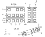
図1に示す保管位置管理システム2は、保管エリア4においてカートラック6(搬送体の一例)に載置された複数の荷物8の各々の保管位置を管理するためのシステムである。保管エリア4は、例えばコンビニエンスストア、アパレル店又は百貨店等の各種店舗における、複数の荷物8を保管するためのバックヤード(倉庫)である。
The storage
図2に示すように、保管エリア4の所定箇所には、カートラック6に載置された荷物8の当該カートラック6に対する位置を検出するための第1の検出部10が配置されている。第1の検出部10は、例えばカートラック6及び当該カートラック6に載置された複数の荷物8を側方から(カートラック6の長手方向に対して略垂直な方向から)撮影する3Dカメラである。
As shown in FIG. 2, a
図1に示すように、保管エリア4の天井面4aには、カートラック6の保管エリア4に対する位置及び向きを検出するための第2の検出部12が配置されている。第2の検出部12は、例えば保管エリア4を上方から撮影する3Dカメラである。
As shown in FIG. 1, a
図1に示すように、保管エリア4の床面4bには、複数のカートラック6が移動可能に配置されている。カートラック6は、複数の荷物8を搬送するためのものであり、例えば作業者13によって押し歩きされることにより、保管エリア4の床面4b上を移動する。カートラック6は、フレーム14と、フレーム14の下端部に設けられた複数の車輪16と、フレーム14に上下方向(Z軸方向)に複数段(例えば4段)設けられた載置棚18とを有している。各載置棚18は、長尺状の板状に形成されている。各載置棚18の上面には、保管すべき荷物8が当該載置棚18の長手方向に並んで複数載置される。
As shown in FIG. 1, a number of
図1に示すように、フレーム14の上端部には、識別コードラベル20が貼り付けられている。識別コードラベル20には、例えばQRコード(登録商標)等の識別コードが印刷されている。識別コードラベル20の識別コードには、当該カートラック6を識別するためのカートラック情報等が含まれている。識別コードラベル20は、第1の検出部10により撮影される。
As shown in FIG. 1, an
また、図2に示すように、カートラック6の最上段の載置棚18の上面には、2つの識別コードラベル22a,22bが貼り付けられている。識別コードラベル22a,22bはそれぞれ、カートラック6の長手方向における両端部に配置されている。また、識別コードラベル22a,22bの各々は、カートラック6の短手方向における中央部に配置されている。識別コードラベル22a,22bの各々には、例えば互いに異なる種類のQRコード(登録商標)等の識別コードが印刷されている。識別コードラベル22a,22bは、第2の検出部12により撮影される。なお、本実施の形態では、カートラック6の最上段の載置棚18に2つの識別コードラベル22a,22bを貼り付けたが、これに限定されず、例えばQRコード(登録商標)のように向きを識別可能な識別コードラベルであれば、1つの識別コードラベルのみをカートラック6の最上段の載置棚18に貼り付けてもよい。
2, two
荷物8は、例えば混載バケットであり、容器と、容器に収納された複数種類の品物とを有する。荷物8の形状は、例えば直方体である。図1に示すように、荷物8の側面には、識別コードラベル24が貼り付けられている。識別コードラベル24には、例えばQRコード(登録商標)等の識別コードが印刷されている。識別コードラベル24の識別コードには、当該荷物8を識別するための荷物情報、及び、当該荷物8の容器に収納された複数種類の品物の各々を識別するための品物情報等が含まれている。識別コードラベル24は、第1の検出部10により撮影される。
The
[2.保管位置管理システムの機能構成]
次に、図3及び図4を参照しながら、実施の形態に係る保管位置管理システム2の機能構成について説明する。図3は、実施の形態に係る保管位置管理システム2の機能構成を示すブロック図である。図4は、実施の形態に係る保管位置管理システム2の記憶部28に記憶された管理テーブル32の一例を示す図である。
[2. Functional configuration of storage location management system]
Next, the functional configuration of the storage
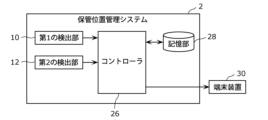
図3に示すように、保管位置管理システム2は、機能構成として、第1の検出部10と、第2の検出部12と、コントローラ26と、記憶部28とを備えている。
As shown in FIG. 3, the storage
第1の検出部10は、例えばカートラック6及び当該カートラック6に載置された複数の荷物8を側方から撮影することにより、荷物8のカートラック6に対する位置を検出する。第1の検出部10は、コントローラ26と無線通信可能であり、検出結果をコントローラ26に送信する。
The
具体的には、第1の検出部10は、撮影したカートラック6及び当該カートラック6に載置された複数の荷物8の画像から、識別コードラベル20,24の各画像を抽出する。これにより、第1の検出部10は、例えば識別コードラベル20を基準位置とする、複数の荷物8の各々に貼り付けられた識別コードラベル24の相対位置を特定する。その結果、第1の検出部10は、荷物8のカートラック6に対する位置として、カートラック6を基準とするXZ平面座標系における荷物8の2次元位置を示すXZ平面座標を検出する。
Specifically, the
第1の検出部10は、識別コードラベル20の識別コードを読み取ることにより、カートラック情報を取得する。また、第1の検出部10は、荷物8毎に識別コードラベル24の識別コードを読み取ることにより、荷物情報及び品物情報を取得する。第1の検出部10は、取得したカートラック情報、並びに、荷物8毎に取得した荷物情報及び品物情報をコントローラ26に送信する。
The
第2の検出部12は、例えば保管エリア4に存在するカートラック6を上方から撮影することにより、カートラック6の保管エリア4に対する位置及び向きを検出する。第2の検出部12は、コントローラ26と無線通信可能であり、検出結果をコントローラ26に送信する。
The
具体的には、第2の検出部12は、撮影したカートラック6の画像から、識別コードラベル22a,22bの各画像を抽出する。これにより、第2の検出部12は、例えば識別コードラベル22aと識別コードラベル22bとの中間位置を、水平面内(XY平面内)におけるカートラック6の保管エリア4に対するXY水平位置として特定する。また、第2の検出部12は、例えば第2の検出部12から識別コードラベル22aと識別コードラベル22bとの中間位置までの距離に基づいて、上下方向(Z軸方向)におけるカートラック6の保管エリア4に対する高さ位置を特定する。第2の検出部12は、特定したカートラック6の保管エリア4に対するXY水平位置及び高さ位置に基づいて、カートラック6の保管エリア4に対する位置として、保管エリア4を基準とする空間座標系におけるカートラック6の3次元位置を示す空間座標を検出する。
Specifically, the
また、第2の検出部12は、例えば保管エリア4と識別コードラベル22a,22bとの位置関係に基づいて、カートラック6の保管エリア4に対する向きを検出する。具体的には、第2の検出部12は、例えば、識別コードラベル22aと識別コードラベル22bとを結ぶ直線(図2において一点鎖線で示す)の、保管エリア4における所定の基準線(例えば、保管エリア4を基準とする空間座標系におけるX軸)に対する角度θ(図2参照)を算出する。第2の検出部16は、算出した角度θに基づいて、カートラック6の保管エリア4に対する向きを検出する。
The
コントローラ26は、第1の検出部10及び第2の検出部12からの検出結果に基づいて、荷物8の保管エリア4に対する位置である保管位置を算出する。すなわち、コントローラ26は、カートラック6の保管エリア4に対する位置及び向きと、荷物8のカートラック6に対する位置とに基づいて、荷物8の保管エリア4に対する保管位置として、保管エリア4を基準とする空間座標系における荷物8の3次元位置を示す空間座標を算出する。具体的には、コントローラ26は、カートラック6の保管エリア4に対するXY水平位置と、荷物8のカートラック6の基準位置に対するXY水平位置とに基づいて、保管エリア4を基準とするXY平面座標系における荷物8の2次元位置を示すXY平面座標を算出する。さらに、コントローラ26は、カートラック6の保管エリア4に対する高さ位置と、荷物8のカートラック6の基準位置に対する高さ位置とに基づいて、保管エリア4を基準とする空間座標系における荷物8の高さ位置を示す高さ座標を算出する。コントローラ26は、算出したXY平面座標と高さ座標とを組み合わせることにより、荷物8の空間座標を算出する。
The
なお、荷物8の空間座標は、例えば荷物8の中心の空間座標である。また、カートラック6の保管エリア4に対する向きは、例えば上記の角度θ=90°又は270°の場合は「縦向き」、角度θ=0°又は180°の場合は「横向き」となる。ここで、「縦向き」とは、上面視でカートラック6の長手方向(図2参照)が保管エリア4の奥行き方向(Y軸方向)に対して略平行となる向きを意味する。一方、「横向き」とは、上面視でカートラック6の長手方向が保管エリア4の奥行き方向に対して略垂直となる向きを意味する。また、カートラック6の保管エリア4に対する向きは、上述した「縦向き」及び「横向き」以外の任意の向き(例えば、角度θ=45°又は70°等)であってもよい。
The spatial coordinates of the
さらに、コントローラ26は、荷物8のカートラック6に対する位置として、荷物8がカートラック6の何段目の何連目に載置されているか(後述する段-連情報)を算出する。なお、図1に示すように、荷物8のカートラック6に対する上下方向の位置は、カートラック6の最下段から最上段にかけて、1段目、2段目、3段目、4段目とする。荷物8のカートラック6に対する横方向の位置は、カートラック6の前端部側から後端部側にかけて、1連目、2連目、3連目、4連目とする。ここで、必ずしも、カートラック6の全ての段及び全ての連に荷物8が載置されている必要は無く、例えば図1に示す3段目の2連目のように、荷物8が載置されていなくてもよい。なお、荷物8のサイズが一定でない場合には、荷物8のカートラック6に対する横方向の位置を、カートラック6の前端部側から後端部側にかけて、1連目、2連目、・・・と、載置した荷物8の個数分だけ管理してもよい。
Furthermore, the
さらに、コントローラ26は、荷物8のカートラック6に対する位置として、カートラック6を基準とする空間座標系における荷物8の3次元位置を示す空間座標(後述する相対保管位置情報)を算出する。
Furthermore, the
また、コントローラ26は、a)算出した荷物8のカートラック6に対する位置を示す相対保管位置情報、b)算出した荷物8の保管エリア4に対する保管位置を示す保管位置情報、及び、c)算出した荷物8のカートラック6に対する位置を示す段-連情報を、カートラック情報、荷物情報及び品物情報と対応付けて、記憶部28の管理テーブル32(後述する)に格納する。さらに、コントローラ26は、端末装置30と無線通信可能であり、記憶部28の管理テーブル32に格納されたカートラック情報、荷物情報、相対保管位置情報、段-連情報、品物情報及び保管位置情報を端末装置30に送信する。なお、端末装置30は、作業者13により操作される、例えばスマートフォン又はタブレット端末等のモバイル端末である。
The
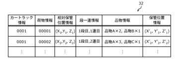
記憶部28は、カートラック情報と、荷物情報と、相対保管位置情報と、段-連情報と、品物情報と、保管位置情報との対応関係を示す管理テーブル32を記憶する。管理テーブル32は、例えば図4に示すようなデータテーブルである。図4に示す例では、管理テーブル32の1行目には、a)カートラック情報「0001」、b)荷物情報「00001」、c)相対保管位置情報「(X1、Y1、Z1)」、d)段-連情報「1段目、1連目」、e)品物情報「品物A×2、品物B×1」、及び、f)保管位置情報「(X1’、Y1’、Z1’)」が格納されている。また、管理テーブル32の2行目には、a)カートラック情報「0001」、b)荷物情報「00002」、c)相対保管位置情報「(X2、Y2、Z2)」、d)段-連情報「1段目、2連目」、e)品物情報「品物A×3、品物C×1」、及び、f)保管位置情報「(X2’、Y2’、Z2’)」が格納されている。
The
なお、図4に示す管理テーブル32において、カートラック情報は、例えばカートラック6毎に割り当てられた、カートラック6を識別するためのID番号である。荷物情報は、例えば荷物8毎に割り当てられた、荷物8を識別するためのID番号である。相対保管位置情報は、例えばカートラック6を基準とする空間座標系における荷物8の3次元位置を示す空間座標である。段-連情報は、荷物8がカートラック6の何段目の何連目に載置されているかを示す情報である。品物情報は、荷物8の容器に収納されている品物の種類及び個数を示す情報である。例えば、「品物A×2、品物B×1」は、品物Aが2個、品物Bが1個収納された荷物8であることを示し、「品物A×3、品物C×1」は、品物Aが3個、品物Cが1個収納された荷物8であることを示す。保管位置情報は、例えば保管エリア4を基準とする空間座標系における荷物8の3次元位置を示す空間座標である。
In the management table 32 shown in FIG. 4, the cart truck information is, for example, an ID number assigned to each
[3.保管位置管理システムの動作]
次に、図5~図8を参照しながら、実施の形態に係る保管位置管理システム2の動作について説明する。図5は、実施の形態に係る保管位置管理システム2の動作の流れを示すフローチャートである。図6は、図5のフローチャートのステップS102,S106,S111を説明するための図である。図7は、図5のフローチャートのステップS109を説明するための図である。図8は、実施の形態に係る端末装置30における表示の一例を示す図である。
[3. Operation of the Storage Location Management System]
Next, the operation of the storage
図5に示すように、まず、卸の作業者(図示せず)は、店舗に出荷する複数の荷物8をカートラック6に載置する(S101)。卸の作業者は、出荷検品時に、カートラック6を識別するためのカートラック情報と、当該カートラック6に載置した各荷物8を識別するための荷物情報と、注文番号と、各荷物8に収納された品物の種類及び個数を示す品物情報とを対応付けて、ASN(Advanced Shipping Notice:事前出荷通知)データに格納する。このASNデータは、卸の端末装置(図示せず)から、ネットワークを介して店舗のコントローラ26に送信される。これにより、コントローラ26は、卸の端末装置から受信したASNデータを記憶部28の所定の記憶領域に格納するとともに、図6の(a)に示すように、当該ASNデータに含まれるカートラック情報、荷物情報及び品物情報を、記憶部28の管理テーブル32に格納する(S102)。
As shown in FIG. 5, first, a wholesale worker (not shown) places
カートラック6に載置された複数の荷物8は、卸から出荷され(S103)、店舗にて受け入れられる(S104)。店舗において、第1の検出部10は、カートラック6及び当該カートラック6に載置された複数の荷物8を側方から撮影し、検出結果をコントローラ26に送信する。コントローラ26は、第1の検出部10からの検出結果を受信し(S105)、受信した検出結果に基づいて、荷物8のカートラック6に対する位置を算出する。コントローラ26は、図6の(b)に示すように、算出した荷物8のカートラック6に対する位置を示す相対保管位置情報及び段-連情報を、カートラック情報、荷物情報及び品物情報と対応付けて記憶部28の管理テーブル32に格納する(S106)。また、コントローラ26は、第1の検出部10からの検出結果に含まれる、カートラック情報、並びに、荷物8毎の荷物情報及び品物情報を取得する。なお、上述したステップS102に代えて、ステップS106のタイミングで、カートラック情報、荷物情報、相対保管位置情報、段-連情報及び品物情報を記憶部28の管理テーブル32に格納してもよい。
The
さらに、コントローラ26は、第1の検出部10からの検出結果と、卸の端末装置からのASNデータとを比較することにより、一括検品を行う(S107)。具体的には、コントローラ26は、第1の検出部10により検出されたカートラック情報、荷物情報及び品物情報と、記憶部28に格納されたASNデータに含まれるカートラック情報、荷物情報及び品物情報とのマッチングの有無に基づいて、一括検品を行う。なお、このような構成に代えて、コントローラ26は、例えばカートラック6に載置された複数の荷物8の各側面に印刷された文字(品名又は品番等)を画像認識することにより、画像認識した文字とASNデータとのマッチングの有無に基づいて、一括検品を行ってもよい。
Furthermore, the
その後、店舗の作業者13は、店舗の保管エリア4においてカートラック6を所定の場所に移動させる(S108)。作業者13がカートラック6の移動を完了したタイミングで、第2の検出部12は、検出結果をコントローラ26に送信する。コントローラ26は、第2の検出部12からの検出結果を受信し(S109)、第1の検出部10及び第2の検出部12の各々からの検出結果に基づいて、荷物8の保管エリア4に対する保管位置を算出する(S110)。
Then, the
なお、図7に示すように、第2の検出部12からの検出結果には、カートラック6毎の情報として、保管エリア4に対するカートラック6の位置を示すカートラック位置情報と、保管エリア4に対するカートラック6の向きを示すカートラック向き情報とが含まれる。図7に示す例では、データテーブルの1行目には、a)カートラック情報「0001」、b)カートラック位置情報「(x1,y1,z1)」、及び、c)カートラック向き情報「0°」が格納されている。また、データテーブルの2行目には、a)カートラック情報「0002」、b)カートラック位置情報「(x2,y2,z2)」、及び、c)カートラック向き情報「45°」が格納されている。
As shown in Fig. 7, the detection result from the
コントローラ26は、図6の(c)に示すように、算出した荷物8の保管エリア4に対する保管位置を示す保管位置情報を、カートラック情報、荷物情報、相対保管位置情報、段-連情報及び品物情報と対応付けて、記憶部28の管理テーブル32に格納する(S111)。
As shown in FIG. 6(c), the
例えば作業者13が、カートラック6に載置された複数の荷物8を保管エリア4に保管した後に、保管エリア4において当該複数の荷物8のうち特定の荷物8の所在を探す場合には、端末装置30にインストールされた所定のアプリケーションを起動し、所在を探したい特定の荷物8の荷物情報(ID番号)を指定する操作を行う。これにより、コントローラ26は、記憶部28の管理テーブル32に格納された、作業者13により指定された荷物情報と、当該荷物情報に対応するカートラック情報、相対保管位置情報、段-連情報、品物情報及び保管位置情報とを端末装置30に送信する。
For example, when the
端末装置30は、コントローラ26からのカートラック情報、荷物情報、相対保管位置情報、段-連情報、品物情報及び保管位置情報に基づいて、保管エリア4における特定の荷物8の所在を表示するためのAR(Augmented Reality:拡張現実)表示を行う(S112)。
The
図6に示す例では、端末装置30の表示部34には、前景画像36と、マーカー画像38とが表示されている。前景画像36は、端末装置30に搭載されたカメラ(図示せず)により撮影された、端末装置30の前景である保管エリア4(カートラック6の最上段に載置された複数の荷物8a,8b,8c,8d等を含む)を示す画像である。マーカー画像38は、相対保管位置情報、段-連情報及び保管位置情報に基づいて生成された、前景画像36の一部を強調するための画像である。具体的には、端末装置30のカメラによる撮影時に、空間の点群データ及びARマーカー等を同時に認識するとともに、現実空間の空間座標情報を把握した上で、相対保管位置情報、段-連情報及び保管位置情報を用いてマーカー画像38を空間座標内に生成し、色付けするなどしてマーカー画像38を強調表示する。マーカー画像38は、例えばカートラック6の最上段に載置された複数の荷物8a,8b,8c,8dのうち、作業者13により指定された荷物情報に対応する(すなわち、作業者13が所在を探している)、4段目の1連目に載置された荷物8aに重畳されている。これにより、作業者13は、探している荷物8の所在を容易に且つ正確に知ることができる。
In the example shown in FIG. 6, a
なお、本実施の形態では、マーカー画像38を荷物8aに重畳させたが、このような構成に代えて、マーカー画像38を荷物8aに貼り付けられた商品ラベル(図示せず)に重畳させてもよい。商品ラベルは、例えば荷物8の品名又は品番等が記載されたラベルである。
In this embodiment, the
また、本実施の形態では、カートラック情報、荷物情報、相対保管位置情報、段-連情報、品物情報及び保管位置情報を端末装置30に送信したが、これに限定されず、例えば、(a)保管位置情報により示される荷物8の空間座標、(b)カートラック6の保管エリア4に対する位置、及び、特定の荷物8のカートラック6に対する位置を示す情報、(c)カートラック6における荷物8の場所(段、連)を示す情報のうちいずれかを端末装置30に送信してもよい。端末装置30がAR表示等を行うモバイル端末である場合には、上記(a)又は(b)を端末装置30に送信するのが好ましい。端末装置30が無線ハンディターミナルである場合には、上記(c)を端末装置30に送信するのが好ましい。
In addition, in this embodiment, the car track information, luggage information, relative storage position information, row-link information, item information, and storage position information are transmitted to the
[4.効果]
本実施の形態では、上述したように、コントローラ26は、カートラック6の保管エリア4に対する位置だけでなく、カートラック6に載置された荷物8の当該カートラック6に対する位置をも考慮して、荷物8の保管エリア4に対する保管位置を算出する。
[4. Effects]
In this embodiment, as described above, the
これにより、荷物8をカートラック6における任意の場所(段、連)に載置した場合であっても、保管エリア4における荷物8の所在を具体的な位置で管理することができるとともに、作業者13が荷物8の所在を探す際に、保管エリア4における荷物8の具体的な位置を正確に端末装置30等に表示することができる。
As a result, even if the
(変形例等)
以上、本発明の保管位置管理システムについて、実施の形態に基づいて説明したが、本発明は、上記実施の形態に限定されるものではない。上記実施の形態に対して当業者が思い付く変形を施して得られる形態、及び、上記実施の形態における構成要素を任意に組み合わせて実現される別の形態も本発明に含まれる。
(Modifications, etc.)
Although the storage location management system of the present invention has been described above based on the embodiment, the present invention is not limited to the above embodiment. The present invention also includes modifications that a person skilled in the art can conceive of to the above embodiment, and other forms realized by arbitrarily combining the components in the above embodiment.
上記実施の形態では、搬送体がカートラック6である場合について説明したが、これに限定されず、例えばカゴ台車又はパレット等であってもよい。
In the above embodiment, the transport body is a
また、上記実施の形態では、荷物8が混載バケットである場合について説明したが、これに限定されず、例えば同種類の品物が容器に収納された単品バケット、又は、複数の品物が収納された段ボール箱等であってもよい。
In the above embodiment, the case where the
また、上記実施の形態では、第1の検出部10が3Dカメラである場合について説明したが、これに限定されず、例えばレーザスキャンセンサ等であってもよい。
In addition, in the above embodiment, the
また、上記実施の形態では、第2の検出部12が3Dカメラである場合について説明したが、これに限定されず、例えばカートラック6に取り付けられたGPS(Grobal Positioning System)等であってもよい。あるいは、第2の検出部12は、例えば作業者13がカートラック6を移動させる際の動きを撮影するカメラ、又は、保管エリア4の床面4bに設置された荷重センサ等であってもよい。また、上記実施の形態では、コントローラ26は、荷物8の空間座標を算出したが、例えばリアルタイムに荷物8の保管位置を検出するリアルタイムロケーションシステム(RTLS)を利用して、荷物8の空間座標を算出してもよい。なお、RTLSには、GPS、超音波、BLE(Bluetooth(登録商標) Low Energy)、可視光通信、UWB(Ultra Wide Band)及び画像認識等の様々な種類が存在するが、種類は問わない。あるいは、コントローラ26は、RTLSと上述した3Dカメラとを組み合わせることにより、荷物8の空間座標だけでなく、荷物8の形状及びサイズを算出してもよい。また、RTLSのIDタグを荷物8に複数取り付けることにより、コントローラ26は、荷物8の保管エリア4に対する向きを算出してもよい。あるいは、RTLSのIDタグをカートラック6に取り付けることにより、荷物8を載置したカートラック6の場所を、荷物8の保管位置として管理してもよい。
In the above embodiment, the
また、上記実施の形態では、第1の検出部10は、識別コードラベル20を基準位置とする、複数の荷物8の各々に貼り付けられた識別コードラベル24の相対位置を特定することにより、荷物8のカートラック6に対する位置を検出したが、これに限定されず、例えば複数の荷物8の各々の外形状を認識することにより、荷物8のカートラック6に対する位置を検出してもよい。
In the above embodiment, the
また、上記実施の形態では、保管エリア4が各種店舗におけるバックヤードである場合について説明したが、これに限定されず、例えば工場の倉庫等であってもよい。
In the above embodiment, the
また、上記実施の形態では、端末装置30は、保管エリア4における荷物8の所在を表示するためのAR表示を行うようにしたが、これに限定されず、例えば作業者13の頭に装着されるゴーグルが、保管エリア4における荷物8の所在を表示するためのMR(Mixed Reality:複合現実)表示を行うようにしてもよい。
In addition, in the above embodiment, the
また、上記実施の形態では、コントローラ26により算出される荷物8の空間座標を相対座標としたが、これに限定されず、例えばGPS等の絶対座標としてもよい。
In addition, in the above embodiment, the spatial coordinates of the
本発明は、例えば保管エリアにおける荷物の保管位置を管理するための保管位置管理システム等に適用することができる。 The present invention can be applied, for example, to a storage location management system for managing the storage location of luggage in a storage area.
2 保管位置管理システム
4 保管エリア
4a 天井面
4b 床面
6 カートラック
8,8a,8b,8c,8d 荷物
10 第1の検出部
12 第2の検出部
13 作業者
14 フレーム
16 車輪
18 載置棚
20,22a,22b,24 識別コードラベル
26 コントローラ
28 記憶部
30 端末装置
32 管理テーブル
34 表示部
36 前景画像
38 マーカー画像
Claims (4)
前記搬送体に載置された前記荷物の前記搬送体に対する位置を検出する第1の検出部と、
前記搬送体の前記保管エリアに対する位置を検出する第2の検出部と、
前記第1の検出部及び前記第2の検出部の各々の検出結果に基づいて、前記荷物の前記保管エリアに対する位置である保管位置を算出し、算出した前記荷物の保管位置を示す保管位置情報を、前記荷物を識別するための荷物情報と対応付けて記憶部に格納するコントローラと、を備える
保管位置管理システム。 A storage location management system that manages storage locations of luggage placed on a carrier that is a movable rack having a loading shelf on which a plurality of luggage can be loaded in a storage area, comprising:
a first detection unit that detects a position of the luggage placed on the conveyance body relative to the conveyance body;
a second detection unit that detects a position of the transport object relative to the storage area;
a controller that calculates a storage location, which is the location of the luggage relative to the storage area, based on detection results of the first detection unit and the second detection unit, and stores storage location information indicating the calculated storage location of the luggage in a memory unit in association with luggage information for identifying the luggage.
容器と、
前記容器に収納された複数の品物と、を含み、
前記コントローラは、前記荷物毎に前記複数の品物の各々を識別するための品物情報を取得し、前記保管位置情報を、取得した前記品物情報と対応付けて前記記憶部に格納する
請求項1に記載の保管位置管理システム。 The baggage is:
A container;
a plurality of items contained in the container;
The storage location management system according to claim 1 , wherein the controller acquires item information for identifying each of the plurality of items for each piece of luggage, and stores the storage location information in the memory unit in association with the acquired item information.
前記コントローラは、検出された前記搬送体の前記保管エリアに対する向きをも考慮して、前記荷物の保管位置を算出する
請求項1又は2に記載の保管位置管理システム。 The second detection unit detects an orientation of the transport object with respect to the storage area,
The storage position management system according to claim 1 or 2, wherein the controller calculates the storage position of the luggage by taking into consideration an orientation of the detected transport object relative to the storage area.
請求項1~3のいずれか1項に記載の保管位置管理システム。 The storage location management system according to any one of claims 1 to 3, wherein the controller inspects the luggage placed on the transport body based on the detection result of the first detection unit.
Priority Applications (1)
| Application Number | Priority Date | Filing Date | Title |
|---|---|---|---|
| JP2020081813A JP7484397B2 (en) | 2020-05-07 | 2020-05-07 | Storage location management system |
Applications Claiming Priority (1)
| Application Number | Priority Date | Filing Date | Title |
|---|---|---|---|
| JP2020081813A JP7484397B2 (en) | 2020-05-07 | 2020-05-07 | Storage location management system |
Publications (2)
| Publication Number | Publication Date |
|---|---|
| JP2021176789A JP2021176789A (en) | 2021-11-11 |
| JP7484397B2 true JP7484397B2 (en) | 2024-05-16 |
Family
ID=78409242
Family Applications (1)
| Application Number | Title | Priority Date | Filing Date |
|---|---|---|---|
| JP2020081813A Active JP7484397B2 (en) | 2020-05-07 | 2020-05-07 | Storage location management system |
Country Status (1)
| Country | Link |
|---|---|
| JP (1) | JP7484397B2 (en) |
Citations (6)
| Publication number | Priority date | Publication date | Assignee | Title |
|---|---|---|---|---|
| JP2000122720A (en) | 1998-10-19 | 2000-04-28 | Ishikawajima Harima Heavy Ind Co Ltd | Inspection and transport method for unmanned guided vehicles |
| JP2002207079A (en) | 2001-01-09 | 2002-07-26 | Denso Corp | Article detection system |
| JP2005289605A (en) | 2004-04-02 | 2005-10-20 | Meidensha Corp | Article managing system |
| JP2007050952A (en) | 2005-08-17 | 2007-03-01 | Nec Engineering Ltd | Baggage storage position detection device |
| US20070046464A1 (en) | 2005-08-25 | 2007-03-01 | Onderko John C | RFID system and method for tracking individual articles |
| JP2011111323A (en) | 2009-11-30 | 2011-06-09 | Mitsubishi Electric Plant Engineering Corp | Storage management system for refrigeration warehouse |
-
2020
- 2020-05-07 JP JP2020081813A patent/JP7484397B2/en active Active
Patent Citations (7)
| Publication number | Priority date | Publication date | Assignee | Title |
|---|---|---|---|---|
| JP2000122720A (en) | 1998-10-19 | 2000-04-28 | Ishikawajima Harima Heavy Ind Co Ltd | Inspection and transport method for unmanned guided vehicles |
| JP2002207079A (en) | 2001-01-09 | 2002-07-26 | Denso Corp | Article detection system |
| JP2005289605A (en) | 2004-04-02 | 2005-10-20 | Meidensha Corp | Article managing system |
| JP2007050952A (en) | 2005-08-17 | 2007-03-01 | Nec Engineering Ltd | Baggage storage position detection device |
| US20070046464A1 (en) | 2005-08-25 | 2007-03-01 | Onderko John C | RFID system and method for tracking individual articles |
| JP2009505923A (en) | 2005-08-25 | 2009-02-12 | キンバリー クラーク ワールドワイド インコーポレイテッド | Radio frequency identification system for tracking individual articles |
| JP2011111323A (en) | 2009-11-30 | 2011-06-09 | Mitsubishi Electric Plant Engineering Corp | Storage management system for refrigeration warehouse |
Also Published As
| Publication number | Publication date |
|---|---|
| JP2021176789A (en) | 2021-11-11 |
Similar Documents
| Publication | Publication Date | Title |
|---|---|---|
| US12181301B2 (en) | Hands-free augmented reality system for picking and/or sorting assets | |
| US20210383320A1 (en) | Object location in a delivery vehicle | |
| KR101043489B1 (en) | Display of picklists for radio frequency identification tags and fulfillers on picking containers | |
| US10268892B1 (en) | System and methods for volume dimensioning for supply chains and shelf sets | |
| US8561897B2 (en) | Load tracking utilizing load identifying indicia and spatial discrimination | |
| CN108027915B (en) | Robot navigation with semantic mapping | |
| CN101836242B (en) | Systems and methods for enhanced RFID transportation device sensor networks | |
| US20120191272A1 (en) | Inferential load tracking | |
| CN111417495A (en) | Autonomous robotic vehicles for checking and counting inventory in warehouses | |
| KR20170094103A (en) | Cargo inventory survey method using autonomous mobile robot and 3D laser scanner | |
| KR20180054585A (en) | Worker identification and performance tracking | |
| US20170286907A1 (en) | Product movement and distribution systems and methods | |
| US12475708B1 (en) | Image-based detection of planogram product spaces | |
| US20170200115A1 (en) | Systems and methods of consolidating product orders | |
| JP7360768B2 (en) | Placement support system, placement support method, and program | |
| CN106446746B (en) | Space object-seeking navigation system based on RFID | |
| EP4298603A1 (en) | Information processing apparatus, information processing system, information processing method, and recording medium | |
| KR101530423B1 (en) | Method and System of pallet packing, and method for providing the data of pallet packing | |
| JP7484397B2 (en) | Storage location management system | |
| US20250182317A1 (en) | System and method for localizing articles in an intralogistics environment | |
| JP7425450B2 (en) | Erroneous delivery prevention system, management computer, worker terminal device, and program | |
| JP2005035751A (en) | Goods storage system | |
| TWI667622B (en) | System for using automatic vehicle to confirm item positions and method thereof | |
| KR20240003604A (en) | System of safety smart logistics in distance measuring and RTLS with 3D image by using AI | |
| JP2021176792A (en) | Storage location management system |
Legal Events
| Date | Code | Title | Description |
|---|---|---|---|
| A621 | Written request for application examination |
Free format text: JAPANESE INTERMEDIATE CODE: A621 Effective date: 20230221 |
|
| A977 | Report on retrieval |
Free format text: JAPANESE INTERMEDIATE CODE: A971007 Effective date: 20231124 |
|
| A131 | Notification of reasons for refusal |
Free format text: JAPANESE INTERMEDIATE CODE: A131 Effective date: 20231205 |
|
| A521 | Request for written amendment filed |
Free format text: JAPANESE INTERMEDIATE CODE: A523 Effective date: 20240130 |
|
| TRDD | Decision of grant or rejection written | ||
| A01 | Written decision to grant a patent or to grant a registration (utility model) |
Free format text: JAPANESE INTERMEDIATE CODE: A01 Effective date: 20240402 |
|
| A61 | First payment of annual fees (during grant procedure) |
Free format text: JAPANESE INTERMEDIATE CODE: A61 Effective date: 20240415 |
|
| R150 | Certificate of patent or registration of utility model |
Ref document number: 7484397 Country of ref document: JP Free format text: JAPANESE INTERMEDIATE CODE: R150 |