JP7480979B2 - Imaging Module and Visualization Probe - Google Patents
Imaging Module and Visualization Probe Download PDFInfo
- Publication number
- JP7480979B2 JP7480979B2 JP2019167407A JP2019167407A JP7480979B2 JP 7480979 B2 JP7480979 B2 JP 7480979B2 JP 2019167407 A JP2019167407 A JP 2019167407A JP 2019167407 A JP2019167407 A JP 2019167407A JP 7480979 B2 JP7480979 B2 JP 7480979B2
- Authority
- JP
- Japan
- Prior art keywords
- sensor
- face
- holding member
- imaging
- optical axis
- Prior art date
- Legal status (The legal status is an assumption and is not a legal conclusion. Google has not performed a legal analysis and makes no representation as to the accuracy of the status listed.)
- Active
Links
- 238000003384 imaging method Methods 0.000 title claims description 161
- 239000000523 sample Substances 0.000 title claims description 40
- 238000012800 visualization Methods 0.000 title claims description 40
- 230000003287 optical effect Effects 0.000 claims description 75
- 239000000853 adhesive Substances 0.000 claims description 52
- 230000001070 adhesive effect Effects 0.000 claims description 52
- 239000000758 substrate Substances 0.000 claims description 20
- 230000000149 penetrating effect Effects 0.000 claims description 8
- 230000005540 biological transmission Effects 0.000 description 8
- 239000006059 cover glass Substances 0.000 description 4
- 230000000007 visual effect Effects 0.000 description 4
- 230000008595 infiltration Effects 0.000 description 3
- 238000001764 infiltration Methods 0.000 description 3
- 230000000052 comparative effect Effects 0.000 description 2
- 238000005286 illumination Methods 0.000 description 2
- 239000000463 material Substances 0.000 description 2
- 239000011347 resin Substances 0.000 description 2
- 229920005989 resin Polymers 0.000 description 2
- 238000007789 sealing Methods 0.000 description 2
- 238000007792 addition Methods 0.000 description 1
- 238000005452 bending Methods 0.000 description 1
- 230000015556 catabolic process Effects 0.000 description 1
- 230000000295 complement effect Effects 0.000 description 1
- 238000006731 degradation reaction Methods 0.000 description 1
- 238000012217 deletion Methods 0.000 description 1
- 230000037430 deletion Effects 0.000 description 1
- 239000000428 dust Substances 0.000 description 1
- 239000000835 fiber Substances 0.000 description 1
- 239000011521 glass Substances 0.000 description 1
- 238000003780 insertion Methods 0.000 description 1
- 230000037431 insertion Effects 0.000 description 1
- 239000002184 metal Substances 0.000 description 1
- 229910044991 metal oxide Inorganic materials 0.000 description 1
- 150000004706 metal oxides Chemical class 0.000 description 1
- 238000012986 modification Methods 0.000 description 1
- 230000004048 modification Effects 0.000 description 1
- 239000013307 optical fiber Substances 0.000 description 1
- 238000004806 packaging method and process Methods 0.000 description 1
- 238000012545 processing Methods 0.000 description 1
- 239000004065 semiconductor Substances 0.000 description 1
- 125000006850 spacer group Chemical group 0.000 description 1
- 238000006467 substitution reaction Methods 0.000 description 1
Images


Classifications
-
- A—HUMAN NECESSITIES
- A61—MEDICAL OR VETERINARY SCIENCE; HYGIENE
- A61B—DIAGNOSIS; SURGERY; IDENTIFICATION
- A61B1/00—Instruments for performing medical examinations of the interior of cavities or tubes of the body by visual or photographical inspection, e.g. endoscopes; Illuminating arrangements therefor
- A61B1/04—Instruments for performing medical examinations of the interior of cavities or tubes of the body by visual or photographical inspection, e.g. endoscopes; Illuminating arrangements therefor combined with photographic or television appliances
- A61B1/05—Instruments for performing medical examinations of the interior of cavities or tubes of the body by visual or photographical inspection, e.g. endoscopes; Illuminating arrangements therefor combined with photographic or television appliances characterised by the image sensor, e.g. camera, being in the distal end portion
- A61B1/051—Details of CCD assembly
-
- A—HUMAN NECESSITIES
- A61—MEDICAL OR VETERINARY SCIENCE; HYGIENE
- A61B—DIAGNOSIS; SURGERY; IDENTIFICATION
- A61B1/00—Instruments for performing medical examinations of the interior of cavities or tubes of the body by visual or photographical inspection, e.g. endoscopes; Illuminating arrangements therefor
- A61B1/04—Instruments for performing medical examinations of the interior of cavities or tubes of the body by visual or photographical inspection, e.g. endoscopes; Illuminating arrangements therefor combined with photographic or television appliances
-
- A—HUMAN NECESSITIES
- A61—MEDICAL OR VETERINARY SCIENCE; HYGIENE
- A61B—DIAGNOSIS; SURGERY; IDENTIFICATION
- A61B1/00—Instruments for performing medical examinations of the interior of cavities or tubes of the body by visual or photographical inspection, e.g. endoscopes; Illuminating arrangements therefor
- A61B1/00064—Constructional details of the endoscope body
- A61B1/00071—Insertion part of the endoscope body
- A61B1/0008—Insertion part of the endoscope body characterised by distal tip features
- A61B1/00096—Optical elements
-
- A—HUMAN NECESSITIES
- A61—MEDICAL OR VETERINARY SCIENCE; HYGIENE
- A61B—DIAGNOSIS; SURGERY; IDENTIFICATION
- A61B1/00—Instruments for performing medical examinations of the interior of cavities or tubes of the body by visual or photographical inspection, e.g. endoscopes; Illuminating arrangements therefor
- A61B1/00064—Constructional details of the endoscope body
- A61B1/0011—Manufacturing of endoscope parts
-
- A—HUMAN NECESSITIES
- A61—MEDICAL OR VETERINARY SCIENCE; HYGIENE
- A61B—DIAGNOSIS; SURGERY; IDENTIFICATION
- A61B1/00—Instruments for performing medical examinations of the interior of cavities or tubes of the body by visual or photographical inspection, e.g. endoscopes; Illuminating arrangements therefor
- A61B1/00163—Optical arrangements
-
- G—PHYSICS
- G02—OPTICS
- G02B—OPTICAL ELEMENTS, SYSTEMS OR APPARATUS
- G02B23/00—Telescopes, e.g. binoculars; Periscopes; Instruments for viewing the inside of hollow bodies; Viewfinders; Optical aiming or sighting devices
- G02B23/24—Instruments or systems for viewing the inside of hollow bodies, e.g. fibrescopes
- G02B23/2476—Non-optical details, e.g. housings, mountings, supports
- G02B23/2484—Arrangements in relation to a camera or imaging device
-
- G—PHYSICS
- G02—OPTICS
- G02B—OPTICAL ELEMENTS, SYSTEMS OR APPARATUS
- G02B23/00—Telescopes, e.g. binoculars; Periscopes; Instruments for viewing the inside of hollow bodies; Viewfinders; Optical aiming or sighting devices
- G02B23/24—Instruments or systems for viewing the inside of hollow bodies, e.g. fibrescopes
- G02B23/26—Instruments or systems for viewing the inside of hollow bodies, e.g. fibrescopes using light guides
Landscapes
- Health & Medical Sciences (AREA)
- Life Sciences & Earth Sciences (AREA)
- Physics & Mathematics (AREA)
- Surgery (AREA)
- Optics & Photonics (AREA)
- Engineering & Computer Science (AREA)
- Heart & Thoracic Surgery (AREA)
- Medical Informatics (AREA)
- Biophysics (AREA)
- Nuclear Medicine, Radiotherapy & Molecular Imaging (AREA)
- Pathology (AREA)
- Radiology & Medical Imaging (AREA)
- Veterinary Medicine (AREA)
- Biomedical Technology (AREA)
- Public Health (AREA)
- General Health & Medical Sciences (AREA)
- Molecular Biology (AREA)
- Animal Behavior & Ethology (AREA)
- General Physics & Mathematics (AREA)
- Astronomy & Astrophysics (AREA)
- Multimedia (AREA)
- Manufacturing & Machinery (AREA)
- Endoscopes (AREA)
- Instruments For Viewing The Inside Of Hollow Bodies (AREA)
- Studio Devices (AREA)
- Transforming Light Signals Into Electric Signals (AREA)
Description
本開示は、撮像モジュールおよび可視化プローブに関する。 This disclosure relates to an imaging module and a visualization probe.
例えば可視化プローブの先端に収容される撮像モジュールは、細径化とともに小型化が求められる。例えば特許文献1に開示されるウエハレベルパッケージング(WLP)型の撮像モジュールは、複数の撮像素子を含む撮像ウエハとガラスウエハとが接着された接合ウエハが切断されて個片化されることで作製される。このため、撮像素子の受光部が形成された受光面の全面がカバーガラスで覆われる。
For example, imaging modules housed at the tip of visualization probes are required to be smaller in size as well as thinner in diameter. For example, a wafer-level packaging (WLP) type imaging module disclosed in
このカバーガラスで覆われた撮像素子に、光学系を収容した鏡筒を一体化させて、撮像モジュールを作る場合、双方の部材を連結するためのセンサ保持部材を使用することが有効となる。以下、撮像素子を「撮像センサ」と称する場合がある。この場合においても、撮像モジュールは、小型化の要請により、センサ保持部材の光軸方向の投影面内に撮像センサが収まることが望ましい。即ち、撮像モジュールは、センサ保持部材と撮像センサとが、ほぼ同一の外形サイズであることが小径化に適する。 When creating an imaging module by integrating a lens barrel housing an optical system with the imaging element covered with this cover glass, it is effective to use a sensor holding member to connect the two components. Hereinafter, the imaging element may be referred to as the "imaging sensor." Even in this case, due to the demand for compact imaging modules, it is desirable for the imaging sensor to fit within the projection surface in the optical axis direction of the sensor holding member. In other words, imaging modules suitable for miniaturization are those in which the sensor holding member and the imaging sensor are roughly the same external size.
しかしながら、撮像モジュールは、センサ保持部材と撮像センサの外形とがほぼ同一サイズの四角形であると、組付け時の位置合わせ作業において対物側から見た場合に撮像センサがセンサ保持部材に隠れてしまい、正規の位置か判りにくいという課題がある。また、センサ保持部材と撮像センサとの間を接着する際、光軸に沿う方向からでも光軸に直交する側方からでも接着剤が塗布できるのが望ましい。更に、未硬化接着剤をセンサ保持部材と撮像センサの間に介在させずに(即ち、光学有効面に接着剤が侵入するのを防いで)位置決め調整作業を行いたい要請もある。 However, in an imaging module, if the sensor holding member and the outer shape of the imaging sensor are rectangular and of roughly the same size, the imaging sensor is hidden by the sensor holding member when viewed from the objective side during alignment work during assembly, making it difficult to determine whether it is in the correct position. In addition, when bonding the sensor holding member and the imaging sensor, it is desirable to be able to apply adhesive either from a direction along the optical axis or from a side perpendicular to the optical axis. Furthermore, there is a demand to perform positioning adjustment work without having uncured adhesive between the sensor holding member and the imaging sensor (i.e., preventing adhesive from penetrating the effective optical surface).
本開示は、上述した従来の事情に鑑みて案出され、センサ保持部材と撮像センサとの組付けにおいて、センサ保持部材と撮像センサとを精度よく位置決めすることが可能な撮像モジュールおよび可視化プローブを提供することを目的とする。 The present disclosure has been devised in consideration of the above-described conventional circumstances, and aims to provide an imaging module and a visualization probe that are capable of precisely positioning a sensor holding member and an imaging sensor when assembling the sensor holding member and the imaging sensor .
本開示は、光学系の光軸に直交するセンサ前面を有し、外形が四角形である撮像センサと、穴部を有し、前記光軸に直交する第1端面と、前記第1端面と平行であり、かつ前記第1端面よりも前記撮像センサの近くに配置されている第2端面と、前記穴部から前記第2端面まで貫通している空間部と、前記第2端面に直交し、かつ前記第2端面から前記第1端面まで延びる外周部と、を含み、前記光軸に平行な方向に関して前記撮像センサの投影面内に配置され、かつ前記第2端面において前記撮像センサと対向するセンサ保持部材と、前記光学系を保持し、前記空間部に配置されている鏡筒と、を備え、前記センサ前面は、4つの角部を有し、前記センサ保持部材は、前記光軸と平行であって前記第1端面から前記第2端面に向かう目視方向に視て四角形よりも頂点が多い形状であり、前記4つの角部のうち1つ以上の角部は、前記センサ保持部材から露出しており、前記外周部は、前記1つ以上の角部と隣接する面取部を有し、前記1つ以上の角部から前記面取部に渡って第1接着剤が設けられる、撮像モジュールを提供する。 The present disclosure provides an imaging sensor including a sensor front surface perpendicular to an optical axis of an optical system and having a rectangular outer shape, a first end face having a hole perpendicular to the optical axis, a second end face parallel to the first end face and disposed closer to the imaging sensor than the first end face, a space penetrating from the hole to the second end face, and an outer periphery perpendicular to the second end face and extending from the second end face to the first end face, the imaging sensor being disposed within a projection plane of the imaging sensor in a direction parallel to the optical axis and facing the imaging sensor at the second end face. Provided is an imaging module comprising: a sensor holding member; and a barrel that holds the optical system and is disposed in the space, wherein the sensor front surface has four corners, the sensor holding member has a shape that has more vertices than a rectangle when viewed in a viewing direction that is parallel to the optical axis and from the first end face to the second end face, one or more of the four corners are exposed from the sensor holding member , the outer periphery has a chamfered portion adjacent to the one or more corners, and a first adhesive is provided from the one or more corners to the chamfered portion .
また、本開示は、可視化プローブであって、光学系の光軸に直交するセンサ前面を有し、外形が四角形である撮像センサと、穴部を有し、前記光軸に直交する第1端面と、前記第1端面と平行であり、かつ前記第1端面よりも前記撮像センサの近くに配置されている第2端面と、前記穴部から前記第2端面まで貫通している空間部と、前記第2端面に直交し、かつ前記第2端面から前記第1端面まで延びる外周部と、を含み、前記光軸に平行な方向に関して前記撮像センサの投影面内に配置され、かつ前記第2端面において前記撮像センサと対向するセンサ保持部材と、前記光学系を保持し、前記空間部に配置されている鏡筒と、前記光学系に光を入射するための撮像窓が形成された先端面を有し、前記鏡筒と、前記撮像センサと、前記センサ保持部材とを覆い、前記可視化プローブの先端に配置されている円柱状の先端部と、前記先端部に挿通され、光出射先端が前記先端面に配置されているライトガイドと、前記光軸に平行な方向に関して前記撮像センサの投影面内に配置され、前記撮像センサに電気的に接続されている可撓基板と、前記先端部に挿通され、前記可撓基板に電気的に接続されているケーブルと、を備え、前記センサ前面は、4つの角部を有し、前記センサ保持部材は、前記光軸と平行であって前記第1端面から前記第2端面に向かう目視方向に視て四角形よりも頂点が多い形状であり、前記4つの角部のうち1つ以上の角部は、前記センサ保持部材から露出しており、前記外周部は、前記1つ以上の角部と隣接する面取部を有し、前記1つ以上の角部から前記面取部に渡って第1接着剤が設けられる、可視化プローブを提供する。 The present disclosure also relates to a visualization probe including an imaging sensor having a sensor front surface orthogonal to an optical axis of an optical system and having a rectangular outer shape, a first end face having a hole and orthogonal to the optical axis, a second end face that is parallel to the first end face and is disposed closer to the imaging sensor than the first end face, a space portion penetrating from the hole to the second end face, and an outer periphery that is orthogonal to the second end face and extends from the second end face to the first end face, the visualization probe including a sensor holding member that is disposed within a projection plane of the imaging sensor in a direction parallel to the optical axis and faces the imaging sensor at the second end face, a lens barrel that holds the optical system and is disposed in the space portion, and a tip surface formed with an imaging window for introducing light into the optical system, the lens barrel, the imaging sensor, and the sensor holding member being covered by the visualization probe, a cylindrical tip portion disposed at a tip of a lobe; a light guide inserted into the tip portion and with its light-emitting tip disposed on the tip surface; a flexible substrate disposed within a projection surface of the imaging sensor in a direction parallel to the optical axis and electrically connected to the imaging sensor; and a cable inserted into the tip portion and electrically connected to the flexible substrate, wherein the sensor front surface has four corners, the sensor holding member has a shape having more vertices than a rectangle when viewed in a visual direction parallel to the optical axis from the first end surface to the second end surface, one or more of the four corners are exposed from the sensor holding member , the outer periphery has a chamfered portion adjacent to the one or more corners, and a first adhesive is provided from the one or more corners to the chamfered portion .
本開示によれば、撮像モジュールあるいは可視化プローブにおいて、センサ保持部材と撮像センサとの組付けにおいて、センサ保持部材と撮像センサとを精度よく位置決めすることが可能な撮像モジュールおよび可視化プローブを提供することができる。 According to the present disclosure, it is possible to provide an imaging module and a visualization probe in which the sensor holding member and the imaging sensor can be accurately positioned when assembling the sensor holding member and the imaging sensor in the imaging module or visualization probe .
以下、適宜図面を参照しながら、本開示に係る撮像モジュールおよび可視化プローブの構成および作用を具体的に開示した実施の形態を詳細に説明する。但し、必要以上に詳細な説明は省略する場合がある。例えば、既によく知られた事項の詳細説明や実質的に同一の構成に対する重複説明を省略する場合がある。これは、以下の説明が不必要に冗長になることを避け、当業者の理解を容易にするためである。なお、添付図面および以下の説明は、当業者が本開示を十分に理解するために提供されるものであり、これらにより特許請求の範囲に記載の主題を限定することは意図されていない。 Below, with reference to the drawings as appropriate, an embodiment that specifically discloses the configuration and operation of the imaging module and visualization probe according to the present disclosure will be described in detail. However, more detailed explanation than necessary may be omitted. For example, detailed explanation of already well-known matters or duplicate explanation of substantially identical configurations may be omitted. This is to avoid the following explanation becoming unnecessarily redundant and to facilitate understanding by those skilled in the art. Note that the attached drawings and the following explanation are provided to enable those skilled in the art to fully understand the present disclosure, and are not intended to limit the subject matter described in the claims.
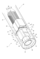
図1は、実施の形態1に係る可視化プローブ11の先端側の外観を表す要部斜視図である。実施の形態1に係る撮像モジュールは、可視化プローブ11に好適に用いられる。可視化プローブ11は、例えば医療用の内視鏡、あるいは工業用の内視鏡として用いることができる。可視化プローブ11は、観察対象の内部に挿入されるスコープ13と、スコープ13の後端部が接続されるプラグ部(図示略)と、を備える構成である。スコープ13は、比較的長い可撓性を有する軟性部15と、軟性部15の先端に設けられた剛性を有する円柱状の先端部17と、を含んで構成される。
Figure 1 is a perspective view of the main parts showing the external appearance of the tip side of a
可視化プローブ11は、先端部17における撮像窓19の背部に撮像モジュール21(図2参照)を備える。先端部17の先端面23には、照明光を照射する複数(図1例のでは3つ)の照射窓25が撮像窓19の周囲に配置される。それぞれの照射窓25には、先端部17に挿通されたライトガイド27の光出射先端が接続される。ライトガイド27には、例えば複数本の光ファイバ素線を束ねたバンドルファイバが用いられる。
The
可視化プローブ11は、上述したプラグ部(図示略)が、ビデオプロセッサ(図示略)のソケット部に挿入され、可視化プローブ11とビデオプロセッサとが接続されることで、可視化プローブ11とビデオプロセッサとの間で電力および各種信号(例えば映像信号、制御信号)の送受信が可能となる。これらの電力および各種信号は、スコープ13の内部に挿通された伝送ケーブル29(図2参照)を介して、プラグ部から軟性部側に伝送される。また、先端部17の内側に設けられた撮像センサ31(図2参照)から出力される画像信号は、伝送ケーブル29およびプラグ部を介してビデオプロセッサに伝送される。
The
ビデオプロセッサは、伝送ケーブル29を介して伝送された画像信号に対し、画像処理を施し、画像処理後の画像データを表示信号に変換して、モニタ(図示略)に出力する。 The video processor performs image processing on the image signal transmitted via the transmission cable 29, converts the processed image data into a display signal, and outputs it to a monitor (not shown).
図2は、図1に示した可視化プローブ11の先端部17を透視した斜視図である。可視化プローブ11の先端部17には、実施の形態1に係る撮像モジュール21と、ライトガイド27と、可撓基板33と、伝送ケーブル29とが収容されている。
Figure 2 is a perspective view showing the
撮像モジュール21は、鏡筒35と、撮像センサ31と、センサ保持部材37とを主要な構成として有する。
The
鏡筒35は、内方に光学系39を保持する。光学系39は、例えば、対物カバーガラス、レンズ、絞り、スペーサ、バンドパスフィルタ等から構成される。
The
実施の形態1において、鏡筒35は、金属(例えばSUS)からなり、円筒で形成される。鏡筒35の外径は、例えば2.4mm程度の細径で製作される。
In the first embodiment, the
図3は、図2に示した撮像モジュール21の斜視図である。撮像センサ31は、光学系39の光軸41にセンサ前面43(図6参照)が垂直に配置される。撮像センサ31は、外形が四角形に形成される。撮像センサ31は、撮像素子45の光入射面側にセンサカバーガラス47が貼着されて構成される。撮像素子45には、例えば、CCD(Charge Coupled Device)あるいはCMOS(Complementary Metal Oxide Semiconductor)等が用いられる。
Figure 3 is a perspective view of the
図4は、図2に示した撮像モジュール21の側面図である。センサ保持部材37は、光軸41に直交する平行な一対の端面(端面42A、端面42B)が、撮像センサ31の外形とほぼ同一サイズであり(図8参照)、端面42Bから端面42Aまで延びる外周部42Cを有する。端面42Aは、本実施形態の第1端面の一例であり、端面42Bは、本実施形態の第2端面の一例である。センサ保持部材37には、一対の端面を貫通する保持穴49が穿設される。端面42Aに配置されている保持穴49の開口は本実施形態の穴部の一例であり、保持穴49は、本実施形態の空間部の一例である。保持穴49には、鏡筒35が嵌入される。また、センサ保持部材37の他方の端面は、センサ前面43に当接するセンサ当接面51となる。
4 is a side view of the
センサ保持部材37は、端面42Bに垂直な稜線部53(図7参照)のうち、少なくとも1箇所が除去された面取部55(図8参照)を有している。この面取部55は、センサ前面43の4つの角部57(図8参照)のうち、1つ以上を露出させる。図8では、4つの角部57を露出させている形状の端面42Aを備えるセンサ保持部材37を有する撮像モジュール21を示している。面取部55により露出したセンサ前面43の角部57は、鏡筒35より前方において光軸41に沿う方向から視て視認が可能となる。つまり、光軸41と平行であって端面42Aから端面42Bに向かう方向(目視方向)に視て、センサ保持部材37は、センサ前面43の4つの角部57のうち1つ以上をセンサ保持部材37から露出させ、かつ四角形よりも頂点が多い形状である(図8参照)。より具体的に、センサ保持部材37は、目視方向に視て八角形である。また、センサ前面43の4つの角部57は、センサ保持部材37から露出している。また、目視方向におけるセンサ保持部材37の形状は、光軸41と平行な方向に視たときの端面42A及び端面42B(図4参照)の形状である。したがって、光軸41と平行な方向に視たときの端面42A及び端面42Bは、四角形よりも頂点が多い形状であり(図8参照)、センサ前面43の4つの角部57のうち1つ以上の角部57は、センサ保持部材37から露出している。
The
実施の形態1において、面取部55は、センサ当接面51に垂直な4つの稜線部53の全てを除去することにより、4箇所に形成されている(図8参照)。
In the first embodiment, the chamfered
撮像モジュール21は、センサ前面43の角部57と、センサ保持部材37の面取部55とに渡って設けられた第1の接着剤59により、センサ保持部材37と撮像センサ31が固定される。
The
また、撮像モジュール21は、センサ当接面51の各辺部と、撮像センサ31とが第2の接着剤61により、固定される。つまり、撮像モジュール21は、第1の接着剤59と第2の接着剤61とにより、撮像センサ31とセンサ保持部材37とが固定されている(図4参照)。また、端面42Bは、第1の接着剤59によってセンサ前面43に固定されている(図4参照)。
Furthermore, in the
撮像モジュール21は、センサ保持部材37の光軸41に平行な一対の側面63に、光軸41に直交する把持溝65が形成されている。つまり、センサ保持部材37の外周部42Cは、光軸41に直交する把持溝65を有する(図4参照)。
In the
また、実施の形態1に係る可視化プローブ11は、撮像センサ31の光軸方向の投影面内に収められ、撮像センサ31に電気的に接続される可撓基板33(図2参照)と、可撓基板33に電気的に接続される伝送ケーブル29(図2参照)と、を備える。
The
図5は、図4に示した撮像モジュール21を可撓基板側から見た背面図である。可撓基板33は、電線67の先端直線部と同方向の軸線を有する筒体69に曲げられる。筒体69は、例えば四角筒とすることができる。四角筒は、軸線に直交する断面の外形状が四角形であれは、可撓基板33の一部分が内方へ折り曲げられていてもよい。
Figure 5 is a rear view of the
可撓基板33は、基板本体部71と、撮像素子実装半島部73と、電子部品実装半島部75とに大別されて一体で成形される。基板本体部71は、更に、第1面77、第2面79、第3面81、第4面83、第5面85、第6面87で区割りされる。筒体69は、第1面77が、内方に折り込まれて、第2面79、第3面81、第4面83、第5面85、第6面87により四角形の外周面が構成される。可撓基板33は、この筒体69が、撮像素子45の投影面積範囲内に配置される。撮像素子実装半島部73は、図5の背面側に設けられる複数の端子が、撮像素子45のバンプ89(図4参照)に接続される。
The
図6は、撮像センサ31および可撓基板33の一部分を切り欠いた斜視図である。電子部品実装半島部75は、四角形に形成され、可撓基板33の第2面79から括れ部を介して延出し、撮像素子実装半島部73を挟んで撮像素子45と反対側に曲げられる。これにより、電子部品実装半島部75は、撮像素子45の投影面積範囲内に配置される。電子部品実装半島部75の撮像素子実装半島部73に対向する面には、回路に導通した複数の電子部品91が実装される。電子部品実装半島部75は、筒体69の内周に接触しない大きさで形成される。電子部品実装半島部75は、筒体69の内方に確実に挿入されるように、90度以上の折り曲げ角で折り曲げられる。これにより、撮像素子実装半島部73との干渉が回避されている。
6 is a perspective view of the
なお、電子部品実装半島部75は、実施の形態1と反対側の面に、電子部品91が実装されてもよい。また、電子部品実装半島部75は、複数が形成されてもよい。この場合、複数の電子部品実装半島部75は、撮像素子実装半島部73の背面側で重ねられ積層状となって対面配置される。
The
筒体69の内面には、それぞれの電線67が、回路に導通接続される。電線67は、全てが筒体69の内面に接続され、筒体69の外面には接続されない。
Each
次に、実施の形態1に係る撮像モジュール21の作用を説明する。
Next, we will explain the operation of the
実施の形態1に係る撮像モジュール21は、光学系39を保持する鏡筒35と、光学系39の光軸41にセンサ前面43が垂直に配置され、四角形状の外形を有する撮像センサ31と、を備える。撮像モジュール21は、光軸41に直交する平行な一対の端面が撮像センサ31の外形とほぼ同一サイズの四角形となる略直方体で形成され一対の端面を貫通する保持穴49が穿設されて一方の端面の保持穴49に鏡筒35が嵌入されるとともに、他方の端面がセンサ前面43に当接するセンサ当接面51となり、このセンサ当接面51に垂直な稜線部53のうち少なくとも1箇所が除去された面取部55を有し、この面取部55がセンサ前面43の角部57を露出させるセンサ保持部材37を備える。
The
実施の形態1に係る撮像モジュール21では、センサ保持部材37が、略直方体で形成される。センサ保持部材37は、光軸41に直交する平行な一対の端面が、撮像センサ31の外形とほぼ同一サイズの四角形となる。センサ保持部材37には、一対の端面を貫通する保持穴49が穿設される。一対の端面の一方には、光学系39を保持した鏡筒35が嵌入される。
In the
センサ保持部材37は、他方の端面が、センサ前面43に当接するセンサ当接面51となる。従って、四角形のセンサ当接面51は、内側に保持穴49が開口する。センサ当接面51は、センサ当接面51の外形とセンサ当接面51に開口する保持穴49とに挟まれる環状枠面(図8参照)となる。センサ前面43は、この環状枠面に開口する保持穴49と対向する領域が光学有効面となる。
The other end face of the
このように、センサ保持部材37は、略直方体で形成され、他方の端面がセンサ前面43に当接するセンサ当接面51となっている。ここで、センサ保持部材37は、センサ当接面51に垂直な稜線部53のうち少なくとも1箇所が除去される面取部55を有している。この他、センサ保持部材37は、2箇所、3箇所、4箇所のいずれの稜線部53が除去されてもよい。センサ保持部材37は、例えば4箇所の稜線部53が除去された面取部55を有する場合、センサ前面43の四隅がそれぞれの面取部55で露出することになる。
In this way, the
図7は、比較例に係る撮像モジュール93の正面図である。撮像モジュールは、撮像センサ31の切り出し時の寸法公差により、標準の外形よりも小さい外形で撮像センサ31が形成される場合がある。この場合、面取部55を有していない撮像モジュール93のセンサ保持部材95では、撮像センサ31の図7に破線で示す外形は、センサ保持部材37の背部に隠れて視認不能となる。
Figure 7 is a front view of an
これに対し、撮像モジュール21では、センサ保持部材37の稜線部53が除去された面取部55を有するので、センサ前面43の角部57を、鏡筒35の前方より光軸41に沿う方向から目視できる。これにより、撮像モジュール21は、撮像センサ31が同一サイズのセンサ保持部材37に隠れる場合であっても、視認される角部57の形状や大きさにより、センサ保持部材37と撮像センサ31との相対位置を把握することができるようになる。
In contrast, the
面取部55は、数が多いほど、センサ保持部材37と撮像センサ31との位置合わせが容易となり、かつ位置決め精度を高めることができる。
The more
また、センサ前面43の角部57が、光軸41に沿う方向で露出するので、接着剤を同方向から角部57に設けることができるようになる。撮像モジュール21は、接着剤が角部57に設けられることにより、角部57と面取部55との双方に渡って接着剤を付着させることができる。つまり、接着剤を光軸41に沿う方向からでも光軸41に直交する側方からでも塗布できる。
In addition, because the
更に、角部57に設ける接着剤は、主に角部57と面取部55とに付着させればよいので、比較的高粘度のものを使用できる。これにより、接着剤が角部57からセンサ前面43とセンサ当接面51との間に深く侵入し、光学有効面に到達することを抑制することができる。
Furthermore, since the adhesive applied to the
従って、本実施の形態1に係る撮像モジュール21によれば、センサ保持部材37と撮像センサ31とが位置合わせしやすく、容易に接着を行うことができ、しかも、光学有効面への接着剤の侵入を抑制できる。
Therefore, according to the
また、撮像モジュール21では、角部57とセンサ保持部材37とに渡って設けられた第1の接着剤59によりセンサ保持部材37と撮像センサ31が固定される。
In addition, in the
この撮像モジュール21では、センサ前面43の角部57に、第1の接着剤59が設けられる。角部57に設けられた第1の接着剤59は、角部57と面取部55との双方に付着が容易に可能となる。これにより、撮像モジュール21は、センサ保持部材37と撮像センサ31とが角部57の第1の接着剤59により固定される。
In this
例えば予め鏡筒35を固定したセンサ保持部材37は、撮像センサ31のセンサ前面43に対し、光軸41に直交する図3に示すXY方向に移動されて、相対位置が調整される。この際、第1の接着剤59は、角部57には塗布されていない。センサ保持部材37と撮像センサ31とは、相対位置が位置決めされたなら、角部57に第1の接着剤59が設けられる(滴下若しくは塗布される)。角部57に設けられた第1の接着剤59が固化することにより、センサ保持部材37と撮像センサ31とは、位置決め完了の直後に速やかに固定、若しくは仮固定が可能となる。
For example, the
また、撮像モジュール21では、センサ当接面51の各辺部と撮像センサ31とが第2の接着剤61で固定される。
In addition, in the
この撮像モジュール21では、例えば角部57に設けられた第1の接着剤59が、センサ保持部材37と撮像センサ31との仮固定用に用いられた場合、第2の接着剤61によりセンサ保持部材37と撮像センサ31とが本固定される。第2の接着剤61は、ほぼ密接状態となっているセンサ保持部材37のセンサ当接面51と、撮像センサ31のセンサ前面43との微小な間隙に、毛管現象を利用して充填・塗布される。従って、第2の接着剤61は、第1の接着剤59よりも低粘度であることが好ましい。
In this
センサ保持部材37と撮像センサ31とは、第1の接着剤59により角部57が仮固定されることに加え、第2の接着剤61により各辺部が本固定されることにより、高い接合強度を得ることができる。
The
また、第2の接着剤61は、センサ保持部材37におけるセンサ当接面51の各辺部に塗布される。これにより、センサ保持部材37と撮像センサ31とにおける間隙の外周は、第1の接着剤59と第2の接着剤61とにより全周囲が密閉される。撮像モジュール21は、センサ保持部材37と撮像センサ31とにおける間隙の外周が密閉されることにより、例えば可視化プローブ11の先端部17を形成する際、周囲を覆う充填樹脂材が光学有効面へ侵入することを抑制できる。
The
また、撮像モジュール21では、センサ保持部材37の光軸41に平行な一対の側面63に、光軸41に直交する把持溝65が形成される。
In addition, in the
この撮像モジュール21では、センサ保持部材37の光軸41に平行な一対の側面63に、光軸41に直交する把持溝65が形成される。センサ保持部材37と撮像センサ31とは、例えば撮像センサ31が固定され、センサ保持部材37が把持具により把持されて、撮像センサ31に対してセンサ保持部材37が位置決めされる。この際、センサ保持部材37は、把持具により挟持される。把持具は、一対の把持溝65に嵌る例えば一対の指杆部を有する。センサ保持部材37は、一対の把持溝65が指杆部により挟持されることにより、センサ前面43と平行なXY平面に移動が可能となって調整される。この際、把持具は、指杆部が把持溝65に嵌っているので、XY平面に垂直な図3に示すZ方向(即ち、光軸41に沿う方向)へ適当な押圧力を付与しながら、センサ保持部材37を滑らずに保持することができる。これにより、センサ保持部材37は、センサ前面43に密着した状態でより高精度な位置合わせが可能となる。
In this
また、撮像モジュール21では、鏡筒35が、円筒である。
In addition, in the
この撮像モジュール21では、鏡筒35が、円筒で形成される。鏡筒35が円筒で形成されることにより、鏡筒35が嵌る保持穴49も円形の穴でセンサ保持部材37を貫通する。センサ保持部材37のセンサ当接面51は、四角形の内側に保持穴49が開口することにより、外形と保持穴49とに挟まれる環状枠面となる。センサ当接面51は、この環状枠面をセンサ前面43に当接する。環状枠面は、ほぼ直交する4方の放射方向で、保持穴49からの距離が遠い点を頂点とした略三角形状の隅部三角面97(図8)が形成される。この隅部三角面97は、底辺が保持穴49の円弧となる。センサ保持部材37は、センサ当接面51に、この四つの隅部三角面97が形成されることにより、面取部55の除去が容易に行えるようになっている。
In this
また、撮像モジュール21では、面取部55が4つの稜線部53を除去した4箇所に形成される。
In addition, in the
図8は、実施の形態1に係る撮像モジュール21の正面図である。この撮像モジュール21では、略直方体に形成されるセンサ保持部材37において、端面42Bに垂直な4つの稜線部53が除去されることにより、4つの面取部55が形成される。センサ保持部材37の外周部42C(図4参照)は、センサ保持部材37において端面42Bから42Aまで延び、かつ面取部55が形成されている部分に相当する。これにより、端面42A、および端面42Bは、実質的には八角形となる。センサ保持部材37は、4つの面取部55により、センサ前面43における4箇所の角部57が視認できるようになるので、XY平面における面内方向の位置決めがより高精度に行えるようになる。
8 is a front view of the
また、実施の形態1に係る可視化プローブ11は、光学系39を保持する鏡筒35と、光学系39の光軸41にセンサ前面43が垂直に配置され、外形が四角形に形成される撮像センサ31と、を備える。可視化プローブ11は、光軸41に直交する平行な一対の端面が撮像センサ31の外形とほぼ同一サイズの四角形となる略直方体で形成され、一対の端面を貫通する保持穴49が穿設されて一方の端面の保持穴49に鏡筒35が嵌入されるとともに、他方の端面がセンサ前面43に当接するセンサ当接面51となり、このセンサ当接面51に垂直な稜線部53のうち少なくとも1箇所が除去される面取部55を有し、この面取部55がセンサ前面43の角部57を露出させるセンサ保持部材37を備える。可視化プローブ11は、撮像光を光学系39に入射させる撮像窓19を先端面23に有し、鏡筒35、撮像センサ31およびセンサ保持部材37を覆う円柱状の先端部17と、先端部17に挿通され先端面23に光出射先端を配置するライトガイド27と、撮像センサ31の光軸方向の投影面内に収められ、撮像センサ31に電気的に接続される可撓基板33と、先端部17に挿通され可撓基板33に電気的に接続されるケーブルと、を備える。
The
実施の形態1に係る可視化プローブ11では、撮像モジュール21を備えることにより、撮像センサ31が同一サイズのセンサ保持部材37に隠れる場合であっても、上記した作用により、視認される角部57の形状や大きさによって、センサ保持部材37と撮像センサ31との相対位置を容易に把握することができる。
The
また、センサ前面43の角部57が、光軸41に沿う方向で露出するので、接着剤を同方向から角部57に設けることができるようになる。つまり、接着剤を光軸41に沿う方向からでも光軸41に直交する側方からでも塗布できる。
In addition, because the
更に、角部57に設ける接着剤は、主に角部57と面取部55とに付着させればよいので、比較的高粘度のものを使用できる。これとは別に、低粘度の接着剤を角部57からセンサ前面43とセンサ当接面51との間に浸潤させることで撮像センサ31と光学系39との間の空間を外部から完全に隔絶し湿気あるいはゴミの侵入による映像の画質劣化を防ぐことができる。なお、上述した低粘度の接着剤はセンサ前面43とセンサ当接面51との微小な隙間に圧送することなくあくまでも浸透させることで深く侵入させ、その状態で硬化させることで、光学有効面に到達することを抑制することができる。
Furthermore, the adhesive applied to the
これに加え、可視化プローブ11は、鏡筒35、撮像センサ31およびセンサ保持部材37が円柱状の先端部17により覆われる。先端部17は、硬質の円筒により外殻が形成されてもよいし、可視化プローブ11の挿入部から延在する可撓性を有したシースの内方に充填樹脂材を固化させて形成してもよい。
In addition, the
これにより、可視化プローブ11は、少ない部品点数で小径化を可能にしながら、撮像モジュール21を気密、水密に封止することができる。
This allows the
また、可視化プローブ11は、撮像モジュール21の半径方向外側にライトガイド27が配置されるので、暗部においても他の照明手段を必要とせずに、単独で被写体の観察を可能にすることができる。
In addition, the
更に、可視化プローブ11は、撮像センサ31の光軸方向の投影面内に可撓基板33が収まるので、小径化を阻害することがない。これにより、可視化プローブ11は、多数の電線67を束ねた伝送ケーブル29を接続する必要がある高画質用の撮像センサ31を使用することができるようになる。
Furthermore, the
実施の形態1に係る可視化プローブ11によれば、センサ保持部材37と撮像センサ31とが位置合わせしやすく、容易に接着を行うことができ、しかも、光学有効面への接着剤の侵入を抑制でき、先端部17を小径化できる。
With the
以上、図面を参照しながら各種の実施の形態について説明したが、本開示はかかる例に限定されないことは言うまでもない。当業者であれば、特許請求の範囲に記載された範疇内において、各種の変更例、修正例、置換例、付加例、削除例、均等例に想到し得ることは明らかであり、それらについても当然に本開示の技術的範囲に属するものと了解される。また、発明の趣旨を逸脱しない範囲において、上述した各種の実施の形態における各構成要素を任意に組み合わせてもよい。 Although various embodiments have been described above with reference to the drawings, it goes without saying that the present disclosure is not limited to such examples. It is clear that a person skilled in the art can conceive of various modifications, amendments, substitutions, additions, deletions, and equivalents within the scope of the claims, and it is understood that these also naturally fall within the technical scope of the present disclosure. Furthermore, the components in the various embodiments described above may be combined in any manner as long as it does not deviate from the spirit of the invention.
本開示は、センサ保持部材と撮像センサとが位置合わせしやすく、容易に接着を行うことができ、光学有効面への接着剤の侵入を抑制する撮像モジュール、ならびに、センサ保持部材と撮像センサとが位置合わせしやすく、容易に接着を行うことができ、しかも、光学有効面への接着剤の侵入を抑制でき、先端部を小径化する可視化プローブとして有用である。 The present disclosure is useful as an imaging module in which the sensor holding member and the imaging sensor can be easily aligned and bonded, and in which the infiltration of adhesive into the optically effective surface is suppressed, and as a visualization probe in which the sensor holding member and the imaging sensor can be easily aligned and bonded, and in which the infiltration of adhesive into the optically effective surface is suppressed, and in which the tip has a small diameter.
11 可視化プローブ
17 先端部
19 撮像窓
21 撮像モジュール
23 先端面
27 ライトガイド
29 伝送ケーブル
31 撮像センサ
33 可撓基板
35 鏡筒
37 センサ保持部材
39 光学系
41 光軸
43 センサ前面
49 保持穴
51 センサ当接面
53 稜線部
55 面取部
57 角部
59 第1の接着剤
61 第2の接着剤
63 側面
65 把持溝
REFERENCE SIGNS
Claims (6)
穴部を有し、前記光軸に直交する第1端面と、前記第1端面と平行であり、かつ前記第1端面よりも前記撮像センサの近くに配置されている第2端面と、前記穴部から前記第2端面まで貫通している空間部と、前記第2端面に直交し、かつ前記第2端面から前記第1端面まで延びる外周部と、を含み、前記光軸に平行な方向に関して前記撮像センサの投影面内に配置され、かつ前記第2端面において前記撮像センサと対向するセンサ保持部材と、
前記光学系を保持し、前記空間部に配置されている鏡筒と、を備え、
前記センサ前面は、4つの角部を有し、
前記センサ保持部材は、前記光軸と平行であって前記第1端面から前記第2端面に向かう目視方向に視て四角形よりも頂点が多い形状であり、
前記4つの角部のうち1つ以上の角部は、前記センサ保持部材から露出しており、
前記外周部は、前記1つ以上の角部と隣接する面取部を有し、
前記1つ以上の角部から前記面取部に渡って第1接着剤が設けられる、
撮像モジュール。 an image sensor having a sensor front surface perpendicular to an optical axis of the optical system and having a rectangular outer shape;
a sensor holding member including a first end face having a hole and perpendicular to the optical axis, a second end face parallel to the first end face and disposed closer to the image sensor than the first end face, a space penetrating from the hole to the second end face, and an outer circumferential portion perpendicular to the second end face and extending from the second end face to the first end face, the sensor holding member being disposed within a projection plane of the image sensor in a direction parallel to the optical axis and facing the image sensor at the second end face;
a lens barrel that holds the optical system and is disposed in the space,
The sensor front surface has four corners,
the sensor holding member has a shape with more vertices than a rectangle when viewed in a viewing direction parallel to the optical axis from the first end face to the second end face,
One or more of the four corners are exposed from the sensor holding member,
the outer periphery has a chamfer adjacent to the one or more corners;
A first adhesive is provided from the one or more corners to the chamfered portion.
Imaging module.
第2接着剤を介して前記センサ前面に固定される、
請求項1に記載の撮像モジュール。 The second end surface is
fixed to the front surface of the sensor via a second adhesive;
The imaging module according to claim 1 .
請求項2に記載の撮像モジュール。 the first adhesive and the second adhesive are continuous and seal an outer periphery of a gap between the sensor holding member and the image sensor;
The imaging module according to claim 2 .
請求項1~3のうちいずれか一項に記載の撮像モジュール。 The lens barrel is a cylinder.
The imaging module according to any one of claims 1 to 3.
前記目視方向に視て、八角形であり、
前記4つの角部は、前記センサ保持部材から露出している、
請求項1~4のうちいずれか一項に記載の撮像モジュール。 The first end surface and the second end surface are
When viewed in the viewing direction, the shape is octagonal;
The four corners are exposed from the sensor holding member.
The imaging module according to any one of claims 1 to 4.
光学系の光軸に直交するセンサ前面を有し、外形が四角形である撮像センサと、
穴部を有し、前記光軸に直交する第1端面と、前記第1端面と平行であり、かつ前記第1端面よりも前記撮像センサの近くに配置されている第2端面と、前記穴部から前記第2端面まで貫通している空間部と、前記第2端面に直交し、かつ前記第2端面から前記第1端面まで延びる外周部と、を含み、前記光軸に平行な方向に関して前記撮像センサの投影面内に配置され、かつ前記第2端面において前記撮像センサと対向するセンサ保持部材と、
前記光学系を保持し、前記空間部に配置されている鏡筒と、
前記光学系に光を入射するための撮像窓が形成された先端面を有し、前記鏡筒と、前記撮像センサと、前記センサ保持部材とを覆い、前記可視化プローブの先端に配置されている円柱状の先端部と、
前記先端部に挿通され、光出射先端が前記先端面に配置されているライトガイドと、
前記光軸に平行な方向に関して前記撮像センサの投影面内に配置され、前記撮像センサに電気的に接続されている可撓基板と、
前記先端部に挿通され、前記可撓基板に電気的に接続されているケーブルと、を備え、
前記センサ前面は、4つの角部を有し、
前記センサ保持部材は、前記光軸と平行であって前記第1端面から前記第2端面に向かう目視方向に視て四角形よりも頂点が多い形状であり、
前記4つの角部のうち1つ以上の角部は、前記センサ保持部材から露出しており、
前記外周部は、前記1つ以上の角部と隣接する面取部を有し、
前記1つ以上の角部から前記面取部に渡って第1接着剤が設けられる、
可視化プローブ。 A visualization probe, comprising:
an image sensor having a sensor front surface perpendicular to an optical axis of the optical system and having a rectangular outer shape;
a sensor holding member including a first end face having a hole and perpendicular to the optical axis, a second end face parallel to the first end face and disposed closer to the image sensor than the first end face, a space penetrating from the hole to the second end face, and an outer circumferential portion perpendicular to the second end face and extending from the second end face to the first end face, the sensor holding member being disposed within a projection plane of the image sensor in a direction parallel to the optical axis and facing the image sensor at the second end face;
a lens barrel that holds the optical system and is disposed in the space;
a cylindrical tip portion having a tip surface on which an imaging window for allowing light to enter the optical system is formed, the tip portion covering the lens barrel, the imaging sensor, and the sensor holding member, and being disposed at the tip of the visualization probe;
a light guide that is inserted through the tip portion and has a light emitting tip disposed on the tip surface;
a flexible substrate disposed within a projection plane of the image sensor in a direction parallel to the optical axis and electrically connected to the image sensor;
a cable that is inserted through the tip portion and electrically connected to the flexible substrate;
The sensor front surface has four corners,
the sensor holding member has a shape with more vertices than a rectangle when viewed in a viewing direction parallel to the optical axis from the first end face to the second end face,
One or more of the four corners are exposed from the sensor holding member,
the outer periphery has a chamfer adjacent to the one or more corners;
A first adhesive is provided from the one or more corners to the chamfered portion.
Visualization probe.
Priority Applications (4)
| Application Number | Priority Date | Filing Date | Title |
|---|---|---|---|
| JP2019167407A JP7480979B2 (en) | 2019-09-13 | 2019-09-13 | Imaging Module and Visualization Probe |
| CN202080063896.1A CN114423329B (en) | 2019-09-13 | 2020-09-09 | Imaging Modules and Visualization Probes |
| DE112020004368.1T DE112020004368T5 (en) | 2019-09-13 | 2020-09-09 | Image acquisition module and visualization probe |
| PCT/JP2020/034122 WO2021049528A1 (en) | 2019-09-13 | 2020-09-09 | Imaging module and visualization probe |
Applications Claiming Priority (1)
| Application Number | Priority Date | Filing Date | Title |
|---|---|---|---|
| JP2019167407A JP7480979B2 (en) | 2019-09-13 | 2019-09-13 | Imaging Module and Visualization Probe |
Publications (3)
| Publication Number | Publication Date |
|---|---|
| JP2021041076A JP2021041076A (en) | 2021-03-18 |
| JP2021041076A5 JP2021041076A5 (en) | 2022-09-22 |
| JP7480979B2 true JP7480979B2 (en) | 2024-05-10 |
Family
ID=74863396
Family Applications (1)
| Application Number | Title | Priority Date | Filing Date |
|---|---|---|---|
| JP2019167407A Active JP7480979B2 (en) | 2019-09-13 | 2019-09-13 | Imaging Module and Visualization Probe |
Country Status (4)
| Country | Link |
|---|---|
| JP (1) | JP7480979B2 (en) |
| CN (1) | CN114423329B (en) |
| DE (1) | DE112020004368T5 (en) |
| WO (1) | WO2021049528A1 (en) |
Citations (3)
| Publication number | Priority date | Publication date | Assignee | Title |
|---|---|---|---|---|
| JP2005117122A (en) | 2003-10-03 | 2005-04-28 | Toko Inc | The camera module |
| JP2019040892A (en) | 2017-08-22 | 2019-03-14 | ソニーセミコンダクタソリューションズ株式会社 | Imaging apparatus, camera module, and electronic device |
| US20190174032A1 (en) | 2017-12-05 | 2019-06-06 | Samsung Electro-Mechanics Co., Ltd. | Mobile device and lens module |
Family Cites Families (14)
| Publication number | Priority date | Publication date | Assignee | Title |
|---|---|---|---|---|
| CN100380924C (en) * | 2002-07-18 | 2008-04-09 | 皇家飞利浦电子股份有限公司 | Camera module, holder for use in camera module, camera system and method of manufacturing camera module |
| KR100479208B1 (en) * | 2002-10-23 | 2005-03-28 | 매그나칩 반도체 유한회사 | Method of manufacturing image sensor using salicide process |
| EP2579312A3 (en) * | 2005-03-25 | 2013-05-29 | Fujifilm Corporation | Solid state imaging device and manufacturing method thereof |
| JP5095113B2 (en) * | 2005-03-25 | 2012-12-12 | 富士フイルム株式会社 | Solid-state imaging device manufacturing method and solid-state imaging device |
| KR20070104010A (en) * | 2006-04-21 | 2007-10-25 | 엘지이노텍 주식회사 | Camera module and portable terminal having same |
| JP5661409B2 (en) * | 2010-10-05 | 2015-01-28 | パナソニックIpマネジメント株式会社 | Endoscope |
| WO2016047354A1 (en) * | 2014-09-25 | 2016-03-31 | 日本電産コパル株式会社 | Imaging device, optical device, electronic device, vehicle, and production method for imaging device |
| US10284757B2 (en) * | 2015-01-30 | 2019-05-07 | Nidec Copal Corporation | Imaging device, optical device provided with same, electronic device provided with same, and method for producing imaging device |
| US9829698B2 (en) * | 2015-08-31 | 2017-11-28 | Panasonic Corporation | Endoscope |
| JP6655343B2 (en) * | 2015-10-15 | 2020-02-26 | 富士フイルム株式会社 | Endoscope |
| US10805596B2 (en) * | 2015-12-09 | 2020-10-13 | Titan Medical Inc. | Stereoscopic imaging sensor apparatus and method for fabricating pairs of image sensors used in stereoscopic imaging |
| CN108432352B (en) * | 2015-12-25 | 2019-11-26 | 太阳诱电株式会社 | Printed wiring board and camera assembly |
| JP2018160763A (en) * | 2017-03-22 | 2018-10-11 | オリンパス株式会社 | Imaging module, endoscope, and manufacturing method of imaging module |
| JP2019167407A (en) | 2018-03-22 | 2019-10-03 | 日立化成株式会社 | Epoxy resin composition, and electronic component device |
-
2019
- 2019-09-13 JP JP2019167407A patent/JP7480979B2/en active Active
-
2020
- 2020-09-09 CN CN202080063896.1A patent/CN114423329B/en active Active
- 2020-09-09 WO PCT/JP2020/034122 patent/WO2021049528A1/en active Application Filing
- 2020-09-09 DE DE112020004368.1T patent/DE112020004368T5/en active Pending
Patent Citations (3)
| Publication number | Priority date | Publication date | Assignee | Title |
|---|---|---|---|---|
| JP2005117122A (en) | 2003-10-03 | 2005-04-28 | Toko Inc | The camera module |
| JP2019040892A (en) | 2017-08-22 | 2019-03-14 | ソニーセミコンダクタソリューションズ株式会社 | Imaging apparatus, camera module, and electronic device |
| US20190174032A1 (en) | 2017-12-05 | 2019-06-06 | Samsung Electro-Mechanics Co., Ltd. | Mobile device and lens module |
Also Published As
| Publication number | Publication date |
|---|---|
| DE112020004368T5 (en) | 2022-06-02 |
| JP2021041076A (en) | 2021-03-18 |
| CN114423329B (en) | 2025-03-18 |
| WO2021049528A1 (en) | 2021-03-18 |
| CN114423329A (en) | 2022-04-29 |
Similar Documents
| Publication | Publication Date | Title |
|---|---|---|
| JP5771901B2 (en) | Imaging device | |
| EP2687144B1 (en) | Imaging unit and endoscope | |
| JP5192559B2 (en) | Endoscope | |
| EP0492349B2 (en) | Camera head for solid-state image pickup device and method of producing same | |
| WO2012137739A1 (en) | Imaging apparatus | |
| WO2011092901A1 (en) | Image pickup unit for endoscope | |
| JP5845569B2 (en) | Imaging unit | |
| US20200060514A1 (en) | Endoscope and method of manufacturing endoscope | |
| JP2014230638A (en) | Endoscope and endoscope system | |
| TW201319651A (en) | Connector cable and connector cable manufacturing method | |
| CN113382671B (en) | Front end unit of endoscope and endoscope | |
| US20180045948A1 (en) | Stereo image pickup unit | |
| US10542874B2 (en) | Imaging device and endoscope device | |
| JP5499828B2 (en) | Imaging device | |
| JP7480979B2 (en) | Imaging Module and Visualization Probe | |
| JP2015047278A (en) | Endoscope | |
| US10962763B2 (en) | Optical unit | |
| JP2009066223A (en) | Prism unit for imaging apparatus and imaging unit | |
| JP6713544B2 (en) | Endoscope | |
| JP6617206B2 (en) | Endoscope | |
| WO2016143194A1 (en) | Image capture device | |
| JPH10146312A (en) | Image pickup device | |
| JP4864539B2 (en) | Electronic endoscope | |
| JP4037873B2 (en) | Imaging device | |
| JP2015047249A (en) | Endoscope |
Legal Events
| Date | Code | Title | Description |
|---|---|---|---|
| A711 | Notification of change in applicant |
Free format text: JAPANESE INTERMEDIATE CODE: A712 Effective date: 20191205 |
|
| A711 | Notification of change in applicant |
Free format text: JAPANESE INTERMEDIATE CODE: A712 Effective date: 20201224 |
|
| A521 | Request for written amendment filed |
Free format text: JAPANESE INTERMEDIATE CODE: A523 Effective date: 20220912 |
|
| A621 | Written request for application examination |
Free format text: JAPANESE INTERMEDIATE CODE: A621 Effective date: 20220912 |
|
| A131 | Notification of reasons for refusal |
Free format text: JAPANESE INTERMEDIATE CODE: A131 Effective date: 20231010 |
|
| A521 | Request for written amendment filed |
Free format text: JAPANESE INTERMEDIATE CODE: A523 Effective date: 20231110 |
|
| A131 | Notification of reasons for refusal |
Free format text: JAPANESE INTERMEDIATE CODE: A131 Effective date: 20240116 |
|
| A521 | Request for written amendment filed |
Free format text: JAPANESE INTERMEDIATE CODE: A523 Effective date: 20240129 |
|
| TRDD | Decision of grant or rejection written | ||
| A01 | Written decision to grant a patent or to grant a registration (utility model) |
Free format text: JAPANESE INTERMEDIATE CODE: A01 Effective date: 20240409 |
|
| A61 | First payment of annual fees (during grant procedure) |
Free format text: JAPANESE INTERMEDIATE CODE: A61 Effective date: 20240418 |
|
| R150 | Certificate of patent or registration of utility model |
Ref document number: 7480979 Country of ref document: JP Free format text: JAPANESE INTERMEDIATE CODE: R150 |