JP7479835B2 - TRANSPORTATION DEVICE AND METHOD FOR MANUFACTURING AN ARTICLE - Google Patents
TRANSPORTATION DEVICE AND METHOD FOR MANUFACTURING AN ARTICLE Download PDFInfo
- Publication number
- JP7479835B2 JP7479835B2 JP2019233231A JP2019233231A JP7479835B2 JP 7479835 B2 JP7479835 B2 JP 7479835B2 JP 2019233231 A JP2019233231 A JP 2019233231A JP 2019233231 A JP2019233231 A JP 2019233231A JP 7479835 B2 JP7479835 B2 JP 7479835B2
- Authority
- JP
- Japan
- Prior art keywords
- mover
- magnets
- permanent magnets
- force
- coil
- Prior art date
- Legal status (The legal status is an assumption and is not a legal conclusion. Google has not performed a legal analysis and makes no representation as to the accuracy of the status listed.)
- Active
Links
- 238000004519 manufacturing process Methods 0.000 title claims description 14
- 238000000034 method Methods 0.000 title claims description 13
- 238000012545 processing Methods 0.000 claims description 14
- 230000008021 deposition Effects 0.000 claims description 13
- 238000005339 levitation Methods 0.000 claims description 11
- 230000001846 repelling effect Effects 0.000 claims description 5
- 230000003993 interaction Effects 0.000 claims description 4
- 238000010586 diagram Methods 0.000 description 35
- 230000032258 transport Effects 0.000 description 35
- 238000004364 calculation method Methods 0.000 description 27
- 238000005381 potential energy Methods 0.000 description 16
- XEEYBQQBJWHFJM-UHFFFAOYSA-N Iron Chemical compound [Fe] XEEYBQQBJWHFJM-UHFFFAOYSA-N 0.000 description 6
- 230000005484 gravity Effects 0.000 description 5
- 239000011295 pitch Substances 0.000 description 4
- 229910052742 iron Inorganic materials 0.000 description 3
- 230000005415 magnetization Effects 0.000 description 3
- 239000000463 material Substances 0.000 description 3
- 230000035699 permeability Effects 0.000 description 3
- 238000013459 approach Methods 0.000 description 2
- 239000010687 lubricating oil Substances 0.000 description 2
- 230000007246 mechanism Effects 0.000 description 2
- 230000001133 acceleration Effects 0.000 description 1
- 230000008859 change Effects 0.000 description 1
- 239000000356 contaminant Substances 0.000 description 1
- 238000013461 design Methods 0.000 description 1
- 230000004907 flux Effects 0.000 description 1
- 230000014509 gene expression Effects 0.000 description 1
- 230000010354 integration Effects 0.000 description 1
- 238000005259 measurement Methods 0.000 description 1
- 230000008569 process Effects 0.000 description 1
- 230000001141 propulsive effect Effects 0.000 description 1
- 239000004065 semiconductor Substances 0.000 description 1
- 238000004904 shortening Methods 0.000 description 1
- 230000006641 stabilisation Effects 0.000 description 1
- 238000011105 stabilization Methods 0.000 description 1
Images


Classifications
-
- H—ELECTRICITY
- H01—ELECTRIC ELEMENTS
- H01L—SEMICONDUCTOR DEVICES NOT COVERED BY CLASS H10
- H01L21/00—Processes or apparatus adapted for the manufacture or treatment of semiconductor or solid state devices or of parts thereof
- H01L21/67—Apparatus specially adapted for handling semiconductor or electric solid state devices during manufacture or treatment thereof; Apparatus specially adapted for handling wafers during manufacture or treatment of semiconductor or electric solid state devices or components ; Apparatus not specifically provided for elsewhere
- H01L21/677—Apparatus specially adapted for handling semiconductor or electric solid state devices during manufacture or treatment thereof; Apparatus specially adapted for handling wafers during manufacture or treatment of semiconductor or electric solid state devices or components ; Apparatus not specifically provided for elsewhere for conveying, e.g. between different workstations
- H01L21/67703—Apparatus specially adapted for handling semiconductor or electric solid state devices during manufacture or treatment thereof; Apparatus specially adapted for handling wafers during manufacture or treatment of semiconductor or electric solid state devices or components ; Apparatus not specifically provided for elsewhere for conveying, e.g. between different workstations between different workstations
- H01L21/67709—Apparatus specially adapted for handling semiconductor or electric solid state devices during manufacture or treatment thereof; Apparatus specially adapted for handling wafers during manufacture or treatment of semiconductor or electric solid state devices or components ; Apparatus not specifically provided for elsewhere for conveying, e.g. between different workstations between different workstations using magnetic elements
-
- B—PERFORMING OPERATIONS; TRANSPORTING
- B65—CONVEYING; PACKING; STORING; HANDLING THIN OR FILAMENTARY MATERIAL
- B65G—TRANSPORT OR STORAGE DEVICES, e.g. CONVEYORS FOR LOADING OR TIPPING, SHOP CONVEYOR SYSTEMS OR PNEUMATIC TUBE CONVEYORS
- B65G54/00—Non-mechanical conveyors not otherwise provided for
- B65G54/02—Non-mechanical conveyors not otherwise provided for electrostatic, electric, or magnetic
-
- B—PERFORMING OPERATIONS; TRANSPORTING
- B60—VEHICLES IN GENERAL
- B60L—PROPULSION OF ELECTRICALLY-PROPELLED VEHICLES; SUPPLYING ELECTRIC POWER FOR AUXILIARY EQUIPMENT OF ELECTRICALLY-PROPELLED VEHICLES; ELECTRODYNAMIC BRAKE SYSTEMS FOR VEHICLES IN GENERAL; MAGNETIC SUSPENSION OR LEVITATION FOR VEHICLES; MONITORING OPERATING VARIABLES OF ELECTRICALLY-PROPELLED VEHICLES; ELECTRIC SAFETY DEVICES FOR ELECTRICALLY-PROPELLED VEHICLES
- B60L13/00—Electric propulsion for monorail vehicles, suspension vehicles or rack railways; Magnetic suspension or levitation for vehicles
- B60L13/04—Magnetic suspension or levitation for vehicles
-
- B—PERFORMING OPERATIONS; TRANSPORTING
- B65—CONVEYING; PACKING; STORING; HANDLING THIN OR FILAMENTARY MATERIAL
- B65G—TRANSPORT OR STORAGE DEVICES, e.g. CONVEYORS FOR LOADING OR TIPPING, SHOP CONVEYOR SYSTEMS OR PNEUMATIC TUBE CONVEYORS
- B65G49/00—Conveying systems characterised by their application for specified purposes not otherwise provided for
- B65G49/05—Conveying systems characterised by their application for specified purposes not otherwise provided for for fragile or damageable materials or articles
- B65G49/06—Conveying systems characterised by their application for specified purposes not otherwise provided for for fragile or damageable materials or articles for fragile sheets, e.g. glass
-
- B—PERFORMING OPERATIONS; TRANSPORTING
- B65—CONVEYING; PACKING; STORING; HANDLING THIN OR FILAMENTARY MATERIAL
- B65G—TRANSPORT OR STORAGE DEVICES, e.g. CONVEYORS FOR LOADING OR TIPPING, SHOP CONVEYOR SYSTEMS OR PNEUMATIC TUBE CONVEYORS
- B65G54/00—Non-mechanical conveyors not otherwise provided for
-
- H—ELECTRICITY
- H01—ELECTRIC ELEMENTS
- H01L—SEMICONDUCTOR DEVICES NOT COVERED BY CLASS H10
- H01L21/00—Processes or apparatus adapted for the manufacture or treatment of semiconductor or solid state devices or of parts thereof
- H01L21/67—Apparatus specially adapted for handling semiconductor or electric solid state devices during manufacture or treatment thereof; Apparatus specially adapted for handling wafers during manufacture or treatment of semiconductor or electric solid state devices or components ; Apparatus not specifically provided for elsewhere
- H01L21/677—Apparatus specially adapted for handling semiconductor or electric solid state devices during manufacture or treatment thereof; Apparatus specially adapted for handling wafers during manufacture or treatment of semiconductor or electric solid state devices or components ; Apparatus not specifically provided for elsewhere for conveying, e.g. between different workstations
-
- H—ELECTRICITY
- H02—GENERATION; CONVERSION OR DISTRIBUTION OF ELECTRIC POWER
- H02K—DYNAMO-ELECTRIC MACHINES
- H02K41/00—Propulsion systems in which a rigid body is moved along a path due to dynamo-electric interaction between the body and a magnetic field travelling along the path
- H02K41/02—Linear motors; Sectional motors
- H02K41/03—Synchronous motors; Motors moving step by step; Reluctance motors
Landscapes
- Engineering & Computer Science (AREA)
- Physics & Mathematics (AREA)
- Power Engineering (AREA)
- Microelectronics & Electronic Packaging (AREA)
- Manufacturing & Machinery (AREA)
- Computer Hardware Design (AREA)
- General Physics & Mathematics (AREA)
- Condensed Matter Physics & Semiconductors (AREA)
- Electromagnetism (AREA)
- Transportation (AREA)
- Mechanical Engineering (AREA)
- Linear Motors (AREA)
- Container, Conveyance, Adherence, Positioning, Of Wafer (AREA)
- Non-Mechanical Conveyors (AREA)
- Magnetic Bearings And Hydrostatic Bearings (AREA)
Description
本発明は、搬送装置及び物品の製造方法に関する。 The present invention relates to a conveying device and a method for manufacturing an article.
一般に、工業製品を組み立てるための生産ラインや半導体露光装置等では、搬送装置が用いられている。特に、生産ラインにおける搬送装置は、ファクトリーオートメーション化された生産ライン内又は生産ラインの間の複数のステーションの間で、部品等のワークを搬送する。また、プロセス装置中の搬送装置として使われる場合もある。搬送装置としては、可動磁石型リニアモータによる搬送装置が既に提案されている。 Transportation devices are generally used in production lines for assembling industrial products, semiconductor exposure equipment, and the like. In particular, transport devices in production lines transport parts and other workpieces within factory-automated production lines or between multiple stations in production lines. They may also be used as transport devices within process equipment. Transport devices using moving magnet linear motors have already been proposed as transport devices.
可動磁石型リニアモータによる搬送装置では、リニアガイド等の機械的な接触を伴う案内装置を使って搬送装置を構成する。しかしながら、リニアガイド等の案内装置を使った搬送装置では、リニアガイドの摺動部から発生する汚染物質、例えば、レールやベアリングの摩耗片や潤滑油、あるいはそれが揮発したもの等が生産性を悪化させるという問題があった。また、高速搬送時には摺動部の摩擦が大きくなってリニアガイドの寿命を小さくするという問題があった。 In a conveying device using a moving magnet type linear motor, the conveying device is configured using a guiding device involving mechanical contact, such as a linear guide. However, in conveying devices using guiding devices such as a linear guide, there is a problem that contaminants generated from the sliding parts of the linear guide, such as wear debris from rails and bearings, lubricating oil, or volatilized lubricating oil, reduce productivity. In addition, there is a problem that friction in the sliding parts increases during high-speed conveying, shortening the lifespan of the linear guide.
そこで、特許文献1には、搬送トレイを非接触で搬送可能な磁気浮上搬送装置が記載されている。文献1で記載されているような磁気浮上搬送装置は、搬送トレイの搬送方向に沿って、チャンバの上部には浮上用電磁石を、チャンバの側面には固定子コイルを一定間隔で並べることで非接触での搬送を実現させている。
しかしながら、生産ライン内又は生産ラインの間の複数のステーションの間でワーク等の可動子を搬送する場合、装置の立ち上げ時や電源がOFFにされた場合など電磁力による制御が行われていない場合はストッパに接触した状態に置かれる。その場合、接触時に摩耗片が発生する。あるいは非接触状態に移行する際に激しく衝突するなどしてストッパが破損する場合がある。 However, when moving parts such as workpieces are transported between multiple stations within a production line or between production lines, they are left in contact with the stoppers when control by electromagnetic force is not performed, such as when the equipment is started up or when the power is turned off. In such cases, wear debris is generated during contact. Or the stoppers may be damaged due to violent collisions when transitioning to a non-contact state.
また、永久磁石吸引型の磁気浮上システムにおいては磁気吸引力が作るポテンシャルエネルギーが一般的に不安定なことから可動子に一定の剛性が必要でそれが可動子の大型化、重量化につながっていた。 In addition, in permanent magnet attraction type magnetic levitation systems, the potential energy created by the magnetic attraction force is generally unstable, so the mover needs to have a certain degree of rigidity, which leads to an increase in the size and weight of the mover.
本発明は、可動子を安定して搬送することが出来る搬送装置及び物品の製造方法を提供することを目的としている。 The present invention aims to provide a conveying device and a method for manufacturing an article that can stably convey a moving element.
本発明の搬送装置は、第1の方向に沿って複数のコイルが配置された固定子と、前記第1の方向に沿って移動する可動子と、を備え、前記固定子は、前記第1の方向に沿って配置され、一方向に着磁された複数の第1の磁石をさらに有し、前記可動子は、前記複数のコイルに対向するように配置された複数の第2の磁石と、前記複数の第1の磁石と対向するように配置され、前記複数の第1の磁石と反発する方向に着磁された複数の第3の磁石と、を有し、前記コイルと前記複数の第2の磁石との相互作用で発生する力と、前記複数の第1の磁石と前記複数の第3の磁石とが反発しあう力によって、浮上する方向の力が制御されることを特徴とする。 The conveying device of the present invention comprises a stator having a plurality of coils arranged along a first direction, and a mover moving along the first direction , wherein the stator further has a plurality of first magnets arranged along the first direction and magnetized in one direction, and the mover has a plurality of second magnets arranged to face the plurality of coils, and a plurality of third magnets arranged to face the plurality of first magnets and magnetized in a direction repelling the plurality of first magnets, and is characterized in that the force in the levitation direction is controlled by the force generated by the interaction between the coils and the plurality of second magnets and the repulsive force between the plurality of first magnets and the plurality of third magnets.
本発明の物品の製造方法は、上記の搬送装置により搬送されたワークに加工を行ない、物品を製造することを特徴とする。 The method for manufacturing an article of the present invention is characterized in that the workpiece transported by the above-mentioned transport device is processed to manufacture the article.
本発明によれば、可動子を安定して非接触で搬送することができる。 According to the present invention, the mover can be transported stably and without contact.
[第一の実施形態]
以下、図面を参照して本発明の第一の実施形態について図1乃至図9を用いて説明する。
[First embodiment]
Hereinafter, a first embodiment of the present invention will be described with reference to the drawings, using FIGS.
まず、本実施形態による搬送装置の全体構成について図1を用いて説明する。 First, the overall configuration of the conveying device according to this embodiment will be described with reference to FIG.
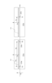
図1は本実施形態における可動子101および固定子201を含む搬送装置の全体構成を示す概略図である。
Figure 1 is a schematic diagram showing the overall configuration of a conveying device including a
図1に示すように、本実施形態による搬送装置1は、台車、スライダ又はキャリッジを構成する可動子101と、搬送路を構成する固定子201とを有している。固定子201に対して非接触で可動子101を搬送する磁気浮上型の搬送装置として構成されている。本実施形態では、搬送装置1の一例として、可動磁石型リニアモータ(ムービング永久磁石型リニアモータ、可動界磁型リニアモータ)による搬送装置を示すが、可動コイル型による搬送装置であってもよい。
As shown in FIG. 1, the
搬送装置1は、例えば、固定子201に対して可動子101を搬送することにより、可動子101とともに移動するワーク102を加工作業を施す加工装置に搬送する。そして、ワーク102に加工作業を施し、物品を製造する。本実施形態においては、加工装置の一例として、蒸着装置を示す。図1において、140は蒸着源であり、固定子201がチャンバとなる。つまり、蒸着装置に、蒸着源に対して可動子101とともにワーク102を搬送する搬送装置1が備えられている。なお、図1では、固定子201に対して1台の可動子101を示しているが、これに限定されるものではない。搬送装置1においては、複数台の可動子101が固定子201に対して搬送されうる。
The
ここで、以下の説明において用いる座標軸、方向等を定義する。まず、可動子101の搬送方向である水平方向に沿ってX軸をとり、可動子101の搬送方向をX方向とする。また、X方向と直交する方向である鉛直方向に沿ってZ軸をとり、鉛直方向をZ方向とする。また、X方向及びZ方向に直交する方向に沿ってY軸をとり、X方向及びZ方向に直交する方向をY方向とする。さらに、X軸周りの回転をWx、Y軸、Z軸周りの回転を各々Wy,Wzとする。また、乗算の記号として“*”を使用する。また、可動子101の中心を原点Oとし、Y+側をR側、Y-側をL側として記載する。なお、可動子101の搬送方向は必ずしも水平方向である必要はないが、その場合も搬送方向をX方向として同様にY方向及びZ方向を定めることができる。
Here, the coordinate axes and directions used in the following description are defined. First, the X-axis is taken along the horizontal direction, which is the transport direction of the
次に、本実施形態による搬送装置1おける搬送対象である可動子101について図1及び図2を用いて説明する。
Next, the
なお、図1は可動子101及び固定子201をX方向から見た図である。図1の左半分は図2の(B)-(B)線に沿った断面を示している。また、図1の右半分は、図2の(A)-(A)線に沿った断面を示している。
Note that FIG. 1 shows the
永久磁石103L、103Rは、可動子101のX方向に沿った上面のL側およびR側の端部にそれぞれ配置されて取り付けられている。具体的には、可動子101の上面のR側に、永久磁石103aR、103bR、103cR、103dRが取り付けられている。また、可動子101の上面のL側に、永久磁石103aL、103bL、103cL、103dLが取り付けられている。なお、以下では、特に区別する必要がない限り、可動子101の上面の永久磁石を単に「永久磁石103」と表記する。また、R側とL側とを区別する必要まではないが、各永久磁石103を個別に特定する必要がある場合、各永久磁石103に対する符号の末尾からR又はLを除いた識別子としての小文字のアルファベットまでの符号を用いて各永久磁石103を個別に特定する。この場合、「永久磁石103a」、「永久磁石103b」、「永久磁石103c」又は「永久磁石103d」と表記して、各永久磁石103を個別に特定する。
永久磁石103aR、103dRは、可動子101のX方向に沿った上面のR側におけるX方向の一方の端部及び他方の端部に取り付けられている。永久磁石103bR、103cRは、可動子101の上面のR側の永久磁石103aR、103dR間に取り付けられている。永久磁石103aR、103bR、103cR、103dRは、例えば、X方向に等ピッチに配置されている。また、永久磁石103aR、103bR、103cR、103dRは、それぞれの中心が、例えば可動子101の上面の中心からR側に所定距離rx3離れたX方向に沿った直線上に並ぶように配置されている。
The permanent magnets 103aR, 103dR are attached to one end and the other end in the X direction on the R side of the top surface of the
永久磁石103aL、103dLは、可動子101のX方向に沿った上面のL側におけるX方向の一方の端部及び他方の端部に取り付けられている。永久磁石103bL、103cLは、可動子101の上面のL側の永久磁石103aL、103dL間に取り付けられている。永久磁石103aL、103bL、103cL、103dLは、例えば、X方向に等ピッチに配置されている。また、永久磁石103aL、103bL、103cL、103dLは、それぞれの中心が、例えば可動子101の上面の中心からL側に所定距離rx3離れたX方向に沿った直線上に並ぶように配置されている。さらに、永久磁石103aL、103bL、103cL、103dLは、X方向においてそれぞれ永久磁石103aR、103bR、103cR、103dRと同位置に配置されている。
The permanent magnets 103aL, 103dL are attached to one end and the other end of the L side of the upper surface of the
永久磁石103a、103dは、それぞれ可動子101の中心である原点OからX方向の一方及び他方の側に距離rz3だけ離れた位置に取り付けられている。永久磁石103a、103b、103c、103dは、それぞれ原点OからY方向に距離rx3だけ離れた位置に取り付けられている。永久磁石103c、103bは、それぞれ原点OからX方向の一方及び他方の側に距離ry3だけ離れた位置に取り付けられている。
Permanent magnets 103a and 103d are attached at positions a distance rz3 away from origin O, which is the center of
永久磁石103aR、103dR、103aL、103dLは、それぞれY方向に沿って配置された2個の永久磁石のセットである。永久磁石103a、103dは、それぞれ、固定子201側を向く外側の磁極の極性が交互に異なるように2個の永久磁石がY方向に沿って並べられて構成されたものである。なお、永久磁石103a、103dを構成するY方向に沿って配置された永久磁石の数は、2個に限定されるものではなく、複数個であればよい。また、永久磁石103a、103dを構成する永久磁石が配置される方向は、必ずしも搬送方向であるX方向と直交するY方向である必要はなく、X方向と交差する方向であればよい。すなわち、永久磁石103a、103dは、それぞれ磁極の極性が交互になるようにX方向と交差する方向に沿って配置された複数の永久磁石からなる磁石群であればよい。
Permanent magnets 103aR, 103dR, 103aL, and 103dL are each a set of two permanent magnets arranged along the Y direction. Each of permanent magnets 103a and 103d is configured by arranging two permanent magnets along the Y direction so that the polarity of the outer magnetic poles facing the
一方、永久磁石103bR、103cR、103bL、103cLは、それぞれX方向に沿って配置された3個の永久磁石のセットである。永久磁石103b、103cは、それぞれ、固定子201側を向く外側の磁極の極性が交互に異なるように3個の永久磁石がX方向に沿って並べられて構成されている。なお、永久磁石103b、103cを構成するX方向に沿って配置された永久磁石の数は、3個に限定されるものではなく、複数個であればよい。すなわち、永久磁石103b、103cは、磁極の極性が交互になるようにX方向に沿って配置された複数の永久磁石からなる磁石群であればよい。
On the other hand, permanent magnets 103bR, 103cR, 103bL, and 103cL are each a set of three permanent magnets arranged along the X direction.
各永久磁石103は、可動子101の上面のR側及びL側に設けられたヨーク107に取り付けられている。ヨーク107は、透磁率の大きな物質、例えば鉄で構成されている。
Each permanent magnet 103 is attached to a yoke 107 provided on the R side and L side of the upper surface of the
こうして、可動子101には、可動子101のX軸に沿った中心軸を対称軸として、複数の永久磁石103が、可動子101の上面のR側及びL側に対称に配置されている。永久磁石103が配置された可動子101は、後述するように、固定子201の複数のコイル202に電流を流すことにより永久磁石103が受ける力(電磁力)により姿勢が6軸制御されつつ移動可能に構成されている。
In this way, the
また、可動子101のX方向に沿った下面のL側およびR側の端部に、永久磁石108が2列配置されて取り付けられている。具体的には、可動子101の下面のR側に、永久磁石108Rが取り付けられている。また、可動子101の下面のL側に、永久磁石108Lが取り付けられている。なお、以下では、特に区別する必要がない限り、可動子101の下面の永久磁石を単に「永久磁石108」と表記する。
In addition, permanent magnets 108 are attached in two rows to the ends of the L and R sides of the underside of the
それぞれの永久磁石108は、可動子101の下面のR側及びL側に設けられたヨーク106R、106Lに取り付けられている。ヨーク106R、106Lは、透磁率の大きな物質、例えば鉄で構成されている。
Each permanent magnet 108 is attached to a
この永久磁石108と、後述する固定子201に設けられた永久磁石127との間に生じる反発力より、電源がOFFにされた場合など電磁力による制御が行われていない場合であっても可動子の位置を保つことが可能になる。つまり、永久磁石108と、固定子201に設けられた永久磁石127との間に、重力の方向と平行な方向に反発しあう力を生じさせることができる。つまり、複数の永久磁石127を、一方向に着磁させ、複数の永久磁石127と対向する複数の永久磁石108を、前記一方向に着磁された複数の永久磁石127と反発する方向に着磁させることにより反発しあう力を生じさせることができる。
The repulsive force generated between this permanent magnet 108 and the permanent magnet 127 provided on the
可動子101は、その上面あるいは下面に搬送すべきワーク102を載置あるいは装着した状態で搬送される。可動子101は、例えば、ワークホルダ等のワーク102を可動子101上に保持する保持機構を有していてもよい。
The
また可動子101は、可動子アダプタ105(105L、105R)に取り付けられていてもよい。この場合、永久磁石103L、108Lは、可動子アダプタ105Lに取り付けられ、永久磁石103R、108Rは、可動子アダプタ105Rに取り付けられる。
The
可動子101が可動子アダプタを有していると、可動子101の形状が変化しても可動子アダプタ105に取り付け可能であれば可動子101の設計を変更することなく搬送が可能である。本明細書において、可動子101は、保持機構を含んでいてもよく、可動子アダプタ105を含んでいてもよい。
If the
可動子アダプタ105L、105Rは、それぞれ、上面(105aL、105aR)、下面(105bL、105bR)、側面(105cL、105cR)を有している。本実施形態においては、側面(105cL、105cR)のそれぞれに、側面(105cL、105cR)から突出する凸部(105dL、105dR)を備えている。そして、固定子201に取り付けられたストッパ124の、上側突出部124aと下側突出部124bとの間に前記凸部105aが突き出すようにしておく。これにより、可動子101の浮上状態が変化してもストッパ124によって可動範囲(上側突出部124aと下側突出部124bとの間)を規制することが出来る。
The
次に、本実施形態による搬送装置1における固定子201について図1、図3、及び図10を用いて説明する。
Next, the
図3は、固定子201のコイル202を示す概略図である。なお、図3は、コイル202をZ方向下から上に向かって見た図である。
Figure 3 is a schematic diagram showing the
図3における固定子201は、可動子101の搬送方向であるX方向に沿って、複数のコイル202がそれぞれ配置されている例を示している。固定子201には、複数のコイル202が可動子101の上面のL側およびR側に配置された永久磁石103L、103Rと対向するように取り付けられている。L側の永久磁石103Lに対向して配置されるコイルを202L、R側の永久磁石103Rに対向して配置されるコイルを202R、と表記する。なお、以下では、特に区別する必要がない限り、コイルを単に「コイル202」と表記する。固定子201は搬送方向であるX方向に延在して可動子101の搬送路を形成する。
The
図1に示すように、固定子201に沿って搬送される可動子101は、L側に、リニアスケール111Lと、Yターゲット110Lと、Zターゲット109Lとを有している。同様に、R側には、Zターゲット109R(不図示)とを有している。なお、以下では、特に区別する必要がない限り、リニアスケールを単にリニアスケール111、Yターゲットを単にYターゲット110及びZターゲットを単にZターゲット109と表記する。リニアスケール111、Yターゲット110及びZターゲット109は、それぞれ例えば可動子101の側面にX方向に沿って取り付けられている。本明細書においてYターゲットとは、Yセンサの目標となる突起であり、YセンサとYターゲットとの距離を検知することにより、Y方向の位置を求めることができる。同様にZターゲットとは、Zセンサの目標となる突起であり、ZセンサとZターゲットとの距離を検知することにより、Z方向の位置を求めることができる。
As shown in FIG. 1, the
図1に示すように、固定子201は、L側に、複数のコイル202Lと、複数のリニアエンコーダ204Lと、複数のYセンサ122Lと、複数のZセンサ121Lとを有している。同様に、R側には、複数のコイル202Rと、複数のZセンサ121Rとを有している。なお、以下では、特に区別する必要がない限り、コイルを単にコイル202、リニアエンコーダを単にリニアエンコーダ0204、Yセンサを単にYセンサ122及びZセンサを単にZセンサ121と表記する。
As shown in FIG. 1, the
複数のコイル202は、可動子101の上面のR側及びL側の永久磁石103と対向可能なように、X方向に沿って2列に配置されて固定子201に取り付けられている。R側において1列に配置された複数のコイル202Rは、可動子101のR側の永久磁石103aR、103bR、103cR、103dRと対向可能にX方向に沿って配置されている。また、L側において1列に配置された複数のコイル202Lの可動子と対向する面は、可動子101のL側の永久磁石103aL、103bL、103cL、103dLと対向可能にX方向に沿って配置されている。
The
本実施形態では、可動子101のR側及びL側のコイル202の列が、それぞれ、互いに構成する複数の永久磁石の配置方向が異なる永久磁石103a、103d及び永久磁石103b、103cに対向可能に配置されている。このため、少ない列数のコイル202で、後述するように可動子101に対して搬送方向及び搬送方向とは異なる力を印加することができ、よって可動子101の搬送制御及び姿勢制御を実現することができる。
In this embodiment, the rows of
こうして、複数のコイル202は、可動子101が搬送される方向に沿って取り付けられている。複数のコイル202は、X方向に所定の間隔で並べられている。また、各コイル202は、その中心軸がZ方向を向くように取り付けられている。なお、コイル202は、コアにコイルが巻かれており、本実施形態において、コイルの位置とは、コアの位置を示す。
In this way, the
複数のコイル202は、例えば3個ずつの単位で電流制御されるようになっている。そのコイル202の通電制御される単位を「コイルユニット203」と記載する。コイル202は、通電されることにより、可動子101の永久磁石103との間で電磁力を発生して可動子101に対して力を印加することができる。
The
図1~図3において、永久磁石103a、103dは、それぞれY方向に2個の永久磁石が並べられた磁石群により構成されていている。これに対して、各コイル202は、永久磁石103a、103dの2個の永久磁石のY方向の中心がコイル202のY方向の中心と合致するように配置されている。永久磁石103a、103dに対向するコイル202に通電することで、永久磁石103a、103dに対してY方向に力を発生する。
In Figures 1 to 3, permanent magnets 103a and 103d are each composed of a magnet group in which two permanent magnets are arranged in the Y direction. In contrast, each
また、永久磁石103b、103cは、X方向に3個の永久磁石が並べられた磁石群により構成されている。これに対して、永久磁石103b、103cに対向するコイル202に通電することで、永久磁石103b、103cに対してX方向及びZ方向に力を発生する。
Furthermore,
複数のリニアエンコーダ204は、それぞれ可動子101のリニアスケール111と対向可能なようにX方向に沿って固定子201に取り付けられている。各リニアエンコーダ204は、可動子101に取り付けられたリニアスケール111を読み取ることで、可動子101のリニアエンコーダ204に対する相対的な位置を検出して出力することができる。
The multiple
複数のYセンサ122は、それぞれ可動子101のYターゲット105と対向可能なようにX方向に沿って固定子201に取り付けられている。各Yセンサ122は、可動子101に取り付けられたYターゲット110との間のY方向の相対距離を検出して出力することができる。
The
複数のZセンサ121は、それぞれ可動子101のZターゲット109と対向可能なようにX方向に沿って固定子201に2列に取り付けられている。各Zセンサ121は、可動子101に取り付けられたZターゲット109との間のZ方向の相対距離を検出して出力することができる。
The
図10は、固定子201の永久磁石127L、127Rを示す概略図である。なお、図10は、永久磁石127L、127RをZ方向上から下に向かって見た図である。
Figure 10 is a schematic diagram showing
図10における固定子201には、複数の永久磁石127が、可動子101の下面のL側およびR側に配置された永久磁石108L、108Rと対向するように取り付けられている。L側の永久磁石108Lに対向して配置される永久磁石を127L、R側の永久磁石108Rに対向して配置される永久磁石を127R、と表記する。永久磁石127Lは、固定子201に設けられたヨーク126Lに取り付けられていてもよい。永久磁石127Rは、固定子201に設けられたヨーク126Rに取り付けられていてもよい。ヨーク126は、透磁率の大きな物質、例えば鉄で構成されている。永久磁石127Lはブラケット125Lを介して固定子に取り付けられていてもよく、永久磁石127Rはブラケット125Rを介して固定子に取り付けられていてもよい。
In FIG. 10, a plurality of permanent magnets 127 are attached to the
なお、以下では、特に区別する必要がない限り、永久磁石を単に「永久磁石127」と表記する場合がある。 In the following, unless there is a need to make a particular distinction, the permanent magnet may simply be referred to as "permanent magnet 127."
図1において、永久磁石108L、108Rと永久磁石127L、127Rの内部の矢印は各々の永久磁石の着磁方向を示している。例えば矢印の先がN極矢印の根本がS極である。図1にあるように永久磁石108Lと永久磁石127Lは着磁方向がZ方向に逆方向を向いている。従って、永久磁石108Lと永久磁石127Lは近づくと互いに反発する方向に力が大きくなる。同様に、永久磁石108Rと永久磁石127Rは着磁方向がZ方向に逆方向を向いている。従って、永久磁石108Rと永久磁石127Rは近づくと互いに反発する方向に力が大きくなる。
In Figure 1, the arrows inside
永久磁石108Lと対向する位置であってストッパ124によるZ方向の可動範囲より離れた位置に、永久磁石127Lが固定子201に取り付けられている。同様に、永久磁石108Rと対向する位置であってストッパ124による可動範囲より離れた位置に、永久磁石127Rが固定子201に取り付けられている。
さらに、永久磁石108Lと永久磁石127L、永久磁石108Rと永久磁石127Rはその中心位置がY方向に予めずらして配置されている。図1では永久磁石127Lが永久磁石108Lより外側に配置されている。同様に永久磁石127Rが永久磁石108Rより外側に配置されている。このように配置することで後述するようにY方向にもポテンシャルエネルギーが極小になる位置がありその位置の周りにおいてコイル202が通電されていない状態においても可動子101の位置がY方向に安定した位置を維持できる。
Furthermore,
この可動子と固定子の状態を、図15を用いて説明する。 The state of the mover and stator is explained using Figure 15.
図15は永久磁石間に働く力の大きさの実験結果の一例である。 Figure 15 shows an example of experimental results on the magnitude of the force acting between permanent magnets.
図15は横軸にZ方向の位置、縦軸にZ方向に受ける力の大きさをプロットしてある。 In Figure 15, the horizontal axis plots the position in the Z direction, and the vertical axis plots the magnitude of the force acting in the Z direction.
コイル202と永久磁石103との間に働く吸引力の大きさは1501、永久磁石108と永久磁石127との間に働く反発力の大きさは1502であり、両者とも上方向に受ける力である。例えば可動子101の質量が1500kgであった場合、合力1503が15000NであるときにZ=ZtおよびZ=Zb近傍で力は釣り合う。
The attractive force acting between
特にZ=Zb近傍では、ZがZbより小さくなると合力1503は可動子101がうける重力より大きくなり上方向に加速度が発生する。逆にZがZbより大きくなると合力1503は可動子101が受ける重力よりも小さくなるので下方向に加速される。そのため、Z=Zb付近では位置が安定する。
In particular, in the vicinity of Z = Zb, when Z becomes smaller than Zb, the
また、実験の結果から吸引力1501はZがZ+方向になるとそのグラフの勾配が大きくなる。また同様に永久磁石同士の反発力1502のグラフの勾配はZがZ-方向になるとグラフの傾きが大きくなることが分かった。
The experimental results also showed that the gradient of the graph of
このことから、コイル202およびそれと対向する永久磁石103、永久磁石108と対向する永久磁石127の位置と大きさを適切に選択すればコイル202に通電しない状態でもその位置を安定させられることが分かる。
This shows that if the positions and sizes of
以上を、図11Aを用いてポテンシャルエネルギーの考え方に基づいて詳細に説明する。 The above will be explained in detail using Figure 11A based on the concept of potential energy.
図11Aは可動子101が受ける力の大きさを模式的に表した図である。
Figure 11A is a schematic diagram showing the magnitude of the force acting on the
図11Aは横軸にZ+、縦軸には可動子101がZ方向に受ける力の大きさFzおよび可動子101のポテンシャルエネルギーΦZをとる。
In Figure 11A, the horizontal axis represents Z+, and the vertical axis represents the magnitude of force Fz that the
以下、コイル202には通電しない状態において受ける力について説明する。
The force that
可動子101が受ける力の大きさ(Fz)は、永久磁石103がコイル202に吸引される力(Fa)、永久磁石108が永久磁石127に押し上げられる力(Fb)、重力(-mg)がある。コイル202はコアを有するのでコイルに電流を印加しない状態でも吸引力が働く。
Fz=Fa+Fb-mg
The magnitude of the force (Fz) acting on the
Fz = Fa + Fb - mg
図11Aでは簡単のため、Fbの符号を反転してプロットしてある。
Fa-mg:1101a
-Fb:1102a
とすると
Fz=Fa+Fb-mg = (Fa-mg)-(-Fb)
となるので、Fzは図中1106aで示される矢印の大きさになる。すなわち、Z=ZbからZ=Ztの区間では下向き、それ以外の区間では上向きの力を受けることになる。
For simplicity, the sign of Fb is inverted in FIG. 11A.
Fa-mg: 1101a
-Fb: 1102a
Then, Fz = Fa + Fb-mg = (Fa-mg) - (-Fb)
Therefore, Fz is the size of the arrow indicated by 1106a in the figure. In other words, a downward force is received in the section from Z=Zb to Z=Zt, and an upward force is received in the other sections.
これをポテンシャルエネルギーΦZで説明する。 This is explained using potential energy ΦZ.
可動子101が持つポテンシャルエネルギーΦZは、可動子101が受ける力(F)に対抗して移動させる力の積分で定義されるので、∫を積分記号として
Φz=-∫(Fa+Fb-mg)dz+定数
で定義される。
The potential energy ΦZ of the
定数を適当にとるとポテンシャルエネルギーΦZ(1103a)は図のようになり、Z=Zbで極小値、Z=Ztで極大値をとる。物体はポテンシャルエネルギーが極小となる位置で安定化するのでZ=Zbで安定化する。 If the constants are chosen appropriately, the potential energy ΦZ (1103a) will be as shown in the figure, with a minimum value at Z = Zb and a maximum value at Z = Zt. The object stabilizes at the position where the potential energy is at a minimum, so it stabilizes at Z = Zb.
ここで、ストッパ124の位置を調整して可動子101の可動範囲を1107aから1108aの範囲に限定すれば可動子101はコイル202による電気的な制御が停止された場合でもZ=Zbの位置で安定する。
Here, if the position of the stopper 124 is adjusted to limit the movable range of the
同様に、可動子101がY方向に受ける力の大きさを図12において説明する。
Similarly, the magnitude of the force that the
ここで、可動子101のポテンシャルエネルギーΦyを
Φy=-∫(FyL+FyR)dy+定数
で定義する。
Here, the potential energy Φy of the
FyLはL側の永久磁石(永久磁石127Lと永久磁石108L)から受けるY方向の力、FyRはR側の永久磁石(永久磁石127Rと永久磁石108R)から受けるY方向の力の大きさである。
FyL is the magnitude of the force in the Y direction received from the permanent magnets on the L side (
今、FyL(1201)は正方向にとり、FyR(1202)は符号を反転して記載することに注意すれば
Φy=-∫(FyL-(-FyR))dy+定数
となるのでポテンシャルエネルギーΦyは矢印1122を積分したものになりΦY(1203)のような形状になる。
Now, if we note that FyL (1201) is taken in the positive direction and FyR (1202) is written with the sign inverted, then Φy = -∫(FyL - (-FyR)) dy + constant, and therefore the potential energy Φy is the integration of arrow 1122 and has a shape like ΦY (1203).
Φy(1203)はY=Ycで極小値をとるのでZ方向と同様、可動子101はY=Ycの位置で安定する。
Since Φy (1203) has a minimum value at Y = Yc, the
以上の構成を取れば、可動子101はコイル202に通電しない状態においてもZ=Zb,Y=Ycの位置で安定する。
With the above configuration, the
本実施形態では永久磁石127の中心と永久磁石108の中心は、搬送方向(X方向)と交差する方向(Y方向)の位置をずらして配置することでY方向に制御可能であり、安定させることができる。つまり、搬送方向(X方向)と交差する方向(Y方向)の位置を所定距離シフトさせて配置することでY方向に制御可能であり安定させることができる。しかしこれに限らず、例えばY方向にも別途永久磁石を設置して互いに反発するように構成することで位置を安定させることも出来る。 In this embodiment, the center of permanent magnet 127 and the center of permanent magnet 108 can be controlled and stabilized in the Y direction by shifting their positions in the direction (Y direction) that intersects with the conveying direction (X direction). In other words, they can be controlled and stabilized in the Y direction by shifting their positions in the direction (Y direction) that intersects with the conveying direction (X direction) by a predetermined distance. However, this is not limited to the above, and the positions can also be stabilized by, for example, installing separate permanent magnets in the Y direction and configuring them to repel each other.
本実施形態では図11AにあるようにポテンシャルエネルギーΦZの極大値をとる位置(Zt)と極小値を取る位置(Zb)は
Zb<Zt
の関係にある。この場合反発用の永久磁石(永久磁石127、108)が無い場合のFz-mg=0となる位置、すなわちコイル202と永久磁石103との間の吸引力が可動子101の重力と釣り合う位置(Z0)よりも可動子101はコイル202から離れた位置にある。
In this embodiment, as shown in FIG. 11A, the position (Zt) where the potential energy ΦZ has a maximum value and the position (Zb) where the potential energy ΦZ has a minimum value are Zb<Zt.
In this case, the
この構成ではコイル202と永久磁石103との間に働く推力定数はZ=Z0にある時よりも小さくなるのでその分可動子101を搬送する際の電流はZ=Z0にある時よりも大きくなる場合がある。
In this configuration, the thrust constant acting between the
次に、本実施形態による搬送装置1を制御する制御システムについてさらに図4を用いて説明する。図4は、本実施形態による搬送装置を制御する制御システムを示す概略図である。
Next, the control system for controlling the conveying
図4に示すように、制御システムは、統合コントローラ301と、コイルコントローラ302と、センサコントローラ304とを有し、可動子101と固定子201とを含む搬送装置を制御する制御装置として機能する。統合コントローラ301には、コイルコントローラ302が通信可能に接続されている。また、統合コントローラ301には、センサコントローラ304が通信可能に接続されている。
As shown in FIG. 4, the control system has an integrated
コイルコントローラ302には、複数の電流コントローラ303が通信可能に接続されている。コイルコントローラ302及びこれに接続された複数の電流コントローラ303は、2列のコイル202(図1参照)のそれぞれの列に対応して設けられている。各電流コントローラ303には、複数のコイル202(図1参照)によるコイルユニット203が接続されている。電流コントローラ303は、接続されたコイルユニット203の各々のコイル202の電流の大きさを制御することができる。
A plurality of
コイルコントローラ302は、接続された各々の電流コントローラ303に対して目標となる電流値を指令する。電流コントローラ303は接続されたコイル202の電流量を制御する。
The
コイル202は、可動子101が搬送されるX方向の可動子101の上面の両側に取り付けられている。
The
センサコントローラ304には、複数のリニアエンコーダ204、複数のYセンサ122及び複数のZセンサ121が通信可能に接続されている。
Multiple
複数のリニアエンコーダ204は、可動子101が搬送中もそのうちの1つが必ず1台の可動子101の位置を測定できるような間隔で固定子201に取り付けられている。また、複数のYセンサ122は、そのうちの2つが必ず1台の可動子101のYターゲット105を測定できるような間隔で固定子201に取り付けられている。また、複数のZセンサ121は、その2列のうちの3つが必ず1台の可動子101のZターゲット109を測定できるような間隔で固定子201に取り付けられている。
The multiple
統合コントローラ301は、リニアエンコーダ204、Yセンサ122及びZセンサ121からの出力に基づき、複数のコイル202に印加する電流指令値を決定して、コイルコントローラ302に送信する。コイルコントローラ302は、統合コントローラ301からの電流指令値に基づき、上述のように電流コントローラ303に対して電流値を指令する。これにより、統合コントローラ301は、制御装置として機能し、固定子201に沿って可動子101を非接触で搬送するとともに、搬送する可動子101の姿勢を6軸で制御する。
The
以下、統合コントローラ301により実行される可動子101の姿勢制御方法について図5を用いて説明する。図5は、本実施形態による搬送装置1における可動子101の姿勢制御方法を示す概略図である。図5は、可動子101の姿勢制御方法の概略について主にそのデータの流れに着目して示している。統合コントローラ301(図4参照)は、以下に説明するように、可動子位置算出関数401、可動子姿勢算出関数402、可動子姿勢制御関数403及びコイル電流算出関数404を用いた処理を実行する。これにより、統合コントローラ301は、可動子101の姿勢を6軸で制御しつつ、可動子101の搬送を制御する。なお、統合コントローラ301に代えて、コイルコントローラ302が統合コントローラ301と同様の処理を実行するように構成することもできる。
The attitude control method of the
まず、可動子位置算出関数401は、複数のリニアエンコーダ204からの測定値及びその取り付け位置の情報から、搬送路を構成する固定子201上にある可動子101の台数及び位置を計算する。これにより、可動子位置算出関数401は、可動子101に関する情報である可動子情報406の可動子位置情報(X)及び台数情報を更新する。可動子位置情報(X)は、固定子201上の可動子101の搬送方向であるX方向における位置を示している。可動子情報406は、例えば図5中にPOS-1、POS-2、…と示すように固定子201上の可動子101ごとに用意される。
First, the mover
次いで、可動子姿勢算出関数402は、可動子位置算出関数401により更新された可動子情報406の可動子位置情報(X)から、各々の可動子101を測定可能なYセンサ122及びZセンサ121を特定する。次いで、可動子姿勢算出関数402は、特定されたYセンサ122及びZセンサ121から出力される値に基づき、各々の可動子101の姿勢に関する情報である姿勢情報(Y,Z,Wx、Wy,Wz)を算出して可動子情報406を更新する。可動子姿勢算出関数402により更新された可動子情報406は、可動子位置情報(X)及び姿勢情報(Y,Z,Wx、Wy,Wz)を含んでいる。
Then, the mover
次いで、可動子姿勢制御関数403は、可動子位置情報(X)及び姿勢情報(Y,Z,Wx、Wy,Wz)を含む現在の可動子情報406及び姿勢目標値から、各々の可動子101について印加力情報408を算出する。印加力情報408は、各々の可動子101に印加すべき力の大きさに関する情報である。印加力情報408は、後述する印加すべき力Tの力の3軸成分(Tx,Ty,Tz)及びトルクの3軸成分(Twx,Twy,Twz)に関する情報を含んでいる。印加力情報408は、例えば図5中にTRQ-1、TRQ-2、…と示すように固定子201上の可動子101ごとに用意される。
Next, the mover
次いで、コイル電流算出関数404は、印加力情報408及び可動子情報406に基づき、各コイル202に印加する電流指令値409を決定する。
Next, the coil
こうして、統合コントローラ301は、可動子位置算出関数401、可動子姿勢算出関数402、可動子姿勢制御関数403及びコイル電流算出関数404を用いた処理を実行することにより、電流指令値409を決定する。統合コントローラ301は、決定した電流指令値409をコイルコントローラ302に送信する。
In this way, the
ここで、可動子位置算出関数401による処理について図6を用いて説明する。図6は、可動子位置算出関数による処理を説明する概略図である。
Here, the processing by the mover
図6において、基準点Oeは、リニアエンコーダ204が取り付けられている固定子201の位置基準である。また、基準点Osは、可動子101に取り付けられているリニアスケール111の位置基準である。図6では、可動子101として2台の可動子101a、101bが搬送され、リニアエンコーダ204として3つのリニアエンコーダ204a、204b、204cが配置されている場合を示している。なお、リニアスケール111は、各可動子101a、101bの同じ位置にX方向に沿って取り付けられている。
In FIG. 6, reference point Oe is the position reference of the
例えば、図6に示す可動子101bのリニアスケール111には、1つのリニアエンコーダ204cが対向している。リニアエンコーダ204cは、可動子101bのリニアスケール111を読み取って距離Pcを出力する。また、リニアエンコーダ204cの基準点Oeを原点とするX軸上の位置はScである。したがって、可動子101bの位置Pos(101b)は次式(1)により算出することができる。
Pos(101b)=Sc-Pc …式(1)
For example, one
Pos(101b)=Sc-Pc...Equation (1)
例えば、図6に示す可動子101aのリニアスケール111には、2つのリニアエンコーダ204a、204bが対向している。リニアエンコーダ204aは、可動子101aのリニアスケール111を読み取って距離Paを出力する。また、リニアエンコーダ204aの基準点Oeを原点とするX軸上の位置はSaである。したがって、リニアエンコーダ204aの出力に基づく可動子101aのX軸上の位置Pos(101a)は、次式(2)で算出することができる。
Pos(101a)=Sa+Pa …式(2)
For example, two
Pos(101a)=Sa+Pa...Equation (2)
また、リニアエンコーダ204bは、可動子101aのリニアスケール111を読み取って距離Pbを出力する。また、リニアエンコーダ204bの基準点Oeを原点とするX軸上の位置はSbである。したがって、リニアエンコーダ204bの出力に基づく可動子101aのX軸上の位置Pos(101a)′は、次式(3)により算出することができる。
Pos(101a)′=Sb-Pb …式(3)
Furthermore, the
Pos(101a)′=Sb−Pb …Equation (3)
ここで、各々のリニアエンコーダ204a、204bの位置は予め正確に測定されているため、2つの値Pos(101a)、Pos(101a)′の差は十分に小さい。このように2つのリニアエンコーダ204の出力に基づく可動子101のX軸上の位置の差が十分小さい場合は、それら2つのリニアエンコーダ204は、同一の可動子101のリニアスケール111を観測していると判定することができる。
Here, the position of each
なお、複数のリニアエンコーダ204が同一の可動子101と対向する場合は、複数のリニアエンコーダ204の出力に基づく位置の平均値を算出する等して、観測された可動子101の位置を一意に決定することができる。
When multiple
可動子位置算出関数401は、上述のようにしてリニアエンコーダ204の出力に基づき、可動子位置情報として可動子101のX方向における位置Xを算出して決定する。
The mover
次に、可動子姿勢算出関数402による処理について図7、図8A及び図8Bを用いて説明する。
Next, the processing by the mover
図7では、可動子101として可動子101cが搬送され、Yセンサ122としてYセンサ122a、122bが配置されている場合を示している。図7に示す可動子101cのYターゲット110には、2つのYセンサ122a、122bが対向している。2つのYセンサ122a、122bが出力する相対距離の値をそれぞれYa、Ybとし、Yセンサ122a、122b間の間隔がLyの場合、可動子101cのZ軸周りの回転量Wzは、次式(4)により算出される。
Wz=(Ya-Yb)/Ly …式(4)
Fig. 7 shows a case where
Wz=(Ya-Yb)/Ly...Equation (4)
なお、可動子101の位置によっては3つ以上のYセンサ122が対向する場合もありうる。その場合、最小二乗法等を使ってYターゲット110の傾き、すなわちZ軸周りの回転量Wzを算出することができる。
Depending on the position of the
また、図8A及び図8Bでは、可動子101として可動子101dが搬送され、Zセンサ121としてZセンサ121a、121b、121cが配置されている場合を示している。図8A及び図8Bに示す可動子101dのZターゲット109には、3つのZセンサ121a、121b、121cが対向している。ここで、3つのZセンサ121a、121b、121cが出力する相対距離の値をそれぞれZa、Zb、Zcとする。また、X方向のセンサ間距離、すなわちZセンサ121a、121b間の距離をLz1とする。また、Y方向のセンサ間距離、すなわちZセンサ121a、121c間の距離をLz2とする。すると、Y軸周りの回転量Wy及びX軸周りの回転量Wxは、それぞれ次式(5a)及び(5b)により算出することができる。
Wy=(Zb-Za)/Lz1 …式(5a)
Wx=(Zc-Za)/Lz2 …式(5b)
8A and 8B show a case where the
Wy=(Zb-Za)/Lz1...Equation (5a)
Wx=(Zc-Za)/Lz2 ... formula (5b)
可動子姿勢算出関数402は、上述のようにして、可動子101の姿勢情報として各軸周りの回転量Wx、Wy,Wzを算出することができる。
As described above, the mover
また、可動子姿勢算出関数402は、次のようにして可動子101の姿勢情報として可動子101のY方向の位置Y及びZ方向の位置Zを算出することができる。
In addition, the mover
まず、可動子101のY方向の位置Yの算出について図7を用いて説明する。図7において、可動子101cがかかる2つのYセンサ122をそれぞれYセンサ122a、122bとする。また、Yセンサ122a、122bの測定値をそれぞれYa、Ybとする。また、Yセンサ122aの位置とYセンサ122bの位置との中点をOe′とする。さらに、式(1)~(3)で得られた可動子101cの位置をOs′とし、Oe′からOs′までの距離をdX′とする。このとき、可動子101cのY方向の位置Yは、次式により近似的に計算して算出することができる。
Y=(Ya+Yb)/2-Wz*dX′
First, the calculation of the position Y of the
Y = (Ya + Yb) / 2 - Wz * dX'
次に、可動子101のZ方向の位置Zの算出について図8A及び図8Bを用いて説明する。可動子101dがかかる3つのZセンサ121をそれぞれZセンサ121a、121b、121cとする。また、Zセンサ121a、121b、121cの測定値をそれぞれZa、Zb、Zcとする。また、Zセンサ121aのX座標とZセンサ121cのX座標とは同一である。また、リニアエンコーダ204は、Zセンサ121aとZセンサ121cとの中間の位置にあるものとする。また、Zセンサ121a及びZセンサ121cの位置XをOe″とする。さらに、Oe″から可動子101の中心Os″までの距離をdX″とする。このとき、可動子101のZ方向の位置Zは、次式により近似的に計算して算出することができる。
Z=(Za+Zb)/2+Wy*dX″
Next, the calculation of the position Z of the
Z = (Za + Zb) / 2 + Wy * dX"
なお、位置Y及び位置ZともにそれぞれWz、Wyの回転量が大きい場合には、さらに近似の精度を高めて算出することができる。 If the rotation amounts Wz and Wy of positions Y and Z are large, respectively, the approximation can be calculated with even higher accuracy.
次に、コイル電流算出関数404による処理について図1を用いて説明する。なお、以下で用いる力の表記において、X方向、Y方向及びZ方向の力が働く方向をそれぞれx、y、zで示し、図1におけるY+側であるR側をR、Y-側であるL側をL、X+側をf、X-方向をbで示す。
Next, the processing by the coil
図2AにおいてR側及びL側の各永久磁石103に働く力をそれぞれ次のように表記する。各永久磁石103に働く力は、電流が印加された複数のコイル202により永久磁石103が受ける電磁力である。永久磁石103は、電流が印加された複数のコイル202により、可動子101の搬送方向であるX方向の電磁力のほか、X方向とは異なる方向であるY方向及びZ方向の電磁力を受ける。
In FIG. 2A, the forces acting on each permanent magnet 103 on the R side and L side are expressed as follows. The forces acting on each permanent magnet 103 are electromagnetic forces that the permanent magnet 103 receives from the
R側の永久磁石103に働く力の表記は、それぞれ次のとおりである。
FzfR:R側の永久磁石103bRのZ方向に働く力
FxfR:R側の永久磁石103bRのX方向に働く力
FyfR:R側の永久磁石103aRのY方向に働く力
FxbR:R側の永久磁石103cRのX方向に働く力
FybR:R側の永久磁石103dRのY方向に働く力
FzbR:R側の永久磁石103cRのZ方向に働く力
The forces acting on the permanent magnet 103 on the R side are expressed as follows:
FzfR: force acting in the Z direction of the permanent magnet 103bR on the R side FxfR: force acting in the X direction of the permanent magnet 103bR on the R side FyfR: force acting in the Y direction of the permanent magnet 103aR on the R side FxbR: force acting in the X direction of the permanent magnet 103cR on the R side FybR: force acting in the Y direction of the permanent magnet 103dR on the R side FzbR: force acting in the Z direction of the permanent magnet 103cR on the R side
L側の永久磁石103に働く力の表記は、それぞれ次のとおりである。
FzfL:L側の永久磁石103bLのZ方向に働く力
FxfL:L側の永久磁石103bLのX方向に働く力
FyfL:L側の永久磁石103aLのY方向に働く力
FxbL:L側の永久磁石103cLのX方向に働く力
FybL:L側の永久磁石103dLのY方向に働く力
FzbL:L側の永久磁石103cLのZ方向に働く力
The forces acting on the L-side permanent magnet 103 are expressed as follows:
FzfL: force acting in the Z direction of the L-side permanent magnet 103bL FxfL: force acting in the X direction of the L-side permanent magnet 103bL FyfL: force acting in the Y direction of the L-side permanent magnet 103aL FxbL: force acting in the X direction of the L-side permanent magnet 103cL FybL: force acting in the Y direction of the L-side permanent magnet 103dL FzbL: force acting in the Z direction of the L-side permanent magnet 103cL
また、可動子101に対して印加される力Tを次式(6)により表記する。なお、Tx、Ty、Tzは、力の3軸成分であり、それぞれ力のX方向成分、Y方向成分及びZ方向成分である。また、Twx,Twy、Twzは、モーメントの3軸成分であり、それぞれモーメントのX軸周り成分、Y軸周り成分及びZ軸周り成分である。本実施形態による搬送装置1は、これら力Tの6軸成分(Tx,Ty,Tz,Twx,Twy,Twz)を制御することにより、可動子101の姿勢を6軸で制御しつつ、可動子101の搬送を制御する。
T=(Tx,Ty,Tz,Twx,Twy,Twz) …式(6)
Moreover, the force T applied to the
T = (Tx, Ty, Tz, Twx, Twy, Twz) ... Equation (6)
すると、Tx、Ty、Tz、Twx、Twy、Twzは、それぞれ次式(7a)、(7b)、(7c)、(7d)、(7e)及び(7f)により算出される。
Tx=FxfR+FxbR+FxfL+FxbL …式(7a)
Ty=FyfL+FyfR+FybL+FybR …式(7b)
Tz=FzbR+FzbL+FzfR+FzfL …式(7c)
Twx={(FzfL+FzbL)-(FzfR+FzbR)}*rx3 …式(7d)
Twy={(FzfL+FzfR)-(FzbL+FzbR)}*ry3 …式(7e)
Twz={-(FyfL+FyfR)+(FybL+FybR)}*rz3 …式(7f)
Then, Tx, Ty, Tz, Twx, Twy, and Twz are calculated by the following equations (7a), (7b), (7c), (7d), (7e), and (7f), respectively.
Tx=FxfR+FxbR+FxfL+FxbL...Equation (7a)
Ty = FyfL + FyfR + FybL + FybR ... formula (7b)
Tz = FzbR + FzbL + FzfR + FzfL ... formula (7c)
Twx={(FzfL+FzbL)-(FzfR+FzbR)}*rx3 ... formula (7d)
Twy={(FzfL+FzfR)-(FzbL+FzbR)}*ry3 ... formula (7e)
Twz={-(FyfL+FyfR)+(FybL+FybR)}*rz3 ... formula (7f)
このとき、永久磁石103に働く力については、次式(7g)、(7h)、(7i)及び(7j)により表される制限を導入することができる。これらの制限を導入することにより、所定の6軸成分を有する力Tを得るための各永久磁石103に働く力の組み合わせを一意に決定することができる。
FxfR=FxbR=FxfL=FxbL …式(7g)
FyfL=FyfR …式(7h)
FybL=FybR …式(7i)
FzbR=FzbL …式(7j)
In this case, the limitations expressed by the following equations (7g), (7h), (7i), and (7j) can be introduced into the forces acting on the permanent magnets 103. By introducing these limitations, it is possible to uniquely determine a combination of forces acting on each permanent magnet 103 to obtain a force T having predetermined six-axis components.
FxfR = FxbR = FxfL = FxbL ... formula (7g)
FyfL = FyfR ... formula (7h)
FybL = FybR ... formula (7i)
FzbR = FzbL ... formula (7j)
次に、コイル電流算出関数404が、各永久磁石103に働く力から各コイル202に印加する電流量を決定する方法について説明する。
Next, we will explain how the coil
まず、N極及びS極の極性がZ方向に交互に並んだ永久磁石103a、103dにZ方向の力を印加する場合について説明する。なお、コイル202は、そのZ方向の中心が永久磁石103a、103dのY方向の中心に位置するように配置されている。これにより、永久磁石103a、103dに対してX方向及びY方向に働く力は、殆ど発生しないようになっている。
First, we will explain the case where a force in the Z direction is applied to permanent magnets 103a and 103d, whose north and south poles are arranged alternately in the Z direction. The
Xを可動子101の位置、jを列に並んだコイル202の番号として、単位電流当たりのコイル202(j)のZ方向に働く力の大きさをFz(j、X)とし、コイル202(j)に印加する電流をi(j)とする。なお、コイル202(j)は、j番目のコイル202である。この場合、電流i(j)は、次式(8)を満足するように決定することができる。なお、次式(8)は、永久磁石103dRについての式である。他の永久磁石103aR、103aL、103dLについても同様にしてコイル202に印加する電流を決定することができる。
Let X be the position of the
ここで、各コイル202に印加する電流とコイル202に働く力の線形性について説明する。図9において永久磁石103はコイル202に対向していて永久磁石103から出た磁束の多くはコイル202内を通過して再び永久磁石103に戻る。
Here, we will explain the linearity of the current applied to each
仮に永久磁石103の起磁力を900kA/m、厚み0.01mとした場合、永久磁石の起磁力は
900kA/m*0.01m=9000A
となる。
If the magnetomotive force of the permanent magnet 103 is 900 kA/m and the thickness is 0.01 m, the magnetomotive force of the permanent magnet is 900 kA/m*0.01 m=9000 A.
It becomes.
一方コイル202の巻き数を900回とし電流として1Aを印加した場合の起磁力は
900*1A=900A
900Aであり、永久磁石103が作る起磁力が十分大きい。このような場合、コイル202に印加する電流量と新たに発生する力の関係は十分線形であることが一般的に知られている。 そのため、
ΣFz(j、X)*i(j)=FzbR …式(8)
が成立する。
On the other hand, when the number of turns of the
900 A, which is a sufficiently large magnetomotive force generated by the permanent magnet 103. In such a case, it is generally known that the relationship between the amount of current applied to the
ΣFz(j,X)*i(j)=FzbR ... Equation (8)
holds true.
コイル電流算出関数404は、上述のようにしてコイル202(j)に印加する電流指令値を決定することができる。こうして決定される電流指令値により可動子101に印加されるZ方向の力により、可動子101は、Z方向に浮上する浮上力を得るとともに、その姿勢が制御される。
The coil
なお、複数のコイル202が永久磁石103に力を及ぼす場合には、各コイル202が及ぼす力に応じて単位電流当たりの力の大きさで電流を按分することにより、永久磁石103に働く力を一意に決定することができる。
When
また、図1に示すように、永久磁石103は、可動子101のL側及びR側に対称に配置されている。このような永久磁石103の対称配置により、永久磁石103に働く多成分の力、例えば永久磁石103a、103dに働くWxの力、すなわちX軸周りのモーメント成分をL側及びR側の力で相殺することが可能になる。この結果、より高精度な可動子101の姿勢の制御が可能になる。
As shown in FIG. 1, the permanent magnets 103 are arranged symmetrically on the L side and R side of the
次に、N極、S極及びN極の極性がX方向に交互に並んだ永久磁石103bに対してX方向及びY方向に対して独立に力を印加する方法について説明する。図9は、永久磁石103bに対してX方向及びY方向に独立に力を印加する方法を説明する概略図である。コイル電流算出関数404は、以下に従って、永久磁石103bに対してX方向及びY方向に対して独立に力を印加するためにコイル202に印加する電流指令値を決定する。なお、永久磁石103cについても、永久磁石103bと同様にX方向及びY方向に対して独立に力を印加することができる。
Next, a method of applying forces in the X and Y directions independently to
Xを可動子101の位置、jを列に並んだコイル202の番号として、単位電流当たりのコイル202(j)のX方向及びY方向に働く力の大きさを、それぞれFx(j、X)及びFy(j、X)とする。また、コイル202(j)の電流の大きさをi(j)とする。なおコイル202(j)は、j番目のコイル202である。
Let X be the position of the
図9Aは、横にX軸、縦にY軸を取り、永久磁石103bRに対向する6個のコイル202を抜き出して示す図である。図9Bは、図9AをY方向から見た図である。コイル202には、X方向に並んだ順に1から6までの番号jを付与し、以下では例えばコイル202(1)のように表記して各コイル202を特定する。
Figure 9A is a diagram showing six
図9A及び図9Bに示すように、コイル202は、距離Lのピッチでされている。一方、可動子101の永久磁石103は、距離3/2*Lのピッチで配置されている。
As shown in Figures 9A and 9B, the
図9Cのグラフは、図9A及び図9Bに示す各々のコイル202に対して単位電流を印加した際に発生するX方向の力Fx及びZ方向の力Fzの大きさを模式的に示したグラフである。
The graph in Figure 9C is a graph that shows the magnitude of the X-direction force Fx and the Z-direction force Fz that are generated when a unit current is applied to each of the
簡単のため、図9では、コイル202のX方向の位置の原点Ocをコイル202(3)とコイル202(4)の中間とし、永久磁石103bRのX方向の中心Omを原点としている。このため、図9は、OcとOmとが合致した場合、すなわちX=0の場合を示している。
For simplicity, in FIG. 9, the origin Oc of the X-direction position of
このとき、例えばコイル202(4)に対して働く単位電流当たりの力は、X方向にFx(4,0)、Z方向にFz(4,0)の大きさである。また、コイル202(5)に対して働く単位電流当たりの力は、X方向にFx(5,0)、Z方向にFz(5,0)の大きさである。 In this case, for example, the force per unit current acting on coil 202(4) is Fx(4,0) in the X direction and Fz(4,0) in the Z direction. Also, the force per unit current acting on coil 202(5) is Fx(5,0) in the X direction and Fz(5,0) in the Z direction.
ここで、コイル202(1)~202(6)に印加する電流値をそれぞれi(1)~i(6)とする。すると、永久磁石103bRに対して、X方向に働く力の大きさFxfR及びY方向に働く力の大きさFzfRは、それぞれ一般的に次式(9)及び(10)で表される。
FxfR=Fx(1,X)*i(1)+Fx(2,X)*i(2)+Fx(3,X)*i(3)+Fx(4,X)*i(4)+Fx(5,X)*i(5)+Fx(6,X)*i(6) …式(9)
FzfR=Fz(1,X)*i(1)+Fz(2,X)*i(2)+Fz(3,X)*i(3)+Fz(4,X)*i(4)+Fz(5,X)*i(5)+Fz(6,X)*i(6) …式(10)
Here, the current values applied to coils 202(1) to 202(6) are i(1) to i(6), respectively. Then, the magnitude of force FxfR acting in the X direction and the magnitude of force FzfR acting in the Y direction on permanent magnet 103bR are generally expressed by the following equations (9) and (10), respectively.
FxfR = Fx(1,X) * i(1) + Fx(2,X) * i(2) + Fx(3,X) * i(3) + Fx(4,X) * i(4) + Fx(5,X) * i(5) + Fx(6,X) * i(6) ... Equation (9)
FzfR = Fz(1,X) * i(1) + Fz(2,X) * i(2) + Fz(3,X) * i(3) + Fz(4,X) * i(4) + Fz(5,X) * i(5) + Fz(6,X) * i(6) ... Equation (10)
上記式(9)及び(10)を満足する電流値i(1)~i(6)をそれぞれコイル202(1)~202(6)に印加されるように電流指令値を決定することにより、永久磁石103bRに対してX方向及びZ方向に独立に力を印加することができる。コイル電流算出関数404は、永久磁石103に対してX方向及びZ方向に独立に力を印加するために、上述のようにしてコイル202(j)に印加する電流指令値を決定することができる。
By determining the current command value so that the current values i(1) to i(6) that satisfy the above formulas (9) and (10) are applied to the coils 202(1) to 202(6), respectively, it is possible to apply forces independently in the X and Z directions to the permanent magnet 103bR. The coil
より簡単のため、図9に示す場合において、永久磁石103bRに対してコイル202(1)~202(6)のうちのコイル202(3)、202(4)、202(5)だけを使い、さらにこれら3つの電流値の総和が0となるように制御する場合を例に考える。この例の場合、永久磁石103bRに対してX方向に働く力FxfR及びZ方向に働く力FzfRは、それぞれ次式(11)及び(12)により表される。
FxfR=Fx(3,X)*i(3)+Fx(4,X)*i(4)+Fx(5,X)*i(5) …式(11)
FzfR=Fz(3,X)*i(3)+Fz(4,X)*i(4)+Fz(5,X)*i(5) …式(12)
For simplicity's sake, in the case shown in Figure 9, let us consider an example in which only coils 202(3), 202(4), and 202(5) of coils 202(1) to 202(6) are used for permanent magnet 103bR, and furthermore, the sum of the current values of these three is controlled to be 0. In this example, the force FxfR acting in the X direction and the force FzfR acting in the Z direction on permanent magnet 103bR are expressed by the following equations (11) and (12), respectively.
FxfR=Fx(3,X)*i(3)+Fx(4,X)*i(4)+Fx(5,X)*i(5) ... Equation (11)
FzfR=Fz(3,X)*i(3)+Fz(4,X)*i(4)+Fz(5,X)*i(5) ...Equation (12)
また、コイル202(1)~202(6)の電流値は、次式(13)及び(14)を満足するように設定することができる。
i(3)+i(4)+i(5)=0 …式(13)
i(1)=i(2)=i(6)=0 …式(14)
Moreover, the current values of the coils 202(1) to 202(6) can be set so as to satisfy the following expressions (13) and (14).
i(3)+i(4)+i(5)=0 ... Equation (13)
i(1)=i(2)=i(6)=0 ... Equation (14)
したがって、永久磁石103bRに対して必要な力の大きさ(FxfR、FzfR)が決定された場合、電流値i(1)、i(2)、i(3)、i(4)、i(5)及びi(6)を一意に決定することができる。こうして決定される電流指令値により可動子101にX方向及びZ方向に力が印加される。可動子101に印加されるX方向の力により、可動子101は、X方向に移動する推進力を得てX方向に移動する。また、こうして決定される電流指令値により可動子101に印加されるX方向及びZ方向の力により、可動子101はその姿勢が制御される。
Therefore, when the magnitude of the force required for the permanent magnet 103bR (FxfR, FzfR) is determined, the current values i(1), i(2), i(3), i(4), i(5), and i(6) can be uniquely determined. Forces are applied to the
こうして、統合コントローラ301は、複数のコイル202に印加する電流を制御することにより、可動子101に印加する力の6軸成分のそれぞれを制御する。
In this way, the
なお、可動子101の搬送により永久磁石103bRの中心Omに対してコイル202の中心Ocが移動した場合、すなわちX≠0の場合は、移動した位置に応じたコイル202を選択することができる。さらに、コイル202に発生する単位電流当たりの力に基づいて、上記と同様の計算を実行することができる。
When the center Oc of the
上述のようにして、統合コントローラ301は、複数のコイル202に印加する電流の電流指令値を決定して制御することにより、固定子201上での可動子101の姿勢を6軸で制御しつつ、可動子101の非接触での固定子201上の搬送を制御する。すなわち、統合コントローラ301は、可動子101の搬送を制御する搬送制御手段として機能し、複数のコイル202により永久磁石103が受ける電磁力を制御することにより、固定子201上における可動子101の非接触での搬送を制御する。また、統合コントローラ301は、可動子101の姿勢を制御する姿勢制御手段として機能し、固定子201上における可動子101の姿勢を6軸で制御する。なお、制御装置としての統合コントローラ301の機能の全部又は一部は、コイルコントローラ302その他の制御装置により代替されうる。
As described above, the
このように、本実施形態によれば、2列に配置された複数のコイル202により、可動子101に対して、3軸の力成分(Tx,Ty,Tz)及び3軸のモーメント成分(Twx,Twy,Twz)の6軸の力を印加することができる。これにより、可動子101の姿勢を6軸で制御しつつ、可動子101の搬送を制御することができる。本実施形態によれば、制御すべき変数である力の6軸成分の数よりも少ない列数である2列のコイル202により、可動子101の姿勢の6軸制御しつつ、可動子101の搬送を制御することができる。
In this way, according to this embodiment, six-axis forces, consisting of three-axis force components (Tx, Ty, Tz) and three-axis moment components (Twx, Twy, Twz), can be applied to the
したがって、本実施形態によれば、コイル202の列数を少なく構成することができるため、システムの大型化や複雑化を伴うことなく、可動子101の姿勢を制御しつつ、可動子101を非接触で搬送することができる。さらに、本実施形態によれば、コイル202の列数を少なく構成することができるため、安価に小型の磁気浮上型の搬送装置を構成することができる。
Therefore, according to this embodiment, the number of rows of
[第二の実施形態]
図13を用いて第二の実施形態について説明する。
[Second embodiment]
The second embodiment will be described with reference to FIG.
第一の実施形態では、可動子101のX方向に沿った下面のL側およびR側の端部に、永久磁石108が2列配置されて取り付けられている例を示した。それに対し、本実施形態においては、永久磁石1301Lが、可動子の上面に取り付けられている例を示す。R側については図示および説明を省略するが、L側と同様である。また、第一の実施形態から変更のない構成については、同じ符号を付し説明を省略する。図13において、永久磁石1301Lが、可動子の上面に取り付けられ、永久磁石1303Lが固定子201に取り付けられている。そして、可動子側の永久磁石1301Lと固定子側の永久磁石1303Lが互いに反発する方向に着磁されている。つまり、可動子側の永久磁石1301Lと固定子側の永久磁石1303Lは互いに反発しあう。1302L、1303Lはそれぞれヨークで、1305Lは固定子201との間のブラケットである。
In the first embodiment, an example was shown in which the permanent magnets 108 are arranged in two rows and attached to the ends of the L side and R side of the lower surface along the X direction of the
これにより、可動子101が上昇すると固定子201に取り付けられた永久磁石1303Lから反発力を受ける構成となっている。
As a result, when the
図11Bでさらに詳細に説明する。 This is explained in further detail in Figure 11B.
図11Bは図11Aと同様に可動子101が受ける力を模式的に表した図である。
Figure 11B is a schematic diagram showing the forces acting on the
図11Aと異なり図11BではFbがZ+方向に行くに従ってその絶対値が大きくなっている。また反発力は下向きの力であるのでFbは図11Aと異なり第二象限(FZ>0)にある。 Unlike Figure 11A, in Figure 11B the absolute value of Fb increases as it moves in the Z+ direction. Also, since the repulsive force is a downward force, Fb is in the second quadrant (FZ>0), unlike Figure 11A.
この場合、コイル202と永久磁石103の関係を変えないとするとFa-mg(1101b)のプロファイルは図11A(1101a)と同じである。一方、Fbの大きさはFa-mg(1101b)よりその勾配の変化が大きくなるように構成されている(1102b)。
In this case, if the relationship between the
以上のように反発しあう永久磁石(1301、1303)を構成すれば図11BにあるようにZ=ZbでそのポテンシャルエネルギーΦZは極小値をとり、Z=Ztで極大値ととる。従って、Z=Zb近傍で可動子101の位置は安定する。
If the repelling permanent magnets (1301, 1303) are configured as described above, the potential energy ΦZ will be at a minimum value when Z = Zb, as shown in Figure 11B, and at a maximum value when Z = Zt. Therefore, the position of the
第二の実施形態の場合、第一の実施形態と比較してFa-mgの勾配が大きい領域で安定化させる必要があるのでFbの勾配はそれよりさらに大きくなる必要があるため反発しあう永久磁石(1301、1303)は第一の実施形態と比べて大型化しやすい。 In the case of the second embodiment, it is necessary to stabilize in the region where the Fa-mg gradient is large compared to the first embodiment, so the Fb gradient needs to be even larger, and therefore the repelling permanent magnets (1301, 1303) tend to be larger than in the first embodiment.
しかしながら、本実施形態ではZ=Z0の位置に比べてコイル202に近い側で可動子101の位置が安定するのでZ=Z0あるいは第一の実施形態と比較して推力定数が大きくなる場合がある。従って同じ推力を発生させる場合でも小さな電流で済む。
However, in this embodiment, the position of the
一方、第一の実施形態と比較してポテンシャルエネルギーの深さ(1105b)は第一の実施形態のポテンシャルエネルギーの深さ(1105a)と比較して小さくなる傾向になるので安定化の度合いが小さい。 On the other hand, compared to the first embodiment, the potential energy depth (1105b) tends to be smaller compared to the potential energy depth (1105a) of the first embodiment, so the degree of stabilization is smaller.
また、第二の実施形態の場合、コイル202と反発用の永久磁石(1301、1303)を近接して配置して設計することが可能なので装置構成をよりコンパクトにすることが出来る。また、加工のためのプロセス装置が可動子101の下側にある蒸着源(図1の140参照)であるような場合、反発しあう永久磁石(1301、1303)が可動子101の下方にあると蒸着源400の邪魔になりかねない。しかし、そういった場合も永久磁石(1301、1303)を蒸着源(図1の140参照)等のプロセス装置の反対側に位置することが出来るため有効である。
In the second embodiment, the
[第三の実施形態]
図14を用いて第三の実施形態について説明する。
[Third embodiment]
The third embodiment will be described with reference to FIG.
第一の実施形態では、可動子101のX方向に沿った下面のL側およびR側の端部に、永久磁石108が2列配置されて取り付けられている例を示した。また、第二の実施形態では、可動子に取り付けられた永久磁石1301Lが下側、固定子に取り付けられた永久磁石1303Lが上側になるように可動子および固定子に取り付けることで、可動子が上昇すると反発力を受ける例を示した。本実施形態では、可動子に取り付けられた永久磁石1401Lが上側、固定子に取り付けられた永久磁石1403Lが下側になるように可動子および固定子に取り付けることで、可動子が下降すると反発力を受ける例を示す。図14ではL側のみについて記載しており、R側については図示および説明を省略するが、L側と同様である。また、第一の実施形態または第二の実施形態から変更のない構成については、同じ符号を付し説明を省略する。図14において、永久磁石1401Lが、可動子の上面に取り付けられた可動子アダプタ105に取り付けられ、永久磁石1403Lが固定子201に取り付けられたブラケット1405Lに取り付けられている。そして、可動子側の永久磁石1401Lと固定子側の永久磁石1403Lが互いに反発する方向に着磁されている。1402L、1403Lはそれぞれヨークで、1305Lは固定子201との間のブラケットである。
In the first embodiment, an example was shown in which the permanent magnets 108 are arranged in two rows and attached to the ends of the L side and R side of the lower surface along the X direction of the
これにより、可動子101が下降すると固定子201に取り付けられた永久磁石1403Lから反発力を受ける構成となっている。
As a result, when the
可動子アダプタ105および固定子のブラケット1305Lの形状が互いにS字の形状になり大型化しやすい。しかし、可動子101が下降すると固定子側の永久磁石1403Lから反発する力を受けるので、第一の実施形態のようにポテンシャルFzを深くすることが容易で安定化させやすい。
The shapes of the mover adapter 105 and the
ポテンシャルエネルギーΦZのとりかたは第一の実施形態と同様であるので説明を省略する。 The method for calculating the potential energy ΦZ is the same as in the first embodiment, so the explanation is omitted.
[第四の実施形態]
図16を用いて第四の実施形態について説明する。
[Fourth embodiment]
The fourth embodiment will be described with reference to FIG.
第一の実施形態では、可動子101のX方向に沿った下面のL側およびR側の端部に、永久磁石108が2列配置されて取り付けられている例を示した。
In the first embodiment, an example was shown in which permanent magnets 108 are arranged in two rows and attached to the ends of the L and R sides of the lower surface of the
本実施形態では、第一の実施形態に加えて、Y方向用の永久磁石のセット、1601L、1602Lが配置されている例を示す。図16ではL側のみについて記載しており、R側については図示および説明を省略するが、L側と同様である。また、第一の実施形態または第二の実施形態から変更のない構成については、同じ符号を付し説明を省略する。 In this embodiment, in addition to the first embodiment, an example is shown in which a set of permanent magnets for the Y direction, 1601L and 1602L, are arranged. In FIG. 16, only the L side is described, and the R side is not shown or described, but is the same as the L side. Also, the same reference numerals are used for configurations that are unchanged from the first or second embodiment, and descriptions are omitted.
Y方向用の永久磁石のセット、1601L、1602Lを配置することで可動子101の位置をY方向にも安定化させることが出来る。
By arranging a set of permanent magnets for the Y direction, 1601L and 1602L, the position of the
なお、永久磁石1601L,1602Lは永久磁石だけでもよいし、裏側にヨークを取り付けてもよい。
Note that
[第五の実施形態]
図17を用いて第五の実施形態について説明する。
[Fifth embodiment]
The fifth embodiment will be described with reference to FIG.
第一の実施形態では、可動子101のX方向に沿った下面のL側およびR側の端部に、永久磁石108が2列配置されて取り付けられている例を示した。また、図1において、永久磁石108L、127Lの形状が平板状である例を示した。
In the first embodiment, an example was shown in which the permanent magnets 108 are arranged in two rows and attached to the ends of the L and R sides of the lower surface of the
本実施形態では、図1の平板状の永久磁石108L、127Lに変えて、C字形状に湾曲した永久磁石1701Lと1702Lがそれぞれ配置されていて対向して置かれている例を示す。図17ではL側のみについて記載しており、R側については図示および説明を省略するが、L側と同様である。また、第一の実施形態または第二の実施形態から変更のない構成については、同じ符号を付し説明を省略する。
In this embodiment, instead of the flat
図17に示すようにC字形状に湾曲した永久磁石1701Lと1702Lを配置することで可動子101の位置をY方向にも安定化させることが出来る。
As shown in Figure 17, by arranging
なお、永久磁石1701L,1702Lは、永久磁石だけでもよいし、裏側にヨークを取り付けてもよい。
Note that
なお、図17では永久磁石1701Lが永久磁石1702Lに囲われる形状になっているが、その磁石の関係を逆にした配置としてもよい。
In addition, in FIG. 17,
[第六の実施形態]
図18を用いて第六の実施形態について説明する。
[Sixth embodiment]
The sixth embodiment will be described with reference to FIG.
第一の実施形態では、可動子101のX方向に沿った下面のL側およびR側の端部に、永久磁石108が2列配置されて取り付けられている例を示した。また、図1において、永久磁石108L、127Lの形状が平板状である例を示した。
In the first embodiment, an example was shown in which the permanent magnets 108 are arranged in two rows and attached to the ends of the L and R sides of the lower surface of the
本実施形態では、図1の平板状の永久磁石108Lに変えて、平板状の永久磁石1801aL、1802aLがV字状に配置され、平板状の永久磁石1801aL、1802aLに対向して永久磁石1801bL、1802bLが置かれている例を示す。図18ではL側のみについて記載しており、R側については図示および説明を省略するが、L側と同様である。また、第一の実施形態または第二の実施形態から変更のない構成については、同じ符号を付し説明を省略する。
In this embodiment, instead of the flat
図18に示すように平板状の永久磁石1801aL、1802aLをV字型に配置することで可動子101の位置をY方向にも安定化させることが出来る。
As shown in FIG. 18, by arranging the flat permanent magnets 1801aL and 1802aL in a V-shape, the position of the
なお、永久磁石1801aL、1802aL、1801bL、1802bLは永久磁石だけでもよいし、裏側にヨークを取り付けてもよい。 Note that permanent magnets 1801aL, 1802aL, 1801bL, and 1802bL may be permanent magnets alone, or a yoke may be attached to the back side.
なお、図18では永久磁石1801aL、1801bLが永久磁石1802aL、1802bLに囲われる形状になっているが、その磁石の関係を逆にした配置としてもよい。 In FIG. 18, permanent magnets 1801aL and 1801bL are surrounded by permanent magnets 1802aL and 1802bL, but the magnets may be arranged in the opposite relationship.
[第七の実施形態]
図19を用いて第七の実施形態について説明する。
[Seventh embodiment]
The seventh embodiment will be described with reference to FIG.
第一の実施形態では、可動子101のX方向に沿った下面のL側およびR側の端部に、永久磁石108が2列配置されて取り付けられている例を示した。また、図1において、永久磁石108L、127Lの形状が平板状である例を示した。
In the first embodiment, an example was shown in which the permanent magnets 108 are arranged in two rows and attached to the ends of the L and R sides of the lower surface of the
本実施形態では、図1ではL側に1列配置された永久磁石127Lの代わりに、L側に2列に配置された永久磁石1902aL、1902bLが永久磁石108Lと対向して置かれている例を示す。図19ではL側のみについて記載しており、R側については図示および説明を省略するが、L側と同様である。また、第一の実施形態または第二の実施形態から変更のない構成については、同じ符号を付し説明を省略する。
In this embodiment, instead of the
図19に示すようにL側に2列に永久磁石1902aL、1902bLを配置することで可動子101の位置をY方向にも安定化させることが出来る。
As shown in Figure 19, by arranging permanent magnets 1902aL and 1902bL in two rows on the L side, the position of the
なお、永久磁石1902aL、1902bLは永久磁石だけでもよいし、裏側にヨークを取り付けてもよい。 Note that permanent magnets 1902aL and 1902bL may be permanent magnets alone, or a yoke may be attached to the back side.
なお、図19では分割された永久磁石1902aL、1902bLが固定子側に取り付けられているが、可動子側の磁石108Lと固定子側の永久磁石1902aL、1902bLとの配置関係を逆にしてもよい。
In FIG. 19, the divided permanent magnets 1902aL and 1902bL are attached to the stator side, but the positional relationship between the
なお、第1から第7の実施形態においてはコイル202と永久磁石103の組み合わせは可動子101の上面側にあったが、これを可動子101の下面側に置いてもよい。その場合、コイル202のコアは無いものが好適である。コイル202のコアが無い場合はコイル202に通電しない場合、コイル202と永久磁石103との間の吸引力が働かないので例えば図15において吸着力1501は働かない。
In the first to seventh embodiments, the combination of the
101 可動子
102 ワーク
103 永久磁石
105 可動子アダプタ
106 ヨーク
107 ヨーク
108 永久磁石
109 Zターゲット
110 Yターゲット
111 リニアスケール
121 Zセンサ
122 Yセンサ
124 ストッパ
125 ブラケット
126 ヨーク
127 永久磁石
REFERENCE SIGNS
Claims (14)
前記第1の方向に沿って移動する可動子と、を備え、
前記固定子は、前記第1の方向に沿って配置され、一方向に着磁された複数の第1の磁石をさらに有し、
前記可動子は、
前記複数のコイルに対向するように配置された複数の第2の磁石と、
前記複数の第1の磁石と対向するように配置され、前記複数の第1の磁石と反発する方向に着磁された複数の第3の磁石と、を有し、
前記コイルと前記複数の第2の磁石との相互作用で発生する力と、前記複数の第1の磁石と前記複数の第3の磁石とが反発しあう力によって、浮上する方向の力が制御される
ことを特徴とする搬送装置。 a stator having a plurality of coils arranged along a first direction;
a mover that moves along the first direction ,
the stator further includes a plurality of first magnets arranged along the first direction and magnetized in one direction;
The mover is
a plurality of second magnets arranged to face the plurality of coils;
a plurality of third magnets arranged to face the plurality of first magnets and magnetized in a direction repelling the plurality of first magnets ;
The force in the levitation direction is controlled by the force generated by the interaction between the coil and the plurality of second magnets and the repulsive force between the plurality of first magnets and the plurality of third magnets.
A conveying device characterized by the above .
前記固定子は、前記複数の第4の磁石と対向可能な位置に、前記複数の第4の磁石と反発する方向に着磁された複数の第5の磁石を有することを特徴とする請求項1乃至7いずれか一項に記載の搬送装置。 the movable element further includes a plurality of fourth magnets arranged on a side surface along the first direction and magnetized in one direction,
A conveying device as described in any one of claims 1 to 7, characterized in that the stator has a plurality of fifth magnets in a position capable of facing the plurality of fourth magnets, the fifth magnets being magnetized in a direction repelling the plurality of fourth magnets.
前記蒸着源が、前記複数の第1の磁石及び前記複数の第3の磁石よりも下方に設けられていることを特徴とする蒸着装置。 A deposition apparatus comprising the transport device according to any one of claims 1 to 11 and a deposition source,
The deposition apparatus, wherein the deposition source is provided below the plurality of first magnets and the plurality of third magnets.
Priority Applications (5)
| Application Number | Priority Date | Filing Date | Title |
|---|---|---|---|
| JP2019233231A JP7479835B2 (en) | 2019-12-24 | 2019-12-24 | TRANSPORTATION DEVICE AND METHOD FOR MANUFACTURING AN ARTICLE |
| US17/119,829 US11370621B2 (en) | 2019-12-24 | 2020-12-11 | Conveyance apparatus and manufacturing method of article |
| KR1020200179287A KR20210082088A (en) | 2019-12-24 | 2020-12-21 | Conveyance apparatus and manufacturing method of article |
| CN202011545704.9A CN113023372A (en) | 2019-12-24 | 2020-12-24 | Conveying apparatus and method of manufacturing article |
| US17/751,476 US11851274B2 (en) | 2019-12-24 | 2022-05-23 | Conveyance apparatus and manufacturing method of article |
Applications Claiming Priority (1)
| Application Number | Priority Date | Filing Date | Title |
|---|---|---|---|
| JP2019233231A JP7479835B2 (en) | 2019-12-24 | 2019-12-24 | TRANSPORTATION DEVICE AND METHOD FOR MANUFACTURING AN ARTICLE |
Publications (3)
| Publication Number | Publication Date |
|---|---|
| JP2021102495A JP2021102495A (en) | 2021-07-15 |
| JP2021102495A5 JP2021102495A5 (en) | 2022-12-28 |
| JP7479835B2 true JP7479835B2 (en) | 2024-05-09 |
Family
ID=76437840
Family Applications (1)
| Application Number | Title | Priority Date | Filing Date |
|---|---|---|---|
| JP2019233231A Active JP7479835B2 (en) | 2019-12-24 | 2019-12-24 | TRANSPORTATION DEVICE AND METHOD FOR MANUFACTURING AN ARTICLE |
Country Status (4)
| Country | Link |
|---|---|
| US (2) | US11370621B2 (en) |
| JP (1) | JP7479835B2 (en) |
| KR (1) | KR20210082088A (en) |
| CN (1) | CN113023372A (en) |
Families Citing this family (3)
| Publication number | Priority date | Publication date | Assignee | Title |
|---|---|---|---|---|
| JP7479835B2 (en) * | 2019-12-24 | 2024-05-09 | キヤノン株式会社 | TRANSPORTATION DEVICE AND METHOD FOR MANUFACTURING AN ARTICLE |
| TW202137866A (en) | 2020-02-20 | 2021-10-01 | 美商布魯克斯自動機械公司 | Substrate processing apparatus |
| EP3955436B1 (en) * | 2020-08-14 | 2024-01-17 | Schneider Electric Industries SAS | Linear motor system and operating method for same |
Citations (3)
| Publication number | Priority date | Publication date | Assignee | Title |
|---|---|---|---|---|
| JP2012138522A (en) | 2010-12-27 | 2012-07-19 | Canon Anelva Corp | Substrate transfer apparatus and vacuum processing apparatus |
| US20150188399A1 (en) | 2013-12-30 | 2015-07-02 | Samsung Display Co., Ltd. | Apparatus for transferring substrate |
| JP2016532308A (en) | 2013-10-16 | 2016-10-13 | コリア エレクトロテクノロジー リサーチ インスティテュートKorea Electrotechnology Research Institute | Magnetic levitation transport device |
Family Cites Families (21)
| Publication number | Priority date | Publication date | Assignee | Title |
|---|---|---|---|---|
| JPS6036222A (en) | 1983-08-05 | 1985-02-25 | Irie Koken Kk | Article conveying device under high-vaccum |
| JPS60249805A (en) | 1984-05-26 | 1985-12-10 | Hitachi Ltd | Magnetically levitating guiding device |
| JPH0616240A (en) * | 1992-07-01 | 1994-01-25 | Sumitomo Electric Ind Ltd | Stop holding device for magnetically levitated carrier |
| US5947361A (en) * | 1996-07-25 | 1999-09-07 | Emo Elektromotorenwerk Kamenz Gmbh | Apparatus for transporting fabrics and web-shaped material with an electric drive device |
| JPH1113855A (en) * | 1997-06-20 | 1999-01-22 | Komatsu Ltd | Magnetic coupling device |
| US6876896B1 (en) * | 1999-04-26 | 2005-04-05 | Ab Tetrapak | Variable motion system and method |
| US6629503B2 (en) * | 2001-06-29 | 2003-10-07 | The Regents Of The University Of California | Inductrack configuration |
| AT500107B1 (en) * | 2003-12-05 | 2007-03-15 | Colenta Laborsysteme Gmbh & Co | METHOD FOR THE FLUID TRANSPORT OF OBJECTS AND ARRANGEMENT FOR IMPLEMENTING THE PROCESS |
| JP2006313587A (en) * | 2005-05-06 | 2006-11-16 | Hitachi Global Storage Technologies Netherlands Bv | Demagnetization method of magnetic recording medium and demagnetizer |
| CN102723843A (en) * | 2007-04-16 | 2012-10-10 | 克瑞斯普兰股份有限公司 | Sorting system with linear synchronous motor drive |
| DE102009002606A1 (en) * | 2009-04-23 | 2010-10-28 | Robert Bosch Gmbh | Circulating transport device with improved drive concept |
| KR101146915B1 (en) * | 2009-11-26 | 2012-05-22 | 한국전기연구원 | Horizontal type contactless deposition apparatus |
| KR101386685B1 (en) * | 2012-04-20 | 2014-04-24 | 세메스 주식회사 | Apparatus for processing substrate |
| KR101939352B1 (en) * | 2012-06-11 | 2019-01-17 | 세메스 주식회사 | Magnetic levitation transfer apparatus |
| KR20150005110A (en) * | 2013-07-04 | 2015-01-14 | 진형일 | Magnetic levitation device, transportation system using the magnetic levitation device, and guide device using the magnetic levitation device |
| DE102016224951A1 (en) * | 2016-12-14 | 2018-06-14 | Robert Bosch Gmbh | Conveying device with a stator for the controlled transport of a transport body relative to the stator |
| JP7066333B2 (en) * | 2017-05-17 | 2022-05-13 | キヤノン株式会社 | Transport system, processing system, article manufacturing method, transport system control method and movable mechanism |
| JP7179488B2 (en) * | 2018-05-11 | 2022-11-29 | キヤノン株式会社 | Conveyor system and its control method |
| US10944314B2 (en) * | 2018-08-08 | 2021-03-09 | Canon Kabushiki Kaisha | Transport system, mover, control apparatus, and control method |
| JP7479835B2 (en) * | 2019-12-24 | 2024-05-09 | キヤノン株式会社 | TRANSPORTATION DEVICE AND METHOD FOR MANUFACTURING AN ARTICLE |
| JP7451205B2 (en) * | 2020-02-07 | 2024-03-18 | キヤノン株式会社 | Conveyance device and article manufacturing method |
-
2019
- 2019-12-24 JP JP2019233231A patent/JP7479835B2/en active Active
-
2020
- 2020-12-11 US US17/119,829 patent/US11370621B2/en active Active
- 2020-12-21 KR KR1020200179287A patent/KR20210082088A/en not_active Application Discontinuation
- 2020-12-24 CN CN202011545704.9A patent/CN113023372A/en active Pending
-
2022
- 2022-05-23 US US17/751,476 patent/US11851274B2/en active Active
Patent Citations (3)
| Publication number | Priority date | Publication date | Assignee | Title |
|---|---|---|---|---|
| JP2012138522A (en) | 2010-12-27 | 2012-07-19 | Canon Anelva Corp | Substrate transfer apparatus and vacuum processing apparatus |
| JP2016532308A (en) | 2013-10-16 | 2016-10-13 | コリア エレクトロテクノロジー リサーチ インスティテュートKorea Electrotechnology Research Institute | Magnetic levitation transport device |
| US20150188399A1 (en) | 2013-12-30 | 2015-07-02 | Samsung Display Co., Ltd. | Apparatus for transferring substrate |
Also Published As
| Publication number | Publication date |
|---|---|
| US11370621B2 (en) | 2022-06-28 |
| JP2021102495A (en) | 2021-07-15 |
| US20220281698A1 (en) | 2022-09-08 |
| US20210188569A1 (en) | 2021-06-24 |
| US11851274B2 (en) | 2023-12-26 |
| CN113023372A (en) | 2021-06-25 |
| KR20210082088A (en) | 2021-07-02 |
Similar Documents
| Publication | Publication Date | Title |
|---|---|---|
| JP7479835B2 (en) | TRANSPORTATION DEVICE AND METHOD FOR MANUFACTURING AN ARTICLE | |
| US20210159769A1 (en) | Transport system, mover, control apparatus, and control method | |
| WO2015056847A1 (en) | Magnetically levitated transportation apparatus | |
| US20230421037A1 (en) | Transport system, mover, control apparatus, and control method | |
| US11670998B2 (en) | Conveyance apparatus and method of manufacturing article | |
| JP2021126012A (en) | Conveyance system | |
| KR102546009B1 (en) | Conveying apparatus and method of manufacturing article | |
| CN111293855B (en) | Conveying device and article manufacturing method | |
| JP2022072439A (en) | Transport apparatus, vacuum apparatus, processing system, and article manufacturing method | |
| KR20210100013A (en) | Transport system, processing system, and article manufacturing method | |
| KR20210071844A (en) | Conveyance system, movable element, control apparatus, control method, and method of manufacturing articles | |
| JP2021126003A (en) | Conveyance apparatus, movable element, and manufacturing method for article | |
| US20220224255A1 (en) | Transport system, processing system, and article manufacturing method | |
| CN115447978A (en) | Conveying system and control method of conveying system | |
| JP2020167929A (en) | Conveyance system, movable element, control device, and control method | |
| KR20220058429A (en) | Transport system and control method of transport system | |
| JP2022108256A (en) | Transportation system, processing system, and method of manufacturing goods |
Legal Events
| Date | Code | Title | Description |
|---|---|---|---|
| A521 | Request for written amendment filed |
Free format text: JAPANESE INTERMEDIATE CODE: A523 Effective date: 20221219 |
|
| A621 | Written request for application examination |
Free format text: JAPANESE INTERMEDIATE CODE: A621 Effective date: 20221219 |
|
| A977 | Report on retrieval |
Free format text: JAPANESE INTERMEDIATE CODE: A971007 Effective date: 20230913 |
|
| A131 | Notification of reasons for refusal |
Free format text: JAPANESE INTERMEDIATE CODE: A131 Effective date: 20231017 |
|
| A521 | Request for written amendment filed |
Free format text: JAPANESE INTERMEDIATE CODE: A523 Effective date: 20231208 |
|
| RD01 | Notification of change of attorney |
Free format text: JAPANESE INTERMEDIATE CODE: A7421 Effective date: 20231213 |
|
| A131 | Notification of reasons for refusal |
Free format text: JAPANESE INTERMEDIATE CODE: A131 Effective date: 20240109 |
|
| A521 | Request for written amendment filed |
Free format text: JAPANESE INTERMEDIATE CODE: A523 Effective date: 20240305 |
|
| TRDD | Decision of grant or rejection written | ||
| A01 | Written decision to grant a patent or to grant a registration (utility model) |
Free format text: JAPANESE INTERMEDIATE CODE: A01 Effective date: 20240326 |
|
| A61 | First payment of annual fees (during grant procedure) |
Free format text: JAPANESE INTERMEDIATE CODE: A61 Effective date: 20240424 |
|
| R150 | Certificate of patent or registration of utility model |
Ref document number: 7479835 Country of ref document: JP Free format text: JAPANESE INTERMEDIATE CODE: R150 |