JP7479318B2 - Gaming Machines - Google Patents
Gaming Machines Download PDFInfo
- Publication number
- JP7479318B2 JP7479318B2 JP2021050612A JP2021050612A JP7479318B2 JP 7479318 B2 JP7479318 B2 JP 7479318B2 JP 2021050612 A JP2021050612 A JP 2021050612A JP 2021050612 A JP2021050612 A JP 2021050612A JP 7479318 B2 JP7479318 B2 JP 7479318B2
- Authority
- JP
- Japan
- Prior art keywords
- game
- winning
- role
- display
- counter
- Prior art date
- Legal status (The legal status is an assumption and is not a legal conclusion. Google has not performed a legal analysis and makes no representation as to the accuracy of the status listed.)
- Active
Links
- 230000008859 change Effects 0.000 claims description 158
- 238000012790 confirmation Methods 0.000 claims description 74
- 230000005856 abnormality Effects 0.000 claims description 9
- 238000000034 method Methods 0.000 description 645
- 230000008569 process Effects 0.000 description 622
- 230000000694 effects Effects 0.000 description 514
- 238000012545 processing Methods 0.000 description 198
- 238000003825 pressing Methods 0.000 description 131
- 230000007704 transition Effects 0.000 description 118
- 238000010586 diagram Methods 0.000 description 113
- 238000004519 manufacturing process Methods 0.000 description 97
- 238000012937 correction Methods 0.000 description 74
- 230000002349 favourable effect Effects 0.000 description 64
- 238000003860 storage Methods 0.000 description 64
- 239000010931 gold Substances 0.000 description 57
- 229910052737 gold Inorganic materials 0.000 description 57
- PCHJSUWPFVWCPO-UHFFFAOYSA-N gold Chemical compound [Au] PCHJSUWPFVWCPO-UHFFFAOYSA-N 0.000 description 56
- 238000009987 spinning Methods 0.000 description 52
- 238000001514 detection method Methods 0.000 description 42
- 238000003780 insertion Methods 0.000 description 38
- 230000037431 insertion Effects 0.000 description 37
- 230000004044 response Effects 0.000 description 36
- 230000002829 reductive effect Effects 0.000 description 31
- 238000011156 evaluation Methods 0.000 description 27
- 230000001960 triggered effect Effects 0.000 description 26
- 239000003086 colorant Substances 0.000 description 25
- 239000005022 packaging material Substances 0.000 description 25
- 230000014759 maintenance of location Effects 0.000 description 23
- 238000002788 crimping Methods 0.000 description 19
- 230000006870 function Effects 0.000 description 19
- 230000001965 increasing effect Effects 0.000 description 19
- 238000007792 addition Methods 0.000 description 18
- 230000005540 biological transmission Effects 0.000 description 18
- 238000004891 communication Methods 0.000 description 18
- 230000007246 mechanism Effects 0.000 description 18
- 230000005284 excitation Effects 0.000 description 17
- 125000004122 cyclic group Chemical group 0.000 description 16
- 244000208734 Pisonia aculeata Species 0.000 description 15
- 238000009434 installation Methods 0.000 description 15
- 241000219109 Citrullus Species 0.000 description 14
- 235000012828 Citrullus lanatus var citroides Nutrition 0.000 description 14
- 230000001186 cumulative effect Effects 0.000 description 13
- 239000000463 material Substances 0.000 description 11
- 238000012360 testing method Methods 0.000 description 11
- 230000002844 continuous effect Effects 0.000 description 10
- 230000001133 acceleration Effects 0.000 description 8
- 238000009825 accumulation Methods 0.000 description 8
- 230000006399 behavior Effects 0.000 description 8
- 238000005259 measurement Methods 0.000 description 8
- 239000011521 glass Substances 0.000 description 7
- 230000007423 decrease Effects 0.000 description 6
- 230000009467 reduction Effects 0.000 description 6
- 230000008901 benefit Effects 0.000 description 5
- 230000008034 disappearance Effects 0.000 description 5
- 238000005286 illumination Methods 0.000 description 5
- 230000004397 blinking Effects 0.000 description 4
- 239000013256 coordination polymer Substances 0.000 description 4
- 239000011347 resin Substances 0.000 description 4
- 229920005989 resin Polymers 0.000 description 4
- 239000000758 substrate Substances 0.000 description 4
- 241000167854 Bourreria succulenta Species 0.000 description 3
- 230000002159 abnormal effect Effects 0.000 description 3
- 235000019693 cherries Nutrition 0.000 description 3
- 238000004040 coloring Methods 0.000 description 3
- 239000012141 concentrate Substances 0.000 description 3
- 230000003247 decreasing effect Effects 0.000 description 3
- 239000003550 marker Substances 0.000 description 3
- 238000012544 monitoring process Methods 0.000 description 3
- 238000000465 moulding Methods 0.000 description 3
- 238000011144 upstream manufacturing Methods 0.000 description 3
- 230000003442 weekly effect Effects 0.000 description 3
- 230000009471 action Effects 0.000 description 2
- 239000000470 constituent Substances 0.000 description 2
- 230000008878 coupling Effects 0.000 description 2
- 238000010168 coupling process Methods 0.000 description 2
- 238000005859 coupling reaction Methods 0.000 description 2
- 238000005034 decoration Methods 0.000 description 2
- 238000013461 design Methods 0.000 description 2
- 238000011161 development Methods 0.000 description 2
- 230000018109 developmental process Effects 0.000 description 2
- 238000009792 diffusion process Methods 0.000 description 2
- 230000002708 enhancing effect Effects 0.000 description 2
- 230000003370 grooming effect Effects 0.000 description 2
- 230000003116 impacting effect Effects 0.000 description 2
- 239000004973 liquid crystal related substance Substances 0.000 description 2
- 238000012423 maintenance Methods 0.000 description 2
- 239000002184 metal Substances 0.000 description 2
- 229910052751 metal Inorganic materials 0.000 description 2
- 238000012986 modification Methods 0.000 description 2
- 230000004048 modification Effects 0.000 description 2
- 230000008450 motivation Effects 0.000 description 2
- 230000000737 periodic effect Effects 0.000 description 2
- 238000002360 preparation method Methods 0.000 description 2
- 230000002250 progressing effect Effects 0.000 description 2
- 230000002441 reversible effect Effects 0.000 description 2
- 229930091051 Arenine Natural products 0.000 description 1
- 206010048909 Boredom Diseases 0.000 description 1
- 206010012335 Dependence Diseases 0.000 description 1
- 241000196324 Embryophyta Species 0.000 description 1
- 206010016322 Feeling abnormal Diseases 0.000 description 1
- 241001465754 Metazoa Species 0.000 description 1
- 230000003213 activating effect Effects 0.000 description 1
- 230000032683 aging Effects 0.000 description 1
- PZTQVMXMKVTIRC-UHFFFAOYSA-L chembl2028348 Chemical compound [Ca+2].[O-]S(=O)(=O)C1=CC(C)=CC=C1N=NC1=C(O)C(C([O-])=O)=CC2=CC=CC=C12 PZTQVMXMKVTIRC-UHFFFAOYSA-L 0.000 description 1
- 230000002860 competitive effect Effects 0.000 description 1
- 238000010924 continuous production Methods 0.000 description 1
- 230000001934 delay Effects 0.000 description 1
- 238000012217 deletion Methods 0.000 description 1
- 230000037430 deletion Effects 0.000 description 1
- 230000002542 deteriorative effect Effects 0.000 description 1
- 230000008921 facial expression Effects 0.000 description 1
- 238000005562 fading Methods 0.000 description 1
- 239000011888 foil Substances 0.000 description 1
- 150000002343 gold Chemical class 0.000 description 1
- 230000012447 hatching Effects 0.000 description 1
- 210000003128 head Anatomy 0.000 description 1
- 230000006872 improvement Effects 0.000 description 1
- 238000001746 injection moulding Methods 0.000 description 1
- 230000005055 memory storage Effects 0.000 description 1
- 230000001151 other effect Effects 0.000 description 1
- 239000003973 paint Substances 0.000 description 1
- 239000000123 paper Substances 0.000 description 1
- 230000036961 partial effect Effects 0.000 description 1
- 230000002093 peripheral effect Effects 0.000 description 1
- 239000011120 plywood Substances 0.000 description 1
- 229920000515 polycarbonate Polymers 0.000 description 1
- 239000004417 polycarbonate Substances 0.000 description 1
- 230000000717 retained effect Effects 0.000 description 1
- 239000003566 sealing material Substances 0.000 description 1
- 230000008054 signal transmission Effects 0.000 description 1
- 229910000679 solder Inorganic materials 0.000 description 1
- 230000035882 stress Effects 0.000 description 1
- 230000001629 suppression Effects 0.000 description 1
- 230000009747 swallowing Effects 0.000 description 1
- 230000001360 synchronised effect Effects 0.000 description 1
- 230000002195 synergetic effect Effects 0.000 description 1
- 230000008685 targeting Effects 0.000 description 1
- 238000012546 transfer Methods 0.000 description 1
- 230000000007 visual effect Effects 0.000 description 1
- 239000002023 wood Substances 0.000 description 1
Images


Classifications
-
- Y—GENERAL TAGGING OF NEW TECHNOLOGICAL DEVELOPMENTS; GENERAL TAGGING OF CROSS-SECTIONAL TECHNOLOGIES SPANNING OVER SEVERAL SECTIONS OF THE IPC; TECHNICAL SUBJECTS COVERED BY FORMER USPC CROSS-REFERENCE ART COLLECTIONS [XRACs] AND DIGESTS
- Y02—TECHNOLOGIES OR APPLICATIONS FOR MITIGATION OR ADAPTATION AGAINST CLIMATE CHANGE
- Y02E—REDUCTION OF GREENHOUSE GAS [GHG] EMISSIONS, RELATED TO ENERGY GENERATION, TRANSMISSION OR DISTRIBUTION
- Y02E60/00—Enabling technologies; Technologies with a potential or indirect contribution to GHG emissions mitigation
- Y02E60/10—Energy storage using batteries
Landscapes
- Slot Machines And Peripheral Devices (AREA)
Description
本発明は、スロットマシンやぱちんこ機等の遊技機に関する。 The present invention relates to gaming machines such as slot machines and pachinko machines.
従来、遊技機には、スロットマシン(回胴式遊技機)、ぱちんこ遊技機、アレンジボール遊技機、じゃん球遊技機などがあり、この種の遊技機の中には、例えば特許文献1に示すようなスロットマシンがある。
Conventionally, gaming machines include slot machines (reel type gaming machines), pachinko gaming machines, arrange ball gaming machines, and jankyu gaming machines, and among these types of gaming machines, there is a slot machine such as that shown in
従来の遊技機では、遊技性を高めて遊技の興趣向上を図るためや、円滑に遊技を行えるようにするために、種々の工夫がなされてきたが更なる改善の余地がある。 In conventional gaming machines, various innovations have been made to improve the gameplay and make the game more interesting, and to make the gameplay smoother, but there is still room for further improvement.
本発明は、遊技の興趣を向上させることができる遊技機を提供することを目的とする。 The present invention aims to provide a gaming machine that can increase the enjoyment of gaming.
本発明は、以下のような特徴を備えている。なお、以下の特徴構成の説明では、後述する実施形態において対応する構成の一例を括弧書きで示している。 The present invention has the following features. In the following description of the characteristic configuration, an example of the corresponding configuration in the embodiment described below is shown in parentheses.
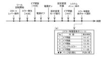
本発明に係る遊技機は、時刻を調整可能な時刻調整画面が表示可能であり、遊技機で発生し得る或る事象を検知可能であり、或る事象に関する履歴を表示可能な履歴画面が表示手段に表示可能であり、履歴画面には或る事象に関する時刻が表示可能であり、履歴画面に表示可能な或る事象には所定の異常を含み、時刻調整画面にて変更操作がされると時刻が変更可能であり、時刻調整画面にて決定操作がされると変更操作により変更された時刻に決定可能であり、時刻調整画面が表示されており、時刻調整画面にて時刻が或る時刻から他の或る時刻へ変更操作がされた後であって、変更操作後の他の或る時刻へ決定操作がされていないときに前記所定の異常を検知し、その後他の或る時刻へ決定操作がされてから履歴画面が表示されたときは、時刻調整画面にて変更操作がされる前の或る時刻に基づいた時刻が当該所定の異常に関する時刻として履歴画面に表示可能である。 The gaming machine of the present invention is capable of displaying a time adjustment screen which allows the time to be adjusted, is capable of detecting a certain event which may occur on the gaming machine, is capable of displaying a history screen on a display means which allows history relating to a certain event to be displayed, the history screen is capable of displaying the time relating to a certain event, the certain event which can be displayed on the history screen includes a predetermined abnormality , the time can be changed when a change operation is performed on the time adjustment screen, and the time changed by the change operation can be confirmed when a confirmation operation is performed on the time adjustment screen, the time adjustment screen is displayed, and after a change operation is performed from a certain time to another certain time on the time adjustment screen but no confirmation operation is performed to the other certain time after the change operation, the predetermined abnormality is detected when the time adjustment screen is displayed and then a confirmation operation is performed to the other certain time and then the history screen is displayed, a time based on a certain time before the change operation was performed on the time adjustment screen can be displayed on the history screen as the time relating to the predetermined abnormality .
上記構成の遊技機によれば、遊技の興趣を向上させることができる。 A gaming machine with the above configuration can increase the enjoyment of the game.
以下、上記図面を参照して本発明の実施形態について説明する。
なお、以下の説明における「役決定処理」とは予め設定された複数の役決定結果番号(1つまたは複数の遊技役またはハズレ(ハズレを設定しない場合は除く)により構成される)の中から、1つまたは複数の役決定結果番号(当選項目)を無作為に選択するために、電子機器等を用いて実行される抽選等の選択行為(「役決定」とも称する)を意味している。ここで、役決定結果番号とは、当該役決定結果番号が決定(選出)された遊技において成立することが許容される1つもしくは複数の遊技役(「成立許容役」や「当選役」とも称する)またはハズレを規定するものである。なお、役決定のことを「内部抽せん」または「役抽選」とも称し、抽選や当選における「選」は「籤」または「せん」とも称する。
Hereinafter, an embodiment of the present invention will be described with reference to the above drawings.
In the following explanation, "role determination process" refers to a selection action such as a lottery (also called "role determination") carried out using electronic devices, etc., in order to randomly select one or more role determination result numbers (winning items) from a number of pre-set role determination result numbers (consisting of one or more game roles or losses (except when losses are not set)). Here, the role determination result number specifies one or more game roles (also called "permitted roles" or "winning roles") or losses that are permitted to be established in a game in which the role determination result number is determined (selected). Note that role determination is also called "internal lottery" or "role lottery", and the "selection" in lottery or winning is also called "chosen" or "sen".
また、「遊技役が成立する」、「遊技役の成立」等と記載する場合の「成立」とは、決定された役決定結果番号に対応する遊技役(遊技メダルの払い出しがある遊技役(小役)か、払い出しのない遊技役(再遊技役や特別役)かは問わない)を構成する図柄組合せ(対応図柄)が、所定の停止態様(例えば、後述の有効ライン上に並ぶ態様)で表示されたことを示す概念として用いている。ただし、成立のタイミングについては、例えば、遊技役の対応図柄を有効ライン上に停止表示させることが可能なタイミングでリール停止操作が行われた時点や、遊技役の対応図柄が有効ライン上に停止表示された時点、スロットマシンが、遊技役の対応図柄が有効ライン上に停止表示されたことを識別した時点や、識別した結果を記憶領域に格納した時点等、適宜のタイミングとすることができる。 In addition, when describing "a game role is established" or "a game role is established", "establishment" is used as a concept indicating that the symbol combination (corresponding symbols) that constitutes the game role (whether it is a game role with a payout of game medals (minor role) or a game role without a payout (replay role or special role)) corresponding to the determined role determination result number is displayed in a predetermined stopping state (for example, a state in which they are lined up on an active line, which will be described later). However, the timing of establishment can be any appropriate timing, such as the time when the reel stop operation is performed at a time when the corresponding symbol of the game role can be stopped and displayed on the active line, the time when the corresponding symbol of the game role is stopped and displayed on the active line, the time when the slot machine identifies that the corresponding symbol of the game role is stopped and displayed on the active line, or the time when the identification result is stored in the memory area.
また、以下の説明において、遊技者による、後述のメダル投入口21への遊技メダルの投入操作(手入れする操作)と、クレジット(貯留)された遊技メダルのうち、遊技を行うために必要な規定数の遊技メダルを遊技の用に供するための、1-BETスイッチ22またはMAX-BETスイッチ23の押圧操作を総称してベット操作と称する。また、このベット操作と、遊技者による、後述の清算スイッチ24の押圧操作、スタートレバー(「スタートスイッチ」とも称する)25の傾動操作、ストップスイッチ(「ストップボタン」とも称する)26a,26b,26cの押圧操作を総称して遊技操作と称する。なお、一般的に、スロットマシンにおける「投入」とは、遊技メダルを「スロットマシン内に入れる」という意味で用いられる場合と、遊技メダルを「遊技の用に供する」という意味で用いられる場合とがある。以下の説明では、基本的に、前者の意味において「投入」という語を用い、後者の意味においては「ベット」という語を用いることとする。
In the following description, the player's operation of inserting (manipulating) game medals into the medal insertion slot 21 (described below) and the operation of pressing the 1-
また、遊技メダルの「払出数」(「払出枚数」とも称する)とは、1回の遊技において遊技者に付与される遊技メダル数を意味する。また、遊技メダルを払い出すという行為には、遊技メダルを実際にスロットマシンから外部に払い出すという行為(「実払い出し」とも称する)と、スロットマシン内に貯留される遊技メダルとして、電磁気的に記憶される数値を増加させるという行為(「貯留加算払い出し」とも称する)とがある。 The "number of medals paid out" (also called "number of medals paid out") refers to the number of medals awarded to a player in one game. The act of paying out medals includes the act of actually paying out medals from the slot machine to the outside (also called "actual payout") and the act of increasing the numerical value electromagnetically stored as medals stored in the slot machine (also called "storage addition payout").
また、遊技メダルの「獲得数」(「獲得枚数」とも称する)とは、所定期間(任意に設定可であるが、例えば、ATの期間やボーナスの期間)において、遊技者が獲得した(遊技者に対して払い出された)遊技メダルの総数として計数される数値のことを意味する。
また、遊技メダルの「差枚数」(「差数」とも称する)とは、所定期間における、払い出された遊技メダルの総数から、ベットされた遊技メダルの総数を引いた値(負値となることもある)を意味する。遊技メダルの「獲得数」と「差枚数」を別の概念として用いることもできるが、以下では同義のものとして扱う。
In addition, the "number of game medals acquired" (also referred to as "number of medals acquired") means a numerical value counted as the total number of game medals acquired by a player (paid out to a player) during a specified period (which can be set arbitrarily, for example, during the AT period or bonus period).
In addition, the "difference in number of medals" (also called "difference number") refers to the total number of medals paid out during a given period minus the total number of medals bet (which may be a negative value). The "number of medals acquired" and the "difference in number" can be used as different concepts, but in the following they are treated as synonyms.
また、「フリーズ」とは、遊技の進行に係る所定の制御処理の実行が一定の時間遅延されることをいう。フリーズとしては、スタートレバー25の操作が受け付けられたときにセットされるフリーズ(「リール回転開始時フリーズ」とも称する)と、全リールの回転停止後にセットされるフリーズ(「リール回転停止時フリーズ」とも称する)とを適宜設けることができる。フリーズの期間は、遊技者による遊技操作が有効に受け付けられない状態となる。また、フリーズの期間において、回胴演出(「リール演出」とも称する)を行うことがある。回胴演出とは、遊技者による遊技操作とは無関係に、後述のリール3a,3b,3cを回転させて、任意の図柄組合せを停止表示させる演出である。
"Freeze" refers to a delay in the execution of a specific control process related to the progress of the game for a certain period of time. There are two types of freeze: a freeze that is set when the operation of the
以下の説明において、「押しナビ」とは、役決定により選出された遊技役の成立をアシストするために押し順や押し位置を報知する処理(行為)をいう。押しナビのうち、特に再遊技役の成立をアシストするものを「RPナビ」(RPはリプレイの略)、入賞役(小役)の成立をアシストするものを「入賞ナビ」、特定の図柄を有効ライン上に停止表示させることができる押し位置をアシストするものを「目押しナビ」(主に副制御手段側で行われる)とも称する。押し位置をアシストするということは、別の観点からすれば、遊技者がストップスイッチを操作すべきタイミングをアシストしているともいえる。また、主制御手段側で行われる押しナビと副制御手段側で行われる押しナビとを区別したいときは、前者を「メイン側押しナビ」(「メイン側RPナビ」、「メイン側入賞ナビ」、「メイン側目押しナビ」)とも称し、後者を「サブ側押しナビ」(「サブ側RPナビ」、「サブ側入賞ナビ」、「サブ側目押しナビ」)とも称したり、「押しナビ演出」(「RPナビ演出」、「入賞ナビ演出」、「目押しナビ演出」)とも称したりする。また、前者と後者を総称して、ストップスイッチの操作態様報知演出と称したりもする。 In the following explanation, "push navigation" refers to a process (action) that notifies the player of the order and position to press in order to assist in the realization of the game role selected by role determination. Among push navigations, those that specifically assist in the realization of a replay role are called "RP navigation" (RP is an abbreviation for replay), those that assist in the realization of a winning role (minor role) are called "prize navigation", and those that assist with the position to press to stop a specific symbol on an active line are called "eye push navigation" (mainly performed by the secondary control means). From another perspective, assisting with the position to press can also be said to assist the player with the timing at which to operate the stop switch. Furthermore, when it is necessary to distinguish between the push navigation performed on the main control means side and the push navigation performed on the sub-control means side, the former is also referred to as the "main side push navigation" ("main side RP navigation", "main side winning navigation", "main side eye push navigation") and the latter is also referred to as the "sub side push navigation" ("sub side RP navigation", "sub side winning navigation", "sub side eye push navigation") or as the "push navigation effect" ("RP navigation effect", "winning navigation effect", "eye push navigation effect"). The former and latter are also collectively referred to as the stop switch operation mode notification effect.
また、以下の説明及び図面においては、数値を、十進数の他に、二進数または十六進数で表記することがある。そこで、これらを区別するため、二進数で表記する場合は数値の末尾に「B」を付記し、十六進数で表記する場合は数値の末尾に「H」を付記することとする。また、十進数で表記する場合は数値の末尾には特に何も付記しないこととする。 In the following explanations and drawings, values may be expressed not only in decimal but also in binary or hexadecimal notation. To distinguish between these, when expressed in binary, a "B" is added to the end of the value, and when expressed in hexadecimal, an "H" is added to the end of the value. When expressed in decimal, no special notation is added to the end of the value.
[第1実施形態]
図1は、本発明に係る遊技機の第1実施形態としてのスロットマシン(「スロットマシン1」と称する)を示しており、以下このスロットマシン1の基本的な構成について図1~図8を参照しながら説明する。
≪スロットマシンの外観≫
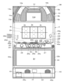
スロットマシン1は、図1(A)に示すように、本体筐体の前面に開閉可能に取り付けられた前扉2を備えており、この前扉2の前面には、上部から順に、上パネルアセンブリ10、中パネルアセンブリ20、下パネルアセンブリ30及び受け皿アセンブリ40が取り付けられている。
[First embodiment]
FIG. 1 shows a slot machine (referred to as "
<Appearance of the slot machine>
As shown in FIG. 1(A), the
上パネルアセンブリ10の中央部には、その裏面側に配された画像表示装置(「液晶表示装置」とも称する)11(図2参照)の表示画面11a(「画像表示部DP」とも称する)が前方を臨むように配置されており、その周辺部には、第1演出ランプ12、第2演出ランプ13a,13b、第3演出ランプ14a,14bが配置されている。また、表示画面11aの下方左右には、一対の上部スピーカ15a,15bが配置されている。
In the center of the
中パネルアセンブリ20の中央部には、本体筐体内に横並びに配設された3個のリール
3a,3b,3cの表面が臨む表示窓Wが設けられており、この表示窓Wの下方には、遊技メダル(遊技媒体)を投入するためのメダル投入口21、クレジットされた範囲内で1枚の遊技メダルをベットするための1-BETスイッチ22、最大ベット許容数(「規定数」ともいう。例えば3枚)の遊技メダルを一度にベットするためのMAX-BETスイッチ23、ベットされた遊技メダル、および/または、クレジットされた遊技メダルを払い出すための清算スイッチ24、全リール3a,3b,3c(リールのことを「回胴」とも称する)を回転開始させる際に操作されるスタートレバー25、各リール3a,3b,3cの回転を個別に停止させるための3個のストップスイッチ26a,26b,26c(図中左側のストップスイッチ26aはリール3aに対応し、中央のストップスイッチ26bはリール3bに対応し、右側のストップスイッチ26cはリール3cに対応する)、及びメダル投入口21から投入されて滞留した遊技メダルを返却するためのリジェクトスイッチ27等が設けられている。
At the center of the
各ストップスイッチは、遊技者が手で押すと引っ込み、手を離すとバネ力等により元に戻るボタン状の操作受付部を有しており、この操作受付部が押圧操作される(手で押される)と、電気回路の接点が閉じてオフ(OFF)状態からオン(ON)状態に切り替わり、押圧操作が解除される(手が離れる)と、接点が開いてオン状態からオフ状態に切り替わるようになっている。 Each stop switch has a button-like operation receiving part that retracts when the player presses it with their hand and returns to its original position due to spring force or the like when the player releases their hand. When this operation receiving part is pressed (pushed by hand), the contacts of the electrical circuit close and the state changes from OFF to ON, and when the pressing operation is released (hand is released), the contacts open and the state changes from ON to OFF.
メダル投入口21とMAX-BETスイッチ23との間には、遊技者がスロットマシン1へ情報を入力するための選択ボタン(「方向ボタン」又は「十字キー」ともいう。)54と、決定ボタン(「メニューボタン」又は「PUSHボタン」ともいう。)55とが設けられている。以下では、選択ボタン54と決定ボタン55とをまとめて「サブボタン」とも称する。選択ボタン54は、図1(B)に示すように、上下左右の方向を指定する上方ボタン54U、下方ボタン54D、左方ボタン54L及び右方ボタン54Rの4つのボタンで構成されている。そして、遊技者に操作されたボタンに対応して、上方向、下方向、左方向または右方向のいずれかが指定される。決定ボタン55は、光が透過する部材で形成され、その内部にはLEDなどの光源が設けられている。決定ボタン55の操作が無効になっているときはスイッチ内部の光源が消灯し、有効になっているときは点滅(点灯でもよい)するようになっている。
Between the
サブボタンは、押圧操作される(手で押される)と、電気回路の接点が閉じてオフ状態からオン状態に切り替わり、押圧操作が解除される(手が離れる)と、接点が開いてオン状態からオフ状態に切り替わるようになっている。サブボタンが有効に操作されると、後述する副制御手段200において、その操作に応じた所定の演出処理が実行される場合がある。また、遊技者にサブボタンを操作するように促す演出処理が行われる場合もある。さらに、サブボタンを所定の手順で操作することにより、画像表示装置11の画面の明るさ調整やスピーカの音量調整を行うための調整画面を表示させることが可能となっている。
When the sub-button is pressed (pushed by hand), the contacts of the electric circuit close and the state changes from OFF to ON, and when the pressing operation is released (hand is removed), the contacts open and the state changes from ON to OFF. When the sub-button is operated effectively, the sub-control means 200, which will be described later, may execute a predetermined presentation process according to the operation. There may also be a presentation process that prompts the player to operate the sub-button. Furthermore, by operating the sub-button in a predetermined procedure, it is possible to display an adjustment screen for adjusting the brightness of the screen of the
ここで、選択ボタン54を構成する上方ボタン54U、下方ボタン54D、左方ボタン54L及び右方ボタン54Rは、個別にオン/オフできるようにしてもよいし、十字型のキートップ(十字キー)を設けて十字キーを傾倒操作した方向のボタンがオンにされるようにしてもよい。十字キーにより上方ボタン54U、下方ボタン54D、左方ボタン54L及び右方ボタン54Rをオン/オフ可能とする場合、隣り合った2つのボタン(上と右、右と下、下と左、左と上)は同時にオンすることが可能であるが、対向するボタン(上と下、右と左)については同時にオンすることができないようにしてもよい。
Here, the up button 54U, down button 54D, left button 54L, and right button 54R constituting the
メダル投入口21の内部は、投入された遊技メダルが有効に受け入れられる場合に当該遊技メダルが通過する受入通路(後述のホッパー50に通ずる)と、投入された遊技メダ
ルが受け入れられない場合に当該遊技メダルが通過する返却通路(後述の遊技メダル払出口41に通ずる)とに分岐しており、その分岐部には、ブロッカ48(図2参照)が設けられている。このブロッカ48は、投入された遊技メダルが有効に受け入れられる期間においては、メダル投入口21に投入された遊技メダルを受入通路に導き、それ以外の期間においては、メダル投入口21に投入された遊技メダルを返却通路に導くように、受入通路と返却通路を選択的に、一方を開状態に他方を閉状態にできるように構成されている。以下の説明において、ブロッカ48がON状態とは、メダル投入口21に投入された遊技メダルが受入通路に導かれる状態(遊技メダル受入可能状態)を示し、ブロッカ48がOFF状態とは、メダル投入口21に投入された遊技メダルが返却通路に導かれる状態(遊技メダル受入不可状態)を示すものとする。
The inside of the
また、メダル投入口21の内部には、遊技メダルを検知するための3つの投入メダルセンサ28a,28b,28c(図2参照)が設けられている。投入メダルセンサ28aは、遊技メダルがメダル投入口21に投入されたことを検出するものであり、投入された遊技メダルが流下する通路上において、ブロッカ48が設置された位置よりも上流側の位置に設置されている。投入メダルセンサ28bは、メダル投入口21に投入された遊技メダルが受入通路に導かれ有効に受け入れられたことを検出するものであり、ブロッカ48が設置された位置よりも下流側(後述のホッパー50寄り)の位置に配置されている。投入メダルセンサ28cは、メダル投入口21に投入された遊技メダルが、受入通路と返却通路との分岐部を通過したことを検出するものであり、当該分岐部近傍(ブロッカ48が設置された位置よりも少し投入メダルセンサ28b寄りの位置)に配置されている。
In addition, inside the
投入メダルセンサ28a及び投入メダルセンサ28bが共に遊技メダルを検出した場合は、遊技メダルがメダル投入口21に投入され、かつ投入された遊技メダルが有効に受け入れられたことを意味する。一方、投入メダルセンサ28aは遊技メダルを検出したが、投入メダルセンサ28bは遊技メダルを検出しない場合は、遊技メダルがメダル投入口21に投入されたが、投入された遊技メダルが有効に受け入れられずに返却されたことを意味する。また、3つの投入メダルセンサ28a,28b,28cが所定の順序(28a,28c,28bの順序)とは異なる順序で遊技メダルの通過を検出した場合や一部の投入メダルセンサで遊技メダルの通過が検出されない場合は、遊技メダルが逆流するなどの異常通過が起きたことを意味する。
When both the inserted
表示窓Wは、3個のリール3a~3cが全て停止した際に、リール毎に3個の図柄、合計9個の図柄が遊技者から視認可能に表示されるように構成されている。リール3a,3b,3cの各中段の図柄表示領域を水平に結ぶ入賞ライン29は、規定数の遊技メダルがベットされることにより有効化される入賞ラインであり、有効化された入賞ライン上に停止表示された図柄組合せにより遊技役の成立の有無を判定できるように構成されている。有効化された入賞ラインのことを「有効ライン」とも称する。なお、入賞ライン29とは別に、リール3a,3b,3cの各上段の図柄表示領域を水平に結ぶラインを上段ラインと称し、リール3a,3b,3cの各下段の図柄表示領域を水平に結ぶラインを下段ラインと称する。また、リール3aの上段、リール3bの中段及びリール3cの下段の図柄表示領域を結ぶラインを右下がりラインと称し、リール3aの下段、リール3bの中段及びリール3cの上段の図柄表示領域を結ぶラインを右上がりラインと称する。
The display window W is configured so that when all three
また、スロットマシン1には、LEDランプ等により構成される各種の表示用ランプが配置されている。本実施形態では、表示用ランプとして、MAX-BETスイッチ表示ランプ46a、BET数表示ランプ46b、投入可能表示ランプ46c、遊技開始表示ランプ46d、再遊技表示ランプ46e、状態表示ランプ46f、回数表示ランプ46g、貯留枚数表示ランプ46h、及び払出数表示ランプ46jを備えている。これらの表示用ランプは、後述の主制御基板60(主制御手段100)により制御されるように構成されて
いる。
In addition, various display lamps composed of LED lamps and the like are arranged in the
MAX-BETスイッチ表示ランプ46aは、遊技メダルをベットすることができる状況下で点灯されるものであり、MAX-BETスイッチ23の内部に配置され、点灯時にはMAX-BETスイッチ23を部分的または全体的に光らせるようになっている。その他の表示用ランプは、中パネルアセンブリ20において表示窓Wの側方または下方に配置されている。
The MAX-BET
BET数表示ランプ46b(以下「BETランプ46b」とも称する)は、ベットされた遊技メダルの枚数を表示するもので、ベットされた遊技メダルが、1枚以上の場合に点灯される1-BET表示ランプ46bCと、2枚以上の場合に点灯される2-BET表示ランプ46bBと、3枚の場合に点灯されるMAX-BET表示ランプ46bAとから構成されている。投入可能表示ランプ46cは、遊技メダルを投入することができる状況下で点灯されるものであり、遊技開始表示ランプ46dは、スタートレバー25を操作して遊技を開始させることができる状況下で点灯されるものである。再遊技表示ランプ46eは、任意の遊技において後述の再遊技役が成立し、後述の自動ベット処理により遊技メダルが自動的にベットされた際に点灯されるものである。
The BET number indicator lamp 46b (hereinafter also referred to as "BET lamp 46b") indicates the number of game medals bet, and is composed of a 1-BET indicator lamp 46bC that is lit when one or more game medals are bet, a 2-BET indicator lamp 46bB that is lit when two or more game medals are bet, and a MAX-BET indicator lamp 46bA that is lit when three game medals are bet. The insertion
状態表示ランプ46fは、貯留(クレジット)されている遊技メダルを清算するときに点灯されるものであり、回数表示ランプ46gは、例えば、ATが設定されたときに、押しナビの実行可能数(押しナビが実行される毎に1減算され、また、抽選等により増加することもある)を表示するものである。貯留枚数表示ランプ46h(以下「CREランプ46h」とも称する)は、貯留された遊技メダルの枚数を1ずつインクリメントしながら表示するものであり、払出数表示ランプ46jは、後述の小役が成立した際に払い出される遊技メダルの枚数を1ずつインクリメントしながら表示するものである。貯留枚数表示ランプ46hや払出数表示ランプ46jは、上位桁の数字及び下位桁の数字を表示するため、各々2つの7セグメント表示器(数字を表すための7つのセグメントランプ及び小数点(ドット)を表す1つのセグメントランプから成る)で構成されている。
The
また、この払出数表示ランプ46jは、スロットマシン1に何らかの異常(エラー)が発生した際に、そのエラーの種類を示す文字(アルファベット)や数字(以下、「エラーコード」ともいう。)を表示するようにも構成されている。本実施形態において設定されるエラーとしては、HPエラー、HEエラー、H0エラー、CEエラー、CPエラー、CHエラー、C0エラー、C1エラー、FEエラー、E1エラー、E5エラー、E6エラー、E7エラー等がある。HPエラーは、後述するホッパー50のメダル払出口で遊技メダルが滞留したと判断した場合エラーであり、HEエラーは、ホッパー50の中の遊技メダルが空と判断した場合のエラー(ホッパーエンプティエラー)であり、H0エラーは、遊技メダルが払出センサを異常通過したと判断したときのエラーである。CEエラーは、投入メダルセンサにより遊技メダルが滞留したと判断した場合のエラー(遊技メダル滞留エラー)であり、CPエラーは、投入された遊技メダルが不正通過したと判断した場合のエラーであり、C0エラーは、投入メダルセンサに異常入力があったと判断したときのエラーであり、C1エラーは投入メダルセンサの通過に異常があったと判断した場合のエラーである。FEエラーは、後述の補助収納庫85が満杯と判断した場合のエラー(満杯エラー)であり、E1エラーは、電源投入時に記憶装置(RAM)の内容が正常でない場合のエラー(RAMエラー)であり、E5エラーは、全回胴停止時の図柄の組合せが異常(成立許容役以外の役を構成する対応図柄が停止表示)となる場合のエラー(回胴停止エラー)である。E6エラーは、役決定確率を定めるための後述の設定値の値(設定値)が範囲外となる場合のエラー(設定値エラー)であり、E7エラーは、各抽選等において用いる内蔵乱数の更新状態の異常を検知した場合のエラー(内蔵乱数エラー)である。E1、E5、E6、E7の各エラー(これらを総称して「E系エラー」とも称する)は、後述の設
定変更により解除され、その他のエラーは、後述のリセットスイッチ82の操作により解除されるようになっている。
In addition, the payout
さらに、この払出数表示ランプ46jは、ストップスイッチ26a~26cの操作順(押し順)を示す、後述のナビ番号を表示する機能も有している。ナビ番号を表示する際の払出数表示ランプ46jのことを「メイン側押し順表示器」とも称する。また、この払出数表示ランプ46jは、後述する設定確認時及び設定変更時において、後述の設定値を表示する機能も有している。設定値を表示する際の払出数表示ランプ46jのことを「設定値表示器」とも称する。
Furthermore, this payout
下パネルアセンブリ30の中央部には、透明な下パネルカバー31が取り付けられており、その左右両端部には、飾りランプ32a,32bが配置されている。なお、下パネルカバー31の裏面側には、所定の図柄が設けられた半透明の下パネルベース及び下パネル照明灯(いずれも図示せず)が取り付けられており、この下パネル照明灯を点灯させることにより、下パネルベースの図柄を後面側から照明するように構成されている。
A transparent
受け皿アセンブリ40には、遊技メダルを払い出すための遊技メダル払出口41が開設されているとともに、遊技メダル払出口41に臨むようにして遊技メダルを貯留するための遊技メダル貯留皿42が設けられており、この遊技メダル貯留皿42の左には、灰皿43が設けられている。また、遊技メダル払出口41の左右には、受け皿アセンブリ40の背面側に配置された一対の下部スピーカ44a,44b(図2参照)の前面に対向して、多数の小孔からなるスピーカ口45a,45bが形成されている。
The
さらに、本体筐体内には、遊技の結果、所定の入賞態様が構成された場合に獲得される遊技メダルを払い出すためのホッパー50(図2参照)が設けられており、このホッパー50には遊技メダルを検出するためのメダル検出部51(図2参照)が設けられている。また、このホッパー50は、投入されて有効に受け入れられた遊技メダルを物理的に収容する機能を有している。さらに、ホッパー50の近傍位置には、ホッパー50から溢れた遊技メダルを収納するための補助収納庫85(図2参照)が設けられるとともに、この補助収納庫85が満杯状態(補助収納庫85から遊技メダルが溢れる可能性のある状態)であるか否かを検出する満杯検出部86(図2参照)が設けられている。
In addition, a hopper 50 (see FIG. 2) is provided inside the main body cabinet for dispensing game medals that are acquired when a predetermined winning mode is achieved as a result of playing, and this
≪制御基板と各機器との接続≫
本実施形態では、スロットマシン1を制御する主な制御基板として図2に示すように、主制御基板60、サブメイン制御基板70A、及びサブサブ制御基板70Bの3つの制御基板を備えている(サブメイン制御基板70Aとサブサブ制御基板70Bを総称して副制御基板70と称する)。遊技の進行に係る主たる制御(リール3a~3cの駆動制御や役決定処理等を含む)が主制御基板60上に配設された制御回路により行われ、バックランプ38a~38c等のランプによる照明制御等は、サブメイン制御基板70A上に配設された制御回路により行われるように構成されている。また、画像表示装置11による演出画像表示制御、上部スピーカ15a,15b等のスピーカからの音声発生制御は、主に、サブサブ制御基板70B上に配設された制御回路により行われるように構成されている。さらに、主制御基板60と副制御基板70との間の情報伝達は、主制御基板60からサブメイン制御基板70Aへの一方向のみ行うことが可能となっており、サブメイン制御基板70Aとサブサブ制御基板70Bとの間の情報伝達は、双方向で行うことが可能となっている。
<Connection between the control board and each device>
In this embodiment, as shown in FIG. 2, the
<主制御基板60の構成>
主制御基板60には、遊技に関する各種の演算処理を行うメインCPU61と、制御プログラム等を記憶した読出し専用の記憶装置であるROM62と、情報の書込み及び読出
しが可能な記憶装置であるRAM63(「RAM」のことを「RWM」とも称する)とが配設されている。メインCPU61が、ROM62に記憶された制御プログラムに従って各駆動回路等を制御することにより、スロットマシン1における遊技の進行に係る制御が行われるようになっている。なお、ROM62及びRAM63は不揮発性の記憶装置であり、電力が供給されない場合でも記憶している情報を保持し得るように構成されている。
<Configuration of
The
メインCPU61には、クロックパルス(クロック信号)を発生するためのクロックパルス発生器64、クロックパルス発生器64で発生したクロックパルスを分周するための分周器65、クロックパルス(または分周されたクロックパルス)に基づいて、役決定等に用いる乱数を発生するための乱数発生器66、及び乱数発生器66で発生した乱数を取り込むための乱数取込回路67が接続されている。クロックパルス発生器64は、2つの発振器(図示略)から構成され、それぞれの発振器から、互いに非同期のクロック信号が出力されている。以下、一方の発振器から出力される所定周波数のクロック信号のことを内部クロックと称し、他方の発振器から出力される所定周波数(内部クロックとは異なる周波数とするが同じでもよい)のクロック信号のことを外部クロックと称する。例えば、内部クロックは、メインCPU61の動作クロックや役決定以外の所定の抽選に用いられる乱数の更新クロックとして利用され、外部クロックは、役決定で用いられる乱数の更新クロックとして利用される。なお、メインCPU61、ROM62、RAM63、分周器65、乱数発生器66、乱数取込回路67、インターフェイス回路68等を1つのICチップ上に搭載し、ワンチップマイクロコンピュータとして構成してもよい。また、メインCPU61は、インターフェイス回路68を介して、モータ駆動回路36、表示用ランプ制御回路47、ホッパー駆動回路52及び副制御基板70に対して信号を送信するとともに、リール位置検出回路37a,37b,37c、払出検出信号回路53及び収納状態信号回路87からの信号を受信するように構成されている。
The
モータ駆動回路36は、リール3a,3b,3cをそれぞれ回転駆動するステッピングモータ35a,35b,35cの回転・停止制御を行うための回路であり、表示用ランプ制御回路47は、上述した各種の表示用ランプの制御を行うための回路である。リール位置検出回路37a,37b,37cは、リール3a,3b,3cの各々に設置されたリールセンサ(図示せず)からの各検出信号を主制御基板60に送信する回路である(検出回路37aはリール3aに対応し、検出回路37bはリール3b、検出回路37cはリール3cに対応する)。ホッパー駆動回路52は、小役が成立した際に、ホッパー50を駆動して遊技メダルの払い出しを行わせる回路であり、払出検出信号回路53は、ホッパー50から遊技メダルが払い出されたことがメダル検出部51により検出された際に、主制御基板60に払出検出信号を送信する回路である。収納状態信号回路87は、補助収納庫85が満杯状態であるか否かを示す収納状態信号を、満杯検出部86の検出結果に応じて、主制御基板60に送信する回路である。
The
また、スロットマシン1には、電源装置80からの電力が主制御基板60を介して供給されるようになっている。この電源装置80には、電源スイッチ81、リセットスイッチ82及び設定鍵型スイッチ83が接続されており、これら各スイッチからの信号がインターフェイス回路68を介して、メインCPU61に送信されるように構成されている。さらに、メインCPU61は、インターフェイス回路68を介して、設定変更スイッチ84からの信号を受信するように構成されている。
The
電源スイッチ81は、電源装置80からスロットマシン1への電源投入及び電源断の操作を受け付けるスイッチであり、リセットスイッチ82は、スロットマシン1において所定のエラー(上述のE系エラーを除くエラー)が発生した場合に、エラーの原因が取り除かれてエラーが解消された際に遊技店員等により操作されるスイッチである。このリセットスイッチ82が操作されることにより、主制御基板60及び副制御基板70において記
憶されたエラー発生の情報がクリアされ、それに伴いエラー解消時の処理が主制御基板60及び副制御基板70により実行される。また、設定鍵型スイッチ83は、役決定確率の高低の程度(ランク)を定める設定値の設定確認及び設定変更を行う場合に操作されるスイッチであり、設定変更スイッチ84は、設定値を複数段階(本実施形態では6段階)で変更するためのスイッチである。
The
前扉2が開いた状態(「ドア開状態」とも称する)で、かつ、スロットマシン1に電源が供給されている状態(電源スイッチ81がON状態)において、設定鍵型スイッチ83がON状態に操作されることによって設定確認モードへ移行し、設定確認が可能となる。また、ドア開状態であり、かつ、スロットマシン1に電源が供給されていない状態(電源スイッチ81がOFF状態)において、設定鍵型スイッチ83がON状態に操作され、その状態のまま電源スイッチ81がON状態に操作される(スロットマシン1に電源が投入される)ことによって設定変更モードへ移行し、設定変更が可能となる。さらに、その状態で設定変更スイッチ84を操作するごとに、設定値を1段階ずつ更新することができる。また、設定値の更新後に、スタートレバー25を傾動操作することにより、更新された設定値が確定し、その確定後に設定鍵型スイッチ83をOFF状態に操作することによって、設定変更の作業が完了するようになっている。
When the
なお、設定鍵型スイッチ83は、所定の鍵部材(設定キー)を、本体側に設けられた所定の錠部材に差し込んで回動させることにより、ON状態とOFF状態が切り替えられるようになっている。また、設定確認及び設定変更は、遊技実行中の状態(遊技メダルがベットされている状態(自動ベットされた場合を含む)や、リールが回転している状態)では実行することができず、遊技待機中の状態でのみ実行することが可能となっている。なお、設定確認モード及び設定変更モードにおいて、設定値は「1」~「6」の6個の整数値を用いて、払出数表示ランプ46jに表示されるようになっている(設定値表示用の別のランプをスロットマシン1の筐体内等に設けてもよい)。
The setting key switch 83 can be switched between ON and OFF by inserting a specified key (setting key) into a specified lock provided on the main body and rotating it. Also, setting confirmation and setting change cannot be performed while a game is being played (when game medals have been bet (including automatic bets) or when the reels are spinning), but can only be performed while the game is in standby. In the setting confirmation mode and setting change mode, the setting value is displayed on the payout
電源装置80からの電力は、主制御基板60を介してサブメイン制御基板70Aに供給され、さらにサブメイン制御基板70Aを介してサブサブ制御基板70Bに供給されるようになっている(電源装置80から直接、サブメイン制御基板70Aとサブサブ制御基板70Bに電力を供給するようにしてもよい)。電源装置80から主制御基板60に電力を供給する回路上と、主制御基板60を介してサブメイン制御基板70Aに電力を供給する回路上には、電圧の供給状態を監視する供給電圧監視回路(図示略)がそれぞれ設けられている。各々の供給電圧監視回路は、供給電圧が所定の電圧値まで低下したときに電源断と判定し電源断検出信号をメインCPU61、及び後述のサブメインCPU71に出力するようになっている。また、各々の供給電圧監視回路は、供給電圧が所定の電圧値(電源断判定のための電圧値とは異なる値(例えば、高い値)とするが、同じ値としてもよい)まで復帰したときに電源投入と判定し電源投入検出信号をメインCPU61、及びサブメインCPU71に出力するようになっている。なお、主制御基板60の電源断を検出するときの電圧値は、サブメイン制御基板70Aの電源断を検出するときの電圧値よりも高い値に設定され、サブメイン制御基板70Aよりも先に主制御基板60が、電源断時に実行するようにプログラムされた処理(電源断処理)を行うように構成されている(電源投入に関しても同様としてもよい)。
Power from the
また、メインCPU61には、スイッチ基板90に接続されているかまたはスイッチ基板90上に搭載されている、リール停止信号回路91、スタートレバー25、投入メダルセンサ28a,28b,28c、1-BETスイッチ22、MAX-BETスイッチ23及び清算スイッチ24からの各信号が、インターフェイス回路68を介して入力されるようになっている。
In addition, the
また、メインCPU61には、インターフェイス回路68を介してブロッカ48が接続されており、このブロッカ48をオン/オフ制御するように構成されている。以下の説明において、ブロッカ48をオン/オフ制御するための信号を「ブロッカ信号」とも称する。さらに、図示は省略しているが、スロットマシン1には、前扉2の開閉状態を検出するドアセンサが設けられており、このドアセンサからの信号が、インターフェイス回路68を介してメインCPU61に入力されるようになっている。メインCPU61は、ドアセンサからの信号により、前扉2が閉じた状態(「ドア閉状態」とも称する)であるか開いた状態(ドア開状態)であるかを判断するようになっている。
The
また、図示は省略しているが、メインCPU61は、所定の遊技状態(例えば、AT状
態やボーナス状態)となったときに、データカウンタやホールコンピュータ等に対し外部接続用端子基板等を介して所定の信号(「外端信号」とも称する)を出力し、この外端信号により、所定の遊技状態に設定された回数等を管理したり遊技者に提示したりできるように構成されている。
Also, although not shown in the figure, the
<副制御基板70の構成>
副制御基板70は、サブメイン制御基板70Aとサブサブ制御基板70Bとによって構成されている。サブメイン制御基板70Aには、主に演出の管理に関する各種の演算処理を行うサブメインCPU71と、制御プログラム等を記憶した読出し専用の記憶装置であるROM72と、情報の書込み及び読出しが可能な記憶装置であるRAM73とが配設されており、ROM72に記憶された制御プログラムに従って各駆動回路等が動作することにより、スロットマシン1における画像演出や音声演出の管理に関する制御、ランプ演出に関する制御等が行われるようになっている。なお、ROM72及びRAM73は不揮発性の記憶装置であり、電力が供給されない場合でも記憶している情報を保持し得るように構成されている。また、サブメインCPU71には、不図示のクロックパルス発生器及び分周器が接続されており、このクロックパルス発生器及び分周器により生成したクロック信号に応じて、所定の処理を実行するようになっている。
<Configuration of the
The
サブメインCPU71は、インターフェイス回路74を介して、主制御基板60からの各種信号を受信し、ランプ制御回路18に対し信号を送信するように構成されている。ランプ制御回路18は、バックランプ38a~38c等のランプの点灯を制御する回路である。また、サブメインCPU71は、インターフェイス回路74を介して、選択ボタン54及び決定ボタン55からの出力信号を受信し、受信した各ボタンの出力信号に応じてサブサブ制御基板70Bにより画像表示装置11にメニュー画面を表示させ、遊技者の選択操作に応じた情報を提供したり、遊技中に画像表示装置11に表示している演出の内容を変化させたりする。
The
サブメインCPU71は、インターフェイス回路74を介して、サブサブ制御基板70Bに各種信号を送信するとともに、サブサブ制御基板70Bから各種信号を受信するように構成されている。以下、主制御基板60からサブメイン制御基板70Aに送信される信号(制御信号)を「制御コマンド」とも称し、サブメイン制御基板70Aからサブサブ制御基板70Bに送信される信号(報知信号や演出信号)を「演出コマンド」とも称する。また、サブサブ制御基板70Bからサブメイン制御基板70Aに送信される信号(状態信号)を「状態コマンド」とも称する。
The
サブサブ制御基板70Bには、主に画像演出及び音声演出の制御に関する各種の演算処理を行うサブサブCPU75と、制御プログラム等を記憶した読出し専用の記憶装置であるROM76と、情報の書込み及び読出しが可能な記憶装置であるRAM77とが配設されており、ROM76に記憶された制御プログラムに従って各駆動回路等が作動することにより、画像演出や音声演出に関する制御等が行われるようになっている。なお、ROM
76及びRAM77は不揮発性の記憶装置であり、電力が供給されない場合でも記憶している情報を保持し得るように構成されている。
The sub-sub control board 70B is provided with a
The RAM 76 and the RAM 77 are non-volatile storage devices that are configured to be able to retain stored information even when power is not supplied.
サブサブCPU75は、インターフェイス回路78を介して、サブメイン制御基板70Aからの報知信号または演出信号を受信し、表示装置制御回路16、スピーカ制御回路17に対し信号を送信するとともに、サブメイン制御基板70Aに状態信号を送信するように構成されている。表示装置制御回路16は、画像表示装置11を制御して所定の演出画像を表示させる回路であり、スピーカ制御回路17は、上部スピーカ15a,15b等のスピーカから発生させる音声等の種類や音量を制御する回路である。なお、画像表示装置11は、ストップスイッチ26a~26cの操作順(押し順)を表示する押し表示器(「サブ側押し順表示器」とも称する)としても機能するように構成されている。
The
<リール>
各リール3a,3b,3cはそれぞれステッピングモータ35a,35b,35cの駆動により回転するように構成されている。また、各リール3a,3b,3cは透光性を有する円筒形状の部材により構成されており、その外周面には、図3に示す複数種類の図柄が表示された、透光性を有するリールテープが貼り付けられている。また、各リール3a,3b,3cの内面側には、バックランプ38a,38b,38cが配設されており、このバックランプ38a,38b,38cを点灯させることにより、表示窓W内に臨む各リール3a,3b,3cの領域を内面側から全体的に照明したり、各リール3a,3b,3c上に停止表示された所定の図柄組合せ(例えば、有効ライン29上や、有効ライン29上とは異なる位置に並んだ遊技役の対応図柄等)を目立たせるように各リール3a,3b,3cの一部領域のみを照明したりするように構成されている。
<Reel>
Each of the
<リールの図柄配列>
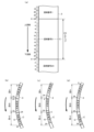
本実施形態では、各リール3a~3cが表示する図柄が、図3(a)に示すように配置されている。ここで、図3(a)中の「左リール」はリール3a、「中リール」はリール3b、「右リール」はリール3cをそれぞれ表す。このように、各リール3a~3cには、図3(b)に示す「赤セブン」、「金セブン」、「黒バー」、「青バー」、「ブランクA」、「ブランクB」、「ベルA」、「ベルB」、「スイカ」、及び「リプレイ」の10種類の図柄が所定数ずつ配置されている。リールテープに配置された各図柄は、リールテープの長手方向において、20等分に区画された各図柄領域に1つの図柄が印刷されている。以下、リール3a,3b,3cのことを、それぞれ、左リール(左回胴)、中リール(中回胴)、右リール(右回胴)とも称する。なお、図3に示す各図柄は、各リール3a~3cの図柄配列を説明するためのものであり、リールテープに実際に描かれる図柄の大きさ(各図柄のサイズの相対的な比率)は反映していない。このリールテープは、図3(a)に示したように、長手方向において上端の図柄が図柄番号19の「ベルA」図柄となり、下端の図柄が図柄番号0の「リプレイ」図柄となっている。したがって、リールテープをリールに張り付けた場合、図柄番号19の「ベルA」図柄と図柄番号0の「リプレイ」図柄との間がリールテープの継ぎ目となる。
<Reel pattern arrangement>
In this embodiment, the symbols displayed by each of the
(リールテープの背景絵柄)
本実施形態の各リール3a~3cのリールテープには、左右の各縁に背景絵柄が表示されて(描かれて)いる。ここで、背景絵柄の一例を図4に示す。図4(a)においてハッチングで示すように、本実施形態では、リールテープRTPの左右側縁に波をモチーフとした背景絵柄BPTが描かれている。また、背景絵柄BPTは、リールテープRTPの長手方向においてリール図柄4個分の長さを1単位(1パターン)とする継ぎ目の無い連続したパターンになっている。したがって、背景絵柄BPTの上端UEにおける絵柄部分と下端LEにおける絵柄部分との間が継ぎ目無く繋がる連続した絵柄となっている。ただし、前述したリールテープの継ぎ目部分においては、リールテープの張り付け誤差などによ
って背景絵柄の継ぎ目にずれが生じる場合がある。
(Background image of reel tape)
In the present embodiment, a background pattern is displayed (drawn) on each of the left and right edges of the reel tape of each of the
また、図3に示したように、本実施形態の各リールの図柄数は20個であり、1単位の背景絵柄BPTの長さ(より正確にはリールの回転方向における長さ)が4図柄分であることから、20/4=5単位の背景絵柄BPTが連続して描かれている。すなわち、リールの全図柄数を、1単位の背景絵柄の長さに相当する図柄数で割った場合、割り切れる数となるように1単位の背景絵柄の長さが定められている。換言すると、リールの全図柄数は、1単位の背景絵柄の長さに相当する図柄数の整数倍になっている。 As shown in FIG. 3, each reel in this embodiment has 20 symbols, and since the length of one unit of background pattern BPT (more precisely, the length in the direction of rotation of the reel) is four symbols, 20/4=5 units of background pattern BPT are drawn continuously. In other words, the length of one unit of background pattern is determined so that the total number of symbols on the reel is an even number when divided by the number of symbols corresponding to one unit of background pattern length. In other words, the total number of symbols on the reel is an integer multiple of the number of symbols corresponding to one unit of background pattern length.
このように、表示窓Wに表示される図柄数が3個であるのに対して1パターン分の背景絵柄の長さが4図柄分(すなわち3図柄分以上)の長さになっていることから、複数単位の背景絵柄BPTをリールテープに描いたとしても、リールの停止時に表示窓Wから見える背景絵柄BPTに同一の絵柄部分が存在しないことになる。これにより、背景絵柄が繰り返しのパターンであることを遊技者に悟られ難くすることができ、遊技者を興醒めさせることなく、見た目上変化に富んだ背景絵柄を遊技者に示すことができる。 Thus, because the number of symbols displayed in the display window W is three and the length of one pattern of background picture is four symbols (i.e., three or more symbols), even if multiple units of background picture BPT are drawn on the reel tape, no identical image portions will exist in the background picture BPT visible through the display window W when the reels stop. This makes it difficult for the player to realize that the background picture is a repeating pattern, and it is possible to show the player a visually varied background picture without losing interest.
また、1単位の背景絵柄の長さに相当する図柄数は、その数でリールの全図柄数を割った場合、割り切れる数に定められているため、リールテープに配置された複数単位の背景絵柄の中に、1単位の長さに満たない背景絵柄を含むことがないことから、リール一周分の背景絵柄の中に絵柄の偏りを生じさせることなく均等かつ一様に配置することができる。これにより、リールの回転中に、背景絵柄の偏り部分が表示窓Wに瞬間的に表示され、それを目印として目押しの補助にされてしまうのを防ぐことができる。 The number of symbols corresponding to one unit of background pattern length is set to a number that is divisible by the total number of symbols on the reel, so that the multiple units of background patterns arranged on the reel tape will not contain a background pattern that is less than one unit in length, and the symbols can be arranged evenly and uniformly without bias among the background patterns for one revolution of the reel. This prevents biased parts of the background patterns from being momentarily displayed in the display window W while the reel is spinning, and being used as a guide to help with hitting the ball.
また、図4(a)に示すように、リールテープRTPの左側縁に描かれている背景絵柄と右側縁に描かれている背景絵柄とが、リールテープRTPの中心Cに対して非対称の絵柄になっているため、背景絵柄が単調になってしまうのを防ぎ、趣のある背景絵柄を遊技者に表示することができる。ここで、「非対称の絵柄」は、図4(a)に示したように右側縁の背景絵柄と、左側縁の背景絵柄とをまったく別の絵柄にしてもよいし、例えば一方の縁に描かれた背景絵柄を、180度回転(上下逆さま)させたものを他方の縁に描く背景絵柄としたものであってもよい。さらに、リール一周当たりにおける背景絵柄の単位数は、左側縁の背景絵柄も右側縁の背景絵柄も同じ5単位になっていることから、リールテープRTPの左側縁に描かれている背景絵柄と右側縁に描かれている背景絵柄との対応が常に一定となることで、両側縁の背景絵柄に一体感を持たせることができる。これにより、リールテープに描いた背景絵柄が遊技者に違和感を持たせ、そのことが遊技者のリール停止操作に影響を与えてしまう虞を回避することができる。 As shown in FIG. 4(a), the background picture drawn on the left edge of the reel tape RTP and the background picture drawn on the right edge are asymmetrical with respect to the center C of the reel tape RTP, so that the background picture is prevented from becoming monotonous and an interesting background picture can be displayed to the player. Here, the "asymmetrical picture" may be a completely different picture for the background picture on the right edge and the background picture on the left edge as shown in FIG. 4(a), or, for example, a background picture drawn on one edge may be rotated 180 degrees (upside down) and drawn on the other edge. Furthermore, the number of units of the background picture per revolution of the reel is the same 5 units for the background picture on the left edge and the background picture on the right edge, so that the correspondence between the background picture drawn on the left edge and the background picture drawn on the right edge of the reel tape RTP is always constant, and the background pictures on both sides can be made to have a sense of unity. This prevents the background image on the reel tape from making the player feel uneasy, which could affect the player's ability to stop the reels.
次にリールテープに描かれたリール図柄と背景絵柄との関係について図4(b)を参照して説明する。図4(b)は、左リール3aのリールテープRTPにおいて、図3に示した図柄配列のうち、図柄番号19及び0~8までのリール図柄を図示している。図4(b)において、リールテープRTPの左側縁からリールテープRTPの中心Cに向かって背景絵柄が最も突出した箇所(背景絵柄の波頭の部分)までの領域が左側領域Laとなっている。また、リールテープRTPの右側縁からリールテープRTPの中心Cに向かって背景絵柄が最も突出した箇所(背景絵柄の波頭の部分)までの領域が右側領域Raとなっている。また、左側領域Laと右側領域Raとの間が中央領域Caとなっている。なお、本実施形態では、左側領域Laの幅(リールテープの長手方向(リールの回転方向)と直交する方向の長さ)と右側領域Raの幅は同じ寸法になっている。
Next, the relationship between the reel patterns and the background pattern drawn on the reel tape will be described with reference to FIG. 4(b). FIG. 4(b) illustrates the
図4(b)に示すように、図柄番号19,4の「リプレイ」図柄、図柄番号0,5の「ベルA」図柄、図柄番号3の「ブランクA」図柄及び図柄番号8の「ブランクB」図柄は、いずれもリールテープの中央領域Caに納まるサイズで描かれている。すなわち、これ
らの図柄は背景絵柄に重複していない図柄であり、このような図柄を単独図柄とも称する。これに対して、図柄番号1,6の「スイカ」図柄、図柄番号2の「赤7」図柄及び図柄番号7の「青バー」図柄は、中央領域Caから左側領域La及び右側領域Raの双方に及ぶサイズで描かれている。すなわち、これらの図柄は背景絵柄に重複している図柄であり、このような図柄を重複図柄とも称する。
As shown in FIG. 4B, the "replay" symbols of
このように、重複図柄によって背景絵柄の一部が隠されることで、背景絵柄の連続性が絶たれ、遊技者は、背景絵柄が1つのパターンの繰り返しであることに気付きにくくなる。このため、背景絵柄の見た目が単調にならず、飽きにくい背景絵柄を提示することができる。また、1つのパターンの背景絵柄を連続して配置することで、例えばリールの回転中における背景絵柄の見た目上の態様が周期的な変化を示し、その周期的な態様の変化を目印に目押しが可能だった場合、重複図柄によって背景絵柄の連続性を絶つことで、そのような目押しをしにくくすることができる。したがって、1パターン分の背景絵柄の長さを2図柄分にしたり、左側縁に描かれている背景絵柄と右側縁に描かれている背景絵柄とを対称の絵柄にしたりしてもよく、そのような場合にリールテープに一定数の重複図柄を配置することで上述した効果を奏することができる。 In this way, by hiding a part of the background pattern with the overlapping pattern, the continuity of the background pattern is broken, and the player is less likely to notice that the background pattern is a repetition of one pattern. This makes it possible to present a background pattern that does not look monotonous and is not easily boring. In addition, by continuously arranging background patterns of one pattern, for example, if the appearance of the background pattern while the reel is rotating shows periodic changes, and it is possible to use the periodic changes as a guide to make a press, it is possible to make such a press difficult by breaking the continuity of the background pattern with the overlapping pattern. Therefore, the length of one pattern of background pattern may be two patterns, or the background pattern drawn on the left edge and the background pattern drawn on the right edge may be symmetrical, and in such a case, the above-mentioned effect can be achieved by arranging a certain number of overlapping patterns on the reel tape.
なお、図4に示した背景絵柄においては、左側領域Laの幅と右側領域Raの幅とが同じ寸法になっていたが、いずれか一方の幅が他方の幅よりも広くてもよい。また、図4に示した重複図柄の大きさは、左側領域La及び右側領域Raの双方に及んでいたが、いずれか一方の領域のみに及ぶようにしてもよい。また、例えば白色のリールテープに着色を施し、その上に背景絵柄及びリール図柄を描いてもよい。この場合、リールテープに施す着色に、リールテープの両側縁から中央にかけて徐々に薄くなるグラデーションがかかっていてもよい(この場合、リールテープの中央はリールテープ本来の色(白)が露出する)。ただし、リールテープに施された着色は背景絵柄には含まれず、その着色は、左側領域Laと中央領域Caとの境界、及び右側領域Raと中央領域Caとの境界には何ら影響しない。また、図4に示した背景絵柄と同じ背景絵柄を中リール3C及び右リール3Rに描いてもよいし、各リールに個別の背景絵柄を描いてもよい。 In the background pattern shown in FIG. 4, the width of the left area La and the width of the right area Ra are the same, but either one may be wider than the other. In addition, the size of the overlapping pattern shown in FIG. 4 covers both the left area La and the right area Ra, but it may cover only one of the areas. In addition, for example, a white reel tape may be colored and the background pattern and reel pattern may be drawn on it. In this case, the coloring applied to the reel tape may have a gradation that gradually becomes thinner from both side edges of the reel tape to the center (in this case, the original color of the reel tape (white) is exposed in the center of the reel tape). However, the coloring applied to the reel tape is not included in the background pattern, and the coloring has no effect on the boundary between the left area La and the center area Ca, and the boundary between the right area Ra and the center area Ca. In addition, the same background pattern as the background pattern shown in FIG. 4 may be drawn on the center reel 3C and the right reel 3R, or a separate background pattern may be drawn on each reel.
<遊技役の種類>
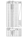
本実施形態においては、各リール3a~3cにおいて停止表示される図柄組合せが、図5~図8に示すように設定されており、それらが遊技役を構成する図柄組合せ(対応図柄)となっている。本実施形態における遊技役としては、BB役1,2の2種類の特別役(BB役;BBはビッグボーナスの略。「1種BB」、「ボーナス役」とも称する)と、再遊技役1~5の5種類の再遊技役と、小役1~44の44種類の入賞役(小役)との計51種類が設定されている。それぞれの遊技役が成立するための図柄組合せ(対応図柄)、遊技役成立時における遊技メダルの払出数等は、図5~図8に示す通りである。
<Types of game roles>
In this embodiment, the symbol combinations displayed on the
BB役1,2は、成立しても遊技メダルは払い出されず、その成立を契機として特別役物としての所定のボーナス(本実施形態では「BB」とも称する)が作動して、次遊技から通常の遊技とは異なる条件下で実行される所定のボーナス遊技(「BB遊技」とも称する)が開始可能となる、遊技者にとって有利な特別遊技状態(「BB作動中」とも称する)に移行されることを示す遊技役(ボーナス役)である。BB役1は、その対応図柄が「青バー・青バー・赤セブン」の図柄組合せとされ、BB役2は、その対応図柄が「黒バー・黒バー・赤セブン」(遊技役を構成する図柄の名称は、リール3a,3b,3cの順番で記す。以下において同じ)の図柄組合せとされている。BB役1又はBB役2の成立により開始可能となるボーナス遊技は、所定数(本実施形態では、例えば70枚とするが、数値は適宜変更可)の遊技メダルが獲得されたことにより終了する(変更態様として、所定数(例えば、30ゲーム)の遊技が実行されたことにより終了するようにしてもよい)。BB役1,2は、後述する非RT、RT1(BB内部中)においては成立することがあ
るが、RT2(BB作動中)では成立することがない役となっている(図5~図8中の「-」は成立しないことを示す)。
本実施形態では、特別役としてBB役のみを設けているが、別の特別役として、RB役(RBはレギュラーボーナスの略)やMB役(MBはミドルボーナスの略。「2種BB」とも称する)を設けるようにしてもよい。そして、RB役が成立すると次遊技からボーナス遊技としてのRB遊技を開始するように設定し、MB役が成立すると次遊技からボーナス遊技としてのMB遊技を開始するように設定してもよい。この場合のRB遊技は、例えば、小役が所定回数(例えば、8回)成立したこと、または所定回数(例えば、12回)の遊技が消化されたことにより終了するようにし、MB遊技は、例えば、所定数(例えば、200超)の遊技メダルが払い出されたことにより終了するようにしてもよい。また、複数の特別役(例えば、複数種類のBB役を設けたり、BB役とMB役の両方を設けたりしてもよい)。 In this embodiment, only the BB role is provided as a special role, but an RB role (RB stands for regular bonus) or an MB role (MB stands for middle bonus, also called "two types of BB") may be provided as another special role. When an RB role is established, an RB game may be set to start as a bonus game from the next game, and when an MB role is established, an MB game may be set to start as a bonus game from the next game. In this case, the RB game may end, for example, when a minor role is established a predetermined number of times (e.g., 8 times) or when a predetermined number of games (e.g., 12 times) have been played, and the MB game may end, for example, when a predetermined number of game medals (e.g., more than 200) have been paid out. In addition, multiple special roles (for example, multiple types of BB roles may be provided, or both BB and MB roles may be provided).
再遊技役1~5は、成立した場合に遊技メダルの払い出しはないが、遊技者が保有する遊技メダルの数を減らすことなく(新たに遊技メダルを投入することなく)、次の遊技を行うことが許可される遊技役(リプレイ役)である。なお、再遊技役1は、その対応図柄「ベルA・リプレイ・(青バー/黒バー/金セブン/赤セブン)」(()内の“/”は「または」の意)が有効ライン29上に停止表示された際に、表示窓W内の右下がりライン上に、図柄「リプレイ」が並ぶように構成されている。このことから、再遊技役1のことを「右下がりリプレイ」(リプレイのことを「RP」とも記す)とも称する。同様の理由から、再遊技役2~4のことを、それぞれ、右上がりRP、上段RP、中段RPとも称する。また、再遊技役5は、その対応図柄「ベルA・(青バー/黒バー/金セブン/赤セブン)・ベルB」が有効ライン29上に停止表示された際に、表示窓W内の上段ライン上に、図柄「スイカ」が並ぶように構成されている。このことから、再遊技役1のことを「上段スイカRP」とも称する。
When
図3(リール図柄)に示すように、再遊技役4を構成する、左リール3a、中リール3b及び右リール3cの各リール上の図柄「リプレイ」は、各リール上において5図柄以内毎に配置されている。これにより、再遊技役4が当選した場合、その対応図柄「リプレイ・リプレイ・リプレイ」は、押し順や押し位置に拘わらず、有効ライン29上に停止表示させる(「引き込む」とも称する)ことが可能である(後述のリール制御手段134によるリールの回転停止制御の説明を参照)。この再遊技役4のように、各ストップスイッチの操作タイミングに拘わらず、その対応図柄(複数組ある場合にはそのうちのいずれか)を有効ライン29上に引き込むことが可能な役を、「100%引込み可能な遊技役」又は「取りこぼしのない遊技役」とも称する。なお、再遊技役1~3,5も、再遊技役4と同様、100%引込み可能な遊技役である。また、再遊技役1~5は、後述する非RT、RT1においては成立することがあるが、RT2では成立することがない役となっている。
As shown in FIG. 3 (reel symbols), the "Replay" symbols on the
小役1~44は、成立時に所定数の遊技メダルが払い出されるように構成された遊技役(入賞役)である。小役1~44のうち、小役1~36は、後述する非RT、RT1及びRT2のいずれでも成立可能な役であるのに対し、小役37~39は、RT2(BB作動中)でのみ成立可能な役となっている。また、小役1~23,40~43は、その成立時の払出数が1枚に設定されていることから、「1枚役」とも称する。同様に、小役24~37のことを「15枚役」、小役38,39のことを「3枚役」とも称する。なお、15枚役のことを、「ベル小役」とも称する。
小役37は、その対応図柄「ベルA・スイカ・(青バー/黒バー/金セブン/赤セブン)」が有効ライン29上に停止表示された際に、表示窓W内の右下がりライン上に、図柄「スイカ」が並ぶように構成されている。このことから、小役37のことを「スイカ小役
」とも称する。また、小役40は、その対応図柄が「赤セブン・赤セブン・赤セブン」とされた1枚役である。このことから、小役40のことを、「赤7揃い1枚役」とも称する。なお、小役1~7,24~37は、100%引き込み可能な遊技役である。
The
<遊技を行うための基本操作>
スロットマシン1で遊技を行うには、まず実際にメダル投入口21に遊技メダルを投入することによりベットするか、1-BETスイッチ22またはMAX-BETスイッチ23の何れかを操作してクレジットの範囲内で規定数の遊技メダルをベットすることにより、入賞ライン29を有効化する。本実施形態では、入賞ライン29を有効化するために必要となる遊技メダルの規定数が、後述する非RT、RT1、RT2の各RT状態のいずれにおいても3枚に設定される。ただし、規定数についてはこれに限定されるものではなく、RT状態等に応じて規定数を異なる値に設定するなど、適宜変更することが可能である。また、複数の入賞ラインを設け、遊技メダルのベット数に応じて、有効化される入賞ラインの数等を変更するようにしてもよい。
<Basic operations for playing games>
To play the
次に、遊技者がスタートレバー25を操作すると、ベット数が確定する(ベットされた遊技メダルが遊技の用に供される)とともに、後述する役決定処理が行われ、その後、最小遊技時間が経過したことが確認された後、各リール3a~3cが回転を開始する。ここで、最小遊技時間とは、1つの遊技において全リールが回転開始してから、次の遊技において全リールを回転開始させるまでに最低限確保しなければならないとされる時間をいい、本実施形態では4.1秒間と定められている。各リール3a~3cが回転を開始すると
、リール3a~3cの外周表面に表示された複数種類の図柄が表示窓W内を上下に(通常、上から下に)移動表示される。そして、リール3a~3cの回転が所定の速度に達して定速回転となると各ストップスイッチ26a~26cが有効化され(ストップスイッチの操作が有効に受付け可能とされ)、遊技者がストップスイッチ26aを操作するとリール3aの回転が停止し、ストップスイッチ26bを操作するとリール3bの回転が停止し、ストップスイッチ26cを操作するとリール3cの回転が停止するように構成されている。
Next, when the player operates the
ここで、有効ライン29上に停止表示された図柄組合せが予め定めた入賞態様(遊技メダルを獲得することができる遊技役の対応図柄)となっていると判定された場合には、各入賞態様に対応した枚数の遊技メダルがホッパー50により払い出されるか、またはクレジットとして加算される。
If it is determined that the symbol combination displayed on the
次に、図9~図29を追加参照しながら、本実施形態に係るスロットマシン1の特徴構成について説明する。
≪機能ブロック≫
図9に示すように、本実施形態に係るスロットマシンは、機能的な観点から説明すれば主に、遊技メダルをベットするためのベット操作(例えば、メダル投入口21への遊技メダルの投入操作、1-BETスイッチ22またはMAX-BETスイッチ23の押圧操作)や、停止中の各リール3a~3cを回転させるためのリール回転開始操作(例えば、スタートレバー25の傾動操作)、複数種類の図柄を可変表示する3個のリール3a,3b,3cの回転を停止させるための各リール回転停止操作(例えば、ストップスイッチ26a,26b,26cの押圧操作)、ベットまたは貯留(クレジット)された遊技メダルを払い出すための清算操作(例えば、清算スイッチ24の押圧操作)等の、遊技者によりなされる各遊技操作に対応した信号(「遊技操作信号」とも称する)を出力する操作信号出力手段95と、遊技の進行に係る主要な制御を行う主制御手段100(主制御基板60に対応する)と、遊技の状況に応じて所定の演出制御を行う副制御手段200(副制御基板70に対応する)とを備えて構成される。
Next, the characteristic configuration of the
<Function Block>
As shown in FIG. 9, from a functional point of view, the slot machine according to this embodiment mainly includes a bet operation for betting game medals (for example, inserting a game medal into the medal insertion slot 21, or pressing the 1-BET switch 22 or the MAX-BET switch 23), a reel rotation start operation for spinning each of the stopped reels 3a to 3c (for example, tilting the start lever 25), and a reel rotation stop operation for stopping the rotation of the three reels 3a, 3b, and 3c that variably display a plurality of types of symbols (for example, The device is equipped with an operation signal output means 95 which outputs a signal (also referred to as a "game operation signal") corresponding to each game operation performed by the player, such as a game operation (for example, pressing the stop switches 26a, 26b, 26c), a settlement operation for paying out bets or accumulated (credited) game medals (for example, pressing the settlement switch 24), a main control means 100 (corresponding to the main control board 60) which performs main control related to the progress of the game, and a sub-control means 200 (corresponding to the sub-control board 70) which performs predetermined presentation control according to the game situation.
(1)主制御手段100の機能ブロック
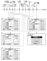
主制御手段100は、大別すると、主に遊技状態を管理する遊技状態管理手段110と、主に遊技進行を管理する遊技進行管理手段130と、主制御手段100における通信を制御するメイン通信制御手段150とを備えて構成されている。このうち、遊技状態管理手段110は、設定値制御手段111、RT状態制御手段112、再遊技作動制御手段113、ボーナス作動制御手段114、フリーズ制御手段115、遊技モード制御手段116、及び乱数発生・取込手段117を備えている。
(1) Functional blocks of the main control means 100 The main control means 100 is broadly composed of a game state management means 110 that mainly manages the game state, a game progress management means 130 that mainly manages the game progress, and a main communication control means 150 that controls communication in the main control means 100. Of these, the game state management means 110 includes a set value control means 111, an RT state control means 112, a replay operation control means 113, a bonus operation control means 114, a freeze control means 115, a game mode control means 116, and a random number generation/acquisition means 117.
また、遊技進行管理手段130は、受容メダル管理手段131、役決定手段132、演出グループ番号決定手段133、リール制御手段134、停止表示図柄判定手段135、払出メダル管理手段136、ブロッカ制御手段137、表示用ランプ制御手段138、押し順管理手段139、及び条件装置グループ番号決定手段140を備えており、メイン通信制御手段150は、制御コマンド送信手段151と外端信号送信手段152を備えている。なお、主制御手段100における上述の各手段は、図2に示す主制御基板60上に配されたメインCPU61、ROM62、RAM63、電子回路等のハードウエア及びROM62等に格納された制御プログラム等のソフトウエアにより構成されるものを機能的に表したものである。
The game progress management means 130 includes a received medal management means 131, a role determination means 132, a performance group number determination means 133, a reel control means 134, a stop display pattern determination means 135, a paid medal management means 136, a blocker control means 137, a display lamp control means 138, a push order management means 139, and a condition device group number determination means 140, and the main communication control means 150 includes a control command transmission means 151 and an outer end signal transmission means 152. Note that each of the above-mentioned means in the main control means 100 is a functional representation of the
(1-1)遊技状態管理手段110を構成する各手段
設定値制御手段111は、役決定確率の設定値(設定1~設定6の6段階構成)を内部的に管理するための数値(「管理用設定値」とも称する)を制御するように構成されている。本実施形態では、管理用設定値として1から6までの連続する整数値(1~6の整数値は設定1~設定6にそれぞれ対応する)を用いている。管理用設定値のデータは、RAM63の所定の記憶領域に記憶されるようになっており、役決定処理において設定値を確認する際に参照されるとともに、設定確認時または設定変更時において、設定値表示器(払出数表示ランプ46j)に設定値を表示する際に参照されるようになっている。また、管理用設定値は、遊技店員による設定変更操作に応じて変更される。具体的には、設定鍵型スイッチ83がON状態に操作され、その状態で設定変更スイッチ84を操作するごとに、設定値が1ずつ更新されるようになっている。
(1-1) Means Constituting the Game Status Management Means 110 The setting value control means 111 is configured to control a numerical value (also referred to as a "management setting value") for internally managing the setting value (six-stage configuration of setting 1 to setting 6) of the winning combination probability. In this embodiment, consecutive integer values from 1 to 6 (the integer values from 1 to 6 correspond to
RT状態制御手段112は、非RT、RT1、RT2の3つのRT状態の設定を制御するように構成されている。非RTは、RAM(RAM63)が初期化された場合に設定されるRT状態である。RT1は、1種BB-A条件装置または1種BB-B条件装置の選出(BB役1またはBB役2の当選)が持ち越されているときに設定されるRT状態(「BB内部中」とも称する)である。RT2は、BB役1またはBB役2が成立したことを契機として次遊技から設定されるRT状態(「BB作動中」とも称する)であり、このRT2中においてボーナス遊技が実行可能となる。RT2では、再遊技役は当選せず、入賞J~Q条件装置のいずれかが選出されるよう(ハズレ無し)に設定されている。上述した各RT状態の移行制御については後に詳しく説明する。
The RT state control means 112 is configured to control the setting of three RT states: non-RT, RT1, and RT2. Non-RT is the RT state that is set when the RAM (RAM 63) is initialized. RT1 is the RT state (also called "inside BB") that is set when the selection of a
再遊技作動制御手段113は、再遊技役が成立したことを契機として、遊技者が所有する遊技メダルをベットすることなく次の遊技を行うことが許可される状態(「再遊技作動状態」とも称する)に設定するように構成されている。再遊技作動状態に設定されると、RAM63の所定の記憶領域に再遊技作動状態であることを示す情報(「再遊技作動状態フラグ」とも称する)がセット(例えば、値「1」が記憶)される。セットされた再遊技作動状態フラグは、再遊技作動状態が解消されるまでの所定の時点でクリア(例えば、値「0」が記憶)される。
The replay operation control means 113 is configured to set a state (also called the "replay operation state") in which the player is permitted to play the next game without betting any game medals owned, when a replay role is established. When the replay operation state is set, information indicating that the replay operation state is in progress (also called the "replay operation state flag") is set (for example, the value "1" is stored) in a specified memory area of the
ボーナス作動制御手段114は、ボーナス役(本実施形態の場合、BB役1またはBB役2)の当選時(1種BB-A条件装置または1種BB-B条件装置の選出時)から、B
B役1またはBB役2が成立したことを契機として実行されるボーナス遊技の終了時までの期間において、所定の処理を実行するように構成されている。具体的には、BB役1またはBB役2が当選すると、RAM63の所定の記憶領域にBB役1またはBB役2が当選したことを示す情報(「1種BB当せん当該フラグ」とも称する)をセット(例えば、値「1」を記憶)する。また、BB役1またはBB役2が成立したことを契機として、RAM63の所定の記憶領域にBB作動状態であることを示す情報(「1種BB作動フラグ」とも称する)をセット(例えば、値「1」を記憶)する。
The bonus operation control means 114 is configured to operate in the following manner: from the time when a bonus role (in this embodiment,
It is configured to execute a predetermined process during the period until the end of the bonus game that is executed when the
フリーズ制御手段115は、所定の条件成立を契機として、遊技の進行に係る制御処理(例えば、ベット操作やリール回転開始操作、リール回転停止操作等を受け付ける処理等)の実行を所定時間遅延させるフリーズを設定するように構成されている。本実施形態では、当せんウェイト(フリーズ時間2秒)、フェイクウェイト(フリーズ時間5秒)、告知ウェイト(フリーズ時間2秒)、全停時終了時ウェイト(フリーズ時間5秒)の4種類のフリーズを実行できるようになっている。
The freeze control means 115 is configured to set a freeze that delays the execution of control processes related to the progress of the game (such as processes that accept bet operations, reel spin start operations, reel spin stop operations, etc.) for a predetermined time when a predetermined condition is met. In this embodiment, four types of freezes can be executed: win wait (freeze
遊技モード制御手段116は、遊技モード0から遊技モード7までの8個の遊技モードの設定を制御するように構成されている。遊技モードとは、RT状態とは別に主制御手段側で制御する、主にATの設定状態に関連する遊技状態(「メイン遊技状態」とも称する)を意味する。また、遊技モード制御手段116は、区間種別番号(0または1の値をとる)によって、後述する通常区間と有利区間のいずれかに滞在するのかを管理している。ここで、区間種別番号=0は通常区間、区間種別番号=1は有利区間にそれぞれ滞在することを示している。さらに、遊技モード制御手段116は、AT当せんフラグ(0または1の値をとる)によって、ATに当選したことを管理している。ここで、AT当せんフラグ=0はATに当選していないことを、AT当せんフラグ=1はATに当選していることを示している。
The game mode control means 116 is configured to control the setting of eight game modes from
遊技モード0は、通常(非有利)の遊技状態である。遊技モード0は、通常区間に滞在するモードであり、AT遊技(アシスト遊技)に関連する抽選等を行わないモードとなっている。遊技モード1は、主に、区間種別番号=1となったが、AT当選していないときに滞在する「チャンス」とも称される遊技状態である。遊技モード2は、主に、区間種別番号=1となりAT当選もしているが、BB当選していないときに滞在する「AT当選後1」とも称される遊技状態である。遊技モード3は、主に、AT当選している状態で、BB当選したことを契機として移行されるATの遊技状態である。この遊技モード3中において、後述の押しナビが実行されるため、遊技者にとって非常に有利な遊技状態となる。
遊技モード4は、主に、後述する遊技モード7においてBB成立した場合にその後滞在する「AT後」とも称される遊技状態である。遊技モード5は、主に、遊技モード4においてAT当選した場合にその後滞在する「AT当選後2」とも称される遊技状態である。遊技モード6は、主に、区間種別番号=1で、AT当選していない状態でのBB内部中に滞在する「チャンス時内部」とも称される遊技状態である。遊技モード7は、主に、1回のAT終了後に、到達フラグ=0の場合に滞在する「AT後内部」とも称される遊技状態である。
上述の8個の遊技モード0~7は、通常区間に属する遊技モード(遊技モード0)と、有利区間に属する遊技モード(遊技モード1~7)とに分けられる。通常区間は、押しナビ(入賞ナビ、RPナビ及び目押しナビ)を行わない期間であり、押し順を判別できる情報(条件装置番号や指示番号等の情報)を主制御手段側から副制御手段側に送信しない期間でもある。また、通常区間は、有利区間への移行の可否を決定するための抽選(例えば、有利区間移行抽せん)を行うことができる期間でもある。
The above-mentioned eight
有利区間は、押しナビを行うことができる期間であり、押し順を判別できる情報を主制御手段側から副制御手段側に送信してもよい期間でもある。また、有利区間は、有利区間の性能等を変更する抽選(例えば、ATモード抽選)や有利区間中のATゲーム数を上乗せする処理(例えば、セブンストック1抽選、セブンストック2抽選)等を行うことができる期間でもある。さらに、有利区間では、有利区間中であることを遊技者に報知するための区間表示器(例えば、払出数表示ランプ46jのうち、7セグメントランプ以外のDPセグメントランプ(「有利区間ランプ」とも称する)を点灯する。有利区間に滞在中は、少なくとも1回は入賞ナビを行うようにしてもよい(この場合は、入賞ナビを1回も行っていないのであれば、通常区間へ移行することはできないようにしてもよい)。
The favorable zone is a period during which push navigation can be performed, and is also a period during which information that can determine the push order can be sent from the main control means to the sub-control means. The favorable zone is also a period during which a lottery that changes the performance of the favorable zone (for example, an AT mode lottery) or a process that adds to the number of AT games during the favorable zone (for example, a seven
また、有利区間に連続滞在できる期間には、上限(1500ゲーム)が設けられている。さらに、上限に達して有利区間を終了するときは、有利区間に関連する情報(例えば、AT当せんフラグ、セブンストック数カウンタの値等の情報)は、全てクリアされる。なお、上限に達して有利区間を終了するときは、有利区間の滞在中に1回も入賞ナビが行われていなくてもよい。また、有利区間への移行の可否を決定するための抽選、有利区間の性能等を変更する抽選を、役決定結果(条件装置)に基づいて行う場合は、設定差を設けていない役決定結果に限って行うようにしてもよいし、特に、有利区間の性能等を変更する抽選は、役決定結果以外の条件に基づいて行うようにしてもよい。そして、その際は、設定値を参照することなく行うようにしてもよい。 In addition, there is an upper limit (1500 games) on the period during which a player can stay continuously in the advantageous zone. Furthermore, when the upper limit is reached and the advantageous zone ends, all information related to the advantageous zone (for example, information such as the AT winning flag and the value of the seven stock counter) is cleared. Note that when the upper limit is reached and the advantageous zone ends, it is not necessary that a winning navigation has been performed even once during the stay in the advantageous zone. In addition, when the lottery for determining whether or not to move to the advantageous zone and the lottery for changing the performance of the advantageous zone are performed based on the role determination result (condition device), they may be limited to the role determination result that does not have a setting difference, and in particular, the lottery for changing the performance of the advantageous zone may be performed based on conditions other than the role determination result. In that case, they may be performed without referring to the setting value.
乱数発生・取込手段117は、上述のCPU61、クロックパルス発生器64、分周器65、乱数発生器66、乱数取込回路67で構成され、各種抽選に用いられる乱数を発生させ、取り込む。本実施形態では、最大で「0~65535」までの数値範囲の乱数列を発生可能な4個(4ch:chは「チャンネル」の略)の16ビット乱数手段と、最大で「0~255」までの数値範囲の乱数列を発生可能な4個(4ch)の8ビット乱数手段を有しており、それぞれが独立して乱数列を発生させることが可能となっている。これらの16ビット乱数手段または8ビット乱数手段が発生する乱数は、クロックパルス発生器64が発生するクロック信号に基づいて更新されるため、ハードウエア乱数(ハード乱数)とも称される。なお、図示はしていないが本実施形態では、乱数発生・取込手段117とは別の乱数発生手段を備えている。この乱数発生手段は、上述のCPU61、RAM63で構成され、役決定等に用いられる乱数として、所定の数値範囲の乱数列を発生可能な乱数手段を有している。この乱数は、プログラムに基づいて更新されるため、ソフトウエア乱数(ソフト乱数)とも称される。
The random number generating and capturing means 117 is composed of the above-mentioned
(RT状態の移行制御について)
前述したRT状態制御手段112によるRT状態の移行制御について図10を参照して説明する。この図に示すように、非RT中において1種BB-A条件装置または1種BB-B条件装置が選出されると条件P1を充足し、これを契機としてRT状態制御手段112は、RT状態を非RTからRT1へ移行させる。また、RT1中において、BB役1またはBB役2が成立(「BB成立」、「BB作動」とも称する)すると条件P2を充足し、これを契機としてRT状態制御手段112は、RT状態をRT1からRT2へ移行させる。
(Regarding RT state transition control)
The above-mentioned RT state transition control by the RT state control means 112 will be described with reference to Figure 10. As shown in this figure, when a
RT2は、BB役1またはBB役2が成立したことを契機として次遊技から設定されるRT状態(「BB作動中」とも称する)であり、このRT2中においてボーナス遊技が実行可能となる。RT2では、再遊技役は当選せず、入賞J~Q条件装置のいずれかが選出されるよう(ハズレ無し)に設定されている。RT2中において、所定数(70枚)を超える遊技メダルが獲得されてボーナス遊技が終了する(「BB作動終了」とも称する)と、条件P3を充足し、これを契機としてRT状態制御手段112は、RT状態をRT2から非RTへ移行させる。
RT2 is an RT state (also called "BB in operation") that is set from the next game when
(遊技モードの移行制御)
前述した遊技モード制御手段116による遊技モードの移行制御について図11及び図12を参照して説明する。図11に示すように、遊技モード0中において、条件Q1が充足されたことを契機として遊技モード0から遊技モード1へ移行し、条件Q2が充足されたことを契機として遊技モード0から遊技モード2へ移行し、条件Q3が充足されたことを契機として遊技モード0から遊技モード3に移行し、条件Q4が充足されたことを契機として遊技モード0から遊技モード6へ移行されるようになっている。各移行条件(条件Q1~Q15)の内容については、図11に簡略化して記載しているが、より詳細な内容については、後述するフローチャートに記載している。
(Game mode transition control)
The transition control of the game mode by the game mode control means 116 will be described with reference to Figures 11 and 12. As shown in Figure 11, in
遊技モード1中において、条件Q5が充足されたことを契機として遊技モード1から遊技モード0へ移行し、条件Q6が充足されたことを契機として遊技モード1から遊技モード6へ移行し、条件Q7が充足されたことを契機として遊技モード1から遊技モード2へ移行し、条件Q8が充足されたことを契機として遊技モード1から遊技モード3へ移行するようになっている。ここで、条件Q5に含まれるチャンスゲーム数カウンタは、遊技モード1に滞在するゲーム数を管理するカウンタ(0~30の値をとる)であり、遊技モード1に移行した際にチャンスゲーム数カウンタの値が30にセットされ、以降毎ゲーム1ずつ減算される(図12も参照)。また、条件Q6~Q8に含まれる1種BB当せん当該フラグは、当該ゲームにおける役抽選においてBB当選したか否かを管理するフラグ(0または1の値をとる)であり、1種BB当せん当該フラグ=0は当該ゲームでBB当選していないことを、1種BB当せん当該フラグ=1は当該ゲームでBB当選していることを示す(図12も参照)。
In
遊技モード2中において、条件Q9が充足されたことを契機として遊技モード3に移行されるようになっている。遊技モード3中において、条件Q11が充足されたことを契機として遊技モード0へ移行し、条件Q12が充足されたことを契機として遊技モード7へ移行するようになっている。ここで、条件Q11、Q12に含まれるベル回数カウンタは、AT中での押しナビ(入賞ナビ)の実行可能回数(「ベル回数」とも称する)を管理するカウンタ(0~134の値をとる)であり、ベル回数カウンタの値が1以上のときに入賞ナビが実行可能となる(図12も参照)。
In
また、条件Q11、Q12に含まれるセブン番号は、ATの種別(赤セブンまたは金セブン)を管理する番号であり、セブン番号=1は赤セブン、セブン番号=2は金セブンを示す(図12も参照)。セブンカウンタは、赤セブンのストック数を管理するカウンタ(0~26の値をとる)であり、累積カウンタは、1回の有利区間での遊技メダルの獲得数(差枚数)を管理するカウンタ(0~2412の値をとる)であり、到達フラグは、遊技メダルの獲得数(差枚数)の上限到達を調整するためのフラグ(0または1の値をとる)である(図12も参照)。 The seven numbers included in conditions Q11 and Q12 are numbers that manage the type of AT (red seven or gold seven), with seven number = 1 indicating red seven and seven number = 2 indicating gold seven (see also Figure 12). The seven counter is a counter (taking a value between 0 and 26) that manages the number of red sevens in stock, the cumulative counter is a counter (taking a value between 0 and 2412) that manages the number of game medals acquired (the difference in number) in one favorable zone, and the reach flag is a flag (taking a value between 0 and 1) that adjusts the upper limit of the number of game medals acquired (the difference in number) (see also Figure 12).
遊技モード6中において、条件Q10が充足されたことを契機として遊技モード1へ移行するようになっている。遊技モード7中において、条件Q10が充足されたことを契機として遊技モード4へ移行するようになっている。遊技モード4中において、条件Q8が充足されたことを契機として遊技モード4から遊技モード3へ移行され、条件Q13が充足されたことを契機として遊技モード4から遊技モード0へ移行し、条件Q14が充足されたことを契機として遊技モード4から遊技モード7へ移行するようになっている。ここで、条件Q13、Q14に含まれるAT周期カウンタは、AT中の滞在周期を管理するカウンタ(0~3の値をとる)である。
In
また、遊技モード4中において、条件Q7が充足されたことを契機として遊技モード4
から遊技モード5へ移行し、遊技モード5中において、条件Q9が充足されたことを契機として遊技モード3へ移行するようになっている。
In addition, when the condition Q7 is satisfied during the
The game mode is switched to
さらに、遊技モード1~7のいずれか(すなわち、有利区間)に滞在中に、条件Q15が充足されたことを契機として遊技モード0に移行されるようになっている。なお、条件Q15に含まれる有利区間クリアカウンタは、有利区間に連続滞在しているゲーム数を管理するカウンタ(0~1500の値をとる)であり、通常区間から有利区間に移行した際に1500にセットされ、有利区間でゲームを消化するごとに1減算される(図12も参照)。また、純増カウンタは、有利区間中の獲得数(差枚数)を管理するカウンタ(0~2412の値をとる)であり、通常区間から有利区間に移行したときに0にセットされ、以降、獲得数に応じて更新される(図12も参照)。
Furthermore, when the player is in any of
このように、通常区間から有利区間へ移行した際に、有利区間クリアカウンタの値を「1500」にセットし、有利区間でゲームを消化するごとに有利区間クリアカウンタの値を1減算する。そして、有利区間クリアカウンタの値が「0」となると通常区間に強制的に移行するようにしている。また、有利区間クリアカウンタの値が「0」となる前に有利区間から通常区間に移行した場合は、有利区間クリアカウンタの値をクリア(「0」にセット)し、再び通常区間から有利区間に移行した際に、有利区間クリアカウンタの値を「1500」にリセットする。 In this way, when transitioning from the normal zone to the advantageous zone, the value of the advantageous zone clear counter is set to "1500", and the value of the advantageous zone clear counter is decremented by 1 each time a game is played in the advantageous zone. When the value of the advantageous zone clear counter reaches "0", a forced transition to the normal zone occurs. Also, if a transition is made from the advantageous zone to the normal zone before the value of the advantageous zone clear counter reaches "0", the value of the advantageous zone clear counter is cleared (set to "0"), and when transitioning from the normal zone to the advantageous zone again, the value of the advantageous zone clear counter is reset to "1500".
また、本実施形態では、有利区間中での遊技メダルの獲得数(差枚数)を計数する純増カウンタも備えている。この純増カウンタは、有利区間の開始時にそのカウンタ値を「0」にセットし(有利区間の終了時に「0」にセットしてもよい)、以降毎遊技、遊技の結果に応じてカウンタ値を更新する。更新する際に、差枚数が0を下回る場合は、カウンタ値を「0」となるよう補正し、差枚数が正値となる場合はそのまま累積して更新する(このような補正を行わないようにしてもよい)。そして、累積した差枚数が2400枚を超えると有利区間を終了して通常区間に移行するようになっている。なお、累積カウンタは、機能的には、純増カウンタと同じ計数を行うカウンタである。制御処理中に遊技メダルの獲得数(差枚数)を確認する場合、処理内容に応じて累積カウンタの値を参照するときと、純増カウンタの値を確認するときがある。 In this embodiment, a net gain counter is also provided to count the number of game medals acquired (the difference in number of medals) during the favorable zone. The net gain counter is set to "0" at the start of the favorable zone (it may also be set to "0" at the end of the favorable zone), and the counter value is updated for each game thereafter according to the game results. When updating, if the difference in number of medals falls below 0, the counter value is corrected to "0", and if the difference in number of medals is a positive value, it is accumulated and updated as is (such correction may not be performed). When the accumulated difference in number of medals exceeds 2400, the favorable zone ends and the normal zone is entered. The accumulation counter is functionally a counter that performs the same count as the net gain counter. When checking the number of game medals acquired (the difference in number of medals) during control processing, the value of the accumulation counter may be referenced or the value of the net gain counter may be checked depending on the processing content.
さらに、有利区間中での遊技メダルの獲得数(差枚数)に関連した計数を行うカウンタとして、補正カウンタも備えている。この補正カウンタは、純増カウンタ(累積カウンタ)の値に、赤セブンや金セブン等のATストック数やベル回数カウンタの値を加味して算出される、1回の有利区間中に獲得することが可能と予想される遊技メダルの獲得数(「獲得予想数」、「獲得可能予想数」とも称する)を計数するカウンタ(0~2101の値をとる)である。そして、補正カウンタの値(獲得予想数)が所定値(2100)を超えると、それを契機として、所定のタイミングで有利区間を終了して通常区間に移行する場合があるようにしている。 In addition, a correction counter is also provided as a counter that performs counting related to the number of game medals won (difference in number) during the favorable zone. This correction counter is a counter (taking a value between 0 and 2101) that counts the number of game medals that can be won during one favorable zone (also called the "expected number won" or "expected number of medals that can be won"), which is calculated by adding the number of AT stocks such as red sevens and gold sevens and the value of the bell count counter to the value of the net increase counter (accumulation counter). When the value of the correction counter (expected number won) exceeds a predetermined value (2100), this may be used as a trigger to end the favorable zone at a predetermined timing and transition to the normal zone.
このような構成とすることにより、有利区間の終了時期を遊技者に分かり難くすることができる。例えば、有利区間クリアカウンタの値または純増カウンタの値のみで、有利区間の終了時期を決める場合、それらの値を遊技者に表示しておくと、遊技者はそれらを確認することにより、有利区間の終了時期を容易に把握することができる。しかし、補正カンタを備えた場合、有利区間クリアカウンタや純増カウンタの値の値が上限値に達していないにも関わらず、補正カウンタの値が所定値に達したことにより、有利区間が終了することが起きる。そのため、有利区間の終了時期が分かり難くなり、遊技の興趣を向上させることができる。また、補正カウンタにおける所定値(2100)を純増カウンタにおける上限値(2400)よりも小さい値に設定することにより、AT中に有利区間が終了する可能性を低減することも可能となる。例えば、AT中に補正カウンタの値(獲得予想数
)が所定値(2100)を超えた場合、そのATの終了後に次のATも実行可能とすると、次のATの実行中に純増カウンタが上限値(2400)を超えて有利区間が終了してしまう可能性が高くなる。AT中に有利区間が終了してしまうと、遊技者が落胆する虞があるが、補正カウンタの値(獲得予想数)が所定値(2100)を超えたより有利区間を終了するようにすれば、このような事態が起きることを回避することができる。
By adopting such a configuration, it is possible to make it difficult for a player to know when the advantageous zone ends. For example, when the advantageous zone ends only by the value of the advantageous zone clear counter or the value of the net gain counter, if these values are displayed to the player, the player can easily know when the advantageous zone ends by checking them. However, when a correction counter is provided, the advantageous zone ends when the value of the correction counter reaches a predetermined value even though the values of the advantageous zone clear counter and the net gain counter have not reached their upper limits. Therefore, it becomes difficult to know when the advantageous zone ends, and the interest in the game can be improved. In addition, by setting the predetermined value (2100) of the correction counter to a value smaller than the upper limit value (2400) of the net gain counter, it is possible to reduce the possibility that the advantageous zone ends during the AT. For example, if the value of the correction counter (expected number of wins) exceeds the predetermined value (2100) during the AT, if the next AT can be executed after the AT ends, the net gain counter will likely exceed the upper limit value (2400) during the execution of the next AT, and the advantageous zone will end. If the advantageous period ends during the AT, the player may become disappointed, but this can be prevented by ending the advantageous period when the correction counter value (expected number of wins) exceeds a predetermined value (2100).
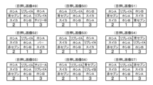
(各遊技モードで実行される抽選)
次に、上述した遊技モード0~7において、遊技モード制御手段116によって行われる種々の抽選について、図13~図20を参照して説明する。図13(A)に示す有利区間移行抽せんは、有利区間へ移行するか否かを決める抽選であり、条件装置グループA番号(条件装置グループ番号については後述する)に基づいて、当選(1)またはハズレ(0)のいずれかを選出する。各条件装置グループA番号に対応する当選置数は図示のとおりである。
(Lottery executed in each game mode)
Next, various lotteries performed by the game mode control means 116 in the above-mentioned
図13(B)に示すチャンスモード1抽せんは、チャンスモード番号(チャンス(遊技モード1)中での抽選での当たり易さを管理する番号)を決める抽選であり、条件装置グループH番号に基づいて、チャンスモード番号0~4のいずれかを選出する。各条件装置グループH番号に対応する当選置数は図示のとおりである。
The
図13(C)に示すチャンスモード2抽せん-1は、チャンス(遊技モード1)中でのBB作動中において、チャンスモード番号を決める抽選であり、条件装置グループD番号に基づいて、チャンスモード番号0~4のいずれか(実際には0または4)を選出する。各条件装置グループD番号に対応する当選置数は図示のとおりである。
図13(D)に示すチャンスモード2抽せん-2は、チャンス(遊技モード1)中でのBB非作動中において、チャンスモード番号を決める抽選であり、条件装置グループB番号に基づいて、チャンスモード番号0~4のいずれか(実際には0または4)を選出する。各条件装置グループB番号に対応する当選置数は図示のとおりである。
The
図13(E)に示すチャンスモード3抽せんは、チャンス(遊技モード1)中の滞在周期の終了時に、チャンスモード番号を新たに決める抽選であり、現在のチャンスモード番号1~3(0の場合は抽選しない)に基づいて、新たなチャンスモード番号0~4のいずれか(実際には0または4)を選出する。各チャンスモード番号に対応する当選置値数は図示のとおりである。なお、チャンスモード番号4は、AT当選であることを示している。図13(B)~(E)の各チャンスモード抽せんのことを総称して、AT抽せんとも称する。
The
図14(A)に示すチャンスゲーム数抽せんは、チャンスモード1抽せんにおいてチャンスモード番号1~3のいずれかが選出されたとき(「チャンスモード当選時」とも称する)に、チャンス(遊技モード1)に滞在するゲーム数を決める抽選であり、選出されたチャンスモード番号1~3に基づいて、ゲーム数0,10,20,30のいずれかを選出する。各チャンスモード番号に対応する当選置数は図示のとおりである。
The chance game number lottery shown in FIG. 14(A) is a lottery that determines the number of games to stay in chance (game mode 1) when any of
図14(B)に示すチャンス周期抽せんは、チャンスモード当選時に周期回数を決める抽選であり、チャンスモード1抽せんにおいて選出されたチャンスモード番号1~3に基づいて、周期数0~4のいずれかを選出する。各チャンスモード番号に対応する当選置数は図示のとおりである。
The chance cycle lottery shown in FIG. 14(B) is a lottery that determines the number of cycles when a chance mode is won, and selects one of the
図14(C)に示すEX1モード抽せんは、AT当選後の上乗せモード番号(AT中のストック上乗せ状態を管理する番号)を決める抽選であり、条件装置グループF番号に基
づいて、上乗せモード番号0~2のいずれか(実際には1または2)を選出する。各条件装置グループF番号に対応する当選置数は図示のとおりである。
The EX1 mode lottery shown in Fig. 14(C) is a lottery to determine the add-on mode number after the AT win (the number that manages the stock add-on state during the AT), and selects one of the add-on
図14(D)に示すEX2モード抽せんは、EX1モード抽せんと同じくAT当選後の上乗せモード番号を決めるため、特に、遊技モード2または5に滞在中に行われる抽選であり、条件装置グループF番号に基づいて、上乗せモード番号0~2のいずれか(実際には0または2)を選出する。各条件装置グループF番号に対応する当選置数は図示のとおりである。
The EX2 mode lottery shown in Figure 14 (D) is a lottery that is held while in
図14(E)に示すATモード抽せん-1は、AT当選時に次回のATモード番号(AT中における抽選での当たり易さを管理する番号)を決めるため、特に、遊技モード0~2の滞在中に行われる抽選であり、条件装置グループJ番号に基づいて、ATモード番号0~5のいずれかを選出する。各条件装置グループJ番号に対応する当選置数は図示のとおりである。
The AT mode lottery-1 shown in Figure 14 (E) is a lottery that is held especially while in
図14(F)に示すATモード抽せん-2は、ATモード抽せん-1と同じくAT当選時に次回のATモード番号(AT中における抽選での当たり易さを管理する番号)を決めるため、特に、遊技モード3~5の滞在中に行われる抽選であり、条件装置グループJ番号に基づいて、ATモード番号0~5のいずれかを選出する。各条件装置グループJ番号に対応する当選置数は図示のとおりである。
The AT mode lottery-2 shown in Figure 14 (F) is a lottery that is held while in
図14(G)に示すATモード抽せん-3は、ATモード抽せん-1,2と同じくAT当選時に次回のATモード番号(AT中における抽選での当たり易さを管理する番号)を決めるため、特に、全回胴停止後(「全停後」とも称する)に行われる抽選であり、条件装置グループJ番号に基づいて、ATモード番号0~5のいずれかを選出する。各条件装置グループJ番号に対応する当選置数は図示のとおりである。
The AT mode lottery-3 shown in Figure 14 (G) is the same as AT mode lottery-1 and -2, in that it determines the next AT mode number (a number that controls the likelihood of winning in the lottery during the AT) when an AT is won, and is a lottery that is held after all reels have stopped (also called "after all stops"), and selects one of the
図15(A)に示すセブン1抽せんは、ATの種別(赤セブンまたは金セブン)を決めるため、特に、遊技モード1または4滞在中と全停後に行われる抽選であり、条件装置グループF番号に基づいて、セブン番号0~2のいずれかを選出する。各条件装置グループF番号に対応する当選置数は図示のとおりである。
The
図15(B)に示すセブン2抽せんは、セブン1抽せんと同じく、ATの種別を決めるため、特に、遊技モード2または5滞在中に行われる抽選であり、条件装置グループF番号に基づいて、セブン番号0~2のいずれかを選出する。各条件装置グループF番号に対応する当選置数は図示のとおりである。
The
図15(C)に示すATモード書換抽せんは、AT終了後にATモード番号を書き換える抽選であり、有利区間クリアカウンタの値(300未満か300以上か)に基づいて、ATモード番号0~5のいずれかを選出する。各有利区間クリアカウンタの値に対応する当選置数は図示のとおりである。
The AT mode rewrite lottery shown in FIG. 15(C) is a lottery to rewrite the AT mode number after the AT ends, and selects one of the
図15(D)に示すセブンループ抽せんは、赤セブンを継続するか否かを決める抽選であり、ループ番号(赤セブンの継続率を管理する番号)に基づいて、当選(1)またはハズレ(0)のいずれかを選出する。各ループ番号に対応する当選置数は図示のとおりである。 The Seven Loop lottery shown in Figure 15 (D) is a lottery to decide whether or not to continue the Red Seven, and selects either a win (1) or a loss (0) based on the loop number (the number that controls the continuation rate of the Red Seven). The number of winning numbers corresponding to each loop number is as shown in the figure.
図15(E)に示す金セブンループ抽せんは、金セブンを継続するか否かを決める抽選であり、当選(1)またはハズレ(0)のいずれかを選出する。当選(1)およびハズレ(0)に割り当てた当選置数は図示のとおりである。 The Gold Seven Loop lottery shown in FIG. 15(E) is a lottery to decide whether or not to continue with Gold Seven, and selects either a winning number (1) or a losing number (0). The winning numbers assigned to winning numbers (1) and losing numbers (0) are as shown in the figure.
図15(F)に示す金セブンループ書換抽せんは、金セブンの継続率を書き換えるための抽選であり、条件装置グループE番号に基づいて、当選(1)またはハズレ(0)のいずれかを選出する。各条件装置グループE番号に対応する当選置数は図示のとおりである。 The Gold Seven Loop Rewrite Lottery shown in FIG. 15(F) is a lottery for rewriting the continuation rate of Gold Seven, and selects either a win (1) or a loss (0) based on the condition device group E number. The number of winning entries corresponding to each condition device group E number is as shown in the figure.
図15(G)に示す上乗せモード抽せんは、AT中に上乗せモード番号を決める抽選であり、上乗せモード番号0~2のいずれか(実際には1または2)を選出する。各上乗せモード番号に割り当てた当選置数は図示のとおりである。
The add-on mode lottery shown in Figure 15 (G) is a lottery to determine the add-on mode number during the AT, and selects one of the add-on
図16(A)に示すベル回数切替抽せんは、ベル回数を書き替えるための抽選であり、ベル回数カウンタの値に基づいて、当選(1)またはハズレ(0)のいずれかを選出する。各ベル回数カウンタの値に対応する当選置数は図示のとおりである。 The bell count change lottery shown in FIG. 16(A) is a lottery for rewriting the number of bells, and selects either a win (1) or a loss (0) based on the value of the bell count counter. The number of wins corresponding to each bell count counter value is as shown in the figure.
図16(B)に示すセブンストック1抽せんは、ATストック数を加算するか否かを決める抽選であり、条件装置グループC番号に基づいて、当選(1)またはハズレ(0)のいずれかを選出する。各条件装置グループC番号に対応する当選置数は図示のとおりである。
The
図16(C)に示すセブンストック2抽せんは、セブンストック1抽せんと同じく、ATストック数を加算するか否かを決める抽選であり、条件装置グループE番号に基づいて、当選(1)またはハズレ(0)のいずれかを選出する。各条件装置グループE番号に対応する当選置数は図示のとおりである。
The
図16(D)に示す演出レバーウェイト抽せんは、フリーズとしてのフェイクウェイトを行うか否かを決める抽選であり、条件装置グループJ番号に基づいて、当選(1)またはハズレ(0)のいずれかを選出する。各条件装置グループJ番号に対応する当選置数は図示のとおりである。 The effect lever wait lottery shown in FIG. 16(D) is a lottery to decide whether or not to perform a fake wait as a freeze, and selects either a win (1) or a loss (0) based on the condition device group J number. The number of winning positions corresponding to each condition device group J number is as shown in the figure.
図17(A)に示すAT周期抽せん-1は、AT終了時に、AT中の滞在周期回数(遊技モード3から遊技モード7,4を経由して遊技モード3に戻るまでに必要なBB作動の回数)を決めるため、特に、ATモード番号が1または2のときに行われる抽選であり、ベル回数カウンタの値に基づいて、滞在周期回数0~3(実際には1~3)のいずれかを選出する。各ベル回数カウンタの値に対応する当選置数は図示のとおりである。
The AT Cycle Lottery-1 shown in Figure 17 (A) is a lottery that is held when the AT mode number is 1 or 2 in order to determine the number of stay cycles during the AT (the number of BB operations required to go from
図17(B)に示すAT周期抽せん-2は、AT周期抽せん-1と同じく、AT終了時に、AT中の滞在周期回数を決めるため、特に、ATモード番号が3または4のときに行われる抽選であり、ベル回数カウンタの値に基づいて、滞在周期回数0~3(実際には1~3)のいずれかを選出する。各ベル回数カウンタの値に対応する当選置数は図示のとおりである。
The AT Cycle Lottery-2 shown in FIG. 17(B) is the same as the AT Cycle Lottery-1, and is a lottery held when the AT mode number is 3 or 4, in order to determine the number of stay cycles during the AT at the end of the AT. Based on the value of the bell count counter, one of the
図17(C)に示す引き戻し1抽せん-1は、AT終了後に、再びAT当選するか否かを決めるため、特に、ATモード番号が1~3のときに行われる抽選であり、条件装置グループC番号に基づいて、当選(1)またはハズレ(0)のいずれかを選出する。各条件装置グループC番号に対応する当選置数は図示のとおりである。
The
図17(D)に示す引き戻し1抽せん-2は、引き戻し1抽せん-1と同じく、AT終了後に、再びAT当選するか否かを決めるため、特に、ATモード番号が4のときに行われる抽選であり、条件装置グループC番号に基づいて、当選(1)またはハズレ(0)のいずれかを選出する。各条件装置グループC番号に対応する当選置数は図示のとおりであ
る。
The
図18(A)に示す引き戻し1抽せん-3は、引き戻し1抽せん-1,2と同じく、AT終了後に、再びAT当選するか否かを決めるため、特に、ATモード番号が5のときに行われる抽選であり、条件装置グループC番号に基づいて、当選(1)またはハズレ(0)のいずれかを選出する。各条件装置グループC番号に対応する当選置数は図示のとおりである。
The
図18(B)に示す引き戻し2抽せんは、AT中の滞在周期回数が0となった後に、再びAT当選するか否かを決める抽選であり、ATモード番号に基づいて、当選(1)またはハズレ(0)のいずれかを選出する。各ATモード番号に対応する当選置数は図示のとおりである。
The
図18(C)に示すAT周期優遇ゲーム数抽せんは、AT終了後に、所定の優遇状態に設定されるゲーム数(「優遇状態ゲーム数」とも称する)を決める抽選であり、ATモード番号に基づいて、優遇状態ゲーム数0,10,20,30のいずれかを選出する。各ATモード番号に対応する当選置数は図示のとおりである。
The AT cycle preferential game number lottery shown in Figure 18 (C) is a lottery to determine the number of games (also called the "preferential state game number") that will be set to a specified preferential state after the AT ends, and selects one of the preferential
図19(A)に示すセブンテーブル1抽せんは、セブンテーブル番号(赤セブン中の継続率を決めるテーブルを管理する番号)を決める抽選であり、ATモード番号に基づいて、セブンテーブル番号0~15のいずれかを選出する。各ATモード番号に対応する当選置数は図示のとおりである。
The Seven Table 1 lottery shown in Figure 19 (A) is a lottery to determine the Seven Table Number (the number that manages the table that determines the continuation rate during red sevens), and one of the
図19(B)に示すセブンテーブル2抽せんは、セブンテーブル1抽せんと同じく、セブンテーブル番号を決める抽選であり、条件装置グループG番号に基づいて、セブンテーブル番号0~15のいずれかを選出する。各条件装置グループG番号に対応する当選置数は図示のとおりである。
The Seven Table 2 drawing shown in FIG. 19(B) is the same as the Seven Table 1 drawing, in that it is a drawing to determine the Seven Table number, and one of the
図20(A)に示すベル回数1抽せん-1は、ベル回数を決めるため、特に、遊技モードが0~2のときに行われる1回目用の抽選であり、CUランク番号(カウントアップのし易さを管理する番号)に基づいて、ベル回数0~4,6,10,11,20のいずれかを選出する。各CUランク番号に対応する当選置数は図示のとおりである。
The
図20(B)に示すベル回数1抽せん-2は、ベル回数1抽せん-1と同じく、ベル回数を決めるため、特に、遊技モードが4または5のときに行われる1回目用の抽選であり、CUランク番号に基づいて、ベル回数0~4,6,10,11,20のいずれかを選出する。各CUランク番号に対応する当選置数は図示のとおりである。
The
図20(C)に示すベル回数2抽せんは、ベル回数を決めるために行われる2回目以降用の抽選であり、CUランク番号に基づいて、ベル回数0~4,6,10,11,20のいずれかを選出する。各CUランク番号に対応する当選置数は図示のとおりである。
The
図20(D)に示すベル回数3抽せんは、ベル回数2抽せんと同じく、ベル回数を決めるために行われる2回目以降用の抽選であり、ベル回数0~4,6,10,11,20のいずれかを選出する。各ベル回数に割り当てた当選置数は図示のとおりである。
The
(1-2)遊技進行管理手段130を構成する各手段
図9に戻り、受容メダル管理手段131は、メダル投入口21から投入された遊技メダル(「投入遊技メダル」とも称する)のうち実際に受け入れられた遊技メダル(受入通路に導かれて投入メダルセンサ28bにより検出された遊技メダルであり、「受容遊技メダ
ル」とも称する)を、直接ベットされる遊技メダルとするのか、クレジットされる遊技メダルとするのかを制御するように構成されている。本実施形態では、ベット数が最大ベット許容数(遊技を実行するのに必要となるベット数(規定数「3」))に達していない場合には、受容遊技メダルを直接ベットされる遊技メダルとし、ベット数が最大ベット許容数に達しており、クレジット数が最大クレジット許容数(例えば「50」)に達していない場合には、受容遊技メダルをクレジットされる遊技メダルとするように構成されている。
(1-2) Means Constituting the Game Progress Management Means 130 Returning to FIG. 9, the received medal management means 131 is configured to control whether the actually accepted medals (the medals that are guided to the receiving passage and detected by the inserted
また、受容メダル管理手段131は、再遊技作動状態に設定された遊技において、自動ベット処理(遊技者が保有する遊技メダルの数を減らすことなく、前回の遊技におけるベット数と同数の遊技メダルがベットされた状態を設定する処理)を行うように構成されている。再遊技作動状態であっても、クレジット数が最大クレジット許容数に達していない場合には、投入された遊技メダルをクレジットされる遊技メダルとして受け入れる(受け入れないようにしてもよい)。ベット数が最大ベット許容数に達しており、かつクレジット数が最大クレジット許容数に達している場合には、投入された遊技メダルは受け入れられずに返却されるようになっている。 The accepted medal management means 131 is also configured to perform automatic betting processing (processing to set a state in which the same number of game medals as the number of bets in the previous game are bet without reducing the number of game medals held by the player) in a game that has been set to the replay operation state. Even in the replay operation state, if the number of credits has not reached the maximum credit allowable number, the inserted game medals are accepted as game medals to be credited (it is also possible to not accept them). If the number of bets has reached the maximum bet allowable number and the number of credits has also reached the maximum credit allowable number, the inserted game medals are not accepted and are returned.
役決定手段132は、スタートレバー25が操作されたこと(スタートレバー25の操作が有効に受け付けられたこと)を契機として、予め設定された役決定確率(抽選置数)に基づき複数の役決定結果(条件装置)の中から少なくとも1つの役決定結果を選出するための役決定処理(内部抽せん)を行うように構成されている。この役決定処理は、上述の16ビット乱数手段が発生する乱数を用いて行われる。具体的には、スタートレバー25が操作されたことを契機として、16ビット乱数手段が発生した乱数を取り込む。そして、役決定処理を行う際に、取り込んだ乱数を読み出し、その読み出した乱数に所定のソフト乱数を加算し、加算後の乱数を用いて、条件装置を選出するように構成されている。所定のソフト乱数を加算せず、読み出した乱数を用いて、条件装置を選出するようにしてもよい。
The role determination means 132 is configured to perform a role determination process (internal lottery) to select at least one role determination result from multiple role determination results (condition devices) based on a preset role determination probability (lottery setting number) when the
役決定処理は、予め設定された所定の役決定テーブル(図示略)を参照して行われる。役決定テーブルは、各条件装置に対応した抽選置数データが設定値別に、ROM62内の所定の記憶領域(複数のアドレス)に記憶された構成のものとなっている。役決定処理において、1つまたは複数の条件装置が選出されると、選出された条件装置に対応した遊技役が当該遊技における成立許容役となる。選出された条件装置(当選役)の情報はRAM63の所定の記憶領域に記憶されるが、1つの遊技において記憶された当選項目の情報が、小役や再遊技役の当選に関する情報である場合は、これら小役、再遊技役の成立の有無に拘わらず、当該遊技の終了後にクリア(「0」にリセット)される。一方、BB役の当選に関する情報は、BB役が当選しても成立しなかった場合、当該BB役が成立するまでクリアされずに記憶保持される。
The role determination process is performed by referring to a predetermined role determination table (not shown). The role determination table is configured such that the lottery placement number data corresponding to each condition device is stored in a predetermined storage area (multiple addresses) in
演出グループ番号決定手段133は、役決定処理により選出された条件装置に対して演出グループ番号を対応付ける処理を行うように構成されている。本実施形態では、図21に示すように、ボーナス条件装置に対しては演出グループAグループ番号(0または1)を対応付け、入賞再遊技条件装置に対しては演出グループBグループ番号(0~29)を対応付けている。例えば、図21(A)に示すように、1種BB-A条件装置および1種BB-B条件装置には、演出グループAグループ番号1を共通で対応付けている。また、図21(B)に示すように、押し順の違いによって遊技上の有利、不利(出玉への影響)が生じたり、遊技メダルの払出数(獲得数)に差が生じたりする、入賞-A1~A12条件装置には演出グループBグループ番号13を共通で対応付けており、入賞-B1~B12条件装置には演出グループBグループ番号14を共通で対応付けている。
The performance group number determination means 133 is configured to perform processing to associate a performance group number with the condition device selected by the role determination processing. In this embodiment, as shown in FIG. 21, the performance group A group number (0 or 1) is associated with the bonus condition device, and the performance group B group number (0 to 29) is associated with the winning replay condition device. For example, as shown in FIG. 21(A), the performance group
これに対し、押し順の違いによって遊技上の有利、不利に影響しない(出玉への影響がない)再遊技役の当選に対応する再遊技-A~L条件装置や、押し順の違いによって遊技メダルの払出数(獲得数)に差が生じないかあるいは獲得し得る遊技メダル数自体が少ない(例えば、ベットの規定数以下)の小役(入賞役)の当選に対応する入賞再遊技条件装置については、個々の条件装置に対して異なる演出グループB番号を対応付けている。 In contrast, for replay-A to L condition devices that correspond to the winning of replay roles in which differences in the pressing order do not affect the game's advantage or disadvantage (no effect on the number of balls issued), and winning replay condition devices that correspond to the winning of minor roles (winning roles) in which differences in the pressing order do not affect the number of game medals paid out (number won) or in which the number of game medals that can be won is small (for example, less than the specified number of bets), different performance group B numbers are associated with each individual condition device.
図9に戻り、リール制御手段134は、スタートレバー25が操作されたこと(スタートレバー25の操作が有効に受け付けられたこと)を契機として、最小遊技時間が経過していることを確認した後、リール3a~3cを回転開始させ、回転開始させた全リールが定速回転状態となった後、ストップスイッチ26a,26b,26cが順次操作されたこと(ストップスイッチ26a~26cの各操作が有効に受け付けられたこと)を契機として、対応する各リール3a~3cを順次回転停止させるように構成されている。
Returning to FIG. 9, the reel control means 134 is configured to, upon operation of the start lever 25 (operation of the
各リール3a~3cの回転停止制御は、役決定処理により選出された役決定結果に応じて設定(セット)される各停止テーブル(図示略)に基づき、ストップスイッチ26a~26cの操作態様(押し順や操作タイミング等)に応じて行われる。各リール3a~3cは、ストップスイッチ26a,26b,26cが操作されたタイミングから、各リール3a~3cが所定の停止許容時間(例えば190ミリ秒)以内に停止するように(本実施形態では、最大滑りコマ数5コマの範囲内で)行われる。
The spinning stop control of each
すなわち、役決定処理の結果、所定の遊技役が成立許容役として選出されている場合、停止許容時間の範囲内において可能な限り、その選出された遊技役の対応図柄が有効ライン29上に停止表示されるように、ハズレの場合には、いずれの遊技役の対応図柄も有効ライン29上に停止表示されないように、リール3a~3cの停止制御がなされるようになっている。なお、特別役の当選持越し中に再遊技役または小役が当選する場合や、特別役と再遊技役または小役が重複当選する場合を設ける場合には、再遊技役、特別役、小役の順に優先して成立させる再遊技役優先(特別役よりも小役の優先順位を高くしてもよい)のリール回転停止制御を行ってもよい。
In other words, if a specific game role is selected as a role that is allowed to be achieved as a result of the role determination process, the
停止表示図柄判定手段135は、ストップスイッチ26a~26cが操作されたタイミングに基づき、リール3a~3cにより停止表示された図柄がどの図柄であるかを判定するとともに、有効ライン29上に停止表示されたと判定した図柄の組合せ(実際に停止表示された図柄組合せとは異なっていてもよい)に基づき、遊技役が成立しているかどうかを判定するように構成されている。
The stop display symbol determination means 135 is configured to determine which symbol is displayed as stopped on the
払出メダル管理手段136は、小役が成立した場合に成立した小役に応じた数の遊技メダルを、クレジット数が最大クレジット許容数に達していない場合には、クレジット数に加算する貯留加算払い出しにより、クレジット数が最大クレジット許容数に達している場合には、ホッパー駆動回路52を介してホッパー50を駆動させる実払い出しにより、払い出すようになっている。また、払出メダル管理手段136は、清算操作(清算スイッチ24の押圧操作)が有効に受け付けられた場合に、ベットされていた数の遊技メダルまたはクレジットされていた数の遊技メダルを、ホッパー50を駆動させて払い戻すようになっている。
When a minor win is achieved, the payout medal management means 136 pays out a number of game medals according to the achieved minor win by a pooled addition payout that adds to the number of credits if the number of credits has not reached the maximum credit allowable number, or by actual payout that drives the
ブロッカ制御手段137は、上述のブロッカ48を制御するためのブロッカ信号を出力して、ブロッカ48をON状態(遊技メダル受入可能状態)とOFF状態(遊技メダル受入不可状態)との間で切り替えるように構成されている。なお、ブロッカ48がOFF状態とされた場合、メダル投入口21に投入された遊技メダルは、返却通路に導かれ返却される。ただし、遊技メダルが投入されたことは、投入メダルセンサ28aにより検出されるようになっている。
The blocker control means 137 is configured to output a blocker signal for controlling the
表示用ランプ制御手段138は、上述の各種表示用ランプ(MAX-BET表示ランプ46a、BETランプ46b、投入可能表示ランプ46c、遊技開始表示ランプ46d、再遊技表示ランプ46e、状態表示ランプ46f、回数表示ランプ46g、CREランプ46h、払出数表示ランプ46j)の点灯や消灯等に関する制御を、表示用ランプ制御回路47を介して行うように構成されている。なお、払出数表示ランプ46jをメイン側押し順報知器として機能させる場合は、押し順管理手段139により払出数表示ランプ46jの制御が行われる。
The display lamp control means 138 is configured to control the lighting and extinguishing of the various display lamps mentioned above (MAX-
押し順管理手段139は、役決定処理により選出された役決定結果(条件装置)に応じて、報知する押し順に対応した指示番号(0~6のいずれか)を選出するようになっている。指示番号0は、押し順を報知しないときに選出されるもので、指示番号1~6は、押し順を報知したいときに選出されるものである。本実施形態では、指示番号1を「左中右」、指示番号2を「左右中」、指示番号3を「中左右」、指示番号4を「中右左」、指示番号5を「右左中」、指示番号6を「右中左」の各押し順に対応付けている。
The push order management means 139 is configured to select an instruction number (any one of 0 to 6) corresponding to the push order to be notified, depending on the role determination result (condition device) selected by the role determination process.
また、押し順管理手段139は、払出数表示ランプ46jをメイン側押し順報知器として機能させ、選出した指示番号を報知させることにより押しナビ(メイン側押しナビ)を行うようにも構成されている。この押しナビは、払出数表示ランプ46jに設けられた2つの7セグメントランプ(以下「7セグ」と略記することがある)を用いて、ナビ番号を報知する。例えば、左の7セグに「=」を表示し、右の7セグに指示番号の数値(例えば、指示番号2であれば「2」)を表示する。左の7セグに表示する「=」は、払出数表示ランプ46jにおいて払出数を表示しているときと区別するためのものである。ナビ番号0が選出された場合には、払出数表示ランプ46jによる表示は行わないようにしているが、別の態様として、左の7セグに「=」を右の7セグに「0」を表示してもよいし、左の7セグと右の7セグとの両方に「0」を表示してもよいし、左右の7セグの一方のみに「0」を表示してもよい。
The push sequence management means 139 is also configured to make the payout
条件装置グループ番号決定手段140は、演出グループ番号決定手段133により決定された演出グループAグループ番号および演出グループBグループ番号に応じて、各種抽選において当選値を選出するために用いられる条件装置グループ番号を決定するように構成されている。具体的には、条件装置グループ番号を、条件装置グループA番号から条件装置グループJ番号までの10種類に分けるとともに、演出グループAグループ番号と演出グループBグループ番号との各組合せについて、それぞれ、条件装置グループA番号から条件装置グループJ番号までの各番号値を予め対応付けている。具体的な対応付けは、図22に示すとおりである。例えば、演出グループAグループ番号1および演出グループBグループ番号0の組合せについては、条件装置グループA番号1、条件装置グループB番号2、条件装置グループC番号2、条件装置グループD番号0、条件装置グループE番号0、条件装置グループF番号1、条件装置グループG番号0、条件装置グループH番号1、条件装置グループI番号0、条件装置グループJ番号1をそれぞれ対応付けているという具合である。なお、図22の表中の備考欄には、演出グループAグループ番号と演出グループBグループ番号との各組合せの内容を表す略称を記載している。
The condition device group number determination means 140 is configured to determine the condition device group number used to select the winning value in various lotteries according to the performance group A group number and the performance group B group number determined by the performance group number determination means 133. Specifically, the condition device group numbers are divided into 10 types from the condition device group A number to the condition device group J number, and each combination of the performance group A group number and the performance group B group number is previously associated with each number value from the condition device group A number to the condition device group J number. The specific association is as shown in FIG. 22. For example, for the combination of the performance group
(役決定処理に関する詳細説明)
役決定手段132によって実行される役決定処理は、1回の遊技につき1回、所定の確率(役決定確率)に基づいて役抽せんを行い、その役抽せんによって決定された当せん番号に基づいて、有効ラインに停止表示させることができる図柄組合せなどを決定する一連の処理である。より詳細には、まず、役決定確率に基づいて役抽せんを行い、この役抽せんによって複数の当せん番号(ハズレを含む)の中から1つの当せん番号を決定する。当せん番号の各々には、予めボーナス条件装置番号又は入賞再遊技条件装置番号が紐付けら
れており、1つの当せん番号が決定されると、その当せん番号に紐付けられたボーナス条件装置番号又は入賞再遊技条件装置番号が、RAMの所定記憶領域に保存される。ここで、ボーナス条件装置番号と入賞再遊技条件装置番号は、異なる記憶領域に保存される。これにより、RAMに保存された各種条件装置番号の条件装置に対応付けられた図柄組合せを、有効ラインに揃えることができる状態となる。
(Detailed explanation of the role determination process)
The role determination process executed by the role determination means 132 is a series of processes that draws a role based on a predetermined probability (role determination probability) once per game, and determines a symbol combination that can be stopped and displayed on a valid line based on the winning number determined by the role drawing. More specifically, first, a role is drawn based on the role determination probability, and one winning number is determined from a plurality of winning numbers (including losses) by this role drawing. Each winning number is previously linked to a bonus condition device number or a winning replay condition device number, and when one winning number is determined, the bonus condition device number or winning replay condition device number linked to the winning number is stored in a predetermined memory area of the RAM. Here, the bonus condition device number and the winning replay condition device number are stored in different memory areas. This makes it possible to align the symbol combinations associated with the condition devices of the various condition device numbers stored in the RAM on the valid line.
なお、上述した例では、1つ当せん番号に対してボーナス条件装置番号又は入賞再遊技条件装置番号のいずれか一方を紐付けていたが、1つ当せん番号に対してボーナス条件装置番号及び入賞再遊技条件装置番号の双方を紐付けてもよい。 In the above example, either the bonus condition device number or the winning replay condition device number is linked to one winning number, but both the bonus condition device number and the winning replay condition device number may be linked to one winning number.
上述した役決定確率は、任意に設定することが可能である。また、役決定確率は、遊技店員等により設定される上述の設定値に応じて変更できるように構成することが可能である。本実施形態では、設定1~6の6段階の設定値構成となっており、設定値に応じて役決定確率が異なる当せん番号と、設定値が変わっても役決定確率が不変である当せん番号とを設けている。以下、設定値に応じて役決定確率が変化するように設定することを「設定差を設ける」と称する。各当せん番号について、設定差を設けるのか否かについては、任意に定めることが可能である。一例として、スロットマシン1における出玉率(遊技の用に供された遊技メダル数に対する払出数の割合)に影響を及ぼす抽選の抽選契機となる条件装置の条件装置番号が紐付けられた当せん番号については設定差を設けず、抽選契機とはならない条件装置の条件装置番号が紐付けられた当せん番号については設定差を設けても設けなくてもよいとすることが挙げられる。
The above-mentioned winning probability can be set arbitrarily. In addition, the winning probability can be configured to be changeable according to the above-mentioned setting value set by a game store clerk or the like. In this embodiment, there are six setting value configurations, from setting 1 to 6, and there are winning numbers with different winning probability depending on the setting value, and winning numbers with constant winning probability even if the setting value is changed. Hereinafter, setting the winning probability to change depending on the setting value is referred to as "setting difference". It is possible to arbitrarily determine whether or not to set a setting difference for each winning number. As an example, there is no setting difference for the winning number linked to the condition device number of the condition device that is the lottery trigger for the lottery that affects the payout rate (the ratio of the number of payouts to the number of game medals used for play) in the
図23に、スロットマシン1における役決定確率の一例として、各当せん番号に割り当てられた当選置数(置数合計65536)を示している。図23は、当せん番号は図示しておらず、各当せん番号に紐付けられた条件装置番号の条件装置を図示している。また、本例では、非RT、RT1、RT2の各RT状態における当選置数を、設定1、設定3、設定6の3つの設定値の場合について示している。本例によれば、非RT中において、1種BB-A条件装置番号が紐付けられた当せん番号又は1種BB-B条件装置番号が紐付けられた当せん番号が選出される確率は、それぞれ7/100程度と、比較的高めに設定されている。また、非RT中またはRT1中において、入賞-A1~A12条件装置番号に対応する当せん番号のいずれかが選出される確率は、7/10程度と、かなり高めに設定されている。
Figure 23 shows the winning numbers assigned to each winning number (total number of places: 65,536) as an example of the probability of winning a winning combination in
図24(A)の表には、ボーナス条件装置の種類とそのボーナス条件装置に付与されたボーナス条件装置番号、各条件装置に対応づけられた図柄組合せ(図24(A)においては「当選役」と表記)とが示されており、図24(B)、図25~図29の各表には、入賞再遊技条件装置の種類とその入賞再遊技条件装置に付与された入賞再遊技条件装置番号、各条件装置に対応づけられた図柄組合せ(図24(B)、図25~図29においては「当選役」と表記)等が示されている。以下、具体的にいくつかの条件装置の内容について説明する。 The table in Figure 24(A) shows the type of bonus condition device, the bonus condition device number assigned to that bonus condition device, and the symbol combination associated with each condition device (referred to as "winning role" in Figure 24(A)). The tables in Figure 24(B) and Figures 25 to 29 show the type of winning replay condition device, the winning replay condition device number assigned to that winning replay condition device, and the symbol combination associated with each condition device (referred to as "winning role" in Figure 24(B) and Figures 25 to 29). The contents of some of the condition devices will be explained in detail below.
図24(A)に示すボーナス条件装置において、1種BB-A条件装置にはボーナス条件装置番号1が付与され、に1種BB-B条件装置にはボーナス条件装置番号2が付与されている。ボーナス条件装置番号0はいずれのボーナス条件装置にも対応していないことを示す。1種BB-A条件装置には、BB役1の図柄組合せが対応付けられており、この図柄組合せは後述する非RT中において停止表示され得るようになっている。また、BB役1の図柄組合せを有効ラインに揃えることができなかった場合は、後述のRT1へ移行し、その図柄組合せを揃えられる状態が持ち越されるようになっている。一方、RT2ではBB役1の図柄組合せを有効ラインに揃えられる状態にはならず、従って、その状態が持ち越されることがないようになっている(図24(A)中、「RT2(BB作動中)」
欄の「-」はその図柄組合せを揃えられる状態にはならず、揃えられる状態が持ち越されることもされないことを示す)。1種BB-B条件装置には、BB役2の図柄組合せが対応付けられており、この図柄組合せは非RT中において停止表示され得るようになっている。また、BB役2の図柄組合せを有効ラインに揃えることができなかった場合は、RT1へ移行し、その図柄組合せを揃えられる状態が持ち越されるようになっている。また、RT2ではBB役2の図柄組合せを有効ラインに揃えられる状態にはならず、従って、その状態が持ち越されることがないようになっている。
In the bonus condition device shown in FIG. 24(A), the
"-" in the column indicates that the symbol combination is not in a state where it can be aligned, and the state where it can be aligned is not carried over.) The symbol combination of BB2 is associated with the
図24(B)に示す再遊技-A~L条件装置には、入賞再遊技条件装置番号が1~12の中からそれぞれに対応して付与されている。これらの条件装置は、再遊技の図柄組合せが対応付けられた条件装置であり、非RT中、RT1中では再遊技の図柄組合せを揃えられる状態になることがあるが、RT2中ではそのような状態がないように構成されている。また、役抽せんによって決定された当せん番号に、図24(B)の入賞再遊技装置番号1~12のいずれかが紐付けられていた場合は、その番号の条件装置に対応する「当選役」欄に示す図柄組合せを有効ラインに揃えることができる状態になる。例えば、役抽せんで当選番号1が決定された場合は、入賞再遊技条件装置番号1の再遊技-A条件装置に対応付けられた再遊技役1~4の図柄組合せのうちいずれ1つを揃えられる状態になる。また、役抽せんで当選番号12が決定された場合は、入賞再遊技条件装置番号12の再遊技-L条件装置に対応付けられた再遊技役2~5の図柄組合せのうちいずれ1つを揃えられる状態になる。図24(B)に示す番号0は、いずれの入賞及び再遊技の図柄組合せを揃えられない状態にする当せん番号が決定されたこと、すなわちハズレのことを示す。ハズレの状態は、本実施形態では非RT中にのみなり得るが、RT1中やRT2中にハズレの状態になってもよい。
The replay-A to L condition devices shown in FIG. 24(B) are assigned winning replay condition device numbers from 1 to 12. These condition devices are condition devices to which replay symbol combinations are associated, and are configured so that during non-RT and RT1, the replay symbol combinations can be aligned, but not during RT2. Also, if any of the winning
図24(B)、図25、図26に示す入賞-A1~A12条件装置には、入賞再遊技条件装置番号が13~24の中からそれぞれに対応して付与されている。これらの条件装置は、小役の図柄組合せが対応付けられた条件装置である。また、非RT中、RT1中では入賞-A1~A12条件装置に対応する図柄組合せを揃えられる状態になることがあるが、RT2中ではそのような状態になることがないように構成されている。図26~図28に示す入賞-B1~B12条件装置には、入賞再遊技条件装置番号が25~36の中からそれぞれに対応して付与されている。これらの条件装置は小役の図柄組合せが対応付けられた条件装置であり、非RT中、RT1中では入賞-B1~B12条件装置に対応する図柄組合せを揃えられる状態になることがあるが、RT2中ではそのような状態にはならないように構成されている。図29に示す入賞-C~E条件装置には、入賞再遊技条件装置番号が37~39の中からそれぞれに対応して付与されている。これらの条件装置は、小役の図柄組合せが対応付けられた条件装置であり、非RT中、RT1中では入賞-C~E条件装置に対応する図柄組合せを揃えられる状態になることがあるが、RT2中ではそのような状態にはならないように構成されている。 The winning-A1 to A12 condition devices shown in Fig. 24(B), Fig. 25, and Fig. 26 are assigned winning replay condition device numbers from 13 to 24, respectively. These condition devices are condition devices to which symbol combinations of small prizes are associated. Also, during non-RT and RT1, it may be possible to arrange symbol combinations corresponding to the winning-A1 to A12 condition devices, but it is configured so that such a state does not occur during RT2. The winning-B1 to B12 condition devices shown in Figs. 26 to 28 are assigned winning replay condition device numbers from 25 to 36, respectively. These condition devices are condition devices to which symbol combinations of small prizes are associated, and during non-RT and RT1, it may be possible to arrange symbol combinations corresponding to the winning-B1 to B12 condition devices, but it is configured so that such a state does not occur during RT2. The winning-C to -E condition devices shown in FIG. 29 are assigned winning replay condition device numbers from 37 to 39. These condition devices are condition devices to which symbol combinations of minor prizes are associated, and during non-RT and RT1, it may be possible to line up symbol combinations corresponding to the winning-C to -E condition devices, but during RT2, it is configured so that such a state does not occur.
(役抽せんの結果に応じたリール制御に関する詳細説明)
次に、上述した各条件装置に対応する図柄組合せを揃えられる状態になったときにリール制御手段134によって実行されるリール制御について説明する。
(a)1種BBに関するリール制御
図24(A)に示した1種BB-A条件装置に対応する図柄組合せを揃えられる状態になった非RT中または1種BB-A条件装置に対応する図柄組合せを揃えられる状態が持ち越されたRT1中においては、遊技者による押し位置によって、BB役1の対応図柄「青バー・青バー・赤セブン」を有効ライン29上に引き込める場合はBB役1が成立する。同様に、1種BB-B条件装置に対応する図柄組合せを揃えられる状態になった非RT中または1種BB-B条件装置に対応する図柄組合せを揃えられる状態持ち越されたRT1中においては、遊技者による押し位置によって、BB役2の対応図柄「黒バー・黒バー
・赤セブン」を有効ライン29上に引き込める場合はBB役2が成立する。
(Detailed explanation of reel control according to the result of the lottery)
Next, a description will be given of reel control executed by the reel control means 134 when a state in which a symbol combination corresponding to each of the above-mentioned condition devices can be achieved will be given.
(a) Reel control for 1 type BB During a non-RT in which a symbol combination corresponding to the 1 type BB-A condition device shown in Fig. 24 (A) can be arranged, or during an RT1 in which a symbol combination corresponding to the 1 type BB-A condition device can be arranged is carried over, if the player's push position allows the corresponding symbols "blue bar, blue bar, red seven" of the
(b)再遊技に関するリール制御
図24(B)に示した再遊技-A~D条件装置に対応する図柄組合せが揃えられる状態になった場合は、非RT中でもRT1中でも、押し順や押し位置に関係なく、必ず再遊技役4(中段RP)が成立するようなリール制御が行われる。また、再遊技-E~G条件装置に対応する図柄組合せが、非RT中またはRT中に揃えられる状態になった場合際は、再遊技役1または3が成立するようなリール制御が行われる。また、再遊技-H~J条件装置に対応する図柄組合せが、非RT中に揃えられる状態になった場合は、押し順や押し位置に関係なく、必ず再遊技役2(右上がりRP)が成立するのに対し、RT1中に揃えられる状態になった場合は、押し順や押し位置に関係なく、必ず再遊技役4(中段RP)が成立するようなリール制御が行われる。さらに、再遊技-K,L条件装置に対応する図柄組合せが、非RT中に揃えられる状態になった場合は、押し順や押し位置に関係なく、必ず再遊技役5(上段スイカRP)が成立するのに対し、RT1中に揃えられる状態になった場合は、押し順や押し位置に関係なく、必ず再遊技役4(中段RP)が成立するようなリール制御が行われる。
(b) Reel control for replay When the symbol combination corresponding to the replay-A to D condition devices shown in FIG. 24(B) is aligned, reel control is performed so that the replay role 4 (middle RP) is always established, regardless of the push order or push position, even during non-RT or RT1. Also, when the symbol combination corresponding to the replay-E to G condition devices is aligned during non-RT or RT, reel control is performed so that the
なお、RT1中にハズレとなる当せん番号が決定されるようにした場合、ハズレとなる当せん番号が決定された際に、押し順が逆押し(ストップスイッチ26cを最初に操作する押し順)等の所定の押し順の場合に、押し位置によっては「赤セブン・赤セブン・赤セブン」の図柄組合せ(「赤7揃い図柄」とも称する)が表示窓W内(例えば、有効ライン29上)に表示されるように構成してもよい。この赤7揃い図柄は、小役40(赤7揃い小役)の対応図柄と共通しているが、小役40はRT2中でしか成立しない(図8参照)。したがって、RT1中で停止表示される赤7揃い図柄は、あくまでハズレ図柄となる。
When a losing winning number is determined during RT1, if the pressing order is a specified one, such as reverse pressing (the
(c)入賞に関するリール制御
図24(B)、図25、図26に示す入賞-A1~A12条件装置に対応する図柄組合せが、非RT中に揃えられる状態になった場合は、押し順や押し位置に関係なく必ず所定の1枚役が成立し、RT1中に揃えられる状態になった場合は、押し順や押し位置によって成立する役が異なるようなリール制御が行われる。例えば、図26に示す入賞-A11条件装置は、小役6,10,15,16,21,34の図柄組合せが対応する条件装置であり、非RT中にこれらの図柄組合せを揃えられる状態になった場合は、押し順や押し位置に関係なく必ず1枚役である小役6が成立するようなリール制御が行われる。
(c) Reel control for winning When the symbol combinations corresponding to the winning-A1 to A12 condition devices shown in Fig. 24 (B), Fig. 25, and Fig. 26 are aligned during non-RT, a predetermined 1-coin role is always established regardless of the push order or push position, and when they are aligned during RT1, reel control is performed so that the role that is established differs depending on the push order or push position. For example, the winning-A11 condition device shown in Fig. 26 is a condition device corresponding to symbol combinations of
一方、入賞-A11条件装置に対応する図柄組合せがRT1中に揃えられる状態になった場合は、押し順が「中右左」のときは15枚役である小役6が確率1/1で成立し、押し順が「右中左」のときは15枚役である小役34が確率1/1で成立し、その他の押し順(「左中右」、「左右中」、「中左右」、「中右左」)のときは1枚役である小役10,15,16のいずれかがそれぞれ確率1/8で成立するようなリール制御が行われる。なお、「左」、「中」、「右」は、ストップスイッチ26a,26b,26cを意味しており、これらの並び順は、その操作順を示している。例えば、「中右左」は、ストップスイッチを26b→26c→26aの順に操作する押し順を表すという具合である。図25~図28では各押し順を「1」、「2」、「3」の数字の並び順で示している。図中の「123」、「132」、「213」、「231」、「312」、「321」は、それぞれ「左中右」、「左右中」、「中左右」、「中右左」、「中右左」、「右中左」の押し順に対応する。
On the other hand, when the symbol combination corresponding to the winning-A11 condition device is aligned during RT1, the reel control is performed so that when the push order is "middle, right, left", the
RT1中は、ボーナス条件装置に対応する図柄組合せを揃えられる状態が持ち越されているため、押し順や押し位置によっては、BB役1やBB役2が成立することもある。例えば、1種BB-B条件装置に対応する図柄組合せ(すなわちBB役2の図柄組合せ)を
揃えられる状態が持ち越されているRT1中で入賞-A11条件装置に対応する図柄組合せを揃えられる状態になった場合、押し順が「中右左」のときと「右中左」のときは、それぞれ小役6、小役34が必ず成立するので、BB役2が成立することはない。一方、その他の押し順(「左中右」、「左右中」、「中左右」、「中右左」)のときは、押し位置によって小役10,15,16のいずれかの対応図柄を引き込める場合はBB役2が成立しないが、これらの対応図柄を引き込むことができず、逆にBB役2の対応図柄「黒バー/黒バー/赤セブン」を引き込むことができる場合はBB役2が成立するようなリール制御が行われる。
During RT1, the state where the symbol combination corresponding to the bonus condition device can be arranged is carried over, so
具体的に、「左中右」の押し順のときを例にとって説明する。まず、1番目の左リールでの押し位置が図柄「赤セブン」を引き込める範囲であった場合について説明する。この場合、左リールにおいて図柄「赤セブン」を引き込むリール制御が行われるため、その段階では小役16か小役21のいずれかが成立する可能性が残る。続いて2番目の中リールでの押し位置が図柄「青バー」を引き込める範囲であった場合は、中リールにおいて図柄「青バー」を引き込むリール制御が行われるため、その段階では小役16が成立する可能性が残り、最後に3番目の右リールでの押し位置が図柄「青バー」を引き込める範囲であった場合は、右リールにおいて図柄「青バー」を引き込むリール制御が行われるため、最終的に小役16(対応図柄「赤セブン・青バー・青バー」)が成立することとなる。これに対し、2番目の中リールでの押し位置が図柄「赤セブン」を引き込める範囲であった場合は、中リールにおいて図柄「赤セブン」を引き込むリール制御が行われるため、その段階で取りこぼし(いずれの役も成立しない)が確定し(最終的に「赤セブン・赤セブン・赤セブン」の図柄組合せが停止表示される可能性は残り)、最後に3番目の右リールでの押し位置が図柄「赤セブン」を引き込める範囲であった場合は、右リールにおいて図柄「赤セブン」を引き込むリール制御が行われるため、最終的に「赤セブン・赤セブン・赤セブン」の図柄組合せが停止表示されることとなる。
To be more specific, let us take the example of the "left, center, right" push order. First, let us explain the case where the push position on the first left reel is within the range where the symbol "red seven" can be drawn. In this case, reel control is performed on the left reel to draw the symbol "red seven", so at that stage, there remains the possibility of either
次に、1番目の左リールでの押し位置が図柄「黒バー」を引き込める範囲であった場合について説明する。この場合、左リールにおいて図柄「黒バー」を引き込むリール制御が行われるため、その段階ではBB役2か小役10か小役15のいずれかが成立する可能性が残る。続いて2番目の中リールでの押し位置が図柄「黒バー」を引き込める範囲であった場合は、中リールにおいて図柄「黒バー」を引き込むリール制御が行われるため、その段階ではBB役2が成立する可能性が残り、最後に3番目の右リールでの押し位置が図柄「赤セブン」を引き込める範囲であった場合は、右リールにおいて図柄「赤セブン」を引き込むリール制御が行われるため、最終的にBB役2(対応図柄「黒バー・黒バー・赤セブン」)が成立することとなる。これに対し、2番目の中リールでの押し位置が図柄「金セブン」を引き込める範囲であった場合は、中リールにおいて図柄「金セブン」を引き込むリール制御が行われるため、その段階では小役10が成立する可能性が残り、最後に3番目の右リールでの押し位置が図柄「金セブン」を引き込める範囲であった場合は、右リールにおいて図柄「金セブン」を引き込むリール制御が行われるため、最終的に小役10(対応図柄「黒バー・金セブン・金セブン」)が成立することとなる。
Next, we will explain the case where the first left reel is pushed in a range that can pull in the "black bar" symbol. In this case, reel control is performed on the left reel to pull in the "black bar" symbol, so at that stage, there remains the possibility of either
図26~図28に示す入賞-B1~B12条件装置の図柄組合せを、非RT中に揃えられる状態になった場合も、RT1中に揃えられる状態になった場合も、押し順や押し位置によって成立する役が異なるようなリール制御が行われる。例えば、図27に示す入賞-B7条件装置は、小役4,5,8,13,18,23,30の図柄組合せが対応つけられた条件装置であり、非RT中にこれらの図柄組合せが揃えられる状態になった場合は、押し順が「中第一」のときは15枚役である小役30が確率1/1で成立し、押し順が「左第一」または「右第一」のときは1枚役である小役5が確率1/1で成立するようなリール制御が行われる。なお、「左第一」はストップスイッチ26aを最初に操作する押し順、「中第一」はストップスイッチ26bを最初に操作する押し順、「右第一」はストップ
スイッチ26cを最初に操作する押し順を表している。図26~図29では、「左第一」、「中第一」、「右第一」の各押し順を、それぞれ「1・-・-」、「-・2・-」、「-・-・3」で表示している。
The reel control is performed so that the winning combinations of the winning-B1 to B12 condition devices shown in Figures 26 to 28 are different depending on the push order and the push position, whether they are aligned during non-RT or RT1. For example, the winning-B7 condition device shown in Figure 27 is a condition device to which the symbol combinations of
一方、入賞-B7条件装置に対応する図柄組合せがRT1中に揃えられる状態になった場合は、押し順が「中左右」のときは1枚役である小役4または小役5が確率1/1で成立し、押し順が「右左中」のときは15枚役である小役30が確率1/1で成立し、その他の押し順(「左中右」、「左右中」、「中右左」、「右中左」)のときは1枚役である小役8,13,18,23のいずれかがそれぞれ確率1/8で成立するようなリール制御が行われる。また、1種BB-A条件装置に対応する図柄組合せ(すなわちBB役1の図柄組合せ)を揃えられる状態が持ち越されているRT1中に、入賞-B7条件装置に対応する図柄組合せが揃えられる状態になった場合、押し順が「中左右」のときと「右左中」のときは、それぞれ小役4,5、小役30が必ず成立するので、BB役1が成立することはない。一方、その他の押し順(「左中右」、「左右中」、「中右左」、「右中左」)のときは、押し位置によって小役8,13,18,23のいずれかの対応図柄を引き込める場合はBB役1が成立しないが、これらの対応図柄を引き込むことができず、逆にBB役1の対応図柄「青バー/青バー/赤セブン」を引き込むことができる場合はBB役1が成立するようなリール制御が行われる。
On the other hand, if the symbol combination corresponding to the winning-B7 condition device is aligned during RT1, when the push order is "middle left right", the
図29に示す入賞-C~E条件装置の図柄組合せは、非RT中に揃えられる状態になった場合も、RT1中に揃えられる状態になった場合も、押し順や押し位置に関係なく、必ず15枚役である小役36が成立するようになっている。
The symbol combinations of the winning-C to E condition device shown in Figure 29 are designed to always produce a
図29に示す入賞-F~Q条件装置は、非RT中、RT1中に、対応付けられた図柄組合せが揃う状態にはならないが、RT2中では選出されるように構成されている。これらのうち、入賞-F,G,L,M条件装置は、RT2中、対応付けられた図柄組合せが揃う状態になった場合、押し順や押し位置に関係なく、必ず15枚役であるスイカ小役(小役24~37)が成立するようなリール制御が行われる。入賞-I,J,K,O,P,Q条件装置に対応付けられた図柄組合せは、RT2中に揃えられる状態になった場合、押し位置によって、1枚役(小役1~23,40~44)が成立するようなリール制御が行われる。入賞-H条件装置に対応付けられた図柄組合せは、RT2中に揃えられる状態になった場合、押し位置によって、3枚役(小役38,39)が成立するようなリール制御が行われる。入賞-N条件装置に対応付けられた図柄組合せは、RT2中に揃えられる状態になった場合、押し順が「左第一」または「中第一」のときは、押し位置によっては1枚役が成立し、押し順が「右第一」のときは押し位置によっては7揃い1枚役(小役40)が成立するようなリール制御が行われる。
The winning-F to Q condition devices shown in FIG. 29 are configured so that the associated symbol combinations are not aligned during non-RT or RT1, but are selected during RT2. Of these, the winning-F, G, L, and M condition devices perform reel control so that when the associated symbol combinations are aligned during RT2, the watermelon minor role (
(1-3)メイン通信制御手段150を構成する各手段
制御コマンド送信手段151は、遊技に関する各種の情報を含む制御コマンドを、所定のタイミングで送信するように構成されている。例えば、スタートレバー25が操作される前に送信する制御コマンドとしては、どの遊技モードに設定されているのかを示す情報を含む制御コマンド(「遊技モードコマンド」とも称する)、どのRT状態に設定されているのかを示す情報を含む制御コマンド(「RTコマンド」とも称する)、再遊技の作動状態を示す情報を含む制御コマンド(「作動状態コマンド」とも称する)がある。また、スタートレバー25が操作されたことを契機として送信する制御コマンドとしては、例えば、指示番号の情報を含む制御コマンド(「指示番号コマンド」とも称する)、演出グループ番号(演出グループA番号および演出グループB番号)の情報を含む制御コマンド(「演出グループ番号コマンド」とも称する)がある。この他に、設定値の情報を含む制御コマンド、ベル回数カウンタなど各種カウンタの値の情報を含む制御コマンド、副制御手段において実行する演出内容を指示する情報を含む制御コマンドや、後述のボーナス遊技
で送信する情報を含む制御コマンド等を、スタートレバー25が操作される前や、スタートレバー25が操作されたことを契機として、またはその他を契機として送信するようにしてもよい。
(1-3) Means Constituting the Main
このように、スタートレバー25の操作が有効に受け付けられると、制御コマンド送信手段151から後述する副制御手段200(より詳細にはサブメイン制御手段200A)に、スロットマシン1における指示番号コマンドや演出グループ番号コマンドに相当する各種の制御コマンド(総称して「レバー操作受付時コマンド」とも称する)が送信される。このレバー操作受付時コマンドを受信することにより副制御手段200は、スタートレバー25の操作が有効に受け付けられたこと(スタートレバー25が有効に操作されたこと)を識別することができる。
In this way, when the operation of the
また、制御コマンド送信手段151は、最小遊技時間の経過が確認されたことを契機として、全リールが回転開始するよりも前に、全リールが回転開始することを示す情報を含む制御コマンド(「全回胴回転開始コマンド」とも称する)を送信する。さらに、第一停止操作(最初にリールを停止させるためのストップスイッチの操作)を受け付けたことを契機として、第一停止操作を受け付けたことを示す情報を含む制御コマンド(「第一停止受付コマンド」とも称する)を送信するとともに、第一回胴停止(第一停止操作に対応するリールの停止)を契機として、第一回胴停止の情報を含む制御コマンド(「第一停止コマンド」とも称する)を送信する。同様に、第二停止操作(次にリールを停止させるためのストップスイッチの操作)を受け付けたことを契機として、第二停止操作を受け付けたことを示す情報を含む制御コマンド(「第二停止受付コマンド」とも称する)を送信するとともに、第二回胴停止(第二停止操作に対応するリールの停止)を契機として、第二回胴停止の情報を含む制御コマンド(「第二停止コマンド」とも称する)を送信する。同じく、第三停止操作(最後にリールを停止させるためのストップスイッチの操作)を受け付けたことを契機として、第三停止操作を受け付けたことを示す情報を含む制御コマンド(「第三停止受付コマンド」とも称する)を送信するとともに、第三回胴停止(第三停止操作に対応するリールの停止)を契機として、第三回胴停止の情報を含む制御コマンド(「第三停止コマンド」とも称する)を送信する。 In addition, the control command transmission means 151, when the minimum play time has elapsed, transmits a control command (also referred to as a "all reels start rotation command") including information indicating that all reels will start rotating before all reels start rotating. Furthermore, when the first stop operation (operation of the stop switch to stop the reels for the first time) is accepted, a control command (also referred to as a "first stop acceptance command") including information indicating that the first stop operation has been accepted is transmitted, and when the first reel stop (stop of the reels corresponding to the first stop operation) is accepted, a control command (also referred to as a "first stop command") including information on the first reel stop is transmitted. Similarly, when the second stop operation (operation of the stop switch to stop the reels next) is accepted, a control command (also referred to as a "second stop acceptance command") including information indicating that the second stop operation has been accepted is transmitted, and when the second reel stop (stop of the reels corresponding to the second stop operation) is accepted, a control command (also referred to as a "second stop command") including information on the second reel stop is transmitted. Similarly, when the third stop operation (finally the operation of the stop switch to stop the reels) is accepted, a control command (also called the "third stop acceptance command") is sent that includes information indicating that the third stop operation has been accepted, and when the third drum stop (stopping of the reels corresponding to the third stop operation) is accepted, a control command (also called the "third stop command") is sent that includes information about the third drum stop.
このように、各ストップスイッチが有効に停止操作を受け付けてオフ状態からオン状態に切り替わると、その度に制御コマンド送信手段151から後述する副制御手段200(より詳細にはサブメイン制御手段200A)に、停止操作を受け付けたことを示す情報を含む制御コマンド(第一、第二及び第三停止受付コマンド)が送信される。そして、副制御手段200は、これらの停止受付コマンドを受信することにより、各ストップスイッチが有効に停止操作(第一、第二及び第三停止操作)を受け付けたことを識別することができる。 In this way, each time each stop switch validly accepts a stop operation and switches from an OFF state to an ON state, the control command sending means 151 sends a control command (first, second, and third stop acceptance commands) including information indicating that the stop operation has been accepted to the sub-control means 200 (more specifically, the sub-main control means 200A) described below. Then, by receiving these stop acceptance commands, the sub-control means 200 can identify that each stop switch has validly accepted a stop operation (first, second, and third stop operation).
また、各ストップスイッチが有効に停止操作を受け付けた後、停止操作が解除されて各ストップスイッチがオン態からオフ状態に切り替わると、その度に制御コマンド送信手段151は、受け付けた停止操作が解除されたことを示す情報を含む制御コマンド(停止操作解除コマンド)を送信する。具体的には、第一停止操作が解除されたことを示す情報を含む制御コマンド(「第一停止操作解除コマンド」と称する)、第二停止操作が解除されたことを示す情報を含む制御コマンド(「第二停止操作解除コマンド」と称する)、および第三停止操作が解除されたことを示す情報を含む制御コマンド(「第三停止操作解除コマンド」と称する)が送信される。これらの停止操作解除コマンドを受信することにより副制御手段200は、各ストップスイッチが有効に受け付けた停止操作が解除されたこと(ストップスイッチから遊技者の手が離れたこと)を識別することができる。なお、第一、第二停止操作解除コマンドは送信されず、第三停止操作解除コマンドのみが送信されるようにしてもよい。 In addition, after each stop switch has accepted a stop operation effectively, when the stop operation is released and each stop switch switches from the on state to the off state, the control command transmission means 151 transmits a control command (stop operation release command) including information indicating that the accepted stop operation has been released. Specifically, a control command including information indicating that the first stop operation has been released (referred to as the "first stop operation release command"), a control command including information indicating that the second stop operation has been released (referred to as the "second stop operation release command"), and a control command including information indicating that the third stop operation has been released (referred to as the "third stop operation release command") are transmitted. By receiving these stop operation release commands, the sub-control means 200 can identify that the stop operation accepted effectively by each stop switch has been released (the player's hand has been removed from the stop switch). Note that the first and second stop operation release commands may not be transmitted, and only the third stop operation release command may be transmitted.
さらに制御コマンド送信手段151は、停止図柄判定をする前に、全回胴停止の情報を含む制御コマンド(「全停止コマンド」とも称する)、停止図柄判定した後に、遊技メダルの払出数の情報を含む制御コマンド(「払出数コマンド」とも称する)を送信する。また、全回胴停止後の所定のタイミングで、入賞判定結果の情報を含む制御コマンド(「役決定結果コマンド」とも称する)を送信する。主制御手段100と副制御手段200(サブメイン制御手段200A)との間の通信は、前者から後者への一方向のみ可能となっている。 Furthermore, the control command sending means 151 sends a control command including information on all reels stopping (also called a "all stop command") before determining the stopping pattern, and a control command including information on the number of game medals to be paid out (also called a "payout number command") after determining the stopping pattern. In addition, at a predetermined timing after all reels have stopped, it sends a control command including information on the winning determination result (also called a "role determination result command"). Communication between the main control means 100 and the sub-control means 200 (sub-main control means 200A) is only possible in one direction, from the former to the latter.
外端信号送信手段152は、所定の遊技状態となったときに、データカウンタやホールコンピュータ等の外部機器に対し外端信号を送信するように構成されている。本実施形態では、有利区間の遊技モード3に滞在中で、入賞-A1~A12条件装置または入賞-B1~B12条件装置に対応付けられた図柄組合せが揃えられる状態になったときに、15枚の遊技メダルが払い出されることが2回(連続で)起きるという状況が発生したときに、外端信号を出力するようにしている。そのような状況は、BB内部中のときであっても、BB内部中ではないとき(BB非内部中)であっても発生し得る。仮に、BB内部中においてこのような状況が生じた場合のみ外端信号を出力するよう構成すると、外端信号が出力されたことによって、BB内部中であることが判別可能となる。これに対し、本実施形態では、BB内部中であってもBB非内部中であっても、上述の状況が発生した場合は、外端信号を出力するようにしている。そのため、外端信号が出力されても、そのことによって、BB内部中であるかどうかを確実に判別することは困難となっている。ただし、BB非内部中において15枚の遊技メダルが払い出される可能性は、BB内部中と比較してかなり低くなっている。したがって、外端信号が出力された場合、それがBB内部中において出力された可能性は高くなる。そのため、外端信号が出力された回数を外部機器等により遊技者が確認し、その回数を遊技者が、BB内部中に移行した回数と判断したとしても、その判断が実情と大きく乖離することはない(外端信号をBB内部中となったことを示す信号と捉えた場合の信頼性を確保することができる)。
The outer edge signal transmitting means 152 is configured to transmit an outer edge signal to an external device such as a data counter or hall computer when a predetermined game state is reached. In this embodiment, when the
(2)副制御手段200の機能ブロック
副制御手段200は、主にランプ演出、画像演出及び音声演出の管理(指示)を行うサブメイン制御手段(「第1副制御手段」とも称する)200Aと、主に画像演出及び音声演出を制御(実行)するサブサブ制御手段(「第2副制御手段」とも称する)200Bとを備えて構成される。
(2) Functional blocks of the sub-control means 200 The sub-control means 200 is composed of a sub-main control means (also referred to as the "first sub-control means") 200A that mainly manages (instructs) the lamp performances, image performances, and audio performances, and a sub-sub control means (also referred to as the "second sub-control means") 200B that mainly controls (executes) the image performances and audio performances.
(2-1)サブメイン制御手段200Aを構成する各手段
サブメイン制御手段200Aは、大別すると、演出管理手段210とサブメイン通信制御手段230とを備えている。演出管理手段210は、ゲーム演出管理手段211、報知演出管理手段212及びランプ演出制御手段213を備えており、サブメイン通信制御手段230は、制御コマンド受信手段231、演出コマンド送信手段232及び状態コマンド受信手段233を備えている。なお、サブメイン制御手段200Aにおける上述の各手段は、図2に示したサブメイン制御基板70A上に配されたサブメインCPU71、ROM72、RAM73、電子回路等のハードウエア及びROM72に格納された制御プログラム等のソフトウエアにより構成されるものを機能的に表したものである。
(2-1) Means Constituting the Sub-Main Control Means 200A The sub-main control means 200A is roughly divided into a presentation management means 210 and a sub-main communication control means 230. The presentation management means 210 is provided with a game presentation management means 211, an annunciation presentation management means 212, and a lamp presentation control means 213, while the sub-main communication control means 230 is provided with a control command receiving means 231, a presentation command transmitting means 232, and a status command receiving means 233. The above-mentioned means in the sub-main control means 200A are functional representations of hardware such as the
(演出管理手段210を構成する各手段)
ゲーム演出管理手段211は、主に遊技の興趣向上や遊技性を高める目的で、サブサブ制御手段200Bにより実行される画像や音声による演出(「ゲーム演出」とも称する)の実行時期等を、主制御手段100からの制御コマンドに基づいて管理するように構成されている。ゲーム演出としては、例えば、連続演出や単発演出、アシスト演出等がある。
(Means constituting the performance management means 210)
The game presentation management means 211 is configured to manage the timing of presentation of images and sounds (also called "game presentation") executed by the sub-sub control means 200B, mainly for the purpose of improving the interest and playability of the game, based on control commands from the main control means 100. Game presentations include, for example, continuous presentations, single presentations, assist presentations, and the like.
連続演出とは、複数の遊技期間に亘って連続する演出であり、主に画像表示装置11を用いて、一続きの物語となるような画像を複数の遊技期間に亘って表示するものや、所定の遊技モード(例えば、遊技モード5)に滞在中であることを象徴するような演出画像等を表示するものなどが挙げられる。なお、連続演出や次述する単発演出を行う際に、演出ランプ12,13a,13b,14a,14bや飾りランプ32a,32bを用いた演出を行ったり、スピーカ15a,15b,44a,44bを用いた演出を組み合わせて行ったりしてもよい。
A continuous performance is a performance that continues over multiple play periods, and examples of this include displaying images that tell a continuous story over multiple play periods, mainly using the
単発演出とは、遊技の進行過程において特定の状況が生じた場合等に単発的に実行される演出である。例えば、各リールの回転時に、遊技役の当選期待度を暗示するような画像を、画像表示装置11により表示する演出などが挙げられる。また、主制御手段100においてATゲーム数(ベル回数)が加算されたことを契機として、加算されたATゲーム数の値(例えば「+10」等の文字)を、画像表示装置11の表示画面11a上に表示する演出も単発演出の例として挙げられる。
A one-off effect is an effect that is executed one-off when a specific situation arises during the progress of the game. For example, an example is an effect in which the
アシスト演出は、遊技者を支援するための演出で、本実施形態では、主に、主制御手段100からのナビ番号コマンドにより伝達されるナビ番号の情報に応じて、押しナビ演出が行われる。この押しナビ演出(サブ側押しナビ)は、画像表示装置11をサブ側押し順表示器として利用して、遊技者に対し、ナビ番号に応じた押し順(正解押し順)を表示画面11a上に表示する単発の演出である。本実施形態では、上述のRPナビに対応するRPナビ演出(サブ側RPナビ)と、入賞ナビに対応する入賞ナビ演出(サブ側入賞ナビ)と、目押しナビに対応する目押しナビ演出(サブ側目押しナビ)を実行するようになっている。
The assist effect is an effect to assist the player, and in this embodiment, the push navigation effect is mainly performed according to the information of the navigation number transmitted by the navigation number command from the main control means 100. This push navigation effect (sub-side push navigation) is a one-off effect that uses the
押し順を報知する押しナビ演出(RPナビ演出、入賞ナビ演出)の具体的態様としては、対応する押し順を示す数字を表示する態様(例えば、「左第一」の押し順の場合は、表示画面11aの左下部に「1」を表示し、「中左右」の押し順の場合は、表示画面11aの下部に押し順を示す数字を左側から「2」、「1」、「3」の順番で並べて報知する態様)が例として挙げられる。第一押し順から第三押し順までを表示する場合には、表示した第一押し順に従って遊技者が1番目のストップスイッチを操作した時点で第一押し順の表示を消し、表示した第二押し順に従って遊技者が2番目のストップスイッチを操作した時点で第二押し順の表示を消し、表示した第三押し順に従って遊技者が3番目のストップスイッチを操作した時点で第三押し順の表示を消すようにしてもよい。
Specific examples of push navigation effects (RP navigation effects, winning navigation effects) that notify the push order include displaying numbers indicating the corresponding push order (for example, for the "left first" push order, "1" is displayed at the bottom left of the
また、表示した押し順とは異なる順番で遊技者がストップスイッチを操作した場合には、押しナビ演出を直ちに終了するようにしてもよい。さらに、押し順を表示する際には、「なか」という音声、「ひだり」という音声、及び「みぎ」という音声を、次に行うべき操作と対応付けてスピーカ15a,15b等から出力するようにしてもよい。さらに、演出ランプ13aを「左」、演出ランプ12を「中」、演出ランプ13bを「右」に対応させて、次に行うべき操作と対応付けて発光または点滅させるようにしてもよい。また、サブ側押しナビを行うための表示器を備えるようにしてもよい。例えば、表示窓Wの下に、7セグメントランプを横に3個並べて構成される表示器を設け、「右中左」の押し順の場合は、左側、中央、右側の各7セグメントランプに「3」、「2」、「1」の数字をそれぞれ表示することが挙げられる。
In addition, if the player operates the stop switch in a different order from the displayed push order, the push navigation effect may be immediately terminated. Furthermore, when the push order is displayed, the sound "middle", the sound "left", and the sound "right" may be output from the
報知演出管理手段212は、主に遊技に関する情報を遊技者に報知する目的で、サブサブ制御手段200Bにより実行される画像や音声による演出(以下「報知演出」と称する)の実行時期等を、主制御手段100からの制御コマンドに基づいて管理するように構成されている。報知演出としては、例えば、エラーが発生したことを「エラー発生」というような文字情報で報知するエラー報知演出や、電源断復帰時に画像が準備中であることを
「画像準備中」というような文字情報で報知する演出等が挙げられる。また、遊技者が過度に遊技に没頭すること(のめり込み)を防止するために、遊技者の注意を喚起させるための文字情報を含む画像(「注意喚起画像」とも称する)を表示する演出も報知演出の例として挙げられる。
The notification effect management means 212 is configured to manage the execution timing of the image and sound effects (hereinafter referred to as "notification effects") executed by the sub-sub control means 200B based on a control command from the main control means 100, mainly for the purpose of notifying the player of information related to the game. Examples of notification effects include an error notification effect that notifies the occurrence of an error with text information such as "error occurred" and an effect that notifies the preparation of an image when the power is restored with text information such as "image preparation". In addition, an example of a notification effect is an effect that displays an image (also referred to as "attention drawing image") containing text information to call the player's attention in order to prevent the player from becoming too absorbed in the game (addiction).
ランプ演出制御手段213は、演出ランプ12,13a,13b,14a,14b、飾りランプ32a,32b、バックランプ38a~38dを用いた各種の照明演出を制御するように構成されている。また、後述の示唆演出も行うように構成されている。
The lamp effect control means 213 is configured to control various lighting effects using the
(サブメイン通信制御手段230を構成する各手段)
制御コマンド受信手段231は、主制御手段100からの制御コマンドを受信し、RAM73等の所定の記憶領域(例えば、受信した制御コマンド用のコマンドバッファ)に記憶するように構成されている。
(Means constituting the sub-main communication control means 230)
The control command receiving means 231 is configured to receive control commands from the main control means 100 and store them in a predetermined storage area such as the RAM 73 (for example, a command buffer for the received control commands).
演出コマンド送信手段232は、主制御手段100からの制御コマンドに基づき、演出に関する各種の情報を含む演出コマンド(例えば、画像情報を含む演出コマンド等)をサブサブ制御手段200Bに送信するように構成されている。 The performance command transmission means 232 is configured to transmit a performance command including various information related to the performance (e.g., a performance command including image information) to the sub-sub control means 200B based on a control command from the main control means 100.
状態コマンド受信手段233は、サブサブ制御手段200Bからの状態コマンド(例えば、演出コマンドの受信エラーが発生したという情報を含む状態コマンド等)を受信し、RAM73等の所定の記憶領域(例えば、受信した状態コマンド用のコマンドバッファ)に記憶するように構成されている。 The status command receiving means 233 is configured to receive a status command (e.g., a status command including information that a reception error has occurred for a performance command) from the sub-sub control means 200B and store it in a predetermined storage area such as the RAM 73 (e.g., a command buffer for the received status command).
(2-2)サブサブ制御手段200Bを構成する各手段
以上のように構成されたサブメイン制御手段200Aに対し、サブサブ制御手段200Bは、大別すると、演出実行制御手段250とサブサブ通信制御手段270とを備えている。演出実行制御手段250は、ゲーム演出実行制御手段251と報知演出実行制御手段252を備えており、サブサブ通信制御手段270は、演出コマンド受信手段271と状態コマンド送信手段272を備えている。なお、サブサブ制御手段200Bにおける上述の各手段は、図2に示すサブサブ制御基板70B上に配されたサブサブCPU75、ROM76、RAM77、電子回路等のハードウエア及びROM76に格納された制御プログラム等のソフトウエアにより構成されるものを機能的に表したものである。
(2-2) Each means constituting the sub-sub control means 200B In contrast to the sub-main control means 200A configured as above, the sub-sub control means 200B is roughly divided into a presentation execution control means 250 and a sub-sub communication control means 270. The presentation execution control means 250 is provided with a game presentation execution control means 251 and an announcement presentation execution control means 252, and the sub-sub communication control means 270 is provided with a presentation command receiving means 271 and a status command transmitting means 272. Note that each of the above-mentioned means in the sub-sub control means 200B is a functional representation of what is constituted by hardware such as the
(演出実行制御手段250を構成する各手段)
ゲーム演出実行制御手段251は、サブメイン制御手段200Aからの演出コマンドに基づいて画像表示装置11やスピーカ15a,15b等を制御し、上述のゲーム演出を実行するように構成されている。
(Means constituting the performance execution control means 250)
The game presentation execution control means 251 is configured to control the
報知演出実行制御手段252は、サブメイン制御手段200Aからの演出コマンドに基づいて画像表示装置11やスピーカ15a,15b等を制御し、上述の報知演出を実行するように構成されている。
The notification performance execution control means 252 is configured to control the
(サブサブ通信制御手段270を構成する各手段)
演出コマンド受信手段271は、サブメイン制御手段200Aからの演出コマンドを受信し、RAM77等の所定の記憶領域(例えば、受信した演出コマンド用のコマンドバッファ)に記憶するように構成されている。
(Means constituting the sub-sub communication control means 270)
The performance command receiving means 271 is configured to receive performance commands from the sub-main control means 200A and store them in a predetermined storage area such as the RAM 77 (for example, a command buffer for received performance commands).
状態コマンド送信手段272は、上述の状態コマンドをサブメイン制御手段200Aに送信するように構成されている。 The status command sending means 272 is configured to send the above-mentioned status command to the sub-main control means 200A.
上述した制御コマンド送信手段151からの制御コマンドの送信、演出コマンド送信手段232からの演出コマンドの送信、及び状態コマンド送信手段272からの状態コマンドの送信は、いずれもシリアル通信方式により行われる(パラレル通信方式で行うようにしてもよい)。また、各送信手段151,232,272は、それぞれ同様の構成を有しており、送信するコマンドを一時記憶する記憶領域としてのコマンドバッファ(「CB」とも称する)、送信するコマンドの書込みや読出し等の処理を行うコマンド処理部、及び、シリアル通信によりコマンドを送信するコマンド送信部を備えて構成される。 The transmission of control commands from the control command transmission means 151, the transmission of performance commands from the performance command transmission means 232, and the transmission of status commands from the status command transmission means 272 are all performed by a serial communication method (parallel communication method may also be used). Each of the transmission means 151, 232, and 272 has a similar configuration, and is configured with a command buffer (also called "CB") as a storage area for temporarily storing commands to be transmitted, a command processing unit that performs processing such as writing and reading the commands to be transmitted, and a command transmission unit that transmits commands by serial communication.
CBは、各々のアドレスによって区別される複数の記憶領域を有し、各々の記憶領域に1バイトのコマンドデータを記憶できるように構成されている。コマンド処理部は、送信するコマンドデータを生成し、それをCBの書込ポインタが示すアドレス領域に書き込むとともに、CBの読込ポインタが示すアドレス領域から以前に書き込まれたコマンドデータを読み出し、それをコマンド送信部のTDR(送信用データレジスタ)に書き込むように構成されている。コマンド送信部は、TDRに書き込まれたコマンドデータをTSR(送信シフトレジスタ)に移し、そこでシリアル変換して送信するように構成されている。 The CB has multiple memory areas, each distinguished by an address, and is configured to be able to store one byte of command data in each memory area. The command processing unit is configured to generate command data to be sent and write it to the address area indicated by the write pointer of the CB, and also to read previously written command data from the address area indicated by the read pointer of the CB and write it to the TDR (transmit data register) of the command sending unit. The command sending unit is configured to transfer the command data written to the TDR to the TSR (transmit shift register), where it is converted to serial data and sent.
なお、パラレル通信方式で行う場合は、CBの読込ポインタが示すアドレス領域から、以前に書き込まれたコマンドデータを読み出し、そのコマンドデータを所定の出力ポート(副制御手段に送信するための出力ポート)に書き込むことで送信するように構成される。本実施形態における1つのコマンドは、通常、2バイト構成である(チェックサムは1バイト構成)。また、通信方式は調歩同期式(非同期式)であり、1ビットのストップビット、1ビットのパリティビット(偶数パリティ)を有している(通信方式やコマンド構成は適宜変更可)。 When using the parallel communication method, previously written command data is read from the address area indicated by the CB read pointer, and the command data is written to a specified output port (output port for sending to the sub-control means) for transmission. In this embodiment, one command is usually two bytes long (the checksum is one byte long). The communication method is asynchronous (start-stop synchronous), and has one stop bit and one parity bit (even parity) (the communication method and command structure can be changed as appropriate).
≪主要な制御処理≫
以下、スロットマシン1の主制御手段100において行われる制御処理のうち、特に、設定変更処理と遊技進行制御処理とタイマ割込処理について、図30~図58を追加参照して説明する。なお、以下の説明で使用するカウンタやフラグ等の変数については、図12の変数一覧表に簡単な説明を記載している。
<Main control processes>
Below, among the control processes performed by the main control means 100 of the
<設定変更処理>
まず、図30(A)を参照して、設定変更装置処理の基本的な流れについて説明する。設定変更装置処理は、設定変更が行われる際に実行するものであり、指示機能に係る性能に影響を及ぼす全ての記憶領域(RAM63内において有利区間に関する情報を記憶するアドレス)に「0」を保存する処理を行う(ステップK1)。
<Settings change process>
First, the basic flow of the setting change device process will be described with reference to Fig. 30 (A). The setting change device process is executed when the setting is changed, and stores "0" in all storage areas (addresses in
<遊技進行制御処理>
次に、図30(B)~図57を参照して、遊技進行制御処理の基本的な流れについて説明する。遊技進行制御処理は、遊技中に繰り返し実行される処理であり、図30(B)に示すように、まず、遊技開始時待機処理を行う(ステップS1)。この遊技開始時待機処理では、図30(C)に示すように、全停時ウェイト番号が0であるか否かを判定する(ステップS11)。ここで、全停時ウェイト番号が0でない場合は、全停時ウェイト番号に対応した待機時間だけ待機して(ステップS12)、ステップS13に進み、全停時ウェイト番号が0である場合は、そのままステップS13に進む。そして、ステップS13において全停時ウェイト番号に0を保存し、遊技開始時待機処理を終了してリターンする。
<Game Progress Control Processing>
Next, the basic flow of the game progress control process will be described with reference to Fig. 30(B) to Fig. 57. The game progress control process is a process that is repeatedly executed during a game, and as shown in Fig. 30(B), first, a game start standby process is performed (step S1). In this game start standby process, as shown in Fig. 30(C), it is determined whether the total stop wait number is 0 or not (step S11). Here, if the total stop wait number is not 0, the process waits for a standby time corresponding to the total stop wait number (step S12) and proceeds to step S13, and if the total stop wait number is 0, the process proceeds directly to step S13. Then, in step S13, 0 is saved in the total stop wait number, and the game start standby process is terminated and returned.
遊技開始時待機処理の終了後、図30(B)のステップS2に進む。ここでは、スタートレバー25の操作が受け付けられるまでその状態で待機し、受け付けられると内部抽せん開始処理を行う(ステップS3)。この内部抽せん開始処理では、図31(A)に示す
ように、内部抽せんを行う(ステップS21)。この内部抽せんでは、ボーナス条件装置番号及び入賞再遊技条件装置番号を決定する。内部抽せんの実行後、グループ番号セット処理に進む。
After the game start standby process is completed, the process proceeds to step S2 in FIG. 30(B). Here, the process waits in that state until the operation of the
グループ番号セット処理では、図31(B)に示すように、演出グループA番号にボーナス条件装置番号に応じた値(図21(A)を参照)を保存し(ステップS31)、演出グループB番号に入賞再遊技条件装置番号に応じた値(図21(B)を参照)を保存する(ステップS32)。次いで、条件装置グループA番号に演出グループA番号及び演出グループB番号に応じた値(図22を参照、以下同様)を保存し(ステップS33)、条件装置グループD番号に演出グループA番号及び演出グループB番号に応じた値を保存し(ステップS34)、条件装置グループG番号に演出グループA番号及び演出グループB番号に応じた値を保存する(ステップS35)。 In the group number set process, as shown in FIG. 31(B), a value corresponding to the bonus condition device number (see FIG. 21(A)) is stored in the performance group A number (step S31), and a value corresponding to the winning replay condition device number (see FIG. 21(B)) is stored in the performance group B number (step S32). Next, values corresponding to the performance group A number and performance group B number (see FIG. 22, same below) are stored in the condition device group A number (step S33), values corresponding to the performance group A number and performance group B number are stored in the condition device group D number (step S34), and values corresponding to the performance group A number and performance group B number are stored in the condition device group G number (step S35).
同様に、条件装置グループB番号に演出グループA番号及び演出グループB番号に応じた値を保存し(ステップS36)、条件装置グループC番号に演出グループA番号及び演出グループB番号に応じた値を保存し(ステップS37)、条件装置グループE番号に演出グループA番号及び演出グループB番号に応じた値を保存する(ステップS38)。さらに、条件装置グループI番号に演出グループA番号及び演出グループB番号に応じた値を保存し(ステップS39)、条件装置グループF番号に演出グループA番号及び演出グループB番号に応じた値を保存し(ステップS40)、条件装置グループH番号に演出グループA番号及び演出グループB番号に応じた値を保存する(ステップS41)。そして、条件装置グループJ番号に演出グループA番号及び演出グループB番号に応じた値を保存し(ステップS42)、区間種別番号管理レバー処理に進む。 Similarly, values corresponding to the performance group A number and performance group B number are stored in the condition device group B number (step S36), values corresponding to the performance group A number and performance group B number are stored in the condition device group C number (step S37), and values corresponding to the performance group A number and performance group B number are stored in the condition device group E number (step S38). Furthermore, values corresponding to the performance group A number and performance group B number are stored in the condition device group I number (step S39), values corresponding to the performance group A number and performance group B number are stored in the condition device group F number (step S40), and values corresponding to the performance group A number and performance group B number are stored in the condition device group H number (step S41). Then, values corresponding to the performance group A number and performance group B number are stored in the condition device group J number (step S42), and the process proceeds to the section type number management lever processing.
区間種別番号管理レバー処理では、図32に示すように、まず、区間種別番号が0(通常区間)であるか否かを判定する(ステップS51)。ここで、区間種別番号が0である場合は、ステップS52に進み、BB未作動か否かを判定する。ここで、BB未作動の場合は、BB内部中であるか否かを判定し(ステップS53)、BB内部中でない場合は、そのままステップS55に進み、BB内部中である場合は、条件装置グループA番号が1であるか否かを判定し(ステップS54)、条件装置グループA番号が1である場合はステップS51に進む。一方、上記ステップS52の判定でBB作動中の場合と、上記ステップS54の判定において条件装置グループA番号が1でない場合はステップS51には進まず、後述の待機演出処理に進む。 In the section type number management lever process, as shown in FIG. 32, first, it is determined whether the section type number is 0 (normal section) (step S51). If the section type number is 0, the process proceeds to step S52 to determine whether the BB is not yet activated. If the BB is not yet activated, it is determined whether the BB is in progress (step S53). If the BB is not in progress, the process proceeds directly to step S55. If the BB is in progress, it is determined whether the condition device group A number is 1 (step S54). If the condition device group A number is 1, the process proceeds to step S51. On the other hand, if the BB is in progress as determined in step S52 above, or if the condition device group A number is not 1 as determined in step S54 above, the process does not proceed to step S51, but proceeds to the standby performance process described below.
ステップS51では、有利区間移行処理を行う。この有利区間移行処理では、図34(A)に示すように、条件装置グループA番号が0であるか否かを判定し(ステップS71)、0である場合はそのまま有利区間移行処理を終了してリターンする。一方、条件装置グループA番号が0でない場合は、有利区間抽せんを行い(ステップS72)、区間種別番号に抽せん結果を保存する(ステップS73)。次に、区間種別番号が0であるか否かを判定し(ステップS74)、0である場合はそのまま有利区間移行処理を終了してリターンする。一方、区間種別番号が0でない場合は、チャンスモード1抽せんを行い(ステップS75)、チャンスモード番号に抽せん結果を保存する(ステップS76)。さらに、セブンテーブル1抽せんを行い(ステップS77)、セブンテーブル番号に抽せん結果を保存する(ステップS78)。
In step S51, the favorable zone transition process is performed. In this favorable zone transition process, as shown in FIG. 34 (A), it is determined whether the condition device group A number is 0 or not (step S71), and if it is 0, the favorable zone transition process is terminated and the process returns. On the other hand, if the condition device group A number is not 0, a favorable zone lottery is performed (step S72), and the lottery result is saved in the zone type number (step S73). Next, it is determined whether the zone type number is 0 or not (step S74), and if it is 0, the favorable zone transition process is terminated and the process returns. On the other hand, if the zone type number is not 0, a
次いで、チャンスモード番号が4であるか否かを判定する(ステップS79)。ここで、チャンスモード番号が4でない場合は、ステップS83に進み、チャンスゲーム数抽せん処理を行う。このチャンスゲーム数抽せん処理では、図34(B)に示すように、チャンスゲーム数抽せんを行い(ステップS91)、チャンスゲーム数カウンタに抽せん結果を保存して(ステップS92)リターンする。チャンスゲーム数抽せん処理からのリター
ンで、図34(A)のステップS84に進み、チャンス周期抽せんを行う。そして、チャンス周期カウンタに抽せん結果を保存し、有利区間移行処理を終了してリターンする。
Next, it is determined whether the chance mode number is 4 or not (step S79). Here, if the chance mode number is not 4, the process proceeds to step S83, where a chance game number drawing process is performed. In this chance game number drawing process, as shown in FIG. 34(B), a chance game number drawing is performed (step S91), the drawing result is stored in the chance game number counter (step S92), and then a return is made. Upon return from the chance game number drawing process, the process proceeds to step S84 in FIG. 34(A), where a chance period drawing is performed. Then, the drawing result is stored in the chance period counter, and the advantageous zone transition process is terminated and a return is made.
一方、上記ステップS79の判定で、チャンスモード番号が4である場合は、ステップS80に進み、AT当せん時処理を行う。このAT当せん時処理では、図35に示すように、まず、AT当せんフラグに1を保存する(ステップS101)。次に、ATモード抽せんを行って抽せん結果をATモード番号に保存し(ステップS102)、さらに、セブン1抽せんを行って抽せん結果をセブン番号に保存する(ステップS103)。次いで、セブン番号補正処理を行う(ステップS104)。
On the other hand, if the chance mode number is determined to be 4 in step S79, the process proceeds to step S80 and AT winning processing is performed. In this AT winning processing, as shown in FIG. 35, first, 1 is stored in the AT winning flag (step S101). Next, an AT mode drawing is performed and the drawing result is stored in the AT mode number (step S102), and then a
このセブン番号補正処理では、図36(A)に示すように、まず、補正カウンタ処理を行う(ステップS121)。この補正カウンタ処理では、図36(B)に示すように、補正カウンタデータ(金セブンカウンタの値とセブンカウンタの値を合算するカウンタ)に0をセットし(ステップS131)、セブン番号が2であるか否かを判定する(ステップS132)。ここで、セブン番号が2である場合は、補正カウンタデータに金セブンカウンタの値をセットし(ステップS133)、さらに補正カウンタデータに1を加算し(ステップS134)、ステップS135に進む。一方、上記ステップS132の判定で、セブン番号が2でない場合は、そこから直接ステップS135に進む。このステップS135では、補正カウンタデータにセブンカウンタの値を加算してステップS136に進む。ステップS136では、補正カウンタデータに、累積カウンタと補正カウンタデータとベル回数カウンタの各値に基づき算出される値を保存し、補正カウンタ処理からリターンする。 In this seven number correction process, as shown in FIG. 36(A), first, the correction counter process is performed (step S121). In this correction counter process, as shown in FIG. 36(B), the correction counter data (counter that adds up the value of the gold seven counter and the value of the seven counter) is set to 0 (step S131), and it is determined whether the seven number is 2 or not (step S132). If the seven number is 2, the correction counter data is set to the value of the gold seven counter (step S133), and 1 is added to the correction counter data (step S134), and the process proceeds to step S135. On the other hand, if the seven number is not 2 as determined in the above step S132, the process proceeds directly to step S135. In this step S135, the seven counter value is added to the correction counter data, and the process proceeds to step S136. In step S136, a value calculated based on each value of the cumulative counter, the correction counter data, and the bell count counter is saved in the correction counter data, and the process returns from the correction counter process.
補正カウンタ処理からのリターンで、図36(A)のステップS122に進み、補正カウンタの値が1901以上であるか否かを判定する。ここで、補正カウンタの値が1901以上の場合は、セブン番号に1を保存してから(ステップS123)、セブン番号補正処理を終了してリターンし、補正カウンタの値が1901以上でない場合は、そのままリターンする。後述する到達フラグ処理では、補正カウンタの値が2101以上であるか否かによって処理手順を分岐するようにしている。これに対し本処理では、補正カウンタの値が1901以上であるか否かによってセブン番号に1を保存するかどうかを判断しており、分岐判断に用いる補正カウンタの値(「判別値」とも称する)が異なっている。これは、セブン番号に1を保存することで、少なくとも次回1回以上のAT遊技が可能となるため、それに伴い将来獲得できる遊技メダル数が増えることを考慮して、判別値を到達フラグ処理における2101よりも少なく設定したものである。このように、状況に応じて判別値を変えることにより、将来獲得できる遊技メダル数を、必要以上に過剰にカウントすることなく管理することができる。 When the correction counter process is returned, the process proceeds to step S122 in FIG. 36 (A) to determine whether the correction counter value is 1901 or more. If the correction counter value is 1901 or more, the process returns after saving 1 in the seven number (step S123), and if the correction counter value is not 1901 or more, the process returns as is. In the reach flag process described later, the process procedure branches depending on whether the correction counter value is 2101 or more. In contrast, in this process, whether to save 1 in the seven number is determined depending on whether the correction counter value is 1901 or more, and the value of the correction counter used for branching judgment (also called the "discrimination value") is different. This is because saving 1 in the seven number allows at least one AT game next time, and the discrimination value is set to be less than 2101 in the reach flag process, taking into consideration that the number of game medals that can be acquired in the future will increase accordingly. In this way, by changing the discrimination value according to the situation, the number of game medals that can be acquired in the future can be managed without overcounting more than necessary.
セブン番号補正処理からのリターンで、図35のステップS105に進み、セブン番号が1であるか否かを判定する。ここで、セブン番号が1でない場合は、金セブンカウンタに3を保存してから(ステップS106)、ステップS107に進み、セブン番号が1である場合は、直接ステップS107に進む。このステップS107では、到達フラグ処理を行う。 When the seven number correction process is returned, the process proceeds to step S105 in FIG. 35 to determine whether the seven number is 1. If the seven number is not 1, the process stores 3 in the gold seven counter (step S106) and proceeds to step S107. If the seven number is 1, the process proceeds directly to step S107. In this step S107, the arrival flag process is performed.
この到達フラグ処理では、図36(C)に示すように、まず、補正カウンタ処理を行う(ステップS141)。補正カウンタ処理の終了後、補正カウンタが2101以上であるか否かを判定し(ステップS142)、2101以上である場合は、到達フラグに1を保存し(ステップS143)、到達フラグ処理を終了してリターンする。一方、補正カウンタが2101以上でない場合は、メイン遊技状態番号が3であるか否かを判定し(ステップS144)3である場合はそのままリターンし、3でない場合は到達フラグに0を保存してから(ステップS145)、リターンする。 In this reach flag processing, as shown in FIG. 36 (C), first, correction counter processing is performed (step S141). After the correction counter processing is completed, it is determined whether the correction counter is 2101 or greater (step S142), and if it is 2101 or greater, 1 is saved in the reach flag (step S143), and the reach flag processing is completed and the process returns. On the other hand, if the correction counter is not 2101 or greater, it is determined whether the main game state number is 3 (step S144), and if it is 3, the process returns directly, and if it is not 3, 0 is saved in the reach flag (step S145) and the process returns.
到達フラグ処理からのリターンで、図35のステップS108に進み、条件装置グループA番号が1であるか否かを判定する。ここで、条件装置グループA番号が1である場合は、そのままAT当せん時処理処理を終了してリターンする。一方、条件装置グループA番号が1でない場合は、EXモード1抽せんを行い(ステップS109)、その抽せん結果をEXモード番号に保存してから(ステップS110)、AT当せん時処理処理を終了してリターンする。
When returning from the arrival flag processing, proceed to step S108 in FIG. 35 and determine whether or not the condition device group A number is 1. If the condition device group A number is 1, the AT winning processing ends and returns. On the other hand, if the condition device group A number is not 1, an
AT当せん時処理処理からのリターンで、図34(A)のステップS81に進み、条件装置グループA番号が1であるか否かを判定する。ここで、条件装置グループA番号が1でない場合は、そのまま有利区間移行を終了してリターンし、条件装置グループA番号が1である場合は、AT突入レバー処理を行う(ステップS82)。 When returning from the AT winning processing process, proceed to step S81 in FIG. 34 (A) and determine whether the condition device group A number is 1. If the condition device group A number is not 1, the transition to the advantageous zone ends and returns, and if the condition device group A number is 1, the AT entry lever processing is performed (step S82).
このAT突入レバー処理では、図37に示すように、まず、ループCUランクセット処理を行う(ステップS151)。ループCUランクセット処理では、図38(A)に示すように、セブンセットカウンタを1加算し(ステップS171)、ループ番号にセブンテーブル番号とセブンセットカウンタに応じた値を保存し(ステップS172)、CUランク番号にセブンテーブル番号とセブンセットカウンタに応じた値を保存し(ステップS173)、リターンする。 In this AT entry lever process, as shown in FIG. 37, first, loop CU rank set process is performed (step S151). In the loop CU rank set process, as shown in FIG. 38(A), the seven set counter is incremented by 1 (step S171), a value corresponding to the seven table number and the seven set counter is stored in the loop number (step S172), a value corresponding to the seven table number and the seven set counter is stored in the CU rank number (step S173), and then the process returns.
ループCUランクセット処理からのリターンで、図37のステップS152に進み、セブン番号が1であるか否かを判定する。ここで、セブン番号が1である場合は、ステップS154に進み、セブンループ抽せん処理を行う。セブンループ抽せん処理では、図38(B)に示すように、セブンループ抽せんを行い(ステップS181)、その抽せん結果をセブンカウンタに保存して(ステップS182)、リターンする。セブンループ抽せん処理からのリターンで、図37のステップS155に進み、そこで、到達フラグ処理を実行してステップS156に進む。一方、上記ステップS153の判定で、セブンカウンタの値が0でない場合は、そこから直接ステップS156に進む。また、上記ステップS152の判定で、セブン番号が1でない場合は、金セブンカウンタの値を1減算し(ステップS158)、金セブンループ抽せん補正処理を行う(ステップS159)。 When the loop CU rank set process is returned, the process proceeds to step S152 in FIG. 37 to determine whether the seven number is 1. If the seven number is 1, the process proceeds to step S154 to perform the seven loop lottery process. In the seven loop lottery process, as shown in FIG. 38(B), a seven loop lottery is performed (step S181), the lottery result is stored in the seven counter (step S182), and the process returns. When the seven loop lottery process is returned, the process proceeds to step S155 in FIG. 37, where the arrival flag process is executed and the process proceeds to step S156. On the other hand, if the seven counter value is not 0 as determined in step S153 above, the process proceeds directly to step S156. Also, if the seven number is not 1 as determined in step S152 above, the gold seven counter value is decremented by 1 (step S158), and gold seven loop lottery correction process is performed (step S159).
この金セブンループ抽せん補正処理では、図38(C)に示すように、到達フラグが0であるか否かを判定し、0でない場合は、そのまま金セブンループ抽せん補正処理を終了してリターンする。一方、到達フラグが0である場合は、補正カウンタ処理を行い(ステップS192)、その終了後、補正カウンタの値が1900よりも小さいか否かを判定する(ステップS193)。ここで、補正カウンタの値が1900以上の場合は、そのまま金セブンループ抽せん補正処理を終了してリターンする。一方、補正カウンタの値が1900よりも小さい場合は、金セブンループ抽せんを行い(ステップS194)、その結果が0であるか否かを判定する(ステップS195)。ここで、金セブンループ抽せんの結果が0である場合は、そのまま金セブンループ抽せん補正処理を終了してリターンする。一方、金セブンループ抽せんの結果が0でない場合は、金セブンカウンタに3を保存し(ステップS196)、到達フラグ処理を実行してから(ステップS197)、リターンする。 In this gold seven loop lottery correction process, as shown in FIG. 38(C), it is determined whether the arrival flag is 0 or not, and if it is not 0, the gold seven loop lottery correction process is terminated and the process returns. On the other hand, if the arrival flag is 0, the correction counter process is performed (step S192), and after the correction counter process is terminated, it is determined whether the value of the correction counter is smaller than 1900 or not (step S193). Here, if the value of the correction counter is 1900 or more, the gold seven loop lottery correction process is terminated and the process returns. On the other hand, if the value of the correction counter is smaller than 1900, the gold seven loop lottery is performed (step S194), and it is determined whether the result is 0 or not (step S195). Here, if the result of the gold seven loop lottery is 0, the gold seven loop lottery correction process is terminated and the process returns. On the other hand, if the result of the gold seven loop lottery is not 0, 3 is stored in the gold seven counter (step S196), the arrival flag process is performed (step S197), and the process returns.
金セブンループ抽せん補正処理からのリターンで、図37のステップS156に進み、上乗せモード抽せんを行い、その結果を上乗せモード番号に保存する(ステップS157)。次いで、補正カウンタ処理を行い(ステップS160)、その終了後にベル回数1抽せんを行い(ステップS161)、その結果をベル回数カウンタに保存する(ステップS162)。次に、ベル回数カウンタ補正処理を行う(ステップS163)。 Upon return from the Gold Seven Loop lottery correction process, the process proceeds to step S156 in FIG. 37, where a draw for the add-on mode is performed and the result is saved in the add-on mode number (step S157). Next, a correction counter process is performed (step S160), and after completion of this, a draw for 1 bell count is performed (step S161), and the result is saved in the bell count counter (step S162). Next, a bell count counter correction process is performed (step S163).
このベル回数カウンタ補正処理では、図39に示すように、まず、補正カウンタに、補正カウンタの上限値(2100)と現在値との差に基づき算出される許容ベル回数の値(補正カウンタが上限値に達するまでに許容されるベル回数の値)を保存する(ステップS201)。次に、到達フラグが0であるか否かを判定し(ステップS202)、0でない場合は、そのままステップS203に進み、0である場合は、補正カウンタの値がベル回数カウンタの値よりも小さいか否かを判定し(ステップS206)、小さい場合は、ステップS203に進む。ステップS203では、ベル回数カウンタに7を保存し、保存後、ベル回数カウンタ補正処理を終了してリターンする。ベル回数カウンタ補正処理からのリターンで、図37のステップS164に進み、そこで到達フラグ処理を実行し、AT突入時レバー処理を終了してリターンする。AT突入時レバー処理からのリターンで、図34(A)の有利区間移行処理も終了してリターンし、図32のステップS56に進み、そこでレバー時ウェイト処理を実行する。 In this bell counter correction process, as shown in FIG. 39, first, the value of the allowable number of bells (the value of the number of bells allowed until the correction counter reaches the upper limit) calculated based on the difference between the upper limit value (2100) of the correction counter and the current value is stored in the correction counter (step S201). Next, it is determined whether the arrival flag is 0 or not (step S202), and if it is not 0, it proceeds directly to step S203, and if it is 0, it is determined whether the value of the correction counter is smaller than the value of the bell counter (step S206), and if it is smaller, it proceeds to step S203. In step S203, 7 is stored in the bell counter, and after saving, the bell counter correction process is terminated and returned. When returning from the bell counter correction process, it proceeds to step S164 in FIG. 37, where the arrival flag process is executed, and the AT entry lever process is terminated and returned. When returning from the AT entry lever process, the advantageous zone transition process in FIG. 34 (A) is also terminated and returned, and it proceeds to step S56 in FIG. 32, where the lever time wait process is executed.
このレバー時ウェイト処理では、図40に示すように、まず、条件装置グループA番号が1であるか否かを判定する(ステップS211)。ここで、条件装置グループA番号が1である場合は、AT当せんフラグが0であるか否かを判定し(ステップS212)、AT当せんフラグが0である場合は、レバーウェイト番号に2を保存し(ステップS213)、0でない場合は、レバーウェイト番号に1を保存する(ステップS214)。そして、保存後、レバー時ウェイト処理を終了してリターンする。一方、上記ステップS211の判定で、条件装置グループA番号が1でない場合は、ステップS215に進み、メイン遊技状態番号が2より小さいか否かを判定する。ここで、メイン遊技状態番号が2より小さい場合は、そのままステップS217に進み、メイン遊技状態番号が2以上の場合は、メイン遊技状態番号が4であるか否かを判定し(ステップS230)、4である場合はステップS217に進む。一方、メイン遊技状態番号が4でない場合は、そのままレバー時ウェイト処理を終了してリターンする。 In this lever time wait process, as shown in FIG. 40, first, it is determined whether the condition device group A number is 1 or not (step S211). Here, if the condition device group A number is 1, it is determined whether the AT winning flag is 0 or not (step S212), and if the AT winning flag is 0, 2 is stored in the lever weight number (step S213), and if it is not 0, 1 is stored in the lever weight number (step S214). Then, after storing, it ends the lever time wait process and returns. On the other hand, if the condition device group A number is not 1 in the judgment of the above step S211, it proceeds to step S215 and determines whether the main game state number is smaller than 2 or not. Here, if the main game state number is smaller than 2, it proceeds directly to step S217, and if the main game state number is 2 or more, it is determined whether the main game state number is 4 or not (step S230), and if it is 4, it proceeds to step S217. On the other hand, if the main game state number is not 4, it ends the lever time wait process and returns directly.
ステップS217では、AT当せんフラグが0であるか否かを判定し、0である場合は、そのままレバー時ウェイト処理を終了してリターンする。一方、AT当せんフラグが0でない場合は、演出レバーウェイト抽せんを行う(ステップS218)。そして、その結果が0であるか否かを判定し(ステップS219)、0である場合は、そのままレバー時ウェイト処理を終了してリターンする。一方、演出レバーウェイト抽せんの結果が0でない場合は、ステップS213に進んでレバーウェイト番号に2を保存し、保存後、レバー時ウェイト処理を終了してリターンする。レバー時ウェイト処理からのリターンで、図32の区間種別番号管理レバー処理に戻り、後述の待機演出処理に進む。 In step S217, it is determined whether the AT winning flag is 0, and if it is 0, the lever time wait processing is terminated and the process returns. On the other hand, if the AT winning flag is not 0, a lever effect weight lottery is performed (step S218). Then, it is determined whether the result is 0 (step S219), and if it is 0, the lever time wait processing is terminated and the process returns. On the other hand, if the result of the lever effect weight lottery is not 0, the process proceeds to step S213, where 2 is saved as the lever weight number, and after saving, the lever time wait processing is terminated and the process returns. On returning from the lever time wait processing, the process returns to the section type number management lever processing in FIG. 32, and proceeds to the standby performance processing described below.
一方、図32のステップS51の判定で、区間種別番号が0でない場合は、レバー全停フラグに0を保存し(ステップS57)、条件装置グループA番号が1であるか否かを判定する(ステップS58)。ここで、条件装置グループA番号が1である場合は、1種BB当せん当該フラグに1を保存し(ステップS59)、1でない場合は、1種BB当せん当該フラグに0を保存する(ステップS60)。そして、保存後、入賞再遊技条件装置番号が13~36のいずれかであるか否かを判定する(ステップS61)。ここで、入賞再遊技条件装置番号が13~36のいずれかである場合は、指示番号に入賞再遊技条件装置番号に応じた値を保存してから(ステップS62)、図33のステップS63に進み、入賞再遊技条件装置番号が13~36のいずれかでない場合は、直接ステップS63に進む。
On the other hand, if the section type number is not 0 in the judgment of step S51 in FIG. 32, 0 is stored in the lever full stop flag (step S57), and it is judged whether the condition device group A number is 1 or not (step S58). If the condition device group A number is 1, 1 is stored in the
ステップS63では、メイン遊技状態番号を判別し、メイン遊技状態番号に応じて、メイン遊技状態番号が1の場合はメイン遊技状態番号1レバー処理を行い(ステップS64)、メイン遊技状態番号が2の場合はメイン遊技状態番号2,5レバー処理を行う(ステップS65)。また、メイン遊技状態番号が3の場合はメイン遊技状態番号3レバー処理
を行い(ステップS66)、メイン遊技状態番号が4の場合はメイン遊技状態番号4レバー処理を行い(ステップS67)、メイン遊技状態番号が5の場合はメイン遊技状態番号2,5レバー処理を行う(ステップS68)。そして、各々のレバー処理の実行後、図32のステップS56に進む。一方、メイン遊技状態番号がその他の番号の場合は、特に処理は行わず、そのままステップS56に進む。
In step S63, the main game state number is determined, and depending on the main game state number, if the main game state number is 1, the main
メイン遊技状態番号1レバー処理では、図41(A)に示すように、チャンスモード2抽せんを行い(ステップS241)、次に、チャンスモード番号判定処理を行う(ステップS2421)。このチャンスモード番号判定処理では、図41(B)に示すように、チャンスモード2抽せん又はチャンスモード3抽せんの抽せん結果が0であるか否かを判定する(ステップS251)。ここで、抽せん結果が0である場合は、そのままチャンスモード番号判定処理を終了してリターンし、抽せん結果が0でない場合は、チャンスモード番号に抽せん結果を保存してから(ステップS252)、リターンする。
In the main
チャンスモード番号判定処理からのリターンで、図41(A)のステップS243に進み、チャンスモード番号が4であるか否かを判定する。ここで、チャンスモード番号が4でない場合は、ステップS247に進み、1種BB当せん当該フラグが0であるか否かを判定し、0である場合は、そのままメイン遊技状態番号1レバー処理を終了してリターンし、0でない場合は、チャンスゲーム数抽せん処理を行い、その終了後、メイン遊技状態番号1レバー処理を終了してリターンする。一方、上記ステップS242の判定で、チャンスモード番号が4である場合は、ステップS244に進み、AT当せん時処理を行う。その終了後、1種BB当せん当該フラグが0であるか否かを判定し(ステップS245)、0である場合はそのままメイン遊技状態番号1レバー処理を終了してリターンし、0でない場合は、AT突入時レバー処理を行い、その後、リターンする。
When the chance mode number determination process is returned, the process proceeds to step S243 in FIG. 41 (A) to determine whether the chance mode number is 4 or not. If the chance mode number is not 4, the process proceeds to step S247 to determine whether the 1st type BB winning flag is 0 or not. If it is 0, the process ends the main
メイン遊技状態番号2,5レバー処理では、図41(C)に示すように、まず、AT当選後レバー処理を行う(ステップS261)。このAT当選後レバー処理では、図42に示すように、まず、到達フラグが0であるか否かを判定する(ステップS271)。ここで、到達フラグが0でない場合は、そのままAT当選後レバー処理を終了してリターンし、到達フラグが0である場合は、ステップS272に進み、EXモード番号が1であるか否かを判定する。ここで、EXモード番号が1である場合は、EXモード2抽せんを行い(ステップS273)、その抽せん結果が2であるか否かを判定する(ステップS274)。ここで、抽せん結果が2である場合は、EXモード番号に2を保存してから(ステップS275)、ステップS276に進む。一方、上記ステップS272の判定で、EXモード番号が1でない場合は、そこから直接ステップS276に進み、上記ステップS274の判定で、EXモード2抽せんの結果が2でない場合は、そこから直接ステップS276に進む。
In the main
ステップS276では、セブンテーブル番号が13より小さいか否かを判定する。ここで、セブンテーブル番号が13より小さい場合は、抽せん済みフラグが0であるか否かを判定し(ステップS277)、0である場合は、さらに条件装置グループG番号が0であるか否かを判定し(ステップS278)、条件装置グループG番号が0でない場合は、ステップS279に進む。ステップS279では、セブンテーブル2抽せんを行い、その抽せん結果が0であるか否かを判定する(ステップS280)。ここで、セブンテーブル2抽せんの結果が0である場合は、そのままステップS282に進み、セブンテーブル2抽せんの結果が0でない場合は、セブンテーブル番号に抽せん結果を保存してから(ステップS281)、ステップS282に進む。ステップS282では、抽せん済みフラグに1を保存し、ステップS283に進む。一方、上記ステップS276の判定でセブンテーブル番号が13以上の場合、上記ステップS277の判定で抽せん済みフラグが0でない場合、あるいは上記ステップS278の判定で条件装置グループG番号が0である場合は、
それぞれ、そこからステップS283に進む。
In step S276, it is determined whether the seven table number is smaller than 13. If the seven table number is smaller than 13, it is determined whether the drawn flag is 0 (step S277), and if it is 0, it is further determined whether the condition device group G number is 0 (step S278), and if the condition device group G number is not 0, it proceeds to step S279. In step S279, a seven table 2 drawing is performed, and it is determined whether the drawing result is 0 (step S280). If the result of the seven table 2 drawing is 0, it proceeds directly to step S282, and if the result of the seven table 2 drawing is not 0, it saves the drawing result in the seven table number (step S281), and then proceeds to step S282. In step S282, 1 is saved in the drawn flag, and it proceeds to step S283. On the other hand, if the seven table number is 13 or more in the determination in step S276, if the drawn flag is not 0 in the determination in step S277, or if the condition device group G number is 0 in the determination in step S278,
In each case, the flow proceeds from there to step S283.
ステップS283では、セブン番号が1であるか否かを判定する。ここで、セブン番号が1である場合は、セブン2抽せんを行い(ステップS284)、抽せん結果が2であるか否かを判定する(ステップS285)。ここで、セブン2抽せんの結果が2である場合は、セブン番号に抽せん結果を保存し(ステップS286)、セブン番号補正処理を行う(ステップS287)。セブン番号補正処理の実行後、セブン番号が2であるか否かを判定し(ステップS288)、2である場合は、金セブンカウンタに3を保存し(ステップS289)、ステップS290に進む。一方、上記ステップS283の判定でセブン番号が1でない場合、上記ステップS285の判定でセブン2抽せんの結果が2でない場合、あるいは上記ステップS289の判定でセブン番号が2でない場合は、それぞれ、そこからステップS291に進む。ステップS291では、セブンストック1抽せんを行い、その抽せん結果をセブンカウンタに加算してから、ステップS290に進む。このステップS290では、到達フラグ処理を行い、その後、AT当選後レバー処理を終了してリターンする。
In step S283, it is determined whether the seven number is 1. If the seven number is 1, a seven 2 lottery is performed (step S284), and it is determined whether the lottery result is 2 (step S285). If the result of the seven 2 lottery is 2, the lottery result is stored in the seven number (step S286), and a seven number correction process is performed (step S287). After the seven number correction process is performed, it is determined whether the seven number is 2 (step S288), and if it is 2, 3 is stored in the gold seven counter (step S289), and the process proceeds to step S290. On the other hand, if the seven number is not 1 in the determination in step S283, if the result of the seven 2 lottery is not 2 in the determination in step S285, or if the seven number is not 2 in the determination in step S289, the process proceeds to step S291. In step S291, a seven
AT当選後レバー処理からのリターンで、図41(C)のステップS262に進み、1種BB当せん当該フラグが0であるか否かを判定する。ここで、1種BB当せん当該フラグが0である場合はそのままメイン遊技状態番号2,5レバー処理を終了してリターンし、0でない場合は、AT突入時レバー処理を行い、その後、遊技状態番号2,5レバー処理を終了してリターンする。
When returning from the lever processing after winning the AT, proceed to step S262 in FIG. 41 (C) and determine whether the
メイン遊技状態番号3レバー処理では、図43(A)に示すように、まず、指示番号が0であるか否かを判定する(ステップS301)。ここで、指示番号が0でない場合は、ベル回数カウンタの値を1減算してから(ステップS302)、ステップS303に進み、指示番号が0である場合は、直接ステップS303に進む。ステップS303では、到達フラグが0であるか否かを判定する。ここで、到達フラグが0でない場合は、そのままメイン遊技状態番号3レバー処理を終了してリターンし、到達フラグが0である場合は、セブンストック2抽せんを行い(ステップS304)、その抽せん結果をセブンカウンタに加算する(ステップS306)。次いで、到達フラグ処理を行い(ステップS306)、到達フラグが0であるか否かを判定する(ステップS307)。ここで、到達フラグが0でない場合は、そのままメイン遊技状態番号3レバー処理を終了してリターンし、到達フラグが0である場合は、金セブンカウンタの値が1又は2であるか否かを判定する(ステップS308)。ここで、金セブンカウンタの値が1又は2でない場合は、そのままメイン遊技状態番号3レバー処理を終了してリターンし、金セブンカウンタの値が1又は2である場合は、金セブンループ書換抽せん補正処理に進む。
In the main
金セブンループ書換抽せん補正処理では、図43(B)に示すように、まず、補正カウンタ処理を行い(ステップS311)、その後、補正カウンタの値が1900より小さいか否かを判定する(ステップS312)。ここで、補正カウンタの値が1900以上の場合は、そのまま金セブンループ書換抽せん補正処理を終了してリターンし、補正カウンタの値が1900より小さい場合は、金セブンループ書換抽せんを行い(ステップS313)、その抽せん結果が0であるか否かを判定する(ステップS314)。ここで、金セブンループ書換抽せんの結果が0である場合は、そのまま金セブンループ書換抽せん補正処理を終了してリターンし、0でない場合は、金セブンカウンタに3を保存する(ステップS316)。そして、到達フラグ処理を行い(ステップS316)、その後、金セブンループ書換抽せん補正処理を終了してリターンする。金セブンループ書換抽せん補正処理からのリターンで、図43(A)のメイン遊技状態番号3レバー処理も終了してリターンする。
In the gold seven loop rewrite lottery correction process, as shown in FIG. 43(B), first, the correction counter process is performed (step S311), and then it is determined whether the correction counter value is smaller than 1900 (step S312). If the correction counter value is 1900 or more, the gold seven loop rewrite lottery correction process is terminated and the process returns. If the correction counter value is smaller than 1900, the gold seven loop rewrite lottery is performed (step S313), and it is determined whether the lottery result is 0 or not (step S314). If the result of the gold seven loop rewrite lottery is 0, the gold seven loop rewrite lottery correction process is terminated and the process returns. If the result is not 0, 3 is stored in the gold seven counter (step S316). Then, the arrival flag process is performed (step S316), and then the gold seven loop rewrite lottery correction process is terminated and the process returns. Upon return from the gold seven loop rewrite lottery correction process, the main
メイン遊技状態番号4レバー処理では、図44(A)に示すように、引き戻し1抽せんを行い、その抽せん結果が0であるか否かを判定する(ステップS321)。ここで、引き戻し1抽せんの結果が0でない場合は、AT当せん時処理を行い(ステップS323)、その後、1種BB当せん当該フラグが0であるか否かを判定する(ステップS324)。ここで、1種BB当せん当該フラグが0である場合は、そのままメイン遊技状態番号4レバー処理を終了してリターンし、1種BB当せん当該フラグが0でない場合は、AT突入時レバー処理を行ってから(ステップS325)、そのままメイン遊技状態番号4レバー処理を終了してリターンする。一方、上記ステップS322の判定で、引き戻し1抽せんの結果が0である場合は、ステップS326に進み、1種BB当せん当該フラグが0であるか否かを判定する。ここで、1種BB当せん当該フラグが0である場合は、そのままメイン遊技状態番号4レバー処理を終了してリターンし、1種BB当せん当該フラグが0でない場合は、AT周期優遇ゲーム数抽せん処理に進む。このAT周期優遇ゲーム数抽せん処理では、図44(B)に示すように、AT周期優遇ゲーム数抽せんを行い(ステップS331)、その抽せん結果をAT周期優遇ゲーム数カウンタに保存し(ステップS332)、AT周期優遇ゲーム数抽せん処理を終了してリターンする。このAT周期優遇ゲーム数抽せん処理からのリターンで、図44(A)のメイン遊技状態番号4レバー処理も終了してリターンする。
In the main
次に、図32の区間種別番号管理レバー処理の後に行われる待機演出処理について説明する。この待機演出処理では、図45に示すように、まず、区間種別番号が0であるか否かを判定する(ステップS341)。ここで、区間種別番号が0でない場合は、メイン遊技状態番号が3であるか否かを判定し(ステップS342)、メイン遊技状態番号が3である場合は、さらにセブンセットカウンタの値が1であるか否かを判定する(ステップS344)。ここで、セブンセットカウンタの値が1である場合は、セブンテーブル番号が15より小さいか否かを判定し(ステップS344)、15より小さい場合はステップS345に進み、15以上の場合はステップS347に進む。ステップS347では、入賞再遊技条件装置番号が1~12又は37~39のいずれかであるか否かを判定し、そのいずれかではないと判定した場合はステップS345に進み、そのいずれかであると判定した場合は、待機演出処理を終了してリターンする。一方、上記ステップS341の判定で区間種別番号が0である場合と、上記ステップS342の判定でメイン遊技状態番号が3でない場合は、それぞれ直接ステップS345に進む。 Next, the standby effect processing performed after the section type number management lever processing in FIG. 32 will be described. In this standby effect processing, as shown in FIG. 45, first, it is determined whether the section type number is 0 or not (step S341). Here, if the section type number is not 0, it is determined whether the main game state number is 3 or not (step S342), and if the main game state number is 3, it is further determined whether the value of the seven set counter is 1 or not (step S344). Here, if the value of the seven set counter is 1, it is determined whether the seven table number is smaller than 15 or not (step S344), and if it is smaller than 15, it proceeds to step S345, and if it is 15 or more, it proceeds to step S347. In step S347, it is determined whether the winning replay condition device number is one of 1 to 12 or 37 to 39 or not, and if it is determined that it is not one of them, it proceeds to step S345, and if it is determined that it is one of them, it ends the standby effect processing and returns. On the other hand, if the section type number is determined to be 0 in step S341 above, or if the main game state number is determined to be not 3 in step S342 above, the process proceeds directly to step S345.
ステップS345では、レバーウェイト番号が0であるか否かを判定する。ここで、レバーウェイト番号が0である場合は、次にステップS345に進み、レバーウェイト番号が0でない場合は、レバーウェイト番号に対応した時間待機し、レバーウェイト番号に0を保存してから(ステップS349)、ステップS346に進む。ステップS346では、待機演出番号が0であるか否かを判定する。ここで、待機演出番号が0である場合は、待機演出処理を終了してリターンする。一方、待機演出番号が0でない場合は、待機演出を実行してから(ステップS349)、待機演出処理を終了してリターンする。 In step S345, it is determined whether the lever weight number is 0. If the lever weight number is 0, the process proceeds to step S345. If the lever weight number is not 0, the process waits for a time period corresponding to the lever weight number, saves 0 as the lever weight number (step S349), and then proceeds to step S346. In step S346, it is determined whether the standby effect number is 0. If the standby effect number is 0, the process ends the standby effect process and returns. On the other hand, if the standby effect number is not 0, the process executes a standby effect (step S349), then ends the standby effect process and returns.
待機演出処理を終了からのリターンで、図32の区間種別番号管理レバー処理も終了し、それにより図31(A)の内部抽せん開始処理も終了し、図30(B)のステップS4に進む。このステップS4では、全回胴が停止したか否かを継続して判定し、全回胴が停止した場合は、遊技メダルの払い出し(入賞役が成立した場合のみ)を行い(ステップS5)、さらに、遊技メダルの払出数に応じて、AT中の遊技メダル獲得数等を表示する表示器(図示略)における表示数を更新するなどの処理を行うカウント管理を行う(ステップS6)。その後、区間種別番号管理遊技終了処理を行う(ステップS8)。 Upon returning from the end of the standby performance process, the section type number management lever process in FIG. 32 also ends, which also ends the internal lottery start process in FIG. 31 (A), and proceeds to step S4 in FIG. 30 (B). In this step S4, it is continuously determined whether all the reels have stopped, and if all the reels have stopped, game medals are paid out (only if a winning combination is achieved) (step S5), and further, count management is performed to perform processing such as updating the displayed number on the display (not shown), which shows the number of game medals won during the AT, etc., according to the number of game medals paid out (step S6). After that, the section type number management game end process is performed (step S8).
この区間種別番号管理遊技終了処理では、図46に示すように、まず、区間種別番号が0であるか否かを判定する(ステップS361)。ここで、区間種別番号が0である場合
は、そのまま区間種別番号管理遊技終了処理を終了してリターンする。一方、区間種別番号が0でない場合は、レバー全停フラグに1を保存し(ステップS362)、累積カウンタ処理を行う(ステップS363)。累積カウンタ処理では、図47に示すように、再遊技作動図柄(再遊技役の対応図柄)が表示されたか否かを判定し(ステップS381)、表示されている場合は、そのまま累積カウンタ処理を終了してリターンする。一方、再遊技作動図柄が表示されていない場合は、累積カウンタの値に遊技メダルの払出数(0の場合も含む)を加算し(ステップS382)、さらに累積カンタの値を3減算してから(ステップS383)、累積カウンタ処理を終了してリターンする。
In this section type number management game end process, as shown in FIG. 46, first, it is determined whether the section type number is 0 or not (step S361). Here, if the section type number is 0, the section type number management game end process is ended as it is and returned. On the other hand, if the section type number is not 0, 1 is stored in the lever full stop flag (step S362), and the cumulative counter process is performed (step S363). In the cumulative counter process, as shown in FIG. 47, it is determined whether the replay operation pattern (the corresponding pattern of the replay role) is displayed (step S381), and if it is displayed, the cumulative counter process is ended as it is and returned. On the other hand, if the replay operation pattern is not displayed, the number of game medals paid out (including the case of 0) is added to the value of the cumulative counter (step S382), and the value of the cumulative counter is further subtracted by 3 (step S383), and the cumulative counter process is ended and returned.
累積カウンタ処理からのリターンで、図46のステップS364に進み、メイン遊技状態番号を判別する。そして、メイン遊技状態番号に応じて、メイン遊技状態番号が0の場合はメイン遊技状態番号0全停処理を行い(ステップS365)、メイン遊技状態番号が1の場合はメイン遊技状態番号1全停処理を行い(ステップS366)、メイン遊技状態番号が2の場合はメイン遊技状態番号2,5全停処理を行う(ステップS367)。また、メイン遊技状態番号が3の場合はメイン遊技状態番号3全停処理を行い(ステップS368)、メイン遊技状態番号が4の場合はメイン遊技状態番号4全停処理を行い(ステップS369)、メイン遊技状態番号が5の場合はメイン遊技状態番号2,5全停処理を行う(ステップS370)。さらに、メイン遊技状態番号が6の場合はメイン遊技状態番号6全停処理を行い(ステップS371)、メイン遊技状態番号が7の場合はメイン遊技状態番号7全停処理を行う(ステップS372)。
After returning from the cumulative counter process, the process proceeds to step S364 in FIG. 46 to determine the main game state number. Then, depending on the main game state number, if the main game state number is 0, main
図46のステップS365におけるメイン遊技状態番号0全停処理では、図48に示すように、まず、AT当せんフラグが0であるか否かを判定する(ステップS391)。ここで、AT当せんフラグが0である場合は、条件装置グループA番号が1であるか否かを判定し(ステップS392)、条件装置グループA番号が1の場合は、さらにBB非成立であるか否かを判定する(ステップS392)。そして、BB非成立の場合は、メイン遊技状態番号に6を保存し(ステップS394)、メイン遊技状態番号0全停処理を終了してリターンする。一方、上記ステップS392の判定で条件装置グループA番号が1でない場合と、上記ステップS393の判定でBB成立の場合は、メイン遊技状態番号に0を保存し(ステップS396)、メイン遊技状態番号0全停処理を終了してリターンする。また、上記ステップS391の判定でAT当せんフラグが0でない場合は、ステップS396に進み、そこで条件装置グループA番号が1であるか否かを判定する。ここで、条件装置グループA番号が1でない場合は、メイン遊技状態番号に2を保存し(ステップS398)、メイン遊技状態番号0全停処理を終了してリターンする。一方、条件装置グループA番号が1である場合は、ステップS397に進み、AT突入時遊技終了処理を行う。
In the main
このAT突入時遊技終了処理では、図49に示すように、チャンスモード番号に0を保存し(ステップS401)、チャンスゲーム数カウンタに0を保存し(ステップS402)、チャンス周期カウンタに0を保存する(ステップS403)。その後、EXモード番号に0を保存し(ステップS404)、AT周期カウンタに0を保存し(ステップS405)、抽せん済みフラグに0を保存する(ステップS406)。さらに、メイン遊技状態番号に3を保存し(ステップS407)、有利区間ランプを点灯状態とする(ステップS408)。 In this game end process when entering the AT, as shown in FIG. 49, 0 is stored in the chance mode number (step S401), 0 is stored in the chance game number counter (step S402), and 0 is stored in the chance cycle counter (step S403). After that, 0 is stored in the EX mode number (step S404), 0 is stored in the AT cycle counter (step S405), and 0 is stored in the completed drawing flag (step S406). Furthermore, 3 is stored in the main game state number (step S407), and the advantageous zone lamp is turned on (step S408).
次に、図50に示すように、表示窓W内の上段ライン上に図柄「赤セブン」が3枚並んで停止表示されたか否かを判定し(ステップS409)、停止表示された場合はステップS410に進み、停止表示されなかった場合はステップS412に進む。ステップS412では、表示窓W内の有効ライン29上に図柄「赤セブン」が3枚並んで停止表示されたか否かを判定し、停止表示された場合はステップS410に進み、停止表示されなかった場合はステップS413に進む。ステップS413では、表示窓W内の下段ライン上に図
柄「赤セブン」が3枚並んで停止表示されたか否かを判定し、停止表示された場合はステップS410に進み、停止表示されなかった場合はステップS414に進む。ステップS414では、表示窓W内の右下がりライン上に図柄「赤セブン」が3枚並んで停止表示されたか否かを判定し、停止表示された場合はステップS410に進み、停止表示されなかった場合はステップS415に進む。ステップS415では、表示窓W内の右上がりライン上に図柄「赤セブン」が3枚並んで停止表示されたか否かを判定し、停止表示された場合はステップS410に進み、停止表示されなかった場合はステップS416に進む。
Next, as shown in FIG. 50, it is determined whether or not three "red seven" symbols are displayed in a row on the upper line in the display window W (step S409), and if they are displayed in a row, the process proceeds to step S410, and if they are not displayed in a row, the process proceeds to step S412. In step S412, it is determined whether or not three "red seven" symbols are displayed in a row on the
上記ステップS410に進んだ場合(図柄「赤セブン」が表示窓W内に3枚並んで停止表示された場合)は、全停時ウェイト番号に1を保存し、さらに待機演出番号に0を保存し(ステップS411)、図49のステップS418に進む。一方、上記ステップS416に進んだ場合(図柄「赤セブン」が表示窓W内に3枚並んで停止表示されてはいない場合)は、全停時ウェイト番号に0を保存し、さらに待機演出番号に1を保存し(ステップS417)、図49のステップS418に進む。このステップS418では、セブン番号が2であるか否かを判定する。ここで、セブン番号が2でない場合は、そのままAT突入時遊技終了処理を終了してリターンし、セブン番号が2である場合は、待機演出番号に2を加算してから(ステップS419)、AT突入時遊技終了処理を終了してリターンする。AT突入時遊技終了処理からのリターンで、図48のメイン遊技状態番号0全停処理も終了してリターンする。
If the process proceeds to step S410 (when three "red seven" symbols are displayed in a row in the display window W), 1 is stored in the wait number when the reels stop, and 0 is stored in the standby effect number (step S411), and the process proceeds to step S418 in FIG. 49. On the other hand, if the process proceeds to step S416 (when three "red seven" symbols are not displayed in a row in the display window W), 0 is stored in the wait number when the reels stop, and 1 is stored in the standby effect number (step S417), and the process proceeds to step S418 in FIG. 49. In this step S418, it is determined whether the seven number is 2 or not. Here, if the seven number is not 2, the game termination process when the AT starts is terminated and the process returns, and if the seven number is 2, 2 is added to the standby effect number (step S419), and the game termination process when the AT starts is terminated and the process returns. When the process returns from the game termination process when the AT starts, the main
図46のステップS366におけるメイン遊技状態番号1全停処理では、図51(A)に示すように、チャンスゲーム数カウンタを1減算し(ステップS431)、当該遊技がBB作動終了遊技(BB遊技の作動が終了する遊技)であるか否かを判定する(ステップS432)。ここで、BB作動終了遊技でない場合は直接ステップS435に進み、BB作動終了遊技である場合は、チャンスゲーム数カウンタに0を保存し(ステップS433)、チャンス周期カウンタを1減算してから(ステップS434)、ステップS435に進む。ステップS435では、AT当せんフラグが0であるか否かを判定する。ここで、AT当せんフラグが0である場合は、チャンスゲーム数カウンタの値が0であるか否かを判定し(ステップS436)、チャンスゲーム数カウンタの値が0である場合は、さらにチャンス周期カウンタの値が0であるか否かを判定する(ステップS437)。ここで、チャンス周期カウンタの値が0である場合は、チャンスモード3抽せんを行い(ステップS438)、さらにチャンスモード番号判定処理を行う(ステップS439)。
In the main
次に、チャンスモード番号が4であるか否かを判定する(ステップS441)。ここで、チャンスモード番号が4でない場合は、有利区間カンタに1を保存し(ステップS441)、メイン遊技状態番号1全停処理を終了してリターンする。これに対し、チャンスモード番号が4である場合は、AT当せん時処理を行い(ステップS445)、その後、メイン遊技状態番号に2を保存し(ステップS448)、メイン遊技状態番号1全停処理を終了してリターンする。一方、上記ステップS436の判定でチャンスゲーム数カウンタの値が0でない場合と、上記ステップS437の判定でチャンス周期カウンタの値が0でない場合は、ステップS442に進み、1種BB当せん当該フラグが0であるか否かを判定する。ここで、1種BB当せん当該フラグが0である場合は、そのままメイン遊技状態番号1全停処理を終了してリターンする。これに対し、1種BB当せん当該フラグが0でない場合は、1種BB作動図柄が非表示であるか否かを判定し(ステップS443)、1種BB作動図柄が非表示である場合はメイン遊技状態番号に6を保存してから(ステップS444)、1種BB作動図柄が非表示でない場合はそのまま、メイン遊技状態番号1全停処理を終了してリターンする。
Next, it is determined whether the chance mode number is 4 or not (step S441). Here, if the chance mode number is not 4, 1 is stored in the advantageous zone counter (step S441), the main
また、上記ステップS435の判定で、AT当せんフラグが0でない場合は、ステップS446に進み、1種BB当せん当該フラグが0であるか否かを判定する。ここで、1種
BB当せん当該フラグが0である場合は、メイン遊技状態番号に2を保存し(ステップS448)、メイン遊技状態番号1全停処理を終了してリターンする。一方、1種BB当せん当該フラグが0でない場合は、AT突入時遊技終了処理を行い(ステップS447)、その後、メイン遊技状態番号1全停処理を終了してリターンする。
Also, if the AT winning flag is not 0 in the judgment of step S435, proceed to step S446 and judge whether the
図46のステップS367におけるメイン遊技状態番号2,5全停処理では、図51(B)に示すように、1種BB当せん当該フラグが0であるか否かを判定し(ステップS421)、1種BB当せん当該フラグが0である場合はそのまま、1種BB当せん当該フラグが0でない場合は、AT突入時遊技終了処理を行ってから(ステップS422)、メイン遊技状態番号2,5全停処理を終了してリターンする。
In the main
図46のステップS368におけるメイン遊技状態番号3全停処理では、図52に示すように、まず、ベル回数カウンタの値が0であるか否かを判定する(ステップS451)。ここで、ベル回数カウンタの値が0でない場合は、そのままメイン遊技状態番号3全停処理を終了してリターンし、ベル回数カウンタの値が0である場合は、ステップS452に進み、セブン番号が1であるか否かを判定する。ここで、セブン番号が1である場合は、ステップS452に進み、セブンカウンタの値が0であるか否かを判定し、セブンカウンタの値が0である場合は、ステップS454に進み、累積カウンタの値が2001より小さいか否かを判定する。ここで、累積カウンタの値が2001より小さい場合は、到達フラグの値が0であるか否かを判定し(ステップS455)、到達フラグの値が0のときはATモード書換抽せんを行う(ステップS456)。次いで、その抽せん結果が0であるか否かを判定し(ステップS457)、抽せん結果が0のときは直接ステップS459に進み、抽せん結果が0でないときは抽せん結果をATモード番号に保存してから(ステップS458)、ステップS459に進む。
In the main
ステップS459ではAT周期抽せんを行い、その抽せん結果をAT周期カウンタに保存する(ステップS460)。さらに、セブンテーブル1抽せんを行い(ステップS462)、その抽せん結果をセブンテーブル番号に記憶する(ステップS463)。次に、AT周期優遇ゲーム数抽せん処理を行い(ステップS464)、その後、AT当せんフラグに0を保存し(ステップS465)、セブン番号に0を保存し(ステップS466)、セブンカウンタに0を保存する(ステップS467)。次に、金セブンカウンタに0を保存し(ステップS468)、セブンセットカウンタに0を保存し(ステップS469)、ループ番号に0を保存する(ステップS470)。続いて、CUランク番号に0を保存し(ステップS471)、到達フラグに0を保存し(ステップS472)、上乗せモード番号に0を保存する(ステップS473)。さらに、ベル回数カウンタに0を保存し(ステップS474)、総獲得カウンタに0を保存する(ステップS475)。そして、メイン遊技状態番号に7を保存し(ステップS476)、さらに全停時ウェイト番号に2を保存し(ステップS477)、メイン遊技状態番号3全停処理を終了してリターンする。
In step S459, an AT cycle lottery is performed, and the lottery result is stored in the AT cycle counter (step S460). Furthermore, a seven table 1 lottery is performed (step S462), and the lottery result is stored in the seven table number (step S463). Next, an AT cycle preferential game number lottery process is performed (step S464), and then 0 is stored in the AT winning flag (step S465), 0 is stored in the seven number (step S466), and 0 is stored in the seven counter (step S467). Next, 0 is stored in the gold seven counter (step S468), 0 is stored in the seven set counter (step S469), and 0 is stored in the loop number (step S470). Next, 0 is stored in the CU rank number (step S471), 0 is stored in the reach flag (step S472), and 0 is stored in the add-on mode number (step S473). Furthermore, 0 is stored in the bell count counter (step S474), and 0 is stored in the total acquisition counter (step S475). Then, 7 is stored in the main game state number (step S476), and 2 is stored in the wait number when all games are stopped (step S477), after which the main
一方、上記ステップS452の判定でセブン番号が1でない場合と、上記ステップS453の判定でセブンカウンタが0でない場合は、図53のステップS481に進み、セブンセットカウンタの値が7であるか否かを判定する。ここで、セブンセットカウンタの値が7でない場合はそのままステップS484に進み、セブンセットカウンタの値が7である場合は、セブンテーブル番号に15を保存し(ステップS482)、さらにセブンセットカウンタに0を保存してから(ステップS483)、ステップS484に進む。ステップS484では、ループCUランクセット処理を行い、その後、セブン番号が1であるか否かを判定する(ステップS485)。ここで、セブン番号が1でない場合は、金セブンカウンタの値が0であるか否かを判定し(ステップS487)、セブン番号に1を保存してから(ステップS488)、ステップS489に進む。これに対し、セブン番号が1である場合はセブンカウンタの値を1減算し(ステップS488)、ステップS489に進
む。
On the other hand, if the seven number is not 1 in the judgment of step S452, and if the seven counter is not 0 in the judgment of step S453, the process proceeds to step S481 in FIG. 53, and judges whether the value of the seven set counter is 7 or not. If the value of the seven set counter is not 7, the process proceeds directly to step S484, and if the value of the seven set counter is 7, 15 is stored in the seven table number (step S482), and 0 is further stored in the seven set counter (step S483), and then the process proceeds to step S484. In step S484, a loop CU rank set process is performed, and then it is judged whether the seven number is 1 or not (step S485). If the seven number is not 1, it is judged whether the value of the gold seven counter is 0 or not (step S487), and 1 is stored in the seven number (step S488), and then the process proceeds to step S489. On the other hand, if the seven number is 1, the value of the seven counter is decremented by 1 (step S488), and then the process proceeds to step S489.
ステップS489では、セブンカウンタの値が0であるか否かを判定し、セブンカウンタの値が0のときは到達フラグが0であるか否かを判定する(ステップS490)。ここで、到達フラグが0である場合は、セブンループ抽せん処理(ステップS491)および到達フラグ処理(ステップS492)を行い、その後ステップS493に進む。一方、上記ステップS489の判定でセブンカウンタの値が0でない場合と、上記ステップS490の判定で到達フラグが0でない場合は、そのままステップS493に進む。また、上記ステップS487の判定で金セブンカウンタの値が0でない場合は、ステップS495に進み、金セブンカウンタの値が3であるか否かを判定する。ここで、金セブンカウンタの値が3でないときはそのままステップS497に進み、金セブンカウンタの値が3のときは、待機演出番号に3を保存してから(ステップS496)、ステップS497に進む。ステップS497では、金セブンカウンタの値を1減算し、さらに金セブンループ抽せん処理を実行し(ステップS498)、その後ステップS493に進む。 In step S489, it is determined whether the value of the seven counter is 0, and if the value of the seven counter is 0, it is determined whether the arrival flag is 0 (step S490). Here, if the arrival flag is 0, a seven loop lottery process (step S491) and an arrival flag process (step S492) are performed, and then the process proceeds to step S493. On the other hand, if the value of the seven counter is not 0 in the determination of step S489 above, or if the arrival flag is not 0 in the determination of step S490 above, the process proceeds directly to step S493. Also, if the value of the gold seven counter is not 0 in the determination of step S487 above, the process proceeds to step S495, and it is determined whether the value of the gold seven counter is 3. Here, if the value of the gold seven counter is not 3, the process proceeds directly to step S497, and if the value of the gold seven counter is 3, 3 is saved in the standby performance number (step S496) before proceeding to step S497. In step S497, the value of the Gold Seven counter is decremented by 1, and then the Gold Seven loop lottery process is executed (step S498), and then the process proceeds to step S493.
ステップS493では上乗せモード抽せんを行い、その抽せん結果を上乗せモード番号に保存する(ステップS494)。その後、図54のステップS501に進み、補正カウンタ処理を行う。次いで、ベル回数切換抽せんを行い(ステップS502)、その抽せん結果が0であるか否かを判定する(ステップS503)。ここで、ベル回数切換抽せんの結果が0の場合は、ベル回数2抽せんを行い(ステップS504)、その抽せん結果をベル回カウンタに保存してから(ステップS505)、ステップS508に進み、ベル回数切換抽せんの結果が0でない場合は、ベル回数3抽せんを行い(ステップS506)、その抽せん結果をベル回カウンタに保存してから(ステップS507)、ステップS508に進む。
In step S493, a draw for the add-on mode is performed, and the result of the draw is stored in the add-on mode number (step S494). After that, the process proceeds to step S501 in FIG. 54, where correction counter processing is performed. Next, a draw for the number of bells change is performed (step S502), and it is determined whether the result of the draw is 0 or not (step S503). Here, if the result of the number of bells change draw is 0, a draw for number of
ステップS508ではベル回数カウンタ補正処理を行い、その後、到達フラグ処理を行う(ステップS509)。次いで、レバーウェイト番号に3を保存し(ステップS510)、待機演出番号が0であるか否かを判定する(ステップS511)。ここで、待機演出番号が0の場合は、待機演出番号に1を保存し(ステップS512)、図52のステップS477に進む。一方、待機演出番号が0でない場合は、そのままステップS477に進む。そして、全停時ウェイト番号に2を保存し、メイン遊技状態番号3全停処理を終了してリターンする。
In step S508, bell counter correction processing is performed, and then arrival flag processing is performed (step S509). Next, 3 is stored in the lever wait number (step S510), and it is determined whether the standby effect number is 0 or not (step S511). If the standby effect number is 0, 1 is stored in the standby effect number (step S512), and the process proceeds to step S477 in FIG. 52. On the other hand, if the standby effect number is not 0, the process proceeds directly to step S477. Then, 2 is stored in the full stop wait number, and the main
図46のステップS369におけるメイン遊技状態番号4全停処理では、図55に示すように、AT周期優遇ゲーム数カンタの値を1減算し(ステップS521)、当該遊技がBB作動終了遊技であるか否かを判定する(ステップS522)。ここで、当該遊技がBB作動終了遊技でないときはそのままステップS525に進み、当該遊技がBB作動終了遊技であるときは、AT周期優遇ゲーム数カウンタに0を保存し(ステップS523)、さらにAT周期カウンタの値を1減算してから(ステップS524)、ステップS525に進む。ステップS525では、AT当せんフラグが0であるか否かを判定する。ここで、AT当せんフラグが0の場合は、AT周期カウンタの値が0であるか否かを判定し(ステップS526)、AT周期カウンタの値も0である場合は、引き戻し2抽せんを行う(ステップS527)。そして、その抽せん結果が0であるか否かを判定し(ステップS528)、抽せん結果が0のときは有利区間クリアカウンタに1を保存し(ステップS529)、メイン遊技状態番号4全停処理を終了してリターンする。
In the main
一方、上記ステップS526の判定でAT周期カウンタの値が0でない場合は、ステップS534に進み、1種BB当せん当該フラグが0であるか否かを判定する。ここで、1種BB当せん当該フラグが0のときはそのままメイン遊技状態番号4全停処理を終了してリターンする。これに対し、1種BB当せん当該フラグが0でないときは、ステップS5
35に進み、BB非成立であるか否かを判定する。そして、BB非成立のときはそのままメイン遊技状態番号4全停処理を終了してリターンし、BB成立のときは、メイン遊技状態番号に7を保存してから(ステップS536)、メイン遊技状態番号4全停処理を終了してリターンする。
On the other hand, if the value of the AT cycle counter is not 0 in the judgment of step S526, the process proceeds to step S534, where it is judged whether the 1st type BB winning flag is 0 or not. Here, if the 1st type BB winning flag is 0, the main
The process proceeds to step S535 to determine whether BB has not been established. If BB has not been established, the process ends the main
また、上記ステップS525の判定でAT当せんフラグが0でない場合は、ステップS531に進み、1種BB当せん当該フラグが0であるか否かを判定する。ここで、1種BB当せん当該フラグが0でないときは、ステップS532に進み、AT突入時遊技終了処理を行い、メイン遊技状態番号4全停処理を終了してリターンする。これに対し、1種BB当せん当該フラグが0のときは、ステップS533に進み、メイン遊技状態番号に5を保存してから、メイン遊技状態番号4全停処理を終了してリターンする。さらに、上記ステップS528の判定で引き戻し2抽せんの結果が0でない場合は、ステップS530に進んでAT当せん時処理を行い、その後、メイン遊技状態番号に5を保存してから(ステップS533)、メイン遊技状態番号4全停処理を終了してリターンする。
If the AT winning flag is not 0 in the determination in step S525, the process proceeds to step S531 to determine whether the
図46のステップS371におけるメイン遊技状態番号6全停処理では、図56(A)に示すように、BB成立か否かを判定する(ステップS541)。そして、BB非成立の場合はそのままメイン遊技状態番号6全停処理を終了してリターンし、BB成立の場合は、メイン遊技状態番号に1を保存してから(ステップS542)、メイン遊技状態番号6全停処理を終了してリターンする。
In the main
図46のステップS372におけるメイン遊技状態番号7全停処理では、図56(B)に示すように、BB成立か否かを判定する(ステップS551)。そして、BB非成立の場合はそのままメイン遊技状態番号7全停処理を終了してリターンし、BB成立の場合は、メイン遊技状態番号に4を保存してから(ステップS552)、メイン遊技状態番号6全停処理を終了してリターンする。
In the main
図46のステップS365~S372に示すメイン遊技状態番号0~7の各全停処理のいずれかを実行した後は、図46のステップS373に進む。ここで指示番号に0を保存し、区間種別番号管理遊技終了処理を終了してリターンする。区間種別番号管理遊技終了処理からのリターンで、図30(B)のステップS8に進み、有利区間クリアカウンタ管理処理を行う。
After executing any of the full stop processes for main
有利区間クリアカウンタ管理処理では、図57に示すように、有利区間クリアカウンタの値を1減算し(ステップS561)、有利区間クリアカウンタの値が今回の減算前から0であるか否かを判定する(ステップS562)。ここで、有利区間クリアカウンタの値が今回の減算前は0でないときはステップS565に進み、有利区間クリアカウンタの値が今回の減算の結果0となったか否かを判定する。ここで、有利区間クリアカウンタの値が今回の減算の結果0となった場合はそのままステップS566に進む。これに対し、有利区間クリアカウンタの値が今回の減算後も0となっていない場合は、ステップS567に進み、当該遊技で再遊技作動図柄が表示されたか否かを判定する。そして、当該遊技で再遊技作動図柄が表示された場合はそのままステップS569に進み、表示されなかった場合は純増カウンタに、当該遊技における遊技メダルの払出数からベット数を引いた値を加算してから(ステップS568)、ステップS569に進む。 In the favorable zone clear counter management process, as shown in FIG. 57, the value of the favorable zone clear counter is subtracted by 1 (step S561), and it is determined whether the value of the favorable zone clear counter is 0 from before the current subtraction (step S562). If the value of the favorable zone clear counter is not 0 before the current subtraction, proceed to step S565, and determine whether the value of the favorable zone clear counter has become 0 as a result of the current subtraction. If the value of the favorable zone clear counter has become 0 as a result of the current subtraction, proceed directly to step S566. On the other hand, if the value of the favorable zone clear counter is not 0 after the current subtraction, proceed to step S567, and determine whether a replay operation pattern has been displayed in the game. If a replay operation pattern has been displayed in the game, proceed directly to step S569, and if not, add the value obtained by subtracting the number of bets from the number of game medals paid out in the game to the net increase counter (step S568), and then proceed to step S569.
ステップS569では純増カウンタの値が2401以上であるか否かを判定し、純増カウンタの値が2401を下回っているときはステップS566に進み、2401以上のときはそのまま有利区間クリアカウンタ管理処理を終了してリターンする。ステップS566では、指示機能に係る性能に影響を及ぼすデータ値を記憶する全ての記憶領域に0を保存し、ステップS563に進む。一方、上記ステップS562の判定で有利区間クリアカ
ウンタの値が今回の減算前から0である場合は、そのままステップS563に進む。ステップS563では区間種別番号が0であるか否かを判定し、区間種別番号が0のときはそのまま有利区間クリアカウンタ管理処理を終了してリターンする。これに対し、区間種別番号が0でないときは有利区間クリアカウンタに1500を保存してから(ステップS564)、有利区間クリアカウンタ管理処理を終了してリターンする。
In step S569, it is determined whether the value of the net increase counter is 2401 or more, and if the value of the net increase counter is below 2401, the process proceeds to step S566, and if the value is 2401 or more, the process ends the favorable zone clearing counter management process and returns. In step S566, 0 is stored in all storage areas that store data values that affect the performance related to the instruction function, and the process proceeds to step S563. On the other hand, if the value of the favorable zone clearing counter is 0 before the current subtraction as determined in step S562, the process proceeds to step S563. In step S563, it is determined whether the zone type number is 0, and if the zone type number is 0, the process ends the favorable zone clearing counter management process and returns. On the other hand, if the zone type number is not 0, 1500 is stored in the favorable zone clearing counter (step S564), and the process ends the favorable zone clearing counter management process and returns.
<タイマ割込処理>
次に、タイマ割込処理について図58を参照しつつ説明する。本実施形態では、遊技者により行われるベット操作等の遊技操作に応じて出力される各遊技操作信号の読込みや信号レベルの検出(確認)、各制御コマンドの送信、リールの駆動制御等の処理が、予め設定された一定の時間(例えば、2.235ミリ秒)毎に実施されるタイマ割込処理によって行われる。このタイマ割込処理では、図58に示すように、まず、割込初期処理(レジスタの退避、割込禁止等)を行い(ステップMT11)、次に、電源断が検知されたか否かを判定する(ステップMT12)。ここで、電源断が検知されていれば電源断処理を行う(ステップMT25)。電源断処理では、レジスタの退避やスタックポインタの保存、割込み状態の保存等が行われる。また、所定の記憶領域に記憶されている、役決定結果に関する情報や遊技状態に関する情報(ATに関する情報を含む)の保持や、チェックサムの算出及び記憶等の処理も行われる。
<Timer interrupt processing>
Next, the timer interrupt process will be described with reference to FIG. 58. In this embodiment, the processes of reading each game operation signal outputted according to the game operation such as the betting operation performed by the player, detecting (checking) the signal level, transmitting each control command, driving control of the reel, etc. are performed by the timer interrupt process performed at a preset fixed time (for example, 2.235 milliseconds). In this timer interrupt process, as shown in FIG. 58, first, the interrupt initial process (saving the register, prohibiting the interrupt, etc.) is performed (step MT11), and then it is determined whether or not a power cut is detected (step MT12). Here, if a power cut is detected, the power cut process is performed (step MT25). In the power cut process, the save of the register, the saving of the stack pointer, the saving of the interrupt state, etc. are performed. In addition, the holding of the information on the role determination result and the information on the game state (including the information on the AT) stored in a predetermined memory area, the calculation and storage of the checksum, etc. are also performed.
一方、電源断が検知されていなければ、割込カウンタ値を更新(「1」減算)する処理を行い(ステップMT13)、さらにタイマ計測を行う(ステップMT14)。このタイマ計測は、上述の遊技進行制御処理においてセットされた任意のタイマのタイマ値の減算や加算処理等を行うものである。次に、入力ポートの読込みを行う(ステップMT15)。この入力ポートの読込みでは、入力ポートに入力された各遊技操作信号等の信号レベルの読込みと記憶、信号レベルの判定等が行われる。 On the other hand, if a power outage has not been detected, the interrupt counter value is updated (decremented by "1") (step MT13), and then a timer measurement is performed (step MT14). This timer measurement involves subtracting or adding to the timer value of any timer set in the game progress control process described above. Next, the input port is read (step MT15). When reading the input port, the signal levels of each game operation signal input to the input port are read and stored, and the signal levels are determined.
次いで、リール3a~3cの駆動(回転の加速、減速、定速維持や停止維持等)を制御するためのリール駆動制御処理を行う(ステップMT16)。このリール駆動制御処理では、リール駆動状態(停止、リール回転待機中、加速中、定速中、減速中等)に応じて、ステッピングモータの出力相(励磁相)を切り替えるタイミングを示すリール駆動パルス出力カウンタ値の更新や、ステッピングモータを駆動させるリール駆動パルスデータの取得、更新、出力等の処理が行われる。次のステップMT17では、リール駆動制御処理を全リールに対し実行したか否かを判定し、実行していない場合にはステップMT16に戻り、リール駆動制御処理を再度行う。一方、全リールに実行した場合には、リールやホッパー、ブロッカ等の励磁出力を行うポート出力処理を行い(ステップMT18)、さらに、制御コマンドバッファ(CB)に記憶された制御コマンドを送信する制御コマンド送信処理を行う(ステップMT19)。
Next, reel drive control processing is performed to control the drive of
次に、ステップMT20に進み、所定の記憶領域に記憶されていた外端信号(外部信号)データを読み出し、外端信号を出力する。次いで、上述の表示用ランプに所定の表示を実行させるLED表示を行う(ステップMT21)。このLED表示では、例えば、払出数表示ランプ46jにおいて、次のような表示を実行させる。すなわち、エラー(E系エラーを除く)が発生していない場合には、遊技メダルの払出数に基づき払出数「0~9」を表示させたり、設定値に基づき「1~6」という数値を表示させたりする。さらに、押し順の報知を行う場合には、指示番号の表示態様「=1」~「=6」を表示させる。また、エラー(E系エラーを除く)が発生している場合には、エラー番号の値に基づきエラー表示を実行させる。
Next, the process proceeds to step MT20, where the outer end signal (external signal) data stored in a specified memory area is read out and the outer end signal is output. Next, an LED display is performed to cause the above-mentioned display lamp to execute a specified display (step MT21). In this LED display, for example, the following display is executed on the payout
次に、ステップMT22に進み、エラー管理を行う。このエラー管理では、まず、エラーチェックを行う。このエラーチェックでは、H0エラーが発生したか否かの判定、CE
エラーが発生したか否かの判定、CPエラーが発生したか否かの判定、CHエラーが発生したか否かの判定、C0エラーが発生したか否かの判定、C1エラーが発生したか否かの判定、E6エラーが発生したか否かの判定、E7エラーが発生したか否かの判定を行い、さらに、E6エラーまたはE7エラーが発生した場合には、払出数表示ランプ46jにエラー表示させ、遊技の実行を停止させる処理などを行う。なお、E系のエラーが発生した場合には、上述の設定変更時処理が実行されればエラー復帰が可能となる。このエラーチェックの後、エラーが発生している場合には、副制御手段200にエラー情報を送信するためのエラー検出時の出力要求セットの処理を行う。このエラー管理の処理を実行後、役決定等に用いる乱数を更新する処理行い(ステップMT23)、さらに割込復帰処理(レジスタの復帰、割込許可等)を行い(ステップMT24)、割込リターンする。
Next, the process proceeds to step MT22, where error management is performed. In this error management, an error check is first performed. In this error check, it is determined whether an H0 error has occurred,
It judges whether an error has occurred, whether a CP error has occurred, whether a CH error has occurred, whether a C0 error has occurred, whether a C1 error has occurred, whether an E6 error has occurred, whether an E7 error has occurred, and further, if an E6 error or an E7 error has occurred, it displays an error on the payout
次に、図59~図71を参照してスロットマシン1における画像表示装置11の表示画面11a(画像表示部DP)に表示する画像によって行われる演出(以下、「表示演出」と称する)について説明する。本実施形態で実行される表示演出としては、例えば、会話演出(「セリフ演出」とも称する)、字幕演出(「テロップ演出」とも称する)、期待度演出(「オブジェクト演出」とも称する)、GET演出、シーン切替演出、暗転演出がある。
Next, with reference to Figures 59 to 71, we will explain the effects (hereinafter referred to as "display effects") that are performed by images displayed on the
(会話演出)
会話演出は、例えば、遊技機のイメージキャラクタとして設定された人や動植物、ロボット、怪獣(実在のものか架空のものかは問わない)など(総称して「キャラクタ」と称する)が、会話する演出であり、各キャラクタが発した所定のセリフを液晶パネル等の画像表示部に表示するとともにスピーカ等の音声出力部から音声を出力する。会話演出は、例えば、遊技者にキャラクタについて紹介したり遊技方法に関する内容を説明したり遊技機の機種や仕様に関する内容を説明したりするというように、遊技結果とは関連しない内容を遊技者に知らせる役割を担うようにしてもよいし、有利な遊技を付与する期待度を示唆するというように遊技結果と関連した内容を遊技者に知らせる役割を担うようにしてもよい。有利な遊技とは、遊技者にとって通常よりも有利となる遊技(例えば、スロットマシンにおけるAT中(ART中も含む)の遊技やボーナス遊技、ぱちんこ機における大当たり中の遊技、確率変動遊技、または時短遊技等のことであり、以下「有利遊技」とも称する)のことをいう。また、有利な遊技を付与する期待度とは、有利遊技を実行することや、有利遊技の実行を許可する確率が高くなる(100%となる場合を含む)遊技結果(例えば、スロットマシンにおけるAT当選、AT上乗せ当選、AT上乗せ数の多い上乗せ当選、ボーナス当選、有利なボーナス当選、レア役当選、ぱちんこ機における大当たり当選、確変大当り(確変なし大当たりよりも有利な大当たり)当選、16ラウンド大当たり(大当たりの出玉が多い大当たり)当選、等)が得られることに対する期待度(信頼度、確度)をいう。会話演出では、所定のタイミングで画像表示部DPに、会話演出のための所定の表示(「会話演出表示」とも称する)が表示される。なお、表示とは、2次元的(平面的)な画像表示に限定されるものはなく、ホログラムのような3次元的(立体的)な表示も含む。なお、会話演出は2以上のキャラクタ同士が話し合う態様でもよいし、1つのキャラクタが遊技者に向けて話しかける態様でもよい。要するに最低限、キャラクタ画像と、キャラクタ画像に対応するセリフ文字があれば会話演出の要件を満たす。
(Conversational performance)
The conversation performance is, for example, a performance in which people, animals, plants, robots, monsters (whether real or imaginary) and the like (collectively referred to as "characters") set as image characters of a gaming machine converse, and predetermined lines uttered by each character are displayed on an image display unit such as a liquid crystal panel, and sound is output from an audio output unit such as a speaker. The conversation performance may play a role of informing the player of content unrelated to the game result, such as introducing the character to the player, explaining the content regarding the game method, or explaining the content regarding the model and specifications of the gaming machine, or may play a role of informing the player of content related to the game result, such as suggesting the expectation of an advantageous game. An advantageous game refers to a game that is more advantageous to the player than usual (for example, a game during AT (including ART) or a bonus game in a slot machine, a game during a jackpot in a pachinko machine, a probability-varying game, or a time-saving game, and is hereinafter also referred to as "advantageous game"). The expectation of granting an advantageous game refers to the expectation (reliability, certainty) of obtaining a game result (e.g., winning an AT in a slot machine, winning an AT add-on, winning an add-on with many AT add-ons, winning a bonus, winning an advantageous bonus, winning a rare role, winning a jackpot in a pachinko machine, winning a chance jackpot (a jackpot more advantageous than a jackpot without a chance jackpot), winning a 16-round jackpot (a jackpot with many balls that are put out), etc.) that has a high probability of executing an advantageous game or of allowing the execution of an advantageous game (including the case where it is 100%). In the conversation performance, a predetermined display (also called a "conversation performance display") for the conversation performance is displayed on the image display unit DP at a predetermined timing. Note that the display is not limited to a two-dimensional (flat) image display, but also includes a three-dimensional (stereoscopic) display such as a hologram. Note that the conversation performance may be a mode in which two or more characters talk to each other, or a mode in which one character talks to the player. In short, at the very least, the requirements for dialogue presentation are met if there is a character image and dialogue text that corresponds to the character image.
会話演出表示は、複数のキャラクタ間の会話における各キャラクタの発言に関連した表示であって、キャラクタの表示と、文字として識別できる表示とを含んで構成される。キャラクタの表示とは、具体的には例えば、発言するキャラクタの姿(外見、主に顔)を示す画(絵)の表示(「キャラクタ画表示」とも称する)である。一方、文字として識別できる表示とは、具体的には例えば、キャラクタの発言内容(会話演出表示において「セリフ」とも称する)を示す文字の表示(「セリフ表示」とも称する)である。キャラクタ画表示とセリフ表示の他に、通常は、キャラクタの名前を識別できる表示が会話演出表示に
含まれる。キャラクタの名前を識別できる表示とは、具体的には例えば、発言するキャラクタの名前を示す文字の表示(「キャラクタ名表示」とも称する)である。会話演出表示は、キャラクタ画表示、セリフ表示およびキャラクタ名表示を含んで構成されているが、キャラクタ名表示を含まずにキャラクタ画表示とセリフ表示により構成される会話演出表示を設けてもよい。会話演出表示の具体例として、第1の会話演出表示KD1を図59(A)に示し、第2の会話演出表示KD2を図59(B)に示している。
The conversation production display is a display related to the remarks of each character in a conversation between multiple characters, and includes a display of the character and a display that can be identified as a character. The character display is, specifically, for example, a display of a picture (picture) showing the appearance (appearance, mainly the face) of the character who is speaking (also referred to as a "character image display"). On the other hand, the display that can be identified as a character is, specifically, for example, a display of characters showing the content of the character's remarks (also referred to as a "line display" in the conversation production display). In addition to the character image display and the line display, the conversation production display usually includes a display that can identify the name of the character. The display that can identify the name of the character is, specifically, for example, a display of characters showing the name of the character who is speaking (also referred to as a "character name display"). The conversation production display is configured to include a character image display, a line display, and a character name display, but a conversation production display that does not include a character name display and is composed of a character image display and a line display may be provided. As specific examples of conversation performance displays, a first conversation performance display KD1 is shown in FIG. 59(A), and a second conversation performance display KD2 is shown in FIG. 59(B).
第1の会話演出表示KD1は、キャラクタCH1の姿を表示するキャラクタ画表示KG1と、キャラクタCH1の名前(「ケンジ」)を表示するキャラクタ名表示KN1と、キャラクタCH1のセリフ(「今日はいい天気だね」)を表示するセリフ表示KS1とを含んで構成される。セリフ表示KS1では、1回のセリフの範囲を分かり易くしたり、どのキャラクタのセリフなのかを分かり易くしたり、セリフを目立たせたりするための枠状の、或る範囲を示す画(「範囲画」とも称する)KW1もセリフと共に表示される。同様に、第2の会話演出表示KD2は、キャラクタCH1とは別のキャラクタCH2の姿を表示するキャラクタ画表示KG2と、キャラクタCH2の名前(「パメラ」)を表示するキャラクタ名表示KN2と、キャラクタCH2によるセリフ(「呑気でいいわね」)を表示するセリフ表示KS2とを含んで構成される。セリフ表示KS2では、範囲画KW2も表示される。 The first conversation performance display KD1 is composed of a character picture display KG1 that displays the appearance of character CH1, a character name display KN1 that displays the name of character CH1 ("Kenji"), and a line display KS1 that displays the lines of character CH1 ("It's a nice day today, isn't it?"). In the line display KS1, a frame-shaped image (also called an "area image") KW1 that indicates a certain range is displayed together with the lines to make it easier to understand the range of one line, to make it easier to understand which character is speaking, and to make the lines stand out. Similarly, the second conversation performance display KD2 is composed of a character picture display KG2 that displays the appearance of character CH2, which is different from character CH1, a character name display KN2 that displays the name of character CH2 ("Pamela"), and a line display KS2 that displays the lines of character CH2 ("You're so carefree"). In the line display KS2, the area image KW2 is also displayed.
第1の会話演出表示KD1では、キャラクタ画表示KG1、キャラクタ名表示KN1、セリフ表示KS1および範囲画KW1が、第1の会話演出表示KD1を構成する各表示構成要素として、1遊技中の所定の同一タイミングで画像表示部DPの所定領域に表示される。同様に、第2の会話演出表示KD2では、キャラクタ画表示KG2、キャラクタ名表示KN2、セリフ表示KS2および範囲画KW2が、第2の会話演出表示KD2を構成する各表示構成要素として、1遊技中の別の所定の同一タイミングで画像表示部DPの別の所定領域(例えば、第1の会話画像KG1が表示される領域と重ならない領域)に表示される。変更例として、例えば、第1の会話演出表示KD1において、キャラクタ画表示KG1とキャラクタ名表示KN1が先に表示され、その後(例えば、0.2秒後)、範囲画KW1と共にセリフ表示KS1が表示されるなど、表示構成要素間での表示タイミングが多少異なるようにしてもよい。この点は、第2の会話演出表示KD2についても同様である。 In the first conversation performance display KD1, the character image display KG1, the character name display KN1, the dialogue display KS1, and the range image KW1 are displayed in a predetermined area of the image display unit DP at a predetermined identical timing during one game as each display component constituting the first conversation performance display KD1. Similarly, in the second conversation performance display KD2, the character image display KG2, the character name display KN2, the dialogue display KS2, and the range image KW2 are displayed in another predetermined area of the image display unit DP (e.g., an area that does not overlap with the area where the first conversation image KG1 is displayed) at another predetermined identical timing during one game as each display component constituting the second conversation performance display KD2. As a modification example, for example, in the first conversation performance display KD1, the character image display KG1 and the character name display KN1 are displayed first, and then (e.g., 0.2 seconds later), the dialogue display KS1 is displayed together with the range image KW1, and the display timing between the display components may be slightly different. This also applies to the second conversation performance display KD2.
会話演出表示が表示されるタイミングについては、主制御手段側で制御する所定のスイッチ(例えば、1-BETスイッチ22及びMAX-BETスイッチ23(以下、まとめて「ベットスイッチ」とも称する)や、スタートレバー25及びストップスイッチ26a,26b,26cなど。それらを総称して「メインスイッチ」とも称する)が操作されたことを契機(表示契機)とする任意のタイミングを、会話演出表示の表示タイミング(表示開始タイミング)として適宜設定することができる。例えば、1遊技中において、スタートレバー25の操作が有効に受け付けられたことを契機として、スタートレバー25が操作を受け付けた時点(「レバー操作受付時」とも称する)以降の所定のタイミング(レバー操作受付時と同一のタイミングあるいはレバー操作受付時から所定時間が経過した時点のタイミング)で第1の会話演出表示KD1が画像表示部DPに表示されるようにしてもよい。また、同じ1遊技中において、3個のストップスイッチ26a,26b,26cのいずれかが第一停止操作を有効に受け付けたことを契機として、第一停止操作が有効に受け付けられた時点(第一停止操作受付時)以降の所定のタイミング(第一停止操作受付時と同一のタイミングあるいは第一停止操作受付時から所定時間が経過した時点のタイミング)で第2の会話演出表示KD2が画像表示部DPに表示されるようにしてもよい。また、第三停止操作受付時のタイミングで第1の会話演出表示KD1乃至第2の会話演出表示KD2が表示された場合、次遊技を開始するためのベットスイッチの操作受付、またはスタートレバー25の操作受付が行われると画像表示部DP上に表示している第1の会話
演出表示KD1乃至第2の会話演出表示KD2が消去されるよう構成されており、次遊技を開始するためのベットスイッチの操作受付、またはスタートレバー25の操作受付が行われて第1の会話演出表示KD1乃至第2の会話演出表示KD2が消去されたときに音声出力部から出力しているセリフの音声がまだ全て出力されていない場合は、画像表示部DP上の第1の会話演出表示KD1乃至第2の会話演出表示KD2は消去されるが、セリフの音声は最後まで出力してもよい。ただし、次遊技のスタートレバー25の操作受付によりレア役告知やフリーズ等の遊技者に注視させたい演出や新たな会話演出が選ばれた場合はセリフの音声はスタートレバー25の操作受付後のタイミングで出力が中止される。このように構成することで、遊技を早く進行させたい遊技者においても演出の内容を理解させることができる。なお、セリフの音声を画像表示部DP上の第1の会話演出表示KD1乃至第2の会話演出表示KD2の消去とともに消去してもよいことは言うまでもない。
Regarding the timing at which the conversation performance display is displayed, any timing triggered (display trigger) by the operation of a predetermined switch controlled by the main control means (e.g., the 1-
会話演出表示が表示されるタイミングとして、副制御手段側で制御するサブボタンが操作されたことを契機(表示契機)とする任意のタイミングを、会話演出表示の表示タイミングとして設定することもできる。例えば、1遊技中において、決定ボタン55を操作するように遊技者に促す画像(例えば、決定ボタン55の画と「PUSH」という文字を組み合わせたような画像)を画像表示部DPに表示する。そして、その表示に応じて決定ボタン55が有効に操作されたこと(1回操作されたことで有効となる場合の他に所定回数連続で操作されたことで有効となる場合等を含む)を契機として、決定ボタン55が操作された時点(「決定ボタン操作時」とも称する)以降の所定のタイミング(決定ボタン操作時と同一のタイミングあるいは決定ボタン操作時から所定時間が経過した時点のタイミング)で第1の会話演出表示KD1や第2の会話演出表示KD2が画像表示部DPに表示されるようにしてもよい。また、会話演出表示が表示されるタイミングとして、ぱちんこ機の場合は例えば、遊技球が始動口に入賞した時点(「始動口入賞時」とも称する)から所定時間が経過した時点のタイミングを、会話演出表示の表示タイミングとして設定することができる。
The timing at which the conversation presentation display is displayed can be set to any timing triggered (display trigger) by the operation of a sub-button controlled by the sub-control means. For example, during one game, an image (e.g., an image combining an image of the
会話演出表示は、1遊技中において、1個も表示されない場合と1個だけ表示される場合と複数個が表示される場合がある。1遊技中に表示される会話演出表示の個数の違いは、遊技結果とは関係しないとしてもよいし、個数の違いによって遊技結果が相違する場合があるようにしてもよい。例えば、1遊技中に1個だけ会話演出表示が表示される場合より、2個以上会話演出が表示される場合の方が、有利な遊技を付与する期待度が高まるようにしてもよい。会話演出表示の表示の可否や、表示させる会話演出表示の種類(例えば、セリフ表示におけるセリフの種類)や個数、表示タイミング等は、例えば、遊技状態(例えば、有利区間中であるか否か)、内部抽せんの結果(例えば、レア役当選であるか否か)、AT抽選やAT上乗せ抽選等の他の抽選結果に基づいて決定される(その他予め定めた任意の条件を満たしたことに基づいて決定してもよい)。複数の会話演出表示が表示される場合、表示契機1回に付き最多でも1個の会話演出表示しか表示されない。 During one game, the conversation performance display may be displayed in a case where none, only one, or multiple conversation performance displays are displayed. The difference in the number of conversation performance displays displayed during one game may not be related to the game result, or the game result may differ depending on the number. For example, the expectation of an advantageous game may be higher when two or more conversation performance displays are displayed than when only one conversation performance display is displayed during one game. Whether or not to display the conversation performance display, the type of conversation performance display to be displayed (for example, the type of dialogue in the dialogue display), the number, and the display timing are determined based on, for example, the game state (for example, whether or not it is in an advantageous zone), the result of the internal lottery (for example, whether or not a rare role has been won), and other lottery results such as the AT lottery and the AT addition lottery (or may be determined based on the satisfaction of any other predetermined condition). When multiple conversation performance displays are displayed, at most one conversation performance display is displayed per display trigger.
例えば、第1の会話演出表示KD1と第2の会話演出表示KD2とが1遊技中で表示されるケースにおいて、スタートレバー25の操作を契機として第1の会話演出表示KD1が表示された場合、第2の会話演出表示KD2が表示されるのは、3個のストップスイッチ26a,26b,26cのうちのいずれかが有効に第一停止操作を受け付けた後となる。すなわち、第一停止操作が有効に受け付けられる前に第2の会話演出表示KD2が表示されることはない(表示される場合を設けることも可)。これにより、例えば、どの契機で会話演出表示が表示されたのかによって、有利な遊技を付与する期待度が相違するようにして遊技の興趣向上を図ることが可能となる。また、1表示契機に付き1個までが表示可能とすることにより、会話演出表示が表示された契機を遊技者が誤認したり、表示された複数の会話演出表示を混同したりすることを防止することが可能となる。
For example, in a case where the first conversation performance display KD1 and the second conversation performance display KD2 are displayed during one game, if the first conversation performance display KD1 is displayed as a trigger for operating the
3個以上の会話演出表示が、1遊技中において画像表示部DPに表示されるようにしてもよい。例えば、スタートレバーの操作受付を契機として第1の会話演出表示KD1が表示され、第一停止操作受付を契機として第2の会話演出表示KD2が表示された後、同じ1遊技中において、残り2つのうちのいずれかのストップスイッチが第二停止操作を有効に受け付けたことを契機として、第二停止操作受付時以降の所定のタイミング(第二停止操作受付時と同一のタイミングあるいは第二停止操作受付時から所定時間が経過した時点のタイミング)で第3の会話演出表示(図示略)が表示され、さらに、残り1つのストップスイッチが第三停止操作を有効に受け付けたことを契機として、第三停止操作受付時以降の所定のタイミング(第三停止操作受付時と同一のタイミングあるいは第三停止操作受付時から所定時間が経過した時点のタイミング)で第4の会話演出表示(図示略)が表示されるようにしてもよい。第3の会話演出表示におけるキャラクタと第4の会話演出表示におけるキャラクタは、キャラクタCH1やキャラクタCH2とは別のキャラクタであってもよいし、同じキャラクタであってもよい。 Three or more conversation production displays may be displayed on the image display unit DP during one game. For example, the first conversation production display KD1 is displayed in response to the operation of the start lever, and the second conversation production display KD2 is displayed in response to the reception of the first stop operation. Then, during the same game, a third conversation production display (not shown) is displayed at a predetermined timing after the reception of the second stop operation (the same timing as the reception of the second stop operation or a timing when a predetermined time has passed since the reception of the second stop operation) in response to one of the remaining two stop switches effectively receiving the second stop operation, and a fourth conversation production display (not shown) is displayed at a predetermined timing after the reception of the third stop operation (the same timing as the reception of the third stop operation or a timing when a predetermined time has passed since the reception of the third stop operation) in response to the remaining one stop switch effectively receiving the third stop operation. The character in the third conversation production display and the character in the fourth conversation production display may be different characters from the character CH1 and the character CH2, or may be the same character.
1遊技中において複数の会話演出表示が画像表示部DPに表示される場合、先に表示された会話演出表示は、後から表示される会話演出表示が表示されても画像表示部DPから消去される(非表示とされる)ことなく継続して表示される。例えば、上述の例において、先に表示された第1の会話演出表示KD1は、第2の会話演出表示KD2が表示されても非表示とされずにそのまま継続して表示され、その後、第3の会話演出表示が表示されても第1、第2の会話演出表示KD1,KD2は非表示とされず、そのまま継続して表示される。さらにその後、第4の会話演出表示が表示されても、その時点では第1~第3の会話演出表示は非表示とされずに表示されている。このように、先に表示された会話演出表示が、後から表示される会話演出表示が表示されても継続して表示されるようにすることで、複数の会話演出表示を1遊技中において同時(各会話演出表示の表示期間が互いに一部重複するよう)に画像表示部DPに表示させることができる。これにより、複数の会話演出表示によって画像表示部DPが賑やかに見えるような演出効果を得ることができる。また、遊技者にとって有利な遊技結果が得られる可能性が低いような遊技状態(例えば非有利区間中)であるために遊技者が倦怠感を覚えそうな場合において、複数の会話演出表示を1遊技中に亘って表示させることにより、それらの会話演出表示に遊技者の意識を向けさせて遊技者の倦怠感を低減することが可能となる。また、どの契機で会話演出表示が表示されるかによって有利な遊技を付与する期待度が相違するようにしてもよく、その場合、遊技者に会話演出の表示タイミングに関心を持たせることができ、遊技の興趣向上を図ることが可能となる。 When multiple conversation production displays are displayed on the image display unit DP during one game, the conversation production display displayed first continues to be displayed without being erased (hidden) from the image display unit DP even if the conversation production display displayed later is displayed. For example, in the above example, the first conversation production display KD1 displayed first continues to be displayed as it is even if the second conversation production display KD2 is displayed, and then, even if the third conversation production display is displayed, the first and second conversation production displays KD1 and KD2 are not hidden and continue to be displayed as they are. Furthermore, even if the fourth conversation production display is displayed after that, the first to third conversation production displays are not hidden and are displayed at that time. In this way, by making the conversation production display displayed first continue to be displayed even if the conversation production display displayed later is displayed, multiple conversation production displays can be displayed simultaneously (so that the display periods of each conversation production display overlap each other) on the image display unit DP during one game. This makes it possible to obtain a production effect in which the image display unit DP looks lively by using multiple conversation production displays. In addition, in cases where the player is likely to feel bored due to a game state (e.g., during a non-advantageous period) in which the player is unlikely to obtain a favorable game result, by displaying multiple conversation performance displays throughout one game, it is possible to draw the player's attention to those conversation performance displays and reduce the player's sense of boredom. Also, the expectation of receiving an advantageous game may differ depending on the trigger at which the conversation performance display is displayed, in which case the player can be made interested in the timing of the display of the conversation performance, making it possible to increase the player's interest in the game.
会話演出表示において、キャラクタのセリフ内容(例えば、第1の会話演出表示KD1におけるセリフ表示KS1の内容や第2の会話演出表示KD2におけるセリフ表示KS2の内容)は、それがどのような内容であっても遊技結果とは関係しないとしてもよいし、セリフ内容によって遊技結果が相違する場合があるようにしてもよい。例えば、セリフ表示KS2の内容が「呑気でいいわね」の場合(図59(B)を参照)と、「本当にそうね」の場合(図60を参照)とがあるケースにおいて、どちらの場合でも遊技結果には何ら影響しないように設定してもよいし、前者の場合よりも後者の場合の方が有利な遊技を付与する期待度が高まるように設定してもよい。また、決定ボタン55が操作されたことを契機として、セリフ内容が変化するようにしてもよい。また、決定ボタン55が操作されたことによりセリフ内容が変化する場合として、決定ボタン55が操作されたことによりセリフが表示される(セリフ表示が表示開始される)場合と、セリフが表示された後、決定ボタン55が操作されることによりセリフ内容が変化する場合とを有してもよい。セリフが表示(セリフ音声も同時出力)された後、決定ボタン55が操作されることによりセリフ内容が変化する場合においては、セリフ音声が終了していない状態で決定ボタン55の操作(操作受付)を有効にしてもよいし、セリフ音声が終了した後に決定ボタン55の操作を有効にしてもよい。セリフ音声が終了していない状態で決定ボタン55の操作を有
効にする場合、セリフ音声の途中で決定ボタン55が操作されると出力中のセリフが中断され新たなセリフが出力されるため、遊技の結果を早く知りたい遊技者に対して好まれる仕様となる。また、セリフ音声が終了した後に決定ボタン55の操作を有効にする場合、セリフが中断されることがないため、演出を楽しみたい遊技者に対して好まれる仕様となる。
In the conversation performance display, the content of the character's lines (for example, the content of the line display KS1 in the first conversation performance display KD1 or the content of the line display KS2 in the second conversation performance display KD2) may be set to have no relation to the game result regardless of the content, or the game result may differ depending on the content of the lines. For example, in a case where the content of the line display KS2 is "You're so carefree" (see FIG. 59(B)) or "That's really true" (see FIG. 60), the content may be set to have no effect on the game result in either case, or the expectation of a more advantageous game may be higher in the latter case than in the former case. Also, the content of the lines may be changed when the
また、会話演出表示におけるセリフ表示の文字は、常に同じ字体(フォントやスタイル)、同じサイズ(大きさ)、同じ色としてもよいし、遊技状況や会話演出表示の表示タイミングによって、字体やサイズ、色等が相違するようにしてもよい。そして、字体、サイズ、色等の違いによって、有利な遊技を付与する期待度が相違するようにしてもよい。例えば、セリフ表示として、文字の外郭線(輪郭線)や外郭線内側の領域のいずれか一方またはその両方の色が、通常色(例えば、黒色や白色)である態様の他に、青色で表示される態様(「青セリフ表示」とも称する)と赤色で表示される態様(「赤セリフ表示」とも称する)とを設けてもよく、その場合において、青セリフ表示よりも赤セリフ表示の方が有利な遊技を付与する期待度が高まるようにしてもよい。 The characters displayed in the dialogue display in the conversation performance display may always be of the same font, size, and color, or the font, size, color, etc. may vary depending on the game situation and the timing of the display of the conversation performance display. The expectation of an advantageous game may differ depending on the font, size, color, etc. For example, in addition to a mode in which the outer line (contour) of the character or the area inside the outer line, or both, are normal colors (e.g., black or white), the dialogue display may be displayed in blue (also referred to as "blue dialogue display") and in red (also referred to as "red dialogue display"), and in that case, the expectation of an advantageous game may be higher with the red dialogue display than with the blue dialogue display.
一例として、図61(A)に、キャラクタケンジのセリフ「今日はいい天気だね」については、文字の外郭線内側の領域を青色とした青セリフ表示、キャラクタパメラのセリフ「本当にそうね」については、文字の外郭線を赤色(外郭線内側の領域は白抜き)とした赤セリフ表示の例を示す。本例では、赤セリフ表示の文字のサイズを青セリフ表示の文字のサイズよりも大きくし、そのサイズの違いによっても、赤セリフ表示の方が有利な遊技を付与する期待度が高いことを遊技者に示唆している。赤セリフ表示では、セリフ表示の文字サイズだけではなく、キャラクタ画表示のキャラクタのサイズやキャラクタ名表示の文字サイズを大きくしてもよい。すなわち、赤セリフ表示では、セリフ表示の文字サイズ、キャラクタ名表示の文字サイズ、キャラクタのサイズのうち、いずれか1つか2つあるいは全部が青セリフ表示のそれらよりも大きくしてもよい(文字等の色だけを変え、文字サイズ等は同じとしてもよい)。なお、1遊技中において複数の会話演出表示が表示される場合、最初に表示される会話演出表示(例えば、第1の会話演出表示KD1)におけるセリフ表示の文字については、サイズやフォントを1種類とし、2番目以降に表示される会話演出表示(例えば、第1の会話演出表示KD1)におけるセリフ表示の文字については、サイズやフォントが異なる複数種類の態様があるようにしてもよい。 As an example, FIG. 61(A) shows an example of a blue dialogue display for the character Kenji's line "It's a nice day today," with the area inside the outline of the text in blue, and a red dialogue display for the character Pamela's line "That's true, isn't it?" with the outline of the text in red (with the area inside the outline in white). In this example, the size of the text in the red dialogue display is made larger than the size of the text in the blue dialogue display, and the difference in size also suggests to the player that the red dialogue display has a higher expectation of awarding a more advantageous game. In the red dialogue display, not only the text size of the dialogue display, but also the size of the character in the character picture display and the text size of the character name display may be made larger. In other words, in the red dialogue display, one or two or all of the text size of the dialogue display, the text size of the character name display, and the size of the character may be made larger than those in the blue dialogue display (only the color of the text, etc. may be changed, and the text size, etc. may be the same). In addition, when multiple conversation performance displays are displayed during one game, the text of the dialogue displayed in the first conversation performance display (e.g., the first conversation performance display KD1) may be of one size or font, and the text of the dialogue displayed in the second or subsequent conversation performance displays (e.g., the first conversation performance display KD1) may be of multiple different sizes or fonts.
青セリフ表示と赤セリフ表示のように、有利な遊技を付与する期待度が相違する複数の会話演出表示を1遊技中で表示する場合は、期待度が高い方の会話演出表示の方が後から表示されるようになっている(先に表示される場合を設けることも可)。そのため、1遊技中において複数の会話演出表示が表示される場合、最初に表示される会話演出表示(例えば、第1の会話演出表示KD1)では、通常色によるセリフ表示や期待度の低い色によるセリフ表示が表示され易く、2番目以降に表示される会話演出表示(例えば、第2の会話演出表示KD2)では、期待度の高い色によるセリフ表示が表示され易くなっている。青セリフ表示と赤セリフ表示のケースでいえば、例えば、スタートレバー25の操作受付を契機として青セリフ表示が表示され、第一停止操作受付を契機として赤セリフ表示が表示される。なお、期待度が相対的に高い赤セリフ表示を期待度が相対的に低い青セリフ表示の上に重なるように表示させる場合を設けてもよい。重ねて表示させる場合は、青セリフ表示の文字の一部または全部が赤セリフ表示によって隠れるようにしてもよいし(図60(B)を参照)、青セリフ表示の文字部分は隠れないように赤セリフ表示を重ねるようにしてもよい(図61(A)を参照)。なお、第1の会話演出表示KD1の後に第2の会話演出表示KD2が表示される場合は、第2の会話演出表示KD2の期待度を示す色が第1の会話演出表示KD1の期待度を示す色よりも期待度が下回る色を表示することはない。このようなことは、第3の会話演出表示や第4の会話演出表示が表示される場合にも適用されており、表示する順番が後の会話演出において、それより前の会話演出で表示した
期待度を下回ることはない。これは、最初に第1の会話演出表示KD1において高期待度である赤セリフ表示を表示した後で、次に第2の会話演出表示KD2において低期待度の青セリフ表示を表示すると、どのくらい期待度があるのかがわかりにくくなるので、そのようなことが起きないようにするためである。なお、第1の会話演出表示KD1において赤セリフ表示を表示した後に第2の会話演出表示KD2において通常態様のセリフ表示を表示することは遊技者の混乱を招かないので問題ない。また、ぱちんこ機においてリーチ演出の前後で会話演出が発生する場合、リーチ演出の後で表示した会話演出表示の期待度がリーチ演出の前で表示した会話演出表示の期待度よりも低くなっていてもよい。これは、リーチ演出を間に挟んでいるため、期待感が段階的に上がっているためである。例えば、リーチ演出前はリーチになるか否かに関心があるため、この段階で会話演出の赤セリフ表示が出た場合には遊技者はリーチになるか否かを期待する。これに対し、リーチ演出後は大当たりとなるか否かに関心があるため、この段階で会話演出の青セリフ表示が出た場合には遊技者は大当たりか否かを期待する。このように期待する対象が異なるため、リーチ演出の前後で期待度が成り下がってもわかりやすい演出構成とすることができる。なお、リーチ演出前後での会話演出で表示されるキャラクタは同一のキャラクタでもよいし、同一のキャラクタであっても別態様での表示(例えば、衣装や表情が異なる等)であってもよいし、別のキャラクタであってもよい。
When multiple dialogue display displays with different expectations for providing advantageous play, such as blue dialogue display and red dialogue display, are displayed during one game, the dialogue display with the higher expectation is displayed later (it is also possible to provide a case where it is displayed first). Therefore, when multiple dialogue display displays are displayed during one game, the first dialogue display (e.g., the first dialogue display KD1) is likely to display dialogue displays in normal colors or dialogue displays in colors with low expectation, and the second or subsequent dialogue display (e.g., the second dialogue display KD2) is likely to display dialogue displays in colors with high expectation. In the case of blue dialogue display and red dialogue display, for example, the blue dialogue display is displayed upon receipt of the operation of the
なお、セリフ表示における文字等の色(通常色以外の色)は、青色と赤色に限定されるものではない。例えば、青セリフ表示と赤セリフ表示の他に、文字等を緑色とする緑セリフ表示、文字等を特定の柄模様(例えば、遊技機メーカーを象徴するような柄模様)とする柄セリフ表示、文字等を虹色とする虹セリフ表示を設けてもよい。そして、青セリフ表示<緑セリフ表示<赤セリフ表示<柄セリフ表示<虹セリフ表示の順に、有利な遊技を付与する期待度が高まるようにしてもよい。その際、最も期待度が高まるセリフ表示(本例では虹セリフ表示)の場合は、期待度100%の確定演出(例えば、AT確定、ボーナス確定、大当たり確定等を示す)としてもよい。 The colors of the characters (colors other than the normal colors) in the dialogue display are not limited to blue and red. For example, in addition to the blue dialogue display and the red dialogue display, a green dialogue display in which the characters are green, a pattern dialogue display in which the characters are a specific pattern (for example, a pattern that symbolizes the gaming machine manufacturer), and a rainbow dialogue display in which the characters are rainbow colored may be provided. The expectation of a favorable game may increase in the order of blue dialogue display < green dialogue display < red dialogue display < pattern dialogue display < rainbow dialogue display. In this case, the dialogue display with the highest expectation (rainbow dialogue display in this example) may be a confirmation presentation with a 100% expectation (for example, indicating AT confirmation, bonus confirmation, jackpot confirmation, etc.).
会話演出表示におけるセリフ表示は、通常は遊技者が意味を理解できる文字による単語や文により構成される。ただし、意味を理解できないような文字、例えば、古代言語による文字や文字化けしたような文字あるいは図形や記号(▽、●、※)等が含まれる文字等により構成されてもよい。そして、意味を理解できないような文字を含むセリフ表示が表示された場合は、意味を理解できる文字で構成されたセリフ表示が表示された場合に比べて、有利な遊技を付与する期待度が高まるようにしてもよい。また、セリフ表示における文字列(文)は、1行で表示される場合(図59を参照)と、改行されて2行以上に亘って表示される場合(2文以上で構成される場合を含む)とがある(図60を参照)。 The dialogue display in the dialogue presentation is usually composed of words and sentences in characters that the player can understand. However, it may be composed of characters whose meaning is incomprehensible, such as characters in an ancient language, garbled characters, or characters containing shapes and symbols (▽, ●, ※). When dialogue display containing characters whose meaning is incomprehensible is displayed, the expectation of receiving an advantageous game may be higher than when dialogue display composed of characters whose meaning is understandable is displayed. Furthermore, the character string (sentence) in the dialogue display may be displayed on a single line (see FIG. 59), or may be broken down into two or more lines (including cases where the character is composed of two or more sentences) (see FIG. 60).
第1の会話演出表示KD1における範囲画KW1と第2の会話演出表示KD2における範囲画KW2は、どちらもいわゆる吹き出しの形状をしているが、範囲画の形状はこのような形状に限られず任意の形状とすることができる。範囲画の形状は、常に同じとしてもよいし、遊技状況や会話演出表示の表示タイミングによって相違するようにしてもよい。そして、範囲画の形状の違いによって、遊技結果に対する期待度等が相違するようにしてもよい。例えば、吹き出しの形状で範囲画が表示される場合と、矢印の形状で範囲画が表示される場合とがあり、前者の場合よりも後者の場合の方が有利な遊技を付与する期待度が高まるようにしてもよい。なお、このような範囲画は表示せずに、セリフ表示の文字をむき出しの状態(枠等により囲まれていない状態)で表示してもよい。 The range image KW1 in the first conversation performance display KD1 and the range image KW2 in the second conversation performance display KD2 are both in the shape of a so-called speech bubble, but the shape of the range image is not limited to this shape and can be any shape. The shape of the range image may always be the same, or may be different depending on the game situation or the display timing of the conversation performance display. Furthermore, the difference in the shape of the range image may differ the expectation level for the game result, etc. For example, there are cases where the range image is displayed in the shape of a speech bubble and cases where the range image is displayed in the shape of an arrow, and the expectation level for granting a favorable game may be higher in the latter case than in the former case. Note that such range images may not be displayed, and the characters of the dialogue display may be displayed in an exposed state (without being surrounded by a frame, etc.).
また、範囲画の外郭線の内側の領域の色や模様等は、常に同じ態様としてもよいし、遊技状況や会話演出表示の表示タイミングによって相違するようにしてもよい。そして、外郭線内側の領域の色や模様等の違いによって、有利な遊技を付与する期待度等が相違するようにしてもよい。例えば、範囲画の外郭線内側の領域が、通常色で表示される態様の他
に、青色で表示される態様(これも青セリフ表示に含める)と赤色で表示される態様(これも赤セリフ表示に含める)とがあるケースにおいて、青色で表示される態様よりも赤色で表示される態様の方が有利な遊技を付与する期待度が高まるようにしてもよい。
The color, pattern, etc. of the area inside the outline of the range image may always be the same, or may be different depending on the game situation or the display timing of the conversation performance display. The expectation level of the advantageous game may be different depending on the color, pattern, etc. of the area inside the outline. For example, in a case where the area inside the outline of the range image has a mode in which it is displayed in blue (also included in blue dialogue display) and a mode in which it is displayed in red (also included in red dialogue display) in addition to a mode in which it is displayed in a normal color, the expectation level of the advantageous game may be higher in the mode in which it is displayed in red than in the mode in which it is displayed in blue.
一例として、図60(A)に、キャラクタケンジのセリフ表示については、範囲画の外郭線内側の領域を青色とした青セリフ表示、キャラクタパメラのセリフ表示については、範囲画の外郭線内側の領域を赤色とした赤セリフ表示の例を示す。なお、範囲画の外郭線内側の領域の色は、青色と赤色に限定されるものではない。例えば、範囲画の外郭線内側の領域を、緑色とする態様(これも緑セリフ表示に含める)、特定の柄模様とする態様(これも柄セリフ表示に含める)、虹色とする態様(これも虹セリフ表示に含める)を設けてもよい。また、図60(A)の例において、赤セリフ表示が青セリフ表示の上に重なるように表示される場合を設けてもよい。 As an example, FIG. 60(A) shows an example of the dialogue display for character Kenji in which the area inside the outline of the range image is blue, and the dialogue display for character Pamela in which the area inside the outline of the range image is red. Note that the color of the area inside the outline of the range image is not limited to blue and red. For example, it is also possible to have the area inside the outline of the range image green (this is also included in green dialogue display), a specific pattern (this is also included in pattern dialogue display), or rainbow colored (this is also included in rainbow dialogue display). Also, in the example of FIG. 60(A), there may be cases where the red dialogue display is displayed overlapping the blue dialogue display.
会話演出表示におけるキャラクタ画表示は、同じキャラクタについては常に同じ態様としてもよいし、遊技状況や会話演出表示の表示タイミングによって同じキャラクタであっても相違するようにしてもよい。そして、キャラクタ画表示の態様の違いによって、有利な遊技を付与する期待度等が相違するようにしてもよい。例えば、第1の会話演出表示KD1におけるキャラクタ画KG1が、帽子を被った状態で表示される態様と帽子を被らない状態で表示される態様とがあるケースにおいて、帽子を被った状態で表示される態様の方が被らない態様よりも有利な遊技を付与する期待度が高まるようにしてもよい。 The character image display in the conversation performance display may always be the same for the same character, or may be different for the same character depending on the game situation or the display timing of the conversation performance display. The expectation of granting an advantageous game move may differ depending on the mode of the character image display. For example, in a case where the character image KG1 in the first conversation performance display KD1 is displayed in a mode in which it is displayed with a hat and a mode in which it is displayed without a hat, the expectation of granting an advantageous game move may be higher in the mode in which it is displayed with a hat than in the mode in which it is not worn.
会話演出表示が画像表示部DPに表示されるとき、会話演出表示とは異なる種類の演出表示(別画像)が同じ画像表示部DPに表示される場合がある。このような場合、画像作成に使用するグラフィックソフトウエアに搭載されたレイヤ機能を用いて、会話演出表示と別の演出表示とを別のレイヤ(層)に描出することができる。例えば、画像表示部DPの画面内の略全領域を占めるように、動画あるいは静止画で構成される画像(「背景画像」とも称する)が表示されているときに、その背景画像の一部領域と重なるように会話演出表示を表示したい場合は、背景画像が描出されるレイヤよりも手前側(遊技者に近い前方側)のレイヤに会話演出表示を描出することができる。こうすることで、背景画像に重ねて会話演出表示を表示しても、会話演出表示の視認性を十分に確保することが可能となる。なお、複数の会話演出表示を表示する場合は、各会話演出表示を別々のレイヤに描出するようにしてもよい。 When a conversation performance display is displayed on the image display section DP, a different type of performance display (another image) may be displayed on the same image display section DP. In such a case, the conversation performance display and the other performance display can be rendered on different layers using a layer function installed in the graphic software used to create the image. For example, when an image (also called a "background image") consisting of a moving image or still image is displayed so as to occupy almost the entire area of the screen of the image display section DP, if it is desired to display a conversation performance display so as to overlap a part of the background image, the conversation performance display can be rendered on a layer on the near side (the front side closer to the player) than the layer on which the background image is rendered. In this way, even if the conversation performance display is displayed overlapping the background image, it is possible to ensure sufficient visibility of the conversation performance display. Note that when multiple conversation performance displays are displayed, each conversation performance display may be rendered on a separate layer.
会話演出表示が画像表示部DPに表示されているときに何らかのエラーが発生したときは、エラーの発生を報知するためのエラー報知表示が画像表示部DPに表示される場合がある。この場合、エラー報知表示は、会話演出表示が描出されるレイヤよりも手前側のレイヤに描出され、会話演出表示に重なるように表示される。一例として図61(B)に、HPエラーの発生を報知するHPエラー報知表示が、会話演出表示に重なるように表示される例を示している。本例では、HPエラー報知表示によって、会話演出表示のセリフ表示が隠れておりその内容を視認することができなくなっている。このように、会話演出表示とエラー報知表示とが同時に画像表示部DPに表示される場合は、エラー報知表示が会話演出表示のセリフ表示に重なって表示され、セリフ表示の内容が見えなくなる(セリフ表示の内容が視認できるようにエラー報知表示を表示する場合を設けることも可)。エラー報知表示を行う場合としては、前述した各種エラーの発生時の他に通信エラーや扉開放エラーの発生時があり、ぱちんこ機の場合では、左打ち警告や下皿満タンエラーの発生時等がある。また、エラーではないがスロットマシン1における遊技者への報知演出として、リール回転停止示唆画像がある。これは、リールの回転が所定時間(例えば1分)経過すると、画像表示部に「リールを停止してください」と表示される演出のことである。リール回転停止示唆画像が表示される場合も会話演出表示の前面(手前側のレイヤ)に表示されるため、会話演出表示は視認困難(全て見えなくてもよいし一部のみ見えなくてもよ
い)となる。このため、「リールを停止してください」という文字がわかりやすく表示されるので、遊技者への注意喚起が効果的に行われる。なお、リール回転停止示唆画像は回転中の複数のリールのうち1つのリールに対する停止操作受付が行われたことで消去してもよいし、全てのリールの停止操作受付が行われたことで消去してもよい。また、遊技中(スロットマシンの場合はリール回転中、ぱちんこ機の場合は変動中)に音量変更に関するボタン操作が受け付けられたことにより音量変更画像が表示される場合においても会話演出表示の前面に音量変更画像が表示される。音量変更画像は、音量のレベルを示すメータ表示であり、音量変更後の決定操作や時間経過で表示が終了し、会話演出表示が再び視認可能となる。
When an error occurs while the conversation performance display is displayed on the image display unit DP, an error notification display for notifying the occurrence of the error may be displayed on the image display unit DP. In this case, the error notification display is displayed on a layer closer to the user than the layer on which the conversation performance display is displayed, and is displayed so as to overlap the conversation performance display. As an example, FIG. 61(B) shows an example in which an HP error notification display for notifying the occurrence of an HP error is displayed so as to overlap the conversation performance display. In this example, the dialogue display of the conversation performance display is hidden by the HP error notification display, and the content cannot be seen. In this way, when the conversation performance display and the error notification display are displayed simultaneously on the image display unit DP, the error notification display is displayed so as to overlap the dialogue display of the conversation performance display, and the content of the dialogue display cannot be seen (it is also possible to provide a case in which the error notification display is displayed so that the content of the dialogue display can be seen). In addition to the occurrence of the various errors described above, the error notification display is displayed when a communication error or a door open error occurs, and in the case of a pachinko machine, when a left hit warning or a lower tray full error occurs, etc. In addition, there is a reel rotation stop suggestion image as a notification effect for a player in the
画像表示部DPにアシスト演出が表示されているときに会話演出表示が画像表示部DPに表示される場合がある。一例として図62に、画像表示部DPに押しナビ演出表示(特に押し順を報知する押し順ナビ演出表示)が表示されているときに、会話演出表示が表示される場合の態様を示している。本例の場合、図62(A)に示すように、第一停止操作から第三停止操作までの「中左右」の押し順を報知する押しナビ演出表示が画像表示部DPの下部の領域に表示されているときに、キャラクタ名ケンジの会話演出表示が表示される。このときケンジの会話演出表示は、押しナビ演出表示の表示領域よりも上方の領域に、押しナビ演出表示と重ならないように表示される。また、図62(B)に示すように、第一停止操作受付後、第二停止操作から第三停止操作までの「左右」の押し順を報知する押しナビ演出表示が画像表示部DPの下部の領域に表示されているときに、キャラクタ名パメラの会話演出表示が表示される。このときパメラの会話演出表示は、押しナビ演出表示の表示領域よりも上方の領域に、押しナビ演出表示と重ならないように表示される。 When an assist effect is displayed on the image display unit DP, a conversation effect display may be displayed on the image display unit DP. As an example, FIG. 62 shows a state in which a conversation effect display is displayed when a push navigation effect display (particularly a push order navigation effect display that notifies the push order) is displayed on the image display unit DP. In this example, as shown in FIG. 62(A), when a push navigation effect display that notifies the "center left and right" push order from the first stop operation to the third stop operation is displayed in the lower area of the image display unit DP, a conversation effect display of the character name Kenji is displayed. At this time, the conversation effect display of Kenji is displayed in an area above the display area of the push navigation effect display so as not to overlap with the push navigation effect display. Also, as shown in FIG. 62(B), when a push navigation effect display that notifies the "left and right" push order from the second stop operation to the third stop operation is displayed in the lower area of the image display unit DP after the first stop operation is accepted, a conversation effect display of the character name Pamela is displayed. At this time, Pamela's conversation performance display is displayed in an area above the display area of the press navigation performance display, so as not to overlap with the press navigation performance display.
このように、画像表示部DPにアシスト演出が表示されているときに会話演出表示が画像表示部DPに表示される場合は、会話演出表示が押しナビ演出表示と重ならないように表示される。より詳細には、会話演出表示におけるセリフ表示とキャラクタ名表示については押しナビ演出表示と重ならずに表示される一方、キャラクタ画表示の一部(例えば、キャラクタの胴体や手の部分)については押しナビ演出表示と重なって表示される場合がある。その場合、例えば、会話演出表示が奥側(遊技者から離れる後方側)のレイヤに描出され、押しナビ演出表示が手前側のレイヤに描出され、これにより、押しナビ演出表示の視認性が確保されるようになっている。なお、会話演出表示におけるセリフ表示とキャラクタ名表示の一部が押しナビ演出表示と重なるように表示される場合を設けてもよい。その場合でも、例えば、会話演出表示を奥側のレイヤに描出し、押しナビ演出表示を手前側のレイヤに描出するようにして、これにより、押しナビ演出表示の視認性が確保されるようにすることが好ましい。また、図62(A),(B)に示す会話演出表示のセリフ(「押し順ナビ通りに押すといいらしいよ」、「ナビに従ってね」)は、会話演出表示におけるセリフの内容が遊技方法に関する内容である場合を例示している。遊技方法に関する内容としては、この他に、「特化ゾーン中はスイカを引くとアツいらしいぞ」、「通常時は左から押してね」、「AT中はナビに従ってね」、「通常中の背景画像のどこかにUFOが現れるとチャンス」というように、様々な内容とすることができる。 In this way, when the conversation performance display is displayed on the image display unit DP while the assist performance is displayed on the image display unit DP, the conversation performance display is displayed so as not to overlap with the push navigation performance display. More specifically, the dialogue display and the character name display in the conversation performance display are displayed without overlapping with the push navigation performance display, while a part of the character image display (for example, the character's torso or hand part) may be displayed overlapping with the push navigation performance display. In that case, for example, the conversation performance display is rendered on the layer on the back side (the rear side away from the player), and the push navigation performance display is rendered on the layer on the front side, thereby ensuring the visibility of the push navigation performance display. Note that a case may be provided in which the dialogue display and a part of the character name display in the conversation performance display are displayed so as to overlap with the push navigation performance display. Even in that case, it is preferable to render, for example, the conversation performance display on the layer on the back side, and the push navigation performance display on the layer on the front side, thereby ensuring the visibility of the push navigation performance display. In addition, the dialogue displayed in the conversational presentation shown in Figures 62(A) and (B) ("It seems like it's best to press the buttons according to the push order navigation" and "Follow the navigation") are examples of cases where the content of the dialogue displayed in the conversational presentation is about how to play. In addition to this, the content about how to play can be a variety of other things, such as "It seems like it's hot if you pull a watermelon during the specialized zone", "Push from the left during normal play", "Follow the navigation during AT", and "If a UFO appears somewhere in the background image during normal play, it's your chance".
会話演出表示が画像表示部DPに表示されるとき、その表示タイミング(表示開始タイミング)と同期して、会話演出音声が音声出力部から出力される。会話演出音声は、基本的には会話演出表示におけるキャラクタのセリフ内容と同じ内容の音声とされる。例えば、第1の会話演出表示KD1におけるセリフ表示KS1の内容が「今日はいい天気だね」の場合、それに対応する会話演出音声は「きょうはいいてんきだね」という音声内容となる。これに対し、会話演出表示におけるキャラクタのセリフ内容と異なる内容の音声を会話演出音声として出力する場合を設けてもよい。例えば、セリフ表示KS1の内容が「※↓●//っをg◇#」というように意味不明な内容の場合に、「きょうはいいてんきだね」という理解可能な内容の会話演出音声を出力するようにしてもよい。そして、会話演出表
示におけるセリフ内容と会話演出音声の内容とが異なる場合は、両内容が一致する場合と比較して、有利な遊技を付与する期待度等が高まるようにしてもよい。
When the conversation production display is displayed on the image display unit DP, the conversation production sound is output from the sound output unit in synchronization with the display timing (display start timing). The conversation production sound is basically the same as the dialogue content of the character in the conversation production display. For example, when the content of the dialogue display KS1 in the first conversation production display KD1 is "It's a nice day today," the corresponding conversation production sound is "It's a nice day today." In contrast, a case may be provided in which a sound with a content different from the dialogue content of the character in the conversation production display is output as the conversation production sound. For example, when the content of the dialogue display KS1 is an incomprehensible content such as "※↓●//っをg◇#," a conversation production sound with an understandable content such as "It's a nice day today" may be output. When the dialogue content in the conversation production display and the content of the conversation production sound are different, the expectation of an advantageous game may be increased compared to when the two contents are the same.
(字幕演出)
字幕演出(「テロップ演出」とも称する)は、例えば、背景画像(動画像)中に登場するキャラクタが発言し(他のキャラクタとの会話中の発言でも独り言でもよい)、その発言内容を示す文字が、テレビ放映中の画面に現れるテロップや映画の字幕のように表示されるように見せる演出である。字幕演出は、主に、遊技の進行状況等を示唆するというように遊技と関連した内容を遊技者に知らせる役割を担うが、遊技とは関連しない内容を遊技者に知らせる役割を担うようにしてもよい。字幕演出では、所定のタイミングで画像表示部DPに、字幕演出ための字幕演出表示が表示される。また、字幕演出は、有利な遊技を付与する期待度を示唆するというように遊技結果と関連した内容を遊技者に知らせる役割を担うようにしてもよい。有利な遊技とは、遊技者にとって通常よりも有利となる遊技(例えば、スロットマシンにおけるAT中(ART中も含む)の遊技やボーナス遊技、ぱちんこ機における大当たり中の遊技、確率変動遊技、または時短遊技等(総称して「有利遊技」と称する)のことをいう。また、有利な遊技を付与する期待度とは、有利遊技を実行することや、有利遊技の実行を許可する確率が高くなる(100%となる場合を含む)遊技結果(例えば、スロットマシンにおけるAT当選、AT上乗せ当選、AT上乗せ数の多い上乗せ当選、ボーナス当選、有利なボーナス当選、レア役当選、ぱちんこ機における大当たり当選、確変大当たり(確変なし大当たりよりも有利な大当たり)当選、16ラウンド大当たり(大当たりの出玉が多い大当たり)当選、等)が得られることに対する期待度(信頼度、確度)をいう。字幕演出では、所定のタイミングで画像表示部DPに、字幕演出ための字幕演出表示が表示される。
(Subtitle direction)
Subtitle effects (also called "telop effects") are effects in which, for example, a character appearing in a background image (moving image) makes a statement (which may be a statement during a conversation with another character or a monologue), and the text indicating the content of the statement is displayed like a telop that appears on a screen during a television broadcast or a subtitle in a movie. Subtitle effects mainly serve to inform the player of content related to the game, such as suggesting the progress of the game, but may also serve to inform the player of content unrelated to the game. In the subtitle effect, a subtitle effect display for the subtitle effect is displayed on the image display unit DP at a predetermined timing. Also, the subtitle effect may serve to inform the player of content related to the game result, such as suggesting the expectation of the granting of an advantageous game. An advantageous game refers to a game that is more advantageous to a player than usual (for example, a game during the AT (including during the ART) or a bonus game in a slot machine, a game during a jackpot in a pachinko machine, a probability-varying game, or a time-saving game (collectively referred to as "advantageous game"). The expectation of granting an advantageous game refers to the expectation (reliability, probability) of performing an advantageous game or obtaining a game result that increases the probability (including 100%) of allowing the performance of an advantageous game (for example, an AT win in a slot machine, an AT add-on win, an add-on win with a large number of AT add-ons, a bonus win, an advantageous bonus win, a rare role win, a jackpot win in a pachinko machine, a chance jackpot (a jackpot that is more advantageous than a jackpot without a chance jackpot), a 16-round jackpot (a jackpot with a large number of balls that are paid out in a jackpot), etc.). In the subtitle production, a subtitle production display for the subtitle production is displayed on the image display unit DP at a predetermined timing.
字幕演出表示は、背景画像中に登場するキャラクタの発言に関連した表示であって、文字として識別できる表示を含んで構成される。文字として識別できる表示とは、具体的には例えば、キャラクタの発言内容(会話演出表示におけるセリフに相当する)を示す文字の表示(「テロップ表示」とも称する)である。なお、字幕演出表示が表示されるときに、背景画像中に必ずしもキャラクタが表示されていなくてもよく、要は、背景画像に対して文字表示があれば字幕演出表示の要件を満たす。字幕演出表示は、背景画像が描出されるレイヤよりも手前側(遊技者に近い前方側)のレイヤに描出される。そのため、背景画像に重ねて字幕演出表示を表示しても、字幕演出表示(特にテロップ表示)の視認性は十分に確保される。字幕演出表示の例として、第1の字幕演出表示JD1を図63(A)に示し、第2の字幕演出表示JD2を図63(B)に示している。 The subtitle effect display is a display related to the remarks of a character appearing in a background image, and is composed of a display that can be identified as text. A display that can be identified as text is, for example, a display of text (also called a "telop display") that shows the content of the character's remarks (corresponding to the lines in a conversation effect display). Note that when the subtitle effect display is displayed, the character does not necessarily have to be displayed in the background image. In short, the requirement for the subtitle effect display is met if text is displayed on the background image. The subtitle effect display is displayed on a layer that is closer to the player than the layer on which the background image is displayed. Therefore, even if the subtitle effect display is displayed superimposed on the background image, the visibility of the subtitle effect display (especially the telop display) is sufficiently ensured. As an example of the subtitle effect display, a first subtitle effect display JD1 is shown in FIG. 63 (A), and a second subtitle effect display JD2 is shown in FIG. 63 (B).
第1の字幕演出表示JD1は、1遊技中において画像表示部DPに表示された背景画像HG1中の一場面に登場するキャラクタCH1の発言内容(「いい天気でチャンスのようです!」)を示すテロップ表示JT1を含んで構成される。このように第1の字幕演出表示JD1は、テロップ表示JT1を含んで構成され、キャラクタCH1の名前(「ケンジ」)を示す表示(会話演出表示のときと同じく「キャラクタ名表示」と称する)は含まない。第2の字幕演出表示JD2は、同じ1遊技中において、画像表示部DPに表示された背景画像HG1中の別の場面に登場するキャラクタCH1の別の発言内容(「天気があやしくなってきました!」)を示すテロップ表示JT2を含んで構成される。このように第2の字幕演出表示JD2は、テロップ表示JT2を含んで構成され、キャラクタ名表示は含まない(キャラクタ名表示を含んで構成される字幕演出表示を設けることも可)。なお、テロップ表示において、発言内容の一部としてキャラクタの名前が表示される場合があってもよい。その場合の名前の表示はキャラクタ名表示とは異なるものとして考える。 The first subtitle performance display JD1 is configured to include a caption display JT1 that shows the contents of a statement made by the character CH1 ("It's fine weather, so it looks like a good chance!") appearing in one scene in the background image HG1 displayed on the image display unit DP during one game. In this way, the first subtitle performance display JD1 is configured to include the caption display JT1, and does not include a display showing the name of the character CH1 ("Kenji") (referred to as a "character name display" as in the conversation performance display). The second subtitle performance display JD2 is configured to include a caption display JT2 that shows another statement made by the character CH1 ("The weather is looking ominous!") appearing in another scene in the background image HG1 displayed on the image display unit DP during the same one game. In this way, the second subtitle performance display JD2 is configured to include the caption display JT2, and does not include a character name display (it is also possible to provide a subtitle performance display that includes a character name display). Note that the name of the character may be displayed as part of the contents of the statement in the caption display. In this case, the display of the name is considered to be different from the character name display.
字幕演出表示が表示されるタイミングについては、ベットスイッチやスタートレバー25、ストップスイッチ26a,26b,26c等の主制御手段側で制御する所定のスイッ
チが操作されたことを契機(表示契機)とする任意のタイミングを、字幕演出表示の表示タイミング(表示開始タイミング)として適宜設定することができる。例えば、1遊技中において、スタートレバー25の操作が有効に受け付けられたことを契機として、スタートレバー25が有効に操作を受け付けた時点(レバー操作受付時)以降の所定のタイミング(レバー操作受付時と同時あるいはレバー操作受付時から所定時間が経過した時点)で第1の字幕演出表示JD1が画像表示部DPに表示されるようにしてもよい。また、同じ1遊技中において、3個のストップスイッチ26a,26b,26cのいずれかが第一停止操作を有効に受け付けたことを契機として、第一停止操作が有効に受け付けられた時点(第一停止操作受付時)以降の所定のタイミング(第一停止操作受付時と同時あるいは第一停止操作受付時から所定時間が経過した時点)で第2の字幕演出表示JD2が画像表示部DPに出現するようにしてもよい。また、字幕演出表示が表示されるタイミングとして、ぱちんこ機の場合は例えば、遊技球が始動口に入賞した時点(「始動口入賞時」や「変動開始時」とも称する)から所定時間が経過した時点のタイミングや、リーチ成立後のSPリーチ演出が表示されている状況の何れかの時点、大入賞口が開放された時点(「大入賞口開放時」や「大当たり開始時」とも称する)から所定時間が経過した時点のタイミング、あるいは遊技球が大入賞口に入賞した時点(「大入賞口入賞時」とも称する)から所定時間が経過した時点のタイミングを、字幕演出表示の表示タイミングとして設定することができる。
Regarding the timing at which the subtitle effect display is displayed, any timing triggered (display trigger) by the operation of a specific switch controlled by the main control means side, such as the bet switch, the
字幕演出表示は、1遊技中において、1個も表示されない場合と1個だけ表示される場合と複数個が表示される場合とがある。字幕演出表示の表示の可否や、表示させる字幕演出表示の種類(例えば、テロップ表示の内容の種類)や個数、表示タイミング等は、例えば、遊技状態(例えば、有利区間中であるか否か)、内部抽せんの結果(例えば、レア役当選であるか否か)、AT抽選やAT上乗せ抽選等の他の抽選結果に基づいて決定される(その他予め定めた任意の条件を満たしたことに基づいて決定してもよい)。なお、内部抽せんの結果が同じ場合であっても、非有利区間中よりも有利区間中の方が、字幕演出表示が表示され易くなっている。複数の字幕演出表示が表示される場合、表示契機1回に付き複数個の字幕演出表示が表示される場合がある。例えば、第1の字幕演出表示JD1と第2の字幕演出表示JD2とが1遊技中で表示されるケースにおいて、スタートレバー25の操作受付を契機として第1の字幕演出表示JD1が表示され、さらに3個のストップスイッチ26a,26b,26cのうちのいずれかが有効に第一停止操作を受け付ける前に、第2の字幕演出表示JD2が表示される場合がある(1表示契機に付き1個までが表示可能とすることも可)。
During one game, there may be no subtitle display, only one subtitle display, or multiple subtitle displays. Whether or not to display a subtitle display, the type of subtitle display to be displayed (e.g., the type of subtitle display content), the number of subtitle displays, and the display timing are determined based on, for example, the game state (e.g., whether or not the game is in a favorable zone), the result of an internal lottery (e.g., whether or not a rare role has been won), and other lottery results such as an AT lottery or an AT addition lottery (or may be determined based on the satisfaction of any other predetermined condition). Note that even if the result of the internal lottery is the same, a subtitle display is more likely to be displayed during a favorable zone than during a non-favorable zone. When multiple subtitle display displays are displayed, multiple subtitle display displays may be displayed per display trigger. For example, in a case where a first subtitle performance display JD1 and a second subtitle performance display JD2 are displayed during one game, the first subtitle performance display JD1 is displayed in response to the operation of the
3個以上の字幕演出表示が、1遊技中において画像表示部DPに表示されるようにしてもよい。例えば、スタートレバー25の操作受付を契機として第1の字幕演出表示JD1が表示され、第一停止操作受付を契機として第2の字幕演出表示JD2が表示された後、同じ1遊技中において、残り2つのうちのいずれかのストップスイッチが第二停止操作を有効に受け付けたことを契機として、第二停止操作が有効に受け付けられた時点(第二停止操作受付時)以降の所定のタイミング(第二停止操作受付時と同時あるいは第二停止操作受付時から所定時間が経過した時点)以降の所定のタイミングで第3の字幕演出表示(図示略)が表示され、さらに、残り1つのストップスイッチが第三停止操作を有効に受け付けたことを契機として、第三停止操作が有効に受け付けられた時点(第三停止操作受付時)以降の所定のタイミング(第三停止操作受付時と同時あるいは第三停止操作受付時から所定時間が経過した時点)以降の所定のタイミングで第4の字幕演出表示(図示略)が表示されるようにしてもよい。
Three or more subtitle effect displays may be displayed on the image display unit DP during one game. For example, the first subtitle effect display JD1 may be displayed upon receipt of the
なお、スタートレバー25の操作受付を契機として字幕演出表示が表示される場合の割合(0%の場合も100%の場合も含む。以下同様)と、第三停止操作受付を契機として字幕演出表示が表示される場合の割合とを比較すると、第三停止操作受付を契機として字
幕演出表示が表示される場合の割合の方が相対的に高くなっている。これは、スタートレバー操作後はストップスイッチの操作に集中したいという遊技者の心理を考慮したもので、第三停止操作後に字幕演出表示を表示する割合を相対的に高めることにより、遊技者が字幕演出表示に注目し易くなる。また、背景画像が単発演出(1遊技中で開始されて終了する演出)のときは、第一停止操作受付や第二停止操作受付を契機として字幕演出表示が表示されることは少ないが、背景画像が連続演出(複数遊技に亘って継続される演出)のときは、第一停止操作受付や第二停止操作受付を契機として字幕演出表示が表示されることも増える。例えば、背景画像が単発演出のときに字幕演出表示が表示される場合(場合H1という)と、背景画像が連続演出のときに字幕演出表示が表示される場合(場合H2という)とを比較すると、場合H1よりも場合H2の方が、第一停止操作受付を契機として字幕演出表示が表示される割合が相対的に高くなっている。これは、連続演出は、遊技者にとって関心の高い所定の遊技結果(AT当選等)を報知するという役割を担い、演出内容に注目させるために停止操作受付ごとに演出内容を進行させることが多いため、第一停止操作受付や第二停止操作受付を契機として連続演出の進行に応じて字幕演出表示を表示する機会を設け易いことによる。字幕演出表示を表示することによって、遊技者に、連続演出の内容(演出の進行状況)について注目させることが可能となる。
In addition, when comparing the percentage of cases where the subtitle effect display is triggered by the acceptance of the operation of the start lever 25 (including the cases of 0% and 100%, the same applies below) with the percentage of cases where the subtitle effect display is triggered by the acceptance of the third stop operation, the percentage of cases where the subtitle effect display is triggered by the acceptance of the third stop operation is relatively higher. This is in consideration of the psychology of the player who wants to concentrate on the operation of the stop switch after the operation of the start lever, and by relatively increasing the percentage of the subtitle effect display displayed after the third stop operation, it becomes easier for the player to pay attention to the subtitle effect display. In addition, when the background image is a single-shot effect (an effect that starts and ends during one game), the subtitle effect display is rarely triggered by the acceptance of the first stop operation or the second stop operation, but when the background image is a continuous effect (an effect that continues over multiple games), the subtitle effect display is often triggered by the acceptance of the first stop operation or the second stop operation. For example, when comparing a case where the subtitle effect display is displayed when the background image is a single effect (case H1) with a case where the subtitle effect display is displayed when the background image is a continuous effect (case H2), the rate at which the subtitle effect display is displayed in response to the acceptance of the first stop operation is relatively higher in case H2 than in case H1. This is because the continuous effect plays the role of notifying a player of a predetermined game result (such as winning the AT) of high interest to the player, and the effect content is often advanced with each acceptance of a stop operation to draw attention to the effect content, so that it is easy to provide an opportunity to display the subtitle effect display in response to the progress of the continuous effect in response to the acceptance of the first stop operation or the second stop operation. By displaying the subtitle effect display, it is possible to draw the player's attention to the content of the continuous effect (the progress of the effect).
1遊技中において複数の字幕演出表示が画像表示部DPに表示される場合、先に表示された字幕演出表示は、後から表示される字幕演出表示が表示された時点では画像表示部DPから消去されている(非表示とされている)。すなわち、先に表示された字幕演出表示は、後から表示される字幕演出表示が表示される前(略同時のタイミングを含む)に、画像表示部DPから消去される。例えば、上述の例において、先に表示された第1の字幕演出表示JD1は、第2の字幕演出表示JD2が表示される前に非表示とされ、第2の字幕演出表示JD2は第3の字幕演出表示が表示される前に非表示とされ、第3の字幕演出表示は第4の字幕演出表示が表示される前に非表示とされる。このように、先に表示された字幕演出表示が、後から表示される字幕演出表示が表示される前に非表示となるようにすることで、遊技や背景画像の進行に合わせて適切に字幕演出表示を切り替えながら字幕演出を行うことができる。そのため、遊技や背景画像の進行と整合性のとれたテンポの良い字幕演出を実行することが可能となる。 When multiple subtitle performance displays are displayed on the image display unit DP during one game, the subtitle performance display displayed first is erased (hidden) from the image display unit DP at the time the subtitle performance display displayed later is displayed. In other words, the subtitle performance display displayed first is erased from the image display unit DP before the subtitle performance display displayed later is displayed (including approximately simultaneous timing). For example, in the above example, the first subtitle performance display JD1 displayed first is hidden before the second subtitle performance display JD2 is displayed, the second subtitle performance display JD2 is hidden before the third subtitle performance display is displayed, and the third subtitle performance display is hidden before the fourth subtitle performance display is displayed. In this way, by making the first subtitle performance display hidden before the subtitle performance display displayed later is displayed, it is possible to perform subtitle performance while appropriately switching the subtitle performance display in accordance with the progress of the game and the background image. Therefore, it is possible to execute a subtitle performance with a good tempo that is consistent with the progress of the game and the background image.
字幕演出表示は、表示された後、所定時間が経過した時点で非表示となるようにしてもよいし、所定のスイッチ類が操作されたことを契機として非表示となるようにしてもよいし、次の字幕演出表示が表示されることに合わせて非表示となるようにしてもよい。例えば、スタートレバー25の操作受付を契機として表示された字幕演出表示を、第一停止操作から第三停止操作のうちいずれかの停止操作を受け付けたことを契機として非表示としたり、停止操作受付とは関係なく表示開始から所定時間(例えば3秒)が経過した時点で非表示としたり、第一停止操作受付前であっても次の字幕演出表示が表示される場合はその字幕表示演出が表示される直前に非表示としたりしてもよい。具体例として、スタートレバー25の操作受付を契機として第1の字幕演出表示JD1が表示され、第三停止操作受付を契機として第2の字幕演出表示JD2が表示されるようにするケースにおいて、第三停止操作受付後、まず第1の字幕演出表示JD1が非表示となり、その後で第2の字幕演出表示が表示されるようにしてもよい。
The subtitle performance display may be hidden when a predetermined time has elapsed after it has been displayed, or when a predetermined switch is operated, or when the next subtitle performance display is displayed. For example, the subtitle performance display displayed in response to the operation of the
字幕演出表示は、背景画像中に登場するキャラクタの動き(例えば、口や目や手の動き)に応じて表示されるようにしてもよい。例えば、レバー操作操作時と同時に背景画像HG1(動画)が表示開始され、開始から所定時間(例えば1秒)が経過した時点で、背景画像HG1中のキャラクタCH1が口を動かす場面(場面Aという)があるケースにおいて、場面Aに合わせて第1の字幕演出表示JD1が表示されるようにしてもよい。場面Aのタイミングと第1の字幕演出表示JD1の表示タイミングを合わせるために、次のような手法を採用してもよい。前提としてレバー操作受付時に主制御手段側で行われる内部抽
せん等の結果を受けてサブメイン制御手段において、背景画像および字幕演出表示の実行の可否や表示内容の選択が行われ、その結果、背景画像HG1の表示と第1の字幕演出表示JD1の表示が決定されたものとする。
The subtitle effect display may be displayed according to the movement (e.g., the movement of the mouth, eyes, or hands) of a character appearing in a background image. For example, in a case where the background image HG1 (moving image) starts to be displayed at the same time as the lever operation, and a scene (referred to as scene A) in which the character CH1 in the background image HG1 moves his/her mouth occurs at a point in time (e.g., one second) after the start of the scene, the first subtitle effect display JD1 may be displayed according to scene A. In order to match the timing of scene A with the display timing of the first subtitle effect display JD1, the following method may be adopted. As a premise, in response to the result of an internal lottery or the like performed on the main control means side at the time of accepting the lever operation, the sub-main control means selects whether or not to execute the background image and the subtitle effect display and the display contents, and as a result, the display of the background image HG1 and the display of the first subtitle effect display JD1 are determined.
その場合、まずサブメイン制御手段200Aが、決定結果を伝達するためのコマンド(コマンドAという)をサブサブ制御手段200Bに送信する。コマンドAを受信したサブサブ制御手段は、背景画像HG1の画像ファイルを読み出して画像表示部DPへの背景画像HG1の表示を開始するとともに、第1の字幕演出表示JD1の画像ファイルを読み出しておき、場面Aのタイミング(例えば、場面Aに至るまでのフレーム数やフレームレート等により求まる)に合わせて第1の字幕演出表示JD1を画像表示部DPへ表示する。なお、計時用のカウンタをセットし、このカウンタにより場面Aのタイミングを計るようにしてもよい。カウンタはサブメイン制御手段200Aでセットしてもよいしサブサブ制御手段200Bでセットしてもよい。サブメイン制御手段200Aでカウンタをセットする場合は、コマンドAの送信時にセットしてもよいし、サブサブ制御手段200Bが、背景画像HG1の画像ファイルを読み出した時点でコマンド(コマンドBという)をサブメイン制御手段200Aに送信するようにして、このコマンドBをサブメイン制御手段200Aが受信したタイミングでセットしてもよい。そして、カウンタのセット後所定時間に到達した時点で、時間到達を伝達するためのコマンド(コマンドCという)をサブサブ制御手段に送信し、このコマンドCを受信したタイミングでサブサブ制御手段200Bが第1の字幕演出表示JD1を画像表示部DPへ表示する。なお、字幕演出表示は、背景画像が描出されるレイヤよりも手前側(遊技者に近い前方側)のレイヤに描出される。こうすることで、背景画像に重ねて字幕演出表示を表示しても、字幕演出表示(特にテロップ表示)の視認性を十分に確保することが可能となる。 In this case, the sub-main control means 200A first transmits a command (called command A) for communicating the result of the decision to the sub-sub control means 200B. The sub-sub control means that receives command A reads out the image file of the background image HG1 and starts displaying the background image HG1 on the image display unit DP, and also reads out the image file of the first subtitle performance display JD1 and displays the first subtitle performance display JD1 on the image display unit DP in accordance with the timing of scene A (determined, for example, by the number of frames leading up to scene A and the frame rate, etc.). A counter for timing may be set and the timing of scene A may be measured using this counter. The counter may be set by the sub-main control means 200A or by the sub-sub control means 200B. When the sub-main control means 200A sets the counter, it may be set when command A is sent, or the sub-sub control means 200B may send a command (called command B) to the sub-main control means 200A when it reads the image file of the background image HG1, and set the command B when the sub-main control means 200A receives it. Then, when a predetermined time is reached after the counter is set, a command (called command C) for notifying the time is reached is sent to the sub-sub control means, and the sub-sub control means 200B displays the first subtitle effect display JD1 on the image display unit DP when it receives this command C. The subtitle effect display is displayed on a layer closer to the player than the layer on which the background image is displayed. This makes it possible to ensure sufficient visibility of the subtitle effect display (especially the telop display) even if the subtitle effect display is displayed superimposed on the background image.
字幕演出表示において、テロップ表示の内容(例えば、第1の字幕演出表示JD1におけるテロップ表示JT1の内容や第2の字幕演出表示JD2におけるテロップ表示JT2の内容)は、それがどのような内容であっても遊技結果とは関係しないとしてもよいし、テロップ表示の内容によって有利な遊技を付与する期待度が相違する場合があるようにしてもよい。例えば、テロップ表示JT2の内容が「天気があやしくなってきました!」の場合(図63(B)を参照)と、「完璧な日本晴れです!!」の場合(図64(B)を参照)とがあるケースにおいて、どちらの場合でも有利な遊技を付与する期待度には何ら影響しないように設定してもよいし、前者の場合よりも後者の場合の方が有利な遊技を付与する期待度が高まるように設定してもよい。また、決定ボタン55が操作されたことを契機として、テロップ表示の内容が変化するようにしてもよい。なお、決定ボタン55の操作受付により表示内容が変化する演出として、会話演出と字幕演出があるが、字幕演出よりも会話演出の方がサブボタンの操作受付により表示内容が変化することが相対的に多くなっている。また、ぱちんこ機においては、1変動中に会話演出と字幕演出が表示される場合があり、このように構成した場合、会話演出と字幕演出の期待度に関連がなくてもよい。例えば、会話演出は赤セリフで表示されるが字幕演出は青文字で表示される態様である。特にリーチ演出の前は会話演出が表示され、リーチ演出の後に字幕演出が表示される場合には、期待する対象が異なることになるため、より好適である。また、第1の字幕演出表示JD1は白文字で、第2の字幕演出表示JD2は赤文字といったように期待度が上昇する態様も考えられる。さらにまた、第2の字幕演出表示JD2は赤文字であるが、第3の字幕演出表示は白文字といったように期待度が下がる態様も考えられる。この態様は、背景画像が失敗を表示する態様になった場合の字幕演出として使用するのが好適である。例えば、有利な特典を付与するか否かを演出しているとき(スロットマシンの場合はボーナス当選やAT当選等、ぱちんこ機の場合はリーチになるか否かや大当たりになるか否かの演出のとき)に、期待感を高めるため字幕演出(例えば「いくぞ!」という文字)を赤文字で表示した場合において、その後、この有利な特典を付与するか否かの演出がはずれであることを示す場面における字幕演出(例えば「負けた」という文字)をやはり赤文
字で表示するとしたならば、はずれたのか復活するのかわかりにくくなるため、この「負けた」という文字は白文字で表示する。
In the subtitle effect display, the contents of the telop display (for example, the contents of the telop display JT1 in the first subtitle effect display JD1 and the contents of the telop display JT2 in the second subtitle effect display JD2) may be set to have no relation to the game result regardless of the contents, or the expectation of the advantageous game may differ depending on the contents of the telop display. For example, in a case where the contents of the telop display JT2 are "The weather is getting ominous!" (see FIG. 63(B)) and "It's a perfect sunny day in Japan!!" (see FIG. 64(B)), the expectation of the advantageous game may be set to have no effect on either case, or the expectation of the advantageous game may be set to be higher in the latter case than in the former case. In addition, the contents of the telop display may be changed when the
また、字幕演出表示におけるテロップ表示の文字は、常に同じ字体(フォントやスタイル)、同じサイズ(大きさ)、同じ色としてもよいし、遊技状況や字幕演出表示の表示タイミングによって、字体やサイズ、色等が相違するようにしてもよい。そして、字体、サイズ、色等の違いによって、有利な遊技を付与する期待度が相違するようにしてもよい。例えば、テロップ表示として、文字の外郭線(輪郭線)や外郭線内側の領域のいずれか一方またはその両方の色が、通常色(黒色や白色)である態様の他に、青色で表示される態様(「青テロップ表示」とも称する)と赤色で表示される態様(「赤テロップ表示」とも称する)とを設けてもよく、その場合において、青テロップ表示よりも赤テロップ表示の方が有利な遊技を付与する期待度が高まるようにしてもよい。 The characters in the subtitle display in the subtitle effect display may always be the same font, size, and color, or the font, size, color, etc. may vary depending on the game situation and the timing of the subtitle effect display. The expectation of an advantageous game may differ depending on the font, size, color, etc. For example, in addition to a mode in which the outer line (contour) of the characters or the area inside the outer line, or both, are normal colors (black or white), the subtitle display may be displayed in blue (also called "blue subtitle display") and in red (also called "red subtitle display"), and in that case, the expectation of an advantageous game may be higher with a red subtitle display than with a blue subtitle display.
一例として、図64(A),(B)に、テロップ表示JT1の「いい天気でチャンスなようです!」については、文字の外郭線内側の領域を青色とした青テロップ表示、テロップ表示JT2の「完璧な日本晴れです!!」については、文字の外郭線内側の領域を赤色とした赤テロップ表示の例を示す。本例では、赤テロップ表示の文字のサイズを、青テロップ表示の文字のサイズよりも大きくするともに赤テロップ表示の文字の字体を変更し、それらの違いによっても、赤テロップ表示の方が有利な遊技を付与する期待度が高いことを遊技者に示唆している。なお、1遊技中において複数の字幕演出表示が表示される場合、最初に表示される字幕演出表示におけるテロップ表示の文字については、サイズやフォントを1種類とし、2番目以降に表示される字幕演出表示におけるテロップ表示の文字については、サイズやフォントが異なる複数種類の態様があるようにしてもよい。青テロップ表示と赤テロップ表示のように、有利な遊技を付与する期待度が相違する複数の字幕演出表示を1遊技中で表示する場合は、期待度が高い方の字幕演出表示の方が後から表示されるようにしてもよい。 As an example, Fig. 64 (A) and (B) show an example of a blue caption display for caption display JT1 "It's a good day, so it looks like we have a chance!", with the area inside the outline of the characters in blue, and a red caption display for caption display JT2 "It's a perfect sunny day!!" with the area inside the outline of the characters in red. In this example, the size of the characters in the red caption display is made larger than the size of the characters in the blue caption display, and the font of the characters in the red caption display is changed, and these differences also suggest to the player that the red caption display has a higher expectation of awarding a more advantageous game. Note that when multiple caption display effects are displayed during one game, the characters in the caption display in the first caption display may be of one size and font, and the characters in the caption display in the second and subsequent caption display may be of multiple sizes and fonts. When multiple subtitle effects with different expectations for providing advantageous play, such as blue and red subtitle effects, are displayed during one game, the subtitle effect with the higher expectation may be displayed later.
テロップ表示における文字等の色(通常色以外の色)は、青色と赤色に限定されるものではない。例えば、青テロップ表示と赤テロップ表示の他に、文字等を緑色とする緑テロップ表示、文字等を虹色とする虹テロップ表示を設けてもよい。そして、青テロップ表示<緑テロップ表示<赤テロップ表示<虹テロップ表示の順に、有利な遊技を付与する期待度が高まるようにしてもよい。その際、最も期待度が高まるテロップ表示(本例では虹テロップ表示)の場合は、期待度100%の確定演出(例えば、AT確定、ボーナス確定、大当たり確定等を示唆する)としてもよい。なお、背景画像の特定の場面で表示されるテロップ表示の場合は、文字等が特定の色で表示されることがないようにしてもよい。例えば、背景画面においてキャラクタが歌う場面において歌詞に関連した内容のテロップ表示を表示する場合は、虹テロップ表示となることはないようにしてもよい。また、確定演出となるテロップ表示(虹テロップ表示)は、表示開始後、遊技者による所定のスイッチ等の操作を受け付たことことを契機として非表示となるように設定され、表示開始から所定時間が経過したことを契機として非表示となることはない。そのため、時間経過により確定演出が消えてしまうことによって遊技者を混乱させてしまうことを防止することができる。なお、画像表示部DPにデモ画面が表示される場合は、それまで表示されていた虹テロップ表示を非表示とするようにしてもよい。その他の色のテロップ表示(例えば、青テロップ表示)は、表示開始から所定時間が経過したことを理由として、非表示とするようにしてもよい。 The colors of the characters, etc. in the telop display (colors other than the normal colors) are not limited to blue and red. For example, in addition to the blue telop display and the red telop display, a green telop display in which the characters, etc. are green and a rainbow telop display in which the characters, etc. are rainbow-colored may be provided. The expectation of a favorable game may increase in the order of blue telop display < green telop display < red telop display < rainbow telop display. In this case, the telop display with the highest expectation (rainbow telop display in this example) may be a confirmation performance with a 100% expectation (for example, indicating AT confirmation, bonus confirmation, jackpot confirmation, etc.). Note that in the case of a telop display displayed in a specific scene of the background image, the characters, etc. may not be displayed in a specific color. For example, when a telop display with content related to the lyrics is displayed in a scene where a character is singing on the background screen, the rainbow telop display may not be used. Furthermore, the caption display (rainbow caption display) which serves as the confirmation effect is set to be hidden when a predetermined switch or the like is operated by the player after the start of display, and is not hidden when a predetermined time has passed since the start of display. This prevents the confirmation effect from disappearing over time, which could confuse the player. Note that when a demo screen is displayed on the image display unit DP, the rainbow caption display that has been displayed up until that point may be hidden. Caption displays of other colors (for example, blue caption display) may be hidden when a predetermined time has passed since the start of display.
字幕演出表示におけるテロップ表示は、通常は遊技者が意味を理解できる文字による単語や文により構成される。ただし、意味を理解できないような文字、例えば、古代言語による文字や文字化けしたような文字あるいは図形や記号(▽、●、※)等が含まれる文字等により構成されてもよい。そして、意味を理解できないような文字を含むテロップ表示
が表示された場合は、意味を理解できる文字で構成されたテロップ表示が表示された場合に比べて、有利な遊技を付与する期待度が高まるようにしてもよい。また、テロップ表示における文字列(文)は、基本的には改行されずに1行で表示されるが、改行されて2行以上に亘って表示される場合(2文以上で構成される場合を含む)を設けてもよい。
The caption display in the subtitle effect display is usually composed of words and sentences in characters that the player can understand. However, it may be composed of characters whose meaning is incomprehensible, such as characters in an ancient language, garbled characters, or characters containing figures and symbols (▽, ●, ※), etc. When a caption display containing characters whose meaning is incomprehensible is displayed, the expectation of receiving an advantageous game may be increased compared to when a caption display composed of characters whose meaning is understandable is displayed. Furthermore, the character string (sentence) in the caption display is basically displayed in one line without line breaks, but there may be cases where the character string (sentence) is displayed across two or more lines (including cases where the character string is composed of two or more sentences).
字幕演出表示におけるテロップ表示の文字は、むき出しの状態(枠等により囲まれていない状態)で表示される場合が多いが、枠等により囲まれた状態で表示される場合もある。一例として、図65(A)に、テロップ表示JT2の文字「天気があやしくなってきました!」を枠(「背景枠」と称する)JW1で囲んで表示した態様を示している。例示した背景枠JW1は、外郭線が矩形状であり外郭線内側の領域が所定の模様で装飾されている。背景枠の態様(外郭線形状や外郭線内側の領域の色や模様)は、このような態様に限られず任意の態様(外郭線が無い態様も含む)とすることができる。背景枠の態様は、常に同じとしてもよいし、遊技状況や会話演出表示の表示タイミングによって相違するようにしてもよい。そして、背景枠の態様の違いによって、有利な遊技を付与する期待度等が相違するようにしてもよい。例えば、背景枠の外郭線内側の領域が、通常色で表示される態様の他に、青色で表示される態様(これも青テロップ表示に含める)と赤色で表示される態様(これも赤テロップ表示に含める)とを設け、青色で表示される場合よりも赤色で表示される場合の方が有利な遊技を付与する期待度が高まるようにしてもよい。 In the subtitle display, the characters of the telop display are often displayed in a bare state (not surrounded by a frame or the like), but may be displayed surrounded by a frame or the like. As an example, FIG. 65(A) shows a state in which the characters of the telop display JT2, "The weather is getting ominous!", are surrounded by a frame (called a "background frame") JW1. The illustrated background frame JW1 has a rectangular outer border, and the area inside the outer border is decorated with a predetermined pattern. The background frame's form (the shape of the outer border and the color and pattern of the area inside the outer border) is not limited to such a form and can be any form (including a form without an outer border). The form of the background frame may always be the same, or may be different depending on the game situation or the display timing of the conversation display. The degree of expectation of an advantageous game may be different depending on the form of the background frame. For example, in addition to the mode in which the area inside the outline of the background frame is displayed in a normal color, a mode in which it is displayed in blue (also included in blue caption display) and a mode in which it is displayed in red (also included in red caption display) may be provided, so that the expectation of awarding a more advantageous game is higher when it is displayed in red than when it is displayed in blue.
字幕演出表示が画像表示部DPに表示されているときに何らかのエラーが発生したときは、エラーの発生を報知するためのエラー報知表示が画像表示部DPに表示される場合がある。この場合、エラー報知表示は、字幕演出表示が描出されるレイヤよりも手前側のレイヤに描出されるが、字幕演出表示とは重ならないように表示される。一例として図65(B)に、HPエラーの発生を報知するHPエラー報知表示が、字幕演出表示JD2に重ならないように画像表示部DPにおいて、字幕演出表示JD2が表示された領域よりも画面内上側の領域に表示される例を示している。このように、字幕演出表示とエラー報知表示とが同時に画像表示部DPに表示される場合は、エラー報知表示が字幕演出表示とは重ならずに表示され(但し背景画像(キャラクタを含む場合あり)はエラー報知表示と重なって少なくとも一部が明確に見えなくなることがある)、テロップ表示の内容の視認性が確保される(テロップ表示の少なくとも一部がエラー報知表示によって隠れる場合を設けることも可)。エラー報知表示を行う場合のエラーの種類については、会話演出の説明で述べた内容と同様である。なお、エラーの種類によっては全画面でエラー報知する場合(PAMエラーやサブ制御側のエラー等)があるため、この場合はテロップ表示が見えなくなっていてもよい。また、上述したリール回転停止示唆画像が表示された場合も字幕演出と重ならないため、字幕演出の視認性は担保される(但し背景画像(キャラクタを含む場合あり)はエラー報知表示と重なって少なくとも一部が明確に見えなくなることがある)。リール回転停止示唆画像はエラーではないため、字幕演出に関係する動画像は継続して実行されている。このため、字幕演出の文字部分が見えないと演出の進行が把握しにくくなる。このような構成により、遊技者への注意喚起を行いつつ、演出内容を把握させることができる。また、遊技中(スロットマシンの場合はリール回転中、ぱちんこ機の場合は変動中)に音量変更に関するボタンが受け付けられたことにより音量変更画像が表示される場合においても字幕演出の文字部分は視認可能となっている。 When an error occurs while the subtitle performance display is displayed on the image display unit DP, an error notification display to notify the occurrence of the error may be displayed on the image display unit DP. In this case, the error notification display is displayed on a layer closer to the layer on which the subtitle performance display is displayed, but is displayed so as not to overlap with the subtitle performance display. As an example, FIG. 65(B) shows an example in which an HP error notification display to notify the occurrence of an HP error is displayed in an area on the image display unit DP above the area in which the subtitle performance display JD2 is displayed so as not to overlap with the subtitle performance display JD2. In this way, when the subtitle performance display and the error notification display are displayed simultaneously on the image display unit DP, the error notification display is displayed without overlapping with the subtitle performance display (however, the background image (which may include characters) may overlap with the error notification display and at least a part of it may not be clearly visible), ensuring the visibility of the contents of the telop display (it is also possible to provide a case in which at least a part of the telop display is hidden by the error notification display). The types of errors when the error notification display is performed are the same as those described in the explanation of the conversation performance. Depending on the type of error, an error may be displayed on the entire screen (such as a PAM error or an error on the sub control side), so in this case the caption display may not be visible. Also, even if the above-mentioned reel spinning suggestion image is displayed, it does not overlap with the subtitle effect, so the visibility of the subtitle effect is guaranteed (however, the background image (which may include characters) may overlap with the error notification display and at least a part of it may not be clearly visible). Since the reel spinning suggestion image is not an error, the video related to the subtitle effect continues to be executed. Therefore, if the text part of the subtitle effect is not visible, it is difficult to understand the progress of the effect. With this configuration, it is possible to alert the player while allowing them to understand the content of the effect. Also, even if a volume change image is displayed due to the volume change button being accepted during play (while the reels are spinning in the case of a slot machine, or while the volume is changing in the case of a pachinko machine), the text part of the subtitle effect is visible.
画像表示部DPにアシスト演出が表示されているときに字幕演出表示が画像表示部DPに表示される場合がある。一例として図66(A)に、画像表示部DPに押しナビ演出表示(押し順ナビ演出表示)が表示されているときに字幕演出表示が表示される場合の態様を示している。本例の場合、第一停止操作から第三停止操作までの「中左右」の押し順を報知する押しナビ演出表示が画像表示部DPの画面内下部の領域に表示されているときに、第1の字幕演出表示JD1が表示される。第1の字幕演出表示JD1は、押しナビ演出表示が表示された領域と同じような位置である画面内下部の領域において押しナビ演出表
示と重なるように表示される。このとき第1の字幕演出表示JD1は、押しナビ演出表示が描出されるレイヤよりも奥側(遊技者から離れる後方側)のレイヤに描出されて表示される。そのため、テロップ表示JT1の文字の一部は押しナビ演出表示に隠れて見えなくなる一方で、遊技者にとって非常に関心の高い押しナビ演出表示の視認性は確保される。なお、押しナビ演出表示と重ならないように、字幕演出表示を押しナビ演出表示の表示領域とは異なる領域に表示してもよい(但し背景画像(キャラクタを含む場合あり)は押しナビ演出表示と重なって少なくとも一部が明確に見えなくなることがある)。また、押しナビ演出表示が表示されているときは、字幕演出表示は表示しないようにしてもよい。特に、第三停止操作受付を契機として字幕表示演出を表示させる場合には、押しナビ演出表示が非表示となってから字幕演出表示を表示させることが好ましい。こうすることにより、遊技者は、押しナビ演出表示の表示中はそのナビ内容に注目しながらストップスイッチの操作に集中し、その操作が完了して押しナビ演出表示が非表示となってから字幕演出表示に注目することが可能となる。なお、押しナビ演出表示には、「中左右」の押し順を報知する態様以外に、「左中右」の押し順を報知する態様、「右中左」の押し順を報知する態様など、複数種類の態様がある。
When an assist effect is displayed on the image display unit DP, a subtitle effect display may be displayed on the image display unit DP. As an example, FIG. 66(A) shows a state in which a subtitle effect display is displayed when a push navigation effect display (push order navigation effect display) is displayed on the image display unit DP. In this example, when a push navigation effect display that notifies the push order of "center left and right" from the first stop operation to the third stop operation is displayed in the lower area of the screen of the image display unit DP, the first subtitle effect display JD1 is displayed. The first subtitle effect display JD1 is displayed so as to overlap with the push navigation effect display in the lower area of the screen, which is in the same position as the area in which the push navigation effect display is displayed. At this time, the first subtitle effect display JD1 is displayed and displayed on a layer that is further back (rearward away from the player) than the layer in which the push navigation effect display is displayed. Therefore, while some of the characters of the caption display JT1 are hidden and cannot be seen by the push navigation effect display, the visibility of the push navigation effect display, which is of great interest to the player, is ensured. The subtitle effect display may be displayed in a different area from the display area of the press navigation effect display so as not to overlap with the press navigation effect display (however, the background image (which may include characters) may overlap with the press navigation effect display and at least a part of it may not be clearly visible). The subtitle effect display may not be displayed when the press navigation effect display is displayed. In particular, when the subtitle display effect is displayed in response to the receipt of the third stop operation, it is preferable to display the subtitle effect display after the press navigation effect display is hidden. This allows the player to concentrate on operating the stop switch while paying attention to the navigation content while the press navigation effect display is displayed, and to pay attention to the subtitle effect display after the operation is completed and the press navigation effect display is hidden. The press navigation effect display has multiple types of modes, such as a mode that notifies the press order of "center left right" and a mode that notifies the press order of "left center right" and a mode that notifies the press order of "right center left".
字幕演出表示が画像表示部DPに表示されるとき、その表示タイミング(表示開始タイミング)と同期して、字幕演出音声が音声出力部から出力される。字幕演出音声は、基本的には字幕演出表示におけるテロップ表示の内容と同じ内容の音声とされる。例えば、第2の字幕演出表示JD2におけるテロップ表示JT2の内容が「完璧な日本晴れです!!」の場合、それに対応する字幕演出音声は「かんぺきなにほんばれです」という音声内容となる。これに対し、字幕演出表示におけるテロップ表示の内容と異なる内容の音声を字幕演出音声として出力する場合を設けてもよい。例えば、図66(B)に示すように、テロップ表示JT2の内容が「▲/%*p・n↑→?ぁ≫!な」というように文字化けしたような意味不明な内容の場合に、「かんぺきなにほんばれです」という理解可能な別の内容の字幕演出音声を出力するようにしてもよい。そして、字幕演出表示におけるテロップ表示の内容と字幕演出音声の内容とが異なる場合は、両内容が一致する場合と比較して、有利な遊技を付与する期待度等が高まるようにしてもよい。また、テロップ表示が文字化けしたような意味不明な内容の場合は、テロップ表示が意味を理解することが可能である内容の場合と比較して、期待度が高まるようにしてもよい。なお、テロップ表示が文字化けしたような意味不明な内容の場合、そのテロップ表示の文字のサイズや字体、色等は、有利な遊技を付与する期待度が低い態様で表示される。このように、文字化けしているが文字の態様は期待度が低いという構成の字幕演出表示とすることで、期待度が高いのか低いのかが不明となり、それを見た遊技者に違和感を覚えさせることができる。そして、このような字幕演出表示に対し期待度は低いという印象を持った遊技者に、実際の期待度の高さとのギャップにより驚きを与えることが可能となる。また、意味不明な内容のテロップ表示が表示された際に、決定ボタン55を操作すると文字化けが解消されて意味を理解できる表示内容に変化する場合を設けてもよい。また、文字化けのテロップ表示のような演出で誤字演出を実行してもよい。例えば、通常であれば第2の字幕演出表示JD2におけるテロップ表示JT2の内容が「完璧な日本晴れです!!」の場合において、誤字演出では、第2の字幕演出表示JD2におけるテロップ表示JT2の内容が「完壁な日本晴れです!!」となり、「璧」が「壁」で表示される。この場合も通常のテロップ表示よりも期待度を高くしつつそのテロップ表示の文字のサイズや字体、色等は、有利な遊技を付与する期待度が低い態様で表示されることで、実際の期待度の高さとのギャップにより驚きを与えることが可能となる。
When the subtitle production display is displayed on the image display unit DP, the subtitle production sound is output from the sound output unit in synchronization with the display timing (display start timing). The subtitle production sound is basically the same as the content of the telop display in the subtitle production display. For example, if the content of the telop display JT2 in the second subtitle production display JD2 is "It's a perfect sunny day in Japan!!", the corresponding subtitle production sound will be "It's a perfect sunny day". In contrast, a case may be provided in which a sound with a content different from the content of the telop display in the subtitle production display is output as the subtitle production sound. For example, as shown in FIG. 66(B), if the content of the telop display JT2 is garbled and meaningless, such as "▲/%*p・n↑→?a≫!na", a subtitle production sound with a different understandable content, "It's a perfect sunny day", may be output. And, when the content of the telop display in the subtitle production display and the content of the subtitle production sound are different, the expectation of granting an advantageous game may be increased compared to when the two contents are the same. In addition, when the caption display is incomprehensible such as garbled characters, the expectation level may be higher than when the caption display is incomprehensible. In addition, when the caption display is incomprehensible such as garbled characters, the size, font, color, etc. of the characters of the caption display are displayed in a manner that the expectation level of the advantageous game is low. In this way, by displaying the caption effect in a manner that the characters are garbled but the expectation level is low, it becomes unclear whether the expectation level is high or low, and the player who sees it can feel a sense of incongruity. Then, it is possible to give a surprise to a player who has the impression that the expectation level is low from such a caption effect display due to the gap with the actual high expectation level. In addition, when a caption display with incomprehensible content is displayed, the garbled characters may be eliminated and the display content may be changed to one that can be understood by operating the
上述したように会話演出表示と字幕演出表示は、どちらもキャラクタの発言に関連している文字の表示を含んでいる点で類似している。文字が表示される演出表示として、連続演出等の所定の演出が開始されるときにその演出のタイトル文字を表示するものや、背景画像中にそれまでの流れとは関係ないような画像を挟み込む演出(カットイン演出)にお
いて文字を表示するものもある。しかし、これらの演出表示は、表示する文字の内容がキャラクタの発言とは直接関連していない点において、会話演出表示や字幕演出表示とは相違する。会話演出表示と字幕演出表示とを比較すると、有利な遊技を付与する期待度の違いを示唆する態様(文字等の色やサイズ)の種類は会話演出表示の方が字幕演出表示よりも多い。また、字幕演出表示よりも会話演出表示の方が、画像表示部DPの画面内上側の領域に表示される。全体的な傾向として、会話演出表示はスタートレバー25の操作受付を契機として表示されることが相対的に多く、字幕演出表示は第三停止操作受付を契機として表示されることが相対的に多い。例えば、会話演出表示が全部で80種類あり、字幕演出表示が全部で70種類ある場合に、80種類の会話演出表示のうちの略75%がスタートレバーの操作受付を契機として表示され、70種類の字幕演出表示のうちの略80%が第三停止操作受付を契機として表示されるという具合である。また、会話演出表示におけるセリフ表示の文字数に比べ、字幕演出表示におけるテロップ表示の文字数の方が相対的に多い。例えば、80種類の会話演出表示の各セリフ表示の文字数の平均値をNとすると、70種類の字幕演出表示の各テロップ表示の文字数の平均値は、1.5×N程度になるという具合である。会話演出表示は非AT中などの通常中(通常の遊技状態中)に表示されることが相対的に多く、字幕演出表示は連続演出実行中やフリーズ中に表示されることが相対的に多い。例えば、80種類の会話演出表示のうちの略70%が通常中に表示され、70種類の字幕演出表示のうちの略75%が連続演出実行中またはフリーズ中に表示されるという具合である。
As described above, the conversation production display and the subtitle production display are similar in that both include the display of characters related to the remarks of the characters. As a production display in which characters are displayed, there are some that display the title characters of a certain production such as a continuous production when the production starts, and some that display characters in a production (cut-in production) in which an image unrelated to the previous flow is inserted into a background image. However, these production displays differ from the conversation production display and the subtitle production display in that the content of the displayed characters is not directly related to the remarks of the characters. When comparing the conversation production display and the subtitle production display, the conversation production display has more types of modes (colors and sizes of characters, etc.) that suggest differences in the expectation of granting advantageous games than the subtitle production display. In addition, the conversation production display is displayed in the upper area of the screen of the image display unit DP than the subtitle production display. As a general tendency, the conversation production display is relatively more often displayed in response to the acceptance of an operation of the
(期待度演出)
期待度演出は、有利な遊技を付与する期待度等を遊技者に示唆する演出である。期待度演出では、所定のタイミングで画像表示部DPに、期待度演出のための期待度演出表示が表示される。期待度演出表示は、例えば、有利な遊技を付与する期待度に応じて表示態様が変化可能な表示であり、所定の形態を有する表示物(「オブジェクト」とも称する)を含んで構成される。期待度演出表示の例として、期待度演出表示OD1を図67に示している。
(Expectation creation)
The expectation presentation is a presentation that suggests to the player the expectation of an advantageous game. In the expectation presentation, an expectation presentation display for the expectation presentation is displayed on the image display unit DP at a predetermined timing. The expectation presentation display is, for example, a display whose display mode can be changed according to the expectation of an advantageous game, and is configured to include a display object (also called an "object") having a predetermined form. As an example of an expectation presentation display, an expectation presentation display OD1 is shown in FIG. 67.
期待度演出表示OD1は、画像表示部DPの所定領域に表示されるハート型のオブジェクトOJ1を含んで構成される。オブジェクトOJ1は、有利な遊技を付与する期待度に応じて表示態様が相違する。具体的には、オブジェクトOJ1の外郭線内側の領域の色が期待度に応じて変化する。本例ではオブジェクトOJ1の外郭線内側の領域の色が、通常色(例えば白色)である態様の他に、青色で表示される態様(「青オブジェクト表示」とも称する)、黄色で表示される態様(「黄オブジェクト表示」とも称する)、緑色で表示される態様(「緑オブジェクト表示」とも称する)、赤色で表示される態様(「赤オブジェクト表示」とも称する)、青色で表示される態様(「青オブジェクト表示」とも称する)、特定の柄模様で表示される態様(「柄オブジェクト表示」とも称する)、および虹色で表示される態様(「虹オブジェクト表示」とも称する)がある。そして、青オブジェクト表示<黄オブジェクト表示<緑オブジェクト表示<赤オブジェクト表示<柄オブジェクト表示<虹オブジェクト表示の順に、有利な遊技を付与する期待度が高まるように設定されている。また、最も期待度が高まる期待度演出表示(本例では虹オブジェクト表示)の場合は、期待度100%の確定演出(例えば、AT確定、ボーナス確定、大当たり確定等を示唆する)として設定されている。 The expectation level performance display OD1 includes a heart-shaped object OJ1 displayed in a predetermined area of the image display section DP. The object OJ1 has different display modes depending on the expectation level of granting advantageous play. Specifically, the color of the area inside the outline of the object OJ1 changes depending on the expectation level. In this example, in addition to the mode in which the color of the area inside the outline of the object OJ1 is a normal color (e.g., white), there are a mode in which it is displayed in blue (also referred to as "blue object display"), a mode in which it is displayed in yellow (also referred to as "yellow object display"), a mode in which it is displayed in green (also referred to as "green object display"), a mode in which it is displayed in red (also referred to as "red object display"), a mode in which it is displayed in blue (also referred to as "blue object display"), a mode in which it is displayed in a specific pattern (also referred to as "pattern object display"), and a mode in which it is displayed in rainbow colors (also referred to as "rainbow object display"). The expectation level of granting advantageous play is set to increase in the order of blue object display < yellow object display < green object display < red object display < pattern object display < rainbow object display. Furthermore, in the case of the expectation effect display that produces the highest expectation (in this example, a rainbow object display), it is set as a confirmation effect with a 100% expectation (for example, indicating a confirmed AT, a confirmed bonus, a confirmed jackpot, etc.).
期待度演出表示が表示されるタイミングについては、ベットスイッチやスタートレバー25、ストップスイッチ26a,26b,26c等の主制御手段側で制御する所定のスイッチが操作されたことを契機(表示契機)とする任意のタイミングを、期待度演出表示の表示タイミング(表示開始タイミング)として適宜設定することができる。例えば、レバー操作受付時以降の所定のタイミング、第一停止操作受付時以降の所定のタイミング、第二停止操作受付時以降の所定のタイミング以降の所定のタイミング、あるいは第三停止操
作受付時以降の所定のタイミングを、期待度演出表示の表示タイミングとすることができる。また、期待度演出表示が表示されるタイミングとして、ぱちんこ機の場合は例えば、始動口入賞時から所定時間が経過した時点のタイミングや、大入賞口開放時から所定時間が経過した時点のタイミング、あるいは大入賞口入賞時から所定時間が経過した時点のタイミングを、期待度演出表示の表示タイミングとして設定することができる。
Regarding the timing at which the expectation effect display is displayed, any timing triggered (display trigger) by the operation of a predetermined switch controlled by the main control means side, such as the bet switch, the
図67では、期待度演出表示OD1と第2の字幕演出表示JD2とが同時に画像表示部DPに表示されている態様を例示している。このように、期待度演出表示と字幕演出表示を同時期に画像表示部DPに表示してもよいし、表示時期が重ならないように別々に表示してもよい。期待度演出表示と字幕演出表示とを比較すると、期待度の違いを示す段階の数(例えば色の数)は、期待度演出表示の方が字幕演出表示よりも多い。これは、字幕演出表示は、そのテロップ表示の内容によって遊技の進行状況等の理解度を高めるという機能も有しているため、期待度の違いを報知することを主目的とする期待度演出表示と比較すると、期待度の違いを示す段階の数が少なくてもよいからである。また、期待度演出表示の虹オブジェクト表示と字幕演出表示の虹テロップ表示は、どちらも確定演出を表す点で共通しているが、他の色の場合、同じ色でも期待度が同じとは限らない。例えば、期待度演出表示の青オブジェクト表示と字幕演出表示の青テロップ表示とを比較すると、青オブジェクト表示よりも青テロップ表示の方が、より高い期待度を示唆するように設定されている。なお、期待度演出表示とテロップ表示は重畳してもよくその場合は、テロップ表示の方が前面(手前側のレイヤ)に表示される。また、期待度演出表示とテロップ表示が重畳する場合は、それらの色が同じであるとわかりにくいため、同じ色を避けて表示する場合があってもよい。 Figure 67 illustrates an example in which the expectation level production display OD1 and the second subtitle production display JD2 are simultaneously displayed on the image display unit DP. In this way, the expectation level production display and the subtitle production display may be displayed on the image display unit DP at the same time, or may be displayed separately so that the display times do not overlap. Comparing the expectation level production display and the subtitle production display, the number of stages (e.g., the number of colors) indicating the difference in expectation level is greater in the expectation level production display than in the subtitle production display. This is because the subtitle production display also has the function of increasing the understanding of the progress of the game, etc., depending on the contents of its subtitle display, and therefore, compared to the expectation level production display whose main purpose is to notify the difference in expectation level, the number of stages indicating the difference in expectation level may be smaller. In addition, the rainbow object display of the expectation level production display and the rainbow subtitle display of the subtitle production display are common in that they both represent a confirmed production, but in the case of other colors, the expectation level is not necessarily the same even if the colors are the same. For example, comparing the blue object display of the expectation level production display and the blue subtitle display of the subtitle production display, the blue subtitle display is set to suggest a higher expectation level than the blue object display. The expectation level effect display and the caption display may be superimposed, in which case the caption display will be displayed in front (on the front layer). Also, when the expectation level effect display and the caption display are superimposed, it may be difficult to tell if they are the same color, so they may be displayed in a way that avoids using the same color.
また、全体的な傾向として、期待度演出表示の色の違いは、内部抽せんの結果(当選役)の違いに関連していること(例えば、赤オブジェクト表示はレア役当選に対応しているとか)が多く、字幕演出表示や会話演出表示での色の違いは、AT当選や大当りなど内部抽せん以外の抽選での当選期待度に関連していることが多い。字幕演出表示でのオブジェクトの形態は、例示したハート型に限られるものではなく種々の形態とすることができる。例えば、ハート型の他に風船型のオブジェクトを設けてもよい。また、別の態様として、椅子型のオブジェクトと机型のオブジェクトを設けたり、ボトル型のオブジェクトとカップ型のオブジェクトを設けたりしてもよい。なお、期待度演出表示でのオブジェクトの種類(形状の違いによる種類)に比べて、字幕演出表示でのテロップ表示の種類(テロップの内容の違いによる種類)の方が多い。これは、上述したように字幕演出表示は、そのテロップ表示の内容によって遊技の進行状況等の理解度を高めるという機能も有しているためである。テロップ表示の種類を多くすることで、様々な遊技状況の説明を行えるようにしている。図67の場合、字幕演出表示の文字等の色として、これを特定の柄模様とする態様がないが、そのような態様を設けてもよい。ただし、テロップの文字を柄模様としても、文字等のサイズが小さいためにそれが柄模様であることを遊技者が視認できない虞がある。そこで、字幕演出表示において文字等に柄模様を用いる場合は、同じ柄模様の期待度演出表示を字幕演出表示と一緒に画像表示部DPに表示させてもよい。 In addition, as a general trend, the difference in color of the expectation performance display is often related to the difference in the result of the internal lottery (winning role) (for example, a red object display corresponds to a rare role winning), and the difference in color of the subtitle performance display and the conversation performance display is often related to the expectation of winning in a lottery other than the internal lottery, such as an AT win or a big win. The shape of the object in the subtitle performance display is not limited to the heart shape shown as an example, and can be various shapes. For example, in addition to the heart shape, a balloon-shaped object may be provided. In addition, as another embodiment, a chair-shaped object and a desk-shaped object, or a bottle-shaped object and a cup-shaped object may be provided. In addition, compared to the types of objects in the expectation performance display (types due to differences in shape), there are more types of telop displays in the subtitle performance display (types due to differences in the content of the telop). This is because, as described above, the subtitle performance display also has the function of increasing the understanding of the progress of the game, etc., depending on the content of the telop display. By increasing the types of telop displays, it is possible to explain various game situations. In the case of FIG. 67, there is no embodiment in which the color of the characters, etc. in the subtitle performance display is a specific pattern, but such an embodiment may be provided. However, even if the characters in the caption are a pattern, there is a risk that the player will not be able to see that it is a pattern because the size of the characters is small. Therefore, if a pattern is used for the characters in the subtitle effect display, an expectation effect display with the same pattern may be displayed on the image display unit DP together with the subtitle effect display.
(GET演出)
GET演出は、例えば、AT中の報知遊技(押しナビが実行される遊技)において、ベル小役などの押し順役が成立した際に、遊技価値(遊技メダル)が付与されることを遊技者に示す演出である。GET演出では、所定のタイミングで画像表示部DPに、GET演出のためのGET演出表示が表示される。GET演出表示は、遊技価値の付与を遊技者にアピールするための表示である。GET演出表示の例として、GET演出表示GD1を図68(D),(E)に示している。
(GET performance)
The GET effect is an effect that indicates to the player that game value (game medals) will be awarded when a push order role such as a bell minor role is achieved during, for example, an announcement game during an AT (a game in which push navigation is executed). In the GET effect, a GET effect display for the GET effect is displayed on the image display unit DP at a predetermined timing. The GET effect display is a display for appealing to the player that game value will be awarded. As an example of a GET effect display, a GET effect display GD1 is shown in Figures 68 (D) and (E).
GET演出表示GD1は、「GET!」という文字の画により構成され、画像表示部D
Pの所定領域(本例では画面略中央の領域としているが適宜変更可)に表示される。GET演出表示が画像表示部DPに表示されるとき、その表示タイミング(表示開始タイミング)と同期して、GET演出音声が音声出力部から出力される。GET演出音声は、遊技価値の付与を遊技者にアピールするための音声であり、例えば、GET演出表示GD1における「GET!」という文字と同じ内容の「げっと」という音声とされる(音声の内容が文字の内容と異なるようにしてもよい)。
The GET effect display GD1 is composed of an image of the characters "GET!", and is displayed on the image display section D
The GET effect display is displayed in a predetermined area of P (in this example, the area is approximately in the center of the screen, but this can be changed as appropriate). When the GET effect display is displayed on the image display unit DP, a GET effect sound is output from the sound output unit in synchronization with the display timing (display start timing). The GET effect sound is a sound for appealing to the player that game value has been awarded, and is, for example, the sound "GET", which has the same content as the word "GET!" in the GET effect display GD1 (the content of the sound may be different from the content of the words).
図68および図69を参照してGET演出(GET演出表示GD1およびGET演出音声)の実行タイミングについて説明する。図68(A)に示すように、「中左右」の押し順を報知する押しナビ演出表示ND1が画像表示部DPに表示されているときに、押しナビ演出表示ND1に従って第一停止操作が受け付けられると、図68(B)に示すように、押しナビ演出表示ND1が「左右」の押し順を報知する態様に変化して画像表示部DPに表示される。ここで、押しナビ演出表示ND1に従って第二停止操作が受け付けられると、図68(C)に示すように、押しナビ演出表示ND1が「右」の押し順を報知する態様に変化して画像表示部DPに表示される。さらに、第三停止操作が受け付けられると(第三停止操作を受け付けたストップスイッチ(本例では右ストップスイッチ)の操作部が押下され、当該ストップスイッチがオフ状態からオン状態に切り替わることを契機として)押しナビ演出表示ND1が非表示とされる。 The execution timing of the GET performance (GET performance display GD1 and GET performance sound) will be described with reference to Figures 68 and 69. As shown in Figure 68 (A), when the push navigation performance display ND1 notifying the push order of "middle, left, right" is displayed on the image display unit DP, if the first stop operation is accepted according to the push navigation performance display ND1, as shown in Figure 68 (B), the push navigation performance display ND1 changes to a state notifying the push order of "left and right" and is displayed on the image display unit DP. Here, when the second stop operation is accepted according to the push navigation performance display ND1, as shown in Figure 68 (C), the push navigation performance display ND1 changes to a state notifying the push order of "right" and is displayed on the image display unit DP. Furthermore, when the third stop operation is accepted (the operation part of the stop switch (in this example, the right stop switch) that accepted the third stop operation is pressed, and the stop switch is switched from the off state to the on state), the push navigation performance display ND1 is hidden.
押しナビ演出表示ND1が非表示となった後、遊技価値の付与(ホッパーによる遊技メダルの払出やクレジット数の加算)とGET演出が実行される。詳細には、第三停止操作が解除されたこと(第三停止操作を受け付けたストップスイッチの操作部の押下が解除され、当該ストップスイッチがオン状態からオフ状態に切り替わること)を契機として、遊技価値の付与、GET演出音声の出力およびGET演出表示の表示が開始される。図69では、これらの開始タイミングを略同時としているが、それぞれ開始タイミングを多少ずらしてもよい。出力開始されたGET演出音声は、遊技価値の付与が終了する時点よりも前の時点で終了する。GET演出音声の出力終了後、遊技価値の付与が終了し、GET演出表示は、遊技価値の付与が終了した時点よりも後の時点で非表示とされる。このように、GET演出表示の表示終了タイミングをGET演出音声の出力終了タイミングおよび遊技価値付与の終了タイミングよりも遅くすることによって、遊技者は、GET演出音声を聞くことにより遊技価値が付与されることに注意を向けることができるとともに、GET演出音声を聞いた後および遊技価値が付与された後でGET演出表示を見ることにより遊技価値が付与されたことを改めて確認することができ、高揚感を得ることが可能となる。 After the push navigation display ND1 is hidden, the game value is awarded (the game medals are paid out by the hopper and the credits are added) and the GET display is executed. In detail, the awarding of the game value, the output of the GET display sound, and the display of the GET display start when the third stop operation is released (the operation part of the stop switch that accepted the third stop operation is released and the stop switch switches from the on state to the off state). In FIG. 69, these start timings are approximately simultaneous, but the start timings of each may be slightly shifted. The GET display sound that has started to be output ends before the awarding of the game value ends. After the output of the GET display sound ends, the awarding of the game value ends, and the GET display is hidden after the awarding of the game value ends. In this way, by delaying the timing at which the display of the GET effect display ends compared to the timing at which the output of the GET effect sound ends and the timing at which the awarding of the game value ends, the player can focus his or her attention on the fact that game value will be awarded by hearing the GET effect sound, and can also confirm once again that game value has been awarded by looking at the GET effect display after hearing the GET effect sound and after the game value has been awarded, which can give the player a sense of elation.
GET演出が行われる遊技において、第三停止操作受付を契機として画像表示部DPに字幕演出表示を表示してもよい。図68(E)には、画像表示部DPにおいてGET演出表示GD1が表示された領域よりも画面内下側の領域に、GET演出表示GD1と重ならずに第2の字幕演出表示JD2(テロップ表示JT2)が表示される例を示している。第三停止操作受付を契機として表示させる字幕演出表示は、GET演出表示が非表示となる時点で表示されていること、すなわち、GET演出表示が非表示となる時点よりも前の時点で字幕演出表示の表示が開始されることが好ましい。こうすることにより、GET演出表示が非表示となった時点において直ちに遊技者の関心を字幕演出表示に向けさせることができる。なお、図69の例では、字幕演出表示の表示開始タイミングを、遊技価値付与の終了時点とGET演出表示が非表示となる時点との間に位置するよう設定しているが、これに限定されるものではない。例えば、第三停止操作受付時からGET演出表示が非表示となる時点までの期間(「字幕演出表示開始好適期間」とも称する)内の任意のタイミングで、あるいは第三停止操作受付時よりも前の所定のタイミングで、字幕演出表示の表示を開始するようにしてもよい。以上のように、第三停止操作受付を契機として押しナビ演出表示が全て消え、GET演出表示は第三停止操作受付時には未だ表示されないようになっており、字幕演出表示は第三停止操作受付時やそれよりも前の時点あるいはGET演
出表示の表示開始後に表示開始される。第三停止操作受付時やそれよりも前の時点で表示開始された字幕演出表示は、第三停止操作受付後も継続して表示されるが、第三停止操作受付を契機として押しナビ演出表示が全て消えるため、字幕演出表示は押しナビ演出表示に隠れることなく良く見えるようになる。また、第三停止操作解除を契機としてGET演出表示が表示されるが、このGET演出表示はもともと字幕演出表示と重ならない位置に表示され、時間経過により消えるので、字幕演出表示はGET演出表示後も見え易くなっている。そのため、押しナビ演出表示が表示されたり、遊技者の満足度を向上させるための祝福演出表示(GET演出表示を含む)が表示されたりしても、遊技者は字幕演出表示のテロップ表示の内容を把握することが可能となる。
In a game in which a GET effect is performed, a subtitle effect display may be displayed on the image display unit DP upon receipt of a third stop operation. FIG. 68(E) shows an example in which a second subtitle effect display JD2 (telop display JT2) is displayed in an area on the lower side of the screen from the area in which the GET effect display GD1 is displayed on the image display unit DP without overlapping with the GET effect display GD1. It is preferable that the subtitle effect display to be displayed upon receipt of a third stop operation is displayed at the time when the GET effect display is hidden, that is, the display of the subtitle effect display starts before the time when the GET effect display is hidden. By doing so, the player's interest can be immediately directed to the subtitle effect display at the time when the GET effect display is hidden. In the example of FIG. 69, the display start timing of the subtitle effect display is set to be located between the end of the game value provision and the time when the GET effect display is hidden, but this is not limited to this. For example, the display of the subtitle effect display may be started at any timing within the period from when the third stop operation is accepted to when the GET effect display is not displayed (also referred to as the "subtitle effect display start suitable period"), or at a predetermined timing before the third stop operation is accepted. As described above, the press navigation effect display is all erased upon the acceptance of the third stop operation, the GET effect display is not yet displayed upon the acceptance of the third stop operation, and the subtitle effect display is started to be displayed upon the acceptance of the third stop operation or at a time point earlier than that, or after the display of the GET effect display has started. The subtitle effect display that has been started to be displayed upon the acceptance of the third stop operation or at a time point earlier than that continues to be displayed after the acceptance of the third stop operation, but the press navigation effect display is all erased upon the acceptance of the third stop operation, so that the subtitle effect display is not hidden by the press navigation effect display and can be clearly seen. In addition, the release of the third stop operation is triggered to display the GET effect display, but this GET effect display is originally displayed at a position that does not overlap with the subtitle effect display and disappears over time, so that the subtitle effect display is easily visible even after the GET effect display is displayed. Therefore, even if a push navigation effect display is displayed or a congratulatory effect display (including a GET effect display) for improving the satisfaction of the player is displayed, the player can understand the contents of the caption display of the subtitle effect display.
(シーン切替演出)
シーン切替演出は、スタートレバーが操作されたことまたはストップスイッチが操作されたことを契機として切り替わる場合がある複数のシーンで構成される表示演出である(例えば、画像表示部DPに表示される)。各シーンは、時間経過に従って表示内容が変化する進行演出と、進行演出の終了後に表示可能となって、同一の表示内容が繰り返される循環演出とから構成される。進行演出は主に動画像で構成され、循環画像は動画像または静止画像で構成される。シーン切替演出は、単発演出として構成される場合もあり、連続演出として構成される場合もある。シーン切替演出の例として、第1のシーン切替演出を図70(A)に示し、第2のシーン切替演出を図70(B)に示している。
(Scene change direction)
The scene switching performance is a display performance consisting of multiple scenes that may be switched when the start lever or the stop switch is operated (for example, displayed on the image display unit DP). Each scene is composed of a progression performance in which the display content changes over time, and a cyclic performance that can be displayed after the progression performance ends and in which the same display content is repeated. The progression performance is mainly composed of moving images, and the cyclic images are composed of moving images or still images. The scene switching performance may be composed as a single performance or as a continuous performance. As an example of the scene switching performance, a first scene switching performance is shown in FIG. 70(A), and a second scene switching performance is shown in FIG. 70(B).
第1のシーン切替演出は、図70(A)に示すように、第1シーンから第4シーンまでの4個のシーンで構成されている。第1シーンは進行演出P1と循環演出L1とから構成され、第2シーンは進行演出P2と循環演出L2とから構成され、第3シーンは進行演出P3と循環演出L3とから構成され、第4シーンは進行演出P4と循環演出L4とから構成される。第1のシーン切替演出では、スタートレバー25の操作受付を契機として、第1シーンの進行演出P1が表示開始される。進行演出P1の表示開始後、第一停止操作が受け付けられずに所定時間(時間T1)が経過すると、経過した時点で進行演出P1の表示が終了して循環演出L1が表示開始される。この循環演出L1は第一停止操作が受け付けられるまで継続して表示される。
As shown in FIG. 70(A), the first scene switching performance is composed of four scenes, from the first scene to the fourth scene. The first scene is composed of a progression performance P1 and a cyclic performance L1, the second scene is composed of a progression performance P2 and a cyclic performance L2, the third scene is composed of a progression performance P3 and a cyclic performance L3, and the fourth scene is composed of a progression performance P4 and a cyclic performance L4. In the first scene switching performance, the display of the progression performance P1 of the first scene begins in response to the acceptance of the operation of the
その後、第一停止操作が有効に受け付けられると、その受付を契機として、第1シーンから第2シーンに切り替わり、第2シーンの進行演出P2が表示開始される。なお、第1シーンの進行演出P1が表示開始された後、時間T1が経過する前に第一停止操作が有効に受け付けられた場合は、循環演出L1は表示されずに、第1シーンから第2シーンに切り替わり、第2シーンの進行演出P2が表示開始される。進行演出P2の表示開始後、第二停止操作が受け付けられずに所定時間(時間T2)が経過すると、経過した時点で進行演出P2の表示が終了して循環演出L2が表示開始される。この循環演出L2は第二停止操作が受け付けられるまで継続して表示される。 After that, when the first stop operation is validly accepted, that acceptance triggers a switch from the first scene to the second scene, and the display of the progress presentation P2 for the second scene begins. Note that if the first stop operation is validly accepted after the display of the progress presentation P1 for the first scene has begun and before time T1 has elapsed, the first scene switches to the second scene without displaying the cyclical presentation L1, and the display of the progress presentation P2 for the second scene begins. If a predetermined time (time T2) elapses after the display of the progress presentation P2 begins without the second stop operation being accepted, at that point the display of the progress presentation P2 ends and the display of the cyclical presentation L2 begins. This cyclical presentation L2 continues to be displayed until the second stop operation is accepted.
その後、第二停止操作が有効に受け付けられると、その受付を契機として、第2シーンから第3シーンに切り替わり、第3シーンの進行演出P3が表示開始される。なお、第2シーンの進行演出P2が表示開始された後、時間T2が経過する前に第二停止操作が有効に受け付けられた場合は、循環演出L2は表示されずに、第2シーンから第3シーンに切り替わり、第3シーンの進行演出P3が表示開始される。進行演出P3の表示開始後、第三停止操作が受け付けられずに所定時間(時間T3)が経過すると、経過した時点で進行演出P3の表示が終了して循環演出L3が表示開始される。この循環演出L3は第三停止操作が受け付けられるまで継続して表示される。 After that, when the second stop operation is validly accepted, the acceptance triggers a switch from the second scene to the third scene, and the display of the third scene's progress presentation P3 begins. Note that if the second stop operation is validly accepted after the display of the second scene's progress presentation P2 has begun and before time T2 has elapsed, the second scene switches to the third scene without displaying the circular presentation L2, and the display of the third scene's progress presentation P3 begins. If a predetermined time (time T3) elapses after the display of the progress presentation P3 begins without the third stop operation being accepted, at that point the display of the progress presentation P3 ends and the display of the circular presentation L3 begins. This circular presentation L3 continues to be displayed until the third stop operation is accepted.
その後、第三停止操作が有効に受け付けられると、その受付を契機として、第3シーンから第4シーンに切り替わり、第4シーンの進行演出P4が表示開始される。なお、第3
シーンの進行演出P3が表示開始された後、時間T3が経過する前に第三停止操作が有効に受け付けられた場合は、循環演出L3は表示されずに、第3シーンから第4シーンに切り替わり、第4シーンの進行演出P4が表示開始される。進行演出P4の表示開始後、次遊技のベット操作やレバー操作、清算操作等(総称して「次遊技操作」とも称する)が受け付けられずに所定時間(時間T4)が経過すると、経過した時点で進行演出P4の表示が終了して循環演出L4が表示開始される。この循環演出L4は次遊技操作が受け付けられるまで継続して表示される(表示開始後、所定時間が経過したら終了するようにしてもよい)。
Thereafter, when the third stop operation is validly accepted, the scene is switched from the third scene to the fourth scene upon acceptance, and the progress performance P4 of the fourth scene is started to be displayed.
If the third stop operation is validly accepted before the time T3 has elapsed after the display of the scene progression effect P3 has started, the loop effect L3 is not displayed, the third scene is switched to the fourth scene, and the display of the fourth scene progression effect P4 starts. If a predetermined time (time T4) elapses after the display of the progression effect P4 starts without a bet operation, lever operation, settlement operation, etc. for the next game (collectively referred to as the "next game operation") being accepted, the display of the progression effect P4 ends at the time that the time has elapsed, and the display of the loop effect L4 starts. This loop effect L4 continues to be displayed until the next game operation is accepted (it may be ended when a predetermined time has elapsed after the display starts).
第1のシーン切替演出において、第一停止操作受付で切り替わる第2シーンの進行演出P2の表示継続可能時間(時間T2)と、第二停止操作受付で切り替わる第3シーンの進行演出P3の表示継続可能時間(時間T3)と、第三停止操作受付で切り替わる第4シーンの進行演出P4の表示継続可能時間(時間T4)とを比較すると、時間T4の方が時間T2,T3よりも相対的に長く設定されている。これは、第一停止操作後や第二停止操作後は、遊技者が次の停止操作を行うことに集中するため進行演出の内容に注意を向けることが困難であるのに対し、第三停止操作後は、停止操作が完了しているため遊技者の気持ちに余裕ができて、進行演出の内容に注意を向け易いことを考慮したものである。すなわち、第三停止操作後の進行演出の時間を相対的に長く設定することにより、第三停止操作後の進行演出の内容に対する遊技者の関心を高め、遊技の興趣向上を図ることが可能となる。また、第三停止操作後の進行演出の時間を相対的に長くすることによって、当該第三停止後の進行演出において遊技結果等を示唆するということも実行し易くなる。このような傾向は、特定のシーン切替演出に限定されるものでなく、複数種類のシーン切替演出全体に及ぶ傾向である。例えば、連続演出中で実行されるシーン切替演出が全部で50種類あり、単発演出中で実行されるシーン切替演出が全部で10種類ある場合に、それら計60種類のシーン切替演出の全体的な傾向(平均値)として、時間T4の方が時間T2,T3よりも相対的に長く設定されている。 In the first scene switching performance, comparing the display continuation time (time T2) of the progress performance P2 of the second scene that is switched by the acceptance of the first stop operation, the display continuation time (time T3) of the progress performance P3 of the third scene that is switched by the acceptance of the second stop operation, and the display continuation time (time T4) of the progress performance P4 of the fourth scene that is switched by the acceptance of the third stop operation, the time T4 is set relatively longer than the times T2 and T3. This is because after the first stop operation or the second stop operation, it is difficult for the player to pay attention to the content of the progress performance because he or she is concentrating on performing the next stop operation, whereas after the third stop operation, the stop operation is completed, so the player has more time to pay attention to the content of the progress performance. In other words, by setting the time of the progress performance after the third stop operation relatively longer, it is possible to increase the player's interest in the content of the progress performance after the third stop operation and improve the enjoyment of the game. Furthermore, by relatively lengthening the duration of the progression presentation after the third stop operation, it becomes easier to suggest game results, etc., in the progression presentation after the third stop. This tendency is not limited to a specific scene change presentation, but is a tendency that extends to all of the multiple types of scene change presentations. For example, if there are a total of 50 types of scene change presentations performed during continuous presentations and a total of 10 types of scene change presentations performed during single presentations, then time T4 is set relatively longer than times T2 and T3 as an overall tendency (average value) for a total of 60 types of scene change presentations.
また、第1のシーン切替演出においては、第一停止操作を受け付けたのが、左中右の3個のストップスイッチのうちのどのストップスイッチであっても第1シーンから第2シーンに切り替えられる。同様に、第二停止操作を受け付けたのがどのストップスイッチであっても第2シーンから第3シーンに切り替えられ、第三停止操作を受け付けたのがどのストップスイッチであっても第3シーンから第4シーンに切り替えられる。こうすることにより、副制御手段における制御処理を簡略化することができる。すなわち、各停止操作が受け付けられるごとに、主制御手段から副制御手段に第一、第二、第三停止受付コマンドが送信され、副制御手段はそれらのコマンドにより第、第二、第三停止操作が受け付けられたことを知ることができる。第一、第二及び第三停止受付コマンドには、どのストップスイッチが操作されたかの情報も含まれている。しかし、第1のシーン切替演出においては、その情報を参照しなくても、1遊技中の何番目の停止受付コマンドであるかということさえ分かればシーンを切り替えることができる。そのため、どのストップスイッチが操作されたかの情報を参照することを省くことができ、これによりシーン切替のための処理を簡略化することが可能となる。また、遊技者が3個のストップスイッチ26a,26b,26cをどのような順序で操作しながら遊技を進めたのかに関係なく、シーンの切替えを適切なタイミングで行うことができるので、遊技の進行と演出内容との整合性を確保し易くなる。なお、副制御手段では、停止受付コマンドであるということさえ分かれば、受信した停止コマンドの回数により何番目の停止受付コマンドであるのかを判別することができるので、何番目の停止操作受付であるのかを示す情報は特に必要としない。そのため、各停止コマンドに含める情報として、何番目の停止操作受付であるのかを示す情報を省くことも可能であり、この場合には、停止受付コマンドの情報量削減が可能となるとともに、メモリの記憶容量削減につなげることも可能となる。
In addition, in the first scene switching performance, the first scene is switched to the second scene regardless of which of the three stop switches on the left, center, and right sides accepts the first stop operation. Similarly, the second scene is switched to the third scene regardless of which stop switch accepts the second stop operation, and the third scene is switched to the fourth scene regardless of which stop switch accepts the third stop operation. By doing so, the control process in the sub-control means can be simplified. That is, each time a stop operation is accepted, the first, second, and third stop acceptance commands are transmitted from the main control means to the sub-control means, and the sub-control means can know that the first, second, and third stop operations have been accepted by those commands. The first, second, and third stop acceptance commands also contain information about which stop switch has been operated. However, in the first scene switching performance, the scene can be switched without referring to that information, as long as it is known which stop acceptance command is issued during one game. Therefore, it is possible to omit referring to information about which stop switch has been operated, thereby simplifying the process for scene switching. Furthermore, regardless of the order in which the player operates the three
第2のシーン切替演出は、図70(B)に示すように、第1シーンから第2シーンまでの2個のシーンで構成されている。第1シーンは進行演出P11と循環演出L11とから構成され、第2シーンは進行演出P12と循環演出L12とから構成される。第2のシーン切替演出では、スタートレバーの操作受付を契機として、第1シーンの進行演出P11が表示開始される。進行演出P11の表示開始後、第三停止操作が受け付けられるまでの間に所定時間(時間T11)が経過すると、経過した時点で進行演出P11の表示が終了して循環演出L11が表示開始される。この循環演出L11は第三停止操作が受け付けられるまで継続して表示される。また、第2のシーン切替演出では、第一停止操作が受け付けられても第二停止操作が受け付けられてもそのことを契機としてシーンが切り替わることはない。 As shown in FIG. 70(B), the second scene switching performance is composed of two scenes, from the first scene to the second scene. The first scene is composed of a progress performance P11 and a cyclic performance L11, and the second scene is composed of a progress performance P12 and a cyclic performance L12. In the second scene switching performance, the display of the progress performance P11 of the first scene begins when the start lever is operated. If a predetermined time (time T11) elapses between the start of the display of the progress performance P11 and the acceptance of the third stop operation, the display of the progress performance P11 ends at that time and the display of the cyclic performance L11 begins. This cyclic performance L11 continues to be displayed until the third stop operation is accepted. In addition, in the second scene switching performance, the scene does not change when the first stop operation or the second stop operation is accepted.
循環演出L11の表示開始後、第一停止操作および第二停止操作の受付を経て第三停止操作が有効に受け付けられると、その受付を契機として、第1シーンから第2シーンに切り替わり、第2シーンの進行演出P12が表示開始される。なお、第1シーンの進行演出P11が表示開始された後、時間T11が経過する前に第三停止操作が有効に受け付けられた場合は、循環演出L11は表示されずに、第1シーンから第2シーンに切り替わり、第2シーンの進行演出P12が表示開始される。進行演出P12の表示開始後、次遊技操作が受け付けられずに所定時間(時間T12)が経過すると、経過した時点で進行演出P12の表示が終了して循環演出L12が表示開始される。この循環演出L12は次遊技操作が受け付けられるまで継続して表示される(表示開始後、所定時間が経過したら終了するようにしてもよい)。 After the display of the cyclic effect L11 starts, if the third stop operation is accepted validly after the first and second stop operations are accepted, the acceptance triggers a switch from the first scene to the second scene, and the display of the progress effect P12 of the second scene starts. If the third stop operation is accepted validly before time T11 has elapsed after the display of the progress effect P11 of the first scene has started, the cyclic effect L11 is not displayed, the first scene is switched to the second scene, and the display of the progress effect P12 of the second scene starts. If a predetermined time (time T12) has elapsed without the next game operation being accepted after the display of the progress effect P12 starts, the display of the progress effect P12 ends at that point, and the display of the cyclic effect L12 starts. This cyclic effect L12 continues to be displayed until the next game operation is accepted (it may also end when a predetermined time has elapsed after the display starts).
第2のシーン切替演出においては、第一停止操作を受け付けたのが、左中右の3個のストップスイッチ26a,26b,26cのうちのどのストップスイッチであっても第1シーンから第2シーンに切り替えられることはない。同様に、第二停止操作を受け付けたのがどのストップスイッチであっても第1シーンから第2シーンに切り替えられることはない。その一方、第三停止操作が受け付けられた場合は、その第三停止操作を受け付けたのがどのストップスイッチであっても第1シーンから第2シーンに切り替えられる。例えば、中ストップスイッチ26bが第一停止操作または第二停止操作を受け付けた場合は第2シーンに切り替えられないが、中ストップスイッチ26bが第三停止操作を受け付けた場合は第2シーンに切り替えられる。また、中ストップスイッチ26bが第三停止操作を受け付けた場合は第2シーンに切り替えられ、左ストップスイッチ26aまたは右ストップスイッチ26cが第三停止操作を受け付けた場合も第2シーンに切り替えられる。このようにすることにより、副制御手段における制御処理を簡略化することができる。すなわち、各停止操作が受け付けられるごとに主制御手段から副制御手段に送信される第一、第二及び第三停止受付コマンドに含まれる、どのストップスイッチが操作されたかの情報を参照することを省いてシーンの切替えを行うことができるので、シーン切替のための処理を簡略化することが可能となる。また、遊技者が3個のストップスイッチ26a,26b,26cをどのような順序で操作しながら遊技を進めたのかに関係なく、シーンの切替えを適切なタイミングで行うことができるので、遊技の進行と演出内容との整合性を確保し易くなる。
In the second scene switching performance, the first scene will not be switched to the second scene even if the first stop operation is received by any of the three
上述のように第2のシーン切替演出においては、第一停止操作が受け付けられても第二停止操作が受け付けられてもそのことを契機としてシーンが切り替わることはない。本実施形態では、第1または第2のシーン切替演出以外の他のシーン切替演出も有しているが、全体的な傾向としてシーン切替演出においては、第三停止操作受付を契機としてシーンが切り替わる場合と、第一停止操作または第二停止操作受付を契機としてシーンが切り替わる場合とを比較すると、第三停止操作受付を契機としてシーンが切り替わる場合の方が、第一停止操作または第二停止操作受付を契機としてシーンが切り替わる場合よりも、シーンが切り替わる割合が相対的に高くなっている(前者の場合を0%、後者の場合を10
0%とすることも可)。これは、第一停止操作後や第二停止操作後は、遊技者が次の停止操作を行うことに集中するため進行演出の内容に注意を向けることが困難であるのに対し、第三停止操作後は、停止操作が完了しているため遊技者の気持ちに余裕ができて、進行演出の内容に注意を向け易いことを考慮したものである。すなわち、第三停止操作を契機としてシーンが切り替わる場合の割合を相対的に高く設定することにより、第三停止操作後の進行演出の内容に対する遊技者の関心を高め、遊技の興趣向上を図ることが可能となる。また、第三停止操作を契機としてシーンが切り替わる場合の割合を相対的に高く設定することによって、当該第三停止後の進行演出において遊技結果を示唆するということも実行し易くなる。
As described above, in the second scene change performance, even if the first stop operation or the second stop operation is accepted, the scene does not change as a result. In this embodiment, there are other scene change performances besides the first and second scene change performances, but as a general trend, in the scene change performance, when comparing the case where the scene change is triggered by the acceptance of the third stop operation with the case where the scene change is triggered by the acceptance of the first stop operation or the second stop operation, the rate of scene change is relatively higher in the case where the scene change is triggered by the acceptance of the third stop operation than in the case where the scene change is triggered by the acceptance of the first stop operation or the second stop operation (the former case is 0%, the latter case is 10%).
0% is also possible). This is because after the first stop operation or the second stop operation, the player is concentrating on performing the next stop operation and it is difficult for the player to pay attention to the content of the progress presentation, whereas after the third stop operation, the player has more time to pay attention to the content of the progress presentation because the stop operation is completed. In other words, by setting the ratio of the scene change triggered by the third stop operation relatively high, it is possible to increase the player's interest in the content of the progress presentation after the third stop operation and improve the enjoyment of the game. In addition, by setting the ratio of the scene change triggered by the third stop operation relatively high, it becomes easier to suggest the game result in the progress presentation after the third stop.
(暗転演出)
暗転演出は、表示の視認性が低下するように見せる表示演出である。暗転演出は、例えば、所定の演出表示が遊技者にとって不利な遊技結果(例えば、AT非当選やボーナス非当選、AT上乗せ非当選、ぱちんこ機では大当り非当選など)を示唆した場合に実行される。また、暗転演出は、連続演出の最終場面が表示された際に実行されることが多いが、単発演出において実行することも可能である。暗転演出の例を図71に示している。
(Blackout)
The blackout effect is a display effect that makes the display appear less visible. The blackout effect is executed, for example, when a predetermined effect display suggests a game result that is unfavorable to the player (for example, no AT win, no bonus win, no AT top-up win, no big win in pachinko machines, etc.). The blackout effect is often executed when the final scene of a continuous effect is displayed, but it can also be executed in a single effect. An example of the blackout effect is shown in FIG. 71.
図71(A)は、暗転演出が実行される直前の画像表示部DPの表示状態を示している。本例では、画像表示部DPに、連続演出の最終場面を示す最終場面表示RD1と、「明日は嵐か?」という内容のテロップ表示JT3を有する字幕演出表示JD3と、ATの残りゲーム数(「残り23G」)を示す第1領域RY1と、遊技状態の名称(「決戦ステージ」)を示す第2領域RY2とが表示されている。連続演出は、例えば、キャラクタCH1が何かにチャレンジするという内容の動画像を複数遊技に亘って表示するものである。また、最終場面表示RD1は、そのチャレンジに失敗したキャラクタCH1がうなだれている様子を表現しており、これにより遊技者にとって不利な遊技結果が得られたことを示唆している。また、最終場面表示RD1の開始時に音声を出力するが、最終場面表示RD1に対する暗転演出を行うときには音声の出力が終了するように構成されていてもよい。このような構成の場合、音声がないことにより終わりであることを明確に遊技者に示すことができる。なお、この状態でエラーが発生したときにはエラー音が出力されることは言うまでもない。 Figure 71 (A) shows the display state of the image display unit DP just before the blackout effect is executed. In this example, the image display unit DP displays a final scene display RD1 showing the final scene of the continuous effect, a subtitle effect display JD3 having a caption display JT3 with the content "Will it be a storm tomorrow?", a first area RY1 showing the number of games remaining in the AT ("23G remaining"), and a second area RY2 showing the name of the game state ("decisive battle stage"). The continuous effect, for example, displays a moving image of the character CH1 challenging something over multiple games. In addition, the final scene display RD1 expresses the character CH1, who failed the challenge, hanging his head, suggesting that the game result was unfavorable to the player. In addition, sound is output at the start of the final scene display RD1, but the output of the sound may be configured to end when the blackout effect is performed for the final scene display RD1. In such a configuration, the absence of sound can clearly indicate to the player that it is over. Needless to say, if an error occurs in this state, an error sound will be output.
図71(B)は、暗転演出が実行された際の画像表示部DPの表示状態を示している。本例の暗転演出では、最終場面表示RD1が全体的に暗くなって視認性が低下するように表示されている。また、字幕演出表示JD3の視認性も低下している。一方、第1領域RY1と第2領域RY2は、元の明るさが維持されて視認性は低下していない。こうすることにより、遊技者にとって不利な遊技結果が得られたことを遊技者に印象付けることができる一方で、その後の遊技に関する情報については視認性を確保することで、その内容を遊技者に明確に報知することが可能となる。画像表示部DP内において暗転演出中でも視認性が低下しないようにする領域(「非暗転領域」とも称する)としては、第1領域RY1や第2領域RY2に限定されない。スロットマシンの場合、クレジット数を表示する領域、ベット数を表示する領域、実行ゲーム数を表示する領域、遊技価値の獲得数を表示する領域、ミニゲーム等のサブ演出を表示する領域等を非暗転領域とすることが可能であり、ぱちんこ機の場合、保留表示を行う領域、装飾図柄とは異なる変動図柄(所謂ミニ図柄)の表示を行う領域、保留数の表示を行う領域、当該変動保留アイコンを示す領域等を非暗転領域とすることが可能である。なお、ミニ図柄とは、第2装図とも称され、第1装図がリーチ演出などで消えた場合であっても常に表示されている装図であり、遊技の進行状況を表すことで、遊技者に対して常に遊技の進行状況を理解させる図柄である。 Figure 71 (B) shows the display state of the image display unit DP when the blackout effect is executed. In the blackout effect of this example, the final scene display RD1 is displayed as being dark overall, reducing visibility. The visibility of the subtitle effect display JD3 is also reduced. On the other hand, the first area RY1 and the second area RY2 maintain their original brightness and do not reduce visibility. By doing so, it is possible to impress upon the player that a game result that is unfavorable to the player has been obtained, while ensuring visibility of information regarding the subsequent game, making it possible to clearly inform the player of the content. The areas in the image display unit DP that do not reduce visibility even during the blackout effect (also referred to as "non-blackout areas") are not limited to the first area RY1 or the second area RY2. In the case of slot machines, the non-darkened areas can be the areas that display the number of credits, the number of bets, the number of games played, the number of game values acquired, and the areas that display sub-effects such as mini-games. In the case of pachinko machines, the non-darkened areas can be the areas that display reserved symbols, the areas that display variable symbols (so-called mini symbols) that are different from decorative symbols, the areas that display the number of reserved symbols, and the areas that show the variable reserved icons. The mini symbols are also called second symbols, and are symbols that are always displayed even if the first symbols disappear due to reach effects, etc., and they indicate the progress of the game, allowing the player to always understand the progress of the game.
また、暗転演出が実行された後で、次遊技操作等が行われずに所定時間が経過した場合には、最終場面表示RD1の視認性がさらに低下する(例えば、より暗くなる)ようにし
てもよい。こうすることにより、連続演出の結果としての暗転と、遊技が進行していないことによる暗転とを遊技者に、誤認しないように区別して認識させることが可能となる。なお、2段階で視認性を低下させるのではなく、時間経過に従って徐々に視認性が低下するようにしてもよい。
Also, if a predetermined time has passed without the next game operation being performed after the blackout effect is executed, the visibility of the final scene display RD1 may be further decreased (for example, made darker). By doing so, it is possible to make the player distinguish between blackouts as a result of consecutive effects and blackouts due to no progress in the game, without mistaking them. Note that instead of decreasing the visibility in two stages, the visibility may be gradually decreased over time.
暗転演出において表示の視認性を低下させるためにレイヤ構造を利用してもよい。例えば、最終場面表示RD1を描出する第1レイヤを奥側に配置し、それよりも手前側に字幕演出表示JD3を描出する第2レイヤを配置し、それよりもさらに手前側に第1領域RY1や第2領域RY2を描出する第3レイヤ(第1領域RYを描出するレイヤと第2領域RY2を描出するレイヤを分けてもよい)を配置する。そして、暗転演出時に、第2レイヤと第3レイヤとの間に第4レイヤを配置し、第4レイヤの全領域の明度を落とす処理を行うことにより、最終場面表示RD1および字幕演出表示JD3の視認性は低下させつつ、第1領域RY1および第2領域RY2の視認性は維持することができる。 A layer structure may be used to reduce the visibility of the display during blackout effects. For example, a first layer depicting the final scene display RD1 is placed at the back, a second layer depicting the subtitle effect display JD3 is placed closer to the first layer, and a third layer depicting the first region RY1 and the second region RY2 is placed even closer to the first layer (the layer depicting the first region RY and the layer depicting the second region RY2 may be separate). Then, during blackout effects, a fourth layer is placed between the second and third layers, and a process is performed to reduce the brightness of the entire region of the fourth layer, thereby reducing the visibility of the final scene display RD1 and the subtitle effect display JD3 while maintaining the visibility of the first region RY1 and the second region RY2.
第4レイヤの明度を落とすのではなく、第4レイヤの不透明性を高くしたり、第4レイヤに多数の細線や細かい模様等を描出したりすることにより、視認性を低下させるようにしてもよい。レイヤを利用するのではなく、モザイク等によるぼかし処理を最終場面表示RD1の画像に施すことにより視認性を低下させてもよい。また、画像表示部DPのバックライトの輝度を下げることにより視認性を低下させてもよい。この場合、バックライトの輝度を下げることによって消費電力を低減することが可能となる。また、図71(B)の例では、視認性の低下した字幕演出表示JD3をそのまま表示しているが、暗転演出時に非表示としてもよい。 Rather than lowering the brightness of the fourth layer, the visibility may be reduced by increasing the opacity of the fourth layer or by depicting a large number of thin lines or fine patterns in the fourth layer. Rather than using layers, the visibility may be reduced by applying a blurring process such as a mosaic to the image of the final scene display RD1. Visibility may also be reduced by reducing the brightness of the backlight of the image display unit DP. In this case, it is possible to reduce power consumption by reducing the brightness of the backlight. Also, in the example of FIG. 71(B), the subtitle display JD3 with reduced visibility is displayed as is, but it may be hidden during the blackout effect.
連続演出中の遊技において遊技者にとって有利な遊技結果(例えば、AT当選やボーナス当選、AT上乗せ当選、ぱちんこ機では大当りなど)が得られた場合は、連続演出の最終場面において、有利な遊技結果が得られたことを示唆する表示(「成功表示」とも称する)を表示することが多く、その場合、暗転演出は行わない。一方、有利な遊技結果が得られたのにも拘らず、不利な遊技結果が得られたことを示唆する表示(「失敗表示」とも称する)を一旦表示し、その後、実は有利な遊技結果が得られていたということを示唆する表示(「復活表示」とも称する)を行うこともある。この場合は、失敗表示を表示しているときに、暗転演出を実行する場合がある。失敗表示の表示中に暗転演出を実行し、その後、復活表示を表示する場合は、復活表示を表示する前に暗転演出を終了する。こうすることにより、視認性を確保した上で復活表示を表示することができるので、遊技者に有利な遊技結果が得られていたということを明確に認識させることが可能となる。 If the player obtains a favorable game result during the continuous performance (for example, an AT win, a bonus win, an AT additional win, or a jackpot in the case of a pachinko machine), a display suggesting that a favorable game result has been obtained (also called a "success display") is often displayed in the final scene of the continuous performance, and in this case, a blackout effect is not performed. On the other hand, even if a favorable game result has been obtained, a display suggesting that an unfavorable game result has been obtained (also called a "failure display") may be displayed once, and then a display suggesting that a favorable game result was actually obtained (also called a "revival display") may be displayed. In this case, the blackout effect may be executed while the failure display is displayed. If a blackout effect is executed while a failure display is displayed and a revival display is then displayed, the blackout effect is terminated before the revival display is displayed. This allows the revival display to be displayed after ensuring visibility, making it possible for the player to clearly recognize that a favorable game result has been obtained.
なお、失敗表示、暗転演出、復活表示を経た場合(暗転演出がない場合でもよい)において付与する有利な遊技結果と、復活表示はなく成功表示が行われる場合において付与する有利な遊技結果とを比較すると、復活表示がある場合の方が、より有利な遊技結果(例えば、AT上乗せが発生し易い上乗せ特化ゾーン当選や、初期ゲーム数が多いAT当選、ぱちんこ機ではラウンド数が多い大当りや、大当り確率が高確率となる確率変動大当り)となる場合が相対的に多くなるようにしてもよい。こうすることにより、失敗表示や暗転演出が行われた場合でも、遊技者が失望せずに期待感を持ち続けるようにすることが可能となる。 In addition, when comparing the advantageous game results awarded when a failure display, a blackout effect, and a revival display have been performed (or when there is no blackout effect), with the advantageous game results awarded when a success display is performed without a revival display, it may be possible to make it so that there are relatively more cases where a more advantageous game result (for example, winning an add-on specialized zone where AT additions are likely to occur, winning an AT with a large number of initial games, a jackpot with a large number of rounds in pachinko machines, or a probability-varying jackpot with a high jackpot probability) is awarded when there is a revival display. By doing so, it is possible to keep the player's expectations up and not be disappointed even when a failure display or blackout effect is performed.
暗転演出により視認性が低下しているときに、例えば決定ボタン55が操作されて、画面の光量(明るさ)や演出音の音量を調整するための調整画面が表示されることがある。その場合には、暗転演出中であっても光量や音量の調整画面の視認性が確保されるようになっている。また、暗転演出実行中に何らかのエラーが発生したときは、エラー発生を報知するためのエラー報知表示が行われる場合がある。この場合には、暗転演出中であってもエラー報知表示の視認性が確保されるようになっている。なお、暗転演出は連続演出以
外の状況においても実行することが可能である。例えば、押しナビ演出によって報知された押し順とは異なる押し順でストップスイッチの停止操作が行われたこと(「押し順失敗」とも称する)を契機として暗転演出を行ってもよい。この場合、第一停止操作で押し順失敗したときでも、第二停止操作で押し順失敗したときでも、押し順失敗の時点で暗転演出を行うことが可能である。その際、視認性が低下しない非暗転領域を設定できることは、連続演出における暗転演出の場合と同様である。
When visibility is reduced by the blackout effect, for example, the
以上、本発明に係る第1実施形態について説明したが、本発明は上述した実施形態に限定されるものではなく、適宜変更することが可能である。例えば、上記第1実施形態の補正カウンタにおいて、第1の閾値と第2の閾値(第1の閾値<第2の閾値)を設定し、補正カウンタ値が第1の閾値は超えたが第2の閾値は超えていない状態で1回のATが終了したときよりも、補正カウンタ値が第2の閾値を超えた状態で1回のATが終了したときの方が、次のATが開始されるまでに消化するゲーム数が多くなる確率が高くなるように設定してもよい。これにより、1回の有利区間の終了上限である2400枚の範囲内で出玉(遊技メダルの獲得数)の推移の波を作ることができ、過剰に遊技メダルが獲得されることを抑制することが可能となる。 Although the first embodiment of the present invention has been described above, the present invention is not limited to the above embodiment and can be modified as appropriate. For example, in the correction counter of the first embodiment, a first threshold and a second threshold (first threshold < second threshold) may be set, and the probability that the number of games played before the next AT is started is higher when one AT ends with the correction counter value exceeding the second threshold than when one AT ends with the correction counter value exceeding the first threshold but not the second threshold. This makes it possible to create a wave of change in the number of balls (number of game medals acquired) within the range of 2400, which is the upper limit at the end of one favorable zone, and to suppress excessive acquisition of game medals.
また、デモ演出(非遊技中に表示される演出であり、遊技終了後所定時間経過で実行する演出。「待機演出」とも称する)に表示されるキャラクタの種類と会話演出に表示されるキャラクタの種類は会話演出の方が多くなるように構成してもよい。デモ演出には出現頻度が低いキャラクタ(所謂プレミアムキャラクタ)は表示せず、会話演出やその他の演出で出現するようにしてもよい。これにより、事前に知らないキャラクタ(存在は知っているが出現することを知らないキャラクタ)が出現するという状況が発生し得るようになり、そのようなキャラクタが出現したことで期待感を効果的に高めることができる。また、デモ演出では会話演出や字幕演出が表示されないように構成する。 In addition, the types of characters displayed in the demo effects (effects that are displayed when not playing, and that are executed a predetermined time after play has ended; also referred to as "standby effects") and the conversation effects may be configured so that there are more types of characters displayed in the conversation effects. Characters that appear less frequently (so-called premium characters) may not be displayed in the demo effects, but may appear in conversation effects or other effects. This may create a situation in which an unknown character appears (a character that you know exists but do not know will appear), and the appearance of such a character can effectively heighten anticipation. In addition, the demo effects are configured so that conversation effects and subtitle effects are not displayed.
[第2実施形態]
以下、第2実施形態に係るスロットマシン(以下「第2形態のスロットマシン」とも称する)について、図72~図85を追加参照しながら説明する。以下では、主に第2形態のスロットマシンの特徴部分について説明する。以下で説明する特徴部分は、第2形態のスロットマシンに限定されるものではなく他の実施形態と組み合わせることが可能である。なお、第2形態のスロットマシンは、上述の第1実施形態のスロットマシン1と基本的な構成が共通または類似しており、それらについては説明を省略する。また、スロットマシン1において説明した役決定処理やリール制御処理等の各制御処理については、第2形態のスロットマシンにおいても同様にあるいは処理内容を一部変更して適用することが可能である。
[Second embodiment]
The slot machine according to the second embodiment (hereinafter also referred to as the "slot machine of the second form") will be described below with additional reference to Figures 72 to 85. Below, the characteristic parts of the slot machine of the second form will be mainly described. The characteristic parts described below are not limited to the slot machine of the second form, but can be combined with other embodiments. The slot machine of the second form has a basic configuration that is common or similar to that of the
<基本構成>
特徴部分の説明の前に、第2形態のスロットマシンの基本的な構成(特徴部分の説明に際し特に関連する構成)について概略説明する。第2形態のスロットマシンは、図示は省略するが、3個のリール(上述のリール3a~3cに相当する)と、全リールを回転開始させる際に操作されるスタートレバー(上述のスタートレバー25に相当する)と、各リールの回転を個別に停止させるための停止操作を受け付ける左、中、右の3個のストップスイッチ(上述のストップスイッチ26a~26cに相当する)を備えている。また、遊技メダルをベットする際に操作されるマックスベットスイッチ(上述のMAX-BETスイッチ23に相当する)と、ベット又はクレジットされた遊技メダルを清算する際に操作される清算スイッチ(上述の清算スイッチ27に相当する)と、演出用のゲームを行う場合や遊技機情報を表示させる場合等に操作されるサブスイッチを備えている。さらに、第2形態のスロットマシンは、主な制御基板として、主制御基板、サブメイン制御基板、及びサブサブ制御基板の3つの制御基板(上述の主制御基板60、サブメイン制御基板70
A、及びサブサブ制御基板70Bに相当する)を備えている。また、第2形態のスロットマシンは、スロットマシン1における画像表示装置11の表示画面11aに相当する画像表示部を備えており、この画像表示部において、各種の表示演出を実行するようになっている。
<Basic configuration>
Before describing the characteristic parts, the basic configuration of the slot machine of the second embodiment (the configuration particularly relevant to the description of the characteristic parts) will be briefly described. Although not shown, the slot machine of the second embodiment includes three reels (corresponding to the
The slot machine of the second embodiment is provided with an image display unit corresponding to the
各ストップスイッチは、第1実施形態のストップスイッチと同様、遊技者が手で押すと引っ込み、手を離すとバネ力等により元に戻るボタン状の操作受付部を有しており、この操作受付部が押圧操作される(手で押される)と、電気回路の接点が閉じてオフ(OFF)状態からオン(ON)状態に切り替わり、押圧操作が解除される(手が離れる)と、接点が開いてオン状態からオフ状態に切り替わるようになっている。また、各ストップスイッチのボタン部分には、遊技の進行状況等に応じて点灯態様等が変化するストップスイッチランプが内蔵されている。 Each stop switch, like the stop switch in the first embodiment, has a button-shaped operation acceptance section that retracts when the player presses it with their hand and returns to its original state due to spring force or the like when the player releases their hand. When this operation acceptance section is pressed (pushed by hand), the contacts of the electrical circuit close and the switch changes from an OFF state to an ON state, and when the pressing operation is released (hand is released), the contacts open and the switch changes from an ON state to an OFF state. In addition, the button portion of each stop switch has a built-in stop switch lamp whose lighting state changes depending on the progress of the game, etc.
マックスベットスイッチは、遊技者が手で押すと引っ込み、手を離すとバネ力等により元に戻るボタン状の操作受付部を有しており、この操作受付部が押圧操作される(手で押される)と、電気回路の接点が閉じてオフ(OFF)状態からオン(ON)状態に切り替わり、押圧操作が解除される(手が離れる)と、接点が開いてオン状態からオフ状態に切り替わるようになっている。また、マックスベットスイッチのボタン部分には、遊技の進行状況等に応じて点灯態様等が変化するマックスベットスイッチランプが内蔵されている。 The max bet switch has a button-shaped operation acceptance part that retracts when the player presses it with their hand and returns to its original state due to spring force or the like when the player releases their hand. When this operation acceptance part is pressed (pushed by hand), the contacts of the electrical circuit close and the state changes from OFF to ON, and when the pressing operation is released (hand is released), the contacts open and the state changes from ON to OFF. The button part of the max bet switch also has a built-in max bet switch lamp that changes lighting state depending on the progress of the game, etc.
清算スイッチは、遊技者が手で押すと引っ込み、手を離すとバネ力等により元に戻るボタン状の操作受付部を有しており、この操作受付部が押圧操作される(手で押される)と、電気回路の接点が閉じてオフ(OFF)状態からオン(ON)状態に切り替わり、押圧操作が解除される(手が離れる)と、接点が開いてオン状態からオフ状態に切り替わるようになっている。 The settlement switch has a button-like operation acceptance part that retracts when the player presses it with their hand and returns to its original position due to spring force or the like when the player releases their hand. When this operation acceptance part is pressed (pushed by hand), the contacts of the electrical circuit close and the state changes from OFF to ON, and when the pressing operation is released (hand is released), the contacts open and the state changes from ON to OFF.
サブスイッチは、第1実施形態の決定ボタン55と同様の構成及び機能を有する。このサブスイッチは、遊技者が手で押すと引っ込み、手を離すとバネ力等により元に戻るボタン状の操作受付部と矢印付きの十字状の操作受付部を有しており、これらの操作受付部が押圧操作される(手で押される)と、電気回路の接点が閉じてオフ状態からオン状態に切り替わり、押圧操作が解除される(手が離れる)と、接点が開いてオン状態からオフ状態に切り替わるようになっている。
The sub-switch has the same structure and function as the
スタートレバー、ストップスイッチ、マックスベットスイッチ及び清算スイッチに対する操作受付等に関する制御は主制御基板により行われ、サブスイッチに対する操作受付等に関する制御や画像表示部における各種演出の制御は副制御基板(サブメイン制御基板またはサブサブ制御基板)により行われる。主制御基板(主制御手段)により制御されるスタートレバーやストップスイッチ等のことを総称して「メインスイッチ」とも称する。また、マックスベットスイッチランプは主制御基板により制御され、ストップスイッチランプは副制御基板(副制御手段)により制御されるが、マックスベットスイッチランプが副制御基板により制御されるようにしたり、ストップスイッチランプが主制御基板により制御されるようにしたりしてもよい。以下、第2形態のスロットマシンの幾つかの特徴部分について順次説明する。 Control over operation reception for the start lever, stop switch, max bet switch, and settlement switch is performed by the main control board, while control over operation reception for the sub-switches and control of various effects on the image display unit is performed by the sub-control board (sub-main control board or sub-sub control board). The start lever, stop switch, etc. controlled by the main control board (main control means) are collectively referred to as the "main switch." In addition, the max bet switch lamp is controlled by the main control board, and the stop switch lamp is controlled by the sub-control board (sub-control means), but the max bet switch lamp may be controlled by the sub-control board, or the stop switch lamp may be controlled by the main control board. Below, several characteristic parts of the second form of slot machine will be explained in order.
<清算スイッチや他のスイッチが操作された場合の処理>
清算スイッチや他のスイッチが操作された場合の処理内容について、図72~図78を参照して説明する。本実施形態では、遊技者等によって操作される各メインスイッチのオン/オフ状態の読込みが、予め設定された一定の時間(例えば、2.235ミリ秒)毎に主制御基板により実施されるタイマ割込処理において行われるようになっている。また、
サブスイッチのオン/オフ状態の読込みが、副制御基板により実施される同様の割込処理において行われるようになっている。図72~図75では、主制御基板によるタイマ割込処理のタイミングを、時間軸上に並ぶ短い矢線で示している。
<Processing when the settlement switch or other switches are operated>
The processing contents when the settlement switch or other switches are operated will be described with reference to Figures 72 to 78. In this embodiment, the on/off state of each main switch operated by a player or the like is read in a timer interrupt process executed by the main control board at a preset fixed time interval (for example, 2.235 milliseconds).
The on/off state of the sub-switch is read in a similar interrupt process performed by the sub-control board. In Figures 72 to 75, the timing of the timer interrupt process by the main control board is indicated by short arrows aligned on the time axis.
(清算スイッチが単独で操作された場合)
図72は、清算スイッチが単独で操作された場合における清算スイッチのオン/オフ状態が切り替わるタイミングと清算処理が実行開始されるタイミングを示している。本例では、各タイマ割込処理における清算スイッチのオン/オフ状態の読込みの結果、清算スイッチがオフ状態からオン状態に切り替わった時点(「オン操作された時点」とも称する)でタイマがセットされ、その時点からの経過時間の計測が開始される。そして、計測開始から、清算スイッチのオン状態が予め設定された所定の時間(「T01」とする)以上継続したときに、清算スイッチの操作が有効に受け付けられたことを示す所定のフラグ(「清算スイッチON受付フラグ」とも称する)がセットされる。次いで、清算スイッチON受付フラグがセットされたことを判定する処理が行われ、その判定を契機として清算スイッチON受付フラグがクリアされ清算処理が開始される。なお、当該判定の処理が行われない場合、清算スイッチON受付フラグは所定時間後に(例えば、次のタイマ割込み処理において)クリアされる。
(When the settlement switch is operated independently)
FIG. 72 shows the timing at which the on/off state of the settlement switch is switched and the timing at which the settlement process is started when the settlement switch is operated alone. In this example, as a result of reading the on/off state of the settlement switch in each timer interrupt process, the timer is set at the time when the settlement switch is switched from the off state to the on state (also referred to as the "time when it is operated on"), and measurement of the elapsed time from that time is started. Then, when the on state of the settlement switch continues for a predetermined time (hereinafter referred to as "T01") or more from the start of measurement, a predetermined flag (also referred to as the "settlement switch ON acceptance flag") indicating that the operation of the settlement switch has been validly accepted is set. Next, a process is performed to determine that the settlement switch ON acceptance flag has been set, and the settlement switch ON acceptance flag is cleared as a result of the determination, and the settlement process is started. If the process of the determination is not performed, the settlement switch ON acceptance flag is cleared after a predetermined time (for example, in the next timer interrupt process).
清算処理の内容としては、ベットされた遊技メダルがある場合はその清算(払い戻し)、クレジットされた遊技メダルがある場合はその清算(払い戻し)を行う。また、ベット数を表示するための1ベットランプ、2ベットランプ及び3ベットランプ(第1実施形態の1-BET表示ランプ46bC、2-BET表示ランプ46bB及びMAX-BET表示ランプ46bAに相当する)を消灯し、クレジット数を表示するクレジット数表示部(第1実施形態の貯留数表示ランプ46hに相当する)における表示数を更新(減算)する。さらに、副制御基板に対し、清算スイッチの操作が有効に受け付けられたことを示す情報を含む制御コマンドを送信する。このコマンドを受けて副制御基板において清算処理に応じた演出が行われる。具体的には例えば、スピーカから清算に応じた所定の音声(「清算音」とも称する)を出力し、画像表示部において、清算中であることを示す所定の画像(「清算画像」とも称する)を表示する。また、画像表示部においてベット数やクレジット数を表示している場合は、表示しているベット数及びクレジット数を更新(減算)する。図72では、清算スイッチがオン操作された時点から清算スイッチON受付フラグがセットされるまでの時間(「清算スイッチ有効操作時間」とも称する)をT11として表記している。この清算スイッチ有効操作時間T11は、清算スイッチがオン操作された時点から清算処理が開始されるまでの時間とは厳密には異なるが、その差は人が感知し得ない程度の僅かの時間(数ミリ秒程度)である。そこで、以下では、清算スイッチがオン操作された時点から清算処理が開始されるまでの時間を清算スイッチ有効操作時間T11と同じ長さの時間とみなす。
The settlement process includes the settlement (refund) of bet medals if any, and the settlement (refund) of credit medals if any. In addition, the 1-BET lamp, 2-BET lamp, and 3-BET lamp (corresponding to the 1-BET display lamp 46bC, 2-BET display lamp 46bB, and MAX-BET display lamp 46bA in the first embodiment) for displaying the number of bets are turned off, and the displayed number in the credit number display unit (corresponding to the accumulated
なお、清算スイッチの操作に応じて清算処理が行われるのは、清算スイッチの操作が有効に受け付けられる期間(「清算操作受付可能期間」とも称する)中において清算スイッチが操作された場合である。清算操作受付可能期間とは、例えば、1つの遊技の終了時点(例えば、全リールが停止し遊技メダルの払出処理等が終了した時点)から次の遊技の開始時点(例えば、スタートレバーが操作されてリールが回転開始する時点)までの期間である。清算操作受付可能期間以外の期間において清算スイッチが操作された場合、清算処理は行われない。例えば、清算スイッチONフラグがセットされなかったり、当該フラグの判定が行われなかったりする。本例では、清算スイッチが1回オン操作されるだけでベット及びクレジットされた遊技メダルの清算を行うようになっているが、清算スイッチが1回オン操作されるとベットされた遊技メダルの清算を行い、清算スイッチが再度オン操作されるとクレジットされた遊技メダルの清算を行うようにしてもよい。また、清算スイッチがオン操作されるとベットされた遊技メダルの清算を行い、さらにそのオン状態が所
定時間継続(長押し)されるとクレジットされた遊技メダルの清算を行うようにしてもよい。
The settlement process is performed in response to the operation of the settlement switch when the settlement switch is operated during a period during which the operation of the settlement switch is validly accepted (also referred to as a "settlement operation acceptable period"). The settlement operation acceptable period is, for example, a period from the end of one game (for example, the time when all reels stop and the payout process of the game medals is completed) to the start of the next game (for example, the time when the start lever is operated and the reels start to rotate). If the settlement switch is operated during a period other than the settlement operation acceptable period, the settlement process is not performed. For example, the settlement switch ON flag is not set, or the flag is not judged. In this example, the settlement of the bet and the credited game medals is performed by only one ON operation of the settlement switch, but the settlement of the bet game medals may be performed when the settlement switch is operated once, and the settlement of the credited game medals may be performed when the settlement switch is operated again. In addition, when the settlement switch is turned on, the betted game medals are settled, and when the on state continues for a predetermined period of time (long press), the credited game medals are settled.
(マックスベットスイッチが単独で操作された場合)
図73は、マックスベットスイッチが単独で操作された場合におけるマックスベットスイッチのオン/オフ状態が切り替わるタイミングとベット処理が実行開始されるタイミングを示している。本例では、各タイマ割込処理におけるマックスベットスイッチのオン/オフ状態の読込みの結果、マックスベットスイッチがオフ状態からオン状態に切り替わった時点(オン操作された時点)でタイマがセットされ、その時点からの経過時間の計測が開始される。そして、計測開始から、マックスベットスイッチのオン状態が予め設定された所定の時間(「T02」とする)以上継続したときに、マックスベットスイッチの操作が有効に受け付けられたことを示す所定のフラグ(「マックスベットスイッチON受付フラグ」とも称する)がセットされる。その後、マックスベットスイッチON受付フラグがセットされたことを判定する処理が行われ、その判定を契機としてマックスベットスイッチON受付フラグがクリアされベット処理が開始される。なお、当該判定の処理が行われない場合、マックスベットスイッチON受付フラグは所定時間後に(例えば、次のタイマ割込み処理において)クリアされる。
(When the Max Bet switch is operated independently)
FIG. 73 shows the timing when the ON/OFF state of the MAX BET switch is switched and the timing when the bet process is started when the MAX BET switch is operated alone. In this example, as a result of reading the ON/OFF state of the MAX BET switch in each timer interrupt process, the timer is set at the time when the MAX BET switch is switched from the OFF state to the ON state (the time when it is operated ON), and the measurement of the elapsed time from that time is started. Then, when the ON state of the MAX BET switch continues for a predetermined time (hereinafter referred to as "T02") or more from the start of the measurement, a predetermined flag (also called "MAX BET switch ON acceptance flag") indicating that the operation of the MAX BET switch has been validly accepted is set. After that, a process is performed to determine that the MAX BET switch ON acceptance flag has been set, and the MAX BET switch ON acceptance flag is cleared as a result of the determination, and the bet process is started. If the process of the determination is not performed, the MAX BET switch ON acceptance flag is cleared after a predetermined time (for example, in the next timer interrupt process).
ベット処理の内容としては、クレジットされた遊技メダルから、マックスベットスイッチ操作直前のベット数に応じた枚数(例えば、直前のベット数が0枚のときは3枚、直前のベット数が1枚のときは2枚、直前のベット数が2枚のときは1枚)の遊技メダルをベットする。また、1ベットランプ、2ベットランプ及び3ベットランプを点灯し、クレジット数表示部における表示数を更新(減算)する。さらに、副制御基板に対し、マックスベットスイッチの操作が有効に受け付けられたことを示す情報を含む制御コマンドを送信する。このコマンドを受けて副制御基板においてベット処理に応じた演出が行われる。具体的には例えば、スピーカからベットに応じた所定の音声(「ベット音」とも称する)を出力する。また、画像表示部においてベット数やクレジット数を表示している場合は、表示しているベット数の更新(加算)及びクレジット数の更新(減算)を行う。図73では、マックスベットスイッチがオン操作された時点から清算スイッチON受付フラグがセットされるまでの時間(「マックスベットスイッチ有効操作時間」とも称する)をT12として表記している。清算スイッチ有効操作時間T11と同様の理由により、以下では、マックスベットスイッチがオン操作された時点からベット処理が開始されるまでの時間を、マックスベットスイッチ有効操作時間T12と同一の長さの時間とみなす。 The bet process involves betting a number of medals from the credited medals according to the number of bets immediately before the max bet switch operation (for example, 3 medals when the previous bet number is 0 medals, 2 medals when the previous bet number is 1 medal, and 1 medal when the previous bet number is 2 medals). The 1 bet lamp, 2 bet lamp, and 3 bet lamp are turned on, and the displayed number in the credit number display unit is updated (subtracted). Furthermore, a control command including information indicating that the max bet switch operation has been validly accepted is transmitted to the sub-control board. In response to this command, the sub-control board performs a performance according to the bet process. Specifically, for example, a predetermined sound (also called a "bet sound") according to the bet is output from the speaker. Furthermore, when the number of bets or the number of credits is displayed on the image display unit, the displayed number of bets is updated (added) and the number of credits is updated (subtracted). In FIG. 73, the time from when the max bet switch is operated to ON until the settlement switch ON acceptance flag is set (also called the "max bet switch valid operation time") is indicated as T12. For the same reason as the settlement switch valid operation time T11, in the following, the time from when the max bet switch is turned on to when the bet process starts is considered to be the same length of time as the max bet switch valid operation time T12.
本例では、マックスベットスイッチの操作が有効に受け付けられた場合、1~3ベットランプの点灯は略同時(人が感知し得ない数ミリ秒程度の時間差がある場合を含む)に行われる。一方、画像表示部において表示されるベット数の更新は更新過程が視認できるように1ずつ行われ、ベット音の出力も音によりベット数が識別できるように1ずつ行われる。例えば、マックスベットスイッチの操作に応じて3枚の遊技メダルがベットされる場合、直前まで消灯していた1ベットランプ、2ベットランプ及び3ベットランプが略同時に点灯する。これに対し、画像表示部における表示ベット数は、「BET:0」→「BET:1」→「BET:2」→「BET:3」というように1ずつインクリメントされて表示され、ベット音は「ポン」→「ポン」→「ポン」というように3つに聞き分けられる音が1ずつ出力される。このように、1~3ベットランプの点灯を略同時に行うことにより、ベットされたことを遊技者に早く知らせることができるので、遊技を速やかに進行させることが可能となる。一方、画像表示部において表示されるベット数の更新及びベット音の出力は1ずつ行われるので、ベットされた遊技メダル数を、例えば、遊技に不慣れな遊技者に対しても分かり易く報知することが可能となる。 In this example, when the operation of the max bet switch is accepted effectively, the 1 to 3 bet lamps are turned on almost simultaneously (including the case where there is a time difference of about several milliseconds that cannot be sensed by humans). On the other hand, the bet number displayed on the image display unit is updated one by one so that the update process can be visually confirmed, and the bet sound is also output one by one so that the bet number can be identified by sound. For example, when three game medals are bet in response to the operation of the max bet switch, the 1 bet lamp, 2 bet lamp, and 3 bet lamp that were off until just before are turned on almost simultaneously. In contrast, the displayed bet number on the image display unit is incremented by one and displayed as "BET: 0" → "BET: 1" → "BET: 2" → "BET: 3", and the bet sound is output one by one, such as "Pong" → "Pong" → "Pong". In this way, by turning on the 1 to 3 bet lamps almost simultaneously, the player can be notified early that a bet has been made, and it becomes possible to progress the game promptly. On the other hand, the number of bets displayed on the image display unit is updated and the bet sound is output one at a time, so it is possible to notify the number of game medals bet in an easy-to-understand manner, even for players who are unfamiliar with the game.
なお、画像表示部における表示ベット数の更新タイミングやベット音の出力タイミング
は、画像の更新や音声の出力のために要する時間に応じて適宜設定してもよい。或いは、主制御基板から副制御基板に対し、ベット数に応じて所定時間ごとに更新のタイミングを示すコマンド(例えば、3枚ベットの場合は3つのコマンド)を送信し、各コマンドの受信タイミングに対応するように、画像の更新や音声の出力を行ってもよい。また、画像表示部にデモ画像(全リールの停止後、スロットマシンが所定時間以上休止した状態のときに表示される画像。「デモ画面」とも称する)が表示されているときに、マックスベットスイッチの操作に応じて遊技メダルがベットされる場合は、デモ画像を遊技中に表示される所定の画像(「遊技進行中画像」とも称する)に切り替えてベット数の表示を行う。その場合、表示ベット数は、デモ画像から遊技進行中画像に切り替わった段階においては、既に「BET:3」が表示されているように構成されている。画像が切り替わってから表示ベット数を1ずつ更新すると実際のベットタイミングと表示ベット数の更新タイミングとのずれが大きくなり、遊技者が違和感を覚えてしまうことを防止するためである。一方、ベット音は、画像の切替えの完了を待たずに、デモ画像の表示中やデモ画像から遊技進行中画像に切り替わる過程であっても、1つずつ出力される。そのため、デモ画像表示中であっても遊技者はベットされたことをベット音により確認することができる。
The timing of updating the number of displayed bets in the image display section and the timing of outputting the bet sound may be appropriately set according to the time required for updating the image and outputting the sound. Alternatively, a command indicating the timing of updating (for example, three commands for three bets) may be sent from the main control board to the sub-control board at a predetermined time according to the number of bets, and the image may be updated and the sound may be output in response to the timing of receiving each command. In addition, when a demo image (an image displayed when the slot machine is in a pause state for a predetermined time or more after all reels have stopped, also called a "demo screen") is displayed on the image display section, if a game medal is bet in response to the operation of the max bet switch, the demo image is switched to a predetermined image (also called a "game in progress image") that is displayed during the game, and the number of bets is displayed. In that case, the number of displayed bets is configured so that "BET: 3" is already displayed at the stage when the demo image is switched to the game in progress image. This is to prevent the player from feeling uncomfortable because the difference between the actual bet timing and the update timing of the displayed bet number becomes large when the displayed bet number is updated by one after the image is switched. On the other hand, the bet sound is output one by one without waiting for the completion of image switching, even while demo images are being displayed or while demo images are being switched to game-in-progress images. Therefore, even while demo images are being displayed, the player can confirm that a bet has been placed by the bet sound.
なお、マックスベットスイッチの操作に応じてベット処理が行われるのは、マックスベットスイッチの操作が有効に受け付けられる期間(「マックスベット操作受付可能期間」とも称する)中においてマックスベットスイッチが操作された場合である。マックスベット操作受付可能期間とは、例えば、1つの遊技の終了時点から次の遊技でのベット数が3に達するまでの期間である。このマックスベット操作受付可能期間では、ベット可能であることを示すためマックスベットランプが所定の態様(例えば、所定の点灯色)で点灯される。マックスベット操作受付可能期間以外の期間においてマックスベットスイッチが操作された場合、ベット処理は行われない。例えば、マックスベットスイッチONフラグがセットされなかったり、当該フラグの判定が行われなかったりする。なお、1ベットスイッチが操作された場合の清算処理の内容や処理の開始タイミング等は、マックスベットスイッチが操作された場合に準じる。 Note that betting processing is performed in response to the operation of the max bet switch when the max bet switch is operated during a period during which the operation of the max bet switch is validly accepted (also referred to as the "max bet operation acceptable period"). The max bet operation acceptable period is, for example, the period from the end of one game to the number of bets in the next game reaching 3. During this max bet operation acceptable period, the max bet lamp is lit in a predetermined manner (for example, a predetermined lighting color) to indicate that a bet is possible. If the max bet switch is operated during a period other than the max bet operation acceptable period, betting processing is not performed. For example, the max bet switch ON flag is not set, or the flag is not judged. Note that the contents of the settlement processing and the start timing of the processing when the 1 bet switch is operated are the same as when the max bet switch is operated.
(清算スイッチの操作中にマックスベットスイッチが操作された場合)
図74は、清算スイッチの操作中(清算スイッチ有効操作時間T11中)にマックスベットスイッチが操作された場合における清算処理が実行されるタイミングを示している。なお、清算スイッチがオン操作されたのは清算操作受付可能期間中であり、マックスベットスイッチがオン操作されたのはマックスベット操作受付可能期間中とする。また、マックスベットスイッチの操作が停止されてマックスベットスイッチがオン状態からオフ状態に切り替わった時点(「オフ操作された時点」とも称する)は、清算スイッチ有効操作時間T11の範囲外とする。本例では、マックスベットスイッチの操作は無効となる一方で、清算スイッチの操作は有効となる。具体的には、清算スイッチがオン操作された時点から清算スイッチがオン状態のまま清算スイッチ有効操作時間T11が経過しても、清算スイッチON受付フラグはセットされず、清算処理は実行開始されない。清算スイッチON受付フラグは、マックスベットスイッチがオフ操作された時点の後でセットされる。その後、清算スイッチON受付フラグがセットされたことを判定する処理が行われ、その判定を契機として清算スイッチON受付フラグがクリアされ清算処理が開始される。そのため、清算処理の実行開始時期は清算スイッチが単独で操作された場合よりも遅くなることがある。なお、清算スイッチがオン操作された時点から清算スイッチ有効操作時間T11が経過した時点で清算スイッチON受付フラグをセットし(図74においてセットタイミングを破線で図示)、マックスベットスイッチがオフ操作された時点の後で、清算スイッチON受付フラグがセットされたことを判定する処理を行って清算処理を開始するようにしてもよい。また、マックスベットスイッチがオフ操作された時点が、清算スイッチ有効操作時間T11中である場合は、清算スイッチが単独で操作された場合と同様のタイミングで清算処理を開始してもよい。
(If the Max Bet switch is operated while the Settlement switch is being operated)
FIG. 74 shows the timing of settlement processing when the max bet switch is operated during settlement switch operation (during settlement switch valid operation time T11). The settlement switch is turned on during the settlement operation acceptable period, and the max bet switch is turned on during the max bet operation acceptable period. The time when the max bet switch operation is stopped and the max bet switch is switched from the on state to the off state (also referred to as the "off operation time") is outside the range of the settlement switch valid operation time T11. In this example, the operation of the max bet switch is invalid, while the operation of the settlement switch is valid. Specifically, even if the settlement switch valid operation time T11 has passed with the settlement switch in the on state from the time when the settlement switch is turned on, the settlement switch ON acceptance flag is not set, and the settlement processing is not started. The settlement switch ON acceptance flag is set after the time when the max bet switch is turned off. Then, a process is performed to determine whether the settlement switch ON reception flag has been set, and the determination triggers the clearing of the settlement switch ON reception flag and the start of the settlement process. Therefore, the start of the execution of the settlement process may be later than when the settlement switch is operated alone. The settlement switch ON reception flag may be set when the settlement switch valid operation time T11 has elapsed from the time when the settlement switch is operated on (the set timing is shown by a broken line in FIG. 74), and the settlement process may be started by performing a process to determine whether the settlement switch ON reception flag has been set after the time when the max bet switch is operated off. In addition, if the max bet switch is operated off during the settlement switch valid operation time T11, the settlement process may be started at the same timing as when the settlement switch is operated alone.
一方、マックスベットスイッチがオン操作された時点からマックスベットスイッチがオン状態のままマックスベットスイッチ有効操作時間T12が経過しても、マックスベットスイッチON受付フラグはセットされず、ベット処理は実行されない。このように本例では、清算スイッチ有効操作時間T11中に、遊技者が誤ってマックスベットスイッチを操作したような場合、清算処理は実行する一方でベット処理は実行しない。こうすることにより、遊技者が遊技を終えたい場合に行われる清算処理と、遊技を継続したい場合に行われるベット処理とが同時に実行され、遊技者を混乱させてしまう事態が生じることを防止することができる。また、清算スイッチ操作中であってもマックスベットスイッチの操作に応じてベット処理が実行されるように構成すると、ベットされた遊技メダルを清算するために再度清算スイッチを操作する手間が生じるが、本例ではそのような手間が生じることを防止することができる。 On the other hand, even if the max bet switch remains on for the max bet switch valid operation time T12 from the time the max bet switch is operated on, the max bet switch ON acceptance flag is not set and the bet process is not executed. In this way, in this example, if the player mistakenly operates the max bet switch during the settlement switch valid operation time T11, the settlement process is executed but the bet process is not executed. This prevents the settlement process, which is executed when the player wants to end play, and the bet process, which is executed when the player wants to continue play, from being executed simultaneously, which would confuse the player. Also, if the bet process is configured to be executed in response to the operation of the max bet switch even while the settlement switch is being operated, the player would have to go through the trouble of operating the settlement switch again to settle the bet medals, but this example prevents such trouble from occurring.
また、本例では、マックスベット操作受付可能期間に入った時点で所定の態様で点灯されるマックスベットランプが、清算スイッチがオン操作された時点の後も点灯状態が維持され、清算処理が開始された時点で消灯されるようになっている。遊技場内が暗いような場合にマックスベットランプが点灯していると、マックスベットスイッチの位置が視認し易くなり、その点灯を見た遊技者の遊技意欲を高めることができる。そのため、清算処理が実行開始されるまでマックスベットランプを点灯させ続けることによって、清算スイッチがオン操作された時点でマックスベットランプを消灯するようにした場合に比べて、より長い時間、遊技者にマックスベットランプの点灯を見せることが可能となり、遊技を終えようとする遊技者の遊技意欲を高めることが可能となる。また、清算処理が実行開始されるまでマックスベットランプが点灯し続けることによって、ベットされていない状態で遊技メダルの清算が行われることが遊技者に分かり易くなる。そのため、遊技者が、清算開始前の時点での表示クレジット数を確認することによって、清算される遊技メダル数を清算開始前において事前に把握することが可能となる。 In this example, the max bet lamp, which is turned on in a predetermined manner when the max bet operation acceptance period begins, remains on even after the settlement switch is turned on, and is turned off when the settlement process begins. If the max bet lamp is on when the gaming center is dark, the position of the max bet switch is easily visible, and the player who sees the lamp on can be motivated to play. Therefore, by keeping the max bet lamp on until the settlement process begins, the player can see the max bet lamp on for a longer period of time than when the max bet lamp is turned off when the settlement switch is turned on, and the motivation of the player who is about to finish playing can be increased. Also, by keeping the max bet lamp on until the settlement process begins, it becomes easy for the player to understand that the settlement of the game medals will be performed without a bet. Therefore, the player can know the number of game medals to be settled before the settlement process begins by checking the number of credits displayed at the time before the settlement process begins.
また、本例では、遊技メダルが所定のタイミング(「手入れ有効タイミング」とも称する)で投入口(第1実施形態のメダル投入口21に相当する)から手入れされた場合、その手入れされた遊技メダルが、清算スイッチがオン操作された時点から清算処理が開始されるまでの期間において、ベットされることが可能に構成されている。具体的には例えば、清算スイッチがオン操作されてもブロッカをオフ状態とせずに、手入れされた遊技メダルを受付可能とすることにより実現される。手入れ有効タイミングは、清算スイッチがオン操作された時点よりも前の時点、清算スイッチがオン操作された時点と略同じ時点、清算スイッチがオン操作された時点よりも前の時点のいずれの時点であってもよい。このような本例に対し、例えば、清算スイッチがオン操作されたことを契機としてブロッカをオフ状態として、手入れされた遊技メダルを不用意に受付不可とした場合は、手入れされた遊技メダルが実際にはスロットマシン内に収容されたにも関わらず、そのことが認識されない状態(「遊技メダルの飲み込み状態」とも称する)が生じる虞がある。本例によれば、そのような遊技メダルの飲み込み状態が生じることを防止することができる。
In addition, in this example, when a game medal is groomed from an insertion port (corresponding to the
(清算スイッチの操作中にサブスイッチが操作された場合)
図75は、清算スイッチの操作中(清算スイッチ有効操作時間T11中)にサブスイッチが操作された場合における清算処理が実行されるタイミングを示している。なお、清算スイッチがオン操作されたのは清算操作受付可能期間中であり、サブスイッチがオン操作されたのはサブスイッチの操作が有効に受け付けられる期間(「サブスイッチ操作受付可能期間」とも称する)中とする。サブスイッチ操作受付可能期間は、例えば、遊技者にサブスイッチを操作することを促すための画像(例えば、「PUSH」の文字とサブスイッチの位置を指す「↓」の矢印とを表示する画像。「サブスイッチ操作促進画像」とも称する)が画像表示部に表示される期間である。本例では、清算スイッチの操作も有効となり
、サブスイッチの操作も有効となる。具体的には、清算処理は、清算スイッチが単独で操作された場合と同様のタイミングで実行開始される。また、サブスイッチがオン操作された時点からサブスイッチのオン状態が所定の時間以上継続したときに、サブスイッチの操作が有効に受け付けられたことを示す所定のフラグ(「サブスイッチON受付フラグ」とも称する。図示せず)がセットされる。その後、サブスイッチON受付フラグがセットされたことを判定する処理が行われ、その判定を契機としてサブスイッチON受付フラグがクリアされ、サブスイッチの操作に応じた所定の演出(「サブスイッチ操作契機演出」とも称する)が開始される。図75では、サブスイッチがオン操作された時点からサブスイッチ操作契機演出が開始されるまでの時間をT13として表記している。サブスイッチの操作に関連するこれらの演出や処理は、副制御基板により実行される。サブスイッチ操作契機演出としては、例えば、遊技者にとって有利な状況(例えば、ATの上乗せや継続等)に進展する可能性(期待度)が高いことを示唆する画像表示や音声出力がなされる演出(「サブスイッチ操作成功演出」とも称する)や、遊技者にとって有利な状況に進展する可能性が低いか無くなることを示唆する画像表示や音声出力がなされる演出(「サブスイッチ操作失敗演出」とも称する)が挙げられる。
(If the sub-switch is operated while the settlement switch is being operated)
FIG. 75 shows the timing of the settlement process when the sub switch is operated during the settlement switch operation (during the settlement switch valid operation time T11). The settlement switch is operated ON during the settlement operation acceptable period, and the sub switch is operated ON during the period during which the operation of the sub switch is validly accepted (also referred to as the "sub switch operation acceptable period"). The sub switch operation acceptable period is, for example, a period during which an image for encouraging the player to operate the sub switch (for example, an image displaying the characters "PUSH" and an arrow "↓" pointing to the position of the sub switch. Also referred to as the "sub switch operation prompting image") is displayed on the image display unit. In this example, the operation of the settlement switch is also valid, and the operation of the sub switch is also valid. Specifically, the settlement process is started at the same timing as when the settlement switch is operated alone. Also, when the ON state of the sub switch continues for a predetermined time or more from the time when the sub switch is operated ON, a predetermined flag (also referred to as the "sub switch ON acceptance flag"; not shown) indicating that the operation of the sub switch has been validly accepted is set. Thereafter, a process is performed to determine whether the sub switch ON reception flag is set, and the determination triggers the sub switch ON reception flag to be cleared, and a predetermined effect (also referred to as a "sub switch operation trigger effect") corresponding to the operation of the sub switch is started. In FIG. 75, the time from when the sub switch is operated to ON until the sub switch operation trigger effect is started is indicated as T13. These effects and processes related to the operation of the sub switch are executed by the sub control board. Examples of the sub switch operation trigger effect include an effect in which an image is displayed or a sound is output suggesting that there is a high possibility (expectation) of the game progressing to a situation advantageous to the player (for example, the addition or continuation of the AT) (also referred to as a "sub switch operation success effect"), and an effect in which an image is displayed or a sound is output suggesting that there is a low or no possibility of the game progressing to a situation advantageous to the player (also referred to as a "sub switch operation failure effect").
サブスイッチ操作契機演出の内容としては、例えば、スピーカから所定の音声(「サブスイッチ操作契機音」とも称する)を出力したり、画像表示部において所定の画像(「サブスイッチ操作契機画像」とも称する)を表示したりする。このように本例では、清算スイッチ有効操作時間T11中にサブスイッチが操作された場合に、サブスイッチ操作契機演出が実行されるようになっている。そのため、遊技を終えようと清算スイッチを操作した遊技者が、サブスイッチ操作促進画像を見て思わずサブスイッチを操作したような場合であっても、サブスイッチ操作契機演出をスムーズに実行することができる。なお、サブスイッチ操作契機演出の開始後に清算処理が開始される場合は、清算処理の開始に伴う清算音の出力や清算画像の表示は、実行しないように構成してもよいし、サブスイッチ操作契機演出の終了後に実行してもよい。清算音の出力や清算画像の表示を実行しない場合は、実行する場合に比べて処理負荷を軽減することができる。サブスイッチ操作契機演出の終了後に清算音の出力や清算画像の表示を実行する場合は、清算されていることが遊技者に分かり易くなる。また、サブスイッチ操作契機演出の実行中であっても清算音を出力するようにしてもよい。清算音の出力により、清算されていることが遊技者に分かり易くなる。清算音を出力する場合、その出力タイミングがサブスイッチ操作契機音の出力タイミングと重ならないように調整するようにしてもよいし、そのような出力タイミング調整は行わずに清算音とサブスイッチ操作契機音が略同時に出力される場合を許容するようにしてもよい。このような出力タイミング調整を行う場合は、清算音を遊技者が聞き易くなるので、清算されていることがより分かり易くなる。一方、このような出力タイミング調整を行わない場合は、調整を行う場合に比べて処理負荷を軽減することができる。 The contents of the sub-switch operation trigger performance may include, for example, outputting a predetermined sound (also referred to as a "sub-switch operation trigger sound") from the speaker or displaying a predetermined image (also referred to as a "sub-switch operation trigger image") on the image display unit. In this way, in this example, when the sub-switch is operated during the settlement switch effective operation time T11, the sub-switch operation trigger performance is executed. Therefore, even if a player who operates the settlement switch to end the game inadvertently operates the sub-switch after seeing the sub-switch operation prompt image, the sub-switch operation trigger performance can be executed smoothly. In addition, when the settlement process starts after the start of the sub-switch operation trigger performance, the output of the settlement sound or the display of the settlement image accompanying the start of the settlement process may be configured not to be executed, or may be executed after the end of the sub-switch operation trigger performance. When the output of the settlement sound or the display of the settlement image is not executed, the processing load can be reduced compared to when it is executed. When the output of the settlement sound or the display of the settlement image is executed after the end of the sub-switch operation trigger performance, it is easy for the player to understand that the settlement has been executed. Also, a settlement sound may be output even while the sub-switch operation trigger performance is being executed. Outputting the settlement sound makes it easier for the player to know that settlement has been completed. When the settlement sound is output, its output timing may be adjusted so that it does not overlap with the output timing of the sub-switch operation trigger sound, or such output timing adjustment may not be performed and the settlement sound and the sub-switch operation trigger sound may be allowed to be output at approximately the same time. When such output timing adjustment is performed, it becomes easier for the player to hear the settlement sound, making it easier for the player to know that settlement has been completed. On the other hand, when such output timing adjustment is not performed, the processing load can be reduced compared to when adjustment is performed.
また、画像表示部にデモ画像が表示されている期間(「デモ表示期間」とも称する)は、サブスイッチ操作促進画像は表示されないので基本的にはサブスイッチ操作受付可能期間とならない。そのため、このデモ表示期間中にサブスイッチが操作されても無効となるが、デモ表示期間中であってもサブスイッチの操作を有効に受け付けてサブスイッチ操作契機演出を実行できるように構成してもよい。サブスイッチの操作を無効とする場合は、清算スイッチ操作中の遊技者が誤ってサブスイッチを操作したようなときにサブスイッチ操作契機演出が開始されたことによって遊技者が困惑してしまうことを防止できる。サブスイッチの操作を有効とする場合は、サブスイッチ操作契機演出の実行機会を増やすことが可能となる。また、デモ表示期間中に清算処理を開始する場合は、デモ画像のままで清算画像は表示せずに清算音のみを出力するようにしてもよいし、デモ画像から清算画像に切り替えて表示するとともに清算音も出力するようにしてもよい。清算音のみを出力する場合は、清算画像を表示するための処理を行わなくて済むので、処理負荷を軽減することができる。デモ画像から清算画像に切り替えて表示するとともに清算音も出力する場合は
、清算されていることが遊技者に分かり易くなる。
In addition, during the period when the demo image is displayed on the image display section (also referred to as the "demo display period"), the sub-switch operation prompt image is not displayed, so the period is basically not a period during which the sub-switch operation can be accepted. Therefore, even if the sub-switch is operated during this demo display period, it is invalid. However, even during the demo display period, the operation of the sub-switch can be validly accepted and the sub-switch operation trigger effect can be executed. If the operation of the sub-switch is invalid, it is possible to prevent the player from being confused by the start of the sub-switch operation trigger effect when the player mistakenly operates the sub-switch while operating the settlement switch. If the operation of the sub-switch is valid, it is possible to increase the opportunities for executing the sub-switch operation trigger effect. Furthermore, when the settlement process is started during the demo display period, the demo image may be left as it is and the settlement image may not be displayed and only the settlement sound may be output, or the demo image may be switched to the settlement image and displayed, and the settlement sound may also be output. When only the settlement sound is output, it is not necessary to perform processing for displaying the settlement image, so the processing load can be reduced. When the demo image is switched to the settlement image and displayed, and the settlement sound is also output, it is easy for the player to understand that the settlement has been made.
(清算スイッチの操作と他のメインスイッチの操作が同時期に行われた場合)
図76(A)は、清算スイッチの操作中(清算スイッチ有効操作時間T11中)に所定のメインスイッチ(本例では、ストップスイッチとする)が操作された場合における清算処理が実行されるタイミングを示しており、図76(B)は、ストップスイッチの操作中に清算スイッチが操作された場合の操作タイミングを示している。ストップスイッチの操作が有効に受け付けられない期間(「ストップ操作受付不可期間」とも称する)中とする。ストップ操作受付不可期間は、例えば、全リールが停止している期間である。なお、図76では図示を省略しているが、タイマ割込み処理ごとに清算スイッチ及びストップスイッチのオン/オフ状態の読込みが行われる。
(When the liquidation switch and other main switches are operated at the same time)
FIG. 76(A) shows the timing at which the settlement process is executed when a specified main switch (in this example, the stop switch) is operated while the settlement switch is being operated (during the settlement switch valid operation time T11), and FIG. 76(B) shows the operation timing when the settlement switch is operated while the stop switch is being operated. This is during a period during which the operation of the stop switch cannot be validly accepted (also referred to as a "stop operation unacceptable period"). The stop operation unacceptable period is, for example, a period during which all reels are stopped. Although not shown in FIG. 76, the on/off state of the settlement switch and the stop switch is read for each timer interrupt process.
清算スイッチ有効操作時間T11中にストップスイッチが操作された場合は、図76(A)に示すように、清算スイッチの操作は有効となりその操作に応じて清算処理が開始される。清算処理が開始されるタイミングは、ストップスイッチがオフ操作されたタイミングによって異なるが、いずれの場合もストップスイッチがオフ操作された時点よりも後で清算処理が開始される。具体的には、ストップスイッチがオフ操作された時点が清算スイッチ有効操作時間T11の範囲外であった場合は、清算スイッチがオン操作された時点から清算スイッチがオン状態のまま清算スイッチ有効操作時間T11が経過しても、清算処理は実行開始されない。清算スイッチON受付フラグ(図示略)は、ストップスイッチがオフ操作された時点の後でセットされ、清算処理はストップスイッチがオフ操作された時点の後で開始される。そのため、清算処理の実行開始時期は清算スイッチが単独で操作された場合よりも遅くなる。一方、ストップスイッチがオフ操作された時点が清算スイッチ有効操作時間T11の範囲内であった場合は、清算スイッチが単独で操作された場合と同様のタイミングで清算処理が開始される。このように清算スイッチ有効操作時間T11中にストップスイッチが操作された場合は、清算スイッチの操作を有効とすることにより、清算スイッチ操作中の遊技者が誤ってストップスイッチを操作したような場合において、清算スイッチが再操作されることなく清算処理をスムーズに実行することが可能となる。 If the stop switch is operated during the settlement switch valid operation time T11, as shown in FIG. 76 (A), the operation of the settlement switch becomes valid and the settlement process starts according to that operation. The timing at which the settlement process starts varies depending on the timing at which the stop switch is turned off, but in either case, the settlement process starts after the stop switch is turned off. Specifically, if the time at which the stop switch is turned off is outside the range of the settlement switch valid operation time T11, the settlement process does not start even if the settlement switch remains on from the time at which the settlement switch is turned on and the settlement switch valid operation time T11 has elapsed. The settlement switch ON reception flag (not shown) is set after the stop switch is turned off, and the settlement process starts after the stop switch is turned off. Therefore, the start time of the settlement process is later than when the settlement switch is operated alone. On the other hand, if the time at which the stop switch is turned off is within the range of the settlement switch valid operation time T11, the settlement process starts at the same timing as when the settlement switch is operated alone. In this way, if the stop switch is operated during the settlement switch valid operation time T11, the operation of the settlement switch is made valid, so that even if a player mistakenly operates the stop switch while operating the settlement switch, the settlement process can be carried out smoothly without the settlement switch being operated again.
ストップスイッチの操作中に清算スイッチが操作された場合は、図76(B)に示すように、清算スイッチの操作は無効となりその操作に応じた清算処理は開始されない。具体的には、ストップスイッチの操作中に清算スイッチが操作されたときは、ストップスイッチがオフ操作された時点が、清算スイッチ有効操作時間T11中であった場合でも、清算スイッチ有効操作時間T11の範囲外であった場合でも(図76(B)において破線で図示するタイミング)、清算スイッチの操作は無効となりその操作に応じた清算処理は開始されない。清算処理を開始するためには、清算スイッチが再操作される必要がある。このように、ストップスイッチの操作中に清算スイッチが操作されたときは清算処理を行わないので、清算処理を行うために必要となる処理(清算スイッチON受付フラグのセットや清算スイッチON受付フラグがセットされたことを判定する処理等)を、ストップスイッチの操作中は一律に行わないようにすることができ、これにより処理負荷を軽減することが可能となる。 If the settlement switch is operated while the stop switch is being operated, as shown in FIG. 76(B), the operation of the settlement switch is invalid and the settlement process corresponding to that operation is not started. Specifically, when the settlement switch is operated while the stop switch is being operated, even if the time when the stop switch is turned off is within the settlement switch valid operation time T11 or outside the range of the settlement switch valid operation time T11 (the timing shown by the dashed line in FIG. 76(B)), the operation of the settlement switch is invalid and the settlement process corresponding to that operation is not started. In order to start the settlement process, the settlement switch needs to be operated again. In this way, since the settlement process is not performed when the settlement switch is operated while the stop switch is being operated, the process required to perform the settlement process (such as setting the settlement switch ON reception flag and the process of determining that the settlement switch ON reception flag has been set) can be uniformly not performed while the stop switch is being operated, which makes it possible to reduce the processing load.
なお、ストップスイッチの操作中に清算スイッチが操作された場合であっても、清算スイッチ有効操作時間T11中にストップスイッチがオフ操作されたときは、清算スイッチの操作を有効に受け付けて清算処理を実行するようにしてもよい。こうすることにより、誤ってストップスイッチを操作した状態で清算スイッチを操作した遊技者が、ストップスイッチを操作していることに気付き、早めにストップスイッチをオフ操作したような場合において、清算スイッチを再操作することなくスムーズに清算することが可能となる。なお、本例では所定のメインスイッチをストップスイッチとしたが、他のメインスイッチが清算スイッチ有効操作時間T11中に操作された場合も本例と同様に処理されることがあ
る。例えば、ベットされていない状態(スタートレバーの操作が有効に受け付けられない期間)における清算スイッチ有効操作時間T11中にスタートレバーが操作された場合が挙げられる。
In addition, even if the settlement switch is operated while the stop switch is being operated, when the stop switch is turned off during the settlement switch valid operation time T11, the operation of the settlement switch may be accepted as valid and the settlement process may be executed. In this way, in the case where a player who operates the settlement switch while mistakenly operating the stop switch realizes that he has operated the stop switch and turns off the stop switch early, it becomes possible to smoothly settle without operating the settlement switch again. In this example, a predetermined main switch is set as the stop switch, but if another main switch is operated during the settlement switch valid operation time T11, it may be processed in the same way as in this example. For example, there is a case where the start lever is operated during the settlement switch valid operation time T11 in a state where no bet is made (a period during which the operation of the start lever is not accepted as valid).
(清算スイッチの操作中にエラーが発生した場合)
図77は、清算スイッチの操作中(清算スイッチ有効操作時間T11中)に所定のエラー(例えば、遊技メダルの補助収納庫の満杯エラー)が発生した場合におけるエラー報知の開始タイミングと終了タイミングを示している。なお、清算スイッチがオン操作されたのは清算操作受付可能期間中とする。また、図77では図示を省略しているが、タイマ割込み処理ごとに清算スイッチのオン/オフ状態の読込みが行われる。本例では、エラー発生の有無を検出する所定のエラー信号(例えば、補助収納庫における遊技メダルの収納状態を検出する満杯センサ(第1実施形態の満杯検出部86に相当する)からの信号)のオン/オフ状態と、リセットスイッチ(第1実施形態のリセットスイッチ82に相当する)のオン/オフ状態をタイマ割込み処理ごとに読み込んでいる(後述の図78でも同様)。
(If an error occurs during operation of the settlement switch)
FIG. 77 shows the start and end timings of error notification when a predetermined error (for example, a full error in the auxiliary storage of game medals) occurs during the operation of the settlement switch (during the settlement switch valid operation time T11). The settlement switch is turned on during the settlement operation acceptable period. Although not shown in FIG. 77, the on/off state of the settlement switch is read for each timer interrupt process. In this example, the on/off state of a predetermined error signal that detects the occurrence of an error (for example, a signal from a full sensor (corresponding to the
本例では図示のように、清算スイッチ有効操作時間T11中にエラー信号がオフ状態(エラー未非検出状態)からオン状態(エラー検出状態)に切り替わり、そのオン状態が所定時間継続するとその時点でエラー発生と判定し、所定のエラー処理を実行してエラー報知を開始する。このエラー報知では、例えば、前扉に設けられたエラー表示器(上述の払出数表示ランプ46jに相当する)に発生したエラーの種類を示す情報を表示するとともに、画像表示部にエラーの発生を知らせる画像(「エラー報知画像」とも称する)を表示し、さらにスピーカからエラーの発生を知らせる音声(「エラー報知音」とも称する)を出力する。エラー表示器によるエラー報知は主制御基板により制御され、エラー報知画像及びエラー報知音は副制御基板により制御される。
As shown in the figure, in this example, during the settlement switch valid operation time T11, the error signal switches from an OFF state (error undetected state) to an ON state (error detected state), and if the ON state continues for a predetermined time, it is determined that an error has occurred at that point, and a predetermined error process is executed to start an error notification. In this error notification, for example, information indicating the type of error that has occurred is displayed on an error indicator (corresponding to the above-mentioned payout
また、本例では図示のように、エラー報知開始後、エラーの原因が取り除かれてエラーが解消されることによりエラー信号がオン状態からオフ状態に切り替わり、さらにその後、リセットスイッチがオン操作されてリセットスイッチがオフ状態からオン状態に切り替わったことを主制御基板が判定し、それを契機として所定のエラー解除処理を実行してエラー報知を終了する。リセットスイッチがオン操作されたのは、清算スイッチ有効操作時間T11の範囲外とする。本例の場合、清算スイッチの操作は無効となりその操作に応じた清算処理は開始されない。清算処理を開始するためには、エラー解消後に清算スイッチが再操作される必要がある。エラー発生中でも清算処理を実行してしまうと、正しく清算が行われなかったのではないかという不信感を遊技者が持つ虞がある。本例では、清算スイッチの操作中にエラーが発生したときは清算処理を行わないので、そのような事態が生じることを防止することができる。 In addition, as shown in the figure, after the error notification starts, the cause of the error is removed and the error is resolved, causing the error signal to switch from on to off. After that, the reset switch is turned on, and the main control board determines that the reset switch has switched from off to on, which triggers the execution of a predetermined error release process to end the error notification. The reset switch is turned on outside the valid settlement switch operation time T11. In this example, the operation of the settlement switch is invalid and the settlement process corresponding to that operation is not started. In order to start the settlement process, the settlement switch needs to be operated again after the error is resolved. If the settlement process is executed even when an error has occurred, there is a risk that the player will have doubts that the settlement was not performed correctly. In this example, if an error occurs during the operation of the settlement switch, the settlement process is not performed, so this situation can be prevented.
また、上記のように本例では、清算スイッチ有効操作時間T11中にエラーが発生した場合、そのエラーの発生を検知してエラー報知を行うようになっている。そのため、遊技者が遊技を終えようとして清算スイッチを操作しているときであっても、遊技の進行に重大な影響を及ぼしかねないエラーが発生したことを、早期に知らせることが可能である。また、清算スイッチ有効操作時間T11中にエラーが発生した場合はエラーの検知や報知を行わないように構成した場合に比べて、エラーの発生を報知することができない期間を減らすことができる。 As described above, in this example, if an error occurs during the settlement switch valid operation time T11, the error is detected and an error notification is made. Therefore, even when a player is operating the settlement switch to end a game, it is possible to notify the player early on that an error has occurred that could have a significant impact on the progress of the game. Also, compared to a configuration in which error detection and notification are not performed if an error occurs during the settlement switch valid operation time T11, the period during which the occurrence of an error cannot be notified can be reduced.
(清算スイッチの操作中にリセットスイッチが操作された場合)
図78は、所定のエラーの発生中(エラー報知中)に清算スイッチがオン操作され、その操作中(本例では、清算スイッチ有効操作時間T11中としている)にリセットスイッチがオン操作された場合におけるエラー報知の終了タイミングを示している。図示のように、清算スイッチ有効操作時間T11中にリセットスイッチがオン操作されると、リセッ
トスイッチがオフ状態からオン状態に切り替わったことを主制御基板が判定し、それを契機として、エラー報知を終了する。本例の場合も、清算スイッチの操作は無効となりその操作に応じた清算処理は開始されない。清算処理を開始するためには、清算スイッチが再操作される必要がある。なお、本例では、リセットスイッチがオン操作された時点を清算スイッチ有効操作時間T11中としているが、リセットスイッチがオン操作された時点が清算スイッチ有効操作時間T11の範囲外(清算スイッチはオン状態を維持)であっても、同様の処理が行われる。
(If the reset switch is operated while the settlement switch is being operated)
FIG. 78 shows the timing of the end of the error notification when the settlement switch is turned on during the occurrence of a specific error (during the error notification) and the reset switch is turned on during that operation (in this example, during the settlement switch valid operation time T11). As shown in the figure, when the reset switch is turned on during the settlement switch valid operation time T11, the main control board determines that the reset switch has switched from the off state to the on state, and uses this as a trigger to end the error notification. In this example, the operation of the settlement switch is also invalidated and the settlement process corresponding to that operation is not started. In order to start the settlement process, the settlement switch needs to be operated again. Note that in this example, the time when the reset switch is turned on is during the settlement switch valid operation time T11, but even if the time when the reset switch is turned on is outside the range of the settlement switch valid operation time T11 (the settlement switch maintains the on state), the same process is performed.
このように本例では、エラー発生中における清算スイッチの操作中(清算スイッチ有効操作時間T11中)にリセットスイッチがオン操作された場合は、エラー報知を終了して通常の状態(遊技を行える状態)に復帰できるようになっている。そのため、清算スイッチ有効操作時間T11中にリセットスイッチがオン操作されても通常の状態に復帰できないように構成した場合に比べて、遊技を行える状態に復帰できる期間を増やすことが可能となるのでスロットマシンの稼働率を高めることができる。なお、本例では、清算スイッチの操作は無効となり清算処理を行わないが、清算処理を行うようにしてもよい。その場合、清算スイッチが再操作されることなく清算処理をスムーズに実行することが可能となる。 In this way, in this example, if the reset switch is turned on while the settlement switch is being operated during an error (during the settlement switch valid operation time T11), the error notification is terminated and the machine is able to return to the normal state (a state in which play can be performed). Therefore, compared to a configuration in which the machine is not able to return to the normal state even if the reset switch is turned on during the settlement switch valid operation time T11, it is possible to increase the period during which the machine can return to a state in which play can be performed, thereby increasing the operating rate of the slot machine. Note that in this example, the operation of the settlement switch is invalidated and settlement processing is not performed, but it is also possible to perform settlement processing. In that case, it is possible to execute the settlement processing smoothly without the settlement switch being operated again.
<押し順ナビ演出及びGET演出>
第2形態のスロットマシンでは、例えば、AT中に押し順役が選出されると、遊技者にとって有利となる押し順(正解押し順)を報知するための押し順ナビ演出が実行される。また、遊技者が、報知された正解押し順に従ってストップスイッチを操作して押し順役が成立すると、遊技メダルが付与されることを遊技者に示すGET演出(「獲得演出」とも称する)が実行される。以下では、これらの押し順ナビ演出とGET演出について、図79~図82を参照して説明する。なお、押し順ナビ演出及びGET演出は、副制御基板により制御される。押し順ナビ演出が行われる際には、主制御基板が制御する押し順表示器(上述の払出数表示ランプ46jに相当する)による押し順ナビも実行される。
<Push order navigation effect and GET effect>
In the second type of slot machine, for example, when a push order role is selected during the AT, a push order navigation effect is executed to notify the player of the push order (correct push order) that is advantageous to the player. In addition, when the player operates the stop switch according to the notified correct push order and the push order role is established, a GET effect (also called a "win effect") is executed to show the player that a game medal will be awarded. Below, these push order navigation effects and GET effects will be explained with reference to Figures 79 to 82. Note that the push order navigation effect and the GET effect are controlled by the sub-control board. When the push order navigation effect is executed, push order navigation is also executed by the push order indicator (corresponding to the above-mentioned payout
(押し順正解時の押し順ナビ演出と押し順失敗時の押し順ナビ演出)
押し順ナビ演出では、押し順報知に関連する所定の画像(「押し順ナビ演出画像」とも称する)が画像表示部に表示される。この押し順ナビ演出画像は、遊技者による停止操作(ストップスイッチの操作)に応じて表示態様が変化する。押し順ナビ演出画像の態様の一例を、左ストップスイッチSS1、中ストップスイッチSS2及び右ストップスイッチSS3の図と共に、図79に示す。図79(A)は、押し順正解時(正解押し順に従って第1停止操作された場合)の押し順ナビ演出画像の変遷例を示し、図79(B)は、押し順失敗時(正解押し順とは異なる順序で第1停止操作された場合)の押し順ナビ演出画像の変遷例を示している。
(When you press the buttons correctly, and when you press the buttons incorrectly)
In the push order navigation effect, a predetermined image (also referred to as a "push order navigation effect image") related to the push order notification is displayed on the image display unit. The display state of this push order navigation effect image changes depending on the stop operation (operation of the stop switch) by the player. An example of the state of the push order navigation effect image is shown in FIG. 79 together with a diagram of the left stop switch SS1, the middle stop switch SS2, and the right stop switch SS3. FIG. 79(A) shows an example of the transition of the push order navigation effect image when the push order is correct (when the first stop operation is performed according to the correct push order), and FIG. 79(B) shows an example of the transition of the push order navigation effect image when the push order is incorrect (when the first stop operation is performed in an order different from the correct push order).
本例では、図79(A),(B)に示すように、AT中の遊技においてベル小役等の押し順役が選出されると、主に正解押し順を示すためのナビ画像NV1と、主に停止操作時の遊技興趣向上を図るためのナビ背景画像NH1が表示される。ナビ背景画像NH1は、ナビ画像NV1が描出されるレイヤ(第1レイヤ)よりも下層(後方)のレイヤ(第2レイヤ)に描出され、ナビ画像NV1と重なる位置に表示されるときはナビ画像NV1の後方に隠れて一部見えなくことがある。本例におけるナビ画像NV1は、「左中右」の正解押し順を示すものであり、第1停止操作が行われるまでは、円形の枠内に数字の1を表示する図(「第1停止操作表示」とも称する)、円形の枠内に数字の2を表示する図(「第2停止操作表示」とも称する)、円形の枠内に数字の3を表示する図(「第3停止操作表示」とも称する)が、画像表示部の下部において、左側からこの順序で表示される。第1停止操作表示は、第2、第3停止操作表示よりも大きく表示される。本例におけるナビ背景画像NH1は、第1停止操作が行われるまでの間、大中小の3個の星型の図が、第1~
第3停止操作表示のそれぞれに対応して表示される。
In this example, as shown in Fig. 79 (A) and (B), when a push order role such as a bell minor role is selected in a game during AT, a navigation image NV1 for mainly indicating the correct push order and a navigation background image NH1 for mainly improving the game interest during a stop operation are displayed. The navigation background image NH1 is displayed in a layer (second layer) lower (rear) than the layer (first layer) in which the navigation image NV1 is displayed, and when it is displayed at a position overlapping with the navigation image NV1, it may be hidden behind the navigation image NV1 and partially invisible. The navigation image NV1 in this example indicates the correct push order of "left, center, right", and until the first stop operation is performed, a figure displaying the
The third stop operation display is displayed corresponding to each of the third stop operation displays.
押し順ナビ演出画像(ナビ画像NV1及びナビ背景画像NH1)が表示された後、図79(A)に示すように、正解押し順に従って第1停止操作として左ストップスイッチSS1が操作された場合、ナビ画像NV1及びナビ背景画像NH1は次のように表示態様が変化する。まず、左ストップスイッチSS1が操作されたタイミングにおいて、ナビ画像NV1の第1停止操作表示における数字の1を囲む枠の形状が円形からギザギザの星型に変化する。また、同じタイミングにおいて、ナビ背景画像NH1における一番左の星型の図の色が変化するとともに小さくなり且つ斜めに傾いて表示される。その後、ナビ画像NV1の第1停止操作表示は徐々に小さくなってフェードアウトするように画像表示部から消え、ナビ背景画像NH1における一番左の星型の図は、徐々に小さくなって遠方に飛び去るようにして画像表示部から消える。このとき、ナビ画像NV1及びナビ背景画像NH1の態様の変化に応じて、スピーカから適宜音声を出力してもよい。例えば、ナビ画像NV1の第1停止操作表示の枠の形状が円形から星型に変化する際に「ばん」という音声を出力したり、第1停止操作表示が小さくなるとともにナビ背景画像NH1における一番左の星型の図が飛び去る際に「ひゅー」という音声を出力したりすることが挙げられる。このような音声のことを「押し順ナビ演出音」とも称する。
After the push order navigation performance image (navigation image NV1 and navigation background image NH1) is displayed, when the left stop switch SS1 is operated as the first stop operation according to the correct push order as shown in FIG. 79 (A), the display mode of the navigation image NV1 and the navigation background image NH1 changes as follows. First, at the timing when the left stop switch SS1 is operated, the shape of the frame surrounding the
一方、押し順ナビ演出画像(ナビ画像NV1及びナビ背景画像NH1)が表示された後、正解押し順とは異なる順序で第1停止操作(本例では中ストップスイッチSS2の操作)が行われた場合は、図79(B)に示すように、ナビ画像NV1及びナビ背景画像NH1が変化する。まず、中ストップスイッチSS2が操作されたタイミングにおいて、ナビ画像NV1の第1停止操作表示、第2停止操作表示及び第3停止操作表示が略同時に画像表示部から消える。これらが消えるまでの時間は、押し順正解時において第1停止操作が行われてから第1停止操作表示が消えるまでの時間よりも短い。これに対し、ナビ背景画像NH1は、押し順正解時と同様に変化する。すなわち、第1停止操作のタイミングにおいて、ナビ背景画像NH1における一番左の星型の図の色が変化するとともに小さくなり且つ斜めに傾いて表示される。その後、ナビ背景画像NH1における一番左の星型の図は、徐々に小さくなって遠方に飛び去るようにして画像表示部から消える。このとき、押し順正解時と同じ押し順ナビ演出音を出力してもよいし、押し順正解時とは異なる押し順ナビ演出音を出力してもよいし、押し順ナビ演出音は出力しないようにしてもよい。 On the other hand, after the push order navigation performance image (navigation image NV1 and navigation background image NH1) is displayed, if the first stop operation (operation of the middle stop switch SS2 in this example) is performed in an order different from the correct push order, the navigation image NV1 and navigation background image NH1 change as shown in FIG. 79 (B). First, at the timing when the middle stop switch SS2 is operated, the first stop operation display, the second stop operation display, and the third stop operation display of the navigation image NV1 disappear from the image display unit almost simultaneously. The time until these disappear is shorter than the time from the first stop operation to the disappearance of the first stop operation display when the push order is correct. In contrast, the navigation background image NH1 changes in the same way as when the push order is correct. That is, at the timing of the first stop operation, the color of the leftmost star-shaped figure in the navigation background image NH1 changes, it becomes smaller, and it is displayed diagonally tilted. After that, the leftmost star-shaped figure in the navigation background image NH1 gradually becomes smaller and disappears from the image display unit as if flying away into the distance. At this time, the same push order navigation sound effect as when the button presses are correct may be output, a push order navigation sound effect different from when the button presses are correct may be output, or the push order navigation sound effect may not be output at all.
上記のように本例では、押し順正解時はナビ画像NV1の一部(停止操作したストップスイッチと対応する停止操作表示のみ)が消えるのに対し、押し順失敗時はナビ画像NV1の全てが同時に消えるようになっている。このように押し順正解時と押し順失敗時とで、ナビ画像NV1の消え方(消える際のエフェクト)が変わることにより、押し順正解したの失敗したのかを遊技者が直観的に認識すること可能となる。また、押し順失敗時はナビ画像NV1の全てを同時に消すことにより、押し順失敗時もナビ画像NV1を表示し続けるようにした場合には懸念される事態、例えば、押し順失敗後における停止操作順を遊技者が誤認したり、押し順失敗後のナビ画像NV1が周囲の人に見られて遊技者が恥ずかしい思いをしたりすることを防止することができる。また、本例では、押し順正解時よりも押し順失敗時の方が、停止操作されてからナビ画像NV1が消えるまでの時間が短く設定されている。このように、押し順正解時と押し順失敗時とで、ナビ画像NV1の消えるまでの時間が相違することにより、押し順正解したのか失敗したのかを遊技者が認識し易くなる。なお、前述したサブスイッチ操作促進画像(「PUSH」の文字を表示する画像)の場合は、サブスイッチの操作後、所定のタイミングで画像表示部から消えるようになっているが、その消えるまでの時間は、サブスイッチ操作成功演出が行われる場合(「サブスイッチ操作成功時」とも称する)よりもサブスイッチ操作失敗演出が行われる場合(「サブスイッチ操作失敗時」とも称する)の方が長くなるように設定されている。サブスイッチ操作失敗時にサブスイッチ操作促進画像を早く消すと、サブスイッチを操作したか
否かが遊技者に分かり難くなってしまうことを防止するためである。
As described above, in this example, when the push order is correct, a part of the navigation image NV1 (only the stop operation display corresponding to the stop switch that was operated to stop) disappears, whereas when the push order is incorrect, the entire navigation image NV1 disappears at the same time. In this way, the way in which the navigation image NV1 disappears (the effect when it disappears) changes between when the push order is correct and when the push order is incorrect, so that the player can intuitively recognize whether the push order is correct or incorrect. In addition, by simultaneously erasing all of the navigation image NV1 when the push order is incorrect, it is possible to prevent a situation that is of concern when the navigation image NV1 is continued to be displayed even when the push order is incorrect, such as the player misunderstanding the stop operation order after the push order is incorrect, or the player feeling embarrassed when the navigation image NV1 after the push order is incorrectly seen by people around them. In addition, in this example, the time from the stop operation to the disappearance of the navigation image NV1 is set to be shorter when the push order is incorrect than when the push order is correct. In this way, the time it takes for the navigation image NV1 to disappear differs between when the push order is correct and when the push order is incorrect, making it easier for the player to recognize whether the push order is correct or incorrect. Note that, in the case of the above-mentioned sub-switch operation prompt image (an image displaying the letters "PUSH"), it is configured to disappear from the image display unit at a predetermined timing after the sub-switch is operated, but the time it takes for it to disappear is set to be longer when a sub-switch operation failure presentation is performed (also referred to as "sub-switch operation failure") than when a sub-switch operation success presentation is performed (also referred to as "sub-switch operation success"). This is to prevent the player from having difficulty in knowing whether the sub-switch has been operated or not if the sub-switch operation prompt image is erased too quickly when the sub-switch operation is incorrect.
一方、本例では上記のように、ナビ背景画像NH1については、押し順正解時であっても押し順失敗時であっても、同じ態様で表示が変化し表示が切り替わるタイミングも同一である。そのため、押し順正解時と押し順失敗時とで同じ画像データを用いることができるので、ナビ背景画像NH1として画像データ量を削減することが可能となり、記憶容量の削減に繋げることもできる。また、押し順失敗時も押し順正解時と同じナビ背景画像NH1を同じタイミングで表示することにより、遊技者が爽快感を得やすいAT中において、押し順失敗により爽快感が損なわれることを抑制することが可能となる。また、押し順失敗時に、ナビ画像NV1を全て消すだけではなく、ナビ背景画像NH1を押し順正解時とは異なる表示としてしまうと、遊技状況(例えばAT中であること等)を遊技者が誤認する虞があるが、本例によれば、そのような事態が生じることを防止することができる。 On the other hand, as described above, in this example, the display of the navigation background image NH1 changes in the same manner whether the button is pressed correctly or not, and the timing of the display change is also the same. Therefore, the same image data can be used when the button is pressed correctly and when the button is pressed incorrectly, so that the amount of image data for the navigation background image NH1 can be reduced, which can also lead to a reduction in memory capacity. In addition, by displaying the same navigation background image NH1 as when the button is pressed correctly at the same timing even when the button is pressed incorrectly, it is possible to prevent the player from losing the sense of exhilaration due to a mistake in the button press during the AT, where the player is likely to feel exhilarated. In addition, if the navigation image NV1 is not only completely erased when the button is pressed incorrectly, but the navigation background image NH1 is displayed differently from when the button is pressed correctly, there is a risk that the player will misunderstand the game situation (for example, that the AT is in progress), but this example prevents such a situation from occurring.
(押し順ナビ演出とGET演出)
図80に、第1停止操作から第3停止操作までの押し順ナビ演出画像の態様の一例を示す。図80(A)は、押し順正解時(正解押し順に従って第1停止操作から第3停止操作まで行われた場合)の押し順ナビ演出画像の変遷例を示し、図80(B)は、押し順失敗時(正解押し順とは異なる順序で第1停止操作から第3停止操作まで行われた場合)の押し順ナビ演出画像の変遷例を示している。
(Push order navigation and GET effects)
Figure 80 shows an example of the state of the push order navigation effect image from the first stop operation to the third stop operation. Figure 80 (A) shows an example of the transition of the push order navigation effect image when the push order is correct (when the first stop operation to the third stop operation are performed according to the correct push order), and Figure 80 (B) shows an example of the transition of the push order navigation effect image when the push order is incorrect (when the first stop operation to the third stop operation are performed in an order different from the correct push order).
押し順ナビ演出画像(ナビ画像NV1及びナビ背景画像NH1)が表示された後、図80(A)に示すように、正解押し順に従って第1停止操作として左ストップスイッチSS1が操作された場合、ナビ画像NV1の第1停止操作表示及びナビ背景画像NH1の一番左の星型の図が先に述べたように画像表示部から消え、それと共に、ナビ画像NV1の第2停止操作表示及びナビ背景画像NH1の中央の星型の図が大きく表示される。その後、正解押し順に従って第2停止操作として中ストップスイッチSS2が操作されると、ナビ画像NV1の第2停止操作表示及びナビ背景画像NH1の中央の星型の図が画像表示部から消え(消え方は第1停止操作表示及び一番左の星型の図の場合と同様)、それと共に、ナビ画像NV1の第3停止操作表示及びナビ背景画像NH1の一番右の星型の図が大きく表示される。さらに、正解押し順に従って第3停止操作として右ストップスイッチSS3が操作されると、ナビ画像NV1の第3停止操作表示及びナビ背景画像NH1の一番右の星型の図が画像表示部から消え(消え方は第1停止操作表示及び一番左の星型の図の場合と同様)、その後、GET演出が実行される。このGET演出では、例えば、「GET!!」という文字を表示する画像(「GET演出画像」とも称する)GT1が画像表示部に表示されるとともに、「げっと」という音声(「GET演出音」とも称する)がスピーカから出力される。 After the push order navigation performance image (navigation image NV1 and navigation background image NH1) is displayed, as shown in FIG. 80(A), when the left stop switch SS1 is operated as the first stop operation according to the correct push order, the first stop operation display of the navigation image NV1 and the leftmost star-shaped diagram of the navigation background image NH1 disappear from the image display section as described above, and at the same time, the second stop operation display of the navigation image NV1 and the central star-shaped diagram of the navigation background image NH1 are displayed large. After that, when the middle stop switch SS2 is operated as the second stop operation according to the correct push order, the second stop operation display of the navigation image NV1 and the central star-shaped diagram of the navigation background image NH1 disappear from the image display section (the disappearance is the same as in the case of the first stop operation display and the leftmost star-shaped diagram), and at the same time, the third stop operation display of the navigation image NV1 and the rightmost star-shaped diagram of the navigation background image NH1 are displayed large. Furthermore, when the right stop switch SS3 is operated as the third stop operation according to the correct button press sequence, the third stop operation display of the navigation image NV1 and the rightmost star-shaped diagram of the navigation background image NH1 disappear from the image display section (they disappear in the same manner as the first stop operation display and the leftmost star-shaped diagram), and then the GET performance is executed. In this GET performance, for example, an image GT1 displaying the words "GET!!" (also called the "GET performance image") is displayed on the image display section, and the sound "GET" (also called the "GET performance sound") is output from the speaker.
一方、押し順ナビ演出画像(ナビ画像NV1及びナビ背景画像NH1)が表示された後、正解押し順とは異なる順序で第1停止操作(本例では中ストップスイッチSS2の操作)が行われた場合は、図80(B)に示すように、ナビ画像NV1が全て消え、それと共に、ナビ背景画像NH1の中央の星型の図が大きく表示される。その後、第2停止操作として左ストップスイッチSS1が操作されると、ナビ画像NV1のナビ背景画像NH1の中央の星型の図が画像表示部から消え(消え方は押し順正解時の場合と同様)、それと共に、ナビ背景画像NH1の一番右の星型の図が大きく表示される。さらに、第3停止操作として右ストップスイッチSS3が操作されると、ナビ背景画像NH1の一番右の星型の図が画像表示部から消える(消え方は押し順正解時の場合と同様)。なお、押し順失敗時は、GET演出(GET演出画像GT1及びGET演出音)は実行されない。 On the other hand, if the push order navigation performance image (navigation image NV1 and navigation background image NH1) is displayed and the first stop operation (operation of the middle stop switch SS2 in this example) is performed in an order different from the correct push order, as shown in FIG. 80(B), the entire navigation image NV1 disappears, and the star-shaped figure in the center of the navigation background image NH1 is displayed large. After that, when the left stop switch SS1 is operated as the second stop operation, the star-shaped figure in the center of the navigation background image NH1 of the navigation image NV1 disappears from the image display section (the disappearance is the same as when the push order is correct), and the star-shaped figure on the rightmost side of the navigation background image NH1 is displayed large. Furthermore, when the right stop switch SS3 is operated as the third stop operation, the star-shaped figure on the rightmost side of the navigation background image NH1 disappears from the image display section (the disappearance is the same as when the push order is correct). Note that if the push order is incorrect, the GET performance (GET performance image GT1 and GET performance sound) is not executed.
(押し順正解時のGET演出及びバックランプ演出)
押し順正解時には、GET演出の他に、リールの内側に配置されたバックランプ(第1
実施形態のバックランプ38a,38b,38cに相当する)を用いたバックランプ演出も実行される。図81に、左リールRE1、中リールRE2及び右リールRE3の概略図を図示するとともに、押し順正解時のGET演出とバックランプ演出の実行タイミングの一例を示す。
(GET effect and backlight effect when the button is pressed correctly)
When the push order is correct, in addition to the GET performance, the back lamps located inside the reels (first
In addition, a back lamp effect is also executed using the left reel RE1, the center reel RE2, and the right reel RE3. FIG. 81 shows a schematic diagram of the left reel RE1, the center reel RE2, and the right reel RE3, and also shows an example of the execution timing of the GET effect and the back lamp effect when the push order is correct.
押し順ナビ演出画像(ナビ画像NV1及びナビ背景画像NH1)が表示された後、図81に示すように、正解押し順に従って第1停止操作として左ストップスイッチSS1が操作された場合、左リールRE1が回転停止し、左リールRE1の中段に押し順役構成図柄(本例では六角形の図柄として表記)が停止表示される。また、ナビ画像NV1の第1停止操作表示及びナビ背景画像NH1の一番左の星型の図が先に述べたように画像表示部から消える。その後、正解押し順に従って第2停止操作として中ストップスイッチSS2が操作されると、中ストップスイッチSS2への第2停止操作により中リールRE2が回転停止し、中リールRE2の中段に押し順役構成図柄が停止表示される。また、ナビ画像NV1の第2停止操作表示及びナビ背景画像NH1の中央の星型の図が画像表示部から消える。さらに、正解押し順に従って第3停止操作として右ストップスイッチSS3が操作されると、右リールRE3が回転停止し、右リールRE3の中段に押し順役構成図柄が停止表示される。また、ナビ画像NV1の第3停止操作表示及びナビ背景画像NH1の一番右の星型の図が画像表示部から消える。 After the push order navigation performance image (navigation image NV1 and navigation background image NH1) is displayed, as shown in FIG. 81, when the left stop switch SS1 is operated as the first stop operation according to the correct push order, the left reel RE1 stops spinning, and the push order role configuration pattern (in this example, shown as a hexagonal pattern) is displayed in a stopped state in the middle of the left reel RE1. Also, the first stop operation display of the navigation image NV1 and the star-shaped figure at the leftmost side of the navigation background image NH1 disappear from the image display unit as described above. After that, when the middle stop switch SS2 is operated as the second stop operation according to the correct push order, the middle reel RE2 stops spinning due to the second stop operation to the middle stop switch SS2, and the push order role configuration pattern is displayed in a stopped state in the middle of the middle reel RE2. Also, the second stop operation display of the navigation image NV1 and the star-shaped figure in the center of the navigation background image NH1 disappear from the image display unit. Furthermore, when the right stop switch SS3 is operated as the third stop operation according to the correct push order, the right reel RE3 stops spinning and the push order role configuration symbol is displayed in a stopped state in the middle of the right reel RE3. In addition, the third stop operation display of the navigation image NV1 and the star-shaped image at the far right of the navigation background image NH1 disappear from the image display section.
ナビ画像NV1及びナビ背景画像NH1が全て消えたタイミングにおいて、バックランプ演出が実行開始される。図示の例では、横一列に並ぶ3個の押し順役構成図柄が目立つように、中段の領域を照明するバックランプを点灯し、上段及び下段の領域を照明するバックランプを消灯する。バックランプ演出の実行開始後、画像表示部にGET演出画像GT1を表示開始する。GET演出画像GT1が表示されたタイミングにおいて、バックランプ演出の態様が変化し始める。図示の例では、バックランプにより照明される領域が上段側及び下段側へと広がり始める。GET演出画像GT1は表示開始後、表示態様が変化し(図示の例では、文字の大きさが徐々に小さくなり)、画像表示部から消える。また、バックランプ演出は、GET演出画像GT1の表示態様が変化している期間において、上段から下段までの領域を照明する通常の照明態様に戻る。 When the navigation image NV1 and the navigation background image NH1 are all gone, the back lamp performance begins. In the illustrated example, the back lamps that illuminate the middle area are turned on and the back lamps that illuminate the upper and lower areas are turned off so that the three push order role configuration patterns lined up in a horizontal row stand out. After the back lamp performance begins, the GET performance image GT1 begins to be displayed on the image display unit. When the GET performance image GT1 is displayed, the mode of the back lamp performance begins to change. In the illustrated example, the area illuminated by the back lamp begins to expand toward the upper and lower sides. After the GET performance image GT1 begins to be displayed, the display mode changes (in the illustrated example, the size of the characters gradually decreases) and the image display unit disappears. In addition, during the period when the display mode of the GET performance image GT1 is changing, the back lamp performance returns to the normal lighting mode that illuminates the area from the upper to lower rows.
ナビ画像NV1が全て消える(非表示となる)までは、遊技者はナビ画像NV1の表示を注視しながら停止操作に集中する。そのため本例では上記のように、ナビ画像NV1が全て消えたタイミング以降にバックランプ演出とGET演出とを実行開始するようにし、これにより、遊技者の集中力を削ぐことなく、押し順正解できたことと遊技メダルが付与されることを、自然な流れで直観的に遊技者に認識させることが可能となる。なお、本例では、GET演出(GET演出が像の表示)よりもバックランプ演出の方がやや先行して開始され先に終了するようになっているが、これに限定されるものではない。GET演出の方を先行して開始して先に終了するようにしたり、バックランプ演出の方を先行して開始するが、GET演出の方を先に終了するようにしたりするなど、GET演出とバックランプ演出の開始タイミング及び終了タイミングは適宜設定することができる。 Until the navigation image NV1 completely disappears (becomes invisible), the player concentrates on the stop operation while watching the display of the navigation image NV1. Therefore, in this example, as described above, the back lamp effect and the GET effect are executed after the timing when the navigation image NV1 completely disappears, and this allows the player to intuitively recognize that the push order is correct and that a game medal will be awarded in a natural flow without losing the player's concentration. Note that in this example, the back lamp effect starts slightly earlier than the GET effect (the GET effect is the display of an image) and ends first, but this is not limited to this. The start and end timings of the GET effect and the back lamp effect can be set appropriately, such as starting the GET effect first and ending first, or starting the back lamp effect first but ending first.
(GET演出及びバックランプ演出とクレジット数の表示更新)
押し順正解してGET演出が実行される場合は、当然ながら遊技メダルも付与される。遊技メダルの付与がクレジット加算で行われる場合、クレジット数表示部(上述の貯留枚数表示ランプ46hに相当する。「クレジットランプ」とも称する)において表示されるクレジット数も更新される。図82に、クレジット数表示部CRLを図示するとともに、GET演出及びバックランプ演出の実行タイミングとクレジット数の表示更新タイミングの一例を示す。なお、図82におけるGET演出及びバックランプ演出の実行タイミングは、図81に示すものと同一である。
(Get effect, back lamp effect and credit number display update)
If the button press sequence is correct and the GET effect is executed, naturally, game medals are also awarded. If game medals are awarded by adding credits, the number of credits displayed in the credit number display unit (corresponding to the above-mentioned stored
図82に示す例では、遊技メダルの付与数は15(1遊技における付与数の最大値)であり、クレジット数表示部CRLに表示されたクレジット数は、各遊技メダルの実際の付与タイミングに応じて、30から45まで1ずつインクリメントされながら更新される。図示のように、クレジット数表示部CRLにおけるクレジット数の更新は、ナビ画像NV1及びナビ背景画像NH1が全て消えた後のタイミングであって(図81を参照)、且つバックランプ演出は実行開始されているが、GET演出(GET演出画像の表示)は開始されていないタイミングで開始される。そして、クレジット数表示部CRLにおけるクレジット数の更新が終了するのは、GET演出もバックランプ演出も実行中である期間内の所定のタイミングとされる。GET演出及びバックランプ演出が終了するのは、クレジット数の更新が完全に終了した後の時点となる。 In the example shown in FIG. 82, the number of game medals awarded is 15 (the maximum number awarded in one game), and the number of credits displayed on the credit number display unit CRL is updated by incrementing by 1 from 30 to 45 depending on the actual timing of awarding of each game medal. As shown, the update of the number of credits on the credit number display unit CRL begins after the navigation image NV1 and the navigation background image NH1 have all disappeared (see FIG. 81), and at a timing when the back lamp effect has started to be executed but the GET effect (display of the GET effect image) has not started. The update of the number of credits on the credit number display unit CRL ends at a predetermined timing within the period when both the GET effect and the back lamp effect are being executed. The GET effect and the back lamp effect end after the update of the number of credits has completely finished.
このように本例では、クレジット数表示部CRLにおけるクレジット数の更新が終了した時点では、遊技メダルが付与されることに関連して実行されるGET演出もバックランプ演出も継続しているように構成される。クレジット数の表示更新が続いている状況にも拘わらず、GET演出やバックランプ演出が終了してしまうと、GET演出等の終了を確認した遊技者が次遊技を開始しようとしても、遊技メダルの付与が完了していないために開始できないことがあり、遊技者が違和感を覚えたり遊技のテンポが乱れたりすることがある。本例では、クレジット数表示部CRLにおけるクレジット数の更新(遊技メダルの付与)が完了した後で、GET演出及びバックランプ演出が終了するので、GET演出等の終了を確認した遊技者が違和感を覚えることなく、且つテンポ良く遊技を進行させることが可能となる。なお、上記では、バックランプによりリールを内部から照明するバックランプ演出を例にとって説明したが、他のリール照明演出としてもよい。例えば、前扉の裏面側でリール窓(上述の表示窓Wに相当する)の枠部近傍に配置した照明ランプ(「リール窓枠ランプ」とも称する)によりリールを外部から照明するリール照明演出が挙げられる。 In this example, when the credit number update in the credit number display unit CRL is completed, the GET effect and the back lamp effect executed in association with the awarding of the game medal are configured to continue. If the GET effect or the back lamp effect ends despite the situation in which the display update of the credit number continues, even if the player who confirmed the end of the GET effect etc. tries to start the next game, the player may not be able to start because the awarding of the game medal has not been completed, which may cause the player to feel strange or the tempo of the game to be disrupted. In this example, the GET effect and the back lamp effect end after the update of the credit number in the credit number display unit CRL (awarding of the game medal) is completed, so that the player who confirmed the end of the GET effect etc. can proceed with the game at a good tempo without feeling strange. Note that, in the above, the back lamp effect in which the reel is illuminated from the inside by the back lamp is described as an example, but other reel illumination effects may be used. For example, there is a reel lighting effect in which the reels are illuminated from the outside by a lighting lamp (also called a "reel window frame lamp") located near the frame of the reel window (corresponding to the display window W described above) on the back side of the front door.
<電源断によるリール再回転時における制御>
第2形態のスロットマシンでは、リールの回転中に電源断が発生した場合、電源復帰後に、電源断時に回転中であったリールを再回転させるように構成されている。以下では、これらの電源復帰後のリール再回転に関する制御内容について、図83~図85を参照して説明する。第2形態のスロットマシンは、3個のリールをそれぞれ回転させる3個のステッピングモータ(第1実施形態のステッピングモータ35a,35b,35cに相当する)を備え、ステッピングモータの励磁相を切り替えることにより、リールの回転を制御するようになっている。また、第2形態のスロットマシンは、各リールの回転位置の指標となるインデックスと、インデックスを検出するインデックスセンサ(第1実施形態のリールセンサに相当する)と、リールの回転位置(図柄位置)を判定するための所定の計数を行うリールカウンタを備え、リールセンサがインデックスを検出するごとに、リールカウンタをリセットするように構成されている。
<Control when reel restart occurs due to power outage>
In the slot machine of the second embodiment, when a power interruption occurs during the rotation of the reels, the reels that were rotating when the power interruption occurred are re-spinned after the power is restored. The control contents regarding the reel re-spinning after the power is restored will be described below with reference to Figs. 83 to 85. The slot machine of the second embodiment includes three stepping motors (corresponding to the stepping motors 35a, 35b, and 35c in the first embodiment) that rotate the three reels, respectively, and controls the rotation of the reels by switching the excitation phase of the stepping motors. In addition, the slot machine of the second embodiment includes indexes that are indicators of the rotational positions of the reels, an index sensor (corresponding to the reel sensor in the first embodiment) that detects the indexes, and a reel counter that performs a predetermined count to determine the rotational positions (symbol positions) of the reels, and is configured to reset the reel counter every time the reel sensor detects an index.
まず、リール制御の概要について、図83を参照して説明する。ここでは、ステッピングモータが、4つの相(φ0,φ1,φ2,φ3)を有し、加速時及び定速時は1-2励磁方式(φ0,φ0・φ1,φ1,φ1・φ2,φ2,φ2・φ3,φ3,φ3・φ0の8個の励磁相ステップを順次切り替える方式)により制御され、減速時はφ0~φ3の全相を励磁する減速方式により制御されるものとする(ステッピングモータの構成及び制御方式は適宜変更可)。また、励磁相の切替えは、所定時間ごとに実行される割込処理(上述のタイマ割込処理に相当する)において行われる。 First, an overview of reel control will be described with reference to FIG. 83. Here, the stepping motor has four phases (φ0, φ1, φ2, φ3), and is controlled by a 1-2 excitation method (a method of sequentially switching between eight excitation phase steps: φ0, φ0-φ1, φ1, φ1-φ2, φ2, φ2-φ3, φ3, φ3-φ0) during acceleration and constant speed, and is controlled by a deceleration method that excites all phases φ0 to φ3 during deceleration (the configuration and control method of the stepping motor can be changed as appropriate). Also, the excitation phase is switched in an interrupt process (corresponding to the timer interrupt process described above) that is executed at predetermined intervals.
図83に示すように、回胴始動操作(スタートレバーの操作)が受け付けられると、それを契機として、加速状態処理(所定の回転速度となるまでリールを加速しながら回転させていく処理)が実行される。加速状態処理では、図示するように、その開始時点から、
割込処理の実行回数(「割込回数」とも称する)が100となる時点で、1ステップ目の励磁相切替えが行われる。その後、割込回数が50の時点で2ステップ目の励磁相切替えが行われ、さらに、割込回数が10、5、2の各時点で3、4、5ステップ目の励磁相切替えが行われる。そして、5ステップ目の励磁相切替えが行われる割込処理の次の割込処理の実行時(割込回数が1の時点)に6ステップ目の励磁相切替えが行われて、加速状態処理(1ステップ目から6ステップ目までの励磁切替え)が終了する(励磁相の切替えタイミングを定める割込回数の値は適宜変更可)。
As shown in Fig. 83, when a reel start operation (operation of the start lever) is accepted, this triggers the execution of an acceleration state process (a process in which the reels are rotated while accelerating until a predetermined rotation speed is reached). In the acceleration state process, as shown in the figure, from the start point,
When the number of times the interrupt process is executed (also referred to as the "interrupt count") reaches 100, the excitation phase switching of the first step is performed. Thereafter, when the interrupt count reaches 50, the excitation phase switching of the second step is performed, and further, when the interrupt count reaches 10, 5, and 2, the excitation phase switching of the third, fourth, and fifth steps is performed. Then, when the next interrupt process is executed after the interrupt process in which the excitation phase switching of the fifth step is performed (when the interrupt count is 1), the excitation phase switching of the sixth step is performed, and the acceleration state process (excitation switching from the first step to the sixth step) is completed (the value of the interrupt count, which determines the timing of switching the excitation phase, can be changed as appropriate).
加速状態処理が終了すると、定速状態処理(リールを一定の速度で回転させる処理)が実行される。定速状態処理では、割込処理が実行されるごと(割込回数が1ごと)に、励磁相切替えが行われる。定速状態処理の実行中に、回胴停止操作(リールを停止させるためのストップスイッチの操作)が受け付けられると、その受け付けられたタイミングに応じてリールの停止予定位置(後述の減速状態処理を開始する位置)及び有効ライン上に停止させる図柄(「停止予定図柄」とも称する)が決まり、リールがその停止予定位置に移動するまでリールを定速で回転させる(滑らせる)減速開始処理(「滑り処理」とも称する)が実行される。そして、リールが停止予定位置に移動すると、減速状態処理(回胴を減速させながら停止させる処理)が実行され、停止予定図柄を有効ライン上に停止させる。減速状態処理では、割込処理が所定回数(例えば6回)実行される間、φ0~φ3の全相が励磁される。 When the acceleration state process is completed, the constant speed state process (processing for rotating the reel at a constant speed) is executed. In the constant speed state process, the excitation phase is switched each time the interrupt process is executed (each time the interrupt count is 1). When the reel stop operation (operation of the stop switch to stop the reel) is accepted during the execution of the constant speed state process, the reel's planned stop position (position for starting the deceleration state process described below) and the pattern to be stopped on the effective line (also called the "planned stop pattern") are determined according to the timing of the acceptance, and the deceleration start process (also called the "slip process") is executed to rotate (slip) the reel at a constant speed until it moves to the planned stop position. Then, when the reel moves to the planned stop position, the deceleration state process (processing for stopping the reel while decelerating) is executed, and the planned stop pattern is stopped on the effective line. In the deceleration state process, all phases φ0 to φ3 are excited while the interrupt process is executed a predetermined number of times (for example, 6 times).
なお、定速状態処理の実行中においては、ステッピングモータの脱調の有無(リールの回転不良の有無)を判定する脱調判定が適宜行われる。この脱調判定は、例えば、次のように行われる。ここでは、リールが正常に回転しているときは、ステッピングモータが、励磁相を336ステップ分切り替えるとリールが1回転する構成とする。この場合、リールが定速状態のときは1割込みごとに1ステップずつ進むので、リールが正常に回転していれば、336割込みでリールが1回転する。そこで、割込回数をリールカウンタ等により計数し、リールが1回転したとき(インデックスがインデックスセンサによって検知されたとき)にその計数値をクリアして、再度割込回数の計数を開始する。このようにすれば、割込回数が336を超えてもインデックスが検出されない場合は、脱調(回転不良)が発生していると判断することが可能となる。なお、脱調が発生していると判断した場合は、再度加速状態処理を実行する。 Note that during execution of the constant speed state process, a step-out determination is appropriately performed to determine whether or not the stepping motor has lost synchronism (whether or not the reel is rotating poorly). For example, this step-out determination is performed as follows. Here, when the reel is rotating normally, the stepping motor switches the excitation phase by 336 steps to rotate the reel once. In this case, when the reel is in a constant speed state, it advances one step for each interrupt, so if the reel is rotating normally, the reel will rotate once with 336 interrupts. Therefore, the number of interrupts is counted by a reel counter or the like, and when the reel has rotated once (when the index is detected by the index sensor), the count is cleared and the number of interrupts is counted again. In this way, if the index is not detected even when the number of interrupts exceeds 336, it is possible to determine that a step-out (rotation failure) has occurred. Note that if it is determined that a step-out has occurred, the acceleration state process is executed again.
(停止操作受付後に電源断が発生した場合)
次に、停止操作受付後に電源断が発生した場合の処理手順について、図84(A)~(C)のフローチャートを参照して説明する。なお、各フローチャートでは、処理内容だけではなく、スロットマシンの状態についても記載している。ここでは、第1回胴(第1停止操作により停止されるリール)と第2回胴(第2停止操作により停止されるリール)が停止している状態において、第3停止操作が受け付けられた後に電源断が発生した場合を例にとって説明する。なお、第1停止操作が受け付けられた後に電源断が発生した場合、第2停止操作が受け付けられた後に電源断が発生した場合の処理は、第3停止操作が受け付けられた後に電源断が発生した場合の処理に準じたものとなる。
(If a power outage occurs after the stop command is accepted)
Next, the processing procedure when a power failure occurs after a stop operation is accepted will be described with reference to the flowcharts of FIG. 84 (A) to (C). Each flowchart describes not only the processing contents but also the state of the slot machine. Here, a case where a power failure occurs after a third stop operation is accepted in a state where the first reel (the reel stopped by the first stop operation) and the second reel (the reel stopped by the second stop operation) are stopped will be described as an example. When a power failure occurs after the first stop operation is accepted, the processing when a power failure occurs after the second stop operation is accepted is similar to the processing when a power failure occurs after the third stop operation is accepted.
図84(A)に示すように、第3回胴(第3停止操作により停止されるリール)に定速状態処理を実行している場合(J11)、第3停止操作が受け付けられると(J12)、第3回胴の停止予定図柄を決定し(J13)、第3回胴に減速開始処理を実行する(J14)。減速開始処理の開始後、第3回胴が停止する前に、電源断を検知すると(J15)、電源断処理を実行する(J16)。そして、電源復帰(J17)の後、第3回胴に再回転処理Aを実行し(J18)、ステップJ11で決定した停止予定図柄を有効ライン上に停止表示する。なお、本例では再回転処理Aは、電源復帰後に自動的に開始されるようになっている。これに対し、例えば、減速開始処理中(滑り処理中)に電源断が発生した場
合にその電源断をエラーとして検知し、電源復帰後にリセットスイッチを操作してエラー状態を解除することによって、その後、再回転処理Aを開始するように構成してもよい。
As shown in FIG. 84(A), when the constant speed state process is being performed on the third drum (the reel stopped by the third stop operation) (J11), when the third stop operation is accepted (J12), the stop target pattern of the third drum is determined (J13), and the deceleration start process is performed on the third drum (J14). After the deceleration start process is started, if a power cut is detected before the third drum stops (J15), the power cut process is performed (J16). Then, after the power is restored (J17), the re-spin process A is performed on the third drum (J18), and the stop target pattern determined in step J11 is displayed as stopped on the active line. In this example, the re-spin process A is automatically started after the power is restored. In contrast, for example, if a power cut occurs during the deceleration start process (during the slip process), the power cut may be detected as an error, and the error state is released by operating a reset switch after the power is restored, and the re-spin process A may then be started.
上記再回転処理Aでは、図84(B)に示すように、加速状態処理を実行し(J21)、次いで、定速状態処理を実行する(J22)。また、定速状態処理の実行中において適宜、脱調判定を行う。その後、減速開始処理を実行し(J23)、さらに減速状態処理を実行する(J24)。なお、第3停止操作が受け付けられる前(第3回胴定速回転中)に電源断を検知した場合は、図84(B)に示す再回転処理Bが行われる。この再回転処理Bでは、定速状態処理の実行後、停止操作を受け付け(J221)、その後、減速開始処理を実行する点が、再回転処理Aとは異なる。 In the above re-rotation process A, as shown in FIG. 84 (B), an acceleration state process is executed (J21), and then a constant speed state process is executed (J22). In addition, an out-of-step determination is performed as appropriate while the constant speed state process is being executed. Then, a deceleration start process is executed (J23), and then a deceleration state process is executed (J24). Note that if a power outage is detected before the third stop operation is accepted (during the third constant speed rotation of the barrel), re-rotation process B shown in FIG. 84 (B) is executed. This re-rotation process B differs from re-rotation process A in that after the constant speed state process is executed, a stop operation is accepted (J221), and then a deceleration start process is executed.
このように本例では、減速開始処理の開始後に電源断が発生した場合、電源復帰後の回胴再回転中においても脱調判定を行う。そのため、脱調判定を行わない場合に比べて、電源断発生前に決定した停止予定図柄を、より正確に有効ライン上に停止させることが可能となる。なお、再回転後に有効ライン上に停止させる停止予定図柄は、電源断発生前に決定された停止予定図柄と単に同じ態様の図柄というだけではなく、リール内の配置位置も一致した図柄のことを指す。例えば、1つのリール内に図柄番号3のベル図柄と、図柄番号8のベル図柄と、図柄番号13のベル図柄と、図柄番号18のベル図柄とが配置されていて、各ベル図柄は同一態様の図柄であるとする。この場合において、電源断発生前に決定された停止予定図柄が図柄番号3のベル図柄であるときは、再回転後の停止予定図柄も図柄番号3のベル図柄とする(図柄番号については図3を参照)。図柄番号3のベル図柄と隣接する図柄番号2には例えばスイカ図柄が配置され、図柄番号13のベル図柄と隣接する図柄番号12には例えばチェリー図柄が配置されているような場合において、電源断発生前に決定された停止予定図柄が図柄番号3のベル図柄であるのに、再回転後の停止予定図柄を図柄番号13のベル図柄としてしまうと、図柄番号3のベル図柄が有効ライン上に停止したときと、図柄番号13のベル図柄が有効ライン上に停止したときとでは、リール窓内に停止表示される9個の図柄の内容が相違してしまう。本例によれば、そのような事態が生じることを防止することができる。
In this example, if a power outage occurs after the start of the deceleration start process, the out-of-step determination is performed even during the reel re-spinning after the power is restored. Therefore, compared to when the out-of-step determination is not performed, it is possible to stop the pattern to be stopped before the power outage on the effective line more accurately. The pattern to be stopped on the effective line after the re-spin is not simply a pattern of the same form as the pattern to be stopped before the power outage, but a pattern that is also the same in the arrangement position on the reel. For example, a bell pattern with
(電源断が発生したタイミングの違いによる相違点)
図84(B)にも示すように、第2形態のスロットマシンでは、停止操作の受付後に電源断が発生した場合、停止操作受付済みのリールの再回転後、当該停止操作受付済みのリールは、再度停止操作を受け付けることなく所定位置で停止するようになっている。停止操作受付済みのリールについて再度の停止操作を行っても無効となり受け付けられない。一方、停止操作の受付後に電源断が発生した場合は、図84(C)にも示すように、停止操作受付前のリールの再回転後、当該停止操作受付前のリールについての停止操作は有効に受け付けられる。また、再回転後、停止操作受付済みのリールに対応するストップスイッチのストップスイッチランプは無効を示す状態(例えば、消灯状態)に制御されるのに対し、停止操作受付前のリールに対応するストップスイッチのストップスイッチランプは、停止操作されるまでの間、有効を示す点灯状態(例えば、赤色点灯状態)に制御される。
(Differences due to differences in timing of power outage)
As shown in FIG. 84(B), in the slot machine of the second embodiment, when a power interruption occurs after the acceptance of a stop operation, the reel for which a stop operation has been accepted is re-spinned, and the reel for which a stop operation has been accepted is stopped at a predetermined position without accepting a stop operation again. A second stop operation performed on the reel for which a stop operation has been accepted is invalid and cannot be accepted. On the other hand, when a power interruption occurs after the acceptance of a stop operation, as shown in FIG. 84(C), after the reel before the acceptance of the stop operation is re-spinned, the stop operation on the reel before the acceptance of the stop operation is validly accepted. After the re-spin, the stop switch lamp of the stop switch corresponding to the reel for which a stop operation has been accepted is controlled to a state indicating invalid (for example, a light-off state), whereas the stop switch lamp of the stop switch corresponding to the reel before the acceptance of the stop operation is controlled to a lighted state indicating valid (for example, a red light-on state) until the reel is stopped.
具体例を図85に示す。ここでは、第1停止操作として左ストップスイッチSS1が操作されて左リールRE1が停止した後、第2停止操作として中ストップスイッチSS2が操作され、中リールRE2が回転中に電源断が発生し、電源復帰後に中リールRE2と右リールRE3が再回転した状況を想定している。その場合、第2停止操作を既に受け付けている中ストップスイッチSS2のストップスイッチランプは消灯状態に制御され、第3停止操作を受け付けていない右ストップスイッチSS3のストップスイッチランプは点灯状態に制御される。 A specific example is shown in Figure 85. Here, we assume a situation in which the left stop switch SS1 is operated as the first stop operation to stop the left reel RE1, and then the middle stop switch SS2 is operated as the second stop operation, a power outage occurs while the middle reel RE2 is spinning, and after the power is restored, the middle reel RE2 and right reel RE3 spin again. In this case, the stop switch lamp of the middle stop switch SS2, which has already accepted the second stop operation, is controlled to an off state, and the stop switch lamp of the right stop switch SS3, which has not accepted the third stop operation, is controlled to an on state.
このように本例では、停止操作の受付後に電源断が発生した場合と、停止操作受付前に電源断が発生した場合とでは、電源復帰後のリール再回転中におけるストップスイッチランプの点灯状態が相違するように構成されている。そのため、電源復帰して再回転中のリールが、電源断前に停止操作受付済みのリールなのか、電源断前に停止操作を受け付けていないリールなのかを、ストップスイッチランプの点灯状態によって遊技者に報知することができる。なお、再回転ではない通常のリールの回転中において、スピーカから遊技者に高揚感を抱かせるような所定の演出音(「リール回転演出音」とも称する)を出力するように構成してもよい。その場合、再回転中もリール回転演出音を出力することが好ましい。再回転中もリール回転演出音を出力することより、再回転中も遊技者に高揚感を抱かせることができる。 In this way, in this example, the lighting state of the stop switch lamp during the reel re-spinning after the power is restored is configured to be different between when the power outage occurs after the stop operation is accepted and when the power outage occurs before the stop operation is accepted. Therefore, the player can be notified by the lighting state of the stop switch lamp whether the reel that is being re-spinned after the power is restored is a reel for which the stop operation was accepted before the power outage, or a reel for which the stop operation was not accepted before the power outage. Note that the configuration may be such that a predetermined sound effect (also referred to as a "reel spinning sound effect") that gives the player a sense of exhilaration during normal reel rotation that is not a re-spinning operation is output from the speaker. In this case, it is preferable to output the reel spinning sound effect during the re-spinning. By outputting the reel spinning sound effect during the re-spinning, the player can be made to feel a sense of exhilaration during the re-spinning.
(電源復帰後のリール再回転中にエラーが発生した場合)
電源復帰後のリール再回転中にエラーが発生することも想定される。第2形態のスロットマシンでは、電源復帰後のリール再回転中に所定のエラー(例えば、補助収納庫における遊技メダルの満杯エラー等)が発生した場合、エラーを検出しても直ちにエラー報知は行わず、再回転したリールの停止後にエラー報知を行うように構成されている。具体的には例えば、停止操作受付済みのリールに対する再回転処理A(図84(B)を参照)の実行中に所定のエラーが発生した場合、エラー検出は行う一方で、エラー報知は停止操作受付済みのリールの停止後に行う。再回転中でもエラー検出できるようにすることにより、エラー検出できない期間を減らすことが可能となる。また、リールの再回転中にエラー報知を行うと、そのエラー報知を遊技者が、リールが再回転したことを報知するためのものであると誤解する虞があるが、本例の場合、そのような誤解が生じることを防止することが可能である。
(If an error occurs while the reel is re-spinning after power is restored)
It is also assumed that an error occurs during the reel re-spinning after the power is restored. In the slot machine of the second form, when a predetermined error (for example, an error of full game medals in the auxiliary storage) occurs during the reel re-spinning after the power is restored, the error is not immediately notified even if the error is detected, but is notified after the re-spinning reel has stopped. Specifically, for example, when a predetermined error occurs during the execution of the re-spinning process A (see FIG. 84(B)) for a reel for which a stop operation has been accepted, the error is detected, but the error is notified after the reel for which a stop operation has been accepted has stopped. By making it possible to detect errors even during re-spinning, it is possible to reduce the period during which errors cannot be detected. In addition, if an error is notified during the re-spinning of the reel, the player may misunderstand that the error notification is for notifying the reel that it has been re-spinned, but in this example, it is possible to prevent such misunderstanding from occurring.
なお、エラー報知を、主制御基板が制御するエラー表示器を用いても行い、副制御基板が制御する画像表示部やスピーカを用いても行う場合、例えば、エラー表示器を用いたエラー報知はリール再回転中でも行い、画像表示部やスピーカを用いたエラー報知は、再回転したリールの停止後に行うようにしてもよい。また、停止操作受付前のリールに対する再回転処理B(図84(C)を参照)の実行中の所定のタイミングで所定のエラーが発生した場合は、エラー検出後直ちにエラー報知を行うようにしてもよい。例えば、再回転処理B中の停止操作受付前にエラー検出した場合は、停止操作を有効に受け付けないようにして、直ちにエラー報知を行うようにしてもよい。 When an error is reported both using an error indicator controlled by the main control board and an image display unit or speaker controlled by the sub-control board, for example, the error may be reported using the error indicator even while the reel is re-spinning, and the error may be reported using the image display unit or speaker after the re-spinning reel has stopped. Also, if a specified error occurs at a specified timing during execution of re-spin process B (see FIG. 84(C)) for the reel before the stop operation is accepted, an error may be reported immediately after the error is detected. For example, if an error is detected before the stop operation is accepted during re-spin process B, the stop operation may not be accepted effectively and an error may be reported immediately.
(電源復帰後のリール再回転中に再び電源断が発生した場合)
電源復帰後のリール再回転中に再び電源断(「再電源断」とも称する)が発生することも想定される。また、再電源断が発生するタイミングも複数の場合が考えられる。例えば、再電源断が発生するタイミングとして、リールの再回転開始後でインデックスが検出される前の時点(「再回転インデックス未検出時点」とも称する)と、リールの再回転開始後でインデックスが検出された後の時点(「再回転インデックス検出後時点」とも称する)とが考えられる。また、再回転インデックス検出後時点は、インデックス検出後から減速開始処理を開始するまでの期間(再回転中のリールの回転位置が、停止予定図柄を有効ライン上に引き込める範囲外にある期間)内の時点(「再回転インデックス検出後減速開始前時点」とも称する)と、インデックス検出後で且つ減速開始処理を開始した後の期間(再回転中のリールの回転位置が、停止予定図柄を有効ライン上に引き込める範囲内にある期間)内の時点(「再回転インデックス検出後減速開始後時点」とも称する)とに分けて考えることができる。
(If power is interrupted again while the reels are spinning again after power is restored)
It is also assumed that a power cutoff (also referred to as a "re-power cutoff") may occur again during the re-spinning of the reel after the power is restored. In addition, there are multiple possible timings for the re-power cutoff. For example, the timing for the re-power cutoff may be a time before the index is detected after the re-spinning of the reel starts (also referred to as a "time when the re-spin index is not detected") and a time after the index is detected after the re-spinning of the reel starts (also referred to as a "time after the re-spin index is detected"). In addition, the time after the re-spin index is detected may be divided into a time within a period from the index detection to the start of the deceleration start process (a period during which the rotation position of the reel during the re-spinning is outside the range in which the pattern to be stopped can be pulled onto the activated line) (also referred to as a "time before the deceleration start after the re-spin index is detected") and a time within a period after the index is detected and after the deceleration start process starts (a period during which the rotation position of the reel during the re-spinning is within the range in which the pattern to be stopped can be pulled onto the activated line) (also referred to as a "time after the deceleration start after the re-spin index is detected").
第2形態のスロットマシンでは、再回転インデックス未検出時点、再回転インデックス検出後減速開始前時点、再回転インデックス検出後減速開始後時点のいずれの時点で再電断が発生した場合であっても、再電断からの電源復帰後にリールを、少なくともインデッ
クスを検出するまでは再び回転(「再々回転」とも称する)させ、その後、停止予定図柄を有効ライン上に停止させる。そのため、いずれの時点で再電源が発生した場合であっても、再々回転におけるインデックスの検出時点を基準として、停止予定図柄を有効ライン上に停止させることができる。したがって、再電断により停止したリールが動かされてしまったような場合であっても、リールを再々回転させることによって、停止予定図柄を有効ライン上に正確に停止させることが可能となる。
In the slot machine of the second type, even if the second power outage occurs at any time, such as when the re-spin index is not detected, before the start of deceleration after the re-spin index is detected, or after the start of deceleration after the re-spin index is detected, the reel is rotated again (also called "re-spin") after the power is restored from the second power outage until the index is detected, and then the symbols to be stopped are stopped on the pay line. Therefore, even if the power is re-spinned at any time, the symbols to be stopped can be stopped on the pay line based on the detection time of the index in the third spin. Therefore, even if the reel stopped due to the second power outage is moved, it is possible to accurately stop the symbols to be stopped on the pay line by spinning the reel again.
変更態様として、再回転インデックス未検出時点で再電断が発生した場合は上記と同様に処理するが、再回転インデックス検出後減速開始前時点または再回転インデックス検出後減速開始後時点で再電断が発生した場合は、リールを再々回転させないようにしてもよい。このような変更態によれば、再回転インデックス未検出時点で再電断が発生した場合は、再々回転におけるインデックスの検出時点を基準として、停止予定図柄を有効ライン上に正確に停止させることができる。また、再回転インデックス検出後時点で再電断が発生した場合は、既に減速開始処理(滑り処理)を実行中であるので、再電断によりリールが停止してしまうよりも前に、停止予定図柄を有効ライン上に停止させることがかなり高い確率で可能となる。また、再々回転は行わないので、再電断からの復帰後、早々に次の遊技に移行させることが可能となる。一方、再回転インデックス検出前時点で再電断が発生した場合は、再電断発生時では減速開始処理を実行していないので、再電断によりリールが停止してしまうよりも前に、停止予定図柄を有効ライン上に停止させることができる確率は低くなる。しかし、再々回転を行わない点は同じなので、早々に次の遊技に移行させることが可能となる効果は得られる。 As a modified embodiment, if a power outage occurs again when the re-spin index is not detected, the process is the same as above, but if the power outage occurs again before the start of deceleration after the re-spin index is detected or after the start of deceleration after the re-spin index is detected, the reel may not be rotated a third time. According to such a modified embodiment, if a power outage occurs again when the re-spin index is not detected, the symbols to be stopped can be accurately stopped on the active line based on the detection time of the index in the third spin. Also, if a power outage occurs again after the re-spin index is detected, the deceleration start process (slip process) is already being performed, so there is a fairly high probability that the symbols to be stopped can be stopped on the active line before the reel stops due to the second power outage. Also, since a third spin is not performed, it is possible to move to the next game as soon as the re-spin is restored. On the other hand, if a power outage occurs again before the re-spin index is detected, the deceleration start process is not performed at the time of the second power outage, so there is a low probability that the symbols to be stopped can be stopped on the active line before the reel stops due to the second power outage. However, the fact that the re-spin is not performed again is the same, so the effect of being able to move on to the next game quickly is obtained.
別の変更態様として、再回転インデックス未検出時点で再電断が発生した場合と、再回転インデックス検出後減速開始後時点で再電断が発生した場合は、上記変更態様と同様に処理するが、再回転インデックス検出前減速開始前時点で再電断が発生した場合は、再電断からの電源復帰後にリールを、少なくともインデックスを検出するまでは再々回転させ、その後、停止予定図柄を有効ライン上に停止させるようにしてもよい。このようにすることで、再回転インデックス未検出時点で再電断が発生した場合と、再回転インデックス検出後減速開始後時点で再電断が発生した場合は、上記変更態様と同様の効果が得られる。また、再回転インデックス検出後減速開始前時点で再電断が発生した場合であっても、停止予定図柄を有効ライン上に正確に停止させることができる。 As another modified embodiment, if a power outage occurs again when the re-spin index is not detected, or if the power outage occurs again after deceleration has started after the re-spin index is detected, the process is the same as in the modified embodiment described above. However, if the power outage occurs again before the re-spin index is detected and before deceleration has started, the reels may be rotated again after power is restored from the re-spinning until at least the index is detected, and then the symbol to be stopped may be stopped on the active line. In this way, the same effect as in the modified embodiment described above can be obtained if a power outage occurs again when the re-spin index is not detected, or if the power outage occurs again after deceleration has started after the re-spin index is detected. Also, even if a power outage occurs again before deceleration has started after the re-spin index is detected, the symbol to be stopped may be stopped accurately on the active line.
[第3実施形態]
以下、第3実施形態に係るスロットマシン(以下「第3形態のスロットマシン」とも称する)について、図86~図120を追加参照しながら説明する。以下では、主に第3形態のスロットマシンの特徴部分について説明する。以下で説明する特徴部分は、第3形態のスロットマシンに限定されるものではなく他の実施形態と組み合わせることが可能である。なお、第3形態のスロットマシンは、前述の第1実施形態のスロットマシン1と基本的な構成が共通または類似しており、それらについては説明を省略する。また、スロットマシン1において説明した役決定処理やリール制御処理等の各制御処理については、第3形態のスロットマシンにおいても同様にあるいは処理内容を一部変更して適用することが可能である。
[Third embodiment]
The slot machine according to the third embodiment (hereinafter also referred to as the "third embodiment slot machine") will be described below with additional reference to FIGS. 86 to 120. The following mainly describes the characteristic parts of the third embodiment slot machine. The characteristic parts described below are not limited to the third embodiment slot machine, and can be combined with other embodiments. The third embodiment slot machine has a basic configuration that is common or similar to the
以下、本実施形態におけるスロットマシンにおける特徴的な構成について説明する。
≪基本仕様≫
(有効ライン)
本実施形態のスロットマシンでは、入賞ラインとして上段水平ライン、中段水平ライン、下段水平ライン、右下がりライン及び右上がりラインの5本が設定されており、規定数のメダルが投入されると、これら5本の入賞ラインが有効ラインとなる。規定数は遊技の種類に応じて異なっており、後述するRB-A遊技中は2枚、それ以外の遊技では3枚に
なっている。
The characteristic configuration of the slot machine according to this embodiment will be described below.
<Basic specifications>
(Valid line)
In the slot machine of this embodiment, five winning lines are set: an upper horizontal line, a middle horizontal line, a lower horizontal line, a downward line to the right, and an upward line to the right. When a specified number of medals are inserted, these five winning lines become active lines. The specified number differs depending on the type of game, and is two medals during RB-A game described later, and three medals during other games.
(図柄配列)
本実施形態では、リール3a~3cの各々に、21個の図柄が図86(a)に示すように配置されている(図86(a)中の「左リール」、「中リール」、「右リール」は、リール3a,3b,3cをそれぞれ表す)。各リール3a~3cに配置される図柄の種類は、図86(b)に示すように、「赤セブン」、「青セブン」、「バー」、「リプレイA」、「リプレイB」、「ホシA」、「ホシB」、「スイカ」、「チェリーA」及び「チェリーB」の10種類となっている。なお、図86(a)に示す矢印は、遊技中(ただしフリーズ演出中を除く)でリール3a~3cが回転しているときに、各リール上の図柄が表示窓W内でスクロールする方向を示している。
(Pattern arrangement)
In this embodiment, 21 symbols are arranged on each of the
(遊技役の種類)
本実施形態においては、各リール3a~3cにおいて停止表示されると、遊技者に対して特典が付与されることとなる図柄組合せが、図87~図90に示すように設定されている。本実施形態のスロットマシンでは、付与される特典としてメダルの払い出し、再遊技、ボーナス遊技がある。このような特典を、遊技媒体に係る特典と称することもある。以下、本実施形態においは、有効ラインに揃うとメダルが払い出されることとなる図柄組合せを小役の図柄組合せといい、小役の図柄組合せが有効ラインに揃ったことを小役が入賞したという。また、有効ラインに揃うと再遊技が行われることとなる図柄組合せを再遊技の図柄組合せといい、再遊技の図柄組合せが有効ラインに揃ったことを再遊技が揃ったという。さらに、有効ラインに揃うとボーナス遊技が行われることとなる図柄組合せをボーナスの図柄組合せといい、ボーナスの図柄組合せが有効ラインに揃ったことをボーナスが揃ったという。
(Types of Gaming Roles)
In this embodiment, the symbol combinations that will give the player a special bonus when stopped and displayed on each of the
ボーナス遊技の種類には、1種BB遊技(「ビッグボーナス」とも称する)、RB遊技(「レギュラーボーナス」とも称する)及びSB遊技(「シングルボーナス」とも称する)がある。1種BB遊技が開始されることとなる図柄組合せには、1種BB01~04の4種類の図柄組合せが設定されている。1種BB01の図柄組合せは「赤セブン・赤セブン・赤セブン」、1種BB02の図柄組合せは「青セブン・青セブン・青セブン」、1種BB03の図柄組合せは「バー・バー・バー」、1種BB04の図柄組合せは「赤セブン・青セブン・赤セブン」となっている。
There are three types of bonus games:
これらの図柄組合せうち、いずれかが有効ラインに揃うと、次の遊技から1種BB遊技が開始され、1種BB遊技中はRB-B遊技(第一種特別役物)が繰り返し実行される。後述するように、RB-B遊技中は、毎遊技、必ず小役が入賞するため、RB-B遊技は、遊技者にとって有利な遊技状態といえる。RB-B遊技は、RB-B遊技が開始してから、小役が入賞した遊技回数が2回になるか、2回の遊技が行われると終了条件が成立する。ただし、1種BB遊技中は、実行中のRB-B遊技が終了すると、次の遊技から新たなRB-B遊技が開始される。このことから、1種BBのことを「第一種特別役物に係る役物連続作動装置」とも称する。このようにRB-B遊技を繰り返し実行し、1種BB遊技中に払い出されたメダルの枚数が279枚を超えると、1種BB遊技の終了条件が成立する。ここで、1種BB遊技中に払い出されたメダルの枚数が279枚を超えたときに、上述したRB-B遊技の終了条件が成立していなかった場合でも、そのRB-B遊技は終了し、1種BB遊技が終了する。
When any of these symbol combinations line up on an active line, a 1st type BB game starts from the next game, and RB-B game (1st type special role) is repeatedly executed during the 1st type BB game. As described later, during the RB-B game, a small role is always won in every game, so the RB-B game can be said to be an advantageous game state for the player. The end condition of the RB-B game is met when the number of games in which a small role is won reaches two after the start of the RB-B game, or when two games have been played. However, during the 1st type BB game, when the RB-B game being played ends, a new RB-B game starts from the next game. For this reason, the 1st type BB is also called the "1st type special role continuous operation device". In this way, the RB-B game is repeatedly executed, and when the number of medals paid out during the 1st type BB game exceeds 279, the end condition of the 1st type BB game is met. Here, when the number of medals paid out during
RB-A遊技が開始されることとなる図柄組合せは「赤セブン・赤セブン・バー」であり、この図柄組合せが有効ラインに揃うと、次の遊技からRB-A遊技が開始される。RB-A遊技はRB-B遊技と同じ第一種特別役物であり、RB-A遊技中はRB-B遊技中と同様に、毎遊技、必ず小役が入賞するため、遊技者にとって有利な遊技状態といえる
。ただし、RB-A遊技の終了条件は、RB-B遊技とは異なり、小役が入賞した遊技回数が5回になるか、12回の遊技が行われる終了条件が成立する。
The symbol combination that starts an RB-A game is "Red Seven Red Seven Bar," and when this symbol combination lines up on an active line, the RB-A game starts from the next game. The RB-A game is the same first-class special device as the RB-B game, and since a small role is always won in every game during an RB-A game, just like in an RB-B game, it can be said to be an advantageous game state for the player. However, the end condition of an RB-A game is different from that of an RB-B game, and is met when the number of games in which a small role is won reaches 5, or when a 12-game game is played.
SB遊技が開始されることとなる図柄組合せは「リプレイB・青セブン・リプレイB」であり、その図柄組合せが有効ラインに揃うと、次の1回の遊技に限って普通役物の遊技が行われる。後述するように、普通役物の遊技では、通常の遊技よりも小役が当せんする確率が僅かに高くなっているが、払い出されるメダルの枚数が、規定数よりも少なくなる可能性が高くなっているため、遊技者にとっては有利な遊技状態とはいえない。例えば、SBが当選した遊技において、その旨を報知しない遊技機である場合においては、遊技者は、通常の遊技では、SB遊技が開始されることとなる図柄組合せが停止表示しないタイミングでストップスイッチを操作することが好ましい。換言すると、通常の遊技において、ランダムな位置でストップスイッチが操作した場合にはSB遊技が開始されることとなる図柄組合せが停止表示する場合があるため、通常の遊技においても緊張感のある遊技を提供することができる。なお、「通常の遊技」とは、本実施形態においては、1種BB遊技、RB-A遊技及び普通役物の遊技のいずれでもなく、かつ、1種BB01~04及びRBの条件装置が作動していない状態の遊技をいう。
The symbol combination that starts the SB game is "Replay B, Blue Seven, Replay B", and when the symbol combination is aligned on the winning line, the normal role game is played only for the next one game. As described later, in the normal role game, the probability of winning a small role is slightly higher than in the normal game, but the number of medals paid out is more likely to be less than the specified number, so it cannot be said to be an advantageous game state for the player. For example, in the case of a gaming machine that does not notify the fact that the SB has been won in a game, it is preferable for the player to operate the stop switch at a timing when the symbol combination that starts the SB game does not stop and display in the normal game. In other words, in the normal game, if the stop switch is operated at a random position, the symbol combination that starts the SB game may stop and display, so that a tense game can be provided even in the normal game. In this embodiment, "normal play" refers to play that is not a
再遊技の図柄組合せは、図87に示す再遊技01~05の5種類の図柄組合せ又は図柄組合せ群が設定されている。このうち再遊技05の図柄組合せ群は6つの図柄組合せで構成されている。小役の図柄組合せは、図87~図90に示す入賞01~40の40種類の図柄組合せ又は図柄組合せ群が設定されている。また、入賞01~03が入賞した(対応する図柄組合せが有効ラインに揃った)場合は10枚のメダルが払い出されるため、これらの図柄組合せを10枚役とも称する。同様に、入賞04の図柄組合せは5枚役、入賞05~13、39及び40の図柄組合せは1枚役、入賞14~23の図柄組合せは2枚役、入賞26~37の図柄組合せは10枚役、入賞38の図柄組合せは7枚役とも称する。なお、入賞24及び25の図柄組合せは、RB-A遊技中は15枚役と称し、RB-B遊技中は10枚役と称する。
As for the replay symbol combinations, five types of symbol combinations or symbol combination groups are set, namely,
≪主制御手段の機能ブロック≫
<役決定手段>
本実施形態において、図9に示した役決定手段132に対応する手段において実行される役決定処理について説明する。まず、図91を参照して本実施形態における各条件装置番号と、それに対応する条件装置の種類について説明する。図91(a)は、ボーナス条件装置番号とボーナス条件装置との対応、及び各ボーナス条件装置に対応付けられた図柄組合せを示す。また、図91(b)は、入賞再遊技条件装置番号と再遊技に関する条件装置又は入賞に関する条件装置との対応、及び各再遊技に関する条件装置と入賞に関する条件装置とに各々対応付けられた図柄組合せを示す。
<Function block of main control means>
<Means of determining roles>
In this embodiment, the role determination process executed by the means corresponding to the role determination means 132 shown in Fig. 9 will be described. First, referring to Fig. 91, each condition device number in this embodiment and the type of the condition device corresponding thereto will be described. Fig. 91(a) shows the correspondence between the bonus condition device number and the bonus condition device, and the symbol combinations corresponding to each bonus condition device. Also, Fig. 91(b) shows the correspondence between the winning replay condition device number and the condition device related to replay or the condition device related to winning, and the symbol combinations corresponding to each of the condition devices related to replay and the condition device related to winning.
図91(a)に示すように、本実施形態のボーナス条件装置には各々ボーナス条件装置番号が付与されており、ボーナス条件装置番号0は、いずれのボーナス条件装置も対応していない。1種BB-Aの条件装置にはボーナス条件装置番号1が付与されており、この条件装置には1種BB01の図柄組合せが対応付けられている。1種BB-Bの条件装置にはボーナス条件装置番号2が付与されており、この条件装置には1種BB02の図柄組合せが対応付けられている。1種BB-Cの条件装置にはボーナス条件装置番号3が付与されており、この条件装置には1種BB03の図柄組合せが対応付けられている。1種BB-Dの条件装置にはボーナス条件装置番号4が付与されており、この条件装置には1種BB04の図柄組合せが対応付けられている。
As shown in FIG. 91(a), each bonus condition device in this embodiment is assigned a bonus condition device number, and bonus
また、RBの条件装置にはボーナス条件装置番号5が付与されており、この条件装置にはRBの図柄組合せが対応付けられている。SBの条件装置にはボーナス条件装置番号6
が付与されており、この条件装置にはSBの図柄組合せが対応付けられている。なお、1種BB01~1種BB04、RB及びSBの図柄組合せは、図87に示したとおりである。
In addition, the RB condition device is assigned the bonus
The symbol combination of 1 type BB01 to 1 type BB04, RB and SB are as shown in FIG.
入賞再遊技条件装置については、図91(b)に示すように、入賞再遊技条件装置番号0~27が付与されている。入賞再遊技条件装置番号0は、いずれの入賞に関する条件装置又は再遊技に関する条件装置も対応していないことを示している。再遊技-A~再遊技-Fの条件装置には、入賞再遊技条件装置番号が1~6の中から各々に対応して付与されている。また、再遊技-A~再遊技-Fの条件装置には、各々「構成図柄組合せ」欄に示す、再遊技に関する図柄組合せ群が対応付けられている。入賞-A1~A3の条件装置には、入賞再遊技条件装置番号が7~9の中から各々に対応して付与されている。入賞-B~Sの条件装置には、入賞再遊技条件装置番号が10~27の中から各々に対応して付与されている。なお、入賞-A1~A3及び入賞-B~Sの条件装置には、各々「構成図柄組合せ」欄に示す、入賞に関する図柄組合せ又は図柄組合せ群が対応付けられている。
As shown in FIG. 91(b), the winning replay condition devices are assigned winning replay
(役抽せんの当せん確率)
次に図92及び図93に示す置数表を参照して、本実施形態の役決定処理において実行される役抽せんの当せん確率について説明する。図92及び図93に示す置数表は、各当せん番号に対して割り当てられた当せん置数を表している。本実施形態においては、図2に示した乱数発生器66に相当する乱数発生器が、0~65535(整数値)の疑似乱数を発生することができるようになっているため、疑似乱数の乱数値は65536通りとなる。したがって、図92及び図93の置数表に示す各当せん番号に割り当てられた当せん置数を、65536で割った値が当せん確率となる。
(Observation probability of winning the lottery)
Next, the winning probability of the role drawing executed in the role determination process of this embodiment will be described with reference to the number setting tables shown in Figures 92 and 93. The number setting tables shown in Figures 92 and 93 show the winning number assigned to each winning number. In this embodiment, the random number generator corresponding to the
役抽せんの抽せん対象となる当せん番号の種類とその当せん確率は、RT状態、実行する遊技の種類及び設定値に応じて異なっている。具体的には、図92に示すように、再遊技-Aの条件装置番号が紐付けられた当せん番号α+1(αは整数、例えば、0)の当せん確率はRT状態に応じて異なっている。また、図92、図93に示すように、ボーナスの条件装置番号や小役の条件装置番号が紐付けられた当せん番号(例えば、α+2~6、α+8やα+51、α+52など)の当せん確率は設定値に応じて異なっている。また、図92(a)~(e)に示すように、現在実行している遊技が、通常の遊技か、普通役物の遊技か、1種BB又はRB内部中の遊技か、1種BB遊技又はRB-A遊技か、によって抽せん対象となる当せん番号の種類が異なっている。本実施形態では、RT状態として「非RT」、「RT1」及び「1種BB作動時/RB-A作動時」の3種類が設定されており、これらのRT状態は、図9に示したRT状態制御手段112に対応する手段によって移行制御される(詳しくは後述する)。また、設定値は「1」~「4」の4通り設定されており、図93に示すように、設定値の値が大きいほどボーナスの条件装置番号が紐付けられた当せん番号(例えばα+51など)の当せん確率が高くなっている。
The type of winning number to be drawn in the role drawing and its probability of winning vary depending on the RT state, the type of game being played, and the setting value. Specifically, as shown in FIG. 92, the winning probability of the winning number α+1 (α is an integer, for example, 0) to which the condition device number of replay-A is linked varies depending on the RT state. Also, as shown in FIG. 92 and FIG. 93, the winning probability of the winning number to which the condition device number of the bonus or the condition device number of the small role is linked (for example, α+2 to 6, α+8, α+51, α+52, etc.) varies depending on the setting value. Also, as shown in FIG. 92(a) to (e), the type of winning number to be drawn varies depending on whether the game currently being played is a normal game, a game with a normal role, a game inside a
図93は、ボーナスの条件装置番号が紐付けられた当せん番号の置数表であり、本実施形態においては、RT状態が非RTの場合に限ってボーナス役に関する役抽せんが行われ、1種BB又はRBの内部中、及び、1種BB遊技中又はRB-A遊技中には行われない。また、ボーナスの条件装置番号のみが紐付けられた当せん番号(α+19、α+29、α+40、α+50、α+52、α+60)と、ボーナスに関する条件装置番号と再遊技又は小役の条件装置番号とが紐付けられた当せん番号とがある。役抽せんによってボーナスに関する条件装置番号と再遊技又は小役の条件装置番号の双方が紐付けられた当せん番号が決定された場合、決定された当せん番号に紐付けられたボーナスに関する条件装置番号と再遊技又は小役の条件装置番号とが、それぞれ主制御手段100のRAMの所定記憶領域に保存される。例えば、役抽せんで当せん番号α+20が決定された場合、ボーナス条件装置番号1(図91(a)参照)が、主制御手段100のRAMにおいて、ボーナス
条件装置番号が保存される記憶領域に保存され、かつ、入賞再遊技条件装置番号5(図91(b)参照)が、主制御手段100のRAMにおいて、入賞再遊技条件装置番号が保存される記憶領域に保存される。
93 is a number setting table of winning numbers linked to the bonus condition device number, and in this embodiment, the bonus role drawing is performed only when the RT state is non-RT, and is not performed inside the 1st type BB or RB, and during the 1st type BB game or RB-A game. In addition, there are winning numbers (α+19, α+29, α+40, α+50, α+52, α+60) linked only to the bonus condition device number, and winning numbers linked to the bonus condition device number and the replay or small role condition device number. When a winning number linked to both the bonus condition device number and the replay or small role condition device number is determined by the role drawing, the bonus condition device number and the replay or small role condition device number linked to the determined winning number are stored in a predetermined storage area of the RAM of the main control means 100. For example, if the winning number α+20 is determined by the draw, the bonus condition device number 1 (see Figure 91(a)) is stored in the memory area in the RAM of the main control means 100 where bonus condition device numbers are stored, and the winning re-play condition device number 5 (see Figure 91(b)) is stored in the memory area in the RAM of the main control means 100 where winning re-play condition device numbers are stored.
図92は、小役及び再遊技役に関する役抽せんの置数表であり、非RT状態(通常時)、非RT状態(SB作動中)、RT1、RB-A作動中及びRB-B作動中で、役抽せんの対象となる当せん番号の種類が異なっている。ここで、非RT状態(通常時)とは、RT状態が非RTで、かつ、普通役物の遊技が行われていない状態をいう。また、非RT状態(SB作動中)とは、RT状態が非RTで、かつ、普通役物の遊技が行われているときの状態をいう。RB-A作動中とは、RB-A遊技が行われているときの状態をいい、RB-B作動中とは、RB-B遊技が行われているとき(すなわち1種BB遊技が行われているとき)の状態をいう。
Figure 92 is a table showing the number of places for the draw for small roles and replay roles, and the types of winning numbers that are the subject of the draw are different for non-RT state (normal), non-RT state (SB in operation), RT1, RB-A in operation, and RB-B in operation. Here, non-RT state (normal) refers to a state in which the RT state is non-RT and normal role play is not being performed. Also, non-RT state (SB in operation) refers to a state in which the RT state is non-RT and normal role play is being performed. RB-A in operation refers to a state in which RB-A play is being performed, and RB-B in operation refers to a state in which RB-B play is being performed (i.e.,
非RT状態(通常時)の置数表(図93(a))と、非RT状態(SB作動中)の置数表(図93(b))とを比べると、入賞に関する条件装置に割り当てられた合計の置数は、非RT状態(SB作動中)の方が1つ多い。しかしながら、当せん番号α+9(入賞-Jの条件装置番号が紐付けられている)の当せん置数の方が、当せん番号α+10(入賞-Kの条件装置番号が紐付けられている)の当せん置数よりも多い。したがって、規定数よりも少ないメダルが払い出される可能性が高くなる(入賞-Jの条件装置には1枚役の図柄組合せが対応付けられている)ため、普通役物の遊技は遊技者にとって有利とはいえない。また、RT1で、役抽せんで図93に示す当せん番号が決定された場合、その当せん番号に紐付けられた入賞再遊技条件装置番号のみがRAMに保存され、ボーナス条件装置番号はRAMに保存されない。また、RT1では図93(c)に示すように、小役の入賞再遊技条件装置番号が紐付けられた当せん番号の当せん確率には非RT状態(通常時)と同じであるが、再遊技入の賞再遊技条件装置番号が紐付けられた当せん番号の当せん確率は非RT状態(通常時)よりも高くなっている。1種BB遊技中に実行されるRB-B遊技においては、図93(d)に示すように、入賞-L~Qのいずれかの条件装置番号が紐付けられた当せん番号が決定され、RB-A遊技においては、図93(e)に示すように、入賞-R又は入賞-Sの条件装置番号が紐付けられた当せん番号が決定されることになることから、これらの遊技が行われているときは遊技者に有利な遊技状態であるといえる。 Comparing the number table for the non-RT state (normal) (Fig. 93(a)) and the number table for the non-RT state (SB in operation) (Fig. 93(b)), the total number of places assigned to the condition devices related to winning is one more in the non-RT state (SB in operation). However, the number of winning places for the winning number α+9 (linked to the condition device number of winning -J) is greater than the number of winning places for the winning number α+10 (linked to the condition device number of winning -K). Therefore, since there is a high possibility that fewer medals than the specified number will be paid out (the condition device of winning -J is associated with a pattern combination of one-coin roles), playing with a normal role is not advantageous for the player. Also, in RT1, when the winning number shown in Fig. 93 is determined by the role drawing, only the winning replay condition device number linked to that winning number is stored in RAM, and the bonus condition device number is not stored in RAM. Also, in RT1, as shown in FIG. 93(c), the probability of winning the winning number linked to the prize replay condition device number of the minor role is the same as in the non-RT state (normal state), but the probability of winning the winning number linked to the prize replay condition device number of the replay entry is higher than in the non-RT state (normal state). In RB-B game executed during the first type BB game, as shown in FIG. 93(d), the winning number linked to one of the condition device numbers of prize-L to prize-Q is determined, and in RB-A game, as shown in FIG. 93(e), the winning number linked to the condition device number of prize-R or prize-S is determined, so it can be said that when these games are being played, the game state is advantageous to the player.
<演出グループ番号決定手段及び条件装置グループ番号決定手段>
次に、本実施形態において、図9に示した演出グループ番号決定手段133及び条件装置グループ番号決定手段140に対応する手段により決定される演出グループ番号及び条件装置グループ番号について、図94を参照して説明する。まず、演出グループ番号は、図94(a)に示すように、役抽せんによって決定された当せん番号に入賞再遊技条件装置番号0が紐付けられていた場合は、演出グループ番号は0となる。また、決定された当せん番号に入賞再遊技条件装置番号1~4のいずれかが紐付けられていた場合は、演出グループ番号が1となり、入賞再遊技条件装置番号5又は6が紐付けられていた場合は演出グループ番号が2となる。
<Performance group number determination means and condition device group number determination means>
Next, in this embodiment, the performance group number and the condition device group number determined by the means corresponding to the performance group number determination means 133 and the condition device group number determination means 140 shown in Fig. 9 will be described with reference to Fig. 94. First, as shown in Fig. 94(a), if the winning replay
さらに、役抽せんで決定された当せん番号に、入賞再遊技条件装置番号7~9のいずれかが紐付けられていた場合は演出グループ番号が3となる。また、役抽せんで決定された当せん番号に、入賞再遊技条件装置番号10~27のいずれかが紐付けられていた場合は、図94(a)に示すように、入賞再遊技条件装置番号に応じて、演出グループ番号3~21のうち、いずれかの演出グループ番号となる。
Furthermore, if the winning number determined by the role drawing is linked to any of the winning replay
本実施形態における条件装置グループ番号は、ボーナス条件装置番号に対応している。具体的には図94(b)に示すように、役抽せんで決定された当せん番号に、ボーナス条
件装置番号0又は6が紐付けられていた場合は、条件装置グループ番号が0となる。また、役抽せんで決定された当せん番号に、ボーナス条件装置番号1~4のいずれかが紐付けられていた場合は、条件装置グループ番号が1となる。さらに、役抽せんで決定された当せん番号にボーナス条件装置番号5が紐付けられていた場合は、条件装置グループ番号が2となる。詳しくは後述するが、本実施形態では、役抽せんで、1種BB-A~D及びRBの条件装置番号に対応する当せん番号が決定されると、メイン遊技状態が通常区間から有利区間へ移行することになるが、上述した条件装置グループ番号は、その際に、有利区間内の移行先となるメイン遊技状態別にまとめたものともいえる。
In this embodiment, the condition device group number corresponds to the bonus condition device number. Specifically, as shown in FIG. 94(b), if the bonus
<RT状態制御手段>
次に、本実施形態において、図9に示したRT状態制御手段112に対応する手段によって行われるRT状態の移行制御について図95を参照して説明する。前述した設定値を変更するための操作が行われると、主制御手段100のRAM63の所定記憶領域がクリアされ、これによりRT状態は「非RT」となる(矢印A参照)。「非RT」において1種BB-A~Dのいずれかのボーナス条件装置番号(1~4)が紐付けられた当せん番号が決定されると1種BB内部中となり、又はRBのボーナス条件装置番号5が紐付けられた当せん番号が決定されるとRB内部中となり、RT状態は「RT1」へ移行する(矢印B参照)。そして、「RT1」において、1種BB内部中に、1種BBに対応する図柄組合せが有効ラインに揃った場合、又はRB内部中に、RBに対応する図柄組合せが有効ラインに揃った場合は、RT状態が「1種BB作動時/RB-A作動時」へ移行する(矢印C参照)。「1種BB作動時/RB-A作動時」において、1種BB遊技の終了条件が成立したとき、又は、RB-A遊技の終了条件が成立したときは、次の遊技が開始されるまでにRT状態が「非RT」へ移行する(矢印D参照)。
<RT state control means>
Next, in this embodiment, the transition control of the RT state performed by the means corresponding to the RT state control means 112 shown in FIG. 9 will be described with reference to FIG. 95. When the operation for changing the above-mentioned set value is performed, a predetermined storage area of the
<メイン遊技状態制御手段>
次に、本実施形態において、図9に示した遊技モード制御手段116に対応するメイン遊技状態制御手段によって行われる遊技モードの移行制御について説明する。以下の説明では、遊技モードのことをメイン遊技状態と称し、各メイン遊技状態をメイン遊技状態番号MSによって表す。本実施形態のメイン遊技状態は、「通常区間」(MS=0)、「高確」(MS=1)、「RB内部中/RB作動中」(MS=2)、「1種BB内部中/1種BB作動中」(MS=3)及び「AT中」(MS=4)の5種類が設定されている。ここで、「高確」、「RB内部中/RB作動中」、「1種BB内部中/1種BB作動中」及び「AT中」は有利区間に属している。これらのメイン遊技状態の移行制御では、前述した演出グループ番号や条件装置グループ番号の他にも、遊技の状態に関する各種の変数が参照されている。そこで、図96を参照して、本実施形態における遊技の状態に関する各種の変数のうち、主なものについて説明する。なお、以下に説明する各種変数は、主制御手段100のRAM63において、各々定められた記憶領域に保存される。
<Main Game State Control Means>
Next, in this embodiment, the transition control of the game mode performed by the main game state control means corresponding to the game mode control means 116 shown in FIG. 9 will be described. In the following description, the game mode is called the main game state, and each main game state is represented by the main game state number MS. The main game states in this embodiment are set to five types, namely, "normal zone" (MS = 0), "high probability" (MS = 1), "inside RB/in operation of RB" (MS = 2), "inside 1st type BB/in operation of 1st type BB" (MS = 3), and "in AT" (MS = 4). Here, "high probability", "inside RB/in operation of RB", "inside 1st type BB/in operation of 1st type BB" and "in AT" belong to the advantageous zone. In the transition control of these main game states, in addition to the above-mentioned performance group number and condition device group number, various variables related to the game state are referenced. Therefore, referring to FIG. 96, the main variables related to the game state in this embodiment will be described. The various variables described below are stored in respective designated memory areas in the
(変数の種類)
図96において、メイン遊技状態番号は、現在滞在しているメイン遊技状態に対応するメイン遊技状態番号MSの値(0~4のいずれか)を示す変数である。演出グループ番号は、役抽せんによって決定された当せん番号に紐付けられている入賞再遊技条件装置番号に応じて定まる演出グループ番号(図94(a)参照)の値(0~21のいずれか)を示す変数である。条件装置グループ番号は、役抽せんによって決定された当せん番号に紐付けられているボーナス条件装置番号に応じて定まる条件装置グループ番号(図94(b)参照)の値(0~2のいずれか)を示す変数である。指示番号は、ストップスイッチ26a,26b,26cの操作順序や目押しすべき図柄(ストップスイッチの有利な操作態様)の報知内容を管理するための番号であり、報知内容に応じて0~6の番号が定められている(詳しくは後述する)。
(Variable type)
In FIG. 96, the main game state number is a variable indicating the value (any of 0 to 4) of the main game state number MS corresponding to the main game state currently in the game. The performance group number is a variable indicating the value (any of 0 to 21) of the performance group number (see FIG. 94(a)) determined according to the winning replay condition device number linked to the winning number determined by the role drawing. The condition device group number is a variable indicating the value (any of 0 to 2) of the condition device group number (see FIG. 94(b)) determined according to the bonus condition device number linked to the winning number determined by the role drawing. The instruction number is a number for managing the operation sequence of the
有利区間クリアカウンタは、有利区間に連続滞在しているゲーム数を管理するカウンタであり、カウンタ値の数値範囲は0~1500となる。すなわち、通常区間から有利区間に移行した際に1500にセットされ、有利区間でゲームを消化するごとに更新(例えば1ずつ減算)される。また、MYカウンタは、純増カウンタとも称し、有利区間中に投入したメダルの枚数と、払い出されたメダルの枚数との差(差枚数)を管理するカウンタである。カウント値の数値範囲は0~2412であり、通常区間から有利区間に移行したときにカウンタに0がセットされ、以降、各遊技におけるメダル投入枚数とメダル払出枚数とに応じてカウント値が更新される。 The favorable zone clear counter is a counter that manages the number of games that have been played consecutively in the favorable zone, and the counter value has a numerical range of 0 to 1500. That is, it is set to 1500 when moving from the normal zone to the favorable zone, and is updated (e.g., subtracted by 1) each time a game is played in the favorable zone. The MY counter is also called the net increase counter, and is a counter that manages the difference (difference) between the number of medals inserted during the favorable zone and the number of medals paid out. The numerical range of the count value is 0 to 2412, and the counter is set to 0 when moving from the normal zone to the favorable zone, and thereafter the count value is updated according to the number of medals inserted and paid out in each game.
なお、有利区間中において、現在のMYカウンタの値、当該遊技のメダル投入枚数、及び当該遊技のメダル払出枚数によって更新後のMYカウンタの値(差枚数)が「0」を下回ることになる場合は、MYカウンタに「0」を記憶するようにしている。例えば、現在のMYカウンタの値が2、当該遊技のメダル投入枚数が3、当該遊技のメダル払出枚数が0の場合には、2-3+0<0となるため、MYカウンタの値として0を記憶するようにしている。 In addition, during the favorable zone, if the updated MY counter value (difference in number) based on the current MY counter value, the number of medals inserted for the game, and the number of medals paid out for the game falls below "0", the MY counter is set to store "0". For example, if the current MY counter value is 2, the number of medals inserted for the game is 3, and the number of medals paid out for the game is 0, then 2-3+0<0, and so the MY counter value is set to store 0.
AT遊技数カウンタは、「AT中」(MS=4)の遊技を行うことができる残りの遊技数(以下、「AT遊技数」と称する)を管理するためのカウンタであり、カウント値の数値範囲は0~1500に定められている。メイン遊技状態が「AT中」へ移行する際に、AT遊技数カウンタに初期値(例えば30)がセットされ、「AT中」において遊技が行われるごとにカウント値が更新(例えば1ずつ減算)される。また、後述する各種上乗せ抽せんが行われた場合は、その上乗せ抽せんによって決定された遊技数の値がカウント値に加算される。なお、「AT中」の遊技では、遊技者は、あたかも第1AT遊技及び第2AT遊技という2種類のAT遊技を実行しているかのような演出が行われる(詳しくは後述する)。 The AT play count counter is a counter for managing the remaining number of games (hereinafter referred to as the "AT play count") that can be played "in AT" (MS = 4), and the numerical range of the count value is set to 0 to 1500. When the main game state transitions to "in AT", an initial value (e.g. 30) is set in the AT play count counter, and the count value is updated (e.g. subtracted by 1) each time a game is played "in AT". In addition, when various additional draws described below are performed, the value of the number of games determined by the additional draw is added to the count value. In addition, during play "in AT", the player is presented as if he is playing two types of AT games, a first AT game and a second AT game (details will be described later).
仮乗せカウンタは、AT遊技数カウンタのカウント値が加算(上乗せ)された場合に、スタートレバー25が操作されたことを契機に、遊技者へ報知する上乗せ遊技数を管理するためのカウンタである。このカウンタのカウント値の数値範囲は0~50に定められている。高確遊技数カウンタは、「高確」(MS=1)の遊技を行うことができる残りの遊技数(以下、「高確遊技数」と称する)を管理するためのカウンタであり、カウント値の数値範囲は0~255に定められている。後述する高確移行抽せんに当せんすると、高確遊技数カウンタに所定値(例えば30)が加算され、「高確」において遊技が行われるごとにカウント値が更新(例えば1ずつ減算)される。
The provisional addition counter is a counter for managing the number of added plays to be notified to the player when the
高確フラグは、メイン遊技状態が「高確」に滞在しているか否かを判別するためのフラグであり、「0」のときは「高確」に滞在しておらず、「1」のときは「高確」に滞在していることを示している。ATフラグは、メイン遊技状態が「AT中」に滞在しているか否かを判別するためのフラグであり、「0」のときは「AT中」に滞在しておらず、「1」のときは「AT中」に滞在していることを示している。1枚役カウンタは、RB-A遊技中に1枚役が入賞した回数をカウントするためのカウンタであり、カウント値の数値範囲は0~8となっている。ループ率番号は、前述した第1AT遊技が一旦終了したときに、新たな第1AT遊技が開始される確率(以下、「ループ率」と称する)を管理するための番号であり、数値範囲は0~2に定められている。すなわち、本実施形態においては予め3通りのループ率が設定されている。 The high probability flag is a flag for determining whether the main game state is in "high probability" or not, and when it is "0", it indicates that it is not in "high probability" and when it is "1", it indicates that it is in "high probability". The AT flag is a flag for determining whether the main game state is in "AT" or not, and when it is "0", it indicates that it is not in "AT" and when it is "1", it indicates that it is in "AT". The 1-piece role counter is a counter for counting the number of times a 1-piece role is won during RB-A play, and the numerical range of the count value is 0 to 8. The loop rate number is a number for managing the probability (hereinafter referred to as "loop rate") that a new 1st AT game will start when the above-mentioned 1st AT game is once ended, and the numerical range is set to 0 to 2. In other words, in this embodiment, three types of loop rates are set in advance.
待機演出番号は、全リールが停止したときに実行するフリーズ演出を管理するための番号であり、数値範囲は0~2に定められている。ここで、フリーズを実行しない場合は待機演出番号が「0」となる。また、非RT又はRT1において全停止フリーズ1抽せん及び全停止フリーズ2抽せん(後述する)の双方に当選した場合は待機演出番号が「1」と
なる。ここで、全停止フリーズ1抽せんは、役抽せんで当せん番号α+27(1種BB-A+入賞-I。図93参照)又はα+47(1種BB-C+入賞-H)が決定されたことを契機に実行される。また、全停止フリーズ2抽せんは、全停止フリーズ1抽せんに当せんしたときに実行される。
The standby effect number is a number for managing the freeze effect that is executed when all reels come to a stop, and the numerical range is set to 0 to 2. Here, if a freeze is not executed, the standby effect number is "0". Also, if both the all stop freeze 1 drawing and the all stop freeze 2 drawing (described later) are won in non-RT or RT1, the standby effect number is "1". Here, the all stop freeze 1 drawing is executed when the winning number α+27 (1st class BB-A+winning-I. See FIG. 93) or α+47 (1st class BB-C+winning-H) is determined in the role drawing. Also, the all stop freeze 2 drawing is executed when the all stop freeze 1 drawing is won.
また、AT遊技数カウンタのカウント値が1以上のときに、役抽せんによってボーナス条件装置番号が対応する当せん番号(図93参照)にうち、入賞-B~E又は再遊技-B~Dの入賞再遊技条件装置番号が紐付けられていない当せん番号が、役抽せんで決定された場合は、待機演出番号が「2」となる。ここで、入賞-B~E又は再遊技-B~Dの入賞再遊技条件装置番号が紐付けられていない当せん番号は、図93に示すように、α+21~α+23、α+30、α+32~α+34、α+41~α+44、α+53~α+55、α+60である。 When the count value of the AT play count counter is 1 or more, if a winning number (see FIG. 93) that is not linked to a winning replay condition device number of Winning-B to E or Replay-B to D is determined by the role drawing among the winning numbers corresponding to the bonus condition device number by the role drawing, the standby performance number will be "2." Here, the winning numbers that are not linked to a winning replay condition device number of Winning-B to E or Replay-B to D are α+21 to α+23, α+30, α+32 to α+34, α+41 to α+44, α+53 to α+55, and α+60, as shown in FIG. 93.
なお、待機演出番号が「1」よりも「2」のときに実行されるフリーズ演出の方が、フリーズ状態になっている時間が長くなっている。EDフラグは、メイン遊技状態が有利区間に滞在しているときに、エンディング状態へ移行したか否かを判定するためのフラグであり、エンディング状態へ移行していないときは「0」となり、エンディング状態へ移行したときは「1」となる。ここで、エンディング状態への移行は、前述した有利区間クリアカウンタの値が所定値(例えば、1250)を上回った場合、又はMYカウンタの値が特定値(例えば、2200)を上回った場合に行われる。 The freeze effect executed when the standby effect number is "2" has a longer freeze time than the freeze effect executed when the standby effect number is "1". The ED flag is a flag for determining whether or not the main game state has transitioned to an ending state when the main game state is in an advantageous zone, and is "0" when the state has not transitioned to an ending state, and is "1" when the state has transitioned to an ending state. Here, the transition to the ending state occurs when the value of the advantageous zone clear counter mentioned above exceeds a predetermined value (e.g., 1250), or when the value of the MY counter exceeds a specific value (e.g., 2200).
ベルこぼしカウンタは、エンディング状態への移行後に、役抽せんで当せん番号α+2~α+4(図92(a),(c)参照)のいずれかが決定されたときに、決定された当せん番号に紐付けられている入賞再遊技条件装置番号に対応付けられた図柄組合せ(入賞01~03のいずれか)が有効ラインに揃わなかった(すなわち、報知された押し順が無視された)回数をカウントするカウンタであり、カウント値の数値範囲は0~241に定められている。内部中遊技数カウンタは、1種BB内部中又はRB内部中に行われた遊技数をカウントするカウンタであり、カウント値の数値範囲は0~4に定められている。
The bell spill counter is a counter that counts the number of times that when one of the winning numbers α+2 to α+4 (see Figures 92 (a) and (c)) is determined by the winning lottery after the transition to the ending state, the symbol combination (any of winning 01 to 03) associated with the winning replay condition device number linked to the determined winning number does not line up on an active line (i.e., the notified push order is ignored), and the numerical range of the count value is set to 0 to 241. The internal play count counter is a counter that counts the number of plays performed inside a
(メイン遊技状態の移行条件)
前述したように、メイン遊技状態の移行制御は上述した各種変数の値と、役抽せんによって決定された当せん番号に応じて定められた演出グループ番号や条件装置グループ番号に基づいて行われるが、次に図97を参照して、メイン遊技状態の各移行条件について説明する。まず、メイン遊技状態が「通常区間」のときに、役抽せんによって決定された当せん番号に応じて条件装置グループ番号が「0」となり(ボーナス条件装置番号が「0」又は「6」(図94(b)参照)になった場合)、かつ、演出グループ番号が「7」になった(入賞再遊技条件装置番号が「15」(図94(a)参照)になった)場合は、「高確」へ移行する(矢印ア参照)。「高確」において、役抽せんによって決定された当せん番号に応じて条件装置グループ番号が「0」となり、かつ、高確遊技数カウンタの値が「0」になったときは、「通常区間」へ移行する(矢印エ参照)。
(Conditions for transition to main game state)
As described above, the transition control of the main game state is performed based on the values of the various variables described above and the performance group number and condition device group number determined according to the winning number determined by the role drawing. Next, referring to FIG. 97, each transition condition of the main game state will be described. First, when the main game state is in the "normal section", if the condition device group number becomes "0" according to the winning number determined by the role drawing (the bonus condition device number becomes "0" or "6" (see FIG. 94 (b))) and the performance group number becomes "7" (the winning replay condition device number becomes "15" (see FIG. 94 (a))), the state transitions to "high probability" (see arrow A). In the "high probability", when the condition device group number becomes "0" according to the winning number determined by the role drawing and the value of the high probability game number counter becomes "0", the state transitions to the "normal section" (see arrow E).
また、「通常区間」において、役抽せんによって決定された当せん番号に応じて条件装置グループ番号が「2」となった(ボーナス条件装置番号が「5」になった)場合は「RB内部中/RB作動中」へ移行し(矢印イ参照)、条件装置グループ番号が「1」となった(ボーナス条件装置番号が「1」~「4」のいずれかになった)場合は「1種BB内部中/1種BB作動中」へ移行する(矢印ウ参照)。これと同様に、「高確」において、役抽せんによって決定された当せん番号に応じて、条件装置グループ番号が「2」となった場合は「RB内部中/RB作動中」へ移行し(矢印オ参照)、条件装置グループ番号が「1」となった(1種BB-A~Dの条件装置が作動した)場合は「1種BB内部中/1種BB作動中」へ移行する(矢印カ参照)。
In addition, in the "normal section", if the condition device group number becomes "2" (bonus condition device number becomes "5") according to the winning number determined by the role drawing, it will transition to "RB inside/RB operating" (see arrow I), and if the condition device group number becomes "1" (bonus condition device number becomes any of "1" to "4"), it will transition to "
「RB内部中/RB作動中」において、RB-A遊技が開始され、その後RB-A遊技の終了条件が成立したときに、AT遊技数カウンタの値が「0」だったときは、「通常区間」へ移行する(矢印キ参照)。これに対して、「RB内部中/RB作動中」においてRB-A遊技が開始され、その後RB-A遊技の終了条件が成立したときに、AT遊技数カウンタの値が「1」以上だったときは、「AT中」へ移行する(矢印ク参照)。 When RB-A play is started while "inside RB/RB in operation", if the RB-A play end condition is met afterwards and the AT play count counter value is "0", it will transition to the "normal section" (see arrow K). On the other hand, when RB-A play is started while "inside RB/RB in operation", if the RB-A play end condition is met afterwards and the AT play count counter value is "1" or greater, it will transition to "in AT" (see arrow K).
また、「1種BB内部中/1種BB作動中」において、1種BB遊技が開始され、その後1種BB遊技の終了条件が成立したときに、AT遊技数カウンタの値が「0」だったときは、「通常区間」へ移行する(矢印ケ参照)。これに対して、「1種BB内部中/1種BB作動中」において1種BB遊技が開始され、その後1種BB遊技の終了条件が成立したときに、AT遊技数カウンタの値が「1」以上だったときは、「AT中」へ移行する(矢印コ参照)。
In addition, if a
「AT中」において、役抽せんによって決定された当せん番号に応じて条件装置グループ番号が「2」となった場合は「RB内部中/RB作動中」へ移行し(矢印シ参照)、条件装置グループ番号が「1」となった(1種BB-A~Dの条件装置が作動した)場合は「1種BB内部中/1種BB作動中」へ移行する(矢印ス参照)。また、役抽せんによって決定された当せん番号に応じて条件装置グループ番号が「0」となり、かつ、AT遊技数カウンタの値が「0」になったときは、「通常区間」へ移行する(矢印サ参照)。さらに、EDフラグの値が「1」となり、かつ、MYカウンタの値に、ベルこぼしカウンタの値を10倍した値を加算した値が2400を超えた場合も、「通常区間」へ移行する(矢印セ参照)。
When "AT" is in progress, if the condition device group number becomes "2" according to the winning number determined by the role drawing, it will transition to "RB in progress/RB in operation" (see arrow 'Shi'), and if the condition device group number becomes "1" (
なお、「高確」、「RB内部中/RB作動中」、「1種BB内部中/1種BB作動中」及び「AT中」(すなわち有利区間に滞在中)において、有利区間カウンタの値が「0」になったとき、又は、MYカウンタの値が2400を超えたとき、メイン遊技状態は「通常区間」へ移行する(矢印ソ参照)。
In addition, in the "High Probability", "Inside RB/RB in operation", "Inside
(各メイン遊技状態で実行される抽せんの種類)
次に図98を参照して、各メイン遊技状態で実行される抽せんの種類について説明する。まず、「通常区間」(MS=0)及び「高確」(MS=1)で実行される抽せんには、全停止フリーズ1抽せん、全停止フリーズ2抽せん、特殊第1AT遊技抽せん及び特殊第1AT遊技上乗せ抽せんがある。全停止フリーズ1抽せん及び全停止フリーズ2抽せんは、前述したように、スタートレバー25の操作を契機として行われた役抽せんによって当せん番号がα+27又はα+47に決定されたときに実行される。詳細には、まず全停止フリーズ1抽せん(当せん確率は約98%)が実行され、当せんした場合に全停止フリーズ2抽せん(当せん確率は約9.8%)が実行される。
(Type of drawing executed in each main gaming state)
Next, referring to FIG. 98, the types of drawings executed in each main game state will be described. First, the drawings executed in the "normal section" (MS=0) and "high probability" (MS=1) include the all stop freeze 1 drawing, the all stop freeze 2 drawing, the special first AT game drawing, and the special first AT game additional drawing. As described above, the all stop freeze 1 drawing and the all stop freeze 2 drawing are executed when the winning number is determined to be α+27 or α+47 by the role drawing triggered by the operation of the
特殊第1AT遊技抽せんは、ボーナス遊技の終了後に特殊第1AT遊技へ移行するか否かを決定する抽せんである。通常の第1AT遊技では、所定の遊技数(後述する抽せんにより遊技数が加算される場合がある)が行われると第1AT遊技が終了して第2AT遊技へ移行するが、特殊第1AT遊技では、所定の遊技数が行われた場合でも、前述したループ率に従って新たな第1AT遊技が開始される可能性が生じる。特殊第1AT遊技抽せんは、スタートレバー25の操作を契機として行われた役抽せんよって決定された当せん番号に応じて実行される。特殊第1AT遊技上乗せ抽せんは、特殊第1AT遊技抽せんに当せんすると実行され、上述したループ率を抽せんによって決定する。
The special first AT game lottery is a lottery that determines whether or not to transition to the special first AT game after the bonus game ends. In normal first AT game, the first AT game ends and transitions to the second AT game when a predetermined number of games have been played (the number of games may be added by a lottery, as described below), but in special first AT game, even if the predetermined number of games have been played, there is a possibility that a new first AT game will start according to the loop rate described above. The special first AT game lottery is executed according to the winning number determined by the role lottery executed in response to the operation of the
次に、「通常区間」(MS=0)、「高確」(MS=1)及び「AT中」(MS=4)で実行される抽せんには、高確移行抽せんがある。高確移行抽せんは、スタートレバー2
5の操作を契機として行われた役抽せんによって決定された当せん番号に応じて実行される。高確移行抽せんに当せんした場合は、図96に示した高確遊技数カウンタに所定値が加算される。
Next, there is a high probability transition lottery in the lottery executed in the "normal section" (MS = 0), "high probability" (MS = 1), and "AT" (MS = 4). The high probability transition lottery is executed by pressing the
This is executed according to the winning number determined by the lottery performed by the operation of 5. When the high probability transition lottery is won, a predetermined value is added to the high probability play number counter shown in FIG.
次に、「通常区間」(MS=0)、「高確」(MS=1)、「RB内部中/RB遊技中」(MS=2)及び「AT中」(MS=4)で実行される抽せんには、第1AT遊技上乗せ抽せん、ループ率抽せん及びループ抽せんがある。第1AT遊技上乗せ抽せんは、予め定められている複数の上乗せ遊技数の中から1つを選択するための抽せんである。ループ率抽せんは、予め定められている複数のループ率の中から1つを選択するための抽せんである。ループ抽せんは、上述したループ率抽せんに基づいて、新たな第1AT遊技を開始させるか否かを決定する抽せんである。これらの抽せんは、スタートレバー25の操作を契機として行われた役抽せんによって所定の当せん番号が決定され、当該遊技において、所定の図柄組合せが揃ったときに実行される。
Next, the drawings executed in the "normal zone" (MS = 0), "high probability" (MS = 1), "inside RB/during RB play" (MS = 2) and "during AT" (MS = 4) include the first AT game add-on drawing, the loop rate drawing and the loop drawing. The first AT game add-on drawing is a drawing to select one from a number of pre-determined numbers of add-on games. The loop rate drawing is a drawing to select one from a number of pre-determined loop rates. The loop drawing is a drawing to determine whether or not to start a new first AT game based on the loop rate drawing described above. These drawings are executed when a predetermined winning number is determined by a role drawing triggered by the operation of the
次に「RB内部中/RB遊技中」(MS=2)及び「1BB内部中/1BB遊技中」(MS=3)で実行される抽せんには、内部中指示抽せんがある。この抽せんは、RB内部中又は1BB内部中のときに、ストップスイッチ26a~26cの操作順の報知(すなわち、押し順ナビ)を行うか否かを決定するための抽せんであり、スタートレバー25の操作を契機として行われた役抽せんによって決定された当せん番号に応じて実行される。
Next, among the drawings that are executed "inside RB/while playing RB" (MS=2) and "inside 1BB/while playing 1BB" (MS=3), there is an inside instruction drawing. This drawing is for deciding whether or not to notify the operation order of the stop switches 26a-26c (i.e., push order navigation) when inside RB or inside 1BB, and is executed according to the winning number determined by the role drawing that is triggered by the operation of the
次に、「1BB内部中/1BB遊技中」(MS=3)で実行される抽せんには、第2AT遊技上乗せ抽せん、3回胴上乗せ1抽せん、3回胴上乗せ2抽せん及び3回胴上乗せ3抽せんがある。これらの抽せんは、全リールが停止したときに特定の図柄組合せが揃ったときに実行される。第2AT遊技上乗せ抽せんは、予め定められている複数の上乗せ遊技数の中から1つを選択するための抽せんである。3回胴上乗せ1抽せん、3回胴上乗せ2抽せん及び3回胴上乗せ3抽せんについて詳しくは後述するが、役抽せんによって所定の当せん番号が決定されたときに、3つのリールのうち、所定の位置で停止した(換言すると、目押しに成功した)リールがいくつあるかによって実行される。 Next, the drawings that are executed "inside 1BB/during 1BB play" (MS=3) include the second AT game add-on drawing, the 3-time body add-on 1 drawing, the 3-time body add-on 2 drawing, and the 3-time body add-on 3 drawing. These drawings are executed when a specific symbol combination is completed when all reels have stopped. The second AT game add-on drawing is a drawing to select one from a number of pre-determined add-on play numbers. The 3-time body add-on 1 drawing, the 3-time body add-on 2 drawing, and the 3-time body add-on 3 drawing will be described in detail later, but they are executed depending on how many of the three reels have stopped at a predetermined position (in other words, the eye-pressing was successful) when a predetermined winning number is determined by the role drawing.
具体的には、1つのリールについて目押しが成功したときは、3回胴上乗せ1抽せんのみが実行される。2つのリールについて目押しが成功したときは、3回胴上乗せ1抽せん及び3回胴上乗せ2抽せんが実行される。全てのリールについて目押しが成功したときは、3回胴上乗せ1抽せん、3回胴上乗せ2抽せん及び3回胴上乗せ3抽せんが実行される。これらの抽せんは第2AT遊技の遊技数に加算する値を決定するものであり、3回胴上乗せ1抽せんよりも3回胴上乗せ2抽せんの方が、上乗せさせる遊技数が多くなる確率が高くなっている。また、3回胴上乗せ2抽せんよりも3回胴上乗せ3抽せんの方が、上乗せさせる遊技数が多くなる確率が高くなっている。 Specifically, when the eye-pressing is successful for one reel, only the 3-times body-added 1 draw is executed. When the eye-pressing is successful for two reels, the 3-times body-added 1 draw and the 3-times body-added 2 draw are executed. When the eye-pressing is successful for all reels, the 3-times body-added 1 draw, the 3-times body-added 2 draw, and the 3-times body-added 3 draw are executed. These draws determine the value to be added to the number of games played in the second AT game, and the 3-times body-added 2 draw is more likely to result in a larger number of games being added than the 3-times body-added 1 draw. Also, the 3-times body-added 3 draw is more likely to result in a larger number of games being added than the 3-times body-added 2 draw.
<押し順管理手段>
本実施形態において、図9に示した押し順管理手段139に対応する手段によって報知される内容について図99を参照して説明する。本実施形態においては、図99(a)に示すように、払出数表示ランプ46j(指示モニタ)及び画像表示装置11の双方によって遊技者に報知する指示内容がA1~A5の5通りある。また、図99(b)に示すように、画像表示装置11のみによって遊技者に報知する指示内容がB1~B9の9通りある。指示モニタを用いて指示内容を報知する場合は、指示モニタに指示番号(0~5)を表示する。ここで、指示番号0は、押し順を報知しないときに表示されるものである。
<Method of controlling the pressing order>
In this embodiment, the contents notified by the means corresponding to the push order management means 139 shown in FIG. 9 will be described with reference to FIG. 99. In this embodiment, as shown in FIG. 99(a), there are five types of instruction contents A1 to A5 notified to the player by both the payout
指示内容A1は、目押しすべき図柄(以下、「目押し図柄」と称する)として「赤セブン」図柄を報知するものであり、払出数表示ランプ46jに指示番号1として「=1」を表示する。このとき、画像表示装置11の表示画面11aには「赤セブンを狙え」という
メッセージが表示される。指示内容A2は、目押し図柄として「青セブン」図柄を報知するものであり、払出数表示ランプ46jに指示番号2として「=2」を表示する。このとき、表示画面11aには「青セブンを狙え」というメッセージが表示される。指示内容A3は、目押し図柄として「バー」図柄を報知するものであり、払出数表示ランプ46jに指示番号3として「=3」を表示する。このとき、表示画面11aには「青セブンを狙え」というメッセージが表示される。
The instruction content A1 notifies the "red seven" symbol as the symbol to be targeted (hereinafter referred to as the "target symbol"), and displays "=1" as the
指示内容A4は、目押し図柄として中リール3bにおける図柄番号13の「ホシA」図柄を表示窓Wの中段に目押しすることを報知するものである。この場合、払出数表示ランプ46jに指示番号4として「=4」を表示する。このとき、表示画面11aには「中リールに(リプレイ・☆・☆)をビタ押し!」というメッセージが表示される。
Instruction content A4 notifies the user to press the "Star A" symbol, which is
指示内容A5は、目押し図柄として左リール3aにおける図柄番号14の「ホシA」図柄を表示窓Wの中段に目押しすること、かつ、中リールbにおける図柄番号12の「ホシB」図柄を表示窓Wの中段に目押しすること、かつ、右リールcにおける図柄番号0の「チェリーB」図柄を表示窓Wの中段に目押しすることを報知するものである。この場合、払出数表示ランプ46jに指示番号5として「=5」を表示する。このとき、表示画面11aには「左リールに(☆・☆・青セブン)、中リールに(☆・☆・バー)、右リールに(リプレイA・チェリーB・赤セブン)をビタ押し!」というメッセージが表示される。
Instruction content A5 notifies the player to press the "Star A" symbol with
指示内容B1は、目押し図柄として「赤セブン」図柄を報知するものであり、この報知が行われる場合は、表示画面11aに「赤セブンを狙え」というメッセージが表示される。指示内容B2は、目押し図柄として「青セブン」図柄を報知するものであり、この報知が行われる場合は、表示画面11aに「青セブンを狙え」というメッセージが表示される。指示内容B3は、目押し図柄として「バー」図柄を報知するものであり、この報知が行われる場合は、表示画面11aに「バーを狙え」というメッセージが表示される。
Instruction B1 notifies the user of the "red seven" symbol as the target symbol, and when this notification is made, the
指示内容B4~B9は、ストップスイッチ26a~26cの操作順序を報知するものである。指示内容B4は、左→中→右の操作順序を報知するものであり、表示画面11aには「1・2・3」の文字列が表示される。指示内容B5は、左→右→中の操作順序を報知するものであり、表示画面11aには「1・3・2」の文字列が表示される。指示内容B6は、中→左→右の操作順序を報知するものであり、表示画面11aには「2・1・3」の文字列が表示される。指示内容B7は、右→左→中の操作順序を報知するものであり、表示画面11aには「3・1・2」の文字列が表示される。指示内容B8は、中→右→左の操作順序を報知するものであり、表示画面11aには「2・3・1」の文字列が表示される。指示内容B9は、右→中→左の操作順序を報知するものであり、表示画面11aには「3・2・1」の文字列が表示される。
Instructions B4 to B9 notify the operation sequence of the stop switches 26a to 26c. Instruction B4 notifies the operation sequence of left → center → right, and the character string "1, 2, 3" is displayed on the
<図柄位置検出手段>
本実施形態では、図9に示した遊技進行管理手段130の中に、さらに図柄位置検出手段を含んでいる。この図柄位置検出手段は、ストップスイッチ26a~26cに対する遊技者の操作(停止操作)が受け付けられた時点において、所定の検出位置における図柄番号及びステップ数を検出する。ここで、本実施形態では、表示窓Wにおいて下段と中段との境界から、ステッピングモータの1ステップ分の角度だけ下方へずれた位置を検出位置としている。
<Pattern Position Detection Means>
In this embodiment, the game progress management means 130 shown in Fig. 9 further includes a symbol position detection means. This symbol position detection means detects the symbol number and step number at a predetermined detection position when the player's operation (stop operation) on the stop switches 26a to 26c is accepted. Here, in this embodiment, the detection position is a position shifted downward by an angle equivalent to one step of the stepping motor from the boundary between the lower and middle rows of the display window W.
図2に示したステッピングモータ35a,35b,35cに対応する本実施形態の各ステッピングモータは4相ステッピングモータであり、これらのステッピングモータを所定の励磁方式(例えば、1-2相励磁)によって駆動した場合における1回転あたりのステップ数は504(1ステップの回転角度は約0.71度)となる。したがって、本実施形
態では、1リールの図柄数が21図柄であるから、1図柄当たりのステップ数は、504/21=24となる。
Each of the stepping motors in this embodiment corresponding to the stepping motors 35a, 35b, and 35c shown in Figure 2 is a four-phase stepping motor, and when these stepping motors are driven by a predetermined excitation method (for example, 1-2 phase excitation), the number of steps per rotation is 504 (the rotation angle of one step is about 0.71 degrees). Therefore, in this embodiment, since there are 21 symbols on one reel, the number of steps per symbol is 504/21=24.
なお、ステッピングモータが1回転したことの検出は、例えば、リール3a,3b,3cの各々に対応して設置されたリールセンサが、リール3a,3b,3cに各々設けられているインデックス(検出片)を検知したことによって可能となる。また、各ステッピングモータを回転駆動するために、4つの相(φ0,φ1,φ2,φ3)のうち励磁する相を切り替える処理をタイマ割込処理で行っているため、タイマ割込処理の実行回数に基づいてステッピングモータが回動したステップ数をカウントすることができる。例えば、504ステップで1回転するステッピングモータを、1.49ミリ秒ごとに実行されるタイマ割込処理によって駆動制御する場合、リールが一定速度に達したとき(リールの駆動状態が定速状態となったとき)のリールの回転速度は1分間あたり約79.90回転(79.90rpm)となる。
The stepping motor can detect one rotation by, for example, a reel sensor installed corresponding to each of the
1回転あたり504ステップのステッピングモータによりリールを回転駆動する場合、各リールの図柄数は21個であることから(図86参照)、リールが1図柄分回動するには24回のタイマ割込処理が実行されることになる。本実施形態では、主制御手段100において、1図柄分のステップ数をカウントする1図柄カウンタ及び図柄番号をカウントする図柄番号カウンタの各カウント値により、図柄の位置を判断している。例えばリール3が一定速度で回転しているときに、図100(a)に示すように、図柄番号0の図柄領域における中央位置(ステップ12)と、表示窓Wの中段の中央位置Cとが一致していたとする。ここで、図示しているリールの符号は、左リール、中リール、右リールの区別をしていないため符号3に添えるa~cの表記を省略している。
When the reels are driven to rotate by a stepping motor with 504 steps per rotation, since each reel has 21 symbols (see FIG. 86), 24 timer interrupt processes are executed to rotate the reels by one symbol. In this embodiment, the main control means 100 determines the position of the symbol based on the count values of the 1 symbol counter, which counts the number of steps for one symbol, and the symbol number counter, which counts the symbol number. For example, when the
このとき、前述した検出位置(表示窓Wの中段と下段との境界より1ステップ分下流側にずれた位置)において検出される図柄番号カウンタの値は、表示窓Wの下段における図柄番号を示す「20」となり、1図柄カウンタの値は「1」となる。この状態で、図100(b)に示すように、リール3が1ステップ分回動すると、1図柄カウンタの値は1つ減算されて一瞬「0」となるが、直ちに「24」の値がセットされる。また、このとき図柄番号カウンタの値は「20」から「0」に更新される。そして、リール3が1ステップ分回動するごとに、1図柄カウンタの値は1つ減算されていき、その値が「0」になると直ちに「24」の値がセットされ、図柄番号カウンタの値は「0」から「1」に更新される。
At this time, the value of the symbol number counter detected at the aforementioned detection position (a position shifted one step downstream from the boundary between the middle and lower sections of the display window W) becomes "20", which indicates the symbol number in the lower section of the display window W, and the value of the 1 symbol counter becomes "1". In this state, as shown in FIG. 100(b), when the
本実施形態の図柄位置検出手段は、リール3に対応するストップスイッチの操作が受け付けられた時点の、検出位置における図柄番号カウンタの値と1図柄カウンタの値とを検出する。これにより、主制御手段100は、図柄位置検出手段によって検出された各カウント値に基づいて、表示窓Wの下段における図柄番号とその図柄領域の位置を判断している。
The symbol position detection means of this embodiment detects the value of the symbol number counter and the value of the 1 symbol counter at the detection position at the time when the operation of the stop switch corresponding to the
(ビタ押しの範囲)
次に図100(b)~(d)を参照して目的の図柄(目押し図柄)を表示窓Wの下段に停止させることができるタイミングについて説明する。これらの図において、矢印はリール3の回転方向を示している。本実施形態においては、図柄番号0の図柄をビタ押しで表示窓Wの下段に停止させることができる最も速い停止操作タイミングは、図100(b)に示すように、検出位置における図柄番号カウンタの値が「0」であり、1図柄カウンタの値が「24」のときにストップスイッチが操作された場合である。このタイミングよりも速くストップスイッチを操作したこと(例えば、停止操作が受け付けられたときに、図柄位置検出手段によって、図柄番号20が検出された場合など)によって、図柄番号0の図柄が下段に停止表示されたとしても、本実施形態ではビタ押しではなく1コマ以上の引
込制御によって図柄番号0の図柄が下段に停止したものとして扱う。
(Vita Push Range)
Next, the timing at which the target symbol (eye-pressing symbol) can be stopped at the lower level of the display window W will be described with reference to Figs. 100(b) to (d). In these figures, the arrow indicates the rotation direction of the
また、図柄番号0の図柄をビタ押しで表示窓Wの下段に停止させる、最も遅い操作タイミングは、図100(c)に示すように、検出位置における図柄番号カウンタの値が「0」であり、1図柄カウンタの値が「5」のときにストップスイッチが操作された場合である。ここで、本実施形態では、図柄番号0の図柄を下段に停止させる場合、1図柄カウンタの値が「5」になったときにステッピングモータを全相励磁してリールの制動を開始する。これにより、リールは慣性によって回動し続けるが、やがて図柄番号0のステップ12の位置が、表示窓Wの下段におけるほぼ中央位置Cに達した所で停止することになる。これに対して、ストップスイッチが操作されたときに、1図柄カウンタの値が「4」以下であった場合、本実施形態のリール制御手段は、全相励磁による制動を実施しないため、表示窓Wの下段には図柄番号1以降の図柄が停止することになる。以上のことから、ストップスイッチが操作されたときに1図柄カウンタの値が「5」であった場合は、最も停止操作タイミングが遅い(換言すると、最も精度の高い)ビタ押しがされたということができる。
The latest operation timing for stopping the
このように、本実施形態では、ストップスイッチが操作されたときに、図柄位置検出手段によって検出された図柄番号カウンタの値が「0」であり、1図柄カウンタの値が「24」~「5」の範囲内であれば、図100(d)の状態でリール3が停止したときに、図柄番号0の図柄が表示窓Wの下段にビタ押しされたものとして扱う。
In this way, in this embodiment, if the value of the symbol number counter detected by the symbol position detection means is "0" when the stop switch is operated, and the value of the 1 symbol counter is within the range of "24" to "5", then when
なお、上述した例では、表示窓Wの下段の位置でビタ押しの判断を行っていたが、表示窓Wの中段又は上段の位置でビタ押しの判断を行ってよい。例えば、図柄位置検出手段によって検出された図柄番号カウンタの値が「0」であり、1図柄カウンタの値が「24」~「5」の範囲内であった場合、表示窓Wの中段に図柄番号1の図柄がビタ押しされたものとして扱ってもよいし、表示窓Wの上段に図柄番号2の図柄がビタ押しされたものとして扱ってもよい。
In the above example, the determination of vita-oshi was made at the lower position of the display window W, but the determination of vita-oshi may be made at the middle or upper position of the display window W. For example, if the value of the symbol number counter detected by the symbol position detection means is "0" and the value of the 1 symbol counter is within the range of "24" to "5", the symbol with
また、検出位置は、表示窓Wの中段と下段との境界より1ステップ分下流側にずれた位置に限らず、任意の位置にしてもよい。例えば、表示窓Wの下段における中央位置を検出位置にした場合、図柄番号カウンタの値が「20」で1図柄カウンタの値が「13」~図柄番号カウンタの値が「0」で1図柄カウンタの値が「16」の範囲内にストップスイッチが操作された場合に、図柄番号0の図柄が表示窓Wの下段にビタ押しされたものとして扱ってもよい。
The detection position is not limited to a position shifted one step downstream from the boundary between the middle and lower sections of the display window W, and may be any position. For example, if the center position of the lower section of the display window W is set as the detection position, when the stop switch is operated within the range from when the symbol number counter value is "20" and the 1 symbol counter value is "13" to when the symbol number counter value is "0" and the 1 symbol counter value is "16", the symbol with
なお、本実施形態では、ストップスイッチの操作が受け付けられると、そのストップスイッチに対応するリールについて、(a)ストップスイッチが操作されたときに表示窓Wの下段に位置していた図柄の図柄番号(例えば、図柄位置検出手段によって検出された図柄番号カウンタのカウント値)を把握できる情報、(b)その図柄の表示窓Wの下段における位置(例えば、図柄位置検出手段によって検出された1図柄カウンタのカウント値)を把握できる情報、(c)最終的に表示窓Wの下段に停止表示されることとなる図柄の図柄番号を把握することができる情報(以下、本実施形態において「停止操作情報」とも称する)が、主制御手段100から副制御手段200へ送信される。これらの停止操作情報は、例えば、左リール停止受付コマンド、中リール停止受付コマンド、又は右リール停止受付コマンドによって主制御手段100から副制御手段200へ送信されてもよい。また、主制御手段100から副制御手段200へ送信される停止操作情報は、1つのコマンドによって送信されなくともよく、例えば、停止操作情報の一部を別のコマンド(複数のコマンド)によって送信するようにしてもよい。 In this embodiment, when the operation of the stop switch is accepted, the following information is transmitted from the main control means 100 to the sub-control means 200: (a) information that allows the user to grasp the symbol number of the symbol that was located in the lower section of the display window W when the stop switch was operated (e.g., the count value of the symbol number counter detected by the symbol position detection means); (b) information that allows the user to grasp the position of that symbol in the lower section of the display window W (e.g., the count value of the 1 symbol counter detected by the symbol position detection means); and (c) information that allows the user to grasp the symbol number of the symbol that will ultimately be stopped and displayed in the lower section of the display window W (hereinafter, also referred to as "stop operation information" in this embodiment). This stop operation information may be transmitted from the main control means 100 to the sub-control means 200 by, for example, a left reel stop acceptance command, a center reel stop acceptance command, or a right reel stop acceptance command. Furthermore, the stop operation information sent from the main control means 100 to the sub-control means 200 does not have to be sent by a single command; for example, part of the stop operation information may be sent by a different command (multiple commands).
さらに、上述した(a)~(c)の情報は個々の情報として送信しなくてもよく、副制
御手段200が、主制御手段100から受信した情報に対して所定の演算処理を施すことによって得られるものであってもよい。例えば、主制御手段100から送信されてきた数値を割算処理して、その商の値が最終的に下段に停止表示する図柄番号を示し、その余りの値が滑りコマ数を示すようにしてもよい。換言すると、例えば、(a)ストップスイッチが操作されたときに表示窓Wの下段に位置していた図柄の図柄番号を把握する情報として、ストップスイッチが操作されたときに表示窓Wの下段に位置していた図柄の図柄番号そのものを送信するのではなく、最終的に下段に停止表示する図柄番号が把握できる情報と滑りコマ数が把握可能な情報を送信することで、副制御手段200は、(a)ストップスイッチが操作されたときに表示窓Wの下段に位置していた図柄の図柄番号を把握することができる。
Furthermore, the above-mentioned information (a) to (c) may not be transmitted as individual pieces of information, and may be obtained by the sub-control means 200 performing a predetermined arithmetic process on the information received from the main control means 100. For example, the numerical value transmitted from the main control means 100 may be divided, the quotient value indicating the symbol number to be finally stopped and displayed in the lower section, and the remainder value indicating the number of sliding frames. In other words, for example, as information for grasping the symbol number of the symbol located in the lower section of the display window W when the stop switch was operated (a), the sub-control means 200 can grasp the symbol number of the symbol located in the lower section of the display window W when the stop switch was operated by transmitting information from which the symbol number to be finally stopped and displayed in the lower section can be grasped and information from which the number of sliding frames can be grasped, rather than transmitting the symbol number itself of the symbol located in the lower section of the display window W when the stop switch was operated.
≪副制御手段の機能ブロック≫
<技量判定手段>
本実施形態では、図9に示した演出管理手段210の中に、さらに技量判定手段を含んでいる。この技量判定手段は、後述するノーマルビッグゲームの開始時において、遊技者がプラクティスモード(後述する)へ移行させると、ノーマルビッグゲーム中の各遊技でストップスイッチの停止操作が行われたときに、主制御手段から送信された上述した停止操作情報に基づいて目押しの精度を判定する(詳細は後述する)。
<Function block of secondary control means>
<Skill Judging Means>
In this embodiment, the performance management means 210 shown in Fig. 9 further includes a skill determination means. When a player shifts to a practice mode (described later) at the start of a normal big game (described later), this skill determination means determines the accuracy of the pressing based on the above-mentioned stop operation information transmitted from the main control means when a stop operation of the stop switch is performed in each game during the normal big game (details will be described later).
≪本実施形態の遊技仕様≫
<基本的な遊技の流れ>
本実施形態のスロットマシンでは、メイン遊技状態が「通常区間」(MS=0)における遊技において、役抽せんで1種BB-A~Dのいずれかのボーナス条件装置番号に対応する当せん番号が決定されると、メイン遊技状態は「1種BB内部中/1種BB作動中」(MS=3)へ移行する。そして、1種BB01~04のいずれかに対応する図柄組合せ(図87参照)が揃うとノーマルビッグボーナスゲーム(1種BB遊技)が開始される。なお、ノーマルビッグボーナスゲームのことを、以下では「ノーマルビッグ」と称する。前述したように、1種BB遊技の終了条件はメダルの払出枚数が279枚を超えたことである(図87の備考欄参照)。したがって、1種BB遊技中に10枚役しか入賞しなかった場合は、28回目に10枚役が入賞したときに、1種BB遊技中に払い出されたメダルの合計数が280枚となってノーマルビッグ(1種BB遊技)が終了する。これに対して、入賞38(図90参照)が入賞した場合は7枚のメダルが払い出されるため、1種BB遊技中に1回だけ入賞38を入賞させると、28回目の遊技が行われるまでに獲得したメダル枚数の合計を277枚にすることができる。そして、29回目の遊技で10枚役を入賞させると、合計287枚のメダルを獲得してノーマルビッグを終了させることができる。
<Game specifications of this embodiment>
<Basic game flow>
In the slot machine of this embodiment, when the main game state is in the "normal zone" (MS=0) and a winning number corresponding to any one of the bonus condition device numbers of BB-A to D is determined by the role drawing, the main game state transitions to "inside BB-1/BB-1 in operation" (MS=3). Then, when a symbol combination (see FIG. 87) corresponding to any one of BB-01 to BB-04 is aligned, a normal big bonus game (BB-1 game) is started. The normal big bonus game is hereinafter referred to as "normal big". As mentioned above, the end condition of the BB-1 game is that the number of medals paid out exceeds 279 (see the remarks column of FIG. 87). Therefore, if only 10-coin roles are won during the BB-1 game, when the 10-coin role is won on the 28th time, the total number of medals paid out during the BB-1 game becomes 280, and the normal big (BB-1 game) ends. On the other hand, when the winning combination 38 (see FIG. 90) is won, seven medals are paid out, so if the winning
このように、ノーマルビッグ中に1回だけ入賞38を入賞させることで、1種BB遊技中のメダル払出枚数をより多くすることができる。本実施形態では、1種BB遊技中に、役抽せんによって当せん番号α+13(図92(d)参照)が決定され、入賞-Nの入賞再遊技条件装置番号22(図91(b)参照)が主制御手段100のRAMの所定記憶領域に保存された遊技において、右ストップスイッチ26cを第1停止操作した場合に入賞38の図柄組合せを揃えることができるリール停止制御を行っている。また、当せん番号α+13が決定されたことに基づいてカットイン演出を実行し、遊技者に入賞38に対応する図柄組合せを揃えることができることを報知している。
In this way, by winning the winning
また、ノーマルビッグ中の遊技では、スタートレバー25が操作されたときに、図101(a)及び図101(b)に示す画像が表示画面11aに表示される場合がある。図101(a)の画像は、役抽せんによって当せん番号がα+11又はα+12(図92(d)参照)に決定されたことにより、演出グループ番号が14又は15になった場合に表示
される。この画像は、遊技者に対して中ストップスイッチ26bを第1停止操作することを指示している(図中、破線アで囲む部分)。加えて、左リール3a及び右リール3cについての操作順序及び停止図柄は不問である。さらに、表示窓Wの上段に中リール3bの「リプレイA」図柄(図柄番号14)、中段に「ホシA」図柄(図柄番号13)、下段に「ホシB」図柄(図柄番号12)を停止させることを指示している(図中、破線イで囲む部分)。なお、図101(a)の画像が表示される場合は、図99に示した指示内容A4の報知も行われる。換言すると、特定のリール(本実施形態では中リール)を特定位置で目押しさせる報知演出である。これにより、指示内容A4の報知を「単回胴報知演出」とも称する。
In addition, in a game during a normal big, when the
図101(b)の画像は、役抽せんによって当せん番号がα+16(図92(d)参照)に決定されたことにより、演出グループ番号が19になった場合に表示される。この画像は、左リール3aについては表示窓Wの上段に「ホシB」図柄(図柄番号15)、中段に「ホシA」図柄(図柄番号14)、下段に「青セブン」図柄(図柄番号13)を停止させることを指示している(図中、破線ウで囲む部分)。中リール3bについては表示窓Wの上段に「ホシA」図柄(図柄番号13)、中段に「ホシB」図柄(図柄番号12)、下段に「バー」図柄(図柄番号11)を停止させることを指示している(図中、破線エで囲む部分)。右リール3cについては表示窓Wの上段に「リプレイA」図柄(図柄番号1)、中段に「チェリーB」図柄(図柄番号0)、下段に「赤セブン」図柄(図柄番号20)を停止させることを指示している(図中、破線オで囲む部分)。なお、ストップスイッチ26a~26cの操作順序は不問である。また、図101(b)の画像が表示される場合は、図99に示した指示内容A5の報知も行われる。換言すると、複数のリール(本実施形態では左リール、中リール、右リール)を特定位置で目押しさせる報知演出である。これにより、指示内容A5の報知を「3回胴報知演出」とも称する。
The image in Figure 101 (b) is displayed when the winning number is determined to be α+16 (see Figure 92 (d)) by the winning combination lottery, resulting in the performance group number being 19. This image indicates that for the
図101(a)の画像が表示された遊技で、演出グループ番号が15になった場合、中リール3bについて目押しが成功し、報知された図柄の並び(「リプレイA」図柄、「ホシA」図柄、「ホシB」図柄)を表示窓Wに停止表示されると、入賞01~03のいずれかの図柄組合せ(図87参照)が有効ラインに揃うようなリール停止制御が行われる。上述した「目押し」の成功は、ビタ押しに成功した場合だけでなく、報知された図柄の並びが、表示窓Wから所定コマ数(例えば1コマ)だけ上流側の位置にあるときのタイミングでストップスイッチが操作された場合を含んでもよい。これにより、図98に示した第2AT遊技上乗せ抽せんが実行され、上乗せ遊技数が決定されると、その数値が図96に示したAT遊技数カウンタに加算される。これに対して、演出グループ番号が14になった場合、中リール3bに報知された図柄の並びを表示窓Wに停止表示させることができなくても、第2AT遊技上乗せ抽せんが実行される。
In a game in which the image in FIG. 101(a) is displayed, if the performance group number becomes 15, and the pressing is successful on the
また、図101(b)の画像が表示された遊技(すなわち、入賞-Qの条件装置に対応付けられた図柄組合せが揃えられる状態になった遊技)で、リール3a~3cのうち、すべてのリールについて目押しに成功すると入賞28の図柄組合せ(図89参照)が有効ラインに揃い、2つのリールについて目押しが成功すると入賞29~31のいずれかの図柄組合せ(図89参照)が有効ラインに揃い、1つのリールについて目押しに成功すると入賞32~34のいずれかの図柄組合せ(図89及び図90参照)が有効ラインに揃うようなリール停止制御が行われる。また、全てのリールについて目押しに失敗した場合は、入賞35又は入賞36の図柄組合せが有効ラインに揃うようなリール停止制御が行われる。ここで、上述した「目押し」の成功は、ビタ押しに成功した場合だけでなく、入賞28の図柄組合せを構成する所定図柄に対応する図柄番号が、基準位置(例えば下段)から所定コマ数(例えば1コマ)だけ上流側の位置にあるときにストップスイッチが操作された場合を含んでもよい。
In addition, in a game in which the image in FIG. 101(b) is displayed (i.e., a game in which the symbol combination associated with the condition device for winning-Q is in a state in which it is possible to align), reel stop control is performed so that if the eye-pressing is successful for all of
このように、3つのリールについて目押しが成功したときと、2つのリールについて目押しが成功したときと、1つのリールについて目押しが成功したときとで、メダル数の払出し数は同じであるが、有効ライン上に揃う図柄組合せが異なるように構成されている。このように、各リールごとに目押しが成功したか否かを判断して、その結果を集計することで、何個のリールについて目押しが成功したか否かを判断するのではなく、有効ライン上に停止表示された図柄組合せ(入賞の種類)によって、何個のリールについて目押しが成功したか否かを判断しているため、主制御手段が有するRAMの記憶容量を圧迫せず、かつ、主制御手段の処理負担を軽減することができる。そして、目押しに成功したリールの数に応じて、図98に示した3回胴上乗せ1抽せん~3回胴上乗せ3抽せんが実行され、各上乗せ抽せんで決定された上乗せ遊技数が図96に示したAT遊技数カウンタに加算される。 In this way, when the eye-pushing is successful for three reels, when the eye-pushing is successful for two reels, and when the eye-pushing is successful for one reel, the number of medals paid out is the same, but the pattern combinations that line up on the active line are different. In this way, by judging whether the eye-pushing is successful for each reel and tallying up the results, it is not judged for how many reels the eye-pushing is successful, but rather it is judged for how many reels the eye-pushing is successful based on the pattern combinations (types of winning) that are stopped and displayed on the active line, so that the memory capacity of the RAM of the main control means is not strained and the processing load of the main control means can be reduced. Then, according to the number of reels that are successful in the eye-pushing, the 3 times drum add-on 1 lottery to the 3 times drum add-on 3 lottery shown in FIG. 98 is executed, and the number of add-on games determined in each add-on lottery is added to the AT game number counter shown in FIG. 96.
具体的には、3つのリールについて目押しに成功すると、3回胴上乗せ1抽せん、3回胴上乗せ2抽せん、3回胴上乗せ3抽せんの3つの抽せんを実行し、2つのリールについて目押しに成功すると、3回胴上乗せ1抽せん、3回胴上乗せ2抽せんの2つの抽せんを実行し、1つのリールについて目押しが成功すると、3回胴上乗せ1抽せんの1つの抽せんを実行し、全てのリールについて目押しが失敗すると、3回胴上乗せ1抽せん、3回胴上乗せ2抽せん、3回胴上乗せ3抽せんの何れの抽せんも実行しない。換言すると、目押しが成功したリール数が多いほど、遊技者にとって有利な結果が得られるようになっている。また、仮に第1停止操作の目押しに失敗した場合であっても残りのリールに対する目押しによって有利な結果が得られるようになっている。このように構成することによって、1遊技全体を通して(すなわち、最後の停止操作が行われるまで)緊張感が高まる遊技性を提供することができる。 Specifically, if the eye-pressing is successful for three reels, three draws are executed: 3 times body-topping 1, 3 times body-topping 2, and 3 times body-topping 3. If the eye-pressing is successful for two reels, two draws are executed: 3 times body-topping 1 and 3 times body-topping 2. If the eye-pressing is successful for one reel, one draw is executed: 3 times body-topping 1. If the eye-pressing is unsuccessful for all reels, none of the draws: 3 times body-topping 1, 3 times body-topping 2, or 3 times body-topping 3 are executed. In other words, the more reels the eye-pressing is successful for, the more advantageous the result is for the player. Also, even if the eye-pressing for the first stop operation is unsuccessful, the player can obtain an advantageous result by eye-pressing the remaining reels. By configuring in this way, it is possible to provide a game with a high sense of tension throughout one game (i.e., until the final stop operation is performed).
そして、1種BB遊技の終了条件が満たされたときに、AT遊技数カウンタのカウント値が1以上であった場合は、メイン遊技状態は「AT中」(MS=4)へ移行するが、遊技者に対しては、表示画面11aにおいて、第1AT遊技を開始するか否かの抽せんが演出として行われる。この抽せんで第1AT遊技の開始が決定された場合は、基本的には所定遊技数の第1AT遊技が行われた後、第2AT遊技が開始される。ただし、図98に示したループ率抽せんによって決定されたループ率に基づくループ抽選により、第1AT遊技が繰り返し実行される場合がある。そして、ノーマルビッグ中に上乗せされた遊技数の第2AT遊技が行われると、通常区間の遊技に戻る。なお、第1AT遊技及び第2AT遊技は、遊技者には個別のAT遊技として認識されるが、どちらのAT遊技もメイン遊技状態は「AT中」(MS=4)である。
When the end condition of the first type BB game is satisfied, if the count value of the AT game counter is 1 or more, the main game state transitions to "AT in progress" (MS = 4), but a lottery is held on the
(「高確」における特典)
メイン遊技状態が「高確」(MS=1)に滞在しているときに、役抽せんにより、1種BB-A~Dのいずれかのボーナス条件装置番号が紐付けられている当せん番号が決定されると、「1種BB内部中/1種BB作動中」(MS=3)へ移行する。その後ノーマルビッグが開始されると、当該ノーマルビッグ中において、表示画面11aに図101(a)又は図101(b)に示す画像が表示された遊技で、表示された画像の図柄を停止表示させることができた場合は、上乗せされる第2AT遊技の遊技数が、「通常区間」から「1種BB内部中/1種BB作動中」へ移行した場合に比べて約2倍になる。
(Benefits in "High Probability")
When the main game state is in "high probability" (MS=1), if a winning number linked to any of the bonus condition device numbers of
(「AT中」における特典)
メイン遊技状態が「AT中」(MS=4)に滞在しているときに、役抽せんにより、1種BB-A~Dのいずれかのボーナス条件装置番号が紐付けられている当せん番号が決定されると、「1種BB内部中/1種BB作動中」(MS=3)へ移行する。そして、決定された当せん番号に紐付けられたボーナス条件装置に対応付けられた図柄組合せが揃った場合、ノーマルビッグではなく、ハイパービッグゲーム(以下、「ハイパービッグ」と称
する。)が開始される。ハイパービッグでは、表示画面11aに図101(a)又は図101(b)に示す画像が表示された遊技で、表示された画像の図柄を停止表示させることができなかった場合でも、第2AT遊技の上乗せ抽せんが行われる。
(Benefits during "AT")
When the main game state is in "AT" (MS=4), if a winning number linked to any of the bonus condition device numbers of BB-A to D is determined by the hand drawing, the state transitions to "inside BB-1/operating BB-1" (MS=3). If the symbol combination associated with the bonus condition device linked to the determined winning number is complete, a hyper big game (hereinafter referred to as "hyper big") is started instead of a normal big. In the hyper big, even if the image shown in FIG. 101(a) or 101(b) is displayed on the
<プラクティスモード>
本実施形態の遊技機においては、ノーマルビッグ中に、遊技者の目押しの技量が判定されるプラクティスモードへ移行することができる。プラクティスモード中はノーマルビッグも並行して進行し、ノーマルビッグが終了すると、これに併せてプラクティスモードも終了する。また、プラクティスモードへ移行したとしても、ノーマルビッグによって享受可能な利益は、プラクティスモードへ移行しなかった場合と何ら変わることはない。
<Practice mode>
In the gaming machine of this embodiment, during a normal big, the player can transition to a practice mode in which the player's skill in pressing the button is judged. During the practice mode, the normal big also progresses in parallel, and when the normal big ends, the practice mode also ends. Even if the game mode is transitioned to the practice mode, the profit that can be enjoyed by the normal big remains the same as if the game mode had not been transitioned to the practice mode.
プラクティスモードへの移行は、1種BBの図柄組合せが揃った後に可能となる。例えば、図102(a)に示すように、1種BBの図柄組合せが揃うと、表示画面11aには「ノーマルビッグ」というメッセージMG1の下側に、「PUSHボタンを長押しすると、PRACTICE MODEに切り替え可能です。」というメッセージMG2が表示される。この状態で規定数のメダルが投入され、スタートレバー25が操作された場合は、プラクティスモードへ移行することなくノーマルビッグが開始される。
Switching to practice mode is possible after a
図102(a)の状態で、遊技者が決定ボタン55(図1(a)参照)を押し続けると、図102(b)に示すように、メッセージMG2が消えて、表示画面11aの左上に「PRACTICE MODE」というメッセージMG3が表示されて、遊技者にプラクティスモードへ移行したことが知らされる。このとき、再度、決定ボタン55が押され続けると、メッセージMG3の表示が消えて、再びメッセージMG2が表示される。そして、図102(b)の状態で規定数のメダルが投入されると、図102(c)に示すように、メッセージMG3の下側に、遊技経過時間を示す時間TMが表示される。時間TMは、プラクティスモード中の各遊技を行うのにかかった時間を累積して表示するものである。具体的には、規定数のメダルが投入され、スタートレバー25が操作されると、副制御手段200が計時を開始し、すべてのリールが停止すると計時を一時停止する。表示されている時間TMの値はそのまま保持され、次の遊技においてスタートレバー25が操作されると、副制御手段200は、保持された時間から計時を再開し、すべてのリールが停止すると再び計時を一時停止する。このように遊技経過時間を計測することによって、メダルの払出しに伴う時間や、メダルの払出し時にホッパーエンプティエラー(ホッパーにメダルが貯留されていないときに発生するエラー)が発生した場合の時間、また、遊技と遊技との間で所用(トイレ休憩)で離席した場合の時間、等は遊技経過時間から除外され、遊技にかかった正味の時間に基づいて、後述するような目押しの技量に関する評価が行われるため、遊技者は安心してプラクティスモードの遊技を楽しむことができる。
In the state of FIG. 102(a), if the player continues to press the decision button 55 (see FIG. 1(a)), as shown in FIG. 102(b), the message MG2 disappears, and a message MG3 saying "PRACTICE MODE" appears in the upper left corner of the
(目押し画像)
プラクティスモード中は、役抽せんによって決定された当せん番号に基づいて演出グループ番号が14又は15になると、単回胴報知演出(図99に示した指示内容A4の報知)とともに、図103~図105に示す目押し画像1~57のうちいずれかが表示画面11aに表示される。また、役抽せんによって決定された当せん番号に基づいて演出グループ番号が19になった場合は、3回胴報知演出(図99に示した指示内容A5の報知)とともに、図101(b)に示した画像(以下、本実施形態において「3回胴ビタ押し画像」とも称する。)が表示画面11aに表示される。
(Eye-catching image)
During practice mode, when the performance group number becomes 14 or 15 based on the winning number determined by the role drawing, one of the
目押し画像は、ストップスイッチ26a,26b,26cの操作順序と、各リールの目押し図柄とを指示する画像であり、図103~図105に示すように目押し画像1~目押し画像57の、57種類の目押し画像が用意されている。これらの図に示す目押し画像には、4行3列で構成されたマス目の中に、図柄の名称と押し順が記されており、左側の列
は左リール3aに対応し、中央の列は中リール3bに対応し、右側の列は右リール3cに対応している。また、第1行目には表示窓Wの上段に停止させる図柄の名称が示され、第2行目には表示窓Wの中段に停止させる図柄の名称が示され、第3行目には表示窓Wの下段に停止させる図柄の名称が示されている。さらに、第4行目には、各リールの押し順を示す数字が示されている。
The pressing images are images that indicate the operation sequence of the stop switches 26a, 26b, and 26c and the pressing symbols of each reel, and 57 types of pressing images, pressing
例えば、図103に示す目押し画像1は、ストップスイッチの押し順については、中→左→右の順序を指示している。また、各リールについてビタ押しする図柄は、左リール3aについては、表示窓Wの上段から順に「バー」図柄(図柄番号6)、「スイカ」図柄(図柄番号5)、「リプレイA」図柄(図柄番号4)をビタ押しすること、中リール3bについては、表示窓Wの上段から順に「リプレイA」図柄(図柄番号14)、「ホシA」図柄(図柄番号13)、「ホシB」図柄(図柄番号12)をビタ押しすること、右リール3cについては、表示窓Wの上段から順に「ホシB」図柄(図柄番号4)、「スイカ」図柄(図柄番号3)、「ホシA」図柄(図柄番号2)をビタ押しすること、を指示している。
For example, the
なお、目押し画像2~57についても指示内容は同様であるが、押し順についてはすべての目押し画像で中→左→右の押し順を指示している。また、目押し画像2~57に示されている、各リールについてビタ押しする図柄に関する図柄番号は、図86に示した図柄配列から特定できるため、その詳細な説明は省略する。
Note that the instructions are the same for
遊技者は、目押し画像1~57のいずれか、又は3回胴ビタ押し画像(図101(b)参照)が表示画面11aに表示されたときに、各リールについて表示画面11aに表示された図柄をビタ押しすると、副制御手段200において、表示された図柄を表示窓Wに停止表示されたか否か、また、停止表示させることができた場合はビタ押しの精度に応じて、目押しに関する技量の目安となるスコアが計算される。また、プラクティスモード中はノーマルビッグ中でもあるため、役抽せんで演出グループ番号が14又は15に決定された遊技において、表示窓Wの上段から順に、中リール3bの「リプレイA」図柄、「ホシA」図柄、「ホシB」図柄、が停止表示された場合は第2AT遊技上乗せ抽せん(図98参照)が実行され、抽せん結果に応じて第2AT遊技数が上乗せされる。
When the player presses the symbol displayed on the
図103~図105に示した目押し画像1~57において、中リール3bについてのビタ押しすべき図柄は、いずれも「リプレイA」図柄、「ホシA」図柄、「ホシB」図柄になっている。したがって、プラクティスモードであるか否かに応じて遊技者に対する報知態様(具体的には、図101(a)に示す報知態様と、図103~図105に示す報知態様)が異なっていても、それにより遊技者に不利益を与えることはない。
In the eye-pressing
図106に、図103~図105に示した各目押し画像について、ビタ押しが成功したか否かの判断対象となる表示窓Wの下段における図柄番号と、各目押し画像のビタ押しの難易度を示す。この図において、例えば、目押し画像1が表示画面11aに表示された場合、表示窓Wの下段に、左リール3aの図柄番号4(「リプレイA」図柄)の図柄が停止表示されると、左リール3aについてビタ押しが成功したか否かの判断が行われる。また、中リール3bについては、図柄番号12(「ホシB」図柄)の図柄が表示窓Wの下段に停止表示されると、中リール3bについてビタ押しが成功したか否かの判断が行われる。さらに、右リール3cについては、図柄番号2(「ホシA」図柄)の図柄が表示窓Wの下段に停止表示されると、中リール3cについてビタ押しが成功したか否かの判断が行われる。他の目押し画像に関しても同様に、表示窓Wの下段に停止表示させる図柄番号が定められている。なお、ビタ押しの判断を行うか否かを決定する際に参照する図柄の停止表示位置は、下段に限らず、上段や中段であってもよい。
Figure 106 shows the symbol numbers in the lower part of the display window W that are used to determine whether or not the vita-oshi has been successful for each of the eye-pressing images shown in Figures 103 to 105, and the difficulty level of the vita-oshi for each eye-pressing image. In this figure, for example, when eye-pressing
また、本実施形態においては、目押し画像1~57によって示される各リールの停止表
示図柄について、ビタ押しの難易度がSS,S,A,B,Cの5ランクで定められている。これらのランクのうち、SSは最もビタ押しが困難であり、以下、S→A→B→Cの順にビタ押しが容易になっていく。これらの難易度は、例えば、各目押し画像によって示される9個の図柄の中に、又はその近傍に、目立つ図柄又は図柄配列が含まれているか否かに応じて定められている。ここで、「近傍」とは、例えば、表示窓Wの上段の1つ上の図柄位置又は下段の1つ下の図柄位置をいう。また、「目立つ図柄」とは、例えばボーナス図柄(「赤セブン」図柄、「青セブン」図柄及び「バー」図柄)をいう。さらに、「目立つ図柄配列」とは、同種の図柄(例えば「ホシA」図柄と「ホシA」図柄や、「ホシA」図柄と「ホシB」図柄など)が連続して配置されている場合などをいう。
In this embodiment, the difficulty of the perfect pressing is determined as five ranks, SS, S, A, B, and C, for the stop display symbols of each reel shown by the
(表示する目押し画像の選択)
プラクティスモード中に表示画面11aに表示される目押し画像は、スタートレバー25の操作を契機として副制御手段200において実行される抽せん(目押し画像抽せん)によって決定される。目押し画像抽せんでは、スタートレバー25が操作されたときの遊技経過時間(図102(c)の時間TMに表示されている時間)に応じて異なる抽せんテーブルが参照される。本実施形態では、図107(a)に示すように、スタートレバー25が操作されたときの遊技経過時間が、0秒以上かつ20秒未満のときは抽せんテーブルAが参照され、20秒以上かつ40秒未満のときは抽せんテーブルBが参照され、40秒以上かつ1分未満のときは抽せんテーブルCが参照され、1分以上かつ1分20秒未満のときは抽せんテーブルDが参照され、1分20秒以上かつ2分未満のときは抽せんテーブルEが参照され、2分以上のときは抽せんテーブルFが参照される。
(Selection of the image to display)
The eye-pressing image displayed on the
本実施形態では、遊技経過時間の値が大きくなるほど、難易度が高い目押し画像が選択されやすくなるような確率が定められている。したがって、抽せんテーブルAが難易度の低い目押し画像が選択される確率が最も高く、抽せんテーブルA→B→C→D→E→Fの順に、難易度の高い目押し画像が選択される確率が徐々に高くなっていくように、選択確率が定められている。換言すると、遊技経過時間が長いより短い方が後述するスコアが高くなりやすいように構成されている。 In this embodiment, the probability is set so that the greater the elapsed play time, the more likely it is that a more difficult pressing image will be selected. Therefore, the selection probabilities are set so that lottery table A has the highest probability of a less difficult pressing image being selected, and the probability of a more difficult pressing image being selected gradually increases in the order of lottery tables A → B → C → D → E → F. In other words, it is configured so that a shorter elapsed play time is more likely to result in a higher score, which will be described later, than a longer one.
(スコア計算)
前述したように、プラクティスモードにおいて算出されるスコアは、遊技者の目押しの技量の目安となる数値である。このスコアは、表示画面11aに表示された目押し画像に示されている図柄が表示されたか否か、ビタ押しの精度、役抽せんによって作動した条件装置の種類などに基づいて、副制御手段200によって算出される。具体的には、図107(b)に示す計算表に基づいてスコアの値にポイントが加算されていく。この計算表では、「ビタ押し判定」、「3回胴ビタ押し成功ポイント」及び「枚数調整役時Marvelous
判定」の3つの項目が定められている。
(Score calculation)
As mentioned above, the score calculated in the practice mode is a numerical value that serves as an indication of the player's skill in pressing the buttons. This score is calculated by the sub-control means 200 based on whether or not the symbol shown in the pressing image displayed on the
The Act defines three items as "judgment".
「ビタ押し判定ポイント」は、表示画面11aに表示された目押し画像に示されている図柄が表示窓Wに停止表示された場合において、ストップスイッチの停止操作タイミングの精度に応じて加算されるポイントである。このポイントは、各リールについて個々に加算される。本実施形態では、停止操作タイミングの精度の評価が「Marvelous」、「Excellent」、「Cool」及び「So-so」の4段階が定められている。「Marvelous」が最も精度が高く、次いで「Excellent」、「Cool」の順に精度が下がっていく。「So-so」は、ビタ押しの停止操作タイミングよりも早いタイミングでストップスイッチが操作されたが、リールの引込制御が行われたことによって、目押し画像に示されている図柄が表示窓Wに停止表示されたときの評価である。
The "vita-push judgment point" is a point that is added according to the accuracy of the timing of the stop operation of the stop switch when the symbol shown in the eye-push image displayed on the
したがって、「So-so」の判定がなされた場合はスコアにポイントが加算されず、
「Marvelous」の判定がなされた場合、スコアに加算されるポイントが最も大きく、次いで「Excellent」、「Cool」の順に、スコアに加算されるポイントが小さくなっていく。なお、これら停止操作タイミングの精度に関する評価の決定方法については後に詳しく説明する。
Therefore, if the judgement is "So-so", no points will be added to the score.
When a "Marvelous" judgment is made, the points added to the score are the largest, followed by "Excellent" and "Cool," in which case the points added to the score decrease in order. Note that the method of determining the evaluation regarding the accuracy of the stop operation timing will be described in detail later.
次に「3回胴ビタ押し成功ポイント」は、特定の状況ですべてのリールについてビタ押しが成功した場合にスコアに加算されるポイントである。「単回胴報知時」は、プラクティスモード中に役抽せんにより当せん番号α+11又はα+12(図92(d)参照)が決定され、単回胴報知演出(図99に示した指示内容A4の報知)が行われたときに、すべてのリールについてビタ押しが成功したときに加算されるポイントである。また、「3回胴報知時」は、プラクティスモード中に役抽せんにより当せん番号α+16(図92(d),図94(a)参照)が決定され、3回胴報知演出(図99に示した指示内容A5の報知)が行われたときに、すべてのリールについてビタ押しが成功したときに加算されるポイントである。 Next, "3-time drum vita-oshi success points" are points added to the score when vita-oshi is successful for all reels under certain circumstances. "Single-time drum notification" is points added when vita-oshi is successful for all reels when the winning number α+11 or α+12 (see FIG. 92(d)) is determined by hand drawing during practice mode and the single-time drum notification performance (notification of instruction A4 shown in FIG. 99) is performed. "3-time drum notification" is points added when vita-oshi is successful for all reels when the winning number α+16 (see FIG. 92(d), FIG. 94(a)) is determined by hand drawing during practice mode and the three-time drum notification performance (notification of instruction A5 shown in FIG. 99) is performed.
次に「枚数調整役時Marvelous判定」は、プラクティスモード中に当せん番号α+13(図92(d),図94(a)参照)が決定された遊技(このとき、カットイン演出が行われる)において、入賞38の図柄組合せ(7枚役。図90参照)を揃えることができた場合に加算されるポイントである。入賞38の図柄組合せを揃えることができた場合は、遊技者に対して「Marvelous」の評価演出が実行される。 Next, the "Marvelous Judgment at Number Adjustment" is a point that is added when a winning symbol combination of 38 (7 symbols, see FIG. 90) is achieved in a game in which the winning number α+13 (see FIG. 92(d) and FIG. 94(a)) is determined during practice mode (at this time, a cut-in effect is performed). If a winning symbol combination of 38 is achieved, a "Marvelous" evaluation effect is executed for the player.
なお、本実施形態では、目押し画像1~57のいずれも表示されず、3回胴ビタ押し画像が表示されず、かつ、カットイン演出が実行されない遊技においても、中ストップスイッチ26bが第1停止操作された場合に限って、中リール3bのみに関する目押し精度を、前述した「Marvelous」、「Excellent」、「Cool」の三段階で評価するように構成されている。
In this embodiment, even in a game in which none of the eye-pressing
プラクティスモード中は、以上の各種項目に関するポイントがスコアに加算されるが、図107(b)に示すように、各項目に対応付けられたポイントはスコア計算レベル1~5に応じて異なっている。本実施形態では、スコア計算レベル1が各項目に対応付けられたポイントが最も低く、スコア計算レベル2から5にかけて各項目に対応付けられたポイントが徐々に大きくなっていくように定められている。
During practice mode, points related to the various items listed above are added to the score, but as shown in FIG. 107(b), the points associated with each item differ according to score
スコア計算レベル1~5のいずれに基づいてスコアに加算するポイントを決定するのかは、図107(a)に示すスタートレバー25が操作されたときの遊技経過時間によって定まる。すなわち、スタートレバー25が操作されたときの遊技経過時間が、0秒以上かつ20秒未満のときはスコア計算レベル3に従ってスコアが計算され、20秒以上かつ40秒未満のときはスコア計算レベル4に従ってスコアが計算され、40秒以上かつ1分未満のときはスコア計算レベル5に従ってスコアが計算され、1分以上かつ1分20秒未満のときはスコア計算レベル3に従ってスコアが計算され、1分20秒以上かつ2分未満のときはスコア計算レベル2に従ってスコアが計算され、2分以上のときはスコア計算レベル1に従ってスコアが計算される。
Which of
以上の特徴により、遊技経過時間が1分になるまでは、選択される目押し画像の難易度が徐々に高くなっていくとともに(抽せんテーブルA→B→C)、スコアに加算されるポイントも大きくなっていく(スコア計算レベル3→4→5)。そして、遊技経過時間が1分を過ぎると、選択される目押し画像の難易度は高くなっていくが(抽せんテーブルD→E→F)、各遊技で目押しに費やす時間が長くかかり過ぎていることが想定されるため、スコアに加算されるポイントが小さくなっていく(スコア計算レベル3→2→1)。
Due to the above characteristics, until one minute has elapsed playing time, the difficulty of the selected eye-pressing image gradually increases (lottery table A → B → C), and the points added to the score also increase (score
なお、スコア計算において、遊技経過時間を直接反映してもよい。具体的には、遊技経過時間がAのとき目押しの精度がαであった遊技と、遊技経過時間がB(BはAよりも大きい)のとき目押しの精度がαであった遊技とにおいて、双方の遊技におけるスコアを比較した場合、遊技経過時間がAのとき目押しの精度がαであった遊技のスコアの方が高くなるように構成されていてもよい。換言すると、同じ目押しの精度であったとしても、遊技経過時間が小さい(短い)方が、より高いスコアとなるように構成されていてもよい。また、遊技経過時間は、プラクティスモード中の各遊技を行うのにかかった時間の累積としたが、遊技経過時間として、プラクティスモード中の1遊技(例えば、スタートレバー25の操作からすべてのリールが停止するまで)ごとに遊技時間を計測し、各遊技における遊技経過時間と目押しの精度とに基づくスコア(各遊技のスコアを算出する際に、遊技経過時間が短い方がスコアは高くなる)としてもよい。このように構成することによって、目押しの精度だけでなく、目押しのスピードもスコアに反映されるようになり、遊技者にとって緊張感のあるゲーム性を提供することができる。
In addition, the elapsed time of play may be directly reflected in the score calculation. Specifically, when comparing the scores of a game in which the accuracy of the eye-pressing was α when the elapsed time of play was A and a game in which the accuracy of the eye-pressing was α when the elapsed time of play was B (B is greater than A), the score of the game in which the accuracy of the eye-pressing was α when the elapsed time of play was A may be configured to be higher. In other words, even if the accuracy of the eye-pressing is the same, the score may be higher when the elapsed time of play is shorter. In addition, the elapsed time of play is the cumulative time taken to play each game in the practice mode, but the elapsed time of play may be measured for each game in the practice mode (for example, from the operation of the
≪ノーマルビッグ中の遊技の進行に伴う報知態様の遷移≫
次にノーマルビッグ中における遊技の進行に伴う報知態様の遷移について、プラクティスモードへ移行しなかった場合(非プラクティスモード)と、プラクティスモードへ移行した場合とに分けて説明する。
<単回胴報知演出が行われる場合>
図108は、役抽せんで当せん番号α+11又はα+12(図92(d),図94(a)参照)が決定され、指示内容A4の報知(単回胴報知演出)が行われる場合の報知態様の遷移を示しており、図108(a-1)~(a-3)は、プラクティスモードへ移行しなかった場合の遷移を示し、図108(b-1)~(b-3)は、プラクティスモードへ移行した場合の遷移を示す。
<<Transition of notification mode with progress of game during normal big>>
Next, the transition of the notification mode with the progress of the game during a normal big will be explained separately for the case where there is no transition to the practice mode (non-practice mode) and the case where there is a transition to the practice mode.
<When a single drum notification is performed>
Figure 108 shows the transition of the notification mode when the winning number α+11 or α+12 (see Figures 92(d) and 94(a)) is determined by the role drawing and the notification of instruction content A4 (single drum notification performance) is performed, with Figures 108(a-1) to (a-3) showing the transition when there is no transition to practice mode, and Figures 108(b-1) to (b-3) showing the transition when there is a transition to practice mode.
(非プラクティスモードにおける報知態様の遷移)
プラクティスモードへ移行しなかった場合は、スタートレバー25の操作を契機として役抽せんが行われ、当せん番号α+11又はα+12(図92(d),図94(a)参照)が決定されると、図108(a-1)に示すように表示画面11aには、図101(a)に示した画像NDPとともに、指示内容A4のメッセージ「中リールに(リプレイ・☆・☆)をビタ押し!」が表示される。
(Transition of Notification Mode in Non-Practice Mode)
If the practice mode is not entered, the draw is triggered by the operation of the
これにより、遊技者が中ストップスイッチ26bを第1停止操作すると、図108(a-2)に示すように画像NDPにおいて中リールの押し順を示す「1」の数字が消去される。そして、第2停止操作及び第3停止操作が順次行われて全リールが停止し、表示窓Wの上段、中段、下段に、中リール3bの「リプレイA」図柄、「ホシA」図柄、「ホシB」図柄が停止表示された場合は、第2AT遊技上乗せ抽せんが行われ、図108(a-3)に示すように、抽せんによって決定された上乗せ遊技数が表示画面11aに表示される。なお、図108(a-3)は、第2AT遊技が5ゲーム上乗せされたことを示している。
As a result, when the player performs the first stop operation on the
(プラクティスモードにおける報知態様の遷移)
これに対して、プラクティスモードへ移行した場合は、スタートレバー25の操作を契機に役抽せんで当せん番号α+11又はα+12(図92(d),図94(a)参照)が決定されると、図108(b-1)に示すように、表示画面11aには、図103~図105に示した目押し画像1~57のうちいずれか1つの目押し画像PDPとともに、指示内容A4のメッセージ「中リールに(リプレイ・☆・☆)をビタ押し!」が表示される。ここで、図108(b-1)は、目押し画像1が表示された状態を示している。
(Transition of Notification Mode in Practice Mode)
In contrast, when the practice mode is entered, when the winning number α+11 or α+12 (see FIG. 92(d) and FIG. 94(a)) is determined by the hand drawing triggered by the operation of the
これにより、遊技者が中ストップスイッチ26bを第1停止操作すると、図108(b
-2)に示すように画像PDPにおいて中リールの押し順を示す「1」の数字が消去される。このとき、中リール3bにおいて、表示窓Wの上段、中段、下段に、それぞれ「リプレイA」図柄、「ホシA」図柄、「ホシB」図柄が停止表示された場合は、ストップスイッチ26bの停止操作タイミングに基づいて中リール3bに関する目押し精度の評価が行われる。目押し精度の評価結果は、画像PDPの下側に表示され、図108(b-2)は「Marvelous」の評価がされた状態を示している。
As a result, when the player operates the
108(b-2), the number "1" indicating the push order of the center reel is erased from the image PDP. At this time, when the "Replay A" symbol, the "Star A" symbol, and the "Star B" symbol are displayed stopped in the upper, middle, and lower rows of the display window W on the
続いて、第2停止操作及び第3停止操作が順次行われると、その都度、目押し精度の評価が行われる。全リールが停止したときに、表示窓Wの上段、中段、下段に、中リール3bの「リプレイA」図柄、「ホシA」図柄、「ホシB」図柄が停止表示されていた場合は、第2AT遊技上乗せ抽せんが行われる。そして、図108(b-3)に示すように、抽せんによって決定された上乗せ遊技数が表示画面11aに表示される。なお、図108(b-3)は、第2AT遊技が5ゲーム上乗せされたことを示している。
Then, when the second and third stop operations are performed in sequence, the accuracy of the eye-pressing is evaluated each time. When all the reels have stopped, if the "Replay A" symbol, "Star A" symbol, and "Star B" symbol on the
<3回胴報知演出が行われる場合>
図109は、役抽せんで当せん番号α+16(図92(d),図94(a)参照)が決定され、指示内容A5の報知(3回胴報知演出)が行われる場合の報知態様の遷移を示しており、図109(a-1)~(a-3)は、非プラクティスモードにおける遷移を示し、図109(b-1)~(b-3)は、プラクティスモードにおける遷移を示す。
<When the 3rd inning alarm is performed>
Figure 109 shows the transition of the notification mode when the winning number α+16 (see Figures 92(d) and 94(a)) is determined by the role drawing and the notification of instruction content A5 (three-drum notification performance) is performed, with Figures 109(a-1) to (a-3) showing the transition in non-practice mode and Figures 109(b-1) to (b-3) showing the transition in practice mode.
(非プラクティスモードにおける報知態様の遷移)
まず、スタートレバー25の操作を契機として役抽せんが行われ、当せん番号α+16(図92(d),図94(a)参照)が決定されると、図109(a-1)に示すように、表示画面11aには3回胴ビタ押し画像SDPとともに、指示内容A5のメッセージ「左リールに(☆・☆・青セブン)、中リールに(☆・☆・バー)、右リールに(リプレイA・チェリーB・赤セブン)をビタ押し!」が表示される。
(Transition of Notification Mode in Non-Practice Mode)
First, the operation of the
これにより、例えば、遊技者が左ストップスイッチ26aを第1停止操作すると、図109(a-2)に示すように画像SDPにおいて左リールに対応する領域が暗転する。さらに、左リール3aのビタ押しが成功して、表示窓Wの上段、中段、下段に、左リール3aの「ホシB」図柄、「ホシA」図柄、「青セブン」図柄が停止表示された場合、画像SDPの下側に「OK」の文字が表示される。なお、ビタ押しに失敗した場合は、「NG」の文字が表示される。
As a result, for example, when a player performs the first stop operation on the
その後、第2停止操作及び第3停止操作が順次行われ、その都度、ビタ押しに成功したときは左リール3aと同様の表示が行われる。全リールが停止し、表示窓Wに停止表示された図柄組合せに応じて3回胴上乗せ1抽せん~3回胴上乗せ3抽せん(図98参照)が行われる。そして、図109(a-3)に示すように、抽せんによって決定された上乗せ遊技数が表示画面11aに表示される。なお、図109(a-3)は、第2AT遊技が10ゲーム上乗せされたことを示している。
Then, the second and third stop operations are performed in sequence, and each time, if the perfect push is successful, the same display as the
(プラクティスモードにおける報知態様の遷移)
プラクティスモードへ移行した場合は、スタートレバー25の操作を契機に、役抽せんによって当せん番号α+16(図92(d),図94(a)参照)が決定されると、図109(b-1)に示すように、非プラクティスモードと同様、表示画面11aには3回胴ビタ押し画像SDPとともに、指示内容A5のメッセージ「左リールに(☆・☆・青セブン)、中リールに(☆・☆・バー)、右リールに(リプレイA・チェリーB・赤セブン)をビタ押し!」が表示される。
(Transition of Notification Mode in Practice Mode)
When the practice mode is entered, the operation of the
これにより、例えば、遊技者が左ストップスイッチ26aを第1停止操作すると、図1
09(b-2)に示すように画像SDPにおいて左リールに対応する領域が暗転する。そして、表示窓Wの上段、中段、下段に、左リール3aの「ホシB」図柄、「ホシA」図柄、「青セブン」図柄が停止表示された場合、画像SDPの下側に「OK」の文字が表示される。なお、表示窓Wに上記の図柄の並びが停止表示されなかった場合は「NG」の文字が表示される。また、表示窓Wに上記の図柄の並びが停止表示された場合は、ストップスイッチ26aの停止操作タイミングに基づいて左リール3aに関する目押し精度の評価が行われる。目押し精度の評価結果は、画像SDPの下側に表示され、図109(b-2)は「Excellent」の評価がされた状態を示している。
In this way, for example, when the player operates the
109(b-2), the area of the image SDP corresponding to the left reel goes dark. Then, when the "Star B", "Star A" and "Blue Seven" symbols of the
その後、第2停止操作及び第3停止操作が順次行われ、その都度、表示窓Wに、報知された図柄の並びが停止表示されたときは左リール3aと同様の表示が行われる。また、併せて各ストップスイッチの停止操作タイミングに基づいて対応するリールに関する目押し精度の評価が行われ、その評価結果が、画像SDPの下側に表示される。全リールが停止すると、表示窓Wに停止表示された図柄組合せに応じて3回胴上乗せ1抽せん~3回胴上乗せ3抽せん(図98参照)が行われる。そして、図109(b-3)に示すように、抽せんによって決定された上乗せ遊技数が表示画面11aに表示される。なお、図109(b-3)は、第2AT遊技が10ゲーム上乗せされたことを示している。
Then, the second and third stop operations are performed in sequence, and each time the notified pattern sequence is displayed in the display window W, the same display as the
≪プラクティスモード中の遊技に係る主な制御処理≫
次にプラクティスモード中の遊技に関連する主な制御処理の内容について、図110~図118に示すフローチャートを参照して説明する。
<主制御手段における主な制御処理>
図110に示すフローチャートを参照して、メイン遊技状態が「1種BB内部中/1種BB作動中」(MS=3)に滞在しているときに、主制御手段100において、全リールの停止後に行われる遊技状態3全停処理の一部内容について説明する。遊技状態3全停処理は、非プラクティスモード及びプラクティスモードの双方で実行される処理である。
<<Main control processes related to play in practice mode>>
Next, the main control processes related to play in the practice mode will be described with reference to the flowcharts shown in Figures 110 to 118.
<Main control processes in the main control means>
With reference to the flow chart shown in Fig. 110, a part of the
「1種BB内部中/1種BB作動中」(MS=3)に滞在しているときに、全リールが停止して、遊技状態3全停処理が開始されると、主制御手段100は、まず、1種BB(RB-B)遊技、RB-A遊技又はSB遊技のいずれかを実行中であるか否かを判断する(ステップSm10)。1種BB遊技、RB-A遊技又はSB遊技のいずれも実行していなければ、ステップSm10の判断結果がNOとなって、他の処理を行う。これに対して、1種BB遊技、RB-A遊技又はSB遊技のいずれかを行っていた場合は、ステップSm10の判断結果がYESとなって、今回の遊技で行われた役抽せんの結果に基づいて演出グループ番号が19になったか否かを判断する(ステップSm12)。
When all reels stop and
役抽せんで当せん番号がα+16に決定されず、その結果、演出グループ番号が19にならなかった場合(図94(a)参照)、ステップSm12の判断結果はNOとなり、次に主制御手段100は、今回の遊技で行われた役抽せんによって当せん番号がα+11又はα+12に決定され、その結果、演出グループ番号が14又は15に決定されたか否かを判断する(ステップSm14)。役抽せんで当せん番号がα+11又はα+12に決定されず、その結果、演出グループ番号が14又は15にならなかった場合、ステップSm14の判断結果はNOとなり、ステップSm32へ移行して、仮乗せカウンタ(図96参照)に0を保存した後、他の処理を行う。これに対して、役抽せんで当せん番号がα+11又はα+12に決定され、その結果、演出グループ番号が14又は15になった場合、ステップSm14の判断結果はYESとなり、主制御手段100は、以下に説明する単回胴報知演出時の処理を行う。 If the winning number is not determined to be α+16 in the role drawing and, as a result, the performance group number is not 19 (see FIG. 94(a)), the judgment result in step Sm12 is NO, and the main control means 100 then judges whether the winning number was determined to be α+11 or α+12 in the role drawing performed in the current game and, as a result, the performance group number was determined to be 14 or 15 (step Sm14). If the winning number was not determined to be α+11 or α+12 in the role drawing and, as a result, the performance group number was not 14 or 15, the judgment result in step Sm14 is NO, and the process proceeds to step Sm32, where 0 is saved in the provisional loading counter (see FIG. 96), and other processing is then performed. On the other hand, if the winning number is determined to be α+11 or α+12 in the role drawing, and as a result, the performance group number is 14 or 15, the result of the determination in step Sm14 will be YES, and the main control means 100 will perform the processing for the single drum notification performance described below.
(単回胴報知演出時の処理)
まず、主制御手段100は、今回の遊技で行われた役抽せんによって当せん番号がα+
11に決定され、その結果、演出グループ番号が14になったか否かを判断する(ステップSm16)。演出グループ番号が14にならなかった場合、ステップSm16の判断結果はNOとなり、主制御手段100は、ATフラグ(図96参照)の値が0であるか否かを判断する(ステップSm18)。ATフラグの値が0だった場合はステップSm18の判断結果がYESとなり、次に主制御手段100は、入賞01~03のいずれかの図柄組合せ(図87参照)が有効ラインに揃ったか否かを判断する(ステップSm20)。そして、入賞01~03のいずれの図柄組合せも有効ラインに揃わなかった場合は、ステップSm20の判断結果がNOとなり、ステップSm32へ移行して、仮乗せカウンタに0を保存した後、他の処理を行う。
(Processing during single drum notification)
First, the main control means 100 determines whether the winning number is α+
11, and as a result, it is determined whether the performance group number has become 14 (step Sm16). If the performance group number is not 14, the judgment result of step Sm16 is NO, and the main control means 100 judges whether the value of the AT flag (see FIG. 96) is 0 (step Sm18). If the value of the AT flag is 0, the judgment result of step Sm18 is YES, and then the main control means 100 judges whether any of the winning
ステップSm16の判断処理で、演出グループ番号が14であった場合は判断結果がYESとなり、また、ステップSm18の判断処理で、ATフラグの値が0だった場合は判断結果がNOとなり、さらに、ステップSm20の判断処理で入賞01~03のいずれかの図柄組合せが有効ラインに揃っていた場合は判断結果がYESとなるが、これらいずれの場合も、第2AT遊技上乗せ抽せん(図98参照)を行う(ステップSm22)。そして、第2AT遊技上乗せ抽せんによって、上乗せする遊技数が決定されると、その遊技数を仮乗せカウンタ(図96参照)にセットし(ステップSm24)し、次いでAT遊技数カウンタ(図96参照)のカウント値に、仮乗せカウンタにセットした値を加算する(ステップSm26)。
In the judgment process of step Sm16, if the performance group number is 14, the judgment result is YES, and in the judgment process of step Sm18, if the value of the AT flag is 0, the judgment result is NO, and further, in the judgment process of step Sm20, if any of the winning
そして、主制御手段100は、高確フラグ(図96参照)の値が0であるか否かを判断する(ステップSm28)。高確フラグの値が0だった場合は、ステップSm28の判断結果がYESとなり、ステップSm32へ移行して、仮乗せカウンタに0を保存した後、他の処理を行う。これに対して、高確フラグの値が1だった場合は、メイン遊技状態が「「高確」(MS=1)に滞在しているときに1種BB遊技を開始したことを意味するため、再度AT遊技数カウンタのカウント値に、仮乗せカウンタにセットした値を加算する(ステップSm30)。これにより、メイン遊技状態が「高確」(MS=1)から「1種BB内部中/1種BB作動中」(MS=3)へ移行した場合は、「通常区間」(MS=0)から「1種BB内部中/1種BB作動中」(MS=3)へ移行した場合に比べて、1種BB遊技中に上乗せされる遊技数が2倍となる。そして、ステップSm32へ移行して、仮乗せカウンタに0を保存した後、他の処理を行う。
Then, the main control means 100 judges whether the value of the high probability flag (see FIG. 96) is 0 or not (step Sm28). If the value of the high probability flag is 0, the judgment result of step Sm28 becomes YES, and the process proceeds to step Sm32, where 0 is stored in the temporary loading counter, and other processes are performed. On the other hand, if the value of the high probability flag is 1, this means that a
(3回胴報知時の処理)
ステップSm12の判断処理で、役抽せんで当せん番号がα+16に決定され、その結果、演出グループ番号が19になった場合は判断結果がYESとなり、主制御手段100は、3回胴報知時の処理を行う。まず、ATフラグの値が0であるか否かを判断し(ステップSm34)、ATフラグの値が0だった場合はステップSm34の判断結果がYESとなって、次に主制御手段100は、入賞28の図柄組合せ(図89参照)が有効ラインに揃ったか否かを判断する(ステップSm36)。入賞28の図柄組合せが有効ラインに揃った場合、すなわち、すべてのリールについて目押しが成功した場合は、ステップSm36の判断結果がYESとなり、まず、3回胴上乗せ3抽せんを行い(ステップSm38)、抽せんによって決定された上乗せする遊技数を、AT遊技数カウンタに加算する処理を行う(ステップSm40)。次いで、3回胴上乗せ2抽せんを行い(ステップSm44)、抽せんによって決定された上乗せする遊技数を、AT遊技数カウンタに加算する処理を行う(ステップSm46)。さらに、3回胴上乗せ1抽せんを行い(ステップSm50)、抽せんによって決定された上乗せする遊技数を、AT遊技数カウンタに加算する処理を行う(ステップSm52)。そして、ステップSm52の処理を行うと、他の処理へ移行する。
(Processing when the third drum is sounded)
In the judgment process of step Sm12, if the winning number is determined to be α+16 by the role drawing and the performance group number becomes 19 as a result, the judgment result becomes YES, and the main control means 100 performs processing when the 3rd drum is notified. First, it is judged whether the value of the AT flag is 0 (step Sm34), and if the value of the AT flag is 0, the judgment result of step Sm34 becomes YES, and then the main control means 100 judges whether the winning 28 symbol combination (see FIG. 89) is aligned on the effective line (step Sm36). If the winning 28 symbol combination is aligned on the effective line, that is, if the eye-pushing is successful for all reels, the judgment result of step Sm36 becomes YES, and first,
ステップSm36の判断処理において、入賞28の図柄組合せが有効ラインに揃わなか
った場合、判断結果はNOとなり、次に主制御手段100は、入賞29~入賞31のいずれかの図柄組合せが有効ラインに揃ったか否かを判断する(ステップSm42)。入賞29~入賞31のいずれかの図柄組合せが有効ラインに揃った場合、すなわち、2つのリールについて目押しが成功した場合は、ステップSm42の判断結果がYESとなり、まず、3回胴上乗せ2抽せんを行い(ステップSm44)、抽せんによって決定された上乗せする遊技数を、AT遊技数カウンタに加算する処理を行う(ステップSm46)。次いで3回胴上乗せ1抽せんを行い(ステップSm50)、抽せんによって決定された上乗せする遊技数を、AT遊技数カウンタに加算する処理を行う(ステップSm52)。そして、ステップSm52の処理を行うと、他の処理へ移行する。
In the judgment process of step Sm36, if the symbol combination of the winning 28 is not aligned on the pay line, the judgment result is NO, and then the main control means 100 judges whether any of the symbol combinations of the winning 29 to the winning 31 are aligned on the pay line (step Sm42). If any of the symbol combinations of the winning 29 to the winning 31 are aligned on the pay line, that is, if the eye-pushing is successful for two reels, the judgment result of step Sm42 is YES, and first, a three-time body-
ステップSm42の判断処理において、入賞29~入賞31の図柄組合せがいずれも有効ラインに揃わなかった場合、判断結果はNOとなり、次に主制御手段100は、入賞32~入賞34のいずれかの図柄組合せが有効ラインに揃ったか否かを判断する(ステップSm48)。入賞32~入賞34のいずれかの図柄組合せが有効ラインに揃った場合、すなわち、1つのリールについて目押しが成功した場合は、ステップSm48の判断結果がYESとなり、3回胴上乗せ1抽せんを行い(ステップSm50)、抽せんによって決定された上乗せする遊技数を、AT遊技数カウンタに加算する処理を行う(ステップSm52)。そして、ステップSm52の処理を行うと、他の処理へ移行する。なお、ステップSm48の判断処理において、入賞32~入賞34の図柄組合せがいずれも有効ラインに揃わなかった場合は、判断結果がNOとなってそのまま他の処理へ移行する。 In the judgment process of step Sm42, if none of the symbol combinations of winning 29 to winning 31 are aligned on the active line, the judgment result is NO, and the main control means 100 then judges whether any of the symbol combinations of winning 32 to winning 34 are aligned on the active line (step Sm48). If any of the symbol combinations of winning 32 to winning 34 are aligned on the active line, that is, if the eye-pressing for one reel is successful, the judgment result of step Sm48 is YES, and a three-times body-adding one lottery is performed (step Sm50), and the number of games to be added determined by the lottery is added to the AT game number counter (step Sm52). Then, after the processing of step Sm52 is performed, the process moves to another process. Note that in the judgment process of step Sm48, if none of the symbol combinations of winning 32 to winning 34 are aligned on the active line, the judgment result is NO, and the process moves directly to another process.
なお、ステップSm34の判断処理において、ATフラグの値が1になっていた場合は、メイン遊技状態が「AT中」(MS=4)に1種BB遊技が開始されたことを意味している。したがって、この場合の1種BB遊技はハイパービッグとなり、ステップSm34の判断結果はNOとなって、そのままステップSm38→Sm40→Sm44→Sm46→Sm50→Sm52の、上乗せ抽せんに関する処理が行われる。
In the judgment process of step Sm34, if the value of the AT flag is 1, it means that the
上述したステップSm36~Sm52の処理では、有効ライン上に揃った図柄組合せ(入賞の種類)を判別することで、目押しに成功したリールの数を判定することができるため、別途、目押しに成功したリールの数を判定するための処理を行う必要が無くなり、制御プログラムの容量を削減することができる。 In the processing of steps Sm36 to Sm52 described above, the number of reels that were successfully pressed can be determined by determining the symbol combination (type of winning) that is lined up on the active line, so there is no need to perform separate processing to determine the number of reels that were successfully pressed, and the capacity of the control program can be reduced.
<副制御手段における主な制御処理>
以下、ノーマルビッグの開始時に遊技者がプラクティスモードへ移行した場合において、副制御手段200で実行されるスコア計算処理について説明する。スコア計算処理では、副制御手段200は、ストップスイッチが操作されたことを契機として主制御手段100から送信された停止操作情報から、(a)ストップスイッチが操作されたときに表示窓Wの下段に位置していた図柄の図柄番号(以下、本実施形態において「停止操作時図柄番号」とも称する)、(b)その図柄の表示窓Wの下段における位置(具体的にはステッピングモータのステップ数。以下、本実施形態において「停止操作時ステップ数」とも称する)、及び(c)最終的に表示窓Wの下段に停止表示されることとなる図柄の図柄番号(以下、本実施形態において「停止表示図柄番号」とも称する)を把握する。したがって、主制御手段100における図柄番号カウンタのカウント値を、副制御手段200は停止操作時図柄番号として把握し、主制御手段100における1図柄カウンタのカウント値を、副制御手段200は停止操作時ステップ数として把握する。そして副制御手段200は、把握した上記(a)~(c)の情報に基づいてスコアを算出する。
<Main control processes in the sub-control means>
Hereinafter, a score calculation process executed by the sub-control means 200 when the player transitions to the practice mode at the start of a normal big will be described. In the score calculation process, the sub-control means 200 grasps (a) the pattern number of the pattern that was located in the lower part of the display window W when the stop switch was operated (hereinafter, also referred to as the "pattern number at the time of the stop operation" in this embodiment), (b) the position of that pattern in the lower part of the display window W (specifically, the number of steps of the stepping motor. Hereinafter, also referred to as the "step number at the time of the stop operation" in this embodiment), and (c) the pattern number of the pattern that will finally be stopped and displayed in the lower part of the display window W (hereinafter, also referred to as the "pattern number at the time of the stop operation" in this embodiment) from the stop operation information transmitted from the main control means 100 in response to the operation of the stop switch. Therefore, the sub-control means 200 grasps the count value of the pattern number counter in the main control means 100 as the pattern number at the time of the stop operation, and the sub-control means 200 grasps the count value of the 1 pattern counter in the main control means 100 as the step number at the time of the stop operation. The sub-control means 200 then calculates a score based on the above-mentioned information (a) to (c) that has been grasped.
(目押し画像1~57のいずれかが表示されたときのスコア計算処理)
まず、図111~図113を参照して、目押し画像1~57(図103~図105参照)のいずれかが表示された場合のスコア計算処理の内容について説明する。図111は、
最初のリールが停止したとき(第1停止時)に実行する第1停止時スコア計算処理のフローチャートであり、図112は、次のリールが停止したとき(第2停止時)に実行する第2停止時スコア計算処理のフローチャートであり、図113は、最後のリールが停止したとき(第3停止時)に実行する第3停止時スコア計算処理のフローチャートである。また、本実施形態において、最初に停止したリールを「第1停止リール」、次に停止したリールを「第2停止リール」、最後に停止したリールを「第3停止リール」と称する。
(Score calculation process when any of the
First, with reference to Figs. 111 to 113, the contents of the score calculation process when any of the
112 is a flowchart of the score calculation process at the second stop time executed when the next reel stops (second stop time), and FIG. 113 is a flowchart of the score calculation process at the third stop time executed when the last reel stops (third stop time). In this embodiment, the first reel that stops is called the "first stopped reel", the next reel that stops is called the "second stopped reel", and the last reel that stops is called the "third stopped reel".
プラクティスモード中に、目押し画像1~57のいずれかが表示された遊技において、リール3a,3b,3cのうち最初のリールが停止すると、副制御手段200は、図111に示す第1停止時スコア計算処理を実行し、まず、第1停止リールが中リール3bであるか否かを判断する(ステップSs10)。第1停止リールが中リール3bでなかった場合はステップSs10の判断結果がNOとなり、第1停止操作のビタ押しが失敗したこと示す情報(第1停止操作失敗情報)を、副制御手段200が備えているRAMの所定記憶領域に保存し(ステップSs12)、第1停止時スコア計算処理を終了して他の処理を行う。
During practice mode, when any of the eye-pressing
これに対して、第1停止リールが中リール3bであった場合はステップSs10の判断結果がYESとなり、副制御手段200は、表示画面11aに表示された目押し画像における中リールの図柄(目押し指定図柄、目押し指定図柄番号、成功判定図柄番号とも称す)と、表示窓Wに停止表示された(停止表示される)中リール3bの図柄とが、一致するか否かを判断する(ステップSs14)。この判断方法の一例としては、主制御手段から送信された停止操作情報から把握した停止表示図柄番号が、上述した目押し指定図柄番号と一致したか否かを判断する。一致しなかった場合は判断結果がNOとなり、ステップSs12へ移行し、第1停止操作失敗情報を、副制御手段200が備えているRAMの所定記憶領域に保存した後、第1停止時スコア計算処理を終了して他の処理を行う。
On the other hand, if the first stopped reel is the
これに対して、一致した場合はステップSs14の判断結果がYESとなり、副制御手段200は、中ストップスイッチ26bのビタ押しが成功したか否かを判断する(ステップSs16)。この判断は、主制御手段100から送信された中ストップスイッチ26bに関する停止操作情報から把握した停止操作時図柄番号に基づいて行われる。すなわち、図106に示されている各目押し画像に関する成功判定図柄番号のうち、表示画面11aに表示された目押し画像の中リールに関する成功判定図柄番号と、停止操作情報から把握した停止操作時図柄番号とが一致するか否かによって判断される。
If there is a match, the result of the determination in step Ss14 is YES, and the sub-control means 200 determines whether the perfect press of the
中リールに関する成功判定図柄番号と、停止操作時図柄番号とが一致しなかった場合、ステップSs16の判断結果がNOとなって、表示画面11aに、目押し指定図柄が停止表示されたがビタ押しには失敗した(引込制御によって目押し指定図柄が停止表示された)ことを示す「So-so」の画像を表示する(ステップSs18)。これに対して、中リールに関する成功判定図柄番号と、停止操作時図柄番号とが一致した場合は、ステップSs16の判断結果がYESとなって、次に副制御手段200は、中ストップスイッチ26bに関する1図柄カウンタのカウント値が5~9の範囲内であるか否かを判断する(ステップSs20)。そして、主制御手段100から送信された停止操作情報から把握した停止操作時ステップ数が5~9の範囲内であった場合は、ステップSs20の判断結果がYESとなり、ビタ押しの精度が最も高いことを示す「Marvelous」の画像を表示画面11aに表示する(ステップSs22)。
If the success determination symbol number for the middle reel does not match the stop operation symbol number, the result of the judgment in step Ss16 is NO, and the
ステップSs20の判断処理で、停止操作時ステップ数が5~9の範囲外であった場合は、ステップSs20の判断結果がNOとなり、次に副制御手段200は、停止操作時ステップ数が10~15の範囲内であるか否かを判断する(ステップSs24)。そして、停止操作時ステップ数が10~15の範囲内であった場合は、ステップSs24の判断結
果がYESとなり、「Marvelous」の次にビタ押しの精度が高いことを示す「Excellent」の画像を表示画面11aに表示する(ステップSs26)。これに対して、停止操作時ステップ数が10~15の範囲外であった場合は、ステップSs24の判断結果がNOとなり、「Excellent」の次にビタ押しの精度が高いことを示す「Cool」の画像を表示画面11aに表示する(ステップSs28)。
In the judgment process of step Ss20, if the number of steps at the time of the stop operation is outside the range of 5 to 9, the judgment result of step Ss20 becomes NO, and the sub-control means 200 next judges whether the number of steps at the time of the stop operation is within the range of 10 to 15 (step Ss24). If the number of steps at the time of the stop operation is within the range of 10 to 15, the judgment result of step Ss24 becomes YES, and the image of "Excellent", which indicates that the accuracy of the Vita-push is the second highest after "Marvelous", is displayed on the
そして、ステップSs18、Ss22、Ss26又はSs28の処理により、表示画面11aにビタ押しの精度に関する評価を表示すると、次に副制御手段200は、表示画面11aに表示した評価に応じて図107に示した仕様に従ってポイントを計算する。例えば、スタートレバー25が操作されたときの遊技経過時間が12秒だった場合は、スコア計算レベルが3となり(図107(a)参照)、ビタ押し精度の評価が「Excellent」だった場合はポイントが36となる(図107(b)参照)。また、ビタ押し精度の評価が「So-so」だった場合はポイントが0となる。そして、副制御手段200が備えているRAMの所定記憶領域に保存されているスコアに、計算したポイントを加算する(ステップSs30)。このスコアは、1回のプラクティスモード(ノーマルビッグでもある)で計算されたポイントの合計値であり、個々のプラクティスモードに対応するスコアが個別に保存されている。そして、ステップSs30の処理を行うと、副制御手段200は第1停止時スコア計算処理を終了して他の処理を行う。
Then, when the evaluation on the accuracy of the Vita-oshi is displayed on the
以上のように、ステップSs16の判断処理において、中リールに関する成功判定図柄番号と、停止操作情報から把握した停止操作時図柄番号とが一致しなかった場合は、ビタ押しのタイミング(「第1のタイミング」とも称する)でストップスイッチが停止操作されたのではなく、1コマ以上のリールの引込制御が行われるタイミング(「第2のタイミング」とも称する)でストップスイッチが停止操作されたことを意味する。したがって、この場合は、停止操作時ステップ数を判断することなく、ステップSs18へ移行して、ビタ押しが失敗したことを意味する評価(So-so)を行っている。これにより、ビタ押し精度を評価するための処理負担を軽減することができる。また、例えば、ビタ押しに成功したか否かの判断をステップ数に基づいて行った場合、誤って、ビタ押しに成功しなかったと判断した時のステップ数に基づいてスコアが計算されてしまう虞がない。 As described above, in the judgment process of step Ss16, if the success judgment pattern number for the middle reel does not match the pattern number at the time of the stop operation grasped from the stop operation information, it means that the stop switch was not stopped at the timing of the vita push (also called the "first timing"), but at the timing when the retraction control of one or more reels is performed (also called the "second timing"). Therefore, in this case, without judging the number of steps at the time of the stop operation, the process proceeds to step Ss18, and an evaluation (So-so) is performed that means that the vita push was unsuccessful. This makes it possible to reduce the processing burden for evaluating the accuracy of the vita push. Also, for example, if the judgment of whether or not the vita push was successful is made based on the number of steps, there is no risk of the score being calculated erroneously based on the number of steps when it is judged that the vita push was not successful.
次に、プラクティスモード中に、目押し画像1~57のいずれかが表示された遊技において、2つ目のリールが停止すると、副制御手段200は、図112に示す第2停止時スコア計算処理を実行する。まず、副制御手段200は、第1停止操作がビタ押しに失敗したか否かを判断する(ステップSs40)。具体的には、図111のステップSs12の処理によって、副制御手段200が備えているRAMの所定記憶領域に、第1停止操作失敗情報が記憶されているか否かを判断する。第1停止操作失敗情報が記憶されていた場合は、ステップSs40の判断結果がYESとなり、第2停止操作のビタ押しが失敗したこと示す情報(第2停止操作失敗情報)を、副制御手段200が備えているRAMの所定記憶領域に保存し(ステップSs42)、第2停止時スコア計算処理を終了して他の処理を行う。
Next, in practice mode, when the second reel stops in a game in which any of the eye-pressing
ステップSs40の判断処理において、第1停止操作がビタ押しに成功していた(すなわち、副制御手段200のRAMに第1停止操作失敗情報が記憶されていなかった)場合は、判断結果がNOとなり、副制御手段200は、第2停止リールが左リール3aであるか否かを判断する(ステップSs44)。第2停止リールが左リール3aでなかった場合はステップSs44の判断結果がNOとなり、ステップSs42の処理へ進み、第2停止操作失敗情報を、副制御手段200が備えているRAMの所定記憶領域に保存する。そして、第2停止時スコア計算処理を終了して他の処理を行う。
If the first stop operation was successful in the judgment process of step Ss40 (i.e., the first stop operation failure information was not stored in the RAM of the sub-control means 200), the judgment result will be NO, and the sub-control means 200 will judge whether the second stopped reel is the
これに対して、第2停止リールが左リール3aであった場合はステップSs44の判断
結果がYESとなり、副制御手段200は、表示画面11aに表示された目押し画像における左リールの図柄と、表示窓Wに停止表示された(停止表示される)左リール3aの図柄とが、一致するか否かを判断する(ステップSs46)。一致しなかった場合は判断結果がNOとなり、ステップSs12へ移行し、第2停止操作失敗情報を、副制御手段200が備えているRAMの所定記憶領域に保存した後、第2停止時スコア計算処理を終了して他の処理を行う。
On the other hand, if the second stopped reel is the
これに対して、一致した場合はステップSs46の判断結果がYESとなり、副制御手段200は、左ストップスイッチ26aのビタ押しが成功したか否かを判断する(ステップSs48)。この判断は、前述した中ストップスイッチ26bの場合と同様に、主制御手段100から送信された左ストップスイッチ26aに関する停止操作情報に基づいて行われる。すなわち、図106に示されている各目押し画像に関する成功判定図柄番号のうち、表示画面11aに表示された目押し画像の左リールに関する成功判定図柄番号と、停止操作情報から把握した停止操作時図柄番号とが一致するか否かによって判断される。
If there is a match, the result of the determination in step Ss46 is YES, and the sub-control means 200 determines whether or not the
左リールに関する成功判定図柄番号と、受信した停止操作情報から把握した停止操作時図柄番号とが一致しなかった場合、ステップSs48の判断結果がNOとなって、表示画面11aに「So-so」の画像を表示する(ステップSs50)。これに対して、左リールに関する成功判定図柄番号と、停止操作時図柄番号とが一致した場合は、ステップSs48の判断結果がYESとなって、次に副制御手段200は、左ストップスイッチ26aに関する停止操作情報から把握した停止操作時ステップ数が5~9の範囲内であるか否かを判断する(ステップSs52)。そして、停止操作時ステップ数が5~9の範囲内であった場合は、ステップSs52の判断結果がYESとなり、「Marvelous」の画像を表示画面11aに表示する(ステップSs54)。
If the success determination symbol number for the left reel does not match the stop operation symbol number obtained from the received stop operation information, the result of the determination in step Ss48 is NO, and the image "So-so" is displayed on the
ステップSs52の判断処理で、停止操作時ステップ数が5~9の範囲外であった場合は、ステップSs52の判断結果がNOとなり、次に副制御手段200は、停止操作時ステップ数が10~15の範囲内であるか否かを判断する(ステップSs56)。そして、停止操作時ステップ数が10~15の範囲内であった場合は、ステップSs56の判断結果がYESとなり、「Excellent」の画像を表示画面11aに表示する(ステップSs58)。これに対して、停止操作時ステップ数が10~15の範囲外であった場合は、ステップSs56の判断結果がNOとなり、「Cool」の画像を表示画面11aに表示する(ステップSs60)。
If the number of steps at the time of the stop operation is outside the range of 5 to 9 in the judgment process of step Ss52, the judgment result of step Ss52 becomes NO, and the sub-control means 200 then judges whether the number of steps at the time of the stop operation is within the range of 10 to 15 (step Ss56). If the number of steps at the time of the stop operation is within the range of 10 to 15, the judgment result of step Ss56 becomes YES, and the image of "Excellent" is displayed on the
そして、ステップSs50、Ss54、Ss58又はSs60の処理により、表示画面11aにビタ押しの精度に関する評価を表示すると、次に副制御手段200は、表示画面11aに表示した評価に応じて図107に示した仕様に従ってポイントを計算する。そして、副制御手段200が備えているRAMの所定記憶領域に保存されているスコアに、計算したポイントを加算する(ステップSs62)。その後、副制御手段200は第2停止時スコア計算処理を終了して他の処理を行う。
Then, when the evaluation regarding the accuracy of the Vita-oshi is displayed on the
さらに、プラクティスモード中に、目押し画像1~57のいずれかが表示された遊技において、最後のリールが停止すると、副制御手段200は、図113に示す第3停止時スコア計算処理を実行する。まず、副制御手段200は、第2停止操作がビタ押しに失敗したか否かを判断する(ステップSs70)。具体的には、図112のステップSs42の処理によって、副制御手段200が備えているRAMの所定記憶領域に、第2停止操作失敗情報が記憶されているか否かを判断する。第2停止操作失敗情報が記憶されていた場合は、ステップSs70の判断結果がYESとなり、第3停止操作のビタ押しが失敗したこと示す情報(第3停止操作失敗情報)を、副制御手段200が備えているRAMの所定記憶領域に保存し(ステップSs72)、第3停止時スコア計算処理を終了して他の処理を
行う。
Furthermore, in a game in which any one of the eye-pressing
ステップSs70の判断処理において、第2停止操作がビタ押しに成功していた(すなわち、副制御手段200のRAMに第2停止操作失敗情報が記憶されていなかった)場合は、判断結果がNOとなり、副制御手段200は、第3停止リールが右リール3cであるか否かを判断する(ステップSs74)。第3停止リールが右リール3cでなかった場合はステップSs74の判断結果がNOとなり、ステップSs72の処理へ進み、第3停止操作失敗情報を、副制御手段200が備えているRAMの所定記憶領域に保存する。そして、第3停止時スコア計算処理を終了して他の処理を行う。
If the second stop operation was successful in the judgment process of step Ss70 (i.e., the second stop operation failure information was not stored in the RAM of the sub-control means 200), the judgment result will be NO, and the sub-control means 200 will judge whether the third stopped reel is the
これに対して、第3停止リールが右リール3cであった場合はステップSs74の判断結果がYESとなり、副制御手段200は、表示画面11aに表示された目押し画像における右リールの図柄と、表示窓Wに停止表示された(停止表示される)右リール3cの図柄とが、一致するか否かを判断する(ステップSs76)。一致しなかった場合は判断結果がNOとなり、ステップSs72へ移行し、第3停止操作失敗情報を、副制御手段200が備えているRAMの所定記憶領域に保存した後、第3停止時スコア計算処理を終了して他の処理を行う。
On the other hand, if the third stopped reel is the
これに対して、一致した場合はステップSs76の判断結果がYESとなり、副制御手段200は、右ストップスイッチ26cのビタ押しが成功したか否かを判断する(ステップSs78)。この判断は、前述した中ストップスイッチ26bの場合と同様に、主制御手段100から送信された右ストップスイッチ26cに関する停止操作情報に基づいて行われる。すなわち、図106に示されている各目押し画像に関する成功判定図柄番号のうち、表示画面11aに表示された目押し画像の右リールに関する成功判定図柄番号と、停止操作情報から把握した停止操作時図柄番号とが一致するか否かによって判断される。
If there is a match, the result of the determination in step Ss76 is YES, and the sub-control means 200 determines whether the perfect press of the
右リールに関する成功判定図柄番号と、受信した停止操作情報から把握した停止操作時図柄番号とが一致しなかった場合、ステップSs78の判断結果がNOとなって、表示画面11aに「So-so」の画像を表示する(ステップSs80)。これに対して、右リールに関する成功判定図柄番号と、停止操作時図柄番号とが一致した場合は、ステップSs78の判断結果がYESとなって、次に副制御手段200は、右ストップスイッチ26cに関する停止操作情報から把握した停止操作時ステップ数が5~9の範囲内であるか否かを判断する(ステップSs82)。そして、停止操作時ステップ数が5~9の範囲内であった場合は、ステップSs82の判断結果がYESとなり、「Marvelous」の画像を表示画面11aに表示する(ステップSs84)。
If the success determination symbol number for the right reel does not match the stop operation symbol number obtained from the received stop operation information, the result of the determination in step Ss78 is NO, and the image "So-so" is displayed on the
ステップSs82の判断処理で、停止操作時ステップ数が5~9の範囲外であった場合は、ステップSs82の判断結果がNOとなり、次に副制御手段200は、停止操作時ステップ数が10~15の範囲内であるか否かを判断する(ステップSs86)。そして、停止操作時ステップ数が10~15の範囲内であった場合は、ステップSs86の判断結果がYESとなり、「Excellent」の画像を表示画面11aに表示する(ステップSs88)。これに対して、停止操作時ステップ数が10~15の範囲外であった場合は、ステップSs86の判断結果がNOとなり、「Cool」の画像を表示画面11aに表示する(ステップSs90)。
If the number of steps at the time of the stop operation is outside the range of 5 to 9 in the judgment process of step Ss82, the judgment result of step Ss82 becomes NO, and the sub-control means 200 then judges whether or not the number of steps at the time of the stop operation is within the range of 10 to 15 (step Ss86). If the number of steps at the time of the stop operation is within the range of 10 to 15, the judgment result of step Ss86 becomes YES, and the image of "Excellent" is displayed on the
そして、ステップSs80、Ss84、Ss88又はSs90の処理により、表示画面11aにビタ押しの精度に関する評価を表示すると、次に副制御手段200は、表示画面11aに表示した評価に応じて図107に示した仕様に従ってポイントを計算する。そして、副制御手段200が備えているRAMの所定記憶領域に保存されているスコアに、計算したポイントを加算する(ステップSs92)。その後、副制御手段200は第3停止
時スコア計算処理を終了して他の処理を行う。
Then, when the evaluation on the accuracy of the Vita-oshi is displayed on the
(3回胴ビタ押し画像が表示された場合のスコア計算処理)
次に、図114~図116を参照して、3回胴ビタ押し画像(図101(b)参照)が表示された場合のスコア計算処理の内容について説明する。図114は、第1停止時に実行する第1停止時スコア計算処理のフローチャートであり、図115は、第2停止時に実行する第2停止時スコア計算処理のフローチャートであり、図116は、第3停止時に実行する第3停止時スコア計算処理のフローチャートである。
(Score calculation process when the 3-time drum push image is displayed)
Next, the contents of the score calculation process when the three-cylinder vita-push image (see FIG. 101(b)) is displayed will be described with reference to FIG. 114 to FIG. 116. FIG. 114 is a flowchart of the first stop score calculation process executed at the first stop, FIG. 115 is a flowchart of the second stop score calculation process executed at the second stop, and FIG. 116 is a flowchart of the third stop score calculation process executed at the third stop.
プラクティスモード中に3回胴ビタ押し画像が表示された遊技において、最初のリールが停止すると、副制御手段200は、図114に示す第1停止時スコア計算処理を実行する。まず、副制御手段200は、第1停止したリールについて、表示窓Wに停止表示された(停止表示される)図柄と、表示画面11aに表示された3回胴ビタ押し画像において対応するリールの図柄とが、一致するか否かを判断する(ステップSs100)。一致しなかった場合は、ステップSs100の判断結果がNOとなり、第1停止操作失敗情報を、副制御手段200が備えているRAMの所定記憶領域に保存して(ステップSs102)、第1停止時スコア計算処理を終了して他の処理を行う。
In a game in which a three-drum vita-push image is displayed during practice mode, when the first reel stops, the sub-control means 200 executes the first stop time score calculation process shown in FIG. 114. First, the sub-control means 200 judges whether or not the symbol displayed (stopped) in the display window W for the first stopped reel matches the symbol of the corresponding reel in the three-drum vita-push image displayed on the
これに対して、一致した場合はステップSs100の判断結果がYESとなり、副制御手段200は、第1停止したリールについて主制御手段100から送信された停止操作情報から把握した停止操作時ステップ数が5~9の範囲内であるか否かを判断する(ステップSs104)。そして、停止操作時ステップ数が5~9の範囲内であった場合は、ステップSs104の判断結果がYESとなり、「Marvelous」の画像を表示画面11aに表示する(ステップSs106)。
On the other hand, if there is a match, the determination result in step Ss100 becomes YES, and the sub-control means 200 determines whether the number of steps at the time of the stop operation determined from the stop operation information transmitted from the main control means 100 for the first stopped reel is within the range of 5 to 9 (step Ss104). If the number of steps at the time of the stop operation is within the range of 5 to 9, the determination result in step Ss104 becomes YES, and the image of "Marvelous" is displayed on the
ステップSs104の判断処理で、停止操作時ステップ数が5~9の範囲外であった場合は、ステップSs104の判断結果がNOとなり、次に副制御手段200は、停止操作時ステップ数が10~15の範囲内であるか否かを判断する(ステップSs108)。そして、停止操作時ステップ数が10~15の範囲内であった場合は、ステップSs108の判断結果がYESとなり、「Excellent」の画像を表示画面11aに表示する(ステップSs110)。これに対して、停止操作時ステップ数が10~15の範囲外であった場合は、ステップSs108の判断結果がNOとなり、「Cool」の画像を表示画面11aに表示する(ステップSs112)。
If the number of steps at the time of the stop operation is outside the range of 5 to 9 in the judgment process of step Ss104, the judgment result of step Ss104 becomes NO, and the sub-control means 200 then judges whether or not the number of steps at the time of the stop operation is within the range of 10 to 15 (step Ss108). If the number of steps at the time of the stop operation is within the range of 10 to 15, the judgment result of step Ss108 becomes YES, and the image of "Excellent" is displayed on the
そして、ステップSs106、Ss110又はSs112の処理により、表示画面11aにビタ押しの精度に関する評価を表示すると、次に副制御手段200は、表示画面11aに表示した評価に応じて図107に示した仕様に従ってポイントを計算する。そして、副制御手段200が備えているRAMの所定記憶領域に保存されているスコアに、計算したポイントを加算する(ステップSs114)。その後、副制御手段200は第1停止時スコア計算処理を終了して他の処理を行う。
Then, when the evaluation regarding the accuracy of the Vita-oshi is displayed on the
プラクティスモード中に3回胴ビタ押し画像が表示された遊技において、2つ目のリールが停止すると、副制御手段200は、図115に示す第2停止時スコア計算処理を実行する。まず、副制御手段200は、第1停止操作がビタ押しに失敗したか否かを判断する(ステップSs120)。具体的には、図114のステップSs102の処理によって、副制御手段200が備えているRAMの所定記憶領域に、第1停止操作失敗情報が記憶されているか否かを判断する。第1停止操作失敗情報が記憶されていた場合は、ステップSs120の判断結果がYESとなり、副制御手段200が備えているRAMの所定記憶領域に第2停止操作失敗情報を保存し(ステップSs122)、第2停止時スコア計算処理を終了して他の処理を行う。 In a game in which a three-reel vita-push image is displayed during practice mode, when the second reel stops, the sub-control means 200 executes the second stop time score calculation process shown in FIG. 115. First, the sub-control means 200 judges whether or not the first stop operation has failed to be vita-push (step Ss120). Specifically, the sub-control means 200 judges whether or not the first stop operation failure information has been stored in a predetermined storage area of the RAM provided in the sub-control means 200 by the process of step Ss102 in FIG. 114. If the first stop operation failure information has been stored, the judgment result of step Ss120 becomes YES, and the second stop operation failure information is saved in a predetermined storage area of the RAM provided in the sub-control means 200 (step Ss122), the second stop time score calculation process is terminated, and other processes are performed.
ステップSs120の判断処理において、第1停止操作がビタ押しに成功していた(すなわち、副制御手段200のRAMに第1停止操作失敗情報が記憶されていなかった)場合は、判断結果がNOとなり、副制御手段200は、第2停止したリールについて、表示窓Wに停止表示された(停止表示される)図柄と、表示画面11aに表示された3回胴ビタ押し画像において対応するリールの図柄とが、一致するか否かを判断する(ステップSs124)。一致しなかった場合は、ステップSs124の判断結果がNOとなり、ステップSs122の処理へ移行して、第2停止操作失敗情報を副制御手段200が備えているRAMの所定記憶領域に保存し、第2停止時スコア計算処理を終了して他の処理を行う。
In the judgment process of step Ss120, if the first stop operation was successful (i.e., the first stop operation failure information was not stored in the RAM of the sub-control means 200), the judgment result is NO, and the sub-control means 200 judges whether the symbol displayed (stopped and displayed) in the display window W for the second stopped reel matches the symbol of the corresponding reel in the three-reel vita-push image displayed on the
これに対して、一致した場合はステップSs124の判断結果がYESとなり、副制御手段200は、第2停止したリールについて主制御手段100から送信された停止操作情報から把握した停止操作時ステップ数が5~9の範囲内であるか否かを判断する(ステップSs126)。そして、停止操作時ステップ数が10~15の範囲内であった場合は、ステップSs126の判断結果がYESとなり、「Marvelous」の画像を表示画面11aに表示する(ステップSs128)。
On the other hand, if there is a match, the determination result in step Ss124 becomes YES, and the sub-control means 200 determines whether the number of steps at the time of the stop operation determined from the stop operation information transmitted from the main control means 100 for the second stopped reel is within the range of 5 to 9 (step Ss126). If the number of steps at the time of the stop operation is within the range of 10 to 15, the determination result in step Ss126 becomes YES, and the image of "Marvelous" is displayed on the
ステップSs126の判断処理で、停止操作時ステップ数が5~9の範囲外であった場合は、ステップSs126の判断結果がNOとなり、次に副制御手段200は、停止操作時ステップ数が10~15の範囲内であるか否かを判断する(ステップSs130)。そして、停止操作時ステップ数が10~15の範囲内であった場合は、ステップSs130の判断結果がYESとなり、「Excellent」の画像を表示画面11aに表示する(ステップSs132)。これに対して、停止操作時ステップ数が10~15の範囲外であった場合は、ステップSs130の判断結果がNOとなり、「Cool」の画像を表示画面11aに表示する(ステップSs134)。
If the number of steps at the time of the stop operation is outside the range of 5 to 9 in the judgment process of step Ss126, the judgment result of step Ss126 becomes NO, and the sub-control means 200 next judges whether the number of steps at the time of the stop operation is within the range of 10 to 15 (step Ss130). If the number of steps at the time of the stop operation is within the range of 10 to 15, the judgment result of step Ss130 becomes YES, and the image of "Excellent" is displayed on the
そして、ステップSs128、Ss132又はSs134の処理により、表示画面11aにビタ押しの精度に関する評価を表示すると、次に副制御手段200は、表示画面11aに表示した評価に応じて図107に示した仕様に従ってポイントを計算する。そして、副制御手段200が備えているRAMの所定記憶領域に保存されているスコアに、計算したポイントを加算する(ステップSs136)。その後、副制御手段200は第2停止時スコア計算処理を終了して他の処理を行う。
Then, when the evaluation regarding the accuracy of the Vita-oshi is displayed on the
プラクティスモード中に3回胴ビタ押し画像が表示された遊技において、最後のリールが停止すると、副制御手段200は、図116に示す第3停止時スコア計算処理を実行する。まず、副制御手段200は、第2停止操作がビタ押しに失敗したか否かを判断する(ステップSs140)。具体的には、図115のステップSs122の処理によって、副制御手段200が備えているRAMの所定記憶領域に、第2停止操作失敗情報が記憶されているか否かを判断する。第2停止操作失敗情報が記憶されていた場合は、ステップSs140の判断結果がYESとなり、副制御手段200が備えているRAMの所定記憶領域に第2停止操作失敗情報を保存し(ステップSs142)、第3停止時スコア計算処理を終了して他の処理を行う。 In a game in which a three-reel vita-push image is displayed during practice mode, when the last reel stops, the sub-control means 200 executes the third stop time score calculation process shown in FIG. 116. First, the sub-control means 200 judges whether or not the second stop operation has failed to be vita-push (step Ss140). Specifically, the sub-control means 200 judges whether or not second stop operation failure information has been stored in a predetermined storage area of the RAM provided in the sub-control means 200 by the process of step Ss122 in FIG. 115. If second stop operation failure information has been stored, the judgment result of step Ss140 becomes YES, and the second stop operation failure information is saved in a predetermined storage area of the RAM provided in the sub-control means 200 (step Ss142), the third stop time score calculation process is terminated, and other processes are performed.
ステップSs140の判断処理において、第2停止操作がビタ押しに成功していた(すなわち、副制御手段200のRAMに第2停止操作失敗情報が記憶されていなかった)場合は、判断結果がNOとなり、副制御手段200は、第3停止したリールについて、表示窓Wに停止表示された図柄と、表示画面11aに表示された3回胴ビタ押し画像において対応するリールの図柄とが、一致するか否かを判断する(ステップSs144)。一致しなかった場合は、ステップSs144の判断結果がNOとなり、ステップSs142の処
理へ移行して、第3停止操作失敗情報を副制御手段200が備えているRAMの所定記憶領域に保存し、第3停止時スコア計算処理を終了して他の処理を行う。
In the judgment process of step Ss140, if the second stop operation was successful in the vita-oshi (i.e., the second stop operation failure information was not stored in the RAM of the sub-control means 200), the judgment result is NO, and the sub-control means 200 judges whether the pattern displayed in the display window W for the third stopped reel matches the pattern of the corresponding reel in the three-reel vita-oshi image displayed on the
これに対して、一致した場合はステップSs144の判断結果がYESとなり、副制御手段200は、第3停止したリールについて主制御手段100から送信された停止操作情報に含まれている1図柄カウンタのカウント値が5~9の範囲内であるか否かを判断する(ステップSs146)。そして、1図柄カウンタのカウント値が5~9の範囲内であった場合は、ステップSs146の判断結果がYESとなり、「Marvelous」の画像を表示画面11aに表示する(ステップSs148)。
On the other hand, if there is a match, the determination result in step Ss144 becomes YES, and the sub-control means 200 determines whether the count value of the 1 symbol counter included in the stop operation information transmitted from the main control means 100 for the third stopped reel is within the range of 5 to 9 (step Ss146). If the count value of the 1 symbol counter is within the range of 5 to 9, the determination result in step Ss146 becomes YES, and the image of "Marvelous" is displayed on the
ステップSs146の判断処理で、停止操作時ステップ数が5~9の範囲外であった場合は、ステップSs146の判断結果がNOとなり、次に副制御手段200は、停止操作時ステップ数が10~15の範囲内であるか否かを判断する(ステップSs150)。そして、停止操作時ステップ数が10~15の範囲内であった場合は、ステップSs150の判断結果がYESとなり、「Excellent」の画像を表示画面11aに表示する(ステップSs152)。これに対して、停止操作時ステップ数が10~15の範囲外であった場合は、ステップSs150の判断結果がNOとなり、「Cool」の画像を表示画面11aに表示する(ステップSs154)。
If the number of steps at the time of the stop operation is outside the range of 5 to 9 in the judgment process of step Ss146, the judgment result of step Ss146 becomes NO, and the sub-control means 200 next judges whether the number of steps at the time of the stop operation is within the range of 10 to 15 (step Ss150). If the number of steps at the time of the stop operation is within the range of 10 to 15, the judgment result of step Ss150 becomes YES, and the image of "Excellent" is displayed on the
そして、ステップSs148、Ss152又はSs154の処理により、表示画面11aにビタ押しの精度に関する評価を表示すると、次に副制御手段200は、表示画面11aに表示した評価に応じて図107に示した仕様に従ってポイントを計算する。そして、副制御手段200が備えているRAMの所定記憶領域に保存されているスコアに、計算したポイントを加算する(ステップSs156)。その後、副制御手段200は第3停止時スコア計算処理を終了して他の処理を行う。
Then, when the evaluation regarding the accuracy of the vita-oshi is displayed on the
(枚数調整用の図柄組合せが揃ったときのスコア計算処理)
次に、図117を参照して、プラクティスモード中に入賞38の図柄組合せ(枚数調整用の図柄組合せ)が揃った場合に行われるスコア計算処理(枚数調整役入賞時のスコア計算)の内容について説明する。まず、副制御手段200は、有効ラインに入賞38の図柄組合せ(図90参照)が揃ったか否かを判断する(ステップSs160)。有効ラインに入賞38の図柄組合せが揃っていなかった場合は、ステップSs160の判断結果がNOとなり、枚数調整役入賞時のスコア計算処理を終了して他の処理を行う。これに対して、有効ラインに入賞38の図柄組合せが揃っていた場合は、ステップSs160の判断結果がYESとなり、副制御手段200は、表示画面11aに「Marvelous」の画像を表示する(ステップSs162)。そして、副制御手段200は、図107に示した仕様に従って枚数調整役が入賞したときのポイントを計算する(図107(b)「枚数調整役時Marvelous判定」欄参照)。そして、副制御手段200が備えているRAMの所定記
憶領域に保存されているスコアに、計算したポイントを加算する(ステップSs164)。その後、副制御手段200は枚数調整役入賞時スコア計算処理を終了して他の処理を行う。
(Score calculation process when the symbol combination for adjusting the number of coins is completed)
Next, referring to FIG. 117, the contents of the score calculation process (score calculation when winning the number adjustment role) performed when the winning 38 symbol combination (symbol combination for adjusting the number of coins) is lined up during the practice mode will be described. First, the sub-control means 200 judges whether the winning 38 symbol combination (see FIG. 90) is lined up on the active line (step Ss160). If the winning 38 symbol combination is not lined up on the active line, the judgment result of step Ss160 is NO, and the score calculation process when the number adjustment role is lined up is terminated and other processing is performed. On the other hand, if the winning 38 symbol combination is lined up on the active line, the judgment result of step Ss160 is YES, and the sub-control means 200 displays the image of "Marvelous" on the
(目押しに関する指示が無かったときのスコア計算処理)
前述したように、プラクティスモード中は、目押し画像1~57(図103~図105参照)のうちいずれの目押し画像も表示されず、3回胴ビタ押し画像(図101(b)参照)も表示されず、かつ、枚数調整用の図柄組合せ(入賞38の図柄組合せ)が揃えられる状態になったときに実行されるカットイン演出が発生しなかった場合(以下、このような状況を「無指示時」と称する)であっても、中ストップスイッチ26bが第1停止操作されたときは、中リール3bに関する目押し精度の評価を行う。
(Score calculation process when there are no instructions regarding pressing the ball)
As described above, during practice mode, even if none of the eye-pressing
以下、図118を参照して、無指示時におけるスコア計算処理の内容について説明する。まず、副制御手段200は、第1停止リールが中リール3bであるか否かを判断する(ステップSs170)。第1停止リールが中リール3bでなかった場合はステップSs170の判断結果がNOとなり、副制御手段200は、無指示時のスコア計算処理を終了して他の処理を行う。これに対して第1停止リールが中リール3bであった場合はステップSs170の判断結果がYESとなり、副制御手段200は、中ストップスイッチ26bのビタ押しが成功したか否かを判断する(ステップSs172)。
The contents of the score calculation process when no instruction is given will be described below with reference to FIG. 118. First, the sub-control means 200 judges whether the first stopped reel is the
すなわち、中リール3bの「リプレイA」図柄(図柄番号14)、「ホシA」図柄(図柄番号13)及び「ホシB」図柄(図柄番号12)の図柄の並びが、表示窓Wの上段、中段、下段にビタ押しされたか否かの判断が行われる。具体的には、中ストップスイッチ26bが第1停止操作されたときに主制御手段100から送信された停止操作情報から把握した停止操作時図柄番号が12であれば、ビタ押しに成功したと判断される。停止操作時図柄番号が12でなく、中ストップスイッチ26bのビタ押しが成功しなかったと判断されたときは、ステップSs172の判断結果がNOとなり、副制御手段200は、無指示時のスコア計算処理を終了して他の処理を行う。
That is, a determination is made as to whether the arrangement of the "Replay A" symbol (symbol number 14), the "Star A" symbol (symbol number 13), and the "Star B" symbol (symbol number 12) on the
これに対して中ストップスイッチ26bのビタ押しが成功したと判断されたときは、ステップSs172の判断結果がYESとなり、次に副制御手段200は、中ストップスイッチ26bが第1停止操作されたときに主制御手段100から送信された停止操作情報から把握した停止操作時ステップ数が5~9の範囲内であるか否かを判断する(ステップSs174)。そして、停止操作時ステップ数が5~9の範囲内であった場合は、ステップSs174の判断結果がYESとなり、「Marvelous」の画像を表示画面11aに表示する(ステップSs176)。
In contrast, if it is determined that the
ステップSs174の判断処理で、停止操作時ステップ数が5~9の範囲外であった場合は、ステップSs174の判断結果がNOとなり、次に副制御手段200は、停止操作時ステップ数が10~15の範囲内であるか否かを判断する(ステップSs178)。そして、停止操作時ステップ数が10~15の範囲内であった場合は、ステップSs178の判断結果がYESとなり、「Excellent」の画像を表示画面11aに表示する(ステップSs180)。これに対して、停止操作時ステップ数が10~15の範囲外であった場合は、ステップSs178の判断結果がNOとなり、「Cool」の画像を表示画面11aに表示する(ステップSs182)。
If the number of steps at the time of the stop operation is outside the range of 5 to 9 in the judgment process of step Ss174, the judgment result of step Ss174 becomes NO, and the sub-control means 200 next judges whether the number of steps at the time of the stop operation is within the range of 10 to 15 (step Ss178). If the number of steps at the time of the stop operation is within the range of 10 to 15, the judgment result of step Ss178 becomes YES, and the image of "Excellent" is displayed on the
そして、ステップSs176、Ss180又はSs182の処理により、表示画面11aにビタ押しの精度に関する評価を表示すると、次に副制御手段200は、表示画面11aに表示した評価に応じて図107に示した仕様に従ってポイントを計算する。そして、副制御手段200が備えているRAMの所定記憶領域に保存されているスコアに、計算したポイントを加算する(ステップSs184)。その後、副制御手段200は第3停止時スコア計算処理を終了して他の処理を行う。
Then, when the evaluation regarding the accuracy of the vita-oshi is displayed on the
以上に説明した各種スコア計算処理を実行する副制御手段200は、得点決定手段としての機能を有しているといえる。また、以上に説明した各種スコア計算処理のうち、単回胴ビタ押し画像が表示された場合のスコア計算処理(図111~図113)のみを実行し、3回胴ビタ押し画像が表示された場合のスコア計算処理(図114~図116)、枚数調整用の図柄組合せが揃ったときのスコア計算処理(図117)、目押しに関する指示が無かったときのスコア計算処理(図118)については、遊技機の仕様など応じて実行しないようにしてもよい。 The sub-control means 200 that executes the various score calculation processes described above can be said to function as a score determination means. In addition, among the various score calculation processes described above, only the score calculation process when a single drum vita-oshi image is displayed (Figs. 111 to 113) is executed, and the score calculation process when a three drum vita-oshi image is displayed (Figs. 114 to 116), the score calculation process when a symbol combination for adjusting the number of coins is completed (Fig. 117), and the score calculation process when there is no instruction regarding eye-pressing (Fig. 118) may not be executed depending on the specifications of the gaming machine.
<プラクティスモード中に計算されたスコアの活用例>
図111~図118に示したスコア計算処理によって計算されたスコアは、1回のプラクティスモードの終了時に、所定時間、画像表示装置11に表示するように構成してもよい。このとき画像表示装置11に表示する項目としては、例えば、当該プラクティスモードにおけるスコア(プラクティスモード中に付与されたポイントの合計値)、プラクティスモードの開始日時、プラクティスモード終了時の遊技経過時間、「Marvelous」の評価回数、「Excellent」の評価回数、「Cool」の評価回数、単回胴報知が行われた回数、3回胴報知が行われた回数、枚数調整役の入賞回数などであってもよい。
<Example of using scores calculated during practice mode>
The score calculated by the score calculation process shown in Figures 111 to 118 may be configured to be displayed on the
また、上述した項目の情報を、プラクティスモードの履歴として、実行されたプラクティスモード毎に副制御手段200のRAMに保存するように構成してもよい。この場合、実行されたプラクティスモードのうち一部のプラクティスモードの履歴を保存するようにしてもよい。例えば、今回のプラクティスモードの履歴と、それまでに実行したプラクティスモードの中で、最もスコアが高かったプラクティスモードの履歴とをRAMに保存するように構成してもよい。 In addition, the information on the above items may be configured to be stored in the RAM of the sub-control means 200 as a practice mode history for each practice mode that has been executed. In this case, the history of some of the practice modes that have been executed may be stored. For example, the history of the current practice mode and the history of the practice mode with the highest score among the practice modes executed up to that point may be stored in the RAM.
各プラクティスモードの履歴は、遊技者の操作によって表示画面11aに表示するようにしてもよい。例えば、遊技機で遊技が行われていないときに決定ボタン55が操作されると、表示画面11aにメニュー画面を表示するように構成し、表示されたメニュー画面の中に、プラクティスモードの履歴を表示する旨の選択肢(例えば「プラクティスモード履歴表示」の項目)を設けておく。そして、遊技者がメニュー画面の中から「プラクティスモード履歴表示」の項目を選択すると、表示画面11aに、各プラクティスモードについて、前述した各種情報を表示する。このとき、複数のプラクティスモードの履歴が保存されているために、全てのプラクティスモードの履歴を1画面に表示しきれない場合は、各プラクティスモードの履歴を個別に表示するように構成し、選択ボタン54を操作することで、表示画面11aに表示するプラクティスモードの履歴を切り替えるようにしてもよい。
The history of each practice mode may be displayed on the
また、本実施形態における遊技機を、主にネットワークに接続されたサーバと、遊技者が所持する情報端末と、遊技機とによって構成される遊技システムにおける遊技機に適用してもよい。このような遊技システムにおいて、各遊技者が、自分で実行したプラクティスモードの履歴を、インターネットに接続された所定のサーバへ送信し、当該所定のサーバにおいて、送信されてきたプラクティスモードの履歴に含まれているスコアに基づいてランキングを生成し、そのランキングを各遊技者が閲覧できるようにしてもよい。例えば、遊技者が所定の手続きを行って、所定のサーバに自分の識別情報(ID)を登録し、所定のサーバから自分のIDを特定し得る情報を含んだパスワードを取得する。遊技機においては、所定のサーバが発行したパスワードを入力可能に構成されており、遊技機にパスワードが入力されてから遊技が開始されると、副制御手段200は、パスワードの入力後に行われた遊技に関する各種項目の履歴情報(プラクティスモードの履歴情報を含む)を記録する。 The gaming machine of this embodiment may also be applied to a gaming machine in a gaming system mainly composed of a server connected to a network, an information terminal owned by a player, and the gaming machine. In such a gaming system, each player may transmit the history of the practice mode that he or she has performed to a specified server connected to the Internet, and the specified server may generate a ranking based on the scores contained in the transmitted practice mode history, and each player may view the ranking. For example, a player may perform a specified procedure to register his or her identification information (ID) with a specified server, and obtain from the specified server a password containing information that can identify his or her ID. The gaming machine is configured to allow the password issued by the specified server to be entered, and when the password is entered into the gaming machine and play is started, the sub-control means 200 records history information (including practice mode history information) of various items related to the game performed after the password is entered.
遊技者が、プラクティスモード中に獲得したスコアのランキング(以下、本実施形態において「目押しランキング」と称する)に参加したい場合は、副制御手段200のRAMに保存された自分のスコア情報を、上述した所定のサーバへ送信する。例えば、遊技機において、前述したメニュー画面に「二次元コード表示」という項目を設けておき、遊技者によってこの項目が選択されると、副制御手段200は、所定のサーバのURL(Uniform Resource Locator)の情報(アクセス情報)と、遊技開始時に入力されたパスワードに対応する遊技者のIDと、プラクティスモードの履歴情報とを含んだ二次元コードを表示画面11aに表示する。したがって、副制御手段200は二次元コード生成手段しての機能も有する。ここで、二次元コードに含まれるプラクティスモードの履歴情報は、副制御
手段200のRAMに保存されていたプラクティスモードの履歴の中で、最も高いスコアを示すプラクティスモードの履歴に関するものとする。また、二次元コードを表示画面11aに表示したことにより、副制御手段200のRAMに保存されているプラクティスモードの履歴を消去するように構成してもよい。これにより、自分が行ったプラクティスモードの履歴が、他者のプラクティスモードの履歴として利用されることを避けることができる。
When a player wants to participate in a ranking of scores obtained during the practice mode (hereinafter, in this embodiment, referred to as "eye-pressing ranking"), the player transmits his/her score information stored in the RAM of the sub-control means 200 to the above-mentioned predetermined server. For example, in a gaming machine, an item "two-dimensional code display" is provided on the above-mentioned menu screen, and when this item is selected by the player, the sub-control means 200 displays a two-dimensional code including information (access information) of the URL (Uniform Resource Locator) of the predetermined server, the player's ID corresponding to the password entered at the start of the game, and the practice mode history information on the
遊技者は、携帯電話やスマートフォンなどの情報端末のカメラで、表示画面11aに表示された二次元コードを撮影すると、二次元コードに含まれていたURLの情報に基づいて、当該情報端末からインターネットを介して所定のサーバにアクセスすることができる。所定のサーバにアクセスすると、二次元コードに含まれていたプラクティスモードの履歴情報が情報端末から所定のサーバに送信される。また、二次元コードを撮影したときにその場所のGPS情報を取得し、取得したGPS情報に基づいて二次元コードを撮影した場所を特定し得る地点情報(例えば緯度及び経度)を生成しておき、プラクティスモードの履歴情報を送る際に、生成した地点情報も送信するようにする。
When a player photographs the two-dimensional code displayed on the
なお、所定のサーバへ送信する地点情報は、情報端末から所定のサーバにアクセスした場所の地点情報であってもよい。この地点情報は、情報端末から所定のサーバにアクセスしたときにGPS情報を取得し、取得したGPS情報から生成する。また、情報端末のカメラで二次元コードを撮影したときに地点情報を生成することができなかった場合に、所定のサーバにアクセスしたときに居た場所の地点情報を生成し、それを送信してもよい。また、予めサーバに日本各地の遊技場と、その遊技場の所在地に関する情報を持たせておき、遊技機は、その遊技機が設置されている遊技場の情報を前述した二次元コードに含めるようにする。これにより、サーバは、二次元コードを読み取った情報端末から送信された遊技場の情報に基づいて、遊技者が遊技を行った地域を判断してもよい。 The location information sent to the specified server may be location information of the location where the specified server is accessed from the information terminal. This location information is generated from GPS information acquired when the specified server is accessed from the information terminal. Also, if location information cannot be generated when the two-dimensional code is photographed by the camera of the information terminal, location information of the location where the player was when the specified server was accessed may be generated and transmitted. Also, the server may be provided with information on game arcades throughout Japan and their locations in advance, and the gaming machine may include information on the game arcade where the gaming machine is installed in the two-dimensional code described above. In this way, the server may determine the area where the player played based on the game arcade information transmitted from the information terminal that read the two-dimensional code.
情報端末からプラクティスモードの履歴情報を受信した所定のサーバは、一緒に送られてきた地点情報が、北海道、東北、関東、中部、近畿、中国、四国、九州の8つの地方のうち、どの地方に属するかを判断し、判断した地方と遊技者のIDとを、受信したプラクティスモードの履歴情報に対応付ける。また、所定のサーバは、受信したプラクティスモードの履歴情報に基づいて目押しランキングを更新する。 The specified server that receives the practice mode history information from the information terminal determines which of the eight regions (Hokkaido, Tohoku, Kanto, Chubu, Kinki, Chugoku, Shikoku, and Kyushu) the location information sent together with the information belongs to, and associates the determined region and the player's ID with the received practice mode history information. The specified server also updates the eye-pressing ranking based on the received practice mode history information.
遊技者が目押しランキングを閲覧する場合は、情報端末から所定のサーバにアクセスしたときに、情報端末の画面に表示されるメニュー画面において、「目押しランキング」の項目を選択する。これにより、情報端末の画面に目押しランキングの内容が表示される。本実施形態では、目押しランキングとして、全国ランキングと地域別ランキングとが可能である。ここで、図119に全国ランキングの表示例を示し、図120に地域別ランキングの表示例を示す。 When a player wishes to view the ranking of pressing moves, the player accesses a specified server from an information terminal and selects the "Ranking of Pressing Moves" item on the menu screen displayed on the screen of the information terminal. This causes the contents of the ranking of pressing moves to be displayed on the screen of the information terminal. In this embodiment, the ranking of pressing moves can be a national ranking or a regional ranking. Here, FIG. 119 shows an example of the display of the national ranking, and FIG. 120 shows an example of the display of the regional ranking.
図119(a)に示す全国ランキングの画面において、情報端末の画面dspはタッチパネルになっており、画面dspの上部に設けられたタイトル表示領域taには、「全国ランキング」の文字列が表示されている。タイトル表示領域taの下側には、「地域別ランキングへ」という文字列が表示された表示切替ボタンb1が表示されている。この表示切替ボタンb1をタップすると、画面dspの表示が図120に示す地域別ランキングに切り替わる。表示切替ボタンb1の下側には、画面dspの幅方向に、4つのタブt1~t4が表示されている。また、タブt1には「マイランキング」の文字列が表示され、タブt2には「週間」の文字列が表示され、タブt3には「月間」の文字列が表示され、タブt4には「歴代」の文字列が表示されている。さらにタブt1~t4の下側の表示領域は、ランキング表示領域raになっている。 In the national ranking screen shown in FIG. 119(a), the screen dsp of the information terminal is a touch panel, and the character string "National Ranking" is displayed in the title display area ta provided at the top of the screen dsp. Below the title display area ta, a display switch button b1 is displayed with the character string "Go to Regional Ranking". When this display switch button b1 is tapped, the display of the screen dsp switches to the regional ranking shown in FIG. 120. Below the display switch button b1, four tabs t1 to t4 are displayed in the width direction of the screen dsp. Furthermore, the character string "My Ranking" is displayed in tab t1, the character string "Weekly" is displayed in tab t2, the character string "Monthly" is displayed in tab t3, and the character string "All Time" is displayed in tab t4. Furthermore, the display area below the tabs t1 to t4 is the ranking display area ra.
図119(a)は、タブt2をタップした場合にランキング表示領域raに表示される週間全国ランキングの画面を示しており、ランキング表示領域raの上側には、表示するランキングの期間(1週間)を指定するための期間指定領域tmが表示されている。期間指定領域tmをタップすると、数字を入力するためのテンキーと、カーソルとが表示され、所望する一週間の始期及び終期の入力が可能となる。そして、期間指定領域tmの下側に表示されている表示ボタンb2をタップすると、指定した1週間のランキングが表示される。図119(a)においては、まず所定のサーバにアクセスするときに送信された遊技者のIDに対応づけられているニックネーム(〇〇さん)と、そのニックネームに対応する最も高いスコア(ベストスコア)と、そのベストスコアに基づく全国の順位(aaa位)とを含む個人ランキングが表示される。 Figure 119(a) shows the weekly national ranking screen displayed in the ranking display area ra when tab t2 is tapped, and a period designation area tm for designating the period (one week) of the ranking to be displayed is displayed above the ranking display area ra. When the period designation area tm is tapped, a numeric keypad for inputting numbers and a cursor are displayed, allowing the start and end of the desired week to be input. When the display button b2 displayed below the period designation area tm is tapped, the ranking for the designated one week is displayed. In Figure 119(a), first, an individual ranking is displayed, including the nickname (Mr. XX) associated with the player's ID transmitted when accessing a specific server, the highest score (best score) associated with that nickname, and the national ranking (aaath place) based on that best score.
そして、個人ランキングの下側には、指定した1週間における全国ランキングがスコア順に表示される。各順位について、遊技者のニックネームとプラクティスモードの成績とが表示されるが、成績の内容として、スコアの値(スコア)、1回のプラクティスモードが終了するまでの遊技経過時間(TIME)、Coolの評価を受けた回数(Cool回数)、Excellentの評価を受けた回数(Excellent回数)、Marvelousの評価を
受けた回数(Marvelous回数)、単回胴報知が行われた回数(単回胴目押し予告総発生回
数)及び3回胴報知が行われた回数(3回胴目押し予告総発生回数)が表示される。なお、図119(a)においては、ランキング2位の成績の途中までしか画面dspに表示されていないが、画面dsp上で上方へフリックすることで、表示内容を上方へスクロールさせることができ、より下位の成績を表示させることができる。
And, below the individual ranking, the national ranking for the specified week is displayed in order of score. For each rank, the player's nickname and the results of the practice mode are displayed, and the contents of the results include the score value (Score), the elapsed time of playing until one practice mode ends (TIME), the number of times that the player was evaluated as Cool (Cool number of times), the number of times that the player was evaluated as Excellent (Excellent number of times), the number of times that the player was evaluated as Marvelous (Marvelous number of times), the number of times that the single-time drum warning was performed (total number of times that the single-time drum warning was performed), and the number of times that the triple-time drum warning was performed (total number of times that the triple-time drum warning was performed). In FIG. 119(a), only the results of the second-ranked player are displayed on the screen dsp, but by flicking upward on the screen dsp, the display contents can be scrolled upward to display the results of lower rank players.
タブt3をタップした場合、ランキング表示領域raには月間全国ランキングの画面が表示されるが、表示内容は、図119(a)に示した内容とほぼ同一である。ただし、期間指定領域tmで指定できる期間は1か月間となる。タブt1をタップした場合は、ランキング表示領域raに、図119(b)に示した内容(マイランキング)が表示される。すなわち、所定のサーバにアクセスするときに送信された遊技者のIDについて、サーバに保存されている過去から現在までのプラクティスモードの成績が、スコアの値が大きい順に表示される。 When tab t3 is tapped, the monthly national ranking screen is displayed in the ranking display area ra, and the displayed contents are almost the same as those shown in FIG. 119(a). However, the period that can be specified in the period specification area tm is one month. When tab t1 is tapped, the contents shown in FIG. 119(b) (My Ranking) are displayed in the ranking display area ra. In other words, for the player ID transmitted when accessing a specific server, the practice mode results from the past to the present that are stored on the server are displayed in descending order of score value.
ここで、プラクティスモードの成績の内容は、図119(a)と同様であるが、図119(b)においては、各順位の表示の横に、その成績が記録された年月日が表示されている。また、図119(b)では、ランキング3位の成績の途中までしか画面dspに表示されていないが、画面dsp上で上方へフリックすることで、表示内容を上方へスクロールさせることができ、より下位の成績を表示させることができる。タブt4をタップした場合、画面dspには歴代ランキングが表示される。歴代ランキングの表示内容は、図119(b)に示したマイランキングの表示内容と同様であるが、各順位について、その順位にランクされた遊技者のニックネームが表示される。 Here, the content of the results in the practice mode is the same as that in FIG. 119(a), but in FIG. 119(b), the date the results were recorded is displayed next to each ranking. Also, in FIG. 119(b), only part of the results for the third place ranking are displayed on the screen DSP, but by flicking upward on the screen DSP, the display content can be scrolled upward and lower ranking results can be displayed. When tab t4 is tapped, the screen DSP displays the historical rankings. The display content of the historical rankings is the same as that of the My Rankings shown in FIG. 119(b), but for each ranking, the nickname of the player who was ranked in that position is displayed.
図119に示した全国ランキングの画面において、表示切替ボタンb1をタップすると、画面dspには図120に示す地域別ランキングが表示される。このとき、タイトル表示領域taには、「地域別ランキング」の文字列が表示され、表示切替ボタンb1には「全国ランキングへ」の文字列が表示されている。また、表示切替ボタンb1の下側には、全国ランキングの画面と同じタブt1~t4が表示されており、タブt1~t4の下側の表示領域は、ランキング表示領域raになっている。 When the display switch button b1 is tapped on the national ranking screen shown in FIG. 119, the regional rankings shown in FIG. 120 are displayed on the screen dsp. At this time, the character string "Regional Rankings" is displayed in the title display area ta, and the character string "Go to National Rankings" is displayed on the display switch button b1. In addition, tabs t1 to t4, which are the same as those on the national rankings screen, are displayed below the display switch button b1, and the display area below the tabs t1 to t4 is the ranking display area ra.
図120(a)は、タブt2をタップした場合にランキング表示領域raに表示される週間地域別ランキングの画面を示しており、ランキング表示領域raの上側には、表示するランキングの期間(1週間)を指定するための期間指定領域tmが表示され、期間指定領域tmには、表示するランキングの地方を指定するための地域指定領域arが表示され
ている。期間指定領域tmをタップすると、数字を入力するためのテンキーと、カーソルとが表示され、所望する一週間の始期及び終期の入力が可能となる。また、地域指定領域arをタップすると、「北海道地方」、「東北地方」、「関東地方」、「中部地方」、「近畿地方」、「中国地方」、「四国地方」、「九州地方」の8つの選択肢が表示され、その選択肢の一つをタップすると、地域指定領域ar内に、選択された地方名が表示される。
FIG. 120(a) shows a screen of weekly regional rankings displayed in the ranking display area ra when the tab t2 is tapped. A period designation area tm for designating the period (one week) of the rankings to be displayed is displayed above the ranking display area ra, and a region designation area ar for designating the region of the rankings to be displayed is displayed in the period designation area tm. When the period designation area tm is tapped, a numeric keypad for inputting numbers and a cursor are displayed, allowing the user to input the start and end of the desired week. When the region designation area ar is tapped, eight options are displayed, namely, "Hokkaido region", "Tohoku region", "Kanto region", "Chubu region", "Kinki region", "Chugoku region", "Shikoku region", and "Kyushu region", and when one of the options is tapped, the name of the selected region is displayed in the region designation area ar.
そして、地域指定領域arの下側に表示されている表示ボタンb2をタップすると、選択された地方が対応付けられているプラクティスモードの履歴について、指定された1週間のランキングが表示される。図120(a)においては地域として関東地方が選択されており、所定のサーバにアクセスするときに送信された遊技者のIDに対応づけられているニックネーム(〇〇さん)と、そのニックネームに対応するベストスコアと、そのベストスコアに基づく関東地方における順位(bbb位)とを含む個人ランキングが表示される。 When the display button b2 displayed below the region designation area ar is tapped, the rankings for the specified week are displayed for the practice mode history associated with the selected region. In FIG. 120(a), the Kanto region is selected as the region, and an individual ranking is displayed that includes the nickname (Mr. XX) associated with the player's ID sent when accessing the specified server, the best score corresponding to that nickname, and the rank in the Kanto region based on that best score (bbbth place).
そして、個人ランキングの下側には、関東地方における指定した1週間のランキングがスコア順に表示される。各順位について、遊技者のニックネームとプラクティスモードの成績とが表示されるが、表示される成績の内容は、図119(a)と同様である。また、図119(b)には、ランキング1位の成績しか画面dspに表示されていないが、画面dsp上で上方へフリックすることで、表示内容を上方へスクロールさせることができ、より下位の成績を表示させることができる。 Below the individual rankings, the rankings for the specified week in the Kanto region are displayed in order of score. For each ranking, the player's nickname and practice mode results are displayed, and the content of the results displayed is the same as in Figure 119(a). Also, in Figure 119(b), only the results of the top-ranked player are displayed on the screen dsp, but by flicking upwards on the screen dsp, the displayed content can be scrolled upwards and lower-ranked results can be displayed.
タブt3をタップした場合、ランキング表示領域raには選択された地域の月間ランキングの画面が表示されるが、表示内容は、図120(a)に示した内容とほぼ同一である。ただし、期間指定領域tmで指定できる期間は1か月間となっている。タブt1をタップした場合は、ランキング表示領域raに、図120(b)に示した内容(マイランキング)が表示される。すなわち、所定のサーバにアクセスするときに送信された遊技者のIDについて、各地方で記録されたプラクティスモードの履歴のうち、ベストスコアとなったプラクティスモードの成績が表示される。図120(b)では、近畿地方におけるベストスコアの成績の途中までしか画面dspに表示されていないが、画面dsp上で上方へフリックすることで、他の地方におけるベストスコアの成績を表示させることができる。タブt4をタップした場合、画面dspには各地方における歴代トップのスコアとなっているプラクティスモードの成績と、その成績を残したランキングが表示される。地域別歴代ランキングの表示内容は、図120(b)に示したマイランキングの表示内容と同様であるが、各地域ごとに、ベストスコアを出した遊技者のニックネームが表示される。 When the tab t3 is tapped, the monthly ranking screen for the selected region is displayed in the ranking display area ra, and the display contents are almost the same as those shown in FIG. 120(a). However, the period that can be specified in the period specification area tm is one month. When the tab t1 is tapped, the contents shown in FIG. 120(b) (my ranking) are displayed in the ranking display area ra. That is, for the ID of the player transmitted when accessing the specified server, the practice mode results that resulted in the best score are displayed among the practice mode history recorded in each region. In FIG. 120(b), only the best score results in the Kinki region are displayed on the screen dsp, but the best score results in other regions can be displayed by flicking upward on the screen dsp. When the tab t4 is tapped, the practice mode results that are the all-time top scores in each region and the rankings in which those results were recorded are displayed on the screen dsp. The display contents of the all-time rankings by region are the same as those of the my rankings shown in FIG. 120(b), but the nicknames of the players who achieved the best scores are displayed for each region.
このように、第3実施形態においては、他の遊技者の目押しの技量(目押しの精度)を知ることができるので、遊技者に目押しの技量に関する競争心を芽生えさせて遊技意欲を高めるとともに、他の遊技者と目押しの技量を競うという新たな興趣を提供することができる。なお、情報端末の画面に表示する項目は、図119及び図120に示したものに限定されない。例えば、図119及び図120に示した項目の一部を省略してもよい。また、例えば、遊技システムのサーバから、目押しの精度を競うようなイベントへ招待するメッセージを、ランキング上位者の情報端末の画面に表示させたり、メールで送信したりしてもよい。 In this way, in the third embodiment, since it is possible to know the timing skills (accuracy) of other players, it is possible to inspire a competitive spirit in players regarding timing skills, increasing their motivation to play, and providing a new interest in competing with other players in timing skills. Note that the items displayed on the screen of the information terminal are not limited to those shown in Figures 119 and 120. For example, some of the items shown in Figures 119 and 120 may be omitted. Also, for example, a message inviting top-ranked players to an event where they will compete in timing accuracy may be displayed on the screen of their information terminal or sent by email from the server of the gaming system.
また、第3実施形態では、遊技機の一例として、遊技メダルを遊技価値として使用するスロットマシン(回胴式遊技機)を例示して説明したが、これに限定されるものではなく、例えば、遊技球を遊技価値として使用する回胴式遊技機や、電子的記録媒体に記録される情報を遊技価値として使用する回胴式遊技機、雀球遊技機、アレンジボール機、ぱちんこ機などについても同様に適用し、同様の効果を得ることが可能である。 In the third embodiment, a slot machine (reel type gaming machine) that uses gaming medals as gaming value is described as an example of a gaming machine, but the present invention is not limited to this, and the present invention can be similarly applied to, for example, reel type gaming machines that use gaming balls as gaming value, reel type gaming machines that use information recorded on an electronic recording medium as gaming value, mahjong ball gaming machines, arrange ball machines, pachinko machines, etc., and similar effects can be obtained.
また、特典として遊技媒体の払い出しを行わず、目押しの精度のみを判定する回胴式遊技機としてもよい。この場合、本実施形態のように、制御手段を主制御手段と副制御手段とに分ける必要はなく、単一の制御手段によって遊技機を構成する各部を制御するようにしてもよい。また、目押しの精度のみを判定する回胴式遊技機とする場合、リールの数は1つでもよいし、4つ以上であってもよい。さらに、役抽せんを行うことなく、常に各リールの個々の図柄について1コマ滑りで引き込むリール停止制御を行うように構成し、例えば図103~図105に示した目押し画像1~57のうち抽せんによって選択した1つの目押し画像を表示し、表示した目押し画像と、停止表示された各リールの図柄とが一致した場合は、ビタ押しが成功したものと判断するようにしてもよい。このように構成した場合であっても、第3実施形態における図柄位置検出手段及び技量判定手段を用いて、ビタ押しの精度をさらに詳細に判定することができる。また、目押しの精度のみを判定する回胴式遊技機とする場合、ボーナスの入賞とは異なる契機(例えば、所定のボタンを操作すること)で、プラクティスモードが開始するようにしてもよい。
In addition, the machine may be a reel type gaming machine that does not pay out game media as a bonus and judges only the accuracy of the eye-pushing. In this case, as in the present embodiment, it is not necessary to divide the control means into a main control means and a sub-control means, and each part of the gaming machine may be controlled by a single control means. In addition, in the case of a reel type gaming machine that judges only the accuracy of the eye-pushing, the number of reels may be one or four or more. Furthermore, it may be configured to perform reel stop control that always pulls in each individual pattern of each reel with one frame slip without performing a role drawing, and for example, one eye-pushing image selected by drawing from the eye-pushing
[第4実施形態]
以下、第4実施形態に係るスロットマシン(以下「第4形態のスロットマシン」とも称する)について、図121~図133を追加参照しながら説明する。以下では、主に第4形態のスロットマシンの特徴部分について説明する。以下で説明する特徴部分は、第4形態のスロットマシンに限定されるものではなく他の実施形態と組み合わせることが可能である。なお、第4形態のスロットマシンは、前述の第1実施形態のスロットマシン1と基本的な構成が共通または類似しており、それらの構成については第1実施形態で参照した各図面を本実施形態においても参照し、詳しい説明を省略する。また、スロットマシン1において説明した役決定処理やリール制御処理等の各制御処理については、第4形態のスロットマシンにおいても同様にあるいは処理内容を一部変更して適用することが可能である。
[Fourth embodiment]
Hereinafter, the slot machine according to the fourth embodiment (hereinafter also referred to as the "fourth embodiment slot machine") will be described with additional reference to FIGS. 121 to 133. Hereinafter, the characteristic parts of the fourth embodiment slot machine will be mainly described. The characteristic parts described below are not limited to the fourth embodiment slot machine, and can be combined with other embodiments. The fourth embodiment slot machine has a basic configuration that is common or similar to the
≪本実施形態における特徴的な演出制御≫
以下に、本実施形態のスロットマシンにおいて実行される特徴的な演出制御の内容について説明する。
Characteristic performance control in this embodiment
The following describes the details of the characteristic presentation control executed in the slot machine of this embodiment.
<特徴的な演出制御の種類とその内容>
(回転停止示唆画像の表示制御)
本実施形態のスロットマシンでは、図2に示したステッピングモータ35a,35b,35cが長時間に亘って連続作動することにより発生する熱でモータの性能が劣化してしまうのを回避すべく、リールが回転してから所定時間が経過しても遊技者によってリールの停止操作が行われない場合、画像表示装置11に回転停止示唆画像を表示する。この回転停止示唆画像は、例えば「リールを止めて下さい」といったメッセージを示す画像であり、それまで画像表示装置11に表示されていた演出画面に重ねて表示してもよいし、それまで表示していた演出画面を、回転停止示唆画像を含んだ告知画面に切り替えてもよい。
<Characteristic types of production control and their contents>
(Display control of rotation stop suggestion image)
In the slot machine of this embodiment, in order to prevent the performance of the stepping motors 35a, 35b, and 35c shown in Fig. 2 from deteriorating due to heat generated by continuous operation for a long period of time, if the player does not perform an operation to stop the reels even after a predetermined time has passed since the reels started to rotate, a rotation stop suggestion image is displayed on the
回転停止示唆画像の表示制御は図9に示した副制御手段200によって行われる。具体的には、規定数のメダルが投入された(若しくは再遊技を開始可能な)状態で、図1に示したスタートレバー25が操作されたことを契機として主制御手段100から送信される制御コマンドのうち、所定の制御コマンドを副制御手段200が受信すると、副制御手段200はタイマの計時を開始し、ストップスイッチ26a,26b,26cが操作されない状態が維持されたまま当該タイマによって所定の時間が計時されると、画像表示装置11に回転停止示唆画像を表示する。
The display control of the spin stop suggestion image is performed by the sub-control means 200 shown in FIG. 9. Specifically, when a specified number of medals have been inserted (or replay is possible), and the sub-control means 200 receives a specific control command from the main control means 100 in response to the operation of the
ここで、スタートレバー25が操作されたことを契機として主制御手段100から送信される制御コマンドには、例えば第1実施形態でも説明したように、指示番号コマンド、演出グループ番号コマンド、全回胴回転開始コマンドなどがある。そして、副制御手段200は、これら制御コマンド(まとめて「レバー操作受付時コマンド」とも称する)のうち、所定の制御コマンドを受信するとタイマの計時を開始する。
The control commands sent from the main control means 100 when the
(遊技待機画面の表示制御)
本実施形態のスロットマシンでは、全リールが停止したことにより1回の遊技が終了した後、スロットマシンに対して何らかの操作(例えば、次遊技を行うためのメダル投入や、BETスイッチ22,23又は清算スイッチ24の操作など)が行われないまま所定時間に達した場合、副制御手段200は、画像表示装置11に遊技待機画面(いわゆる「デモ画面」)の表示を開始する。この遊技待機画面は、例えばスロットマシンを製造したメーカのロゴやスロットマシンの機種名を示す画像や、スロットマシンで実施される演出に用いられたキャラクタ等の動画などによって構成されている。遊技待機画面の表示制御も副制御手段200によって行われており、具体的には、全てのリールが停止したことを契機として主制御手段100から送信される制御コマンドのうち、所定の制御コマンドを副制御手段200が受信すると、副制御手段200はタイマの計時を開始し、メダルの投入などの操作が行われない状態が維持されたまま当該タイマによって所定の時間が計時されると、画像表示装置11に遊技待機画面の表示を開始する。
(Display control of game standby screen)
In the slot machine of this embodiment, after one game is ended by stopping all the reels, if a predetermined time is reached without any operation being performed on the slot machine (for example, inserting a medal to play the next game, or operating the BET switches 22, 23 or the settlement switch 24), the sub-control means 200 starts displaying a game standby screen (so-called "demo screen") on the
ここで、全リールが停止したことを契機として主制御手段100から送信される制御コマンドには、例えば第1実施形態でも説明したように、全停止コマンド、払出数コマンド、役決定結果コマンドなどがある。そして、副制御手段200は、これら制御コマンド(まとめて「全リール停止時コマンド」とも称する)のうち、所定の制御コマンドを受信するとタイマの計時を開始する。 The control commands sent from the main control means 100 when all reels have stopped include, for example, the all stop command, the payout number command, and the role determination result command, as described in the first embodiment. The sub-control means 200 starts the timer when it receives a specific control command from among these control commands (collectively referred to as "all reels stop command").
(演出音の音量制御)
本実施形態のスロットマシンでは、全リールが停止したことによって1回の遊技が終了した後、遊技中に出力されていた演出音(例えばBGM)が継続して出力されている状態で、スロットマシンに対して何らかの操作(例えば、次遊技を行うためのメダル投入や、BETスイッチ22,23又は清算スイッチ24の操作など)が行われないまま所定時間に達した場合、副制御手段200は、電力の消費を抑制するためにスピーカ15a,15b,44a,44b(図2,図9参照)から出力していた演出音の音量を低下させる。具体的には、前述した全リール停止時コマンドのうち、所定の制御コマンドを受信するとタイマの計時を開始し、メダルの投入などの操作が行われない状態が維持されたまま当該タイマによって所定の時間が計時されると、演出音の音量を低下させる。ここで、「音量の低下」には、音量がゼロの場合(演出音が出力されていない状態)も含む。
(Volume control of performance sounds)
In the slot machine of this embodiment, after one game ends due to the stopping of all reels, when the sound effects (e.g., BGM) that were being output during the game are still being output, if a predetermined time is reached without any operation being performed on the slot machine (e.g., inserting a medal to play the next game, or operating the
<各種演出制御のタイミング>
次に図121に示すタイミングチャートを参照して、上述した回転停止示唆画像及び遊技待機画面の表示制御、並びに演出音の音量制御のタイミングについて説明する。図121(a)は、スタートレバーが操作されてから回転停止示唆画像の表示が行われるまでのタイミングを示すタイミングチャートであり、スタートレバー25及びストップスイッチ26a,26b,26cのオン/オフ、第1停止リール~第3停止リールの回転/停止、及び、回転停止示唆画像の表示開始のタイミングを示している。ここで、第1停止リール~第3停止リールは回転が停止した順番を示すものであって、左リール3a,中リール3b,右リール3cの区別を表すものではない。すなわち、第1停止リールは最初に停止したリールであり、第2停止リールは2番目に停止したリールであり、第3停止リールは最後に停止したリールである。
<Timing of various performance controls>
Next, the timing of the display control of the spin stop suggestion image and the game standby screen, and the volume control of the performance sound will be described with reference to the timing chart shown in FIG. 121. FIG. 121(a) is a timing chart showing the timing from the operation of the start lever to the display of the spin stop suggestion image, and shows the on/off of the
図121(b)は、全リールが停止してから遊技待機画面の表示及び演出音の一つであるBGMの音量が低下されるまでのタイミングを示すタイミングチャートであり、スタートレバー25及びストップスイッチ26a,26b,26cのオン/オフ、第1停止リール~第3停止リールの回転/停止、回転停止示唆画像の表示開始、及び出力されているBGMの音量の低下(図中には「消音」と表記)のタイミングを示している。
Figure 121 (b) is a timing chart showing the timing from when all reels have stopped until the game standby screen is displayed and the volume of the background music, which is one of the sound effects, is reduced, and shows the timing of the on/off of the
図121(a)において、スタートレバーがオンにされると、すべてのリールが回転を開始し、主制御手段100から副制御手段200に対してレバー操作受付時コマンドが送信される。これにより、副制御手段200は受信したレバー操作受付時コマンドのうち所定の制御コマンドを受信すると、副制御手段200はタイマの計時を開始する。ここで、副制御手段200がタイマの計時を開始した時刻をts1(スタートレバーがオンにされてから時間d1が経過した時)とすると、時刻ts1からいずれのストップスイッチに対しても停止操作が行われないまま時間T1が経つと画像表示装置11に回転停止示唆画像を表示する。すなわち、スタートレバーが操作された後の所定のタイミング(時刻ts1)から時間T1が経ったときに画像表示装置11に回転停止示唆画像を表示する。これにより、回転停止示唆画像を見た遊技者がいずれかのストップスイッチを停止操作すると、副制御手段200は回転停止示唆画像の表示を終了させる。
In FIG. 121(a), when the start lever is turned on, all the reels start to rotate, and a lever operation reception command is sent from the main control means 100 to the sub-control means 200. When the sub-control means 200 receives a predetermined control command from the received lever operation reception command, the sub-control means 200 starts counting the timer. If the time when the sub-control means 200 starts counting the timer is ts1 (the time when the time d1 has elapsed since the start lever was turned on), when time T1 has elapsed from time ts1 without a stop operation being performed on any of the stop switches, the spin stop suggestion image is displayed on the
副制御手段200は、ストップスイッチが停止操作されたことによって主制御手段100から送信された制御コマンドのうち所定の制御コマンドを受信すると、再びタイマの計時を開始する。ここで、副制御手段200がタイマの計時を開始した時刻をts2(第1停止リールが停止してから時間d2が経過した時)とすると、時刻ts2から次のストップスイッチに対して停止操作がされないまま所定時間(時間T1以下であることが好ましい)が経過すると、画像表示装置11に回転停止示唆画像を表示させる。
The sub-control means 200 starts counting the timer again when it receives a predetermined control command from the main control means 100 in response to the stop operation of the stop switch. If the time when the sub-control means 200 starts counting the timer is ts2 (the time when a time d2 has elapsed since the first stopped reel stopped), then when a predetermined time (preferably equal to or shorter than time T1) has elapsed from time ts2 without a stop operation being performed on the next stop switch, it causes the
次に図121(b)において、スタートレバーがオンにされると、それを契機として主制御手段100から副制御手段200に対してレバー操作受付時コマンドが送信される。副制御手段200は、受信したレバー操作受付時コマンドのうち演出グループ番号コマンドによって示される演出グループ番号が特定の演出グループ番号だった場合、演出としてスピーカ15a,15b,44a,44bからBGMを出力させる。その後、遊技者がストップスイッチ26a,26b,26cを順次停止操作し、すべてのリールが停止すると、主制御手段100は前述した全リール停止時コマンドを送信する。
Next, in FIG. 121(b), when the start lever is turned on, this triggers a lever operation reception command to be sent from the main control means 100 to the sub-control means 200. If the performance group number indicated by the performance group number command in the received lever operation reception command is a specific performance group number, the sub-control means 200 outputs background music from the
副制御手段200は、受信した全リール停止時コマンドのうち所定の制御コマンドを受信すると、副制御手段200はタイマの計時を開始する。ここで、副制御手段200がタイマの計時を開始した時刻をts3とすると、副制御手段200は時刻ts3(第3停止リールが停止してから時間d3が経過した時)から時間T2が経ったときに画像表示装置11に遊技待機画面を表示する。また、副制御手段200は時刻ts3から時間T3が経ったときに、それまで出力していたBGMの音量を低下させる。
When the sub-control means 200 receives a predetermined control command from among the received all reel stop commands, the sub-control means 200 starts timing the timer. If the time at which the sub-control means 200 starts timing the timer is ts3 , the sub-control means 200 displays a game standby screen on the
ここで、スタートレバー操作後の所定タイミングから回転停止示唆画面が表示されるまでの時間を第1所定時間とし、全リールが停止してから遊技待機画面が表示されるまでの時間を第2所定時間とし、全リールが停止してからBGMの音量が低下されるまでの時間を第3所定時間とした場合、第2所定時間と第3所定時間とは、同じ時間になっており、かつ、第1所定時間は、上述した第2所定時間及び第3所定時間よりも長くなっている。 Here, if the time from a specified timing after the start lever is operated until the spin stop indication screen is displayed is defined as the first specified time, the time from when all the reels have stopped until the game standby screen is displayed is defined as the second specified time, and the time from when all the reels have stopped until the volume of the background music is reduced is defined as the third specified time, the second specified time and the third specified time are the same, and the first specified time is longer than the second and third specified times described above.
上述した例では、遊技待機画面の表示や演出音の音量低下は、全リールが停止して1回の遊技が終了し、一区切り着いた状態で行われるものであるから、全リール停止後から遊技待機画面の表示や演出音の音量低下が行われる時間が比較的短く設定されたとしても、遊技者に煩わしさを感じさせる虞は少ない。これに対して、回転停止示唆画像が表示され
るのはリールの回転中、すなわち遊技の途中であるため、回転停止示唆画像が表示されるまでの時間を短く設定してしまうと、例えば、遊技者が目押しをしようとリールの回転を注視していたり、演出画像や演出音を楽しんでいたりするときに回転停止示唆画像が表示されてしまうこととなり、遊技者に煩わしさを感じさせてしまう虞がある。したがって、前述した第3所定時間を第1所定時間及び第2所定時間よりも長く設定することで、遊技者にストレスを与えてしまう虞を少なくしつつ、遊技待機画面の表示制御及び遊技機における消費電力の抑制制御を行うことができ、且つ遊技者にリールの停止操作を促すことができる。
In the above example, the display of the game standby screen and the reduction in the volume of the effect sound are performed when all the reels have stopped and one game has ended, and a break has been reached, so even if the time from when the game standby screen is displayed or the volume of the effect sound is reduced after all the reels have stopped is set relatively short, there is little risk of the player feeling annoyed. On the other hand, since the spin stop suggestion image is displayed while the reels are rotating, that is, during a game, if the time until the spin stop suggestion image is displayed is set short, for example, when the player is watching the reels spinning to press the button or enjoying the effect image or sound, there is a risk of the player feeling annoyed. Therefore, by setting the third predetermined time longer than the first predetermined time and the second predetermined time, it is possible to perform display control of the game standby screen and suppression control of power consumption in the gaming machine while reducing the risk of causing stress to the player, and to encourage the player to stop the reels.
図121に示した例では、全リールが停止してから所定時間が経過したときにBGMの音量を低下させる制御を行っていたが、これとは別に、スタートレバーが操作されてから所定時間が経過したときにBGMの音量を低下させる制御を行ってもよい。このようなBGMの音量制御とともに、上述した回転停止示唆画像及び遊技待機画面の表示制御を行う場合について、図122に示すタイミングチャートを参照して説明する。なお、図122において、図121に図示した時刻及び時間と同様の時刻及び時間については、図121と同じ符号を付している。 In the example shown in FIG. 121, the volume of the BGM is controlled to be lowered when a predetermined time has elapsed since all reels have stopped, but separately, the volume of the BGM may be controlled to be lowered when a predetermined time has elapsed since the start lever is operated. A case in which such BGM volume control is performed together with the display control of the spin stop indication image and game standby screen described above will be explained with reference to the timing chart shown in FIG. 122. Note that in FIG. 122, the same times and durations as those shown in FIG. 121 are given the same symbols as in FIG. 121.
図122(a)は、スタートレバーが操作されてから回転停止示唆画像の表示及びBGMの音量低下が行われるまでのタイミングを示すタイミングチャートであり、BGMの音量の低下(図中には「消音」と表記)に関するタイミングチャートが追加されている以外は図121(a)と同様である。また、図122(b)は、全リールが停止してから遊技待機画面が表示されるまでのタイミングを示すタイミングチャートであり、BGMの音量の低下に関するタイミングチャートが削除されている以外は図121(b)と同様である。 Figure 122(a) is a timing chart showing the timing from when the start lever is operated to when the spin stop indication image is displayed and the volume of the background music is reduced, and is the same as Figure 121(a) except for the addition of a timing chart for reducing the volume of the background music (marked "Mute" in the figure). Figure 122(b) is a timing chart showing the timing from when all the reels have stopped to when the game standby screen is displayed, and is the same as Figure 121(b) except for the deletion of the timing chart for reducing the volume of the background music.
図122(a)において、スタートレバーがオンにされると、すべてのリールが回転を開始し、主制御手段100から副制御手段200に対してレバー操作受付時コマンドが送信される。これにより、副制御手段200は、受信したレバー操作受付時コマンドのうち演出グループ番号コマンドによって示される演出グループ番号が特定の演出グループ番号だった場合、演出としてスピーカ15a,15b,44a,44bからBGMを出力させる。これに加え、副制御手段200は受信したレバー操作受付時コマンドのうち所定の制御コマンドを受信すると、副制御手段200はタイマの計時を開始する。
In FIG. 122(a), when the start lever is turned on, all the reels start spinning, and a lever operation reception command is sent from the main control means 100 to the sub-control means 200. As a result, if the performance group number indicated by the performance group number command in the received lever operation reception command is a specific performance group number, the sub-control means 200 outputs background music from the
ここで、副制御手段200がタイマの計時を開始した時刻をts1とすると、時刻ts1からいずれのストップスイッチに対しても停止操作が行われないまま時間T1が経つと、画像表示装置11に回転停止示唆画像を表示する。また、副制御手段200は、時刻ts1からいずれのストップスイッチに対しても停止操作が行われないまま時間T4が経つと、出力していたBGMの音量を低下させる。そして、回転停止示唆画像を見た遊技者がいずれかのストップスイッチを停止操作すると、副制御手段200は回転停止示唆画像の表示を終了させ、さらにBGMの音量を低下させる前のレベルに戻す。
Here, assuming that the time when the sub-control means 200 starts counting the timer is ts1 , when time T1 has passed since time ts1 without any stop operation being performed on any of the stop switches, the sub-control means 200 displays a rotation stop suggestion image on the
次に図122(b)において、スタートレバーがオンにされると、それを契機として主制御手段100から副制御手段200に対してレバー操作受付時コマンドが送信される。その後、遊技者がストップスイッチ26a,26b,26cを順次停止操作し、すべてのリールが停止すると、主制御手段100は前述した全リール停止時コマンドを送信する。一方、副制御手段200は、受信した全リール停止時コマンドのうち所定の制御コマンドを受信すると、副制御手段200はタイマの計時を開始する。ここで、副制御手段200がタイマの計時を開始した時刻をts3とすると、副制御手段200は時刻ts3ら時間T2が経ったときに画像表示装置11に遊技待機画面を表示する。
122(b), when the start lever is turned on, this triggers the main control means 100 to send a lever operation acceptance command to the sub-control means 200. Thereafter, when the player operates the stop switches 26a, 26b, 26c in sequence to stop all the reels, the main control means 100 sends the all reels stop command described above. On the other hand, when the sub-control means 200 receives a predetermined control command from among the all reels stop commands it starts timing the timer. Here, assuming that the time when the sub-control means 200 starts timing the timer is ts3 , the sub-control means 200 displays a game standby screen on the
ここで、スタートレバー操作後の所定タイミングから回転停止示唆画面が表示されるまでの時間を第1所定時間とし、全リール停止後の所定のタイミングから遊技待機画面が表示されるまでの時間を第2所定時間とし、スタートレバー操作後の所定タイミングからBGMの音量が低下されるまでの時間を第4所定時間とした場合、図122の例では、第1所定時間、第2所定時間及び第4所定時間が、すべて同じ時間になっている。 Here, if the time from a predetermined timing after the start lever is operated until the spin stop indication screen is displayed is defined as the first predetermined time, the time from a predetermined timing after all reels have stopped until the game standby screen is displayed is defined as the second predetermined time, and the time from a predetermined timing after the start lever is operated until the volume of the background music is reduced is defined as the fourth predetermined time, in the example of FIG. 122, the first predetermined time, second predetermined time, and fourth predetermined time are all the same length of time.
上述した回転停止示唆画面及び遊技待機画面の表示やBGMの音量低下は、いずれも遊技中の演出の進行に影響を与える(遊技待機画面の表示は、例えば、複数の遊技に亘って実施される連続演出に影響する)ものである。したがって、これらの制御を遊技者が遊技を行っているときに実行してしまうと、遊技者を興ざめさせたり煩わしさを感じさせたりする虞があるため、遊技が行われていないと推定できる時間が経過したときに行われることが望ましい。そこで、回転停止示唆画面及び遊技待機画面の表示やBGMの音量低下を、いずれも「遊技が行われていないと推定できる時間」が経過したときに実行することで、遊技者を興ざめさせたり煩わしさを感じさせたりする虞を少なくすることができる。 The display of the spin stop suggestion screen and game standby screen, as well as the reduction in the volume of the background music, all affect the progress of the presentation during play (the display of the game standby screen, for example, affects continuous presentations that are implemented across multiple games). Therefore, if these controls are executed while the player is playing, there is a risk that the player will lose interest or feel annoyed, so it is desirable to execute these controls when a period of time during which it is estimated that no play is being performed has passed. Therefore, by executing the display of the spin stop suggestion screen and game standby screen, as well as the reduction in the volume of the background music, when "a period of time during which it is estimated that no play is being performed" has passed, it is possible to reduce the risk of the player losing interest or feeling annoyed.
また、回転停止示唆画面及び遊技待機画面の表示やBGMの音量低下を実行する際に参照するタイマの計測時間(具体的にはタイマにセットする計測値)を共通にすることができるため、メモリに記憶するデータ量を軽減することができるとともに制御フローを簡素化することができる。さらに、回転停止示唆画面の表示に併せてBGMの音量低下を実施することで、遊技者又はホールの係員の注意をより喚起することができるため、リールの回転の停止操作が行われる可能性を高くすることができる。 In addition, because the timer measurement time (specifically the measurement value set in the timer) referenced when displaying the spin stop suggestion screen and game standby screen and when lowering the volume of the background music can be made common, the amount of data stored in memory can be reduced and the control flow can be simplified. Furthermore, lowering the volume of the background music in conjunction with the display of the spin stop suggestion screen can better attract the attention of players or hall staff, thereby increasing the likelihood that the reel spinning will be stopped.
次に、図122に示した例では、BGMの音量低下をスタートレバーが操作されてから所定時間が経過したときに行っていたが、これに加えて、全リールが停止してから所定時間が経過したときにもBGMの音量を低下させる制御を行ってもよい。このような制御を行う場合について、図123に示すタイミングチャートを参照して説明する。なお、図123において、図121及び図122に図示した時刻及び時間と同様の時刻及び時間については、図121及び図122と同じ符号を付している。 Next, in the example shown in FIG. 122, the volume of the BGM is reduced when a predetermined time has elapsed since the start lever was operated, but in addition to this, control may also be performed to reduce the volume of the BGM when a predetermined time has elapsed since all the reels have stopped. Such control will be explained with reference to the timing chart shown in FIG. 123. Note that in FIG. 123, the same times and durations as those shown in FIG. 121 and FIG. 122 are given the same symbols as those in FIG. 121 and FIG. 122.
図123(a)は、スタートレバーが操作されてから回転停止示唆画像の表示及びBGMの音量低下が行われるまでのタイミングを示すタイミングチャートであり、図122(a)と同様である。また、図123(b)は、全リールが停止してから遊技待機画面の表示及びBGMの音量低下が行われるまでのタイミングを示すタイミングチャートである。 Figure 123(a) is a timing chart showing the timing from when the start lever is operated until the spin stop indication image is displayed and the background music volume is reduced, and is similar to Figure 122(a). Also, Figure 123(b) is a timing chart showing the timing from when all reels have stopped until the game standby screen is displayed and the background music volume is reduced.
図123(a)において、スタートレバーがオンにされると、すべてのリールが回転を開始し、主制御手段100から副制御手段200に対してレバー操作受付時コマンドが送信される。これにより、副制御手段200は、受信したレバー操作受付時コマンドのうち演出グループ番号コマンドによって示される演出グループ番号が特定の演出グループ番号だった場合、演出としてスピーカ15a,15b,44a,44bからBGMを出力させる。これに加え、副制御手段200は受信したレバー操作受付時コマンドのうち所定の制御コマンドを受信すると、副制御手段200はタイマの計時を開始する。
In FIG. 123(a), when the start lever is turned on, all the reels start spinning, and a lever operation reception command is sent from the main control means 100 to the sub-control means 200. As a result, if the performance group number indicated by the performance group number command in the received lever operation reception command is a specific performance group number, the sub-control means 200 outputs background music from the
ここで、副制御手段200がタイマの計時を開始した時刻をts1とすると、時刻ts1からいずれのストップスイッチに対しても停止操作が行われないまま時間T1が経つと、画像表示装置11に回転停止示唆画像を表示する。また、副制御手段200は、時刻ts1からいずれのストップスイッチに対しても停止操作が行われないまま時間T4が経つと、出力していたBGMの音量を低下させる。そして、回転停止示唆画像を見た遊技者がいずれかのストップスイッチを停止操作すると、副制御手段200は回転停止示唆画像の表示を終了させ、さらにBGMの音量を低下させる前のレベルに戻す。
Here, assuming that the time when the sub-control means 200 starts counting the timer is ts1 , when time T1 has passed since time ts1 without any stop operation being performed on any of the stop switches, the sub-control means 200 displays a rotation stop suggestion image on the
次に図123(b)において、スタートレバーがオンにされると、それを契機として主制御手段100から副制御手段200に対してレバー操作受付時コマンドが送信される。その後、遊技者がストップスイッチ26a,26b,26cを順次停止操作し、すべてのリールが停止すると、主制御手段100は前述した全リール停止時コマンドを送信する。一方、副制御手段200は、受信した全リール停止時コマンドのうち所定の制御コマンドを受信すると、副制御手段200はタイマの計時を開始する。ここで、副制御手段200がタイマの計時を開始した時刻をts3とすると、副制御手段200は時刻ts3ら時間T2が経ったときに画像表示装置11に遊技待機画面を表示する。また、副制御手段200は時刻ts3ら時間T3が経ったときにBGMの音量を低下させる。
Next, in FIG. 123(b), when the start lever is turned on, the main control means 100 transmits a lever operation reception command to the sub-control means 200. After that, when the player operates the stop switches 26a, 26b, and 26c in sequence to stop all the reels, the main control means 100 transmits the above-mentioned all reels stop command. On the other hand, when the sub-control means 200 receives a predetermined control command from the all reels stop command, the sub-control means 200 starts counting the timer. Here, if the time when the sub-control means 200 starts counting the timer is ts3 , the sub-control means 200 displays a game standby screen on the
ここで、スタートレバー操作後の所定タイミングから回転停止示唆画面が表示されるまでの時間を第1所定時間とし、全リール停止後の所定のタイミングから遊技待機画面が表示されるまでの時間を第2所定時間とし、全リール停止後の所定のタイミングからBGMの音量が低下されるまでの時間を第3所定時間とし、スタートレバー操作後の所定タイミングからBGMの音量が低下されるまでの時間を第4所定時間とした場合、図123の例では、第1所定時間と第4所定時間とが同じ時間になっており、第2所定時間と第3所定時間とが同じ時間になっている。 Here, if the time from the specified timing after the start lever is operated until the spin stop indication screen is displayed is defined as the first specified time, the time from the specified timing after all reels have stopped until the game standby screen is displayed is defined as the second specified time, the time from the specified timing after all reels have stopped until the volume of the background music is reduced is defined as the third specified time, and the time from the specified timing after the start lever is operated until the volume of the background music is reduced is defined as the fourth specified time, in the example of FIG. 123, the first specified time and the fourth specified time are the same time, and the second specified time and the third specified time are the same time.
前述したように、回転停止示唆画面及び遊技待機画面の表示やBGMの音量低下は、いずれも遊技中の演出の進行に影響を与えるものであるため、これらの表示は遊技が行われていないと推定できる時間が経過したときに行われることが望ましい。したがって、回転停止示唆画面や遊技待機画面の表示を「遊技が行われていないと推定できる時間」が経過したときに行い、かつ、それぞれの表示に併せてBGMの音量低下を実施することで、遊技機の消費電力をより効果的に低減させることができる。また、特に回転停止示唆画面の表示に併せてBGMの音量低下を実施することで、遊技者又はホールの係員の注意をより喚起することができるため、リールの回転の停止操作が行われる可能性を高くすることができる。 As mentioned above, since the display of the spin stop suggestion screen and game standby screen and the reduction in the volume of the background music all affect the progress of the presentation during gameplay, it is desirable for these displays to be performed when a period of time during which it is estimated that no gameplay is being performed has elapsed. Therefore, by displaying the spin stop suggestion screen and game standby screen when the "period of time during which it is estimated that no gameplay is being performed" has elapsed and by reducing the volume of the background music in conjunction with each display, it is possible to more effectively reduce the power consumption of the gaming machine. In particular, by reducing the volume of the background music in conjunction with the display of the spin stop suggestion screen, it is possible to more effectively attract the attention of the player or hall staff, thereby increasing the likelihood that the reel spinning will be stopped.
なお、図121(a),図122(a),図123(a)に示した例では、回転停止示唆画像の表示後にストップスイッチが操作されると回転停止示唆画像の表示を終了して再びタイマの計時を開始し、次の停止操作がされないまま所定時間が経過すると、再び回転停止示唆画像を表示させていたが、回転停止示唆画像の表示を終了させた後は、再び回転停止示唆画像を表示させないようにしてもよい。また、これとは別に、回転停止示唆画像を表示した場合は、その後停止操作が行われたとしても、その遊技が終了するまで回転停止示唆画像を表示し続けるようにしてもよい。 In the examples shown in Figures 121(a), 122(a), and 123(a), when the stop switch is operated after the spin stop suggestion image is displayed, the display of the spin stop suggestion image is terminated and the timer starts counting again, and when a predetermined time has elapsed without the next stop operation being performed, the spin stop suggestion image is displayed again, but after the display of the spin stop suggestion image is terminated, it may not be displayed again. Also, separately from this, when the spin stop suggestion image is displayed, it may be configured to continue to display the spin stop suggestion image until the end of the game, even if a stop operation is performed thereafter.
≪エラー等の履歴情報の管理及び表示≫
次に、本実施形態におけるエラー等の履歴情報の管理やその表示に関する処理の概要について、図124~133を参照して説明する。
<Management and display of error history information>
Next, an overview of the management and display of history information of errors and the like in this embodiment will be described with reference to FIGS.
(制御コマンド送信手段から送信される制御コマンド)
本実施形態における制御コマンド送信手段151(図9参照)は、副制御手段200に対して第1実施形態で説明した制御コマンドに加え、設定確認モードの状態であることを示す情報を含む制御コマンド(以下、適宜「設定確認状態コマンド」と称する)、設定変更モードの状態であることを示す情報を含む制御コマンド(以下、適宜「設定変更状態コマンド」と称する)、ドア開状態(前扉2が開いた状態)であることを示す情報を含む制御コマンド(以下、適宜「ドア開状態コマンド」と称する)、ドア閉状態(前扉2が閉じた状態)であることを示す情報を含む制御コマンド(以下、適宜「ドア閉状態コマンド」と称する)を送信するように構成されている。
(Control command transmitted from control command transmitting means)
The control command sending means 151 (see Figure 9) in this embodiment is configured to send to the sub-control means 200, in addition to the control commands described in the first embodiment, a control command including information indicating that the setting confirmation mode is in effect (hereinafter referred to as the "setting confirmation state command" as appropriate), a control command including information indicating that the setting change mode is in effect (hereinafter referred to as the "setting change state command" as appropriate), a control command including information indicating that the door is in an open state (
また、主制御手段100においてエラーの発生が検出されると、発生したエラーの種類等を示す情報を含む制御コマンド(以下、適宜「エラー発生制御コマンド」と称する)を副制御手段200へ送信し、検出されたエラーが解消されると、エラーが解消されたことを示す情報を含む制御コマンド(以下、適宜「エラー解消制御コマンド」と称する)を送信するように構成されている。 When the main control means 100 detects the occurrence of an error, it transmits a control command (hereinafter, appropriately referred to as an "error occurrence control command") including information indicating the type of error that has occurred to the sub-control means 200, and when the detected error is resolved, it transmits a control command (hereinafter, appropriately referred to as an "error resolution control command") including information indicating that the error has been resolved.
(エラー等の履歴情報の表示について)
本実施形態の副制御手段200は、RTC(リアルタイムクロック)回路を備えており、主制御手段100から上述したドア開状態コマンド、ドア閉状態コマンド、エラー発生制御コマンドを受信するごとに、それらコマンドを受信した時刻をRTC回路から取得し、その時刻情報(受信時刻情報)と、受信したコマンドによって示される事象を表す情報(発生事象情報)とを合わせて、エラー等履歴情報としてRAM73(図2参照)に順次記憶、蓄積していく。
(Displaying history information such as errors)
The sub-control means 200 of this embodiment is equipped with an RTC (real-time clock) circuit, and each time it receives the above-mentioned door open state command, door closed state command, or error occurrence control command from the main control means 100, it obtains the time at which the command was received from the RTC circuit, and combines this time information (reception time information) with information indicating the event indicated by the received command (occurrence event information), and sequentially stores and accumulates it in RAM 73 (see Figure 2) as error etc. history information.
RAM73に蓄積されているエラー等の履歴情報は、画像表示装置11に表示されるシステムメニュー画面に含まれている「エラー等履歴表示モード」を選択することで見ることができる。システムメニュー画面は、スロットマシンの管理者などが上述したエラー等履歴情報の確認、演出に関する各種パラメータの調整、現在時刻の調整などを行う際に、所定の操作を行うことで、画像表示装置11に表示されるものであり、一般の遊技者には表示することができないようになっている。システムメニュー画面を表示させるための手順としては、例えば、第1実施形態で説明した設定変更モード及び設定確認モードのいずれかに移行した後、所定の操作を行われると、画像表示装置11にシステムメニュー画面を表示するように構成することが考えられる。なお、システムメニュー画面が表示可能となるモードは設定変更モード又は設定確認モードのいずれかに一方に限定してもよい。また、システムメニュー画面を表示するための「所定の操作」としては、例えば図1に示した決定ボタン55の操作、又は、図2に示した主制御基板60へオン/オフ信号を出力する各スイッチ(スタートレバー25、ストップスイッチ26a,26b,26c、1-BETスイッチ22、MAX-BETスイッチ23、清算スイッチ24、リセットスイッチ82など)の操作が考えられる。さらに、設定変更モード又は設定確認モード(システムメニュー画面の表示がいずれか一方のモードに限定されているときは、その一方のモード)へ移行すると、「所定の操作」が行われなくてもシステムメニュー画面を表示するようにしてもよい。
The error history information stored in the RAM 73 can be viewed by selecting the "error history display mode" included in the system menu screen displayed on the
ここで、画像表示装置11に表示されたシステムメニュー画面の一例を図124(a)に示す。この図に示すシステムメニュー画面は、設定確認モードに移行した後に所定の操作がなされると表示されるものであり、画像表示装置11の画面左上には、「システムメニュー」の文字列と、その下に「設定確認中」という文字列が表示されている。また、システムメニュー画面の中央には、画面上方から順に、「音量調整モード」、「サイドランプテストモード」、「エラー等履歴表示モード」及び「時刻設定モード」という4つの項目が表示されている。
Here, an example of the system menu screen displayed on the
上述した4つの項目において、「音量調整モード」は、演出中に発生する演出音の大きさを調整することができるモードである。「サイドランプテストモード」は、図1に示した第1演出ランプ12、第2演出ランプ13a,13b、第3演出ランプ14a,14b及び飾りランプ32a,32bの点滅パターンのテストが可能となるモードである。「エラー等履歴表示モード」は、前述したRAM73に記憶されているエラー等履歴情報を画像表示装置11に表示させることができるモードである。「時刻設定モード」は、副制御手段200が備えるRTC回路における時刻の調整が可能となるモードである。
Of the four items mentioned above, the "volume adjustment mode" is a mode that allows the volume of the performance sound generated during the performance to be adjusted. The "side lamp test mode" is a mode that allows the blinking patterns of the
上記の4つの選択項目の選択は、図1に示した選択ボタン54の上方ボタン54U及び
下方ボタン54Dと、決定ボタン55とを操作することで可能となる。具体的には、システムメニュー画面の初期状態においては、一番上に表示されている項目である「音量調整モード」が選択された状態になっている。すなわち、「音量調整モード」の表示において背景を暗色(例えば黒)、文字列を白抜きの文字で表すことで、「音量調整モード」が選択されていることを示している。これに対して、選択されていない項目は、背景が白色、文字列が暗色で表示されている。
The above four selection items can be selected by operating the up button 54U and down button 54D of the
この状態で、下方ボタン54Dが操作されると、操作されるごとに1つ下の項目が選択されていき、「時刻設定モード」が選択されている状態で下方ボタン54Dが操作されると、一番上に表示されている「音量調整モード」が選択された状態となる。また、「音量調整モード」が選択されている状態で上方ボタン54Uが操作されると「時刻設定モード」が選択された状態となり、以下、上方ボタン54Uが操作されるごとに1つ上の項目が選択されていく。そして、所望する項目を選択した状態で決定ボタン55が操作されると、画像表示装置11の表示が、選択したモードの画面に切り替わる。
In this state, when the lower button 54D is operated, the next lower item is selected each time it is operated, and when the "time setting mode" is selected and the lower button 54D is operated, the "volume adjustment mode" displayed at the top is selected. When the "volume adjustment mode" is selected and the upper button 54U is operated, the "time setting mode" is selected, and thereafter, each time the upper button 54U is operated, the next higher item is selected. Then, when the
例えば、システムメニュー画面において「時刻設定モード」が選択された状態で決定ボタン55が操作されると、画像表示装置11の表示は図124(b)に示す時刻設定画面に切り替わる。この時刻設定画面のほぼ中央には、「時刻設定モード」が選択された時点のRTC回路における現在時刻が「年」、「月」、「日」、「時」、「分」で表示されており、このうち調整可能な項目は「▲」及び「▼」で表示されるマーカmkに挟まれた状態となり、時刻設定画面の初期状態では、図124(b)に示すように「年」が調整可能な状態になっている。この状態で上方ボタン54Uが操作されると西暦を示す数値が1つずつ増加し、下方ボタン54Dが操作されると西暦を示す数値が1つずつ減少していく。
For example, when the "Time Setting Mode" is selected on the system menu screen and the
また、例えば「年」が調整可能な状態で右方ボタン54Rが操作されると、操作されるごとにマーカmkの表示位置が右方向へ1項目ずつシフト(「年」→「月」→「日」→「時」→「分」)していく。また、例えば「分」が調整可能な状態で左方ボタン54Lが操作されると、操作されるごとにマーカmkの表示位置が左方向へ1項目ずつシフト(「分」→「時」→「日」→「月」→「年」)していく。そして、マーカmkが表示されている位置で上方ボタン54U及び下方ボタン54Dを操作すると、対応する項目の数値を変更することができる。ただし、この段階では変更後の時刻がRTC回路にされておらず、時刻設定画面が表示されているときに決定ボタン55が操作されると、変更後の時刻がRTC回路に反映され、変更後の時刻が現在時刻として確定する。また、変更後の時刻が確定するとともに画像表示装置11の表示が再びシステムメニュー画面に切り替わる。なお、RTC回路は現在時刻を秒の単位まで計時しているが、時刻設定画面では秒の数値をリセット又は所望する値に設定することはできないようになっている。
For example, when the right button 54R is operated while the year is adjustable, the display position of the marker mk shifts one item to the right each time it is operated (year → month → day → hour → minute). For example, when the left button 54L is operated while the minute is adjustable, the display position of the marker mk shifts one item to the left each time it is operated (minute → hour → day → month → year). Then, when the up button 54U and down button 54D are operated at the position where the marker mk is displayed, the value of the corresponding item can be changed. However, at this stage, the changed time has not been set in the RTC circuit, and when the
次に、システムメニュー画面において、「エラー等履歴表示モード」が選択されている状態で決定ボタン55が操作されると、画像表示装置11の表示は図124(c)に示すエラー等履歴表示画面に切り替わる。このエラー等履歴表示画面([エラー等履歴表示](1/2))では、「No.」欄、「内容」欄及び「発生時刻」欄で構成された表形式でエラー等(以下、「事象」とも称する)の履歴が表示される。具体的には、「No.」欄に表示されている「1」~「5」の各数字に対応して、「内容」欄に示す事象と「発生時刻」欄に示すその事象の発生時刻とが表示される。また、エラー等履歴表示画面は2つの画面で構成されており、図124(c)に示すエラー等履歴表示画面において、右方スイッチ54R又は左方スイッチ54Lが操作されると、図124(d)に示す2つ目のエラー等履歴表示画面([エラー等履歴表示](2/2))の表示に切り替わる。なお、図124(d)に示すエラー等履歴表示画面が表示されているときに右方スイッチ54R又は左方スイッチ54Lが操作されると、再び図124(c)に示すエラー等履歴表示画面に切り替わる。
Next, when the "Error History Display Mode" is selected on the system menu screen and the
図124(d)に示すエラー等履歴表示画面は、図124(c)に示したエラー等履歴表示画面と同じ内容を示すものであるが、「No.」欄に表示されている数字が「6」~「10」になっている。ここで、「No.」欄に表示される数字は記憶された事象の発生順序を示すものであり、その値が小さいもの程、直近に発生した事象であることを意味している。したがって、図124(c)及び(d)に示すエラー等履歴表示画面のうち、「No.」欄において「1」が表示されている行に表示された事象(以下、「No.1の事象」と称する。他の「No.」欄についても同様。)が直近に発生した事象であり、No.10の事象が最先に発生した事象となる。また、新たな事象が記憶されると、その事象はエラー等履歴表示画面においてNo.1の事象として表示され、それまでエラー等履歴表示画面に表示されていた各事象のNo.は、1つずつ繰り下がって表示される。また、No.1~No.10の事象が表示されている状態で、新たな事象が記憶された場合は、No.10の事象が消去され、No.1~No.9の事象が1行ずつ繰り下がってNo.2~No.10の事象にシフトし、新たに記憶された事象がNo.1の事象として表示される。 The error history display screen shown in FIG. 124(d) shows the same contents as the error history display screen shown in FIG. 124(c), but the numbers displayed in the "No." column are "6" to "10". Here, the numbers displayed in the "No." column indicate the order of occurrence of the stored events, and the smaller the value, the more recently the event occurred. Therefore, in the error history display screens shown in FIG. 124(c) and (d), the event displayed in the row in which "1" is displayed in the "No." column (hereinafter referred to as "event No. 1". The same applies to the other "No." columns) is the most recently occurred event, and event No. 10 is the first event to occur. In addition, when a new event is stored, the event is displayed as event No. 1 on the error history display screen, and the numbers of each event that had been displayed on the error history display screen up until that point are moved down by one. In addition, No. 1 to No. If event No. 10 is displayed and a new event is stored, event No. 10 is erased, events No. 1 to No. 9 are shifted down one row to become events No. 2 to No. 10, and the newly stored event is displayed as event No. 1.
なお、図124(c)又は図124(d)に示すエラー等履歴表示画面が表示されているときに決定ボタン55が操作されると、画像表示装置11の表示は、図124(a)に示したシステムメニュー画面に切り替わる。
When the
次に、上述したエラー等履歴表示画面を表示しているときに、当該エラー等履歴表示画面に表示されるべき事象が発生した場合、表示中のエラー等履歴表示画面の内容がどのように変化するかについて図125を参照して説明する。この図では、スロットマシンにおいて生じた主な事象を時間軸上においてドットで示している。ここで、「▼」のドットはエラー等履歴表示画面に表示されるべき事象を示し、「●」のドットはそれ以外の事象を示している。また、時間軸上の各ドットは、発生した事象を時系列に示したものに過ぎず、各ドットの間隔は、各事象間の経過時間には対応していない。 Next, referring to FIG. 125, we will explain how the contents of the error history display screen change when an event that should be displayed on the error history display screen occurs while the error history display screen described above is being displayed. In this figure, the main events that occur on the slot machine are shown by dots on the time axis. Here, a "▼" dot indicates an event that should be displayed on the error history display screen, and a "●" dot indicates other events. Furthermore, each dot on the time axis merely indicates the events that occurred in chronological order, and the intervals between each dot do not correspond to the elapsed time between each event.
図125において、例えば時刻23時7分に遊技場の管理者によりスロットマシンの前扉2が開放され、設定確認モードへ移行するための操作が行われた後、決定ボタン55が操作されると、画像表示装置11に図124(a)に示したシステムメニュー画面が表示される。そして、管理者が23時9分に前扉2を閉めた後、システムメニュー画面においてエラー等履歴表示モードを選択し、決定ボタン55を操作すると、画像表示装置11の表示がエラー等履歴表示画面に切り替わる。このときのエラー等履歴表示画面には、図125(a)に示すように、No.1の事象には直近の23時9分に行われた「ドア閉鎖」が表示され、その1つ前のNo.2の事象には23時7分に行われた「ドア開放」が表示されている。
In FIG. 125, for example, when the
そして、画像表示装置11にエラー等履歴表示画面が表示されている状況で、例えば23時15分に前扉2が再び開けられたとすると、図125(b)に示すように、画像表示装置11に表示されていたエラー等履歴表示画面のNo.1の事象として23時15分に生じた「ドア開放」を表示する。また、23時16分に第1実施形態で説明したCPエラー(投入されたメダルの不正通過)が発生した場合も、図125(c)に示すように表示中のエラー等履歴表示画面に「メダル不正通過エラー」として表示する。さらに、23時17分に前扉2が再び閉められたとすると、この事象についても図125(d)に示すように「ドア閉鎖」として表示中のエラー等履歴表示画面に表示する。
If the
このように、図125に示した例では、エラー等履歴表示画面を表示しているときに生じた事象が、表示中のエラー等履歴表示画面に反映されるので、履歴に残すべき事象が発生した場合に、その事象が適時検出されて履歴に残されるか否かを確認することができる
。なお、エラー等履歴表示画面の「内容」欄には、発生したエラーの内容を具体的に示す文字列を表示してもよいし、エラーコードを表示してもよい。例えば、第1実施形態で説明したHPエラーが発生した場合、エラー等履歴表示画面の「内容」欄に「払出メダル滞留エラー」と表示してもよいし、「HPエラー」と表示してもよい。また、図125に示した例では、23時7分に前扉2を開け、設定確認モードへ移行してからシステムメニュー画面を表示させた後に、前扉2を閉めてからエラー等履歴表示画面を表示していたが、前扉2を閉めずに開けたままの状態でエラー等履歴表示画面を表示させることができる。このとき、エラー等履歴表示画面に表示されるNo.1の事象は23時7分の「ドア開放」となり、エラー等履歴表示画面が表示されている間に前扉2が閉められた場合は、その時の時刻とともに「ドア閉鎖」の履歴がNo.1の事象として表示される。
In this way, in the example shown in FIG. 125, since the event that occurred while the error history display screen is displayed is reflected in the error history display screen being displayed, when an event that should be recorded in the history occurs, it is possible to check whether the event is detected in a timely manner and recorded in the history. In addition, in the "content" column of the error history display screen, a character string specifically indicating the content of the error that occurred may be displayed, or an error code may be displayed. For example, when the HP error described in the first embodiment occurs, the "content" column of the error history display screen may display "Payout medal retention error" or "HP error". In addition, in the example shown in FIG. 125, the
図125に示した例では、エラー等履歴表示画面を表示しているときに、当該エラー等履歴表示画面に表示されるべき事象が発生した場合、その事象がほぼリアルタイムで表示中のエラー等履歴表示画面に反映されていたが、それとは異なるタイミングでエラー等履歴表示画面に反映される例について、図126を参照して説明する。なお、図126においても時間軸上に配置されるドットの意味などは図125と同様である。 In the example shown in FIG. 125, when an event that should be displayed on the error history display screen occurs while the error history display screen is displayed, the event is reflected on the currently displayed error history display screen in almost real time. However, an example in which the event is reflected on the error history display screen at a different timing will be described with reference to FIG. 126. Note that the meanings of the dots on the time axis in FIG. 126 are the same as those in FIG. 125.
図126において、例えば時刻23時7分に遊技場の管理者によりスロットマシンの前扉2が開放され、設定確認モードへ移行するための操作が行われた後、決定ボタン55が操作されると、画像表示装置11に図124(a)に示したシステムメニュー画面が表示される。そして、前扉2を開けたままシステムメニュー画面においてエラー等履歴表示モードを選択し、決定ボタン55を操作すると、画像表示装置11の表示がエラー等履歴表示画面に切り替わる。このときのエラー等履歴表示画面には、図126(a)に示すように、No.1の事象として23時7分に行われた「ドア開放」が表示されている。
In FIG. 126, for example, when the
ここで、画像表示装置11にエラー等履歴表示画面が表示されている状況で、例えば23時7分に前扉2が閉められ、23時15分に再び開けられ、23時16分に前述したC0エラーが発生し、さらに23時17分に前扉2が再び閉められたとしても、図125に示した例とは異なり、それらの事象を表示中のエラー等履歴表示画面に反映させない。また、このとき右方スイッチ54R又は左方スイッチ54Lが操作されたことにより、図126(b)に示すように「[エラー等履歴表示](2/2)」の画面が画像表示装置11に表示され、その後、再び右方スイッチ54R又は左方スイッチ54Lが操作されて、図126(c)に示すように「[エラー等履歴表示](1/2)」の画面に戻ったとしても、図126(a)に示した画面と同じ画面を表示し、23時7分に行われた前扉2の閉鎖、23時15分に行われた前扉2の開放、23時16分に発生したC0エラー、及び、23時17分に行われた前扉2の閉鎖に関する履歴を、エラー等履歴表示画面に反映させない。
Here, when the error history display screen is displayed on the
一方、エラー等履歴表示画面が表示されている状態で決定ボタン55が操作されたことにより、図126(d)に示すように一旦エラー等履歴表示画面の表示を終了させて、システムメニュー画面へ移行し、その後、エラー等履歴表示モードが選択されたことにより、再びエラー等履歴表示画面を表示したときは、図126(e)に示すように、No.4の事象として23時9分に生じた「ドア閉鎖」を表示し、No.3の事象として23時15分に生じた「ドア開放」を表示し、No.2の事象として23時16分に生じた「メダル不正通過エラー」を表示し、No.1の事象として23時17分に生じた「ドア閉鎖」が反映されている。
On the other hand, when the
このように、図126に示した例では、エラー等履歴表示画面を表示しているときに生じた事象を、表示中のエラー等履歴表示画面に反映させないので、例えば、エラー等履歴表示画面の表示中に不正行為を働く者(「不正行為者」ともいう。)が、その不正行為に
よって生じさせたエラーの種類を、遊技場の管理者に知られないようにするのを困難にすることができる。例えば、エラー等履歴表示画面を表示しているときに生じた事象を、表示中のエラー等履歴表示画面に反映させる場合において、不正行為者が、C0エラー(メダル不正通過エラー)を発生させたことを知られたくないと考えていたとすると、エラー等履歴表示画面を視認しつつ前扉2の開閉を繰り返し、「メダル不正通過エラー」の履歴がエラー等履歴表示画面から追い出されるまで「ドア開放」及び「ドア閉鎖」の履歴を増やしていけばよい。例えば、不正行為者がエラー等履歴表示画面の表示中に前扉2の開閉が連続して5回行うと、エラー等履歴表示画面には「ドア開放」と「ドア閉鎖」の履歴が交互に5つずつ(合計10個の履歴)表示されていき、最終的にエラー等履歴表示画面内の履歴が「ドア開放」と「ドア閉鎖」で埋め尽くされ、遊技場の管理者などに知られたくない履歴が残らないことを容易に確認することができるが、図126に示した例では、そのような行為を困難にすることができる。
In this way, in the example shown in Fig. 126, since the events that occur while the error history display screen is displayed are not reflected on the currently displayed error history display screen, for example, it is possible to make it difficult for a person who commits a fraudulent act while the error history display screen is displayed (also called a "fraudster") to hide the type of error caused by the fraudulent act from the manager of the game center. For example, in the case where the events that occur while the error history display screen is displayed are reflected on the currently displayed error history display screen, if the fraudster does not want to know that he or she has caused a C0 error (unauthorized medal passage error), he or she can simply repeatedly open and close the
また、図126に示した例では、エラー等履歴表示画面の表示中に、履歴に残す事象(ドア開放、ドア閉鎖、メダル不正通過エラー等)が複数重複して発生した場合、それらの事象は、一旦エラー等履歴表示画面の表示を終了してから再びエラー等履歴表示画面を表示したときに漏れなく表示されるため、不正行為によって発生したエラーの履歴が欠落してしまう虞が無い。なお、図126に示した例では、23時7分に前扉2を開け、設定確認モードへ移行した後、システムメニュー画面を表示させてエラー等履歴表示画面を表示していたが、システムメニュー画面を表示させた後、前扉2を閉めてからエラー等履歴表示画面を表示させることも可能である。この場合、表示されたエラー等履歴表示画面には、No.1の事象として表示される履歴は、直近で前扉2を閉めた時刻の「ドア閉鎖」となり、No.2の事象として表示される履歴は、23時7分の「ドア開放」となる。
In the example shown in FIG. 126, if multiple events to be recorded in the history (door open, door closed, illegal medal passage error, etc.) occur while the error history display screen is displayed, those events are displayed without omission when the error history display screen is displayed again after the display of the error history display screen is once closed, so there is no risk of missing the history of errors caused by fraudulent acts. In the example shown in FIG. 126, the
次に、図124(b)に示した時刻設定画面によって副制御手段200が有するRTC回路の時刻が変更された場合に、そのことがエラー等履歴表示画面に表示される履歴にどのような影響を与えるかについて、図127を参照しつつ説明する。なお、図127においても時間軸上に配置されるドットの意味などは図125と同様である。 Next, with reference to FIG. 127, we will explain how the change in the time of the RTC circuit of the sub-control means 200 using the time setting screen shown in FIG. 124(b) affects the history displayed on the error history display screen. Note that the meanings of the dots on the time axis in FIG. 127 are the same as those in FIG. 125.
図127において、例えば時刻23時7分に遊技場の管理者によりスロットマシンの前扉2が開放され、設定確認モードへ移行するための操作が行われた後、決定ボタン55が操作されると、画像表示装置11に図124(a)に示したシステムメニュー画面が表示される。そして、前扉2を開けたままシステムメニュー画面においてエラー等履歴表示モードを選択し、決定ボタン55を操作すると、画像表示装置11の表示がエラー等履歴表示画面に切り替わる。このときのエラー等履歴表示画面には、図127(a)に示すように、No.1の事象として23時7分に行われた「ドア開放」が表示されている。
In FIG. 127, for example, when the
そして、23時9分に前扉2が閉められ、エラー等履歴表示画面が表示されているときに決定ボタン55が操作されると、副制御手段200は、図124(a)に示したシステムメニュー画面を画像表示装置11に表示し、システムメニュー画面において管理者が時刻設定モードを選択して、決定ボタン55を操作すると、副制御手段200は、図127(b)に示した時刻設定画面を画像表示装置11に表示する。ここで、管理者が時刻設定モードを選択して決定ボタン55を操作した時刻が2020年12月14日23時12分であった場合は、その時刻が時刻設定画面に表示される。このとき副制御手段200が有するRTC回路は時刻の計時を継続して行っているが、時刻設定画面に表示される時刻は2020年12月14日23時12分のまま変化しない。
When the
ただし、一旦時刻設定画面の表示を終了させてシステムメニュー画面に移行し、再度、時刻設定画面を表示するときには、その時点の時刻を時刻設定画面に表示する。例えば、図127(b)に示した時刻設定画面から一旦システムメニュー画面に移行し、23時1
4分に再び時刻設定画面を表示した場合は、図127(c-1)に示すように、時刻設定画面に2020年12月14日23時14分の時刻を表示する。そして、画像表示装置11に時刻設定画面が表示されている状態で、23時15分にC0エラーが発生し、その後管理者が時刻設定画面に表示されている時刻を図127(c-2)に示すように2020年12月15日0時43分に変更したとする。なお、この段階では、時刻設定画面で変更された時刻(2020年12月15日0時43分)は確定していない(RTC回路における現在時刻は「2020年12月15日0時43分」に更新されていない)。
However, when the display of the time setting screen is terminated and the system menu screen is displayed, and the time setting screen is displayed again, the time at that time is displayed on the time setting screen. For example, when the display of the time setting screen shown in FIG. 127(b) is switched to the system menu screen and 23:01 is displayed,
If the time setting screen is displayed again at 4 minutes, the time setting screen will display a time of 23:14 on December 14, 2020, as shown in FIG. 127(c-1). Then, with the time setting screen displayed on the
この状態で決定ボタン55が操作されると、現在時刻が変更後の時刻に確定し、副制御手段200は画像表示装置11にシステムメニュー画面を表示する。当該システムメニュー画面においてエラー等履歴表示モードが選択され、決定ボタン55が操作されると、副制御手段200は図127(d)に示すエラー等履歴表示画面を画像表示装置11に表示する。図127(d)に示すエラー等履歴表示画面では、直近に発生したNo.1の事象として、メダル不正通過エラー(C0エラー)が、時刻変更前の時刻に則って23時15分に発生したことを示している。また、No.2の事象として「ドア閉鎖」が時刻変更前の時刻に則って23時9分に発生したことを示している。すなわち、23時14分に時刻設定画面を表示してから、変更後の時刻が確定する23時16分までの間に、時刻設定画面に表示されている時刻を変化させても副制御手段200のRTC回路が計時している時間には影響しない。また、時刻設定画面に表示されている時刻を変化させただけでは(決定ボタン55が操作されなければ)計時中の時刻は変更されないので、時刻設定画面の表示中に発生した事象の発生時刻は、時刻を変更する前の時間の経過に則した時刻となる。
When the
このように、図127に示した例では、C0エラーが発生した後に、時刻が変更された場合、エラー等履歴表示画面におけるC0エラーの発生時刻は、変更前の時間の経過に従った時刻で表示される。ここで、例えば所定のエラーが発生した後に時刻が変更された場合に、変更後の時刻が所定のエラーの発生時刻に影響を与えてしまうと(例えば、現在時刻を10分間戻した場合、それ以前に発生したエラーの発生時刻も10分間遡ってしまう等)、エラー等履歴表示画面に表示される各エラーの発生順序が入れ替わってしまう虞があるが、図127に示した例ではそのような虞を避けることができる。 In this way, in the example shown in FIG. 127, if the time is changed after a C0 error occurs, the time at which the C0 error occurred on the error history display screen is displayed as the time that corresponds to the passage of time before the change. Here, for example, if the time is changed after a specific error occurs, and the changed time affects the time at which the specific error occurred (for example, if the current time is set back 10 minutes, the time at which any errors that occurred before that also go back 10 minutes), there is a risk that the order in which the errors occurred displayed on the error history display screen will be swapped; however, the example shown in FIG. 127 makes it possible to avoid such a risk.
また、図127に示した例では、時刻設定画面において、変更途中の時刻はRTC回路の計時時間に反映されない(時刻設定画面の表示中に発生した事象の発生時刻が、変更途中の時刻で履歴に残ることがない)ため、例えば、時刻設定画面の表示中に不正行為が行われたことによって発生した事象の発生時刻を改竄し難くすることができる。また、図127(b),(c-1),(c-2)に示した時刻設定画面では、現在時刻について秒の単位の調整ができず、時刻設定画面の表示中も秒の単位の計時は0秒から59秒まで循環的に継続して行われている状態になっているので、現在時刻を特定の時分に調整したとしても、調整したタイミングによっては、その直後に分の単位が「1」増加してしまう場合が起こり得る。このため、特定の時分に特定の事象の履歴を残すことで成し得る不正行為があった場合に、容易には達成できないようにすることができる。 In the example shown in FIG. 127, the time in the middle of being changed is not reflected in the time kept by the RTC circuit on the time setting screen (the time of occurrence of an event that occurs while the time setting screen is displayed is not left in the history as a time in the middle of being changed), so it is difficult to tamper with the time of an event that occurs due to fraudulent behavior while the time setting screen is displayed. In addition, in the time setting screens shown in FIG. 127(b), (c-1), and (c-2), the current time cannot be adjusted in units of seconds, and the time keeping in units of seconds continues to be cyclically performed from 0 to 59 seconds while the time setting screen is displayed. Therefore, even if the current time is adjusted to a specific hour and minute, depending on the timing of the adjustment, it may happen that the minute unit increases by "1" immediately afterwards. Therefore, if there is fraudulent behavior that can be achieved by leaving a history of a specific event at a specific hour and minute, it can be made difficult to achieve.
次に、図124(b)に示した時刻設定画面によって現在時刻が遡って変更された場合における、エラー等履歴表示画面の表示内容について、図128を参照しつつ説明する。なお、図128においても時間軸上に配置されるドットの意味などは図125と同様である。 Next, the display contents of the error history display screen when the current time is changed retroactively using the time setting screen shown in FIG. 124(b) will be explained with reference to FIG. 128. Note that the meanings of the dots on the time axis in FIG. 128 are the same as those in FIG. 125.
図128において、例えば時刻23時7分に遊技場の管理者によりスロットマシンの前扉2が開放され、設定確認モードへ移行するための操作が行われた後、決定ボタン55が操作されると、画像表示装置11に図124(a)に示したシステムメニュー画面が表示される。そして、管理者が23時9分に前扉2を閉めた後、システムメニュー画面におい
てエラー等履歴表示モードを選択し、決定ボタン55を操作すると、画像表示装置11の表示がエラー等履歴表示画面に切り替わる。このときのエラー等履歴表示画面には、図128(a)に示すように、No.1の事象として直近の23時9分に行われた「ドア閉鎖」が表示され、その1つ前のNo.2の事象として23時7分に行われた「ドア開放」が表示されている。
In Fig. 128, for example, when the
そして、エラー等履歴表示画面が表示されているときに決定ボタン55が操作されると、副制御手段200は、図124(a)に示したシステムメニュー画面を画像表示装置11に表示し、システムメニュー画面において管理者が時刻設定モードを選択して、決定ボタン55を操作すると、副制御手段200は、図124(b)に示した時刻設定画面を画像表示装置11に表示する。ここで、管理者が時刻設定モードを選択して決定ボタン55を操作した時刻が2020年12月14日23時13分であった場合は、図128(b-1)に示すように、その時刻が時刻設定画面に表示される。
When the
そして、画像表示装置11に時刻設定画面が表示されている状態で、23時16分に前扉2を開け、その状態で時刻設定画面において現在時刻を2020年12月14日23時9分に変更し(この段階では変更された時刻は確定していない)、23時19分に決定ボタン55を操作して、変更後の時刻を確定したとする。そして、変更後の現在時刻において2020年12月14日23時12分に管理者が前扉2を閉めた後、決定ボタン55を操作すると、副制御手段200は画像表示装置にシステムメニュー画面を表示する。これにより、当該システムメニュー画面においてエラー等履歴表示モードが選択され、決定ボタン55が操作されると、副制御手段200は図128(c)に示すエラー等履歴表示画面を画像表示装置11に表示する。図128(c)に示すエラー等履歴表示画面では、直近に発生したNo.1の事象として、「ドア閉鎖」が時刻変更後の時刻に則って23時12分に発生したことを示している。また、その1つ前のNo.2の事象として「ドア開放」が時刻変更前の時刻に則って23時16分に行われたことを示している。
With the time setting screen displayed on the
このように、図128に示す例では、履歴に残す事象の発生時刻についてはRTC回路から取得した現在時刻をそのまま採用するが、事象が発生した順序については現在時刻に関わらず実際に発生した順序を維持する。このため、例えば不正行為を行う者が、不正行為の発覚を困難にする、または不正行為の手順を分かりにくくするために、現在時刻を適当に変更し、事象の発生時刻を改竄することにより各事象の発生順序を前後させられてしまうのを防ぐことができる。なお、図127及び図128に示した時刻設定画面では、表示した時刻は、時間の経過に伴って更新されなかったが、時刻設定画面に表示されている時刻をリアルタイムで更新するようにしてもよい。 In this way, in the example shown in FIG. 128, the current time obtained from the RTC circuit is used as is for the occurrence time of events recorded in the history, but the order in which the events actually occurred is maintained regardless of the current time. This prevents, for example, a person committing fraud from arbitrarily changing the current time and falsifying the occurrence time of events to rearrange the order of occurrence of each event in order to make it difficult to detect the fraud or to make the fraud procedure difficult to understand. Note that in the time setting screens shown in FIG. 127 and FIG. 128, the displayed time is not updated over time, but the time displayed on the time setting screen may be updated in real time.
次に、設定確認モード中と非設定確認モード中(遊技が可能な状態)とで履歴に残す事象が異なる場合について、図129を参照して説明する。例えば、非設定確認モード中において全リールが停止した後、第1実施形態で説明したHPエラー(払出メダル滞留エラー)が16時13分に報知され、これにより呼び出しを受けたホールの店員が16時15分に前扉2を開けて払出メダル滞留エラーを解消した後、16時17分に再び前扉2を閉めた場合、これらの事象は履歴に残される。また、遊技中において第1実施形態で説明したCEエラー(投入メダル滞留エラー)が報知された場合も、同様に当該投入メダル滞留エラーが報知された時刻や、当該投入メダル滞留エラーを解消すべく前扉2が開閉された場合は、「ドア開放」及び「ドア閉鎖」が履歴に残される。
Next, referring to FIG. 129, a case where events recorded in the history differ between during setting confirmation mode and during non-setting confirmation mode (a state in which play is possible) will be described. For example, after all reels have stopped during non-setting confirmation mode, if an HP error (a medal retention error) described in the first embodiment is reported at 16:13, and a hall staff member who is called opens the
これに対して、例えば時刻23時7分に遊技場の管理者によりスロットマシンの前扉2が開放されて、設定確認モードへ移行するための操作が行われた後、設定確認モード中の23時10分に上述した投入メダル滞留エラーが発生し、次いで23時15分に払出メダル滞留エラーが発生したとする。ここで、本実施形態では設定確認モード中はこれらのエ
ラーの検出を行っていないため、これらのエラーが発生したことは報知されない。そして、例えば管理者が目視によりこれらのエラーに気付き、セレクタやホッパーで滞留していたメダルを取り除いた後、23時18分に前扉2を閉め、システムメニュー画面からエラー等履歴表示画面を表示させたとする。この場合、副制御手段200はエラー等履歴表示画面には、23時18分に発生した「ドア閉鎖」については表示するが、23時10分に発生した投入メダル滞留エラー及び23時15分に発生した払出メダル滞留エラーについては表示しない。
In contrast, for example, suppose that the
このように構成することで、例えば、不正行為によって設定確認モードや設定変更モードへ移行させること自体が極めて困難であり、かつ、前扉2の開閉に比べてセレクタやホッパーに対する不正行為が極めて困難である場合は、仮に設定確認モードや設定変更モードにおいて、払出メダル滞留エラーや投入メダル滞留エラーが発生したとしても、それらのエラーが不正行為によって発生した可能性は極めて低いといえる。したがって、このように不正行為の可能性が極めて低い事象をエラー等履歴表示画面の表示対象とする事象から省くことで、例えば、エラー等履歴表示画面に表示することができる事象の数が少なく、かつ、新たな事象が発生すると最先に発生した事象が消去されてしまうような場合、より不正行為の可能性が高い事象が少しでも長くエラー等履歴表示画面にとどまるようにすることができる。
By configuring in this way, for example, if it is extremely difficult to switch to the setting confirmation mode or setting change mode through fraudulent behavior, and fraudulent behavior against the selector or hopper is extremely difficult compared to opening and closing the
なお、エラー等履歴表示画面において、各エラーに対応して表示する時刻は、そのエラーが報知された時刻の代わりに、そのエラーが検出された時刻を履歴に残し、表示するようにしてもよい。例えば、スロットマシンで検出されたエラーは、当該エラーが解除された後でなければ当該エラーの報知がされず、かつ、当該エラーがリール回転中に検知されたときは、全リールが停止してからでないと当該エラーの解除ができない構成であった場合は、当該エラーの報知時刻を履歴に残す代わりに当該エラーが検知された時刻を履歴に残すようにしてもよい。 In addition, the time displayed for each error on the error history display screen may be the time the error was detected, instead of the time the error was notified, and may be recorded in the history and displayed. For example, if an error detected in a slot machine is not notified until the error is cleared, and if the error is detected while the reels are rotating, the error cannot be cleared until all the reels have stopped, the time the error was detected may be recorded in the history instead of the time the error was notified.
次に、リールの回転中に所定のエラーが発生した場合、当該所定のエラーが発生したことを報知する時刻と、履歴に残す当該所定のエラーの発生時刻との関係について図130を参照して説明する。なお、図130においても時間軸上に配置されるドットの意味などは図125と同様である。 Next, when a specific error occurs while the reels are spinning, the relationship between the time at which the occurrence of the specific error is notified and the time at which the specific error occurs and is recorded in the history will be explained with reference to FIG. 130. Note that the meanings of the dots on the time axis in FIG. 130 are the same as those in FIG. 125.
図130において、遊技者によってスタートレバーが操作されたことにより、すべてのリールが一斉に回転を開始した後、エラー等履歴表示画面の表示対象になっている所定のエラーが、例えば時刻14時38分に発生したとする。ここで、当該所定のエラーが発生した場合、そのエラーが発生したことは直ちに報知されず、全リール停止後(図130においては14時39分)に図130(a)に示すような態様で報知される。ここで、上述した所定のエラーは、図130(a)に示す報知画面において「〇×エラー」と表記されている。そして、遊技場の営業時間終了後、例えば23時7分に遊技場の管理者が前扉2を開け、設定確認モードへ移行する操作を行った後、所定の操作を行うと、副制御手段200は、図124(a)に示したシステムメニュー画面を画像表示装置11に表示する。
In FIG. 130, after the player operates the start lever and all the reels start spinning at the same time, a specific error that is the subject of display on the error history display screen occurs, for example, at 14:38. If the specific error occurs, the occurrence of the error is not immediately notified, but is notified in the manner shown in FIG. 130(a) after all the reels have stopped (14:39 in FIG. 130). The above-mentioned specific error is displayed as "Ox Error" on the notification screen shown in FIG. 130(a). After the business hours of the arcade are over, for example at 23:07, the arcade manager opens the
これにより、管理者が表示されたシステムメニュー画面においてエラー等履歴表示モードを選択し、決定ボタン55を操作すると、副制御手段200は、画像表示装置11に図130(b)に示すエラー等履歴表示画面を表示する。ここで、表示されたエラー等履歴表示画面において、所定のエラー(図130(b)において「〇×エラー」と表記)の発生時刻は、エラーが発生した14時38分ではなく、エラーの報知が行われた14時39分になっている。
As a result, when the administrator selects the error history display mode on the displayed system menu screen and operates the
このように、エラー等履歴表示画面において、エラーの発生時刻の代わりにエラーの報
知時刻を表示することで、エラー等履歴表示画面に表示されている所定のエラーの発生時刻と、管理者が当該所定のエラーを把握した時刻との間に時差が生じ難くなる。これにより、エラー等履歴表示画面に表示された所定のエラーについて、そのエラーの発生状況や原因などを管理者の記憶に基づいて特定しやすくなるため、例えば当該所定のエラーの発生防止対策として、誤った対策を施してしまう虞を低くすることができる。
In this way, by displaying the time when an error was notified instead of the time when the error occurred on the error history display screen, a time difference is unlikely to occur between the time when a specific error displayed on the error history display screen occurred and the time when the administrator became aware of the specific error. This makes it easier for the administrator to identify the circumstances under which the error occurred and the cause of the specific error displayed on the error history display screen based on his or her memory, thereby reducing the risk of taking incorrect measures to prevent the occurrence of the specific error, for example.
次に、リールの回転中に所定のエラーが発生し、当該リールの回転中に設定変更モードへ移行した場合、当該所定のエラーの履歴がどのように扱われるのかについて、図131を参照して説明する。なお、図131においても時間軸上に配置されるドットの意味などは図125と同様である。 Next, referring to FIG. 131, we will explain how the history of a specific error is handled when a specific error occurs while the reels are spinning and the game transitions to setting change mode while the reels are spinning. Note that the meanings of the dots on the time axis in FIG. 131 are the same as those in FIG. 125.
図131において、遊技者によってスタートレバーが操作されたことにより、すべてのリールが一斉に回転を開始した後、リールの回転中に所定のエラー(例えば第1実施形態で説明したE系エラー)が時刻14時38分に発生したとする。これにより、例えば遊技場の管理者が、上記所定のエラーが発生したことが報知される前の14時39分に前扉2を開けてスロットマシンの電源をオフにした後、所定の操作を行ってから電源をオンにすることで設定変更モードへ移行して設定変更作業を行うと、E系エラーは設定変更作業によって解除される。そして、設定変更作業後に、副制御手段200がエラー等履歴表示画面を画像表示装置11に表示する場合、図131(a)に示すように、所定のエラーが発生してから設定変更作業が行われるまでの間に発生した所定のエラー及び前扉2の開放については、その履歴を表示しない。
In FIG. 131, suppose that after the player operates the start lever and all the reels start to spin at the same time, a specific error (for example, the E-system error described in the first embodiment) occurs at 14:38 while the reels are spinning. As a result, if, for example, the manager of the gaming facility opens the
このように、リールの回転中にE系エラーに該当するエラーが発生し、このエラーの報知が行われる前に管理者が設定変更作業を行った場合、設定変更作業によって当該エラーが解除されるので、管理者は発生したエラーが具体的にはどのようなエラーだったのかを認識しないことになる。このような状況で、例えば、設定変更後にエラー等履歴表示画面を表示したときに、発生したエラーに関する履歴を表示してしまうと、その履歴を見た管理者が認識していないエラーが含まれていることになるので混乱させてしまう虞がある。したがって、エラー等履歴表示画面において、管理者が認識していないエラーに関する履歴を表示しないようにすることで、管理者が混乱してしまう虞をなくすことができる。 In this way, if an error corresponding to an E-system error occurs while the reels are spinning, and the administrator changes the settings before this error is notified, the error is cleared by changing the settings, and the administrator will not know what specific error occurred. In this situation, for example, if the history of errors that occurred is displayed when the error history display screen is displayed after a setting change, this could confuse the administrator who views the history, as it may contain errors that the administrator does not recognize. Therefore, by not displaying history of errors that the administrator does not recognize on the error history display screen, the risk of the administrator becoming confused can be eliminated.
次に、設定確認モード中に複数のエラーが発生した場合において、各エラーの報知が行われるタイミングと、エラー等履歴表示画面に表示されるエラーの発生順序との関係について図132を参照して説明する。 Next, when multiple errors occur during the setting confirmation mode, the relationship between the timing at which each error is notified and the order in which the errors are displayed on the error history display screen will be explained with reference to FIG. 132.
まず、管理者が時刻21時12分に前扉2を開けて設定確認モードへ移行した後、21時14分にメダル不正通過エラーが発生し、さらに21時16分に払出メダル滞留エラーが発生したとする。ここで、図132に示す例においては、メダル不正通過エラーは遊技が可能な状態(すなわち、設定変更モード及び設定確認モードではない状態)でリセットスイッチ82を操作すると報知され、払出メダル滞留エラーは設定確認モードを終了させると報知されるものとする。これにより、管理者がまず設定確認モードを終了させると払出メダル滞留エラーが報知され、この報知を認識した管理者が払出メダル滞留エラーの原因を取り除いた後、払出メダル滞留エラーを解除すべくリセットスイッチ82を操作すると、次にメダル不正通過エラーが報知される。そして、管理者がメダル不正通過エラーの原因を取り除いた後、メダル不正通過エラーを解除すべくリセットスイッチ82を操作し、これにより全てのエラーを解除させた後、21時28分に前扉2を閉めて、遊技者に引き続き遊技を行わせる。
First, the manager opens the
そして、遊技場の営業時間終了後、例えば23時37分に遊技場の管理者が前扉2を開け、設定確認モードへ移行するための操作を行い、設定確認モードにおいて所定の操作を
行うと、副制御手段200は、図124(a)に示したシステムメニュー画面を画像表示装置11に表示する。これにより、管理者が表示されたシステムメニュー画面においてエラー等履歴表示モードを選択し、決定ボタン55を操作すると、副制御手段200は、画像表示装置11に図132(a)に示すエラー等履歴表示画面を表示する。このとき副制御手段200は、エラー等履歴表示画面において、前述したメダル不正通過エラー及び払出メダル滞留エラーの履歴を発生順序に従ってではなく、エラー報知が行われた順序に従って表示する。
Then, after the business hours of the gaming center have ended, for example at 11:37 p.m., the manager of the gaming center opens the
このように、設定確認モード中に複数のエラーが発生した場合、エラー等履歴表示画面において、それらのエラーをエラーが報知された順序で表示することにより、エラー等履歴表示画面に表示された複数のエラーと、管理者が把握している複数のエラーとの一致が容易となる。これにより、エラー等履歴表示画面に表示された複数のエラーについて、それらのエラーの発生状況や原因などを管理者の記憶に基づいて特定しやすくなるため、例えば当該複数のエラーの発生防止対策として、誤った対策を施してしまう虞を低くすることができる。 In this way, when multiple errors occur during the setting confirmation mode, the errors are displayed on the error history display screen in the order in which they were reported, making it easier to match the multiple errors displayed on the error history display screen with the multiple errors that the administrator is aware of. This makes it easier for the administrator to identify the circumstances under which the errors occurred and the causes of the multiple errors displayed on the error history display screen based on their memory, thereby reducing the risk of taking incorrect measures to prevent the occurrence of the multiple errors, for example.
次に、遊技が可能な状態と、設定確認モード中とにおいて、各々で複数のエラーが発生した場合に、各エラーがエラー等履歴表示画面においてどのように表示されるのかを図133を参照して説明する。 Next, with reference to Figure 133, we will explain how each error is displayed on the error history display screen when multiple errors occur in both a state where play is possible and in the setting confirmation mode.
まず図133(a)に示すように、スロットマシンにおいて遊技が行われているときに例えば20時48分にメダル不正通過エラーが発生したとすると、メダル不正通過エラーが発生したことが報知される。この報知を受けて遊技場の係員が20時51分にドアを開放して、エラーの原因を排除してからリセットスイッチ82を操作するとメダル不正通過エラーが解除され、20時52分にドアを閉めると再び遊技が可能となる。その後、21時2分に払出メダル滞留エラーが発生したとすると、払出メダル滞留エラーが発生したことが報知される。この報知を受けて遊技場の係員が21時4分にドアを開放して、エラーの原因を排除してからリセットスイッチ82を操作すると払出メダル滞留エラーが解除され、21時10分にドアを閉めると再び遊技が可能となる。 First, as shown in FIG. 133(a), if an illegal medal passage error occurs at 20:48 while a game is being played on a slot machine, a notification is issued that an illegal medal passage error has occurred. Upon receiving this notification, an attendant at the game center opens the door at 20:51, eliminates the cause of the error, and operates the reset switch 82, which clears the illegal medal passage error. The game becomes available again when the door is closed at 20:52. If a medal retention error occurs at 21:02, a notification is issued that a medal retention error has occurred. Upon receiving this notification, an attendant at the game center opens the door at 21:04, eliminates the cause of the error, and operates the reset switch 82, which clears the medal retention error. The game becomes available again when the door is closed at 21:10.
そして、遊技場の営業時間終了後、例えば23時37分に遊技場の管理者が前扉2を開け、設定確認モードへ移行するための操作を行い、設定確認モードにおいて所定の操作を行うと、副制御手段200は、図124(a)に示したシステムメニュー画面を画像表示装置11に表示する。これにより、管理者が表示されたシステムメニュー画面においてエラー等履歴表示モードを選択し、決定ボタン55を操作すると、副制御手段200は、画像表示装置11に図133(a-1)及び(a-2)に示すエラー等履歴表示画面を表示する。このとき副制御手段200は、表示したエラー等履歴表示画面において、前述したメダル不正通過エラー及び払出メダル滞留エラーの履歴を発生順序に従って表示する。
Then, after the business hours of the arcade have ended, for example at 11:37 p.m., the arcade manager opens the
図133(a)の例とは異なるシチュエーションにおいて、例えば図133(b)に示すように、まず管理者が時刻21時12分に前扉2を開けて設定確認モードへ移行した後、21時14分にメダル不正通過エラーが発生し、さらに21時16分に払出メダル滞留エラーが発生したとする。ここで、払出メダル滞留エラーは設定確認モードを終了させると報知されるものとする。また、メダル不正通過エラーは設定確認モードを終了させた後、リセットスイッチ82を操作すると報知されるものとする。
In a situation different from the example in Figure 133(a), for example as shown in Figure 133(b), the administrator first opens the
これにより、管理者がまず設定確認モードを終了させると払出メダル滞留エラーが報知され、この報知を認識した管理者が払出メダル滞留エラーの原因を取り除いた後、払出メダル滞留エラーを解除すべくリセットスイッチ82を操作すると、次にメダル不正通過エラーが報知される。そして、管理者がメダル不正通過エラーの原因を取り除いた後、メダ
ル不正通過エラーを解除すべくリセットスイッチ82を操作し、これにより全てのエラーを解除させた後、21時28分に前扉2を閉めて、遊技者に引き続き遊技を行わせる。
As a result, when the manager first ends the setting confirmation mode, a payout medal retention error is notified, and when the manager recognizes this notification, removes the cause of the payout medal retention error and then operates the reset switch 82 to cancel the payout medal retention error, and then an illegal medal passage error is notified. Then, after the manager removes the cause of the illegal medal passage error and operates the reset switch 82 to cancel the illegal medal passage error, thereby canceling all errors, the
そして、遊技場の営業時間終了後、例えば23時37分に遊技場の管理者が前扉2を開け、設定確認モードへ移行する操作を行った後、所定の操作を行うと、副制御手段200は、図124(a)に示したシステムメニュー画面を画像表示装置11に表示する。これにより、管理者が表示されたシステムメニュー画面においてエラー等履歴表示モードを選択し、決定ボタン55を操作すると、副制御手段200は、画像表示装置11に図133(b-1)に示すエラー等履歴表示画面を表示する。このとき副制御手段200は、エラー等履歴表示画面において、前述したメダル不正通過エラー及び払出メダル滞留エラーを発生順序に従ってではなく、エラー報知が行われた順序に従って表示する。
Then, after the business hours of the arcade have ended, for example at 11:37 p.m., the arcade manager opens the
このように、遊技中及び設定確認モード中に複数のエラーが発生した場合、エラー等履歴表示画面において、それらのエラーをエラーが報知された順序で表示することにより、エラー等履歴表示画面に表示された複数のエラーと、管理者が把握している複数のエラーとの一致が容易となる。これにより、エラー等履歴表示画面に表示された複数のエラーについて、それらのエラーの発生状況や原因などを管理者の記憶に基づいて特定しやすくなるため、例えば当該複数のエラーの発生防止対策として、誤った対策を施してしまう虞を低くすることができる。 In this way, when multiple errors occur during play and in the setting confirmation mode, the errors are displayed on the error history display screen in the order in which they were reported, making it easier to match the multiple errors displayed on the error history display screen with the multiple errors that the administrator is aware of. This makes it easier for the administrator to identify the circumstances under which the errors occurred and the causes of the multiple errors displayed on the error history display screen based on his or her memory, thereby reducing the risk of taking incorrect measures to prevent the occurrence of the multiple errors, for example.
なお、図125~図133に示した例では、エラー等履歴表示画面を表示するには、設定変更モード又は設定確認モードへ移行させなければならず、設定変更モード又は設定確認モードへ移行するには、前扉2を開ける必要がある。このような前提の下、エラー等履歴表示画面においてドアの開閉とそれらの発生時刻とを表示している。このため、例えばドアの開放から閉鎖までの時間が著しく長くなっている場合や、ドアの開放履歴をその発生時刻順に並べたときに、ドアの閉鎖の後に再度ドアの閉鎖が記録されていたり、ドアの開放の後に再度ドアの開放が記録されていたりした場合は、現在時刻が変更された可能性が極めて高いといえる。したがって、現在時刻が変更された場合に、そのことを履歴に残さなくとも、エラー等履歴表示画面に表示されたドアの開閉とそれらの発生時刻とに基づいて現在時刻が変更されたか否かを判断することができる。
In the examples shown in Figs. 125 to 133, in order to display the error history display screen, the mode must be changed to the setting change mode or the setting confirmation mode, and in order to change to the setting change mode or the setting confirmation mode, the
また、エラー等履歴表示画面に表示する事象は、図125~図133に示したものに限らず、主制御手段100から送信されてくる制御コマンドによって示される事象を適宜定めることができる。例えば、主制御手段100から送信される制御コマンドとして、設定変更モードや設定確認モードへ移行したことを示すコマンドや、設定鍵型スイッチ83やリセットスイッチ82のオン/オフ状態を示すコマンドが含まれている場合は、それらのコマンドによって示される事象をその事象の発生時刻と共にエラー等履歴表示画面に表示してもよい。また、図124(c)及び(d)に示したエラー等履歴表示画面では、各事象が検知又は報知された時刻を表示していたが、時刻を表示する代わりにスロットマシンの電源投入時からの経過時間を表示するようにしてもよい。このような場合であっても、エラー等履歴表示画面の表示内容を、図124(c)及び(d)に示したエラー等履歴表示画面と同様に、「No.」欄、「内容」欄及び「発生時刻」欄(ただし表示されるのは電源投入時からの経過時間)で構成してもよい。 The events displayed on the error history display screen are not limited to those shown in Figs. 125 to 133, and events indicated by control commands sent from the main control means 100 can be appropriately determined. For example, if the control commands sent from the main control means 100 include commands indicating a transition to a setting change mode or a setting confirmation mode, or commands indicating the on/off state of the setting key switch 83 or the reset switch 82, the events indicated by these commands may be displayed on the error history display screen together with the occurrence time of the events. In addition, the error history display screen shown in Figs. 124(c) and (d) displays the time when each event was detected or notified, but instead of displaying the time, the time elapsed since the slot machine was turned on may be displayed. Even in such a case, the display contents of the error history display screen may be configured with a "No." column, a "content" column, and a "occurrence time" column (however, the time elapsed since the power was turned on is displayed) in the same manner as the error history display screen shown in Figs. 124(c) and (d).
また、上述した例ではエラー等履歴表示画面に前扉2の開閉履歴とエラーに関する履歴とを表示していたが、前扉2の開閉履歴とエラーに関する履歴とを別々に表示するようにしてもよい。例えば、エラー等履歴表示画面とは別にドア開閉履歴表示画面を追加し、前扉2の開閉履歴についてはドア開閉履歴表示画面に表示し、エラーに関する履歴についてはエラー等履歴表示画面に表示する。画像表示装置11に表示させる履歴表示画面の選択は、例えばシステムメニュー画面に「ドア開閉履歴表示モード」という項目を追加し、「
ドア開閉履歴表示モード」が選択された場合は、画像表示装置11にドア開閉履歴表示画面を表示し、「エラー等履歴表示モード」が選択された場合はエラー等履歴表示画面するように構成するとよい。
In the above example, the opening and closing history of the
When the "door opening/closing history display mode" is selected, the
また、エラー等履歴表示画面(又は前扉2の開閉履歴を独立して表示する場合は上述したドア開閉履歴表示画面)に表示する前扉2の開閉履歴は、「ドア開放」(前扉2の開放)のみを履歴に残し、「ドア閉鎖」(前扉2の閉鎖)については履歴に残さないようにしてもよい。
In addition, the opening and closing history of the
なお、上述した各実施形態では、本発明が適用される遊技機の一例として、遊技メダルを遊技価値として使用するスロットマシン(回胴式遊技機)を例示して説明したが、これに限定されるものではなく、例えば、遊技球を遊技価値として使用する回胴式遊技機や、電子的記録媒体に記録される情報を遊技価値として使用する回胴式遊技機、雀球遊技機、アレンジボール機、ぱちんこ機などについても同様に適用し、同様の効果を得ることが可能である。また、4個以上のリールを有するスロットマシンについても本発明を同様に適用し、同様の効果を得ることが可能である。 In the above-described embodiments, a slot machine (reel type gaming machine) that uses gaming medals as gaming value has been described as an example of a gaming machine to which the present invention can be applied, but the present invention is not limited to this, and can be similarly applied to, for example, reel type gaming machines that use gaming balls as gaming value, reel type gaming machines that use information recorded on an electronic recording medium as gaming value, mahjong ball gaming machines, arrange ball machines, pachinko machines, etc., and similar effects can be obtained. The present invention can also be similarly applied to slot machines with four or more reels, and similar effects can be obtained.
[第5実施形態]
以下、第5実施形態に係る遊技機について、図134~図154を追加参照しながら説明する。以下では、主に第5実施形態に係る遊技機の特徴部分について説明する。以下で説明する特徴部分は、第5実施形態に限定されるものではなく他の実施形態と組み合わせることが可能である。なお、図134及び図135には、第5実施形態に係る遊技機の一例として、スロットマシンSMを示しており、図136及び図137には、第5実施形態に係る遊技機の別の例として、ぱちんこ遊技機PMを示している。第5実施形態における特徴部分を説明する前に、スロットマシンSM及びぱちんこ遊技機PMの概略的な構成について説明する。
[Fifth embodiment]
The gaming machine according to the fifth embodiment will be described below with additional reference to Figs. 134 to 154. The following mainly describes the characteristic parts of the gaming machine according to the fifth embodiment. The characteristic parts described below are not limited to the fifth embodiment and can be combined with other embodiments. Figs. 134 and 135 show a slot machine SM as an example of the gaming machine according to the fifth embodiment, and Figs. 136 and 137 show a pachinko gaming machine PM as another example of the gaming machine according to the fifth embodiment. Before describing the characteristic parts of the fifth embodiment, the schematic configurations of the slot machine SM and the pachinko gaming machine PM will be described.
≪スロットマシンSMの概略構成≫
スロットマシンSMは、前述の第1実施形態のスロットマシン1と基本的な構成が共通または類似しており、それらの構成については第1実施形態で参照した各図面を本実施形態においても参照し、詳しい説明を省略する。また、スロットマシン1において説明した役決定処理やリール制御処理等の各制御処理については、スロットマシンSMにおいても同様にあるいは処理内容を一部変更して適用することが可能である。なお、図134及び図135において、スロットマシン1と同様の構成要素については、第1実施形態で参照した各図面で用いたのと同じ記号(数字や英文字等)を付している。
<General Configuration of Slot Machine SM>
The slot machine SM has a basic configuration similar to or common to that of the
図134及び図135に示すようにスロットマシンSMは、前面(前方)が開口した箱状の筐体5(本体部材)と、筐体5の前面開口部に開閉可能に取り付けられた前扉2とを備えている。前扉2は、正面視において、筐体5の左側板5aの前部に配設されたヒンジ機構6a~6cを用いて筐体5の前面開口部に対し横開き開閉可能に取り付けられている。この前扉2の前面には、上部から順に、上パネルアセンブリ10、中パネルアセンブリ20、下パネルアセンブリ30及び受け皿アセンブリ40が取り付けられている。
As shown in Figures 134 and 135, the slot machine SM comprises a box-shaped housing 5 (main body member) with an open front (forward) and a
スロットマシンSMにおける中パネルアセンブリ20、下パネルアセンブリ30及び受け皿アセンブリ40は、第1実施形態のスロットマシン1のそれらと同じ構成である。一方、スロットマシンSMにおける上パネルアセンブリ10は、第1実施形態のスロットマシン1のそれと以下の点で異なっている。すなわち、スロットマシンSMにおける上パネルアセンブリ10には、第1演出ランプ12、第2演出ランプ13a,13b、第3演出ランプ14a,14bの他に、表示画面11aの左右両隣に、第1実施形態のスロットマシン1にはない第4演出ランプ16a,16bが配置されている。また、第1演出ランプ
12及び上部スピーカ15a,15bの形状及び位置が第1実施形態のスロットマシン1とは異なっている。
The
図135に示すように、筐体5内の下部(底板5d上)には、ホッパー50、補助収納庫85及び電源装置80が設けられている。筐体5内の中央部には、左右の側板5a,5bに架け渡されるように中板5fが設けられており、この中板5f上に、3個のリール3a,3b,3cを有するリールユニットRUが設けられている。
As shown in FIG. 135, a
筐体5内の上部(背板5eの上部内面)には、主制御基板60(図2を参照)を有する主制御基板ケースユニット160が、基板ケース保持ブラケット機構170を介して前後方向に揺動可能に設けられている。また、前扉2の背面部には、副制御基板70(図2を参照)を有する副制御基板ケースユニット(図示略)が設けられている。
A main control
≪ぱちんこ遊技機PMの概略構成≫
次に、ぱちんこ遊技機PMの概略的な構成について説明する。なお、以降の説明においては、便宜上、図136の各矢印で示す方向をそれぞれ、前後方向、左右方向、上下方向と称して説明する。ぱちんこ遊技機PMは、図136に示すように、外郭方形枠サイズに構成された縦向きの固定保持枠をなす外枠401の開口前面に、これに合わせた方形枠サイズに構成されて開閉搭載枠をなす前枠402が互いの正面左側縁部に配設された上下のヒンジ機構403により横開き開閉および着脱が可能に取り付けられ、正面右側縁部に設けられたダブル錠と称される施錠装置404を利用して常には外枠401と係合連結された閉鎖状態に保持される。
<<Overview of the Pachinko Machine PM>>
Next, the outline of the structure of the pachinko game machine PM will be described. For convenience, in the following description, the directions indicated by the arrows in FIG. 136 will be referred to as the front-rear direction, the left-right direction, and the up-down direction, respectively. As shown in FIG. 136, the pachinko game machine PM has an
前枠402には、この前枠402の上部前面域に合わせた方形状のガラス枠405が上下のヒンジ機構403を利用して横開き開閉および着脱可能に組み付けられ、施錠装置404を利用して常には前枠402の前面を覆う閉鎖状態に保持される。前枠402には、遊技盤410が着脱可能にセット保持され、常には閉鎖保持されるガラス枠405の複層ガラス405aを通して遊技盤410の正面の遊技領域PAを視認可能に臨ませるようになっている。
A
ガラス枠405の下部には遊技球を貯留する上下の球皿(上球皿406a及び下球皿406b)が設けられ、下球皿406bの正面右側には遊技球の発射操作を行う発射ハンドル407が設けられている。ガラス枠405の前面側には、発光ダイオード(LED)等の発光素子を有する電飾ランプ408や、遊技の展開状態に応じて効果音を発生させるスピーカ409が設けられている。
The lower part of the
図136では詳細な図示を省略しているが、遊技盤410は、ルータ加工等を施した矩形状の積層合板に、所定の図柄が印刷されたセルを貼り付けて成型される化粧板を基板とし、上下のレール飾りに囲まれて略円形状の遊技領域PAが形成される。遊技領域PAには、多数本の遊技釘、風車、中央飾り、遊技の進行状況に応じて所定の画像が表示される演出画像表示部、各種入賞口などの遊技構成部品(いずれも図示略)が設けられ、遊技領域PAの下端部には入賞口に落入することなく落下した遊技球を裏面側に排出するためのアウト口(図示略)が遊技盤410を前後に貫通して形成されている。
Although detailed illustration is omitted in Figure 136, the
図137に示すように、前枠402の背面側には、中央に前後連通する窓口を有して前枠402よりも幾分小型の矩形枠状に形成された基枠体をベースとしてなる裏セット盤430が、上下のヒンジ機構403を介して前枠402後方に横開き開閉及び着脱が可能に連結されている。この裏セット盤430には、前面開放の矩形箱状をなす裏セットカバー430Cが着脱自在に装着されており、常には前枠402に取り付けられた遊技盤410の裏面側を覆って配設されている。
As shown in FIG. 137, on the rear side of the
裏セット盤430の各部には、多数個の遊技球を貯留する球貯留タンク431、球貯留タンク431から右方に緩やかな下り傾斜を有して延びるタンクレール432、タンクレール432の右端部に繋がり下方に延びる球供給通路部材433、球供給通路部材433により導かれた遊技球を払い出す賞球払出ユニット434、賞球払出ユニット434から払い出された遊技球を上球皿406に導くための賞球通路部材435などが設けられている。
Each part of the
遊技盤410の背面側には、ぱちんこ遊技機PMの作動を統括的に制御する主制御基板(図示略)を有する主制御基板ケースユニットCU1や、遊技展開に応じた画像表示、効果照明、効果音等の演出全般の制御を行う演出制御基板(図示略)を有する演出制御基板ケースユニットCU2などが、裏セットカバー430Cにより覆われるように取り付けられている。これに対して、裏セット盤430の背面側には、遊技球の発射及び払い出しに関する制御を行う払出制御基板(図示略)を有する払出制御基板ケースユニットCU3や、遊技施設側から受電して各種制御基板や電気・電子部品に電力を供給する電源基板(図示略)を有する電源基板ケースユニットCU4などが取り付けられている。これらの制御基板とぱちんこ遊技機PM各部の電気・電子部品とがハーネス(コネクタケーブル)で接続されて、ぱちんこ遊技機PMが作動可能に構成されている。
On the rear side of the
ぱちんこ遊技機PMは、外枠401が遊技施設の遊技島(設置枠台)に固定設置され、前枠402、ガラス枠405等が閉鎖施錠された状態で遊技に供され、上球皿406aに遊技球を貯留させて発射ハンドル407を回動操作することにより遊技が開始される。発射ハンドル407が回動操作されると、上球皿406aに貯留された遊技球が、ガラス枠405の背面側に配設される球送り機構によって1球ずつ発射機構に送り出され、発射機構により遊技領域PAに打ち出されて、以降パチンコゲームが展開される。
The pachinko game machine PM is played with the
≪本実施形態における特徴的な構成≫
以下に、第5実施形態に係る遊技機における特徴的な構成の内容について説明する。なお、以下に説明する内容(特徴構成)は、スロットマシンSMとぱちんこ遊技機PMのどちらにも適用可能なものである。
Characteristic Configuration of the Present Embodiment
The following describes the characteristic configuration of the gaming machine according to the fifth embodiment. Note that the following description (characteristic configuration) is applicable to both the slot machine SM and the pachinko gaming machine PM.
<LED基板及び発光部品>
まず、主に図138~図145を参照して、これらの図に示すLED基板や発光部品について説明する。なお、以下の説明では便宜的に、これらのLED基板及び発光部品を、スロットマシンSMの演出ランプ用のものとして説明するが、これに限定されるものではない。
<LED board and light-emitting components>
First, the LED boards and light emitting components shown in these figures will be described with reference to Figures 138 to 145. For the sake of convenience, in the following description, these LED boards and light emitting components will be described as those for the performance lamps of the slot machine SM, but they are not limited to this.
(LED基板の部品面形状と発光部品の構成)
図138に示すLED基板310は、スロットマシンSM(図134を参照)の第1演出ランプ12に用いられるLED基板を例示するものである。同様に、図138に示すLED基板320,330は、スロットマシンSMの第4演出ランプ16a,16bにそれぞれ用いられるLED基板を例示するものである。LED基板310,320,330は、遊技者が遊技中に注目することの多い表示部(ここでは、表示画面11a)の周囲に配置されている。
(LED board component surface shape and light-emitting component configuration)
The
LED基板310の部品面311、LED基板320の部品面321、及びLED基板330の部品面331は、その正面視においてそれぞれ曲がった形状に形成されている。すなわち、LED基板310の部品面311は、その上側縁部312a及び下側縁部312bが全体的に湾曲した形状をなしており、LED基板320の部品面321は、上方に向かうに従って全体的に右方に湾曲するような形状をなしている。また、LED基板33
0の部品面331は、上方に向かうに従って全体的に左方に湾曲するような形状をなしている。なお、部品面に関して、曲がっている形状とは、上述の部品面311,321,331のような形状に限定されるものではない。例えば、図139(A)に示すLED基板301のように、その部品面302の側縁部の一部に図示するような屈曲部303や湾曲部304が形成されたものや、図139(B)に示すLED基板306のように、その部品面307が全体的に単数又は複数の位置で屈曲した形状をなすものも、部品面が曲がった形状に形成されているLED基板とする。
The
LED基板310の部品面311、LED基板320の部品面311、及びLED基板330の部品面331には、それぞれ複数の発光部品340(一部のみに付番)が実装されている。発光部品340は、図140に示すように、直方体状に形成されたランプハウス(成形枠)341と、ランプハウス341に設けられたリードフレーム(電極)342と、ランプハウス341に形成された円筒状の凹部343内に設置された3個の発光素子とを有する表面実装型のPLCC(成形枠付)タイプのLEDデバイスである。3個の発光素子は、赤色LED素子344R、緑色LED素子344G及び青色LED素子344Bにより構成され、図示しないボンディングワイヤによりリードフレーム342に接続されている。ランプハウス341の凹部343内には、樹脂が注入されて3個の発光素子が封止されている。
A plurality of light-emitting components 340 (only some of which are numbered) are mounted on the
発光部品340では、図140に示すように、3個の発光素子(赤色LED素子344R、緑色LED素子344G及び青色LED素子344B)が正三角形状に位置し、かつ、赤色LED素子344Rから時計回りに、青色LED素子344B、緑色LED素子344Gの順に並ぶように配置されている。このように、3個の発光素子は各々の相対位置が定められている。なお、3個の発光素子の配置はこれに限定されるものではない。例えば、図141(A)に示す発光部品340Aのように、3個の発光素子(赤色LED素子344R、緑色LED素子344G及び青色LED素子344B)を直線状に配置してもよいし、図141(B)に示す発光部品340Bのように、3個の発光素子(赤色LED素子344R、緑色LED素子344G及び青色LED素子344B)をL字状に配置してもよい。また、赤色LED素子344R、緑色LED素子344G及び青色LED素子344Bの並び方は、図示した例とは異なる並び方(例えば、図示した例において、赤色LED素子344Rと緑色LED素子344Gの位置を入れ替えた並び方や、緑色LED素子344Gと青色LED素子344Bの位置を入れ替えた並び方など)であってもよい。
In the light-emitting
ここでは、表面実装型のPLCCタイプのLEDデバイスを例にとって説明したが、他のタイプのLEDデバイス、例えば、表面実装型のPCB(基板)タイプのLEDデバイスや、ピン挿入型(縦型)のLEDデバイスなどを用いてもよい。また、光の三原色を構成する赤色、緑色、青色の発光素子に加え、それ以外の色(例えば、白色や黄色)の発光素子を備えたLEDデバイスを用いてもよい。 Here, a surface-mounted PLCC type LED device has been described as an example, but other types of LED devices, such as a surface-mounted PCB (circuit board) type LED device or a pin-insertion type (vertical) LED device, may also be used. Also, in addition to the red, green, and blue light-emitting elements that make up the three primary colors of light, an LED device equipped with light-emitting elements of other colors (for example, white and yellow) may also be used.
(発光部品の設置姿勢と赤色LED素子の向き)
LED基板310の部品面311に実装された各発光部品340はそれぞれ同一の姿勢で設置されている。また、LED基板320の部品面321に実装された各発光部品340もそれぞれ同一の姿勢で設置されており、LED基板330の部品面331に実装された各発光部品340もそれぞれ同一の姿勢で設置されている。具体的には、表示画面11aの上方に配置されるLED基板310の部品面311においては、図142(A)に示すように、各発光部品340は赤色LED素子344Rが下方(表示画面11aの方)を向く同一の姿勢(赤色LED素子344Rが表示画面11aの方に偏倚した状態の姿勢)で設置されている。図142(A)における4個の矢印は、LED基板310がスロットマシンSMに設置された状態における部品面311に対する上下左右の各方向を示してい
る。
(Installation position of light-emitting component and orientation of red LED element)
Each of the light-emitting
また、表示画面11aの左方に配置されるLED基板320の部品面321においては、図142(B)に示すように、各発光部品340は赤色LED素子344Rが右方(表示画面11aの方)を向く同一の姿勢(赤色LED素子344Rが表示画面11aの方に偏倚した状態の姿勢)で設置されている。さらに、表示画面11aの右方に配置されるLED基板330の部品面331においては、図142(C)に示すように、各発光部品340は赤色LED素子344Rが左方(表示画面11aの方)を向く姿勢(赤色LED素子344Rが表示画面11aの方に偏倚した状態の姿勢)で設置されている。図142(B)における4個の矢印は、LED基板320がスロットマシンSMに設置された状態における部品面321に対する上下左右の各方向を示し、図142(C)における4個の矢印は、LED基板330がスロットマシンSMに設置された状態における部品面331に対する上下左右の各方向を示している。
Also, on the
このように、1つのLED基板の部品面に実装される各発光部品を同一姿勢に揃えることによって、各発光部品の光り方を均一化することができるので、各発光部品による照明による演出効果を高めることが可能となる。これに対し、1つのLED基板の部品面に実装される各発光部品の姿勢がバラバラであると、各発光部品を一斉に同一色で光らせた場合などにおいて、各発光部品の光り方にバラつきが生じて演出効果が低減する虞がある。なお、1つのLED基板の部品面においては、そこに実装される全ての発光部品を同一姿勢に揃えることが好ましいが、一部の発光部品が異なる姿勢で設置されていてもよい。同一姿勢で設置される発光部品の割合としては、1つのLED基板の部品面に配置される全発光部品のうちの7割または8割以上とすることが好ましいが、5割以上の発光部品が同一姿勢で設置されていれば、一応の効果を得ることが可能である。これは、以下に説明する赤色LED素子344Rの向きの効果についても同様である。
In this way, by aligning the light-emitting components mounted on the component surface of one LED board in the same position, the light of each light-emitting component can be made uniform, so that the performance effect of the illumination by each light-emitting component can be enhanced. On the other hand, if the positions of the light-emitting components mounted on the component surface of one LED board are different, there is a risk that the light of each light-emitting component will vary and the performance effect will be reduced when the light-emitting components are made to light up with the same color at the same time. It is preferable to align all the light-emitting components mounted on the component surface of one LED board in the same position, but some light-emitting components may be installed in different positions. The proportion of light-emitting components installed in the same position is preferably 70% or 80% or more of all the light-emitting components arranged on the component surface of one LED board, but if 50% or more of the light-emitting components are installed in the same position, it is possible to obtain a certain effect. This also applies to the effect of the orientation of the
また、上述したように、赤色LED素子344Rが表示画面11aの方に偏倚した姿勢となるように各発光部品340を設置することにより、次のような効果が得られる。すなわち、赤色LED素子344Rが発する赤色光は、緑色光や青色光に比べて波長が長く人の眼に届きやすい。また、赤色は人の注意を引く色であり目立つ。一方、表示画面11aは、遊技中において遊技者が注目することも多い。そのため、赤色LED素子344Rが表示画面11aの方を向くように各発光部品340を設置することによって、表示画面11aを見ている遊技者の眼に赤色光が入りやすくなり、これにより視覚上、発光部品340の光り方が強まるような効果が得られるので、照明による演出効果を高めることが可能となる。
Also, as described above, by installing each light-emitting
なお、発光部品340において、赤色LED素子344Rが表示画面11aの方に偏倚した状態の姿勢とは、好ましくは、緑色LED素子344G及び青色LED素子344Bよりも赤色LED素子344Rの方が最も表示画面11aに近い側に位置するような姿勢(図142(A)~(C)に示すような姿勢)をいうが、これに限定されるものではない。例えば、図143(A)に示すような姿勢で発光部品340が設置された場合を考える。このとき、表示画面11aは、右方に配置されているものとする。この姿勢の場合、赤色LED素子344Rよりも緑色LED素子344Gの方が、右方側(表示画面11aに近い側)に位置することになる。しかし、発光部品340を左右方向に二分する仮想線L11を設定すると、赤色LED素子344Rは、この仮想線L11よりも右側の領域に位置しており、その点で、表示画面11aの方を向いているといえる。そこで、このような発光部品340の姿勢についても、赤色LED素子344Rが表示画面11aの方(右方)に偏倚した状態の姿勢とする。
In addition, in the light-emitting
また、同様に、図143(B)に示すような姿勢で発光部品340が設置された場合を
考える。このとき、表示画面11aは、下方に配置されているものとする。この姿勢の場合、赤色LED素子344Rよりも青色LED素子344Bの方が、下方側(表示画面11aに近い側)に位置することになる。しかし、発光部品340を上下方向に二分する仮想線L12を設定すると、赤色LED素子344Rは、この仮想線L11よりも下方側の領域に位置しており、その点で、表示画面11aの方を向いているといえる。そこで、このような発光部品340の姿勢についても、赤色LED素子344Rが表示画面11aの方(下方)に偏倚した状態の姿勢とする。
Similarly, consider a case where the
(発光部品の設置密度)
図138に示すように、LED基板310の部品面311は、領域AR1と領域AR2との2つの領域に分けられる。領域AR1は、領域AR2よりも表示画面11aに近い下方側に配置されている。そして、表示画面11aからの距離(例えば、表示画面11aの中心からの距離)が相対的に遠い領域AR2よりも、表示画面11aからの距離が相対的に近い領域AR1の方が、発光部品340の設置密度(単位面積当たりの設置数)が高くなるように設定されている。すなわち、領域AR1における複数の発光部品340の配置ピッチ(隣接する発光部品340間の距離)の方が、領域AR2における複数の発光部品340の配置ピッチよりも短くなるように各発光部品340が設置されている。
(Installation density of light-emitting components)
As shown in FIG. 138, the
このように、表示画面11aからの距離が相対的に遠い領域AR2よりも、表示画面11aからの距離が相対的に近い領域AR1において、発光部品340の設置密度を高く設定することにより、次のような効果が得られる。すなわち、領域AR1における発光部品340の設置密度を高くすることにより、領域AR1における各発光部品340による単位面積当たりの光の強度を高めることができる。また、領域AR1は領域AR2よりも表示画面11aに近いので、領域AR1の発光部品340からの光は、表示画面11aを見ている遊技者の眼に入りやすい。そのため、領域AR1における各発光部品340による単位面積当たりの光の強度が高まることにより、照明による演出効果を高めることが可能となる。
In this way, by setting the installation density of the light-emitting
このような発光部品340の設置密度については、LED基板320の部品面321及びLED基板330の部品面331に関しても同様に構成されており、同様の効果を得ることが可能である。すなわち、図138に示すように、LED基板320の部品面321は、領域AR11~領域R15の5つの領域に分けられる。領域AR11は、領域AR12よりも表示画面11aに近い右方側に配置されており、領域AR11の方が領域AR12よりも発光部品340の設置密度が高く設定されている。また、領域AR14は領域AR15よりも表示画面11aに近い右斜め下側に配置され、領域AR13は領域AR14よりも表示画面11aに近い右斜め下側に配置されている。そして、発光部品340の設置密度は、領域AR15よりも領域AR14の方が高く、領域AR14よりも領域AR13の方が高く設定されている。
The installation density of the light-emitting
同様に、LED基板330の部品面331は、領域AR21~領域R25の5つの領域に分けられる。領域AR21は、領域AR22よりも表示画面11aに近い左方側に配置されており、領域AR21の方が領域AR22よりも発光部品340の設置密度が高く設定されている。また、領域AR24は領域AR25よりも表示画面11aに近い左斜め下側に配置され、領域AR13は領域AR14よりも表示画面11aに近い左斜め下側に配置されている。そして、発光部品340の設置密度は、領域AR25よりも領域AR24の方が高く、領域AR24よりも領域AR23の方が高く設定されている。
Similarly, the
(赤色LED素子同士が近接しない)
LED基板310の部品面311、LED基板320の部品面321、及びLED基板330の部品面331では、赤色LED素子344R同士が互いに近接しない状態となる
ように各発光部品340が配置されている。ここで、赤色LED素子344R同士が近接しない状態とは、1つのLED基板の部品面において、最も近接して配置された2つの発光部品のうちの一方の発光部品の赤色LED素子344Rと他方の発光部品の赤色LED素子344Rとの間に、赤色ではない別の色のLED素子(緑色LED素子344G又は青色LED素子344B)が位置するように2つの発光部品が配置されることをいう。以下、この点について具体的に説明する。
(Red LED elements should not be placed close to each other)
On the
例えば、部品面311の領域AR1において、左右方向に互いに最も近接して配置される2つの発光部品340は、図144(A)に示すような状態で配置されている。このとき、図中左側の発光部品340の赤色LED素子344Rと、図中右側の発光部品340の赤色LED素子344Rとの間には(より詳細には、2つの赤色LED素子344Rの間でかつ2つの発光部品340の上下方向の幅内の領域(図中2点鎖線で囲む矩形の領域)内には)、図中左側の発光部品340の緑色LED素子344Gと、図中右側の発光部品340の青色LED素子344Bとが位置している。そのため、2つの発光部品340は、それぞれの赤色LED素子344R同士が近接しない状態となるように配置されていることになる。
For example, in the region AR1 of the
別の例として、部品面321の領域AR11において、上下方向に互いに最も近接して配置される2つの発光部品340は、図144(B)に示すような状態で配置されている。このとき、図中上側の発光部品340の赤色LED素子344Rと、図中下側の発光部品340の赤色LED素子344Rとの間には(より詳細には、2つの赤色LED素子344Rの間でかつ2つの発光部品340の左右方向の幅内の領域(図中2点鎖線で囲む矩形の領域)内には)、図中上側の発光部品340の青色LED素子344Bと、図中下側の発光部品340の緑色LED素子344Gとが位置している。そのため、2つの発光部品340は、それぞれの赤色LED素子344R同士が近接しない状態となるように配置されていることになる。
As another example, in the region AR11 of the
なお、1つのLED基板の部品面において、最も近接して配置された2つの発光部品のうちの一方の発光部品の赤色LED素子344Rと他方の発光部品の赤色LED素子344Rとの間に、赤色ではない別の色のLED素子が位置しない場合には、それらの2つの発光部品は、それぞれの赤色LED素子344R同士が近接した状態で配置されていることになる。
In addition, if there is no LED element of a color other than red between the
例えば、1つのLED基板の部品面において、左右方向に互いに最も近接して配置される2つの発光部品340が、図145(A)に示すような状態で配置されている場合を考える。このとき、図中左側の発光部品340の赤色LED素子344Rと、図中右側の発光部品340の赤色LED素子344Rとの間(2つの赤色LED素子344Rの間でかつ2つの発光部品340の上下方向の幅内の領域(図中2点鎖線で囲む矩形の領域)内)には、緑色LED素子344Gも青色LED素子344Bも位置していない。そのため、この2つの発光部品340は、それぞれの赤色LED素子344R同士が近接した状態で配置されていることになる。
For example, consider a case where two light-emitting
なお、図145(A)に示すような状態で配置されている2つの発光部品340の間に、別の発光部品340を、例えば図145(B)に示すような状態で配置してもよい。その場合、図中左側の発光部品340の赤色LED素子344Rと、図中右側の発光部品340の赤色LED素子344Rとの間(図中2点鎖線で囲む矩形の領域内)に、図中下側の発光部品340の緑色LED素子344G及び青色LED素子344Bが位置することになる。そのため、これにより、赤色LED素子344R同士が互いに近接するように配置された状態は解消されることになる。
Note that between two light emitting
上述したように、赤色LED素子344R同士が互いに近接しない状態となるように各発光部品340を配置することにより、次のような効果が得られる。すなわち、先にも述べたように、赤色LED素子344Rの発光色である赤色は人の注意を引く目立つ色である。そのため、赤色LED素子344R同士が互いに近接していると、そのような近接している部分において赤色が偏り、視覚上、色ムラ等が発生してしまう虞がある。赤色LED素子344R同士が互いに近接しない状態とすることにより、部分的な赤色の偏りを解消して色を均一化することができるので、照明による演出効果を高めることが可能となる。
As described above, by arranging each light-emitting
なお、1つのLED基板の部品面においては、そこに実装される全ての発光部品について、それぞれの赤色LED素子同士が互いに近接しない状態となるように各発光部品が設置されていることが好ましいが、一部の発光部品についてはそれぞれの赤色LED素子同士が互いに近接した状態で設置されていてもよい。赤色LED素子同士が互いに近接しない状態となるように設置される発光部品の割合としては、1つのLED基板の部品面に配置される全発光部品のうちの7割または8割以上とすることが好ましいが、5割以上の発光部品が、それぞれの赤色LED素子同士が互いに近接しない状態となるように設置されていれば、一応の効果を得ることが可能である。 It is preferable that all light-emitting components mounted on the component surface of one LED board are installed so that their red LED elements are not close to each other, but some light-emitting components may be installed so that their red LED elements are close to each other. The proportion of light-emitting components installed so that their red LED elements are not close to each other is preferably 70% or 80% or more of all light-emitting components arranged on the component surface of one LED board, but it is possible to obtain a certain effect if 50% or more of the light-emitting components are installed so that their red LED elements are not close to each other.
ここでは、スロットマシンSMにおける第1演出ランプ12に用いられるLED基板310及び、第4演出ランプ16a,16bにそれぞれ用いられるLED基板320,330を例にとって、LED基板の形状や実装される発光部品の配置等に関する特徴構成について説明したが、これに限定されるものではなく、任意のLED基板及び発光部品に対して上述の特徴構成を適用することが可能である。また、上述のようなLED基板及び発光部品の特徴構成は、ぱちんこ遊技機PMにおける任意のLED基板及び発光部品に対しても適用することが可能である。
Here, we have explained the characteristic configurations related to the shape of the LED board and the arrangement of the mounted light-emitting components using the
また、ここでは、スロットマシンSMにおける表示画面11aを表示部の例として説明したが、これに限定されるものではなく、例えば、表示窓Wや下パネルカバー31を表示部としてもよい。また、特定のキャラクタが表示される領域を表示部としてもよい。ぱちんこ遊技機PMにおける表示部としては、遊技領域PAや遊技領域PA内に設けられる演出画像表示部、或いは、特定のキャラクタが表示される領域を挙げることができる。
Here, the
<基板ケースユニット>
次に、図146~図154を参照して、これらの図に示す基板ケースユニット500について説明する。なお、以下の説明では便宜的に、この基板ケースユニット500を、ぱちんこ遊技機PMの主制御基板ケースユニットCU1(図137を参照)に相当するものとして説明するが、これに限定されるものではない。また、以下の説明においては、説明の便宜のため、前後左右上下の各方向は、ぱちんこ遊技機PMへの取付状態での方向として、図146の状態を基準にして定義しており、図146に示す矢印の方向をそれぞれ前後左右上下と称して説明する。
<Board case unit>
Next, the
主制御基板ケースユニット500は、例えば、ぱちんこ遊技機PMにおける制御の中枢を担う主制御基板510と、主制御基板510を内部に収容する略矩形容器状の基板ケース560と、を主体として構成される。
The main control
主制御基板510は、矩形形状のプリント配線板を基板として構成され、図149に示すように、その部品面(「実装面」とも称する)511に、CPU520、設定変更部530、設定値表示モニタ540、性能表示モニタ550及び複数のコネクタ(図ではコネクタCN1~CN5のみに付番)が実装されている。また、この部品面511には、詳細図示を省略しているが、ROMやRAM等の電子デバイスや抵抗等の電子・電気部品も実
装されている。なお、CPU520は、その長辺が主制御基板510の長辺方向(図146における左右方向)に沿うように部品面511に配置されている。主制御基板510は、その四隅にビス挿通孔512a~512dを有しており、各ビス挿通孔512a~512dに挿通されるビス(図154に示すビス513を参照)により、基板ケース560(後述するトップケース565)の内面側に固定される。
The
設定変更部530は、図149に示すように、設定鍵型スイッチ531と設定変更スイッチ536とを有して構成される。設定鍵型スイッチ531は、遊技者にとっての有利度、例えば特別図柄の当否抽選など出玉率に影響する所定の当否抽選における当選確率の高低の程度(ランク)を定める設定値の設定確認及び設定変更を行う場合に操作されるスイッチであり、設定変更スイッチ536は、設定値を複数段階(本実施形態では6段階)で変更するためのスイッチである。設定鍵型スイッチ531は、遊技店員が所持する設定変更キー(図示せず)を差し込んで回動操作することが可能な設定変更キーシリンダ532を有しており、設定鍵型スイッチ531は、この設定変更キーシリンダ532の回動操作により切り換えられるように構成されている。設定変更スイッチ536は、遊技店員により押圧操作される設定変更ボタン537を有しており、この設定変更ボタン537の押圧操作により切り換えられるように構成されている。なお、設定変更部530(設定鍵型スイッチ531、設定変更スイッチ536)は、主制御基板510以外の別の基板に設けてもよいし、基板以外の他の部位に設けてもよい。
As shown in FIG. 149, the setting
設定変更部530は、主制御基板510に電源が供給されていない状態で、かつ、設定変更キーシリンダ532に設定変更キーが差し込まれて後方から見て時計方向(「設定変更キー操作方向」とも称する)に約90度回動操作された状態で、かつ、設定変更スイッチ536がオン状態(設定変更ボタン537が押圧操作された状態)において、電源が供給されると、設定変更モード(設定値を変更可能とするモード)を開始する。また、この設定変更モードにおいて、設定変更スイッチ536(設定変更ボタン537)が押圧操作される毎に1~6の6段階で設定値を切り換え、切り換えた設定値を設定値表示モニタ540に表示させる。そして、設定変更キーが元の位置に戻されると設定値を確定し、設定変更モードを終了して通常モード(遊技を行うことが可能なモードで設定値表示モニタ540は非点灯状態となる)に移行する。なお、設定変更モードを起動させるための条件として、上記条件以外に、外枠401に対し前枠402が開いた状態(「前枠開放状態」とも称する)であることを加えてもよい。また、前枠開放状態でない場合は、設定変更モードから通常モードに移行しないようにしてもよい。設定変更モードから通常モードに移行すると、設定変更が完了したことを報知する設定変更音が、所定のスピーカから出力される。
When power is supplied to the setting
また、設定変更部600における設定変更スイッチ536は、RAMクリアスイッチとしても機能するように構成されている。すなわち、設定変更モードを開始させるために、設定変更スイッチ536(設定変更ボタン537)を押圧操作した状態において電源投入を行うと、主制御基板510は、RAMに記憶された全情報のうち、少なくとも遊技状態に関する情報(通常状態、確変状態、時短状態、潜伏確変状態等の情報)をクリアする。また、このとき、設定値は出玉率が一番低くなる設定値(例えば、設定1)に更新される。なお、設定変更スイッチ536をRAMクリアスイッチとして兼用せずに、専用のRAMクリアスイッチ(RAMクリアボタン)を別に設けるようにしてもよい。この場合、専用のRAMクリアスイッチがオン状態において、電源が供給されると、設定変更モードが起動されるようにしてもよい。また、設定値が1段階(例えば、設定1)しかないように構成してもよい。その場合、設定変更スイッチ536(設定変更ボタン537)を押圧操作しても設定値が更新されることはない(例えば、設定1のまま変わらない)。
The setting
さらに、設定変更部530は、主制御基板510に電源が供給されていない状態で、か
つ、設定変更キーシリンダ532に設定変更キーが差し込まれて設定変更キー操作方向に約90度回動操作された状態(但し、設定変更スイッチ536はオフ状態)において、電源が供給されると、設定確認モード(設定値を確認可能とするモード)を開始し、現在の設定値を設定値表示モニタ540に表示する。そして、設定変更キーが元の位置に戻されると、設定確認モードを終了して通常モードに移行するようになっている。なお、設定確認モードを起動させるための条件として、上記条件以外に、前枠開放状態であることを加えてもよい。ぱちんこ遊技機PMでは、電源が供給された後に、設定変更キーにより設定変更キーシリンダ532が回動操作されて設定鍵型スイッチ531がオン状態とされても設定変更モードにも設定確認モードにも移行せず、設定値表示モニタ540に設定値が表示されることはない。
Furthermore, when power is supplied to the setting
基板ケース560は、遊技盤20の背面に着脱されるボトムケース561と、このボトムケース561に着脱自在に取り付けられるトップケース565とを備えて構成されており、ボトムケース561にトップケース565を装着した閉止状態で前後整合するケース右側縁部に、係合連結機構570が設けられている。ボトムケース561及びトップケース565は、互いの開口同士を相対向させた閉止状態で組み合わされて一体化される。ボトムケース561及びトップケース565は、共に無色透明な樹脂材料(例えば、ポリカーボネート等)を用いて射出成形等の成形手段により形成され、外部からでも基板ケース560内を視認可能に構成されている。
The
ボトムケース561は全体として後面開放の矩形箱状に形成されており、トップケース565は全体として前面開放の矩形箱状に形成されている。トップケース565は、ボトムケース561に対して左右方向にスライド装着可能に構成されている。すなわち、ボトムケース561に対してトップケース565を左方に若干ずらした状態で両ケース561,565を前後方向に対向させながら組み合せ、トップケース565を右方向(以下において「閉止方向」とも称する)にスライド移動させることにより、ボトムケース561とトップケース565とを、互いの開口同士を相対向させた閉止状態で一体化することができる。一方、一体化された両ケース561,565は、ボトムケース561に対しトップケース565を左方向(以下において「開放方向」とも称する)に所定距離スライド移動させることにより、分離することが可能となる。
The
係合連結機構570は、一体化されたボトムケース561とトップケース565とを、さらにカシメ部材575を用いて互いに係合連結し、これにより、ボトムケース561に対してトップケース565が開放方向へスライド移動することができないように規制する。すなわち、係合連結機構570は、ボトムケース561の右側縁部に設けられたボトム側ロック部571(図148を参照)と、トップケース565の右側縁部に設けられたトップ側ロック部573(図147を参照)と、ボトム側ロック部571とトップ側ロック部573とを係合連結するためのカシメ部材575(図146を参照)と、を有して構成されている。
The engagement and
ボトム側ロック部571は、後方に向けて開口するボトム側ロック孔(図示略)を有しており、トップ側ロック部573は、ボトム側ロック孔と前後に整合する位置に表裏貫通して形成された上下のトップ側ロック孔573a(図146を参照)を有している。カシメ部材575は、前後に延びる軸部575aと、この軸部575aよりも大径の円盤状に形成された操作部575bと、軸部575bに凹設されたピン収容孔(図示略)内に設けられて軸部575aの中心軸と直交する方向に進退自在に支持された円筒状のロックピン575cとを有している。ロックピン575cは、ピン収容孔内に設けられたバネ(図示略)の反発力によってピン先端部が軸部575aの外方に突出するよう付勢されている。
The
このような構成の係合連結機構570において、ボトムケース561とトップケース5
65とが閉止状態に一体化されると、ボトム側ロック部571とトップ側ロック部573が前後に対向して重なり合う状態となる。この状態で、カシメ部材575の軸部575aをボトム側ロック孔及びトップ側ロック孔573aに跨るように挿入して、カシメ部材575をボトム側ロック部571とトップ側ロック部573とに係合連結することで、ボトムケース561に対してトップケース565が閉止状態で取り外し不能(開放不能)となる。
In the engagement and
When the
トップケース565には、主制御基板510の各コネクタ(コネクタCN1~CN5を含む)の実装位置に対応して表裏貫通するコネクタ挿抜口(図示略)が形成されており、主制御基板510がトップケース565に取り付けられた状態で、主制御基板510の各コネクタがコネクタ挿抜口を通して外部に露出し(図146を参照)、演出制御基板や画像制御基板、払出制御基板等とハーネス(コネクタケーブル)を介して電気接続可能となる。
The
また、トップケース565には、主制御基板510の設定変更部530(設定鍵型スイッチ531及び設定変更スイッチ536)の実装位置に対応して表裏貫通する設定変更部対応口(図示略)が形成されており、主制御基板510がトップケース565に取り付けられた状態で、設定変更部530が設定変更部対応口を通して外部に露出するようになっている(図146を参照)。なお、トップケース565には、設定変更部対応口から後方に臨む設定変更部530を覆う小扉567(図147を参照)が、開閉揺動可能に取り付けられている(図146では図示略)。設定変更部530(設定鍵型スイッチ531及び設定変更スイッチ536)を操作する際には、この小扉567を上方に揺動させて、設定変更部530を露出させる。
The
以上のように構成され、基板ケース560内に主制御基板510を収納した基板ケースユニット500は、ボトムケース561が前方側、トップケース565が後方側となる状態で、遊技盤420の背面側に取り付けられる。基板ケースユニット500が遊技盤420の背面側に取り付けられた状態において、基板ケース560の右側縁部(基板ケース560の左右の側縁部のうち、係合連結機構570が設けられている方の側縁部)は、前枠402の開放端側縁部(前枠402の左右の側縁部のうち、ヒンジ機構403a,403bが設けられた方の側縁部とは反対側の、前枠402が開く方の側縁部)の側に位置することとなる。
The
(7セグメントLEDの構成の違い)
上述した設定値表示モニタ540は、図150に示すように、1桁のLED表示灯(ドット付き7セグメントLED)541から構成されている。このLED表示灯541は、8の字形に配置された7個の棒状のLEDセグメントと、ドットポイント形に形成された1個の点状のLEDセグメントとで構成される。LED表示灯541の各LEDセグメントは、赤色に点灯するように構成されるとともに、非点灯状態(消灯状態)においても赤色に見えるように構成される。例えば、各LEDセグメントの発光素子として赤色点灯のLED素子が用いられるとともに、LED素子を覆うカバー部材(ランプカバー)や拡散シートが赤色の透光性部材で構成される。
(Differences in the configuration of 7-segment LEDs)
The above-mentioned set value display monitor 540 is composed of a single-digit LED indicator lamp (7-segment LED with dots) 541, as shown in Fig. 150. This LED indicator lamp 541 is composed of seven bar-shaped LED segments arranged in a figure of eight and one point-shaped LED segment formed in a dot point shape. Each LED segment of the LED indicator lamp 541 is configured to light up in red, and is configured to appear red even in a non-lighted state (light-out state). For example, a red-lighting LED element is used as the light-emitting element of each LED segment, and the cover member (lamp cover) and diffusion sheet covering the LED element are made of a red light-transmitting material.
なお、点灯状態におけるLEDセグメントの赤色と、非点灯状態におけるLEDセグメントの赤色とは、厳密には同じ色とは限らない。具体的には例えば、256階調のRBG表色系で色を表す場合、点灯状態におけるLEDセグメントの赤色を、(R,G,B)=(255,0,0)としたとき、非点灯状態におけるLEDセグメントの赤色は、(R,G,B)=(255,0,0)とは限らない。例えば、R成分が「200」以上あり、G成分及びB成分が「100」以下である色の場合、具体例として、(R,G,B)=(237,26,61)や、(R,G,B)=(241,91,91)などの場合も赤色に含
まれるとする。なお、非点灯状態におけるLEDセグメントの色は、非点灯状態におけるLEDセグメントを白色光(遊技店における室内照明灯の光なども含む)で照明したときの色である。なお、厳密な色の違いを考慮して、以下の説明では、点灯状態におけるLEDセグメントの色のことを「赤色」と称し、非点灯状態におけるLEDセグメントの色のことを「赤系色」とも称する。
In addition, the red color of the LED segment in the lit state and the red color of the LED segment in the unlit state are not necessarily the same color. Specifically, for example, when expressing colors in a 256-level RGB color system, if the red color of the LED segment in the lit state is (R, G, B) = (255, 0, 0), the red color of the LED segment in the unlit state is not necessarily (R, G, B) = (255, 0, 0). For example, in the case of a color in which the R component is "200" or more and the G component and the B component are "100" or less, specific examples such as (R, G, B) = (237, 26, 61) and (R, G, B) = (241, 91, 91) are also included in the red color. In addition, the color of the LED segment in the unlit state is the color when the LED segment in the unlit state is illuminated with white light (including the light of the indoor lighting in a game arcade). In addition, taking into consideration the exact color differences, in the following description, the color of the LED segment in the lit state will be referred to as "red," and the color of the LED segment in the unlit state will be referred to as a "reddish color."
図150(A)は、LED表示灯541の全てのLEDセグメントが非点灯状態にある場合を示し、図150(B)は、LED表示灯541の全てのLEDセグメントが点灯状態にある場合を示している。また、図150(C)は、LED表示灯541が数字の「6」を表示する場合の各LEDセグメントの点灯/非点灯状態を示している。これらの図では、便宜上、点灯状態のLEDセグメントを黒色(実際の色は赤色)、非点灯状態のLEDセグメントを灰色(実際の色は赤系色)で示し、両者を区別している。赤色は人の注意を引く目立つ色であり視認性が高い。そのため、LED表示灯541の各LEDセグメントを赤色点灯するように構成することにより、点灯状態でのLED表示灯541の視認性を高めることが可能となっている。また、設定値表示モニタ540のLED表示灯541は、各LEDセグメントが非点灯状態でも赤色(赤系色)に見えるように構成されているので、非点灯状態においても視認性が高く目立ちやすくなっている。 Figure 150 (A) shows a case where all LED segments of the LED indicator lamp 541 are in a non-illuminated state, and Figure 150 (B) shows a case where all LED segments of the LED indicator lamp 541 are in a lit state. Also, Figure 150 (C) shows the lit/non-lit state of each LED segment when the LED indicator lamp 541 displays the number "6". In these figures, for convenience, the lit LED segments are shown in black (actual color is red) and the non-lit LED segments are shown in gray (actual color is reddish) to distinguish between the two. Red is a conspicuous color that attracts people's attention and has high visibility. Therefore, by configuring each LED segment of the LED indicator lamp 541 to light up in red, it is possible to increase the visibility of the LED indicator lamp 541 in the lit state. Also, the LED indicator lamp 541 of the setting value display monitor 540 is configured so that each LED segment appears red (reddish color) even in the non-illuminated state, so that it is highly visible and easy to notice even in the non-illuminated state.
一方、上記性能表示モニタ550は、図151に示すように、4桁のLED表示灯(ドット付き7セグメントLED)551~554から構成されている。各桁のLED表示灯551~554は、8の字形に配置された7個の棒状のLEDセグメントと、ドットポイント形に形成された点状の1個のLEDセグメントとで構成される。各LED表示灯551~554は、8個のLEDセグメントを選択的に点灯することで、0~9までの数字、アルファベット文字、ハイフンなどの表示が可能となっている。上位2桁のLED表示灯551,552は、例えば、ぱちんこ機PMの遊技性能データの種別を識別するための識別記号(例えば「bL.」)を表示する。一方、下位2桁のLED表示灯553,554は、遊技性能データの算出結果を示す数値(算出値「00」~「99」)を表示する。また、各LED表示灯551~554は、その計数データのサンプル数(累積遊技済み球数)が予め設定された規定数に達していない状況では点滅表示され、サンプル数が規定数に達した状況では点灯表示されるようになっている。また、性能表示モニタ550の各LED表示灯551~554は、電源投入時から所定期間(例えば、5秒間)は、点状のLEDセグメントを含む全てのLEDセグメントを点滅表示させるようになっている。これは、全てのLEDセグメントが点灯可能であるかを視認可能とするためのテストパターンとして設けられている。なお、点滅表示は、割込処理が実行される間隔に応じて、所定時間(例えば、0.3秒±10%の誤差;0.297秒以上0.33秒以下の範囲内の時間)ごとに、点灯と消灯を交互に繰り返すパターンで行われる。
On the other hand, the performance display monitor 550 is composed of 4-digit LED indicator lights (7-segment LEDs with dots) 551-554, as shown in FIG. 151. Each digit LED indicator light 551-554 is composed of 7 bar-shaped LED segments arranged in the shape of a figure of eight and one dot-shaped LED segment formed in a dot point shape. Each LED indicator light 551-554 can display numbers from 0 to 9, alphabetic characters, hyphens, etc. by selectively lighting up the 8 LED segments. The
性能表示モニタ550におけるLED表示灯551~554の各LEDセグメントは、赤色(例えば、(R,G,B)=(255,0,0))に点灯するように構成されるとともに、非点灯状態(消灯状態)においては白系色に見えるように構成される。例えば、各LEDセグメントの発光素子として赤色点灯のLED素子が用いられるとともに、LED素子を覆うカバー部材(ランプカバー)や拡散シートが白系色の透光性部材で構成される。なお、白系色とは、基本的には、(R,G,B)=(255,255,255)の白色や、(R,G,B)=(243,243,243)の乳白色など、R成分、G成分及びB成分を対等的、均等的に含む無彩色で比較的明るい(例えば、明度7以上)色をいうが、R成分、G成分及びB成分の割合が相対的に10%程度異なっている色、例えば、(R,G,B)=(250,240,230)なども白系色に含めるものとする。赤色は人の注意を引く目立つ色であり視認性が高い。そのため、LED表示灯541の各LEDセグメントを赤色点灯するように構成することにより、点灯時の各LED表示灯551~554の視認性を高めることが可能となっている。一方、白系色は、赤色(赤系色)と比べると
目立たない色であり視認性は低い。そのため、LED表示灯551~554の各LEDセグメントが非点灯状態では白系色に見えるように構成された設定値表示モニタ540は、非点灯状態おける視認性が低く目立たないようになっている。
Each LED segment of the
図151(A)は、LED表示灯551~554の全てのLEDセグメントが非点灯状態にある場合を示し、図151(B)は、LED表示灯551~554の全てのLEDセグメントが点灯状態にある場合を示している。また、図151(C)は、LED表示灯551~554が「bL.53」を表示する場合の各LEDセグメントの点灯/非点灯状態を示している。これらの図では、便宜上、点灯状態のLEDセグメントを黒色(実際の色は赤色)、非点灯状態のLEDセグメントを白色(実際の色は白系色)で示し、両者を区別している。
Figure 151 (A) shows the case where all LED segments of
設定値表示モニタ540のLED表示灯541も性能表示モニタ550のLED表示灯551~554も、各LEDセグメントが点灯状態において赤色点灯(または赤色点滅)するので、非点灯状態における視認性はどちらも同等に高く目立つ。一方、設定値表示モニタ540のLED表示灯541の各LEDセグメントは非点灯状態でも赤系色に見えるように構成されているのに対し、性能表示モニタ550のLED表示灯551~554の各LEDセグメントは非点灯状態では白系色に見えるように構成されているので、非点灯状態における両者を識別しやすくなっている。また、性能表示モニタ550のLED表示灯551~554は点灯状態のときに点滅することがあるので、各LEDセグメントが非点灯状態では白系色、点灯状態では赤色に見えるように構成されていることで、点滅時に間欠的に点灯するLEDセグメントと消灯しているLEDセグメントとを識別しやすくなっている。これに対し、設定値表示モニタ540のLED表示灯541は点灯状態のときに点滅することはない。
The LED indicator lamp 541 of the set
なお、設定値表示モニタ540のLED表示灯541の各LEDセグメントを非点灯状態では白系色に見えるように、各セグメントにおけるカバー部材等を白系色の透光性部材で構成して相対的に目立たないようにし、性能表示モニタ550のLED表示灯551~554の各LEDセグメントを非点灯状態でも赤系色に見えるように、各LEDセグメントにおけるカバー部材等を赤系色の透光性部材で構成して相対的に目立つようにしてもよい。この場合には、非点灯状態における設定値表示モニタ540のLED表示灯541よりも同じく非点灯状態における性能表示モニタ550のLED表示灯551~554の方が視認しやすくなる。また、設定値表示モニタ540のLED表示灯541よりも性能表示モニタ550のLED表示灯551~554の方が点灯したり点滅したりする機会が多いため、性能表示モニタ550のLED表示灯551~554(LED素子)の方が経年劣化しやすい。しかし、経年劣化等によりLED表示灯551~554の発光強度が低下して赤色の度合いが弱まった場合でも、各LEDセグメントにおけるカバー部材等の赤系色により補うことが可能となる。なお、設定値表示モニタ540のLED表示灯541の各LEDセグメントも性能表示モニタ550のLED表示灯551~554の各LEDセグメントも、非点灯状態ではどちらも赤系色又は白系色に見えるように構成してもよい。
In addition, the cover members of the LED indicator lamps 541 of the set value display monitor 540 may be made of a translucent material of a white color so that each LED segment of the LED indicator lamps 541 of the set value display monitor 540 appears to be whitish in the unlit state, making them relatively inconspicuous, and the cover members of the
設定値表示モニタ540は所定の状況で電源投入された時は非点灯状態のままで点灯状態とはならないのに対し、性能表示モニタ550は、同じ所定の状況での電源投入時であっても非点灯状態から点灯状態または点滅状態に移行する。所定の状況での電源投入時とは、特別な処理や操作がなされずに電源が入れられた状態、例えば、設定変更部530の設定鍵型スイッチ531が回動操作されていない状態で電源が入れられた時(「通常の電源投入時」とも称する)や、エラー状態で電源がオフとなって設定鍵型スイッチ531が回動操作されていない状態で電源が入れられた時(この場合、電源投入後にエラー状態となる)などをいう。但し、復帰させることが不可能なエラー状態のときは、所定の状況での電源投入時において非点灯状態から点灯状態または点滅状態に移行するようにすること
により、非点灯状態では目立たない性能表示モニタ550のLED表示灯551~554を、電源投入後直ちに目立たせることが可能となる。なお、性能表示モニタ550のLED表示灯551~554は、エラー状態にあるときや、設定変更中であっても点灯又は点滅可能に構成してもよい。但し、エラー状態からの復帰が不可能なエラーの発生時には、性能表示モニタ550が消灯するように構成してもよい。
The setting value display monitor 540 remains in a non-illuminated state and does not turn on when the power is turned on under a specified condition, whereas the performance display monitor 550 transitions from a non-illuminated state to a lit state or a blinking state even when the power is turned on under the same specified condition. When the power is turned on under a specified condition, it means a state in which the power is turned on without any special processing or operation, for example, when the power is turned on without the setting
また、設定値表示モニタ540のLED表示灯541は、性能表示モニタ550のLED表示灯551~554よりも大きく構成されており(図149を参照)、この点でも、性能表示モニタ550のLED表示灯551~554よりも視認性が高く目立つようになっている。なお、設定値表示モニタ540のLED表示灯541と性能表示モニタ550のLED表示灯551~554とを同等の大きさに構成したり、設定値表示モニタ540のLED表示灯541よりも性能表示モニタ550のLED表示灯551~554の方を大きく構成したりしてもよい。また、設定値表示モニタ540のLED表示灯541及び/または性能表示モニタ550のLED表示灯551~554を、ドット付きではない7セグメントLEDで構成してもよい。
The LED indicator lamp 541 of the set value display monitor 540 is larger than the
ここでは、ぱちんこ遊技機PMにおける設定値表示モニタ540及び性能表示モニタ550を例にとって、LED表示灯(7セグメントLED)の構成の違いについて説明したが、これに限定されるものではなく、任意の異なる7セグメントLEDを用いる場合に、それらに対し上述のような構成の違いを持たせることが可能である。また、上述のような7セグメントLEDの構成の違いは、スロットマシンSMにおいて用いられる複数のLED表示灯に対しても適用することが可能である。例えば、スロットマシンSMの主制御基板60において、性能表示モニタ550と類似した構成の表示モニタ(例えば、役物比率を表示する役物比率表示モニタ)や、設定値表示モニタ540と同様の構成の設定値表示モニタを設けるようにして、これらの表示モニタに対して、上述のような7セグメントLEDの構成の違いを持たせてもよい。また、貯留枚数表示ランプ46h及び払出数表示ランプ46jに対して、上述のような7セグメントLEDの構成の違いを持たせてもよい。
Here, the difference in the configuration of the LED indicator lamp (7-segment LED) is explained using the setting
(有色のカシメ部材)
上述したように基板ケース560の右側縁部には、係合連結機構570が設けられており(図146を参照)、係合連結機構570にはカシメ部材575が配置されている。本実施形態では、このカシメ部材575が有色部材(色の付いた部材)で構成されている。有色部材とは、部材表面に有色の塗装やメッキ処理が施された部材や、有色の材料で形成された部材等をいう。有色部材を形成する材料としては、樹脂や木材、金属等の任意の材料を用いることができる。なお、有色とは、無色透明の状態を除く、任意の色が付いた状態を意味しており、白色や灰色、黒色等の無彩色も含む。有色であれば透明(有色透明)であってもよいし、不透明であってもよい。
(Colored crimping parts)
As described above, the right edge of the
カシメ部材575を有色部材で構成することにより、次のような効果が得られる。すなわち、基板ケースユニット500が遊技盤420の背面側に取り付けられた状態において、図147の矢印Kの方向から、基板ケース560の右側縁部を通して基板ケース560内を覗こうとすると、有色のカシメ部材575によって視線が遮られ、基板ケース560内が見えにくい状態となる。そのため、例えば、前枠402を少しだけ開き、その開放端側縁部からぱちんこ遊技機PM内を覗き込んでも、基板ケース560の右側縁部を通して基板ケース560内を見通すことが難しくなるので、基板ケース560に対して不正行為が行われにくくなる。なお、遊技盤420の背面部(例えば、基板ケースユニット500を保持するために遊技盤420の背面に設けられるブラケット部材(図示略))からの基板ケースユニット500の取外し及び/または取付けは、基板ケース560の右側縁部以外の側縁部(上側縁部や左側縁部、下側縁部)の側から行われるように構成してもよいし、基板ケース560の右側縁部側から行われるように構成してもよい。
By constructing the crimping
図147に示すように、カシメ部材575は、カシメ部材575の軸部575aの直径の寸法(径寸法)Dが、CPU520の短辺(図147におけるCPU520の上下方向)の幅寸法Wよりも長くなるように構成されている。また、主制御基板510の部品面511を高さ(図146における前後方向の位置)の基準面としたとき、図152に示すように、カシメ部材575の部品面511からの高さH12の方が、CPU520の部品面511からの高さH11よりも高くなるように構成されている。さらに、上下のカシメ部材575のうち下方に配置されるカシメ部材575と、主制御基板510に実装されたCPU520とは、図147に示すように、左右方向に直線的に並ぶ位置(左右方向に延びる仮想の同一直線上)に配置されている。すなわち、図147の矢印Kの方向から基板ケース560を見た場合に、CPU520はカシメ部材575の後ろに隠れる位置に配置されている。そのため、前枠402を少しだけ開き、その開放端側縁部からぱちんこ遊技機PM内を覗き込み、基板ケース560の右側縁部を通して基板ケース560内を見ようとした場合、CPU520はカシメ部材575の後ろに隠れて視認できないようになっている。したがって、基板ケース560内のCPU520を対象とする不正行為が行われにくくなっている。
147, the crimping
ここでは、基板ケースユニット500に設置される有色部材として、カシメ部材575を例にとって説明したが、これに限定されるものではなく、カシメ部材以外の任意の有色部材を基板ケース560の右側縁部に配置することによっても同様の効果を得ることが可能である。例えば、ぱちんこ遊技機PMの型式試験時等において試験装置側と電気的に接続されるために主制御基板510に実装される試験用コネクタを有色部材で形成し、この試験用コネクタ及びCPU520を、部品面511において左右方向に直線的に並ぶ位置(例えば、図147におけるCPU520とカシメ部材575との間の位置)に配置してもよい。この場合、CPU520の短辺の幅寸法Wよりも試験用コネクタの幅寸法(図146おける上下方向の幅寸法)の方が長くなるように、また、試験用コネクタの主制御基板510の部品面511からの高さの方が、CPU520の部品面511から高さよりも高く構成することが好ましい。これにより、基板ケース560の右側縁部を通して基板ケース560内を覗こうとした場合に、CPU520が試験用コネクタの後ろに隠れて見えにくくなる。
Here, the crimping
また、上述したような有色部材を、基板ケース560の右側縁部以外の側縁部(上側縁部や左側縁部、下側縁部)に設けてもよい。例えば、基板ケースユニット500が遊技盤420の背面側に取り付けられた状態における基板ケース560の上側縁部に有色部材を配置すれば、上方から、基板ケース560の上側縁部を通して基板ケース560内を覗こうとした場合に、有色部材により視線が遮られ、基板ケース560内が見えにくい状態となる。基板ケース560の左側縁部や下側縁部に有色部材を配置した場合も、同様の作用効果が得られる。
The colored members as described above may also be provided on side edges (upper edge, left edge, or lower edge) other than the right edge of the
(基板ケースの側縁部における段差)
図146及び図147に示すように、基板ケース560右側縁部には段差部580が設けられている。この段差部580は、トップケース565に一体に形成されており、図153に示すように、第1段部581、第2段部582及び第3段部583の3つの段部と、第1段部581と第2段部582とを繋ぐ第1壁部584と、第2段部582と第3段部583とを繋ぐ第2壁部585と、第3壁部586とを有している。図153(A)は、図147の矢印Lの方向から見た状態の段差部580を模式的に示し、図153(B),(C)は、図147の矢印Kの方向から見た状態の段差部580を模式的に示している。
(Steps at the side edges of the board case)
As shown in Fig. 146 and Fig. 147, a
このような段差部580を基板ケース560右側縁部に設けることにより、次のような
効果が得られる。すなわち、基板ケースユニット500が遊技盤420の背面側に取り付けられた状態において、図147の矢印Kの方向から、基板ケース560の右側縁部を通して基板ケース560内を覗こうとすると、基板ケース560内の様子(景色)が段差部580(主に第2段部582と第3段部583)により分断されたり歪められたりするので、基板ケース560内の視認性が低くなる。そのため、例えば、前枠402を少しだけ開き、その開放端側縁部からぱちんこ遊技機PM内を覗き込んでも、基板ケース560の右側縁部(段差部580)を通して基板ケース560内を視認することが難しくなるので、基板ケース560に対して不正行為が行われにくくなる。
By providing such a
なお、段差部580に、上述したような有色部材を配置するようにしてもよい。例えば、上述したような試験用コネクタを段差部580に配置してもよい。段差部580に有色部材を配置することにより、基板ケース560の右側縁部を通して基板ケース560内を覗く場合、基板ケース560内の様子(景色)が段差部580により分断されたり歪められたりするだけではなく、有色部材によって視線が遮られて基板ケース560内を見通すことが困難となるので、基板ケース560内の視認性をさらに低下させることができる。
A colored member as described above may be placed in the
ここでは、基板ケース560の右側縁部に段差部580を設ける場合を例にとって説明したが、上述したような段差部を、基板ケース560の右側縁部以外の側縁部(上側縁部や左側縁部、下側縁部)に設けてもよい。例えば、基板ケースユニット500が遊技盤420の背面側に取り付けられた状態における基板ケース560の下側縁部に段差部を設ければ、下方から、基板ケース560の下側縁部を通して基板ケース560内を覗こうとした場合に、基板ケース560内の様子(景色)が段差部により分断されたり歪められたりするので、基板ケース560内を視認することが難しい状態となる。基板ケース560の左側縁部や上側縁部に段差部を向ける場合も、同様の作用効果が得られる。
Here, the
上述した段差部580はトップケース565に形成されたものであるが、ボトムケース561とトップケース565とにより段差部が形成される(例えば、ボトムケース561とトップケース565との境界部分に段差部が形成される)ようにしてもよい。また、係合連結機構570と基板ケース560とにより段差部が形成される(例えば、合連結機構570と基板ケース560との境界部分に段差部が形成される)ようにしたり、遊技盤420の背面に設けられる上述のブラケット部材と基板ケース560とにより段差部が形成される(例えば、ブラケット部材と基板ケース560との境界部分に段差部が形成される)ようにしたりしてもよい。
The
(有色のシール部材)
図146及び図147に示すように、上述した段差部580にはシール部材SLを貼付してもよい。このシール部材SLは帯状の有色のシート状部材で構成され、図153(C)に示すように、段差部580に沿うようにして基板ケース560右側縁部に貼付される。有色のシート状部材とは、シート状に形成された部材の表面に有色の塗装や印刷が施された部材や、有色の材料でシート状に形成された部材等をいう。有色のシート状部材を形成する材料としては、樹脂や紙、金属箔等の任意の材料を用いることができる。先述したように、有色とは、無色透明の状態を除く、任意の色が付いた状態を意味しており、白色や灰色、黒色等の無彩色も含む。有色であれば透明(有色透明)であってもよいし、不透明であってもよい。なお、シール部材SLは、例えば、基板ケースを封じたことを示す封印シールや、所定の情報を表す1次元や2次元のコード(識別子)が記載された識別用シールなど、任意のシール部材とすることができる。
(Colored seal member)
As shown in FIG. 146 and FIG. 147, a seal member SL may be attached to the
有色のシール部材SLを段差部580(基板ケース560の右側縁部)に貼付することにより、次のような効果が得られる。すなわち、基板ケースユニット500が遊技盤420の背面側に取り付けられた状態において、図147の矢印Kの方向から、基板ケース5
60の右側縁部を通して基板ケース560内を覗こうとすると、有色のシール部材SLによって視線が遮られ、基板ケース560内が見えにくい状態となる。そのため、例えば、前枠402を少しだけ開き、その開放端側縁部からぱちんこ遊技機PM内を覗き込んでも、基板ケース560の右側縁部を通して基板ケース560内を見通すことが難しくなるので、基板ケース560に対して不正行為が行われにくくなる。なお、シール部材SLを段差部580に設けることにより、シール部材SLと段差部580との相乗効果により、基板ケース560内の視認性をより有効に低下させるという優れた効果が得られるが、基板ケース560の右側縁部の段差部580が形成されていない部分にシール部材SLを貼付するようにしてもよい。
By attaching the colored seal member SL to the step portion 580 (the right edge portion of the board case 560), the following effect can be obtained. That is, when the
When someone tries to look into the
また、上述したような有色のシール部材(シート状部材)を、基板ケース560の右側縁部以外の側縁部(上側縁部や左側縁部、下側縁部)に設けてもよい。例えば、基板ケースユニット500が遊技盤420の背面側に取り付けられた状態における基板ケース560の上側縁部に有色のシール部材を配置すれば、上方から、基板ケース560の上側縁部を通して基板ケース560内を覗こうとした場合に、有色のシール部材により視線が遮られ、基板ケース560内が見えにくい状態となる。基板ケース560の左側縁部や下側縁部に有色のシール部材を配置した場合も、同様の作用効果が得られる。
Also, the colored seal member (sheet-like member) as described above may be provided on a side edge (upper edge, left edge, or lower edge) of the
(基板取付用ビスとコネクタ)
上述したように主制御基板510は、図149に示すように、その四隅にビス挿通孔512a~512dを有しており、各ビス挿通孔512a~512dに挿通されるビスにより、トップケース565の内面側に固定される。図154は、ビス挿通孔512bに挿通されるビス513と、コネクタCN3との関係を示している。コネクタCN3は、主制御基板510の部品面511に実装される全てのコネクタのうち、ビス挿通孔512bから最も近い位置に配置されたコネクタである。
(Board mounting screws and connectors)
As described above, the
図154に示すように、トップケース565の内面(部品面511と対向する面)には、部品面511に対し垂直な円筒状のビス受部566がトップケース565と一体に形成されている。主制御基板510の半田面515側から部品面511側に突き抜けてビス挿通孔512bに挿通されたビス513は、ビス受部566の内周面と螺合しながらビス受部566の内部に進入するように取り付けられ、主制御基板510をトップケース565に固定する。
As shown in FIG. 154, a cylindrical
図154に示すように、主制御基板510がトップケース565に固定された状態(ビス513が主制御基板510を介してビス受部566に固定された状態)において、部品面511からのビス513の高さ(ビス513の、部品面511から突き出た部分の長さ)をH1とする。また、コネクタCN3が有する各端子ピンPNの部品面511からの高さをH2とし、部品面511からのコネクタCN3の高さ(各端子ピンPNを囲むハウジングの高さ)をH3とする。このとき、ビス513の高さH1は、コネクタCN3の各端子ピンPNの高さH2よりも高く、コネクタCN3の高さH3よりも低くなるように構成されている。
As shown in FIG. 154, when the
このようにビス513の高さH1、コネクタCN3の各端子ピンPNの高さH2、及びコネクタCN3の高さH3を設定することにより、次のような効果が得られる。すなわち、基板ケースユニット500が遊技盤420の背面側に取り付けられた状態において、主制御基板510に対し不正行為を行うために、不正行為に使用される不正器具(例えば、棒状の器具)を基板ケース560内に挿入しようとした場合に、ビス513の高さH1の方がコネクタCN3の各端子ピンPNの高さH2よりも高いので、不正器具が端子ピンPNに接触したり衝撃を加えたりすることをビス513によりブロックして防ぐことができる。
By setting the height H1 of the
一方、不正器具を基板ケース560内に挿入してビス513に衝撃を加えて破損しようとした場合に、ビス513の高さH1よりもコネクタCN3の高さH3の方が高いので、不正器具がビス513に衝撃を加えることをコネクタCN3よりブロックして防いだり、コネクタCN3により衝撃を緩和したりすることができる。そのため、ビス513(及びビス受部566)が破壊されて主制御基板510が外されにくくなっている。
On the other hand, if an unauthorized tool is inserted into the
ここでは、ビス513とコネクタCN3について、上述のように部品面511からの高さを設定する場合を例にとって説明したが、主制御基板510を固定するための任意のビスや、そのビスの近くに配置される任意のコネクタに対しても、上述のように高さを設定することができ、同様の作用効果を得ることができる。
Here, the example has been described in which the heights of the
以上説明した基板ケースユニット500(基板ケース560及び主制御基板510)に係る特徴構成は、ぱちんこ遊技機PMにおける主制御基板ケースユニットCU1以外の、例えば、演出制御基板ケースユニットCU2、払出制御基板ケースユニットCU3及び電源基板ケースユニットCU4に対しても同様に適用し同様の効果を得ることが可能である。また、スロットマシンSMにおける主制御基板ケースユニット160や副制御基板ケースユニットに対しても同様に適用し同様の効果を得ることが可能である。
The characteristic configuration of the board case unit 500 (
なお、上述した各実施形態では、本発明が適用される遊技機の一例として、遊技メダルを遊技価値として使用するスロットマシン(回胴式遊技機)や、遊技球を遊技価値として使用するぱちんこ遊技機を例示して説明したが、これに限定されるものではなく、例えば、遊技球を遊技価値として使用する回胴式遊技機や、電子的記録媒体に記録される情報を遊技価値として使用する回胴式遊技機やぱちんこ遊技機、雀球遊技機、アレンジボール機などについても同様に適用し、同様の効果を得ることが可能である。また、4個以上のリールを有するスロットマシンについても本発明を同様に適用し、同様の効果を得ることが可能である。 In the above-mentioned embodiments, as examples of gaming machines to which the present invention can be applied, slot machines (reel type gaming machines) that use gaming medals as gaming value and pachinko gaming machines that use gaming balls as gaming value have been described as examples, but the present invention is not limited to these, and the present invention can be similarly applied to, for example, reel type gaming machines that use gaming balls as gaming value, reel type gaming machines, pachinko gaming machines, mahjong ball gaming machines, arrange ball machines, etc. that use information recorded on an electronic recording medium as gaming value, and the same effects can be obtained. The present invention can also be similarly applied to slot machines with four or more reels, and the same effects can be obtained.
1 スロットマシン
2 前扉
3a,3b,3c リール(第1実施形態)
25 スタートレバー
26a,26b,26c ストップスイッチ(第1実施形態)
60 主制御基板
70 副制御基板
70A サブメイン制御基板
70B サブサブ制御基板
100 主制御手段
200 副制御手段
200A サブメイン制御手段
200B サブサブ制御手段
RE1,RE2,RE3 リール(第2実施形態)
SS1,SS2,SS3 ストップスイッチ(第2実施形態)
W 表示窓
DP 画像表示部
SM スロットマシン(第5実施形態)
PM ぱちんこ遊技機(第5実施形態)
1
25
60
SS1, SS2, SS3 Stop switches (second embodiment)
W: display window DP: image display section SM: slot machine (fifth embodiment)
PM Pachinko Game Machine (Fifth embodiment)
Claims (1)
遊技機で発生し得る或る事象を検知可能であり、
或る事象に関する履歴を表示可能な履歴画面が表示手段に表示可能であり、
履歴画面には或る事象に関する時刻が表示可能であり、
履歴画面に表示可能な或る事象には所定の異常を含み、
時刻調整画面にて変更操作がされると時刻が変更可能であり、時刻調整画面にて決定操作がされると変更操作により変更された時刻に決定可能であり、
時刻調整画面が表示されており、時刻調整画面にて時刻が或る時刻から他の或る時刻へ変更操作がされた後であって、変更操作後の他の或る時刻へ決定操作がされていないときに前記所定の異常を検知し、その後他の或る時刻へ決定操作がされてから履歴画面が表示されたときは、時刻調整画面にて変更操作がされる前の或る時刻に基づいた時刻が当該所定の異常に関する時刻として履歴画面に表示可能である遊技機。 A time adjustment screen is available for adjusting the time.
Capable of detecting certain events that may occur in the gaming machine;
a history screen capable of displaying a history relating to a certain event can be displayed on the display means;
The history screen can display the time of an event,
Certain events that can be displayed on the history screen include certain abnormalities ,
When a change operation is performed on the time adjustment screen, the time can be changed, and when a confirmation operation is performed on the time adjustment screen, the time changed by the change operation can be confirmed.
This gaming machine detects the specified abnormality when a time adjustment screen is displayed, and after a change operation is performed on the time adjustment screen from a certain time to another certain time, but a confirmation operation is not performed for the other certain time after the change operation, and when a confirmation operation is performed for the other certain time and then a history screen is displayed, a time based on the certain time before the change operation was performed on the time adjustment screen can be displayed on the history screen as the time related to the specified abnormality .
Priority Applications (2)
| Application Number | Priority Date | Filing Date | Title |
|---|---|---|---|
| JP2021050612A JP7479318B2 (en) | 2021-03-24 | 2021-03-24 | Gaming Machines |
| JP2024001160A JP2024028407A (en) | 2021-03-24 | 2024-01-09 | gaming machine |
Applications Claiming Priority (1)
| Application Number | Priority Date | Filing Date | Title |
|---|---|---|---|
| JP2021050612A JP7479318B2 (en) | 2021-03-24 | 2021-03-24 | Gaming Machines |
Related Child Applications (1)
| Application Number | Title | Priority Date | Filing Date |
|---|---|---|---|
| JP2024001160A Division JP2024028407A (en) | 2021-03-24 | 2024-01-09 | gaming machine |
Publications (3)
| Publication Number | Publication Date |
|---|---|
| JP2022148794A JP2022148794A (en) | 2022-10-06 |
| JP2022148794A5 JP2022148794A5 (en) | 2023-04-06 |
| JP7479318B2 true JP7479318B2 (en) | 2024-05-08 |
Family
ID=83462387
Family Applications (2)
| Application Number | Title | Priority Date | Filing Date |
|---|---|---|---|
| JP2021050612A Active JP7479318B2 (en) | 2021-03-24 | 2021-03-24 | Gaming Machines |
| JP2024001160A Withdrawn JP2024028407A (en) | 2021-03-24 | 2024-01-09 | gaming machine |
Family Applications After (1)
| Application Number | Title | Priority Date | Filing Date |
|---|---|---|---|
| JP2024001160A Withdrawn JP2024028407A (en) | 2021-03-24 | 2024-01-09 | gaming machine |
Country Status (1)
| Country | Link |
|---|---|
| JP (2) | JP7479318B2 (en) |
Family Cites Families (1)
| Publication number | Priority date | Publication date | Assignee | Title |
|---|---|---|---|---|
| JP7019554B2 (en) * | 2018-12-20 | 2022-02-15 | 株式会社三共 | Pachinko machine |
-
2021
- 2021-03-24 JP JP2021050612A patent/JP7479318B2/en active Active
-
2024
- 2024-01-09 JP JP2024001160A patent/JP2024028407A/en not_active Withdrawn
Also Published As
| Publication number | Publication date |
|---|---|
| JP2024028407A (en) | 2024-03-04 |
| JP2022148794A (en) | 2022-10-06 |
Similar Documents
| Publication | Publication Date | Title |
|---|---|---|
| JP7336698B2 (en) | game machine | |
| JP7479318B2 (en) | Gaming Machines | |
| JP7479319B2 (en) | Gaming Machines | |
| JP7479320B2 (en) | Gaming Machines | |
| JP7457442B2 (en) | Slot Machines | |
| JP7277802B2 (en) | game machine | |
| JP7315859B2 (en) | game machine | |
| JP7372555B2 (en) | gaming machine | |
| JP2024071704A (en) | Gaming Machines | |
| JP2022148790A (en) | game machine | |
| JP2022148791A (en) | game machine | |
| JP2022148796A (en) | game machine | |
| JP2023030845A (en) | game machine | |
| JP2023062974A (en) | game machine | |
| JP2023030844A (en) | game machine | |
| JP2023062976A (en) | game machine | |
| JP2023062973A (en) | game machine | |
| JP2023062968A (en) | game machine | |
| JP2023062970A (en) | game machine | |
| JP2023062977A (en) | game machine | |
| JP2023030846A (en) | game machine | |
| JP2023062971A (en) | game machine | |
| JP2023062979A (en) | game machine | |
| JP2023062966A (en) | game machine | |
| JP2023062978A (en) | game machine |
Legal Events
| Date | Code | Title | Description |
|---|---|---|---|
| A521 | Request for written amendment filed |
Free format text: JAPANESE INTERMEDIATE CODE: A523 Effective date: 20230329 |
|
| A621 | Written request for application examination |
Free format text: JAPANESE INTERMEDIATE CODE: A621 Effective date: 20230420 |
|
| A871 | Explanation of circumstances concerning accelerated examination |
Free format text: JAPANESE INTERMEDIATE CODE: A871 Effective date: 20230421 |
|
| A131 | Notification of reasons for refusal |
Free format text: JAPANESE INTERMEDIATE CODE: A131 Effective date: 20230627 |
|
| A02 | Decision of refusal |
Free format text: JAPANESE INTERMEDIATE CODE: A02 Effective date: 20231017 |
|
| A521 | Request for written amendment filed |
Free format text: JAPANESE INTERMEDIATE CODE: A523 Effective date: 20240115 |
|
| A911 | Transfer to examiner for re-examination before appeal (zenchi) |
Free format text: JAPANESE INTERMEDIATE CODE: A911 Effective date: 20240123 |
|
| A912 | Re-examination (zenchi) completed and case transferred to appeal board |
Free format text: JAPANESE INTERMEDIATE CODE: A912 Effective date: 20240216 |
|
| A61 | First payment of annual fees (during grant procedure) |
Free format text: JAPANESE INTERMEDIATE CODE: A61 Effective date: 20240423 |
|
| R150 | Certificate of patent or registration of utility model |
Ref document number: 7479318 Country of ref document: JP Free format text: JAPANESE INTERMEDIATE CODE: R150 |