JP7477536B2 - METHOD AND APPARATUS FOR SIGNALING MERGE DATA SYNTAX IN A VIDEO/IMAGE CODING SYSTEM - Patent application - Google Patents
METHOD AND APPARATUS FOR SIGNALING MERGE DATA SYNTAX IN A VIDEO/IMAGE CODING SYSTEM - Patent application Download PDFInfo
- Publication number
- JP7477536B2 JP7477536B2 JP2021570240A JP2021570240A JP7477536B2 JP 7477536 B2 JP7477536 B2 JP 7477536B2 JP 2021570240 A JP2021570240 A JP 2021570240A JP 2021570240 A JP2021570240 A JP 2021570240A JP 7477536 B2 JP7477536 B2 JP 7477536B2
- Authority
- JP
- Japan
- Prior art keywords
- prediction
- mode
- merge
- flag
- information
- Prior art date
- Legal status (The legal status is an assumption and is not a legal conclusion. Google has not performed a legal analysis and makes no representation as to the accuracy of the status listed.)
- Active
Links
- 238000000034 method Methods 0.000 title claims description 121
- 230000011664 signaling Effects 0.000 title description 18
- 238000000638 solvent extraction Methods 0.000 claims description 60
- 238000005192 partition Methods 0.000 claims description 21
- 230000005540 biological transmission Effects 0.000 claims description 4
- 239000000523 sample Substances 0.000 description 154
- 239000013598 vector Substances 0.000 description 87
- 241000023320 Luma <angiosperm> Species 0.000 description 53
- OSWPMRLSEDHDFF-UHFFFAOYSA-N methyl salicylate Chemical compound COC(=O)C1=CC=CC=C1O OSWPMRLSEDHDFF-UHFFFAOYSA-N 0.000 description 53
- 230000002123 temporal effect Effects 0.000 description 41
- 238000001914 filtration Methods 0.000 description 36
- 238000013139 quantization Methods 0.000 description 21
- 238000012545 processing Methods 0.000 description 20
- PXFBZOLANLWPMH-UHFFFAOYSA-N 16-Epiaffinine Natural products C1C(C2=CC=CC=C2N2)=C2C(=O)CC2C(=CC)CN(C)C1C2CO PXFBZOLANLWPMH-UHFFFAOYSA-N 0.000 description 19
- 230000008569 process Effects 0.000 description 19
- 239000011449 brick Substances 0.000 description 18
- 238000009795 derivation Methods 0.000 description 16
- 208000037170 Delayed Emergence from Anesthesia Diseases 0.000 description 12
- 238000010586 diagram Methods 0.000 description 9
- 230000009466 transformation Effects 0.000 description 8
- 230000003044 adaptive effect Effects 0.000 description 6
- 239000013074 reference sample Substances 0.000 description 6
- 238000004891 communication Methods 0.000 description 5
- 230000006835 compression Effects 0.000 description 5
- 238000007906 compression Methods 0.000 description 5
- 230000002093 peripheral effect Effects 0.000 description 5
- 230000006978 adaptation Effects 0.000 description 4
- 239000011159 matrix material Substances 0.000 description 4
- 230000006870 function Effects 0.000 description 3
- 230000002146 bilateral effect Effects 0.000 description 2
- 238000010276 construction Methods 0.000 description 2
- 238000005516 engineering process Methods 0.000 description 2
- 238000013507 mapping Methods 0.000 description 2
- 238000002156 mixing Methods 0.000 description 2
- 230000003287 optical effect Effects 0.000 description 2
- 238000012935 Averaging Methods 0.000 description 1
- YDONNITUKPKTIG-UHFFFAOYSA-N [Nitrilotris(methylene)]trisphosphonic acid Chemical compound OP(O)(=O)CN(CP(O)(O)=O)CP(O)(O)=O YDONNITUKPKTIG-UHFFFAOYSA-N 0.000 description 1
- 230000002457 bidirectional effect Effects 0.000 description 1
- 230000015572 biosynthetic process Effects 0.000 description 1
- 238000006243 chemical reaction Methods 0.000 description 1
- 238000004590 computer program Methods 0.000 description 1
- 238000013500 data storage Methods 0.000 description 1
- 230000001419 dependent effect Effects 0.000 description 1
- 230000002452 interceptive effect Effects 0.000 description 1
- 238000010295 mobile communication Methods 0.000 description 1
- 238000003672 processing method Methods 0.000 description 1
- 230000008707 rearrangement Effects 0.000 description 1
- 230000004044 response Effects 0.000 description 1
- 239000010454 slate Substances 0.000 description 1
- 239000004984 smart glass Substances 0.000 description 1
- 238000003786 synthesis reaction Methods 0.000 description 1
Images


Classifications
-
- H—ELECTRICITY
- H04—ELECTRIC COMMUNICATION TECHNIQUE
- H04N—PICTORIAL COMMUNICATION, e.g. TELEVISION
- H04N19/00—Methods or arrangements for coding, decoding, compressing or decompressing digital video signals
- H04N19/70—Methods or arrangements for coding, decoding, compressing or decompressing digital video signals characterised by syntax aspects related to video coding, e.g. related to compression standards
-
- H—ELECTRICITY
- H04—ELECTRIC COMMUNICATION TECHNIQUE
- H04N—PICTORIAL COMMUNICATION, e.g. TELEVISION
- H04N19/00—Methods or arrangements for coding, decoding, compressing or decompressing digital video signals
- H04N19/10—Methods or arrangements for coding, decoding, compressing or decompressing digital video signals using adaptive coding
- H04N19/102—Methods or arrangements for coding, decoding, compressing or decompressing digital video signals using adaptive coding characterised by the element, parameter or selection affected or controlled by the adaptive coding
- H04N19/103—Selection of coding mode or of prediction mode
-
- H—ELECTRICITY
- H04—ELECTRIC COMMUNICATION TECHNIQUE
- H04N—PICTORIAL COMMUNICATION, e.g. TELEVISION
- H04N19/00—Methods or arrangements for coding, decoding, compressing or decompressing digital video signals
- H04N19/10—Methods or arrangements for coding, decoding, compressing or decompressing digital video signals using adaptive coding
- H04N19/102—Methods or arrangements for coding, decoding, compressing or decompressing digital video signals using adaptive coding characterised by the element, parameter or selection affected or controlled by the adaptive coding
- H04N19/119—Adaptive subdivision aspects, e.g. subdivision of a picture into rectangular or non-rectangular coding blocks
-
- H—ELECTRICITY
- H04—ELECTRIC COMMUNICATION TECHNIQUE
- H04N—PICTORIAL COMMUNICATION, e.g. TELEVISION
- H04N19/00—Methods or arrangements for coding, decoding, compressing or decompressing digital video signals
- H04N19/10—Methods or arrangements for coding, decoding, compressing or decompressing digital video signals using adaptive coding
- H04N19/102—Methods or arrangements for coding, decoding, compressing or decompressing digital video signals using adaptive coding characterised by the element, parameter or selection affected or controlled by the adaptive coding
- H04N19/12—Selection from among a plurality of transforms or standards, e.g. selection between discrete cosine transform [DCT] and sub-band transform or selection between H.263 and H.264
- H04N19/122—Selection of transform size, e.g. 8x8 or 2x4x8 DCT; Selection of sub-band transforms of varying structure or type
-
- H—ELECTRICITY
- H04—ELECTRIC COMMUNICATION TECHNIQUE
- H04N—PICTORIAL COMMUNICATION, e.g. TELEVISION
- H04N19/00—Methods or arrangements for coding, decoding, compressing or decompressing digital video signals
- H04N19/10—Methods or arrangements for coding, decoding, compressing or decompressing digital video signals using adaptive coding
- H04N19/102—Methods or arrangements for coding, decoding, compressing or decompressing digital video signals using adaptive coding characterised by the element, parameter or selection affected or controlled by the adaptive coding
- H04N19/132—Sampling, masking or truncation of coding units, e.g. adaptive resampling, frame skipping, frame interpolation or high-frequency transform coefficient masking
-
- H—ELECTRICITY
- H04—ELECTRIC COMMUNICATION TECHNIQUE
- H04N—PICTORIAL COMMUNICATION, e.g. TELEVISION
- H04N19/00—Methods or arrangements for coding, decoding, compressing or decompressing digital video signals
- H04N19/10—Methods or arrangements for coding, decoding, compressing or decompressing digital video signals using adaptive coding
- H04N19/134—Methods or arrangements for coding, decoding, compressing or decompressing digital video signals using adaptive coding characterised by the element, parameter or criterion affecting or controlling the adaptive coding
- H04N19/157—Assigned coding mode, i.e. the coding mode being predefined or preselected to be further used for selection of another element or parameter
- H04N19/159—Prediction type, e.g. intra-frame, inter-frame or bidirectional frame prediction
-
- H—ELECTRICITY
- H04—ELECTRIC COMMUNICATION TECHNIQUE
- H04N—PICTORIAL COMMUNICATION, e.g. TELEVISION
- H04N19/00—Methods or arrangements for coding, decoding, compressing or decompressing digital video signals
- H04N19/10—Methods or arrangements for coding, decoding, compressing or decompressing digital video signals using adaptive coding
- H04N19/169—Methods or arrangements for coding, decoding, compressing or decompressing digital video signals using adaptive coding characterised by the coding unit, i.e. the structural portion or semantic portion of the video signal being the object or the subject of the adaptive coding
- H04N19/17—Methods or arrangements for coding, decoding, compressing or decompressing digital video signals using adaptive coding characterised by the coding unit, i.e. the structural portion or semantic portion of the video signal being the object or the subject of the adaptive coding the unit being an image region, e.g. an object
- H04N19/174—Methods or arrangements for coding, decoding, compressing or decompressing digital video signals using adaptive coding characterised by the coding unit, i.e. the structural portion or semantic portion of the video signal being the object or the subject of the adaptive coding the unit being an image region, e.g. an object the region being a slice, e.g. a line of blocks or a group of blocks
-
- H—ELECTRICITY
- H04—ELECTRIC COMMUNICATION TECHNIQUE
- H04N—PICTORIAL COMMUNICATION, e.g. TELEVISION
- H04N19/00—Methods or arrangements for coding, decoding, compressing or decompressing digital video signals
- H04N19/10—Methods or arrangements for coding, decoding, compressing or decompressing digital video signals using adaptive coding
- H04N19/169—Methods or arrangements for coding, decoding, compressing or decompressing digital video signals using adaptive coding characterised by the coding unit, i.e. the structural portion or semantic portion of the video signal being the object or the subject of the adaptive coding
- H04N19/17—Methods or arrangements for coding, decoding, compressing or decompressing digital video signals using adaptive coding characterised by the coding unit, i.e. the structural portion or semantic portion of the video signal being the object or the subject of the adaptive coding the unit being an image region, e.g. an object
- H04N19/176—Methods or arrangements for coding, decoding, compressing or decompressing digital video signals using adaptive coding characterised by the coding unit, i.e. the structural portion or semantic portion of the video signal being the object or the subject of the adaptive coding the unit being an image region, e.g. an object the region being a block, e.g. a macroblock
-
- H—ELECTRICITY
- H04—ELECTRIC COMMUNICATION TECHNIQUE
- H04N—PICTORIAL COMMUNICATION, e.g. TELEVISION
- H04N19/00—Methods or arrangements for coding, decoding, compressing or decompressing digital video signals
- H04N19/50—Methods or arrangements for coding, decoding, compressing or decompressing digital video signals using predictive coding
- H04N19/503—Methods or arrangements for coding, decoding, compressing or decompressing digital video signals using predictive coding involving temporal prediction
- H04N19/51—Motion estimation or motion compensation
- H04N19/513—Processing of motion vectors
- H04N19/517—Processing of motion vectors by encoding
- H04N19/52—Processing of motion vectors by encoding by predictive encoding
Description
本技術は、ビデオ/映像コーディングシステムにおいてマージデータシンタックス(merge data syntax)をシグナリングする方法及び装置に関する。 The present technology relates to a method and apparatus for signaling merge data syntax in a video/image coding system.
近年、4Kまたは8K以上のUHD(Ultra High Definition)映像/ビデオのような高解像度、高品質の映像/ビデオに対する需要が様々な分野で増加している。映像/ビデオデータが高解像度、高品質になるほど、既存の映像/ビデオデータに比べて相対的に送信される情報量またはビット量が増加するので、既存の有無線広帯域回線のような媒体を利用して映像データを送信するか、既存の格納媒体を利用して映像/ビデオデータを格納する場合、送信費用と格納費用が増加される。 In recent years, the demand for high-resolution, high-quality images/videos such as 4K or 8K or higher UHD (Ultra High Definition) images/videos has been increasing in various fields. As the image/video data has higher resolution and quality, the amount of information or bits transmitted increases relatively compared to existing image/video data. Therefore, when image data is transmitted using a medium such as an existing wired or wireless broadband line or when image/video data is stored using an existing storage medium, the transmission and storage costs increase.
また、近年、VR(Virtual Reality)、AR(Artificial Realtiy)コンテンツやホログラムなどの実感メディア(Immersive Media)に対する関心及び需要が増加しており、ゲーム映像のように、現実映像と異なる映像特性を有する映像/ビデオに対する放送が増加している。 In addition, interest in and demand for immersive media such as virtual reality (VR) and artificial reality (AR) content and holograms has been growing in recent years, and the broadcast of images/videos with different image characteristics from real images, such as game images, is increasing.
これにより、前記のような様々な特性を有する高解像度・高品質の映像/ビデオの情報を効果的に圧縮して送信するか、格納し、再生するために高効率の映像/ビデオ圧縮技術が求められる。 As a result, there is a demand for highly efficient image/video compression technology to effectively compress and transmit, store, and play back high-resolution, high-quality image/video information having the various characteristics described above.
本文書の技術的課題は、映像コーディング効率を高める方法及び装置を提供することにある。 The technical problem of this document is to provide a method and apparatus for improving video coding efficiency.
本文書の他の技術的課題は、効率的にインター予測(inter prediction)を行う方法及び装置を提供することにある。 Another technical problem of this document is to provide a method and apparatus for efficiently performing inter prediction.
本文書のまた他の技術的課題は、インター予測時に不必要なシグナリングを除去する方法及び装置を提供することにある。 Another technical problem of this document is to provide a method and apparatus for removing unnecessary signaling during inter prediction.
本文書のまた他の技術的課題は、インター予測時に効率的にマージモード(merge mode)に関する情報をシグナリングする方法及び装置を提供することにある。 Another technical problem of this document is to provide a method and device for efficiently signaling information regarding a merge mode during inter prediction.
本文書の一実施形態によれば、デコーディング装置により行われるデコーディング方法は、ビットストリームから取得した予測モードに関する情報に基づいて現在ブロックの予測モードを決定するステップと、前記予測モードに基づいて前記現在ブロックの動き情報を導出するステップと、前記動き情報に基づいて前記現在ブロックの予測サンプルを生成するステップと、前記予測サンプルに基づいて復元サンプルを生成するステップとを含むものの、前記決定するステップは、CIIP(combined inter-picture merge and intra-picture prediction)が可用であるか否かを示すCIIP可用フラグに基づいて前記ビットストリームからレギュラーマージフラグ(regular merge flag)を取得するステップを含む。 According to one embodiment of this document, a decoding method performed by a decoding device includes the steps of determining a prediction mode of a current block based on information about a prediction mode obtained from a bitstream, deriving motion information of the current block based on the prediction mode, generating a prediction sample of the current block based on the motion information, and generating a reconstructed sample based on the prediction sample, where the determining step includes the step of obtaining a regular merge flag from the bitstream based on a CIIP availability flag indicating whether CIIP (combined inter-picture merge and intra-picture prediction) is available.
本文書の他の実施形態によれば、エンコーディング装置により行われるエンコーディング方法は、現在ブロックの予測モードを決定するステップと、前記予測モードに基づいて前記現在ブロックの動き情報を導出するステップと、前記動き情報に基づいて前記現在ブロックの予測サンプルを導出するステップと、前記予測サンプルに基づいてレジデュアルサンプルを導出するステップと、前記予測モードに基づいて生成された予測モードに関する情報と前記レジデュアルサンプルに基づいて生成されたレジデュアル情報を含む映像情報をエンコーディングするステップとを含むものの、前記映像情報は、CIIPが可用であるか否かを示すCIIP可用フラグに基づいてレギュラーマージフラグを含む。 According to another embodiment of the present document, an encoding method performed by an encoding device includes the steps of determining a prediction mode of a current block, deriving motion information of the current block based on the prediction mode, deriving a prediction sample of the current block based on the motion information, deriving a residual sample based on the prediction sample, and encoding video information including information on the prediction mode generated based on the prediction mode and residual information generated based on the residual sample, wherein the video information includes a regular merge flag based on a CIIP availability flag indicating whether CIIP is available.
本文書のまた他の実施形態によれば、コンピュータ読み取り可能なデジタル格納媒体であって、前記デジタル格納媒体は、デコーディング装置によりデコーディング方法が行われるようにする情報を含み、前記デコーディング方法は、ビットストリームから取得した予測モードに関する情報に基づいて現在ブロックの予測モードを決定するステップと、前記予測モードに基づいて前記現在ブロックの動き情報を導出するステップと、前記動き情報に基づいて前記現在ブロックの予測サンプルを生成するステップと、前記予測サンプルに基づいて復元サンプルを生成するステップとを含むものの、前記予測モードを設定するステップは、CIIPが可用であるか否かを示すCIIP可用フラグに基づいて前記ビットストリームからレギュラーマージフラグを取得するステップを含む。 According to another embodiment of the present document, a computer-readable digital storage medium includes information for enabling a decoding method to be performed by a decoding device, the decoding method including the steps of determining a prediction mode of a current block based on information regarding a prediction mode obtained from a bitstream, deriving motion information of the current block based on the prediction mode, generating a prediction sample of the current block based on the motion information, and generating a reconstructed sample based on the prediction sample, wherein the step of setting the prediction mode includes the step of obtaining a regular merge flag from the bitstream based on a CIIP availability flag indicating whether CIIP is available.
本文書の一実施形態によれば、全般的な映像/ビデオ圧縮効率を向上させることができる。 One embodiment of this document can improve overall image/video compression efficiency.
本文書の一実施形態によれば、効率的にインター予測を行うことができる。 According to one embodiment of this document, inter prediction can be performed efficiently.
本文書の一実施形態によれば、インター予測時に不要なシンタックスのシグナリングを効率的に除去することができる。 According to one embodiment of this document, it is possible to efficiently remove unnecessary syntax signaling during inter prediction.
本文書の一実施形態によれば、インター予測時に効率的にマージモード(merge mode)に関する情報をシグナリングすることができる。 According to one embodiment of this document, information regarding merge modes can be efficiently signaled during inter prediction.
本文書の開示は様々な変更を加えることができ、様々な実施形態が有することができるため、特定の実施形態を図面に例示し、詳細に説明しようとする。本文書で使用する用語は、単に特定の実施形態を説明するために使用されたものであって、本文書の技術的思想を限定しようとする意図で使用されるものではない。単数の表現は、文脈上明白に異なる意味を有しない限り、「少なくとも1つ」の表現を含む。本文書において「含む」又は「有する」などの用語は、明細書上に記載された特徴、数字、ステップ、動作、構成要素、部品、またはこれらを組み合わせたものが存在することを指定しようとするものであり、1つ又はそれ以上の他の特徴や数字、ステップ、動作、構成要素、部品、またはこれらを組み合わせたものなどの存在又は付加可能性を予め排除しないことと理解されるべきである。 Since the disclosure of this document can be modified in various ways and can have various embodiments, a specific embodiment will be illustrated in the drawings and described in detail. The terms used in this document are used merely to describe a specific embodiment and are not intended to limit the technical ideas of this document. The singular expression includes the expression "at least one" unless the context clearly indicates otherwise. In this document, the terms "include" or "have" are intended to specify the presence of features, numbers, steps, operations, components, parts, or combinations thereof described in the specification, and should be understood not to preclude the presence or addition of one or more other features, numbers, steps, operations, components, parts, or combinations thereof.
一方、本文書において説明される図面上の各構成は、互いに異なる特徴的な機能に関する説明の便宜のために独立的に図示されたものであって、各構成が互いに別個のハードウェアや別個のソフトウェアで実現されるということを意味するものではない。例えば、各構成のうち、2つ以上の構成が結合されて1つの構成をなすこともでき、1つの構成を複数の構成に分けることもできる。各構成が統合及び/又は分離された実施形態も本文書において開示された方法の本質から逸脱しない限り、本文書の開示範囲に含まれる。 Meanwhile, each configuration in the drawings described in this document is illustrated independently for the convenience of explaining the different characteristic functions, and does not mean that each configuration is realized by separate hardware or software. For example, two or more of each configuration may be combined to form one configuration, or one configuration may be divided into multiple configurations. Embodiments in which each configuration is integrated and/or separated are also included in the scope of disclosure of this document as long as they do not deviate from the essence of the method disclosed in this document.
以下、添付した図面を参照して、本文書の実施形態をより詳細に説明する。以下、図面上の同一の構成要素に対しては同一の参照符号を使用し、同一の構成要素に関して重複する説明は省略する。 Hereinafter, the embodiments of the present document will be described in more detail with reference to the attached drawings. Hereinafter, the same reference symbols will be used for the same components in the drawings, and duplicate descriptions of the same components will be omitted.
図1は、本文書の実施形態が適用できるビデオ/映像コーディングシステムの例を概略的に示す。 Figure 1 illustrates a schematic diagram of an example video/image coding system to which embodiments of this document may be applied.
図1に示すように、ビデオ/映像コーディングシステムは、第1の装置(ソースデバイス)及び第2の装置(受信デバイス)を備えることができる。ソースデバイスは、エンコーディングされたビデオ(video)/映像(image)情報またはデータをファイルまたはストリーミング形態でデジタル格納媒体またはネットワークを介して受信デバイスに伝達することができる。 As shown in FIG. 1, a video/image coding system may include a first device (source device) and a second device (receiving device). The source device may transmit encoded video/image information or data in file or streaming form to the receiving device via a digital storage medium or network.
前記ソースデバイスは、ビデオソース、エンコーディング装置、送信部を備えることができる。前記受信デバイスは、受信部、デコーディング装置、及びレンダラを備えることができる。前記エンコーディング装置は、ビデオ/映像エンコーディング装置と呼ばれることができ、前記デコーディング装置は、ビデオ/映像デコーディング装置と呼ばれることができる。送信機は、エンコーディング装置に備えられることができる。受信機は、デコーディング装置に備えられることができる。レンダラは、ディスプレイ部を備えることができ、ディスプレイ部は、別個のデバイスまたは外部コンポーネントで構成されることもできる。 The source device may comprise a video source, an encoding device, and a sending unit. The receiving device may comprise a receiving unit, a decoding device, and a renderer. The encoding device may be referred to as a video/video encoding device, and the decoding device may be referred to as a video/video decoding device. The transmitter may be comprised in the encoding device. The receiver may be comprised in the decoding device. The renderer may comprise a display unit, which may be a separate device or an external component.
ビデオソースは、ビデオ/映像のキャプチャ、合成、または生成過程などを介してビデオ/映像を取得できる。ビデオソースは、ビデオ/映像キャプチャデバイス及び/又はビデオ/映像生成デバイスを含むことができる。ビデオ/映像キャプチャデバイスは、例えば、1つ以上のカメラ、以前にキャプチャされたビデオ/映像を含むビデオ/映像アーカイブなどを含むことができる。ビデオ/映像生成デバイスは、例えば、コンピュータ、タブレット、及びスマートフォンなどを含むことができ、(電子的に)ビデオ/映像を生成できる。例えば、コンピュータなどを介して仮想のビデオ/映像が生成され得るし、この場合、関連データが生成される過程にビデオ/映像キャプチャ過程が代替されることができる。 A video source may obtain video/images through a video/image capture, synthesis, or generation process. A video source may include a video/image capture device and/or a video/image generation device. A video/image capture device may include, for example, one or more cameras, a video/image archive containing previously captured video/images, etc. A video/image generation device may include, for example, a computer, a tablet, a smartphone, etc., and may (electronically) generate video/images. For example, a virtual video/image may be generated via a computer, etc., in which case the video/image capture process may be replaced by a process in which the associated data is generated.
エンコーディング装置は、入力ビデオ/映像をエンコーディングすることができる。エンコーディング装置は、圧縮及びコーディング効率のために、予測、変換、量子化など、一連の手順を行うことができる。エンコーディングされたデータ(エンコーディングされたビデオ/映像情報)は、ビットストリーム(bitstream)形態で出力されることができる。 An encoding device can encode input video/images. The encoding device can perform a series of procedures such as prediction, transformation, and quantization for compression and coding efficiency. The encoded data (encoded video/image information) can be output in the form of a bitstream.
送信部は、ビットストリーム形態で出力されたエンコーディングされたビデオ/映像情報またはデータをファイルまたはストリーミング形態でデジタル格納媒体またはネットワークを介して受信デバイスの受信部に伝達することができる。デジタル格納媒体は、USB、SD、CD、DVD、ブルーレイ、HDD、SSDなど、様々な格納媒体を含むことができる。送信部は、予め決められたファイルフォーマットを介してメディアファイルを生成するためのエレメントを含むことができ、放送/通信ネットワークを介しての送信のためのエレメントを含むことができる。受信部は、前記ビットストリームを受信/抽出してデコーディング装置に伝達することができる。 The transmitting unit may transmit the encoded video/image information or data output in the form of a bitstream to a receiving unit of a receiving device via a digital storage medium or a network in the form of a file or streaming. The digital storage medium may include various storage media such as USB, SD, CD, DVD, Blu-ray, HDD, SSD, etc. The transmitting unit may include elements for generating a media file via a predetermined file format and may include elements for transmission via a broadcasting/communication network. The receiving unit may receive/extract the bitstream and transmit it to a decoding device.
デコーディング装置は、エンコーディング装置の動作に対応する逆量子化、逆変換、予測など、一連の手順を行ってビデオ/映像をデコーディングすることができる。 The decoding device can decode the video/image by performing a series of steps such as inverse quantization, inverse transformation, and prediction that correspond to the operations of the encoding device.
レンダラは、デコーディングされたビデオ/映像をレンダリングすることができる。レンダリングされたビデオ/映像は、ディスプレイ部を介してディスプレイされることができる。 The renderer can render the decoded video/image. The rendered video/image can be displayed via a display unit.
本文書は、ビデオ(video)/映像(image)コーディングに関する。例えば、この文書において開示された方法/実施形態は、VVC(versatile video coding)標準で開示される方法に適用できる。また、この文書で開示された方法/実施形態は、EVC(essential video coding)標準、AV1(AOMedia Video 1)標準、AVS2(2nd generation of audio video coding standard)又は次世代ビデオ/映像コーディング標準(例えば、H.267,H.268など)に開示される方法に適用できる。 This document relates to video/image coding. For example, the methods/embodiments disclosed in this document may be applied to methods disclosed in the versatile video coding (VVC) standard. Also, the methods/embodiments disclosed in this document may be applied to methods disclosed in the essential video coding (EVC) standard, the AOMedia Video 1 (AV1) standard, the 2nd generation of audio video coding standard (AVS2) or next generation video/image coding standards (e.g., H.267, H.268, etc.).
本文書では、ビデオ/映像コーディングに関する様々な実施形態が提示され、他に言及がない限り、前記実施形態は互いに組み合わせられて行われることもできる。 Various embodiments relating to video/image coding are presented in this document, and unless otherwise stated, the embodiments may be combined with each other.
本文書において、量子化/逆量子化及び/又は変換/逆変換の少なくとも1つは省略されてもよい。前記量子化/逆量子化が省略される場合、前記量子化された変換係数は変換係数と呼ばれる。前記変換/逆変換が省略される場合、前記変換係数は係数又はレジデュアル係数と呼ばれてもよく、または表現の統一性のために変換係数と呼ばれてもよい。 In this document, at least one of quantization/dequantization and/or transform/inverse transform may be omitted. If the quantization/dequantization is omitted, the quantized transform coefficients are referred to as transform coefficients. If the transform/inverse transform is omitted, the transform coefficients may be referred to as coefficients or residual coefficients, or may be referred to as transform coefficients for uniformity of representation.
本文書において、量子化された変換係数及び変換係数は、それぞれ変換係数及びスケーリングされた(scaled)変換係数と呼ばれてもよい。この場合、レジデュアル情報は、変換係数(ら)に関する情報を含み、前記変換係数(ら)に関する情報は、レジデュアルコーディングシンタックスを介してシグナリングされることができる。前記レジデュアル情報(又は、前記変換係数(ら)に関する情報)に基づいて変換係数が導出され、前記変換係数に対する逆変換(スケーリング)によりスケーリングされた変換係数が導出される。前記スケーリングされた変換係数に対する逆変換(変換)に基づいてレジデュアルサンプルを導出される。これは、本文書の他の部分でも同様に適用/表現できる。 In this document, the quantized transform coefficients and the transform coefficients may be referred to as transform coefficients and scaled transform coefficients, respectively. In this case, the residual information includes information about the transform coefficient(s), and the information about the transform coefficient(s) may be signaled via a residual coding syntax. Transform coefficients are derived based on the residual information (or information about the transform coefficient(s)), and scaled transform coefficients are derived by inverse transform (scaling) on the transform coefficients. Residual samples are derived based on inverse transform (transform) on the scaled transform coefficients. This can be similarly applied/expressed in other parts of this document.
この文書においてビデオ(video)は、時間の流れによる一連の映像(image)の集合を意味し得る。ピクチャ(picture)は、一般に特定の時間帯の1つの映像を示す単位を意味し、スライス(slice)/タイル(tile)はコーディングにおいてピクチャの一部を構成する単位である。スライス/タイルは、1つ以上のCTU(coding tree unit)を含んでもよい。1つのピクチャは1つ以上のスライス/タイルで構成されてもよい。1つのピクチャは1つ以上のタイルグループで構成されてもよい。1つのタイルグループは1つ以上のタイルを含んでもよい。ブリックはピクチャ内のタイル内のCTU行の四角領域を示す(a brick may represent a rectangular region of CTU rows within a tile in a picture)。タイルは多数のブリックによりパーティショニングされ、各ブリックは前記タイル内の1つ以上のCTU行で構成される(A tile may be partitioned into multiple bricks, each of which consisting of one or more CTU rows within the tile)。複数のブリックによりパーティショニングされていないタイルもブリックと呼ばれてもよい(A tile that is not partitioned into multiple bricks may be also referred to as a brick)。ブリックスキャンはピクチャをパーティショニングするCTUの特定の順次オーダリングを示し、前記CTUはブリック内においてCTUラスタスキャンで整列され、タイル内のブリックは前記タイルの前記ブリックのラスタスキャンで連続的に整列され、そして、ピクチャ内のタイルは前記ピクチャの前記タイルのラスタスキャンで連続整列される(A brick scan is a specific sequential ordering of CTUs partitioning a picture in which the CTUs are ordered consecutively in CTU raster scan in a brick, bricks within a tile are ordered consecutively in a raster scan of the bricks of the tile, and tiles in a picture are ordered consecutively in a raster scan of the tiles of the picture)。タイルは特定タイル列及び特定タイル列以内のCTUの四角領域である(A tile is a rectangular region of CTUs within a particular tile column and a particular tile row in a picture)。前記タイル列はCTUの四角領域であり、前記四角領域は前記ピクチャの高さと同じ高さを有し、幅はピクチャパラメータセット内のシンタックス要素により明示される(The tile column is a rectangular region of CTUs having a height equal to the height of the picture and a width specified by syntax elements in the picture parameter set)。前記タイル行はCTUの四角領域であり、前記四角領域はピクチャパラメータセット内のシンタックス要素により明示される幅を有し、高さは前記ピクチャの高さと同一であり得る(The tile row is a rectangular region of CTUs having a height specified by syntax elements in the picture parameter set and a width equal to the width of the picture)。タイルスキャンはピクチャをパーティショニングするCTUの特定の順次オーダリングを示し、前記CTUはタイル内のCTUラスタスキャンで連続整列され、ピクチャ内のタイルは前記ピクチャの前記タイルのラスタスキャンで連続整列される(A tile scan is a specific sequential ordering of CTUs partitioning a picture in which the CTUs are ordered consecutively in CTU raster scan in a tile whereas tiles in a picture are ordered consecutively in a raster scan of the tiles of the picture)。スライスはピクチャの整数個のブリックを含み、前記整数個のブリックは1つのNALユニットに含まれる(A slice includes an integer number of bricks of a picture that may be exclusively contained in a single NAL unit)。スライスは複数の完全なタイルで構成され、または、1つのタイルの完全なブリックの連続的なシーケンスであり得る(A slice may consists of either a number of complete tiles or only a consecutive sequence of complete bricks of one tile)。この文書において、タイルグループとスライスは混用されてもよい。例えば、本文書において、tile group/tile group headerはslice/slice headerと呼ばれてもよい。 In this document, video may mean a collection of a series of images over time. A picture generally means a unit that indicates one image at a specific time, and a slice/tile is a unit that constitutes a part of a picture in coding. A slice/tile may include one or more coding tree units (CTUs). A picture may be composed of one or more slices/tiles. A picture may be composed of one or more tile groups. A tile group may include one or more tiles. A brick may represent a rectangular region of CTU rows within a tile in a picture. A tile may be partitioned into multiple bricks, each of which consisting of one or more CTU rows within the tile. A tile that is not partitioned into multiple bricks may also be referred to as a brick. A brick scan is a specific sequential ordering of CTUs partitioning a picture in which the CTUs are ordered consecutively in CTU raster scan in a brick, bricks within a tile are ordered consecutively in a raster scan of the bricks of the tile, and tiles in a picture are ordered consecutively in a raster scan of the tiles of the picture. A tile is a rectangular region of CTUs within a particular tile column and a particular tile row in a picture. The tile column is a rectangular region of CTUs having a height equal to the height of the picture and a width specified by syntax elements in the picture parameter set. The tile row is a rectangular region of CTUs having a height specified by syntax elements in the picture parameter set and a width equal to the width of the picture. A tile scan is a specific sequential ordering of CTUs partitioning a picture in which the CTUs are ordered consecutively in CTU raster scan in a tile whereas tiles in a picture are ordered consecutively in a raster scan of the tiles of the picture. A slice includes an integer number of bricks of a picture that may be exclusively contained in a single NAL unit. A slice may consist of either a number of complete tiles or only a consecutive sequence of complete bricks of one tile. In this document, tile group and slice may be used interchangeably. For example, in this document, a tile group/tile group header may be referred to as a slice/slice header.
ピクセル(pixel)又はペル(pel)は、1つのピクチャ(又は、映像)を構成する最小の単位を意味し得る。また、ピクセルに対応する用語として「サンプル(sample)」が使用されることができる。サンプルは、一般的にピクセルまたはピクセルの値を示すことができ、ルマ(luma)成分のピクセル/ピクセル値のみを示すこともでき、クロマ(chroma)成分のピクセル/ピクセル値のみを示すこともできる。 A pixel or pel may refer to the smallest unit that constitutes one picture (or image). In addition, the term "sample" may be used as a term corresponding to a pixel. A sample may generally refer to a pixel or a pixel value, may refer to only a pixel/pixel value of a luma component, or may refer to only a pixel/pixel value of a chroma component.
ユニット(unit)は、映像処理の基本単位を示す。ユニットは、ピクチャの特定領域及び当該領域に関連した情報のうち、少なくとも1つを含む。1つのユニットは、1つのルマブロック及び2つのクロマ(例えば、cb、cr)ブロックを含んでもよい。ユニットは、場合によって、ブロック(block)又は領域(area)などの用語と混用して使用されてもよい。一般的な場合、M×Nブロックは、M個の列とN個の行からなるサンプル(又は、サンプルアレイ)、又は変換係数(transform coefficient)の集合(又は、アレイ)を含んでもよい。 A unit refers to a basic unit of image processing. A unit includes at least one of a specific region of a picture and information related to the region. A unit may include one luma block and two chroma (e.g., cb, cr) blocks. A unit may be used interchangeably with terms such as block or area in some cases. In general, an M×N block may include a sample (or sample array) consisting of M columns and N rows, or a set (or array) of transform coefficients.
この文書において、“/”と“、”は“及び/又は”と解釈される。例えば,“A/B”は“A及び/又はB”と解釈され,“A、Bは“A及び/又はB”と解釈される。追加的に、“A/B/C”は“A、B及び/又はCの少なくとも1つ”を意味する。また、“A、B、C”も“A、B及び/又はCの少なくとも1つ”を意味する(In this document, the term "/" and "," should be interpreted to indicate "and/or." For instance, the expression "A/B" may mean "A and/or B." Further, "A, B" may mean "A and/or B." Further, "A/B/C" may mean "at least one of A, B, and/or C." Also, "A/B/C" may mean "at least one of A, B, and/or C.")。 In this document, the terms "/" and "," should be interpreted to indicate "and/or." For instance, the expression "A/B" may mean "A and/or B." Further, "A, B" may mean "A and/or B." Further, "A/B/C" may mean "at least one of A, B, and/or C." Also, "A/B/C" may mean "at least one of A, B, and/or C." (In this document, the term "/" and "," should be interpreted to indicate "and/or." For instance, the expression "A/B" may mean "A and/or B." Further, "A, B" may mean "A and/or B." Further, "A/B/C" may mean "at least one of A, B, and/or C." Also, "A/B/C" may mean "at least one of A, B, and/or C.")
追加的に、本文書において、“又は”は“及び/又は”と解釈される。例えば、“A又はB”は、1)“A”のみを意味し、2)“B”のみを意味するか、3)“A及びB”を意味し得る。言い換えると、本文書の“又は”は“追加的に又は代替的に(additionally or alternatively)”を意味し得る(Further, in the document, the term "or" should be interpreted to indicate "and/or." For instance, the expression "A or B" may comprise 1) only A, 2) only B, and/or 3) both A and B. In other words, the term "or" in this document should be interpreted to indicate "additionally or alternatively.")。 Further, in this document, the term "or" should be interpreted to indicate "and/or." For instance, the expression "A or B" may comprise 1) only A, 2) only B, and/or 3) both A and B. In other words, the term "or" in this document should be interpreted to indicate "additionally or alternatively."
図2は、本文書の実施形態が適用できるビデオ/映像エンコーディング装置の構成を概略的に説明する図である。以下、ビデオエンコーディング装置とは、映像エンコーディング装置を含む。 Figure 2 is a diagram that illustrates the configuration of a video/image encoding device to which the embodiments of this document can be applied. Hereinafter, a video encoding device includes an image encoding device.
図2に示すように、エンコーディング装置200は、映像分割部(image partitioner)210、予測部(predictor)220、レジデュアル処理部(residual processor)230、エントロピーエンコーディング部(entropy encoder)240、加算部(adder)250、フィルタリング部(filter)260、及びメモリ(memory)270を備えて構成されることができる。予測部220は、インター予測部221及びイントラ予測部222を備えることができる。レジデュアル処理部230は、変換部(transformer)232、量子化部(quantizer)233、逆量子化部(dequantizer)234、逆変換部(inverse transformer)235を備えることができる。レジデュアル処理部230は、減算部(subtractor、231)をさらに備えることができる。加算部250は、復元部(reconstructor)または復元ブロック生成部(recontructged block generator)と呼ばれることができる。前述した映像分割部210、予測部220、レジデュアル処理部230、エントロピーエンコーディング部240、加算部250、及びフィルタリング部260は、実施形態によって1つ以上のハードウェアコンポーネント(例えば、エンコーダチップセットまたはプロセッサ)によって構成されることができる。また、メモリ270は、DPB(decoded picture buffer)を備えることができ、デジタル格納媒体によって構成されることもできる。前記ハードウェアコンポーネントは、メモリ270を内/外部コンポーネントとしてさらに備えることもできる。
As shown in FIG. 2, the
映像分割部210は、エンコーディング装置200に入力された入力映像(または、ピクチャ、フレーム)を1つ以上の処理ユニット(processing unit)に分割することができる。一例として、前記処理ユニットは、コーディングユニット(coding unit、CU)と呼ばれることができる。この場合、コーディングユニットは、コーディングツリーユニット(coding tree unit、CTU)または最大コーディングユニット(largest coding unit、LCU)からQTBTTT(Quad-tree binary-tree ternary-tree)構造によって再帰的に(recursively)分割されることができる。例えば、1つのコーディングユニットは、クアッドツリー構造、バイナリツリー構造、及び/又はターナリ構造に基づいて下位(deeper)デプスの複数のコーディングユニットに分割されることができる。この場合、例えば、クアッドツリー構造が先に適用され、バイナリツリー構造及び/又はターナリ構造がその後に適用されることができる。または、バイナリツリー構造が先に適用されることもできる。それ以上分割されない最終コーディングユニットに基づいて本開示に係るコーディング手順が行われ得る。この場合、映像特性によるコーディング効率などに基づいて、最大コーディングユニットが最終コーディングユニットとして使用されることができ、または、必要に応じてコーディングユニットは、再帰的に(recursively)もっと下位デプスのコーディングユニットに分割されて最適のサイズのコーディングユニットが最終コーディングユニットとして使用されることができる。ここで、コーディング手順とは、後述する予測、変換、及び復元などの手順を含むことができる。他の例として、前記処理ユニットは、予測ユニット(PU:Prediction Unit)または変換ユニット(TU:Transform Unit)をさらに備えることができる。この場合、前記予測ユニット及び前記変換ユニットは、各々前述した最終コーディングユニットから分割またはパーティショニングされることができる。前記予測ユニットは、サンプル予測の単位であることができ、前記変換ユニットは、変換係数を導く単位及び/又は変換係数からレジデュアル信号(residual signal)を導く単位であることができる。
The
ユニットは、場合によって、ブロック(block)または領域(area)などの用語と混用して使用されることができる。一般的な場合、M×Nブロックは、M個の列とN個の行からなるサンプルまたは変換係数(transform coefficient)等の集合を示すことができる。サンプルは、一般的にピクセルまたはピクセルの値を示すことができ、輝度(luma)成分のピクセル/ピクセル値のみを示すことができ、彩度(chroma)成分のピクセル/ピクセル値のみを示すこともできる。サンプルは、1つのピクチャ(または、映像)をピクセル(pixel)またはペル(pel)に対応する用語として使用することができる。 The unit may be used interchangeably with terms such as block or area, depending on the case. In general, an M×N block may refer to a set of samples or transform coefficients consisting of M columns and N rows. A sample may generally refer to a pixel or a pixel value, may refer to only a pixel/pixel value of a luma component, or may refer to only a pixel/pixel value of a chroma component. A sample may be used as a term corresponding to a pixel or pel of one picture (or image).
エンコーディング装置200は、入力映像信号(原本ブロック、原本サンプルアレイ)でインター予測部221またはイントラ予測部222から出力された予測信号(予測されたブロック、予測サンプルアレイ)を減算してレジデュアル信号(residual signal、残余ブロック、残余サンプルアレイ)を生成でき、生成されたレジデュアル信号は、変換部232に送信される。この場合、図示されたように、エンコーダ200内において入力映像信号(原本ブロック、原本サンプルアレイ)で予測信号(予測ブロック、予測サンプルアレイ)を減算するユニットは、減算部231と呼ばれることができる。予測部は、処理対象ブロック(以下、現在ブロックという)に対する予測を行い、前記現在ブロックに対する予測サンプルを含む予測されたブロック(predicted block)を生成できる。予測部は、現在ブロックまたはCU単位でイントラ予測が適用されるか、またはインター予測が適用されるか決定することができる。予測部は、各予測モードについての説明で後述するように、予測モード情報など、予測に関する様々な情報を生成してエントロピーエンコーディング部240に伝達することができる。予測に関する情報は、エントロピーエンコーディング部240でエンコーディングされてビットストリーム形態で出力されることができる。
The
イントラ予測部222は、現在ピクチャ内のサンプルを参照して現在ブロックを予測できる。前記参照されるサンプルは、予測モードによって前記現在ブロックの周辺(neighbor)に位置することができ、または、離れて位置することもできる。イントラ予測で予測モードは、複数の非方向性モードと複数の方向性モードとを含むことができる。非方向性モードは、例えば、DCモード及びプラナーモード(Planarモード)を含むことができる。方向性モードは、予測方向の細かい程度によって、例えば、33個の方向性予測モードまたは65個の方向性予測モードを含むことができる。ただし、これは、例示であり、設定によってそれ以上またはそれ以下の個数の方向性予測モードが使用され得る。イントラ予測部222は、周辺ブロックに適用された予測モードを用いて、現在ブロックに適用される予測モードを決定することもできる。
The
インター予測部221は、参照ピクチャ上で動きベクトルにより特定される参照ブロック(参照サンプルアレイ)に基づいて、現在ブロックに対する予測されたブロックを導くことができる。このとき、インター予測モードで送信される動き情報の量を減らすために、周辺ブロックと現在ブロックとの間の動き情報の相関性に基づいて、動き情報をブロック、サブブロック、またはサンプル単位で予測することができる。前記動き情報は、動きベクトル及び参照ピクチャインデックスを含むことができる。前記動き情報は、インター予測方向(L0予測、L1予測、Bi予測等)情報をさらに含むことができる。インター予測の場合に、周辺ブロックは、現在ピクチャ内に存在する空間的周辺ブロック(spatial neighboring block)と参照ピクチャに存在する時間的周辺ブロック(temporal neighboring block)とを含むことができる。前記参照ブロックを含む参照ピクチャと前記時間的周辺ブロックを含む参照ピクチャとは同じであることができ、異なることもできる。前記時間的周辺ブロックは、同一位置参照ブロック(collocated reference block)、同一位置CU(col CU)などの名前で呼ばれることができ、前記時間的周辺ブロックを含む参照ピクチャは、同一位置ピクチャ(collocated picture、colPic)と呼ばれることもできる。例えば、インター予測部221は、周辺ブロックに基づいて動き情報候補リストを構成し、前記現在ブロックの動きベクトル及び/又は参照ピクチャインデックスを導出するために、どの候補が使用されるかを指示する情報を生成できる。様々な予測モードに基づいてインター予測が行われ得るし、例えば、スキップモードとマージモードとの場合に、インター予測部221は、周辺ブロックの動き情報を現在ブロックの動き情報として利用することができる。スキップモードの場合、マージモードとは異なり、レジデュアル信号が送信されないことがある。動き情報予測(motion vector prediction、MVP)モードの場合、周辺ブロックの動きベクトルを動きベクトル予測子(motion vector predictor)として用い、動きベクトル差分(motion vector difference)をシグナリングすることにより、現在ブロックの動きベクトルを指示することができる。 The inter prediction unit 221 may derive a predicted block for the current block based on a reference block (reference sample array) identified by a motion vector on a reference picture. In this case, in order to reduce the amount of motion information transmitted in the inter prediction mode, the motion information may be predicted in units of blocks, sub-blocks, or samples based on the correlation of the motion information between the neighboring blocks and the current block. The motion information may include a motion vector and a reference picture index. The motion information may further include inter prediction direction (L0 prediction, L1 prediction, Bi prediction, etc.) information. In the case of inter prediction, the neighboring blocks may include a spatial neighboring block present in the current picture and a temporal neighboring block present in the reference picture. The reference picture including the reference block and the reference picture including the temporal neighboring block may be the same or different. The temporal neighboring blocks may be called collocated reference blocks, collocated CUs, etc., and the reference pictures including the temporal neighboring blocks may be called collocated pictures (colPic). For example, the inter prediction unit 221 may generate information indicating which candidate is used to construct a motion information candidate list based on the neighboring blocks and derive a motion vector and/or a reference picture index of the current block. Inter prediction may be performed based on various prediction modes, and for example, in the case of a skip mode and a merge mode, the inter prediction unit 221 may use the motion information of the neighboring blocks as the motion information of the current block. In the case of the skip mode, unlike the merge mode, a residual signal may not be transmitted. In the case of motion vector prediction (MVP) mode, the motion vector of the current block can be indicated by using the motion vector of the neighboring block as a motion vector predictor and signaling the motion vector difference.
予測部220は、後述する様々な予測方法に基づいて予測信号を生成できる。例えば、予測部は、1つのブロックに対する予測のために、イントラ予測またはインター予測を適用できるだけでなく、イントラ予測とインター予測とを同時に適用することができる。これは、combined inter and intra prediction(CIIP)と呼ばれることができる。また、予測部は、ブロックに対する予測のために、イントラブロックコピー(intra block copy、IBC)予測モードに基づくことができ、またはパレットモード(palette mode)に基づくこともできる。前記IBC予測モードまたはパレットモードは、例えば、SCC(screen content coding)などのように、ゲームなどのコンテンツ映像/動画コーディングのために使用されることができる。IBCは、基本的に現在ピクチャ内で予測を行うが、現在ピクチャ内で参照ブロックを導出する点においてインター予測と同様に行われることができる。すなわち、IBCは、本文書において説明されるインター予測技法のうち、少なくとも1つを用いることができる。パレットモードは、イントラコーディングまたはイントラ予測の一例と見なすことができる。パレットモードが適用される場合、パレットテーブル及びパレットインデックスに関する情報に基づいてピクチャ内のサンプル値をシグナリングすることができる。
The
前記予測部(インター予測部221及び/又は前記イントラ予測部222を含む)を介して生成された予測信号は、復元信号を生成するために用いられるか、レジデュアル信号を生成するために用いられることができる。 The prediction signal generated via the prediction unit (including the inter prediction unit 221 and/or the intra prediction unit 222) can be used to generate a restored signal or can be used to generate a residual signal.
変換部232は、レジデュアル信号に変換技法を適用して、変換係数(transform coefficients)を生成することができる。例えば、変換技法は、DCT(Discrete Cosine Transform)、DST(Discrete Sine Transform)、GBT(Graph-Based Transform)、又はCNT(Conditionally Non-linear Transform)の少なくとも1つを含むことができる。ここで、GBTは、ピクセル間の関係情報をグラフで表現するという際に、このグラフから得られた変換を意味する。CNTは、以前に復元された全てのピクセル(all previously reconstructed pixel)を用いて予測信号を生成し、それに基づいて獲得される変換を意味する。また、変換過程は正方形の同じサイズを有するピクセルブロックに適用されてもよく、正方形ではない可変サイズのブロックに適用されてもよい。
The
量子化部233は、変換係数を量子化してエントロピーエンコーディング部240に送信され、エントロピーエンコーディング部240は、量子化された信号(量子化された変換係数に関する情報)をエンコーディングしてビットストリームに出力することができる。前記量子化された変換係数に関する情報は、レジデュアル情報と呼ばれることができる。量子化部233は、係数スキャン順序(scan order)に基づいてブロック形態の量子化された変換係数を1次元ベクトル形態で再整列することができ、前記1次元ベクトル形態の量子化された変換係数に基づいて前記量子化された変換係数に関する情報を生成することもできる。
The
エントロピーエンコーディング部240は、例えば、指数ゴロム(exponential Golomb)、CAVLC(context-adaptive variable length coding)、CABAC(context-adaptive binary arithmetic coding)などのような様々なエンコーディング方法を行うことができる。エントロピーエンコーディング部240は、量子化された変換係数の他に、ビデオ/イメージ復元に必要な情報(例えば、シンタックス要素(syntax elements)の値等)を共にまたは別にエンコーディングすることもできる。エンコーディングされた情報(例えば、エンコーディングされたビデオ/映像情報)は、ビットストリーム形態でNAL(network abstraction layer)ユニット単位で送信または格納されることができる。前記ビデオ/映像情報は、アダプテーションパラメータセット(APS)、ピクチャパラメータセット(PPS)、シーケンスパラメータセット(SPS)、またはビデオパラメータセット(VPS)等、様々なパラメータセットに関する情報をさらに含むことができる。また、前記ビデオ/映像情報は、一般制限情報(general constraint information)をさらに含むことができる。本文書において、エンコーディング装置からデコーディング装置に伝達/シグナリングされる情報及び/又はシンタックス要素は、ビデオ/映像情報に含まれることができる。前記ビデオ/映像情報は、前述したエンコーディング手順を介してエンコーディングされて前記ビットストリームに含まれることができる。前記ビットストリームは、ネットワークを介して送信されることができ、またはデジタル格納媒体に格納されることができる。ここで、ネットワークは、放送網及び/又は通信網などを含むことができ、デジタル格納媒体は、USB、SD、CD、DVD、ブルーレイ、HDD、SSDなど、様々な格納媒体を含むことができる。エントロピーエンコーディング部240から出力された信号は、送信する送信部(図示せず)及び/又は格納する格納部(図示せず)がエンコーディング装置200の内/外部エレメントとして構成されることができ、または送信部は、エントロピーエンコーディング部240に含まれることもできる。
The
量子化部233から出力された量子化された変換係数は、予測信号を生成するために用いられることができる。例えば、量子化された変換係数に逆量子化部234及び逆変換部235を介して逆量子化及び逆変換を適用することにより、レジデュアル信号(レジデュアルブロックまたはレジデュアルサンプル)を復元できる。加算部155は、復元されたレジデュアル信号をインター予測部221またはイントラ予測部222から出力された予測信号に加えることにより、復元(reconstructed)信号(復元ピクチャ、復元ブロック、復元サンプルアレイ)が生成され得る。スキップモードが適用された場合のように、処理対象ブロックに対するレジデュアルがない場合、予測されたブロックが復元ブロックとして使用されることができる。加算部250は、復元部または復元ブロック生成部と呼ばれることができる。生成された復元信号は、現在ピクチャ内の次の処理対象ブロックのイントラ予測のために使用されることができ、後述するように、フィルタリングを経て次のピクチャのインター予測のために使用されることもできる。
The quantized transform coefficients output from the
一方、ピクチャエンコーディング及び/又は復元過程でLMCS(luma mapping with chroma scaling)が適用されることもできる。 Meanwhile, LMCS (luma mapping with chroma scaling) can also be applied during picture encoding and/or restoration.
フィルタリング部260は、復元信号にフィルタリングを適用して主観的/客観的画質を向上させることができる。例えば、フィルタリング部260は、復元ピクチャに様々なフィルタリング方法を適用して修正された(modified)復元ピクチャを生成でき、前記修正された復元ピクチャをメモリ270、具体的に、メモリ270のDPBに格納することができる。前記様々なフィルタリング方法は、例えば、デブロッキングフィルタリング、サンプル適応的オフセット(sample adaptive offset)、適応的ループフィルタ(adaptive loop filter)、両方向フィルタ(bilateral filter)などを含むことができる。フィルタリング部260は、各フィルタリング方法についての説明で後述するように、フィルタリングに関する様々な情報を生成してエントロピーエンコーディング部240に伝達することができる。フィルタリングに関する情報は、エントロピーエンコーディング部240でエンコーディングされてビットストリーム形態で出力されることができる。
The
メモリ270に送信された修正された復元ピクチャは、インター予測部221で参照ピクチャとして使用されることができる。エンコーディング装置は、これを介してインター予測が適用される場合、エンコーディング装置100とデコーディング装置における予測ミスマッチを避けることができ、符号化効率も向上させることができる。
The modified reconstructed picture transmitted to the
メモリ270のDPBは、修正された復元ピクチャをインター予測部221における参照ピクチャとして使用するために格納することができる。メモリ270は、現在ピクチャ内の動き情報が導出された(または、エンコーディングされた)ブロックの動き情報及び/又は既に復元されたピクチャ内のブロックの動き情報を格納することができる。前記格納された動き情報は、空間的周辺ブロックの動き情報または時間的周辺ブロックの動き情報として活用するために、インター予測部221に伝達することができる。メモリ270は、現在ピクチャ内の復元されたブロックの復元サンプルを格納することができ、イントラ予測部222に伝達することができる。
The DPB of the
図3は、本文書の実施形態が適用できるビデオ/映像デコーディング装置の構成を概略的に説明する図である。 Figure 3 is a diagram that outlines the configuration of a video/image decoding device to which an embodiment of this document can be applied.
図3に示すように、デコーディング装置300は、エントロピーデコーディング部(entropy decoder)310、レジデュアル処理部(residual processor)320、予測部(predictor)330、加算部(adder)340、フィルタリング部(filter)350、及びメモリ(memoery)360を備えて構成されることができる。予測部330は、インター予測部331及びイントラ予測部332を備えることができる。レジデュアル処理部320は、逆量子化部(dequantizer)321及び逆変換部(inverse transformer)321を備えることができる。前述したエントロピーデコーディング部310、レジデュアル処理部320、予測部330、加算部340、及びフィルタリング部350は、実施形態によって1つのハードウェアコンポーネント(例えば、デコーダチップセットまたはプロセッサ)により構成されることができる。また、メモリ360は、DPB(decoded picture buffer)を備えることができ、デジタル格納媒体により構成されることもできる。前記ハードウェアコンポーネントは、メモリ360を内/外部コンポーネントとしてさらに備えることもできる。
As shown in FIG. 3, the
ビデオ/映像情報を含むビットストリームが入力されれば、デコーディング装置300は、図3のエンコーディング装置でビデオ/映像情報が処理されたプロセスに対応して映像を復元できる。例えば、デコーディング装置300は、前記ビットストリームから取得したブロック分割関連情報に基づいてユニット/ブロックを導出できる。デコーディング装置300は、エンコーディング装置で適用された処理ユニットを用いてデコーディングを行うことができる。したがって、デコーディングの処理ユニットは、例えば、コーディングユニットであることができ、コーディングユニットは、コーディングツリーユニットまたは最大コーディングユニットからクアッドツリー構造、バイナリツリー構造、及び/又はターナリツリー構造にしたがって分割されることができる。コーディングユニットから1つ以上の変換ユニットが導出され得る。そして、デコーディング装置300を介してデコーディング及び出力された復元映像信号は、再生装置を介して再生されることができる。
When a bitstream including video/image information is input, the
デコーディング装置300は、図3のエンコーディング装置から出力された信号をビットストリーム形態で受信することができ、受信された信号は、エントロピーデコーディング部310を介してデコーディングされることができる。例えば、エントロピーデコーディング部310は、前記ビットストリームをパーシングして映像復元(または、ピクチャ復元)に必要な情報(例えば、ビデオ/映像情報)を導出できる。前記ビデオ/映像情報は、アダプテーションパラメータセット(APS)、ピクチャパラメータセット(PPS)、シーケンスパラメータセット(SPS)、またはビデオパラメータセット(VPS)など、様々なパラメータセットに関する情報をさらに含むことができる。また、前記ビデオ/映像情報は、一般制限情報(general constraint information)をさらに含むことができる。デコーディング装置は、前記パラメータセットに関する情報及び/又は前記一般制限情報に基づいてさらにピクチャをデコーディングすることができる。本文書において後述されるシグナリング/受信される情報及び/又はシンタックス要素は、前記デコーディング手順を介してデコーディングされて、前記ビットストリームから取得されることができる。例えば、エントロピーデコーディング部310は、指数ゴロム符号化、CAVLC、またはCABACなどのコーディング方法を基にビットストリーム内の情報をデコーディングし、映像復元に必要なシンタックスエレメントの値、レジデュアルに関する変換係数の量子化された値を出力できる。より具体的に、CABACエントロピーデコーディング方法は、ビットストリームで各シンタックス要素に該当するビンを受信し、デコーディング対象のシンタックス要素情報と周辺及びデコーディング対象ブロックのデコーディング情報あるいは以前ステップでデコーディングされたシンボル/ビンの情報を利用して文脈(context)モデルを決定し、決定された文脈モデルによってビン(bin)の発生確率を予測してビンの算術デコーディング(arithmetic decoding)を行い、各シンタックス要素の値に該当するシンボルを生成できる。このとき、CABACエントロピーデコーディング方法は、文脈モデル決定後、次のシンボル/ビンの文脈モデルのためにデコーディングされたシンボル/ビンの情報を利用して文脈モデルをアップデートすることができる。エントロピーデコーディング部310でデコーディングされた情報のうち、予測に関する情報は、予測部(インター予測部332及びイントラ予測部331)に提供され、エントロピーデコーディング部310でエントロピーデコーディングが行われたレジデュアル値、すなわち、量子化された変換係数及び関連パラメータ情報は、レジデュアル処理部320に入力されることができる。
The
レジデュアル処理部320は、レジデュアル信号(レジデュアルブロック、レジデュアルサンプル、レジデュアルサンプルアレイ)を導出できる。また、エントロピーデコーディング部310でデコーディングされた情報のうち、フィルタリングに関する情報は、フィルタリング部350に提供されることができる。一方、エンコーディング装置から出力された信号を受信する受信部(図示せず)がデコーディング装置300の内/外部エレメントとしてさらに構成されることができ、または受信部は、エントロピーデコーディング部310の構成要素であることもできる。一方、本文書に係るデコーディング装置は、ビデオ/映像/ピクチャデコーディング装置と呼ばれることができ、前記デコーディング装置は、情報デコーダ(ビデオ/映像/ピクチャ情報デコーダ)及びサンプルデコーダ(ビデオ/映像/ピクチャサンプルデコーダ)に区分することもできる。前記情報デコーダは、前記エントロピーデコーディング部310を備えることができ、前記サンプルデコーダは、前記逆量子化部321、逆変換部322、加算部340、フィルタリング部350、メモリ360、インター予測部332、及びイントラ予測部331のうち、少なくとも1つを備えることができる。
The
逆量子化部321では、量子化された変換係数を逆量子化して変換係数を出力できる。逆量子化部321は、量子化された変換係数を2次元のブロック形態で再整列することができる。この場合、前記再整列は、エンコーディング装置で行われた係数スキャン順序に基づいて再整列を行うことができる。逆量子化部321は、量子化パラメータ(例えば、量子化ステップサイズ情報)を用いて量子化された変換係数に対する逆量子化を行い、変換係数(transform coefficient)を取得できる。
The
逆変換部322では、変換係数を逆変換してレジデュアル信号(レジデュアルブロック、レジデュアルサンプルアレイ)を取得するようになる。
The
予測部330は、現在ブロックに対する予測を行い、前記現在ブロックに対する予測サンプルを含む予測されたブロック(predicted block)を生成できる。予測部330は、エントロピーデコーディング部310から出力された前記予測に関する情報に基づいて、前記現在ブロックにイントラ予測が適用されるか、またはインター予測が適用されるか決定することができ、具体的なイントラ/インター予測モードを決定できる。
The
予測部330は、後述する様々な予測方法に基づいて予測信号を生成できる。例えば、予測部は、1つのブロックに対する予測のために、イントラ予測またはインター予測を適用できるだけでなく、イントラ予測とインター予測とを同時に適用することができる。これは、combined inter and intra prediction(CIIP)と呼ばれることができる。また、予測部は、ブロックに対する予測のために、イントラブロックコピー(intra block copy、IBC)予測モードに基づくことができ、またはパレットモード(palette mode)に基づくこともできる。前記IBC予測モードまたはパレットモードは、例えば、SCC(screen content coding)などのように、ゲームなどのコンテンツ映像/動画コーディングのために使用されることができる。IBCは、基本的に現在ピクチャ内で予測を行うが、現在ピクチャ内で参照ブロックを導出する点においてインター予測と同様に行われることができる。すなわち、IBCは、本文書において説明されるインター予測技法のうち、少なくとも1つを利用することができる。パレットモードは、イントラコーディングまたはイントラ予測の一例と見なすことができる。パレットモードが適用される場合、パレットテーブル及びパレットインデックスに関する情報が前記ビデオ/映像情報に含まれてシグナリングされることができる。
The
イントラ予測部331は、現在ピクチャ内のサンプルを参照して現在ブロックを予測できる。前記参照されるサンプルは、予測モードによって前記現在ブロックの周辺(neighbor)に位置することができ、または離れて位置することができる。イントラ予測において予測モードは、複数の非方向性モードと複数の方向性モードとを含むことができる。イントラ予測部331は、周辺ブロックに適用された予測モードを用いて、現在ブロックに適用される予測モードを決定することもできる。
The
インター予測部332は、参照ピクチャ上で動きベクトルにより特定される参照ブロック(参照サンプルアレイ)に基づいて、現在ブロックに対する予測されたブロックを導くことができる。このとき、インター予測モードで送信される動き情報の量を減らすために、周辺ブロックと現在ブロックとの間の動き情報の相関性に基づいて動き情報をブロック、サブブロック、またはサンプル単位で予測することができる。前記動き情報は、動きベクトル及び参照ピクチャインデックスを含むことができる。前記動き情報は、インター予測方向(L0予測、L1予測、Bi予測等)情報をさらに含むことができる。インター予測の場合に、周辺ブロックは、現在ピクチャ内に存在する空間的周辺ブロック(spatial neighboring block)と参照ピクチャに存在する時間的周辺ブロック(temporal neighboring block)とを備えることができる。例えば、インター予測部332は、周辺ブロックに基づいて動き情報候補リストを構成し、受信した候補選択情報に基づいて前記現在ブロックの動きベクトル及び/又は参照ピクチャインデックスを導出できる。様々な予測モードに基づいてインター予測が行われ得るし、前記予測に関する情報は、前記現在ブロックに対するインター予測のモードを指示する情報を含むことができる。
The
加算部340は、取得されたレジデュアル信号を予測部(インター予測部332及び/又はイントラ予測部331を備える)から出力された予測信号(予測されたブロック、予測サンプルアレイ)に加えることにより、復元信号(復元ピクチャ、復元ブロック、復元サンプルアレイ)を生成できる。スキップモードが適用された場合のように、処理対象ブロックに対するレジデュアルがない場合、予測されたブロックが復元ブロックとして使用されることができる。
The
加算部340は、復元部または復元ブロック生成部と呼ばれることができる。生成された復元信号は、現在ピクチャ内の次の処理対象ブロックのイントラ予測のために使用されることができ、後述するように、フィルタリングを経て出力されることができ、または次のピクチャのインター予測のために使用されることもできる。
The
一方、ピクチャデコーディング過程でLMCS(luma mapping with chroma scaling)が適用されることもできる。 Meanwhile, LMCS (luma mapping with chroma scaling) can also be applied during the picture decoding process.
フィルタリング部350は、復元信号にフィルタリングを適用して主観的/客観的画質を向上させることができる。例えば、フィルタリング部350は、復元ピクチャに様々なフィルタリング方法を適用して修正された(modified)復元ピクチャを生成でき、前記修正された復元ピクチャをメモリ360、具体的に、メモリ360のDPBに送信することができる。前記様々なフィルタリング方法は、例えば、デブロッキングフィルタリング、サンプル適応的オフセット(sample adaptive offset)、適応的ループフィルタ(adaptive loop filter)、両方向フィルタ(bilateral filter)などを含むことができる。
The
メモリ360のDPBに格納された(修正された)復元ピクチャは、インター予測部332で参照ピクチャとして使用されることができる。メモリ360は、現在ピクチャ内の動き情報が導出された(または、デコーディングされた)ブロックの動き情報及び/又は既に復元されたピクチャ内のブロックの動き情報を格納できる。前記格納された動き情報は、空間的周辺ブロックの動き情報または時間的周辺ブロックの動き情報として活用するために、インター予測部260に伝達することができる。メモリ360は、現在ピクチャ内の復元されたブロックの復元サンプルを格納でき、イントラ予測部331に伝達することができる。
The (modified) reconstructed picture stored in the DPB of the
本明細書において、エンコーディング装置200のフィルタリング部260、インター予測部221及びイントラ予測部222において説明された実施形態は、それぞれデコーディング装置300のフィルタリング部350、インター予測部332及びイントラ予測部331にも同一に又は対応するように適用できる。
In this specification, the embodiments described for the
本文書によるビデオ/映像コーディング方法は、次のようなパーティショニング構造に基づいて行われる。具体的に、後述する予測、レジデュアル処理((逆)変換、(逆)量子化など)、シンタックス要素コーディング、フィルタリングなどの手順は、前記パーティショニング構造に基づいて導出されたCTU、CU(及び/又はTU、PU)に基づいて行われることができる。ブロックパーティショニング手順は、前述のエンコーディング装置の映像分割部210で行われ、パーティショニング関連情報がエントロピーエンコーディング部240で(エンコーディング)処理されてビットストリーム形態でデコーディング装置に伝達される。デコーディング装置のエントロピーデコーディング部310は、前記ビットストリームから取得した前記パーティショニング関連情報に基づいて現在ピクチャのブロックパーティショニング構造を導出し、これに基づいて映像デコーディングのための一連の手順(例えば、予測、レジデュアル処理、ブロック/ピクチャ復元、インループフィルタリングなど)を行うことができる。CUサイズとTUサイズが同一であってもよく、又は、CU領域内に複数のTUが存在する可能性もある。一方、CUサイズとは、一般的にルマ成分(サンプル)CB(coding block)サイズを示す。TUサイズとは、一般的にルマ成分(サンプル)TB(transform block)サイズを示す。クロマ成分(サンプル)CB又はTBサイズは、ピクチャ/映像のカラーフォーマット(クロマフォーマット、例えば、4:4:4、4:2:2、4:2:0など)による成分比に応じて、ルマ成分(サンプル)CB又はTBサイズに基づいて導出できる。前記TUサイズはmaxTbSizeに基づいて導出される。例えば、前記CUサイズが前記maxTbSizeより大きい場合、前記CUから前記maxTbSizeの複数のTU(TB)が導出され、前記TU(TB)単位で変換/逆変換が行われることができる。また、例えば、イントラ予測が適用される場合、イントラ予測モード/タイプは前記CU(又は、CB)単位で導出され、周辺参照サンプル導出及び予測サンプル生成手順はTU(又は、TB)単位で行われることができる。この場合、1つのCU(又は、CB)領域内に1つ又は複数のTU(又は、TB)が存在し、この場合、前記複数のTU(又は、TB)は同一のイントラ予測モード/タイプを共有することができる。
The video/image coding method according to this document is performed based on the following partitioning structure. Specifically, procedures such as prediction, residual processing ((inverse) transform, (inverse) quantization, etc.), syntax element coding, filtering, etc., described below, can be performed based on the CTU, CU (and/or TU, PU) derived based on the partitioning structure. The block partitioning procedure is performed in the
また、本文書によるビデオ/イメージのコーディングにおいて、映像処理単位は階層的構造を有する。1つのピクチャは、1つ以上のタイル、ブリック、スライス及び/又はタイルグループに区分される。1つのスライスは1つ以上のブリックを含む。1つのブリックはタイル内の1つ以上のCTU行(row)を含む。スライスはピクチャの整数個のブリックを含む。1つのタイルグループは1つ以上のタイルを含む。1つのタイルは1つ以上のCTUを含む。前記CTUは1つ以上のCUに分割できる。タイルは、ピクチャ内で特定のタイル行及び特定のタイル列内のCTUsを含む四角領域である(A rectangular region of CTUs within a particular tile column and a particular tile row in a picture)。タイルグループは、ピクチャ内のタイルラスタースキャンによる整数個のタイルを含む。スライスヘッダは、当該スライス(スライス内のブロック)に適用できる情報/パラメータを運ぶことができる。エンコーディング/デコーディング装置がマルチコアプロセッサを有する場合、前記タイル、スライス、ブリック及び/又はタイルグループに対するエンコーディング/デコーディング手順は並列処理される。本文書においてスライス又はタイルグループは混用されてもよい。すなわち、タイルグループヘッダはスライスヘッダと呼ばれてもよい。ここで、スライスは、intra(I)slice、predictive(P)slice及びbI-predictive(B)sliceを含むスライスタイプのいずれか1つのタイプを有する。Iスライス内のブロックに対しては予測のためにインター予測は使われず、イントラ予測のみが使用される。もちろん、この場合にも、予測なしに原本サンプル値をコーディングしてシグナリングすることもできる。Pスライス内のブロックに対してはイントラ予測又はインター予測が使用され、インター予測が使用される場合は単(uni)予測のみが使用される。一方、Bスライス内のブロックに対してはイントラ予測又はインター予測が使用され、インター予測が使用される場合には最大双(bi)予測まで使用されることができる。 Also, in the video/image coding according to this document, the image processing units have a hierarchical structure. A picture is divided into one or more tiles, bricks, slices, and/or tile groups. A slice includes one or more bricks. A brick includes one or more CTU rows in a tile. A slice includes an integer number of bricks of a picture. A tile group includes one or more tiles. A tile includes one or more CTUs. The CTUs can be divided into one or more CUs. A tile is a rectangular region of CTUs within a particular tile column and a particular tile row in a picture. A tile group includes an integer number of tiles according to tile raster scan in a picture. A slice header can carry information/parameters applicable to the slice (blocks in a slice). If the encoding/decoding device has a multi-core processor, the encoding/decoding procedures for the tiles, slices, bricks, and/or tile groups are parallelized. In this document, slices and tile groups may be used interchangeably. That is, a tile group header may be referred to as a slice header. Here, a slice has any one of slice types including an intra (I) slice, a predictive (P) slice, and a bi-predictive (B) slice. For blocks in an I slice, inter prediction is not used for prediction, and only intra prediction is used. Of course, in this case, original sample values can also be coded and signaled without prediction. For blocks in a P slice, intra prediction or inter prediction is used, and when inter prediction is used, only uni prediction is used. On the other hand, for blocks in a B slice, intra prediction or inter prediction is used, and when inter prediction is used, up to bi prediction can be used.
エンコーダにおいては、ビデオ映像の特性(例えば、解像度)に応じて又はコーディングの効率又は並列処理を考慮して、タイル/タイルグループ、ブリック、スライス、最大及び最小コーディングユニットサイズを決定し、これに関する情報又はこれを誘導できる情報がビットストリームに含まれる。 In the encoder, the tile/tile group, brick, slice, maximum and minimum coding unit sizes are determined according to the characteristics of the video image (e.g., resolution) or taking into account coding efficiency or parallel processing, and information regarding this or information from which this can be derived is included in the bitstream.
デコーダにおいては、現在ピクチャのタイル/タイルグループ、ブリック、スライス、タイル内のCTUが複数のコーディングユニットに分割されているかなどを示す情報を得ることができる。このような情報は特定の条件下でのみ取得するように(送信できるように)すると効率を高めることができる。 At the decoder, it is possible to obtain information indicating whether the tile/tile group, brick, slice, or CTU within the current picture is split into multiple coding units. Efficiency can be improved by allowing such information to be obtained (transmitted) only under certain conditions.
前記スライスヘッダ(スライスヘッダシンタックス)は、前記スライスに共通に適用できる情報/パラメータを含む。APS(APSシンタックス)又はPPS(PPSシンタックス)は、1つ以上のピクチャに共通に適用できる情報/パラメータを含む。前記SPS(SPSシンタックス)は、1つ以上のシーケンスに共通に適用できる情報/パラメータを含む。前記VPS(VPSシンタックス)は多重レイヤに共通に適用できる情報/パラメータを含む。前記DPS(DPSシンタックス)はビデオ全般に共通に適用できる情報/パラメータを含む。前記DPSはCVS(coded video sequence)のconcatenationに関連する情報/パラメータを含む。 The slice header (slice header syntax) includes information/parameters that are commonly applicable to the slices. The APS (APS syntax) or PPS (PPS syntax) includes information/parameters that are commonly applicable to one or more pictures. The SPS (SPS syntax) includes information/parameters that are commonly applicable to one or more sequences. The VPS (VPS syntax) includes information/parameters that are commonly applicable to multiple layers. The DPS (DPS syntax) includes information/parameters that are commonly applicable to the entire video. The DPS includes information/parameters related to concatenation of CVS (coded video sequence).
本文書において上位レベルシンタックスとは、前記APSシンタックス、PPSシンタックス、SPSシンタックス、VPSシンタックス、DPSシンタックス、スライスヘッダシンタックスの少なくとも1つを含む。 In this document, higher level syntax includes at least one of the APS syntax, PPS syntax, SPS syntax, VPS syntax, DPS syntax, and slice header syntax.
また、例えば、前記タイル/タイルグループ/ブリック/スライスの分割及び構成などに関する情報は、前記上位レベルシンタックスを介してエンコーディング段において構成されてビットストリーム形態でデコーディング装置に伝達される。 In addition, for example, information regarding the division and configuration of the tiles/tile groups/bricks/slice is constructed in the encoding stage via the higher level syntax and transmitted to the decoding device in the form of a bitstream.
一方、前述のようにビデオコーディングを行うにおいて、圧縮効率を高めるために予測が行われる。これにより、コーディング対象ブロックである現在ブロックに対する予測サンプルを含む予測されたブロックを生成することができる。ここで、前記予測されたブロックは、空間ドメイン(又は、ピクセルドメイン)での予測サンプルを含む。前記予測されたブロックはエンコーディング装置及びデコーディング装置において同様に導出され、前記エンコーディング装置は原本ブロックの原本サンプル値自体ではなく、前記原本ブロックと前記予測されたブロック間のレジデュアルに関する情報(レジデュアル情報)をデコーディング装置にシグナリングすることにより映像コーディング効率を高めることができる。デコーディング装置は、前記レジデュアル情報に基づいてレジデュアルサンプルを含むレジデュアルブロックを導出し、前記レジデュアルブロックと前記予測されたブロックを合わせて復元サンプルを含む復元ブロックを生成し、復元ブロックを含む復元ピクチャを生成することができる。 Meanwhile, in performing video coding as described above, prediction is performed to improve compression efficiency. As a result, a predicted block including predicted samples for a current block, which is a block to be coded, can be generated. Here, the predicted block includes predicted samples in the spatial domain (or pixel domain). The predicted block is derived in the same way in an encoding device and a decoding device, and the encoding device can improve video coding efficiency by signaling information (residual information) regarding the residual between the original block and the predicted block to the decoding device, rather than the original sample value of the original block itself. The decoding device can derive a residual block including residual samples based on the residual information, combine the residual block and the predicted block to generate a reconstructed block including reconstructed samples, and generate a reconstructed picture including the reconstructed block.
前記レジデュアル情報は、変換及び量子化手順により生成される。例えば、エンコーディング装置は、前記原本ブロックと前記予測されたブロック間のレジデュアルブロックを導出し、前記レジデュアルブロックに含まれたレジデュアルサンプル(レジデュアルサンプルアレイ)に変換手順を行って変換係数を導出し、前記変換係数に量子化手順を行って量子化された変換係数を導出して、関連するレジデュアル情報を(ビットストリームを介して)デコーディング装置にシグナリングする。ここで、前記レジデュアル情報は、前記量子化された変換係数の値情報、位置情報、変換技法、変換カーネル、量子化パラメータなどの情報を含んでもよい。デコーディング装置は、前記レジデュアル情報に基づいて逆量子化/逆変換手順を行い、レジデュアルサンプル(又は、レジデュアルブロック)を導出することができる。デコーディング装置は、予測されたブロックと前記レジデュアルブロックに基づいて復元ピクチャを生成する。エンコーディング装置はまた、以後、ピクチャのインター予測のための参照のために量子化された変換係数を逆量子化/逆変換してレジデュアルブロックを導出し、これに基づいて復元ピクチャを生成する。 The residual information is generated by a transform and quantization procedure. For example, the encoding apparatus derives a residual block between the original block and the predicted block, performs a transform procedure on the residual samples (residual sample array) included in the residual block to derive transform coefficients, performs a quantization procedure on the transform coefficients to derive quantized transform coefficients, and signals the related residual information (via a bitstream) to the decoding apparatus. Here, the residual information may include information such as value information, position information, transform technique, transform kernel, and quantization parameter of the quantized transform coefficients. The decoding apparatus may perform an inverse quantization/inverse transform procedure based on the residual information to derive residual samples (or residual blocks). The decoding apparatus generates a reconstructed picture based on the predicted block and the residual block. The encoding apparatus also inverse quantizes/inverse transforms the quantized transform coefficients for reference for inter-prediction of a picture in the future to derive residual blocks, and generates a reconstructed picture based on the residual blocks.
現在ブロックにインター予測が適用される場合、エンコーディング装置/デコーディング装置の予測部はブロック単位でインター予測を行って予測サンプルを導出する。インター予測は、現在ピクチャ以外のピクチャ(ら)のデータ要素(例えば、サンプル値又は動き情報など)に依存的な方法で導出される予測を示す(Inter prediction can be a prediction derived in a manner that is dependent on data elements (e.g., sample values or motion information) of picture(s) other than the current picture)。現在ブロックにインター予測が適用される場合、参照ピクチャインデックスが示す参照ピクチャ上で動きベクトルにより特定される参照ブロック(参照サンプルアレイ)に基づいて、現在ブロックに対する予測されたブロック(予測サンプルアレイ)を誘導することができる。この時、インター予測モードで送信される動き情報の量を減らすために周辺ブロックと現在ブロック間の動き情報の相関性に基づいて現在ブロックの動き情報をブロック、サブブロック又はサンプル単位で予測できる。前記動き情報は、動きベクトル及び参照ピクチャインデックスを含んでもよい。前記動き情報は、インター予測タイプ(L0予測、L1予測、Bi予測など)情報をさらに含んでもよい。インター予測が適用される場合、周辺ブロックは、現在ピクチャ内に存在する空間的周辺ブロック(spatial neighbouring block)と参照ピクチャに存在する時間的周辺ブロック(temporal neighbouring block)を含む。前記参照ブロックを含む参照ピクチャと前記時間的周辺ブロックを含む参照ピクチャは同一であっても異なってもよい。前記時間的周辺ブロックは、同一位置参照ブロック(collocated reference block)、同一位置CU(colCU)などの名称で呼ばれてもよく、前記時間的周辺ブロックを含む参照ピクチャは、同一位置ピクチャ(collocated picture、colPic)と呼ばれてもよい。例えば、現在ブロックの周辺ブロックに基づいて動き情報候補リストが構成され、前記現在ブロックの動きベクトル及び/又は参照ピクチャインデックスを導出するためにどの候補が選択(使用)されるかを指示するフラグ又はインデックス情報がシグナリングされることができる。様々な予測モードに基づいてインター予測が行われることができ、例えば、スキップモードと(ノーマル)マージモードの場合、現在ブロックの動き情報は選択された周辺ブロックの動き情報と同一であり得る。スキップモードの場合、マージモードと違ってレジデュアル信号が送信されない場合がある。動き情報予測(motion vector prediction、MVP)モードの場合、選択された周辺ブロックの動きベクトルを動きベクトル予測子(motion vector predictor)として利用し、動きベクトル差分(motion vector difference)はシグナリングされる。この場合、前記動きベクトル予測子及び動きベクトル差分の和を利用して前記現在ブロックの動きベクトルを導出することができる。 When inter prediction is applied to the current block, the prediction unit of the encoding device/decoding device performs inter prediction on a block basis to derive a prediction sample. Inter prediction indicates a prediction derived in a manner that is dependent on data elements (e.g., sample values or motion information) of picture(s) other than the current picture. When inter prediction is applied to the current block, a predicted block (prediction sample array) for the current block can be derived based on a reference block (reference sample array) identified by a motion vector on a reference picture indicated by a reference picture index. At this time, in order to reduce the amount of motion information transmitted in the inter prediction mode, the motion information of the current block can be predicted on a block, sub-block, or sample basis based on the correlation of motion information between a neighboring block and the current block. The motion information may include a motion vector and a reference picture index. The motion information may further include inter prediction type (L0 prediction, L1 prediction, Bi prediction, etc.) information. When inter prediction is applied, the neighboring blocks include a spatial neighboring block present in the current picture and a temporal neighboring block present in the reference picture. The reference picture including the reference block and the reference picture including the temporal neighboring block may be the same or different. The temporal neighboring block may be called a collocated reference block, a collocated CU (colCU), or the like, and the reference picture including the temporal neighboring block may be called a collocated picture (colPic). For example, a motion information candidate list is constructed based on the neighboring blocks of the current block, and a flag or index information indicating which candidate is selected (used) to derive the motion vector and/or reference picture index of the current block may be signaled. Inter prediction may be performed based on various prediction modes. For example, in the case of skip mode and (normal) merge mode, the motion information of the current block may be the same as the motion information of the selected neighboring block. In the case of skip mode, unlike the merge mode, a residual signal may not be transmitted. In the case of motion vector prediction (MVP) mode, the motion vector of the selected neighboring block is used as a motion vector predictor, and a motion vector difference is signaled. In this case, the motion vector of the current block may be derived using the sum of the motion vector predictor and the motion vector difference.
インター予測に基づくビデオ/映像エンコーディング手順は、概略的に、例えば、以下を含むことができる。 A video/image encoding procedure based on inter prediction may generally include, for example, the following:
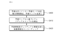
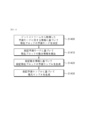
図4は、インター予測ベースのビデオ/映像エンコーディング方法の例を示す。 Figure 4 shows an example of an inter-prediction based video/image encoding method.
エンコーディング装置は、現在ブロックに対するインター予測を行う(S400)。エンコーディング装置は、現在ブロックのインター予測モード及び動き情報を導出し、前記ブロックの予測サンプルを生成する。ここで、インター予測モードの決定、動き情報の導出、及び予測サンプルの生成手順は同時に行われてもよく、ある1つの手順が他の手順より先に行われてもよい。例えば、エンコーディング装置のインター予測部は、予測モード決定部、動き情報導出部、予測サンプル導出部を含み、予測モード決定部で前記現在ブロックに対する予測モードを決定し、動き情報導出部で前記現在ブロックの動き情報を導出し、予測サンプル導出部で前記現在ブロックの予測サンプルを導出する。例えば、エンコーディング装置のインター予測部は、動き推定(motion estimation)により参照ピクチャの一定領域(サーチ領域)内において前記現在ブロックと類似したブロックをサーチし、前記現在ブロックとの差が最小又は一定基準以下である参照ブロックを導出することができる。これに基づいて前記参照ブロックが位置する参照ピクチャを示す参照ピクチャインデックスを導出し、前記参照ブロックと前記現在ブロックの位置差に基づいて動きベクトルを導出することができる。エンコーディング装置は、様々な予測モードのうち前記現在ブロックに対して適用されるモードを決定することができる。エンコーディング装置は、前記様々な予測モードに対するRD(rate-distortion)費用(cost)を比較し、前記現在ブロックに対する最適の予測モードを決定することができる。 The encoding apparatus performs inter prediction for the current block (S400). The encoding apparatus derives an inter prediction mode and motion information of the current block, and generates a prediction sample of the block. Here, the procedures of determining the inter prediction mode, deriving the motion information, and generating the prediction sample may be performed simultaneously, or one procedure may be performed before the other procedures. For example, the inter prediction unit of the encoding apparatus includes a prediction mode determination unit, a motion information derivation unit, and a prediction sample derivation unit, and the prediction mode determination unit determines a prediction mode for the current block, the motion information derivation unit derives motion information of the current block, and the prediction sample derivation unit derives a prediction sample of the current block. For example, the inter prediction unit of the encoding apparatus may search for a block similar to the current block within a certain area (search area) of a reference picture by motion estimation, and derive a reference block whose difference with the current block is minimum or equal to a certain criterion. Based on this, a reference picture index indicating a reference picture in which the reference block is located can be derived, and a motion vector can be derived based on a position difference between the reference block and the current block. The encoding device can determine a mode to be applied to the current block from among various prediction modes. The encoding device can compare rate-distortion (RD) costs for the various prediction modes to determine an optimal prediction mode for the current block.
例えば、エンコーディング装置は、前記現在ブロックにスキップモード又はマージモードが適用される場合、後述するマージ候補リストを構成し、前記マージ候補リストに含まれたマージ候補が示す参照ブロックのうち前記現在ブロックとうち前記現在ブロックとの差が最小又は一定基準以下である参照ブロックを導出することができる。この場合、前記導出された参照ブロックに関連するマージ候補が選択され、前記選択されたマージ候補を示すマージインデックス情報が生成されてデコーディング装置にシグナリングされる。前記選択されたマージ候補の動き情報を利用して前記現在ブロックの動き情報を導出することができる。 For example, when a skip mode or a merge mode is applied to the current block, the encoding device may construct a merge candidate list (described below) and derive a reference block, among reference blocks indicated by merge candidates included in the merge candidate list, whose difference between the current block and the current block is minimum or equal to or less than a certain criterion. In this case, a merge candidate associated with the derived reference block is selected, and merge index information indicating the selected merge candidate is generated and signaled to the decoding device. Motion information of the current block may be derived using motion information of the selected merge candidate.
他の例として、エンコーディング装置は、前記現在ブロックに(A)MVPモードが適用される場合、後述する(A)MVP候補リストを構成し、前記(A)MVP候補リストに含まれたmvp(motion vector predictor)候補のうち選択されたmvp候補の動きベクトルを前記現在ブロックのmvpとして利用できる。この場合、例えば、前述の動き推定により導出された参照ブロックを示す動きベクトルが前記現在ブロックの動きベクトルとして利用され、前記mvp候補のうち前記現在ブロックの動きベクトルとの差が最も小さい動きベクトルを有するmvp候補が前記選択されたmvp候補となり得る。前記現在ブロックの動きベクトルから前記mvpを除いた差分であるMVD(motion vector difference)が導出できる。この場合、前記MVDに関する情報がデコーディング装置にシグナリングされる。また、(A)MVPモードが適用される場合、前記参照ピクチャインデックスの値は参照ピクチャインデックス情報で構成されて、別途に前記デコーディング装置にシグナリングされることができる。 As another example, when the (A)MVP mode is applied to the current block, the encoding device may construct an (A)MVP candidate list described below, and use the motion vector of a selected MVP candidate from among the motion vector predictor (MVP) candidates included in the (A)MVP candidate list as the MVP of the current block. In this case, for example, a motion vector indicating a reference block derived by the above-mentioned motion estimation may be used as the motion vector of the current block, and an MVP candidate having a motion vector with the smallest difference from the motion vector of the current block among the MVP candidates may be the selected MVP candidate. A motion vector difference (MVD), which is the difference obtained by subtracting the MVP from the motion vector of the current block, may be derived. In this case, information regarding the MVD is signaled to the decoding device. Also, when (A) MVP mode is applied, the value of the reference picture index can be composed of reference picture index information and signaled separately to the decoding device.
エンコーディング装置は、前記予測サンプルに基づいてレジデュアルサンプルを導出する(S410)。エンコーディング装置は、前記現在ブロックの原本サンプルと前記予測サンプルを比較することにより、前記レジデュアルサンプルを導出することができる。 The encoding device derives a residual sample based on the predicted sample (S410). The encoding device may derive the residual sample by comparing the original sample of the current block with the predicted sample.
エンコーディング装置は、予測情報及びレジデュアル情報を含む映像情報をエンコーディングする(S420)。エンコーディング装置は、エンコーディングされた映像情報をビットストリーム形態で出力する。前記予測情報は、前記予測手順に関連する情報であって、予測モード情報(例えは、skip flag、merge flag又はmode indexなど)及び動き情報に関する情報を含む。前記動き情報に関する情報は、動きベクトルを導出するための情報である候補選択情報(例えば、merge index、mvp flag又はmvp index)を含む。また、前記動き情報に関する情報は、前述のMVDに関する情報及び/又は参照ピクチャインデックス情報を含む。また、前記動き情報に関する情報は、L0予測、L1予測、又は双(bi)予測が適用されるか否かを示す情報を含む。前記レジデュアル情報は、前記レジデュアルサンプルに関する情報である。前記レジデュアル情報は、前記レジデュアルサンプルに対する量子化された変換係数に関する情報を含む。 The encoding apparatus encodes the image information including the prediction information and the residual information (S420). The encoding apparatus outputs the encoded image information in the form of a bitstream. The prediction information is information related to the prediction procedure and includes prediction mode information (e.g., skip flag, merge flag, or mode index) and information on motion information. The information on the motion information includes candidate selection information (e.g., merge index, mvp flag, or mvp index) which is information for deriving a motion vector. The information on the motion information also includes information on the above-mentioned MVD and/or reference picture index information. The information on the motion information also includes information indicating whether L0 prediction, L1 prediction, or bi-prediction is applied. The residual information is information on the residual sample. The residual information includes information on quantized transform coefficients for the residual sample.
出力されたビットストリームは(デジタル)格納媒体に格納されてデコーディング装置に伝達されるか、又は、ネットワークを介してデコーディング装置に伝達される。 The output bitstream is either stored on a (digital) storage medium and transmitted to the decoding device, or transmitted to the decoding device via a network.
一方、前述のように、エンコーディング装置は、前記参照サンプル及び前記レジデュアルサンプルに基づいて復元ピクチャ(復元サンプル及び復元ブロックを含む)を生成することができる。これは、デコーディング装置により行われるのと同一の予測結果をエンコーディング装置から導出するためであり、これによりコーディング効率を高めることができるからである。従って、エンコーディング装置は、復元ピクチャ(又は、復元サンプル、復元ブロック)をメモリに格納し、インター予測のための参照ピクチャとして活用する。前記復元ピクチャにインループフィルタリング手順などがさらに適用できることは前述の通りである。 Meanwhile, as described above, the encoding apparatus can generate a reconstructed picture (including reconstructed samples and reconstructed blocks) based on the reference sample and the residual sample. This is because the encoding apparatus derives the same prediction result as that performed by the decoding apparatus, thereby improving coding efficiency. Therefore, the encoding apparatus stores the reconstructed picture (or reconstructed sample, reconstructed block) in a memory and uses it as a reference picture for inter prediction. As described above, an in-loop filtering procedure, etc. can further be applied to the reconstructed picture.
インター予測に基づくビデオ/映像デコーディング手順は、概略的に、例えば、以下を含む。 A video/image decoding procedure based on inter prediction generally includes, for example, the following:
図5は、インター予測ベースのビデオ/映像デコーディング方法の例を示す。 Figure 5 shows an example of an inter-prediction based video/image decoding method.
図5に示すように、デコーディング装置は前記エンコーディング装置により行われた動作と対応する動作を行う。デコーディング装置は受信された予測情報に基づいて現在ブロックに予測を行い、予測サンプルを導出する。 As shown in FIG. 5, the decoding device performs operations corresponding to those performed by the encoding device. The decoding device performs prediction on the current block based on the received prediction information and derives a prediction sample.
具体的に、デコーディング装置は、受信された予測情報に基づいて前記現在ブロックに対する予測モードを決定する(S500)。デコーディング装置は、前記予測情報内の予測モード情報に基づいて前記現在ブロックにどのインター予測モードが適用されるかを決定することができる。 Specifically, the decoding device determines a prediction mode for the current block based on the received prediction information (S500). The decoding device may determine which inter prediction mode is applied to the current block based on prediction mode information in the prediction information.
例えば、前記merge flagに基づいて前記現在ブロックに前記マージモードが適用されるか又は(A)MVPモードが決定されるかを決定することができる。または、前記mode indexに基づいて様々なインター予測モード候補のうち1つを選択することができる。前記インター予測モード候補は、スキップモード、マージモード及び/又は(A)MVPモードを含み、または、後述する様々なインター予測モードを含む。 For example, it may be determined whether the merge mode is applied to the current block or whether the (A)MVP mode is determined based on the merge flag. Alternatively, one of various inter prediction mode candidates may be selected based on the mode index. The inter prediction mode candidates may include skip mode, merge mode, and/or (A)MVP mode, or may include various inter prediction modes described below.
デコーディング装置は、前記決定されたインター予測モードに基づいて前記現在ブロックの動き情報を導出する(S510)。例えば、デコーディング装置は、前記現在ブロックにスキップモード又はマージモードが適用される場合、後述するマージ候補リストを構成し、前記マージ候補リストに含まれたマージ候補のうち1つのマージ候補を選択することができる。前記選択は、前述の選択情報(merge index)に基づいて行われる。前記選択されたマージ候補の動き情報を利用して前記現在ブロックの動き情報を導出することができる。前記選択されたマージ候補の動き情報が前記現在ブロックの動き情報として利用されることができる。 The decoding device derives motion information of the current block based on the determined inter prediction mode (S510). For example, when a skip mode or a merge mode is applied to the current block, the decoding device may construct a merge candidate list (described later) and select one merge candidate from among the merge candidates included in the merge candidate list. The selection is performed based on the above-mentioned selection information (merge index). The motion information of the selected merge candidate may be used to derive motion information of the current block. The motion information of the selected merge candidate may be used as motion information of the current block.
他の例として、デコーディング装置は、前記現在ブロックに(A)MVPモードが適用される場合、後述の(A)MVP候補リストを構成し、前記(A)MVP候補リストに含まれたmvp(motion vector predictor)候補のうち選択されたmvp候補の動きベクトルを前記現在ブロックのmvpとして利用できる。前記選択は、前述の選択情報(mvp flag又はmvp index)に基づいて行われる。この場合、前記MVDに関する情報に基づいて前記現在ブロックのMVDを導出することができ、前記現在ブロックのmvpと前記MVDに基づいて前記現在ブロックの動きベクトルを導出することができる。また、前記参照ピクチャインデックス情報に基づいて前記現在ブロックの参照ピクチャインデックスを導出することができる。前記現在ブロックに関する参照ピクチャリスト内で前記参照ピクチャインデックスが示すピクチャが前記現在ブロックのインター予測のために参照される参照ピクチャとして導出されることができる。 As another example, when the (A)MVP mode is applied to the current block, the decoding apparatus may construct an (A)MVP candidate list described below, and may use a motion vector of a selected MVP candidate from among the motion vector predictor (MVP) candidates included in the (A)MVP candidate list as the MVP of the current block. The selection is performed based on the selection information (mvp flag or mvp index) described above. In this case, the MVD of the current block may be derived based on information about the MVD, and the motion vector of the current block may be derived based on the mvp and the MVD of the current block. Also, the reference picture index of the current block may be derived based on the reference picture index information. A picture indicated by the reference picture index in the reference picture list for the current block may be derived as a reference picture referenced for inter prediction of the current block.
一方、後述のように、候補リスト構成なしに前記現在ブロックの動き情報が導出されることができ、この場合、後述の予測モードにおいて開示された手順に従って前記現在ブロックの動き情報が導出されることができる。この場合、前述のような候補リスト構成は省略されてもよい。 Meanwhile, as described below, the motion information of the current block may be derived without constructing a candidate list. In this case, the motion information of the current block may be derived according to the procedure disclosed in the prediction mode described below. In this case, the candidate list construction as described above may be omitted.
デコーディング装置は、前記現在ブロックの動き情報に基づいて前記現在ブロックに対する予測サンプルを生成する(S520)。この場合、前記現在ブロックの参照ピクチャインデックスに基づいて前記参照ピクチャを導出し、前記現在ブロックの動きベクトルが前記参照ピクチャ上で指す参照ブロックのサンプルを利用して前記現在ブロックの予測サンプルを導出することができる。この場合、後述のように、場合によっては前記現在ブロックの予測サンプルのうち全部又は一部に対する予測サンプルフィルタリング手順がさらに行われることができる。 The decoding apparatus generates a prediction sample for the current block based on the motion information of the current block (S520). In this case, the reference picture may be derived based on a reference picture index of the current block, and the prediction sample for the current block may be derived using a sample of a reference block to which the motion vector of the current block points on the reference picture. In this case, as described below, a prediction sample filtering procedure may be further performed on all or some of the prediction samples of the current block, if necessary.
例えば、デコーディング装置のインター予測部は、予測モード決定部、動き情報導出部、予測サンプル導出部を含み、予測モード決定部で受信された予測モード情報に基づいて前記現在ブロックに対する予測モードを決定し、動き情報導出部で受信された動き情報に関する情報に基づいて前記現在ブロックの動き情報(動きベクトル及び/又は参照ピクチャインデックスなど)を導出し、予測サンプル導出部から前記現在ブロックの予測サンプルを導出することができる。 For example, the inter prediction unit of the decoding device may include a prediction mode determination unit, a motion information derivation unit, and a prediction sample derivation unit, and may determine a prediction mode for the current block based on prediction mode information received by the prediction mode determination unit, derive motion information (such as a motion vector and/or a reference picture index) of the current block based on information regarding the motion information received by the motion information derivation unit, and derive a prediction sample of the current block from the prediction sample derivation unit.
デコーディング装置は、受信されたレジデュアル情報に基づいて前記現在ブロックに対するレジデュアルサンプルを生成する(S530)。デコーディング装置は、前記予測サンプル及び前記レジデュアルサンプルに基づいて前記現在ブロックに対する復元サンプルを生成し、これに基づいて復元ピクチャを生成する(S540)。以後、前記復元ピクチャにインループフィルタリング手順などがさらに適用できることは前述の通りである。 The decoding device generates a residual sample for the current block based on the received residual information (S530). The decoding device generates a reconstructed sample for the current block based on the predicted sample and the residual sample, and generates a reconstructed picture based on the reconstructed sample (S540). As described above, an in-loop filtering procedure can then be further applied to the reconstructed picture.
前述のように、インター予測手順は、インター予測モード決定ステップ、決定された予測モードに応じる動き情報導出ステップ、導出された動き情報に基づいた予測実行(予測サンプル生成)ステップを含む。前記インター予測手順は、前述のようにエンコーディング装置及びデコーディング装置で行われる。本文書において、コーディング装置とはエンコーディング装置及び/又はデコーディング装置を含む。 As described above, the inter prediction procedure includes an inter prediction mode determination step, a motion information derivation step according to the determined prediction mode, and a prediction execution step (prediction sample generation) step based on the derived motion information. The inter prediction procedure is performed in an encoding device and a decoding device as described above. In this document, a coding device includes an encoding device and/or a decoding device.
ピクチャ内の現在ブロックの予測のために様々なインター予測モードが使用される。例えば、マージモード、スキップモード、MVP(motion vector prediction)モード、アフィン(Affine)モード、サブブロックマージモード、MMVD(merge with MVD)モード、HMVP(historical motion vector prediction)モードなど様々なモードが使用できる。DMVR(decoder side motion vector refinement)モード、AMVR(adaptive motion vector resolution)モード、BCW(Bi-prediction with CU-level weight)、BDOF(Bi-directional optical flow)などが付随的なモードとしてさらに又は代わりに使われることができる。アフィンモードは、アフィン動き予測(affine motion prediction)モードと呼ばれてもよい。MVPモードは、AMVP(advanced motion vector prediction)モードと呼ばれてもよい。本文書において、一部のモード及び/又は一部のモードにより導出された動き情報候補は、他のモードの動き情報関連候補の1つとして含まれてもよい。例えば、HMVP候補は前記マージ/スキップモードのマージ候補として追加されてもよく、または、前記MVPモードのmvp候補として追加されてもよい。 Various inter prediction modes are used for predicting the current block in a picture. For example, merge mode, skip mode, motion vector prediction (MVP) mode, affine mode, sub-block merge mode, merge with MVD (MMVD) mode, historical motion vector prediction (HMVP) mode, and other modes can be used. Decoder side motion vector refinement (DMVR) mode, adaptive motion vector resolution (AMVR) mode, bi-prediction with CU-level weight (BCW), bi-directional optical flow (BDOF), etc. may be used in addition to or instead of the additional modes. The affine mode may be referred to as an affine motion prediction mode. The MVP mode may be referred to as an advanced motion vector prediction mode. In this document, some modes and/or motion information candidates derived by some modes may be included as one of the motion information related candidates of other modes. For example, an HMVP candidate may be added as a merge candidate of the merge/skip mode, or may be added as an MVP candidate of the MVP mode.
現在ブロックのインター予測モードを指す予測モード情報がエンコーディング装置からデコーディング装置にシグナリングされることができる。前記予測モード情報は、ビットストリームに含まれ、デコーディング装置に受信されることができる。前記予測モード情報は、多数の候補モードのうちの1つを指示するインデックス情報を含むことができる。或いは、フラグ情報の階層的シグナリングを通じて、インター予測モードを指示することもある。この場合、前記予測モード情報は、1つ以上のフラグを含むことができる。例えば、スキップフラグをシグナリングしてスキップモードの適用可否を指示し、スキップモードが適用されない場合に、マージフラグをシグナリングしてマージモードの適用可否を指示し、マージモードが適用されない場合に、MVPモードが適用されるものと指示するか、追加的な区分のためのフラグをさらにシグナリングすることもある。アフィンモードは、独立したモードとしてシグナリングされることもあり、又はマージモード又はMVPモード等に従属的なモードとしてシグナリングされることもある。例えば、アフィンモードは、アフィンマージモード及びアフィンMVPモードを含むことができる。 Prediction mode information indicating an inter prediction mode of the current block may be signaled from the encoding device to the decoding device. The prediction mode information may be included in a bitstream and received by the decoding device. The prediction mode information may include index information indicating one of a number of candidate modes. Alternatively, the inter prediction mode may be indicated through hierarchical signaling of flag information. In this case, the prediction mode information may include one or more flags. For example, a skip flag may be signaled to indicate whether or not a skip mode is applied, and if the skip mode is not applied, a merge flag may be signaled to indicate whether or not a merge mode is applied, and if the merge mode is not applied, an MVP mode may be indicated to be applied, or a flag for additional classification may be further signaled. The affine mode may be signaled as an independent mode, or may be signaled as a mode subordinate to the merge mode, MVP mode, etc. For example, the affine mode may include an affine merge mode and an affine MVP mode.
一方、現在ブロックに前述のlist0(L0)予測、list1(L1)予測、又は双予測(bi-prediction)が現在ブロック(現在コーディングユニット)に使用されるか否かを示す情報がシグナリングされる。前記情報は、動き予測方向情報、インター予測方向情報、又はインター予測指示情報と呼ばれ、例えば、inter_pred_idcシンタックス要素の形態で構成/エンコーディング/シグナリングされることができる。すなわち、inter_pred_idcシンタックス要素は、前述のlist0(L0)予測、list1(L1)予測、又は双予測(bi-prediction)が現在ブロック(現在コーディングユニット)に使用されるか否かを示すことができる。本文書においては、説明の便宜のためにinter_pred_idcシンタックス要素が示すインター予測タイプ(L0予測、L1予測、又はBI予測)は動き予測方向と表示されることができる。L0予測はpred_L0、L1予測はpred_L1、双予測はpred_BIで表されることもできる。例えば、inter_pred_idcシンタックス要素の値に応じて以下のような予測タイプを示すことができる。 Meanwhile, information indicating whether the above-mentioned list0 (L0) prediction, list1 (L1) prediction, or bi-prediction is used for the current block (current coding unit) is signaled. The information is called motion prediction direction information, inter prediction direction information, or inter prediction indication information, and may be configured/encoded/signaled, for example, in the form of an inter_pred_idc syntax element. That is, the inter_pred_idc syntax element may indicate whether the above-mentioned list0 (L0) prediction, list1 (L1) prediction, or bi-prediction is used for the current block (current coding unit). In this document, for convenience of explanation, the inter prediction type (L0 prediction, L1 prediction, or BI prediction) indicated by the inter_pred_idc syntax element may be referred to as a motion prediction direction. L0 prediction can be represented as pred_L0, L1 prediction as pred_L1, and bi-prediction as pred_BI. For example, the following prediction types can be indicated depending on the value of the inter_pred_idc syntax element:
前述したように、1つのピクチャは、1つ以上のスライス(slice)を含むことができる。スライスは、Iスライス(intra slice)、Pスライス(predictive slice)及びBスライス(bi-predictive slice)を含むスライスタイプのうちの1つのタイプを有することができる。前記スライスタイプは、スライスタイプ情報に基づいて指示されることができる。Iスライス内のブロックに対しては、予測のためにインター予測は使用されず、イントラ予測のみ使用されることができる。もちろん、この場合にも、予測なしで原本サンプル値をコーディングしてシグナリングすることもある。Pスライス内のブロックに対しては、イントラ予測又はインター予測が使用でき、インター予測が使用される場合には、単(uni)予測のみ使用できる。一方、Bスライス内のブロックに対しては、イントラ予測又はインター予測が使用でき、インター予測が使用される場合には、最大の双(bi)予測まで使用できる。 As described above, one picture may include one or more slices. A slice may have one of slice types including an I slice, a P slice, and a bi-predictive slice. The slice type may be indicated based on slice type information. For blocks in an I slice, inter prediction may not be used for prediction, and only intra prediction may be used. Of course, even in this case, original sample values may be coded and signaled without prediction. For blocks in a P slice, intra prediction or inter prediction may be used, and when inter prediction is used, only uni prediction may be used. On the other hand, for blocks in a B slice, intra prediction or inter prediction may be used, and when inter prediction is used, up to bi prediction may be used.
L0及びL1は、現在ピクチャより以前にエンコーディング/デコーディングされた参照ピクチャを含む。例えば、L0はPOC順序上、現在ピクチャより以前及び/又は以後の参照ピクチャを含んでもよく、L1はPOC順序上、現在ピクチャより以後及び/又は以前の参照ピクチャを含んでもよい。この場合、L0にはPOC順序上、現在ピクチャより以前の参照ピクチャに相対的にさらに低い参照ピクチャインデックスが割り当てられ、L1にはPOC順序上、現在ピクチャより以後の参照ピクチャに相対的にさらに低い参照ピクチャインデックスが割り当てられる。B sliceの場合は双予測が適用されてもよく、この場合にも単方向双予測が適用されることも、又は、双方向双予測が適用されることもできる。双方向双予測はtrue双予測と呼ばれてもよい。 L0 and L1 include reference pictures encoded/decoded before the current picture. For example, L0 may include reference pictures before and/or after the current picture in the POC order, and L1 may include reference pictures after and/or before the current picture in the POC order. In this case, L0 is assigned a reference picture index that is lower than the reference picture before the current picture in the POC order, and L1 is assigned a reference picture index that is lower than the reference picture after the current picture in the POC order. In the case of B slice, bi-prediction may be applied, and in this case, unidirectional bi-prediction may be applied or bi-directional bi-prediction may be applied. Bi-directional bi-prediction may be called true bi-prediction.
具体的に、例えば、現在ブロックのインター予測モードに関する情報は、CU(CUシンタックス)などのレベルでコーディングされてシグナリングされるか、あるいは条件に応じて黙示的に決定される。この場合、一部のモードに対しては明示的にシグナリングされ、残りの一部のモードは黙示的に導出される。 For example, information regarding the inter prediction mode of the current block may be coded and signaled at a level such as a CU (CU syntax), or may be implicitly determined depending on conditions. In this case, some modes may be explicitly signaled, and the remaining modes may be derived implicitly.
例えば、CUシンタックスは、次の表1のように(インター)予測モードに関する情報などを運ぶことができる。 For example, the CU syntax can carry information about (inter) prediction modes, as shown in Table 1 below.
ここで、cu_skip_flagは現在ブロック(CU)にスキップモードが適用されるか否かを示す。 Here, cu_skip_flag indicates whether skip mode is applied to the current block (CU).
pred_mode_flagの値が0であると、現在コーディングユニットがインター予測モードでコーディングされることを示す。pred_mode_flagの値が1であると、現在コーディングユニットがイントラ予測モードでコーディングされることを示す(pred_mode_flag equal to 0 specifies that the current coding unit is coded in inter prediction mode. pred_mode_flag equal to 1 specifies that the current coding unit is coded in intra prediction mode.)。 A value of 0 for pred_mode_flag indicates that the current coding unit is coded in inter prediction mode. A value of 1 for pred_mode_flag indicates that the current coding unit is coded in intra prediction mode (pred_mode_flag equal to 0 specifies that the current coding unit is coded in inter prediction mode. pred_mode_flag equal to 1 specifies that the current coding unit is coded in intra prediction mode.).
pred_mode_ibc_flagの値が1であると、現在コーディングユニットがIBC予測モードでコーディングされることを示す。pred_mode_ibc_flagの値が0であると、現在コーディングユニットがIBC予測モードでコーディングされないことを示す(pred_mode_ibc_flag equal to 1 specifies that the current coding unit is coded in IBC prediction mode. pred_mode_ibc_flag equal to 0 specifies that the current coding unit is not coded in IBC prediction mode.)。 When the value of pred_mode_ibc_flag is 1, it indicates that the current coding unit is coded in IBC prediction mode. When the value of pred_mode_ibc_flag is 0, it indicates that the current coding unit is not coded in IBC prediction mode (pred_mode_ibc_flag equal to 1 specifies that the current coding unit is coded in IBC prediction mode. pred_mode_ibc_flag equal to 0 specifies that the current coding unit is not coded in IBC prediction mode).
pcm_flag[x0][y0]の値が1であると、pcm_sample( )構文構造が存在し、transform_tree( )構文構造が(x0,y0)位置のルマコーディングブロックを含むコーディング単位に存在しないことを示す。pcm_flag[x0][y0]が0であると、pcm_sample( )構文構造が存在しないことを示す(pcm_flag[x0][y0] equal to 1 specifies that the pcm_sample( ) syntax structure is present and the transform_tree( ) syntax structure is not present in the coding unit including the luma coding block at the location (x0, y0). pcm_flag[x0][y0] equal to 0 specifies that pcm_sample( ) syntax structure is not present.)。すなわち、pcm_flagは現在ブロックにPCM(pulse coding modulation)モードが適用されるか否かを示す。現在ブロックにPCMモードが適用される場合、予測、変換、量子化などが適用されることなく、現在ブロック内の原本サンプルの値がコーディングされてシグナリングされることができる。 A value of 1 in pcm_flag[x0][y0] indicates that the pcm_sample( ) syntax structure is present and the transform_tree( ) syntax structure is not present in the coding unit including the luma coding block at the location (x0, y0). A value of 0 in pcm_flag[x0][y0] indicates that the pcm_sample( ) syntax structure is not present. (pcm_flag[x0][y0] equal to 1 specifies that the pcm_sample( ) syntax structure is present and the transform_tree( ) syntax structure is not present in the coding unit including the luma coding block at the location (x0, y0). pcm_flag[x0][y0] equal to 0 specifies that pcm_sample( ) syntax structure is not present.) That is, pcm_flag indicates whether or not PCM (pulse coding modulation) mode is applied to the current block. When PCM mode is applied to the current block, the values of the original samples in the current block can be coded and signaled without applying prediction, transformation, quantization, etc.
intra_mip_flag[x0][y0]の値が1であると、ルマサンプルに対するイントラ予測タイプがマトリックスベースのイントラ予測(MIP)であることを示す。intra_mip_flag[x0][y0]が0であると、ルマサンプルに対するイントラ予測タイプがマトリックスベースのイントラ予測ではないことを示す(intra_mip_flag[x0][y0] equal to 1 specifies that the intra prediction type for luma samples is matrix-based intra prediction (MIP). intra_mip_flag[x0][y0] equal to 0 specifies that the intra prediction type for luma samples is not matrix-based intra prediction.)。すなわち、intra_mip_flagは現在ブロック(のルマサンプル)にMIP予測モード(タイプ)が適用されるか否かを示す。 When intra_mip_flag[x0][y0] has a value of 1, it indicates that the intra prediction type for the luma sample is matrix-based intra prediction (MIP). When intra_mip_flag[x0][y0] has a value of 0, it indicates that the intra prediction type for the luma sample is not matrix-based intra prediction (intra_mip_flag[x0][y0] equal to 1 specifies that the intra prediction type for luma samples is matrix-based intra prediction (MIP). intra_mip_flag[x0][y0] equal to 0 specifies that the intra prediction type for luma samples is not matrix-based intra prediction. In other words, intra_mip_flag indicates whether or not the MIP prediction mode (type) is applied to the current block (luma sample).
intra_chroma_pred_mode[x0][y0]は、現在ブロックにおいてクロマサンプルに対するイントラ予測モードを示す(intra_chroma_pred_mode[x0][y0] specifies the intra prediction mode for chroma samples in the current block.)。 intra_chroma_pred_mode[x0][y0] specifies the intra prediction mode for chroma samples in the current block.
general_merge_flag[x0][y0]は、現在コーディングユニットに対するインター予測パラメータが隣接するインター予測されたパーティションから誘導されるか否かを示す(general_merge_flag[x0][y0] specifies whether the inter prediction parameters for the current coding unit are inferred from a neighbouring inter-predicted partition.)。すなわち、general_merge_flagは一般マージが可用であることを示し、general_merge_flagの値が1であると、regular merge mode、mmvd mode及びmerge subblock mode(subblock merge mode)が可用である。例えば、general_merge_flagの値が1であると、マージデータシンタックス(merge data syntax)がエンコーディングされたビデオ/イメージ情報(又は、ビットストリーム)からパーシングされ、マージデータシンタックスは次の表2のような情報を含むように構成/コーディングされる。 general_merge_flag[x0][y0] specifies whether the inter prediction parameters for the current coding unit are inferred from a neighboring inter-predicted partition. That is, general_merge_flag indicates that general merging is available, and when the value of general_merge_flag is 1, regular merge mode, mmvd mode, and merge subblock mode (subblock merge mode) are available. For example, if the value of general_merge_flag is 1, the merge data syntax is parsed from the encoded video/image information (or bitstream), and the merge data syntax is configured/coded to include information as shown in Table 2 below.
ここで、regular_merge_flag[x0][y0]の値が1であると、レギュラーマージモードを用いて現在コーディングユニットのインター予測パラメータを生成することを示す(regular_merge_flag[x0][y0] equal to 1 specifies that regular merge mode is used to generate the inter prediction parameters of the current coding unit.)。すなわち、regular_merge_flagはマージモード(レギュラーマージモード)が現在ブロックに適用できるか否かを示す。 Here, if the value of regular_merge_flag[x0][y0] is 1, it indicates that the regular merge mode is used to generate the inter prediction parameters of the current coding unit. That is, regular_merge_flag indicates whether the merge mode (regular merge mode) can be applied to the current block.
mmvd_merge_flag[x0][y0]の値が1であると、動きベクトル差分を有するマージモードが現在コーディングユニットのインター予測パラメータの生成に使用されることを示す(mmvd_merge_flag[x0][y0] equal to 1 specifies that merge mode with motion vector difference is used to generate the inter prediction parameters of the current coding unit.)。すなわち、mmvd_merge_flagはMMVDが現在ブロックに適用されるか否かを示す。 When the value of mmvd_merge_flag[x0][y0] is 1, it indicates that merge mode with motion vector difference is used to generate the inter prediction parameters of the current coding unit. That is, mmvd_merge_flag indicates whether MMVD is applied to the current block.
mmvd_cand_flag[x0][y0]は、マージ候補リスト内の1番目(0)又は2番目(1)候補がmmvd_distance_idx[x0][y0]及びmmvd_direction_idx[x0][y0]から導出された動きベクトル差分とともに使用されるか否かを示す(mmvd_cand_flag[x0][y0] specifies whether the first (0) or the second (1) candidate in the merging candidate list is used with the motion vector difference derived from mmvd_distance_idx[x0][y0] and mmvd_direction_idx[x0][y0].)。 mmvd_cand_flag[x0][y0] specifies whether the first (0) or the second (1) candidate in the merging candidate list is used with the motion vector difference derived from mmvd_distance_idx[x0][y0] and mmvd_direction_idx[x0][y0].
mmvd_distance_idx[x0][y0]は、MmvdDistance[x0][y0]の導出に使用されるインデックスを示す(mmvd_distance_idx[x0][y0] specifies the index used to derive MmvdDistance[x0][y0].)。 mmvd_distance_idx[x0][y0] specifies the index used to derive MmvdDistance[x0][y0].
mmvd_direction_idx[x0][y0]は、MmvdSign[x0][y0]の導出に使用されるインデックスを示す(mmvd_direction_idx[x0][y0] specifies index used to derive MmvdSign[x0][y0].)。 mmvd_direction_idx[x0][y0] specifies the index used to derive MmvdSign[x0][y0].
merge_subblock_flag[x0][y0]は、現在コーディングに対するサブブロックベースのインター予測パラメータを示す(merge_subblock_flag[x0][y0] specifies whether the subblock-based inter prediction parameters for the current coding.)。すなわち、merge_subblock_flagは現在ブロックにサブブロックマージモード(又は、affine merge mode)が適用されるか否かを示す。 merge_subblock_flag[x0][y0] indicates the subblock-based inter prediction parameters for the current coding. That is, merge_subblock_flag indicates whether the subblock merge mode (or affine merge mode) is applied to the current block.
merge_subblock_idx[x0][y0]はサブブロックベースのマージ候補リストのマージ候補インデックスを示す(merge_subblock_idx[x0][y0] specifies the merging candidate index of the subblock-based merging candidate list.)。 merge_subblock_idx[x0][y0] specifies the merging candidate index of the subblock-based merging candidate list.
ciip_flag[x0][y0]は、結合されたインター-ピクチャマージ及びイントラ-ピクチャ予測が現在コーディングユニットに適用されるか否かを示す(ciip_flag[x0][y0] specifies whether the combined inter-picture merge and intra-picture prediction is applied for the current coding unit.)。 ciip_flag[x0][y0] specifies whether the combined inter-picture merge and intra-picture prediction is applied for the current coding unit.
merge_triangle_idx0[x0][y0]は、三角形ベースの動き補償候補リストの1番目のマージ候補インデックスを示す(merge_triangle_idx0[x0][y0] specifies the first merging candidate index of the triangular shape based motion compensation candidate list.)。 merge_triangle_idx0[x0][y0] specifies the first merging candidate index of the triangular shape based motion compensation candidate list.
merge_triangle_idx1[x0][y0]は、三角形ベースの動き補償候補リストの2番目のマージ候補インデックスを示す(merge_triangle_idx1[x0][y0] specifies the second merging candidate index of the triangular shape based motion compensation candidate list.)。 merge_triangle_idx1[x0][y0] specifies the second merging candidate index of the triangular shape based motion compensation candidate list.
merge_idx[x0][y0]は、マージ候補リストのマージ候補インデックスを示す(merge_idx[x0][y0] specifies the merging candidate index of the merging candidate list.)。 merge_idx[x0][y0] specifies the merging candidate index of the merging candidate list.
一方、再び表1のCUシンタックスを参照すると、mvp_l0_flag[x0][y0]はリスト0の動きベクトル予測子のインデックスを示す(mvp_l0_flag[x0][y0] specifies the motion vector predictor index of list 0.)。すなわち、mvp_l0_flagはMVPモードが適用される場合、MVP候補リスト0において前記現在ブロックのMVP導出のために選択される候補を示す。
Meanwhile, referring again to the CU syntax in Table 1, mvp_l0_flag[x0][y0] specifies the motion vector predictor index of
mvp_l1_flag[x0][y0]はmvp_l0_flagと同一の意味を有し、l0及びリスト0はそれぞれl1及びリスト1に置き換えることができる(ref_idx_l1[x0][y0] has the same semantics as ref_idx_l0, with l0, L0 and list 0 replaced by l1, L1 and list 1, respectively.)。
mvp_l1_flag[x0][y0] has the same semantics as mvp_l0_flag, and l0 and
inter_pred_idc[x0][y0]は現在コーディングユニットに対してリスト0、リスト1又はbi-predictionが使用されるか否かを示す(inter_pred_idc[x0][y0] specifies whether list0, list1, or bi-prediction is used for the current coding unit.)。 inter_pred_idc[x0][y0] specifies whether list0, list1, or bi-prediction is used for the current coding unit.
sym_mvd_flag[x0][y0]の値が1であると、構文要素ref_idx_l0[x0][y0]及びref_idx_l1[x0][y0]を示し、1と同一のrefListに対するmvd_coding(x0、y0、refList、cpIdx)構文構造が存在しないことを示す(sym_mvd_flag[x0][y0] equal to 1 specifies that the syntax elements ref_idx_l0[x0][y0] and ref_idx_l1[x0][y0], and the mvd_coding(x0, y0, refList, cpIdx) syntax structure for refList equal to 1 are not present.)。すなわち、sym_mvd_flagはmvdコーディングにおいてsymmetric MVDが使用されるか否かを示す。 When the value of sym_mvd_flag[x0][y0] is 1, it indicates the syntax elements ref_idx_l0[x0][y0] and ref_idx_l1[x0][y0], and indicates that the mvd_coding(x0, y0, refList, cpIdx) syntax structure for refList equal to 1 is not present. (sym_mvd_flag[x0][y0] equal to 1 specifies that the syntax elements ref_idx_l0[x0][y0] and ref_idx_l1[x0][y0], and the mvd_coding(x0, y0, refList, cpIdx) syntax structure for refList equal to 1 are not present.) In other words, sym_mvd_flag indicates whether symmetric MVD is used in mvd coding.
ref_idx_l0[x0][y0]は現在コーディングユニットに対するリスト0参照ピクチャインデックスを示す(ref_idx_l0[x0][y0] specifies the list 0 reference picture index for the current coding unit.)。
ref_idx_l0[x0][y0] specifies the
ref_idx_l1[x0][y0]はref_idx_l0と同一の意味を有し、l0、L0及びリスト0はそれぞれl1、L1及びリスト1に置き換えることができる(ref_idx_l1[x0][y0] has the same semantics as ref_idx_l0, with l0, L0 and list 0 replaced by l1, L1 and list 1, respectively.)。
ref_idx_l1[x0][y0] has the same semantics as ref_idx_l0, with l0, L0 and
inter_affine_flag[x0][y0]の値が1であると、現在コーディングユニットに対してP又はBスライスをデコーディングするとき、現在コーディングユニットの予測サンプルを生成するためにアフィンモデルベースの動き補償が使用されることを示す(inter_affine_flag[x0][y0] equal to 1 specifies that for the current coding unit, when decoding a P or B slice, affine model based motion compensation is used to generate the prediction samples of the current coding unit.)。 inter_affine_flag[x0][y0] equal to 1 specifies that for the current coding unit, when decoding a P or B slice, affine model based motion compensation is used to generate the prediction samples of the current coding unit.
cu_affine_type_flag[x0][y0]の値が1であると、現在コーディングユニットに対してP又はBスライスをデコーディングするとき、6-パラメータアフィンモデルベースの動き補償が現在コーディングユニットの予測サンプルの生成に使用されることを示す。cu_affine_type_flag[x0][y0]の値が0であると、現在コーディングユニットの予測サンプルを生成するために4-パラメータアフィンモデルベースの動き補償が使用されることを示す(cu_affine_type_flag[x0][y0] equal to 1 specifies that for the current coding unit, when decoding a P or B slice, 6-parameter affine model based motion compensation is used to generate the prediction samples of the current coding unit. cu_affine_type_flag[x0][y0] equal to 0 specifies that 4-parameter affine model based motion compensation is used to generate the prediction samples of the current coding unit.)。 A value of 1 in cu_affine_type_flag[x0][y0] indicates that 6-parameter affine model based motion compensation is used to generate the prediction samples of the current coding unit when decoding a P or B slice for the current coding unit. A value of 0 in cu_affine_type_flag[x0][y0] indicates that 4-parameter affine model based motion compensation is used to generate the prediction samples of the current coding unit. (cu_affine_type_flag[x0][y0] equal to 1 specifies that for the current coding unit, when decoding a P or B slice, 6-parameter affine model based motion compensation is used to generate the prediction samples of the current coding unit. cu_affine_type_flag[x0][y0] equal to 0 specifies that 4-parameter affine model based motion compensation is used to generate the prediction samples of the current coding unit.)
amvr_flag[x0][y0]は、動きベクトル差分の解像度を示す。アレイインデックスx0、y0は、ピクチャの左上側ルマサンプルに対して考慮されたコーディングブロックの左上側ルマサンプルの位置(x0,y0)を示す。amvr_flag[x0][y0]の値が0であると、動きベクトル差分の解像度がルマサンプルの1/4であることを示す。amvr_flag[x0][y0]の値が1であると、動きベクトル差分の解像度がamvr_precision_flag[x0][y0]により追加で示されることを示す(amvr_flag[x0][y0] specifies the resolution of motion vector difference. The array indices x0, y0 specify the location (x0, y0) of the top-left luma sample of the considered coding block relative to the top-left luma sample of the picture. amvr_flag[x0][y0] equal to 0 specifies that the resolution of the motion vector difference is 1/4 of a luma sample. amvr_flag[x0][y0] equal to 1 specifies that the resolution of the motion vector difference is further specified by amvr_precision_flag[x0][y0].)。 amvr_flag[x0][y0] indicates the resolution of the motion vector differential. The array indexes x0, y0 indicate the position (x0, y0) of the top left luma sample of the considered coding block relative to the top left luma sample of the picture. A value of 0 for amvr_flag[x0][y0] indicates that the resolution of the motion vector differential is 1/4 of the luma sample. A value of 1 for amvr_flag[x0][y0] indicates that the resolution of the motion vector difference is further specified by amvr_precision_flag[x0][y0] (amvr_flag[x0][y0] specifies the resolution of motion vector difference. The array indices x0, y0 specify the location (x0, y0) of the top-left luma sample of the considered coding block relative to the top-left luma sample of the picture. amvr_flag[x0][y0] equal to 0 specifies that the resolution of the motion vector difference is 1/4 of a luma sample. amvr_flag[x0][y0] equal to 1 specifies that the resolution of the motion vector difference is further specified by amvr_precision_flag[x0][y0].)
amvr_precision_flag[x0][y0]の値が0であると、inter_affine_flag[x0][y0]の値が0である場合、動きベクトル差分の解像度が1つの整数ルマサンプルであることを示し、そうでない場合は、ルマサンプルの1/16であることを示す。amvr_precision_flag[x0][y0]の値が1であると、inter_affine_flag[x0][y0] の値が0である場合、動きベクトル差分の解像度が4つのルマサンプルであることを示し、そうでない場合は、1つの整数ルマサンプルであることを示す。アレイインデックスx0、y0は、ピクチャの左上側ルマサンプルに対して考慮されたコーディングブロックの左上側ルマサンプルの位置(x0,y0)を示す(amvr_precision_flag[x0][y0] equal to 0 specifies that the resolution of the motion vector difference is one integer luma sample if inter_affine_flag[x0][y0] is equal to 0, and 1/16 of a luma sample otherwise. amvr_precision_flag[x0][y0] equal to 1 specifies that the resolution of the motion vector difference is four luma samples if inter_affine_flag[x0][y0] is equal to 0, and one integer luma sample otherwise. The array indices x0, y0 specify the location (x0, y0) of the top-left luma sample of the considered coding block relative to the top-left luma sample of the picture.)。 When amvr_precision_flag[x0][y0] has a value of 0, it indicates that the resolution of the motion vector differential is one integer luma sample if the value of inter_affine_flag[x0][y0] is 0, and 1/16 of a luma sample otherwise. When amvr_precision_flag[x0][y0] has a value of 1, it indicates that the resolution of the motion vector differential is four luma samples if the value of inter_affine_flag[x0][y0] is 0, and 1 integer luma sample otherwise. The array indices x0, y0 specify the location (x0, y0) of the top-left luma sample of the considered coding block relative to the top-left luma sample of the picture. (amvr_precision_flag[x0][y0] equal to 0 specifies that the resolution of the motion vector difference is one integer luma sample if inter_affine_flag[x0][y0] is equal to 0, and 1/16 of a luma sample otherwise. amvr_precision_flag[x0][y0] equal to 1 specifies that the resolution of the motion vector difference is four luma samples if inter_affine_flag[x0][y0] is equal to 0, and one integer luma sample otherwise. The array indices x0, y0 specify the location (x0, y0) of the top-left luma sample of the considered coding block relative to the top-left luma sample of the picture.)
bcw_idx[x0][y0]は、CU加重値を使用する双方向予測の加重値インデックスを示す(bcw_idx[x0][y0] specifies the weight index of bi-prediction with CU weights.)。 bcw_idx[x0][y0] specifies the weight index of bi-prediction with CU weights.
コーディング装置は、現在ブロックの動き情報を利用してインター予測を行う。エンコーディング装置は、動き推定(motion estimation)手順を介して現在ブロックに対する最適な動き情報を導出することができる。例えば、エンコーディング装置は、現在ブロックに対する原本ピクチャ内の原本ブロックを利用して相関性の高い類似の参照ブロックを参照ピクチャ内の決まった探索範囲内において分数ピクセル単位で探索し、それにより、動き情報を導出することができる。ブロックの類似性は、位相(phase)ベースのサンプル値の差に基づいて導出することができる。例えば、ブロックの類似性は、現在ブロック(又は、現在ブロックのテンプレート)と参照ブロック(又は、参照ブロックのテンプレート)間のSADに基づいて計算される。この場合、探索領域内のSADが最も小さい参照ブロックに基づいて動き情報を導出することができる。導出された動き情報は、インター予測モードに基づいて様々な方法によりデコーディング装置にシグナリングされる。 The coding apparatus performs inter prediction using the motion information of the current block. The encoding apparatus can derive optimal motion information for the current block through a motion estimation procedure. For example, the encoding apparatus can search for a similar reference block with high correlation in a fractional pixel unit within a determined search range in the reference picture using an original block in an original picture for the current block, thereby deriving motion information. The similarity of the blocks can be derived based on the difference in phase-based sample values. For example, the similarity of the blocks is calculated based on the SAD between the current block (or the template of the current block) and the reference block (or the template of the reference block). In this case, the motion information can be derived based on the reference block with the smallest SAD in the search area. The derived motion information is signaled to the decoding apparatus in various ways based on the inter prediction mode.
コーディング装置は、前記動き情報に基づいて前記現在ブロックに対する予測サンプル(ら)を導出することができる。前記予測サンプルを含む現在ブロックは、予測されたブロックと呼ばれてもよい。 The coding device may derive a predictive sample(s) for the current block based on the motion information. The current block including the predictive sample(s) may be referred to as a predicted block.
前記予測されたブロックは、前記現在ブロックの予測サンプル(予測サンプルアレイ)を含むことができる。現在ブロックの動きベクトルが分数サンプル単位を示す場合、補間(interpolation)手順が行われ、これを介して参照ピクチャ内において分数サンプル単位の参照サンプルに基づいて前記現在ブロックの予測サンプルが導出できる。現在ブロックにアフィン(Affine)インター予測が適用される場合、コーディング装置はサンプル/サブブロック単位の動きベクトル(MV)に基づいて予測サンプルを生成することができる。双予測が適用される場合、L0予測(すなわち、参照ピクチャリストL0内の参照ピクチャとMVL0を用いた予測)に基づいて導出された予測サンプルとL1予測(すなわち、参照ピクチャリストL1内の参照ピクチャとMVL1を用いた予測)に基づいて導出された予測サンプルの(位相に応じた)加重和又は加重平均を介して導出された予測サンプルが現在ブロックの予測サンプルとして利用できる。双予測が適用される場合、L0予測に利用された参照ピクチャとL1予測に利用された参照ピクチャが現在ピクチャを基準に互いに異なる時間的方向に位置する場合(すなわち、双予測でありながら双方向予測に該当する場合)、これをtrue双予測と呼んでもよい。 The predicted block may include a prediction sample (prediction sample array) of the current block. If the motion vector of the current block indicates a fractional sample unit, an interpolation procedure is performed, through which the prediction sample of the current block can be derived based on a reference sample of a fractional sample unit in a reference picture. If affine inter prediction is applied to the current block, the coding device can generate a prediction sample based on a motion vector (MV) of a sample/subblock unit. If bi-prediction is applied, a prediction sample derived through a weighted sum or weighted average (according to the phase) of a prediction sample derived based on L0 prediction (i.e., prediction using a reference picture in a reference picture list L0 and MVL0) and a prediction sample derived based on L1 prediction (i.e., prediction using a reference picture in a reference picture list L1 and MVL1) can be used as a prediction sample of the current block. When bi-prediction is applied, if the reference picture used for L0 prediction and the reference picture used for L1 prediction are located in different temporal directions relative to the current picture (i.e., bi-prediction is bidirectional), this may be referred to as true bi-prediction.
導出された予測サンプルに基づいて復元サンプル及び復元ピクチャが生成でき、その後、インループフィルタリングなどの手順が行われる。 Reconstructed samples and pictures can be generated based on the derived predicted samples, after which procedures such as in-loop filtering are performed.
図6及び図7は、インター予測に使用できる空間的候補を説明する図である。 Figures 6 and 7 are diagrams illustrating spatial candidates that can be used for inter prediction.
インター予測時にマージモード(merge mode)が適用される場合、現在ブロックの動き情報が直接的に送信されず、周辺予測ブロックの動き情報を利用して前記現在ブロックの動き情報を誘導する。従って、エンコーディング装置は、マージモードを用いたことを示すフラグ情報及び周辺のどの予測ブロックを用いているかを示すマージインデックスを送信することにより、現在ブロックの動き情報を示すことができる。前記マージモードは、レギュラーマージモード(regular merge mode)と呼ばれてもよい。 When a merge mode is applied during inter prediction, motion information of the current block is not directly transmitted, but is derived using motion information of neighboring predicted blocks. Thus, the encoding device can indicate motion information of the current block by transmitting flag information indicating that the merge mode is used and a merge index indicating which neighboring predicted block is used. The merge mode may be referred to as a regular merge mode.
コーディング装置は、マージモードを実行するために現在ブロックの動き情報を誘導するために用いられるマージ候補ブロック(merge candidate block)をサーチする。例えば、前記マージ候補ブロックは最大で5つまで利用できるが、本実施形態はこれに限定されない。また、前記マージ候補ブロックの最大個数に関する情報はスライスヘッダ又はタイルグループヘッダにおいて送信できるが、本実施形態はこれに限定されない。前記マージ候補ブロックを見つけた後、コーディング装置はマージ候補リストを生成し、これらのうち最も小さい費用を有するマージ候補ブロックを最終マージ候補ブロックとして選択することができる。 The coding device searches for a merge candidate block to be used to derive motion information of the current block to perform the merge mode. For example, up to five merge candidate blocks may be used, but this embodiment is not limited thereto. Also, information regarding the maximum number of merge candidate blocks may be transmitted in a slice header or a tile group header, but this embodiment is not limited thereto. After finding the merge candidate blocks, the coding device may generate a merge candidate list and select the merge candidate block with the smallest cost among them as the final merge candidate block.
本文書は、前記マージ候補リストを構成するマージ候補ブロックに対する様々な実施形態を提供する。 This document provides various embodiments for the merge candidate blocks that make up the merge candidate list.
前記マージ候補リストは、例えば、5つのマージ候補ブロックを含む。例えば、4つの空間的マージ候補(spatial merge candidate)と1つの時間的マージ候補(temporal merge candidate)が利用できる。具体例として、空間的マージ候補の場合、図6に示されたブロック(A0、A1、B0、B1、B2)を空間的マージ候補として利用することができる。以下、前記空間的マージ候補又は後述する空間的MVP候補はSMVPと呼ばれてもよく、前記時間的マージ候補又は後述する時間的MVP候補はTMVPと呼ばれてもよい。 The merge candidate list includes, for example, five merge candidate blocks. For example, four spatial merge candidates and one temporal merge candidate can be used. As a specific example, in the case of spatial merge candidates, blocks ( A0 , A1 , B0 , B1 , B2 ) shown in FIG. 6 can be used as spatial merge candidates. Hereinafter, the spatial merge candidates or spatial MVP candidates described later may be referred to as SMVPs, and the temporal merge candidates or temporal MVP candidates described later may be referred to as TMVPs.
前記現在ブロックに対するマージ候補リストは、例えば、以下のような手順に基づいて構成される。 The merge candidate list for the current block is constructed, for example, based on the following procedure:
まず、コーディング装置(エンコーディング装置/デコーディング装置)は、現在ブロックの空間的周辺ブロックを探索して導出された空間的マージ候補をマージ候補リストに挿入することができる。例えば、前記空間的周辺ブロックは、前記現在ブロックの左下側コーナー周辺ブロック(A0)、左側周辺ブロック(A1)、右上側コーナー周辺ブロック(B0)、上側周辺ブロック(B1)、及び左上側コーナー周辺ブロック(B2)を含む。ただし、これは例示であって、前述した空間的周辺ブロック以外にも右側周辺ブロック、下側周辺ブロック、右下側周辺ブロックなどの追加的な周辺ブロックが前記空間的周辺ブロックとしてさらに使用できる。コーディング装置は、前記空間的周辺ブロックを優先順位に基づいて探索して可用のブロックを検出し、検出されたブロックの動き情報を前記空間的マージ候補として導出することができる。例えば、エンコーディング装置及び/又はデコーディング装置は、図6に示された5つのブロックをA1、B1、B0、A0、B2の順に探索し、可用の候補者を順次インデックスすることにより、マージ候補リストとして構成することができる。 First, a coding apparatus (encoding apparatus/decoding apparatus) may insert spatial merging candidates derived by searching spatial neighboring blocks of a current block into a merging candidate list. For example, the spatial neighboring blocks include a lower left corner neighboring block ( A0 ), a left peripheral block ( A1 ), a right upper corner neighboring block ( B0 ), an upper peripheral block ( B1 ), and an upper left corner neighboring block ( B2 ) of the current block. However, this is merely an example, and additional neighboring blocks such as a right peripheral block, a lower peripheral block, and a lower right peripheral block may be further used as the spatial neighboring blocks in addition to the above-mentioned spatial neighboring blocks. The coding apparatus may search the spatial neighboring blocks based on a priority order to detect available blocks, and derive motion information of the detected blocks as the spatial merging candidates. For example, the encoding apparatus and/or the decoding apparatus may search the five blocks shown in FIG. 6 in the order of A1 , B1 , B0 , A0 , and B2 , and sequentially index available candidates to form a merging candidate list.
また、コーディング装置は、前記現在ブロックの時間的周辺ブロックを探索して導出された時間的マージ候補を前記マージ候補リストに挿入することができる。前記時間的周辺ブロックは、前記現在ブロックが位置する現在ピクチャとは異なるピクチャである参照ピクチャ上に位置することができる。前記時間的周辺ブロックが位置する参照ピクチャは同一位置(collocated)ピクチャ又はcolピクチャと呼ばれてもよい。前記時間的周辺ブロックは、前記colピクチャ上での前記現在ブロックに対する同一位置ブロック(co-located block)の右下側のコーナー周辺ブロック及び右下側センターブロックの順で探索される。 The coding apparatus may also insert temporal merge candidates derived by searching for temporal neighboring blocks of the current block into the merge candidate list. The temporal neighboring blocks may be located on a reference picture that is a different picture from the current picture in which the current block is located. The reference picture in which the temporal neighboring blocks are located may be called a co-located picture or col picture. The temporal neighboring blocks are searched for in the order of the lower right corner neighboring block and the lower right center block of the co-located block with respect to the current block on the col picture.
一方、コーディング装置は、現在マージ候補の個数が最大マージ候補の個数より小さいか否かを確認できる。前記最大マージ候補の個数は、予め定義されるか、エンコーディング装置からデコーディング装置にシグナリングされることができる。例えば、エンコーディング装置は、前記最大マージ候補者の個数に関する情報を生成し、エンコーディングしてビットストリーム形態で前記デコーディング装置に伝達する。前記最大マージ候補の個数が全て充填されると、以後の候補の追加過程は行われなくてもよい。 Meanwhile, the coding device may check whether the current number of merging candidates is smaller than the maximum number of merging candidates. The number of the maximum merging candidates may be predefined or may be signaled from the encoding device to the decoding device. For example, the encoding device may generate information regarding the number of the maximum merging candidates, encode it, and transmit it to the decoding device in the form of a bitstream. When the maximum number of merging candidates is filled, no further candidate addition process may be performed.
前記確認の結果、前記現在マージ候補の個数が前記最大マージ候補の個数より小さい場合、コーディング装置は追加マージ候補を前記マージ候補リストに挿入することができる。前記追加マージ候補は、例えば、history based merge candidate(s)、pair-wise average merge candidate(s)、ATMP、combined bi-predictiveマージ候補(現在スライス/タイルグループのスライス/タイルグループのタイプがBタイプである場合)及び/又は零ベクトルマージ候補の少なくとも1つを含む。 If the check indicates that the number of the current merge candidates is less than the maximum number of merge candidates, the coding device may insert additional merge candidates into the merge candidate list. The additional merge candidates may include, for example, at least one of history based merge candidate(s), pair-wise average merge candidate(s), ATMP, combined bi-predictive merge candidate (if the type of the slice/tile group of the current slice/tile group is type B), and/or zero vector merge candidate.
前記確認の結果、前記現在のマージ候補の個数が前記最大のマージ候補の個数よりも小さくない場合、コーディング装置は、前記マージ候補リストの構成を終了し得る。この場合、エンコーディング装置は、RD(rate-distortion)コストに基づき、前記マージ候補リストを構成するマージ候補のうち、最適のマージ候補を選択することができ、前記選択されたマージ候補を指す選択情報(ex. merge index)をデコーディング装置にシグナリングすることができる。デコーディング装置は、前記マージ候補リスト及び前記選択情報に基づいて、前記最適のマージ候補を選択することができる。 If the check shows that the number of current merge candidates is not less than the maximum number of merge candidates, the coding device may terminate construction of the merge candidate list. In this case, the encoding device may select an optimal merge candidate from among the merge candidates constituting the merge candidate list based on a rate-distortion (RD) cost, and may signal selection information (ex. merge index) indicating the selected merge candidate to the decoding device. The decoding device may select the optimal merge candidate based on the merge candidate list and the selection information.
前記選択されたマージ候補の動き情報が前記現在ブロックの動き情報に使用でき、前記現在ブロックの動き情報に基づいて、前記現在ブロックの予測サンプルを導出することができることは前述した通りである。エンコーディング装置は、前記予測サンプルに基づいて前記現在ブロックのレジデュアルサンプルを導出することができ、前記レジデュアルサンプルに関するレジデュアル情報をデコーディング装置にシグナリングできる。デコーディング装置は、前記レジデュアル情報に基づいて導出されたレジデュアルサンプル、及び前記予測サンプルに基づいて復元サンプルを生成することができ、これに基づいて、復元ピクチャを生成することができることは前述した通りである。 As described above, the motion information of the selected merging candidate can be used for the motion information of the current block, and a prediction sample of the current block can be derived based on the motion information of the current block. The encoding device can derive a residual sample of the current block based on the prediction sample, and can signal residual information regarding the residual sample to a decoding device. As described above, the decoding device can generate a reconstructed sample based on the residual sample derived based on the residual information and the prediction sample, and can generate a reconstructed picture based on the residual sample.
インター予測時にスキップモードが適用される場合、前述のマージモードが適用される場合と同様の方法で前記現在ブロックの動き情報を導出することができる。ただし、スキップモードが適用される場合、該当ブロックに対するレジデュアル信号が省略され、従って、予測サンプルが直ちに復元サンプルとして利用されることができる。 When the skip mode is applied during inter prediction, the motion information of the current block can be derived in the same manner as when the merge mode is applied. However, when the skip mode is applied, the residual signal for the corresponding block is omitted, and therefore the predicted sample can be used immediately as the reconstructed sample.
空間的マージ候補の導出は空間的隣接ブロックに基づいて行われる(The derivation of spatial merge candidates is performed based on spatial neighboring blocks.)。例えば、図6に示されている位置にある候補のうち最大4つの併合候補が選択される(As an example, a maximum of four merge candidates may be selected among candidates located in the positions depicted in Figure 6.)。導出順序はA1、B1、B0、A0及びB2であり得る(The order of derivation may be A1, B1, B0, A0 and B2.)。B2位置は、A1、B1、B0、A0位置のCUが使用できないか(例えば、他のスライス又はタイルに属しているため)イントラコーディングされた場合にのみ考慮される(Position B2 is considered only when any CU of position A1、B1、B0、A0 is not available (e.g. because it belong to another slice or tile) or is intracoded.)。A0位置で候補が追加された後、残りの候補の追加は重複検査を経て同一の動き情報を有する候補がリストから除かれて、コーディング効率が向上する(After candidate at position A0 is added, the addition of the remaining candidates is subject to a redundancy check which ensures that candidates with same motion information are excluded from the list so that coding efficiency is improved.)例えば、計算複雑性を減少させるために、前述の重複検査において全ての可能な候補双が考慮されることではない(For example, to reduce computational complexity, not all possible candidate pairs are considered in the mentioned redundancy check.)。代わりに、図7において矢印で連結された双のみが考慮され、重複検査に使用された当該候補が同一の動き情報を有していない場合にのみ候補がリストに追加される(Instead only the pairs linked with an arrow in Figure 7 are considered and a candidate may be only added to the list if the corresponding candidate used for redundancy check has not the same motion information.)。 The derivation of spatial merge candidates is performed based on spatial neighboring blocks. As an example, a maximum of four merge candidates may be selected among candidates located in the positions depicted in Figure 6. The order of derivation may be A1 , B1 , B0 , A0 and B2 . Position B2 is considered only when any CU of position A1 , B1 , B0 , A0 is not available (eg because it belong to another slice or tile ) or is intracoded. After a candidate at position A 0 is added, the addition of the remaining candidates is subject to a redundancy check which ensures that candidates with same motion information are excluded from the list so that coding efficiency is improved. For example, to reduce computational complexity, not all possible candidate pairs are considered in the mentioned redundancy check. Instead, only the pairs linked with an arrow in Figure 7 are considered and a candidate may be only added to the list if the corresponding candidate used for redundancy check has not the same motion information.
図8及び図9は、インター予測に使用できる時間的候補を説明する図である。 Figures 8 and 9 are diagrams illustrating temporal candidates that can be used for inter prediction.
ここで、時間的候補(temporal candidate)は前述の時間的マージ候補(temporal merge candidate)を示す。また、時間的候補に含まれる動きベクトルは時間的mvp候補(temporal mvp candidate)に対応し得る。 Here, the temporal candidate refers to the temporal merge candidate described above. Also, the motion vector included in the temporal candidate may correspond to a temporal MVP candidate.
このステップでは、1つの候補のみが候補リストに追加される(In this step, only one candidate is added to the candidate list.)。特に、時間的マージ候補の導出において、スケーリングされた動きベクトルは同一位置(collocated)参照ピクチャ(colPicと呼ばれてもよい)に属する同一位置CUに基づいて導出される(Particularly, in the derivation of this temporal merge candidate, a scaled motion vector is derived based on co-located CU belonging to the collocated reference picture (may be referred to as colPic).)。同一位置(co-located)CUの導出に使用される参照ピクチャリストはスライスヘッダにおいて明示的にシグナリングされる(The reference picture list to be used for derivation of the co-located CU is explicitly signalled in the slice header.)。POC(picture order count)距離、tb及びtdを使って同一位置CUの動きベクトルからスケーリングされる時間的マージ候補に対するスケーリングされた動きベクトルは、図8において点線で示されているように得られ、ここで、tbは現在ピクチャの参照ピクチャと現在ピクチャのPOCの差として定義され、tbは同一位置ピクチャの参照ピクチャと同一位置ピクチャとの間のPOC差として定義される(The scaled motion vector for temporal merge candidate is obtained as illustrated by the dotted line in Figure 8, which is scaled from the motion vector of the co-located CU using the POC distances, tb and td, where tb is defined to be the POC difference between the reference picture of the current picture and the current picture and td is defined to be the POC difference between the reference picture of the co-located picture and the co-located picture.)。時間マージ候補の参照ピクチャインデックスは0に設定される(The reference picture index of temporal merge candidate is set equal to zero.)。 In this step, only one candidate is added to the candidate list. Particularly, in the derivation of this temporal merge candidate, a scaled motion vector is derived based on co-located CU belonging to the collocated reference picture (may be referred to as colPic). The reference picture list to be used for derivation of the co-located CU is explicitly signalled in the slice header. The scaled motion vector for temporal merge candidate is obtained as illustrated by the dotted line in Figure 8, which is scaled from the motion vector of the co-located CU using the POC (picture order count) distances, tb and td, where tb is defined to be the POC difference between the reference picture of the current picture and the current picture and td is defined to be the POC difference between the reference picture of the co-located picture and the co-located picture. The reference picture index of temporal merge candidate is set equal to zero.
時間的候補の位置は、図9に示されたように、候補C0とC1の間で選択される。C0位置のCUを使用できないか、C0位置のCUがイントラコーディングされているか又は現在CTUの行外部にある場合、C1位置が使用される(The position for the temporal candidate is selected between candidates C0 and C1, as depicted in Figure 9. If CU at position C0 is not available, is intra coded, or is outside of the current row of CTUs, position C1 is used.)。そうでない場合、 C0の位置は時間的マージ候補の導出に使用される(Otherwise, position C0 is used in the derivation of the temporal merge candidate.)。 The position for the temporal candidate is selected between candidates C0 and C1 , as depicted in Figure 9. If CU at position C0 is not available , is intra coded, or is outside of the current row of CTUs, position C1 is used. Otherwise , position C0 is used in the derivation of the temporal merge candidate.
内在的に(implicitly)導出された動き情報が現在のCUの予測サンプル生成のために直接的に使われるマージモードに加えて、動きベクトル差分を有するマージモード(merge mode with motion vector differences、MMVD)がVVCに導入される(In addition to merge mode, where the implicitly derived motion information is directly used for prediction samples generation of the current CU, the merge mode with motion vector differences (MMVD) is introduced in VVC.)。スキップモード及びマージモードには類似の動き情報導出方法が用いられるため、MMVDは前記スキップモードに適用できる(Because similar motion information derivation methods are used for the skip mode and the merge mode, MMVD may be applied to the skip mode.)。MMVDフラグ(例えば、mmvd_flag)はスキップフラグ及びマージフラグを送った直後にシグナリングされてMMVDモードがCUに適用されるか否かを示す(A MMVD flag (ex. mmvd_flag) may be signaled right after sending a skip flag and merge flag to specify whether MMVD mode is used for a CU.)。 In addition to the merge mode, where the implicitly derived motion information is directly used for prediction samples generation of the current CU, the merge mode with motion vector differences (MMVD) is introduced in VVC. Because similar motion information derivation methods are used for the skip mode and the merge mode, MMVD may be applied to the skip mode. An MMVD flag (ex. mmvd_flag) may be signaled right after sending a skip flag and merge flag to specify whether MMVD mode is used for a CU.
MMVDにおいては、マージ候補が選択された後、シグナリングされたMVDの情報によりリファインされる(In MMVD, after a merge candidate is selected, it is further refined by the signaled MVDs information.)。MMVDが現在プロックに適用される場合(すなわち、mmvd_flagが1である場合)、MMVDに関する追加情報がシグナリングされる(When MMVD is applied to the current block (i.e. when the mmvd_flag is equal to 1), further information for the MMVD may be signaled.)。 In MMVD, after a merge candidate is selected, it is further refined by the signaled MVDs information. When MMVD is applied to the current block (i.e. when the mmvd_flag is equal to 1), further information for the MMVD may be signaled.
追加情報は、前記マージ候補リスト内の第1(0)又は第2(1)候補が動きベクトル差分とともに使用されるかを示すマージ候補リスト(例えば、mmvd_merge_flag)、動きの大きさを示すインデックス(例えば、mmvd_distance_idx)、及び動き方向表示インデックス(例えば、mmvd_direction_idx)を含む(The further information includes a merge candidate flag (ex. mmvd_merge_flag) indicating whether the first (0) or the second (1) candidate in the merging candidate list is used with the motion vector difference, an index to specify motion magnitude (ex. mmvd_distance_idx), and an index for indication of motion direction (ex. mmvd_direction_idx).)。MMVDモードでは、マージリストにおいて最初の2つの候補の1つがMVの基準として使用されるように選択される(In MMVD mode, one for the first two candidates in the merge list is selected to be used as MV basis.)。マージ候補フラグは、どのフラグが使われるかを示すようにシグナリングされる(The merge candidate flag is signaled to specify which one is used.)。 The further information includes a merge candidate flag (ex. mmvd_merge_flag) indicating whether the first (0) or the second (1) candidate in the merging candidate list is used with the motion vector difference, an index to specify motion magnitude (ex. mmvd_distance_idx), and an index for indication of motion direction (ex. mmvd_direction_idx). In MMVD mode, one for the first two candidates in the merge list is selected to be used as MV basis. The merge candidate flag is signaled to specify which one is used.
距離インデックスは動きの大きさ情報を示し、開始点から予め決められたオフセット(Offset)を示す(Distance index specifies motion magnitude information and indicate the pre-defined offset from the starting point.)。 Distance index specifies motion magnitude information and indicates the pre-defined offset from the starting point.
オフセットは開始動きベクトルの水平成分又は垂直成分に加えられる(An offset is added to either horizontal component or vertical component of starting MV.)。距離インデックスと予め決められたオフセットの関係は、以下の表3のように示す(The relation of distance index and pre-defined offset is specified in Table 3.)。 An offset is added to either horizontal component or vertical component of starting MV. The relation of distance index and pre-defined offset is specified in Table 3.
ここで、slice_fpel_mmvd_enabled_flagが1であると、動きベクトル差分があるマージモードが現在スライスにおいて整数サンプル精度を使用することを示す(Here, slice_fpel_mmvd_enabled_flag equal to 1 specifies that merge mode with motion vector difference uses integer sample precision in the current slice.)。slice_fpel_mmvd_enabled_flagが0であると、動きベクトル差分があるマージモードが現在スライスにおいて分数サンプル精度を使用することを示す(slice_fpel_mmvd_enabled_flag equal to 0 specifies that merge mode with motion vector difference can use fractional sample precision in the current slice.)。存在しない場合、slice_fpel_mmvd_enabled_flagの値は0として導出される(When not present, the value of slice_fpel_mmvd_enabled_flag is inferred to be 0.)。slice_fpel_mmvd_enabled_flagシンタックス要素はスライスヘッダを介して(スライスヘッダに含まれて)シグナリングされることができる(slice_fpel_mmvd_enabled_flag syntax element may be signaled through (may be comprised in) a slice header.)。 Here, slice_fpel_mmvd_enabled_flag equal to 1 specifies that merge mode with motion vector difference uses integer sample precision in the current slice. Here, slice_fpel_mmvd_enabled_flag equal to 1 specifies that merge mode with motion vector difference uses integer sample precision in the current slice. Here, slice_fpel_mmvd_enabled_flag equal to 0 specifies that merge mode with motion vector difference can use fractional sample precision in the current slice. When not present, the value of slice_fpel_mmvd_enabled_flag is inferred to be 0. The slice_fpel_mmvd_enabled_flag syntax element may be signaled through (may be comprised in) a slice header.
方向インデックスは、開始点を基準にMVDの方向を示す。方向インデックスは、表4に示すように、4方向を示すことができる(Direction index represents the direction of the MVD relative to the starting point.)。MVD表示の意味は、MVの開始情報に応じて変更される(The direction index can represent of the four directions as shown in Table4. It's noted that the meaning of MVD sign could be variant according to the information of starting MVs.)。開始MVが予測ではないMVであるか又は2つのリストを有する双予測MVが現在ピクチャの同一面を指す場合(例えば、2つの参照のPOCは両方とも現在ピクチャのPOCより大きいか、又は両方とも現在ピクチャのPOCより小さい場合)、表4のサインは、前記開始MVに追加されたMVオフセットのサインを示す(When the starting MVs is an un-prediction MV or bi-prediction MVs with both lists point to the same side of the current picture (i.e. POCs of two references are both larger than the POC of the current picture, or are both smaller than the POC of the current picture), the sign in Table 4 specifies the sign of MV offset added to the starting MV.)。開始MVが現在ピクチャの他の面を指す2つのMVを有する双予測MVである場合(すなわち、1つの参照のPOCが現在ピクチャのPOCより大きく他の参照のPOCが現在ピクチャのPCOより小さい場合)、表4のサインは開始MVのlist0 MV成分に追加されたMVオフセットのサインを示し、list1 MVのサインは逆の値を有する(When the starting MVs is bi-prediction MVs with the two MVs point to the different sides of the current picture (i.e. the POC of one reference is larger than the POC of the current picture, and the POC of the other reference is smaller than the POC of the current picture), the sign in Table 4 specifies the sign of MV offset added to the list0 MV component of starting MV and the sign for the list1 MV has opposite value.)。 The direction index indicates the direction of the MVD relative to the starting point. The direction index represents the direction of the MVD relative to the starting point. The meaning of the MVD sign can be variant according to the information of starting MVs. When the starting MVs is an un-prediction MV or bi-prediction MVs with both lists point to the same side of the current picture (i.e. POCs of two references are both larger than the POC of the current picture, or are both smaller than the POC of the current picture), the sign in Table 4 specifies the sign of MV offset added to the starting MV. When the starting MVs is bi-prediction MVs with the two MVs pointing to the different sides of the current picture (i.e. the POC of one reference is larger than the POC of the current picture, and the POC of the other reference is smaller than the POC of the current picture), the sign in Table 4 specifies the sign of MV offset added to the list0 MV component of starting MV and the sign for the list1 MV has opposite value.
マージプラスMVDオフセットMmvdOffset[x0][y0]の2つの構成要素は、以下のように導出される(Both components of the merge plus MVD offset MmvdOffset[x0][y0] are derived as follows.)。 The two components of the merge plus MVD offset MmvdOffset[x0][y0] are derived as follows.
図10は、インター予測時に使用できるサブブロックベースの時間的動きベクトル予測プロセスを説明する図である。 Figure 10 illustrates a subblock-based temporal motion vector prediction process that can be used during inter prediction.
インター予測のためにサブブロックベースの時間的動きベクトル予測(SbTMVP)方法が用いられる(Subblock-based temporal motion vector prediction (SbTMVP) method can be used for inter prediction.)。MVP(temporal motion vector prediction)と類似して、SbTMVPは同一位置ピクチャの動きフィールドを使用して現在ピクチャのCUに対する動きベクトル予測及びマージモードを向上させる(Similar to the temporal motion vector prediction (TMVP), SbTMVP uses the motion field in the collocated picture to improve motion vector prediction and merge mode for CUs in the current picture.)。TMVPにおいて使用される同一位置ピクチャが同一にSbTVMPに使用される(The same collocated picture used by TMVP is used for SbTVMP.)。SbTMVPは、以下の2つの主要側面でTMVPと異なる(SbTMVP differs from TMVP in the following two main aspects.)。 Subblock-based temporal motion vector prediction (SbTMVP) method can be used for inter prediction. Similar to MVP (temporal motion vector prediction), SbTMVP uses the motion field in the collocated picture to improve motion vector prediction and merge mode for CUs in the current picture. The same collocated picture used by TMVP is used for SbTVMP. SbTMVP differs from TMVP in the following two main aspects.
1.TMVPはCUレベルでの動きを予測するが、SbTMVPはサブCUレベルでの動きを予測する(TMVP predicts motion at CU level but SbTMVP predicts motion at sub-CU level.)。 1. TMVP predicts motion at CU level but SbTMVP predicts motion at sub-CU level.
2.TMVPは同一位置ピクチャ内の同一位置ブロックから時間的動きベクトルをフェッチする反面(前記同一位置ブロックは現在CUを基準に右下側又はセンター(右下側センター)ブロックである)、SbTMVPは前記同一位置ピクチャから時間的動き情報をフェッチする前にモーションシフト(ここで、モーションシフトは現在CUの空間的周辺ブロックのうち1つからの動きベクトルから取得される)を適用する(Whereas TMVP fetches the temporal motion vectors from the collocated block in the collocated picture (the collocated block is the bottom-right or center (below-right center) block relative to the current CU), SbTMVP applies a motion shift before fetching the temporal motion information from the collocated picture, where the motion shift is obtained from the motion vector from one of the spatial neighbouring blocks of the current CU.)。 2. Whereas TMVP fetches the temporal motion vectors from the collocated block in the collocated picture (the collocated block is the bottom-right or center (below-right center) block relative to the current CU), SbTMVP applies a motion shift before fetching the temporal motion information from the collocated picture, where the motion shift is obtained from the motion vector from one of the spatial neighbouring blocks of the current CU.
図10にはSbTVMPプロセスが示されている。SbTMVPは、現在CU内のサブCUの動きベクトルを2つのステップで予測する(SbTMVP predicts the motion vectors of the sub-CUs within the current CU in two steps.)。第1ステップにおいて、空間的隣接A1を検査する(In the first step, the spatial neighbour A1 is examined.)。参照ピクチャが識別される時に同一位置ピクチャを参照ピクチャとして使用する動きベクトルをA1が有する場合、この動きベクトル(時間的MV(tempVM)と呼ばれてもよい)が適用されるモーションシフトとして選択される(If A1 has a motion vector that uses the collocated picture as its reference picture is identified, this motion vector (may be referred to as a temporal MV (tempVM)) is selected to be the motion shift to be applied.)。このような動きが識別されないと、モーションシフトは(0,0)に設定される(If no such motion is identified, then the motion shift is set to (0, 0).)。 The SbTVMP process is shown in Figure 10. SbTMVP predicts the motion vectors of the sub-CUs within the current CU in two steps. In the first step, the spatial neighbour A1 is examined. If A1 has a motion vector that uses the collocated picture as its reference picture is identified, this motion vector (may be referred to as a temporal MV (tempVM)) is selected to be the motion shift to be applied. If no such motion is identified, then the motion shift is set to (0, 0).
第2ステップにおいて、第1ステップで識別されたモーションシフトが適用されて(すなわち、現在ブロックの候補として追加される)、図10に示されているように同一位置ピクチャからサブCUレベル動き情報(動きベクトル及び参照インデックス)を取得する(In the second step, the motion shift identified in Step 1 is applied (i.e. added to the current block's coordinates) to obtain sub-CU-level motion information (motion vectors and reference indices) from the collocated picture as shown in Figure 10.)。図10の例は、モーションシフトがブロックA1’の動きに設定されていると仮定する(The example in Figure 10 assumes the motion shift is set to block A1's motion.)。そして、それぞれのサブCUに対して、同一位置ピクチャ内の対応するブロック(センターサンプルをカバーする最も小さなモーショングリッド)の動き情報がサブCUに対するモーション情報の導出に使われる(Then, for each sub-CU, the motion information of its corresponding block (the smallest motion grid that covers the center sample) in the collocated picture is used to derive the motion information for the sub-CU.)。センターブロック(右下側センターサンプル)はサブブロックが長さ及び幅が偶数である場合、サブCU内の4つのセンターサンプルのうち右下側サンプルに該当する(The center sample (below right center sample) may correspond to a below-right sample among 4 central samples in the sub-CU when the sub-block has even length width and height.)。
In the second step, the motion shift identified in
同一位置サブCUの動き情報が識別された後、TMVPプロセスと類似の方式で現在のサブCUの動きベクトル及び参照インデックスに変換され、ここで、時間的動きスケーリングが適用されて時間的動きベクトルの参照ピクチャを現在CUの参照ピクチャに配置する(After the motion information of the collocated sub-CU is identified, it is converted to the motion vectors and reference indices of the current sub-CU in a similar way as the TMVP process, where temporal motion scaling may be applied to align the reference pictures of the temporal motion vectors to those of the current CU.)。 After the motion information of the collocated sub-CU is identified, it is converted to the motion vectors and reference indices of the current sub-CU in a similar way as the TMVP process, where temporal motion scaling may be applied to align the reference pictures of the temporal motion vectors to those of the current CU.
SBTVMP候補及びアフィンマージ候補を全て含む結合されたサブブロックベースのマージリストは、アフィンマージモード(サブブロック(ベース)マージモードと称されてもよい)のシグナリングのために使用されることができる(A combined sub-block based merge list which contains both SbTVMP candidate and affine merge candidates may be used for the signalling of affine merge mode (may be referred to as sub-block (based) merge mode).)。SbTVMPモードはSPS(Sequence Parameter Set)フラグにより活性化/非活性化される(The SbTVMP mode is enabled/disabled by a sequence parameter set (SPS) flag.)。SbTMVPモードが活性化する場合、SbTMVP予測子はサブブロックマージ候補リストの1番目の項目として追加された後、アフィンマージ候補が追加される(If the SbTMVP mode is enabled, the SbTMVP predictor is added as the first entry of the list of sub-block merge candidates, and followed by the affine merge candidates.)。アフィンマージ候補リストの最大許容サイズは5であり得る(The maximum allowed size of the affine merge candidate list may be 5.)。 A combined sub-block based merge list which contains both SbTVMP candidate and affine merge candidates may be used for the signalling of affine merge mode (may be referred to as sub-block (based) merge mode). The SbTVMP mode is enabled/disabled by a sequence parameter set (SPS) flag. If the SbTMVP mode is enabled, the SbTMVP predictor is added as the first entry of the list of sub-block merge candidates, and followed by the affine merge candidates. The maximum allowed size of the affine merge candidate list may be 5.
SbTMVPにおいて使用されるsub-CUサイズは8×8に固定され、アフィンマージモードでのようにSbTMVPモードは幅と高さが両方とも8以上であるCUにのみ該当する(The sub-CU size used in SbTMVP may be fixed to be 8x8, and as done for affine merge mode, SbTMVP mode may be only applicable to the CU with both width and height are larger than or equal to 8.)。 The sub-CU size used in SbTMVP may be fixed to be 8x8, and as done for affine merge mode, SbTMVP mode may be only applicable to the CU with both width and height are larger than or equal to 8.
追加的なSbTMVPマージ候補のエンコーディングロジックは他のマージ候補と同一であり、すなわち、P又はBスライスの各CUに対して、SbTMVP候補の使用可否を決定するために追加的なRDチェックが行われる(The encoding logic of the additional SbTMVP merge candidate is the same as for the other merge candidates, that is, for each CU in P or B slice, an additional RD check may be performed to decide whether to use the SbTMVP candidate.)。 The encoding logic of the additional SbTMVP merge candidate is the same as for the other merge candidates, that is, for each CU in P or B slice, an additional RD check may be performed to decide whether to use the SbTMVP candidate.
図11は、インター予測に適用できるためのパーティショニングモードを説明する図である。 Figure 11 is a diagram explaining partitioning modes that can be applied to inter prediction.
インター予測のためにトライアングルパーティションモードが使用される(A triangle partition mode may be used for inter prediction.)。前記トライアングルパーティションモードは、8×8又はそれ以上のCUに対してのみ適用できる(The triangle partition mode may be only applied to CUs that are 8x8 or larger.)。前記トライアングルパーティションモードは、レギュラーマージモード、MMVDモード、CIIPモード及びサブブロックマージモードを含む他のマージモードとともに、マージモードの一種としてCUレベルフラグを用いてシグナリングされることができる(The triangle partition mode is signalled using a CU-level flag as one kind of merge mode, with other merge modes including the regular merge mode, the MMVD mode, the CIIP mode and the subblock merge mode.)。 A triangle partition mode may be used for inter prediction. The triangle partition mode may be only applied to CUs that are 8x8 or larger. The triangle partition mode is signalled using a CU-level flag as one kind of merge mode, with other merge modes including the regular merge mode, the MMVD mode, the CIIP mode and the subblock merge mode.
このモードが使用される場合、図11に示されているようにCUは対角線分割又は半対角線分割を使用して2つの三角形のパーティションに均等に分割される(When this mode is used, a CU may be split evenly into two triangle-shaped partitions, using either the diagonal split or the anti-diagonal split as shown in Figure 11.)。CU内の各三角形パーティションは、自体の動きを使用してインター予測され、各パーティションに対して単予測のみが許容される。すなわち、各パーティションは1つの動きベクトルと1つの参照インデックスを有する(Each triangle partition in the CU is inter-predicted using its own motion; only uni-prediction is allowed for each partitioning the CU is inter-partition has one motion vector and one reference index.)。単方向予測の動き制約は既存の双予測と同様に、各CUに対して2つの動き補償予測のみが必要であることを保障するために適用される(The uni-prediction motion constraint is applied to ensure that same as the conventional bi-prediction, only two motion compensated prediction are needed for each CU.)。 When this mode is used, a CU may be split evenly into two triangle-shaped partitions, using either the diagonal split or the anti-diagonal split as shown in Figure 11. Each triangle partition in the CU is inter-predicted using its own motion; only uni-prediction is allowed for each partitioning the CU is inter-partition has one motion vector and one reference index. The uni-prediction motion constraint is applied to ensure that same as the conventional bi-prediction, only two motion compensated predictions are needed for each CU.
現在CUに対してトライアングルパーティションモードが使用される場合、前記トライアングルパーティションの方向(対角線又は半対角線)を示すフラグと2つのマージインデックス(各パーティション毎に1つずつ)が追加でシグナリングされる(If triangle partition mode is used for the current CU, then a flag indicating the triangle partition (diagonal or anti-diagonal), and two merge indices (one for each partition) are further signalled.)。最大TPM(triangle partition mode)候補サイズの数は、スライスレベルで明示的にシグナリングされ、TPMマージインデックスに対するシンタックス二進化を示す(The number of maximum TPM candidate size is signalled explicitly at slice level and specifies syntax binarization for TMP merge indices.)。それぞれのトライアングルパーティションを予測した後、対角線又は半対角線エッジに沿うサンプル値は適応的加重値を有するブレンディングプロセスを利用して調整される(After predicting each of the triangle partitions, the sample values along the diagonal or anti-diagonal edge are adjusted using a blending processing with adaptive weights.)。これは、全体CUに対する予測信号であり、変換及び量子化プロセスは他の予測モードでのように全体CUに適用される(This is the prediction signal for the whole CU, and transform and quantization process will be applied to the whole CU as in other prediction modes.)。最後に、トライアングルパーティションモードを使用して予測したCUのモーションフィールドは、4×4単位で格納される(Finally, the motion field of a CU predicted using the triangle partition mode is stored in 4x4 units.)。トライアングルパーティションモードはSBT(subblock transform)と一緒に使用されない。すなわち、シグナリングされたトライアングルモードの値が1であるとき、cu_sbt_flagはシグナリングなしに0として導出される(The triangle partition mode is not used in combination with SBT, that is, when the signalled triangle mode is equal to 1, the cu_sbt_flag is inferred to be 0 without signalling.)。 If triangle partition mode is used for the current CU, then a flag indicating the triangle partition (diagonal or anti-diagonal), and two merge indices (one for each partition) are further signalled. The number of maximum TPM candidate sizes is signalled explicitly at slice level and specifies syntax binarization for TPM merge indices. After predicting each of the triangle partitions, the sample values along the diagonal or anti-diagonal edge are adjusted using a blending process with adaptive weights. This is the prediction signal for the whole CU, and transform and quantization process will be applied to the whole CU as in other prediction modes. Finally, the motion field of a CU predicted using the triangle partition mode is stored in 4x4 units. The triangle partition mode is not used with SBT (subblock transform). That is, when the signalled triangle mode is equal to 1, the cu_sbt_flag is inferred to be 0 without signalling. (The triangle partition mode is not used in combination with SBT, that is, when the signalled triangle mode is equal to 1, the cu_sbt_flag is inferred to be 0 without signalling.)
単予測候補リストは前述のマージ候補リストから直接導出される(The uni-prediction candidate list is derived directly from the merge candidate list constructed as described above.)。 The uni-prediction candidate list is derived directly from the merge candidate list constructed as described above.
自体の動きを使って各トライアングルパーティションを予測した後、2つの予測信号にブレンディングが適用されて対角線又は半対角線エッジの周辺においてサンプルを導出する(After predicting each triangle partition using its own motion, blending is applied to the two prediction signals to derive samples around the diagonal or anti-diagonal edge.)。 After predicting each triangle partition using its own motion, blending is applied to the two prediction signals to derive samples around the diagonal or anti-diagonal edge.
一方、結合されたインター及びイントラの予測が現在ブロックに適用されることができる(Combined inter and intra prediction can be applied to a current block.)。CIIPモードが現在CUに適用されるか否かを示すために追加フラグ(例えば、ciip_flag)がシグナリングされる(An additional flag (ex. ciip_flag) may be signalled to indicate if the combined inter/intra prediction (CIIP) mode is applied to the current CU.)。例えば、CUがマージモードでコーディングされた場合、CUに最小64個のルマサンプルが含まれ(すなわち、CU幅とCU高さの積が64ルマサンプルより大きいか等しく)CU幅とCU高さが全て128ルマサンプルより小さい場合、CIIPモードが現在のCUに適用されるか否かを示すために追加フラグがシグナリングされる(For example, when a CU is coded in merge mode, if the CU contains at least 64 luma samples (that is, CU width times CU height is equal to or larger than 64), and if both CU width and CU height are less than 128 luma samples, the additional flag is signalled to indicate if the combined inter/intra prediction (CIIP) mode is applied to the current CU.)。その名称が示しているすように、CIIP予測はインター予測信号とイントラ予測信号を結合する(As its name indicates, the CIIP prediction combines an inter prediction signal with an intra prediction signal.)。CIIPモードP_interにおけるインター予測信号は、レギュラーマージモードに適用される同一のインター予測プロセスを利用して導出され、イントラ予測信号P_intraはプラナーモードを有するレギュラーイントラ予測プロセスに従って導出される(The inter prediction signal in the CIIP mode P_inter is derived using the same inter prediction process applied to regular merge mode; and the intra prediction signal P_intra is derived following the regular intra prediction process with the planar mode.)。その後、イントラ及びインター予測信号は加重平均を使用して結合され、ここで、加重値は次のように上側及び左側周辺ブロックのコーディングモードに応じて計算される(Then, the intra and inter prediction signals are combined using weighted averaging, where the weight value is calculated depending on the coding modes of the top and left neighbouring blocks as follows.) On the other hand, combined inter and intra prediction can be applied to a current block. An additional flag (ex. ciip_flag) may be signalled to indicate if the combined inter/intra prediction (CIIP) mode is applied to the current CU. For example, when a CU is coded in merge mode, if the CU contains at least 64 luma samples (that is, CU width times CU height is equal to or larger than 64), and if both CU width and CU height are less than 128 luma samples, the additional flag is signalled to indicate if the combined inter/intra prediction (CIIP) mode is applied to the current CU. As its name indicates, the CIIP prediction combines an inter prediction signal with an intra prediction signal. The inter prediction signal in the CIIP mode P_inter is derived using the same inter prediction process applied to regular merge mode; and the intra prediction signal P_intra is derived following the regular intra prediction process with the planar mode. Then, the intra and inter prediction signals are combined using weighted averaging, where the weight value is calculated depending on the coding modes of the top and left neighbouring blocks as follows.
上側隣接が使用可能で、イントラコーディングされた場合、isIntraTopを1に設定し、そうでない場合、isIntraTopを0に設定する(If the top neighbor is available and intra coded, then set isIntraTop to 1, otherwise set isIntraTop to 0.)。 If the top neighbor is available and intra coded, then set isIntraTop to 1, otherwise set isIntraTop to 0.
左側隣接が使用可能で、イントラコーディングされた場合、isIntraLeftを1に設定し、そうでない場合、isIntraLeftを0に設定する(If the left neighbor is available and intra coded, then set isIntraLeft to 1, otherwise set isIntraLeft to 0.)。 If the left neighbor is available and intra coded, then set isIntraLeft to 1, otherwise set isIntraLeft to 0.
(isIntraLeft+isIntraLeft)が2である場合、加重値(wt)は3に設定される(If (isIntraLeft + isIntraLeft) is equal to 2, then wt is set to 3.)。 If (isIntraLeft + isIntraLeft) is equal to 2, then wt is set to 3.
そうではなく(isIntraLeft+isIntraLeft)が1であると、wtは2に設定される(Otherwise, if (isIntraLeft + isIntraLeft) is equal to 1, then wt is set to 2.)。 Otherwise, if (isIntraLeft + isIntraLeft) is equal to 1, then wt is set to 2.
そうでないと、wtは1に設定される(Otherwise, set wt to 1.)。 Otherwise, set wt to 1.
CIIP予測は次のように形成される(The CIIP prediction is formed as follows.)。 The CIIP prediction is formed as follows.
一方、コーディング装置において予測ブロックを生成するために、前述のレギュラーマージモード、スキップモード、SbTMVPモード、MMVDモード、トライアングルパーティションモード(パーティショニングモード)及び/又はCIIPモードに基づいて動き情報を誘導することができる。各モードは、シーケンスパラメータセット(SPS)に含まれるそれぞれのモードに対するオン/オフフラグ(on/off flag)を介して活性化/非活性化(enable/disable)される。もし、特定モードのためのオン/オフフラグが非活性化(disable)されると、エンコーディング装置はCU又はPU単位で当該予測モードのために明示的(explicit)に送信されるシンタックス(syntax)をシグナリングしない。 Meanwhile, in order to generate a prediction block in a coding device, motion information can be derived based on the above-mentioned regular merge mode, skip mode, SbTMVP mode, MMVD mode, triangle partition mode (partitioning mode), and/or CIIP mode. Each mode is enabled/disabled via an on/off flag for each mode included in a sequence parameter set (SPS). If an on/off flag for a particular mode is disabled, the encoding device does not signal a syntax that is explicitly transmitted for that prediction mode on a CU or PU basis.
本文書では、不要な(redundant)シンタックスのシグナリングが除去されるようにするために、マージ/スキップモードのオン/オフ及び適用方法を考慮してシンタックスをシグナリングする方法が開示される。 This document discloses a method for signaling syntax that takes into account the on/off and application method of merge/skip mode so that signaling of redundant syntax is eliminated.
例えば、レギュラーマージフラグ(regular_merge_flag)の場合、MMVD、サブブロックマージ(subblock merge)、CIIPマージ、及びトライアングルマージ(triangle merge)が許容されない条件では、可能な候補がレギュラーマージモード以外に存在しないため、フラグ(例えば、レギュラーマージフラグ)をシグナリングする必要がない。 For example, in the case of the regular merge flag (regular_merge_flag), in conditions where MMVD, subblock merge, CIIP merge, and triangle merge are not allowed, there is no need to signal a flag (e.g., regular merge flag) since there are no possible candidates other than the regular merge mode.
また、mmvd関連フラグ(例えば、mmvd_merge_flag)も、サブブロックマージ、CIIPマージ及びトライアングルマージが許容されない条件ではシグナリングする必要がない。 In addition, mmvd-related flags (e.g., mmvd_merge_flag) do not need to be signaled under conditions where subblock merging, CIIP merging, and triangle merging are not permitted.
サブブロック関連のフラグ(例えば、merge_subblock_flag)はCIIPマージ及びトライアングルマージが許容されない条件ではシグナリングする必要がない。 Subblock-related flags (e.g., merge_subblock_flag) do not need to be signaled in conditions where CIIP merging and triangle merging are not allowed.
CIIP関連フラグ(例えば、 ciip_flag) の場合、トライアングルマージが許容されない条件ではシグナリングする必要がない。 CIIP-related flags (e.g., ciip_flag) do not need to be signaled if conditions in which triangle merging is not allowed.
従って、表2のマージデータシンタックスによれば、マージ/スキップモードのための特定モードが全て非活性化(disable)されるか、一部非活性化(disable)されたる場合、オン/オフフラグが不要に(redundant)シグナリングされる問題が発生する。従って、本文書では、現在ブロックに適用されるマージモードを選択する過程で、同一の情報(フラグ)が重複してシグナリングされることを防止するために、次のような方法が使用される。 Therefore, according to the merge data syntax of Table 2, if a specific mode for the merge/skip mode is completely or partially disabled, a problem occurs in which the on/off flag is signaled redundantly. Therefore, in this document, the following method is used to prevent the same information (flag) from being signaled redundantly in the process of selecting the merge mode to be applied to the current block.
以下の図面は、本文書の具体的な一例を説明するために作成された。図面に記載された具体的な装置の名称や具体的な信号/情報の名称は例示的に提示されたものであるので、本明細書の技術的特徴が以下の図面に用いられた具体的な名称に制限されるものではない。 The following drawings have been created to illustrate a specific example of this document. The names of specific devices and names of specific signals/information shown in the drawings are presented as examples, and the technical features of this specification are not limited to the specific names used in the following drawings.
図12及び図13は、本文書の実施形態に沿ったインター予測方法を含むビデオ/映像エンコーディング方法及び関連コンポーネントの一例を概略的に示す。 Figures 12 and 13 show a schematic diagram of an example of a video/image encoding method and associated components including an inter-prediction method consistent with an embodiment of this document.
図12に開示されたエンコーディング方法は、図2に開示されたエンコーディング装置200により行われることができる。具体的に、例えば、図12 のS1200ないしS1220はエンコーディング装置200の予測部220により行われ、S1230はエンコーディング装置200のレジデュアル処理部230により行われ、S1240はエンコーディング装置200のエントロピーエンコーディング部240により行われる。図12に開示されたエンコーディング方法は、本文書で前述した実施形態を含む。
The encoding method disclosed in FIG. 12 may be performed by the
具体的に、図12及び図13に示すように、エンコーディング装置の予測部は現在ブロックの予測モードを決定する(S1200)。一例として、エンコーディング装置の予測部は、現在ブロックにインター予測が適用される場合、レギュラーマージモード、スキップモード、MMVDモード、サブブロックマージモード、パーティショニングモード、CIIPモードのいずれか1つを前記現在ブロックの予測モードとして決定する。 Specifically, as shown in FIG. 12 and FIG. 13, a prediction unit of an encoding device determines a prediction mode of a current block (S1200). As an example, when inter prediction is applied to the current block, the prediction unit of the encoding device determines one of a regular merge mode, a skip mode, an MMVD mode, a sub-block merge mode, a partitioning mode, and a CIIP mode as the prediction mode of the current block.
ここで、前記レギュラーマージモードは、周辺ブロックの動き情報を利用して現在ブロックの動き情報を誘導するモードと定義される。スキップモードは、予測ブロックを復元ブロックとして使用するモードと定義される。前記MMVDモードは、前記マージモード又は前記スキップモードに適用されるものであり、動きベクトル差分を利用するマージ(又は、スキップ)モードと定義される。前記サブブロックマージモードは、サブブロックに基づくマージモードと定義される。前記パーティショニングモードは、現在ブロックを2つのパーティション(対角線又は半対角線)に分けて予測を行うモードと定義される。前記CIIPモードは、ピクチャ間の併合(inter-picture merge)とピクチャ内の予測(intra-picture prediction)が結合されたモードと定義される。 Here, the regular merge mode is defined as a mode in which motion information of the current block is derived using motion information of a neighboring block. The skip mode is defined as a mode in which a predicted block is used as a reconstruction block. The MMVD mode is applied to the merge mode or the skip mode and is defined as a merge (or skip) mode that uses a motion vector difference. The sub-block merge mode is defined as a merge mode based on a sub-block. The partitioning mode is defined as a mode in which prediction is performed by dividing the current block into two partitions (diagonal or semi-diagonal). The CIIP mode is defined as a mode in which inter-picture merge and intra-picture prediction are combined.
エンコーディング装置の予測部は、現在ブロックの予測モードに基づいて現在ブロックの動き情報を導出する(S1210)。前記動き情報は、動きベクトル及び参照ピクチャインデックスを含む。例えば、現在ブロックに対する予測モードが(レギュラー)マージモードと決定される場合、エンコーディング装置の予測部は、前記現在ブロックの空間的周辺ブロックと時間的周辺ブロックに基づいてマージ候補リスト(又は、動き情報候補リスト)を構成し、これに基づいて動き情報を生成する。このとき、エンコーディング装置の予測部は、動き推定を介して参照ピクチャの一定領域(サーチ領域)内で現在ブロックと類似したブロックをサーチして前記現在ブロックとの差が最小又は一定基準以下である参照ブロックを導出し、これに基づいて前記参照ブロックが位置する参照ピクチャを示す参照ピクチャインデックスを導出することができる。そして、前記参照ブロックと前記現在ブロックの位置差に基づいて動きベクトルを導出することができる。 The prediction unit of the encoding device derives motion information of the current block based on a prediction mode of the current block (S1210). The motion information includes a motion vector and a reference picture index. For example, when the prediction mode for the current block is determined to be a (regular) merge mode, the prediction unit of the encoding device forms a merge candidate list (or a motion information candidate list) based on spatial and temporal neighboring blocks of the current block, and generates motion information based on the merge candidate list. In this case, the prediction unit of the encoding device searches for a block similar to the current block within a certain region (search region) of the reference picture through motion estimation, derives a reference block whose difference with the current block is minimum or equal to or less than a certain criterion, and based on the reference block, derives a reference picture index indicating a reference picture in which the reference block is located. Then, a motion vector can be derived based on a position difference between the reference block and the current block.
例えば、現在ブロックに対する予測モードが(レギュラー)マージモードと決定される場合、エンコーディング装置の予測部は、前記現在ブロックの空間的周辺ブロックと時間的周辺ブロックに基づいてマージ候補リスト(又は、動き情報候補リスト)を構成し、これに基づいて動き情報を生成する。 For example, if the prediction mode for the current block is determined to be a (regular) merge mode, the prediction unit of the encoding device constructs a merge candidate list (or a motion information candidate list) based on the spatial and temporal neighboring blocks of the current block, and generates motion information based on the merge candidate list.
エンコーディング装置の予測部は、現在ブロックの予測モードと現在ブロックの動き情報に基づいて現在ブロックの予測サンプル(予測ブロック)を導出する(S1220)。また、前記予測モードに基づいて予測モードに関する情報を生成する。ここで、前記予測モードに関する情報は、インター/イントラ予測区分情報、インター予測モード情報などを含み、これに関する様々なシンタックス要素を含む。 The prediction unit of the encoding device derives a prediction sample (prediction block) of the current block based on the prediction mode of the current block and motion information of the current block (S1220). Also, information on the prediction mode is generated based on the prediction mode. Here, the information on the prediction mode includes inter/intra prediction classification information, inter prediction mode information, etc., and includes various syntax elements related thereto.
エンコーディング装置のレジデュアル処理部は、前記現在ブロックに対する原本サンプル(原本ブロック)と前記現在ブロックに対する予測サンプル(予測ブロック)に基づいてレジデュアルサンプルを生成する(S1230)。そして、前記レジデュアルサンプルに基づいてレジデュアルサンプルに関する情報を導出する。 The residual processing unit of the encoding device generates residual samples based on original samples (original block) for the current block and predicted samples (predicted block) for the current block (S1230). Then, information about the residual samples is derived based on the residual samples.
エンコーディング装置のエンコーディング部は、前記レジデュアルサンプルに関する情報、前記予測モードに関する情報などを含む映像情報をエンコーディングする(S1240)。前記映像情報はパーティショニング関連情報、予測モードに関する情報、レジデュアル情報、インループフィルタリング関連情報などを含み、それに関する様々なシンタックス要素を含む。エンコーディング装置のエンコーディング部においてエンコーディングされた情報はビットストリーム形態で出力される。前記ビットストリームは、ネットワーク又は格納媒体を介してデコーディング装置に送信される。 The encoding unit of the encoding device encodes image information including information on the residual samples, information on the prediction mode, etc. (S1240). The image information includes partitioning-related information, prediction mode-related information, residual information, in-loop filtering-related information, etc., and includes various syntax elements related thereto. The information encoded in the encoding unit of the encoding device is output in the form of a bitstream. The bitstream is transmitted to a decoding device via a network or a storage medium.
例えば、前記映像情報は、アダプテーションパラメータセット(APS)、ピクチャパラメータセット(PPS)、シーケンスパラメータセット(SPS)又はビデオパラメータセット(VPS)など、様々なパラメータセットに関する情報を含む。また、前記映像情報は、コーディングユニットシンタックス、マージデータシンタックスなどの現在ブロックの予測モードに関する情報を含む。ここで、前記シーケンスパラメータセットはCIIP(combined inter-picture merge and intra-picture prediction)可用フラグ(ciip enabled flag)、パーティショニングモードに対する可用フラグなどを含む。前記コーディングユニットシンタックスは、現在ブロックにスキップモードが適用されるか否かを示すCUスキップフラグ(CU skip flag)を含む。 For example, the image information includes information on various parameter sets, such as an adaptation parameter set (APS), a picture parameter set (PPS), a sequence parameter set (SPS), or a video parameter set (VPS). The image information also includes information on a prediction mode of the current block, such as a coding unit syntax and a merge data syntax. Here, the sequence parameter set includes a combined inter-picture merge and intra-picture prediction (CIIP) enabled flag, an enabled flag for a partitioning mode, and the like. The coding unit syntax includes a CU skip flag indicating whether a skip mode is applied to the current block.
一実施形態によれば、一例として、エンコーディング装置は、同一シンタックスが重複送信されないようにMMVD(MMVDモード)が許容される条件(MMVDAllowed)、マージサブブロック(サブブロックマージモードが許容される条件(MergeSubBlockAllowed)、マージCIIP(CIIPモード)が許容される条件(MergeCIIPAllowed)及び/又はマージトライアングル(パーティショニングモード)が許容される条件(MergeTriangleAllowed)に基づいてレギュラーマージフラグ(regular_merge_flag)のシグナリング条件と関連セマンティクス、MMVDマージフラグ(MMVD_merge_flag)のシグナリング条件と関連セマンティックス、マージサブブロックフラグ(merge_subblock_flag)のシグナリング条件と関連セマンティックス及び/又はCIIPフラグのシグナリング条件と関連セマンティックスの一部が適用されるか全てが適用されることができる。 According to one embodiment, for example, the encoding device may allow a condition for allowing MMVD (MMVD mode) (MMVDAllowed), a condition for allowing merge sub-block (sub-block merge mode) (MergeSubBlockAllowed), a condition for allowing merge CIIP (CIIP mode) (MergeCIIPAllowed), and/or a condition for allowing merge triangle (partitioning mode) (MergeTriangleAllowed) so that the same syntax is not transmitted in duplicate. Based on the signaling condition and associated semantics of the regular merge flag (regular_merge_flag), the signaling condition and associated semantics of the MMVD merge flag (MMVD_merge_flag), the signaling condition and associated semantics of the merge subblock flag (merge_subblock_flag), and/or some or all of the signaling condition and associated semantics of the CIIP flag may be applied.
このために、マージデータシンタックスは一例として、次の表5のように構成される。 For this reason, the merge data syntax is structured as shown in Table 5 below, as an example.
表5において、general_merge_flag[x0][y0]は、現在コーディングユニットに対するインター予測パラメータが隣接するインター予測されたパーティションから誘導されるか否かを示す(general_merge_flag[x0][y0] specifies whether the inter prediction parameters for the current coding unit are inferred from a neighbouring inter-predicted partition.)。アレイインデックスx0、y0はピクチャの左上側ルマサンプルに対する考慮されたコーディングブロックの左上側ルマサンプル位置(x0,y0)を示す(The array indices x0, y0 specify the location (x0, y0) of the top-left luma sample of the considered coding block relative to the top-left luma sample of the picture.)。 In Table 5, general_merge_flag[x0][y0] specifies whether the inter prediction parameters for the current coding unit are inferred from a neighbouring inter-predicted partition. The array indices x0, y0 specify the location (x0, y0) of the top-left luma sample of the considered coding block relative to the top-left luma sample of the picture.
general_merge_flag[x0][y0]が存在しない場合、これは次のように導出される(When general_merge_flag[x0][y0] is not present, it is inferred as follows.)。 When general_merge_flag[x0][y0] is not present, it is inferred as follows.
-cu_skip_flag[x0][y0]の値が1であると、general_merge_flag[x0][y0]は1として導出される(If cu_skip_flag[x0][y0] is equal to 1, general_merge_flag[x0][y0] is inferred to be equal to 1.)。 - If the value of cu_skip_flag[x0][y0] is equal to 1, general_merge_flag[x0][y0] is inferred to be equal to 1.
-そうでないと、general_merge_flag[x0][y0]の値は0として導出される(Otherwise, general_merge_flag[x0][y0] is inferred to be equal to 0.)。 - Otherwise, the value of general_merge_flag[x0][y0] is inferred to be equal to 0.
表5において、MMVD(MMVD モード)が許容される条件(MMVDAllowed)、マージサブブロック(サブブロックマージモード)が許容される条件(MergeSubBlockAllowed)、マージCIIP(CIIPモード)が許容される条件(MergeCIIPAllowed)、及びマージトライアングル(パーティショニングモード)が許容される条件(MergeTriangleAlowed)はそれぞれ次のような条件に従って誘導される。 In Table 5, the conditions under which MMVD (MMVD mode) is allowed (MMVDAllowed), the conditions under which merge subblocks (subblock merge mode) are allowed (MergeSubBlockAllowed), the conditions under which merge CIIP (CIIP mode) is allowed (MergeCIIPAllowed), and the conditions under which merge triangles (partitioning mode) are allowed (MergeTriangleAllowed) are derived according to the following conditions.
もし、次の条件が全て真であれば、変数MMVDAllowedは真に設定される(If all of the following conditions are true, the variable MMVDAllowed is set equal to true.)。 If all of the following conditions are true, the variable MMVDAllowed is set equal to true.
-general_merge_flag[x0][y0]の値が1(general_merge_flag[x0][y0] is equal to 1) -The value of general_merge_flag[x0][y0] is equal to 1.
-sps_mmvd_enabled_flagの値が1(sps_mmvd_enabled_flag is equal to 1) -The value of sps_mmvd_enabled_flag is 1 (sps_mmvd_enabled_flag is equal to 1)
-現在ブロックの高さと現在ブロックの幅の積が32より大きい(cbWidth *cbHeight is greater than 32) - The product of the current block height and the current block width is greater than 32 (cbWidth *cbHeight is greater than 32)
もし、次の条件が全て真であれば、変数MMVDSubblockAllowedは真に設定される(If all of the following conditions are true, the variable MergeSubblockAllowed is set equal to true.)。 If all of the following conditions are true, the variable MMVDSubblockAllowed is set equal to true.
-general_merge_flag[x0][y0]の値が1(general_merge_flag[x0][y0] is equal to 1) -The value of general_merge_flag[x0][y0] is equal to 1.
-サブブロックマージ候補の最大個数が0より大きい(MaxNumSubblockMergeCand > 0) - The maximum number of subblock merge candidates is greater than 0 (MaxNumSubblockMergeCand > 0)
-ブロックの幅が8以上であり、ブロックの高さが8以上(cbWidth is greater than or equal to 8 and cbHeight is greater than or equal to 8) - Block width is greater than or equal to 8 and block height is greater than or equal to 8 (cbWidth is greater than or equal to 8 and cbHeight is greater than or equal to 8)
もし、次の条件が全て真であれば、変数 MergeCIIPAllowedは真に設定される(If all of the following conditions are true, the variable MergeCIIPAllowed is set equal to true.)。 If all of the following conditions are true, the variable MergeCIIPAllowed is set equal to true.
-general_merge_flag[x0][y0]の値が1(general_merge_flag[x0][y0] is equal to 1) -The value of general_merge_flag[x0][y0] is equal to 1.
-sps_ciip_enabled_Flagの値が1(sps_ciip_enabled_Flag is equal to 1) -The value of sps_ciip_enabled_Flag is 1 (sps_ciip_enabled_Flag is equal to 1)
-cu_skip_flag[x0][y0]の値が0(cu_skip_flag[x0][y0] is equal to 0) -cu_skip_flag[x0][y0] is equal to 0.
-現在ブロックの幅と高さの積が64以上(cbWidth * cbHeight is greater than or equal to 64) - The product of the current block's width and height is greater than or equal to 64 (cbWidth * cbHeight is greater than or equal to 64)
-現在ブロックの幅が128より小さく、現在ブロックの高さが128より小さい(cbWidth is smaller than 128 and cbHeight is smaller than 128) - The width of the current block is smaller than 128 and the height of the current block is smaller than 128 (cbWidth is smaller than 128 and cbHeight is smaller than 128)
もし、次の条件が全て真であれば、変数MergeTriangleAllowedは真に設定される(If all of the following conditions are true, MergeTriangleAllowed is set equal to true.)。 If all of the following conditions are true, the variable MergeTriangleAllowed is set equal to true.
-general_merge_flag[x0][y0]の値が1(general_merge_flag[x0][y0] is equal to 1) -The value of general_merge_flag[x0][y0] is equal to 1.
-sps_triangle_enalbed_Flagの値が1であり、スライドタイプがB(sps_triangle_enalbed_Flag is equal to 1 and slice_type is equal to B) -The value of sps_triangle_enalbed_Flag is equal to 1 and slice_type is equal to B.
-トライアングルマージ候補の最大個数が2以上(NaxNumTriangleMergeCand is greater than or equal to 2) - The maximum number of triangle merge candidates is 2 or more (NaxNumTriangleMergeCand is greater than or equal to 2)
-現在ブロックの幅と高さの積が64以上(cbWidth * cbHeight is greater than or equal to 64) - The product of the current block's width and height is greater than or equal to 64 (cbWidth * cbHeight is greater than or equal to 64)
前記条件のうち、MMVDAllowedはMMVDが許容可能である条件を意味するが、このとき、ブロックサイズに基づく条件は、現在ブロックが4×8及び8×4でない場合に可能である。しかしながら、4×8及び/又は8×4ブロックにおいて単予測(uni-prediction)MMVD が許容される場合、圧縮効率が改善できるため、MMVDAllowed条件は以下のように変更できる。 Among the above conditions, MMVDAllowed means a condition under which MMVD is permissible, and in this case, the condition based on block size is possible when the current block is not 4x8 and 8x4. However, if uni-prediction MMVD is allowed in 4x8 and/or 8x4 blocks, compression efficiency can be improved, so the MMVDAllowed condition can be modified as follows:
もし、次の条件が全て真であれば、変数MMVDAllowedは真に設定される(If all of the following conditions are true, the variable MMVDAllowed is set equal to true.)。 If all of the following conditions are true, the variable MMVDAllowed is set equal to true.
-general_merge_flag[x0][y0]の値は1(general_merge_flag[x0][y0] is equal to 1) -The value of general_merge_flag[x0][y0] is equal to 1.
-sps_mmvd_enabled_flagの値は1(sps_mmvd_enabled_flag is equal to 1) -The value of sps_mmvd_enabled_flag is 1 (sps_mmvd_enabled_flag is equal to 1)
一方、レギュラーマージフラグの値1は、現在コーディングユニット(現在ブロック)のインター予測パラメータの生成にレギュラーマージモードが使用されることを示す(regular_merge_flag[x0][y0] equal to 1 specifies that regular merge mode is used to generate the inter prediction parameters of the current coding unit.)。アレイインデックスx0、y0はピクチャの左上側ルマサンプルに対して考慮されるコーディングブロックの左上側ルマサンプルの位置(x0,y0)を示す(The array indices x0, y0 specify the location (x0, y0) of the top-left luma sample of the considered coding block relative to the top-left luma sample of the picture.)。 Regular_merge_flag[x0][y0] equal to 1 specifies that regular merge mode is used to generate the inter prediction parameters of the current coding unit. The array indices x0, y0 specify the location (x0, y0) of the top-left luma sample of the considered coding block relative to the top-left luma sample of the picture.
表5を参照すると、レギュラーメジフラグはMMVDモードに基づく条件(MMVDAllowed)、サブブロックマージモードに基づく条件(MergeSubBlockAllowed)、CIIPモードに基づく条件(MergeCIIPAllowed)及びパーティショニングモードに基づく条件(MergeTriangleAllowed)のうち少なくとも1つの値は1である場合、映像情報に含まれてビットストリームの形態でシグナリングされる。 Referring to Table 5, if at least one of the conditions based on the MMVD mode (MMVDAllowed), the conditions based on the subblock merge mode (MergeSubBlockAllowed), the conditions based on the CIIP mode (MergeCIIPAllowed), and the conditions based on the partitioning mode (MergeTriangleAllowed) has a value of 1, the regular merge flag is included in the video information and signaled in the form of a bitstream.
一例として、レギュラーマージフラグはCIIPが可用である場合、ビットストリームに含まれることができる。CIIPが可用であることは、ゼネラルマージフラグ、CIIP可用フラグ、現在ブロックのサイズ及びCUスキップフラグの少なくとも1つに基づいて判断できる。例えば、前記レギュラーマージフラグは、ゼネラルマージフラグの値が1である場合、又は、CIIP可用フラグの値が1である場合、又は、前記現在ブロックの高さと前記現在ブロックの幅の積が64以上である場合、又は、前記現在ブロックの高さと前記現在ブロックの幅がそれぞれ128より小さい場合、又は、前記スキップフラグの値が0である場合、ビットストリームに含まれる。または、前記レギュラーマージフラグは、ゼネラルマージフラグ、CIIP可用フラグ、現在ブロックのサイズ及びCUスキップフラグに基づく条件が全て満たされる場合、ビットストリームに含まれる。 As an example, the regular merge flag may be included in the bitstream if CIIP is available. Availability of CIIP may be determined based on at least one of the general merge flag, the CIIP available flag, the size of the current block, and the CU skip flag. For example, the regular merge flag is included in the bitstream if the general merge flag has a value of 1, or if the CIIP available flag has a value of 1, or if the product of the height and width of the current block is 64 or greater, or if the height and width of the current block are each less than 128, or if the skip flag has a value of 0. Alternatively, the regular merge flag is included in the bitstream if all of the conditions based on the general merge flag, the CIIP available flag, the size of the current block, and the CU skip flag are satisfied.
他の例として、レギュラーマージフラグは、パーティショニングモードが可用である場合、ビットストリームに含まれることができる。パーティショニングモードが可用であることは、ゼネラルマージフラグ、パーティショニングモードが可用であるか否かを示すパーティショニングモード可用フラグ、現在ブロックに関する情報の少なくとも1つに基づいて判断される。例えば、前記レギュラーマージフラグは、ゼネラルマージフラグの値が1である場合、又はパーティショニングモード可用フラグの値が1である場合、又は前記現在ブロックの高さと前記現在ブロックの幅の積が64以上である場合、又は前記現在ブロックのスライスタイプがBスライスである場合、又はパーティショニングモード候補の最大個数が2以上である場合、ビットストリームに含まれる。または、前記レギュラーマージフラグは、前記条件が全て満たされる場合にビットストリームに含まれる。 As another example, the regular merge flag may be included in the bitstream if the partitioning mode is available. The availability of the partitioning mode is determined based on at least one of the general merge flag, the partitioning mode available flag indicating whether the partitioning mode is available, and information on the current block. For example, the regular merge flag is included in the bitstream if the value of the general merge flag is 1, or if the value of the partitioning mode available flag is 1, or if the product of the height and width of the current block is 64 or more, or if the slice type of the current block is a B slice, or if the maximum number of partitioning mode candidates is 2 or more. Or, the regular merge flag is included in the bitstream if all of the above conditions are satisfied.
マージデータシンタックスにレギュラーマージフラグが存在しない場合、これは次のように導出される(When regular_merge_flag[x0][y0] is not present in the merge data syntax, it is inferred as follows.)。 When regular_merge_flag[x0][y0] is not present in the merge data syntax, it is inferred as follows.
もし、次の条件が全て真である場合、レギュラーマージフラグの値は1として導出される(If all of the following conditions are true, regular_merge_flag[x0][y0] is inferred to be equal to 1.)。 If all of the following conditions are true, regular_merge_flag[x0][y0] is inferred to be equal to 1.
-MMVDAllowedの値は0(MMVDAllowed is equal to 0) -The value of MMVDAllowed is 0 (MMVDAllowed is equal to 0)
-MergeSubBlockAllowedの値は0(MergeSubBlockAllowed is equal to 0) -The value of MergeSubBlockAllowed is equal to 0.
-MergeCIIPAllowedの値は0(MergeCIIPAllowed is equal to 0) -The value of MergeCIIPAllowed is equal to 0.
-MergeTriangleAllowedの値は0(MergeTriangleAllowed is equal to 0) -The value of MergeTriangleAllowed is equal to 0.
-その他、レギュラーマージフラグの値は0として導出される(Otherwise, regular_merge_flag[x0][y0] is inferred to be equal to 0.)。 - Otherwise, the value of the regular merge flag is inferred to be equal to 0. (Otherwise, regular_merge_flag[x0][y0] is inferred to be equal to 0.)
一方、MMVDマージフラグの値1は、動きベクトル差分を有するマージモードが現在コーディングユニット(現在ブロック)のインター予測パラメータの生成に使用されることを示す(mmvd_merge_flag[x0][y0] equal to 1 specifies that merge mode with motion vector difference is used to generate the inter prediction parameters of the current coding unit.)。アレイインデックスx0、y0はピクチャの左上側のルマサンプルに対して考慮されるコーディングブロックの左上側のルマサンプルの位置(x0,y0)を示す(The array indices x0, y0 specify the location (x0, y0) of the top-left luma sample of the considered coding block relative to the top-left luma sample of the picture.)。 On the other hand, the value of the MMVD merge flag equal to 1 specifies that merge mode with motion vector difference is used to generate the inter prediction parameters of the current coding unit. The array indices x0, y0 specify the location (x0, y0) of the top-left luma sample of the considered coding block relative to the top-left luma sample of the picture.
表5を参照すると、MMVDマージフラグはMMVDモードに基づく条件(MMVDAllowed)、サブブロックマージモードに基づく条件(MergeSubBlockAllowed)、CIIPモードに基づく条件(MergeCIIPAllowed)及びパーティショニングモードに基づく条件(MergeTriangleAllowed)のうち少なくとも1つの値が1である場合、映像情報に含まれてビットストリームの形態でシグナリングされる。 Referring to Table 5, the MMVD merge flag is included in the video information and signaled in the form of a bitstream if at least one of the conditions based on the MMVD mode (MMVDAllowed), the conditions based on the subblock merge mode (MergeSubBlockAllowed), the conditions based on the CIIP mode (MergeCIIPAllowed), and the conditions based on the partitioning mode (MergeTriangleAllowed) is 1.
マージデータシンタックスにMMVDマージフラグが存在しない場合、これは次のように導出される(When mmvd_merge_flag[x0][y0] is not present in the merge data syntax, it is inferred as follows.)。 When mmvd_merge_flag[x0][y0] is not present in the merge data syntax, it is inferred as follows.
もし、次の条件が全て真である場合、MMVDマージフラグの値は1として導出される(If all of the following conditions are true, mmvd_merge_flag[x0][y0] is inferred to be equal to 1.)。 If all of the following conditions are true, the value of the MMVD merge flag is inferred to be equal to 1. (If all of the following conditions are true, mmvd_merge_flag[x0][y0] is inferred to be equal to 1.)
-regular_merge_flag[x0][y0]の値は0(regular_merge_flag[x0][y0] is equal to 0) -The value of regular_merge_flag[x0][y0] is equal to 0.
-MMVDAllowedの値は1(MMVDAllowed is equal to 0) - The value of MMVDAllowed is 1 (MMVDAllowed is equal to 0)
-MergeSubBlockAllowedの値は0(MergeSubBlockAllowed is equal to 0) -The value of MergeSubBlockAllowed is equal to 0.
-MergeCIIPAllowedの値は0(MergeCIIPAllowed is equal to 0) -The value of MergeCIIPAllowed is equal to 0.
-MergeTriangleAllowedの値は0(MergeTriangleAllowed is equal to 0) -The value of MergeTriangleAllowed is equal to 0.
-以外には、MMVDマージフラグの値が0として導出される(Otherwise, mmvd_merge_flag[x0][y0] is inferred to be equal to 0.)。 Otherwise, the value of the MMVD merge flag is inferred to be equal to 0.
mmvd_cand_flag[x0][y0]は、マージ候補リストの1番目(0)又は2番目(1)候補がmmvd_distance_idx[x0][y0]及びmmvd_direction_idx[x0][y0] から導出された動きベクトル差分と共に使用されるか否かを示す(mmvd_cand_flag[x0][y0] specifies whether the first (0) or the second (1) candidate in the merging candidate list is used with the motion vector difference derived from mmvd_distance_idx[x0][y0] and mmvd_direction_idx[x0][y0].)。アレイインデックスx0、y0は、ピクチャの左上側ルマサンプルに対して考慮されるコーディングブロックの左上側ルマサンプルの位置(x0,y0)を示す(The array indices x0, y0 specify the location (x0, y0) of the top-left luma sample of the considered coding block relative to the top-left luma sample of the picture.)。mmvd_cand_flag[x0][y0]が存在しない場合、これは0として導出される(When mmvd_cand_flag[x0][y0] is not present, it is inferred to be equal to 0.)。 mmvd_cand_flag[x0][y0] specifies whether the first (0) or the second (1) candidate in the merging candidate list is used with the motion vector difference derived from mmvd_distance_idx[x0][y0] and mmvd_direction_idx[x0][y0]. The array indices x0, y0 specify the location (x0, y0) of the top-left luma sample of the considered coding block relative to the top-left luma sample of the picture. When mmvd_cand_flag[x0][y0] is not present, it is inferred to be equal to 0.
mmvd_distance_idx[x0][y0]は、表3に指定されたMMVDDistance[x0][y0]の導出に使用されるインデックスを示す(mmvd_distance_idx[x0][y0] specifies the index used to derive MMVDDistance[x0][y0] as specified in Table 3.)。アレイインデックスx0、y0はピクチャの左上側のルマサンプルに対して考慮されるコーディングブロックの左上側ルマサンプルの位置(x0,y0)を示す(The array indices x0, y0 specify the location (x0, y0) of the top-left luma sample of the considered coding block relative to the top-left luma sample of the picture.)。 mmvd_distance_idx[x0][y0] specifies the index used to derive MMVDDistance[x0][y0] as specified in Table 3. The array indices x0, y0 specify the location (x0, y0) of the top-left luma sample of the considered coding block relative to the top-left luma sample of the picture.
mmvd_direction_idx[x0][y0]は、表4に指定されたMMVDSign[x0][y0]の導出に使用されるインデックスを示す(mmvd_direction_idx[x0][y0] specifies index used to derive MMVDSign[x0][y0] as specified in Table 4.)。アレイインデックスx0、y0はピクチャの左上側ルマサンプルに対して考慮されるコーディングブロックの左上側ルマサンプルの位置(x0,y0)を示す(The array indices x0, y0 specify the location (x0, y0) of the top-left luma sample of the considered coding block relative to the top-left luma sample of the picture.)。 mmvd_direction_idx[x0][y0] specifies index used to derive MMVDSign[x0][y0] as specified in Table 4. The array indices x0, y0 specify the location (x0, y0) of the top-left luma sample of the considered coding block relative to the top-left luma sample of the picture.
マージプラスMVDオフセットMMVDOffset[x0][y0]の2つの構成要素は、数式1のように導出される(Both components of the merge plus MVD offset MMVDOffset[x0][y0] are derived as Equation 1.)。
The two components of the merge plus MVD offset MMVDOffset[x0][y0] are derived as
一方、マージサブブロックフラグは、周辺ブロックから現在コーディングユニットのためにサブブロックベースのインター予測パラメータが導出されるか否かを示す(merge_subblock_flag[x0][y0] specifies whether the subblock-based inter prediction parameters for the current coding unit are inferred from neighbouring blocks.)。アレイインデックスx0、y0はピクチャの左上側のルマサンプルに対して考慮されるコーディングブロックの左上側ルマサンプルの位置(x0,y0)を示す(The array indices x0, y0 specify the location (x0, y0) of the top-left luma sample of the considered coding block relative to the top-left luma sample of the picture.)。 On the other hand, the merge_subblock_flag[x0][y0] specifies whether the subblock-based inter prediction parameters for the current coding unit are inferred from neighbouring blocks. The array indices x0, y0 specify the location (x0, y0) of the top-left luma sample of the considered coding block relative to the top-left luma sample of the picture.
表5を参照すると、マージサブブロックフラグは、サブブロックマージモードに基づく条件(MergeSubBlockAllowed)、CIIPモードに基づく条件(MergeCIIPAllowed)及びパーティショニングモードに基づく条件(MergeTriangleAllowed)のうち少なくとも1つの値が1である場合、映像情報に含まれてビットストリーム形態でシグナリングされる。 Referring to Table 5, the merge sub-block flag is included in the video information and signaled in the form of a bitstream if at least one of the conditions based on the sub-block merge mode (MergeSubBlockAllowed), the conditions based on the CIIP mode (MergeCIIPAllowed), and the conditions based on the partitioning mode (MergeTriangleAllowed) has a value of 1.
マージデータシンタックスにマージサブブロックフラグが存在しない場合、これは次のように導出される(When merge_subblock_flag[x0][y0] is not present in the merge data syntax, it is inferred as follow.)。 When merge_subblock_flag[x0][y0] is not present in the merge data syntax, it is inferred as follow.
もし、次の条件が全て真である場合、マージサブブロックフラグの値は1として導出される(If all of the following conditions are true, merge_subblock_flag[x0][y0] is inferred to be equal to 1.)。 If all of the following conditions are true, the value of the merge subblock flag is inferred to be equal to 1. If all of the following conditions are true, merge_subblock_flag[x0][y0] is inferred to be equal to 1.
-レギュラーマージフラッグの値が0(regular_merge_flag[x0][y0] is equal to 0) - The value of the regular merge flag is 0 (regular_merge_flag[x0][y0] is equal to 0)
-MMVDマージフラグの値が0(mmvd_merge_flag[x0][y0] is equal to 0) - The value of the MMVD merge flag is 0 (mmvd_merge_flag[x0][y0] is equal to 0)
-MergeSubBlockAllowedの値は0(MergeSubBlockAllowed is equal to 0) -The value of MergeSubBlockAllowed is equal to 0.
-MergeCIIPAllowedの値は0(MergeCIIPAllowed is equal to 0) -The value of MergeCIIPAllowed is equal to 0.
-MergeTriangleAllowedの値は0(MergeTriangleAllowed is equal to 0) -The value of MergeTriangleAllowed is equal to 0.
-以外には、マージサブブロックフラグの値が0として導出される(Otherwise, merge_subblock_flag[x0][y0] is inferred to be equal to 0.)。 Otherwise, the value of the merge subblock flag is inferred to be equal to 0.
merge_subblock_idx[x0][y0]はサブブロックベースのマージ候補リストのマージ候補インデックスを示す。ここで、x0、y0は、ピクチャの左上側ルマサンプルに対して考慮されるコーディングブロックの左上側ルマサンプルの位置(x0,y0)を示す。(merge_subblock_idx[x0][y0] specifies the merging candidate index of the subblock-based merging candidate list where x0, y0 specify the location (x0, y0) of the top-left luma sample of the considered coding block relative to the top-left luma sample of the picture.)。 merge_subblock_idx[x0][y0] specifies the merging candidate index of the subblock-based merging candidate list where x0, y0 specify the location (x0, y0) of the top-left luma sample of the considered coding block relative to the top-left luma sample of the picture.
merge_subblock_idx[x0][y0]が存在しない場合、これは0として導出される(When merge_subblock_idx[x0][y0] is not present, it is inferred to equal to0.)。 When merge_subblock_idx[x0][y0] is not present, it is inferred to equal to0.
一方、ciip_flag[x0][y0]は、結合されたインター-ピクチャマージ及びイントラ-ピクチャマージが現在コーディングユニットに適用されるか否かを示す(ciip_flag[x0][y0] specifies whether the combined inter-picture merge and intra-picture prediction is applied for the current coding unit.)。アレイインデックスx0、y0はピクチャの左上側ルマサンプルに対して考慮されるコーディングブロックの左上側ルマサンプルの位置(x0,y0)を示す(The array indices x0, y0 specify the location (x0, y0) of the top-left luma sample of the considered coding block relative to the top-left luma sample of the picture.)。 On the other hand, ciip_flag[x0][y0] specifies whether the combined inter-picture merge and intra-picture prediction is applied for the current coding unit. The array indices x0, y0 specify the location (x0, y0) of the top-left luma sample of the considered coding block relative to the top-left luma sample of the picture.
表5を参照すると、CIIPフラグはCIIPモードに基づく条件(MergeCIIPAllowed)及びパーティショニングモードに基づく条件(MergeTriangleAllowed)の少なくとも1つの値が1である場合、映像情報に含まれてビットストリームの形態でシグナリングされる。 Referring to Table 5, if at least one of the conditions based on the CIIP mode (MergeCIIPAllowed) and the conditions based on the partitioning mode (MergeTriangleAllowed) has a value of 1, the CIIP flag is included in the video information and signaled in the form of a bitstream.
例えば、CIIPフラグはパーティショニングモードが可用である場合、ビットストリームに含まれることができる。パーティショニングモードが可用であることは、ゼネラルマージフラグ、パーティショニングモードが可用であるか否かを示すパーティショニングモード可用フラグ、現在ブロックに関する情報の少なくとも1つに基づいて判断できる。例えば、前記CIIPフラグは、ゼネラルマージフラグの値が1である場合、又はパーティショニングモード可用フラグの値が1である場合、又は前記現在ブロックの高さと前記現在ブロックの幅の積が64以上である場合、又は前記現在ブロックのスライスタイプがBスライスである場合、又はパーティショニングモード候補の最大個数が2以上である場合、ビットストリームに含まれることができる。または、前記CIIPフラグは、前記条件が全て満たされる場合、ビットストリームに含まれる。 For example, the CIIP flag may be included in the bitstream if the partitioning mode is available. Availability of the partitioning mode may be determined based on at least one of the general merge flag, the partitioning mode available flag indicating whether the partitioning mode is available, and information on the current block. For example, the CIIP flag may be included in the bitstream if the general merge flag has a value of 1, or if the partitioning mode available flag has a value of 1, or if the product of the height and width of the current block is 64 or greater, or if the slice type of the current block is a B slice, or if the maximum number of partitioning mode candidates is 2 or greater. Alternatively, the CIIP flag may be included in the bitstream if all of the above conditions are met.
マージデータシンタックスにciip_flag[x0][y0]が存在しない場合、これは次のように導出される(When ciip_flag[x0][y0] is not present, it is inferred as follows.)。 When ciip_flag[x0][y0] is not present in the merge data syntax, it is inferred as follows.
もし、次の条件が全て真である場合、CIIPフラグの値は1として導出される(If all the following conditions are true, ciip_flag[x0][y0] is set equal to 1.)。 If all the following conditions are true, the value of the CIIP flag is derived as 1 (If all the following conditions are true, ciip_flag[x0][y0] is set equal to 1.)
-MergeCIIPAllowedの値は0(MergeCIIPAllowed is equal to 0) -The value of MergeCIIPAllowed is equal to 0.
-MergeTriangleAllowedの値は0(MergeTriangleAllowed is equal to 0) -The value of MergeTriangleAllowed is equal to 0.
-以外には、CIIPフラグの値が0として導出される(Otherwise, ciip_flag[x0][y0] is set equal to 0.) Otherwise, the CIIP flag value is derived as 0 (Otherwise, ciip_flag[x0][y0] is set equal to 0.)
ciip_flag[x0][y0]の値が1である場合、x=xCb..xCb+cbWidth-1及びy=yCb..yCb+cbHeight-1である変数IntraPredModeY[x][y]はINTRA_PLANARとして設定される(When ciip_flag[x0][y0] is equal to 1, the variable IntraPredModeY[x][y] with x = xCb..xCb + cbWidth - 1 and y = yCb..yCb + cbHeight - 1 is set to be equal to INTRA_PLANAR.)。 When ciip_flag[x0][y0] is equal to 1, the variable IntraPredModeY[x][y] with x = xCb..xCb + cbWidth - 1 and y = yCb..yCb + cbHeight - 1 is set to be equal to INTRA_PLANAR.
変数MergeTriangleFlag[x0][y0]は、トライアングルスライスベースの動き補償がBスライスをデコーディングするときに現在コーディングユニットの予測サンプルの生成に使われるか否かを示し、次のように導出される(The variable MergeTriangleFlag[x0][y0], which specifies whether triangular shape based motion compensation is used to generate the prediction samples of the current coding unit, when decoding a B slice, is derived as follows.)。 The variable MergeTriangleFlag[x0][y0], which specifies whether triangular shape based motion compensation is used to generate the prediction samples of the current coding unit, when decoding a B slice, is derived as follows.
次の条件が全て真である場合、MergeTriangleFlag[x0][y0]の値は1に設定される(If all the following conditions are true, MergeTriangleFlag[x0][y0] is set equal to 1.)。 If all the following conditions are true, the value of MergeTriangleFlag[x0][y0] is set equal to 1.
-MergeTriangleAllowedの値は1(MergeTriangleAllowed is equal to 1) -The value of MergeTriangleAllowed is equal to 1.
-regular_merge_flag[x0][y0]の値は0(regular_merge_flag[x0][y0] is equal to 0) -The value of regular_merge_flag[x0][y0] is equal to 0.
-mmvd_merge_flag[x0][y0]の値は0(mmvd_merge_flag[x0][y0] is equal to 0) -The value of mmvd_merge_flag[x0][y0] is equal to 0.
-merge_subblock_flag[x0][y0]の値は0(merge_subblock_flag[x0][y0] is equal to 0) -The value of merge_subblock_flag[x0][y0] is 0 (merge_subblock_flag[x0][y0] is equal to 0)
-ciip_flag[x0][y0]の値は0(ciip_flag[x0][y0] is equal to 0) - The value of ciip_flag[x0][y0] is equal to 0.
-以外には、MergeTriangleFlag[x0][y0]の値が0に設定される。 Other than -, the value of MergeTriangleFlag[x0][y0] is set to 0.
図14及び図15は、本文書の実施形態によるインター予測方法を含むビデオ/映像デコーディング方法及び関連コンポーネントの一例を概略的に示す。 Figures 14 and 15 show an example of a video/image decoding method and associated components including an inter-prediction method according to an embodiment of this document.
図14に開示されたデコーディング方法は、図3及び図15に開示されたデコーディング装置300により行われることができる。具体的に、例えば、図14のS1400ないしS1420はデコーディング装置300の予測部330により行われ、S1430はデコーディング装置300の加算部340により行われる。図14において開示されたデコーディング方法は、本文書で前述した実施形態を含む。
The decoding method disclosed in FIG. 14 may be performed by the
図14及び図15に示すように、デコーディング装置はビットストリームから現在ブロックの予測モードに関する情報を取得し、これに基づいて現在ブロックの予測モードを決定する(S1400)。具体的に、デコーディング装置のエントロピーデコーディング部310は、図2のエンコーディング装置からビットストリーム形態で受信した信号からレジデュアル情報及び予測モードに関する情報を導出する。ここで、前記予測モードに関する情報は予測関連情報と称されてもよい。前記予測モードに関する情報は、インター/イントラ予測区分情報、インター予測モード情報などを含み、これに関する様々なシンタックス要素を含む。
As shown in FIG. 14 and FIG. 15, the decoding device obtains information about the prediction mode of the current block from a bitstream, and determines the prediction mode of the current block based on the information (S1400). Specifically, the
前記ビットストリームには、アダプテーションパラメータセット(APS)、ピクチャパラメータセット(PPS)、シーケンスパラメータセット(SPS)又はビデオパラメータセット(VPS)などの様々なパラメータセットに関する情報を含む映像情報が含まれる。前記映像情報は、コーディングユニットシンタックス、マージデータシンタックスなどの現在ブロックの予測モードに関する情報をさらに含んでもよい。前記シーケンスパラメータセットは、CIIP可用フラグ、パーティショニングモードに対する可用フラグなどを含む。前記コーディングユニットシンタックスは、現在ブロックにスキップモードが適用されるか否かを示すCUスキップフラグを含む。 The bitstream includes video information including information on various parameter sets, such as an adaptation parameter set (APS), a picture parameter set (PPS), a sequence parameter set (SPS), or a video parameter set (VPS). The video information may further include information on a prediction mode of the current block, such as a coding unit syntax and a merge data syntax. The sequence parameter set includes a CIIP available flag, an available flag for a partitioning mode, and the like. The coding unit syntax includes a CU skip flag indicating whether a skip mode is applied to the current block.
デコーディング装置の予測部320は、現在ブロックの予測モードに基づいて現在ブロックの動き情報を導出する(S1410)。例えば、デコーディング装置の予測部320は、ビットストリームから取得した予測モードに関する情報に基づいて現在ブロックに関する動き情報候補リスト(又は、マージ候補リスト)を構成することができる。そして、ビットストリームから取得した候補選択情報(merge index)に基づいて前記動き情報候補リストからマージ候補を選択し、選択されたマージ候補の動き情報を利用して現在ブロックの動き情報を導出する。
The
現在ブロックの動き情報が導出されると、デコーディング装置の予測部は前記現在ブロックの動き情報に基づいて現在ブロックの予測サンプルを生成する(S1420)。 Once the motion information of the current block is derived, a prediction unit of the decoding device generates a prediction sample of the current block based on the motion information of the current block (S1420).
一方、デコーディング装置のレジデュアル処理部320は、ビットストリームから取得したレジデュアル情報に基づいてレジデュアルサンプルを生成する。
Meanwhile, the
デコーディング装置の加算部340は、予測部330から生成された予測サンプルとレジデュアル処理部320から生成されたレジデュアルサンプルに基づいて復元サンプルを生成する(S1430)。復元ピクチャは前記復元サンプルに基づいて生成される。以後、必要に応じて主観的/客観的画質を向上させるためにデブロッキングフィルタリング、SAO及び/又はALF手順のようなインループフィルタリング手順が前記復元ピクチャに適用できる。
The
一実施形態として、現在ブロックの予測モードを決定するにおいて、デコーディング装置の予測部は、前述のMMVDモードに基づく条件(MMVDAllowed)、サブブロックマージモードに基づく条件(MergeSubBlockAllowed)、CIIPモードに基づく条件(MergeCIIPAllowed)及びパーティショニングモードに基づく条件(MergeTrrangleAllowed)の少なくとも1つの値が1である場合、ビットストリームからレギュラーマージフラグを取得又はパーシングすることができる。 In one embodiment, in determining the prediction mode of the current block, the prediction unit of the decoding device can obtain or parse a regular merge flag from the bitstream if at least one of the above-mentioned MMVD mode-based condition (MMVDAllowed), subblock merge mode-based condition (MergeSubBlockAllowed), CIIP mode-based condition (MergeCIIPAllowed), and partitioning mode-based condition (MergeTrangleAllowed) has a value of 1.
一例として、デコーディング装置は、CIIPが可用である場合、ビットストリームからレギュラーマージフラグをパーシングすることができる。CIIPが可用であることは、ゼネラルマージフラグ、CIIP可用フラグ、現在ブロックのサイズ及びCUスキップフラグの少なくとも1つに基づいて判断できる。例えば、前記ゼネラルマージフラグの値が1である場合、又はCIIP可用フラグの値が1である場合、又は前記現在ブロックの高さと前記現在ブロックの幅の積が64以上である場合、又は前記現在ブロックの高さと前記現在ブロックの幅がそれぞれ128より小さい場合、又は前記スキップフラグの値が0である場合、デコーディング装置はCIIPが可用であると判断する。または、デコーディング装置は、ゼネラルマージフラグ、CIIP可用フラグ、現在ブロックのサイズ及びCUスキップフラグに基づく条件が全て満たされる場合、CIIPが可用であると判断する。 As an example, the decoding device may parse a regular merge flag from the bitstream if CIIP is available. Availability of CIIP may be determined based on at least one of a general merge flag, a CIIP available flag, a size of the current block, and a CU skip flag. For example, the decoding device may determine that CIIP is available if the general merge flag has a value of 1, or if the CIIP available flag has a value of 1, or if the product of the height and width of the current block is 64 or greater, or if the height and width of the current block are each less than 128, or if the skip flag has a value of 0. Alternatively, the decoding device may determine that CIIP is available if all of the conditions based on the general merge flag, the CIIP available flag, the size of the current block, and the CU skip flag are satisfied.
他の例として、デコーディング装置は、パーティショニングモードが可用である場合、ビットストリームからレギュラーマージフラグをパーシングすることができる。パーティショニングモードが可用であることは、ゼネラルマージフラグ、パーティショニングモードが可用であるか否かを示すパーティショニングモード可用フラグ、現在ブロックに関する情報の少なくとも1つに基づいて判断される。例えば、前記レギュラーマージフラグは、ゼネラルマージフラグの値が1である場合、又はパーティショニングモード可用フラグの値が1である場合、又は前記現在ブロックの高さと前記現在ブロックの幅の積が64以上である場合、又は前記現在ブロックのスライスタイプがBスライスである場合、又はパーティショニングモード候補の最大個数が2以上である場合、デコーディング装置は、パーティショニングモードが可用であると判断する。または、デコーディング装置は、前記条件が全て満たされる場合、パーティショニングモードが可用であると判断する。 As another example, the decoding device may parse a regular merge flag from the bitstream if the partitioning mode is available. The availability of the partitioning mode is determined based on at least one of the general merge flag, the partitioning mode available flag indicating whether the partitioning mode is available, and information on the current block. For example, the decoding device may determine that the partitioning mode is available if the general merge flag has a value of 1, or if the partitioning mode available flag has a value of 1, or if the product of the height and width of the current block is 64 or more, or if the slice type of the current block is a B slice, or if the maximum number of partitioning mode candidates is 2 or more. Alternatively, the decoding device may determine that the partitioning mode is available if all of the above conditions are met.
一方、現在ブロックの予測モードを決定するにおいて、デコーディング装置の予測部は、前述のMMVDモードに基づく条件(MMVDAllowed)、サブブロックマージモードに基づく条件(MergeSubBlockAllowed)、CIIPモードに基づく条件(MergeCIIPAllowed)、及びパーティショニングモードに基づく条件(MerlgeTriangleAllowed)の少なくとも1つの値が1である場合、ビットストリームからMMVDマージフラグを取得又はパーシングすることもできる。 Meanwhile, in determining the prediction mode of the current block, the prediction unit of the decoding device can also acquire or parse the MMVD merge flag from the bitstream if at least one of the above-mentioned MMVD mode-based condition (MMVDAllowed), subblock merge mode-based condition (MergeSubBlockAllowed), CIIP mode-based condition (MergeCIIPAllowed), and partitioning mode-based condition (MergeTriangleAllowed) has a value of 1.
また、現在ブロックの予測モードを決定するにおいて、デコーディング装置の予測部は、前述のサブブロックマージモードに基づく条件(MergeSubBlockAllowed)、CIIPモードに基づく条件(MergeCIIPAllowed)、及びパーティショニングモードに基づく条件(MergeTriangleAllowed)の少なくとも1つの値が1である場合、ビットストリームからマージサブブロックフラグを取得又はパーシングすることができる。 In addition, when determining the prediction mode of the current block, the prediction unit of the decoding device can obtain or parse a merge sub-block flag from the bitstream if at least one of the conditions based on the sub-block merge mode (MergeSubBlockAllowed), the condition based on the CIIP mode (MergeCIIPAllowed), and the condition based on the partitioning mode (MergeTriangleAllowed) has a value of 1.
また、現在ブロックの予測モードを決定するにおいて、デコーディング装置の予測部は、前述のCIIPモードに基づく条件(MergeCIIPAllowed)及びパーティショニングモードに基づく条件(MergeTriangleAllowed)の少なくとも1つの値が1である場合、ビットストリームからCIIPフラグを取得又はパーシングすることができる。一例として、デコーディング装置は、パーティショニングモードが可用である場合、ビットストリームからCIIPフラグをパーシングすることができる。パーティショニングモードが可用であることは、ゼネラルマージフラグ、パーティショニングモードが可用であるか否かを示すパーティショニングモード可用フラグ、現在ブロックに関する情報の少なくとも1つに基づいて判断される。例えば、前記レギュラーマージフラグは、ゼネラルマージフラグの値が1である場合、又はパーティショニングモード可用フラグの値が1である場合、又は前記現在ブロックの高さと前記現在ブロックの幅の積が64以上の場合、又は前記現在ブロックのスライスタイプがBスライスである場合、又はパーティショニングモード候補の最大個数が2以上である場合、デコーディング装置はパーティショニングモードが可用であると判断する。または、デコーディング装置は、前記条件が全て満たされる場合、パーティショニングモードが可用であると判断する。 In addition, in determining the prediction mode of the current block, the prediction unit of the decoding device may acquire or parse the CIIP flag from the bitstream if at least one of the above-mentioned CIIP mode-based condition (MergeCIIPAllowed) and partitioning mode-based condition (MergeTriangleAllowed) has a value of 1. As an example, the decoding device may parse the CIIP flag from the bitstream if the partitioning mode is available. The availability of the partitioning mode is determined based on at least one of a general merge flag, a partitioning mode available flag indicating whether the partitioning mode is available, and information on the current block. For example, the decoding device determines that the partitioning mode is available if the general merge flag has a value of 1, or if the partitioning mode available flag has a value of 1, or if the product of the height and width of the current block is 64 or more, or if the slice type of the current block is a B slice, or if the maximum number of partitioning mode candidates is 2 or more. Alternatively, the decoding device determines that the partitioning mode is available if all of the above conditions are met.
前述した実施形態において、方法は、一連のステップ又はブロックとしてフローチャートに基づいて説明されているが、該当実施形態は、ステップの順序に限定されるわけではなく、あるステップは、前述したところと異なるステップと異なる順序で、又は同時に発生し得る。また、当業者であれば、フローチャートに示されているステップが排他的ではなく、異なるステップが含まれるか、フローチャートの1つ又はそれ以上のステップが本文書の実施形態の範囲に影響を与えずに削除され得ることを理解することができる。 In the above-described embodiments, the methods are described with reference to flowcharts as a series of steps or blocks, but the embodiments are not limited to the order of steps, and certain steps may occur in a different order or simultaneously with other steps than those described above. Additionally, one skilled in the art will appreciate that the steps shown in the flowcharts are not exclusive, and that different steps may be included, or one or more steps of the flowcharts may be removed without affecting the scope of the embodiments herein.
前述した本文書の実施形態に係る方法は、ソフトウェアの形態で具現されることができ、本文書に係るエンコーディング装置及び/又はデコーディング装置は、例えば、TV、コンピュータ、スマートフォン、セットトップボックス、ディスプレイ装置等の映像処理を行う装置に含まれ得る。 The methods according to the embodiments of this document described above may be implemented in the form of software, and the encoding device and/or decoding device according to this document may be included in a device that performs image processing, such as a TV, a computer, a smartphone, a set-top box, a display device, etc.
本文書で、実施形態がソフトウェアで具現される際、前述した方法は、前述した機能を行うモジュール(過程、機能等)で具現されることができる。モジュールはメモリに格納され、プロセッサにより実行されることができる。メモリは、プロセッサの内部又は外部にあってもよく、よく知られている様々な手段でプロセッサと連結されてもよい。プロセッサは、ASIC(application-specific integrated circuit)、他のチップセット、論理回路及び/又はデータ処理装置を含むことができる。メモリは、ROM(read-only memory)、RAM(random access memory)、フラッシュメモリ、メモリカード、格納媒体及び/又は他の格納装置を含むことができる。即ち、本文書で説明した実施形態は、プロセッサ、マイクロプロセッサ、コントローラ又はチップ上で具現されて行われ得る。例えば、各図面で示している機能ユニットは、コンピュータ、プロセッサ、マイクロプロセッサ、コントローラ又はチップ上で具現されて行われ得る。この場合、具現のための情報(ex.information on instructions)又はアルゴリズムがデジタル格納媒体に格納されることができる。 When the embodiments described herein are implemented in software, the methods described above may be implemented in modules (processes, functions, etc.) that perform the functions described above. The modules may be stored in memory and executed by a processor. The memory may be internal or external to the processor and may be coupled to the processor in various well-known ways. The processor may include an application-specific integrated circuit (ASIC), other chipsets, logic circuits, and/or data processing devices. The memory may include read-only memory (ROM), random access memory (RAM), flash memory, memory cards, storage media, and/or other storage devices. That is, the embodiments described herein may be implemented and performed on a processor, microprocessor, controller, or chip. For example, the functional units shown in each drawing may be implemented and performed on a computer, processor, microprocessor, controller, or chip. In this case, information on instructions or algorithms for implementation can be stored on a digital storage medium.
また、本文書の実施形態が適用されるデコーディング装置及びエンコーディング装置は、マルチメディア放送送受信装置、モバイル通信端末、ホームシネマビデオ装置、デジタルシネマビデオ装置、監視用カメラ、ビデオ対話装置、ビデオ通信のようなリアルタイム通信装置、モバイルストリーミング装置、格納媒体、カムコーダ、オーダーメイド型ビデオ(VoD)サービス提供装置、OTTビデオ(Over the top video)装置、インターネットストリーミングサービス提供装置、3次元(3D)ビデオ装置、VR(virtual reality)装置、AR(argumente reality)装置、映像電話ビデオ装置、運送手段端末(ex.車両(自律走行車両含む)端末、飛行機端末、船舶端末など)及び医療用ビデオ装置等に含まれ得、ビデオ信号又はデータ信号を処理するために使用され得る。例えば、OTTビデオ(Over the top video)装置としては、ゲームコンソール、ブルーレイプレーヤー、インターネットアクセスTV、ホームシアターシステム、スマートフォン、タブレットPC、DVR(Digital Video Recoder)等を含み得る。 In addition, the decoding device and encoding device to which the embodiments of this document are applied may be included in multimedia broadcast transmitting/receiving devices, mobile communication terminals, home cinema video devices, digital cinema video devices, surveillance cameras, video interactive devices, real-time communication devices such as video communication, mobile streaming devices, storage media, camcorders, customized video (VoD) service providing devices, over the top video (OTT) devices, Internet streaming service providing devices, three-dimensional (3D) video devices, virtual reality (VR) devices, argumente reality (AR) devices, video telephone video devices, transportation terminals (e.g. vehicle (including autonomous vehicle) terminals, airplane terminals, ship terminals, etc.), medical video devices, etc., and may be used to process video signals or data signals. For example, OTT video (over the top video) devices may include game consoles, Blu-ray players, Internet access TVs, home theater systems, smartphones, tablet PCs, DVRs (Digital Video Recorders), etc.
また、本文書の実施形態(ら)が適用される処理方法は、コンピュータで実行されるプログラムの形態で生産されることができ、コンピュータが読み取ることができる記録媒体に格納されることができる。本文書の実施形態に係るデータ構造を有するマルチメディアデータもまた、コンピュータが読み取ることができる記録媒体に格納されることができる。前記コンピュータが読み取ることができる記録媒体は、コンピュータで読み取られるデータが格納される全ての種類の格納装置及び分散格納装置を含む。前記コンピュータが読み取ることができる記録媒体は、例えば、ブルーレイディスク(BD)、汎用直列バス(USB)、ROM、PROM、EPROM、EEPROM、RAM、CD-ROM、磁気テープ、フロッピディスク、及び光学的データ格納装置を含み得る。また、前記コンピュータが読み取ることができる記録媒体は、搬送波(例えば、インターネットを介した送信)の形態で具現されたメディアを含む。また、エンコーディング方法で生成されたビットストリームが、コンピュータが読み取られる記録媒体に格納されるか、有無線通信ネットワークを介して送信されることができる。 In addition, the processing method to which the embodiment(s) of this document are applied can be produced in the form of a program executed by a computer and can be stored in a computer-readable recording medium. Multimedia data having a data structure according to the embodiment of this document can also be stored in a computer-readable recording medium. The computer-readable recording medium includes all types of storage devices and distributed storage devices in which computer-readable data is stored. The computer-readable recording medium can include, for example, a Blu-ray Disc (BD), a Universal Serial Bus (USB), a ROM, a PROM, an EPROM, an EEPROM, a RAM, a CD-ROM, a magnetic tape, a floppy disk, and an optical data storage device. The computer-readable recording medium also includes a medium embodied in the form of a carrier wave (e.g., transmission via the Internet). The bit stream generated by the encoding method can also be stored in a computer-readable recording medium or transmitted via a wired or wireless communication network.
また、本文書の実施形態は、プログラムコードによるコンピュータプログラム製品で具現されることができ、前記プログラムコードは、本文書の実施形態によってコンピュータで実行されることができる。前記プログラムコードは、コンピュータによって読み取り可能なキャリア上に格納されることができる。 Furthermore, the embodiments of this document may be embodied in a computer program product by program code, which may be executed by a computer in accordance with the embodiments of this document. The program code may be stored on a carrier readable by a computer.
図16は、本文書で開示された実施形態が適用できるコンテンツストリーミングシステムの例を示す。 Figure 16 shows an example of a content streaming system to which the embodiments disclosed in this document can be applied.
図16を参照すると、本文書の実施形態が適用されるコンテンツストリーミングシステムは、大きくエンコーディングサーバ、ストリーミングサーバ、ウェブサーバ、メディアストレージ、ユーザ装置、及びマルチメディア入力装置を含むことができる。 Referring to FIG. 16, a content streaming system to which the embodiments of this document are applied can broadly include an encoding server, a streaming server, a web server, media storage, a user device, and a multimedia input device.
前記エンコーディングサーバは、スマートフォン、カメラ、カムコーダ等のようなマルチメディア入力装置から入力されたコンテンツをデジタルデータに圧縮してビットストリームを生成し、これを前記ストリーミングサーバに送信する役割をする。別の例として、スマートフォン、カメラ、カムコーダなどのようなマルチメディア入力装置がビットストリームを直接生成する場合、前記エンコーディングサーバは省略され得る。 The encoding server compresses content input from a multimedia input device such as a smartphone, camera, camcorder, etc. into digital data to generate a bitstream and transmits it to the streaming server. As another example, if a multimedia input device such as a smartphone, camera, camcorder, etc. generates a bitstream directly, the encoding server may be omitted.
前記ビットストリームは、本文書の実施形態が適用されるエンコーディング方法又はビットストリームの生成方法により生成されることができ、前記ストリーミングサーバは、前記ビットストリームを送信又は受信する過程で、一時的に前記ビットストリームを格納することができる。 The bitstream may be generated by an encoding method or a bitstream generation method to which an embodiment of this document is applied, and the streaming server may temporarily store the bitstream during the process of transmitting or receiving the bitstream.
前記ストリーミングサーバは、ウェブサーバを介してのユーザ要請に基づいてマルチメディアデータをユーザ装置に送信し、前記ウェブサーバは、ユーザにどのようなサービスがあるかを知らせる媒介体役割をする。ユーザが前記ウェブサーバに所望のサービスを要請すれば、前記ウェブサーバは、これをストリーミングサーバに伝達し、前記ストリーミングサーバは、ユーザにマルチメディアデータを送信する。このとき、前記コンテンツストリーミングシステムは、別の制御サーバを含むことができ、この場合、前記制御サーバは、前記コンテンツストリーミングシステム内の各装置間の命令/応答を制御する役割をする。 The streaming server transmits multimedia data to a user device based on a user request via a web server, and the web server acts as an intermediary to inform the user of available services. When a user requests a desired service from the web server, the web server transmits the request to the streaming server, and the streaming server transmits the multimedia data to the user. In this case, the content streaming system may include a separate control server, and in this case, the control server controls commands/responses between each device in the content streaming system.
前記ストリーミングサーバは、メディア格納所及び/又はエンコーディングサーバからコンテンツを受信することができる。例えば、前記エンコーディングサーバからコンテンツを受信するようになる場合、前記コンテンツをリアルタイムに受信することができる。この場合、円滑なストリーミングサービスを提供するために、前記ストリーミングサーバは、前記ビットストリームを一定時間の間、格納することができる。 The streaming server may receive content from a media repository and/or an encoding server. For example, when content is received from the encoding server, the content may be received in real time. In this case, the streaming server may store the bitstream for a certain period of time to provide a smooth streaming service.
前記ユーザ装置の例では、携帯電話、スマートフォン(smart phone)、ノートブックコンピュータ(laptop computer)、デジタル放送用端末機、PDA(personal digital assistants)、PMP(portable multimedia player)、ナビゲーション、スレートPC(slate PC)、タブレットPC(tablet PC)、ウルトラブック(ultrabook)、ウェアラブルデバイス(wearable device、例えば、ウォッチ型端末機(smartwatch)、グラス型端末機(smart glass)、HMD(head mounted display))、デジタルTV、デスクトップコンピュータ、デジタルサイニジなどがありうる。 Examples of the user device include mobile phones, smart phones, laptop computers, digital broadcasting terminals, personal digital assistants (PDAs), portable multimedia players (PMPs), navigation systems, slate PCs, tablet PCs, ultrabooks, wearable devices (e.g., smartwatches, smart glass, and head mounted displays (HMDs)), digital TVs, desktop computers, and digital signage.
前記コンテンツストリーミングシステム内の各サーバは、分散サーバとして運営されることができ、この場合、各サーバで受信するデータは、分散処理されることができる。 Each server in the content streaming system can be operated as a distributed server, in which case data received by each server can be processed in a distributed manner.
Claims (3)
ビットストリームからゼネラルマージフラグをパーシングするステップと、
前記ゼネラルマージフラグに基づいて、前記ビットストリームから予測情報をパーシングするステップと、
前記予測情報に基づいて、現在ブロックの予測サンプルを生成するステップと、
前記予測サンプルに基づいて、復元サンプルを生成するステップと、を含み、
前記ビットストリームは、前記現在ブロックを2つのパーティションに分けて予測を行うパーティショニングモードに対する可用フラグを含み、
前記ゼネラルマージフラグ及び前記パーティショニングモードに対する前記可用フラグの値に基づいて、レギュラーマージフラグが前記予測情報に含まれる、デコーディング方法。 A decoding method performed by a decoding device,
parsing a general merge flag from the bitstream;
parsing prediction information from the bitstream based on the general merge flag;
generating a predicted sample for a current block based on the prediction information;
generating a reconstructed sample based on the predicted sample;
The bitstream includes an availability flag for a partitioning mode in which the current block is divided into two partitions for prediction,
A decoding method, wherein a regular merge flag is included in the prediction information based on the values of the general merge flag and the availability flag for the partitioning mode.
現在ブロックの予測モードを決定するステップと、
前記予測モードに基づいて、予測情報を生成するステップと、
前記予測情報を含む映像情報をエンコーディングするステップと、を含み、
前記映像情報は、ゼネラルマージフラグ及び前記現在ブロックを2つのパーティションに分けて予測を行うパーティショニングモードに対する可用フラグを含み、
前記ゼネラルマージフラグ及び前記パーティショニングモードに対する前記可用フラグの値に基づいて、レギュラーマージフラグが前記予測情報に含まれる、エンコーディング方法。 An encoding method performed by an encoding device,
determining a prediction mode for a current block;
generating prediction information based on the prediction mode;
encoding video information including the prediction information;
The image information includes a general merge flag and an availability flag for a partitioning mode for performing prediction by dividing the current block into two partitions;
A method of encoding, wherein a regular merge flag is included in the prediction information based on the values of the general merge flag and the availability flag for the partitioning mode.
請求項2に記載の方法に基づいて、映像情報をエンコーディングするステップと、
前記エンコーディングされた映像情報を含むビットストリームを生成するステップと、
前記ビットストリームを送信するステップと、を含む、データ送信方法。 A transmission method performed by an encoding device , comprising:
encoding video information according to the method of claim 2;
generating a bitstream including the encoded video information;
and transmitting said bitstream.
Applications Claiming Priority (3)
| Application Number | Priority Date | Filing Date | Title |
|---|---|---|---|
| US201962865288P | 2019-06-23 | 2019-06-23 | |
| US62/865,288 | 2019-06-23 | ||
| PCT/KR2020/008155 WO2020262931A1 (en) | 2019-06-23 | 2020-06-23 | Signaling method and device for merge data syntax in video/image coding system |
Publications (2)
| Publication Number | Publication Date |
|---|---|
| JP2022537255A JP2022537255A (en) | 2022-08-25 |
| JP7477536B2 true JP7477536B2 (en) | 2024-05-01 |
Family
ID=74060285
Family Applications (1)
| Application Number | Title | Priority Date | Filing Date |
|---|---|---|---|
| JP2021570240A Active JP7477536B2 (en) | 2019-06-23 | 2020-06-23 | METHOD AND APPARATUS FOR SIGNALING MERGE DATA SYNTAX IN A VIDEO/IMAGE CODING SYSTEM - Patent application |
Country Status (6)
| Country | Link |
|---|---|
| US (2) | US11877010B2 (en) |
| EP (1) | EP3989583A4 (en) |
| JP (1) | JP7477536B2 (en) |
| KR (1) | KR20210143325A (en) |
| CN (1) | CN114009047A (en) |
| WO (1) | WO2020262931A1 (en) |
Families Citing this family (4)
| Publication number | Priority date | Publication date | Assignee | Title |
|---|---|---|---|---|
| WO2020262929A1 (en) * | 2019-06-23 | 2020-12-30 | 엘지전자 주식회사 | Method and device for syntax signaling in video/image coding system |
| EP3989584A4 (en) * | 2019-06-23 | 2023-06-14 | LG Electronics Inc. | Method and device for removing redundant syntax from merge data syntax |
| US20220264142A1 (en) * | 2019-07-24 | 2022-08-18 | Sharp Kabushiki Kaisha | Image decoding apparatus, image coding apparatus, and image decoding method |
| WO2023113209A1 (en) * | 2021-12-15 | 2023-06-22 | 현대자동차주식회사 | Video encoding method and device using candidate list of motion vector predictors |
Citations (2)
| Publication number | Priority date | Publication date | Assignee | Title |
|---|---|---|---|---|
| JP7238173B2 (en) | 2019-06-23 | 2023-03-13 | エルジー エレクトロニクス インコーポレイティド | Syntax signaling method and apparatus in video/video coding system |
| JP7238172B2 (en) | 2019-06-23 | 2023-03-13 | エルジー エレクトロニクス インコーポレイティド | Method and apparatus for removing duplicate syntax in merge data syntax |
Family Cites Families (9)
| Publication number | Priority date | Publication date | Assignee | Title |
|---|---|---|---|---|
| SG187094A1 (en) * | 2010-07-20 | 2013-03-28 | Ntt Docomo Inc | Image prediction encoding device, image prediction encoding method, image prediction encoding program, image prediction decoding device, image prediction decoding method, and image prediction decoding program |
| KR101478959B1 (en) | 2010-11-25 | 2015-01-06 | 엘지전자 주식회사 | Method offor signaling image information, and method offor decoding image information using same |
| US9066110B2 (en) * | 2011-03-08 | 2015-06-23 | Texas Instruments Incorporated | Parsing friendly and error resilient merge flag coding in video coding |
| US20130336386A1 (en) * | 2012-06-18 | 2013-12-19 | Qualcomm Incorporated | Sample adaptive offset (sao) coding |
| US9912942B2 (en) * | 2012-12-28 | 2018-03-06 | Qualcomm Incorporated | High-frequency-pass sample adaptive offset in video coding |
| US10778999B2 (en) * | 2016-09-30 | 2020-09-15 | Qualcomm Incorporated | Frame rate up-conversion coding mode with affine motion model |
| WO2019099444A1 (en) * | 2017-11-14 | 2019-05-23 | Qualcomm Incorporated | Unified merge candidate list usage |
| EP3518536A1 (en) * | 2018-01-26 | 2019-07-31 | Thomson Licensing | Method and apparatus for adaptive illumination compensation in video encoding and decoding |
| US20210281849A1 (en) * | 2018-07-06 | 2021-09-09 | Sony Corporation | Image processing device, image processing method, and program |
-
2020
- 2020-06-23 US US17/429,569 patent/US11877010B2/en active Active
- 2020-06-23 CN CN202080045848.XA patent/CN114009047A/en active Pending
- 2020-06-23 EP EP20831383.3A patent/EP3989583A4/en active Pending
- 2020-06-23 KR KR1020217036944A patent/KR20210143325A/en not_active Application Discontinuation
- 2020-06-23 WO PCT/KR2020/008155 patent/WO2020262931A1/en unknown
- 2020-06-23 JP JP2021570240A patent/JP7477536B2/en active Active
-
2023
- 2023-12-06 US US18/530,927 patent/US20240107074A1/en active Pending
Patent Citations (2)
| Publication number | Priority date | Publication date | Assignee | Title |
|---|---|---|---|---|
| JP7238173B2 (en) | 2019-06-23 | 2023-03-13 | エルジー エレクトロニクス インコーポレイティド | Syntax signaling method and apparatus in video/video coding system |
| JP7238172B2 (en) | 2019-06-23 | 2023-03-13 | エルジー エレクトロニクス インコーポレイティド | Method and apparatus for removing duplicate syntax in merge data syntax |
Non-Patent Citations (3)
Also Published As
| Publication number | Publication date |
|---|---|
| EP3989583A4 (en) | 2023-06-14 |
| EP3989583A1 (en) | 2022-04-27 |
| US11877010B2 (en) | 2024-01-16 |
| KR20210143325A (en) | 2021-11-26 |
| US20220109883A1 (en) | 2022-04-07 |
| JP2022537255A (en) | 2022-08-25 |
| CN114009047A (en) | 2022-02-01 |
| WO2020262931A1 (en) | 2020-12-30 |
| US20240107074A1 (en) | 2024-03-28 |
Similar Documents
| Publication | Publication Date | Title |
|---|---|---|
| JP7157152B2 (en) | Image decoding method and apparatus based on sub-block motion prediction in image coding system | |
| JP7477536B2 (en) | METHOD AND APPARATUS FOR SIGNALING MERGE DATA SYNTAX IN A VIDEO/IMAGE CODING SYSTEM - Patent application | |
| US20230082083A1 (en) | Method and device for image coding using motion vector differences | |
| JP7238172B2 (en) | Method and apparatus for removing duplicate syntax in merge data syntax | |
| JP7249441B2 (en) | Video decoding method and apparatus for deriving weight index information for generating prediction samples | |
| JP2023154003A (en) | Image decoding method for deriving weight index information for bi-prediction, and device for the same | |
| US11949851B2 (en) | Inter prediction method and apparatus using CPR-based MMVD | |
| JP2023060014A (en) | Method and device for syntax signaling in video/image coding system | |
| KR20210158402A (en) | Image decoding method and apparatus for performing inter prediction when it is not possible to finally select a prediction mode for the current block | |
| KR20210153739A (en) | Video decoding method and apparatus for deriving prediction samples based on default merge mode | |
| JP7462094B2 (en) | Method and apparatus for eliminating duplicate signaling in a video/image coding system | |
| JP2024019432A (en) | Video decoding method and device for generating prediction samples by applying determined prediction mode | |
| EP3979645A1 (en) | Motion prediction-based image coding method and device | |
| JP2023090963A (en) | Method and device for coding image on basis of inter prediction | |
| JP2023093650A (en) | Video decoding method for deriving predicted sample by using merge candidate and device therefor | |
| KR20240015171A (en) | Sbtmvp-based image or video coding | |
| JP7485819B2 (en) | Video or image coding to derive weight index information for bi-prediction - Patents.com | |
| US20240146931A1 (en) | Method and device for image coding using motion vector |
Legal Events
| Date | Code | Title | Description |
|---|---|---|---|
| A521 | Request for written amendment filed |
Free format text: JAPANESE INTERMEDIATE CODE: A523 Effective date: 20211209 |
|
| A621 | Written request for application examination |
Free format text: JAPANESE INTERMEDIATE CODE: A621 Effective date: 20211209 |
|
| A131 | Notification of reasons for refusal |
Free format text: JAPANESE INTERMEDIATE CODE: A131 Effective date: 20230131 |
|
| A521 | Request for written amendment filed |
Free format text: JAPANESE INTERMEDIATE CODE: A523 Effective date: 20230417 |
|
| A131 | Notification of reasons for refusal |
Free format text: JAPANESE INTERMEDIATE CODE: A131 Effective date: 20230725 |
|
| A601 | Written request for extension of time |
Free format text: JAPANESE INTERMEDIATE CODE: A601 Effective date: 20231025 |
|
| A521 | Request for written amendment filed |
Free format text: JAPANESE INTERMEDIATE CODE: A523 Effective date: 20231220 |
|
| TRDD | Decision of grant or rejection written | ||
| A01 | Written decision to grant a patent or to grant a registration (utility model) |
Free format text: JAPANESE INTERMEDIATE CODE: A01 Effective date: 20240319 |
|
| A61 | First payment of annual fees (during grant procedure) |
Free format text: JAPANESE INTERMEDIATE CODE: A61 Effective date: 20240418 |