JP7476096B2 - Apparatus and method for vascular navigation, evaluation and/or diagnosis - Patents.com - Google Patents
Apparatus and method for vascular navigation, evaluation and/or diagnosis - Patents.com Download PDFInfo
- Publication number
- JP7476096B2 JP7476096B2 JP2020511440A JP2020511440A JP7476096B2 JP 7476096 B2 JP7476096 B2 JP 7476096B2 JP 2020511440 A JP2020511440 A JP 2020511440A JP 2020511440 A JP2020511440 A JP 2020511440A JP 7476096 B2 JP7476096 B2 JP 7476096B2
- Authority
- JP
- Japan
- Prior art keywords
- catheter
- sensors
- fluid
- vascular
- pressure
- Prior art date
- Legal status (The legal status is an assumption and is not a legal conclusion. Google has not performed a legal analysis and makes no representation as to the accuracy of the status listed.)
- Active
Links
- 230000002792 vascular Effects 0.000 title description 400
- 238000000034 method Methods 0.000 title description 51
- 238000003745 diagnosis Methods 0.000 title description 2
- 238000011156 evaluation Methods 0.000 title description 2
- 239000012530 fluid Substances 0.000 claims description 270
- 238000009792 diffusion process Methods 0.000 claims description 37
- 230000008859 change Effects 0.000 claims description 16
- 238000004891 communication Methods 0.000 claims description 16
- 238000001514 detection method Methods 0.000 claims description 7
- 238000010790 dilution Methods 0.000 claims description 5
- 239000012895 dilution Substances 0.000 claims description 5
- 238000001802 infusion Methods 0.000 description 164
- 210000004369 blood Anatomy 0.000 description 61
- 239000008280 blood Substances 0.000 description 61
- 230000017531 blood circulation Effects 0.000 description 51
- 210000003462 vein Anatomy 0.000 description 46
- 239000003351 stiffener Substances 0.000 description 37
- 210000004204 blood vessel Anatomy 0.000 description 33
- 238000002347 injection Methods 0.000 description 32
- 239000007924 injection Substances 0.000 description 32
- 210000005166 vasculature Anatomy 0.000 description 32
- 230000007246 mechanism Effects 0.000 description 29
- 210000003484 anatomy Anatomy 0.000 description 27
- 210000001367 artery Anatomy 0.000 description 26
- FAPWRFPIFSIZLT-UHFFFAOYSA-M Sodium chloride Chemical compound [Na+].[Cl-] FAPWRFPIFSIZLT-UHFFFAOYSA-M 0.000 description 23
- 238000013461 design Methods 0.000 description 20
- 238000005070 sampling Methods 0.000 description 20
- 229910052751 metal Inorganic materials 0.000 description 19
- 239000002184 metal Substances 0.000 description 19
- 230000000694 effects Effects 0.000 description 18
- 239000000463 material Substances 0.000 description 18
- 239000011780 sodium chloride Substances 0.000 description 18
- 230000000747 cardiac effect Effects 0.000 description 17
- 238000003780 insertion Methods 0.000 description 17
- 230000037431 insertion Effects 0.000 description 17
- 238000005259 measurement Methods 0.000 description 17
- 230000006870 function Effects 0.000 description 16
- 239000003978 infusion fluid Substances 0.000 description 16
- 229920000642 polymer Polymers 0.000 description 15
- 239000007789 gas Substances 0.000 description 14
- 238000001990 intravenous administration Methods 0.000 description 14
- 230000003287 optical effect Effects 0.000 description 14
- 125000006850 spacer group Chemical group 0.000 description 14
- 230000037452 priming Effects 0.000 description 13
- 230000036541 health Effects 0.000 description 11
- 239000000835 fiber Substances 0.000 description 10
- 230000008569 process Effects 0.000 description 10
- 238000012545 processing Methods 0.000 description 10
- 210000002620 vena cava superior Anatomy 0.000 description 10
- 230000008901 benefit Effects 0.000 description 8
- 230000036760 body temperature Effects 0.000 description 8
- 239000000411 inducer Substances 0.000 description 8
- 238000009413 insulation Methods 0.000 description 8
- 239000000203 mixture Substances 0.000 description 8
- 238000002156 mixing Methods 0.000 description 7
- 230000002093 peripheral effect Effects 0.000 description 7
- 230000002829 reductive effect Effects 0.000 description 7
- 210000005245 right atrium Anatomy 0.000 description 7
- 230000000007 visual effect Effects 0.000 description 7
- 239000003814 drug Substances 0.000 description 6
- 229940079593 drug Drugs 0.000 description 6
- 238000005516 engineering process Methods 0.000 description 6
- 238000001125 extrusion Methods 0.000 description 6
- 239000011521 glass Substances 0.000 description 6
- 238000010438 heat treatment Methods 0.000 description 6
- 239000010410 layer Substances 0.000 description 6
- 239000007788 liquid Substances 0.000 description 6
- 239000004033 plastic Substances 0.000 description 6
- 229920003023 plastic Polymers 0.000 description 6
- 230000000541 pulsatile effect Effects 0.000 description 6
- XLYOFNOQVPJJNP-UHFFFAOYSA-N water Chemical compound O XLYOFNOQVPJJNP-UHFFFAOYSA-N 0.000 description 6
- 239000004642 Polyimide Substances 0.000 description 5
- 230000003190 augmentative effect Effects 0.000 description 5
- 230000005540 biological transmission Effects 0.000 description 5
- 238000010586 diagram Methods 0.000 description 5
- 208000037265 diseases, disorders, signs and symptoms Diseases 0.000 description 5
- 210000003743 erythrocyte Anatomy 0.000 description 5
- 239000000976 ink Substances 0.000 description 5
- 210000004731 jugular vein Anatomy 0.000 description 5
- 239000012528 membrane Substances 0.000 description 5
- 229920001721 polyimide Polymers 0.000 description 5
- 150000003839 salts Chemical class 0.000 description 5
- 239000000243 solution Substances 0.000 description 5
- WQZGKKKJIJFFOK-GASJEMHNSA-N Glucose Natural products OC[C@H]1OC(O)[C@H](O)[C@@H](O)[C@@H]1O WQZGKKKJIJFFOK-GASJEMHNSA-N 0.000 description 4
- 238000004458 analytical method Methods 0.000 description 4
- 238000001816 cooling Methods 0.000 description 4
- 201000010099 disease Diseases 0.000 description 4
- 239000012153 distilled water Substances 0.000 description 4
- 230000010102 embolization Effects 0.000 description 4
- 230000033001 locomotion Effects 0.000 description 4
- 230000005499 meniscus Effects 0.000 description 4
- 238000012544 monitoring process Methods 0.000 description 4
- 229920001296 polysiloxane Polymers 0.000 description 4
- 239000003826 tablet Substances 0.000 description 4
- 238000002604 ultrasonography Methods 0.000 description 4
- 206010007559 Cardiac failure congestive Diseases 0.000 description 3
- 239000004593 Epoxy Substances 0.000 description 3
- 239000000853 adhesive Substances 0.000 description 3
- 230000001070 adhesive effect Effects 0.000 description 3
- 210000003129 brachiocephalic vein Anatomy 0.000 description 3
- 210000000038 chest Anatomy 0.000 description 3
- 239000003086 colorant Substances 0.000 description 3
- 230000007423 decrease Effects 0.000 description 3
- 239000008103 glucose Substances 0.000 description 3
- 230000036571 hydration Effects 0.000 description 3
- 238000006703 hydration reaction Methods 0.000 description 3
- 239000013307 optical fiber Substances 0.000 description 3
- 230000002572 peristaltic effect Effects 0.000 description 3
- 239000004810 polytetrafluoroethylene Substances 0.000 description 3
- 229920001343 polytetrafluoroethylene Polymers 0.000 description 3
- 230000008439 repair process Effects 0.000 description 3
- 230000004044 response Effects 0.000 description 3
- 230000002441 reversible effect Effects 0.000 description 3
- 239000000126 substance Substances 0.000 description 3
- 238000001356 surgical procedure Methods 0.000 description 3
- 230000007704 transition Effects 0.000 description 3
- 238000011144 upstream manufacturing Methods 0.000 description 3
- 208000022211 Arteriovenous Malformations Diseases 0.000 description 2
- 208000002102 Atrial Premature Complexes Diseases 0.000 description 2
- RYGMFSIKBFXOCR-UHFFFAOYSA-N Copper Chemical compound [Cu] RYGMFSIKBFXOCR-UHFFFAOYSA-N 0.000 description 2
- 206010051055 Deep vein thrombosis Diseases 0.000 description 2
- 206010019280 Heart failures Diseases 0.000 description 2
- 208000031481 Pathologic Constriction Diseases 0.000 description 2
- 239000004698 Polyethylene Substances 0.000 description 2
- XUIMIQQOPSSXEZ-UHFFFAOYSA-N Silicon Chemical compound [Si] XUIMIQQOPSSXEZ-UHFFFAOYSA-N 0.000 description 2
- 208000001871 Tachycardia Diseases 0.000 description 2
- 206010046996 Varicose vein Diseases 0.000 description 2
- 206010057469 Vascular stenosis Diseases 0.000 description 2
- 206010047249 Venous thrombosis Diseases 0.000 description 2
- 239000000654 additive Substances 0.000 description 2
- 238000002399 angioplasty Methods 0.000 description 2
- 230000005744 arteriovenous malformation Effects 0.000 description 2
- 230000001746 atrial effect Effects 0.000 description 2
- 208000013914 atrial heart septal defect Diseases 0.000 description 2
- 210000001229 azygos vein Anatomy 0.000 description 2
- 238000009530 blood pressure measurement Methods 0.000 description 2
- 238000009529 body temperature measurement Methods 0.000 description 2
- 210000004556 brain Anatomy 0.000 description 2
- 230000001413 cellular effect Effects 0.000 description 2
- 230000006835 compression Effects 0.000 description 2
- 238000007906 compression Methods 0.000 description 2
- 229910052802 copper Inorganic materials 0.000 description 2
- 239000010949 copper Substances 0.000 description 2
- 210000004351 coronary vessel Anatomy 0.000 description 2
- 238000007667 floating Methods 0.000 description 2
- 210000004013 groin Anatomy 0.000 description 2
- 210000002837 heart atrium Anatomy 0.000 description 2
- 230000002439 hemostatic effect Effects 0.000 description 2
- 208000015181 infectious disease Diseases 0.000 description 2
- 230000010354 integration Effects 0.000 description 2
- 230000003993 interaction Effects 0.000 description 2
- 238000012423 maintenance Methods 0.000 description 2
- 238000004519 manufacturing process Methods 0.000 description 2
- 239000003550 marker Substances 0.000 description 2
- QSHDDOUJBYECFT-UHFFFAOYSA-N mercury Chemical compound [Hg] QSHDDOUJBYECFT-UHFFFAOYSA-N 0.000 description 2
- 229910052753 mercury Inorganic materials 0.000 description 2
- 238000001579 optical reflectometry Methods 0.000 description 2
- 210000000056 organ Anatomy 0.000 description 2
- -1 polyethylene Polymers 0.000 description 2
- 229920000573 polyethylene Polymers 0.000 description 2
- 230000002685 pulmonary effect Effects 0.000 description 2
- 238000002310 reflectometry Methods 0.000 description 2
- 230000036387 respiratory rate Effects 0.000 description 2
- 238000007789 sealing Methods 0.000 description 2
- 230000035945 sensitivity Effects 0.000 description 2
- 229910052710 silicon Inorganic materials 0.000 description 2
- 239000010703 silicon Substances 0.000 description 2
- 239000007787 solid Substances 0.000 description 2
- 229910001220 stainless steel Inorganic materials 0.000 description 2
- 239000010935 stainless steel Substances 0.000 description 2
- 230000036262 stenosis Effects 0.000 description 2
- 208000037804 stenosis Diseases 0.000 description 2
- 230000006794 tachycardia Effects 0.000 description 2
- 210000000115 thoracic cavity Anatomy 0.000 description 2
- 238000011282 treatment Methods 0.000 description 2
- YMHOBZXQZVXHBM-UHFFFAOYSA-N 2,5-dimethoxy-4-bromophenethylamine Chemical compound COC1=CC(CCN)=C(OC)C=C1Br YMHOBZXQZVXHBM-UHFFFAOYSA-N 0.000 description 1
- 238000010146 3D printing Methods 0.000 description 1
- 206010002329 Aneurysm Diseases 0.000 description 1
- 206010002915 Aortic valve incompetence Diseases 0.000 description 1
- 200000000007 Arterial disease Diseases 0.000 description 1
- 206010003658 Atrial Fibrillation Diseases 0.000 description 1
- 206010003662 Atrial flutter Diseases 0.000 description 1
- 208000006017 Cardiac Tamponade Diseases 0.000 description 1
- 208000020446 Cardiac disease Diseases 0.000 description 1
- 208000031229 Cardiomyopathies Diseases 0.000 description 1
- 208000002330 Congenital Heart Defects Diseases 0.000 description 1
- 206010056370 Congestive cardiomyopathy Diseases 0.000 description 1
- 208000036828 Device occlusion Diseases 0.000 description 1
- 206010012725 Diaphragmatic paralysis Diseases 0.000 description 1
- 208000003037 Diastolic Heart Failure Diseases 0.000 description 1
- 201000010046 Dilated cardiomyopathy Diseases 0.000 description 1
- 206010070559 Distributive shock Diseases 0.000 description 1
- JOYRKODLDBILNP-UHFFFAOYSA-N Ethyl urethane Chemical compound CCOC(N)=O JOYRKODLDBILNP-UHFFFAOYSA-N 0.000 description 1
- 206010016654 Fibrosis Diseases 0.000 description 1
- HTTJABKRGRZYRN-UHFFFAOYSA-N Heparin Chemical compound OC1C(NC(=O)C)C(O)OC(COS(O)(=O)=O)C1OC1C(OS(O)(=O)=O)C(O)C(OC2C(C(OS(O)(=O)=O)C(OC3C(C(O)C(O)C(O3)C(O)=O)OS(O)(=O)=O)C(CO)O2)NS(O)(=O)=O)C(C(O)=O)O1 HTTJABKRGRZYRN-UHFFFAOYSA-N 0.000 description 1
- 208000002682 Hyperkalemia Diseases 0.000 description 1
- 206010020772 Hypertension Diseases 0.000 description 1
- 208000019025 Hypokalemia Diseases 0.000 description 1
- 206010021138 Hypovolaemic shock Diseases 0.000 description 1
- 206010070911 Inferior vena cava syndrome Diseases 0.000 description 1
- 208000035478 Interatrial communication Diseases 0.000 description 1
- 206010027076 Mediastinal mass Diseases 0.000 description 1
- 208000003430 Mitral Valve Prolapse Diseases 0.000 description 1
- 208000020128 Mitral stenosis Diseases 0.000 description 1
- 206010027727 Mitral valve incompetence Diseases 0.000 description 1
- 241000699670 Mus sp. Species 0.000 description 1
- 206010029458 Nodal arrhythmia Diseases 0.000 description 1
- 239000004677 Nylon Substances 0.000 description 1
- 206010073708 Obstructive shock Diseases 0.000 description 1
- 208000008883 Patent Foramen Ovale Diseases 0.000 description 1
- 208000005228 Pericardial Effusion Diseases 0.000 description 1
- 206010034487 Pericarditis constrictive Diseases 0.000 description 1
- 208000002151 Pleural effusion Diseases 0.000 description 1
- 208000010378 Pulmonary Embolism Diseases 0.000 description 1
- 206010056342 Pulmonary mass Diseases 0.000 description 1
- 206010067171 Regurgitation Diseases 0.000 description 1
- 206010038748 Restrictive cardiomyopathy Diseases 0.000 description 1
- 206010039163 Right ventricular failure Diseases 0.000 description 1
- 208000006011 Stroke Diseases 0.000 description 1
- 241000282887 Suidae Species 0.000 description 1
- 208000001122 Superior Vena Cava Syndrome Diseases 0.000 description 1
- 208000003734 Supraventricular Tachycardia Diseases 0.000 description 1
- 208000008253 Systolic Heart Failure Diseases 0.000 description 1
- 208000007536 Thrombosis Diseases 0.000 description 1
- 206010070863 Toxicity to various agents Diseases 0.000 description 1
- 201000001943 Tricuspid Valve Insufficiency Diseases 0.000 description 1
- 206010044640 Tricuspid valve incompetence Diseases 0.000 description 1
- 206010044642 Tricuspid valve stenosis Diseases 0.000 description 1
- 206010046798 Uterine leiomyoma Diseases 0.000 description 1
- 206010052664 Vascular shunt Diseases 0.000 description 1
- 206010048671 Venous stenosis Diseases 0.000 description 1
- 208000009729 Ventricular Premature Complexes Diseases 0.000 description 1
- 206010047281 Ventricular arrhythmia Diseases 0.000 description 1
- 206010047289 Ventricular extrasystoles Diseases 0.000 description 1
- 241000545067 Venus Species 0.000 description 1
- 206010000269 abscess Diseases 0.000 description 1
- 230000009471 action Effects 0.000 description 1
- 230000001154 acute effect Effects 0.000 description 1
- 238000004873 anchoring Methods 0.000 description 1
- 238000002583 angiography Methods 0.000 description 1
- 239000003146 anticoagulant agent Substances 0.000 description 1
- 229940127219 anticoagulant drug Drugs 0.000 description 1
- 208000007474 aortic aneurysm Diseases 0.000 description 1
- 206010002906 aortic stenosis Diseases 0.000 description 1
- 201000002064 aortic valve insufficiency Diseases 0.000 description 1
- 206010003119 arrhythmia Diseases 0.000 description 1
- 238000013528 artificial neural network Methods 0.000 description 1
- QVGXLLKOCUKJST-UHFFFAOYSA-N atomic oxygen Chemical compound [O] QVGXLLKOCUKJST-UHFFFAOYSA-N 0.000 description 1
- 206010003664 atrial septal defect Diseases 0.000 description 1
- 230000002238 attenuated effect Effects 0.000 description 1
- 210000002048 axillary vein Anatomy 0.000 description 1
- WQZGKKKJIJFFOK-VFUOTHLCSA-N beta-D-glucose Chemical compound OC[C@H]1O[C@@H](O)[C@H](O)[C@@H](O)[C@@H]1O WQZGKKKJIJFFOK-VFUOTHLCSA-N 0.000 description 1
- 230000000740 bleeding effect Effects 0.000 description 1
- 230000000903 blocking effect Effects 0.000 description 1
- 230000023555 blood coagulation Effects 0.000 description 1
- 230000036772 blood pressure Effects 0.000 description 1
- 238000009534 blood test Methods 0.000 description 1
- 230000036471 bradycardia Effects 0.000 description 1
- 208000006218 bradycardia Diseases 0.000 description 1
- 206010007625 cardiogenic shock Diseases 0.000 description 1
- 238000013172 carotid endarterectomy Methods 0.000 description 1
- 210000004027 cell Anatomy 0.000 description 1
- 230000010109 chemoembolization Effects 0.000 description 1
- 230000001684 chronic effect Effects 0.000 description 1
- 208000037998 chronic venous disease Diseases 0.000 description 1
- 230000007882 cirrhosis Effects 0.000 description 1
- 208000019425 cirrhosis of liver Diseases 0.000 description 1
- 239000011248 coating agent Substances 0.000 description 1
- 238000000576 coating method Methods 0.000 description 1
- 206010010121 compartment syndrome Diseases 0.000 description 1
- 238000002591 computed tomography Methods 0.000 description 1
- 208000028831 congenital heart disease Diseases 0.000 description 1
- 208000000839 constrictive pericarditis Diseases 0.000 description 1
- 238000010276 construction Methods 0.000 description 1
- 230000006837 decompression Effects 0.000 description 1
- 230000003247 decreasing effect Effects 0.000 description 1
- 239000008121 dextrose Substances 0.000 description 1
- 238000000502 dialysis Methods 0.000 description 1
- 208000035475 disorder Diseases 0.000 description 1
- 238000006073 displacement reaction Methods 0.000 description 1
- 239000002355 dual-layer Substances 0.000 description 1
- 238000002592 echocardiography Methods 0.000 description 1
- 230000002526 effect on cardiovascular system Effects 0.000 description 1
- 239000003792 electrolyte Substances 0.000 description 1
- 238000002618 extracorporeal membrane oxygenation Methods 0.000 description 1
- 210000003191 femoral vein Anatomy 0.000 description 1
- 238000002594 fluoroscopy Methods 0.000 description 1
- 238000001631 haemodialysis Methods 0.000 description 1
- 208000019622 heart disease Diseases 0.000 description 1
- 208000038003 heart failure with preserved ejection fraction Diseases 0.000 description 1
- 208000038002 heart failure with reduced ejection fraction Diseases 0.000 description 1
- 230000000322 hemodialysis Effects 0.000 description 1
- 229960002897 heparin Drugs 0.000 description 1
- 229920000669 heparin Polymers 0.000 description 1
- 201000011200 hepatorenal syndrome Diseases 0.000 description 1
- 230000002209 hydrophobic effect Effects 0.000 description 1
- 239000000819 hypertonic solution Substances 0.000 description 1
- 229940021223 hypertonic solution Drugs 0.000 description 1
- 206010020871 hypertrophic cardiomyopathy Diseases 0.000 description 1
- 238000003384 imaging method Methods 0.000 description 1
- 239000007943 implant Substances 0.000 description 1
- 238000010348 incorporation Methods 0.000 description 1
- 238000009440 infrastructure construction Methods 0.000 description 1
- 238000001746 injection moulding Methods 0.000 description 1
- 238000002697 interventional radiology Methods 0.000 description 1
- 201000010260 leiomyoma Diseases 0.000 description 1
- 230000000670 limiting effect Effects 0.000 description 1
- 238000001459 lithography Methods 0.000 description 1
- 230000004807 localization Effects 0.000 description 1
- 230000007774 longterm Effects 0.000 description 1
- 210000004072 lung Anatomy 0.000 description 1
- 238000010801 machine learning Methods 0.000 description 1
- 230000000873 masking effect Effects 0.000 description 1
- 238000012067 mathematical method Methods 0.000 description 1
- 238000002483 medication Methods 0.000 description 1
- 150000002739 metals Chemical class 0.000 description 1
- 238000005065 mining Methods 0.000 description 1
- 208000006887 mitral valve stenosis Diseases 0.000 description 1
- 238000012986 modification Methods 0.000 description 1
- 230000004048 modification Effects 0.000 description 1
- 238000013188 needle biopsy Methods 0.000 description 1
- HLXZNVUGXRDIFK-UHFFFAOYSA-N nickel titanium Chemical compound [Ti].[Ti].[Ti].[Ti].[Ti].[Ti].[Ti].[Ti].[Ti].[Ti].[Ti].[Ni].[Ni].[Ni].[Ni].[Ni].[Ni].[Ni].[Ni].[Ni].[Ni].[Ni].[Ni].[Ni].[Ni] HLXZNVUGXRDIFK-UHFFFAOYSA-N 0.000 description 1
- 229910001000 nickel titanium Inorganic materials 0.000 description 1
- 229920001778 nylon Polymers 0.000 description 1
- 239000003921 oil Substances 0.000 description 1
- 239000001301 oxygen Substances 0.000 description 1
- 229910052760 oxygen Inorganic materials 0.000 description 1
- 208000003278 patent ductus arteriosus Diseases 0.000 description 1
- 230000037361 pathway Effects 0.000 description 1
- 230000000737 periodic effect Effects 0.000 description 1
- 238000000053 physical method Methods 0.000 description 1
- 230000035479 physiological effects, processes and functions Effects 0.000 description 1
- 239000011295 pitch Substances 0.000 description 1
- 238000007747 plating Methods 0.000 description 1
- 208000024356 pleural disease Diseases 0.000 description 1
- 201000003144 pneumothorax Diseases 0.000 description 1
- 239000011148 porous material Substances 0.000 description 1
- 208000024896 potassium deficiency disease Diseases 0.000 description 1
- 230000002250 progressing effect Effects 0.000 description 1
- 230000000644 propagated effect Effects 0.000 description 1
- 208000002815 pulmonary hypertension Diseases 0.000 description 1
- 201000010298 pulmonary valve insufficiency Diseases 0.000 description 1
- 208000009138 pulmonary valve stenosis Diseases 0.000 description 1
- 208000030390 pulmonic stenosis Diseases 0.000 description 1
- 238000007674 radiofrequency ablation Methods 0.000 description 1
- 230000000241 respiratory effect Effects 0.000 description 1
- 230000036391 respiratory frequency Effects 0.000 description 1
- 230000029058 respiratory gaseous exchange Effects 0.000 description 1
- 210000005241 right ventricle Anatomy 0.000 description 1
- 206010040560 shock Diseases 0.000 description 1
- 210000001013 sinoatrial node Anatomy 0.000 description 1
- 238000005476 soldering Methods 0.000 description 1
- 239000007921 spray Substances 0.000 description 1
- 210000001321 subclavian vein Anatomy 0.000 description 1
- 238000002560 therapeutic procedure Methods 0.000 description 1
- 229920001187 thermosetting polymer Polymers 0.000 description 1
- 239000004634 thermosetting polymer Substances 0.000 description 1
- 238000013151 thrombectomy Methods 0.000 description 1
- 230000002537 thrombolytic effect Effects 0.000 description 1
- 238000012546 transfer Methods 0.000 description 1
- 230000002485 urinary effect Effects 0.000 description 1
- 201000002327 urinary tract obstruction Diseases 0.000 description 1
- 210000000685 uterine artery Anatomy 0.000 description 1
- 208000010579 uterine corpus leiomyoma Diseases 0.000 description 1
- 201000007954 uterine fibroid Diseases 0.000 description 1
- 201000004822 varicocele Diseases 0.000 description 1
- 230000004218 vascular function Effects 0.000 description 1
- 230000006438 vascular health Effects 0.000 description 1
- 210000001631 vena cava inferior Anatomy 0.000 description 1
- 208000037997 venous disease Diseases 0.000 description 1
- 230000002861 ventricular Effects 0.000 description 1
- 238000012795 verification Methods 0.000 description 1
- 238000011179 visual inspection Methods 0.000 description 1
Images


Classifications
-
- A—HUMAN NECESSITIES
- A61—MEDICAL OR VETERINARY SCIENCE; HYGIENE
- A61B—DIAGNOSIS; SURGERY; IDENTIFICATION
- A61B5/00—Measuring for diagnostic purposes; Identification of persons
- A61B5/06—Devices, other than using radiation, for detecting or locating foreign bodies ; determining position of probes within or on the body of the patient
- A61B5/065—Determining position of the probe employing exclusively positioning means located on or in the probe, e.g. using position sensors arranged on the probe
-
- A—HUMAN NECESSITIES
- A61—MEDICAL OR VETERINARY SCIENCE; HYGIENE
- A61B—DIAGNOSIS; SURGERY; IDENTIFICATION
- A61B5/00—Measuring for diagnostic purposes; Identification of persons
- A61B5/01—Measuring temperature of body parts ; Diagnostic temperature sensing, e.g. for malignant or inflamed tissue
-
- A—HUMAN NECESSITIES
- A61—MEDICAL OR VETERINARY SCIENCE; HYGIENE
- A61B—DIAGNOSIS; SURGERY; IDENTIFICATION
- A61B5/00—Measuring for diagnostic purposes; Identification of persons
- A61B5/02—Detecting, measuring or recording pulse, heart rate, blood pressure or blood flow; Combined pulse/heart-rate/blood pressure determination; Evaluating a cardiovascular condition not otherwise provided for, e.g. using combinations of techniques provided for in this group with electrocardiography or electroauscultation; Heart catheters for measuring blood pressure
- A61B5/026—Measuring blood flow
- A61B5/0265—Measuring blood flow using electromagnetic means, e.g. electromagnetic flowmeter
- A61B5/027—Measuring blood flow using electromagnetic means, e.g. electromagnetic flowmeter using catheters
-
- A—HUMAN NECESSITIES
- A61—MEDICAL OR VETERINARY SCIENCE; HYGIENE
- A61B—DIAGNOSIS; SURGERY; IDENTIFICATION
- A61B5/00—Measuring for diagnostic purposes; Identification of persons
- A61B5/06—Devices, other than using radiation, for detecting or locating foreign bodies ; determining position of probes within or on the body of the patient
- A61B5/065—Determining position of the probe employing exclusively positioning means located on or in the probe, e.g. using position sensors arranged on the probe
- A61B5/068—Determining position of the probe employing exclusively positioning means located on or in the probe, e.g. using position sensors arranged on the probe using impedance sensors
-
- A—HUMAN NECESSITIES
- A61—MEDICAL OR VETERINARY SCIENCE; HYGIENE
- A61B—DIAGNOSIS; SURGERY; IDENTIFICATION
- A61B5/00—Measuring for diagnostic purposes; Identification of persons
- A61B5/145—Measuring characteristics of blood in vivo, e.g. gas concentration, pH value; Measuring characteristics of body fluids or tissues, e.g. interstitial fluid, cerebral tissue
- A61B5/14503—Measuring characteristics of blood in vivo, e.g. gas concentration, pH value; Measuring characteristics of body fluids or tissues, e.g. interstitial fluid, cerebral tissue invasive, e.g. introduced into the body by a catheter or needle or using implanted sensors
-
- A—HUMAN NECESSITIES
- A61—MEDICAL OR VETERINARY SCIENCE; HYGIENE
- A61B—DIAGNOSIS; SURGERY; IDENTIFICATION
- A61B5/00—Measuring for diagnostic purposes; Identification of persons
- A61B5/145—Measuring characteristics of blood in vivo, e.g. gas concentration, pH value; Measuring characteristics of body fluids or tissues, e.g. interstitial fluid, cerebral tissue
- A61B5/1495—Calibrating or testing of in-vivo probes
-
- A—HUMAN NECESSITIES
- A61—MEDICAL OR VETERINARY SCIENCE; HYGIENE
- A61B—DIAGNOSIS; SURGERY; IDENTIFICATION
- A61B5/00—Measuring for diagnostic purposes; Identification of persons
- A61B5/24—Detecting, measuring or recording bioelectric or biomagnetic signals of the body or parts thereof
- A61B5/316—Modalities, i.e. specific diagnostic methods
- A61B5/318—Heart-related electrical modalities, e.g. electrocardiography [ECG]
-
- A—HUMAN NECESSITIES
- A61—MEDICAL OR VETERINARY SCIENCE; HYGIENE
- A61B—DIAGNOSIS; SURGERY; IDENTIFICATION
- A61B5/00—Measuring for diagnostic purposes; Identification of persons
- A61B5/68—Arrangements of detecting, measuring or recording means, e.g. sensors, in relation to patient
- A61B5/6846—Arrangements of detecting, measuring or recording means, e.g. sensors, in relation to patient specially adapted to be brought in contact with an internal body part, i.e. invasive
- A61B5/6847—Arrangements of detecting, measuring or recording means, e.g. sensors, in relation to patient specially adapted to be brought in contact with an internal body part, i.e. invasive mounted on an invasive device
- A61B5/6852—Catheters
-
- A—HUMAN NECESSITIES
- A61—MEDICAL OR VETERINARY SCIENCE; HYGIENE
- A61B—DIAGNOSIS; SURGERY; IDENTIFICATION
- A61B5/00—Measuring for diagnostic purposes; Identification of persons
- A61B5/68—Arrangements of detecting, measuring or recording means, e.g. sensors, in relation to patient
- A61B5/6846—Arrangements of detecting, measuring or recording means, e.g. sensors, in relation to patient specially adapted to be brought in contact with an internal body part, i.e. invasive
- A61B5/6867—Arrangements of detecting, measuring or recording means, e.g. sensors, in relation to patient specially adapted to be brought in contact with an internal body part, i.e. invasive specially adapted to be attached or implanted in a specific body part
- A61B5/6876—Blood vessel
-
- A—HUMAN NECESSITIES
- A61—MEDICAL OR VETERINARY SCIENCE; HYGIENE
- A61B—DIAGNOSIS; SURGERY; IDENTIFICATION
- A61B5/00—Measuring for diagnostic purposes; Identification of persons
- A61B5/72—Signal processing specially adapted for physiological signals or for diagnostic purposes
- A61B5/7235—Details of waveform analysis
- A61B5/7253—Details of waveform analysis characterised by using transforms
- A61B5/7257—Details of waveform analysis characterised by using transforms using Fourier transforms
-
- A—HUMAN NECESSITIES
- A61—MEDICAL OR VETERINARY SCIENCE; HYGIENE
- A61B—DIAGNOSIS; SURGERY; IDENTIFICATION
- A61B6/00—Apparatus for radiation diagnosis, e.g. combined with radiation therapy equipment
- A61B6/48—Diagnostic techniques
- A61B6/481—Diagnostic techniques involving the use of contrast agents
-
- A—HUMAN NECESSITIES
- A61—MEDICAL OR VETERINARY SCIENCE; HYGIENE
- A61B—DIAGNOSIS; SURGERY; IDENTIFICATION
- A61B8/00—Diagnosis using ultrasonic, sonic or infrasonic waves
- A61B8/48—Diagnostic techniques
- A61B8/488—Diagnostic techniques involving Doppler signals
-
- A—HUMAN NECESSITIES
- A61—MEDICAL OR VETERINARY SCIENCE; HYGIENE
- A61B—DIAGNOSIS; SURGERY; IDENTIFICATION
- A61B2562/00—Details of sensors; Constructional details of sensor housings or probes; Accessories for sensors
- A61B2562/02—Details of sensors specially adapted for in-vivo measurements
-
- A—HUMAN NECESSITIES
- A61—MEDICAL OR VETERINARY SCIENCE; HYGIENE
- A61B—DIAGNOSIS; SURGERY; IDENTIFICATION
- A61B2562/00—Details of sensors; Constructional details of sensor housings or probes; Accessories for sensors
- A61B2562/04—Arrangements of multiple sensors of the same type
- A61B2562/043—Arrangements of multiple sensors of the same type in a linear array
-
- A—HUMAN NECESSITIES
- A61—MEDICAL OR VETERINARY SCIENCE; HYGIENE
- A61B—DIAGNOSIS; SURGERY; IDENTIFICATION
- A61B5/00—Measuring for diagnostic purposes; Identification of persons
- A61B5/02—Detecting, measuring or recording pulse, heart rate, blood pressure or blood flow; Combined pulse/heart-rate/blood pressure determination; Evaluating a cardiovascular condition not otherwise provided for, e.g. using combinations of techniques provided for in this group with electrocardiography or electroauscultation; Heart catheters for measuring blood pressure
- A61B5/02028—Determining haemodynamic parameters not otherwise provided for, e.g. cardiac contractility or left ventricular ejection fraction
- A61B5/02035—Determining blood viscosity
-
- A—HUMAN NECESSITIES
- A61—MEDICAL OR VETERINARY SCIENCE; HYGIENE
- A61B—DIAGNOSIS; SURGERY; IDENTIFICATION
- A61B5/00—Measuring for diagnostic purposes; Identification of persons
- A61B5/68—Arrangements of detecting, measuring or recording means, e.g. sensors, in relation to patient
- A61B5/6846—Arrangements of detecting, measuring or recording means, e.g. sensors, in relation to patient specially adapted to be brought in contact with an internal body part, i.e. invasive
- A61B5/6847—Arrangements of detecting, measuring or recording means, e.g. sensors, in relation to patient specially adapted to be brought in contact with an internal body part, i.e. invasive mounted on an invasive device
- A61B5/6865—Access ports
Description
関連出願の相互参照
本出願は、2017年8月31日出願の米国仮特許出願第62/553,023号明細書、2017年9月26日出願の米国仮特許出願第62/563,604号明細書、及び2017年11月1日出願の米国仮特許出願第62/580,238号明細書の優先権の利益を主張し、それらそれぞれの全体を本願明細書に援用する。
CROSS-REFERENCE TO RELATED APPLICATIONS This application claims the benefit of priority to U.S. Provisional Patent Application No. 62/553,023, filed August 31, 2017, U.S. Provisional Patent Application No. 62/563,604, filed September 26, 2017, and U.S. Provisional Patent Application No. 62/580,238, filed November 1, 2017, each of which is incorporated herein by reference in its entirety.
本発明は、血管のナビゲーション、評価、及び/又は診断を行うための機器及び方法に関する。 The present invention relates to devices and methods for vascular navigation, evaluation, and/or diagnosis.
参照による引用
本明細書で述べる全ての文献及び特許出願は、あたかも、そのような個別の文献又は特許出願それぞれが具体的に且つ個別に示されて、参照することによりそのように援用されているのと同じ程度に、参照することにより本書に援用する。
INCORPORATION BY REFERENCE All publications and patent applications mentioned in this specification are herein incorporated by reference to the same extent as if each individual publication or patent application was specifically and individually indicated to be incorporated by reference.
中心ライン、中心静脈ライン又は中心静脈アクセスカテーテルとしても公知の中心血管カテーテル(central vascular catheter)(血管カテーテル)は、首(内頸静脈)、胸(鎖骨下静脈又は腋窩静脈)、腕又は鼡径部(大腿静脈)にある大静脈に設置されるカテーテルである。主に、薬物又は流体を投与し、血液検査値(中心静脈酸素飽和度など)を獲得し、及び中心静脈圧力を測定するために使用される。 A central vascular catheter, also known as a central line, central venous line or central venous access catheter, is a catheter placed in a large vein in the neck (internal jugular vein), chest (subclavian or axillary vein), arm or groin (femoral vein). It is primarily used to administer drugs or fluids, obtain blood test values (such as central venous oxygen saturation), and measure central venous pressure.
末梢挿入中心静脈カテーテル(PICC:peripherally inserted central catheter又はPICライン)は、長期間及び/又は物質の投与に使用され得る血管カテーテルの形態である。これは、末梢部位で皮膚を通って(経皮的に)体内に入り、上大静脈(中心静脈幹(central vein trunk))に延在するカテーテルであり、及び数日又は数週間、適所に留まり得る。 A peripherally inserted central catheter (PICC, or PIC line) is a form of vascular catheter that can be used for long-term administration of blood and/or substances. It is a catheter that enters the body through the skin (percutaneously) at a peripheral site, extends into the superior vena cava (the central vein trunk), and can remain in place for days or weeks.
カテーテル(本明細書では「血管カテーテル」又は「カテーテル」と呼ばれるPICC、中心血管カテーテル又は関連の血管カテーテル)を理想的な場所に設置することは、困難であり得る。カテーテルは、静脈の代わりに誤って動脈に、又は間違った静脈又は間違った静脈枝に挿入されたり、又は行き過ぎたり又は血管壁に/それに沿って前進されたりすることがある。理想的には、カテーテル先端部は、上大静脈/大静脈心房接合部(cavo-atrial junction)(SVC-CAJ又はCAJ)に、又は上大静脈の下方3分の1に設置される。 Placing a catheter (PICC, central vascular catheter or related vascular catheters, referred to herein as "vascular catheter" or "catheter") in the ideal location can be difficult. The catheter may be mistakenly inserted into an artery instead of a vein, into the wrong vein or the wrong venous branch, or may be overdone or advanced into/along the vessel wall. Ideally, the catheter tip is placed at the superior vena cava/cavo-atrial junction (SVC-CAJ or CAJ) or in the lower third of the superior vena cava.
正しい設置は、現在のところ、カテーテル入口点から上大静脈又はCAJの下方3分の1の推定場所までの距離の、物理的な測定を行うことによって決定される。現在の技術にはいくつかの課題がある。第1に、カテーテルは、静脈の代わりに動脈に入ることもある。第2に、カテーテルは、静脈の樹状構造(vein tree)の間違った枝を下方に前進させられることもある。カテーテルは、奇静脈、胸静脈、頸静脈、又は枝にある任意の数の追加的な静脈を下方に前進させられることもある。第3に、カテーテルは、上大静脈を通り過ぎて、心臓内へ又は下大静脈内へと前進させられることもある。これは、危険な状況とし得る。第4に、カテーテルは、血管壁に当たるように前進させられたり、又はそこに埋め込まれたりするかもしれず、これは、流体の送給又は流体の採取を防止し得る。第5に、カテーテル設置の判断基準は実質的に目に見えないため、胸部x線で設置の検証を裏付ける必要があり、これは、実質的に追加的なコスト及び時間がかかる。第6に、上大静脈又はCAJの下方3分の1までの推定距離は不正確なこともある。 Correct placement is currently determined by making a physical measurement of the distance from the catheter entry point to the estimated location of the superior vena cava or the lower third of the CAJ. There are several challenges with the current technology. First, the catheter may enter an artery instead of a vein. Second, the catheter may be advanced down the wrong branch of the vein tree. The catheter may be advanced down the azygos vein, thoracic vein, jugular vein, or any number of additional veins in the branches. Third, the catheter may be advanced past the superior vena cava into the heart or into the inferior vena cava. This can be a dangerous situation. Fourth, the catheter may be advanced against or embedded in the vessel wall, which can prevent fluid delivery or collection. Fifth, because the criteria for catheter placement are substantially invisible, a chest x-ray must be taken to corroborate verification of placement, which adds substantial cost and time. Sixth, the estimated distance to the superior vena cava or the lower third of the CAJ may be inaccurate.
その標的の場所まで前進させられるときに、カテーテルの先端部の場所を正確に特定することによって、血管カテーテルにナビゲーションを行うための比較的簡単且つ正確な方法が必要とされている。 What is needed is a relatively simple and accurate method for navigating a vascular catheter by precisely identifying the location of the catheter's tip as it is advanced to its target location.
本発明は、測定可能なパラメータ(温度、光反射、音反射、コンダクタンス、インピーダンスなど)を有する媒質(又は注入液)の導入を使用して、及びカテーテルが、流れている流体、例えば血管中の血液の流れ内で前進させられるときに測定可能なパラメータを感知及び測定して、血管カテーテルの先端部の場所を決定する、血管カテーテル場所特定及びナビゲーション機器及び方法を含む。パラメータの測定は、経時的に追跡され、記録され、且つ分析される。パラメータの値及び/又はパラメータ値対時間の曲線の形状が、分析において使用され得る。例えば、曲線の振幅、変動性、拍動性、位相、標準偏差、傾斜(slope)などが、カテーテルの場所の分析において使用され得る。 The present invention includes a vascular catheter location and navigation device and method that uses the introduction of a medium (or infusate) having a measurable parameter (temperature, light reflection, sound reflection, conductance, impedance, etc.) and sensing and measuring the measurable parameter as the catheter is advanced within a flowing fluid, e.g., blood flow in a blood vessel, to determine the location of the tip of the vascular catheter. The parameter measurements are tracked, recorded, and analyzed over time. The value of the parameter and/or the shape of the curve of the parameter value versus time may be used in the analysis. For example, the amplitude, variability, pulsatility, phase, standard deviation, slope, etc. of the curve may be used in the analysis of the catheter location.
カテーテル及びカテーテル先端部に対する、流れの方向、特性、プロファイル、及びタイプは、設置の間、初期の設置後又は設置に続いて、カテーテルがある期間適所に置かれた後、及び/又はカテーテルを引き出す際、カテーテルの位置決めに関する広範囲の情報を提供し得る。 The direction, characteristics, profile, and type of flow to the catheter and catheter tip can provide extensive information regarding catheter positioning during placement, after initial placement or following placement, after the catheter has been in place for a period of time, and/or when the catheter is withdrawn.
本明細書で開示する機器及び方法を使用して、ユーザに、以下の条件の1つ以上を知らせ得る:静脈ではなく動脈へのカテーテルの挿入、設置又は前進;望ましくない静脈枝へのカテーテルの挿入、設置又は前進;心臓に近すぎる、心臓内への、又は心臓を通り過ぎてのカテーテルの設置又は前進;又は血管の壁に当たるような、又はそこに埋め込まれるようなカテーテル先端部の設置、又はカテーテルの不十分な前進。これらの状況のそれぞれについて、本明細書で詳細に説明する。 The devices and methods disclosed herein may be used to alert a user to one or more of the following conditions: insertion, placement or advancement of a catheter into an artery rather than a vein; insertion, placement or advancement of a catheter into an undesirable venous branch; placement or advancement of a catheter too close to, into or past the heart; or placement of the catheter tip against or embedded in the wall of a blood vessel, or insufficient advancement of the catheter. Each of these situations is described in detail herein.
血流の特性及び方向は、カテーテルが動脈にあるか又は静脈にあるかを決定するのを助け得る。静脈の場合、血液は、一般的に、心臓の方へよりゆっくりと流れているが、動脈では、血液は、一般的に、心臓から離れるように、より迅速に流れている。少なくともカテーテルに対する血流の方向及び速度は、カテーテルが動脈にあるか又は静脈にあるかに依存して、異なる。他のフローパラメータも異なり得る(乱流、拍動性など)。さらに、血管のより細い枝内にある血液の流動特性は、より太い血管における流動特性とは異なる。例えば、静脈枝内の血流は、カテーテル先端部が全体的に又は部分的に静脈枝を閉塞する箇所で、完全に又は実質的に止まり得る。カテーテル先端部が血管壁に載置される場合、カテーテルの周りのフローパターンは、カテーテル先端部が血液で自由に浮いているときとは、異なる。 The characteristics and direction of blood flow can help determine whether the catheter is in an artery or a vein. In veins, blood generally flows more slowly toward the heart, while in arteries, blood generally flows more quickly away from the heart. At least the direction and speed of blood flow relative to the catheter is different depending on whether the catheter is in an artery or a vein. Other flow parameters may also be different (turbulence, pulsatility, etc.). Additionally, the flow characteristics of blood in smaller branches of a blood vessel are different from the flow characteristics in larger blood vessels. For example, blood flow in a venous branch may completely or substantially stop where the catheter tip totally or partially occludes the venous branch. When the catheter tip rests against the vessel wall, the flow pattern around the catheter is different than when the catheter tip is floating freely in the blood.
カテーテル先端部が上大静脈に入り、及び右心房又は右心室の近くを通過するか又はそこに入る状況では、血液の流動特性が変化する。例えば、血流は、乱流が多くなったり又は少なくなったりすることもある。乱流が多い又は少ないことは、異なる流動特性、プロファイル、及び流れのタイプを生じ、及び様々なタイプのセンサーによって検出され得る。 As the catheter tip enters the superior vena cava and passes near or into the right atrium or right ventricle, the blood flow characteristics change. For example, the blood flow may become more or less turbulent. More or less turbulent flow results in different flow characteristics, profiles, and flow types, and can be detected by various types of sensors.
これらの流れのプロファイルの変化は、本明細書で開示する機器及び方法を使用して測定され得る。 These changes in flow profiles can be measured using the instruments and methods disclosed herein.
本明細書で開示する機器は、カテーテル、ガイドワイヤ、スタイレット、コントローラ、通信装置、輸液機構、媒質源、1つ又は複数の媒質センサーなどを含み得る。 The devices disclosed herein may include a catheter, a guidewire, a stylet, a controller, a communication device, an infusion mechanism, a medium source, one or more medium sensors, and the like.
本明細書で開示する機器及び方法は、測定可能なパラメータ(温度、伝導率、インピーダンス、不透明度、光反射性、音反射性、密度、粘度、光を吸収する能力、音を吸収する能力、振幅など)を有する媒質又は注入液(食塩水、流体、光、音など)の導入を含み得、測定可能なパラメータは、センサー(センサー、熱電対、電極、光センサー、音センサー、マイクロフォンなど)を使用して検出され得る。カテーテルの先端部に又はその近くに媒質を導入することによって、及び経時的に、及びおそらくは距離にわたって、媒質の1つ以上のパラメータを測定することによって、フローパラメータ、例えば流れの方向、流速(rate)、量及びタイプ、乱流又は層流が、決定され得る。これらの決定に基づいて、ユーザは、カテーテル先端部が所望の経路を経由して血管系内の所望の位置まで進んでいるかどうかを特定できる。血管は、タイプ(静脈対動脈、対心臓など)、サイズ、形状などによって特定され得る。 The devices and methods disclosed herein may include the introduction of a medium or infusate (saline, fluid, light, sound, etc.) having measurable parameters (temperature, conductivity, impedance, opacity, light reflectivity, sound reflectivity, density, viscosity, ability to absorb light, ability to absorb sound, amplitude, etc.) that may be detected using sensors (sensors, thermocouples, electrodes, light sensors, sound sensors, microphones, etc.). By introducing a medium at or near the tip of the catheter and measuring one or more parameters of the medium over time and possibly over distance, flow parameters such as direction, rate, amount and type of flow, turbulent or laminar, may be determined. Based on these determinations, the user may identify whether the catheter tip is progressing via a desired path to a desired location within the vasculature. Blood vessels may be identified by type (vein vs. artery vs. cardiac, etc.), size, shape, etc.
注入液媒質の測定可能なパラメータは、血液のものとは異なり、より高いか又はより低いかのいずれかである。いくつかの実施形態では、注入液媒質又は血液の測定可能なパラメータは、ゼロ又は実質的にゼロとし得る。例えば、パラメータが伝導率である場合、注入液媒質は、ゼロ伝導率の流体、例えば蒸留水又は同様のものとし得る。 The measurable parameter of the infusate medium is different from that of blood, either higher or lower. In some embodiments, the measurable parameter of the infusate medium or blood may be zero or substantially zero. For example, if the parameter is conductivity, the infusate medium may be a zero conductivity fluid, such as distilled water or the like.
媒質は、カテーテル設置の全て又は一部の期間中に周期的に、カテーテル設置の全て又は一部の期間中に継続的に、又はカテーテル設置の全て又は一部の期間中に規則的な間隔で、ボーラス又は滴下で注入又は導入され得る。媒質は、手動で、又はコントローラによって自動的に、又はIVポンプを用いて若しくは用いずに静脈内(IV)バッグによって自動的に、又はIVを用いて受動的に、導入され得る。 The medium may be infused or introduced as a bolus or drip periodically during all or a portion of the catheter placement, continuously during all or a portion of the catheter placement, or at regular intervals during all or a portion of the catheter placement. The medium may be introduced manually, automatically by a controller, automatically by an intravenous (IV) bag with or without an IV pump, or passively using an IV.
1つ以上の媒質パラメータの測定は、媒質導入の前、その期間中及び/又はその後に行われ得る。例えば、室温又は他の非体温の食塩水(又は他の流体)が、設置の間にカテーテル又はスタイレットを通して注入され得る。カテーテル/スタイレットの遠位先端部にある又はそこの近くにある1つ以上のセンサーが、機器が前進する/移動するにつれて、経時的に、センサーを直接取り囲む流体の温度を測定し得る。方向、拍動性及び乱流を含む血流の特性に基づいて、経時的な温度プロファイルは、異なる場所において異なり、異なる流れのタイプに、ある温度(又はパラメータ)プロファイル又はシグニチャー、それゆえ、異なるカテーテル/スタイレット先端部の場所のシナリオを生じる。 Measurements of one or more media parameters may be taken before, during, and/or after media introduction. For example, room temperature or other non-body temperature saline (or other fluid) may be injected through the catheter or stylet during placement. One or more sensors at or near the distal tip of the catheter/stylet may measure the temperature of the fluid immediately surrounding the sensor over time as the device advances/moves. Based on the characteristics of the blood flow, including direction, pulsatility, and turbulence, the temperature profile over time will be different at different locations, resulting in certain temperature (or parameter) profiles or signatures for different flow types and therefore different catheter/stylet tip location scenarios.
機器が、例えば血管内の流体の流れで使用される実施形態では、媒質は、測定可能なパラメータを有する流体(第1の流体)とし得、このパラメータは、血管内の流体(血液とし得る第2の流体)とは異なり得る。本明細書で開示する実施形態のいずれかにおけるセンサーは、機器の場所を決定するために、経時的な及び異なる場所での、第1の流体と第2の流体の混合物のパラメータを測定し得る。いくつかの実施形態では、媒質パラメータレベルは、無視できる程度とし得、及び第1の流体と第2の流体の混合物のパラメータを希釈する働きをし得ることに留意されたい。例えば、パラメータが電気伝導率すなわち導電率である場合、媒質、又は注入液は、蒸留水、又は別の注入液としてもよく、これは、無視できる程度の伝導率を有し、ここでは、血液はより高い伝導率を有する。これらの実施形態では、センサーは、注入された媒質/血液混合物の伝導率を測定して、機器の場所を決定し得る。 In embodiments where the device is used in, for example, a blood vessel, the medium may be a fluid (first fluid) having a measurable parameter that may be different from the fluid (second fluid, which may be blood) in the vessel. The sensor in any of the embodiments disclosed herein may measure the parameter of the mixture of the first and second fluids over time and at different locations to determine the location of the device. Note that in some embodiments, the medium parameter level may be negligible and may serve to dilute the parameter of the mixture of the first and second fluids. For example, if the parameter is electrical conductivity, the medium, or infusate, may be distilled water, or another infusate, which has negligible conductivity, where blood has a higher conductivity. In these embodiments, the sensor may measure the conductivity of the infused medium/blood mixture to determine the location of the device.
温度センサーは、熱電対又は他の温度センサー、例えば、光ファイバー、抵抗、バイメタル、温度計、状態変化、シリコンダイオード、サーミスタ、光学温度測定(赤外線又は他のもの)、水銀温度計、圧力計などを含み得る。1つ又は複数のセンサーはコントローラと通信し、コントローラは、センサーからの信号を記録及び/又は分析する。センサーとコントローラとの間の通信は、有線としても又は無線としてもよい。 The temperature sensors may include thermocouples or other temperature sensors, such as fiber optic, resistive, bimetallic, thermometer, change of state, silicon diode, thermistor, optical temperature measurement (infrared or other), mercury thermometer, pressure gauge, etc. The sensor or sensors are in communication with a controller, which records and/or analyzes signals from the sensors. Communication between the sensors and the controller may be wired or wireless.
カテーテル上に又はそれを通して、熱電対、サーミスタ、又は他の温度感知機器、又は温度感知機器のアレイを設置することによって、血流に注入される室温の流体ボーラスの流れの方向を決定できる。血液温度は約37℃であるため、温度が約20~25℃又は15~30℃又は0~35℃、又は全体的に37℃よりも冷たい食塩水(又は他のもの)の流体ボーラス又は流体輸液は、体温と区別でき、及び血流の方向及び特性、それゆえ、機器の場所を検出するために使用され得る。 By placing a thermocouple, thermistor, or other temperature sensing device, or an array of temperature sensing devices, on or through the catheter, the direction of flow of a room temperature fluid bolus injected into the bloodstream can be determined. Since blood temperature is approximately 37°C, a saline (or other) fluid bolus or fluid infusion having a temperature of approximately 20-25°C or 15-30°C or 0-35°C, or generally colder than 37°C, can be distinguished from body temperature and used to detect the direction and characteristics of blood flow and therefore the location of the device.
或いは、流体は、体温を上回り、最適には約40℃とし得るが、約39℃~42℃又は約37℃~約45℃の範囲にあってもよい。 Alternatively, the fluid may be above body temperature, optimally about 40°C, but may range from about 39°C to 42°C or from about 37°C to about 45°C.
いくつかの実施形態では、光学的感知が使用され得る。光センサーは、光学特性が異なる食塩水などの別の流体との血液の希釈量を測定することによって、流れの方向を検出するために使用され得る。 In some embodiments, optical sensing may be used. Optical sensors may be used to detect the direction of flow by measuring the amount of dilution of blood with another fluid, such as saline, that has different optical properties.
或いは、ソナー又は音が、血流の方向、速度及び他の血流特性を検出するためのパラメータとして使用され得る。音波は、コントローラによって生じ、及びカテーテルの先端部へ、又は先端部の近くへ伝えられ得る。音検出器、又はマイクロフォンは、赤血球又は血液の他の成分によって反射される音波を記録する。食塩水も導入されて、検出される音波に変化を生じ得る。 Alternatively, sonar or sound may be used as a parameter to detect blood flow direction, velocity, and other blood flow characteristics. Sound waves may be generated by a controller and transmitted to or near the tip of the catheter. A sound detector, or microphone, records the sound waves reflected by red blood cells or other components of blood. Saline may also be introduced to produce a change in the sound waves detected.
いくつかの実施形態では、様々な媒質及び/又はパラメータが組み合わせて使用され得る。例えば、光(可視及び/又は非可視)及び温度が双方とも使用され得る。さらに、心電図(ECG)、超音波、ドップラー、x線などを含む他のセンサーが、カテーテルの場所設定を支援するために使用され得る。圧力も、これらの実施形態代わりに、又はそれらと組み合わせて使用され得る。 In some embodiments, various media and/or parameters may be used in combination. For example, both light (visible and/or non-visible) and temperature may be used. Additionally, other sensors may be used to assist in catheter location, including electrocardiogram (ECG), ultrasound, Doppler, x-ray, etc. Pressure may also be used instead or in combination with these embodiments.
2つ以上のタイプのセンサーを組み込む実施形態は、各状況のいずれか(静脈対動脈、血管枝、血管壁、心臓内の又は心臓を越えたカテーテル)において使用され得、又は異なるセンサーは、異なる状況において使用され得る。例えば、圧力は、カテーテル先端部が心臓にあるときを決定するために使用され得、ここで、温度は、カテーテルが動脈にあるかどうかを決定するために使用され得る。又は、例えば、ECGは、カテーテルが大静脈心房接合部にあるかどうかを決定するために使用され得るが、温度は、カテーテルが奇静脈又は望ましくない静脈枝を下方に進んだかどうかを決定するために使用され得る。 Embodiments incorporating more than one type of sensor may be used in any of the following situations (vein vs. artery, vessel branch, vessel wall, catheter in or beyond the heart), or different sensors may be used in different situations. For example, pressure may be used to determine when the catheter tip is in the heart, where temperature may be used to determine if the catheter is in an artery. Or, for example, an ECG may be used to determine if the catheter is at the caval-atrial junction, but temperature may be used to determine if the catheter has advanced down the azygos vein or an undesirable venous branch.
いくつかの実施形態では、カメラが使用されて、赤血球の存在、及びおそらくは密度、又は数を光学的に決定し得る。より多数の赤血球が通り過ぎる場合、流れはより強い。赤血球が反対方向に流れる場合、流れは逆の方向になり、カテーテルは、間違った方向に進んでいる。 In some embodiments, a camera may be used to optically determine the presence and possibly the density or number of red blood cells. If more red blood cells pass, the flow is stronger. If the red blood cells flow in the opposite direction, the flow is reversed and the catheter is going in the wrong direction.
これらの感知モダリティはまた、1つ以上の(ECG)センサーと組み合わせられて、カテーテルの設置を検出し得る。ECG電極は、カテーテル先端部の標的の場所に(例えば、大静脈の上方1/3)、又は心臓自体の上側のいずれかに正確に設置されて、カテーテルの不必要な過伸展を検出し得る。或いは、1つ以上のECGセンサーが、機器自体に、例えばガイドワイヤ/スタイレットに組み込まれ得る。或いは、ECG信号は、伝導率、温度又は他のパラメータを測定するために使用される同じセンサー又は電極で集められ得る。受信した信号は、例えばECGと伝導率とで交互とし得、それらの間に中断があったり又はなかったりする。 These sensing modalities may also be combined with one or more (ECG) sensors to detect catheter placement. ECG electrodes may be placed precisely at the target location of the catheter tip (e.g., the upper 1/3 of the vena cava) or either on the upper side of the heart itself to detect unwanted overstretching of the catheter. Alternatively, one or more ECG sensors may be incorporated into the device itself, e.g., the guidewire/stylet. Alternatively, ECG signals may be collected with the same sensors or electrodes used to measure conductivity, temperature or other parameters. The received signals may alternate, for example, between ECG and conductivity, with or without a break between them.
本明細書で開示する実施形態のいずれかにおいて、センサーは、血管カテーテルを通過するガイドワイヤ又はスタイレットの遠位先端部に又はその近くに、又はその長さに沿って置かれ得る。 In any of the embodiments disclosed herein, the sensor may be placed at or near the distal tip or along the length of a guidewire or stylet that passes through the vascular catheter.
本明細書で開示する実施形態のいくつかのうちの1つの目的は、x線及び/又は蛍光透視、及び/又は超音波及び/又は磁場、及び/又は他の画像診断法を使用せずに、血管系内で機器を場所設定することにある。 One objective of some of the embodiments disclosed herein is to locate devices within the vasculature without the use of x-ray and/or fluoroscopy and/or ultrasound and/or magnetic fields and/or other imaging modalities.
本明細書で開示するいくつかの実施形態は、座っている患者、又はペースメーカを入れている患者、又は特定の状態にある患者などで使用されるように、特別に設計され得る。 Some embodiments disclosed herein may be specifically designed for use with patients who are seated, or who have pacemakers, or who have certain conditions, etc.
場所検出システムの一実施形態は、一般的に、長尺状本体の長さに沿って少なくとも部分的にルーメンを規定する、長尺状本体を含み得る。1つ以上のセンサーが、長尺状本体の遠位先端部に又はその近くに位置決めされ得、及び1つ以上の開口部が、1つ以上のセンサーに近接して、長尺状本体に沿って規定され得、ここで、1つ以上の開口部は、1つ以上のセンサーと、1つ以上の開口部から放出されるときに公知の初期値のパラメータを有する流体との間の境界距離を制御するように構成されている。コントローラが、1つ以上のセンサーと通信し得、ここで、コントローラは、1つ以上のセンサーの上側を覆う濃度に関するパラメータの変化を追跡し且つ対象者の体内での1つ以上のセンサーの位置を決定するように構成されている。 An embodiment of a location detection system may generally include an elongate body defining a lumen at least partially along a length of the elongate body. One or more sensors may be positioned at or near a distal tip of the elongate body, and one or more openings may be defined along the elongate body proximate to the one or more sensors, where the one or more openings are configured to control a boundary distance between the one or more sensors and a fluid having a parameter with a known initial value when released from the one or more openings. A controller may be in communication with the one or more sensors, where the controller is configured to track changes in the parameter with respect to concentration overlying the one or more sensors and determine a location of the one or more sensors within the subject's body.
場所検出システムの別の実施形態はまた、一般的に、長尺状本体の長さに沿って少なくとも部分的にルーメンを規定する、長尺状本体を含み得る。1つ以上のセンサーが、長尺状本体の遠位先端部に又はその近くに位置決めされ得、及び1つ以上の開口部が、1つ以上のセンサーに近接して、長尺状本体に沿って規定され得、ここで、1つ以上の開口部は、1つ以上のセンサーと、流体が予め決められた流量で放出されるときに公知の初期値のパラメータを有する流体との間の境界距離を制御するようなサイズにされている。コントローラが、1つ以上のセンサーと通信し得、ここで、コントローラは、1つ以上のセンサーの上側を覆う濃度に関するパラメータの変化を追跡し且つ対象者の体内での1つ以上のセンサーの位置を決定するように構成されている。 Another embodiment of the location detection system may also generally include an elongate body defining a lumen at least partially along a length of the elongate body. One or more sensors may be positioned at or near a distal tip of the elongate body, and one or more openings may be defined along the elongate body proximate to the one or more sensors, where the one or more openings are sized to control a boundary distance between the one or more sensors and a fluid having a parameter of a known initial value when the fluid is released at a predetermined flow rate. A controller may be in communication with the one or more sensors, where the controller is configured to track changes in a parameter related to a concentration overlying the one or more sensors and determine a location of the one or more sensors within the subject's body.
対象者の体内の場所を決定する方法の一例では、方法は、一般的に、長尺状本体に沿って規定された1つ以上の開口部を通して、公知の初期値のパラメータの流体を放出すること、及び長尺状本体の遠位先端部に又はその近くに位置決めされた1つ以上のセンサーを経由し且つ1つ以上の開口部に近接する濃度に関する流体のパラメータの変化を感知することであって、1つ以上の開口部は、1つ以上のセンサーと、1つ以上の開口部から放出されるときにパラメータを有する流体との間の境界距離を制御するように構成されていることを含み得る。対象者の体内の1つ以上のセンサーの位置は、流体の希釈に基づいて決定され得る。 In one example of a method for determining a location within a subject's body, the method generally includes releasing a fluid of a parameter of known initial value through one or more openings defined along the elongated body, and sensing a change in the parameter of the fluid in terms of concentration via one or more sensors positioned at or near a distal tip of the elongated body and proximate the one or more openings, the one or more openings may be configured to control a boundary distance between the one or more sensors and the fluid having the parameter when released from the one or more openings. The location of the one or more sensors within the subject's body may be determined based on a dilution of the fluid.
図1は、ヒトの解剖学的構造のナビゲーションを行う血管カテーテルナビゲーション機器又はシステムの実施形態を示す。血管カテーテルナビゲーション機器102は、患者の静脈104内に示されている。血管カテーテルナビゲーション機器は、挿入点106を経由して患者に挿入されている。挿入点は、ここでは患者の胸部にあると示しているが、挿入点は、その代わりに、患者の脚、腕又は首又は他の場所としてもよい。標準的な血管カテーテルをその所望の場所までナビゲーションするために、いくつかの望ましくない障害を回避し及び/又は克服する必要がある。例えば、血管カテーテルが、静脈の代わりに誤って動脈に設置されたり、血管カテーテルは、血管系の間違った枝を下方に又は上方に進まされたり(venture)、血管カテーテルが、血管の壁に引っかかったり、血管カテーテルは、心臓に近すぎる、心臓内へ又は心臓を越えてのいずれかで行き過ぎて前進させられたり、又は血管カテーテルが、その所望の場所に到達するように十分に遠くまで前進させられない、又はあまり望ましくない場所までしか移動しないこともある。これらの危険領域のいくつかに、符号116を付した。血管カテーテルナビゲーション機器の遠位先端部は、108として示されている。血管カテーテルナビゲーション機器の近位端部には、血管カテーテルナビゲーション機器の遠位端部にある又はその近くにある1つ又は複数の開口部と流体連通する輸液又はサンプリングルーメン110が示されている。コントローラ114と通信する感知ポート112も示されている。感知ポート112は、血管カテーテルナビゲーション機器102の遠位先端部108にある又はその近くにある1つ以上のセンサー(ここでは図示しない)と通信している。ここでは1つの輸液/サンプリングルーメン及び1つの感知ポートを示すが、複数の輸液/サンプリング及び/又は感知ポートが存在してもよい。輸液ルーメン110はまた、コントローラ114と通信し得る。
FIG. 1 illustrates an embodiment of a vascular catheter navigation device or system for navigating the human anatomy. A vascular
図2は、血管カテーテルナビゲーション機器の実施形態を示し、ここでは、遠位先端部は、上大静脈/大静脈心房接合部(SVC-CAJ)202に設置されている。 Figure 2 shows an embodiment of a vascular catheter navigation device where the distal tip is placed at the superior vena cava/caval atrial junction (SVC-CAJ) 202.
図3は、血管カテーテルナビゲーション機器の実施形態を示す。血管カテーテルナビゲーション機器の遠位端部が、適切なアクセス静脈に挿入され、及び静脈に沿ってその標的の場所まで前進させられる。血管カテーテルナビゲーション機器が血管に挿入された後、一般的に、感知素子302が、針、カテーテル又はシースを通して、血管内を通る血流のパラメータを感知する。温度、又は伝導率などの測定可能なパラメータを伴う流体などの媒質が、機器を通して、及び血管内に、注入される。センサー信号は、コントローラに戻すように通信され、そこで、センサー信号が、データの曲線の傾斜(slope)、大きさ、値、長さ、ばらつき、拍動性、位相、標準偏差、形状、拍動性/フーリエ分析などを含む経時的なセンサーデータに基づいて分析される。例えば、コントローラは、測定可能なパラメータを測定及び分析することによって、血管カテーテルナビゲーション機器の周りの血流の大きさ及び方向に基づいて、血管カテーテルナビゲーション機器の遠位端部が静脈の代わりに動脈内にあるかどうかを決定し得る。コントローラが、血管カテーテルナビゲーション機器の遠位端部が望ましくない位置にあると決定する場合、警報又は他のインジケータでユーザに伝え得る。例えば、コントローラが、カテーテルが静脈の代わりに動脈にあると決定する場合、可聴、視覚信号などを含む特定の識別信号が合図して、ユーザに、血管カテーテルナビゲーション機器、及び任意の他の機器、例えばシース、カテーテルなどを除去し、及び血管に圧力を加えるように指示し得る。
FIG. 3 illustrates an embodiment of a vascular catheter navigation device. The distal end of the vascular catheter navigation device is inserted into an appropriate access vein and advanced along the vein to its target location. After the vascular catheter navigation device is inserted into the blood vessel, typically a
同様に、血管カテーテルナビゲーション機器は、流れの方向、おそらくは流れのプロファイル及び大きさに基づいて、遠位端部が静脈の間違った枝にあるときを感知できる。血管カテーテルナビゲーション機器を正しい方向に及び正しい血管に(静脈内のSVC-CAJの方へ)前進させるとき、血液は、より近位端部から遠位端部へと血管カテーテルナビゲーション機器の上側を流れる。 Similarly, the vascular catheter navigation device can sense when the distal end is in the wrong branch of the vein based on the direction of flow and possibly the flow profile and magnitude. When the vascular catheter navigation device is advanced in the correct direction and into the correct vessel (towards the SVC-CAJ in the vein), blood will flow over the top of the vascular catheter navigation device from the more proximal end to the distal end.
図3は、1つのセンサー302、1つのセンサーポート112及び1つの輸液/サンプリングルーメン110を示す。しかしながら、2つ以上の輸液/サンプリングルーメン及び/又は2つ以上のセンサーが存在してもよい。さらに、コントローラへのポート及びサンプリングルーメンは、同じルーメンとし、及びシングルルーメン機器に組み込まれ得る。輸液及び/又はサンプリングルーメンはまた、コントローラに接続され得る。
FIG. 3 shows one
図4A~Fは、流体ボーラスの注入前、注入中及び注入後の、カテーテル先端部に関する流動性に及ぼす流体の流れの方向の影響を示す。時点=0では、機器102は血管404内にある。機器102はセンサー302を含む。センサー302は、血液及び/又は注入媒質のパラメータを測定するように設計されている。コントローラ(図示せず)は、コネクタ又はリード402を介してセンサー302と通信し、このコネクタは、この例では、コントローラまでのカテーテルの長さに延びている。センサー302及びコネクタ402は、血管カテーテルに組み込まれ得るか、又はカテーテルを通って延びているスタイレットに組み込まれ得る。媒質410は、時点=xで血管に導入される。例えば、媒質は、体温とは異なる温度の食塩水とし得る。この例では、センサーによって測定されるパラメータは、温度であるが、任意のパラメータ、例えば伝導率としてもよい。注入後、T=x+1において、血流は、媒質を血流と混合する。図4A~Cは、インライン血流(in-line blood flow)状態の機器を示す。血流406がカテーテルから離れるように流れるとき、媒質404のボーラスは、カテーテル先端部から離れるように及びセンサーから離れるように移動する。図4D~4Fは、動脈内などの、血流が逆流する状態にある機器を示す。血流408がカテーテルの方へ流れるとき、媒質410のボーラスは、カテーテル先端部の方へ及びその上側を流れる。この例は、流体のボーラスを示すが、流体のストリームも使用され得る。
4A-F show the effect of the fluid flow direction on the fluidity with respect to the catheter tip before, during and after injection of a fluid bolus. At time=0, the
センサーの場所に依存して、経時的な/場所で、異なる温度、又はパラメータ、又はプロファイルが測定され得る。流量、方向、乱流などの変動が、血液と媒質との混合に影響を及ぼし、及びパラメータのプロファイル、この例では経時的な温度に影響を及ぼす。このようにして、システムは、カテーテル先端部における又はその近くの血流方向及び特徴を決定し得る。 Depending on the location of the sensor, different temperatures or parameters or profiles can be measured over time/location. Variations in flow rate, direction, turbulence, etc. affect the mixing of the blood and medium and affect the profile of the parameter, in this example temperature, over time. In this way, the system can determine the blood flow direction and characteristics at or near the catheter tip.
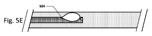
図5A~5E及び図6A~6Eは、血管カテーテルナビゲーション機器のいくつかの例示的な実施形態を示す。図5Aは、センサー302がカテーテル先端部にある実施形態を示す。図5Bは、センサーがカテーテル先端部ではなく、そこの近くにある実施形態を示す。この構成は、カテーテル先端部から媒質を導入する際にセンサーがパラメータを測定するのを防止し、流れの方向をより良好に区別できるようにし得る。図5Cは、2つのセンサーを備え、1つはカテーテル先端部にあり、及び1つは、カテーテル先端部ではなく、そこの近くにある実施形態を示す。異なる位置でのセンサー読取値は、流体の流れの方向、特徴、プロファイルなどによって変わり得る。カテーテル先端部ではなく、そこの近くにあるセンサーは、先端部から約0.05cm~約2.0cm戻ったところにあり得る。或いは、カテーテル先端部ではなく、そこの近くにあるセンサーは、先端部から約0.75cm~約1.25cm戻ったところにあり得る。図5Dは、センサーがガイドワイヤ又はスタイレット502上にある実施形態を示す。スタイレット502は、カテーテル内で自由に動いて、1つ以上のセンサーをカテーテル先端部から、ある距離に設置できるようにし得る。さらに、ガイドワイヤ/スタイレットは、カテーテルの設置後に除去され得る。この実施形態では、カテーテルはまた、ここで示すように、センサーを含み得る。図5Eは、開口部504がカテーテル先端部ではなく、そこの近くにある実施形態を示す。この開口部は、別個の媒質導入ルーメン若しくは輸液ルーメンと、又は遠位開口部と同じルーメンと、流体連通し得る。この特定の媒質導入ルーメンは、カテーテル先端部で出てもよい。カテーテル先端部ではなく、そこの近くにある開口部は、先端部から約0.25cm~約2.0cm戻ったところにあり得る。或いは、カテーテル先端部ではなく、そこの近くにある開口部は、先端部から約0.75cm~約1.25cm戻ったところにあり得る。2種以上の注入液媒質が、機器の同じルーメン又は別個のルーメンのいずれかに導入され得る。
5A-5E and 6A-6E show some exemplary embodiments of a vascular catheter navigation device. FIG. 5A shows an embodiment where the
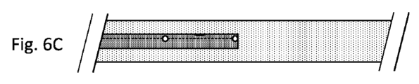
図6Aは、2つのセンサー間に開口部があり、両センサーは、カテーテル先端部ではなく、そこの近くにある実施形態を示す。図6Bは、2つ以上のセンサーがカテーテルの先端部ではなく、そこの近くにある実施形態を示す。図6Cは、2つのセンサー間に開口部を備え、センサーの一方がカテーテル先端部にある実施形態を示す。図6Dは、2つのセンサーに近接して開口部を含む実施形態を示す。図6Eは、チャンネル602を備える実施形態を示す。チャンネル602は、流体がカテーテル内を、カテーテル内のセンサーに近接して流れることができるようにする。
Figure 6A shows an embodiment with an opening between two sensors, both near but not at the catheter tip. Figure 6B shows an embodiment with two or more sensors near but not at the catheter tip. Figure 6C shows an embodiment with an opening between two sensors, one of the sensors at the catheter tip. Figure 6D shows an embodiment including an opening proximate to two sensors. Figure 6E shows an embodiment with a
図7は、2つのセンサーを備え、2つのセンサー間に複数の開口部が設けられた、血管ナビゲーション機器の実施形態を示す。 Figure 7 shows an embodiment of a vascular navigation device having two sensors with multiple openings between the two sensors.
血管カテーテルナビゲーション機器のこれら及び他の実施形態の多数の変形例が想定されることは明らかである。例えば、センサー、開口部、チャンネルなどは、カテーテル及び/又はガイドワイヤ/スタイレットの異なる側面にあってもよい。センサー、開口部及びチャンネルは、ここでは、カテーテル先端部にある又はその近くにあると示しているが、それらは、カテーテル及び/又はガイドワイヤ/スタイレットに沿ったいずれの箇所に置かれてもよい。 Clearly, numerous variations of these and other embodiments of the vascular catheter navigation device are contemplated. For example, the sensors, openings, channels, etc. may be on different sides of the catheter and/or guidewire/stylet. Although the sensors, openings, and channels are shown here as being at or near the catheter tip, they may be located anywhere along the catheter and/or guidewire/stylet.
異なるセンサー構成は、異なる血管の場所において異なるパラメータ曲線のシグニチャーを生じる。例えば、単一のセンサーは、2つのセンサーを備えるシステムとは異なる組の曲線を与える。輸液出口部位からのセンサーの距離も、異なる曲線を提供する。異なる輸液流量(infusion rates)、輸液量、輸液タイプ(ボーラス対ストリーム)、輸液圧力、輸液速度(infusion velocities)なども、異なる曲線、それゆえ異なる解剖学的特徴を提供する。曲線の異なる局面がコントローラによって分析されて、血管の場所を決定し得る。これらは、限定されるものではないが、傾斜、大きさ、値、長さ、ばらつき、拍動性、位相、標準偏差、形状、曲線の下側の領域、フーリエ変換、周波数、高調波などを含み得る。いくつかの実施形態では、心拍、システム雑音、組織コンダクタンスなどに関するものを含む、データ中のいくつかの周波数が、除去され得る。 Different sensor configurations will produce different parameter curve signatures at different vascular locations. For example, a single sensor will give a different set of curves than a system with two sensors. The distance of the sensor from the infusion exit site will also provide different curves. Different infusion rates, infusion volumes, infusion types (bolus vs. stream), infusion pressures, infusion velocities, etc. will also provide different curves and therefore different anatomical characteristics. Different aspects of the curves may be analyzed by the controller to determine vascular location. These may include, but are not limited to, slope, magnitude, value, length, variance, pulsatility, phase, standard deviation, shape, area under the curve, Fourier transform, frequency, harmonics, etc. In some embodiments, some frequencies in the data may be removed, including those related to heart rate, system noise, tissue conductance, etc.
いくつかの実施形態では、1つのセンサーがあるため、1つのパラメータ対時間/場所の曲線がある。いくつかの実施形態では、2つ以上のセンサーがあるため、2つ以上のパラメータ対時間/場所の曲線がある。いくつかの実施形態では、輸液出口ポートは、より近位の1つ又は複数のセンサーの近くにある。いくつかの実施形態では、輸液出口ポートは、1つ又は複数のセンサーよりも近位又は遠位にある。いくつかの実施形態では、輸液出口ポートはセンサー間にある。いくつかの実施形態では、1つ又は3つ以上のセンサーを使用してもよい。 In some embodiments, there is one sensor, and therefore one parameter vs. time/location curve. In some embodiments, there is two or more sensors, and therefore two or more parameter vs. time/location curves. In some embodiments, the infusion outlet port is near the more proximal sensor or sensors. In some embodiments, the infusion outlet port is more proximal or distal than the sensor or sensors. In some embodiments, the infusion outlet port is between the sensors. In some embodiments, one or more than two sensors may be used.
曲線は、異なる解剖学的構造では、及び血管カテーテルナビゲーション機器の設計に基づいて、異なって見えることもあることに留意されたい。例えば、曲線は、流体出口ポートに対して異なるセンサーの場所では、異なり得る。曲線は、センサーのタイプ又は流体注入速度に依存し得る。曲線は、注入流体の初期パラメータレベルに依存し得る。他の設計要因も、異なるパラメータ対時間/場所の曲線の形状となり得る。 Note that the curves may look different in different anatomies and based on the design of the vascular catheter navigation device. For example, the curves may be different for different sensor locations relative to the fluid exit port. The curves may depend on the type of sensor or the fluid injection rate. The curves may depend on the initial parameter level of the injected fluid. Other design factors may also result in different parameter vs. time/location curve shapes.
さらに、パラメータ対時間/場所の曲線の較正は、コントローラによって実施され得る。例えば、基準測定は、システムの挿入後、又はシステムの使用中の他の時点で導き出され得る。例えば、基準測定は、いずれかの注入流体が注入される前に、又は特定の注入速度で、血管において行われ得る。基準測定(システムに流体を全く注入せずに取られた測定値)は、解剖学的構造内での血管カテーテルナビゲーション機器の場所を決定するために、コントローラでのデータの分析に使用され得る。 Furthermore, calibration of the parameter versus time/location curves may be performed by the controller. For example, a baseline measurement may be derived after insertion of the system or at other times during use of the system. For example, a baseline measurement may be taken in the blood vessel before any infusion fluid is injected or at a particular infusion rate. The baseline measurement (a measurement taken without injecting any fluid into the system) may be used in the analysis of the data in the controller to determine the location of the vascular catheter navigation device within the anatomy.
パラメータ対時間の曲線の様々な特性が、血管カテーテルナビゲーション機器の場所を決定するために、分析され得る。例えば、1つ以上の曲線の曲線振幅、雑音、標準偏差、形状、傾斜、値、曲線の下側の領域、フーリエ変換、周波数、高調波などが、血管系内での血管カテーテルナビゲーション機器の場所を決定するために、使用され得る。これらの同じパラメータが、複数のパラメータ対時間/場所の曲線間で比較されて、血管カテーテルナビゲーション機器の設置場所を決定し得る。例えば、曲線の位置、相対的位置、大きさ、及び/又はピークの相対的な大きさ(正又は負)が、血管カテーテルナビゲーション機器の場所を決定するために、使用され得る。さらに、複数のセンサーからのデータの振幅、雑音、標準偏差、形状、傾斜、値、曲線の下側の領域、及び/又はフーリエ変換、高調波、周波数間の差を使用して、血管の場所を決定し得る。液滴サイズ及び/又は輸液流量に依存して、曲線の下側の領域又はフーリエ変換を使用して、パラメータ対時間の曲線、それゆえ血管の場所を分析し得る。さらに、最大値、又はいくつもの最大値が、意味があるとし得る。 Various characteristics of the parameter versus time curves may be analyzed to determine the location of the vascular catheter navigation device. For example, the curve amplitude, noise, standard deviation, shape, slope, value, area under the curve, Fourier transform, frequency, harmonics, etc. of one or more curves may be used to determine the location of the vascular catheter navigation device within the vasculature. These same parameters may be compared between multiple parameter versus time/location curves to determine the placement location of the vascular catheter navigation device. For example, the position of the curves, the relative position, magnitude, and/or the relative magnitude (positive or negative) of the peaks may be used to determine the location of the vascular catheter navigation device. Additionally, the difference between the amplitude, noise, standard deviation, shape, slope, value, area under the curve, and/or Fourier transform, harmonics, frequency of data from multiple sensors may be used to determine the location of the vessel. Depending on the droplet size and/or infusion rate, the area under the curve or Fourier transform may be used to analyze the parameter versus time curve and therefore the location of the vessel. Additionally, the maximum value, or multiple maximum values, may be meaningful.
本明細書では、用語「液滴」は、注入液に言及するときの、滴、ボーラス、ストリーム、間欠的なストリームなどを意味し得る。 As used herein, the term "droplet" can mean a drop, a bolus, a stream, an intermittent stream, etc., when referring to an infusion fluid.
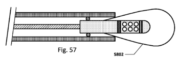
図8は、所望の(正しい)及び望ましくない(間違った)機器の設置を表す、血管系の異なる領域における流体の流れを示す概略図である。矢印802は血流方向を示す。領域804は、流体(食塩水など)の輸液を示す。異なる解剖学的な場所がどのように流体輸液の異なる流動状態、それゆえ異なる散逸パターンを生じるかに留意されたい。ここでは1つのセンサー806を示すが、本明細書で開示するこの及び任意の他の実施形態においては、2個、又は3個、又は4個又は5個又は6個又はそれよりも多いセンサーが使用されてもよい。
Figure 8 is a schematic diagram showing fluid flow in different regions of the vasculature, representing desired (correct) and undesired (incorrect) device placement.
本明細書で開示するいくつかの実施形態は、特定のタイプのセンサー及び測定されたパラメータ、例えばセンサー測定温度について述べ得ることに留意されたい。しかしながら、本明細書で開示する実施形態のいずれかは、センサーのパラメータを測定する任意のタイプのセンサー(又は2つ以上のタイプのセンサー)を使用し得る。例えば、温度を測定するセンサーを開示する実施形態は、その代わりに、又はそれに加えて、伝導率を測定する伝導率センサーを含み得る。特定のタイプのセンサーからのデータを使用するコントローラについて説明する実施形態は、その代わりに、又はそれに加えて、別のタイプのセンサーからのデータを使用し得る。 It should be noted that some embodiments disclosed herein may describe a particular type of sensor and measured parameter, e.g., the sensor measures temperature. However, any of the embodiments disclosed herein may use any type of sensor (or more than one type of sensor) that measures the sensor parameter. For example, an embodiment that discloses a sensor that measures temperature may instead or additionally include a conductivity sensor that measures conductivity. An embodiment that describes a controller that uses data from a particular type of sensor may instead or additionally use data from another type of sensor.
図9A~9Eは、2つのセンサー、又は他のタイプのセンサーがガイドワイヤ/スタイレット上にある、血管カテーテルナビゲーション機器の様々な実施形態を示す。図9Aは、近位センサー902及び遠位センサー904を備えるスタイレット910を示す。この実施形態では、注入液906は、近位センサー902の近位にある又はそれに近いカテーテル908の遠位先端部で流出する。或いは、注入液は、ガイドワイヤ/スタイレットのルーメンを通して注入され得る。ここでは2つのセンサーを示すが、1つ、又は3つ以上のセンサーも使用され得る。
Figures 9A-9E show various embodiments of a vascular catheter navigation device with two sensors, or other types of sensors, on the guidewire/stylet. Figure 9A shows a
図9Bは、注入液がスタイレット/ガイドワイヤを通して注入され、且つ2つのセンサー間で流出する実施形態を示す。図9Cは、注入液がスタイレット/ガイドワイヤを通して注入され、且つ遠位センサーの近く又はそれよりも遠位で流出する実施形態を示す。1つのセンサーが使用される場合、流体注入出口ポートは、センサーよりも近位、又は遠位のいずれかにあるとし得る。 FIG. 9B shows an embodiment where the infusate is injected through the stylet/guidewire and exits between two sensors. FIG. 9C shows an embodiment where the infusate is injected through the stylet/guidewire and exits near or distal to the distal sensor. If one sensor is used, the fluid injection exit port can be either proximal or distal to the sensor.
図9D及び図9Eは、スタイレット/ガイドワイヤ上に2つのセンサーがあり、ガイドワイヤが、カテーテルの端部に対して動かされることができる実施形態を示す。この実施形態は、感知及び/又はカテーテルの先端部に対する注入液出口の場所を変更するために使用され得る。 Figures 9D and 9E show an embodiment where there are two sensors on the stylet/guidewire and the guidewire can be moved relative to the end of the catheter. This embodiment can be used to change the sensing and/or infusate outlet location relative to the tip of the catheter.
例えば、いくつかの実施形態では、スタイレット/ガイドワイヤは、注入ルーメン(すなわちスタイレット/ガイドワイヤは中空とし得る)及びセンサーの双方を含み得るため、解剖学的構造内に最初に及び/又は血管カテーテルとは無関係に位置決めされ得る。例えば頸静脈アクセスがカテーテル挿入に使用されるとき。ひとたびスタイレット/ガイドワイヤが設置されたら、血管カテーテルは前進され得るため、カテーテルの遠位先端部は、スタイレット/ガイドワイヤの遠位先端部に対して公知の位置にある。その後、スタイレット/ガイドワイヤは除去され得る。 For example, in some embodiments, the stylet/guidewire may include both an infusion lumen (i.e., the stylet/guidewire may be hollow) and a sensor, and therefore may be positioned within the anatomy initially and/or independent of the vascular catheter, such as when jugular vein access is used for catheter insertion. Once the stylet/guidewire is in place, the vascular catheter may be advanced so that the distal tip of the catheter is in a known position relative to the distal tip of the stylet/guidewire. The stylet/guidewire may then be removed.
図9F~9Hは、流体出口ポートとセンサーとの間の距離、及びカテーテル/スタイレット先端部とセンサー/ポートとの間の距離を示す。図9Fは、注入液出口又はポートと、遠位又は単一のセンサーとの間の軸方向距離aaを示す。軸方向距離bbは、流体出口ポートと近位センサーとの間の距離である。軸方向距離ccは、遠位センサーと近位センサーとの間の距離である。これらの距離は、正でも又は負でもよい。ここでは2つのセンサーを示すが、機器は、1つのセンサー又は3つ以上のセンサーを有してもよい。 Figures 9F-9H show the distance between the fluid exit port and the sensor, and the distance between the catheter/stylet tip and the sensor/port. Figure 9F shows the axial distance aa between the infusate exit or port and the distal or single sensor. The axial distance bb is the distance between the fluid exit port and the proximal sensor. The axial distance cc is the distance between the distal and proximal sensors. These distances may be positive or negative. Although two sensors are shown here, the device may have one sensor or more than two sensors.
距離aaは約0mmとし得る。或いは、距離aaは、約0mm~約0.5mm、又は約0mm~約1mmの範囲にあるとし得る。或いは、距離aaは約0mm~約2mmの範囲にあるとし得る。或いは、距離aaは約0mm~約3mmの範囲にあるとし得る。或いは、距離aaは約3mm~約5mmとし得る。或いは、距離aaは約5mm~約10mmとし得る。或いは、距離aaは約0mm~約100mmの範囲にあるとし得る。或いは、これらの距離は負でもよい。例えば、距離aaは、約1mmとしても、又は約-1mmとしてもよい。1mmの場合、遠位センサーは、流体出口ポートよりも遠位にある。-1mmの場合、流体出口ポートは、遠位センサーよりも遠位にある。これは、図9F~9Hに関連して提供されるあらゆる寸法において真である。 Distance aa may be about 0 mm. Alternatively, distance aa may range from about 0 mm to about 0.5 mm, or from about 0 mm to about 1 mm. Alternatively, distance aa may range from about 0 mm to about 2 mm. Alternatively, distance aa may range from about 0 mm to about 3 mm. Alternatively, distance aa may be from about 3 mm to about 5 mm. Alternatively, distance aa may be from about 5 mm to about 10 mm. Alternatively, distance aa may range from about 0 mm to about 100 mm. Alternatively, these distances may be negative. For example, distance aa may be about 1 mm or about -1 mm. At 1 mm, the distal sensor is more distal than the fluid exit port. At -1 mm, the fluid exit port is more distal than the distal sensor. This is true for all dimensions provided in connection with Figures 9F-9H.
距離bbは約10mmとし得る。或いは、距離bbは約0mm~約10mmの範囲にあるとし得る。或いは、距離bbは約8mm~約12mmの範囲にあるとし得る。或いは、距離bbは約5mm~約15mmの範囲にあるとし得る。或いは、距離bbは約1mm~約100mmの範囲にあるとし得る。或いは、距離bbは約3mm~約5mmとし得る。或いは、距離bbは約5mm~約10mmとし得る。或いは、距離bbは約0mm~約100mmの範囲にあるとし得る。これらの範囲も負の距離としてもよい。 The distance bb may be about 10 mm. Alternatively, the distance bb may be in the range of about 0 mm to about 10 mm. Alternatively, the distance bb may be in the range of about 8 mm to about 12 mm. Alternatively, the distance bb may be in the range of about 5 mm to about 15 mm. Alternatively, the distance bb may be in the range of about 1 mm to about 100 mm. Alternatively, the distance bb may be in the range of about 3 mm to about 5 mm. Alternatively, the distance bb may be in the range of about 5 mm to about 10 mm. Alternatively, the distance bb may be in the range of about 0 mm to about 100 mm. These ranges may also be negative distances.
距離ccは約10mmとし得る。或いは、距離ccは約0.0mm~約5mmの範囲にあるとしても、或いは、距離ccは約5mm~約15mmの範囲にあるとしてもよい。或いは、距離ccは約15mm~約20mmの範囲にあるとし得る。或いは、距離ccは約1mm~約100mmの範囲にあるとし得る。 The distance cc may be about 10 mm. Alternatively, the distance cc may be in the range of about 0.0 mm to about 5 mm. Alternatively, the distance cc may be in the range of about 5 mm to about 15 mm. Alternatively, the distance cc may be in the range of about 15 mm to about 20 mm. Alternatively, the distance cc may be in the range of about 1 mm to about 100 mm.
図9Gの距離ddは、流体出口ポートと、遠位センサー又は近位センサーのいずれかとの間の距離である。距離は、ここでは近位センサーに対して示されるが、距離ddはいずれかに適用され得る。或いは、センサーは1つのみ存在し得る。距離ddは約0.75mmとし得る。或いは、距離ddは約0.25mm~1.5mmの範囲にあるとし得る。或いは、距離ddは約0.1mm~5mmの範囲にあるとし得る。 Distance dd in FIG. 9G is the distance between the fluid exit port and either the distal sensor or the proximal sensor. Although the distance is shown here for the proximal sensor, distance dd may apply to either. Alternatively, there may be only one sensor. Distance dd may be about 0.75 mm. Alternatively, distance dd may be in the range of about 0.25 mm to 1.5 mm. Alternatively, distance dd may be in the range of about 0.1 mm to 5 mm.
図9Hは、流体出口ポートとカテーテル及び/又はスタイレットの端部との間の軸方向距離eeを示す。距離eeは約0mmとし得る。或いは、距離eeは約0mm~約1mmの範囲にあるとし得る。或いは、距離eeは約0mm~約3mmの範囲にあるとし得る。或いは、距離eeは約0mm~約5mmの範囲にあるとし得る。或いは、距離eeは約5mm~約10mmの範囲にあるとし得る。或いは、距離eeは約0mm~約100mmの範囲にあるとし得る。これらの距離は正でも又は負でもよい。 FIG. 9H shows the axial distance ee between the fluid exit port and the end of the catheter and/or stylet. The distance ee may be about 0 mm. Alternatively, the distance ee may be in the range of about 0 mm to about 1 mm. Alternatively, the distance ee may be in the range of about 0 mm to about 3 mm. Alternatively, the distance ee may be in the range of about 0 mm to about 5 mm. Alternatively, the distance ee may be in the range of about 5 mm to about 10 mm. Alternatively, the distance ee may be in the range of about 0 mm to about 100 mm. These distances may be positive or negative.
図9Iは、センサーを1つのみ含み且つシステム内に導管902を含む、血管カテーテルナビゲーション機器の実施形態を示す。導管を含むシステムの様々な実施形態は、本明細書の他の箇所でより詳細に説明する。導管902は、Xで示す注入液出口ポートを組み込む。ここで示す距離ffは、導管の流体注入液出口ポートとセンサーとの間の長手方向距離である。
FIG. 9I shows an embodiment of a vascular catheter navigation device that includes only one sensor and includes a
図9Jは、図9Iのものと同様の、距離ggが導管の流体注入液出口ポートとセンサーとの間の半径方向距離を表す実施形態を示す。 Figure 9J shows an embodiment similar to that of Figure 9I, where distance gg represents the radial distance between the fluid infusion outlet port of the conduit and the sensor.
図10は、任意のカテーテルと一緒に使用され得る、又は換言すると、センサー、注入液ルーメン、コントローラ、及びロッキング機構がスタイレット/ガイドワイヤに含まれる、血管カテーテルナビゲーション機器の実施形態を示す。図10は、2つの熱電対、遠位センサー1012及び近位センサー1010、及びガイドワイヤ/スタイレット1001の一部として注入液出口ポート1002を備える実施形態を示す。或いは、スタイレット/ガイドワイヤは、1つのセンサーしか有しなくてもよく、又は3つ以上のセンサーを有してもよい。スタイレット/ガイドワイヤは、スタイレット/ガイドワイヤとカテーテルを位置合わせするのを支援するための特徴1014を含み得る。この実施形態は、センサーを埋め込むために、先端部分1006、例えば成形されたウレタン、ナイロン、シリコーン、又は他のポリマー部分を含み得る。同様にここに、任意選択的なガイドワイヤ/スタイレットコイル1008、及びカテーテル1018の遠位先端部を示す。断面図では、注入ルーメン1016も示され得る。
10 shows an embodiment of a vascular catheter navigation device that can be used with any catheter, or in other words, where the sensor, infusate lumen, controller, and locking mechanism are included in the stylet/guidewire. FIG. 10 shows an embodiment with two thermocouples, a
この実施形態はトルク又はロッキング機器1022を含み得、トルク又はロッキング機器は、例えばカテーテル1018の近位端部にあるルアーロック1020を使用して、スタイレットをカテーテルの近位端部にロックするために使用され得る。トルク/ロッキング機器はスタイレット/ガイドワイヤにロックされるため、スタイレット/ガイドワイヤは血管カテーテルに対して動かない。コントローラ(図示せず)は、輸液機構を含み及び/又は流体ポート1026を介してそれを制御し、並びにポート1004を介してセンサーからのデータを読み取り得る。コントローラは、スタイレットの近位端部の近くに置かれてもよいし、又はスタイレットの近位端部から数インチ又は数フィートに置かれてもよい。センサーリード線1024も示されている。輸液は、定常でも、又は間欠的でも、又はボーラスからなってもよい。
This embodiment may include a torque or locking
図11A~11Iは、血管カテーテルナビゲーション機器のスタイレット/ガイドワイヤのバージョンの様々な実施形態の様々な図を示す。 Figures 11A-11I show various views of various embodiments of the stylet/guidewire version of a vascular catheter navigation device.
11A~11I及びいくつかの他の実施形態に示すスタイレットは:1)挿入を支援するためのカテーテルの補剛、2)流体送給のための媒質の提供、及び3)1つ又は複数のセンサーのリードのためのチャンネルの提供を含む、いくつかの機能を果たす。図11Aは、図10の実施形態に示すものなどのスタイレットの断面である。ここでは2つのセンサーを示すが、機器は、1つ、又は3つ以上のセンサーを含んでもよい。 The stylet shown in 11A-11I and several other embodiments serves several functions, including: 1) stiffening the catheter to aid in insertion, 2) providing a medium for fluid delivery, and 3) providing channels for one or more sensor leads. FIG. 11A is a cross-section of a stylet such as that shown in the embodiment of FIG. 10. Although two sensors are shown here, the device may include one, or more than two sensors.
図11Bは、トリプルルーメンの熱収縮及び/又はチューブのハウジング1102に3つの構成要素を含むスタイレットの実施形態を示し、そこに、2つのセンサー1104及び流体ルーメン1016を入れている。或いは、1つ又は3つ以上のセンサーが存在してもよい。
FIG. 11B shows an embodiment of a stylet that includes three components in a triple lumen heat shrink and/or
図11Cは、スタイレットコイルの全て、又は一部が、センサーワイヤ又はリードから作製される実施形態を示す。図11Dは、図11Cに示す実施形態の側面図である。 FIG. 11C shows an embodiment in which all or part of the stylet coil is made from a sensor wire or lead. FIG. 11D shows a side view of the embodiment shown in FIG. 11C.
図11Eは、2つのセンサー並びに流体ルーメンを収納する押出品、すなわちチューブ(金属又はプラスチック)を含む実施形態を示す。或いは、1つ又は3つ以上のセンサーが存在してもよい。 Figure 11E shows an embodiment that includes an extrusion, i.e., tube (metal or plastic), that houses two sensors and a fluid lumen. Alternatively, there may be one or more than two sensors.
図11Fは、ひとまとめに束ねた複数のセンサーリード、並びに流体ルーメンを収納する押出品、すなわちチューブ(金属又はプラスチック)を含む実施形態を示す。 Figure 11F shows an embodiment that includes multiple sensor leads bundled together, as well as an extrusion, i.e., tube (metal or plastic), that contains a fluid lumen.
図11Gは、センサーリードが流体ルーメンによって囲まれている、薄壁の押出品、すなわちチューブを含む実施形態を示す。1つ、2つ、又は3つ以上のセンサーが存在してもよい。 FIG. 11G shows an embodiment that includes a thin-walled extrusion, i.e., tube, in which the sensor lead is surrounded by a fluid lumen. There may be one, two, three or more sensors.
図11Hは、複数のセンサー、流体ルーメン、並びにワイヤやロッドとし得る補剛材1108を含む、押出品、すなわちチューブ(プラスチック又は金属)を含む実施形態を示す。1つ、2つ、又は3つ以上のセンサーが存在してもよい。
FIG. 11H shows an embodiment including an extrusion, i.e., a tube (plastic or metal), that includes multiple sensors, a fluid lumen, and a
図11Iは、センサーリード束並びに流体ルーメンを含む、押出品、すなわちチューブ(プラスチック又は金属)を含む実施形態を示す。センサーリード束の外面は、外側押出品と同様の材料で作製され、これにより、任意選択的な化学的に又は熱で形成される接着又は溶接1106を可能にし得る。1つ、2つ、又は3つ以上のセンサーが存在してもよい。 FIG. 11I shows an embodiment that includes an extrusion, i.e., a tube (plastic or metal), that contains the sensor lead bundle as well as a fluid lumen. The outer surface of the sensor lead bundle may be made of a similar material as the outer extrusion, allowing for optional chemically or thermally formed bonds or welds 1106. There may be one, two, three or more sensors.
いくつかの実施形態では、カテーテル先端部とガイドワイヤ/スタイレットとの間の距離を固定する、又は正確に制御すること、又はカテーテル先端部とガイドワイヤ/スタイレットとの間の距離を決定できるようにすることのいずれかが重要である。センサーに対する注入の場所を固定できるようにすること、又は注入出口ポートの場所とセンサーとの間の距離を知ることができるようにすることも重要とし得る。出口ポートとセンサーとの間の距離は、流体輸液の期間中のパラメータプロファイルに対する影響を有し得る。これらの距離は、複数の患者及びシナリオで固定されても、又は異なる患者のタイプ及び異なるシナリオに対して異なってもよい。例えば、距離は、アクセス中の血管系に依存して異なってもよい。距離は、異なる重量、サイズ、体重指数、健康状態、年齢、性別、心臓の症状(heart condition)、又は他の患者特性を有する患者に対して異なってもよい。距離は、カテーテルルーメンの数及び形状が異なるカテーテルなど、異なるカテーテルサイズに対して異なってもよい。 In some embodiments, it is important to either fix or precisely control the distance between the catheter tip and the guidewire/stylet, or to be able to determine the distance between the catheter tip and the guidewire/stylet. It may also be important to be able to fix the location of the infusion relative to the sensor, or to be able to know the distance between the location of the infusion exit port and the sensor. The distance between the exit port and the sensor may have an effect on the parameter profile during the period of fluid infusion. These distances may be fixed across multiple patients and scenarios, or may be different for different patient types and different scenarios. For example, the distances may be different depending on the vasculature being accessed. The distances may be different for patients with different weights, sizes, body mass indexes, health conditions, ages, sexes, heart conditions, or other patient characteristics. The distances may be different for different catheter sizes, such as catheters with different numbers and shapes of catheter lumens.
いくつかの実施形態では、スタイレット/ガイドワイヤは、図10に示すようなカテーテルの近位端部の近くにあるトルク機器を使用して、カテーテル先端部に対して固定又はロックされる。 In some embodiments, the stylet/guidewire is secured or locked to the catheter tip using a torque device near the proximal end of the catheter, such as that shown in FIG. 10.
いくつかの実施形態では、ユーザは、目で確認することによって、カテーテルとスタイレット/ガイドワイヤとの相対的な位置合わせを決定してから、2つの値から相対距離を測定する。 In some embodiments, the user determines the relative alignment of the catheter and stylet/guidewire by visual inspection and then measures the relative distance from the two values.
図12~17は、スタイレット上の1つ又は複数のセンサーと、カテーテル先端部又は流体注入点との間の距離を固定するか、又は知るための、様々な登録技術を含む血管カテーテルナビゲーション機器の様々な実施形態を示す。 Figures 12-17 show various embodiments of vascular catheter navigation devices that include various registration techniques for fixing or knowing the distance between one or more sensors on the stylet and the catheter tip or fluid injection point.
図12は、センサーから固定された公知の距離に、スタイレット/ガイドワイヤ上にインジケータを備える実施形態を示す。この実施形態では、ユーザは、患者に挿入する前に、カテーテル1202の先端部と、スタイレット1206上のインジケータ、すなわち印1204を位置合わせする。スタイレットの先端部に対するカテーテル先端部の相対距離1208は、カテーテルが患者に挿入される前に、好ましくは近位端部において、トルク機器、ロッキング・ローテーティング(locking rotating)止血弁、トゥーイ・ボースト(tuohy-borst)弁、又は他のロッキング機構を使用してロックされ得る。ガイドワイヤ/スタイレット上のインジケータは、可視的な印、例えば赤色のストライプ又はドット、又は触覚的な印、例えば突起や溝、又は他のタイプのインジケータとし得る。
12 shows an embodiment with an indicator on the stylet/guidewire at a fixed, known distance from the sensor. In this embodiment, the user aligns the tip of the
図13は、遠位センサーから固定された公知の距離に、スタイレット上に隆起部、又は突起1302を備える実施形態を示す。これにより、ユーザは、可視的に、又は手触りによってのいずれかで、カテーテルの先端部をスタイレット上の突起と位置合わせすることができる。この位置合わせは、体外又は体内で行われ得る。いくつかの実施形態では、突起は、解剖学的構造内に設置した後でスタイレットがカテーテルから除去され得るように、十分に小さいか又は柔らかい。 FIG. 13 shows an embodiment with a protuberance, or projection, 1302 on the stylet at a fixed, known distance from the distal sensor. This allows the user to align the tip of the catheter with the projection on the stylet, either visually or by feel. This alignment can be performed outside the body or inside the body. In some embodiments, the projection is small or soft enough that the stylet can be removed from the catheter after placement within the anatomy.
図14は、図13に示すものと同様の、センサー1104がスタイレット上の突起の機能を果たす実施形態を示す。
Figure 14 shows an embodiment similar to that shown in Figure 13, in which the
図15は、治具、又はブロック、又はアライナー1502を使用して、カテーテルの先端部を、スタイレットの先端部から固定された公知の距離に位置合わせする実施形態を示す。そのため、スタイレットに対するカテーテルの相対的位置は、トルク機器、ロッキング・ローテーティング止血弁、トゥーイ・ボースト弁、又は他のロッキング機構を使用して近位端部において、及び/又は固定式導管(本明細書の他の箇所で詳細に開示する)を使用して遠位端部において、又はそれら双方で、ロックされる。治具又はブロック1502は、それ自体、調整可能とし得るため、流体出口ポート(ここではカテーテルの遠位端部)を様々な異なる長さでセンサーと位置合わせできる。
15 shows an embodiment in which a jig, or block, or
図16は、可膨張性のバルーン1602を突起として使用して、カテーテルとスタイレットを位置合わせする、図13に示すものと同様の実施形態を示す。バルーンは、環状としてもよいし、又はスタイレットの1つ以上の側面上にあってもよい。バルーンは、位置合わせの際に使用するために膨張され、及び設置の期間中に膨張されたままにされて、カテーテルに対してスタイレットを適所にロックするか、又は設置の期間中にしぼまされる(カテーテル及びスタイレットが、トルク又は弁を使用して互いにロックされる箇所)かのいずれかとし得る。この実施形態では、スタイレット又はカテーテルは膨張ルーメンを含み、バルーンを膨張させ、且つしぼませる。バルーンは、カテーテルの設置後にスタイレットを除去するために、しぼまされ得る。
16 shows an embodiment similar to that shown in FIG. 13, in which an
図17は、使用中にカテーテル先端部の内側にあるときを感知し得るセンサー1702を含む、血管カテーテルナビゲーション機器の実施形態を示す。例えば、センサーは、磁気、超音波、光、温度などとし得る。いくつかの実施形態では、近位センサー1704は、近位センサーがカテーテル先端部の内側にあるときを決定するセンサーとして使用される。注入液の注入後のパラメータ対時間/場所の曲線の形状は、センサーがカテーテル先端部のすぐ内側にあるときの特定のプロファイルを示し、及びこの位置合わせを特定するために使用され得る。この実施形態は、1つ、2つ、又はそれよりも多いセンサーを含み得る。
FIG. 17 shows an embodiment of a vascular catheter navigation device that includes a
いくつかの実施形態では、注入液出口のフローパターンの制御が、一貫した結果を達成するために、重要とし得る。注入液の流れを、血管系/心臓内の血流の流れと対比することも重要とし得る。注入液の流れは、これらの目標を達成するために、より層流又はより乱流のいずれかに意図的にされ得る。いくつかの実施形態は、流れを方向付け且つカテーテル又はスタイレットの一部である特徴を含み得る。これらの特徴は、ディンプリング、又はカテーテル又はスタイレットの表面仕上げを変化させるオレンジピール仕上げのような表面特徴とし得る。これらの特徴は、スタイレット/温度センサーのODの一部、又は流体ルーメンのID、又はそれら双方とし得る。 In some embodiments, control of the infusate outlet flow pattern may be important to achieve consistent results. It may also be important to contrast the infusate flow with the blood flow in the vasculature/heart. The infusate flow may be intentionally made to be either more laminar or more turbulent to achieve these goals. Some embodiments may include features that direct the flow and are part of the catheter or stylet. These features may be surface features such as dimpling or an orange peel finish that changes the surface finish of the catheter or stylet. These features may be part of the OD of the stylet/temperature sensor, or the ID of the fluid lumen, or both.
図18A及び図18Bは、血管カテーテルナビゲーション機器の注入液ルーメン1016にある、(層流又は乱流の流れを生じるための)導流体(flow director)に対する2つの考えられる実施形態を示す。導流体1802は、図18Aに示すように、注入液ルーメンの端部にあってもよいし、又は図18Bに示すように、ルーメン出口の先端部から奥まったところにあってもよい。
18A and 18B show two possible embodiments for a flow director (to create laminar or turbulent flow) in the
図19A~19Cは、注入液ルーメンの形状が、ルーメンから流出する流体の流れのタイプを制御する、血管カテーテルナビゲーション機器の他の実施形態を示す。変更され得るパラメータのいくつかは、注入液ルーメンの開口部の面積、形状、表面状態などを含み得る。センサーリード及び/又は補剛材1902も示されている。
19A-19C show another embodiment of a vascular catheter navigation device in which the shape of the infusate lumen controls the type of fluid flow exiting the lumen. Some of the parameters that may be varied may include the area, shape, surface condition, etc. of the infusate lumen opening. Sensor leads and/or
いくつかの実施形態は、スタイレット及び/又はカテーテルを振動させて、注入液ルーメンから注入液の乱流を生じる。 Some embodiments vibrate the stylet and/or catheter to create turbulent flow of infusate from the infusate lumen.
図20は、注入ルーメンのないスタイレットの実施形態を示す。流体は、カテーテル先端部の上流の、挿入部位により近い、又はどこか他の箇所にある、別のカテーテルルーメン(おそらくは、別個のカテーテル上にある)を通って導入され得る。例えば、流体は、ここでは、血管カテーテルと一緒に示される「相棒」カテーテル2002によって注入され得る。流体はまた、カテーテル又は「相棒」カテーテル上にある加熱/冷却素子によって加熱又は冷却され得る。輸液用の「相棒」ガイドワイヤ/スタイレットも想定される。
FIG. 20 shows an embodiment of a stylet without an infusion lumen. Fluid may be introduced through another catheter lumen (possibly on a separate catheter) upstream of the catheter tip, closer to the insertion site, or elsewhere. For example, fluid may be infused through a "buddy"
図21は、乱流制御を強化する注入液ルーメン内の特徴2102を示す。
Figure 21 shows
図22は、層流(又は乱流が少ない)制御を生じ得る注入液ルーメン内の特徴2202を示す。
Figure 22 shows
本明細書で開示するいくつかの実施形態は、2つのセンサーを示すことに留意されたい。これらの実施形態のいずれかでは、1つ、2つ、又はそれよりも多いセンサーが使用され得る。 Note that some embodiments disclosed herein show two sensors. In any of these embodiments, one, two, or more sensors may be used.
いくつかの実施形態では、スタイレットの外径(OD)は約1mm以下である。いくつかの実施形態では、スタイレットのODは約0.5mm以下である。いくつかの実施形態では、スタイレットのODは約1.5mm以下である。いくつかの実施形態では、スタイレットのODは約0.2mm~約5mmの範囲内にあるとし得る。 In some embodiments, the outer diameter (OD) of the stylet is about 1 mm or less. In some embodiments, the OD of the stylet is about 0.5 mm or less. In some embodiments, the OD of the stylet is about 1.5 mm or less. In some embodiments, the OD of the stylet may be in the range of about 0.2 mm to about 5 mm.
カテーテルがダブル又はトリプルルーメンであるいくつかの実施形態では、スタイレットの機能性は別々の部分に分割され(流体、補剛材、感知リードなど)、及び複数のスタイレットが、カテーテルの複数のルーメン内で使用され得る。 In some embodiments where the catheter is double or triple lumen, the functionality of the stylet is split into separate portions (fluid, stiffener, sensing lead, etc.) and multiple stylets may be used within the multiple lumens of the catheter.
熱電対、光ファイバー、抵抗、バイメタル、温度計、状態変化、シリコンダイオード、サーミスタ、光学温度測定(赤外線又は別の方法)、水銀温度計、圧力計などを含む、多くのタイプの温度センサーが、本明細書で開示する実施形態のいずれかにおいて使用され得る。 Many types of temperature sensors may be used in any of the embodiments disclosed herein, including thermocouples, fiber optics, resistors, bimetallics, thermometers, change of state, silicon diodes, thermistors, optical temperature measurements (infrared or otherwise), mercury thermometers, manometers, and the like.
流体を輸液することに加え、本明細書の他の箇所で開示しているように、カテーテル/スタイレットの先端部で又はその近くで熱変化を生じる他の方法が、使用され得る。体温よりも高い温度の流体が導入され得、抵抗加熱素子、又は圧電冷却素子などが、カテーテル内、カテーテル上、ガイドワイヤ/スタイレット上、又は注入器に、体外に、含まれ得る。或いは、注入される流体は、体温とは異なるが、厳しく制御されてはいない温度にあるとしてもよく、及び(体温と注入液の温度との間の)この温度差が、コントローラによって測定され、且つ追跡される。 In addition to infusing fluid, other methods of creating a thermal change at or near the tip of the catheter/stylet may be used, as disclosed elsewhere herein. Fluids at temperatures above body temperature may be introduced, and resistive heating elements, piezoelectric cooling elements, or the like may be included in or on the catheter, on the guidewire/stylet, or in the injector, external to the body. Alternatively, the fluid being injected may be at a temperature that is different from body temperature, but is not tightly controlled, and this temperature difference (between body temperature and the injectate temperature) is measured and tracked by the controller.
抵抗加熱素子を用いる実施形態では、抵抗加熱素子は、カテーテル上に、又はスタイレット上にあるとし得る。カテーテル上にある実施形態では、カテーテルの外部に、又はカテーテルの1つ以上のルーメン内にあるとし得る。或いは、ガイドワイヤ/スタイレット上にあってもよい。ガイドワイヤ/スタイレット上にある実施形態では、カテーテルルーメン内に、部分的にカテーテルルーメン内に、又は血液に曝されるカテーテルルーメンの外部にあってもよい。血液を加熱/冷却する実施形態は、注入流体(injectate fluid)を必要としないこともある。 In embodiments using a resistive heating element, the resistive heating element may be on the catheter or on the stylet. In embodiments on the catheter, the element may be external to the catheter or within one or more lumens of the catheter. Alternatively, the element may be on the guidewire/stylet. In embodiments on the guidewire/stylet, the element may be within the catheter lumen, partially within the catheter lumen, or external to the catheter lumen exposed to the blood. Embodiments that heat/cool blood may not require an injectate fluid.
図23A~23E及び図24A~24Eに示すように、グラフィカルユーザインターフェースが、小型スクリーン/ディスプレイ2314、大型スクリーン、投影の形態で、仮想現実又は拡張現実ゴーグルなどで、表示され得る。ユーザインタラクションの主な分類は、ユーザ警報:1)アイコン、2)アイコンの色又は警告灯、3)警報を伴う聴覚トーン、4)カテーテル先端部の場所に適合し且つ警報のタイプを用いる視覚的な身体マップ、5)ステータス又は警報、振動などを示す、ディスプレイ上に書かれた語句又は言葉のいずれかの組み合わせを有し得る。分類は、以下とし得る:1)「前進続行」、これは、カテーテル先端部が末梢静脈を通って前進していること、又はカーブを曲がって上大静脈に到達していることを意味する。このモードは、緑色の点灯及び図像及びポジティブなトーンなどのポジティブな状態を示す視覚及び聴覚フィードバックを伴う。2)チェックマーク図像を用いる「正しい設置」は、先端部が適切な場所-PICCラインに対しては大静脈心房接合部、又は別のタイプのカテーテル挿入に関してはおそらくは別の場所に、到達したことを示す。この状態にも、ポジティブなトーン及び点灯が伴い得る。3)カテーテルが、対向する流れに直面する場合、警告、「向きの変更」が現れ得る。これは、カテーテルが奇静脈枝を下方に前進する、IVC内へ前進する、又は動脈内に設置された場合の警告である。これはポジティブな状態ではないため、この状態は、赤色、黄色又はオレンジ色の点灯又は図像を、好ましくない状態が実施されていることを示すトーンと一緒に、伴い得る。不快な周波数、ピッチ及びトーンが伴い得る。4)カテーテルが心臓内に、心房又は心室のいずれかにある場合、ユーザは、心臓のアイコン及び/又は「心臓内」の警告によって、注意喚起され得る。この状態にはネガティブな色及びトーンが伴い得る。5)カテーテル先端部が、静脈の壁に当たる場合、又はある種の障害物を有する場合、「調整」の警告が表示され得る。この状態にはネガティブな色及びトーンが伴い得る。また、図23A~23E及び図24A~24Eには、カテーテル2302、スタイレット2304、センサーアダプター2306、流体アダプター2308、主ボタン2310、及び挿入/追跡ボタン2312が示されている。
23A-23E and 24A-24E, a graphical user interface may be displayed in the form of a small screen/
グラフィカルユーザインターフェース(GUI)は、リアルタイムで、3次元空間に関するカテーテルの先端部の場所を表示し、それによってナビゲーションし得る。図23A~23E及び図24A~24Eに示すグラフィカルユーザインターフェースは2次元であるが、いくつかの実施形態は、3次元でも情報を通信し得る3次元ディスプレイを含む。 A graphical user interface (GUI) may display and navigate in real time the location of the catheter tip relative to three-dimensional space. Although the graphical user interfaces shown in FIGS. 23A-23E and 24A-24E are two-dimensional, some embodiments include a three-dimensional display that may also communicate information in three dimensions.
本明細書で開示するいくつかの実施形態は、血管カテーテルにセンサーを組み込むが、血管カテーテルナビゲーション機器は、血管カテーテル内に収まり、且つひとたび血管カテーテルの設置が完了したら除去され得るスタンドアロン機器とし得ることに留意されたい。血管カテーテルナビゲーション機器は、例えば、標準的な血管カテーテルのスタイレット又はガイドワイヤの機能を果たし得る。 Note that although some embodiments disclosed herein incorporate sensors into the vascular catheter, the vascular catheter navigation device may be a standalone device that fits within the vascular catheter and can be removed once placement of the vascular catheter is complete. The vascular catheter navigation device may, for example, perform the function of a stylet or guidewire in a standard vascular catheter.
図25A~25Cは、機器の流体出口点から流出する流体の流れを制御するための導管を含む血管カテーテルナビゲーション機器の実施形態を示す。この実施形態では、導管2502は、ガイドワイヤ/スタイレット2504に取り付けられ、スタイラス/導管複合機器を形成する。導管2502は、血管カテーテル2508の輸液ルーメン2506のID内に収まるように設計される。この図面では、血管カテーテル2508のみが、1つのルーメン、輸液ルーメンを含むが、輸液ルーメンに加えて、複数のルーメンが血管カテーテル内に存在してもよい。
25A-25C show an embodiment of a vascular catheter navigation device that includes a conduit for controlling the flow of fluid exiting the device's fluid exit point. In this embodiment, the
いくつかの実施形態では、ガイドワイヤ/スタイレット2504は、コア2510、コイル2512、エンドキャップ2514及びセンサー2516を含む。コア2510は補剛ワイヤを含み得、補剛ワイヤは、テーパが付けられていてもよく、且つセンサーに至る。センサーは、エンドキャップに組み込まれても、又は別個としてもよい。1つ以上のセンサーが存在してもよい。センサーは熱電対とし得る。センサーのより大きな断面寸法はパラメータ測定値を減衰し、ここでは、熱電対のより小さな断面寸法は、より迅速な応答時間を可能にし得る。センサーの直径又は断面寸法2526は約0.2mm~0.3mmとし得る。或いは、熱電対の直径又は断面寸法2526は約.02mm~約.5mmとし得る。
In some embodiments, the guidewire/
いくつかの実施形態では、導管2502は、長さ2520を有し、及び直径又は断面寸法2522の1つ又は複数の流体流路2518を含む。流路は、断面形状が円形、又は卵形、又は任意の形状とし得る。流路は、直径又は断面寸法が約0.4~0.6mmとし得る。或いは、流路は、直径又は断面寸法が約0.1~1.0mmとし得る。或いは、流路は、直径又は断面寸法が約0.01~2.0mmとし得る。導管長2520は約4~8mmとし得る。或いは、導管長2520は約0.5mm~20mmとし得る。
In some embodiments, the
流路の断面の面積及び形状は、少なくとも部分的に、導管から流出する流速を決定する。流路の数も、導管から流出する流体のフローパラメータに影響を及ぼす。好ましくは、流体の輸液流量は約2~3ml/分とし得る。或いは、流体の輸液流量は約3~5ml/分とし得る。或いは、流体の輸液流量は約5~10ml/分とし得る。或いは、流体の輸液流量は約1~5ml/分とし得る。或いは、流体の輸液流量は約0.5~7ml/分とし得る。導管出口の流速は、好ましくは、約60~100cm/秒である。或いは、導管出口の流速は約1~300cm/秒である。 The cross-sectional area and shape of the flow paths at least partially determine the flow rate out of the conduit. The number of flow paths also influences the flow parameters of the fluid out of the conduit. Preferably, the fluid infusion rate is about 2-3 ml/min. Alternatively, the fluid infusion rate is about 3-5 ml/min. Alternatively, the fluid infusion rate is about 5-10 ml/min. Alternatively, the fluid infusion rate is about 1-5 ml/min. Alternatively, the fluid infusion rate is about 0.5-7 ml/min. The flow rate at the conduit outlet is preferably about 60-100 cm/sec. Alternatively, the flow rate at the conduit outlet is about 1-300 cm/sec.
導管2502は、いくつかの目的を果たし得る:
1) 流体がカテーテルの輸液ルーメンを通して輸液されると、流体の大部分が流路2518を経由して血管カテーテルから流出するように、導管を通り/それを越える流体の流れを可能にしながら、血管カテーテルの輸液ルーメンの遠位端部を実質的に密閉する。導管は、カテーテルの輸液ルーメンを十分に閉塞せず、流体がそこを通過できるようにし、及び場合によっては、その周りにあるチャンネルを通過できるようにすることに留意することが重要である。
The
1) It substantially seals the distal end of the infusion lumen of the vascular catheter while allowing fluid flow through/over the conduit such that as fluid is infused through the infusion lumen of the catheter, the majority of the fluid exits the vascular catheter via
2) 流体出口点2503とガイドワイヤ/スタイレット上のセンサーとの間の距離2524を、血管系内でのより制御されたパラメータ測定のために、分かるようにし及び固定できるようにする。流体出口点は、導管が部分的にカテーテルの遠位端部から突き出ているかどうかに依存して、導管の流路の遠位端部の出口点としても、又はカテーテルの遠位端部としてもよい。距離2524は約0.0~1.0mmとし得る。或いは、距離2524は約0.5~1.0mmとし得る。或いは、距離2524は約0.0~2.0mmとし得る。或いは、距離2524は約0.0~5.0mmとし得る。或いは、距離2524は約0.0~10.0mmとし得る。本明細書では、「約0.0」又は「実質的にゼロ」はプラスマイナス1mmを意味し、又は「実質的にゼロ」はプラスマイナス2mmを意味し、又は「実質的にゼロ」はプラスマイナス3mm意味し得る。これは、本明細書で開示する実施形態のいずれかに当てはまるとし得る。
2) The
3) 導管の流体出口点を温度センサーとセンタリングする又は他の方法で位置合わせする。 3) Center or otherwise align the fluid exit point of the conduit with the temperature sensor.
4) 流体出口点をカテーテル先端部とセンタリングする又は他の方法で位置合わせする。 4) Center or otherwise align the fluid exit point with the catheter tip.
5) 出口点から流出する流体の流動特性を制御する。例えば、出口ポートのサイズ、形状及び数は、少なくとも部分的に、ポートから流出する流体の流動特性を制御する。乱流、流速、体積流量、流量(flow volume)などのパラメータが制御され得る。流路2518の断面は、流体の輸液流量に加えて、流路2518から流出する輸液流量の速度を決定する。輸液流量の速度は、血流の速度に適合され得る。
5) Control the flow characteristics of the fluid exiting the exit point. For example, the size, shape and number of the exit ports at least partially control the flow characteristics of the fluid exiting the ports. Parameters such as turbulence, flow rate, volumetric flow rate, flow volume, etc. may be controlled. The cross section of the
ガイドワイヤ/スタイレットを血管カテーテルと完璧に位置合わせする必要なく、導管の外表面を血管カテーテルの輸液ルーメンの内表面によって実質的に密閉できるようにする。血管カテーテルは、スタイレットよりも大きく、及びより圧縮性があるため、それぞれの遠位先端部の相対的な位置合わせは、処置の期間中に変化し得る。導管の長さがこの変化した値よりも長い場合、導管は、依然として、スタイレット/導管のコンボの遠位先端部及び血管カテーテルが互いに対して動く場合でも、血管カテーテルの輸液ルーメンを密閉する。その代わりに又はそれに加えて、導管は、ガイドワイヤ/スタイレットを血管カテーテルに固定するため、一方は、実質的に他方に対して少なくとも長手方向に動かない。 Allows the outer surface of the conduit to be substantially sealed by the inner surface of the vascular catheter's infusion lumen without the need for perfect alignment of the guidewire/stylet with the vascular catheter. Because the vascular catheter is larger and more compressible than the stylet, the relative alignment of their respective distal tips may change during the procedure. If the length of the conduit is longer than this changed value, the conduit will still seal the vascular catheter's infusion lumen even if the distal tip of the stylet/conduit combo and the vascular catheter move relative to each other. Alternatively or additionally, the conduit secures the guidewire/stylet to the vascular catheter so that one does not substantially move relative to the other, at least longitudinally.
導管の断面寸法/直径は約0.5~1.5mmとし得る。或いは、導管の断面寸法/直径は約0.1~3mmとし得る。いくつかの実施形態では、導管の外側と血管カテーテルの輸液ルーメンの内側との間の隙間は、導管の外側と血管カテーテルの輸液ルーメンの内側との間を実質的に密閉できるほど、十分に小さい。これにより、輸液された流体の本質的に全てが、流体出口と温度センサーとの間の距離を制御する流路2518から流出できるように促す。導管の外側と、血管カテーテルの輸液ルーメンの内側との間の隙間はまた、スタイレット/導管の組み合わせが、位置決め及び/又は除去のために、血管カテーテルの輸液ルーメン内で動くことができるほど、十分に大きくし得る。導管の外表面は、潤滑性材料、例えばPTFE、疎水性材料、親水性材料などで被覆されても、又はそれらから製造されてもよい。導管の外側と、血管カテーテルの輸液ルーメンの内側との間の隙間は約0.070~0.080mmとし得る。或いは、導管の外側と血管カテーテルの輸液ルーメンの内側との間の隙間は約0.05~0.1mmとし得る。或いは、導管の外側と血管カテーテルの輸液ルーメンの内側との間の隙間は約0.001~1.00mmとし得る。
The cross-sectional size/diameter of the conduit may be about 0.5-1.5 mm. Alternatively, the cross-sectional size/diameter of the conduit may be about 0.1-3 mm. In some embodiments, the gap between the outside of the conduit and the inside of the infusion lumen of the vascular catheter is small enough to allow a substantial seal between the outside of the conduit and the inside of the infusion lumen of the vascular catheter. This encourages essentially all of the infused fluid to exit the
導管の外側と血管カテーテルの輸液ルーメンの内側との間の隙間は、図27、図28、図29A~29C、図30、図36A~36Cに示すものなどの拡張/収縮する導管、又は拡張/収縮する特徴を有する導管の実施形態によって異なり得ることに留意されたい。例えば、収縮状態での隙間は、拡張/収縮しない導管のものよりも大きいとし、及び拡張状態での隙間は、拡張/収縮しない導管のものよりも小さいとし得る。例えば、拡張状態での隙間は、実質的にゼロとし得る。 It should be noted that the clearance between the outside of the conduit and the inside of the infusion lumen of the vascular catheter may vary for embodiments of conduits that expand/contract, or have expand/contract features, such as those shown in Figures 27, 28, 29A-29C, 30, and 36A-36C. For example, the clearance in the contracted state may be larger than that of a conduit that does not expand/contract, and the clearance in the expanded state may be smaller than that of a conduit that does not expand/contract. For example, the clearance in the expanded state may be substantially zero.
図25Aは、カテーテル2508の遠位端部と実質的に位置合わせされる導管2502の遠位端部を示す(本明細書では、「遠位」は、血管カテーテルナビゲーション機器の、体内に入る端部を意味することに留意されたい。本明細書では、「近位」は、血管カテーテルナビゲーション機器の、体内に入らない端部を意味する)。図25Bは、導管の遠位端部が、輸液のために、カテーテルの輸液ルーメンの遠位端部の内側に載置されるように設計される実施形態を示す。図25Cは、導管の遠位端部が、輸液のためのカテーテルの輸液ルーメンの遠位端部の遠位端部の外側に載置されるように設計される実施形態を示す。いくつかの実施形態は、2つ以上の位置に載置されるように設計され得ることに留意されたい。
Figure 25A shows the distal end of the
流体出口点2503は、図25A~25C及び他の図面における機器に対して示されている。出口点は、導管とカテーテルの遠位端部との位置合わせに依存して、導管の遠位端部、又はカテーテルの遠位端部とし得ることに留意されたい。
A
使用中、スタイレット/導管複合機器が、血管カテーテルの輸液ルーメン内に挿入される(又は挿入されるようになる)。その後、カテーテルは、血管系に挿入され、そこを通して前進される。機器が前進されるとき、流体は、輸液ルーメンを通して輸液される。導管は、カテーテルの輸液ルーメンを実質的に密閉するため、流体は、システムから導管の流路を通って流出し、且つ流体は血管系を通って流れ、及び血管系の血液/流体の感知されるパラメータは、センサーによって感知される。流体の出口点とセンサーとの間の距離は、固定/知られており、及びパラメータ対時間/場所の曲線は、血管内の流動特性に関連する。これらの曲線の異なるシグニチャーを使用して、血管カテーテルナビゲーション機器の先端部の場所を特定し得る。システムがその所望の場所までナビゲーションされた後、スタイレット/導管複合機器は除去され、及び血管カテーテルの輸液ルーメンは標準的な輸液ルーメンの機能を果たす。スタイレット/導管複合機器は、血管カテーテルの先端部の場所を確認するために、後で血管カテーテルの輸液ルーメンに再挿入され得る。 In use, the stylet/conduit combination device is inserted (or becomes inserted) into the infusion lumen of the vascular catheter. The catheter is then inserted into and advanced through the vascular system. As the device is advanced, fluid is infused through the infusion lumen. The conduit substantially seals the catheter's infusion lumen, so that fluid exits the system through the conduit's flow path, and the fluid flows through the vascular system, and a sensed parameter of the blood/fluid in the vascular system is sensed by the sensor. The distance between the fluid's exit point and the sensor is fixed/known, and the parameter versus time/location curve is related to the flow characteristics within the vessel. Different signatures of these curves can be used to identify the location of the tip of the vascular catheter navigation device. After the system is navigated to its desired location, the stylet/conduit combination device is removed, and the vascular catheter's infusion lumen functions as a standard infusion lumen. The stylet/conduit combination device can be later reinserted into the vascular catheter's infusion lumen to confirm the location of the vascular catheter's tip.
図26は、流路がガイドワイヤ/スタイレット構成要素自体の内部にある、血管カテーテルナビゲーション機器の実施形態を示す。この実施形態では、導管は、カテーテルの輸液ルーメンの端部を実質的に密閉する働きをするが、流路は、スタイレットコア2510とスタイレットコイル2512との間を流れ、及びコイル間の開口部2602を経由して出る。
26 shows an embodiment of a vascular catheter navigation device in which the flow path is within the guidewire/stylet component itself. In this embodiment, the conduit serves to substantially seal the end of the catheter's infusion lumen, but the flow path flows between the
いくつかの実施形態では、導管とカテーテルとの間のシールは、Oリング、膨らみ、フランジ、フレア、バルーン、圧縮シール、親水性材料、又は他の封止機構とし得る。シールは、導管の一部、例えばフレア、膨らみ、又はフランジとしても、又はシールは、別個の構成要素、例えばOリングとしてもよい。シールは、射出成形を含む任意の好適な方法で製造され得る。いくつかの実施形態では、シールは、スタイレット/導管上にあるが、いくつかの実施形態では、シールはカテーテル上にある。いくつかの実施形態では、シールは、スタイレット/導管とカテーテルの組み合わせ上にある。 In some embodiments, the seal between the conduit and the catheter may be an O-ring, a bulge, a flange, a flare, a balloon, a compression seal, a hydrophilic material, or other sealing mechanism. The seal may be part of the conduit, e.g., a flare, a bulge, or a flange, or the seal may be a separate component, e.g., an O-ring. The seal may be manufactured by any suitable method, including injection molding. In some embodiments, the seal is on the stylet/conduit, while in some embodiments, the seal is on the catheter. In some embodiments, the seal is on the stylet/conduit and catheter combination.
図27は、近位フランジ2702を含む導管の変形例を示す。フランジは、シールの機能を果たし、流体が一定の圧力を上回ってカテーテルの輸液ルーメンを通して注入されると、導管をカテーテルの輸液ルーメンのIDに対して実質的に密閉し得る。フランジは、剛体、半剛体、又は可撓性とし得る。流体がもはや輸液ルーメンを通して輸液されないと、又は輸液圧力が一定の圧力未満に低減されると、フランジ2702はわずかに潰れて、フランジにおける導管の直径又は断面積を減少させ、それにより、血管カテーテルの場所が確立された後で、スタイレット/導管複合機器を血管カテーテルから除去できるようにする。或いは、フランジは、引き出す動きの間に、内側に折り畳まれて方向反転して、スタイレット/導管複合機器を簡単に除去できるようにする。
27 shows a variation of the conduit that includes a
図28は、導管が近位フランジ及び遠位フランジの双方を有する、図27に示す実施形態の変形例を示す。本明細書で開示するこれらの並びに他の実施形態では、使用中、すなわち、カテーテルナビゲーションの期間中、導管の遠位端部は、カテーテルの遠位先端部と同一平面に、カテーテルの遠位端部よりも遠位に、又はカテーテルの遠位端部よりも近位になり得ることに留意されたい。 28 illustrates a variation of the embodiment shown in FIG. 27 in which the conduit has both a proximal and a distal flange. Note that in these and other embodiments disclosed herein, during use, i.e., during catheter navigation, the distal end of the conduit can be flush with the distal tip of the catheter, distal to the distal end of the catheter, or proximal to the distal end of the catheter.
図29A~29Cは、導管が薄壁の可膨張性構造を含む血管カテーテルナビゲーション機器の実施形態を示す。図29Aは、薄壁の、可膨張性の近位部分2902及び遠位部分2904を備える導管を示し、遠位部分は、スタイレットにボンディングされるか、又は他の方法で取り付けられる。導管の近位部分2902は、開口部2906を含む。近位導管部分2902は、流体がカテーテルの輸液ルーメンを通して輸液されると、拡張し、可膨張性部分を輸液ルーメンの内壁に当てて実質的に密閉する。輸液流体はまた、カテーテルから開口部2906を経由して流出し得る。開口部は、部分2902内の圧力が増大してこの部分が輸液ルーメン内で「膨張」できるようにするように、十分に小さい必要がある。開口部は、適切な流体が血流内へと逃げて、有意義なパラメータ測定を行うことができるように、十分に大きい必要がある。開口部の直径又は断面寸法は約0.4~.06mmとし得る。或いは、開口部の直径又は断面寸法は約0.05~1.0mmとし得る。導管の近位セクション2902の長さ2910は約0.3~0.5mmとし得る。或いは、導管の近位セクション2902の長さ2910は約0.3~20mmとし得る。
29A-29C show an embodiment of a vascular catheter navigation device in which the conduit comprises a thin-walled inflatable structure. FIG. 29A shows a conduit with a thin-walled, inflatable
血管カテーテルからスタイレット/導管構成要素を除去するために、流体輸液は減少されるか又は逆転されて導管の近位セクション2902を「しぼませる」ため、スタイレット/導管が除去され得る。これは、図29Bに示されている。いくつかの実施形態では、しぼませることは必須ではなく、及びスタイレット/導管は、流体輸液を行っている間に、血管カテーテルから除去され得る。
To remove the stylet/conduit components from the vascular catheter, the fluid infusion is reduced or reversed to "collapse" the
図29Cは、流体の流れが導管から流出するときにそれを方向付けるのを支援し得るカラー2912を備える可膨張性導管の変形例を示す。
Figure 29C shows a variation of an inflatable conduit with a
「可膨張性」導管の利点の1つは、導管の形状が、丸い、半円形、三角形、卵形などに関わらず、任意の形状の輸液ルーメンに一致し得ることである。展開した導管対非展開導管の断面積の差は、かなり大きいとし得、これは、より小さい輸液ルーメン機器では有用である。 One advantage of an "expandable" conduit is that the shape of the conduit can conform to any shape of infusion lumen, whether round, semicircular, triangular, oval, etc. The difference in cross-sectional area of the deployed versus undeployed conduit can be significant, which is useful in smaller infusion lumen devices.
図30は、薄壁の「スカート」3002を有する導管の実施形態を示す。この「スカート」は、図29A及び図29Bに示す実施形態の「可膨張性」部分と同様に、拡張し、且つ収縮する。 Figure 30 shows an embodiment of a conduit having a thin-walled "skirt" 3002. This "skirt" expands and contracts similarly to the "inflatable" portion of the embodiment shown in Figures 29A and 29B.
図31は、導管から流出する流体の流れを方向付けるのを支援する、特徴3102を含む導管の実施形態を示す。特徴は、流れを、図31に示すように平行に、図32に示すように内向きに、図33に示すように外向きに、又は任意の他の方法で方向付け得る。
Figure 31 shows an embodiment of a conduit that includes
図34は、システムを血管の壁から離れるように保つのを支援するデフレクタ3402を備える実施形態を示す。デフレクタは、球形、又は実質的に球形又は任意の他の形状とし得る。デフレクタの直径又は断面寸法は約0.3~0.4mmとし得る。或いは、デフレクタの直径又は断面寸法は約0.01~1.0mmとし得る。
Figure 34 shows an embodiment with a
図35は、注入の期間中にカテーテルの輸液ルーメン内を密閉するのを支援する円錐形状の導管の実施形態を示す。 Figure 35 shows an embodiment of a cone-shaped conduit that helps seal the infusion lumen of the catheter during the infusion period.
図36A~36Cは、圧縮性導管3606を含む血管カテーテルナビゲーション機器の実施形態を示す。圧縮性導管は、シリコーン、ポリマー、又は他の好適な材料で作製され得る。図36Aは、導管をその圧縮状態において示す。この状態では、導管は、カテーテルの輸液ルーメンを実質的に密閉する。図36Bは、圧縮性導管をその非圧縮状態において示し、これは、直径/断面寸法を減少させるため、再位置決め及び/又は除去され得る。導管の圧縮/非圧縮は、ロッド又はハイポチューブ(hypotube)又はチューブ3602によって行われ得、これは、圧縮性導管の近位端部に接続され、且つカテーテルの近位端部から操作されて(押される、引かれる、ねじられるなど)、導管を圧縮及び復元し得る。図36Cは、導管と係合するねじ山を有するロッド/ハイポチューブ/チューブ3604を回転させることによって、ユーザが導管を圧縮/復元できるようにするシステムの変形例を示す。
36A-36C show an embodiment of a vascular catheter navigation device including a
図37A~37Fは、血管カテーテルナビゲーション機器のいくつかの実施形態の2つの異なる断面図を示す。図37Aは、ガイドワイヤ/スタイレット2504が、血管カテーテル2508の輸液ルーメン内の導管2502内でほぼ中心にされる実施形態を示す。流路2518は、異なる断面形状、例えば、球形、三角形、ここで示すもの及び他のものを有し得る。1つ、2つ、又はそれよりも多い流路が存在してもよい。ガイドワイヤ/スタイレットは、センサーリード線3702を含み得る。リード線は、直径約0.001インチ~約0.005インチ(約0.0254mm乃至約0.127mm)の、例えば、銅マグネットワイヤとし得る。
Figures 37A-37F show two different cross-sectional views of several embodiments of a vascular catheter navigation device. Figure 37A shows an embodiment in which a guidewire/
図37Bは、ガイドワイヤ/スタイレットが中心を外れている血管カテーテルナビゲーション機器の実施形態を示す。断面図は、ガイドワイヤ/スタイレット及び流路の様々な考えられる構成を示す。流路は、円形、三日月形などとし得、本明細書で開示する実施形態のいずれかにおいて、1つ、2つ、又はそれよりも多い流路が存在してもよい。導管は、3704によって示すように、単なるチューブとしてもよいことに留意されたい。 FIG. 37B shows an embodiment of a vascular catheter navigation device with an off-center guidewire/stylet. The cross-sectional views show various possible configurations of the guidewire/stylet and flow channels. The flow channels can be circular, crescent shaped, etc., and there may be one, two, or more flow channels in any of the embodiments disclosed herein. Note that the conduit may simply be a tube, as shown by 3704.
図37Cは、ガイドワイヤ/スタイレットが中心を外れており、及びガイドワイヤ/スタイレットの先端部が、導管内の流路と位置合わせするために角度が付けられているため、センサー2516が流路とほぼ位置合わせされている、血管カテーテルナビゲーション機器の実施形態を示す。ガイドワイヤ/スタイレットの先端部は、例えば、流路間に位置するように又は単にカテーテルの中心の近くになるように、他の方法で位置合わせされてもよい。断面図は、ガイドワイヤ/スタイレット及び流路の様々な考えられる構成を示す。流路は、円形、三日月形などとし得る。導管は、単なるチューブとし得る。
FIG. 37C shows an embodiment of a vascular catheter navigation device in which the guidewire/stylet is off-center and the tip of the guidewire/stylet is angled to align with the flow passage in the conduit so that the
図37Dは、導管が単なるチューブであり、及びガイドワイヤ/スタイレットが、導管のID内で浮いているか(ここで、導管のIDは、導管の流路と同じである)、又は導管の内壁に取り付けられているかのいずれかである、血管カテーテルナビゲーション機器の実施形態を示す。ガイドワイヤ/スタイレットは角度が付けられ得るため、センサーは、導管流路の中心とより位置合わせされるか、又は直線、又は何らかの他の方法で曲がっている若しくは湾曲している。 Figure 37D shows an embodiment of a vascular catheter navigation device where the conduit is simply a tube and the guidewire/stylet is either floating within the ID of the conduit (where the ID of the conduit is the same as the conduit flow path) or attached to the inner wall of the conduit. The guidewire/stylet can be angled so the sensor is more aligned with the center of the conduit flow path, or bent or curved in a straight line or some other way.
図37Eは、センサー2516を導管内の中心流路にわたって中心に置くケージ又は足場3706を含む血管カテーテルナビゲーション機器の実施形態を示す。ケージ/足場は、金属ワイヤ、ポリマーから作製されても、多孔質材料などから作製されてもよい。ケージ/足場は、導管に埋め込まれ得るか又は取り付けられ得る。
FIG. 37E shows an embodiment of a vascular catheter navigation device that includes a cage or
図37Fは、導管2502が外表面を有しない血管カテーテルナビゲーション機器の実施形態を示す。この実施形態では、流路は、カテーテル2508のIDと直接接触している。
Figure 37F shows an embodiment of a vascular catheter navigation device in which the
図38A~38Eは、血管カテーテルナビゲーション機器の様々な実施形態のいくつかの考えられるアーキテクチャを示す。図38Aは、血管カテーテル2508、ガイドワイヤ/スタイレット2504及び導管2502を、輸液ポンプ3804を任意選択的に備えるIVバッグ3802と一緒に示し、ここで、輸液バッグは、血管カテーテルの流体輸液ポート2806に接続されている。ガイドワイヤ/スタイレットは、スタイレットポート3808を経由してカテーテルに挿入/除去される。いくつかの実施形態では、カテーテルのスタイレットポートは、輸液ポートと同じポートとし得る。スタイレット/感知コネクタ3810は、ディスプレイ3814、並びに1つ以上の制御部3816を含み得るコントローラ3812に接続する。この実施形態では、血管カテーテル、及び導管の流路を通る流体輸液は、IVバッグ/輸液ポンプによって制御される。IVバッグは、一貫した滴下、流れに設定され得、及び/又は輸液ポンプによって制御され得る。この実施形態では、IVバッグ及び/又は輸液ポンプは、コントローラを経ずに、血管カテーテルに接続される。図38Bは、IVバッグからのIV流体の流れがコントローラによって制御されることを除いて、同様の実施形態を示す。IVバッグ3802は、IV流体ライン3818を経由してコントローラに接続される。コントローラは、IVバッグからの流体輸液を制御し、及びカテーテル流体ライン3820を経由して、その流体をカテーテルへ送給する。コントローラは廃棄可能とも、又は再使用可能ともし得る。キットも、IVバッグ又は病院の輸液ポンプに取り付けられる廃棄可能ラインに付いてくる。
38A-38E show some possible architectures of various embodiments of the vascular catheter navigation device. FIG. 38A shows the
図38Cは、シリンジポンプなどの流体ポンプ3822を含む、血管カテーテルナビゲーション機器の実施形態を示す。流体ポンプは標準的な既製の流体ポンプとし得る。これは、蠕動ポンプ、又は主ねじによって駆動されるポンプとし得る。この実施形態では、流体ポンプはコントローラに接続しないことに留意されたい。
FIG. 38C illustrates an embodiment of a vascular catheter navigation device that includes a
図38Dは、流体ポンプ3824がコントローラに接続するため、コントローラが流体ポンプを介してカテーテルへの流体送給を制御できる実施形態を示す。コントローラは、ユーザが既製の流体ポンプを取り付けることができるモジュールを有し得るか、又はコントローラは、特定の流体ポンプを必要とし得る。接続は、電気的接続によるものとし得るか、又はコントローラが、無線プロトコル、例えばBluetooth(登録商標)、Wi-Fiなどによって輸液又は流体ポンプを制御し得る。流体ポンプ及び/又は流体ポンプ内のシリンジカートリッジは、廃棄可能とし得る。
FIG. 38D shows an embodiment in which the
図38Eは、流体ポンプがコントローラ3812に組み込まれる実施形態を示す。流体ポンプ及び/又は流体ポンプ内のシリンジカートリッジは廃棄可能とし得る。
FIG. 38E illustrates an embodiment in which the fluid pump is integrated into the
図39Aは、導管2502、ガイドワイヤ/スタイレット2504、センサー2516及び血管カテーテル2508を含む、血管カテーテルナビゲーション機器の縦断面図である。
Figure 39A is a longitudinal cross-sectional view of a vascular catheter navigation device including a
図39Bは、ガイドワイヤ/スタイレットの長さに沿って複数の導管を備える血管カテーテルナビゲーション機器の実施形態を示す。0個、1個、2個、3個、4個、5個、6個又はそれよりも多い導管がある。 FIG. 39B shows an embodiment of a vascular catheter navigation device with multiple conduits along the length of the guidewire/stylet. There may be 0, 1, 2, 3, 4, 5, 6 or more conduits.
図39Cは、導管2502並びに固定式導管3902を備える、血管カテーテルナビゲーション機器の実施形態を示す。いくつかの実施形態では、これらの固定式導管は、バルーンなど可膨張性であるが、圧縮性、例えばシリコーン又は別の軟質/適合性材料、例えば任意の好適なポリマーともし得る。或いは、固定式導管は、より硬質の材料、例えばエポキシ、又は金属、又はポリマーなどから作製されてもよい。好ましくは、固定式導管は、ガイドワイヤ/スタイレットをカテーテルの内側ルーメンに固定するため、スタイレットは、カテーテルに対して長手方向に有意義な動きはしない。その結果、流体出口点とセンサーとの間の距離は実質的に固定される。流体出口点に対するセンサーの動きは、プラスマイナス1mmに制限され得る。又は流体出口点に対するセンサーの動きは、プラスマイナス2mmに制限され得る。又は流体出口点に対するセンサーの動きは、プラスマイナス3mmに制限され得る。好ましくは、固定式導管はまた、流体を、固定している導管を通り過ぎて、及び輸液中のカテーテルルーメンを通って、流れることができるようにする。0個、1個、2個、3個、4個、5個、6個又はそれよりも多い固定式導管があってもよい。ガイドワイヤ/スタイレットがバルーンを含む実施形態では、膨張ルーメンも含む。バルーンは、比較的不適合性としても、又は比較的適合性としてもよい。不適合性バルーンの利点は、臨界圧を超えて膨張されるときに、その形状、又は丸みを保持できることである。これにより、バルーンが輸液ルーメンに一致してルーメンを塞がないようにする。その代わりに、不適合性バルーンは膨張時に比較的円形のままとなり、及び図39Gに示すように、流体の流れルーメンが、カテーテル輸液ルーメンの内壁、補剛材/電極、及び固定式導管の間で利用可能となる。
FIG. 39C shows an embodiment of a vascular catheter navigation device that includes a
図39Dは、固定式導管3902を備える血管カテーテルナビゲーション機器の実施形態を示す。この実施形態では、固定式導管は導管の機能を果たし得る。固定式導管は、カテーテルの先端部にあってもよいし、又は長さ3904だけ、カテーテルの先端部から近位方向にさらに戻った位置にあってもよい。長さ3904は約0~0.5mmとし得る。或いは、長さ3904は約0~1.0mmとし得る。或いは、長さ3904は約0.5~1.0mmとし得る。或いは、長さ3904は約0~5mmとし得る。或いは、長さ3904は約0~10mmとし得る。或いは、長さ3904は約0~20mmとし得る。或いは、長さ3904は約0~30mmとし得る。或いは、長さ3904は約0~40mmとし得る。或いは、長さ3904は約0~50mmとし得る。或いは、長さ3904は約0~60mmとし得る。或いは、長さ3904は約0~70mmとし得る。或いは、長さ3904は約0~80mmとし得る。或いは、長さ3904は約0~90mmとし得る。或いは、長さ3904は約0~100mmとし得る。
FIG. 39D illustrates an embodiment of a vascular catheter navigation device that includes a fixed
長さ3905は、センサーと、この実施形態では流体出口点であるカテーテルの先端部との間の長さである。固定式導管は、ガイドワイヤ/スタイレットをカテーテルの輸液ルーメンに固定し、設置の期間中は長さ3905を実質的に固定する。長さ3905は約0~0.5mmとし得る。或いは、長さ3905は約0~1.0mmとし得る。或いは、長さ3905は約0.5~1.0mmとし得る。或いは、長さ3905は約0~5mmとし得る。或いは、長さ3905は約0~10mmとし得る。或いは、長さ3905は約0~20mmとし得る。或いは、長さ3905は約0~30mmとし得る。或いは、長さ3905は約0~40mmとし得る。或いは、長さ3905は約0~50mmとし得る。或いは、長さ3905は約0~60mmとし得る。或いは、長さ3905は約0~70mmとし得る。或いは、長さ3905は約0~80mmとし得る。或いは、長さ3905は約0~90mmとし得る。或いは、長さ3905は約0~100mmとし得る。
固定式導管3902の長さは約1mmとし得る。或いは、固定式導管3902の長さは約1~2mmとし得る。或いは、固定式導管3902の長さは約1~3mmとし得る。或いは、固定式導管3902の長さは約1~4mmとし得る。或いは、固定式導管3902の長さは約0.5~5mmとし得る。
The length of the fixed
図39E~39Gは、固定式導管3902の実施形態のいくつかを明らかにする半径方向断面図を示す。図39Eには、ガイドワイヤ/スタイレット2504の周りに3つのバルーン、又は軟質の隆起がある。図39Fは、2つのバルーン/隆起を示し、及び図39Gは、1つのみのバルーン/隆起を示す。これらの固定式導管の流路3906は、固定式導管とカテーテル2508の内側ルーメンとの間の空間であり、及び図37Fに示す導管と同様に、外表面を有しないことに留意されたい。これらの実施形態のいくつかでは、流路は、カテーテル2508のIDと直接接触している。
Figures 39E-39G show radial cross-sections revealing some embodiments of fixed
一実施形態では、固定式導管3902は、スタイレット/ガイドワイヤの遠位端部の近くにある小さなシリコーンの隆起又は可膨張性のバルーンであり、及びそのようなものとして、導管の機能を果たし得る。挿入前、ガイドワイヤ/スタイレットは、所望の位置に設置されるため、センサーは、カテーテルの遠位先端部に対して正しく位置決めされる。この点において、固定式導管は、例えば、バルーンを膨張させることによって、「起動され得る」。固定式導管は、設置プロセスの期間中、ガイドワイヤ/スタイレット及びカテーテルの相対位置を保持する。設置プロセスの期間中、流体が、カテーテルを通して注入され、固定式導管を通り過ぎて、及びカテーテルの遠位先端部から流出する。固定式導管は、除去するために、しぼまされるか、又は十分に可撓性があるかのいずれかであり、その場合に、ガイドワイヤ/スタイレットをカテーテルから除去が可能となる。密閉式導管3902は、起動されると、ガイドワイヤ/スタイレット2504のものよりも大きい断面寸法になるとし得る。導管の断面寸法は、ガイドワイヤ/スタイレットよりも約0.05mm大きいとし得る。或いは、導管の断面寸法は、ガイドワイヤ/スタイレットのものより約0.05~0.1mm大きいとし得る。或いは、導管の断面寸法は、ガイドワイヤ/スタイレットのものより約0.05~0.5mm大きいとし得る。或いは、導管の断面寸法は、ガイドワイヤ/スタイレットのものより約0.5~1.0mm大きいとし得る。或いは、導管の断面寸法は、ガイドワイヤ/スタイレットのものより約1.0~2.0mm大きいとし得る。
In one embodiment, the fixed
図39Hは、複数の固定式導管3902を含む血管カテーテルナビゲーション機器の実施形態を示す。複数の固定式導管は、ガイドワイヤ/スタイレットとカテーテルとの間を、それぞれの遠位端部の近くで長手方向により良好に固着できるとし得る。この例では、長さ3905は実質的にゼロであり、これは、センサー2516が実施的にカテーテルの遠位先端部にあるときの場合であることに留意されたい。「実質的にゼロ」はプラスマイナス1mmを意味しても、又は「実質的にゼロ」はプラスマイナス2mmを意味しても、又は「実質的にゼロ」はプラスマイナス3mmを意味してもよい。これは、本明細書で開示する実施形態のいずれかの場合とし得る。
FIG. 39H illustrates an embodiment of a vascular catheter navigation device that includes multiple fixed
図39Iは、固定式導管がらせん形である血管カテーテルナビゲーション機器の実施形態を示す。らせん形導管は、ガイドワイヤ/スタイレットを、カテーテルの輸液ルーメン内で、安定化させ且つ中心に置く一方で、流体が導管を通り過ぎて流れることができるようにする。らせん形導管は、好ましくは、端部で開口して、流体がそこを通って流れることができるようにする。 Figure 39I illustrates an embodiment of a vascular catheter navigation device in which the fixed conduit is helical. The helical conduit stabilizes and centers the guidewire/stylet within the infusion lumen of the catheter while allowing fluid to flow past the conduit. The helical conduit is preferably open at the end to allow fluid to flow therethrough.
図39Jは、固定式導管3902が1本以上の金属ワイヤ又はフィラメントであり、これが、外向きの機械力によってスタイレットをカテーテルルーメンに対して固定する、血管カテーテルナビゲーション機器の実施形態を示す。フィラメントは、ガイドワイヤ/スタイレットの長さに延び、及びガイドワイヤ/スタイレットの近位端部にある機構を使用して、拡張され得る/引っ込まされ得る。フィラメントは、1本の金属としてもよいし、又はケージとしても、又はスパイラルなどとしてもよい。
FIG. 39J illustrates an embodiment of a vascular catheter navigation device in which the fixed
図39Kは、導管2502がカテーテル2508の長さ、又は実質的に全長に延びる血管カテーテルナビゲーション機器の実施形態を示す。ここでは、任意選択的な固定機構3908を示す。固定機構は、導管をカテーテルに固定するため、一方は、他方に対して実質的に長手方向に動かない。この実施形態では、固定機構は、注入ルーメンが導管に組み込まれているため、流体を、固定機構を通り過ぎて流れることができるようにする必要はない。
FIG. 39K shows an embodiment of a vascular catheter navigation device in which the
印又は任意の他の機構を使用して、カテーテルナビゲーションのために導管をカテーテルの遠位端部と位置合わせし得る。例えば、可動マーカが、ガイドワイヤ/スタイレットの近位端部上に存在し得るため、血管カテーテルの遠位先端部(おそらくは、ある長さに切断された後)は、体外で導管と位置合わせされ得、可動マーカは血管カテーテルの近位端部とぴったり合うように動かされ、その後、カテーテルが体内に挿入され得る。他の機構は、トゥーイ・ボースト弁などの弁、又はクランプ、トルク機器などを含む。導管の長さは十分に長いため、カテーテルの遠位先端部と導管との間の正確な位置合わせは必要ではないこともある。例えば、血管カテーテルは、設置処置の期間中は、ガイドワイヤ/スタイレットに対して約0~2mm動き得る。或いは、血管カテーテルは、設置処置の期間中は、ガイドワイヤ/スタイレットに対して約0~4mm動き得る。導管は、これよりも長く、例えば約2~12mm、位置合わせにおけるこれらの変化に対応し、且つ導管が確実にカテーテルの遠位先端部に広がるようにする。 Markings or any other mechanism may be used to align the conduit with the distal end of the catheter for catheter navigation. For example, a movable marker may be present on the proximal end of the guidewire/stylet so that the distal tip of the vascular catheter (possibly after being cut to length) may be aligned with the conduit outside the body, the movable marker moved to flush with the proximal end of the vascular catheter, and the catheter then inserted into the body. Other mechanisms include valves such as a Tuohy-Borst valve, or clamps, torque devices, etc. The length of the conduit may be long enough that precise alignment between the distal tip of the catheter and the conduit is not necessary. For example, the vascular catheter may move about 0-2 mm relative to the guidewire/stylet during the placement procedure. Alternatively, the vascular catheter may move about 0-4 mm relative to the guidewire/stylet during the placement procedure. The conduit may be longer than this, for example about 2-12 mm, to accommodate these changes in alignment and ensure that the conduit extends to the distal tip of the catheter.
血管カテーテルナビゲーション機器のいくつかの実施形態は、導管が血管カテーテルの遠位端部から出るのを抑制し得る。いくつかの実施形態は、導管が血管カテーテルの遠位端部から出るのを可能にする。導管の近位端部は、近位方向により小さい断面積となるようにテーパが付けられているため、導管は、捉えられずに、カテーテルに引き戻され得る。 Some embodiments of the vascular catheter navigation device may inhibit the conduit from exiting the distal end of the vascular catheter. Some embodiments allow the conduit to exit the distal end of the vascular catheter. The proximal end of the conduit is tapered to a smaller cross-sectional area in the proximal direction so that the conduit can be pulled back into the catheter without being trapped.
図40A~40Cは、血管カテーテルルーメンのいくつかの異なる構成、及びそれらと一緒に働く血管カテーテルナビゲーション機器の実施形態の変形例を示す。血管カテーテルは、1個、2個、3個、4個、5個又はそれよりも多いルーメンを有し得る。図40Aは、2ルーメン血管カテーテルのいくつかの例示的な構成を示す。これらの構成は、輸液ルーメン2506及び補助ルーメン4002を含む。補助ルーメンは、追加的な輸液ルーメン、サンプリングルーメン、圧力ルーメン、ガイドワイヤ/スタイレットルーメン、器具ルーメン、又は任意の他の目的のために使用されるルーメンとし得る。ここでは、ガイドワイヤ/スタイレット2504、導管2502、流路2518及び血管カテーテル2508を示す。スタイレット、導管、及び流路を含む、血管カテーテルナビゲーション機器の様々な構成要素は、異なる断面形状を有して、異なる形状の血管カテーテルルーメンに対応し得る。いくつかの例がここで示されているが、他も想定される。導管の形状は、例えばポリマー導管の形態に前もって作られてもよいし、又は、例えば図27、図28、図29A~29C、図30、及び図36A~36Cに示すような、例えば可膨張性の又は適合可能な導管を経由するルーメンの形状を取ってもよい。
40A-40C show several different configurations of vascular catheter lumens and variations of embodiments of vascular catheter navigation devices that work with them. Vascular catheters can have one, two, three, four, five or more lumens. FIG. 40A shows several exemplary configurations of a two-lumen vascular catheter. These configurations include an
図40Bは、3ルーメン血管カテーテルの構成のいくつかの例を示す。図40Cは、4ルーメン血管カテーテルの構成の例を示す。 Figure 40B shows some example configurations of three-lumen vascular catheters. Figure 40C shows example configurations of four-lumen vascular catheters.
マルチルーメンカテーテルでは、ここで示す血管ナビゲーション機器のいくつかの実施形態は、ルーメンの形状に一致する血管ナビゲーション機器を示すが、血管ナビゲーションは、丸を含む、異なる断面形状を有し得る。 In multi-lumen catheters, some embodiments of the vascular navigation device shown herein show a vascular navigation device that matches the shape of the lumen, but the vascular navigation device can have different cross-sectional shapes, including round.
本明細書で開示する実施形態は、血管カテーテルの輸液ルーメンにおける血管カテーテルナビゲーション機器を示すが、血管カテーテルナビゲーション機器が、血管カテーテルのいずれかのルーメン、例えばサンプリングルーメンにおいて使用され得ることも可能であることに留意されたい。2つ以上のルーメンにおいて一度に2つ以上の血管カテーテルナビゲーション機器が使用され得ることも可能である。 It should be noted that although the embodiments disclosed herein show a vascular catheter navigation device in the infusion lumen of a vascular catheter, it is also possible that a vascular catheter navigation device may be used in any lumen of a vascular catheter, such as the sampling lumen. It is also possible that more than one vascular catheter navigation device may be used in more than one lumen at a time.
図41A~41Fは、血管カテーテルナビゲーション機器のガイドワイヤ/スタイレット構成要素の様々な実施形態を示す。図41Aは、コア2510、コイル2512、エンドキャップ2514及びセンサー2516を含む、ガイドワイヤ/スタイレット2504を示す。また、ここでは、センサーリード線4102、センサーリード線絶縁層4104、補剛材4108及びコアのエンクロージャ4106を示す。センサーリード線は、機器の遠位端部上にあるセンサーを、機器の近位端部上にあるコントローラに接続する。1つ、2つ又はそれよりも多いリード線があってもよい。例えば、熱電対は、通常、2つのリード線を有する。しかしながら、いくつかの熱電対は、リード線のうちの1つがアース線である場合には、3つのリード線を有し得る。リード線は、好ましくは金属で作製される。リード線は、各リード線を囲む絶縁層4104によって絶縁され得る。いくつかの実施形態では、リード線のうちの1つのみが絶縁される。絶縁材は、ポリエチレン又はPTFE又はポリイミド又は他の好適な材料などのポリマーから作製され得、及び熱収縮可能であっても又はそうでなくてもよい。リード線は、金属、例えば銅、ステンレス鋼又は他の好適な材料から作製され得る。補剛材は、金属(ニチノール又はステンレス鋼など)から作製され得、及び遠位先端部において、より小さい断面寸法へとテーパが付けられてもよく、又は補剛材は、その長さにわたって一定の断面を有してもよい。補剛材は、断面積が丸くても、又は任意の他の形状でもよい。或いは、補剛材はポリマーとし得る。その場合、リード線が補剛材の機能を果たし得、及び追加的な補剛材は存在しない。
41A-41F show various embodiments of the guidewire/stylet component of a vascular catheter navigation device. FIG. 41A shows a guidewire/
リード線及び追加的な補剛材を含むコアは、存在する場合、エンクロージャ4106によって封入され得る。エンクロージャ4106は、ポリイミド、ポリエチレン、PTFEなどのポリマー、又は金属又は他の好適な材料から作製されたチューブとし得る。或いは、エンクロージャは、浸漬又はスプレー塗装され得る。エンクロージャは熱収縮可能チューブとし得る。
The core, including the leads and additional stiffeners, if present, may be encapsulated by an
図41Aは、リード線がスタイレットの遠位端部まで移動し、そこでは、センサー2516がエンドキャップ2514とは別個に及びエンドキャップよりも近位方向に存在する、ガイドワイヤ/スタイレットを示す。図41Bは、エンドキャップ及びセンサーが組み合わせられている実施形態を示す。図41Cは、センサーがエンドキャップよりも遠位にある実施形態を示す。
FIG. 41A shows a guidewire/stylet where the lead has been moved to the distal end of the stylet where the
図41Dは、コイルがリード線の機能を果たすスタイレット/ガイドワイヤの実施形態を示す。この実施形態では、リード線は、コアから出て、センサーよりも近位のコイルに組み込まれる。 Figure 41D shows an embodiment of a stylet/guidewire in which the coil functions as a lead. In this embodiment, the lead exits the core and is integrated into the coil proximal to the sensor.
図41Eは、リード線4102が導電性インクで作製される実施形態を示す。この実施形態では、リード線は、エンクロージャ4106の外部にあってもよい。インクは、エンクロージャ上に堆積され得る。導電性インクのリード線は、2つのエンクロージャの間に挟まれ得る。導電性インクは、コンダクタンスセンサー、熱電対、ECG、センサーなどを含むセンサーのいずれかのために使用され得、及びスタイレット及び/又はカテーテル及び/又は導管に印刷され得るか、又はフレキシブル回路に印刷され、且つ機器に巻き付けられ得る、若しくは適用され得ることに留意されたい。
FIG. 41E shows an embodiment where the
図41Fは、コイルがスタイレット/ガイドワイヤの全長、又は実質的に全長にわたって存在する、スタイレット/ガイドワイヤの実施形態を示す。 Figure 41F shows an embodiment of a stylet/guidewire in which the coil runs the entire length, or substantially the entire length, of the stylet/guidewire.
図42Aは、リード線4102が補剛材の機能も果たすスタイレット/ガイドワイヤの実施形態を示す。リード線はエンクロージャ4106に入れられ、且つセンサー2516に接続される。より太いリード線、より厚い/剛性の高いエンクロージャ、例えば、金属編組線又はコイル又はフィラメント強化ポリイミド又はポリマーチューブなどを使用することによって、追加的な剛性がこの実施形態に加えられる。或いは、エンクロージャとリード線との間の間隙は、エポキシ又は接着剤で埋められ得る。リード線は、互いに又はエンクロージャに溶接され得るか又はボンディングされ得る。エンクロージャは、図42Bに示すように、リード線の絶縁層の1つ以上と同時押出され得る。熱硬化性ポリマー及び/又は金属がエンクロージャ、絶縁材及び/又はリード線において使用され得る。例えば接着剤又はエポキシがスタイレットを補剛するために使用される実施形態では、各リード線が絶縁層を含んでもよいし、又は1つのみのリード線が絶縁層を有してもよいし、又はいずれのリード線も絶縁層を含まなくてもよい。そのような実施形態では、リード線の直径、断面設計、及び材料は、補剛材の所望の剛性に適合するように設計され得る。リード線の1つ以上は、所望の補剛材の機械的特性を達成するために、スパイラル形状に、コイル状に、又は編組され得る。
FIG. 42A shows an embodiment of a stylet/guidewire in which the
図42Cは、コイルを追加した、図42Aに示す実施形態を示す。 Figure 42C shows the embodiment shown in Figure 42A with the addition of a coil.
本明細書で開示するガイドワイヤ/スタイラスのいずれかは、導管の実施形態のいずれかを含む、本明細書で開示する実施形態のいずれかと一緒に使用され得る。 Any of the guidewires/styluses disclosed herein may be used with any of the embodiments disclosed herein, including any of the conduit embodiments.
本明細書で「センサー」又は「センサー」を使用する場合、温度、不透明度、光反射性、音反射性、密度、粘度、光を吸収する能力、音を吸収する能力、圧力などを含む任意の測定可能なパラメータを含む、他のタイプのセンサーが使用されてもよい。 When "sensor" or "sensor" is used herein, other types of sensors may be used that include any measurable parameter including temperature, opacity, light reflectivity, sound reflectivity, density, viscosity, ability to absorb light, ability to absorb sound, pressure, etc.
図43は、光信号が血流の方向及び他の血流パラメータの情報を提供し得ることを示す。この実施形態では、媒質は光であり、及び測定されるパラメータは、光強度及び/又は反射光である。曲線4302は、血流が機器の方に向かっている血管内での経時的な反射光の測定値を表す。
Figure 43 shows that the optical signal can provide information on the direction of blood flow and other blood flow parameters. In this embodiment, the medium is light and the parameters measured are light intensity and/or reflected light.
図44は、光センサーを使用する機器の実施形態を示す。光ファイバーケーブル4402及び4404は、光の透過及び検出のために使用され得る。一方のケーブルが媒質(光)を導入するために使用され、且つ他方のケーブルが、媒質のパラメータ(光強度/波長)のセンサーの機能を果たし得る。検出器及びエミッターの組み合わせが使用され得るか、又は1本のファイバーのみを必要とする、エミッターのない光検出器が使用され得る。いくつかの実施形態では、特定の波長の光が使用され得る。例えば、約620nm~750nmの赤色光が放出され得、これは、食塩水、又は食塩水で希釈された血液によるよりも、赤血球によって多く反射される。それゆえ、応答は、流れの方向又は特性を示し得る。この同じ実施形態は、約350nm~800nmの他のタイプの可視光及び約400~1400nmの近赤外光によって、より広範に可能にされ得る。この実施形態は、測定点に置かれた検出器及び/又はエミッターを用いて達成され得、及びフレックス回路と組み合わせて使用され得る可能性がある。光測定実施形態はまた、光ファイバー(プラスチック、ガラス又は他のもの)又はライトパイプの使用と一緒に使用され得、ここでは、実際の検出器及びエミッターはコントローラ及びライトパイプ内に置かれるか、又は光ファイバーは、カテーテル先端部で又はその近くで収集される情報を、患者の体外に置かれるコントローラに通信する。これは、直径約0.1mm~約0.5mm又は直径約0.5mm~約4mmの光ファイバーラインによって実施され得る。光ファイバーケーブルは、絶縁被覆を有し得る。いくつかの実施形態では、単一の光ファイバーが使用され得る。
Figure 44 shows an embodiment of the device using an optical sensor.
図45及び図46は、2つの光ファイバーケーブルを備える、トリプルルーメン機器及びダブルルーメン機器をそれぞれ示す。 Figures 45 and 46 show a triple lumen device and a double lumen device, respectively, with two fiber optic cables.
図47は、血液の方向を検出するためにソナー及び/又は音波を使用する実施形態を示す。この実施形態では、導入される媒質は音であり、及びセンサーによって測定されるパラメータは、反射音の強度及び/又は波長である。音は、機器を介して導入され、血管内へ透過される音波4702を生じる。いくつかの音波は、反射された音波4704として戻るように反射され、及び機器上にある、マイクロフォンなどのセンサーによって測定され得る。
Figure 47 shows an embodiment using sonar and/or acoustic waves to detect the direction of blood. In this embodiment, the medium introduced is sound, and the parameter measured by the sensor is the intensity and/or wavelength of the reflected sound. Sound is introduced through the device, resulting in
図48及び図49は、乱流誘発装置を用いて流れの方向性を決定するために、1つ以上の圧力センサーを使用する実施形態を示す。単一の圧力センサー4804又は複数の圧力センサーを使用して、カテーテル又は圧力センサーに対する流れの方向を検出し得る。この実施形態は、乱流4808を誘発して、流れ分断特徴が圧力センサーの上流にあるか又は下流にあるかに依存して、読取場所において異なる圧力を生じる機構4802を含み得る。圧力センサー4804によって測定された圧力データは、コネクタ4806を介してコントローラ(図示せず)に通信される。この乱流誘発装置はスタイレット上に含まれ、及び傘のように展開され、その後引っ込められ得る。この乱流誘発装置は、機器が心臓に到達するときに、展開され、且つ血管系を通して押し進められ得るか、又は乱流誘発装置は、機器の場所を決定する必要があるときに、特定の時点で展開され得る。これは、予め決められた間隔、例えば、約3秒毎(又は1秒~5秒の範囲内)であるか、又は、単にオペレータが測定を行いたいときはいつでも展開されるかのいずれかとし得る。或いは、乱流誘発装置は、十分に小さいとし得るため、永久的に展開されてもよい。
48 and 49 show an embodiment using one or more pressure sensors to determine flow directionality with a turbulence inducer. A
図50は、コントローラ114と、レバー又は機構5004を介してコントローラによって制御される媒質導入機構5002とを含む実施形態を示す。媒質導入機構は、食塩水又は他の流体を入れているシリンジとしてもよく、及び機構5004は、コントローラ内のモータによって制御されるレバーとし得る。或いは、コントローラは、媒質導入機構から離れたところにあってもよい。或いは、媒質導入機構は手動で駆動されてもよい。コントローラは、患者のベッドのそばにあっても、又は離れたところにあってもよい。コントローラは、安全性の問題になんらかの変化がある場合には、リアルタイムのフィードバックを提供し得る。ブランドに関わらず、標準的なPICC、鎖骨下、及び頚静脈孔内カテーテル、中心カテーテルを使用し得る。
FIG. 50 shows an embodiment including a
コントローラ
コントローラは、媒質の送給、及び血流中での媒質パラメータの検出を制御し得る。さらに、コントローラは、1つ以上のセンサーから情報を受信し、且つ情報を解釈して、血管系内の場所、相対的位置、及び/又は危険区域を評価する。センサー信号は、ワイヤ、光ファイバーケーブル、又は他の手段を介して、コントローラに戻るように通信され、そこで、測定されたパラメータ、パラメータプロファイル、2つ以上のセンサーのパラメータ、又は経時的なパラメータの変化、及び/又は距離に基づいて、信号が分析される。例えば、コントローラは、血管カテーテルナビゲーション機器の近くの血流の大きさ及び方向、及び/又は他のフローパラメータに基づいて、血管カテーテルナビゲーション機器の遠位端部が静脈の代わりに動脈内にあるかどうかを決定し得る。例えば、コントローラが、血管カテーテルナビゲーション機器の遠位端部が静脈の代わりに動脈内にあると決定する場合、可聴、視覚信号などを含む特定の識別信号が合図して、ユーザに、血管カテーテルナビゲーション機器、及び任意の他の機器、例えばシース、カテーテルなどを除去し、及び血管に圧力を加えるように、指示する。例えば、血管カテーテルナビゲーション機器の前進、後退、向きの変更、停止又は除去の指示は、コントローラによって、コントローラのいずれかに接続されたスクリーン上に表示され得る。接続は有線でも又は無線でもよく、及びスクリーンは、ローカルでも又はリモートでもよい。コントローラからの信号は、Bluetooth(登録商標)、又は他の無線プロトコルで、ラップトップ、タブレット、電話、腕時計、又は他の周辺機器などのコンピュータへ伝送され得る。
Controller The controller may control the delivery of media and the detection of media parameters in the bloodstream. Additionally, the controller receives information from one or more sensors and interprets the information to assess location, relative position, and/or danger zones within the vasculature. The sensor signals are communicated via wires, fiber optic cables, or other means back to the controller, where the signals are analyzed based on the measured parameters, parameter profiles, parameters of two or more sensors, or changes in parameters over time, and/or distance. For example, the controller may determine whether the distal end of the vascular catheter navigation device is in an artery instead of a vein based on the magnitude and direction of blood flow near the vascular catheter navigation device and/or other flow parameters. For example, if the controller determines that the distal end of the vascular catheter navigation device is in an artery instead of a vein, a specific identification signal, including an audible, visual signal, etc., is signaled to instruct the user to remove the vascular catheter navigation device and any other devices, such as sheaths, catheters, etc., and to apply pressure to the blood vessel. For example, instructions to advance, retract, change direction, stop or remove the vascular catheter navigation device may be displayed by the controller on a screen connected to either the controller. The connection may be wired or wireless, and the screen may be local or remote. Signals from the controller may be transmitted over Bluetooth or other wireless protocols to a computer such as a laptop, tablet, phone, watch, or other peripheral device.
コントローラは、食塩水などの温度制御された溶液の注入、音の導入、光の導入、あるレベルのパラメータを含む流体の導入などを含む、媒質の導入を制御し得る。温度制御されたとは、体温とは異なる温度を意味し得る。 The controller may control the introduction of a medium, including the injection of a temperature controlled solution such as saline, the introduction of sound, the introduction of light, the introduction of a fluid with a certain level of parameters, etc. Temperature controlled may mean a temperature different from body temperature.
注入機構及び流体特性
カテーテルの場所を検出するために使用される輸液の滴下、ボーラス、液滴、ストリームなどは、特定のパラメータを有し得る。輸液は滴下としてもよいし、又はストリームとしてもよい。好ましい間欠的な量のサイズ(滴下、滴、ボーラス、間欠的なストリーム)は約0.5cc~約3ccとし得るが、約0.1cc~約10ccの範囲ともし得る。或いは、量は約0.5cc~約1ccの範囲ともし得る。或いは、量は約0.5cc~約2ccの範囲ともし得る。
Infusion Mechanism and Fluid Characteristics The drip, bolus, droplet, stream, etc. of fluid used to detect catheter location may have specific parameters. The fluid may be a drip or a stream. A preferred intermittent volume size (drip, drop, bolus, intermittent stream) may be about 0.5 cc to about 3 cc, but may range from about 0.1 cc to about 10 cc. Alternatively, the volume may range from about 0.5 cc to about 1 cc. Alternatively, the volume may range from about 0.5 cc to about 2 cc.
好ましい滴下間隔は、約0.5秒毎~約4秒毎、より広い範囲では約0.25秒毎~約10秒毎とし得る。輸液が連続的なストリームである場合、好ましい流量は約4cc/分であるが、約0.25cc/分~約15cc/分又は約0.1cc/分~約30cc/分又は約0.1cc/分~約60cc/分の範囲とし得る。 The preferred interval between drops may be from about every 0.5 seconds to about every 4 seconds, or more broadly from about every 0.25 seconds to about every 10 seconds. If the infusion is a continuous stream, the preferred flow rate is about 4 cc/min, but may range from about 0.25 cc/min to about 15 cc/min, or from about 0.1 cc/min to about 30 cc/min, or from about 0.1 cc/min to about 60 cc/min.
注入のために注入機構(例えばシリンジ)に加えられる圧力は約3psi(約30.684kPa)とし得るが、約1psi~約5psi(約6.894kPa~約34.473kPa)の範囲としてもよいし、又は範囲は約0.1psi~約200psi(約6.894kPa~約1379.31kPa)としてもよい。 The pressure applied to the injection mechanism (e.g., syringe) for injection can be about 3 psi (about 30.684 kPa), but may range from about 1 psi to about 5 psi (about 6.894 kPa to about 34.473 kPa), or may range from about 0.1 psi to about 200 psi (about 6.894 kPa to about 1379.31 kPa).
コントローラは、注入機器、又は容量移動機器、例えばシリンジを制御し得るため、注入機器は、カテーテル又はスタイレット/ガイドワイヤに流体を、制御した量及び/又は流速で導入し得る。流体の固定量及び/又は流速は、血液温度(約37℃)を上回る又は下回る、又は測定される公知の温度のいずれかの、制御された温度にあるとし得る。注入機器は、予め決められた間隔で、又は他の間隔で、又は連続的に、流体を制御した量及び/又は流速で注入し得る。制御した量及び/又は流速の流体は、処置を通して同じままとしても、又は量及び/又は流速は、患者、血管系内のカテーテル/システムの場所などに依存して、変化してもよい。例えば、注入される流体の量及び/又は流速は、カテーテルの先端部が心臓に近くなるほど、増加され得る。量及び/又は流速は、異なるサイズの血管カテーテル又は血管カテーテルの異なるサイズのルーメン、例えば複数のルーメンを備えるカテーテルでは、異なり得る。 The controller may control an infusion device, or a volume transfer device, such as a syringe, so that the infusion device introduces a controlled amount and/or flow rate of fluid into the catheter or stylet/guidewire. The fixed amount and/or flow rate of fluid may be at a controlled temperature, either above or below blood temperature (approximately 37° C.), or at a known temperature that is measured. The infusion device may inject a controlled amount and/or flow rate of fluid at predetermined intervals, or at other intervals, or continuously. The controlled amount and/or flow rate of fluid may remain the same throughout the procedure, or the amount and/or flow rate may vary depending on the patient, the location of the catheter/system within the vasculature, etc. For example, the amount and/or flow rate of fluid injected may be increased the closer the tip of the catheter is to the heart. The amount and/or flow rate may be different for different sized vascular catheters or different sized lumens of vascular catheters, such as catheters with multiple lumens.
注入される流体の量及び/又は流速は、主ねじ、カム、リニアアクチュエータモータ、蠕動ポンプなどによって制御され得る。注入要件の力も制御及び/又は監視され得る。例えば、非常に高い力が流体の注入に必要とされる場合、警報によって、カテーテルのねじれ、血餅、カテーテル先端部が血管壁に当たっている、又は細い血管内にある、又は他のカテーテル開存性状況を含む、カテーテル遮断状況が存在する可能性があることをユーザに示す。より高い又はより低い力での注入は、解剖学的構造の異なる領域において、又は解剖学的構造内の場所を確認するために、使用され得る。例えば、より少ない量及び/又は流速での、より高い力での注入は、より低い力の、より多い量及び/又は流速での注入とは異なる温度曲線情報を提供し得る。より高い頻度での少量の注入は、より低い頻度でのより多い量の注入などとは異なる情報を提供し得る。 The amount and/or flow rate of the fluid injected may be controlled by a lead screw, cam, linear actuator motor, peristaltic pump, etc. The force of the injection requirement may also be controlled and/or monitored. For example, if too much force is required to inject the fluid, an alarm may indicate to the user that there may be a catheter blockage situation, including a kinked catheter, a blood clot, the catheter tip hitting the vessel wall or in a small vessel, or other catheter patency situation. Injections at higher or lower forces may be used in different regions of the anatomy or to confirm locations within the anatomy. For example, injections at higher forces with lower volumes and/or flow rates may provide different temperature curve information than injections at higher volumes and/or flow rates with lower forces. Injections of smaller volumes at higher frequencies may provide different information than injections of larger volumes at lower frequencies, etc.
流体注入器はまた、注入ルーメン/先端部の開存性を決定するために、カテーテル/スタイレット/ガイドワイヤを通して流体を引き出すように構成され得る。コントローラは、流体がカテーテル/スタイレット/ガイドワイヤを通って自由に流れていることを決定するために、流体を引き出す力を評価し得る。流体が自由に流れていない場合、開存性警報によってユーザに注意喚起し得る。或いは、コントローラは、注入器がカテーテル/スタイレット/ガイドワイヤを通して流体を引き出すときに、システム内に血液が存在することを感知するセンサーを有し得る。これは、光学的に又は他の方法で行われ得る。 The fluid injector may also be configured to draw fluid through the catheter/stylet/guidewire to determine the patency of the injection lumen/tip. The controller may evaluate the force of drawing fluid to determine that fluid is flowing freely through the catheter/stylet/guidewire. If fluid is not flowing freely, a patency alarm may alert the user. Alternatively, the controller may have a sensor that senses the presence of blood in the system as the injector draws fluid through the catheter/stylet/guidewire. This may be done optically or in other ways.
注入機構の実施形態を図51に示す。この実施形態は、モータ駆動式主ねじとし得る、カートリッジ/シリンジ/溜め部用の自動注入システムを含み得る。コントローラは、圧力、量、頻度、流速などを含む輸液送給パラメータを制御する。コントローラはまた、GUIを制御し得る。図51に示すボタンは、機器のスイッチをオン及びオフにし、挿入前にカテーテルから空気を追放してもよいし、及び/又は感知した問題の状況の場合、機器の動作を停止させてもよい。ユニットは、完全に廃棄可能としても、部分的に廃棄可能としても、又は廃棄不能としてもよく、及び処置の際に滅菌野にあっても又は非滅菌野にあってもよい。 An embodiment of the injection mechanism is shown in FIG. 51. This embodiment may include an automatic injection system for the cartridge/syringe/reservoir, which may be a motor-driven lead screw. The controller controls the infusion delivery parameters, including pressure, volume, frequency, flow rate, etc. The controller may also control the GUI. Buttons shown in FIG. 51 may switch the device on and off, expel air from the catheter before insertion, and/or stop operation of the device in case of a sensed problem condition. The unit may be fully disposable, partially disposable, or non-disposable, and may be in the sterile or non-sterile field during the procedure.
システムは、プレフィルド(prefilled)注入機器、又は充填可能な注入機器と一緒に梱包され得る。食塩水は、流体として使用され得る。造影剤が使用され得る(これは、食塩水よりも粘度が高い)。異なる粘度の流体が使用され得る、又は流体が混合されて(例えば造影剤及び食塩水)、所望の粘度又は他の所望の特性を達成し得る。異なる表面張力、異なる比熱容量、異なる酸性度又は他の異なる属性の流体が使用され得る。血液のものとは異なる特性の流体は、異なる温度、又はパラメータ、曲線を提供し、それゆえ、血管系におけるカテーテル/ガイドワイヤ/スタイレット先端部の場所に関して、異なる情報を提供する。いくつかの流体は、血液に溶解し、及び他のものはあまり溶解しないとし得る。注入流体は、血流に注入されるため、使用される流体は、好ましくは生体適合性である。 The system may be packaged with a prefilled or fillable infusion device. Saline may be used as the fluid. Contrast may be used (which is more viscous than saline). Fluids of different viscosities may be used or fluids may be mixed (e.g. contrast and saline) to achieve a desired viscosity or other desired properties. Fluids of different surface tension, specific heat capacity, acidity or other different attributes may be used. Fluids with properties different from those of blood provide different temperatures, or parameters, curves and therefore provide different information regarding the location of the catheter/guidewire/stylet tip in the vasculature. Some fluids may dissolve in blood and others less soluble. Because the infusion fluid is injected into the bloodstream, the fluids used are preferably biocompatible.
異なる結果のために、添加剤が注入流体に添加され得る。例えば、NaClなどの塩が添加され得る。ECG電極を含む実施形態では、異なる塩又は他の添加剤は、ECG信号を改善し得る。異なる流体(液体又は気体)は、主流体と一緒に導入されて、流体特性を修正し得る。例えば、生体適合性の液体又は気体は、食塩水中で「泡立たせられ」得る。 Additives may be added to the infusion fluid for different results. For example, a salt such as NaCl may be added. In embodiments that include ECG electrodes, different salts or other additives may improve the ECG signal. Different fluids (liquids or gases) may be introduced along with the main fluid to modify the fluid properties. For example, a biocompatible liquid or gas may be "bubbled" in the saline solution.
2種以上の注入流体が、混合され且つ同じルーメン及び出口ポートを通して注入されるか、又は異なるルーメン及び異なる出口ポートを通して別々に注入されるかのいずれかで、使用され得る。注入流体の1種以上は、薬剤又は薬物を含み得る。 Two or more infusion fluids may be used, either mixed and infused through the same lumen and exit port, or separately infused through different lumens and different exit ports. One or more of the infusion fluids may contain a drug or medication.
コントローラによって制御されるユーザインターフェースは、ディスプレイ、警報(可聴、可視、光、振動など)及び他の情報を含み得る。ユーザインターフェースは、解剖学的構造内でのカテーテル/ガイドワイヤ/スタイレット先端部の場所の仮想現実インジケータを用いる、解剖学的構造のディスプレイを含み得る。例えば、ディスプレイは、ヒトの血管系の画像とし得、及び動的インジケータ、例えば光は、解剖学的構造内のカテーテル/ガイドワイヤ/スタイレット先端部がある個所を示し得る。ディスプレイは、実寸法とし、及びおそらくは患者に投影されてもよく、又はより小さい又はより大きいサイズとし、例えば、コントローラ、タブレット上に表示されても、又は壁に投影されてもよい。コントローラ及び/又はディスプレイは、コンピュータ、ラップトップ、タブレット、携帯電話、仮想現実/拡張現実眼鏡などを含み得る。 The user interface controlled by the controller may include a display, alarms (audible, visual, light, vibration, etc.) and other information. The user interface may include a display of the anatomy with a virtual reality indicator of the location of the catheter/guidewire/stylet tip within the anatomy. For example, the display may be an image of the human vasculature and a dynamic indicator, e.g., a light, may indicate where the catheter/guidewire/stylet tip is within the anatomy. The display may be actual size and possibly projected onto the patient, or may be smaller or larger in size, e.g., displayed on the controller, tablet, or projected onto a wall. The controller and/or display may include a computer, laptop, tablet, cell phone, virtual reality/augmented reality glasses, etc.
システムは完全に廃棄可能とし得る。完全に廃棄可能なシステムの主なパッケージは:シリンジと、シリンジポンプと、選択した流体が充填されたシリンジと、コントローラと、ディスプレイ、警報、及び光のいずれかの組み合わせとして存在し得るユーザインターフェースと、カテーテルと、スタイレット/ガイドワイヤと、導入機構とを含む。これらの要素は全て、完全に廃棄可能とし得る。そうすることによって、感染の機会が減少される。 The system may be fully disposable. The main package of a fully disposable system includes: a syringe, a syringe pump, a syringe filled with the fluid of choice, a controller, a user interface which may be any combination of display, alarms, and lights, a catheter, a stylet/guidewire, and an introduction mechanism. All of these elements may be fully disposable. By doing so, the chances of infection are reduced.
別の実施形態は、上記でリストしたアイテムを全て含み、ディスプレイは廃棄不能である。ディスプレイは、非滅菌野内にあって、及びケーブル又はBluetooth(登録商標)などの無線通信プロトコルを介して通信し得る。或いは、ディスプレイは、有線又は無線接続を使用して、滅菌野内にあってもよい。それに加えて/その代わりに、ディスプレイは、眼鏡-仮想現実眼鏡又は拡張現実眼鏡のいずれかに投影されてもよい。眼鏡は、滅菌にあっても又は非滅菌野内にあってもよい。さらに、プロジェクターが、ディスプレイを選択した面上に映してもよく、及びプロジェクターは、滅菌野にあっても又は非滅菌野にあってもよい。 Another embodiment includes all of the items listed above, with the display being non-disposable. The display may be in a non-sterile field and communicate via cable or a wireless communication protocol such as Bluetooth. Alternatively, the display may be in a sterile field using a wired or wireless connection. Additionally/alternatively, the display may be projected onto glasses - either virtual reality glasses or augmented reality glasses. The glasses may be sterile or in a non-sterile field. Additionally, a projector may project the display onto a selected surface, and the projector may be in a sterile field or in a non-sterile field.
別の実施形態は、2つのサブシステムからなる。廃棄可能要素は、カテーテル、スタイレット/ガイドワイヤ、及び流体が充填された体積変位機器、例えばシリンジを含み得る。廃棄不能要素は、ハウジング内のコントローラ、シリンジ/カートリッジ上の主ねじを押すためのメカニック/モータ、ディスプレイ、オーディオ、及び視覚要素、並びにユーザインタラクションボタンなどを含み得る。 Another embodiment consists of two subsystems. The disposable elements may include the catheter, stylet/guidewire, and fluid filled volume displacement device, e.g., syringe. The non-disposable elements may include the controller in the housing, mechanics/motor for pushing the lead screw on the syringe/cartridge, display, audio, and visual elements, and user interaction buttons, etc.
本明細書で開示するカテーテル/スタイレット/ガイドワイヤの設置及び/又は開存性の技術のいずれかは、血管系内に機器を設置する間に、並びに設置後に、機器が経時的にその設置場所から著しく外れていないかを決定するために使用され得る。 Any of the catheter/stylet/guidewire placement and/or patency techniques disclosed herein may be used during placement of a device within the vasculature, as well as after placement, to determine whether the device has significantly shifted from its placement location over time.
本明細書で開示する実施形態のいずれかは、中心ビーナスライン、鎖骨ライン、正中線などを含む、任意のタイプの中心血管カテーテルと一緒に使用され得る。さらに、本明細書で開示する実施形態のいずれかは:冠動脈、卵円孔開存、心房中隔欠損などに使用されるカテーテルを含む、末梢血管カテーテル、透析カテーテル、及び心臓カテーテルと一緒に使用され得る。本明細書で開示する実施形態のいずれかは、任意のタイプの尿カテーテルと一緒に使用され得る。同様の技術が、水中ナビゲーション、採鉱、オイル及びガスの輸出、公共施設の製作又は修繕、交通インフラストラクチャーの製作及び修繕などにおいて使用され得る。 Any of the embodiments disclosed herein may be used with any type of central vascular catheter, including central venus lines, clavicular lines, midline, etc. Additionally, any of the embodiments disclosed herein may be used with peripheral vascular catheters, dialysis catheters, and cardiac catheters, including catheters used for coronary arteries, patent foramen ovale, atrial septal defects, etc. Any of the embodiments disclosed herein may be used with any type of urinary catheter. Similar technology may be used in underwater navigation, mining, oil and gas export, utility construction or repair, transportation infrastructure construction and repair, etc.
他の技術はまた、血管カテーテルからのセンサー読取値と併せて使用され得る。例えばECG読取値、超音波読取値、ドップラー読取値、x線読取値、誘導電流技術、圧力読取値など。いくつかの読取値、全ての読取値が、乱流誘発装置によって増大されても、又は読取値は増大されなくてもよい。これらの、及び他の、他のタイプの読取値は、コントローラによってセンサー読取値と併せて使用されて、血管カテーテルナビゲーション機器の遠位先端部の場所を決定し得る。特定のモダリティは、特定の血管の目標又は条件を特定するのに、より良好とし得る。 Other techniques may also be used in conjunction with sensor readings from the vascular catheter. For example, ECG readings, ultrasound readings, Doppler readings, x-ray readings, induced current techniques, pressure readings, etc. Some readings, all readings may be augmented by turbulence inducers, or no readings may be augmented. These and other types of readings may be used in conjunction with the sensor readings by the controller to determine the location of the distal tip of the vascular catheter navigation device. Certain modalities may be better at identifying particular vascular targets or conditions.
例えば、血管ナビゲーション機器の導電性構成要素のいずれかが、ECGリード線として使用され得る。別のECGリード線は、患者の皮膚に設置され得る。例えば、ガイドワイヤスタイレット補剛材、コイル、エンクロージャ、熱電対リード線、センサーリード線、熱電対、エンドキャップ、導管などは、1つ又は複数のECGリード線として使用され得る。或いは、別個のECGリード線がシステムに追加され得る。 For example, any of the conductive components of the vascular navigation device may be used as an ECG lead. Separate ECG leads may be placed on the patient's skin. For example, guidewire stylet stiffeners, coils, enclosures, thermocouple leads, sensor leads, thermocouples, end caps, conduits, etc. may be used as one or more ECG leads. Alternatively, separate ECG leads may be added to the system.
血管ナビゲーション機器の実施形態は、心拍出量又は心臓流量を測定する能力を含み得る。パラメータ対時間/場所の曲線は、コントローラによって分析され、同時に又は別の時点でのいずれかで、血管の場所に加えて心拍出量を決定し得る。心拍出量はまた、血管系内での血管ナビゲーション機器の場所を確立するのを支援するために使用され得る。 Embodiments of the vascular navigation device may include the ability to measure cardiac output or cardiac flow. The parameter versus time/location curve may be analyzed by the controller to determine cardiac output in addition to the vascular location, either simultaneously or at a separate time. Cardiac output may also be used to assist in establishing the location of the vascular navigation device within the vasculature.
血管ナビゲーション機器の実施形態は、体/血管系の他の領域の血流量を測定する能力を含み得る。 Embodiments of the vascular navigation device may include the ability to measure blood flow in other regions of the body/vasculature.
いくつかの実施形態を本明細書で開示した。実施形態のいずれかの特徴のいずれかは、任意の実施形態と組み合わせられ得ることが理解される。 Several embodiments are disclosed herein. It is understood that any of the features of any of the embodiments may be combined with any of the embodiments.
血管アクセス又は血管ナビゲーション機器のいくつかの実施形態は、他の適用例において使用され得る。例えば、機器のコントローラは、様々な血管又は他の解剖学的構造のナビゲーションを行う、それらを特定する、及びそれらの健康状態を評価するための論理を備え得る。例えば、いくつかの実施形態は、末梢血管(例えば、静脈)系内の弁の場所を特定するように構成され得る。弁の場所は、弁の近くの及びその内部の流動特性に基づいて特定され得る。弁の健康状態は、弁の近くの及びその内部の流動特性に基づいて評価され得る。弁の機能は、弁の近くの及びその内部の流動特性に基づいて評価され得る。弁の閉鎖は、弁の近くの及びその内部の流動特性に基づいて評価され得る。血管の流動特性は、システムによって、弁の近くに、その内部に、及び/又はそれを通り過ぎてナビゲーションするために使用され得る。血管ナビゲーション機器のいくつかの実施形態は、治療処置と併せて使用され得る。例えば、システムは、人工弁(valve prosthetics)の設置、弁の修復などを支援するために使用され得る。システムは、流動特性、設置場所などに基づいて、そのような処置の成功を評価するために使用され得る。システムはまた、血管ステント留置場所をナビゲーションし、及び処置の前後に、血管の機能を評価するために使用され得る。システムは、プロテーゼ(ステント、弁など)の機能及び/又は場所及び/又は健康状態を、その設置の前後に評価するために使用され得る。 Some embodiments of the vascular access or vascular navigation device may be used in other applications. For example, the device controller may include logic for navigating, identifying, and assessing the health of various blood vessels or other anatomical structures. For example, some embodiments may be configured to identify the location of a valve within a peripheral vascular (e.g., venous) system. The location of the valve may be identified based on flow characteristics near and within the valve. The health of the valve may be assessed based on flow characteristics near and within the valve. The function of the valve may be assessed based on flow characteristics near and within the valve. Valve closure may be assessed based on flow characteristics near and within the valve. The flow characteristics of the vessel may be used by the system to navigate near, within, and/or past the valve. Some embodiments of the vascular navigation device may be used in conjunction with therapeutic procedures. For example, the system may be used to assist in placement of valve prostheses, valve repair, and the like. The system may be used to assess the success of such procedures based on flow characteristics, placement location, and the like. The system may also be used to navigate vascular stent placement sites and assess vascular function before and after procedures. The system may be used to assess the function and/or location and/or health of prostheses (stents, valves, etc.) before and after their placement.
いくつかの実施形態では、システムは、流動特性に基づいて、血管の狭窄(stenosis)、閉塞(blockage)、狭窄(narrowings)又は疾患を診断するために使用され得る。システムは、流動特性に基づいて、血管の狭窄(stenosis)、遮断、狭窄(narrowings)又は疾患を分類するために使用され得る。システムは、髄液の漏れの場所及び量を特定するために使用され得る。 In some embodiments, the system may be used to diagnose vascular stenosis, blockage, narrowings, or disease based on flow characteristics. The system may be used to classify vascular stenosis, blockage, narrowings, or disease based on flow characteristics. The system may be used to identify the location and amount of CSF leaks.
システムのいくつかの実施形態では、血管系は、脚、腕、鼡径部などを経由して末梢からアクセスされる。 In some embodiments of the system, the vascular system is accessed peripherally, such as via the legs, arms, groin, etc.
システムのいくつかの実施形態は、血管又は他の器官(例えば嚢、肺など)の流動特性に基づいて他の疾患又は健康状態を診断するために使用され得る。 Some embodiments of the system may be used to diagnose other diseases or health conditions based on the flow characteristics of blood vessels or other organs (e.g., sacs, lungs, etc.).
システムのいくつかの実施形態は、脳内にあるものなどの、他の血管の健康状態を評価し、且つ、それを通ってナビゲーションするために使用され得る。例えば、システムは、脳の及び体内の他の箇所の動脈瘤、閉塞、狭窄(narrowings、stenosis)を特定し、そこまでナビゲーションし、及びその健康状態を評価するために使用され得る。 Some embodiments of the system may be used to assess the health of and navigate through other blood vessels, such as those in the brain. For example, the system may be used to identify, navigate to, and assess the health of aneurysms, occlusions, narrowings, stenosis in the brain and elsewhere in the body.
システムの実施形態は、血管造影、動静脈奇形(AVM)、バルーン血管形成術、胆管ドレナージ及びステント留置、内出血(Bleeding Internally)、中心静脈アクセス(Central Venous Access)、化学塞栓療法、塞栓形成、胃造瘻チューブ、血液透析アクセス維持、高血圧、感染及び膿瘍ドレナージ、針生検、ラジオ波焼灼法、ステント、ステントグラフト、血栓崩壊、TIPS(経頸静脈肝内門脈静脈短絡術)、尿路閉塞、子宮動脈塞栓術、子宮筋腫塞栓術、精索静脈瘤塞栓術、静脈瘤治療、大静脈フィルタ、椎体形成術、深部静脈血栓症などを含む、任意のインターベンショナルラジオロジー処置に使用され得る。 Embodiments of the system may be used in any interventional radiology procedure, including angiography, arteriovenous malformations (AVM), balloon angioplasty, biliary drainage and stent placement, bleeding internally, central venous access, chemoembolization, embolization, gastrostomy tubes, hemodialysis access maintenance, hypertension, infection and abscess drainage, needle biopsy, radiofrequency ablation, stents, stent grafts, thrombolysis, TIPS (transjugular intrahepatic porto-venous shunt), urinary obstruction, uterine artery embolization, uterine fibroid embolization, varicocele embolization, varicose vein treatment, vena cava filters, vertebroplasty, deep vein thrombosis, and the like.
システムのいくつかの実施形態は、血流の方向、速さ、流動特性などを特定するために使用され得る。これは、静脈系のナビゲーションだけでなく、心疾患、慢性静脈障害、静脈流出路閉塞(venous outflow obstruction)などを特定するのに有用である静脈又は動脈の流動状態の評価にも有用とし得る。 Some embodiments of the system can be used to identify blood flow direction, velocity, flow characteristics, etc. This can be useful not only for navigating the venous system, but also for assessing venous or arterial flow conditions, which can be useful for identifying cardiac disease, chronic venous disorders, venous outflow obstructions, etc.
システムのいくつかの実施形態は、抗凝血剤(blood thinner)(ヘパリンなど)などの薬剤に急性的に又は時間が経つにつれて応答するときの、血液の流動特性の変化を特定するために使用され得る。例えば、血液の薄さ、粘度、又は他の特性は、流動特性に基づいて評価され得る。 Some embodiments of the system may be used to identify changes in blood flow properties in response to medications such as blood thinners (e.g., heparin) either acutely or over time. For example, blood thinning, viscosity, or other properties may be evaluated based on the flow properties.
マルチセンサー技術のいくつかの実施形態はまた、一時的な機器として使用されるのではなく、体内の永久インプラントに含まれ得る。経時的な心血管系のパフォーマンス又は健康状態を測定し、経時的な介入後のパフォーマンスを測定するためなどに使用され得る。このタイプの介入は、バイパス術において使用されるときなど、手術のみとし得、且つまた、結果及び/又はパフォーマンス、及び/又は例えば機械弁、ステント、バルーンなどの介入の成功を監視することを含み得る。また、介入に必要な評価に使用され得る。 Some embodiments of the multi-sensor technology may also be included in a permanent implant within the body, rather than being used as a temporary device. It may be used to measure cardiovascular performance or health over time, to measure post-intervention performance over time, etc. This type of intervention may be surgery only, such as when used in bypass surgery, and may also include monitoring the outcome and/or performance and/or success of an intervention, such as mechanical valves, stents, balloons, etc. It may also be used for assessments required for intervention.
本明細書で開示する実施形態のいずれかでは、注入される流体のボーラス又はストリームの温度の測定に加えて又はその代わりに、システムは、流体のボーラス又はストリームの電気伝導率を測定し得る。流体のストリーム又はボーラスは様々な流動状態及び流れの方向で変動するため、電気伝導率の変動が検出され得る。さらに、流体は、電気伝導率を最適にするために注入され得る。例えば、1種以上の塩を含有する流体が、流体をより電気伝導性すなわち導電性にするために使用され得るか、又は、例えば、蒸留水、又はブドウ糖液など、血液よりも伝導性が劣る流体が使用され得る。 In any of the embodiments disclosed herein, in addition to or instead of measuring the temperature of the injected fluid bolus or stream, the system may measure the electrical conductivity of the fluid bolus or stream. As the fluid stream or bolus varies with various flow conditions and flow directions, variations in electrical conductivity may be detected. Additionally, the fluid may be injected to optimize electrical conductivity. For example, a fluid containing one or more salts may be used to make the fluid more electrically conductive or electrically conductive, or a fluid that is less conductive than blood may be used, such as, for example, distilled water or a glucose solution.
この技術はまた、体外で、1つ以上の静脈に近接した皮膚表面上で使用されてもよい。これは、皮膚上で又は皮膚のすぐ下で、皮膚を横切って又は皮膚内で行われ得る。例えば、温度センサーは、皮膚の上部又は静脈のいくつかの場所に設置され得る。加熱又は冷却事象は、血管内に投与されて、閉塞、流れ、又はナビゲーション要件を検出し得る。反対に、加熱及び又は冷却事象は、システムが血管内の温度を感知している間に、皮膚の外部で発生し得る。或いは、圧力、又は電気伝導率が使用され得る。いくつかの実施形態はまた、急性又は慢性のいずれかの事象で、流動特性を検出し、静脈又は動脈の疾患、課題、及び障害を診断し得る。体表面又は静脈にある機器の実施形態は、一時的な評価ツールとしてもよいし、又はより永久的に装着されるバイオセンサー、例えば腕時計、指輪、リストバンド、ネックレス、イアリング、コンタクトレンズなどとしてもよい。 This technology may also be used outside the body, on the skin surface in proximity to one or more veins. This may be done on the skin or just under the skin, across the skin, or within the skin. For example, a temperature sensor may be placed on top of the skin or in some locations in the vein. A heating or cooling event may be administered within the blood vessel to detect blockages, flow, or navigation requirements. Conversely, a heating and or cooling event may occur outside the skin while the system senses temperature within the blood vessel. Alternatively, pressure, or electrical conductivity may be used. Some embodiments may also detect flow characteristics and diagnose venous or arterial diseases, challenges, and disorders, either in acute or chronic events. Device embodiments on the body surface or in the vein may be temporary assessment tools, or may be more permanently worn biosensors, such as watches, rings, wristbands, necklaces, earrings, contact lenses, etc.
データ処理システムの例
図52は、本発明の任意の実施形態と一緒に使用され得るデータ処理システムのブロック図である。例えば、システム5200は、コントローラの一部として使用され得る。図52は、コンピュータシステムの様々な構成要素を示すが、構成要素を相互接続するいずれかの特定のアーキテクチャ又は方法を表すものではないことに留意されたい;そのようなものとして、詳細は本発明に直接関係するものではない。ネットワークコンピュータ、ハンドヘルドコンピュータ、モバイル機器、タブレット、セル方式の携帯電話、及びより少数の構成要素又はおそらくはより多数の構成要素を有する他のデータ処理システムも、本発明と一緒に使用され得ることも理解されたい。
An Example of a Data Processing System Fig. 52 is a block diagram of a data processing system that may be used with any embodiment of the present invention. For example,
図52に示すように、データ処理システムの形態にあるコンピュータシステム5200は、1つ以上のマイクロプロセッサー5203及びROM5207、揮発性RAM5205、及び不揮発性メモリ5206に結合されるバス又はインターコネクト5202を含む。マイクロプロセッサー5203はキャッシュメモリ5204に結合される。バス5202は、これらの様々な構成要素を相互接続し、且つまた、これらの構成要素5203、5207、5205、及び5206を、ディスプレイコントローラ及びディスプレイ機器5208に、並びにマウス、キーボード、モデム、ネットワークインターフェース、プリンター、及び当業界で周知の他の機器とし得る入力/出力(I/O)機器5210に相互接続する。
As shown in FIG. 52, a
一般に、入力/出力機器5210は、入力/出力コントローラ5209によってシステムに結合される。揮発性RAM5205は、一般に、ダイナミックRAM(DRAM)として実装され、これは、メモリ内のデータをリフレッシュする又は維持するために、絶えず電力を必要とする。不揮発性メモリ5206は、一般に、磁気ディスクドライブ、磁気オプティカルドライブ、オプティカルドライブ、又はDVD RAM、又はシステムから電力が除去された後でもデータを維持する他のタイプのメモリシステムである。一般に、不揮発性メモリはまた、ランダムアクセスメモリであるが、これは必須ではない。
Typically, input/
図52は、不揮発性メモリは、データ処理システムの構成要素の残りのものに直接結合されるローカルデバイスであることを示すが、本発明は、システムから離れたところにある不揮発性メモリ;例えば、モデム又はイーサネットインターフェースなどのネットワークインターフェースによってデータ処理システムに結合されるネットワーク記憶機器を用いてもよい。バス5202は、当業界で周知なような様々なブリッジ、コントローラ、及び/又はアダプターによって互いに接続される1つ以上のバスを含み得る。一実施形態では、I/Oコントローラ5209は、USB周辺機器を制御するために、USB(ユニバーサル・シリアルバス)アダプターを含む。或いは、I/Oコントローラ5209は、FireWire(登録商標)機器を制御するための、FireWire(登録商標)アダプターとしても公知のIEEE-1394アダプター、SPI(シリアル周辺機器インターフェース)、I2C(集積回路間通信(inter-integrated Circuit))又はUART(非同期受信機送信機(universal asynchronous receiver/transmitter))、又は任意の他の好適な技術を含み得る。無線通信プロトコルは、Wi-Fi、Bluetooth(登録商標)、ZigBee(登録商標)、近距離、セルラー及び他のプロトコルを含み得る。
Although FIG. 52 shows the non-volatile memory to be a local device directly coupled to the rest of the data processing system components, the present invention may also use non-volatile memory that is remote from the system; for example, a network storage device that is coupled to the data processing system by a network interface such as a modem or an Ethernet interface.
先の詳細な説明のいくつかの部分は、コンピュータメモリ内でのデータビットのオペレーションのアルゴリズム及び象徴の観点から提示された。これらのアルゴリズムの説明及び表示は、仕事の本質を他の当業者に最も効果的に伝えるために、データ処理業界の当業者によって使用される方法である。アルゴリズムは、ここでは、及び全体的に、所望の結果に至るオペレーションの首尾一貫したシーケンスであると想像される。これらのオペレーションは、物理量の物理的操作を必要とするものである。 Some portions of the preceding detailed descriptions are presented in terms of algorithms and symbolic representations of operations on data bits within a computer memory. These algorithmic descriptions and representations are the method used by those skilled in the data processing arts to most effectively convey the substance of their work to others skilled in the art. An algorithm is here, and generally, conceived to be a self-consistent sequence of operations leading to a desired result. These operations are those requiring physical manipulations of physical quantities.
しかしながら、これら及び同様の用語は全て、適切な物理量に関連付けられること、及び単にこれらの量に適用される便利なラベルにすぎないことを心に留める必要がある。特に具体的に明記しない限り、上記の説明から明らかなように、説明を通して、下記の特許請求の範囲で説明されるものなどの用語を使用する説明は、コンピュータシステム又は同様の電子計算機器のアクション及び処理を指し、コンピュータシステムのレジスタ及びメモリ内で物理(電子)量として表わされるデータを操作し、且つそれを、コンピュータシステムメモリ又はレジスタ又は他のそのような情報記憶、伝送又は表示機器内で同様に物理量として表わされる他のデータに変換することが理解される。 It should be borne in mind, however, that all of these and similar terms are to be associated with the appropriate physical quantities and are merely convenient labels applied to these quantities. As is apparent from the above description, unless otherwise specifically stated, throughout the description, descriptions using terms such as those described in the following claims are understood to refer to the actions and processing of a computer system or similar electronic computing device, manipulating data represented as physical (electronic) quantities in the computer system's registers and memory, and converting it to other data also represented as physical quantities in the computer system's memory or registers or other such information storage, transmission or display device.
図面に示される技術は、1つ以上の電子デバイスで記憶及び実行されるコード及びデータを使用して実装され得る。そのような電子デバイスは、コンピュータ可読媒体、例えば非一時的なコンピュータ可読記憶媒体(例えば、磁気ディスク;光ディスク;ランダムアクセスメモリ;リードオンリーメモリ;フラッシュメモリ素子;相変化メモリ)及び一時的なコンピュータ可読伝送媒体(例えば、電気、光、音響又は他の形態の伝搬信号-例えば搬送波、赤外線信号、デジタル信号)を使用して、コード及びデータを記憶して通信する(内部的に及び/又はネットワークによって他の電子デバイスと)。 The techniques illustrated in the drawings may be implemented using code and data stored and executed on one or more electronic devices. Such electronic devices store and communicate (internally and/or with other electronic devices over a network) the code and data using computer-readable media, such as non-transitory computer-readable storage media (e.g., magnetic disks; optical disks; random access memory; read-only memory; flash memory elements; phase-change memory) and transitory computer-readable transmission media (e.g., electrical, optical, acoustic or other forms of propagated signals - e.g., carrier waves, infrared signals, digital signals).
先の図面に示すプロセス又は方法は、ハードウェア(例えば回路部品、専用の論理など)、ファームウェア、ソフトウェア(例えば、非一時的なコンピュータ可読媒体に実装されている)、又はそれら双方の組み合わせを含む論理を処理することによって実行され得る。プロセス又は方法は、いくつかの連続的なオペレーションの観点で、上記で説明されたが、説明したオペレーションのいくつかは、異なる順序で実施され得ることを理解されるべきである。さらに、いくつかのオペレーションは、連続的にではなく、並行して実施されてもよい。 The processes or methods illustrated in the preceding drawings may be performed by processing logic that may include hardware (e.g., circuit components, dedicated logic, etc.), firmware, software (e.g., implemented in a non-transitory computer-readable medium), or a combination of both. Although the processes or methods are described above in terms of several sequential operations, it should be understood that some of the described operations may be performed in a different order. Additionally, some operations may be performed in parallel rather than sequentially.
本明細書で述べるように、流体注入を使用する血管の場所特定はまた、例えば、センサーが1つ以上の電極を含む箇所での、伝導率すなわち導電率の感知によって決定され得る。これらの実施形態では、センサー、又は電極は、血液/媒質混合物の伝導率(又はインピーダンス)を測定し、ここで、媒質は、血液の伝導率とは異なる伝導率を有する。例えば、血管に輸液される媒質は、血液よりも高い又は低い伝導率を有し得る。 As described herein, localization of a blood vessel using fluid injection can also be determined by sensing conductivity or electrical conductivity, for example, where the sensor includes one or more electrodes. In these embodiments, the sensor, or electrodes, measure the conductivity (or impedance) of the blood/medium mixture, where the medium has a conductivity different from that of the blood. For example, the medium infused into the blood vessel can have a higher or lower conductivity than blood.
塩は、伝導性であるため、血液/媒質混合物の塩分濃度は、一対の電極間での電圧降下によって決定され得る。例えば、血液よりも伝導性が劣る流体(塩分濃度がより低い食塩水(例えば、0.45%のNaCl食塩水)、又はH2Oやブドウ糖溶液などの塩を含有しない溶液)が、血流に導入される媒質である場合、伝導率センサーは、血流内の血液/媒質混合物の伝導率を測定することによって、血流におけるその流体の存在を測定し得る。経時的な/血管内の機器の位置での伝導率の測定を使用して、機器の先端部における又はセンサーの場所における、層流、乱流、流れの方向などを決定し得る。参照として、血液の塩分濃度は約0.9%である。 Salt is conductive, so the salinity of the blood/medium mixture can be determined by the voltage drop between a pair of electrodes. For example, if a fluid less conductive than blood (a less saline solution (e.g., 0.45% NaCl saline) or a salt-free solution such as H2O or glucose solution) is the medium introduced into the bloodstream, a conductivity sensor can measure the presence of that fluid in the bloodstream by measuring the conductivity of the blood/medium mixture in the bloodstream. Conductivity measurements over time/at the location of the device within the blood vessel can be used to determine laminar flow, turbulent flow, direction of flow, etc. at the tip of the device or at the location of the sensor. As a reference, the salinity of blood is about 0.9%.
或いは、血液よりも伝導率が高い媒質が使用され得る。例えば、3%のNaCl溶液が使用されて、流体の流動特性を検出し得る。さらに、高張液が、測定されたECG信号の信号強度を高め得る。或いは、温度センサー又は他のセンサーを使用する本明細書で説明する構成の全ては、伝導率又はインピーダンスセンサーを使用し得る。いくつかの実施形態では、センサーとしての機能を果たす電極は、外面(すなわち皮膚)接地電極を用いずに、ECG信号を検出し得る。 Alternatively, a medium with a higher conductivity than blood may be used. For example, a 3% NaCl solution may be used to detect the flow characteristics of the fluid. Additionally, a hypertonic solution may increase the signal strength of the measured ECG signal. Alternatively, all of the configurations described herein that use temperature or other sensors may use a conductivity or impedance sensor. In some embodiments, the electrodes that act as sensors may detect the ECG signal without the use of an external (i.e., skin) ground electrode.
図53は、伝導率を測定するために、センサー、又は電極を含む血管カテーテルナビゲーション機器の実施形態を示す。ここには、遠位電極対5302、近位電極対5304、流体出口点2503、導管5202、シール5306、カテーテル2508、及びガイドワイヤ/スタイレット2504を示す。単一のセンサーが一対の電極を含み得る。例えば、遠位電極対5302は遠位センサーを表し得、及び近位電極対5304は近位センサーを表し得る。シール5306は、導管とカテーテルとの間に実質的に流体密封シールを提供し得る。電極は、機器の表面上にあってもよいし、又はいくつかの実施形態ではソリッドディスクとしてもよい。いくつかの実施形態では、流体出口点2503は、導管に複数の小さな開口部を含み得る。流体出口点は、本明細書のいくつかの実施形態に示すように前向きとしても、又は本明細書で示すように側面/横向きとしてもよい。複数の小さな開口部は、単一の開口部によって生じ得るより方向性の強いストリームとは対照的に、媒質流体をより拡散した輸液にし得る。複数の開口部は、機器の実質的に円周方向(360度)に延びても、又は機器の周囲の実質的に360度未満に存在してもよい。図53は、2対の電極を備え且つ拡散出口ポートが設けられている実施形態を示す。図54は、電極を1対のみ備える実施形態を示す。いくつかの実施形態では、センサー、又は電極対は、センサーの感度を高めるため、流体出口ポート/孔の近くにある(0.05mm~1mm)。
FIG. 53 shows an embodiment of a vascular catheter navigation device that includes a sensor, or electrode, to measure conductivity. Shown are a
血管ナビゲーション機器の場所を決定するために伝導率又はインピーダンスを使用する実施形態では、電流がセンサーの電極に印加され、及び2つの電極間の血液/媒質混合物の伝導率又はインピーダンスが、センサーの第2の電極によって感知される。信号の駆動周波数は、約10,000Hzとし得る。或いは、駆動周波数は、約500Hz~約100,000Hzとし得る。或いは、駆動周波数は、約100,000Hzよりも高いとし得る。サンプリング周波数は約50Hzとし得る。或いは、サンプリング周波数は約25Hz~約100Hzとし得る。サンプリング周波数は、固定されていても、又は可変で、及び検出された伝導率又はインピーダンス信号内の周波数に依存してもよい。 In embodiments using conductivity or impedance to determine the location of the vascular navigation device, a current is applied to an electrode of the sensor, and the conductivity or impedance of the blood/medium mixture between the two electrodes is sensed by a second electrode of the sensor. The driving frequency of the signal may be about 10,000 Hz. Alternatively, the driving frequency may be about 500 Hz to about 100,000 Hz. Alternatively, the driving frequency may be greater than about 100,000 Hz. The sampling frequency may be about 50 Hz. Alternatively, the sampling frequency may be about 25 Hz to about 100 Hz. The sampling frequency may be fixed or variable and may depend on the frequency in the detected conductivity or impedance signal.
図55は、媒質輸液ルーメンがガイドワイヤ/スタイレットの長さに延びる実施形態を示す。 Figure 55 shows an embodiment in which the media infusion lumen extends the length of the guidewire/stylet.
図56は、流体出口点の構成要素としてオープンメッシュ又は編組5702を含む、血管カテーテルナビゲーション機器の実施形態を示す。メッシュ/編組は、導管の実質的に360度を包み得るか、又は、導管の実質的に360度未満を包み得る。メッシュ/編組は、金属、ポリマー又は他の好適な材料とし得る。
FIG. 56 illustrates an embodiment of a vascular catheter navigation device that includes an open mesh or
図57及び図58は、血管壁と電極センサーとの間の空間を維持して、センサーが血管壁に直接触れないようにするスペーサ5802を含む実施形態を示す。スペーサは、ここで示すように単純なワイヤループとし得るか、又は泡立て器のように2つ以上のループを有し得るか、又は他の好適な構成のものとし得る。好ましくは、スペーサは、血管への導入及びそこからの除去のために圧縮され得る。例えば、スペーサは、図58に示すように、ガイドワイヤ/スタイレットをカテーテルに引き入れることによって、圧縮され得る。
57 and 58 show an embodiment including a
図59A及び図59Bは、機器の遠位端部にある電極対のいくつかの考えられる実施形態を示す。図59Aでは、ヘビのような又は他の好適なパターンを示して、電極対中の2つの電極の表面積を大きくしている。電極対内の電極間の距離も、信号を最適にするために変更され得る。コネクタ5902を使用して、電極を、コントローラに戻るワイヤ/リード線又は機器内の他の伝導機構に接続し得る。例えば、コネクタ5902は、電極の下にあるワイヤに接続し、このワイヤは、コントローラに戻るように機器の長さに延び得る。或いは、コネクタ5902は、機器の内部又は外部にあるトレーシングに接続し得る。
59A and 59B show some possible embodiments of electrode pairs at the distal end of the device. In FIG. 59A, a snake-like or other suitable pattern is shown to increase the surface area of the two electrodes in the electrode pair. The distance between the electrodes in the electrode pair may also be varied to optimize the signal. A
本明細書では、血流への注入液、又は媒質の注入に依存する、血管カテーテルナビゲーション機器の様々な実施形態が開示されており、ここでは、注入液は、血液とは値が異なるパラメータを有する。例えば、注入液の温度又はコンダクタンス又はインピーダンスは、血液の温度、コンダクタンス又はインピーダンスとは異なる。これらの実施形態は、血管内の血液の流動特性を決定するために注入液のパラメータを感知及び分析しているため、注入液の流動特性が、再現性があり且つ有意義であることが重要である。注入液出口ポートデザインが異なると、異なる注入液流動特性を生じ、及びコントローラによって収集され且つ分析されるデータに影響を及ぼす。 Disclosed herein are various embodiments of vascular catheter navigation devices that rely on the injection of an infusate, or medium, into the bloodstream, where the infusate has parameters that differ in value from the blood. For example, the temperature or conductance or impedance of the infusate differs from the temperature, conductance or impedance of the blood. Because these embodiments sense and analyze parameters of the infusate to determine the flow characteristics of the blood in the vessel, it is important that the infusate flow characteristics are reproducible and meaningful. Different infusate exit port designs result in different infusate flow characteristics and affect the data collected and analyzed by the controller.
注入液が、機器上のセンサーに近接して流れて、センサーが、感知したパラメータの変化を測定できるようにすることも望ましい。注入液の流れが、特に層流の、又はあまり乱流でない血流で、ナビゲーション機器を実質的に360度又は可能な限り360度に近く囲むことが望ましいとし得る。 It may also be desirable for the infusate to flow in close proximity to sensors on the device so that the sensors can measure changes in sensed parameters. It may be desirable for the infusate flow to surround the navigation device substantially 360 degrees, or as close to 360 degrees as possible, particularly in laminar or less turbulent blood flow.
これを達成するために、いくつかの実施形態は、注入液の出口の流れを拡散させる注入液出口又はポートを含み、注入液の出口流速を制御する及び/又は最小限にする。これらのタイプの注入液ポート出口設計は、「拡散」出口ポートデザインと呼ばれる。そのような拡散出口ポートは、図53~59Bに示すものと同様の複数の開口部又はメッシュを組み込み得る。このタイプの流体出口点又はポートをさらに説明するために、図60A~60Cを参照されたい。 To accomplish this, some embodiments include an infusate outlet or port that diffuses the infusate outlet flow to control and/or minimize the infusate outlet flow rate. These types of infusate port outlet designs are referred to as "diffusing" outlet port designs. Such diffuse outlet ports may incorporate multiple openings or meshes similar to those shown in Figures 53-59B. See Figures 60A-60C for further illustration of this type of fluid exit point or port.
図60Aは、拡散出口ポート領域6002を備える、血管カテーテルナビゲーション機器の遠位端部を示す。出口ポートは、開口部6004を含み、及びこの実施形態では、それぞれが一対の電極とし得る2つのセンサー6006の間にある。この実施形態で示す出口ポート6002は、薄い穴あきシートを機器の開口部に巻き付けて拡散出口ポートを生じることによって、製造される。シートの例は、図60Bに示す。シートは、ポリイミド又は任意の他の好適な薄くて強度のある材料、例えばポリマー、金属などから作製され得る。
Figure 60A shows the distal end of a vascular catheter navigation device with a diffusion
図60Cは、開口部6004が導管の表面に組み込まれている実施形態を示す。導管は、カテーテル内側ルーメンの実質的に全長又はカテーテル内側ルーメンの一部分を通って延び得る。例えば、血管アクセス機器は、長尺状のポリイミド、又は他の材料製のチューブを含み得、チューブの遠位端部の近くでチューブの壁に開口部6004が切り込まれている。センサーは、ここで示すように、チューブに巻き付けられるシートとし得るか、又は本明細書で開示するような他のタイプのセンサーとし得る。センサーリード線(図示せず)は、チューブの内側又は外側のいずれかにあるワイヤ又はトレーシングとし得る。
60C shows an embodiment in which the
平らにした拡散出口ポートを示すことによって、出口ポートが表面積、X×Yを有することが分かる。シートの表面積から開口部の全表面積を引いたものである、開口部面積の割合も有し得る。開口部が円形である場合、各開口部の面積はπR2である。開口部が円形である場合、開口部の全表面積は、n×πR2である。ここで示すシートはまた、zとして示す厚さを有する。いくつかの実施形態では、出口ポートでの流れに対する抵抗はまた、注入液出口ポートでの速度を最小にする及び/又は制御するために、増大され得る。流れ抵抗は、開口部の数を増やすこと(所与の開口面積に対して)及び/又は開口部の外周を大きくすること(所与の開口面積に対して)、及び/又は開口部の厚さ(z)を厚くすること(所与の開口面積に対して)によって、増大され得る。例えば、小さい開口部のメッシュは、流れに対して、同じ開口部面積の単一の開口部よりも高い抵抗を有する。 By showing the diffusion outlet port flattened, it can be seen that the outlet port has a surface area, X x Y. There can also be an aperture area percentage, which is the surface area of the sheet minus the total surface area of the apertures. If the apertures are circular, the area of each aperture is πR2 . If the apertures are circular, the total surface area of the apertures is n x πR2 . The sheet shown here also has a thickness, shown as z. In some embodiments, the resistance to flow at the outlet port can also be increased to minimize and/or control the velocity at the infusate outlet port. The flow resistance can be increased by increasing the number of apertures (for a given aperture area) and/or increasing the perimeter of the apertures (for a given aperture area) and/or increasing the thickness (z) of the apertures (for a given aperture area). For example, a mesh of small apertures has a higher resistance to flow than a single aperture of the same aperture area.
拡散出口ポートデザインは、導管にある複数の孔、導管に取り付けられる二次原料にある孔、導管に組み込まれるメッシュ(ポリマー、金属など)、心線などの他の構造によって支持される導管内の中断部又は開口部、スポンジ(ポリマー、焼結又は3D印刷金属又はポリマー)を含み得る。 Diffusion outlet port designs can include multiple holes in the conduit, holes in a secondary material attached to the conduit, a mesh (polymer, metal, etc.) incorporated into the conduit, interruptions or openings in the conduit supported by other structures such as a core wire, a sponge (polymer, sintered or 3D printed metal or polymer).
図61A~61Dは、メッシュ(図61A)、多孔質ポリマー(図61B)、ストラット6102が渡されている大きな出口ポート開口部(図61C)、中心心線6104が渡されている大きな出口ポート開口部(図61D)、及びスパイラル状出口ポート開口部(図61E)を含む、拡散出口ポートデザインのいくつかの実施形態を示す。出口ポート領域の材料は、剛体、可撓性、又は半剛体とし得る。
FIGS. 61A-61D show several embodiments of diffusion outlet port designs, including mesh (FIG. 61A), porous polymer (FIG. 61B), large outlet port opening with
出口ポートデザイン及びポートからセンサーまでの距離は、設計における変数であり、及びセンサーが、ある範囲の血流の速度(両方向において1cm/秒~200cm/秒)、大小の双方を含む広範な血管及び器官の直径(0.5mmの直径~100mmの直径)、及び注入液の広範な輸液流量(0.001cc/分~100cc/分、又はより最適には0.5cc/分~5cc/分)などを含め、広範な条件で上手く機能するように、最適にされる。 The exit port design and the distance from the port to the sensor are design variables and are optimized so that the sensor works well in a wide range of conditions, including a range of blood flow velocities (1 cm/sec to 200 cm/sec in both directions), a wide range of vessel and organ diameters, both large and small (0.5 mm diameter to 100 mm diameter), and a wide range of infusion flow rates of infusate (0.001 cc/min to 100 cc/min, or more optimally 0.5 cc/min to 5 cc/min).
いくつかの実施形態では、注入液出口ポートを出るときの注入液の速度を制限することが望ましいとし得る。これは、機器の近位端部の注入液流量(injectate rate)を制限することによって、行われ得、且つまた、注入液出口ポートの開口部の面積を増大させることによって、行われ得る。出口ポートの開口部の面積の増大は、注入液出口ポート内で開放している面積の割合を増大させることによって、及び/又は注入液出口ポートの表面積を増大させることによって、行われ得る。 In some embodiments, it may be desirable to limit the velocity of the injectate as it leaves the injectate outlet port. This may be done by limiting the injectate flow rate at the proximal end of the device, and may also be done by increasing the area of the opening of the injectate outlet port. Increasing the area of the opening of the outlet port may be done by increasing the percentage of the area that is open within the injectate outlet port and/or by increasing the surface area of the injectate outlet port.
拡散注入液出口ポートのいくつかの実施形態は、円周方向に複数の開口部を含み得る。図62A~62Cは、拡散出口ポート領域6202、電極対又は他のセンサーとし得るセンサー6206、拡散出口ポート領域長さ部分6204、及び開口部6208を含む、血管カテーテルナビゲーション機器の実施形態を示す。点線で輪郭を描かれた開口部は、機器の裏面にあることに留意されたい。図62Aは、例えば、出口ポート領域長さ部分6204内の円周方向にある2つの開口部を示す。図62Bはまた、出口ポート領域長さ部分6204内の円周方向にある2つの開口部を示すが、図62Bでは、開口部は、円周方向に位置合わせされている一方で、図62Aでは、開口部は、円周方向にずらされている。
Some embodiments of the diffusion infusate outlet port may include multiple openings in the circumferential direction. FIGS. 62A-62C show an embodiment of a vascular catheter navigation device including a diffusion
例として、出口ポートは、約0.5cmの長さ内に2つ以上の開口部を有し得る。別の例として、出口ポートは、出口ポート内で円周方向に位置合わせされた2つ以上の開口部を有し得る。例として、出口ポートは、約0.5cmの長さ内に3つ以上の開口部を有し得る。別の例として、出口ポートは、出口ポート内で円周方向に位置合わせされた3つ以上の開口部を有し得る。 As an example, the exit port may have two or more openings within a length of about 0.5 cm. As another example, the exit port may have two or more openings aligned circumferentially within the exit port. As an example, the exit port may have three or more openings within a length of about 0.5 cm. As another example, the exit port may have three or more openings aligned circumferentially within the exit port.
図62Cは、出口ポート開口部が拡散出口ポートの円周の40%超を占める実施形態を示す。他の実施形態では、出口ポート開口部が拡散出口ポートの円周の30%超を占める。他の実施形態では、出口ポート開口部が拡散出口ポートの円周の50%超を占める。他の実施形態では、出口ポート開口部が拡散出口ポートの面積の30%超を占める。他の実施形態では、出口ポート開口部が拡散出口ポートの面積の40%超を占める。他の実施形態では、出口ポート開口部が拡散出口ポートの面積の50%超を占める。他の実施形態では、出口ポート開口部が拡散出口ポートの面積の60%超を占める。拡散出口ポートの開口面積の割合は、10%~99%の範囲とし得るが、より最適には、面積で30%~80%の範囲とし得る。 FIG. 62C shows an embodiment in which the outlet port opening occupies more than 40% of the circumference of the diffusion outlet port. In other embodiments, the outlet port opening occupies more than 30% of the circumference of the diffusion outlet port. In other embodiments, the outlet port opening occupies more than 50% of the circumference of the diffusion outlet port. In other embodiments, the outlet port opening occupies more than 30% of the area of the diffusion outlet port. In other embodiments, the outlet port opening occupies more than 40% of the area of the diffusion outlet port. In other embodiments, the outlet port opening occupies more than 50% of the area of the diffusion outlet port. In other embodiments, the outlet port opening occupies more than 60% of the area of the diffusion outlet port. The percentage of the open area of the diffusion outlet port can range from 10% to 99%, but more optimally can range from 30% to 80% by area.
いくつかの実施形態では、拡散出口ポートの長さ部分6204は、約0.10cmを上回る。いくつかの実施形態では、拡散出口ポートの長さ部分6204は、約0.25cmを上回る。いくつかの実施形態では、拡散出口ポートの長さ部分6204は、約0.5cmを上回る。いくつかの実施形態では、拡散出口ポートの長さ部分6204は、約0.75cmを上回る。いくつかの実施形態では、拡散出口ポートの長さ部分6204は、約1.0cmを上回る。
In some embodiments, the
図63A~63Dは、注入液の出口流速が、血管の血流内の注入液パラメータを感知するセンサーの能力に影響を及ぼすことを示す。図63A及び図63Bは、より高速の出口流速で注入液出口ポート領域6304から出るときの注入流体6302の流動特性の2次元表示を示す。図63A及び63Bは、反対方向の血流のシナリオでの、所与の輸液流量での注入流体の流れを示す。距離λは、流出する注入流体とセンサーの平面内でのセンサー6306との間の近似距離である。この距離は、境界距離とも称し得る。図63C及び図63Dは、より低速の注入液の出口流速で、例えば拡散出口ポートを経由して、機器から流出する同じ輸液流量での注入液の流体の流れを示す。境界距離λは、低速の注入液の出口流速のシナリオでは遥かに短いことに留意されたい。センサーの感度を最適にするために、λが、層流の又はあまり乱流でない血流の状況ではゼロ又はほぼゼロであり、及び乱流の血流の状況ではゼロを上回り得るように、出口ポートを設計することが望ましい。図63C及び図63Dに示すような拡散出口ポートデザインを用いることによって、任意の所与の近位の注入液注入率に関して境界距離λを制御できるようにし、並びに、層流又は低乱流の血流の状況では、境界距離をゼロに近くする。所与の注入液注入速度(injection rate)に関して適切な出口ポート構成を選択することによって、センサーは、ある範囲の血流流速下で実行し得る。センサーは、コントローラの分析能力と共に、インラインの及び対向する流れを検出でき、及び層流の血流条件と乱流の血流条件との間の差を検出できる。
63A-63D show that the infusate outlet flow rate affects the sensor's ability to sense infusate parameters in the bloodstream of a vessel. FIGS. 63A and 63B show a two-dimensional representation of the flow characteristics of the
例えば、3ml/分の注入液の輸液流量(infusion rate)において、注入液の入口流速は、約6cm/秒とし得、及び出口ポートから出る注入液の出口流速は、約1.5cm/秒とし得る。これは、約4の入口流速:出口流速の比を表す。或いは、5ml/分の注入輸液流量では、注入液の入口流速は、約10cm/秒とし得、及び出口ポートから流出する注入液の出口流速は、約2.5cm/秒とし得る。これは、約4の入口流速:出口流速の比を表す。或いは、出口流速は、約0~1cm/秒の範囲にあるとし得る。或いは、出口流速は、約1~3cm/秒の範囲にあるとし得る。或いは、出口流速は、約1~4cm/秒の範囲にあるとし得る。或いは、出口流速は、約1~6cm/秒の範囲にあるとし得る。或いは、出口流速は、約1~8cm/秒の範囲にあるとし得る。入口流速:出口流速の比は、約4とし得る。或いは、入口流速:出口流速の比は、約2~5とし得る。或いは、入口流速:出口流速の比は、約1~6とし得る。或いは、入口流速:出口流速の比は、約5~10とし得る。或いは、入口流速:出口流速の比は、約2を上回り得る。或いは、入口流速:出口流速の比は、約5を上回り得る。或いは、入口流速:出口流速の比は、約10を上回り得る。 For example, at an infusion rate of 3 ml/min, the infusion inlet flow rate may be about 6 cm/sec and the infusion outlet flow rate may be about 1.5 cm/sec. This represents an infusion:outlet flow rate ratio of about 4. Alternatively, at an infusion rate of 5 ml/min, the infusion inlet flow rate may be about 10 cm/sec and the infusion outlet flow rate may be about 2.5 cm/sec. This represents an infusion:outlet flow rate ratio of about 4. Alternatively, the outlet flow rate may be in the range of about 0-1 cm/sec. Alternatively, the outlet flow rate may be in the range of about 1-3 cm/sec. Alternatively, the outlet flow rate may be in the range of about 1-4 cm/sec. Alternatively, the outlet flow rate may be in the range of about 1-6 cm/sec. Alternatively, the outlet flow rate may be in the range of about 1-8 cm/sec. The ratio of inlet flow rate to outlet flow rate may be about 4. Alternatively, the ratio of inlet flow rate to outlet flow rate may be about 2-5. Alternatively, the ratio of inlet flow rate to outlet flow rate may be about 1-6. Alternatively, the ratio of inlet flow rate to outlet flow rate may be about 5-10. Alternatively, the ratio of inlet flow rate to outlet flow rate may be greater than about 2. Alternatively, the ratio of inlet flow rate to outlet flow rate may be greater than about 5. Alternatively, the ratio of inlet flow rate to outlet flow rate may be greater than about 10.
拡散出口ポートを含む実施形態では、出口ポートとセンサーとの間の距離は、最も近い開口部からセンサーまで測定され得る。例えば、図63Dでは、出口ポートと遠位センサーとの間の距離は、長さ部分6308である。
In embodiments that include a diffusion outlet port, the distance between the outlet port and the sensor may be measured from the nearest opening to the sensor. For example, in FIG. 63D, the distance between the outlet port and the distal sensor is
血管カテーテルナビゲーション機器のいくつかの実施形態では、センサーを血管カテーテル自体内に又はその上に組み込むことが望ましい。この特徴は、ガイドワイヤ/スタイレットが除去された後でも、ユーザが、時間が経つにつれてカテーテルが移動したかどうかを検出できるようにする。カテーテル自体にセンサー及び輸液ポートを含むことによって、ガイドワイヤ又はスタイレットの必要性も必須ではなくなる可能性がある。これらの実施形態のいくつかでは、電極は、電極及び/又はセンサー機能を犠牲にすることなく、血管カテーテルが遠位端部においてトリミングされ得るように、設計される。例えば、電極が3D印刷技術によってカテーテルに印刷されても、導電性インクが使用されても、金属帯が取り付けられても、又はフレックス回路がカテーテルに固着されてもよい。導電性プラスチックはまた、同時押出されて、別個のトレース又は電極を生じ得る。 In some embodiments of the vascular catheter navigation device, it is desirable to incorporate a sensor in or on the vascular catheter itself. This feature allows the user to detect if the catheter has moved over time, even after the guidewire/stylet has been removed. By including the sensor and infusion port on the catheter itself, the need for a guidewire or stylet may also be obviated. In some of these embodiments, the electrodes are designed such that the vascular catheter can be trimmed at the distal end without sacrificing electrode and/or sensor functionality. For example, the electrodes may be printed on the catheter by 3D printing techniques, conductive inks may be used, metal strips may be attached, or a flex circuit may be affixed to the catheter. Conductive plastics may also be co-extruded to produce separate traces or electrodes.
図64A~64Cは、電極がカテーテルに組み込まれた、トリミング可能な血管カテーテルのいくつかの実施形態を示す。図64Aは、カテーテルの長さに沿って延びる電極6402及び電極6404を示す。図64Bは、センサーとしての機能を果たし得る複数の電極対領域を備える血管カテーテルを示す。図64Cは、矢印の箇所においてトリミングされた後の図64Bのカテーテルを示す。最も遠位の1つ又は複数のセンサーは、カテーテル設置の最中に、それに続く注入液パラメータ感知のために使用され得る。コントローラは、センサーループの抵抗に基づいて、どのセンサーが最も遠位であるかを決定し得る。血管カテーテルは、長さが約42~約53cmの範囲にあるとし得、及び遠位端部でトリミングされた長さは、約6cmまでとし得る。
64A-64C show several embodiments of a trimmable vascular catheter with electrodes integrated into the catheter. FIG. 64A shows
本明細書で開示する伝導率センサー/電極のいずれかは、丸められた印刷回路基板に組み込まれ得、この印刷回路基板は、機器に巻き付けられて取り付けられ得る。メッキ、マスキング、リソグラフィー、スタンピング、はんだ付けなどを含む異なる製造技術が、単独で又は組み合わせて、使用され得る。 Any of the conductivity sensors/electrodes disclosed herein may be incorporated into a rolled printed circuit board, which may be wrapped and attached to the device. Different manufacturing techniques may be used, alone or in combination, including plating, masking, lithography, stamping, soldering, etc.
伝導率センサーはまた、患者のECG信号を測定するために使用され得る。2つの技術が一緒に使用されて、解剖学的構造内での機器の遠位先端部の場所を特定し得る。 The conductivity sensor may also be used to measure the patient's ECG signal. The two techniques may be used together to localize the location of the distal tip of the device within the anatomy.
図65は、血管をナビゲーションするために圧力を使用する、血管ナビゲーション機器の実施形態を示す。血管ナビゲーション機器の遠位端部は、適切なアクセス静脈に挿入され、及び静脈に沿ってその標的の場所まで前進させられる。これらの実施形態は、機器の場所を決定するために、輸液媒質又は注入液を用いなくてもよい。或いは、圧力ベースの血管のナビゲーションの実施形態は、本明細書で開示する他の実施形態と組み合わせられ得る。 FIG. 65 illustrates an embodiment of a vascular navigation device that uses pressure to navigate a vessel. The distal end of the vascular navigation device is inserted into a suitable access vein and advanced along the vein to its target location. These embodiments may not require the use of an infusion medium or infusate to determine the location of the device. Alternatively, pressure-based vascular navigation embodiments may be combined with other embodiments disclosed herein.
血管ナビゲーション機器が、一般的に、針又はシースによって、血管に挿入された後、圧力感知素子、バルーン又はブラダー6502が、血管内の圧力を感知する。圧力信号は、コントローラに戻すように通信され、そこで、圧力信号が、圧力トランスデューサを使用して、圧力、圧力プロファイル、2つ以上の圧力ブラダーの圧力、又は経時的な圧力及び/又は距離の変化に基づいて分析される。例えば、コントローラは、血管ナビゲーション機器の周りの血流の大きさ及び方向に基づいて、血管ナビゲーション機器の遠位端部が静脈の代わりに動脈内にあるかどうかを決定し得る。コントローラが、血管ナビゲーション機器の遠位端部が静脈の代わりに動脈にあると決定する場合、可聴、視覚信号などを含む特定の識別信号が合図して、ユーザに、血管ナビゲーション機器、及び任意の他の機器、例えばシース、カテーテルなどを除去し、及び血管に圧力を加えるように指示し得る。
After the vascular navigation device is inserted into the blood vessel, typically by a needle or sheath, a pressure sensing element, balloon or
同様に、圧力ベースの血管ナビゲーション機器は、流れの方向、及びおそらくは流れのプロファイル及び大きさに基づいて、遠位端部が静脈の間違った枝にあるときを感知できる。圧力ベースの血管ナビゲーション機器を正しい方向に(静脈内のSVC-CAJの方へ)前進させるとき、圧力パルスは、より近位端部から遠位端部へと血管ナビゲーション機器の上側を前進する。反対に、機器をSVC-CAJから離れるように動かすとき、圧力パルスは、遠位端部からより近位端部へと血管ナビゲーション機器の上側を前進する。本明細書で説明するいくつかの実施形態は、複数の圧力ブラダーを利用して、流れの方向性を検出する。図66A及び図66Bは、これら2つの流れの異なるシナリオに関する圧力プロファイルを示す。図示の圧力は、差圧トランスデューサによって測定された、感知ブラダーの圧力(基準ブラダーに対して近位)と基準ブラダー(血管ナビゲーション機器の遠位先端部に最も近い)との間の圧力差である。図66Aでは、圧力ベースの血管ナビゲーション機器が、流れと同じ方向に前進するため、感知ブラダーは、基準ブラダーの前に圧力波を生じるので、圧力に正の初期スパイクを生じる。図66Bでは、カテーテルは、流れに逆らって前進しているため、初期スパイクは負である。このようにして、血管での設置は、流れの方向に前進させられていることを保証するために、監視され得る。 Similarly, a pressure-based vascular navigation device can sense when its distal end is in the wrong branch of the vein based on the direction of flow, and possibly the flow profile and magnitude. When advancing the pressure-based vascular navigation device in the correct direction (towards the SVC-CAJ in the vein), a pressure pulse advances up the top of the vascular navigation device from the more proximal end to the distal end. Conversely, when moving the device away from the SVC-CAJ, a pressure pulse advances up the top of the vascular navigation device from the distal end to the more proximal end. Some embodiments described herein utilize multiple pressure bladders to detect flow directionality. Figures 66A and 66B show pressure profiles for these two different flow scenarios. The pressures shown are the pressure difference between the pressure of the sensing bladder (proximal to the reference bladder) and the reference bladder (closest to the distal tip of the vascular navigation device) as measured by a differential pressure transducer. In FIG. 66A, the pressure-based vascular navigation device is advanced in the same direction as the flow, so the sensing bladder creates a pressure wave before the reference bladder, resulting in a positive initial spike in pressure. In FIG. 66B, the catheter is advanced against the flow, so the initial spike is negative. In this way, placement in the vessel can be monitored to ensure it is advanced in the direction of the flow.
図66A及び図66Bは、2つの圧力センサー間、又は2つの圧力ルーメン間の圧力差測定値を示すが、1つのルーメンが使用され得ること、及び各圧力センサーからの読取値を分離するためにデータが分析されることが可能である。図80~82に示すような圧力開口部も、使用され得る。 Although Figs. 66A and 66B show pressure differential measurements between two pressure sensors or two pressure lumens, one lumen could be used and the data analyzed to separate the readings from each pressure sensor. Pressure openings such as those shown in Figs. 80-82 could also be used.
血管ナビゲーション機器は、1つ以上の圧力ブラダーによって感知される圧力の変化に基づいて、遠位端部が血管壁に当たるときを感知できる。 The vascular navigation device can sense when the distal end hits the vessel wall based on changes in pressure sensed by one or more pressure bladders.
圧力信号の空間分解能は、差圧センサー又は圧力開口部の位置に依存する。いくつかの実施形態では、空間分解能は、約1~2cmとし得る。圧力読取値は、約1秒毎に取られ得る。或いは、圧力読取値は、約0.5秒毎に取られ得る。或いは、圧力読取値は、約0.5~1.5秒毎に取られ得る。 The spatial resolution of the pressure signal depends on the location of the differential pressure sensor or pressure opening. In some embodiments, the spatial resolution may be about 1-2 cm. Pressure readings may be taken about every 1 second. Alternatively, pressure readings may be taken about every 0.5 seconds. Alternatively, pressure readings may be taken about every 0.5-1.5 seconds.
圧力ベースの血管ナビゲーション機器は、心拍の形状及び大きさを検出できる。心拍の大きさは、心臓への近接性を、それゆえ血管ナビゲーション機器の先端部の場所を決定するために使用され得る。 Pressure-based vascular navigation devices can detect the shape and magnitude of the heartbeat. The magnitude of the heartbeat can be used to determine the proximity to the heart and therefore the location of the tip of the vascular navigation device.
図65は、1つの圧力ブラダー6502、1つの圧力ルーメン6504及び1つの輸液/サンプリングルーメン6506を示す。しかしながら、2つ以上の輸液/サンプリングルーメン及び/又は2つ以上の圧力ルーメン/ブラダーが存在し得る。
FIG. 65 shows one
図67~74は、圧力ベースの血管ナビゲーション機器の様々な実施形態の遠位端部を示す。図67は、圧力ブラダー6704が、圧力ベースの血管ナビゲーション機器6702の外部にあり、血管ナビゲーション機器の遠位端部にある又はその近くにある、圧力ベースの血管ナビゲーション機器を示す。輸液/サンプリングルーメン開口部6706は、流体を血管に輸液できるようにするか、又は血管からサンプルを採取できるようにする。
Figures 67-74 show the distal end of various embodiments of a pressure-based vascular navigation device. Figure 67 shows a pressure-based vascular navigation device in which a
図68は、圧力ブラダー6802が機器の遠位端部の近くにある、圧力ベースの血管ナビゲーション機器を示す。この実施形態では、圧力ブラダーは、血管ナビゲーション機器の遠位端部から約1mm~約10mmだけ奥まったところにあってもよい。或いは、圧力ブラダーは、血管ナビゲーション機器の遠位端部から約10mm~約30mmだけ奥まったところにあってもよい。
FIG. 68 illustrates a pressure-based vascular navigation device with a
図69は、血管ナビゲーション機器の遠位端部にある又はその近くにある遠位圧力ブラダー6902、並びに遠位圧力ブラダー6902から約1mm~約10mmだけ離れている第2の圧力ブラダー6904を含む、2つ以上の圧力ブラダーを備える圧力ベースの血管ナビゲーション機器を示す。或いは、第2の圧力ブラダー6904は、約10mm~約30mmだけ遠位圧力ブラダー6902から離れていてもよい。ここでは2つの圧力ブラダーを示すが、3つ以上の圧力ブラダーが存在してもよい。これらは、同じ距離だけ互いに離間されても、すなわち規則的に離間されても、又は互いに異なる距離だけ離間されても、すなわち不規則に離間されてもよい。圧力ブラダー間の間隔は、約1mm~約50mmとし得る。各圧力ブラダーは、別個の圧力ルーメンと連通し得る。
FIG. 69 shows a pressure-based vascular navigation device with two or more pressure bladders, including a
図70は、2つ以上の圧力ブラダーを備える圧力ベースの血管ナビゲーション機器を示し、ここで、圧力ブラダーは、異なる長さ及び/又は直径及び/又は体積を含め、異なるサイズである。或いは、圧力ブラダーは、図69に示すように、同じサイズとしてもよい。より遠位の圧力ブラダー7002は、より近位の圧力ブラダー7004よりも大きくても、又は小さくてもよい。
70 illustrates a pressure-based vascular navigation device with two or more pressure bladders, where the pressure bladders are different sizes, including different lengths and/or diameters and/or volumes. Alternatively, the pressure bladders may be the same size, as shown in FIG. 69. A more
図71は、圧力ブラダー7102が、血管ナビゲーション機器の内部にあり、機器の遠位端部にある又はその近くにある、圧力ベースの血管ナビゲーション機器を示す。この構成は、血管壁に接触する圧力ブラダーによって生じる干渉が少ない状態で、圧力ブラダーが血管内の圧力を感知できるようにする。さらに、第2の圧力ブラダーは、血管ナビゲーション機器の外部にあって、血管壁との接触及び/又は他の圧力を検出してもよい。
FIG. 71 illustrates a pressure-based vascular navigation device in which a
図72は、シャフト7204に圧力ブラダー7202を含む、圧力ベースの血管ナビゲーション機器の実施形態を示す。シャフト7204は、血管カテーテルの内側ルーメンを通過し得るガイドワイヤ、他のワイヤ、細いチューブ、スタイレット、細いマルチルーメンチューブ、又は他の長尺状部材とし得る。シャフト7204は、ブラダー7202と組み合わせて、互いに一体化されていても、及び血管カテーテルから分離されており、血管カテーテルの挿入前又は必要な時のいずれかに、血管カテーテルに挿入されてもよい。シャフト/ブラダーの組み合わせは、血管カテーテルのルーメン内で可動としても、又は血管カテーテル内に固定されていてもよい。
72 shows an embodiment of a pressure-based vascular navigation device including a
図73は、血管カテーテルの遠位開口部内に置かれたシャフト/ブラダーの組み合わせを示す。この配置構成は、血管カテーテル内でシャフト/ブラダーの組み合わせを動かすことによって達成され得るか、又はこの位置若しくは別の位置において血管カテーテルに固定され得るシャフト/ブラダーの組み合わせとし得る。図72に示すような遠位先端部の外部とは対照的に、遠位先端部内のこの位置は、血管壁に接触する圧力ブラダーによって生じる干渉が少ない状態で、圧力ブラダーが血管内の圧力を感知できるようにし得る。さらに、第2の圧力ブラダーが、血管ナビゲーション機器の外部にあって、血管壁との接触及び/又は他の圧力を検出してもよい。 73 shows a shaft/bladder combination placed within the distal opening of a vascular catheter. This arrangement may be achieved by moving the shaft/bladder combination within the vascular catheter, or the shaft/bladder combination may be fixed to the vascular catheter at this or another location. This location within the distal tip, as opposed to external to the distal tip as shown in FIG. 72, may allow the pressure bladder to sense pressure within the vessel with less interference caused by the pressure bladder contacting the vessel wall. Additionally, a second pressure bladder may be external to the vascular navigation device to detect contact with the vessel wall and/or other pressures.
図74は、圧力ブラダー7404に加えて、スペーサ、又はケージ7402を組み込む、圧力ベースの血管ナビゲーション機器の実施形態を示す。スペーサ7402は、機器を通り過ぎる血液の流れを邪魔することなく、血管内で血管ナビゲーション機器を中心にするのを支援し得る。ケージ7402は、ここでは、圧力ブラダー7404の近位に示すが、他の実施形態は、圧力ブラダーのより遠位にあるケージ、及び/又は複数のケージ及び/又は複数の圧力ブラダーを含み得る。ここで図74に示す実施形態は、血液が流れることができるようにするケージを示すが、いくつかの実施形態は、中実、穴あき、溝付きなどのような異なる構成にあるスペーサを含み得る。異なるスペーサ構成は、予測可能な方法で血流に影響を及ぼすように設計され得る。スペーサはまた、可膨張性又は折り畳み式とし得るため、血管ナビゲーション機器は、患者の体内への導入では、より小さい直径を有する。圧力ブラダーも、スペーサ内に置かれ得る。
FIG. 74 shows an embodiment of a pressure-based vascular navigation device that incorporates a spacer, or cage, 7402 in addition to a
いくつかの実施形態では、スペーサ及び/又は圧力ブラダーは、血管ナビゲーション機器シャフトの外部又は内部の長手方向軸に沿って摺動可能である。いくつかの実施形態では、スペーサ及び/又は圧力ブラダーは、血管ナビゲーション機器シャフトの外部又は内部の周りで回転できる。 In some embodiments, the spacer and/or pressure bladder can slide along a longitudinal axis on the exterior or interior of the vascular navigation device shaft. In some embodiments, the spacer and/or pressure bladder can rotate about the exterior or interior of the vascular navigation device shaft.
プライミング
圧力ブラダーを含み、圧力ブラダーから、感度が高く、高解像度及び正確な圧力測定値を得る実施形態では、圧力ブラダーが適切に「プライミングされる」ことが重要である。これは、圧力ブラダーが最適な圧力へと加圧されて、血流、血圧及び血管圧力から最大の大きさの圧力読取値を得ることを意味する。圧力ブラダーの膜の両側での圧力の均衡の継続的な調整及び維持が、必要であり、且つコントローラによって制御され得る。この圧力の均衡は、圧力差と呼ばれ得る。いくつかの実施形態では、好ましい圧力差は、ゼロ又はほぼゼロである。いくつかの実施形態では、好ましい圧力差は、異なる値とし得る。圧力ブラダーの外部インターフェース(血管の内面に対面する)に作用する圧力は、患者の生理機能に従って変化を受けやすい。圧力ブラダーの内部インターフェース(コントローラと流体連通している血管ナビゲーション機器内の流体柱と流体連通している)への圧力は、流体の漏れ及び不完全なシールのために、低下することがある。
Priming In embodiments that include a pressure bladder and obtain sensitive, high resolution and accurate pressure measurements from the pressure bladder, it is important that the pressure bladder is properly "primed". This means that the pressure bladder is pressurized to an optimal pressure to obtain the maximum magnitude pressure reading from blood flow, blood pressure and vascular pressure. Continuous adjustment and maintenance of pressure balance on both sides of the membrane of the pressure bladder is necessary and can be controlled by the controller. This pressure balance can be referred to as the pressure differential. In some embodiments, the preferred pressure differential is zero or near zero. In some embodiments, the preferred pressure differential can be a different value. The pressure acting on the external interface of the pressure bladder (facing the inner surface of the blood vessel) is subject to change according to the physiology of the patient. The pressure on the internal interface of the pressure bladder (in fluid communication with the fluid column in the vascular navigation device, which is in fluid communication with the controller) can drop due to fluid leaks and incomplete seals.
血管ナビゲーション機器を最初に挿入すると、外圧が、一般に、流体柱に、及び圧力インターフェースに対して、血管内から圧力インターフェースに加えられる第1の近似圧力まで、加えられる。圧力インターフェースの前後で測定されるような圧力信号は、圧力差がほぼゼロであるとき、最大振幅を有する。従って、圧力信号の振幅は、流体柱から圧力インターフェースに対して加えられている圧力に調整するために使用され得る。インターフェースに対して適切な量の圧力を加えるこのプロセスは、流体柱をプライミングする、又は圧力ブラダーをプライミングすると呼ばれ得る。上述の通り、圧力インターフェースの両側の圧力は変化し得るために、流体柱は、時々、再プライミングされる又は再び調整される必要があることもある。再プライミングの必要性は、圧力信号プロファイルの最大振幅を達成するために圧力の小さな変化を検査することによって、監視され得る。或いは、プライミングは、定期的に、コントローラを介して自動的に発生し得る。 When the vascular navigation device is first inserted, external pressure is typically applied to the fluid column and to the pressure interface up to a first approximation of the pressure applied to the pressure interface from within the vessel. The pressure signal as measured before and after the pressure interface has a maximum amplitude when the pressure difference is near zero. Thus, the amplitude of the pressure signal can be used to adjust the pressure being applied from the fluid column to the pressure interface. This process of applying an appropriate amount of pressure to the interface can be referred to as priming the fluid column or priming the pressure bladder. As mentioned above, the pressure on either side of the pressure interface can vary, so the fluid column may need to be reprimed or adjusted again from time to time. The need for repriming can be monitored by checking for small changes in pressure to achieve a maximum amplitude in the pressure signal profile. Alternatively, priming can occur automatically via the controller on a periodic basis.
開示のシステム及び方法の実施形態は、コントローラによる自動圧力調整を含む。従って、調整システムは、最適な標的圧力及び体積を検出して、感知した圧力信号を監視し且つ空気又は流体の体積を必要に応じて追加又は除去することによって圧力ブラダーを膨張させることができる。例えば、血管ナビゲーション機器を挿入すると、圧力ブラダーの体積及び圧力を調整する圧力調整回路は、心拍などの生理学的要因による圧力レート(pressure rate)を検出するまで、ブラダーを膨張させ得る。そのレートを感知すると、圧力調整コントローラは、感知した波の振幅が最大になるまで、ルーチン化したシーケンスで微量の空気を追加し得る又は差し引き得る。最適に調整された圧力(圧力ブラダーの圧力及び体積として現れる)と感知した生理学的な圧力プロファイルとの間の制御フィードバックループが、連続的に及び/又は必要に応じて繰り返して、生理学的データの高忠実度測定を保証する。いくつかの実施形態では、自動圧力調整は、見かけの背景(apparent background)で実施され得るが、生理学的データは、送信及び表示されている;他の実施形態では、システムは、圧力調整シーケンスの最中、生理学的データの送信を一時停止し得る。 Embodiments of the disclosed systems and methods include automatic pressure adjustment by the controller. Thus, the adjustment system can detect optimal target pressure and volume to inflate the pressure bladder by monitoring the sensed pressure signal and adding or removing air or fluid volume as needed. For example, upon insertion of a vascular navigation device, a pressure adjustment circuit that adjusts the pressure bladder volume and pressure can inflate the bladder until it detects a pressure rate due to physiological factors such as heart rate. Upon sensing that rate, the pressure adjustment controller can add or subtract small amounts of air in a routine sequence until the amplitude of the sensed wave is maximized. A control feedback loop between the optimally adjusted pressure (manifested as pressure and volume of the pressure bladder) and the sensed physiological pressure profile can be repeated continuously and/or as needed to ensure high fidelity measurement of physiological data. In some embodiments, the automatic pressure adjustment can be performed in the apparent background while the physiological data is transmitted and displayed; in other embodiments, the system can pause transmission of physiological data during the pressure adjustment sequence.
開示の技術の実施形態は、プライミング動作においてガスを送給できるガス送給システムを含み、それにより、圧力が、圧力インターフェースの近位側に面した面に近位の流体柱に加えられ得る。圧縮空気などのガス、又は液体の供給源は、貯蔵タンクに保持される。CO2を例として使用して、CO2は、タンク内の圧力(例えば、約850psi(約5862.0689kPa)の圧力)を約1psi~約2psi(約6.896kPa乃至約13.793kPa)の範囲に下げ得る圧力調整器によって、貯蔵タンクから制御式に放出される。放出されたガスは、フィルタ、及び約2.5psi(約17.241kPa)に設定された圧力逃し弁を通過する。圧力逃し弁は、上流の調整器が故障する場合に、2.5psi(約17.241kPa)を上回るレベルのガスが流れるのを防止する安全特徴である。次いで、圧力逃し弁から流出するCO2は、第1の電磁充填弁を通過して、カテーテルラインに入り、最終的には、圧力感知インターフェースを含む圧力ブラダーを充填する。圧力ブラダー内の圧力は、30mmHg(約3.999kPa)の高さのレベルまで上昇できるようにされ、するとすぐに、第1の電磁弁が閉鎖する。第1の弁の遠位にある第2の電磁弁は、ドレン弁として動作し、これは、標的圧力へと圧力を放出できる。或いは、ドレン弁は、圧力波形が検出されるまで、起動され得、その後、圧力ブラダーは、最適にプライミングされ、且つ弁は閉鎖される。ドレン弁は、電圧又はパルス幅変調(PWM)に基づいて、動作可能に比例制御されてもよく、これにより、標的圧力が達成され、及び弁がオーバーシュート前に閉鎖され得るように、ドレン速度(drain rate)を十分に減速させることが可能となる。或いは、蠕動又は他の空気ポンプが、室内の空気によって圧力ブラダーを充填するために用いられ得る。 An embodiment of the disclosed technology includes a gas delivery system capable of delivering gas in a priming operation, whereby pressure can be applied to the fluid column proximal to the proximal-facing surface of the pressure interface. A source of gas, such as compressed air, or liquid is held in a storage tank. Using CO2 as an example, CO2 is controllably released from the storage tank by a pressure regulator that can reduce the pressure in the tank (e.g., a pressure of about 850 psi) to a range of about 1 psi to about 2 psi. The released gas passes through a filter and a pressure relief valve set at about 2.5 psi. The pressure relief valve is a safety feature that prevents gas levels above 2.5 psi from flowing in the event of an upstream regulator failure. The CO2 exiting the pressure relief valve then passes through the first solenoid fill valve, enters the catheter line, and finally fills the pressure bladder containing the pressure sensing interface. The pressure in the pressure bladder is allowed to rise to a level as high as 30 mmHg, whereupon the first solenoid valve closes. A second solenoid valve distal to the first valve acts as a drain valve, which can release pressure to the target pressure. Alternatively, the drain valve can be activated until a pressure waveform is detected, after which the pressure bladder is optimally primed and the valve is closed. The drain valve may be operatively proportionally controlled based on voltage or pulse width modulation (PWM), allowing the drain rate to be slowed down sufficiently so that the target pressure is achieved and the valve can be closed before overshooting. Alternatively, a peristaltic or other air pump can be used to fill the pressure bladder with room air.
図75は、いくつかの実施形態における圧力ブラダーのプライミング方法を表すグラフを示す。ここでは、少量のバースト(およそ約0.3cc)の流体量が、圧力ブラダーに追加され、及びブラダー内の圧力が測定される。流体の少量のバーストは、ブラダー内の測定された圧力が安定圧力7501に落ち着くまで、導入される。この推移は変曲点7502に示される。複数の量のバーストが、この点を過ぎて、測定された圧力が急速に上昇し始めるまで(例えば曲線の傾斜7504が約2mmHg/10msを上回る場合)、導入される。この変曲点を7506に示す。この時点で、ブラダー内の圧力は、ほぼ安定圧力7501であるか又はわずかにそれを上回る圧力まで低下される。この圧力は、いくつかの実施形態において圧力を測定するプライム圧力を表す。このプロセスはまた、図78のフローチャートに説明されている。
FIG. 75 shows a graph depicting a method for priming a pressure bladder in some embodiments. Here, a small burst (approximately about 0.3 cc) of fluid volume is added to the pressure bladder and the pressure in the bladder is measured. The small burst of fluid is introduced until the measured pressure in the bladder settles to a
流体の少量のバーストは、約0.2cc~約0.4ccとし得る。流体の少量のバーストは、約0.1cc~約0.5ccとし得る。流体の少量のバーストは、約0.5ccまでとし得る。流体の少量のバーストは、約1.0ccまでとし得る。 The small burst of fluid may be about 0.2cc to about 0.4cc. The small burst of fluid may be about 0.1cc to about 0.5cc. The small burst of fluid may be up to about 0.5cc. The small burst of fluid may be up to about 1.0cc.
図76は、いくつかの実施形態における圧力ブラダーのプライミング方法を表すグラフを示す。この方法は、図75に示すバーストがなく、圧力が圧力ブラダー内でより滑らかに上昇されることを除いて、図75に示すものと同様である。流体量が圧力ブラダーに追加され、及びブラダー内の圧力が測定される。ブラダー圧力は、圧力ブラダー内の測定された圧力が安定圧力7605に落ち着くまで、上昇される。この推移は、変曲点7606に示されている。ブラダー圧力は、この点を過ぎると、測定された圧力が急速に上昇し始めるまで(例えば曲線の傾斜7610が約2mmHg/10msを上回る場合)、上昇される。この変曲点を7608に示す。この時点で、ブラダー内の圧力は、ほぼ安定圧力7605であるか又はわずかにそれを上回る圧力まで低下される。この圧力は、いくつかの実施形態において圧力を測定するプライム圧力を表す。このプロセスはまた、図79のフローチャートに表されている。
FIG. 76 shows a graph depicting a method for priming a pressure bladder in some embodiments. This method is similar to that shown in FIG. 75, except that there is no burst as shown in FIG. 75, and the pressure is more smoothly built up in the pressure bladder. A volume of fluid is added to the pressure bladder, and the pressure in the bladder is measured. The bladder pressure is increased until the measured pressure in the pressure bladder settles to a
図77は、いくつかの実施形態の圧力ブラダーのプライミングプロセスのフローチャートを示す。開示のシステム及び方法の実施形態は、コントローラによる自動圧力調整を含む。従って、調整システムは、感知した圧力信号を監視し、且つ必要に応じて空気の量を追加又は除去することによって、ブラダーを膨張させるために最適な標的圧力及び体積を検出できる。例えば、血管ナビゲーション機器を挿入すると、圧力ブラダーの体積及び圧力を調整する圧力調整回路は、生理学的要因による圧力レートを検出するまで、ブラダーを膨張させる。そのレートを感知すると、圧力調整コントローラは、ルーチン化したシーケンスにおいて、感知した波の振幅が最大になるまで、微量の空気又は流体(およそ約0.3cc)を追加するか又は引く。最適に調整された圧力(圧力ブラダーの圧力及び体積として現れる)と感知された生理学的な圧力プロファイルとの間の制御フィードバックループは、連続的に及び/又は必要に応じて繰り返して、生理学的データの高忠実度測定を保証する。いくつかの実施形態では、生理学的データが送信及び表示されている間、自動圧力調整は、見かけの背景において実施され得る;他の実施形態では、システムは、圧力調整シーケンスの最中、生理学的データの送信を一時停止し得る。 FIG. 77 shows a flow chart of a pressure bladder priming process of some embodiments. An embodiment of the disclosed system and method includes automatic pressure adjustment by the controller. Thus, the adjustment system can detect an optimal target pressure and volume for inflating the bladder by monitoring the sensed pressure signal and adding or removing an amount of air as needed. For example, upon insertion of a vascular navigation device, the pressure adjustment circuit, which adjusts the pressure bladder volume and pressure, inflates the bladder until it detects a pressure rate due to physiological factors. Upon sensing that rate, the pressure adjustment controller adds or subtracts a small amount of air or fluid (approximately about 0.3 cc) in a routine sequence until the sensed wave amplitude is maximized. The control feedback loop between the optimally adjusted pressure (manifested as pressure bladder pressure and volume) and the sensed physiological pressure profile can be repeated continuously and/or as needed to ensure high fidelity measurement of physiological data. In some embodiments, the automatic pressure adjustment can be performed in the apparent background while the physiological data is transmitted and displayed; in other embodiments, the system can pause transmission of physiological data during the pressure adjustment sequence.
微量の空気又は流体は、約0.2cc~約0.4ccとし得る。微量の空気又は流体は、約0.1cc~約0.5ccとし得る。微量の空気又は流体は、約0.5ccまでとし得る。微量の空気又は流体は、約1.0ccまでとし得る。 The amount of air or fluid may be from about 0.2 cc to about 0.4 cc. The amount of air or fluid may be from about 0.1 cc to about 0.5 cc. The amount of air or fluid may be up to about 0.5 cc. The amount of air or fluid may be up to about 1.0 cc.
図80~85は、ブラダーレス圧力感知機能を含む、圧力ベースの血管ナビゲーション機器の実施形態を示す。これらの実施形態はまた、圧力ブラダーを含んでもよい。ブラダーレス圧力感知機能の1つの利点は、プライミングが必要ではないかもしれないことである。図80は、輸液又はサンプリングルーメンへの開口部8002が設けられた、血管ナビゲーション機器の遠位端部を示す。開口部8004及び開口部8006は、2つの別々の圧力ルーメンにつながり、これらルーメンは、流体柱を介して差圧トランスデューサにつながっている。他の実施形態に示すような圧力ブラダーの代わりに、図80の実施形態は、開口部8004及び8006に圧力インターフェースを含む。このインターフェースは、空気と血液などの気体と液体との間のメニスカスとし得る。或いは、このインターフェースは、2種の異なる流体間のメニスカスとし得る。その代わりに又はそれに加えて、このインターフェースは、2種の流体を分離する膜を含み得る。膜は緩み得るため、2種の流体間のインターフェースは、それが曝される圧力に依存して、自由に動く。膜は、関連する流体の一方又は双方に対して不透過性とし得る。
80-85 show embodiments of a pressure-based vascular navigation device that includes a bladderless pressure sensing feature. These embodiments may also include a pressure bladder. One advantage of a bladderless pressure sensing feature is that priming may not be necessary. FIG. 80 shows the distal end of a vascular navigation device with an
例えば、気体が、圧力ベースの血管ナビゲーション機器の圧力ルーメンに使用され、及びルーメンが十分に細い場合、気体は、ルーメンから漏れて血流に入らない。その代わりに、血液と気体との間のインターフェースはメニスカスを形成し、メニスカスは、本明細書で開示する圧力ブラダーと同様であるが、プライミングを必要としない圧力インターフェースとしての機能を果たす。或いは、液体、好ましくは血液とは粘度が異なるなどの異なる特性を備える液体が、圧力ルーメンにおいて使用され得る。 For example, if gas is used in the pressure lumen of a pressure-based vascular navigation device and the lumen is narrow enough, the gas will not leak out of the lumen and enter the bloodstream. Instead, the interface between the blood and the gas forms a meniscus, which acts as a pressure interface similar to the pressure bladders disclosed herein, but without the need for priming. Alternatively, a liquid, preferably one with different properties than blood, such as a different viscosity, may be used in the pressure lumen.
図81は、2つの圧力ルーメンと、血管内で機器の心合わせを支援し得るケージ8102とを備える、圧力ベースの血管ナビゲーション機器の実施形態を示す。他のセンタリング機構、例えばループ、ワイヤ、バルーン、バンパーなどが使用されてもよい。
Figure 81 shows an embodiment of a pressure-based vascular navigation device with two pressure lumens and a
図82は、2つの圧力ルーメン及び圧力ブラダー8202を備える圧力ベースの血管ナビゲーション機器の実施形態を示す。圧力ブラダーは、血管内で機器を心合わせすること、且つまたナビゲーションを支援するために、血管壁によって加えられた圧力を感知することの双方の働きをし得る。この実施形態では、3つの圧力ルーメンが機器に存在してもよい。
Figure 82 shows an embodiment of a pressure-based vascular navigation device with two pressure lumens and a
或いは、膜は、本明細書で開示する他の圧力ブラダーと同様の圧力ブラダーとしての機能を果たし得る。これらの実施形態では、プライミングは依然として必要なこともある。 Alternatively, the membrane may function as a pressure bladder similar to other pressure bladders disclosed herein. In these embodiments, priming may still be required.
図83~85は、圧力ベースの血管ナビゲーション機器の様々な断面を示す。これらの構成は、本明細書で開示する実施形態のいずれかによって用いられ得る。図83は、輸液/サンプリングルーメン8302、及び圧力ルーメン8304、8306及び8308を示す。この構成は、カテーテル壁の側に2つの圧力ルーメンを互いに近くに有することが好都合とし得る図80~82に示す実施形態においては、特に有用とし得る。例えば、2つ以上の圧力インターフェース開口部は、血管ナビゲーション機器カテーテルシャフトの円周の同じ半分の部分にあるとし得る。これにより、カテーテルの一方の側に沿った圧力対カテーテルの異なる側間の圧力の圧力差を検出できるようにする。例えば、ルーメン8304は、1つの圧力インターフェース開口部につながり、及びルーメン8306は、別の圧力インターフェース開口部につながり得る。任意選択的に、圧力ルーメン8308は、図82に示すものなどの、圧力ブラダーにつながり得る。或いは、3つ以上の圧力インターフェースが血管ナビゲーション機器に存在してもよい。
83-85 show various cross sections of a pressure-based vascular navigation device. These configurations may be used with any of the embodiments disclosed herein. FIG. 83 shows an infusion/
小さい断面積及び/又は少容量の圧力ルーメンにとって利点がある。容量が少ないほど、カテーテル先端部で感知された圧力を、機器内の流体柱を通って、コントローラに接続された又はそれに統合された圧力トランスデューサへ伝えるために動かす必要のある流体/気体が少なくなる。さらに、圧力インターフェース開口部が小さいほど、圧力ルーメンの流体と血管内の血液との間にメニスカスが形成される可能性が高くなる。明確にするために言うと、「流体」は、気体又は液体のいずれかを含み得る。 There are advantages to a small cross-sectional area and/or small volume pressure lumen. The smaller the volume, the less fluid/gas that needs to be moved to convey the pressure sensed at the catheter tip through the fluid column in the device to a pressure transducer connected to or integrated into the controller. Additionally, the smaller the pressure interface opening, the greater the likelihood of a meniscus forming between the fluid in the pressure lumen and the blood in the vessel. For clarity, "fluid" can include either gas or liquid.
図84は、輸液/サンプリングルーメン8402、及び圧力ルーメン8404、8406及び8408を示す。この例では、圧力ルーメン8404及び8408は、圧力インターフェース開口部に接続され得、及び圧力ルーメン8406は、圧力ブラダーに接続され得る。この構成では、ルーメン8404及び8408は、図83の構成よりも大きな断面積及び容量を有するが、依然として、カテーテル壁の側で2つの圧力インターフェース開口部を互いに近くにすることができる。
Figure 84 shows an infusion/
図85は、本明細書で開示する実施形態のいずれかによって使用され得る別の断面図を示す。この実施形態は、輸液/サンプリングルーメン8502、及び圧力ルーメン8504、8506及び8508を示す。
Figure 85 shows another cross-sectional view that may be used with any of the embodiments disclosed herein. This embodiment shows infusion/
ここに示す多くの図面は、血管カテーテルに圧力ルーメンを組み込んでいるが、血管ナビゲーション機器は、血管カテーテル内に収まり、且つひとたび血管カテーテルの設置が完了したら除去され得る、スタンドアロン機器としてもよいことに留意されたい。血管ナビゲーション機器は、例えば、標準的な血管カテーテル用のスタイレットとしての機能を果たし得る。 Note that while many of the figures shown herein incorporate a pressure lumen into the vascular catheter, the vascular navigation device may be a standalone device that fits within the vascular catheter and can be removed once placement of the vascular catheter is complete. The vascular navigation device may, for example, function as a stylet for a standard vascular catheter.
圧力ベースの血管ナビゲーション機器のいくつかの実施形態では、1つ又は複数の圧力ブラダーが使用され得る、1つ以上の圧力インターフェース開口部が使用され得る、圧力ブラダーと圧力インターフェース開口部との組み合わせが使用され得るなど。カテーテル上の小型の圧力トランスデューサ、圧電式圧力センサーなどを含む、他の圧力測定機構も使用され得る。 In some embodiments of pressure-based vascular navigation devices, one or more pressure bladders may be used, one or more pressure interface openings may be used, a combination of pressure bladders and pressure interface openings may be used, etc. Other pressure measurement mechanisms may also be used, including miniature pressure transducers on the catheter, piezoelectric pressure sensors, etc.
異なるタイプのセンサーを備える実施形態が、本明細書で開示される。任意のタイプのセンサーが、本明細書で開示する実施形態のいずれかによって用いられ得ることが理解される。例えば、本明細書で開示する実施形態のいずれかは、コンダクタンス又は抵抗などの電気特性を感知するセンサーを用い得る。 Disclosed herein are embodiments that include different types of sensors. It is understood that any type of sensor may be used with any of the embodiments disclosed herein. For example, any of the embodiments disclosed herein may use a sensor that senses an electrical property, such as conductance or resistance.
図86は、センサーとして電極を使用して、電極対間を流れる血液及び/又は血液/注入液の混合物のコンダクタンスを感知し、ここで、電極対は1つのセンサーとみなされ得る、血管ナビゲーション機器の実施形態を示す。この実施形態では、スタイレット8604は、カテーテル8602に収まるように構成されている。スタイレット8604は、近位電極対すなわちセンサー8606、及び遠位電極対すなわちセンサー8608を含む。注入液が、カテーテル又はスタイレットのルーメンを通して注入され、及び拡散出口ポート領域8612にある開口部8610を経由してスタイレットから流出する。この実施形態では、電極リード線8614が、スタイレットの補剛材8616に巻き付けられている。スタイレット末端プラグ8618も示されている。スタイレット末端プラグは、ここに示すように丸い先端を有しても、又は軟質の隆起を組み込んでもよい。4本の電極リード線をここで示すが、より少数のリード線が使用されてもよい。例えば、単一のリード線が、2つのセンサーの接地電極の双方に接続して、4本の代わりに3本のリード線としてもよい。
FIG. 86 shows an embodiment of a vascular navigation device that uses electrodes as sensors to sense the conductance of blood and/or blood/infusate mixtures flowing between electrode pairs, where the electrode pairs may be considered one sensor. In this embodiment, a
図87は、補剛材8616が末端プラグ9618を通り過ぎて出る、血管ナビゲーション機器の実施形態を示す。補剛材は、血管系を通る機器の案内を支援し得る。末端プラグは、接着剤、ポリマー、金属又は他の好適な材料から作製され得る。
FIG. 87 shows an embodiment of a vascular navigation device in which a
図88は、補剛材8616が湾曲部分で終端している、血管ナビゲーション機器の実施形態を示す。湾曲部分は、剛性としても、又は補剛材のより近位のセクションよりも可撓性としてもよい。湾曲部分は、受動的としても、すなわち機器の設定湾曲部としてもよく、又は湾曲部分は、能動的としてもよく、ここでは、ユーザが、血管系をナビゲーションするのを支援するために、機器の先端部の湾曲の形状又は曲率の量を変更できる。湾曲の変更は、処置の最中に近位端部から行われ得るか、又は処置の前に行われ得る。湾曲は、滑らかでも、又は急でも、すなわち屈曲でもよい。湾曲は、任意の好適な角度、例えば、約120度、又は約100度~約140度とし得る。
88 shows an embodiment of a vascular navigation device in which the
図89は、小径の出口ポート領域8612を備える、血管ナビゲーション機器の実施形態を示す。例えば、出口ポート領域8612の外径は、機器の電極/センサー領域の外径よりも小さいとし得る。この実施形態は、出口ポートから開口部を経由して流出する注入液の異なる流体の流動力学を可能にする。或いは、出口ポート領域の外径は、機器の電極/センサー領域の外径よりも大きいとし得る。
FIG. 89 illustrates an embodiment of a vascular navigation device with a small diameter
図90Aは、スリーブ型出口ポート領域を備える、血管ナビゲーション機器の実施形態を示す。この実施形態では、注入液は、スタイレットから近位開口部9002及び/又は遠位開口部9004を経由して出る。開口部は、環状としてもよく、又は機器の円周に1つ以上の開口部を含んでもよい。この実施形態は、出口ポートから開口部を経由して出る注入液の異なる流体の流動力学を可能にする。他の実施形態は、開口部に隣接してバッフル又はスカートを含み、出口ポートから出るときに注入液の流れを方向付け得る。
90A shows an embodiment of a vascular navigation device with a sleeve-type exit port region. In this embodiment, infusate exits the stylet via a
図90Bは、小径のスリーブ型出口ポート領域を備える、血管ナビゲーション機器の実施形態を示す。この実施形態では、出口ポートは凹んでいる。換言すると、出口ポートから流出する流体は、機器の外表面の凹部内に流出する。図89及び図90Aに示す実施形態と同様に、これにより、機器が血管の壁に当たる状況で、又は他の拘束状況で、注入流体が機器から出ることができるようにする。凹んだ出口ポートが設けられている実施形態はまた、図63A~63Dに示すような境界距離λを短くするのを支援し得る。拡散出口ポート、スリーブ出口ポート及び凹んだ出口ポートが設けられている実施形態は、境界距離λを短くし得る。 90B shows an embodiment of a vascular navigation device with a small diameter sleeve-type exit port region. In this embodiment, the exit port is recessed. In other words, fluid exiting the exit port exits into a recess in the outer surface of the device. As with the embodiment shown in FIGS. 89 and 90A, this allows infusion fluid to exit the device in situations where the device hits the vessel wall or in other restrictive situations. The embodiment with recessed exit ports may also help to shorten the boundary distance λ as shown in FIGS. 63A-63D. The embodiment with diffusion exit ports, sleeve exit ports, and recessed exit ports may shorten the boundary distance λ.
図91は、二重層出口ポート領域を備える、血管ナビゲーション機器の実施形態を示す。この実施形態では、内側出口ポート領域9102は、外側出口ポート領域9104と同軸であり、且つその内側にある。この実施形態は、出口ポート領域から流出する注入液の異なる流動力学を可能にする。
FIG. 91 shows an embodiment of a vascular navigation device with a dual-layered exit port region. In this embodiment, the inner
図92は、コアすなわち補剛材がセンサー/電極用のリード線を含む、血管ナビゲーション機器の実施形態を示す。ここでは、外側シース9204内の4本の絶縁されたリード線9202を示す。追加的な補剛用コアが、補剛材を構成する束に含まれても又は含まれなくてもよい。いくつかの実施形態では、絶縁されたリード線は、それらの遠位端部において剥がされ、且つ巻き付けられて、スタイレットの外部にコイル状電極9206を生じる。
FIG. 92 shows an embodiment of a vascular navigation device where the core or stiffener contains the leads for the sensors/electrodes. Here, four
図93は、遠位端部において補剛材が露出されて、最も遠位の電極9302を形成する、血管ナビゲーション機器の実施形態を示す。
Figure 93 shows an embodiment of a vascular navigation device in which the stiffener is exposed at the distal end to form the most
これらの、及び他の実施形態では、補剛用心線のOD9304と機器の外側チューブのID9306との間の空間が重要とし得る。これは、少なくとも機器の一部分に沿って、流体注入用の注入領域を規定する。チューブID対補剛材ODの比は、約0.4とし得る。或いは、チューブID対補剛材ODの比は、約0.3~0.5とし得る。或いは、チューブID対補剛材ODの比は、約0.2~0.6とし得る。或いは、チューブID対補剛材ODの比は、約0.1~0.7とし得る。いくつかの実施形態では、補剛用心線のODは、ゼロ又は実質的にゼロであり、これにより、この比を無限大に又はそれに近くする。
In these and other embodiments, the space between the
これらの及び他の実施形態では、出口ポート開口部の総面積(例えば、ポートの長さ部分6204*%ポート開口面積*チューブID9306*π)対補剛材ODとチューブIDとの間の空間を規定する断面積(π(チューブID9306/2)2-π(補剛材OD9304/2)2)の比は、重要とし得る。この比は、約4.5とし得る。或いは、この比は、約1.8~14とし得る。或いは、この比は、約1.4~20とし得る。或いは、この比は、約1.2~30とし得る。補剛材ODがゼロである実施形態では、この比は約4とし得る。或いは、補剛材ODがゼロである実施形態では、この比は約1.6~13とし得る。或いは、補剛材ODがゼロである実施形態では、この比は約1.2~30とし得る。
In these and other embodiments, the ratio of the total area of the outlet port opening (e.g.,
図94は、センサー信号の大きさと、ナビゲーション機器の場所との関係を示す。図94は、伝導率センサーを含む血管ナビゲーション機器の遠位センサーから収集された伝導率データを示す。これらのデータは、注入流体の間欠的な又はボーラスの輸液とは対照的に、注入流体の一定輸液の最中の、血管ナビゲーション機器からの信号を表す。この場合、注入流体の伝導率は、血液よりも低い。 Figure 94 shows the relationship between the magnitude of the sensor signal and the location of the navigation device. Figure 94 shows conductivity data collected from a distal sensor of a vascular navigation device that includes a conductivity sensor. These data represent the signal from the vascular navigation device during a constant infusion of infusion fluid, as opposed to an intermittent or bolus infusion of infusion fluid, where the conductivity of the infusion fluid is lower than blood.
この信号は、ナビゲーション機器が血管系を通ってナビゲーションされるときに、信号の大きさをより明白に示すために、減衰/フィルタリングされている。機器の遠位先端部は、SVCを通って、CAJ内へ、心臓内へナビゲーションされ、その後、CAJ及びSVCを通って引っ込まされる。注入液媒質の輸液のない、基準の伝導率信号は、点線によって表示されている。これは、一般的に、注入液を全く注入せずに機器が血管系を通して前進させられた場合に、伝導率信号がどうなるかである。しかしながら、注入液が、機器を通して連続的に輸液されて、遠位先端部の近くの機器開口部から流出するようにするとき、センサー(この場合電極)は、解剖学的構造の機器の場所に依存して、異なる伝導率信号を検出する。 This signal has been attenuated/filtered to more clearly show the magnitude of the signal as the navigation device is navigated through the vasculature. The distal tip of the device is navigated through the SVC, into the CAJ, into the heart, and then retracted through the CAJ and SVC. The baseline conductivity signal, without infusion of infusate medium, is shown by the dotted line. This is generally what the conductivity signal would be if the device were advanced through the vasculature without any infusion of infusate. However, when infusate is continuously infused through the device to flow out of the device opening near the distal tip, the sensor (electrode in this case) will detect a different conductivity signal depending on the location of the device in the anatomy.
機器がSVCの上部にある間、伝導率は、血液よりも伝導率が低い注入液の輸液であるため、一般的に基準を下回る。乱流が少なく、且つ血管系のこの領域での混合が少ないため、信号の大きさ、又は信号と基準との差は、この領域において比較的大きい。この信号の大きさは、血管のサイズ及び/又は解剖学的構造で変化し得る。ここに示すように、機器がCAJに入るときには、かなり大きい大きさの信号もある。機器が上大静脈/大静脈心房接合部(SVC-CAJ)を横断し、且つ右心房に入るとき、信号の大きさは小さくなる。換言すると、信号は基準に到達する。これは、流量、乱流及び心房での血液の混合が増大するためであり、これにより、迅速に希釈し、且つより低い伝導率の注入液を排除するため、センサーは、注入液の存在を感知しない。カテーテル先端部の理想的な場所はCAJ内であるため、ユーザは、一般的に曲線で「X」によって表される点まで伝導率信号の大きさが再度増大するまで、カテーテルを引き出す。このようにして、伝導率信号の大きさは、CAJ内にナビゲーション機器を場所設定するために使用され得る。 While the device is at the top of the SVC, the conductivity is generally below the baseline due to the infusion of infusate, which has a lower conductivity than blood. The signal magnitude, or the difference between the signal and the baseline, is relatively large in this region due to less turbulence and less mixing in this region of the vasculature. This signal magnitude may vary with vessel size and/or anatomy. As shown here, there is also a fairly large magnitude signal when the device enters the CAJ. The signal magnitude decreases when the device crosses the superior vena cava/caval atrial junction (SVC-CAJ) and enters the right atrium. In other words, the signal reaches the baseline. This is due to increased flow, turbulence, and mixing of the blood in the atrium, which quickly dilutes and eliminates the lower conductivity infusate, so the sensor does not sense the presence of infusate. Since the ideal location for the catheter tip is within the CAJ, the user withdraws the catheter until the conductivity signal magnitude increases again, typically to the point represented by an "X" on the curve. In this manner, the magnitude of the conductivity signal can be used to locate the navigation device within the CAJ.
図95及び図96は、近位センサー及び近位センサーからの信号の相対的な大きさが、血流の方向を決定するためにどのように使用され得るかを示す。図95は、豚の外頸静脈の血管ナビゲーション機器の伝導率信号を示す。図96は、豚の腕頭静脈の血管ナビゲーション機器の伝導率信号を示す。遠位センサー及び近位センサーの双方からの信号を示す。血液は、腕頭静脈内で機器の前進と同じ方向に、機器と一緒に、及び外頸静脈内で機器に逆らって、流れることに留意されたい。機器に逆らって流れる血液は、機器が間違った血管内にあり且つ引っ込められる必要があることを指示するため、この状況を特定できることが重要である。 95 and 96 show how the relative magnitude of the signals from the proximal and distal sensors can be used to determine the direction of blood flow. FIG. 95 shows the conductivity signal of a vascular navigation device in the external jugular vein of a pig. FIG. 96 shows the conductivity signal of a vascular navigation device in the brachiocephalic vein of a pig. Signals from both the distal and proximal sensors are shown. Note that blood flows with the device in the same direction as the advancement of the device in the brachiocephalic vein, and against the device in the external jugular vein. It is important to be able to identify this situation, as blood flowing against the device indicates that the device is in the wrong vessel and needs to be retracted.
機器が、血液が機器に逆らって流れる、間違った場所にある状況では、近位センサーからの信号は、遠位信号からの信号よりも、基準からの大きさが大きい(より低い伝導率)。これを図95に示す。機器が、血液が機器と一緒に流れる、血管内にある状況では、近位センサーからの信号は、遠位信号からの信号よりも、基準からの大きさが小さい(より高い伝導率)。これを図96に示す。遠位センサー及び近位センサーの相対的な大きさを分析することによって、コントローラは、機器が、血液が間違った方向に流れている血管(間違った静脈又は動脈のいずれか)内にあるかどうかを決定し得る。 In a situation where the device is in the wrong place, with blood flowing against the device, the signal from the proximal sensor will have a greater magnitude from the reference (lower conductivity) than the signal from the distal sensor. This is shown in FIG. 95. In a situation where the device is in a blood vessel, with blood flowing with the device, the signal from the proximal sensor will have a smaller magnitude from the reference (higher conductivity) than the signal from the distal sensor. This is shown in FIG. 96. By analyzing the relative magnitudes of the distal and proximal sensors, the controller can determine if the device is in a vessel where blood is flowing in the wrong direction (either the wrong vein or artery).
図96はまた、血管系内のいくつかの場所での信号の拍動性を明白に示す。ここで、腕頭静脈では、近位センサー信号及び遠位センサー信号の双方の拍動性が見られ得る。呼吸パルス及び心臓パルスの双方がこれらの信号に見られ得、それぞれ、それ自体の周波数を有する。心拍周波数はパルス長9602を有し、及び呼吸周波数はパルス長9604を有する。フーリエ変換又は他の数学的方法がコントローラによって使用されて、センサー信号から様々な周波数を抽出し、センサー信号の大きさ及び相対的な大きさに加えて、心拍及び呼吸数を決定し得る。
Figure 96 also clearly shows the pulsatility of the signal at some locations within the vasculature. Here, in the brachiocephalic vein, the pulsatility of both the proximal and distal sensor signals can be seen. Both respiratory and cardiac pulses can be seen in these signals, each with its own frequency. The cardiac frequency has a
注入液の定常注入は、豚におけるこれらのデータを得るために使用された。注入液の定常、可変又は間欠的な注入が使用され得る。 A constant infusion of infusate was used to obtain these data in pigs. Constant, variable or intermittent infusion of infusate may be used.
センサー信号の拍動性は、血管系内での機器の場所に依存する。例えば、より細い血管は、非常に太い血管又は心臓よりも拍動する信号を生じ得る。それゆえ、センサー信号の拍動性はまた、血管ナビゲーション機器を場所設定するために使用され得る。信号の拍動性、信号の大きさ及び/又は相対的な信号の大きさは、解剖学的構造内で機器を場所設定するために使用され得る。 The pulsatility of the sensor signal depends on the location of the device within the vasculature. For example, smaller blood vessels may produce a more pulsatile signal than very large blood vessels or the heart. Therefore, the pulsatility of the sensor signal may also be used to locate the vascular navigation device. The pulsatility of the signal, the signal magnitude, and/or the relative signal magnitude may be used to locate the device within the anatomy.
図97は、血管カテーテルを設置するときに、血管系内で直面し得る異なるタイプの流れを示す:インライン流、逆流、高乱流の二方向の流れ、及び高乱流の多方向の流れ。図97はまた、血管ナビゲーション機器が感知又は監視し得る異なるタイプの信号を示す:信号の大きさ、信号の拍動性、電気的活動に起因する信号、及び他の信号タイプを含む。血管ナビゲーションシステムのコントローラは、これらの信号タイプの1つ以上を使用して、機器が解剖学的構造内にある箇所を特定し、且つまた感知した場所に基づいて、ユーザに指示を通信する。 Figure 97 illustrates different types of flows that may be encountered within the vasculature when placing a vascular catheter: in-line flow, reverse flow, highly turbulent bi-directional flow, and highly turbulent multi-directional flow. Figure 97 also illustrates different types of signals that the vascular navigation device may sense or monitor, including signal magnitude, signal pulsatility, signals due to electrical activity, and other signal types. The controller of the vascular navigation system uses one or more of these signal types to identify where the device is within the anatomy and also communicates instructions to the user based on the sensed location.
本明細書ではいくつかの例が提供されるが、信号シグニチャーは、例とは異なってもよいこと、及びより少数若しくは多数の、又は異なる信号タイプを組み込み得ることが理解される。コントローラは、絶対値、又は相対値として、1つ以上の信号タイプを組み込み得る。相対値は、別の時点に対するものとしても、又は別の信号タイプに対するものとしても、又は異なるセンサーからの同じ信号タイプに対するものとしてもよい。例えば、血管ナビゲーション機器のコントローラは、近位センサー信号の大きさが高いことに基づいて、機器の遠位先端部が動脈にあることを決定し得る。その代わりに又はそれに加えて、決定は、機器の以前の時点/場所からの近位センサー信号の大きさの増大に基づき得る。その代わりに又はそれに加えて、決定は、遠位センサー信号の大きさに対する近位センサー信号の大きさに基づき得、そこでは、近位センサー信号の大きさは、動脈においてより高いとし得る。本明細書で開示する信号タイプのいずれかは、絶対若しくは相対のいずれか、又はそれら双方で、同様に分析され得る。 While some examples are provided herein, it is understood that the signal signature may differ from the examples and may incorporate fewer or more or different signal types. The controller may incorporate one or more signal types as absolute or relative values. The relative values may be relative to another time point, or to another signal type, or to the same signal type from a different sensor. For example, the controller of a vascular navigation device may determine that the distal tip of the device is in an artery based on the magnitude of the proximal sensor signal being high. Alternatively or in addition, the determination may be based on an increase in the magnitude of the proximal sensor signal from a previous time point/location of the device. Alternatively or in addition, the determination may be based on the magnitude of the proximal sensor signal relative to the magnitude of the distal sensor signal, where the magnitude of the proximal sensor signal may be higher in an artery. Any of the signal types disclosed herein may be analyzed similarly, either absolute or relative, or both.
解剖図は、入口静脈(A)、SVC(B)、対側の血流のある静脈(C)、動脈(D)、CAJ(E)、及び右心房(F)の場所を示す。機器は血管系を前進させられるため、理想的には、入口静脈を通過して、SVC内、CAJ内に入る。血管ナビゲーションシステムは、1つ以上の信号シグニチャーに基づいて機器の先端部がある箇所を検出し得る。血管ナビゲーションシステムはまた、ある解剖学的領域から別の解剖学的領域への機器の場所の推移を検出できるとし得る。例えば、血管ナビゲーションシステムは、機器が、CAJを通り過ぎて移動し、且つCAJから前進させられるために右心房に入った時点を検出し、且つユーザに、カテーテル/機器が再度CAJ内に又はその近くになるように、カテーテル/機器をわずかに引っ込めるように指示し得る。ナビゲーションシステムは、機器が、CAJ内に又はその近くに戻るように通過した時点を検出し、且つユーザに、機器が今は所望の場所にあることを指示し得る。 The anatomical diagram shows the location of the entrant vein (A), SVC (B), contralateral flowing vein (C), artery (D), CAJ (E), and right atrium (F). As the device is advanced through the vasculature, ideally it passes through the entrant vein, into the SVC, and into the CAJ. The vascular navigation system may detect where the tip of the device is based on one or more signal signatures. The vascular navigation system may also be able to detect the transition of the device location from one anatomical region to another. For example, the vascular navigation system may detect when the device has moved past the CAJ and entered the right atrium to be advanced from the CAJ, and instruct the user to slightly retract the catheter/device so that it is again in or near the CAJ. The navigation system may detect when the device has passed back into or near the CAJ, and instruct the user that the device is now in the desired location.
ナビゲーションの最中、カテーテル/機器が、場所(C)又は(D)などの動脈又は対側の血流のある静脈のいずれかに入り得ることも可能である。これが発生するとき、システムは、1つ以上の信号シグニチャーに基づいて、機器が間違った場所にあることを検出し、且つユーザに、機器はもはや間違った場所にはないという信号をシステムが送るまで、ユーザが機器を引っ込める必要があることを指示し得る。 During navigation, it is also possible that the catheter/instrument may enter either an artery, such as location (C) or (D), or a vein with contralateral blood flow. When this occurs, the system may detect that the instrument is in the wrong place based on one or more signal signatures, and instruct the user that they should retract the instrument until the system signals that the instrument is no longer in the wrong place.
血管ナビゲーション機器の表示を、カテーテル9702、近位センサー9704、遠位センサー9706及び輸液ポート領域9708と一緒に示す。
A representation of the vascular navigation device is shown with the
図97の表は、血管系の異なる場所においてセンサーによって感知され且つシステムのコントローラによって受信された、いくつかの異なるタイプの信号を示す。これらの信号タイプは、以下のものを含む:
1.信号の大きさ
信号の大きさは、基準に対するセンサー信号の大きさである。コントローラによって使用される信号の大きさは、絶対的な信号の大きさとしても、又は相対的な信号の大きさとしてもよい。相対的な信号の大きさは、血管系内の別の時点/場所の信号の大きさに対するとしても、又は別のセンサーの大きさ信号に対するとしてもよい。例えば、コントローラは、絶対的な信号、すなわち機器が血管系を前進させられるときの信号の増減を使用し得る。その代わりに、又はそれに加えて、コントローラは、遠位センサーと近位センサーとの間の信号の相対的な大きさ-換言すると、一方が他方よりも高い大きさの信号であるかどうか、及びどの程度だけ高いかを使用し得る。
2.信号の拍動性
コントローラによって使用される信号の拍動性は、絶対的な信号の拍動性としても、又は相対的な信号の拍動性としてもよい。相対的な信号の拍動性は、血管系内の別の時点/場所での信号の拍動性に対するとしても、又は別のセンサーの拍動性信号に対するとしてもよい。
3.心臓の電気的活動に起因する信号
心臓の電気的活動に起因する信号は、センサーによって感知され得る。1つのセンサー又は2つ以上のセンサーのいずれかが、心臓の電気的活動を拾い上げ得る。心臓の電気的活動に起因する相対的な信号は、時間/場所に対するとしても、又は2つのセンサー間の相対的な信号としてもよい。概して、心臓の電気的活動に起因する信号は、心臓への通路にある洞房結節のより近くではより強くなる。
The table in Figure 97 shows several different types of signals sensed by sensors at different locations in the vasculature and received by the system's controller. These signal types include:
1. Signal Magnitude Signal magnitude is the magnitude of the sensor signal relative to a reference. The signal magnitude used by the controller may be the absolute signal magnitude or the relative signal magnitude. The relative signal magnitude may be relative to the signal magnitude at another time/location in the vasculature or relative to another sensor magnitude signal. For example, the controller may use the absolute signal, i.e., the increase or decrease in signal as the device is advanced through the vasculature. Alternatively, or in addition, the controller may use the relative magnitude of the signal between the distal and proximal sensors - in other words, whether and by how much one is a higher magnitude signal than the other.
2. Signal pulsatility The signal pulsatility used by the controller may be either absolute signal pulsatility or relative signal pulsatility, which may be relative to the signal pulsatility at another time/location within the vasculature or relative to the pulsatile signal of another sensor.
3. Signals due to cardiac electrical activity Signals due to cardiac electrical activity may be sensed by sensors. Either one sensor or two or more sensors may pick up the cardiac electrical activity. The relative signal due to cardiac electrical activity may be over time/location or between two sensors. Generally, the signal due to cardiac electrical activity is stronger closer to the sinoatrial node in the pathway to the heart.
他の信号タイプは、その代わりに又は同様に、使用され得る。例えば、信号位相(例えば、2つのセンサー間の信号の相対的な位相)が、使用され得る。 Other signal types may be used instead or as well. For example, signal phase (e.g., the relative phase of the signal between two sensors) may be used.
以下は、血管アクセス機器が、解剖学的構造内で機器を場所設定するために、どのように信号シグニチャーを使用し得るかの例である。機器/カテーテルが静脈及びSVCを通って適切に前進させられているとき、血流はインラインであり、近位センサー信号の大きさは、小さいか又は無視できる程度とし得、及び遠位センサー信号の大きさは、比較的大きいとし得る(これは、静脈のサイズに依存して変化し得るが)。換言すると、遠位信号の大きさと近位信号の大きさとの比は、一般的に、1超の比へシフトする。センサー信号の拍動性も、比較的大きいとし得る。心臓の電気的活動に起因する信号は、比較的低いとし得る。コントローラは、これらの信号タイプの一方又はそれらの2つ以上の組み合わせから、機器が適切な静脈内にあることを決定し、且つユーザに機器の前進続行を指示し得る。 The following is an example of how a vascular access device may use signal signatures to locate the device within the anatomy. When the device/catheter is properly advanced through the vein and SVC, blood flow is in-line, the magnitude of the proximal sensor signal may be small or negligible, and the magnitude of the distal sensor signal may be relatively large (although this may vary depending on the size of the vein). In other words, the ratio of the distal signal magnitude to the proximal signal magnitude generally shifts to a ratio of greater than 1. The pulsatility of the sensor signal may also be relatively large. The signal due to electrical activity of the heart may be relatively low. From one of these signal types or a combination of two or more of them, the controller may determine that the device is in the proper vein and instruct the user to continue advancing the device.
機器が、動脈又は対側の血流のある静脈などの間違った血管に入るとき、近位センサー信号の大きさは、比較的大きくなり得る一方で、遠位センサー信号の大きさは、比較的小さくなり得る、換言すると、遠位信号の大きさと近位信号の大きさの比は、一般的に1未満の比へシフトする。信号の拍動性は、機器が動脈内にある場合には大きい、又は機器が対側流の静脈にある場合には小さいとし得る。心臓の電気的活動に起因する信号は、比較的低いままとし得る。これらの信号の1つ以上に基づいて、血管ナビゲーションシステムのコントローラは、機器が間違った場所にあると決定し得、及び機器が動脈内又は静脈内のどちらにあるかを決定することができる。コントローラは、ユーザに、機器はさらに前進されるべきではないこと、及びセンサー信号が再度、機器がインライン血流のある静脈にあることを示すまで、機器は引っ込められる必要があることを指示する。 When the device enters the wrong vessel, such as an artery or a vein with contralateral blood flow, the magnitude of the proximal sensor signal may be relatively large while the magnitude of the distal sensor signal may be relatively small, in other words, the ratio of the distal signal magnitude to the proximal signal magnitude shifts to a ratio generally less than one. The pulsatility of the signal may be large when the device is in an artery or small when the device is in a vein with contralateral flow. The signal due to the electrical activity of the heart may remain relatively low. Based on one or more of these signals, the controller of the vascular navigation system may determine that the device is in the wrong place and may determine whether the device is in an artery or a vein. The controller instructs the user that the device should not be advanced further and that the device should be retracted until the sensor signal again indicates that the device is in a vein with in-line blood flow.
ユーザが、SVCを通ってCAJ内へ機器を前進させ続けるとき、システムは、CAJ又は右心房が検出されるまで、ユーザに前進続行を指示する。CAJでは、遠位センサー信号の大きさは比較的高いとし得る一方で、近位センサー信号の大きさは変化し得る。信号の拍動性は比較的高いとし得、及び心臓の電気的活動に起因する信号は比較的高いとし得る。コントローラは、機器がこの時点でCAJ内にあることを特定することができ、且つユーザに、前進をやめることを指示し得る。或いは、ユーザは、機器が右心房に入るために、機器の前進続行を指示され得る。 As the user continues to advance the device through the SVC and into the CAJ, the system instructs the user to continue advancing until the CAJ or right atrium is detected. At the CAJ, the magnitude of the distal sensor signal may be relatively high while the magnitude of the proximal sensor signal may vary. The pulsatility of the signal may be relatively high, and the signal due to the electrical activity of the heart may be relatively high. The controller may determine that the device is now in the CAJ and may instruct the user to stop advancing. Alternatively, the user may be instructed to continue advancing the device so that it enters the right atrium.
右心房内の血流は、高度に乱流であり且つ多方向であり、注入液のかなりの混合及び迅速な希釈を引き起こす。この領域では、遠位センサー及び近位センサーの双方の信号の大きさは、小さくされ、及び信号の拍動性は低減され得る。心臓の電気的活動に起因する信号は比較的低いとし得る。これらの信号の1つ以上は、コントローラによって使用されて、機器が心臓に入ったことを決定し得る。この時点で、コントローラは、ユーザに、機器の前進をやめて、コントローラが、機器が再度ほぼCAJの箇所に又はその近くにあると検出するまで、機器を引っ込めるという信号を送る。血管ナビゲーションシステムは、CAJ内又はその近くの遠位カテーテル先端部の適切な場所を保証するために、機器/カテーテルが引っ込められる距離を自動的に制御し得る。いくつかの実施形態では、血管ナビゲーション機器は、カテーテルの先端部を越えて、公知の距離延在し、及びこの場合、血管ナビゲーション機器の遠位先端部が心臓内にあるときには、カテーテルの遠位先端部はCAJ内にあるとし得るため、機器/カテーテルは引っ込められる必要はないとし得る。 Blood flow in the right atrium is highly turbulent and multidirectional, causing considerable mixing and rapid dilution of the infusate. In this region, the magnitude of both the distal and proximal sensor signals may be reduced and the pulsatility of the signals may be reduced. Signals due to electrical activity of the heart may be relatively low. One or more of these signals may be used by the controller to determine that the device has entered the heart. At this point, the controller signals the user to stop advancing the device and to retract the device until the controller detects that the device is again approximately at or near the CAJ. The vascular navigation system may automatically control the distance the device/catheter is retracted to ensure proper location of the distal catheter tip in or near the CAJ. In some embodiments, the vascular navigation device extends a known distance beyond the tip of the catheter, and in this case, when the distal tip of the vascular navigation device is in the heart, the distal tip of the catheter may be in the CAJ, so the device/catheter may not need to be retracted.
ナビゲーション機器/カテーテルが適切に設置された後、ナビゲーション機器は、カテーテルのルーメンから係合解除され、及び除去され得る。 After the navigation device/catheter is properly positioned, the navigation device may be disengaged and removed from the catheter lumen.
コントローラは、信号シグニチャーに基づいて、血管系内の機器の場所を決定し得る。信号タイプの1つ又は2つ以上が、機器を場所設定するために使用され得る。ある場所で使用される信号タイプ又は信号タイプの組み合わせは、解剖学的構造の別の場所で使用されるものとは異なり得る。コントローラは、同様に、又はそれに加えて、心拍、呼吸数又は他の要因を表す特定の周波数に関する信号を分析し得る。この情報はまた、機器を場所設定するために又は他の目的で使用されるコントローラ論理に、要因としておりこまれ得る。 The controller may determine the location of the device within the vasculature based on the signal signature. One or more of the signal types may be used to locate the device. The signal type or combination of signal types used at one location may differ from that used at another location in the anatomy. The controller may also, or in addition, analyze the signal for specific frequencies indicative of heart rate, respiration rate, or other factors. This information may also be factored into the controller logic to be used to locate the device or for other purposes.
血管ナビゲーション機器の実施形態は、解剖学的構造、患者、解剖学的構造内の場所などに依存して、注入液の一定の輸液流量、間欠的な注入、可変輸液流量、又は様々な輸液流量を使用し得る。例えば、定常注入率は、機器が乱流を検出するまで、ナビゲーションのために使用され得る。その後、機器は、ユーザに信号を送るか、又は自動的にのいずれかで、注入液の輸液流量を増加するか又は他の方法で変更する。結果として生じるセンサーデータは、心臓内の機器の場所対解剖学的構造内の胸部移行部(thoracic junction)又は他の分岐部又は他の箇所を確認するために使用され得る。 Embodiments of the vascular navigation device may use a constant infusion rate, intermittent infusion, variable infusion rates, or varying infusion rates of infusate depending on the anatomy, the patient, location within the anatomy, etc. For example, a constant infusion rate may be used for navigation until the device detects turbulence. The device then either signals the user or automatically increases or otherwise modifies the infusion rate of infusate. The resulting sensor data may be used to verify the location of the device within the heart versus the thoracic junction or other bifurcation or other point within the anatomy.
いくつかの実施形態では、注入液の輸液流量は、異なる注入率でのより多くのデータが絶えず収集され且つ分析されるように、絶えず変更され得る。例えば、注入率は、正弦波、一定の増加若しくは一定の減少、又は他の関数で変化し得る。 In some embodiments, the infusion rate of the infusion fluid may be continually changed so that more data at different infusion rates is continually collected and analyzed. For example, the infusion rate may vary as a sine wave, a constant increase or decrease, or other function.
いくつかの実施形態では、注入液の輸液流量は、センサー信号が最大にされるように、自動的に調整され得る。この「調整された」輸液流量は、患者によって、解剖学的構造によって、解剖学的構造内の場所によって、又はこれらの任意の組み合わせによって、決定され得る。 In some embodiments, the infusion rate of the infusate may be automatically adjusted so that the sensor signal is maximized. This "adjusted" infusion rate may be determined by the patient, by the anatomy, by location within the anatomy, or any combination of these.
いくつかの実施形態では、注入液の輸液流量は、センサーからの信号が一定となるように、変更され且つ追跡され得る。このようにして、輸液流量は、直径を含む血管のパラメータ、機器の場所などを決定するために使用され得る。 In some embodiments, the infusion rate of the infusate can be varied and tracked so that the signal from the sensor is constant. In this manner, the infusion rate can be used to determine vessel parameters including diameter, device location, etc.
いくつかの実施形態では、信号シグニチャー、及び/又は信号の大きさは、血管の直径を決定するために使用され得、ここでは、より大きな信号の大きさは、一般的に、直径がより小さい血管を示す。 In some embodiments, the signal signature and/or signal magnitude may be used to determine the diameter of the vessel, where a larger signal magnitude generally indicates a vessel with a smaller diameter.
いくつかの実施形態では、血管の健康状態は、センサー信号、輸液流量、又はそれら双方に基づいて決定され得る。 In some embodiments, vascular health may be determined based on the sensor signal, the infusion flow rate, or both.
いくつかの実施形態では、血管ナビゲーションシステムのコントローラは、センサーデータを使用して、患者の健康データを収集し得る。例えば、システムは、患者の血液の塩分濃度に基づいて、患者の水分補給レベルを評価できる。機器はまた、センサーデータに基づいて、呼吸数、心拍、血流量を決定できる。 In some embodiments, the controller of the vascular navigation system may use the sensor data to collect patient health data. For example, the system may assess the patient's hydration level based on the salt concentration of the patient's blood. The device may also determine respiratory rate, heart rate, and blood flow based on the sensor data.
血管ナビゲーションシステムのいくつかの実施形態は、収集されたデータを使用して、患者の健康状態、例えば、心臓不整脈、弁の問題、肺高血圧症、深部静脈血栓症、徐脈若しくはヒートブロック、様々な種類の先天性心疾患、心室性不整脈、上室性頻拍症、心房細動、心房粗動、頻脈、リエントリー性頻脈(tre-entrant tachycardia)、心房性期外収縮(PACs)、心室性期外収縮、接合部不整脈(junctional arrhythmias)、三尖弁閉鎖不全、三尖弁狭窄、肺動脈弁閉鎖不全、肺動脈弁狭窄、僧帽弁若しくは大動脈弁狭窄、僧帽弁若しくは大動脈弁閉鎖不全、心房中隔欠損、動脈管開存(patient ductus arteriosus)、収縮期心不全(又はHFrEF)、拡張期心不全(HFpEF)、右心不全、心原性ショック、血液分布異常性ショック(distributive shock)、血液量減少性ショック、閉塞・拘束性ショック(obstructive shock)、肺塞栓症、心浸出液(cardiac effusion)、心タンポナーデ、弁周囲逆流、鎖骨下狭窄、頸静脈狭窄、肺血管シャント、肝腎症候群、低カリウム血症、高カリウム血症、ジギタリス中毒、上大静脈症候群、下大静脈症候群、気胸、肺若しくは縦隔腫瘤、胸膜疾患若しくは浸出液、横隔膜麻痺、コンパートメント症候群、肝硬変、血管形成、大動脈瘤、動脈バイパス、心臓カテーテル法、心臓装置監視(cardiac devic monitoring)、心筋症、頸動脈ステント留置、頚動脈内膜切除術、コンピュータ断層撮影、うっ血性心不全(CHF)、収縮性心膜炎、冠動脈バイパス手術、拡張型心筋症、心エコー検査、心臓移植、肥大型心筋症、植え込み型除細動器(ICD)、静脈瘤治療、僧帽弁逸脱症、心膜液、拘束型心筋症、卒中、血栓摘出、心室補助装置(VAD)などの有無又はステータスを評価し得る。機械学習及び/又は神経回路網は、一人の患者内で使用され得るか、又はコントローラによって受信及び分析されたシグニチャー信号を特定の疾患状態又はリスクと相関させるために、2人以上の患者からのデータを使用し得る。 Some embodiments of the vascular navigation system use the collected data to diagnose and evaluate the health of the patient, for example, cardiac arrhythmias, valve problems, pulmonary hypertension, deep vein thrombosis, bradycardia or heat block, various types of congenital heart disease, ventricular arrhythmias, supraventricular tachycardia, atrial fibrillation, atrial flutter, tachycardia, re-entrant tachycardia, premature atrial contractions (PACs), premature ventricular contractions, junctional arrhythmias, tricuspid regurgitation, tricuspid stenosis, pulmonary regurgitation, pulmonary stenosis, mitral or aortic stenosis, mitral or aortic regurgitation, atrial septal defect, patent ductus arteriosus, arteriosus), systolic heart failure (HFrEF), diastolic heart failure (HFpEF), right heart failure, cardiogenic shock, distributive shock, hypovolemic shock, obstructive shock, pulmonary embolism, cardiac effusion, cardiac tamponade, perivalvular regurgitation, subclavian stenosis, jugular venous stenosis, pulmonary vascular shunt, hepatorenal syndrome, hypokalemia, hyperkalemia, digitalis toxicity, superior vena cava syndrome, inferior vena cava syndrome, pneumothorax, pulmonary or mediastinal mass, pleural disease or effusion, diaphragmatic paralysis, compartment syndrome, cirrhosis, angioplasty, aortic aneurysm, arterial bypass, cardiac catheterization, cardiac device monitoring The controller may assess the presence or status of: cardiomyopathy, carotid stenting, carotid endarterectomy, computed tomography, congestive heart failure (CHF), constrictive pericarditis, coronary artery bypass surgery, dilated cardiomyopathy, echocardiography, heart transplant, hypertrophic cardiomyopathy, implantable cardioverter defibrillator (ICD), varicose vein treatment, mitral valve prolapse, pericardial effusion, restrictive cardiomyopathy, stroke, thrombectomy, ventricular assist device (VAD), etc. Machine learning and/or neural networks may be used within a single patient or may use data from two or more patients to correlate the signature signals received and analyzed by the controller with a particular disease state or risk.
血管ナビゲーションシステムのいくつかの実施形態は、例えば、ペースメーカ、ECMO(対外膜型人工肺)回路、大動脈内バルーンポンプ、インペラー(impellor)ベースの心臓ポンプ、IVCフィルタ留置、臍血管カテーテルなどの機器の位置又は位置異常を特定するのを支援し得る。 Some embodiments of the vascular navigation system may assist in identifying the location or malposition of devices such as pacemakers, ECMO circuits, intra-aortic balloon pumps, impeller-based cardiac pumps, IVC filter placements, and umbilical vascular catheters.
血管ナビゲーションシステムのいくつかの実施形態は、システムを自動的に較正するように設計されている。例えば、最初に挿入されるとき、機器は、患者の血液の相対的な塩分濃度、患者の相対的な血管系のサイズ、血流量、血液粘度などを評価できてもよい。システムは、自動的に、ある範囲の注入液輸液流量で運転して、所与の患者でのセンサー信号を最大にし得る。システムは、ゼロ注入液輸液で、及び注入液輸液の設定された又は可変の流量で、センサーデータを収集し得る。較正プロセスは、処置の初めに、又は処置の最中の任意の時点で、実行され得る。較正プロセスはまた、手動で、コントローラからのプロンプトによって又はプロンプトなしで、実行され得る。 Some embodiments of the vascular navigation system are designed to automatically calibrate the system. For example, when initially inserted, the device may be able to assess the relative salinity of the patient's blood, the size of the patient's relative vasculature, blood flow rate, blood viscosity, etc. The system may automatically run at a range of infusate infusion flow rates to maximize the sensor signal in a given patient. The system may collect sensor data at zero infusate infusion and at set or variable flow rates of infusate infusion. The calibration process may be performed at the beginning of a procedure or at any time during a procedure. The calibration process may also be performed manually, with or without a prompt from the controller.
血管ナビゲーションシステムのいくつかの実施形態は、機器の振動データを使用して、機器の場所を決定するのを支援する。いくつかの実施形態は、機器の振動を制御する。 Some embodiments of the vascular navigation system use device vibration data to assist in determining device location. Some embodiments control device vibration.
本明細書で開示するいくつかの実施形態は、患者の流体レベル、又は水分補給レベルを決定するために使用され得る。流体レベルは、患者がうっ血心の問題を抱えているとき、特に重要である。流体レベルが低いと、血流中の振幅パルスが低くなる可能性があり、流体レベルが高いと、大きな振幅の血流パルスとなる可能性がある。他のフローパターンは、水分補給した患者と、水分補給がより少ない患者との間で異なり得る。これらのフローパターンは、本明細書で開示する実施形態を使用して検出され得る。水分補給レベルは、経時的に患者において監視され得るか、又は患者間で比較され得る。 Some embodiments disclosed herein may be used to determine a patient's fluid level, or hydration level. Fluid levels are especially important when a patient has congestive heart problems. Low fluid levels may result in low amplitude pulses in the bloodstream, and high fluid levels may result in large amplitude bloodstream pulses. Other flow patterns may differ between hydrated and less hydrated patients. These flow patterns may be detected using the embodiments disclosed herein. Hydration levels may be monitored in patients over time or compared between patients.
血管ナビゲーションシステムのいくつかの実施形態は、コントローラ論理を使用して、機器のセンサー領域が血管の壁に当たっている又は血管の湾曲部にある条件を含む、ある条件に特有の信号シグニチャーを特定する。この条件では、センサーは適切に又は円周方向に注入流体に曝されない可能性がある。センサーが、血管内の流体の代わりに、血管自体の壁の組織を感知し得ることも可能である。コントローラは、本明細書で開示するセンサー信号のいずれかの変化に基づいて、これらの状況を特定し得、及び条件を変更するためにいくつかの機能、例えば:ユーザに、機器を前方、後方又は回転して動かすように指示する、機器を自動的に動かす、機器をカテーテルに対して動かす、注入液の輸液流量を増加又は減少させる、注入液の輸液流量を拍動性から連続的へ又は連続的から拍動性へ変更する、サンプリング及び/又は駆動周波数を変更するなどのうちの1つ以上を実行し得る。 Some embodiments of the vascular navigation system use controller logic to identify signal signatures characteristic of certain conditions, including conditions where the sensor area of the device is against the wall of the vessel or at a bend in the vessel. In this condition, the sensor may not be properly or circumferentially exposed to the infusion fluid. It is also possible that the sensor may sense tissue in the wall of the vessel itself instead of fluid within the vessel. The controller may identify these situations based on changes in any of the sensor signals disclosed herein and may perform one or more of several functions to change the condition, such as: prompting the user to move the device forward, backward or rotate; moving the device automatically; moving the device relative to the catheter; increasing or decreasing the infusion rate of the infusate; changing the infusion rate of the infusate from pulsatile to continuous or from continuous to pulsatile; changing the sampling and/or drive frequency; etc.
血管ナビゲーションシステムのいくつかの実施形態は、他の患者パラメータを感知するためのセンサー、例えば化学センサー(O2、グルコース、電解質など)、温度センサー、粘度センサー、血液粘度センサー、圧力センサー、ECGなどを含む。例えば、血液凝固時間は、抗凝血剤の導入後に決定されることができてもよい。これらのセンサーは、リアルタイムでこれらのパラメータを感知し得る。 Some embodiments of the vascular navigation system include sensors for sensing other patient parameters, such as chemical sensors ( O2 , glucose, electrolytes, etc.), temperature sensors, viscosity sensors, blood viscosity sensors, pressure sensors, ECG, etc. For example, blood clotting time may be able to be determined after the introduction of an anticoagulant. These sensors may sense these parameters in real time.
血管ナビゲーションシステムのいくつかの実施形態は、異なるタイプの信号及び/又は決定を使用するアルゴリズムを含み得る。例えば、血管の直径及び血流量を測定すること、並びに機器の位置を決定することによって、いくつかの実施形態は、どの程度良好に薬剤が血流に混合されているか、又は血流に輸液されているかのリアルタイムの推定を実行し得る。いくつかの実施形態では、薬剤を注入流体とし得る。正中線カテーテル設置は、PICCS及び中心カテーテルラインよりも手ごろ且つ簡単な設置とし得るが、PICCS及び中心カテーテルラインは、CAJには設置されない点で、PICCラインとは異なる。2種の輸液媒質の混合率、又は混合結果を決定することによって、血管ナビゲーションシステムは、CAJ外でのこの混合に基づいて、機器の場所を決定し得る。 Some embodiments of the vascular navigation system may include algorithms that use different types of signals and/or determinations. For example, by measuring the diameter and blood flow of the vessel and determining the location of the device, some embodiments may perform a real-time estimation of how well a drug is mixed or infused into the bloodstream. In some embodiments, the drug may be the infusion fluid. Midline catheter placement may be more affordable and easier to place than PICCS and central catheter lines, which differ from PICC lines in that they are not placed at the CAJ. By determining the mixing rate or mixing result of the two infusion media, the vascular navigation system may determine the location of the device based on this mixing outside the CAJ.
コンダクタンス/抵抗センサー/電極を使用する実施形態における輸液流体は、血液よりも高い又は低い塩分濃度(すなわちより高い又は低い伝導率)とし得る。例えば、輸液流体は、蒸留水、5%のブドウ糖液(D5W)などとし得る。 The infusion fluid in embodiments using conductance/resistance sensors/electrodes may be of higher or lower salinity (i.e., higher or lower conductivity) than blood. For example, the infusion fluid may be distilled water, 5% dextrose in water (D5W), etc.
コントローラはまた、他のシステム、例えば電子医療システム、電子健康システムなどと統合され得る。この統合は、有線でも又は無線でもよく、及びローカルでも又はリモートでもよい。統合は、「EMRスニッファー」を介してもよい。 The controller may also be integrated with other systems, such as electronic medical systems, electronic health systems, etc. This integration may be wired or wireless, and local or remote. Integration may be via an "EMR sniffer."
上記から、本発明の特定の実施形態を説明のために本明細書に記載したが、様々な修正が、本発明の様々な実施形態の趣旨及び範囲を逸脱することなく、なされ得ることが理解される。例えば、いくつかの実施形態は、本明細書で説明する実施形態のいずれかからの構成要素、機器及び/又はシステムの様々な好適な組み合わせを含み得る。さらに、本発明のいくつかの実施形態に関連する様々な利点を、それらの実施形態に照らして説明したが、他の実施形態もそのような利点を示してもよく、及び全ての実施形態が、必ずしも、本発明の範囲に入るために、そのような利点を示す必要はない。 From the foregoing, it will be understood that, although specific embodiments of the invention have been described herein for purposes of illustration, various modifications may be made without departing from the spirit and scope of the various embodiments of the invention. For example, some embodiments may include various suitable combinations of components, devices and/or systems from any of the embodiments described herein. Furthermore, while various advantages associated with some embodiments of the invention have been described in the context of those embodiments, other embodiments may also exhibit such advantages, and not all embodiments necessarily need to exhibit such advantages in order to fall within the scope of the invention.
Claims (28)
前記長尺状本体の遠位先端部に又はその近くに位置決めされた1つ以上のセンサーと、
前記1つ以上のセンサーに近接して前記長尺状本体に沿って規定された1つ以上の開口部であって、前記1つ以上の開口部から放出され、前記1つ以上のセンサーに近接する流体の流れを制御するように構成され、前記流体は測定可能なパラメータによって変化が追跡される、1つ以上の開口部と、
前記1つ以上のセンサーと通信するコントローラであって、前記コントローラは、前記1つ以上のセンサーが対象者の体内の標的の場所に配置されたときを決定するように構成され、また、前記1つ以上の開口部から放出され、前記標的の場所で前記1つ以上のセンサー上を通過した後の前記流体の濃度に関する前記パラメータの変化を追跡するよう構成され、さらに、前記コントローラは、放出された後の前記流体の希釈に基づいて、前記対象者の前記体内での前記標的の場所で前記1つ以上のセンサーの位置を確認するように構成されている、コントローラを含む、場所検出システム。 an elongate body defining a lumen at least partially along a length of the elongate body ;
one or more sensors positioned at or near a distal tip of the elongate body ;
one or more apertures defined along the elongate body proximate to the one or more sensors, the one or more apertures configured to emit from the one or more apertures and control a flow of fluid proximate to the one or more sensors, the fluid having a measurable parameter that can be tracked for changes ;
A location detection system comprising: a controller in communication with the one or more sensors, the controller configured to determine when the one or more sensors are positioned at a target location within the subject's body and configured to track a change in the parameter related to the concentration of the fluid after it is released from the one or more openings and passes over the one or more sensors at the target location , and the controller configured to confirm the position of the one or more sensors at the target location within the subject's body based on dilution of the fluid after it is released.
前記長尺状本体の遠位先端部に又はその近くに位置決めされた1つ以上のセンサーと、
前記1つ以上のセンサーに近接して前記長尺状本体に沿って規定された1つ以上の開口部であって、予め決められた流量で前記1つ以上の開口部から放出され、前記1つ以上のセンサーに近接する流体の流れを制御するようなサイズにされ、前記流体は測定可能なパラメータによって変化が追跡される、1つ以上の開口部と、
前記1つ以上のセンサーと通信するコントローラであって、前記コントローラは、前記1つ以上のセンサーが対象者の体内の標的の場所に配置されたときを決定するように構成され、また、前記1つ以上の開口部から放出され、前記標的の場所で前記1つ以上のセンサー上を通過した後の前記流体の濃度に関する前記パラメータの変化を追跡するよう構成され、さらに、前記コントローラは、放出された後の前記流体の希釈に基づいて、前記対象者の前記体内での前記標的の場所で前記1つ以上のセンサーの位置を確認するように構成されているコントローラを含む、場所検出システム。 an elongate body defining a lumen at least partially along a length of the elongate body ;
one or more sensors positioned at or near a distal tip of the elongate body ;
one or more apertures defined along the elongate body proximate to the one or more sensors, the one or more apertures being sized to emit a predetermined flow rate and control the flow of fluid proximate to the one or more sensors, the fluid having a measurable parameter that can be tracked for changes ;
A location detection system comprising: a controller in communication with the one or more sensors, the controller configured to determine when the one or more sensors are positioned at a target location within the subject's body and configured to track a change in the parameter related to the concentration of the fluid after it is released from the one or more openings and passes over the one or more sensors at the target location , and the controller further configured to confirm the position of the one or more sensors at the target location within the subject 's body based on dilution of the fluid after it is released.
Priority Applications (1)
| Application Number | Priority Date | Filing Date | Title |
|---|---|---|---|
| JP2024022390A JP2024059731A (en) | 2017-08-31 | 2024-02-16 | Apparatus and method for vascular navigation, evaluation and/or diagnosis - Patents.com |
Applications Claiming Priority (7)
| Application Number | Priority Date | Filing Date | Title |
|---|---|---|---|
| US201762553023P | 2017-08-31 | 2017-08-31 | |
| US62/553,023 | 2017-08-31 | ||
| US201762563604P | 2017-09-26 | 2017-09-26 | |
| US62/563,604 | 2017-09-26 | ||
| US201762580238P | 2017-11-01 | 2017-11-01 | |
| US62/580,238 | 2017-11-01 | ||
| PCT/US2018/049177 WO2019046769A1 (en) | 2017-08-31 | 2018-08-31 | Devices and methods for vascular navigation, assessment and/or diagnosis |
Related Child Applications (1)
| Application Number | Title | Priority Date | Filing Date |
|---|---|---|---|
| JP2024022390A Division JP2024059731A (en) | 2017-08-31 | 2024-02-16 | Apparatus and method for vascular navigation, evaluation and/or diagnosis - Patents.com |
Publications (2)
| Publication Number | Publication Date |
|---|---|
| JP2020532351A JP2020532351A (en) | 2020-11-12 |
| JP7476096B2 true JP7476096B2 (en) | 2024-04-30 |
Family
ID=65526061
Family Applications (2)
| Application Number | Title | Priority Date | Filing Date |
|---|---|---|---|
| JP2020511440A Active JP7476096B2 (en) | 2017-08-31 | 2018-08-31 | Apparatus and method for vascular navigation, evaluation and/or diagnosis - Patents.com |
| JP2024022390A Pending JP2024059731A (en) | 2017-08-31 | 2024-02-16 | Apparatus and method for vascular navigation, evaluation and/or diagnosis - Patents.com |
Family Applications After (1)
| Application Number | Title | Priority Date | Filing Date |
|---|---|---|---|
| JP2024022390A Pending JP2024059731A (en) | 2017-08-31 | 2024-02-16 | Apparatus and method for vascular navigation, evaluation and/or diagnosis - Patents.com |
Country Status (5)
| Country | Link |
|---|---|
| US (2) | US11707206B2 (en) |
| EP (1) | EP3675714B1 (en) |
| JP (2) | JP7476096B2 (en) |
| CN (1) | CN111148463A (en) |
| WO (1) | WO2019046769A1 (en) |
Families Citing this family (17)
| Publication number | Priority date | Publication date | Assignee | Title |
|---|---|---|---|---|
| CN111148463A (en) | 2017-08-31 | 2020-05-12 | 皮科洛医疗公司 | Device and method for vessel navigation, evaluation and/or diagnosis |
| EP4013338A4 (en) | 2019-08-12 | 2023-08-30 | Bard Access Systems, Inc. | Shape-sensing systems and methods for medical devices |
| JP7282645B2 (en) * | 2019-09-26 | 2023-05-29 | テルモ株式会社 | Catheter system and support device |
| EP4061466A4 (en) | 2019-11-25 | 2023-11-22 | Bard Access Systems, Inc. | Optical tip-tracking systems and methods thereof |
| US11525670B2 (en) | 2019-11-25 | 2022-12-13 | Bard Access Systems, Inc. | Shape-sensing systems with filters and methods thereof |
| WO2021118974A1 (en) * | 2019-12-09 | 2021-06-17 | The Regents Of The University Of California | System and method for diagnosing pulsatile tinnitus and other blood vessel disorders |
| CN113325524A (en) | 2020-02-28 | 2021-08-31 | 巴德阿克塞斯系统股份有限公司 | Optical connection system and method thereof |
| CN113456054A (en) | 2020-03-30 | 2021-10-01 | 巴德阿克塞斯系统股份有限公司 | Optical and electrical diagnostic system and method thereof |
| CN216319408U (en) * | 2020-06-26 | 2022-04-19 | 巴德阿克塞斯系统股份有限公司 | Dislocation detection system |
| CN216136534U (en) | 2020-06-29 | 2022-03-29 | 巴德阿克塞斯系统股份有限公司 | Medical device system for placing a medical device into the body of a patient |
| CN113907705A (en) | 2020-07-10 | 2022-01-11 | 巴德阿克塞斯系统股份有限公司 | Continuous optical fiber function monitoring and self-diagnosis reporting system |
| CN114052658A (en) | 2020-08-03 | 2022-02-18 | 巴德阿克塞斯系统股份有限公司 | Bragg grating optical fiber fluctuation sensing and monitoring system |
| US11872355B2 (en) * | 2020-09-04 | 2024-01-16 | Covidien Lp | Medical device for detecting fluid parameters using fluorescent probes |
| WO2022081586A1 (en) | 2020-10-13 | 2022-04-21 | Bard Access Systems, Inc. | Disinfecting covers for functional connectors of medical devices and methods thereof |
| RU2766396C1 (en) * | 2021-04-30 | 2022-03-15 | Александр Григорьевич ВИЛЛЕР | Percutaneous vascular puncture system and method |
| EP4355210A1 (en) * | 2021-06-14 | 2024-04-24 | Vanderbilt University | A system and method for providing assistive perception for effective thrombus retrieval and aneurysm embolization |
| KR20240026510A (en) * | 2021-07-28 | 2024-02-28 | 에스에이치엘 메디컬 아게 | Medication delivery device with monitoring and user feedback |
Citations (5)
| Publication number | Priority date | Publication date | Assignee | Title |
|---|---|---|---|---|
| JP2001212091A (en) | 2000-02-03 | 2001-08-07 | Transonic Systems Inc | Method for mensurating bloodstream during orthodontic process of vasocommunication dysfunction and its instrument |
| US20070137296A1 (en) | 1999-10-19 | 2007-06-21 | Transonic Systems, Inc. | Method and Apparatus to Determine an Initial Flow Rate in a Conduit |
| JP2008541799A (en) | 2005-05-06 | 2008-11-27 | バソノバ・インコーポレイテッド | Method and apparatus for guiding and positioning an intravascular device |
| JP2013500142A (en) | 2009-09-23 | 2013-01-07 | ライトラブ イメージング, インコーポレイテッド | Flash catheter with flow-oriented sheath |
| JP2013502269A (en) | 2009-08-19 | 2013-01-24 | ミラドール バイオメディカル, インコーポレイテッド | Systems, methods, and devices for facilitating access to a target anatomical site or environment |
Family Cites Families (12)
| Publication number | Priority date | Publication date | Assignee | Title |
|---|---|---|---|---|
| US4572206A (en) * | 1982-04-21 | 1986-02-25 | Purdue Research Foundation | Method and apparatus for measuring cardiac output |
| US5531679A (en) * | 1994-03-14 | 1996-07-02 | Schulman; Joseph H. | Fluidic infusion system for catheter or probe |
| JP2006288670A (en) * | 2005-04-11 | 2006-10-26 | Terumo Corp | Catheter |
| EP1945291A2 (en) * | 2006-02-27 | 2008-07-23 | Edwards Lifesciences Corporation | Catheter with integral biosensor |
| US20090024015A1 (en) * | 2007-07-17 | 2009-01-22 | Edwards Lifesciences Corporation | Sensing element having an adhesive backing |
| US20100016731A1 (en) * | 2008-07-15 | 2010-01-21 | Cardiox Corporation | Hemodynamic Detection of Circulatory Anomalies |
| WO2013128016A1 (en) * | 2012-03-01 | 2013-09-06 | Medical Device Works Nv | Kit and devices for organ perfusion |
| US10159531B2 (en) * | 2012-04-05 | 2018-12-25 | C. R. Bard, Inc. | Apparatus and methods relating to intravascular positioning of distal end of catheter |
| JP6185048B2 (en) * | 2012-05-07 | 2017-08-23 | バソノバ・インコーポレイテッドVasonova, Inc. | System and method for detection of superior vena cava area and vena cava atrial junction |
| US20140276034A1 (en) * | 2013-03-15 | 2014-09-18 | Cardiox Corporation | Apparatus Detection of Circulatory Anomalies |
| US11224382B2 (en) * | 2016-02-16 | 2022-01-18 | Bruce Reiner | Method and apparatus for embedded sensors in diagnostic and therapeutic medical devices |
| CN111148463A (en) | 2017-08-31 | 2020-05-12 | 皮科洛医疗公司 | Device and method for vessel navigation, evaluation and/or diagnosis |
-
2018
- 2018-08-31 CN CN201880055288.9A patent/CN111148463A/en active Pending
- 2018-08-31 WO PCT/US2018/049177 patent/WO2019046769A1/en unknown
- 2018-08-31 EP EP18852643.8A patent/EP3675714B1/en active Active
- 2018-08-31 JP JP2020511440A patent/JP7476096B2/en active Active
-
2020
- 2020-02-13 US US16/790,379 patent/US11707206B2/en active Active
-
2023
- 2023-06-05 US US18/329,406 patent/US20230380715A1/en active Pending
-
2024
- 2024-02-16 JP JP2024022390A patent/JP2024059731A/en active Pending
Patent Citations (5)
| Publication number | Priority date | Publication date | Assignee | Title |
|---|---|---|---|---|
| US20070137296A1 (en) | 1999-10-19 | 2007-06-21 | Transonic Systems, Inc. | Method and Apparatus to Determine an Initial Flow Rate in a Conduit |
| JP2001212091A (en) | 2000-02-03 | 2001-08-07 | Transonic Systems Inc | Method for mensurating bloodstream during orthodontic process of vasocommunication dysfunction and its instrument |
| JP2008541799A (en) | 2005-05-06 | 2008-11-27 | バソノバ・インコーポレイテッド | Method and apparatus for guiding and positioning an intravascular device |
| JP2013502269A (en) | 2009-08-19 | 2013-01-24 | ミラドール バイオメディカル, インコーポレイテッド | Systems, methods, and devices for facilitating access to a target anatomical site or environment |
| JP2013500142A (en) | 2009-09-23 | 2013-01-07 | ライトラブ イメージング, インコーポレイテッド | Flash catheter with flow-oriented sheath |
Also Published As
| Publication number | Publication date |
|---|---|
| WO2019046769A1 (en) | 2019-03-07 |
| CN111148463A (en) | 2020-05-12 |
| EP3675714B1 (en) | 2024-03-27 |
| EP3675714A4 (en) | 2021-01-13 |
| US11707206B2 (en) | 2023-07-25 |
| JP2020532351A (en) | 2020-11-12 |
| EP3675714A1 (en) | 2020-07-08 |
| US20230380715A1 (en) | 2023-11-30 |
| JP2024059731A (en) | 2024-05-01 |
| US20200281503A1 (en) | 2020-09-10 |
Similar Documents
| Publication | Publication Date | Title |
|---|---|---|
| JP7476096B2 (en) | Apparatus and method for vascular navigation, evaluation and/or diagnosis - Patents.com | |
| JP7071442B2 (en) | Equipment and methods for navigation, evaluation and / or diagnosis of blood vessels | |
| US11826128B2 (en) | Physiological sensor delivery device and method | |
| US8298156B2 (en) | Physiological sensor delivery device and method | |
| US20150141853A1 (en) | Multi-sensor lesion assessment device and method | |
| US20150173629A1 (en) | Device, system, and method for assessing intravascular pressure | |
| KR20100127815A (en) | Pressure sensing catheter | |
| US20230285719A1 (en) | Devices and methods for vascular navigation, assessment, treatment and/or diagnosis | |
| US11707563B2 (en) | Advanced dialysis catheter with pressure sensor |
Legal Events
| Date | Code | Title | Description |
|---|---|---|---|
| A621 | Written request for application examination |
Free format text: JAPANESE INTERMEDIATE CODE: A621 Effective date: 20210702 |
|
| A977 | Report on retrieval |
Free format text: JAPANESE INTERMEDIATE CODE: A971007 Effective date: 20220422 |
|
| A131 | Notification of reasons for refusal |
Free format text: JAPANESE INTERMEDIATE CODE: A131 Effective date: 20220510 |
|
| A601 | Written request for extension of time |
Free format text: JAPANESE INTERMEDIATE CODE: A601 Effective date: 20220721 |
|
| A521 | Request for written amendment filed |
Free format text: JAPANESE INTERMEDIATE CODE: A523 Effective date: 20220907 |
|
| A131 | Notification of reasons for refusal |
Free format text: JAPANESE INTERMEDIATE CODE: A131 Effective date: 20230110 |
|
| A601 | Written request for extension of time |
Free format text: JAPANESE INTERMEDIATE CODE: A601 Effective date: 20230329 |
|
| A601 | Written request for extension of time |
Free format text: JAPANESE INTERMEDIATE CODE: A601 Effective date: 20230523 |
|
| A521 | Request for written amendment filed |
Free format text: JAPANESE INTERMEDIATE CODE: A523 Effective date: 20230706 |
|
| A02 | Decision of refusal |
Free format text: JAPANESE INTERMEDIATE CODE: A02 Effective date: 20231017 |
|
| A521 | Request for written amendment filed |
Free format text: JAPANESE INTERMEDIATE CODE: A523 Effective date: 20240216 |
|
| A911 | Transfer to examiner for re-examination before appeal (zenchi) |
Free format text: JAPANESE INTERMEDIATE CODE: A911 Effective date: 20240301 |
|
| TRDD | Decision of grant or rejection written | ||
| A01 | Written decision to grant a patent or to grant a registration (utility model) |
Free format text: JAPANESE INTERMEDIATE CODE: A01 Effective date: 20240319 |
|
| A61 | First payment of annual fees (during grant procedure) |
Free format text: JAPANESE INTERMEDIATE CODE: A61 Effective date: 20240417 |
|
| R150 | Certificate of patent or registration of utility model |
Ref document number: 7476096 Country of ref document: JP Free format text: JAPANESE INTERMEDIATE CODE: R150 |