JP7467433B2 - Coupling assembly for variable diameter surgical instruments - Patents.com - Google Patents
Coupling assembly for variable diameter surgical instruments - Patents.com Download PDFInfo
- Publication number
- JP7467433B2 JP7467433B2 JP2021518531A JP2021518531A JP7467433B2 JP 7467433 B2 JP7467433 B2 JP 7467433B2 JP 2021518531 A JP2021518531 A JP 2021518531A JP 2021518531 A JP2021518531 A JP 2021518531A JP 7467433 B2 JP7467433 B2 JP 7467433B2
- Authority
- JP
- Japan
- Prior art keywords
- guidewire
- compression
- hollow shaft
- compression element
- elongated
- Prior art date
- Legal status (The legal status is an assumption and is not a legal conclusion. Google has not performed a legal analysis and makes no representation as to the accuracy of the status listed.)
- Active
Links
- 230000008878 coupling Effects 0.000 title description 62
- 238000010168 coupling process Methods 0.000 title description 62
- 238000005859 coupling reaction Methods 0.000 title description 62
- 230000007246 mechanism Effects 0.000 claims description 166
- 230000006835 compression Effects 0.000 claims description 139
- 238000007906 compression Methods 0.000 claims description 139
- 230000010339 dilation Effects 0.000 claims description 39
- 238000013519 translation Methods 0.000 claims description 23
- 238000000034 method Methods 0.000 description 29
- 241000013987 Colletes Species 0.000 description 25
- 230000004044 response Effects 0.000 description 18
- 230000007704 transition Effects 0.000 description 18
- 239000012530 fluid Substances 0.000 description 15
- 238000002675 image-guided surgery Methods 0.000 description 14
- 210000002388 eustachian tube Anatomy 0.000 description 12
- 210000003811 finger Anatomy 0.000 description 8
- 230000000916 dilatatory effect Effects 0.000 description 7
- 238000005286 illumination Methods 0.000 description 7
- 230000002262 irrigation Effects 0.000 description 7
- 238000003973 irrigation Methods 0.000 description 7
- 238000012986 modification Methods 0.000 description 7
- 230000004048 modification Effects 0.000 description 7
- 210000001331 nose Anatomy 0.000 description 7
- 230000014509 gene expression Effects 0.000 description 6
- 238000001356 surgical procedure Methods 0.000 description 6
- 230000033001 locomotion Effects 0.000 description 5
- 210000003484 anatomy Anatomy 0.000 description 4
- 230000005855 radiation Effects 0.000 description 4
- 210000001519 tissue Anatomy 0.000 description 4
- FAPWRFPIFSIZLT-UHFFFAOYSA-M Sodium chloride Chemical compound [Na+].[Cl-] FAPWRFPIFSIZLT-UHFFFAOYSA-M 0.000 description 3
- 238000004140 cleaning Methods 0.000 description 3
- 210000003128 head Anatomy 0.000 description 3
- 239000000463 material Substances 0.000 description 3
- 239000011780 sodium chloride Substances 0.000 description 3
- 210000003813 thumb Anatomy 0.000 description 3
- 230000008901 benefit Effects 0.000 description 2
- 238000001574 biopsy Methods 0.000 description 2
- 210000000988 bone and bone Anatomy 0.000 description 2
- 210000000959 ear middle Anatomy 0.000 description 2
- 239000013536 elastomeric material Substances 0.000 description 2
- 230000005672 electromagnetic field Effects 0.000 description 2
- 210000001214 frontal sinus Anatomy 0.000 description 2
- 238000002955 isolation Methods 0.000 description 2
- 238000002595 magnetic resonance imaging Methods 0.000 description 2
- 210000004086 maxillary sinus Anatomy 0.000 description 2
- 210000001989 nasopharynx Anatomy 0.000 description 2
- 230000003287 optical effect Effects 0.000 description 2
- 239000013307 optical fiber Substances 0.000 description 2
- 238000007674 radiofrequency ablation Methods 0.000 description 2
- 230000000717 retained effect Effects 0.000 description 2
- 238000012800 visualization Methods 0.000 description 2
- 241000894006 Bacteria Species 0.000 description 1
- IAYPIBMASNFSPL-UHFFFAOYSA-N Ethylene oxide Chemical compound C1CO1 IAYPIBMASNFSPL-UHFFFAOYSA-N 0.000 description 1
- 239000004775 Tyvek Substances 0.000 description 1
- 229920000690 Tyvek Polymers 0.000 description 1
- 238000009825 accumulation Methods 0.000 description 1
- 230000009471 action Effects 0.000 description 1
- 238000013459 approach Methods 0.000 description 1
- 230000005540 biological transmission Effects 0.000 description 1
- 238000004891 communication Methods 0.000 description 1
- 230000000295 complement effect Effects 0.000 description 1
- 238000002591 computed tomography Methods 0.000 description 1
- 238000012790 confirmation Methods 0.000 description 1
- 210000003792 cranial nerve Anatomy 0.000 description 1
- 238000006073 displacement reaction Methods 0.000 description 1
- 239000012636 effector Substances 0.000 description 1
- 230000000694 effects Effects 0.000 description 1
- 238000013129 endoscopic sinus surgery Methods 0.000 description 1
- 210000001180 ethmoid sinus Anatomy 0.000 description 1
- 230000005484 gravity Effects 0.000 description 1
- 210000000867 larynx Anatomy 0.000 description 1
- 230000004807 localization Effects 0.000 description 1
- 238000004519 manufacturing process Methods 0.000 description 1
- 210000004877 mucosa Anatomy 0.000 description 1
- 210000005036 nerve Anatomy 0.000 description 1
- 210000003695 paranasal sinus Anatomy 0.000 description 1
- 210000003800 pharynx Anatomy 0.000 description 1
- 239000004033 plastic Substances 0.000 description 1
- 229920001296 polysiloxane Polymers 0.000 description 1
- 238000007634 remodeling Methods 0.000 description 1
- 238000002271 resection Methods 0.000 description 1
- 230000000284 resting effect Effects 0.000 description 1
- 238000000926 separation method Methods 0.000 description 1
- 201000009890 sinusitis Diseases 0.000 description 1
- 210000003718 sphenoid sinus Anatomy 0.000 description 1
- 230000001954 sterilising effect Effects 0.000 description 1
- 238000004659 sterilization and disinfection Methods 0.000 description 1
- 238000009423 ventilation Methods 0.000 description 1
- 230000000007 visual effect Effects 0.000 description 1
- XLYOFNOQVPJJNP-UHFFFAOYSA-N water Chemical compound O XLYOFNOQVPJJNP-UHFFFAOYSA-N 0.000 description 1
Images


Classifications
-
- A—HUMAN NECESSITIES
- A61—MEDICAL OR VETERINARY SCIENCE; HYGIENE
- A61M—DEVICES FOR INTRODUCING MEDIA INTO, OR ONTO, THE BODY; DEVICES FOR TRANSDUCING BODY MEDIA OR FOR TAKING MEDIA FROM THE BODY; DEVICES FOR PRODUCING OR ENDING SLEEP OR STUPOR
- A61M29/00—Dilators with or without means for introducing media, e.g. remedies
-
- A—HUMAN NECESSITIES
- A61—MEDICAL OR VETERINARY SCIENCE; HYGIENE
- A61M—DEVICES FOR INTRODUCING MEDIA INTO, OR ONTO, THE BODY; DEVICES FOR TRANSDUCING BODY MEDIA OR FOR TAKING MEDIA FROM THE BODY; DEVICES FOR PRODUCING OR ENDING SLEEP OR STUPOR
- A61M39/00—Tubes, tube connectors, tube couplings, valves, access sites or the like, specially adapted for medical use
- A61M39/22—Valves or arrangement of valves
- A61M39/28—Clamping means for squeezing flexible tubes, e.g. roller clamps
-
- A—HUMAN NECESSITIES
- A61—MEDICAL OR VETERINARY SCIENCE; HYGIENE
- A61B—DIAGNOSIS; SURGERY; IDENTIFICATION
- A61B17/00—Surgical instruments, devices or methods, e.g. tourniquets
- A61B17/24—Surgical instruments, devices or methods, e.g. tourniquets for use in the oral cavity, larynx, bronchial passages or nose; Tongue scrapers
-
- A—HUMAN NECESSITIES
- A61—MEDICAL OR VETERINARY SCIENCE; HYGIENE
- A61M—DEVICES FOR INTRODUCING MEDIA INTO, OR ONTO, THE BODY; DEVICES FOR TRANSDUCING BODY MEDIA OR FOR TAKING MEDIA FROM THE BODY; DEVICES FOR PRODUCING OR ENDING SLEEP OR STUPOR
- A61M25/00—Catheters; Hollow probes
- A61M25/01—Introducing, guiding, advancing, emplacing or holding catheters
- A61M25/0105—Steering means as part of the catheter or advancing means; Markers for positioning
- A61M25/0113—Mechanical advancing means, e.g. catheter dispensers
-
- A—HUMAN NECESSITIES
- A61—MEDICAL OR VETERINARY SCIENCE; HYGIENE
- A61M—DEVICES FOR INTRODUCING MEDIA INTO, OR ONTO, THE BODY; DEVICES FOR TRANSDUCING BODY MEDIA OR FOR TAKING MEDIA FROM THE BODY; DEVICES FOR PRODUCING OR ENDING SLEEP OR STUPOR
- A61M25/00—Catheters; Hollow probes
- A61M25/01—Introducing, guiding, advancing, emplacing or holding catheters
- A61M25/06—Body-piercing guide needles or the like
- A61M25/0662—Guide tubes
-
- A—HUMAN NECESSITIES
- A61—MEDICAL OR VETERINARY SCIENCE; HYGIENE
- A61M—DEVICES FOR INTRODUCING MEDIA INTO, OR ONTO, THE BODY; DEVICES FOR TRANSDUCING BODY MEDIA OR FOR TAKING MEDIA FROM THE BODY; DEVICES FOR PRODUCING OR ENDING SLEEP OR STUPOR
- A61M25/00—Catheters; Hollow probes
- A61M25/01—Introducing, guiding, advancing, emplacing or holding catheters
- A61M25/09—Guide wires
- A61M25/09041—Mechanisms for insertion of guide wires
-
- A—HUMAN NECESSITIES
- A61—MEDICAL OR VETERINARY SCIENCE; HYGIENE
- A61M—DEVICES FOR INTRODUCING MEDIA INTO, OR ONTO, THE BODY; DEVICES FOR TRANSDUCING BODY MEDIA OR FOR TAKING MEDIA FROM THE BODY; DEVICES FOR PRODUCING OR ENDING SLEEP OR STUPOR
- A61M39/00—Tubes, tube connectors, tube couplings, valves, access sites or the like, specially adapted for medical use
- A61M39/22—Valves or arrangement of valves
- A61M39/28—Clamping means for squeezing flexible tubes, e.g. roller clamps
- A61M39/286—Wedge clamps, e.g. roller clamps with inclined guides
-
- A—HUMAN NECESSITIES
- A61—MEDICAL OR VETERINARY SCIENCE; HYGIENE
- A61B—DIAGNOSIS; SURGERY; IDENTIFICATION
- A61B17/00—Surgical instruments, devices or methods, e.g. tourniquets
- A61B17/22—Implements for squeezing-off ulcers or the like on the inside of inner organs of the body; Implements for scraping-out cavities of body organs, e.g. bones; Calculus removers; Calculus smashing apparatus; Apparatus for removing obstructions in blood vessels, not otherwise provided for
- A61B2017/22038—Implements for squeezing-off ulcers or the like on the inside of inner organs of the body; Implements for scraping-out cavities of body organs, e.g. bones; Calculus removers; Calculus smashing apparatus; Apparatus for removing obstructions in blood vessels, not otherwise provided for with a guide wire
- A61B2017/22049—Means for locking the guide wire in the catheter
-
- A—HUMAN NECESSITIES
- A61—MEDICAL OR VETERINARY SCIENCE; HYGIENE
- A61M—DEVICES FOR INTRODUCING MEDIA INTO, OR ONTO, THE BODY; DEVICES FOR TRANSDUCING BODY MEDIA OR FOR TAKING MEDIA FROM THE BODY; DEVICES FOR PRODUCING OR ENDING SLEEP OR STUPOR
- A61M25/00—Catheters; Hollow probes
- A61M25/01—Introducing, guiding, advancing, emplacing or holding catheters
- A61M25/06—Body-piercing guide needles or the like
- A61M25/0662—Guide tubes
- A61M2025/0681—Systems with catheter and outer tubing, e.g. sheath, sleeve or guide tube
-
- A—HUMAN NECESSITIES
- A61—MEDICAL OR VETERINARY SCIENCE; HYGIENE
- A61M—DEVICES FOR INTRODUCING MEDIA INTO, OR ONTO, THE BODY; DEVICES FOR TRANSDUCING BODY MEDIA OR FOR TAKING MEDIA FROM THE BODY; DEVICES FOR PRODUCING OR ENDING SLEEP OR STUPOR
- A61M25/00—Catheters; Hollow probes
- A61M25/01—Introducing, guiding, advancing, emplacing or holding catheters
- A61M25/09—Guide wires
- A61M2025/09125—Device for locking a guide wire in a fixed position with respect to the catheter or the human body
Description
(優先権)
本出願は、その開示全体が参照により本明細書に組み込まれる、「Coupling Assembly for Variable Diameter Surgical Instrument」と題する2018年10月5日出願の米国仮特許出願第62/741,611号に対する優先権を主張する。
(priority)
This application claims priority to U.S. Provisional Patent Application No. 62/741,611, filed October 5, 2018, entitled “Coupling Assembly for Variable Diameter Surgical Instrument,” the entire disclosure of which is incorporated herein by reference.
本出願は、その開示全体が参照により本明細書に組み込まれる、「Locking Mechanism for Variable Diameter Surgical Instrument」と題する2018年12月19日出願の米国仮特許出願第62/781,667号に対する優先権も主張する。 This application also claims priority to U.S. Provisional Patent Application No. 62/781,667, filed December 19, 2018, entitled "Locking Mechanism for Variable Diameter Surgical Instrument," the entire disclosure of which is incorporated herein by reference.
本出願は、その開示全体が参照により本明細書に組み込まれる、「Quick Release Mechanism for Variable Diameter Surgical Instrument」と題する2019年3月29日出願の米国仮特許出願第62/825,847号に対する優先権も主張する。 This application also claims priority to U.S. Provisional Patent Application No. 62/825,847, filed March 29, 2019, entitled "Quick Release Mechanism for Variable Diameter Surgical Instrument," the entire disclosure of which is incorporated herein by reference.
一部の症例においては、患者の解剖学的通路の拡張が望ましい場合がある。これには、副鼻腔の口の拡張(例えば、副鼻腔炎を治療するため)、喉頭の拡張、耳管の拡張、耳、鼻、又は喉内の他の通路の拡張などが含まれ得る。解剖学的通路を拡張する1つの方法としては、ガイドワイヤ及びカテーテルを用いて解剖学的通路内に膨張可能なバルーンを配置し、続いてバルーンを流体(例えば、生理食塩水)を用いて膨張させて解剖学的通路を拡張することが挙げられる。例えば、拡張可能なバルーンを副鼻腔の口内に位置決めし、次に膨張させることによって、粘膜の切開や骨の切除を必要とせずに、口に隣接する骨を再構築することにより口を拡張することができる。その後、拡張した口によって、罹患した副鼻腔からの排液及びその副鼻腔の通気を改善することができる。こうした処置を実施するために使用できるシステムは、その開示全体が参照により本明細書に組み込まれる、「Systems and Methods for Transnasal Dilation of Passageways in the Ear,Nose or Throat」と題する2011年1月6日公開の米国特許出願公開第2011/0004057号の教示に従って提供され得る。かかるシステムの一例として、Acclarent,Inc.(Irvine,California)によるRelieva(登録商標)Spin Balloon Sinuplasty Systemがある。 In some cases, it may be desirable to dilate a patient's anatomical passageways. This may include dilating the ostium of a sinus (e.g., to treat sinusitis), dilating the larynx, dilating the Eustachian tube, dilating other passageways in the ear, nose, or throat, and the like. One method of dilating an anatomical passageway includes positioning an inflatable balloon in the anatomical passageway using a guidewire and catheter, and then inflating the balloon with a fluid (e.g., saline) to dilate the anatomical passageway. For example, an expandable balloon may be positioned in the ostium of a sinus and then inflated to dilate the ostium by remodeling the bone adjacent to the ostium, without the need for incision of mucosa or resection of bone. The dilated ostium may then improve drainage from and ventilation of the affected sinus. Systems that can be used to perform such procedures may be provided in accordance with the teachings of U.S. Patent Application Publication No. 2011/0004057, published Jan. 6, 2011, entitled "Systems and Methods for Transnasal Dilation of Passageways in the Ear, Nose or Throat," the entire disclosure of which is incorporated herein by reference. One example of such a system is the Relieva® Spin Balloon Sinuplasty System by Acclarent, Inc. (Irvine, California).
耳管拡張との関連で、拡張カテーテル又は他の拡張器具を耳管に挿入し、続いて、これを膨張させるか、又は別の方法で拡張することによって耳管を拡張することができる。拡張された耳管は、鼻咽頭から中耳への通気を改善し、更に中耳から鼻咽頭への排液を改善することができる。耳管を拡張するための方法及び装置は、その開示が参照により本明細書に組み込まれる、2010年10月28日公開の「Method and System for Treating Target Tissue within the ET」と題する米国特許出願公開第2010/0274188号、及びその開示全体が参照により本明細書に組み込まれる、2013年10月17日公開の「Method and System for Eustachian Tube Dilation」と題する米国特許出願公開第2013/0274715号に開示されている。かかるシステムの一例は、Acclarent,Inc.(Irvine,California)によるAera(登録商標)Eustachian Tube Balloon Dilation Systemである。 In connection with Eustachian tube dilation, the Eustachian tube can be dilated by inserting a dilation catheter or other dilation device into the Eustachian tube and then inflating or otherwise expanding it. The dilated Eustachian tube can improve airflow from the nasopharynx to the middle ear and also improve drainage from the middle ear to the nasopharynx. Methods and devices for dilating the Eustachian tube are disclosed in U.S. Patent Application Publication No. 2010/0274188, published October 28, 2010, entitled "Method and System for Treating Target Tissue within the ET," the disclosures of which are incorporated herein by reference, and U.S. Patent Application Publication No. 2013/0274715, published October 17, 2013, entitled "Method and System for Eustachian Tube Dilation," the disclosures of which are incorporated herein by reference in their entirety. One example of such a system is the Eustachian tube dilation system developed by Acclarent, Inc. and the Aera® Eustachian Tube Balloon Dilation System by Aerospace Exploration Agency (Irvine, California).
可変視野方向内視鏡は、解剖学的通路内の可視化に使用できるが、バルーンの膨張前に、バルーンの正しい位置決めの更なる視覚的確認を得ることが望ましい場合もある。これは、照明ガイドワイヤを用いて行うことができる。かかるガイドワイヤが標的領域内に位置決めされ、その後、ガイドワイヤの遠位端部から投射される光によって照明することができる。この光は、隣接組織(例えば、皮下(hypodermis)組織、皮下(subdermis)組織など)を照明するため、皮膚を通過する照明により患者の体外から肉眼で見ることができる。例えば、遠位端部が上顎洞内に位置決めされると、患者の頬を通して光を見ることができる。ガイドワイヤの位置の確認にこのような外部可視化を利用して、バルーンをその後、拡張部位の位置内にガイドワイヤに沿って遠位に進めることができる。このような照明ガイドワイヤは、その開示全体が参照により本明細書に組み込まれる、「Sinus Illumination Lightwire Device」と題する2015年10月13日発行の米国特許第9,155,492号の教示に従って得ることができる。かかる照明ガイドワイヤの一例として、Acclarent,Inc.(Irvine,California)によるRelieva Luma Sentry(登録商標)副鼻腔照明システムがある。 While a variable viewing endoscope can be used for visualization within an anatomical passageway, it may be desirable to obtain additional visual confirmation of correct positioning of the balloon prior to inflation. This can be accomplished using an illuminated guidewire. Such a guidewire can be positioned within the target area and then illuminated with light projected from the distal end of the guidewire. This light is visible to the naked eye from outside the patient's body with illumination through the skin to illuminate adjacent tissue (e.g., hypodermis tissue, subdermis tissue, etc.). For example, when the distal end is positioned within the maxillary sinus, the light can be visible through the patient's cheek. Using such external visualization to confirm the position of the guidewire, the balloon can then be advanced distally along the guidewire into the location of the dilation site. Such an illuminated guidewire can be obtained in accordance with the teachings of U.S. Pat. No. 9,155,492, issued Oct. 13, 2015, entitled "Sinus Illumination Lightwire Device," the entire disclosure of which is incorporated herein by reference. One example of such an illumination guidewire is the Relieva Luma Sentry® sinus illumination system by Acclarent, Inc. (Irvine, California).
画像誘導手術(image-guided surgery、IGS)は、コンピュータを用いて、患者の身体内に挿入された器具の位置の、術前に得られた画像(例えば、CTスキャン又はMRIスキャン、3Dマップなど)のセットに対するリアルタイムの相関を得ることで、コンピュータシステムが器具の現在の位置を術前に得られた画像に重ねる技術である。IGS処置で使用できる電磁IGSナビゲーションシステムの例は、Biosense-Webster,Inc.(Irvine,California)によるCARTO(登録商標)3 Systemである。いくつかのIGS手技では、手術の前に術野のデジタルトモグラフィスキャン(例えば、CT又はMRI、3Dマップなど)を得る。次に、特別にプログラムされたコンピュータを用いて、デジタルトモグラフィスキャンデータをデジタルマップに変換する。手術中、センサ(例えば、電磁界を発生させる及び/又は外部で発生した電磁界に反応する電磁コイル)を有する特別な器具を用いて処置を実行し、同時に、センサがコンピュータに各外科用器具の現在位置を示すデータを送る。コンピュータは、センサから受信したデータを、術前トモグラフィスキャンから作成されたデジタルマップと相関付ける。トモグラフィスキャン画像は、スキャン画像内に示される解剖学的構造に対する各外科用器具のリアルタイム位置を示す指標(例えば、クロスヘア又は照明ドットなど)と共にビデオモニタ上に表示される。したがって、外科医が器具自体を体内のその現在の位置において直接視覚化することができない場合であっても、ビデオモニタを見ることによって、各センサ搭載器具の正確な位置を知ることができる。 Image-guided surgery (IGS) is a technique that uses a computer to obtain real-time correlation of the positions of instruments inserted within a patient's body to a set of preoperatively acquired images (e.g., CT or MRI scans, 3D maps, etc.), whereby the computer system overlays the current positions of the instruments onto the preoperatively acquired images. An example of an electromagnetic IGS navigation system that can be used in IGS procedures is the CARTO® 3 System by Biosense-Webster, Inc. (Irvine, California). In some IGS procedures, a digital tomographic scan (e.g., CT or MRI, 3D maps, etc.) of the surgical field is obtained prior to surgery. A specially programmed computer is then used to convert the digital tomographic scan data into a digital map. During surgery, special instruments with sensors (e.g., electromagnetic coils that generate electromagnetic fields and/or respond to externally generated electromagnetic fields) are used to perform the procedure while the sensors send data to the computer indicating the current position of each surgical instrument. The computer correlates the data received from the sensors with a digital map created from the preoperative tomographic scan. The tomographic scan images are displayed on a video monitor along with indicia (e.g., crosshairs or illuminated dots) indicating the real-time location of each surgical instrument relative to the anatomical structures shown in the scan images. Thus, by viewing the video monitor, the surgeon can know the exact location of each sensor-equipped instrument, even if he or she cannot directly visualize the instrument itself in its current location within the body.
ENT及び副鼻腔手術で使用できる電磁IGSシステムの実施例は、Biosense-Webster,Inc.(Irvine,California)によるCARTO(登録商標)3 Systemである。機能的内視鏡下副鼻腔手術(FESS)、バルーン副鼻腔手術、及び/又は他のENT手技に適用される場合、IGSシステムを使用することで、外科医は、内視鏡単独による視野によって行うよりも正確に外科用器具を動かして位置決めすることが可能になる。その結果、IGSシステムは、FESS、バルーンサイナプラスティ、及び/又は通常の解剖学的目印が存在しないか又は内視鏡的に可視化することが困難である他のENT処置の実行中に特に有用であり得る。ENT処置におけるIGSシステムの使用を可能にするために、ENT処置で使用される器具は、IGSシステムと協働する位置センサを有するガイドワイヤを含んで、リアルタイムでガイドワイヤの遠位端部の位置を示すデータを提供することができる。こうしたIGSシステムナビゲーションガイドワイヤは、上記で参照した誘導ガイドワイヤに加えて、又はその代わりに使用することができる。ENT処置におけるIGSシステムの使用例は、その開示が参照により本明細書に組み込まれる、「Systems and Methods for Performing Image Guided Procedures within the Ear,Nose,Throat and Paranasal Sinuses」と題する2014年12月11日公開の米国特許出願公開第2014/0364725号、及びその開示全体が参照により本明細書に組み込まれる、「Apparatus to Secure Field Generating Device to Chair」と題する2018年11月1日公開の米国特許出願公開第2018/0310886号に記載されている。 An example of an electromagnetic IGS system that can be used in ENT and sinus surgery is the CARTO® 3 System by Biosense-Webster, Inc. (Irvine, California). When applied to functional endoscopic sinus surgery (FESS), balloon sinus surgery, and/or other ENT procedures, the IGS system allows the surgeon to move and position surgical instruments more precisely than is possible with endoscopic vision alone. As a result, the IGS system may be particularly useful during the performance of FESS, balloon sinaplasty, and/or other ENT procedures where normal anatomical landmarks are not present or are difficult to visualize endoscopically. To enable the use of the IGS system in ENT procedures, the instruments used in the ENT procedures may include a guidewire having a position sensor that cooperates with the IGS system to provide data indicative of the position of the distal end of the guidewire in real time. Such an IGS system navigation guidewire may be used in addition to, or instead of, the guiding guidewire referenced above. Examples of the use of the IGS system in ENT procedures are described in U.S. Patent Application Publication No. 2014/0364725, published December 11, 2014, entitled "Systems and Methods for Performing Image Guided Procedures within the Ear, Nose, Throat and Paranasal Sinuses," the disclosures of which are incorporated herein by reference, and U.S. Patent Application Publication No. 2018/0310886, published November 1, 2018, entitled "Apparatus to Secure Field Generating Device to Chair," the entire disclosures of which are incorporated herein by reference.
これまでに解剖学的通路内に拡張カテーテルのバルーンを位置決めするためのいくつかのシステムが作られ方法が使用されているが、本発明者らに先行して、添付の特許請求の範囲に記載される本発明を製造又は使用した者はいないと考えられる。 Although several systems have been made and methods used for positioning a balloon of a dilatation catheter within an anatomical passageway, it is believed that no one prior to the present inventors has made or used the invention as described in the appended claims.
本明細書は、本発明を具体的に示し、明確にその権利を請求する特許請求の範囲をもって結論とするものであるが、本発明は以下の特定の実施例の説明を添付図面と併せ読むことでより深い理解が得られるものと考えられる。図中、同様の参照番号は同様の要素を示す。
図面は、いかなる方式でも限定することを意図しておらず、本発明の様々な実施形態は、図面に必ずしも描写されていないものを含め、他の様々な方式で実施し得ることが企図される。本明細書に組み込まれ、その一部をなす添付図面は、本発明のいくつかの態様を図示したものであり、本説明文と共に本発明の原理を説明する役割を果たすものである。しかし、本発明が、示される正確な配置に限定されない点は理解される。 The drawings are not intended to be limiting in any manner, and it is contemplated that various embodiments of the invention may be embodied in other various ways, including those not necessarily depicted in the drawings. The accompanying drawings, which are incorporated in and form a part of this specification, illustrate several aspects of the invention and, together with the description, serve to explain the principles of the invention. It is understood, however, that the invention is not limited to the precise arrangements shown.
本発明の特定の実施例の以下の説明文は、本発明の範囲を限定する目的で用いられるべきではない。本発明の他の実施例、特徴、態様、実施形態、及び利点は、本発明を実施するために想到される最良の形態の1つを実例として示す以下の説明文より、当業者には明らかとなろう。理解されるように、本発明は、いずれも本発明から逸脱することなく、他の異なるかつ明白な態様が可能である。例えば、様々であるが。したがって、図面及び説明は、限定的な性質のものではなく、例示的な性質のものと見なされるべきである。 The following description of specific examples of the present invention should not be used for the purpose of limiting the scope of the present invention. Other examples, features, aspects, embodiments, and advantages of the present invention will become apparent to those skilled in the art from the following description, which illustrates, by way of example, one of the best modes contemplated for carrying out the present invention. As will be understood, the present invention is capable of other different and obvious aspects, all without departing from the present invention. For example, various. Thus, the drawings and description are to be regarded as illustrative in nature, and not as restrictive.
「近位」及び「遠位」という用語は、本明細書では、ハンドピースアセンブリを把持している臨床医に対して使用されることが理解されるであろう。したがって、エンドエフェクタは、より近位のハンドピースアセンブリに対して遠位側にある。便宜上、また説明を明確にするため、本明細書では「周囲方向に」及び「半径方向に」などの空間的用語も、長手方向軸に対して使用されている点も更に理解されるであろう。しかしながら、外科用器具は、多くの向き及び位置で使用されるものであり、これらの用語は、限定的かつ絶対的なものであることを意図するものではない。 It will be understood that the terms "proximal" and "distal" are used herein with respect to the clinician holding the handpiece assembly. Thus, the end effector is distal to the more proximal handpiece assembly. It will be further understood that for convenience and clarity of explanation, spatial terms such as "circumferentially" and "radially" are also used herein with respect to the longitudinal axis. However, surgical instruments are used in many orientations and positions, and these terms are not intended to be limiting and absolute.
本明細書に記載の教示、表現、変形、実施例などのうちのいずれか1つ以上を、本明細書に記載の他の教示、表現、変形、実施例などのうちのいずれか1つ以上と組み合わせることができる点も更に理解される。したがって、以下に記載されている教示、表現、変形例、実施例などは、互いに独立して考慮されるべきではない。本明細書の教示に照らして、本明細書の教示を組み合わせることができる様々な好適な方法が、当業者には容易に明らかとなろう。このような修正及び変形は、「特許請求の範囲」内に含まれることが意図されている。 It is further understood that any one or more of the teachings, expressions, variations, examples, etc. described herein can be combined with any one or more of the other teachings, expressions, variations, examples, etc. described herein. Thus, the teachings, expressions, variations, examples, etc. described below should not be considered in isolation from one another. Various suitable ways in which the teachings herein can be combined will be readily apparent to those of skill in the art in light of the teachings herein. Such modifications and variations are intended to be included within the scope of the claims.
I.例示的拡張器具の概要
図1A~図1Dは、副鼻腔の小孔を拡張する、副鼻腔の排液に関連する別の通路を拡張する、耳管を拡張する、又は他の何らかの解剖学的通路(例えば、耳、鼻、又は咽喉内などの)を拡張するために使用することが可能な例示的な拡張器具(10)を示している。本実施例の拡張器具(10)は、操作者が様々な器具を切り替える必要なく、様々な状況下で操作者が拡張器具(10)を使用することを可能にする調節性を提供する。例えば、拡張器具(10)を使用して、器具の構造的特徴に簡単な調整を行うことにより、様々な異なる解剖学的通路(例えば、前頭洞小孔、前頭洞窩、上顎洞小孔、蝶形骨洞小孔、篩骨洞小孔、耳管など)を拡張することができる。
I. Overview of an Exemplary Dilator Device FIGS. 1A-1D show an exemplary dilator device (10) that can be used to dilate a sinus ostium, dilate another passageway associated with sinus drainage, dilate a Eustachian tube, or dilate any other anatomical passageway (e.g., in the ear, nose, or throat). The dilator device (10) of this example provides adjustability that allows an operator to use the dilator device (10) in a variety of situations without the operator having to switch between different devices. For example, the dilator device (10) can be used to dilate a variety of different anatomical passageways (e.g., frontal sinus ostium, frontal sinus fossa, maxillary sinus ostium, sphenoid sinus ostium, ethmoid sinus ostium, Eustachian tube, etc.) by making simple adjustments to the structural features of the device.
A.拡張器具の概要
本実施例の拡張器具(10)は、ハンドルアセンブリ(500)と、ハンドルアセンブリ(500)から遠位方向に延びるガイドシャフトアセンブリ(100)と、ハンドルアセンブリ(500)と摺動可能に連結されたガイドワイヤ作動アセンブリ(600)と、ハンドルアセンブリ(500)と摺動可能に連結された拡張カテーテル作動アセンブリ(700)とを含んでいる。ガイドワイヤモジュール(12)(図1A)が、コネクタ(604)を介して拡張器具(10)のガイドワイヤ(602)と連結されている。膨張流体源(14)及び灌注流体源(16)が、コネクタ(710)を介して拡張器具(10)の拡張カテーテル(702)と連結されている。吸引源(18)が、吸引ポート(550)を介して拡張器具(10)の吸引導管(図示せず)と連結されている。
A. Overview of the Dilation Instrument The dilation instrument (10) of this example includes a handle assembly (500), a guide shaft assembly (100) extending distally from the handle assembly (500), a guidewire actuation assembly (600) slidably coupled to the handle assembly (500), and a dilation catheter actuation assembly (700) slidably coupled to the handle assembly (500). A guidewire module (12) (FIG. 1A) is coupled to the guidewire (602) of the dilation instrument (10) via a connector (604). An inflation fluid source (14) and an irrigation fluid source (16) are coupled to the dilation catheter (702) of the dilation instrument (10) via a connector (710). A suction source (18) is coupled to the suction conduit (not shown) of the dilation instrument (10) via a suction port (550).
ハンドルアセンブリ(500)は、操作者の片手で握られて操作されるようなサイズ及び構成となっている。操作者は、ハンドルアセンブリ(500)を握るのと同じ方の片手で、ガイドワイヤ作動アセンブリ(600)及び拡張カテーテル作動アセンブリ(700)を選択的に操作することができる。図1Aから図1Bへの移行で示されるように、操作者は、ガイドワイヤ作動アセンブリ(600)をハンドルアセンブリ(500)に沿って遠位方向に前進させ、それによりガイドワイヤ(602)を遠位方向に前進させ、その結果、ガイドワイヤ(602)の遠位端部(606)を、ガイドシャフトアセンブリ(100)の遠位端部の遠位側に位置決めすることができる。図1Bから図1Cへの移行で示されるように、操作者は、拡張カテーテル作動アセンブリ(700)をハンドルアセンブリ(500)に沿って遠位方向に前進させ、それにより拡張カテーテル(702)を遠位方向に前進させ、その結果、拡張カテーテル(702)の遠位先端部(720)をガイドシャフトアセンブリ(100)の遠位端部の遠位側に位置決めすることができる。拡張カテーテル(702)が遠位位置に前進させられた状態で、操作者は次に拡張カテーテル(702)の拡張器(722)を膨張させて、図1Dに示される膨張状態を達成し、これにより拡張器(722)がその中に位置決めされた解剖学的通路を拡張することができる。 The handle assembly (500) is sized and configured to be grasped and operated by one hand of an operator. The operator can selectively operate the guidewire actuation assembly (600) and the dilation catheter actuation assembly (700) with the same hand that grasps the handle assembly (500). As shown in the transition from FIG. 1A to FIG. 1B, the operator can advance the guidewire actuation assembly (600) distally along the handle assembly (500), thereby advancing the guidewire (602) distally, so that the distal end (606) of the guidewire (602) is positioned distal to the distal end of the guide shaft assembly (100). As shown in the transition from FIG. 1B to FIG. 1C, the operator can advance the dilatation catheter actuation assembly (700) distally along the handle assembly (500), thereby advancing the dilatation catheter (702) distally, thereby positioning the distal tip (720) of the dilatation catheter (702) distal to the distal end of the guide shaft assembly (100). With the dilatation catheter (702) advanced to a distal position, the operator can then inflate the dilator (722) of the dilatation catheter (702) to achieve the expanded state shown in FIG. 1D, thereby dilating the anatomical passage in which the dilator (722) is positioned.
本実施例のガイドシャフトアセンブリ(100)は、剛性シャフト部材(110)と、可撓性シャフト部材(200)と、偏向制御ノブ(300)とを含む。偏向制御ノブ(300)は、ガイドシャフトアセンブリ(100)を可撓性ガイドシャフト部材(200)の位置で横方向に曲げ、それによって、操作者が剛性シャフト部材(110)の長手方向軸に対する拡張カテーテル(702)の出口角度を変化させることができるように、動作可能である。回転制御ノブ(320)は、ガイドシャフトアセンブリ(100)を剛性シャフト部材(110)の長手方向軸を中心に回転させ、それによって、操作者に更なる制御を提供して、患者の頭部内の様々な解剖学的通路へのアクセスを容易にするように、動作可能である。 The guide shaft assembly (100) of this embodiment includes a rigid shaft member (110), a flexible shaft member (200), and a deflection control knob (300). The deflection control knob (300) is operable to bend the guide shaft assembly (100) laterally at the flexible guide shaft member (200), thereby allowing an operator to vary the exit angle of the dilatation catheter (702) relative to the longitudinal axis of the rigid shaft member (110). The rotation control knob (320) is operable to rotate the guide shaft assembly (100) about the longitudinal axis of the rigid shaft member (110), thereby providing the operator with additional control to facilitate access to various anatomical passageways within the patient's head.
本実施例では、拡張カテーテル(702)はガイドシャフトアセンブリ(100)内に同軸に配置され、ガイドワイヤ(602)は拡張カテーテル(702)内に同軸に配置されている。いくつかの他の変形例では、ガイドシャフトアセンブリ(100)が拡張カテーテル(702)内に同軸に配置され、ガイドワイヤ(602)がガイドシャフトアセンブリ(100)内に同軸に配置される。また、いくつかの変形例では、ガイドワイヤ(602)は省略される。 In this embodiment, the dilatation catheter (702) is coaxially disposed within the guide shaft assembly (100) and the guidewire (602) is coaxially disposed within the dilatation catheter (702). In some other variations, the guide shaft assembly (100) is coaxially disposed within the dilatation catheter (702) and the guidewire (602) is coaxially disposed within the guide shaft assembly (100). Also, in some variations, the guidewire (602) is omitted.
図1Aに示すように、拡張カテーテル(702)の近位端部は、膨張流体源(14)及び灌注流体源(16)と連結するように構成されたコネクタ(710)を含む。ほんの一例として、コネクタ(710)は、その開示全体が参照により本明細書に組み込まれる、2019年1月15日出願の「Fluid Fitting for Dilation Instrument」と題する米国特許出願第16/247,739号の教示のうち少なくともいくつかに従って接続され、かつ操作可能となり得る。膨張流体源(14)(図1A)は、コネクタ(710)を介して膨張流体(例えば生理食塩水)を提供することで拡張カテーテル(702)の拡張器(722)を選択的に膨張及び収縮させるように動作可能である。いくつかの変形例では、膨張流体源(14)は、その開示全体が参照により本明細書に組み込まれる、2018年5月8日発行の「Inflator for Dilation of Anatomical Passageway」と題する米国特許第9,962,530号の教示のうち少なくともいくつかに従って構築され、かつ動作可能である。別の単なる例示的な実施例として、膨張流体源(14)は、その開示全体が参照により本明細書に組み込まれる、2016年3月3日公開の「Automated Inflator for Balloon Dilator」と題する米国特許出願公開第2016/0058985号の教示のうち少なくともいくつかに従って構築され、かつ動作可能であり得る。膨張流体源(14)が取り得る他の適当な形態は、本明細書の教示を考慮することで当業者には明らかとなろう。 As shown in FIG. 1A, the proximal end of the dilation catheter (702) includes a connector (710) configured to couple with an inflation fluid source (14) and an irrigation fluid source (16). By way of example only, the connector (710) may be connected and operable in accordance with at least some of the teachings of U.S. Patent Application No. 16/247,739, filed January 15, 2019, entitled "Fluid Fitting for Dilation Instrument," the entire disclosure of which is incorporated herein by reference. The inflation fluid source (14) (FIG. 1A) is operable to selectively inflate and deflate the dilator (722) of the dilation catheter (702) by providing an inflation fluid (e.g., saline) via the connector (710). In some variations, the inflation fluid source (14) may be constructed and operable in accordance with at least some of the teachings of U.S. Patent No. 9,962,530, entitled "Inflator for Dilation of Anatomical Passageway," issued May 8, 2018, the entire disclosure of which is incorporated herein by reference. As another merely illustrative example, the inflation fluid source (14) may be constructed and operable in accordance with at least some of the teachings of U.S. Patent Application Publication No. 2016/0058985, entitled "Automated Inflator for Balloon Dilator," published March 3, 2016, the entire disclosure of which is incorporated herein by reference. Other suitable forms that the inflation fluid source (14) may take will be apparent to those skilled in the art in view of the teachings herein.
拡張することができること以外に、本実施例の拡張カテーテル(702)は、患者内の部位の灌注を行うようにも構成される。ほんの一例として、拡張カテーテル(702)は、その開示全体が参照により本明細書に組み込まれる、2015年8月4日発行の「Devices and Methods for Transnasal Dilation and Irrigation of the Sinuses」と題する米国特許第9,095,646号の教示のうち少なくともいくつかに従って構築され、かつ動作可能であり得る。拡張カテーテル(702)は、上記で述べたように、コネクタ(710)のコネクタ(710)を介して灌注流体源(16)から灌注流体(例えば生理食塩水)を受ける。ほんの一例として、灌注流体源(16)は、重力供給式灌注流体を提供してもよく、注射器を含んでもよく、電気的に作動されるポンプを含んでもよく、又は本明細書の教示を考慮することで当業者に明らかとなるであろう他の任意の適当な形態を取り得る。 In addition to being expandable, the dilation catheter (702) of this embodiment is also configured to irrigate a site within a patient. By way of example only, the dilation catheter (702) may be constructed and operable in accordance with at least some of the teachings of U.S. Pat. No. 9,095,646, entitled "Devices and Methods for Transnasal Dilation and Irrigation of the Sinuses," issued Aug. 4, 2015, the entire disclosure of which is incorporated herein by reference. The dilation catheter (702) receives irrigation fluid (e.g., saline) from an irrigation fluid source (16) via a connector (710) of the connector (710), as described above. By way of example only, the irrigation fluid source (16) may provide a gravity-fed irrigation fluid, may include a syringe, may include an electrically actuated pump, or may take any other suitable form that will be apparent to those of skill in the art in view of the teachings herein.
更なるほんの一例として、拡張器具(10)は、その開示が参照により本明細書に組み込まれる、2019年1月17日公開の「Adjustable Instrument for Dilation of Anatomical Passageway」と題する米国特許出願公開第2019/0015645号の教示に従って、又は本明細書で引用される任意の他の特許参考文献の教示に従って、更に構成され、かつ動作可能であり得る。本明細書の教示を考慮することで、本明細書に記載される特徴及び機能の他の変形例が当業者に明らかとなろう。 By way of further example only, the dilation instrument (10) may be further configured and operable in accordance with the teachings of U.S. Patent Application Publication No. 2019/0015645, entitled "Adjustable Instrument for Dilation of Anatomical Passageway," published January 17, 2019, the disclosure of which is incorporated herein by reference, or in accordance with the teachings of any other patent references cited herein. Other variations of the features and functions described herein will be apparent to those of ordinary skill in the art in light of the teachings herein.
B.拡張器具の例示的なガイドワイヤ及び関連する作動アセンブリ
図2~図5は、ガイドワイヤ作動アセンブリ(600)の様々な構成要素をより詳細に示す。これらの構成要素には、スピンアクチュエータ(610)及び摺動アクチュエータ(650)が含まれる。スピンアクチュエータ(610)は、ハンドルアセンブリ(500)(図1A)に対して、ガイドワイヤ(602)の長手方向軸を中心にガイドワイヤ(602)を回転させるように動作可能であり、一方で摺動アクチュエータ(650)は、ハンドルアセンブリ(500)に対して、ガイドワイヤ(602)の長手方向軸に沿ってガイドワイヤ(602)を並進させるように動作可能である。
B. Exemplary Guidewire and Associated Actuation Assembly of a Dilator Instrument Figures 2-5 show various components of guidewire actuation assembly (600) in greater detail. These components include spin actuator (610) and slide actuator (650). Spin actuator (610) is operable to rotate guidewire (602) about its longitudinal axis relative to handle assembly (500) (Figure 1A), while slide actuator (650) is operable to translate guidewire (602) along its longitudinal axis relative to handle assembly (500).
いくつかの変形例では、ガイドワイヤ(602)は、1つ以上の光ファイバと、可視光を放射するように構成された遠位端部(606)と、を含む。いくつかのかかる変形例では、ガイドワイヤモジュール(12)(図1A)は光源を含み、コネクタ(604)は、ガイドワイヤモジュール(12)の光源からの光をガイドワイヤ(602)に伝達するように動作可能である。ガイドワイヤ(602)の照明形態を用いて透光効果の観察によって位置確認を行うことができる。ほんの一例として、ガイドワイヤ(602)の照明変形例は、その開示全体が参照により本明細書に組み込まれる、2015年10月13日発行の「Sinus Illumination Lightwire Device」と題する米国特許第9,155,492号の教示のうち少なくともいくつかに従って構築され、かつ動作可能であり得る。 In some variations, the guidewire (602) includes one or more optical fibers and a distal end (606) configured to emit visible light. In some such variations, the guidewire module (12) (FIG. 1A) includes a light source, and the connector (604) is operable to transmit light from the light source of the guidewire module (12) to the guidewire (602). The illuminated form of the guidewire (602) can be used to perform localization by observing the transillumination effect. By way of example only, the illuminated variation of the guidewire (602) can be constructed and operable in accordance with at least some of the teachings of U.S. Pat. No. 9,155,492, entitled "Sinus Illumination Lightwire Device," issued Oct. 13, 2015, the entire disclosure of which is incorporated herein by reference.
照明を提供することに加えて、又は照明を提供することに代えて、ガイドワイヤ(602)は、位置検知性能も提供することができる。いくつかのそのような変形例では、ガイドワイヤ(602)の遠位端部は、位置センサを含むことができる。ほんの一例として、こうしたガイドワイヤ(602)は、その開示が参照により本明細書に組み込まれる、2018年8月2日公開の「Navigation Guidewire with Interlocked Coils」と題する米国特許出願公開第2018/0214216号、その開示が参照により本明細書に組み込まれる、2019年6月27日公開の「Reusable Navigation Guidewire」と題する米国特許出願公開第2019/0192177号、その開示全体が参照により本明細書に組み込まれる、2016年1月14日公開の「Guidewire Navigation for Sinuplasty」と題する米国特許出願公開第2016/0008083号の教示のうち少なくともいくつかに従って構築され、かつ動作可能であり得る。いくつかのそのような変形例では、ガイドワイヤモジュール(12)はIGSナビゲーションシステムを含み、コネクタ(604)は、ガイドワイヤ(602)のセンサからの位置指示信号をガイドワイヤモジュール(12)に伝達するように動作可能である。 In addition to or as an alternative to providing illumination, the guidewire (602) may also provide position sensing capabilities. In some such variations, the distal end of the guidewire (602) may include a position sensor. By way of example only, such a guidewire (602) may be any of the devices described in U.S. Patent Application Publication No. 2018/0214216, published August 2, 2018, entitled "Navigation Guidewire with Interlocked Coils," the disclosures of which are incorporated herein by reference; U.S. Patent Application Publication No. 2019/0192177, published June 27, 2019, entitled "Reusable Navigation Guidewire," the disclosures of which are incorporated herein by reference; U.S. Patent Application Publication No. 2019/0192177, published January 14, 2016, entitled "Guidewire Navigation for The guidewire module (602) may be constructed and operative in accordance with at least some of the teachings of U.S. Patent Application Publication No. 2016/0008083, entitled "Sinuplasty." In some such variations, the guidewire module (12) includes an IGS navigation system, and the connector (604) is operable to transmit position-indicating signals from a sensor on the guidewire (602) to the guidewire module (12).
いくつかの変形例では、コネクタ(604)は、スリップカップリングの形態である。かかるスリップカップリングは、コネクタ(604)とガイドワイヤモジュール(12)に関連付けられた任意の連結された構成要素(例えば、コネクタ(604)とガイドワイヤモジュール(12)との間に連結された更なるケーブルなど)との間でガイドワイヤ(602)が自由に回転することを可能とする一方で、ガイドワイヤ(602)の引張歪みの緩和をもたらすように構成することができる。これにより、ガイドワイヤ(602)がガイドワイヤ(602)の長手方向軸を中心として回転する間に、コネクタ(604)の近位側に位置する任意の構成要素に沿ったねじれの蓄積を防止することができる。ガイドワイヤ(602)が1つ以上の光ファイバ又は他の光伝達機構を含む変形例では、コネクタ(604)は、コネクタ(604)に光を自由に通過させる機構を含むことにより、コネクタ(604)はガイドワイヤモジュール(12)とガイドワイヤ(602)との間の光学的連続性を維持する。ガイドワイヤ(602)が1つ以上の位置センサを含む変形例では、コネクタ(604)は、ガイドワイヤモジュール(12)とガイドワイヤ(602)との間の電気的連続性を与える機構を含む。 In some variations, the connector (604) is in the form of a slip coupling. Such a slip coupling can be configured to provide tensile strain relief for the guidewire (602) while allowing the guidewire (602) to rotate freely between the connector (604) and any connected components associated with the guidewire module (12) (e.g., additional cables connected between the connector (604) and the guidewire module (12)). This can prevent the accumulation of twist along any components proximal to the connector (604) as the guidewire (602) rotates about its longitudinal axis. In variations in which the guidewire (602) includes one or more optical fibers or other optical transmission mechanisms, the connector (604) includes mechanisms that allow light to pass freely through the connector (604) such that the connector (604) maintains optical continuity between the guidewire module (12) and the guidewire (602). In variations in which the guidewire (602) includes one or more position sensors, the connector (604) includes a mechanism for providing electrical continuity between the guidewire module (12) and the guidewire (602).
図5で最もよく分かるように、本実施例のスピンアクチュエータ(610)は、複数のサムホイール係合機構(612)、近位シャフト(614)、及び遠位シャフト(616)を含む。近位シャフト(614)は、直径方向に互いに反対側の、長手方向に延びるスロット(622)によって分離された一対のコレットリーフ(620)によって形成されるコレットチャック機構(640)を含む。スロット(622)は、コレットリーフ(620)が互いに向かって内側に偏向することによってガイドワイヤ(602)を把持することを可能とするための隙間を与えるように構成されている。各コレットリーフ(620)は、長手方向かつ半径方向外側に向かって延びるフィン(624)を含む。各フィン(624)は、近位側に位置決めされた戻り止め機構(626)を含む。 As best seen in FIG. 5, the spin actuator (610) of this embodiment includes a plurality of thumbwheel engagement mechanisms (612), a proximal shaft (614), and a distal shaft (616). The proximal shaft (614) includes a collet chuck mechanism (640) formed by a pair of diametrically opposed collet leaves (620) separated by a longitudinally extending slot (622). The slot (622) is configured to provide clearance to allow the collet leaves (620) to deflect inwardly toward one another to grip the guidewire (602). Each collet leaf (620) includes a longitudinally and radially outwardly extending fin (624). Each fin (624) includes a proximally positioned detent mechanism (626).
図3~図4に示されるように、コレットカラー(630)は、近位シャフト(614)に沿って近位位置(図3)と遠位位置(図4)との間を並進し、それによりコレットチャック機構(640)をロック状態(図3)とロック解除状態(図4)との間で移行させるように構成されている。コレットカラー(630)の内部は、コレットカラー(630)が遠位位置から近位位置まで並進される際にリーフ(620)を互いに向かって内向きに駆動するためのカム動作を提供するように動作可能な機構を含む。コレットチャック機構(640)の戻り止め機構(626)はコレットカラー(630)のノッチ(632)と協働して、コレットカラー(630)が近位位置にあるときに近位シャフト(614)に沿ったコレットカラー(630)の長手方向位置を選択的に維持する。したがって、戻り止め機構(626)はノッチ(632)と協働して、コレットチャック機構(640)をロック状態に選択的に維持する。 As shown in FIGS. 3-4, the collet collar (630) is configured to translate between a proximal position (FIG. 3) and a distal position (FIG. 4) along the proximal shaft (614), thereby transitioning the collet chuck mechanism (640) between a locked state (FIG. 3) and an unlocked state (FIG. 4). The interior of the collet collar (630) includes a mechanism operable to provide a camming action to drive the leaves (620) inwardly toward one another as the collet collar (630) is translated from the distal position to the proximal position. A detent mechanism (626) of the collet chuck mechanism (640) cooperates with a notch (632) of the collet collar (630) to selectively maintain the longitudinal position of the collet collar (630) along the proximal shaft (614) when the collet collar (630) is in the proximal position. Thus, the detent mechanism (626) cooperates with the notch (632) to selectively maintain the collet chuck mechanism (640) in a locked state.
コレットチャック機構(640)がロック状態(図3)にあるとき、コレットリーフ(620)は内向きに変形して、スピンアクチュエータ(610)の長手方向中央穴(642)内に配置されたガイドワイヤ(602)を把持する。コレットチャック機構(640)がロック解除状態(図4)にあるとき、コレットリーフ(620)はそれらの自然位置に弾性的に戻ることによって、ガイドワイヤ(602)に対する把持を解除する。したがって、コレットチャック機構(640)がロック解除状態にある場合、操作者は、スピンアクチュエータ(610)に対するガイドワイヤ(602)の長手方向位置を選択的に調節することができる。場合によっては、操作者は、コレットチャック機構(640)がロック解除状態にある場合に、ガイドワイヤ(602)をスピンアクチュエータ(610)から取り外すことを望む場合がある。いくつかのそのような場合では、操作者は、1つのガイドワイヤ(602)を別のガイドワイヤ(602)と交換することを望む場合がある(例えば、照明用ガイドワイヤ(602)を位置センサを有するガイドワイヤ(602)に交換する、又はその逆など)。 When the collet chuck mechanism (640) is in the locked state (FIG. 3), the collet leaves (620) deform inwardly to grip the guidewire (602) disposed within the central longitudinal bore (642) of the spin actuator (610). When the collet chuck mechanism (640) is in the unlocked state (FIG. 4), the collet leaves (620) resiliently return to their natural position, thereby releasing their grip on the guidewire (602). Thus, when the collet chuck mechanism (640) is in the unlocked state, an operator can selectively adjust the longitudinal position of the guidewire (602) relative to the spin actuator (610). In some cases, an operator may wish to remove the guidewire (602) from the spin actuator (610) when the collet chuck mechanism (640) is in the unlocked state. In some such cases, the operator may wish to exchange one guidewire (602) for another (e.g., exchange an illuminating guidewire (602) for a guidewire (602) with a position sensor, or vice versa).
図3~図4で最もよく分かるように、本実施例の摺動アクチュエータ(650)は、遠位ノーズ部分(652)、下側ベース部(654)、及び近位ヨーク(660)を備える。遠位ノーズ部分(652)は、スピンアクチュエータ(610)の遠位シャフト(615)を回転可能に支持するように構成されている。近位ヨーク(660)は、スピンアクチュエータ(610)の近位シャフト(614)を回転可能に支持するように構成された一対のフォーク歯(662)を含む。下側ベース部(654)は、ハンドルアセンブリ(500)のハウジング(540)によって画定される対応するレール(図示せず)を摺動可能に受け入れるように構成された、長手方向に延びる一対の凹部(656)を含む。摺動アクチュエータ(650)はハウジング(540)に対して長手方向に摺動するように動作可能であり、これによりガイドワイヤ(602)及びスピンアクチュエータ(610)を長手方向に並進させ、同時に、スピンアクチュエータ(610)が摺動アクチュエータ(650)に対してガイドワイヤ(602)を回転させることもまた、可能とする。遠位ノーズ部分(652)はまた、ガイドワイヤ(602)を、第1の長手方向軸(ガイドワイヤ(602)の近位部分に付随する)から第2の長手方向軸(拡張カテーテル(702)(図1A)、及びガイドワイヤ(602)の遠位部分に付随する)に再配向するようにも構成されており、第2の長手方向軸は第1の長手方向軸と平行である。 As best seen in FIGS. 3-4, the sliding actuator (650) of this example includes a distal nose portion (652), a lower base portion (654), and a proximal yoke (660). The distal nose portion (652) is configured to rotatably support the distal shaft (615) of the spin actuator (610). The proximal yoke (660) includes a pair of fork tines (662) configured to rotatably support the proximal shaft (614) of the spin actuator (610). The lower base portion (654) includes a pair of longitudinally extending recesses (656) configured to slidably receive corresponding rails (not shown) defined by the housing (540) of the handle assembly (500). The sliding actuator (650) is operable to slide longitudinally relative to the housing (540), thereby longitudinally translating the guidewire (602) and the spin actuator (610), while also allowing the spin actuator (610) to rotate the guidewire (602) relative to the sliding actuator (650). The distal nose portion (652) is also configured to reorient the guidewire (602) from a first longitudinal axis (associated with a proximal portion of the guidewire (602)) to a second longitudinal axis (associated with the dilatation catheter (702) (FIG. 1A) and a distal portion of the guidewire (602)), the second longitudinal axis being parallel to the first longitudinal axis.
図1A~図1Bを参照して上述したように、操作者は、ガイドワイヤ作動アセンブリ(600)を係合させ、ガイドワイヤ作動アセンブリ(600)をハンドルアセンブリ(500)に沿って長手方向に摺動させることによって、ガイドワイヤ(602)をハンドルアセンブリ(500)に対して長手方向に並進させることができる。ガイドワイヤ作動アセンブリ(600)の位置及び構成により、操作者は、ハンドルアセンブリ(500)を把持している方の手の親指(又は別の指)で単純にガイドワイヤ作動アセンブリ(600)を係合させることによってそのような運動を実現することができる。場合によっては、操作者は、ガイドワイヤ(602)の長手方向軸を中心にガイドワイヤ(602)を回転させることを望む場合もある。これは、ガイドワイヤ(602)の遠位端部が予め形成された屈曲部を含む場合、ガイドワイヤ(602)の回転を利用してガイドワイヤ(602)の屈曲した遠位端部を効果的に再配向することによりガイドワイヤ(602)の屈曲した遠位端部を標的通路と整列させることができるため、特に望ましい場合がある。このような回転を提供するため、操作者は、1つ以上のサムホイール係合機構(612)(図3)を、ハンドルアセンブリ(500)を把持している方の手の親指(又は別の指)と係合させることができる。したがって、ガイドワイヤ作動アセンブリ(600)は、ガイドワイヤ(602)の並進及び回転を含む片手での使用を容易にするように構成されている。ガイドワイヤ作動アセンブリ(600)の細長い構成は、ガイドワイヤ作動アセンブリ(600)がハンドルアセンブリ(500)に沿って遠位側又は近位側のどちらに位置決めされているかによらず、片手での使用を更に容易とすることができる。 As described above with reference to FIGS. 1A-1B, an operator can translate the guidewire (602) longitudinally relative to the handle assembly (500) by engaging the guidewire actuation assembly (600) and sliding the guidewire actuation assembly (600) longitudinally along the handle assembly (500). The position and configuration of the guidewire actuation assembly (600) allows the operator to achieve such motion by simply engaging the guidewire actuation assembly (600) with the thumb (or another finger) of the hand holding the handle assembly (500). In some cases, the operator may wish to rotate the guidewire (602) about its longitudinal axis. This may be particularly desirable when the distal end of the guidewire (602) includes a preformed bend, as the rotation of the guidewire (602) can be used to effectively reorient the bent distal end of the guidewire (602) to align it with the target passageway. To provide such rotation, the operator can engage one or more thumbwheel engagement mechanisms (612) (FIG. 3) with the thumb (or another finger) of the hand gripping the handle assembly (500). Thus, the guidewire actuation assembly (600) is configured to facilitate one-handed use, including translation and rotation of the guidewire (602). The elongated configuration of the guidewire actuation assembly (600) can further facilitate one-handed use, regardless of whether the guidewire actuation assembly (600) is positioned distally or proximally along the handle assembly (500).
II.複数の個別ロック位置を有する例示的なガイドワイヤ作動機構
上述したように、ガイドワイヤ作動アセンブリ(600)のスピンアクチュエータ(610)は、コレットカラー(630)を近位シャフト(614)上で近位及び遠位に並進させることによって、ガイドワイヤ(602)に対するロック解除状態とロック状態との間を移行する。いくつかの例では、様々な外径を有するガイドワイヤ(602)又は他の挿入された器具と共にスピンアクチュエータ(610)を使用することを円滑にするために、ロック機構をスピンアクチュエータ(610)と一体化させ、かつ、複数のロック位置を有することが望ましい場合がある。ロック機構をスピンアクチュエータ(610)と一体化することはまた、利点の中でもとりわけ、製造を単純化することができる。下記は、スピンアクチュエータ(610)の変形例が、様々な外径を有する様々な器具に対して容易に適応し、かつ選択的にロックすることができるように、様々な外径を有するガイドワイヤ及び他の挿入された器具と共に使用することを促進する、スピンアクチュエータ(610)の例示的な変形例を説明する。
II. Exemplary Guidewire Actuation Mechanism with Multiple Discrete Locking Positions As described above, the spin actuator (610) of the guidewire actuation assembly (600) transitions between an unlocked state and a locked state relative to the guidewire (602) by translating the collet collar (630) proximally and distally on the proximal shaft (614). In some instances, it may be desirable to integrate a locking mechanism with the spin actuator (610) and have multiple locking positions to facilitate use of the spin actuator (610) with guidewires (602) or other inserted instruments having a variety of outer diameters. Integrating a locking mechanism with the spin actuator (610) can also simplify manufacturing, among other benefits. The following describes exemplary variations of the spin actuator (610) that facilitate use with guidewires and other inserted instruments having a variety of outer diameters, such that the variations of the spin actuator (610) can be easily adapted to and selectively locked to a variety of instruments having a variety of outer diameters.
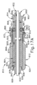
図6は、スピンアクチュエータ(610)(図2~図5)及びコレットカラー(630)(図2~図4)の代わりに、拡張器具(10)(図1A~図1D)との併用に好適な例示的なガイドワイヤ作動機構(810)を示す。図示されていないが、ガイドワイヤ作動機構(810)は、下記でより詳細に説明するように、ガイドワイヤ作動機構(810)が回転可能に装着される、上記の摺動アクチュエータ(650)(図2~図4)と同様の摺動可能な支持構造体を有するガイドワイヤ作動アセンブリ(図示せず)内に組み込まれてもよいことが理解されよう。図6に示すように、ガイドワイヤ作動機構(810)は、係合部材(812)と、中空シャフト(814)と、弾性把持部材(816)と、圧縮要素(818)と、圧縮部材(820)と、を含む。本実施例では、圧縮要素(818)はボール形態である。あるいは、圧縮要素(818)は、本明細書の教示を考慮することで当業者には明らかとなるように、様々な他の形態を取ってもよい。 FIG. 6 illustrates an exemplary guidewire actuation mechanism (810) suitable for use with the expansion device (10) (FIGS. 1A-1D) in place of the spin actuator (610) (FIGS. 2-5) and collet collar (630) (FIGS. 2-4). Although not illustrated, it will be understood that the guidewire actuation mechanism (810) may be incorporated into a guidewire actuation assembly (not shown) having a slidable support structure similar to the slide actuator (650) (FIGS. 2-4) described above, to which the guidewire actuation mechanism (810) is rotatably mounted, as described in more detail below. As shown in FIG. 6, the guidewire actuation mechanism (810) includes an engagement member (812), a hollow shaft (814), a resilient gripping member (816), a compression element (818), and a compression member (820). In this example, the compression element (818) is in the form of a ball. Alternatively, compression element (818) may take a variety of other forms, as will be apparent to those of ordinary skill in the art in view of the teachings herein.
ガイドワイヤ作動機構(810)は、図17A~図18Bに示され、以下でより詳細に説明されるように、様々な外径の細長い部材(802、803)上でロック及びロック解除するように構成されている。本実施例では、細長い部材(802)はガイドワイヤであるが、細長い部材(802)の他の変形例としては、拡張カテーテル、吸引器具カニューレ、内視鏡、及び/又は本明細書の教示を考慮することで当業者には明らかとなる様々な他の種類の細長い部材が挙げられ得る(ただしこれらに限定されない)。細長い部材(802)は、ガイドワイヤ作動機構(810)がロック解除状態にあるとき(図17A)、ガイドワイヤ作動機構(810)を通り長手方向軸(A1)に沿って並進する。ロック状態に達するために、圧縮部材(820)は、係合部材(812)に対して遠位方向に並進される。圧縮部材(820)は、圧縮要素(818)を弾性把持部材(816)に対して半径方向内向きに付勢して、弾性把持部材(816)を半径方向内向きに変形させて細長い部材(802)(図17B)を把持させ、それによって細長い部材(802)をロックする。図12に示すように、圧縮部材(820)は、弾性把持部材(816)が膨張状態へと付勢されることにより、圧縮部材(820)が近位方向に並進し、保持圧縮要素(retain compression element)(818)をロック解除することに抵抗するため、戻り止め機構(822)を有する円錐状の内側表面(880)を有する。戻り止め機構(822)はまた、ガイドワイヤ作動機構(810)が、様々な直径の細長い部材(802、803)をロックすることを可能にする。 The guidewire actuation mechanism (810) is configured to lock and unlock on elongated members (802, 803) of various outer diameters, as shown in FIGS. 17A-18B and described in more detail below. In this example, the elongated member (802) is a guidewire, but other variations of the elongated member (802) may include, but are not limited to, a dilatation catheter, an aspiration cannula, an endoscope, and/or various other types of elongated members that will be apparent to those skilled in the art in view of the teachings herein. The elongated member (802) translates along the longitudinal axis (A1) through the guidewire actuation mechanism (810) when the guidewire actuation mechanism (810) is in an unlocked state (FIG. 17A). To reach the locked state, the compression member (820) is translated distally relative to the engagement member (812). The compression member (820) biases the compression element (818) radially inward against the elastic gripping member (816) to deform the elastic gripping member (816) radially inward to grip the elongated member (802) (FIG. 17B), thereby locking the elongated member (802). As shown in FIG. 12, the compression member (820) has a conical inner surface (880) with a detent mechanism (822) to resist proximal translation of the compression member (820) and unlocking the retain compression element (818) when the elastic gripping member (816) is biased to an expanded state. The detent mechanism (822) also allows the guidewire actuation mechanism (810) to lock elongated members (802, 803) of various diameters.
図7~図8で最もよく示されるように、本実施例の係合部材(812)は、近位係合部材端部(826)と遠位係合部材端部(828)とを有する略管状本体(824)を含む。管状本体(824)は、長手方向軸(A1)(図6)に沿って軸方向に延びる第1の貫通穴(830)を含む。管状本体(824)は、管状本体(834)の外面上で互いに角度方向に離間配置された複数の半径方向に配向された指係合突出部(832)を有する。突出部(832)は、操作者によって係合されるように構成される。管状本体(824)はまた、近位係合部材端部(826)に近接した近位係合部材部分(836)を有する。近位係合部材端部(826)は、フレーム(660)(図4)の第1の端部分によって回転可能に支持されるように構成される。管状本体(824)は、遠位係合部材端部(828)から近位方向に延びる第1の穴ぐり(838)を有する。第1の穴ぐり(838)は、第1の貫通穴(830)よりも大きい直径を有する。第1の穴ぐり及び第1の貫通穴は、第1の穴ぐりの基部(842)から遠位方向に延びる突出部(840)を画定する。突出部(840)は、弾性把持部材(816)が長手方向軸(A1)(図6)に沿って近位方向に移動することを防止するように構成される。 As best shown in FIGS. 7-8, the engagement member (812) of this example includes a generally tubular body (824) having a proximal engagement member end (826) and a distal engagement member end (828). The tubular body (824) includes a first throughbore (830) extending axially along a longitudinal axis (A1) (FIG. 6). The tubular body (824) has a plurality of radially oriented finger engagement projections (832) angularly spaced apart from one another on an outer surface of the tubular body (834). The projections (832) are configured to be engaged by an operator. The tubular body (824) also has a proximal engagement member portion (836) proximal to the proximal engagement member end (826). The proximal engagement member end (826) is configured to be rotatably supported by a first end portion of the frame (660) (FIG. 4). The tubular body (824) has a first counterbore (838) extending proximally from the distal engagement member end (828). The first counterbore (838) has a larger diameter than the first throughbore (830). The first counterbore and the first throughbore define a protrusion (840) extending distally from a base (842) of the first counterbore. The protrusion (840) is configured to prevent the elastic gripping member (816) from moving proximally along the longitudinal axis (A1) (FIG. 6).
図9~図10は、略管状本体(844)と、近位シャフト端部(846)と、遠位シャフト端部(850)と、を含む、本実施例の中空シャフト(814)を示す。管状本体(844)は、環状リング(852)と、キー溝(854)と、第2の貫通穴(856)と、第2の穴ぐり(858)と、角度方向に離間配置された半径方向開口部(860)のアレイと、遠位シャフト部分(862)と、を有する。各半径方向開口部(860)は、遠位シャフト部分(862)の管状側壁(864)を通って半径方向に配設される。各半径方向開口部(860)は、対応する圧縮要素(818)(図6)を受容するようなサイズである。遠位シャフト部分(852)は、遠位シャフト端部(850)に近接しており、フレーム(652)(図4)の第2の端部分によって回転可能に支持されるように構成されている。 9-10 show the hollow shaft (814) of this example including a generally tubular body (844), a proximal shaft end (846), and a distal shaft end (850). The tubular body (844) has an annular ring (852), a keyway (854), a second throughbore (856), a second counterbore (858), an array of angularly spaced radial openings (860), and a distal shaft portion (862). Each radial opening (860) is radially disposed through a tubular sidewall (864) of the distal shaft portion (862). Each radial opening (860) is sized to receive a corresponding compression element (818) (FIG. 6). The distal shaft portion (852) is adjacent the distal shaft end (850) and is configured to be rotatably supported by a second end portion of the frame (652) (FIG. 4).
環状リング(852)は、遠位シャフト部分(862)に近接した管状本体(844)の管状側壁上に位置する。環状リング(852)は、ガイドワイヤ作動機構(810)を長手方向軸(A1)に沿って直線的に位置決めする。キー溝(854)は、管状側壁(864)内で遠位方向に延び、環状リング(852)において終端する。第2の穴ぐり(858)は、近接シャフト端部(proximate shaft end)(846)から第2の穴ぐり(858)の基部まで遠位方向に延びる。第2の穴ぐり(858)は、弾性把持部材(816)を受容するようなサイズである。第2の貫通穴(856)は、第2の穴ぐり(858)の基部から遠位シャフト端部(850)まで遠位方向に延びる。 The annular ring (852) is located on the tubular sidewall of the tubular body (844) proximate the distal shaft portion (862). The annular ring (852) linearly positions the guidewire actuation mechanism (810) along the longitudinal axis (A1). The keyway (854) extends distally within the tubular sidewall (864) and terminates at the annular ring (852). The second bore (858) extends distally from the proximate shaft end (846) to a base of the second bore (858). The second bore (858) is sized to receive the resilient gripping member (816). The second through hole (856) extends distally from a base of the second bore (858) to the distal shaft end (850).
図11~図12は、近位部材端部(868)と遠位部材端部(870)とを有する略環状本体(866)を有する、本実施例の圧縮部材(820)を示す。環状本体(866)は、環状本体(866)の外面上で互いに角度方向に離間配置された複数の半径方向に延びる指係合突起部(872)を有する。指係合突起部(872)は、操作者によって係合されるように構成される。圧縮部材(820)は、近位部材端部(868)から遠位部材端部(870)まで遠位方向に延びる第3の貫通穴(874)を通って中空シャフト(814)上に摺動可能に配設されるように構成される。第3の貫通穴(874)は、長手方向軸(A1)に沿って遠位方向に延びるキー溝突出部(876)を有する。キー溝突出部(876)は、中空シャフト(814)のキー溝(854)(図9)と摺動可能に嵌合するように構成されている。圧縮部材(820)は、中空シャフト(814)に沿ってロック位置とロック解除位置との間を長手方向に選択的に並進する。本実施例では、圧縮部材(820)はカラーの形態である。圧縮部材(820)は、圧縮要素(818)と係合するように構成された円錐状の内側表面(880)を含む。円錐状の内側表面(880)は、近位部材端部(868)から遠位部材端部(870)まで遠位方向に延びる。近位部材端部(868)は、遠位部材端部(870)に対してより小さい内径を有する。円錐状の内側表面(880)は、円錐状の内側表面(880)に沿って直線的に変位し、圧縮部材(820)を複数のロック位置に保持するように構成された、複数の戻り止め機構(822)を有する。各戻り止め機構(822)は、圧縮要素(818)(図6)を保持することによって異なるサイズの細長い部材(802、803)をロック位置に保持するように構成された弓状半径(884)を有する。本実施例における圧縮要素(818)は、ボールの形態である。戻り止め機構(822)は、操作者が、圧縮要素(818)をロック位置からロック解除位置へ、又はその逆に移行させるために、追加の長手方向力を加えることを必要とする。この追加の長手方向力は、操作者に触覚フィードバックを提供する。このフィードバックは、操作者が、圧縮要素(818)が戻り止め機構(822)によって保持されているかどうか区別することを補助する。加えて、戻り止め機構(822)は、圧縮部材(820)が誤って長手方向に滑ることを防止し、それによってロック状態を維持することを助ける。 11-12 show the compression member (820) of this example having a generally annular body (866) having a proximal member end (868) and a distal member end (870). The annular body (866) has a plurality of radially extending finger engagement projections (872) angularly spaced apart from one another on an outer surface of the annular body (866). The finger engagement projections (872) are configured to be engaged by an operator. The compression member (820) is configured to be slidably disposed on the hollow shaft (814) through a third throughbore (874) extending distally from the proximal member end (868) to the distal member end (870). The third throughbore (874) has a keyway projection (876) extending distally along the longitudinal axis (A1). The keyway protrusion (876) is configured to slidably mate with the keyway (854) (FIG. 9) of the hollow shaft (814). The compression member (820) selectively translates longitudinally along the hollow shaft (814) between locked and unlocked positions. In this example, the compression member (820) is in the form of a collar. The compression member (820) includes a conical inner surface (880) configured to engage the compression element (818). The conical inner surface (880) extends distally from a proximal member end (868) to a distal member end (870). The proximal member end (868) has a smaller inner diameter relative to the distal member end (870). The conical inner surface (880) has a plurality of detent features (822) configured to linearly displace along the conical inner surface (880) and to retain the compression member (820) in a plurality of locked positions. Each detent mechanism (822) has an arcuate radius (884) configured to retain the different sized elongated members (802, 803) in the locked position by retaining the compression element (818) (FIG. 6). The compression element (818) in this embodiment is in the form of a ball. The detent mechanism (822) requires the operator to apply an additional longitudinal force to transition the compression element (818) from the locked position to the unlocked position or vice versa. This additional longitudinal force provides tactile feedback to the operator. This feedback helps the operator distinguish whether the compression element (818) is being retained by the detent mechanism (822). In addition, the detent mechanism (822) prevents the compression member (820) from accidentally slipping longitudinally, thereby helping to maintain the locked state.
図13~図14は、ロック解除位置にあるガイドワイヤ作動機構(810)を示す。図13では、弾性把持部材(816)は膨張状態にあることに留意されたい。本実施例では、ガイドワイヤ作動機構(810)は、細長い部材(802、803)(図17~図18)、又は約2.2ミリメートルまでの直径を有する他の器具に適応するように構成されている。この最大直径は、弾性把持部材(816)が膨張状態にあるときの、弾性把持部材(816)(図6)の貫通穴(888)(図17A~図17B)の直径によって左右される。当然ながら、2.2ミリメートルは単なる例示的な一例にすぎない。あるいは、ガイドワイヤ作動機構(810)は、細長い部材(802、803)(図17A~図18B)又は最大で任意の他の好適な最大直径までの他の器具に適応するように構成されてもよい。 13-14 show the guidewire actuation mechanism (810) in an unlocked position. Note that in FIG. 13, the elastic gripping member (816) is in an expanded state. In this embodiment, the guidewire actuation mechanism (810) is configured to accommodate elongated members (802, 803) (FIGS. 17-18) or other instruments having a diameter of up to about 2.2 millimeters. This maximum diameter is governed by the diameter of the through hole (888) (FIGS. 17A-17B) of the elastic gripping member (816) (FIG. 6) when the elastic gripping member (816) is in an expanded state. Of course, 2.2 millimeters is merely an illustrative example. Alternatively, the guidewire actuation mechanism (810) may be configured to accommodate elongated members (802, 803) (FIGS. 17A-18B) or other instruments up to any other suitable maximum diameter.
図15~図16は、ロック状態にあるガイドワイヤ作動機構(810)を示す。弾性把持部材(816)は歪んだ状態にあり、弾性把持部材(816)は長手方向軸(A1)に向かって歪められていることに留意されたい。ロック状態では、適合され得る最小直径の細長い部材(802)は、0.75ミリメートルである。最小直径は、(弾性把持部材が歪んだ状態にあるときの)弾性把持部材の貫通穴(888)によって左右される。当然ながら、0.75ミリメートルは単なる例示的な一例にすぎない。あるいは、ガイドワイヤ作動機構(810)は、細長い部材(802、803)又は最小で任意の他の好適な最小直径までの他の器具に適応するように構成されてもよい。 15-16 show the guidewire actuation mechanism (810) in a locked state. Note that the elastic gripping member (816) is in a distorted state, with the elastic gripping member (816) distorted toward the longitudinal axis (A1). In the locked state, the smallest diameter of the elongated member (802) that can be accommodated is 0.75 millimeters. The smallest diameter is governed by the through hole (888) of the elastic gripping member (when the elastic gripping member is in a distorted state). Of course, 0.75 millimeters is merely an illustrative example. Alternatively, the guidewire actuation mechanism (810) may be configured to accommodate elongated members (802, 803) or other instruments down to any other suitable minimum diameter.
図17Aは、スピンアクチュエータ(810)をロック位置からロック解除位置まで移行させるガイドワイヤ作動機構(810)を示す。圧縮部材(820)は、長手方向軸(A1)に沿って近位方向に並進して、細長い部材(802)をロック解除する。弾性把持部材(816)は、弾性把持部材(816)を膨張状態に復元するように付勢される。膨張状態の弾性把持部材(816)は、略円筒状構成を有する。弾性把持部材(816)は、細長い部材(802)から半径方向に離れるように移動し、それによって、ガイドワイヤ作動機構(810)がロック解除状態にあるときに、ガイドワイヤ作動機構(810)を通した細長い部材(802)の並進を可能にする。把持部材の貫通穴(888)は、弾性把持部材(816)がロック解除位置にあるとき、第1の貫通穴(830)及び第2の貫通穴(856)のサイズに適合する。ロック解除状態では、弾性把持部材(816)は、中空シャフト(814)の第2の穴ぐり(858)、把持部材の貫通穴(888)によって画定される。細長い部材(802)は、ガイドワイヤ作動機構(810)を通して自由に並進され得る。 17A illustrates the guidewire actuation mechanism (810) transitioning the spin actuator (810) from a locked position to an unlocked position. The compression member (820) translates proximally along the longitudinal axis (A1) to unlock the elongated member (802). The elastic gripping member (816) is biased to restore the elastic gripping member (816) to an expanded state. In the expanded state, the elastic gripping member (816) has a generally cylindrical configuration. The elastic gripping member (816) moves radially away from the elongated member (802), thereby allowing translation of the elongated member (802) through the guidewire actuation mechanism (810) when the guidewire actuation mechanism (810) is in the unlocked state. The through hole (888) of the gripping member matches the size of the first through hole (830) and the second through hole (856) when the elastic gripping member (816) is in the unlocked position. In the unlocked state, the resilient gripping member (816) is defined by the second bore (858) of the hollow shaft (814), the through hole (888) of the gripping member. The elongate member (802) is free to translate through the guidewire actuation mechanism (810).
図17Bは、スピンアクチュエータ(810)をロック解除位置からロック位置まで移行させるガイドワイヤ作動機構(810)を示す。圧縮部材(820)は、長手方向軸(A1)に沿ってロック位置まで遠位方向に並進される。圧縮部材(820)が遠位方向に並進されると、圧縮部材(820)の円錐状の内側表面(880)は、圧縮要素(818)を細長い部材(802)に向かって半径方向内向きに付勢する。圧縮要素(818)は、弾性把持部材(816)を半径方向内向きに付勢し、弾性把持部材(816)を弾性的に変形させ、弾性把持部材(816)を細長い部材(802)に対して内向きに圧迫させ、摩擦によって細長い部材(802)をロックする。円錐状の内側表面(880)上の戻り止め機構(822)は、異なるサイズの細長い部材(802、803)(図18A~図18B)上で圧縮要素(818)をロック位置に保持する。 17B illustrates the guidewire actuation mechanism (810) transitioning the spin actuator (810) from an unlocked position to a locked position. The compression member (820) is translated distally along the longitudinal axis (A1) to the locked position. As the compression member (820) is translated distally, the conical inner surface (880) of the compression member (820) biases the compression element (818) radially inward toward the elongated member (802). The compression element (818) biases the elastic gripping member (816) radially inward, elastically deforming the elastic gripping member (816) and squeezing the elastic gripping member (816) inward against the elongated member (802), frictionally locking the elongated member (802). A detent mechanism (822) on the conical inner surface (880) holds the compression element (818) in a locked position on elongated members (802, 803) of different sizes (FIGS. 18A-18B).
図18A~図18Bは、細長い部材(802)の直径よりも大きい直径を有する異なる細長い部材(803)が取り付けられたガイドワイヤ作動機構(810)を示す。ほんの一例として、細長い部材(802)はガイドワイヤを備えてもよく、一方で細長い部材(803)は、拡張カテーテル、吸引カニューレ、内視鏡などを備える。図18A~図18Bの実施例では、細長い部材(803)は、ガイドワイヤ作動機構(810)の穴(830、856、874)内に配設される。図18Aは、ロック位置からロック解除位置まで移行するガイドワイヤ作動機構(810)を示す。図18Bは、ロック解除位置からロック位置まで移行するガイドワイヤ作動機構(810)を示す。 18A-18B show a guidewire actuation mechanism (810) with a different elongated member (803) attached thereto, the elongated member (802) having a diameter greater than that of the elongated member (802). By way of example only, the elongated member (802) may comprise a guidewire, while the elongated member (803) comprises a dilatation catheter, aspiration cannula, endoscope, and the like. In the embodiment of FIGS. 18A-18B, the elongated member (803) is disposed within the bores (830, 856, 874) of the guidewire actuation mechanism (810). FIG. 18A shows the guidewire actuation mechanism (810) transitioning from a locked position to an unlocked position. FIG. 18B shows the guidewire actuation mechanism (810) transitioning from an unlocked position to a locked position.
ロック位置では、圧縮部材(820)は、長手方向軸(A1)に沿って遠位方向に並進する。圧縮部材(820)が遠位方向に並進されると、圧縮部材(820)の円錐状の内側表面(880)は、圧縮要素(818)をガイドワイヤ(802、803)に向かって半径方向内向きに付勢する。圧縮要素(818)は、弾性把持部材(816)を半径方向内向きに付勢し、弾性把持部材(816)を弾性的に変形させ、弾性把持部材(816)をガイドワイヤ(802、803)に対して内向きに圧迫させ、摩擦によってガイドワイヤ(802、803)をロックする。円錐状の内側表面(880)上の戻り止め機構(822)は、異なるサイズの細長い部材(802、803)でロック位置に圧縮要素(818)を保持する。圧縮部材(820)は、より大きな細長い部材(803)が取り付けられたときの圧縮部材(820)ほど遠くに遠位方向に並進されないことに留意されたい。したがって、より大きな細長い部材(803)上では、圧縮要素(818)は、より小さな細長い部材(802)が取り付けられた場合と比較してより遠位に位置する戻り止め機構(822)と係合する。 In the locked position, the compression member (820) translates distally along the longitudinal axis (A1). As the compression member (820) translates distally, the conical inner surface (880) of the compression member (820) urges the compression element (818) radially inward toward the guidewires (802, 803). The compression element (818) urges the elastic gripping member (816) radially inward, elastically deforming the elastic gripping member (816) and squeezing the elastic gripping member (816) inward against the guidewires (802, 803), frictionally locking the guidewires (802, 803). A detent mechanism (822) on the conical inner surface (880) holds the compression element (818) in the locked position with the different sized elongated members (802, 803). Note that the compression member (820) is not translated distally as far as the compression member (820) when the larger elongate member (803) is attached. Thus, on the larger elongate member (803), the compression element (818) engages a more distally located detent mechanism (822) compared to when the smaller elongate member (802) is attached.
図19~図20Bは、上記のガイドワイヤ作動機構(810)と実質的に同様であるガイドワイヤ作動機構(910)の別の実施例を示す。本実施例では、ガイドワイヤ作動機構(910)は、係合部材(912)と、中空シャフト(914)と、弾性把持部材(916)と、圧縮要素(918)と、圧縮部材(920)と、を含む。ガイドワイヤ作動機構(910)はまた、異なる直径の細長い部材(802、803)上でロック及びロック解除するように構成されている。本実施例では、中空シャフト(914)は一体化された圧縮要素(918)を有し、圧縮要素(818)は中空シャフト(814)とは分離しているという点で、中空シャフト(914)は中空シャフト(814)とは異なる。中空シャフト(914)は、可撓性アーム(921)形態の複数の圧縮要素(918)を含む。各可撓性アーム(921)は、可撓性アーム(924)の基端部から弓状突出部(926)まで遠位方向に延びる可撓性アーム本体(923)を有する。各可撓性アーム(924)の基端部は、中空シャフト(914)に一体的に取り付けられている。各可撓性アーム(921)は、可撓性アーム(924)の基端部から遠位に位置する弓状突出部(926)を有する。各弓状突出部(926)は、圧縮部材(920)が遠位方向に並進されると円錐状の内側表面(914)と係合するように構成されている。圧縮部材(920)はまた、円錐状の内側表面(880)と同様の円錐状の内側表面(980)を有する。円錐状の内側表面(980)はまた、複数の戻り止め機構(922)を有する。弓状突出部(926)は、複数の戻り止め機構(922)によって保持されるように構成される。弓状突出部(926)は、圧縮要素(818)と同様に作用する。しかしながら、弾性把持部材(916)と同様に、可撓性アーム(921)は、膨張した静止状態へと弾性的に付勢される。 19-20B show another embodiment of a guidewire actuation mechanism (910) that is substantially similar to the guidewire actuation mechanism (810) described above. In this embodiment, the guidewire actuation mechanism (910) includes an engagement member (912), a hollow shaft (914), a resilient gripping member (916), a compression element (918), and a compression member (920). The guidewire actuation mechanism (910) is also configured to lock and unlock on elongated members (802, 803) of different diameters. In this embodiment, the hollow shaft (914) differs from the hollow shaft (814) in that the hollow shaft (914) has an integrated compression element (918) and the compression element (818) is separate from the hollow shaft (814). The hollow shaft (914) includes multiple compression elements (918) in the form of flexible arms (921). Each flexible arm (921) has a flexible arm body (923) that extends distally from a proximal end of the flexible arm (924) to an arcuate projection (926). The proximal end of each flexible arm (924) is integrally attached to the hollow shaft (914). Each flexible arm (921) has an arcuate projection (926) located distally from the proximal end of the flexible arm (924). Each arcuate projection (926) is configured to engage the conical inner surface (914) when the compression member (920) is translated distally. The compression member (920) also has a conical inner surface (980) similar to the conical inner surface (880). The conical inner surface (980) also has a plurality of detent features (922). The arcuate projection (926) is configured to be retained by the plurality of detent features (922). The arcuate projection (926) acts similarly to the compression element (818); however, similar to the elastic gripping member (916), the flexible arm (921) is elastically biased to an expanded resting state.
図20Aは、ロック解除位置にあるガイドワイヤ作動機構(910)を示す。ロック解除位置にあるとき、可撓性アーム(921)は、真っ直ぐな構成へと半径方向外側に弾性的に戻り、弾性把持部材(916)は膨張状態へと付勢される。膨張状態にある弾性把持部材(916)は、より大きな直径の把持部材穴(988)を有する。 Figure 20A shows the guidewire actuation mechanism (910) in an unlocked position. When in the unlocked position, the flexible arms (921) resiliently return radially outward to a straight configuration and the elastic gripping members (916) are biased to an expanded state. In the expanded state, the elastic gripping members (916) have a larger diameter gripping member hole (988).
図20Bは、ロック位置にあるガイドワイヤ作動機構(910)を示す。ロック位置にあるとき、可撓性アーム(921)は、円錐状の内側表面(980)によって係合されたことに応答して半径方向内向きに変形して、弾性把持部材(916)と係合し、それによって、弾性把持部材(916)を変形させて、把持部材穴(988)の有効内径を減少させ、それによって細長い部材(802)を把持する。 Figure 20B shows the guidewire actuation mechanism (910) in a locked position. When in the locked position, the flexible arms (921) deform radially inward in response to being engaged by the conical inner surface (980) to engage the resilient gripping member (916), thereby deforming the resilient gripping member (916) and reducing the effective inner diameter of the gripping member bore (988), thereby gripping the elongate member (802).
ガイドワイヤ作動機構(810、910)は、ガイドワイヤ(802、803)を選択的に把持、回転、及び並進させるものとして上記で説明されてきたが、あるいは、ガイドワイヤ作動機構(810、910)は、実質的にあらゆる可撓性器具を選択的に把持し、回転させ、並進させるように用いてもよいことを理解されたい。ガイドワイヤ(602)の代わりにガイドワイヤ作動機構と組み合わせて使用され得る可撓性器具又は他の細長い部材(802、803)の単に例示的な実施例としては、RFアブレーションカテーテル、バルーン拡張カテーテル、生検器具、及び他の可撓性器具が挙げられるが、これらに限定されない。ガイドワイヤ(602)の代わりにガイドワイヤ作動機構(810、910)と組み合わせて使用され得る可撓性器具又は他の細長い部材(802、803)の他の例は、本明細書の教示を考慮すれば当業者には明らかとなるであろう。 Although the guidewire actuation mechanism (810, 910) has been described above as selectively gripping, rotating, and translating the guidewire (802, 803), it should be understood that the guidewire actuation mechanism (810, 910) may alternatively be used to selectively grip, rotate, and translate virtually any flexible instrument. Merely illustrative examples of flexible instruments or other elongated members (802, 803) that may be used in combination with the guidewire actuation mechanism in place of the guidewire (602) include, but are not limited to, RF ablation catheters, balloon dilation catheters, biopsy instruments, and other flexible instruments. Other examples of flexible instruments or other elongated members (802, 803) that may be used in combination with the guidewire actuation mechanism (810, 910) in place of the guidewire (602) will be apparent to those skilled in the art in view of the teachings herein.
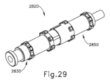
III.ねじ式ロック部材を有する例示的なガイドワイヤ作動機構
図21~図27Bは、本明細書で別途明示的に記載されることを除いては上述のガイドワイヤ作動機構(910)と実質的に同様である、ガイドワイヤ作動機構(1810)の更に別の例を示す。ガイドワイヤ作動機構(910)と同様に、ガイドワイヤ作動機構(1810)は、スピンアクチュエータ(610)(図2~図5)及びコレットカラー(630)(図2~図4)の代わりに、拡張器具(10)(図1A~図1D)との併用に好適である。図示されていないが、スピンアクチュエータ(1810)は、ガイドワイヤ作動機構(1810)が回転可能に装着される上記の摺動アクチュエータ(650)(図2~図4)と同様の摺動可能な支持構造体を有するガイドワイヤ作動アセンブリ(図示せず)内に組み込まれてもよいことが理解されよう。
III. Exemplary Guidewire Actuation Mechanism with Threaded Locking Member FIGS. 21-27B show yet another example of a guidewire actuation mechanism (1810), which is substantially similar to the guidewire actuation mechanism (910) described above, except as otherwise expressly described herein. Like the guidewire actuation mechanism (910), the guidewire actuation mechanism (1810) is suitable for use with the expansion device (10) (FIGS. 1A-1D) in place of the spin actuator (610) (FIGS. 2-5) and collet collar (630) (FIGS. 2-4). Although not shown, it will be understood that the spin actuator (1810) may be incorporated into a guidewire actuation assembly (not shown) having a slidable support structure similar to the slide actuator (650) (FIGS. 2-4) described above to which the guidewire actuation mechanism (1810) is rotatably mounted.
上述したように、ガイドワイヤ作動機構(910)は、圧縮部材(920)を長手方向に並進させることによって、細長い部材(802)をガイドワイヤ作動機構(910)に対して固定し、これにより弾性把持部材が細長い部材(802)と摩擦係合する。ガイドワイヤ作動機構(910)と同様に、ガイドワイヤ作動機構(1810)はまた、細長い部材(802)をガイドワイヤ作動機構(810)に対して固定するようにも構成されている。しかしながら、細長い部材(802)を固定するために長手方向運動を利用するガイドワイヤ作動機構(910)とは異なり、下記でより詳細に説明するように、本実施例のガイドワイヤ作動機構(1810)は、長手方向軸(A1)を中心とした回転運動を利用することによって細長い部材(802)を固定する。 As described above, the guidewire actuation mechanism (910) secures the elongated member (802) relative to the guidewire actuation mechanism (910) by longitudinally translating the compression member (920), which causes the elastic gripping member to frictionally engage the elongated member (802). Similar to the guidewire actuation mechanism (910), the guidewire actuation mechanism (1810) is also configured to secure the elongated member (802) relative to the guidewire actuation mechanism (810). However, unlike the guidewire actuation mechanism (910), which utilizes longitudinal motion to secure the elongated member (802), the guidewire actuation mechanism (1810) of this embodiment secures the elongated member (802) by utilizing rotational motion about the longitudinal axis (A1), as described in more detail below.
ガイドワイヤ作動機構(1810)は、第1の連結部材(1812)と、第2の連結部材(1830)と、アセンブリ(1810)の長手方向軸(A1)に沿って第1の連結部材(1812)及び第2の連結部材(1830)の対面する端部間に配置された圧縮性本体(1840)と、を含む。下記でより詳細に説明されるように、第1の連結部材(1812)及び第2の連結部材(1830)は、長手方向軸(A1)を中心とした相対的回転を介して一体にねじ結合して、圧縮性本体(1840)を半径方向内向きに圧縮して、細長い部材(802)と摩擦係合するように構成されている。連結部材(1812、1830)間の相対的回転に応答して十分に圧縮された状態に達すると、圧縮性本体(1840)は、細長い部材(802)をガイドワイヤ作動機構(1810)に対して軸方向及び回転方向に固定する。 The guidewire actuation mechanism (1810) includes a first coupling member (1812), a second coupling member (1830), and a compressible body (1840) disposed between opposing ends of the first coupling member (1812) and the second coupling member (1830) along the longitudinal axis (A1) of the assembly (1810). As described in more detail below, the first coupling member (1812) and the second coupling member (1830) are configured to threadably couple together via relative rotation about the longitudinal axis (A1) to compress the compressible body (1840) radially inwardly into frictional engagement with the elongated member (802). Upon reaching a fully compressed state in response to relative rotation between the coupling members (1812, 1830), the compressible body (1840) axially and rotationally secures the elongated member (802) to the guidewire actuation mechanism (1810).
図23~図24で最も良く示されるように、本実施例の第1の連結部材(1812)は、近位端部(1824)と、遠位端部(1826)と、長手方向軸(A1)(図22)に沿って近位端(1824)と遠位端部(1826)との間を延びる第1の貫通穴(1820)と、を有する略管状本体(1822)を含む。第1の連結部材(1812)の管状本体(1822)は、近位端部(1824)に配置されたカラー(1814)と、カラー(1814)から遠位方向に延びる第1の近位シャフト部分(1816)と、第1の近位シャフト部分(1816)から遠位方向に延びる第1の遠位シャフト部分(1818)と、を含む。第1の遠位シャフト部分(1818)は、第1の遠位シャフト部分(1818)の外部に半径方向に配置され、ユーザによって係合されるように構成された複数の指係合突出部(1842)を有する。第1の連結部材(1812)の遠位端部(1826)は、下記でより詳細に説明するように、第2の連結部材(1830)(図25~図27B)の第2のねじ山付き部分(1846)(図25)にねじ式に係合するように構成された第1のねじ山付き部分(1844)を含む。本変形例では、第1のねじ山付き部分(1844)は、雄右ねじを含む。しかしながら、第1のねじ山付き部分(1844)が第2のねじ山付き部分(1846)とねじ式に係合するように構成されている限り、他の変形例では、第1のねじ山付き部分(1844)は左ねじ及び/又は雌ねじを含んでもよいことが理解されよう。いくつかの他の変形例では、連結部材(1812、1830)は、ねじ山付き部分(1844、1846)を介する代わりにバヨネット取付具を介して一体に連結される。ねじ山付き部分(1844、1846)が補完的なバヨネット取付具部分に置き換えられ得る様々な好適な方法は、本明細書の教示を鑑みれば当業者には明らかとなろう。 As best shown in FIGS. 23-24, the first coupling member (1812) of this embodiment includes a generally tubular body (1822) having a proximal end (1824), a distal end (1826), and a first through hole (1820) extending between the proximal end (1824) and the distal end (1826) along a longitudinal axis (A1) (FIG. 22). The tubular body (1822) of the first coupling member (1812) includes a collar (1814) disposed at the proximal end (1824), a first proximal shaft portion (1816) extending distally from the collar (1814), and a first distal shaft portion (1818) extending distally from the first proximal shaft portion (1816). The first distal shaft portion (1818) has a plurality of finger engagement protrusions (1842) disposed radially on the exterior of the first distal shaft portion (1818) and configured to be engaged by a user. The distal end (1826) of the first coupling member (1812) includes a first threaded portion (1844) configured to threadably engage a second threaded portion (1846) (FIG. 25) of a second coupling member (1830) (FIGS. 25-27B), as described in more detail below. In this variation, the first threaded portion (1844) includes male right-handed threads. However, it will be understood that in other variations, the first threaded portion (1844) may include left-handed threads and/or female threads, so long as the first threaded portion (1844) is configured to threadably engage the second threaded portion (1846). In some other variations, the coupling members (1812, 1830) are coupled together via a bayonet attachment instead of via the threaded portions (1844, 1846). Various suitable ways in which the threaded portions (1844, 1846) may be replaced with complementary bayonet attachment portions will be apparent to those of skill in the art in view of the teachings herein.
第1の連結部材(1812)の遠位端部(1826)は、第1の貫通穴(1820)と連通する第1の穴ぐり(1856)を画定する。第1の穴ぐり(1856)は、第1の貫通穴(1820)よりも大きい直径を有する。円錐形表面(1854)は、第1の穴ぐり(1856)の近位端部に位置決めされ、より大きい第1の直径(1860)からより小さい第2の直径(1862)にかけて近位方向に先細となる。下記でより詳細に説明するように、円錐形表面(1854)は、第2の連結部材(1830)(図25~図27B)の円筒形突出部(1864)(図25)と協働して、これらの間で圧縮性本体(1840)を軸方向に圧縮し、それにより、圧縮性本体を細長い部材(802)(図27B)に対して半径方向内向きに変形させるように構成されている。 The distal end (1826) of the first connecting member (1812) defines a first bore (1856) in communication with the first through hole (1820). The first bore (1856) has a larger diameter than the first through hole (1820). A conical surface (1854) is positioned at the proximal end of the first bore (1856) and tapers proximally from a larger first diameter (1860) to a smaller second diameter (1862). As described in more detail below, the conical surface (1854) is configured to cooperate with the cylindrical protrusion (1864) (FIG. 25) of the second connecting member (1830) (FIGS. 25-27B) to axially compress the compressible body (1840) therebetween, thereby deforming the compressible body radially inward relative to the elongate member (802) (FIG. 27B).
図25~図26で最も良く示されるように、本実施例の第2の連結部材(1830)は、近位端部(1834)と、遠位端部(1836)と、長手方向軸(A1)(図22)に沿って近位端部(1834)と遠位端部(1836)との間を軸方向に延びる第2の貫通穴(1848)と、を有する略管状本体(1832)を含む。第2の連結部材(1830)は、第2の近位シャフト部分(1850)及び第2の遠位シャフト部分(1852)を含む。第2の近位シャフト部分(1850)は、第2の遠位シャフト部分(1852)と比較して直径が大きい。第2の近位シャフト部分(1850)は、第2の近位シャフト部分(1850)の外部に半径方向に配置され、ユーザによって係合されるように構成された複数の指係合突出部(1872)を有する。第2の連結部材(1830)の近位端部(1834)は、第2の穴ぐり(1858)を更に含む。第2の穴ぐり(1858)を画定する内壁は、連結部材(1812、1830)が互いに対して回転されると第1の連結部材(1812)の第1のねじ山付き部分(1844)とねじ式に係合するように構成された、第2のねじ山付き部分(1846)を有する。本変形例では、第2のねじ山付き部分(1846)は、雌右ねじを含む。しかしながら、第2のねじ山付き部分(1846)が第1のねじ山付き部分(1844)とねじ式に係合するように構成されている限り、他の変形例では、第2のねじ山付き部分(1846)は左ねじ及び/又は右雌ねじを含んでもよいことが理解されよう。第2の連結部材(1812)の近位端部(1834)は、第2の穴ぐり(1858)の遠位基部表面から近位方向に延び、第2の貫通穴(1848)の近位端部を画定する、円筒形突出部(1864)を更に含む。 As best shown in FIGS. 25-26, the second coupling member (1830) of this embodiment includes a generally tubular body (1832) having a proximal end (1834), a distal end (1836), and a second through hole (1848) extending axially between the proximal end (1834) and the distal end (1836) along a longitudinal axis (A1) (FIG. 22). The second coupling member (1830) includes a second proximal shaft portion (1850) and a second distal shaft portion (1852). The second proximal shaft portion (1850) has a larger diameter compared to the second distal shaft portion (1852). The second proximal shaft portion (1850) has a plurality of finger engagement protrusions (1872) radially disposed on the exterior of the second proximal shaft portion (1850) and configured to be engaged by a user. The proximal end (1834) of the second connecting member (1830) further includes a second counterbore (1858). The inner wall defining the second counterbore (1858) has a second threaded portion (1846) configured to threadably engage with the first threaded portion (1844) of the first connecting member (1812) when the connecting members (1812, 1830) are rotated relative to one another. In this variation, the second threaded portion (1846) includes right-handed female threads. However, it will be understood that in other variations, the second threaded portion (1846) may include left-handed threads and/or right-handed female threads, so long as the second threaded portion (1846) is configured to threadably engage with the first threaded portion (1844). The proximal end (1834) of the second connecting member (1812) further includes a cylindrical protrusion (1864) extending proximally from the distal base surface of the second bore (1858) and defining the proximal end of the second through hole (1848).
図22で最もよく示されるように、本実施例の圧縮性本体(1840)は、略環状の形状を有する。更に、圧縮性本体(1840)は、ゴム又はゴム様材料などの、半径方向に膨張した非圧縮状態と半径方向に圧縮された状態との間で弾性的に移行することを可能にするエラストマー材料から構成されてもよい。図27A及び図27Bに示されるように、圧縮性本体(1840)は、第1の連結部材(1812)の第1の穴ぐり(1856)内で、円錐形表面(1854)に対して位置決めされる。本実施例の圧縮性本体(1840)は、長手方向軸(A1)に沿って第1の貫通穴(1820)及び第2の貫通穴(1848)と同軸状に整列ように構成された穴(1828)を画定しており、圧縮性本体(1840)の穴(1828)を通して細長い部材(802)を軸方向に受け入れる。 As best shown in FIG. 22, the compressible body (1840) of this embodiment has a generally annular shape. Additionally, the compressible body (1840) may be constructed from an elastomeric material, such as rubber or a rubber-like material, that allows it to resiliently transition between a radially expanded uncompressed state and a radially compressed state. As shown in FIGS. 27A and 27B, the compressible body (1840) is positioned against the conical surface (1854) within the first bore (1856) of the first connecting member (1812). The compressible body (1840) of this embodiment defines a bore (1828) configured to be coaxially aligned with the first through bore (1820) and the second through bore (1848) along the longitudinal axis (A1) and axially receive the elongated member (802) through the bore (1828) of the compressible body (1840).
図27Aに示すように、圧縮性本体(1840)は、細長い部材(802)が、第1の連結部材(1812)、第2の連結部材(1830)、及び圧縮性本体(1840)を通って自由に並進可能である、半径方向膨張状態に向けて弾性的に付勢される。図27Bに示すように、圧縮性本体(1840)は、第1の連結部材(1812)と第2の連結部材(1830)との間の相対的回転に応答して半径方向内向きに圧縮し、その結果、穴(1828)が細長い部材(802)の周囲を閉鎖するように構成されている。下記で説明する通り、この半径方向圧縮により、圧縮性本体(1840)が細長い部材(802)と摩擦係合し、それによって、細長い部材(802)を第1の連結部材(1812)及び第2の連結部材(1830)に対して軸方向及び回転方向に固定させる。 As shown in FIG. 27A, the compressible body (1840) is resiliently biased toward a radially expanded state in which the elongated member (802) is freely translatable through the first connecting member (1812), the second connecting member (1830), and the compressible body (1840). As shown in FIG. 27B, the compressible body (1840) is configured to compress radially inward in response to relative rotation between the first connecting member (1812) and the second connecting member (1830), such that the bore (1828) closes around the elongated member (802). As described below, this radial compression causes the compressible body (1840) to frictionally engage the elongated member (802), thereby axially and rotationally fixing the elongated member (802) relative to the first connecting member (1812) and the second connecting member (1830).
図27Aは、第1の連結部材(1812)の第1のねじ山付き部分(1844)が第2の連結部材(1830)の第2のねじ山付き部分(1846)から少なくとも部分的に螺出されている(de-threaded)、例示的なロック解除状態にあるガイドワイヤ作動機構(1810)を示す。ロック解除状態では、圧縮性本体(1840)は、穴(1828)が細長い部材(802)の周囲で拡大され、それによって細長い部材(802)がガイドワイヤ作動機構(1810)を通って軸方向に自由に並進することができるように、非圧縮状態にある。図27Aは、ガイドワイヤアクチュエータアセンブリ(1810)がロック解除状態にあるときの圧縮性本体(1840)と円錐形表面(1854)との間の軸方向の間隙を示しているが、圧縮性本体(1840)は、非圧縮の状態のままで、円錐形表面(1854)と直接接触して位置決めされ得ることが理解されるであろう。 27A illustrates the guidewire actuation mechanism (1810) in an exemplary unlocked state in which the first threaded portion (1844) of the first coupling member (1812) is at least partially de-threaded from the second threaded portion (1846) of the second coupling member (1830). In the unlocked state, the compressible body (1840) is in an uncompressed state such that the bore (1828) is enlarged around the elongated member (802) thereby allowing the elongated member (802) to freely translate axially through the guidewire actuation mechanism (1810). Although FIG. 27A illustrates an axial gap between the compressible body (1840) and the conical surface (1854) when the guidewire actuator assembly (1810) is in the unlocked state, it will be understood that the compressible body (1840) may remain in an uncompressed state and be positioned in direct contact with the conical surface (1854).
図27Bは、第1の連結部材(1812)及び第2の連結部材(1830)が圧縮性本体(1840)を軸方向に圧縮して、その結果、圧縮性本体(1872)が半径方向内向きに弾性変形して、細長い部材(802)と摩擦係合(又は「把持」)している、ロック状態にあるガイドワイヤ作動機構(1810)を示す。図27Aに示されるロック解除状態から図27Bに示されるロック状態へとガイドワイヤ作動機構(1810)を移行させることは、第1の連結部材(1812)と第2の連結部材(1830)との間の相対的回転を提供し、その結果、第1のねじ山付き部分(1844)及び第2のねじ山付き部分(1846)が完全に係合し、連結部材(1812、1830)を互いに向けて軸方向に駆動することによって達成される。第1のねじ山付き部分(1844)及び第2のねじ山付き部分(1846)のこのねじ式係合に応答して、第2の連結部材(1830)の円筒形突出部(1864)は、第1の連結部材(1812)の円錐形表面(1854)に対して圧縮性本体(1840)を軸方向に圧縮する。円筒形突出部(1864)が前進して円錐形表面(1854)に近づくと、円錐形表面(1854)は、圧縮性本体(1840)の外径に漸進的に増加する内向き半径方向力を及ぼし、それにより圧縮性本体(1840)を細長い部材(802)の周囲で半径方向内向きに変形させる。連結部材(1812、1830)の互いに対する連続的なねじ式係合により、圧縮性本体(1840)は、圧縮性本体(1840)が細長い部材(802)に摩擦係合して、それによって、細長い部材(802)を第1の連結部材(1812)及び第2の連結部材(1830)に対して軸方向及び回転方向に固定する点まで、半径方向内向きに圧縮する。 27B illustrates the guidewire actuation mechanism (1810) in a locked state in which the first and second coupling members (1812 and 1830) axially compress the compressible body (1840) such that the compressible body (1872) elastically deforms radially inward and frictionally engages (or "grapples") the elongate member (802). Transitioning the guidewire actuation mechanism (1810) from the unlocked state illustrated in FIG. 27A to the locked state illustrated in FIG. 27B is accomplished by providing relative rotation between the first and second coupling members (1812 and 1830) such that the first and second threaded portions (1844 and 1846) fully engage and drive the coupling members (1812, 1830) axially toward one another. In response to this threaded engagement of first threaded portion (1844) and second threaded portion (1846), cylindrical protrusion (1864) of second connecting member (1830) axially compresses compressible body (1840) against conical surface (1854) of first connecting member (1812). As cylindrical protrusion (1864) advances and approaches conical surface (1854), conical surface (1854) exerts a progressively increasing inward radial force on the outer diameter of compressible body (1840), thereby deforming compressible body (1840) radially inward about elongated member (802). The continued threaded engagement of the coupling members (1812, 1830) relative to one another causes the compressible body (1840) to compress radially inwardly to the point where the compressible body (1840) frictionally engages the elongated member (802), thereby axially and rotationally fixing the elongated member (802) relative to the first coupling member (1812) and the second coupling member (1830).
ガイドワイヤ作動アセンブリ(1810)は、第1の連結部材(1812)及び第2の連結部材(1830)を回転的に互いから螺出させることによって、ロック状態からロック解除状態に戻され得ることが理解されるであろう。本明細書で使用するとき、用語「螺出」は、連結部材(1812、1830)が互いに完全に分離されることを必要とするように読み取られるべきではない。代わりに、この用語は、図27Bに示される状態から図27Aに示される状態であって、連結部材(1812、1830)は共に結合されたままであるが、もはや協働して圧縮性本体(1840)を細長い部材(802)に対して圧縮していない状態への移行を含むものとして読み取られるべきである。 It will be appreciated that the guidewire actuation assembly (1810) may be returned from a locked state to an unlocked state by rotationally unscrewing the first coupling member (1812) and the second coupling member (1830) from one another. As used herein, the term "screwing" should not be read to require that the coupling members (1812, 1830) be completely separated from one another. Instead, the term should be read to include a transition from the state shown in FIG. 27B to the state shown in FIG. 27A, where the coupling members (1812, 1830) remain coupled together but no longer cooperate to compress the compressible body (1840) against the elongate member (802).
ロック解除状態(図27A)とロック状態(図27B)との間を移行するための第1の連結部材(1812)と第2の連結部材(1830)との間の相対的回転は、対向する連結部材(1812、1830)が静止したままの状態で一方の連結部材(1812、1830)を回転させることによって達成することができる。他の変形例では、両方の連結部材(1812、1830)は、互いに対して反対方向に回転させることができる。いずれの場合も、ガイドワイヤ作動アセンブリ(1810)は、上記の摺動アクチュエータ(650)(図2~図5)と同様であり得る支持構造体に好適に装着されており、その結果、両方の連結部材(1812、1830)が支持構造体に対して回転可能であり、また、その結果、連結部材(1812、1830)のうちの少なくとも1つが支持構造体に対して並進可能であることが理解されよう。こうした構成により、連結部材(1812、1830)の互いに対する回転及び支持構造体に対する回転、並びに、上述したようなねじ山付き部分(1844、1846)の回転螺入及び螺出中の連結部材(1812、1830)の軸方向の前進及び分離が可能となる。いくつかの変形例では、第1の連結部材(1812)は、第1の近位シャフト部分(1816)に沿って支持構造体(図示せず)の第1の端部分に回転可能かつ並進可能に装着されてもよく、第2の連結部材(1830)は、第2の遠位シャフト部分(1852)に沿って支持構造体(図示せず)の第2の端部分に回転可能に装着されてもよい。 Relative rotation between the first and second coupling members (1812, 1830) to transition between the unlocked (FIG. 27A) and locked (FIG. 27B) states can be accomplished by rotating one coupling member (1812, 1830) while the opposing coupling member (1812, 1830) remains stationary. In other variations, both coupling members (1812, 1830) can be rotated in opposite directions relative to one another. In either case, it will be appreciated that the guidewire actuation assembly (1810) is suitably mounted to a support structure, which may be similar to the slide actuator (650) (FIGS. 2-5) described above, such that both coupling members (1812, 1830) are rotatable relative to the support structure, and also such that at least one of the coupling members (1812, 1830) is translatable relative to the support structure. Such a configuration allows for rotation of the coupling members (1812, 1830) relative to each other and to the support structure, as well as axial advancement and separation of the coupling members (1812, 1830) during rotational threading and unthreading of the threaded portions (1844, 1846) as described above. In some variations, the first coupling member (1812) may be rotatably and translatably mounted to a first end portion of the support structure (not shown) along a first proximal shaft portion (1816), and the second coupling member (1830) may be rotatably mounted to a second end portion of the support structure (not shown) along a second distal shaft portion (1852).
上述したように、図示される例示的な変形例の圧縮性本体(1840)は、円筒形突出部(1864)と円錐形表面(1854)との間で圧縮される。他の変形例では、当業者には容易に明らかである様々な他の好適な構造体を導入して、圧縮性本体(1840)を圧縮することができる。例えば、第1の連結部材(1812)及び第2の連結部材(1830)は、2つの対向する突出部(1864)、又は2つの対向する円錐形表面(1854)を含んでもよい。 As described above, the compressible body (1840) of the illustrated exemplary variation is compressed between the cylindrical protrusion (1864) and the conical surface (1854). In other variations, various other suitable structures, readily apparent to one skilled in the art, can be implemented to compress the compressible body (1840). For example, the first connecting member (1812) and the second connecting member (1830) may include two opposing protrusions (1864) or two opposing conical surfaces (1854).
ガイドワイヤ作動機構(1810)は、細長い部材(802)を選択的に把持、回転、及び並進させるものとして上記で説明されてきたが、あるいは、ガイドワイヤ作動機構(1810)は、実質的にあらゆる可撓性器具を選択的に把持し、回転させ、並進させるように用いてもよいことを理解されたい。ガイドワイヤ(602)の代わりにガイドワイヤ作動機構(1810)と組み合わせて使用され得る可撓性器具又は他の細長い部材(802、803)の単に例示的な実施例としては、RFアブレーションカテーテル、バルーン拡張カテーテル、生検器具、及び他の可撓性器具が挙げられるが、これらに限定されない。ガイドワイヤ(602)の代わりにガイドワイヤ作動機構(1810)と組み合わせて使用され得る可撓性器具又は他の細長い部材(802、803)の他の例は、本明細書の教示を考慮すれば当業者には明らかとなるであろう。 Although the guidewire actuation mechanism (1810) has been described above as selectively gripping, rotating, and translating the elongated member (802), it should be understood that the guidewire actuation mechanism (1810) may alternatively be used to selectively grip, rotate, and translate virtually any flexible instrument. Merely illustrative examples of flexible instruments or other elongated members (802, 803) that may be used in combination with the guidewire actuation mechanism (1810) in place of the guidewire (602) include, but are not limited to, RF ablation catheters, balloon dilation catheters, biopsy instruments, and other flexible instruments. Other examples of flexible instruments or other elongated members (802, 803) that may be used in combination with the guidewire actuation mechanism (1810) in place of the guidewire (602) will be apparent to those skilled in the art in view of the teachings herein.
IV.選択的把持機構を有する例示的なガイドワイヤ作動機構
図28は、ガイドワイヤ作動アセンブリ(2800)内に取り付けられた、更に別の例示的な代替のガイドワイヤ作動機構(2820)を示す。この例示的な代替のガイドワイヤ作動機構(2820)は、本明細書内で別途明示的に記載されていることを除いて、上述のガイドワイヤ作動機構(1810)(図21~図22)と実質的に同様である。ガイドワイヤ作動機構(1810)(図21~図22)のように、ガイドワイヤ作動機構(2800)は、スピンアクチュエータ(610)(図2~図5)及びコレットカラー(630)(図2~図4)の代わりに拡張器具(10)(図1A~図1D)に組み込むことができる。ガイドワイヤ作動機構(1810)及びガイドワイヤ作動機構(2820)は両方とも、細長い部材(802)を把持する弾性部材(1840、2820)を有する。ガイドワイヤ作動機構(1810)は、圧縮性本体(1840)に力を加えることによって細長い部材(802)を把持する。対照的に、本実施例のガイドワイヤ作動機構(2820)は、下記で更に説明するように、把持部材(2860)上で力を解放することによって細長い部材(802)を把持する。
IV. Exemplary Guidewire Actuation Mechanism with Selective Grip Mechanism FIG. 28 illustrates yet another exemplary alternative guidewire actuation mechanism (2820) mounted within a guidewire actuation assembly (2800). This exemplary alternative guidewire actuation mechanism (2820) is substantially similar to the guidewire actuation mechanism (1810) (FIGS. 21-22) described above, except as otherwise expressly described herein. Like the guidewire actuation mechanism (1810) (FIGS. 21-22), the guidewire actuation mechanism (2800) may be incorporated into the expander device (10) (FIGS. 1A-1D) in place of the spin actuator (610) (FIGS. 2-5) and collet collar (630) (FIGS. 2-4). Both the guidewire actuation mechanism (1810) and the guidewire actuation mechanism (2820) have resilient members (1840, 2820) that grip the elongate member (802). Guidewire actuation mechanism (1810) grips elongate member (802) by applying a force to compressible body (1840). In contrast, guidewire actuation mechanism (2820) of this example grips elongate member (802) by releasing a force on gripping member (2860), as described further below.
本実施例のガイドワイヤ作動アセンブリ(2800)は、摺動アクチュエータ(2810)及びガイドワイヤ作動機構(2820)を備える。摺動アクチュエータ(2810)は、ハンドルアセンブリ(500)と摺動可能に連結され、それによって細長い部材(802)をハンドルアセンブリ(500)に対して長手方向に並進させるように構成されている。ガイドワイヤ作動機構(2820)は、細長い部材(802)を選択的に把持し、細長い部材(802)の長手方向軸を中心に細長い部材(802)を回転させるように動作可能である。 The guidewire actuation assembly (2800) of this embodiment includes a sliding actuator (2810) and a guidewire actuation mechanism (2820). The sliding actuator (2810) is slidably coupled to the handle assembly (500) and configured to longitudinally translate the elongated member (802) relative to the handle assembly (500). The guidewire actuation mechanism (2820) is operable to selectively grasp the elongated member (802) and rotate the elongated member (802) about the longitudinal axis of the elongated member (802).
本実施例の摺動アクチュエータ(2810)は、把持機構(2812)と、第1のヨーク(2814)と、第2のヨーク(2816)と、を含む。いくつかの変形例では、把持機構(2812)及び第1のヨーク(2814)はガイドワイヤ作動アセンブリ(2800)の遠位端部にあり、一方で、第2のヨーク(2816)はガイドワイヤ作動アセンブリ(2800)の近位端部にある。いくつかの他の変形例では、把持機構(2812)及び第1のヨーク(2814)はガイドワイヤ作動アセンブリ(2800)の近位端部にあり、一方で、第2のヨーク(2816)はガイドワイヤ作動アセンブリ(2800)の遠位端部にある。摺動アクチュエータ(2810)は、ハンドルアセンブリ(500)と摺動可能に連結され、それによって、ガイドワイヤ作動機構(2820)及び細長い部材(802)をハンドルアセンブリ(500)に対して長手方向に並進させるように動作可能である。把持機構(2812)は、操作者の親指又は親指以外の指と摺動アクチュエータ(2810)との間の係合を円滑にするように構成されている。 The sliding actuator (2810) of this example includes a gripping mechanism (2812), a first yoke (2814), and a second yoke (2816). In some variations, the gripping mechanism (2812) and the first yoke (2814) are at the distal end of the guidewire actuation assembly (2800), while the second yoke (2816) is at the proximal end of the guidewire actuation assembly (2800). In some other variations, the gripping mechanism (2812) and the first yoke (2814) are at the proximal end of the guidewire actuation assembly (2800), while the second yoke (2816) is at the distal end of the guidewire actuation assembly (2800). The sliding actuator (2810) is slidably coupled to the handle assembly (500) and is operable to longitudinally translate the guidewire actuation mechanism (2820) and the elongate member (802) relative to the handle assembly (500). The gripping mechanism (2812) is configured to facilitate engagement between the operator's thumb or fingers and the sliding actuator (2810).
図29~図30に示されるように、ガイドワイヤ作動機構(2820)は、第1の部材(2850)と、第2の部材(2830)と、把持部材(2860)と、リテーナ(2870)と、コイルばね(2880)と、を備え、これらの全ては、互いに同軸状に整列される。いくつかの変形例では、第1の部材(2850)は、第2の部材(2830)に対して遠位に位置決めされる。いくつか他の変形例では、第1の部材(2850)は、第2の部材(2830)に対して近位に位置決めされる。本実施例では、第1の部材(2850)及び第2の部材(2830)は、共に一体的に回転するように構成されており、一方で第1の部材(2850)及び第2の部材(2830)は、互いに対して長手方向に並進するように構成されている。いくつかの変形例では、ガイドワイヤ作動アセンブリ(2800)は、第2の部材(2830)を長手方向に静止するように保持しながら、第1の部材(2850)が長手方向に並進することを可能にするように構成されている。いくつかの他の変形例では、ガイドワイヤ作動アセンブリ(2800)は、第1の部材(2850)を長手方向に静止するように保持しながら、第2の部材(2830)が長手方向に並進することを可能にするように構成されている。 29-30, the guidewire actuation mechanism (2820) includes a first member (2850), a second member (2830), a gripping member (2860), a retainer (2870), and a coil spring (2880), all of which are coaxially aligned with one another. In some variations, the first member (2850) is positioned distally relative to the second member (2830). In some other variations, the first member (2850) is positioned proximally relative to the second member (2830). In this example, the first member (2850) and the second member (2830) are configured to rotate together in unison, while the first member (2850) and the second member (2830) are configured to translate longitudinally relative to one another. In some variations, the guidewire actuation assembly (2800) is configured to allow the first member (2850) to translate longitudinally while holding the second member (2830) longitudinally stationary. In some other variations, the guidewire actuation assembly (2800) is configured to allow the second member (2830) to translate longitudinally while holding the first member (2850) longitudinally stationary.
図31~図33に示されるように、第1の部材(2850)は、装着部材(2852)と、一対のラッチアーム(2854)と、一対のキー溝(2856)と、一対のリテーナ凹部(2858)と、を含む。図32で最もよく示されるように、把持部材(2860)は、中央穴(2862)と、中央穴(2862)につながる円錐台形の引込面(2864)と、を画定する円筒状本体(2860)を備える。本実施例の把持部材(2860)は、エラストマー材料(例えば、シリコーン、ゴムなど)で形成され、中央穴(2862)が細長い部材(802)の外径より小さい直径を有する構成を取るように弾性的に付勢される。したがって、把持部材(2860)は、中央穴(2862)内に配設された細長い部材(802)を把持部材(2860)が把持する構成を取るように、弾性的に付勢される。しかしながら、以下で更に詳細に説明されるように、把持部材(2860)は長手方向に圧縮されてもよく、これにより、中央穴(2862)の直径が効果的に拡大し、これにより、把持部材(2860)が、中央穴(2862)内に配設された細長い部材(802)を解放することが可能となる。 As shown in FIGS. 31-33, the first member (2850) includes a mounting member (2852), a pair of latch arms (2854), a pair of keyways (2856), and a pair of retainer recesses (2858). As best shown in FIG. 32, the gripping member (2860) includes a cylindrical body (2860) defining a central bore (2862) and a frustoconical lead-in surface (2864) that communicates with the central bore (2862). The gripping member (2860) of this example is formed of an elastomeric material (e.g., silicone, rubber, etc.) and is resiliently biased to assume a configuration in which the central bore (2862) has a diameter smaller than the outer diameter of the elongated member (802). Thus, the gripping member (2860) is resiliently biased to a configuration in which the gripping member (2860) grips the elongated member (802) disposed within the central bore (2862). However, as described in more detail below, the gripping member (2860) may be compressed longitudinally, which effectively expands the diameter of the central bore (2862), thereby allowing the gripping member (2860) to release the elongated member (802) disposed within the central bore (2862).
把持部材(2860)は、第2の穴領域(2853)内に位置決めされる。把持部材(2860)は、把持部材(2860)の外側壁がスプライン面(2896)と当接するように、第2の穴領域(2853)にわずかにプレス嵌めされる。スプライン面(2896)及び把持部材(2860)の構成、並びに把持部材(2860)のエラストマー特性が、把持部材(2860)が第2の穴領域(2853)内で回転するのを防ぐ。 The gripping member (2860) is positioned within the second bore area (2853). The gripping member (2860) is slightly press-fit into the second bore area (2853) such that the outer wall of the gripping member (2860) abuts the splined surface (2896). The configuration of the splined surface (2896) and the gripping member (2860), as well as the elastomeric properties of the gripping member (2860), prevent the gripping member (2860) from rotating within the second bore area (2853).
リテーナ(2870)は、第1の肩面(2892)及び把持部材(2860)の端部に対して嵌合して、その結果、把持部材(2860)がリテーナ(2870)と第2の肩面(2894)との間で長手方向に捕捉されるように構成されている。リテーナ(2870)は、外向きに延びる一対のタブ(2872)(図30)を含み、これらは、互いから180度の角度方向に離間配置され、かつ第1の部材(2850)のリテーナ凹部(2858)に嵌合するように構成されている。したがって、タブ(2872)(図30)及びリテーナ凹部(2858)は、協働してリテーナ(2870)を第1の部材(2850)内に保持する。 The retainer (2870) is configured to fit against the first shoulder surface (2892) and the end of the gripping member (2860) such that the gripping member (2860) is captured longitudinally between the retainer (2870) and the second shoulder surface (2894). The retainer (2870) includes a pair of outwardly extending tabs (2872) (FIG. 30) that are angularly spaced apart from each other by 180 degrees and configured to fit into the retainer recesses (2858) of the first member (2850). Thus, the tabs (2872) (FIG. 30) and the retainer recesses (2858) cooperate to hold the retainer (2870) within the first member (2850).
第1の部材(2850)は、第1の穴領域(2851)と、第2の穴領域(2853)と、第3の穴領域(2855)と、を画定する。第2の穴領域(2853)は、第1の穴領域(2851)の直径よりも大きい直径を有し、第3の穴領域(2855)は、第2の穴領域(2853)の直径よりも大きい直径を有する。第1の部材(2850)の内部は、第1の肩面(2892)と、第2の肩面(2894)と、第2の穴領域(2853)に沿って肩面(2892、2894)の間で長手方向に延びる内側スプライン面(2896)と、を更に含む。ラッチアーム(2854)、キー溝(2856)、及びリテーナ凹部(2858)は、第3の穴領域(2855)に沿って位置決めされる。 The first member (2850) defines a first hole region (2851), a second hole region (2853), and a third hole region (2855). The second hole region (2853) has a diameter larger than the diameter of the first hole region (2851), and the third hole region (2855) has a diameter larger than the diameter of the second hole region (2853). The interior of the first member (2850) further includes a first shoulder surface (2892), a second shoulder surface (2894), and an internal spline surface (2896) extending longitudinally between the shoulder surfaces (2892, 2894) along the second hole region (2853). The latch arm (2854), keyway (2856), and retainer recess (2858) are positioned along the third hole area (2855).
本実施例の装着部材(2852)は円筒状であり、第1のヨーク(2814)(図28)に摺動可能に嵌合するように構成されている。第1のヨーク(2814)(図28)は、ガイドワイヤ作動機構(2820)が摺動アクチュエータ(2810)に対して回転することを依然として可能にしながら、装着部材(2852)を介して第1の部材(2850)を支持するように構成されている。いくつかの変形例では、以下でより詳細に説明するように、第1のヨーク(2814)(図28)はまた、第1の部材(2850)が第1のヨーク(2814)に対して長手方向に並進することを可能にする。装着部材(2852)(図30)は、第1の穴領域(2851)に対応するように長手方向に位置決めされる。 The mounting member (2852) in this example is cylindrical and configured to slidably fit into the first yoke (2814) (FIG. 28). The first yoke (2814) (FIG. 28) is configured to support the first member (2850) via the mounting member (2852) while still allowing the guidewire actuation mechanism (2820) to rotate relative to the sliding actuator (2810). In some variations, the first yoke (2814) (FIG. 28) also allows the first member (2850) to translate longitudinally relative to the first yoke (2814), as described in more detail below. The mounting member (2852) (FIG. 30) is positioned longitudinally to correspond to the first bore area (2851).
図34に示すように、第2の部材(2830)は、環状凹部(2832)と、環状凹部(2832)に隣接する環状フランジ(2834)と、長手方向に延びる一対のキー(2836)と、一対のラッチボス(2838)と、プランジャ機構(2890)と、を備える。中央穴(2831)は、第2の部材(2830)の全長に沿って延び、第1の部材(2850)の穴領域(2851、2853、2855)(図33)と整列するように構成される。環状凹部(2832)は、第2のヨーク(2816)(図28)内に受け入れられるように構成される。第2のヨーク(2816)(図28)は、ガイドワイヤ作動機構(2820)(図28)が摺動アクチュエータ(2810)(図28)に対して回転することを依然として可能にしながら、環状凹部(2832)を介して第2の部材(2830)を支持するように構成されている。いくつかの変形例では、以下でより詳細に説明するように、第2のヨーク(2816)及び環状凹部(2832)は、第2の部材(2830)が第2のヨーク(2816)に対して長手方向に並進することを可能にするように構成される。こうした変形例では、それでもなお、環状フランジ(2834)は、第2のヨーク(2816)に対する第2の部材(2830)の並進を制限し得る。いくつかの他の変形例では、第2のヨーク(2816)及び環状凹部(2832)は、第2の部材(2830)が第2のヨーク(2816)に対して長手方向に並進するのを防ぐように構成される。こうした変形例では、第1の部材(2850)は、第1のヨーク(2814)に対して長手方向に並進するように動作可能である。 As shown in FIG. 34, the second member (2830) includes an annular recess (2832), an annular flange (2834) adjacent the annular recess (2832), a pair of longitudinally extending keys (2836), a pair of latch bosses (2838), and a plunger mechanism (2890). The central bore (2831) extends along the entire length of the second member (2830) and is configured to align with the bore areas (2851, 2853, 2855) (FIG. 33) of the first member (2850). The annular recess (2832) is configured to be received within the second yoke (2816) (FIG. 28). The second yoke (2816) (FIG. 28) is configured to support the second member (2830) via the annular recess (2832) while still allowing the guidewire actuation mechanism (2820) (FIG. 28) to rotate relative to the slide actuator (2810) (FIG. 28). In some variations, as described in more detail below, the second yoke (2816) and the annular recess (2832) are configured to allow the second member (2830) to translate longitudinally relative to the second yoke (2816). In such variations, the annular flange (2834) may still limit the translation of the second member (2830) relative to the second yoke (2816). In some other variations, the second yoke (2816) and the annular recess (2832) are configured to prevent the second member (2830) from translating longitudinally relative to the second yoke (2816). In such a variation, the first member (2850) is operable to translate longitudinally relative to the first yoke (2814).
第2の部材(2830)のキー(2836)は、互いから180度の角度方向に離間配置され、第1の部材(2850)(図33)の対応するキー溝(2856)(図33)内に摺動可能に嵌合するように構成されている。キー(2836)及びキー溝(2856)(図33)は協働して、第1の部材(2850)及び第2の部材(2830)(図33、図34)が互いに対して回転することを防止し、一方で、第1の部材(2850)及び第2の部材(2830)が互いに対して並進することを可能にする。第2の部材(2830)のラッチボス(2838)は、互いから180度の角度方向に離間配置され、第1の部材(2850)の対応するラッチアーム(2854)(図33)と係合するように構成されている。ラッチボス(2838)は、ラッチアーム(2854)と協働して、第1の部材(2850)に対する第2の部材(2830)の並進を制限し、それによって、第2の部材(2830)が第1の部材(2850)から不意に分離することを防止するように構成されている。コイルばね(2880)は、第3の穴領域(2855)に嵌合し、第1の部材(2850)及び第2の部材(2830)を、長手方向に互いに離れるように弾性的に付勢するように構成されている。 The keys (2836) of the second member (2830) are spaced apart from each other at 180 degrees and are configured to slidably fit within corresponding keyways (2856) (FIG. 33) of the first member (2850) (FIG. 33). The keys (2836) and keyways (2856) (FIG. 33) cooperate to prevent the first member (2850) and the second member (2830) (FIGS. 33, 34) from rotating relative to each other while allowing the first member (2850) and the second member (2830) to translate relative to each other. The latch bosses (2838) of the second member (2830) are spaced apart from each other at 180 degrees and are configured to engage corresponding latch arms (2854) (FIG. 33) of the first member (2850). The latch boss (2838) is configured to cooperate with the latch arm (2854) to limit translation of the second member (2830) relative to the first member (2850), thereby preventing the second member (2830) from inadvertently separating from the first member (2850). The coil spring (2880) is configured to fit into the third bore area (2855) and resiliently bias the first member (2850) and the second member (2830) longitudinally away from each other.
図35A~図35Bは、把持部材(2860)が細長い部材(802)をしっかりと把持するロック状態(図35A)と、把持部材(2860)が細長い部材(802)を解放するロック解除状態(図35B)との間を移行するガイドワイヤ作動機構(2820)を示す。図35Aに示されるように、把持部材(2860)は非圧縮状態にあり、そのため把持部材(2860)は、細長い部材(802)上でしっかりした把持を維持する。したがって、ガイドワイヤ作動機構(2820)が細長い部材(802)の長手方向軸に沿って並進すると、ガイドワイヤ作動機構(2820)は、細長い部材(802)を駆動して、細長い部材(802)の長手方向軸に沿って並進させる。同様に、ガイドワイヤ作動機構(2820)が細長い部材(802)の長手方向軸を中心に回転すると、ガイドワイヤ作動機構(2820)は、細長い部材(802)を駆動して、細長い部材(802)の長手方向軸を中心に回転させる。 35A-35B show the guidewire actuation mechanism (2820) transitioning between a locked state (FIG. 35A), in which the gripping member (2860) firmly grips the elongated member (802), and an unlocked state (FIG. 35B), in which the gripping member (2860) releases the elongated member (802). As shown in FIG. 35A, the gripping member (2860) is in an uncompressed state, such that the gripping member (2860) maintains a firm grip on the elongated member (802). Thus, as the guidewire actuation mechanism (2820) translates along the longitudinal axis of the elongated member (802), the guidewire actuation mechanism (2820) drives the elongated member (802) to translate along the longitudinal axis of the elongated member (802). Similarly, when the guidewire actuation mechanism (2820) rotates about the longitudinal axis of the elongate member (802), the guidewire actuation mechanism (2820) drives the elongate member (802) to rotate about the longitudinal axis of the elongate member (802).
図35Bは、第1の部材(2850)が長手方向に静止した状態を維持する間に第2の部材(2820)を長手方向に並進させることによって、ロック解除状態に移行している、ガイドワイヤ作動機構(2820)を示す。上述したように、いくつかの他の変形例では、第2の部材(2820)が長手方向に静止した状態を維持する間に第1の部材(2850)を長手方向に並進させることによって、ガイドワイヤ作動機構(2820)はロック解除状態に移行することができる。いずれの場合でも、ガイドワイヤ作動機構(2820)がロック解除状態にあるとき、プランジャ機構(2890)は把持部材(2860)に当接し、それによって把持部材(2860)を第2の肩面(2894)に対して圧縮する。把持部材(2860)のこの圧縮によって中央穴(2862)の直径が拡大し、それにより把持部材(2860)に、細長い部材(802)に対するその把持を解放させる。図35Bは、細長い部材(802)の周囲に間隙を画定する把持部材(2860)を示す。いくつかの他の変形例では、圧縮された把持部材(2860)は、別の場合では、細長い部材(802)の周囲に間隙を必ずしも画定すること必要なく、細長い部材(802)に対するその把持を効果的に解放することができる。いずれの場合でも、細長い部材(802)が把持部材(2860)から解放されると、操作者は、細長い部材(802)をガイドワイヤ作動機構(2820)から引くか、又は別の方法でガイドワイヤ作動機構(2820)に対する細長い部材(802)の長手方向位置を調節することができる。 35B illustrates the guidewire actuation mechanism (2820) being transitioned to an unlocked state by longitudinally translating the second member (2820) while the first member (2850) remains longitudinally stationary. As noted above, in some other variations, the guidewire actuation mechanism (2820) can be transitioned to an unlocked state by longitudinally translating the first member (2850) while the second member (2820) remains longitudinally stationary. In either case, when the guidewire actuation mechanism (2820) is in the unlocked state, the plunger mechanism (2890) abuts the gripping member (2860), thereby compressing the gripping member (2860) against the second shoulder surface (2894). This compression of the gripping member (2860) expands the diameter of the central bore (2862), thereby causing the gripping member (2860) to release its grip on the elongated member (802). FIG. 35B shows the gripping member (2860) defining a gap around the elongated member (802). In some other variations, the compressed gripping member (2860) may otherwise effectively release its grip on the elongated member (802) without necessarily defining a gap around the elongated member (802). In either case, once the elongated member (802) is released from the gripping member (2860), the operator may pull the elongated member (802) from the guidewire actuation mechanism (2820) or otherwise adjust the longitudinal position of the elongated member (802) relative to the guidewire actuation mechanism (2820).
ほんの一例として、図35Bに示されるロック解除状態に達した後、操作者は、第1の種類の細長い部材(802)(例えば、照明ガイドワイヤ)を除去し、それを第2の種類の細長い部材(802)(例えば、IGSシステムと協働する位置センサを有するガイドワイヤ)と交換することを望む場合がある。操作者が細長い部材(802)を交換すると、又は別の方法で、ガイドワイヤ作動機構(2820)に対する細長い部材(802)の長手方向位置を調整すると、操作者が第1の部材(2850)を第2の部材(2830)に対して並進させた場合、操作者は、第2の部材(2830)を解放する(又は第1の部材(2850)を解放する)ことができる。コイルばね(2880)の弾力性は、第1の部材(2850)及び第2の部材(2830)を図35Aに示す関係に戻し、その結果、プランジャ(2890)は把持部材(2860)をもはや圧縮しない。把持部材(2860)がもはや圧縮されていないと、中央穴(2862)は、より小さな直径を備えたその自然な状態に戻り、その結果、プランジャ(2890)からの圧縮が取り除かれた後で、把持部材(2860)は細長い部材(802)を再び把持する。ガイドワイヤ作動機構(2820)が図35Aのロック状態に戻ると、操作者は、ガイドワイヤ作動アセンブリ(2800)を再び操作して、細長い部材(802)を細長い部材(802)の長手方向軸に沿って並進させ、細長い部材(802)を細長い部材(802)の長手方向軸を中心に回転させることができる。 By way of example only, after reaching the unlocked state shown in FIG. 35B, the operator may wish to remove the first type of elongate member (802) (e.g., an illumination guidewire) and replace it with a second type of elongate member (802) (e.g., a guidewire having a position sensor that cooperates with an IGS system). Once the operator has replaced the elongate member (802) or otherwise adjusted the longitudinal position of the elongate member (802) relative to the guidewire actuation mechanism (2820), the operator may release the second member (2830) (or release the first member (2850)) if the operator has translated the first member (2850) relative to the second member (2830). The resilience of the coil spring (2880) returns the first member (2850) and the second member (2830) to the relationship shown in FIG. 35A, so that the plunger (2890) no longer compresses the gripping member (2860). With the gripping member (2860) no longer compressed, the central bore (2862) returns to its natural state with a smaller diameter, so that the gripping member (2860) again grips the elongated member (802) after the compression from the plunger (2890) is removed. Once the guidewire actuation mechanism (2820) has returned to the locked state of FIG. 35A, the operator can again manipulate the guidewire actuation assembly (2800) to translate the elongated member (802) along its longitudinal axis and rotate the elongated member (802) about its longitudinal axis.
前述の実施例は、ガイドワイヤ作動アセンブリ(2800)を、ガイドワイヤ(602)の形態で細長い部材(802)を選択的に把持、並進、及び回転させるものとして説明しているが、同様の構成を使用して、他の種類の装置を選択的に把持、並進、及び回転させることができる。ほんの一例として、ガイドワイヤ作動アセンブリ(2800)は、本明細書の教示を考慮することで当業者には明らかとなるように、内視鏡又は他の細長い器具に適応するように変更されてもよい。 Although the above examples have described the guidewire actuation assembly (2800) as selectively grasping, translating, and rotating an elongated member (802) in the form of a guidewire (602), a similar configuration can be used to selectively grasp, translate, and rotate other types of devices. By way of example only, the guidewire actuation assembly (2800) may be modified to accommodate an endoscope or other elongated instrument, as will be apparent to those skilled in the art in view of the teachings herein.
本明細書に記載される様々な実施例は、副鼻腔口を通過するようなサイズの器具の文脈で提供されるが、これは単なる例示的な実施例にすぎないことを理解されたい。本明細書の教示は、患者の頭部内の任意の場所、又は患者の解剖学的構造内の他の場所に位置決めされる器具の文脈に容易に適用され得る。本明細書の教示に従って構成された器具によって到達され得る解剖学的構造の他の例としては、脳神経、ヴィディアン神経などが挙げられるが、これらに限定されない。本明細書の教示に従って構成された器具によって到達され得る解剖学的構造の更に他の例は、本明細書の教示を考慮すれば当業者には明らかとなろう。 While the various examples described herein are provided in the context of instruments sized to pass through a sinus ostium, it should be understood that this is merely an illustrative example. The teachings herein may be readily applied to the context of instruments positioned anywhere within a patient's head or elsewhere within a patient's anatomy. Other examples of anatomical structures that may be reached by instruments configured in accordance with the teachings herein include, but are not limited to, the cranial nerves, the vidian nerves, and the like. Still other examples of anatomical structures that may be reached by instruments configured in accordance with the teachings herein will be apparent to one of ordinary skill in the art in view of the teachings herein.
V.例示的な組み合わせ
以下の実施例は、本明細書の教示を組み合わせるか又は適用することができる、様々な非網羅的な方法に関する。以下の実施例は、本出願における又は本出願の後の出願におけるどの時点でも提示され得る、いずれの請求項の適用範囲をも限定することを目的としたものではないと理解されよう。一切の棄権を意図するものではない。以下の実施例は、単なる例示の目的で記載されるものにすぎない。本明細書の様々な教示は、他の多くの方法で構成及び適用が可能であると考えられる。また、いくつかの変形では、以下の実施例において言及される特定の特徴を省略してよいことも考えられる。したがって、本発明者又は本発明者の利益の継承者により、後日、そうである旨が明示的に示されない限り、以下に言及される態様又は特徴のいずれも重要なものとして見なされるべきではない。以下に言及される特徴以外の更なる特徴を含む請求項が、本出願において、又は本出願に関連する後の出願において示される場合、それらの更なる特徴は、特許性に関連するいかなる理由によっても追加されたものとして仮定されるべきではない。
V. Exemplary Combinations The following examples relate to various non-exhaustive ways in which the teachings herein may be combined or applied. It will be understood that the following examples are not intended to limit the scope of any claims that may be presented at any time in this application or in a later application of this application. No disclaimer is intended. The following examples are provided for illustrative purposes only. It is contemplated that the various teachings herein may be configured and applied in many other ways. It is also contemplated that certain features mentioned in the following examples may be omitted in some variations. Thus, none of the aspects or features mentioned below should be considered as critical unless expressly indicated to be so at a later date by the inventor or the inventor's successor in interest. If a claim including additional features other than those mentioned below is presented in this application or in a later application related to this application, those additional features should not be assumed to have been added for any reason related to patentability.
細長い部材と共に使用する機器であって、(a)係合部材と、(b)係合部材から長手方向軸に沿って延びる中空シャフトと、(c)中空シャフトによって支持された圧縮要素であって、中空シャフトに対して半径方向に移動可能である、圧縮要素と、(d)中空シャフト内に配設された弾性把持部材であって、弾性把持部材は、内部を通して細長い部材を長手方向軸に沿って摺動可能に受け入れるように構成され、圧縮要素が、弾性把持部材の半径方向外側表面と対面するように位置決めされている、弾性把持部材と、(e)中空シャフト上に摺動可能に配設された圧縮部材であって、圧縮部材がロック解除位置からロック位置に向かって前進する際に圧縮要素と係合するように構成された内側表面を含み、内側表面は、ロック位置で圧縮要素を異なるサイズの細長い部材と係合させるように構成された複数の戻り止め機構を有し、圧縮部材は、中空シャフトに沿ってロック位置とロック解除位置との間を長手方向に選択的に並進するように動作可能である、圧縮部材と、を備え、ロック位置で、圧縮部材は、弾性把持部材が半径方向内向きに変形して細長い部材を把持し、それによって機器を通る細長い部材の並進を妨げるように、圧縮要素を弾性把持部材に対して半径方向に付勢するように構成され、ロック解除位置で、圧縮部材は、圧縮要素及び弾性把持部材が細長い部材から半径方向に離れるように移動することを可能にし、それによって機器を通る細長い部材の並進を可能にするように構成されている、機器。 An instrument for use with an elongated member, comprising: (a) an engagement member; (b) a hollow shaft extending from the engagement member along a longitudinal axis; (c) a compression element supported by the hollow shaft, the compression element being radially movable relative to the hollow shaft; (d) an elastic gripping member disposed within the hollow shaft, the elastic gripping member configured to slidably receive the elongated member therethrough along the longitudinal axis, the compression element being positioned to face a radially outer surface of the elastic gripping member; and (e) a compression member slidably disposed on the hollow shaft, the compression member including an inner surface configured to engage the compression element as the compression member advances from an unlocked position toward a locked position, the inner surface being configured to engage the compression element as the compression member advances from an unlocked position toward a locked position. The side surface has a plurality of detent mechanisms configured to engage the compression element with elongated members of different sizes in a locked position, the compression member being operable to selectively translate longitudinally along the hollow shaft between locked and unlocked positions, and in the locked position, the compression member is configured to radially bias the compression element against the elastic gripping member such that the elastic gripping member deforms radially inward to grip the elongated member, thereby preventing translation of the elongated member through the instrument, and in the unlocked position, the compression member is configured to allow the compression element and the elastic gripping member to move radially away from the elongated member, thereby allowing translation of the elongated member through the instrument.
弾性把持部材は、圧縮部材がロック位置にあるとき、細長い部材を機器に対して軸方向及び回転方向に固定するように構成され、弾性把持部材は、圧縮部材がロック解除位置にあるとき、内部を通して細長い部材を自由に並進及び回転させるように構成されている、実施例1に記載の機器。 The device of Example 1, wherein the elastic gripping member is configured to axially and rotationally secure the elongated member relative to the device when the compression member is in a locked position, and the elastic gripping member is configured to freely translate and rotate the elongated member therethrough when the compression member is in an unlocked position.
係合部材、中空シャフト、圧縮要素、弾性把持部材、及び圧縮部材は、長手方向軸を中心に共に回転するように構成されている、実施例2に記載の機器。 The device of Example 2, wherein the engagement member, hollow shaft, compression element, elastic gripping member, and compression member are configured to rotate together about a longitudinal axis.
圧縮要素は、ロック位置で弾性把持部材を覆うように構成されている、実施例2~3のいずれか1つ以上に記載の機器。 The device according to any one or more of Examples 2-3, wherein the compression element is configured to cover the elastic gripping member in the locked position.
圧縮要素はボールを備え、中空シャフトの側壁は、内部にボールを移動可能に受け入れる開口部を含む、実施例4に記載の機器。 The device of Example 4, wherein the compression element comprises a ball and the sidewall of the hollow shaft includes an opening for movably receiving the ball therein.
圧縮要素は可撓性アームを備え、可撓性アームの基端部は中空シャフトに対して固定されている、実施例4に記載の機器。 The device of Example 4, wherein the compression element comprises a flexible arm, the proximal end of which is fixed relative to the hollow shaft.
圧縮部材は、中空シャフトの周囲で円周方向に配置された複数の圧縮部材を備える、実施例5~6のいずれか1つ以上に記載の機器。 The device of any one or more of Examples 5-6, wherein the compression member comprises a plurality of compression members arranged circumferentially around the hollow shaft.
中空シャフトは可撓性アームを含む、実施例6に記載の機器。 The device of Example 6, wherein the hollow shaft includes a flexible arm.
可撓性アームは、戻り止め機構のうちの1つと係合するように構成された弓状突出部を含む、実施例8に記載の機器。 The device of Example 8, wherein the flexible arm includes an arcuate protrusion configured to engage one of the detent mechanisms.
第1の端部分及び第2の端部分を有する支持構造体を更に備え、第1の端部分は、第1の連結部材の第1の端部を支持し、第2の端部分は、第2の連結部材の第2の端部を支持する、実施例1~9のいずれか1つ以上に記載の機器。 The device of any one or more of Examples 1 to 9 further comprises a support structure having a first end portion and a second end portion, the first end portion supporting a first end of the first connecting member and the second end portion supporting a second end of the second connecting member.
(a)ハンドルアセンブリと、(b)実施例10に記載の機器と、を備え、支持構造体がハンドルアセンブリに摺動可能に連結されている、器具。 An apparatus comprising: (a) a handle assembly; and (b) the device described in Example 10, wherein the support structure is slidably coupled to the handle assembly.
ハンドルアセンブリから遠位方向に延びるガイドカテーテルを更に備える、実施例11に記載の器具。 The device of Example 11, further comprising a guide catheter extending distally from the handle assembly.
ガイドカテーテルに対して摺動可能に配設された拡張カテーテルを更に備える、実施例12に記載の器具。 The device described in Example 12 further comprises an expansion catheter slidably disposed relative to the guide catheter.
ガイドカテーテル内又は拡張カテーテル内のうち一方又は両方に摺動可能に配設された細長い部材を更に備える、実施例13に記載の器具。 The device of Example 13 further comprises an elongated member slidably disposed within either or both of the guide catheter and the dilation catheter.
細長い部材はガイドワイヤを備える、実施例14に記載の器具。 The device of Example 14, wherein the elongated member comprises a guidewire.
細長い部材は、患者の副鼻腔口を通過するようなサイズである、実施例14に記載の器具。 The device of Example 14, wherein the elongated member is sized to pass through the sinus ostium of the patient.
細長い部材と共に使用する機器であって、(a)係合部材と、(b)係合部材から長手方向軸に沿って延びる中空シャフトと、(c)中空シャフトによって支持された圧縮要素であって、中空シャフトに対して半径方向に移動可能である、圧縮要素と、(d)中空シャフト内に配設された弾性把持部材であって、弾性把持部材は、内部を通して細長い部材を長手方向軸に沿って摺動可能に受け入れるように構成され、圧縮要素が、弾性把持部材の半径方向外側表面と対面するように位置決めされている、弾性把持部材と、(e)中空シャフト上に摺動可能に配設されたカラーであって、カラーは、中空シャフトに沿ってロック位置とロック解除位置との間を長手方向に選択的に並進するように動作可能であり、カラーは、カラーがロック解除位置からロック位置に向かって前進すると圧縮要素と係合するように構成された円錐状の内側表面を含み、円錐状の内側表面は、ロック位置で圧縮要素を異なるサイズの細長い部材と係合させるように構成された一組の戻り止め機構を有する、カラーと、を備え、ロック位置で、カラーは、弾性把持部材が半径方向内向きに変形して細長い部材を把持し、それによって機器を通る細長い部材の並進を妨げるように、圧縮要素を弾性把持部材に対して半径方向に付勢するように構成され、ロック解除位置で、カラーは、圧縮要素及び弾性把持部材が細長い部材から半径方向に離れるように移動することを可能にし、それによって機器を通る細長い部材の並進を可能にするように構成されている、機器。 An instrument for use with an elongated member, comprising: (a) an engagement member; (b) a hollow shaft extending from the engagement member along a longitudinal axis; (c) a compression element supported by the hollow shaft, the compression element being radially movable relative to the hollow shaft; (d) a resilient gripping member disposed within the hollow shaft, the resilient gripping member configured to slidably receive the elongated member therethrough along the longitudinal axis, the compression element being positioned to face a radially outer surface of the resilient gripping member; and (e) a collar slidably disposed on the hollow shaft, the collar operable to selectively translate longitudinally along the hollow shaft between a locked position and an unlocked position, the collar being A collar including a conical inner surface configured to engage the compression element as the collar advances from the unlocked position toward the locked position, the conical inner surface having a set of detent mechanisms configured to engage the compression element with elongated members of different sizes in the locked position, and in the locked position, the collar is configured to radially bias the compression element against the elastic gripping member such that the elastic gripping member deforms radially inward to grip the elongated member, thereby preventing translation of the elongated member through the instrument, and in the unlocked position, the collar is configured to allow the compression element and the elastic gripping member to move radially away from the elongated member, thereby allowing translation of the elongated member through the instrument.
圧縮要素は球形であり、中空シャフトの側壁は、内部に圧縮要素を移動可能に受け入れる開口部を含む、実施例17に記載の機器。 The device of Example 17, wherein the compression element is spherical and the sidewall of the hollow shaft includes an opening for movably receiving the compression element therein.
細長い部材と共に使用する機器であって、(a)係合部材と、(b)係合部材から長手方向軸に沿って延びる中空シャフトであって、中空シャフトはカンチレバーアームを含み、カンチレバーアームは、中空シャフトに対して固定された基端部を有する、中空シャフトと、(c)中空シャフトによって支持されるカンチレバーアームであって、中空シャフトに対して半径方向に移動可能である、カンチレバーアームと、(d)中空シャフト内に配設された弾性把持部材であって、弾性把持部材は、内部を通して細長い部材を長手方向軸に沿って摺動可能に受け入れるように構成され、圧縮要素が、弾性把持部材の半径方向外側表面と対面するように位置決めされている、弾性把持部材と、(e)中空シャフト上に摺動可能に配設されたカラーであって、カラーは、中空シャフトに沿ってロック位置とロック解除位置との間を長手方向に選択的に並進するように動作可能であり、カラーは、カラーがロック解除位置からロック位置に向かって前進すると圧縮要素と係合するように構成された円錐状の内側表面を含み、円錐状の内側表面は、ロック位置で圧縮要素を異なるサイズのガイドワイヤと係合させるように構成された戻り止め機構を有する、カラーと、を備え、ロック位置で、カラーは、弾性把持部材が半径方向内向きに変形して細長い部材を把持し、それによって機器を通る細長い部材の並進を妨げるように、圧縮要素を弾性把持部材に対して半径方向に付勢し、ロック解除位置で、カラーは、圧縮要素及び弾性把持部材が細長い部材から半径方向に離れるように移動することを可能にし、それによって機器を通る細長い部材の並進を可能にする、機器。 A device for use with an elongated member, comprising: (a) an engagement member; (b) a hollow shaft extending from the engagement member along a longitudinal axis, the hollow shaft including a cantilever arm, the cantilever arm having a proximal end fixed relative to the hollow shaft; (c) a cantilever arm supported by the hollow shaft, the cantilever arm being radially movable relative to the hollow shaft; (d) an elastic gripping member disposed within the hollow shaft, the elastic gripping member configured to slidably receive the elongated member therethrough along the longitudinal axis, the compression element being positioned to face a radially outer surface of the elastic gripping member; and (e) a collar slidably disposed on the hollow shaft, the collar being configured to slidably receive the elongated member therethrough along the longitudinal axis, the compression element being positioned to face a radially outer surface of the elastic gripping member. and a collar operable to selectively translate longitudinally between a locked position and an unlocked position by a guidewire, the collar including a conical inner surface configured to engage the compression element as the collar advances from the unlocked position toward the locked position, the conical inner surface having a detent mechanism configured to engage the compression element with a different sized guidewire in the locked position, wherein in the locked position, the collar biases the compression element radially against the elastic gripping member such that the elastic gripping member deforms radially inward to grip the elongated member, thereby preventing translation of the elongated member through the instrument, and in the unlocked position, the collar allows the compression element and the elastic gripping member to move radially away from the elongated member, thereby allowing translation of the elongated member through the instrument.
カンチレバーアームは、戻り止め機構と係合するように構成された弓状突出部を有する、実施例19に記載の機器。 The device of Example 19, wherein the cantilever arm has an arcuate protrusion configured to engage a detent mechanism.
可撓性器具を有する拡張器具と共に使用するための機器であって、(a)第1の連結部材であって、(i)第1の端部と、(ii)第2の端部と、(iii)第1の連結部材の第1の端部と第2の端部との間に延びる第1の貫通穴と、を含む、第1の連結部材と、(b)第1の連結部材と解放可能に連結するように構成された第2の連結部材であって、(i)第1の端部と、(ii)第2の端部と、(iii)第2の連結部材の第1の端部と第2の端部との間に延びる第2の貫通穴と、を含む、第2の連結部材と、(c)第1の連結部材内に配設された圧縮性本体であって、第1の貫通穴及び第2の貫通穴と同軸状に整列して、可撓性器具を内部を通して軸方向に受け入れるように構成された穴を画定する、圧縮性本体と、を備え、第1の貫通穴及び第2の貫通穴は、内部を通して可撓性器具を軸方向に受け入れるようなサイズであり、圧縮性本体は、可撓性器具が第1の連結部材及び第2の連結部材並びに圧縮性本体を通って自由に並進可能である膨張状態に向かって弾性的に付勢され、圧縮性本体は、第1の連結部材と第2の連結部材との間の相対的回転に応答して半径方向内向きに圧縮して可撓性器具と摩擦係合し、それによって可撓性器具を第1の連結部材及び第2の連結部材に対して固定するように構成されている、機器。 A device for use with an expansion device having a flexible device, comprising: (a) a first connecting member, the first connecting member including: (i) a first end, (ii) a second end, and (iii) a first through hole extending between the first end and the second end of the first connecting member; (b) a second connecting member configured to releasably connect with the first connecting member, the second connecting member including: (i) a first end, (ii) a second end, and (iii) a second through hole extending between the first end and the second end of the second connecting member; and (c) a compressible body disposed within the first connecting member, the compressible body being coaxially aligned with the first through hole and the second through hole. and a compressible body defining a bore arranged to axially receive a flexible instrument therethrough, the first and second through holes being sized to axially receive a flexible instrument therethrough, the compressible body being resiliently biased toward an expanded state in which the flexible instrument is freely translatable through the first and second coupling members and the compressible body, and the compressible body being configured to compress radially inwardly in response to relative rotation between the first and second coupling members to frictionally engage the flexible instrument, thereby securing the flexible instrument relative to the first and second coupling members.
第1の連結部材は第1のねじ山付き部分を含み、第2の連結部材は、第1の連結部材が第2の連結部材に対して回転すると、第1のねじ山付き部分にねじ式に係合するように構成された第2のねじ山付き部分を含む、実施例21に記載の機器。 The device of Example 21, wherein the first connecting member includes a first threaded portion and the second connecting member includes a second threaded portion configured to threadably engage the first threaded portion when the first connecting member is rotated relative to the second connecting member.
第1のねじ山付き部分は雄ねじを含み、第2のねじ山付き部分は雌ねじを含む、実施例22に記載の機器。 The device of Example 22, wherein the first threaded portion includes male threads and the second threaded portion includes female threads.
第2の連結部材は突出部を更に備え、突出部は、第1の連結部材と第2の連結部材との間の相対的回転に応答して、圧縮性本体を圧縮するように構成されている、実施例21~23のいずれか1つ以上に記載の機器。 The device of any one or more of Examples 21-23, wherein the second connecting member further comprises a protrusion, the protrusion being configured to compress the compressible body in response to relative rotation between the first connecting member and the second connecting member.
第1の連結部材は円錐形表面を含み、突出部は、第1の連結部材と第2の連結部材との間の相対的回転に応答して、圧縮性本体を円錐形表面に対して軸方向に圧縮し、その結果、圧縮性本体が可撓性器具に対して半径方向内向きに変形するように構成されている、実施例24に記載の機器。 The device of Example 24, wherein the first connecting member includes a conical surface and the protrusion is configured to axially compress the compressible body against the conical surface in response to relative rotation between the first connecting member and the second connecting member, such that the compressible body deforms radially inward relative to the flexible instrument.
第2の連結部材は穴ぐりを含み、突出部が穴ぐり内に配設される、実施例24~25のいずれか1つ以上に記載の機器。 The device of any one or more of Examples 24-25, wherein the second connecting member includes a bore and the protrusion is disposed within the bore.
第1の連結部材及び第2の連結部材は管状である、実施例21~26のいずれか1つ以上に記載の機器。 The device according to any one or more of Examples 21 to 26, wherein the first connecting member and the second connecting member are tubular.
第1の連結部材の第2の端部は第2の連結部材の第1の端部とねじ式に係合するように構成され、圧縮性本体は第1の連結部材の第2の端部に配設される、実施例21~27のいずれか1つ以上に記載の機器。 The device of any one or more of Examples 21-27, wherein the second end of the first connecting member is configured to threadably engage the first end of the second connecting member, and the compressible body is disposed on the second end of the first connecting member.
第1の端部分及び第2の端部分を有する支持構造体を更に備え、第1の端部分は、第1の連結部材の第1の端部を支持し、第2の端部分は、第2の連結部材の第2の端部を支持する、実施例21~28のいずれか1つ以上に記載の機器。 The device of any one or more of Examples 21 to 28, further comprising a support structure having a first end portion and a second end portion, the first end portion supporting a first end of the first connecting member and the second end portion supporting a second end of the second connecting member.
第1の端部分は、支持構造体に対する第1の連結部材の回転を可能とするように構成され、第2の端部分は、支持構造体に対する第2の連結部材の回転を可能とするように構成されている、実施例29に記載の機器。 The device of Example 29, wherein the first end portion is configured to allow rotation of the first coupling member relative to the support structure, and the second end portion is configured to allow rotation of the second coupling member relative to the support structure.
(i)第1の端部分は、支持構造体に対する第1の連結部材の軸方向移動を可能とするように構成されている、又は、(ii)第2の端部分は、支持構造体に対する第2の連結部材の軸方向移動を可能とするように構成されている、のいずれかである、実施例29~30のいずれか1つ以上に記載の機器。 The device of any one or more of Examples 29-30, wherein either (i) the first end portion is configured to allow axial movement of the first coupling member relative to the support structure, or (ii) the second end portion is configured to allow axial movement of the second coupling member relative to the support structure.
(a)ハンドルアセンブリと、(b)実施例29~31のいずれか1つ以上に記載の機器と、を備え、支持構造体がハンドルアセンブリに摺動可能に連結されている、器具。 An apparatus comprising: (a) a handle assembly; and (b) an instrument according to any one or more of Examples 29-31, wherein a support structure is slidably coupled to the handle assembly.
ハンドルアセンブリから遠位方向に延びるガイドカテーテルを更に備える、実施例32に記載の器具。 The device of Example 32, further comprising a guide catheter extending distally from the handle assembly.
ガイドカテーテル内に摺動可能に配設された拡張カテーテルを更に備える、実施例33に記載の器具。 The device of Example 33 further comprises an expansion catheter slidably disposed within the guide catheter.
拡張カテーテル内に摺動可能に配設された可撓性器具を更に備え、可撓性器具はガイドワイヤを備える、実施例34に記載の器具。 The device of Example 34 further comprises a flexible device slidably disposed within the dilatation catheter, the flexible device comprising a guidewire.
可撓性器具はガイドワイヤを備える、実施例35に記載の器具。 The flexible device comprises a guidewire, as described in Example 35.
可撓性器具は、患者の副鼻腔口を通過するようなサイズである、実施例36に記載の器具。 The device of Example 36, wherein the flexible device is sized to pass through the sinus ostium of the patient.
(a)本体と、(b)本体から遠位方向に延びるシャフトアセンブリと、(c)シャフトアセンブリ内に摺動可能に配設された可撓性器具と、(d)シャフトアセンブリを通して可撓性器具を作動させるように構成された可撓性器具作動アセンブリであって、可撓性器具作動アセンブリは、(i)支持構造体と、(ii)支持構造体に装着されたアクチュエータと、を備え、アクチュエータは、(A)第1の貫通穴を有する第1の連結部材と、(B)第1の連結部材と解放可能に連結するように構成された第2の連結部材であって、第2の貫通穴を含む、第2の連結部材と、(C)把持部材と、を備え、可撓性器具は、第1の貫通穴及び第2の貫通穴を通って軸方向に延びるように構成され、把持部材は、第1の連結部材と第2の連結部材との間の相対的回転に応答して第1の状態と第2の状態との間を移行するように構成され、第1の状態では、把持部材は可撓性器具がアクチュエータを通して自由に並進することを可能にし、第2の状態では、把持部材は可撓性器具と摩擦係合し、可撓性器具をアクチュエータに対して固定する、機器。 (a) a body; (b) a shaft assembly extending distally from the body; (c) a flexible instrument slidably disposed within the shaft assembly; and (d) a flexible instrument actuation assembly configured to actuate the flexible instrument through the shaft assembly, the flexible instrument actuation assembly comprising: (i) a support structure; and (ii) an actuator mounted to the support structure, the actuator comprising: (A) a first coupling member having a first through hole; and (B) a second coupling member configured to releasably couple to the first coupling member. The device includes: (C) a second connecting member including a second through hole; and (D) a gripping member, wherein the flexible instrument is configured to extend axially through the first through hole and the second through hole, and the gripping member is configured to transition between a first state and a second state in response to relative rotation between the first connecting member and the second connecting member, wherein in the first state, the gripping member allows the flexible instrument to freely translate through the actuator, and in the second state, the gripping member frictionally engages the flexible instrument and secures the flexible instrument relative to the actuator.
第1の連結部材は第1のねじ山付き部分を含み、第2の連結部材は、第1の連結部材と第2の連結部材との間の相対的回転に応答して、第1のねじ山付き部分にねじ式に係合するように構成された第2のねじ山付き部分を含む、実施例38に記載の機器。 The device of Example 38, wherein the first connecting member includes a first threaded portion and the second connecting member includes a second threaded portion configured to threadably engage the first threaded portion in response to relative rotation between the first connecting member and the second connecting member.
第1の連結部材は円錐形表面を含み、第2の連結部材は突出部を含み、突出部は、第1の連結部材と第2の連結部材との間の相対的回転に応答して、圧縮性本体を円錐形表面に対して軸方向に圧縮し、その結果、圧縮性本体は可撓性器具に対して半径方向内向きに変形するように構成されている、実施例38~39のいずれか1つ以上に記載の機器。 The device of any one or more of Examples 38-39, wherein the first connecting member includes a conical surface and the second connecting member includes a protrusion configured to axially compress the compressible body against the conical surface in response to relative rotation between the first connecting member and the second connecting member, such that the compressible body deforms radially inwardly relative to the flexible instrument.
可撓性器具を有する拡張器具と共に使用するための機器であって、(a)第1の連結部材であって、(i)第1の端部と、(ii)ねじ付きの第2の端部と、(iii)第1の連結部材の第1の端部と第2の端部との間に延びる第1の貫通穴と、を含む、第1の連結部材と、(b)第1の連結部材と解放可能に連結するように構成された第2の連結部材であって、(i)ねじ付きの第1の端部と、(ii)第2の端部と、(iii)第2の連結部材の第1の端部と第2の端部との間に延びる第2の貫通穴と、を含む、第2の連結部材と、(c)第1の連結部材内に配設された圧縮性本体であって、第1の貫通穴及び第2の貫通穴と同軸状に整列して、可撓性器具を内部を通して軸方向に受け入れるように構成された穴を画定する、圧縮性本体と、を備え、第1の貫通穴及び第2の貫通穴は、内部を通して可撓性器具を軸方向に受け入れるようなサイズであり、可撓性器具は患者の副鼻腔口と通過するようなサイズであり、圧縮性本体は、可撓性器具が第1の連結部材及び第2の連結部材並びに圧縮性本体を通って自由に並進可能である膨張状態に向かって弾性的に付勢され、圧縮性本体は、第1の連結部材のねじ付きの第2の端部と第2の連結部材のねじ付きの第1の端部とのねじ式係合に応答して半径方向内向きに圧縮するように構成され、圧縮性本体は、圧縮されると、可撓性器具と摩擦係合し、それによって可撓性器具を第1の連結部材及び第2の連結部材に対して固定するように構成されている、機器。 An apparatus for use with an expansion instrument having a flexible instrument, comprising: (a) a first coupling member including: (i) a first end; (ii) a threaded second end; and (iii) a first through hole extending between the first and second ends of the first coupling member; (b) a second coupling member configured to releasably couple to the first coupling member, including: (i) a threaded first end; (ii) a threaded second end; and (iii) a second through hole extending between the first and second ends of the second coupling member; and (c) a compressible body disposed within the first coupling member, coaxially aligned with the first and second through holes and configured to axially receive a flexible instrument therethrough. and a compressible body defining an opening through which the first and second through holes are sized to axially receive a flexible instrument therethrough, the flexible instrument being sized to pass through a sinus ostium of a patient, the compressible body being resiliently biased toward an expanded state in which the flexible instrument is freely translatable through the first and second connecting members and the compressible body, the compressible body being configured to compress radially inwardly in response to threaded engagement of the threaded second end of the first connecting member with the threaded first end of the second connecting member, the compressible body being configured to frictionally engage the flexible instrument when compressed, thereby securing the flexible instrument relative to the first and second connecting members.
第1の連結部材は円錐形表面を含み、第2の連結部材は突出部を含み、突出部は、第1の連結部材と第2の連結部材との間の相対的回転に応答して、圧縮性本体を円錐形表面に対して軸方向に圧縮し、その結果、圧縮性本体は可撓性器具に対して半径方向内向きに変形するように構成されている、実施例41に記載の機器。 The device of Example 41, wherein the first connecting member includes a conical surface and the second connecting member includes a protrusion configured to axially compress the compressible body against the conical surface in response to relative rotation between the first connecting member and the second connecting member, such that the compressible body deforms radially inward relative to the flexible instrument.
拡張器具の可撓性器具作動アセンブリを操作する方法であって、可撓性器具作動アセンブリは、第1の細長い部材と、第2の細長い部材と、その間に配置された把持部材と、を含み、方法は、(a)第2の細長い部材に対して第1の回転状態にある第1の細長い部材を提供することと、(b)第1の細長い部材が第1の回転状態にある間に、第1の細長い部材及び第2の細長い部材を通して可撓性器具を並進させることと、(c)第1の細長い部材を第2の細長い部材に対して第2の回転状態に向けて回転させ、ここで把持部材が可撓性器具と摩擦係合して、第1の連結部材及び第2の連結部材に対する可撓性器具の更なる並進を防ぐことと、を含む、方法。 A method of operating a flexible instrument actuation assembly of an expansion instrument, the flexible instrument actuation assembly including a first elongated member, a second elongated member, and a gripping member disposed therebetween, the method including: (a) providing the first elongated member in a first rotational state relative to the second elongated member; (b) translating a flexible instrument through the first elongated member and the second elongated member while the first elongated member is in the first rotational state; and (c) rotating the first elongated member relative to the second elongated member toward a second rotational state, where the gripping member frictionally engages the flexible instrument to prevent further translation of the flexible instrument relative to the first connecting member and the second connecting member.
把持部材は圧縮性本体を備え、第1の細長い部材を第2の細長い部材に対して回転させることは、圧縮性本体が可撓性器具と摩擦係合するように圧縮性本体を圧縮することを含む、実施例43に記載の方法。 The method of example 43, wherein the gripping member comprises a compressible body, and rotating the first elongate member relative to the second elongate member includes compressing the compressible body such that the compressible body frictionally engages the flexible instrument.
(a)第1の穴を画定する第1の細長い部材であって、第1の細長い部材の第1の穴はガイドワイヤを受け入れるようなサイズである、第1の細長い部材と、(b)第2の穴を画定する第2の細長い部材であって、第2の細長い部材の第2の穴は、第1の細長い部材の第1の穴と同軸状に整列し、ガイドワイヤを受け入れるようなサイズであり、第2の細長い部材は、第1の細長い部材の第1の穴内に位置決めされた突出部を更に含む、第2の細長い部材と、(c)第1の細長い部材の第1の穴内に配設された圧縮性本体であって、圧縮性本体は第3の穴を画定し、圧縮性本体は弾性的に付勢されて、圧縮性本体の第3の穴の第1の内径を画定し、第2の細長い部材の突出部は、第1の細長い部材と第2の細長い部材との間の相対的並進に応答して、圧縮性本体を変形させるように構成されており、圧縮性本体は、第2の細長い部材の突出部による変形に応答して、圧縮性本体の第3の穴の第2の内径を画定するように構成されている、圧縮性本体と、を備え、第2の内径は第1の内径よりも大きく、圧縮性本体は、第3の穴が第1の内径を有するときは、圧縮性本体の第3の穴内でガイドワイヤを把持するように構成されており、圧縮性本体は、圧縮性本体の第3の穴が第2の内径を有するときは、圧縮性本体の第3の穴内でガイドワイヤを解放するように構成されている、機器。 (a) a first elongated member defining a first bore, the first bore of the first elongated member sized to receive a guidewire; (b) a second elongated member defining a second bore, the second bore of the second elongated member coaxially aligned with the first bore of the first elongated member and sized to receive a guidewire, the second elongated member further including a protrusion positioned within the first bore of the first elongated member; and (c) a compressible body disposed within the first bore of the first elongated member, the compressible body defining a third bore, the compressible body being resiliently biased to define a first inner diameter of the third bore of the compressible body. and a compressible body, the protrusion of the second elongate member being configured to deform the compressible body in response to relative translation between the first elongate member and the second elongate member, the compressible body being configured to define a second inner diameter of a third hole of the compressible body in response to deformation by the protrusion of the second elongate member, the second inner diameter being greater than the first inner diameter, the compressible body being configured to grip the guidewire within the third hole of the compressible body when the third hole has the first inner diameter, and the compressible body being configured to release the guidewire within the third hole of the compressible body when the third hole of the compressible body has the second inner diameter.
第1の端部分及び第2の端部分を有するフレームを更に備え、第1の端部分は第1の細長い部材の端部を支持し、第2の端部分は第2の細長い部材の端部を支持する、実施例45に記載の機器。 The device of Example 45 further comprises a frame having a first end portion and a second end portion, the first end portion supporting an end of the first elongated member and the second end portion supporting an end of the second elongated member.
第1の端部分は、フレームに対する第1の細長い部材の回転を可能とするように構成され、第2の端部分は、フレームに対する第2の細長い部材の回転を可能とするように構成されている、実施例46に記載の機器。 The device of Example 46, wherein the first end portion is configured to allow rotation of the first elongated member relative to the frame and the second end portion is configured to allow rotation of the second elongated member relative to the frame.
(i)第1の端部分は、フレームに対する第1の細長い部材の並進を可能とするように構成されている、又は、(ii)第2の端部分は、フレームに対する第2の細長い部材の並進を可能とするように構成されている、のいずれかである、実施例46~47のいずれか1つ以上に記載の機器。 The device of any one or more of Examples 46-47, wherein either (i) the first end portion is configured to allow translation of the first elongate member relative to the frame, or (ii) the second end portion is configured to allow translation of the second elongate member relative to the frame.
ハンドルアセンブリを更に備え、フレームはハンドルアセンブリに摺動可能に固定され、その結果、フレームは、ハンドルアセンブリに対する第1の細長い部材及び第2の細長い部材の並進を提供するように構成されている、実施例46~48のいずれか1つ以上に記載の機器。 The device of any one or more of Examples 46-48, further comprising a handle assembly, the frame being slidably secured to the handle assembly such that the frame is configured to provide translation of the first elongated member and the second elongated member relative to the handle assembly.
ハンドルアセンブリから遠位方向に延びるガイドカテーテルを更に備える、実施例49に記載の機器。 The device of Example 49, further comprising a guide catheter extending distally from the handle assembly.
ガイドカテーテル内に摺動可能に配設された拡張カテーテルを更に備える、実施例50に記載の機器。 The device of Example 50 further comprises an expansion catheter slidably disposed within the guide catheter.
拡張カテーテル内に摺動可能に配設されたガイドワイヤを更に備え、ガイドワイヤは、圧縮性本体を介して第1の細長い部材及び第2の細長い部材に固定されている、実施例51に記載の機器。 The device of Example 51 further comprises a guidewire slidably disposed within the dilatation catheter, the guidewire being secured to the first elongate member and the second elongate member via the compressible body.
圧縮性本体を介して第1の細長い部材及び第2の細長い部材に固定されたガイドワイヤを更に備える、実施例45~51のいずれか1つ以上に記載の機器。 The device of any one or more of Examples 45-51, further comprising a guidewire secured to the first elongate member and the second elongate member via the compressible body.
ガイドワイヤはヒトの副鼻腔口を通過するように構成されている、実施例53に記載の機器。 The device of Example 53, wherein the guidewire is configured to pass through a sinus ostium of a human.
第1の細長い部材と第2の細長い部材とを、互いから遠ざかるように付勢するように構成された弾性部材を更に備える、実施例45~54のいずれか1つ以上に記載の機器。 The device of any one or more of Examples 45-54, further comprising a resilient member configured to bias the first elongate member and the second elongate member away from each other.
第1の細長い部材と第2の細長い部材とが互いから遠ざかる変位を制限するように構成されたボス構造体を更に備える、実施例55に記載の機器。 The device of Example 55 further comprises a boss structure configured to limit the displacement of the first and second elongated members away from each other.
圧縮性本体は円筒状である、実施例45~56のいずれか1つ以上に記載の機器。 A device according to any one or more of Examples 45 to 56, wherein the compressible body is cylindrical.
第1の部材の第1の穴は、圧縮性本体と係合し、それにより第1の部材に対する圧縮性本体の回転を防ぐように構成された把持機構を含む、実施例57に記載の機器。 The device of Example 57, wherein the first hole of the first member includes a gripping mechanism configured to engage the compressible body and thereby prevent rotation of the compressible body relative to the first member.
圧縮性本体はエラストマー性である、実施例45~58のいずれか1つ以上に記載の機器。 A device according to any one or more of Examples 45 to 58, wherein the compressible body is elastomeric.
(a)ガイドワイヤであって、ガイドワイヤの遠位部分は、ヒトの頭部内の解剖学的通路を通して適合するようなサイズである、ガイドワイヤと、(b)アクチュエータアセンブリであって、(i)第1の管状部材と、(ii)第2の管状部材であって、第2の管状部材の自由端が第1の管状部材内に位置決めされた第2の管状部材と、(iii)第1の管状部材内に位置決めされたエラストマー本体と、を備えるアクチュエータアセンブリとを備え、第1の管状部材及び第2の管状部材は、ロック状態とロック解除状態との間を移行するように構成され、ガイドワイヤはエラストマー本体の穴内に位置決めされ、エラストマー本体は把持状態と解放状態との間を移行するように構成され、エラストマー本体は把持状態でガイドワイヤをしっかりと把持するように構成され、エラストマー本体は、解放状態でガイドワイヤが穴に沿って並進することを可能にするように構成され、圧縮性本体は、第1の管状部材及び第2の管状部材がロック状態にあるときは把持状態を維持するように構成され、第2の管状部材の自由端は、第1の管状部材及び第2の管状部材がロック状態からロック解除状態へと移行したときに、圧縮性本体を把持状態から解放状態へと駆動するように構成されている、機器。 (a) a guidewire, a distal portion of the guidewire sized to fit through an anatomical passageway in a human head; and (b) an actuator assembly comprising: (i) a first tubular member; (ii) a second tubular member, the second tubular member having a free end positioned within the first tubular member; and (iii) an elastomeric body positioned within the first tubular member, the first tubular member and the second tubular member configured to transition between a locked state and an unlocked state, the guidewire being inserted into a bore in the elastomeric body. The device is positioned such that the elastomeric body is configured to transition between a gripping state and a released state, the elastomeric body is configured to firmly grip the guidewire in the gripping state, the elastomeric body is configured to allow the guidewire to translate along the lumen in the released state, the compressible body is configured to maintain the gripping state when the first tubular member and the second tubular member are in the locked state, and the free end of the second tubular member is configured to drive the compressible body from the gripping state to the released state when the first tubular member and the second tubular member transition from the locked state to the unlocked state.
第1の管状部材及び第2の管状部材は、ロック状態で共に第1の長さを画定し、第1の管状部材及び第2の管状部材は、ロック解除状態で共に第2の長さを画定する、実施例60に記載の機器。 The device of Example 60, wherein the first tubular member and the second tubular member together define a first length in the locked state, and the first tubular member and the second tubular member together define a second length in the unlocked state.
第2の長さは第1の長さよりも短い、実施例61に記載の機器。 The device of Example 61, wherein the second length is shorter than the first length.
(a)アクチュエータアセンブリが第1の状態にある間にアクチュエータアセンブリを係合させることであって、アクチュエータアセンブリは、(i)第1の細長い部材と、(ii)第2の細長い部材と、(iii)エラストマー性円筒状本体であって、アクチュエータアセンブリが第1の状態にある間ガイドワイヤをしっかりと把持する、エラストマー性円筒状本体と、を含む、係合させることと、(b)第1の細長い部材を第2の細長い部材に対して並進させてアクチュエータアセンブリを第2の状態に移行させることであって、第1の細長い部材が第2の細長い部材に対して並進することにより、エラストマー性円筒状本体が変形し、変形したエラストマー性円筒状本体はガイドワイヤを少なくとも部分的に解放する、並進させることと、(c)アクチュエータアセンブリが第2の状態にある間、ガイドワイヤをアクチュエータアセンブリに対して並進させることと、を含む、方法。 A method comprising: (a) engaging an actuator assembly while the actuator assembly is in a first state, the actuator assembly including (i) a first elongated member, (ii) a second elongated member, and (iii) an elastomeric cylindrical body that securely grips the guidewire while the actuator assembly is in the first state; (b) translating the first elongated member relative to the second elongated member to transition the actuator assembly to a second state, the translation of the first elongated member relative to the second elongated member deforming the elastomeric cylindrical body, the deformed elastomeric cylindrical body at least partially releasing the guidewire; and (c) translating the guidewire relative to the actuator assembly while the actuator assembly is in the second state.
ガイドワイヤの遠位端部をヒトの耳管内、又はヒトの副鼻腔口内に挿入することを更に含む、実施例63に記載の方法。 The method of Example 63, further comprising inserting the distal end of the guidewire into the human Eustachian tube or into the ostium of a human sinus.
VI.その他
本明細書に記載されている実施例のうちのいずれも、上述のものに加えて又はそれに代えて、様々な他の特徴を含み得ることが理解されるべきである。ほんの一例として、本明細書に記載されている実施例のうちのいずれも、参照によりその全体が本明細書に組み込まれる様々な参考文献のいずれかに開示される様々な特徴のうちの1つ以上を更に含むことができる。
VI. Miscellaneous It should be understood that any of the embodiments described herein may include various other features in addition to or in place of those described above. By way of example only, any of the embodiments described herein may further include one or more of the various features disclosed in any of the various references incorporated herein by reference in their entireties.
本明細書に記載の教示、表現、実施形態、実施例などのうちのいずれか1つ以上を、本明細書に記載の他の教示、表現、実施形態、実施例などのうちのいずれか1つ以上と組み合わせることができる点が理解されるべきである。したがって、上記の教示、表現、実施形態、実施例などは、互いに対して独立して考慮されるべきではない。本明細書の教示に照らして、本明細書の教示を組み合わせることができる様々な好適な方法が、当業者には容易に明らかとなろう。このような修正及び変形は、「特許請求の範囲」内に含まれることが意図されている。 It should be understood that any one or more of the teachings, expressions, embodiments, examples, etc. described herein can be combined with any one or more of the other teachings, expressions, embodiments, examples, etc. described herein. Thus, the above teachings, expressions, embodiments, examples, etc. should not be considered in isolation with respect to one another. In light of the teachings herein, various suitable ways in which the teachings herein can be combined will be readily apparent to those skilled in the art. Such modifications and variations are intended to be included within the scope of the claims.
本明細書に参照により組み込まれると言及されるいかなる特許、公報、又はその他の開示内容も、全体的に又は部分的に、組み込まれる内容が現行の定義、見解、又は本開示に記載される他の開示内容とあくまで矛盾しない範囲でのみ本明細書に組み込まれると理解されるべきである。それ自体、また必要な範囲で、本明細書に明瞭に記載される開示内容は、参照により本明細書に組み込まれるあらゆる矛盾する記載に優先するものとする。参照により本明細書に組み込まれると言及されているが、現行の定義、見解、又は本明細書に記載される他の開示内容と矛盾する任意の資料、又はそれらの部分は、組み込まれた内容と現行の開示内容との間に矛盾が生じない範囲においてのみ、組み込まれるものとする。 Any patent, publication, or other disclosure referred to as being incorporated by reference herein should be understood to be incorporated, in whole or in part, only to the extent that the incorporated content does not conflict with current definitions, views, or other disclosures set forth in this disclosure. As such, and to the extent necessary, the disclosures expressly set forth herein shall take precedence over any conflicting statements incorporated by reference herein. Any material, or portions thereof, referred to as being incorporated by reference herein but which conflicts with current definitions, views, or other disclosures set forth herein shall be incorporated only to the extent that no conflict arises between the incorporated content and the current disclosures.
本明細書に開示される装置の変形例は、1回の使用後に処分されるように設計されるか又は複数回使用されるように設計されることができる。変形例は、いずれか又は両方の場合においても、少なくとも1回の使用後に再利用のために再調整され得る。再調整は、デバイスの分解工程、それに続く特定の部品の洗浄又は交換工程、及びその後の再組み立て工程の、任意の組み合わせを含み得る。特に、装置の変形例は、分解することができ、かつ、装置の任意の数の特定の部品若しくは部分を、任意の組み合わせにおいて選択的に交換又は取り外してもよい。特定の部分の洗浄時及び/又は交換時に、装置の変形例は、再調整用の施設において、又は外科手技の直前に外科チームによって、のいずれかで、その後の使用のために再組み立てすることができる。当業者であれば、デバイスの再調整において、分解、洗浄/交換、及び再組み立てのための様々な技術を利用することができることを理解するであろう。かかる技術の使用、及び結果として得られる再調整されたデバイスは、全て本出願の範囲内にある。 The device variations disclosed herein can be designed to be disposed of after a single use or can be designed to be used multiple times. The variations, in either or both cases, can be reconditioned for reuse after at least one use. Reconditioning can include any combination of the steps of disassembly of the device, followed by cleaning or replacement of particular parts, and subsequent reassembly. In particular, the device variations can be disassembled and any number of the particular parts or portions of the device can be selectively replaced or removed in any combination. Upon cleaning and/or replacement of particular parts, the device variations can be reassembled for subsequent use either at a reconditioning facility or by a surgical team immediately prior to a surgical procedure. Those skilled in the art will appreciate that reconditioning of a device can utilize a variety of techniques for disassembly, cleaning/replacement, and reassembly. The use of such techniques, and the resulting reconditioned device, are all within the scope of the present application.
ほんの一例として、本明細書に記載の変形例は、手術前に処理することができる。まず、新品又は使用済みの器具を入手し、必要に応じて洗浄してもよい。次いで器具を滅菌することができる。1つの滅菌技術では、器具は、プラスチックバッグ又はTYVEKバッグなど、閉鎖され密封された容器に入れられる。次いで、容器及び器具を、γ線、X線、又は高エネルギー電子などの容器を透過し得る放射線野に置くことができる。放射線は、器具上及び容器内の細菌を死滅させることができる。この後、滅菌済みの器具を滅菌容器内で保管することができる。密封容器は、外科施設で開封されるまで器具を滅菌状態に保つことができる。β線若しくはγ線、エチレンオキシド、又は水蒸気が挙げられるがこれらに限定されない、当該技術分野で既知の他の任意の技術を用いて、デバイスを滅菌してもよい。 By way of example only, the variations described herein can be processed prior to surgery. First, new or used instruments may be obtained and cleaned if necessary. The instruments can then be sterilized. In one sterilization technique, the instruments are placed in a closed and sealed container, such as a plastic or TYVEK bag. The container and instruments can then be placed in a field of radiation that can penetrate the container, such as gamma radiation, x-rays, or high energy electrons. The radiation can kill bacteria on the instruments and in the container. The sterilized instruments can then be stored in the sterile container. The sealed container can keep the instruments sterile until they are opened at the surgical facility. Any other technique known in the art can be used to sterilize the device, including, but not limited to, beta or gamma radiation, ethylene oxide, or water vapor.
本発明の様々な変形例について図示し説明してきたが、本明細書で説明した方法及びシステムの更なる応用が、当業者による適切な改変例により、本発明の範囲から逸脱することなく実現され得る。そのような可能な改変のうちのいくつかについて述べたが、他の改変も当業者には明らかになるであろう。例えば、上述の実施例、変形例、幾何形状、材料、寸法、比率、工程などは例示的なものであって、必須ではない。したがって、本発明の範囲は、以下の特許請求の範囲の観点から考慮されるべきものであり、本明細書及び図面に示され記載された構造及び動作の細部に限定されないものとして理解される。 Although various modifications of the present invention have been shown and described, further applications of the methods and systems described herein may be realized by those skilled in the art through appropriate modifications without departing from the scope of the present invention. Although some of such possible modifications have been described, other modifications will be apparent to those skilled in the art. For example, the above-described embodiments, modifications, geometries, materials, dimensions, ratios, steps, etc. are illustrative and not required. Thus, the scope of the present invention should be considered in terms of the following claims and should not be understood to be limited to the details of structure and operation shown and described in this specification and drawings.
〔実施の態様〕
(1) 細長い部材と共に使用する機器であって、
(a)係合部材と、
(b)前記係合部材から長手方向軸に沿って延びる中空シャフトと、
(c)前記中空シャフトによって支持された圧縮要素であって、前記中空シャフトに対して半径方向に移動可能である、圧縮要素と、
(d)前記中空シャフト内に配設された弾性把持部材であって、前記弾性把持部材は、内部を通して前記細長い部材を前記長手方向軸に沿って摺動可能に受け入れるように構成され、前記圧縮要素が、前記弾性把持部材の半径方向外側表面と対面するように位置決めされている、弾性把持部材と、
(e)前記中空シャフト上に摺動可能に配設された圧縮部材であって、前記圧縮部材がロック解除位置からロック位置に向かって前進する際に前記圧縮要素と係合するように構成された内側表面を含み、前記内側表面は、前記ロック位置で前記圧縮要素を異なるサイズの細長い部材と係合させるように構成された複数の戻り止め機構を有し、前記圧縮部材は、前記中空シャフトに沿ってロック位置とロック解除位置との間を長手方向に選択的に並進するように動作可能である、圧縮部材と、を備え、
前記ロック位置で、前記圧縮部材は、前記弾性把持部材が半径方向内向きに変形して前記細長い部材を把持し、それによって前記機器を通る前記細長い部材の並進を妨げるように、前記圧縮要素を前記弾性把持部材に対して半径方向に付勢するように構成され、
前記ロック解除位置で、前記圧縮部材は、前記圧縮要素及び前記弾性把持部材が前記細長い部材から半径方向に離れるように移動することを可能にし、それによって前記機器を通る前記細長い部材の並進を可能にするように構成されている、機器。
(2) 前記弾性把持部材は、前記圧縮部材が前記ロック位置にあるとき、前記細長い部材を前記機器に対して軸方向及び回転方向に固定するように構成され、前記弾性把持部材は、前記圧縮部材が前記ロック解除位置にあるとき、内部を通して前記細長い部材を自由に並進及び回転させるように構成されている、実施態様1に記載の機器。
(3) 前記係合部材、前記中空シャフト、前記圧縮要素、前記弾性把持部材、及び前記圧縮部材は、前記長手方向軸を中心に共に回転するように構成されている、実施態様2に記載の機器。
(4) 前記圧縮要素は、前記ロック位置で前記弾性把持部材を覆うように構成されている、実施態様3に記載の機器。
(5) 前記圧縮要素はボールを備え、前記中空シャフトの側壁は、内部に前記ボールを移動可能に受け入れる開口部を含む、実施態様4に記載の機器。
[Embodiment]
(1) A device for use with an elongated member,
(a) an engagement member;
(b) a hollow shaft extending along a longitudinal axis from the engagement member;
(c) a compression element supported by the hollow shaft, the compression element being radially movable relative to the hollow shaft; and
(d) a resilient gripping member disposed within the hollow shaft, the resilient gripping member configured to slidably receive the elongated member therethrough along the longitudinal axis, the compression element positioned facing a radially outer surface of the resilient gripping member;
(e) a compression member slidably disposed on the hollow shaft, the compression member including an inner surface configured to engage the compression element as the compression member advances from an unlocked position toward a locked position, the inner surface having a plurality of detent mechanisms configured to engage the compression element with elongated members of different sizes at the locked position, the compression member operable to selectively translate longitudinally along the hollow shaft between locked and unlocked positions;
in the locked position, the compression member is configured to bias the compression element radially against the resilient gripping member such that the resilient gripping members deform radially inward to grip the elongate member, thereby preventing translation of the elongate member through the instrument;
In the unlocked position, the compression member is configured to allow the compression element and the elastic gripping member to move radially away from the elongate member, thereby allowing translation of the elongate member through the instrument.
(2) The device of claim 1, wherein the elastic gripping member is configured to axially and rotationally secure the elongated member relative to the device when the compression member is in the locked position, and the elastic gripping member is configured to freely translate and rotate the elongated member therethrough when the compression member is in the unlocked position.
3. The device of claim 2, wherein the engagement member, the hollow shaft, the compression element, the elastic gripping member, and the compression member are configured to rotate together about the longitudinal axis.
(4) The device of claim 3, wherein the compression element is configured to cover the elastic gripping member in the locked position.
5. The device of claim 4, wherein the compression element comprises a ball, and the sidewall of the hollow shaft includes an opening for movably receiving the ball therein.
(6) 前記圧縮要素は可撓性アームを備え、前記可撓性アームの基端部は前記中空シャフトに対して固定されている、実施態様4に記載の機器。
(7) 前記圧縮部材は、前記中空シャフトの周囲で円周方向に配置された複数の圧縮部材を備える、実施態様6に記載の機器。
(8) 前記中空シャフトは前記可撓性アームを含む、実施態様6に記載の機器。
(9) 前記可撓性アームは、前記戻り止め機構のうちの1つと係合するように構成された弓状突出部を含む、実施態様8に記載の機器。
(10) 第1の端部分及び第2の端部分を有する支持構造体を更に備え、前記第1の端部分は、第1の連結部材の第1の端部を支持し、前記第2の端部分は、第2の連結部材の第2の端部を支持する、実施態様9に記載の機器。
6. The device of claim 4, wherein the compression element comprises a flexible arm, a proximal end of the flexible arm being fixed relative to the hollow shaft.
7. The device of claim 6, wherein the compression member comprises a plurality of compression members arranged circumferentially around the hollow shaft.
8. The device of claim 6, wherein the hollow shaft comprises the flexible arm.
9. The device of claim 8, wherein the flexible arm includes an arcuate protrusion configured to engage one of the detent mechanisms.
10. The device of claim 9, further comprising a support structure having a first end portion and a second end portion, the first end portion supporting a first end of a first connecting member and the second end portion supporting a second end of a second connecting member.
(11) (a)ハンドルアセンブリと、
(b)実施態様9に記載の機器と、を備え、前記支持構造体が前記ハンドルアセンブリに摺動可能に連結されている、器具。
(12) 前記ハンドルアセンブリから遠位方向に延びるガイドカテーテルを更に備える、実施態様11に記載の器具。
(13) 前記ガイドカテーテルに対して摺動可能に配設された拡張カテーテルを更に備える、実施態様12に記載の器具。
(14) 前記ガイドカテーテル内又は前記拡張カテーテル内のうち一方又は両方に摺動可能に配設された細長い部材を更に備える、実施態様13に記載の器具。
(15) 前記細長い部材はガイドワイヤを備える、実施態様14に記載の器具。
(a) a handle assembly;
(b) the instrument of claim 9, wherein the support structure is slidably connected to the handle assembly.
12. The instrument of claim 11, further comprising a guide catheter extending distally from the handle assembly.
(13) The device of
14. The device of claim 13, further comprising an elongate member slidably disposed within one or both of the guide catheter or the dilation catheter.
15. The device of
(16) 可撓性器具を有する拡張器具と共に使用するための機器であって、
(a)第1の連結部材であって、
(i)第1の端部と、
(ii)第2の端部と、
(iii)前記第1の連結部材の前記第1の端部と前記第2の端部との間に延びる第1の貫通穴と、を含む、第1の連結部材と、
(b)前記第1の連結部材と解放可能に連結するように構成された第2の連結部材であって、
(i)第1の端部と、
(ii)第2の端部と、
(iii)前記第2の連結部材の前記第1の端部と前記第2の端部との間に延びる第2の貫通穴と、を含む、第2の連結部材と、
(c)前記第1の連結部材内に配設された圧縮性本体であって、前記第1の貫通穴及び前記第2の貫通穴と同軸状に整列して、前記可撓性器具を内部を通して軸方向に受け入れるように構成された穴を画定する、圧縮性本体と、を備え、
前記第1の貫通穴及び前記第2の貫通穴は、内部を通して可撓性器具を軸方向に受け入れるようなサイズであり、
前記圧縮性本体は、前記可撓性器具が前記第1の連結部材及び前記第2の連結部材並びに前記圧縮性本体を通って自由に並進可能である膨張状態に向かって弾性的に付勢され、
前記圧縮性本体は、前記第1の連結部材と前記第2の連結部材との間の相対的回転に応答して半径方向内向きに圧縮して前記可撓性器具と摩擦係合し、それによって前記可撓性器具を前記第1の連結部材及び前記第2の連結部材に対して固定するように構成されている、機器。
(17) 前記第1の連結部材は第1のねじ山付き部分を含み、前記第2の連結部材は、前記第1の連結部材が前記第2の連結部材に対して回転すると、前記第1のねじ山付き部分にねじ式に係合するように構成された第2のねじ山付き部分を含む、実施態様16に記載の機器。
(18) 前記第1のねじ山付き部分は雄ねじを含み、前記第2のねじ山付き部分は雌ねじを含む、実施態様17に記載の機器。
(19) 前記第2の連結部材は突出部を更に備え、前記突出部は、前記第1の連結部材と前記第2の連結部材との間の相対的回転に応答して、前記圧縮性本体を圧縮するように構成されている、実施態様18に記載の機器。
(20) (a)第1の穴を画定する第1の細長い部材であって、前記第1の細長い部材の前記第1の穴はガイドワイヤを受け入れるようなサイズである、第1の細長い部材と、
(b)第2の穴を画定する第2の細長い部材であって、前記第2の細長い部材の前記第2の穴は、前記第1の細長い部材の前記第1の穴と同軸状に整列し、ガイドワイヤを受け入れるようなサイズであり、前記第2の細長い部材は、前記第1の細長い部材の前記第1の穴内に位置決めされた突出部を更に含む、第2の細長い部材と、
(c)前記第1の細長い部材の前記第1の穴内に配設された圧縮性本体であって、前記圧縮性本体は第3の穴を画定し、前記圧縮性本体は弾性的に付勢されて、前記圧縮性本体の前記第3の穴の第1の内径を画定し、前記第2の細長い部材の前記突出部は、前記第1の細長い部材と前記第2の細長い部材との間の相対的並進に応答して、前記圧縮性本体を変形させるように構成されており、前記圧縮性本体は、前記第2の細長い部材の前記突出部による変形に応答して、前記圧縮性本体の前記第3の穴の第2の内径を画定するように構成されている、圧縮性本体と、を備え、
前記第2の内径は前記第1の内径よりも大きく、
前記圧縮性本体は、前記第1の穴が前記第1の内径を有するときは、前記圧縮性本体の前記第3の穴内で前記ガイドワイヤを把持するように構成されており、
前記圧縮性本体は、前記圧縮性本体の前記第3の穴が前記第2の内径を有するときは、前記圧縮性本体の前記第3の穴内で前記ガイドワイヤを解放するように構成されている、機器。
(16) An apparatus for use with an expansion device having a flexible device, comprising:
(a) a first connecting member,
(i) a first end;
(ii) a second end; and
(iii) a first coupling member including a first through hole extending between the first end and the second end of the first coupling member; and
(b) a second coupling member configured to releasably couple with the first coupling member,
(i) a first end;
(ii) a second end; and
(iii) a second coupling member including a second through hole extending between the first end and the second end of the second coupling member; and
(c) a compressible body disposed within the first connecting member, the compressible body defining a bore coaxially aligned with the first through bore and the second through bore configured to axially receive the flexible instrument therethrough;
the first throughbore and the second throughbore are sized to axially receive a flexible instrument therethrough;
the compressible body is resiliently biased toward an expanded state in which the flexible instrument is freely translatable through the first and second connecting members and the compressible body;
The compressible body is configured to compress radially inwardly in response to relative rotation between the first connecting member and the second connecting member to frictionally engage the flexible instrument, thereby securing the flexible instrument to the first connecting member and the second connecting member.
17. The device of
18. The device of claim 17, wherein the first threaded portion includes male threads and the second threaded portion includes female threads.
19. The device of
(20) A catheter comprising: (a) a first elongated member defining a first bore, the first bore of the first elongated member sized to receive a guidewire;
(b) a second elongated member defining a second bore, the second bore of the second elongated member coaxially aligned with the first bore of the first elongated member and sized to receive a guidewire, the second elongated member further including a protrusion positioned within the first bore of the first elongated member;
(c) a compressible body disposed within the first bore of the first elongated member, the compressible body defining a third bore, the compressible body being resiliently biased to define a first inner diameter of the third bore of the compressible body, the protrusion of the second elongated member configured to deform the compressible body in response to relative translation between the first elongated member and the second elongated member, and the compressible body configured to define a second inner diameter of the third bore of the compressible body in response to deformation by the protrusion of the second elongated member;
the second inner diameter is greater than the first inner diameter;
the compressible body is configured to grip the guidewire within the third bore of the compressible body when the first bore has the first inner diameter;
the compressible body is configured to release the guidewire within the third bore of the compressible body when the third bore of the compressible body has the second inner diameter.
Claims (13)
(a)係合部材と、
(b)前記係合部材から長手方向軸に沿って延びる中空シャフトと、
(c)前記中空シャフトによって支持された圧縮要素であって、前記中空シャフトに対して半径方向に移動可能である、圧縮要素と、
(d)前記中空シャフト内に配設された弾性把持部材であって、前記弾性把持部材は、内部を通して前記細長い部材を前記長手方向軸に沿って摺動可能に受け入れるように構成され、前記圧縮要素が、前記弾性把持部材の半径方向外側表面と対面するように位置決めされている、弾性把持部材と、
(e)前記中空シャフト上に摺動可能に配設された圧縮部材であって、前記圧縮部材がロック解除位置からロック位置に向かって前進する際に前記圧縮要素と係合するように構成された内側表面を含み、前記内側表面は、前記ロック位置で前記圧縮要素を異なるサイズの前記細長い部材と係合させるように構成された複数の戻り止め機構を有し、前記圧縮部材は、前記中空シャフトに沿って第1のロック位置及び第2のロック位置と前記ロック解除位置との間を長手方向に選択的に並進するように動作可能である、圧縮部材と、を備え、
前記ロック位置で、前記圧縮部材は、前記弾性把持部材が半径方向内向きに変形して前記細長い部材を把持し、それによって前記機器を通る前記細長い部材の並進を妨げるように、前記圧縮要素を前記弾性把持部材に対して半径方向に付勢するように構成され、
前記ロック解除位置で、前記圧縮部材は、前記圧縮要素及び前記弾性把持部材が前記細長い部材から半径方向に離れるように移動することを可能にし、それによって前記機器を通る前記細長い部材の並進を可能にするように構成されており、
前記戻り止め機構の前記第1及び第2のロック位置に対応する前記内側表面が前記圧縮要素を保持するように構成された弓状半径を備え、
前記圧縮部材が前記第1のロック位置から前記第2のロック位置に並進することにより、前記圧縮要素が、前記第1のロック位置において係合する前記細長い部材よりも細い前記細長い部材と係合するように構成された、機器。 1. An apparatus for use with an elongated member, comprising:
(a) an engagement member;
(b) a hollow shaft extending along a longitudinal axis from the engagement member;
(c) a compression element supported by the hollow shaft, the compression element being radially movable relative to the hollow shaft; and
(d) a resilient gripping member disposed within the hollow shaft, the resilient gripping member configured to slidably receive the elongated member therethrough along the longitudinal axis, the compression element positioned facing a radially outer surface of the resilient gripping member;
(e) a compression member slidably disposed on the hollow shaft, the compression member including an inner surface configured to engage the compression element as the compression member advances from an unlocked position toward a locked position, the inner surface having a plurality of detent mechanisms configured to engage the compression element with elongate members of different sizes at the locked position, the compression member operable to selectively translate longitudinally along the hollow shaft between first and second locked positions and the unlocked position;
in the locked position, the compression member is configured to bias the compression element radially against the resilient gripping member such that the resilient gripping members deform radially inward to grip the elongate member, thereby preventing translation of the elongate member through the instrument;
in the unlocked position, the compression member is configured to allow the compression element and the resilient gripping member to move radially away from the elongate member, thereby allowing translation of the elongate member through the instrument;
the inner surfaces corresponding to the first and second locked positions of the detent mechanism include an arcuate radius configured to retain the compression element;
a device configured such that translation of the compression member from the first locking position to the second locking position causes the compression element to engage an elongate member that is thinner than the elongate member it engages in the first locking position.
Priority Applications (1)
| Application Number | Priority Date | Filing Date | Title |
|---|---|---|---|
| JP2023210108A JP2024023653A (en) | 2018-10-05 | 2023-12-13 | Coupling assembly for variable diameter surgical instruments |
Applications Claiming Priority (9)
| Application Number | Priority Date | Filing Date | Title |
|---|---|---|---|
| US201862741611P | 2018-10-05 | 2018-10-05 | |
| US62/741,611 | 2018-10-05 | ||
| US201862781667P | 2018-12-19 | 2018-12-19 | |
| US62/781,667 | 2018-12-19 | ||
| US201962825847P | 2019-03-29 | 2019-03-29 | |
| US62/825,847 | 2019-03-29 | ||
| US16/556,283 US11602619B2 (en) | 2018-10-05 | 2019-08-30 | Coupling assembly for variable diameter surgical instrument |
| US16/556,283 | 2019-08-30 | ||
| PCT/IB2019/058350 WO2020070648A1 (en) | 2018-10-05 | 2019-10-01 | Coupling assembly for variable diameter surgical instrument |
Related Child Applications (1)
| Application Number | Title | Priority Date | Filing Date |
|---|---|---|---|
| JP2023210108A Division JP2024023653A (en) | 2018-10-05 | 2023-12-13 | Coupling assembly for variable diameter surgical instruments |
Publications (2)
| Publication Number | Publication Date |
|---|---|
| JP2022502198A JP2022502198A (en) | 2022-01-11 |
| JP7467433B2 true JP7467433B2 (en) | 2024-04-15 |
Family
ID=70052551
Family Applications (2)
| Application Number | Title | Priority Date | Filing Date |
|---|---|---|---|
| JP2021518531A Active JP7467433B2 (en) | 2018-10-05 | 2019-10-01 | Coupling assembly for variable diameter surgical instruments - Patents.com |
| JP2023210108A Pending JP2024023653A (en) | 2018-10-05 | 2023-12-13 | Coupling assembly for variable diameter surgical instruments |
Family Applications After (1)
| Application Number | Title | Priority Date | Filing Date |
|---|---|---|---|
| JP2023210108A Pending JP2024023653A (en) | 2018-10-05 | 2023-12-13 | Coupling assembly for variable diameter surgical instruments |
Country Status (6)
| Country | Link |
|---|---|
| US (1) | US11602619B2 (en) |
| EP (1) | EP3860699A1 (en) |
| JP (2) | JP7467433B2 (en) |
| CN (1) | CN112888472A (en) |
| IL (1) | IL281891B1 (en) |
| WO (1) | WO2020070648A1 (en) |
Families Citing this family (11)
| Publication number | Priority date | Publication date | Assignee | Title |
|---|---|---|---|---|
| US10272083B2 (en) | 2014-01-21 | 2019-04-30 | Acerta Pharma B.V. | Methods of treating chronic lymphocytic leukemia and small lymphocytic leukemia using a BTK inhibitor |
| US11629790B2 (en) * | 2017-09-11 | 2023-04-18 | Fresenius Vial Sas | Pinch clamp device |
| US11911574B2 (en) | 2019-06-26 | 2024-02-27 | Boston Scientific Scimed, Inc. | Fortified balloon inflation fluid for plasma system to disrupt vascular lesions |
| US20210290286A1 (en) | 2020-03-18 | 2021-09-23 | Bolt Medical, Inc. | Optical analyzer assembly and method for intravascular lithotripsy device |
| US20220071704A1 (en) * | 2020-09-09 | 2022-03-10 | Bolt Medical, Inc. | Valvuloplasty treatment system and method |
| US20220080165A1 (en) * | 2020-09-15 | 2022-03-17 | Acclarent, Inc. | Grip adjustment assembly for ent instrument |
| JP7056986B1 (en) | 2020-10-27 | 2022-04-19 | コデン株式会社 | Detention device |
| EP4329856A2 (en) * | 2021-04-26 | 2024-03-06 | Medtronic Ireland Manufacturing Unlimited Company | Catheter with adjustable working length catheter shaft |
| CN117120133A (en) * | 2021-04-26 | 2023-11-24 | 美敦力爱尔兰制造无限公司 | Multifunctional catheter shaft tool |
| WO2023017443A2 (en) * | 2021-08-12 | 2023-02-16 | Medtronic, Inc. | Catheter handle with a locking mechanism |
| US11839391B2 (en) | 2021-12-14 | 2023-12-12 | Bolt Medical, Inc. | Optical emitter housing assembly for intravascular lithotripsy device |
Citations (3)
| Publication number | Priority date | Publication date | Assignee | Title |
|---|---|---|---|---|
| JP2005143647A (en) | 2003-11-12 | 2005-06-09 | Terumo Corp | Medical connector |
| US20070171540A1 (en) | 2006-01-19 | 2007-07-26 | Sdgi Holdings, Inc. | Devices and methods for grasping an elongated medical element |
| JP2013540501A (en) | 2010-09-22 | 2013-11-07 | アクラレント インコーポレイテッド | Medical device for treatment of sinus opening |
Family Cites Families (41)
| Publication number | Priority date | Publication date | Assignee | Title |
|---|---|---|---|---|
| US703229A (en) | 1902-02-28 | 1902-06-24 | Eagle Pencil Co | Rubber-tip attachment for lead-pencils. |
| US930695A (en) | 1906-11-27 | 1909-08-10 | Vernon Royle | Cutter-holder for grinding routing-cutters. |
| US3550861A (en) | 1968-08-28 | 1970-12-29 | William R Teson | Hose nozzle |
| US3762732A (en) | 1972-02-25 | 1973-10-02 | Standard Pneumatic Motor Co | Clamping device or chuck |
| FR2218527B1 (en) | 1973-02-19 | 1978-03-03 | Valves & Produits Industriels | |
| US4013310A (en) | 1975-07-09 | 1977-03-22 | The Kendall Company | Tubing connector |
| SE414272B (en) * | 1978-10-17 | 1980-07-21 | Viggo Ab | CANNEL OR CATETER DEVICE |
| US4525111A (en) | 1982-09-27 | 1985-06-25 | Gutsche Gunter E | Slide-on rotary tools |
| US5125915A (en) | 1990-03-02 | 1992-06-30 | Cardiopulmonics, Inc. | Locking y-connector for selective attachment to exterior of medical tubing |
| US5489274A (en) | 1992-10-09 | 1996-02-06 | Boston Scientific Corporation | Rotatable medical valve closure |
| WO1993006878A1 (en) * | 1991-10-11 | 1993-04-15 | Boston Scientific Corporation | Catheter introducer sheath assembly |
| JPH07163666A (en) * | 1993-12-16 | 1995-06-27 | Terumo Corp | Connector |
| US5851189A (en) | 1996-05-24 | 1998-12-22 | B. Braun Medical, Inc. | Torque device for angioplasty guidewire |
| IL130482A0 (en) | 1996-12-16 | 2000-06-01 | Icu Medical Inc | Positive flow valve |
| US5947484A (en) | 1997-09-03 | 1999-09-07 | Power Tool Holders Incorporated | Quick-change chuck device |
| US6234491B1 (en) | 1999-08-02 | 2001-05-22 | Black & Decker Inc. | Tool liner |
| DE102004003778B4 (en) | 2004-01-23 | 2008-01-31 | Robert Schröder GmbH & Co. KG | chuck |
| US20070208252A1 (en) | 2004-04-21 | 2007-09-06 | Acclarent, Inc. | Systems and methods for performing image guided procedures within the ear, nose, throat and paranasal sinuses |
| US20110004057A1 (en) | 2004-04-21 | 2011-01-06 | Acclarent, Inc. | Systems and methods for transnasal dilation of passageways in the ear, nose or throat |
| ATE538834T1 (en) | 2007-10-22 | 2012-01-15 | Eg Tech I S | TORQUE DEVICE FOR A MEDICAL GUIDE WIRE AND USE OF THE DEVICE |
| US20100274188A1 (en) | 2007-12-20 | 2010-10-28 | Acclarent, Inc. | Method and System for Treating Target Tissue Within the Eustachian Tube |
| CA2808051C (en) | 2010-08-10 | 2018-06-12 | Medical Components, Inc. | Collet lock |
| US9155492B2 (en) | 2010-09-24 | 2015-10-13 | Acclarent, Inc. | Sinus illumination lightwire device |
| CA2843145A1 (en) | 2011-07-25 | 2013-01-31 | Acclarent, Inc. | Devices and methods for transnasal dilation and irrigation of the sinuses |
| US20130274715A1 (en) | 2012-04-13 | 2013-10-17 | Acclarent, Inc. | Method and System for Eustachian Tube Dilation |
| CN104768480B (en) | 2012-09-10 | 2017-12-08 | 阿克拉伦特公司 | For expanding the force feed device of anatomical passageway |
| US9480822B2 (en) | 2013-12-23 | 2016-11-01 | Hologic, Inc. | Locking device |
| US10463242B2 (en) | 2014-07-09 | 2019-11-05 | Acclarent, Inc. | Guidewire navigation for sinuplasty |
| CN106470658B (en) | 2014-07-10 | 2021-11-30 | 艾伯维公司 | System and method for tubular delivery |
| US20160058985A1 (en) | 2014-08-29 | 2016-03-03 | Acclarent, Inc. | Automated inflator for balloon dilator |
| EP3256198A1 (en) | 2015-02-13 | 2017-12-20 | GI Dynamics, Inc. | Devices and methods for placing a gastrointestinal device |
| US10071235B1 (en) | 2015-06-09 | 2018-09-11 | Luis Alberto Narciso-Martinez | Slide-button catheter connector device |
| CN109069034B (en) | 2016-02-23 | 2021-08-20 | 波士顿科学国际有限公司 | Pressure sensing guidewire system including optical connector cable |
| US10478599B2 (en) | 2016-11-17 | 2019-11-19 | Vascugenix LLC | Compression torque device |
| CN106580375B (en) | 2016-12-15 | 2020-09-22 | 杭州启明医疗器械股份有限公司 | Seal wire regulator and conveying system control handle |
| CN207071112U (en) | 2016-12-29 | 2018-03-06 | 先健科技(深圳)有限公司 | Induction system |
| US10610308B2 (en) | 2017-02-01 | 2020-04-07 | Acclarent, Inc. | Navigation guidewire with interlocked coils |
| US10561370B2 (en) | 2017-04-26 | 2020-02-18 | Accalrent, Inc. | Apparatus to secure field generating device to chair |
| US11027105B2 (en) | 2017-07-13 | 2021-06-08 | Biosense Webster (Israel) Ltd. | Adjustable instrument for dilation of anatomical passageway |
| US20190192177A1 (en) | 2017-12-22 | 2019-06-27 | Acclarent, Inc. | Reusable navigation guidewire |
| US11272946B2 (en) | 2018-03-09 | 2022-03-15 | Acclarent, Inc. | Fluid fitting for dilation instrument |
-
2019
- 2019-08-30 US US16/556,283 patent/US11602619B2/en active Active
- 2019-10-01 EP EP19782754.6A patent/EP3860699A1/en active Pending
- 2019-10-01 IL IL281891A patent/IL281891B1/en unknown
- 2019-10-01 WO PCT/IB2019/058350 patent/WO2020070648A1/en active Application Filing
- 2019-10-01 JP JP2021518531A patent/JP7467433B2/en active Active
- 2019-10-01 CN CN201980065136.1A patent/CN112888472A/en active Pending
-
2023
- 2023-12-13 JP JP2023210108A patent/JP2024023653A/en active Pending
Patent Citations (3)
| Publication number | Priority date | Publication date | Assignee | Title |
|---|---|---|---|---|
| JP2005143647A (en) | 2003-11-12 | 2005-06-09 | Terumo Corp | Medical connector |
| US20070171540A1 (en) | 2006-01-19 | 2007-07-26 | Sdgi Holdings, Inc. | Devices and methods for grasping an elongated medical element |
| JP2013540501A (en) | 2010-09-22 | 2013-11-07 | アクラレント インコーポレイテッド | Medical device for treatment of sinus opening |
Also Published As
| Publication number | Publication date |
|---|---|
| IL281891B1 (en) | 2024-02-01 |
| US20200108236A1 (en) | 2020-04-09 |
| EP3860699A1 (en) | 2021-08-11 |
| IL281891A (en) | 2021-05-31 |
| WO2020070648A1 (en) | 2020-04-09 |
| US11602619B2 (en) | 2023-03-14 |
| JP2022502198A (en) | 2022-01-11 |
| CN112888472A (en) | 2021-06-01 |
| JP2024023653A (en) | 2024-02-21 |
Similar Documents
| Publication | Publication Date | Title |
|---|---|---|
| JP7467433B2 (en) | Coupling assembly for variable diameter surgical instruments - Patents.com | |
| US20210154450A1 (en) | Adjustable instrument for dilation of anatomical passageway | |
| US9308011B2 (en) | Surgical device and methods | |
| US9962531B2 (en) | Inflator for dilation of anatomical passageway | |
| US11964114B2 (en) | Shaft deflection control assembly for ENT guide instrument | |
| US20220211982A1 (en) | Sinuplasty instrument with deflectable guide rail | |
| US20240108371A1 (en) | Instrument with integral imaging and irrigation features | |
| US20190321607A1 (en) | Devices and methods for the dilation of sinus ostia and other body passages | |
| US20220080165A1 (en) | Grip adjustment assembly for ent instrument | |
| US20210121666A1 (en) | Illuminating guidewire with slip coupling between segments |
Legal Events
| Date | Code | Title | Description |
|---|---|---|---|
| A621 | Written request for application examination |
Free format text: JAPANESE INTERMEDIATE CODE: A621 Effective date: 20220810 |
|
| A977 | Report on retrieval |
Free format text: JAPANESE INTERMEDIATE CODE: A971007 Effective date: 20230711 |
|
| A131 | Notification of reasons for refusal |
Free format text: JAPANESE INTERMEDIATE CODE: A131 Effective date: 20230718 |
|
| A601 | Written request for extension of time |
Free format text: JAPANESE INTERMEDIATE CODE: A601 Effective date: 20231018 |
|
| A521 | Request for written amendment filed |
Free format text: JAPANESE INTERMEDIATE CODE: A523 Effective date: 20231213 |
|
| TRDD | Decision of grant or rejection written | ||
| A01 | Written decision to grant a patent or to grant a registration (utility model) |
Free format text: JAPANESE INTERMEDIATE CODE: A01 Effective date: 20240305 |
|
| A61 | First payment of annual fees (during grant procedure) |
Free format text: JAPANESE INTERMEDIATE CODE: A61 Effective date: 20240403 |