JP7467120B2 - Intelligent Ultrasound System - Google Patents
Intelligent Ultrasound System Download PDFInfo
- Publication number
- JP7467120B2 JP7467120B2 JP2019546148A JP2019546148A JP7467120B2 JP 7467120 B2 JP7467120 B2 JP 7467120B2 JP 2019546148 A JP2019546148 A JP 2019546148A JP 2019546148 A JP2019546148 A JP 2019546148A JP 7467120 B2 JP7467120 B2 JP 7467120B2
- Authority
- JP
- Japan
- Prior art keywords
- ultrasound
- region
- probe
- roi
- interest
- Prior art date
- Legal status (The legal status is an assumption and is not a legal conclusion. Google has not performed a legal analysis and makes no representation as to the accuracy of the status listed.)
- Active
Links
- 238000002604 ultrasonography Methods 0.000 title claims description 261
- 239000000523 sample Substances 0.000 claims description 142
- 238000000034 method Methods 0.000 claims description 57
- 238000003384 imaging method Methods 0.000 claims description 54
- 238000005259 measurement Methods 0.000 claims description 26
- 230000004044 response Effects 0.000 claims description 19
- 230000007246 mechanism Effects 0.000 claims description 18
- 230000005540 biological transmission Effects 0.000 claims description 15
- 238000002608 intravascular ultrasound Methods 0.000 claims description 15
- 238000004422 calculation algorithm Methods 0.000 claims description 8
- 238000010801 machine learning Methods 0.000 claims description 4
- 210000004027 cell Anatomy 0.000 description 40
- 239000012528 membrane Substances 0.000 description 27
- 238000012285 ultrasound imaging Methods 0.000 description 20
- 230000035515 penetration Effects 0.000 description 15
- 230000001965 increasing effect Effects 0.000 description 14
- 230000000747 cardiac effect Effects 0.000 description 11
- 230000033001 locomotion Effects 0.000 description 10
- 239000000758 substrate Substances 0.000 description 10
- 210000003484 anatomy Anatomy 0.000 description 9
- 230000008901 benefit Effects 0.000 description 9
- 230000003068 static effect Effects 0.000 description 9
- 238000001514 detection method Methods 0.000 description 7
- 238000002592 echocardiography Methods 0.000 description 7
- 238000013152 interventional procedure Methods 0.000 description 7
- 230000007423 decrease Effects 0.000 description 6
- 230000006870 function Effects 0.000 description 5
- 238000010191 image analysis Methods 0.000 description 5
- 230000000670 limiting effect Effects 0.000 description 5
- 238000003491 array Methods 0.000 description 4
- 230000009286 beneficial effect Effects 0.000 description 4
- 230000008878 coupling Effects 0.000 description 4
- 238000010168 coupling process Methods 0.000 description 4
- 238000005859 coupling reaction Methods 0.000 description 4
- 238000004519 manufacturing process Methods 0.000 description 4
- 230000002829 reductive effect Effects 0.000 description 4
- 230000000007 visual effect Effects 0.000 description 4
- 239000003990 capacitor Substances 0.000 description 3
- 230000008859 change Effects 0.000 description 3
- 238000013461 design Methods 0.000 description 3
- 238000011156 evaluation Methods 0.000 description 3
- 238000012545 processing Methods 0.000 description 3
- 238000013175 transesophageal echocardiography Methods 0.000 description 3
- 239000002033 PVDF binder Substances 0.000 description 2
- 238000004458 analytical method Methods 0.000 description 2
- 230000017531 blood circulation Effects 0.000 description 2
- 210000001715 carotid artery Anatomy 0.000 description 2
- 238000004891 communication Methods 0.000 description 2
- 230000000875 corresponding effect Effects 0.000 description 2
- 230000002349 favourable effect Effects 0.000 description 2
- 230000001605 fetal effect Effects 0.000 description 2
- 210000003754 fetus Anatomy 0.000 description 2
- 239000012530 fluid Substances 0.000 description 2
- 229910052451 lead zirconate titanate Inorganic materials 0.000 description 2
- 210000005240 left ventricle Anatomy 0.000 description 2
- 239000000463 material Substances 0.000 description 2
- 150000004767 nitrides Chemical class 0.000 description 2
- 229920002981 polyvinylidene fluoride Polymers 0.000 description 2
- 230000008569 process Effects 0.000 description 2
- 238000011002 quantification Methods 0.000 description 2
- 230000011218 segmentation Effects 0.000 description 2
- 230000002792 vascular Effects 0.000 description 2
- 229910052581 Si3N4 Inorganic materials 0.000 description 1
- XUIMIQQOPSSXEZ-UHFFFAOYSA-N Silicon Chemical compound [Si] XUIMIQQOPSSXEZ-UHFFFAOYSA-N 0.000 description 1
- BOTDANWDWHJENH-UHFFFAOYSA-N Tetraethyl orthosilicate Chemical compound CCO[Si](OCC)(OCC)OCC BOTDANWDWHJENH-UHFFFAOYSA-N 0.000 description 1
- 238000005411 Van der Waals force Methods 0.000 description 1
- 238000002679 ablation Methods 0.000 description 1
- 230000005856 abnormality Effects 0.000 description 1
- 230000003044 adaptive effect Effects 0.000 description 1
- 210000001765 aortic valve Anatomy 0.000 description 1
- 238000013459 approach Methods 0.000 description 1
- 210000004204 blood vessel Anatomy 0.000 description 1
- 210000000481 breast Anatomy 0.000 description 1
- 238000004364 calculation method Methods 0.000 description 1
- 210000000170 cell membrane Anatomy 0.000 description 1
- 238000005229 chemical vapour deposition Methods 0.000 description 1
- 230000001427 coherent effect Effects 0.000 description 1
- 238000004590 computer program Methods 0.000 description 1
- 238000012790 confirmation Methods 0.000 description 1
- 230000002596 correlated effect Effects 0.000 description 1
- 238000013500 data storage Methods 0.000 description 1
- 230000003247 decreasing effect Effects 0.000 description 1
- 230000001419 dependent effect Effects 0.000 description 1
- 238000003745 diagnosis Methods 0.000 description 1
- 238000002059 diagnostic imaging Methods 0.000 description 1
- 238000010586 diagram Methods 0.000 description 1
- 238000009826 distribution Methods 0.000 description 1
- 239000003814 drug Substances 0.000 description 1
- 239000012777 electrically insulating material Substances 0.000 description 1
- 238000005516 engineering process Methods 0.000 description 1
- 230000002708 enhancing effect Effects 0.000 description 1
- 230000007613 environmental effect Effects 0.000 description 1
- 230000001747 exhibiting effect Effects 0.000 description 1
- 210000002458 fetal heart Anatomy 0.000 description 1
- 238000001914 filtration Methods 0.000 description 1
- 238000010304 firing Methods 0.000 description 1
- 238000007667 floating Methods 0.000 description 1
- 238000009499 grossing Methods 0.000 description 1
- 210000002837 heart atrium Anatomy 0.000 description 1
- 230000003993 interaction Effects 0.000 description 1
- 230000001788 irregular Effects 0.000 description 1
- HFGPZNIAWCZYJU-UHFFFAOYSA-N lead zirconate titanate Chemical compound [O-2].[O-2].[O-2].[O-2].[O-2].[Ti+4].[Zr+4].[Pb+2] HFGPZNIAWCZYJU-UHFFFAOYSA-N 0.000 description 1
- 210000004185 liver Anatomy 0.000 description 1
- 238000004518 low pressure chemical vapour deposition Methods 0.000 description 1
- 210000004072 lung Anatomy 0.000 description 1
- 230000014759 maintenance of location Effects 0.000 description 1
- 238000001465 metallisation Methods 0.000 description 1
- 238000011017 operating method Methods 0.000 description 1
- 230000003287 optical effect Effects 0.000 description 1
- 238000005457 optimization Methods 0.000 description 1
- 210000000056 organ Anatomy 0.000 description 1
- 210000000496 pancreas Anatomy 0.000 description 1
- 230000036961 partial effect Effects 0.000 description 1
- 230000000737 periodic effect Effects 0.000 description 1
- 238000000623 plasma-assisted chemical vapour deposition Methods 0.000 description 1
- 229910021420 polycrystalline silicon Inorganic materials 0.000 description 1
- 229920005591 polysilicon Polymers 0.000 description 1
- 230000008439 repair process Effects 0.000 description 1
- 210000005241 right ventricle Anatomy 0.000 description 1
- 229910052710 silicon Inorganic materials 0.000 description 1
- 239000010703 silicon Substances 0.000 description 1
- HQVNEWCFYHHQES-UHFFFAOYSA-N silicon nitride Chemical compound N12[Si]34N5[Si]62N3[Si]51N64 HQVNEWCFYHHQES-UHFFFAOYSA-N 0.000 description 1
- 239000007787 solid Substances 0.000 description 1
- 238000001228 spectrum Methods 0.000 description 1
- 238000004544 sputter deposition Methods 0.000 description 1
- 230000000638 stimulation Effects 0.000 description 1
- 238000003860 storage Methods 0.000 description 1
- 230000001360 synchronised effect Effects 0.000 description 1
- 239000010409 thin film Substances 0.000 description 1
- 210000001685 thyroid gland Anatomy 0.000 description 1
- 238000012549 training Methods 0.000 description 1
- 230000002861 ventricular Effects 0.000 description 1
- 238000012795 verification Methods 0.000 description 1
- 238000012800 visualization Methods 0.000 description 1
Images


Classifications
-
- A—HUMAN NECESSITIES
- A61—MEDICAL OR VETERINARY SCIENCE; HYGIENE
- A61B—DIAGNOSIS; SURGERY; IDENTIFICATION
- A61B8/00—Diagnosis using ultrasonic, sonic or infrasonic waves
- A61B8/58—Testing, adjusting or calibrating the diagnostic device
- A61B8/585—Automatic set-up of the device
-
- A—HUMAN NECESSITIES
- A61—MEDICAL OR VETERINARY SCIENCE; HYGIENE
- A61B—DIAGNOSIS; SURGERY; IDENTIFICATION
- A61B8/00—Diagnosis using ultrasonic, sonic or infrasonic waves
- A61B8/08—Detecting organic movements or changes, e.g. tumours, cysts, swellings
- A61B8/0858—Detecting organic movements or changes, e.g. tumours, cysts, swellings involving measuring tissue layers, e.g. skin, interfaces
-
- A—HUMAN NECESSITIES
- A61—MEDICAL OR VETERINARY SCIENCE; HYGIENE
- A61B—DIAGNOSIS; SURGERY; IDENTIFICATION
- A61B8/00—Diagnosis using ultrasonic, sonic or infrasonic waves
- A61B8/08—Detecting organic movements or changes, e.g. tumours, cysts, swellings
- A61B8/0883—Detecting organic movements or changes, e.g. tumours, cysts, swellings for diagnosis of the heart
-
- A—HUMAN NECESSITIES
- A61—MEDICAL OR VETERINARY SCIENCE; HYGIENE
- A61B—DIAGNOSIS; SURGERY; IDENTIFICATION
- A61B8/00—Diagnosis using ultrasonic, sonic or infrasonic waves
- A61B8/12—Diagnosis using ultrasonic, sonic or infrasonic waves in body cavities or body tracts, e.g. by using catheters
-
- A—HUMAN NECESSITIES
- A61—MEDICAL OR VETERINARY SCIENCE; HYGIENE
- A61B—DIAGNOSIS; SURGERY; IDENTIFICATION
- A61B8/00—Diagnosis using ultrasonic, sonic or infrasonic waves
- A61B8/44—Constructional features of the ultrasonic, sonic or infrasonic diagnostic device
- A61B8/4438—Means for identifying the diagnostic device, e.g. barcodes
-
- A—HUMAN NECESSITIES
- A61—MEDICAL OR VETERINARY SCIENCE; HYGIENE
- A61B—DIAGNOSIS; SURGERY; IDENTIFICATION
- A61B8/00—Diagnosis using ultrasonic, sonic or infrasonic waves
- A61B8/44—Constructional features of the ultrasonic, sonic or infrasonic diagnostic device
- A61B8/4483—Constructional features of the ultrasonic, sonic or infrasonic diagnostic device characterised by features of the ultrasound transducer
- A61B8/4488—Constructional features of the ultrasonic, sonic or infrasonic diagnostic device characterised by features of the ultrasound transducer the transducer being a phased array
-
- A—HUMAN NECESSITIES
- A61—MEDICAL OR VETERINARY SCIENCE; HYGIENE
- A61B—DIAGNOSIS; SURGERY; IDENTIFICATION
- A61B8/00—Diagnosis using ultrasonic, sonic or infrasonic waves
- A61B8/46—Ultrasonic, sonic or infrasonic diagnostic devices with special arrangements for interfacing with the operator or the patient
- A61B8/461—Displaying means of special interest
- A61B8/466—Displaying means of special interest adapted to display 3D data
-
- A—HUMAN NECESSITIES
- A61—MEDICAL OR VETERINARY SCIENCE; HYGIENE
- A61B—DIAGNOSIS; SURGERY; IDENTIFICATION
- A61B8/00—Diagnosis using ultrasonic, sonic or infrasonic waves
- A61B8/46—Ultrasonic, sonic or infrasonic diagnostic devices with special arrangements for interfacing with the operator or the patient
- A61B8/467—Ultrasonic, sonic or infrasonic diagnostic devices with special arrangements for interfacing with the operator or the patient characterised by special input means
- A61B8/469—Ultrasonic, sonic or infrasonic diagnostic devices with special arrangements for interfacing with the operator or the patient characterised by special input means for selection of a region of interest
-
- A—HUMAN NECESSITIES
- A61—MEDICAL OR VETERINARY SCIENCE; HYGIENE
- A61B—DIAGNOSIS; SURGERY; IDENTIFICATION
- A61B8/00—Diagnosis using ultrasonic, sonic or infrasonic waves
- A61B8/52—Devices using data or image processing specially adapted for diagnosis using ultrasonic, sonic or infrasonic waves
- A61B8/5292—Devices using data or image processing specially adapted for diagnosis using ultrasonic, sonic or infrasonic waves using additional data, e.g. patient information, image labeling, acquisition parameters
-
- A—HUMAN NECESSITIES
- A61—MEDICAL OR VETERINARY SCIENCE; HYGIENE
- A61B—DIAGNOSIS; SURGERY; IDENTIFICATION
- A61B8/00—Diagnosis using ultrasonic, sonic or infrasonic waves
- A61B8/44—Constructional features of the ultrasonic, sonic or infrasonic diagnostic device
- A61B8/4483—Constructional features of the ultrasonic, sonic or infrasonic diagnostic device characterised by features of the ultrasound transducer
-
- A—HUMAN NECESSITIES
- A61—MEDICAL OR VETERINARY SCIENCE; HYGIENE
- A61B—DIAGNOSIS; SURGERY; IDENTIFICATION
- A61B8/00—Diagnosis using ultrasonic, sonic or infrasonic waves
- A61B8/48—Diagnostic techniques
- A61B8/483—Diagnostic techniques involving the acquisition of a 3D volume of data
-
- A—HUMAN NECESSITIES
- A61—MEDICAL OR VETERINARY SCIENCE; HYGIENE
- A61B—DIAGNOSIS; SURGERY; IDENTIFICATION
- A61B8/00—Diagnosis using ultrasonic, sonic or infrasonic waves
- A61B8/52—Devices using data or image processing specially adapted for diagnosis using ultrasonic, sonic or infrasonic waves
- A61B8/5215—Devices using data or image processing specially adapted for diagnosis using ultrasonic, sonic or infrasonic waves involving processing of medical diagnostic data
- A61B8/5223—Devices using data or image processing specially adapted for diagnosis using ultrasonic, sonic or infrasonic waves involving processing of medical diagnostic data for extracting a diagnostic or physiological parameter from medical diagnostic data
Landscapes
- Health & Medical Sciences (AREA)
- Life Sciences & Earth Sciences (AREA)
- Engineering & Computer Science (AREA)
- Medical Informatics (AREA)
- Surgery (AREA)
- Pathology (AREA)
- Radiology & Medical Imaging (AREA)
- Biophysics (AREA)
- Biomedical Technology (AREA)
- Heart & Thoracic Surgery (AREA)
- Physics & Mathematics (AREA)
- Molecular Biology (AREA)
- Nuclear Medicine, Radiotherapy & Molecular Imaging (AREA)
- Animal Behavior & Ethology (AREA)
- General Health & Medical Sciences (AREA)
- Public Health (AREA)
- Veterinary Medicine (AREA)
- Computer Vision & Pattern Recognition (AREA)
- Computer Graphics (AREA)
- General Engineering & Computer Science (AREA)
- Gynecology & Obstetrics (AREA)
- Cardiology (AREA)
- Ultra Sonic Daignosis Equipment (AREA)
Description
本発明は、超音波アレイを備えるプローブ、斯かるアレイに結合されて超音波送信を制御すると共にボリューム測定領域の超音波画像データを供給するように構成された超音波制御ユニット、及び前記超音波画像データに応答し、該超音波画像データに基づいて超音波画像を生成するように構成された画像プロセッサを有する関心領域を含むボリューム測定領域を撮像するための超音波システムに関する。 The present invention relates to an ultrasound system for imaging a volume measurement region including a region of interest having a probe with an ultrasound array, an ultrasound control unit coupled to the array and configured to control ultrasound transmissions and to provide ultrasound image data of the volume measurement region, and an image processor configured to respond to the ultrasound image data and generate an ultrasound image based on the ultrasound image data.
本発明は、更に、このような超音波システムを構成する方法にも関する。 The present invention further relates to a method for constructing such an ultrasound system.
超音波は医療において幾つかの用途を有している。1つの斯様な用途は超音波撮像であり、斯かる撮像において、超音波は超音波トランスジューサのアレイを有する超音波装置により患者の身体内へと放出され、該超音波のエコーが上記超音波トランスジューサにより又は専用の超音波受信器により収集されると共に例えば1D、2D又は3Dの超音波画像を生成するように処理される。このような超音波システムは、典型的に、超音波を被検者(例えば、撮像又は治療される患者)に供給するための超音波トランスジューサアレイ(例えば、超音波プローブの一部としての)を有する。このような超音波トランスジューサアレイは、典型的に、チタン酸ジルコン酸鉛(PZT)又はポリフッ化ビニリデン(PVDF)等の材料から形成される圧電トランスジューサ素子及び容量性微細加工超音波トランスジューサ(CMUT)素子等の複数の超音波トランスジューサを有する。上記CMUTにおいては、空洞上の第1電極を含む膜体であって、この空洞が第1電極に対向すると共に該空洞により第1電極から隔てられた第2電極を有するような膜体が、第1及び第2電極に対する適切な刺激(例えば、交流電流)の供給を介して超音波を生成する(又は、受信モードにおいて超音波を受信する)ために使用される。CMUTトランスジューサプローブを備える超音波撮像システムは、国際特許出願公開第2015/028314号から既知である。このプローブは、以下のモード、即ち、CMUTセルの動作の間においてDCバイアス電圧が該セルのCMUT膜をセルフロア上で自由に振動するように設定する通常モード及びCMUTセルの動作の間においてDCバイアス電圧が該セルのCMUT膜をセルフロアに倒れ込むように設定する圧潰モードの何れかにおいて動作するように構成されたCMUTセルを備えたアレイを有する。DCバイアス電圧の増加の結果、圧潰モードにおける動作の間においてCMUTセルの周波数応答の中心周波数は増加し、DCバイアス電圧の減少の結果、圧潰モードにおける動作の間においてCMUTセルの周波数応答の中心周波数は減少する。DCバイアス電圧は、異なる臨床用途に対し、身体のボリューム測定領域が撮像される周波数に依存して選択することができる。 Ultrasound has several applications in medicine. One such application is ultrasound imaging, in which ultrasound waves are emitted into a patient's body by an ultrasound device having an array of ultrasound transducers, and echoes of the ultrasound waves are collected by the ultrasound transducers or by dedicated ultrasound receivers and processed to generate, for example, 1D, 2D, or 3D ultrasound images. Such ultrasound systems typically have an ultrasound transducer array (e.g., as part of an ultrasound probe) for delivering ultrasound waves to a subject (e.g., a patient being imaged or treated). Such ultrasound transducer arrays typically have a plurality of ultrasound transducers, such as piezoelectric transducer elements and capacitive micromachined ultrasound transducer (CMUT) elements, formed from materials such as lead zirconate titanate (PZT) or polyvinylidene fluoride (PVDF). In said CMUT, a membrane body including a first electrode on a cavity, the cavity having a second electrode facing the first electrode and separated from the first electrode by the cavity, is used to generate ultrasound waves (or receive ultrasound waves in a receive mode) via the supply of suitable stimuli (e.g. alternating current) to the first and second electrodes. An ultrasound imaging system comprising a CMUT transducer probe is known from WO 2015/028314. The probe comprises an array with CMUT cells configured to operate in one of the following modes: a normal mode, in which a DC bias voltage during operation of the CMUT cells sets the CMUT membrane of the cell to vibrate freely on the cell floor, and a collapse mode, in which a DC bias voltage during operation of the CMUT cells sets the CMUT membrane of the cell to collapse onto the cell floor. An increase in the DC bias voltage results in an increase in the center frequency of the frequency response of the CMUT cell during operation in the collapse mode, and a decrease in the DC bias voltage results in a decrease in the center frequency of the frequency response of the CMUT cell during operation in the collapse mode. The DC bias voltage can be selected for different clinical applications depending on the frequency at which the volumetric region of the body is imaged.
このようなボリューム測定的(3D又は4D)撮像は、例えば、心内エコー法(intra-cardiac echography: ICE)及び血管内超音波(IVUS)処置(例えば、後退取得の間における)等の侵襲的超音波撮像技術において用いられ、その場合、超音波プローブはカテーテルの形態をとり得る一方、関心領域を調査すると共に、幾つかのケースでは、該関心領域(ROI)において超音波プローブに取り付けられた手術器具により又は別個の手術器具により手術を実行するために患者内に挿入することができ、後者の場合、超音波プローブは関心領域内の手術器具を撮像し、例えば該器具がROIに正しく当てられていることを確かめるために該器具の操作者に視覚的フィードバックを提供するために使用することができる。この目的のために、超音波システムは、例えばICE手順の場合における心臓モデル等の適切な解剖学的モデルを用いてROIの自動化された検出を容易化する、所謂、解剖学的知性(インテリジェンス)を備えることができる。このようなモデルは、典型的に、超音波プローブによりキャプチャされた(ボリューム測定的)超音波画像データを評価し、このデータ内の解剖学的フィーチャを、ピクセル(又はボクセル)輝度及び隣接する(グループの)ピクセル(又はボクセル)間のコントラストレベルの評価により識別する1以上のセグメンテーションアルゴリズムを備える。このように、斯かるモデルは識別された解剖学的構造上に、例えば解剖学的寸法及び心駆出率推定等の解剖学的関数のような関心の解剖学的パラメータを当該(ボリューム測定)超音波画像データから自動的に導出することができるようにマッピングされ、これにより、得られる結果の間の操作者間の一貫性を改善すると共に当該システムを経験の浅い操作者にとり一層使用し易くさせる。 Such volumetric (3D or 4D) imaging is used, for example, in invasive ultrasound imaging techniques such as intra-cardiac echography (ICE) and intravascular ultrasound (IVUS) procedures (e.g., during retrograde acquisition), where an ultrasound probe, which may take the form of a catheter, can be inserted into the patient to explore a region of interest and, in some cases, perform an operation at the region of interest (ROI) with a surgical instrument attached to the ultrasound probe or with a separate surgical instrument, in the latter case, which can be used to image the surgical instrument in the region of interest and provide visual feedback to the operator of the instrument, for example to ensure that the instrument is correctly applied to the ROI. For this purpose, the ultrasound system can be equipped with so-called anatomical intelligence, which facilitates automated detection of the ROI using an appropriate anatomical model, such as, for example, a cardiac model in the case of an ICE procedure. Such models typically comprise one or more segmentation algorithms that evaluate (volumetric) ultrasound image data captured by an ultrasound probe and identify anatomical features within this data by evaluation of pixel (or voxel) brightness and contrast levels between adjacent (groups of) pixels (or voxels). In this way, such models are mapped onto the identified anatomical structures such that anatomical parameters of interest, e.g. anatomical dimensions and anatomical functions such as cardiac ejection fraction estimates, can be automatically derived from the (volumetric) ultrasound image data, thereby improving inter-operator consistency among the results obtained and making the system easier to use for less experienced operators.
残る問題は、当該超音波システムが例えば侵襲的技術等の異なる医療手順のために使用され得る場合、その操作者(特に、経験の浅い操作者)にとり該超音波システムを正しく構成(設定)及び操作することが困難であり得るということである。 A remaining problem is that if the ultrasound system is to be used for different medical procedures, such as invasive techniques, it may be difficult for an operator (especially an inexperienced operator) to correctly configure and operate the ultrasound system.
本発明の目的は、操作者による使いやすさを促進させる超音波システムを提供することである。 The object of the present invention is to provide an ultrasound system that promotes ease of use for the operator.
この目的は、本発明によれば、関心領域を有するボリューム測定領域を撮像するための超音波システムであって、超音波トランスジューサアレイを有するプローブと;前記アレイに結合され、超音波送信を制御すると共に前記ボリューム測定領域の超音波画像データを供給するように構成された超音波制御ユニットと;前記超音波画像データに応答し、該超音波画像データに基づいて超音波画像を生成するように構成された画像プロセッサと;前記超音波画像データに基づいて関心領域を識別することを可能にすると共に、前記ボリューム測定領域内で該関心領域を示す識別データを生成するように構成された関心領域(ROI)識別器と;を有し、前記超音波送信は、複数の使用ケース(使用事例)により、これら使用ケースの各識別子に応答して構成可能であり、各使用ケースは特定の撮像手順に関連付けられると共に該撮像手順に関する解剖学的モデルを有し、前記ROI識別器が前記使用ケースの各解剖学的モデルにより構成可能であるような超音波システムを提供することにより達成される。 This object is achieved according to the present invention by providing an ultrasound system for imaging a volumetric region having a region of interest, comprising: a probe having an ultrasound transducer array; an ultrasound control unit coupled to the array and configured to control ultrasound transmission and to provide ultrasound image data of the volumetric region; an image processor responsive to the ultrasound image data and configured to generate an ultrasound image based on the ultrasound image data; and a region of interest (ROI) identifier configured to enable identification of a region of interest based on the ultrasound image data and to generate identification data indicative of the region of interest within the volumetric region; wherein the ultrasound transmission is configurable according to a plurality of use cases in response to respective identifiers of these use cases, each use case being associated with a particular imaging procedure and having an anatomical model relating to the imaging procedure, and the ROI identifier is configurable according to respective anatomical models of the use cases.
このような超音波システムは、特定の撮像手順に対して固有である設定に従って(半)自動的に構成することができ、このことは、このようなシステムの経験の浅いユーザによる使用を容易化すると共に斯かるシステムを構成(設定)するために要する時間を低減し、これにより、一層高い患者スループットを可能にすると同時に、斯様な手順においてキャプチャされるボリューム測定撮像データから取り出される解剖学的パラメータの精度を改善する。特定の撮像手順に依存して、前記超音波制御ユニットは、前記使用ケースの各識別子に応答して、前記複数の使用ケースにより構成されるように適合され、前記超音波アレイを各解剖学的モデルに対して超音波画像データを取得するように特性が最適化された超音波を送信するように適合することができる。 Such ultrasound systems can be (semi)automatically configured according to settings specific to a particular imaging procedure, which facilitates use by inexperienced users of such systems and reduces the time required to configure such systems, thereby enabling higher patient throughput while improving the accuracy of anatomical parameters extracted from volumetric imaging data captured in such procedures. Depending on the particular imaging procedure, the ultrasound control unit can be adapted to be configured with the multiple use cases in response to each identifier of the use case, and the ultrasound array can be adapted to transmit ultrasound waves with characteristics optimized to acquire ultrasound image data for each anatomical model.
本出願の一実施態様において、前記超音波制御ユニットは送信される超音波の超音波ビームステアリングを制御するように構成されたビーム成形器を有する。 In one embodiment of the present application, the ultrasound control unit includes a beamformer configured to control ultrasound beam steering of the transmitted ultrasound.
他の実施態様において、前記プローブは腔内(空洞内)撮像に適したものであり、各使用ケースは特定の腔内撮像手順及びそれに従う解剖学的モデルに関連付けられる。 In other embodiments, the probe is suitable for intracavitary imaging, and each use case is associated with a specific intracavitary imaging procedure and an anatomical model to follow.
他の実施態様において、当該超音波システムは、前記プローブ及び前記ROI識別器に結合された駆動機構を更に有し、該駆動機構は動作の間において前記ROI識別器の制御の下で前記プローブを移動させるように作用する。このようにして、前記ROI識別器は、前記プローブを当該超音波システムが構成される使用ケースで指定されるROIに対する目標位置へと移動させるよう前記駆動機構を制御することができる(例えば、ROIの撮像のための該ROIから最適距離のために、又はROIにおける介入手順を容易化するために)。この実施態様は、低い熟練度のユーザにとり特に有益であり得る。何故なら、当該超音波撮像システムは、所与のプローブの位置にとり適用可能な最適な超音波送信を評価するために、識別された使用ケースに基づいて配置されると共に選択された解剖学的モデルに関連付けられるからである。最適な構成を達成することができない場合、前記駆動機構はプローブをROIに対して改善された位置へと移動させる。 In another embodiment, the ultrasound system further comprises a drive mechanism coupled to the probe and the ROI identifier, which is operative to move the probe under the control of the ROI identifier during operation. In this manner, the ROI identifier can control the drive mechanism to move the probe to a target position relative to the ROI specified in the use case for which the ultrasound system is configured (e.g., for an optimal distance from the ROI for imaging of the ROI or to facilitate an interventional procedure in the ROI). This embodiment may be particularly beneficial for less skilled users, since the ultrasound imaging system is configured and associated with a selected anatomical model based on the identified use case to evaluate the optimal ultrasound transmission applicable for a given probe position. If an optimal configuration cannot be achieved, the drive mechanism moves the probe to an improved position relative to the ROI.
一実施態様において、前記プローブは当該超音波システムのユーザコンソールに接続するためのプラグを含んだケーブルを有し、前記プラグは前記プローブに関連付けられた特定の使用ケースの識別子を記憶したタグを有し、前記ユーザコンソールは当該超音波システムを前記特定の使用ケースに従って構成するために前記識別子を取り込むよう構成された前記タグの読取器を有する。このようにして、適切な使用ケースを自動的に検出することができ、該使用ケースは、例えば、プローブ10が単一の手順のみで(例えば、IVUSプローブによるケースにおけるように)使用される場合に特に適している。
In one embodiment, the probe has a cable including a plug for connecting to a user console of the ultrasound system, the plug having a tag that stores an identifier of a particular use case associated with the probe, and the user console having a tag reader configured to retrieve the identifier to configure the ultrasound system according to the particular use case. In this manner, an appropriate use case can be automatically detected, which is particularly suitable, for example, when the
他の例として、当該超音波システムは、特定の使用ケースのユーザ指定識別子を受信するよう構成されたユーザインターフェースを更に有する。この構成は、プローブが異なる侵襲的手順(例えば、異なるICE手順)で使用され得る場合に一層適切であり得る。 As another example, the ultrasound system further includes a user interface configured to receive a user-specified identifier for a particular use case. This configuration may be more appropriate when the probe may be used in different invasive procedures (e.g., different ICE procedures).
他の実施態様において、当該超音波システムは、前記ROI識別器に応答して前記プローブのユーザが該プローブを前記ROIに関連付けられた目標位置へ誘導(案内)することを支援するための誘導命令を生成するように構成される。例えば、該超音波システムは、前記誘導命令を前記ROIまでの前記プローブの決定された距離に基づいて生成するよう構成することができる。従って、このことは、前記プローブのコントローラが該プローブを所望の(目標)位置まで誘導することを支援し、このことは、該コントローラがプローブを制御することを容易にさせる。この実施態様は、低熟練度のユーザにとり更に有利であり得る。何故なら、当該超音波撮像システムは、所与のプローブの位置にとり適用可能な最適な超音波送信を評価するために、識別された使用ケースに基づいて配置されると共に選択された解剖学的モデルに関連付けられるからである。最適な構成を達成することができない場合、ユーザがプローブをROIに対して改善された位置へ移動させることを支援するために、当該システムにより上記誘導命令が生成されるであろう。 In another embodiment, the ultrasound system is configured to generate guidance commands in response to the ROI identifier to assist a user of the probe in guiding the probe to a target location associated with the ROI. For example, the ultrasound system can be configured to generate the guidance commands based on a determined distance of the probe to the ROI. This then assists the probe controller in guiding the probe to a desired (target) location, which makes it easier for the controller to control the probe. This embodiment may be more advantageous for less skilled users, since the ultrasound imaging system is associated with a selected anatomical model that is configured based on the identified use case to assess the optimal ultrasound transmission applicable for a given probe location. If an optimal configuration cannot be achieved, the system will generate the guidance commands to assist the user in moving the probe to an improved location relative to the ROI.
一例示的実施態様において、前記プローブは超音波ビームを前記ボリューム測定領域にわたり可変周波数範囲内でステアリングするよう構成されたCMUTトランスジューサのアレイを有し、当該超音波システムは前記ビーム成形器に結合されると共に前記CMUTトランスジューサの動作周波数を前記周波数範囲内で変化させるように構成されたトランスジューサ周波数コントローラを更に有し、該周波数コントローラは前記動作周波数を前記超音波ビームが前記ボリューム測定領域内でステアリングされるための第1周波数に設定するよう構成される。 In one exemplary embodiment, the probe has an array of CMUT transducers configured to steer an ultrasonic beam within a variable frequency range across the volumetric measurement region, and the ultrasonic system further includes a transducer frequency controller coupled to the beamformer and configured to vary an operating frequency of the CMUT transducers within the frequency range, the frequency controller configured to set the operating frequency to a first frequency for steering the ultrasonic beam within the volumetric measurement region.
この例示的実施態様は、識別された関心領域内の超音波ビームの周波数を増加させることを可能にする新しい撮像技術を提供するためにCMUTトランスジューサの可変周波数能力を使用する。ROIがROI識別器により超音波データ内で識別されたなら、前記トランスジューサ周波数コントローラは、当該ボリューム測定領域における該ROIが位置される部分においてビーム周波数を増加させる。更に、当該システムは腔内プローブがボリューム測定領域に対して移動されることを可能にし、ユーザに超音波撮像の間においてボリューム測定領域に対するプローブの位置を該領域内の識別されたROIの位置に依存して自動的に調整することにより付加的柔軟性を提供する。識別されたROIとプローブとの間の距離が、選択された増加された周波数における音響ビームの侵入深度より大きい場合、当該システムは、前記駆動機構を、当該プローブをROIの一層近くに移動させるようにすることができ、かくして、ROIの詳細ビューを増加されたビーム周波数で生成することができるようにする。 This exemplary embodiment uses the variable frequency capability of a CMUT transducer to provide a new imaging technique that allows for increasing the frequency of an ultrasound beam within an identified region of interest. Once an ROI is identified in the ultrasound data by an ROI identifier, the transducer frequency controller increases the beam frequency in the portion of the volumetric region where the ROI is located. Additionally, the system allows the intracavity probe to be moved relative to the volumetric region, providing the user with additional flexibility by automatically adjusting the position of the probe relative to the volumetric region during ultrasound imaging depending on the location of the identified ROI within the region. If the distance between the identified ROI and the probe is greater than the penetration depth of the acoustic beam at the selected increased frequency, the system can cause the drive mechanism to move the probe closer to the ROI, thus allowing a detailed view of the ROI to be generated at the increased beam frequency.
一実施態様において、前記ビーム成形器は、前記ボリューム測定領域内では相対的に低い空間分解能及び前記関心領域内では相対的に高い空間分解能を有する超音波画像データを供給する。 In one embodiment, the beamformer provides ultrasound image data having a relatively low spatial resolution within the volumetric measurement region and a relatively high spatial resolution within the region of interest.
この実施態様において、関心領域にわたって送信されるビームの周波数を増加させることは、前記ビーム成形器が該ROIから生じる一層高い周波数のエコー信号を受信することを可能にし、かくして、該識別されたROIの一層高い分解能の超音波データをもたらす。従来技術のシステムと比較して、本発明の超音波システムは、超音波スキャンの間において当該ボリューム測定領域に関する一層詳細な超音波情報を受信することができる。 In this embodiment, increasing the frequency of the beam transmitted over the region of interest allows the beamformer to receive higher frequency echo signals originating from the ROI, thus resulting in higher resolution ultrasound data of the identified ROI. Compared to prior art systems, the ultrasound system of the present invention is able to receive more detailed ultrasound information about the volumetric region during an ultrasound scan.
他の実施態様において、前記画像プロセッサは、低い空間分解能のデータに基づくボリューム測定領域のワイドビュー及び高い空間分解能のデータに基づく関心領域の詳細ビューを生成する。 In another embodiment, the image processor generates a wide view of the volumetric region based on low spatial resolution data and a detailed view of the region of interest based on high spatial resolution data.
音響波の減衰は、周波数が増加するにつれて増加する。従って、ボリューム測定領域のワイドビューを大きな侵入深度ではあるが減少された空間分解能で生成し、且つ、ワイド視野内のROIを一層高い空間分解能で撮像することができる詳細ビューを生成することが有益であり得る。本発明の利点は、両視野を単一の超音波スキャンの間において同一のCMUTトランスジューサアレイを用いて生成することができることである。 Acoustic wave attenuation increases as frequency increases. Therefore, it may be beneficial to generate a wide view of a volumetric measurement area with a large penetration depth but reduced spatial resolution, and generate a detailed view that can image an ROI within the wide field of view with higher spatial resolution. An advantage of the present invention is that both fields of view can be generated using the same CMUT transducer array during a single ultrasound scan.
他の実施態様において、当該超音波システムは前記画像プロセッサに結合された画像ディスプレイを更に有し、該ディスプレイは前記ボリューム測定領域のワイドビュー及び前記関心領域の詳細ビューの両方を表示する。 In another embodiment, the ultrasound system further includes an image display coupled to the image processor, the display displaying both a wide view of the volumetric measurement region and a detailed view of the region of interest.
両視野は、ユーザに対して、互いに隣り合わせで別個の超音波画像として又は空間的位置合わせ状態で1つの超音波画像として表示することができる。 Both fields of view can be displayed to the user as separate ultrasound images next to each other or in spatial registration as one ultrasound image.
更に他の実施態様において、当該超音波システムは、前記ROI識別器に結合されると共に、前記ボリューム測定領域内のROIの手動選択に応答するユーザインターフェースを更に有する。 In yet another embodiment, the ultrasound system further includes a user interface coupled to the ROI identifier and responsive to manual selection of an ROI within the volumetric measurement region.
この構成は、ユーザにROI識別器により識別されるべきROIを手動で選択する機会を提供する。オプションとして、該ユーザインターフェースは前記周波数コントローラにも結合することができ、ユーザがボリューム測定領域内及び関心領域内でステアリングされるビームの相対的に低い及び高い周波数を対応して選択することもできるようにする。 This configuration provides a user with the opportunity to manually select the ROI to be identified by the ROI identifier. Optionally, the user interface may also be coupled to the frequency controller, allowing the user to correspondingly select the relative low and high frequencies of the beam to be steered within the volumetric region and within the region of interest.
他の実施態様において、前記アレイは二次元アレイ又は一次元アレイである。 In other embodiments, the array is a two-dimensional array or a one-dimensional array.
該アレイの設計に依存して、当該超音波システムは、ボリューム測定領域の三次元超音波画像又は二次元超音波画像(2Dスライス)を提供することができる。 Depending on the array design, the ultrasound system can provide three-dimensional or two-dimensional ultrasound images (2D slices) of a volumetric area.
他の態様によれば、関心領域を有するボリューム測定領域を撮像するための、腔内撮像に適したプローブに接続するよう構成された超音波システムモジュールが提供され、該モジュールは、前記アレイに結合するための、超音波ビームステアリングを制御すると共に前記ボリューム測定領域の超音波画像データを供給するように構成されたビーム成形器と;前記超音波画像データに応答し、該超音波画像データに基づいて超音波画像を生成するように構成された画像プロセッサと;前記超音波画像データに基づいて関心領域を識別することを可能にすると共に、前記ボリューム測定領域内で該関心領域を示す識別データを生成するように構成された関心領域(ROI)識別器と;を有し、前記超音波システムは、複数の使用ケースにより、これら使用ケースの各識別子に応答して構成可能であり、各使用ケースは特定の腔内撮像手順に関連付けられると共に該腔内撮像手順に関する解剖学的モデルを有し、前記ROI識別器は前記使用ケースの各解剖学的モデルにより構成可能である。 According to another aspect, an ultrasound system module is provided that is configured to connect to a probe suitable for intracavity imaging for imaging a volumetric region having a region of interest, the module comprising: a beamformer configured to control ultrasound beam steering and provide ultrasound image data of the volumetric region for coupling to the array; an image processor configured to generate an ultrasound image based on the ultrasound image data in response to the ultrasound image data; and a region of interest (ROI) identifier configured to generate identification data indicative of the region of interest within the volumetric region, enabling identification of a region of interest based on the ultrasound image data; the ultrasound system is configurable with a plurality of use cases in response to respective identifiers of the use cases, each use case being associated with a particular intracavity imaging procedure and having an anatomical model for the intracavity imaging procedure, the ROI identifier being configurable with a respective anatomical model for the use case.
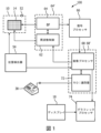
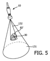
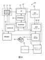
図1は、本発明の原理による超音波システム100を概略的且つ例示的に示す。プローブ10は、患者内のボリューム測定領域を撮像するための超音波トランスジューサのアレイ14を有することができる。このようなアレイには、任意の好適なタイプの超音波トランスジューサを設けることができる。プローブ10は、ICE又はIVUS手順等の侵襲的超音波手順に適合させることができる。例えば、該プローブ10は、このような手順のためにカテーテル等の形態をとることができる。このアレイ14は、二次元又は一次元アレイとすることができる。特定の実施態様において、アレイ14は、例えば容量性微細加工超音波トランスジューサ(CMUT)等の可変周波数超音波トランスジューサを用いて、ボリューム測定領域の可変周波数撮像に適合される。当該アレイのCMUTは、ボリューム測定視野131(図5)(当該ボリューム測定領域を有する)にわたって可変周波数範囲内の超音波ビームを送信すると共に、該送信されたビームに応答したエコーを受信する。トランスジューサアレイ14のトランスジューサはビーム成形器(ビームフォーマ)64に結合され、該ビーム成形器はトランスジューサアレイ14のトランスジューサ(限定するものでない例としてCMUT)により送信される超音波ビームのステアリングを制御する。該ビーム成形器は、更に、当該トランスジューサにより受信されたエコーをビーム成形する。ビームは、トランスジューサアレイ14から真っ直ぐ前方に(トランスジューサアレイ14に対し垂直に)ステアリングし、又は一層大きな視野のために異なる角度でステアリングすることができる。更に、ビーム成形器64は、ボリューム測定領域内のステアリングされるビームの密度及び分布も制御することができる。オプションとして、当該超音波システムは、各々が個別のトランスジューサのグループをビーム成形器64に結合する複数のマイクロビーム成形器(図示略)を有することもできる。斯かるマイクロビーム成形器(副アレイビーム成形器)は、トランスジューサの各グループからの信号を部分的にビーム成形し、これにより、当該プローブ及び主取得システムを結合する信号チャンネルの量を低減する。該マイクロビーム成形器は、好ましくは集積回路の形で作製され、プローブ10のハウジング内の当該トランスジューサアレイの近傍に配置される。プローブ10は位置センサ52を更に含むことができ、該位置センサはプローブ10の位置を示す信号をトランスジューサ位置検出器54に供給する。センサ52は、磁気センサ、電磁センサ、ラジオ周波数センサ、赤外線センサ又は他のタイプのセンサとすることができる。
FIG. 1 shows a schematic and
各マイクロビーム成形器により生成された部分的にビーム成形された信号はビーム成形器64に供給され、個々のトランスジューサグループからの部分的にビーム成形された信号は完全にビーム成形された信号へと組み合わされる。当該超音波システム100は、更に、アレイ14及びビーム成形器64(又は、オプションとして、複数のマイクロビーム成形器)に結合されたトランスジューサ周波数コントローラ62を有する。該周波数コントローラ62は、以下にCMUTトランスジューサに関して一層詳細に説明するように、送信され及び受信される超音波ビームの周波数をアレイ14における各トランスジューサの共振周波数を調整することにより制御する。前記の完全にビーム成形された信号(即ち、当該ビームに沿うコヒーレントなエコー信号)は超音波画像データを表すもので、信号プロセッサ66によって、フィルタ処理、振幅検出、ドプラ信号検出及び他の処理により処理される。該超音波データは、次いで、画像プロセッサ68により当該プローブの座標系(例えば、r,θ,φ)における超音波画像信号へと処理される。これら超音波画像信号は、更に、グラフィックプロセッサ74により所望の超音波画像フォーマット(例えば、x,y,zデカルト座標)に変換し、ディスプレイ18上に表示することができる。
The partially beamformed signals generated by each microbeamformer are fed to a
関心領域識別器72は、画像プロセッサ68に結合され、前記超音波画像データの分析に基づいてボリューム測定視野131内の関心領域(ROI)82’を示す識別データを生成するように構成される。画像プロセッサ68及びROI識別器72の両者は、1つの画像分析ユニット68’の一部とすることができる。超音波撮像システム100は、ユーザインターフェース38により制御することができる。特に、ユーザインターフェース38はROI識別器72に又は直接画像分析ユニット68’に接続することができ、ディスプレイ18上に表示される超音波画像に基づいてROI82’の手動選択を可能にする。更に、可変周波数アレイ14の場合、ユーザはユーザインターフェース38を介して、ROIが撮像されることを望む該アレイの可変周波数範囲内の所望の周波数も選択する。他の例として、ユーザに、ROIが撮像されることを望む所望の解像度(分解能)範囲の選択を提供することもできる。ボリューム測定視野131内のROI82’の位置及び寸法並びに所望のROI撮像周波数又は解像度範囲等の該ユーザ入力は、画像分析ユニット68’により識別データの形でトランスジューサ周波数コントローラ62に通知される。本実施態様において、ユーザにより識別されるデータはROI識別器と画像プロセッサ68との間で交換され、該画像プロセッサはROI82’及びボリューム測定視野131内の識別されたROIを囲むボリューム測定領域132(図5に示される)の座標を、ROI識別器により供給される生成された識別データに基づいて計算する。トランスジューサ周波数コントローラ62及びビーム成形器64は、ROI識別器72により生成され画像プロセッサ68により処理された識別データに応答する。アレイ14の動作周波数が調整可能である特定の実施態様において、トランスジューサ周波数コントローラ62はビーム成形器と共に、ボリューム測定視野131内で識別されたROIを囲むボリューム測定領域132内でステアリングされるビームの周波数を調整する。ステアリングされるビームの解像度が調整可能である他の実施態様において、トランスジューサ周波数コントローラ62はビーム成形器と共に、ボリューム測定領域132内でステアリングされるビームの密度を変化させることができる。当該ビーム成形器及びトランジスタ周波数コントローラは、周波数変化及びビーム成形能力を組み合わせた1つの超音波制御ユニット64’として設計することができる。前記他の実施態様においては、マイクロビーム成形器をトランスジューサ周波数コントローラと共に超音波制御ユニット64’に組み込み、当該プローブのハウジング内に配置することができる。更に他の実施態様において、超音波制御ユニット(64’)は発散性超音波を送信するようアレイを制御するように構成することができる。当該アレイの技術的仕様に依存して、送信される波(特定の実施態様では、ステアリングされるビーム)の周波数及び/又は密度をビーム成形器64により(又は超音波制御ユニット64’により)制御することができる。ユーザがROIの外側でステアリングされる超音波ビームの密度を低下させ、これにより当該ボリューム測定領域から取得される超音波データのフレームレートを増加させることが有益であろう。この全体的フレームレートの増加の結果、当該ボリューム測定領域内であるがROIの外側に位置する解剖学的特徴構造の解像度を低下させることができる。所与の解剖学的構造(当該医療手順により定まる)の最適な解像度及び/又はフレームレートは、当該ROIの位置及び該ROIの当該ボリューム測定領域内でのプローブからの相対位置に関連され得る。
The region of
本発明の該特定の実施態様において、当該超音波システムの撮像周波数の変化は、圧潰モードで動作するように構成されたCMUTトランスジューサを用いてもたらされる。CMUT技術は、バイアス電圧を変化させることにより撮像周波数の調整を可能にする。この周波数範囲は広い範囲にわたり広がり、このような範囲に加えて、各周波数においては相当の部分が100%に近いような帯域幅も存在する。この大きな周波数変化可能性は、広範囲の侵入度及び解像度にわたる撮像を可能にする。しかしながら、例えば米国特許第6,123,670号に説明されているように、当該ボリューム測定画像の異なる領域を異なる解像度で撮像することができる他のタイプのアレイ14を備えることもできると理解されるべきである。
In this particular embodiment of the invention, the change in imaging frequency of the ultrasound system is achieved using a CMUT transducer configured to operate in a collapse mode. CMUT technology allows for the adjustment of the imaging frequency by varying the bias voltage. This frequency range spans a wide range, and in addition to this range, there is also a bandwidth at each frequency where a significant portion approaches 100%. This large frequency variability allows imaging over a wide range of penetration and resolution. However, it should be understood that other types of
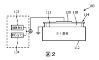
本発明の超音波システムのアレイ14がCMUTトランスジューサアレイである場合、該アレイは典型的に複数のCMUTセル(トランスジューサ)を有する。各CMUTセル103は、典型的に、間にギャップ又は空洞118を伴ってシリコン基板112上に懸架された可撓性の膜体又はダイヤフラム(振動板)114を有する。上部電極120は、ダイヤフラム114上に配置され、該ダイヤフラムと一緒に運動する。底部電極は、この例では、基板112の上側表面上の当該セルのフロア(床部)上に配置される。電極120を膜体114内に埋め込むことができ、又は該電極を膜体114上に追加の層として堆積することができる等の、該電極120の設計の他の実現例も考えられる。本例において、底部電極122は、限定するものでない例として、円形に構成されて基板層112内に埋め込まれる。底部電極122がギャップ118に直に露出される又は上部電極120と該底部電極122との間の短絡を防止するためにギャップ118から電気絶縁層若しくは薄膜により分離される等の、例えば基板層112上における当該底部電極122の他の好適な構成(例えば、他の電極形状及び他の配置)も考えられる。更に、膜体層114は、基板層112の上面に対して固定され、該膜体層114と基板層112との間に球状又は円柱状の空洞118を画定するように構成及び寸法決めされる。疑義を回避するために、図2において底部電極122は限定するものでない例として接地されていることに注意されたい。例えば、接地された上部電極120又は上部電極120及び底部電極122の両方がフローティング状態である等の他の構成も、勿論、同様に可能である。
When the
セル103及び該セルの空洞118は他の幾何学構造を呈することもできる。例えば、空洞118は、長方形若しくは正方形断面、六角形断面、楕円形断面又は不規則断面を呈することができる。本明細書において、CMUTセル103の直径に対する言及は、該セルの最大横方向寸法として理解されるべきである。
The
底部電極122は、空洞に面する表面を追加の層(図示略)により絶縁することができる。電気絶縁層は基板電極122上及び膜体電極120下に形成される酸化膜窒化膜酸化膜(ONO)誘電体層であるが、この層に関しては如何なる電気絶縁材料を考えることもできると理解されるべきである。ONO誘電体層は、有利にも、装置の不安定性及びドリフト並びに音響出力圧の減少につながる電極上の電荷蓄積を減少させる。
The
CMUT上のONO誘電体層の例示的製造法は、2008年9月16日に出願されたKlootwijk他による“Capacitive micromachined ultrasound transducer”なる名称のヨーロッパ特許出願公開第2,326,432号に詳細に説明されている。ONO誘電体層の使用は、懸架された膜体で動作されるCMUTよりも電荷保持の影響を一層受け易い事前圧潰(pre-collapsed)CMUTにとり望ましい。開示された要素は、例えば、Al、Ti、窒化物(例えば、窒化シリコン)、酸化物(種々の等級の)、テトラエチルオキシシラン(TEOS)及びポリシリコン等のCMOS適合性材料から作製することができる。CMOS製造においては、例えば、酸化物及び窒化物層を化学蒸着法により形成することができ、金属化(電極)層をスパッタリング法により形成することができる。好適なCMOS工程はLPCVD及びPECVDであり、後者は400℃未満の相対的に低い処理温度を有する。開示された空洞118を形成する例示的技術は、膜体層114の上面を追加する前に該膜体層114の初期部分に該空洞を画定することを含む。他の製造の詳細は、米国特許第6,328,697号(Fraser)に見られる。
An exemplary fabrication method for an ONO dielectric layer on a CMUT is described in detail in European Patent Application Publication No. 2,326,432, entitled "Capacitive micromachined ultrasound transducer," filed on September 16, 2008, by Klootwijk et al. The use of an ONO dielectric layer is desirable for pre-collapsed CMUTs, which are more susceptible to charge retention than CMUTs operated with suspended membranes. The disclosed elements can be fabricated from CMOS-compatible materials, such as, for example, Al, Ti, nitrides (e.g., silicon nitride), oxides (various grades), tetraethyloxysilane (TEOS), and polysilicon. In CMOS fabrication, for example, oxide and nitride layers can be formed by chemical vapor deposition, and metallization (electrode) layers can be formed by sputtering. Preferred CMOS processes are LPCVD and PECVD, the latter having relatively low processing temperatures below 400°C. An exemplary technique for forming the
図2において、円柱状空洞118の直径は円形の構造の電極プレート122の直径より大きい。電極120は円形構造の電極プレート122と同一の外径を有することができるが、このような一致は必要ではない。このように、膜体電極120は膜体層114の上面に対して下側の電極プレート122と整列するように固定することができる。CMUTセル100の斯かる電極は当該装置の容量プレートを形成し、ギャップ118は斯かるコンデンサのプレートの間の誘電体となる。当該ダイヤフラムが振動する場合、これらプレートの間の誘電体ギャップの変化する寸法が変化する容量をもたらし、斯かる変化する容量は受信される音響エコーに対するCMUTセル100の応答として感知される。
In FIG. 2, the diameter of the
上記電極間の間隔は、電圧供給部45により静電圧(例えば、DCバイアス電圧)を電極に印加することにより制御される。電圧供給部45は、トランスジューサ周波数コントローラ62内で実施化され、該コントローラの周波数制御能力を提供する。アレイ14におけるトランスジューサの各々は、別個の電圧供給部を有することができるか、又はトランスジューサ周波数コントローラ62内に実施化された幾つかの電圧供給部を共有することができる。電圧供給部45は、オプションとして、CMUTセル103の駆動電圧におけるDC及びAC(又は刺激)成分を各々供給するための別個の段102、104を有することもできる。第1段104は静的(DC)電圧成分を生成するように構成することができる一方、第2段102は設定された交流周波数を持つ交流可変電圧成分又は刺激を生成するように構成することができ、該成分は典型的に全体の駆動電圧と上述した該全駆動電圧の静的成分との間の差分である。印加される駆動電圧の静的又はバイアス成分は、好ましくは、CMUTセル103を圧潰状態に強制するための閾電圧を満たす又は超えるものとする。このことは、第1段104が全体の電圧の特に低ノイズの静的成分を生成するために相対的に大きなコンデンサ(例えば、平滑コンデンサ)を含むことができるという利点を有する。この場合、上記静的成分は、典型的に、上記全体の電圧を、該全体の電圧の信号のノイズ特性が該静的成分のノイズ特性により支配される如くに支配するものである。例えば、前記電圧供給部45がCMUT駆動電圧の静的DC成分を生成するための第1段、該駆動電圧の可変DC成分を生成するための第2段及び該信号の周波数変調又は刺激成分を生成するための第3段(例えば、パルス回路等)を含む3つの別個の段を含むような実施態様等の、電圧供給部45の他の好適な実施態様は明らかであろう。要約すると、電圧供給部45は任意の好適な態様で実施化することができる。
The spacing between the electrodes is controlled by applying static voltages (e.g., DC bias voltages) to the electrodes by a voltage supply 45. The voltage supply 45 is implemented in the
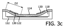
それ自体既知のように、特定の閾値より高い静電圧を印加することにより、CMUTセル103は、膜体114が基板112上に崩れ込むような圧潰状態に強制される。この閾値は、CMUTセル103の正確な設計に依存し得ると共に、このバイアス電圧の印加の間におけるファンデルワールス力により膜体114がセルフロアに当たる(接触する)DCバイアス電圧として定義される。膜体114と基板112との間の接触の量(面積)は、印加されるバイアス電圧に依存する。膜体114と基板112との間の接触面積を増加させることは、図3a~図3dを用いて更に詳細に説明されるように、膜体114の共振周波数を増加させる。
As known per se, by applying a static voltage higher than a certain threshold, the
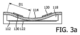
圧潰モードのCMUTセル103の周波数応答は、圧潰後のCMUT電極に印加されるDCバイアス電圧を調整することにより変化させることができる。結果として、CMUTセルの共振周波数は、一層高いDCバイアス電圧が電極に印加されるにつれて増加する。このような現象の背後にある原理が、図3a~図3dに示されている。図3a及び図3cの断面図は、これを、各図において膜体114の外側支持部と該膜体が空洞118の床部に接触し始める位置との間の距離D1及びD2により一次元的に示している。相対的に低いバイアス電圧が印加される図3aにおいては距離D1が相対的に長い距離となる一方、図3cにおける距離D2は、より高いバイアス電圧が印加されることにより大幅に短い距離となる。これらの距離は、端部により保持され、次いで弾かれる長い及び短い弦に相当し得る。長い緩められた弦は、弾かれた場合に、より短い強く張った弦よりも大幅に低い周波数で振動する。同様にして、図3aのCMUTセルの共振周波数は、より高い引き下げバイアス電圧を受ける図3cのCMUTの共振周波数より低くなるであろう。
The frequency response of the
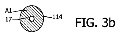
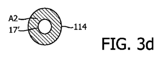
上記現象は、図3b及び図3dの二次元図から、実際にはCMUT膜体の有効動作面積の関数であるとして理解することもできる。図3aに示されたように膜体114がCMUTセルの床部に丁度接触したばかりの場合、該セル膜体114の非接触(自由振動)部分の有効振動領域A1は、図3bに示されるように、大きい。中心における小さな孔17は、該膜体の中心の接触領域を表している。該大面積の膜体は相対的に低い周波数で振動する。上記領域17は、膜体114におけるCMUTセルの床部に崩れ込んだ領域である。しかしながら、当該膜体が図3cに示されるように一層高いバイアス電圧により一層深い圧潰へと引き込まれた場合、一層大きな中心接触領域17’の結果、図3dに示されるように、より少ない自由度の振動領域A2となる。この一層小さな領域A2は、より大きなA1領域より高い周波数で振動する。このように、DCバイアス電圧が減少されるにつれて、圧潰CMUTセルの周波数応答は低下し、DCバイアス電圧が増加すると、圧潰CMUTセルの周波数応答は上昇する。
The above phenomenon can also be understood from the two-dimensional diagrams of Figures 3b and 3d as being a function of the effective operating area of the CMUT membrane. When the
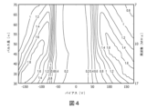
図4は、圧潰モードにおける典型的なCMUTセル103の音響圧出力の、送信の間における一定周波数のAC変調又は周波数変調の形態での刺激を含む印加DCバイアス電圧の関数としての等高線図を示す。対応するパルス長は、印加される周波数の半分である。この等高線図から分かるように、CMUTセル103が一定又は静止電圧(例えば、一定値のDCバイアス電圧)において動作される場合、最適な音響性能は小さな範囲の周波数に対してしか得られない。しかしながら、バイアス電圧及び該バイアス電圧信号に対する周波数変調を相関された態様で変化させる場合、CMUTセル103の最適音響性能は大幅に大きな周波数範囲にわたり達成することができ、これにより、該CMUTセル103を含む超音波プローブの送信モードにおいて生成される超音波パルス(又はパルス列)の有効帯域波を増加させることができる。このように、周波数を、この例におけるように7~17MHz;3~10MHz;又は2~15MHzに広がる更に一層大きな周波数範囲において変化させることができる。
4 shows a contour plot of the acoustic pressure output of a
このことは、圧潰モードにおけるCMUTセル103の共振周波数は印加される(DC)バイアス電圧の関数であることを説明した図3a~図3dを振り返って参照すると理解することができる。特定の設定周波数の超音波パルスを生成する際に適切な設定周波数を持つ刺激を供給することによって印加されるバイアス電圧を調整することにより、異なる周波数のパルスを生成することができ、各パルス周波数に対してCMUTセル103の(準)最適な音響性能を呈するようにする。従って、このことは、当該撮像スペクトルの大きな帯域幅にわたり(準)最適な撮像分解能を保証する。
This can be understood by referring back to Figures 3a-3d, which explained that the resonant frequency of the
音響波減衰は周波数の増加に伴い増加する一方、超音波画像分解能は周波数の増加に伴い減少する。例えば、組織における2サイクルパルスに関する典型的な深度及び軸方向分解能が下記の表に示される。 While acoustic wave attenuation increases with increasing frequency, ultrasound image resolution decreases with increasing frequency. For example, typical depth and axial resolution for a two-cycle pulse in tissue is shown in the table below.

最適な及び侵入度の要件を合理的に満たすために、殆どの診断用途のための周波数範囲は2~15MHzとされる。該範囲の低い部分は、大きな侵入度(例えば、関心領域が人体の一層深くに位置される場合)又は高い減衰度(例えば、経頭蓋検査における)に対する場合に有効である。該周波数範囲の高い部分は、小さな侵入度しか必要とされない場合(例えば、乳房、甲状腺又は表層血管を撮像する場合、又は小児の撮像の場合)に有効である。殆どの大きな患者においては3~5MHzが満足の行く周波数であるが、痩せた患者及び子供の場合、5及び7.5MHzをしばしば使用することができる。15MHzを超える一層高い周波数範囲は、IVUS、ICE、FL-ICE等のように、腔内(血管内)プローブを用いる高解像度撮像を提供することができる。これらのプローブは、体腔、血管等の内部のROIの一層近傍に配置することができる。しかしながら、CMUTアレイ14の使用は幾つかの実施態様においては有益であり得るが、前述したように、本発明の前後関係において如何なる好適なタイプのアレイ14も使用することができることを繰り返し述べておく。
To reasonably meet the optimum and penetration requirements, the frequency range for most diagnostic applications is 2-15 MHz. The lower part of the range is useful for larger penetration (e.g., when the region of interest is located deeper in the body) or higher attenuation (e.g., in transcranial studies). The higher part of the frequency range is useful for cases where only small penetration is required (e.g., when imaging the breast, thyroid or superficial vessels, or when imaging children). For most large patients, 3-5 MHz is a satisfactory frequency, but for thin patients and children, 5 and 7.5 MHz can often be used. Higher frequency ranges above 15 MHz can provide higher resolution imaging using intracavity (intravascular) probes, such as IVUS, ICE, FL-ICE, etc. These probes can be placed closer to the ROI inside body cavities, blood vessels, etc. However, while the use of
本発明によれば、超音波システム100は、所謂“解剖学的知性”により拡張される。超音波撮像における解剖学的知性は、患者の超音波データを解釈し、(3D)解剖学モデルを用いた適応的システム知性を適用して、より容易且つ一層再現性のある結果を生成する。解剖学的知性ツールは、先進的臓器モデル化、画像スライス化及び検認された定量化を利用して、超音波検査を一層実行するのを容易に且つ一層再現性のあるものさせる一方、生成される臨床的情報を改善且つ拡張させる助けとなり、これにより、超音波システム100の機能を拡張する。
In accordance with the present invention, the
本出願の前後関係において、“解剖学的知性(インテリジェンス)”とは、撮像されるべき解剖学的構造を識別すると共に、プローブ10により供給される超音波撮像データ内の関心の解剖学的特徴構造(例えば、ROI)を識別する超音波システム100の能力を含む。例えば、超音波システム100は、当該超音波撮像データに対して、該超音波撮像データにおいて患者の心臓の構造を識別することができると共に、例えば、心周期を視覚化する超音波画像のシーケンスから駆出量等の機能的心臓パラメータを抽出するために心臓幾何学構造の変化を追跡することができる心臓モデル等の適切な解剖学的モデルを適用するように構成することができる。本発明の解剖学的モデルは、マシン訓練を解剖構造の生体力学モデルと組み合わせるアルゴリズム等の種々のマシン学習アルゴリズムに基づくものとすることもできる。
In the context of this application, "anatomical intelligence" includes the ability of the
開示される超音波システムを用いて撮像されるべき解剖構造の例は、肝臓、胎児(超音波撮像の産科的応用)、肺臓、頸動脈及び膵臓を含み得る。 Examples of anatomical structures to be imaged using the disclosed ultrasound system may include the liver, fetus (obstetric applications of ultrasound imaging), lungs, carotid arteries, and pancreas.
上記産科的応用の一実施態様は、当該超音波システムを胎児(識別される関心領域として)の存在及び該胎児の頭殿長(頭殿長測定手順が選択される場合)を識別するように構成することを含むことができる。産科的超音波医療使用ケースの他の例は、胎児の心臓拍動の確認であり、この場合、識別される解剖学的関心特徴は胎児心臓の位置である。 One embodiment of the obstetric application can include configuring the ultrasound system to identify the presence of a fetus (as an identified region of interest) and the fetal crown-rump length (if a crown-rump length measurement procedure is selected). Another example of an obstetric ultrasound medical use case is confirmation of fetal heartbeat, where the identified anatomical feature of interest is the location of the fetal heart.
血管超音波評価の一実施態様は、頸動脈の超音波撮像である。血管超音波撮像においては、しばしば、Bモード撮像に次いで、ドプラ撮像モードが使用される。ドプラ入射角識別に関する誤差は超音波ビームと血流との間の特定の範囲の角度に対して低減することができるので、記載されるシステムにおいて識別されるROIは、超音波ビームと血流との間の最適な範囲の角度を、当該関心領域を示す識別データを生成するために考慮に入れるであろう。 One embodiment of vascular ultrasound evaluation is ultrasound imaging of the carotid artery. In vascular ultrasound imaging, B-mode imaging is often followed by Doppler imaging mode. Since errors related to Doppler incidence angle discrimination can be reduced for a certain range of angles between the ultrasound beam and blood flow, the ROI identified in the described system will take into account the optimal range of angles between the ultrasound beam and blood flow to generate discrimination data indicative of the region of interest.
更に、このような解剖学的知性は、介入処置のために使用される超音波システムに対して特に有利に適用することができる。該解剖学的知性、特に当該介入処置が適用されるべきROIを識別する能力を活用することができるからである。このような介入的応用分野の限定するものでない例は、血管内超音波法(IVUS)、心臓内心エコー法(ICE)及び経食道エコー法(TEE)を含む。IVUSは、典型的に、その間に動脈壁異常が評価される血管内超音波ワークフローにおいて使用される。 Moreover, such anatomical intelligence can be particularly advantageously applied to ultrasound systems used for interventional procedures, as the anatomical intelligence can be leveraged, particularly the ability to identify the ROI to which the intervention is to be applied. Non-limiting examples of such interventional applications include intravascular ultrasound (IVUS), intracardiac echocardiography (ICE), and transesophageal echocardiography (TEE). IVUS is typically used in intravascular ultrasound workflows during which arterial wall abnormalities are evaluated.
例えば、動脈壁プラグ(粉瘤)はROIとして識別することができると共にIVUSプローブ10により接近することができ、その場合、プローブ10はROIに向かって自動的に、又はユーザが本出願で説明されるROI識別に基づいた当該超音波システム100からの誘導命令を受信することにより誘導(ガイド)することができる。
For example, an arterial wall plug can be identified as an ROI and can be accessed by the
他の例として、ICEカテーテル又はTEEプローブ10は、カテーテルが2つの心房の間の隔壁を穿刺する経中隔横断若しくは穿刺術等の心臓介入処置又は経カテーテル大動脈弁修復(TAVR)処置において使用することができる。勿論、例えば心室容積推定又は駆出率推定のような自動化された心定量化(通常、2Dで用いられる)等の非介入的処置も、このような解剖学的知性支援撮像から利益を受けることができる。
As another example, the ICE catheter or
当該ROIは必ずしも解剖学的特徴構造だけとは限らないことが更に注記される。一実施態様において、プローブ10はカテーテル等の介入装置を撮像するために用いることもでき、その場合、患者の解剖構造内での該介入装置の位置が超音波撮像データ内でのROIとなり得る。例えば、カテーテル等の別体の介入ツールが心臓内で撮像されるべきであるシナリオにおいて、超音波システム100は、心臓内のプローブ10の所要の位置決めに関する知識により、後の介入処置を支援するための当該介入ツールの適切な撮像を容易化するように構成することができ、該所要の位置決めは、心臓内の1以上のROIの識別により、当該プローブ10が該介入ツールを撮像するよう正しく位置決めされているかのチェックとして検証することができ、当該解剖学的知性は超音波システム100にプローブ10が自身の目標位置から該介入ツールを視覚化(及び追跡)しようとする知識を更に提供する。
It is further noted that the ROI is not necessarily only an anatomical feature. In one embodiment, the
前述したように、当該解剖学的知性は、ROIに向かっての、自動的な又はプローブ10のユーザにROI検出に基づく誘導命令を供給することによる該プローブ10(又はカテーテル)の誘導を支援するために利用することができる。限定するものでない例として、プローブ10が患者の心臓の左心室を撮像しなければならない処置において、ユーザには誘導命令(例えば、可聴命令又はディスプレイ18上に表示される視覚的命令)を提供することができ、当該左心室の適切な撮像を容易にするためにプローブ10がユーザにより右心室内へと誘導されることを保証するようにする。後に詳細に説明される一実施態様において、斯かる誘導命令は、当該超音波システム100により(例えば、ROI識別器72により、画像プロセッサ68により、又はROI識別器72のROI評価に基づいて当該システムの何れかの他の適切な要素により)生成することができる。
As previously discussed, the anatomical intelligence can be utilized to assist in guiding the probe 10 (or catheter) toward an ROI, either automatically or by providing a user of the
例えば、実際の解剖学的知性使用ケース(使用事例)は、プローブ10のための目標位置及び/又はROIからの目標距離を、ROI識別器72がROIに対するプローブ10の実際の位置及び/又は実際の距離を決定するように構成されることにより特定することができる。画像分析ユニット68’は、前記使用ケースの解剖学的モデルに関連した識別された使用ケースに基づいて、当該所与のプローブの位置のために適用可能な最適な超音波送信を評価するように構成することができる。取得された超音波画像データに基づいては最適な構成を達成することができない、例えばROIが当該医療手順により定義される診断を実行するためには遠すぎる(又は、視野内に最適に位置されていない)場合、この実際の位置情報は超音波システム100によりプローブ10の制御者(人又は後に更に詳述されるべき駆動機構21)のための誘導命令を生成するために活用することができ、プローブ10を自身の現在の位置から目標位置まで誘導するようにする。ROI識別器72は、当該使用ケースにおいて指定された目標位置に向かうプローブ10の誘導の間において定期的なフィードバックを供給することができ、例えば、介入処置を実行し又は前述したように他の介入ツールを成功裏に撮像するためにプローブ10が正しく位置決めされることを保証するようにする。
For example, an actual anatomical intelligence use case (use case) can be identified by a target position and/or target distance from the ROI for the
このような誘導命令がプローブ10の操作者に提供される場合、これら命令は、例えば、可聴命令及び/又はディスプレイ18上の視覚的命令等の、任意の好適な態様で提供することができる。このような視覚的命令は、例えば、ディスプレイ18上に表示されるプローブ10によりキャプチャされたボリューム測定画像内に提示される文章命令として又は図形命令として(例えば、プローブ10が自身の目標位置に向かって辿るべき軌道を強調表示するために、この画像の着色オーバーレイとして)等の如何なる適切な形態で提供することもできる。このような誘導命令の他の好適な視覚化は、当業者により即座に明らかとなるであろう。
When such guidance instructions are provided to the operator of the
超音波システム100は、このような解剖学的知性を任意の適切な態様で構成することができる。例えば、超音波システム100は複数の使用ケースによりプログラムすることができ、例えば、各使用ケースはユーザを正しい操作手順(例えば、産科、IVUS又はICE手順)並びに当該使用ケースにとり適切な解剖学的モデルを介して誘導するワークフローステップを有し、斯かる解剖学的モデルは、例えば、プローブ10により生成された超音波画像データ内のROIの自動化された検出を容易にするために1以上のセグメンテーションアルゴリズムを含むことができる。この目的のために、当該超音波システムは、後に更に詳細に説明するように識別に際して適切な使用ケースを検索することができるデータ記憶装置(図示略)を有し又は斯かる記憶装置に接続することができる。
The
オプションとして、各使用ケースは、当該特定の手順のために少なくとも部分的に手動のナビゲーションが必要とされる場合の患者の解剖構造を介してプローブ10をナビゲーションするためのナビゲーション命令、及びプローブ10が自身の意図される位置にある場合に患者の解剖構造を介して介入装置等の移動する物体を追跡するための追跡アルゴリズムの少なくとも一方を更に含むことができる。超音波システム100のプログラミングは、例えば、ユーザがユーザインターフェース38を介して超音波システム100を手動でプログラミングすることにより、及びユーザが遠隔使用ケースデータベースから(例えば、何らかの好適な方法でインターネット等のネットワークを介して)使用ケースのダウンロードを実施することにより、等の任意の好適な態様で実行することができる。
Optionally, each use case may further include at least one of navigation instructions for navigating the
一実施態様において、超音波システム100は、自動化されたROI検出、自動化された超音波送信の構成(設定)及びプローブ10の使用の間におけるユーザ誘導を提供するために、適切な使用ケースを自動的に選択するように構成される。この構成は、プローブ10を超音波システム100のユーザコンソール等に接続するために該プローブ10に取り付けられたケーブルのプラグにタグ等を含めることにより達成することができる。このようなタグは、プローブ10及び/又は該プローブの適切な使用ケースの識別子を含むことができ、該識別子から超音波システム100は該使用ケースを導出することができる。このようなタグは、例えば、上記プラグの接続ピンを介して、又はRFタグと前記プラグが挿入されるユーザコンソール等のソケットに近接して配置されるタグ読取器との間の近距離無線通信を用いることによる等の如何なる好適な方法で読み取ることもできる。当該タグから識別情報を取得する他の好適な方法は、当業者により即座に明らかとなるであろう。この実施態様は、例えばIVUSプローブ等の、単一の固有の用途のために使用されるプローブタイプに特に適している。
In one embodiment, the
代わりに又は加えて、当該超音波システムは適切な使用ケースを識別するユーザ入力に応答して適切な使用ケースを選択するように構成され、該ユーザ入力は、例えば、タッチスクリーンディスプレイ18及び/又はユーザインターフェース38を介して等の如何なる適切な方法で供給することもできる。このことは、例えば、産科、IVUS又はICEプローブ(前述したように、(中壁横断を伴う)アブレーション、弁置換又は介入ツール追跡等の異なる心臓手術において使用することができる)のための場合である等の、プローブ10が異なる手順で使用され得るシナリオにおいて望ましい。
Alternatively or additionally, the ultrasound system may be configured to select the appropriate use case in response to user input identifying the appropriate use case, which may be provided in any suitable manner, such as, for example, via the
例示的実施態様において、上述した様な種々の手順的使用ケースにより構成可能な当該超音波システムは、CMUTトランスジューサの単一のアレイ14を用いた、広周波数範囲における可変周波数超音波撮像の固有の組み合わせを提供する。
In an exemplary embodiment, the ultrasound system, which can be configured with a variety of procedural use cases as described above, provides a unique combination of variable frequency ultrasound imaging over a wide frequency range using a
図5は、この例示的実施態様の基本原理をROI82’に対して固定されたプローブ位置で示す。プローブ10は、ボリューム測定視野131の超音波画像を取得するために使用される。トランスジューサ周波数コントローラ62は、関心領域識別器72に応答して、ボリューム測定視野131内でステアリングされる超音波ビームの相対的に低い周波数、及び識別されたROI82’を囲むボリューム測定領域132内でステアリングされる超音波ビームの総体的に高い周波数を設定する。CMUTにより受信されるエコーは前記ビーム成形器により処理され、該ビーム成形器はROIの外側のボリューム測定領域内で相対的に低い空間分解能及び該関心領域内で相対的に高い空間分解能を有する当該ボリューム測定領域の超音波画像データを供給する。これらの超音波データは画像プロセッサ68内で処理され、該プロセッサにおいて、低い空間分解能データに基づく当該ボリューム測定領域のワイドビュー80及び高い空間分解能データに基づく関心領域82の詳細ビュー132’が図6に示されるように生成される。識別されたROI82を囲むボリューム測定領域132の詳細ビュー132’は、当該プローブとROIとの間に位置する領域の画像133も有し得る。
5 shows the basic principle of this exemplary embodiment with the probe position fixed relative to the ROI 82'. The
このCMUTアレイに限定するものでない例において、超音波制御ユニット64’はボリューム測定領域内でステアリングされるビーム超音波ビームの密度を変化させるように構成することもでき、該密度は選択される撮像手順により定められる。該超音波制御ユニットは、関心領域識別器72に応答して、ボリューム測定視野131内でステアリングされる超音波ビームの相対的に低い密度、及び識別されたROI82’外のボリューム測定領域132内でステアリングされる超音波ビームの総体的に高い密度を設定する。更に、超音波制御ユニット64’は、識別されたROI内の超音波ビームのステアリング角を変化させるように構成することができる(しばしば、ドプラ撮像手順のために適用可能である)。
In this non-CMUT array example, the ultrasound control unit 64' may also be configured to vary the density of the ultrasound beam steered within the volumetric measurement region, the density being determined by the selected imaging procedure. In response to the region of
図6は、ユーザに対し互いに空間的に位置合わせされたワイドビュー80及び詳細ビュー132’で表示された2D超音波画像の表示99を示す。選択されたROI82’の表示82は、詳細ビュー132’内に増加された撮像周波数(又は増加されたフレームレート)で表示される。相対的に高い周波数を持つ超音波ビームの侵入深度は相対的に低い周波数を持つ超音波ビームの侵入深度と比較して減少されるので、相対的に高い周波数の範囲の周波数上限は、ROIが位置される深度(プローブまでの距離)により制限されると共に、その計算の間において画像プロセッサ68により考慮に入れられる。システム100は、先ず当該ボリューム測定視野の超音波データを相対的に低いビーム周波数(又は、低いステアリングビーム密度)で取得し、かくして該ボリューム測定領域の周囲の環境情報を提供し、更にROI82を識別したら該ROIに“ズームイン”することができる。ROI82の詳細ビュー132’は、前に取得されたワイドビュー80に次いでリアルタイムに更新し、当該状況に関して図6Cに示されるように表示することができる。
6 shows a
他の例として、ROI82の詳細ビュー132’及びワイドビュー80を互いに隣り合わせで表示することができる。心臓撮像の間における心臓学的応用において、当該超音波画像の表示及び取得は、ECGゲーティングにより心周期と同期させることができる。
As another example, a detailed view 132' and a
CMUTアレイ14が線形アレイである場合、トランスジューサ周波数コントローラ62は個々のトランスジューサセル103を異なる周波数でアドレス指定(駆動)することができ、かくして、ROIは高い周波数で撮像される一方、他のエレメントは低い周波数に維持されるようにする。線形アレイにより取得される代表的画像が図6Bに示されている。
If the
埋め込まれるリアルタイム高周波数詳細ビュー132’画像は、リアルタイムな低周波数ワイドビュー80画像と同時に生成される。このことは、周囲の状況が依然として相対的に大きな深度でリアルタイムに撮像され(より低い分解能においてであるが)、例えば当該ROIの周辺で行うツールの配向及びナビゲーションを可能にするという利点を有する。当該CMUTアレイ14がフェーズドアレイである場合、図6A及び図6Cに示されるように同様の画像を得ることもできる。フェーズドアレイの場合、ビーム成形は当該画像を構成する各ラインに関して全トランスジューサに対し適切な周波数が選択されるように実行され、かくして高周波数詳細ビュー132’が、低周波数ラインを含むワイドビュー80内に埋め込まれるようにする。両ビュー、即ちROI82の詳細ビュー132’及ワイドビュー80がリアルタイムに更新される場合、フェーズドアレイを有する該システムは、連続して、ボリューム測定視野131ボリュームの全ラインを先ず低い周波数において取得し、次いで、識別されたROI82の周囲のボリューム測定領域132の全ラインを一層高い周波数で取得することができる。取得されたビューは、更に、1つの超音波画像へとインターリーブ又は補間することができる。これが、図6Cに示されている。他の取得ワークフローにおいて、ワイドビュー80は詳細ビュー132’を超えて更新され、ユーザに対して表示される結果としての画像は図6Aに示されている。前者は、例えば前述した特定の手順使用ケースにおいて介入装置を追跡するための、全ボリュームのリアルタイムビューという利点を有する。後者は、より少ないラインしか取得されず、一層高いフレームレートを達成することができるという利点を有する。
The embedded real-time high-frequency detailed view 132' image is generated simultaneously with the real-time low-frequency
図7は、本発明の特に有利な一実施態様を示すもので、プローブの位置をボリューム測定視野131’内で変化させることができる。例えば、当該プローブは、該プローブをROIに向かって及び該ROIから遠ざかるように容易に平行移動することができるように前方視又はエンドファイア(end firing)構成で配置することができる。このことは、例えば文献EP1742580Bに記載されているようにIVUS(血管内超音波法)、ICE(心臓内心エコー法)、FL-ICE(前方視心臓内心エコー法)等の腔内プローブを設けることにより実現することができる。 Figure 7 shows a particularly advantageous embodiment of the invention, in which the position of the probe can be varied within the volumetric field of view 131'. For example, the probe can be arranged in a forward looking or end firing configuration so that the probe can be easily translated towards and away from the ROI. This can be achieved by providing an intracavity probe, e.g. IVUS (intravascular ultrasound), ICE (intracardiac echocardiography), FL-ICE (forward looking intracardiac echocardiography), etc., as described in document EP1742580B.
腔内プローブは、遠位先端内にボリューム測定領域を走査するために掃引されるトランスジューサアレイを含むことができる。ボリュームの掃引は、1Dアレイの機械的移動又は2Dアレイによるビームの電子的ステアリングの何れかを行って実施することができる。当該トランスジューサアレイはプローブの遠位先端に配置された流体チェンバ内に収納され、この流体は該プローブと撮像されるボリューム測定領域との間の適切な音響的結合をもたらす。図9において、本発明の超音波システム100’は、当該プローブに結合される駆動機構21及びROI識別器72(分析ユニット68’のオプションとして)を更に有することができ、該駆動機構は撮像の間において前記識別データに基づいてプローブ10を移動させるように動作する。また、駆動機構21は、当該プローブの空間位置を追跡する位置センサ52から信号を受信することができ、かくして、ボリューム測定視野131’内での該プローブの移動の独立した検証を行う。この実施態様は、プローブ10がCMUTを配する場合にROI82’を撮像することができる高い周波数の上限に対して一層高い柔軟性を提供する。ROIが識別された場合、画像プロセッサ68は、前述したような選択された使用ケースの解剖学的モデルを用いて得られる識別データに基づいて、ボリューム測定視野131内のROI82及び該識別されたROIの周囲のボリューム測定領域132の座標を計算する。当該ROI識別器は、プローブ10と関心領域との間の距離を決定することができると共に、当該ROIの一層良好なビューを得るため、又は前述したように選択された手順的使用ケースにより指定される目標位置へとプローブ10を移動させるために該プローブ10が調整されることを要するかを決定することができる。例えば、CMUTアレイ14の場合において、該トランスジューサアレイ14(実際には、プローブ10)とROIとの間の距離が、選択された高周波数によるビームの侵入深度を超える場合、駆動機構21は、ボリューム測定視野131’内でROIに向かい一層近くに移動して(図7B)該ROIの“ズームイン”画像が取得され得るように、又はプローブ10を選択された使用ケースにおいて指定されたROIに対する目標位置の一層近くに移動させるように通知される。同様に、ROIを完全に撮像することができない場合、又はプローブ10が自身の目標位置の使用ケース指定によればROIに近過ぎる場合、“ズームアウト”を実施することができ、その場合、駆動機構21はボリューム測定視野131’内においてROIから遠ざかるように通知される。他の例として、プローブ10の操作者に、先に説明したように、それに応じてプローブ10を移動させるための誘導命令を供給することもできる。
The intracavity probe may include a transducer array in the distal tip that is swept to scan the volumetric region. The volumetric sweep may be performed by either mechanical movement of a 1D array or electronic steering of the beam by a 2D array. The transducer array is housed in a fluid chamber located at the distal tip of the probe, and the fluid provides suitable acoustic coupling between the probe and the volumetric region to be imaged. In FIG. 9, the ultrasound system 100' of the present invention may further include a
本発明は、超音波システム100に解剖学的知性(インテリジェンス)の追加の利益を組み合わせてプローブ10の目標位置への誘導を容易にするもので、特定の撮像手順に適したROIの最適超音波画像を取得することができる。好ましくは、当該ボリューム測定領域内での自動化されたズームイン及びアウト機能が、ROI識別器72から駆動装置21へのフィードバックループによりもたらされ、これにより、ユーザに新世代の超音波システムを提供する。特定の実施態様においては、小型化されたCMUTトランスジューサ(CMOS製造の進歩により可能にされる)及び斯かるCMUTトランスジューサの広い動作帯域(圧潰動作モードにより可能にされる)が、圧潰モードで動作するCMUTアレイの広周波数帯域と該アレイを有するプローブを物理的に移動させる手段との組み合わせが、増加された細部を伴う進化された超音波撮像、従って改善された診断撮像の新しいユーザ体験を可能にするように活用される。
The present invention combines the additional benefit of anatomical intelligence in the
図8は、ユーザに対して表示される2D超音波画像の表示99を示す。詳細ビュー82及びワイドビュー80を、互いに隣り合わせで又は空間的に位置合わせ状態で示すことができる。後者が図8に示され、リニア及びフェーズドアレイで取得された画像が互いに隣り合わせで配置されている。図6のA~Cと比較すると、詳細ビュー82はユーザに対して、プローブの位置がROIの位置に対して固定された実施態様と比較して一層大きな侵入深度を有するように出現する。当該詳細ビュー画像はプローブの進行(移動)の間において継続的に取得することができ、かくして、ワイドビュー画像80が、異なる時点で取得される高分解能の詳細ビュー82によりリアルタイムに更新され得るようにする。加えて、当該ボリューム測定領域内の移動するプローブの現在位置を、該ワイドビュー画像80内に表示することができる。
Figure 8 shows a
ROIの識別及び使用ケースで識別されたパラメータに基づいて、画像プロセッサ68は取得された超音波データを分析して軸ノイズ、横斑点(lateral speckle)、軸輝度等の画像品質パラメータを求めることができる。これらの品質パラメータをユーザに対して更に表示することができる。これらの品質パラメータは、当該プローブを自動的に移動させるための駆動機構の入力として用いることもでき、ROI画像品質の自動的最適化及び/又は前述したような使用ケースで指定された位置におけるプローブ10の位置決めのためのフィードバックループの一部とすることができる。このような自動化は当該プローブの精密な移動のために使用することができる一方、大まかな移動はユーザインターフェース38を介して制御することができる(この目的のために、ユーザには前述したように誘導命令が提供され得る)。ユーザインターフェース38を介して、ユーザは前記駆動機構の動作に対する追加の制御を行うことができる。該ユーザインターフェースはディスプレイ18に組み合わされたタッチスクリーンとすることができ、該タッチスクリーンはユーザが表示された画像においてROI及び/又はプローブの動きを手動で定めることを可能にする。ROIにタッチすること及び/又は“ピンチイン”若しくは“ピンチアウト”動作を行うことは、当該プローブを特定の方向(又は複数の方向)に物理的に移動させ、又は当該所与のプローブ位置にとり侵入深度が十分な場合は詳細な画像を取得するために用いることができる。
Based on the identification of the ROI and the parameters identified in the use case, the
他の実施態様においては、相対的に高い周波数で取得されるROIのリアルタイムな詳細3D視野がワイドビューの2D画像に埋め込まれる。この構成は、上記ワイドビュー2D画像の取得が一層少ない処理能力及びトランスジューサの使用だけですみ、且つ、上記3D画像(又はバイプレーン2D)を可能な最も高いフレームレートで取得することができるという利点を有する。一次元において小さな開口を有するアレイの場合(例えば、ICE)、この実施態様は、一層好ましい開口次元(ICE軸方向及び横方向)に基づくワイドビュー撮像及び全ての次元(例えば、ICE:エレベーションを含む)における詳細なROI撮像を提供し、このことは高い周波数において一層好ましくなる。 In another embodiment, a real-time detailed 3D view of the ROI acquired at a relatively high frequency is embedded in a wide-view 2D image. This configuration has the advantage that the wide-view 2D image acquisition requires less processing power and transducers, and the 3D image (or bi-plane 2D) can be acquired at the highest possible frame rate. For arrays with a small aperture in one dimension (e.g., ICE), this embodiment provides wide-view imaging based on a more favorable aperture dimension (ICE axial and lateral) and detailed ROI imaging in all dimensions (e.g., including ICE: elevation), which becomes more favorable at higher frequencies.
当該ROI識別器は、例えば選択された解剖学的知性の使用ケースの解剖学的モデルを用い、カテーテル、ニードル又はツール等の特定の物体からの超音波データを用いてROIを自動的に識別することができ、これは、オプションとして、超音波強調コントラストフィーチャによりマーク付けすることができる。これらの物体は、それらの幾何学構造及び態様(又はマーカ若しくは位置センサ)のお蔭で画像分析ユニット68’により認識することができ、該ROIの座標を自動的に生成することができる。 The ROI identifier can, for example, use an anatomical model of a selected anatomical intelligence use case to automatically identify an ROI using ultrasound data from a particular object, such as a catheter, needle or tool, which can optionally be marked with ultrasound-enhanced contrast features. These objects can be recognized by the image analysis unit 68' thanks to their geometry and aspect (or markers or position sensors) and the coordinates of the ROI can be automatically generated.
他の実施態様において、関心ボリュームの画像は最初に相対的に高い周波数のビームにより取得することができ、この関心ボリュームはユーザによりROIとして識別することができる。更に、ユーザは、前記ユーザインターフェースを介して、撮像周波数を当該ROIに対して使用されたものに対して減少させ、該ROIを有するワイドビュー画像を一層大きな侵入深度で取得することができる。先の実施態様と同様に、これらの視野は互いに隣り合わせで又は空間的位置合わせ状態で表示することができる。 In another embodiment, an image of a volume of interest can be first acquired with a relatively high frequency beam, and this volume of interest can be identified by the user as a ROI. The user can then, via the user interface, decrease the imaging frequency relative to that used for the ROI, and acquire a wide-view image with the ROI at a greater penetration depth. As with the previous embodiment, these views can be displayed next to each other or in spatial registration.
当該CMUTに印加されるバイアス電圧変化の最適速度を提供するために、超音波制御ユニット64’の(又は、オプションとして、トランスジューサ周波数コントローラ62の)集積回路(IC)電子装置に別個の要件が課され得る。上述した殆どの事例に対して、現在のIC電子技術は十分であり得る。他の例として、バイアス電圧変化の更に大きな速度が必要とされる場合、国際特許出願公開第2015/086413号に記載されたような3端子CMUTを使用することができる。 Separate requirements may be placed on the integrated circuit (IC) electronics of the ultrasonic control unit 64' (or, optionally, the transducer frequency controller 62) to provide an optimal rate of bias voltage change applied to the CMUT. For most of the above mentioned cases, current IC electronics may be sufficient. As another example, if an even greater rate of bias voltage change is required, a three-terminal CMUT such as that described in WO 2015/086413 may be used.
図10は、可変超音波画像取得の基本原理のワークフロー200を示す。ステップ201において、ボリューム測定視野131が撮像され、この視野はワイドビュー80を有する。ステップ202において、ROI82が前記識別器により検出され、自動的検出は、例えば解剖学的特徴30を区別することに基づいて、又は解剖学的知性による選択された手順使用ケースに基づいて実行することができる。ステップ203において、ROIの輪郭をユーザに表示することができる。この段階で、ユーザはユーザインターフェース38を介してシステム100と手動で対話し、ROIの寸法及び/又は位置を調整することができる。更に、ステップ204において、ユーザはROIの詳細ビューの所望の分解能(又は周波数)及び/又はフレームレートを選択することができる。画像プロセッサ68は、更に、選択された分解能をトランスジューサの動作周波数又はステアリングされるビーム密度に変換する。代わりに、このステップにおいて、画像プロセッサ68は、ROI82をプローブ10(即ち、該プローブ内のトランスジューサアレイ14)からROIまでの固定の距離に基づいて撮像することができる周波数上限(又はビーム密度の下限)を計算することができる。この情報は、前記ディスプレイ上に表示することができる。ステップ205において、システム100は、増加された分解能(又はフレームレート)でROIの詳細ビューを取得する。ステップ206において、ワイドな及び詳細な視野がユーザに表示される。
10 shows a
図11は、本発明の例示的実施態様による超音波画像取得のためのワークフロー300を示す。ステップ301において、ボリューム測定視野131が取得される。ステップ302において、ROI82が、前記識別器により、本医療手順の選択された解剖学的知性使用ケースに関連する解剖学的モデルを使用して検出される。ステップ303において、ROIの輪郭をユーザに表示することができる。この段階において、ユーザはユーザインターフェース38を介してシステム100’と手動で対話し、ROIの寸法及び/又は位置を調整することができる。これと並行して、ステップ307において、画像プロセッサ68はプローブからROIの最遠エッジまでの距離を計算する。更に、ステップ304において、ユーザはROIの詳細ビューの所望の分解能(又は周波数)及び/又はフレームレートを選択することができる。ステップ309において、この情報に基づいて画像プロセッサ68は該選択された分解能(周波数)に対応する侵入深度を計算する。ステップ308において、プローブとROIとの間の距離が該侵入深度と比較される。該計算された侵入深度がROIまでの距離より大きい場合、当該ワークフローはステップ305により後続され、該ステップにおいてシステム100は該選択された分解能でROIの詳細ビューを取得する。前記計算された侵入深度がROIまでの距離より小さい場合、当該ワークフローはステップ310により後続され、該ステップにおいて前記駆動機構はROIの位置に向かうプローブの移動を行う。移動距離は、ROIの位置及び選択された分解能により決定される。当該移動距離が撮像されるボリューム(物体)の解剖構造により、プローブを更に移動することができないように、制限される場合、システム100’は、ユーザに対し、当該ROIを解剖構造の制限を考慮に入れて取得することができる計算された最適分解能によるフィードバックを供給することができる。更に、システム100はステップ305においてROIの詳細ビューを選択された分解能又は最適の推奨された分解能で取得する。ステップ306において、ワイドな及び詳細な視野がユーザに表示される。他の例として、プローブとROIとの間の距離を、選択された使用ケースにより提供される目標値と比較することができ、その場合、先に詳細に説明したようにプローブ10をROIに対して該プローブの目標位置まで誘導するために、プローブ10のユーザ又は駆動機構21に対する誘導命令を生成することができる。尚、図11はCMUTの前後関係で説明されているが、他のタイプのトランスジューサも等しく利用することができることが再度注記される。
11 shows a
図12は、超音波システム100に適切な解剖学的知性を付与するために該超音波システム100の超音波撮像送信を手順的使用ケースにより構成する方法400の一実施態様のフローチャートを示す。処理401において、ROI識別器72により使用されるべき解剖学的モデル及び特定の撮像手順(例えば、産科、ICE、FL-ICE又はIVUS手順)における超音波撮像データの許容可能な品質等の、超音波システム100に付与されるべき解剖学的知性を各々が定義する複数の使用ケースが供給される。先に詳細に説明したように、このような使用ケースは当該超音波システム100のための(例えば、ビーム成形器64、画像プロセッサ68及び駆動機構21等のための)構成パラメータを更に有し、かくして、超音波システム100は斯様な使用ケースにより自動的に構成することができ、これにより、当該システムを特定の介入手順のために最適に設定するために必要とされる該超音波システム100とのユーザの対話(相互作用)を大幅に低減する。従って、このことは、このような手順のための斯様な超音波システム100の使用を経験の浅いユーザにとり一層近付き易いものとさせる。
12 shows a flow chart of one embodiment of a
処理402において、超音波システム100は特定の使用ケースの識別子を、タッチスクリーンディスプレイの場合はディスプレイ18を介して若しくはユーザインターフェース38を介してユーザから、又は前述したように超音波システム100のユーザコンソール内に挿入されるべきプローブ10のプラグ内のタグの自動的検出から受信する。該識別子は、超音波システム100により処理403において、上記の受信された識別子により識別される使用ケースをデータ記憶装置(例えば、超音波システム100のデータ記憶装置又はインターネット等のネットワークを介してアクセス可能な遠隔データ記憶装置)から取り出すために使用される。最後に、超音波システム100は処理404において自身及び自身の超音波送信(例えば、ROI識別器72)を前記取り出された使用ケースにより構成し、これにより、超音波システム100の、少なくともプローブ10を用いて実行されるべき撮像手順に従った半自動化された構成を行う。
In
当業者によれば、本発明の原理は2D及び3Dの両方の超音波撮像において実施することができると理解されるべきである。 It should be understood by those skilled in the art that the principles of the present invention can be implemented in both 2D and 3D ultrasound imaging.
尚、単一のユニット又は装置は、請求項に記載される幾つかの項目の機能を満たすことができる。また、特定の手段が互いに異なる従属請求項に記載されているという単なる事実は、これら手段の組み合わせを有利に使用することができないということを示すものではない。 It should be noted that a single unit or device may fulfill the functions of several items recited in the claims. The mere fact that certain means are recited in mutually different dependent claims does not indicate that a combination of these means cannot be used to advantage.
コンピュータプログラムは、光記憶媒体又は他のハードウェアと一緒に若しくは他のハードウェアの一部として供給される固体媒体等の適切な媒体により記憶/分配することができるのみならず、インターネット又は他の有線若しくは無線通信システムを介して等のように、他の形態で分配することもできる。 Computer programs can be stored/distributed on suitable media, such as optical storage media or solid state media supplied together with or as part of other hardware, but can also be distributed in other forms, such as over the Internet or other wired or wireless communication systems.
請求項における如何なる符号も、当該範囲を限定するものと見なしてはならない。 Any signs in the claims shall not be construed as limiting the scope.
上記において、超音波システム100が参照される場合、このようなシステムは超音波プローブ10無しで(例えば、適切な超音波プローブ10に接続された場合に本明細書に記載されるような本発明の何れかの実施態様を形成するユーザコンソール等の超音波システムモジュールとして)設けることもできると理解されるべきである。
Where reference is made above to an
Claims (18)
アレイを有するプローブと、
前記アレイに結合され、前記アレイに含まれる超音波ビームを前記ボリューム測定領域にわたり可変周波数範囲内でステアリングするCMUTトランスジューサの動作周波数を前記周波数範囲内で変化させることで、前記アレイによる超音波送信を制御すると共に、超音波画像データを供給する超音波制御ユニットと、
前記超音波画像データに応答し、該超音波画像データに基づいて超音波画像を生成する画像プロセッサと、
関心領域(ROI)識別器と、
を有し、
受信される複数の使用ケースの各々は、識別子により識別され、特定の撮像手順に関連付けられると共に該撮像手順に関する解剖学的モデルであって、マシン学習アルゴリズムに基づく解剖学的モデルを有し、
前記超音波送信は、前記識別子を受信又は取り込むことで選択された特定の使用ケースに従って構成され、
前記ROI識別器が、前記特定の使用ケースの解剖学的モデルにより構成され、前記超音波制御ユニットから供給された前記ボリューム測定領域の超音波画像データに基づいて、関心領域を識別すると共に、前記ボリューム測定領域内で該関心領域を示す識別データを生成し、前記超音波制御ユニットが、当該生成された識別データに基づいて、前記動作周波数を、前記超音波ビームが前記関心領域外の前記ボリューム測定領域でステアリングされるための第1周波数及び前記超音波ビームが前記関心領域内でステアリングされるための前記第1周波数より高い第2周波数に設定して、当該設定に基づく超音波画像データを供給する、
超音波システム。 1. An ultrasound system for imaging a volumetric region having a region of interest, comprising:
a probe having an array;
an ultrasound control unit for controlling ultrasound transmissions by the array by varying an operating frequency within a variable frequency range of a CMUT transducer coupled to the array for steering an ultrasound beam contained in the array across the volumetric measurement volume and for providing ultrasound image data;
an image processor responsive to the ultrasound image data and configured to generate an ultrasound image based on the ultrasound image data;
a region of interest (ROI) identifier;
having
each of the received use cases is identified by an identifier and associated with a particular imaging procedure and has an anatomical model related to the imaging procedure, the anatomical model being based on a machine learning algorithm;
the ultrasound transmission is configured according to a particular use case selected by receiving or capturing the identifier;
the ROI identifier is configured with an anatomical model of the particular use case, and identifies a region of interest based on ultrasound image data of the volume measurement region provided by the ultrasound control unit, and generates identification data indicative of the region of interest within the volume measurement region; and the ultrasound control unit sets the operating frequency to a first frequency for steering the ultrasound beam in the volume measurement region outside the region of interest and a second frequency higher than the first frequency for steering the ultrasound beam within the region of interest based on the generated identification data, and provides ultrasound image data based on the setting.
Ultrasound systems.
アレイを有し、腔内撮像に適したプローブと、
前記アレイに結合され、前記アレイに含まれる超音波ビームを前記ボリューム測定領域にわたり可変周波数範囲内でステアリングするCMUTトランスジューサの動作周波数を前記周波数範囲内で変化させることで、前記アレイによる超音波送信を制御すると共に、超音波画像データを供給する超音波制御ユニットと、
前記超音波画像データに応答し、該超音波画像データに基づいて超音波画像を生成する画像プロセッサと、
関心領域(ROI)識別器と、
を有し、
受信される複数の使用ケースの各々は、識別子により識別され、特定の腔内撮像手順に関連付けられると共に該腔内撮像手順に関する解剖学的モデルであって、マシン学習アルゴリズムに基づく解剖学的モデルを有し、
前記超音波送信は、前記識別子を受信又は取り込むことで選択された特定の使用ケースに従って構成され、
前記ROI識別器が、前記特定の使用ケースの解剖学的モデルにより構成され、前記超音波制御ユニットから供給された前記ボリューム測定領域の超音波画像データに基づいて、関心領域を識別すると共に、前記ボリューム測定領域内で該関心領域を示す識別データを生成し、前記超音波制御ユニットが、当該生成された識別データに基づいて、前記動作周波数を、前記超音波ビームが前記関心領域外の前記ボリューム測定領域でステアリングされるための第1周波数及び前記超音波ビームが前記関心領域内でステアリングされるための前記第1周波数より高い第2周波数に設定して、当該設定に基づく超音波画像データを供給する、
超音波システム。 1. An ultrasound system for imaging a volumetric region having a region of interest, comprising:
a probe having an array and suitable for intracavity imaging;
an ultrasound control unit for controlling ultrasound transmissions by the array by varying an operating frequency within a variable frequency range of a CMUT transducer coupled to the array for steering an ultrasound beam contained in the array across the volumetric measurement volume and for providing ultrasound image data;
an image processor responsive to the ultrasound image data and configured to generate an ultrasound image based on the ultrasound image data;
a region of interest (ROI) identifier;
having
each of the received use cases is identified by an identifier and associated with a particular intracavity imaging procedure and has an anatomical model for the intracavity imaging procedure, the anatomical model being based on a machine learning algorithm;
the ultrasound transmission is configured according to a particular use case selected by receiving or capturing the identifier;
the ROI identifier is configured with an anatomical model of the particular use case, and identifies a region of interest based on ultrasound image data of the volume measurement region provided by the ultrasound control unit, and generates identification data indicative of the region of interest within the volume measurement region; and the ultrasound control unit sets the operating frequency to a first frequency for steering the ultrasound beam in the volume measurement region outside the region of interest and a second frequency higher than the first frequency for steering the ultrasound beam within the region of interest based on the generated identification data, and provides ultrasound image data based on the setting.
Ultrasound systems.
前記プラグは前記プローブに関連付けられた特定の使用ケースの識別子を記憶するタグを有し、
前記ユーザコンソールが当該超音波システムを前記特定の使用ケースに従って構成するために前記識別子を取り込む前記タグの読取器を有する、
請求項1又は請求項4に記載の超音波システム。 the probe having a cable including a plug for connecting to a user console of the ultrasound system;
the plug having a tag that stores an identifier for a particular use case associated with the probe;
the user console having a reader of the tag that captures the identifier to configure the ultrasound system according to the particular use case;
5. The ultrasound system of claim 1 or 4.
各々が使用ケース識別子により識別される複数の使用ケースを受信するステップであって、各使用ケースが特定の撮像手順に関連付けられると共に該撮像手順に関する解剖学的モデルであって、マシン学習アルゴリズムに基づく解剖学的モデルを有するステップと、
特定の使用ケース識別子を受信するステップと、
前記超音波送信を前記特定の使用ケース識別子により識別された特定の使用ケースに従って構成するステップであって、前記ROI識別器を前記特定の使用ケースの解剖学的モデルにより構成するステップを少なくとも含むステップと、
を有する、作動方法。 13. A method of operating an ultrasound system according to any one of claims 1 to 12 , comprising the steps of:
receiving a plurality of use cases, each identified by a use case identifier, each use case associated with a particular imaging procedure and having an anatomical model for the imaging procedure, the anatomical model being based on a machine learning algorithm;
receiving a specific use case identifier;
configuring the ultrasound transmission according to a particular use case identified by the particular use case identifier, the step including at least configuring the ROI identifier with an anatomical model of the particular use case;
The method of operation comprises:
Priority Applications (1)
| Application Number | Priority Date | Filing Date | Title |
|---|---|---|---|
| JP2022184519A JP7442599B2 (en) | 2017-02-28 | 2022-11-18 | intelligent ultrasound system |
Applications Claiming Priority (3)
| Application Number | Priority Date | Filing Date | Title |
|---|---|---|---|
| EP17158367.7A EP3366221A1 (en) | 2017-02-28 | 2017-02-28 | An intelligent ultrasound system |
| EP17158367.7 | 2017-02-28 | ||
| PCT/EP2018/054865 WO2018158283A1 (en) | 2017-02-28 | 2018-02-28 | An intelligent ultrasound system |
Related Child Applications (1)
| Application Number | Title | Priority Date | Filing Date |
|---|---|---|---|
| JP2022184519A Division JP7442599B2 (en) | 2017-02-28 | 2022-11-18 | intelligent ultrasound system |
Publications (3)
| Publication Number | Publication Date |
|---|---|
| JP2020508753A JP2020508753A (en) | 2020-03-26 |
| JP2020508753A5 JP2020508753A5 (en) | 2021-04-08 |
| JP7467120B2 true JP7467120B2 (en) | 2024-04-15 |
Family
ID=58192173
Family Applications (2)
| Application Number | Title | Priority Date | Filing Date |
|---|---|---|---|
| JP2019546148A Active JP7467120B2 (en) | 2017-02-28 | 2018-02-28 | Intelligent Ultrasound System |
| JP2022184519A Active JP7442599B2 (en) | 2017-02-28 | 2022-11-18 | intelligent ultrasound system |
Family Applications After (1)
| Application Number | Title | Priority Date | Filing Date |
|---|---|---|---|
| JP2022184519A Active JP7442599B2 (en) | 2017-02-28 | 2022-11-18 | intelligent ultrasound system |
Country Status (5)
| Country | Link |
|---|---|
| EP (3) | EP3366221A1 (en) |
| JP (2) | JP7467120B2 (en) |
| CN (1) | CN110352039B (en) |
| RU (1) | RU2759235C2 (en) |
| WO (1) | WO2018158283A1 (en) |
Families Citing this family (4)
| Publication number | Priority date | Publication date | Assignee | Title |
|---|---|---|---|---|
| EP3366221A1 (en) | 2017-02-28 | 2018-08-29 | Koninklijke Philips N.V. | An intelligent ultrasound system |
| EP3669787A1 (en) * | 2018-12-19 | 2020-06-24 | Koninklijke Philips N.V. | Ultrasound transducer unit with friction guiding function |
| US11521335B2 (en) * | 2019-11-05 | 2022-12-06 | GE Precision Healthcare LLC | Method and system for coherent compounding motion detection using channel coherency and transmit coherency |
| EP4111982A1 (en) * | 2021-06-29 | 2023-01-04 | Koninklijke Philips N.V. | Systems and apparatuses for navigation and procedural guidance of laser leaflet resection under intracardiac echocardiography |
Citations (5)
| Publication number | Priority date | Publication date | Assignee | Title |
|---|---|---|---|---|
| JP2006326084A (en) | 2005-05-27 | 2006-12-07 | Matsushita Electric Ind Co Ltd | Ultrasonic image diagnosing apparatus |
| JP2010263958A (en) | 2009-05-12 | 2010-11-25 | Toshiba Corp | Ultrasonic diagnostic imaging apparatus |
| JP2011139722A (en) | 2010-01-05 | 2011-07-21 | Konica Minolta Medical & Graphic Inc | Ultrasonic diagnostic apparatus |
| JP2013541392A (en) | 2010-11-08 | 2013-11-14 | コリブリ テクノロジーズ インコーポレーテッド | System and method for improved visualization during minimally invasive procedures |
| EP3589211B1 (en) | 2017-02-28 | 2020-09-30 | Koninklijke Philips N.V. | An intelligent ultrasound system |
Family Cites Families (35)
| Publication number | Priority date | Publication date | Assignee | Title |
|---|---|---|---|---|
| JP3723663B2 (en) * | 1997-07-15 | 2005-12-07 | フクダ電子株式会社 | Ultrasonic diagnostic equipment |
| US5873830A (en) * | 1997-08-22 | 1999-02-23 | Acuson Corporation | Ultrasound imaging system and method for improving resolution and operation |
| US6123670A (en) | 1998-12-15 | 2000-09-26 | General Electric Company | Ultrasound imaging with optimal image quality in region of interest |
| US6443901B1 (en) | 2000-06-15 | 2002-09-03 | Koninklijke Philips Electronics N.V. | Capacitive micromachined ultrasonic transducers |
| US7660453B2 (en) * | 2000-10-11 | 2010-02-09 | Imaging Therapeutics, Inc. | Methods and devices for analysis of x-ray images |
| US6506155B2 (en) * | 2000-12-15 | 2003-01-14 | Atl Ultrasound, Inc. | Data entry and setup system and method for ultrasound imaging |
| JP2003284719A (en) * | 2002-03-27 | 2003-10-07 | Aloka Co Ltd | Ultrasonic diagnostic device |
| JP4130114B2 (en) * | 2002-10-09 | 2008-08-06 | 株式会社日立メディコ | Ultrasonic imaging apparatus and ultrasonic signal processing method |
| US7092749B2 (en) * | 2003-06-11 | 2006-08-15 | Siemens Medical Solutions Usa, Inc. | System and method for adapting the behavior of a diagnostic medical ultrasound system based on anatomic features present in ultrasound images |
| US9808221B2 (en) | 2004-04-02 | 2017-11-07 | Koninklijke Philips N.V. | Ultrasonic intracavity probe for 3D imaging |
| FR2882512B1 (en) * | 2005-02-28 | 2008-11-21 | Mascio Gerard Di | INSTALLATION AND METHOD FOR MEASURING A GEOMETRIC CHARACTERISTIC OF AN ANATOMIC SEGMENT OF A SUBJECT AND A COMPUTER PROGRAM USING SUCH A METHOD |
| US7927280B2 (en) * | 2005-08-05 | 2011-04-19 | Koninklijke Philips Electronics N.V. | Curved 2-D array ultrasound transducer and method for volumetric imaging |
| JP5041907B2 (en) * | 2007-08-08 | 2012-10-03 | 日立アロカメディカル株式会社 | Ultrasonic diagnostic equipment |
| RU2511671C2 (en) | 2008-09-16 | 2014-04-10 | Конинклейке Филипс Электроникс Н.В. | Capacitive micromachined ultrasonic transducer |
| US8355554B2 (en) * | 2009-04-14 | 2013-01-15 | Sonosite, Inc. | Systems and methods for adaptive volume imaging |
| JP5538822B2 (en) * | 2009-11-06 | 2014-07-02 | キヤノン株式会社 | Ultrasonic detection device and ultrasonic diagnostic device |
| US9259594B2 (en) * | 2010-10-18 | 2016-02-16 | Bwt Property, Inc. | Apparatus and methods for deep tissue laser therapy |
| US8920322B2 (en) * | 2011-03-09 | 2014-12-30 | Siemens Aktiengesellschaft | Valve treatment simulation from medical diagnostic imaging data |
| US20150011886A1 (en) * | 2011-12-12 | 2015-01-08 | Koninklijke Philips N.V. | Automatic imaging plane selection for echocardiography |
| JP2014023716A (en) * | 2012-07-26 | 2014-02-06 | Olympus Medical Systems Corp | Ultrasonic wave observation equipment, operation method of ultrasonic wave observation equipment, and operation program of ultrasonic wave observation equipment |
| JP6257930B2 (en) * | 2012-08-07 | 2018-01-10 | 東芝メディカルシステムズ株式会社 | Ultrasonic diagnostic apparatus and ultrasonic probe |
| WO2014097090A1 (en) * | 2012-12-21 | 2014-06-26 | Koninklijke Philips N.V. | Anatomically intelligent echocardiography for point-of-care |
| BR112015025074B1 (en) * | 2013-04-03 | 2022-03-22 | Koninklijke Philips N.V. | Ultrasound imaging system and method for generating and evaluating standard two-dimensional views from three-dimensional ultrasonic volume data |
| CN105392428B (en) * | 2013-06-26 | 2019-06-04 | 皇家飞利浦有限公司 | System and method for mapping the measurement of ultrasonic shear wave elastogram |
| JP2015008777A (en) * | 2013-06-27 | 2015-01-19 | ジーイー・メディカル・システムズ・グローバル・テクノロジー・カンパニー・エルエルシー | Ultrasonic diagnostic apparatus and control program for the same |
| JP6513674B2 (en) | 2013-08-27 | 2019-05-15 | コーニンクレッカ フィリップス エヌ ヴェKoninklijke Philips N.V. | Dual mode CMUT transducer |
| WO2015028949A2 (en) * | 2013-08-27 | 2015-03-05 | Koninklijke Philips N.V. | A cmut-based ultrasound imaging system for wide frequency range imaging |
| WO2015049609A1 (en) * | 2013-10-04 | 2015-04-09 | Koninklijke Philips N.V. | Ultrasound systems and methods for automated fetal heartbeat identification |
| WO2015086413A1 (en) | 2013-12-12 | 2015-06-18 | Koninklijke Philips N.V. | Monolithically integrated three electrode cmut device |
| WO2015110436A1 (en) * | 2014-01-27 | 2015-07-30 | Koninklijke Philips N.V. | An ultrasound imaging system and an ultrasound imaging method |
| WO2015136854A1 (en) * | 2014-03-12 | 2015-09-17 | テルモ株式会社 | Control device, and operation method and diagnosis system for same |
| US10695034B2 (en) * | 2015-05-15 | 2020-06-30 | Butterfly Network, Inc. | Autonomous ultrasound probe and related apparatus and methods |
| US9824442B2 (en) * | 2015-08-20 | 2017-11-21 | Siemens Medical Solutions Usa, Inc. | View direction adaptive volume ultrasound imaging |
| CN105640591A (en) * | 2016-03-22 | 2016-06-08 | 北京悦琦创通科技有限公司 | Transcranial Doppler equipment |
| US11712221B2 (en) | 2016-06-20 | 2023-08-01 | Bfly Operations, Inc. | Universal ultrasound device and related apparatus and methods |
-
2017
- 2017-02-28 EP EP17158367.7A patent/EP3366221A1/en not_active Withdrawn
-
2018
- 2018-02-28 RU RU2019130402A patent/RU2759235C2/en active
- 2018-02-28 EP EP18709964.3A patent/EP3589211B1/en active Active
- 2018-02-28 EP EP20189725.3A patent/EP3763294A1/en active Pending
- 2018-02-28 CN CN201880014489.4A patent/CN110352039B/en active Active
- 2018-02-28 WO PCT/EP2018/054865 patent/WO2018158283A1/en unknown
- 2018-02-28 JP JP2019546148A patent/JP7467120B2/en active Active
-
2022
- 2022-11-18 JP JP2022184519A patent/JP7442599B2/en active Active
Patent Citations (5)
| Publication number | Priority date | Publication date | Assignee | Title |
|---|---|---|---|---|
| JP2006326084A (en) | 2005-05-27 | 2006-12-07 | Matsushita Electric Ind Co Ltd | Ultrasonic image diagnosing apparatus |
| JP2010263958A (en) | 2009-05-12 | 2010-11-25 | Toshiba Corp | Ultrasonic diagnostic imaging apparatus |
| JP2011139722A (en) | 2010-01-05 | 2011-07-21 | Konica Minolta Medical & Graphic Inc | Ultrasonic diagnostic apparatus |
| JP2013541392A (en) | 2010-11-08 | 2013-11-14 | コリブリ テクノロジーズ インコーポレーテッド | System and method for improved visualization during minimally invasive procedures |
| EP3589211B1 (en) | 2017-02-28 | 2020-09-30 | Koninklijke Philips N.V. | An intelligent ultrasound system |
Also Published As
| Publication number | Publication date |
|---|---|
| JP2023022122A (en) | 2023-02-14 |
| RU2019130402A3 (en) | 2021-06-11 |
| CN110352039B (en) | 2022-11-11 |
| JP2020508753A (en) | 2020-03-26 |
| EP3589211A1 (en) | 2020-01-08 |
| CN110352039A (en) | 2019-10-18 |
| RU2759235C2 (en) | 2021-11-11 |
| JP7442599B2 (en) | 2024-03-04 |
| EP3589211B1 (en) | 2020-09-30 |
| US20200060660A1 (en) | 2020-02-27 |
| WO2018158283A1 (en) | 2018-09-07 |
| RU2019130402A (en) | 2021-03-30 |
| EP3366221A1 (en) | 2018-08-29 |
| EP3763294A1 (en) | 2021-01-13 |
Similar Documents
| Publication | Publication Date | Title |
|---|---|---|
| JP7132915B2 (en) | Ultrasound system with tissue type analyzer | |
| JP7442599B2 (en) | intelligent ultrasound system | |
| JP6907193B2 (en) | Ultrasonic system with wide depth and detailed view | |
| US10996333B2 (en) | Ultrasound system for providing ultrasound images at variable frequencies of a volumetric region comprising an interferer analyzer | |
| JP7346444B2 (en) | Ultrasonic processing unit and method and imaging system | |
| EP3975867B1 (en) | Methods and systems for guiding the acquisition of cranial ultrasound data | |
| JP6767575B2 (en) | Ultrasonic Transducer / Tile Alignment | |
| US12127888B2 (en) | Intelligent ultrasound system | |
| EP3883478B1 (en) | Ultrasound control unit | |
| JP2023517512A (en) | Contextual multiplanar reconstruction of 3D ultrasound image data and related apparatus, systems, and methods | |
| US20220361961A1 (en) | An ultrasound system |
Legal Events
| Date | Code | Title | Description |
|---|---|---|---|
| A521 | Request for written amendment filed |
Free format text: JAPANESE INTERMEDIATE CODE: A523 Effective date: 20210226 |
|
| A621 | Written request for application examination |
Free format text: JAPANESE INTERMEDIATE CODE: A621 Effective date: 20210226 |
|
| A977 | Report on retrieval |
Free format text: JAPANESE INTERMEDIATE CODE: A971007 Effective date: 20220131 |
|
| A131 | Notification of reasons for refusal |
Free format text: JAPANESE INTERMEDIATE CODE: A131 Effective date: 20220210 |
|
| A02 | Decision of refusal |
Free format text: JAPANESE INTERMEDIATE CODE: A02 Effective date: 20220719 |
|
| A521 | Request for written amendment filed |
Free format text: JAPANESE INTERMEDIATE CODE: A523 Effective date: 20221118 |
|
| C60 | Trial request (containing other claim documents, opposition documents) |
Free format text: JAPANESE INTERMEDIATE CODE: C60 Effective date: 20221118 |
|
| A911 | Transfer to examiner for re-examination before appeal (zenchi) |
Free format text: JAPANESE INTERMEDIATE CODE: A911 Effective date: 20221205 |
|
| C21 | Notice of transfer of a case for reconsideration by examiners before appeal proceedings |
Free format text: JAPANESE INTERMEDIATE CODE: C21 Effective date: 20221212 |
|
| A912 | Re-examination (zenchi) completed and case transferred to appeal board |
Free format text: JAPANESE INTERMEDIATE CODE: A912 Effective date: 20230113 |
|
| C211 | Notice of termination of reconsideration by examiners before appeal proceedings |
Free format text: JAPANESE INTERMEDIATE CODE: C211 Effective date: 20230120 |
|
| C22 | Notice of designation (change) of administrative judge |
Free format text: JAPANESE INTERMEDIATE CODE: C22 Effective date: 20230424 |
|
| A601 | Written request for extension of time |
Free format text: JAPANESE INTERMEDIATE CODE: A601 Effective date: 20230926 |
|
| A521 | Request for written amendment filed |
Free format text: JAPANESE INTERMEDIATE CODE: A523 Effective date: 20231228 |
|
| A61 | First payment of annual fees (during grant procedure) |
Free format text: JAPANESE INTERMEDIATE CODE: A61 Effective date: 20240403 |
|
| R150 | Certificate of patent or registration of utility model |
Ref document number: 7467120 Country of ref document: JP Free format text: JAPANESE INTERMEDIATE CODE: R150 |