JP7464562B2 - Ratchet drive handle for medical instruments - Google Patents
Ratchet drive handle for medical instruments Download PDFInfo
- Publication number
- JP7464562B2 JP7464562B2 JP2021066198A JP2021066198A JP7464562B2 JP 7464562 B2 JP7464562 B2 JP 7464562B2 JP 2021066198 A JP2021066198 A JP 2021066198A JP 2021066198 A JP2021066198 A JP 2021066198A JP 7464562 B2 JP7464562 B2 JP 7464562B2
- Authority
- JP
- Japan
- Prior art keywords
- tool
- ratchet
- circumferential surface
- handle
- handle grip
- Prior art date
- Legal status (The legal status is an assumption and is not a legal conclusion. Google has not performed a legal analysis and makes no representation as to the accuracy of the status listed.)
- Active
Links
- 238000004891 communication Methods 0.000 claims description 4
- 210000003811 finger Anatomy 0.000 description 49
- 230000014759 maintenance of location Effects 0.000 description 34
- 230000008878 coupling Effects 0.000 description 12
- 238000010168 coupling process Methods 0.000 description 12
- 238000005859 coupling reaction Methods 0.000 description 12
- 230000007246 mechanism Effects 0.000 description 12
- 230000033001 locomotion Effects 0.000 description 11
- 238000013461 design Methods 0.000 description 8
- 238000004519 manufacturing process Methods 0.000 description 6
- 238000003780 insertion Methods 0.000 description 5
- 230000037431 insertion Effects 0.000 description 5
- 210000000988 bone and bone Anatomy 0.000 description 4
- 230000000399 orthopedic effect Effects 0.000 description 4
- 238000001356 surgical procedure Methods 0.000 description 4
- 230000013011 mating Effects 0.000 description 3
- XECAHXYUAAWDEL-UHFFFAOYSA-N acrylonitrile butadiene styrene Chemical compound C=CC=C.C=CC#N.C=CC1=CC=CC=C1 XECAHXYUAAWDEL-UHFFFAOYSA-N 0.000 description 2
- 229920000122 acrylonitrile butadiene styrene Polymers 0.000 description 2
- 239000004676 acrylonitrile butadiene styrene Substances 0.000 description 2
- 239000000654 additive Substances 0.000 description 2
- 230000000996 additive effect Effects 0.000 description 2
- 238000005452 bending Methods 0.000 description 2
- 238000001746 injection moulding Methods 0.000 description 2
- 239000000463 material Substances 0.000 description 2
- 238000000034 method Methods 0.000 description 2
- 230000008569 process Effects 0.000 description 2
- 210000003813 thumb Anatomy 0.000 description 2
- 230000007704 transition Effects 0.000 description 2
- 238000010146 3D printing Methods 0.000 description 1
- 230000009471 action Effects 0.000 description 1
- 230000002457 bidirectional effect Effects 0.000 description 1
- 230000005540 biological transmission Effects 0.000 description 1
- 230000037237 body shape Effects 0.000 description 1
- 230000008859 change Effects 0.000 description 1
- 230000003749 cleanliness Effects 0.000 description 1
- 238000010276 construction Methods 0.000 description 1
- 230000000881 depressing effect Effects 0.000 description 1
- 230000000994 depressogenic effect Effects 0.000 description 1
- 210000003414 extremity Anatomy 0.000 description 1
- 238000009434 installation Methods 0.000 description 1
- 238000011900 installation process Methods 0.000 description 1
- 239000002184 metal Substances 0.000 description 1
- 238000000465 moulding Methods 0.000 description 1
- 230000002093 peripheral effect Effects 0.000 description 1
- 229920002401 polyacrylamide Polymers 0.000 description 1
- 229920000515 polycarbonate Polymers 0.000 description 1
- 239000004417 polycarbonate Substances 0.000 description 1
- 230000004044 response Effects 0.000 description 1
- 238000000926 separation method Methods 0.000 description 1
- 238000012546 transfer Methods 0.000 description 1
Images


Classifications
-
- A—HUMAN NECESSITIES
- A61—MEDICAL OR VETERINARY SCIENCE; HYGIENE
- A61B—DIAGNOSIS; SURGERY; IDENTIFICATION
- A61B17/00—Surgical instruments, devices or methods, e.g. tourniquets
-
- A—HUMAN NECESSITIES
- A61—MEDICAL OR VETERINARY SCIENCE; HYGIENE
- A61B—DIAGNOSIS; SURGERY; IDENTIFICATION
- A61B17/00—Surgical instruments, devices or methods, e.g. tourniquets
- A61B17/56—Surgical instruments or methods for treatment of bones or joints; Devices specially adapted therefor
- A61B17/58—Surgical instruments or methods for treatment of bones or joints; Devices specially adapted therefor for osteosynthesis, e.g. bone plates, screws, setting implements or the like
- A61B17/88—Osteosynthesis instruments; Methods or means for implanting or extracting internal or external fixation devices
- A61B17/8875—Screwdrivers, spanners or wrenches
-
- A—HUMAN NECESSITIES
- A61—MEDICAL OR VETERINARY SCIENCE; HYGIENE
- A61B—DIAGNOSIS; SURGERY; IDENTIFICATION
- A61B17/00—Surgical instruments, devices or methods, e.g. tourniquets
- A61B17/16—Bone cutting, breaking or removal means other than saws, e.g. Osteoclasts; Drills or chisels for bones; Trepans
- A61B17/1613—Component parts
- A61B17/162—Chucks or tool parts which are to be held in a chuck
-
- A—HUMAN NECESSITIES
- A61—MEDICAL OR VETERINARY SCIENCE; HYGIENE
- A61B—DIAGNOSIS; SURGERY; IDENTIFICATION
- A61B17/00—Surgical instruments, devices or methods, e.g. tourniquets
- A61B2017/00367—Details of actuation of instruments, e.g. relations between pushing buttons, or the like, and activation of the tool, working tip, or the like
- A61B2017/00398—Details of actuation of instruments, e.g. relations between pushing buttons, or the like, and activation of the tool, working tip, or the like using powered actuators, e.g. stepper motors, solenoids
-
- A—HUMAN NECESSITIES
- A61—MEDICAL OR VETERINARY SCIENCE; HYGIENE
- A61B—DIAGNOSIS; SURGERY; IDENTIFICATION
- A61B17/00—Surgical instruments, devices or methods, e.g. tourniquets
- A61B2017/00367—Details of actuation of instruments, e.g. relations between pushing buttons, or the like, and activation of the tool, working tip, or the like
- A61B2017/00407—Ratchet means
-
- A—HUMAN NECESSITIES
- A61—MEDICAL OR VETERINARY SCIENCE; HYGIENE
- A61B—DIAGNOSIS; SURGERY; IDENTIFICATION
- A61B17/00—Surgical instruments, devices or methods, e.g. tourniquets
- A61B2017/0046—Surgical instruments, devices or methods, e.g. tourniquets with a releasable handle; with handle and operating part separable
-
- A—HUMAN NECESSITIES
- A61—MEDICAL OR VETERINARY SCIENCE; HYGIENE
- A61B—DIAGNOSIS; SURGERY; IDENTIFICATION
- A61B17/00—Surgical instruments, devices or methods, e.g. tourniquets
- A61B2017/00477—Coupling
-
- B—PERFORMING OPERATIONS; TRANSPORTING
- B25—HAND TOOLS; PORTABLE POWER-DRIVEN TOOLS; MANIPULATORS
- B25B—TOOLS OR BENCH DEVICES NOT OTHERWISE PROVIDED FOR, FOR FASTENING, CONNECTING, DISENGAGING OR HOLDING
- B25B13/00—Spanners; Wrenches
- B25B13/46—Spanners; Wrenches of the ratchet type, for providing a free return stroke of the handle
-
- B—PERFORMING OPERATIONS; TRANSPORTING
- B25—HAND TOOLS; PORTABLE POWER-DRIVEN TOOLS; MANIPULATORS
- B25B—TOOLS OR BENCH DEVICES NOT OTHERWISE PROVIDED FOR, FOR FASTENING, CONNECTING, DISENGAGING OR HOLDING
- B25B15/00—Screwdrivers
- B25B15/02—Screwdrivers operated by rotating the handle
- B25B15/04—Screwdrivers operated by rotating the handle with ratchet action
Description
本発明は、一般には外科用器具またはデバイスのためのハンドルに関し、より詳細には、時計回りおよび反時計回りのラチェット駆動を提供する外科用器具またはデバイスのためのクイックディスコネクトハンドルに関する。 The present invention relates generally to handles for surgical instruments or devices, and more particularly to quick disconnect handles for surgical instruments or devices that provide clockwise and counterclockwise ratcheting action.
市場に出回っている現在の使い捨てハンドルは、手術中に外科医が使用するには非常に高額で扱いにくい傾向がある。例えば標準的なスクリュードライバデバイスに関しては、外科医はドライバを着座させ、ネジを回転させ、次いでドライバを取り外し、再び回転させる前に再度着座させなくてはならない。このプロセスは手術を遅延させることになり、デバイスを再度着座させる間に間違いや他の問題を生じさせ得る。 Current disposable handles on the market tend to be prohibitively expensive and cumbersome for surgeons to use during surgery. For example, with a standard screwdriver device, the surgeon must seat the driver, turn the screw, then remove the driver and reseat it before turning again. This process can slow down the surgery and introduce errors or other problems while reseating the device.
したがって、外科用器具のためのハンドル、または例えば使用中に頻繁に再度着座を必要としないデバイスに対する必要が存在する。 Therefore, a need exists for a handle for a surgical instrument, or device, for example, that does not require frequent re-seating during use.
簡潔に言えば、本発明の1つまたは複数の態様に従って構成されたハンドルは、外科用器具またはデバイスのためのクイックディスコネクトハンドルのために、時計回りおよび反時計回りのラチェット駆動を提供する必要を充足する。双方向のラチェット駆動により、全体的には設置は更に容易となる。本発明の1つまたは複数の態様に従って構成されたラチェット機構に関しては、外科医はドライバを1度着座させることのみが必要となり、次いで両方向にて自由に、スピンバックさせることができる(例えば、ネジの挿入および取り外し)。これは、設置プロセスから2つのステップを取り除き、上記作業を大幅に高速化する。 Briefly, a handle constructed in accordance with one or more aspects of the present invention fills the need for providing clockwise and counterclockwise ratcheting for a quick disconnect handle for a surgical instrument or device. The bidirectional ratcheting makes installation easier overall. With a ratcheting mechanism constructed in accordance with one or more aspects of the present invention, the surgeon only needs to seat the driver once and then is free to spin back in both directions (e.g., inserting and removing a screw). This removes two steps from the installation process, greatly speeding up the operation.
本発明の一態様では、外科用ツールを解放可能に保持するための機器が提供される。機器には、ラチェットシフタ、ツールコネクタ、ラチェット継手およびリアパワーハウジングを備える。ラチェットシフタは、近位端部、遠位端部および貫通穴を画定する本体を含む。ツールコネクタは、長手方向軸、近位端部および遠位端部を含む。ツールコネクタは、近位端部から延在しているツール係合体、およびツール係合体から遠位端部まで長手方向軸に沿って長手方向に延在している取付けピンを更に含む。ツール係合体は、近位端部にて、長手方向軸に沿ってツール係合体の少なくとも一部を通って延在している長手方向ボアと連通しているツール係合開口部を含む。長手方向ボアは、外科用ツールを解放可能に連結するように構成される。ラチェットシフタは、ツールコネクタを伸縮自在に受容し、第1の位置と第2の位置の間で摺動可能に可動する。 In one aspect of the invention, an instrument for releasably holding a surgical tool is provided. The instrument includes a ratchet shifter, a tool connector, a ratchet joint, and a rear power housing. The ratchet shifter includes a body defining a proximal end, a distal end, and a throughbore. The tool connector includes a longitudinal axis, a proximal end, and a distal end. The tool connector further includes a tool engager extending from the proximal end, and a mounting pin extending longitudinally along the longitudinal axis from the tool engager to the distal end. The tool engager includes a tool engagement opening at the proximal end in communication with a longitudinal bore extending through at least a portion of the tool engager along the longitudinal axis. The longitudinal bore is configured to releasably couple a surgical tool. The ratchet shifter telescopically receives the tool connector and is slidably movable between a first position and a second position.
ラチェット継手は、貫通穴を画定する本体および外部表面を含む。ツールコネクタの取付けピンは、円筒形の本体の貫通穴を通過する。取付けピンは、ラチェット継手と摺動可能に連結される。ラチェットシフタの遠位端部は、ラチェット継手に連結される。ラチェット継手の外部表面は、第1の前方部分および第2の後方部分を含む。第1の前方部分は、外部表面から半径方向に外側へと延在している複数の指を含む。第2の後方部分は、外部表面から半径方向に外側へと延在している複数の指を含む。 The ratchet joint includes a body and an exterior surface defining a through hole. A mounting pin of the tool connector passes through the through hole of the cylindrical body. The mounting pin is slidably coupled to the ratchet joint. A distal end of the ratchet shifter is coupled to the ratchet joint. The exterior surface of the ratchet joint includes a first forward portion and a second rearward portion. The first forward portion includes a plurality of fingers extending radially outward from the exterior surface. The second rearward portion includes a plurality of fingers extending radially outward from the exterior surface.
リアパワーハウジングは、遠位端部にてツールコネクタの取付けピンへと回転可能に連結される。リアパワーハウジングは、長手方向軸、本体および本体から長手方向軸に沿って長手方向に延在しているドライブシャフトを含む。本体は、内部表面を画定する空洞を含む。内部表面は、前方の円周方向面、中間の円周方向面および後方の円周方向面を含む。前方の円周方向面は、内部表面から半径方向に内側へと突出している複数の歯を含む。後方の円周方向面は、内部表面から半径方向に内側へと突出している複数の歯を含む。 The rear power housing is rotatably coupled at a distal end to a mounting pin of the tool connector. The rear power housing includes a longitudinal axis, a body, and a drive shaft extending longitudinally from the body along the longitudinal axis. The body includes a cavity defining an interior surface. The interior surface includes a forward circumferential surface, a middle circumferential surface, and an aft circumferential surface. The forward circumferential surface includes a plurality of teeth projecting radially inward from the interior surface. The aft circumferential surface includes a plurality of teeth projecting radially inward from the interior surface.
第1の位置では、ラチェット継手の第1の前方部分の複数の指は、第1の方向でのラチェット駆動および第2の方向での最大トルクを可能とするように前方の円周方向面上の複数の歯と係合し、第2の後方部分の複数の指は、中間の円周方向面と係合する。第2の位置では、ラチェット継手の第2の後方部分の複数の指は、第2の方向でのラチェット駆動および第1の方向での最大トルクを可能とするように後方の円周方向面上の複数の歯と係合し、第1の前方部分の複数の指は、中間の円周方向面と係合する。 In a first position, the fingers of the first forward portion of the ratchet joint engage the teeth on the forward circumferential surface to allow ratcheting in a first direction and maximum torque in a second direction, and the fingers of the second aft portion engage the intermediate circumferential surface. In a second position, the fingers of the second aft portion of the ratchet joint engage the teeth on the aft circumferential surface to allow ratcheting in a second direction and maximum torque in the first direction, and the fingers of the first forward portion engage the intermediate circumferential surface.
別の態様では、外科用ツールを解放可能に保持するための機器のリアパワーハウジングは、ハンドルグリップに取り外し可能に取り付け可能である。 In another aspect, the rear power housing of the instrument for releasably holding a surgical tool is removably attachable to the handle grip.
本発明のこれらの特徴および他の目的、特徴ならびに利点は、添付図面と併せて、本発明の様々な態様の、以下に続く詳細な説明から明らかとなるだろう。 These and other objects, features and advantages of the present invention will become apparent from the following detailed description of the various aspects of the invention taken in conjunction with the accompanying drawings.
本発明は、以下に提供された詳細な説明および添付された本発明の特定の実施形態の図面を添付することで、より完全に理解されるだろう。ただし、これらは説明、例示および理解のみを目的とし、本発明を制限するものとみなしてはならない。 The present invention will be more fully understood in light of the detailed description provided below and the accompanying drawings of specific embodiments of the present invention, which are for the purposes of explanation, illustration and understanding only and should not be construed as limiting the present invention.
本発明は、添付の図面を参照することで、本発明による種々の例示的な実施形態に関して以下にて詳細に議論される。以下の詳細な説明にて、本発明の完全な理解を提供するため、多数の特定の詳細部分が説明されている。ただし、本発明が一部のこのような特定の詳細部分なしに実施可能であることは、当業者には明白である。他の例においては、本発明の無用な曖昧さを避けるため、周知の構造は詳細には示されていない。 The present invention will be discussed in detail below with reference to the accompanying drawings, with reference to various exemplary embodiments according to the present invention. In the following detailed description, numerous specific details are set forth in order to provide a thorough understanding of the present invention. However, it will be apparent to one skilled in the art that the present invention may be practiced without some of these specific details. In other instances, well-known structures have not been shown in detail to avoid unnecessarily obscuring the present invention.
したがって、以下に記載された実施態様の全ては、当業者が本開示の実施形態を製造または利用可能であるよう提供されている例示的な実施態様である。またこの実施態様は、本開示の範囲を制限しようとするものではなく、この範囲は請求項によって規定されている。本明細書で使用される場合、用語「例示的(exemplary)」または「例示的(illustrative)」または「例」、およびそれらの派生語は、「例、場合または例証として機能している」ことを意味する。本明細書で「例示的」または「例示的」または「例」として記載される実装、およびそれらの派生語は、必ずしも他の実装よりも好ましいまたは有利であると解釈されるべきではなく、また解釈されるべきではない。更には、本説明において、用語「上方」、「下方」、「左」、「後方」、「右」、「前方」、「垂直の」、「水平の」およびそれらの派生語は、図1Aにて方向付けられたように本発明に関連する。 Thus, all of the embodiments described below are exemplary embodiments provided to enable one skilled in the art to make or use embodiments of the present disclosure. Furthermore, the embodiments are not intended to limit the scope of the present disclosure, which is defined by the claims. As used herein, the terms "exemplary" or "illustrative" or "example" and their derivatives mean "serving as an example, instance, or illustration." Any implementation described herein as "exemplary" or "illustrative" or "example" and their derivatives should not be construed as necessarily preferred or advantageous over other implementations. Furthermore, in this description, the terms "upper," "lower," "left," "rear," "right," "front," "vertical," "horizontal," and their derivatives relate to the present invention as oriented in FIG. 1A.
更には、前述した技術分野、背景技術、概要または以下の詳細な説明において提示された、何らかの明示的または暗示的な理論によって拘束されることを意図してはいない。添付の図面中に例示された、および以下の明細書にて記載された特定のデバイスおよびプロセスは、添付の特許請求の範囲にて規定された発明の概念の、単なる例示的実施形態であることもまた理解される。したがって、本明細書において開示されている実施形態に関連する特定の寸法および他の物理的特性は、請求項にて他の場合を明示的に述べない限り、限定するものとして考えられるべきではない。本発明は多くの異なる形態にて実施形態により充足される一方で、本開示が、本発明の例示的な原理および態様として考慮され、例示された実施形態に対し、本発明を制限することを意図していないという理解を有する本発明の1つまたは複数の実施形態が図面に示された状態で存在し、本明細書にて詳細に記載される。本発明の範囲は、添付の特許請求の範囲にて示される。 Furthermore, there is no intention to be bound by any expressed or implied theory presented in the preceding technical field, background, brief summary or the following detailed description. It is also understood that the specific devices and processes illustrated in the accompanying drawings and described in the following specification are merely exemplary embodiments of the inventive concepts defined in the appended claims. Thus, specific dimensions and other physical characteristics relating to the embodiments disclosed herein are not to be considered as limiting, unless the claims expressly state otherwise. One or more embodiments of the invention are presented as shown in the drawings and described in detail herein, with the understanding that, while the invention can be embodied in many different forms, the disclosure is to be considered as illustrative of the principles and aspects of the invention and is not intended to limit the invention to the illustrated embodiments. The scope of the invention is set forth in the appended claims.
要するに、本発明の1つまたは複数の態様に従って構成されたハンドルは、時計回りおよび反時計回りのラチェット駆動を提供する、例えばドリルビットまたはスクリュードライバといった外科用器具と使用するためのクイックディスコネクトハンドルである。ハンドルは、任意の取り外し可能なハンドルグリップによって、または取り外し可能に取り付けられた動力器具による動力によって手動で操作されてよい。 In summary, a handle constructed in accordance with one or more aspects of the present invention is a quick disconnect handle for use with a surgical instrument, such as a drill bit or screwdriver, that provides clockwise and counterclockwise ratcheting drive. The handle may be operated manually by an optional removable handle grip or by power from a removably attached power instrument.
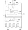
ここで図1A~図1Cを参照すると、本発明の1つまたは複数の態様に従って構成されたハンドル1000の種々の分解図が示されている。図1Aおよび図1Bに例示されるように、ハンドル1000は、ラチェットシフタ200、ツールコネクタ300、ラチェット継手400、リアパワーハウジング500および任意のハンドルグリップ600を含んでよい。ラチェットシフタ200、ツールコネクタ300、ラチェット継手400、リアパワーハウジング500および任意のハンドルグリップ600のそれぞれは、共通の長手方向軸または回転軸1100を共有する。ハンドルは、例えばスクリュードライバまたはドリルといった医療器具または医療用ツールに連結されるように構成される。一例では、スクリュードライバまたはドリルは、ハンドル1000のツールコネクタ300の近位端部314にて提供されるカップリング機構に、的確にかつ取り外し可能に把持されているか、またはこれに連結されている。カップリング機構は以下でより詳細に記載されるが、医療器具または医療用ツールへと、ハンドル1000に加えられるトルクを移動するように構成される。
1A-1C, various exploded views of a
ラチェットシフタ200、ツールコネクタ300、ラチェット継手400およびリアパワーハウジング500は組み立てられ、使用中は分離不可能である。ラチェットシフタ200、ツールコネクタ300、ラチェット継手400およびリアパワーハウジング500のアセンブリは、リアパワーハウジング500の遠位端部514にて、例えばコードレスのパワードリルといった動力器具またはツールへと容易にかつ取り外し可能に連結または取り付け可能である。動力器具またはツールに取り付ける代わりに、ラチェットシフタ200、ツールコネクタ300、ラチェット継手400およびリアパワーハウジング500のアセンブリはまた、例えばネジを手動で挿入するといった手動操作のための任意のハンドルグリップ600へと容易にかつ取り外し可能に連結または取り付け可能である。ハンドルグリップ600は、ハンドル1000に加えられるねじりの、動力による印加と手動による印加との間で移行するために、エンドユーザによって取り外しまたは取り付けられてよい。
The
図2Aおよび図2Bは、本発明の1つまたは複数の態様に従って構成されたラチェットシフタ200の一例を例示する。図2Aに示されるように、ラチェットシフタ200は、長手方向軸210、近位端部212および遠位端部214を含む。組立て中、長手方向軸210はハンドル1000の長手方向軸1100と一直線上に置かれる。ラチェットシフタ200は、貫通穴222を画定する本体220を更に備える。
2A and 2B illustrate an example of a
近位端部212では、ラチェットシフタ200は、貫通穴222と連通している開口部232を有する輪形状の外部表面230(図1Aに例示される)を含んでよい。図1Aおよび図2Bに例示されるように、2つのガイド突出部234は、長手方向軸210に向かって外部表面230から半径方向に内側へと延在する。一実施形態では、ガイド突出部234は、形状としては半円状のものとして現れてよい。この例では、ガイド突出部234は、ツールコネクタ300の本体320の外部表面326上にあるガイドスロット370(図1Aに示される)に対応し、ガイドスロット370におけるガイド突出部234を摺動係合可能とする嵌合界面を提供する。これは以下にて詳細に説明される。代替的な実施形態では、ガイド突出部234およびガイドスロット370の対応する嵌合面は、組立て中および操作中にガイド突出部234がガイドスロット370に摺動可能に係合可能である限りは、半円状以外の異なる構成または設計を有してよい。
At the
図2Aに例示されるように、ラチェットシフタ200は、遠位端部214から長手方向に突出している2つの弾性および可撓クリップ240を含んでよい。各クリップ240は、近位端部242および遠位端部244を含む。近位端部242は、遠位端部214に固定されてよい。縁246は、各クリップ240の遠位端部244から半径方向に内側へと延在してよい。近位端部242は、環状隅肉250を形成するために底部にフレアを含んでよい。環状隅肉250はクリップ240に構造的強度を提供し、クリップ240が遠位端部214から急に外れるか、脱落させ得るせん断応力および他の応力に抵抗する。
2A , the
図3Aおよび図3Bは、本発明の1つまたは複数の態様に従って構成されたツールコネクタ300の一例を例示する。図3Aに示されるように、ツールコネクタ300は、長手方向軸310、近位端部312および遠位端部314を含む。組立て中および操作中に、長手方向軸310はハンドル1000の長手方向軸1100と一直線上に置かれる。ツールコネクタ300はまた、近位端部312から延在しているツールまたは器具係合体320、およびツールまたは器具係合体320から遠位端部314まで長手方向に延在している取付けピン340を含む。
3A and 3B illustrate an example of a
ツールまたは器具係合体320は、近位端部312における第1の側面322および取付けピン340が自身から延在する第2の側面324を含む。ツールまたは器具係合体320は、長手方向軸310に沿った本体320の少なくとも一部を通って配置され、かつおよび例えばドリルまたはスクリュードライバといった外科用ツールまたは器具のドライブシャンクを受容し、かつこれを取り外し可能に連結または保定するように形作られた、ツール係合開口部330と連通している長手方向ボア332を含んでよい。
The tool or
使用中に外科用ツールまたは器具を取り外し可能に連結または保定する、当該技術分野に既知のカップリング機構が多く存在する。一例として、例えばドリルビットまたはスクリュードライバといった外科用ツールまたは器具のドライブシャンクまたは端部(図示せず)は、ツールまたは器具係合体320に形成された長手方向ボア332内部に、取り外し可能に把持または連結される。外科用ツールまたは器具のドライブシャンクは、ドライブシャンクの端部またはドライブシャンクの側面が、更なる挿入を防止し得る地点である停止部分334に接触するまで、長手方向ボア332内部へと挿入されてよい。一例では、ドライブシャンクは長手方向ボア332内部へと完全に挿入されていることから、本体320へと弾性的に取り付けられたリビングヒンジは、ツールまたは器具係合体320の長手方向ボア332内部へと挿入されるドライブシャンクの外部表面上にある、対応する溝またはくぼみと共働するように適合される。この例では、リビングヒンジは、ユーザによる手動係合のため、ツールまたは器具係合体の側面に形成された横方向の開口部を通って操作可能であってよい。代替的な実施形態では、ツールまたは器具係合体320は、外科用ツールまたは器具のドライブシャンクを取り外し可能に把持するチャックを含んでよい。他の実施形態では、ツールまたは器具係合体は、当該技術分野に既知の、AOスタイル、四角ドライブスタイルまたはHudsonスタイルの整形外科用連結部により、ツールまたは器具ドライブシャンクと取り外し可能に連結されてよい。
There are many coupling mechanisms known in the art for releasably connecting or retaining a surgical tool or instrument during use. In one example, a drive shank or end (not shown) of a surgical tool or instrument, such as a drill bit or screwdriver, is releasably grasped or connected within a
図1Aに例示されるように、ツール係合体320は、本体320の外部表面326に形成され、半径方向に内側へと延在している2つのガイドスロット370を含んでよい。上で説明されるように、ガイドスロット370の断面は、組立て中および操作中に、ガイドスロット370においてガイド突出部234の摺動係合を可能とするようなラチェットシフタ200の2つのガイド突出部234に対応する。
As illustrated in FIG. 1A, the
取付けピン340は、遠位端部314にて、基礎部分350およびキャップ360を備える。基礎部分350およびキャップ360は、図3に例示されるように、リアパワーハウジング500の保定基部530に形成された貫通穴532へと受け入れられるために構成される。基礎部分350は、取付けピン340に取り付けられ、かつここから長手方向に延在する。基礎部分350は、特定の用途および保定基部530の特定の寸法に依存する種々の横方向の高さを有し得る。例示された基礎部分350は、一般には円筒形の形状を有する。ただし、種々の他の形状にて構成されることもある。これらは、リアパワーハウジング500の保定基部530に形成された貫通穴532の形状と一致し得る。
The mounting
キャップ360は、基礎部分350の頂部から半径方向に外側へと延在する。キャップ360は、保定基部530から基礎部分350の分離を防止することにより、リアパワーハウジング500の保定基部530へのツールコネクタ300の取付けピン340の連結を援助する。例示されたキャップ360は、製造を容易にするために、基礎部分350の形状と一般には類似した横断形状を有する。ただし、保定基部530における貫通穴532の形状と一般には一致するように種々の他の横断形状で構成される可能性がある。これは以下に記載されている。キャップ360は、縁368により、望ましくは基礎部分350の円周を越えて延在し、取付けピン340を保定基部530への固定的な連結を援助し、互いに対し並進方向の運動を防止する。他の実施形態では、キャップ360は基礎部分350全体を取り囲む必要はなく、例えば基礎部分350から半径方向に外側へと延在する、1つまたは複数の半径方向部材のみを備えることができる。キャップ360の横方向の厚さは、著しく折れたり破断したりすることなく、取付けピン340を保定基部530へと連結するといったその構造的機能を実行するのに十分な厚さである。
The
切り面362は、以下に記載されるように、キャップ360の上方周辺縁部に形成され、取付けピン340の組立てを援助してよい。一例では、例示された切り面362は、キャップ360の厚さの約半分だけ横断方向に延在する。一実施形態では、基礎部分350およびキャップ360は、キャップ360および基礎部分350の少なくとも一部を通って軸方向に延在している穴またはスロット364を更に含む。穴またはスロット364は、以下に記載されるように、キャップ360が、組立て中に貫通穴532を通るように付勢され、キャップ360および基礎部分350の少なくとも一部を半径方向に内側へと曲げることにより、保定基部530における貫通穴532を介した取付けピン340と保定基部530の間の連結を容易にする。
A
基礎部分350は望ましくは、基礎部分350が、保定基部530のためのベアリング面を提供するように、保定基部530に対し基礎部分350の摺動および回転を容易にする目的で滑らかな側面354を有する。キャップ360の縁368は、以下に記載されるように、リアパワーハウジング500に対しツールコネクタ300の回転を目的として同一平面およびベアリング面を提供するため、貫通穴532を通り過ぎて保定基部530の接触面538の構成と一致させる平坦な下方側面366を含んでよい。例示された例では、基礎部分350およびキャップ360は、製造を容易にするためにおよび強度のために一続きの構成を有する。ただし、基礎部分350およびキャップ360は、取付けピン340から延在するか、またはこれに取り付けられる二部構成を代替的に備えることができる。基礎部分350およびキャップ360は、一般にはキノコ型ではあるが、基礎部分350およびキャップ360はまた、一般にはT字型、逆L字型などであり得る。
The
基礎部分350およびキャップ360は望ましくは、構造的強度のために取付けピン340を用いて一体に形成される。ただし、基礎部分350およびキャップ360は、別個の構成要素を備えることができる。例示された基礎部分350、キャップ360および保定基部530の貫通穴532は、ツールコネクタ300が中心回転することができるように、基礎部分350、キャップ360および保定基部530の貫通穴532の両方の長手方向軸が、ハンドル1000の長手方向軸1100と一直線上に置かれた状態で、円形構成を有する。
The
例示された実施形態では、図3Cに最も良好に示されるように、リアパワーハウジング500の保定基部530は、ツールコネクタ300が基礎部分350を中心として、リアパワーハウジング500に対して回転可能とするため、基礎部分350を受容するように、より好ましくは基礎部分350の貫通穴と一般には一致するように、サイズ決めおよび構成された貫通穴532を有する。例示された貫通穴532は、保定基部530を通って延在し、第1の径を有する。貫通穴532は、第2の径を有し得る保定スペース536と連通する。一実施形態では、第1の径は基礎部分350の径よりわずかに大きく、保定スペース536の第2の径は、縁368を有するキャップ360の径よりわずかに大きくてよい。基礎部分350のように、貫通穴532は、ツールコネクタ300が回転する際に摩擦を最小限とするよう、滑らかな面を有する。一実施形態では、以下に記載されるように、ツールコネクタ300の回転可能な取付けピン340の組立てを援助するため、切り面(図示せず)は第1の径の下方部分または貫通穴532の空洞540からの入り口を取り囲んでよい。
In the illustrated embodiment, as best shown in FIG. 3C , the
組み立てられる場合、基礎部分350およびキャップ360は、貫通穴532に挿入および軸510に沿って横断方向に前進され、保定基部530へと固定される。特に、キャップ360は、キャップ360の縁368の下方側面366が、保定スペース536内部の接触面538と一般には同一平面にある、保定基部530の保定スペース536内部に収容される。キャップ360を取り囲む切り面362により、キャップ360を分解または半径方向に内側へと変位し、貫通穴532を通って前進させることが可能となる。いくつかの実施形態では、例えば空洞540からの貫通穴532の入り口を取り囲む切り面(図示せず)によってこれが支援される。一度キャップ360が貫通穴532を通過すると、キャップ360はそのオリジナル構成へと弾んで戻り、基礎部分350が貫通穴532を通って延在しながら、縁368の下方側面366は保定スペース536における接触面538と噛み合う。この構成により、ツールコネクタ300はリアパワーハウジング500に対して360度回転する。
When assembled, the
図4A~図4Cは、本発明の1つまたは複数の態様に従って構成されたラチェット継手400の一例を例示する。ラチェット継手400は、長手方向軸410、近位端部412および遠位端部414を含む。操作中、長手方向軸410は、ハンドル1000の長手方向軸1100と一直線上に置かれる。ラチェット継手400はまた、長手方向の貫通穴422を画定する本体420を備える。長手方向の貫通穴422は、組立て中、ツールコネクタ300の取付けピン340を摺動可能に受容するように構成および形作られている。貫通穴422はまた、ラチェット継手400がハンドル1000の操作中、ツールコネクタ300と同時に回転するように構成および形作られている。ラチェット継手400はまた、近位端部412近くの外部表面に形成された円周方向の溝402を含む。
4A-4C illustrate an example of a ratchet joint 400 configured in accordance with one or more aspects of the present invention. The
図4Aおよび図4Bに例示されるように、本体420は第1の前方部分430および第2の後方部分460を含んでよい。第1の前方部分430は、外部表面432および第1の径492を含む。第2の後方部分460は、外部表面462および第2の径494を含む。第1の径492は、第2の径494と異なっていてよい。一例では、図4Bに例示されるように、第1の径492は第2の径494よりも大きい。第1の前方部分430および異なる径を有する第2の後方部分460を有する一実施形態は、ラチェット継手400が組立て中にリアパワーハウジング500内部に確実に適切に適合するように援助してよい。
4A and 4B, the
一実施形態では、図4Aおよび図4Bに例示されるように、第1の前方部分430は、外部表面432から半径方向に外側へと突出する複数のヒンジまたは指440を含んでよい。一例では、図4Aに示されるように、外部表面432の周りから半径方向に等距離で離間された2つの指またはヒンジ440が存在してよい。各ヒンジまたは指440は、近位端部442、遠位端部444、近位端部442にて外部表面432に直接固定され、かつ外部表面432から半径方向に外側へと延在している近位部分446および遠位端部444に向かって近位部分446から延在している遠位部分448を含む。近位部分446は、底部にフレアを含み、環状隅肉450を形成してよい。環状隅肉450は指またはヒンジに構造的強度を提供し、指またはヒンジ440が第1の前方部分430の外部表面432から急に外れるか、脱落させ得るせん断応力および他の応力に抵抗する。遠位部分448は、半径方向に外側へと面している表面452を含んでよい。遠位部分448は、近位部分446に対してある角度で曲がってよく、第1の前方部分430の周りで円周方向に、または第1の前方部分430の円周の周りを追随して更に延在してよい。一例では、各ヒンジまたは指440の遠位部分448は、図4Aに示されるように、長手方向軸410に対して時計回りの方向で円周方向に周りに延在する。
In one embodiment, as illustrated in FIGS. 4A and 4B, the first
一実施形態では、図4Aおよび図4Bに例示されるように、第2の部分460は、外部表面462から半径方向に外側へと突出する複数のヒンジまたは指470を含んでよい。一例では、図4Aに示されるように、外部表面462の周りから半径方向に等距離にて離間された2つの指またはヒンジ470が存在してよい。各ヒンジまたは指470は、近位端部472、遠位端部474、近位部分476にて外部表面462に直接固定され、かつ外部表面462から半径方向に外側へと延在している近位端部472および遠位端部474に向かって近位部分476から延在している遠位部分478を含む。近位部分476は、底部にフレアを含み、環状隅肉480を形成してよい。環状隅肉480は指またはヒンジに構造的強度を提供し、指またはヒンジ470が第2の後方部分460の外部表面462から急に外れるか、脱落させ得るせん断応力および他の応力に抵抗する。遠位部分478は、半径方向に外側へと面している表面482を含んでよい。遠位部分478は、近位部分446に対してある角度で曲がってよく、第2の後方部分460の周りで円周方向に、または第2の後方部分460の円周の周りを追随して更に延在してよい。一例では、各ヒンジまたは指470の遠位部分478は、図4Aに示されるように、長手方向軸410に対して反時計回りの方向で円周方向に周りに延在する。
In one embodiment, as illustrated in FIGS. 4A and 4B, the
以下に更に詳細に説明されるように、複数の指またはヒンジ440、470は、リアパワーハウジング500の空洞540の、前方の円周方向面542および後方の円周方向面546のそれぞれにおいて、各指またはヒンジ440、470と、歯560、561との間でそれぞれ係合可能であるように半径方向に互いに等距離にて離間されてよい。各指またはヒンジ440、470は弾性であり、可撓性であり、ラチェット継手400の長手方向軸410から半径方向に外側へと付勢される。一例では、指またはヒンジ440、470は、第1の前方部分430および第2の後方部分460とそれぞれ一体であり、同じ射出成形プロセス中に形成される。代替的な実施形態では、指またはヒンジ440、470は付加製造により作成されてよく、ラチェット継手400の外部表面432、462へと組み立てられるか、または例えばインサート成形によって成形される金属部材であってよい。
As described in more detail below, the fingers or hinges 440, 470 may be radially equidistantly spaced apart from one another to be engageable between each finger or hinge 440, 470 and the
例示された実施形態が、外部表面432の周りで互いに等距離にて離間された2つの指またはヒンジ440、および外部表面462の周りで互いに等距離にて離間された2つの指またはヒンジ470を有し得る一方、複数のオフセット距離は、実質的に同じ結果または異なる所望の結果を得るために同様に使用されてよい。更には、指//ヒンジ440、470の数ならびに/または各指もしくはヒンジ440、470の厚さおよび幅は、各指またはヒンジ440、470により、特定の用途にとって所望される特定の荷重または力(例えば、特定の方向にてリアパワーハウジング500の歯を越えてラチェット駆動させる指またはヒンジ440、470にとって所望のトルク)に応じて「調整」されるか、または大幅に変化し得る。複数の指またはヒンジ440、470の特定の数、構成および設計は、ハンドル1000の操作中全体を通し、必要とされ得るか、または所望され得る種々の荷重または力を供給するために変えられ得る。
While the illustrated embodiment may have two fingers or hinges 440 spaced equidistant from one another around the
図5Aおよび図5Bは、本発明の1つまたは複数の態様に従って構成されたリアパワーハウジング500の一例を例示する。リアパワーハウジング500は、長手方向軸510、近位端部512および遠位端部514を含む。操作中に、長手方向軸510は、組立て中および使用中に、ハンドル1000の長手方向軸1100と一直線上に置かれる。図5Aに例示されるように、リアパワーハウジング500は、近位端部512から延在する本体520、本体520から延在するドライブシャンク基部570、および遠位端部514に向かってドライブシャンク基部570から長手方向に延在するドライブシャンク580を備える。
5A and 5B illustrate an example of a
図5Aに例示されるように、本体520は、近位端部512にて開いている長手方向空洞540を共に画定する側壁522および保定基部530を含み得る、一般には円筒形の形状である。空洞は、以下にて詳細に説明されるように、ラチェット継手400を受容するように構成および形作られている。空洞540は、貫通穴532を介して保定スペース536と連通する。空洞540は、側壁522の内側表面524および保定基部530の内部表面534によって画定される。保定スペース536は、接触面538およびドライブシャンク基部570によって画定される。ドライブシャンク基部570は、ドライブシャンク580と不変的に連結するか、これを保持する。
As illustrated in FIG. 5A, the
図5Bに示されるように、側壁522の内側表面524は、第1の径543を有する前方の円周方向面542、第2の径545を有する中間の円周方向面544および第3の径547を有する後方の円周方向面546を含む。一実施形態では、図5Bに例示されるように、第1の径543は第2の径545および第3の径547より大きく、第2の径545は第3の径547よりも大きい。
As shown in FIG. 5B, the
図5B、図8Cおよび図9Cに例示されるように、前方の円周方向面542は、長手方向軸510に向かって半径方向に内側へと突出している複数の歯560を含む。複数の歯560は、半径方向に等距離にて離間されているか、または周りに円周方向にて間隔を空けて配置されており、前方の円周方向面542に沿って軸方向に延在する。図8Cに明確に例示されるように、各歯560は傾斜面562および停止面564を含む。傾斜面562は、傾斜路を作成するために反時計回りの方向で半径方向に内側へと角度付けられる。停止面564は、前方の円周方向面542から半径方向に外側へと延在し、実質的に長手方向軸510を横切る。スロットまたはスペース566は、1つの歯560の停止面564と、隣接する歯560の傾斜面562との間で、前方の円周方向面542により形成されてよい。
5B, 8C, and 9C, the forward
図5B、図8Cおよび図9Cに例示されるように、後方の円周方向面546は、長手方向軸510に向かって半径方向に内側へと突出している複数の歯561を含む。複数の歯561は、半径方向に等距離にて離間されているか、または周りに円周方向にて間隔を空けて配置されており、後方の円周方向面546に沿って軸方向に延在する。図8Cに明確に例示されるように、各歯561は傾斜面563および停止面565を含む。傾斜面563は、傾斜路を作成するために時計回りの方向で半径方向に内側へと角度付けられる。停止面565は、後方の円周方向面546から半径方向に外側へと延在し、実質的に長手方向軸510を横切る。スロットまたはスペース567は、1つの歯561の停止面565と、隣接する歯561の傾斜面563との間で、後方の円周方向面546により形成されてよい。
5B, 8C, and 9C, the rear
一実施形態では、歯560および561は、歯560の呼び径が歯561の呼び径と異なるように成形される。複数の歯560、561の特定の数、構成および設計は、ハンドル1000の操作中全体を通し、必要とされてよい、または所望され得る種々の荷重または力を供給するために変えられてよい。更に、歯560、561の数および/または各歯560、561の傾斜面562、563の高さおよび長さはそれぞれ、特定の用途に所望される特定のラチェット荷重または力(例えば、特定の方向にてリアパワーハウジング500の歯560、561を越えて乗り越えるか、またはこれを通過する指またはヒンジ440、470にとって所望のラチェット力)に応じて大幅に「調整」または変えられてよい。
In one embodiment, the
ドライブシャンク580は、ハンドル1000を駆動させるための種々の種類の動力器具と連結するように構成および設計されてよい。例えば、図5Aに例示されるように、ドライブシャンク580はクイックコネクト機能を含む六角ドライブシャンクを備える。六角ドライブシャンクの設計により高いトルク伝達が提供され、締める必要がなくなる。六角ドライブシャンクの設計によって、垂直な円筒形ドライブシャンクが共通して受ける滑りもまた可能ではなくなる。代替的な実施形態では、ドライブシャンクは、例えばSDSドライブシャンク、直線ドライブシャンク、四角ドライブシャンク、三角ドライブシャンクなどといった、他の既知のドライブシャンク形状といった形態であってよい。ドライブシャンクはまた、例えばAOスタイル、四角ドライブスタイルまたはHudson(登録商標)スタイルの整形外科用連結部のうち1つを備える動力器具と取り外し可能に連結されるよう、設計されてよい。
The
一実施形態では、回転は、例えば動力器具によってドライブシャフト580へと直接、または例えば、ハンドルグリップ600への手動回転によって、リアパワーハウジング500の他の態様(例えば、ドライブシャンク基部)に直接のいずれかで、リアパワーハウジング500へと加えられ得る。
In one embodiment, rotation can be applied to the
図6Aおよび図6Bは、本発明の1つまたは複数の態様に従って構成された、任意のハンドルグリップ600の一例である、斜視図および断面図をそれぞれ例示する。図6Aに例示されるように、ハンドルグリップ600は、長手方向軸610、近位端部612および遠位端部614を有する本体620を含んでよい。組立て中および操作中に、長手方向軸610はハンドル1000の長手方向軸1100と一直線上に置かれる。一例では、図6Aに例示されるように、本体620は人間の手で保持されるのに適している隆起形状を有してよい。ハンドルグリップ600に対する本体形状の他の例は図7A~図7Cに例示され、これは例えばT型ハンドル構成(図7A)、ピストルグリップ(図7B)またはパームハンドル(図7C)を含む。ハンドルグリップ600はまた、ハンドルに取り付けられた外科用器具またはツールに加えられるトルクを可能とする、ユーザによる手動処置を許容する、例えばボールまたは任意の他の種々の形状である構成といった形態であってよい。他の実施形態では、ハンドルグリップ600は、例えば色、マークおよび質感に関して、種々の商業マーケティング目的での用途においてカスタマイズ可能であってよい。
6A and 6B illustrate perspective and cross-sectional views, respectively, of an example of an
ハンドルグリップ600の本体620は、軽量で安価であり、生物学的に不活性な材料を有してよい。一例では、ハンドルグリップ600は、ポリアクリルアミド、ポリカーボネートまたはアクリルニトリルブタジエンスチレン(「ABS」)から作製されてよい。ハンドルグリップ600はまた、図6Aに示されるように、ユニボディ設計またはモノリシック設計であってよい。このユニボディ構造により、ハンドルグリップ600の製造が容易となる。同じ構造材料を有する複数構成要素設計よりもこれは強度が高くなる。
The
ハンドルグリップ600は、長手方向軸610に沿っており、ハンドルグリップ600を通って配置された長手方向ボア630を含んでよい。長手方向ボア630は、ハンドルグリップ600の近位端部612にて開いている。
The
ハンドルグリップ600はまた、横断方向ボア640を含んでよい。横断方向ボア640は、ハンドルグリップ600の本体620を通って配置される。横断方向ボア640は、長手方向軸642を有してよい。横断方向ボア640は、長手方向ボア630と交差する。一例では、横断方向ボア640は、長手方向ボア630と直角に交わる。横断方向ボア640はまた、本体620の外部に開いている第1の開口部および長手方向ボア630と連通している第2の開口部を有してよい。
The
ハンドルグリップ600は、ボタン650を更に含んでよい。一実施形態では、図6Bに示されるように、ボタン650はハンドルグリップ600に可撓式に取り付けられる。ボタン650は、長手方向ボア630と交差している横断方向ボア640を通って延在してよい。ボタン650および横断方向ボア640は、親指によってボタン650を操作可能および/または押し込み可能とするように、ハンドルグリップ600の本体620上に配置されてよい。ハンドルグリップ600の近位端部612のより近くにボタン650を位置づけることでまた、リアパワーハウジング500のドライブシャンク本体570に形成された溝572と係合するハンドルグリップ600の一部のより近くにボタン650を位置づける。ハンドルグリップ600は、第1の指または親指が、ボタン600に容易にアクセスしおよび押し込み可能であるように、ハンドルグリップ600が手のひらの周りで、かつ第1の指と第2の指の間の領域の方向にて延在している状態にて、五指および小指球領域がハンドルグリップ600の遠位端部614の近位に、またはその周りに位置づけられるように、ハンドルグリップ600を手で保持、把持または使用可能とするように構成(例えば、形作られるおよび寸法)されてよい。
The
有利には、ユニボディ設計を理由として、本発明に従って作成されたデバイスは、バネといった追加の構成要素を有さなくてもよい。ボタン650は、弾性部材652により本体に接続される。したがって、本発明の1つまたは複数の態様に従って構成されたハンドルグリップ600は、製造するのにより安価であり、かつ使用が簡単なものとなり得る。更には、ハンドルグリップ600が作成にとって安価であることから、単回使用(例えば使い捨て)デバイスに理想的に適合する。ハンドルグリップ600は、滅菌パッケージから取り出されて1回のみ使用されることから、清潔さが保障される。
Advantageously, due to the unibody design, devices made in accordance with the present invention may not have additional components such as springs. The
ここで図6Bを参照すると、本発明の1つまたは複数の態様に従って構成されたハンドルグリップ600の断面図が示されている。図示のように、ハンドルグリップ600は、長手方向ボア630内部に配置された戻り止め装置660を含む。ボタン650はまた、長手方向軸642に対し長手方向にて横断方向ボア640へと延在し得る厚さを有してよい。一実施形態では、ボタン650は縁654を有する遠位端部を含む。縁654は突出し、ハンドルグリップ600の長手方向軸610に向かって半径方向に下方に通常は付勢される。一実施形態では、リアパワーハウジング500に連結される場合には、縁654を備えるボタン650によってリビングヒンジが作成される。
6B, a cross-sectional view of a
図6Cを参照すると、リアパワーハウジング500のドライブシャンク580は、ハンドルグリップ600の長手方向ボア630へと近位端部612を通って挿入され得る。リアパワーハウジング500のドライブシャンク580は、リアパワーハウジング500のドライブシャンク基部570の端面574が厚肉部660と接触するまでか、または代替的にはリアパワーハウジング500の保定基部530の接触面538が、更なる挿入が抑止され得る地点である、ハンドルグリップ600の近位端部612と接触するまで、長手方向ボア630へと挿入されてよい。ドライブシャンク580が長手方向ボア630へと完全に挿入されている場合、ボタン650の縁654は、リアパワーハウジング500のドライブシャンク基部570の外部表面576上に形成された溝572内部へと摺動する。ボタン650の縁654は、ハンドルグリップ600の長手方向ボア630へと挿入されたリアパワーハウジング500のドライブシャンク基部570の、外部表面576上の対応する溝またはくぼみ572と共働するように適合される。
6C, the
一旦ドライブシャンク580およびリアパワーハウジング500のドライブシャンク基部570がハンドルグリップ600へと挿入されると、ボタン650の縁654は、溝572内部へと半径方向に付勢されるか、変位される。一実施形態では、縁654が溝572と完全に係合する場合、「カチッ」という音が聞こえてよい。ただし、ユーザは、縁654がリアパワーハウジング500のドライブシャンク基部570の溝572の外部を枢動するように、ハンドルグリップ600からリアパワーハウジング500を強制的に引き抜くことで、ハンドルグリップ600からリアパワーハウジング500を切り離すことができる。リアパワーハウジング500は、切り離し力に対して高い抵抗を提供する溝572へと適合された縁654と接続してよい。ただし、リアパワーハウジング500は、ハンドルグリップ600を通してリアパワーハウジング500へとユーザによって加えられる高い力に応答して依然として引っ張られてよい。一例では、横断力はボタン650を押し込むことにより、リアパワーハウジング500のドライブシャンク基部570へと加えられてよく、切り離し力によってリアパワーハウジング500の引き抜きを防止する追加の力を提供する。
Once the
他の実施形態では、ハンドルグリップ600は、リアパワーハウジング500のドライブシャンク基部570に形成された溝572と係合する2つ以上のボタンまたはリビングヒンジ630を含んでよい。代替的には、他のカップリング機構は、使用中にハンドルグリップ600内部に取り外し可能に保定するために、ドライブシャンク580またはリアパワーハウジング500のドライブシャンク基部570へと加えられてよい。例えば、ここで参照として本明細書に組み入れられる、国際公開第2019/168987号に記載および例示されたカップリング機構が使用されてよい。代替的な実施形態では、カップリング機構は、外科用ツールまたは器具のドライブシャンクを取り外し可能に把持するチャックを含んでよい。他の実施形態では、ドライブシャンク580は、当該技術分野に既知の、AOスタイル、四角ドライブスタイルまたはHudsonスタイルの整形外科用連結部により、ハンドルグリップ600内部に取り外し可能に連結されてよい。
In other embodiments, the
組み立てられる場合、ラチェット継手400は、ツールコネクタ300の取付けピン340を越えて摺動する。一実施形態では、第2の後方部分460の第2の径494と比較すると、より大きな第1の径492を有する第1の前方部分430は、ツールコネクタ300の遠位端部312を越えて最初に挿入され、ラチェット継手400が前後逆に組み立てられるのを防止する。
When assembled, the ratchet joint 400 slides over the mounting
次に、ラチェットシフタ200の遠位端部214は、ツールコネクタ300の近位端部312を越えて摺動するように構成される。ラチェットシフタ200がツールコネクタ300を越えて摺動されている時、ガイド突出部234は、ガイドスロット370と一直線上に置かれ、かつこれによって摺動可能に受容される。ラチェットシフタ200のクリップ240は、ラチェット継手400の溝402と係合する。一例では、ラチェット継手400の近位端部412が、ラチェットシフタ200によって連結するツールコネクタ300の取付けピン340上で、長手方向に摺動するように構成されている時、クリップ240は半径方向に外側へと曲がる。切り面241は、クリップ240の縁242が、ラチェット継手400の溝402へと半径方向に内側へとはね戻るか、曲がるか、変位するまで、ラチェット継手400の近位端部412を通り過ぎてクリップ240の遠位端部244が到達するのを援助するように、クリップ240の遠位端部244に形成されてよい。一例では、縁242および溝402は、ラチェットシフタ200およびラチェット継手400に共に連結するリビングヒンジを形成する。このようにしてラチェットシフタ200およびラチェット継手が共に連結される場合、ラチェット継手400(ラチェットシフタが取り付けられた状態である)は、ツールコネクタ300の取付けピン340上に依然として摺動可能であるが、回転することはできない。
The
ラチェットシフタ200、ツールコネクタ300およびラチェット継手400の組立て後、ツールコネクタ300の遠位端部314は次に、リアパワーハウジング500の本体520に形成された空洞540へと、長手方向軸510に沿って軸方向に挿入される。遠位端部314は空洞540へと前進するにつれ、ラチェット継手400を備える取付けピン340はまた、ツールコネクタ300の空洞540へと挿入される。基礎部分350およびツールコネクタ300の遠位端部314のキャップ360は挿入され、かつリアパワーハウジング500の保定基部530に形成された貫通穴532へと横断方向に前進される。キャップ360は、キャップ360の縁368の下方側面366が保定スペース536に保定基部530の接触面538と一般には同一平面にある状態で、キャップ360が半径方向に変位し、かつ保定スペース536内部に完全に収容されるまで、貫通穴532を通って完全に前進される。一旦キャップ360が保定スペース536内部に完全に着座すると、遠位コネクタ300は回転可能であるが、リアパワーハウジング500に対して軸方向に移動することはできない。ラチェット継手400は、リアパワーハウジング500の空洞540内部にて、ツールコネクタ300の取付けピン340上にて軸方向に摺動し得る。この時点では、ラチェットシフタ200、ツールコネクタ300、ラチェット継手400およびリアパワーハウジング500は、リアパワーハウジング500のドライブシャフト580に取り外し可能で取り付け可能である任意のハンドルグリップ600または動力器具のいずれかを用いて、使用のために共に組み立てられる。
After assembly of the
操作中、ハンドル1000は、例えば整形外科的な四肢の大型関節手術、または脊椎手術中に、骨内部または骨外部へと締結具をネジ留めするかゆるめるために、時計回りまたは反時計回りのいずれかでラチェットドライブとして使用されてよい。第1に、ネジまたはドリルビットは、ラチェットシフタの開口部232およびツールコネクタ300のツールまたは器具開口部330を通ってツールコネクタ300の長手方向ボア332へと挿入され、カップリング機構により内部に取り外し可能に連結されてよい。外科医またはユーザが、手動でのネジ挿入を所望する場合、ボタン650の縁654が、リアパワーハウジング500のシャンク基部570の溝572と係合するまで、または例えば厚肉部560またはハンドルグリップ600の近位端部612によって停止されない限り、ハンドルグリップ600は、ハンドルグリップ600の近位端部612にて、ドライブシャンク580の遠位端部514を長手方向ボア630へと挿入することで、リアパワーハウジング500のドライブシャンク580に取り外し可能に連結される。外科医またはユーザが、例えば動力ドリルまたは動力器具を用いたネジ挿入を所望する場合、ドライブシャンク580は、動力ドリルまたは動力器具のカップリング機構に取り外し可能に取り付けられる。本発明の1つまたは複数の態様に従って、ハンドル1000は、外科医またはユーザがトルクの動力による印加と手動による印加との間を容易に移行するように設計される。
In operation, the
ハンドル1000は、時計回り方向または挿入方向と、反時計回りまたは引き抜き方向の両方でのラチェット駆動が可能となる。例えば、ラチェットシフタ200がツールコネクタ300から軸方向に引き離される場合、ハンドル1000は、例えば骨内部に締結具を挿入している間、時計回りでのネジ留めおよび反時計回りでのラチェット駆動を可能とする状態にある。この操作モードは、図8A~図8Cに例示される。ラチェットシフタ200がツールコネクタ300に向かって軸方向に押し込まれる場合、ハンドル1000は、骨から締結具を反時計回りに引き抜き、かつ時計回りでのラチェット駆動を可能とする状態にある。この操作モードは、図9A~図9Cに例示される。これらの操作モードの両方は、本明細書に記載の実施形態に基づき、より詳細に記載される。
The
図8A~図8Cは、ハンドル1000の第1の操作モードを例示している。時計回りでのネジ留めおよび反時計回りでのラチェット駆動を可能とする第1の操作モードでは、ラチェットシフタ200はツールコネクタ300の近位端部312から軸方向に引き離される。この引き離しが発生した時、ガイド突出部234はガイドスロット370内部に摺動する。同時に、ラチェット継手400はラチェットシフタ200の運動およびラチェット継手400の円周方向溝402にてラチェットシフタ200のクリップ240の取付けに基づき、ツールコネクタ300の取付けピン340に沿って摺動する。この摺動が発生している間、ツールコネクタ300およびリアパワーハウジング500は、回転可能に連結されたままであり、互いに対してまたはラチェットシフタ200およびラチェット継手400の運動に対して軸方向に移動することはない。
8A-8C illustrate a first mode of operation of the
ラチェット継手400が、ツールコネクタの近位端部312からラチェットシフタ200を引き離した結果として取付けピン340上で摺動すると、ラチェット継手400は、リアパワーハウジング500の近位端部512に向かって移動する。第1の操作モードでは、ラチェット継手400の第1の前方部分430は、前方の円周方向面542と一直線上に置かれ、第2の後方部分460は、中間の円周方向面544と一直線上に置かれる。この構成では、例示されるように、例えば、図8Cでは、第1の前方部分430上の指またはヒンジ440は、リアパワーハウジング500の空洞540内部にて前方の円周方向面542上で歯560と係合し、第2の後方部分460上の指またはヒンジ470は、他の歯と係合しない。指またはヒンジ440が歯560と係合する場合、リアパワーハウジング500のドライブシャフト580の時計回りの運動(例えば、ハンドルグリップ600によって手動で、またはドライブシャフト580に取り外し可能に連結された動力器具によってのいずれかによる)は、歯560の停止面564内部へと指またはヒンジ440の遠位端部444と係合するか、または噛み合う。これにより、時計回りの方向でのトルクを、ツールコネクタ300の長手方向ボア320内部に連結された駆動器具(例えば、ドリルまたはスクリュードライバビット)へと移す。一実施形態では、側壁522の内部表面524は、1つまたは複数の前方の円周方向面542、中間の円周方向面544および/または後方の円周方向面546上またはこれらの間にいくつかの種類の1つまたは複数の戻り止め、1つまたは複数の止め具またはこぶ(図示せず)を含み、第1の操作モードにてラチェット継手400を保定し、ラチェット継手400が取付けピン340上で摺動するのを防止することができる。この例では、1つまたは複数の戻り止め、1つまたは複数の止め具またはこぶは、第1の操作モードと第2の操作モードの間を切り替えるため、外科医またはユーザによるいくつかの種類の力または強制力を必要としてよい。代替的には、1つまたは複数の戻り止め、1つまたは複数の止め具またはこぶは、取付けピン340上に、および/またはラチェット継手400の貫通穴422の内部表面上に含まれてよい。
When the ratchet joint 400 slides on the mounting
ドライブシャフト580の反時計回り運動により、指またはヒンジ440を歯560の傾斜面562を容易に押しのけるか、またはこれを通過することが可能となる。これにより、反時計回り方向にてラチェット駆動または自由回転が生じる。一例では、「カチッ」という音は、指またはヒンジ440が歯560の頂部を通過するたびに聞くことができる。歯が多く存在すればするほど、戻りストロークに必要となる運動は少なくなる。
The counterclockwise motion of the
ラチェット駆動方向の変更が必要または所望される場合、第2の操作モードを行うことができる。第2の操作モードは図9A~図9Cに例示される。骨から反時計回りで締結具を引き抜き、かつ時計回りでのラチェット駆動を可能とする第2の操作モードを行うため、ラチェットシフタ200はツールコネクタ300の近位端部312に向かって軸方向に押される。これが生じると、ガイド突出部234は、ガイドスロット370内部で摺動するように構成される。同時に、ラチェット継手400は、ラチェットシフタ200の運動およびラチェット継手400の円周方向溝402内部でのラチェットシフタ200のクリップ240の取付けに基づき、ツールコネクタ300の取付けピン340に沿って摺動するように構成される。この摺動が発生している間、ツールコネクタ300およびリアパワーハウジング500は、回転可能に連結されたままであり、互いに対してまたはラチェットシフタ200およびラチェット継手400の運動に対して軸方向に移動することはない。
If a change in ratchet drive direction is necessary or desired, a second mode of operation can be performed. The second mode of operation is illustrated in FIGS. 9A-9C. To perform the second mode of operation, which allows for counterclockwise fastener withdrawal from bone and clockwise ratchet drive, the
ツールコネクタの近位端部312に向かってラチェットシフタ200を押した結果として、ラチェット継手400が取付けピン340上で摺動する時、ラチェット継手400は近位端部から離れて移動し、更にはリアパワーハウジング500の空洞540へと移動する。第2の操作モードでは、ラチェット継手400の第1の前方部分430は、中間の円周方向面544と一直線上に置かれ、第2の後方部分460は、後方の円周方向面546と一直線上に置かれる。この構成では、例えば図9Cに例示されるように、第1の前方部分430上の指またはヒンジ440はどの歯とも係合しない。一実施形態では、中間の円周方向面544は、指またはヒンジ440を捕らえるか、またはこれを掴む歯を持たない第2の径545を有する。一例では、中間の円周方向面544の第2の径545は、前方の円周方向面542の第1の径543より小さい。この例では、中間の円周方向面544は、半径方向に内側へと指またはヒンジ440を曲げるか、または押す。ただし、中間の円周方向面544上に歯が存在しないため、指またはヒンジ440は時計回りの方向、または反時計回りの方向にて自由に回転することができる。
As a result of pushing the
第2の操作モードでは、第2の後方部分460上の指またはヒンジ470は、リアパワーハウジング500の空洞540内部にて後方の円周方向面546上の歯561と係合する。指またはヒンジ470が歯561と係合する場合、リアパワーハウジング500のドライブシャフト580における反時計回りの運動(例えば、ハンドルグリップ600によって手動で、またはドライブシャフト580に取り外し可能に連結された動力器具によってのいずれかによる)は、歯561の停止面565内部へと指またはヒンジ470の遠位端部474と係合するか、または噛み合う。これにより、反時計回りの方向でのトルクを、ツールコネクタ300の長手方向ボア320に連結された駆動器具へと移す。
In the second mode of operation, the fingers or hinges 470 on the second
ドライブシャフト580の時計回り運動により、指またはヒンジ470を歯561の傾斜面563を容易に押しのけるか、またはこれを通過することが可能となる。これにより、反時計回り方向にてラチェット駆動または自由回転が生じる。一例では、「カチッ」という音は、指またはヒンジ470が歯561の頂部を通過するたびに聞くことができる。歯が多く存在すればするほど、戻りストロークに必要となる運動は少なくなる。
The clockwise motion of the
ラチェットシフタ200、ツールコネクタ300、ラチェット継手400、リアパワーハウジング500および任意のハンドルグリップ600は、例えば射出成形、付加製造または3D印刷によって全て製造され得る。更に、これらの構成要素はそれぞれ、例えばガイドワイヤまたはKワイヤ自身を通過することを許容するように、長手方向軸に沿ってカニューレで挿入されてよい。
The
一実施形態では、ラチェットシフタ200は、ボタンまたはロッキング機構を供給するための、図2Aに示されるように切抜き部204を含んでよい。これはツールコネクタ300の一部であってよく、ツールコネクタ300の長手方向ボア332内に挿入されるツールまたは器具と解放可能に係合可能である。
In one embodiment, the
本発明の複数の態様が本明細書に記載および図示されるが、当業者は代替の態様を実施し、同様の目的を達成してもよい。したがって、添付の特許請求の範囲によって、これらの代替の態様が本発明の真の趣旨および範囲内にあるものとして全てを網羅することが意図されている。
While several embodiments of the present invention are described and illustrated herein, those skilled in the art may implement alternative embodiments to accomplish similar objectives, and it is therefore intended by the appended claims to cover all such alternative embodiments as fall within the true spirit and scope of the present invention.
Claims (10)
近位端部、遠位端部および貫通穴を画定する本体を含む、ラチェットシフタと、
ツールコネクタであって、長手方向軸、近位端部および遠位端部を含み、前記近位端部から延在しているツール係合体および前記ツール係合体から前記遠位端部まで、前記長手方向軸に沿って長手方向に延在している取付けピンを更に含み、前記ツール係合体が、前記近位端部にて、前記長手方向軸に沿って前記ツール係合体の少なくとも一部を通って延在している長手方向ボアと連通しているツール係合開口部を含み、前記長手方向ボアが前記外科用ツールを解放可能に連結するように構成され、前記ラチェットシフタが、前記ツールコネクタを入れ子状に伸縮自在に受容し、かつ第1の位置と第2の位置の間を摺動可能に可動する、ツールコネクタと、
ラチェット継手であって、貫通穴を画定する本体および外部表面を含み、前記ツールコネクタの前記取付けピンが、円筒形の本体の前記貫通穴を通過し、前記取付けピンが、前記ラチェット継手に摺動可能に連結され、前記ラチェットシフタの前記遠位端部が、前記ラチェット継手に連結され、前記ラチェット継手の前記外部表面が、第1の前方部分および第2の後方部分を含み、前記第1の前方部分が、前記外部表面から半径方向に外側へと延在している複数の指を含み、前記第2の後方部分が、前記外部表面から半径方向に外側へと延在している複数の指を含む、ラチェット継手と、
リアパワーハウジングであって、前記遠位端部にて前記ツールコネクタの前記取付けピンへと回転可能に連結され、長手方向軸、本体および前記本体から前記長手方向軸に沿って長手方向に延在しているドライブシャフトを含み、前記本体が、内部表面を画定する空洞を含み、前記内部表面が前方の円周方向面、中間の円周方向面および後方の円周方向面を含み、前記前方の円周方向面が、前記内部表面から半径方向に内側へと突出している複数の歯を含み、前記後方の円周方向面が、前記内部表面から半径方向に内側へと突出している複数の歯を含み、前記第1の位置では、前記ラチェット継手の前記第1の前方部分の複数の指が、第1の方向でのラチェット駆動および第2の方向での最大トルクを可能とするため、前記前方の円周方向面上の前記複数の歯と係合し、前記第2の後方部分の複数の指が、前記中間の円周方向面と係合し、前記第2の位置では、前記ラチェット継手の前記第2の後方部分の前記複数の指が、前記第2の方向でのラチェット駆動および前記第1の方向での最大トルクを可能とするため、前記後方の円周方向面上の前記複数の歯と係合し、前記第1の前方部分の前記複数の指が、前記中間の円周方向面と係合する、リアパワーハウジングと、を備える、外科用ツールを解放可能に保持するための機器。 1. An instrument for releasably holding a surgical tool, said instrument comprising:
a ratchet shifter including a body defining a proximal end, a distal end and a throughbore;
a tool connector including a longitudinal axis, a proximal end and a distal end, further including a tool engager extending from the proximal end and a mounting pin extending longitudinally along the longitudinal axis from the tool engager to the distal end, the tool engager including a tool engagement opening at the proximal end in communication with a longitudinal bore extending through at least a portion of the tool engager along the longitudinal axis, the longitudinal bore configured to releasably couple the surgical tool, the ratchet shifter telescopically receiving the tool connector and slidably movable between a first position and a second position;
a ratchet joint including a body and an exterior surface defining a through hole, the mounting pin of the tool connector passing through the through hole of a cylindrical body, the mounting pin slidably coupled to the ratchet joint, the distal end of the ratchet shifter coupled to the ratchet joint, the exterior surface of the ratchet joint including a first forward portion and a second rearward portion, the first forward portion including a plurality of fingers extending radially outward from the exterior surface, and the second rearward portion including a plurality of fingers extending radially outward from the exterior surface;
a rear power housing rotatably coupled at its distal end to the mounting pin of the tool connector, the rear power housing including a longitudinal axis, a body, and a drive shaft extending longitudinally from the body along the longitudinal axis, the body including a cavity defining an interior surface, the interior surface including a forward circumferential surface, a middle circumferential surface, and an aft circumferential surface, the forward circumferential surface including a plurality of teeth projecting radially inwardly from the interior surface, the aft circumferential surface including a plurality of teeth projecting radially inwardly from the interior surface, and in the first position, the first forward circumferential surface of the ratchet joint is in engagement with the first circumferential surface of the ratchet joint. and a rear power housing, wherein in the second position, fingers of the second rear portion of the ratchet joint engage the teeth on the rear circumferential surface to enable ratcheting in the second direction and maximum torque in the first direction and fingers of the second rear portion engage the intermediate circumferential surface, and wherein in the second position, fingers of the second rear portion of the ratchet joint engage the teeth on the rear circumferential surface to enable ratcheting in the second direction and maximum torque in the first direction and fingers of the first forward portion engage the intermediate circumferential surface.
The apparatus of claim 1 , wherein the drive shaft is removably attachable to a power tool.
Applications Claiming Priority (2)
| Application Number | Priority Date | Filing Date | Title |
|---|---|---|---|
| US202063007993P | 2020-04-10 | 2020-04-10 | |
| US63/007,993 | 2020-04-10 |
Publications (3)
| Publication Number | Publication Date |
|---|---|
| JP2021166707A JP2021166707A (en) | 2021-10-21 |
| JP2021166707A5 JP2021166707A5 (en) | 2022-12-27 |
| JP7464562B2 true JP7464562B2 (en) | 2024-04-09 |
Family
ID=75783605
Family Applications (1)
| Application Number | Title | Priority Date | Filing Date |
|---|---|---|---|
| JP2021066198A Active JP7464562B2 (en) | 2020-04-10 | 2021-04-09 | Ratchet drive handle for medical instruments |
Country Status (5)
| Country | Link |
|---|---|
| US (1) | US20210315555A1 (en) |
| JP (1) | JP7464562B2 (en) |
| AU (1) | AU2021201890B2 (en) |
| DE (1) | DE102021108611A1 (en) |
| GB (1) | GB2598019A (en) |
Families Citing this family (4)
| Publication number | Priority date | Publication date | Assignee | Title |
|---|---|---|---|---|
| EP2214565A4 (en) | 2007-10-27 | 2015-08-26 | Parcus Medical Llc | Suture anchor |
| WO2015171962A1 (en) | 2014-05-07 | 2015-11-12 | Bart Bracy | Multipart suture |
| WO2017210620A1 (en) | 2016-06-02 | 2017-12-07 | Bracy Barton | Suture tool and method of use |
| US11517301B2 (en) | 2016-06-02 | 2022-12-06 | Parcus Medical, Llc | Surgical tool and method of use |
Citations (1)
| Publication number | Priority date | Publication date | Assignee | Title |
|---|---|---|---|---|
| US20160278748A1 (en) | 2014-12-18 | 2016-09-29 | Eca Medical Instruments | Disposable bidirectional ratchet |
Family Cites Families (30)
| Publication number | Priority date | Publication date | Assignee | Title |
|---|---|---|---|---|
| US2333549A (en) * | 1942-05-25 | 1943-11-02 | Victor B Novak | Ratchet chuck |
| US3209802A (en) * | 1963-08-30 | 1965-10-05 | Human Arthur | Tool for removing and replacing threaded fasteners |
| US4224969A (en) * | 1979-06-14 | 1980-09-30 | Plessner Jac A | Universal chuck adaptor |
| US4413937A (en) * | 1980-12-18 | 1983-11-08 | Gutsche Guenter E | Elements for a tool system |
| US5255576A (en) * | 1992-04-01 | 1993-10-26 | Keith John R | Adjustable universal ratcheting fire hydrant wrench |
| US5673594A (en) * | 1996-01-03 | 1997-10-07 | Industrial Technology Research Institute | Speed change lever apparatus for use in bicycles |
| US6047801A (en) * | 1997-12-09 | 2000-04-11 | Liao; Yung-Chuan | Ratchet screwdriver |
| US6070501A (en) * | 1998-08-31 | 2000-06-06 | Snap-On Tools Company | Mini ratcheting screwdriver with latching swiveling handle |
| US6076432A (en) * | 1999-08-03 | 2000-06-20 | Chang; Yueh | Reversible ratchet screwdriver |
| US6199872B1 (en) * | 1999-08-13 | 2001-03-13 | Maxtech Consumer Products, L.L.C. | Quick-release mechanism for screwdriver bits and the like |
| US7213491B1 (en) * | 2004-07-16 | 2007-05-08 | Snap-On Incorporated | Ratcheting tool |
| US20060248987A1 (en) * | 2005-05-05 | 2006-11-09 | Patrick White | Ratchet handle |
| US7222557B2 (en) * | 2005-09-21 | 2007-05-29 | Easco Hand Tools, Inc. | Ratcheting tool driver |
| US20070290458A1 (en) * | 2006-06-15 | 2007-12-20 | Shun-Yuan Chuang | Replaceable adapter for an electric hand tool |
| US20080092695A1 (en) * | 2006-10-19 | 2008-04-24 | Hector Ray Hernandez | Bi-directional ratchet drive |
| US8709015B2 (en) * | 2008-03-10 | 2014-04-29 | DePuy Synthes Products, LLC | Bilateral vertebral body derotation system |
| CN201350611Y (en) * | 2008-12-22 | 2009-11-25 | 上海美瑞实业有限公司 | Screw locking mechanism for double-helix ratchet screw driver |
| GB2468544A (en) * | 2009-03-14 | 2010-09-15 | Jin-Tsai Lai | Bi-directional Ratchet Screwdriver |
| US20100294595A1 (en) * | 2009-05-19 | 2010-11-25 | Jason Todd Osburn | Adjustable scaffolding apparatus |
| LT5838B (en) * | 2010-08-16 | 2012-05-25 | Linas ADOMAVIČIUS | Tool for restoration/fixing of the formwork props and method of use |
| US9643298B2 (en) * | 2013-01-18 | 2017-05-09 | Hangzhou Great Star Tools Co., Ltd | Thin bi-directional ratchet wrench |
| CA2903436C (en) * | 2013-03-12 | 2017-08-01 | Eca Medical Instruments | Ratcheting torque wrench |
| US20140260816A1 (en) * | 2013-03-14 | 2014-09-18 | William Frank Budleski | Opposing force tool drive system |
| MX2016001667A (en) * | 2013-08-08 | 2016-11-07 | Global Bio Therapeutics Inc | Clamp device for minimally invasive procedures and uses thereof. |
| US20150096413A1 (en) * | 2013-10-08 | 2015-04-09 | Colin G. Knight | Quick Release Ratchet Driver |
| CA2872837A1 (en) * | 2014-12-01 | 2016-06-01 | Bartosz Markiewicz | Torque limiting filter wrench |
| US10730167B2 (en) * | 2017-07-19 | 2020-08-04 | Zimmer, Inc. | Disposable surgical screwdriver |
| EP3527328A1 (en) * | 2018-02-14 | 2019-08-21 | Ruetschi Technology AG | A disposable instrument for torque control tightening a threaded implant device |
| DE112019001029T5 (en) | 2018-02-27 | 2021-01-07 | Nextremity Solutions, Inc. | DISPOSABLE HANDLE FOR MEDICAL INSTRUMENTS |
| US10702978B2 (en) * | 2018-07-24 | 2020-07-07 | Larry J. Meehan | Spiral ratchet driver with a crank and slider mechanism |
-
2021
- 2021-03-24 US US17/210,609 patent/US20210315555A1/en active Pending
- 2021-03-26 AU AU2021201890A patent/AU2021201890B2/en active Active
- 2021-03-26 GB GB2104358.3A patent/GB2598019A/en active Pending
- 2021-04-07 DE DE102021108611.6A patent/DE102021108611A1/en active Pending
- 2021-04-09 JP JP2021066198A patent/JP7464562B2/en active Active
Patent Citations (1)
| Publication number | Priority date | Publication date | Assignee | Title |
|---|---|---|---|---|
| US20160278748A1 (en) | 2014-12-18 | 2016-09-29 | Eca Medical Instruments | Disposable bidirectional ratchet |
Also Published As
| Publication number | Publication date |
|---|---|
| DE102021108611A1 (en) | 2021-10-14 |
| GB2598019A (en) | 2022-02-16 |
| AU2021201890B2 (en) | 2023-09-28 |
| GB202104358D0 (en) | 2021-05-12 |
| US20210315555A1 (en) | 2021-10-14 |
| AU2021201890A1 (en) | 2021-10-28 |
| JP2021166707A (en) | 2021-10-21 |
Similar Documents
| Publication | Publication Date | Title |
|---|---|---|
| JP7464562B2 (en) | Ratchet drive handle for medical instruments | |
| AU2021201895B2 (en) | Torque limiting ratcheting handle for medical instrument | |
| US20210315656A1 (en) | Torque limiting handle for medical instrument | |
| US7922719B2 (en) | Adjustable angle pawl handle for surgical instruments | |
| EP2259732B1 (en) | Handle for a surgical instrument and surgical instrument assembly | |
| US4763548A (en) | Screwdriver, particularly for surgical purposes | |
| JP5722338B2 (en) | Screw delivery system | |
| CA2677166C (en) | Screwdriving tool with free wheel gear | |
| JP2021166707A5 (en) | ||
| JP2021151502A (en) | screwdriver | |
| EP1955667B1 (en) | Global nail screw retaining screwdriver | |
| JP2021166708A5 (en) | ||
| US7587962B2 (en) | Ratcheting handle for a tool | |
| US11331134B2 (en) | Orthopedic device holder | |
| CA3072215C (en) | Cannulated t-handle driver | |
| AU2019275477B2 (en) | Surgical handle | |
| CN220145862U (en) | Handle and tool system with same | |
| US20020157505A1 (en) | Handle grip for a wrench | |
| KR101872495B1 (en) | Screw driver | |
| JPH10156738A (en) | Screw fastening tool | |
| JPH081532A (en) | Screw driver |
Legal Events
| Date | Code | Title | Description |
|---|---|---|---|
| A521 | Request for written amendment filed |
Free format text: JAPANESE INTERMEDIATE CODE: A523 Effective date: 20221219 |
|
| A621 | Written request for application examination |
Free format text: JAPANESE INTERMEDIATE CODE: A621 Effective date: 20221219 |
|
| A977 | Report on retrieval |
Free format text: JAPANESE INTERMEDIATE CODE: A971007 Effective date: 20230922 |
|
| A131 | Notification of reasons for refusal |
Free format text: JAPANESE INTERMEDIATE CODE: A131 Effective date: 20230926 |
|
| A521 | Request for written amendment filed |
Free format text: JAPANESE INTERMEDIATE CODE: A523 Effective date: 20231130 |
|
| TRDD | Decision of grant or rejection written | ||
| A01 | Written decision to grant a patent or to grant a registration (utility model) |
Free format text: JAPANESE INTERMEDIATE CODE: A01 Effective date: 20240305 |
|
| A61 | First payment of annual fees (during grant procedure) |
Free format text: JAPANESE INTERMEDIATE CODE: A61 Effective date: 20240328 |
|
| R150 | Certificate of patent or registration of utility model |
Ref document number: 7464562 Country of ref document: JP Free format text: JAPANESE INTERMEDIATE CODE: R150 |