JP7463516B2 - Battery pack, electronic device including same, and automobile - Google Patents
Battery pack, electronic device including same, and automobile Download PDFInfo
- Publication number
- JP7463516B2 JP7463516B2 JP2022537187A JP2022537187A JP7463516B2 JP 7463516 B2 JP7463516 B2 JP 7463516B2 JP 2022537187 A JP2022537187 A JP 2022537187A JP 2022537187 A JP2022537187 A JP 2022537187A JP 7463516 B2 JP7463516 B2 JP 7463516B2
- Authority
- JP
- Japan
- Prior art keywords
- frame
- cover portion
- base plate
- battery pack
- plate
- Prior art date
- Legal status (The legal status is an assumption and is not a legal conclusion. Google has not performed a legal analysis and makes no representation as to the accuracy of the status listed.)
- Active
Links
Images


Classifications
-
- H—ELECTRICITY
- H01—ELECTRIC ELEMENTS
- H01M—PROCESSES OR MEANS, e.g. BATTERIES, FOR THE DIRECT CONVERSION OF CHEMICAL ENERGY INTO ELECTRICAL ENERGY
- H01M50/00—Constructional details or processes of manufacture of the non-active parts of electrochemical cells other than fuel cells, e.g. hybrid cells
- H01M50/20—Mountings; Secondary casings or frames; Racks, modules or packs; Suspension devices; Shock absorbers; Transport or carrying devices; Holders
- H01M50/233—Mountings; Secondary casings or frames; Racks, modules or packs; Suspension devices; Shock absorbers; Transport or carrying devices; Holders characterised by physical properties of casings or racks, e.g. dimensions
- H01M50/242—Mountings; Secondary casings or frames; Racks, modules or packs; Suspension devices; Shock absorbers; Transport or carrying devices; Holders characterised by physical properties of casings or racks, e.g. dimensions adapted for protecting batteries against vibrations, collision impact or swelling
-
- H—ELECTRICITY
- H01—ELECTRIC ELEMENTS
- H01M—PROCESSES OR MEANS, e.g. BATTERIES, FOR THE DIRECT CONVERSION OF CHEMICAL ENERGY INTO ELECTRICAL ENERGY
- H01M50/00—Constructional details or processes of manufacture of the non-active parts of electrochemical cells other than fuel cells, e.g. hybrid cells
- H01M50/20—Mountings; Secondary casings or frames; Racks, modules or packs; Suspension devices; Shock absorbers; Transport or carrying devices; Holders
- H01M50/244—Secondary casings; Racks; Suspension devices; Carrying devices; Holders characterised by their mounting method
-
- B—PERFORMING OPERATIONS; TRANSPORTING
- B60—VEHICLES IN GENERAL
- B60L—PROPULSION OF ELECTRICALLY-PROPELLED VEHICLES; SUPPLYING ELECTRIC POWER FOR AUXILIARY EQUIPMENT OF ELECTRICALLY-PROPELLED VEHICLES; ELECTRODYNAMIC BRAKE SYSTEMS FOR VEHICLES IN GENERAL; MAGNETIC SUSPENSION OR LEVITATION FOR VEHICLES; MONITORING OPERATING VARIABLES OF ELECTRICALLY-PROPELLED VEHICLES; ELECTRIC SAFETY DEVICES FOR ELECTRICALLY-PROPELLED VEHICLES
- B60L50/00—Electric propulsion with power supplied within the vehicle
- B60L50/50—Electric propulsion with power supplied within the vehicle using propulsion power supplied by batteries or fuel cells
- B60L50/60—Electric propulsion with power supplied within the vehicle using propulsion power supplied by batteries or fuel cells using power supplied by batteries
- B60L50/64—Constructional details of batteries specially adapted for electric vehicles
-
- B—PERFORMING OPERATIONS; TRANSPORTING
- B60—VEHICLES IN GENERAL
- B60L—PROPULSION OF ELECTRICALLY-PROPELLED VEHICLES; SUPPLYING ELECTRIC POWER FOR AUXILIARY EQUIPMENT OF ELECTRICALLY-PROPELLED VEHICLES; ELECTRODYNAMIC BRAKE SYSTEMS FOR VEHICLES IN GENERAL; MAGNETIC SUSPENSION OR LEVITATION FOR VEHICLES; MONITORING OPERATING VARIABLES OF ELECTRICALLY-PROPELLED VEHICLES; ELECTRIC SAFETY DEVICES FOR ELECTRICALLY-PROPELLED VEHICLES
- B60L58/00—Methods or circuit arrangements for monitoring or controlling batteries or fuel cells, specially adapted for electric vehicles
- B60L58/10—Methods or circuit arrangements for monitoring or controlling batteries or fuel cells, specially adapted for electric vehicles for monitoring or controlling batteries
- B60L58/24—Methods or circuit arrangements for monitoring or controlling batteries or fuel cells, specially adapted for electric vehicles for monitoring or controlling batteries for controlling the temperature of batteries
- B60L58/26—Methods or circuit arrangements for monitoring or controlling batteries or fuel cells, specially adapted for electric vehicles for monitoring or controlling batteries for controlling the temperature of batteries by cooling
-
- H—ELECTRICITY
- H01—ELECTRIC ELEMENTS
- H01M—PROCESSES OR MEANS, e.g. BATTERIES, FOR THE DIRECT CONVERSION OF CHEMICAL ENERGY INTO ELECTRICAL ENERGY
- H01M10/00—Secondary cells; Manufacture thereof
- H01M10/42—Methods or arrangements for servicing or maintenance of secondary cells or secondary half-cells
- H01M10/425—Structural combination with electronic components, e.g. electronic circuits integrated to the outside of the casing
-
- H—ELECTRICITY
- H01—ELECTRIC ELEMENTS
- H01M—PROCESSES OR MEANS, e.g. BATTERIES, FOR THE DIRECT CONVERSION OF CHEMICAL ENERGY INTO ELECTRICAL ENERGY
- H01M50/00—Constructional details or processes of manufacture of the non-active parts of electrochemical cells other than fuel cells, e.g. hybrid cells
- H01M50/20—Mountings; Secondary casings or frames; Racks, modules or packs; Suspension devices; Shock absorbers; Transport or carrying devices; Holders
- H01M50/204—Racks, modules or packs for multiple batteries or multiple cells
-
- H—ELECTRICITY
- H01—ELECTRIC ELEMENTS
- H01M—PROCESSES OR MEANS, e.g. BATTERIES, FOR THE DIRECT CONVERSION OF CHEMICAL ENERGY INTO ELECTRICAL ENERGY
- H01M50/00—Constructional details or processes of manufacture of the non-active parts of electrochemical cells other than fuel cells, e.g. hybrid cells
- H01M50/20—Mountings; Secondary casings or frames; Racks, modules or packs; Suspension devices; Shock absorbers; Transport or carrying devices; Holders
- H01M50/249—Mountings; Secondary casings or frames; Racks, modules or packs; Suspension devices; Shock absorbers; Transport or carrying devices; Holders specially adapted for aircraft or vehicles, e.g. cars or trains
-
- H—ELECTRICITY
- H01—ELECTRIC ELEMENTS
- H01M—PROCESSES OR MEANS, e.g. BATTERIES, FOR THE DIRECT CONVERSION OF CHEMICAL ENERGY INTO ELECTRICAL ENERGY
- H01M50/00—Constructional details or processes of manufacture of the non-active parts of electrochemical cells other than fuel cells, e.g. hybrid cells
- H01M50/20—Mountings; Secondary casings or frames; Racks, modules or packs; Suspension devices; Shock absorbers; Transport or carrying devices; Holders
- H01M50/258—Modular batteries; Casings provided with means for assembling
-
- B—PERFORMING OPERATIONS; TRANSPORTING
- B60—VEHICLES IN GENERAL
- B60K—ARRANGEMENT OR MOUNTING OF PROPULSION UNITS OR OF TRANSMISSIONS IN VEHICLES; ARRANGEMENT OR MOUNTING OF PLURAL DIVERSE PRIME-MOVERS IN VEHICLES; AUXILIARY DRIVES FOR VEHICLES; INSTRUMENTATION OR DASHBOARDS FOR VEHICLES; ARRANGEMENTS IN CONNECTION WITH COOLING, AIR INTAKE, GAS EXHAUST OR FUEL SUPPLY OF PROPULSION UNITS IN VEHICLES
- B60K11/00—Arrangement in connection with cooling of propulsion units
- B60K11/02—Arrangement in connection with cooling of propulsion units with liquid cooling
-
- H—ELECTRICITY
- H01—ELECTRIC ELEMENTS
- H01M—PROCESSES OR MEANS, e.g. BATTERIES, FOR THE DIRECT CONVERSION OF CHEMICAL ENERGY INTO ELECTRICAL ENERGY
- H01M10/00—Secondary cells; Manufacture thereof
- H01M10/60—Heating or cooling; Temperature control
- H01M10/61—Types of temperature control
- H01M10/613—Cooling or keeping cold
-
- H—ELECTRICITY
- H01—ELECTRIC ELEMENTS
- H01M—PROCESSES OR MEANS, e.g. BATTERIES, FOR THE DIRECT CONVERSION OF CHEMICAL ENERGY INTO ELECTRICAL ENERGY
- H01M10/00—Secondary cells; Manufacture thereof
- H01M10/60—Heating or cooling; Temperature control
- H01M10/62—Heating or cooling; Temperature control specially adapted for specific applications
- H01M10/625—Vehicles
-
- H—ELECTRICITY
- H01—ELECTRIC ELEMENTS
- H01M—PROCESSES OR MEANS, e.g. BATTERIES, FOR THE DIRECT CONVERSION OF CHEMICAL ENERGY INTO ELECTRICAL ENERGY
- H01M10/00—Secondary cells; Manufacture thereof
- H01M10/60—Heating or cooling; Temperature control
- H01M10/65—Means for temperature control structurally associated with the cells
- H01M10/655—Solid structures for heat exchange or heat conduction
- H01M10/6556—Solid parts with flow channel passages or pipes for heat exchange
-
- H—ELECTRICITY
- H01—ELECTRIC ELEMENTS
- H01M—PROCESSES OR MEANS, e.g. BATTERIES, FOR THE DIRECT CONVERSION OF CHEMICAL ENERGY INTO ELECTRICAL ENERGY
- H01M10/00—Secondary cells; Manufacture thereof
- H01M10/42—Methods or arrangements for servicing or maintenance of secondary cells or secondary half-cells
- H01M10/425—Structural combination with electronic components, e.g. electronic circuits integrated to the outside of the casing
- H01M2010/4271—Battery management systems including electronic circuits, e.g. control of current or voltage to keep battery in healthy state, cell balancing
-
- H—ELECTRICITY
- H01—ELECTRIC ELEMENTS
- H01M—PROCESSES OR MEANS, e.g. BATTERIES, FOR THE DIRECT CONVERSION OF CHEMICAL ENERGY INTO ELECTRICAL ENERGY
- H01M2220/00—Batteries for particular applications
- H01M2220/20—Batteries in motive systems, e.g. vehicle, ship, plane
-
- Y—GENERAL TAGGING OF NEW TECHNOLOGICAL DEVELOPMENTS; GENERAL TAGGING OF CROSS-SECTIONAL TECHNOLOGIES SPANNING OVER SEVERAL SECTIONS OF THE IPC; TECHNICAL SUBJECTS COVERED BY FORMER USPC CROSS-REFERENCE ART COLLECTIONS [XRACs] AND DIGESTS
- Y02—TECHNOLOGIES OR APPLICATIONS FOR MITIGATION OR ADAPTATION AGAINST CLIMATE CHANGE
- Y02E—REDUCTION OF GREENHOUSE GAS [GHG] EMISSIONS, RELATED TO ENERGY GENERATION, TRANSMISSION OR DISTRIBUTION
- Y02E60/00—Enabling technologies; Technologies with a potential or indirect contribution to GHG emissions mitigation
- Y02E60/10—Energy storage using batteries
Landscapes
- Engineering & Computer Science (AREA)
- Chemical & Material Sciences (AREA)
- General Chemical & Material Sciences (AREA)
- Electrochemistry (AREA)
- Chemical Kinetics & Catalysis (AREA)
- Manufacturing & Machinery (AREA)
- Mechanical Engineering (AREA)
- Life Sciences & Earth Sciences (AREA)
- Transportation (AREA)
- Power Engineering (AREA)
- Sustainable Energy (AREA)
- Sustainable Development (AREA)
- Aviation & Aerospace Engineering (AREA)
- Microelectronics & Electronic Packaging (AREA)
- Battery Mounting, Suspending (AREA)
- Secondary Cells (AREA)
Description
本発明は、バッテリーパック、それを含む電子デバイス及び自動車に関し、より詳しくは、外部衝撃に対する安全性を高めたバッテリーパック、それを含む電子デバイス及び自動車に関する。 The present invention relates to a battery pack, an electronic device including the same, and an automobile, and more specifically to a battery pack with improved safety against external impacts, and an electronic device and an automobile including the same.
本出願は、2020年9月4日付け出願の韓国特許出願第10-2020-0113233号に基づく優先権を主張し、当該出願の明細書及び図面に開示された内容は、すべて本出願に組み込まれる。 This application claims priority to Korean Patent Application No. 10-2020-0113233, filed on September 4, 2020, the entire contents of which are incorporated herein by reference in their entirety in the specification and drawings.
近年、ノートパソコン、ビデオカメラ、携帯電話などのような携帯用電子製品の需要が急激に伸び、電気自動車、エネルギー貯蔵用蓄電池、ロボット、衛星などの開発が本格化されるにつれて、繰り返して充放電可能な高性能二次電池に対する研究が活発に行われている。 In recent years, as the demand for portable electronic products such as laptops, video cameras, and mobile phones has grown rapidly and the development of electric vehicles, energy storage batteries, robots, satellites, and other products has accelerated, active research is being conducted into high-performance secondary batteries that can be repeatedly charged and discharged.
現在、ニッケルカドミウム電池、ニッケル水素電池、ニッケル亜鉛電池、リチウム二次電池などの二次電池が商用化しているが、中でもリチウム二次電池はニッケル系の二次電池に比べてメモリ効果が殆ど起きず充放電が自在であって、自己放電率が非常に低くてエネルギー密度が高いという長所から脚光を浴びている。 Currently, secondary batteries such as nickel-cadmium batteries, nickel-metal hydride batteries, nickel-zinc batteries, and lithium secondary batteries are commercially available, but lithium secondary batteries are attracting attention due to their advantages over nickel-based secondary batteries, such as almost no memory effect, the ability to be charged and discharged freely, a very low self-discharge rate, and a high energy density.
このようなリチウム二次電池は、主に、リチウム系酸化物と炭素材をそれぞれ正極活物質と負極活物質として使用する。また、このようなリチウム二次電池は、正極活物質が塗布された正極板と負極活物質が塗布された負極板とがセパレータを介在して配置された電極組立体と、このような電極組立体を電解液とともに封止収納する外装材、例えば電池ケースを備える。 Such lithium secondary batteries mainly use lithium-based oxides and carbon materials as the positive and negative electrode active materials, respectively. In addition, such lithium secondary batteries include an electrode assembly in which a positive electrode plate coated with a positive electrode active material and a negative electrode plate coated with a negative electrode active material are arranged with a separator interposed therebetween, and an exterior material, such as a battery case, that seals and houses the electrode assembly together with the electrolyte.
そして、リチウム二次電池は、外装材の形状に応じて、電極組立体が金属缶に収納されている缶型二次電池と、電極組立体がアルミニウムラミネートシートのパウチに収納されているパウチ型二次電池とに分類され得る。 Depending on the shape of the exterior material, lithium secondary batteries can be classified into can-type secondary batteries, in which the electrode assembly is housed in a metal can, and pouch-type secondary batteries, in which the electrode assembly is housed in a pouch made of an aluminum laminate sheet.
近年、電気自動車などに適用される大容量のバッテリーパックの需要が増加している。自動車に搭載された大容量のバッテリーパックは、自動車が外部物体と衝突する場合、衝撃が車体内部のバッテリーパックにまで伝達され得る。このようにバッテリーパックに大きい衝撃が与えられる場合、複数のバッテリーモジュールが損傷されて外部部品と短絡するか又は相互間で短絡が発生し得、バッテリーモジュールに爆発や火災が発生する危険が大きい。 In recent years, there has been an increasing demand for large-capacity battery packs for use in electric vehicles and the like. When a large-capacity battery pack installed in a vehicle collides with an external object, the impact can be transmitted to the battery pack inside the vehicle. When a large impact is applied to the battery pack in this way, multiple battery modules can be damaged and short-circuited with external parts or between each other, raising the risk of explosion or fire in the battery modules.
そこで、外部衝撃からバッテリーパックに取り付けられた多数のバッテリーモジュールを安全に保護可能な技術が重要な要素として浮上している。 As a result, technology that can safely protect the numerous battery modules attached to a battery pack from external impacts is emerging as an important factor.
本発明は、上記の問題点を解決するために創案されたものであって、外部衝撃に対する安全性を高めたバッテリーパック、それを含む電子デバイス及び自動車を提供することを目的とする。 The present invention was devised to solve the above problems, and aims to provide a battery pack with improved safety against external shocks, as well as an electronic device and an automobile that include the battery pack.
本発明の他の目的及び長所は、下記の説明によって理解でき、本発明の実施形態によってより明らかに分かるであろう。また、本発明の目的及び長所は、特許請求の範囲に示される手段及びその組合せによって実現することができる。 Other objects and advantages of the present invention can be understood from the following description and will become more apparent from the embodiments of the present invention. The objects and advantages of the present invention can be realized by the means and combinations thereof described in the claims.
上記の目的を達成するため、本発明の一態様によるバッテリーパックは、
複数のバッテリーモジュールと、
上部に複数のバッテリーモジュールが位置するベースプレートと、
ベースプレートの前方を覆う前方カバー部及び前方カバー部の一側から後方に延びた前方プレート部を備え、前方カバー部と前方プレート部とが一体的に形成された前方フレームと、
ベースプレートの後方を覆う後方カバー部及び後方カバー部の一側から前方に延びた後方プレート部を備え、後方カバー部と後方プレート部とが一体的に形成された後方フレームと、
ベースプレートの左側を覆う第1サイドフレームと、
ベースプレートの右側を覆う第2サイドフレームと、を含む。
In order to achieve the above object, a battery pack according to one aspect of the present invention comprises:
A plurality of battery modules;
a base plate having a plurality of battery modules located thereon;
a front frame including a front cover portion covering a front portion of a base plate and a front plate portion extending rearward from one side of the front cover portion, the front cover portion and the front plate portion being integrally formed;
a rear frame including a rear cover portion covering a rear of the base plate and a rear plate portion extending forward from one side of the rear cover portion, the rear cover portion and the rear plate portion being integrally formed;
a first side frame covering a left side of the base plate;
and a second side frame covering the right side of the base plate.
また、前方フレームには、複数のバッテリーモジュール同士の間の空間と対面するように位置し、前方プレート部から前方カバー部に延びた少なくとも一つの強化リブが備えられ得る。 The front frame may also be provided with at least one reinforcing rib that is positioned to face the space between the multiple battery modules and extends from the front plate portion to the front cover portion.
一方、後方フレームには、複数のバッテリーモジュール同士の間の空間と対面するように位置し、後方プレート部から後方カバー部に延びた少なくとも一つの強化リブが備えられ得る。 Meanwhile, the rear frame may be provided with at least one reinforcing rib positioned to face the space between the battery modules and extending from the rear plate portion to the rear cover portion.
そして、前方カバー部の左右側の両端部には、外側に段階的に高さが低くなる第1段差構造が形成され得る。 A first step structure that gradually decreases in height on the outside can be formed at both left and right ends of the front cover part.
一方、第1サイドフレーム及び第2サイドフレームの前端部及び後端部には、それぞれ、前方カバー部の第1段差構造と結合されるように外側に段階的に高さが低くなる第2段差構造が形成され得る。 Meanwhile, a second step structure that is gradually reduced in height on the outside may be formed at the front and rear ends of the first and second side frames so as to be combined with the first step structure of the front cover part.
また、前方フレームは、前方カバー部の前面に、上部が相対的に下部よりも前方に突出した第1突出部をさらに備え得る。 The front frame may further include a first protrusion on the front surface of the front cover portion, the upper portion of which protrudes relatively further forward than the lower portion.
一方、後方フレームは、後方カバー部の後面に、上部が相対的に下部よりも後方に突出した第2突出部を備え得る。 On the other hand, the rear frame may have a second protrusion on the rear surface of the rear cover portion, the upper part of which protrudes relatively further rearward than the lower part.
さらに、前方フレームの前方カバー部は、それぞれが前面から前方に突出して左右方向に延びたプレート状を有し、上下方向に配列された複数の水平リブを備え得る。 Furthermore, the front cover portion of the front frame may have a plate shape that protrudes forward from the front surface and extends in the left-right direction, and may have multiple horizontal ribs arranged in the up-down direction.
一方、複数の水平リブのうち、下部に位置した水平リブであるほど上部に位置した水平リブよりも相対的に前方への突出長さが短くなるように構成され得る。 On the other hand, among the multiple horizontal ribs, the horizontal ribs located at the bottom may be configured to protrude forward relatively shorter than the horizontal ribs located at the top.
そして、バッテリーパックは、BMS(Battery Management System:バッテリー管理システム)をさらに含み得る。 The battery pack may further include a BMS (Battery Management System).
一方、前方カバー部または後方カバー部は、BMSの少なくとも一部を収容する収容空間を備え得る。 On the other hand, the front cover portion or the rear cover portion may have a storage space that accommodates at least a portion of the BMS.
さらに、バッテリーパックは、冷媒が移動するように構成された冷媒流路、冷媒流路に冷媒を注入するように構成された注入口、及び冷媒流路から冷媒を排出するように構成された排出口を備えた冷却ユニットをさらに含み得る。 Additionally, the battery pack may further include a cooling unit having a refrigerant flow path configured to move the refrigerant, an inlet configured to inject the refrigerant into the refrigerant flow path, and an outlet configured to discharge the refrigerant from the refrigerant flow path.
また、第1サイドフレームは、冷却ユニットの注入口と連通する第1連結口、及び第1連結口と連通して第1サイドフレームの本体に沿って前後方向に延びた第1冷媒移動路を備え得る。 The first side frame may also have a first connection port that communicates with the inlet of the cooling unit, and a first refrigerant transfer path that communicates with the first connection port and extends in the front-rear direction along the main body of the first side frame.
一方、第2サイドフレームは、冷却ユニットの排出口と連通する第2連結口、及び第2連結口と連通して第2サイドフレームの本体に沿って前後方向に延びた第2冷媒移動路を備え得る。 On the other hand, the second side frame may have a second connection port that communicates with the exhaust port of the cooling unit, and a second refrigerant movement path that communicates with the second connection port and extends in the front-rear direction along the main body of the second side frame.
そして、上記の目的を達成するため、本発明の他の一態様による電子デバイスは、上述したバッテリーパックを少なくとも一つ含む。 And to achieve the above object, an electronic device according to another aspect of the present invention includes at least one battery pack as described above.
さらに、上記の目的を達成するため、本発明のさらに他の一態様による自動車は、上述したバッテリーパックを少なくとも一つ含む。 Furthermore, to achieve the above object, a vehicle according to yet another aspect of the present invention includes at least one battery pack as described above.
本発明の一態様によれば、バッテリーモジュールの前側、後側、左側及び右側を覆うように、前方フレーム、後方フレーム、第1サイドフレーム及び第2サイドフレームを備えているため、搭載された複数のバッテリーモジュールを外部衝撃から安全に保護することができる。 According to one aspect of the present invention, a front frame, a rear frame, a first side frame, and a second side frame are provided to cover the front, rear, left, and right sides of the battery modules, thereby safely protecting the multiple battery modules mounted thereon from external impacts.
さらに、本発明の前方フレームは一体的に形成された前方カバー部と前方プレート部とを備え、後方フレームは一体的に形成された後方カバー部と後方プレート部とを備えているため、従来技術と比べて、前方フレーム及び後方フレームの前後方向の全体幅が増加し、バッテリーパックが前後方向の外部衝撃を受ける場合、搭載された複数のバッテリーモジュールを保護できる程度に機械的剛性が高い。 Furthermore, the front frame of the present invention has a front cover portion and a front plate portion that are integrally formed, and the rear frame has a rear cover portion and a rear plate portion that are integrally formed. Therefore, compared to the conventional technology, the overall width of the front and rear frames in the fore-and-aft direction is increased, and the mechanical rigidity is high enough to protect the multiple battery modules mounted on the battery pack when the battery pack is subjected to an external impact in the fore-and-aft direction.
そして、本発明の一態様によれば、前方カバー部及び後方カバー部のそれぞれに第1段差構造が形成され、第1サイドフレーム及び第2サイドフレームのそれぞれにも第2段差構造が形成されることで、前方カバー部及び後方カバー部と第1サイドフレーム及び第2サイドフレームとの間の結合面積が効果的に増大することができる。これにより、本発明は、従来技術と比べて、前方フレーム及び後方フレームと第1サイドフレーム及び第2サイドフレームとの結合力が効果的に増大して、バッテリーパックが前後方向の外部衝撃を受ける場合、衝撃を第1サイドフレーム及び第2サイドフレームにそれぞれ効果的に伝達することができ、搭載された複数のバッテリーモジュールを保護できる程度に機械的剛性を高めることができる。 According to one aspect of the present invention, a first step structure is formed on each of the front cover part and the rear cover part, and a second step structure is also formed on each of the first side frame and the second side frame, so that the bonding area between the front cover part and the rear cover part and the first side frame and the second side frame can be effectively increased. As a result, the present invention effectively increases the bonding force between the front frame and the rear frame and the first side frame and the second side frame compared to the conventional technology, so that when the battery pack receives an external impact in the front-rear direction, the impact can be effectively transmitted to the first side frame and the second side frame, respectively, and the mechanical rigidity can be increased to a degree that can protect the multiple battery modules mounted.
また、本発明の一態様によれば、前方カバー部と前方プレート部とが一体的に形成されているため、前方カバー部と前方プレート部との間のシーリングが確保され、該当部位に追加的な溶接が不要になるため、製造便宜性が増大する。また、本発明の一態様によれば、後方カバー部と後方プレート部とが一体的に形成されているため、後方カバー部と後方プレート部との間のシーリングが確保され、該当部位に追加的な溶接が不要になるため、製造便宜性が増大する。 According to one aspect of the present invention, the front cover portion and the front plate portion are integrally formed, so sealing between the front cover portion and the front plate portion is ensured and additional welding is not required in the corresponding area, which increases manufacturing convenience. According to one aspect of the present invention, the rear cover portion and the rear plate portion are integrally formed, so sealing between the rear cover portion and the rear plate portion is ensured and additional welding is not required in the corresponding area, which increases manufacturing convenience.
外にも本発明は多様な他の効果を奏し、それについてはそれぞれの実施形態で説明するか、又は、通常の技術者が容易に類推可能な効果などについては説明を省略することにする。 In addition, the present invention provides a variety of other effects, which will be described in each embodiment, or the description of effects that can be easily inferred by a person of ordinary skill in the art will be omitted.
本明細書に添付される次の図面は、本発明の望ましい実施形態を例示するものであり、発明の詳細な説明とともに本発明の技術的な思想をさらに理解させる役割をするものであるため、本発明は図面に記載された事項だけに限定されて解釈されてはならない。 The following drawings attached to this specification are illustrative of preferred embodiments of the present invention and, together with the detailed description of the invention, serve to further understand the technical concept of the present invention. Therefore, the present invention should not be interpreted as being limited to only the matters described in the drawings.
以下、添付された図面を参照して本発明の望ましい実施形態を詳しく説明する。これに先立ち、本明細書及び特許請求の範囲に使われた用語や単語は通常的や辞書的な意味に限定して解釈されてはならず、発明者自らは発明を最善の方法で説明するために用語の概念を適切に定義できるという原則に則して本発明の技術的な思想に応ずる意味及び概念で解釈されねばならない。 Hereinafter, a preferred embodiment of the present invention will be described in detail with reference to the attached drawings. Prior to this, the terms and words used in this specification and claims should not be interpreted as being limited to their ordinary or dictionary meanings, but should be interpreted as having meanings and concepts that correspond to the technical ideas of the present invention, in accordance with the principle that the inventor himself can appropriately define the concepts of terms in order to best describe the invention.
したがって、本明細書に記載された実施形態及び図面に示された構成は、本発明のもっとも望ましい一実施形態に過ぎず、本発明の技術的な思想のすべてを代弁するものではないため、本出願の時点においてこれらに代替できる多様な均等物及び変形例があり得ることを理解せねばならない。 Therefore, it should be understood that the embodiment described in this specification and the configuration shown in the drawings are merely the most preferred embodiment of the present invention and do not represent the entire technical idea of the present invention, and that there may be various equivalents and modifications that can be substituted for them at the time of this application.
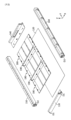
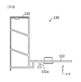
図1は本発明の一実施形態によるバッテリーパックを概略的に示した斜視図であり、図2は本発明の一実施形態によるバッテリーパックを概略的に示した分解斜視図であり、図3は本発明の一実施形態によるバッテリーパックの前方フレームを概略的に示した右側面図であり、図4は本発明の一実施形態によるバッテリーパックの後方フレームを概略的に示した右側面図である。 Figure 1 is a perspective view showing a battery pack according to one embodiment of the present invention, Figure 2 is an exploded perspective view showing a battery pack according to one embodiment of the present invention, Figure 3 is a right side view showing a front frame of a battery pack according to one embodiment of the present invention, and Figure 4 is a right side view showing a rear frame of a battery pack according to one embodiment of the present invention.
図1~図4を参照すると、本発明の一実施形態によるバッテリーパック100は、複数のバッテリーモジュール110、ベースプレート120、前方フレーム130、後方フレーム140、第1サイドフレーム150、及び第2サイドフレーム160を含む。
Referring to Figures 1 to 4, a
具体的には、バッテリーモジュール110は、複数の電池セル(図示せず)、及び複数の電池セルを内部に収容するモジュールハウジング111を備え得る。電池セルはリチウム二次電池であり得る。電池セルは、電極組立体(図示せず)、電解液(図示せず)、及びこれらを内部に収容したパウチを備えたパウチ型電池セルであり得る。しかし、本発明によるバッテリーパック100は、上述したパウチ型電池セルのみに限定されず、例えば、電池セルが円筒型電池セルであってもよい。すなわち、電池セルには、本願の出願時点で公知の多様な電池セルが採用され得る。
Specifically, the
バッテリーモジュール110は、複数の電池セル同士を電気的に接続するように構成された少なくとも一つのバスバー(図示せず)を備え得る。具体的には、バスバーは伝導性金属を含み得、例えば、銅、アルミニウム、ニッケルなどを含み得る。
The
また、モジュールハウジング111は、電気絶縁性の素材を含み得る。例えば、モジュールハウジング111は、ポリ塩化ビニル素材で製造され得る。モジュールハウジング111は、複数の電池セルを内部に収容可能な空間を備え得る。モジュールハウジング111は、全体的に直方体の箱状であり得る。
さらに、複数のバッテリーモジュール110は、電源ケーブルまたはバスバーを通じて互いに電気的に接続され得る。バッテリーモジュール110の詳細構成としては、一般に公知の構成が適用され得るため、具体的に説明を省略する。
Furthermore, the
そして、ベースプレート120は、水平方向に延びたプレート状であり得る。ベースプレート120は、機械的な剛性に優れた金属素材を含み得る。ベースプレート120の上部には、複数のバッテリーモジュール110が位置し得る。また、ベースプレート120は、前方フレーム130、後方フレーム140、第1サイドフレーム150及び第2サイドフレーム160のそれぞれと結合されるように構成され得る。結合方法は、例えば、摩擦撹拌溶接であり得る。ここで、水平方向とは、平たい地面の面方向を意味する。
The
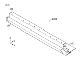
さらに、図1の矢印Fを基準にして正面から眺める場合、前方フレーム130は、複数のバッテリーモジュール110の前方を覆うようにベースプレート120の前端部に結合され得る。前方フレーム130は、前方カバー部131及び前方プレート部132を備え得る。ここで、前方フレーム130は、前方カバー部131と前方プレート部132とが一体的に構成され得る。例えば、前方フレーム130は押出成形され、前方カバー部131と前方プレート部132とが一体になるように製造され得る。したがって、本発明によれば、バッテリーパック100の前端部領域において、別途の溶接が不要になる。さらに、前方カバー部131と前方プレート部132とが一体的に形成されるため、バッテリーパック100の前端部のシーリングを確保することができる。
Furthermore, when viewed from the front with reference to the arrow F in FIG. 1, the
ここで、前、後、左、右、上、下のような方向を示す用語は、観測者の位置や対象が置かれた形態によって変わり得る。ただし、本明細書においては、説明の便宜上、図1の矢印F方向から眺めたときを基準として、前、後、左、右、上、下などの方向を区分して示すようにする。 Here, terms indicating directions such as front, back, left, right, up, and down may vary depending on the position of the observer and the shape in which the object is placed. However, for the sake of convenience, in this specification, directions such as front, back, left, right, up, and down are indicated based on the view from the direction of arrow F in Figure 1.
また、前方カバー部131は、左右方向に長く延びて上方に立てられた形態であり得る。前方カバー部131の下面は、ベースプレート120の上面と結合され得る。例えば、図2に示されたように、前方カバー部131は、前後方向に所定の幅を有し、両端部が第1サイドフレーム150及び第2サイドフレーム160のそれぞれに達するように左右方向に延びた形態であり得る。また、図3に示されたように、前方カバー部131は、外壁で囲まれて内部が空いている内部空間を有し得る。内部空間には、機械的剛性を補強するための複数のリブが所定の間隔で離隔して設けられ得る。
The
前方プレート部132は、前方カバー部131の一側から後方に延びて形成され得る。例えば、図3に示されたように、前方プレート部132は、前方カバー部131の後側下部から後方に延びたプレート状であり得る。前方プレート部132は、ベースプレート120の上面と結合されるように、水平方向に延びた本体から下方に延びた略I字状のビーム形態の支持構造132aを備え得る。
The
例えば、図14を参照すると、前方プレート部132の水平方向に延びた本体から下方に突出した支持構造132aが備えられ得る。支持構造132aは、例えば略I字状のビーム形態であり得る。支持構造132aの下面は、ベースプレート120と接触した状態で結合され得る。すなわち、支持構造132aは、前方プレート部132をベースプレート120から上方に支持し得る。一方、前方カバー部131の下面も、ベースプレート120上に接触した状態で結合され得る。このとき、前方カバー部131の下面と支持構造132aの下面とは略同一平面上にあり得る。したがって、前方カバー部131の下面と支持構造132aの下面とは、同時にベースプレート120上に接触及び結合され得る。
For example, referring to FIG. 14, a
一方、前方プレート部132によって前方フレーム130の前後方向の全体幅が増加するため、バッテリーパック100が前後方向の外部衝撃を受ける場合、搭載された複数のバッテリーモジュール110を保護できる程度に機械的剛性を高めることができる。
Meanwhile, since the
そして、後方フレーム140は、複数のバッテリーモジュール110の後方を覆うように構成され得る。後方フレーム140は、ベースプレート120の後端部に結合され得る。後方フレーム140は、後方カバー部141及び後方プレート部142を備え得る。ここで、後方フレーム140は、後方カバー部141と後方プレート部142とが一体的に構成され得る。例えば、後方フレーム140は押出成形され、後方カバー部141と後方プレート部142とが一体になるように製造され得る。したがって、本発明によれば、バッテリーパック100の後端部領域において、別途の溶接が不要になる。さらに、後方カバー部141と後方プレート部142とが一体的に形成されるため、バッテリーパック100の後端部のシーリングを確保することができる。
The
さらに、後方カバー部141は、左右方向に長く延びて上方に立てられた形態であり得る。後方カバー部141の下面は、ベースプレート120の上面と結合され得る。例えば、図2に示されたように、後方カバー部141は、前後方向に所定の幅を有し、両端部が第1サイドフレーム150及び第2サイドフレーム160のそれぞれに達するように左右方向に延びた形態であり得る。また、図4に示されたように、後方カバー部141は、外壁で囲まれて内部が空いている内部空間を有し得る。内部空間には、機械的剛性を補強するための複数のリブが所定の間隔で離隔して設けられ得る。
Furthermore, the
後方プレート部142は、後方カバー部141の一側から前方に延びて形成され得る。例えば、図4に示されたように、後方プレート部142は、後方カバー部141の前側下部から前方に延びたプレート状であり得る。後方プレート部142は、ベースプレート120の上面と結合されるように、水平方向に延びた本体から下方に延びたI字状のビーム形態の支持構造142aを備え得る。
The
例えば、図示していないが、後方プレート部142の水平方向に延びた本体から下方に突出した支持構造142aが備えられ得る。支持構造142aは、例えば略I字状のビーム形態であり得る。支持構造142aの下面は、ベースプレート120と接触した状態で結合され得る。すなわち、支持構造142aは、後方プレート部142をベースプレート120から上方に支持し得る。一方、後方カバー部141の下面も、ベースプレート120上に接触した状態で結合され得る。このとき、後方カバー部141の下面と支持構造142aの下面とは略同一平面上にあり得る。したがって、後方カバー部141の下面と支持構造142aの下面とは、同時にベースプレート120上に接触及び結合され得る。
For example, although not shown, a
一方、後方プレート部142によって後方フレーム140の前後方向の幅が増加するため、バッテリーパック100が前後方向の外部衝撃を受ける場合、搭載された複数のバッテリーモジュール110を保護できる程度に機械的剛性を高めることができる。
Meanwhile, the
第1サイドフレーム150は、前後方向(Y軸に平行な方向)に長く延びた形態であり得る。第1サイドフレーム150の一部分は、複数のバッテリーモジュール110の左側を覆うようにベースプレート120の左端部と結合され得る。第1サイドフレーム150は、前方フレーム130及び後方フレーム140のそれぞれの左端部と結合されるように構成され得る。
The
そして、第2サイドフレーム160は、前後方向(Y軸に平行な方向)に長く延びた形態であり得る。第2サイドフレーム160の一部分は、複数のバッテリーモジュール110の右側を覆うようにベースプレート120の右端部と結合され得る。第2サイドフレーム160は、前方フレーム130及び後方フレーム140のそれぞれの右端部に結合され得る。
The
したがって、本発明のこのような構成によれば、バッテリーモジュール110の前側、後側、左側及び右側を覆うように、前方フレーム130、後方フレーム140、第1サイドフレーム150及び第2サイドフレーム160を備えているため、搭載された複数のバッテリーモジュール110を外部衝撃から安全に保護することができる。
Therefore, according to this configuration of the present invention, the
さらに、本発明の前方フレーム130は一体的に形成された前方カバー部131と前方プレート部132とを備え、後方フレーム140は一体的に形成された後方カバー部141と後方プレート部142とを備えているため、従来技術と比べて、前方フレーム130及び後方フレーム140の前後方向の全体幅が増加し、バッテリーパック100が前後方向の外部衝撃を受ける場合、搭載された複数のバッテリーモジュール110を保護できる程度に機械的剛性が高い。
Furthermore, the
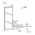
図5は、本発明の他の一実施形態によるバッテリーパックの前方フレームを概略的に示した側面図である。 Figure 5 is a side view showing a schematic diagram of a front frame of a battery pack according to another embodiment of the present invention.
図1及び図2とともに図5を参照すると、本発明の他の一実施形態によるバッテリーパック100の前方フレーム130Aは、少なくとも一つの強化リブR1をさらに備え得る。強化リブR1は、前方プレート部132の上面から前方カバー部131の後面まで斜線方向に延びた形態であり得る。強化リブR1は、複数のバッテリーモジュール110同士の間の空間と対面するように位置し得る。すなわち、強化リブR1は、複数のバッテリーモジュール110と前後方向で対面しないように位置し得る。または、強化リブR1は、複数のバッテリーモジュール110同士の間に一部分が挿入されるように延びた形態であり得る。
5 together with FIGS. 1 and 2, the
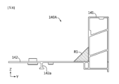
図6は、本発明の他の一実施形態によるバッテリーパックの後方フレームを概略的に示した側面図である。 Figure 6 is a side view showing a schematic diagram of a rear frame of a battery pack according to another embodiment of the present invention.
図1とともに図6を参照すると、本発明の他の一実施形態によるバッテリーパック100の後方フレーム140Aは、少なくとも一つの強化リブR1をさらに備え得る。強化リブR1は、後方プレート部142から後方カバー部141まで斜線方向に延びた形態であり得る。強化リブR1は、複数のバッテリーモジュール110同士の間の空間と対面するように位置し得る。すなわち、強化リブR1は、複数のバッテリーモジュール110と前後方向で対面しないように位置し得る。または、強化リブR1は、複数のバッテリーモジュール110同士の間に一部分が挿入されるように延びた形態であり得る。
Referring to FIG. 6 together with FIG. 1, the
したがって、本発明のこのような構成によれば、前方フレーム130A及び/または後方フレーム140Aに強化リブR1が備えられることで、バッテリーパック100が前後方向の外部衝撃を受ける場合、搭載された複数のバッテリーモジュール110を保護できる程度に前方フレーム130A及び/または後方フレーム140Aの機械的剛性を高めることができる。
Therefore, according to this configuration of the present invention, by providing the
さらに、本発明の強化リブR1は、複数のバッテリーモジュール110同士の間に位置しているため、複数のバッテリーモジュール110それぞれの搭載位置をガイドする役割を果たすことができる。これにより、バッテリーモジュール110の製造効率を効果的に高めることができる。
Furthermore, since the reinforcing rib R1 of the present invention is located between
一方、図1及び図2をさらに参照すると、本発明の一実施形態によるバッテリーパック100は、前方カバー部131の左右側の両端部に第1段差構造D1が形成され得る。第1段差構造D1は、前方カバー部131の端部に外側に段階的に高さが低くなる形態で設けられ得る。例えば、図2に示されたように、前方カバー部131の左端部には、左側に向かって高さが段階的に低くなる第1段差構造D1が形成され得る。前方カバー部131の右端部には、右側に向かって高さが段階的に低くなる第1段差構造D1が形成され得る。
Meanwhile, referring further to FIG. 1 and FIG. 2, the
また、第1サイドフレーム150及び第2サイドフレーム160の前端部及び/または後端部には、それぞれ、第2段差構造D2が形成され得る。例えば、第2段差構造D2は、前方カバー部131の第1段差構造D1と結合されるように構成され得る。すなわち、第2段差構造D2は、前方カバー部131に形成された第1段差構造D1と対応する形状を有し得る。第1サイドフレーム150及び第2サイドフレーム160のそれぞれの第2段差構造D2は、バッテリーパック100の中心を基準にして外側に段階的に高さが低くなる形態であり得る。
In addition, a second step structure D2 may be formed at the front end and/or rear end of the
したがって、本発明のこのような構成によれば、前方カバー部131に第1段差構造D1が形成され、第1サイドフレーム150及び第2サイドフレーム160にもそれぞれ第2段差構造D2が形成されることで、前方カバー部131及び後方カバー部141と第1サイドフレーム150及び第2サイドフレーム160との間の結合面積が効果的に増大することができる。これにより、本発明は、従来技術と比べて、前方フレーム130及び後方フレーム140と第1サイドフレーム150及び第2サイドフレーム160との結合力が効果的に増大して、バッテリーパック100が前後方向の外部衝撃を受ける場合、衝撃を第1サイドフレーム150及び第2サイドフレーム160にそれぞれ効果的に伝達することができ、搭載された複数のバッテリーモジュール110を保護できる程度に機械的剛性を高めることができる。
Therefore, according to this configuration of the present invention, the first step structure D1 is formed on the
図7は、本発明のさらに他の一実施形態によるバッテリーパックの前方フレームを概略的に示した前方斜視図である。 Figure 7 is a front perspective view that shows a schematic diagram of a front frame of a battery pack according to yet another embodiment of the present invention.
図7を参照すると、本発明のさらに他の一実施形態によるバッテリーパックの前方フレーム130Bは、図2の前方フレーム130Bと比べて、第1突出部133をさらに備え得る。第1突出部133は、前方カバー部131の前面から前方に突出して形成され得る。例えば、図7に示されたように、第1突出部133は、前方カバー部131の前面のうち中央を基準にして下部に位置し、前面から前方に突出した形態であり得る。また、第1突出部133は、下方に向かって前方への突出長さが短くなる形状を有し得る。
Referring to FIG. 7, the
すなわち、第1突出部133は、水平方向に延びた部分、及び後方に傾くように下方に延びた部分を有し得る。
That is, the
したがって、本発明のこのような構成によれば、前方フレーム130Bが第1突出部133をさらに備えることで、外部物体がバッテリーパック100の前方と衝突する場合、外部物体が第1突出部133と先に衝突し、衝突衝撃が前方フレーム130Bの前方プレート部132に集中的に伝達される。前方プレート部132を備えた前方フレーム130Bは、下部の前後方向の断面積が上部よりも大きいため、下部のほうが前後方向の衝撃に対する抵抗力が大きい。これにより、バッテリーパック100に搭載された複数のバッテリーモジュール110が損傷されることを効果的に防止することができる。
Therefore, according to this configuration of the present invention, the
図8は、本発明のさらに他の一実施形態によるバッテリーパックの後方フレームを概略的に示した後方斜視図である。 Figure 8 is a rear perspective view that shows a schematic diagram of a rear frame of a battery pack according to yet another embodiment of the present invention.
図8を参照すると、本発明のさらに他の一実施形態によるバッテリーパックの後方フレーム140Bは、図2の後方フレーム140と比べて、第2突出部143をさらに備え得る。第2突出部143は、後方カバー部141の後面のうち中央を基準にして下部に位置し得る。また、第2突出部143は、後方カバー部141の後面よりも後方にさらに突出した形態であり得る。例えば、図8に示されたように、第2突出部143は、上部が下部よりも後方にさらに突出した形態であり得る。すなわち、第2突出部143は、下方に向かって後方への突出長さが短くなる形状を有し得る。
Referring to FIG. 8, the
すなわち、第2突出部143は、水平方向に延びた部分、及び後方に傾くように下方に延びた部分を有し得る。
That is, the
したがって、本発明のこのような構成によれば、後方フレーム140Bが第2突出部143をさらに備えることで、外部物体がバッテリーパック100の後方と衝突する場合、外部物体が第2突出部143と先に衝突し、衝突衝撃が後方フレーム140Bの下部に位置した後方プレート部142に効果的に集中される。すなわち、後方プレート部142を備えた後方フレーム140Bは、下部の前後方向の断面積が上部よりも大きいため、下部のほうが前後方向の衝撃に対する抵抗力が大きい。これにより、バッテリーパック100に搭載された複数のバッテリーモジュール110が損傷されることを効果的に防止することができる。
Therefore, according to this configuration of the present invention, the
図9は、本発明のさらに他の一実施形態によるバッテリーパックの前方フレームを概略的に示した前方斜視図である。 Figure 9 is a front perspective view that shows a schematic diagram of a front frame of a battery pack according to yet another embodiment of the present invention.
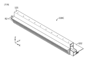
図9を参照すると、本発明のさらに他の一実施形態によるバッテリーパックの前方フレーム130Cは、図2の前方フレーム130と比べて、複数の水平リブR2をさらに備え得る。具体的には、複数の水平リブR2は、それぞれ、前方カバー部131の前面から前方に突出したプレート形態であり得る。複数の水平リブR2は、前方フレーム130の前面のうち中央を基準にして下部に位置し得る。複数の水平リブR2は、それぞれ、前方カバー部131の端部まで左右方向に延びたプレート状を有し得る。複数の水平リブR2は、互いに所定の間隔で上下方向で離隔して配列され得る。
Referring to FIG. 9, a
また、複数の水平リブR2のうち、下部に位置した水平リブR2であるほど上部に位置した水平リブR2よりも相対的に前方への突出長さが短くなるように構成され得る。すなわち、複数の水平リブR2は、前方への突出長さが相異なるように形成され得る。すなわち、複数の水平リブR2は、相対的に下部に位置するほど徐々に前方への突出長さが短くなるように構成され得る。 Furthermore, among the horizontal ribs R2, the horizontal ribs R2 located at the lower part may be configured to have a relatively shorter forward protruding length than the horizontal ribs R2 located at the upper part. That is, the horizontal ribs R2 may be formed to have different forward protruding lengths. That is, the horizontal ribs R2 may be configured to have gradually shorter forward protruding lengths as they are located relatively lower.
したがって、本発明のこのような構成によれば、複数の水平リブR2が備えられた前方フレーム130Cを備えることで、バッテリーパック100の前方衝撃を効果的に防御することができる。すなわち、外部物体がバッテリーパック100の前方と衝突する場合、外部物体が複数の水平リブR2と先に衝突し、衝突衝撃が前方フレーム130Cの下部に位置した前方プレート部132に集中される。すなわち、前方プレート部132を備えた前方フレーム130Cは、下部の前後方向の断面積が上部よりも大きいため、下部のほうが前後方向の衝撃に対する抵抗力が大きい。これにより、バッテリーパック100に搭載された複数のバッテリーモジュール110が損傷されることを効果的に防止することができる。
Therefore, according to this configuration of the present invention, the
図10は、本発明の一実施形態によるバッテリーパックの後方フレームを概略的に示した後方斜視図である。 Figure 10 is a rear perspective view that shows a schematic of the rear frame of a battery pack according to one embodiment of the present invention.
図10を参照すると、本発明の一実施形態によるバッテリーパック100は、BMS172をさらに含み得る。前方カバー部131または後方カバー部141は、BMS172の少なくとも一部を収容するように一部分が開口され得る。例えば、前方カバー部131または後方カバー部141は、BMS172の一部部品を収容するように一部分に開口Kが形成され得る。開口Kを通してBMS172の一部部品を内部に投入し得る。後方カバー部141には、BMS172の一部部品を内部に収容するように開口Kと連通して内部が空いている収容空間Sが備えられ得る。
Referring to FIG. 10, the
したがって、本発明のこのような構成によれば、BMS172の少なくとも一部を内部に収容可能な収容空間Sを備えることで、バッテリーパック100の異常作動に対する安全制御を行うBMSをより安全に収納することができ、バッテリーパック100の安全性を極大化することができる。さらに、収容空間Sは、複数のバッテリーモジュール110から発生した電磁波からBMS172の一部部品を保護することができる。例えば、BMS172は、制御ボード、リレー、ヒューズ、ケーブルなどを備え得る。
Therefore, according to this configuration of the present invention, by providing a storage space S capable of storing at least a portion of the
図11は、本発明の一実施形態によるバッテリーパックの冷却ユニット及び中間フレームを概略的に示した斜視図である。図11には、説明の便宜上、冷媒の移動方向を矢印で示した。 Figure 11 is a schematic perspective view of a cooling unit and an intermediate frame of a battery pack according to one embodiment of the present invention. For ease of explanation, the direction of movement of the refrigerant is indicated by arrows in Figure 11.
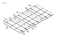
図2とともに図11を参照すると、本発明の一実施形態によるバッテリーパック100は、冷却ユニット180をさらに含み得る。冷却ユニット180は、上面に複数のバッテリーモジュール110を搭載するように水平方向に延びたプレート状であり得る。図14を参照すると、冷却ユニット180は、下面がベースプレート120と結合され得る。また、冷却ユニット180は、一側面が前方プレート部132に当接し得る。このような構造によれば、前方プレート部132の側面が冷却ユニット180に当接して支持され得る。したがって、前方フレーム130が前後方向の衝撃を受ける場合、前方プレート部132が冷却ユニット180の側面によって支持されることで、前方プレート部132とベースプレート120との間の結合部位が破損される危険が少ない。また、前方フレーム130に加えられる前後方向の衝撃が非常に大きい場合は、前方プレート部132が冷却ユニット180の側面で支持された状態で前後方向に潰されながら衝撃を吸収できる。
Referring to FIG. 11 together with FIG. 2, the
図示していないが、冷却ユニット180は、他側面が後方プレート部142に当接し得る。このような構造によれば、後方プレート部142の側面が冷却ユニット180に当接して支持され得る。したがって、後方フレーム140が前後方向の衝撃を受ける場合、後方プレート部142が冷却ユニット180の側面によって支持されることで、後方プレート部142とベースプレート120との間の結合部位が破損される危険が少ない。また、後方フレーム140に加えられる前後方向の衝撃が非常に大きい場合は、後方プレート部142が冷却ユニット180の側面で支持された状態で前後方向に潰されながら衝撃を吸収することができる。
Although not shown, the
冷却ユニット180は、冷媒流路(図示せず)、注入口182及び排出口183を備え得る。
The
また、冷媒流路は、冷却ユニット180の内部に備えられ得る。冷媒流路には、冷媒が移動するように隔壁が備えられ得る。冷媒は、例えば、空気、水、絶縁油などであり得る。
The refrigerant flow path may be provided inside the
さらに、注入口182は、冷媒流路と連通するように構成され得る。注入口182は、冷媒が注入されるように構成され得る。すなわち、注入口182は、冷媒流路に冷媒を注入するように構成され得る。排出口183は、冷媒流路を通過した冷媒を外部に排出するように構成され得る。すなわち、排出口183は、冷媒流路と連通するように構成され得る。
Furthermore, the
例えば、図11に示されたように、バッテリーパック100は、三つの冷却ユニット180を備え得る。三つの冷却ユニット180には、それぞれ、二つの注入口182と二つの排出口183が備えられ得る。二つの注入口182に注入された冷媒は、内部の冷媒流路に沿って矢印方向に移動し、二つの排出口183から放出され得る。
For example, as shown in FIG. 11, the
また、冷却ユニット180は、上部に複数のバッテリーモジュール110を搭載するように構成され得る。冷却ユニット180は、熱伝導パッド184をさらに備え得る。熱伝導パッド184は、バッテリーモジュール110と冷却ユニット180との間に介在され得る。
The
したがって、本発明のこのような構成によれば、冷却ユニット180を備えることで、搭載された複数のバッテリーモジュール110を効果的に冷却させることができる。また、冷却ユニット180は、ベースプレート120と結合されるように構成されることで、外部衝撃に抵抗する役割を果たすことができる。
Therefore, according to this configuration of the present invention, the
一方、図2及び図11をさらに参照すると、本発明の一実施形態によるバッテリーパックは、少なくとも一つの中間フレーム190をさらに含み得る。中間フレーム190は、冷却ユニット同士の間に配置され得る。中間フレーム190は、中間カバー191及び中間プレート部192を備え得る。中間カバー191は、前後方向に所定の厚さを有して左右方向に延びた形態であり得る。中間カバー191は、上方に立てられた形態であり得る。中間プレート部192は、水平方向に延びた形態であり得る。中間プレートは、中間カバー191の下部と一体に結合された形態であり得る。例えば、中間フレーム190は、押出成形によって一体的に形成され得る。
2 and 11, the battery pack according to an embodiment of the present invention may further include at least one
また、中間フレーム190の両端部は、第1サイドフレーム150と第2サイドフレーム160の側部とそれぞれ結合され得る。中間フレーム190の下面は、ベースプレート120の上面と結合されるように構成され得る。
In addition, both ends of the
図12は、本発明の一実施形態によるバッテリーパックの第1サイドフレームを概略的に示した後方斜視図である。図12には、説明の便宜上、冷媒の流れを矢印で示した。 Figure 12 is a rear perspective view that shows a schematic diagram of a first side frame of a battery pack according to one embodiment of the present invention. For ease of explanation, the flow of the refrigerant is indicated by arrows in Figure 12.
図12を参照すると、本発明の一実施形態によるバッテリーパック100の第1サイドフレーム150は、第1連結口151及び第1冷媒移動路152を備え得る。第1連結口151は、冷却ユニット180の注入口182と連通するように注入口182と連結され得る。すなわち、第1連結口151は、注入口182と対応する大きさを有し得る。第1連結口151は、注入口182に密着して位置し得る。また、第1連結口151は、第1冷媒移動路152と連通するように第1冷媒移動路152の一部分が開口して形成され得る。第1冷媒移動路152は、第1サイドフレーム150の本体に沿って前後方向に延び得る。
Referring to FIG. 12, the
例えば、図12に示されたように、第1サイドフレーム150には、6個の第1連結口151が備えられ得る。6個の第1連結口151は、前後方向に配列されて所定の間隔で離隔して形成され得る。第1サイドフレーム150の第1冷媒移動路152は、本体に沿って前後方向に延び得る。第1冷媒移動路152は、別途のチューブを備えず、第1サイドフレーム150を押出成形するとき、管状で前後方向(Y方向)に延ばして形成され得る。6個の第1連結口151のそれぞれは第1冷媒移動路152と連通し得る。6個の第1連結口151のそれぞれは冷却ユニット180の注入口182と連結されるように構成され得る。
For example, as shown in FIG. 12, the
すなわち、第1サイドフレーム150の第1冷媒移動路152の後端部から注入された冷媒は、第1冷媒移動路152に沿って後方に移動し、6個の第1連結口151のそれぞれを通って冷却ユニット180に移動し得る。
That is, the refrigerant injected from the rear end of the first
図13は、本発明の一実施形態によるバッテリーパックの第2サイドフレームを概略的に示した後方斜視図である。図13には、説明の便宜上、冷媒の流れを矢印で示した。 Figure 13 is a rear perspective view that shows a schematic diagram of a second side frame of a battery pack according to one embodiment of the present invention. For ease of explanation, the flow of the refrigerant is indicated by arrows in Figure 13.
図13を参照すると、本発明の一実施形態によるバッテリーパック100の第2サイドフレーム160は、第2連結口161及び第2冷媒移動路162を備え得る。第2連結口161は、冷却ユニット180の排出口183と連通するように排出口183と連結され得る。すなわち、第2連結口161は、排出口183と対応する大きさを有し、排出口183と密着して位置し得る。また、第2連結口161は、第2冷媒移動路162と連通するように第2冷媒移動路162の一部分が開口して形成され得る。第2冷媒移動路162は、第2サイドフレーム160の本体に沿って前後方向(Y方向)に延び得る。
Referring to FIG. 13, the
例えば、図13に示されたように、第2サイドフレーム160には、6個の第2連結口161が備えられ得る。6個の第2連結口161は、前後方向に配列されて所定の間隔で離隔して形成され得る。第2サイドフレーム160の第2冷媒移動路162は、本体に沿って前後方向(Y方向)に延び得る。第2冷媒移動路162は、別途のチューブを備えず、第2サイドフレーム160を押出成形するとき、管状で前後方向に延ばされて形成され得る。6個の第2連結口161のそれぞれは第2冷媒移動路162と連通し得る。6個の第2連結口161のそれぞれは冷却ユニット180の排出口183と連結されるように構成され得る。
For example, as shown in FIG. 13, the
すなわち、第2サイドフレーム160の第2冷媒移動路162は、冷却ユニット180から冷媒が6個の第2連結口161をそれぞれ通って流れ込み、該冷媒が第2冷媒移動路162の後端部に移動して外部に排出され得る。
That is, the second
したがって、本発明のこのような構成によれば、別途の管やチューブを備えず、第1サイドフレーム150及び第2サイドフレーム160それぞれの内部に冷媒移動路を形成することで、バッテリーパックの構成部品の個数を減らし、材料コストを低減して製造工程を単純化することができる。これにより、本発明は、複数のバッテリーモジュールの冷却効率は高めながらも製造コストを大幅に低減することができる。
Therefore, according to this configuration of the present invention, by forming a refrigerant movement path inside each of the
一方、本発明の一実施形態によるバッテリーパックは、少なくとも一つのバッテリーモジュール110、及びバッテリーモジュール110と電気的に接続されるBMS(Battery Management System:バッテリー管理システム)を含み得る。BMSは複数の電池セルの充放電を制御するための各種の回路や素子などを備え得る。
Meanwhile, a battery pack according to an embodiment of the present invention may include at least one
一方、本発明の一実施形態による自動車(図示せず)は、少なくとも一つのバッテリーモジュール110、及びバッテリーモジュール110を収容する収容空間を有する車体を含み得る。例えば、自動車は、電気自動車、電気スクーター、電気車椅子、または電気バイクなどであり得る。
Meanwhile, a vehicle (not shown) according to one embodiment of the present invention may include at least one
一方、本発明の一実施形態による電子デバイス(図示せず)は、少なくとも一つのバッテリーモジュール110、及びバッテリーモジュール110を収容する収容空間を有する外装ケースを含み得る。例えば、電子デバイスは、コンピュータまたは電力貯蔵装置であり得る。
Meanwhile, an electronic device (not shown) according to one embodiment of the present invention may include at least one
なお、本明細書において、上、下、左、右、前、後のような方向を示す用語が使用されたが、このような用語は説明の便宜のためのものであるだけで、対象となる事物の位置や観測者の位置などによって変わり得ることは、当業者にとって自明である。 In this specification, terms indicating directions such as up, down, left, right, front, and back are used, but it will be obvious to those skilled in the art that such terms are used merely for convenience of explanation and may vary depending on the position of the object in question or the position of the observer.
以上のように、本発明を限定された実施形態と図面によって説明したが、本発明はこれに限定されず、本発明が属する技術分野における通常の知識を持つ者によって本発明の技術思想と特許請求の範囲の均等範囲内で多様な修正及び変形が可能であることは言うまでもない。 As described above, the present invention has been described using limited embodiments and drawings, but the present invention is not limited thereto, and it goes without saying that various modifications and variations are possible within the scope of the technical concept of the present invention and the scope of the claims by a person with ordinary knowledge in the technical field to which the present invention pertains.
100 バッテリーパック
110 バッテリーモジュール
111 モジュールハウジング
120 ベースプレート
130 前方フレーム
130A 前方フレーム
130B 前方フレーム
130C 前方フレーム
131 前方カバー部
132 前方プレート部
132a 支持構造
133 第1突出部
140 後方フレーム
140A 後方フレーム
140B 後方フレーム
141 後方カバー部
142 後方プレート部
142a 支持構造
143 第2突出部
150 第1サイドフレーム
151 第1連結口
152 第1冷媒移動路
160 第2サイドフレーム
161 第2連結口
162 第2冷媒移動路
180 冷却ユニット
182 注入口
183 排出口
184 熱伝導パッド
190 中間フレーム
191 中間カバー
192 中間プレート部
D1 第1段差構造
D2 第2段差構造
R1 強化リブ
R2 水平リブ
S 収容空間
100
Claims (9)
上部に前記複数のバッテリーモジュールが位置するベースプレートと、
前記ベースプレートの前方を覆う前方カバー部及び前記前方カバー部の一側から後方に延びた前方プレート部を備え、前記前方カバー部と前記前方プレート部とが一体的に形成された前方フレームと、
前記ベースプレートの後方を覆う後方カバー部及び前記後方カバー部の一側から前方に延びた後方プレート部を備え、前記後方カバー部と前記後方プレート部とが一体的に形成された後方フレームと、
前記ベースプレートの左側を覆う第1サイドフレームと、
前記ベースプレートの右側を覆う第2サイドフレームと、
を含み、
前記前方プレート部の水平方向に延びた本体から下方に突出した支持構造が備えられ、前記支持構造は、前記前方プレート部の前記本体から下方に延びた垂直部分と、前記垂直部分の下端に設けられた水平部分とを含み、前記前方プレート部は、前記支持構造の前記水平部分の下面が前記ベースプレートと接触した状態で前記ベースプレートに結合され、及び/または、
前記後方プレート部の水平方向に延びた本体から下方に突出した支持構造が備えられ、前記支持構造は、前記後方プレート部の前記本体から下方に延びた垂直部分と、前記垂直部分の下端に設けられた水平部分とを含み、前記後方プレート部は、前記支持構造の前記水平部分の下面が前記ベースプレートと接触した状態で前記ベースプレートに結合される、バッテリーパック。 A plurality of battery modules;
a base plate on which the plurality of battery modules are located;
a front frame including a front cover portion covering a front of the base plate and a front plate portion extending rearward from one side of the front cover portion, the front cover portion and the front plate portion being integrally formed;
a rear frame including a rear cover portion covering a rear of the base plate and a rear plate portion extending forward from one side of the rear cover portion, the rear cover portion and the rear plate portion being integrally formed;
a first side frame covering a left side of the base plate;
A second side frame covering a right side of the base plate;
Including,
a support structure protruding downward from a horizontally extending main body of the front plate portion, the support structure including a vertical portion extending downward from the main body of the front plate portion and a horizontal portion provided at a lower end of the vertical portion, the front plate portion being coupled to the base plate with a lower surface of the horizontal portion of the support structure in contact with the base plate; and/or
a support structure protruding downward from a horizontally extending main body of the rear plate portion, the support structure including a vertical portion extending downward from the main body of the rear plate portion and a horizontal portion provided at a lower end of the vertical portion, the rear plate portion being coupled to the base plate with a lower surface of the horizontal portion of the support structure in contact with the base plate .
前記複数のバッテリーモジュール同士の間の空間と対面するように位置し、前記前方プレート部から前記前方カバー部に延びた少なくとも一つの強化リブが備えられ、
前記後方フレームには、
前記複数のバッテリーモジュール同士の間の空間と対面するように位置し、前記後方プレート部から前記後方カバー部に延びた少なくとも一つの強化リブが備えられた、請求項1に記載のバッテリーパック。 The front frame includes:
At least one reinforcing rib is provided, the reinforcing rib being positioned to face spaces between the battery modules and extending from the front plate portion to the front cover portion;
The rear frame includes:
2. The battery pack according to claim 1, further comprising at least one reinforcing rib extending from the rear plate portion to the rear cover portion and positioned to face spaces between the plurality of battery modules.
前記第1サイドフレーム及び前記第2サイドフレームの前端部及び後端部には、それぞれ、前記前方カバー部の第1段差構造と結合されるように外側に段階的に高さが低くなる第2段差構造が形成された、請求項1又は2に記載のバッテリーパック。 A first step structure is formed at both left and right end portions of the front cover portion, the height of which is gradually decreased toward the outside.
3. The battery pack of claim 1, wherein a second step structure is formed at a front end and a rear end of the first side frame and the second side frame, the second step structure being gradually decreased in height outwardly to be combined with the first step structure of the front cover part.
前記後方フレームは、前記後方カバー部の後面に、上部が相対的に下部よりも後方に突出した第2突出部を備える、請求項1から3のいずれか一項に記載のバッテリーパック。 The front frame further includes a first protrusion having an upper portion protruding relatively further forward than a lower portion on a front surface of the front cover portion,
The battery pack according to claim 1 , wherein the rear frame includes a second protrusion, the upper portion of which protrudes relatively further rearward than the lower portion, on a rear surface of the rear cover portion.
上部に前記複数のバッテリーモジュールが位置するベースプレートと、
前記ベースプレートの前方を覆う前方カバー部及び前記前方カバー部の一側から後方に延びた前方プレート部を備え、前記前方カバー部と前記前方プレート部とが一体的に形成された前方フレームと、
前記ベースプレートの後方を覆う後方カバー部及び前記後方カバー部の一側から前方に延びた後方プレート部を備え、前記後方カバー部と前記後方プレート部とが一体的に形成された後方フレームと、
前記ベースプレートの左側を覆う第1サイドフレームと、
前記ベースプレートの右側を覆う第2サイドフレームと、
を含み、
前記前方フレームの前方カバー部は、それぞれが前面から前方に突出して左右方向に延びたプレート状を有し、上下方向に配列された複数の水平リブを備え、
前記複数の水平リブのうち、下部に位置した水平リブであるほど上部に位置した水平リブよりも相対的に前方への突出長さが短くなるように構成された、バッテリーパック。 A plurality of battery modules;
a base plate on which the plurality of battery modules are located;
a front frame including a front cover portion covering a front of the base plate and a front plate portion extending rearward from one side of the front cover portion, the front cover portion and the front plate portion being integrally formed;
a rear frame including a rear cover portion covering a rear of the base plate and a rear plate portion extending forward from one side of the rear cover portion, the rear cover portion and the rear plate portion being integrally formed;
a first side frame covering a left side of the base plate;
A second side frame covering a right side of the base plate;
Including,
The front cover portion of the front frame has a plate shape that protrudes forward from a front surface and extends in the left-right direction, and includes a plurality of horizontal ribs arranged in the up-down direction,
The battery pack is configured such that the horizontal ribs located at the lower part among the plurality of horizontal ribs have a relatively shorter forward protruding length than the horizontal ribs located at the upper part .
上部に前記複数のバッテリーモジュールが位置するベースプレートと、
前記ベースプレートの前方を覆う前方カバー部及び前記前方カバー部の一側から後方に延びた前方プレート部を備え、前記前方カバー部と前記前方プレート部とが一体的に形成された前方フレームと、
前記ベースプレートの後方を覆う後方カバー部及び前記後方カバー部の一側から前方に延びた後方プレート部を備え、前記後方カバー部と前記後方プレート部とが一体的に形成された後方フレームと、
前記ベースプレートの左側を覆う第1サイドフレームと、
前記ベースプレートの右側を覆う第2サイドフレームと、
を含み、
前記バッテリーパックは、BMSをさらに含み、
前記前方カバー部または前記後方カバー部は、前記BMSの少なくとも一部を収容する収容空間を備える、バッテリーパック。 A plurality of battery modules;
a base plate on which the plurality of battery modules are located;
a front frame including a front cover portion covering a front of the base plate and a front plate portion extending rearward from one side of the front cover portion, the front cover portion and the front plate portion being integrally formed;
a rear frame including a rear cover portion covering a rear of the base plate and a rear plate portion extending forward from one side of the rear cover portion, the rear cover portion and the rear plate portion being integrally formed;
a first side frame covering a left side of the base plate;
A second side frame covering a right side of the base plate;
Including,
The battery pack further includes a BMS,
The battery pack, wherein the front cover portion or the rear cover portion has an accommodation space that accommodates at least a portion of the BMS .
冷媒が移動するように構成された冷媒流路、前記冷媒流路に冷媒を注入するように構成された注入口、及び前記冷媒流路から冷媒を排出するように構成された排出口を備えた冷却ユニットをさらに含む、請求項1から6のいずれか一項に記載のバッテリーパック。 The battery pack includes:
7. The battery pack of claim 1, further comprising a cooling unit including a coolant flow path configured to move a coolant therethrough, an inlet configured to inject a coolant into the coolant flow path, and an outlet configured to discharge the coolant from the coolant flow path.
前記第2サイドフレームは、前記排出口と連通する第2連結口、及び前記第2連結口と連通して前記第2サイドフレームの本体に沿って前後方向に延びた第2冷媒移動路を備える、請求項7に記載のバッテリーパック。 the first side frame includes a first connection port communicating with the injection port, and a first refrigerant transfer passage communicating with the first connection port and extending in a front-rear direction along a main body of the first side frame,
8. The battery pack of claim 7, wherein the second side frame includes a second connection port communicating with the exhaust port, and a second refrigerant transfer path communicating with the second connection port and extending in a front-rear direction along a main body of the second side frame.
Priority Applications (1)
| Application Number | Priority Date | Filing Date | Title |
|---|---|---|---|
| JP2024052276A JP2024074849A (en) | 2020-09-04 | 2024-03-27 | Battery pack, electronic device including same, and automobile |
Applications Claiming Priority (3)
| Application Number | Priority Date | Filing Date | Title |
|---|---|---|---|
| KR10-2020-0113233 | 2020-09-04 | ||
| KR20200113233 | 2020-09-04 | ||
| PCT/KR2021/011979 WO2022050780A1 (en) | 2020-09-04 | 2021-09-03 | Battery pack, vehicle, and electronic device comprising same |
Related Child Applications (1)
| Application Number | Title | Priority Date | Filing Date |
|---|---|---|---|
| JP2024052276A Division JP2024074849A (en) | 2020-09-04 | 2024-03-27 | Battery pack, electronic device including same, and automobile |
Publications (2)
| Publication Number | Publication Date |
|---|---|
| JP2023508274A JP2023508274A (en) | 2023-03-02 |
| JP7463516B2 true JP7463516B2 (en) | 2024-04-08 |
Family
ID=80491285
Family Applications (2)
| Application Number | Title | Priority Date | Filing Date |
|---|---|---|---|
| JP2022537187A Active JP7463516B2 (en) | 2020-09-04 | 2021-09-03 | Battery pack, electronic device including same, and automobile |
| JP2024052276A Pending JP2024074849A (en) | 2020-09-04 | 2024-03-27 | Battery pack, electronic device including same, and automobile |
Family Applications After (1)
| Application Number | Title | Priority Date | Filing Date |
|---|---|---|---|
| JP2024052276A Pending JP2024074849A (en) | 2020-09-04 | 2024-03-27 | Battery pack, electronic device including same, and automobile |
Country Status (10)
| Country | Link |
|---|---|
| US (1) | US20230335846A1 (en) |
| EP (2) | EP4068480B1 (en) |
| JP (2) | JP7463516B2 (en) |
| KR (2) | KR102871338B1 (en) |
| CN (2) | CN118983601A (en) |
| DE (1) | DE202021004381U1 (en) |
| ES (1) | ES3037373T3 (en) |
| HU (1) | HUE072740T2 (en) |
| PL (1) | PL4068480T3 (en) |
| WO (1) | WO2022050780A1 (en) |
Families Citing this family (20)
| Publication number | Priority date | Publication date | Assignee | Title |
|---|---|---|---|---|
| US11996576B2 (en) * | 2020-07-03 | 2024-05-28 | Teijin Automotive Technologies, Inc. | Impact resistant frame of battery containment system |
| EP4498493A4 (en) * | 2022-04-04 | 2025-07-09 | Lg Energy Solution Ltd | BATTERY MODULE |
| KR20230167969A (en) * | 2022-06-03 | 2023-12-12 | 주식회사 엘지에너지솔루션 | Battery pack |
| KR102872648B1 (en) * | 2022-06-03 | 2025-10-16 | 주식회사 엘지에너지솔루션 | Battery pack |
| EP4362191A4 (en) * | 2022-06-27 | 2025-01-01 | LG Energy Solution, Ltd. | BATTERY PACK |
| KR20240006431A (en) | 2022-07-06 | 2024-01-15 | 주식회사 엘지에너지솔루션 | Battery pack and manufacturing method of the same |
| WO2024010364A1 (en) | 2022-07-06 | 2024-01-11 | 주식회사 엘지에너지솔루션 | Battery pack and method for manufacturing battery pack |
| JP7794966B2 (en) * | 2022-07-20 | 2026-01-06 | エルジー エナジー ソリューション リミテッド | Battery packs and cell blocks contained therein, and automobiles containing the same |
| KR20240020080A (en) * | 2022-08-05 | 2024-02-14 | 주식회사 엘지에너지솔루션 | Battery pack |
| KR102835623B1 (en) * | 2022-08-17 | 2025-07-22 | (주)레드이엔지 | Mobile electric vehicle charging apparatus |
| KR102872029B1 (en) * | 2022-09-01 | 2025-10-15 | 주식회사 엘지에너지솔루션 | Battery pack with improved safety |
| DE102022127273A1 (en) * | 2022-10-18 | 2024-04-18 | Bayerische Motoren Werke Aktiengesellschaft | Assembly for an electrical energy storage device with heat conducting plate |
| JP7755562B2 (en) * | 2022-11-02 | 2025-10-16 | 株式会社神戸製鋼所 | Vehicle battery case |
| FR3143874B1 (en) * | 2022-12-20 | 2025-02-14 | Accumulateurs Fixes | Battery pack, system and manufacturing method thereof |
| JP2025526305A (en) * | 2022-12-22 | 2025-08-13 | エルジー エナジー ソリューション リミテッド | Battery module and battery pack including same |
| US20240372196A1 (en) * | 2023-05-01 | 2024-11-07 | Amar MARPU | Battery pack with energy absorbing end plate |
| KR102628969B1 (en) * | 2023-09-27 | 2024-01-24 | 주식회사케이에스엠 | Electric vehicle battery case manufacturing method |
| CN119725959A (en) * | 2023-09-27 | 2025-03-28 | 标致雪铁龙汽车股份有限公司 | Power battery pack and vehicle |
| KR20250120061A (en) * | 2024-02-01 | 2025-08-08 | 주식회사 엘지에너지솔루션 | Battery pack |
| KR102901269B1 (en) * | 2024-04-16 | 2025-12-18 | 주식회사 파인엠텍 | Inner plate, die casting mold and end plate manufactured using the same |
Citations (5)
| Publication number | Priority date | Publication date | Assignee | Title |
|---|---|---|---|---|
| CN209071441U (en) | 2018-12-07 | 2019-07-05 | 蜂巢能源科技有限公司 | For the lower case structure of battery pack and with its battery pack |
| CN209071435U (en) | 2018-12-07 | 2019-07-05 | 蜂巢能源科技有限公司 | For the lower case structure of battery pack and with its battery pack |
| CN210200804U (en) | 2019-08-08 | 2020-03-27 | 广州小鹏汽车科技有限公司 | Tray of battery pack, battery pack and vehicle |
| CN111029512A (en) | 2020-01-19 | 2020-04-17 | 王佳先 | Embedded liquid cooling integrated battery box |
| CN210403849U (en) | 2019-09-27 | 2020-04-24 | 比亚迪股份有限公司 | Trays, battery pack cases and vehicles |
Family Cites Families (23)
| Publication number | Priority date | Publication date | Assignee | Title |
|---|---|---|---|---|
| JPH07242125A (en) * | 1994-03-03 | 1995-09-19 | Nissan Motor Co Ltd | Battery frame mounting structure for electric vehicles |
| EP2501576B1 (en) * | 2009-11-18 | 2013-08-21 | Benteler Aluminium Systems France SNC | Battery tray for vehicle and method for producing the battery tray |
| JP6053618B2 (en) * | 2013-06-13 | 2016-12-27 | アイシン軽金属株式会社 | Support structure for vehicle |
| KR101568276B1 (en) * | 2014-03-31 | 2015-11-11 | 주식회사 태산하이텍 | Battery racking assembly |
| DE102016110330A1 (en) * | 2016-06-03 | 2017-12-07 | Thyssenkrupp Ag | Housing for a vehicle battery and method for producing such a housing |
| KR102235655B1 (en) * | 2016-06-17 | 2021-04-01 | 에스케이이노베이션 주식회사 | Secondary battery pack |
| KR102101906B1 (en) * | 2016-10-21 | 2020-04-17 | 주식회사 엘지화학 | Battery Pack Comprising Coupling Member Having Assembling Guide Function |
| DE102017103653B4 (en) * | 2017-02-22 | 2025-12-18 | Thyssenkrupp Ag | Battery housing for a vehicle battery and chassis for an electric vehicle |
| CN206789577U (en) * | 2017-03-31 | 2017-12-22 | 合肥恒达机电科技有限公司 | A kind of high-tension battery case |
| KR102065099B1 (en) * | 2017-04-04 | 2020-01-10 | 주식회사 엘지화학 | Battery Pack having crash beam and drain structure |
| KR102258827B1 (en) * | 2017-06-02 | 2021-05-31 | 주식회사 엘지에너지솔루션 | Battery pack and vehicle including the same |
| EP3514852B1 (en) * | 2017-07-19 | 2024-05-08 | LG Energy Solution, Ltd. | Battery pack fixing apparatus |
| DE102018101792B4 (en) | 2018-01-26 | 2021-03-25 | Harting Electric Gmbh & Co. Kg | Circuit card connector and associated circuit card arrangement for the transmission of high currents |
| WO2019169080A1 (en) * | 2018-03-01 | 2019-09-06 | Shape Corp. | Cooling system integrated with vehicle battery tray |
| KR102311075B1 (en) * | 2018-04-09 | 2021-10-07 | 주식회사 엘지에너지솔루션 | Battery Pack Having Pack Housing |
| CN208324862U (en) * | 2018-05-15 | 2019-01-04 | 江苏敏安电动汽车有限公司 | Be conducive to the battery pack housing of automotive crash safety |
| EP3584877A1 (en) * | 2018-05-16 | 2019-12-25 | Samsung SDI Co., Ltd. | Battery pack comprising a frame profile with integral coolant circuit elements |
| CN208738323U (en) * | 2018-09-06 | 2019-04-12 | 江苏卡耐新能源有限公司 | A kind of power battery pack arrangement |
| KR102445909B1 (en) * | 2018-09-20 | 2022-09-21 | (주)엘엑스하우시스 | Battery case for electric vehicle |
| JP7209528B2 (en) * | 2018-12-21 | 2023-01-20 | アイシン軽金属株式会社 | Battery housing structure and its mounting structure |
| CN110190211B (en) * | 2018-12-29 | 2020-03-31 | 比亚迪股份有限公司 | Battery tray, power battery package and vehicle |
| DE102019102754B4 (en) * | 2019-02-05 | 2022-03-17 | Benteler Automobiltechnik Gmbh | battery tray assembly |
| CN111146383B (en) * | 2019-11-29 | 2024-02-02 | 广汽新能源汽车有限公司 | Battery pack, lower shell and lower shell manufacturing method |
-
2021
- 2021-09-03 WO PCT/KR2021/011979 patent/WO2022050780A1/en not_active Ceased
- 2021-09-03 US US18/023,879 patent/US20230335846A1/en active Pending
- 2021-09-03 CN CN202411057333.8A patent/CN118983601A/en active Pending
- 2021-09-03 ES ES21864739T patent/ES3037373T3/en active Active
- 2021-09-03 EP EP21864739.4A patent/EP4068480B1/en active Active
- 2021-09-03 EP EP25179148.9A patent/EP4586367A3/en active Pending
- 2021-09-03 CN CN202180008285.1A patent/CN114930623B/en active Active
- 2021-09-03 DE DE202021004381.0U patent/DE202021004381U1/en active Active
- 2021-09-03 PL PL21864739.4T patent/PL4068480T3/en unknown
- 2021-09-03 HU HUE21864739A patent/HUE072740T2/en unknown
- 2021-09-03 JP JP2022537187A patent/JP7463516B2/en active Active
- 2021-09-03 KR KR1020210117917A patent/KR102871338B1/en active Active
-
2024
- 2024-03-27 JP JP2024052276A patent/JP2024074849A/en active Pending
-
2025
- 2025-10-10 KR KR1020250146116A patent/KR20250151329A/en active Pending
Patent Citations (5)
| Publication number | Priority date | Publication date | Assignee | Title |
|---|---|---|---|---|
| CN209071441U (en) | 2018-12-07 | 2019-07-05 | 蜂巢能源科技有限公司 | For the lower case structure of battery pack and with its battery pack |
| CN209071435U (en) | 2018-12-07 | 2019-07-05 | 蜂巢能源科技有限公司 | For the lower case structure of battery pack and with its battery pack |
| CN210200804U (en) | 2019-08-08 | 2020-03-27 | 广州小鹏汽车科技有限公司 | Tray of battery pack, battery pack and vehicle |
| CN210403849U (en) | 2019-09-27 | 2020-04-24 | 比亚迪股份有限公司 | Trays, battery pack cases and vehicles |
| CN111029512A (en) | 2020-01-19 | 2020-04-17 | 王佳先 | Embedded liquid cooling integrated battery box |
Also Published As
| Publication number | Publication date |
|---|---|
| KR20220031530A (en) | 2022-03-11 |
| CN114930623B (en) | 2024-08-20 |
| HUE072740T2 (en) | 2025-12-28 |
| KR20250151329A (en) | 2025-10-21 |
| KR102871338B1 (en) | 2025-10-15 |
| JP2024074849A (en) | 2024-05-31 |
| EP4586367A3 (en) | 2025-10-22 |
| CN118983601A (en) | 2024-11-19 |
| EP4068480A1 (en) | 2022-10-05 |
| EP4586367A2 (en) | 2025-07-16 |
| WO2022050780A1 (en) | 2022-03-10 |
| DE202021004381U1 (en) | 2024-01-24 |
| US20230335846A1 (en) | 2023-10-19 |
| PL4068480T3 (en) | 2025-09-08 |
| EP4068480A4 (en) | 2024-08-14 |
| CN114930623A (en) | 2022-08-19 |
| ES3037373T3 (en) | 2025-10-01 |
| EP4068480B1 (en) | 2025-07-16 |
| JP2023508274A (en) | 2023-03-02 |
Similar Documents
| Publication | Publication Date | Title |
|---|---|---|
| JP7463516B2 (en) | Battery pack, electronic device including same, and automobile | |
| JP7532521B2 (en) | Battery pack having improved fixing structure and gas exhaust structure, and electronic device and automobile including same | |
| US20230369716A1 (en) | Battery module, and battery pack and vehicle including the same | |
| JP7436682B2 (en) | Battery packs and cars containing them | |
| JP7527407B2 (en) | Battery module, battery pack, and automobile | |
| CN114982056B (en) | Battery module, battery pack including the battery module, and vehicle | |
| US20230261282A1 (en) | Battery pack, and automotive vehicle comprising same | |
| JP2025503129A (en) | Battery pack and automobile including same | |
| JP7550890B2 (en) | Battery module, battery pack, and automobile | |
| JP7769023B2 (en) | Battery pack, electronic device including same, and automobile | |
| CN120660226A (en) | battery pack | |
| JP7513761B2 (en) | Battery packs, automobiles and electronic devices |
Legal Events
| Date | Code | Title | Description |
|---|---|---|---|
| A621 | Written request for application examination |
Free format text: JAPANESE INTERMEDIATE CODE: A621 Effective date: 20220616 |
|
| A977 | Report on retrieval |
Free format text: JAPANESE INTERMEDIATE CODE: A971007 Effective date: 20230626 |
|
| A131 | Notification of reasons for refusal |
Free format text: JAPANESE INTERMEDIATE CODE: A131 Effective date: 20230710 |
|
| A601 | Written request for extension of time |
Free format text: JAPANESE INTERMEDIATE CODE: A601 Effective date: 20231010 |
|
| A521 | Request for written amendment filed |
Free format text: JAPANESE INTERMEDIATE CODE: A523 Effective date: 20231211 |
|
| TRDD | Decision of grant or rejection written | ||
| A01 | Written decision to grant a patent or to grant a registration (utility model) |
Free format text: JAPANESE INTERMEDIATE CODE: A01 Effective date: 20240226 |
|
| A61 | First payment of annual fees (during grant procedure) |
Free format text: JAPANESE INTERMEDIATE CODE: A61 Effective date: 20240327 |
|
| R150 | Certificate of patent or registration of utility model |
Ref document number: 7463516 Country of ref document: JP Free format text: JAPANESE INTERMEDIATE CODE: R150 |