JP7459410B1 - Laser device and laser processing device - Google Patents
Laser device and laser processing device Download PDFInfo
- Publication number
- JP7459410B1 JP7459410B1 JP2024502677A JP2024502677A JP7459410B1 JP 7459410 B1 JP7459410 B1 JP 7459410B1 JP 2024502677 A JP2024502677 A JP 2024502677A JP 2024502677 A JP2024502677 A JP 2024502677A JP 7459410 B1 JP7459410 B1 JP 7459410B1
- Authority
- JP
- Japan
- Prior art keywords
- pulsed light
- aberration
- laser device
- laser
- light
- Prior art date
- Legal status (The legal status is an assumption and is not a legal conclusion. Google has not performed a legal analysis and makes no representation as to the accuracy of the status listed.)
- Active
Links
- 230000003287 optical effect Effects 0.000 claims abstract description 127
- 230000004075 alteration Effects 0.000 claims abstract description 119
- 238000007493 shaping process Methods 0.000 claims abstract description 52
- 238000009826 distribution Methods 0.000 claims abstract description 40
- 230000005374 Kerr effect Effects 0.000 claims abstract description 26
- 239000007787 solid Substances 0.000 claims description 66
- 230000007246 mechanism Effects 0.000 claims description 21
- 239000002131 composite material Substances 0.000 claims description 6
- 230000005284 excitation Effects 0.000 description 36
- 230000008859 change Effects 0.000 description 25
- 238000010586 diagram Methods 0.000 description 18
- 238000000034 method Methods 0.000 description 10
- 239000013078 crystal Substances 0.000 description 9
- 230000006870 function Effects 0.000 description 9
- 230000000694 effects Effects 0.000 description 8
- 238000006243 chemical reaction Methods 0.000 description 7
- 239000000835 fiber Substances 0.000 description 6
- 239000004065 semiconductor Substances 0.000 description 5
- 229910009372 YVO4 Inorganic materials 0.000 description 4
- JNDMLEXHDPKVFC-UHFFFAOYSA-N aluminum;oxygen(2-);yttrium(3+) Chemical compound [O-2].[O-2].[O-2].[Al+3].[Y+3] JNDMLEXHDPKVFC-UHFFFAOYSA-N 0.000 description 4
- 230000003321 amplification Effects 0.000 description 4
- 230000008901 benefit Effects 0.000 description 4
- 238000003199 nucleic acid amplification method Methods 0.000 description 4
- 229910019901 yttrium aluminum garnet Inorganic materials 0.000 description 4
- 230000009471 action Effects 0.000 description 3
- 238000003754 machining Methods 0.000 description 3
- 239000000463 material Substances 0.000 description 3
- PCTMTFRHKVHKIS-BMFZQQSSSA-N (1s,3r,4e,6e,8e,10e,12e,14e,16e,18s,19r,20r,21s,25r,27r,30r,31r,33s,35r,37s,38r)-3-[(2r,3s,4s,5s,6r)-4-amino-3,5-dihydroxy-6-methyloxan-2-yl]oxy-19,25,27,30,31,33,35,37-octahydroxy-18,20,21-trimethyl-23-oxo-22,39-dioxabicyclo[33.3.1]nonatriaconta-4,6,8,10 Chemical compound C1C=C2C[C@@H](OS(O)(=O)=O)CC[C@]2(C)[C@@H]2[C@@H]1[C@@H]1CC[C@H]([C@H](C)CCCC(C)C)[C@@]1(C)CC2.O[C@H]1[C@@H](N)[C@H](O)[C@@H](C)O[C@H]1O[C@H]1/C=C/C=C/C=C/C=C/C=C/C=C/C=C/[C@H](C)[C@@H](O)[C@@H](C)[C@H](C)OC(=O)C[C@H](O)C[C@H](O)CC[C@@H](O)[C@H](O)C[C@H](O)C[C@](O)(C[C@H](O)[C@H]2C(O)=O)O[C@H]2C1 PCTMTFRHKVHKIS-BMFZQQSSSA-N 0.000 description 2
- 238000000862 absorption spectrum Methods 0.000 description 2
- 230000005540 biological transmission Effects 0.000 description 2
- 230000007547 defect Effects 0.000 description 2
- 239000011159 matrix material Substances 0.000 description 2
- 238000005459 micromachining Methods 0.000 description 2
- 230000008569 process Effects 0.000 description 2
- 238000005086 pumping Methods 0.000 description 2
- 238000004088 simulation Methods 0.000 description 2
- NNAZVIPNYDXXPF-UHFFFAOYSA-N [Li+].[Cs+].OB([O-])[O-] Chemical compound [Li+].[Cs+].OB([O-])[O-] NNAZVIPNYDXXPF-UHFFFAOYSA-N 0.000 description 1
- QBLDFAIABQKINO-UHFFFAOYSA-N barium borate Chemical compound [Ba+2].[O-]B=O.[O-]B=O QBLDFAIABQKINO-UHFFFAOYSA-N 0.000 description 1
- 238000004590 computer program Methods 0.000 description 1
- 230000006866 deterioration Effects 0.000 description 1
- 230000020169 heat generation Effects 0.000 description 1
- 230000010354 integration Effects 0.000 description 1
- 150000002500 ions Chemical class 0.000 description 1
- VCZFPTGOQQOZGI-UHFFFAOYSA-N lithium bis(oxoboranyloxy)borinate Chemical compound [Li+].[O-]B(OB=O)OB=O VCZFPTGOQQOZGI-UHFFFAOYSA-N 0.000 description 1
Images


Abstract
レーザ装置(100)は、パルス光を出力し、パルス光の繰り返し周波数を制御可能なシード光源(10)と、パルス光に光カー効果による収差を加える収差生成部(20)と、パルス光のビーム径および強度分布のうち少なくとも一方を調節するビーム整形光学系(30)と、パルス光を増幅してレーザ光を出射する固体増幅器(40)と、パルス光の繰り返し周波数に応じて収差生成部(20)およびビーム整形光学系(30)のうち少なくとも一方を操作可能な配置調整部(21,31)と、を備える。The laser device (100) includes a seed light source (10) that outputs pulsed light and is capable of controlling the repetition frequency of the pulsed light, an aberration generating unit (20) that adds aberration due to the optical Kerr effect to the pulsed light, a beam shaping optical system (30) that adjusts at least one of the beam diameter and intensity distribution of the pulsed light, a solid-state amplifier (40) that amplifies the pulsed light and emits laser light, and a placement adjustment unit (21, 31) that is capable of operating at least one of the aberration generating unit (20) and the beam shaping optical system (30) in accordance with the repetition frequency of the pulsed light.
Description
本開示は、レーザ加工に用いられるレーザ光を出射するレーザ装置およびレーザ加工装置に関する。 The present disclosure relates to a laser device that emits a laser beam used in laser processing, and a laser processing device.
近年、微細加工用のレーザ光源として、高ピークパワーの短パルス光を出力するレーザ装置が広く利用されている。このようなレーザ装置では、シード光源から出力される短パルス光を固体増幅器によって増幅して出力するMOPA(Master Oscillator Power Amplifier)方式を採用することが多い。MOPA方式の利点として、繰り返し周波数を制御しやすい点、固体増幅器の段数を増やすことで出力を増大できる点などが挙げられる。In recent years, laser devices that output short pulse light with high peak power have been widely used as laser light sources for micromachining. Such laser devices often use the MOPA (Master Oscillator Power Amplifier) method, in which the short pulse light output from a seed light source is amplified by a solid-state amplifier and output. Advantages of the MOPA method include the ease of controlling the repetition frequency and the ability to increase output by increasing the number of stages in the solid-state amplifier.
MOPA方式のレーザ装置で微細加工を行う際、加工形状に応じてレーザの繰り返し周波数を変更することで生産性を向上できる場合がある。しかし、一般的なシード光源では繰り返し周波数に応じて出力されるパルス光のピークパワーが変化する。ピークパワーが変化すると、パルス光が光学素子および固体活性媒質を透過する際に発生する非線形光学効果の影響が変化する。特に、パルス光の強度に応じて媒質の屈折率が変化する光カー効果(optical Kerr effect)によって、固体活性媒質透過後のパルス光のビーム伝搬特性が、繰り返し周波数に応じて変化する問題があった。パルス光のビーム品質が変化すると、加工点における最小集光径および強度分布が変化するため、繰り返し周波数変更後に加工品質を一定に保つことが困難となる。When performing micromachining with a MOPA type laser device, productivity can be improved by changing the repetition frequency of the laser according to the machining shape. However, in a typical seed light source, the peak power of the pulsed light output changes according to the repetition frequency. When the peak power changes, the influence of the nonlinear optical effect that occurs when the pulsed light passes through an optical element and a solid active medium changes. In particular, there was a problem that the beam propagation characteristics of the pulsed light after passing through a solid active medium change according to the repetition frequency due to the optical Kerr effect, in which the refractive index of the medium changes according to the intensity of the pulsed light. When the beam quality of the pulsed light changes, the minimum focusing diameter and intensity distribution at the machining point change, making it difficult to maintain a constant machining quality after changing the repetition frequency.
特許文献1には、ゲインスイッチング法でパルス光を出力するシード光源と、シード光源から出力されるパルス光を増幅するファイバ増幅器と、ファイバ増幅器から出力されるパルス光を増幅する固体増幅器と、固体増幅器から出力されるパルス光を波長変換する非線形光学素子と、を備えるレーザ光源装置が開示されている。 Patent Document 1 describes a seed light source that outputs pulsed light using a gain switching method, a fiber amplifier that amplifies the pulsed light output from the seed light source, a solid-state amplifier that amplifies the pulsed light output from the fiber amplifier, and a solid-state amplifier that amplifies the pulsed light output from the fiber amplifier. A laser light source device is disclosed that includes a nonlinear optical element that converts the wavelength of pulsed light output from an amplifier.
しかしながら、上記従来のレーザ光源装置の構成では、繰り返し周波数を変更した場合の光カー効果による固体活性媒質透過後のパルス光のビーム伝搬特性の変化については考慮されていない。つまり、上記従来のレーザ光源装置の構成では、シード光源から出力されるパルス光の繰り返し周波数を変更した場合にパルス光のピークパワーが変化してしまい、増幅後のパルス光のビーム伝搬特性変化を抑制することは困難であるという問題があった。 However, the configuration of the conventional laser light source device described above does not take into account changes in the beam propagation characteristics of the pulsed light after passing through the solid active medium due to the optical Kerr effect when the repetition frequency is changed. In other words, in the configuration of the conventional laser light source device described above, when the repetition frequency of the pulsed light output from the seed light source is changed, the peak power of the pulsed light changes, resulting in changes in the beam propagation characteristics of the pulsed light after amplification. The problem was that it was difficult to suppress.
本開示は、上記に鑑みてなされたものであって、シード光源の繰り返し周波数の変更による増幅後のビーム伝搬特性の変化を抑制することができるレーザ装置を得ることを目的とする。 The present disclosure has been made in consideration of the above, and aims to obtain a laser device that can suppress changes in the beam propagation characteristics after amplification due to changes in the repetition frequency of the seed light source.
上述した課題を解決し、目的を達成するために、本開示のレーザ装置は、パルス光を出力し、パルス光の繰り返し周波数を制御可能なシード光源と、パルス光に光カー効果による収差を加える収差生成部と、パルス光のビーム径および強度分布のうち少なくとも一方を調節するビーム整形光学系と、パルス光を増幅してレーザ光を出射する固体増幅器と、パルス光の繰り返し周波数に応じて収差生成部およびビーム整形光学系のうち少なくとも一方を操作可能な配置調整部と、を備える。 In order to solve the above-mentioned problems and achieve the objectives, the laser device of the present disclosure includes a seed light source that outputs pulsed light and can control the repetition frequency of the pulsed light, and adds aberration due to the optical Kerr effect to the pulsed light. an aberration generation unit, a beam shaping optical system that adjusts at least one of the beam diameter and intensity distribution of the pulsed light, a solid-state amplifier that amplifies the pulsed light and emits the laser light, and an aberration generating unit that adjusts the aberration according to the repetition frequency of the pulsed light. An arrangement adjustment section that can operate at least one of the generation section and the beam shaping optical system.
本開示に係るレーザ装置は、シード光源の繰り返し周波数の変更による増幅後のビーム伝搬特性の変化を抑制することができるという効果を奏する。 The laser device according to the present disclosure has the effect of being able to suppress changes in beam propagation characteristics after amplification due to changes in the repetition frequency of the seed light source.
以下に、本開示の実施の形態に係るレーザ装置およびレーザ加工装置を図面に基づいて詳細に説明する。なお、以下に説明する実施の形態は例示に過ぎず、本開示の範囲は、以下に説明する実施の形態に限定されない。 Below, a laser device and a laser processing device according to an embodiment of the present disclosure are described in detail with reference to the drawings. Note that the embodiments described below are merely examples, and the scope of the present disclosure is not limited to the embodiments described below.
実施の形態1.
図1は、実施の形態1に係るレーザ装置を備えるレーザ加工装置の構成の一例を模式的に示すブロック図である。レーザ加工装置1は、レーザ光を出力するレーザ装置100と、レーザ装置100から出力されるレーザ光を加工対象物70に集光し、照射する加工光学系60と、を備える。レーザ装置100は、固体活性媒質41によってレーザ光を誘導放出させる装置である。レーザ装置100は、波長変換結晶50によって所望の波長のレーザ光を出力するようにすることもできる。レーザ加工装置1は、固体活性媒質41を用いたレーザ装置100から出力されるレーザ光を用いて加工対象物70の加工を行う装置である。
Embodiment 1.
FIG. 1 is a block diagram schematically showing an example of the configuration of a laser processing apparatus including a laser device according to the first embodiment. The laser processing device 1 includes a
レーザ装置100は、シード光源10と、制御部11と、収差生成部20と、配置調整部21と、ビーム整形光学系30と、配置調整部31と、固体増幅器40と、波長変換結晶50と、を備える。The
シード光源10は、パルス幅が数十ピコ秒以下のレーザ光である短パルス光を出力する。シード光源10から出力される短パルス光は、固体活性媒質41で増幅されるレーザ光である。以下では、シード光源10から出力される短パルス光は、パルス光と称される。シード光源10には、一例ではゲインスイッチ駆動の半導体レーザ、モードロック方式のファイバレーザ発振器あるいは固体レーザ発振器が用いられる。シード光源10は、パルス光を出力するシードパルス光源と、パルス光を増幅する増幅器と、で構成されるMOPA光源であってもよい。パルス光の波長の一例は1064nmである。
The
制御部11は、シード光源10から出力されるパルス光の波長、平均出力、繰り返し周波数、パルス幅などの諸パラメータを制御する。繰り返し周波数は、一定の周期で生成するパルスの1秒間当たりのパルス生成数である。The
ここで、制御部11のハードウェア構成について説明する。図2は、実施の形態1に係るレーザ装置の制御部のハードウェア構成の一例を示す図である。Here, we will explain the hardware configuration of the
制御部11は、図2に示される制御回路400、すなわちプロセッサ401およびメモリ402により実現することができる。プロセッサ401の例は、CPU(中央処理装置、処理装置、演算装置、マイクロプロセッサ、マイクロコンピュータ、プロセッサ、DSP(Digital Signal Processor)ともいう)またはシステムLSI(Large Scale Integration)である。メモリ402の例は、RAM(Random Access Memory)またはROM(Read Only Memory)である。
The
プロセッサ401がメモリ402に記憶されている、制御部11での処理を実行するためのプログラムである制御プログラムを読み出して実行することによって、制御部11の機能は実現される。また、この制御プログラムは、制御部11におけるシード光源10からのパルス光の出射方法をコンピュータに実行させるものであるともいえる。制御部11で実行される制御プログラムは、シード光源10のパルス光の出射処理をモジュール化したモジュール構成となっており、これらが主記憶装置上にロードされ、これらが主記憶装置上に生成される。The functions of the
メモリ402は、パルス光の出射処理を行う際に、シード光源10に設定するデータ等を記憶する。メモリ402は、プロセッサ401が各種処理を実行する際の一時メモリにも使用される。
The
プロセッサ401が実行する制御プログラムは、インストール可能な形式または実行可能な形式のファイルで、コンピュータが読み取り可能な記憶媒体に記憶されてコンピュータプログラムプロダクトとして提供されてもよい。また、プロセッサ401が実行する制御プログラムは、インターネットなどのネットワーク経由でレーザ装置100の制御部11に提供されてもよい。
The control program executed by the processor 401 may be an installable or executable file stored in a computer-readable storage medium and provided as a computer program product. Further, the control program executed by the processor 401 may be provided to the
また、制御部11を専用のハードウェアで実現してもよい。また、制御部11の機能について、一部を専用のハードウェアで実現し、一部をソフトウェアまたはファームウェアで実現するようにしてもよい。
Further, the
図1に戻り、収差生成部20は、シード光源10から出力されるパルス光を透過させるが、このときパルス光は、光カー効果による位相変調を受ける。この結果、収差生成部20は、パルス光に光カー効果による収差を加える。つまり、収差生成部20は、光カー効果を有する材料である光カー媒質によって構成される。光カー効果は、透過させる高強度のレーザ光の強度分布に応じてレーザ光を透過させる材料である媒質の屈折率が変化する現象である。また、光カー媒質は、透過させるレーザ光の強度分布に応じて屈折率が変化する媒質である。一般にレーザ光はガウシアン状の強度分布を有しているため、屈折率分布はガウシアン状となる。媒質におけるガウシアン状の屈折率分布はレンズとして作用し、レーザは集光される。これをカーレンズという。カーレンズの屈折率分布はガウシアン状のため、収差が発生する。これによって透過するレーザの波面が乱れ、ビーム品質の劣化が引き起こされる。
Returning to FIG. 1, the
収差生成部20は、入射するパルス光および出射するパルス光の反射を抑制する構成とされる。一例では、収差生成部20は、パルス光の入射面および出射面に、パルス光の波長に対する反射防止膜を有する。他の例では、収差生成部20の入射面および反射面には、パルス光の波長に対する反射防止膜が設けられない構成であってもよい。図3は、実施の形態1に係るレーザ装置における収差生成部の構成の他の例を模式的に示す図である。収差生成部20は、図3に模式的に示されるように、収差生成部20におけるパルス光LPの入射面201および出射面202をノンコートとし、かつ収差生成部20に対してパルス光LPがブリュースター角θBiで入射し、パルス光LPがブリュースター角θBoで出射するように構成してもよい。この場合、ブリュースター角θBi,θBoで収差生成部20にパルス光LPが入出射されるので、反射防止膜がなくても、入射面201および出射面202での反射率を低減することができる。また、収差生成部20に反射防止膜を設けないことから、反射防止膜の損傷を回避できるという利点がある。
The
図1に戻り、配置調整部21は、収差生成部20の配置を調整する部材である。配置調整部21は、パルス光の繰り返し周波数が変更された場合に、固体増幅器40から出力されるレーザ光のビーム品質を大きく低下させないようにパルス光を調整するために、レーザ加工装置1またはレーザ装置100の使用者によって操作される。配置調整部21は、第2配置調整部に対応する。配置調整部21の詳細については後述する。
Returning to FIG. 1, the
ビーム整形光学系30は、収差生成部20で位相変調を受けたパルス光のビーム径および強度分布のうち少なくとも一方を調節する。ビーム整形光学系30は、構成要素として、球面レンズおよび曲面ミラーのうち少なくとも1つの光学素子を有する。ビーム整形光学系30を透過したパルス光は、固体増幅器40で増幅される。
The beam shaping
配置調整部31は、ビーム整形光学系30の配置を調整する部材である。配置調整部31は、パルス光の繰り返し周波数が変更された場合に、固体増幅器40から出力されるレーザ光のビーム品質を大きく低下させないようにパルス光を調整するために、レーザ加工装置1またはレーザ装置100の使用者によって操作される。配置調整部31は、ビーム整形光学系30を構成する光学素子である構成要素を移動させる第1配置調整部に対応する。配置調整部31の詳細については後述する。なお、配置調整部21および配置調整部31は、パルス光の繰り返し周波数に応じて収差生成部20およびビーム整形光学系30のうち少なくとも一方を操作可能な広義の配置調整部に対応する。
The
固体増幅器40は、ビーム整形光学系30から出力されるパルス光を増幅してレーザ光を出射する。固体増幅器40は、固体活性媒質41と、励起用光源42と、ダイクロイックミラー43と、を備えている。なお、本開示では、一例ではYAG(Yttrium Aluminum Garnet)、YVO4などの固体の母材にNd,Yb,Tmなどのレーザ活性イオンをドープし、決められた波長で励起することによってレーザ光を増幅する性質、すなわち利得を持つものは固体活性媒質と称される。以下では、固体増幅器40で増幅されたパルス光は、パルス増幅光と称される。
The solid-state amplifier 40 amplifies the pulsed light output from the beam shaping
固体活性媒質41には、利得帯域にシード光源10から出射されるパルス光の波長を含む媒質が選択される。一例ではシード光源10から出射されるパルス光の波長が1064nmの場合には、固体活性媒質41にはNd:YVO4,Nd:YAGなどが好適に用いられる。また、シード光源10から出射されるパルス光の波長が1030nmの場合には、固体活性媒質41にはYb:YAGなどが用いられる。固体活性媒質41は励起用光源42によって端面励起される。端面励起は、固体活性媒質41から出射されるレーザ光の光軸と同軸方向に励起用光源42からの励起光を固体活性媒質41に入射させて励起する方式である。なお、固体活性媒質41に対する励起用光源42からの励起光の入射方向は、固体活性媒質41の形状または使用する励起用光源42のビーム伝搬特性に応じて適宜選択される。固体活性媒質41に入射したパルス光は増幅され、パルス増幅光であるレーザ光として出射される。
A medium whose gain band includes the wavelength of the pulsed light emitted from the
励起用光源42は、固体活性媒質41を励起するレーザ光を出力する光源である。励起用光源42には半導体レーザが好適に用いられる。端面励起の場合、励起用光源42はファイバ結合型の半導体レーザとする場合が多い。励起用光源42から出力されるレーザ光の波長は固体活性媒質41の吸収スペクトルに応じて選定される。一例では固体活性媒質41がNd:YVO4である場合には、波長808nm、879nm、888nm、914nmのレーザ光が用いられる。特に、直接励起である波長879nm、888nm、914nmのレーザ光による励起は、量子欠損による発熱が少なく、励起に伴う固体活性媒質41の温度上昇を低減できる利点がある。
The
ダイクロイックミラー43は、固体活性媒質41に対して、シード光源10からのパルス光と励起用光源42からの励起光とを同軸上に入射させるために設けられている。励起用光源42から出力される励起光はダイクロイックミラー43を透過または反射してパルス光と同軸で固体活性媒質41に入射する。図1の例では、ダイクロイックミラー43は、シード光源10からのパルス光を透過し、励起用光源42からの励起光を反射させるように構成されている。The
波長変換結晶50は、パルス増幅光を波長変換する。波長変換結晶50にはLiB3O5(Lithium Triborate:LBO)、CsLiB6O10(Cesium Lithium Borate:CLBO)、β-BaB2O4(Barium Metaborate:BBO)結晶が用いられ、高調波発生により第二高調波、第三高調波または第四高調波へと波長変換される。なお、波長変換結晶50は、必要に応じて設けられる。
The
以上によって、レーザ装置100は、波長変換結晶50で定められる波長のパルス状のレーザ光を出射する。
As described above, the
加工光学系60は、レーザ装置100から出射されるパルス増幅光を加工対象物70に導くように光路を形成し、加工対象物70上の所望の位置にパルス増幅光を集光する光学素子を有する。加工光学系60は、パルス増幅光のビーム径を調節する1個以上のレンズ、パルス増幅光を伝送する伝送ミラー、パルス増幅光を走査するガルバノスキャナ、パルス増幅光を集光するfθレンズなどを備える。波長変換されたパルス増幅光は、加工光学系60によって加工対象物70まで伝送される。The processing
実施の形態1では、シード光源10に設定される繰り返し周波数に応じて、収差生成部20およびビーム整形光学系30のうち少なくとも一方を操作可能な配置調整部である配置調整部21および配置調整部31の少なくとも一方を備えることを特徴とする。つまり、シード光源10から出力されるパルス光の繰り返し周波数が変更された場合には、変更されたパルス光の繰り返し周波数に応じて、収差生成部20およびビーム整形光学系30のうち少なくとも一方が使用者によって操作される。具体的には、収差生成部20の配置およびビーム整形光学系30の配置の少なくとも一方を調整するように、配置調整部21および配置調整部31のうち少なくとも一方が使用者によって操作される。
In the first embodiment, the
収差生成部20は、光カー効果によりパルス光に位相変化を与え、収差を生じさせる。ビーム整形光学系30は、収差生成部20で生じた収差を利用し、固体活性媒質41におけるパルス光のビーム径および強度分布のうち少なくとも一方を調節する。使用者の操作によってパルス光の繰り返し周波数に応じて収差生成部20およびビーム整形光学系30のうち少なくとも一方の配置を調整することによって、固体活性媒質41を透過後のパルス光のビーム伝搬特性、特にビーム品質の変化を抑制することが可能となる。以下に、上記操作の効果および方法について詳細に説明する。The
高いピークパワーを有する短パルス光が固体活性媒質41を透過する場合、固体活性媒質41中で生じる光カー効果の影響が無視できなくなる。光カー効果による屈折率変化n(r)は次式(1)で表される。ここで、rは、レーザ光であるパルス光の径方向の位置を表し、n0は固体活性媒質41の線形屈折率であり、n2は固体活性媒質41の非線形屈折率であり、I(r)はパルス光の径方向の位置rにおけるパルス光のピーク強度である。 When short pulse light having a high peak power is transmitted through the solid active medium 41, the influence of the optical Kerr effect occurring in the solid active medium 41 cannot be ignored. The refractive index change n(r) due to the optical Kerr effect is expressed by the following equation (1). Here, r represents the position in the radial direction of the pulsed light that is the laser light, n 0 is the linear refractive index of the solid active medium 41, n 2 is the nonlinear refractive index of the solid active medium 41, and I( r) is the peak intensity of the pulsed light at the position r in the radial direction of the pulsed light.
n(r)=n0+n2I(r) ・・・(1) n(r)=n 0 +n 2 I(r)...(1)
(1)式は、固体活性媒質41のパルス光の径方向の位置rにおける屈折率が非線形屈折率n2とパルス光のピーク強度I(r)とによって変化することを示している。また、パルス光が長さLの固体活性媒質41を透過する際に生じるパルス光の径方向の位置rにおける位相変化φ(r)は次式(2)で与えられる。ここでkはパルス光の波数である。 Equation (1) indicates that the refractive index of the solid active medium 41 at a position r in the radial direction of the pulsed light changes depending on the nonlinear refractive index n 2 and the peak intensity I(r) of the pulsed light. Further, the phase change φ(r) of the pulsed light at the radial position r that occurs when the pulsed light passes through the solid active medium 41 having the length L is given by the following equation (2). Here, k is the wave number of the pulsed light.
φ(r)=kLn2I(r) ・・・(2) φ(r)=kLn 2 I(r)...(2)
(2)式から、固体活性媒質41を透過するパルス光が受ける位相変化は、媒質長Lが長く、固体活性媒質41の非線形屈折率n2が大きく、またパルス光のピーク強度I(r)が高いほど大きくなる。 From equation (2), the phase change that the pulsed light that passes through the solid active medium 41 undergoes is determined by the fact that the medium length L is long, the nonlinear refractive index n 2 of the solid active medium 41 is large, and the peak intensity I(r) of the pulsed light is The higher the value, the larger the value.
一般にシード光源10から出力されるパルス光のピークパワーはパルス光の繰り返し周波数に応じて変化するため、光カー効果による位相変化はパルス光の繰り返し周波数によって変化することになる。一例ではパルス光の強度分布がガウシアン分布である場合、パルス光の位相は光カー効果によってガウシアン状に変調される。この位相変化は凸レンズのような集光作用をもたらすため、カーレンズと呼ばれる。カーレンズの屈折率分布は理想的なレンズとは異なるため、パルス光は固体活性媒質41を透過する際にカーレンズの収差を受け、パルス光のビーム品質は変化する。
Generally, the peak power of the pulsed light output from the
図4は、一般的な固体増幅器におけるパルス光が固体活性媒質を透過した後のビーム品質のシミュレーション結果の一例を示す図である。この図で、横軸は、パルス光の繰り返し周波数を示し、縦軸は、固体活性媒質41を透過したパルス光の品質を示すM2(M Square)を示している。光カー効果によるビーム品質変化に着目するため、ここでは、固体活性媒質41内での増幅によるパルス光の強度変化と、励起に伴う熱レンズ効果と、は考慮していない。また、パルス光の平均出力は繰り返し周波数によらず50Wに固定している。パルス光のパルス幅は10psであり、波長は1064nmであり、ビーム直径は1mmとし、固体活性媒質41には長さ30mmのNd:YVO4結晶を想定する。Nd:YVO4の非線形屈折率n2は1.5×10⁻¹⁹m2/Wとする。図4に示されるように、Nd:YVO4透過後のビーム品質M2は繰り返し周波数によって変化することが見て取れる。繰り返し周波数の変更によってビーム品質が変化した場合、加工点におけるパルス光の最小集光径および強度分布が変化し、加工品質を一定に保つことが困難となる。
FIG. 4 is a diagram showing an example of a simulation result of the beam quality after the pulsed light in a general solid-state amplifier passes through a solid-state active medium. In this figure, the horizontal axis indicates the repetition frequency of the pulsed light, and the vertical axis indicates M2 (M Square), which indicates the quality of the pulsed light that passes through the solid-state
このような課題に対して実施の形態1では、シード光源10から出力されるパルス光に光カー媒質からなる収差生成部20と、ビーム整形光学系30と、を作用させる。つまり、繰り返し周波数の変更による固体活性媒質41を透過後のビーム伝搬特性の変化を相殺するように、収差生成部20およびビーム整形光学系30の少なくとも一方の配置を操作して、固体活性媒質41に入射するパルス光を調整する。これによって、パルス光の繰り返し周波数を変更したときの固体活性媒質41を透過後のビーム伝搬特性の変化を抑制することができる。この結果、パルス光の繰り返し周波数を変更しても、加工品質を一定に保つことが可能となる。
To solve this problem, in Embodiment 1, an
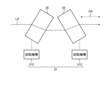
光カー効果は(1)式に示される通りパルス光のピーク強度I(r)に依存し、ピーク強度I(r)はビーム径に依存する。したがって、繰り返し周波数に応じて収差生成部20に入射するパルス光のビーム径を調整することで、光カー効果による収差量を調整することができる。ここでは、パルス光のビーム径を調整する例を示す。図5は、実施の形態1に係るレーザ装置の収差生成部の構成の一例を模式的に示す図である。上記したように、レーザ装置100は、1つの収差生成部20と、1つの収差生成部20を移動させる配置調整部21と、を有する。図5に示される例では、配置調整部21は、パルス光LPの光軸OAの方向に対して収差生成部20を移動可能な移動機構211によって構成される。パルス光LPの光軸OAの方向に対する収差生成部20の位置を、繰り返し周波数に応じて移動機構211を操作して調整することで、パルス光LPのビーム径を調整することができる。このとき、パルス光LPが発散伝搬する位置または収束伝搬する位置に収差生成部20を配置することで、少ない移動量でビーム径を調整する効果を奏するため、装置の小型化が可能である。つまり、パルス光LPのビーム伝搬が収束し、発散する光路上の位置に収差生成部20を配置し、ビーム伝搬が収束する位置または発散する位置に収差生成部20を配置するように移動機構211を操作すればよい。
As shown in equation (1), the optical Kerr effect depends on the peak intensity I(r) of the pulsed light, and the peak intensity I(r) depends on the beam diameter. Therefore, by adjusting the beam diameter of the pulsed light incident on the
光カー効果は(2)式に示される通り媒質長Lにも依存する。したがって、繰り返し周波数に応じて収差生成部20を透過するパルス光の媒質長Lを調整することで、光カー効果による収差量を調整することもできる。ここでは、媒質長Lを調整する例を示す。図6は、実施の形態1に係るレーザ装置の収差生成部の構成の他の例を模式的に示す図である。図6に示される例では、レーザ装置100は、2つの収差生成部20と、2つの収差生成部20のそれぞれに設けられる回転機構212と、を有する。2つの回転機構212は、収差生成部20の配置を調整する配置調整部21の一例である。回転機構212は、収差生成部20を透過するパルス光LPの長さを変更することができるように、パルス光LPの光軸OAの方向とは異なる方向の軸、すなわちパルス光LPの光軸OAとは平行でない軸の回りに収差生成部20を回転させる。収差生成部20を透過するパルス光LPの長さは、パルス光LPと収差生成部20との作用長である。パルス光LPと収差生成部20との作用長は、収差生成部20を透過するパルス光LPの媒質長Lに対応する。一例では、回転機構212は、図6の紙面に垂直な軸を中心に収差生成部20を回転可能である。収差生成部20に回転機構212を設けて収差生成部20を回転させることで、パルス光LPと収差生成部20との作用長を調整し、光カー効果による収差量を調整することができる。このとき、図6に示されるように、収差生成部20を2個向かい合わせて配置し、それぞれを逆方向に同じ角度だけ回転させることで、収差生成部20の回転によって生じる光軸シフトを相殺する効果を奏する。また、図6に示される例では、レーザ装置100は、2つの収差生成部20と、2つの回転機構212と、を有する場合を示したが、1つの収差生成部20と、1つの回転機構212と、を有する構成であってもよい。配置調整部21は、図5に示される移動機構211と、図6に示される回転機構212と、を有していてもよい。
The optical Kerr effect also depends on the medium length L, as shown in equation (2). Therefore, by adjusting the medium length L of the pulsed light that passes through the
以上のようにして、収差生成部20の光軸OAの方向に対する位置を調整することで、またはパルス光LPの光軸OAとは平行でない軸を中心とした収差生成部20の回転角度を調整することで、収差量を調整することができる。なお、収差生成部20におけるパルス光LPの光軸中心の位相変化はπ/10以上であることが望ましい。パルス光LPの光軸中心の位相変化をπ/10以上とすることで、カーレンズによる収差を有意に発生させることが可能となる。
As described above, by adjusting the position of the
ビーム整形光学系30は、収差生成部20によって生じたパルス光の収差を利用し、固体活性媒質41におけるパルス光のビーム径および強度分布のうち少なくとも一方を調節する。ただし、ビーム整形光学系30は、パルス光の繰り返し周波数を変更したときに収差生成部20によって収差を生じさせたパルス光の固体活性媒質41におけるビーム径および強度分布が、固体活性媒質41を透過後のパルス光のビーム品質を変化させるものではない場合には、固体活性媒質41におけるパルス光のビーム径および強度分布を調節しなくてもよい。
The beam shaping
収差生成部20でパルス光に収差を与えた場合、固体活性媒質41の入射面における光軸上のパルス光の強度分布は、理想的なガウシアン分布から崩れる。(1)式および(2)式に示される通り、光カー効果による屈折率分布および位相変調はピーク強度I(r)の分布に依存するため、同じビーム径であってもピーク強度I(r)の分布が異なれば固体活性媒質41を透過後のビーム品質が変化する場合がある。なお、本開示におけるビーム径は二次モーメント径を指すものとする。
When the
一例ではパルス光の光軸中心付近の強度分布がパルス光と同じビーム径を有する理想的なガウシアン分布よりも細い場合には、固体活性媒質41を透過後のパルス光のビーム品質の変化は大きくなる。一方、パルス光の光軸中心付近の強度分布がパルス光と同じビーム径を有する理想的なガウシアン分布よりも太い場合には、固体活性媒質41を透過後のパルス光のビーム品質の変化は小さくなる。 For example, if the intensity distribution near the center of the optical axis of the pulsed light is narrower than an ideal Gaussian distribution having the same beam diameter as the pulsed light, the beam quality of the pulsed light after passing through the solid active medium 41 will change significantly. Become. On the other hand, if the intensity distribution near the optical axis center of the pulsed light is thicker than the ideal Gaussian distribution having the same beam diameter as the pulsed light, the change in the beam quality of the pulsed light after passing through the solid active medium 41 is small. Become.
また、パルス光の光軸中心付近の強度分布が二次曲線で近似できる場合には、光カー効果による屈折率分布は収差のない理想レンズと見なすことができ、透過後のビーム品質は変化しない。 In addition, if the intensity distribution near the center of the optical axis of pulsed light can be approximated by a quadratic curve, the refractive index distribution due to the optical Kerr effect can be regarded as an ideal lens without aberrations, and the beam quality after passing through it will not change. .
さらに、パルス光の強度分布がトップハットあるいは高次のスーパーガウシアンの場合、光カー効果による屈折率分布は形成されず、透過後のビーム品質は変化しない。 Furthermore, when the intensity distribution of the pulsed light is top-hat or higher-order super-Gaussian, no refractive index distribution is formed due to the optical Kerr effect, and the beam quality after transmission does not change.
このように、ビーム整形光学系30によって固体活性媒質41に入射するパルス光の強度分布を調節することで、固体活性媒質41で生じる光カー効果によるビーム品質の変化を増加させるあるいは低減させることができる。この操作を適宜行うことで、シード光源10の繰り返し周波数の変更によるパルス光の固体活性媒質41を透過後のビーム品質の変化を抑制することができる。
In this way, by adjusting the intensity distribution of the pulsed light incident on the solid active medium 41 using the beam shaping
ビーム整形光学系30は、パルス光のビーム径および強度分布のうち少なくとも一方を調節するために、ビーム整形光学系30を1個の合成レンズと見なした場合の主点位置および焦点距離のうち少なくとも一方が変化するように操作される。すなわち、ビーム整形光学系30を構成する光学素子である構成要素の配置が配置調整部31によって操作される。このときの操作は、ビーム整形光学系30を1個の合成レンズと見なした場合の主点位置および焦点距離のうち少なくとも1つを変化させる操作である。または、このときの操作は、ビーム整形光学系30をABCD光線行列で考える場合には、合成レンズのABCD行列の要素のうち少なくとも1個を変化させる操作と見なすこともできる。
The beam shaping
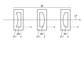
図7は、実施の形態1に係るレーザ装置のビーム整形光学系の構成の一例を模式的に示す図である。図7の例では、ビーム整形光学系30は、2枚の平凸レンズ301と1枚の平凹レンズ302とを有する。2枚の平凸レンズ301と1枚の平凹レンズ302とは、ビーム整形光学系30を構成する光学素子の一例である。2枚の平凸レンズ301および1枚の平凹レンズ302のそれぞれには、移動機構311が設けられる。移動機構311は、ビーム整形光学系30の構成要素をパルス光の光軸方向に移動させる機能、またはビーム整形光学系30の構成要素をパルス光の光軸上から除外する方向に移動させる機能を有する。つまり、移動機構311は、パルス光の光軸方向に対する各レンズ301,302の位置調整および各レンズ301,302を光路から除外する機能を有する。移動機構311は、配置調整部31の一例である。なお、各レンズ301,302の枚数および種類は図7に示されるものに限定されるものではない。
FIG. 7 is a diagram schematically showing an example of the configuration of the beam shaping optical system of the laser device according to the first embodiment. In the example of FIG. 7, the beam shaping
図8は、収差生成部を透過したパルス光にビーム整形光学系を作用させ、固体活性媒質の入射面における強度分布をシミュレーションした結果の一例を示す図である。この図で、横軸は固体活性媒質41の入射面に入射したパルス光における位置を示し、縦軸はパルス光の強度を示している。図8に示した点線のグラフは、収差生成部20を透過したパルス光にビーム整形光学系30を作用させ、固体活性媒質41の入射面における強度分布をシミュレーションした結果を示している。このうち、4通りの点線のグラフは、ビーム整形光学系30を4通り操作したことに対応している。これら4通りの点線のグラフは強度分布が異なっているが、全て同じビーム径を有する。比較のため、各点線と同じビーム径を有する理想的なガウシアン分布を図8に実線のグラフで示す。図8の結果から、ビーム整形光学系30の操作、すなわちビーム整形光学系30を構成する各レンズ301,302の位置構成または各レンズ301,302の光路からの除外によって固体活性媒質41におけるパルス光のビーム径および強度分布の少なくとも一方を調節できることが分かる。
FIG. 8 is a diagram showing an example of the result of simulating the intensity distribution on the entrance surface of the solid active medium by applying a beam shaping optical system to the pulsed light transmitted through the aberration generating section. In this figure, the horizontal axis indicates the position of the pulsed light incident on the incident surface of the solid active medium 41, and the vertical axis indicates the intensity of the pulsed light. The dotted line graph shown in FIG. 8 shows the result of simulating the intensity distribution on the entrance surface of the solid active medium 41 by causing the beam shaping
以上のように、パルス光の繰り返し周波数に応じて、配置調整部21によって収差生成部20の位置が変化させられるか、または配置調整部31によってビーム整形光学系30を1個の合成レンズと見なした場合の主点位置および焦点距離のうち少なくとも1つが変化させられる。つまり、広義の配置調整部は、パルス光の繰り返し周波数に応じて、収差生成部の位置、またはビーム整形光学系を1個の合成レンズと見なした場合の主点位置および焦点距離のうち少なくとも1つを変化させる。
As described above, depending on the repetition frequency of the pulsed light, the
ビーム整形光学系30は、シード光源10の繰り返し周波数が低くなるほど、すなわちシード光源10のピークパワーが高くなるほど、固体活性媒質41の入射面におけるパルス光の光軸中心強度が低くなるように操作されることが望ましい。
The beam shaping
実施の形態1のレーザ装置100は、パルス光を出力し、パルス光の繰り返し周波数を制御可能なシード光源10と、パルス光に光カー効果による収差を加える収差生成部20と、パルス光のビーム径および強度分布のうち少なくとも一方を調節するビーム整形光学系30と、パルス光の繰り返し周波数に応じて収差生成部20およびビーム整形光学系30のうち少なくとも一方を操作可能な配置調整部である配置調整部21および配置調整部31の少なくとも一方と、を備えるようにした。具体的には、パルス光の繰り返し周波数に応じて、パルス光と同一出力で、同一ビーム径の理想的なガウシアンビームの軸上強度に対するパルス光の軸上強度の割合を変化させる。これによって、パルス光の繰り返し周波数が変更された場合でも、固体活性媒質41に入射するパルス光のビーム品質の繰り返し周波数の変更前からの変化、または固体活性媒質41から出力されるパルス増幅光のビーム伝搬特性の変化を抑制することができるという効果を有する。The
なお、上記した説明では、パルス光の繰り返し周波数を変えたときに、収差生成部20の配置を調整する配置調整部21およびビーム整形光学系30の配置を調整する配置調整部31のうち少なくとも一方を使用者が操作する場合を示した。しかし、パルス光の繰り返し周波数を変えたときに、固体活性媒質41に入射するパルス光のビーム品質の変化が抑制されるように、制御部11が収差生成部20の配置を調整する配置調整部21およびビーム整形光学系30の配置を調整する配置調整部31のうち少なくとも一方を制御するようにしてもよい。
In the above description, when the repetition frequency of the pulsed light is changed, at least one of the
実施の形態2.
図9は、実施の形態2に係るレーザ装置を備えるレーザ加工装置の構成の一例を模式的に示す図である。なお、図1と同一の構成要素には同一の符号を付して、その説明を省略する。実施の形態1では、収差生成部20には光カー媒質が用いられていた。実施の形態2では、収差生成部20aが実施の形態1とは異なる。つまり、実施の形態2のレーザ加工装置1aにおけるレーザ装置100aでは、収差生成部20aに固体活性媒質が用いられる。ただし、収差生成部20aに用いられる固体活性媒質も光カー媒質として機能する。このような収差生成部20aを構成する固体活性媒質には、Nd:YVO4などの非線形屈折率n2が1×10-19m2/W以上の固体活性媒質が用いられる。このような構成によって、光カー媒質である収差生成部20aを固体増幅器として機能させることができる。
Embodiment 2.
FIG. 9 is a diagram schematically showing an example of the configuration of a laser processing apparatus including a laser device according to the second embodiment. Note that the same components as in FIG. 1 are denoted by the same reference numerals, and their explanations will be omitted. In the first embodiment, an optical Kerr medium is used in the
このように、収差生成部20aを固体増幅器として機能させる場合には、レーザ装置100aは、実施の形態1の構成に加えて、励起用光源22と、ダイクロイックミラー23と、をさらに備える。
In this way, when the
励起用光源22は、収差生成部20aを励起するレーザ光を出力する光源である。励起用光源22には半導体レーザが好適に用いられる。端面励起の場合、励起用光源22はファイバ結合型の半導体レーザとする場合が多い。励起用光源22から出力されるレーザ光の波長は収差生成部20aの吸収スペクトルに応じて選定される。一例では固体活性媒質41がNd:YVO4である場合には、波長808nm、879nm、888nm、914nmのレーザ光が用いられる。特に、直接励起である波長879nm、888nm、914nmのレーザ光による励起は、量子欠損による発熱が少なく、励起に伴う固体活性媒質41の温度上昇を低減できる利点がある。
The
ダイクロイックミラー23は、収差生成部20aに対して、シード光源10からのパルス光と励起用光源22からの励起光とを同軸上に入射させるために設けられている。励起用光源22から出力される励起光はダイクロイックミラー23を透過または反射してパルス光と同軸で固体活性媒質41に入射する。図9の例では、ダイクロイックミラー23は、シード光源10からのパルス光を透過し、励起用光源22からの励起光を反射させるように構成されている。The
一例では、2段の固体増幅器で構成されるレーザ装置に実施の形態2の技術を適用することが可能である。1段目の固体活性媒質である収差生成部20aで生じる光カー効果を利用し、2段目の固体活性媒質41から出射後のパルス増幅光のビーム伝搬特性の変化を抑制する。また、収差生成部20aと固体活性媒質41とに同じ固体活性媒質を用いることで、部品種類の削減および低コスト化が可能である。
As an example, the technique of the second embodiment can be applied to a laser device configured with two stages of solid-state amplifiers. By utilizing the optical Kerr effect generated in the
実施の形態2では、収差生成部20aを非線形屈折率n2が1×10-19m2/W以上の固体活性媒質で構成した。これによって、収差生成部20aを固体増幅器として機能させることができるという効果を有する。また、収差生成部20aと固体活性媒質41とに同じ固体活性媒質を用いることで、部品種類の削減および低コスト化ができるという効果を有する。
In the second embodiment, the
以上の実施の形態に示した構成は、一例を示すものであり、別の公知の技術と組み合わせることも可能であるし、実施の形態同士を組み合わせることも可能であるし、要旨を逸脱しない範囲で、構成の一部を省略、変更することも可能である。 The configurations shown in the embodiments above are merely examples, and can be combined with other known techniques, or can be combined with other embodiments, within the scope of the gist. It is also possible to omit or change part of the configuration.
1,1a レーザ加工装置、10 シード光源、11 制御部、20,20a 収差生成部、21,31 配置調整部、22,42 励起用光源、23,43 ダイクロイックミラー、30 ビーム整形光学系、40 固体増幅器、41 固体活性媒質、50 波長変換結晶、60 加工光学系、70 加工対象物、100,100a レーザ装置、201 入射面、202 出射面、211,311 移動機構、212 回転機構、301 平凸レンズ、302 平凹レンズ、LP パルス光、OA 光軸、θBi,θBo ブリュースター角。
Claims (11)
前記パルス光に光カー効果による収差を加える収差生成部と、
前記パルス光のビーム径および強度分布のうち少なくとも一方を調節するビーム整形光学系と、
前記パルス光を増幅してレーザ光を出射する固体増幅器と、
前記パルス光の繰り返し周波数に応じて前記収差生成部および前記ビーム整形光学系のうち少なくとも一方を操作可能な配置調整部と、
を備えることを特徴とするレーザ装置。 a seed light source that outputs pulsed light and can control the repetition frequency of the pulsed light;
an aberration generation unit that adds aberration due to the optical Kerr effect to the pulsed light;
a beam shaping optical system that adjusts at least one of the beam diameter and intensity distribution of the pulsed light;
a solid-state amplifier that amplifies the pulsed light and emits a laser beam;
a placement adjustment unit capable of operating at least one of the aberration generation unit and the beam shaping optical system according to the repetition frequency of the pulsed light;
A laser device comprising:
前記第1配置調整部は、前記構成要素を前記パルス光の光軸方向に移動させる機能、または前記構成要素を前記パルス光の光軸上から除外する方向に移動させる機能を有することを特徴とする請求項1に記載のレーザ装置。 The arrangement adjustment section includes a first arrangement adjustment section that moves a component that is an optical element constituting the beam shaping optical system,
The first arrangement adjustment section has a function of moving the component in the optical axis direction of the pulsed light, or a function of moving the component in a direction to exclude it from the optical axis of the pulsed light. The laser device according to claim 1 .
前記レーザ装置から出射される前記レーザ光を加工対象物に照射する加工光学系と、
を備えることを特徴とするレーザ加工装置。 A laser device according to any one of claims 1 to 10,
a processing optical system that irradiates the workpiece with the laser light emitted from the laser device;
A laser processing device comprising:
Applications Claiming Priority (1)
| Application Number | Priority Date | Filing Date | Title |
|---|---|---|---|
| JP2023038269 | 2023-10-24 |
Publications (1)
| Publication Number | Publication Date |
|---|---|
| JP7459410B1 true JP7459410B1 (en) | 2024-04-01 |
Family
ID=90474226
Family Applications (1)
| Application Number | Title | Priority Date | Filing Date |
|---|---|---|---|
| JP2024502677A Active JP7459410B1 (en) | 2023-10-24 | 2023-10-24 | Laser device and laser processing device |
Country Status (1)
| Country | Link |
|---|---|
| JP (1) | JP7459410B1 (en) |
Citations (4)
| Publication number | Priority date | Publication date | Assignee | Title |
|---|---|---|---|---|
| JP2010234444A (en) | 2009-03-11 | 2010-10-21 | Omron Corp | Laser beam machining apparatus |
| JP2013102088A (en) | 2011-11-09 | 2013-05-23 | Fujikura Ltd | Mopa system laser light source device and mopa system laser control method |
| WO2021181511A1 (en) | 2020-03-10 | 2021-09-16 | 三菱電機株式会社 | Wavelength conversion laser device and wavelength conversion laser processing machine |
| JP7254260B1 (en) | 2022-09-12 | 2023-04-07 | 三菱電機株式会社 | Solid-state laser device and solid-state laser processing device |
-
2023
- 2023-10-24 JP JP2024502677A patent/JP7459410B1/en active Active
Patent Citations (4)
| Publication number | Priority date | Publication date | Assignee | Title |
|---|---|---|---|---|
| JP2010234444A (en) | 2009-03-11 | 2010-10-21 | Omron Corp | Laser beam machining apparatus |
| JP2013102088A (en) | 2011-11-09 | 2013-05-23 | Fujikura Ltd | Mopa system laser light source device and mopa system laser control method |
| WO2021181511A1 (en) | 2020-03-10 | 2021-09-16 | 三菱電機株式会社 | Wavelength conversion laser device and wavelength conversion laser processing machine |
| JP7254260B1 (en) | 2022-09-12 | 2023-04-07 | 三菱電機株式会社 | Solid-state laser device and solid-state laser processing device |
Similar Documents
| Publication | Publication Date | Title |
|---|---|---|
| JP5649548B2 (en) | Non-critical phase matching in CLBO to generate sub-213 nm wavelengths | |
| US8248688B2 (en) | Tandem photonic amplifier | |
| US7924892B2 (en) | Fiber amplifier based light source for semiconductor inspection | |
| US20050157382A1 (en) | Industrial directly diode-pumped ultrafast amplifier system | |
| JP7451656B2 (en) | Laser beam method and system | |
| JP2007523499A (en) | Laser equipment | |
| JP5255838B2 (en) | Fiber amplifier based light source for semiconductor inspection | |
| US20200036152A1 (en) | Laser amplifier system | |
| Yoon et al. | Ultra-high intensity lasers as tools for novel physics | |
| JP7459410B1 (en) | Laser device and laser processing device | |
| JP7254260B1 (en) | Solid-state laser device and solid-state laser processing device | |
| WO2009090935A1 (en) | Optical amplifier | |
| JP7079953B2 (en) | Wavelength conversion method, wavelength conversion device and laser light source device | |
| Laskin et al. | Beam shaping in high-power laser systems with using refractive beam shapers | |
| JP6588707B2 (en) | Laser light source device and laser pulse light generation method | |
| JP2013201328A (en) | Fiber amplification device, method of adjusting spectral band width thereof, laser processing system equipped with fiber amplification device, and method of reducing optical loss thereof | |
| WO2016125919A2 (en) | Laser light-source apparatus and laser pulse light generating method | |
| CN113258425A (en) | Laser amplification system and device | |
| Lührmann et al. | High-average power Nd: YVO4 regenerative amplifier seeded by a gain switched diode laser | |
| JP2006203117A (en) | Solid-state laser device | |
| Dashkevich et al. | Comparative studies of eye-safe intracavity and extracavity optical parametric oscillators with an unstable telescopic cavity | |
| Guo et al. | Advanced LD pumped 3.3 J/1 Hz nanosecond Nd: glass preamplifier for SG-II upgrade laser facility | |
| TW202412416A (en) | Solid laser device and solid laser processing device | |
| Forster et al. | 12.2 W ZGP OPO pumped by a Q-Switched Tm3+: Ho3+-codoped fiber laser | |
| Poulter et al. | Q-switched Nd: YAG lasers for high average-power and high peak-power operation |
Legal Events
| Date | Code | Title | Description |
|---|---|---|---|
| A521 | Request for written amendment filed |
Free format text: JAPANESE INTERMEDIATE CODE: A523 Effective date: 20240117 |
|
| A621 | Written request for application examination |
Free format text: JAPANESE INTERMEDIATE CODE: A621 Effective date: 20240117 |
|
| A871 | Explanation of circumstances concerning accelerated examination |
Free format text: JAPANESE INTERMEDIATE CODE: A871 Effective date: 20240117 |
|
| TRDD | Decision of grant or rejection written | ||
| A01 | Written decision to grant a patent or to grant a registration (utility model) |
Free format text: JAPANESE INTERMEDIATE CODE: A01 Effective date: 20240220 |
|
| A61 | First payment of annual fees (during grant procedure) |
Free format text: JAPANESE INTERMEDIATE CODE: A61 Effective date: 20240319 |
|
| R150 | Certificate of patent or registration of utility model |
Ref document number: 7459410 Country of ref document: JP Free format text: JAPANESE INTERMEDIATE CODE: R150 |