JP7458969B2 - Microelectronic component with molded area with through-mold vias - Google Patents
Microelectronic component with molded area with through-mold vias Download PDFInfo
- Publication number
- JP7458969B2 JP7458969B2 JP2020209276A JP2020209276A JP7458969B2 JP 7458969 B2 JP7458969 B2 JP 7458969B2 JP 2020209276 A JP2020209276 A JP 2020209276A JP 2020209276 A JP2020209276 A JP 2020209276A JP 7458969 B2 JP7458969 B2 JP 7458969B2
- Authority
- JP
- Japan
- Prior art keywords
- die
- vias
- layer
- interconnects
- microelectronic component
- Prior art date
- Legal status (The legal status is an assumption and is not a legal conclusion. Google has not performed a legal analysis and makes no representation as to the accuracy of the status listed.)
- Active
Links
- 238000004377 microelectronic Methods 0.000 title claims description 166
- 239000000758 substrate Substances 0.000 claims description 162
- 238000000034 method Methods 0.000 claims description 88
- 238000004519 manufacturing process Methods 0.000 claims description 36
- 229910052710 silicon Inorganic materials 0.000 claims description 19
- 239000010703 silicon Substances 0.000 claims description 19
- 230000000712 assembly Effects 0.000 claims description 18
- 238000000429 assembly Methods 0.000 claims description 18
- 230000008878 coupling Effects 0.000 claims description 18
- 238000010168 coupling process Methods 0.000 claims description 18
- 238000005859 coupling reaction Methods 0.000 claims description 18
- XUIMIQQOPSSXEZ-UHFFFAOYSA-N Silicon Chemical compound [Si] XUIMIQQOPSSXEZ-UHFFFAOYSA-N 0.000 claims description 15
- 239000000463 material Substances 0.000 description 170
- 239000010410 layer Substances 0.000 description 159
- 239000003989 dielectric material Substances 0.000 description 57
- 230000008569 process Effects 0.000 description 45
- 239000011810 insulating material Substances 0.000 description 43
- 229910052751 metal Inorganic materials 0.000 description 38
- 239000002184 metal Substances 0.000 description 38
- 238000004891 communication Methods 0.000 description 25
- 239000004020 conductor Substances 0.000 description 25
- 239000012778 molding material Substances 0.000 description 21
- 239000011295 pitch Substances 0.000 description 21
- 229920002120 photoresistant polymer Polymers 0.000 description 20
- 238000012545 processing Methods 0.000 description 19
- 239000004593 Epoxy Substances 0.000 description 17
- VYPSYNLAJGMNEJ-UHFFFAOYSA-N Silicium dioxide Chemical compound O=[Si]=O VYPSYNLAJGMNEJ-UHFFFAOYSA-N 0.000 description 17
- PXHVJJICTQNCMI-UHFFFAOYSA-N Nickel Chemical compound [Ni] PXHVJJICTQNCMI-UHFFFAOYSA-N 0.000 description 14
- 239000004065 semiconductor Substances 0.000 description 13
- RYGMFSIKBFXOCR-UHFFFAOYSA-N Copper Chemical compound [Cu] RYGMFSIKBFXOCR-UHFFFAOYSA-N 0.000 description 12
- 229910052802 copper Inorganic materials 0.000 description 12
- 239000010949 copper Substances 0.000 description 12
- 229910000679 solder Inorganic materials 0.000 description 12
- 229910052581 Si3N4 Inorganic materials 0.000 description 10
- HQVNEWCFYHHQES-UHFFFAOYSA-N silicon nitride Chemical compound N12[Si]34N5[Si]62N3[Si]51N64 HQVNEWCFYHHQES-UHFFFAOYSA-N 0.000 description 10
- 239000004642 Polyimide Substances 0.000 description 9
- 238000000151 deposition Methods 0.000 description 9
- 150000002739 metals Chemical class 0.000 description 9
- 229920000620 organic polymer Polymers 0.000 description 9
- 229920001721 polyimide Polymers 0.000 description 9
- 238000001020 plasma etching Methods 0.000 description 8
- 239000012790 adhesive layer Substances 0.000 description 7
- 238000005530 etching Methods 0.000 description 7
- -1 for example Substances 0.000 description 7
- 239000011159 matrix material Substances 0.000 description 7
- 229910052759 nickel Inorganic materials 0.000 description 7
- 239000000853 adhesive Substances 0.000 description 6
- 230000001070 adhesive effect Effects 0.000 description 6
- 229910052782 aluminium Inorganic materials 0.000 description 6
- XAGFODPZIPBFFR-UHFFFAOYSA-N aluminium Chemical compound [Al] XAGFODPZIPBFFR-UHFFFAOYSA-N 0.000 description 6
- 238000003486 chemical etching Methods 0.000 description 6
- 239000002131 composite material Substances 0.000 description 6
- 229910052732 germanium Inorganic materials 0.000 description 6
- GNPVGFCGXDBREM-UHFFFAOYSA-N germanium atom Chemical compound [Ge] GNPVGFCGXDBREM-UHFFFAOYSA-N 0.000 description 6
- 235000012239 silicon dioxide Nutrition 0.000 description 6
- RNFJDJUURJAICM-UHFFFAOYSA-N 2,2,4,4,6,6-hexaphenoxy-1,3,5-triaza-2$l^{5},4$l^{5},6$l^{5}-triphosphacyclohexa-1,3,5-triene Chemical compound N=1P(OC=2C=CC=CC=2)(OC=2C=CC=CC=2)=NP(OC=2C=CC=CC=2)(OC=2C=CC=CC=2)=NP=1(OC=1C=CC=CC=1)OC1=CC=CC=C1 RNFJDJUURJAICM-UHFFFAOYSA-N 0.000 description 5
- 229910045601 alloy Inorganic materials 0.000 description 5
- 239000000956 alloy Substances 0.000 description 5
- 239000003990 capacitor Substances 0.000 description 5
- 239000003063 flame retardant Substances 0.000 description 5
- 238000000227 grinding Methods 0.000 description 5
- 229910052814 silicon oxide Inorganic materials 0.000 description 5
- 125000006850 spacer group Chemical group 0.000 description 5
- 230000004888 barrier function Effects 0.000 description 4
- 238000005516 engineering process Methods 0.000 description 4
- 230000006870 function Effects 0.000 description 4
- 238000003475 lamination Methods 0.000 description 4
- 238000001465 metallisation Methods 0.000 description 4
- 229920000642 polymer Polymers 0.000 description 4
- 229920005989 resin Polymers 0.000 description 4
- 239000011347 resin Substances 0.000 description 4
- 239000000377 silicon dioxide Substances 0.000 description 4
- 238000010146 3D printing Methods 0.000 description 3
- 229910002601 GaN Inorganic materials 0.000 description 3
- JMASRVWKEDWRBT-UHFFFAOYSA-N Gallium nitride Chemical compound [Ga]#N JMASRVWKEDWRBT-UHFFFAOYSA-N 0.000 description 3
- BQCADISMDOOEFD-UHFFFAOYSA-N Silver Chemical compound [Ag] BQCADISMDOOEFD-UHFFFAOYSA-N 0.000 description 3
- RTAQQCXQSZGOHL-UHFFFAOYSA-N Titanium Chemical compound [Ti] RTAQQCXQSZGOHL-UHFFFAOYSA-N 0.000 description 3
- 239000000654 additive Substances 0.000 description 3
- 230000000996 additive effect Effects 0.000 description 3
- 238000013459 approach Methods 0.000 description 3
- UMIVXZPTRXBADB-UHFFFAOYSA-N benzocyclobutene Chemical compound C1=CC=C2CCC2=C1 UMIVXZPTRXBADB-UHFFFAOYSA-N 0.000 description 3
- 239000000919 ceramic Substances 0.000 description 3
- 230000008021 deposition Effects 0.000 description 3
- 239000002019 doping agent Substances 0.000 description 3
- 238000009713 electroplating Methods 0.000 description 3
- PCHJSUWPFVWCPO-UHFFFAOYSA-N gold Chemical compound [Au] PCHJSUWPFVWCPO-UHFFFAOYSA-N 0.000 description 3
- 229910052737 gold Inorganic materials 0.000 description 3
- 239000010931 gold Substances 0.000 description 3
- 229910010271 silicon carbide Inorganic materials 0.000 description 3
- HBMJWWWQQXIZIP-UHFFFAOYSA-N silicon carbide Chemical compound [Si+]#[C-] HBMJWWWQQXIZIP-UHFFFAOYSA-N 0.000 description 3
- 229910052709 silver Inorganic materials 0.000 description 3
- 239000004332 silver Substances 0.000 description 3
- 239000007921 spray Substances 0.000 description 3
- 229910052719 titanium Inorganic materials 0.000 description 3
- 239000010936 titanium Substances 0.000 description 3
- JYEUMXHLPRZUAT-UHFFFAOYSA-N 1,2,3-triazine Chemical compound C1=CN=NN=C1 JYEUMXHLPRZUAT-UHFFFAOYSA-N 0.000 description 2
- XQUPVDVFXZDTLT-UHFFFAOYSA-N 1-[4-[[4-(2,5-dioxopyrrol-1-yl)phenyl]methyl]phenyl]pyrrole-2,5-dione Chemical compound O=C1C=CC(=O)N1C(C=C1)=CC=C1CC1=CC=C(N2C(C=CC2=O)=O)C=C1 XQUPVDVFXZDTLT-UHFFFAOYSA-N 0.000 description 2
- ZOXJGFHDIHLPTG-UHFFFAOYSA-N Boron Chemical compound [B] ZOXJGFHDIHLPTG-UHFFFAOYSA-N 0.000 description 2
- KDLHZDBZIXYQEI-UHFFFAOYSA-N Palladium Chemical compound [Pd] KDLHZDBZIXYQEI-UHFFFAOYSA-N 0.000 description 2
- OAICVXFJPJFONN-UHFFFAOYSA-N Phosphorus Chemical compound [P] OAICVXFJPJFONN-UHFFFAOYSA-N 0.000 description 2
- 229910000676 Si alloy Inorganic materials 0.000 description 2
- ATJFFYVFTNAWJD-UHFFFAOYSA-N Tin Chemical compound [Sn] ATJFFYVFTNAWJD-UHFFFAOYSA-N 0.000 description 2
- QCWXUUIWCKQGHC-UHFFFAOYSA-N Zirconium Chemical compound [Zr] QCWXUUIWCKQGHC-UHFFFAOYSA-N 0.000 description 2
- 238000000137 annealing Methods 0.000 description 2
- 229910052785 arsenic Inorganic materials 0.000 description 2
- RQNWIZPPADIBDY-UHFFFAOYSA-N arsenic atom Chemical compound [As] RQNWIZPPADIBDY-UHFFFAOYSA-N 0.000 description 2
- 229910052796 boron Inorganic materials 0.000 description 2
- 238000000748 compression moulding Methods 0.000 description 2
- 238000005137 deposition process Methods 0.000 description 2
- 238000013461 design Methods 0.000 description 2
- 238000010586 diagram Methods 0.000 description 2
- 238000001312 dry etching Methods 0.000 description 2
- 238000007772 electroless plating Methods 0.000 description 2
- 230000004907 flux Effects 0.000 description 2
- 239000011521 glass Substances 0.000 description 2
- 229910052735 hafnium Inorganic materials 0.000 description 2
- VBJZVLUMGGDVMO-UHFFFAOYSA-N hafnium atom Chemical compound [Hf] VBJZVLUMGGDVMO-UHFFFAOYSA-N 0.000 description 2
- 229910003475 inorganic filler Inorganic materials 0.000 description 2
- 239000011256 inorganic filler Substances 0.000 description 2
- MRELNEQAGSRDBK-UHFFFAOYSA-N lanthanum(3+);oxygen(2-) Chemical compound [O-2].[O-2].[O-2].[La+3].[La+3] MRELNEQAGSRDBK-UHFFFAOYSA-N 0.000 description 2
- 238000001459 lithography Methods 0.000 description 2
- 229910044991 metal oxide Inorganic materials 0.000 description 2
- 150000004706 metal oxides Chemical class 0.000 description 2
- 239000000203 mixture Substances 0.000 description 2
- 238000002161 passivation Methods 0.000 description 2
- 229910052698 phosphorus Inorganic materials 0.000 description 2
- 239000011574 phosphorus Substances 0.000 description 2
- BASFCYQUMIYNBI-UHFFFAOYSA-N platinum Chemical compound [Pt] BASFCYQUMIYNBI-UHFFFAOYSA-N 0.000 description 2
- 229920003192 poly(bis maleimide) Polymers 0.000 description 2
- 239000010453 quartz Substances 0.000 description 2
- 239000002210 silicon-based material Substances 0.000 description 2
- 238000005476 soldering Methods 0.000 description 2
- 239000007787 solid Substances 0.000 description 2
- 238000004544 sputter deposition Methods 0.000 description 2
- 239000003826 tablet Substances 0.000 description 2
- 229910052715 tantalum Inorganic materials 0.000 description 2
- GUVRBAGPIYLISA-UHFFFAOYSA-N tantalum atom Chemical compound [Ta] GUVRBAGPIYLISA-UHFFFAOYSA-N 0.000 description 2
- 238000012546 transfer Methods 0.000 description 2
- 229910052726 zirconium Inorganic materials 0.000 description 2
- JBRZTFJDHDCESZ-UHFFFAOYSA-N AsGa Chemical compound [As]#[Ga] JBRZTFJDHDCESZ-UHFFFAOYSA-N 0.000 description 1
- 229910001218 Gallium arsenide Inorganic materials 0.000 description 1
- GPXJNWSHGFTCBW-UHFFFAOYSA-N Indium phosphide Chemical compound [In]#P GPXJNWSHGFTCBW-UHFFFAOYSA-N 0.000 description 1
- KJTLSVCANCCWHF-UHFFFAOYSA-N Ruthenium Chemical compound [Ru] KJTLSVCANCCWHF-UHFFFAOYSA-N 0.000 description 1
- 229910000577 Silicon-germanium Inorganic materials 0.000 description 1
- GWEVSGVZZGPLCZ-UHFFFAOYSA-N Titan oxide Chemical compound O=[Ti]=O GWEVSGVZZGPLCZ-UHFFFAOYSA-N 0.000 description 1
- HCHKCACWOHOZIP-UHFFFAOYSA-N Zinc Chemical compound [Zn] HCHKCACWOHOZIP-UHFFFAOYSA-N 0.000 description 1
- 229910026551 ZrC Inorganic materials 0.000 description 1
- OTCHGXYCWNXDOA-UHFFFAOYSA-N [C].[Zr] Chemical compound [C].[Zr] OTCHGXYCWNXDOA-UHFFFAOYSA-N 0.000 description 1
- XWCMFHPRATWWFO-UHFFFAOYSA-N [O-2].[Ta+5].[Sc+3].[O-2].[O-2].[O-2] Chemical compound [O-2].[Ta+5].[Sc+3].[O-2].[O-2].[O-2] XWCMFHPRATWWFO-UHFFFAOYSA-N 0.000 description 1
- LEVVHYCKPQWKOP-UHFFFAOYSA-N [Si].[Ge] Chemical compound [Si].[Ge] LEVVHYCKPQWKOP-UHFFFAOYSA-N 0.000 description 1
- ILCYGSITMBHYNK-UHFFFAOYSA-N [Si]=O.[Hf] Chemical compound [Si]=O.[Hf] ILCYGSITMBHYNK-UHFFFAOYSA-N 0.000 description 1
- CAVCGVPGBKGDTG-UHFFFAOYSA-N alumanylidynemethyl(alumanylidynemethylalumanylidenemethylidene)alumane Chemical compound [Al]#C[Al]=C=[Al]C#[Al] CAVCGVPGBKGDTG-UHFFFAOYSA-N 0.000 description 1
- 229910052787 antimony Inorganic materials 0.000 description 1
- WATWJIUSRGPENY-UHFFFAOYSA-N antimony atom Chemical compound [Sb] WATWJIUSRGPENY-UHFFFAOYSA-N 0.000 description 1
- 238000003491 array Methods 0.000 description 1
- QVGXLLKOCUKJST-UHFFFAOYSA-N atomic oxygen Chemical compound [O] QVGXLLKOCUKJST-UHFFFAOYSA-N 0.000 description 1
- 229910052788 barium Inorganic materials 0.000 description 1
- DSAJWYNOEDNPEQ-UHFFFAOYSA-N barium atom Chemical compound [Ba] DSAJWYNOEDNPEQ-UHFFFAOYSA-N 0.000 description 1
- VKJLWXGJGDEGSO-UHFFFAOYSA-N barium(2+);oxygen(2-);titanium(4+) Chemical compound [O-2].[O-2].[O-2].[Ti+4].[Ba+2] VKJLWXGJGDEGSO-UHFFFAOYSA-N 0.000 description 1
- 239000011230 binding agent Substances 0.000 description 1
- 230000005540 biological transmission Effects 0.000 description 1
- 238000005422 blasting Methods 0.000 description 1
- 229910010293 ceramic material Inorganic materials 0.000 description 1
- 239000003795 chemical substances by application Substances 0.000 description 1
- 239000011248 coating agent Substances 0.000 description 1
- 238000000576 coating method Methods 0.000 description 1
- 229910017052 cobalt Inorganic materials 0.000 description 1
- 239000010941 cobalt Substances 0.000 description 1
- GUTLYIVDDKVIGB-UHFFFAOYSA-N cobalt atom Chemical compound [Co] GUTLYIVDDKVIGB-UHFFFAOYSA-N 0.000 description 1
- 230000002950 deficient Effects 0.000 description 1
- 230000001419 dependent effect Effects 0.000 description 1
- 238000009792 diffusion process Methods 0.000 description 1
- 238000009826 distribution Methods 0.000 description 1
- 238000005553 drilling Methods 0.000 description 1
- 230000009977 dual effect Effects 0.000 description 1
- 230000005670 electromagnetic radiation Effects 0.000 description 1
- 238000004146 energy storage Methods 0.000 description 1
- 239000011152 fibreglass Substances 0.000 description 1
- 230000005669 field effect Effects 0.000 description 1
- 239000012530 fluid Substances 0.000 description 1
- VTGARNNDLOTBET-UHFFFAOYSA-N gallium antimonide Chemical compound [Sb]#[Ga] VTGARNNDLOTBET-UHFFFAOYSA-N 0.000 description 1
- 229910000449 hafnium oxide Inorganic materials 0.000 description 1
- WIHZLLGSGQNAGK-UHFFFAOYSA-N hafnium(4+);oxygen(2-) Chemical compound [O-2].[O-2].[Hf+4] WIHZLLGSGQNAGK-UHFFFAOYSA-N 0.000 description 1
- WHJFNYXPKGDKBB-UHFFFAOYSA-N hafnium;methane Chemical compound C.[Hf] WHJFNYXPKGDKBB-UHFFFAOYSA-N 0.000 description 1
- 239000007943 implant Substances 0.000 description 1
- 230000006872 improvement Effects 0.000 description 1
- 238000011065 in-situ storage Methods 0.000 description 1
- 229910052738 indium Inorganic materials 0.000 description 1
- WPYVAWXEWQSOGY-UHFFFAOYSA-N indium antimonide Chemical compound [Sb]#[In] WPYVAWXEWQSOGY-UHFFFAOYSA-N 0.000 description 1
- APFVFJFRJDLVQX-UHFFFAOYSA-N indium atom Chemical compound [In] APFVFJFRJDLVQX-UHFFFAOYSA-N 0.000 description 1
- 239000012212 insulator Substances 0.000 description 1
- 238000005468 ion implantation Methods 0.000 description 1
- 238000002955 isolation Methods 0.000 description 1
- 238000010030 laminating Methods 0.000 description 1
- 229910052746 lanthanum Inorganic materials 0.000 description 1
- FZLIPJUXYLNCLC-UHFFFAOYSA-N lanthanum atom Chemical compound [La] FZLIPJUXYLNCLC-UHFFFAOYSA-N 0.000 description 1
- 238000000608 laser ablation Methods 0.000 description 1
- JQJCSZOEVBFDKO-UHFFFAOYSA-N lead zinc Chemical compound [Zn].[Pb] JQJCSZOEVBFDKO-UHFFFAOYSA-N 0.000 description 1
- 239000004973 liquid crystal related substance Substances 0.000 description 1
- 230000007774 longterm Effects 0.000 description 1
- 150000001247 metal acetylides Chemical class 0.000 description 1
- 229910001092 metal group alloy Inorganic materials 0.000 description 1
- 239000007769 metal material Substances 0.000 description 1
- 239000002923 metal particle Substances 0.000 description 1
- NFFIWVVINABMKP-UHFFFAOYSA-N methylidynetantalum Chemical compound [Ta]#C NFFIWVVINABMKP-UHFFFAOYSA-N 0.000 description 1
- 239000011317 mixed pitch Substances 0.000 description 1
- 238000010295 mobile communication Methods 0.000 description 1
- 238000012986 modification Methods 0.000 description 1
- 230000004048 modification Effects 0.000 description 1
- 239000002074 nanoribbon Substances 0.000 description 1
- 239000002070 nanowire Substances 0.000 description 1
- 229910052758 niobium Inorganic materials 0.000 description 1
- 239000010955 niobium Substances 0.000 description 1
- GUCVJGMIXFAOAE-UHFFFAOYSA-N niobium atom Chemical compound [Nb] GUCVJGMIXFAOAE-UHFFFAOYSA-N 0.000 description 1
- 239000012811 non-conductive material Substances 0.000 description 1
- 230000003287 optical effect Effects 0.000 description 1
- 239000011368 organic material Substances 0.000 description 1
- TWNQGVIAIRXVLR-UHFFFAOYSA-N oxo(oxoalumanyloxy)alumane Chemical compound O=[Al]O[Al]=O TWNQGVIAIRXVLR-UHFFFAOYSA-N 0.000 description 1
- KJXBRHIPHIVJCS-UHFFFAOYSA-N oxo(oxoalumanyloxy)lanthanum Chemical compound O=[Al]O[La]=O KJXBRHIPHIVJCS-UHFFFAOYSA-N 0.000 description 1
- SIWVEOZUMHYXCS-UHFFFAOYSA-N oxo(oxoyttriooxy)yttrium Chemical compound O=[Y]O[Y]=O SIWVEOZUMHYXCS-UHFFFAOYSA-N 0.000 description 1
- 229910052760 oxygen Inorganic materials 0.000 description 1
- 239000001301 oxygen Substances 0.000 description 1
- BPUBBGLMJRNUCC-UHFFFAOYSA-N oxygen(2-);tantalum(5+) Chemical compound [O-2].[O-2].[O-2].[O-2].[O-2].[Ta+5].[Ta+5] BPUBBGLMJRNUCC-UHFFFAOYSA-N 0.000 description 1
- RVTZCBVAJQQJTK-UHFFFAOYSA-N oxygen(2-);zirconium(4+) Chemical compound [O-2].[O-2].[Zr+4] RVTZCBVAJQQJTK-UHFFFAOYSA-N 0.000 description 1
- 238000012858 packaging process Methods 0.000 description 1
- 229910052763 palladium Inorganic materials 0.000 description 1
- 238000007747 plating Methods 0.000 description 1
- 229910052697 platinum Inorganic materials 0.000 description 1
- 230000004044 response Effects 0.000 description 1
- 229910052707 ruthenium Inorganic materials 0.000 description 1
- 229910001925 ruthenium oxide Inorganic materials 0.000 description 1
- WOCIAKWEIIZHES-UHFFFAOYSA-N ruthenium(iv) oxide Chemical compound O=[Ru]=O WOCIAKWEIIZHES-UHFFFAOYSA-N 0.000 description 1
- 229910052706 scandium Inorganic materials 0.000 description 1
- SIXSYDAISGFNSX-UHFFFAOYSA-N scandium atom Chemical compound [Sc] SIXSYDAISGFNSX-UHFFFAOYSA-N 0.000 description 1
- 238000009751 slip forming Methods 0.000 description 1
- 238000004528 spin coating Methods 0.000 description 1
- 230000003068 static effect Effects 0.000 description 1
- 210000002784 stomach Anatomy 0.000 description 1
- 238000003860 storage Methods 0.000 description 1
- 229910052712 strontium Inorganic materials 0.000 description 1
- CIOAGBVUUVVLOB-UHFFFAOYSA-N strontium atom Chemical compound [Sr] CIOAGBVUUVVLOB-UHFFFAOYSA-N 0.000 description 1
- VEALVRVVWBQVSL-UHFFFAOYSA-N strontium titanate Chemical compound [Sr+2].[O-][Ti]([O-])=O VEALVRVVWBQVSL-UHFFFAOYSA-N 0.000 description 1
- CZXRMHUWVGPWRM-UHFFFAOYSA-N strontium;barium(2+);oxygen(2-);titanium(4+) Chemical compound [O-2].[O-2].[O-2].[O-2].[Ti+4].[Sr+2].[Ba+2] CZXRMHUWVGPWRM-UHFFFAOYSA-N 0.000 description 1
- 239000000126 substance Substances 0.000 description 1
- 229910003468 tantalcarbide Inorganic materials 0.000 description 1
- 229910001936 tantalum oxide Inorganic materials 0.000 description 1
- OCGWQDWYSQAFTO-UHFFFAOYSA-N tellanylidenelead Chemical compound [Pb]=[Te] OCGWQDWYSQAFTO-UHFFFAOYSA-N 0.000 description 1
- 238000012360 testing method Methods 0.000 description 1
- OGIDPMRJRNCKJF-UHFFFAOYSA-N titanium oxide Inorganic materials [Ti]=O OGIDPMRJRNCKJF-UHFFFAOYSA-N 0.000 description 1
- MTPVUVINMAGMJL-UHFFFAOYSA-N trimethyl(1,1,2,2,2-pentafluoroethyl)silane Chemical compound C[Si](C)(C)C(F)(F)C(F)(F)F MTPVUVINMAGMJL-UHFFFAOYSA-N 0.000 description 1
- 230000000007 visual effect Effects 0.000 description 1
- 238000001039 wet etching Methods 0.000 description 1
- 229910052727 yttrium Inorganic materials 0.000 description 1
- VWQVUPCCIRVNHF-UHFFFAOYSA-N yttrium atom Chemical compound [Y] VWQVUPCCIRVNHF-UHFFFAOYSA-N 0.000 description 1
- 229910052725 zinc Inorganic materials 0.000 description 1
- 239000011701 zinc Substances 0.000 description 1
- 229910001928 zirconium oxide Inorganic materials 0.000 description 1
- GFQYVLUOOAAOGM-UHFFFAOYSA-N zirconium(iv) silicate Chemical compound [Zr+4].[O-][Si]([O-])([O-])[O-] GFQYVLUOOAAOGM-UHFFFAOYSA-N 0.000 description 1
Images


Classifications
-
- H—ELECTRICITY
- H01—ELECTRIC ELEMENTS
- H01L—SEMICONDUCTOR DEVICES NOT COVERED BY CLASS H10
- H01L25/00—Assemblies consisting of a plurality of individual semiconductor or other solid state devices ; Multistep manufacturing processes thereof
- H01L25/16—Assemblies consisting of a plurality of individual semiconductor or other solid state devices ; Multistep manufacturing processes thereof the devices being of types provided for in two or more different main groups of groups H01L27/00 - H01L33/00, or in a single subclass of H10K, H10N, e.g. forming hybrid circuits
-
- H—ELECTRICITY
- H01—ELECTRIC ELEMENTS
- H01L—SEMICONDUCTOR DEVICES NOT COVERED BY CLASS H10
- H01L23/00—Details of semiconductor or other solid state devices
- H01L23/52—Arrangements for conducting electric current within the device in operation from one component to another, i.e. interconnections, e.g. wires, lead frames
- H01L23/538—Arrangements for conducting electric current within the device in operation from one component to another, i.e. interconnections, e.g. wires, lead frames the interconnection structure between a plurality of semiconductor chips being formed on, or in, insulating substrates
- H01L23/5381—Crossover interconnections, e.g. bridge stepovers
-
- H—ELECTRICITY
- H01—ELECTRIC ELEMENTS
- H01L—SEMICONDUCTOR DEVICES NOT COVERED BY CLASS H10
- H01L23/00—Details of semiconductor or other solid state devices
- H01L23/48—Arrangements for conducting electric current to or from the solid state body in operation, e.g. leads, terminal arrangements ; Selection of materials therefor
- H01L23/481—Internal lead connections, e.g. via connections, feedthrough structures
-
- H—ELECTRICITY
- H01—ELECTRIC ELEMENTS
- H01L—SEMICONDUCTOR DEVICES NOT COVERED BY CLASS H10
- H01L23/00—Details of semiconductor or other solid state devices
- H01L23/52—Arrangements for conducting electric current within the device in operation from one component to another, i.e. interconnections, e.g. wires, lead frames
- H01L23/538—Arrangements for conducting electric current within the device in operation from one component to another, i.e. interconnections, e.g. wires, lead frames the interconnection structure between a plurality of semiconductor chips being formed on, or in, insulating substrates
- H01L23/5384—Conductive vias through the substrate with or without pins, e.g. buried coaxial conductors
-
- H—ELECTRICITY
- H01—ELECTRIC ELEMENTS
- H01L—SEMICONDUCTOR DEVICES NOT COVERED BY CLASS H10
- H01L21/00—Processes or apparatus adapted for the manufacture or treatment of semiconductor or solid state devices or of parts thereof
- H01L21/02—Manufacture or treatment of semiconductor devices or of parts thereof
- H01L21/04—Manufacture or treatment of semiconductor devices or of parts thereof the devices having at least one potential-jump barrier or surface barrier, e.g. PN junction, depletion layer or carrier concentration layer
- H01L21/48—Manufacture or treatment of parts, e.g. containers, prior to assembly of the devices, using processes not provided for in a single one of the subgroups H01L21/06 - H01L21/326
- H01L21/4814—Conductive parts
- H01L21/4846—Leads on or in insulating or insulated substrates, e.g. metallisation
- H01L21/486—Via connections through the substrate with or without pins
-
- H—ELECTRICITY
- H01—ELECTRIC ELEMENTS
- H01L—SEMICONDUCTOR DEVICES NOT COVERED BY CLASS H10
- H01L21/00—Processes or apparatus adapted for the manufacture or treatment of semiconductor or solid state devices or of parts thereof
- H01L21/67—Apparatus specially adapted for handling semiconductor or electric solid state devices during manufacture or treatment thereof; Apparatus specially adapted for handling wafers during manufacture or treatment of semiconductor or electric solid state devices or components ; Apparatus not specifically provided for elsewhere
- H01L21/683—Apparatus specially adapted for handling semiconductor or electric solid state devices during manufacture or treatment thereof; Apparatus specially adapted for handling wafers during manufacture or treatment of semiconductor or electric solid state devices or components ; Apparatus not specifically provided for elsewhere for supporting or gripping
- H01L21/6835—Apparatus specially adapted for handling semiconductor or electric solid state devices during manufacture or treatment thereof; Apparatus specially adapted for handling wafers during manufacture or treatment of semiconductor or electric solid state devices or components ; Apparatus not specifically provided for elsewhere for supporting or gripping using temporarily an auxiliary support
-
- H—ELECTRICITY
- H01—ELECTRIC ELEMENTS
- H01L—SEMICONDUCTOR DEVICES NOT COVERED BY CLASS H10
- H01L23/00—Details of semiconductor or other solid state devices
- H01L23/28—Encapsulations, e.g. encapsulating layers, coatings, e.g. for protection
- H01L23/29—Encapsulations, e.g. encapsulating layers, coatings, e.g. for protection characterised by the material, e.g. carbon
- H01L23/293—Organic, e.g. plastic
-
- H—ELECTRICITY
- H01—ELECTRIC ELEMENTS
- H01L—SEMICONDUCTOR DEVICES NOT COVERED BY CLASS H10
- H01L23/00—Details of semiconductor or other solid state devices
- H01L23/28—Encapsulations, e.g. encapsulating layers, coatings, e.g. for protection
- H01L23/31—Encapsulations, e.g. encapsulating layers, coatings, e.g. for protection characterised by the arrangement or shape
- H01L23/3107—Encapsulations, e.g. encapsulating layers, coatings, e.g. for protection characterised by the arrangement or shape the device being completely enclosed
- H01L23/3114—Encapsulations, e.g. encapsulating layers, coatings, e.g. for protection characterised by the arrangement or shape the device being completely enclosed the device being a chip scale package, e.g. CSP
-
- H—ELECTRICITY
- H01—ELECTRIC ELEMENTS
- H01L—SEMICONDUCTOR DEVICES NOT COVERED BY CLASS H10
- H01L23/00—Details of semiconductor or other solid state devices
- H01L23/28—Encapsulations, e.g. encapsulating layers, coatings, e.g. for protection
- H01L23/31—Encapsulations, e.g. encapsulating layers, coatings, e.g. for protection characterised by the arrangement or shape
- H01L23/3157—Partial encapsulation or coating
- H01L23/3185—Partial encapsulation or coating the coating covering also the sidewalls of the semiconductor body
-
- H—ELECTRICITY
- H01—ELECTRIC ELEMENTS
- H01L—SEMICONDUCTOR DEVICES NOT COVERED BY CLASS H10
- H01L23/00—Details of semiconductor or other solid state devices
- H01L23/34—Arrangements for cooling, heating, ventilating or temperature compensation ; Temperature sensing arrangements
- H01L23/36—Selection of materials, or shaping, to facilitate cooling or heating, e.g. heatsinks
- H01L23/367—Cooling facilitated by shape of device
- H01L23/3672—Foil-like cooling fins or heat sinks
-
- H—ELECTRICITY
- H01—ELECTRIC ELEMENTS
- H01L—SEMICONDUCTOR DEVICES NOT COVERED BY CLASS H10
- H01L23/00—Details of semiconductor or other solid state devices
- H01L23/34—Arrangements for cooling, heating, ventilating or temperature compensation ; Temperature sensing arrangements
- H01L23/36—Selection of materials, or shaping, to facilitate cooling or heating, e.g. heatsinks
- H01L23/373—Cooling facilitated by selection of materials for the device or materials for thermal expansion adaptation, e.g. carbon
-
- H—ELECTRICITY
- H01—ELECTRIC ELEMENTS
- H01L—SEMICONDUCTOR DEVICES NOT COVERED BY CLASS H10
- H01L23/00—Details of semiconductor or other solid state devices
- H01L23/48—Arrangements for conducting electric current to or from the solid state body in operation, e.g. leads, terminal arrangements ; Selection of materials therefor
- H01L23/482—Arrangements for conducting electric current to or from the solid state body in operation, e.g. leads, terminal arrangements ; Selection of materials therefor consisting of lead-in layers inseparably applied to the semiconductor body
- H01L23/485—Arrangements for conducting electric current to or from the solid state body in operation, e.g. leads, terminal arrangements ; Selection of materials therefor consisting of lead-in layers inseparably applied to the semiconductor body consisting of layered constructions comprising conductive layers and insulating layers, e.g. planar contacts
-
- H—ELECTRICITY
- H01—ELECTRIC ELEMENTS
- H01L—SEMICONDUCTOR DEVICES NOT COVERED BY CLASS H10
- H01L23/00—Details of semiconductor or other solid state devices
- H01L23/48—Arrangements for conducting electric current to or from the solid state body in operation, e.g. leads, terminal arrangements ; Selection of materials therefor
- H01L23/50—Arrangements for conducting electric current to or from the solid state body in operation, e.g. leads, terminal arrangements ; Selection of materials therefor for integrated circuit devices, e.g. power bus, number of leads
-
- H—ELECTRICITY
- H01—ELECTRIC ELEMENTS
- H01L—SEMICONDUCTOR DEVICES NOT COVERED BY CLASS H10
- H01L23/00—Details of semiconductor or other solid state devices
- H01L23/52—Arrangements for conducting electric current within the device in operation from one component to another, i.e. interconnections, e.g. wires, lead frames
- H01L23/538—Arrangements for conducting electric current within the device in operation from one component to another, i.e. interconnections, e.g. wires, lead frames the interconnection structure between a plurality of semiconductor chips being formed on, or in, insulating substrates
- H01L23/5385—Assembly of a plurality of insulating substrates
-
- H—ELECTRICITY
- H01—ELECTRIC ELEMENTS
- H01L—SEMICONDUCTOR DEVICES NOT COVERED BY CLASS H10
- H01L23/00—Details of semiconductor or other solid state devices
- H01L23/52—Arrangements for conducting electric current within the device in operation from one component to another, i.e. interconnections, e.g. wires, lead frames
- H01L23/538—Arrangements for conducting electric current within the device in operation from one component to another, i.e. interconnections, e.g. wires, lead frames the interconnection structure between a plurality of semiconductor chips being formed on, or in, insulating substrates
- H01L23/5386—Geometry or layout of the interconnection structure
-
- H—ELECTRICITY
- H01—ELECTRIC ELEMENTS
- H01L—SEMICONDUCTOR DEVICES NOT COVERED BY CLASS H10
- H01L24/00—Arrangements for connecting or disconnecting semiconductor or solid-state bodies; Methods or apparatus related thereto
- H01L24/01—Means for bonding being attached to, or being formed on, the surface to be connected, e.g. chip-to-package, die-attach, "first-level" interconnects; Manufacturing methods related thereto
- H01L24/10—Bump connectors ; Manufacturing methods related thereto
- H01L24/15—Structure, shape, material or disposition of the bump connectors after the connecting process
- H01L24/16—Structure, shape, material or disposition of the bump connectors after the connecting process of an individual bump connector
-
- H—ELECTRICITY
- H01—ELECTRIC ELEMENTS
- H01L—SEMICONDUCTOR DEVICES NOT COVERED BY CLASS H10
- H01L25/00—Assemblies consisting of a plurality of individual semiconductor or other solid state devices ; Multistep manufacturing processes thereof
- H01L25/03—Assemblies consisting of a plurality of individual semiconductor or other solid state devices ; Multistep manufacturing processes thereof all the devices being of a type provided for in the same subgroup of groups H01L27/00 - H01L33/00, or in a single subclass of H10K, H10N, e.g. assemblies of rectifier diodes
- H01L25/04—Assemblies consisting of a plurality of individual semiconductor or other solid state devices ; Multistep manufacturing processes thereof all the devices being of a type provided for in the same subgroup of groups H01L27/00 - H01L33/00, or in a single subclass of H10K, H10N, e.g. assemblies of rectifier diodes the devices not having separate containers
- H01L25/065—Assemblies consisting of a plurality of individual semiconductor or other solid state devices ; Multistep manufacturing processes thereof all the devices being of a type provided for in the same subgroup of groups H01L27/00 - H01L33/00, or in a single subclass of H10K, H10N, e.g. assemblies of rectifier diodes the devices not having separate containers the devices being of a type provided for in group H01L27/00
- H01L25/0652—Assemblies consisting of a plurality of individual semiconductor or other solid state devices ; Multistep manufacturing processes thereof all the devices being of a type provided for in the same subgroup of groups H01L27/00 - H01L33/00, or in a single subclass of H10K, H10N, e.g. assemblies of rectifier diodes the devices not having separate containers the devices being of a type provided for in group H01L27/00 the devices being arranged next and on each other, i.e. mixed assemblies
-
- H—ELECTRICITY
- H01—ELECTRIC ELEMENTS
- H01L—SEMICONDUCTOR DEVICES NOT COVERED BY CLASS H10
- H01L25/00—Assemblies consisting of a plurality of individual semiconductor or other solid state devices ; Multistep manufacturing processes thereof
- H01L25/50—Multistep manufacturing processes of assemblies consisting of devices, each device being of a type provided for in group H01L27/00 or H01L29/00
-
- H—ELECTRICITY
- H05—ELECTRIC TECHNIQUES NOT OTHERWISE PROVIDED FOR
- H05K—PRINTED CIRCUITS; CASINGS OR CONSTRUCTIONAL DETAILS OF ELECTRIC APPARATUS; MANUFACTURE OF ASSEMBLAGES OF ELECTRICAL COMPONENTS
- H05K1/00—Printed circuits
- H05K1/02—Details
- H05K1/11—Printed elements for providing electric connections to or between printed circuits
- H05K1/115—Via connections; Lands around holes or via connections
-
- H—ELECTRICITY
- H01—ELECTRIC ELEMENTS
- H01L—SEMICONDUCTOR DEVICES NOT COVERED BY CLASS H10
- H01L2221/00—Processes or apparatus adapted for the manufacture or treatment of semiconductor or solid state devices or of parts thereof covered by H01L21/00
- H01L2221/67—Apparatus for handling semiconductor or electric solid state devices during manufacture or treatment thereof; Apparatus for handling wafers during manufacture or treatment of semiconductor or electric solid state devices or components; Apparatus not specifically provided for elsewhere
- H01L2221/683—Apparatus for handling semiconductor or electric solid state devices during manufacture or treatment thereof; Apparatus for handling wafers during manufacture or treatment of semiconductor or electric solid state devices or components; Apparatus not specifically provided for elsewhere for supporting or gripping
- H01L2221/68304—Apparatus for handling semiconductor or electric solid state devices during manufacture or treatment thereof; Apparatus for handling wafers during manufacture or treatment of semiconductor or electric solid state devices or components; Apparatus not specifically provided for elsewhere for supporting or gripping using temporarily an auxiliary support
- H01L2221/68345—Apparatus for handling semiconductor or electric solid state devices during manufacture or treatment thereof; Apparatus for handling wafers during manufacture or treatment of semiconductor or electric solid state devices or components; Apparatus not specifically provided for elsewhere for supporting or gripping using temporarily an auxiliary support used as a support during the manufacture of self supporting substrates
-
- H—ELECTRICITY
- H01—ELECTRIC ELEMENTS
- H01L—SEMICONDUCTOR DEVICES NOT COVERED BY CLASS H10
- H01L2224/00—Indexing scheme for arrangements for connecting or disconnecting semiconductor or solid-state bodies and methods related thereto as covered by H01L24/00
- H01L2224/01—Means for bonding being attached to, or being formed on, the surface to be connected, e.g. chip-to-package, die-attach, "first-level" interconnects; Manufacturing methods related thereto
- H01L2224/10—Bump connectors; Manufacturing methods related thereto
- H01L2224/12—Structure, shape, material or disposition of the bump connectors prior to the connecting process
- H01L2224/14—Structure, shape, material or disposition of the bump connectors prior to the connecting process of a plurality of bump connectors
- H01L2224/1401—Structure
- H01L2224/1403—Bump connectors having different sizes, e.g. different diameters, heights or widths
-
- H—ELECTRICITY
- H01—ELECTRIC ELEMENTS
- H01L—SEMICONDUCTOR DEVICES NOT COVERED BY CLASS H10
- H01L2224/00—Indexing scheme for arrangements for connecting or disconnecting semiconductor or solid-state bodies and methods related thereto as covered by H01L24/00
- H01L2224/01—Means for bonding being attached to, or being formed on, the surface to be connected, e.g. chip-to-package, die-attach, "first-level" interconnects; Manufacturing methods related thereto
- H01L2224/10—Bump connectors; Manufacturing methods related thereto
- H01L2224/15—Structure, shape, material or disposition of the bump connectors after the connecting process
- H01L2224/16—Structure, shape, material or disposition of the bump connectors after the connecting process of an individual bump connector
- H01L2224/161—Disposition
- H01L2224/16151—Disposition the bump connector connecting between a semiconductor or solid-state body and an item not being a semiconductor or solid-state body, e.g. chip-to-substrate, chip-to-passive
- H01L2224/16221—Disposition the bump connector connecting between a semiconductor or solid-state body and an item not being a semiconductor or solid-state body, e.g. chip-to-substrate, chip-to-passive the body and the item being stacked
- H01L2224/16225—Disposition the bump connector connecting between a semiconductor or solid-state body and an item not being a semiconductor or solid-state body, e.g. chip-to-substrate, chip-to-passive the body and the item being stacked the item being non-metallic, e.g. insulating substrate with or without metallisation
- H01L2224/16227—Disposition the bump connector connecting between a semiconductor or solid-state body and an item not being a semiconductor or solid-state body, e.g. chip-to-substrate, chip-to-passive the body and the item being stacked the item being non-metallic, e.g. insulating substrate with or without metallisation the bump connector connecting to a bond pad of the item
-
- H—ELECTRICITY
- H01—ELECTRIC ELEMENTS
- H01L—SEMICONDUCTOR DEVICES NOT COVERED BY CLASS H10
- H01L2224/00—Indexing scheme for arrangements for connecting or disconnecting semiconductor or solid-state bodies and methods related thereto as covered by H01L24/00
- H01L2224/01—Means for bonding being attached to, or being formed on, the surface to be connected, e.g. chip-to-package, die-attach, "first-level" interconnects; Manufacturing methods related thereto
- H01L2224/10—Bump connectors; Manufacturing methods related thereto
- H01L2224/15—Structure, shape, material or disposition of the bump connectors after the connecting process
- H01L2224/16—Structure, shape, material or disposition of the bump connectors after the connecting process of an individual bump connector
- H01L2224/161—Disposition
- H01L2224/16151—Disposition the bump connector connecting between a semiconductor or solid-state body and an item not being a semiconductor or solid-state body, e.g. chip-to-substrate, chip-to-passive
- H01L2224/16221—Disposition the bump connector connecting between a semiconductor or solid-state body and an item not being a semiconductor or solid-state body, e.g. chip-to-substrate, chip-to-passive the body and the item being stacked
- H01L2224/16225—Disposition the bump connector connecting between a semiconductor or solid-state body and an item not being a semiconductor or solid-state body, e.g. chip-to-substrate, chip-to-passive the body and the item being stacked the item being non-metallic, e.g. insulating substrate with or without metallisation
- H01L2224/16235—Disposition the bump connector connecting between a semiconductor or solid-state body and an item not being a semiconductor or solid-state body, e.g. chip-to-substrate, chip-to-passive the body and the item being stacked the item being non-metallic, e.g. insulating substrate with or without metallisation the bump connector connecting to a via metallisation of the item
-
- H—ELECTRICITY
- H01—ELECTRIC ELEMENTS
- H01L—SEMICONDUCTOR DEVICES NOT COVERED BY CLASS H10
- H01L2224/00—Indexing scheme for arrangements for connecting or disconnecting semiconductor or solid-state bodies and methods related thereto as covered by H01L24/00
- H01L2224/01—Means for bonding being attached to, or being formed on, the surface to be connected, e.g. chip-to-package, die-attach, "first-level" interconnects; Manufacturing methods related thereto
- H01L2224/26—Layer connectors, e.g. plate connectors, solder or adhesive layers; Manufacturing methods related thereto
- H01L2224/31—Structure, shape, material or disposition of the layer connectors after the connecting process
- H01L2224/32—Structure, shape, material or disposition of the layer connectors after the connecting process of an individual layer connector
- H01L2224/321—Disposition
- H01L2224/32151—Disposition the layer connector connecting between a semiconductor or solid-state body and an item not being a semiconductor or solid-state body, e.g. chip-to-substrate, chip-to-passive
- H01L2224/32221—Disposition the layer connector connecting between a semiconductor or solid-state body and an item not being a semiconductor or solid-state body, e.g. chip-to-substrate, chip-to-passive the body and the item being stacked
- H01L2224/32225—Disposition the layer connector connecting between a semiconductor or solid-state body and an item not being a semiconductor or solid-state body, e.g. chip-to-substrate, chip-to-passive the body and the item being stacked the item being non-metallic, e.g. insulating substrate with or without metallisation
-
- H—ELECTRICITY
- H01—ELECTRIC ELEMENTS
- H01L—SEMICONDUCTOR DEVICES NOT COVERED BY CLASS H10
- H01L2224/00—Indexing scheme for arrangements for connecting or disconnecting semiconductor or solid-state bodies and methods related thereto as covered by H01L24/00
- H01L2224/73—Means for bonding being of different types provided for in two or more of groups H01L2224/10, H01L2224/18, H01L2224/26, H01L2224/34, H01L2224/42, H01L2224/50, H01L2224/63, H01L2224/71
- H01L2224/732—Location after the connecting process
- H01L2224/73201—Location after the connecting process on the same surface
- H01L2224/73203—Bump and layer connectors
- H01L2224/73204—Bump and layer connectors the bump connector being embedded into the layer connector
-
- H—ELECTRICITY
- H01—ELECTRIC ELEMENTS
- H01L—SEMICONDUCTOR DEVICES NOT COVERED BY CLASS H10
- H01L2224/00—Indexing scheme for arrangements for connecting or disconnecting semiconductor or solid-state bodies and methods related thereto as covered by H01L24/00
- H01L2224/73—Means for bonding being of different types provided for in two or more of groups H01L2224/10, H01L2224/18, H01L2224/26, H01L2224/34, H01L2224/42, H01L2224/50, H01L2224/63, H01L2224/71
- H01L2224/732—Location after the connecting process
- H01L2224/73251—Location after the connecting process on different surfaces
- H01L2224/73253—Bump and layer connectors
-
- H—ELECTRICITY
- H01—ELECTRIC ELEMENTS
- H01L—SEMICONDUCTOR DEVICES NOT COVERED BY CLASS H10
- H01L2225/00—Details relating to assemblies covered by the group H01L25/00 but not provided for in its subgroups
- H01L2225/03—All the devices being of a type provided for in the same subgroup of groups H01L27/00 - H01L33/648 and H10K99/00
- H01L2225/04—All the devices being of a type provided for in the same subgroup of groups H01L27/00 - H01L33/648 and H10K99/00 the devices not having separate containers
- H01L2225/065—All the devices being of a type provided for in the same subgroup of groups H01L27/00 - H01L33/648 and H10K99/00 the devices not having separate containers the devices being of a type provided for in group H01L27/00
- H01L2225/06503—Stacked arrangements of devices
- H01L2225/06513—Bump or bump-like direct electrical connections between devices, e.g. flip-chip connection, solder bumps
-
- H—ELECTRICITY
- H01—ELECTRIC ELEMENTS
- H01L—SEMICONDUCTOR DEVICES NOT COVERED BY CLASS H10
- H01L2225/00—Details relating to assemblies covered by the group H01L25/00 but not provided for in its subgroups
- H01L2225/03—All the devices being of a type provided for in the same subgroup of groups H01L27/00 - H01L33/648 and H10K99/00
- H01L2225/04—All the devices being of a type provided for in the same subgroup of groups H01L27/00 - H01L33/648 and H10K99/00 the devices not having separate containers
- H01L2225/065—All the devices being of a type provided for in the same subgroup of groups H01L27/00 - H01L33/648 and H10K99/00 the devices not having separate containers the devices being of a type provided for in group H01L27/00
- H01L2225/06503—Stacked arrangements of devices
- H01L2225/06517—Bump or bump-like direct electrical connections from device to substrate
-
- H—ELECTRICITY
- H01—ELECTRIC ELEMENTS
- H01L—SEMICONDUCTOR DEVICES NOT COVERED BY CLASS H10
- H01L2225/00—Details relating to assemblies covered by the group H01L25/00 but not provided for in its subgroups
- H01L2225/03—All the devices being of a type provided for in the same subgroup of groups H01L27/00 - H01L33/648 and H10K99/00
- H01L2225/04—All the devices being of a type provided for in the same subgroup of groups H01L27/00 - H01L33/648 and H10K99/00 the devices not having separate containers
- H01L2225/065—All the devices being of a type provided for in the same subgroup of groups H01L27/00 - H01L33/648 and H10K99/00 the devices not having separate containers the devices being of a type provided for in group H01L27/00
- H01L2225/06503—Stacked arrangements of devices
- H01L2225/06541—Conductive via connections through the device, e.g. vertical interconnects, through silicon via [TSV]
-
- H—ELECTRICITY
- H01—ELECTRIC ELEMENTS
- H01L—SEMICONDUCTOR DEVICES NOT COVERED BY CLASS H10
- H01L2225/00—Details relating to assemblies covered by the group H01L25/00 but not provided for in its subgroups
- H01L2225/03—All the devices being of a type provided for in the same subgroup of groups H01L27/00 - H01L33/648 and H10K99/00
- H01L2225/04—All the devices being of a type provided for in the same subgroup of groups H01L27/00 - H01L33/648 and H10K99/00 the devices not having separate containers
- H01L2225/065—All the devices being of a type provided for in the same subgroup of groups H01L27/00 - H01L33/648 and H10K99/00 the devices not having separate containers the devices being of a type provided for in group H01L27/00
- H01L2225/06503—Stacked arrangements of devices
- H01L2225/06548—Conductive via connections through the substrate, container, or encapsulation
-
- H—ELECTRICITY
- H01—ELECTRIC ELEMENTS
- H01L—SEMICONDUCTOR DEVICES NOT COVERED BY CLASS H10
- H01L2225/00—Details relating to assemblies covered by the group H01L25/00 but not provided for in its subgroups
- H01L2225/03—All the devices being of a type provided for in the same subgroup of groups H01L27/00 - H01L33/648 and H10K99/00
- H01L2225/04—All the devices being of a type provided for in the same subgroup of groups H01L27/00 - H01L33/648 and H10K99/00 the devices not having separate containers
- H01L2225/065—All the devices being of a type provided for in the same subgroup of groups H01L27/00 - H01L33/648 and H10K99/00 the devices not having separate containers the devices being of a type provided for in group H01L27/00
- H01L2225/06503—Stacked arrangements of devices
- H01L2225/06555—Geometry of the stack, e.g. form of the devices, geometry to facilitate stacking
- H01L2225/06562—Geometry of the stack, e.g. form of the devices, geometry to facilitate stacking at least one device in the stack being rotated or offset
-
- H—ELECTRICITY
- H01—ELECTRIC ELEMENTS
- H01L—SEMICONDUCTOR DEVICES NOT COVERED BY CLASS H10
- H01L2225/00—Details relating to assemblies covered by the group H01L25/00 but not provided for in its subgroups
- H01L2225/03—All the devices being of a type provided for in the same subgroup of groups H01L27/00 - H01L33/648 and H10K99/00
- H01L2225/04—All the devices being of a type provided for in the same subgroup of groups H01L27/00 - H01L33/648 and H10K99/00 the devices not having separate containers
- H01L2225/065—All the devices being of a type provided for in the same subgroup of groups H01L27/00 - H01L33/648 and H10K99/00 the devices not having separate containers the devices being of a type provided for in group H01L27/00
- H01L2225/06503—Stacked arrangements of devices
- H01L2225/06589—Thermal management, e.g. cooling
-
- H—ELECTRICITY
- H01—ELECTRIC ELEMENTS
- H01L—SEMICONDUCTOR DEVICES NOT COVERED BY CLASS H10
- H01L23/00—Details of semiconductor or other solid state devices
- H01L23/12—Mountings, e.g. non-detachable insulating substrates
- H01L23/13—Mountings, e.g. non-detachable insulating substrates characterised by the shape
-
- H—ELECTRICITY
- H01—ELECTRIC ELEMENTS
- H01L—SEMICONDUCTOR DEVICES NOT COVERED BY CLASS H10
- H01L23/00—Details of semiconductor or other solid state devices
- H01L23/12—Mountings, e.g. non-detachable insulating substrates
- H01L23/14—Mountings, e.g. non-detachable insulating substrates characterised by the material or its electrical properties
- H01L23/15—Ceramic or glass substrates
-
- H—ELECTRICITY
- H01—ELECTRIC ELEMENTS
- H01L—SEMICONDUCTOR DEVICES NOT COVERED BY CLASS H10
- H01L2924/00—Indexing scheme for arrangements or methods for connecting or disconnecting semiconductor or solid-state bodies as covered by H01L24/00
- H01L2924/15—Details of package parts other than the semiconductor or other solid state devices to be connected
- H01L2924/181—Encapsulation
Description
集積回路(IC)パッケージは、2つ以上のICダイを結合するため、またはメモリまたは電力管理のような特定の機能を提供するために、埋め込み型マルチダイ相互接続ブリッジ(embedded multi-die interconnect bridge、EMIB)を含んでいてもよい。これらの極薄EMIBは、ICパッケージに埋め込む際に損傷を受けやすく、ICパッケージの動作中に反りを生じやすい。 Integrated circuit (IC) packages use embedded multi-die interconnect bridges to join two or more IC dies or to provide specific functionality such as memory or power management. EMIB). These ultra-thin EMIBs are susceptible to damage when embedded in IC packages and are prone to warping during IC package operation.
実施形態は、添付の図面との関連で下記の詳細な説明によって容易に理解されるであろう。この説明を容易にするために、同様の参照番号は、同様の構造要素を示す。実施形態は、添付の図面の図において、限定ではなく、例として示される。 The embodiments will be readily understood by the following detailed description in conjunction with the accompanying drawings, in which: For ease of description, like reference numerals refer to like structural elements. The embodiments are illustrated by way of example, and not by way of limitation, in the figures of the accompanying drawings, in which:
マイクロ電子コンポーネント、および関連するアセンブリ、デバイス、および方法が本明細書に開示される。たとえば、いくつかの実施形態では、マイクロ電子コンポーネントは、第1の面および対向する第2の面を有する基板であって、該基板は、基板貫通ビア(through-substrate via、TSV)を含む、基板と;前記第1の面における第1のモールド材料領域であって、該第1のモールド材料領域は、該TSVに伝導的に結合された第1のモールド貫通ビア(through-mold via、TMV)を含む、第1のモールド材料領域と;前記第2の面における第2のモールド材料領域であって、該第2のモールド材料領域は、前記TSVに伝導的に結合された第2のTMVを含む、第2のモールド材料領域とを含んでいてもよい。いくつかの実施形態では、マイクロ電子アセンブリは、第1の表面および対向する第2の表面を有する第1の基板を含み、該第1の基板は、第1の基板貫通ビア(TSV)を含む、第1の基板と;前記第1の基板に埋め込まれたマイクロ電子コンポーネントであって、該マイクロ電子コンポーネントは、第1の面および対向する第2の面を有する第2の基板であって、該第2の基板は、第2のTSVを含む、基板と;前記第1の面における第1のモールド材料領域であって、該第1のモールド材料領域は、前記第2のTSVに伝導的に結合された第1のモールド貫通ビア(TMV)を含む、第1のモールド材料領域と;前記第2の面における第2のモールド材料領域であって、該第2のモールド材料領域は、前記第2のTSVに伝導的に結合された第2のTMVを含む、第2のモールド材料領域とを含み、前記第1のモールド材料領域は、前記第1の基板の前記第1の表面にあり、前記第2のモールド材料領域は、前記第1の基板の前記第2の表面にある、マイクロ電子コンポーネントと;前記第1の基板の前記第2の表面において、前記第1のTSVおよび前記第2のTMVに電気的に結合されているダイとを含んでいてもよい。 Microelectronic components and related assemblies, devices, and methods are disclosed herein. For example, in some embodiments, the microelectronic component is a substrate having a first side and an opposing second side, the substrate including a through-substrate via (TSV). a first mold material region on the first side, the first mold material region having a first through-mold via (TMV) conductively coupled to the TSV; ); a second mold material region on the second side, the second mold material region comprising a second TMV conductively coupled to the TSV; and a second mold material region. In some embodiments, the microelectronic assembly includes a first substrate having a first surface and an opposing second surface, the first substrate including a first through-substrate via (TSV). , a first substrate; a microelectronic component embedded in the first substrate, the microelectronic component having a first surface and an opposing second surface; the second substrate includes a second TSV; a first molding material region on the first side, the first molding material region being conductive to the second TSV; a first mold material region including a first through-mold via (TMV) coupled to the second side; a second mold material region comprising a second TMV conductively coupled to a second TSV, the first mold material region being on the first surface of the first substrate; , the second molding material region includes a microelectronic component on the second surface of the first substrate; and the first TSV and the first TSV on the second surface of the first substrate. and a die electrically coupled to two TMVs.
ICデバイスの小型化に向けた動きは、パッケージ・アセンブリ内のダイ間に密な相互接続を提供するための同様の動きを作り出した。たとえば、インターポーザおよびブリッジのようなマイクロ電子コンポーネントが、ダイまたは他の電気コンポーネント間の高密度の相互接続ルーティングを提供するために出現している。パッケージ基板の機能性を高めるために、EMIBアーキテクチャーでのように、一つまたは複数のダイ間の信号をルーティングするために、パッケージ基板にインターポーザまたはブリッジが埋め込まれてもよい。従来の製造設備を用いてさらに高密度の相互接続を提供するスケーラブルな高アスペクト比のコンポーネントが望まれることがありうる。本明細書に開示されるプロセスは、高アスペクト比のコンポーネントを製造し、それらをICパッケージに統合するために、既存の半導体処理技術を適用するために使用されうる。このコンピューティング密度の改善は、寸法が制約されるウェアラブル・コンピューティング装置およびシステム・イン・パッケージ用途のための新しい形状因子を可能にしうる。本明細書に開示される実施形態のさまざまなものは、従来のアプローチと比較して製造の容易さを改善しつつ、従来のアプローチと比較して、より大きな設計の柔軟性をもって、より低いコストで、および/またはより小さいサイズで、ICパッケージの性能を改善することができる。本明細書に開示されるマイクロ電子アセンブリは、コンピュータ、タブレット、産業用ロボット、および消費者用電子機器(たとえば、ウェアラブル・デバイス)における小型および低プロファイルの用途に特に有利でありうる。 The movement toward miniaturization of IC devices has created a similar movement to provide dense interconnections between die within package assemblies. For example, microelectronic components such as interposers and bridges are emerging to provide high density interconnect routing between dies or other electrical components. To increase the functionality of the package substrate, interposers or bridges may be embedded in the package substrate to route signals between one or more dies, as in the EMIB architecture. Scalable high aspect ratio components that provide higher density interconnects using conventional manufacturing equipment may be desired. The processes disclosed herein can be used to apply existing semiconductor processing techniques to manufacture high aspect ratio components and integrate them into IC packages. This improvement in computing density may enable new form factors for size-constrained wearable computing devices and system-in-package applications. Various of the embodiments disclosed herein improve ease of manufacturing compared to conventional approaches, while providing greater design flexibility and lower cost compared to conventional approaches. The performance of the IC package can be improved with smaller size and/or smaller size. The microelectronic assemblies disclosed herein may be particularly advantageous for small size and low profile applications in computers, tablets, industrial robots, and consumer electronics (eg, wearable devices).
以下の詳細な説明では、本明細書の一部をなす添付の図面が参照され、図面において、同様の数字は全体を通して同様の部分を示し、図面において、実施されうる実施形態が例として示される。本開示の範囲から逸脱することなく、他の実施形態が利用されてもよく、構造的または論理的な変更がなされてもよいことを理解しておくべきである。したがって、以下の詳細な説明は、限定的な意味で解釈されるべきではない。 In the following detailed description, reference is made to the accompanying drawings, which form a part hereof, in which like numerals indicate like parts throughout, and in which the drawings illustrate by way of example embodiments that may be practiced. . It should be understood that other embodiments may be utilized and structural or logical changes may be made without departing from the scope of this disclosure. Accordingly, the following detailed description is not to be construed in a limiting sense.
さまざまな動作は、特許請求される主題事項を理解するのに最も有用な仕方で、複数の個別のアクションまたは動作として順番に記述されることがある。しかしながら、記述の順序は、これらの動作が必ずしも順序依存であることを意味すると解釈されるべきではない。特に、これらの動作は、提示の順序で実行されなくてもよい。記載される諸動作は、記載される実施形態とは異なる順序で実行されてもよい。さまざまな追加的動作が実行されてもよく、および/または記載される諸動作は、追加的な実施形態において省略されてもよい。 Various acts may be described as multiple separate actions or acts in sequence in a manner most useful for understanding the claimed subject matter. However, the order of description should not be construed to mean that these operations are necessarily order dependent. In particular, these operations may not be performed in the order of presentation. The described operations may be performed in a different order than in the described embodiments. Various additional operations may be performed and/or described operations may be omitted in additional embodiments.
本開示の目的では、「Aおよび/またはB」という句は、(A)、(B)または(AおよびB)を意味する。本開示の目的では、「A、Bおよび/またはC」という句は、(A)、(B)、(C)、(AおよびB)、(AおよびC)、(BおよびC)、または(A、BおよびC)を意味する。図面は必ずしも同縮尺ではない。図面の多くは、平らな壁および直角のコーナーを有する直線構造を示すが、これは単に例示を容易にするためであり、これらの技術を用いて作られる実際の装置は、丸いコーナー、表面粗さ、および他の特徴を示すであろう。 For purposes of this disclosure, the phrase "A and/or B" means (A), (B) or (A and B). For purposes of this disclosure, the phrase "A, B and/or C" means (A), (B), (C), (A and B), (A and C), (B and C), or means (A, B and C). Drawings are not necessarily to scale. Although many of the drawings show straight structures with flat walls and right-angled corners, this is merely for ease of illustration; actual devices made using these techniques may have rounded corners, rough surfaces, etc. and other characteristics.
本稿は、「ある実施形態において」または「諸実施形態において」という句を使用し、これはそれぞれ、同じまたは異なる実施形態の一つまたは複数を参照することがありうる。さらに、「有する」、「含む」、「もつ」などの用語は、本開示の実施形態に関して使用される場合、同義である。本明細書で使用されるところでは、「パッケージ」および「ICパッケージ」は、「ダイ」および「ICダイ」と同義である。本明細書では、「上」および「下」という用語は、図面のさまざまな特徴を説明するために使用されることがあるが、これらの用語は、単に議論の簡単のためであり、所望または要求される配向を含意しない。本明細書で使用されるところでは、「絶縁」という語は、別途特定されない限り、「電気的に絶縁」を意味する。明細書および特許請求の範囲において、用語「結合される」は、直接的または間接的な接続を意味する。たとえば、接続される物の間の直接的な電気的、機械的または磁気的接続、または、一つまたは複数の受動的もしくは能動的な介在デバイスを通じた間接的な接続である。「a」、「an」、「the」の意味は複数の参照を含む。「in」の意味は「in」および「on」を含む。 This article uses the phrases "in one embodiment" or "in embodiments," each of which may refer to one or more of the same or different embodiments. Additionally, terms such as "comprising," "comprising," "having," and the like are synonymous when used with respect to embodiments of this disclosure. As used herein, "package" and "IC package" are synonymous with "die" and "IC die." Although the terms "above" and "below" may be used herein to describe various features of the drawings, these terms are used solely for ease of discussion and as desired or Does not imply any required orientation. As used herein, the term "insulated" means "electrically insulated" unless specified otherwise. In the specification and claims, the term "coupled" means a direct or indirect connection. For example, a direct electrical, mechanical or magnetic connection between the connected objects, or an indirect connection through one or more passive or active intervening devices. The meanings of "a," "an," and "the" include plural references. The meaning of "in" includes "in" and "on."
寸法の範囲を記述するために使用される場合、「XとYの間」という句は、XとYを含む範囲を表わす。便宜上、「図5」という句が、図5A~図5Iの図面の集合を参照するために使用されることがあり、「図6」という句が、図6A~図6Iの図面の集合を参照するために使用されることがある。本明細書においてある種の要素が単数で言及することがあるが、そのような要素は、複数のサブ要素を含んでいてもよい。たとえば、「絶縁材料」は、一つまたは複数の絶縁材料を含んでいてもよい。本明細書で使用されるところでは、「伝導性接点」とは、異なる構成要素間の電気的インターフェースとして機能する伝導性材料(たとえば、金属)の一部分を指してもよく;伝導性接点は、構成要素の表面の凹部に置かれてもよく、表面と面一であってもよく、あるいは表面からでっぱっていてもよく、任意の好適な形態(たとえば、伝導性パッドもしくはソケット、または伝導性ラインもしくはビアの一部分)をとりうる。本明細書で使用されるところでは、「低密度」および「高密度」という用語は、低密度媒質中の伝導性経路(たとえば、伝導性相互接続、伝導性ライン、および伝導性ビアを含む)が、高密度媒質中の伝導性経路よりも大きいおよび/または広いピッチを有することを示す相対的な用語である。本明細書で使用されるところでは、用語「TSV」は、「through-substrate via(基板貫通ビア)」として定義され、図1を参照して後述するように、基板はシリコン材料を含んでいてもよいが、シリコン材料を含むことは必須とされないという点で、一般的な用語「シリコン貫通ビア」とは区別される。 When used to describe a range of dimensions, the phrase "between X and Y" refers to a range that includes X and Y. For convenience, the phrase "Figure 5" may be used to refer to the collection of drawings in Figures 5A through 5I, and the phrase "Figure 6" may be used to refer to the collection of drawings in Figures 6A through 6I. may be used to. Although certain elements may be referred to herein in the singular, such elements may include multiple sub-elements. For example, "insulating material" may include one or more insulating materials. As used herein, a "conductive contact" may refer to a portion of a conductive material (e.g., metal) that acts as an electrical interface between different components; It may be recessed in the surface of the component, it may be flush with the surface, or it may protrude from the surface and may be in any suitable form (e.g., a conductive pad or socket, or a conductive line). or part of a via). As used herein, the terms "low density" and "high density" refer to conductive paths in low density media (e.g., including conductive interconnects, conductive lines, and conductive vias) is a relative term indicating that conductive paths have a larger and/or wider pitch than conductive paths in dense media. As used herein, the term "TSV" is defined as "through-substrate via," where the substrate includes silicon material, as described below with reference to FIG. It is distinguished from the general term "through-silicon via" in that it is not required to contain silicon material, although it may also be used.
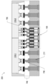
図1は、さまざまな実施形態による、マイクロ電子コンポーネント100の横断面図である。マイクロ電子コンポーネント100は、第1の表面170-1における第1のモールド材料層162と、対向する第2の表面170-2における第2のモールド材料層164とを有する基板160を含み、該基板は、複数の基板貫通ビア(TSV)161を含む。第1のモールド材料層162は、第1のモールド材料166と、前記複数のTSV 161に伝導的に結合された複数の第1のモールド貫通ビア(TMV)163とを含んでいてもよく、第2のモールド材料層164は、第2のモールド材料167と、前記複数のTSV 161に伝導的に結合された複数の第2のTMV 165とを含んでいてもよい。いくつかの実施形態では、個々の第1のTMV 163は、個々のTSV 161に伝導的に結合されてもよい。いくつかの実施形態では、個々の第1のTMV 163は、2つ以上のTSV 161に伝導的に結合されてもよい。いくつかの実施形態では、個々の第2のTMV 165は、個々のTSV 161に伝導的に結合されてもよい。いくつかの実施形態では、個々の第2のTMV 165は、2つ以上のTSV 161に伝導的に結合されてもよい。本明細書で使用されるところでは、用語「電気的に結合された」および「伝導的に結合された」は交換可能に使用されることがある。本明細書で使用されるところでは、「モールド材料層」、「モールド材料領域」、「モールド層」、および「モールド領域」は交換可能に使用されることがある。
FIG. 1 is a cross-sectional view of a
基板160は、任意の好適な絶縁材料(たとえば、当技術分野で知られる、多層に形成された誘電体材料)で形成されてもよい。基板160の絶縁材料は、二酸化ケイ素、窒化ケイ素、酸窒化物、ポリイミド材料、ガラス強化エポキシマトリックス材料、または低kもしくは超低k誘電体(たとえば、炭素ドープ誘電体、フッ素ドープ誘電体、多孔質誘電体、有機ポリマー誘電体、光像形成可能誘電体、および/またはベンゾシクロブテン系ポリマー)などの誘電体材料を含んでいてもよい。いくつかの実施形態では、絶縁材料は、シリコン、ゲルマニウム、またはIII-V材料(たとえば、窒化ガリウム)などの半導体材料、および一つまたは複数の追加的な材料を含んでいてもよい。たとえば、絶縁材料は、酸化ケイ素または窒化ケイ素を含んでいてもよい。いくつかの実施形態では、基板160は、ダイまたは、能動ウェハまたは受動ウェハなどのウェハであってもよい。いくつかの実施形態では、基板は、信号トレース、抵抗器、キャパシタ、またはインダクタなどの追加の伝導性コンポーネントを含んでいてもよい。TSV 161は、たとえば、銅、銀、ニッケル、金、アルミニウム、または他の金属または合金のような任意の適切な伝導性材料で形成されてもよい。いくつかの実施形態では、基板160は、30ミクロンと55ミクロンの間の厚さ(すなわち、z高さ)を有していてもよい。
The
第1のモールド材料166および第2のモールド材料167は、マイクロ電子コンポーネント100に機械的支持を提供する任意の好適な絶縁材料であってよい。第1および第2のモールド材料166、167は、それぞれ前記複数の第1および第2のTMV 163、165への損傷の可能性を低減することができ、そのことは機能性および製造歩留まりを高めうる(すなわち、不良品の数を減少させる)。第1のモールド材料166は、第1のTMV 163と同じ厚さ(すなわち、z高さ)を有していてもよい。いくつかの実施形態では、第1のモールド材料166は、15ミクロンから40ミクロンの厚さを有していてもよい。第2のモールド材料167は、第2のTMV 165と同じ厚さ(すなわち、z高さ)を有していてもよい。いくつかの実施形態では、第2のモールド材料167は、15ミクロンから40ミクロンの厚さを有していてもよい。いくつかの実施形態では、マイクロ電子コンポーネント100は、60ミクロンから135ミクロンの間の全体的な厚さ168と、1:10から1:20の間(たとえば、約1:15)の高いアスペクト比(幅:長さ)とを有していてもよく、モールド材料は、マイクロ電子コンポーネント100に、反りの少ない剛性構造を提供するように選択されてもよい。
いくつかの実施形態では、モールド材料は、無機シリカ粒子を有する有機ポリマーである。いくつかの実施形態では、モールド材料は、有機誘電体材料、難燃性グレード4材料(FR-4)、ビスマレイミドトリアジン(BT)樹脂、ポリイミド材料、ガラス強化エポキシマトリックス材料、または低k誘電体および超低k誘電体(たとえば、炭素ドープ誘電体、フッ素ドープ誘電体、多孔質誘電体、および有機ポリマー誘電体)である。いくつかの実施形態において、第1のモールド材料166および第2のモールド材料167は、同一のモールド材料である。いくつかの実施形態では、第1のモールド材料166および第2のモールド材料167は、異なるモールド材料である。
In some embodiments, the mold material is an organic polymer with inorganic silica particles. In some embodiments, the molding material is an organic dielectric material, a flame retardant grade 4 material (FR-4), a bismaleimide triazine (BT) resin, a polyimide material, a glass-reinforced epoxy matrix material, or a low-k dielectric material. and ultra-low k dielectrics (e.g., carbon-doped dielectrics, fluorine-doped dielectrics, porous dielectrics, and organic polymer dielectrics). In some embodiments,
TMV 163、165は、たとえば、銅、銀、ニッケル、金、アルミニウム、または他の金属または合金のような任意の適切な伝導性材料で形成されうる。TMV 163、165は、たとえば、図5を参照して記載されるプロセスを含む、任意の好適なプロセスを使用して形成されうる。TMV 163、165は、任意の好適なサイズおよび形状を有しうる。いくつかの実施形態では、TMV 163、165は、円形、長方形、または他の形状の断面を有してもよい。いくつかの実施形態では、第1のTMV 163は、15ミクロンから40ミクロンの間の厚さ(たとえば、z高さ)を有してもよく、個々の第1のTMV 163は、30から70ミクロンの間の断面を有してもよい。いくつかの実施形態では、第1のTMV 163は、15ミクロンから25ミクロンの厚さを有していてもよい。いくつかの実施形態では、第1のTMV 163は、90ミクロンと300ミクロンの間のピッチを有していてもよい。本明細書で使用されるところでは、ピッチは、隣接するTMVの中心間(たとえば、第1のTMVの中心から隣接する第1のTMVの中心まで)で測定される。いくつかの実施形態では、第2のTMV 165は、15ミクロンと40ミクロンの間の厚さ(たとえば、z高さ)を有していてもよく、個々の第2のTMV 165は、5ミクロンと40ミクロンの間の断面を有していてもよい。いくつかの実施形態では、第2のTMV 165は、20ミクロンから30ミクロンの厚さを有していてもよい。いくつかの実施形態では、第2のTMV 165は、20ミクロンから100ミクロンの間のピッチを有していてもよい。いくつかの実施形態では、第1のTMVのピッチは、第2のTMVのピッチと同じであってもよい。いくつかの実施形態では、第1のTMVのピッチは、第2のTMVのピッチとは異なっていてもよい。
マイクロ電子コンポーネント100は、60ミクロンから100ミクロンの間の全体的な厚さ168(すなわち、z高さ)を有していてもよい。いくつかの実施形態では、第1のモールド材料層162は、10ミクロンから40ミクロンの厚さを有していてもよい。いくつかの実施形態では、第1のモールド材料層162は、10ミクロンから20ミクロンの間の厚さを有していてもよい。いくつかの実施形態では、第2のモールド材料層164は、15ミクロンから50ミクロンの間の厚さを有していてもよい。いくつかの実施形態では、第2のモールド材料層164は、20ミクロンから30ミクロンの間の厚さを有していてもよい。
図1は、基板160内の特定の数のTSV、特定の数の第1のTMV 163、特定の数の第2のTMV 165、およびTSV 161に電気的に結合されたTMV 163、165の特定の配置を有するマイクロ電子コンポーネント100の特定の構成を示しているが、マイクロ電子コンポーネント100は、任意の数のおよび配置のTSV 161およびTMV 163、165を含みうる。
Although FIG. 1 illustrates a particular configuration of
図2は、さまざまな実施形態による、多層ダイ・サブアセンブリ200の横断面図である。本明細書で使用されるところでは、用語「多層ダイ・サブアセンブリ」および「複合ダイ」は、交換可能に使用されうる。多層ダイ・サブアセンブリ200は、複数のTSV 211および埋め込まれたマイクロ電子コンポーネント100を有する基板210を有する第1の層204-1と、前記複数のTSV 211および前記マイクロ電子コンポーネント100に電気的に結合された第1のダイ114-1および第2のダイ114-2を有する第2の層204-2とを含んでいてもよい。本明細書で使用されるところでは、用語「多層ダイ・サブアセンブリ」200は、2つの層;複数のTSVおよび埋め込まれたマイクロ電子コンポーネント100を有する基板を有する第1の層204-1と、前記複数のTSV 211および前記埋め込まれたマイクロ電子コンポーネント100の前記複数の第2のTMV 165に電気的に結合された一つまたは複数のダイ114を有する第2の層204-2とを含む、複合ダイを指しうる。図1を参照して説明したように、第1および第2のTMV 163、165は異なるピッチを有してもよく、多層ダイ・サブアセンブリ200のダイ114も、異なるピッチをもつ接点(たとえば、TSV 211に結合するための「より粗い」伝導性接点、および第2のTMV 165に結合するための「より細かい」伝導性接点)を有していてもよい。多層ダイ・サブアセンブリ200のダイ114は、片面ダイ(ダイ114が、単一表面上に伝導性接点を有するだけであるという意味で)であってもよく、混合ピッチ・ダイ(ダイ114が、異なるピッチをもつ伝導性接点の諸セットを有するという意味で)であってもよい。
2 is a cross-sectional view of a
基板210は、任意の好適な絶縁材料(たとえば、当技術分野で知られている、多層に形成された誘電体材料)で形成されてもよい。基板210の絶縁材料は、二酸化ケイ素、窒化ケイ素、酸窒化物、ポリイミド材料、ガラス強化エポキシマトリックス材料、または低kもしくは超低k誘電体(たとえば、炭素ドープ誘電体、フッ素ドープ誘電体、多孔質誘電体、有機ポリマー誘電体、光像形成可能誘電体、および/またはベンゾシクロブテン系ポリマー)などの誘電体材料を含んでいてもよい。いくつかの実施形態では、ダイ114の絶縁材料は、シリコン、ゲルマニウム、またはIII-V材料(たとえば、窒化ガリウム)などの半導体材料、および一つまたは複数の追加的材料を含んでいてもよい。たとえば、絶縁材料は、酸化ケイ素または窒化ケイ素を含んでいてもよい。複数のTSV 211は、たとえば、銅、銀、ニッケル、金、アルミニウム、または他の金属または合金のような任意の適切な伝導性材料で形成されうる。複数のTSV 211は、障壁酸化物によって周囲の絶縁材料から絶縁されてもよい。電力、接地、および/または信号は、TSV 211を介して、および他の伝導性経路を介して、ダイ114-1、114-2との間で伝送されうる。
本明細書に開示されるダイ114は、絶縁材料(たとえば、当技術分野で知られている、多層に形成された誘電体材料)および絶縁材料を通じて形成された複数の伝導性経路を含んでいてもよい。いくつかの実施形態では、ダイ114の絶縁材料は、二酸化ケイ素、窒化ケイ素、酸窒化物、ポリイミド材料、ガラス強化エポキシマトリックス材料、または低kもしくは超低k誘電体(たとえば、炭素ドープ誘電体、フッ素ドープ誘電体、多孔質誘電体、有機ポリマー誘電体、光像形成可能誘電体、および/またはベンゾシクロブテン系ポリマー)などの誘電体材料を含んでいてもよい。いくつかの実施形態では、ダイ114の絶縁材料は、シリコン、ゲルマニウム、またはIII-V材料(たとえば、窒化ガリウム)などの半導体材料、および一つまたは複数の追加的材料を含んでいてもよい。たとえば、絶縁材料は、酸化ケイ素または窒化ケイ素を含んでいてもよい。ダイ114内の伝導性経路は、伝導性トレースおよび/または伝導性ビアを含んでいてもよく、ダイ114内の伝導性接点のいずれかに任意の好適な仕方で接続してもよい(たとえば、ダイ114の同一表面上または異なる表面上の複数の伝導性接点に接続する)。本明細書に開示されるダイ114に含まれうる例示的な構造は、図9を参照して後述される。ダイ114内の伝導路は、適宜、接着ライナーおよび/または障壁ライナーのようなライナー材料によって縁取られてもよい。いくつかの実施形態では、ダイ114はウェハである。いくつかの実施形態では、ダイ114は、モノリシック・シリコン、ファンアウトまたはファンイン・パッケージ・ダイ、またはダイ・スタック(たとえば、スタックされたウェハ、スタックされたダイ、またはスタックされた多層ダイ)である。
The die 114 disclosed herein includes an insulating material (e.g., a dielectric material formed in multiple layers as known in the art) and a plurality of conductive paths formed through the insulating material. Good too. In some embodiments, the insulating material of
ダイ114-1、114-2は、図2にそれぞれFLI 250-1および250-2として示されているように、第1レベル相互接続(first level interconnect、FLI)250を介して、基板210内のマイクロ電子コンポーネント100およびTSV 211に結合されてもよい。本明細書に開示されるFLI 250は、任意の好適な形をとることができる。いくつかの実施形態では、FLI 250は、はんだ(たとえば、相互接続を形成するために熱リフローを受けるはんだバンプまたはボール)を含んでいてもよい。いくつかの実施形態では、FLI 250は、異方性伝導性フィルムまたは異方性伝導性ペーストのような異方性伝導性材料を含んでいてもよい。異方性伝導性材料は、非伝導性材料中に分散された伝導性材料を含んでいてもよい。いくつかの実施形態では、FLI 250-1(すなわち、ダイ114とマイクロ電子コンポーネント100との間のFLI)は、15ミクロンと100ミクロンとの間(たとえば、20ミクロンと30ミクロンとの間)のピッチを有する。いくつかの実施形態では、FLI 250-2(すなわち、基板210内のダイ114とTSV211との間のFLI)は、80ミクロンから500ミクロン(たとえば、80ミクロンから120ミクロン)の間のピッチを有する。
Dies 114-1, 114-2 are connected within
図2の多層ダイ・サブアセンブリ200はまた、アンダーフィル材料217をも含んでいてもよい。いくつかの実施形態では、アンダーフィル材料217は、ダイ114-1、114-2と、関連するFLI 250のまわりの基板210との間に延在することができる。アンダーフィル材料217は、適切なエポキシ材料のような絶縁材料であってもよい。いくつかの実施形態では、アンダーフィル材料217は、キャピラリー・アンダーフィル、非伝導性フィルム(non-conductive film、NCF)または成形アンダーフィルを含んでいてもよい。いくつかの実施形態では、アンダーフィル材料217は、FLI 250を形成する際にダイ114-1、114-2を基板210にはんだ付けするのを支援し、次いでFLI 250を重合し、カプセル化するエポキシ・フラックスを含んでいてもよい。アンダーフィル材料217は、多層ダイ・サブアセンブリ200における不均一な熱膨張から生じるダイ114-1、114-2と基板210との間の応力を緩和または最小化しうる熱膨張係数(coefficient of thermal expansion、CTE)を有するように選択されうる。いくつかの実施形態では、アンダーフィル材料217のCTEは、基板210のCTE(たとえば、基板210の誘電体材料のCTE)とダイ114-1、114-2のCTEとの中間的な値を有していてもよい。
図2の多層ダイ・サブアセンブリ200はまた、オーバーモールド材料219をも含んでいてもよい。いくつかの実施形態では、オーバーモールド材料219は、ダイ114-1、114-2のまわりに、基板210の表面271と接触して配置されてもよい。オーバーモールド材料219は、適切なエポキシ材料のような絶縁材料であってもよい。
図3は、さまざまな実施形態による、マイクロ電子アセンブリ300の側断面図である。図3のマイクロ電子アセンブリ300は、多層ダイ・サブアセンブリ200、パッケージ基板306、およびインターポーザ302を含んでいてもよい。多層ダイ・サブアセンブリ200は、中間レベル相互接続(mid-level interconnect、MLI)352を介してパッケージ基板306に結合されてもよく、インターポーザ302は、第2レベル相互接続(second level interconnect、SLI)354を介してパッケージ基板306に結合されてもよい。本明細書に開示されるMLI 352およびSLI 354は、任意の好適な形をとることができる。いくつかの実施形態では、MLI 352およびSLI 354は、はんだ(たとえば、相互接続を形成するために熱リフローを受けるはんだバンプまたはボール)を含んでいてもよい。いくつかの実施形態では、MLI 352およびSLI 354は、ボール・グリッド・アレイ構成のためのはんだボール、ピン・グリッド・アレイ構成におけるピン、またはランド・グリッド・アレイ構成におけるランドを含んでいてもよい。いくつかの実施形態では、インターポーザ302は、回路基板であってもよい。回路基板は、たとえば、マザーボードであってもよく、それに取り付けられた他のコンポーネントを有していてもよい。回路基板は、当技術分野で知られているように、回路基板を通じて電力、接地、および信号をルーティングするための伝導性経路および他の伝導性接点を含んでいてもよい。いくつかの実施形態では、SLI 354は、パッケージ基板306を別のICパッケージまたは任意の他の好適なコンポーネントに結合することができる。いくつかの実施形態では、多層ダイ・サブアセンブリ200は、パッケージ基板306に結合されなくてもよく、代わりに、PCBなどの回路基板に結合されてもよい。
FIG. 3 is a side cross-sectional view of a
パッケージ基板306は、絶縁材料(たとえば、当該技術分野で知られている、複数層に形成された誘電体材料)と、該誘電体材料を通じて電力、接地、および信号をルーティングする一つまたは複数の伝導経路(たとえば、図示されるような、伝導トレースおよび/または伝導ビアを含む)とを含んでいてもよい。いくつかの実施形態では、パッケージ基板306の絶縁材料は、有機誘電体材料、難燃性グレード4材料(FR-4)、BT樹脂、ポリイミド材料、ガラス強化エポキシマトリックス材料、無機充填材を含む有機誘電体、または低k誘電体および超低k誘電体(たとえば、炭素ドープ誘電体、フッ素ドープ誘電体、多孔質誘電体、および有機ポリマー誘電体)であってもよい。特に、パッケージ基板306が標準的なプリント回路基板(printed circuit board、PCB)プロセスを用いて形成される場合、パッケージ基板306はFR-4を含んでいてもよく、パッケージ基板306内の伝導性経路は、FR-4のビルドアップ層によって分離された銅のパターン化されたシートによって形成されてもよい。パッケージ基板306内の伝導性経路は、適宜、接着ライナーおよび/または障壁ライナーのようなライナー材料によって縁取られてもよい。
The
いくつかの実施形態では、パッケージ基板306は、リソグラフィー的に画定されるビア・パッケージング・プロセスを用いて形成されてもよい。いくつかの実施形態では、パッケージ基板306は、標準的な有機パッケージ製造プロセスを用いて製造されてもよく、よって、パッケージ基板306は、有機パッケージの形を取ってもよい。いくつかの実施形態では、パッケージ基板306は、誘電体材料をラミネートまたはスピン塗布し、レーザドリルおよびめっきによって伝導性ビアおよびラインを作成することによって、パネル・キャリア上に形成された一組の再分配層であってもよい。いくつかの実施形態では、パッケージ基板306は、再分配層技術などの任意の好適な技術を用いて、取り外し可能なキャリア上に形成されてもよい。パッケージ基板306の製造のための当該技術分野で知られている任意の方法を使用することができ、簡潔のため、そのような方法は、本明細書ではさらに詳細に説明しない。
In some embodiments,
図3のマイクロ電子アセンブリ300はまた、アンダーフィル材料327をも含んでいてもよい。いくつかの実施形態では、アンダーフィル材料327は、関連するMLI 352のまわりの多層ダイ・サブアセンブリ200とパッケージ基板306との間に延在してもよい。アンダーフィル材料327は、適切なエポキシ材料のような絶縁材料であってもよい。いくつかの実施形態では、アンダーフィル材料327は、キャピラリー・アンダーフィル、非伝導性フィルム(NCF)または成形アンダーフィルを含んでいてもよい。いくつかの実施形態では、アンダーフィル材料327は、MLI 352を形成するときに多層ダイ・サブアセンブリ200をパッケージ基板306にはんだ付けするのを支援し、次いで、重合し、MLI 352をカプセル化するエポキシ・フラックスを含んでいてもよい。アンダーフィル材料327は、不均一な熱膨張から生じる多層ダイ・サブアセンブリ200とパッケージ基板306との間の応力を緩和または最小化しうる熱膨張係数(CTE)を有するように選択されてもよい。
図3のマイクロ電子アセンブリ300はまた、オーバーモールド材料329をも含んでいてもよい。いくつかの実施形態では、オーバーモールド材料329は、多層ダイ・サブアセンブリ200のまわりに、パッケージ基板306の表面371と接触して配置されてもよい。オーバーモールド材料は、適切なエポキシ材料のような絶縁材料であってもよい。
図3のマイクロ電子アセンブリ300はまた、ヒート・スプレッダ333をも含んでいてもよい。ヒート・スプレッダ333は、熱をダイ114-1、114-2から遠ざけるために使用されてもよい(たとえば、熱がヒート・シンクまたは他の熱管理デバイスによってより容易に散逸されうるようにする)。ヒート・スプレッダ333は、任意の好適な熱伝導性材料(たとえば、金属、適切なセラミックなど)を含んでいてもよく、任意の好適な特徴(たとえば、フィン)を含んでいてもよい。いくつかの実施形態では、ヒート・スプレッダ333は、統合されたヒート・スプレッダであってもよい。
The
図3のマイクロ電子アセンブリ300はまた、高熱伝導性のモールド材料または熱インターフェース材料(thermal interface material、TIM)331をも含んでいてもよい。TIM 331は、ポリマーまたは他のバインダー中に熱伝導性材料(たとえば、金属粒子)を含んでいてもよい。TIM 331は、熱インターフェース材料ペーストまたは熱伝導性エポキシであってもよい(これは、当技術分野で知られている、塗布時に流体であってもよく、硬化時に硬くなってもよい)。TIM 331は、ダイ114-1、114-2によって生成された熱がヒート・スプレッダ333に容易に流れるための経路を提供してもよい。ヒート・スプレッダ333において、熱が拡散および/または放散されうる。
The
図4は、さまざまな実施形態による、マイクロ電子アセンブリ400の横断面図である。図4のマイクロ電子アセンブリ400は、図3のマイクロ電子アセンブリ300と同様であり、多層ダイ・サブアセンブリ200が、複数のTSV 211およびマイクロ電子コンポーネント100に電気的に結合された、複数のダイではなく単一のダイ114を含むという点においてのみ異なる。
FIG. 4 is a cross-sectional view of a
図5Aは、基板513および複数のTSV 516を有するウェハ514を含むアセンブリ500Aを示し、TSV 516の上面が露出されている。いくつかの実施形態では、ウェハ514は、活性層(図示せず)およびTSVを有する裏面層を有する活性ウェハであり、ウェハの裏面層から非電気材料(non-electrical material)が除去されて、TSVの上面を露出させる。非電気材料は、ウェハの不活性部分であり、他の材料の中でも、シリコン、セラミック、またはクォーツを含んでいてもよい。非電気材料は、たとえば、研削(grinding)、エッチング、たとえば反応性イオンエッチングまたは化学エッチングを含む任意の好適な技術を用いて除去することができる。いくつかの実施形態では、ウェハ514は、受動ウェハである。いくつかの実施形態では、ウェハ514は、製造作業中にキャリア(図示せず)上に配置される。キャリアは、製造作業中に機械的安定性を提供するための任意の好適な材料を含むことができる。キャリアを使用する場合、ウェハ514は、一時的な接着層またはダイ取り付けフィルム(die attach film、DAF)を含む任意の好適な技術を使用してキャリアに取り付けられてもよい。
5A illustrates an
図5Bは、TSV 516の上面に伝導性ピラー592を形成した後のアセンブリ500Bを示す。伝導性ピラー592は、本明細書に開示される実施形態のいずれかの形をとることができ、任意の好適な技術、たとえば、リソグラフィー・プロセスまたは付加プロセス、たとえばコールドスプレーまたは3次元印刷を用いて形成することができる。たとえば、伝導性ピラー592は、TSV 516の上面にフォトレジスト層を堆積させ、露光し、および現像することによって形成することができる。フォトレジスト層は、伝導性ピラーの形状における空洞を形成するようにパターン化されてもよい。銅のような伝導性材料が、パターン化されたフォトレジスト層の開口部に堆積されて、伝導性ピラー592を形成してもよい。伝導性材料は、電気めっき、スパッタリング、または無電解めっきのような任意の好適なプロセスを使用して堆積されうる。フォトレジストを除去して、伝導性ピラー592を露出させてもよい。別の例では、光像形成可能誘電体が、伝導性ピラー592を形成するために使用されてもよい。いくつかの実施形態では、フォトレジスト材料および伝導性材料を堆積する前に、TSVの上面にシード層(図示せず)が形成されてもよい。シード層は、銅を含む任意の好適な伝導性材料でありうる。シード層は、フォトレジスト層を除去した後、とりわけ、化学エッチングを含む任意の好適なプロセスを使用して除去されてもよい。いくつかの実施形態では、シード層は省略されてもよい。
5B illustrates
図5Cは、伝導性ピラー592のまわりにモールド材料594を提供した後のアセンブリ500Cを示す。モールド材料594は、圧縮成形またはラミネートなどの任意の好適な技術を使用して堆積されうる。いくつかの実施形態では、モールド材料は、堆積後に硬化される。いくつかの実施形態では、モールド材料594は、初期には伝導性ピラー592の頂部の上にかぶせて堆積され、次に、後ろに研磨され、平坦化されて、伝導性ピラー592の上面を露出させることができる。モールド材料を堆積するために使用される技術は、使用されるモールド材料のタイプに依存しうる。モールド材料は、たとえば、研削、エッチング、たとえば反応性イオンエッチング(RIE)または化学エッチングを含む、任意の好適な技術を用いて除去することができる。いくつかの実施形態では、使用されるモールド材料は、マイクロ電子コンポーネント(たとえば、マイクロ電子コンポーネント100)についての所望の特性に依存しうる。モールド材料594は、図1を参照して上述したように、任意の好適なモールド材料でありうる。伝導性ピラー592は、図1の第2のTMV 165と同様である。
FIG. 5C shows the
図5Dは、アセンブリ500Cの上面570-2上にキャリア512を堆積した後のアセンブリ500Dを示す。キャリアは、製造作業中に機械的安定性を提供するための任意の好適な材料を含むことができる。アセンブリ500Cは、一時的な接着層またはダイ取り付けフィルム(DAF)を含む任意の好適な技術を用いてキャリア512に取り付けられてもよい。
FIG. 5D shows
図5Eは、アセンブリ500Dの底面570-1から非電気材料を除去し、平坦化してTSV 516の底面を露出させた後のアセンブリ500Eを示す。非電気材料は、ウェハの不活性部分であり、他の材料の中でも、シリコン、セラミック、またはクォーツを含みうる。非電気材料は、たとえば、研削、エッチング、たとえば反応性イオンエッチング(RIE)または化学エッチングを含む任意の好適な技術を用いて除去することができる。
FIG. 5E shows
図5Fは、TSV 516の露出した底面570-1上に伝導性ピラー598を形成した後のアセンブリ500Fを示す。伝導性ピラー598は、本明細書では、伝導性バンプまたはパッケージ側バンプと称されることもある。伝導性ピラー598は、本明細書に開示される実施形態のいずれかの形をとることができ、任意の好適な技術、たとえば、リソグラフィー・プロセスまたは付加プロセス、たとえばコールドスプレーまたは3次元印刷を用いて形成することができる。いくつかの実施形態では、伝導性ピラー598は、窒化シリコン不動態化層を堆積させ、窒化シリコン不動態化層を開いて(opening)TSV 516の表面を(すなわち、底面570-1において)露出させ、TSVの露出した表面上に伝導性シード層を堆積させ、フォトレジスト層をスピンし、フォトレジスト層を現像して伝導性ピラー598を形成するための開口を作製し、伝導性ピラー598を形成するための開口部に伝導性材料を電気めっきし、フォトレジスト層を除去し、任意的に、適宜シード層をエッチングすることによって形成されてもよい。伝導性ピラー598は、任意の好適な伝導性材料で作製することができ、図1を参照して上述したように、任意の好適なサイズおよび形状を有することができる。伝導性ピラー598は、図1の第1のTMV 163と同様である。
FIG. 5F shows
図5Gは、伝導性ピラー598のまわりにモールド材料595を提供した後のアセンブリ500Gを示す。モールド材料595は、圧縮成形またはラミネートなどの任意の好適な技術を使用して堆積されうる。いくつかの実施形態では、モールド材料は、堆積後に硬化される。いくつかの実施形態では、モールド材料595は、初期に伝導性ピラー598上にかぶせて堆積され、次いで、研磨され、平坦化されて、伝導性ピラー598の底面を(すなわち、570-1において)を露出させてもよい。モールド材料を堆積するために使用される技術は、使用されるモールド材料のタイプに依存しうる。モールド材料は、たとえば、研削、エッチング、たとえば反応性イオンエッチング(RIE)または化学エッチングを含む、任意の好適な技術を用いて除去することができる。いくつかの実施形態では、使用されるモールド材料は、マイクロ電子コンポーネント(たとえば、マイクロ電子コンポーネント100)についての所望される特性に依存しうる。モールド材料595は、図1を参照して上述したように、任意の好適なモールド材料であってよい。
FIG. 5G shows
図5Hは、キャリア512の除去後および底面570-1上にボンディング層517を取り付けた後のアセンブリ500Hを示す。ボンディング層(bonding layer)517は、接着層(adhesive layer)またはダイ取り付けフィルム(DAF)のような任意の好適なボンディング層であってもよく、一時的な接着剤またはラミネートを含む任意の好適な技術を使用して取り付けられてもよい。いくつかの実施形態では、ボンディング層517は、2ミクロンから15ミクロンの間の厚さを有する。いくつかの実施形態では、ボンディング層517は、3ミクロンから7ミクロンの間の厚さを有する。
FIG. 5H shows
図5Iは、個々のユニットに切り離した後の、アセンブリ500Iを示す。これは、本明細書ではマイクロ電子コンポーネントとも呼ばれ、たとえばマイクロ電子コンポーネント100である。いくつかの実施形態では、個々のユニットは同じであってもよい。いくつかの実施形態では、個々のユニットは異なっていてもよい。
FIG. 5I shows the assembly 500I after being cut into individual units. This is also referred to herein as a microelectronic component, for example a
図6A~6Iは、さまざまな実施形態による、図3のマイクロ電子アセンブリ300を製造するための例示的なプロセスにおけるさまざまな段階の横断面図である。本明細書に開示されるマイクロ電子アセンブリを製造するために、任意の好適な技術を使用することができる。図6A~6I(および製造プロセスを表わす添付の図面の他のもの)を参照して以下で論じられる作業は、特定の順序で示されているが、これらの作業は、任意の好適な順序で実行されうる。さらに、特定のアセンブリおよび特定の多層ダイ・サブアセンブリが、図6A~6I(および製造プロセスを表わす添付の図面の他のもの)に示されているが、図6A~6Iを参照して下記で論じられる作業は、任意の好適なアセンブリおよびサブアセンブリを形成するために使用されうる。図6A~図6Iの実施形態では、マイクロ電子コンポーネント(たとえば、アセンブリ500I)は、まず、複合ダイ(たとえば、アセンブリ600G)に組み立てられてもよく、次いで、該複合ダイが、インターポーザおよび/またはパッケージ基板(たとえば、アセンブリ600I)に結合されてもよい。このアプローチは、より厳しい公差を可能にすることができ、比較的小さなダイ114のためのマイクロ電子コンポーネント(たとえば、図1のマイクロ電子コンポーネント100)を複合ダイ(たとえば、図2のサブアセンブリ200)に統合するために特に望ましいことがありうる。
6A-6I are cross-sectional views of various stages in an exemplary process for manufacturing the
図6Aは、キャリア605および任意的にボンディング膜616を含むアセンブリ600Aを示す。ボンディング膜616の上面に第1の伝導性パッド607、エッチング停止層613、第2の伝導性パッド609、および伝導性TSV 611を形成する。キャリア605は、製造作業中に機械的安定性を提供するための任意の好適な材料を含んでいてもよく、たとえば、ガラス・キャリアを含む。
い。ボンディング膜616は、任意の好適な一時的なボンディング膜、たとえば、一時的な接着層またはDAFであってもよい。第1の伝導性パッド607、エッチング停止層613、第2の伝導性パッド609、および伝導性TSV 611は、その中に伝導構造が存在しない一つまたは複数の非分布領域(de-population region)655を形成するように配置されてもよい。本明細書中で使用されるところでは、用語「伝導性パッド」、「伝導性相互接続」、および「伝導性接点」は、交換可能に使用されうる。第1の伝導性パッド607、エッチング停止層613、第2の伝導性パッド609、および伝導性TSV 611は、任意の好適な技術、たとえば、リソグラフィー・プロセスまたは付加プロセス、たとえばコールドスプレーまたは3次元印刷を使用して形成されてもよい。たとえば、第1の伝導性パッド607、エッチング停止層613、第2の伝導性パッド609、および伝導性TSV 611は、ボンディング膜616上で、複数のフォトレジスト層を堆積し、露光し、および現像し、金属などの伝導性材料を堆積することによって形成されてもよい。フォトレジスト層は、第1の伝導性パッド607、エッチング停止層613、第2の伝導性パッド609、および伝導性TSV 611の形状の空洞を形成するようにパターン化されてもよい。銅のような伝導性材料が、第1の伝導性パッド607、第2の伝導性パッド609、および伝導性TSV 611を形成するために、パターン化されたフォトレジスト層の開口部に堆積されてもよい。ニッケルのようなエッチング停止材料が、エッチング停止層613を形成するために、パターン化されたフォトレジスト層の開口部に堆積されてもよい。伝導性材料およびエッチング停止材料は、電気めっき、スパッタリング、または無電解めっきなどの任意の好適なプロセスを使用して堆積されてもよい。いくつかの実施形態では、第1の伝導性パッド607、エッチング停止層613、第2の伝導性パッド609、および伝導性TSV 611をそれぞれ露出するために、各材料堆積後にフォトレジストを除去してもよい。いくつかの実施形態では、第1のフォトレジスト材料が堆積および現像されて、第1の伝導性パッド607、エッチング停止層613、および第2の伝導性パッド609を形成してもよく、次いで、第1のフォトレジスト材料が除去されてもよく、第2のフォトレジスト材料が堆積および現像されて、伝導性TSV 611を形成してもよく、次いで、第2のフォトレジスト材料が除去されてもよい。別の例では、光像形成可能誘電体を使用して、第1の伝導性パッド607、エッチング停止層613、第2の伝導性パッド609、および伝導性TSV 611を形成してもよい。いくつかの実施形態では、フォトレジスト材料および伝導性材料を堆積する前に、ボンディング膜616の上面にシード層(図示せず)が形成されてもよい。シード層は、銅またはチタン/銅を含む任意の好適な伝導性材料でありうる。シード層は、最後のフォトレジスト層を除去した後、とりわけ化学エッチングを含む任意の好適なプロセスを使用して除去されてもよい。いくつかの実施形態では、シード層は省略されてもよい。
FIG. 6A shows an
stomach.
第1の伝導性パッド607は、任意の好適な寸法を有してもよく、任意の好適な伝導性材料で作製されてもよく、たとえば、第1の伝導性パッド607は、2ミクロンから10ミクロンの間の厚さを有してもよく、銅で作られてもよい。エッチング停止層613は、任意の好適な寸法を有してもよく、たとえば、エッチング停止層613は、第1の伝導性パッド607と等しい長さおよび幅を有してもよく、2ミクロンから5ミクロンの間の厚さを有してもよい。エッチング停止層は、ニッケルのような任意の好適な材料で作ることができる。第2の伝導性パッド609は、任意の好適な寸法を有してもよく、任意の好適な伝導性材料で作られてもよく、たとえば、第2の伝導性パッド609は、第1の伝導性パッド607と等しい長さおよび幅を有してもよく、10ミクロンと20ミクロンとの間の厚さを有してもよい。
The first
伝導性TSV 611は、任意の好適な寸法を有することができ、図2を参照して説明したように、任意の好適な伝導性材料で作ることができる。いくつかの実施形態では、個々の伝導性TSV 611は、10ミクロンから1000ミクロンの間の直径(たとえば、断面(cross-section))を有してもよい。たとえば、個々の伝導性TSV 611は、50ミクロンから400ミクロンの間の直径を有していてもよい。いくつかの実施形態では、個々の伝導性TSV 611は、50ミクロンから150ミクロンの間の高さ(たとえば、z高さまたは厚さ)を有していてもよい。伝導性ピラーは、任意の好適な断面形状、たとえば、特に正方形、三角形、および楕円形を有していてもよい。
The
図6Bは、アセンブリ600A(図6A)の脱分布領域655内にマイクロ電子コンポーネント100を配置した後のアセンブリ600Bを示す。マイクロ電子コンポーネント100は、図1のマイクロ電子コンポーネント100であってもよく、または、第1のモールド貫通伝導構造を有する第1の表面における第1のモールド領域および第2のモールド貫通伝導構造を有する対向する第2の表面における第2のモールド領域を有する基板を含む別の類似のコンポーネントであってもよい。ここで、該基板は、複数のシリコン貫通ビア(TSV)を含み、第1のモールド貫通伝導構造および第2のモールド貫通伝導構造は、TSVに電気的に結合される。マイクロ電子コンポーネント100は、接着層618、またはアセンブリ600Aの脱分布領域655に付着するための、DAF、ダイ・ボンディング膜(die bonding film、DBF)、または剥離層などの他の類似の層を含んでいてもよい。剥離層(本明細書では脱ボンディング層とも呼ばれる)は、一時的な接着剤、または、たとえば熱または光に暴露されると剥離する他の材料を含んでいてもよい。図1および図5Iのマイクロ電子コンポーネントなどのマイクロ電子コンポーネントは、ピックアンドプレースツールなど、ダイを配置するためと同じまたは類似の技術を使用して、脱分布領域655内に配置されてもよい。
FIG. 6B shows
図6Cは、マイクロ電子コンポーネント100、第1の伝導性パッド607、エッチング停止層613、第2の伝導性パッド609、および伝導性TSV 611のまわりに絶縁材料630を提供した後のアセンブリ600Cを示す。絶縁材料630は、任意の好適な技術を用いて、たとえば、ラミネートによって堆積されてもよい。いくつかの実施形態では、絶縁材料630は、初期にマイクロ電子コンポーネント100および伝導性TSV 611の頂部の上にかぶせて堆積され、その後、研磨されて、マイクロ電子コンポーネント100の上面および伝導性TSV 611の上面を露出させる。いくつかの実施形態では、絶縁材料630は、無機シリカ粒子を有する有機ポリマーのようなモールド材料である。いくつかの実施形態では、絶縁材料630は、誘電体材料である。いくつかの実施形態では、誘電体材料は、有機誘電体材料、難燃性グレード4材料(FR-4)、BT樹脂、ポリイミド材料、ガラス強化エポキシマトリックス材料、または低k誘電体および超低k誘電体(たとえば、炭素ドープ誘電体、フッ素ドープ誘電体、多孔質誘電体、および有機ポリマー誘電体)を含んでいてもよい。誘電体材料は、ラミネート、またはスリットコーティングおよび硬化を含む任意の好適なプロセスを使用して形成されうる。誘電体層が、伝導性TSV 611およびマイクロ電子コンポーネント100を完全に覆うように形成される場合、誘電体層は、研削、またはエッチング、たとえばウェットエッチング、ドライエッチング(たとえば、プラズマエッチング)、ウェットブラスト、またはレーザーアブレーション(たとえば、エキシマレーザーを使用する)などの任意の好適な技術を使用して除去され、マイクロ電子コンポーネント100の上面および伝導性TSV 611の上面を露出させてもよい。いくつかの実施形態では、必要なエッチング時間を短縮するために、絶縁材料630の厚さを最小限にしてもよい。いくつかの実施形態では、再分配層(redistribution layer、RDL)(図示せず)が、アセンブリ600Cの上面に形成されてもよい。RDLは、PCB技術または再分配層技術のような任意の好適な技術を用いて製造されうる。
FIG. 6C shows
図6Dは、伝導性接点652を伝導性TSV 611の上面に形成し、伝導性接点654をマイクロ電子コンポーネント100の上面に形成した後のアセンブリ600Dを示す。伝導性接点652、654は、リソグラフィー(高度なレーザーまたはリソグラフィー・プロセスによって形成される小さな垂直相互接続特徴を有する)を使用することを含む、任意の好適な技術を使用して形成されてもよい。伝導性接点652、654は、銅を含む任意の好適な伝導性材料で作製されてもよい。いくつかの実施形態では、伝導性接点652、654は、複数の金属層を有してもよく、各金属層は、異なる金属材料を含んでいてもよい。たとえば、伝導性接点652、654は、3つの金属層、すなわち、銅を含む第1の金属層、ニッケルを含む第2の金属層、およびスズを含む第3の金属層を含んでいてもよい。スズ層652-3、654-3は、任意の好適な化学的または機械的エッチングを使用して平坦化されてもよい。いくつかの実施形態では、第2の金属層652-2、654-2は、エッチング停止層であってもよい。
FIG. 6D illustrates the
図6Eは、ダイ114-1、114-2を配置し、相互接続650-1、650-2のまわりにアンダーフィル材料617を提供し、ダイのまわりに絶縁材料619を提供した後のアセンブリ600Eを示す。ダイ114-1、114-2は、相互接続650-2によって伝導性TSVに電気的および機械的に結合されてもよく、相互接続650-1によってマイクロ電子コンポーネント100に電気的および機械的に結合されてもよい。相互接続650-1、650は、任意の好適な形態をとることができる。いくつかの実施形態では、相互接続650-1、650-は、はんだ(たとえば、はんだバンプまたはボール)を含んでいてもよい。アンダーフィル材料617および絶縁材料619、またはオーバーモールド材料は、任意の好適な材料であってよく、図2を参照して上述したように、任意の好適な技術を使用して形成されてもよい。
FIG. 6E illustrates the
図6Fは、キャリア605およびボンディング膜616を除去して第1の伝導性パッド607および接着層618を露出させた後、アセンブリ600Eの上面にキャリア603を取り付けた後のアセンブリ600Fを示す。キャリア603は、たとえばガラス・キャリアを含む、製造作業中に機械的安定性を提供するための任意の好適な材料を含んでいてもよい。キャリア603は、任意の好適な技術、たとえば、一時的なボンディング膜、接着剤、またはDAF(図示せず)を用いて取り付けることができる。いくつかの実施形態では、キャリア603を取り付ける前に、ヒート・スプレッダおよび/またはTIM(図示せず)をアセンブリ600Eの上面に取り付けてもよい。ヒート・スプレッダおよび/またはTIMは、図3を参照して説明したように、任意の好適な形を有しうる。
FIG. 6F shows
図6Gは、アセンブリ600Fの底部から第1の伝導性パッド607、エッチング停止層613、絶縁材料630、および接着層618を除去して、マイクロ電子コンポーネント100の底面上の第2の伝導性パッド609およびTMV 663(たとえば、図1の第1のTMV 163)を露出させた後のアセンブリ600Gを示す。第1の伝導性パッド607、エッチング停止層613、および接着層618のそれぞれは、中でもたとえば、ドライエッチングまたは機械的研削を含む任意の好適な技術を使用して除去されてもよい。
FIG. 6G shows
図6Hは、キャリア603の除去後のアセンブリ600Hを示す。キャリア603は、任意の好適なプロセスを使用して除去されうる。複数の複合ダイ(たとえば、図2の多層ダイ・サブアセンブリ200)が一緒に製造される場合、複合ダイは、キャリア603の除去後に切り離されてもよい。切り離しの前または後のいずれでもさらなる作業が適宜実施されてもよい(たとえば、TIMを提供すること、ヒート・スプレッダを取り付けること、はんだレジスト層を堆積させること、インターポーザまたはパッケージ基板に結合するためのはんだボールを取り付けることなど)。
FIG. 6H shows
図6Iは、アセンブリ600Hをパッケージ基板606に結合し、パッケージ基板606をインターポーザ602に結合した後のアセンブリ600Iを示す。アセンブリ600Hは、機械的および電気的にパッケージ基板606に結合されてもよく、インターポーザ602は、図3を参照して説明したように、任意の好適な相互接続を使用して、機械的および電気的にパッケージ基板606に結合されてもよい。いくつかの実施形態では、図3を参照して説明したように、アンダーフィル材料627およびオーバーモールド材料629が提供されてもよい。
FIG. 6I shows assembly 600I after coupling
本明細書に開示されるマイクロ電子コンポーネント100、多層ダイ・サブアセンブリ200、およびマイクロ電子アセンブリ300、400は、特定の数および配置のマイクロ電子コンポーネント100および特定の数のTSV、ダイ、および相互接続を有する多層ダイ・サブアセンブリ200を示すが、任意の数および配置のマイクロ電子コンポーネント100、多層ダイ・サブアセンブリ200、TSV、ダイ、および相互接続が使用されうる。
The
本明細書に開示されるマイクロ電子コンポーネント100および多層ダイ・サブアセンブリ200は、任意の好適な用途に使用されうる。たとえば、いくつかの実施形態では、多層ダイ・サブアセンブリ200は、特にモバイル装置および小さな形状因子の装置において、フィールドプログラマブルゲートアレイ(FPGA)または処理ユニット(たとえば、中央処理ユニット、グラフィックス処理ユニット、FPGA、モデム、アプリケーションプロセッサなど)のための非常に小さな形状因子の電圧制御を可能にするために使用されうる。別の例では、多層ダイ・サブアセンブリ200内のダイ114は、処理装置(たとえば、中央処理装置、グラフィックス処理装置、FPGA、モデム、アプリケーションプロセッサなど)であってもよい。
The
図7は、さまざまな実施形態による、別の例示的な多層ダイ・サブアセンブリ200の横断面図である。本明細書に開示されるマイクロ電子アセンブリ300、400において、多層ダイ・サブアセンブリ200は、RDL 748を含んでいてもよい。たとえば、図7は、ダイ114-1、114-2の下方にRDL 748を有する多層ダイ・サブアセンブリ200の実施形態を示す。ダイ114-1、114-2は、RDL 748内の伝導経路796を介して、伝導性TSV 211およびマイクロ電子コンポーネント100に電気的に結合されてもよい。RDL 748は、より低密度のピッチを有するコンポーネントをより高密度のピッチを有するコンポーネントに結合することができる。本明細書に開示されるマイクロ電子アセンブリ300、400は、任意の好適な電子コンポーネントに含まれてもよい。
FIG. 7 is a cross-sectional view of another exemplary multilayer die
図8~図11は、本明細書に開示されているマイクロ電子アセンブリ300、400のいずれかを含んでいてもよく、またはそれらに含まれてもよい装置のさまざまな例を示す。
8-11 illustrate various examples of devices that may include or be included in any of the
図8は、本明細書に開示されるマイクロ電子アセンブリ300、400のいずれか(たとえば、ダイ114のいずれかの好適なもの)に含まれうるウェハ1500およびダイ1502の上面図である。ウェハ1500は、半導体材料から構成されてもよく、ウェハ1500の表面上に形成されたIC構造を有する一つまたは複数のダイ1502を含んでいてもよい。ダイ1502のそれぞれは、任意の好適なICを含む半導体製品の反復ユニットであってもよい。半導体製品の製造が完了した後、ウェハ1500は、ダイ1502が互いに分離されて、半導体製品の個別の「チップ」を提供する切り離しプロセスを経てもよい。ダイ1502は、本明細書に開示されるダイ114のいずれであってもよい。ダイ1502は、一つまたは複数のトランジスタ(たとえば、後述する図9のトランジスタ1640の一部)、電気信号をトランジスタ、受動コンポーネント(たとえば、信号トレース、抵抗器、キャパシタ、またはインダクタ)、および/または任意の他のICコンポーネントにルーティングするためのサポート回路を含んでいてもよい。いくつかの実施形態では、ウェハ1500またはダイ1502は、メモリデバイス(たとえば、ランダムアクセスメモリ(RAM)デバイス、たとえばスタティックRAM(SRAM)デバイス、磁気RAM(MRAM)デバイス、抵抗RAM(RRAM)デバイス、伝導性ブリッジングRAM(CBRAM)デバイスなど)、論理デバイス(たとえば、AND、OR、NAND、またはNORゲート)、または任意の他の好適な回路要素を含んでいてもよい。これらのデバイスのうち複数のものが、単一のダイ1502上に組み合わされてもよい。たとえば、複数のメモリデバイスによって形成されるメモリアレイは、処理装置(たとえば、図11の処理装置1802)またはそれらのメモリデバイスに情報を記憶するか、またはメモリアレイに記憶された命令を実行するように構成される他のロジックとして、同じダイ1502上に形成されてもよい。いくつかの実施形態では、ダイ1502(たとえば、ダイ114)は、中央処理装置、無線周波数チップ、電力変換器、またはネットワーク・プロセッサであってもよい。本明細書に開示されるマイクロ電子アセンブリ300、400のさまざまなものは、ダイとウェハのアセンブリ技術を用いて製造されてもよく、いくつかのダイ114がダイ114の他のものを含むウェハ1500に取り付けられ、その後、ウェハ1500が切り離される。
FIG. 8 is a top view of a
図9は、本明細書に開示されるマイクロ電子アセンブリ300、400のいずれか(たとえば、いずれかのダイ114)に含まれうるICデバイス1600の断面側面図である。ICデバイス1600の一つまたは複数は、一つまたは複数のダイ1502(図8)に含まれてもよい。ICデバイス1600は、ダイ基板1602(たとえば、図8のウェハ1500)上に形成されてもよく、ダイ(たとえば、図8のダイ1502)に含まれてもよい。ダイ基板1602は、たとえば、n型またはp型材料システム(またはその両方の組み合わせ)を含む半導体材料システムで構成される半導体基板であってもよい。ダイ基板1602は、たとえば、バルクシリコンまたはシリコン・オン・インシュレータ(SOI)サブ構造を用いて形成される結晶基板を含んでいてもよい。いくつかの実施形態では、ダイ基板1602は、シリコンと組み合わせても組み合わせなくてもよい代替材料を使用して形成されてもよく、代替材料は、ゲルマニウム、アンチモン化インジウム、テルル化鉛、ヒ化インジウム、リン化インジウム、ヒ化ガリウム、またはアンチモン化ガリウムを含む、これらに限定されない。II~VI族、III~V族、またはIV族に分類されるさらなる材料もまた、ダイ基板1602を形成するために使用されうる。ここでは、ダイ基板1602がそこから形成されうる材料のいくつかの例が記載されているが、ICデバイス1600の基盤として機能しうる任意の材料が使用されうる。ダイ基板1602は、切り離されたダイ(たとえば、図8のダイ1502)またはウェハ(たとえば、図8のウェハ1500)の一部であってもよい。
FIG. 9 is a cross-sectional side view of an
ICデバイス1600は、ダイ基板1602上に配置された一つまたは複数のデバイス層1604を含んでいてもよい。デバイス層1604は、ダイ基板1602上に形成される一つまたは複数のトランジスタ1640(たとえば、金属酸化物半導体電界効果トランジスタ(MOSFET))の特徴を含んでいてもよい。デバイス層1604は、たとえば、一つまたは複数のソースおよび/またはドレイン(S/D)領域1620、S/D領域1620間のトランジスタ1640内の電流の流れを制御するためのゲート1622、およびS/D領域1620への/からの電気信号をルーティングするための一つまたは複数のS/D接点1624を含んでいてもよい。トランジスタ1640は、デバイス隔離領域、ゲート接点等のような、明快さのために描かれていない追加的な特徴を含んでいてもよい。トランジスタ1640は、図9に示されるタイプおよび構成に限定されず、たとえば、平面トランジスタ、非平面トランジスタ、または両者の組み合わせのような、幅広い多様な他のタイプおよび構成を含んでいてもよい。非平面トランジスタは、ダブルゲートトランジスタまたはトリゲートトランジスタなどのFinFETトランジスタ、ならびに、ナノリボンおよびナノワイヤトランジスタなどのラップアラウンドゲートトランジスタまたは全アラウンドゲートトランジスタを含みうる。
各トランジスタ1640は、少なくとも2つの層、ゲート誘電体、およびゲート電極から形成されるゲート1622を含んでいてもよい。ゲート誘電体は、1つの層または層のスタックを含んでいてもよい。前記一つまたは複数の層は、酸化ケイ素、二酸化ケイ素、炭化ケイ素、および/または高k誘電体材料を含んでいてもよい。高k誘電体材料は、ハフニウム、シリコン、酸素、チタン、タンタル、ランタン、アルミニウム、ジルコニウム、バリウム、ストロンチウム、イットリウム、鉛、スカンジウム、ニオブ、および亜鉛のような元素を含んでいてもよい。ゲート誘電体に使用されうる高k材料の例としては、ハフニウム酸化物、ハフニウムシリコン酸化物、ランタン酸化物、ランタンアルミニウム酸化物、ジルコニウム酸化物、ジルコニウムシリコン酸化物、タンタル酸化物、チタン酸化物、バリウムストロンチウムチタン酸化物、バリウムチタン酸化物、ストロンチウムチタン酸化物、イットリウム酸化物、アルミニウム酸化物、鉛スカンジウムタンタル酸化物、およびニオブ酸鉛亜鉛を含むが、これらに限定されない。いくつかの実施形態では、高k材料が使用される場合、ゲート誘電体の品質を改善するために、ゲート誘電体に対してアニーリングプロセスが実行されてもよい。
Each
ゲート電極は、ゲート誘電体上に形成されてもよく、トランジスタ1640がPMOSトランジスタであるかNMOSトランジスタであるかに依存して、少なくとも1つのp型仕事関数金属またはn型仕事関数金属を含んでいてもよい。いくつかの実装では、ゲート電極は、2つ以上の金属層のスタックからなっていてもよく、ここで、一つまたは複数の金属層は、仕事関数金属層(work function metal layer)であり、少なくとも1つの金属層は、充填金属層(fill metal layer)である。障壁層のような他の目的のためにさらなる金属層が含まれてもよい。PMOSトランジスタの場合、ゲート電極に使用されうる金属は、ルテニウム、パラジウム、白金、コバルト、ニッケル、伝導性金属酸化物(たとえば、酸化ルテニウム)、およびNMOSトランジスタを参照して後述する金属のうちの任意のもの(たとえば、仕事関数の調整のため)を含むが、これらに限定されない。NMOSトランジスタの場合、ゲート電極に使用されうる金属は、ハフニウム、ジルコニウム、チタン、タンタル、アルミニウム、これらの金属の合金、これらの金属の炭化物(たとえば、炭化ハフニウム、炭化ジルコニウム、炭化チタン、炭化タンタル、および炭化アルミニウム)、およびPMOSトランジスタを参照して上述した金属のうちの任意のもの(たとえば、仕事関数の調整のため)を含むが、これらに限定されない。
The gate electrode may be formed on the gate dielectric and includes at least one p-type or n-type work function metal, depending on whether
いくつかの実施形態では、ソース‐チャネル‐ドレイン方向に沿ったトランジスタ1640の断面として見たとき、ゲート電極は、ダイ基板1602の表面に実質的に平行な底部と、ダイ基板1602の上面に実質的に垂直な2つの側壁部とを含むU字形構造から構成されてもよい。他の実施形態では、ゲート電極を形成する金属層のうちの少なくとも1つは、ダイ基板1602の上面に実質的に平行な平面層であってもよく、ダイ基板1602の上面に実質的に垂直な側壁部を含まない。他の実施形態では、ゲート電極は、U字形構造と平面状の非U字形構造との組み合わせから構成されてもよい。たとえば、ゲート電極は、一つまたは複数の平面状の非U字形の層の上に形成された一つまたは複数のU字形の金属層から構成されてもよい。
In some embodiments, when viewed as a cross-section of the
いくつかの実施形態では、ゲートスタックをはさむために、一対の側壁スペーサーがゲートスタックの対向する側に形成されてもよい。側壁スペーサーは、窒化ケイ素、酸化ケイ素、炭化ケイ素、炭素をドープした窒化ケイ素、および酸窒化ケイ素などの材料から形成されてもよい。側壁スペーサーを形成するためのプロセスは、当技術分野で周知であり、一般に、堆積およびエッチングプロセスステップを含む。いくつかの実施形態では、複数のスペーサー対が使用されてもよく、たとえば、ゲートスタックの対向する側に、2対、3対、または4対の側壁スペーサーが形成されてもよい。 In some embodiments, a pair of sidewall spacers may be formed on opposite sides of the gate stack to sandwich the gate stack. Sidewall spacers may be formed from materials such as silicon nitride, silicon oxide, silicon carbide, carbon-doped silicon nitride, and silicon oxynitride. Processes for forming sidewall spacers are well known in the art and generally include deposition and etching process steps. In some embodiments, multiple pairs of spacers may be used, for example, two, three, or four pairs of sidewall spacers may be formed on opposite sides of the gate stack.
S/D領域1620は、各トランジスタ1640のゲート1622に隣接してダイ基板1602内に形成されてもよい。S/D領域1620は、たとえば、注入/拡散プロセスまたはエッチング/堆積プロセスを使用して形成されてもよい。前者のプロセスでは、S/D領域1620を形成するために、ホウ素、アルミニウム、アンチモン、リン、またはヒ素などのドーパントが、ダイ基板1602にイオン注入されてもよい。イオン注入プロセスの後に、ドーパントを活性化し、ダイ基板1602内にさらに拡散させるアニーリングプロセスが行なわれてもよい。後者のプロセスでは、まず、ダイ基板1602をエッチングして、S/D領域1620の位置に凹部を形成してもよい。次いで、エピタキシャル堆積プロセスが実行されて、該凹部を、S/D領域1620を作製するために使用される材料で充填してもよい。いくつかの実施形態では、S/D領域1620は、シリコンゲルマニウムまたはシリコンカーバイド〔炭化ケイ素〕のようなシリコン合金を用いて製造されてもよい。いくつかの実施形態では、エピタキシャル堆積されたシリコン合金は、ホウ素、ヒ素またはリンのようなドーパントをその場で(in situ)ドープされてもよい。いくつかの実施形態では、S/D領域1620は、ゲルマニウムまたはIII-V族材料または合金などの一つまたは複数の代替的な半導体材料を使用して形成されてもよい。さらなる実施形態では、S/D領域1620を形成するために、金属および/または金属合金の一つまたは複数の層が使用されてもよい。
An S/
電力および/または入出力(I/O)信号などの電気信号が、デバイス層1604上に配置された一つまたは複数の相互接続層(相互接続層1606~1610として図9に示される)を通じて、デバイス層1604のデバイス(たとえば、トランジスタ1640)へおよび/または該デバイスからルーティングされてもよい。たとえば、デバイス層1604の伝導性特徴(たとえば、ゲート1622およびS/D接点1624)は、相互接続層1606~1610の相互接続構造1628と電気的に結合されてもよい。一つまたは複数の相互接続層1606~1610は、ICデバイス1600のメタライゼーション・スタック(「ILDスタック」とも呼ばれる)1619を形成してもよい。
Electrical signals, such as power and/or input/output (I/O) signals, are routed through one or more interconnect layers (shown in FIG. 9 as interconnect layers 1606-1610) disposed on
相互接続構造1628は、幅広い多様な設計に従って電気信号をルーティングするために、相互接続層1606~1610内に配置されてもよく、特に、この配置は、図9に描かれる相互接続構造1628の特定の構成に限定されない。図9には、特定の数の相互接続層1606~1610が示されているが、本開示の実施形態は、示されているよりも多くの、または少ない相互接続層を有するICデバイスを含む。
いくつかの実施形態では、相互接続構造1628は、ライン1628aおよび/または金属などの電気伝導性材料で充填されたビア1628bを含んでいてもよい。ライン1628aは、デバイス層1604が形成されるダイ基板1602の表面と実質的に平行な平面の方向に電気信号をルーティングするように構成されてもよい。たとえば、ライン1628aは、図9の透視図から紙面内および紙面から飛び出る方向に電気信号をルーティングすることができる。ビア1628bは、その上にデバイス層1604が形成されるダイ基板1602の表面に対して実質的に垂直な平面の方向に電気信号をルーティングするように構成されてもよい。いくつかの実施形態では、ビア1628bは、異なる相互接続層1606~1610のライン1628aを一緒に電気的に結合してもよい。
In some embodiments, the
相互接続層1606~1610は、図9に示されるように、相互接続構造1628の間に配置された誘電体材料1626を含んでいてもよい。いくつかの実施形態では、相互接続層1606~1610のうちの異なるものにおける相互接続構造1628の間で配置される誘電体材料1626は異なる組成を有してもよく、他の実施形態では、異なる相互接続層1606~1610の間で誘電体材料1626の組成は同じであってもよい。
The interconnect layers 1606-1610 may include a
第1の相互接続層1606(金属1または「M1」と称される)は、デバイス層1604上に直接形成されてもよい。いくつかの実施形態では、第1の相互接続層1606は、図のように、ライン1628aおよび/またはビア1628bを含んでいてもよい。第1の相互接続層1606のライン1628aは、デバイス層1604の接点(たとえば、S/D接点1624)と結合されてもよい。
A first interconnect layer 1606 (referred to as
第2の相互接続層1608(金属2または「M2」と称される)は、第1の相互接続層1606上に直接形成されてもよい。いくつかの実施形態では、第2の相互接続層1608は、第2の相互接続層1608のライン1628aを第1の相互接続層1606のライン1628aと結合するために、ビア1628bを含んでいてもよい。ライン1628aおよびビア1628bは、明確のため、各相互接続層内(たとえば、第2の相互接続層1608内)において線で構造的に輪郭が示されているが、ライン1628aおよびビア1628bは、いくつかの実施形態では、構造的および/または物質的に連続していてもよい(たとえば、二重ダマシンプロセスの間に同時に充填されてもよい)。
A second interconnect layer 1608 (referred to as
第3の相互接続層1610(金属3または「M3」と称される)(および、所望に応じて、追加的な相互接続層)は、第2の相互接続層1608または第1の相互接続層1606に関連して記載したのと類似の技術および構成に従って、第2の相互接続層1608の上に連続的に形成されてもよい。いくつかの実施形態では、ICデバイス1600内のメタライゼーション・スタック1619において「より高いところにある」(すなわち、デバイス層1604からさらに離れた)相互接続層が、より厚くてもよい。
The third interconnect layer 1610 (referred to as
ICデバイス1600は、はんだレジスト材料1634(たとえば、ポリイミドまたは類似の材料)と、相互接続層1606~1610上に形成される一つまたは複数の伝導性接点1636とを含んでいてもよい。図9では、伝導性接点1636は、ボンドパッドの形をとるものとして示されている。伝導性接点1636は、相互接続構造1628と電気的に結合されてもよく、トランジスタ1640の電気信号を他の外部デバイスにルーティングするように構成されてもよい。たとえば、ICデバイス1600を含むチップを別のコンポーネント(たとえば、回路基板)と機械的および/または電気的に結合するために、一つまたは複数の伝導性接点1636上にはんだボンドが形成されてもよい。ICデバイス1600は、相互接続層1606~1610からの電気信号をルーティングするための追加的または代替的な構造を含んでいてもよく、たとえば、伝導性接点1636は、電気信号を外部のコンポーネントにルーティングする他の類似の特徴(たとえば、ポスト)を含んでいてもよい。
The
ICデバイス1600が両面ダイであるいくつかの実施形態では、ICデバイス1600は、デバイス層(単数または複数)1604の反対側に別のメタライゼーション・スタック(図示せず)を含んでいてもよい。このメタライゼーション・スタックは、デバイス層1604と、ICデバイス1600の、伝導性接点1636とは反対側の追加的な伝導性接点(図示せず)との間に伝導経路(たとえば、伝導線およびビアを含む)を提供するために、相互接続層1606~1610を参照して上述したような複数の相互接続層を含んでいてもよい。
In some embodiments in which
ICデバイス1600が両面ダイである他の実施形態では、ICデバイス1600は、ダイ基板1602を貫通する一つまたは複数のTSVを含んでいてもよく、これらのTSVは、デバイス層(単数または複数)1604と接触してもよく、デバイス層1604と、ICデバイス1600の、伝導性接点1636とは反対側の追加的な伝導性接点(図示せず)との間に伝導性経路を提供してもよい。
In other embodiments in which the
図10は、本明細書に開示される任意のマイクロ電子アセンブリ300、400を含みうる、ICデバイス・アセンブリ1700の断面側面図である。いくつかの実施形態では、ICデバイス・アセンブリ1700は、マイクロ電子アセンブリ300、400であってもよい。ICデバイス・アセンブリ1700は、回路基板1702(たとえば、マザーボードであってもよい)上に配置されたいくつかのコンポーネントを含む。ICデバイス・アセンブリ1700は、回路基板1702の第1の面1740および回路基板1702の対向する第2の面1742上に配置されたコンポーネントを含んでいてもよく、概して、コンポーネントは、一方または両方の面1740および1742上に配置されうる。ICデバイス・アセンブリ1700を参照して後述するICパッケージのいずれも、本明細書に開示されるマイクロ電子アセンブリ300、400の実施形態のうちの任意の好適なものの形をとることができる。
FIG. 10 is a cross-sectional side view of an
いくつかの実施形態では、回路基板1702は、誘電体材料の層によって互いに分離され、電気伝導性ビアによって相互接続された複数の金属層を含むPCBであってもよい。それらの金属層のうち任意の一つまたは複数が、回路基板1702に結合されたコンポーネント間で電気信号を(任意的には他の金属層との関連で)ルーティングするために、所望の回路パターンで形成されてもよい。他の実施形態では、回路基板1702は非PCB基板であってもよい。いくつかの実施形態では、回路基板1702は、たとえば、回路基板であってもよい。
In some embodiments, the
図10に示されたICデバイス・アセンブリ1700は、コンポーネント1716を結合することによって回路基板1702の第1の面1740に結合されたパッケージ・オン・インターポーザ構造1736を含む。結合コンポーネント1716は、パッケージ・オン・インターポーザ構造1736を回路基板1702に電気的および機械的に結合することができ、はんだボール(図10に示されるように)、ソケットのオス部分およびメス部分、接着剤、アンダーフィル材料、および/または任意の他の好適な電気的および/または機械的結合構造を含みうる。
The
パッケージ・オン・インターポーザ構造1736は、コンポーネント1718を結合することによってインターポーザ1704に結合されるICパッケージ1720を含んでいてもよい。結合コンポーネント1718は、結合コンポーネント1716を参照して上述した形など、用途のための任意の好適な形をとることができる。図10には単一のICパッケージ1720が示されているが、複数のICパッケージが、インターポーザ1704に結合されてもよく、実際に、追加的なインターポーザが、インターポーザ1704に結合されてもよい。インターポーザ1704は、回路基板1702およびICパッケージ1720をブリッジするために使用される介在基板を提供してもよい。ICパッケージ1720は、たとえば、ダイ(図8のダイ1502)、ICデバイス(たとえば、図9のICデバイス1600)、または任意の他の好適なコンポーネントであってもよく、またはそれらを含んでいてもよい。一般に、インターポーザ1704は、接続をより広いピッチに広げてもよく、または、接続を異なる接続にルーティングし直してもよい。たとえば、インターポーザ1704は、ICパッケージ1720(たとえば、ダイ)を、回路基板1702に結合するために、結合コンポーネント1716の一組のボール・グリッド・アレイ(BGA)伝導性接点に結合してもよい。図10に示される実施形態では、ICパッケージ1720および回路基板1702は、インターポーザ1704の反対側に取り付けられる;他の実施形態では、ICパッケージ1720および回路基板1702は、インターポーザ1704の同じ側に取り付けられてもよい。いくつかの実施形態では、3つ以上のコンポーネントが、インターポーザ1704によって相互接続されてもよい。
Package-on-
いくつかの実施形態では、インターポーザ1704は、誘電体材料の層によって互いに分離され、電気伝導性ビアによって相互接続された複数の金属層を含むPCBとして形成されてもよい。いくつかの実施形態では、インターポーザ1704は、エポキシ樹脂、ガラス繊維強化エポキシ樹脂、無機充填材を含むエポキシ樹脂、セラミック材料、またはポリイミド等のポリマー材料から形成されうる。いくつかの実施形態では、インターポーザ1704は、シリコン、ゲルマニウム、および他のIII~V族およびIV族材料のような、半導体基板での使用のために上述したのと同じ材料を含みうる代替的な剛性または可撓性材料で形成されうる。インターポーザ1704は、金属相互接続1708と、TSV 1706を含むが、これに限定されないビア1710とを含んでいてもよい。インターポーザ1704は、受動および能動デバイスの両方を含む、埋め込みデバイス1714をさらに含んでいてもよい。そのようなデバイスは、キャパシタ、デカップリングキャパシタ、抵抗器、インダクタ、ヒューズ、ダイオード、トランス、センサー、静電気放電(ESD)デバイス、およびメモリデバイスを含みうるが、これらに限定されない。無線周波数装置、電力増幅器、電力管理装置、アンテナ、アレイ、センサー、および微小電気機械システム(MEMS)装置などの、より複雑な装置も、インターポーザ1704上に形成されうる。パッケージ・オン・インターポーザ構造1736は、当技術分野で知られているパッケージ・オン・インターポーザ構造のうち任意のものの形をとりうる。
In some embodiments, the
ICデバイス・アセンブリ1700は、結合コンポーネント1722によって回路基板1702の第1の面1740に結合されたICパッケージ1724を含んでいてもよい。結合コンポーネント1722は、結合コンポーネント1716を参照して上述した実施形態のうち任意のものの形をとることができ、ICパッケージ1724は、ICパッケージ1720を参照して上述した実施形態のうち任意のものの形態をとることができる。
図10に示されるICデバイス・アセンブリ1700は、結合コンポーネント1728によって回路基板1702の第2の面1742に結合されたパッケージ・オン・パッケージ構造1734を含む。パッケージ・オン・パッケージ構造1734は、結合コンポーネント1730によって一緒に結合されるICパッケージ1726およびICパッケージ1732を含んでいてもよい。ここで、ICパッケージ1726が回路基板1702とICパッケージ1732との間に配置される。結合コンポーネント1728および1730は、上述の結合コンポーネント1716の実施形態のうち任意のものの形をとることができ、ICパッケージ1726および1732は、上述のICパッケージ1720の実施形態のうち任意のものの形をとることができる。パッケージ・オン・パッケージ構造1734は、当技術分野で知られているパッケージ・オン・パッケージ構造の任意のものに従って構成されてもよい。
The
図11は、本明細書に開示されるマイクロ電子アセンブリ300、400の一つまたは複数を含んでいてもよい、例示的電気デバイス1800のブロック図である。たとえば、電気装置1800のコンポーネントのうちの任意の好適なものが、本明細書に開示されるICデバイス・アセンブリ1700、ICデバイス1600、またはダイ1502のうちの一つまたは複数を含んでいてもよく、本明細書に開示されるマイクロ電子アセンブリ300、400のいずれかに配置されてもよい。図11には、電気装置1800に含まれるいくつかのコンポーネントが示されているが、これらのコンポーネントのうちの任意の一つまたは複数が、用途のために適宜、省略または複製されてもよい。いくつかの実施形態では、電気装置1800に含まれるコンポーネントの一部または全部が、一つまたは複数のマザーボードに取り付けられてもよい。いくつかの実施形態では、これらのコンポーネントの一部または全部が、単一のシステム・オン・チップ(SoC)ダイ上に製造される。
FIG. 11 is a block diagram of an exemplary
さらに、さまざまな実施形態において、電気装置1800は、図11に示されるコンポーネントのうちの一つまたは複数を含まなくてもよいが、電気装置1800は、該一つまたは複数のコンポーネントに結合するためのインターフェース回路を含んでいてもよい。たとえば、電気装置1800は、表示装置1806を含まなくてもよいが、表示装置1806が結合されうる表示装置インターフェース回路(たとえば、コネクタおよびドライバ回路)を含んでいてもよい。別の一組の例では、電気装置1800は、オーディオ入力装置1824またはオーディオ出力装置1808を含まなくてもよいが、オーディオ入力装置1824またはオーディオ出力装置1808が結合されうるオーディオ入力または出力装置インターフェース回路(たとえば、コネクタおよび支援回路)を含んでいてもよい。
Additionally, in various embodiments,
電気装置1800は、処理装置1802(たとえば、一つまたは複数の処理装置)を含んでいてもよい。本明細書で使用される場合、用語「処理装置」または「プロセッサ」は、レジスタおよび/またはメモリからの電子データを処理して、その電子データをレジスタおよび/またはメモリに記憶されうる他の電子データに変換する任意の装置または装置の一部を指してもよい。処理装置1802は、一つまたは複数のデジタル信号プロセッサ(DSP)、特定用途向けIC(ASIC)、中央処理装置(CPU)、グラフィックス処理装置(GPU)、暗号プロセッサ(ハードウェア内で暗号アルゴリズムを実行する特化したプロセッサ)、サーバープロセッサ、または他の任意の好適な処理装置を含みうる。電気装置1800は、メモリ1804を含んでいてもよく、該メモリ自体は、揮発性メモリ(たとえば、ダイナミック・ランダム・アクセス・メモリ(DRAM))、不揮発性メモリ(たとえば、リード・オンリー・メモリ(ROM))、フラッシュ・メモリ、ソリッド・ステート・メモリ、および/またはハード・ドライブなどの一つまたは複数のメモリ装置を含みうる。いくつかの実施形態では、メモリ1804は、ダイを処理装置1802と共有するメモリを含んでいてもよい。このメモリは、キャッシュメモリとして使用されてもよく、埋め込みダイナミックランダムアクセスメモリ(eDRAM)またはスピン転送トルク磁気ランダムアクセスメモリ(STT-MRAM)を含みうる。
The
いくつかの実施形態では、電気装置1800は、通信チップ1812(たとえば、一つまたは複数の通信チップ)を含んでいてもよい。たとえば、通信チップ1812は、電気装置1800との間でデータを転送するための無線通信を管理するように構成されてもよい。用語「無線」およびその派生形は、非固体媒体を通じる、変調された電磁放射の使用を通じてデータを通信することができる回路、装置、システム、方法、技術、通信チャネルなどを記述するために使用されうる。関連する装置がワイヤを含まないことを含意するものではないが、いくつかの実施形態では、関連するデバイスがワイヤを含まなくてもよい。
In some embodiments,
通信チップ1812は、Wi-Fi(IEEE802.11ファミリー)、IEEE802.16規格(たとえば、IEEE802.16-2005補正)を含む米国電気電子技術者協会(IEEE)規格、ロングタームエボリューション(LTE)プロジェクトとその任意の補正、更新および/または修正(たとえば、アドバンストLTEプロジェクト、超モバイルブロードバンド(UMB)プロジェクト(「3GPP2」とも呼ばれる)など)を含むが、これらに限定されない、多くの無線規格またはプロトコルのうちの任意のものを実装しうる。IEEE802.16互換ブロードバンド無線アクセス(BWA)ネットワークは、一般にWiMAXネットワークと呼ばれ(Worldwide Interoperability for Microwave Access[マイクロ波アクセスのための世界的相互運用性]の略)、これは、IEEE802.16規格のための適合性と相互運用性テストに合格した製品の認証マークである。通信チップ1812は、グローバル移動通信システム(Global System for Mobile Communication、GSM)、一般パケット無線サービス(General Packet Radio Service、GPRS)、万国移動通信システム(Universal Mobile Telecommunications System、UMLS)、高速パケットアクセス(High Speed Packet Access、HSPA)、進化型HSPA(Evolved HSPA、E-HSPA)またはLTEネットワークに従って動作することができる。通信チップ1812は、エンハンストデータフォーGSMエボリューション(Enhanced Data for GSM Evolution、EDGE)、GSM EDGE無線アクセスネットワーク(GSM EDGE Radio Access Network、GERAN)、万国地上無線アクセスネットワーク(Universal Terrestrial Radio Access Network、UTRAN)または進化型UTRAN(Evolved UTRAN、E-UTRAN)に従って動作してもよい。通信チップ1812は、符号分割多重アクセス(Code Division Multiple Access、CDMA)、時分割多重アクセス(Time Division Multiple Access、TDMA)、デジタル向上コードレス通信(Digital Enhanced Cordless Telecommunications、DECT)、エボリューションデータオプティマイズド(Evolution-Data Optimized、EV-DO)およびそれらの派生物ならびに3G、4G、5Gおよびそれ以降として指定される他の任意の無線プロトコルに従って動作してもよい。通信チップ1812は、他の実施形態における他の無線プロトコルに従って動作してもよい。電気装置1800は、無線通信を容易にする、および/または他の無線通信(AMまたはFM無線送信など)を受信するために、アンテナ1822を含んでいてもよい。
The
いくつかの実施形態では、通信チップ1812は、電気、光、または任意の他の好適な通信プロトコル(たとえば、イーサネット〔登録商標〕)などの有線通信を管理してもよい。上述のように、通信チップ1812は、複数の通信チップを含んでいてもよい。たとえば、第1の通信チップ1812は、Wi-FiまたはBluetoothなどの、より短距離の無線通信に専用であってもよく、第2の通信チップ1812は、グローバル・ポジショニング・システム(GPS)、EDGE、GPRS、CDMA、WiMAX、LTE、EV-DOなどの、より長距離の無線通信に専用であってもよい。いくつかの実施形態では、第1の通信チップ1812は、無線通信専用であってもよく、第2の通信チップ1812は、有線通信専用であってもよい。
In some embodiments,
電気装置1800は、バッテリー/電力回路1814を含んでいてもよい。バッテリー/電力回路1814は、一つまたは複数のエネルギー蓄積装置(たとえば、バッテリーまたはキャパシタ)および/または電気装置1800のコンポーネントを電気装置1800とは別のエネルギー源(たとえば、AC線電源)に結合するための回路を含んでいてもよい。
電気装置1800は、表示装置1806(または、上述のように、対応するインターフェース回路)を含んでいてもよい。表示装置1806は、ヘッドアップディスプレイ、コンピュータモニタ、プロジェクタ、タッチスクリーンディスプレイ、液晶ディスプレイ(LCD)、発光ダイオードディスプレイ、またはフラットパネルディスプレイなどの任意の視覚的インジケータを含みうる。
電気装置1800は、オーディオ出力装置1808(または、上述のように、対応するインターフェース回路)を含んでいてもよい。オーディオ出力装置1808は、スピーカー、ヘッドセット、またはイヤホンなどの、可聴インジケータを生成する任意の装置を含みうる。
The
電気装置1800は、オーディオ入力装置1824(または、上述のように、対応するインターフェース回路)を含んでいてもよい。音声入力装置1824は、マイクロフォン、マイクロフォンアレイ、またはデジタルインストゥルメント(たとえば、楽器デジタルインターフェース(MIDI)出力を有する機器)など、音を表わす信号を生成する任意の装置を含んでいてもよい。
電気装置1800は、GPS装置1818(または、上述のように、対応するインターフェース回路)を含んでいてもよい。GPS装置1818は、衛星ベースのシステムと通信してもよく、当技術分野で知られているように、電気装置1800の位置を受領してもよい。
電気装置1800は、他の出力装置1810(または、上述のように、対応するインターフェース回路)を含んでいてもよい。他の出力装置1810の例は、オーディオコーデック、ビデオコーデック、プリンタ、他の装置に情報を提供するための有線または無線送信機、または追加の記憶装置を含みうる。
電気装置1800は、他の入力装置1820(または、上述のように、対応するインターフェース回路)を含んでいてもよい。他の入力装置1820の例は、加速度計、ジャイロスコープ、コンパス、画像捕捉装置、キーボード、カーソル制御装置、たとえばマウス、スタイラス、タッチパッド、バーコードリーダー、クイックレスポンス(QR)コードリーダー、任意のセンサー、または無線周波数識別(RFID)リーダーを含んでいてもよい。
The
電気装置1800は、任意の所望の形状因子を有しうる。たとえば、コンピューティング装置、またはハンドヘルド、ポータブルまたはモバイル・コンピューティング装置(たとえば、携帯電話、スマートフォン、モバイルインターネット装置、音楽プレーヤー、タブレットコンピュータ、ラップトップコンピュータ、ネットブックコンピュータ、ウルトラブックコンピュータ、パーソナルデジタルアシスタント(PDA)、ウルトラモバイルパーソナルコンピュータなど)、デスクトップ電気装置、サーバー、または他のネットワーク接続されたコンピューティングコンポーネント、プリンタ、スキャナ、モニタ、セットトップボックス、娯楽制御ユニット、車両制御ユニット、デジタルカメラ、デジタルビデオレコーダ、またはウェアラブル・コンピューティング装置などである。いくつかの実施形態では、電気装置1800は、データを処理する任意の他の電子装置であってもよい。
以下のパラグラフは、本明細書に開示された実施形態のさまざまな例を提供する。 The following paragraphs provide various examples of embodiments disclosed herein.
実施例1は、第1の面および対向する第2の面を有する基板であって、前記基板は、貫通基板ビア(TSV)を含む、基板と; 前記第1の面における第1のモールド材料領域であって、前記第1のモールド材料領域は、前記TSVに伝導的に結合された第1のモールド貫通ビア(TMV)を含む、第1のモールド材料領域と; 前記第2の面における第2のモールド材料領域であって、前記第2のモールド材料領域は、前記TSVに伝導的に結合された第2のTMVを含む、第2のモールド材料領域とを含む、マイクロ電子コンポーネントである。 Example 1 is a substrate having a first side and an opposing second side, the substrate including a through-substrate via (TSV); a first molding material on the first side; a first mold material region, the first mold material region including a first through-mold via (TMV) conductively coupled to the TSV; a second mold material region, the second mold material region including a second TMV conductively coupled to the TSV.
実施例2は、実施例1の主題を含んでいてもよく、さらに、前記第1のTMVは、第1のピッチを有する複数の第1のTMVであり、前記第2のTMVは、前記第1のピッチとは異なる第2のピッチを有する複数のTMVであることを指定してもよい。 Example 2 may include the subject matter of Example 1 and may further specify that the first TMV is a plurality of first TMVs having a first pitch, and the second TMV is a plurality of TMVs having a second pitch different from the first pitch.
実施例3は、実施例1~2のいずれか一項に記載の主題を含んでいてもよく、さらに、前記第1のピッチが90ミクロンから300ミクロンの間であり、前記第2のピッチが20ミクロンから100ミクロンの間であることを指定してもよい。 Example 3 may include the subject matter of any one of Examples 1-2, further comprising: the first pitch being between 90 microns and 300 microns; and the second pitch being between 90 microns and 300 microns. You may specify that it is between 20 microns and 100 microns.
実施例4は、実施例1~3のいずれか一項に記載の主題を含んでいてもよく、さらに、前記第1のモールド材料領域の厚さは、15ミクロンから40ミクロンの間であることを指定してもよい。 Example 4 may include the subject matter of any one of Examples 1-3, further comprising: the thickness of the first mold material region being between 15 microns and 40 microns. may also be specified.
実施例5は、実施例1~4のいずれか一項に記載の主題を含んでいてもよく、さらに、前記第2のモールド材料領域の厚さは、15ミクロンから40ミクロンの間であることを指定してもよい。 Example 5 may include the subject matter of any one of Examples 1-4, further comprising: the second mold material region having a thickness of between 15 microns and 40 microns. may also be specified.
実施例6は、実施例1~5のいずれか一項に記載の主題を含んでいてもよく、さらに、当該マイクロ電子コンポーネントの全体的な厚さが、60ミクロンから135ミクロンの間であることを指定してもよい。 Example 6 may include the subject matter of any one of Examples 1-5, further comprising: the overall thickness of the microelectronic component being between 60 microns and 135 microns. may also be specified.
実施例7は、実施例1~6のいずれか一項に記載の主題を含んでいてもよく、さらに、前記第1のモールド材料領域のモールド材料は、有機ポリマー、有機誘電体材料、難燃性グレード4材料、ビスマレイミドトリアジン樹脂、ポリイミド材料、ガラス強化エポキシマトリックス材料、低k誘電体、および超低k誘電体のうちの一つまたは複数を含むことを指定してもよい。 Example 7 may include the subject matter described in any one of Examples 1 to 6, further comprising the mold material of the first mold material region comprising an organic polymer, an organic dielectric material, a flame retardant material, and a flame retardant material. The material may include one or more of a grade 4 material, a bismaleimide triazine resin, a polyimide material, a glass-reinforced epoxy matrix material, a low-k dielectric, and an ultra-low-k dielectric.
実施例8は、第1の表面および対向する第2の表面を有する第1の基板であって、前記第1の基板は、第1の基板貫通基板ビア(TSV)を含む、第1の基板; 前記第1の基板に埋め込まれたマイクロ電子コンポーネントであって、前記マイクロ電子コンポーネントは: 第1の面および対向する第2の面を有する第2の基板であって、前記第2の基板は第2のTSVを含む、第2の基板と; 前記第1の面における第1のモールド材料領域であって、前記第1のモールド材料領域は、前記第2のTSVに伝導的に結合された第1のモールド貫通ビア(TMV)を含む、第1のモールド材料領域と; 前記第2の面における第2のモールド材料領域であって、前記第2のモールド材料領域は、前記第2のTSVに伝導的に結合された第2のTMVを含む、第2のモールド材料領域とを有しており、前記第1のモールド材料領域は、前記第1の基板の前記第1の表面にあり、前記第2のモールド材料領域は、前記第1の基板の前記第2の表面にある、マイクロ電子コンポーネント;ならびに 前記第1の基板の前記第2の表面において前記第1のTSVおよび前記第2のTMVに電気的に結合されたダイを有する、 マイクロ電子アセンブリである。 Example 8 provides a first substrate having a first surface and an opposing second surface, the first substrate including a first through-substrate via (TSV). a microelectronic component embedded in the first substrate, the microelectronic component having: a second substrate having a first surface and an opposing second surface, the second substrate having a a second substrate comprising a second TSV; a first mold material region on the first side, the first mold material region conductively coupled to the second TSV; a first mold material region including a first through-mold via (TMV); a second mold material region on the second side, the second mold material region including a first through-mold via (TMV); a second molding material region including a second TMV conductively coupled to the second TMV, the first molding material region being on the first surface of the first substrate; the second molding material region is on the second surface of the first substrate; and the first TSV and the second TSV on the second surface of the first substrate. A microelectronic assembly having a die electrically coupled to a TMV.
実施例9は、実施例8に記載の主題を含んでいてもよく、さらに、 前記ダイが第1のダイであり、前記第1のTSVが複数の第1のTSVであり、前記第2のTMVが複数の第2のTMVであることを指定してもよく、さらに: 前記第1の基板の前記第2の表面において前記複数の第1のTSVのうちの一つまたは複数および前記複数の第2のTMVのうちの一つまたは複数に電気的に結合された第2のダイを含んでいてもよい。 Example 9 may include the subject matter described in Example 8, and may further specify that the die is a first die, the first TSVs are a plurality of first TSVs, and the second TMV is a plurality of second TMVs, and may further include: a second die electrically coupled to one or more of the plurality of first TSVs and one or more of the plurality of second TMVs at the second surface of the first substrate.
実施例10は、実施例8~9のいずれか一項に記載の主題を含んでいてもよく、さらに、前記ダイのまわりに、前記第1の基板と接触して絶縁材料をさらに含んでいてもよい。 Example 10 may include the subject matter of any one of Examples 8-9, further comprising an insulating material around the die and in contact with the first substrate. Good too.
実施例11は、実施例10に記載の主題を含んでいてもよく、さらに、前記絶縁材料は、モールド材料であることを指定してもよい。 Example 11 may include the subject matter described in Example 10 and further specify that the insulating material is a molding material.
実施例12は、実施例8~11のいずれか一項に記載の主題を含んでいてもよく、さらに、前記ダイと前記第1の基板との間において前記第1の基板の前記第2の表面におけるアンダーフィル材料をさらに含んでいてもよい。 Example 12 may include the subject matter of any one of Examples 8-11, and further includes the second substrate of the first substrate between the die and the first substrate. It may further include an underfill material on the surface.
実施例13は、実施例8~12のいずれか一項に記載の主題を含んでいてもよく、さらに、前記第1のTSVが複数の第1のTSVであり、前記第1のTMVが複数の第1のTMVであることを指定してもよく、さらに、前記第1の基板の前記第1の表面において、前記複数の第1のTSVのうちの一つまたは複数および前記複数の第1のTMVのうちの一つまたは複数に電気的に結合されたパッケージ基板を含んでいてもよい。 Example 13 may include the subject matter of any one of Examples 8 to 12, further comprising: the first TSV being a plurality of first TSVs; and the first TMV being a plurality of first TSVs. may further include one or more of the plurality of first TSVs and the plurality of first TSVs on the first surface of the first substrate. may include a package substrate electrically coupled to one or more of the TMVs.
実施例14は、実施例8~13のいずれか一項に記載の主題を含んでいてもよく、さらに、前記ダイは、第1の表面および対向する第2の表面を有し、前記ダイの前記第1の表面は、前記第1のTSVおよび前記第2のTMVに電気的に結合されることを指定してもよく、さらに、前記ダイの前記第2の表面上の熱インターフェース材料を含んでいてもよい。 Example 14 may include the subject matter of any one of Examples 8-13, further comprising: the die having a first surface and an opposing second surface; The first surface may be specified to be electrically coupled to the first TSV and the second TMV, and further includes a thermal interface material on the second surface of the die. It's okay to stay.
実施例15は、実施例14に記載の主題を含んでいてもよく、さらに、前記熱インターフェース材料上のヒート・スプレッダを含んでいてもよい。 Example 15 may include the subject matter described in Example 14 and may further include a heat spreader on the thermal interface material.
実施例16は、第1の表面および対向する第2の表面を有する第1の基板を有するマイクロ電子アセンブリを含むコンピューティング装置である。該マイクロ電子アセンブリは、第1の表面および対向する第2の表面を有する第1の基板であって、前記第1の基板は、第1の基板貫通基板ビア(TSV)を含む、第1の基板; 前記第1の基板に埋め込まれたマイクロ電子コンポーネントであって、前記マイクロ電子コンポーネントは: 第1の面および対向する第2の面を有する第2の基板であって、前記第2の基板は第2のTSVを含む、第2の基板と; 前記第1の面における第1のモールド材料領域であって、前記第1のモールド材料領域は、前記第2のTSVに伝導的に結合された第1のモールド貫通ビア(TMV)を含む、第1のモールド材料領域と; 前記第2の面における第2のモールド材料領域であって、前記第2のモールド材料領域は、前記第2のTSVに伝導的に結合された第2のTMVを含む、第2のモールド材料領域とを含んでおり、前記第1のモールド材料領域は、前記第1の基板の前記第1の表面にあり、前記第2のモールド材料領域は、前記第1の基板の前記第2の表面にある、マイクロ電子コンポーネント;ならびに 前記第1の基板の前記第2の表面において前記第1のTSVおよび前記第2のTMVに電気的に結合されたダイを有する。当該コンピューティング装置はさらに、前記マイクロ電子アセンブリの前記第1の表面において、前記第1のTSVおよび前記第1のTMVに電気的に結合されたパッケージ基板を含む。 Example 16 is a computing device that includes a microelectronic assembly having a first substrate having a first surface and an opposing second surface. The microelectronic assembly includes a first substrate having a first surface and an opposing second surface, the first substrate including a first through-substrate via (TSV). a substrate; a microelectronic component embedded in the first substrate, the microelectronic component comprising: a second substrate having a first side and an opposing second side; a second substrate comprising a second TSV; a first molding material region on the first side, the first molding material region being conductively coupled to the second TSV; a first mold material region on the second side, the second mold material region including a first through-mold via (TMV); a second mold material region comprising a second TMV conductively coupled to a TSV, the first mold material region being on the first surface of the first substrate; the second molding material region is on the second surface of the first substrate; and the first TSV and the second TSV on the second surface of the first substrate. having a die electrically coupled to the TMV. The computing device further includes a package substrate electrically coupled to the first TSV and the first TMV at the first surface of the microelectronic assembly.
実施例17は、実施例16の主題を含んでいてもよく、前記ダイが中央処理装置、無線周波数チップ、電力変換器、またはネットワーク・プロセッサであることをさらに指定してもよい。 Example 17 may include the subject matter of Example 16 and further specify that the die is a central processing unit, a radio frequency chip, a power converter, or a network processor.
実施例18は、実施例16~17のいずれか一項に記載の主題を含んでいてもよく、さらに、当該コンピューティング装置がサーバーであることを指定してもよい。 Example 18 may include the subject matter as described in any of Examples 16-17 and further specify that the computing device is a server.
実施例19は、実施例16~18のいずれか一項に記載の主題を含んでいてもよく、さらに、当該コンピューティング装置がポータブル・コンピューティング装置であることを指定してもよい。 Example 19 may include the subject matter described in any one of Examples 16 to 18 and may further specify that the computing device is a portable computing device.
実施例20は、実施例16~19のいずれか一項に記載の主題を含んでいてもよく、さらに、当該コンピューティング装置がウェアラブル・コンピューティング装置であることを指定してもよい。 Example 20 may include the subject matter described in any one of Examples 16-19 and further specify that the computing device is a wearable computing device.
実施例21は、複数の貫通基板ビア(TSV)を有する基板の第1の表面上に第1のモールド貫通ビア(TMV)を形成するステップであって、前記第1のTMVは前記基板上の前記複数のTSVのうちの一つまたは複数に伝導的に結合される、ステップと;前記第1のTMVのまわりに第1の絶縁材料を形成するステップと;前記基板の反対側の第2の表面上に第2のTMVを形成するステップであって、前記第2のTMVは、前記基板上の前記複数のTSVのうちの一つまたは複数に伝導的に結合される、ステップと;前記第2のTMVのまわりに第2の絶縁材料を形成するステップとを含む、マイクロ電子コンポーネントの製造方法である。 Example 21 is a method for manufacturing a microelectronic component, comprising the steps of: forming a first through-mold via (TMV) on a first surface of a substrate having a plurality of through-substrate vias (TSVs), the first TMV being conductively coupled to one or more of the plurality of TSVs on the substrate; forming a first insulating material around the first TMV; forming a second TMV on an opposite second surface of the substrate, the second TMV being conductively coupled to one or more of the plurality of TSVs on the substrate; and forming a second insulating material around the second TMV.
実施例22は、実施例21の主題を含んでいてもよく、さらに、前記第1の絶縁材料を平坦化することを含んでいてもよい。 Example 22 may include the subject matter of Example 21 and further include planarizing the first insulating material.
実施例23は、実施例21~22のいずれか一項に記載の主題を含んでいてもよく、さらに、第2の絶縁材料を平坦化することを含んでいてもよい。 Example 23 may include the subject matter described in any one of Examples 21-22 and may further include planarizing the second insulating material.
実施例24は、実施例21~23のいずれか一項に記載の主題を含んでいてもよく、さらに、前記第2の絶縁材料が第1の面および対向する第2の面を有し、前記第2の絶縁材料の第2の面が前記基板と接触していることを指定してもよく、さらに、接着層を前記第2の絶縁材料の第1の面に取り付けることを含んでいてもよい。 Example 24 may include the subject matter of any one of Examples 21-23, further comprising: the second insulating material having a first side and an opposing second side; A second side of the second insulating material may be in contact with the substrate, further comprising attaching an adhesive layer to the first side of the second insulating material. Good too.
実施例25は、実施例21~24のいずれか一項に記載の主題を含んでいてもよく、さらに、前記第1の絶縁材料または前記第2の絶縁材料がモールド材料であることを指定してもよい。 Example 25 may include the subject matter of any one of Examples 21-24, further specifying that the first insulating material or the second insulating material is a molding material. You can.
Claims (20)
第1の側および該第1の側に対向する第2の側を有するマイクロ電子コンポーネントであって、前記マイクロ電子コンポーネントは第1の側と第2の側の間に第1の側壁および第2の側壁を有し、前記第1の側壁は前記第2の側壁に横方向に対向しており、前記マイクロ電子コンポーネントの第2の側と前記パッケージ基板の第1の側の間に第1の複数の相互接続がある、マイクロ電子コンポーネントと; A microelectronic component having a first side and a second side opposite the first side, the microelectronic component having a first sidewall and a second side between the first side and the second side. a sidewall, the first sidewall laterally opposing the second sidewall, and a first sidewall between the second side of the microelectronic component and the first side of the package substrate. microelectronic components with multiple interconnections;
前記マイクロ電子コンポーネントの前記第1の側壁に横方向に隣接し、かつ接触する第1の部分を有する第1の絶縁層であって、前記第1の絶縁層は、前記マイクロ電子コンポーネントの前記第2の側壁に横方向に隣接し、かつ接触する第2の部分を有する、第1の絶縁層と; a first insulating layer having a first portion laterally adjacent to and in contact with the first sidewall of the microelectronic component; a first insulating layer having a second portion laterally adjacent to and in contact with the sidewalls of the first insulating layer;
前記第1の絶縁層の前記第1の部分における第1の複数の貫通ビアであって、前記第1の複数の貫通ビアは前記マイクロ電子コンポーネントの前記第1の側壁から横方向に離間しており、前記第1の複数の貫通ビアは前記パッケージ基板の第1の側に、第2の複数の相互接続によって結合されている、第1の複数の貫通ビアと;a first plurality of through vias in the first portion of the first insulating layer, the first plurality of through vias being laterally spaced from the first sidewall of the microelectronic component, the first plurality of through vias being coupled to a first side of the package substrate by a second plurality of interconnects;
前記第1の絶縁層の前記第2の部分における第2の複数の貫通ビアであって、前記第2の複数の貫通ビアは前記マイクロ電子コンポーネントの前記第2の側壁から横方向に離間しており、前記第2の複数の貫通ビアは前記パッケージ基板の第1の側に、第3の複数の相互接続によって結合されている、第2の複数の貫通ビアと; a second plurality of through vias in the second portion of the first insulating layer, the second plurality of through vias being laterally spaced from the second sidewall of the microelectronic component; a second plurality of through vias, the second plurality of through vias being coupled to the first side of the package substrate by a third plurality of interconnects;
前記第1の絶縁層と前記パッケージ基板の間および前記マイクロ電子コンポーネントと前記パッケージ基板の間の第1のアンダーフィル層であって、前記第1のアンダーフィル層は前記第1の複数の相互接続のまわりにあり、前記第1のアンダーフィル層は前記第2の複数の相互接続のまわりにあり、前記第1のアンダーフィル層は前記第3の複数の相互接続のまわりにある、第1のアンダーフィル層と; a first underfill layer between the first insulating layer and the package substrate and between the microelectronic component and the package substrate, the first underfill layer being connected to the first plurality of interconnects; , the first underfill layer is around the second plurality of interconnects, and the first underfill layer is around the third plurality of interconnects. an underfill layer;
前記マイクロ電子コンポーネントの第1の部分上および前記第1の複数の貫通ビアの上の第1のダイであって、前記第1のダイは前記マイクロ電子コンポーネントの第1の側および前記第1の複数の貫通ビアに、第4の複数の相互接続によって結合されている、第1のダイと; a first die on a first portion of the microelectronic component and above the first plurality of through vias, the first die being on a first side of the microelectronic component and on a first side of the microelectronic component; a first die coupled to the plurality of through vias by a fourth plurality of interconnects;
前記マイクロ電子コンポーネントの第2の部分上および前記第2の複数の貫通ビアの上の第2のダイであって、前記第2のダイは前記マイクロ電子コンポーネントの第1の側および前記第2の複数の貫通ビアに、第5の複数の相互接続によって結合されている、第2のダイと; a second die on a second portion of the microelectronic component and on the second plurality of through vias, the second die being connected to the first side of the microelectronic component and on the second side of the microelectronic component; a second die coupled to the plurality of through vias by a fifth plurality of interconnects;
前記第1の絶縁層の前記第1の部分と前記第1のダイの間および前記第1の絶縁層の前記第2の部分と前記第2のダイの間の第2のアンダーフィル層であって、前記第2のアンダーフィル層は前記第4の複数の相互接続のまわりにあり、前記第2のアンダーフィル層は前記第5の複数の相互接続のまわりにある、第2のアンダーフィル層と;a second underfill layer between the first portion of the first insulating layer and the first die and between the second portion of the first insulating layer and the second die, the second underfill layer around the fourth plurality of interconnects and the second underfill layer around the fifth plurality of interconnects;
前記第1のダイの側部に横方向に隣接し、かつ接触する第1の部分を有する第2の絶縁層と; a second insulating layer having a first portion laterally adjacent to and in contact with a side of the first die;
前記パッケージ基板の第2の側の下にある第6の複数の相互接続であって、前記第6の複数の相互接続は前記マイクロ電子コンポーネントの第2の側の垂直下方にあり、前記第1の複数の貫通ビアの垂直下方にあり、前記第2の複数の貫通ビアの垂直下方にある、第6の複数の相互接続とを有する、 a sixth plurality of interconnects below a second side of the package substrate, the sixth plurality of interconnects being vertically below the second side of the microelectronic component; a sixth plurality of interconnects vertically below the plurality of through vias and vertically below the second plurality of through vias;
マイクロ電子アセンブリ。Microelectronic assemblies.
シリコンを含む基板を有するブリッジであって、前記ブリッジは第1の側および該第1の側に対向する第2の側を有し、前記ブリッジは第1の側と第2の側の間に第1の側壁および第2の側壁を有し、前記第1の側壁は前記第2の側壁に横方向に対向しており、前記ブリッジの第2の側と前記パッケージ基板の第1の側の間に第1の複数の相互接続がある、ブリッジと; A bridge having a substrate comprising silicon, the bridge having a first side and a second side opposite the first side, the bridge having a substrate between the first side and the second side. a first sidewall and a second sidewall, the first sidewall laterally opposite the second sidewall, and the second side of the bridge and the first side of the package substrate a bridge, between which there is a first plurality of interconnections;
前記ブリッジの前記第1の側壁に横方向に隣接し、かつ接触する第1の部分を有する第1のモールド層であって、前記第1のモールド層は、前記ブリッジの前記第2の側壁に横方向に隣接し、かつ接触する第2の部分を有する、第1のモールド層と;a first mold layer having a first portion laterally adjacent and in contact with the first sidewall of the bridge, the first mold layer having a second portion laterally adjacent and in contact with the second sidewall of the bridge;
前記第1のモールド層の前記第1の部分における第1の複数の貫通ビアであって、前記第1の複数の貫通ビアは前記ブリッジの前記第1の側壁から横方向に離間しており、前記第1の複数の貫通ビアは前記パッケージ基板の第1の側に、第2の複数の相互接続によって結合されている、第1の複数の貫通ビアと; a first plurality of through vias in the first portion of the first mold layer, the first plurality of through vias being laterally spaced from the first sidewall of the bridge; a first plurality of through vias, the first plurality of through vias being coupled to a first side of the package substrate by a second plurality of interconnects;
前記第1のモールド層の前記第2の部分における第2の複数の貫通ビアであって、前記第2の複数の貫通ビアは前記ブリッジの前記第2の側壁から横方向に離間しており、前記第2の複数の貫通ビアは前記パッケージ基板の第1の側に、第3の複数の相互接続によって結合されている、第2の複数の貫通ビアと; a second plurality of through vias in the second portion of the first mold layer, the second plurality of through vias being laterally spaced from the second sidewall of the bridge; a second plurality of through vias, the second plurality of through vias being coupled to the first side of the package substrate by a third plurality of interconnects;
前記第1のモールド層と前記パッケージ基板の間および前記ブリッジと前記パッケージ基板の間の第1のアンダーフィル層であって、前記第1のアンダーフィル層は前記第1の複数の相互接続のまわりにあり、前記第1のアンダーフィル層は前記第2の複数の相互接続のまわりにあり、前記第1のアンダーフィル層は前記第3の複数の相互接続のまわりにある、第1のアンダーフィル層と; a first underfill layer between the first mold layer and the package substrate and between the bridge and the package substrate, the first underfill layer around the first plurality of interconnects; wherein the first underfill layer is around the second plurality of interconnects, the first underfill layer is around the third plurality of interconnects, and the first underfill layer is around the third plurality of interconnects. layer and;
前記ブリッジの第1の部分上および前記第1の複数の貫通ビアの上の第1のダイであって、前記第1のダイは前記ブリッジの第1の側および前記第1の複数の貫通ビアに、第4の複数の相互接続によって結合されている、第1のダイと;a first die on a first portion of the bridge and on the first plurality of through vias, the first die being coupled to a first side of the bridge and to the first plurality of through vias by a fourth plurality of interconnects;
前記ブリッジの第2の部分上および前記第2の複数の貫通ビアの上の第2のダイであって、前記第2のダイは前記ブリッジの第1の側および前記第2の複数の貫通ビアに、第5の複数の相互接続によって結合されている、第2のダイと; a second die on a second portion of the bridge and over the second plurality of through vias, the second die on a first side of the bridge and the second plurality of through vias; a second die coupled to the second die by a fifth plurality of interconnects;
前記第1のモールド層の前記第1の部分と前記第1のダイの間および前記第1のモールド層の前記第2の部分と前記第2のダイの間の第2のアンダーフィル層であって、前記第2のアンダーフィル層は前記第4の複数の相互接続のまわりにあり、前記第2のアンダーフィル層は前記第5の複数の相互接続のまわりにある、第2のアンダーフィル層と; a second underfill layer between the first portion of the first mold layer and the first die and between the second portion of the first mold layer and the second die; wherein the second underfill layer is around the fourth plurality of interconnects, and the second underfill layer is around the fifth plurality of interconnects. and;
前記第1のダイの側部に横方向に隣接し、かつ接触する第1の部分を有する第2のモールド層と;a second mold layer having a first portion laterally adjacent and contacting a side of the first die;
前記パッケージ基板の第2の側の下にある第6の複数の相互接続であって、前記第6の複数の相互接続は前記ブリッジの第2の側の垂直下方にあり、前記第1の複数の貫通ビアの垂直下方にあり、前記第2の複数の貫通ビアの垂直下方にある、第6の複数の相互接続とを有する、a sixth plurality of interconnects beneath the second side of the package substrate, the sixth plurality of interconnects being vertically below the second side of the bridge, vertically below the first plurality of through vias, and vertically below the second plurality of through vias.
マイクロ電子アセンブリ。Microelectronic assembly.
第1の側および該第1の側に対向する第2の側を有するパッケージ基板を提供する段階と;providing a package substrate having a first side and a second side opposite the first side;
前記パッケージ基板にマイクロ電子コンポーネントを結合する段階であって、前記マイクロ電子コンポーネントは第1の側および該第1の側に対向する第2の側を有し、前記マイクロ電子コンポーネントは第1の側と第2の側の間に第1の側壁および第2の側壁を有し、前記第1の側壁は前記第2の側壁に横方向に対向しており、前記マイクロ電子コンポーネントの第2の側と前記パッケージ基板の第1の側の間に第1の複数の相互接続がある、段階と; coupling a microelectronic component to the package substrate, the microelectronic component having a first side and a second side opposite the first side; and a second side, the first sidewall being laterally opposed to the second sidewall, the second side of the microelectronic component and a first plurality of interconnections between the package substrate and the first side of the package substrate;
前記マイクロ電子コンポーネントの前記第1の側壁に横方向に隣接し、かつ接触する第1の部分を有する第1の絶縁層を形成する段階であって、前記第1の絶縁層は、前記マイクロ電子コンポーネントの前記第2の側壁に横方向に隣接し、かつ接触する第2の部分を有する、段階と; forming a first insulating layer having a first portion laterally adjacent to and in contact with the first sidewall of the microelectronic component; having a second portion laterally adjacent to and in contact with the second sidewall of the component;
前記第1の絶縁層の前記第1の部分における第1の複数の貫通ビアを形成する段階であって、前記第1の複数の貫通ビアは前記マイクロ電子コンポーネントの前記第1の側壁から横方向に離間しており、前記第1の複数の貫通ビアは前記パッケージ基板の第1の側に、第2の複数の相互接続によって結合される、段階と;forming a first plurality of through vias in the first portion of the first insulating layer, the first plurality of through vias being laterally spaced from the first sidewall of the microelectronic component, the first plurality of through vias being coupled to a first side of the package substrate by a second plurality of interconnects;
前記第1の絶縁層の前記第2の部分における第2の複数の貫通ビアを形成する段階であって、前記第2の複数の貫通ビアは前記マイクロ電子コンポーネントの前記第2の側壁から横方向に離間しており、前記第2の複数の貫通ビアは前記パッケージ基板の第1の側に、第3の複数の相互接続によって結合される、段階と; forming a second plurality of through vias in the second portion of the first insulating layer, the second plurality of through vias extending laterally from the second sidewall of the microelectronic component; spaced apart, the second plurality of through vias being coupled to the first side of the package substrate by a third plurality of interconnects;
前記第1の絶縁層と前記パッケージ基板の間および前記マイクロ電子コンポーネントと前記パッケージ基板の間の第1のアンダーフィル層を形成する段階であって、前記第1のアンダーフィル層は前記第1の複数の相互接続のまわりにあり、前記第1のアンダーフィル層は前記第2の複数の相互接続のまわりにあり、前記第1のアンダーフィル層は前記第3の複数の相互接続のまわりにある、段階と; forming a first underfill layer between the first insulating layer and the package substrate and between the microelectronic component and the package substrate, the first underfill layer being the first insulating layer and the package substrate; about a plurality of interconnects, the first underfill layer about the second plurality of interconnects, and the first underfill layer about the third plurality of interconnects. , stages and;
前記マイクロ電子コンポーネントの第1の部分上および前記第1の複数の貫通ビアの上の第1のダイを提供する段階であって、前記第1のダイは前記マイクロ電子コンポーネントの第1の側および前記第1の複数の貫通ビアに、第4の複数の相互接続によって結合される、段階と; providing a first die on a first portion of the microelectronic component and above the first plurality of through vias, the first die being on a first side of the microelectronic component and on a first side of the microelectronic component; coupled to the first plurality of through-vias by a fourth plurality of interconnects;
前記マイクロ電子コンポーネントの第2の部分上および前記第2の複数の貫通ビアの上の第2のダイを提供する段階であって、前記第2のダイは前記マイクロ電子コンポーネントの第1の側および前記第2の複数の貫通ビアに、第5の複数の相互接続によって結合される、段階と; providing a second die on a second portion of the microelectronic component and above the second plurality of through vias, the second die being on a first side of the microelectronic component and coupled to the second plurality of through vias by a fifth plurality of interconnects;
前記第1の絶縁層の前記第1の部分と前記第1のダイの間および前記第1の絶縁層の前記第2の部分と前記第2のダイの間の第2のアンダーフィル層を形成する段階であって、前記第2のアンダーフィル層は前記第4の複数の相互接続のまわりにあり、前記第2のアンダーフィル層は前記第5の複数の相互接続のまわりにある、段階と; forming a second underfill layer between the first portion of the first insulating layer and the first die and between the second portion of the first insulating layer and the second die; the second underfill layer is around the fourth plurality of interconnects, and the second underfill layer is around the fifth plurality of interconnects; ;
前記第1のダイの側部に横方向に隣接し、かつ接触する第1の部分を有する第2の絶縁層を形成する段階と; forming a second insulating layer having a first portion laterally adjacent to and in contact with a side of the first die;
前記パッケージ基板の第2の側の下にある第6の複数の相互接続を形成する段階であって、前記第6の複数の相互接続は前記マイクロ電子コンポーネントの第2の側の垂直下方にあり、前記第1の複数の貫通ビアの垂直下方にあり、前記第2の複数の貫通ビアの垂直下方にある、段階とを含む、 forming a sixth plurality of interconnects below a second side of the package substrate, the sixth plurality of interconnects being vertically below the second side of the microelectronic component; , vertically below the first plurality of through vias, and vertically below the second plurality of through vias.
方法。Method.
Applications Claiming Priority (2)
| Application Number | Priority Date | Filing Date | Title |
|---|---|---|---|
| US16/829,396 | 2020-03-25 | ||
| US16/829,396 US11302643B2 (en) | 2020-03-25 | 2020-03-25 | Microelectronic component having molded regions with through-mold vias |
Publications (3)
| Publication Number | Publication Date |
|---|---|
| JP2021158338A JP2021158338A (en) | 2021-10-07 |
| JP2021158338A5 JP2021158338A5 (en) | 2023-01-17 |
| JP7458969B2 true JP7458969B2 (en) | 2024-04-01 |
Family
ID=77658977
Family Applications (1)
| Application Number | Title | Priority Date | Filing Date |
|---|---|---|---|
| JP2020209276A Active JP7458969B2 (en) | 2020-03-25 | 2020-12-17 | Microelectronic component with molded area with through-mold vias |
Country Status (5)
| Country | Link |
|---|---|
| US (4) | US11302643B2 (en) |
| JP (1) | JP7458969B2 (en) |
| KR (1) | KR20210119866A (en) |
| CN (1) | CN113451287A (en) |
| DE (1) | DE102020132231A1 (en) |
Families Citing this family (12)
| Publication number | Priority date | Publication date | Assignee | Title |
|---|---|---|---|---|
| US11488918B2 (en) * | 2018-10-31 | 2022-11-01 | Intel Corporation | Surface finishes with low rBTV for fine and mixed bump pitch architectures |
| US11854935B2 (en) * | 2020-02-19 | 2023-12-26 | Intel Corporation | Enhanced base die heat path using through-silicon vias |
| US11417819B2 (en) * | 2020-04-27 | 2022-08-16 | Microsoft Technology Licensing, Llc | Forming a bumpless superconductor device by bonding two substrates via a dielectric layer |
| US11233035B2 (en) * | 2020-05-28 | 2022-01-25 | Taiwan Semiconductor Manufacturing Company, Ltd. | Package structure and method of manufacturing the same |
| KR20220001643A (en) * | 2020-06-30 | 2022-01-06 | 삼성전자주식회사 | Semiconductor package |
| US11532582B2 (en) * | 2020-08-25 | 2022-12-20 | Taiwan Semiconductor Manufacturing Co., Ltd. | Semiconductor device package and method of manufacture |
| KR20220031237A (en) * | 2020-09-04 | 2022-03-11 | 삼성전자주식회사 | Semiconductor package and method of manufacturing the same |
| US11664301B2 (en) * | 2021-03-18 | 2023-05-30 | Advanced Semiconductor Engineering, Inc. | Semiconductor device package |
| US11823973B2 (en) * | 2021-10-15 | 2023-11-21 | STATS ChipPAC Pte. Ltd. | Package with compartmentalized lid for heat spreader and EMI shield |
| US20230197554A1 (en) * | 2021-12-21 | 2023-06-22 | Qualcomm Incorporated | Thermal bridge interposer structure |
| US20240014174A1 (en) * | 2022-07-05 | 2024-01-11 | Global Unichip Corporation | Interface for a semiconductor chip with adaptive via region arrangement and semiconductor device with stacked semiconductor chips |
| CN114883279B (en) * | 2022-07-12 | 2022-10-25 | 深圳市冠禹半导体有限公司 | Packaging method of gallium nitride device |
Citations (4)
| Publication number | Priority date | Publication date | Assignee | Title |
|---|---|---|---|---|
| JP2004079658A (en) | 2002-08-13 | 2004-03-11 | Fujitsu Ltd | Semiconductor device and its manufacturing method |
| JP2008261311A (en) | 2007-04-13 | 2008-10-30 | Daikin Ind Ltd | Impeller for multi-blade fan |
| JP2014179613A (en) | 2013-03-14 | 2014-09-25 | Intel Corp | Direct external interconnection of embedded interconnection bridge package |
| WO2020021402A1 (en) | 2018-07-24 | 2020-01-30 | International Business Machines Corporation | Multi-chip package structure having chip interconnection bridge which provides power connections between chip and package substrate |
Family Cites Families (12)
| Publication number | Priority date | Publication date | Assignee | Title |
|---|---|---|---|---|
| US7262074B2 (en) | 2002-07-08 | 2007-08-28 | Micron Technology, Inc. | Methods of fabricating underfilled, encapsulated semiconductor die assemblies |
| JP4581768B2 (en) | 2005-03-16 | 2010-11-17 | ソニー株式会社 | Manufacturing method of semiconductor device |
| TWI543307B (en) * | 2012-09-27 | 2016-07-21 | 欣興電子股份有限公司 | Package carrier and chip package structure |
| US9275955B2 (en) | 2013-12-18 | 2016-03-01 | Intel Corporation | Integrated circuit package with embedded bridge |
| US9542522B2 (en) | 2014-09-19 | 2017-01-10 | Intel Corporation | Interconnect routing configurations and associated techniques |
| TW201626531A (en) * | 2015-01-14 | 2016-07-16 | 鈺橋半導體股份有限公司 | Wiring board with interposer embedded in stiffener and method of making the same |
| US9437536B1 (en) * | 2015-05-08 | 2016-09-06 | Invensas Corporation | Reversed build-up substrate for 2.5D |
| US10008439B2 (en) * | 2015-07-09 | 2018-06-26 | Avago Technologies General Ip (Singapore) Pte. Ltd. | Thin recon interposer package without TSV for fine input/output pitch fan-out |
| KR20180086804A (en) * | 2017-01-23 | 2018-08-01 | 앰코 테크놀로지 인코포레이티드 | Semiconductor device and manufacturing method thereof |
| US20180240778A1 (en) | 2017-02-22 | 2018-08-23 | Intel Corporation | Embedded multi-die interconnect bridge with improved power delivery |
| US10373893B2 (en) * | 2017-06-30 | 2019-08-06 | Intel Corporation | Embedded bridge with through-silicon vias |
| US10763239B2 (en) * | 2017-10-27 | 2020-09-01 | Taiwan Semiconductor Manufacturing Co., Ltd. | Multi-chip wafer level packages and methods of forming the same |
-
2020
- 2020-03-25 US US16/829,396 patent/US11302643B2/en active Active
- 2020-12-03 DE DE102020132231.3A patent/DE102020132231A1/en active Pending
- 2020-12-08 KR KR1020200170257A patent/KR20210119866A/en unknown
- 2020-12-17 JP JP2020209276A patent/JP7458969B2/en active Active
- 2020-12-22 CN CN202011525753.6A patent/CN113451287A/en active Pending
-
2022
- 2022-02-22 US US17/677,130 patent/US11640942B2/en active Active
- 2022-12-29 US US18/090,795 patent/US11817390B2/en active Active
-
2023
- 2023-10-02 US US18/375,867 patent/US20240030142A1/en active Pending
Patent Citations (4)
| Publication number | Priority date | Publication date | Assignee | Title |
|---|---|---|---|---|
| JP2004079658A (en) | 2002-08-13 | 2004-03-11 | Fujitsu Ltd | Semiconductor device and its manufacturing method |
| JP2008261311A (en) | 2007-04-13 | 2008-10-30 | Daikin Ind Ltd | Impeller for multi-blade fan |
| JP2014179613A (en) | 2013-03-14 | 2014-09-25 | Intel Corp | Direct external interconnection of embedded interconnection bridge package |
| WO2020021402A1 (en) | 2018-07-24 | 2020-01-30 | International Business Machines Corporation | Multi-chip package structure having chip interconnection bridge which provides power connections between chip and package substrate |
Also Published As
| Publication number | Publication date |
|---|---|
| US20220181262A1 (en) | 2022-06-09 |
| DE102020132231A1 (en) | 2021-09-30 |
| US20230134770A1 (en) | 2023-05-04 |
| KR20210119866A (en) | 2021-10-06 |
| CN113451287A (en) | 2021-09-28 |
| US20210305162A1 (en) | 2021-09-30 |
| US20240030142A1 (en) | 2024-01-25 |
| JP2021158338A (en) | 2021-10-07 |
| US11640942B2 (en) | 2023-05-02 |
| US11302643B2 (en) | 2022-04-12 |
| US11817390B2 (en) | 2023-11-14 |
Similar Documents
| Publication | Publication Date | Title |
|---|---|---|
| JP7458969B2 (en) | Microelectronic component with molded area with through-mold vias | |
| JP7282794B2 (en) | small electronic assemblies | |
| US20200098692A1 (en) | Microelectronic assemblies having non-rectilinear arrangements | |
| US11557579B2 (en) | Microelectronic assemblies having an integrated capacitor | |
| US11688692B2 (en) | Embedded multi-die interconnect bridge having a substrate with conductive pathways and a molded material region with through-mold vias | |
| EP4152366A2 (en) | Microelectronic assemblies including solder and non-solder interconnects | |
| TW202301591A (en) | Microelectronic assemblies having topside power delivery structures | |
| US20230086691A1 (en) | Microelectronic assemblies including bridges | |
| US20230197543A1 (en) | Microelectronic assemblies with adaptive multi-layer encapsulation materials | |
| US20230197679A1 (en) | Microelectronic assemblies including interconnects with different solder materials | |
| US20230082706A1 (en) | Microelectronic assemblies with direct attach to circuit boards | |
| CN116266585A (en) | Microelectronic assembly with silicon nitride multilayer | |
| CN114695306A (en) | Sacrificial redistribution layer in microelectronic assembly with direct bonding |
Legal Events
| Date | Code | Title | Description |
|---|---|---|---|
| A521 | Request for written amendment filed |
Free format text: JAPANESE INTERMEDIATE CODE: A523 Effective date: 20230104 |
|
| A621 | Written request for application examination |
Free format text: JAPANESE INTERMEDIATE CODE: A621 Effective date: 20230104 |
|
| A977 | Report on retrieval |
Free format text: JAPANESE INTERMEDIATE CODE: A971007 Effective date: 20240214 |
|
| TRDD | Decision of grant or rejection written | ||
| A01 | Written decision to grant a patent or to grant a registration (utility model) |
Free format text: JAPANESE INTERMEDIATE CODE: A01 Effective date: 20240220 |
|
| A61 | First payment of annual fees (during grant procedure) |
Free format text: JAPANESE INTERMEDIATE CODE: A61 Effective date: 20240319 |
|
| R150 | Certificate of patent or registration of utility model |
Ref document number: 7458969 Country of ref document: JP Free format text: JAPANESE INTERMEDIATE CODE: R150 |