JP7458653B2 - Cellulite treatment system and method - Google Patents
Cellulite treatment system and method Download PDFInfo
- Publication number
- JP7458653B2 JP7458653B2 JP2021527003A JP2021527003A JP7458653B2 JP 7458653 B2 JP7458653 B2 JP 7458653B2 JP 2021527003 A JP2021527003 A JP 2021527003A JP 2021527003 A JP2021527003 A JP 2021527003A JP 7458653 B2 JP7458653 B2 JP 7458653B2
- Authority
- JP
- Japan
- Prior art keywords
- septum
- treatment
- cellulite
- tissue
- cutting
- Prior art date
- Legal status (The legal status is an assumption and is not a legal conclusion. Google has not performed a legal analysis and makes no representation as to the accuracy of the status listed.)
- Active
Links
- 238000011282 treatment Methods 0.000 title claims description 382
- 208000035484 Cellulite Diseases 0.000 title claims description 122
- 206010049752 Peau d'orange Diseases 0.000 title claims description 122
- 230000036232 cellulite Effects 0.000 title claims description 122
- 238000000034 method Methods 0.000 title description 22
- 238000005520 cutting process Methods 0.000 claims description 105
- 238000005286 illumination Methods 0.000 claims description 11
- 238000003780 insertion Methods 0.000 claims description 11
- 230000037431 insertion Effects 0.000 claims description 11
- 230000001678 irradiating effect Effects 0.000 claims 1
- 238000013459 approach Methods 0.000 description 112
- 210000003491 skin Anatomy 0.000 description 86
- 210000001519 tissue Anatomy 0.000 description 74
- 210000001217 buttock Anatomy 0.000 description 12
- 210000002808 connective tissue Anatomy 0.000 description 12
- 238000011161 development Methods 0.000 description 10
- 239000003925 fat Substances 0.000 description 10
- 230000036961 partial effect Effects 0.000 description 10
- 238000007373 indentation Methods 0.000 description 9
- 238000007920 subcutaneous administration Methods 0.000 description 9
- 238000002594 fluoroscopy Methods 0.000 description 8
- 230000005484 gravity Effects 0.000 description 8
- 210000000689 upper leg Anatomy 0.000 description 8
- 238000002604 ultrasonography Methods 0.000 description 7
- 238000012800 visualization Methods 0.000 description 7
- 210000003484 anatomy Anatomy 0.000 description 6
- 210000002414 leg Anatomy 0.000 description 6
- 239000000463 material Substances 0.000 description 6
- 230000008859 change Effects 0.000 description 5
- 210000004207 dermis Anatomy 0.000 description 5
- 230000007246 mechanism Effects 0.000 description 5
- 239000013307 optical fiber Substances 0.000 description 5
- 238000003860 storage Methods 0.000 description 5
- 238000012360 testing method Methods 0.000 description 5
- 230000009471 action Effects 0.000 description 4
- 230000008901 benefit Effects 0.000 description 4
- 230000000903 blocking effect Effects 0.000 description 4
- 238000005345 coagulation Methods 0.000 description 4
- 230000015271 coagulation Effects 0.000 description 4
- 230000000694 effects Effects 0.000 description 4
- 229920001971 elastomer Polymers 0.000 description 4
- 239000000806 elastomer Substances 0.000 description 4
- 230000006870 function Effects 0.000 description 4
- 230000006872 improvement Effects 0.000 description 4
- 210000003205 muscle Anatomy 0.000 description 4
- 206010033675 panniculitis Diseases 0.000 description 4
- 210000004003 subcutaneous fat Anatomy 0.000 description 4
- 230000000740 bleeding effect Effects 0.000 description 3
- 239000003086 colorant Substances 0.000 description 3
- 238000012790 confirmation Methods 0.000 description 3
- 230000000994 depressogenic effect Effects 0.000 description 3
- 239000006185 dispersion Substances 0.000 description 3
- 230000002500 effect on skin Effects 0.000 description 3
- 230000001747 exhibiting effect Effects 0.000 description 3
- 238000003384 imaging method Methods 0.000 description 3
- 230000003902 lesion Effects 0.000 description 3
- 238000005259 measurement Methods 0.000 description 3
- 230000008569 process Effects 0.000 description 3
- 230000002829 reductive effect Effects 0.000 description 3
- 238000000926 separation method Methods 0.000 description 3
- 210000004304 subcutaneous tissue Anatomy 0.000 description 3
- 239000000126 substance Substances 0.000 description 3
- 230000008685 targeting Effects 0.000 description 3
- 230000007704 transition Effects 0.000 description 3
- KIUKXJAPPMFGSW-DNGZLQJQSA-N (2S,3S,4S,5R,6R)-6-[(2S,3R,4R,5S,6R)-3-Acetamido-2-[(2S,3S,4R,5R,6R)-6-[(2R,3R,4R,5S,6R)-3-acetamido-2,5-dihydroxy-6-(hydroxymethyl)oxan-4-yl]oxy-2-carboxy-4,5-dihydroxyoxan-3-yl]oxy-5-hydroxy-6-(hydroxymethyl)oxan-4-yl]oxy-3,4,5-trihydroxyoxane-2-carboxylic acid Chemical compound CC(=O)N[C@H]1[C@H](O)O[C@H](CO)[C@@H](O)[C@@H]1O[C@H]1[C@H](O)[C@@H](O)[C@H](O[C@H]2[C@@H]([C@@H](O[C@H]3[C@@H]([C@@H](O)[C@H](O)[C@H](O3)C(O)=O)O)[C@H](O)[C@@H](CO)O2)NC(C)=O)[C@@H](C(O)=O)O1 KIUKXJAPPMFGSW-DNGZLQJQSA-N 0.000 description 2
- AEMRFAOFKBGASW-UHFFFAOYSA-N Glycolic acid Chemical compound OCC(O)=O AEMRFAOFKBGASW-UHFFFAOYSA-N 0.000 description 2
- 238000002679 ablation Methods 0.000 description 2
- 230000001154 acute effect Effects 0.000 description 2
- 210000000577 adipose tissue Anatomy 0.000 description 2
- 230000003444 anaesthetic effect Effects 0.000 description 2
- 210000004204 blood vessel Anatomy 0.000 description 2
- 230000001066 destructive effect Effects 0.000 description 2
- 230000002497 edematous effect Effects 0.000 description 2
- 239000000945 filler Substances 0.000 description 2
- 229920002674 hyaluronan Polymers 0.000 description 2
- 229960003160 hyaluronic acid Drugs 0.000 description 2
- 208000014674 injury Diseases 0.000 description 2
- 230000003993 interaction Effects 0.000 description 2
- 238000012986 modification Methods 0.000 description 2
- 230000004048 modification Effects 0.000 description 2
- 230000037311 normal skin Effects 0.000 description 2
- YGSDEFSMJLZEOE-UHFFFAOYSA-N salicylic acid Chemical compound OC(=O)C1=CC=CC=C1O YGSDEFSMJLZEOE-UHFFFAOYSA-N 0.000 description 2
- 239000003381 stabilizer Substances 0.000 description 2
- 230000001225 therapeutic effect Effects 0.000 description 2
- 230000008733 trauma Effects 0.000 description 2
- 230000000472 traumatic effect Effects 0.000 description 2
- 206010000349 Acanthosis Diseases 0.000 description 1
- 206010002091 Anaesthesia Diseases 0.000 description 1
- 102000029816 Collagenase Human genes 0.000 description 1
- 108060005980 Collagenase Proteins 0.000 description 1
- 208000034656 Contusions Diseases 0.000 description 1
- 206010049287 Lipodystrophy acquired Diseases 0.000 description 1
- 206010039580 Scar Diseases 0.000 description 1
- 206010039897 Sedation Diseases 0.000 description 1
- 210000001015 abdomen Anatomy 0.000 description 1
- 239000000853 adhesive Substances 0.000 description 1
- 230000001070 adhesive effect Effects 0.000 description 1
- 210000001789 adipocyte Anatomy 0.000 description 1
- FQPFAHBPWDRTLU-UHFFFAOYSA-N aminophylline Chemical compound NCCN.O=C1N(C)C(=O)N(C)C2=C1NC=N2.O=C1N(C)C(=O)N(C)C2=C1NC=N2 FQPFAHBPWDRTLU-UHFFFAOYSA-N 0.000 description 1
- 229960003556 aminophylline Drugs 0.000 description 1
- 230000037005 anaesthesia Effects 0.000 description 1
- 229940035674 anesthetics Drugs 0.000 description 1
- 230000003466 anti-cipated effect Effects 0.000 description 1
- 229940121363 anti-inflammatory agent Drugs 0.000 description 1
- 239000002260 anti-inflammatory agent Substances 0.000 description 1
- 230000015572 biosynthetic process Effects 0.000 description 1
- 210000001124 body fluid Anatomy 0.000 description 1
- 239000010839 body fluid Substances 0.000 description 1
- 230000001680 brushing effect Effects 0.000 description 1
- 210000004027 cell Anatomy 0.000 description 1
- 239000003795 chemical substances by application Substances 0.000 description 1
- 229960002424 collagenase Drugs 0.000 description 1
- 238000004590 computer program Methods 0.000 description 1
- 238000010276 construction Methods 0.000 description 1
- 230000006378 damage Effects 0.000 description 1
- 230000007547 defect Effects 0.000 description 1
- 229960003964 deoxycholic acid Drugs 0.000 description 1
- KXGVEGMKQFWNSR-LLQZFEROSA-N deoxycholic acid Chemical compound C([C@H]1CC2)[C@H](O)CC[C@]1(C)[C@@H]1[C@@H]2[C@@H]2CC[C@H]([C@@H](CCC(O)=O)C)[C@@]2(C)[C@@H](O)C1 KXGVEGMKQFWNSR-LLQZFEROSA-N 0.000 description 1
- KXGVEGMKQFWNSR-UHFFFAOYSA-N deoxycholic acid Natural products C1CC2CC(O)CCC2(C)C2C1C1CCC(C(CCC(O)=O)C)C1(C)C(O)C2 KXGVEGMKQFWNSR-UHFFFAOYSA-N 0.000 description 1
- 230000000881 depressing effect Effects 0.000 description 1
- 235000014113 dietary fatty acids Nutrition 0.000 description 1
- 238000002224 dissection Methods 0.000 description 1
- 238000009826 distribution Methods 0.000 description 1
- 229940079593 drug Drugs 0.000 description 1
- 239000003814 drug Substances 0.000 description 1
- 238000001839 endoscopy Methods 0.000 description 1
- 238000005516 engineering process Methods 0.000 description 1
- 210000002615 epidermis Anatomy 0.000 description 1
- 238000011156 evaluation Methods 0.000 description 1
- 210000003195 fascia Anatomy 0.000 description 1
- 239000000194 fatty acid Substances 0.000 description 1
- 229930195729 fatty acid Natural products 0.000 description 1
- 150000004665 fatty acids Chemical class 0.000 description 1
- 239000000835 fiber Substances 0.000 description 1
- 239000006260 foam Substances 0.000 description 1
- 239000003193 general anesthetic agent Substances 0.000 description 1
- 229960004275 glycolic acid Drugs 0.000 description 1
- 230000035876 healing Effects 0.000 description 1
- 230000008595 infiltration Effects 0.000 description 1
- 238000001764 infiltration Methods 0.000 description 1
- 238000011221 initial treatment Methods 0.000 description 1
- 230000006651 lactation Effects 0.000 description 1
- 230000000670 limiting effect Effects 0.000 description 1
- 208000006132 lipodystrophy Diseases 0.000 description 1
- 238000007443 liposuction Methods 0.000 description 1
- 210000004324 lymphatic system Anatomy 0.000 description 1
- 239000003550 marker Substances 0.000 description 1
- 238000000694 mesotherapy Methods 0.000 description 1
- 210000001087 myotubule Anatomy 0.000 description 1
- 230000003647 oxidation Effects 0.000 description 1
- 238000007254 oxidation reaction Methods 0.000 description 1
- RVTZCBVAJQQJTK-UHFFFAOYSA-N oxygen(2-);zirconium(4+) Chemical compound [O-2].[O-2].[Zr+4] RVTZCBVAJQQJTK-UHFFFAOYSA-N 0.000 description 1
- 238000002559 palpation Methods 0.000 description 1
- FJKROLUGYXJWQN-UHFFFAOYSA-N papa-hydroxy-benzoic acid Natural products OC(=O)C1=CC=C(O)C=C1 FJKROLUGYXJWQN-UHFFFAOYSA-N 0.000 description 1
- 230000001575 pathological effect Effects 0.000 description 1
- 230000035515 penetration Effects 0.000 description 1
- 239000000049 pigment Substances 0.000 description 1
- 230000035935 pregnancy Effects 0.000 description 1
- 238000003825 pressing Methods 0.000 description 1
- 230000002265 prevention Effects 0.000 description 1
- 230000035755 proliferation Effects 0.000 description 1
- 238000007674 radiofrequency ablation Methods 0.000 description 1
- 230000009103 reabsorption Effects 0.000 description 1
- 238000011084 recovery Methods 0.000 description 1
- 230000008439 repair process Effects 0.000 description 1
- 230000029058 respiratory gaseous exchange Effects 0.000 description 1
- 230000000717 retained effect Effects 0.000 description 1
- 229960004889 salicylic acid Drugs 0.000 description 1
- 238000013341 scale-up Methods 0.000 description 1
- 230000037390 scarring Effects 0.000 description 1
- 230000036280 sedation Effects 0.000 description 1
- 239000002884 skin cream Substances 0.000 description 1
- 230000036555 skin type Effects 0.000 description 1
- 125000006850 spacer group Chemical group 0.000 description 1
- 238000009987 spinning Methods 0.000 description 1
- 230000003068 static effect Effects 0.000 description 1
- 230000007863 steatosis Effects 0.000 description 1
- 231100000240 steatosis hepatitis Toxicity 0.000 description 1
- 210000002784 stomach Anatomy 0.000 description 1
- 238000005728 strengthening Methods 0.000 description 1
- 238000011421 subcutaneous treatment Methods 0.000 description 1
- 239000013589 supplement Substances 0.000 description 1
- 230000000153 supplemental effect Effects 0.000 description 1
- 238000001356 surgical procedure Methods 0.000 description 1
- 238000010408 sweeping Methods 0.000 description 1
- 230000008719 thickening Effects 0.000 description 1
- 230000000451 tissue damage Effects 0.000 description 1
- 231100000827 tissue damage Toxicity 0.000 description 1
- 230000000699 topical effect Effects 0.000 description 1
- 239000003053 toxin Substances 0.000 description 1
- 231100000765 toxin Toxicity 0.000 description 1
- 108700012359 toxins Proteins 0.000 description 1
- 238000012546 transfer Methods 0.000 description 1
- 238000011277 treatment modality Methods 0.000 description 1
- 230000000007 visual effect Effects 0.000 description 1
- 230000037303 wrinkles Effects 0.000 description 1
Images


Classifications
-
- A—HUMAN NECESSITIES
- A61—MEDICAL OR VETERINARY SCIENCE; HYGIENE
- A61B—DIAGNOSIS; SURGERY; IDENTIFICATION
- A61B17/00—Surgical instruments, devices or methods, e.g. tourniquets
- A61B17/32—Surgical cutting instruments
- A61B17/320016—Endoscopic cutting instruments, e.g. arthroscopes, resectoscopes
-
- A—HUMAN NECESSITIES
- A61—MEDICAL OR VETERINARY SCIENCE; HYGIENE
- A61B—DIAGNOSIS; SURGERY; IDENTIFICATION
- A61B1/00—Instruments for performing medical examinations of the interior of cavities or tubes of the body by visual or photographical inspection, e.g. endoscopes; Illuminating arrangements therefor
- A61B1/06—Instruments for performing medical examinations of the interior of cavities or tubes of the body by visual or photographical inspection, e.g. endoscopes; Illuminating arrangements therefor with illuminating arrangements
-
- A—HUMAN NECESSITIES
- A61—MEDICAL OR VETERINARY SCIENCE; HYGIENE
- A61B—DIAGNOSIS; SURGERY; IDENTIFICATION
- A61B17/00—Surgical instruments, devices or methods, e.g. tourniquets
- A61B17/32—Surgical cutting instruments
-
- A—HUMAN NECESSITIES
- A61—MEDICAL OR VETERINARY SCIENCE; HYGIENE
- A61B—DIAGNOSIS; SURGERY; IDENTIFICATION
- A61B17/00—Surgical instruments, devices or methods, e.g. tourniquets
- A61B17/32—Surgical cutting instruments
- A61B17/320016—Endoscopic cutting instruments, e.g. arthroscopes, resectoscopes
- A61B17/320036—Endoscopic cutting instruments, e.g. arthroscopes, resectoscopes adapted for use within the carpal tunnel
-
- A—HUMAN NECESSITIES
- A61—MEDICAL OR VETERINARY SCIENCE; HYGIENE
- A61B—DIAGNOSIS; SURGERY; IDENTIFICATION
- A61B17/00—Surgical instruments, devices or methods, e.g. tourniquets
- A61B17/32—Surgical cutting instruments
- A61B17/3201—Scissors
-
- A—HUMAN NECESSITIES
- A61—MEDICAL OR VETERINARY SCIENCE; HYGIENE
- A61B—DIAGNOSIS; SURGERY; IDENTIFICATION
- A61B17/00—Surgical instruments, devices or methods, e.g. tourniquets
- A61B17/32—Surgical cutting instruments
- A61B17/3205—Excision instruments
- A61B17/32056—Surgical snare instruments
-
- A—HUMAN NECESSITIES
- A61—MEDICAL OR VETERINARY SCIENCE; HYGIENE
- A61B—DIAGNOSIS; SURGERY; IDENTIFICATION
- A61B17/00—Surgical instruments, devices or methods, e.g. tourniquets
- A61B17/32—Surgical cutting instruments
- A61B17/3205—Excision instruments
- A61B17/3207—Atherectomy devices working by cutting or abrading; Similar devices specially adapted for non-vascular obstructions
- A61B17/320725—Atherectomy devices working by cutting or abrading; Similar devices specially adapted for non-vascular obstructions with radially expandable cutting or abrading elements
-
- A—HUMAN NECESSITIES
- A61—MEDICAL OR VETERINARY SCIENCE; HYGIENE
- A61B—DIAGNOSIS; SURGERY; IDENTIFICATION
- A61B17/00—Surgical instruments, devices or methods, e.g. tourniquets
- A61B2017/00743—Type of operation; Specification of treatment sites
- A61B2017/00747—Dermatology
-
- A—HUMAN NECESSITIES
- A61—MEDICAL OR VETERINARY SCIENCE; HYGIENE
- A61B—DIAGNOSIS; SURGERY; IDENTIFICATION
- A61B17/00—Surgical instruments, devices or methods, e.g. tourniquets
- A61B2017/00743—Type of operation; Specification of treatment sites
- A61B2017/00792—Plastic surgery
-
- A—HUMAN NECESSITIES
- A61—MEDICAL OR VETERINARY SCIENCE; HYGIENE
- A61B—DIAGNOSIS; SURGERY; IDENTIFICATION
- A61B17/00—Surgical instruments, devices or methods, e.g. tourniquets
- A61B17/32—Surgical cutting instruments
- A61B2017/320052—Guides for cutting instruments
-
- A—HUMAN NECESSITIES
- A61—MEDICAL OR VETERINARY SCIENCE; HYGIENE
- A61B—DIAGNOSIS; SURGERY; IDENTIFICATION
- A61B90/00—Instruments, implements or accessories specially adapted for surgery or diagnosis and not covered by any of the groups A61B1/00 - A61B50/00, e.g. for luxation treatment or for protecting wound edges
- A61B90/39—Markers, e.g. radio-opaque or breast lesions markers
- A61B2090/3937—Visible markers
- A61B2090/3945—Active visible markers, e.g. light emitting diodes
-
- A—HUMAN NECESSITIES
- A61—MEDICAL OR VETERINARY SCIENCE; HYGIENE
- A61B—DIAGNOSIS; SURGERY; IDENTIFICATION
- A61B90/00—Instruments, implements or accessories specially adapted for surgery or diagnosis and not covered by any of the groups A61B1/00 - A61B50/00, e.g. for luxation treatment or for protecting wound edges
- A61B90/39—Markers, e.g. radio-opaque or breast lesions markers
- A61B2090/3937—Visible markers
- A61B2090/395—Visible markers with marking agent for marking skin or other tissue
Description
本開示は、概して、セルライトを治療するためのシステムおよび方法に関する。本開示は、2018年7月23日に出願された米国特許出願番号62/702,314号、2018年9月25日出願された米国特許出願番号62/736,016号、2019年1月30日に出願された米国特許出願番号62/798,515号、2019年2月7日に出願された米国特許出願番号62/802,368号及び2019年3月28日に出願された米国特許出願番号62/8254,447号の利益及び優先権を主張し、これらの出願内容全てを援用する。 This disclosure relates generally to systems and methods for treating cellulite. This disclosure claims the benefit of and priority to U.S. Patent Application No. 62/702,314, filed July 23, 2018, U.S. Patent Application No. 62/736,016, filed September 25, 2018, U.S. Patent Application No. 62/798,515, filed January 30, 2019, U.S. Patent Application No. 62/802,368, filed February 7, 2019, and U.S. Patent Application No. 62/8254,447, filed March 28, 2019, the entire contents of which are incorporated by reference.
ギノイド脂肪異栄養症、結節性脂肪硬化症、浮腫性線維硬化性脂肪織症、組織層炎、浮腫性脂肪症、変形性脂肪織症、またはステータス突刺炎としても知られている、セルライトを治療するための効果的なアプローチに対する継続的な必要性が存在する。さらに、将来的なセルライトの発生又はセルライトの再発を防止し、容易に使用できかつ効果的な積極的治療法が必要とされている。 Treats cellulite, also known as ginoid lipodystrophy, tuberous liposclerosis, edematous fibrosclerotic panniculosis, histiolaminitis, edematous steatosis, deforming panniculitis, or status acanthosis There is a continuing need for effective approaches to Additionally, there is a need for an easily available and effective active treatment that prevents future cellulite development or cellulite recurrence.
85%以上の女性がセルライトを有し、それ故、セルライトが病的状態ではなく生理学的であることを示唆することが報告されている。網状真皮単独での脂肪の存在は、セルライトを引き起こすとは考えられない。セルライトは、皮膚のくぼみとして表される繊維状結合組織内の皮下脂肪のヘルニアとして説明され得る。この脂肪負荷は、脂肪球の間に位置する結合組織にストレスをもたらし得る。このようなくぼみは、脂肪細胞を含むチャンバを画定する皮下繊維状構造の配向に起因して、男性よりも女性においてより一般的である。実際、太りすぎよりもセルライトの発現を引き起こすと考えられているのはこの構造である。しばしば、臀部、下肢および腹部を含む骨盤領域上にセルライトは現れる。 It has been reported that over 85% of women have cellulite, thus suggesting that cellulite is physiological rather than a pathological condition. The presence of fat in the reticular dermis alone is not thought to cause cellulite. Cellulite can be described as a herniation of subcutaneous fat within fibrous connective tissue, which is represented as a depression in the skin. This fat load can lead to stress on the connective tissue located between fat globules. Such depressions are more common in women than men due to the orientation of subcutaneous fibrous structures that define chambers containing fat cells. In fact, it is this structure that is thought to cause the development of cellulite more than overweight. Cellulite often appears on the pelvic area, including the buttocks, lower legs, and abdomen.
真皮層の間に結合組織として作用するセプタムによって連結された真皮層の間に、表皮下の皮下脂肪層が含まれている。男性においては、セプタムは、より十字形に交差した形態でよりランダムかつ密に配向されており、一方で、女性においては、通常セプタムは、より平行に配置されている。また、男性は、皮膚表面に対してより厚い真皮およびより角度のあるセプタムを有し、一方、女性は、年齢とともに薄くなる比較的薄い真皮と、皮膚表面に対して垂直であるセプタムと、を有する。さらに、セルライトを有する女性は、セルライトの領域におけるセプタムの肥厚を示し、セプタムのストレスはセルライトを強調する。女性の場合、脂肪組織での脂肪貯蔵は、妊娠と授乳に十分なカロリーを確保するために最大化されるという生物学的目的がある。そのような皮下脂肪層における脂肪組織の体液貯留または増殖の増加は、セプタムが真皮層間の第1距離を維持しているセルライトの発現をさらにもたらし得、したがってディンプルを作成し、セプタム間のポケットは膨らむ。時間の経過とともに、セプタムは伸び、最終的に収縮して硬化し、一定の距離で組織層を保持するが、そのようなセプタム間のポケットは拡大し、セルライトの発現を増す。 A subcutaneous fat layer beneath the epidermis is contained between the dermal layers, which are connected by septa that act as connective tissue between the dermal layers. In men, the septa are more randomly and tightly oriented in a criss-cross fashion, whereas in women, the septa are usually more parallelly arranged. Men also have a thicker dermis and septa that are more angular to the skin surface, whereas women have a relatively thin dermis that thins with age and septa that are perpendicular to the skin surface. have In addition, women with cellulite exhibit thickening of the septum in the area of cellulite, and stress on the septum accentuates cellulite. In women, fat storage in adipose tissue has the biological purpose of being maximized to ensure sufficient calories for pregnancy and lactation. Such increased fluid retention or proliferation of adipose tissue in the subcutaneous fat layer may further result in the development of cellulite, where the septum maintains the first distance between the dermal layers, thus creating dimples and pockets between the septa. Inflates. Over time, the septum stretches and eventually contracts and hardens, holding the tissue layers at a certain distance, but the pockets between such septa enlarge and increase the appearance of cellulite.
セルライトを治療または対処するために様々なアプローチがとられてきた。初期の治療は、セルライトを示す領域における循環及び脂肪酸化を増加させる試みに関与していた。ここでは、標的領域にヒアルロン酸、アミノフィリン等の物質を注入し、セルライトを減少させた。他のアプローチは、標的領域を電気穿孔とそれに続く、メソセラピーを適用する、若しくはセルライトに皮膚用クリームまたは他のサプリメントを適用することに関与していた。これらのアプローチは、マッサージによって補うことができ、又は治療された領域内の体液および毒素の増加した脂肪再吸収または排水を促進するために、マッサージが単独で利用された。超音波はまた、皮下組織および脂肪を破壊するために提案されて、脂肪吸引と組み合わせて使用されてきた。マイクロバブルの浸潤と組み合わせた低い音響圧力もまた、レーザ及び無線周波数のような他のエネルギーの使用するように、セルライトの発現を減少させるために使用されてきた。そのようなアプローチは、限定されたまたは予測不可能な結果によって特徴付けられている。より最近では、皮下領域のブレード(刃)または針でセプタムを切断することが採用されている。従来のアプローチは、出血、ブラッシング、強靱な組織小結節、長く、痛みのある回復、および一貫性のない結果に至る組織に対して、労働集約的であり、かつ非常に外傷性があることが分かっている。 Various approaches have been taken to treat or address cellulite. Early treatments involved attempts to increase circulation and fatty acid oxidation in areas exhibiting cellulite. Here, substances such as hyaluronic acid and aminophylline were injected into the target area to reduce cellulite. Other approaches have involved electroporating the target area, followed by applying mesotherapy, or applying skin creams or other supplements to the cellulite. These approaches can be supplemented with massage, or massage is utilized alone to promote increased fat reabsorption or drainage of body fluids and toxins within the treated area. Ultrasound has also been proposed and used in conjunction with liposuction to destroy subcutaneous tissue and fat. Low acoustic pressure combined with microbubble infiltration has also been used to reduce the appearance of cellulite, as has the use of other energies such as lasers and radio frequencies. Such approaches are characterized by limited or unpredictable results. More recently, cutting the septum with a blade or needle in the subcutaneous area has been employed. Traditional approaches can be labor intensive and highly traumatic to the tissue leading to bleeding, brushing, tough tissue nodules, long and painful recovery, and inconsistent results. I know it.
従って、外傷を最小限に抑える簡単なシステムでセルライトを治療、最小化、または排除するための効果的で効率的なアプローチが必要とされている。これらのアプローチは、予測可能な結果に関連付けられるべきであり、使用するのが比較的容易であるべきである。 Therefore, there is a need for effective and efficient approaches to treat, minimize, or eliminate cellulite in a simple system that minimizes trauma. These approaches should be associated with predictable results and should be relatively easy to use.
本開示は、これらおよび他の必要性に対処する。 The present disclosure addresses these and other needs.
簡単にかつ一般的には、本開示は、使用されるシステムおよびユーザによって負荷される力に依存して、セルライトの位置にある1つ又は複数のセプタムの伸張、再配向、破壊、切断、スライス、および/または引き裂きを容易にする装置及びそれらを含む方法を含むセルライト治療システム及び方法を対象とする。一態様では、治療アプローチは、組織切断または組織スライスシステムを含む。 Briefly and generally, the present disclosure is directed to cellulite treatment systems and methods including devices and methods that facilitate stretching, reorienting, disrupting, cutting, slicing, and/or tearing one or more septa at locations of cellulite depending on the system used and the force applied by the user. In one aspect, the treatment approach includes a tissue cutting or tissue slicing system.
一実施形態では、セルライト治療装置は、シャフトの遠位端部に取り付けられ、組織層の間で前進するようなサイズおよび形状である。特に一態様では、皮膚内の上部筋膜プラトーと下部筋膜プラトーを接続する線維性セプタムは、1つまたは複数のツールを使用して治療装置と交差させ、係合することができ、使用するツールとユーザが加える力に応じて、セプタムを伸ばしたり、向きを変えたり、引き裂いたり、破壊したり、切断したり、スライスする。そうすることにより、表面欠陥に関連する標的皮下結合組織を、周囲の血管への最小の衝撃で直接的に改変することができ、リンパ系および脂肪をより均一に分布させることができ、皮膚をより滑らかな外観とすることができる。 In one embodiment, the cellulite treatment device is sized and shaped to be attached to the distal end of the shaft and advanced between the tissue layers. In particular, in one aspect, the fibrous septum connecting the upper and lower fascial plateaus within the skin can be crossed and engaged with the treatment device using one or more tools and used Depending on the tool and the force applied by the user, the septum can be stretched, redirected, torn, destroyed, cut, or sliced. By doing so, the target subcutaneous connective tissue associated with surface defects can be directly modified with minimal impact on surrounding blood vessels, allowing for a more even distribution of lymphatic system and fat, and improving skin A smoother appearance can be achieved.
1つまたは複数の態様では、セルライト治療システムは、皮膚を通る単一または限定された数の進入を介して、全ての標的セルライト発現領域に到達し、治療する能力を促進するツールを具体化する。ある態様では、このようなツールは、吸引装置のような外部皮膚安定化構造からの補助なしにツール自体で、組織層の間に配置されて前進するようなサイズ、形状および構成(例えば、約2mm以下の直径と鈍い切開先端部)になっている。ビキニや下着のストラップが置かれるヒップの高さや、臀部と太ももの間のしわや移行部に沿った、皮膚を通る進入点が採用される。標的セプタムの認識および評価は、皮膚の外側でのセルライトの発現に関連すると考えられる領域のセプタムを押し、引っ張り、または他の方法で伸張させることによって達成される。ディンプルまたはくぼみを生じさせるセプタムは、皮膚上に観察されるディンプルまたはくぼみに対して様々な角度および位置に配置されており、必ずしもそのようなセルライトの発現の直下には存在しないことが認識されており、治療システムおよび方法は、皮膚上にマークされたセルライトの発現に関与するセプタムおよびそれらのセプタム上の目的治療を識別し、隣接するセプタム、血管などを無傷のまま残すように構成されている。さらに、小サブセットまたはより多くのセプタムのような範囲は、特定のくぼみまたはディンプルを引き起こす構造であり得る。 In one or more aspects, the cellulite treatment system embodies tools that facilitate the ability to reach and treat all target cellulite expression areas via a single or limited number of entries through the skin. . In some embodiments, such tools are sized, shaped, and configured (e.g., approximately 2 mm or less in diameter and a blunt dissection tip). Entry points through the skin are used at hip height, where bikini or underwear straps are placed, and along the crease and transition between the buttocks and thighs. Recognition and evaluation of the target septum is accomplished by pushing, pulling, or otherwise stretching the septum in areas thought to be associated with the development of cellulite on the outside of the skin. It is recognized that the septa that give rise to dimples or depressions are located at various angles and positions relative to the dimples or depressions observed on the skin, and are not necessarily located directly beneath such cellulite manifestations. The treatment system and method are configured to identify septa involved in the development of marked cellulite on the skin and target treatment on those septa, leaving adjacent septa, blood vessels, etc. intact. . Additionally, a small subset or more septum-like areas may be structures that give rise to certain depressions or dimples.
ある方法では、麻酔薬は皮下または皮下の治療部位に注射され、セルライト治療システムが治療部位の皮下に挿入され、さまざまなセプタムを押したり引いたりして、標的領域(目的領域)の皮膚のくぼみを引き起こすことにより、くぼみまたはディンプルの原因となるセプタムを特定するために使用され、切断またはスライス装置またはセプタム破壊構造が治療部位の皮下に配置され、セプタム組織に係合し、切断またはスライスまたは破壊するために使用される。ある特定の態様では、患者は、標的領域を識別することを補助するためにそれらの臀部および/または脚部の筋肉をつかむように指示され、セプタム治療の後に、ディンプルまたはくぼみを形成するセプタムの剥離を確認する。代わりに、医師は、治療標的(治療目標)の上で皮膚の上を頭尾方向に押すか、又は、治療標的の下から引くことができる。処置を観察するために、遠隔撮像または超音波またはx線透視エネルギーを使用することができる。治療構造のサイズ変更または代替構成を使用して、特定の領域の治療が完了される。その後、治療装置を再配置して追加の領域を治療する。治療装置は、複数の領域を同時に又は患者から除去することなく連続的に又は連続的に治療するように構成され得る。直接治療の基準としてランゲルラインが採用され得る。さらに、1つまたは複数の進入点を介して、様々な治療軌道が指示され、特定の用途において、操縦可能な導入器が治療領域にアクセスするために使用される。さらに、抗炎症剤、コラゲナーゼ、デオキシコール酸、サリチル酸、グリコール酸、ヒアルロン酸またはセルライト治療薬が、介入デバイスまたは他の治療装置によって、介入部位で別々に、または直接的に使用され得る。本発明の態様は、セルライトの発現に関与するセプタムの特定の識別、それらのセプタムの切断または分離、それらのセプタムの分離の術中確認が達成されたこと、およびセルライトの再発現の防止を含む。 In one method, an anesthetic is injected subcutaneously or subcutaneously into the treatment area, and a cellulite treatment system is inserted under the skin of the treatment area and pushes and pulls various septa to create depressions in the skin in the target area. A cutting or slicing device or septum destruction structure is placed subcutaneously at the treatment site and engages the septum tissue, cutting or slicing or destroying it by causing a dent or dimple. used for In certain embodiments, the patient is instructed to grasp their buttock and/or leg muscles to assist in identifying the target area, and after septum treatment, the patient is instructed to grasp their buttock and/or leg muscles to assist in identifying the target area, and after septum treatment, the patient is instructed to grasp the muscles of the septum to form a dimple or indentation. Check for peeling. Alternatively, the clinician can push cranio-caudally over the skin over the treatment target or pull from below the treatment target. Remote imaging or ultrasound or fluoroscopic energy can be used to monitor the procedure. Treatment of a particular area is completed using resizing or alternative configurations of the treatment structure. The treatment device is then repositioned to treat additional areas. The treatment device may be configured to treat multiple areas simultaneously or sequentially or sequentially without removal from the patient. Langer's line may be adopted as a standard for direct treatment. Additionally, various treatment trajectories are directed through one or more entry points, and in certain applications, steerable introducers are used to access the treatment area. Additionally, anti-inflammatory agents, collagenase, deoxycholic acid, salicylic acid, glycolic acid, hyaluronic acid or cellulite treatment agents may be used separately or directly at the intervention site by the interventional device or other treatment device. Aspects of the invention include specific identification of septa involved in the development of cellulite, cutting or separation of those septa, intraoperative confirmation of separation of those septa achieved, and prevention of re-development of cellulite.
様々な態様では、治療装置は、鈍い先端鋏、ギロチン型傾斜ブレード、突出リンケージ、側方開口フックまたはV字形構造、内部フック、ベベルフック、回転構造またはブレード、切断バルーンまたは組織を破壊し、切断し、スライスし、または切開し、および/または出血を制御するための高調波メス、選択的焼灼構造、またはエネルギー伝達構造を含み得る。ある特定のアプローチでは、治療装置は、セプタムフッキング要素と協働し、セプタムを引っ掛けてから切断、スライス、引き裂き、または破壊する、ブレードまたは鋭利な表面などの機械的セプタム切断要素を含む。1つまたは複数のセプタムフッキング要素およびセプタム切断要素は、フッキング構成から切断構成へ、および切断構成からフッキング構成、または、格納構成に変換可能である。別の特定のアプローチでは、治療装置は、少なくとも1つの領域をより小さい状態からより広い状態に拡張することができる、皮膚を通して挿入可能な細長い部材で具現化され、より広い状態では、対象のセプタムをフックし、切断、スライスまたは破壊するように構成可能である。1つまたは複数の代替または追加の態様において、切断または破壊は、単極性または双極性構造のような電気的または熱的手段、またはブリージングに対処するように及び切断しやすいように構成されたホットワイヤによって達成される。 In various embodiments, the treatment device includes blunt tip scissors, a guillotine-type angled blade, a protruding linkage, a side-opening hook or V-shaped structure, an internal hook, a beveled hook, a rotating structure or blade, a cutting balloon or the like to disrupt and cut tissue. , a harmonic scalpel, a selective ablation structure, or an energy delivery structure for slicing or dissecting and/or controlling bleeding. In certain approaches, the treatment device includes a mechanical septum cutting element, such as a blade or sharp surface, that cooperates with the septum hooking element to hook and then cut, slice, tear, or destroy the septum. The one or more septum hooking elements and septum cutting elements are convertible from a hooking configuration to a cutting configuration and from a cutting configuration to a hooking configuration or a retracted configuration. In another particular approach, the treatment device is embodied in an elongate member insertable through the skin that is capable of expanding at least one region from a smaller state to a wider state, where the region is a septum of interest. Configurable to hook, cut, slice or destroy. In one or more alternative or additional embodiments, the cutting or breaking may be accomplished by electrical or thermal means, such as unipolar or bipolar structures, or by hot-tubing devices configured to address breathing and to facilitate cutting. Achieved by wire.
セルライト治療システムはまた、特定のアプローチにおいて、治療部位へのツールの前進を追跡し、治療部位に皮内構造を配置する目的で、治療構造の先端で構成または放出されるか、治療構造に沿ってまたは治療構造に沿った戦略的位置に配置される明るいライトなどの照明を含む。セルライト治療システムこれにより、皮膚を介した透視による治療装置の直接観察が提供され、その皮下への位置決めおよび性能は、操作者が容易に利用できる。 The cellulite treatment system also includes illumination, such as bright lights, configured or emitted at the tip of the treatment structure or positioned at strategic locations along or along the treatment structure, for the purpose of tracking the advancement of the tool to the treatment site and positioning the intradermal structure at the treatment site in certain approaches. This provides direct observation of the treatment device by fluoroscopy through the skin, and its subcutaneous positioning and performance, readily available to the operator.
さらに、治療システムには、治療の結果を評価するための目的物測定装置が含まれている。あるアプローチでは、明るいライトまたはレーザ光のようなレーザ光エネルギーが測定装置によって放出されて受信され、治療された領域の表面がスキャンされる。測定装置は、正常な皮膚に対する全セルの完全な3次元マップを作成する。ディボットの体積の改善を通常の理想化された表面と比較することにより、オペレータは治療の全体および局所的な体積効果を計算し、経時的な改善を追跡できる。 Furthermore, the treatment system includes an object measurement device for evaluating the results of the treatment. In one approach, laser light energy, such as a bright light or laser light, is emitted and received by a measurement device to scan the surface of the treated area. The measurement device creates a complete three-dimensional map of all cells for normal skin. By comparing the volumetric improvement of the divot to a normal idealized surface, the operator can calculate the global and local volumetric effects of the treatment and track the improvement over time.
さらに、開示された装置および構造は、ボディスカルピングのために使用され、しわを除去し、ニキビ跡を治療し、および/または皮膚を再配置するために使用される。このような目的を達成するために、様々な長さの発泡充填剤またはスペーサ、および吸収性または永久的である皮下取り付け構造のような他の構造が使用される。 Additionally, the disclosed devices and structures may be used for body sculpting, removing wrinkles, treating acne scars, and/or repositioning skin. To accomplish this purpose, foam fillers or spacers of various lengths and other structures such as subcutaneous attachment structures, either absorbable or permanent, are used.
本開示のこれらおよび他の特徴は、以下にさらに詳細に説明するシステムおよび方法の詳細を読むことにより、当業者に明らかになる。 These and other features of the present disclosure will be apparent to those skilled in the art from reading the details of the systems and methods described in more detail below.
本システムおよび方法が説明される前に、本開示は、記載される特定の実施形態に限定されるものではなく、例えば、当然に変更してもよいことを理解されたい。本開示の範囲は添付の特許請求の範囲によってのみ限定されるので、本明細書で使用される用語は、特定の実施形態のみを説明するためのものであり、限定を意図するものではないことも理解されたい。 Before the present systems and methods are described, it is to be understood that this disclosure is not limited to particular embodiments described, as such may, of course, vary. The terminology used herein is for the purpose of describing particular embodiments only and is not intended to be limiting, as the scope of the disclosure is limited only by the appended claims. I also want to be understood.
値の範囲が提供される場合には、文脈が明確に別段の指示をしない限り、下限の単位の10分の1までの各介在値もまた、その範囲の上限と下限との間で具体的に開示されることが理解される。記載された値または記載された範囲内の介在値と、その記載された範囲内の他の記載された値または介在する値との間の各より小さい範囲は、本開示に含まれる。これらのより小さい範囲の上限および下限は、独立して、範囲内に含まれるか、または除外され得、より小さい範囲に含まれる下限と上限のいずれか、又は両方が本開示内に含まれ、若しくはいずれも本開示内に含まれず、記載された範囲内の具体的に除外された制限を対象とする。記載された範囲は、制限のうちの1つまたは両方を含み、これらの制限のいずれかまたは両方を除外する範囲もまた本開示に含まれる。 When a range of values is provided, unless the context clearly dictates otherwise, each intervening value up to one-tenth of the unit of the lower limit is also specified between the upper and lower limits of the range. It is understood that this is disclosed in Each smaller range between a stated value or intervening value within a stated range and any other stated value or intervening value within that stated range is included in this disclosure. The upper and lower limits of these smaller ranges may independently be included or excluded within the range, and either or both of the lower and upper limits included in the smaller range are included within this disclosure; or none are included within this disclosure and are subject to specifically excluded limitations within the recited scope. Any stated range may include one or both of the limits, and ranges excluding either or both of these limits are also included in the disclosure.
別段の定義がない限り、本明細書で使用される全ての技術用語および科学用語は、本開示が属する技術分野の当業者によって一般的に理解されるものと同じ意味を有する。本明細書に記載される方法および材料と類似または同等の方法および材料が、本開示の実施または試験に使用することができるが、好ましい方法および材料がここでは説明される。 Unless otherwise defined, all technical and scientific terms used herein have the same meaning as commonly understood by one of ordinary skill in the art to which this disclosure belongs. Although methods and materials similar or equivalent to those described herein can be used in the practice or testing of this disclosure, the preferred methods and materials are now described.
本明細書および添付の特許請求の範囲において、単数形の「1つ」、「ある」および「その」は、文脈が明確に指示しない限り、複数の参照を含むことに留意されたい。したがって、例えば、「システム」を参照することは、当業者に公知の1つまたは複数のシステムおよびその等価物を参照することを含む。 It is noted that in this specification and the appended claims, the singular forms "a," "an," and "the" include plural references unless the context clearly dictates otherwise. Thus, for example, reference to a "system" includes reference to one or more systems and equivalents thereof known to those skilled in the art.
図1A~図1Bを参照すると、大腿部および臀部の周りにセルライト200を示す人が示されている。ある治療アプローチにおいて、多くの患者にとって、うつ伏せになると重力が異なる方向に引っ張るので、セルライトの発現が消失するように、治療しようとするセルライト200のディンプルおよび/またはくぼみの特徴は、好ましくは患者が立っている間に、マーキング204を用いて識別または囲まれる。別の実施形態では、コンピュータ化された撮像装置が、ディンプルおよび/またはくぼみを位置決めし、マークするために使用される。図1A、図1Bにおいて、45個のディンプルおよびくぼみが、可能な治療のためにマークされている。患者を治療する医師は、最小量の挿入部位および皮膚下の器具経路でセルライトを最も効率的に治療する器具挿入部位210および経路212を決定する。好ましくは、臀部が大腿部に適合するような皮膚の折り目または折り目にあるか、または臀部が手術治癒期間の後に改善された美容のための自然な接触にあるときに見られない位置での2つの臀部の間の折り目にある器具挿入部位が選択される。ある患者においては、内側の太ももは、治癒するにつれてこの位置が視覚的でなくなるため、挿入部位として選択さる。このような治療経路は、好ましくは、患者に対して曲がるまたは輪郭を描く直線エッジを使用して、オペレータによって選択される、または事前定義された治療部位に存在するセルライトに最も効率的に対処および測定するようにプログラムされたコンピュータ化されたコントローラを使用することによって自動的に生成され得る。コンピュータ化されたコントローラは、例えばレーザ技術を使用することによって、特定のディンプルおよび治療のための領域を識別するスキャナに関連付けられ得る。この点に関して、コンピュータ化されたコントローラは、セルライト治療に特有のプログラムを含み、電子的および機械的デバイスと共に使用され、非一時的なコンピュータ可読記憶媒体と、その中に埋め込まれ、治療領域を識別し、一次及び代替のアプローチをプロットするためのコンピュータプログラム機構とを備える、または含む。別の実施形態では、コンピュータ化される視覚化及び治療計画装置が使用され、医師が、マーキングされた標的に取られる挿入部位の位置及び経路を決定することを補助する。
Referring to FIGS. 1A-1B, a person is shown exhibiting
治療アプローチが計画されると、患者は治療台上にうつ伏せになる。あるいは、現在のアプローチの最小侵襲性のために、患者は、特に少数の患者に対しては、立ったままで、又は支持体上で起立し、かつ前方に傾斜したままで、代替的には、重力が標的化されたセプタムの治療を識別し、確認することを助けることができるように、起立と前方に傾斜した状態のままで治療されることができる。さらに、測定装置は、正常な皮膚に対する全セルライトの完全な3次元マップを作成する。ディボットまたはディンプルの体積の改善と通常の理想化された表面とのデータ取りおよび比較により、オペレータは、治療の全体的および局所的な体積効果を計算し、経時的な改善を追跡する。 Once the treatment approach is planned, the patient lies face down on the treatment table. Alternatively, due to the minimally invasive nature of current approaches, the patient remains standing or erect on a support and leaning forward, particularly for small numbers of patients; alternatively, The treatment can be done standing up and remaining tilted forward so that gravity can help identify and confirm targeted septum treatment. Furthermore, the measuring device creates a complete three-dimensional map of total cellulite relative to normal skin. By data acquisition and comparison of the divot or dimple volume improvement with a normal idealized surface, the operator calculates the global and local volume effects of the treatment and tracks the improvement over time.
ある特定のアプローチでは、図1Cに示されるように、セルライト治療は、組織内に存在するランゲルライン214を追従または参照する。ランゲルライン214は、ヒトに存在する組織繊維の自然な配向に対応し、筋肉繊維の配向と通常平行であると認識されている。ランゲルライン214は、セルライトを治療するための基準として使用され得る。特に、セルライトは、ランゲルラインの位置に沿って関連し、それに沿って落下するように見える。あるアプローチでは、ランゲルラインに沿った複数の治療標的が、単一のエントリ216から治療され、ランゲルライン214は、治療が達成されるマップを提供する。このように、治療は、標的のセプタムを治療するための例示的な目的のために大腿部に示されているように、ランゲルライン214に沿って方向付けられ得るか、または追加的に、または代替的に、標的化されたセプタムを治療するための例示的な目的のために臀部に示されるように、ランゲルライン214に対して横断することができる。治療はまた、組織またはセプタムを接続するための様々な位置に向けられ得る。すなわち、セプタムは、セプタムに関してさまざまな側面または角度から、係合、伸長、再配光、引き裂き、切断、スライス、破裂、または破壊され得る。このようにして、セプタムは、セプタムの上、下、または側から治療されて、最良の結果を達成することができる。例えば、特定の状況では、重力を利用するために特定の接続組織の上から治療を最も効果的に行うことができ、セルライトは立っている人に最もよく見えることが観察されているため、結合組織にかかる治療力は、重力の方向または重力が立っている体に最も頻繁に作用する方向と一致する。
In one particular approach, cellulite treatment follows or references Langer's
ここで図1Dを参照すると、ハンドル222と、ハンドルから縦方向に延びる構造224のような、好ましくは直径が2ミリメートル以下である細長い部材または針サイズの構造とを含むセルライト治療アセンブリ220が示されている。力ゲージ(電子的または機械的)を提供して、セプタムをテストするときに組織に所定の量の力が加えられ、引っ張りすぎまたは引っ張り不足を防ぐことができる。細長い部材224(例えば、図1E~図1N)の遠位端部に、結合組織を係合、伸張、スライス、切断、または断裂のうちの1つまたは複数を可能にする治療装置225が構成される。すべての切断手段は、RF、レーザ、超音波、または熱エネルギーと組み合わせられ、またはさらにエネルギーを与えられ、一緒にまたは別々に切断および凝固を生成することができる。特定の態様では、臀部と大腿部との間の折り目または移行部に沿って、または内側大腿部において、単一の進入部位または2つの進入部位が存在し得る。このような場所は、自然に、または衣類によって容易に隠すことができることを特徴とする。患者が立っているときに皮膚表面にマークされた治療標的、くぼみ、ディンプルは、患者がうつ伏せになると、インクマークは発現するがくぼみやディンプルは発現しないように重力が皮膚とその下の結合組織に異なる方向に作用するので、しばしば消える。開示された介入デバイスは、ユーザが標的位置に接近することができるように構成され、第1の使用は、皮膚の下の標的領域の中のセプタムを押し、引っ張り、または他の方法で張力をかけて、標的に衝突する、および/または、セルライトの発現の原因となる特定のセプタムを識別する。換言すれば、皮膚下のセプタムを引っ張ったり押したりすることにより、皮膚表面にディンプル又はくぼみを形成する1つまたは複数のセプタムを見つけることができる。一部の治療標的では、治療標的の下にある入口からアプローチを取り、介入デバイスの端を治療標的を超えて前進させてから、下に引っ張る(患者が立っている場合は事実上「下」方向)と、より良いアプローチが得られ、たとえば、脚の治療標的の場合、患者が横になっているときにディンプルを再作成する。1つまたは複数の歪みゲージは治療装置内に組み込まれ得、標的セプタムを識別するのを助け、並びに治療中のセプタムの進行および完了を評価する。これにより、影響の少ない方法で主要なセプタムの標的化が容易になり、理想的には、標的の周囲の広い領域の切断または破壊に関連するあざやその他の問題を最小限に抑えることができる。したがって、本明細書では、皮膚表面のディンプル又はくぼみ200として表されるセルライトを治療するための様々なアプローチが示されている。さらに、ハンドル部分を使用して、介入デバイスを皮下に挿入することができる皮膚にくぼみを形成することができる。治療計画は、脂肪組織または他の組織を保持するチャンバを定義する組織層を接続するセプタム350に関連するため、被験者の解剖学的構造に基づいて介入器具を挿入するために選択される。所望であれば、麻酔剤及び/又は鎮静作用が作用している間、超音波を使用して、表面の凹凸の原因となる種々の結合組織バンドの皮下軌跡及び深さを評価することができる。超音波評価は、所望の深さに対して選択された特定の軌道に役立ち得る。超音波評価は、結合組織と真皮または筋膜との間の接続点に治療器具の遠位端部分を戦略的に配置することにも役立ち得る。
1D, a
図1Eに示すように、治療されるセルライト200の標的位置は、皮膚の表面上にマーク204される。これは、患者が最も良くセルライトが見える状態で立っているときになされ得る。図1Fに模式的に示されているように、セルライトは、個人が横になっているときに減少または消滅し得、このことが起こると、マークはそれらの位置を識別して確認することができる。
As shown in FIG. 1E, the target location of
一態様では、セルライト治療アセンブリ220の遠位端部は、皮膚を通って挿入され、先端がマークされた位置204の近くのセプタム350(図1G)に向かって前進するときに、先端が追跡され得るので、鈍い先端部は真皮の近位に誘導される。本発明者らは、弾性のあるセプタム350を発見したが、治療アセンブリ220が皮膚に挿入されるマークされた位置204からの距離は、セプタム350を引っ張るのに十分な距離があるように、好ましくは少なくとも約2cmであり、セルライト治療アセンブリの先端はプロセス中の皮膚から出ることがないことを発見した。さらに、セプタム350が好ましくは係合する(すなわち、切断され、スライスされ、引き裂かれ、伸張され、再配向される(例えば、十字交差)若しくは破壊される)皮膚の下の深さが識別され、決定される。セプタム350の切断、スライス、引裂、伸張、再配向(例えば、十字交差)若しくは破壊のためにアクセスされるべき皮下深さを決定した後、鋭利なまたは鈍い先端を有するセルライト治療アセンブリまたは他のツールが皮膚を通して挿入され、皮下組織層の間でセプタム350に向かって前進される。1つのアプローチにおいて、セルライト治療アセンブリの遠位端部は、皮膚を通して見えるのに十分な明るさを有する照明付けられた先端352を有するように構成される。先端352によって発光される光の強度は、セプタム350を切断または他の方法で係合するために皮膚の下の好ましい深さで、皮膚のレベルで円または投影として表示される光は、予め定められた大きさであるように、特定の一定レベルに設定することができる。これにより、治療装置を標的部位まで前進させる。標的部位で、ユーザは、光の円または投影が予め定められた大きさとなるように治療ツールの先端の深さを調整する。セプタム350が試験され、治療の対象として確認した場合、予め定められた大きさで円または投影を維持しながらセプタム350が治療される。ユーザは、円のサイズまたは光の投影を使用して、治療ツールが皮膚の下で治療標的に進むときに、治療ツールの先端の深さを維持することもできる。代替の態様または別の態様では、鋭利な先端が、標的組織へのアクセスを形成するために使用され、したがって、ツールが組織内へ及び組織層の間で所望の経路を形成することを可能にする。これらのツールが前進される深さは、皮膚表面の約3mm~約10mmの間であることが予想されるが、より小さい深さおよびより大きい深さも、特定の対象に対して最適であり得ることが予想される。いずれの場合にも、選択された深さは、被検体のセプタム350の切断、スライス、破壊、引き裂き、伸張又は再配向のために選択される。さらに、一実施形態では、装置220は、皮膚表面の下の一貫した平面がアクセスされるように、実質的に剛性の材料から形成されることが理解されるべきである。
In one aspect, the distal end of the
触診、直接視覚化(例えば、透視または内視鏡)または非侵襲的可視化(例えば、超音波または蛍光透視)、または組織内の器具の長さおよびその経路に沿ったマーキングするような、介入器具の位置を決定するための他の手段、または介入器具に放射線不透過性マーカを提供するための他の手段を使用して、ツールは、対象者の皮膚上にセルライト(例えば、ディンプル)が見える部位に配置される。治療装置225は、セプタム350を通って、治療装置225が標的セプタムの認識およびセルライト除去または最小化治療を達成するのに最も適した位置に前進する。図1H~図1Jに示すように、1つのアプローチでは、治療装置225は、セプタム350を越えて通され、フックが展開され、次いで、例えばセプタム(図1K)を引っ掛けることによって、セプタム350を近位方向に引っ張り伸張する。別のアプローチでは、治療装置225は、短手方向に数ミリメートル、好ましくは約1~約10ミリメートル、より好ましくは約3~約6ミリメートル、目標位置を超えて通過され、フックが展開され、次いで、標的に向かって短手方向に掃引され、続いてフックおよび張力セプタムに近位方向へ引っ張られる。これらのステップおよび他のステップの間に、治療装置を追跡し、治療をガイドするために、透視撮影を使用され得る。マーク204は、治療装置225の位置を見るために透視を使用しながら、セプタム350の標的化を容易にすることができる。他のアプローチにおいて、別の装置を使用して、セプタム350を係合させて、このようなセプタムが皮膚の外側に発現されるディンプルまたはくぼみの供給源であるか否かを明らかにすることができる。このような二次装置は、ターゲット(すなわち、病変)から離れて配置することができ、皮膚の表面に予め決められた方向へ張力を付することができるように構成され、重力の影響を生じさせ、患者は腹臥位にある(すなわち、ばね機構に取り付けられた広い領域の接着剤は、重力で立っているときに皮膚が動く方向に、皮膚の表面に比較的平行に所定の力が加えられるようにする)間、病変を視覚化させる。この付加的な装置を使用することにより、病変の確認および位置付けをさらに助け、治療が効果的であったことを確認することができる。また、様々なアプローチにおいて、細長い部材の一部分は、より小さい状態からより広い状態またはより大きい状態に遷移するように構成され得、より広い状態またはより大きい状態において、切断面(すなわち、鋭利なエッジまたはエネルギー)が、組織を切断するために提示され、装置は、皮膚を通して挿入されるようなサイズおよび形状であり、皮下セプタムの1つまたは複数の領域に係合する。
Interventional instruments, such as palpation, direct visualization (e.g., fluoroscopy or endoscopy) or non-invasive visualization (e.g., ultrasound or fluoroscopy), or marking the length of the instrument and its path within the tissue. Using other means to determine the location of the cellulite (e.g., dimples) on the subject's skin, or to provide a radiopaque marker to the interventional device, the tool placed in the area. The
また、ディンプル又はくぼみを生じさせるセプタムは、ディンプル又はくぼみの直下にあるのではなく、皮膚上に見られるディンプル又はくぼみに対する様々な角度および位置に由来し、ディンプル又はくぼみを遠隔的に引き起こす1つ又は数個のセプタムまたは多数のセプタムによるものであり得ることに留意されたい。したがって、あるセプタムを係合することは、皮膚上のディンプル又はくぼみの何らかの変化に反映されるであろう。皮膚上に形成されたマーク204と、形成または再形成されたディンプルとの対応関係について決定される。ユーザがツールを使用して押したり引いたりする最初のセプタム350が、マークされた領域204にディンプル又はくぼみを再形成しない場合、ユーザは、係合していた最初のセプタムを解放し、ツールを別のセプタムに再配置して、再び押す又は引っ張る。これは、マークされた位置におけるディンプル又はくぼみの原因となるセプタムが識別されるまで繰り返される(図1K)。一旦適切なセプタムが識別されると、ツール225は、組織層を接続するセプタム350を切断、スライス、破壊、再配向、伸張、または引き裂くために操作される。あるアプローチでは、ブレード353が展開され、治療のために提示される(図1L)。別のアプローチでは、バルーン(図示せず)が膨張してセプタムを破壊する。
Also, note that the septum causing the dimple or indentation may not be directly under the dimple or indentation, but may originate from various angles and positions relative to the dimple or indentation seen on the skin, and may be due to one or a few septa or multiple septa causing the dimple or indentation remotely. Thus, engaging a septum will be reflected in some change in the dimple or indentation on the skin. A correspondence is determined between the
適切なセプタムが切断、スライス、破壊、伸張、伸張、再配向、または引き裂かれた後、治療要素225は、その最初の折り畳まれた構成に戻される。次いで、治療要素をマーキングされた治療位置を越えて前進させ、治療要素(例えば、フック)を展開し、マーキングされた治療位置の下で引き戻して、マーキングされたディンプル又はくぼみを引き起こすセプタムの全てが術中に分離されていることを確認する。それらが存在していない場合には、ツールを操作して、追加のセプタムを切断、スライス、破壊、伸張、再配向、または引き裂く。マーキングされたディンプル又はくぼみを形成するセプタムの全てが切断、または十分に伸張されるまで、工程が繰り返され、ディンプル又はくぼみは、ツールを使用して術中に再形成され得ない。このような操作により、標的セプタム350の選択的断裂、引き裂き、切断、またはスライスが行われ、皮膚上のディンプルおよびセルライトの発現が除去または最小化される(図1M)。その後、治療要素(例えば、フックおよび/またはブレード)を(部分的に折り畳まれた図1N)後退させて、ツール220を部位から取り除き、身体から引き出し、または標的組織平面に沿って、及び該平面内の任意の方向に再配置して追加の領域を治療する。
After the appropriate septum has been cut, sliced, broken, stretched, stretched, reoriented, or torn, the
図1O~図1Rを参照して、追加的または代替的なアプローチにおいて、LED(または他の光源)のような第2の光源354が、照明付けられた先端352の近位で、または代替的に、先端352において、セルライト治療アセンブリ220に沿って構成される。様々なアプローチにおいて、LEDチップのような光源は、操作者による制御のために近位方向に走行する電線を有する治療装置の先端、又はそうでなければ該装置に沿って構成することができ、または光源は、装置に沿ってまたはLEDを有するチップに延在する光ファイバによって生じ得、または治療装置のハンドルのような近位に配置されたポジション内で構成され得る。このような光源352、354を構成することによって、組織内のセルライト治療アセンブリ220の深さを評価することができる。図1O~図1Pに示されるように、セルライト治療アセンブリ220が第1の比較的浅い所望の深さの範囲内に配置されたとき、光源352、354は離間して現れ、皮膚を通して透光を介して光源を見るとき(図1P)離散的なパターンを構成する。セルライト治療アセンブリ220が組織内により深く配置されると(図1Q~図1R)、光源352、354から放出される光の自然分散のために、光源352、354は重なり合う(図1R)。治療システムのオペレータは、光の離散的なパターンまたは光の重複の程度、光源352、354から発光される光の分散及び発光強度を記録することによって、セルライト治療アセンブリ229の深さを決定することができる。したがって、オペレータは、皮膚の下の所望の深さを維持しながら、治療アセンブリの遠位端を所望の治療位置に誘導することができる。光源352、354はまた、照明を通して組織内のセルライト治療システム220の配向を決定することを助けるために、異なる色のものであってもよい。さらに、第2の光源354は、例えば、照明付けされた先端部352が白色光を発することができる一方で、色の変化を記録することも可能である。また、光の色は、例えば、装置が被覆または収納時に白色または第1の色を投影することができるように治療装置の構成に依拠して変化し得、装置の一部が展開されたとき、または組織が切断されたときのような使用の前後に、他の色または第2の色に変化し得る。ひずみゲージは、光源と通信および協調して、治療中に治療装置にかかる負荷を感知し、それによって光源の色の変化を容易にし、標的治療の進行または完了を知らせるように構成することができる。さらに、第2の光源354は、治療標的領域に対してセルライト治療システムを配置するために、皮膚を透過した透視を介して使用することができる。第2の光源の別の利点は、フックおよびブレードが標的セプタムに対して位置する場所をユーザに指示することができることである。治療ツールが治療標的領域を通って近位方向に引っ張られているとき、照明付けされた先端部352は、フック及びブレードが標的領域を通って引っ張られたときにユーザに知らせる。さらに、光源352、354は、治療装置に沿った様々な代替位置に配置されることができ、様々な量だけ互いに離間させることができることに留意されたい。すなわち、近位に配置された光源は、治療システムのフック及びブレードの近位に光を提供し、該光源は、オペレータが標的部位のすべてのセプタムを評価および/または係合することを補助する。従って、オペレータは、治療標的領域の下及び/又は治療標的領域を超えて近位に配置された光源から投影された光の中心を配置し得、治療装置のフック及びブレードが、例えば、標的セプタムの予想される位置を超えて展開することを確認するのに役立ち得、装置が近位に引っ張られるとき、治療装置のフック又は他の組織係合構造が標的セプタムに遭遇し、それ故、くぼみを複製する。また、セルライト治療システムは、同じまたは異なる色の2つより多い光源を含み得る。別の実施形態では、器具の遠位端の状態を示すために、異なる色の光を使用することができる。例えば、フック及びブレードが器具の内側にあり、皮膚の下を進むことを示すために赤色光が使用され、白色光を使用してフックが展開されていることを示し、次に、赤色光を使用して、ブレードが展開された時を示す。
1O-1R, in an additional or alternative approach, a second
1つの標的領域の治療が完了した後、手順が繰り返され、他の標的領域を治療する。すなわち、同じ装置を使用して、皮膚に存在する他の部位またはくぼみの下の組織層にアクセスすることができる。注目すべきことに、一実施形態では、装置は、追加の位置または新たな位置に進むときに、必要に応じてまたは所望により麻酔を送達することができる。これにより、単一の進入部位を含む限られた数の小さな進入部位を通して臀部及び大腿部上の全ての標的領域を治療するように構成されたシステムが提供される。システムは、アセンブリが皮下治療部位に操舵自在であることを可能にする構造をさらに含み得ることが認識されるべきである。このような実施形態では、装置は、長手方向に可撓性の材料を画定するように構成され、器具は、組織内の所望の位置に操舵される。さらに、特定の用途では、装置は、その長さに沿って変化する剛性を有する。別の実施形態では、治療装置は、偏向可能なカテーテル内に具現化される。 After treatment of one target area is completed, the procedure is repeated to treat other target areas. That is, the same device can be used to access tissue layers beneath other sites or depressions present in the skin. Of note, in one embodiment, the device can deliver anesthesia as needed or desired as it advances to additional or new locations. This provides a system configured to treat all target areas on the buttocks and thighs through a limited number of small entry sites, including a single entry site. It should be appreciated that the system may further include structure that allows the assembly to be steerable to the subcutaneous treatment site. In such an embodiment, the device is configured to define a longitudinally flexible material, and the instrument is steered to a desired location within the tissue. Additionally, in certain applications, the device has a stiffness that varies along its length. In another embodiment, the treatment device is embodied in a deflectable catheter.
さらに、特定の実施形態では、セルライト治療システムは、皮膚に短手方向の力を再現可能に適用して、セルライトのディンプルまたは発現を強調する圧搾ツールを含み、そのため、患者の我慢を要求することなく及び/又は介入ツールを取り除くことなく、治療前後の効果が得られる。圧搾ツールは、例えば、反対側に細長い脚部を有するクランプにおいて具現化することができ、または、皮膚の表面上に展開された後に半径方向内向きに引っ張られ、標的化されたセルライト領域上または該領域に隣接して活性化される4つのフィンガーを含む。さらに、患者は、治療部位を識別し、治療部位を確認するために手術台の上に横たわっている間または立っている間、患者は臀部および/または脚の筋肉を締め付けるように指示される。別の実施形態では、吸引安定剤のような皮膚安定剤を使用して、セルライト治療ツールが皮膚の下に前進し、ツールが前進するときに標的位置を維持する深さを制御することを助け得る。 Additionally, in certain embodiments, the cellulite treatment system includes a squeezing tool that reproducibly applies lateral force to the skin to accentuate dimples or manifestations of cellulite, thus requiring patient patience. Pre- and post-treatment effects can be achieved without the need for treatment and/or removal of interventional tools. The squeezing tool can be embodied, for example, in a clamp with an elongated leg on the opposite side or, after being deployed on the surface of the skin, pulled radially inward and placed on the targeted cellulite area or It includes four fingers that are activated adjacent to the region. Additionally, the patient identifies the treatment site and is instructed to tighten the muscles in the buttocks and/or legs while lying or standing on the operating table to confirm the treatment site. In another embodiment, a skin stabilizer, such as a suction stabilizer, is used to help control the depth at which the cellulite treatment tool is advanced under the skin and maintains the target position as the tool is advanced. obtain.
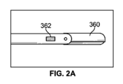
図2A~図2Bに関して、セルライト治療アセンブリ220の遠位端部に構成された鈍い先端鋏360が示されている。鈍い先端鋏360は、皮膚の下で標的に進められ、疑わしいセプタムと係合するために使用される。開示されたアプローチ及び装置の各々におけるように、このようなセプタムの係合は、皮膚上に発現されたディンプルまたはくぼみの何らかの変化をもたらすべきであり、治療構造、ここでは鋏360は、セプタムを破壊、切断またはスライスするように操作される。これにより、鋏360が開いて、そのブレードの間にセプタムが配置される。次に、セプタムに対してブレードを前進または閉鎖させて、それによりセプタムを切断し、スライスし、または切り離し、組織層の間の張力を緩和し、皮膚上のディンプルまたはくぼみの発現を排除または最小化する。鋏の作動は、例えば、ワイヤを引っ張ること、または鋏配置(図示せず)に関連する細長い部材を前進及び押すことによって、治療装置の近位端から達成される。鋏360の近位に構成された光362によって照明を提供することができ、治療アセンブリ220の遠位部分の位置を追跡するために透視化され得る。さらに、または代替的に、各開示された実施形態では、照明は、外部光源からのライトガイドを介して、または1つ以上のLEDを介してもよい。照明は、ユーザが治療装置を配置すること及びツールの深さを増大させて透視が減少することに伴う適切な深さを配置することを補助する。一態様では、照明の量は、治療装置または構造の適切な深さを保証するために設定され、標的化される照明のレベルは、皮膚のタイプ、厚さ、脂肪および顔料の存在のために調節される。一度選択または標的化されたセプタムが切断され、スライスされ、または破壊されると、各開示されたアプローチにおいて、セルライト治療装置は、同じまたは異なる皮膚挿入デバイスから追加の標的領域を治療するために進められ得る、または再配置され得る。
2A-2B,
短手方向に突出可能な組織係合および/または切断構造への様々なアプローチが図3A~図3Eに示されている。セルライト治療アセンブリの遠位端部分は、長手方向のシャフト372に対して回転する側方開口フックアーム370を具現化し得、セプタム係合および/またはセプタム切断構造を代替的に表示する(図3A、図3B)。フックアーム370は、シャフト372と平行な、近位方向に向けられた長手方向の構成から、装置が標的位置を越えて前進し、次いで後退されると、セプタムを捕捉して張力をかけるように、短手方向に突出した構成までスイングアウトするように構成されている。ここでも、セプタムを係合すると、セプタムとの係合が皮膚表面の物理的変化に反映されるように、皮膚表面のディンプル又はくぼみの形成に関与するセプタムが標的になっていることを確認できる。破壊は、フックアーム370の狭い縁部に対して、または、その切断部または鋭利な縁部に抗して、張力をかけることから生じる。アーム370の外向き部分は、鈍い構造を画定することができ、刃先は、アーム370によって画定される鋭角内に配置され得る。この構造によれば、セプタムがアーム370によって定義される鋭角内に引かれるときに、張力を増加させて、限られた刃先と協働することができる。図3A、図3Bにおいて、透視機能は、装置の末端に構成された光376によって提供され、図3C、図3Dに示されるアセンブリでは、末端の近位のシャフトに形成されたスリット378は、光エネルギーの分散を可能にする。図3Eにおいて、切断およびセプタム係合構造は、単一の移動アーム380において具現化され、照明はヒンジ382の近位に設けられているが、装置の終端に配置することができる。先の実施形態と同様に、アーム380の露出された縁部は、切断またはスライスのために鈍く、または鋭利にすることができる。ここで、アーム380は、組織層の間を前進させるためにシャフト372に平行な遠位方向の長手方向構成を想定し、アーム380は、短手方向外側に突出され、標的セプタムを捕捉および切断またはスライスする。係合および切断構造の作動は、ワイヤまたは長手方向に向いたシャフト(図示せず)を介して同一に連結された、近位に位置決めされたレバーまたはトリガの操作によって達成することができる。所望の領域が治療されると、追加の標的領域を治療することができる。
Various approaches to transversely extrudable tissue engaging and/or cutting structures are illustrated in FIGS. 3A-3E. The distal end portion of the cellulite treatment assembly may embody a side
セルライト治療アセンブリ220の遠位端部分は、1つ以上の皮膚挿入部位から標的領域を治療するために、内部静的フック388(図4A)を代替的にまたは追加的に具現化することができる。アセンブリの終端部またはフック388自体を使用して、組織の周りに配置することができ、組織を係合及び検査して、標的セプタムを認識することができる。フック内の鋭利なエッジは、標的化され、皮膚上のセルライトの発現に関連するものとして認識されたセプタムを係合および切断するために使用され得る。図4Bに示すように、セルライト治療アセンブリの近位端から作動可能な同心スライドチューブ390が、フック392に対して近位および遠位に移動されるように追加的に提供され得る。チューブ390は、選択的に先鋭化された縁部を含むことができ、または鈍くすることができ、したがって、フック392と協働して、セプタムを捕捉し、切断し、スライスし、引き裂きまたは破壊することができる。このアセンブリはさらに、セプタムを介して切断またはスライスするように、スピニング法で前進させることができる。チューブ390を使用して組織を切断するためにチューブ390を使用することにより、隔置された切れ目がセプタムを介して同時に行われるので、セプタムから取り出される部分が生じる。
The distal end portion of
図5A~図5Cに示されるように、複数の治療部位を治療するための関連するアプローチにおいて、切断、スライスまたは破砕アセンブリは、フック392を代替的にカバーし、露出させる長手方向に伸縮可能なシース393を追加的に又は代替的にさらに含み、さらに伸縮自在で格納自在なギロチンのようなブレード394をさらに具現化する。ブレード394は、フック392によって画定された開口内で摺動し、フック392によって切断された組織を切断するようなサイズおよび形状にされている。したがって、その遠位位置において、シース393によって、アセンブリが治療部位への前進に適した構造を画定することが容易にされる。アセンブリの近位端に配置されシース393に接続された構造の操作を介してシース393を引き出すことは、フック構造392を露出する。フック392が使用され、標的組織が皮膚上のセルライトの発現に関連する場合、フック392は標的組織を係合および捕捉するために使用される。フックはセプタムを捕捉された位置に維持している間、ギロチンブレード394は、近位に配置されたアクチュエータ(図示せず)の操作を介して前進され、捕捉されたセプタムをスライスまたは切断することにより、セルライトの発現を除去または最小化する。
In a related approach to treating multiple treatment sites, as shown in FIGS. 5A-5C, the cutting, slicing or fracturing assembly is longitudinally extendable to alternatively cover and expose
ここで図6A、図6Bを参照すると、セルライト治療システム220の遠位端部への別のアプローチが示されている。ここでは、2セグメントフックアセンブリ396、397は、角度の付いた表面398上で張力(ばねまたはそれに接続されたワイヤまたはシャフトなど)とともに保持される。1つのセグメントが他方に対して回転されたときに、2つのセグメントの間に角度が形成される。このフック構造の長さは、特定の必要性に適合するように調節できることが認識されるべきである。さらに、フックアセンブリの選択された縁部を鋭利にするか、または鈍くすることができる。開示された実施形態の各々に適用されるある特定の態様では、エラストマーが張力をかけられるとき、エラストマーが変位されて、鋭利な縁部を露出させるように、フックはエラストマーで覆われ得る。張力がかかっていない場合には、鋭利な縁部が安全に収容される。別のアプローチでは、ばね負荷シールドがエラストマーを置換することができる。組織内および組織層の間の2セグメントフックアセンブリ396、397の操作により、本明細書に記載されるような標的セプタムの係合および識別、ならびに標的セプタムのスライス、切断または破壊を可能にする。
Referring now to FIGS. 6A and 6B, another approach to the distal end of
ここで、図7A~図7Dを参照すると、切断、スライスまたは破砕治療アセンブリは、突出リンケージ配置によって画定される。第1のリンク400は、ブレード401を含み、一端が第2のリンク402に回転可能に取り付けられている。第1のリンク400の反対側の端部は長手方向のシャフト405に対してスライドする。第2のリンク402の第2端部は、シャフト405の遠位点に回転自在に固定されている。ある実施形態において、第1のリンク400の反対側の端部に取り付けられた駆動シャフト407が前進させられると、リンク400、402が完全に重なり(図7C)、組織を係合するような寸法および形状のフック配置を形成し、そのようなセプタムが患者の皮膚上のセルライトの発現に関連しているか否かを決定するためにセプタムを試験する。この配置では、ブレード構造401は露出されず、むしろ第2のリンク402によって保護または覆われる。切断またはスライス動作が望まれる場合には、一旦選択されたセプタムが標的化されると、駆動シャフト407がわずかに後退し、それによってブレード構造401を露出させて、フックされたセプタムを切断するための鋭いエッジが存在する(図7D参照)。組織層の間の前進または再配置のためにリンク400、402を離れて保存するために、シャフト407は完全に引き出され、シャフトとの共線的かつ平行な関係を仮定してリンク400、402をもたらす。
Referring now to FIGS. 7A-7D, the cutting, slicing or fracturing treatment assembly is defined by a protruding linkage arrangement. First link 400 includes a
図7E~図7Gに示すように、関連するアプローチにおいて、第1のリンク400は、アセンブリがフック構成に配置されたとき(図7F参照)、ブレード401を覆うようなサイズおよび形状の通常三角形または尖った突出部408を含む第2のリンク402に回転可能に接続される湾曲したブレードを構成する。ブレード401が露出するように駆動シャフト407(破線で示す)を操作すると(図7G参照)、ブレード401を使用してセプタムを切断することができる。治療装置を介入部位におよび介入部位間で前進させるとき、アセンブリが第1のリンク400と第2のリンク402とがほぼ長手方向にそろえて配置される下側の輪郭を画定する(図7E)ように駆動シャフト407が引っ張られる。図7H~図7Kに示されるように、第1のリンク400と第2のリンク402との間の回転可能な接続は、追加的にまたは代替的に、スロット配置409によって特徴付けられ得る。このような接続により、突出部408を小さくすることができ、治療装置の全体外形が小さくなる。特に、駆動シャフト407を僅かに近位方向に引っ張ると、セプタムフッキング構造(図7J)では、第1のリンク400の端部は、スロット409内の近位位置にあり、第2のリンク402のより小さい突出部408はブレード401を覆う。セプタム切断構造(図7K)において、第1のリンク400の端部は、ブレード401が切断のために露出されるように、スロット409内の遠位位置を想定している。図7L~図7Nを参照して、別の実施形態では、第1のリンク400はまた、直線ブレード401を構成することができる。このアプローチでは、突出部408はより大きく、したがって、装置がフッキング構造に配置されたときにブレード401の必要なカバレージを提供する(図7M)。これらの装置の各々はさらにまたは代替的に、透視および高周波切断および凝固を提供する構造のような、本明細書に開示された特徴の他のものを含むことができる。
In a related approach, as shown in FIGS. 7E-7G, the
図7O及び図7Pを参照すると、セルライトを治療するために用いることができるセルライト治療システム940(図11に関連してより詳細に記載されている)の一実施形態が示されている。(図7O)に示すように、治療システム940の遠位端部は、治療装置925で構成されている。ここでは、図7L~図7Nの治療装置は、フック構成(図7P)において治療装置940の遠位端に配置されていることが示されている。開示された治療装置のいずれかは、治療システム940の遠位端でそのように構成され得る。
7O and 7P, one embodiment of a cellulite treatment system 940 (described in more detail in connection with FIG. 11) that can be used to treat cellulite is shown. As shown in (FIG. 7O), the distal end of
図7Q~図7Sに示されるように、治療装置は、代替的にまたは追加的に、第2のリンク402に回転可能に取り付けられたワイヤ410を含むことができる。ここで、ワイヤ410の近位部分は、治療装置を閉じた、引っかけ(フッキング)および切断位置に構成するために進退可能な構造を提供する。さらに、ワイヤ410は、ワイヤ410を閉じた構成(図7Q)及び切断構成(図7S)の間に移動させるための必要な強度および堅牢性を提供するコイル411(図7S参照)に形成される。セプタムフッキング構成(図7R)において、第2のリンク402はワイヤ410を覆い、それによってワイヤが標的セプタムに露出することを防止し、コイル411は第2のブレード402とそろえて配置される。閉じた構成(図7Q)において、治療装置は治療標的におよび治療標的の間で前進させることに適したロープロファイルを画定する。ワイヤの近位側の縁部を鋭利にして切刃を形成することができる。さらにまたは代替的に、ワイヤは、ワイヤが標的組織の電気焼灼またはRF切断のために使用され得るように、高周波発生器に取り付けられた電極とすることができる。
As shown in Figures 7Q-7S, the treatment device may alternatively or additionally include a
別の態様または追加の態様では、図7T及び図7Uに示されるように、セルライト治療装置の細長い部材224は、管状の形状を具現化することができ、それを通って延びる、光ファイバ414のための空間を提供する管腔412を含む。注目すべきことに、光ファイバ414によって占有されていない残りの空間は、断面視斜視から三日月形状を画定する。あるアプローチでは、管状部分は治療装置225で終端する。
In another or additional aspect, as shown in FIGS. 7T and 7U, the
図7V~図7Xに示されるように、再び1つまたは複数の実施形態では、細長い部材224の管腔412は、1つ以上の追加のセプタム係合、切断、スライスまたは破壊治療装置225を個別に受容するようなサイズおよび形状にすることができ、または治療の前、最中または後に、麻酔薬、薬、充填剤または脂肪移動のような他の物質を注入することができる。1つのアプローチでは、治療部位は、治療処置を実施するために別個の装置および処置を用いるのではなく、治療処置と同時にまたは治療処置の間に、材料を投与または充填され得る。注目すべきことに、開示された実施形態の各々は、同様の方法で組み合わせセルライト治療アセンブリを提供するために組み合わせることができる。
As shown in Figures 7V-7X, again in one or more embodiments, the
別の実施形態では、一度に1つの介入部位を治療するように構成されたセルライト治療システム800を使用して、セプタムのスポット治療が可能である。これにより、切断構造体を皮膚に対して垂直に挿入して治療を達成することができ、または皮膚の表面に対してほぼ平行な方向又は皮膚の表面に対して角度を有して皮膚の下に進めることができる。さらに、開示された組織係合および切断デバイスの各々の構造は、代替的にまたは追加的に、治療に使用されるように構成され得る。1つの特定の態様では、カッター構造が、介入部位において観察されたセプタム構造によって指示された方法でセプタムを切断するように構成された、制御された速度でスピンするように、切断動作はキャラクタ内で回転する。カッターは代替的にまたは追加的に、カッターを目標セプタムに対して係合または引っ張ることによって切断作用を達成するように構成されている。ここで、引っ張りが行われる程度は、セプタム及びセプタム固有の構造によって指示される。1つのアプローチでは、システム800は、オペレータによって把持するために設けられた細長いハンドル802を含む(図8A~図8C参照)。ハンドル802から長手方向に延びるものが針アセンブリ804である。針804は、特定のセルライト標的領域に隣接する挿入部位を形成するように構成されている、または直接ディンプルセルライト部位に挿入されるように構成されている。さらに、被験者の皮膚のくぼみ発現下にあるセプタムに対処して治療及び治療するために、介入部位の器具が進められるのは、針アセンブリ804を通してである。さらに、一実施形態では、拡張器は、組織を切開および/または出血を制御するための高調波メス、選択的焼灼構造またはエネルギー伝達構造を含む、又はそれらと協働することができる。1つのアプローチでは、正しい深さにアクセスされると、切断器具が360度掃引されて周囲のセプタムを切断する。追加的にまたは代替的に、カッターを含むアセンブリに内視鏡を使用して、セプタムを標的に切断することができる。すなわち、内視鏡で観察されるセプタムは、カッターによる切断を対象としている。ここで、治療の直接的な目視確認が提供される。
In another embodiment, spot treatment of the septum is possible using
一実施形態では、針804は、所望に応じて、または特定の手順または解剖学的構造によって指示されるように、針804に沿って位置決め可能な止め具810によって形成することができる。止め具810は、針804が組織内に配置されたとき、その終端部が、セプタムによって接続された組織層の間のような所望の深さに位置決めされるように配置される。針804の終端には、さらに側方開口部822が設けられている。この側方開口部822を通って、カッター、火傷、焼灼構造、又はエネルギー伝達装置のような介入デバイスが組織層の間で前進される。このような装置は、次いで、セルライトの発現を除去または低減するために、皮膚の下に存在するセプタムを選択的に治療するために使用される。治療が成功したと判定されると、スポットセルライト治療システム800は除去され、セルライトを示す別の位置で使用される。
In one embodiment,
ここで図8D~図8Jを参照すると、他のアプローチにおけるセルライトの治療に使用されるツールのさらなる態様が示されている。このような構造は、図1Dに示すセルライト治療アセンブリの遠位端部構造としても使用することができる。図8Dを参照して、治療装置は、結合組織を切断するような大きさおよび形状である切断ブレード831配置を押し出す機能を有するリンケージ830の操作を含むワイヤを備えることができる。図8Eに示すように、スポット治療装置の遠位端部は、ループ832を画定するように前進可能に配置されたワイヤを備えることができ、ループは、組織を切断するために使用される構造を容易にするゲージを有する。あるいは、セプタムを切断するためにRFエネルギーが使用され得る。図8F、図8Gは、2つまたはそれ以上のアーム836が、治療のための別の非外傷的アプローチで切断するためのブレードを画定するために突出するように拡張可能で変形可能なハイポチューブ834を示す。図8Hは、セルライトの発現を除去または低減するためにディンプルの下で拡張され得る針ハイポチューブ842に取り付けられたバルーン構造840を示す。最後に、別の非外傷的アプローチにおいて(図8I、図8J)、スポット治療装置の遠位端部分は、ブレード850で形成することができ、1つは展開のために切断し、少なくとも1つは結合組織を回転および切断するように構成されている。
Referring now to FIGS. 8D-8J, additional aspects of tools used to treat cellulite in other approaches are shown. Such a structure may also be used as the distal end structure of the cellulite treatment assembly shown in FIG. 1D. Referring to FIG. 8D, the treatment device can include a wire that includes manipulation of a
図8Kに示すように、拡張器410は、セルライト治療装置の遠位端部を形成することができ、拡張器410が拡張されるときに展開される長手方向に延びるブレード853をさらに備えることができる。ブレード853は、治療の代替アプローチにおいて、標的組織またはセプタムを係合および切断するように構成されている。このような切断は、非外傷性アプローチの代わりに使用され、拡張器410を回転させたり、前進させたり、掃引したり、後退させたりすることによって達成される。アセンブリは拡張されず、例えばチューブを介して使用された後に介入部位から引き出される。
As shown in FIG. 8K,
さらに別の治療アプローチでは、ラッソ859を形成し、セルライト治療アセンブリの遠位端部を形成し、シャフト861を介して進退自在である湾曲ワイヤ(図8L~図8O)は、標的領域内のセプタム350の周りに展開することができる。ラッソ859を引っ張り、ラッソ859が画定する周囲長さを減少させることにより、セプタム350を切断し、セルライトを治療する。一態様では、ラッソ859はニチノールワイヤから形成されているか、事前に形成されたワイヤまたはその断片である。ラッソ859は、標的化されたセプタムを取り囲み、締め付けを介して、セプタムを切断する。1つのアプローチは、シャフトの移動なしに標的領域を切断することを含み、従って、治療への制御されたアプローチを提供する。
In yet another treatment approach, a curved wire (FIGS. 8L-8O) that forms the
図8P~図8Tに示されているように、ラッソ859は、追加的に、または代替的に、チューブを画定することができ、アセンブリは、管状構造内に摺動自在に構成されたワイヤ863をさらに含むことができる。セプタム350が標的化された後、ラッソ構造859は、シャフト861から押し出すことによって、セプタム350の周りに部分的に構成される。ワイヤ863は、その後、ラッソ859内で前進され、ラッソ859(図8Q)の終端から出る。次いで、ワイヤ863は、シャフト861に形成されたスロットまたは開口865に向かって前進し、そこに保持される。その後、ラッソ859をさらに前進させてシャフト861と係合させて完成したフープまたはループ(図8R)を画定する。次いで、ラッソ859は、標的セプタム350の周りで緊密に引っ張られて、所望のようにセプタムを切断し、スライスし、または分裂させる(図8T)。あるいは、完成されたフープは、より大きなフープ形状に留まることができ、装置全体を近位方向に引っ張ることができ、包囲されたセプタムをスライスまたは破壊することができる。標的組織を治療した後、ラッソ859およびワイヤ863は、それらがスロット865から外れるようにシャフト861を通して近位に引っ張られ、治療装置が追加の場所で使用され得るようにシャフト861内で完全にまたは部分的に引き抜かれる。
As shown in FIGS. 8P-8T, the
関連したラッソ治療アプローチ(図8U~図8V)においては、標的セプタム350の周りにほぼ平行な配置で構成可能な一対の細長いチューブ867、868が設けられている。ラッソ859は、第1のチューブ867の内部で前進され、その終端から第2のチューブ868に向かって前進する(図8U)。次いで、治療装置が標的セプタム350を取り囲むように、第2のチューブ868によってラッソ859が捕捉される。次いで、アセンブリが近位方向に引っ張られて、標的組織を切断し、スライスし、または破壊する。治療後、ラッソ859が第1のチューブ867の中に引き出され、第2のチューブ868との係合から解放される。次に、追加の領域を治療するために必要に応じてアセンブリが位置決めされる。
In a related lasso treatment approach (FIGS. 8U-8V), a pair of
アテレクトミー切除術式カッター902(図9A、図9B参照)もまた、代替的にまたは追加的に、器具の側部の開口904を介して組織を除去するように構成されてもよく、特定の補助的な、より外傷的な治療アプローチに使用することができる。切断構造906は、ブロックまたは他の接続910を介して細長いアクチュエータ908に取り付けられる。アクチュエータ908の操作により、切断構造906が標的組織に係合する。切断または浸軟した組織912が除去されるように、介入部位に吸引力を加えるための導管として、管腔912がさらに設けられている。この装置は、拡張器で治療され、作成された空間を充填するために使用された部位にその後の配置のための脂肪を回収するために使用することができる。また、カッター902は、セルライトを治療するためのセプタムを切断するための一次治療装置として使用することもできる。
An atherectomy cutter 902 (see Figs. 9A, 9B) may also be alternatively or additionally configured to remove tissue through an
ここで図10A~図10Cを参照すると、標的組織を治療するための先に記載された装置のうちの1つまたは複数に関連して使用することができる治療システム920の1つの好ましい実施形態が示されている。治療システム920は、ハンドル922と、ハンドル922から長手方向に延在する細長い部材924とを含む。上述されたように、力ゲージまたはセンサ(電子的または機械的)は、セプタムをテストするときに、あらかじめ決められた量の力が組織に加えられ、引っ張りすぎや引っ張り不足を防ぐことを確実にするために提供され得る。さらに、結合組織を係合、スライス、切断、または破壊することのうちの1つまたは複数を可能にする治療装置925が、細長い部材924の遠位端部分に構成される。したがって、本明細書に記載される治療装置のうちの任意の1つまたは複数は、治療装置925を画定することができる。全ての切断手段は、RF、レーザ、超音波または熱エネルギーで結合又はそれらでさらに通電され、一緒にまたは別々に切断および凝固を生成することができる。
Referring now to FIGS. 10A-10C, one preferred embodiment of a
ハンドル922は、ハンドル922の上面に沿って摺動するように構成されたボタンまたはスライドトリガ926を備える。トリガ926はシャフトまたはワイヤ928の近位端部分に取り付けられ、その遠位端部分は治療装置925に関連しているか、または治療装置925に取り付けられる。閉じた構成において、トリガ926はその最も近位の位置(図10A)内に配置され、治療装置925はほぼ長手方向にそろって配置された構成を維持する。このように構成されているように、治療システム920は、所望のセルライト治療を達成するために位置決めまたは再配置することができる。トリガ926をその最も遠位の位置に順に移動させて、シャフトまたはワイヤ928を遠位に前進させ、治療装置925を、例えば、標的組織(図10B)を引っ掛けるための形態で配置させる。トリガ926を中間位置に引き出すことにより、切断構造(例えば、ブレードまたは切断ワイヤ)を露出させ、それによって、標的組織を切断、スライスまたは破壊するための治療装置925を構成する(図10C)。戻り止めまたは他の協働構造をハンドルまたはトリガに組み込むことができ、トリガを1つまたは複数の位置に固定し、位置決めに関する触覚フィードバックを提供することができる。さらに、システム925は、代替的に、または追加的に、透視および高周波切断、凝固を提供するための構造など、先に説明した機能のいずれかを含むことができる。
Handle 922 includes a button or
図11に示すように、別の実施形態では、治療システム940は、ハンドル942と、ハンドルから延びる細長い部材944とを含む。細長い部材944の内部に構成されたシャフトまたはワイヤ(図示せず)が治療装置925に取り付けられ、代替的にまたは追加的に、ハンドル942の下側遠位部に回転可能なトリガ946が取り付けられている。ハンドル942内に構成されたスライダ947は、シャフトまたはワイヤに取り付けられ、トリガ946と協働する。一定の力スプリング950が関連付けられ、トリガ946が解放されると、スライダ947と協働して治療装置925の切断構造を後退させる。さらに、透視構造は、ハンドル942の内部に構成され、治療システム940の遠位端に構成された光源(例えばLED)をオンオフするためのバッテリコンパートメント952および電気スイッチ954を含む。
As shown in FIG. 11, in another embodiment, a
トリガ946を完全に引っ張ることは、治療装置925の切断構造が保護されるフッキング構成に治療装置925を構成することになる。トリガ946を僅かに解放すると、スプリング950は、治療装置925に関連するシャフトまたはワイヤを後退させ、スライダ947の戻り止め内にシャフトまたはワイヤを位置決めして、治療装置925の切断構造が露出されたことを触覚フィードバックでユーザに知らせる。トリガ946が完全に解放されると、スプリング950がシャフトまたはワイヤを完全に後退させ、それによって治療装置925を閉じた位置または展開していない位置に配置する。次いで、治療システム940を再度位置決めし、再度操作して追加の領域を治療することができる。
Fully pulling the
図12A~図18Cには、治療装置の様々な追加の実施形態が記載されている。図12A~図12Cを参照して、切断、スライスまたは破壊治療アセンブリは、再び、突出リンケージ配列によって画定される。第1のリンク1400は、ブレード1401を含み、一端が第2のリンク1402に回転可能に取り付けられる。第1のリンク1400の反対側の端部は、(少なくとも部分的に透明で示されている)長手方向のシャフト1405に対して摺動する。シャフト1405は、リンケージ機構を支持して収容するためのハウジングを画定する。第2のリンク1402の第2の端部は、シャフト1405の遠位点に回転可能に固定される。駆動シャフトまたはプッシュロッド1407は、アセンブリがフック構造に配置されたときにブレード1401を組織に接触させないように遮蔽する大きさおよび形状を有する略三角形または尖った突出部1408を含む第1のリンク1400及び第2のリンク1402の反対側の端部に回転可能または旋回可能に取り付けられる。プッシュロッド1407を完全に後退させると(図12A)、ブレード1401は長手方向のシャフト1405の本体内に納められる。完全に後退した構成では、第1及び第2のリンク1400、1401が鈍角を形成し、突出部1408が長手方向のシャフトの反対側から相対的に小さい距離を延長することに留意されたい。プッシュロッド1407が完全に停止するまで前進すると、突出部1408はプッシュロッド1407に接触し、ブレード1401は再び突出部1408によって保護される(図12B)。このような構成では、治療装置を使用して、標的セプタムをフックし、セプタムを試験して、そのようなセプタムが患者の皮膚上のセルライトの発現に関連しているか否かを決定することができる。一実施形態では、プッシュロッド1407をその完全に前進した位置から約0.070インチのオーダーで引き出し(ブレード1401が例示目的のために透明で示されている図12Cを参照)、ブレード1401は露出されて、標的セプタムを係合および切断、スライスまたは破壊するために提示される。治療装置はまた、治療装置が外傷の少ない皮下組織を通って前進させることを可能にする鈍い、非外傷性の先端1406を有する。全ての実施形態において、鈍い先端1406は、治療装置の先端の位置を知る際の案内のために使用者が使用するために皮膚を透過することを容易にするために、発光ダイオードを収容することができ、発光ダイオードであってもよく、または光ファイバの端部を収容することができる。
Various additional embodiments of treatment devices are described in FIGS. 12A-18C. Referring to FIGS. 12A-12C, the cutting, slicing or destructive treatment assembly is again defined by a protruding linkage arrangement.
追加的にまたは代替的に、開示された実施形態のいずれかにおける先端部は、患者の皮膚および解剖学的構造を介して、それら内で低導入および前進力によって特徴づけられるか、またはそれに関連するような形状にすることができ、一方、組織を損傷させる可能性が低いことを提示することもできる。したがって、先端部は、弾丸点または短い拡張器先端形状とすることができ、または、前進または追跡の容易さのために鋭利な輪郭またはトロカールタイプの形状を画定することができる。さらに、先端部に予め定められたレベルの抵抗があったときにのみ、先端部が後退可能で、再構成可能であり、さもなければ鋭利な構造を画定することができる。1つの特定のアプローチでは、ばね負荷されたカバーまたはシールドは、定義された抵抗があったときに、カバーまたはシールドが取り外されて、治療装置の前進を容易にするか、または患者の解剖学的構造を横切る力を低減するように構成された鋭利な先端を露出するように、先端の周りに構成される。 Additionally or alternatively, the tip in any of the disclosed embodiments is characterized by or associated with low introduction and advancement forces through and within the patient's skin and anatomy. It can be shaped so that it does, while also presenting a low possibility of tissue damage. Thus, the tip may be bullet point or short dilator tip shape, or may define a sharp profile or trocar-type shape for ease of advancement or tracking. Furthermore, only when there is a predetermined level of resistance at the tip can the tip be retractable, reconfigurable, or otherwise define a sharp structure. In one particular approach, a spring-loaded cover or shield is removed to facilitate advancement of the treatment device or when there is a defined resistance to the patient's anatomy. Constructed around the tip to expose a sharp tip configured to reduce forces across the structure.
代替的なアプローチ(図13A~図13D)において、第2のリンク1402は、鋭利な突出部1403を有するブレード1401を含み、第1のリンク1400は、治療装置がフック構成であるとき、ブレード1401の主要部分を組織に接触させないように遮蔽するためのブロッカーとして機能する。治療装置がフック形状であるとき、鋭利な突出部1403は、治療装置が使用者によって近位方向に引っ張られると、後退中の装置の先導部分としてのピボット位置が組織に引っ掛かることなく、むしろユーザがフックし、第1のリンク1400の主要部分とのセプタムの抵抗を感じさせることができるように、第1のリンク1400と第2のリンク1402との間のピボットから近位方向に延在する。特に完全に後退した位置(図13A)において、第1および第2のリンク1400、1401は鈍角を画定し、プッシュロッド1407がほぼ完全に前進したとき(図13B)、ブレード1401の大部分は第2のリンク1402によって保護される。フックの捕捉を促進するとともに、第1のリンク1400と第2のリンク1402との間の接続部の近くに保護されていないブレード1403の一部を提供するためにフック形状である。治療装置が使用者によって近位方向に後退されると、プッシュロッド1407を完全に前進させることにより、標的セプタムの切断、スライスまたは破砕するために完全に露出させる(図13C、図13D参照:図13Dは、説明のために透明な第1ブレードを示す)。
In an alternative approach (FIGS. 13A-13D), the
治療手順において開示された実施形態のうちの1つまたは複数を使用する際には、フック付きセプタムを破壊しないことが望ましい場合があることが予想され、そのような場合、フック付きセプタムを解放または非係合することが望ましい。特定のアプローチでは、治療装置は、解放または非係合するために、フック付きのセプタムから前進またはねじられることになる。このように、フック構造の場合、治療装置によって意図せず再係合され得る領域内に追加のセプタムまたは他の組織が存在し得るという課題があることが認識され、これは、隣接する患者の解剖学的構造によって、治療装置の収納が阻害され得ることが認識される。図13E、図13Fを参照して、長手方向のシャフト1405に対してピボット(旋回)することで、フック構造(図13E)から収納構造(図13F)への移行するヒンジリンク構成1400、1402または同様の構造を含む治療装置は、治療装置が被覆または収納されているときに、セプタム350または他の組織を治療装置から押しのけるように移動するブロッキングリンク1400(または同様の構造)の利益を受ける。この動作は、患者の解剖学的構造内で治療装置の追加の前進を必要とせず、セプタム350または他の組織が望ましくないように捕捉されないことを保証する。さらに、収納されているとき、リンク1400、1402は長手方向のシャフト1405内に捕捉された可能性のある任意の組織を除去し、リンク1400、1402は、最終的に、長手方向のシャフト1405内のこのような空間を占有する。
It is anticipated that when using one or more of the disclosed embodiments in a treatment procedure, it may be desirable not to destroy the hooked septum, and in such cases, the hooked septum may be released or It is desirable to disengage. In certain approaches, the treatment device will be advanced or twisted from the hooked septum to release or disengage. Thus, it is recognized that with hook configurations there is a challenge in that there may be additional septa or other tissue within the area that may be unintentionally re-engaged by the treatment device, and this may be due to the presence of adjacent patient It is recognized that anatomy may inhibit storage of the treatment device. 13E, 13F, a hinged
ここで図14A~14Fを参照すると、治療装置へのさらに別のアプローチが示されている。ここでは、第2のリンク1402の縁部に取り付けられ又は形成されるブレード1401をブロック又は遮蔽するように配置された2つの平行に配置され、関節運動する第1のリンク1420、1422が設けられている。第1のリンク1420、1422はそれぞれ、第2のリンク1402を選択的に遮蔽するように設計された固有の輪郭を有する湾曲またはヨーク形状の部材を画定し、各々の第1の端部1424はプッシャ1407に回転可能または旋回可能に取り付けられ、第2の端部1426は第2のリンク1402に回転または旋回可能に取り付けられる。平行に配置された第1のリンク1420、1422は、フッキング位置および切断位置のための追加の強度を提供する。プッシュロッド1407が完全に後退しているとき(図14A、図14D)、第1のリンク1420、1422の湾曲した部分は、(少なくとも部分的に透明で示されている)長手方向のシャフト1405の反対側から突出しており、リンクはセプタムを引っ掛けたり、切ったり、スライスしたり、破壊したりするために展開すると長手方向のシャフト1405から伸びる。組織のフック付き構造を提示するために、プッシュロッド1407は、第1のリンク1420、1422がブレード1401(図14Bおよび図14Eを参照:図14Eでは、説明の目的で、1つの第1のリンク1420が透明として示されている)を接触組織から完全にブロックまたは遮蔽するように前進される。プッシュロッド1405を前進させてブレード1401を完全に露出させ(図14Cおよび図14Fを参照)、したがって、標的組織を切断、スライスまたは破壊するためのブレード1401を提示する。
Referring now to FIGS. 14A-14F, yet another approach to a treatment device is shown. Here, two parallel arranged and articulating
図15A~図15Fに示すように、治療装置は代替的に、または追加的に、第1および第2のプッシュロッド1430、1432を含み、第1のプッシュロッド1430は、関節運動または旋回する第1のリンク1434を操作するように構成され、第2のプッシュロッド1432は、ブレード1401表面を含む関節運動または旋回する第2のリンク1436を操作するように構成される。プッシュロッド1430、1432が完全に前進した位置にあるとき(図15A、図15D)、第1のリンク1434と第2のリンク1436は、ほぼ平行であり、(少なくとも部分的に透明に示されている)長手方向のシャフト1405内に収納される。プッシュロッド1430、1432を引き出すことにより、第1のリンク1434および第2のリンク1436を収納位置から突出させる(図15B、図15C、図15E、図15F参照)。プッシュロッドを同様に引き抜くと、標的組織を切断、スライス、または破壊するため、第1のリンク1436が重なって、ブレード1401が完全に露出する(図15C及び図15F)が、第1のリンク1434に関連するプッシュロッド1430が第2のプッシュロッド1432とは異なる程度に前進するとき、ブレード1401の一部は、第1のリンク1434(図15B)によって遮蔽またはブロックされ得、それによって標的組織を引っ掛けるための構造を示し、またはブレード1401の一部を遮蔽することができ(図15E)、したがって、フッキング構造と切断構造の両方を提示することができる。この実施形態はまた、鈍い先端1406を有し得る。
As shown in FIGS. 15A-15F, the treatment device alternatively or additionally includes first and
付加的または代替的な態様では、治療装置のブレード構造のロバスト性は、旋回点を強化し、長手方向のシャフトの強度を高め、組織内への挿入及び前進の間のブレードの被覆、および組織のフッキングを改善することによって、高められる。図16Aに示すように、第1のリンク1400と第2のリンクまたはリンク1402との間の接続において、溶接ピンまたはスエージ加工されたチューブ1450を使用することができる。また、溶接ピンまたはスエージ加工されたチューブのような機械的接合は、第2のリンクまたはリンク1402と長手方向のシャフト1405の遠位部分との間の接続を形成することができる。そのような旋回点は、例えば、約0.025インチの直径のピンまたはチューブによって画定されることができ、治療システムの1つまたは複数の回転または旋回接続で使用することができる。さらに、図16B、図16Cに最も良く示されているように、ブレード1401を含む第1のリンク1400は、単一の第1のリンク1400によって被覆される、または協働するのではなく、一対の第2のリンク1402(透明として示されている1つのリンク)の間に構成され得る。
In additional or alternative aspects, the robustness of the blade structure of the treatment device is increased by strengthening the pivot point, increasing the strength of the longitudinal shaft, improving the coverage of the blade during insertion and advancement into tissue, and the hooking of the tissue. As shown in FIG. 16A, a welded pin or swaged
図17A~図17Cに示すように、代替または追加のアプローチでは、治療システムは、リンク1400、1402が完全に後退されて長手方向のシャフト1405内に収容されるときに突出構造を欠いている(図17A)。ブロッキング部材または鈍い部材として作用する第1のリンク1400は、第2のリンク1402(図17B)上に形成されたブレード1401を限界力が達成されるまで遮蔽するようにばね負荷され得、次いで、ブレード1401が標的セプタムを切断し、スライスし、または破壊するために提示される(図17C)。切断またはスライス後に、ブレード1401を自動的に再被覆するように構成することができ、または、ボタンのようなアクチュエータがブレード1401を再被覆するために提供され得る。このようなアプローチでは、リンクの2つの位置、すなわち、被覆され、展開される位置がある。使用者がフック構造を強過ぎる力で使用している状態がないため、全体の力要件を低減することができる。従って、ブレード1401は、ナビゲーション中に長手方向のシャフト1405内に完全に被覆または収容され、必要に応じて展開される。このようにして、長手方向のシャフト1405は、例えば、リンク1400、1402を排出および収容するためのより少ない切断でハイポチューブから形成することができる。このような構造または関連する機能は、開示された実施形態のいずれかに組み込むことができ、したがって、ばね負荷切断を提供し、切断のためにブレードを露出するための一定の制御された力量を必要とする。この実施形態はまた、鈍い先端1406を有することができる。
In an alternative or additional approach, the treatment system lacks protruding structures when the
関連するアプローチ(図18A~図18C参照)では、ブロッキング又はフッキング機能が、一対の湾曲または傾斜した第1のリンク1400によって提供される。収納構造では、湾曲または傾斜したリンク1400が、シャフト1405の展開側または治療側からの長手方向のシャフト1405の反対側から突出する(図18A)。しかしながら、その直前のアプローチと同様に、第1のリンク1400をブロッキングまたは遮蔽することは、限界力が達成されるまでブレード1401を反対側に位置させ、ブレード1401を遮蔽するようにばね負荷され(図18B)、標的対象のセプタムを切断、スライスまたは破壊するためにブレードが露出される(図18C)。ここで、切断またはスライス後、ブレード1401は、自動的に再被覆されるように構成されてもよく、または、ボタンなどのアクチュエータが、ブレード1401を再被覆するために提供され得、リンクの2つの位置、すなわち、シースされ、展開される位置がある。
In a related approach (see FIGS. 18A-18C), the blocking or hooking function is provided by a pair of curved or angled
ここで、図19A、図19Bを参照して、押下可能ボタン1928を含むトリガまたはスライダ組立体1926を含む治療装置のハンドル1922が示される。ハンドル1922は、ボタン1928が記録されるトラック1929を含む。このような構成は、先に開示した治療システムの1つまたは複数に組み込むことができる。図19Aに示すように、一実施形態では、ボタン1928は、螺旋ばね1930によってトラック1929に対して付勢されている。スライダ組立体1926は、治療装置(図示せず)の操作を容易にし、かつ治療装置に接続された駆動シャフトまたはプッシャ1407に取り付けられている。ボタン1928は、スライダ組立体1926をハンドル1922に対してスライドさせることができるように、ボタン1928とトラック1929との間のロックまたは他の係合を解除するように押し下げ可能である。ボタン1928を解放することにより、ボタンがトラック1929に係合し、トラック1929に形成された一連の切り欠き1932の1つとロッキング係合することを可能にする。トラック1929にロックされていないとき、スライダアセンブリのボタン1928は、ロック位置の間でトラック1929に沿って係合及び摺動することができることに留意されたい。スライダアセンブリ1926がトラック1929にロックされていないとき、治療装置が組織内及び標的セプタムに対して1つ以上のシース、フッキング、切断位置に配置されるように、このような切欠き1932は配置され、位置決めされる。このように、スライダ組立体1926とハンドル1922との間の確実な係合が提供され、治療装置の位置決めおよび状態または構成に関してユーザに触感が与えられる。図19Bに示すように、ボタン1930は螺旋ばねではなく、板ばね1934によって付勢される。ここで、ボタン1928は、別個に作動可能に構成され、スライダ組立体1926の摺動構造から独立して押し下げ可能な構造を画定し、それにより、摺動及びロック機能の別の個別制御を提供する。
19A-19B, a
治療システムへの他のアプローチが、図20A~図22Cに示されている。図20A~図20Cに示されるように、治療システム1940は、スプリング1944によって付勢されたスライダ1943を含むハンドルアセンブリ1942を含み、スライダ1943は、ハンドルアセンブリ1942の本体1946の一部に沿って並進するように構成されている。ボタン1947は、スライダ1943の上面から垂直に突出し、ボタン1947は、スライダ1942に形成されたスロット内に乗るボス1948に接続されるか、またはそれに関連している。ボス1948はまた、ハンドル本体1946内に形成されたランプ1949または他の係合構造に沿って記録されるように構成される。また、スライダ1943に回転可能に取り付けられ、ブラケット1953から突出するボス1952を受け入れる湾曲スロット1951を含むレバー1950である。スライダ1943及びブラケット1953の各々は、その末端部に取り付けられた治療装置1956に関連する1つ又はそれ以上の長手方向に延びる部材1954に取り付けられている(図20D~図20F参照)。例えば発光ダイオードおよびバッテリである任意の光およびエネルギー源ユニット1995は、ハンドルアセンブリ1942の近位端に取り付けられる。ハンドルアセンブリ1942および治療装置1956の長手方向のシャフトを通って長手方向のシャフトの遠位部分まで遠位方向に延びることは、光およびエネルギー源ユニット1995から治療装置1956の遠位部分に光を伝達し、ユーザに皮膚を通して透光を提供するための光ファイバ(図示せず)である。
Another approach to a treatment system is shown in FIGS. 20A-22C. As shown in FIGS. 20A-20C, a
治療装置収納位置(図20A及び図20B参照)では、スライダ1943はその最近接位置にあり、スプリング1944は大部分が圧縮される。スライダ1943を前方に移動させると(図20B、図20E)、スプリング1944が伸長され、スライダボス1948がランプ1949に沿って一時的に固定的に記録される。この作用により、長手方向に延びる部材1954が前進して治療装置1956を操作する。この構成において、治療装置1956は、標的セプタムを引っかけ又は他の方法で係合するように意図された、展開されているが被覆された構成である。レバー1950とブラケット1953との相互作用を介して回動可能なレバー1950を実質的に押すことによって、長手方向に延びる部材1956が遠位方向にわずかに前進して、治療装置の尖ったリンクまたはブレード1957をカバーせず(図20C、図20F参照)、鋭利なリンクまたはブレード1957は、セプタムを切断、スライスまたは破壊するように構成されている。特に、ばね(図示せず)が、レバー1950とブラケット1953との間に構成されて、レバー1950を付勢して治療装置1956をロックおよびフック構成に戻すように構成されている。介入部位で治療装置1956の所望の操作の後に、スライダボタン1947を押し下げてスライダボス1948とランプ1949との係合を解除し、それにより、スプリング1944によりスライダ1943を最も近位の位置に戻し、治療装置1956を介入部位からさらに使用または除去するために治療装置1956を収納する。代替的なアプローチでは、システム1940は、レバー1950を欠いており、追加のばね(図示せず)は、治療装置1956に予め定められた抵抗があったときに、ブラケット1953の前進を可能にするように構成され、このとき、ブレード1957が露出され得る。このようにして、ツールは使用に容易であり、また、セプタムフックする工程後の切断工程は省略され可能性が低い。
In the treatment device storage position (see FIGS. 20A and 20B),
別のアプローチ(図21A~図21C)において、治療システム1960は、スプリング1964によって付勢されたスライダ1963を含むハンドルアセンブリ1962を含み、スライダ1963はまた、ハンドルアセンブリ1962の本体1966の一部に沿って移動されるように構成されている。ここで、スライダ1963をロック解除するためのボタンを設けるのではなく、スライダ1963は、本体1966に対して回転するように構成され、スライダ1963自体は、ハンドル本体1966内に形成されたランプ1969または他の係合構造に沿って摺動するとともに、該ランプ1969に沿って記録されるように構成されたボス1968を含む。ここで、ブラケット1973から突出するボス1972を受ける湾曲スロット1971を含むレバー1970は、スライダ1962に回転自在に取り付けられている。スライダ1962およびブラケット1973の各々は、1つまたは複数の長手方向に延在する部材1976に取り付けられており、これらの部材1976は、その終端部分(図示していないが、例えば、図20D~図20Fに示される構造)に取り付けられた治療装置に関連している。
In another approach (FIGS. 21A-21C), the
治療装置が収容位置にあるとき(図21A参照)、スライダ1962はその最も近位の位置にあり、スプリング1964はほとんど圧縮される。スライダ1962が前方に移動すると(図21B参照)、スプリング1964が伸長され、スライダボス1968がランプ1969に沿って一時的に固定的に記録され、長手方向に延びる部材1976が前進して治療装置を操作する。この構成において、治療装置が、標的セプタムを引っかける、さもなければ係合させるように意図された、展開されたが被覆された構成にある。その後、レバー1970とブラケット1973との相互作用を介して、回転可能なレバー1970を押し下げることにより、長手方向に延在する部材1976は、治療装置の鋭利なリンクまたはブレード(図21Cを参照)を覆わないようにするために、遠位方向にわずかにさらに前進される。この構成において、治療装置は、標的セプタムを切断し、スライスし、または破壊するように構成されている。レバー1970とブラケット1973との間にスプリング(図示せず)が構成され、レバー1970を付勢して治療装置をロックされたフック構成に戻す。治療装置を介入部位に所望の操作した後、スライダ1962を押し下げて回転させて、スライダボス1968とランプ1969との間の係合を解除して、それによりスプリング1964によってスライダ1962を最も近位の位置に戻し、治療装置を収納させる。
When the treatment device is in the stowed position (see FIG. 21A), slider 1962 is in its most proximal position and
図22A~図22Cに示されるように、治療装置1980は、ハンドルアセンブリ1982の本体に沿ってスライドするように構成されたスライダ1984を含むハンドルアセンブリ1982を追加的または代替的に含むことができる。スライダ1984がその最も近位の位置にあるとき(図22A)、治療装置(図示せず)は収納位置にある。スライダ1984は、一対の回転可能な傾斜部材1986、1987に取り付けられ、それぞれの端部はハンドル本体及びスライダ1984にそれぞれ回転可能に取り付けられている。前方に配置された回転可能部材1986はさらに、回転可能なブラケット1989に回転可能に取り付けられ、順に、その遠位端部分に取り付けられた治療装置(図示せず)を有する長手方向に延びる部材1990に回転可能に取り付けられた延長部1988を含む。ボタン1992はスライダ1984から垂直に突出し、ボタン1992は、ハンドルアセンブリ1982の本体の一部に沿って記録されるように構成されたボス1993に関連している(図22Bを参照)。ハンドル本体に沿って前進させたスライダ1984と、ハンドル本体に形成された凹部1994に記録されたボス1993とで位置決めされると、治療装置は展開されるが、少なくとも部分的に標的セプタムを引っ掛けたり係合させるための構造に覆われている。ボタン1992を押すことにより、スライダ1984のボス1993を凹部1994から外すことができ、これによりスライダ1992をさらに遠位方向に前進させることができる。これにより、長手方向に延在する部材1990をさらに前進させて、組織を切断、スライスまたは係合するための治療装置の切断部分を露出させ、所望の介入治療を達成することができる。次に、スライダ1992は、さらなる介入ステップのために所望されるように、収納または展開されているが被覆された位置のいずれかに戻されることができる。したがって、このアプローチは、治療装置(例えば、フックまたは切断位置が含まれる)の構成がユーザにより明らかになるように、ハンドルアセンブリの小さな動きをスケールアップする機構を提供する。
As shown in FIGS. 22A-22C, the
記載された先の実施形態では、フックおよび/または先鋭化された縁部がセプタムを介して引き裂かまたは切断された後に、リンケージがセプタムを破ったり切断したりする際に、リンケージに力が急激に減少したときに、リンケージが自動的に再収容するように、ハンドルアセンブリにおいて、ボールポイントペン型の機構を使用することができる。 In the previous embodiments described, after the hook and/or sharpened edge has been torn or severed through the septum, the force is suddenly applied to the linkage as it ruptures or sever the septum. A ball point pen type mechanism can be used in the handle assembly so that the linkage automatically re-seats when reduced.
別の実施形態では、コイルは、治療装置の遠位部分から展開され、セプタムをコイル内に巻きつけて回転させ、標的セルライトを皮膚表面に再生成させた後、使用者によってコイルを引っ張ってセプタムを破壊または切断し、セプタムを切断するためにカッターを使用する。 In another embodiment, the coil is deployed from the distal portion of the treatment device, the septum is wound and rotated within the coil to regenerate the target cellulite on the skin surface, and then the coil is pulled by the user to remove the septum. Use a cutter to break or cut the septum.
したがって、セルライト治療方法および装置への様々なアプローチが提示される。開示されたアプローチは、セルライトを治療、最小化、および防止するための有効かつ集束されたアプローチを提供するように構成される。開示されたアプローチはまた、標的化された方法でセルライトの外観を修復および低減するために使用され得る。さらに、開示されたプロアクティブ治療様式は、使用に容易かつ効果的である。 Thus, various approaches to cellulite treatment methods and devices are presented. The disclosed approaches are configured to provide an effective and focused approach to treating, minimizing, and preventing cellulite. The disclosed approaches may also be used to repair and reduce the appearance of cellulite in a targeted manner. Furthermore, the disclosed proactive treatment modalities are easy and effective to use.
本開示のいくつかの特定の態様は、皮膚にディンプルまたはくぼみを引き起こす原因であるセプタムのうちの1つまたは複数の局所の治療と、傷を最小化することと、限定された、美容的に許容可能なエントリから全ての治療標的にアクセスすることと、セプタムを分離しながらセプタムを捕捉して保持することと、治療された標的の術中確認と、小さな開口のための針径寸法のツールと、ツール先端位置の透視識別とを含む。 Some specific aspects of the present disclosure provide topical treatment of one or more of the septa that cause dimples or depressions in the skin, minimizing scarring, and providing limited, cosmetically Accessing all treatment targets from an acceptable entry, capturing and retaining the septum while separating it, intraoperative confirmation of the treated target, and tools with needle diameter dimensions for small openings. , and perspective identification of the tool tip position.
本開示は、その特定の実施形態を参照して説明されたが、本開示の真の趣旨および範囲から逸脱することなく、様々な変更を行うことができ、均等物を置換することができることは、当業者には理解されるべきである。加えて、本開示の目的、趣旨および範囲に、特定の状況、材料、物質、プロセス、プロセスステップまたはステップを適合させるために多くの修正を行うことができる。全てのこのような修正は、本開示の範囲内にあるものとされる。 Although the present disclosure has been described with reference to particular embodiments thereof, it is understood that various changes may be made and equivalents may be substituted without departing from the true spirit and scope of the disclosure. , should be understood by those skilled in the art. In addition, many modifications may be made to adapt a particular situation, materials, substances, processes, process steps or steps, to the objective, spirit and scope of the present disclosure. All such modifications are intended to be within the scope of this disclosure.
Claims (5)
組織内に挿入され、組織層の間でセプタム治療部位に進められる、前記ハンドルから長手方向に延在するシャフトと、
前記シャフトの遠位部分にあるセプタム係合アセンブリと、
前記セプタム係合アセンブリを作動させ、前記セプタム係合アセンブリを少なくとも、切断領域が露出されない被覆位置、前記切断領域が露出されず前記切断領域と異なる鈍い領域で組織と係合するセプタム伸張位置、および前記切断領域が露出したセプタム破壊位置に配置する、前記ハンドル上のアクチュエータと、
を備え、
前記セプタム係合アセンブリは、前記シャフトの側面に設けられた開口に格納自在な前記切断領域を構成する鋭いエッジを有する側方開口フックを画定する、セプタム治療部位に関連する患者の皮膚上のセルライトの発現を治療するためのセルライト治療装置。
handle and
a shaft extending longitudinally from the handle for insertion into tissue and advancing between tissue layers to a septum treatment site;
a septum engagement assembly on a distal portion of the shaft;
actuating the septum engaging assembly, placing the septum engaging assembly at least in a covered position in which the cutting region is not exposed, in a septum extended position in which the cutting region is not exposed and engages tissue at a blunt region different from the cutting region; an actuator on the handle positioned at a septum rupture position with the cutting region exposed ;
Equipped with
The septum engagement assembly defines a side opening hook with a sharp edge defining the cutting area retractable into an opening in the side of the shaft, the septum engaging assembly defining a side opening hook on the patient's skin associated with a septum treatment site. Cellulite treatment device for treating the appearance of cellulite.
組織内に挿入され、組織層の間でセプタム治療部位に進められる、前記ハンドルから長手方向に延在するシャフトと、
前記シャフトの遠位部分にあるセプタム係合アセンブリと、
前記セプタム係合アセンブリを作動させ、前記セプタム係合アセンブリを少なくとも、切断領域が露出されない被覆位置、前記切断領域が露出されず前記切断領域と異なる鈍い領域で組織と係合するセプタム伸張位置、および前記切断領域が露出したセプタム破壊位置に配置する、前記ハンドル上のアクチュエータと、
を備え、
セルライトを透過する光を照射する透過照明をさらに備える、セプタム治療部位に関連する患者の皮膚上のセルライトの発現を治療するためのセルライト治療装置。
A handle and
a shaft extending longitudinally from the handle that is inserted into tissue and advanced between tissue layers to a septum treatment site;
a septum engagement assembly at a distal portion of the shaft;
an actuator on the handle for actuating the septum engaging assembly to position the septum engaging assembly in at least a covered position in which the cutting area is not exposed, a septum extending position in which the cutting area is not exposed and engages tissue at a blunt area distinct from the cutting area , and a septum breaking position in which the cutting area is exposed;
Equipped with
A cellulite treatment device for treating the appearance of cellulite on a patient's skin associated with a septum treatment area, further comprising a transillumination device for irradiating light that penetrates the cellulite.
3. The device according to claim 2, wherein the transmitted illumination is a plurality of illuminations arranged along the longitudinal direction of the distal portion of the shaft, and the light is emitted from a side surface of the distal portion of the shaft.
4. Apparatus according to claim 3, wherein the illumination is one or more LEDs or light guides.
組織内に挿入され、組織層の間でセプタム治療部位に進められる、前記ハンドルから長手方向に延在するシャフトと、
前記シャフトの遠位部分にあるセプタム係合アセンブリと、
前記セプタム係合アセンブリを作動させ、前記セプタム係合アセンブリを少なくとも、切断領域が露出されない被覆位置、前記切断領域が露出されず前記切断領域と異なる鈍い領域で組織と係合するセプタム伸張位置、および前記切断領域が露出したセプタム破壊位置に配置する、前記ハンドル上のアクチュエータと、
を備え、
前記セプタム係合アセンブリは、前記シャフトの側面に設けられた開口に格納自在な前記切断領域を有する側方開口フックを含み、前記側方開口フックは、前記シャフトに回転自在に取り付けられる、セプタム治療部位に関連する患者の皮膚上のセルライトの発現を治療するためのセルライト治療装置。 handle and
a shaft extending longitudinally from the handle for insertion into tissue and advancing between tissue layers to a septum treatment site;
a septum engagement assembly on a distal portion of the shaft;
actuating the septum engaging assembly, placing the septum engaging assembly at least in a covered position in which the cutting region is not exposed, in a septum extended position in which the cutting region is not exposed and engages tissue at a blunt region different from the cutting region; an actuator on the handle positioned at a septum rupture position with the cutting region exposed ;
Equipped with
The septum engagement assembly includes a side-opening hook having the cutting region retractable in an opening in a side of the shaft, the side-opening hook being rotatably attached to the shaft. Cellulite treatment device for treating site-related manifestations of cellulite on the skin of a patient.
Applications Claiming Priority (11)
| Application Number | Priority Date | Filing Date | Title |
|---|---|---|---|
| US201862702314P | 2018-07-23 | 2018-07-23 | |
| US62/702,314 | 2018-07-23 | ||
| US201862736016P | 2018-09-25 | 2018-09-25 | |
| US62/736,016 | 2018-09-25 | ||
| US201962798515P | 2019-01-30 | 2019-01-30 | |
| US62/798,515 | 2019-01-30 | ||
| US201962802368P | 2019-02-07 | 2019-02-07 | |
| US62/802,368 | 2019-02-07 | ||
| US201962825447P | 2019-03-28 | 2019-03-28 | |
| US62/825,447 | 2019-03-28 | ||
| PCT/US2019/042871 WO2020023412A1 (en) | 2018-07-23 | 2019-07-22 | Cellulite treatment system and methods |
Publications (2)
| Publication Number | Publication Date |
|---|---|
| JP2022502213A JP2022502213A (en) | 2022-01-11 |
| JP7458653B2 true JP7458653B2 (en) | 2024-04-01 |
Family
ID=69181894
Family Applications (1)
| Application Number | Title | Priority Date | Filing Date |
|---|---|---|---|
| JP2021527003A Active JP7458653B2 (en) | 2018-07-23 | 2019-07-22 | Cellulite treatment system and method |
Country Status (8)
| Country | Link |
|---|---|
| US (4) | US20210137551A1 (en) |
| EP (1) | EP3826558A4 (en) |
| JP (1) | JP7458653B2 (en) |
| CN (1) | CN112752549A (en) |
| BR (1) | BR112021001186A8 (en) |
| CA (1) | CA3107347A1 (en) |
| MX (1) | MX2021000902A (en) |
| WO (1) | WO2020023412A1 (en) |
Families Citing this family (2)
| Publication number | Priority date | Publication date | Assignee | Title |
|---|---|---|---|---|
| US20220233210A1 (en) * | 2021-01-25 | 2022-07-28 | Matthew Donavon Forrester | Cutting Grasper for Valve Leaflet Laceration |
| WO2023154474A1 (en) * | 2022-02-11 | 2023-08-17 | Revelle Aesthetics, Inc. | Aesthetic treatment systems and methods |
Citations (6)
| Publication number | Priority date | Publication date | Assignee | Title |
|---|---|---|---|---|
| US20040204734A1 (en) | 2003-04-11 | 2004-10-14 | Wagner Darrell Orvin | Tunneling tool with subcutaneous transdermal illumination |
| US20100057056A1 (en) | 2008-09-02 | 2010-03-04 | Gurtner Geoffrey C | Methods and devices for improving the appearance of tissue |
| US20100228182A1 (en) | 2005-09-07 | 2010-09-09 | Cabochon Aesthetics, Inc. | Dissection handpiece and method for reducing the appearance of cellulite |
| US20110319839A1 (en) | 2010-06-29 | 2011-12-29 | Del Vecchio Daniel A | Disposable surgical instruments |
| US20120165725A1 (en) | 2010-12-22 | 2012-06-28 | Cabochon Aesthetics, Inc. | Dissection handpiece with aspiration means for reducing the appearance of cellulite |
| US20150064165A1 (en) | 2013-08-29 | 2015-03-05 | Allergan, Inc. | Devices and methods for reducing the appearance of cellulite |
Family Cites Families (58)
| Publication number | Priority date | Publication date | Assignee | Title |
|---|---|---|---|---|
| US5478347A (en) | 1990-10-05 | 1995-12-26 | United States Surgical Corporation | Endoscopic surgical instrument having curved blades |
| WO1992008415A1 (en) | 1990-11-09 | 1992-05-29 | Arthrotek, Inc. | Surgical cutting instrument |
| US6241753B1 (en) | 1995-05-05 | 2001-06-05 | Thermage, Inc. | Method for scar collagen formation and contraction |
| US5728112A (en) | 1995-09-22 | 1998-03-17 | Yoon; Inbae | Combined tissue clamping and suturing instrument |
| JP3252088B2 (en) | 1996-04-26 | 2002-01-28 | 長谷川刃物株式会社 | scissors |
| US7204832B2 (en) * | 1996-12-02 | 2007-04-17 | Pálomar Medical Technologies, Inc. | Cooling system for a photo cosmetic device |
| GB2350080A (en) | 1999-04-10 | 2000-11-22 | Liou Yaw Jang | Suture removal instrument |
| US20040260210A1 (en) | 2003-06-23 | 2004-12-23 | Engii (2001) Ltd. | System and method for face and body treatment |
| CN2504047Y (en) | 2001-10-24 | 2002-08-07 | 庄福财 | Rotary blade of pellet cutter |
| US6916328B2 (en) | 2001-11-15 | 2005-07-12 | Expanding Concepts, L.L.C | Percutaneous cellulite removal system |
| US20030130628A1 (en) | 2002-01-08 | 2003-07-10 | Duffy David M. | Method and apparatus for the treatment of scar tissue and wrinkles |
| US8840608B2 (en) * | 2002-03-15 | 2014-09-23 | The General Hospital Corporation | Methods and devices for selective disruption of fatty tissue by controlled cooling |
| US20030187457A1 (en) * | 2002-04-02 | 2003-10-02 | Weber John A. | Apparatus and method for removing an object from a body |
| US7442192B2 (en) | 2002-07-14 | 2008-10-28 | Knowlton Edward W | Method and apparatus for surgical dissection |
| US20040206365A1 (en) * | 2003-03-31 | 2004-10-21 | Knowlton Edward Wells | Method for treatment of tissue |
| US7223275B2 (en) | 2003-05-27 | 2007-05-29 | Yichieh Shiuey | System for cutting the cornea of an eye |
| US8133180B2 (en) * | 2004-10-06 | 2012-03-13 | Guided Therapy Systems, L.L.C. | Method and system for treating cellulite |
| US7771199B2 (en) | 2004-10-15 | 2010-08-10 | Ace Surgical Supply Co, Inc. | Bone cutting osteotome tool and method for preparing a surgical sinus-lift osteotomy |
| US20060241673A1 (en) | 2005-04-21 | 2006-10-26 | Zadini Filiberto P | Subcision device |
| US20060241663A1 (en) | 2005-04-21 | 2006-10-26 | Zimmer Spine, Inc. | Surgical cutter |
| US7871423B2 (en) | 2005-04-29 | 2011-01-18 | Bovie Medical Corporation | Forceps for performing endoscopic or arthroscopic surgery |
| US7217265B2 (en) | 2005-05-18 | 2007-05-15 | Cooltouch Incorporated | Treatment of cellulite with mid-infrared radiation |
| US7967763B2 (en) | 2005-09-07 | 2011-06-28 | Cabochon Aesthetics, Inc. | Method for treating subcutaneous tissues |
| US9358033B2 (en) | 2005-09-07 | 2016-06-07 | Ulthera, Inc. | Fluid-jet dissection system and method for reducing the appearance of cellulite |
| US9486274B2 (en) | 2005-09-07 | 2016-11-08 | Ulthera, Inc. | Dissection handpiece and method for reducing the appearance of cellulite |
| EP2796168B1 (en) | 2005-09-28 | 2017-09-06 | Candela Corporation | Treating cellulite |
| WO2007052662A1 (en) | 2005-10-31 | 2007-05-10 | Terumo Kabushiki Kaisha | Puncture device, dosing device and puncture method |
| US7885793B2 (en) | 2007-05-22 | 2011-02-08 | International Business Machines Corporation | Method and system for developing a conceptual model to facilitate generating a business-aligned information technology solution |
| US20080200863A1 (en) | 2005-12-02 | 2008-08-21 | Cabochon Aesthetics, Inc. | Devices and methods for selectively lysing cells |
| US20080058603A1 (en) | 2006-09-01 | 2008-03-06 | Edelstein Peter S | Method and Apparatus for Assisting in the Introduction of Surgical Implements into a Body |
| US20080109023A1 (en) | 2006-11-03 | 2008-05-08 | Greer Steven E | Method and apparatus for altering the appearance of a patient's skin |
| WO2009048969A1 (en) | 2007-10-09 | 2009-04-16 | Cabochon Aesthetics, Inc. | Ultrasound apparatus with treatment lens |
| US7671423B2 (en) | 2008-01-10 | 2010-03-02 | International Business Machines Corporation | Resistor ballasted transistors |
| WO2010048334A1 (en) | 2008-10-21 | 2010-04-29 | Microcube, Llc | Microwave treatment devices and methods |
| US20100106063A1 (en) | 2008-10-29 | 2010-04-29 | Cabochon Aesthetics, Inc. | Ultrasound Enhancing Target for Treating Subcutaneous Tissue |
| KR20130086245A (en) | 2009-03-05 | 2013-07-31 | 싸이노슈어, 인코포레이티드 | Thermal surgery safety apparatus and method |
| US8167280B2 (en) | 2009-03-23 | 2012-05-01 | Cabochon Aesthetics, Inc. | Bubble generator having disposable bubble cartridges |
| US20100256596A1 (en) | 2009-04-07 | 2010-10-07 | Cabochon Aesthetics, Inc. | Fiber growth promoting implants for reducing the appearance of cellulite |
| US10080482B2 (en) * | 2009-06-30 | 2018-09-25 | Intuitive Surgical Operations, Inc. | Compliant surgical device |
| US9919168B2 (en) | 2009-07-23 | 2018-03-20 | Palomar Medical Technologies, Inc. | Method for improvement of cellulite appearance |
| US9358064B2 (en) | 2009-08-07 | 2016-06-07 | Ulthera, Inc. | Handpiece and methods for performing subcutaneous surgery |
| EP2493399A1 (en) | 2009-10-29 | 2012-09-05 | Cook Medical Technologies LLC | Compartment syndrome treatment method and surgical instrument for same |
| CN201617909U (en) | 2010-03-22 | 2010-11-03 | 单良 | Rib scissors |
| US20110295297A1 (en) | 2010-05-26 | 2011-12-01 | Medicinelodge, Inc. Dba Imds Co-Innovation | Dice cutting surgical instrument |
| CN202154724U (en) | 2011-06-20 | 2012-03-07 | 宋瑞鹏 | Intestinal tract surgical scissors |
| CN202821527U (en) | 2012-10-24 | 2013-03-27 | 宋佰峰 | Anti-slip surgical scissors for general surgery department |
| US20140276693A1 (en) * | 2013-03-15 | 2014-09-18 | Palomar Medical Technologies, Llc | Treatment of tissue |
| CN104644244A (en) | 2013-11-25 | 2015-05-27 | 成都卓青科技有限公司 | Surgery scissors |
| CA2936453A1 (en) * | 2014-01-09 | 2015-07-16 | Axiosonic, Llc | Systems and methods using ultrasound for treatment |
| WO2015117026A2 (en) * | 2014-01-31 | 2015-08-06 | Zeltiq Aesthetics, Inc. | Treating systems and methods for treating cellulite and providing other treatments |
| CN204191319U (en) | 2014-10-28 | 2015-03-11 | 吉木萨尔县鑫绿源农业科技开发有限公司 | A kind of for emasculation device in corn breeding process |
| CN204500879U (en) | 2015-02-13 | 2015-07-29 | 安徽理工大学 | A kind of operating scissors |
| WO2016183307A1 (en) | 2015-05-12 | 2016-11-17 | Soliton, Inc. | Methods of treating cellulite and subcutaneous adipose tissue |
| US9974519B1 (en) | 2015-07-01 | 2018-05-22 | Btl Holdings Limited | Aesthetic method of biologoical structure treatment by magnetic field |
| WO2017027586A1 (en) | 2015-08-10 | 2017-02-16 | Indiana University Research And Technology Corporation | Device and method for scar subcision |
| MX2019008552A (en) | 2017-01-17 | 2019-12-19 | Soliton Inc | Rapid pulse electrohydraulic (eh) shockwave generator apparatus with improved acoustic wavefronts. |
| US10773031B2 (en) | 2017-08-09 | 2020-09-15 | WLB Interventional, LLC | Needle for subcision procedures |
| AU2018335583B2 (en) | 2017-09-25 | 2023-08-17 | Paul Weber | Apparatus and systems for minimally invasive dissection of tissues |
-
2019
- 2019-07-22 MX MX2021000902A patent/MX2021000902A/en unknown
- 2019-07-22 WO PCT/US2019/042871 patent/WO2020023412A1/en active Application Filing
- 2019-07-22 CN CN201980062511.7A patent/CN112752549A/en active Pending
- 2019-07-22 JP JP2021527003A patent/JP7458653B2/en active Active
- 2019-07-22 BR BR112021001186A patent/BR112021001186A8/en unknown
- 2019-07-22 EP EP19841959.0A patent/EP3826558A4/en active Pending
- 2019-07-22 CA CA3107347A patent/CA3107347A1/en active Pending
-
2021
- 2021-01-21 US US17/154,232 patent/US20210137551A1/en active Pending
- 2021-02-17 US US17/177,271 patent/US11013527B1/en active Active
-
2023
- 2023-08-14 US US18/233,406 patent/US20230380854A1/en active Pending
- 2023-08-24 US US18/237,450 patent/US20230389951A1/en active Pending
Patent Citations (7)
| Publication number | Priority date | Publication date | Assignee | Title |
|---|---|---|---|---|
| US20040204734A1 (en) | 2003-04-11 | 2004-10-14 | Wagner Darrell Orvin | Tunneling tool with subcutaneous transdermal illumination |
| US20100228182A1 (en) | 2005-09-07 | 2010-09-09 | Cabochon Aesthetics, Inc. | Dissection handpiece and method for reducing the appearance of cellulite |
| US20100057056A1 (en) | 2008-09-02 | 2010-03-04 | Gurtner Geoffrey C | Methods and devices for improving the appearance of tissue |
| JP2013526967A (en) | 2010-05-25 | 2013-06-27 | カボチョン、エステティクス、インコーポレイテッド | Dissection handpiece and method for reducing the appearance of cellulite |
| US20110319839A1 (en) | 2010-06-29 | 2011-12-29 | Del Vecchio Daniel A | Disposable surgical instruments |
| US20120165725A1 (en) | 2010-12-22 | 2012-06-28 | Cabochon Aesthetics, Inc. | Dissection handpiece with aspiration means for reducing the appearance of cellulite |
| US20150064165A1 (en) | 2013-08-29 | 2015-03-05 | Allergan, Inc. | Devices and methods for reducing the appearance of cellulite |
Also Published As
| Publication number | Publication date |
|---|---|
| BR112021001186A8 (en) | 2023-01-10 |
| BR112021001186A2 (en) | 2021-04-27 |
| CA3107347A1 (en) | 2020-01-30 |
| EP3826558A1 (en) | 2021-06-02 |
| WO2020023412A1 (en) | 2020-01-30 |
| US20230380854A1 (en) | 2023-11-30 |
| US20210137551A1 (en) | 2021-05-13 |
| CN112752549A (en) | 2021-05-04 |
| US11013527B1 (en) | 2021-05-25 |
| EP3826558A4 (en) | 2022-04-20 |
| MX2021000902A (en) | 2021-08-24 |
| US20230389951A1 (en) | 2023-12-07 |
| JP2022502213A (en) | 2022-01-11 |
Similar Documents
| Publication | Publication Date | Title |
|---|---|---|
| JP6712279B2 (en) | Method and system for manipulation of ovarian tissue | |
| US6916328B2 (en) | Percutaneous cellulite removal system | |
| JP2771039B2 (en) | Retrograde high-frequency tissue separator | |
| JP5607100B2 (en) | Tissue removal device | |
| US20220183714A1 (en) | Cellulite treatment system and methods | |
| US20230380854A1 (en) | Cellulite treatment system and methods | |
| US20050065483A1 (en) | Medical instrument for fluid injection and related method | |
| WO2017156229A1 (en) | Pericardial modification devices and methods | |
| WO2009009275A1 (en) | Methods and systems for submucosal implantation of a device for diagnosis and treatment of a body | |
| JP5602756B2 (en) | Hood method and apparatus for material resection | |
| EP3565483A1 (en) | Apparatus with deployable probe and blade and methods of use | |
| US20230389956A1 (en) | Cellulite treatment system and methods | |
| US20220354565A1 (en) | Systems for improving the appearance of tissue | |
| US20230255678A1 (en) | Aesthetic treatment systems and methods | |
| US20220347496A1 (en) | Systems for treating tissue | |
| US11116888B2 (en) | Cellulite treatment system and methods | |
| WO2023154474A1 (en) | Aesthetic treatment systems and methods | |
| Watanabe | Laparoscopic anterior resection for rectal cancer |
Legal Events
| Date | Code | Title | Description |
|---|---|---|---|
| A521 | Request for written amendment filed |
Free format text: JAPANESE INTERMEDIATE CODE: A523 Effective date: 20210330 |
|
| A521 | Request for written amendment filed |
Free format text: JAPANESE INTERMEDIATE CODE: A523 Effective date: 20210802 |
|
| A621 | Written request for application examination |
Free format text: JAPANESE INTERMEDIATE CODE: A621 Effective date: 20210802 |
|
| A977 | Report on retrieval |
Free format text: JAPANESE INTERMEDIATE CODE: A971007 Effective date: 20220712 |
|
| A131 | Notification of reasons for refusal |
Free format text: JAPANESE INTERMEDIATE CODE: A131 Effective date: 20220802 |
|
| A601 | Written request for extension of time |
Free format text: JAPANESE INTERMEDIATE CODE: A601 Effective date: 20221101 |
|
| A521 | Request for written amendment filed |
Free format text: JAPANESE INTERMEDIATE CODE: A523 Effective date: 20221130 |
|
| A131 | Notification of reasons for refusal |
Free format text: JAPANESE INTERMEDIATE CODE: A131 Effective date: 20230314 |
|
| A521 | Request for written amendment filed |
Free format text: JAPANESE INTERMEDIATE CODE: A523 Effective date: 20230605 |
|
| A131 | Notification of reasons for refusal |
Free format text: JAPANESE INTERMEDIATE CODE: A131 Effective date: 20230912 |
|
| A521 | Request for written amendment filed |
Free format text: JAPANESE INTERMEDIATE CODE: A523 Effective date: 20231130 |
|
| TRDD | Decision of grant or rejection written | ||
| A01 | Written decision to grant a patent or to grant a registration (utility model) |
Free format text: JAPANESE INTERMEDIATE CODE: A01 Effective date: 20240220 |
|
| A61 | First payment of annual fees (during grant procedure) |
Free format text: JAPANESE INTERMEDIATE CODE: A61 Effective date: 20240312 |
|
| R150 | Certificate of patent or registration of utility model |
Ref document number: 7458653 Country of ref document: JP Free format text: JAPANESE INTERMEDIATE CODE: R150 |