JP7451663B2 - Communication devices, communication methods and integrated circuits - Google Patents
Communication devices, communication methods and integrated circuits Download PDFInfo
- Publication number
- JP7451663B2 JP7451663B2 JP2022203066A JP2022203066A JP7451663B2 JP 7451663 B2 JP7451663 B2 JP 7451663B2 JP 2022203066 A JP2022203066 A JP 2022203066A JP 2022203066 A JP2022203066 A JP 2022203066A JP 7451663 B2 JP7451663 B2 JP 7451663B2
- Authority
- JP
- Japan
- Prior art keywords
- data
- mode
- dci
- resource
- symbol
- Prior art date
- Legal status (The legal status is an assumption and is not a legal conclusion. Google has not performed a legal analysis and makes no representation as to the accuracy of the status listed.)
- Active
Links
Images
Classifications
-
- H—ELECTRICITY
- H04—ELECTRIC COMMUNICATION TECHNIQUE
- H04L—TRANSMISSION OF DIGITAL INFORMATION, e.g. TELEGRAPHIC COMMUNICATION
- H04L5/00—Arrangements affording multiple use of the transmission path
- H04L5/0091—Signalling for the administration of the divided path, e.g. signalling of configuration information
- H04L5/0094—Indication of how sub-channels of the path are allocated
-
- H—ELECTRICITY
- H04—ELECTRIC COMMUNICATION TECHNIQUE
- H04L—TRANSMISSION OF DIGITAL INFORMATION, e.g. TELEGRAPHIC COMMUNICATION
- H04L5/00—Arrangements affording multiple use of the transmission path
- H04L5/003—Arrangements for allocating sub-channels of the transmission path
- H04L5/0053—Allocation of signalling, i.e. of overhead other than pilot signals
-
- H—ELECTRICITY
- H04—ELECTRIC COMMUNICATION TECHNIQUE
- H04L—TRANSMISSION OF DIGITAL INFORMATION, e.g. TELEGRAPHIC COMMUNICATION
- H04L5/00—Arrangements affording multiple use of the transmission path
- H04L5/003—Arrangements for allocating sub-channels of the transmission path
- H04L5/0044—Allocation of payload; Allocation of data channels, e.g. PDSCH or PUSCH
-
- H—ELECTRICITY
- H04—ELECTRIC COMMUNICATION TECHNIQUE
- H04W—WIRELESS COMMUNICATION NETWORKS
- H04W72/00—Local resource management
- H04W72/04—Wireless resource allocation
- H04W72/044—Wireless resource allocation based on the type of the allocated resource
-
- H—ELECTRICITY
- H04—ELECTRIC COMMUNICATION TECHNIQUE
- H04W—WIRELESS COMMUNICATION NETWORKS
- H04W72/00—Local resource management
- H04W72/04—Wireless resource allocation
- H04W72/044—Wireless resource allocation based on the type of the allocated resource
- H04W72/0446—Resources in time domain, e.g. slots or frames
-
- H—ELECTRICITY
- H04—ELECTRIC COMMUNICATION TECHNIQUE
- H04W—WIRELESS COMMUNICATION NETWORKS
- H04W72/00—Local resource management
- H04W72/04—Wireless resource allocation
- H04W72/044—Wireless resource allocation based on the type of the allocated resource
- H04W72/0453—Resources in frequency domain, e.g. a carrier in FDMA
-
- H—ELECTRICITY
- H04—ELECTRIC COMMUNICATION TECHNIQUE
- H04W—WIRELESS COMMUNICATION NETWORKS
- H04W72/00—Local resource management
- H04W72/20—Control channels or signalling for resource management
- H04W72/23—Control channels or signalling for resource management in the downlink direction of a wireless link, i.e. towards a terminal
- H04W72/232—Control channels or signalling for resource management in the downlink direction of a wireless link, i.e. towards a terminal the control data signalling from the physical layer, e.g. DCI signalling
Landscapes
- Engineering & Computer Science (AREA)
- Signal Processing (AREA)
- Computer Networks & Wireless Communication (AREA)
- Mobile Radio Communication Systems (AREA)
Description
本開示は、通信装置、通信方法及び集積回路に関する。 The present disclosure relates to a communication device, a communication method, and an integrated circuit.
第5世代移動通信システム(5G)と呼ばれる通信システムが検討されている。5Gでは、通信トラフィックの増大、接続する端末数の増大、高信頼性、低遅延のそれぞれが必要とされるユースケース毎に機能を柔軟に提供することが検討されている。代表的なユースケースとして、拡張モバイルブロードバンド(eMBB:enhanced Mobile Broadband)、大規模コミュニケーション/多数接続(mMTC:massive Machin Type Communications)、超信頼性・低遅延コミュニケーション(URLLC:Ultra Reliable and Low Latency Communicant)の3つがある。国際標準化団体である3GPP(3rd Generation Partnership Project)では、LTEシステムの高度化と、New RAT(Radio Access Technology)(例えば、非特許文献1を参照)の両面から、通信システムの高度化を検討している。 A communication system called the fifth generation mobile communication system (5G) is being considered. With 5G, consideration is being given to flexibly providing functions for each use case that requires an increase in communication traffic, an increase in the number of connected terminals, high reliability, and low latency. Typical use cases include enhanced mobile broadband (eMBB), massive machine type communications (mMTC), and ultra-reliable and low-latency communication (URLLC). There are three. The 3rd Generation Partnership Project (3GPP), an international standardization organization, is considering the advancement of communication systems from the perspectives of both LTE system advancement and New RAT (Radio Access Technology) (for example, see Non-Patent Document 1). ing.
New RATでは、データ領域(例えば、シンボル位置)を通知する方法について検討する必要がある。 With New RAT, it is necessary to consider how to notify the data area (for example, symbol position).
本開示の一態様は、データ領域を適切に通知することができる基地局、端末及び通信方法の提供に資する。 One aspect of the present disclosure contributes to providing a base station, a terminal, and a communication method that can appropriately notify a data area.
本開示の一態様に係る基地局は、データを割り当てるリソース領域の複数のパターンの中からデータ割当に使用する1つのパターンを選択する回路と、前記複数のパターンに関する設定情報を上位レイヤシグナリングによって通知し、前記選択された1つのパターンを下り制御信号(DCI)によって通知する送信機と、を具備する。 A base station according to an aspect of the present disclosure includes a circuit that selects one pattern to be used for data allocation from among a plurality of patterns of resource areas to allocate data, and notifies configuration information regarding the plurality of patterns by upper layer signaling. and a transmitter that notifies the selected one pattern by a downlink control signal (DCI).
本開示の一態様に係る端末は、データを割り当てるリソース領域の複数のパターンに関する設定情報を含む上位レイヤシグナリングを受信し、前記複数のパターンの中からデータ割当に使用する1つのパターンを示す下り制御信号(DCI)を受信する受信機と、前記設定情報及び前記下り制御信号に基づいて、前記データが割り当てられるリソースを特定する回路と、を具備する。 A terminal according to an aspect of the present disclosure receives upper layer signaling including configuration information regarding a plurality of patterns of resource areas to which data is allocated, and provides downlink control indicating one pattern to be used for data allocation from among the plurality of patterns. The information processing apparatus includes a receiver that receives a signal (DCI), and a circuit that identifies a resource to which the data is allocated based on the configuration information and the downlink control signal.
本開示の一態様に係る通信方法は、データを割り当てるリソース領域の複数のパターンの中からデータ割当に使用する1つのパターンを選択し、前記複数のパターンに関する設定情報を上位レイヤシグナリングによって通知し、前記選択された1つのパターンを下り制御信号(DCI)によって通知する。 A communication method according to an aspect of the present disclosure selects one pattern to be used for data allocation from among a plurality of patterns of resource areas to which data is allocated, and notifies setting information regarding the plurality of patterns by upper layer signaling, The selected one pattern is notified by a downlink control signal (DCI).
本開示の一態様に係る通信方法は、データを割り当てるリソース領域の複数のパターンに関する設定情報を含む上位レイヤシグナリングを受信し、前記複数のパターンの中からデータ割当に使用する1つのパターンを示す下り制御信号(DCI)を受信し、前記設定情報及び前記下り制御信号に基づいて、前記データが割り当てられるリソースを決定する。 A communication method according to an aspect of the present disclosure receives upper layer signaling including configuration information regarding a plurality of patterns of resource areas to which data is allocated, and indicates a downstream pattern to be used for data allocation from among the plurality of patterns. A control signal (DCI) is received, and a resource to which the data is allocated is determined based on the configuration information and the downlink control signal.
なお、これらの包括的または具体的な態様は、システム、装置、方法、集積回路、コンピュータプログラム、または、記録媒体で実現されてもよく、システム、装置、方法、集積回路、コンピュータプログラムおよび記録媒体の任意な組み合わせで実現されてもよい。 Note that these comprehensive or specific aspects may be realized by a system, an apparatus, a method, an integrated circuit, a computer program, or a recording medium. It may be realized by any combination of the following.
本開示の一態様によれば、データ領域を適切に通知することができる。 According to one aspect of the present disclosure, a data area can be appropriately notified.
本開示の一態様における更なる利点および効果は、明細書および図面から明らかにされる。かかる利点および/または効果は、いくつかの実施形態並びに明細書および図面に記載された特徴によってそれぞれ提供されるが、1つまたはそれ以上の同一の特徴を得るために必ずしも全てが提供される必要はない。 Further advantages and advantages of one aspect of the disclosure will become apparent from the specification and drawings. Such advantages and/or effects may be provided by each of the several embodiments and features described in the specification and drawings, but not necessarily all are provided in order to obtain one or more of the same features. There isn't.
以下、本開示の実施の形態について図面を参照して詳細に説明する。 Embodiments of the present disclosure will be described in detail below with reference to the drawings.
LTEでは、基地局がPCFICH(Physical Control Format Indicator channel)を用いてPDCCH(Physical Downlink Shared Channel)領域のシンボル数をダイナミックに通知し、PDCCH領域の次のシンボルからデータが送信される。また、LTEでは、CoMP(Coordinated Multiple Point)を適用するために又は干渉制御のために、データの開始シンボルを変更する場合、上位レイヤのシグナリングで、データの開始シンボルを通知することも可能である。 In LTE, a base station dynamically notifies the number of symbols in a PDCCH (Physical Downlink Shared Channel) area using a PCFICH (Physical Control Format Indicator channel), and data is transmitted from the next symbol in the PDCCH area. In addition, in LTE, when changing the starting symbol of data in order to apply CoMP (Coordinated Multiple Point) or for interference control, it is also possible to notify the starting symbol of data using upper layer signaling. .
一方、New RATでは、スロット内のデータの開始シンボルを、DCI(Downlink control indicator)を用いて通知することが検討されている。DCIとしては、複数の端末(UE:User Equipment)が同時に受信することを想定している「group common PDCCH」、及び、各端末が個別に受信することを想定している「UE specific DCI」が検討されている。 On the other hand, in New RAT, it is being considered to notify the start symbol of data in a slot using a DCI (Downlink control indicator). There are two types of DCI: "group common PDCCH" which is assumed to be received by multiple terminals (UE: User Equipment) at the same time, and "UE specific DCI" which is assumed to be received by each terminal individually. It is being considered.
しかしながら、New RATでは、DCI等の制御信号が配置される領域(control resource set)である「group common control resource set」又は「UE specific control resource set」は、システム帯域のうち、全周波数帯域ではなく、一部の周波数帯域に割り当てることが検討されている。したがって、control resource setが配置される領域と、control resource setが配置されない領域とでは、データ領域(データに使用できるシンボル数)が異なる。 However, in New RAT, the "group common control resource set" or "UE specific control resource set", which is the area (control resource set) where control signals such as DCI are allocated, is not the entire frequency band of the system band. , allocation to some frequency bands is being considered. Therefore, the data area (number of symbols that can be used for data) is different between the area where the control resource set is placed and the area where the control resource set is not placed.
端末(ユーザ)は、自機に割り当てられたUE specific control resource set又は自機が所属するグループのgroup common control resource setの領域を認識することができる一方で、他の端末に割り当てられているUE specific control resource setの領域又は、他の用途(例えば、Sidelink, URLLC, mMTC等)に使用される領域を認識することができない。例えば、基地局は、上位レイヤのシグナリングを用いて、端末に割り当てないリソース領域を通知し、当該リソース領域を避けてデータ割当を行うことも可能であるが、上位レイヤのシグナリングを用いたリソース領域の通知では、semi-staticな割り当てとなってしまう。New RATでは、スロット毎に異なる用途の使用が考えられるため、上位レイヤによる通知のみでは、リソースを柔軟に割り当てることができないという問題がある。 A terminal (user) can recognize the area of the UE specific control resource set assigned to it or the group common control resource set of the group to which it belongs, while recognizing the UE assigned to other terminals. Unable to recognize specific control resource set areas or areas used for other purposes (for example, Sidelink, URLLC, mMTC, etc.). For example, the base station can use upper layer signaling to notify terminals of resource areas that are not to be allocated, and allocate data while avoiding the resource areas. This notification results in semi-static allocation. In New RAT, each slot can be used for a different purpose, so there is a problem in that resources cannot be allocated flexibly only by notifications from upper layers.
そこで、以下では、control resource setが配置される領域を考慮して、データ領域を適切に通知し、リソースを柔軟に割り当てる方法について説明する。 Therefore, in the following, we will explain how to appropriately notify the data area and allocate resources flexibly, taking into consideration the area where the control resource set is placed.
[通信システムの概要]
本開示の各実施の形態に係る通信システムは、基地局100及び端末200を備える。
[Overview of communication system]
A communication system according to each embodiment of the present disclosure includes a
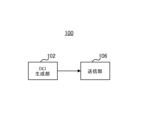
図1は本開示の実施の形態に係る基地局100の一部の構成を示すブロック図である。図1に示す基地局100において、DCI生成部102は、データを割り当てるリソース領域の複数のパターン(Mode)の中からデータ割当に使用する1つのパターンを選択する。送信部106は、複数のパターンに関する設定情報を上位レイヤシグナリングによって通知し、選択された1つのパターンを下り制御信号(DCI)によって通知する。
FIG. 1 is a block diagram showing a partial configuration of
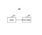
図2は本開示の実施の形態に係る端末200の一部の構成を示すブロック図である。図2に示す端末200において、受信部201は、データを割り当てるリソース領域の複数のパターン(Mode)に関する設定情報を含む上位レイヤのシグナリングを受信し、複数のパターンの中からデータ割当に使用する1つのパターンを示す下り制御情報(DCI)を受信する。信号分離部202は、設定情報及び下り制御信号に基づいて、データが割り当てられるリソースを特定する。
FIG. 2 is a block diagram showing a partial configuration of
(実施の形態1)
[基地局の構成]
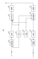
図3は、本実施の形態に係る基地局100の構成を示すブロック図である。図3において、基地局100は、設定部101と、DCI生成部102と、誤り訂正符号化部103と、変調部104と、信号割当部105と、送信部106と、受信部107と、信号分離部108と、復調部109と、誤り訂正復号部110とを有する。
(Embodiment 1)
[Base station configuration]
FIG. 3 is a block diagram showing the configuration of
設定部101は、データを割り当てるリソース領域の複数のパターン(以下、「Mode」と呼ぶ)、及び、複数のModeにおいてデータを割り当てるリソース領域に関するパラメータを設定する。例えば、設定部101は、データ割当てから除外するリソース候補の周波数領域(例えば、PRB(Physical Resource Block))及び時間領域(例えば、シンボル)を設定する。そして、設定部101は、複数のModeに関する設定情報(例えば、上記周波数領域及び時間領域を示すパラメータ)を含む上位レイヤのシグナリング(SIB(System Information Block)又はdedicated RRC(Radio Resource Control))を生成する。設定部101は、上位レイヤのシグナリングを誤り訂正符号化部103へ出力し、設定情報をDCI生成部102、信号割当部105及び信号分離部108へ出力する。
The setting unit 101 sets parameters regarding a plurality of patterns of resource areas to which data is allocated (hereinafter referred to as "Modes") and resource areas to which data is allocated in the plurality of modes. For example, the setting unit 101 sets the frequency domain (for example, PRB (Physical Resource Block)) and time domain (for example, symbol) of resource candidates to be excluded from data allocation. Then, the configuration unit 101 generates upper layer signaling (SIB (System Information Block) or dedicated RRC (Radio Resource Control)) that includes configuration information regarding multiple modes (for example, parameters indicating the frequency domain and time domain). do. Setting section 101 outputs upper layer signaling to error correction encoding section 103 and outputs setting information to
DCI生成部102は、例えば、スロットあたりの制御信号量又はデータ量等の情報(図示せず)に基づいて、設定部101で設定された複数のModeの中から、端末200向けのデータ割当に使用する1つのModeを選択(決定)し、選択したModeに対応するビット情報を生成する。
For example, the
DCI生成部102は、DL(Downlink)データ信号又はUL(Uplink)データ信号のリソース割当情報(DL割当情報又はUL割当情報)、及び、選択したModeに対応するビット情報を含む下り制御信号(DCI)を生成し、DCIを信号割当部105へ出力する。また、DCI生成部102は、生成したDCIのうち、DL割当情報を信号割当部105に出力し、UL割当情報を信号分離部108へ出力する。
The
誤り訂正符号化部103は、送信データ信号(DLデータ信号)及び、設定部101から入力される上位レイヤのシグナリング(設定情報)を誤り訂正符号化し、符号化後の信号を変調部104へ出力する。 Error correction encoding section 103 performs error correction encoding on the transmission data signal (DL data signal) and upper layer signaling (configuration information) input from configuration section 101, and outputs the encoded signal to modulation section 104. do.
変調部104は、誤り訂正符号化部103から受け取る信号に対して変調処理を施し、変調後の信号を信号割当部105へ出力する。 Modulation section 104 performs modulation processing on the signal received from error correction encoding section 103 and outputs the modulated signal to signal allocation section 105 .
信号割当部105は、DCI生成部102から入力されるDL割当情報に基づいて、変調部104から受け取るDLデータ信号、設定情報、又は、DCI生成部102から受け取る制御信号であるDCIを、下りリソースに割り当てる。具体的には、信号割当部105は、設定部101で設定された複数のModeのうち、DCI生成部102から入力されるDCIによって示されるMode(DCI生成部102で選択されたMode)に従って、データ割当てから除外するリソース以外のリソースにDLデータ信号を割り当てる。このようにして送信信号が形成される。形成された送信信号は、送信部106へ出力される。
Signal allocation section 105 assigns the DL data signal and setting information received from modulation section 104 or the DCI, which is a control signal received from
送信部106は、信号割当部105から入力される送信信号に対してアップコンバート等の無線送信処理を施し、アンテナを介して端末200へ送信する。
Transmitting
受信部107は、端末200から送信された信号をアンテナを介して受信し、受信信号に対してダウンコンバート等の無線受信処理を施し、信号分離部108へ出力する。
Receiving section 107 receives a signal transmitted from
信号分離部108は、DCI生成部102から入力される情報(Modeに対応するビット情報、及び、UL割当情報)、及び設定部101から入力される設定情報に基づいて、受信部107から受け取る受信信号からULデータ信号を分離する。具体的には、信号分離部108は、設定部101で設定された複数のModeのうち、DCI生成部102から入力されるDCIによって示されるMode(DCI生成部102で選択されたMode)に従って、ULデータ信号の割り当てから除外されたリソースを特定し、データ割当てから除外するリソース以外のリソースに配置された信号を分離して、復調部109へ出力する。
The
復調部109は、信号分離部108から入力される信号に対して復調処理を施し、得られた信号を誤り訂正復号部110へ出力する。
誤り訂正復号部110は、復調部109から入力される信号を復号し、端末200からの受信データ信号(ULデータ信号)を得る。
Error correction decoding section 110 decodes the signal input from
[端末の構成]
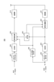
図4は、本実施の形態に係る端末200の構成を示すブロック図である。図4において、端末200は、受信部201と、信号分離部202と、DCI受信部203と、復調部204と、誤り訂正復号部205と、設定情報受信部206と、誤り訂正符号化部207と、変調部208と、信号割当部209と、送信部210と、を有する。
[Terminal configuration]
FIG. 4 is a block diagram showing the configuration of
受信部201は、受信信号をアンテナを介して受信し、受信信号に対してダウンコンバート等の受信処理を施した後に信号分離部202へ出力する。受信信号には、例えば、上位レイヤシグナリング(設定情報を含む)、又は、DCI(基地局100で選択されたModeに対応するビット情報を含む)等が含まれる。
Receiving
信号分離部202は、受信部201から受け取る受信信号からDCIが割り当てられる可能性のあるリソースに配置された信号を分離して、DCI受信部203へ出力する。また、信号分離部202は、DCI受信部203から入力される情報(基地局100で選択されたModeに対応するビット情報、及び、DL割当情報)及び設定情報受信部206から入力される情報に基づいて、DLデータ信号の割り当てから除外されたリソースを特定し、DLデータ信号が割り当てられたリソースを特定する。そして、信号分離部202は、受信信号からDLデータ信号又は上位レイヤのシグナリングを分離して、復調部204へ出力する。
DCI受信部203は、信号分離部202から入力されるDCIが割り当てられる可能性のあるリソースの信号に対して復号を試みて、DCIを検出(受信)する。DCI受信部203は、受信したDCIに示されるUL割当情報を信号割当部209へ出力し、DL割当情報を信号分離部202へ出力する。また、DCI受信部203は、DCIに含まれるModeに対応するビット情報(基地局100で選択されたMode)を信号分離部202へ出力する。
The
復調部204は、信号分離部202から入力される信号を復調し、復調後の信号を誤り訂正復号部205へ出力する。
誤り訂正復号部205は、復調部204から受け取る復調信号を復号し、得られた受信データ信号を出力し、得られた上位レイヤのシグナリングを設定情報受信部206へ出力する。
Error
設定情報受信部206は、誤り訂正復号部205から出力される上位レイヤのシグナリンに含まれる設定情報に基づいて、データ割当に関する複数のModeにおいてデータ割り当てから除外するリソースの候補の周波数領域及び時間領域を示すパラメータを特定する。そして、設定情報受信部206は、複数のModeに関するパラメータを信号分離部202及び信号割当部209へ出力する。
The configuration
誤り訂正符号化部207は、送信データ信号(ULデータ信号)を誤り訂正符号化し、符号化後のデータ信号を変調部208へ出力する。
Error
変調部208は、誤り訂正符号化部207から入力されるデータ信号を変調し、変調後のデータ信号を信号割当部209へ出力する。
信号割当部209は、DCI受信部203から入力されるUL割当情報、Modeに対応するビット情報(基地局100で選択されたMode)、及び、設定情報受信部206から入力される情報(複数のModeに関するパラメータ)に基づいて、ULデータの割り当てから除外されるリソースを特定し、ULデータが割り当てられるリソースを特定する。そして、信号割当部209は、変調部209から入力されたデータ信号を特定したリソースに割り当て、送信部210へ出力する。
The
送信部210は、信号割当部209から入力される信号に対してアップコンバート等の送信処理を施し、アンテナを介して送信する。
The transmitting unit 210 performs transmission processing such as up-conversion on the signal input from the
[基地局100及び端末200の動作]
以上の構成を有する基地局100及び端末200における動作について詳細に説明する。
[Operation of
The operations of
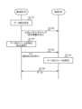
図5は基地局100及び端末200の動作を示すシーケンス図である。
FIG. 5 is a sequence diagram showing the operations of
基地局100は、データ割当の設定、つまり、データ割当に関する周波数領域又は時間領域の複数のMode(パターン)を設定する(ST101)。各Modeにおける周波数領域又は時間領域は、例えば、データ割当てから除外するリソース候補の周波数領域及び時間領域を示す。
The
基地局100は、設定した複数のModeに関する設定情報(周波数領域又は時間領域を示すパラメータ)を、上位レイヤのシグナリング(SIB又はdedicated RRC)を用いて端末200へ送信する(ST102)。
次いで、基地局100は、データ割当の際、ST101で設定した複数のModeの中から1つのModeを選択し、選択したModeに基づいてデータの割当に使用可能なリソース領域を特定する(ST103)。例えば、基地局100は、データの割当に使用可能なリソース領域をPRB毎に特定してもよい。
Next, when allocating data, the
そして、基地局100は、データ(DLデータ信号又はULデータ信号)の割当情報、及び、選択したModeを含むDCIを端末200へ送信する(ST104)。
Then, the
一方、端末200は、ST102で受信した上位レイヤのシグナリングに含まれる設定情報(周波数領域及び時間領域)、及び、ST104で受信したDCIに基づいて、データの割当に使用可能なリソース領域を特定する(ST105)。例えば、端末200は、データ割当に使用可能なリソース領域をPRB毎に特定してもよい。具体的には、端末200は、複数のModeの中から、DCIで通知される1つのModeを選択し、選択したModeに関する設定情報を用いて、データ割当から除外するリソース領域、つまり、データ割当に使用可能なリソース領域を特定する。 On the other hand, terminal 200 identifies a resource area that can be used for data allocation based on the configuration information (frequency domain and time domain) included in the upper layer signaling received in ST102 and the DCI received in ST104. (ST105). For example, the terminal 200 may specify a resource area that can be used for data allocation for each PRB. Specifically, the terminal 200 selects one Mode notified by DCI from a plurality of Modes, and uses setting information regarding the selected Mode to determine resource areas to be excluded from data allocation, that is, data allocation. Identify the resource space available for use.
そして、基地局100及び端末200は、特定したリソースを用いてデータ(DLデータ信号又はULデータ信号)を送受信する(ST106)。
Then, the
このように、本実施の形態では、基地局100は、データの割当情報を通知する際、データ割当の複数のMode(パターン)に関する設定情報(周波数領域又は時間領域を示すパラメータ)を上位レイヤシグナリングによって通知し、実際のデータ割当に使用する1つのMode(パターン)をDCIによって通知する。つまり、上位レイヤのシグナリングと、DCIとを併用してデータ割当の通知が行われる。
As described above, in the present embodiment, when notifying data allocation information,
これにより、基地局100は、データ割当の際に、DCIによって1つのMode(ビット情報)を通知すればよく、周波数領域又は時間領域に関する設定情報をデータ割当の度に通知する必要がなくなるので、DCIのシグナリングのオーバヘッドを削減しつつ、データ以外に使用される領域をデータ領域から除外できる。また、基地局100は、DCIによって、複数のModeの中からデータ割当に使用するModeをダイナミックに変更できるので、柔軟にデータを割り当てることができる。
As a result, the
次に、本実施の形態に係る動作例1,2について説明する。 Next, operation examples 1 and 2 according to the present embodiment will be explained.
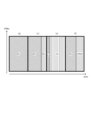
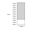
<動作例1>
基地局100は、データ割当のModeとして、例えば、図6Aに示す「Mode 1」及び図6Bに示す「Mode 2」を設定する。また、基地局100は、上位レイヤのシグナリングを用いて、Mode 1及びMode 2に関する設定情報として、周波数領域「X0」及びデータの割り当てを開始するシンボルであるスタートシンボル「A0」、「A1」、「A2」を通知する。ここで、後述するように、A0はMode 1に関するパラメータであり、X0、A1、A2はMode 2に関するパラメータである。周波数領域X0は、例えば、PRB番号又はRBG番号で表されてもよい。
<Operation example 1>
The
また、基地局100は、DCIに含まれる1ビットを用いて、データ割当に使用するModeとして、Mode 1又はMode 2を端末200へ通知する。
Furthermore, the
端末200は、上位レイヤのシグナリングによって通知されたMode 1及びMode 2に関する設定情報のうち、DCIに示されるModeに対応する情報に基づいて、データが割り当てられるリソース領域を特定する。
The terminal 200 identifies the resource area to which data is allocated based on the information corresponding to the Mode indicated in the DCI, among the configuration
ここで、各Modeでは、例えば、以下のようにデータが割り当てられる。
Mode 1:データはシンボルA0から割り当てられる。
Mode 2:周波数領域X0では、データはシンボルA1から割り当てられ、X0以外の周波数領域では、データはシンボルA2から割り当てられる。
Here, in each mode, data is allocated as follows, for example.
Mode 1: Data is allocated starting from symbol A0.
Mode 2: In frequency domain X0, data is allocated from symbol A1, and in frequency domains other than X0, data is allocated from symbol A2.
また、設定情報として上位レイヤのシグナリングによって通知される{X0,A0,A1,A2}は、以下のように設定されてもよい。
周波数領域X0:UE specific control resource setと同一周波数領域
A0:Group common control resource setが配置されるシンボルの後ろのシンボル
A1:UE specific control resource setが配置されるシンボルの後ろのシンボル
A2:シンボル#0
Further, {X0, A0, A1, A2} notified by upper layer signaling as setting information may be set as follows.
Frequency domain X0: Same frequency domain as UE specific control resource set
A0: Symbol after the symbol where Group common control resource set is placed
A1: Symbol after the symbol where the UE specific control resource set is placed
A2:
つまり、Mode 1に関して、A0は、DLデータ信号が割り当てられる時間領域の開始位置(スタートシンボル)を示す。
That is, regarding
また、Mode 2に関して、X0は、DL制御信号(例えば、UE specific DCI等)が割り当てられる周波数領域を示し、A1は、周波数領域X0においてDLデータ信号が割り当てられる時間領域の開始位置を示し、A2は、周波数領域X0以外の周波数領域においてDLデータ信号が割り当てられる時間領域の開始位置を示す。
Regarding
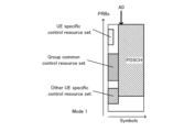
すなわち、Mode 1では、端末200は、図6Aに示すように、データ(PDSCH)が割り当てられるデータリソース(DL割当情報に示されるリソース)に依らず、上位レイヤのシグナリングで通知されたスタートシンボル(A0)に基づいて、データ(PDSCH)が割り当てられるシンボルの開始位置を特定する。つまり、Mode 1では、データは、データリソースの全帯域においてシンボルA0から割り当てられる。
That is, in
したがって、UE specific control resource set及びGroup common control resource setの両方と、データリソースとが周波数領域でオーバラップしている場合、又は、他の端末向けのUE specific control resource setとデータリソースとが周波数領域でオーバラップしている場合でも、これらの制御信号領域を避けて、端末200に対するデータを配置することができる。 Therefore, if both the UE specific control resource set and the Group common control resource set and the data resource overlap in the frequency domain, or if the UE specific control resource set and the data resource for another terminal overlap in the frequency domain. Even if these control signal areas overlap, data for the terminal 200 can be placed avoiding these control signal areas.
また、Mode 1は、ICIC(Inter Cell Interference Coordination)において前半のシンボル(例えば、シンボルA0以前のシンボル)との干渉を低減したい場合にも有効である。
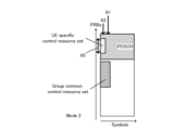
一方、Mode 2では、端末200は、図6Bに示すように、上位レイヤのシグナリングで通知された周波数領域(X0)及びスタートシンボル(A1,A2)に基づいて、データ(PDSCH)が割り当てられるリソースを特定する。つまり、Mode 2では、周波数領域X0と、周波数領域X0以外の領域とでデータが割り当てらえるシンボルの開始位置が異なる。
On the other hand, in
したがって、Mode 2は、例えば、図6Bに示すように、データリソースと周波数領域X0(UE specific control resource set)とがオーバラップしている場合に有効である。具体的には、端末200に対するデータリソースのうち、周波数領域X0では、UE specific control resource setを避けてデータを配置でき、周波数領域X0以外の領域では、シンボル#0(A2)からデータを配置できる。これにより、リソースを有効利用することができる。
Therefore,
なお、上記例では、周波数領域X0が、UE specific control resource setと同一周波数領域である場合について説明したが、周波数領域X0は、group common control resource setと同一領域としてもよく、UE specific control resource setとgroup common control resource setを合わせた周波数領域としてもよい。周波数領域X0を、UE specific control resource set又はgroup common control resource setと同一領域とすると、上位レイヤのシグナリングを削減することができる。 In addition, in the above example, the case where the frequency domain X0 is the same frequency domain as the UE specific control resource set was explained, but the frequency domain X0 may be the same domain as the group common control resource set, and the UE specific control resource set The frequency domain may be a combination of the group common control resource set and group common control resource set. If the frequency region X0 is the same region as the UE specific control resource set or the group common control resource set, upper layer signaling can be reduced.
また、周波数領域X0は、PRB単位又はRBG(Resource Block Group)単位で通知されてもよい。周波数領域X0をPRB単位又はRBG単位で通知すると、基地局100は、端末200に対してリソースをより柔軟に指示できるので、他の端末に割り当てられるcontrol resource setの領域を避けたり、他の用途に使われる領域を避けたりすることができる。 Further, the frequency domain X0 may be notified in PRB units or RBG (Resource Block Group) units. By notifying the frequency region You can also avoid areas that are used for
また、スタートシンボルA0は、Group common control resource setに限らず、例えば、制御信号チャネルのうち最も後方に配置されるシンボルの後ろのシンボルでもよい。また、スタートシンボルA0,A1,A2は、Group common control resource set又はgroup common control resourceが配置されるシンボルの後ろのシンボルとしてもよく、シンボル番号を通知してもよい。また、A0とA2は同じ値としてもよく、A1とA2は同じ値としてもよい。 Furthermore, the start symbol A0 is not limited to the Group common control resource set, and may be, for example, a symbol after the symbol arranged at the rearmost position in the control signal channel. Further, the start symbols A0, A1, and A2 may be symbols after the group common control resource set or the symbol in which the group common control resource is arranged, and the symbol numbers may be notified. Further, A0 and A2 may be the same value, and A1 and A2 may be the same value.
<動作例2>
動作例1では、上位レイヤのシグナリングを用いて2つのMode(Mode 1とMode 2)を用意し、DCIに含まれる1ビットを用いてMode 1とMode 2とを切り替える場合について説明した。これに対して、動作例2では、上位レイヤのシグナリングで4つのMode(Mode 1、Mode 2、Mode 3、Mode 4)を用意し、DCIに含まれる2ビットを用いてMode 1、Mode 2、Mode 3、Mode 4を切り替える場合について説明する。
<Operation example 2>
In operation example 1, a case has been described in which two modes (
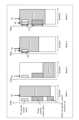
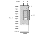
図7は、動作例2に係るMode 1、Mode 2、Mode 3、Mode 4の一例を示す。
FIG. 7 shows an example of
具体的には、基地局100は、データ割当のModeとして、例えば、図7に示すMode 1~Mode 4を設定する。また、基地局100は、上位レイヤのシグナリングを用いて、Mode 1~Mode 4に関する設定情報として、周波数領域「X0」、「X1」、及び、データのスタートシンボル「A0」,「A1」,「A2」,「A3」,「A4」,「A5」を通知する。ここで、後述するように、A0はMode 1に関するパラメータであり、A1はMode 2に関するパラメータであり、X0、A2、A3はMode 3に関するパラメータであり、X1、A4、A5はMode 4に関するパラメータである。周波数領域X0,X1は、例えば、PRB番号又はRBG番号で表されてもよい。
Specifically, the
また、基地局100は、DCIに含まれる2ビットを用いて、データ割当に使用するModeとして、Mode 1、Mode 2、Mode 3又はMode 4の何れか1つのModeを端末200へ通知する。
Furthermore, the
端末200は、上位レイヤのシグナリングによって通知されたMode 1~Mode 4に関する設定情報のうち、DCIに示されるModeに対応する情報に基づいて、データが割り当てられるリソース領域を特定する。
The terminal 200 specifies the resource area to which data is allocated based on the information corresponding to the Mode indicated in the DCI among the configuration
ここで、各Modeでは、例えば、以下のようにデータが割り当てられる。
Mode 1:データはシンボルA0から割り当てられる。
Mode 2:データはシンボルA1から割り当てられる。
Mode 3:周波数領域X0では、データはシンボルA2から割り当てられ、X0以外の周波数領域では、データはシンボルA3から割り当てられる。
Mode 4:周波数領域X1では、データはシンボルA4から割り当てられ、X1以外の周波数領域では、データはシンボルA5から割り当てられる。
Here, in each mode, data is allocated as follows, for example.
Mode 1: Data is allocated starting from symbol A0.
Mode 2: Data is allocated starting from symbol A1.
Mode 3: In frequency domain X0, data is allocated from symbol A2, and in frequency domains other than X0, data is allocated from symbol A3.
Mode 4: In frequency domain X1, data is allocated from symbol A4, and in frequency domains other than X1, data is allocated from symbol A5.
また、設定情報として上位レイヤのシグナリングによって通知される{X0,X1,A0,A1,A2,A3,A4,A5}は、以下のように設定されてもよい。
周波数領域X0:UE specific control resource setと同一周波数領域
周波数領域X1:UE specific control resource setとGroup common control resource setとを合わせた周波数領域
A0:Group common control resource setが配置されるシンボルの後ろのシンボル
A1:シンボル#0
A2:UE specific control resource setが配置されるシンボルの後ろのシンボル
A3:シンボル#0
A4:Group common control resource set又はUE specific control resource setが配置されるシンボルの後ろのシンボル
A5:シンボル#0
Further, {X0, X1, A0, A1, A2, A3, A4, A5} notified by upper layer signaling as setting information may be set as follows.
Frequency domain X0: Same frequency domain as UE specific control resource set Frequency domain X1: Frequency domain that combines UE specific control resource set and Group common control resource set
A0: Symbol after the symbol where Group common control resource set is placed
A1:
A2: Symbol after the symbol where the UE specific control resource set is placed
A3:
A4: Symbol after the symbol where Group common control resource set or UE specific control resource set is placed
A5:
つまり、Mode 1に関して、A0は、DLデータ信号が割り当てられる時間領域の開始位置(スタートシンボル)を示す。
That is, regarding
また、Mode 2に関して、A1は、DLデータ信号が割り当てられる時間領域の開始位置(スタートシンボル)を示す。
Regarding
また、Mode 3に関して、X0は、DL制御信号(例えば、UE specific DCI等)が割り当てられる周波数領域を示し、A2は、周波数領域X0においてDLデータ信号が割り当てられる時間領域の開始位置を示し、A3は、周波数領域X0以外の周波数領域においてDLデータ信号が割り当てられる時間領域の開始位置を示す。
Regarding
また、Mode 4に関して、X1は、DL制御信号(例えば、UE specific DCI又はgroup common PDCCH等)が割り当てられる周波数領域を示し、A4は、周波数領域X1においてDLデータ信号が割り当てられる時間領域の開始位置を示し、A5は、周波数領域X1以外の周波数領域においてDLデータ信号が割り当てられる時間領域の開始位置を示す。
Regarding
図7のMode 1は、動作例1のMode 1(図6A)と同様の動作である。すなわち、Mode 1では、端末200は、図7に示すように、データ(PDSCH)が割り当てられるデータリソース(DL割当情報に示されるリソース)に依らず、上位レイヤのシグナリングで通知されたスタートシンボル(A0)に基づいて、データ(PDSCH)が割り当てられるシンボルの開始位置を特定する。つまり、Mode 1では、データは、データリソースの全帯域においてシ
Mode 2は、Mode 1とは異なるシンボル(図7ではシンボル#0)からデータ割当が開始される。すなわち、Mode 2では、図7に示すように、データリソースに依らず、シンボル#0からデータ(PDSCH)が割り当てられる。このようにMode 2ではシンボル#0からデータが割り当てられるので、Mode 2は、例えば、端末200に対して、control resource setとオーバラップしない周波数領域にデータが割り当てられた場合に有効である。
In
Mode 3では、動作例1のMode 2(図6B)と同様、周波数領域X0と、周波数領域X0以外の領域とでデータが割り当てられるスタートシンボルが異なる。Mode 3では、周波数領域X0では、UE specific control resource setを避けて、端末200に対するデータを配置でき、周波数領域X0以外の領域では、シンボル#0からデータを配置できる。これにより、リソースを有効利用できる。このように、図7のMode 3は、周波数領域X0(UE specific control resource set)とオーバラップしている周波数領域にデータが割り当てられた場合に有効である。
In
Mode 4では、Mode 3と同様、周波数領域X1と、周波数領域X1以外の領域とでデータが割り当てられるスタートシンボルが異なる。Mode 4では、周波数領域X1の領域では、制御信号を避けて、端末200に対するデータを配置でき、周波数領域X1以外の領域では、シンボル#0から端末200に対するデータを配置できる。これにより、リソースを有効利用できる。このように、図7のMode 4は、周波数領域X1(UE specific control resource setとgroup common control resource set)とオーバラップしている周波数領域にデータが割り当てられた場合に有効である。ただし、UE specific control resource setとgroup common control resource setのシンボル数が異なる場合、シンボル数が長い方に合わせてA4を設定する必要がある。
In
なお、周波数領域X0、X1は、UE specific control resource setと同じ周波数領域としてもよく、group common control resource setと同じ領域としてもよく、UE specific control resource setとgroup common control resource setを合わせた周波数領域としてもよい。周波数領域X0、X1をUE specific control resource set又はgroup common control resource setと同じ領域とすると、上位レイヤのシグナリングを削減することができる。 Note that the frequency regions X0 and X1 may be the same frequency region as the UE specific control resource set, the same region as the group common control resource set, or the frequency region that is the combination of the UE specific control resource set and the group common control resource set. You can also use it as If the frequency regions X0 and X1 are the same region as the UE specific control resource set or the group common control resource set, upper layer signaling can be reduced.
また、周波数領域X0,X1は、PRB単位またはRBG単位で指示をしてもよい。周波数領域X0、X1をPRB単位またはRBG単位で指示をすると、基地局100は、端末200に対してリソースをより柔軟に指示できるので、他の移動局に割り当てられるcontrol resource setの周波数領域を避けたり、他の用途に使われる領域を避けたりすることができる。
Further, the frequency regions X0 and X1 may be specified in PRB units or RBG units. By instructing the frequency regions X0 and X1 in units of PRB or RBG, the
また、スタートシンボルA0は、Group common control resource setに限らず、例えば、制御信号チャネルのうち最も後方に配置されるシンボルの後ろのシンボルでもよい。また、A0,A1,A2,A3,A3,A5は、Group common control resource set又はgroup common control resourceが配置されるシンボルの後ろのシンボルとしてもよく、シンボル番号を通知してもよい。また、A0,A1,A3,A5はシンボル#0としてもよい。または、A0,A2,A4を同じ値としてもよく、A1,A3,A5を同じ値としてもよい。
Furthermore, the start symbol A0 is not limited to the Group common control resource set, and may be, for example, a symbol after the symbol arranged at the rearmost position in the control signal channel. Further, A0, A1, A2, A3, A3, and A5 may be symbols after the symbol in which Group common control resource set or group common control resource is arranged, and the symbol numbers may be notified. Further, A0, A1, A3, and A5 may be
以上、動作例1、2について説明した。例えば、基地局100は、DLデータ信号(PDSCH)の割当リソース(データリソース)と、制御信号の割当リソース(control resource set)との関係(例えば、オーバラップの有無等)に基づいて、複数のModeの中からDLデータの割当リソースに適した1つのModeを選択すればよい。
Operation examples 1 and 2 have been described above. For example, the
このようにして、本実施の形態では、基地局100は、データを割り当てるリソース領域の複数のModeに関する設定情報(例えば、X0,X1、A0,A1,A2,A3,A4,A5等)を上位レイヤシグナリングによって通知する。また、基地局100は、複数のModeの中からデータ割当に使用する1つのModeを選択し、選択した1つのパターンをDCIによって通知する。端末200は、上位レイヤシグナリングによって既に通知されている設定情報の中から、DCIによって通知されるModeに対応するパラメータを用いてリソースを特定する。
In this way, in the present embodiment, the
これにより、基地局100は、端末200に対してDCIによってModeを通知することにより、スロット毎に異なる用途の使用を考慮したダイナミックなリソース割当を行うことができる。また、基地局100は、リソース割当を変更する際に、DCIを用いてModeを通知すればよく、リソース割当変更の度にリソース(例えば、周波数領域毎のデータのシンボル開始位置等)を通知する必要がないので、DCIのシグナリングオーバヘッドを削減することができる。
Thereby, the
また、基地局100は、制御信号チャネルが配置されるリソース(control resource set)に応じてModeを選択することにより、各スロットにおいて端末200に割り当てないリソース領域を避けた柔軟なデータ割当を行うことができる。
Furthermore, the
よって、本実施の形態によれば、control resource setの配置される領域を考慮して、データ領域(データの開始位置)を適切に通知し、リソースを柔軟に割り当てることができる。 Therefore, according to the present embodiment, it is possible to appropriately notify the data area (data start position) and flexibly allocate resources, taking into consideration the area where the control resource set is placed.
なお、group common PDCCHと呼ばれるスロットの構成を指示する制御信号によって、group common control resource set又はUE specific control resource setの領域がダイナミックに変更される場合、X0,X1等の周波数領域はgroup common PDCCHで指示される領域に従ってもよい。 Note that when the area of group common control resource set or UE specific control resource set is dynamically changed by a control signal that instructs the configuration of slots called group common PDCCH, frequency areas such as X0 and X1 are group common PDCCH. You may follow the indicated areas.
また、X0,X1等の周波数領域、及び、A2,A4等の時間領域は、端末200が検出したPDCCHによって可変としてもよい。例えば、X0は、端末200がUE specific control resource set内で検出したPDCCH(DL割り当て又はUL割り当て、またはその両者)と同一の周波数領域とし、A2は、端末200が検出したPDCCHの時間領域としてもよい。このようにすると、UE specific control resource set内で、PDCCH送信に使用したリソースのみをデータ割り当てから除外し、PDCCH送信に使用していないリソースは、データ割り当てに使用できる。このとき、X1はCommon control resource set全体又はUE specific control resource set全体、又は両者の全体の領域とし、Mode 3又はMode 4の切り替えによって、UE specific control resource setの一部分をデータに使用できるようにするか、全体とデータに使用できないようにするかを切り替えることもできる。
Further, the frequency domain such as X0 and X1 and the time domain such as A2 and A4 may be variable depending on the PDCCH detected by the
また、上記動作例では、周波数領域X0又はX1を使用するMode(Mode 3、Mode 4)と、X0及びX1を使用しないMode(Mode 1、Mode 2)とを半分ずつ用意する場合について説明したが、これに限定されるものではない。基地局100は、全てのModeを周波数領域X0又はX1を使用するModeに設定してもよく、全てのモードを周波数領域X0及びX1を使用しないModeに設定してもよい。全てのModeが周波数領域を使用するModeである場合にはデータ割当の柔軟性が向上し、全てのModeが周波数領域を使用しないModeである場合には動作がシンプルになり、特にICIC又はCoMPを想定する場合に適している。
In addition, in the above operation example, we explained the case where half of the modes (
(実施の形態2)
実施の形態1では、時間領域においてデータの開始位置(スタートシンボル)を通知する場合について説明したのに対して、本実施の形態では、時間領域又は周波数領域においてデータ領域として使用されるシンボル(例えば、シンボル番号)又は周波数帯域(例えば、PRB)を通知する場合について説明する。
(Embodiment 2)
In
なお、本実施の形態に係る基地局及び端末は、実施の形態1に係る基地局100及び端末200と基本構成が共通するので、図3及び図4を援用して説明する。
Note that the base station and terminal according to this embodiment have the same basic configuration as the
以下では、一例として、1スロットは7シンボルで構成される。また、各シンボルの状態(タイプ)として、DLシンボル、ULシンボル、及び、その他の用途のシンボルの3つの状態があるとする。この場合、1スロット内の7シンボルについて、全ての状態のパターンを通知するには3の7乗(2187)通りを通知するビット数が必要となり、DCIで全ての情報を通知するとオーバヘッドが多くなるという課題がある。 In the following, as an example, one slot is composed of seven symbols. Further, it is assumed that there are three states (types) of each symbol: a DL symbol, a UL symbol, and a symbol for other uses. In this case, in order to notify all state patterns for the 7 symbols in one slot, the number of bits to notify 3 to the 7th power (2187) is required, and reporting all information with DCI will result in a large amount of overhead. There is a problem.
そこで、本実施の形態では、基地局100は、まず、上位レイヤのシグナリング(SIB又はdedicated RRC)を用いて、DLシンボル、ULシンボル又は他の用途に使用されるシンボルによって構成されるスロット内のシンボル構成又は周波数帯域の構成の複数のパターンを示す設定情報を通知する。そして、基地局100は、複数のパターンから1つのパターンを選択し、選択したパターンに基づいてデータの割当に使用可能なリソース領域(例えば、シンボル、PRB単位)を特定する。また、基地局は、選択したパターンをDCIによって端末200へ通知する。
Therefore, in the present embodiment, the
一方、端末200は、上位レイヤのシグナリングによってスロット内のシンボル構成又は周波数帯の構成を示す複数のパターンを受信する。そして、端末200は、複数のパターンの中から、DCIで通知される1つのパターンを選択し、データ割当に使用可能なリソース領域(例えばシンボル、PRB単位)を特定する。 On the other hand, terminal 200 receives a plurality of patterns indicating the symbol configuration within a slot or the frequency band configuration through upper layer signaling. Then, the terminal 200 selects one pattern notified by the DCI from among the plurality of patterns, and specifies a resource area (eg, symbol, PRB unit) that can be used for data allocation.
これにより、基地局100は、データ割当の際に、DCIによってシンボル構成又は周波数帯を示す1つのパターンを通知すればよく、データ割当の度に時間領域又は周波数領域においてデータ領域として使用されるリソースを通知する必要がなくなるので、DCIのシグナリングのオーバヘッドを削減することができる。また、基地局100は、DCIによってスロット内のリソース構成の変更をダイナミックに変更できるので、柔軟にデータを割り当てることができる。
As a result, the
次に、本実施の形態に係る動作例1,2について説明する。 Next, operation examples 1 and 2 according to the present embodiment will be explained.
<動作例1>
動作例1ではスロット内のシンボルを通知する動作について説明する。
<Operation example 1>
In operation example 1, an operation of notifying a symbol within a slot will be described.
基地局100は、上位レイヤのシグナリングを用いて、1スロット内又は複数スロット内のDLシンボル、ULシンボル、その他の用途に使用されるシンボルの構成を通知する。以下では、スロット内のシンボル数を7とする。基地局100は、上位レイヤのシグナリングの一例として、以下のパターン(a)~(g)のうち4パターンを選択する。
The
1スロット毎の通知:
(a)7シンボル全てがDLシンボル
(b)6シンボルがDLシンボル、1シンボルがULシンボル
(主にDLのデータ送信に使用、ULは制御信号の送信に使用)
(c)5シンボルがDLシンボル、2シンボルがULシンボル
(主にDLのデータ送信に使用、ULは制御信号の送信に使用)
(d)2シンボルがDLシンボル、5シンボルがULシンボル
(主にULのデータ送信に使用、DLは制御信号の送信に使用)
(e)1シンボルがDLシンボル、6シンボルがULシンボル
(主にULのデータ送信に使用、DLは制御信号の送信に使用)
(f)4シンボルがDLシンボル、3シンボルがその他の用途に使用されるシンボル
(前半をDLのデータ送信に使用、後半をミニスロット又はSidelink)
(g)1シンボルがDLシンボル、6シンボルがその他の用途に使用されるシンボル
(主にその他のデータの送信に使用、DLは制御信号の送信に使用)
Notification for each slot:
(a) All 7 symbols are DL symbols (b) 6 symbols are DL symbols, 1 symbol is UL symbol (mainly used for DL data transmission, UL is used for control signal transmission)
(c) 5 symbols are DL symbols, 2 symbols are UL symbols (mainly used for DL data transmission, UL is used for control signal transmission)
(d) 2 symbols are DL symbols, 5 symbols are UL symbols (mainly used for UL data transmission, DL is used for control signal transmission)
(e) 1 symbol is DL symbol, 6 symbols are UL symbol
(Mainly used for UL data transmission, DL used for control signal transmission)
(f) 4 symbols are DL symbols, 3 symbols are symbols used for other purposes
(The first half is used for DL data transmission, the second half is used for mini slot or Sidelink)
(g) 1 symbol is a DL symbol and 6 symbols are symbols used for other purposes.
(Mainly used for transmitting other data, DL is used for transmitting control signals)
複数スロット毎の通知:
基地局100は、複数のスロットのパターンとして、上記1スロット毎のパターン(a)~(g)を複数個組み合わせて通知してもよい。
Notifications for multiple slots:
The
例えば、基地局100は、2スロット分のパターンをまとめて通知する場合、パターン(a)(a)とすると、2スロット内の14シンボル全てがDLシンボルとなる。また、2スロット毎の通知の場合、端末200は、2スロット毎にDCIをモニタしてもよい。
For example, when the
また、複数スロット毎の通知の場合、以下の1スロット内のパターン(h)、(i)を追加して、基地局100は、パターン(a)~(i)の中から4パターンを選択してもよい。
(h)7シンボル全てがULシンボル
(i)7シンボル全てがその他の用途に使用されるシンボル
In addition, in the case of notification for each slot, the
(h) All 7 symbols are UL symbols (i) All 7 symbols are symbols used for other purposes
上位レイヤのシグナリングを用いて、さらに、長い周期でのパターンを通知してもよい。長い周期は、例えば、LTEでDL/UL configurationとして通知していたsubframe(1msec)単位でのDL,UL, special subframeと同等の通知を含んでもよい。LTEと同等の通知は、New RATの基地局とLTE基地局とが同一周波数帯に存在する場合、他セルに与える干渉の影響を低減できるという効果がある。 A pattern with a longer period may be notified using upper layer signaling. The long cycle may include, for example, notifications equivalent to DL, UL, and special subframes in subframe (1 msec) units that are notified as DL/UL configuration in LTE. Notification equivalent to LTE has the effect of reducing the influence of interference on other cells when a New RAT base station and an LTE base station exist in the same frequency band.
上位レイヤのシグナリングを用いてシンボル構成のパターンを上記(a)~(g)(又は(a)~(i))から4パターン指定すると、基地局100は、DCIに含まれる2ビットを用いて、1スロット毎又は複数スロット毎に、実際のデータ割当に使用するパターンを端末200へ通知する。選択されたパターンを含むDCIは、例えば、group common PDCCH又はUE specific DCIで送信されてもよい。
When four symbol configuration patterns from the above (a) to (g) (or (a) to (i)) are specified using upper layer signaling, the
例えば、基地局100から端末200に対してDCIを用いて4スロット分のパターンが1スロット毎にパターン(a)、(c)、(e)、(f)と通知された場合、スロット毎の割り当ては図8に示すようになる。
For example, if the
端末200は、DCIで通知されたパターンに基づいて、スロット内のDLシンボル、ULシンボル、その他の用途に使用されるシンボルを特定する。そして、端末200は、特定したDLシンボルの位置(構成)により、DLデータ、制御信号、参照信号(CSI-RS(Channel State Information Reference signal),(DMRS(Demodulation reference signal),CRS(cell specific Reference signal),PT-RS(Phase Tracking Reference Signal))をどのシンボルで送信すべきかを認識できる。また、端末200は、特定したULシンボルの位置により、ULデータ、UL制御信号(ACK/NACK,CSI(Channel State Information),SR(Scheduling Request))、参照信号(DMRS,SRS(Sounding Reference Signal))をどのシンボルで送信すべきかを認識できる。 The terminal 200 identifies DL symbols, UL symbols, and symbols used for other purposes in the slot based on the pattern notified by the DCI. Then, the terminal 200 receives DL data, control signals, reference signals (CSI-RS (Channel State Information Reference signal), (DMRS (Demodulation reference signal), CRS (cell specific reference signal)) according to the position (configuration) of the specified DL symbol. The terminal 200 can recognize which symbol should be used to transmit UL data, UL control signals (ACK/NACK, CSI), and PT-RS (Phase Tracking Reference Signal). (Channel State Information), SR (Scheduling Request)) and reference signals (DMRS, SRS (Sounding Reference Signal)) can be recognized in which symbols to be transmitted.
なお、スロット毎のシンボルとしてDL,UL,その他の用途に使用されるシンボルの何れかを通知する場合について説明したが、DLのシンボルのみを通知、ULのシンボルのみを通知、又はその他の用途のシンボルのみを通知する上位レイヤのシグナリングとDCIとを個別に設定してもよい。 In addition, although we have explained the case where either DL, UL, or a symbol used for other purposes is notified as a symbol for each slot, it is also possible to notify only DL symbols, only UL symbols, or for other purposes. Upper layer signaling that notifies only symbols and DCI may be configured separately.
また、スロット内のシンボル構成は上記(a)~(i)のパターンに限定されず、上位レイヤシグナリングによって通知されるパターン数は4個に限定されず、4個以外の他の個数でもよい。 Further, the symbol configuration within a slot is not limited to the patterns (a) to (i) above, and the number of patterns notified by upper layer signaling is not limited to four, but may be any number other than four.
<動作例2>
動作例2ではスロット内の周波数領域を通知する動作について説明する。
<Operation example 2>
In operation example 2, an operation of notifying a frequency domain within a slot will be described.
基地局100は、上位レイヤのシグナリングを用いて、1スロット内又は複数スロット内における、DL、ULの周波数領域の構成の複数のパターン(Mode)に関する設定情報を通知する。周波数領域は、例えば、PRB番号又はRBG番号で表されてもよい。
The
例えば、DCIを2ビットとする場合、基地局100は、上位レイヤのシグナリングを用いて、各Mode 1~4にそれぞれ対応するDL周波数領域X0, X1, X2, X3、及び、UL 周波数領域Y0, Y1, Y2, Y3を通知する。
Mode 1: DL 周波数帯 X0, UL周波数帯Y0
Mode 2: DL 周波数帯 X1, UL周波数帯Y1
Mode 3: DL 周波数帯 X2, UL周波数帯Y2
Mode 4: DL 周波数帯 X3, UL周波数帯Y3
For example, when the DCI is 2 bits, the
Mode 1: DL frequency band X0, UL frequency band Y0
Mode 2: DL frequency band X1, UL frequency band Y1
Mode 3: DL frequency band X2, UL frequency band Y2
Mode 4: DL frequency band X3, UL frequency band Y3
そして、基地局100は、2ビットのDCIを用いて、データ割当に使用されるModeとして、Mode 1~4の何れか1つのModeを端末200へ通知する。
Then, the
端末200は、上位レイヤのシグナリングを受信して、Mode 1~4のDL周波数領域X0, X1, X2, X3、及び、UL周波数領域Y0, Y1, Y2, Y3を認識する。そして、端末200は、DCIを受信して、1スロット又は複数スロット内の周波数領域を特定する。
The terminal 200 receives the upper layer signaling and recognizes the DL frequency ranges X0, X1, X2, X3 and the UL frequency ranges Y0, Y1, Y2, Y3 of
端末200は、周波数領域を特定すると、DLのCSI-RSの配置又はモビリティのために測定するRSの配置が分かるので、データ割り当てがない領域のRSを使用することができる。また、端末200は、ULでは、ACK/NACK, CSI,SRを送信すべき周波数帯域又はSRSを送信すべき帯域が分かる。 When the terminal 200 specifies the frequency domain, the terminal 200 knows the arrangement of CSI-RSs for DL or the arrangement of RSs to be measured for mobility, and therefore can use RSs in regions where no data is allocated. Further, in UL, the terminal 200 knows the frequency band in which ACK/NACK, CSI, and SR should be transmitted or the band in which SRS should be transmitted.
なお、使用される周波数帯域幅によって、DLデータ又はULデータの割り当ての粒度であるRBG(PRB単位、2PRB単位、3PRB単位、4PRB単位)を変更してもよい。 Note that, depending on the frequency bandwidth used, the RBG (RBG unit, 2PRB unit, 3PRB unit, 4PRB unit), which is the granularity of allocation of DL data or UL data, may be changed.
また、上記の一例では、DL周波数帯域とUL周波数帯域とを別途通知したが、DLとULとで共通の帯域を通知してもよい。また、DL周波数帯域とUL周波数帯域に加えて、その他の用途の周波数帯を追加で通知してもよい。 Further, in the above example, the DL frequency band and the UL frequency band are notified separately, but a common band may be notified for the DL and UL. Further, in addition to the DL frequency band and the UL frequency band, frequency bands for other uses may be additionally notified.
以上、本実施の形態に係る動作例1、2について説明した。 The first and second operation examples according to the present embodiment have been described above.
なお、動作例1と動作例2を組み合わせて、1スロット内又は複数スロット内のシンボル及び周波数領域を上位レイヤのシグナリングで通知してもよい。 Note that operation example 1 and operation example 2 may be combined to notify symbols and frequency regions within one slot or multiple slots by upper layer signaling.
このように、本実施の形態では、基地局100は、スロット内のリソース領域の構成を示す複数のパターン(Mode)に関する設定情報(例えば、上記(a)~(i)の中の一部、又は、X0, X1, X2, X3,Y0, Y1, Y2, Y3等)を上位レイヤシグナリングによって通知する。また、基地局100は、複数のパターン(Mode)の中からデータ割当に使用する1つのパターン(Mode)を選択し、選択した1つのパターンをDCIによって通知する。端末200は、上位レイヤシグナリングによって既に通知されている設定情報の中から、DCIによって通知されるパターン(Mode)に対応するパラメータを用いてリソースを特定する。
As described above, in the present embodiment, the
これにより、基地局100は、端末200に対してDCIによってパターン(Mode)を通知することにより、スロット毎に異なる用途の使用を考慮したダイナミックなリソース割当を行うことができる。また、基地局100は、スロット内の構成を変更する際に、DCIを用いてパターン(Mode)を通知すればよく、リソース割当変更の度にリソース(例えば、スロット内のデータのシンボル位置又は周波数帯等)を通知する必要がないので、DCIのシグナリングオーバヘッドを削減することができる。
Thereby, the
よって、本実施の形態によれば、データ領域(データのシンボル又は周波数帯)を適切に通知し、リソースを柔軟に割り当てることができる。 Therefore, according to the present embodiment, it is possible to appropriately notify the data area (data symbol or frequency band) and flexibly allocate resources.
(実施の形態3)
本実施の形態に係る基地局及び端末は、実施の形態1に係る基地局100及び端末200と基本構成が共通するので、図3及び図4を援用して説明する。
(Embodiment 3)
The base station and terminal according to this embodiment have the same basic configuration as the
実施の形態1では、データを割り当てない領域として、スロットの先頭に配置されるcontrol resource setを想定したのに対して、本実施の形態では、スロットの途中に挿入される信号(例えば、URLCCの信号)を想定する場合について説明する。 In the first embodiment, a control resource set placed at the beginning of a slot is assumed as an area to which no data is allocated, whereas in this embodiment, a signal inserted in the middle of a slot (for example, a URLCC A case in which a signal is assumed) will be explained.
URLLCの信号は、他の信号が送受信されるスロットを構成するシンボルよりも少ないシンボルで構成されるミニスロットで送受信されることが想定される。すなわち、ミニスロットは、スロットの一部分を使用する。よって、ミニスロットに使用されない領域は、他の信号の送受信に使用できる。そこで、ミニスロットに使用される領域を、スロット毎に通知することが考えられる。 It is assumed that URLLC signals are transmitted and received in minislots that are composed of fewer symbols than symbols that constitute slots in which other signals are transmitted and received. That is, a minislot uses a portion of a slot. Therefore, areas not used for mini-slots can be used for transmitting and receiving other signals. Therefore, it is conceivable to notify the area used for mini-slots for each slot.
本実施の形態では、データ割当の柔軟性を高めるために、上位レイヤのシグナリングとDCIとを併用して、ミニスロットに使用される領域を通知する方法について説明する。 In this embodiment, in order to increase the flexibility of data allocation, a method will be described in which upper layer signaling and DCI are used in combination to notify the area to be used for mini-slots.
以下、本実施の形態に係る動作例について説明する。 An example of operation according to this embodiment will be described below.
基地局100は、上位レイヤのシグナリングを用いて、ミニスロットが占有する可能性のある周波数領域X0及びシンボル番号Y0を、リソースがスロット単位で割り当てられる端末200へ通知する。周波数領域は、例えば、PRB番号又はRBG番号で表される。
また、基地局100は、DCIに含まれる1ビットを用いて、データ割当に使用されるModeとして、後述するMode 1又はMode 2を通知する。
Furthermore, the
端末200は、上位レイヤのシグナリングによって通知された設定情報(X0、Y0)、及び、DCIに示されるMode 1又はMode 2に基づいて、データが割り当てられるリソース領域を特定する。
The terminal 200 identifies the resource area to which data is allocated based on the configuration information (X0, Y0) notified by upper layer signaling and
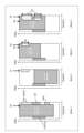
ここで、各Modeでは、例えば、以下のようにデータが割り当てられる。
Mode 1:スロット単位で割り当てられた端末200に対してデータを割り当てられた領域にデータが配置される(例えば、図9Aを参照)。
Mode 2:スロット単位で割り当てられた端末200に対してデータを割り当てられた領域のうち、周波数領域X0のシンボル番号Y0には、データが配置されない(例えば、図9Bを参照)。
Here, in each mode, data is allocated as follows, for example.
Mode 1: Data is placed in the area allocated to the terminal 200 in units of slots (for example, see FIG. 9A).
Mode 2: Data is not allocated to symbol number Y0 of frequency domain X0 among the areas to which data is allocated to
また、上位レイヤのシグナリングによって通知される{X0,Y0}は、以下のように設定されてもよい。
周波数領域X0:PRB#2~PRB#5
時間領域Y0:シンボル#3,#4,#5
Further, {X0, Y0} notified by upper layer signaling may be set as follows.
Frequency domain X0:
Time domain Y0:
上位レイヤシグナリングによって通知される設定情報に含まれる周波数領域X0及び時間領域Y0は、スロット内の身にスロットが占有する可能性のある一部のリソース領域を示す。また、DCIによって通知されるModeには、上記ミニスロットに対応する一部のリソース領域にデータを割り当てないMode 1、及び、上記ミニスロットに対応する一部のリソース領域にデータを割り当てるMode 2が含まれる。
A frequency domain X0 and a time domain Y0 included in the configuration information notified by upper layer signaling indicate some resource regions within the slot that may be occupied by the slot. In addition, the modes notified by DCI include
基地局100は、例えば、スロット単位でリソースが割り当てられる端末200、及び、ミニスロット単位でリソースが割り当てられる他の端末のリソース割当の状況に応じて、端末200に対するModeを選択し、DCIによって選択したModeを通知する。
For example, the
これにより、Mode 1では、端末200は、ミニスロットを使用する他の端末が存在しないと認識できるので、当該端末200に割り当てられたリソースを全て使用することができる。
As a result, in
また、Mode 2では、ミニスロットを使用する他の端末が存在する可能性があるので、端末200に対して、ミニスロットに使用される可能性のある領域を避けて、データを配置することができる。
In addition, in
このように、本実施の形態では、基地局100は、スロット内の一部のリソース領域(ミニスロットに占有される可能性のある領域)に関する設定情報(例えば、上記X0,Y0等)を上位レイヤシグナリングによって通知する。また、基地局100は、複数のModeの中からデータ割当に使用する1つのModeを選択し、選択した1つのパターンをDCIによって通知する。端末200は、上位レイヤシグナリングによって既に通知されている設定情報、及び、DCIによって通知されるModeに基づいて、端末200に割り当てられるリソースを特定する。
As described above, in the present embodiment, the
これにより、基地局100は、端末200に対してDCIによってModeを通知することにより、スロット毎に異なる用途の使用を考慮したダイナミックなリソース割当を行うことができる。また、基地局100は、スロット内のデータ領域の割当を変更する際に、DCIを用いてModeを通知すればよく、リソース割当変更の度にリソース(例えば、ミニスロットに占有されるリソース等)を通知する必要がないので、DCIのシグナリングオーバヘッドを削減することができる。
Thereby, the
よって、本実施の形態によれば、データ領域を適切に通知し、リソースを柔軟に割り当てることができる。 Therefore, according to this embodiment, data areas can be appropriately notified and resources can be allocated flexibly.
なお、Mode数は2に限定するものではなく、3個以上のModeでもよい。その場合、ミニスロットとして使用されるリソースを複数通知することもでき、ミニスロットの領域の大きさを変更することもできる。 Note that the number of modes is not limited to two, and may be three or more modes. In that case, multiple resources to be used as mini-slots can be notified, and the size of the mini-slot area can also be changed.
また、ミニスロットとして使用される可能性のあるリソースを指定する周波数領域X0及び時間領域Y0は、連続する領域に限定するものではなく、連続しない領域を指定してもよい。 Furthermore, the frequency domain X0 and time domain Y0 that specify resources that may be used as minislots are not limited to continuous areas, and may specify non-contiguous areas.
また、スロットに挿入される信号は、URLLCの信号を想定したが、他の用途の信号でもよい。例えば、CSI-RS等の参照信号の挿入又はD2Dに使用されるSidelink、又は、干渉制 Further, although the signal inserted into the slot is assumed to be a URLLC signal, it may be a signal for other purposes. For example, insertion of reference signals such as CSI-RS, Sidelink used for D2D, or interference control
(実施の形態4)
実施の形態1では、主にDLのデータ(PDSCH)の割り当てを想定したのに対して、本実施の形態ではULのデータ(PUSCH:Physical Uplink Shared Channel)の割り当てを想定する場合について説明する。
(Embodiment 4)
In the first embodiment, the assignment of DL data (PDSCH) was mainly assumed, whereas in this embodiment, the case where the assignment of UL data (PUSCH: Physical Uplink Shared Channel) is assumed will be explained.
端末は、自機に割り当てられたACK/NACK、CSI、SR、SRS領域を認識することができるのに対して、他の端末に割り当てられている領域、又は、他の用途(例えば、Sidelink、URLLC、mMTC)に使用される領域を認識することができない。上述したように、基地局は、上位レイヤのシグナリングを用いて、端末に割り当てないリソース領域を通知し、当該リソース領域を避けてデータ割当を行うことも可能であるが、上位レイヤのシグナリングを用いたリソース領域の通知では、semi-staticな割り当てとなってしまう。New RATでは、スロット毎に異なる用途の使用が考えられるため、上位レイヤによる通知のみではリソース割当の柔軟性が低いという問題がある。 A terminal can recognize the ACK/NACK, CSI, SR, and SRS areas assigned to itself, while it can recognize the areas assigned to other terminals or for other purposes (e.g., Sidelink, Unable to recognize the area used for URLLC, mMTC). As mentioned above, the base station can use upper layer signaling to notify terminals of resource areas that are not to be allocated and allocate data while avoiding the resource areas, but it is also possible to use upper layer signaling to Notification of the resource area that was previously used results in semi-static allocation. In New RAT, each slot can be used for different purposes, so there is a problem in that resource allocation is less flexible if only notifications from upper layers are used.
そこで、本実施の形態では、実施の形態1と同様にして、ULデータに使用できる領域を上位レイヤのシグナリングとDCIとを組み合わせて通知する。 Therefore, in this embodiment, as in the first embodiment, the area that can be used for UL data is notified by combining upper layer signaling and DCI.
本実施の形態に係る基地局及び端末は、実施の形態1に係る基地局100及び端末200と基本構成が共通するので、図3及び図4を援用して説明する。
The base station and terminal according to this embodiment have the same basic configuration as the
具体的には、基地局100は、データ割当に関する周波数領域又は時間領域の複数のMode(パターン)を設定する。また、基地局100は、設定した複数のModeに関する設定情報(周波数領域又は時間領域を示すパラメータ)を、上位レイヤのシグナリング(SIB又はdedicated RRC)を用いて端末200へ送信する。
Specifically, the
また、基地局100は、データ割当の際、複数のModeの中から1つのModeを選択し、選択したModeに基づいてULデータの割当に使用可能なリソース領域を例えばPRB毎に特定する。そして、基地局100は、データの割当情報及び選択したModeを含むDCIを端末200へ送信する。
Furthermore, when allocating data, the
一方、端末200は、受信した上位レイヤのシグナリングに含まれる設定情報、及び、DCIに基づいて、ULデータの割当に使用可能なリソース領域(例えば、PRB単位)を特定する。 On the other hand, the terminal 200 identifies a resource area (eg, PRB unit) that can be used for UL data allocation based on the configuration information included in the received upper layer signaling and the DCI.
このように、本実施の形態では、基地局100は、ULデータの割当情報を通知する際、ULデータ割当の複数のModeに関する設定情報を上位レイヤシグナリングによって通知し、実際のULデータ割当に使用する1つのModeをDCIによって通知する。つまり、上位レイヤのシグナリングと、DCIとを併用してULデータ割当の通知が行われる。
As described above, in this embodiment, when notifying UL data assignment information,
これにより、実施の形態1(DL割り当て)と同様、基地局100は、データ割当の際に、DCIによって1つのModeを通知すればよく、周波数領域又は時間領域に関する設定情報をデータ割当の度に通知する必要がなくなるので、DCIのシグナリングのオーバヘッドを削減しつつ、データ以外に使用される領域をデータ領域から排除できる。また、基地局100は、DCIによって、複数のModeの中からデータ割当に使用するModeをダイナミックに変更できるので、柔軟にデータを割り当てることができる。
As a result, as in Embodiment 1 (DL allocation), the
以下、本実施の形態に係る動作例について説明する。 An example of operation according to this embodiment will be described below.
以下では、実施の形態1の動作例2と同様に、上位レイヤのシグナリングで4つのMode(Mode 1、Mode 2、Mode 3、Mode 4)を用意し、DCIに含まれる2ビットを用いてMode 1、Mode 2、Mode 3、Mode 4を切り替える場合について説明する。
In the following, similarly to the operation example 2 of the first embodiment, four modes (
図10は、本動作例に係るMode 1、Mode 2、Mode 3、Mode 4の一例を示す。
FIG. 10 shows an example of
具体的には、基地局100は、データ割当のModeとして、例えば、図10に示すMode 1~Mode 4を設定する。また、基地局100は、上位レイヤのシグナリングを用いて、Mode 1~Mode 4に関する設定情報として、周波数領域「X0」、「X1」、及び、データの終了シンボル「A0」,「A1」,「A2」,「A3」,「A4」,「A5」を通知する。ここで、後述するように、A0はMode 1に関するパラメータであり、A1はMode 2に関するパラメータであり、X0、A2、A3はMode 3に関するパラメータであり、X1、A4、A5はMode 4に関するパラメータである。周波数領域X0,X1は、例えば、PRB番号又はRBG番号で表されてもよい。
Specifically, the
また、基地局100は、DCIに含まれる2ビットを用いて、データ割当に使用するModeとして、Mode 1、Mode 2、Mode 3又はMode 4の何れか1つのModeを端末200へ通知する。
Furthermore, the
端末200は、上位レイヤのシグナリングによって通知されたMode 1~Mode 4に関する設定情報のうち、DCIに示されるModeに対応する情報に基づいて、データが割り当てられるリソース領域を特定する。
The terminal 200 specifies the resource area to which data is allocated based on the information corresponding to the Mode indicated in the DCI among the configuration
ここで、各Modeでは、例えば、以下のようにデータが割り当てられる。
Mode 1:データはシンボルA0まで割り当てられる。
Mode 2:データはシンボルA1まで割り当てられる。
Mode 3:周波数領域X0では、データはシンボルA2まで割り当てられ、X0以外の周波数領域では、データはシンボルA3まで割り当てられる。
Mode 4:周波数領域X1では、データはシンボルA4まで割り当てられ、X1以外の周波数領域では、データはシンボルA5まで割り当てられる。
Here, in each mode, data is allocated as follows, for example.
Mode 1: Data is allocated up to symbol A0.
Mode 2: Data is allocated up to symbol A1.
Mode 3: In frequency domain X0, data is allocated up to symbol A2, and in frequency domains other than X0, data is allocated up to symbol A3.
Mode 4: In frequency domain X1, data is allocated up to symbol A4, and in frequency domains other than X1, data is allocated up to symbol A5.
また、設定情報として上位レイヤのシグナリングによって通知される{X0,X1,A0,A1,A2,A3,A4,A5}は、以下のように設定されてもよい。
周波数領域X0:ACK/NACKと同一周波数領域
周波数領域X1:ACK/NACKとCSIとを合わせた周波数領域
A0:ACK/NACK、CSI、SRSが配置されるシンボルの前のシンボル
A1:スロットの最終シンボル
A2:ACK/NACKが配置されるシンボルの前のシンボル
A3:スロットの最終シンボル
A4:ACK/NACK又はCSIの前のシンボル
A5:スロットの最終シンボル
Further, {X0, X1, A0, A1, A2, A3, A4, A5} notified by upper layer signaling as setting information may be set as follows.
Frequency domain X0: Same frequency domain as ACK/NACK Frequency domain X1: Frequency domain that combines ACK/NACK and CSI
A0: Symbol before the symbol where ACK/NACK, CSI, and SRS are placed
A1: Last symbol of the slot
A2: Symbol before the symbol where ACK/NACK is placed
A3: Final symbol of the slot
A4: Symbol before ACK/NACK or CSI
A5: Final symbol of the slot
つまり、Mode 1に関して、A0は、ULデータ信号が割り当てられる時間領域の終了位置を示す。
That is, for
また、Mode 2に関して、A1は、ULデータ信号が割り当てられる時間領域の終了位置を示す。
Regarding
また、Mode 3に関して、X0は、UL制御信号(例えば、ACK/NACK等)が割り当てられる周波数領域を示し、A2は、周波数領域X0においてULデータ信号が割り当てられる時間領域の終了位置を示し、A3は、周波数領域X0以外の周波数領域においてULデータ信号が割り当てられる時間領域の終了位置を示す。
Regarding
また、Mode 4に関して、X1は、UL制御信号(例えば、ACK/NACK、CSI等)が割り当てられる周波数領域を示し、A4は、周波数領域X1においてULデータ信号が割り当てられる時間領域の終了位置を示し、A5は、周波数領域X1以外の周波数領域においてULデータ信号が割り当てられる時間領域の終了位置を示す。
Regarding
すなわち、Mode 1では、端末200は、図10に示すように、データ(PUSCH)が割り当てられるデータリソース(UL割当情報に示されるリソース)に依らず、上位レイヤのシグナリングで通知された終了シンボル(A0)に基づいて、データ(PUSCH)が割り当てられるシンボルの終了位置を特定する。つまり、Mode 1では、データは、データリソースの全帯域においてシンボルA0まで割り当てられる。
That is, in
Mode 2は、Mode 1とは異なるシンボル(図10ではスロットの最終シンボル)までデータが割り当てられる。すなわち、Mode 2では、図10に示すように、データリソースに依らず、スロットの最終シンボルまでデータ(PUSCH)が割り当てられる。このように、Mode 2ではスロットの最終シンボルまでデータが割り当てられるので、Mode 2は、例えば、端末200に対して、UL制御信号又は参照信号とオーバラップしない周波数領域にデータが割り当てられた場合に有効である。
In
Mode 3では、周波数領域X0と、周波数領域X0以外の領域とでデータが割り当てられる終了シンボルが異なる。Mode 3では、端末200は、周波数領域X0では、ACK/NACK(スロットの最終シンボル)を避けてデータを配置でき、周波数領域X0以外の領域では、スロットの最終シンボルまでデータを配置できる。これにより、リソースを有効利用できる。このように、Mode 3は、周波数領域X0(ACK/NACK)とオーバラップしている周波数領域にデータが割り当てられた場合に有効である。
In
Mode 4では、Mode 3と同様、周波数領域X1と、周波数領域X1以外の領域とでデータが割り当てられる終了シンボルが異なる。Mode 4では、端末200は、周波数領域X1では、制御信号(ACK/NACKとCSI)を避けてデータを配置でき、周波数領域X1以外の領域では、スロットの最終シンボルまでデータを配置できる。これにより、リソースを有効利用できる。このように、Mode 4は、周波数領域X1(ACK/NACKとCSI)とオーバラップしている周波数領域にデータが割り当てられた場合に有効である。ただし、ACK/NACKとCSIのシンボル数が異なる場合、シンボル数が長い方に合わせてA4を設定する必要がある。
In
例えば、基地局100は、ULデータ信号(PUSCH)の割当リソース(データリソース)と、制御信号(ACK/NACK、CSI等)の割当リソースとの関係(例えば、オーバラップの有無等)に基づいて、複数のModeの中からULデータの割当リソースに適した1つのModeを選択すればよい。
For example, the
なお、周波数領域X0、X1は、ACK/NACK、CSI、SRS又はSRと同じ周波数領域としてもよく、これらを合わせた周波数領域としてもよい。 Note that the frequency regions X0 and X1 may be the same frequency region as ACK/NACK, CSI, SRS, or SR, or may be a combination of these frequency regions.
また、周波数領域X0,X1は、PRB単位またはRBG単位で指示をしてもよい。周波数領域X0、X1をPRB単位またはRBG単位で指示をすると、基地局100は、端末200に対してリソースをより柔軟に指示できるので、他の移動局に割り当てられる制御信号、参照信号又はデータの周波数領域を避けたり、他の用途に使われる領域を避けたりすることができる。
Further, the frequency regions X0 and X1 may be specified in PRB units or RBG units. By instructing frequency regions X0 and X1 in units of PRB or RBG,
また、A0,A1,A2,A3,A3,A5は、ACK/NACK、CSI、SRS又はSRが配置されるシンボルの前のシンボルとしてもよく、シンボル番号を通知してもよい。また、A0,A1,A3,A5はスロット又はsubframeの最終シンボルとしてもよい。または、A0,A2,A4を同じ値としてもよく、A1,A3,A5を同じ値としてもよい。 Further, A0, A1, A2, A3, A3, and A5 may be symbols before the symbol in which ACK/NACK, CSI, SRS, or SR is arranged, and may notify symbol numbers. Furthermore, A0, A1, A3, and A5 may be the final symbols of the slot or subframe. Alternatively, A0, A2, and A4 may be set to the same value, and A1, A3, and A5 may be set to the same value.
このようにして、本実施の形態では、基地局100は、データを割り当てるリソース領域の複数のModeに関する設定情報(例えば、X0,X1、A0,A1,A2,A3,A4,A5等)を上位レイヤシグナリングによって通知する。また、基地局100は、複数のModeの中からデータ割当に使用する1つのModeを選択し、選択した1つのパターンをDCIによって通知する。端末200は、上位レイヤシグナリングによって既に通知されている設定情報の中から、DCIによって通知されるModeに対応するパラメータを用いてリソースを特定する。
In this way, in the present embodiment, the
これにより、基地局100は、端末200に対してDCIによってModeを通知することにより、スロット毎に異なる用途の使用を考慮したダイナミックなリソース割当を行うことができる。また、基地局100は、リソース割当を変更する際に、DCIを用いてModeを通知すればよく、リソース割当変更の度にリソース(例えば、周波数領域毎のデータのシンボル開始位置等)を通知する必要がないので、DCIのシグナリングオーバヘッドを削減することができる。
Thereby, the
また、基地局100は、制御信号チャネルが配置されるリソース(control resource set)に応じてModeを選択することにより、各スロットにおいて端末200に割り当てないリソース領域を避けた柔軟なデータ割当を行うことができる。
Furthermore, the
よって、本実施の形態によれば、UL制御信号の配置される領域を考慮して、データ領域(データの開始位置)を適切に通知し、リソースを柔軟に割り当てることができる。 Therefore, according to the present embodiment, it is possible to appropriately notify the data area (data start position) and flexibly allocate resources, taking into account the area where the UL control signal is placed.
以上、本開示の各実施の形態について説明した。 Each embodiment of the present disclosure has been described above.
なお、上記実施の形態では、DCIに含まれる1ビット又は2ビットを用いてModeを通知する場合について説明したが、これに限定されず、DCIに含まれる2ビットより多くのビット数を用いてModeを通知してもよい。また、Mode数は、2個又は4個に限らず、他の個数でもよい。 Note that in the above embodiment, a case has been described in which the Mode is notified using 1 bit or 2 bits included in the DCI, but the mode is not limited to this, and it is possible to notify the mode using more bits than 2 bits included in the DCI. The Mode may be notified. Further, the number of Modes is not limited to 2 or 4, but may be any other number.
また、上記実施の形態では、周波数領域(PRB#)について、物理的なマッピングを一例として説明したが、論理的なマッピングについても適用することができる。論理的なマッピングの場合、論理的なマッピングから物理的なマッピングに変更されるので、論理的なマッピングにおいて連続している周波数領域であっても、物理的には離れた位置に配置されるので、周波数ダイバーシチ効果が得られる。 Further, in the above embodiment, physical mapping has been described as an example in the frequency domain (PRB#), but logical mapping can also be applied. In the case of logical mapping, the logical mapping is changed to physical mapping, so even if the frequency regions are continuous in the logical mapping, they are physically located at separate locations. , a frequency diversity effect can be obtained.
また、上記DCIは、group common PDCCH、端末200(UE)のデータ割り当て時に送信されるPDCCH(UE-specific DCI)、又は、group common control resource setで送信される他のPDCCHで送信されてもよい。Group common PDCCHでDCIが送信される場合、複数の端末が同じ設定を受信するのでオーバヘッドを削減できる。また、個別のPDCCHでDCIが送信される場合、端末毎に個別に設定できる。また、DCIは、group common resource set及びUE specific control resource setに限らず、他のリソースで送信されてもよい。 Further, the DCI may be transmitted using a group common PDCCH, a PDCCH (UE-specific DCI) transmitted when data is allocated to the terminal 200 (UE), or another PDCCH transmitted in a group common control resource set. . When DCI is transmitted using the Group common PDCCH, overhead can be reduced because multiple terminals receive the same settings. Furthermore, when DCI is transmitted on individual PDCCHs, it can be configured individually for each terminal. Further, the DCI is not limited to the group common resource set and the UE specific control resource set, but may be transmitted using other resources.
また、group common PDCCHは、PCFICH(Physical Control Format Indicator channel)、PSFICH(Physical Slot Format Indicator channel)、又は、PDCCH type0等の異なる名称で定義される場合もある。 Further, the group common PDCCH may be defined with different names such as PCFICH (Physical Control Format Indicator channel), PSFICH (Physical Slot Format Indicator channel), or PDCCH type0.
また、group common control resource setは、common control resource set、group common search space又はcommon search spaceと呼ばれることもある。また、control resource setは、CORESETと呼ばれることもある。 Further, a group common control resource set is sometimes called a common control resource set, a group common search space, or a common search space. Control resource set is also sometimes called CORESET.
また、上位レイヤのシグナリングは、MACのシグナリングに置き換えてもよい。MACのシグナリングの場合、RRCのシグナリングと比較して、UEに設定するModeの変更の頻度を上げることができる。 Further, the upper layer signaling may be replaced with MAC signaling. In the case of MAC signaling, compared to RRC signaling, the mode set in the UE can be changed more frequently.
本開示はソフトウェア、ハードウェア、又は、ハードウェアと連携したソフトウェアで実現することが可能である。上記実施の形態の説明に用いた各機能ブロックは、部分的に又は全体的に、集積回路であるLSIとして実現され、上記実施の形態で説明した各プロセスは、部分的に又は全体的に、一つのLSI又はLSIの組み合わせによって制御されてもよい。LSIは個々のチップから構成されてもよいし、機能ブロックの一部または全てを含むように一つのチップから構成されてもよい。LSIはデータの入力と出力を備えてもよい。LSIは、集積度の違いにより、IC、システムLSI、スーパーLSI、ウルトラLSIと呼称されることもある。集積回路化の手法はLSIに限るものではなく、専用回路、汎用プロセッサ又は専用プロセッサで実現してもよい。また、LSI製造後に、プログラムすることが可能なFPGA(Field Programmable Gate Array)や、LSI内部の回路セルの接続や設定を再構成可能なリコンフィギュラブル・プロセッサを利用してもよい。本開示は、デジタル処理又はアナログ処理として実現されてもよい。さらには、半導体技術の進歩または派生する別技術によりLSIに置き換わる集積回路化の技術が登場すれば、当然、その技術を用いて機能ブロックの集積化を行ってもよい。バイオ技術の適用等が可能性としてありえる。 The present disclosure can be implemented with software, hardware, or software in conjunction with hardware. Each functional block used in the description of the above embodiment is partially or entirely realized as an LSI that is an integrated circuit, and each process explained in the above embodiment is partially or entirely realized as an LSI, which is an integrated circuit. It may be controlled by one LSI or a combination of LSIs. The LSI may be composed of individual chips, or may be composed of a single chip that includes some or all of the functional blocks. The LSI may include data input and output. LSIs are sometimes called ICs, system LSIs, super LSIs, and ultra LSIs depending on the degree of integration. The method of circuit integration is not limited to LSI, but may be implemented using a dedicated circuit, a general-purpose processor, or a dedicated processor. Furthermore, an FPGA (Field Programmable Gate Array) that can be programmed after the LSI is manufactured or a reconfigurable processor that can reconfigure the connections and settings of circuit cells inside the LSI may be used. The present disclosure may be implemented as digital or analog processing. Furthermore, if an integrated circuit technology that replaces LSI emerges due to advancements in semiconductor technology or other derived technology, then of course the functional blocks may be integrated using that technology. Possibilities include the application of biotechnology.
本開示の基地局は、データを割り当てるリソース領域の複数のパターンの中からデータ割当に使用する1つのパターンを選択する回路と、前記複数のパターンに関する設定情報を上位レイヤシグナリングによって通知し、前記選択された1つのパターンを下り制御信号(DCI)によって通知する送信機と、を具備する。 A base station of the present disclosure includes a circuit that selects one pattern to be used for data allocation from among a plurality of patterns of resource areas to which data is allocated, and a circuit that notifies configuration information regarding the plurality of patterns by upper layer signaling, and and a transmitter that notifies the selected pattern using a downlink control signal (DCI).
本開示の基地局において、前記設定情報は、下りリンクの前記データが割り当てられる時間領域の開始位置を示す。 In the base station of the present disclosure, the configuration information indicates a starting position of a time domain to which the downlink data is allocated.
本開示の基地局において、前記設定情報は、下りリンクの制御信号が割り当てられる周波数領域、当該周波数領域において下りリンクの前記データが割り当てられる時間領域の開始位置、及び、当該周波数領域以外の周波数領域において下りリンクの前記データが割り当てられる時間領域の開始位置を示す。 In the base station of the present disclosure, the configuration information includes a frequency domain to which a downlink control signal is allocated, a start position of a time domain in which the downlink data is allocated in the frequency domain, and a frequency domain other than the frequency domain. indicates the start position of the time domain to which the downlink data is allocated.
本開示の基地局において、前記設定情報は、下りリンクシンボル、上りリンクシンボル又は他の用途に使用されるシンボルによって構成されるスロット内のシンボル構成の複数のパターンを示す。 In the base station of the present disclosure, the configuration information indicates a plurality of patterns of symbol configurations within a slot configured by downlink symbols, uplink symbols, or symbols used for other purposes.
本開示の基地局において、前記設定情報は、スロット内における、下りリンク、上りリンク又は他の用途に使用される周波数帯の構成の複数のパターンを示す。 In the base station of the present disclosure, the configuration information indicates multiple patterns of configurations of frequency bands used for downlink, uplink, or other purposes within a slot.
本開示の基地局において、前記設定情報は、スロット内の一部のリソース領域を示し、前記複数のパターンは、前記一部のリソース領域に前記データを割り当てるパターン、及び、前記一部のリソース領域に前記データを割り当てないパターンを含む。 In the base station of the present disclosure, the configuration information indicates a part of the resource area within the slot, and the plurality of patterns include a pattern of allocating the data to the part of the resource area, and a pattern of allocating the data to the part of the resource area. includes a pattern in which the data is not assigned to.
本開示の基地局において、前記設定情報は、上りリンクの前記データが割り当てられる時間領域の終了位置を示す。 In the base station of the present disclosure, the configuration information indicates an end position of a time domain to which the uplink data is allocated.
本開示の基地局において、前記設定情報は、上りリンクの制御信号が割り当てられる周波数領域、当該周波数領域において上りリンクの前記データが割り当てられる時間領域の終了位置、及び、当該周波数領域以外の周波数領域において上りリンクの前記データが割り当てられる時間領域の終了位置を示す。 In the base station of the present disclosure, the configuration information includes a frequency domain to which an uplink control signal is allocated, an end position of a time domain in which the uplink data is allocated in the frequency domain, and a frequency domain other than the frequency domain. indicates the end position of the time domain to which the uplink data is allocated.
本開示の端末は、データを割り当てるリソース領域の複数のパターンに関する設定情報を含む上位レイヤシグナリングを受信し、前記複数のパターンの中からデータ割当に使用する1つのパターンを示す下り制御信号(DCI)を受信する受信機と、前記設定情報及び前記下り制御信号に基づいて、前記データが割り当てられるリソースを特定する回路と、を具備する。 A terminal of the present disclosure receives upper layer signaling including configuration information regarding a plurality of patterns of resource areas to allocate data, and generates a downlink control signal (DCI) indicating one pattern to be used for data allocation from among the plurality of patterns. and a circuit that identifies a resource to which the data is allocated based on the configuration information and the downlink control signal.
本開示の通信方法は、データを割り当てるリソース領域の複数のパターンの中からデータ割当に使用する1つのパターンを選択し、前記複数のパターンに関する設定情報を上位レイヤシグナリングによって通知し、前記選択された1つのパターンを下り制御信号(DCI)によって通知する。 The communication method of the present disclosure selects one pattern to be used for data allocation from among a plurality of patterns of resource areas to which data is allocated, notifies setting information regarding the plurality of patterns by upper layer signaling, and One pattern is notified by a downlink control signal (DCI).
本開示の通信方法は、データを割り当てるリソース領域の複数のパターンに関する設定情報を含む上位レイヤシグナリングを受信し、前記複数のパターンの中からデータ割当に使用する1つのパターンを示す下り制御信号(DCI)を受信し、前記設定情報及び前記下り制御信号に基づいて、前記データが割り当てられるリソースを決定する。 The communication method of the present disclosure receives upper layer signaling including configuration information regarding a plurality of patterns of resource areas to which data is allocated, and receives a downlink control signal (DCI) indicating one pattern to be used for data allocation from among the plurality of patterns. ), and determines a resource to which the data is allocated based on the configuration information and the downlink control signal.
本開示の一態様は、移動通信システムに有用である。 One aspect of the present disclosure is useful for mobile communication systems.
100 基地局
101 設定部
102 DCI生成部
103,207 誤り訂正符号化部
104,208 変調部
105,209 信号割当部
106,210 送信部
107,201 受信部
108,202 信号分離部
109,204 復調部
110,205 誤り訂正復号部
200 端末
203 DCI受信部
206 設定情報受信部
100 Base station 101
Claims (4)
前記4つのリソースパターンの中から選択されたリソースパターンを示す2ビットの情報を含むDCIを生成する、制御回路と、
前記DCIを一部の周波数帯域に割り当てられるコントロールリソースセットにおいて送信する送信機と、を具備し、
前記ダウンリンクデータに関する前記4つのリソースパターンのうち、複数のリソースパターンの各々は、時間領域および周波数領域においてダウンリンクデータ割当から除外するリソースを示す、
通信装置。 generating upper layer signaling indicating four resource patterns regarding downlink data, each of the four resource patterns being indicated by a physical resource block and a symbol within a slot;
a control circuit that generates a DCI including 2-bit information indicating a resource pattern selected from the four resource patterns;
a transmitter that transmits the DCI in a control resource set allocated to some frequency bands,
Each of the plurality of resource patterns among the four resource patterns regarding the downlink data indicates resources to be excluded from downlink data allocation in the time domain and the frequency domain.
Communication device.
請求項1に記載の通信装置。 Each of the four resource patterns for downlink data indicates a symbol for starting downlink data allocation;
The communication device according to claim 1.
前記4つのリソースパターンの中から選択されたリソースパターンを示す2ビットの情報を含むDCIを生成する、制御回路と、
前記DCIを一部の周波数帯域に割り当てられるコントロールリソースセットにおいて送信し、
前記ダウンリンクデータに関する前記4つのリソースパターンのうち、複数のリソースパターンの各々は、時間領域および周波数領域においてダウンリンクデータ割当から除外するリソースを示す、
通信方法。 generating upper layer signaling indicating four resource patterns regarding downlink data, each of the four resource patterns being indicated by a physical resource block and a symbol within a slot;
a control circuit that generates a DCI including 2-bit information indicating a resource pattern selected from the four resource patterns;
transmitting the DCI in a control resource set allocated to some frequency bands;
Each of the plurality of resource patterns among the four resource patterns regarding the downlink data indicates resources to be excluded from downlink data allocation in the time domain and the frequency domain.
Communication method.
前記4つのリソースパターンの中から選択されたリソースパターンを示す2ビットの情報を含むDCIを生成する、処理と、
前記DCIを一部の周波数帯域に割り当てられるコントロールリソースセットにおいて送信する、処理と、を制御し、
前記ダウンリンクデータに関する前記4つのリソースパターンのうち、複数のリソースパターンの各々は、時間領域および周波数領域においてダウンリンクデータ割当から除外するリソースを示す、
集積回路。
generating upper layer signaling indicating four resource patterns for downlink data, each of the four resource patterns being indicated by a physical resource block and a symbol within a slot;
A process of generating a DCI including 2-bit information indicating a resource pattern selected from the four resource patterns;
controlling a process of transmitting the DCI in a control resource set allocated to some frequency bands;
Each of the plurality of resource patterns among the four resource patterns regarding the downlink data indicates resources to be excluded from downlink data allocation in the time domain and the frequency domain.
integrated circuit.
Priority Applications (1)
| Application Number | Priority Date | Filing Date | Title |
|---|---|---|---|
| JP2024033017A JP7772845B2 (en) | 2017-03-17 | 2024-03-05 | Control device, communication method and integrated circuit |
Applications Claiming Priority (4)
| Application Number | Priority Date | Filing Date | Title |
|---|---|---|---|
| JP2017052863 | 2017-03-17 | ||
| JP2017052863 | 2017-03-17 | ||
| PCT/JP2018/001516 WO2018168189A1 (en) | 2017-03-17 | 2018-01-19 | Base station, terminal, and communication method |
| JP2019505731A JP7246303B2 (en) | 2017-03-17 | 2018-01-19 | Communication device, communication method and integrated circuit |
Related Parent Applications (1)
| Application Number | Title | Priority Date | Filing Date |
|---|---|---|---|
| JP2019505731A Division JP7246303B2 (en) | 2017-03-17 | 2018-01-19 | Communication device, communication method and integrated circuit |
Related Child Applications (1)
| Application Number | Title | Priority Date | Filing Date |
|---|---|---|---|
| JP2024033017A Division JP7772845B2 (en) | 2017-03-17 | 2024-03-05 | Control device, communication method and integrated circuit |
Publications (2)
| Publication Number | Publication Date |
|---|---|
| JP2023027321A JP2023027321A (en) | 2023-03-01 |
| JP7451663B2 true JP7451663B2 (en) | 2024-03-18 |
Family
ID=63523412
Family Applications (3)
| Application Number | Title | Priority Date | Filing Date |
|---|---|---|---|
| JP2019505731A Active JP7246303B2 (en) | 2017-03-17 | 2018-01-19 | Communication device, communication method and integrated circuit |
| JP2022203066A Active JP7451663B2 (en) | 2017-03-17 | 2022-12-20 | Communication devices, communication methods and integrated circuits |
| JP2024033017A Active JP7772845B2 (en) | 2017-03-17 | 2024-03-05 | Control device, communication method and integrated circuit |
Family Applications Before (1)
| Application Number | Title | Priority Date | Filing Date |
|---|---|---|---|
| JP2019505731A Active JP7246303B2 (en) | 2017-03-17 | 2018-01-19 | Communication device, communication method and integrated circuit |
Family Applications After (1)
| Application Number | Title | Priority Date | Filing Date |
|---|---|---|---|
| JP2024033017A Active JP7772845B2 (en) | 2017-03-17 | 2024-03-05 | Control device, communication method and integrated circuit |
Country Status (5)
| Country | Link |
|---|---|
| US (3) | US11595182B2 (en) |
| EP (2) | EP4351257A3 (en) |
| JP (3) | JP7246303B2 (en) |
| CN (3) | CN116667987B (en) |
| WO (1) | WO2018168189A1 (en) |
Families Citing this family (6)
| Publication number | Priority date | Publication date | Assignee | Title |
|---|---|---|---|---|
| CN108282293B (en) * | 2017-01-06 | 2021-12-03 | 大唐移动通信设备有限公司 | Data transmission method, terminal and base station |
| US11271701B2 (en) * | 2018-01-12 | 2022-03-08 | Qualcomm Incorporated | Physical downlink control channel (PDCCH) monitoring with overlapping resources |
| US20190261454A1 (en) * | 2018-05-11 | 2019-08-22 | Intel Corporation | Handling radio resource control (rrc) configured channels and signals with conflict direction |
| EP3855846A1 (en) * | 2018-09-21 | 2021-07-28 | Ntt Docomo, Inc. | User terminal |
| CN113287352B (en) | 2019-01-10 | 2024-05-24 | 上海诺基亚贝尔股份有限公司 | Control resource reuse for data transmission |
| US20250365730A1 (en) * | 2024-05-24 | 2025-11-27 | Samsung Electronics Co., Ltd. | Avoidance-based coexistence in shared spectrum |
Citations (1)
| Publication number | Priority date | Publication date | Assignee | Title |
|---|---|---|---|---|
| WO2016047729A1 (en) | 2014-09-25 | 2016-03-31 | 株式会社Nttドコモ | User terminal, wireless base station and wireless communication method |
Family Cites Families (18)
| Publication number | Priority date | Publication date | Assignee | Title |
|---|---|---|---|---|
| CN101938747B (en) * | 2009-07-01 | 2013-12-04 | 中兴通讯股份有限公司 | Method and device for transmitting and receiving resource metric |
| CN105450379B (en) * | 2010-01-26 | 2018-11-27 | Lg电子株式会社 | The method and apparatus of resource is distributed in a wireless communication system |
| JP5072999B2 (en) * | 2010-04-05 | 2012-11-14 | 株式会社エヌ・ティ・ティ・ドコモ | Wireless communication control device and wireless communication control method |
| US8743799B2 (en) | 2010-06-24 | 2014-06-03 | Nokia Siemens Networks Oy | Change of rate matching modes in presence of channel state information reference signal transmission |
| CN105812101B (en) * | 2011-01-05 | 2019-06-21 | 太阳专利信托公司 | Terminal device and communication method |
| US9526091B2 (en) * | 2012-03-16 | 2016-12-20 | Intel Corporation | Method and apparatus for coordination of self-optimization functions in a wireless network |
| US9083479B2 (en) * | 2012-05-11 | 2015-07-14 | Intel Corporation | Signaling for downlink coordinated multipoint in a wireless communication system |
| WO2014014253A1 (en) * | 2012-07-16 | 2014-01-23 | 엘지전자 주식회사 | Method and device for reporting channel state information in wireless communication system |
| US20140064135A1 (en) | 2012-08-28 | 2014-03-06 | Texas Instruments Incorporated | Reception of Downlink Data for Coordinated Multi-Point Transmission in the Event of Fall-Back |
| CN103634074B (en) | 2012-08-29 | 2018-04-10 | 中兴通讯股份有限公司 | The speed matching method and device of downlink data |
| AU2013318674B2 (en) | 2012-09-19 | 2016-04-07 | Telefonaktiebolaget L M Ericsson (Publ) | Method and communication node for mapping an enhanced physical downlink control channel, EPDCCH, message |
| EP2983306B1 (en) * | 2013-04-05 | 2020-02-19 | LG Electronics Inc. | Method for transmitting uplink control information in wireless access system and apparatus therefor |
| CN110635889B (en) * | 2013-08-06 | 2022-06-10 | 太阳专利信托公司 | Transmitter, receiver, communication method, and integrated circuit |
| EP3629514B1 (en) | 2014-09-24 | 2024-11-20 | InterDigital Patent Holdings, Inc. | Channel usage indication and synchronization for lte operation in unlicensed bands |
| CN112996006B (en) | 2014-11-07 | 2024-01-19 | 松下电器(美国)知识产权公司 | Integrated circuit for controlling a process of a communication device |
| EP4075901A1 (en) * | 2015-05-15 | 2022-10-19 | Kyocera Corporation | Base station and radio terminal |
| US10998994B2 (en) * | 2016-10-11 | 2021-05-04 | Lg Electronics Inc. | Signal transmission method for removing phase noise in wireless communication system and device therefor |
| CN110050433B (en) * | 2017-01-09 | 2022-07-05 | 苹果公司 | Bandwidth adaptation for wireless communication systems |
-
2018
- 2018-01-19 CN CN202310674056.4A patent/CN116667987B/en active Active
- 2018-01-19 US US16/488,963 patent/US11595182B2/en active Active
- 2018-01-19 JP JP2019505731A patent/JP7246303B2/en active Active
- 2018-01-19 EP EP24159596.6A patent/EP4351257A3/en active Pending
- 2018-01-19 CN CN201880014224.4A patent/CN110337833B/en active Active
- 2018-01-19 EP EP18767762.0A patent/EP3598821B1/en active Active
- 2018-01-19 CN CN202310680418.0A patent/CN116667988B/en active Active
- 2018-01-19 WO PCT/JP2018/001516 patent/WO2018168189A1/en not_active Ceased
-
2022
- 2022-12-20 JP JP2022203066A patent/JP7451663B2/en active Active
-
2023
- 2023-01-23 US US18/158,353 patent/US12160396B2/en active Active
-
2024
- 2024-03-05 JP JP2024033017A patent/JP7772845B2/en active Active
- 2024-10-23 US US18/924,212 patent/US20250047458A1/en active Pending
Patent Citations (1)
| Publication number | Priority date | Publication date | Assignee | Title |
|---|---|---|---|---|
| WO2016047729A1 (en) | 2014-09-25 | 2016-03-31 | 株式会社Nttドコモ | User terminal, wireless base station and wireless communication method |
Non-Patent Citations (2)
| Title |
|---|
| Huawei, HiSilicon,Discussion on sPDCCH design,3GPP TSG RAN WG1 #88 R1-1701731,2017年02月13日,Figure5-Figure9 |
| ZTE, ZTE Microelectronics,NR DL Control Channel Structure,3GPP TSG RAN WG1 adhoc_NR_AH_1701 R1-1700257,2017年01月16日,Fig1 |
Also Published As
| Publication number | Publication date |
|---|---|
| EP3598821B1 (en) | 2024-04-03 |
| CN110337833B (en) | 2023-05-30 |
| US12160396B2 (en) | 2024-12-03 |
| CN110337833A (en) | 2019-10-15 |
| JP2023027321A (en) | 2023-03-01 |
| WO2018168189A1 (en) | 2018-09-20 |
| EP3598821A1 (en) | 2020-01-22 |
| JP2024059966A (en) | 2024-05-01 |
| CN116667987A (en) | 2023-08-29 |
| JP7772845B2 (en) | 2025-11-18 |
| EP4351257A2 (en) | 2024-04-10 |
| EP3598821A4 (en) | 2020-03-18 |
| US20250047458A1 (en) | 2025-02-06 |
| CN116667987B (en) | 2026-01-06 |
| JPWO2018168189A1 (en) | 2020-01-16 |
| JP7246303B2 (en) | 2023-03-27 |
| US20190379516A1 (en) | 2019-12-12 |
| US20230163934A1 (en) | 2023-05-25 |
| EP4351257A3 (en) | 2024-07-10 |
| CN116667988A (en) | 2023-08-29 |
| CN116667988B (en) | 2026-04-28 |
| US11595182B2 (en) | 2023-02-28 |
Similar Documents
| Publication | Publication Date | Title |
|---|---|---|
| JP7451663B2 (en) | Communication devices, communication methods and integrated circuits | |
| US9276717B2 (en) | Terminal device, base station device, transmission method and reception method | |
| JP7475516B2 (en) | COMMUNICATION DEVICE, COMMUNICATION METHOD, AND INTEGRATED CIRCUIT | |
| CN114567420B (en) | User equipment and receiving method | |
| WO2013168389A1 (en) | Transmission device, receiving device, transmission method, and receiving method | |
| CN110474750B (en) | Signal transmission method, related equipment and system | |
| JP2020022210A (en) | Communication device, communication method, and integrated circuit | |
| CA2985765A1 (en) | Terminal device, base station device, and communication method | |
| CN110612732A (en) | Base station, terminal and communication method | |
| JP7265069B2 (en) | Communication device, communication method, and integrated circuit | |
| JP7108863B2 (en) | Communication device, communication method and integrated circuit | |
| JP6748894B2 (en) | Base station, communication method, and integrated circuit | |
| JP6365954B2 (en) | COMMUNICATION DEVICE, COMMUNICATION METHOD, AND INTEGRATED CIRCUIT |
Legal Events
| Date | Code | Title | Description |
|---|---|---|---|
| A621 | Written request for application examination |
Free format text: JAPANESE INTERMEDIATE CODE: A621 Effective date: 20221220 |
|
| TRDD | Decision of grant or rejection written | ||
| A01 | Written decision to grant a patent or to grant a registration (utility model) |
Free format text: JAPANESE INTERMEDIATE CODE: A01 Effective date: 20240213 |
|
| A61 | First payment of annual fees (during grant procedure) |
Free format text: JAPANESE INTERMEDIATE CODE: A61 Effective date: 20240306 |
|
| R150 | Certificate of patent or registration of utility model |
Ref document number: 7451663 Country of ref document: JP Free format text: JAPANESE INTERMEDIATE CODE: R150 |