JP7449128B2 - Vehicle control device - Google Patents
Vehicle control device Download PDFInfo
- Publication number
- JP7449128B2 JP7449128B2 JP2020042225A JP2020042225A JP7449128B2 JP 7449128 B2 JP7449128 B2 JP 7449128B2 JP 2020042225 A JP2020042225 A JP 2020042225A JP 2020042225 A JP2020042225 A JP 2020042225A JP 7449128 B2 JP7449128 B2 JP 7449128B2
- Authority
- JP
- Japan
- Prior art keywords
- slip
- torque
- target
- angular acceleration
- vehicle
- Prior art date
- Legal status (The legal status is an assumption and is not a legal conclusion. Google has not performed a legal analysis and makes no representation as to the accuracy of the status listed.)
- Active
Links
- 230000001133 acceleration Effects 0.000 claims description 100
- 230000001172 regenerating effect Effects 0.000 claims description 51
- 238000001514 detection method Methods 0.000 claims description 28
- 230000005540 biological transmission Effects 0.000 claims description 19
- 238000000034 method Methods 0.000 description 40
- 230000008030 elimination Effects 0.000 description 29
- 238000003379 elimination reaction Methods 0.000 description 29
- 238000010586 diagram Methods 0.000 description 14
- 238000009987 spinning Methods 0.000 description 10
- 230000008929 regeneration Effects 0.000 description 5
- 238000011069 regeneration method Methods 0.000 description 5
- 230000007423 decrease Effects 0.000 description 4
- 230000007704 transition Effects 0.000 description 4
- 238000004364 calculation method Methods 0.000 description 3
- 238000006243 chemical reaction Methods 0.000 description 3
- HBBGRARXTFLTSG-UHFFFAOYSA-N Lithium ion Chemical compound [Li+] HBBGRARXTFLTSG-UHFFFAOYSA-N 0.000 description 1
- 230000000994 depressogenic effect Effects 0.000 description 1
- 229910001416 lithium ion Inorganic materials 0.000 description 1
- 238000004088 simulation Methods 0.000 description 1
Images


Classifications
-
- Y—GENERAL TAGGING OF NEW TECHNOLOGICAL DEVELOPMENTS; GENERAL TAGGING OF CROSS-SECTIONAL TECHNOLOGIES SPANNING OVER SEVERAL SECTIONS OF THE IPC; TECHNICAL SUBJECTS COVERED BY FORMER USPC CROSS-REFERENCE ART COLLECTIONS [XRACs] AND DIGESTS
- Y02—TECHNOLOGIES OR APPLICATIONS FOR MITIGATION OR ADAPTATION AGAINST CLIMATE CHANGE
- Y02T—CLIMATE CHANGE MITIGATION TECHNOLOGIES RELATED TO TRANSPORTATION
- Y02T10/00—Road transport of goods or passengers
- Y02T10/60—Other road transportation technologies with climate change mitigation effect
- Y02T10/72—Electric energy management in electromobility
Description
本発明は、車両に搭載される車両用制御装置に関する。 The present invention relates to a vehicle control device mounted on a vehicle.
車両の移動速度である車速を求める方法として、各車輪の回転速度のうち最も遅い回転速度を車速とする方法が提案されている(特許文献1または2参照)。また、車速を求める方法として、車両加速度等から車速を算出する方法や、GPS(Global Positioning System)の位置信号から車速を算出する方法が考えられている。
As a method for determining the vehicle speed, which is the moving speed of the vehicle, a method has been proposed in which the slowest rotational speed of each wheel is determined as the vehicle speed (see
しかしながら、全ての車輪がスリップする状況や、登坂路や降坂路を走行する状況等においては、車速を適切に検出することが困難であった。 However, it has been difficult to appropriately detect the vehicle speed in situations where all wheels slip or when the vehicle is traveling on an uphill or downhill road.
本発明の目的は、車両の移動速度を適切に検出することにある。 An object of the present invention is to appropriately detect the moving speed of a vehicle.
本発明の車両用制御装置は、車両に搭載される車両用制御装置であって、駆動輪に動力伝達経路を介して連結される回転体を備えた動力源と、前記駆動輪がスリップした状態のもとで、前記回転体に発生する角加速度を検出する角加速度検出部と、前記駆動輪がスリップした状態のもとで、前記回転体に作用するトルクを検出するトルク検出部と、前記角加速度および前記トルクに基づいて、前記駆動輪のスリップが解消される前記回転体の目標角加速度を設定する目標角加速度設定部と、前記駆動輪、前記動力伝達経路および前記回転体からなる回転系のイナーシャに前記目標角加速度を乗算し、前記回転体の目標トルクを設定する目標トルク設定部と、前記目標トルクに基づき前記動力源を制御した状態のもとで、車両の移動速度として前記駆動輪の回転速度を検出する車速検出部と、を有する。 A vehicle control device of the present invention is a vehicle control device mounted on a vehicle, and includes a power source including a rotating body connected to a drive wheel via a power transmission path, and a state in which the drive wheel is in slip state. an angular acceleration detection unit that detects the angular acceleration generated on the rotating body under the conditions of a target angular acceleration setting unit that sets a target angular acceleration of the rotary body at which slip of the drive wheel is eliminated based on the angular acceleration and the torque; and a rotation comprising the drive wheel, the power transmission path, and the rotary body. a target torque setting unit that multiplies the inertia of the system by the target angular acceleration to set a target torque of the rotating body; and a vehicle speed detection section that detects the rotational speed of the drive wheels.
本発明の車両用制御装置は、車両に搭載される車両用制御装置であって、前後一方の第1駆動輪に第1動力伝達経路を介して連結される第1ロータを備えた第1モータと、前後他方の第2駆動輪に第2動力伝達経路を介して連結される第2ロータを備えた第2モータと、前記第1駆動輪のスリップ状態に基づいて、スリップ制御の実行条件が成立するか否かを判定するスリップ判定部と、前記スリップ制御の実行条件が成立した場合に前記第1モータを制御し、前記第1駆動輪を所定のスリップ率に保持するスリップ制御部と、前記第2駆動輪がスリップした状態のもとで、前記第2ロータに発生する角加速度を検出する角加速度検出部と、前記第2駆動輪がスリップした状態のもとで、前記第2ロータに作用するトルクを検出するトルク検出部と、前記角加速度および前記トルクに基づいて、前記第2駆動輪のスリップが解消される前記第2ロータの目標角加速度を設定する目標角加速度設定部と、前記第2駆動輪、前記第2動力伝達経路および前記第2ロータからなる回転系のイナーシャに前記目標角加速度を乗算し、前記第2ロータの目標トルクを設定する目標トルク設定部と、前記目標トルクに基づき前記第2モータを制御した状態のもとで、車両の移動速度として前記第2駆動輪の回転速度を検出する車速検出部と、を有し、前記スリップ制御部は、前記第1駆動輪の回転速度と、車両の移動速度である前記第2駆動輪の回転速度とに基づいて、前記スリップ制御に使用する前記第1駆動輪のスリップ率を算出する。 The vehicle control device of the present invention is a vehicle control device mounted on a vehicle, and includes a first motor including a first rotor connected to one of the front and rear first drive wheels via a first power transmission path. and a second motor having a second rotor connected to the other front and rear second drive wheels via a second power transmission path, and a slip control execution condition based on the slip state of the first drive wheel. a slip determination unit that determines whether the slip control execution condition is satisfied; a slip control unit that controls the first motor and maintains the first drive wheel at a predetermined slip rate when the slip control execution condition is satisfied; an angular acceleration detection unit that detects angular acceleration generated at the second rotor when the second drive wheel is in a slip state; a torque detection unit that detects a torque acting on the second rotor; and a target angular acceleration setting unit that sets a target angular acceleration of the second rotor to eliminate slip of the second drive wheel based on the angular acceleration and the torque. , a target torque setting unit that multiplies the inertia of a rotation system including the second drive wheel, the second power transmission path, and the second rotor by the target angular acceleration to set a target torque of the second rotor; a vehicle speed detection section that detects the rotational speed of the second drive wheel as the moving speed of the vehicle under a state in which the second motor is controlled based on the target torque, and the slip control section A slip rate of the first drive wheel used for the slip control is calculated based on the rotation speed of the first drive wheel and the rotation speed of the second drive wheel, which is the moving speed of the vehicle.
本発明によれば、駆動輪のスリップを解消させることができ、車両の移動速度として駆動輪の回転速度を用いることができる。これにより、車両の移動速度を適切に求めることができる。 According to the present invention, it is possible to eliminate slippage of the drive wheels, and the rotational speed of the drive wheels can be used as the moving speed of the vehicle. Thereby, the moving speed of the vehicle can be appropriately determined.
以下、本発明の実施の形態を図面に基づいて詳細に説明する。 Hereinafter, embodiments of the present invention will be described in detail based on the drawings.
[車両構成]
図1は本発明の一実施の形態である車両用制御装置10を備える車両11の構成例を示す概略図である。図1に示すように、車両11には、前輪(第1駆動輪)20を駆動するモータジェネレータ(第1モータ)MG1が設けられている。このモータジェネレータMG1のロータ(第1ロータ)21には、第1動力伝達経路22を介して前輪20が連結されている。また、モータ動力を伝達する第1動力伝達経路22は、モータ出力軸23、フロントデファレンシャル機構24および前輪駆動軸25によって構成されている。さらに、ロータ21、第1動力伝達経路22および前輪20によって前輪回転系26が構成されている。なお、前輪回転系26とは、前輪20およびこれと共に回転する各回転要素からなる回転系である。
[Vehicle configuration]
FIG. 1 is a schematic diagram showing an example of the configuration of a
また、車両11には、後輪(駆動輪,第2駆動輪)30を駆動するモータジェネレータ(動力源,モータ,第2モータ)MG2が設けられている。このモータジェネレータMG2のロータ31(回転体,第2ロータ)31には、第2動力伝達経路32を介して後輪30が連結されている。また、モータ動力を伝達する第2動力伝達経路32は、モータ出力軸33、リヤデファレンシャル機構34および後輪駆動軸35によって構成されている。さらに、ロータ31、第2動力伝達経路32および後輪30によって後輪回転系(回転系)36が構成されている。なお、後輪回転系36とは、後輪30およびこれと共に回転する各回転要素からなる回転系である。
The
さらに、モータジェネレータMG1,MG2のステータ40,41には、電力変換機器であるインバータユニット42を介して、リチウムイオンバッテリ等のバッテリ43が接続されている。ステータ40,41の通電状態を制御するインバータユニット42には、ステータ40とバッテリ43とを接続するインバータ44が設けられるとともに、ステータ41とバッテリ43とを接続するインバータ45が設けられている。
Furthermore, a
[制御系]
車両用制御装置10には、モータジェネレータMG1,MG2のトルクや回転数を制御するため、マイコン等からなるメインコントローラ50およびモータコントローラ51が設けられている。メインコントローラ50には、駆動力設定部52、第1モータ制御部53および第2モータ制御部54が設けられている。メインコントローラ50の駆動力設定部52は、運転手のアクセル操作等に基づき車両11に対する要求駆動力Fvを設定し、この要求駆動力Fvを前輪20の要求駆動力(以下、前輪要求駆動力Fftと記載する。)と、後輪30の要求駆動力(以下、後輪要求駆動力Frrと記載する。)と、に分配する。なお、要求駆動力Fvの前後分配比率は、予め設定された固定分配比率であっても良く、走行状況に応じて変化する分配比率であっても良い。
[Control system]
The
メインコントローラ50の第1モータ制御部53は、前輪要求駆動力Fftに基づきモータジェネレータMG1の目標トルクTm1を設定し、この目標トルクTm1をモータコントローラ51に出力する。目標トルクTm1を受信したモータコントローラ51は、目標トルクTm1に対応する目標電流値等を設定し、目標電流値等に基づいてインバータ44を制御する。同様に、メインコントローラ50の第2モータ制御部54は、後輪要求駆動力Frrに基づきモータジェネレータMG2の目標トルクTm2を設定し、この目標トルクTm2をモータコントローラ51に出力する。目標トルクTm2を受信したモータコントローラ51は、目標トルクTm2に対応する目標電流値等を設定し、目標電流値等に基づいてインバータ45を制御する。
First
また、メインコントローラ50には、前輪スリップ判定部(スリップ判定部)55、前輪スリップ制御部(スリップ制御部)56、後輪スリップ判定部57および後輪スリップ制御部58が設けられている。後述するように、前輪スリップ判定部55は、前輪20のスリップ率に基づき、前輪20のスリップ制御(以下、前輪スリップ制御と記載する。)の実行条件Faが成立するか否かを判定する。そして、前輪スリップ制御の実行条件Faが成立した場合に、前輪スリップ制御部56は、前輪スリップ制御としてモータジェネレータMG1のトルク制御を実行し、前輪20を所定のスリップ率に保持しながら回転させる。
The
同様に、後輪スリップ判定部57は、後輪30のスリップ率に基づき、後輪30のスリップ制御(以下、後輪スリップ制御と記載する。)の実行条件Raが成立するか否かを判定する。そして、後輪スリップ制御の実行条件Raが成立した場合に、後輪スリップ制御部58は、後輪スリップ制御としてモータジェネレータMG2のトルク制御を実行し、後輪30を所定のスリップ率に保持しながら回転させる。なお、前輪スリップ制御部56からの制御信号は、第1モータ制御部53を介してモータコントローラ51に出力され、後輪スリップ制御部58からの制御信号は、第2モータ制御部54を介してモータコントローラ51に出力される。
Similarly, the rear wheel
メインコントローラ50に接続されるセンサとして、アクセルペダル60の踏み込み量(以下、アクセル開度Accと記載する。)を検出するアクセルセンサ61が設けられており、ブレーキペダル62の踏み込み量を検出するブレーキセンサ63が設けられている。また、メインコントローラ50に接続されるセンサとして、前輪20の回転速度(以下、前輪速度Vftと記載する。)を検出する前輪回転センサ64が設けられており、後輪30の回転速度(以下、後輪速度Vrrと記載する。)を検出する後輪回転センサ65が設けられている。また、メインコントローラ50に接続されるセンサとして、モータジェネレータMG1のロータ21の回転速度を検出するロータ回転センサ66が設けられており、モータジェネレータMG2のロータ31の回転速度を検出するロータ回転センサ67等が設けられている。なお、メインコントローラ50とモータコントローラ51とは、CAN等の車載ネットワーク68を介して互いに通信自在に接続されている。
As a sensor connected to the
図2は要求駆動力Fvを示した駆動力マップの一例を示す図である。図2に示すように、駆動力マップには、アクセル開度Acc毎に要求駆動力Fvを示す特性線L1~L5が設定されている。つまり、アクセル開度Accが0%である場合には、特性線L1に沿って要求駆動力Fvが設定され、アクセル開度Accが25%である場合には、特性線L2に沿って要求駆動力Fvが設定される。同様に、アクセル開度Accが50%である場合には、特性線L3に沿って要求駆動力Fvが設定され、アクセル開度Accが75%である場合には、特性線L4に沿って要求駆動力Fvが設定され、アクセル開度Accが100%である場合には、特性線L5に沿って要求駆動力Fvが設定される。例えば、アクセル開度Accが「50%」であり、かつ車速が「Vx」である場合には、運転手から要求される要求駆動力Fvとして「Fx」が設定される。なお、図2に示される駆動力マップには、一例として5本の特性線L1~L5が設定されているが、これに限られることはなく、6本以上の特性線が設定された駆動力マップを使用しても良い。 FIG. 2 is a diagram showing an example of a driving force map showing the required driving force Fv. As shown in FIG. 2, characteristic lines L1 to L5 indicating the required driving force Fv for each accelerator opening degree Acc are set in the driving force map. In other words, when the accelerator opening Acc is 0%, the required driving force Fv is set along the characteristic line L1, and when the accelerator opening Acc is 25%, the required driving force Fv is set along the characteristic line L2. The force Fv is set. Similarly, when the accelerator opening Acc is 50%, the required driving force Fv is set along the characteristic line L3, and when the accelerator opening Acc is 75%, the required driving force Fv is set along the characteristic line L4. When the driving force Fv is set and the accelerator opening degree Acc is 100%, the required driving force Fv is set along the characteristic line L5. For example, when the accelerator opening degree Acc is "50%" and the vehicle speed is "Vx", "Fx" is set as the required driving force Fv requested by the driver. Note that in the driving force map shown in FIG. 2, five characteristic lines L1 to L5 are set as an example, but the present invention is not limited to this, and the driving force map shown in FIG. You can also use a map.
[前輪スリップ制御および後輪スリップ制御(タイミングチャート)]
前輪スリップ制御および後輪スリップ制御の概要について説明する。図3は加速走行時における前輪スリップ制御および後輪スリップ制御の実行状況の一例を示すタイミングチャートである。なお、図3のタイミングチャートには、前輪スリップ制御と後輪スリップ制御との双方がまとめて記載されている。また、図3においては、トルクや駆動力等の推移を明確にする観点から、線が互いに重なる場合であってもこれらの線を若干ずらして記載している。
[Front wheel slip control and rear wheel slip control (timing chart)]
An overview of front wheel slip control and rear wheel slip control will be explained. FIG. 3 is a timing chart showing an example of the execution status of front wheel slip control and rear wheel slip control during acceleration driving. Note that both the front wheel slip control and the rear wheel slip control are described together in the timing chart of FIG. 3. Furthermore, in FIG. 3, from the viewpoint of clarifying the transition of torque, driving force, etc., even when the lines overlap each other, these lines are shown shifted slightly.
以下の説明において、前輪20のスリップ率SLftは、前輪20のスリップ状態を示す値であり、以下の式(1)を用いて算出される値である。また、後輪30のスリップ率SLrrは、後輪30のスリップ状態を示す値であり、以下の式(2)を用いて算出される値である。また、式(1)および(2)において、「Vv」は車速つまり車両11の移動速度である。すなわち、前輪20や後輪30が空転せずに前輪速度Vftや後輪速度Vrrが車速Vvに一致する場合には、スリップ率SLft,SLrrが0%として算出される。一方、加速走行時に前輪20や後輪30が空転することにより、前輪速度Vftや後輪速度Vrrが車速Vvを上回る場合には、スリップ率SLft,SLrrが0%よりも正側(+側)に算出される。
SLft={(Vft-Vv)/Vv}×100 ・・・(1)
SLrr={(Vrr-Vv)/Vv}×100 ・・・(2)
In the following description, the slip ratio SLft of the
SLft={(Vft-Vv)/Vv}×100...(1)
SLrr={(Vrr-Vv)/Vv}×100...(2)
以下、加速走行時の前輪スリップ制御および後輪スリップ制御について説明する。前輪スリップ制御や後輪スリップ制御とは、凍結路面等の低μ路で前輪20や後輪30が空転した場合に、モータジェネレータMG1,MG2のモータトルクを調整し、前輪20や後輪30を所定のスリップ率Sx1(例えば10%)に保持する制御である。このスリップ制御を実行することにより、前輪20や後輪30の過度な空転を回避することができるため、凍結路面等での走行安定性を高めることができる。このスリップ制御の実行条件として、例えば、スリップ率SLft,SLrrが所定の閾値SL1を上回ることが挙げられる。つまり、スリップ制御の実行条件が成立するか否かについては、前輪20や後輪30のスリップ率SLft,SLrrに基づき判定される。また、スリップ制御の停止条件として、例えば、スリップ率SLft,SLrrが所定の閾値SL2を下回ることが挙げられる。
Hereinafter, front wheel slip control and rear wheel slip control during acceleration driving will be explained. Front wheel slip control and rear wheel slip control adjust the motor torque of motor generators MG1 and MG2 to control the
図3に時刻t1で示すように、アクセルペダル60の踏み込みによってアクセル開度Accが増加すると、前輪要求駆動力Fftおよび後輪要求駆動力Frrが増加するとともに、モータジェネレータMG1,MG2の目標トルクTm1,Tm2が増加する。そして、目標トルクTm1,Tm2に追従するように、モータジェネレータMG1,MG2の力行トルクTm1’,Tm2’が増加し、前輪20や後輪30の実駆動力Fft’,Frr’が増加する。なお、力行トルクTm1’,Tm2’は、モータジェネレータMG1,MG2から力行側に出力されるモータトルク[Nm]であり、実駆動力Fft’,Frr’は、前輪20や後輪30から出力される駆動力[N]である。
As shown at time t1 in FIG. 3, when the accelerator opening degree Acc increases due to depression of the
続いて、時刻t2に示すように、前輪20や後輪30の実駆動力Fft’,Frr’が増加して路面反力を上回ると、前輪20や後輪30が空転することからスリップ率SLft,SLrrが増加し始める。そして、時刻t3に示すように、スリップ率SLft,SLrrが閾値SL1を上回ると、前輪20や後輪30の空転を抑制するため、目標トルクTm1,Tm2を低下させる前輪スリップ制御および後輪スリップ制御が実行される。
Subsequently, as shown at time t2, when the actual driving forces Fft', Frr' of the
前輪スリップ制御および後輪スリップ制御においては、前輪20や後輪30のスリップ率SLft,SLrrが、所定のスリップ率である目標スリップ率Sx1(例えば10%)を維持するように、モータジェネレータMG1,MG2の目標トルクTm1,Tm2が制御される。つまり、スリップ率SLft,SLrrが目標スリップ率Sx1を上回る場合には、目標トルクTm1,Tm2が下げて設定される一方、スリップ率SLft,SLrrが目標スリップ率Sx1を下回る場合には、目標トルクTm1,Tm2が上げて設定される。これにより、前輪20や後輪30が空転する状況であっても、スリップ率SLft,SLrrを目標スリップ率Sx1に保持することができ、車両11の走行安定性を高めることができる。
In front wheel slip control and rear wheel slip control, motor generator MG1, Target torques Tm1 and Tm2 of MG2 are controlled. That is, when the slip ratios SLft and SLrr exceed the target slip ratio Sx1, the target torques Tm1 and Tm2 are set lower, while when the slip ratios SLft and SLrr are lower than the target slip ratio Sx1, the target torque Tm1 , Tm2 are set higher. Thereby, even in a situation where the
すなわち、アクセルペダル60の踏み込みによって前輪要求駆動力Fftや後輪要求駆動力Frrが大きく設定され、破線Txで示すように、目標トルクTm1,Tm2が大きく設定され得る状況であっても、矢印αで示すように、目標トルクTm1,Tm2が下げて設定される。これにより、矢印βで示すように、前輪20や後輪30の実駆動力Fft’,Frr’を下げることができるため、前輪20や後輪30の過度な空転を回避することができ、低μ路における車両11の走行安定性を高めることができる。
That is, even in a situation where the front wheel required driving force Fft and the rear wheel required driving force Frr are set large due to depression of the
[スリップ解消制御]
続いて、後輪30のスリップを解消するスリップ解消制御について説明する。前述したように、前輪スリップ制御や後輪スリップ制御を適切に実行するためには、スリップ率SLft,SLrrの算出に影響を与える車速Vvを高精度に検出することが必要である。この車速Vvとして、後述するように、前輪速度Vftおよび後輪速度Vrrのうち遅い回転速度を用いることが可能であるが、例えば、前輪20と後輪30との双方にスリップが生じた場合には、前輪速度Vftと後輪速度Vrrとの双方が車速Vvから乖離するため、車速Vvを精度良く検出することが困難である。そこで、車両用制御装置10は、前輪20と後輪30との双方にスリップが生じる場合に、車速Vvを精度良く検出する観点から、後輪30のスリップを解消するためのスリップ解消制御を実行する。このスリップ解消制御を実行するため、メインコントローラ50には、角加速度検出部70、トルク検出部71、目標角加速度設定部72、目標トルク設定部73および車速検出部74が設けられている。
[Slip elimination control]
Next, slip elimination control for eliminating slip of the
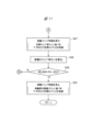
図4はスリップ解消制御の実行手順の一例を示すフローチャートである。図4に示すように、ステップS10では、前輪20と後輪30との双方にスリップが生じているか否かについて判定される。ステップS10において、前輪20と後輪30との双方がスリップしている場合、つまり前輪速度Vftと後輪速度Vrrとの双方が車速Vvから乖離する場合には、ステップS11に進み、後輪30のスリップを解消するスリップ解消制御が開始される。
FIG. 4 is a flowchart showing an example of an execution procedure of slip cancellation control. As shown in FIG. 4, in step S10, it is determined whether or not both the
ステップS11では、スリップ中の後輪30に連結されるモータジェネレータMG2のロータ31の角加速度ω'が検出され、続くステップS12では、スリップ中の後輪30に連結されるモータジェネレータMG2のロータ31の力行トルク(トルク)Tm2’が検出される。つまり、ステップS11では、メインコントローラ50の角加速度検出部70によって、モータジェネレータMG2の回転速度に基づき、ロータ31に発生する角加速度ω'が算出される。続くステップS12では、メインコントローラ50のトルク検出部71によって、ステータ41に供給される通電電流等に基づき、ロータ31に作用する力行トルクTm2’が算出される。
In step S11, the angular acceleration ω' of the
ここで、図5はモータジェネレータMG2の角加速度ω'と力行トルクTm2’との関係を示す線図である。図5に矢印A1で示すように、車両11が乾燥路面等の高μ路を走行する場合、つまり後輪30を空転させずに走行する場合には、特性線L1aに沿うように、力行トルクTm2’の増加に伴って角加速度ω'が緩やかに上昇する。また、矢印B1,C1,D1で示すように、車両11が凍結路面や圧雪路面等の低μ路を走行する場合、つまり力行トルクTm2’の大きさによって後輪30に空転が生じてしまう場合には、特性線L1b,L1c,L1dに沿うように、力行トルクTm2’が所定値を上回ると角加速度ω'が急速に上昇する。
Here, FIG. 5 is a diagram showing the relationship between angular acceleration ω' of motor generator MG2 and power running torque Tm2'. As shown by arrow A1 in FIG. 5, when the
つまり、低μ路のなかでも摩擦抵抗が小さい場合には、力行トルクTm2’が所定値T1を上回ると、後輪30が空転し始めて角加速度ω'が急速に上昇する。また、低μ路のなかでも摩擦抵抗が中程度である場合には、力行トルクTm2’が所定値T2を上回ると、後輪30が空転し始めて角加速度ω'が急速に上昇する。また、低μ路のなかでも摩擦抵抗が大きい場合には、力行トルクTm2’が所定値T3を上回ると、後輪30が空転し始めて角加速度ω'が急速に上昇する。なお、特性線L1b,L1c,L1dの傾きは、後輪30が空転することから路面の摩擦抵抗に影響され難く、ほぼ一定の傾きとなっている。また、図示する例では、3つの特性線L1b,L1c,L1dを示しているが、これに限られることはなく、路面の摩擦抵抗に応じて多数の特性線を示すことが可能である。
That is, when the frictional resistance is small even on a low μ road, when the power running torque Tm2' exceeds the predetermined value T1, the
図4のフローチャートに示すように、ステップS13では、角加速度ω'および力行トルクTm2’に基づき、後輪30のスリップ状態を示す特性線が推定され、続くステップS14では、特性線に基づき、モータジェネレータMG2の目標角加速度Tω'が設定される。以下、目標角加速度設定部72による目標角加速度Tω'の設定手順について説明する。ここで、図6は、図5と同様の線図であり、モータジェネレータMG2の角加速度ω'と力行トルクTm2’との関係を示す線図である。
As shown in the flowchart of FIG. 4, in step S13, a characteristic line indicating the slip state of the
図6に示すように、角加速度ω'が「A1a」であり、力行トルクTm2’が「T1a」であった場合には、特性線L1bに沿って後輪30が空転していると考えられる。このため、後輪30のスリップを解消するためには、特性線L1aに達するまで角加速度ω'を下げる必要がある。つまり、目標角加速度Tω'を「A1b」に設定し、矢印X1で示すように、力行トルクTm2’を下げることにより、後輪30のスリップを解消することができる。また、例えば、角加速度ω'が「A2a」であり、力行トルクTm2’が「T2a」であった場合には、破線で示した特性線L1eに沿って後輪30が空転していると考えられる。この場合には、目標角加速度Tω'を「A2b」に設定し、矢印X2で示すように、力行トルクTm2’を下げることにより、後輪30のスリップを解消することができる。
As shown in FIG. 6, when the angular acceleration ω' is "A1a" and the power running torque Tm2' is "T1a", it is considered that the
このように、後輪30のスリップを解消するための目標角加速度Tω'が設定されると、目標トルク設定部73は以下の手順に沿って目標トルクTm2を算出する。つまり、図4のフローチャートに示すように、ステップS15に進み、以下の式(3)に基づき、モータジェネレータMG2の目標トルクTm2が算出される。つまり、後輪回転系36のイナーシャIに目標角加速度Tω'を乗算することにより、後輪30のスリップを解消するための目標トルクTm2が算出される。すなわち、前述した図6において、角加速度ω'が「A1a」であり、かつ力行トルクTm2’が「T1a」であった場合には、目標トルクTm2として「T1b」が算出され、角加速度ω'が「A2a」であり、かつ力行トルクTm2’が「T2a」であった場合には、目標トルクTm2として「T2b」が算出される。なお、後輪回転系36のイナーシャIとは、ロータ31、第2動力伝達経路32および後輪30からなる回転系のイナーシャであり、実験やシミュレーション等によって予め設定されるイナーシャである。
Tm2=I×Tω' ・・・(3)
In this way, when the target angular acceleration Tω' for eliminating the slip of the
Tm2=I×Tω'...(3)
図4のフローチャートに示すように、ステップS15において、モータジェネレータMG2の目標トルクTm2が算出されると、ステップS16に進み、目標トルクTm2に基づきモータジェネレータMG2が制御される。これにより、モータジェネレータMG2の力行トルクTm2’を下げて後輪30の空転を解消することができるため、後輪速度Vrrを車速Vvに一致させることができ、後輪速度Vrrをそのまま車速Vvとして設定することができる。これにより、前後輪20,23にスリップが発生し得る状況や、登坂路や降坂路を走行する状況であっても、車速Vvを精度良く検出することができるため、後述する前輪スリップ制御および後輪スリップ制御を適切に実行することができる。
As shown in the flowchart of FIG. 4, in step S15, when target torque Tm2 of motor generator MG2 is calculated, the process proceeds to step S16, and motor generator MG2 is controlled based on target torque Tm2. As a result, it is possible to reduce the powering torque Tm2' of the motor generator MG2 and eliminate the slippage of the
[車速特定制御]
前述したように、スリップ解消制御が実行されるか否かに応じて、車速Vvの特定方法が相違している。以下、車速Vvを特定する車速特定制御について説明する。図7は車速特定制御の実行手順の一例を示すフローチャートである。
[Vehicle speed specific control]
As described above, the method for identifying vehicle speed Vv differs depending on whether slip elimination control is executed. Vehicle speed identification control for identifying vehicle speed Vv will be described below. FIG. 7 is a flowchart showing an example of an execution procedure of vehicle speed identification control.
図7に示すように、ステップS20では、スリップ解消制御が実行されているか否かが判定される。ステップS20において、スリップ解消制御が実行されていると判定された場合には、ステップS21に進み、後輪速度Vrrが車速Vvとして特定される。つまり、スリップ解消制御によって後輪30の空転が解消した状態であることから、後輪速度Vrrがそのまま車速Vvとして読み込まれている。すなわち、スリップ解消制御が実行された状態のもとで、メインコントローラ50の車速検出部74は車速Vvとして後輪速度Vrrを検出する。
As shown in FIG. 7, in step S20, it is determined whether slip cancellation control is being executed. If it is determined in step S20 that the slip elimination control is being executed, the process proceeds to step S21, where the rear wheel speed Vrr is specified as the vehicle speed Vv. In other words, since the slipping of the
ステップS20において、スリップ解消制御が実行されていないと判定された場合には、ステップS22に進み、前輪速度Vftが後輪速度Vrrを下回るか否かが判定される。ステップS22において、前輪速度Vftが後輪速度Vrrを下回ると判定された場合には、低速側の前輪速度Vftが車速Vvに一致することが想定されるため、ステップS23に進み、前輪速度Vftが車速Vvとして特定される。一方、ステップS22において、前輪速度Vftが後輪速度Vrr以上であると判定された場合には、低速側の後輪速度Vrrが車速Vvに一致することが想定されるため、ステップS21に進み、後輪速度Vrrが車速Vvとして特定される。 If it is determined in step S20 that the slip elimination control is not being executed, the process proceeds to step S22, where it is determined whether or not the front wheel speed Vft is lower than the rear wheel speed Vrr. If it is determined in step S22 that the front wheel speed Vft is lower than the rear wheel speed Vrr, it is assumed that the lower speed side front wheel speed Vft matches the vehicle speed Vv, so the process proceeds to step S23, and the front wheel speed Vft is lower than the rear wheel speed Vrr. It is specified as vehicle speed Vv. On the other hand, if it is determined in step S22 that the front wheel speed Vft is equal to or higher than the rear wheel speed Vrr, it is assumed that the low speed side rear wheel speed Vrr matches the vehicle speed Vv, so the process proceeds to step S21. Rear wheel speed Vrr is specified as vehicle speed Vv.
[前輪スリップ制御および後輪スリップ制御(タイミングチャート)]
続いて、スリップ解消制御を踏まえたスリップ制御の実行状況について詳細に説明する。図8は前輪スリップ制御および後輪スリップ制御の実行状況の一例を示すタイミングチャートである。なお、図8のタイミングチャートに示した例では、前後の駆動力分配比が50:50に設定されており、前輪要求駆動力Fftと後輪要求駆動力Frrとは互いに等しい値になっている。また、図8のタイミングチャートにおいては、トルク、駆動力および速度等の推移を明確にする観点から、線が互いに重なる場合であってもこれらの線を若干ずらして記載している。
[Front wheel slip control and rear wheel slip control (timing chart)]
Next, the execution status of slip control based on slip elimination control will be explained in detail. FIG. 8 is a timing chart showing an example of the execution status of front wheel slip control and rear wheel slip control. In the example shown in the timing chart of FIG. 8, the front and rear driving force distribution ratio is set to 50:50, and the front wheel required driving force Fft and the rear wheel required driving force Frr are equal to each other. . In addition, in the timing chart of FIG. 8, from the viewpoint of clarifying the transition of torque, driving force, speed, etc., even when the lines overlap each other, these lines are shown slightly shifted from each other.
また、図8において、前輪スリップ制御が「ON」である状況は、実行条件Faが成立して前輪スリップ制御が実行される状況であり、前輪スリップ制御が「OFF」である状況は、停止条件Fbが成立して前輪スリップ制御が停止される状況である。さらに、後輪スリップ制御が「ON」である状況は、実行条件Raが成立して後輪スリップ制御が実行される状況であり、後輪スリップ制御が「OFF」である状況は、停止条件Rbが成立して後輪スリップ制御が停止される状況である。 In addition, in FIG. 8, a situation where the front wheel slip control is "ON" is a situation where the execution condition Fa is satisfied and the front wheel slip control is executed, and a situation where the front wheel slip control is "OFF" is a situation where the front wheel slip control is "OFF". This is a situation where Fb is established and front wheel slip control is stopped. Furthermore, a situation in which the rear wheel slip control is "ON" is a situation in which the execution condition Ra is satisfied and the rear wheel slip control is executed, and a situation in which the rear wheel slip control is "OFF" is a situation in which the execution condition Ra is satisfied and the rear wheel slip control is executed. This is a situation in which the following holds true and rear wheel slip control is stopped.
図8に時刻t1で示すように、アクセルペダル60が踏み込まれてアクセル開度Accが増加すると(符号a1)、前輪要求駆動力Fftおよび後輪要求駆動力Frrが増加するとともに(符号b1)、モータジェネレータMG1,MG2の目標トルクTm1,Tm2が増加する(符号c1)。これにより、前輪20の実駆動力Fft’は前輪要求駆動力Fftに沿うように推移し、後輪30の実駆動力Frr’は後輪要求駆動力Frrに沿うように推移する(符号b1)。なお、図8に示した破線αは、アクセル操作に連動する要求駆動力Fft,Frrを得るために必要なモータトルクを示している。
As shown at time t1 in FIG. 8, when the
図8に時刻t2で示すように、車両11が凍結路面等の低μ路に進入すると、前輪20および後輪30が空転し始めることから、前輪速度Vftおよび後輪速度Vrrが車速Vvから離れて上昇し始める(符号d1)。続いて、時刻t3で示すように、前輪速度Vftおよび後輪速度Vrrが車速Vvから離れて更に上昇すると(符号d2)、スリップ率SLft,SLrrが所定の閾値SL1を上回ることから(符号e1)、前輪20の空転を抑制する前輪スリップ制御が実行され(符号f1)、後輪30の空転を抑制する後輪スリップ制御が実行される(符号g1)。このように、前輪スリップ制御および後輪スリップ制御が実行されると、モータジェネレータMG1,MG2の目標トルクTm1,Tm2が下げられ(符号c2)、前輪20および後輪30の実駆動力Fft’,Frr’が下げられる(符号b2)。
As shown at time t2 in FIG. 8, when the
ここで、前輪20を駆動するモータジェネレータMG1については、前輪スリップ制御が実行されることから、前輪20のスリップ率SLftが目標スリップ率Sx1(例えば10%)を維持するように(符号e2)、モータジェネレータMG1の目標トルクTm1が制御される(符号c3)。これに対し、後輪30を駆動するモータジェネレータMG2については、前輪20と後輪30との双方が空転する状況であることから、前述したスリップ解消制御が実行される。つまり、後輪30の空転を解消するための目標トルクTx1が設定され、この目標トルクTx1に向けて目標トルクTm2が下げられる(符号c4)。これにより、図8に時刻t4で示すように、後輪30の空転を解消することができ(符号e3)、後輪速度Vrrを車速Vvに一致させることができる(符号d3)。
Here, since front wheel slip control is executed for the motor generator MG1 that drives the
このように、スリップ解消制御によって後輪速度Vrrを車速Vvに一致させた場合には、メインコントローラ50によって後輪速度Vrrが車速Vvとして特定され、前輪スリップ制御を実行する際の車速Vvとして用いられる。これにより、精度良く検出された車速Vvを前輪スリップ制御に用いることができるため、前輪スリップ制御を適切に実行することができる。
In this way, when the rear wheel speed Vrr is made to match the vehicle speed Vv by the slip elimination control, the
また、スリップ解消制御によって後輪速度Vrrを車速Vvに一致させた後には、以下の式(4)に基づき、モータジェネレータMG2の目標トルクTm2が設定される。つまり、後輪30のグリップ状態が維持される目標トルクTm2を設定するため、モータジェネレータMG1の目標トルクTm1に対して所定係数k1(例えば0.9)を乗算することにより、モータジェネレータMG2の目標トルクTm2が算出される。なお、本実施形態においては、前輪20の目標スリップ率Sx1が「10%」であることから、後輪30のスリップ率SLrrを「0%」に向けて制御するため、所定係数k1として「0.9」が用いられている。
Tm2=Tm1×k1 ・・・(4)
Further, after the rear wheel speed Vrr is made to match the vehicle speed Vv by the slip elimination control, the target torque Tm2 of the motor generator MG2 is set based on the following equation (4). That is, in order to set the target torque Tm2 at which the grip state of the
Tm2=Tm1×k1...(4)
これにより、後輪30のスリップ率SLrrが「0%」を維持するように、後輪30を駆動するモータジェネレータMG2を制御することができるため、精度良く車速Vvを検出し続けることができる。このように、車速Vvを精度良く検出し続けることができるため、前輪スリップ制御を適切に実行することができ、車両11の走行安定性を高めることができる。
Thereby, the motor generator MG2 that drives the
[前輪スリップ制御(フローチャート)]
前述した前輪スリップ制御の実行手順をフローチャートに沿って説明する。図9は前輪スリップ制御の実行手順の一例を示すフローチャートである。
[Front wheel slip control (flow chart)]
The execution procedure of the front wheel slip control described above will be explained according to a flowchart. FIG. 9 is a flowchart showing an example of the procedure for executing front wheel slip control.
図9に示すように、ステップS30では、前輪20のスリップ率SLftが算出され、続くステップS31では、前輪20のスリップ率SLft等に基づき、前輪スリップ制御の実行条件Faが成立するか否かが判定される。ステップS31において、実行条件Faが成立すると判定された場合には、ステップS32に進み、前輪スリップ制御が実行される。ステップS32においては、前輪20のスリップ率SLftが目標スリップ率Sx1(例えば10%)を維持するように、モータジェネレータMG1の目標トルクTm1が制御される。
As shown in FIG. 9, in step S30, the slip rate SLft of the
続いて、ステップS33では、前輪20のスリップ率SLftが算出され、続くステップS34では、前輪20のスリップ率SLft等に基づき、前輪スリップ制御の停止条件Fbが成立するか否かが判定される。ステップS34において、停止条件Fbが成立すると判定された場合には、ステップS35に進み、前輪スリップ制御が停止される。このステップS35においては、前輪要求駆動力Fftに基づき、モータジェネレータMG1の目標トルクTm1が制御される。
Subsequently, in step S33, the slip rate SLft of the
[後輪スリップ制御(フローチャート)]
前述した後輪スリップ制御の実行手順をフローチャートに沿って説明する。図10および図11は後輪スリップ制御の実行手順の一例を示すフローチャートである。図10および図11のフローチャートにおいては、符号Aの箇所で互いに接続されており、符号Bの箇所で互いに接続されている。
[Rear wheel slip control (flow chart)]
The execution procedure of the rear wheel slip control described above will be explained according to a flowchart. FIGS. 10 and 11 are flowcharts showing an example of an execution procedure of rear wheel slip control. In the flowcharts of FIGS. 10 and 11, they are connected to each other at points A and connected to each other at points B.
図10に示すように、ステップS40では、後輪30のスリップ率SLrrが算出され、続くステップS41では、後輪30のスリップ率SLrr等に基づき、後輪スリップ制御の実行条件Raが成立するか否かが判定される。ステップS41において、実行条件Raが成立すると判定された場合には、ステップS42に進み、スリップ解消制御が実行されているか否かが判定される。ステップS42において、スリップ解消制御が実行されていると判定された場合、つまり後輪30のスリップ解消によって後輪速度Vrrが車速Vvとして特定される場合には、ステップS43に進み、モータジェネレータMG2の目標トルクTm2が設定される。ステップS43では、前述した式(4)を用いることにより、モータジェネレータMG1の目標トルクTm1に所定係数k1(例えば0.9)を乗算し、モータジェネレータMG2の目標トルクTm2が算出される。
As shown in FIG. 10, in step S40, the slip rate SLrr of the
続いて、ステップS44では、前輪20のスリップ率SLftが算出され、続くステップS45では、前輪20のスリップ率SLft等に基づき、前輪スリップ制御の停止条件Fbが成立するか否かが判定される。つまり、スリップ解消制御によって後輪30のスリップ率SLrrは「0%」になることから、前輪スリップ制御の停止条件Fbを用いて通常制御への復帰が判定されている。ステップS45において、停止条件Fbが成立すると判定された場合には、ステップS46に進み、後輪スリップ制御が停止される。このステップS46においては、後輪要求駆動力Frrに基づき、モータジェネレータMG2の目標トルクTm2が制御される。
Subsequently, in step S44, the slip rate SLft of the
一方、ステップS42において、スリップ解消制御が実行されていないと判定された場合には、ステップS47に進み、後輪スリップ制御が実行される。ステップS47においては、後輪30のスリップ率SLrrが目標スリップ率Sx1(例えば10%)を維持するように、モータジェネレータMG2の目標トルクTm2が制御される。次いで、ステップS48では、後輪30のスリップ率SLrrが算出され、続くステップS49では、後輪30のスリップ率SLrr等に基づき、後輪スリップ制御の停止条件Rbが成立するか否かが判定される。ステップS49において、停止条件Rbが成立すると判定された場合には、ステップS50に進み、後輪スリップ制御が停止される。このステップS50においては、後輪要求駆動力Frrに基づき、モータジェネレータMG2の目標トルクTm2が制御される。
On the other hand, if it is determined in step S42 that slip elimination control is not being executed, the process proceeds to step S47, where rear wheel slip control is executed. In step S47, target torque Tm2 of motor generator MG2 is controlled so that slip rate SLrr of
[他の実施形態]
前述の説明では、図4のフローチャートを用いて減速走行時のスリップ解消制御について説明したが、これに限られることはなく、減速走行時にスリップ解消制御を実行しても良い。つまり、後輪30がスリップする状態としては、モータジェネレータMG2の力行トルクによって後輪30が加速方向にスリップする状態だけでなく、モータジェネレータMG2の回生トルクによって後輪30が減速方向にスリップする状態がある。すなわち、後輪30がスリップする状態としては、アクセルペダル60の踏み込みによって車両走行中に後輪30が空転する状態だけでなく、アクセルペダル60の踏み込み解除によって車両走行中に後輪30がロックする状態がある。
[Other embodiments]
In the above description, the slip elimination control during deceleration traveling was explained using the flowchart of FIG. 4, but the slip elimination control may be executed during deceleration traveling without being limited to this. In other words, the state in which the
以下の説明では、車両減速時の各種制御であることから、モータトルクが力行側(+側)とは逆向きの回生側(-側)に現れる。このため、前述した目標トルクTm1,Tm2および力行トルクTm1’,Tm2’を、目標回生トルクTm1,Tm2および回生トルクTm1’,Tm2’として記載する。なお、目標回生トルクTm1,Tm2や回生トルクTm1’,Tm2’が大きいことは、目標トルクTm1,Tm2や力行トルクTm1’,Tm2’が負側に大きいことを意味している。 In the following explanation, since various controls are performed during vehicle deceleration, motor torque appears on the regeneration side (-side) opposite to the powering side (+ side). Therefore, the target torques Tm1, Tm2 and powering torques Tm1', Tm2' described above are described as target regenerative torques Tm1, Tm2 and regenerative torques Tm1', Tm2'. Note that the fact that the target regenerative torques Tm1, Tm2 and the regenerative torques Tm1', Tm2' are large means that the target torques Tm1, Tm2 and the power running torques Tm1', Tm2' are large on the negative side.
また、車両減速時の各種制御であることから、前述した前輪要求駆動力Fft、後輪要求駆動力Frrおよび実駆動力Fft’,Frr’は、駆動側(+側)とは逆向きの制動側(-側)に出力される。このため、前輪要求駆動力Fftを前輪要求駆動力Fftとして記載し、後輪要求駆動力Frrを後輪要求制動力Frrとして記載し、実駆動力Fft’,Frr’を実制動力Fft’,Frr’として記載する。なお、前輪要求制動力Fft、後輪要求制動力Frrおよび実制動力Fft’,Frr’が大きいことは、前輪要求駆動力Fft、後輪要求駆動力Frrおよび実駆動力Fft’,Frr’が負側に大きいことを意味している。 In addition, since these are various controls during vehicle deceleration, the above-mentioned front wheel required driving force Fft, rear wheel required driving force Frr, and actual driving force Fft', Frr' are braking in the opposite direction to the drive side (+ side). Output to the negative side (- side). Therefore, the front wheel required driving force Fft is written as the front wheel required driving force Fft, the rear wheel required driving force Frr is written as the rear wheel required braking force Frr, and the actual driving forces Fft', Frr' are written as the actual braking force Fft', It is written as Frr'. Note that the fact that front wheel required braking force Fft, rear wheel required braking force Frr, and actual braking force Fft', Frr' are large means that front wheel required driving force Fft, rear wheel required driving force Frr, and actual driving force Fft', Frr' are large. This means that it is large on the negative side.
[減速走行時のスリップ制御(タイミングチャート)]
減速走行時のスリップ制御について説明する。図12は減速走行時における前輪スリップ制御および後輪スリップ制御の実行状況の一例を示すタイミングチャートである。図12のタイミングチャートには、前輪スリップ制御と後輪スリップ制御との双方がまとめて記載されている。また、図12においては、トルクや駆動力等の推移を明確にする観点から、線が互いに重なる場合であってもこれらの線を若干ずらして記載している。なお、前輪20のスリップ率SLftとは、前述した式(1)を用いて算出される値であり、後輪30のスリップ率SLrrとは、前述の式(2)を用いて算出される値である。すなわち、前輪20や後輪30がロックせずに前輪速度Vftや後輪速度Vrrが車速Vvに一致する場合には、スリップ率SLft,SLrrが0%として算出される。一方、減速走行時に前輪20や後輪30がロックすることにより、前輪速度Vftや後輪速度Vrrが車速Vvを下回る場合には、スリップ率SLft,SLrrが0%よりも負側(-側)に算出される。
[Slip control during deceleration driving (timing chart)]
Slip control during deceleration traveling will be explained. FIG. 12 is a timing chart showing an example of the execution status of front wheel slip control and rear wheel slip control during deceleration driving. In the timing chart of FIG. 12, both front wheel slip control and rear wheel slip control are described together. In addition, in FIG. 12, from the viewpoint of clarifying the transition of torque, driving force, etc., even when the lines overlap each other, these lines are shown shifted slightly. Note that the slip ratio SLft of the
減速走行時の前輪スリップ制御や後輪スリップ制御とは、凍結路面等の低μ路で前輪20や後輪30がロックした場合に、モータジェネレータMG1,MG2のモータトルクを調整し、前輪20や後輪30を所定のスリップ率Sx2(例えば-10%)に保持する制御である。このスリップ制御を実行することにより、前輪20や後輪30の過度なロックを回避することができるため、凍結路面等での走行安定性を高めることができる。このスリップ制御の実行条件として、例えば、スリップ率SLft,SLrrの絶対値が所定の閾値SL3を上回ることが挙げられる。つまり、スリップ制御の実行条件が成立するか否かについては、前輪20や後輪30のスリップ率SLft,SLrrに基づき判定される。また、スリップ制御の停止条件として、例えば、スリップ率SLft,SLrrの絶対値が所定の閾値SL4を下回ることが挙げられる。
Front wheel slip control and rear wheel slip control during deceleration driving mean that when the
図12に時刻t1で示すように、アクセルペダル60の踏み込み解除によってアクセル開度Accが減少すると、前輪要求制動力Fftおよび後輪要求制動力Frrが増加するとともに、モータジェネレータMG1,MG2の目標回生トルクTm1,Tm2が増加する。そして、目標回生トルクTm1,Tm2に追従するように、モータジェネレータMG1,MG2の回生トルクTm1’,Tm2’が増加し、前輪20や後輪30の実制動力Fft’,Frr’が増加する。
As shown at time t1 in FIG. 12, when the accelerator opening degree Acc decreases due to release of the
続いて、時刻t2に示すように、前輪20や後輪30の実制動力Fft’,Frr’が増加して路面反力を超えると、前輪20や後輪30がロックすることからスリップ率SLft,SLrrの絶対値が増加し始める。そして、時刻t3に示すように、スリップ率SLft,SLrrの絶対値が閾値SL3を上回ると、前輪20や後輪30のロックを抑制するため、目標回生トルクTm1,Tm2を低下させる前輪スリップ制御および後輪スリップ制御が実行される。
Subsequently, as shown at time t2, when the actual braking force Fft', Frr' of the
前輪スリップ制御および後輪スリップ制御においては、前輪20や後輪30のスリップ率SLft,SLrrが、所定のスリップ率である目標スリップ率Sx2(例えば-10%)を維持するように、モータジェネレータMG1,MG2の目標回生トルクTm1,Tm2が制御される。つまり、スリップ率SLft,SLrrが目標スリップ率Sx2を上回る場合には、目標回生トルクTm1,Tm2が下げて設定される一方、スリップ率SLft,SLrrが目標スリップ率Sx2を下回る場合には、目標回生トルクTm1,Tm2が上げて設定される。これにより、前輪20や後輪30がロックする状況であっても、スリップ率SLft,SLrrを目標スリップ率Sx2に保持することができ、車両11の走行安定性を高めることができる。
In the front wheel slip control and the rear wheel slip control, the motor generator MG1 is controlled so that the slip rates SLft and SLrr of the
すなわち、アクセルペダル60の踏み込み解除によって前輪要求制動力Fftや後輪要求制動力Frrが大きく設定され、破線Txで示すように、目標回生トルクTm1,Tm2が大きく設定され得る状況であっても、矢印αで示すように、目標回生トルクTm1,Tm2が下げて設定される。これにより、矢印βで示すように、前輪20や後輪30の実制動力Fft’,Frr’を下げることができるため、前輪20や後輪30の過度なロックを回避することができ、低μ路における車両11の走行安定性を高めることができる。
That is, even in a situation where the front wheel required braking force Fft and the rear wheel required braking force Frr are set large by releasing the
[減速走行時のスリップ解消制御(フローチャート)]
図13はスリップ解消制御の実行手順の一例を示すフローチャートである。図13に示すように、ステップS60では、前輪20と後輪30との双方にスリップが生じているか否かについて判定される。ステップS60において、前輪20と後輪30との双方がスリップしている場合、つまり前輪速度Vftと後輪速度Vrrとの双方が車速Vvから乖離する場合には、ステップS61に進み、後輪30のスリップを解消するスリップ解消制御が開始される。
[Slip elimination control during deceleration driving (flow chart)]
FIG. 13 is a flowchart illustrating an example of an execution procedure of slip cancellation control. As shown in FIG. 13, in step S60, it is determined whether or not both the
ステップS61では、スリップ中の後輪30に連結されるモータジェネレータMG2のロータ31の角加速度ω'が検出され、続くステップS62では、スリップ中の後輪30に連結されるモータジェネレータMG2のロータ31の回生トルク(トルク)Tm2’が検出される。つまり、ステップS61では、メインコントローラ50の角加速度検出部70によって、モータジェネレータMG2の回転速度に基づき、ロータに発生する角加速度ω'が算出される。続くステップS62では、メインコントローラ50のトルク検出部71によって、ステータに供給される通電電流等に基づき、ロータに作用する回生トルクTm2’が算出される。
In step S61, the angular acceleration ω' of the
ここで、図14はモータジェネレータMG2の角加速度ω'と回生トルクTm2’との関係を示す線図である。図14に矢印A2で示すように、車両11が乾燥路面等の高μ路を走行する場合、つまり後輪30をロックさせずに走行する場合には、特性線L2aに沿うように、回生トルクTm2’の増加に伴って角加速度ω'が緩やかに上昇する。また、矢印B2,C2,D2で示すように、車両11が凍結路面や圧雪路面等の低μ路を走行する場合、つまり回生トルクTm2’の大きさによって後輪30にロックが生じてしまう場合には、特性線L2b,L2c,L2dに沿うように、回生トルクTm2’が所定値を上回ると角加速度ω'が急速に上昇する。
Here, FIG. 14 is a diagram showing the relationship between angular acceleration ω' of motor generator MG2 and regenerative torque Tm2'. As shown by arrow A2 in FIG. 14, when the
つまり、低μ路のなかでも摩擦抵抗が小さい場合には、回生トルクTm2’が所定値T4を上回ると、後輪30がロックし始めて角加速度ω'が急速に上昇する。また、低μ路のなかでも摩擦抵抗が中程度である場合には、回生トルクTm2’が所定値T5を上回ると、後輪30がロックし始めて角加速度ω'が急速に上昇する。また、低μ路のなかでも摩擦抵抗が大きい場合には、回生トルクTm2’が所定値T6を上回ると、後輪30がロックし始めて角加速度ω'が急速に上昇する。なお、特性線L2b,L2c,L2dの傾きは、後輪30がロックすることから路面の摩擦抵抗に影響され難く、ほぼ一定の傾きとなっている。また、図示する例では、3つの特性線L2b,L2c,L2dを示しているが、これに限られることはなく、路面の摩擦抵抗に応じて多数の特性線を示すことが可能である。
That is, when the frictional resistance is small even on a low μ road, when the regenerative torque Tm2' exceeds the predetermined value T4, the
図13のフローチャートに示すように、ステップS63では、角加速度ω'および回生トルクTm2’に基づき、後輪30のスリップ状態を示す特性線が推定され、続くステップS64では、特性線に基づき、モータジェネレータMG2の目標角加速度Tω'が設定される。以下、目標角加速度設定部72による目標角加速度Tω'の設定手順について説明する。ここで、図15は、図14と同様の線図であり、モータジェネレータMG2の角加速度ω'と回生トルクTm2’との関係を示す線図である。
As shown in the flowchart of FIG. 13, in step S63, a characteristic line indicating the slip state of the
図15に示すように、角加速度ω'が「A3a」であり、回生トルクTm2’が「T3a」であった場合には、特性線L2bに沿って後輪30がロックしていると考えられる。このため、後輪30のスリップを解消するためには、特性線L2aに達するまで負側の角加速度ω'を下げる必要がある。つまり、目標角加速度Tω'を「A3b」に設定し、矢印X1で示すように、回生トルクTm2’を下げることにより、後輪30のスリップを解消することができる。また、例えば、角加速度ω'が「A4a」であり、回生トルクTm2’が「T4a」であった場合には、破線で示した特性線L2eに沿って後輪30がロックしていると考えられる。この場合には、目標角加速度Tω'を「A2b」に設定し、矢印X2で示すように、回生トルクTm2’を下げることにより、後輪30のスリップを解消することができる。
As shown in FIG. 15, when the angular acceleration ω' is "A3a" and the regenerative torque Tm2' is "T3a", it is considered that the
このように、後輪30のスリップを解消するための目標角加速度Tω'が設定されると、目標トルク設定部73は以下の手順に沿って目標回生トルク(目標トルク)Tm2を算出する。つまり、図13のフローチャートに示すように、ステップS65に進み、前述の式(3)に基づき、モータジェネレータMG2の目標回生トルクTm2が算出される。つまり、後輪回転系36のイナーシャIに目標角加速度Tω'を乗算することにより、後輪30のスリップを解消するための目標回生トルクTm2が算出される。すなわち、前述した図15において、角加速度ω'が「A3a」であり、かつ回生トルクTm2’が「T3a」であった場合には、目標回生トルクTm2として「T3b」が算出され、角加速度ω'が「A4a」であり、かつ回生トルクTm2’が「T4a」であった場合には、目標回生トルクTm2として「T4b」が算出される。
In this way, when the target angular acceleration Tω' for eliminating the slip of the
図13のフローチャートに示すように、ステップS65において、モータジェネレータMG2の目標回生トルクTm2が算出されると、ステップS66に進み、目標回生トルクTm2に基づきモータジェネレータMG2が制御される。これにより、モータジェネレータMG2の回生トルクTm2’を下げて後輪30のロックを解消することができるため、後輪速度Vrrを車速Vvに一致させることができ、後輪速度Vrrをそのまま車速Vvとして設定することができる。これにより、車速Vvを精度良く検出することができるため、後述する前輪スリップ制御および後輪スリップ制御を適切に実行することができる。
As shown in the flowchart of FIG. 13, in step S65, when target regenerative torque Tm2 of motor generator MG2 is calculated, the process proceeds to step S66, and motor generator MG2 is controlled based on target regenerative torque Tm2. As a result, it is possible to reduce the regenerative torque Tm2' of the motor generator MG2 and release the lock of the
[減速走行時の前輪スリップ制御および後輪スリップ制御(タイミングチャート)]
続いて、スリップ解消制御を踏まえたスリップ制御の実行状況について詳細に説明する。図16は前輪スリップ制御および後輪スリップ制御の実行状況の一例を示すタイミングチャートである。なお、図16のタイミングチャートに示した例では、前後の制動力分配比が50:50に設定されており、前輪要求制動力Fftと後輪要求制動力Frrとは互いに等しい値になっている。また、図16のタイミングチャートにおいては、トルク、制動力および速度等の推移を明確にする観点から、線が互いに重なる場合であってもこれらの線を若干ずらして記載している。
[Front wheel slip control and rear wheel slip control during deceleration driving (timing chart)]
Next, the execution status of slip control based on slip elimination control will be explained in detail. FIG. 16 is a timing chart showing an example of the execution status of front wheel slip control and rear wheel slip control. In the example shown in the timing chart of FIG. 16, the front and rear braking force distribution ratio is set to 50:50, and the front wheel required braking force Fft and the rear wheel required braking force Frr are equal to each other. . Further, in the timing chart of FIG. 16, from the viewpoint of clarifying the transition of torque, braking force, speed, etc., even when the lines overlap each other, these lines are shown slightly shifted from each other.
図16に時刻t1で示すように、アクセルペダル60の踏み込みが解除されてアクセル開度Accが減少すると(符号a1)、前輪要求制動力Fftおよび後輪要求制動力Frrが増加するとともに(符号b1)、モータジェネレータMG1,MG2の目標回生トルクTm1,Tm2が増加する(符号c1)。これにより、前輪20の実制動力Fft’は前輪要求制動力Fftに沿うように推移し、後輪30の実制動力Frr’は後輪要求制動力Frrに沿うように推移する(符号b1)。なお、図16に示した破線αは、アクセル操作に連動する要求制動力Fft,Frrを得るために必要なモータトルクを示している。
As shown at time t1 in FIG. 16, when the
図16に時刻t2で示すように、車両11が凍結路面等の低μ路に進入すると、前輪20および後輪30がロックし始めることから、前輪速度Vftおよび後輪速度Vrrが車速Vvから離れて低下し始める(符号d1)。続いて、時刻t3で示すように、前輪速度Vftおよび後輪速度Vrrが車速Vvから離れて更に低下すると(符号d2)、スリップ率SLft,SLrrの絶対値が所定の閾値SL3を上回ることから(符号e1)、前輪20のロックを抑制する前輪スリップ制御が実行され(符号f1)、後輪30のロックを抑制する後輪スリップ制御が実行される(符号g1)。このように、前輪スリップ制御および後輪スリップ制御が実行されると、モータジェネレータMG1,MG2の目標回生トルクTm1,Tm2が下げられ(符号c2)、前輪20および後輪30の実制動力Fft’,Frr’が下げられる(符号b2)。
As shown at time t2 in FIG. 16, when the
ここで、前輪20を駆動するモータジェネレータMG1については、前輪スリップ制御が実行されることから、前輪20のスリップ率SLftが目標スリップ率Sx2(例えば-10%)を維持するように(符号e2)、モータジェネレータMG1の目標回生トルクTm1が制御される(符号c3)。これに対し、後輪30を駆動するモータジェネレータMG2については、前輪20と後輪30との双方がロックする状況であることから、前述したスリップ解消制御が実行される。つまり、後輪30のロックを解消するための目標回生トルクTx2が設定され、この目標回生トルクTx2に向けて目標回生トルクTm2が下げられる(符号c4)。これにより、図16に時刻t4で示すように、後輪30のロックを解消することができ(符号e3)、後輪速度Vrrを車速Vvに一致させることができる(符号d3)。
Here, since front wheel slip control is executed for the motor generator MG1 that drives the
このように、スリップ解消制御によって後輪速度Vrrを車速Vvに一致させた場合には、メインコントローラ50によって後輪速度Vrrが車速Vvとして特定され、前輪スリップ制御を実行する際の車速Vvとして用いられる。これにより、精度良く検出された車速Vvを前輪スリップ制御に用いることができるため、前輪スリップ制御を適切に実行することができる。
In this way, when the rear wheel speed Vrr is made to match the vehicle speed Vv by the slip elimination control, the
また、スリップ解消制御によって後輪速度Vrrを車速Vvに一致させた後には、前述の式(4)に基づき、モータジェネレータMG2の目標回生トルクTm2が設定される。つまり、後輪30のグリップ状態が維持される目標回生トルクTm2を設定するため、モータジェネレータMG1の目標回生トルクTm1に対して所定係数k1(例えば0.9)を乗算することにより、モータジェネレータMG2の目標回生トルクTm2が算出される。なお、本実施形態においては、前輪20の目標スリップ率Sx2が「-10%」であることから、後輪30のスリップ率SLrrを「0%」に向けて制御するため、所定係数k1として「0.9」が用いられている。
Further, after the rear wheel speed Vrr is made to match the vehicle speed Vv by the slip elimination control, the target regenerative torque Tm2 of the motor generator MG2 is set based on the above-mentioned equation (4). That is, in order to set the target regenerative torque Tm2 at which the grip state of the
これにより、後輪30のスリップ率SLrrが「0%」を維持するように、後輪30を駆動するモータジェネレータMG2を制御することができるため、精度良く車速Vvを検出し続けることができる。このように、車速Vvを精度良く検出し続けることができるため、前輪スリップ制御を適切に実行することができ、車両11の走行安定性を高めることができる。
Thereby, the motor generator MG2 that drives the
本発明は前記実施の形態に限定されるものではなく、その要旨を逸脱しない範囲で種々変更可能であることはいうまでもない。前述の説明では、車両用制御装置10が適用される車両11として、エンジンを備えていない電気自動車を例示しているが、これに限られることはなく、動力源としてエンジンを備えたハイブリッド車両であっても良く、動力源としてエンジンのみを備えた車両であっても良い。また、前述の説明では、前輪スリップ制御、後輪スリップ制御およびスリップ解消制御を実行しているが、これに限られることはなく、前輪スリップ制御や後輪スリップ制御を実行せずにスリップ解消制御を実行しても良い。つまり、スリップ制御を実行せずにスリップ解消制御を実行した場合であっても、車速Vvを精度良く検出することが可能である。また、車両用制御装置10が適用される車両としては、前述した全輪駆動車両に限られることはなく、前輪駆動車両や後輪駆動車両であっても良い。
It goes without saying that the present invention is not limited to the embodiments described above, and can be modified in various ways without departing from the spirit thereof. In the above description, an electric vehicle without an engine is exemplified as the
前述の説明では、前後一方の第1駆動輪を前輪20とし、前後他方の第2駆動輪を後輪30とすることにより、スリップ解除制御においては、モータジェネレータMG2を制御して後輪30のスリップを解消させているが、これに限られることはない。つまり、前輪20に対してスリップ解除制御を実行することにより、モータジェネレータMG1を制御して前輪20のスリップを解消させても良い。これにより、前輪速度Vftを車速Vvに一致させることができ、前輪速度Vftをそのまま車速Vvとして用いることができる。この場合には、前輪20がスリップした状態のもとで、ロータ21の角加速度ω'およびトルクTm1’が検出され、これら角加速度ω'およびトルクTm1’に基づき前輪20のスリップを解消する目標角加速度Tω'が設定される。そして、前輪回転系26のイナーシャIに目標角加速度Tω'を乗じて目標トルクTm1が算出され、この目標トルクTm1に基づきモータジェネレータMG1が制御される。このように、前輪20に対してスリップ解除制御を実行する場合には、後輪30が第1駆動輪として機能し、モータジェネレータMG2が第1モータとして機能し、前輪20が駆動輪や第2駆動輪として機能し、モータジェネレータMG1が動力源、モータあるいは第2モータとして機能する。
In the above description, the first drive wheel on one of the front and rear wheels is the
また、モータジェネレータMG2のロータ31に発生する角加速度を算出する際には、ロータ回転センサ67によって検出されるロータ31の回転速度を用いて算出することが可能であるが、これに限られることはなく、例えば、後輪回転系36の回転速度である後輪速度Vrrを用いてロータ31に発生する角加速度を算出しても良い。同様に、モータジェネレータMG1のロータ21に発生する角加速度を算出する際には、ロータ回転センサ66によって検出されるロータ21の回転速度を用いて算出することが可能であるが、これに限られることはなく、例えば、前輪回転系26の回転速度である前輪速度Vftを用いてロータ21に発生する角加速度を算出しても良い。
Further, when calculating the angular acceleration generated in the
図示する車両11は、1つのモータジェネレータMG1によって2つの前輪20を駆動し、1つのモータジェネレータMG2によって2つの後輪30を駆動しているが、これに限られることはない。例えば、4つのモータジェネレータを搭載することにより、1つのモータジェネレータによって1つの車輪を駆動しても良い。また、前述の説明では、メインコントローラ50を、前輪スリップ判定部55、前輪スリップ制御部56、後輪スリップ判定部57、後輪スリップ制御部58、角加速度検出部70、トルク検出部71、目標角加速度設定部72、目標トルク設定部73および車速検出部74として機能させているが、これに限られることはない。例えば、他のコントローラや複数のコントローラを用いて、前輪スリップ判定部55、前輪スリップ制御部56、後輪スリップ判定部57、後輪スリップ制御部58、角加速度検出部70、トルク検出部71、目標角加速度設定部72、目標トルク設定部73および車速検出部74を構成しても良い。
Although the illustrated
前述の説明では、スリップ率SLft,SLrrに基づきスリップ制御を実行しているが、これに限られることはない。例えば、前輪20のスリップ状態を示す数値として、車速Vvと前輪速度Vftとの回転速度差を用いても良く、後輪30のスリップ状態を示す数値として、車速Vvと後輪速度Vrrとの回転速度差を用いても良い。また、前述の説明では、前輪スリップ制御と後輪スリップ制御との双方において、スリップ率SLft,SLrrを共通の目標スリップ率Sx1,Sx2に制御しているが、これに限られることはなく、前輪スリップ制御で用いる目標スリップ率と後輪スリップ制御で用いる目標スリップ率とを互いに相違させても良い。
In the above description, slip control is executed based on the slip rates SLft and SLrr, but the slip control is not limited to this. For example, the rotational speed difference between the vehicle speed Vv and the front wheel speed Vft may be used as a numerical value indicating the slip state of the
前述の説明では、スリップ制御の実行条件として、スリップ率SLft,SLrrの絶対値が所定の閾値SL1,SL3を上回ることを例示し、スリップ制御の停止条件として、スリップ率SLft,SLrrの絶対値が所定の閾値SL2,SL4を下回ることを例示しているが、これに限られることはない。例えば、加速走行時におけるスリップ制御の実行条件として、アクセル開度Accが所定の閾値を上回り、かつスリップ率SLft,SLrrが所定の閾値SL1を上回ることを採用しても良い。また、加速走行時におけるスリップ制御の停止条件として、アクセル開度Accが所定の閾値を下回ることや、スリップ率SLft,SLrrが所定の閾値SL2を下回ることを採用しても良い。また、スリップ解除制御が行われていない場合には、車両11加速度等から車速Vvを算出しても良く、GPS(Global Positioning System)の位置信号から車速Vvを算出しても良い。
In the above description, the execution condition for slip control is that the absolute values of the slip rates SLft and SLrr exceed the predetermined thresholds SL1 and SL3, and the condition for stopping the slip control is that the absolute values of the slip rates SLft and SLrr are Although being below the predetermined thresholds SL2 and SL4 is illustrated, the present invention is not limited to this. For example, the conditions for executing slip control during acceleration traveling may be that the accelerator opening degree Acc exceeds a predetermined threshold value and that the slip ratios SLft and SLrr exceed a predetermined threshold value SL1. In addition, as a condition for stopping the slip control during accelerated driving, it is also possible to adopt that the accelerator opening degree Acc is less than a predetermined threshold value, or that the slip ratios SLft and SLrr are less than a predetermined threshold value SL2. Further, when the slip release control is not performed, the vehicle speed Vv may be calculated from the acceleration of the
10 車両用制御装置
11 車両
20 前輪(第1駆動輪)
21 ロータ(第1ロータ)
22 第1動力伝達経路
30 後輪(駆動輪,第2駆動輪)
31 ロータ(回転体,第2ロータ)
32 第2動力伝達経路
36 後輪回転系(回転系)
55 前輪スリップ判定部(スリップ判定部)
56 前輪スリップ制御部(スリップ制御部)
70 角加速度検出部
71 トルク検出部
72 目標角加速度設定部
73 目標トルク設定部
74 車速検出部
MG1 モータジェネレータ(第1モータ)
MG2 モータジェネレータ(動力源,モータ,第2モータ)
Vv 車速(車両の移動速度)
Vrr 後輪速度(駆動輪の回転速度)
Tm2 目標トルク,目標回生トルク(目標トルク)
Tm2’ 力行トルク,回生トルク(トルク)
ω’ 角加速度
Tω’ 目標角加速度
I イナーシャ
Fa 実行条件
10
21 Rotor (first rotor)
22 First
31 Rotor (rotating body, second rotor)
32 Second
55 Front wheel slip determination section (slip determination section)
56 Front wheel slip control section (slip control section)
70 Angular
MG2 motor generator (power source, motor, second motor)
Vv Vehicle speed (vehicle movement speed)
Vrr Rear wheel speed (rotational speed of drive wheels)
Tm2 Target torque, target regeneration torque (target torque)
Tm2' Powering torque, regenerative torque (torque)
ω' Angular acceleration Tω' Target angular acceleration I Inertia Fa Execution conditions
Claims (7)
駆動輪に動力伝達経路を介して連結される回転体を備えた動力源と、
前記駆動輪がスリップした状態のもとで、前記回転体に発生する角加速度を検出する角加速度検出部と、
前記駆動輪がスリップした状態のもとで、前記回転体に作用するトルクを検出するトルク検出部と、
前記角加速度および前記トルクに基づいて、前記駆動輪のスリップが解消される前記回転体の目標角加速度を設定する目標角加速度設定部と、
前記駆動輪、前記動力伝達経路および前記回転体からなる回転系のイナーシャに前記目標角加速度を乗算し、前記回転体の目標トルクを設定する目標トルク設定部と、
前記目標トルクに基づき前記動力源を制御した状態のもとで、車両の移動速度として前記駆動輪の回転速度を検出する車速検出部と、
を有する、車両用制御装置。 A vehicle control device installed in a vehicle,
a power source including a rotating body connected to a drive wheel via a power transmission path;
an angular acceleration detection unit that detects angular acceleration generated in the rotating body when the drive wheel is in a slip state;
a torque detection unit that detects torque acting on the rotating body when the drive wheel is in a slip state;
a target angular acceleration setting unit that sets a target angular acceleration of the rotating body at which slip of the driving wheels is eliminated based on the angular acceleration and the torque;
a target torque setting unit that multiplies the inertia of a rotating system including the drive wheels, the power transmission path, and the rotating body by the target angular acceleration to set a target torque of the rotating body;
a vehicle speed detection unit that detects a rotational speed of the driving wheels as a moving speed of the vehicle under a state in which the power source is controlled based on the target torque;
A vehicle control device having:
前記動力源は、モータである、
車両用制御装置。 The vehicle control device according to claim 1,
the power source is a motor;
Vehicle control device.
前記駆動輪がスリップする状態とは、前記モータの力行トルクによって前記駆動輪がスリップする状態、または前記モータの回生トルクによって前記駆動輪がスリップする状態である、
車両用制御装置。 The vehicle control device according to claim 2,
The state in which the drive wheel slips is a state in which the drive wheel slips due to the power running torque of the motor, or a state in which the drive wheel slips due to regenerative torque of the motor.
Vehicle control device.
前後一方の第1駆動輪に第1動力伝達経路を介して連結される第1ロータを備えた第1モータと、
前後他方の第2駆動輪に第2動力伝達経路を介して連結される第2ロータを備えた第2モータと、
前記第1駆動輪のスリップ状態に基づいて、スリップ制御の実行条件が成立するか否かを判定するスリップ判定部と、
前記スリップ制御の実行条件が成立した場合に前記第1モータを制御し、前記第1駆動輪を所定のスリップ率に保持するスリップ制御部と、
前記第2駆動輪がスリップした状態のもとで、前記第2ロータに発生する角加速度を検出する角加速度検出部と、
前記第2駆動輪がスリップした状態のもとで、前記第2ロータに作用するトルクを検出するトルク検出部と、
前記角加速度および前記トルクに基づいて、前記第2駆動輪のスリップが解消される前記第2ロータの目標角加速度を設定する目標角加速度設定部と、
前記第2駆動輪、前記第2動力伝達経路および前記第2ロータからなる回転系のイナーシャに前記目標角加速度を乗算し、前記第2ロータの目標トルクを設定する目標トルク設定部と、
前記目標トルクに基づき前記第2モータを制御した状態のもとで、車両の移動速度として前記第2駆動輪の回転速度を検出する車速検出部と、
を有し、
前記スリップ制御部は、前記第1駆動輪の回転速度と、車両の移動速度である前記第2駆動輪の回転速度とに基づいて、前記スリップ制御に使用する前記第1駆動輪のスリップ率を算出する、
車両用制御装置。 A vehicle control device installed in a vehicle,
a first motor including a first rotor connected to one of the front and rear first drive wheels via a first power transmission path;
a second motor including a second rotor connected to the other front and rear second drive wheels via a second power transmission path;
a slip determination unit that determines whether a slip control execution condition is satisfied based on the slip state of the first drive wheel;
a slip control unit that controls the first motor and maintains the first drive wheel at a predetermined slip ratio when a condition for executing the slip control is satisfied;
an angular acceleration detection unit that detects angular acceleration generated in the second rotor when the second drive wheel is in a slip state;
a torque detection unit that detects torque acting on the second rotor when the second drive wheel is in a slip state;
a target angular acceleration setting unit that sets a target angular acceleration of the second rotor at which slip of the second drive wheel is eliminated based on the angular acceleration and the torque;
a target torque setting unit that multiplies the inertia of a rotation system including the second drive wheel, the second power transmission path, and the second rotor by the target angular acceleration to set a target torque of the second rotor;
a vehicle speed detection unit that detects the rotational speed of the second drive wheel as the moving speed of the vehicle while the second motor is controlled based on the target torque;
has
The slip control section controls the slip rate of the first drive wheel used for the slip control based on the rotation speed of the first drive wheel and the rotation speed of the second drive wheel, which is the moving speed of the vehicle. calculate,
Vehicle control device.
前記第2駆動輪がスリップする状態とは、前記第2モータの力行トルクによって前記第2駆動輪がスリップする状態、または前記第2モータの回生トルクによって前記第2駆動輪がスリップする状態である、
車両用制御装置。 The vehicle control device according to claim 4,
The state in which the second drive wheel slips is a state in which the second drive wheel slips due to the power running torque of the second motor, or a state in which the second drive wheel slips due to regenerative torque of the second motor. ,
Vehicle control device.
前記第1駆動輪は前輪であり、前記第2駆動輪は後輪である、
車両用制御装置。 The vehicle control device according to claim 4 or 5,
The first driving wheel is a front wheel, and the second driving wheel is a rear wheel.
Vehicle control device.
前記第1駆動輪は後輪であり、前記第2駆動輪は前輪である、
車両用制御装置。 The vehicle control device according to claim 4 or 5,
The first driving wheel is a rear wheel, and the second driving wheel is a front wheel.
Vehicle control device.
Priority Applications (1)
| Application Number | Priority Date | Filing Date | Title |
|---|---|---|---|
| JP2020042225A JP7449128B2 (en) | 2020-03-11 | 2020-03-11 | Vehicle control device |
Applications Claiming Priority (1)
| Application Number | Priority Date | Filing Date | Title |
|---|---|---|---|
| JP2020042225A JP7449128B2 (en) | 2020-03-11 | 2020-03-11 | Vehicle control device |
Publications (2)
| Publication Number | Publication Date |
|---|---|
| JP2021145451A JP2021145451A (en) | 2021-09-24 |
| JP7449128B2 true JP7449128B2 (en) | 2024-03-13 |
Family
ID=77767405
Family Applications (1)
| Application Number | Title | Priority Date | Filing Date |
|---|---|---|---|
| JP2020042225A Active JP7449128B2 (en) | 2020-03-11 | 2020-03-11 | Vehicle control device |
Country Status (1)
| Country | Link |
|---|---|
| JP (1) | JP7449128B2 (en) |
Citations (7)
| Publication number | Priority date | Publication date | Assignee | Title |
|---|---|---|---|---|
| JP2002186107A (en) | 2000-12-18 | 2002-06-28 | Japan Science & Technology Corp | Electric vehicle control device |
| JP2004090695A (en) | 2002-08-29 | 2004-03-25 | Toyota Motor Corp | Road surface state change estimation device and automobile loaded with it |
| JP2006034012A (en) | 2004-07-16 | 2006-02-02 | Toyota Motor Corp | Method for operating slip ratio of wheel and method for controlling brake power of wheel |
| JP2006044536A (en) | 2004-08-06 | 2006-02-16 | Toyota Motor Corp | Hybrid vehicle and control method thereof |
| JP2007049825A (en) | 2005-08-10 | 2007-02-22 | Hitachi Ltd | Travel controller and electric travel control system for electric vehicle |
| JP2015023691A (en) | 2013-07-19 | 2015-02-02 | 富士重工業株式会社 | Drive control device of vehicle |
| WO2015079553A1 (en) | 2013-11-29 | 2015-06-04 | パイオニア株式会社 | Traction control device and traction control method |
-
2020
- 2020-03-11 JP JP2020042225A patent/JP7449128B2/en active Active
Patent Citations (7)
| Publication number | Priority date | Publication date | Assignee | Title |
|---|---|---|---|---|
| JP2002186107A (en) | 2000-12-18 | 2002-06-28 | Japan Science & Technology Corp | Electric vehicle control device |
| JP2004090695A (en) | 2002-08-29 | 2004-03-25 | Toyota Motor Corp | Road surface state change estimation device and automobile loaded with it |
| JP2006034012A (en) | 2004-07-16 | 2006-02-02 | Toyota Motor Corp | Method for operating slip ratio of wheel and method for controlling brake power of wheel |
| JP2006044536A (en) | 2004-08-06 | 2006-02-16 | Toyota Motor Corp | Hybrid vehicle and control method thereof |
| JP2007049825A (en) | 2005-08-10 | 2007-02-22 | Hitachi Ltd | Travel controller and electric travel control system for electric vehicle |
| JP2015023691A (en) | 2013-07-19 | 2015-02-02 | 富士重工業株式会社 | Drive control device of vehicle |
| WO2015079553A1 (en) | 2013-11-29 | 2015-06-04 | パイオニア株式会社 | Traction control device and traction control method |
Also Published As
| Publication number | Publication date |
|---|---|
| JP2021145451A (en) | 2021-09-24 |
Similar Documents
| Publication | Publication Date | Title |
|---|---|---|
| KR102417515B1 (en) | Brake control system and method for electric vehicle | |
| US7451847B2 (en) | Vehicle control method | |
| JP5302749B2 (en) | Electric vehicle control device | |
| JP6308941B2 (en) | Control system, vehicle, and vehicle control method | |
| US7072756B2 (en) | Vehicle driving force control apparatus | |
| US7828394B2 (en) | Vehicle and control method of vehicle slip-down velocity | |
| US8494702B2 (en) | Method and driveline stability control system for a vehicle | |
| JP2006217677A (en) | Regenerative brake controller of vehicle | |
| KR20210071132A (en) | Vehicle driving control method using friction coefficient estimating of road surface | |
| GB2550836A (en) | Controller and method | |
| JP2004096932A (en) | Controller of hybrid vehicle | |
| JP2003209905A (en) | Controller of hybrid vehicle | |
| US11590944B2 (en) | Braking control device | |
| JP2009143292A (en) | Motion controller for vehicle | |
| JP7449128B2 (en) | Vehicle control device | |
| JP2021100362A (en) | Vehicular control device | |
| KR20210018652A (en) | Wheel slip control method for vehicle | |
| JP4135700B2 (en) | Vehicle motor traction control device | |
| WO2021080011A1 (en) | Control device | |
| KR20200046275A (en) | regenerative braking control method of vehicle | |
| JP4325539B2 (en) | Vehicle motor traction control device | |
| CN116635281A (en) | Method for distributing a required torque for driving a vehicle having wheels | |
| JP5048692B2 (en) | Front and rear wheel drive vehicle | |
| JP4325538B2 (en) | Vehicle motor traction control device | |
| US8489265B2 (en) | Method and engine stability control system for a hybrid electric vehicle |
Legal Events
| Date | Code | Title | Description |
|---|---|---|---|
| A621 | Written request for application examination |
Free format text: JAPANESE INTERMEDIATE CODE: A621 Effective date: 20230206 |
|
| A977 | Report on retrieval |
Free format text: JAPANESE INTERMEDIATE CODE: A971007 Effective date: 20230816 |
|
| A131 | Notification of reasons for refusal |
Free format text: JAPANESE INTERMEDIATE CODE: A131 Effective date: 20230822 |
|
| TRDD | Decision of grant or rejection written | ||
| A01 | Written decision to grant a patent or to grant a registration (utility model) |
Free format text: JAPANESE INTERMEDIATE CODE: A01 Effective date: 20240206 |
|
| A61 | First payment of annual fees (during grant procedure) |
Free format text: JAPANESE INTERMEDIATE CODE: A61 Effective date: 20240301 |
|
| R150 | Certificate of patent or registration of utility model |
Ref document number: 7449128 Country of ref document: JP Free format text: JAPANESE INTERMEDIATE CODE: R150 |