JP7449093B2 - Subject identification system and method - Google Patents
Subject identification system and method Download PDFInfo
- Publication number
- JP7449093B2 JP7449093B2 JP2019570371A JP2019570371A JP7449093B2 JP 7449093 B2 JP7449093 B2 JP 7449093B2 JP 2019570371 A JP2019570371 A JP 2019570371A JP 2019570371 A JP2019570371 A JP 2019570371A JP 7449093 B2 JP7449093 B2 JP 7449093B2
- Authority
- JP
- Japan
- Prior art keywords
- subject
- patient
- detected
- images
- template
- Prior art date
- Legal status (The legal status is an assumption and is not a legal conclusion. Google has not performed a legal analysis and makes no representation as to the accuracy of the status listed.)
- Active
Links
- 238000000034 method Methods 0.000 title claims description 86
- 230000001815 facial effect Effects 0.000 claims description 68
- 239000013598 vector Substances 0.000 claims description 45
- 238000011524 similarity measure Methods 0.000 claims description 37
- 230000008569 process Effects 0.000 claims description 27
- 238000012545 processing Methods 0.000 claims description 21
- 238000013527 convolutional neural network Methods 0.000 claims description 17
- 238000013528 artificial neural network Methods 0.000 claims description 14
- 230000015654 memory Effects 0.000 claims description 14
- 238000004458 analytical method Methods 0.000 claims description 12
- 230000004044 response Effects 0.000 claims description 6
- 238000012544 monitoring process Methods 0.000 description 38
- 238000001514 detection method Methods 0.000 description 20
- 230000000875 corresponding effect Effects 0.000 description 16
- 230000006866 deterioration Effects 0.000 description 13
- 230000006870 function Effects 0.000 description 11
- 210000000887 face Anatomy 0.000 description 7
- 238000004891 communication Methods 0.000 description 6
- 230000036387 respiratory rate Effects 0.000 description 6
- 238000010801 machine learning Methods 0.000 description 5
- 239000000463 material Substances 0.000 description 5
- 230000036772 blood pressure Effects 0.000 description 4
- 230000036760 body temperature Effects 0.000 description 4
- 238000005516 engineering process Methods 0.000 description 4
- 230000008921 facial expression Effects 0.000 description 4
- 210000003128 head Anatomy 0.000 description 4
- 230000014759 maintenance of location Effects 0.000 description 4
- 238000005259 measurement Methods 0.000 description 4
- 208000024891 symptom Diseases 0.000 description 4
- 230000000007 visual effect Effects 0.000 description 4
- 230000036541 health Effects 0.000 description 3
- 230000007246 mechanism Effects 0.000 description 3
- 230000002093 peripheral effect Effects 0.000 description 3
- 230000009471 action Effects 0.000 description 2
- 230000001154 acute effect Effects 0.000 description 2
- 238000013459 approach Methods 0.000 description 2
- 230000008859 change Effects 0.000 description 2
- 230000003247 decreasing effect Effects 0.000 description 2
- 229940079593 drug Drugs 0.000 description 2
- 239000003814 drug Substances 0.000 description 2
- 230000003993 interaction Effects 0.000 description 2
- 238000007726 management method Methods 0.000 description 2
- 238000010606 normalization Methods 0.000 description 2
- 230000000474 nursing effect Effects 0.000 description 2
- 230000003287 optical effect Effects 0.000 description 2
- 238000003909 pattern recognition Methods 0.000 description 2
- 230000011218 segmentation Effects 0.000 description 2
- 230000035900 sweating Effects 0.000 description 2
- 241001522296 Erithacus rubecula Species 0.000 description 1
- WQZGKKKJIJFFOK-GASJEMHNSA-N Glucose Natural products OC[C@H]1OC(O)[C@H](O)[C@@H](O)[C@@H]1O WQZGKKKJIJFFOK-GASJEMHNSA-N 0.000 description 1
- 241000543540 Guillardia theta Species 0.000 description 1
- 206010020751 Hypersensitivity Diseases 0.000 description 1
- 230000003044 adaptive effect Effects 0.000 description 1
- 230000007815 allergy Effects 0.000 description 1
- 230000003466 anti-cipated effect Effects 0.000 description 1
- QVGXLLKOCUKJST-UHFFFAOYSA-N atomic oxygen Chemical compound [O] QVGXLLKOCUKJST-UHFFFAOYSA-N 0.000 description 1
- 230000008901 benefit Effects 0.000 description 1
- 239000008280 blood Substances 0.000 description 1
- 210000004369 blood Anatomy 0.000 description 1
- 238000012937 correction Methods 0.000 description 1
- 230000002596 correlated effect Effects 0.000 description 1
- 238000013135 deep learning Methods 0.000 description 1
- 230000002542 deteriorative effect Effects 0.000 description 1
- 238000002059 diagnostic imaging Methods 0.000 description 1
- 238000010586 diagram Methods 0.000 description 1
- 230000003467 diminishing effect Effects 0.000 description 1
- 238000003708 edge detection Methods 0.000 description 1
- 230000005713 exacerbation Effects 0.000 description 1
- 238000000605 extraction Methods 0.000 description 1
- 230000014509 gene expression Effects 0.000 description 1
- 230000002068 genetic effect Effects 0.000 description 1
- 239000008103 glucose Substances 0.000 description 1
- 230000006872 improvement Effects 0.000 description 1
- 239000004973 liquid crystal related substance Substances 0.000 description 1
- 238000007477 logistic regression Methods 0.000 description 1
- 238000002483 medication Methods 0.000 description 1
- 230000004048 modification Effects 0.000 description 1
- 238000012986 modification Methods 0.000 description 1
- 230000000877 morphologic effect Effects 0.000 description 1
- 230000006855 networking Effects 0.000 description 1
- 229910052760 oxygen Inorganic materials 0.000 description 1
- 239000001301 oxygen Substances 0.000 description 1
- 230000000737 periodic effect Effects 0.000 description 1
- 230000002085 persistent effect Effects 0.000 description 1
- 238000013186 photoplethysmography Methods 0.000 description 1
- 238000011176 pooling Methods 0.000 description 1
- 230000036544 posture Effects 0.000 description 1
- 238000007781 pre-processing Methods 0.000 description 1
- 238000012913 prioritisation Methods 0.000 description 1
- 230000000717 retained effect Effects 0.000 description 1
- 230000002441 reversible effect Effects 0.000 description 1
- 238000012502 risk assessment Methods 0.000 description 1
- 238000012360 testing method Methods 0.000 description 1
- 238000012549 training Methods 0.000 description 1
- 230000007704 transition Effects 0.000 description 1
- 230000001960 triggered effect Effects 0.000 description 1
- 238000012795 verification Methods 0.000 description 1
- 238000009528 vital sign measurement Methods 0.000 description 1
- 238000005406 washing Methods 0.000 description 1
Images


Classifications
-
- G—PHYSICS
- G08—SIGNALLING
- G08B—SIGNALLING OR CALLING SYSTEMS; ORDER TELEGRAPHS; ALARM SYSTEMS
- G08B21/00—Alarms responsive to a single specified undesired or abnormal condition and not otherwise provided for
- G08B21/02—Alarms for ensuring the safety of persons
- G08B21/04—Alarms for ensuring the safety of persons responsive to non-activity, e.g. of elderly persons
- G08B21/0407—Alarms for ensuring the safety of persons responsive to non-activity, e.g. of elderly persons based on behaviour analysis
- G08B21/043—Alarms for ensuring the safety of persons responsive to non-activity, e.g. of elderly persons based on behaviour analysis detecting an emergency event, e.g. a fall
-
- G—PHYSICS
- G06—COMPUTING; CALCULATING OR COUNTING
- G06F—ELECTRIC DIGITAL DATA PROCESSING
- G06F18/00—Pattern recognition
- G06F18/20—Analysing
- G06F18/22—Matching criteria, e.g. proximity measures
-
- G—PHYSICS
- G06—COMPUTING; CALCULATING OR COUNTING
- G06F—ELECTRIC DIGITAL DATA PROCESSING
- G06F18/00—Pattern recognition
- G06F18/20—Analysing
- G06F18/24—Classification techniques
- G06F18/241—Classification techniques relating to the classification model, e.g. parametric or non-parametric approaches
- G06F18/2413—Classification techniques relating to the classification model, e.g. parametric or non-parametric approaches based on distances to training or reference patterns
- G06F18/24147—Distances to closest patterns, e.g. nearest neighbour classification
-
- G—PHYSICS
- G06—COMPUTING; CALCULATING OR COUNTING
- G06N—COMPUTING ARRANGEMENTS BASED ON SPECIFIC COMPUTATIONAL MODELS
- G06N3/00—Computing arrangements based on biological models
- G06N3/02—Neural networks
- G06N3/08—Learning methods
-
- G—PHYSICS
- G06—COMPUTING; CALCULATING OR COUNTING
- G06V—IMAGE OR VIDEO RECOGNITION OR UNDERSTANDING
- G06V10/00—Arrangements for image or video recognition or understanding
- G06V10/40—Extraction of image or video features
- G06V10/44—Local feature extraction by analysis of parts of the pattern, e.g. by detecting edges, contours, loops, corners, strokes or intersections; Connectivity analysis, e.g. of connected components
- G06V10/443—Local feature extraction by analysis of parts of the pattern, e.g. by detecting edges, contours, loops, corners, strokes or intersections; Connectivity analysis, e.g. of connected components by matching or filtering
- G06V10/449—Biologically inspired filters, e.g. difference of Gaussians [DoG] or Gabor filters
- G06V10/451—Biologically inspired filters, e.g. difference of Gaussians [DoG] or Gabor filters with interaction between the filter responses, e.g. cortical complex cells
- G06V10/454—Integrating the filters into a hierarchical structure, e.g. convolutional neural networks [CNN]
-
- G—PHYSICS
- G06—COMPUTING; CALCULATING OR COUNTING
- G06V—IMAGE OR VIDEO RECOGNITION OR UNDERSTANDING
- G06V10/00—Arrangements for image or video recognition or understanding
- G06V10/70—Arrangements for image or video recognition or understanding using pattern recognition or machine learning
- G06V10/74—Image or video pattern matching; Proximity measures in feature spaces
- G06V10/761—Proximity, similarity or dissimilarity measures
-
- G—PHYSICS
- G06—COMPUTING; CALCULATING OR COUNTING
- G06V—IMAGE OR VIDEO RECOGNITION OR UNDERSTANDING
- G06V30/00—Character recognition; Recognising digital ink; Document-oriented image-based pattern recognition
- G06V30/10—Character recognition
- G06V30/19—Recognition using electronic means
- G06V30/191—Design or setup of recognition systems or techniques; Extraction of features in feature space; Clustering techniques; Blind source separation
- G06V30/19173—Classification techniques
-
- G—PHYSICS
- G06—COMPUTING; CALCULATING OR COUNTING
- G06V—IMAGE OR VIDEO RECOGNITION OR UNDERSTANDING
- G06V40/00—Recognition of biometric, human-related or animal-related patterns in image or video data
- G06V40/10—Human or animal bodies, e.g. vehicle occupants or pedestrians; Body parts, e.g. hands
- G06V40/16—Human faces, e.g. facial parts, sketches or expressions
- G06V40/168—Feature extraction; Face representation
-
- G—PHYSICS
- G06—COMPUTING; CALCULATING OR COUNTING
- G06V—IMAGE OR VIDEO RECOGNITION OR UNDERSTANDING
- G06V40/00—Recognition of biometric, human-related or animal-related patterns in image or video data
- G06V40/10—Human or animal bodies, e.g. vehicle occupants or pedestrians; Body parts, e.g. hands
- G06V40/16—Human faces, e.g. facial parts, sketches or expressions
- G06V40/172—Classification, e.g. identification
-
- G—PHYSICS
- G08—SIGNALLING
- G08B—SIGNALLING OR CALLING SYSTEMS; ORDER TELEGRAPHS; ALARM SYSTEMS
- G08B5/00—Visible signalling systems, e.g. personal calling systems, remote indication of seats occupied
- G08B5/22—Visible signalling systems, e.g. personal calling systems, remote indication of seats occupied using electric transmission; using electromagnetic transmission
- G08B5/36—Visible signalling systems, e.g. personal calling systems, remote indication of seats occupied using electric transmission; using electromagnetic transmission using visible light sources
-
- G—PHYSICS
- G16—INFORMATION AND COMMUNICATION TECHNOLOGY [ICT] SPECIALLY ADAPTED FOR SPECIFIC APPLICATION FIELDS
- G16H—HEALTHCARE INFORMATICS, i.e. INFORMATION AND COMMUNICATION TECHNOLOGY [ICT] SPECIALLY ADAPTED FOR THE HANDLING OR PROCESSING OF MEDICAL OR HEALTHCARE DATA
- G16H30/00—ICT specially adapted for the handling or processing of medical images
- G16H30/40—ICT specially adapted for the handling or processing of medical images for processing medical images, e.g. editing
-
- G—PHYSICS
- G16—INFORMATION AND COMMUNICATION TECHNOLOGY [ICT] SPECIALLY ADAPTED FOR SPECIFIC APPLICATION FIELDS
- G16H—HEALTHCARE INFORMATICS, i.e. INFORMATION AND COMMUNICATION TECHNOLOGY [ICT] SPECIALLY ADAPTED FOR THE HANDLING OR PROCESSING OF MEDICAL OR HEALTHCARE DATA
- G16H40/00—ICT specially adapted for the management or administration of healthcare resources or facilities; ICT specially adapted for the management or operation of medical equipment or devices
- G16H40/20—ICT specially adapted for the management or administration of healthcare resources or facilities; ICT specially adapted for the management or operation of medical equipment or devices for the management or administration of healthcare resources or facilities, e.g. managing hospital staff or surgery rooms
-
- G—PHYSICS
- G16—INFORMATION AND COMMUNICATION TECHNOLOGY [ICT] SPECIALLY ADAPTED FOR SPECIFIC APPLICATION FIELDS
- G16H—HEALTHCARE INFORMATICS, i.e. INFORMATION AND COMMUNICATION TECHNOLOGY [ICT] SPECIALLY ADAPTED FOR THE HANDLING OR PROCESSING OF MEDICAL OR HEALTHCARE DATA
- G16H40/00—ICT specially adapted for the management or administration of healthcare resources or facilities; ICT specially adapted for the management or operation of medical equipment or devices
- G16H40/60—ICT specially adapted for the management or administration of healthcare resources or facilities; ICT specially adapted for the management or operation of medical equipment or devices for the operation of medical equipment or devices
- G16H40/67—ICT specially adapted for the management or administration of healthcare resources or facilities; ICT specially adapted for the management or operation of medical equipment or devices for the operation of medical equipment or devices for remote operation
-
- G—PHYSICS
- G16—INFORMATION AND COMMUNICATION TECHNOLOGY [ICT] SPECIALLY ADAPTED FOR SPECIFIC APPLICATION FIELDS
- G16H—HEALTHCARE INFORMATICS, i.e. INFORMATION AND COMMUNICATION TECHNOLOGY [ICT] SPECIALLY ADAPTED FOR THE HANDLING OR PROCESSING OF MEDICAL OR HEALTHCARE DATA
- G16H50/00—ICT specially adapted for medical diagnosis, medical simulation or medical data mining; ICT specially adapted for detecting, monitoring or modelling epidemics or pandemics
- G16H50/70—ICT specially adapted for medical diagnosis, medical simulation or medical data mining; ICT specially adapted for detecting, monitoring or modelling epidemics or pandemics for mining of medical data, e.g. analysing previous cases of other patients
Description
[0001] 本開示は、専らではないが広くはデジタル画像(デジタル画像のストリームを含む)内で人を識別することに関する。更に詳細には、専らではないが、ここに開示される種々の方法及び装置は、病院の待合室等の領域において人を位置特定することができるようにデジタル画像(デジタル画像のストリームを含む)内で人を識別することに関する。 [0001] This disclosure relates generally, but not exclusively, to identifying people in digital images (including streams of digital images). More specifically, but not exclusively, the various methods and apparatus disclosed herein use digital images (including streams of digital images) to locate a person in an area such as a hospital waiting room. Concerning identifying people.
[0002] 人を含むシーンをキャプチャしたデジタル画像に基づいて人(被検者)を自動的に識別することが望ましいような多くのシナリオが存在する。例えば、患者が病院を訪れた場合、典型的に、該患者は登録され、トリアージされ、次いで、医師が該患者を検査及び/又は治療することができるようになること等の病院資源を待つために待合室等の領域に送られる。個々の患者を自動的に識別することができることは、医療資源の割り当てを待つ間に斯かる患者の状態を監視(例えば、悪化に関して)し続ける助けとなり得る。また、患者が診察を受けずに帰宅した(LWBS)か、を判断する助けともなり得る。デジタル画像に基づいて人を自動的に識別することは、空港、駅、入国、ジム及びフィットネスセンタ、種々のビジネス等の種々の他の前後関係においても有用であり得る。 [0002] There are many scenarios in which it is desirable to automatically identify a person (subject) based on a digital image captured of a scene containing the person. For example, when a patient visits a hospital, the patient is typically registered, triaged, and then waited for hospital resources such as for a physician to be able to test and/or treat the patient. is sent to an area such as a waiting room. The ability to automatically identify individual patients may assist in continuing to monitor the condition of such patients (eg, for deterioration) while awaiting allocation of medical resources. It can also help determine whether a patient has gone home without seeing a doctor (LWBS). Automatically identifying people based on digital images may also be useful in a variety of other contexts, such as airports, train stations, immigration, gyms and fitness centers, and various businesses.
[0003] 幾つかの前後関係においては、複数の被検者を含むデジタル画像内で個々の被検者を識別することが望ましいであろう。例えば、待合室のカメラによりキャプチャされるデジタル画像は、待機中の患者に加えて、該患者と共に待っている友人、親戚等の他の人も示すことがあり得る。顔検出技術は、斯かるデジタル画像内の全ての顔を検出することができるが、何の顔が患者に属し、何の顔が他のものに属するかは明らかとならないであろう。更に、待合室等の監視される領域内の被検者は、当該カメラを見ようとしそうにない。代わりに、これら被検者は、自身のスマートフォン、雑誌又は互いを見ている可能性がある。このように、示される顔が検出されたとしても、生の状態で示される斯かる検出された顔は被検者を識別するためには理想的ではないであろう。加えて、当該領域における光条件は、時間にわたり(例えば、日中対夜間)及び/又は物理的空間にわたり変化し得る。 [0003] In some contexts, it may be desirable to identify individual subjects within a digital image that includes multiple subjects. For example, a digital image captured by a waiting room camera may show, in addition to the waiting patient, other people, such as friends, relatives, etc., waiting with the patient. Although face detection techniques can detect all faces in such digital images, it will not be obvious which faces belong to the patient and which faces belong to others. Additionally, subjects in monitored areas, such as waiting rooms, are less likely to view the camera. Instead, these subjects may be looking at their smartphones, magazines, or each other. Thus, even if the face shown is detected, such a detected face shown live would not be ideal for identifying the subject. Additionally, light conditions in the area may vary over time (eg, day vs. night) and/or across physical space.
[0004] 本開示は、取得されたデジタル画像内に示される人を自動的に識別する方法、システム及び装置に関するものである。限定するものでない一例として、複数のトリアージされた患者は、救急医師により診察され得るまで待合室で待機し得る。これらの患者は、例えば、トリアージ看護師により当該患者から取得/収集された情報に基づいて決定される各患者に関連付けられる急性さの尺度(ここでは、“患者急性尺度”と称する)、及び患者の待ち時間、患者の存在等の他のデータ点に基づいて順序付け又は順位付けされた患者監視待ち行列(単に、“患者待ち行列”とも称する)に含めることができる。待合室に取り付けられる1以上の“バイタルサイン(生命兆候)収集カメラ”は、1以上の各患者からの最新のバイタルサイン及び/又は生理学的パラメータの無接触的及び/又は目立たない収集を定期的に実行するように構成することができる。これらの最新バイタルサイン及び/又は生理学的パラメータは、これらに限られるものではないが、体温、脈拍数、酸素飽和度(“SpO2”)、呼吸数、姿勢(ポーズ)及び発汗等を含むことができる。 [0004] The present disclosure relates to methods, systems, and apparatus for automatically identifying people shown in captured digital images. As a non-limiting example, triaged patients may wait in a waiting room until they can be seen by an emergency physician. These patients have, for example, an acuteness measure associated with each patient (referred to herein as the “Patient Acuteness Measure”) determined based on information obtained/collected from that patient by a triage nurse; patient monitoring queues (also referred to simply as "patient queues") that are ordered or ranked based on other data points, such as wait times, patient presence, etc. One or more "vital signs collection cameras" installed in the waiting room provide periodic non-contact and/or unobtrusive collection of up-to-date vital signs and/or physiological parameters from each one or more patients. can be configured to run. These updated vital signs and/or physiological parameters may include, but are not limited to, body temperature, pulse rate, oxygen saturation (“SpO 2 ”), respiratory rate, posture, and sweating. Can be done.
[0005] バイタルサイン収集カメラ(又は複数のカメラ)が最新のバイタルサインを収集すべき特定の患者を識別するために、本明細書に記載される技術を、所謂“被検者参照テンプレート”(例えば、被検者の顔の種々の異なるビューを示すデジタル画像)を、1以上のバイタルサイン収集カメラにより、例えば相対的に広い視野(“FOV”)から取得される1以上のデジタル画像でキャプチャされたシーン内に含まれる人と照合するために用いることができる。もっと一般的には、本明細書に記載される技術は、種々の前後関係においてデジタル画像(例えば、単一の画像及び/又は配信ビデオ等のデジタル画像のストリーム)に示される被検者を、例えば、監視されるべき各被検者(ここでは、“登録被検者”と称することができる)に関連する被検者参照テンプレートを収集すると共に、後に、これら被検者参照テンプレートを後にキャプチャされるデジタル画像において当該被検者を識別するために使用することにより、識別するように実施することができる。 [0005] In order to identify a particular patient for whom the vital signs collection camera (or cameras) should collect the most recent vital signs, the techniques described herein are applied to a so-called "subject reference template" ( e.g., digital images showing various different views of the subject's face) captured by one or more vital signs collection cameras, e.g., one or more digital images obtained from a relatively wide field of view ("FOV"). It can be used to match people included in the scene. More generally, the techniques described herein allow subjects to be shown in digital images (e.g., a single image and/or a stream of digital images, such as a distributed video) in various contexts. For example, collecting subject reference templates associated with each subject to be monitored (which may be referred to herein as an “enrolled subject”) and later capturing these subject reference templates later. The subject can be identified by being used to identify the subject in a digital image that is displayed.
[0006] 概して、一態様において、一方法は:領域内の被検者(対象者)を示す1以上のデジタル画像を取得するステップと;前記1以上のデジタル画像における前記被検者の顔を示す1以上の部分を、1以上の検出された顔画像として検出するステップと;前記1以上の検出された顔画像の各々の特徴を、複数の被検者に関する被検者参照テンプレートを記憶した被検者参照データベースにおける所与の被検者に関連付けられた一群の被検者参照テンプレートの各々の特徴と比較するステップと;前記比較に基づいて、前記所与の被検者に関連付けられた前記一群の被検者参照テンプレートから被検者参照テンプレートを選択するステップと;前記1以上の検出された顔画像における所与の検出された顔画像と前記選択された被検者参照テンプレートとの間の1以上の類似性尺度を決定するステップと;前記1以上の類似性尺度に基づいて前記被検者の身元(ID)を決定するステップと;を含むことができる。 [0006] Generally, in one aspect, a method includes: obtaining one or more digital images showing a subject within a region; detecting one or more portions shown as one or more detected facial images; storing characteristics of each of the one or more detected facial images as a subject reference template for a plurality of subjects; comparing features of each of a set of subject reference templates associated with a given subject in a subject reference database; selecting a subject reference template from the group of subject reference templates; and determining an identity (ID) of the subject based on the one or more similarity measures.
[0007] 種々の実施態様において、前記比較するステップは:前記1以上の検出された顔画像をニューラルネットワークに入力として供給し、1以上の対応する顔特徴ベクトルを発生するステップと;前記所与の被検者に関連付けられた前記一群の被検者参照テンプレートを前記ニューラルネットワークに入力として供給し、複数の対応するテンプレート特徴ベクトルを発生するステップと;を含むことができる。種々の実施態様において、前記ニューラルネットワークは畳み込みニューラルネットワークを有する。 [0007] In various embodiments, the comparing step includes: providing the one or more detected facial images as input to a neural network to generate one or more corresponding facial feature vectors; providing the set of subject reference templates associated with the subjects as input to the neural network to generate a plurality of corresponding template feature vectors; In various embodiments, the neural network comprises a convolutional neural network.
[0008] 種々の実施態様において、前記比較するステップは前記1以上の顔特徴ベクトルと前記複数のテンプレート特徴ベクトルとの間の複数の距離を計算するステップを含むことができ、該計算するステップは、前記複数のテンプレート特徴ベクトルの各テンプレート特徴ベクトルに関して、前記1以上の顔特徴ベクトルの各々からの距離を計算するステップを有する。種々の実施態様において、前記選択するステップは、前記複数の距離のうちの最小の距離に基づくものであり得る。種々の実施態様において、当該方法は、前記所与の検出された顔画像を前記1以上の検出された顔画像から前記最小の距離に基づいて選択するステップを更に含むことができる。 [0008] In various embodiments, the step of comparing can include the step of calculating a plurality of distances between the one or more facial feature vectors and the plurality of template feature vectors, the step of calculating , calculating a distance from each of the one or more facial feature vectors for each template feature vector of the plurality of template feature vectors. In various implementations, the selecting step may be based on a minimum distance of the plurality of distances. In various implementations, the method can further include selecting the given detected facial image from the one or more detected facial images based on the minimum distance.
[0009] 種々の実施態様において、前記領域は待合室を含むことができ、該待合室を示す前記1以上のデジタル画像は、該待合室をキャプチャするよう構成されたカメラを用いて取得することができる。種々の実施態様において、前記比較するステップは、前記1以上の検出された顔画像の各々の特徴を前記複数の被検者に関連付けられた複数群の被検者参照テンプレートの各々の特徴と比較するステップを含むことができる。種々の実施態様において、前記1以上の類似性尺度は:前記所与の検出された顔画像の前記選択された被検者参照テンプレートに幾何学的に位置合わせされたバージョンに基づいて計算される第1類似性尺度と;前記所与の検出された顔画像に直に基づいて計算される第2類似性尺度と;を含むことができる。種々の実施態様において、前記被検者の身元は、前記第1及び第2類似性尺度のうちの大きい方に基づいて決定することができる。 [0009] In various embodiments, the area can include a waiting room, and the one or more digital images depicting the waiting room can be obtained using a camera configured to capture the waiting room. In various embodiments, the comparing step includes comparing features of each of the one or more detected facial images to features of each of a plurality of groups of subject reference templates associated with the plurality of subjects. The process may include the step of: In various embodiments, the one or more similarity measures are: calculated based on a geometrically aligned version of the given detected facial image to the selected subject reference template. and a second similarity measure calculated based directly on the given detected facial image. In various embodiments, the identity of the subject can be determined based on the greater of the first and second similarity measures.
[0010] 上述した概念及び後に詳述する追加の概念の全ての組み合わせ(斯かる概念が互いに矛楯しない限り)は、ここに開示される主題の一部であると意図されることが理解されるべきである。特に、この開示の末尾に現れる請求項に記載の主題の全ての組み合わせは、ここに開示される主題の一部であると意図される。また、参照により本明細書に組み込まれる何れかの文献にも現れる、ここで明示的に使用される用語は、ここに開示される特定の概念と最も一貫性のある意味が付与されるべきであると理解されるべきである。 [0010] It is understood that all combinations of the concepts described above and additional concepts detailed below (unless such concepts are mutually exclusive) are intended to be part of the subject matter disclosed herein. Should. In particular, all combinations of the subject matter recited in the claims appearing at the end of this disclosure are intended to be part of the subject matter disclosed herein. Additionally, terms expressly used herein that also appear in any document incorporated by reference shall be given the meaning most consistent with the specific concepts disclosed herein. It should be understood that there is.
[0011] 尚、図面において同様の符号は、異なる図を通して、同様の部分を概して示している。また、各図は必ずしも寸法通りではなく、代わりに本開示の原理を解説するに当たり概して誇張されている。 [0011] In the drawings, like reference numerals generally indicate similar parts throughout different figures. Additionally, the figures are not necessarily to scale, emphasis instead being placed upon illustrating the principles of the disclosure.
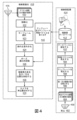
[0023] 図1は、開示される技術を用いて患者をどの様に監視することができるかを概略的に示す。特に、受け付け及び/若しくは登録並びに/又はトリアージ局、又はこれら両方を含み得る待合室前領域(又は複数の領域)102における等の待合室前領域内で起こり得る処理及び動作が示されている。更に、待合室104内で起こり得る処理及び動作が示されている。図1の順序は限定しようとするものではなく、他の順序も可能であると理解されるべきである。
[0023] Figure 1 schematically illustrates how a patient can be monitored using the disclosed technology. In particular, processing and operations are shown that may occur within a waiting room front area, such as in a waiting room front area (or areas) 102, which may include reception and/or registration and/or triage stations. Additionally, processes and actions that may occur within the
[0024] ブロック106において、新たな患者が、受け付けデスクにおけるチェックイン(図示略)の後、待合室前領域(又は複数の領域)102に入場及び/又は接近し得る。ブロック108において、該新患者は登録され得る。登録は、例えば、当該患者の名前、年齢、性別、保健情報及び訪問理由等の該患者に関する情報を収集することを含み得る。専らではないが、典型的には、この情報は受付係又は登録係等の医療要員によりコンピュータに手動で入力され得る。幾つかの実施態様においては、当該患者の1以上の参照デジタル画像を、例えば、トリアージ看護師により操作されるコンピュータ装置と一体であるカメラにより、独立したカメラにより、及び/又はバイタルサイン収集カメラ(この場合、少なくとも幾つかのバイタルサインがオプションとして登録時に取得され得る)により取得することができる。以下に更に詳細に説明するように、幾つかの実施態様において、ブロック108における登録の間にカメラにより取得されるデジタル画像は、“取込デジタル画像”と称することができる。これらの取込デジタル画像の部分組(幾つかのケースでは、これら画像のうちの例えば顔を示す選択された小部分)を、待合室104等の領域において後に患者(又は、もっと広くは“被検者”)を識別するために使用することができる“被検者参照テンプレート”として選択的に保持することができる。
[0024] At
[0025] 多くの事例において、トリアージ看護師は、更に、ブロック110において種々の初期バイタルサイン及び/又は生理学的パラメータを種々の医療機器を用いて取得することができる。これらの初期バイタルサイン及び/又は生理学的パラメータは、これらに限定されるものではないが、血圧、脈拍、血糖値、SpO2、光電式容積脈波記録(“PPG”)、呼吸速度(例えば、呼吸数)、体温及び皮膚色等を含むことができる。図1には示されていないが、幾つかの実施態様では、患者の医療履歴を取得/更新する、患者のアレルギを判定する、及び患者の医薬の使用を判定する等の他の情報もトリアージ時に収集することができる。幾つかの実施態様において、患者には、患者の病気の重症度を等級分けするために使用される尺度であり得ると共に、幾つかの事例では、救急処置室資源の予測必要性を示し得る、所謂、“患者の急性度”を割り当てることができる。これらに限定されるものではないが、救急重症度(Emergency Severity Index:“ESI”)、台湾トリアージシステム(“TTS”)及びカナダ式トリアージ及び急性度スケール(“CTAS”)等を含む患者の急性度を判定及び/又は割り当てるために、任意の数の普通に使用される指示子及び/又は臨床判断支援(“CDS”)アルゴリズムを使用することができる。例えば、幾つかの実施態様において、患者のバイタルサインを、システムデータベースに記憶された予め定められたバイタルサイン閾値と、又は所与の患者の年齢、性別、体重等に典型的な公開された若しくは既知のバイタルサイン値と比較して、該患者の初期患者急性度及び/又は該患者の患者待ち行列における初期位置を決定することができる。幾つかの実施態様において、患者に関する種々の生理学的及び他の情報は,1以上の急性度を導出するための訓練されるモデル(例えば、回帰モデル、ニューラルネットワーク、ディープ学習ネットワーク等)、事例ベースの推論アルゴリズム又は他の臨床的推論アルゴリズムに対する入力として供給することができる。幾つかの実施態様において、急性度を導出するために使用される情報は、前記バイタルサイン収集カメラによりキャプチャすることができるバイタル又は他の情報を含むことができ、又はこれらに完全に限定することができる。幾つかの実施態様において、急性度を導出ために使用される情報は、代わりに又は加えて、患者の以前の電子医療記録(“EMR”)からの情報、トリアージ時に患者から取得される情報、患者により持ち運ばれるウェアラブル装置又は他のセンサからの情報、待合室内の他の患者又は人に関する情報(例えば、部屋内の他の者のバイタル)、患者の家族又は他の者に関する情報(例えば、家族のEMR)等を含むことができる。 [0025] In many instances, the triage nurse may also obtain various initial vital signs and/or physiological parameters at block 110 using various medical devices. These initial vital signs and/or physiological parameters include, but are not limited to, blood pressure, pulse, blood glucose, SpO 2 , photoplethysmography (“PPG”), respiratory rate (e.g., respiratory rate), body temperature, skin color, etc. Although not shown in FIG. 1, other information may also be triaged in some implementations, such as retrieving/updating a patient's medical history, determining patient allergies, and determining patient medication usage. can be collected from time to time. In some embodiments, the patient may be provided with a scale that may be used to grade the severity of the patient's illness and, in some cases, may indicate the anticipated need for emergency room resources. A so-called "patient acuteness" can be assigned. Patient acute assessment measures including, but not limited to, the Emergency Severity Index (“ESI”), the Taiwan Triage System (“TTS”), and the Canadian Triage and Acuteness Scale (“CTAS”) Any number of commonly used indicators and/or clinical decision support ("CDS") algorithms may be used to determine and/or assign the grade. For example, in some embodiments, the patient's vital signs may be compared to predetermined vital sign thresholds stored in the system database, or to published or The patient's initial patient acuteness and/or the patient's initial position in a patient queue can be determined by comparison to known vital sign values. In some embodiments, various physiological and other information about the patient may be trained to derive one or more acuity levels, such as a model (e.g., regression model, neural network, deep learning network, etc.), case-based, etc. or other clinical reasoning algorithms. In some embodiments, the information used to derive acuteness may include, or be limited entirely to, vitals or other information that may be captured by the vital signs collection camera. Can be done. In some embodiments, the information used to derive the acuity level may alternatively or additionally include information from the patient's previous electronic medical record (“EMR”), information obtained from the patient at the time of triage, Information from wearable devices or other sensors carried by the patient, information about other patients or persons in the waiting room (e.g., the vitals of others in the room), information about the patient's family or others (e.g. family's EMR), etc.
[0026] 患者が登録及び/又はトリアージされたら、ブロック112において、該患者は待合室104に送ることができる。多くのシナリオにおいて、図1の処理は僅かに異なる順序で生じ得る。例えば、幾つかのシナリオにおいて、患者は最初に登録され、次いで、トリアージされ得るまで待合室に行き、次いで、トリアージの幾らか後に(即座に又は待合室に戻された後に)医師へと送られる。救急状況(例えば、災害における)等の幾つかの状況において、患者は真っ直ぐトリアージに進み、次いで医師へと進むことができるか、又は患者が安定した後にのみ登録することができる。
[0026] Once the patient has been registered and/or triaged, at block 112, the patient may be sent to the
[0027] ブロック114において、患者が待合室を離れたことを、例えば、1以上のカメラ、センサ又は医療要員からの入力を用いて判定することができる。ブロック114は、現在待合室内に居る各人をスキャンすること(例えば、後述するブロック120の実行等の、当該患者が、バイタルがキャプチャされるべき患者の待ち行列の先頭となった場合に、該患者を位置特定しようと試みる探索機能の一部として、又は後述するブロック118及び120を含むループの多重実行等の、バイタルをキャプチャするために部屋内の各人を経て繰り返すこと等)、及び当該患者が位置特定されなかったと判定することを含み得る。幾つかの実施態様において、当該システムは、一時的な不在(例えば、休憩室を訪れる又は医療要員と会話する等)を考慮するために、当該患者が待合室を離れたと見なされる前に、該患者が居ない場合が所定の数に達する又は該患者が居ない所定の時間量が経過するまで待機することができる。例えば、当該患者は、診察を受ける順番であるので、ERに適切に運び込まれているかも知れない。又は、待っている間に当該患者の症状が改善し、病院を離れたかも知れない。又は、当該患者は待ちきれず、別の場所での治療を捜すために離れたかも知れない。どの様な理由であれ、当該患者が少なくとも或る閾値の時間量にわたり待合室を離れていたと判定されたなら、ブロック116において、該患者は、診察されずに離れたと見なされ、例えば、登録された患者が入力された待ち行列から該患者を削除することにより当該システムから解除することができる。
[0027] At
[0028] ブロック118において、待合室104内の1以上の患者を、監視するために選択することができる。例えば、幾つかの実施態様において、ブロック108~110において取得された登録情報を記憶するデータベース(例えば、図4における被検者参照データベース412)を、最も高い患者急性度を持つ患者、又は全患者に関して設定された若しくは急性度に基づいて設定された(例えば、逆相関された)時間閾値により決定することができる最近監視されていなかった最も高い急性度を持つ患者を選択するために検索することができる。他の実施態様においては、待合室内の複数の患者に関連付けられた登録情報を、例えば、待ち時間、待合室内での患者の在室(例えば、居ない患者は、繰り返し不在なら解除されるべきかを判定するために一層頻繁に監視するよう選択することができる)等の他の尺度に加えて又は代えて、これら患者の各患者急性度により、患者監視待ち行列において順位付けすることができる。更に他の実施態様において、患者監視待ち行列を順位付けする際に患者急性度は考慮されず、その代わりに、患者の待ち時間、患者の在室等のみを考慮することができる。更に他の実施態様において、患者は、例えば待合室104内の椅子又は長椅子の順番により支配される所定のスキャン順序等で、単に1人ずつ選択することができる。
[0028] At
[0029] しかしながら、幾つかの実施態様において、患者監視待ち行列は、該待ち行列における最初の患者を次に監視されるべき者として選択することができるように順位付けされる。患者監視待ち行列は、患者急性度により順序付けられた物理的メモリ位置の順番で記憶されることを要さない(可能ではあるが)。むしろ、幾つかの実施態様において、順位付けされた患者監視待ち行列は、単に、各患者に関連付けられた順位又は優先レベル値を含むことができる。言い換えると、ここに記載される“患者監視待ち行列”は、必ずしも連続した順序のメモリ位置ではなく、患者の急性度、待ち時間等に基づいて論理的に順位付けされた“論理的”待ち行列を指し得る。患者は、ブロック118において、監視するために当該患者監視待ち行列における対応する順位付けの順序で選択することができる。
[0029] However, in some embodiments, the patient monitoring queue is ranked such that the first patient in the queue can be selected as the next person to be monitored. The patient monitoring queue does not need to be stored in the order of physical memory locations ordered by patient acuity (although it is possible). Rather, in some embodiments, the ranked patient monitoring queue may simply include a ranking or priority level value associated with each patient. In other words, a "patient monitoring queue" as described herein is not necessarily a sequential order of memory locations, but rather a "logical" queue that is logically ranked based on patient acuity, waiting time, etc. can refer to. Patients may be selected for monitoring at
[0030] ブロック120において、ブロック118において選択された患者を待合室104内で位置特定することができる。種々の実施態様において、待合室104内又は待合室104の近傍に配置された1以上のバイタルサイン収集カメラ(図1には図示されておらず、図2及び図3を参照)又は他のもっと一般的なカメラ等の1以上のカメラを操作して(例えば、パン、チルト、ズーム等)待合室104内の患者の1以上のデジタル画像を取得することができる。後に更に詳細に説明されるように、これらの取得されたデジタル画像は、ブロック108における登録の間にキャプチャされた1以上の参照患者画像(ここでは、しばしば、“被検者参照テンプレート”と称される)と比較することができる。幾つかの実施態様において、これらの取得されたデジタル画像における訓練される畳み込みニューラルネットワーク等の機械学習モデルを用いて抽出される特徴を、登録された患者に関連する被検者参照テンプレートにおいて同様に抽出される特徴と比較することができる。
[0030] At
[0031] ブロック122において、待合室104内に又は該待合室の近傍に取り付けられ若しくはそれ以外で配置された1以上のバイタルサイン収集カメラを動作させ、ブロック118において選択されると共にブロック120で位置特定された患者からの1以上の最新のバイタルサイン及び/又は生理学的パラメータの目立たない(例えば、非接触の)取得を実行することができる。これらのバイタルサイン収集カメラは、これらに限られるものではないが、血圧、脈拍(又は心拍)数、皮膚色、呼吸数、SpO2、体温、ポーズ及び発汗レベル等を含む、当該患者からの種々の異なるバイタルサイン及び/又は生理学的パラメータを取得する(患者に物理的に接触することなしに)ように構成することができる。幾つかの実施態様においては、患者からバイタルサインを取得し及び/又は生理学的情報を抽出するために、所謂、“非接触方法”を実行するように装備されたバイタルサイン収集カメラを、医療画像装置として使用することができる。このようなカメラの限定するものでない例は、米国特許出願公開第20140192177号、同第20140139656号、同第20140148663号、同第20140253709号及び同第20140235976号並びに米国特許第9125606号に記載されており、これら文献は参照により実質的に本明細書に組み込まれるものである。
[0031] At
[0032] ブロック124において、例えば図2に示される1以上の要素(後述する)により、ブロック122で取得された最新のバイタルサイン(又は複数のバイタルサイン)及び/又は生理学的パラメータと、以前に収集されたバイタルサイン及び/又は生理学的パラメータ(例えば、ブロック110で取得された初期バイタルサイン又はバイタルサイン収集カメラにより収集された以前の反復による最新のバイタルサイン/生理学的パラメータ)との比較に基づいて当該患者の症状が変化したかを判定することができる。例えば、患者が待っていた間に、該患者の脈拍数、呼吸数、血圧、SpO2、PPG、体温等が増加又は減少したかを判定することができる。答えがノーである場合、当該制御はブロック118に戻り、新たな患者(例えば、次の最高の患者急性度を持つ患者)が選択され得ると共に、該制御はブロック120に進むことができる。しかしながら、答えがイエスである(即ち、患者の症状が変化した)場合、当該制御はブロック126に進むことができる。幾つかの実施態様においては、当該患者の状態を、監視順序を決定する目的で使用されたものと同一の急性度で(少なくとも部分的に)表すことができる。
[0032] At
[0033] ブロック124において検出された変化に基づいて医療警報が認可されるかを、ブロック126において判定することができる(ここでも、図2の1以上の要素により)。例えば、1以上のバイタルサイン又は患者の急性度の変化が1以上の閾値を満たす(例えば、血圧が、この患者にとり安全と考えられるレベルより上昇した)か、を判定することができる。答えがイエスである場合、当該制御はブロック128に進む。ブロック128においては、当該患者が悪化しているとの警報を、例えば付き添い看護師又は他の医療要員に出力することができる。この場合、当該医療要員は当該患者をチェックして、診察を受けるために即座にEDに送る等の治療行為が認可されるかを判定することができる。幾つかの実施態様において、当該制御は次いでブロック118に戻ることができる。しかしながら、ブロック126における答えがノーであった場合、幾つかの実施態様において、当該制御はブロック118に戻ることができる。
[0033] It may be determined at
[0034] 図2は、種々の実施態様による、開示された技術を実施するために使用することができる例示的構成要素を示す。病院情報システム240は、病院及び医師のオフィス等で普通に見付けられるタイプのものであり得る。病院情報システム240は、1以上のコンピュータネットワーク(図示略)を介して又は介さないで接続され得る1以上のコンピュータシステムを用いて実施化することができる。病院情報システム240は、なかでも、登録モジュール242、トリアージモジュール244、解除モジュール246及び警報モジュール248を含むことができる。モジュール242~248のうちの1以上又はここに記載される何れの他のモジュール若しくはエンジンも、メモリに記憶された命令を実行する1以上のマイクロプロセッサを含むハードウェア及びソフトウェアの任意の組み合わせを用いて実施化することができる。例えば、登録モジュール242はプロセッサ上で実行する登録に関して本明細書に記載される機能を実施する登録命令を含むことができる一方、トリアージモジュール244は同じプロセッサ上で実行するトリアージに関して本明細書に記載される機能を実施するトリアージ命令を含むことができる。同様の基となるハードウェア及びソフトウェアも、ここに記載される他の“モジュール”を実施化するために使用することができる。
[0034] FIG. 2 depicts example components that can be used to implement the disclosed techniques, according to various implementations.
[0035] 登録モジュール242は、新たな患者の登録情報を受信する(例えば、担当介護士からの手動入力として)よう構成することができる。この登録情報は、例えば、患者の名前、年齢及び保健情報等を含むことができる。トリアージモジュール244は、前述したようなバイタルサイン及び/又は体重、身長、患者の訪問理由等の他の生理学的データを受信する(例えば、担当看護師からの手動入力として、又はネットワーク医療装置から直接的に)ように構成することができる。種々の実施態様において、トリアージモジュール244により受信されるバイタルサイン及び/又は患者の急性度(例えば、図2におけるESI)は、例えば病院情報システム240に関連する1以上のデータベース(図示略)において、登録モジュール242により受信された対応する患者情報に関連付けることができる。
[0035]
[0036] 警報モジュール248は、患者の悪化等の種々の事象(イベント)を示す情報を受信すると共に、これに応答して種々の警報及び/又は警告を提起するように構成することができる。これらの警報及び/又は警告は、これらに限定されるものではないが、視覚的出力(例えば、病院要員に見える表示スクリーン上への)、構内アナウンス、テキストメッセージ、Eメール、音響警報、触覚警報、呼び出し、ポップアップウインドウ及び閃光等を含む種々の方式を用いて出力することができる。病院情報システム240のモジュール242~248は、例えば1以上のコンピュータネットワーク(図示略)を介して病院情報システムインターフェース250(図2における“H.I.S.インターフェース”)に動作的に結合することができる。
[0036]
[0037] 病院情報システムインターフェース250は、伝統的な病院情報システム240と、本開示の選択された態様で構成された患者監視システム252との間のインターフェースとして機能することができる。種々の実施態様において、病院情報システムインターフェース250は、例えば患者監視システム252の他のモジュールに対して、登録情報、患者の急性度(例えば、ESI)、処方及び/又は投与された医薬、患者が解除されたか及び種々の警報/警告等の患者に関する種々の情報を公開することができる。後述されるように、幾つかの実施態様において、これら公開情報はイベント公開及びサブスクライブ(“EPS”)モジュール270に供給することができ、該モジュールは、これら情報をデータベース272に選択的に記憶し及び/又は該情報を患者監視システム252の他のモジュールに選択的に公開することができる。幾つかの実施態様において、病院情報システムインターフェース250は、加えて又は代わりに、他のモジュールにより供給される1以上の警報又は公開情報にサブスクライブ(予約購読)することができる。例えば、病院情報システムインターフェース250は悪化検出モジュール268からの警報をサブスクライブすることができ、かくして、例えば病院情報システムインターフェース250が警報モジュール248等の病院情報システム240の適切な要素に患者が悪化していることを通知することができるようにする。EPSは、システム要素の間での通信のために使用することができる多数の可能なプロトコルのうちの1つに過ぎず、限定しようとするものではない。
[0037] Hospital
[0038] 患者監視システム252は、患者が実際の症状に合った態様で扱われることを保証するために、待合室104等の領域における患者の監視を容易にする種々の要素を含むことができる。患者監視システム252は、例えば、1以上のカメラ256とインターフェースする患者キャプチャモジュール254、患者待ち行列モジュール258、患者識別モジュール260、ダイナミック較正モジュール262、顔/胴収集モジュール264、バイタルサイン測定モジュール266、悪化検出モジュール268、前述したEPSモジュール270及び1以上のデータベース272、274を含むことができる。前述したように、モジュール250、254及び258~270の各々は、ハードウェア及びソフトウェアの任意の組み合わせを用いて実施化することができる。これらモジュールは別々に図示されているが、各モジュールが個別のハードウェア上で実施化されることに限定し又は推奨しようとするものではない。例えば、1以上のモジュールを組み合わせ及び/又は省略することができ、1以上のモジュールを1以上のコンピュータネットワーク(図示略)を介して動作的に接続された1以上のコンピュータシステム上で実施化することもできる。図2の種々の要素を接続するように描かれたラインは、これら要素によりアクセスすることができる通信チャンネルを示し得る。これらの通信チャンネルは、1以上のバス、イーサネット(登録商標)、Wi-Fi(登録商標)、ブルートゥース(登録商標)、Z-Wave、ZigBee(登録商標)及びセルラ通信等の何れのネットワーク化又は他のコンピュータ通信技術を用いて実施化することもできる。
[0038] Patient monitoring system 252 may include various elements that facilitate monitoring of patients in areas such as
[0039] 患者監視システム252は、患者から幾らから離れた距離から該患者の1以上のバイタルサイン及び/又は生理学的パラメータを取得するように較正された1以上のバイタルサイン収集カメラ276も含むことができる。このようなバイタルサイン収集カメラの例は前述した通りである。種々の実施態様において、バイタルサイン収集カメラ276は、待合室104等の領域の異なる部分がFOV内に含まれるようにパン、チルト及びズームを行うように動作可能なパン/チルト/ズーム(“PTZ”)カメラとすることができる。このようにして、異なる患者を位置特定するために監視される領域を、最新のバイタルサイン及び/又は生理学的パラメータを目立たないように取得することができるようにスキャンすることができる。
[0039] Patient monitoring system 252 also includes one or more vital
[0040] 患者キャプチャモジュール254は、1以上のカメラ256から、患者のキャプチャされた画像データを伝達する1以上の信号を受信することができる。例えば、幾つかの実施態様において、患者キャプチャモジュール254はカメラ256からビデオストリームを受信することができる。患者キャプチャモジュール254は、患者が何時居るかを検出するために上記ビデオストリームに画像処理(例えば、顔検出、セグメンテーション、人型を検出するための形状検出等)を実行すると共に、該検出に応答して当該患者の1以上の参照デジタル画像(例えば、後述する取込デジタル画像)をキャプチャすることができる。幾つかの実施態様において、上記参照デジタル画像は、必要ということではないが、前記ビデオストリームの個々のフレームよりも高い解像度でキャプチャすることができる。幾つかの実施態様において、カメラ256は、待合室前領域(又は複数の領域)102内又は近傍に配置されるウェブカメラ及びPTZカメラ(例えば、276)等の独立型カメラとすることができる。カメラ256によりキャプチャされた取込デジタル画像の部分組は、登録された患者(一層一般的には“被検者”)に関連付けられると共に監視される領域において登録された患者を識別するために後に使用される被検者参照テンプレートを発生するために使用することができる。
[0040]
[0041] 患者待ち行列モジュール258は、領域内の患者が監視されるべき順序の優先待ち行列を例えばデータベース内に確立及び/又は維持するように構成することができる。種々の実施態様において、該待ち行列は種々のパラメータにより順序付けることができる。幾つかの実施態様において、該待ち行列内の患者は患者の急性度の順序で(即ち、優先度により)順位付けすることができる。例えば、最も危ない患者は、余り危なくない患者よりも頻繁に待ち行列の前部に配置することができる。幾つかの実施態様において、最新のバイタルサインは、待合室104等の監視される領域において待機している患者から当該待ち行列の順序で取得することができる。他の実施態様において、最新のバイタルサインは患者からFIFO順序又はラウンドロビン順序で取得することができる。他の実施態様において、最新のバイタルサインは、患者から、バイタルサイン収集カメラ276にプログラムされた所定のスキャン軌道(例えば、各列の椅子を順番にスキャンする)に対応する順序で取得することができる。
[0041]
[0042] 患者識別モジュール260は、本開示の選択された態様により、監視される領域(例えば、待合室104)における1以上の患者を位置特定するためにバイタルサイン収集カメラ276(又は、バイタルサインを目立たないように取得するよう構成されていない他のカメラ)によりキャプチャされた1以上のデジタル画像を患者キャプチャモジュール254によりキャプチャされた被検者参照テンプレートと関連させて使用するように構成することができる。患者識別モジュール260は、取得されたデジタル画像を、患者(被検者)を識別及び位置特定するために後述する種々の技術を用いて解析することができる。後述する図4~図10は、何らかの前後関係において、患者(又は、一層一般的には、被検者)を認識/識別/位置特定することの一部として採用することができる種々の技術の種々の側面を示す。
[0042]
[0043] 幾つかの実施態様において、患者識別モジュール260は、最新のバイタルサインを取得すべき特定の患者を求めて、監視される領域を検索することができる。例えば、患者識別モジュール260は、患者待ち行列モジュール258により選択された患者(例えば、待ち行列における最も高い患者急性度を持つ患者であり得る)を求めて、当該監視される領域を検索することができる。幾つかの実施態様において、患者識別モジュール260は、バイタルサイン収集カメラ(又は複数のカメラ)276に、選択された患者が識別されるまで、監視される領域(例えば、待合室104)をスキャンさせることができる。
[0043] In some implementations, the
[0044] ダイナミック較正モジュール262は、バイタルサイン収集カメラ276が特定のPTZ位置を指すように命令された場合に該カメラが常に正確に同一の位置を指すことを保証することができる。PTZカメラは、常に又は少なくとも頻繁に動いている可能性がある。従って、これらカメラの機械部品は摩耗又は亀裂を被り得る。小さな機械的誤差/バイアスは、蓄積し得ると共に、バイタルサイン収集カメラ276が、時間にわたり、所与のPTZコマンドに対して違って応答するようにさせ得る。ダイナミック較正モジュール262は、これを、例えば、バイタルサイン収集カメラ276が適切に応答するようにさせる補正機構を訓練するために目印(例えば、壁上の小さなステッカ等の印)を用いることができる較正ルーチンを時折実行することにより補正することができる。
[0044]
[0045] 患者待ち行列モジュール258により識別された患者が患者識別モジュール260により認識/位置特定されたなら、顔/胴収集モジュール264は、視野が該患者の所望の部分をキャプチャするように1以上のバイタルサイン収集カメラ276をパン、チルト及び/又はズームするようにし得る。例えば、幾つかの実施態様において、顔/胴収集モジュール264は、バイタルサイン収集カメラ276を、患者の顔及び/又は上部胴体上に焦点が合わされるようにパン、チルト又はズームすることができる。加えて又は代わりに、顔/胴収集モジュール264は1つのバイタルサイン収集カメラ276を患者の顔を主にキャプチャするように、及び他のものを患者の胴を主にキャプチャするようにパン、チルト又はズームすることができる。次いで、種々のバイタルサイン及び/又は生理学的パラメータを取得することができる。例えば、当該患者の脈拍数及びSpO2等のバイタルサインを、例えばバイタルサイン測定モジュール266により、バイタルサイン収集カメラ(又は複数のカメラ)276によりキャプチャされた患者の顔のビデオに対する画像処理を実行することにより取得することができる。患者の呼吸数等のバイタルサイン及び/又は生理学的パラメータを、例えばバイタルサイン測定モジュール266により、バイタルサイン収集カメラ(又は複数のカメラ)276によりキャプチャされた患者の胴のビデオに対する画像処理を実行することにより取得することができる。勿論、顔及び胴は、バイタルサインを取得するために検査され得る身体部分の2つの例に過ぎず、限定しようとするものではない。
[0045] Once the patient identified by the
[0046] 悪化検出モジュール268は、種々の信号及び/又はデータを解析して、登録された患者の(又は、登録されていない同伴者さえもの)状態が悪化している、改善している及び/又は安定状態に留まっているかを判定するよう構成することができる。幾つかの実施態様において、患者の状態は、少なくとも部分的に、患者の監視するための順番を決定するための前述したのと同一の患者急性度により表すことができる。かくして、悪化検出モジュール268は、ここで述べた急性度以外の患者の状態尺度を評価するために、1以上のCDS、事例ベースの推論、又は本明細書に記載した他の臨床推論アルゴリズム若しくは他の臨床推論(例えば、訓練されるロジスティック回帰モデル又は他の機械学習モデル)を含むことができる。幾つかの実施態様において、悪化検出モジュール268により採用される患者の急性度又は患者の状態の他の尺度を評価するためのアルゴリズムは、例えば、選択された機械学習モデルのための新たな訓練された重み(例えば、シータ値)を書くことにより又はプロセッサにより実行するための新たな命令(例えば、ジャバアーカイブ、JAR、ファイル又はコンパイルされたライブラリの形で)を供給することにより、時折、更新することができる。これらの信号は、例えば、患者の初期バイタルサイン及び他の生理学的情報(例えば、図1のブロック108~110で取得された)、バイタルサイン測定モジュール266により取得される最新のバイタルサイン、患者の初期患者急性度(例えば、登録の間に計算された)、及び/又は患者の最新の患者急性度(例えば、バイタルサイン測定モジュール266から受信される最新のバイタルサイン及び/又は生理学的パラメータに基づいて計算される)を含むことができる。
[0046]
[0047] これらのデータ及び/又は信号を用いてなされた判定に基づいて、悪化検出モジュール268は、種々の措置を講じるために、種々の他のモジュールに種々の警報を送ることができる。例えば、悪化検出モジュール268は、例えば警報をEPSモジュール270に送出することにより該警報を公開することができ、かくして、該EPSモジュールが病院情報システム240の警報モジュール248等のサブスクライブされたモジュールに対し該警報を公開することができるようにする。幾つかの実施態様において、このような警報は、例えば、患者の名前(又は、もっと一般的には、患者の識別子)、画像、生のビデオストリーム、待合室における患者の最後に検出された位置、基準バイタルサイン、1以上の最新のバイタルサイン、及び/又は患者の急性度の指示情報を含むことができる。斯かる警報の受信に際し、警報モジュール248は、医療要員に対する当該患者の悪化に関して及び、とりわけ、該患者の待合室における最後に検出された位置に関して警報又は警告を提起することができる。
[0047] Based on the determinations made using these data and/or signals, the
[0048] EPSモジュール270は、図2の種々の他の要素により公表される事象(イベント)を分配するように構成された一般的通信ハブであり得る。幾つかの実施態様において、図2に図示される他のモジュールの全て又は少なくとも幾つかは、当該モジュールからの何らかの形態の結果/判定/計算/決定を示すイベントを発生することができる。これらのイベントは、EPSモジュール270に対して伝送され又は“公開”され得る。図2に図示される他のモジュールの全て又は幾つかは、如何なる他のモジュールからの如何なるイベントも受信する又は“サブスクライブする”ことを決定することができる。EPSモジュール270がイベントを受信した場合、該モジュールは該イベントを示すデータを、該イベントをサブスクライブしている全てのモジュールに伝送する(例えば、該イベントを転送する)ことができる。
[0048]
[0049] 幾つかの実施態様において、EPSモジュール270は、データベース272及び/又はアーカイブ274(オプションであり得る)等の1以上のデータベースと通信することができる。幾つかの実施態様において、EPSモジュール270は、1以上のデータベース272及び/又は274に記憶された情報に対するアクセスを提供するために、及び/又は他のモジュールから受信された情報(例えば、警報)をデータベース272及び/又は274に追加するために、如何なるモジュールからの遠隔手続き呼出し(“RPC”)も受け付けることができる。データベース272(幾つかの実施態様においては、被検者参照データベース412と同一であり得る)は、図2における1以上の他のモジュールにより送出/ブロードキャスト/送信された警報、公開情報又は他の通知に含まれる情報を記憶することができる。幾つかの実施態様において、データベース272は、例えば、患者及び/又は患者の初期バイタルサインに関連する被検者参照テンプレート、最新のバイタルサイン(バイタルサイン収集カメラ276により取得される)、及び/又は患者の急性度を記憶することができる。オプションとしてのアーカイブ274は、幾つかの実施態様において、一層長い期間にわたり同一の又は同様の情報を記憶することができる。
[0049] In some implementations,
[0050] 患者監視システム252を実施化するために種々のハードウェア構成を用いることができることが明らかであろう。例えば、幾つかの実施態様においては、単一の装置が全体のシステム252を構成する(例えば、バイタルサイン収集機能260~266を果たすためにカメラ276を動作させると共に、バイタルサイン分析、悪化検出268を含む警報機能及び患者の待ち行列管理258を実行するための単一のサーバ)ことができる。他の実施態様においては、複数の独立した装置がシステム252を形成することができる。例えば、第1装置がバイタルサイン収集カメラを駆動して機能260~266を実施化することができる一方、他の装置(又は複数の装置)が残りの機能を果たすことができる。幾つかの斯様な実施態様においては、或る装置を待合室に対してローカルなものとすることができる一方、他のものは遠隔なもの(例えば、地理的に遠いクラウドコンピュータアーキテクチャの仮想マシンとして構成される)とすることができる。幾つかの実施態様においては、或る装置(例えば、プロセッサ及びメモリを含む)をバイタルサイン収集カメラ276自体内に配置することができ、かくして、該カメラ276は処理能力の無い周辺機器に過ぎないのではなく、代わりにバイタルサイン機能260~266を果たすことができる。幾つかの斯様な実施態様においては、他のサーバが、バイタルが更なる処理のために返送されるようリクエストするためにカメラ276に指示情報(例えば、識別子、全記録又は登録された顔画像)を供給することができる。幾つかの斯様な実施態様においては、例えば悪化検出268(又はそのための前処理)等の付加的機能をカメラ276上に設けることができ、及び/又は患者待ち行列モジュール258の管理をカメラ276上で実行することができる。幾つかの実施態様において、カメラ276は、HISインターフェース250又はEPS270を実施化することさえできる。種々の更なる構成は明らかであろう。
[0050] It will be apparent that various hardware configurations may be used to implement patient monitoring system 252. For example, in some embodiments, a single device constitutes the entire system 252 (e.g., operating the
[0051] 図3は、開示される技術を、監視目的で待合室304内の患者378A~Cを識別するように実施化することができる例示的シナリオを示す。この例においては、3人の患者387A~Cが病院待合室304内で医療要員380により応対されるのを待っている。2台のビデオカメラ376A、376Bが待合室304の表面(例えば、天井、壁)上に取り付けられている。該2台のビデオカメラ376A、376Bは、待合室304内の患者378を監視するために用いることができる。患者378A~Cには、各々、トリアージ要員(図示略)により予備的患者症状分析に基づいて患者の急性度を割り当てることができる。患者378が応対する医師を待つ間に、2台のビデオカメラ376A,376Bはデジタル画像を取得することができ、これらデジタル画像は、監視のために選択された患者を識別すべく、ここに記載される技術を用いて解析される。この場合、同じビデオカメラ(バイタルサインを目立たずに取得するように構成されていると仮定する)又は別のビデオカメラを動作させて、前述したように例えば患者の悪化を検出するために患者378を監視することができる。幾つかの実施態様において、患者に関連付けられた患者の急性度は、医療要員により、患者が悪化したとの患者監視システム(更に詳細には、悪化検出モジュール268)による検出に応答して更新することができる。種々の実施態様において、新たな患者が待合室304に入室した場合、例えば患者監視システム252により、新たな区切の患者の監視及び優先付けを実行することができる。患者待ち行列は、新たな患者が待合室304に入室する毎に、例えば患者待ち行列モジュール258により自動的に更新することができる。加えて又は代わりに、医療要員が患者待ち行列を、トリアージ後の新たに到来した患者を含めるように手動で更新することもできる。
[0051] FIG. 3 depicts an example scenario in which the disclosed techniques may be implemented to identify
[0052] ここに記載される技術は、病院の待合室に限定されるものではない。ここに記載される技術をデジタル画像又はビデオ内の被検者を識別/位置特定するように実施化することができる多数の他のシナリオが存在する。例えば、開示される技術は、空港、劇場、入国及び他の公共の場における群衆の保安監視のために用いることもできる。このようなシナリオにおいては、患者を患者の急性度を判定するために監視するというより、被検者は、リスク評価又はイベント後調査等の他の目的のために識別することができる。ここに記載される技術は、デジタル画像内に示される個々の被検者の識別を実施することができるフィットネス環境(例えば、ジム、老人ホーム等)等のシナリオ又は他の監視(見張り)シナリオ(例えば、空港、入国等)においても適用することができる。例えば、空港においては、ゲートで待っている被検者を、例えば、ゲートで待っている被検者の画像をチェクインで取得された被検者参照テンプレートと比較することにより識別することができる。更に、ここに記載される技術は、診察を受けずに帰った患者を、該患者の顔を見えるようにすることを要せずに識別するために用いることができる。 [0052] The techniques described herein are not limited to hospital waiting rooms. There are numerous other scenarios in which the techniques described herein can be implemented to identify/locate a subject in a digital image or video. For example, the disclosed technology can also be used for security monitoring of crowds at airports, theaters, immigration, and other public places. In such a scenario, rather than monitoring the patient to determine the patient's acuteness, the subject may be identified for other purposes such as risk assessment or post-event surveillance. The techniques described herein are suitable for use in scenarios such as fitness environments (e.g., gyms, nursing homes, etc.) or other surveillance scenarios (e.g., gyms, nursing homes, etc.) where identification of individual subjects shown in digital images can be performed. For example, it can also be applied at airports, immigration, etc.). For example, at an airport, a subject waiting at a gate may be identified, for example, by comparing an image of the subject waiting at the gate with a subject reference template obtained at check-in. Additionally, the techniques described herein can be used to identify patients who have left the clinic without having to make their faces visible.
[0053] 図4は、本開示の選択された態様で構成された要素の例及びこれら要素の間の例示的相互作用を相対的に高いレベルで概略的に示す。種々の実施態様において、これら要素の1以上は、例えば図2における患者監視システム252の一部として、特には患者キャプチャモジュール254及び患者識別モジュール260の一部として、ハードウェア及びソフトウェアの何らかの組み合わせを用いて実施化することができる。例えば、図4の構成要素は、患者等の被検者を被検者参照データベース412に登録するために図1のブロック108において使用することができる。被検者の取込情報(例えば、年齢、性別、名前、初期バイタルサイン等)と一緒に、複数のビュー(例えば、異なるアングル、異なる表情、異なる照明条件、異なる頭部位置等)からの被検者の顔のデジタル画像を有する如何なる数の“被検者参照テンプレート”も、例えば医療記録番号(“MRN”)により選択すると共に被検者参照データベース412における被検者と関連付けることができる。これらの被検者参照テンプレート(及び、後述するように、これらの被検者参照テンプレートから発生されるテンプレート特徴ベクトル)は、次いで、例えば患者識別モジュール260により、待合室を視野内でキャプチャする他のカメラ(例えば、バイタルサイン収集カメラ276,376)を用いて待合室等の領域における被検者を識別するために後に使用することができる。被検者が識別されたなら、該被検者の位置は、医療要員により接触される、バイタルサインを目立たずに取得されるようにする、等の種々の目的のために使用することができる。
[0053] FIG. 4 schematically depicts, at a relatively high level, example elements configured in selected aspects of the disclosure and example interactions between these elements. In various embodiments, one or more of these elements may include some combination of hardware and software, such as as part of patient monitoring system 252 in FIG. It can be implemented using For example, the components of FIG. 4 may be used in
[0054] 右下から開始して、種々の実施態様によれば、新たに登録される被検者の取り込み(例えば、新たな患者の登録及び/又はトリアージ)及び該被検者の被検者参照データベース412への追加のための処理を含む取込ルーチン402が示されている。第1カメラ456は、ここでは“取込”デジタル画像404(例えば、個別の画像及び/又はビデオストリーム等の画像のストリーム)と称されるものの1以上をキャプチャするように構成することができる。幾つかの事例では図2のカメラ256に対応し得る第1カメラ456は、取込領域(例えば、登録及び/又はトリアージ)に配置されるウェブカメラ、取込要員(例えば、トリアージ看護師)により操作されるコンピュータ装置と一体のカメラ等の種々の形態をとることができる。この画像キャプチャは取込要員及び被検者の両方に対して非干渉的なものとし得る。該画像キャプチャは、僅かな人の介入で又は人の介入無しで自動的に行われ得るからである(これは、限定しようとするものではない)。
[0054] Starting at the bottom right, the intake of newly enrolled subjects (e.g., enrollment and/or triage of new patients) and the subjects of the subjects, according to various embodiments. A capture routine 402 is shown that includes processing for addition to a
[0055] ブロック406において、取込デジタル画像(又は複数の画像)404は、例えばカメラ456(例えば、図2の患者キャプチャモジュール254)に動作的に結合された1以上のコンピュータシステムにより解析されて、デジタル画像404における、取込領域(例えば、登録及び/又はトリアージ)に現在位置する被検者の顔を示す1以上の部分を検出することができる。図5は、被検者の顔を検出するための1つの例示的技術を示す。他の技術は、例えば遺伝的アルゴリズム、固有顔技術等を含むことができる。幾つかの実施態様において、取込デジタル画像404の1以上は、被検者の顔に焦点を当てるために刈り込み又はそれ以外で変化させることができる(もっとも、これは必要ではない)。
[0055] At block 406, the captured digital image (or images) 404 is analyzed, for example, by one or more computer systems operatively coupled to the camera 456 (e.g.,
[0056] ブロック408において、当該被検者の顔の複数の異なるビューを示す取込デジタル画像の部分組を、複数の取込デジタル画像404から選択することができる。該選択された部分組は、後に被検者を視覚的に識別/位置特定するために使用される被検者参照テンプレートを発生するために使用することができる。幾つかの実施態様において、被検者参照テンプレートを発生するために使用される取込デジタル画像の部分組は、1以上の他の取込デジタル画像に十分に似ていないことに基づいて選択することができる。後の図5及び図8は、被検者参照テンプレートを発生するための取込画像の部分組を選択する例示的技術を示す。
[0056] At
[0057] 幾つかの実施態様においては、ブロック408において発生された被検者参照テンプレートを、ブロック409において、畳み込みニューラルネットワーク等の機械学習モデルに入力として供給して、本明細書において“テンプレート特徴ベクトル”と称されるものを発生することができる。これらのテンプレート特徴ベクトルは、被検者参照テンプレートの生データに加えて又は代えて、種々の特徴を含むことができる。特に、畳み込みニューラルネットワークは、近年、他の顔認識アプローチを超える改善を示している。畳み込みニューラルネットワークは、種々の頭部ポーズ、表情、照明条件等を含む数百万(又はそれ以上)の顔画像により訓練することができ、該畳み込みニューラルネットワークが、ソース画像のみよりも一層区別可能なテンプレート特徴ベクトル(及び後述する他の特徴ベクトル)を発生するために使用可能となることを保証することができる。幾つかの実施態様において、畳み込みニューラルネットワークは、畳み込み、正則化及びプーリング層の積層を有することができる。幾つかの実施態様においては、1以上のグラフィック処理ユニット(“GPU”)を、畳み込みニューラルネットワークを用いた特徴抽出を実行するために使用することができる。GPUは、これを、標準的中央処理ユニット(“CPU”)より一層効率的に行うことができるからである。
[0057] In some implementations, the subject reference template generated at
[0058] 記載された種々の特徴ベクトルを発生するために使用することができる適切な畳み込みニューラルネットワークの例、及びこれらをどの様に訓練することができるかは、O. M. Parkhi, A. Vedaldi, A. Zisserman, Deep Face Recognition, British Machine Vision Conference (2015)、Yaniv Taigman, Ming Yang, Marc'Aurelio Ranzato, Lior Wolf, DeepFace: Closing the Gap to Human-Level Performance in Face Verification, IEEE International Conference on Computer Vision and Pattern Recognition (2014)及びFlorian Schroff, Dmitry Kalenichenko, James Philbin, FaceNet: A Unified Embedding for Face Recognition and Clustering, IEEE International Conference on Computer Vision and Pattern Recognition (2015)なる各文献に記載されている。種々の実施態様において、畳み込みニューラルネットワークは、各被検者の身元を固有のクラスレベルとして最後のネットワーク層におけるソフトマックス損失を最小化することにより訓練することができる。該損失は、次いで、全ての前の層に逆伝搬され、各層における全係数を徐々に更新することができる。該逆伝搬は、反復的に(例えば、数千回)実行することができる。各反復の間において、数十及び数百ほどの少ない顔画像を、収集された数百万の訓練顔画像から損失最小化のために使用されるようにランダムにサンプリングすることができる。 [0058] Examples of suitable convolutional neural networks that can be used to generate the various feature vectors described, and how these can be trained, can be found in O. M. Parkhi, A. Vedaldi, A. Zisserman, Deep Face Recognition, British Machine Vision Conference (2015), Yaniv Taigman, Ming Yang, Marc'Aurelio Ranzato, Lior Wolf, DeepFace: Closing the Gap to Human-Level Performance in Face Verification, IEEE International Conference on Computer Vision and Pattern Recognition (2014) and Florian Schroff, Dmitry Kalenichenko, James Philbin, FaceNet: A Unified Embedding for Face Recognition and Clustering, IEEE International Conference on Computer Vision and Pattern Recognition (2015). In various implementations, a convolutional neural network can be trained by minimizing the softmax loss in the last network layer with each subject's identity as a unique class level. The loss can then be back-propagated to all previous layers, progressively updating all coefficients in each layer. The backpropagation can be performed iteratively (eg, thousands of times). During each iteration, as few as tens and hundreds of facial images can be randomly sampled from the millions of collected training facial images to be used for loss minimization.
[0059] ブロック410において、前記の発生された被検者参照テンプレート及び対応するテンプレート特徴ベクトルを、当該被検者に関連させて例えば被検者参照データベース412に記憶することができる。種々の実施態様において、該発生された被検者参照テンプレート及びテンプレート特徴ベクトルは、被検者参照データベース412に当該被検者に関する情報に関連させて(例えば、前記MRNにより)記憶することができる。もっと一般的には、被検者参照データベース412は、待合室104内の医療処置を待っている複数の登録された患者等の複数の被検者に関する被検者参照テンプレート(及び関連するテンプレート特徴ベクトル)を記憶することができる。他の実施態様において、登録された被検者に関連するテンプレート特徴ベクトルを、必要に応じて発生することができる。
[0059] At
[0060] 左上には、例えば図2の患者識別モジュール260により前述したバイタルサイン収集カメラの形をとり得るか又はとらない他のカメラ476を用いて実行することができる被検者識別ルーチン418が示されている。患者識別ルーチン418は、種々のイベントに応答して種々の時点に、定期的に、連続して等により実行することができる。幾つかの実施態様において、被検者は、看護師等の要員が特定の被検者を位置特定しようとする問い合わせを発する被検者監視ルーチン414の一部として捜し出すことができる。他の実施態様において、被検者識別ルーチン418は、患者の急性度を監視するための前述した進行中の動作の一部として連続して実行することができる。幾つかの実施態様において、カメラ476は、検出された被検者の身元を決定すると共に検出された被検者の位置に関連付けるために、検出される各被検者を経て巡回動作される。
[0060] At the top left is a subject identification routine 418, which may be executed by the
[0061] 被検者識別ルーチン418は、待合室104等の問い合わされた被検者又は複数の被検者が居ると大凡信じられる領域を示すデジタル画像420(例えば、ビデオストリーム)の取得で開始することができる。ブロック422において、当該領域における特定の被検者の顔を示すデジタル画像420の1以上の部分を、例えば患者識別モジュール260により、本明細書において“検出された顔画像”と称されるものとして検出することができる。種々の実施態様において、ブロック422の処理は、連続的に実行することができ、及び/又は患者監視ルーチン414からの被検者問い合わせの受信により起動することができる。顔検出のための同様の技術を、ブロック406において適用されたのと同様にブロック422において適用することができ、後に更に詳細に説明される。
[0061] The subject identification routine 418 begins with the acquisition of a digital image 420 (e.g., a video stream) showing an area, such as the
[0062] 幾つかの実施態様においては、ブロック422において発生された1以上の検出された顔画像のうちの該検出された被検者の顔の最も大きな変化態様の描写を表す(例えば、異なるポーズ、姿勢、照明、表情等を示す)部分組(又は“キーフレーム”)を、ブロック423において選択することができる。幾つかの実施態様において、該検出された顔画像の部分組(又は“キーフレーム”)を選択するために、図8に示すものと同様の処理を使用することができる。ブロック424において、検出された顔画像に示される顔を正規化するために1以上の処理を実行することができる。例えば、幾つかの実施態様において、検出された顔が正面ビュー又は略正面ビューとなるように正規化するために、幾何学的ワーピング(変形)及び/又は他の同様の技術を用いることができる。後の図7は、検出された顔を正規化するための1つの例示的技術を示す。このように、ブロック424の出力は、監視される領域内の特定の被検者の一連の正規化された検出顔画像となり得る。
[0062] In some implementations, the one or more detected face images generated at block 422 represent the most variable depiction of the detected subject's face (e.g., different Subsets (or “key frames”) indicating poses, poses, lighting, facial expressions, etc. may be selected at
[0063] ブロック426において、特定の被検者を被検者参照データベース412において登録された被検者と照合することにより該特定の被検者の身元を決定するために、本明細書で“ポーズ適応的認識”と称される処理を採用することができる。ポーズ適応的顔画像照合の処理は、概して、1以上の検出された顔画像(ポーズが正規化されているか又は正規化されていなくてもよい)を複数の登録された被検者の各々に関連付けられた被検者参照テンプレートと増加的に(例えば、ループとして)照合することに関するものである。幾つかの実施態様において、検出された被検者と現在考察されている登録された被検者との間の1以上の類似性尺度を決定するために、各ループの増加において2段階方法を用いることができる。
[0063] At
[0064] 第1段階においては、現在考察中の登録された被検者に対応する各被検者参照テンプレートの特徴を、検出された顔画像の各々(検出された被検者の顔を示す)の特徴と比較して、最も類似した画像対を識別することができる。このように、現在考察されている登録された被検者が検出された被検者と実際に合致しなくても、最も近い画像対が識別されるであろう。幾つかのケースにおいて、斯かる最も近い画像対は、当該被検者がそれ以外では違って見えるとしても、最も類似したポーズ(例えば、姿勢、表情等)を有する2つの画像となるであろう。 [0064] In the first stage, the features of each subject reference template corresponding to the registered subject under consideration are applied to each detected face image (indicating the detected subject's face). ) to identify the most similar image pairs. In this way, even if the currently considered enrolled subject does not actually match the detected subject, the closest image pair will be identified. In some cases, the closest such image pair will be the two images that have the most similar poses (e.g., posture, facial expressions, etc.) even though the subject may otherwise look different. .
[0065] 次いで、第2段階において、上記の最も類似した画像対(即ち、最も類似した特徴を備える、検出された顔画像及び現在考察中の登録被検者に関連する被検者参照テンプレート)を、1以上の類似性尺度を決定するために、テンプレートマッチング、ヒストグラムの生成及び比較、知覚ハッシュ、エッジ検出+セグメンテーション、共起行列、訓練されるニューラルネットワーク等の種々の画像比較技術を用いて比較することができる。検出された被検者と現在考察中の登録被検者との間の斯かる1以上の類似性尺度は、次いで、検出された被検者と他の登録被検者との間で決定された(当該ループの他の反復の間において)類似性尺度と比較することができる。最高の類似性尺度(又は複数の尺度)を備える登録された被検者を、検出された被検者として識別することができる。ブロック436において、前記の検出された被検者の身元及び/又は該検出された被検者の位置(例えば、待合室内の該被検者が位置する座席等の特定の位置)を、出力として供給することができる。ポーズ適応的認識のための1つの例示的処理は、図9に関連して詳細に説明されるであろう。
[0065] Then, in a second step, the most similar image pair (i.e., the detected face image and the subject reference template associated with the enrolled subject currently under consideration, with the most similar features). using various image comparison techniques such as template matching, histogram generation and comparison, perceptual hashing, edge detection + segmentation, co-occurrence matrices, and trained neural networks to determine one or more similarity measures. can be compared. Such one or more similarity measures between the detected subject and the enrolled subject currently under consideration are then determined between the detected subject and other enrolled subjects. (among other iterations of the loop) can be compared with a similarity measure. The enrolled subject with the highest similarity measure (or measures) may be identified as the detected subject. At
[0066] 図5は、種々の実施態様による、図4の取込ルーチン402のワークフローの種々の態様をどの様に実施化するかの一例を示す。前述したように、カメラ456は取込デジタル画像404を例えばビデオストリームとして取得することができる。幾つかの実施態様において、取込デジタル画像404は取込(例えば、トリアージ)領域を示すことができる(もっとも、これは必要ではない)。図5に示される処理は、取込領域内又は近傍のカメラ456に動作的に結合されたコンピュータ装置等の種々のコンピュータ装置において実行することができる。
[0066] FIG. 5 illustrates an example of how various aspects of the workflow of the capture routine 402 of FIG. 4 may be implemented, according to various implementations. As previously discussed,
[0067] 新たな被検者が評価される(例えば、臨床的に評価される)取込(例えば、トリアージ)領域において、カメラ456によりキャプチャされた新たな各取込デジタル画像(例えば、ビデオストリームのフレーム)に対して、ブロック502及び504において、顔検出(例えば、新たな顔の)及び顔追跡(例えば、前の取込デジタル画像において検出された顔の)を、各々、併行して実行することができる。このことは、どちらの被検者が最初に入ったかに拘わらず、当該取込領域における各被検者の顔が検出されることを保証する。新たに検出された各顔に対して、ブロック506において新たな顔トラッカ(顔追跡部)が始動される。この新たな顔トラッカは、次の画像フレームにおいて解析を開始する。次いで、ブロック508において、該新たに検出された顔は、例えば略正面向きのビューに正規化される(正規化は図7において更に詳細に示す)。
[0067] In the acquisition (e.g., triage) area where a new subject is being evaluated (e.g., clinically evaluated), each new acquisition digital image (e.g., video stream) captured by
[0068] 幾つかの実施態様において、この正規化された検出された顔は被検者テンプレートの候補と見なされ得る。次いで、該新たな被検者参照テンプレート候補は、例えばブロック510において、もし依然として存在するなら、既存の被検者参照テンプレート候補(例えば、前の画像フレームから取得された)と比較することができる。新たな被検者参照テンプレート候補を例えば他の以前にキャプチャされた被検者参照テンプレート候補の置換えとして保持するか、又は該新たな被検者参照テンプレート候補を破棄するかを判定するために、種々の基準を用いることができる。最終的に、最も代表的な被検者参照テンプレート候補のみを、選択し、被検者参照データベース412に維持することができる。図8は、被検者参照テンプレートを生成する際に使用するために、取込デジタル画像をどの様に選択する(510)ことができるかの一例を更に詳細に示す。
[0068] In some implementations, this normalized detected face may be considered a candidate for a subject template. The new subject reference template candidate, if still present, may then be compared to an existing subject reference template candidate (e.g., obtained from a previous image frame), e.g., at
[0069] ここで顔追跡ブロック504を参照すると、各取込画像フレームにおいて以前に検出された追跡される各顔に対し、ブロック512において、対応する被検者がカメラの視野から去っているかを判定することができる。図6は、被検者が去っているかの判定をどの様に行うことができるかの一例を示す。ブロック512における答えがイエスの場合、処理はブロック504に戻り、次の追跡される顔が選択される。ブロック512における答えがノーの場合、ブロック514において、例えば現取込画像フレームにおける追跡される顔の三次元頭部姿勢を推定するために、ホモグラフィ推定を実行することができる。推定された姿勢に基づいて、現フレームにおける追跡される顔画像をブロック516において“正面向き化”(顔の見え方に対する姿勢の影響を除去する)することができる。次いで、当該制御はブロック508に進むことができる。
[0069] Referring now to face tracking
[0070] 図6は、例えば取り込みの間における(例えば、ブロック406における)又は後の被検者監視の間における(例えば、ブロック422における)被検者の顔を検出するための1つの例示的技術を示す。或るカメラの視野(“FOV”)640が示されており、カメラ456又はカメラ476等の本明細書に記載される如何なるカメラに関連付けることもできる。図6は、入ってくる被検者(642A)及び去って行く被検者(642B)の両検出を示している。両状態は、被検者の顔がFOV640において部分的に見える場合にのみ生じる。被検者の存在は、例えば、FOV640に対する顔領域の重なり率を測定することにより検出することができる。この率が1等の特定の数より小さく、且つ、前のフレーム(又は複数のフレーム)と比較して増加している場合、当該被検者は入ってきていると判定することができる。それ以外で、上記率が1より大きく、且つ、前のフレーム(又は複数のフレーム)と比較して減少している場合、当該被検者は去って行くと判定することができる。斯かる2つの状況のうちの何れかが5秒等の予め定められた期間にわたり継続する場合、当該被検者は入った又は去ったと判定することができる。
[0070] FIG. 6 shows one example example for detecting a subject's face, e.g., during capture (e.g., at block 406) or during subsequent subject monitoring (e.g., at block 422). Demonstrate technique. A field of view (“FOV”) 640 of a camera is shown and can be associated with any camera described herein, such as
[0071] 図7は、例えば図4のブロック424及び/又は図5のブロック508において実行することができる1つの例示的な顔正規化ルーチンの詳細を示す。入力は、例えば図4のブロック422からの及び/又は図5のブロック506/516からの検出された顔画像の形態をとることができる。出力は正規化された検出された顔画像となり得る。ブロック702及び704において、左目及び右目検出処理を実行することができる(処理702及び704は、逆の順序で又は並列に実行することもできる)。これらの処理は、テンプレート照合、固有空間法、ハフ変換、形態学的処理、訓練されるニューラルネットワーク等の、種々の画像処理技術を含むことができる。ブロック706において、両目が成功裏に検出されたなら、当該制御はブロック714に進み、該ブロックにおいて当該顔を正規化することができる(例えば、当該検出された顔に幾何学的ワーピングを適用して、該顔を略正面を向くようにすることができる)。ブロック714から、当該制御は、例えば、図4のブロック426又は図5のブロック510に進み得る。
[0071] FIG. 7 illustrates details of one example face normalization routine that may be performed, for example, at
[0072] ブロック706における答えがノーである場合、ブロック708において、何れかの目が検出されたかを判定することができる。その答えがノーである場合、当該制御は処理714の下流側に進み、幾つかの事例では不成功イベントを提起することができ、次いで当該制御は図4のブロック426又は図5のブロック510に進むことができる。ブロック702~704において一方の目だけが成功裏に検出された場合、ブロック710において、当該検出された目の領域を水平方向に鏡映させることができ、該鏡映の目のパッチを例えばテンプレート照合を用いて検索することにより他方の目を位置特定することができる。次いで、当該処理は前述したブロック714に進むことができる。
[0072] If the answer at
[0073] 図8は、図4のブロック408及び図5のブロック510において、例えば被検者参照データベース412に含めるために、検出された顔画像をどの様にして被検者参照テンプレートとして選択することができるかの一例を示す。当該制御は、図8の処理へと、図4のブロック406、図5のブロック508(考察中の検出された顔画像が現在の取込デジタル画像フレームにおいて新たに検出されたものである場合)、及び/又は図5のブロック516(考察中の検出された顔画像が、前の取込デジタル画像フレームにおいて検出されたもので、現在追跡されている場合)等の種々の位置から進むことができる。ブロック802において、当該顔が遮蔽されているかを判定することができる。その答えがイエスである場合、当該制御はブロック504に進み、該ブロックにおいて次の追跡される顔(もし、あるなら)解析することができる。
[0073] FIG. 8 illustrates how a detected facial image is selected as a subject reference template, for example, for inclusion in the
[0074] ブロック802における答えがノーである場合、ブロック806において、現在の検出された顔画像と現被検者の全ての既存の被検者参照テンプレートとの間の画像類似性を決定することができる。ブロック808において、現被検者に対して収集された十分な被検者参照テンプレートが存在するかを判定することができる。新たな各被検者に対して、種々の数の被検者参照テンプレートを選択することができる。幾つかの実施態様においては、9個ほど多くの被検者参照テンプレートを収集することができる。もっと多くの被検者参照テンプレートを収集することも可能であるが、或る点を超えると収穫逓減が生じ得る。
[0074] If the answer at
[0075] 現被検者に対して収集された十分な被検者参照テンプレートが未だ存在しない場合、ブロック408~410(図4と同様)において、現在の検出された顔画像を、被検者参照テンプレートを発生するために使用することができ(408)、対応するテンプレート特徴ベクトルを発生することができ(409)及び両方を被検者参照データベース412に追加することができる(410)。しかしながら、ブロック808において既に十分な収集されたテンプレートが存在する場合、幾つかの実施態様において、以前に収集された被検者参照テンプレートを置換することを是認するために、現在の検出された顔画像が現被検者の以前に収集された被検者参照テンプレートとは十分に異なるかを判定することができる。例えば、ブロック812において、現在の検出された顔画像が、以前に収集された各被検者参照テンプレートから、これら以前に収集された被検者参照テンプレートの何れかが互いに相違するよりも一層類似しないかについての判定を行うことができる。その答えが特定の被検者参照テンプレートに対してイエスである場合、現在の検出された顔画像を、被検者参照データベース412内の当該特定の被検者参照テンプレートに置き換わる新たな被検者参照テンプレートを発生するために使用することができる。例えば、対応するテンプレート特徴ベクトルを発生することができ(409)、該テンプレート及び特徴ベクトルを被検者参照データベース412に追加することができる(410)。
[0075] If there are not yet enough subject reference templates collected for the current subject, at blocks 408-410 (similar to FIG. 4), the current detected facial image is A reference template can be used to generate (408) a corresponding template feature vector can be generated (409) and both can be added to the subject reference database 412 (410). However, if there are already sufficient collected templates at
[0076] 図8の処理(及び、もっと広くは、図5の処理)は、カメラ456によりキャプチャされる各取込デジタル画像に対して繰り返され、各被検者は、例えば、取込領域を去るまで(ブロック512)追跡することができる。結果として、当該被検者がカメラ456のFOV640内に居る間に取得される全数の取込デジタル画像のうち、最も適した(例えば、最も多様な)ビューを有するn個の取込デジタル画像を、当該特定の被検者に対する被検者参照テンプレートを発生するために選択することができる。前述したように、これらの被検者参照テンプレートは、後に、例えば被検者が被検者監視ルーチン414において問い合わされることに応答して使用することができる。
[0076] The process of FIG. 8 (and more generally the process of FIG. 5) is repeated for each captured digital image captured by
[0077] 図5及び図8は、被検者参照データベース412に記憶されるべき各被検者に関する被検者参照テンプレート及び対応するテンプレート特徴ベクトルの収集に関するものである。図6及び図7は、両方とも、被検者基準テンプレートを収集すると共に、これら被検者参照テンプレートを病院待合室等の取込領域から下流の領域において被検者を識別するために用いることに関するものである。図9は、後者に関するものである。特に、図9は、監視されている領域(例えば、待合室104)において患者等の被検者を識別することの一部として実行することができる処理の一例を示す。
[0077] FIGS. 5 and 8 relate to the collection of subject reference templates and corresponding template feature vectors for each subject to be stored in the
[0078] 図9においては、2つの入力、即ち、考察中の現在の検出された顔画像(又は複数の顔画像)及び被検者参照データベース412からの被検者参照テンプレートが受信される。ブロック902において、検出された顔画像(又は複数の顔画像)は、検出された各顔画像に関連する、所謂、“顔特徴ベクトル”を(ブロック904において)発生するために、前述した畳み込みニューラルネットワーク等の機械学習モデルに入力として供給することができる。幾つかの実施態様においては、被検者参照データベース412に被検者参照テンプレートと一緒に記憶されるテンプレート特徴ベクトルを発生するために、図4のブロック409において使用されたものと同一の畳み込みニューラルネットワーク(又は複数のニューラルネットワーク)を使用することもできる。その間に、ブロック906において、全ての登録された被検者のテンプレート特徴ベクトルを被検者参照データベース412において検索し及び/又は位置特定することができる。他の実施態様においては、全ての登録された被検者のテンプレート特徴ベクトルをオンザフライで(実行しながら)、例えば同一の畳み込みニューラルネットワークを用いてブロック902の処理と同時的に、発生することができる。
[0078] In FIG. 9, two inputs are received: the current detected facial image (or facial images) under consideration and a subject reference template from the
[0079] 幾つかの実施態様において、ブロック908~924はループで実行することができ、その場合、該ループの各反復においては異なる登録被検者(ここでは、“現在考察中の登録被検者”と称する)が考察される。ブロック908において、次の登録被検者を現在考察中の登録被検者として設定することができ、該現在考察中の登録被検者に関連するテンプレート特徴ベクトルを、例えば全ての登録被検者のテンプレート特徴ベクトルから選択することができる。ブロック910において、前記顔特徴ベクトル(ブロック904)の各々を、現在考察中の登録被検者のためにブロック908で選択されたテンプレート特徴ベクトルの各々と比較して、最も近い合致を識別することができる。幾つかの実施態様において、これらの比較は最近傍探索として実行することができる。幾つかの実施態様においては、間に最小(例えば、ユークリッド)距離を有する(例えば、ドット積、コサイン類似度等を用いて決定される)顔特徴ベクトル及びテンプレート特徴ベクトルが、最も近い合致を表し得る。次いで、ブロック912において、最も密に合致する特徴ベクトルに対応する(即ち、これらを発生するために使用された)検出された顔画像及び被検者参照テンプレートを識別することができ、ここでは、現在考察中の登録被検者に対する“最も類似した画像対”と称する。このことは、現在考察中の登録被検者に対する図9の解析の前述した第1段階を終了させる。
[0079] In some implementations, blocks 908-924 may be performed in a loop, where each iteration of the loop includes a different enrolled subject (herein "enrolled subject currently under consideration"). (referred to as “person”) will be considered. At
[0080] 現在考察中の登録被検者に関する解析の第2段階は、ブロック914及び916において開始する。ブロック914において、最も類似した画像対の間の類似性尺度S1が計算される。画像間の類似性尺度を決定するための前述した技術の何れかを使用することができる。幾つかの実施態様ではブロック914と併行して実行することができるブロック916において、例えば如何なる幾何学的差異も軽減するために、前記最も類似した画像対の検出された顔画像の、該最も類似した画像対の被検者参照テンプレートに幾何学的に位置合わせされた(例えば、変形された)バージョンを発生することができる。ブロック918において、当該被検者参照テンプレートに幾何学的に位置合わせされた該所与の検出された顔画像のバージョンと、当該最も類似した画像対の被検者参照テンプレートとの間の他の類似性尺度S2を計算することができる。
[0080] The second stage of analysis for the enrolled subject currently under consideration begins at
[0081] ブロック920において、S1及びS2のうちの大きい方を、一時的値Siとして選択することができる(ここで、iは、現在考察中の登録被検者であるi番目の登録被検者に対応する正の整数を表す)。ブロック922において、今までに全ての登録被検者の間で見付かった最大の類似性尺度SmaxがSiと比較される(現在考察中の登録被検者が最初に考察される者である場合、Smaxは最初にゼロに設定することができる)。SiがSmaxより大きい場合、SmaxはSiに設定され、現在考察中の登録被検者は、当該検出された被検者に対し今までで最も近い合致と考えることができ(そして、該登録被検者に関連する識別子を保存することができ)、それ以外の場合、Smaxは以前の値を維持する。登録された被検者の各々が考察されるにつれ、Smaxは、何れかの新たな最も類似する画像対が以前の最も類似する画像対よりも一層類似するなら、増加し続け得る。ブロック924において、まだ他の登録被検者が存在する場合、当該制御はブロック908に戻り、当該ループの次の反復が次の登録被検者(i+1)に対して進行することができる。ブロック924において他の登録被検者がいない場合、当該ループは離脱することができ、Smaxは当該検出された被検者に対する全ての登録被検者のうちの最高の類似性を表す。ブロック926において、Smaxに関連する登録被検者の識別子(例えば、MRN)を当該検出された被検者の身元(ID)として供給することができる。
[0081] At
[0082] 図10は、種々の実施態様による、本開示の選択された態様を実施するための例示的方法1000を示す。便宜上、当該フローチャートの処理は、これら処理を実行するシステムを参照して説明する。このシステムは、患者監視システム252を含む種々のコンピュータシステムの種々の構成要素を含むことができる。更に、方法1000の処理は特定の順序で示されているが、これは限定しようとするものではない。1以上の処理を、順序替えし、省略し又は追加することができる。
[0082] FIG. 10 illustrates an
[0083] ブロック1002において、当該システムは、例えば1以上のカメラ(例えば、276、376、476)から、待合室104等の領域における被検者を示す1以上のデジタル画像(例えば、ビデオフレーム)を取得することができる。例えば、幾つかの実施態様において、当該システムは、デジタルカメラにより取得される複数のデジタル画像を含むビデオフィード(動画配信)を取得することができる。ブロック1004において、当該システムは、上記1以上のデジタル画像における被検者の顔を示す1以上の部分を、1以上の検出された顔画像として検出することができる。種々の実施態様において、図4のブロック406で採用されたものと同様の技術(そのうちの一例が、図5に更に詳細に示されている)を、顔を検出するために使用することができる。幾つかの実施態様において、カメラに向く方向から40~45度もの頭部姿勢を、顔を検出するために使用することが可能であり得る。前述したように、幾つかの実施態様においては、当該検出された被検者の種々の異なる姿勢(ポーズ)、表情等を示す複数のデジタル画像(例えば、ビデオストリーム)の“キーフレーム”を選択することができる。種々の実施態様において、上記デジタル画像(例えば、キーフレーム)は種々の顔検出技術(例えば、テンプレート比較)を用いて解析することができ、当該検出された顔画像が被検者の顔のみを含むように刈り込み、背景を除去し、等々を行うことができる。
[0083] At block 1002, the system captures one or more digital images (e.g., video frames) depicting a subject in an area, such as
[0084] ブロック1006(ポーズ適応的認識解析の段階1を開始する)において、当該システムは、1以上の検出された顔画像の各々の特徴を、所与の被検者に関連する一群の被検者参照テンプレートの各々の特徴と比較することができる。幾つかの実施態様において、ブロック1006の処理は、ブロック1008において、上記1以上の検出された顔画像をニューラルネットワーク(例えば、畳み込みニューラルネットワーク)に入力として供給して、1以上の対応する顔特徴ベクトルを発生するステップを含むことができる。加えて又は代わりに、幾つかの実施態様において、ブロック1006の処理は、ブロック1010において、上記所与の被検者に関連する一群の被検者参照テンプレートをニューラルネットワークに入力として供給して、複数の対応するテンプレート特徴ベクトルを発生するステップを含むことができる。他の実施態様において、上記ブロック1010の処理は、以前に、例えば登録/トリアージの間又は直後に(例えば、ブロック409において)実行されているかも知れず、従って、上記複数の対応するテンプレート特徴ベクトルは被検者参照データベース412から単に取り出すことができる。
[0084] At block 1006 (beginning stage 1 of pose-adaptive recognition analysis), the system identifies features of each of the one or more detected facial images to a set of subjects associated with the given subject. It can be compared with each feature of the examiner reference template. In some implementations, the processing of
[0085] 上記比較に基づき、ブロック1012において、当該システムは当該所与の被検者に関連する一群の被検者参照テンプレートから被検者参照テンプレートを選択することができる。例えば、図9に関して前述したように、当該システムは、間に最小距離(例えば、ユークリッドの)を持つ顔特徴ベクトル及びテンプレート特徴ベクトルに対応する被検者参照テンプレート及び検出された顔画像(即ち、“最も類似する画像対”)を選択することができる。 [0085] Based on the above comparison, at block 1012, the system may select a subject reference template from a set of subject reference templates associated with the given subject. For example, as described above with respect to FIG. 9, the system includes a subject reference template and a detected facial image (i.e. The “most similar image pair”) can be selected.
[0086] ブロック1014(ポーズ適応的認識解析の段階2を開始する)において、当該システムは、前記1以上の検出された顔画像における所与の検出された顔画像(例えば、前記“最も類似する画像対”における検出された顔画像)とブロック1012において選択された被検者参照テンプレートとの間の1以上の類似性尺度(例えば、図9のS1、S2)を決定することができる。幾つかの実施態様においては、2つの類似性尺度(即ち、前述したS1及びS2)を計算することができる。これらの1以上の類似性尺度に基づいて(及び、多くの実施態様では、更に他の登録患者に関連する類似性尺度に基づいて)、ブロック1016において、当該システムは該被検者の身元を決定することができる。例えば、前記1以上の類似性尺度を各登録被検者に関して計算することができ、最も大きな1以上の類似性尺度を持つ登録被検者の身元を当該被検者に帰属させることができる。
[0086] At block 1014 (beginning
[0087] ブロック1016において決定された被検者の身元(ID)は、種々の目的のために使用することができる。幾つかの実施態様において、オリジナルのデジタル画像(ブロック1002において取得された)に示される被検者の位置は、例えば該デジタル画像をキャプチャしたカメラのPTZ設定に基づいて決定することができる。例えば、幾つかの実施態様において、当該カメラは、待合室104内の椅子等の複数の位置を経て、各位置において被検者を捜しながらスキャンするよう構成することができる。被検者が特定の位置において検出され、次いで、登録された被検者と合致した場合、該被検者の身元は、該被検者の位置と共に、例えば音響的又は視覚的出力として担当看護師又は他の医療要員に供給することができる。幾つかの実施態様において、該身元/位置は、患者監視システム252の他のモジュールに出力することもできる。
[0087] The subject's identity (ID) determined at
[0088] 他のシナリオにおいては、例えば、特定の登録被検者(例えば、問い合わされた被検者)のバイタルサインを監視し(例えば、カメラ276を用いて目立たずに)、該被検者を医師の診察を受けるために連れて行く、等を行うことができるように、該特定の登録被検者の位置が望まれ得る。このような状況において、方法1000は、待合室104等の領域を監視する1以上のカメラにより検出される各被検者に対して、探し求めた被検者が位置特定されるまで実行することができる。幾つかのシナリオにおいて、問い合わされた被検者が見付からない(該被検者が救急部門の治療領域に送られたか又は該被検者が診察を受けずに立ち去った故に)場合、関係者(例えば、病院スタッフ)は通知され得る。当該被検者が例えば手洗いを使用するために一時的に離れた場合、該被検者は前述した待ち行列に再投入することができ、斯かる被検者を後に監視することができるようにする。
[0088] In other scenarios, for example, the vital signs of a particular enrolled subject (e.g., a queried subject) may be monitored (e.g., unobtrusively using camera 276) to The location of the particular enrolled subject may be desired so that the patient can be taken to see a doctor, etc. In such situations, the
[0089] 図11は、例示的コンピュータシステム1110のブロック図を示す。コンピュータシステム1110は、典型的に、バスサブシステム1112を介して複数の周辺装置と通信する少なくとも1つのプロセッサ1114を含む。ここで使用される場合、“プロセッサ”なる用語は、例えば、マイクロプロセッサ、GPU、FPGA、ASIC、他の同様のデバイス及びこれらの組み合わせ等の、ここに記載される要素に帰属する種々の機能を実行することができる種々のデバイスを含むと理解される。これらの周辺装置は、例えばメモリサブシステム1125及びファイル記憶サブシステム1126を含むデータ保持サブシステム1124、ユーザインターフェース出力装置1120、ユーザインターフェース入力装置1122並びにネットワークインターフェースサブシステム1116を含むことができる。上記入力及び出力装置は、コンピュータシステム1110とのユーザ対話を可能にする。ネットワークインターフェースサブシステム1116は、外部ネットワークに対するインターフェースを提供するもので、他のコンピュータシステムにおける対応するインターフェース装置と結合される。
[0089] FIG. 11 depicts a block diagram of an
[0090] ユーザインターフェース入力装置1122は、キーボード、マウス、トラックボール、タッチパッド又はグラフィックタブレット等のポインティング装置、スキャナ、ディスプレイに組み込まれたタッチスクリーン、音声認識システム等のオーディオ入力装置、マイクロフォン、及び/又は他のタイプの入力装置を含むことができる。一般的に、“入力装置”なる用語の使用は、情報をコンピュータシステム1110内に又は通信ネットワーク上に入力するための全ての可能なタイプの装置及び方法を含めようとするものである。
[0090] User
[0091] ユーザインターフェース出力装置1120は、表示サブシステム、プリンタ、ファックスマシン、又はオーディオ出力装置等の非視覚的ディスプレイを含むことができる。上記表示サブシステムは、陰極線管(CRT)、液晶ディスプレイ(LCD)等のフラットパネル装置、投影装置又は可視画像を生成する何らかの他のメカニズムを含むことができる。該表示サブシステムは、オーディオ出力装置を介して等のように、非視覚的表示を提供することもできる。一般的に、“出力装置”なる用語の使用は、情報をコンピュータシステム1110からユーザへ又は他のマシン若しくはコンピュータシステムへ出力するための全ての可能なタイプの装置及び方法を含めようとするものである。
[0091] User
[0092] データ保持システム1124は、ここに記載されるモジュールの幾つか又は全ての機能を提供するプログラミング及びデータ構造を記憶する。例えば、データ保持システム1124は、図4~図10の選択された側面を実行するための及び/又は患者識別モジュール260、患者キャプチャモジュール254等を含む患者監視システム252の1以上の要素を実施化するための論理を含むことができる。
[0092]
[0093] これらのソフトウェアモジュールは、一般的に、プロセッサ1114により単独で又は他のプロセッサとの組み合わせで実行される。当該記憶サブシステムに使用されるメモリ1125は、プログラム実行の間における命令及びデータの記憶のための主ランダムアクセスメモリ(RAM)1130、固定の命令が記憶されるリードオンリメモリ(ROM)1132、及び命令/データキャッシュ(加えて又は代わりに、少なくとも1つのプロセッサ1114と統合することができる)等の他のタイプのメモリを含む複数のメモリを含むことができる。ファイル記憶サブシステム1126は、プログラム及びデータファイルの持続性記憶部を提供することができるもので、ハードディスクドライブ、関連する取外し可能媒体を伴うフロッピーディスクドライブ、CD-ROMドライブ、光学ドライブ、又は取外し可能な媒体カートリッジを含むことができる。特定の構成の機能を実施するモジュールは、データ保持サブシステム1124におけるファイル記憶サブシステム1126により、又はプロセッサ1114によりアクセス可能な他のマシンに記憶することができる。ここで使用される場合、“非一時的コンピュータ読取可能な媒体”なる用語は、揮発性メモリ(例えば、DRAM及びSRAM)及び不揮発性メモリ(例えば、フラッシュメモリ、磁気記憶装置及び光記憶装置)の両方を含むが、一時的信号は除外するものと理解される。
[0093] These software modules are generally executed by
[0094] バスサブシステム1112は、コンピュータシステム1110の種々の構成要素及びサブシステムを互いに意図するように通信させるためのメカニズムを提供する。バスサブシステム1112は単一のバスとして概略的に図示されているが、該バスサブシステムの他の構成例は複数のバスを使用することができる。幾つかの実施態様において、特にコンピュータシステム1110が1以上のネットワークを介して接続された複数の個別のコンピュータ装置を有する場合、1以上のバスを追加し及び/又は有線若しくは無線ネットワーク接続により置換することができる。
[0094]
[0095] コンピュータシステム1110は、ワークステーション、サーバ、計算クラスタ、ブレードサーバ、サーバファーム又は他のデータ処理システム若しくはコンピュータ装置を含む種々のタイプのものとすることができる。幾つかの実施態様において、コンピュータシステム1110は、クラウドコンピュータ環境内で実施化することもできる。コンピュータ及びネットワークの絶え間なく変化する性質により、図11に示されるコンピュータシステム1110の説明は、幾つかの構成例を解説する目的の特定の例としてだけを意図するものである。図11に示されたコンピュータシステムよりも多い又は少ない要素を有する多くの他の構成のコンピュータシステム1110が可能である。
[0095]
[0096] 以上、種々の本発明実施態様を本明細書において説明及び図示したが、当業者であれば、ここに説明した機能を実行し、及び/又はここで述べた結果及び/又は利点の1以上を得るための種々の他の手段及び/又は構成に容易に想到することができるであろう。このような変更及び/又は修正の各々は、ここに述べた本発明の実施態様の範囲内であると見なされる。もっと一般的には、当業者であれば、ここに述べた全てのパラメータ、寸法、材料及び/又は構成は例示的なものであることを意味し、実際のパラメータ、寸法、材料及び/又は構成は、当該教示内容が用いられる特定の用途又は複数の用途に依存するであろうことを容易に理解するであろう。また、当業者であれば、ここで述べた本発明の特定の実施態様に対する多くの均等物を認識し、又は通例の実験を用いるだけで確認することができるであろう。従って、上述した実施態様は例示としてのみ提示されたものであり、添付請求項及びその均等物の範囲内で、実施態様を、特定的に説明及び請求項に記載したもの以外で実施することができると理解される。本開示の発明的実施態様は、本明細書で述べた各フィーチャ、システム、物品、材料、キット及び/又は方法に向けられたものである。更に、2以上の斯様なフィーチャ、システム、物品、材料、キット及び/又は方法の如何なる組み合わせも、このようなフィーチャ、システム、物品、材料、キット及び/又は方法が相互に矛楯しないならば、本開示の発明の範囲内に含まれるものである。 [0096] While various embodiments of the invention have been described and illustrated herein, it is difficult for those skilled in the art to be able to perform the functions described and/or obtain the results and/or advantages described herein. Various other means and/or arrangements for obtaining one or more may be readily envisaged. Each such change and/or modification is considered to be within the scope of the embodiments of the invention described herein. More generally, those skilled in the art will appreciate that all parameters, dimensions, materials and/or configurations mentioned herein are meant to be exemplary and that actual parameters, dimensions, materials and/or configurations may be It will be readily appreciated that the teachings will depend on the particular application or applications in which the teachings are employed. Those skilled in the art will also recognize, or be able to ascertain using no more than routine experimentation, many equivalents to the specific embodiments of the invention described herein. Therefore, the embodiments described above are presented by way of example only, and within the scope of the appended claims and their equivalents, the embodiments may be practiced otherwise than as specifically described and claimed. It is understood that it can be done. An inventive embodiment of the present disclosure is directed to each feature, system, article, material, kit, and/or method described herein. Furthermore, any combination of two or more such features, systems, articles, materials, kits, and/or methods, provided that such features, systems, articles, materials, kits, and/or methods are not mutually exclusive. , are included within the scope of the invention of the present disclosure.
[0097] ここで定められ及び使用された全ての定義は、辞書の定義、参照により組み込まれた文献における定義及び/又は定義された用語の通常の意味を規制すると理解されるべきである。 [0097] All definitions set forth and used herein are to be understood to govern dictionary definitions, definitions in documents incorporated by reference and/or the ordinary meaning of the defined term.
[0098] 本明細書及び請求項で使用される単数形は、そうでないと明示しない限り、“少なくとも1つの”を意味すると理解されるべきである。 [0098] As used in this specification and the claims, the singular forms singular and singular should be understood to mean "at least one" unless explicitly stated otherwise.
[0099] 本明細書及び請求項において使用される“及び/又は”なる語句は、そのように結合されたエレメントの“何れか又は両方”、即ち或る場合には連接的に存在し、他の場合には離接的に存在するエレメントを意味すると理解されるべきである。“及び/又は”で列挙された複数のエレメントは、同様に、即ちそのように結合されたエレメントの“1以上”であると見なされたい。“及び/又は”なる文により固有に識別されたエレメント以外の他のエレメントも、これらの固有に識別されたエレメントに関係するか関係しないかによらず、オプションとして存在することもできる。このように、限定するものではない例として、“有する”等の非制限的文言との関連で使用される場合、“A及び/又はB”なる言及は、一実施態様ではAのみを(オプションとしてB以外のエレメントを含む)、他の実施態様ではBのみを(オプションとしてA以外のエレメントを含む)、更に他の実施態様ではA及びBの両方を(オプションとして他のエレメントを含む)等を指すことができる。 [0099] As used in this specification and the claims, the phrase "and/or" refers to "either or both" of the elements so conjoined, i.e., in some cases present conjunctively, and in others. In the case of , it should be understood that it means elements that exist disjunctively. Multiple elements recited with “and/or” should be construed in the same manner, ie, “one or more” of the elements so conjoined. Other elements than those uniquely identified by the phrase "and/or" may optionally also be present, whether related or unrelated to those uniquely identified elements. Thus, by way of non-limiting example, when used in conjunction with a non-limiting term such as "having", reference to "A and/or B" refers in one embodiment to only A (optional). In other implementations, only B (optionally including elements other than A), in still other implementations, both A and B (optionally including other elements), etc. can point to.
[0100] 本明細書及び請求項で使用される場合、“又は”は上記に定義した“及び/又は”と同じ意味を持つと理解されたい。例えば、リスト内で項目を分ける場合、“又は”又は“及び/又は”は、包含的であると、即ち、複数の又は一連のエレメントのうちの少なくとも1つの包含のみならず、2以上及びオプションとして追加の非掲載項目も含むと解釈されるべきである。“のうちの1つのみ”又は“のうちの正確に1つ”のように、そうでないと明確に示された用語のみ、又は請求項で使用される場合の“からなる”は、複数の又は一連のエレメントのうちの正確に1つのエレメントの包含を指す。一般的に、ここで使用される“又は”なる用語は、“何れか”、“のうちの1つ”、“のうちの1つのみ”又は“のうちの正確に1つ”等の排他性の用語により先行された場合にのみ、排他的な代替物(即ち、“一方又は他方であるが、両方ではない”)を示すと解釈されるべきである。“から本質的になる”は、請求項において使用される場合、特許法の分野で使用される通常の意味を有するものである。 [0100] As used herein and in the claims, "or" should be understood to have the same meaning as "and/or" as defined above. For example, when separating items in a list, "or" or "and/or" is inclusive, i.e. includes not only the inclusion of at least one of a plurality or series of elements, but also two or more and optional should be construed as including additional non-listed items. Only words explicitly stated otherwise, such as “only one of” or “exactly one of” or “consisting of” when used in a claim, refer to multiple or refers to the inclusion of exactly one element of a series of elements. Generally, the term "or" as used herein refers to exclusivity, such as "any," "one of," "only one of," or "exactly one of." should be construed as indicating an exclusive alternative (ie, "one or the other, but not both") only when preceded by the term "one or the other, but not both." "Consisting essentially of" when used in the claims has its ordinary meaning as used in the field of patent law.
[0101] 本明細書及び請求項で使用される場合、1以上のエレメントのリストを参照する“少なくとも1つの”なる語句は、該エレメントのリストにおけるエレメントの何れか1以上から選択された少なくとも1つのエレメントを意味するものであり、該エレメントのリスト内の各及び全エレメントの少なくとも1つを必ずしも含むものではなく、該エレメントのリスト内のエレメントの如何なる組み合わせをも除くものではないと理解されるべきである。この定義は、上記“少なくとも1つの”なる語句が参照する上記エレメントのリスト内で特定的に識別されるエレメント以外のエレメント(上記の特定的に識別されたエレメントに関係するか又は関係しないかに拘わらず)がオプションとして存在することも可能にする。このように、限定するものではない例として、“A及びBの少なくとも1つ”(又は等価的に“A又はBの少なくとも1つ”若しくは等価的に“A及び/又はBの少なくとも1つ”)は、一実施態様では、少なくとも1つの(オプションとして2以上を含む)Aで、Bは存在しない(オプションとしてB以外のエレメントを含む)場合、他の実施態様では、少なくとも1つの(オプションとして2以上を含む)Bで、Aは存在しない(オプションとしてA以外のエレメントを含む)場合、更に他の実施態様では、少なくとも1つの(オプションとして2以上を含む)A及び少なくとも1つの(オプションとして2以上を含む)B(オプションとして他のエレメントを含む)の場合等を指すことができる。 [0101] As used herein and in the claims, the phrase "at least one" referring to a list of one or more elements refers to at least one selected from any one or more of the elements in the list of elements. is understood to mean one element, not necessarily including at least one of each and every element in the list of elements, and not excluding any combination of elements in the list of elements. Should. This definition means that any element (related or unrelated to the specifically identified element) other than the element specifically identified in the list of elements referred to by the phrase "at least one" above refers to ) may also exist as an option. Thus, by way of non-limiting example, "at least one of A and B" (or equivalently "at least one of A or B" or equivalently "at least one of A and/or B") ) is in one embodiment at least one (optionally including more than one) A and no B (optionally including elements other than B); in another embodiment, at least one (optionally including elements other than B) (optionally including elements other than A), and A is absent (optionally including elements other than A), in still other embodiments, at least one (optionally including two or more) A and at least one (optionally B (including two or more elements) (including other elements as an option), etc.
[0102] 明確にそうでないと示さない限り、請求項に記載された2以上のステップ又は動作を含む如何なる方法においても、該方法のステップ又は動作の順序は、該方法の斯かるステップ又は動作が記載された順序に必ずしも限定されるものではないと理解されるべきである。 [0102] Unless clearly indicated to the contrary, in any method that includes more than one step or act recited in a claim, the order of the steps or acts of the method does not dictate the order in which such steps or acts of the method occur. It should be understood that the order listed is not necessarily limited.
[0103] 請求項及び明細書において、“有する”、“含む”、“担持する”、“持つ”、“収容する”、“伴う”、“保持する”及び“からなる”等の全ての移行句は非制限的であると、即ち含むが限定されるものではないことを意味すると理解されるべきである。“からなる”及び“から本質的になる”なる移行句のみが、各々、制限的又は半制限的移行句である(米国特許庁の特許審査手順マニュアル、第2111.03節に記載されているように)。特許協力条約(“PCT”)の規則6.2(b)に従って請求項で使用される特定の表現及び符号は、当該範囲を限定することはないと理解されるべきである。 [0103] In the claims and the specification, all transitions such as "comprising," "including," "carrying," "having," "accommodating," "accompanying," "retaining," and "consisting of," etc. The phrase should be understood to be non-limiting, meaning including but not limiting. Only the transitional phrases "consisting of" and "consisting essentially of," respectively, are restrictive or semi-restrictive transitional phrases (as described in the United States Patent Office's Manual of Patent Examination Procedures, Section 2111.03). ). Pursuant to Rule 6.2(b) of the Patent Cooperation Treaty (“PCT”), certain language and reference signs used in the claims should not be understood as limiting their scope.
Claims (12)
領域内の被検者を示す1以上のデジタル画像を取得するステップと、
前記1以上のデジタル画像における前記被検者の顔を示す1以上の部分を、1以上の検出された顔画像として検出するステップと、
顔認識解析の第1段階において、前記1以上の検出された顔画像の各々の特徴を、複数の被検者に関する被検者参照テンプレートの群を記憶した被検者参照データベースにおける所与の被検者に関連付けられた一群の被検者参照テンプレートの各々の特徴と比較するステップと、
前記比較に基づいて、前記所与の被検者に関連付けられた前記一群の被検者参照テンプレートから被検者参照テンプレートを選択するステップと、
前記顔認識解析の第2段階において、前記1以上の検出された顔画像における所与の検出された顔画像と前記選択された被検者参照テンプレートとの間の1以上の類似性尺度を決定するステップと、
前記1以上の類似性尺度に基づいて前記被検者の身元を決定するステップと、
を有し、
前記1以上の類似性尺度は、
前記所与の検出された顔画像の前記選択された被検者参照テンプレートに幾何学的に位置合わせされたバージョンに基づいて計算される第1類似性尺度と、
前記所与の検出された顔画像に直に基づいて計算される第2類似性尺度と、
を含み、
前記被検者の身元が、前記第1及び第2類似性尺度のうちの大きい方に基づいて決定される、方法。 A method implemented by one or more processors, the method comprising:
acquiring one or more digital images showing the subject within the area;
detecting one or more portions of the subject's face in the one or more digital images as one or more detected face images;
In a first step of facial recognition analysis, features of each of the one or more detected facial images are compared to a given subject in a subject reference database storing a group of subject reference templates for a plurality of subjects. comparing features of each of a set of subject reference templates associated with the examiner;
selecting a subject reference template from the group of subject reference templates associated with the given subject based on the comparison;
In the second step of the face recognition analysis, determining one or more similarity measures between a given detected face image and the selected subject reference template in the one or more detected face images. the step of
determining the identity of the subject based on the one or more similarity measures;
has
The one or more similarity measures are:
a first similarity measure calculated based on a geometrically registered version of the given detected facial image to the selected subject reference template;
a second similarity measure calculated directly based on the given detected facial image;
including;
The method wherein the identity of the subject is determined based on the greater of the first and second similarity measures .
前記1以上の検出された顔画像をニューラルネットワークに入力として供給して、1以上の対応する顔特徴ベクトルを発生するステップと、
前記所与の被検者に関連付けられた前記一群の被検者参照テンプレートを前記ニューラルネットワークに入力として供給して、複数の対応するテンプレート特徴ベクトルを発生するステップと、
を有する、請求項1に記載の方法。 The comparing step includes:
providing the one or more detected facial images as input to a neural network to generate one or more corresponding facial feature vectors;
providing the set of subject reference templates associated with the given subject as input to the neural network to generate a plurality of corresponding template feature vectors;
The method according to claim 1, comprising:
領域内の被検者を示す1以上のデジタル画像を取得する処理、
前記1以上のデジタル画像における前記被検者の顔を示す1以上の部分を、1以上の検出された顔画像として検出する処理、
顔認識解析の第1段階において、前記1以上の検出された顔画像の各々の特徴を、複数の被検者に関する被検者参照テンプレートの群を記憶した被検者参照データベースにおける所与の被検者に関連付けられた一群の被検者参照テンプレートの各々の特徴と比較する処理、
前記比較に基づいて、前記所与の被検者に関連付けられた前記一群の被検者参照テンプレートから被検者参照テンプレートを選択する処理、
前記顔認識解析の第2段階において、前記1以上の検出された顔画像における所与の検出された顔画像と前記選択された被検者参照テンプレートとの間の1以上の類似性尺度を決定する処理、及び
前記1以上の類似性尺度に基づいて前記被検者の身元を決定する処理、
を実行させる命令を記憶し、
前記1以上の類似性尺度は、
前記所与の検出された顔画像の前記選択された被検者参照テンプレートに幾何学的に位置合わせされたバージョンに基づいて計算される第1類似性尺度と、
前記所与の検出された顔画像に直に基づいて計算される第2類似性尺度と、
を含み、
前記被検者の身元が、前記第1及び第2類似性尺度のうちの大きい方に基づいて決定される、システム。 A system having one or more processors and a memory operatively coupled to the one or more processors, the memory comprising: processing the one or more processors in response to execution by the one or more processors;
acquiring one or more digital images depicting the subject within the region;
a process of detecting one or more parts showing the face of the subject in the one or more digital images as one or more detected face images;
In a first step of facial recognition analysis, features of each of the one or more detected facial images are compared to a given subject in a subject reference database storing a group of subject reference templates for a plurality of subjects. a process of comparing features of each of a group of subject reference templates associated with the examiner;
selecting a subject reference template from the group of subject reference templates associated with the given subject based on the comparison;
In the second step of the face recognition analysis, determining one or more similarity measures between a given detected face image and the selected subject reference template in the one or more detected face images. and determining the identity of the subject based on the one or more similarity measures.
memorize instructions to execute
The one or more similarity measures are:
a first similarity measure calculated based on a geometrically registered version of the given detected facial image to the selected subject reference template;
a second similarity measure calculated directly based on the given detected facial image;
including;
The system wherein the identity of the subject is determined based on the greater of the first and second similarity measures .
前記1以上の検出された顔画像をニューラルネットワークに入力として供給して、1以上の対応する顔特徴ベクトルを発生する処理、及び
前記所与の被検者に関連付けられた前記一群の被検者参照テンプレートを前記ニューラルネットワークに入力として供給して、複数の対応するテンプレート特徴ベクトルを発生する処理、
を有する、請求項9に記載のシステム。 The comparison process is
providing the one or more detected facial images as input to a neural network to generate one or more corresponding facial feature vectors; and the group of subjects associated with the given subject. providing a reference template as input to the neural network to generate a plurality of corresponding template feature vectors;
10. The system of claim 9 , comprising:
領域内の被検者を示す1以上のデジタル画像を取得する処理、
前記1以上のデジタル画像における前記被検者の顔を示す1以上の部分を、1以上の検出された顔画像として検出する処理、
顔認識解析の第1段階において、前記1以上の検出された顔画像の各々の特徴を、複数の被検者に関する被検者参照テンプレートの群を記憶した被検者参照データベースにおける所与の被検者に関連付けられた一群の被検者参照テンプレートの各々の特徴と比較する処理、
前記比較に基づいて、前記所与の被検者に関連付けられた前記一群の被検者参照テンプレートから被検者参照テンプレートを選択する処理、
前記顔認識解析の第2段階において、前記1以上の検出された顔画像における所与の検出された顔画像と前記選択された被検者参照テンプレートとの間の1以上の類似性尺度を決定する処理、及び
前記1以上の類似性尺度に基づいて前記被検者の身元を決定する処理、
を実行させる命令を有し、
前記1以上の類似性尺度が、
前記所与の検出された顔画像の前記選択された被検者参照テンプレートに幾何学的に位置合わせされたバージョンに基づいて計算される第1類似性尺度と、
前記所与の検出された顔画像に直に基づいて計算される第2類似性尺度と、
を含み、
前記被検者の身元が、前記第1及び第2類似性尺度のうちの大きい方に基づいて決定される、少なくとも1つの非一時的コンピュータ読取可能な媒体。 to the one or more processors in response to execution by the one or more processors;
acquiring one or more digital images depicting the subject within the region;
a process of detecting one or more parts showing the face of the subject in the one or more digital images as one or more detected face images;
In a first step of facial recognition analysis, features of each of the one or more detected facial images are compared to a given subject in a subject reference database storing a group of subject reference templates for a plurality of subjects. a process of comparing features of each of a group of subject reference templates associated with the examiner;
selecting a subject reference template from the group of subject reference templates associated with the given subject based on the comparison;
In the second step of the face recognition analysis, determining one or more similarity measures between a given detected face image and the selected subject reference template in the one or more detected face images. and determining the identity of the subject based on the one or more similarity measures.
has an instruction to execute
The one or more similarity measures are
a first similarity measure calculated based on a geometrically registered version of the given detected facial image to the selected subject reference template;
a second similarity measure calculated directly based on the given detected facial image;
including;
At least one non-transitory computer-readable medium , wherein the identity of the subject is determined based on the greater of the first and second similarity measures .
前記1以上の検出された顔画像を畳み込みニューラルネットワークに入力として供給して、1以上の対応する顔特徴ベクトルを発生する処理、及び
前記所与の被検者に関連付けられた前記一群の被検者参照テンプレートを前記畳み込みニューラルネットワークに入力として供給して、複数の対応するテンプレート特徴ベクトルを発生する処理、
を有する、請求項11に記載の少なくとも1つの非一時的コンピュータ読取可能な媒体。 The comparison process is
providing the one or more detected facial images as input to a convolutional neural network to generate one or more corresponding facial feature vectors; and the group of subjects associated with the given subject. providing a user reference template as input to the convolutional neural network to generate a plurality of corresponding template feature vectors;
12. The at least one non-transitory computer readable medium of claim 11 .
Applications Claiming Priority (3)
| Application Number | Priority Date | Filing Date | Title |
|---|---|---|---|
| US201762523434P | 2017-06-22 | 2017-06-22 | |
| US62/523,434 | 2017-06-22 | ||
| PCT/EP2018/066751 WO2018234542A1 (en) | 2017-06-22 | 2018-06-22 | Subject identification systems and methods |
Publications (3)
| Publication Number | Publication Date |
|---|---|
| JP2020524850A JP2020524850A (en) | 2020-08-20 |
| JP2020524850A5 JP2020524850A5 (en) | 2021-07-29 |
| JP7449093B2 true JP7449093B2 (en) | 2024-03-13 |
Family
ID=62837862
Family Applications (1)
| Application Number | Title | Priority Date | Filing Date |
|---|---|---|---|
| JP2019570371A Active JP7449093B2 (en) | 2017-06-22 | 2018-06-22 | Subject identification system and method |
Country Status (5)
| Country | Link |
|---|---|
| US (1) | US10832035B2 (en) |
| EP (1) | EP3642757A1 (en) |
| JP (1) | JP7449093B2 (en) |
| CN (1) | CN111095264B (en) |
| WO (1) | WO2018234542A1 (en) |
Families Citing this family (15)
| Publication number | Priority date | Publication date | Assignee | Title |
|---|---|---|---|---|
| US11869150B1 (en) | 2017-06-01 | 2024-01-09 | Apple Inc. | Avatar modeling and generation |
| US10341407B2 (en) * | 2017-06-30 | 2019-07-02 | Gfycat, Inc. | Mapping a low quality media file to a segment of a high quality media file |
| WO2019052997A1 (en) | 2017-09-13 | 2019-03-21 | Koninklijke Philips N.V. | Camera and image calibration for subject identification |
| US11727724B1 (en) * | 2018-09-27 | 2023-08-15 | Apple Inc. | Emotion detection |
| US11308133B2 (en) * | 2018-09-28 | 2022-04-19 | International Business Machines Corporation | Entity matching using visual information |
| AU2020249883A1 (en) * | 2019-03-26 | 2021-09-02 | Alcon Inc. | System and method of utilizing computer-aided identification with medical procedures |
| US11830182B1 (en) | 2019-08-20 | 2023-11-28 | Apple Inc. | Machine learning-based blood flow tracking |
| CN111178203B (en) * | 2019-12-20 | 2021-01-29 | 江苏常熟农村商业银行股份有限公司 | Signature verification method and device, computer equipment and storage medium |
| US11967018B2 (en) | 2019-12-20 | 2024-04-23 | Apple Inc. | Inferred shading |
| CN111325276A (en) * | 2020-02-24 | 2020-06-23 | Oppo广东移动通信有限公司 | Image classification method and device, electronic equipment and computer-readable storage medium |
| CN113449756B (en) * | 2020-03-26 | 2022-08-16 | 太原理工大学 | Improved DenseNet-based multi-scale image identification method and device |
| WO2022102076A1 (en) * | 2020-11-13 | 2022-05-19 | 日本電気株式会社 | Information processing device, information processing method, and recording medium |
| JP2022091341A (en) * | 2020-12-09 | 2022-06-21 | 日本電気株式会社 | Transmitter collation device, learning device, transmitter collation method, learning method, and program |
| WO2022128116A1 (en) * | 2020-12-17 | 2022-06-23 | Telefonaktiebolaget Lm Ericsson (Publ) | Determining an emergency based on a facial expression |
| CN116309593B (en) * | 2023-05-23 | 2023-09-12 | 天津市中西医结合医院(天津市南开医院) | Liver puncture biopsy B ultrasonic image processing method and system based on mathematical model |
Citations (5)
| Publication number | Priority date | Publication date | Assignee | Title |
|---|---|---|---|---|
| JP2003150963A (en) | 2001-11-13 | 2003-05-23 | Japan Science & Technology Corp | Face image recognition method and face image recognition device |
| JP2003276849A (en) | 2002-03-20 | 2003-10-02 | Toshiba Corp | Article control system and method |
| JP2004086625A (en) | 2002-08-27 | 2004-03-18 | Hitoshi Hongo | Customer information managing device |
| JP2008242853A (en) | 2007-03-27 | 2008-10-09 | Fujifilm Corp | Waiting status guidance device |
| JP2017054532A (en) | 2013-09-16 | 2017-03-16 | アイベリファイ インコーポレイテッド | Feature extraction, matching, and template update for biometric authentication |
Family Cites Families (34)
| Publication number | Priority date | Publication date | Assignee | Title |
|---|---|---|---|---|
| US7127087B2 (en) * | 2000-03-27 | 2006-10-24 | Microsoft Corporation | Pose-invariant face recognition system and process |
| GB2414615A (en) * | 2004-05-28 | 2005-11-30 | Sony Uk Ltd | Object detection, scanning and labelling |
| US7715597B2 (en) | 2004-12-29 | 2010-05-11 | Fotonation Ireland Limited | Method and component for image recognition |
| US7519200B2 (en) * | 2005-05-09 | 2009-04-14 | Like.Com | System and method for enabling the use of captured images through recognition |
| US8165282B1 (en) * | 2006-05-25 | 2012-04-24 | Avaya Inc. | Exploiting facial characteristics for improved agent selection |
| US9105306B2 (en) * | 2006-12-27 | 2015-08-11 | Nec Corporation | Identifying objects in images using object identity probabilities based on interframe distances |
| RU2007102021A (en) * | 2007-01-19 | 2008-07-27 | Корпораци "Самсунг Электроникс Ко., Лтд." (KR) | METHOD AND SYSTEM OF IDENTITY RECOGNITION |
| KR100886557B1 (en) * | 2007-05-03 | 2009-03-02 | 삼성전자주식회사 | System and method for face recognition based on adaptive learning |
| JP5012247B2 (en) * | 2007-06-21 | 2012-08-29 | ソニー株式会社 | Authentication device, entrance management device, entrance / exit management device, entrance management system, entrance / exit management system, authentication processing method and program |
| US9721148B2 (en) * | 2007-12-31 | 2017-08-01 | Applied Recognition Inc. | Face detection and recognition |
| US8194938B2 (en) * | 2009-06-02 | 2012-06-05 | George Mason Intellectual Properties, Inc. | Face authentication using recognition-by-parts, boosting, and transduction |
| JP5709410B2 (en) * | 2009-06-16 | 2015-04-30 | キヤノン株式会社 | Pattern processing apparatus and method, and program |
| JP5451302B2 (en) * | 2009-10-19 | 2014-03-26 | キヤノン株式会社 | Image processing apparatus and method, program, and storage medium |
| RU2628648C2 (en) | 2011-08-01 | 2017-08-21 | Конинклейке Филипс Н.В. | Device and method for obtaining and processing measurement readings of a living being |
| MX2014002199A (en) | 2011-09-02 | 2014-05-30 | Koninkl Philips Nv | Camera for generating a biometrical signal of a living being. |
| JP6000602B2 (en) * | 2012-03-30 | 2016-09-28 | キヤノン株式会社 | Body detection method and object detection apparatus |
| US8948465B2 (en) * | 2012-04-09 | 2015-02-03 | Accenture Global Services Limited | Biometric matching technology |
| RU2653799C2 (en) | 2012-11-23 | 2018-05-14 | Конинклейке Филипс Н.В. | Device and method for extracting physiological information |
| US20150324634A1 (en) * | 2012-12-20 | 2015-11-12 | Koninklijke Philips N.V. | Monitoring a waiting area |
| EP2767232A1 (en) | 2013-02-15 | 2014-08-20 | Koninklijke Philips N.V. | System and method for determining a vital sign of a subject |
| US9589181B2 (en) * | 2013-02-28 | 2017-03-07 | Hitachi Kokusai Electric Inc. | Person search method and device for searching person staying on platform |
| WO2014136027A1 (en) * | 2013-03-06 | 2014-09-12 | Koninklijke Philips N.V. | System and method for determining vital sign information |
| US9125606B2 (en) | 2013-03-13 | 2015-09-08 | Koninklijke Philips N.V. | Device and method for determining the blood oxygen saturation of a subject |
| US9558396B2 (en) * | 2013-10-22 | 2017-01-31 | Samsung Electronics Co., Ltd. | Apparatuses and methods for face tracking based on calculated occlusion probabilities |
| US20150317511A1 (en) * | 2013-11-07 | 2015-11-05 | Orbeus, Inc. | System, method and apparatus for performing facial recognition |
| US9361510B2 (en) * | 2013-12-13 | 2016-06-07 | Intel Corporation | Efficient facial landmark tracking using online shape regression method |
| EP3158498A4 (en) | 2014-11-15 | 2017-08-16 | Beijing Kuangshi Technology Co. Ltd. | Face detection using machine learning |
| CN108701207B (en) | 2015-07-15 | 2022-10-04 | 15秒誉股份有限公司 | Apparatus and method for face recognition and video analysis to identify individuals in contextual video streams |
| US20170206403A1 (en) * | 2016-01-19 | 2017-07-20 | Jason RAMBACH | Method of distributed face recognition and system thereof |
| US10043058B2 (en) * | 2016-03-09 | 2018-08-07 | International Business Machines Corporation | Face detection, representation, and recognition |
| US10423830B2 (en) * | 2016-04-22 | 2019-09-24 | Intel Corporation | Eye contact correction in real time using neural network based machine learning |
| US10089521B2 (en) * | 2016-09-02 | 2018-10-02 | VeriHelp, Inc. | Identity verification via validated facial recognition and graph database |
| CN108241836A (en) * | 2016-12-23 | 2018-07-03 | 同方威视技术股份有限公司 | For the method and device of safety check |
| US10565433B2 (en) * | 2017-03-30 | 2020-02-18 | George Mason University | Age invariant face recognition using convolutional neural networks and set distances |
-
2018
- 2018-06-21 US US16/014,046 patent/US10832035B2/en active Active
- 2018-06-22 EP EP18737506.8A patent/EP3642757A1/en active Pending
- 2018-06-22 WO PCT/EP2018/066751 patent/WO2018234542A1/en unknown
- 2018-06-22 CN CN201880053977.6A patent/CN111095264B/en active Active
- 2018-06-22 JP JP2019570371A patent/JP7449093B2/en active Active
Patent Citations (5)
| Publication number | Priority date | Publication date | Assignee | Title |
|---|---|---|---|---|
| JP2003150963A (en) | 2001-11-13 | 2003-05-23 | Japan Science & Technology Corp | Face image recognition method and face image recognition device |
| JP2003276849A (en) | 2002-03-20 | 2003-10-02 | Toshiba Corp | Article control system and method |
| JP2004086625A (en) | 2002-08-27 | 2004-03-18 | Hitoshi Hongo | Customer information managing device |
| JP2008242853A (en) | 2007-03-27 | 2008-10-09 | Fujifilm Corp | Waiting status guidance device |
| JP2017054532A (en) | 2013-09-16 | 2017-03-16 | アイベリファイ インコーポレイテッド | Feature extraction, matching, and template update for biometric authentication |
Also Published As
| Publication number | Publication date |
|---|---|
| JP2020524850A (en) | 2020-08-20 |
| CN111095264A (en) | 2020-05-01 |
| US10832035B2 (en) | 2020-11-10 |
| US20180373925A1 (en) | 2018-12-27 |
| WO2018234542A1 (en) | 2018-12-27 |
| CN111095264B (en) | 2024-04-16 |
| EP3642757A1 (en) | 2020-04-29 |
Similar Documents
| Publication | Publication Date | Title |
|---|---|---|
| JP7449093B2 (en) | Subject identification system and method | |
| JP7199426B2 (en) | Camera and image calibration for subject identification | |
| CN111344715B (en) | Object recognition system and method | |
| JP7229174B2 (en) | Person identification system and method | |
| JP7107932B2 (en) | Patient identification system and method | |
| US11694809B2 (en) | Patient monitoring systems and methods | |
| JP7197475B2 (en) | Patient monitoring system and method | |
| US20190267136A1 (en) | Queue for patient monitoring | |
| JP7299923B2 (en) | Personal identification system and method | |
| Jere et al. | Deep learning-based architecture for social anxiety diagnosis | |
| Gaete et al. | Visitrack: A pervasive service for monitoring the social activity of older adults living at home |
Legal Events
| Date | Code | Title | Description |
|---|---|---|---|
| A521 | Request for written amendment filed |
Free format text: JAPANESE INTERMEDIATE CODE: A523 Effective date: 20210617 |
|
| A621 | Written request for application examination |
Free format text: JAPANESE INTERMEDIATE CODE: A621 Effective date: 20210617 |
|
| A131 | Notification of reasons for refusal |
Free format text: JAPANESE INTERMEDIATE CODE: A131 Effective date: 20220608 |
|
| A601 | Written request for extension of time |
Free format text: JAPANESE INTERMEDIATE CODE: A601 Effective date: 20220826 |
|
| A131 | Notification of reasons for refusal |
Free format text: JAPANESE INTERMEDIATE CODE: A131 Effective date: 20230328 |
|
| A02 | Decision of refusal |
Free format text: JAPANESE INTERMEDIATE CODE: A02 Effective date: 20230905 |
|
| A521 | Request for written amendment filed |
Free format text: JAPANESE INTERMEDIATE CODE: A523 Effective date: 20231219 |
|
| A911 | Transfer to examiner for re-examination before appeal (zenchi) |
Free format text: JAPANESE INTERMEDIATE CODE: A911 Effective date: 20231226 |
|
| TRDD | Decision of grant or rejection written | ||
| A01 | Written decision to grant a patent or to grant a registration (utility model) |
Free format text: JAPANESE INTERMEDIATE CODE: A01 Effective date: 20240201 |
|
| A61 | First payment of annual fees (during grant procedure) |
Free format text: JAPANESE INTERMEDIATE CODE: A61 Effective date: 20240301 |
|
| R150 | Certificate of patent or registration of utility model |
Ref document number: 7449093 Country of ref document: JP Free format text: JAPANESE INTERMEDIATE CODE: R150 |