JP7444635B2 - Filling equipment and filling method - Google Patents
Filling equipment and filling method Download PDFInfo
- Publication number
- JP7444635B2 JP7444635B2 JP2020030427A JP2020030427A JP7444635B2 JP 7444635 B2 JP7444635 B2 JP 7444635B2 JP 2020030427 A JP2020030427 A JP 2020030427A JP 2020030427 A JP2020030427 A JP 2020030427A JP 7444635 B2 JP7444635 B2 JP 7444635B2
- Authority
- JP
- Japan
- Prior art keywords
- filling
- liquid
- valves
- flow rate
- parallel
- Prior art date
- Legal status (The legal status is an assumption and is not a legal conclusion. Google has not performed a legal analysis and makes no representation as to the accuracy of the status listed.)
- Active
Links
Images


Landscapes
- Filling Of Jars Or Cans And Processes For Cleaning And Sealing Jars (AREA)
Description
本開示は、液体を充填する充填装置および充填方法に関する。 The present disclosure relates to a filling device and a filling method for filling a liquid.
従来、飲料等の製品液を容器に充填する回転式の充填装置は、回転体と共に回転方向に移動しつつ、容器に製品液を吐出する複数の充填バルブを有する充填機、および充填機と同規模に大型の貯液タンクを備えている。
製品液は、原料の調合や成分の抽出等の調製処理を行う設備により例えば30分程度のサイクルで調製され、一括して貯液タンクに移送される。一括して移送される製品液を受け入れて貯留できるように、貯液タンクには大容積が与えられている。無菌充填に用いられる典型的な貯液タンクは、密閉されている。
Conventionally, rotary filling devices that fill containers with product liquids such as beverages are similar to filling machines and filling machines that have multiple filling valves that discharge product liquids into containers while moving in the rotational direction with a rotating body. Equipped with a relatively large liquid storage tank.
The product liquid is prepared in a cycle of about 30 minutes, for example, by equipment that performs preparation processes such as mixing raw materials and extracting components, and is transferred all at once to a liquid storage tank. The liquid storage tank has a large volume so that it can receive and store the product liquid transferred in bulk. Typical storage tanks used for aseptic filling are sealed.
貯液タンクに貯留されている製品液は、充填機に備わる充填タンクへと移送される。そして、充填タンクから複数の充填バルブへと水頭差(ヘッド差)により製品液が供給される。充填バルブを通じて容器に一定量の製品液を充填するため、充填タンクの液位が一定に制御される。 The product liquid stored in the liquid storage tank is transferred to a filling tank provided in the filling machine. Then, the product liquid is supplied from the filling tank to the plurality of filling valves based on the head difference. Since a fixed amount of product liquid is filled into the container through the filling valve, the liquid level in the filling tank is controlled to be constant.
特許文献1に記載された充填システムは、大気に開放された貯液タンクを備えている。貯液タンクから充填機に移送された製品液は、充填機に備わるチャンバーを介して複数の充填バルブへと分配される。
特許文献1では、貯液タンクの内部に立設した仕切により貯液タンク内を上流側と下流側とに区分し、仕切の貫通孔を通じて上流側から下流側に製品液を送り込み、下流側から仕切の上端を超えて上流側に製品液を溢れ出させる。貯液タンクの液位は、貫通孔の位置から仕切の上端の位置までの間に維持され、貯液タンクと充填バルブとの水頭差により充填に必要な圧力を得ている。
また、特許文献1では、始動時の運転過渡期における流量変化に対処するため、貯液タンク内の下流区画と充填機のチャンバーとの間に流量調整弁を設けている。流量調整弁は、充填中の容器の数あるいは充填機の速度に応じて、予め設定された開度に調整される。
The filling system described in Patent Document 1 includes a liquid storage tank that is open to the atmosphere. The product liquid transferred from the liquid storage tank to the filling machine is distributed to a plurality of filling valves via a chamber provided in the filling machine.
In Patent Document 1, the inside of the liquid storage tank is divided into an upstream side and a downstream side by a partition installed inside the liquid storage tank, and the product liquid is sent from the upstream side to the downstream side through the through hole of the partition, and the product liquid is sent from the downstream side to the downstream side. The product liquid overflows to the upstream side beyond the top of the partition. The liquid level in the liquid storage tank is maintained between the position of the through hole and the upper end of the partition, and the pressure required for filling is obtained by the head difference between the liquid storage tank and the filling valve.
Further, in Patent Document 1, in order to cope with a flow rate change during an operation transition period at startup, a flow rate adjustment valve is provided between a downstream section in a liquid storage tank and a chamber of a filling machine. The flow rate regulating valve is adjusted to a preset opening depending on the number of containers being filled or the speed of the filling machine.
調製設備から製品液が一括して移送される際等に貯液タンクの液位が顕著に変動するのに伴い、貯液タンクから下流に供給される液の圧力および流量の過大な変化が発生すると、特許文献1に記載された流量調整弁の開度調整をもってしても、所定の圧力および流量により充填量を一定にすることは難しい。特許文献1では、貯液タンクが大気開放されていることを前提としてオーバーフローさせる構造を採用しているため、圧力および流量の過大な変動は想定されていない。 When the product liquid is transferred in bulk from the preparation equipment, the liquid level in the liquid storage tank fluctuates significantly, resulting in excessive changes in the pressure and flow rate of the liquid supplied downstream from the storage tank. Then, even with the opening degree adjustment of the flow rate regulating valve described in Patent Document 1, it is difficult to keep the filling amount constant at a predetermined pressure and flow rate. In Patent Document 1, a structure is adopted in which overflow occurs on the premise that the liquid storage tank is opened to the atmosphere, so excessive fluctuations in pressure and flow rate are not assumed.
以上より、本発明は、貯液タンクの液位変動に伴い液体の圧力や流量が変動したとしても安定して充填可能な充填装置および充填方法を提供することを目的とする。 As described above, an object of the present invention is to provide a filling device and a filling method that can stably fill liquid even if the pressure and flow rate of the liquid fluctuate due to fluctuations in the liquid level of the liquid storage tank.
本開示に係る充填装置は、液体を供給源から受け入れて貯留する貯液タンクと、貯液タンクから液体が移送される充填機と、充填機に備えられ、充填機に移送された液体が分配される複数の充填バルブと、貯液タンクよりも下流で、複数の充填バルブへの分配前における液体の流量を調整可能に構成される液調整部と、を備える。
液調整部は、互いに並列に接続される2以上の並列弁を含む。
A filling device according to the present disclosure includes a liquid storage tank that receives and stores liquid from a supply source, a filling machine to which the liquid is transferred from the liquid storage tank, and a filling machine that is provided with the liquid and that distributes the liquid transferred to the filling machine. and a liquid adjustment section configured to be able to adjust the flow rate of the liquid before being distributed to the plurality of filling valves downstream of the liquid storage tank.
The liquid regulator includes two or more parallel valves connected in parallel to each other.
また、本開示は、液体を供給源から受け入れて貯留する貯液タンクから充填機へと移送された液体が分配される複数の充填バルブを用いて充填を行う方法であって、貯液タンクよりも下流で複数の充填バルブへの分配前における液体の流量を調整可能な液調整部が、互いに並列に接続される2以上の並列弁を含んで構成されており、複数の充填バルブのノズルにそれぞれ流入する液体の充填流量の総和、あるいは、充填バルブへの分配前の液体の流量または圧力に基づいて、2以上の並列弁のそれぞれの開度を調整する。 The present disclosure also provides a method of filling using a plurality of filling valves that distribute liquid transferred from a liquid storage tank that receives and stores liquid from a supply source to a filling machine, the method comprising: Also, the liquid adjustment section that can adjust the flow rate of the liquid before distributing it to the plurality of filling valves downstream is configured to include two or more parallel valves connected in parallel to each other, and the liquid adjusting section is configured to include two or more parallel valves connected in parallel to each other. The opening degree of each of the two or more parallel valves is adjusted based on the sum of the filling flow rates of the respective inflowing liquids, or the flow rates or pressures of the liquids before distribution to the filling valves.
本開示によれば、液調整部の並列弁を選択的に動作させることにより、貯液タンクへの液体の受け入れ時や操業開始・停止時に液体に発生する圧力および流量の変動にかかわらず、一定の充填流量を得て安定した充填処理が可能となる。 According to the present disclosure, by selectively operating the parallel valve of the liquid adjustment section, the pressure and flow rate can be kept constant regardless of fluctuations in the pressure and flow rate that occur in the liquid when receiving the liquid into the liquid storage tank or when starting and stopping the operation. A stable filling process is possible by obtaining a filling flow rate of .
以下、添付図面を参照しながら、実施形態について説明する。
〔充填装置の全体構成〕
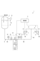
図1に示す充填装置1は、容器入り飲料製品を製造するラインの一部を構成し、図示しないボトル等の容器に製品液を充填する。
充填装置1は、製品液を貯留する貯液タンク2と、貯液タンク2から製品液が移送される充填機3と、充填機3に移送された製品液が分配される複数の充填バルブ4と、製品液の流量を調整可能に構成される液調整部10と、液調整部10を制御可能な制御部5とを備えている。充填装置1は、例えば、無菌状態の環境下で充填処理を行う。
Embodiments will be described below with reference to the accompanying drawings.
[Overall configuration of filling equipment]
A filling device 1 shown in FIG. 1 constitutes a part of a line for manufacturing containerized beverage products, and fills a container such as a bottle (not shown) with a product liquid.
The filling device 1 includes a liquid storage tank 2 that stores product liquid, a
〔貯液タンク〕
貯液タンク2は、原材料の調合や成分の抽出等の処理を行う図示しない調製設備(製品液の供給源)から製品液を受け入れて貯留する。
充填バルブ4に製品液を送り、充填バルブ4のノズルから吐出させる圧力(充填液圧力)を製品液に得るため、貯液タンク2内の製品液の水頭が用いられる。水頭と、製品液を圧送するポンプとが併用されてもよい。
[Liquid storage tank]
The liquid storage tank 2 receives and stores product liquid from a preparation facility (not shown) (supply source of product liquid) that performs processes such as mixing raw materials and extracting components.
In order to send the product liquid to the
貯液タンク2には、例えば30分を要する調合や抽出等の調製処理を終えた液を一度に受け入れ可能な容積が与えられている。貯液タンク2の液位は、貯液タンク2から充填機3への製品液の移送に伴い次第に低下する。貯液タンク2の液位は、一例として、図1にRLで示す範囲で変動する。
貯液タンク2には、液面より上方の気体の圧力を検知する圧力計21が設けられている。貯液タンク2内の気体の圧力は、貯液タンク2に気体を導入する弁および貯液タンク2から気体を排出させる弁(いずれも図示しない)の開閉動作により加減される。
The liquid storage tank 2 is given a volume that can receive at once a liquid that has been subjected to a preparation process such as blending or extraction that takes 30 minutes, for example. The liquid level in the liquid storage tank 2 gradually decreases as the product liquid is transferred from the liquid storage tank 2 to the
The liquid storage tank 2 is provided with a
〔充填機および充填バルブ〕
充填機3は、詳しい図示を省略するが、立設された軸部30を中心に回転駆動される回転体31と、回転体31に設けられて容器を保持するグリッパ等の容器保持具(図示しない)と、回転体31と共に回転方向に移動しつつ、容器保持具に保持された容器にノズル4Aを通じて製品液を吐出する充填バルブ4とを備えている。回転体31には、充填バルブ4および容器保持具がそれぞれ回転方向に一定ピッチで設けられている。
図示しない回転体から回転体31へと容器が順次供給され、充填バルブ4により一定量の製品液が充填された容器が回転体31からキャッパ等の図示しない回転体へと順次渡される。
[Filling machine and filling valve]
Although detailed illustrations are omitted, the
Containers are sequentially supplied from a rotating body (not shown) to a rotating
充填機3は、典型的な充填機に備わる充填タンク(フィラーボウル)を備えていない。典型例によると、充填タンクの液位を一定に維持し、充填タンクと充填バルブ4との水頭差に基づいて充填タンクから各充填バルブ4へと分配された製品液が、充填バルブ4のノズル4Aを通じて吐出される。それに対して、本実施形態では、貯液タンク2と複数の充填バルブ4との間には、上記のような充填タンクが介在していない。貯液タンク2と複数の充填バルブ4との間には、液調整部10が介在している。
The
貯液タンク2から移送路6に流出した製品液は、液調整部10を経て、充填機3の軸部30に設けられた図示しないロータリージョイントを介して液供給路に導入され、その図示しない液供給路から各充填バルブ4に向けて分配される。
充填バルブ4は、例えば、製品液が流れる流路を開閉する弁体と、圧縮空気を用いて弁体を駆動するエアシリンダ41とを備えて構成されている。
The product liquid flowing out from the liquid storage tank 2 into the
The
充填機3には、複数の充填バルブ4のノズル4Aにそれぞれ流入する製品液の流量を計測する複数の分配後流量計7が設けられている。回転体31に設けられた多数の充填バルブ4のうち、並行して製品液を充填する充填バルブ4の数の最大がNであるとすると、充填バルブ4に個別に対応する分配後流量計7により、F1~FnのN個の流量値を得ることができる。
The
飲料製品の製造は、充填装置1等の装置の内部や、装置が置かれた環境の洗浄および殺菌の処理を適時に行いながら実施される。
例えば洗浄処理後の操業開始により、充填機3の回転体31に容器が順次供給されると、充填機3は、受け取った容器に対応する充填バルブ4から順次、製品液の充填を開始する。容器に製品液を並行して充填する充填バルブ4の数(開弁数n)が次第に増加して最大数Nに達すると、充填機3は、N個の充填バルブ4から並行して製品液を容器に充填する定常運転を継続する。定常運転時における開弁数n(最大数N)は、例えば100である。充填機3は、例えば600~900 BPM(Bottle Per Minute)の能力を実現するため、容器に高速で充填する。
操業終了時は、回転体31への容器の供給の停止に伴い、開弁数nが次第に減少し、回転体31から最後の容器が排出された後、充填機3を停止させる。
The production of beverage products is carried out while cleaning and sterilizing the inside of the device such as the filling device 1 and the environment in which the device is placed in a timely manner.
For example, when the containers are sequentially supplied to the rotating
At the end of the operation, as the supply of containers to the
〔液調整部および制御部〕
液調整部10は、貯液タンク2よりも下流で、複数の充填バルブ4への分配前における製品液の流量を調整可能に構成されている。液調整部10は、貯液タンク2と充填機3とを結ぶ移送路6に設けられている。
液調整部10は、互いに並列に接続された複数の流量調整弁である並列弁11~13を備えている。加えて、外乱に対してより安定して流量調整を行うため、液調整部10は、並列弁11~13に対して直列に接続される流量調整弁である直列弁14を備えていることが好ましい。
[Liquid adjustment section and control section]
The
The
並列弁11~13および直列弁14のそれぞれの数は、あくまで一例である。液調整部10が、2あるいは4以上の並列弁を備えていたり、2以上の直列弁を備えていたりしてもよい。液調整部10は、必ずしも直列弁14を備えていなくてもよい。
また、直列弁14の接続形態は、図1に示す例に限らず、並列弁11~13の少なくとも1つに対して直列弁14が直列に接続されていればよい。
さらに、液調整部10が、必要に応じて、図示しない他の弁を備えていてもよい。例えば、並列弁11~13のそれぞれの上流に、各並列弁に対して直列に、並列弁と比べて応答性の高い電磁開閉弁(図示しない)が配置されていてもよい。この場合、電磁開閉弁を閉じた状態で各並列弁を所定開度まで開いた後、電磁開閉弁を開くことにより、並列弁を単体で用いる場合と比べて応答性を向上させることができる。
The respective numbers of
Further, the connection form of the
Furthermore, the
まず、並列弁11~13について説明する。充填機3による充填の実施に伴い貯液タンク2から製品液が下流へ流出し、制御部5による並列弁11~13のそれぞれの開度の調整により、並列弁11~13のうちの1以上を流れて充填機3へ供給される。制御部5は、開度指令を生成して並列弁11~13のそれぞれの開度を調整する。並列弁11~13の一次側6A(上流側)には圧力計61が設けられ、二次側6B(下流側)には圧力計62が設けられている。並列弁11~13の制御には、圧力計61,62によりそれぞれ検知される圧力P1,P2の差が用いられる。
First, the
第1~第3の並列弁11~13のそれぞれの流量に係る特性は互いに異なることが好ましい。
図2に第1~第3の並列弁11~13のそれぞれの開度-流量特性を模式的に示すように、第1~第3の並列弁11~13は、異なる流量範囲に対応している。
第1~第3の並列弁11~13は、図2に二点鎖線で示すように仮想の単一の流量調整弁として機能することで、流量範囲RFに適用可能である。そのため、第1~第3の並列弁11~13は、充填機3に供給される製品液の最小流量から最大流量までの流量範囲の全体に亘り対応できる。
It is preferable that the first to third
As shown in FIG. 2 schematically showing the opening degree-flow rate characteristics of each of the first to third
The first to third
流量に係るバルブの特性を示す値として、容量係数が用いられる。
容量係数は、バルブを全開にしたとき、単位時間あたりにバルブを通過する流体の体積、または重量を言う。容量係数としてはCv値、Kv値、Av値があり、典型的にはCv値が用いられる。バルブの容量係数には、バルブが適切に機能する流量範囲(適正領域)が定められている。バルブは、圧力が変動しても適正領域においては一定の流量に調整可能である。図2に示す並列弁11~13のそれぞれの流量範囲は、適正領域に相当する。
A capacity coefficient is used as a value indicating the characteristics of a valve related to flow rate.
Capacity coefficient refers to the volume or weight of fluid that passes through a valve per unit time when the valve is fully open. Capacity coefficients include C v value, K v value, and A v value, and typically C v value is used. The flow rate range (appropriate range) in which the valve functions properly is determined by the capacity coefficient of the valve. The valve can adjust the flow rate to be constant in the proper range even if the pressure fluctuates. The flow rate range of each of the
JIS B0100より、Cv値は、特定のトラベルにおける圧力差(バルブ出入口の圧力差)が1 lbf/in2(PSi)のときバルブを流れる60°Fの温度の水の流量をUS gal/min で表す数値のことを言い、次式(1)によって求める。 According to JIS B0100, the Cv value is the flow rate of water at a temperature of 60°F flowing through a valve when the pressure difference at a specific travel (pressure difference between the valve inlet and outlet) is 1 lbf/in 2 (PSi), US gal/min. It refers to the numerical value expressed by , and is determined by the following equation (1).
Cv=Q√(G/Δp) (1)
Q :流量(US gal/min)
Δp:圧力差(1 lbf/in2)
G :流体の比重(水の比重である1)
C v =Q√(G/Δp) (1)
Q: Flow rate (US gal/min)
Δp: Pressure difference (1 lbf/in 2 )
G: Specific gravity of fluid (1, which is the specific gravity of water)
並列接続される複数の並列弁11~13に製品液を分配可能であって、並列弁11~13の1以上を選択的に動作させることにより、並列弁11~13がそれぞれ調整を受け持つ流量範囲を適正領域に留めることができるので、単一の流量調整弁を用いる場合と比べ、圧力変動に対して安定して流量調整を行える。
したがって、並列弁11~13の容量係数の総和として、充填バルブ4への分配前における製品液に必要な最大流量に対応しつつ、最小流量から最大流量までに亘り、圧力変動に対して安定して流量調整を行うことができる。
The product liquid can be distributed to a plurality of
Therefore, the sum of the capacity coefficients of the
並列接続に加え、並列弁11~13のそれぞれの流量に係る特性が互いに異なることによれば、充填機3に供給される製品液の最小流量から最大流量までに亘り、少ない数の流量調整弁により効率よく流量調整を行うことができる。
In addition to the parallel connection, since the
定常時における充填バルブ4の開弁数n(最大数N)が多いほど、開弁数nが0から最大数Nまで増加する、あるいは、最大数Nから0へと減少する非定常時の流量変化が大きい。そして、充填機3の能力が高いほど、開弁数nの増減に伴って流量が急激に変化する。
並列接続される複数の並列弁11~13によれば、非定常時の広い流量範囲に亘る急激な流量変化に対しても安定して、応答性良く流量調整を行うことができる。
The larger the number of openings n (maximum number N) of the filling
With the plurality of
製品液の流量に係る外乱としては、例えば、調整設備により調整された製品液を貯液タンク2に一度に受け入れることによる貯液タンク2内の液位の顕著で急激な変動が該当する。貯液タンク2の液位によっては、充填液圧力に対して貯液タンク2と充填バルブ4との水頭差が過大である。貯液タンク2内の液位の急激な変動に伴い、貯液タンク2の下流に製品液の流量変化および圧力変動が発生したとしても、制御部5により液調整部10の並列弁11~13のそれぞれの開度が適切に調整されることにより、充填バルブ4への製品液の安定供給を継続することができる。
The disturbance related to the flow rate of the product liquid includes, for example, a noticeable and sudden change in the liquid level in the liquid storage tank 2 caused by receiving the product liquid adjusted by the adjustment equipment into the liquid storage tank 2 all at once. Depending on the liquid level of the liquid storage tank 2, the water head difference between the liquid storage tank 2 and the filling
より十分に外乱に対処するため、並列弁11~13に加えて、直列弁14を用いることができる。直列弁14の開度が調整されることで、直列弁14の二次側における製品液の圧力および流量を安定させる。直列弁14が、並列弁11~13の二次側に設けられることも許容される。
なお、直列弁14を用いることに代えて、あるいは直列弁14の使用と併せ、貯液タンク2への窒素ガス等の供給量の調整により貯液タンク2の内圧を加減することで、貯液タンク2からの送液圧力P1の変動を抑制することも有効である。
In order to cope with disturbances more fully, in addition to the parallel valves 11-13, a
In addition, instead of using the
〔液調整部の制御による充填方法〕
充填機3は、回転体31に供給された容器に対して、複数の充填バルブ4により、充填バルブ4が開いている間に一定量の製品液を充填する。
したがって、制御部5は、各充填バルブ4に流入する製品液の充填流量F1~Fnの総和を液調整部10の二次側に得るため、計測された充填流量F1~Fnの演算による総和に基づいて、並列弁11~13および直列弁14をいずれも所定の開度に調整する制御を行う。
ここで、制御部5は、移送路6や充填機3の管路における圧力損失、回転体31の回転に伴う遠心力等の影響をも加味し、充填流量F1~Fnの演算による総和に基づいて並列弁11~13および直列弁14の開度調整を行うものとする。
充填流量F1~Fnの総和は算出できるため、液調整部10の二次側6Bに必ずしも分配前流量計8が設けられている必要はない。分配前流量計8は、液調整部10の校正のために用いることができる。
あるいは、充填装置1が分配前流量計8を備えているならば、充填流量F1~Fnの総和を算出する必要がなく、その場合は、分配後流量計7を備えている必要がない。
[Filling method by controlling the liquid adjustment section]
The filling
Therefore, in order to obtain the sum of the filling flow rates F 1 -F n of the product liquid flowing into each filling
Here, the
Since the sum of the filling flow rates F 1 to F n can be calculated, the
Alternatively, if the filling device 1 is equipped with a
制御部5は、各分配後流量計7により充填流量F1~Fnを計測しつつ、目標値に対する充填流量F1~Fnの総和の偏差を解消するように並列弁11~13および直列弁14の開度を調整するフィードバック制御を行うことができる。目標値は、開弁数nおよび充填機3の能力に応じた規定の充填流量の総和に相当する。
The
液調整部10の二次側6Bに位置する分配前流量計8は、充填流量F1~Fnの総和に対応する流量F0を示す。したがって、液調整部10のフィードバック制御には、充填流量F1~Fnの演算による総和に代えて、分配前流量計8により計測された流量F0、または、充填流量F1~Fnの演算による総和および計測された流量F0の双方を用いることができる。
あるいは、充填流量F1~Fnの総和や流量F0を用いてフィードバック制御することは、液調整部10の二次側の圧力P2を一定にすることとなるから、充填流量F1~Fnの総和や流量F0に代えて、圧力P2をフィードバック制御に用いることも可能である。
The
Alternatively, since performing feedback control using the sum of the filling flow rates F 1 to F n or the flow rate F 0 makes the pressure P 2 on the secondary side of the
上記のようなフィードバック制御に加えて、制御部5は、貯液タンク2への液の受け入れ時や、操業の開始時または停止時等、圧力または流量の予測可能な変動に際して、フィードフォワード制御を行うことが好ましい。このとき制御部5は、液調整部10の一次側6Aおよび二次側6Bの少なくとも一方における製品液の圧力または流量の変動に際し、開度指令を与えて並列弁11~13および直列弁14を所定の開度に調整する。所定の開度は、計算や試験により予め適切に定められるものとする。
操業の開始時または停止時であれば、開弁数nに応じて並列弁11~13を段階的に開閉させるように、並列弁11~13に所定の開度を与える。例えば、第1~第3の並列弁11~13のうち第1の並列弁11および第2の並列弁12のみを開弁数nに対応した合計の充填流量から定められた所定の開度で開き、第3の並列弁13を全閉する。
あるいは、回転体31への容器の受け渡し後に容器保持具に容器が存在しているか否かを検知し、容器が存在していないならば充填バルブ4を閉じる場合にも、第1~第3の並列弁11~13のそれぞれを充填バルブ4の実際の開弁数nに対応した合計の充填流量から定められた所定の開度で開くように制御するとよい。
フィードフォワード制御によれば、圧力および流量の変動を液調整部10の各弁の開度設定により打ち消すことができるので、外乱発生の前後に亘り、充填バルブ4に規定の充填流量の製品液を安定して供給することができる。
In addition to the feedback control described above, the
When starting or stopping the operation, a predetermined opening degree is given to the
Alternatively, the first to third It is preferable to control each of the
According to feedforward control, fluctuations in pressure and flow rate can be canceled by setting the opening degree of each valve in the
図3を参照し、液調整部10の制御例について説明する。
縦軸は、バルブのCv値や製品液の圧力、流量等の変化量を示す変化軸である。横軸は、時間軸である。
図3において変化量を示す記号の意味を以下に示す。
Cv0:直列弁14のCv値
Cv:並列弁11~13のCv値の総和
Cv1:第1の並列弁11のCv値
Cv2:第2の並列弁12のCv値
Cv3:第3の並列弁13のCv値
P2:液調整部10の二次側の圧力
P1:貯液タンク2からの送液圧力
Fn:充填バルブ4の代表充填流量
F:全充填流量
n:充填バルブ4の開弁数
An example of controlling the
The vertical axis is a change axis indicating the amount of change in the Cv value of the valve, the pressure of the product liquid, the flow rate, etc. The horizontal axis is the time axis.
The meanings of the symbols indicating the amount of change in FIG. 3 are shown below.
C v0 : C v value of the series valve 14 C v : Sum of C v values of the
図3では、充填機3による充填処理を開始し、短い定常運転の後、充填処理を停止した場合を想定している。非定常運転時には開弁数nが増減する。
充填処理の進行に伴い、貯液タンク2内の液位が減少することで、液調整部10の一次側6Aの圧力P1が次第に減少する。直列弁14の開度制御によれば、圧力P1の変化に対して、直列弁14の二次側(並列弁11~13の一次側)の圧力の安定を図ることができる。図3に示す例では、直列弁14の開度調整により、Cv0を次第に増加させている。
In FIG. 3, it is assumed that the filling
As the filling process progresses, the liquid level in the liquid storage tank 2 decreases, so that the pressure P1 on the
充填処理の開始から定常運転を経て充填処理を停止するまでに亘り、図3に実線で示すように開弁数nに対応したCvに制御することで、各充填バルブ4の充填流量を一定にすることができる。
貯液タンク2から送られる製品液の流量調整を仮に単一の流量調整弁のみによって行う場合は、図3に破線で示すようにCvが実線の理想状態に対してシフトしてしまうとしても、並列弁11~13のCv1~Cv3を適宜に組み合わせるならば、並列弁11~13の全体として実線で示すCvを実現することができる。
From the start of the filling process through steady operation until the filling process is stopped, the filling flow rate of each filling
If the flow rate of the product liquid sent from the liquid storage tank 2 is adjusted using only a single flow rate adjustment valve, as shown by the broken line in Fig. 3, even if Cv shifts from the ideal state shown by the solid line. , C v1 to C v3 of the
また、充填処理に伴う貯液タンク2内の液位の変化に起因して一次側6Aの圧力P1が変動したとしても、直列弁14の開度制御により直列弁14の二次側の圧力を安定させつつ、充填流量F1~Fnの総和、あるいは、充填バルブ4への分配前の製品液の流量F0または圧力P2に基づいて並列弁11~13のそれぞれの開度を制御するフィードバック制御を行うことにより、二次側6Bに一定の圧力P2を得て、充填流量への影響を避けながら充填処理を安定して行うことができる。
さらに、開弁数nに応じて並列弁11~13を段階的に開閉し、F1~Fnの総和、あるいは、充填バルブ4への分配前の製品液の流量F0または圧力P2に対応する流量Fを二次側6Bに与えるフィードフォワード制御により、開弁数nが変化する非定常時において充填流量Fnが破線で示すように実線の理想状態に対してシフトしてしまうことなく、充填流量を常時一定に制御することができる。
Furthermore, even if the pressure P1 on the
Furthermore, the
以上で説明した本実施形態の充填装置1および充填方法によれば、典型例とは異なり、貯液タンク2と充填バルブ4とが充填タンクを介さないで接続されている構造にあって、液調整部10の並列弁11~13を選択的に動作させることにより、貯液タンク2への製品液の受け入れ時や操業開始・停止時に製品液に発生する圧力および流量の変動にかかわらず、一定の充填流量を得て安定した充填処理が可能となる。
また、貯液タンク2および充填タンクの2つのタンクを備えた典型例に対し、充填タンクを備えていない分、製造コストを抑えることができる上、タンクの洗浄および殺菌に要する非生産時間を削減できるので生産効率を向上させることができる。
According to the filling device 1 and the filling method of the present embodiment described above, unlike the typical example, the liquid storage tank 2 and the filling
In addition, unlike the typical example that has two tanks, the liquid storage tank 2 and the filling tank, since there is no filling tank, manufacturing costs can be reduced, and non-productive time required for tank cleaning and sterilization can be reduced. Therefore, production efficiency can be improved.
〔変形例〕
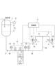
図4に示す充填機3の複数の充填バルブ4のそれぞれには、電動シリンダ42が設けられている。電動シリンダ42に備わるモータに制御部5から制御指令を与えることで、対応する充填バルブ4を任意の開度に調整可能である。そのため、各充填バルブ4に分配された製品液の流量がばらついていたとしても、分配後流量計7により計測された充填流量F1~Fnに基づいて電動シリンダ42により充填バルブ4毎に開度が調整されることで、各充填バルブ4から吐出される製品液の流量を一定にすることができる。
また、電動シリンダ42を用いることで、充填バルブ4により製品液を充填するサイクルの開始時と終了時における充填流量をサイクルの中間時の充填流量と比べて低くするといった制御を容易に実現できる。
[Modified example]
Each of the plurality of filling
Further, by using the
上記以外にも、上記実施形態で挙げた構成を取捨選択したり、他の構成に適宜変更したりすることが可能である。
本開示の充填装置および充填方法により充填される液体は、飲料に限らず、医薬品等であってもよい。
In addition to the above, it is possible to select the configurations mentioned in the above embodiments or to change them to other configurations as appropriate.
The liquid filled by the filling device and filling method of the present disclosure is not limited to beverages, and may be pharmaceuticals or the like.
〔付記〕
上記実施形態に記載の充填装置および充填方法は、以下のように把握される。
(1)充填装置1は、液体を供給源から受け入れて貯留する貯液タンク2と、貯液タンク2から液体が移送される充填機3と、充填機3に備えられ、充填機3に移送された液体が分配される複数の充填バルブ4と、貯液タンク2よりも下流で、複数の充填バルブ4への分配前における液体の流量を調整可能に構成される液調整部10とを備える。液調整部10は、互いに並列に接続される2以上の並列弁11~13を含む。
(2)2以上の並列弁11~13のそれぞれの流量に係る特性が互いに異なる。
(3)充填装置1は、液調整部10を制御する制御部5を備える。制御部5は、複数の充填バルブ4のノズル4Aにそれぞれ流入する液体の充填流量を計測する複数の分配後流量計7によりそれぞれ計測された充填流量F1~Fnの総和、あるいは、充填バルブ4への分配前の液体の流量または圧力に基づいて、2以上の並列弁11~13のそれぞれの開度を調整する。
(4)制御部5は、複数の分配後流量計7によりそれぞれ充填流量を計測しつつ、充填流量F1~Fnの総和、あるいは、充填バルブ4への分配前の液体の流量または圧力の目標値に対する偏差を解消するように2以上の並列弁11~13のそれぞれの開度を調整するフィードバック制御を行うとともに、液調整部10の一次側6Aおよび二次側6Bの少なくとも一方における液体の圧力または流量の変動に際して、2以上の並列弁11~13を所定の開度に調整するフィードフォワード制御を行う。
(5)貯液タンク2と複数の充填バルブ4との間には、別のタンクが介在しておらず、液調整部10が介在している。
(6)液調整部10は、並列弁11~13のうちの1以上に対して直列に接続される直列弁14を含む。
(7)複数の充填バルブ4のそれぞれには、充填バルブ4に備わるノズル4Aに流入する液体の充填流量を調整可能な電動シリンダ42が設けられている。
(8)液体を供給源から受け入れて貯留する貯液タンク2から充填機3へと移送された液体が分配される複数の充填バルブ4を用いて充填を行う方法であって、貯液タンク2よりも下流で複数の充填バルブ4への分配前における液体の流量を調整可能な液調整部10が、互いに並列に接続される2以上の並列弁11~13を含んで構成されており、複数の充填バルブ4のノズル4Aにそれぞれ流入する液体の充填流量F1~Fnの総和、あるいは、充填バルブ4への分配前の液体の流量または圧力に基づいて、2以上の並列弁11~13のそれぞれの開度を調整する。
(9)並列弁11~13の開度に加え、並列弁11~13の1以上に対して直列に接続される直列弁14の開度を調整する。
[Additional note]
The filling device and filling method described in the above embodiments can be understood as follows.
(1) The filling device 1 includes a liquid storage tank 2 that receives liquid from a supply source and stores it, a filling
(2) The two or more
(3) The filling device 1 includes a
(4) The
(5) Another tank is not interposed between the liquid storage tank 2 and the plurality of filling
(6) The
(7) Each of the plurality of filling
(8) A method of filling the liquid storage tank 2 using a plurality of filling
(9) In addition to the opening degrees of the
1 充填装置
2 貯液タンク
3 充填機
4 充填バルブ
4A ノズル
5 制御部
6 移送路
6A 一次側
6B 二次側
7 分配後流量計
8 分配前流量計
10 液調整部
11~13 並列弁
14 直列弁
21 圧力計
30 軸部
31 回転体
41 エアシリンダ
42 電動シリンダ
61,62 圧力計
F0 流量
F1~Fn 充填流量
P1,P2 圧力
RF 流量範囲
n 開弁数
1 Filling device 2
Claims (9)
前記貯液タンクから前記液体が移送される充填機と、
前記充填機に備えられ、前記充填機に移送された前記液体が分配される複数の充填バルブと、
前記貯液タンクよりも下流で、前記複数の充填バルブへの分配前における前記液体の流量を調整可能に構成される液調整部と、
前記液調整部よりも上流における前記液体の圧力P1を測定する第1圧力計と、
前記液調整部よりも下流であって前記充填機よりも上流における前記液体の圧力P2を測定する第2圧力計と、
前記液調整部を制御する制御部と、を備え、
前記液調整部は、
互いに並列に接続される2以上の並列弁を含み、
前記制御部は、
前記圧力P1が減少するのに対し、
前記圧力P2が一定になるように、前記並列弁のそれぞれの開度を制御する充填装置。 a liquid storage tank that receives and stores liquid from a supply source;
a filling machine for transferring the liquid from the liquid storage tank;
a plurality of filling valves included in the filling machine and distributing the liquid transferred to the filling machine;
A liquid adjustment section configured to be able to adjust the flow rate of the liquid before distribution to the plurality of filling valves downstream of the liquid storage tank;
a first pressure gauge that measures the pressure P1 of the liquid upstream of the liquid adjustment section;
a second pressure gauge that measures the pressure P2 of the liquid downstream of the liquid adjustment section and upstream of the filling machine;
A control unit that controls the liquid adjustment unit ,
The liquid adjustment section is
including two or more parallel valves connected in parallel to each other,
The control unit includes:
While the pressure P1 decreases,
A filling device that controls the opening degree of each of the parallel valves so that the pressure P2 is constant .
請求項1に記載の充填装置。 The two or more parallel valves have different flow rate characteristics,
The filling device according to claim 1.
前記複数の充填バルブのノズルにそれぞれ流入する前記液体の充填流量を計測する複数の分配後流量計によりそれぞれ計測された前記充填流量の総和、あるいは、前記充填バルブへの分配前の前記液体の流量または圧力に基づいて、前記2以上の並列弁のそれぞれの開度を調整する、
請求項1または2に記載の充填装置。 The control unit includes :
The sum of the filling flow rates measured by a plurality of post-distribution flowmeters that measure the filling flow rates of the liquid flowing into the nozzles of the plurality of filling valves, or the flow rate of the liquid before distribution to the filling valves. or adjusting the opening degree of each of the two or more parallel valves based on the pressure;
The filling device according to claim 1 or 2.
前記複数の分配後流量計によりそれぞれ前記充填流量を計測しつつ、前記充填流量の総和、あるいは、前記充填バルブへの分配前の前記液体の流量または圧力の目標値に対する偏差を解消するように前記2以上の並列弁のそれぞれの開度を調整するフィードバック制御を行うとともに、
前記液調整部の一次側および二次側の少なくとも一方における前記液体の圧力または流量の変動に際して、
前記2以上の並列弁を所定の開度に調整するフィードフォワード制御を行う、
請求項3に記載の充填装置。 The control unit includes:
While each of the plurality of post-dispensing flowmeters measures the filling flow rate, the total filling flow rate or the deviation from the target value of the flow rate or pressure of the liquid before distribution to the filling valve is eliminated. Feedback control is performed to adjust the opening degree of each of two or more parallel valves, and
When the pressure or flow rate of the liquid changes on at least one of the primary side and secondary side of the liquid adjustment section,
performing feedforward control to adjust the two or more parallel valves to a predetermined opening degree;
The filling device according to claim 3.
請求項1から4のいずれか一項に記載の充填装置。 No other tank is interposed between the liquid storage tank and the plurality of filling valves, and the liquid adjustment section is interposed between the liquid storage tank and the plurality of filling valves.
A filling device according to any one of claims 1 to 4.
前記並列弁のうちの1以上に対して直列に接続される直列弁を含む、
請求項1から5のいずれか一項に記載の充填装置。 The liquid adjustment section is
a series valve connected in series to one or more of the parallel valves;
A filling device according to any one of claims 1 to 5.
前記充填バルブに備わるノズルに流入する前記液体の充填流量を調整可能な電動シリンダが設けられている、
請求項1から6のいずれか一項に記載の充填装置。 Each of the plurality of filling valves includes:
An electric cylinder is provided that can adjust the filling flow rate of the liquid flowing into the nozzle provided in the filling valve.
A filling device according to any one of claims 1 to 6.
前記貯液タンクよりも下流で前記複数の充填バルブへの分配前における前記液体の流量を調整可能な液調整部が、互いに並列に接続される2以上の並列弁を含んで構成されており、
前記複数の充填バルブのノズルにそれぞれ流入する前記液体の充填流量の総和、あるいは、前記充填バルブへの分配前の前記液体の流量または圧力に基づいて、前記液調整部よりも上流において第1圧力計で計測される前記液体の圧力P1が減少するのに対し、前記液調整部よりも下流であって前記充填機よりも上流において第2圧力計で計測される前記液体の圧力P2が一定になるように、前記2以上の並列弁のそれぞれの開度を調整する、充填方法。 A method for performing filling using a plurality of filling valves that distribute the liquid transferred from a liquid storage tank that receives and stores liquid from a supply source to a filling machine, the method comprising:
A liquid adjustment section that can adjust the flow rate of the liquid before distribution to the plurality of filling valves downstream of the liquid storage tank is configured to include two or more parallel valves connected in parallel to each other,
A first pressure upstream of the liquid adjustment section based on the sum of the filling flow rates of the liquid flowing into the nozzles of the plurality of filling valves, or the flow rate or pressure of the liquid before distribution to the filling valves. While the pressure P1 of the liquid measured by the meter decreases, the pressure P2 of the liquid measured by a second pressure gauge downstream of the liquid adjustment section and upstream of the filling machine remains constant. A filling method in which the opening degree of each of the two or more parallel valves is adjusted so that
前記並列弁の1以上に対して直列に接続される直列弁の開度を調整する、
請求項8に記載の充填方法。 In addition to the opening degree of the parallel valve,
adjusting the opening degree of a series valve connected in series to one or more of the parallel valves;
The filling method according to claim 8.
Priority Applications (1)
| Application Number | Priority Date | Filing Date | Title |
|---|---|---|---|
| JP2020030427A JP7444635B2 (en) | 2020-02-26 | 2020-02-26 | Filling equipment and filling method |
Applications Claiming Priority (1)
| Application Number | Priority Date | Filing Date | Title |
|---|---|---|---|
| JP2020030427A JP7444635B2 (en) | 2020-02-26 | 2020-02-26 | Filling equipment and filling method |
Publications (2)
| Publication Number | Publication Date |
|---|---|
| JP2021133954A JP2021133954A (en) | 2021-09-13 |
| JP7444635B2 true JP7444635B2 (en) | 2024-03-06 |
Family
ID=77662364
Family Applications (1)
| Application Number | Title | Priority Date | Filing Date |
|---|---|---|---|
| JP2020030427A Active JP7444635B2 (en) | 2020-02-26 | 2020-02-26 | Filling equipment and filling method |
Country Status (1)
| Country | Link |
|---|---|
| JP (1) | JP7444635B2 (en) |
Citations (5)
| Publication number | Priority date | Publication date | Assignee | Title |
|---|---|---|---|---|
| JP2001255194A (en) | 2000-03-09 | 2001-09-21 | Mitsubishi Paper Mills Ltd | Liquid metering device |
| JP2002527313A (en) | 1998-10-16 | 2002-08-27 | レミ・エキプモン | Method for controlling the filling of a container with a flow product and a filling device for implementing said method |
| JP2005187016A (en) | 2003-12-26 | 2005-07-14 | Asahi Breweries Ltd | Beer filling equipment |
| JP2011114067A (en) | 2009-11-25 | 2011-06-09 | Jsr Corp | Device and method for filling lithography composition |
| JP2012176783A (en) | 2011-02-28 | 2012-09-13 | Mitsubishi Heavy Industries Food & Packaging Machinery Co Ltd | Filling valve device |
Family Cites Families (2)
| Publication number | Priority date | Publication date | Assignee | Title |
|---|---|---|---|---|
| JPH0176500U (en) * | 1987-11-12 | 1989-05-23 | ||
| JP3712452B2 (en) * | 1995-12-06 | 2005-11-02 | 三菱重工業株式会社 | Flow rate control filling method |
-
2020
- 2020-02-26 JP JP2020030427A patent/JP7444635B2/en active Active
Patent Citations (5)
| Publication number | Priority date | Publication date | Assignee | Title |
|---|---|---|---|---|
| JP2002527313A (en) | 1998-10-16 | 2002-08-27 | レミ・エキプモン | Method for controlling the filling of a container with a flow product and a filling device for implementing said method |
| JP2001255194A (en) | 2000-03-09 | 2001-09-21 | Mitsubishi Paper Mills Ltd | Liquid metering device |
| JP2005187016A (en) | 2003-12-26 | 2005-07-14 | Asahi Breweries Ltd | Beer filling equipment |
| JP2011114067A (en) | 2009-11-25 | 2011-06-09 | Jsr Corp | Device and method for filling lithography composition |
| JP2012176783A (en) | 2011-02-28 | 2012-09-13 | Mitsubishi Heavy Industries Food & Packaging Machinery Co Ltd | Filling valve device |
Also Published As
| Publication number | Publication date |
|---|---|
| JP2021133954A (en) | 2021-09-13 |
Similar Documents
| Publication | Publication Date | Title |
|---|---|---|
| US11142443B2 (en) | Method and filling system for filling containers | |
| CN102372241B (en) | Apparatus and method for filling multicomponent beverages | |
| JP5370951B2 (en) | Pneumatic transport method and apparatus for bulk material with poor flow | |
| RU2386579C1 (en) | Method and device for controlled foaming of filler added into bottles or similar containers | |
| US4539903A (en) | Filling apparatus | |
| CN105636898A (en) | A method for a filling valve, and a filling valve system | |
| CN112399883B (en) | Liquid mixing and supplying device | |
| CN105177200A (en) | Blast furnace coal injection system and control method thereof | |
| CN114516610B (en) | Device for filling containers with filling products | |
| JP3335182B2 (en) | Container filling method and apparatus | |
| JP7444635B2 (en) | Filling equipment and filling method | |
| CN109592623A (en) | A kind of liquid-filling machine | |
| CN103771315A (en) | Device for filling at least one container with a filling product | |
| US8887751B2 (en) | System and method for continuously producing a liquid mixture | |
| RU2240591C2 (en) | Method and apparatus for preparing of milk product | |
| US8382904B2 (en) | Gas feed installation for machines depositing a barrier layer on containers | |
| JP7223195B1 (en) | Liquid delivery system | |
| JP2006264755A (en) | Flow meter type liquid filling device | |
| JP2007197062A (en) | Pressurization filling machine | |
| CN111247088B (en) | Method of filling a container with filling product | |
| JP7365149B2 (en) | Filling mechanism and method for transferring filled products into containers | |
| JP2013001417A (en) | Liquid filling apparatus and liquid filling method | |
| US20140238531A1 (en) | Method for controlling a filling system, and the filling system | |
| CN117891133B (en) | Photoresist printing system and printing method | |
| JP3536479B2 (en) | Pressurized filling device |
Legal Events
| Date | Code | Title | Description |
|---|---|---|---|
| A625 | Written request for application examination (by other person) |
Free format text: JAPANESE INTERMEDIATE CODE: A625 Effective date: 20220906 |
|
| A977 | Report on retrieval |
Free format text: JAPANESE INTERMEDIATE CODE: A971007 Effective date: 20230621 |
|
| A131 | Notification of reasons for refusal |
Free format text: JAPANESE INTERMEDIATE CODE: A131 Effective date: 20230627 |
|
| A521 | Request for written amendment filed |
Free format text: JAPANESE INTERMEDIATE CODE: A523 Effective date: 20230825 |
|
| A131 | Notification of reasons for refusal |
Free format text: JAPANESE INTERMEDIATE CODE: A131 Effective date: 20231010 |
|
| TRDD | Decision of grant or rejection written | ||
| A01 | Written decision to grant a patent or to grant a registration (utility model) |
Free format text: JAPANESE INTERMEDIATE CODE: A01 Effective date: 20240130 |
|
| A61 | First payment of annual fees (during grant procedure) |
Free format text: JAPANESE INTERMEDIATE CODE: A61 Effective date: 20240222 |
|
| R150 | Certificate of patent or registration of utility model |
Ref document number: 7444635 Country of ref document: JP Free format text: JAPANESE INTERMEDIATE CODE: R150 |