以下に、図面を参照しながら本開示を実施するための複数の形態を説明する。各形態において先行する形態で説明した事項に対応する部分には同一の参照符号を付して重複する説明を省略する場合がある。各形態において構成の一部のみを説明している場合は、構成の他の部分については先行して説明した他の形態を適用することができる。各実施形態で具体的に組み合わせが可能であることを明示している部分同士の組み合わせばかりではなく、特に組み合わせに支障が生じなければ、明示していなくても実施形態同士を部分的に組み合せることも可能である。
Hereinafter, a plurality of embodiments for carrying out the present disclosure will be described with reference to the drawings. In each form, parts corresponding to matters explained in the preceding form may be given the same reference numerals and redundant explanation may be omitted. When only a part of the configuration is described in each form, the other forms previously described can be applied to other parts of the structure. Not only combinations of parts that specifically indicate that combinations are possible in each embodiment, but also partial combinations of embodiments even if it is not explicitly stated, as long as there is no particular problem with the combination. It is also possible.
<第1実施形態>
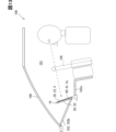
図1に示す画像表示装置10は車両100に搭載されている。画像表示装置10は、車両100の車室101に露出した状態でインパネ102に設けられている。インパネ102は、インストルメントパネルであり、運転席などの座席の前方に設けられている。インパネ102は、車室101の内装を形成する内装パネルである。内装パネルは、車室101において仕上げ加工が施された仕上げ面を形成している。運転席とインパネ102との間にはステアリング105がある。運転席の前方には、ステアリング105に加えてフロントウインドシールド106がある。フロントウインドシールド106は、インパネ102の上側にある。座席の前方は、車両100にとっての前方である。車両100のウインドシールドとしては、フロントウインドシールド106の他にサイドウインドシールドなどがある。
<First embodiment>
The image display device 10 shown in FIG. 1 is mounted on a vehicle 100. The image display device 10 is provided on the instrument panel 102 in a state where it is exposed to the cabin 101 of the vehicle 100. The instrument panel 102 is an instrument panel, and is provided in front of a seat such as a driver's seat. The instrument panel 102 is an interior panel that forms the interior of the vehicle interior 101 . The interior panel forms a finished surface in the vehicle interior 101 that has been subjected to finishing processing. A steering wheel 105 is located between the driver's seat and the instrument panel 102. In addition to the steering wheel 105, there is a front windshield 106 in front of the driver's seat. The front windshield 106 is located above the instrument panel 102. The front of the seat is the front of the vehicle 100. In addition to the front windshield 106, the windshield of the vehicle 100 includes a side windshield and the like.
画像表示装置10は、各種情報を画像Vとして表示する。画像表示装置10は表示装置に相当する。各種情報には、例えば車両情報及び走行情報が含まれている。車両情報は車載バッテリの蓄電量などを示す情報であり、走行情報は車両100の走行速度や走行モード、走行距離などを示す情報である。また、各種情報には、ナビゲーション情報やエンタメ情報、空調情報、カメラ情報などが含まれている。例えば、ナビゲーション情報は、車両100の現在値を示す情報や現在地から目的地までの経路を案内する情報などである。カメラ情報は、カメラ等の撮像装置により撮像された情報である。カメラ情報には、車両100の後方など車両周辺を撮像した情報が含まれている。
The image display device 10 displays various information as an image V. The image display device 10 corresponds to a display device. The various information includes, for example, vehicle information and driving information. The vehicle information is information indicating the amount of electricity stored in the on-board battery, and the traveling information is information indicating the traveling speed, traveling mode, traveling distance, etc. of the vehicle 100. Further, the various information includes navigation information, entertainment information, air conditioning information, camera information, etc. For example, the navigation information is information indicating the current value of the vehicle 100, information guiding the route from the current location to the destination, and the like. Camera information is information captured by an imaging device such as a camera. The camera information includes information captured around the vehicle, such as behind the vehicle 100.
画像表示装置10は、表示面22を有しており、この表示面22に画像Vを表示することが可能である。表示面22は、画像光を出力することで画像Vを表示する。画像表示装置10は、表示面22に加えてフード背面52を有している。画像表示装置10は、全体として板状に形成されている。フード背面52は、装置厚さ方向において表示面22とは反対側を向いている。装置厚さ方向は、画像表示装置10の厚さ方向であり、本実施形態では上下に延びる方向である。装置厚さ方向は、表示面22に直交する方向である。
The image display device 10 has a display surface 22, and can display an image V on this display surface 22. The display surface 22 displays the image V by outputting image light. The image display device 10 has a hood back 52 in addition to the display surface 22. The image display device 10 is formed into a plate shape as a whole. The hood back surface 52 faces the opposite side from the display surface 22 in the thickness direction of the device. The device thickness direction is the thickness direction of the image display device 10, and in this embodiment is a direction extending vertically. The device thickness direction is a direction perpendicular to the display surface 22.
画像表示装置10は反射ミラー15と共に、虚像表示装置11に含まれている。虚像表示装置11は車両100に搭載されており、画像Vを虚像Viとして表示する。反射ミラー15は、画像光を反射する反射部材であり、反射鏡と称されることがある。反射ミラー15は、反射面16を有しており、反射面16で画像光を反射して虚像Viを表示する。反射面16は、反射ミラー15が有する一対の板面のうち一方に含まれている。反射ミラー15は、反射面16に入射する画像光について透過及び反射のうち反射を行う部材である。反射ミラー15は、画像光により虚像を表示する虚像表示部に相当する。
The image display device 10 is included in the virtual image display device 11 together with the reflective mirror 15 . The virtual image display device 11 is mounted on the vehicle 100 and displays the image V as a virtual image Vi. The reflecting mirror 15 is a reflecting member that reflects image light, and is sometimes referred to as a reflecting mirror. The reflective mirror 15 has a reflective surface 16, and reflects the image light on the reflective surface 16 to display a virtual image Vi. The reflective surface 16 is included in one of the pair of plate surfaces that the reflective mirror 15 has. The reflective mirror 15 is a member that transmits and reflects image light incident on the reflective surface 16. The reflecting mirror 15 corresponds to a virtual image display unit that displays a virtual image using image light.
反射ミラー15は、反射面16が車室101に露出した状態でインパネ102に設けられている。反射ミラー15は、インパネ102に埋め込まれた状態でインパネ102に固定されている。反射面16は、座席側を向くように斜め上方を向いている。座席に座った乗員にとっては反射面16を視認しやすくなっている。
The reflective mirror 15 is provided on the instrument panel 102 with a reflective surface 16 exposed to the vehicle interior 101. The reflective mirror 15 is embedded in the instrument panel 102 and fixed to the instrument panel 102. The reflective surface 16 faces obliquely upward so as to face the seat side. The reflective surface 16 is easily visible to the passenger sitting in the seat.
画像表示装置10は、表示面22からの画像光が反射面16で座席側に反射するように設けられている。画像表示装置10は、表示面22が下方を向き且つフード背面52が上方を向いた状態で、反射ミラー15の上側に設けられている。表示面22と反射面16とは互いに向き合った状態になっている。座席に座った乗員にとっては、画像光により表示された虚像Viがあたかも反射面16よりも奥側にあるかのように見える。
The image display device 10 is provided so that the image light from the display surface 22 is reflected by the reflective surface 16 toward the seat side. The image display device 10 is provided above the reflective mirror 15 with the display surface 22 facing downward and the hood back surface 52 facing upward. The display surface 22 and the reflective surface 16 are in a state facing each other. For the occupant sitting in the seat, the virtual image Vi displayed by the image light appears as if it were located further back than the reflective surface 16.
虚像表示装置11においては、視認者としての乗員は表示面22を直接的に見るのではなく、反射面16を視認することで表示面22を間接的に見ることになる。本実施形態では、反射面16が乗員により視認される視認面Svである。乗員は、視認面Svである反射面16を視認することで虚像Viを視認することが可能である。
In the virtual image display device 11, the occupant as a viewer does not directly view the display surface 22, but indirectly views the display surface 22 by viewing the reflective surface 16. In this embodiment, the reflective surface 16 is a visible surface Sv that is visually recognized by the occupant. The occupant can visually recognize the virtual image Vi by viewing the reflective surface 16 that is the viewing surface Sv.
図1、図4に示すように、インパネ102は、手前部分102a、奥部分102b及び側方部分102cを有している。手前部分102aと奥部分102bとは車両前後方向に並べられている。車両前後方向は、車両100にとっての前後方向である。インパネ102において座席側を手前側と称すると、手前部分102aはインパネ102の手前側端部を形成している。奥部分102bはインパネ102の奥側端部を形成している。奥部分102bは、手前部分102aよりも高い位置にある。反射ミラー15は、手前部分102aと奥部分102bとの間に配置されている。反射ミラー15は、反射面16が斜め上方を向くように、手前部分102aと奥部分102bとにかけ渡された状態になっている。
As shown in FIGS. 1 and 4, the instrument panel 102 has a front portion 102a, a back portion 102b, and side portions 102c. The front portion 102a and the rear portion 102b are arranged in the longitudinal direction of the vehicle. The vehicle longitudinal direction is the longitudinal direction of the vehicle 100. When the seat side of the instrument panel 102 is referred to as the front side, the front portion 102a forms the front end of the instrument panel 102. The back portion 102b forms the back end of the instrument panel 102. The back portion 102b is located at a higher position than the front portion 102a. The reflective mirror 15 is arranged between the front part 102a and the back part 102b. The reflective mirror 15 is in a state in which it spans between a front portion 102a and a rear portion 102b such that a reflective surface 16 faces obliquely upward.
側方部分102cは、インパネ102が有する一対の側端部のそれぞれを形成しており、インパネ102に一対含まれている。一対の側方部分102cは、車両幅方向に並べられている。車両幅方向は、車両100にとっての幅方向であり、車両前後方向に直交する方向である。側方部分102cは、車両前後方向に延びており、画像表示装置10及び反射ミラー15を跨いで手前部分102aと奥部分102bとにかけ渡された状態になっている。
The side portions 102c form each of a pair of side end portions of the instrument panel 102, and are included in the instrument panel 102. The pair of side portions 102c are arranged in the vehicle width direction. The vehicle width direction is the width direction of the vehicle 100, and is a direction perpendicular to the vehicle longitudinal direction. The side portion 102c extends in the longitudinal direction of the vehicle, and spans the image display device 10 and the reflective mirror 15 between the front portion 102a and the rear portion 102b.
画像表示装置10は、奥部分102bから手前側に向けて突出している。画像表示装置10は、奥部分102bに固定されている。画像表示装置10の奥側端部は、奥部分102bに固定された基端部である。画像表示装置10の手前側端部は、手前部分102aの上方に配置された先端部である。表示面22は反射面16に対して傾斜している。表示面22と反射面16との離間距離は、画像表示装置10の手前側端部に近い位置ほど大きくなっている。表示面22は、水平方向又は水平方向に対して少し傾斜した方向に延びている。
The image display device 10 protrudes toward the front from the back portion 102b. The image display device 10 is fixed to the inner part 102b. The back end of the image display device 10 is a base end fixed to the back portion 102b. The front end of the image display device 10 is a tip located above the front portion 102a. The display surface 22 is inclined with respect to the reflective surface 16. The distance between the display surface 22 and the reflective surface 16 increases as the position nearer to the front end of the image display device 10 increases. The display surface 22 extends in the horizontal direction or in a direction slightly inclined with respect to the horizontal direction.
画像表示装置10は、反射面16とフロントウインドシールド106との間に設けられており、反射面16を上から覆った状態になっている。フード背面52は、フロントウインドシールド106に対向している。太陽光がフロントウインドシールド106を透過して車室101に差し込んだ場合、この太陽光は、フード背面52に当たりやすい一方で、反射面16には当たりにくい。乗員は、視認面Svである反射面16に太陽光が当たらないことで、視認面Svで虚像Viを視認しやすくなっている。
The image display device 10 is provided between the reflective surface 16 and the front windshield 106, and covers the reflective surface 16 from above. The hood back 52 faces the front windshield 106. When sunlight passes through the front windshield 106 and enters the vehicle interior 101, this sunlight tends to hit the hood back 52, but it hardly hits the reflective surface 16. The occupant can easily view the virtual image Vi on the viewing surface Sv because sunlight does not hit the reflective surface 16, which is the viewing surface Sv.
図2に示すように、画像表示装置10は、ディスプレイ20、断熱部30、放熱部40、バイザフード50、フードカバー60を有している。画像表示装置10においては、ディスプレイ20、断熱部30及び放熱部40が、後述するディスプレイユニット70に含まれている。
As shown in FIG. 2, the image display device 10 includes a display 20, a heat insulator 30, a heat radiator 40, a visor hood 50, and a hood cover 60. In the image display device 10, a display 20, a heat insulator 30, and a heat radiator 40 are included in a display unit 70, which will be described later.
ディスプレイ20は、表示面22及びディスプレイ背面24を有している。ディスプレイ20は、板状に形成されており、一対の板面を有している。ディスプレイ20においては、一方の板面がディスプレイ前面21であり、他方の板面がディスプレイ背面24である。ディスプレイ前面21は、表示面22及び枠面23(図3参照)を有している。表示面22は、横長の長方形状である。枠面23は、矩形枠状であり、表示面22の外周縁に沿って延びている。ディスプレイ20は、表示面22から画像光を出射させることが可能である。枠面23からは画像光が出射されない。表示面22は画像Vを表示する表示エリアであり、枠面23は画像Vを表示しない非表示エリアである。ディスプレイ20は画像表示部に相当し、ディスプレイ背面24は表示背面に相当する。ディスプレイ20は表示器と称されることがある。
Display 20 has a display surface 22 and a display back surface 24. The display 20 is formed into a plate shape and has a pair of plate surfaces. In the display 20, one board surface is a display front surface 21, and the other board surface is a display back surface 24. The display front surface 21 has a display surface 22 and a frame surface 23 (see FIG. 3). The display surface 22 has a horizontally long rectangular shape. The frame surface 23 has a rectangular frame shape and extends along the outer periphery of the display surface 22 . The display 20 is capable of emitting image light from the display surface 22. No image light is emitted from the frame surface 23. The display surface 22 is a display area where the image V is displayed, and the frame surface 23 is a non-display area where the image V is not displayed. The display 20 corresponds to an image display section, and the display back surface 24 corresponds to a display back surface. Display 20 is sometimes referred to as an indicator.
反射ミラー15は、表示面22の画像Vを虚像Viとして表示するとともに、枠面23を図示しない虚像V23として表示する。画像Vの虚像Viは画像光により表示されるのに対して、枠面23の虚像V23は単に枠面23が反射ミラー15に映ることで表示される。このため、乗員にとっては、画像Vを表示する虚像Viの方が、枠面23を映した虚像V23に比べて目立ちやすくなっている。例えば、虚像V23は、乗員がほとんど視認できないくらいにわずかに表示される程度である。
The reflective mirror 15 displays the image V on the display surface 22 as a virtual image Vi, and displays the frame surface 23 as a virtual image V23 (not shown). The virtual image Vi of the image V is displayed by image light, whereas the virtual image V23 of the frame surface 23 is displayed simply by the reflection of the frame surface 23 on the reflection mirror 15. Therefore, for the occupant, the virtual image Vi displaying the image V is more noticeable than the virtual image V23 showing the frame surface 23. For example, the virtual image V23 is displayed so slightly that the occupant can barely see it.
枠面23の色は、虚像V23が目立ちにくい色になっている。例えば、枠面23の色は黒色になっている。また、枠面23の色は、表示面22が画像Vを表示していないオフ状態での表示面22の色と同色又は同系色になっていてもよい。さらに、枠面23の色は、彩度及び明度の少なくとも一方がオフ状態での表示面22の色よりも低い色になっていてもよい。加えて、枠面23の色は、画像Vに含まれる各種情報及び背景のうち背景と同色又は同系色になっていてもよい。
The color of the frame surface 23 is such that the virtual image V23 is hard to stand out. For example, the color of the frame surface 23 is black. Further, the color of the frame surface 23 may be the same color or similar color to the color of the display surface 22 in the off state in which the display surface 22 is not displaying the image V. Further, the color of the frame surface 23 may have at least one of saturation and brightness lower than the color of the display surface 22 in the off state. In addition, the color of the frame surface 23 may be the same color or similar color to the background among various information and the background included in the image V.
ディスプレイ20は、自発光式の表示部である。ディスプレイ20は、例えば有機ELディスプレイを含んで構成されている。有機ELディスプレイは、有機発光ダイオードを含んで構成されている。有機発光ダイオードはOLEDと称されることがあり、OLEDはOrganic Light-Emitting Diodeの略称である。ディスプレイ20は有機EL素子等の表示素子を複数有している。複数の表示素子は、表示面22に沿って行列状に配置されており、それぞれ画像光になる光を発する。
The display 20 is a self-luminous display section. The display 20 includes, for example, an organic EL display. Organic EL displays include organic light emitting diodes. Organic light-emitting diodes are sometimes referred to as OLEDs, which is an abbreviation for Organic Light-Emitting Diode. The display 20 has a plurality of display elements such as organic EL elements. The plurality of display elements are arranged in a matrix along the display surface 22, and each emits light that becomes image light.
ディスプレイ20は、自発光式であることに起因して、光源としてのバックライトを必要としない。このようにバックライトを含まずに構成されたディスプレイ20では、発光素子の発光を停止することによって画像Vの黒色部分を表示することが可能である。これに対して、本実施形態とは異なり、バックライトを含んで構成されたバックライト付きのディスプレイでは、画像Vの黒色部分からバックライトの光が僅かに漏れることが考えられる。画像Vにおいて黒色部分からバックライトの光が僅かでも漏れると、黒色部分又はその周辺が白っぽく見えると考えられる。
Since the display 20 is self-luminous, it does not require a backlight as a light source. In the display 20 configured without a backlight in this manner, it is possible to display the black portion of the image V by stopping light emission from the light emitting elements. On the other hand, unlike this embodiment, in a backlit display configured to include a backlight, light from the backlight may slightly leak from the black portion of the image V. If even a small amount of light from the backlight leaks from the black portion of the image V, the black portion or its surroundings will appear whitish.
バイザフード50は、表示面22の画像光を反射ミラー15に向けて照射可能な状態で、ディスプレイ20、断熱部30及び放熱部40を収容している。バイザフード50は、樹脂材料等により形成されており、遮光性を有している。バイザフード50は全体として板状に形成されている。バイザフード50の厚さ方向は装置厚さ方向である。バイザフード50は、ディスプレイ20のディスプレイ背面24を覆っている。バイザフード50は、表示ケースに相当し、筐体ケースやメータフードと称されることがある。バイザフード50は、フード背面52に加えてフード前面51を有している。バイザフード50は、全体として板状に形成されており、一対の板面を有している。バイザフード50においては、一方の板面がフード背面52であり、他方の板面がフード前面51である。フード背面52が表示ケースの背面及びケース背面に相当する。
The visor hood 50 accommodates the display 20, the heat insulating section 30, and the heat dissipating section 40 in a state where the image light from the display surface 22 can be directed toward the reflecting mirror 15. The visor hood 50 is made of a resin material or the like and has light blocking properties. The visor hood 50 is formed into a plate shape as a whole. The thickness direction of the visor hood 50 is the device thickness direction. The visor hood 50 covers the display back surface 24 of the display 20. The visor hood 50 corresponds to a display case, and is sometimes referred to as a housing case or a meter hood. The visor hood 50 has a hood front surface 51 in addition to a hood back surface 52. The visor hood 50 is formed into a plate shape as a whole and has a pair of plate surfaces. In the visor hood 50, one plate surface is a hood back surface 52, and the other plate surface is a hood front surface 51. The hood back 52 corresponds to the back of the display case and the back of the case.
バイザフード50は、フード前面51に設けられたフード凹部53を有している。フード凹部53は、フード前面51においてフード背面52に向けて凹んだ凹部である。フード凹部53は、フード背面52とは反対側に向けて開放されている。フード凹部53は、フード前面51の外周縁から内側に離間した位置に設けられている。フード前面51は、フード凹部53の外周縁に沿って延びており、枠状になっている。フード凹部53は、フード前面51に凹開口部56を形成している。凹開口部56は、フード凹部53の開放端により形成された開口である。
The visor hood 50 has a hood recess 53 provided on the front surface 51 of the hood. The hood recess 53 is a recess that is recessed toward the hood rear surface 52 in the hood front surface 51 . The hood recess 53 is open toward the side opposite to the hood back surface 52. The hood recess 53 is provided at a position spaced inward from the outer peripheral edge of the hood front surface 51. The hood front surface 51 extends along the outer peripheral edge of the hood recess 53 and has a frame shape. The hood recess 53 forms a recessed opening 56 in the hood front 51. The recessed opening 56 is an opening formed by the open end of the hood recess 53.
フード凹部53の内面には、凹底面54及び凹壁面55が含まれている。凹底面54は、フード凹部53の底面であり、装置厚さ方向においてフード背面52とは反対側を向いている。凹底面54はフード背面52に沿って延びている。凹壁面55は、凹開口部56の外周縁に沿って延びている。凹壁面55は、装置厚さ方向において凹底面54の外周縁とフード前面51の内周縁とにかけ渡されている。
The inner surface of the hood recess 53 includes a recessed bottom surface 54 and a recessed wall surface 55. The concave bottom surface 54 is the bottom surface of the hood recess 53 and faces the opposite side from the hood back surface 52 in the device thickness direction. The concave bottom surface 54 extends along the hood back surface 52. The concave wall surface 55 extends along the outer peripheral edge of the concave opening 56. The concave wall surface 55 extends between the outer circumferential edge of the concave bottom surface 54 and the inner circumferential edge of the hood front surface 51 in the thickness direction of the device.
ディスプレイ20は、表示面22を凹底面54とは反対側に向けた状態でフード凹部53に収容されている。凹底面54は、ディスプレイ背面24に対向しており、ケース対向面に相当する。凹底面54は、ディスプレイ背面24に沿って延びている。バイザフード50は、ディスプレイ20をディスプレイ背面24側から覆った状態になっている。バイザフード50は、ディスプレイ20とフロントウインドシールド106との間にあり、遮光板として機能する。フロントウインドシールド106を通じてディスプレイ20に向けて進む太陽光は、バイザフード50により遮られる。このため、ディスプレイ20が直接日射を受けることがバイザフード50により抑制される。
The display 20 is housed in the hood recess 53 with the display surface 22 facing away from the recessed bottom surface 54. The concave bottom surface 54 faces the display back surface 24 and corresponds to a case-facing surface. Concave bottom surface 54 extends along display back surface 24 . The visor hood 50 covers the display 20 from the display back 24 side. The visor hood 50 is located between the display 20 and the front windshield 106 and functions as a light shielding plate. Sunlight traveling toward the display 20 through the front windshield 106 is blocked by the visor hood 50. Therefore, the visor hood 50 prevents the display 20 from receiving direct sunlight.
バイザフード50は、フード先端部57及びフード基端部58を有している。フード先端部57は画像表示装置10の先端部を形成しており、フード基端部58は画像表示装置10の基端部を形成している。バイザフード50は、奥部分102bに固定されており、奥部分102bから手前側に向けて庇状に突出している。バイザフード50は、インパネ102に取り付けられる部材であり、車室101においてインパネ102に取り付けられている。バイザフード50は、奥部分102bにより片持ち支持された状態になっており、庇部材と称されることがある。バイザフード50は、車室101の内装を形成している。
The visor hood 50 has a hood distal end 57 and a hood proximal end 58. The hood distal end portion 57 forms the distal end portion of the image display device 10 , and the hood base end portion 58 forms the proximal end portion of the image display device 10 . The visor hood 50 is fixed to the back part 102b, and protrudes like an eave toward the front from the back part 102b. The visor hood 50 is a member attached to the instrument panel 102 , and is attached to the instrument panel 102 in the vehicle interior 101 . The visor hood 50 is cantilevered by the inner portion 102b and is sometimes referred to as an eaves member. The visor hood 50 forms the interior of the vehicle compartment 101.
フードカバー60は、凹開口部56を覆った状態でバイザフード50に固定されている。フードカバー60は、透光性を有しており、例えば樹脂材料やガラス材料により形成されている。フードカバー60は、板状に形成されており、一対の板面を有している。フードカバー60においては、一方の板面がカバー前面61であり、他方の板面がカバー背面62である。カバー前面61及びカバー背面62はいずれも、表示面22に沿って延びている。カバー前面61は、表示面22とは反対側を向いている。カバー背面62は、表示面22側を向いており、表示面22に対向している。フードカバー60は、表示面22から手前側に離間した位置に配置されている。表示面22から出射された画像光は、フードカバー60を透過して反射ミラー15に照射される。
The hood cover 60 is fixed to the visor hood 50 while covering the recessed opening 56. The hood cover 60 has translucency and is made of, for example, a resin material or a glass material. The hood cover 60 is formed into a plate shape and has a pair of plate surfaces. In the hood cover 60, one plate surface is a cover front surface 61, and the other plate surface is a cover rear surface 62. Both the cover front surface 61 and the cover rear surface 62 extend along the display surface 22. The cover front surface 61 faces the opposite side from the display surface 22. The cover back surface 62 faces the display surface 22 and is opposed to the display surface 22. The hood cover 60 is arranged at a position spaced toward the front from the display surface 22. The image light emitted from the display surface 22 passes through the hood cover 60 and is irradiated onto the reflecting mirror 15 .
放熱部40は、ディスプレイ20の熱をバイザフード50の外部に放出する。放熱部40は、放熱板部41及び放熱フィン44を有している。放熱板部41及び放熱フィン44はいずれも、金属材料などにより形成されており、熱伝導性を有している。
The heat radiation section 40 radiates heat from the display 20 to the outside of the visor hood 50. The heat radiation part 40 has a heat radiation plate part 41 and a radiation fin 44. Both the heat sink portion 41 and the heat sink fins 44 are made of a metal material or the like and have thermal conductivity.
放熱板部41は、ディスプレイ背面24に沿って延びており、ディスプレイ背面24と断熱部30との間に設けられている。放熱板部41は伝熱材であり、伝熱層を形成している。放熱板部41は放熱前面42及び放熱背面43を有している。放熱板部41は、板状に形成されており、一対の板面を有している。放熱板部41においては、一方の板面が放熱前面42であり、他方の板面が放熱背面43である。放熱前面42はディスプレイ背面24に重ねられており、放熱背面43は凹底面54に対向している。放熱前面42とディスプレイ背面24とが接着剤等により接合されていることで、放熱板部41とディスプレイ20とが互いに固定されている。
The heat sink section 41 extends along the display back surface 24 and is provided between the display back surface 24 and the heat insulating section 30 . The heat sink portion 41 is a heat transfer material and forms a heat transfer layer. The heat sink portion 41 has a heat sink front surface 42 and a heat sink back surface 43. The heat sink portion 41 is formed into a plate shape and has a pair of plate surfaces. In the heat dissipation plate section 41, one plate surface is a heat dissipation front surface 42, and the other plate surface is a heat dissipation rear surface 43. The heat dissipation front surface 42 is overlapped with the display back surface 24, and the heat dissipation back surface 43 faces the concave bottom surface 54. The heat dissipation plate section 41 and the display 20 are fixed to each other by bonding the heat dissipation front surface 42 and the display back surface 24 with an adhesive or the like.
放熱フィン44は、放熱板部41に熱的に接続されている。放熱フィン44は、放熱板部41からバイザフード50の外側に向けて延びており、放熱延び部に相当する。放熱フィン44は、複数のフィン部とこれらフィン部を接続する接続部とを有している。放熱フィン44は、バイザフード50の外側に露出している。放熱フィン44は、装置厚さ方向において放熱板部41からフード前面51側に向けて延びている。放熱フィン44は、フード凹部53からフード基端部58側に離間した位置に設けられている。放熱フィン44は、ディスプレイ20からフード基端部58側及びフード背面52側の両方に離間した位置にある。放熱フィン44は、バイザフード50及びインパネ102の少なくとも一方により上から覆われた状態になっている。車室101においては、放熱フィン44への太陽光の照射がバイザフード50及びインパネ102の少なくとも一方により遮られる。
The radiation fins 44 are thermally connected to the radiation plate portion 41. The heat radiation fin 44 extends from the heat radiation plate portion 41 toward the outside of the visor hood 50, and corresponds to a heat radiation extension portion. The radiation fin 44 has a plurality of fin parts and a connection part that connects these fin parts. The radiation fins 44 are exposed to the outside of the visor hood 50. The heat radiation fins 44 extend from the heat radiation plate portion 41 toward the hood front surface 51 side in the device thickness direction. The radiation fin 44 is provided at a position spaced apart from the hood recess 53 toward the hood base end 58 side. The heat radiation fins 44 are located apart from the display 20 on both the hood base end 58 side and the hood back side 52 side. The radiation fin 44 is covered from above by at least one of the visor hood 50 and the instrument panel 102. In the vehicle interior 101, irradiation of sunlight onto the radiation fins 44 is blocked by at least one of the visor hood 50 and the instrument panel 102.
放熱フィン44は、放熱板部41に対して着脱可能に接続されている。放熱フィン44は、例えばネジ等の固定具により放熱板部41に固定されている。例えば、放熱フィン44の接続部と放熱板部41とがフード凹部53の内部にて接続されている。放熱部40においては、放熱板部41、放熱フィン44及び接続具が伝熱経路を形成している。ディスプレイ20の駆動に伴ってディスプレイ20が発熱した場合、この熱は、放熱板部41を介して放熱フィン44からインパネ102の下方に放出される。放熱部40の伝熱経路は、ディスプレイ20の熱をバイザフード50の外側に放出する放熱経路である。
The heat radiation fins 44 are detachably connected to the heat radiation plate portion 41. The heat radiation fins 44 are fixed to the heat radiation plate portion 41 using fixing tools such as screws, for example. For example, the connection portion of the heat radiation fin 44 and the heat radiation plate portion 41 are connected inside the hood recess 53. In the heat dissipation section 40, the heat dissipation plate section 41, the heat dissipation fins 44, and the connectors form a heat transfer path. When the display 20 generates heat as the display 20 is driven, this heat is radiated downward from the instrument panel 102 from the heat radiating fins 44 via the heat radiating plate section 41. The heat transfer path of the heat radiation section 40 is a heat radiation path that radiates the heat of the display 20 to the outside of the visor hood 50.
断熱部30は、バイザフード50の熱が凹底面54からディスプレイ20に伝わることを規制する。断熱部30は伝熱規制部と称されることがある。バイザフード50に付与される熱としては太陽熱がある。例えば、フード背面52に太陽光が照射された場合に、太陽光による太陽熱がバイザフード50に付与される。太陽光は、ウインドシールドを透過してフード背面52に照射される外光の一種である。フード背面52への外光の照射によりバイザフード50に付与される熱を外光熱と称すると、太陽光は外光熱の一種である。
The heat insulating section 30 restricts the heat of the visor hood 50 from being transmitted from the concave bottom surface 54 to the display 20. The heat insulating section 30 is sometimes referred to as a heat transfer regulating section. The heat applied to the visor hood 50 includes solar heat. For example, when the back surface 52 of the hood is irradiated with sunlight, the visor hood 50 receives solar heat from the sunlight. Sunlight is a type of external light that passes through the windshield and illuminates the hood rear surface 52. When the heat imparted to the visor hood 50 by irradiating the hood back surface 52 with external light is referred to as external light heat, sunlight is a type of external light heat.
画像表示装置10においては、別系統の熱経路が2つある。2つの熱経路のうち1つは、断熱部30が太陽熱を遮断する断熱経路であり、もう1つは、放熱部40がディスプレイ20の熱を放出する放出経路である。断熱経路は画像表示装置10においてフード背面52側にあり、放熱経路はフード前面51側にある。断熱経路と放熱経路とは、装置厚さ方向において互いに反対側にある。
In the image display device 10, there are two separate heat paths. One of the two heat paths is an adiabatic path where the heat insulating section 30 blocks solar heat, and the other is a radiation path through which the heat radiating section 40 radiates heat from the display 20. The heat insulation path is on the hood back side 52 side of the image display device 10, and the heat radiation path is on the hood front side 51 side. The heat insulation path and the heat radiation path are on opposite sides of each other in the thickness direction of the device.
断熱部30は、樹脂材料や繊維材料などにより形成された断熱材であり、断熱性を有している。断熱部30の熱伝導率は、例えば空気の熱伝導率とほぼ同じ又はそれよりも低くなっている。断熱材としては、樹脂発泡フォームや不織布とシリカエアロゲル等の高性能断熱部材を組み合わせたものや、柔軟性を持った真空断熱部材などがある。断熱部30は断熱層を形成している。例えば、断熱部30の断熱性はバイザフード50の断熱性よりも高くなっている。断熱部30の熱伝導率は、断熱部30の温度が変化しても変化しにくくなっている。これに対して、空気の熱伝導率は、空気の温度が変化すると変化しやすい。このため、例えば本実施形態とは異なり、空気により断熱層が形成された構成では、断熱層の温度変化に伴って断熱層の断熱性能が変化する、ということが懸念される。
The heat insulating section 30 is a heat insulating material made of a resin material, a fiber material, or the like, and has heat insulating properties. The thermal conductivity of the heat insulating section 30 is, for example, approximately the same as or lower than that of air. Examples of heat insulating materials include those that combine resin foam or nonwoven fabric with high-performance heat insulating materials such as silica airgel, and flexible vacuum heat insulating materials. The heat insulating section 30 forms a heat insulating layer. For example, the heat insulating properties of the heat insulating section 30 are higher than the heat insulating properties of the visor hood 50. The thermal conductivity of the heat insulator 30 does not change easily even if the temperature of the heat insulator 30 changes. On the other hand, the thermal conductivity of air tends to change as the temperature of the air changes. For this reason, for example, in a configuration in which the heat insulating layer is formed of air, unlike the present embodiment, there is a concern that the heat insulating performance of the heat insulating layer changes as the temperature of the heat insulating layer changes.
断熱部30は、弾性及び伸縮性を有する弾性部材であり、弾性変形可能である。断熱部30は、断熱部30に外力が加えられることに伴って弾性変形又は柔軟に伸縮変形する。断熱部30は、断熱部30の温度変化に応じて伸縮変形する。例えば、断熱部30は、温度上昇に伴って延び、温度低下に伴って縮む。また、断熱部30は、断熱部30の温度変化に応じて柔軟性が変化してもよい。例えば、断熱部30は、温度上昇に伴って柔軟性が高くなり、温度低下に伴って柔軟性が低くなってもよい。断熱部30はバイザフード50及び放熱板部41よりも線膨張しやすい、又は外力により変形しやすい。すなわち、断熱部30の線膨張係数は、バイザフード50及び放熱板部41の各線膨張係数よりも大きい、又は引っ張り強度やヤング率が低い。
The heat insulating section 30 is an elastic member having elasticity and stretchability, and is elastically deformable. The heat insulating part 30 elastically deforms or flexibly expands and contracts as an external force is applied to the heat insulating part 30 . The heat insulator 30 expands and contracts in response to changes in the temperature of the heat insulator 30. For example, the heat insulating section 30 expands as the temperature rises and contracts as the temperature falls. Furthermore, the flexibility of the heat insulating part 30 may change depending on the temperature change of the heat insulating part 30. For example, the heat insulating section 30 may become more flexible as the temperature rises, and become less flexible as the temperature falls. The heat insulating part 30 is more likely to linearly expand than the visor hood 50 and the heat sink part 41 or to be easily deformed by external force. That is, the linear expansion coefficient of the heat insulating part 30 is larger than each of the linear expansion coefficients of the visor hood 50 and the heat sink part 41, or the tensile strength and Young's modulus are lower.
断熱部30は、凹底面54に沿って延びており、凹底面54と放熱板部41との間に設けられている。断熱部30は、板状に形成されており、一対の板面を有している。断熱部30においては、一方の板面が断熱前面31であり、他方の板面が断熱背面32である。断熱前面31は、放熱背面43に重ねられており、接着剤等により放熱背面43に接合されている。断熱前面31は、ディスプレイ背面24に対向している。断熱背面32は、凹底面54に重ねられており、接着剤等により凹底面54に接合されている。断熱部30は、放熱板部41及びバイザフード50の両方に固定されている。
The heat insulating section 30 extends along the concave bottom surface 54 and is provided between the concave bottom surface 54 and the heat sink section 41 . The heat insulating section 30 is formed into a plate shape and has a pair of plate surfaces. In the heat insulating section 30, one plate surface is a heat insulating front surface 31, and the other plate surface is a heat insulating back surface 32. The heat insulating front surface 31 is stacked on the heat dissipating back surface 43 and is bonded to the heat dissipating back surface 43 with an adhesive or the like. The insulating front surface 31 faces the display back surface 24 . The heat insulating back surface 32 is overlapped with the concave bottom surface 54 and is bonded to the concave bottom surface 54 with an adhesive or the like. The heat insulating section 30 is fixed to both the heat sink section 41 and the visor hood 50.
ディスプレイ20は、放熱板部41及び断熱部30を介して凹底面54に固定されている。弾性変形可能な断熱部30は、バイザフード50に対するディスプレイ20及び放熱板部41の相対的な変位に応じて弾性変形する。例えば、車両100の走行に伴う振動が画像表示装置10に付与された場合、バイザフード50に対するディスプレイ20の相対的な変位が生じてディスプレイ20の振動が増加する、ということが断熱部30の弾性変形により抑制される。同様に、バイザフード50に対する放熱板部41の相対的な変位が生じて放熱板部41及びディスプレイ20の振動が増加する、ということが断熱部30の弾性変形により抑制される。バイザフード50に対するディスプレイ20及び放熱板部41の相対的な変位には、バイザフード50、ディスプレイ20及び放熱板部41の少なくとも1つが変形することが含まれる。
The display 20 is fixed to the concave bottom surface 54 via the heat sink section 41 and the heat insulating section 30. The elastically deformable heat insulating section 30 is elastically deformed in accordance with the relative displacement of the display 20 and the heat sink section 41 with respect to the visor hood 50. For example, when vibrations accompanying the running of the vehicle 100 are applied to the image display device 10, a relative displacement of the display 20 with respect to the visor hood 50 occurs, and the vibrations of the display 20 increase. suppressed by Similarly, the elastic deformation of the heat insulator 30 suppresses the increase in vibration of the heat sink 41 and the display 20 due to relative displacement of the heat sink 41 with respect to the visor hood 50 . The relative displacement of the display 20 and the heat sink part 41 with respect to the visor hood 50 includes deformation of at least one of the visor hood 50, the display 20, and the heat sink part 41.
また、ディスプレイ20の振動は、振動の減衰や、プリロードによる背面支持によっても抑制される。例えば本実施形態とは異なり、ディスプレイ20の背面側に断熱部30ではなく空気層がある構成では、振動抑制についての付加効果が得られずに、ディスプレイ20が容易に振動することが懸念される。
Further, vibrations of the display 20 are suppressed by damping the vibrations and supporting the back by preloading. For example, unlike this embodiment, in a configuration in which there is an air layer instead of the heat insulating section 30 on the back side of the display 20, there is a concern that the display 20 may easily vibrate without obtaining an additional effect of vibration suppression. .
図3に示すように、ディスプレイ20はディスプレイユニット70に含まれている。ディスプレイユニット70は画像表示装置10に含まれている。ディスプレイユニット70は、ディスプレイ20に加えて、回路基板71及び接続ケーブル72を有している。回路基板71は、発光素子などの制御を行うことでディスプレイ20の制御を行う。回路基板71は、電子部品を搭載しており、例えばドライバ回路を構成している。接続ケーブル72は、回路基板71とディスプレイ20とを電気的に接続しており、回路基板71からの信号をディスプレイ20に入力する。接続ケーブル72は、可撓性を有する帯状のケーブルであり、例えばフレキシブルフラットケーブルである。接続ケーブル72は、ディスプレイ20の外面に沿って複数並べられている。
As shown in FIG. 3, the display 20 is included in a display unit 70. The display unit 70 is included in the image display device 10. In addition to the display 20, the display unit 70 includes a circuit board 71 and a connection cable 72. The circuit board 71 controls the display 20 by controlling light emitting elements and the like. The circuit board 71 has electronic components mounted thereon, and constitutes, for example, a driver circuit. The connection cable 72 electrically connects the circuit board 71 and the display 20 and inputs a signal from the circuit board 71 to the display 20. The connection cable 72 is a flexible belt-shaped cable, for example, a flexible flat cable. A plurality of connection cables 72 are arranged along the outer surface of the display 20.
ディスプレイユニット70は、バイザフード50に収容されている。すなわち、バイザフード50は、ディスプレイ20に加えて回路基板71及び接続ケーブル72を収容している。バイザフード50においては、回路基板71がディスプレイ20からフード基端部58側に離間した位置に設けられている。ディスプレイユニット70においては、回路基板71及び接続ケーブル72への太陽光の照射がバイザフード50及びインパネ102の少なくとも一方により遮られる。なお、回路基板71及び接続ケーブル72への太陽光の照射が遮られるのであれば、回路基板71及び接続ケーブル72はバイザフード50に収容されていなくてもよい。
The display unit 70 is housed in the visor hood 50. That is, the visor hood 50 houses a circuit board 71 and a connection cable 72 in addition to the display 20. In the visor hood 50, a circuit board 71 is provided at a position spaced apart from the display 20 toward the hood base end 58 side. In the display unit 70, irradiation of sunlight onto the circuit board 71 and the connection cable 72 is blocked by at least one of the visor hood 50 and the instrument panel 102. Note that the circuit board 71 and the connection cable 72 do not need to be housed in the visor hood 50 as long as the circuit board 71 and the connection cable 72 are blocked from being irradiated with sunlight.
図4に示すように、車両100においては、一対のAピラー108が車両幅方向に並べられている。Aピラー108は、車両幅方向においてフロントウインドシールド106に横並びに設けられている。Aピラー108は、ピラーに相当し、フロントピラーと称されることがある。フロントウインドシールド106は、車両幅方向において一対のAピラー108にかけ渡された状態になっている。
As shown in FIG. 4, in the vehicle 100, a pair of A-pillars 108 are arranged in the vehicle width direction. The A-pillar 108 is provided side by side with the front windshield 106 in the vehicle width direction. The A-pillar 108 corresponds to a pillar and is sometimes referred to as a front pillar. The front windshield 106 extends across a pair of A-pillars 108 in the vehicle width direction.
虚像表示装置11は車両幅方向に延びている。虚像表示装置11は、装置幅方向が車両幅方向になるように車両100に設置されている。装置幅方向は、画像表示装置10の幅方向である。虚像表示装置11においては、画像表示装置10及び反射ミラー15がいずれも車両幅方向に延びている。画像表示装置10及び反射ミラー15は、少なくとも運転席の前方位置において車両幅方向に延びている。画像表示装置10では、バイザフード50及びフードカバー60が車両幅方向に延びている。例えば、バイザフード50、フードカバー60及び反射ミラー15はいずれも、車両幅方向においてインパネ102の両側端にかけ渡された状態になっている。この場合、バイザフード50、フードカバー60及び反射ミラー15はいずれも、一対のAピラー108にかけ渡された状態になっている。ディスプレイユニット70は、車両幅方向に複数並んでいる。複数のディスプレイユニット70においては、ディスプレイ20及び回路基板71のそれぞれが凹底面54に沿って車両幅方向に複数並べられている。
The virtual image display device 11 extends in the vehicle width direction. The virtual image display device 11 is installed in the vehicle 100 so that the device width direction is in the vehicle width direction. The device width direction is the width direction of the image display device 10. In the virtual image display device 11, the image display device 10 and the reflective mirror 15 both extend in the vehicle width direction. The image display device 10 and the reflective mirror 15 extend in the vehicle width direction at least at a position in front of the driver's seat. In the image display device 10, a visor hood 50 and a hood cover 60 extend in the vehicle width direction. For example, the visor hood 50, the hood cover 60, and the reflective mirror 15 are all extended across both ends of the instrument panel 102 in the vehicle width direction. In this case, the visor hood 50, the hood cover 60, and the reflective mirror 15 are all stretched across the pair of A-pillars 108. A plurality of display units 70 are arranged in the vehicle width direction. In the plurality of display units 70, a plurality of displays 20 and circuit boards 71 are arranged along the concave bottom surface 54 in the vehicle width direction.
虚像表示装置11においては、表示面22が車両幅方向に複数並べられている。これら表示面22のそれぞれにより表示される虚像Viは、反射ミラー15において車両幅方向に横並びに配置される。例えば、複数の虚像Viは、車両幅方向においてインパネ102の両側端にかけ渡されるように並んだ状態になる。
In the virtual image display device 11, a plurality of display surfaces 22 are arranged in the vehicle width direction. The virtual images Vi displayed by each of these display surfaces 22 are arranged side by side in the vehicle width direction on the reflection mirror 15. For example, the plurality of virtual images Vi are lined up across both ends of the instrument panel 102 in the vehicle width direction.
図5に示すように、ディスプレイユニット70には、断熱部30及び放熱部40が含まれている。ディスプレイユニット70においては、車両幅方向におけるディスプレイ20、断熱部30及び放熱板部41の各端部が装置厚さ方向に並んでいる。画像表示装置10では、ディスプレイ20、断熱部30及び放熱板部41のそれぞれが凹底面54に沿って車両幅方向に複数並べられている。複数のディスプレイユニット70は、それぞれ個別に凹底面54に固定されている。このため、複数のディスプレイユニット70のそれぞれを個別にバイザフード50に対して着脱することが可能になっている。
As shown in FIG. 5, the display unit 70 includes a heat insulating section 30 and a heat dissipating section 40. In the display unit 70, the ends of the display 20, the heat insulating section 30, and the heat sink section 41 in the vehicle width direction are lined up in the device thickness direction. In the image display device 10, a plurality of the display 20, the heat insulating section 30, and the heat sink section 41 are arranged in plurality in the vehicle width direction along the concave bottom surface 54. The plurality of display units 70 are each individually fixed to the concave bottom surface 54. Therefore, each of the plurality of display units 70 can be individually attached to and detached from the visor hood 50.
複数のディスプレイ20においては、それぞれのディスプレイ前面21が装置幅方向に複数並べられている。複数のディスプレイ前面21は、いずれも反射面16を向いている。これらディスプレイ前面21においては、それぞれの表示面22及び枠面23がいずれも反射面16を向いている。複数のディスプレイ前面21においては、それぞれの枠面23が互いに同色又は同系色になっている。これら枠面23の色はいずれも、例えば黒色になっており、彩度及び明度が同じになっている。なお、複数の枠面23については、色相、彩度及び明度の少なくとも1つが違っていてもよいが、その違いは小さいほど好ましい。
In the plurality of displays 20, a plurality of display front surfaces 21 are arranged in the width direction of the device. All of the plurality of display front surfaces 21 face the reflective surface 16. In these display front surfaces 21, each display surface 22 and frame surface 23 face the reflective surface 16. In the plurality of display front surfaces 21, the respective frame surfaces 23 are of the same color or similar colors. The color of these frame surfaces 23 is, for example, black, and the saturation and brightness are the same. Note that the plurality of frame surfaces 23 may differ in at least one of hue, saturation, and lightness, but the smaller the difference, the better.
虚像表示装置11においては、表示面22及び枠面23が複数ずつ設けられているのに対して、反射面16及びカバー前面61は1つずつ設けられている。虚像表示装置11においては、複数の画像Vにより生成された複数の虚像Viが、1つの反射面16にまとめて表示される。上述したように、反射面16では、画像Vを映した虚像Viが枠面23を映した虚像V23よりも目立ちやすい。このため、乗員にとっては、複数の虚像Viが、枠面23で仕切られた状態ではなく一体的な状態で視認されやすくなっている。
In the virtual image display device 11, a plurality of display surfaces 22 and a plurality of frame surfaces 23 are provided, whereas one reflective surface 16 and one cover front surface 61 are provided. In the virtual image display device 11, a plurality of virtual images Vi generated from a plurality of images V are collectively displayed on one reflective surface 16. As described above, on the reflective surface 16, the virtual image Vi that reflects the image V is more noticeable than the virtual image V23 that reflects the frame surface 23. Therefore, for the occupant, the plurality of virtual images Vi are easily seen as being integrated rather than being partitioned by the frame surface 23.
複数のディスプレイ20は、それぞれが出射する画像光を互いに遮らない位置に設けられている。隣り合う2つのディスプレイ20においては、一方のディスプレイ20が、他方のディスプレイ20から出射された画像光を遮らない位置に設けられている。
The plurality of displays 20 are provided at positions where the image light emitted by each display does not block each other. In the two adjacent displays 20, one display 20 is provided at a position where it does not block the image light emitted from the other display 20.
複数のディスプレイユニット70において、それぞれのディスプレイ20、断熱部30及び放熱板部41のそれぞれの厚さ寸法は揃っており、ほぼ同じになっている。複数のディスプレイユニット70において、それぞれの表示面22、断熱前面31及び放熱前面42は、いずれも車両幅方向に横並びに配置されている。複数のディスプレイユニット70において、それぞれの表示面22と反射ミラー15との離間距離は揃っており、ほぼ同じになっている。
In the plurality of display units 70, the respective thickness dimensions of the respective displays 20, heat insulating sections 30, and heat sink sections 41 are the same and almost the same. In the plurality of display units 70, each display surface 22, heat insulation front surface 31, and heat radiation front surface 42 are arranged side by side in the vehicle width direction. In the plurality of display units 70, the distances between the respective display surfaces 22 and the reflective mirrors 15 are the same and are approximately the same.
隣り合う2つのディスプレイユニット70は、互いに離間している。隣り合う2つのディスプレイユニット70においては、それぞれのディスプレイ20、断熱部30及び放熱板部41が互いに離間している。隣り合う2つのディスプレイユニット70においては、ディスプレイ20同士の隙間と、断熱部30同士の隙間と、放熱板部41同士の隙間とが、装置厚さ方向に並んでいる。ディスプレイ20、断熱部30及び放熱板部41はいずれも、装置幅方向に並んだ一対の側端部を有している。1つのディスプレイユニット70においては、ディスプレイ20、断熱部30及び放熱板部41のそれぞれの側端部が装置厚さ方向に並んでいる。
Two adjacent display units 70 are spaced apart from each other. In two adjacent display units 70, each display 20, heat insulating section 30, and heat sink section 41 are spaced apart from each other. In two adjacent display units 70, the gaps between the displays 20, the gaps between the heat insulating sections 30, and the gaps between the heat sink sections 41 are arranged in the thickness direction of the device. The display 20, the heat insulating part 30, and the heat sink part 41 all have a pair of side end parts lined up in the device width direction. In one display unit 70, the side ends of the display 20, the heat insulating section 30, and the heat sink section 41 are lined up in the thickness direction of the device.
図5に示すように、ディスプレイ20及び表示面22は、装置幅方向に複数並べられている。画像表示装置10については、互いに直交した方向をX方向、Y方向、Z方向と称し、X方向が装置幅方向であり、Z方向が装置厚さ方向であるとする。Z方向は装置奥行き方向である。装置奥行き方向は、画像表示装置10の奥行き方向である。車両100においては、X方向が車両幅方向であり、Z方向が上下方向であり、Y方向が車両前後方向である。なお、図5においては、断熱部30、放熱板部41及びフードカバー60の図示を省略している。
As shown in FIG. 5, a plurality of displays 20 and display surfaces 22 are arranged in the width direction of the device. Regarding the image display device 10, mutually orthogonal directions are referred to as an X direction, a Y direction, and a Z direction, with the X direction being the width direction of the device, and the Z direction being the thickness direction of the device. The Z direction is the depth direction of the device. The device depth direction is the depth direction of the image display device 10. In the vehicle 100, the X direction is the vehicle width direction, the Z direction is the vertical direction, and the Y direction is the vehicle longitudinal direction. In addition, in FIG. 5, illustration of the heat insulating part 30, the heat sink part 41, and the hood cover 60 is omitted.
画像表示装置10は、取付対象としてのインパネ102に取り付けられている。図6に示すように、バイザフード50はフード本体120及び連結部111~113を有している。バイザフード50は、連結部111~113によりインパネ102に連結されている。
The image display device 10 is attached to an instrument panel 102 as an attachment target. As shown in FIG. 6, the visor hood 50 has a hood body 120 and connecting parts 111 to 113. The visor hood 50 is connected to the instrument panel 102 by connecting portions 111 to 113.
フード本体120は、バイザフード50の主要部分を形成しており、全体として横長板状になっている。例えば、フード本体120は、フード前面51、フード背面52、フード凹部53、フード先端部57、フード基端部58及びフード側端部59を形成している。
The hood main body 120 forms the main part of the visor hood 50, and has a horizontally long plate shape as a whole. For example, the hood main body 120 forms a hood front side 51, a hood back side 52, a hood recess 53, a hood tip 57, a hood base end 58, and a hood side end 59.
フード先端部57及びフード基端部58は、全体としてX方向に延びている。フード側端部59は、画像表示装置10の側端部を形成している。フード側端部59は、バイザフード50に一対含まれている。一対のフード側端部59は、X方向に並べられている。フード側端部59は、Y方向に延びており、フード先端部57とフード基端部58とを接続している。フード側端部59は、フード先端部57及びフード基端部58よりも短く、ケース短縁部に相当する。フード先端部57及びフード基端部58は、ケース長縁部と称されることがある。フード先端部57はケース先端部に相当し、フード基端部58はケース基端部に相当する。
The hood distal end portion 57 and the hood proximal end portion 58 extend in the X direction as a whole. The hood side end portion 59 forms a side end portion of the image display device 10 . A pair of hood side end portions 59 are included in the visor hood 50. The pair of hood side ends 59 are arranged in the X direction. The hood side end 59 extends in the Y direction and connects the hood tip 57 and the hood base end 58. The hood side end 59 is shorter than the hood tip 57 and the hood base end 58, and corresponds to a short edge of the case. The hood distal end 57 and the hood proximal end 58 are sometimes referred to as case long edges. The hood distal end 57 corresponds to the case distal end, and the hood base end 58 corresponds to the case proximal end.
バイザフード50は、全体としてフード先端部57側に膨らむように曲がった形状になっている。バイザフード50においては、フード先端部57がフード基端部58側に向けて凹むように曲がっており、例えば湾曲している。フード先端部57は、フード先端部57は先端頂部57aを有している。先端頂部57aは、フード先端部57においてフード基端部58側に向けて最も凹んだ位置にある。先端頂部57aは、フード先端部57において一対のフード側端部59の中間位置にある。フード基端部58は、フード先端部57とは反対側に向けて膨らむように曲がっており、例えば湾曲している。フード基端部58は基端頂部58aを有している。基端頂部58aは、フード基端部58においてフード先端部57とは反対側に向けて最も突出した位置にある。基端頂部58aは、フード基端部58において一対のフード側端部59の中間位置にある。
The visor hood 50 as a whole has a curved shape that bulges toward the hood tip 57 side. In the visor hood 50, the hood distal end 57 is bent so as to be concave toward the hood proximal end 58, for example, curved. The hood tip 57 has a tip apex 57a. The tip top portion 57a is located at the most recessed position in the hood tip portion 57 toward the hood base end portion 58 side. The tip apex 57a is located at an intermediate position between the pair of hood side ends 59 in the hood tip 57. The hood base end portion 58 is curved so as to swell toward the opposite side from the hood distal end portion 57, for example, is curved. The hood base end portion 58 has a base end top portion 58a. The proximal apex portion 58a is located at the most protruding position in the hood proximal end portion 58 toward the side opposite to the hood distal end portion 57. The base end apex 58 a is located at an intermediate position between the pair of hood side ends 59 in the hood base end 58 .
バイザフード50のフード横線L1aは、全体としてX方向に延びている。フード横線L1aは、バイザフード50の中心を通ってバイザフード50の長手方向に延びる仮想の中心線であり、フード基端部58側に向けてY方向に膨らむように曲がっている。フード横線L1aは、一対のフード側端部59にかけ渡されるようにX方向に延びており、長手曲がり線に相当する。フード横線L1aは、フード先端部57及びフード基端部58の両方に沿って曲がっており、例えば湾曲している。フード横線L1aは、フード側端部59の側端中心C1を通っている。側端中心C1は、フード側端部59においてフード先端部57とフード基端部58との中間位置にある。バイザフード50においては、長手方向がX方向であり、短手方向がY方向である。
The hood horizontal line L1a of the visor hood 50 extends in the X direction as a whole. The hood horizontal line L1a is an imaginary center line that passes through the center of the visor hood 50 and extends in the longitudinal direction of the visor hood 50, and is curved so as to bulge in the Y direction toward the hood base end 58 side. The hood horizontal line L1a extends in the X direction so as to span the pair of hood side ends 59, and corresponds to a longitudinal curve line. The hood horizontal line L1a is bent along both the hood distal end 57 and the hood proximal end 58, and is, for example, curved. The hood horizontal line L1a passes through the side end center C1 of the hood side end portion 59. The side end center C1 is located at an intermediate position between the hood distal end portion 57 and the hood proximal end portion 58 in the hood side end portion 59. In the visor hood 50, the longitudinal direction is the X direction, and the lateral direction is the Y direction.
バイザフード50のフード縦線L1bは、フード側端部59に沿ってY方向に直線状に延びている。フード縦線L1bは、バイザフード50の中心を通ってバイザフード50の短手方向に延びる仮想の中心線であり、一対のフード基端部58の中間位置にある。フード先端部57においては、フード縦線L1bが通る位置に先端頂部57aがある。フード基端部58においては、フード縦線L1bが通る位置に基端頂部58aがある。
The hood vertical line L1b of the visor hood 50 extends linearly in the Y direction along the hood side end 59. The hood vertical line L1b is an imaginary center line that passes through the center of the visor hood 50 and extends in the lateral direction of the visor hood 50, and is located at an intermediate position between the pair of hood base ends 58. In the hood tip 57, there is a tip apex 57a at a position where the hood vertical line L1b passes. In the hood base end portion 58, the base end top portion 58a is located at a position where the hood vertical line L1b passes.
図2に示すように、フード本体120は、本体ベース部121及び本体枠部122を有している。本体ベース部121は板状に形成されており、本体枠部122は枠状に形成されている。本体ベース部121と本体枠部122とは、Z方向に直交する方向に並べて配置されている。本体枠部122は本体ベース部121からフード前面51側に突出しており、これによってフード凹部53が形成されている。フード凹部53においては、凹底面54が本体ベース部121により形成されており、凹壁面55が本体枠部122により形成されている。Z方向においては、本体枠部122の厚さ寸法が本体ベース部121の厚さ寸法より大きい。すなわち、本体枠部122は、本体ベース部121よりも肉厚になっている。バイザフード50においては、フード背面52が本体ベース部121により形成されている。また、フード前面51、フード先端部57、フード基端部58及びフード側端部59が本体枠部122により形成されている。
As shown in FIG. 2, the hood body 120 has a body base portion 121 and a body frame portion 122. The main body base portion 121 is formed into a plate shape, and the main body frame portion 122 is formed into a frame shape. The main body base portion 121 and the main body frame portion 122 are arranged side by side in a direction orthogonal to the Z direction. The main body frame portion 122 protrudes from the main body base portion 121 toward the hood front surface 51 side, thereby forming a hood recess 53. In the hood recess 53, a concave bottom surface 54 is formed by the main body base part 121, and a concave wall surface 55 is formed by the main body frame part 122. In the Z direction, the thickness of the main body frame portion 122 is greater than the thickness of the main body base portion 121. That is, the main body frame portion 122 is thicker than the main body base portion 121. In the visor hood 50, a hood back surface 52 is formed by a main body base portion 121. Further, a hood front surface 51, a hood distal end portion 57, a hood base end portion 58, and a hood side end portion 59 are formed by the main body frame portion 122.
図5に示すように、バイザフード50は、一対のフード側端部59の間に上端部が存在するように上方に向けて膨らむようにZ方向に曲がっており、例えば湾曲している。具体的には、バイザフード50が有する本体ベース部121が、上方に向けて膨らむようにZ方向に湾曲して曲がっている。本体ベース部121は、上方に凸になるように湾曲しており、アーチ状や円弧状になっている。本体ベース部121の曲率は、X方向において均一になっている。本体ベース部121のアーチは緩やかになっている。本体ベース部121の曲率半径は、例えばX方向における本体ベース部121の長さ寸法より大きい。
As shown in FIG. 5, the visor hood 50 is bent in the Z direction so as to bulge upward so that the upper end is between the pair of hood side ends 59, and is, for example, curved. Specifically, the main body base portion 121 of the visor hood 50 is curved in the Z direction so as to bulge upward. The main body base portion 121 is curved so as to be convex upward, and has an arch shape or a circular arc shape. The curvature of the main body base portion 121 is uniform in the X direction. The main body base portion 121 has a gentle arch. The radius of curvature of the main body base portion 121 is larger than the length dimension of the main body base portion 121 in the X direction, for example.
フード横線L1aは、本体ベース部121の中心を通ってX方向に延びている。フード横線L1aは、上方に向けて膨らむようにZ方向に曲がっており、例えば湾曲している。フード横線L1aの曲率は、X方向において均一になっている。フード横線L1aの曲率半径は、例えばX方向における本体ベース部121の長さ寸法より大きい。フード背面52及び凹底面54はいずれも、フード横線L1aに沿って湾曲している。フード横線L1aは上曲がり線に相当する。
The hood horizontal line L1a passes through the center of the main body base portion 121 and extends in the X direction. The hood horizontal line L1a is bent in the Z direction so as to bulge upward, and is, for example, curved. The curvature of the hood horizontal line L1a is uniform in the X direction. The radius of curvature of the hood horizontal line L1a is larger than the length of the main body base portion 121 in the X direction, for example. Both the hood back surface 52 and the concave bottom surface 54 are curved along the hood horizontal line L1a. The hood horizontal line L1a corresponds to an upward curve line.
本体ベース部121及びフード横線L1aにおいては、フード上下線L1c(図7参照)が通る部分が上端部になっている。フード上下線L1cは、本体ベース部121の中心を通ってZ方向に延びる仮想の中心線であり、一対のフード基端部58の中間位置にある。本体ベース部121及びフード横線L1aにおいては、上端部がZ方向において最も上方の位置にあり、下端部がZ方向において最も下方の位置にある。本体ベース部121の上端部には、先端頂部57a及び基端頂部58aが含まれている。本体ベース部121においては、先端頂部57a及び基端頂部58aが上端部に相当する。
In the main body base portion 121 and the hood horizontal line L1a, the portion through which the hood up and down line L1c (see FIG. 7) passes is the upper end portion. The hood vertical line L1c is an imaginary center line that passes through the center of the main body base portion 121 and extends in the Z direction, and is located at an intermediate position between the pair of hood base end portions 58. In the main body base portion 121 and the hood horizontal line L1a, the upper end portion is located at the uppermost position in the Z direction, and the lower end portion is located at the lowermost position in the Z direction. The upper end portion of the main body base portion 121 includes a distal apex portion 57a and a proximal apex portion 58a. In the main body base portion 121, the distal apex portion 57a and the proximal apex portion 58a correspond to the upper end portion.
図6において、連結部111~113は、フード本体120をインパネ102のうち奥部分102b及び側方部分102cに連結している。連結部111~113は、インパネ102に対してフード本体120を位置保持している。連結部111~113は、締結具又は係合部を受ける受部が設けられた部位である。連結部111~113は、例えばZ方向に直交する方向においてフード本体120から側方に突出した耳部と、耳部に設けられた受部とを有している。締結具は、ボルト等の固定具であり、連結部111~113の受部に挿通された状態でバイザフード50とインパネ102とを締結している。係合部は、インパネ102に設けられたクリップ等の部位であり、受部に引き込まれるなどして係合する突起である。受部は、締結具又は係合部が挿入される孔又は凹部であり、例えば耳部の中央に配置されている。本実施形態では、連結部111~113の位置が、バイザフード50とインパネ102とが連結された位置である。連結部111~113は、保持締結部と称されることがある。
In FIG. 6, connecting portions 111 to 113 connect the hood main body 120 to the back portion 102b and side portion 102c of the instrument panel 102. As shown in FIG. The connecting portions 111 to 113 hold the hood main body 120 in position with respect to the instrument panel 102. The connecting portions 111 to 113 are portions provided with receiving portions for receiving fasteners or engaging portions. The connecting portions 111 to 113 each have, for example, an ear portion that protrudes laterally from the hood body 120 in a direction perpendicular to the Z direction, and a receiving portion provided on the ear portion. The fasteners are fixing tools such as bolts, and fasten the visor hood 50 and the instrument panel 102 by being inserted into the receiving parts of the connecting parts 111 to 113. The engaging portion is a portion such as a clip provided on the instrument panel 102, and is a protrusion that is pulled into and engaged with the receiving portion. The receiver is a hole or recess into which the fastener or engagement part is inserted, and is located, for example, in the center of the ear. In this embodiment, the positions of the connecting parts 111 to 113 are the positions where the visor hood 50 and the instrument panel 102 are connected. Connections 111-113 are sometimes referred to as retention fasteners.
連結部111~113は、フード本体120の外周縁に沿って並べられている。連結部111~113のうち、外連結部111及び内連結部112は、フード基端部58を奥部分102bに連結しており、基端連結部に相当する。外連結部111と内連結部112とは、フード基端部58に沿って複数ずつ並べられている。外連結部111及び内連結部112は、フード本体120からフード先端部57とは反対側に向けて突出した状態になっている。
The connecting portions 111 to 113 are arranged along the outer peripheral edge of the hood body 120. Among the connecting parts 111 to 113, the outer connecting part 111 and the inner connecting part 112 connect the hood base end part 58 to the inner part 102b, and correspond to the base end connecting parts. A plurality of the outer connecting portions 111 and the inner connecting portions 112 are arranged along the hood base end portion 58. The outer connecting portion 111 and the inner connecting portion 112 protrude from the hood main body 120 toward the side opposite to the hood tip 57.
外連結部111は、X方向において内連結部112よりも外側に設けられている。すなわち、外連結部111は、内連結部112よりもフード側端部59に近い位置に設けられている。外連結部111は、一対のフード側端部59のそれぞれに対して設けられている。一対の外連結部111は、フード基端部58に沿って並べられている。一対の外連結部111はいずれも、フード側端部59からフード縦線L1b側に離間した位置にある。外連結部111は、X方向においてフード縦線L1bよりもフード側端部59に近い位置にある。外連結部111は、ベース連結部に相当し、主保持締結部と称されることがある。
The outer connecting portion 111 is provided outside the inner connecting portion 112 in the X direction. That is, the outer connecting portion 111 is provided at a position closer to the hood side end portion 59 than the inner connecting portion 112 is. The outer connecting portion 111 is provided for each of the pair of hood side ends 59. The pair of external connecting portions 111 are arranged along the hood base end portion 58. Each of the pair of external connecting portions 111 is located at a position spaced apart from the hood side end portion 59 toward the hood vertical line L1b side. The outer connecting portion 111 is located closer to the hood side end portion 59 than the hood vertical line L1b in the X direction. The outer connecting portion 111 corresponds to a base connecting portion and is sometimes referred to as a main holding fastening portion.
内連結部112は、X方向において一対の外連結部111の間に複数設けられている。これら内連結部112は、フード基端部58に沿って並べられている。複数の内連結部112はいずれも、Y方向において外連結部111よりもフード先端部57とは反対側に設けられている。内連結部112は、外連結部111に対してY方向にずれた位置にある。内連結部112は、ズレ連結部に相当し、副保持締結部と称されることがある。
A plurality of inner connecting portions 112 are provided between the pair of outer connecting portions 111 in the X direction. These internal connecting portions 112 are arranged along the hood base end portion 58. Each of the plurality of inner connecting portions 112 is provided on the side opposite to the hood tip portion 57 than the outer connecting portion 111 in the Y direction. The inner connecting portion 112 is located at a position shifted from the outer connecting portion 111 in the Y direction. The inner connecting portion 112 corresponds to a displacement connecting portion and is sometimes referred to as a sub-holding and fastening portion.
複数の内連結部112には、中間連結部112aが含まれている。中間連結部112aは、フード縦線L1bが通る位置に配置された内連結部112である。中間連結部112aは、フード基端部58において一対のフード側端部59の中間位置に配置されている。中間連結部112aは、複数の内連結部112で最もフード先端部57とは反対側にある。なお、中間連結部112aは、一対のフード側端部59の中間位置からX方向に多少ずれていても、フード縦線L1bが中間連結部112aの一部を通る位置にあればよい。
The plurality of inner connecting portions 112 include an intermediate connecting portion 112a. The intermediate connecting portion 112a is an inner connecting portion 112 arranged at a position where the hood vertical line L1b passes. The intermediate connecting portion 112a is disposed at an intermediate position between the pair of hood side ends 59 in the hood base end portion 58. The intermediate connecting portion 112a is located on the opposite side of the hood tip 57 among the plurality of inner connecting portions 112. Note that even if the intermediate connecting portion 112a is slightly shifted in the X direction from the intermediate position between the pair of hood side ends 59, it is sufficient that the hood vertical line L1b is located at a position where the hood vertical line L1b passes through a part of the intermediate connecting portion 112a.
外連結部111は、Y方向において中間連結部112aよりもフード先端部57側に配置されている。Y方向においては、外連結部111が基端頂部58aよりも先端頂部57aに近い位置にある。Y方向において、外連結部111と先端頂部57aとの離間距離Dbは、中間連結部112aと先端頂部57aとの離間距離Daよりも小さい。
The outer connecting portion 111 is arranged closer to the hood tip portion 57 than the intermediate connecting portion 112a in the Y direction. In the Y direction, the outer connecting portion 111 is located closer to the distal apex 57a than the proximal apex 58a. In the Y direction, the distance Db between the outer connecting portion 111 and the top end 57a is smaller than the distance Da between the intermediate connecting portion 112a and the top end 57a.
連結部111~113のうち、手前連結部113は、フード側端部59を側方部分102cに連結している。手前連結部113は、一対のフード側端部59のそれぞれに1つずつ設けられている。手前連結部113は、フード側端部59から側方に向けて突出している。手前連結部113は短縁連結部に相当し、左右端締結部と称されることがある。
Among the connecting portions 111 to 113, the front connecting portion 113 connects the hood side end portion 59 to the side portion 102c. One front connecting portion 113 is provided on each of the pair of hood side ends 59. The front connecting portion 113 projects laterally from the hood side end portion 59. The front connecting portion 113 corresponds to a short edge connecting portion, and is sometimes referred to as a left and right end fastening portion.
手前連結部113は、フード側端部59においてフード基端部58からフード先端部57側に離間した位置に設けられている。手前連結部113は、フード先端部57とフード基端部58との間にあり、フード先端部57及びフード基端部58のいずれからも離間した位置にある。手前連結部113は、例えばフード側端部59においてフード先端部57とフード基端部58との中間位置にある。手前連結部113にとっての中間位置は、手前連結部113が側端中心C1をY方向に跨ぐ位置である。この中間位置は、フード横線L1aが手前連結部113の一部を通る位置である。Y方向においては、手前連結部113がフード基端部58よりもフード先端部57に近い位置にある。
The front connecting portion 113 is provided at a position spaced apart from the hood base end portion 58 toward the hood distal end portion 57 side at the hood side end portion 59 . The front connecting portion 113 is located between the hood distal end portion 57 and the hood proximal end portion 58, and is spaced apart from both the hood distal end portion 57 and the hood proximal end portion 58. The front connecting portion 113 is located, for example, at an intermediate position between the hood distal end portion 57 and the hood proximal end portion 58 at the hood side end portion 59 . The intermediate position for the front connecting portion 113 is a position where the front connecting portion 113 straddles the side end center C1 in the Y direction. This intermediate position is a position where the hood horizontal line L1a passes through a part of the front connecting portion 113. In the Y direction, the front connecting portion 113 is located closer to the hood distal end portion 57 than the hood base end portion 58.
本実施形態では、連結部111~113の位置を、それぞれの中心がある位置で設定している。例えば、外連結部111及び内連結部112は、Y方向においてフード基端部58よりも外側にはみ出した位置にあってもよく、フード基端部58よりも内側に入り込んだ位置にあってもよい。手前連結部113は、X方向においてフード側端部59よりも外側にはみ出した位置にあってもよく、フード側端部59よりも内側に入り込んだ位置にあってもよい。
In this embodiment, the positions of the connecting parts 111 to 113 are set at the respective centers. For example, the outer connecting portion 111 and the inner connecting portion 112 may be located at a position that protrudes outward from the hood base end portion 58 in the Y direction, or may be located at a position that extends inward from the hood base end portion 58. good. The front connecting portion 113 may be located at a position that protrudes outward from the hood side end portion 59 in the X direction, or may be located at a position that extends inward from the hood side end portion 59.
複数のディスプレイ20は、フード横線L1aに沿って並べられている。これらディスプレイ20は、フード先端部57及びフード基端部58の両方に沿って並んでいる。ディスプレイ20は、フード横線L1aが延びる方向に延びている。隣り合う2つのディスプレイ20のうち一方は他方に対して傾斜している。隣り合う2つのディスプレイ20を1セットと称すると、隣り合う2つのディスプレイ20のうち一方に対する他方の相対的な傾斜角度は、複数セットのそれぞれについて同じになっている。例えば、複数のディスプレイ20においては、X方向において一方の端にあるディスプレイ20から順番に見て相対的な傾斜角度は例えば10度ずつになっているなど全て同じになっている。
The plurality of displays 20 are arranged along the hood horizontal line L1a. These displays 20 are lined up along both the hood distal end 57 and the hood proximal end 58. The display 20 extends in the direction in which the hood horizontal line L1a extends. One of the two adjacent displays 20 is inclined with respect to the other. When two adjacent displays 20 are referred to as one set, the relative inclination angle of one of the two adjacent displays 20 to the other is the same for each of the plurality of sets. For example, in the plurality of displays 20, when viewed sequentially from the display 20 at one end in the X direction, the relative inclination angles are all the same, for example, 10 degrees at a time.
Z方向においてフード背面52を見た平面視において、複数のディスプレイ20は、両端のディスプレイ20が最もフード先端部57側に配置されるようにフード横線L1aに沿って並べられている。複数のディスプレイ20においては、それぞれのディスプレイ横線L2aが全体としてX方向に延びている。ディスプレイ横線L2aは、フード横線L1aに沿って直線状に延びている。ディスプレイ横線L2aは、ディスプレイ20の中心を通ってディスプレイ前面21の長辺に沿って延びる仮想の中心線である。隣り合う2つのディスプレイ20のうち、一方のディスプレイ横線L2aは他方のディスプレイ横線L2aに対して傾斜している。
In a plan view of the hood rear surface 52 in the Z direction, the plurality of displays 20 are arranged along the hood horizontal line L1a such that the displays 20 at both ends are disposed closest to the hood tip 57 side. In the plurality of displays 20, each display horizontal line L2a extends in the X direction as a whole. The display horizontal line L2a extends linearly along the hood horizontal line L1a. The display horizontal line L2a is a virtual center line that passes through the center of the display 20 and extends along the long sides of the display front surface 21. Of the two adjacent displays 20, one display horizontal line L2a is inclined with respect to the other display horizontal line L2a.
ディスプレイ20のディスプレイ縦線L2bは、フード縦線L1bと同様に、Y方向に直線状に延びている。ディスプレイ縦線L2bは、ディスプレイ20の中心を通ってディスプレイ前面21の短辺に沿って延びる仮想の中心線である。隣り合う2つのディスプレイ20においては、それぞれのディスプレイ縦線L2bが互いに平行に延びている。複数のディスプレイ20には、Y方向においてバイザフード50の中心に配置されたディスプレイ20が含まれている。このディスプレイ20が有するディスプレイ縦線L2bは、フード縦線L1bに一致している。ディスプレイ縦線L2bは表示中心線に相当する。
The display vertical line L2b of the display 20 extends linearly in the Y direction, similarly to the hood vertical line L1b. The display vertical line L2b is a virtual center line that passes through the center of the display 20 and extends along the short side of the display front surface 21. In two adjacent displays 20, respective display vertical lines L2b extend parallel to each other. The plurality of displays 20 includes a display 20 arranged at the center of the visor hood 50 in the Y direction. The display vertical line L2b of this display 20 corresponds to the hood vertical line L1b. The display vertical line L2b corresponds to the display center line.
外連結部111及び内連結部112といった基端連結部は、複数のディスプレイ20のそれぞれに個別に設けられている。外連結部111及び内連結部112は、フード基端部58においてディスプレイ縦線L2bが通る位置に配置されている。外連結部111及び内連結部112の中心を通ってY方向に延びる中心線はディスプレイ縦線L2bに一致している。フード基端部58において、複数のディスプレイ縦線L2bのそれぞれが通る位置には、外連結部111及び内連結部112のうち一方が配置されている。
Proximal connecting portions such as the outer connecting portion 111 and the inner connecting portion 112 are provided individually for each of the plurality of displays 20 . The outer connecting portion 111 and the inner connecting portion 112 are arranged at a position in the hood base end portion 58 where the display vertical line L2b passes. A center line extending in the Y direction through the centers of the outer connecting portion 111 and the inner connecting portion 112 coincides with the display vertical line L2b. In the hood base end portion 58, one of the outer connecting portion 111 and the inner connecting portion 112 is arranged at a position where each of the plurality of display vertical lines L2b passes.
複数のディスプレイ20は、Y方向における両端のディスプレイ20が最も下方に配置されるようにフード横線L1aに沿って並べられている。複数のディスプレイ20は、全体として上方に膨らんだ形状になるように並んでいる。これらディスプレイ20はいずれも、断熱部30、放熱板部41及びバイザフード50を介して互いに接続されている。すなわち、複数のディスプレイ20は互いに間接的に接続されている。
The plurality of displays 20 are arranged along the hood horizontal line L1a such that the displays 20 at both ends in the Y direction are arranged lowest. The plurality of displays 20 are arranged so as to have an upwardly bulging shape as a whole. All of these displays 20 are connected to each other via a heat insulating section 30, a heat sink section 41, and a visor hood 50. That is, the plurality of displays 20 are indirectly connected to each other.
図2、図6に示すように、画像表示装置10は補強部材90を有している。補強部材90は、バイザフード50を補強しており、補強部に相当する。補強部材90は導電性を有している。補強部材90の導電性はバイザフード50の導電性よりも高くなっている。補強部材90は、バイザフード50よりも高い曲げ剛性を有している。補強部材90は、バイザフード50よりも高い弾性率を有しており、バイザフード50よりも変形しにくくなっている。例えば、バイザフード50は、弾性率が高い材料により形成されている。補強部材90は、バイザフード50よりも高い強度を有している。補強部材90については、強度及び曲げ剛性の少なくとも一方がバイザフード50よりも高くなっていればよい。
As shown in FIGS. 2 and 6, the image display device 10 includes a reinforcing member 90. The reinforcing member 90 reinforces the visor hood 50 and corresponds to a reinforcing portion. The reinforcing member 90 has electrical conductivity. The electrical conductivity of the reinforcing member 90 is higher than that of the visor hood 50. The reinforcing member 90 has higher bending rigidity than the visor hood 50. The reinforcing member 90 has a higher elastic modulus than the visor hood 50 and is less likely to deform than the visor hood 50. For example, the visor hood 50 is made of a material with a high elastic modulus. The reinforcing member 90 has higher strength than the visor hood 50. The reinforcing member 90 only needs to have at least one of strength and bending rigidity higher than that of the visor hood 50.
補強部材90を形成している材料は、バイザフード50を形成している材料よりも強度及び弾性率の少なくとも一方が高くなっている。補強部材90を形成している材料としては、SUS、AL、CFRPなどがある。SUSはステンレスであり、ALはアルミニウムであり、CFRPは炭素繊維強化プラスチックである。
The material forming the reinforcing member 90 has at least one of higher strength and modulus of elasticity than the material forming the visor hood 50. Materials forming the reinforcing member 90 include SUS, AL, CFRP, and the like. SUS is stainless steel, AL is aluminum, and CFRP is carbon fiber reinforced plastic.
補強部材90は、バイザフード50に埋め込まれており、バイザフード50に内蔵された状態になっている。補強部材90は、Y方向においてフード先端部57とディスプレイ20との間に設けられている。補強部材90は、Y方向においてフード先端部57とフード凹部53との間に設けられている。補強部材90は、フード先端部57及び凹壁面55の両方から離間した位置にある。補強部材90は、Z方向においてフード前面51とフード背面52との間に設けられている。補強部材90は、フード前面51及びフード背面52の両方から離間した位置にある。
The reinforcing member 90 is embedded in the visor hood 50 and is built into the visor hood 50. The reinforcing member 90 is provided between the hood tip 57 and the display 20 in the Y direction. The reinforcing member 90 is provided between the hood tip 57 and the hood recess 53 in the Y direction. The reinforcing member 90 is located apart from both the hood tip 57 and the concave wall surface 55. The reinforcing member 90 is provided between the hood front surface 51 and the hood back surface 52 in the Z direction. The reinforcing member 90 is located apart from both the hood front 51 and the hood back 52.
補強部材90は、ディスプレイ20よりもフード先端部57に近い位置に設けられている。Y方向においては、補強部材90とフード先端部57との離間距離が、補強部材90とディスプレイ20との離間距離よりも小さい。補強部材90は、凹壁面55よりもフード先端部57に近い位置にある。Y方向においては、補強部材90とフード先端部57との離間距離が、補強部材90と凹壁面55との離間距離より小さい。
The reinforcing member 90 is provided at a position closer to the hood tip 57 than the display 20. In the Y direction, the distance between the reinforcing member 90 and the hood tip 57 is smaller than the distance between the reinforcing member 90 and the display 20. The reinforcing member 90 is located closer to the hood tip 57 than the concave wall surface 55. In the Y direction, the distance between the reinforcing member 90 and the hood tip 57 is smaller than the distance between the reinforcing member 90 and the concave wall surface 55.
補強部材90は、例えば丸棒状の細長部材であり、フード先端部57に沿ってX方向に延びている。補強部材90は、フード先端部57の形状に合わせた形状になっている。補強部材90は、Y方向においてフード基端部58側に向けて膨らむように曲がっており、例えば湾曲している。補強部材90は、Z方向において上方に向けて膨らむように曲がっており、例えば湾曲している。
The reinforcing member 90 is, for example, an elongated member in the shape of a round bar, and extends in the X direction along the hood tip 57. The reinforcing member 90 has a shape that matches the shape of the hood tip 57. The reinforcing member 90 is bent so as to swell toward the hood base end 58 side in the Y direction, and is, for example, curved. The reinforcing member 90 is bent so as to bulge upward in the Z direction, and is, for example, curved.
補強部材90は、補強中間部91及び補強端部92を有している。補強部材90は一対の端部を有しており、これら端部が補強端部92である。補強中間部91は、一対の補強端部92の中間位置にあり、補強部材90の中心を含んでいる。補強部材90では、Y方向において、補強中間部91が最もフード基端部58側にあり、補強端部92が最もフード先端部57側にある。補強部材90では、Z方向において、補強中間部91が最も上方にあり、補強端部92が最も下方にある。
The reinforcing member 90 has a reinforcing intermediate portion 91 and a reinforcing end portion 92. The reinforcing member 90 has a pair of ends, and these ends are reinforcing ends 92 . The reinforcing intermediate portion 91 is located at an intermediate position between the pair of reinforcing end portions 92 and includes the center of the reinforcing member 90. In the reinforcing member 90, the reinforcing intermediate portion 91 is located closest to the hood base end portion 58, and the reinforcing end portion 92 is located closest to the hood distal end portion 57 side in the Y direction. In the reinforcing member 90, the reinforcing intermediate portion 91 is located at the uppermost position, and the reinforcing end portion 92 is located at the lowermost position in the Z direction.
補強部材90は、フード先端部57に沿って一対のフード側端部59にかけ渡された状態になっている。補強部材90は、フード先端部57の全体に対して設けられており、バイザフード50において梁状に配置されている。補強端部92は、フード側端部59から離間した位置にあり、フード側端部59から外部に露出していない。補強中間部91は、バイザフード50においてフード縦線L1bが通る位置に配置されている。補強部材90は、フード先端部57の1/2よりも長く、且つフード先端部57よりも短い。X方向においては、補強部材90の長さ寸法L1がフード先端部57の長さ寸法L2よりも小さい。一方で、長さ寸法L1は、長さ寸法L2の1/2よりも大きい。
The reinforcing member 90 extends along the hood tip 57 and between the pair of hood side ends 59 . The reinforcing member 90 is provided over the entire hood tip 57 and is arranged in a beam shape in the visor hood 50. The reinforcing end 92 is located at a distance from the hood side end 59 and is not exposed to the outside from the hood side end 59. The reinforcing intermediate portion 91 is arranged in the visor hood 50 at a position where the hood vertical line L1b passes. The reinforcing member 90 is longer than 1/2 of the hood tip 57 and shorter than the hood tip 57. In the X direction, the length L1 of the reinforcing member 90 is smaller than the length L2 of the hood tip 57. On the other hand, the length dimension L1 is larger than 1/2 of the length dimension L2.
補強部材90は、複数のディスプレイ20にかけ渡された状態になっている。補強部材90は、隣り合う2つのディスプレイ20にかけ渡されている。X方向においては、補強端部92がディスプレイ20とフード側端部59との間にある。補強部材90は、X方向においてフード凹部53とフード側端部59との間にある。補強部材90は、複数のディスプレイ20のうち最もフード側端部59に近い位置にあるディスプレイ20よりも更にフード側端部59側に延びている。
The reinforcing member 90 is in a state where it is extended over the plurality of displays 20. The reinforcing member 90 extends between two adjacent displays 20. In the X direction, the reinforcing end 92 is between the display 20 and the hood side end 59. The reinforcing member 90 is located between the hood recess 53 and the hood side end 59 in the X direction. The reinforcing member 90 extends further toward the hood side end 59 from the display 20 located closest to the hood side end 59 among the plurality of displays 20 .
ここまで説明した本実施形態によれば、バイザフード50において補強部材90がフード先端部57に沿って延びている。この構成では、例えばフード先端部57に外力が付与された場合に、この外力が補強部材90の全体に分散されやすい。このため、フード先端部57が局所的に変形するということを補強部材90により抑制できる。したがって、バイザフード50が局所的に変形してディスプレイ20に応力が集中し、ディスプレイ20に異常が発生する、ということを抑制できる。
According to the embodiment described so far, the reinforcing member 90 extends along the hood tip 57 in the visor hood 50 . With this configuration, for example, when an external force is applied to the hood tip 57, this external force is easily dispersed throughout the reinforcing member 90. Therefore, the reinforcing member 90 can suppress local deformation of the hood tip 57. Therefore, it is possible to prevent the visor hood 50 from deforming locally and stress to concentrate on the display 20, thereby preventing abnormalities from occurring in the display 20.
画像表示装置10については、本実施形態とは異なり、バイザフード50等の筐体ケースが金属材料により形成されることがある。例えば、ノートパソコンやスマートフォン、タブレット、車載表示器などに対する薄型デザインへのニーズの高まりについて、筐体ケースをアルミやマグネシウム等の軽金属により作ることがある。これにより、製品の重量を減らし、且つデザイン性の良い製品を実現することが可能になる。ところが、金属製の筐体ケースを採用すると、重量が重たくなることや、部品製造の難易度が高くなること、価格が高くなること、などの不都合が考えられる。例えば、部品製造については、成形や金型加工などの難易度が高くなることがある。金型加工については、特殊な金型や技術が必要になることがある。
Regarding the image display device 10, unlike this embodiment, the housing case such as the visor hood 50 may be formed of a metal material. For example, in response to the growing need for thinner designs for notebook computers, smartphones, tablets, car displays, etc., cases are sometimes made of light metals such as aluminum and magnesium. This makes it possible to reduce the weight of the product and create a product with good design. However, if a metal housing case is used, there may be disadvantages such as increased weight, increased difficulty in manufacturing parts, and increased cost. For example, when manufacturing parts, the difficulty level of molding, mold processing, etc. may increase. For mold processing, special molds and techniques may be required.
これら不都合の解決策として、PBT樹脂にガラス繊維を分散させて補強した筐体ケースが使われることがある。また、PPS樹脂やナイロン樹脂にカーボン繊維を分散させて補強した筐体ケースが使われることがある。PBT樹脂やPPS樹脂、ナイロン樹脂は、金属より軽量であり、加工性や成形性が良く、安価である。例えば、部品製造が容易になることが考えられる。金型加工については、一般的な金型や技術を用いることが可能になる。PBT樹脂はポリブチレンテレフタレート樹脂であり、PPS樹脂はポリフェニレンサルファイド樹脂である。
As a solution to these inconveniences, a housing case reinforced by dispersing glass fibers in PBT resin is sometimes used. In addition, a case made of reinforced PPS resin or nylon resin with carbon fiber dispersed therein is sometimes used. PBT resin, PPS resin, and nylon resin are lighter than metal, have good processability and moldability, and are inexpensive. For example, it is conceivable that parts manufacturing will become easier. Regarding mold processing, it becomes possible to use general molds and techniques. PBT resin is polybutylene terephthalate resin, and PPS resin is polyphenylene sulfide resin.
しかし、このように樹脂を補強しても、金属に比べて筐体ケースの強度が1/2~1/10などに低下しやすい。このため、乗員が筐体ケースに不用意に手をついたり筐体ケースを把持したりすると、筐体ケースの局部的な変形が容易に発生してしまう。換言すれば、筐体ケースについて軽量化やコストダウン観点で樹脂化を行うと、強度や剛性が金属より落ちやすい。筐体ケースの軽量化により車両重量の低減や燃費改善を実現しやすいと考えられる。これに対して、筐体ケースの薄型デザインを少しだけ緩和して、筐体ケースの撓みが少なくなるような対策が考えられる。この対策としては、筐体ケースについて、ケース板厚を厚くすることや、断面形状を深くして曲げ剛性をアップすることなどがある。ところが、この対策は、筐体ケースの薄型デザインを犠牲にすることになり、デザイン性が低下してしまう。
However, even if the resin is reinforced in this way, the strength of the housing case tends to be reduced to 1/2 to 1/10 of that of metal. Therefore, if the occupant carelessly touches or grips the housing case, local deformation of the housing case easily occurs. In other words, when a housing case is made of resin to reduce weight and cost, the strength and rigidity tend to be lower than that of metal. It is thought that reducing the weight of the housing case will help reduce vehicle weight and improve fuel efficiency. To deal with this, a possible countermeasure is to slightly relax the thin design of the housing case so that the flexure of the housing case is reduced. Countermeasures for this include increasing the case plate thickness and deepening the cross-sectional shape of the housing case to increase bending rigidity. However, this measure sacrifices the thin design of the housing case, resulting in a decrease in design quality.
これに対して、本実施形態によれば、補強部材90がフード先端部57に沿って延びている。この構成では、支持点を十分には付与できない筐体ケースの長辺や先端部に、強度や弾性率の高い補強部材90を梁状に配置することになる。このため、筐体ケースについて、曲げ剛性や強度を向上させることができる。また、X方向をワイド方向と称すると、補強部材90は、ワイド方向において局部的ではなく、筐体ケースの全体に配置されている。このため、筐体ケースへの荷重は、補強部材90を通じて広範囲に伝達されて分散される。したがって、例えば筐体ケースに補強部材90が設けられておらずに樹脂だけの構成とは異なり、荷重点付近の局所的な応力集中や、変形の発生、撓みの発生を低減できる。これらのことにより、ワイドな表示画面や筐体ケースを持つ計器や表示器について、樹脂ベースで軽量化を狙い、且つ薄型で高い強度及び剛性を実現できる。
In contrast, according to the present embodiment, the reinforcing member 90 extends along the hood tip 57. In this configuration, the reinforcing member 90 having high strength and elastic modulus is arranged in a beam shape on the long side and the tip of the housing case where sufficient support points cannot be provided. Therefore, the bending rigidity and strength of the housing case can be improved. Further, when the X direction is referred to as the wide direction, the reinforcing member 90 is arranged not locally in the wide direction but over the entire housing case. Therefore, the load on the housing case is transmitted and dispersed over a wide range through the reinforcing member 90. Therefore, for example, unlike a structure in which the reinforcing member 90 is not provided in the housing case and is made of only resin, local stress concentration near the load point, occurrence of deformation, and occurrence of deflection can be reduced. As a result, instruments and displays with wide display screens and casings can be made lightweight with a resin base, and can also be thin and have high strength and rigidity.
例えば、図7に示すように、乗員などがフード先端部57を上から押すなどしてフード先端部57に局所的に外力が加えられた場合、バイザフード50が変形するとしても、フード先端部57が補強部材90と共に全体的に緩やかに曲がる程度で済む。これは、バイザフード50においてフード先端部57に近い部分が補強部材90により補強されていることにより、バイザフード50が厚さ方向に変形しにくくなっているためである。また、補強部材90の弾性率がバイザフード50の弾性率よりも高いため、バイザフード50に塑性変形などの異常が発生するほどには補強部材90が変形しないようになっている。
For example, as shown in FIG. 7, when an external force is locally applied to the hood tip 57 by an occupant pushing the hood tip 57 from above, even if the visor hood 50 deforms, the hood tip 57 It is sufficient that the reinforcing member 90 is bent gently as a whole. This is because the portion of the visor hood 50 near the hood tip 57 is reinforced by the reinforcing member 90, making it difficult for the visor hood 50 to deform in the thickness direction. Further, since the elastic modulus of the reinforcing member 90 is higher than that of the visor hood 50, the reinforcing member 90 is prevented from deforming to the extent that an abnormality such as plastic deformation occurs in the visor hood 50.
画像表示装置10について、例えば本実施形態とは異なる比較例10xを想定する。図8に示すように、比較例10xにおいては、バイザフード50に対して補強部材90が設けられていない。比較例10xでは、フード先端部57に局所的に外力が加えられた場合、フード先端部57において外力が加えられた部分が局所的に下方に向けて大きく曲がることが考えられる。このように、フード先端部57がバイザフード50の厚さ方向に局所的に曲がるように変形すると、この変形に伴ってディスプレイ20に異常が発生することが懸念される。
Regarding the image display device 10, for example, a comparative example 10x different from this embodiment is assumed. As shown in FIG. 8, in Comparative Example 10x, the reinforcing member 90 is not provided for the visor hood 50. In Comparative Example 10x, when an external force is locally applied to the hood tip 57, it is conceivable that the portion of the hood tip 57 to which the external force is applied locally bends significantly downward. In this way, if the hood tip 57 deforms so as to locally bend in the thickness direction of the visor hood 50, there is a concern that an abnormality may occur in the display 20 due to this deformation.
本実施形態によれば、画像表示装置10が車両に搭載された状態で、バイザフード50がインパネ102に取り付けられている。車室101においては、乗員が手の届く位置にバイザフード50が配置されると考えられる。このため、フード先端部57が補強部材90により補強されていることは、乗員が触ったり手をついたりすることから画像表示装置10を保護するという観点で効果的である。
According to this embodiment, the visor hood 50 is attached to the instrument panel 102 while the image display device 10 is mounted on the vehicle. In the vehicle interior 101, the visor hood 50 is considered to be placed in a position within the reach of the occupant. Therefore, reinforcing the hood tip 57 with the reinforcing member 90 is effective in protecting the image display device 10 from being touched or touched by the occupant.
本実施形態によれば、補強部材90は、フード先端部57の1/2以上の長さ寸法を有しており、且つフード先端部57よりも短い。この構成では、フード先端部57が局所的に変形することをバイザフード50の広範囲について補強部材90により抑制すること、及び補強部材90によりバイザフード50のデザイン性が低下することを抑制すること、の両方を実現できる。
According to this embodiment, the reinforcing member 90 has a length dimension of 1/2 or more of the hood tip 57 and is shorter than the hood tip 57. With this configuration, the reinforcing member 90 suppresses local deformation of the hood tip 57 over a wide range of the visor hood 50, and the reinforcing member 90 suppresses deterioration in the design of the visor hood 50. can be realized.
本実施形態によれば、補強部材90は一対のフード側端部59にかけ渡された状態になっている。この構成では、フード先端部57が局所的に変形することを、X方向におけるバイザフード50の全体について補強部材90により抑制できる。このため、例えば乗員がフード先端部57のどの部分に手をつくなどして外力を加えたとしても、バイザフード50の局所的な変形が生じにくくなっている。
According to this embodiment, the reinforcing member 90 is in a state where it is stretched across the pair of hood side ends 59. With this configuration, local deformation of the hood tip 57 can be suppressed by the reinforcing member 90 for the entire visor hood 50 in the X direction. Therefore, local deformation of the visor hood 50 is less likely to occur even if, for example, the occupant applies an external force by touching any part of the hood tip 57.
本実施形態によれば、補強部材90は、隣り合う2つのディスプレイ20にかけ渡された状態になっている。この構成では、バイザフード50のうち隣り合う2つのディスプレイ20の間の部分が局所的に変形する、ということを補強部材90により抑制できる。
According to this embodiment, the reinforcing member 90 is in a state where it spans between two adjacent displays 20. With this configuration, the reinforcing member 90 can prevent the portion of the visor hood 50 between two adjacent displays 20 from deforming locally.
本実施形態によれば、補強部材90はフード先端部57とディスプレイ20との間に設けられている。この構成では、フード先端部57と共にディスプレイ20が局所的に変形するということを補強部材90により抑制できる。仮に、フード先端部57が局所的に変形するほどの外力がフード先端部57に加えられたとしても、その外力がディスプレイ20に伝わることを、フード先端部57とディスプレイ20との間にある補強部材90により規制できる。
According to this embodiment, the reinforcing member 90 is provided between the hood tip 57 and the display 20. With this configuration, the reinforcing member 90 can suppress local deformation of the display 20 together with the hood tip 57. Even if an external force large enough to locally deform the hood tip 57 is applied to the hood tip 57, the reinforcement between the hood tip 57 and the display 20 will prevent that external force from being transmitted to the display 20. This can be controlled by the member 90.
例えば本実施形態とは異なり、Y方向において補強部材90よりもフード先端部57側にディスプレイ20が延びた構成を想定する。この構成では、フード先端部57に加えられた外力がディスプレイ20に伝わることが補強部材90により規制されにくい。このため、フード先端部57の局所的な変形と共にディスプレイ20に異常が発生する、ということが懸念される。
For example, unlike this embodiment, a configuration is assumed in which the display 20 extends closer to the hood tip 57 than the reinforcing member 90 in the Y direction. With this configuration, it is difficult for the reinforcing member 90 to restrict the external force applied to the hood tip 57 from being transmitted to the display 20 . Therefore, there is a concern that abnormalities may occur in the display 20 along with local deformation of the hood tip 57.
また、補強部材90がフード先端部57とディスプレイ20との間に設けられているため、補強部材90をZ方向においてディスプレイ20に重なる位置に配置する必要がない。このため、Z方向においてバイザフード50が補強部材90の分だけ肉厚になるということを回避できる。したがって、画像表示装置10の薄型化を実現できる。
Further, since the reinforcing member 90 is provided between the hood tip 57 and the display 20, it is not necessary to arrange the reinforcing member 90 at a position overlapping the display 20 in the Z direction. Therefore, it is possible to prevent the visor hood 50 from becoming thicker by the amount of the reinforcing member 90 in the Z direction. Therefore, the image display device 10 can be made thinner.
特に、補強部材90はフード先端部57とディスプレイ20との間において、ディスプレイ20よりもフード先端部57に近い位置に設けられている。この構成では、補強部材90がフード先端部57に極力近い位置に配置されている。このため、仮に外力によってフード先端部57が変形したとしても、バイザフード50においてフード先端部57と共に変形する部分を極力小さくできる。換言すれば、Y方向においてバイザフード50の変形を補強部材90により抑制できる範囲を極力大きくできる。
In particular, the reinforcing member 90 is provided between the hood tip 57 and the display 20 at a position closer to the hood tip 57 than the display 20. In this configuration, the reinforcing member 90 is placed as close to the hood tip 57 as possible. Therefore, even if the hood tip 57 is deformed by an external force, the portion of the visor hood 50 that deforms together with the hood tip 57 can be minimized. In other words, the range in which the deformation of the visor hood 50 can be suppressed by the reinforcing member 90 in the Y direction can be made as large as possible.
本実施形態によれば、補強部材90は、バイザフード50よりも高い導電性を有している。この構成では、バイザフード50に帯電していた電荷が外部に放出される場合に、この電荷は補強部材90を通りやすくなっている。このため、この電荷によって画像表示装置10に異常が発生するということを抑制できる。例えば、乗員がバイザフード50に触った時、バイザフード50に帯電していた電荷は、静電気として補強部材90を流れやすくなっている。したがって、補強部材90が静電気を積極的に引き受けることで、ディスプレイ20や回路基板71、接続ケーブル72を保護することができる。換言すれば、筐体ケース内の表示器や配線、基板等を保護する機能を補強部材90に付与できる。
According to this embodiment, the reinforcing member 90 has higher conductivity than the visor hood 50. With this configuration, when the electric charge charged on the visor hood 50 is discharged to the outside, this electric charge easily passes through the reinforcing member 90. Therefore, it is possible to prevent abnormalities from occurring in the image display device 10 due to this charge. For example, when the occupant touches the visor hood 50, the electric charge on the visor hood 50 tends to flow through the reinforcing member 90 as static electricity. Therefore, the display 20, the circuit board 71, and the connection cable 72 can be protected by the reinforcing member 90 actively absorbing static electricity. In other words, the reinforcing member 90 can be given the function of protecting the display, wiring, board, etc. inside the housing case.
<構成群B>
本実施形態によれば、虚像表示装置11においては、複数の表示面22が反射面16を向いた状態で反射面16に沿って並べられている。この構成では、複数の表示面22のそれぞれに表示された画像Vが反射面16により複数の虚像Viとして表示される。このため、乗員にとっては、複数の虚像Viを1つの反射面16においてまとめて視認することが可能になる。乗員にとっては反射面16が視認面Svであるため、虚像表示装置11において視認面Svの大型化を図ることができる。
<Constitution group B>
According to this embodiment, in the virtual image display device 11, the plurality of display surfaces 22 are arranged along the reflective surface 16 with the display surfaces 22 facing the reflective surface 16. In this configuration, the images V displayed on each of the plurality of display surfaces 22 are displayed by the reflective surface 16 as a plurality of virtual images Vi. Therefore, it becomes possible for the occupant to visually recognize the plurality of virtual images Vi all at once on one reflective surface 16. Since the reflective surface 16 is the visible surface Sv for the occupant, it is possible to increase the size of the visible surface Sv in the virtual image display device 11.
しかも、反射面16においては、画像光により表示された虚像Viの方が、枠面23が映っただけの虚像V23よりも目立ちやすい。このため、複数の虚像Viを表示する1つの視認面Svにおいて虚像隙間領域が目立つことを緩和できる。虚像隙間領域は、隣り合う虚像Viの隙間を示す領域である。したがって、乗員が視認面Svを視認した際に、その乗員が虚像隙間領域に違和感を抱くということを抑制できる。換言すれば、視認面Svにより視認される複数の虚像Viについてシームレス感を高めることができる。
Furthermore, on the reflective surface 16, the virtual image Vi displayed by the image light is more conspicuous than the virtual image V23 in which only the frame surface 23 is reflected. For this reason, it is possible to reduce the conspicuousness of the virtual image gap area on one viewing surface Sv on which a plurality of virtual images Vi are displayed. The virtual image gap area is an area indicating a gap between adjacent virtual images Vi. Therefore, when the occupant visually recognizes the viewing surface Sv, it is possible to prevent the occupant from feeling uncomfortable about the virtual image gap area. In other words, it is possible to enhance the seamlessness of the plurality of virtual images Vi visually recognized by the viewing surface Sv.
さらに、ディスプレイ20として自発光式の表示部が採用されているため、画像Vの黒色部分などからバックライトの光が漏れるということが回避される。例えば、ディスプレイ前面21において、表示面22の外周縁と枠面23の内周縁との境界部にてバックライトの光が漏れるということが回避される。このため、虚像隙間領域において、バックライトの光で枠面23が目立つということを抑制できる。したがって、視認面Svでのシームレス感をバックライトの光漏れ防止によっても高めることができる。
Furthermore, since a self-luminous display unit is employed as the display 20, leakage of backlight light from black portions of the image V is avoided. For example, on the display front surface 21, leakage of backlight light at the boundary between the outer peripheral edge of the display surface 22 and the inner peripheral edge of the frame surface 23 can be avoided. For this reason, it is possible to suppress the frame surface 23 from becoming conspicuous due to the light of the backlight in the virtual image gap region. Therefore, the seamless feeling on the viewing surface Sv can also be enhanced by preventing light leakage from the backlight.
本実施形態によれば、複数のディスプレイ20が装置幅方向に並べられている。この構成では、隣り合う2つのディスプレイ20においては、一方のディスプレイ20から出射された画像光が他方のディスプレイ20により遮られる、ということを回避できる。このため、画像光が遮られることで虚像隙間領域が目立つということを回避できる。
According to this embodiment, a plurality of displays 20 are arranged in the width direction of the device. With this configuration, in two adjacent displays 20, it is possible to avoid that the image light emitted from one display 20 is blocked by the other display 20. Therefore, it is possible to avoid the virtual image gap region becoming conspicuous due to the image light being blocked.
本実施形態では、隣り合う2つのディスプレイ20の間に隙間があるため、視認面Svにおいて、この隙間を映した虚像が虚像隙間領域に含まれる。また、虚像Viが画像光により表示されるため、隙間の虚像は、虚像隙間領域において枠面23の虚像Viと同様に目立ちにくい。これらのことにより、ディスプレイ20の着脱容易性などを優先して、隣り合う2つのディスプレイ20の間に隙間が確保されていても、この隙間を映した虚像に乗員が違和感を抱くということを抑制できる。
In this embodiment, since there is a gap between two adjacent displays 20, a virtual image that reflects this gap is included in the virtual image gap area on the viewing surface Sv. Further, since the virtual image Vi is displayed by image light, the virtual image in the gap is not easily noticeable in the virtual image gap area, similarly to the virtual image Vi in the frame surface 23. As a result, even if a gap is secured between two adjacent displays 20 by prioritizing the ease of attaching and detaching the displays 20, it is possible to prevent the occupants from feeling uncomfortable with the virtual image that reflects this gap. can.
本実施形態によれば、複数のディスプレイ20において、それぞれの枠面23が同系色になっている。この構成では、複数のディスプレイ20について、枠面23の虚像V23が目立たない度合いを揃えることができる。このため、枠面23について、視認面Svにより複数の虚像V23が表示された場合に、一部の虚像V23だけが目立つということを抑制できる。
According to this embodiment, the respective frame surfaces 23 of the plurality of displays 20 have similar colors. With this configuration, the degree to which the virtual image V23 on the frame surface 23 is inconspicuous can be made uniform for the plurality of displays 20. Therefore, when a plurality of virtual images V23 are displayed on the viewing surface Sv on the frame surface 23, it is possible to suppress that only some of the virtual images V23 stand out.
本実施形態によれば、ディスプレイ背面24を覆うバイザフード50が、複数のディスプレイ20にかけ渡された状態になっている。このため、複数のディスプレイ20が位置ずれするということをバイザフード50により抑制できる。例えば、隣り合う2つの表示面22が相対的にずれて、これら表示面22により表示される2つの虚像Viが位置ずれする、ということをバイザフード50により抑制できる。
According to the present embodiment, the visor hood 50 that covers the display back surface 24 extends across the plurality of displays 20. Therefore, the visor hood 50 can prevent the plurality of displays 20 from being misaligned. For example, the visor hood 50 can prevent two adjacent display surfaces 22 from shifting relative to each other and positioning the two virtual images Vi displayed by these display surfaces 22 from shifting.
本実施形態によれば、車両100において、バイザフード50が一対のAピラー108にかけ渡されている。この構成では、バイザフード50がインパネ102に固定された部分をAピラー108に極力近い位置に配置できる。このため、インパネ102によるバイザフード50の支持強度を高めることができる。また、この構成では、車室101においてバイザフード50を車両幅方向に極力大きくできる。このため、バイザフード50に収容する画像表示装置10の数を増やすことができる。さらに、画像表示装置10の数に合わせて反射ミラー15を大型化することで、反射面16である視認面Svを大型化することができる。
According to this embodiment, in the vehicle 100, the visor hood 50 spans the pair of A-pillars 108. With this configuration, the portion of the visor hood 50 fixed to the instrument panel 102 can be placed as close to the A-pillar 108 as possible. Therefore, the support strength of the visor hood 50 by the instrument panel 102 can be increased. Further, with this configuration, the visor hood 50 can be made as large as possible in the vehicle width direction in the vehicle interior 101. Therefore, the number of image display devices 10 accommodated in the visor hood 50 can be increased. Furthermore, by increasing the size of the reflective mirror 15 in accordance with the number of image display devices 10, the viewing surface Sv, which is the reflective surface 16, can be increased in size.
本実施形態によれば、バイザフード50がインパネ102に取り付けられる部材である。このため、車室101のデザイン性がバイザフード50により低下するということを抑制できる。したがって、バイザフード50により車室101のデザイン性を高めることができる。特に、視認面Svの大型化に伴ってバイザフード50も大型化された構成では、車室101においてバイザフード50が目立ちやすい。このため、バイザフード50により車室101のデザイン性を高めることは効果的である。
According to this embodiment, the visor hood 50 is a member attached to the instrument panel 102. Therefore, it is possible to prevent the design of the vehicle interior 101 from being degraded by the visor hood 50. Therefore, the design of the vehicle interior 101 can be improved by the visor hood 50. In particular, in a configuration in which the visor hood 50 is also increased in size as the viewing surface Sv is increased in size, the visor hood 50 is likely to be noticeable in the vehicle interior 101. Therefore, it is effective to enhance the design of the vehicle interior 101 by using the visor hood 50.
<変形例1>
補強部材90は、フード先端部57及びフード側端部59の両方に沿って延びていてもよい。変形例1では、例えば第1実施形態において、図9に示すように、補強部材90が折れるように曲がった形状になっている。この折れ曲がった部分は、補強中間部91よりも補強端部92に近い位置にある。
<Modification 1>
The reinforcing member 90 may extend along both the hood tip 57 and the hood side end 59. In the first modification, for example, in the first embodiment, the reinforcing member 90 has a bent shape as shown in FIG. 9 . This bent portion is located closer to the reinforcing end portion 92 than the reinforcing intermediate portion 91.
補強部材90は横延び部93及び縦延び部94を有している。横延び部93は、フード先端部57に沿ってX方向に延びている。縦延び部94は、フード側端部59に沿ってY方向に延びている。補強部材90において横延び部93と縦延び部94との境界部分は、フード先端部57側に向けて膨らむように湾曲している。横延び部93は、Y方向においてフード先端部57とフード凹部53との間に設けられている。縦延び部94は、X方向においてフード側端部59とフード凹部53との間に設けられている。縦延び部94は補強端部92を形成している。補強端部92は、Y方向においてフード先端部57とフード横線L1aとの間に設けられている。
The reinforcing member 90 has a horizontally extending portion 93 and a vertically extending portion 94. The horizontally extending portion 93 extends in the X direction along the hood tip 57. The longitudinally extending portion 94 extends in the Y direction along the hood side end portion 59. In the reinforcing member 90, a boundary portion between the horizontally extending portion 93 and the vertically extending portion 94 is curved so as to swell toward the hood tip portion 57 side. The horizontally extending portion 93 is provided between the hood tip portion 57 and the hood recess 53 in the Y direction. The longitudinally extending portion 94 is provided between the hood side end portion 59 and the hood recess 53 in the X direction. The longitudinally extending portion 94 forms a reinforcing end portion 92 . The reinforcing end portion 92 is provided between the hood tip portion 57 and the hood horizontal line L1a in the Y direction.
補強端部92は、Y方向においてフード先端部57よりもフード横線L1aに近い位置にある。なお、補強端部92は、Y方向においてフード横線L1aよりもフード先端部57に近い位置にあってもよく、フード横線L1aよりもフード基端部58側にあってもよい。換言すれば、縦延び部94がフード側端部59に沿って延びていればよい。例えば、横延び部93と縦延び部94とは、接続されずに互いに離間した位置に配置されていてもよい。
The reinforcing end portion 92 is located closer to the hood horizontal line L1a than the hood tip portion 57 in the Y direction. Note that the reinforcing end portion 92 may be located closer to the hood distal end portion 57 than the hood horizontal line L1a in the Y direction, or may be located closer to the hood base end portion 58 than the hood horizontal line L1a. In other words, it is sufficient that the longitudinally extending portion 94 extends along the hood side end portion 59. For example, the horizontally extending portion 93 and the vertically extending portion 94 may be arranged at positions separated from each other without being connected.
補強部材90は、手前連結部113に接続されている。補強部材90は、例えば手前連結部113の耳部に接続されている。補強部材90は、手前連結部113に接続されていれば、手前連結部113の受部や締結具、係合部に接続されていてもよい。すなわち、補強部材90から手前連結部113を介してインパネ102に荷重が伝わる構成になっていればよい。また、補強部材90から手前連結部113に荷重が伝わる構成になっていれば、補強部材90と手前連結部113とは直接的に接続されていなくてもよい。例えば、補強部材90が手前連結部113の近くに配置されていればよい。
The reinforcing member 90 is connected to the front connecting portion 113. The reinforcing member 90 is connected, for example, to the ear portion of the front connecting portion 113. As long as the reinforcing member 90 is connected to the front connecting portion 113, it may be connected to a receiving portion, a fastener, or an engaging portion of the front connecting portion 113. That is, it is sufficient that the load is transmitted from the reinforcing member 90 to the instrument panel 102 via the front connecting portion 113. Further, as long as the structure is such that the load is transmitted from the reinforcing member 90 to the front connecting portion 113, the reinforcing member 90 and the front connecting portion 113 do not need to be directly connected. For example, the reinforcing member 90 may be disposed near the front connecting portion 113.
手前連結部113は、車両100において車体フレーム等の車体に連結されている。補強部材90は、手前連結部113を介して車体に電気的に接続されている。補強部材90は、手前連結部113を介して電気的にグランドに接続され、アースがとられた状態になっている。このため、仮にバイザフード50に電荷が付与されたとしても、この電荷が車体を介してグランドに放出される。したがって、静電気により画像表示装置10に異常が発生するということを抑制できる。
The front connecting portion 113 is connected to a vehicle body such as a vehicle body frame in the vehicle 100. The reinforcing member 90 is electrically connected to the vehicle body via the front connecting portion 113. The reinforcing member 90 is electrically connected to the ground via the front connecting portion 113 and is in a grounded state. Therefore, even if an electric charge is applied to the visor hood 50, this electric charge is discharged to the ground via the vehicle body. Therefore, it is possible to prevent abnormalities from occurring in the image display device 10 due to static electricity.
本変形例によれば、補強部材90が手前連結部113に連結されている。この構成では、フード先端部57に外力が加えられた場合に、この外力が補強部材90から手前連結部113を介してインパネ102に伝わりやすい。すなわち、補強部材90に加えられた荷重を手前連結部113からインパネ102に分散させることが可能である。したがって、バイザフード50が変形することインパネ102への力の分散により抑制できる。
According to this modification, the reinforcing member 90 is connected to the front connecting portion 113. With this configuration, when an external force is applied to the hood tip 57, this external force is easily transmitted from the reinforcing member 90 to the instrument panel 102 via the front connecting portion 113. That is, it is possible to disperse the load applied to the reinforcing member 90 from the front connecting portion 113 to the instrument panel 102. Therefore, deformation of the visor hood 50 can be suppressed by dispersing force to the instrument panel 102.
手前連結部113等の短縁連結部は、フード側端部59に複数設けられていてもよい。変形例1では、バイザフード50が、手前連結部113に加えて奥連結部114を短縁連結部として有している。手前連結部113及び奥連結部114はいずれも、一対のフード側端部59のそれぞれに設けられている。奥連結部114は、手前連結部113とフード基端部58との間に設けられている。手前連結部113が第1連結部に相当し、奥連結部114が第2連結部に相当する。
A plurality of short edge connecting portions such as the front connecting portion 113 may be provided at the hood side end portion 59. In Modification 1, the visor hood 50 has a rear connecting portion 114 as short edge connecting portions in addition to the front connecting portion 113. Both the front connecting portion 113 and the back connecting portion 114 are provided at each of the pair of hood side ends 59. The rear connecting portion 114 is provided between the front connecting portion 113 and the hood base end portion 58. The front connecting portion 113 corresponds to a first connecting portion, and the back connecting portion 114 corresponds to a second connecting portion.
奥連結部114は、手前連結部113と同様に、フード側端部59を側方部分102cに連結している。奥連結部114は、耳部及び受部を有しているなど、連結部111~113と同じ構成になっている。奥連結部114は、一対のフード側端部59のそれぞれに1つずつ設けられている。奥連結部114は、フード側端部59から側方に向けて突出している。奥連結部114は、手前連結部113と同様に短縁連結部に相当し、左右端締結部と称されることがある。外連結部111がフード側端部59からフード縦線L1b側に離間した位置にあることで、奥連結部114は外連結部111からフード側端部59側に離間した位置にある。
Like the front connecting portion 113, the rear connecting portion 114 connects the hood side end portion 59 to the side portion 102c. The inner connecting portion 114 has the same configuration as the connecting portions 111 to 113, such as having an ear portion and a receiving portion. One inner connecting portion 114 is provided on each of the pair of hood side ends 59. The inner connecting portion 114 projects laterally from the hood side end portion 59. The rear connecting portion 114 corresponds to a short edge connecting portion like the front connecting portion 113, and is sometimes referred to as a left and right end fastening portion. Since the outer connecting portion 111 is located away from the hood side end 59 toward the hood vertical line L1b, the inner connecting portion 114 is located away from the outer connecting portion 111 toward the hood side end 59.
奥連結部114は、フード側端部59において手前連結部113よりも奥側に設けられており、フード側端部59においてフード基端部58にある。奥連結部114は、フード基端部58からフード先端部57側に向けて延びている。奥連結部114は、フード側端部59において側端中心C1からフード基端部58側に離間した位置にある。なお、奥連結部114は、フード基端部58からフード先端部57側に離間した位置に設けられていてもよい。また、奥連結部114は、フード基端部58をY方向に跨ぐ位置に設けられていてもよい。要は、奥連結部114は、フード側端部59において手前連結部113よりもフード基端部58側に設けられていればよい。
The rear connecting portion 114 is provided on the back side of the front connecting portion 113 at the hood side end portion 59, and is located at the hood base end portion 58 at the hood side end portion 59. The inner connecting portion 114 extends from the hood base end 58 toward the hood distal end 57 side. The inner connecting portion 114 is located at a position spaced from the side end center C1 of the hood side end portion 59 toward the hood base end portion 58 side. Note that the inner connecting portion 114 may be provided at a position spaced apart from the hood base end portion 58 toward the hood distal end portion 57 side. Further, the inner connecting portion 114 may be provided at a position straddling the hood base end portion 58 in the Y direction. In short, it is sufficient that the rear connecting portion 114 is provided closer to the hood base end portion 58 than the front connecting portion 113 in the hood side end portion 59 .
手前連結部113は、奥連結部114よりも手前側に設けられており、フード側端部59においてフード先端部57にある。手前連結部113は、フード先端部57からフード基端部58側に向けて延びている。手前連結部113は、フード側端部59において側端中心C1からフード先端部57側に離間した位置にある。なお、手前連結部113は、上記第1実施形態のように、フード先端部57からフード基端部58側に離間した位置に設けられていてもよい。また、手前連結部113は、フード先端部57をY方向に跨ぐ位置に設けられていてもよい。要は、手前連結部113は、フード側端部59において奥連結部114よりもフード先端部57側に設けられていればよい。
The front connecting portion 113 is provided on the front side of the rear connecting portion 114 and is located at the hood tip portion 57 at the hood side end portion 59 . The front connecting portion 113 extends from the hood distal end portion 57 toward the hood proximal end portion 58 side. The front connecting portion 113 is located in the hood side end portion 59 at a position spaced apart from the side end center C1 toward the hood tip portion 57 side. Note that the front connecting portion 113 may be provided at a position spaced apart from the hood distal end portion 57 toward the hood proximal end portion 58 side, as in the first embodiment. Further, the front connecting portion 113 may be provided at a position straddling the hood tip portion 57 in the Y direction. In short, it is sufficient that the front connecting portion 113 is provided closer to the hood tip portion 57 than the rear connecting portion 114 in the hood side end portion 59 .
<変形例2>
補強部材90は、バイザフード50において放熱部40に接続されていてもよい。変形例2では、例えば第1実施形態において、図10に示すように、補強部材90が放熱板部41に接続されている。放熱板部41は、凹壁面55よりもフード先端部57側に向けて延びている。放熱板部41においては、放熱フィン44とは反対側の端部が補強部材90に接続されている。補強部材90と放熱板部41とは、溶接や固定具などにより接続されている。放熱板部41は、例えば1mm前後の金属板により形成されている。
<Modification 2>
The reinforcing member 90 may be connected to the heat radiation section 40 in the visor hood 50. In the second modification, for example, in the first embodiment, the reinforcing member 90 is connected to the heat sink part 41, as shown in FIG. The heat sink portion 41 extends toward the hood tip portion 57 side from the concave wall surface 55 . The end of the heat sink portion 41 opposite to the heat sink fins 44 is connected to the reinforcing member 90 . The reinforcing member 90 and the heat sink portion 41 are connected by welding, a fixture, or the like. The heat dissipation plate portion 41 is formed of a metal plate with a diameter of about 1 mm, for example.
補強部材90は、放熱板部41に電気的に接続されている。放熱板部41は、電気的にグランドに接続されており、アースがとられた状態になっている。このため、仮にバイザフード50に電荷が付与されたとしても、この電荷が放熱板部41を介してグランドに放出される。
The reinforcing member 90 is electrically connected to the heat sink part 41. The heat sink portion 41 is electrically connected to the ground and is in a grounded state. Therefore, even if a charge is applied to the visor hood 50, this charge is discharged to the ground via the heat sink portion 41.
本変形例によれば、補強部材90が放熱板部41に接続されている。この構成では、フード先端部57に外力が加えられた場合に、この外力を補強部材90から放熱板部41に分散させることができる。したがって、バイザフード50が変形することを放熱板部41への力の分散により抑制できる。
According to this modification, the reinforcing member 90 is connected to the heat sink part 41. With this configuration, when an external force is applied to the hood tip portion 57, this external force can be dispersed from the reinforcing member 90 to the heat sink portion 41. Therefore, deformation of the visor hood 50 can be suppressed by dispersing the force to the heat sink portion 41.
<変形例3>
補強部材90等の補強部は、バイザフード50において複数設けられていてもよい。変形例3では、例えば第1実施形態において、図11に示すように、補強部材90に加えて補強部材96がバイザフード50に設けられている。本変形例では、補強部材90を第1補強部材90と称し、補強部材96を第2補強部材96と称する。第2補強部材96は、バイザフード50よりも高い強度を有しているなど、第1補強部材90と同様の構成になっている。第2補強部材96は、第1補強部材90と同様に、バイザフード50を補強しており、補強部に相当する。
<Modification 3>
A plurality of reinforcing parts such as the reinforcing member 90 may be provided in the visor hood 50. In modification 3, for example, in the first embodiment, as shown in FIG. 11, a reinforcing member 96 is provided in the visor hood 50 in addition to the reinforcing member 90. In this modification, the reinforcing member 90 is called a first reinforcing member 90, and the reinforcing member 96 is called a second reinforcing member 96. The second reinforcing member 96 has a structure similar to that of the first reinforcing member 90, such as having higher strength than the visor hood 50. The second reinforcing member 96 reinforces the visor hood 50 similarly to the first reinforcing member 90, and corresponds to a reinforcing portion.
第2補強部材96は、第1補強部材90と同様にバイザフード50に埋め込まれており、バイザフード50に内蔵された状態になっている。第2補強部材96は、第1補強部材90からフード基端部58側に離間した位置にある。例えば、第2補強部材96は、Y方向においてフード先端部57とフード基端部58との中間位置や、フード基端部58よりもフード先端部57に近い位置にある。第2補強部材96は、Z方向においてディスプレイ20に重なる位置に配置されている。例えば、第2補強部材96は、Z方向においてフード背面52と凹底面54との間に設けられている。
The second reinforcing member 96 is embedded in the visor hood 50 similarly to the first reinforcing member 90, and is in a built-in state. The second reinforcing member 96 is located away from the first reinforcing member 90 toward the hood base end portion 58 side. For example, the second reinforcing member 96 is located at an intermediate position between the hood distal end 57 and the hood base end 58 in the Y direction, or at a position closer to the hood distal end 57 than the hood base end 58 . The second reinforcing member 96 is arranged at a position overlapping the display 20 in the Z direction. For example, the second reinforcing member 96 is provided between the hood back surface 52 and the concave bottom surface 54 in the Z direction.
第2補強部材96は、例えば板状の細長部材であり、X方向に延びている。第2補強部材96においては、一方の板面がディスプレイ背面24に対向している。第2補強部材96は、一対のフード側端部59にかけ渡された状態になっている。例えば、第2補強部材96は、X方向において第1補強部材90とほぼ同じ長さを有している。なお、第2補強部材96は複数設けられていてもよい。例えば、複数の第2補強部材96は、X方向、Y方向及びZ方向の少なくとも一方に並べられていてもよい。
The second reinforcing member 96 is, for example, a plate-like elongated member and extends in the X direction. In the second reinforcing member 96, one plate surface faces the display back surface 24. The second reinforcing member 96 is in a state where it spans the pair of hood side ends 59. For example, the second reinforcing member 96 has approximately the same length as the first reinforcing member 90 in the X direction. Note that a plurality of second reinforcing members 96 may be provided. For example, the plurality of second reinforcing members 96 may be arranged in at least one of the X direction, the Y direction, and the Z direction.
<変形例4>
補強部材90は、バイザフード50から外側に露出した状態になっていてもよい。変形例4では、例えば第1実施形態において、図12に示すように、補強部材90がバイザフード50の外側においてフード先端部57に設けられている。補強部材90は、バイザフード50に埋め込まれておらず、フード先端部57に対して接着剤やネジ等により固定されている。補強部材90は、例えば加飾モールのようなデザイン部材として配置されており、バイザフード50のデザイン性を向上させている。
<Modification 4>
The reinforcing member 90 may be exposed to the outside from the visor hood 50. In the fourth modification, for example, in the first embodiment, a reinforcing member 90 is provided at the hood tip 57 on the outside of the visor hood 50, as shown in FIG. The reinforcing member 90 is not embedded in the visor hood 50, but is fixed to the hood tip 57 with adhesive, screws, or the like. The reinforcing member 90 is arranged as a design member such as a decorative molding, and improves the design of the visor hood 50.
<第2実施形態>
上記第1実施形態では、反射面16が視認面Svとして視認者により視認されるように配置されていた。これに対して、第2実施形態では、カバー前面61が視認面Svとして視認者により視認されるように配置されている。第2実施形態で特に説明しない構成、作用、効果については上記第1実施形態と同様である。第2実施形態では、上記第1実施形態と異なる点を中心に説明する。
<Second embodiment>
In the first embodiment, the reflective surface 16 is arranged so as to be visually recognized by the viewer as the viewing surface Sv. On the other hand, in the second embodiment, the cover front surface 61 is arranged so as to be visually recognized by the viewer as the viewing surface Sv. Configurations, operations, and effects that are not particularly described in the second embodiment are the same as those in the first embodiment. The second embodiment will be explained mainly on points different from the first embodiment.
図13に示す車両100では、乗員は、視認面Svにおいて虚像Viではなく画像Vを視認することが可能になっている。車両100には、反射ミラー15が搭載されておらず、画像表示装置10は虚像表示装置11を構成していない。
In the vehicle 100 shown in FIG. 13, the occupant can visually recognize the image V instead of the virtual image Vi on the viewing surface Sv. The vehicle 100 is not equipped with a reflective mirror 15, and the image display device 10 does not constitute a virtual image display device 11.
図13~図16に示す画像表示装置10は、カバー前面61が視認されるように設置されている。カバー前面61は、座席側を向くように斜め上方を向いている。座席に座った乗員にとってはカバー前面61を視認しやすくなっている。本実施形態では、カバー前面61が乗員により視認される視認面Svである。乗員は、視認面Svであるカバー前面61を視認することで画像Vを視認することが可能である。表示面22から出射された画像光は、フードカバー60を透過して座席側に向かって進む。乗員は、上記第1実施形態のように表示面22を間接的に見るのではなく、フードカバー60を介して表示面22を直接的に見ることになる。なお、図15においては、フード前面51の図示を省略している。本実施形態では、装置厚さ方向が車両100の前後に延びる方向である。
The image display device 10 shown in FIGS. 13 to 16 is installed so that the front surface 61 of the cover is visible. The cover front surface 61 faces obliquely upward so as to face the seat side. The front cover 61 is easily visible to the occupant sitting in the seat. In this embodiment, the cover front surface 61 is the visible surface Sv that is visually recognized by the occupant. The occupant can visually recognize the image V by viewing the cover front surface 61, which is the viewing surface Sv. The image light emitted from the display surface 22 passes through the hood cover 60 and proceeds toward the seat side. The occupant does not view the display screen 22 indirectly as in the first embodiment, but directly views the display screen 22 through the hood cover 60. In addition, in FIG. 15, illustration of the hood front surface 51 is omitted. In this embodiment, the device thickness direction is the direction extending from the front to the rear of the vehicle 100.
画像表示装置10は、カバー前面61及びフード背面52が車室101に露出した状態でインパネ102に設けられている。画像表示装置10は、インパネ102から上方に向けて延びている。画像表示装置10は、手前部分102aと奥部分102bとの間に入り込んだ状態になっている。画像表示装置10の下端部は、インパネ102の奥側に入り込んでおり、インパネ102に固定された基端部である。画像表示装置10の上端部は、奥部分102bの上方に配置された先端部である。カバー前面61は、鉛直方向又は鉛直方向に対して少し傾斜した方向に延びている。
The image display device 10 is provided on the instrument panel 102 with the front cover 61 and the back hood 52 exposed to the vehicle interior 101. The image display device 10 extends upward from the instrument panel 102. The image display device 10 is in a state of being inserted between the front portion 102a and the back portion 102b. The lower end of the image display device 10 is inserted into the back side of the instrument panel 102 and is a base end fixed to the instrument panel 102. The upper end of the image display device 10 is a tip located above the inner portion 102b. The cover front surface 61 extends in the vertical direction or in a direction slightly inclined with respect to the vertical direction.
画像表示装置10はフロントウインドシールド106の下側に設けられている。表示面22及びカバー前面61は、フロントウインドシールド106とは異なる方向を向いている。太陽光がフロントウインドシールド106を透過して車室101に差し込んだ場合、この太陽光は、フード背面52に当たりやすい一方で、表示面22及びカバー前面61には当たりにくくなっている。
The image display device 10 is provided below the front windshield 106. The display surface 22 and the cover front surface 61 face in a different direction from the front windshield 106. When sunlight passes through the front windshield 106 and enters the vehicle interior 101, this sunlight tends to hit the hood back 52, but is less likely to hit the display surface 22 and the cover front 61.
図14に示すように、バイザフード50においては、フード先端部57が画像表示装置10の上端部を形成し、フード基端部58が画像表示装置10の下端部を形成している。バイザフード50は、フード基端部58が手前部分102a及び奥部分102bの下側に配置された状態でインパネ102に固定されている。
As shown in FIG. 14, in the visor hood 50, the hood tip 57 forms the upper end of the image display device 10, and the hood base end 58 forms the lower end of the image display device 10. The visor hood 50 is fixed to the instrument panel 102 with the hood base end 58 disposed below the front portion 102a and the rear portion 102b.
放熱部40においては、放熱フィン44が、インパネ102により上から覆われた状態になっている。例えば、放熱フィン44は、奥部分102bの下方に配置されており、奥部分102bにより上から覆われた状態になっている。車室101においては、放熱フィン44への太陽光の照射がインパネ102により遮られる。なお、放熱フィン44の位置は、フード凹部53からフード基端部58側に離間した位置でなくてもよい。
In the heat dissipation section 40, the heat dissipation fins 44 are covered by the instrument panel 102 from above. For example, the heat dissipation fins 44 are arranged below the deep portion 102b and are covered from above by the deep portion 102b. In the vehicle interior 101 , the instrument panel 102 blocks sunlight from irradiating the radiation fins 44 . Note that the position of the radiation fins 44 does not have to be a position away from the hood recess 53 toward the hood base end 58 side.
画像表示装置10は、上記第1実施形態と同様に、取付対象としてのインパネ102に取り付けられている。例えば、バイザフード50は、基端連結部によりインパネ102に連結されている。基端連結部は、上記第1実施形態の外連結部111及び内連結部112と同様の構成であり、フード基端部58をインパネ102に連結している。本実施形態では、バイザフード50がインパネ102から上方に向けて延びていることに伴って、フード側端部59はインパネ102に連結されていない。本実施形態では、バイザフード50が基端連結部を有している一方で、短縁連結部を有していない。
The image display device 10 is attached to an instrument panel 102 as an attachment target, similarly to the first embodiment. For example, the visor hood 50 is connected to the instrument panel 102 by a proximal connecting portion. The base end connecting portion has the same configuration as the outer connecting portion 111 and the inner connecting portion 112 of the first embodiment, and connects the hood base end portion 58 to the instrument panel 102. In this embodiment, since the visor hood 50 extends upward from the instrument panel 102, the hood side end portion 59 is not connected to the instrument panel 102. In this embodiment, the visor hood 50 has a proximal connection portion, but does not have a short edge connection portion.
図14、図16に示すように、上記第1実施形態と同様に、画像表示装置10は補強部材90を有している。本実施形態と上記第1実施形態とでは、画像表示装置10の設置向きが異なるものの、画像表示装置10における補強部材90の構成は同じになっている。例えば、本実施形態では、バイザフード50がインパネ102から上方に向けて延びていることに伴って、補強部材90がフード先端部57の下方にある。
As shown in FIGS. 14 and 16, the image display device 10 includes a reinforcing member 90 similarly to the first embodiment. Although the installation orientation of the image display device 10 is different between this embodiment and the first embodiment, the configuration of the reinforcing member 90 in the image display device 10 is the same. For example, in this embodiment, since the visor hood 50 extends upward from the instrument panel 102, the reinforcing member 90 is located below the hood tip 57.
本実施形態と上記第1実施形態とで異なる点は、主に、表示面22及びカバー前面61の向きが異なっていること、フード側端部59がインパネ102に連結されていないこと、という2点である。したがって、これら2点を除いて、上記第1実施形態の画像表示装置10が奏する効果は、本実施形態の画像表示装置10が奏することができる。
The main differences between this embodiment and the first embodiment are that the orientations of the display surface 22 and the front cover 61 are different, and that the hood side end 59 is not connected to the instrument panel 102. It is a point. Therefore, except for these two points, the image display device 10 of this embodiment can achieve the same effects as the image display device 10 of the first embodiment.
例えば、図17に示すように、乗員などがフード先端部57を手前に引っ張るなどしてフード先端部57に局所的に外力が加えられた場合、フード先端部57が下方に膨らむように曲がるのではなく、乗員にとっての手前側に膨らむように曲がることが考えられる。このように、本実施形態では、上記第1実施形態に対して、表示面22の向きが異なっていることで、フード先端部57が曲がりやすい向きが異なるが、補強部材90により得られる効果は同じである。具体的には、フード先端部57に局所的に外力が加えられた場合、バイザフード50が変形するとしても、フード先端部57が補強部材90と共に全体的に緩やかに曲がる程度で済む。これは、表示面22の向きに関係なく、バイザフード50においてフード先端部57に近い部分が補強部材90により補強されていることにより、バイザフード50が厚さ方向に変形しにくくなっているためである。
For example, as shown in FIG. 17, when an external force is locally applied to the hood tip 57 by a passenger or the like pulling the hood tip 57 toward the driver, the hood tip 57 will bend to bulge downward. Instead, it is conceivable that the vehicle curves in such a way that it bulges toward the passenger. As described above, in this embodiment, since the orientation of the display surface 22 is different from that in the first embodiment, the direction in which the hood tip 57 tends to bend is different, but the effect obtained by the reinforcing member 90 is It's the same. Specifically, even if the visor hood 50 is deformed when an external force is locally applied to the hood tip 57, the hood tip 57 as a whole along with the reinforcing member 90 only gently bends. This is because regardless of the orientation of the display surface 22, the portion of the visor hood 50 near the hood tip 57 is reinforced by the reinforcing member 90, making it difficult for the visor hood 50 to deform in the thickness direction. .
これに対して、上記第1実施形態と同様に、バイザフード50に対して補強部材90が設けられていない比較例10xを想定する。この比較例10xでは、フード先端部57に局所的に外力が加えられた場合、フード先端部57において外力が加えられた部分が局所的に乗員にとっての手前側に向けて大きく曲がることが考えられる。
On the other hand, a comparative example 10x in which the reinforcing member 90 is not provided to the visor hood 50 is assumed as in the first embodiment. In this comparative example 10x, when an external force is locally applied to the hood tip 57, it is considered that the portion of the hood tip 57 to which the external force is applied locally bends significantly toward the front side for the occupant. .
<変形例5>
補強部材90は、上記変形例1と同様に、フード先端部57及びフード側端部59の両方に沿って延びていてもよい。変形例5では、例えば第2実施形態において、図19に示すように、補強部材90が折れるように曲がった形状になっている。本変形例と上記変形例1とでは、画像表示装置10の設置向きが異なるものの、補強部材90の構成は同じになっている。例えば、本変形例では、横延び部93がフード先端部57に沿って水平方向に延びており、縦延び部94が横延び部93から下方に向けて延びている。本変形例では、上記変形例1と同様の効果を補強部材90により奏することができる。
<Modification 5>
The reinforcing member 90 may extend along both the hood tip 57 and the hood side end 59 as in the first modification. In modification 5, for example, in the second embodiment, the reinforcing member 90 has a bending shape as shown in FIG. 19 . Although the installation orientation of the image display device 10 is different between this modification example and the above modification 1, the configuration of the reinforcing member 90 is the same. For example, in this modification, the horizontally extending portion 93 extends horizontally along the hood tip 57, and the vertically extending portion 94 extends downward from the horizontally extending portion 93. In this modification, the same effect as in the first modification can be achieved by the reinforcing member 90.
<変形例6>
補強部材90は、上記変形例2と同様に、バイザフード50において放熱部40に接続されていてもよい。変形例6では、例えば第2実施形態において、図20に示すように、補強部材90が放熱板部41に接続されている。本変形例と上記変形例2とでは、画像表示装置10の設置向きが異なるものの、補強部材90の構成は同じになっている。例えば、本変形例では、放熱板部41が凹壁面55よりもフード先端部57側に向けて上方に向けて延びている。補強部材90は、放熱板部41の上端部に接続されている。本変形例では、上記変形例2と同様の効果を補強部材90により奏することができる。
<Modification 6>
The reinforcing member 90 may be connected to the heat dissipation section 40 in the visor hood 50 as in the second modification. In modification 6, for example, in the second embodiment, the reinforcing member 90 is connected to the heat sink portion 41, as shown in FIG. Although the installation orientation of the image display device 10 is different between this modification and the modification 2 described above, the configuration of the reinforcing member 90 is the same. For example, in this modification, the heat dissipation plate portion 41 extends upward toward the hood tip 57 side rather than the concave wall surface 55. The reinforcing member 90 is connected to the upper end of the heat sink section 41 . In this modification, the same effect as in the second modification can be achieved by the reinforcing member 90.
<変形例7>
補強部材90等の補強部は、上記変形例3と同様に、バイザフード50において複数設けられていてもよい。変形例7では、例えば第2実施形態において、図21に示すように、第1補強部材90に加えて第2補強部材96がバイザフード50に設けられている。本変形例と上記変形例3とでは、画像表示装置10の設置向きが異なるものの、第1補強部材90及び第2補強部材96の構成は同じになっている。例えば、本変形例では、第1補強部材90がディスプレイ20の上方にあり、第2補強部材96がディスプレイ20を介して座席とは反対側にある。本変形例では、上記変形例3と同様の効果を第1補強部材90及び第2補強部材96により奏することができる。
<Modification 7>
A plurality of reinforcing parts such as the reinforcing member 90 may be provided in the visor hood 50 as in the third modification. In Modification 7, for example, in the second embodiment, as shown in FIG. 21, a second reinforcing member 96 is provided in the visor hood 50 in addition to the first reinforcing member 90. Although the present modification example and the third modification example differ in the installation orientation of the image display device 10, the configurations of the first reinforcing member 90 and the second reinforcing member 96 are the same. For example, in this modification, the first reinforcing member 90 is located above the display 20, and the second reinforcing member 96 is located on the opposite side of the display 20 from the seat. In this modification, the same effects as in the third modification can be achieved by the first reinforcing member 90 and the second reinforcing member 96.
<変形例8>
補強部材90は、上記変形例4と同様に、バイザフード50から外側に露出した状態になっていてもよい。変形例4では、例えば第2実施形態において、図22に示すように、補強部材90がバイザフード50の外側においてフード先端部57に設けられている。本変形例と上記変形例4とでは、画像表示装置10の設置向きが異なるものの、補強部材90の構成は同じになっている。例えば、本変形例では、補強部材90がバイザフード50の上側に設けられている。本変形例では、上記変形例4と同様の効果を補強部材90により奏することができる。
<Modification 8>
The reinforcing member 90 may be exposed to the outside from the visor hood 50 as in the fourth modification. In modification 4, for example in the second embodiment, a reinforcing member 90 is provided at the hood tip 57 on the outside of the visor hood 50, as shown in FIG. Although the installation orientation of the image display device 10 is different between this modification example and the above modification 4, the configuration of the reinforcing member 90 is the same. For example, in this modification, the reinforcing member 90 is provided above the visor hood 50. In this modification, the same effect as in modification 4 can be achieved by the reinforcing member 90.
<第3実施形態>
第3実施形態では、虚像Viに歪みが生じないように画像Vについて補正処理が行われる。第3実施形態で特に説明しない構成、作用、効果については上記第1実施形態と同様である。第3実施形態では、上記第1実施形態と異なる点を中心に説明する。
<Third embodiment>
In the third embodiment, correction processing is performed on the image V so that distortion does not occur in the virtual image Vi. Configurations, operations, and effects that are not particularly described in the third embodiment are the same as those in the first embodiment. The third embodiment will be described with a focus on points that are different from the first embodiment.
図23に示すように、虚像表示装置11において、画像表示装置10及び反射ミラー15が全体として曲がった形状になっている。バイザフード50及び反射ミラー15は、一対のAピラー108にかけ渡された状態になっている。バイザフード50及び反射ミラー15は、それぞれの中央部分が車両前方に向けて膨らむように湾曲している。反射ミラー15が有する反射面16は、平坦面又は湾曲面であり、1つの連続した連続面になっている。フード先端部57は、車両幅方向におけるフード先端部57の中央部分がフード基端部58に向けて凹むように湾曲している。
As shown in FIG. 23, in the virtual image display device 11, the image display device 10 and the reflection mirror 15 have a curved shape as a whole. The visor hood 50 and the reflection mirror 15 are in a state where they span the pair of A-pillars 108. The visor hood 50 and the reflective mirror 15 are curved so that their central portions bulge toward the front of the vehicle. The reflective surface 16 of the reflective mirror 15 is a flat surface or a curved surface, and is one continuous surface. The hood distal end portion 57 is curved such that the center portion of the hood distal end portion 57 in the vehicle width direction is recessed toward the hood base end portion 58 .
図24に示すように、画像表示装置10においては、複数のディスプレイユニット70がフード先端部57に沿って並べられている。複数のディスプレイユニット70は車両幅方向に並べられている。複数のディスプレイユニット70のそれぞれにおいては、ディスプレイ20と回路基板71とが車両前後方向に並べられている。
As shown in FIG. 24, in the image display device 10, a plurality of display units 70 are arranged along the hood tip 57. The plurality of display units 70 are arranged in the vehicle width direction. In each of the plurality of display units 70, the display 20 and the circuit board 71 are arranged in the longitudinal direction of the vehicle.
図25に示すように、複数のディスプレイユニット70において、それぞれのディスプレイ20はフード先端部57に沿って並べられている。ディスプレイ20は、フード先端部57に沿って複数並べられていれば、車両幅方向に対して傾斜していてもよく、傾斜していなくてもよい。例えば、隣り合う2つのディスプレイ20のうち、一方のディスプレイ20が他方のディスプレイ20に対して傾斜していてもよく、傾斜していなくてもよい。なお、図24、図25においては、フードカバー60の図示を省略している。
As shown in FIG. 25, in the plurality of display units 70, the respective displays 20 are arranged along the hood tip 57. As long as a plurality of displays 20 are arranged along the hood tip 57, the displays 20 may or may not be inclined with respect to the vehicle width direction. For example, among two adjacent displays 20, one display 20 may or may not be inclined relative to the other display 20. Note that illustration of the hood cover 60 is omitted in FIGS. 24 and 25.
図26に示すように、画像表示装置10は、制御部80及び検出部83を有している。制御部80は、複数のディスプレイ20のそれぞれに電気的に接続されており、これらディスプレイ20のそれぞれについて個別に制御を行う。制御部80は、例えばドライバ回路を介してディスプレイ20の制御を行う。
As shown in FIG. 26, the image display device 10 includes a control section 80 and a detection section 83. The control unit 80 is electrically connected to each of the plurality of displays 20 and controls each of these displays 20 individually. The control unit 80 controls the display 20 via, for example, a driver circuit.
制御部80は、例えばECUであり、制御装置に相当する。ECUは、Electronic Control Unitの略称である。制御部80は、演算処理装置としてのCPU81と、記憶装置としてのメモリ82とを有している。CPU81はプロセッサである。制御部80は、例えばCPU81、メモリ82、I/O、これらを接続するバスを備えるマイクロコンピュータを主体として構成される。制御部80は、メモリ82に記憶された制御プログラムを実行することで、ディスプレイ20の駆動に関する各種の処理を実行する。このメモリ82は、コンピュータによって読み取り可能なプログラム及びデータを非一時的に格納する非遷移的実体的記憶媒体(non-transitory tangible storage medium)である。また、非遷移的実体的記憶媒体は、半導体メモリ又は磁気ディスクなどによって実現される。
The control unit 80 is, for example, an ECU, and corresponds to a control device. ECU is an abbreviation for Electronic Control Unit. The control unit 80 includes a CPU 81 as an arithmetic processing device and a memory 82 as a storage device. CPU81 is a processor. The control unit 80 is mainly composed of a microcomputer including, for example, a CPU 81, a memory 82, an I/O, and a bus connecting these. The control unit 80 executes various processes related to driving the display 20 by executing a control program stored in the memory 82 . The memory 82 is a non-transitory tangible storage medium that non-temporarily stores computer-readable programs and data. Further, the non-transitional physical storage medium is realized by a semiconductor memory, a magnetic disk, or the like.
検出部83は、制御部80に電気的に接続されている。検出部83は、反射面16に照射される外光の明るさを検出し、その明るさを示す検出信号を制御部80に対して出力する。検出部83は、インパネ102において反射面16よりも手前側の位置に設けられている。制御部80は、検出部83の検出信号を用いて、反射面16に照射される外光の明るさを外光明るさとして測定し、この外光明るさに応じてディスプレイ20を制御する。制御部80は、外光明るさに応じて、例えば画像Vの色や輝度、画質などを調整する。例えば、制御部80は、夕日又は朝日が反射面16に照射されるなどして外光明るさの測定値が高い場合には、画像Vの明度や輝度を高めに設定する。
The detection section 83 is electrically connected to the control section 80. The detection unit 83 detects the brightness of the external light irradiated onto the reflective surface 16, and outputs a detection signal indicating the brightness to the control unit 80. The detection unit 83 is provided in the instrument panel 102 at a position closer to this side than the reflective surface 16 . The control unit 80 uses the detection signal from the detection unit 83 to measure the brightness of the external light irradiated onto the reflective surface 16 as external light brightness, and controls the display 20 according to this external light brightness. The control unit 80 adjusts, for example, the color, brightness, image quality, etc. of the image V according to the brightness of external light. For example, when the measured value of the external light brightness is high, such as when the reflecting surface 16 is irradiated with the setting sun or the morning sun, the control unit 80 sets the brightness or luminance of the image V to be high.
なお、検出部83は、表示面22に照射される外光の明るさを検出する位置に設けられていてもよい。また、検出部83は、反射面16に照射される外光の明るさを検出する位置、表示面22に照射される外光の明るさを検出する位置、の少なくとも一方に設けられていてもよい。この構成では、制御部80は、反射面16での外光明るさ、及び表示面22での外光明るさの少なくとも一方を測定し、測定した外光明るさに応じてディスプレイ20を制御する。
Note that the detection unit 83 may be provided at a position that detects the brightness of external light irradiated onto the display surface 22. Further, the detection unit 83 may be provided at at least one of a position for detecting the brightness of external light irradiated on the reflective surface 16 and a position for detecting the brightness of external light irradiated on the display surface 22. good. In this configuration, the control unit 80 measures at least one of the brightness of external light on the reflective surface 16 and the brightness of external light on the display surface 22, and controls the display 20 according to the measured brightness of external light. .
反射面16により表示される虚像Viは、表示面22により表示される画像Vに対して歪むことが考えられる。虚像Viが歪む構成としては、例えば、表示面22に対して反射面16が装置厚さ方向や車両前後方向に相対的に湾曲している構成が挙げられる。
It is conceivable that the virtual image Vi displayed by the reflective surface 16 is distorted with respect to the image V displayed by the display surface 22. An example of a configuration in which the virtual image Vi is distorted is a configuration in which the reflective surface 16 is curved relative to the display surface 22 in the device thickness direction or the vehicle longitudinal direction.
制御部80は、虚像Viが歪まないように画像Vを補正する歪み補正処理を行う。制御部80は、歪み補正処理として、例えば、虚像Viの歪みを打ち消すように画像Vを表示面22に対して意図的に歪ませる処理を行う。例えば図27に示すように、制御部80は、画像Vの横中心線Lvaが表示面22の横中心線Laに対して傾斜し、且つ画像Vの縦中心線Lvbが表示面22の縦中心線Lbに対して傾斜するように、歪み補正を行う。画像V及び表示面22においては、横中心線Lva,Laが表示面22横方向に伸びており、縦中心線Lvb,Lbが表示面22の縦方向に伸びている。画像V及び表示面22においては、横方向が長手方向であり、縦方向が短手方向である。例えば、表示面22の横方向は車両幅方向であり、表示面22の縦方向は車両前後方向である。
The control unit 80 performs distortion correction processing to correct the image V so that the virtual image Vi is not distorted. As the distortion correction process, the control unit 80 performs, for example, a process of intentionally distorting the image V with respect to the display surface 22 so as to cancel the distortion of the virtual image Vi. For example, as shown in FIG. 27, the control unit 80 is configured such that the horizontal center line Lva of the image V is inclined with respect to the horizontal center line La of the display surface 22, and the vertical center line Lvb of the image V is inclined relative to the vertical center line La of the display surface 22. Distortion correction is performed so as to be inclined with respect to line Lb. In the image V and the display surface 22, horizontal center lines Lva and La extend in the horizontal direction of the display surface 22, and vertical center lines Lvb and Lb extend in the vertical direction of the display surface 22. In the image V and the display surface 22, the horizontal direction is the longitudinal direction, and the vertical direction is the transverse direction. For example, the horizontal direction of the display surface 22 is the vehicle width direction, and the vertical direction of the display surface 22 is the vehicle longitudinal direction.
制御部80により歪み補正処理が行われた場合、虚像Viの歪みが解消される。例えば図28に示すように、複数の虚像Viのそれぞれについて歪みが解消された場合、これら虚像Viのそれぞれの横中心線Lvaが互いに平行になったり一致したりして、車両幅方向に延びた状態になる。また、これら虚像Viのそれぞれの縦中心線Lvbが互いに平行になったり一致したりして、車両前後方向に延びた状態になる。
When the distortion correction process is performed by the control unit 80, the distortion of the virtual image Vi is eliminated. For example, as shown in FIG. 28, when the distortion is eliminated for each of the plurality of virtual images Vi, the horizontal center lines Lva of each of these virtual images Vi become parallel to or coincide with each other, and extend in the vehicle width direction. become a state. Further, the vertical center lines Lvb of these virtual images Vi are parallel to each other or coincide with each other, and extend in the longitudinal direction of the vehicle.
例えば、本実施形態とは異なり、制御部80が歪み補正を行わない場合、図29に示すように、画像Vが表示面22に対して歪んでいない状態になる。この状態では、画像V及び表示面22について、それぞれの横中心線Lva,Laが互いに平行になったり一致したりする。同様に、それぞれの縦中心線Lvb,Lbが互いに平行になったり一致したりする。このように画像Vが表示面22に対して歪んでいない状態では、図30に示すように、虚像Viが画像V及び反射面16の両方に対して歪むことになる。
For example, unlike this embodiment, if the control unit 80 does not perform distortion correction, the image V will be in a state where it is not distorted with respect to the display surface 22, as shown in FIG. In this state, the horizontal center lines Lva and La of the image V and the display surface 22 are parallel to or coincide with each other. Similarly, the respective vertical center lines Lvb and Lb are parallel to or coincide with each other. In this state where the image V is not distorted with respect to the display surface 22, the virtual image Vi is distorted with respect to both the image V and the reflective surface 16, as shown in FIG.
<変形例9>
反射面16は、1つの連続面になっているのではなく、複数の連続面を有していてもよい。変形例9では、例えば第3実施形態において、図31に示すように、反射ミラー15は、センタミラー15aと、一対の側方ミラー15b,15cとを有している。センタミラー15aは、車両幅方向に延びており、座席側を向いている。センタミラー15aは、一対の側方ミラー15b,15cの間に設けられており、これら側方ミラー15b,15cを接続している。センタミラー15a及び側方ミラー15b,15cは、いずれも板状に形成されている。反射ミラー15では、車両幅方向において一方の端部が側方ミラー15bにより形成されており、他方の端部が側方ミラー15cにより形成されている。反射ミラー15においては、一対のAピラー108のうち一方に対して側方ミラー15bが固定され、他方に対して側方ミラー15cが固定されている。
<Modification 9>
The reflective surface 16 may have a plurality of continuous surfaces instead of one continuous surface. In modification 9, for example in the third embodiment, as shown in FIG. 31, the reflection mirror 15 includes a center mirror 15a and a pair of side mirrors 15b and 15c. The center mirror 15a extends in the vehicle width direction and faces the seat side. The center mirror 15a is provided between a pair of side mirrors 15b, 15c, and connects these side mirrors 15b, 15c. The center mirror 15a and the side mirrors 15b, 15c are both formed into plate shapes. In the reflective mirror 15, one end in the vehicle width direction is formed by a side mirror 15b, and the other end is formed by a side mirror 15c. In the reflecting mirror 15, a side mirror 15b is fixed to one of the pair of A-pillars 108, and a side mirror 15c is fixed to the other.
反射面16は、センタ面16aと、一対の側方面16b,16cとを有している。センタ面16aは、センタミラー15aが有する一方の板面により形成されており、座席側を向いている。側方面16b,16cは、側方ミラー15b,15cが有する一方の板面により形成されている。側方面16b,16cは、いずれもセンタ面16aに対して傾斜しており、センタ面16a側を向くようにして座席側を向いている。このため、車両幅方向に並んだ2つの座席のうち、一方の座席に近い側方面16bについても他方の座席から見やすくなっている。同様に、他方の座席に近い側方面16cについても一方の座席から見やすくなっている。
The reflective surface 16 has a center surface 16a and a pair of side surfaces 16b and 16c. The center surface 16a is formed by one plate surface of the center mirror 15a, and faces the seat side. The side surfaces 16b, 16c are formed by one plate surface of the side mirrors 15b, 15c. The side surfaces 16b and 16c are both inclined with respect to the center surface 16a, and face the seat side so as to face the center surface 16a. Therefore, of the two seats lined up in the vehicle width direction, the side surface 16b near one seat can also be easily seen from the other seat. Similarly, the side surface 16c near the other seat is also easily visible from one seat.
側方面16b,16cは、センタ面16aに対して屈曲しており、その屈曲角度は例えば鈍角になっている。側方面16b,16cは、例えばそれぞれの中央部分が座席側に向けて膨らむように湾曲している。反射面16においては、車両幅方向において一方の端部が側方面16bにより形成されており、他方の端部が側方面16cにより形成されている。
The side surfaces 16b and 16c are bent with respect to the center surface 16a, and the bending angle is, for example, an obtuse angle. The side surfaces 16b and 16c are curved, for example, so that their central portions swell toward the seat side. In the reflective surface 16, one end in the vehicle width direction is formed by a side surface 16b, and the other end is formed by a side surface 16c.
側方面16b,16cは、車両100の周辺を撮像した画像Vを虚像Viとして表示することが可能になっている。例えば、運転者にとっての右側に側方面16bがある場合には、この側方面16bに車両右側を撮像した画像Vが虚像Viとして表示される。運転者にとっての左側に側方面16cがある場合には、この側方面16cに車両左側を撮像した画像Vが虚像Viとして表示される。この場合、側方面16b,16cは、サイドミラーとしての機能を果たす電子ミラーに相当する。サイドミラーとしては、ドアミラーやフェンダーミラーがある。
The side surfaces 16b and 16c are capable of displaying an image V of the surroundings of the vehicle 100 as a virtual image Vi. For example, when the side surface 16b is on the right side of the driver, an image V of the right side of the vehicle is displayed on the side surface 16b as a virtual image Vi. When the side surface 16c is on the left side of the driver, an image V of the left side of the vehicle is displayed on the side surface 16c as a virtual image Vi. In this case, the side surfaces 16b and 16c correspond to electronic mirrors that function as side mirrors. Side mirrors include door mirrors and fender mirrors.
<第4実施形態>
第4実施形態では、隣り合う2つのディスプレイ20の一部が互いに画像表厚さ方向に重複している。第4実施形態で特に説明しない構成、作用、効果については上記第3実施形態と同様である。第4実施形態では、上記第3実施形態と異なる点を中心に説明する。
<Fourth embodiment>
In the fourth embodiment, parts of two adjacent displays 20 overlap each other in the image surface thickness direction. Configurations, operations, and effects that are not particularly described in the fourth embodiment are the same as those in the third embodiment. The fourth embodiment will be described with a focus on points that are different from the third embodiment.
図32に示す画像表示装置10においては、隣り合う2つのディスプレイ20のうち一方が他方よりも手前側に配置されている。これらディスプレイ20のうち、手前側に配置されたディスプレイ20を手前ディスプレイ20Aと称し、奥側に配置されたディスプレイ20を奥ディスプレイ20Bと称する。手前ディスプレイ20A及び奥ディスプレイ20Bはいずれも、凹底面54及びカバー前面61に平行に延びている。複数のディスプレイ20には、手前ディスプレイ20Aを介して隣り合う2つの奥ディスプレイ20Bが含まれている。手前ディスプレイ20Aにおいて一方の側端部25は、2つの奥ディスプレイ20Bのうち一方の奥ディスプレイ20Bの手前側にある。他方の側端部25は、2つの奥ディスプレイ20Bのうち他方の奥ディスプレイ20Bの手前側にある。側端部25は、ディスプレイ側端部25と称されることがある。
In the image display device 10 shown in FIG. 32, one of the two adjacent displays 20 is placed closer to the front than the other. Among these displays 20, the display 20 placed on the front side is called a front display 20A, and the display 20 placed on the back side is called a back display 20B. Both the front display 20A and the rear display 20B extend parallel to the concave bottom surface 54 and the cover front surface 61. The plurality of displays 20 include two rear displays 20B that are adjacent to each other with a front display 20A interposed therebetween. One side end 25 of the front display 20A is located on the front side of one of the two rear displays 20B. The other side end portion 25 is located on the front side of the other of the two rear displays 20B. The side edge 25 is sometimes referred to as a display side edge 25.
手前ディスプレイ20Aが有するディスプレイ背面24の一部と奥ディスプレイ20Bが有するディスプレイ前面21の一部とは、互いに対向しており、互いに重なっている。手前ディスプレイ20Aが有する側端部25は、装置厚さ方向において奥ディスプレイ20Bに重複する位置に配置されている。手前ディスプレイ20Aが有する側端部25は、奥ディスプレイ20Bが有するディスプレイ前面21の手前側に配置されている。手前ディスプレイ20Aは、奥ディスプレイ20Bが出射した画像光を遮らない位置に配置されている。例えば、手前ディスプレイ20Aが有する側端部25は、奥ディスプレイ20Bが有する枠面23に重複する位置に配置されている一方で、奥ディスプレイ20Bが有する表示面22には重複しない位置に配置されている。
A portion of the display back surface 24 of the front display 20A and a portion of the display front surface 21 of the rear display 20B are opposed to each other and overlap each other. The side end portion 25 of the front display 20A is arranged at a position overlapping the rear display 20B in the thickness direction of the device. The side end portion 25 of the front display 20A is arranged on the front side of the display front surface 21 of the rear display 20B. The front display 20A is arranged at a position where it does not block the image light emitted by the rear display 20B. For example, the side edge portion 25 of the front display 20A is placed at a position overlapping the frame surface 23 of the back display 20B, while it is placed at a position that does not overlap the display surface 22 of the back display 20B. There is.
複数のディスプレイユニット70には、手前ディスプレイユニット70A及び奥ディスプレイユニット70Bが含まれている。手前ディスプレイユニット70Aは手前ディスプレイ20Aを有しており、奥ディスプレイユニット70Bは奥ディスプレイ20Bを有している。
The plurality of display units 70 include a front display unit 70A and a back display unit 70B. The front display unit 70A has a front display 20A, and the back display unit 70B has a back display 20B.
図32に示すように、画像表示装置10では、手前ディスプレイ20A及び奥ディスプレイ20Bがそれぞれの表示面22を下方に向けて設けられている。手前ディスプレイ20Aが有する側端部25は、奥ディスプレイ20Bが有する表示面22の下側に配置されている。
As shown in FIG. 32, in the image display device 10, a front display 20A and a rear display 20B are provided with their respective display surfaces 22 facing downward. A side end portion 25 of the front display 20A is arranged below the display surface 22 of the rear display 20B.
図33に示すように、画像表示装置10にはディスプレイ重複部26が存在する。ディスプレイ重複部26は、手前ディスプレイ20Aと奥ディスプレイ20Bとが、装置厚さ方向に重複した部分である。ディスプレイ重複部26では、手前ディスプレイ20Aが有するディスプレイ背面24と奥ディスプレイ20Bが有するディスプレイ前面21とが重なった状態になっている。
As shown in FIG. 33, the image display device 10 includes a display overlapping section 26. The display overlapping portion 26 is a portion where the front display 20A and the back display 20B overlap in the device thickness direction. In the display overlapping portion 26, the display back surface 24 of the front display 20A and the display front surface 21 of the back display 20B are in an overlapping state.
図34に示すように、手前ディスプレイ20Aは、凹開口部56から突出した状態でバイザフード50に収容されている。一方で、奥ディスプレイ20Bは、凹開口部56から突出しない状態でバイザフード50に収容されている。奥ディスプレイ20Bは厚さ寸法D1を有している。手前ディスプレイ20Aの厚さ寸法は奥ディスプレイ20Bの厚さ寸法と同じになっている。凹開口部56からの奥ディスプレイ20Bの突出寸法D2は、厚さ寸法D1よりも小さくなっている。例えば、突出寸法D2は厚さ寸法D1の1/2以下になっている。なお、本実施形態では、画像表示装置10がフードカバー60を有していない。また、図34においては、断熱部30及び放熱部40の図示を省略している。
As shown in FIG. 34, the front display 20A is housed in the visor hood 50 while protruding from the recessed opening 56. As shown in FIG. On the other hand, the rear display 20B is housed in the visor hood 50 without protruding from the recessed opening 56. The rear display 20B has a thickness dimension D1. The thickness of the front display 20A is the same as the thickness of the rear display 20B. The protrusion dimension D2 of the back display 20B from the concave opening 56 is smaller than the thickness dimension D1. For example, the protrusion dimension D2 is 1/2 or less of the thickness dimension D1. Note that in this embodiment, the image display device 10 does not have the hood cover 60. Further, in FIG. 34, illustration of the heat insulating section 30 and the heat radiating section 40 is omitted.
図35に示すように、複数のディスプレイ20はいずれも、ディスプレイ本体201、偏光板202及びディスプレイ枠部203を有している。ディスプレイ本体201は、例えば、有機ELディスプレイであり、板状に形成されている。偏光板202は、ディスプレイ本体201の板面に重ねられており、ディスプレイ本体201に固定されている。偏光板202は、ディスプレイ前面21を形成している。偏光板202は、表示面22及び枠面23の両方を形成している。偏光板202は、例えば互いに直交する透過軸及び吸収軸を有しており、透過軸方向に変更した光を透過させ、吸収軸方向に変更した光を吸収する。
As shown in FIG. 35, each of the plurality of displays 20 has a display main body 201, a polarizing plate 202, and a display frame 203. The display main body 201 is, for example, an organic EL display, and is formed into a plate shape. The polarizing plate 202 is stacked on the plate surface of the display main body 201 and is fixed to the display main body 201. Polarizing plate 202 forms display front surface 21 . The polarizing plate 202 forms both the display surface 22 and the frame surface 23. The polarizing plate 202 has, for example, a transmission axis and an absorption axis that are orthogonal to each other, and transmits light changed in the direction of the transmission axis and absorbs light changed in the direction of the absorption axis.
ディスプレイ枠部203は、ディスプレイ本体201の外周縁に沿って延びており、枠状に形成されている。ディスプレイ枠部203は、側端部25及び枠面23を形成している。ディスプレイ枠部203は、樹脂材料等により形成されている。ディスプレイ枠部203は、例えば塗料がディスプレイ本体201及び偏光板202に塗布されることで形成されている。ディスプレイ枠部203は、明度が低い黒色等の暗色を有している。ディスプレイ枠部203においては、光の反射性が低くなっている。ディスプレイ枠部203は、光の反射を抑制する反射抑制部である。ディスプレイ枠部203に画像光等の光が当たった場合、その光はディスプレイ枠部203にて反射しにくくなっている。ディスプレイ枠部203を形成するために塗料を塗布するなどの処理は反射抑制処理である。
The display frame portion 203 extends along the outer peripheral edge of the display body 201 and is formed in a frame shape. The display frame portion 203 forms a side end portion 25 and a frame surface 23. The display frame portion 203 is made of a resin material or the like. The display frame portion 203 is formed by applying paint to the display body 201 and the polarizing plate 202, for example. The display frame portion 203 has a dark color such as black with low brightness. The display frame portion 203 has low light reflectivity. The display frame portion 203 is a reflection suppressing portion that suppresses reflection of light. When light such as image light hits the display frame 203, the light is less likely to be reflected by the display frame 203. Processing such as applying paint to form the display frame portion 203 is reflection suppression processing.
ディスプレイ枠部203は、枠前面部203a及び枠縁部203bを有している。枠前面部203aは、枠面23を形成する部位であり、例えば偏光板202に重ねられている。枠縁部203bは、ディスプレイ20の縁面を形成する部位であり、例えばディスプレイ本体201及び偏光板202の各端面に重ねられている。側端部25は、枠縁部203bにより形成されている。
The display frame section 203 has a frame front section 203a and a frame edge section 203b. The frame front part 203a is a part that forms the frame surface 23, and is overlapped with the polarizing plate 202, for example. The frame edge portion 203b is a portion forming the edge surface of the display 20, and is overlapped with each end surface of the display body 201 and the polarizing plate 202, for example. The side end portion 25 is formed by the frame edge portion 203b.
手前ディスプレイ20Aが有するディスプレイ枠部203は、奥ディスプレイ20Bが有する表示面22と枠面23とを装置幅方向に跨いだ状態になっている。装置幅方向において、ディスプレイ重複部26の幅寸法W1は、枠前面部203aが形成する枠面23の幅寸法W2よりも大きくい。装置幅方向において、手前ディスプレイ20Aが有する表示面22と奥ディスプレイ20Bが有する表示面22との離間距離W3は幅寸法W2と同じになっている。一方で、離間距離W3は幅寸法W1よりも小さい。
The display frame portion 203 of the front display 20A is in a state spanning the display surface 22 and frame surface 23 of the rear display 20B in the device width direction. In the device width direction, the width dimension W1 of the display overlapping section 26 is larger than the width dimension W2 of the frame surface 23 formed by the frame front section 203a. In the device width direction, the separation distance W3 between the display surface 22 of the front display 20A and the display surface 22 of the rear display 20B is the same as the width dimension W2. On the other hand, the separation distance W3 is smaller than the width dimension W1.
例えば本実施形態とは異なり、手前ディスプレイ20Aが有する側端部25が、奥ディスプレイ20Bが有する枠面23の前方に配置された構成を想定する。この構成では、装置幅方向では、手前ディスプレイ20Aが有する表示面22と、奥ディスプレイ20Bが有する表示面22との間において、奥ディスプレイ20Bが有する枠面23の少なくとも一部が露出する。このため、装置幅方向では、隣り合う2つの表示面22の間において、手前ディスプレイ20Aが有する枠面23及び奥ディスプレイ20Bが有する枠面23の両方が露出する。これにより、離間距離W3が幅寸法W2よりも大きくなる。
For example, unlike this embodiment, a configuration is assumed in which the side end portion 25 of the front display 20A is disposed in front of the frame surface 23 of the back display 20B. In this configuration, in the device width direction, at least a portion of the frame surface 23 of the back display 20B is exposed between the display surface 22 of the front display 20A and the display surface 22 of the back display 20B. Therefore, in the device width direction, both the frame surface 23 of the front display 20A and the frame surface 23 of the rear display 20B are exposed between the two adjacent display surfaces 22. Thereby, the separation distance W3 becomes larger than the width dimension W2.
これに対して、本実施形態によれば、奥ディスプレイ20Bが有する枠面23の全体が手前ディスプレイ20Aの奥側に隠れた状態になる。このため、装置幅方向では、隣り合う2つの表示面22の間において、奥ディスプレイ20Bが有する枠面23が露出しない。これにより、離間距離W3が幅寸法W2と同じになる。このように離間距離W3が幅寸法W2と同じになると、上述したような離間距離W3が幅寸法W2よりも大きい構成に比べて、虚像隙間領域の幅寸法が小さくなる。したがって、乗員が虚像Viを視認した場合に虚像隙間領域が目立つということを抑制できる。
In contrast, according to the present embodiment, the entire frame surface 23 of the rear display 20B is hidden behind the front display 20A. Therefore, in the device width direction, the frame surface 23 of the back display 20B is not exposed between the two adjacent display surfaces 22. Thereby, the separation distance W3 becomes the same as the width dimension W2. When the separation distance W3 becomes the same as the width dimension W2 in this way, the width dimension of the virtual image gap region becomes smaller compared to the above-described configuration in which the separation distance W3 is larger than the width dimension W2. Therefore, when the occupant visually recognizes the virtual image Vi, it is possible to prevent the virtual image gap area from becoming noticeable.
図36に示すように、視認面Svにおいては、隣り合う2つの虚像Viの間に虚像隙間領域が表示される。この虚像隙間領域には、手前ディスプレイ20Aが有する枠面23が虚像V23として表示される。ただし、この虚像V23は乗員がほとんど視認できないくらいにわずかに表示される程度である。虚像Viには、情報虚像Vi1及び背景虚像Vi2が含まれている。情報虚像Vi1は、車両情報などの各種情報を表示する虚像である。背景虚像Vi2は、情報虚像Vi1にとっての背景を表示する虚像である。背景虚像Vi2は、枠面23を表示する虚像V23に沿って延びており、虚像V23に隣接する位置に表示される。情報虚像Vi1と虚像V23との間には、背景虚像Vi2が表示されることが考えられる。情報虚像Vi1は第1虚像と称されることがあり、背景虚像Vi2は第2虚像と称されることがある。
As shown in FIG. 36, on the viewing surface Sv, a virtual image gap area is displayed between two adjacent virtual images Vi. In this virtual image gap area, the frame surface 23 of the front display 20A is displayed as a virtual image V23. However, this virtual image V23 is displayed so slightly that the occupant can barely see it. The virtual image Vi includes an information virtual image Vi1 and a background virtual image Vi2. The information virtual image Vi1 is a virtual image that displays various information such as vehicle information. The background virtual image Vi2 is a virtual image that displays the background for the information virtual image Vi1. The background virtual image Vi2 extends along the virtual image V23 that displays the frame surface 23, and is displayed at a position adjacent to the virtual image V23. A background virtual image Vi2 may be displayed between the information virtual image Vi1 and the virtual image V23. The information virtual image Vi1 may be referred to as a first virtual image, and the background virtual image Vi2 may be referred to as a second virtual image.
画像表示装置10は、上記第3実施形態と同様に制御部80を有している。制御部80は、枠面23を示す虚像V23と背景虚像Vi2とを乗員が識別できないような画像Vをディスプレイ20に表示させる。例えば、制御部80は、背景虚像Vi2が有する色相、彩度及び明度の少なくとも1つが虚像V23に同じ又は近くなるように、ディスプレイ20を制御する。これにより、背景虚像Vi2に対して虚像V23が目立って乗員が違和感を抱くということを抑制できる。
The image display device 10 includes a control section 80 similarly to the third embodiment. The control unit 80 causes the display 20 to display an image V in which the occupant cannot distinguish between the virtual image V23 showing the frame surface 23 and the background virtual image Vi2. For example, the control unit 80 controls the display 20 so that at least one of the hue, saturation, and brightness of the background virtual image Vi2 is the same as or close to that of the virtual image V23. This can prevent the virtual image V23 from standing out against the background virtual image Vi2 and causing the occupant to feel uncomfortable.
本実施形態によれば、ディスプレイ枠部203が反射抑制部である。この構成では、奥ディスプレイ20Bから出射された画像光が、手前ディスプレイ20Aが有するディスプレイ枠部203に反射するということが生じにくい。このため、奥ディスプレイ20Bから出射された画像光が手前ディスプレイ20Aの縁面に反射し、その反射した光により背景虚像Vi2と虚像V23との境界部が目立つ、ということを抑制できる。
According to this embodiment, the display frame portion 203 is the reflection suppressing portion. With this configuration, it is difficult for the image light emitted from the rear display 20B to be reflected on the display frame 203 of the front display 20A. Therefore, it is possible to prevent the image light emitted from the rear display 20B from being reflected on the edge surface of the front display 20A, and the boundary between the background virtual image Vi2 and the virtual image V23 becoming conspicuous due to the reflected light.
本実施形態によれば、手前ディスプレイ20Aが有する側端部25は、奥ディスプレイ20Bが有する表示面22に装置厚さ方向に重複する位置に設けられている。このため、装置厚さ方向において手前ディスプレイ20Aと奥ディスプレイ20Bとの間に隙間がある構成とは異なり、隙間を映した虚像が虚像隙間領域に含まれない。したがって、虚像Viを視認した乗員にとって、隙間を映した虚像により虚像隙間領域が目立つということを抑制できる。
According to this embodiment, the side end portion 25 of the front display 20A is provided at a position overlapping the display surface 22 of the rear display 20B in the device thickness direction. Therefore, unlike a configuration in which there is a gap between the front display 20A and the back display 20B in the device thickness direction, a virtual image reflecting the gap is not included in the virtual image gap area. Therefore, it is possible to prevent the virtual image gap region from being noticeable to the occupant who visually recognizes the virtual image Vi due to the virtual image showing the gap.
<変形例10>
上記第4実施形態において、ディスプレイ枠部203は、ディスプレイ背面24側に回り込んだ形状になっていてもよい。変形例10では、例えば図37に示すように、ディスプレイ枠部203は、枠前面部203a及び枠縁部203bに加えて、枠背面部203cを有している。枠背面部203cは、ディスプレイ本体201を介して枠前面部203aとは反対側に設けられている。枠背面部203cは、ディスプレイ本体201が有する背面側板面に重ねられている。ディスプレイ枠部203においては、枠縁部203bが枠前面部203aと枠背面部203cとを接続している。枠背面部203cは、ディスプレイ背面24の一部を形成している。
<Modification 10>
In the fourth embodiment, the display frame portion 203 may have a shape that wraps around toward the display back surface 24 side. In Modification 10, for example, as shown in FIG. 37, the display frame section 203 has a frame rear section 203c in addition to a frame front section 203a and a frame edge section 203b. The frame back portion 203c is provided on the opposite side of the display body 201 from the frame front portion 203a. The frame back portion 203c is stacked on the back side plate surface of the display main body 201. In the display frame section 203, a frame edge section 203b connects the frame front section 203a and the frame rear section 203c. The frame back portion 203c forms a part of the display back surface 24.
ディスプレイ重複部26においては、手前ディスプレイ20Aが有する枠背面部203cが、奥ディスプレイ20Bが有する表示面22と枠面23とを装置幅方向に跨ぐ位置に配置されている。すなわち、手前ディスプレイ20Aが有する枠背面部203cの少なくとも一部が、奥ディスプレイ20Bが有する表示面22に対向している。この構成では、奥ディスプレイ20Bが有する表示面22からの画像光が、手前ディスプレイ20Aにおいてディスプレイ本体201ではなく枠背面部203cに照射されても、枠背面部203cでは反射しにくくなっている。このため、奥ディスプレイ20Bから出射された画像光により、虚像Viと虚像V23との境界部が目立つ、ということを抑制できる。
In the display overlapping section 26, the frame back section 203c of the front display 20A is arranged at a position spanning the display surface 22 and the frame surface 23 of the rear display 20B in the device width direction. That is, at least a portion of the frame back portion 203c of the front display 20A faces the display surface 22 of the rear display 20B. With this configuration, even if the image light from the display surface 22 of the rear display 20B is irradiated onto the frame back section 203c instead of the display main body 201 in the front display 20A, it is difficult to be reflected at the frame back section 203c. Therefore, it is possible to prevent the boundary between the virtual image Vi and the virtual image V23 from becoming conspicuous due to the image light emitted from the rear display 20B.
<他の実施形態>
この明細書の開示は、例示された実施形態に制限されない。開示は、例示された実施形態と、それらに基づく当業者による変形態様を包含する。例えば、開示は、実施形態において示された部品、要素の組み合わせに限定されず、種々変形して実施することが可能である。開示は、多様な組み合わせによって実施可能である。開示は、実施形態に追加可能な追加的な部分をもつことができる。開示は、実施形態の部品、要素が省略されたものを包含する。開示は、一つの実施形態と他の実施形態との間における部品、要素の置き換え、または組み合わせを包含する。開示される技術的範囲は、実施形態の記載に限定されない。開示される技術的範囲は、特許請求の範囲の記載によって示され、さらに特許請求の範囲の記載と均等の意味および範囲内での全ての変更を含むものと解されるべきである。
<Other embodiments>
The disclosure in this specification is not limited to the illustrated embodiments. The disclosure includes the illustrated embodiments and variations thereon by those skilled in the art. For example, the disclosure is not limited to the combinations of parts and elements shown in the embodiments, and can be implemented with various modifications. The disclosure can be implemented in various combinations. The disclosure may have additional parts that can be added to the embodiments. The disclosure includes embodiments in which parts and elements of the embodiments are omitted. The disclosure encompasses any substitutions, or combinations of parts, elements between one embodiment and another. The disclosed technical scope is not limited to the description of the embodiments. The disclosed technical scope is indicated by the claims, and should be understood to include all changes within the meaning and scope equivalent to the claims.
<構成群A>
上記各実施形態において、補強部材90は、フード先端部57に沿って延びていれば、一対のフード側端部59にかけ渡された状態になっていなくてもよい。例えば、補強部材90は、X方向において一対のフード側端部59のうち一方に寄った位置に配置されていてもよい。補強部材90は、隣り合う2つのディスプレイ20にかけ渡された状態になっていれば、フード先端部57の1/2より短くてもよい。補強部材90は、隣り合う2つのディスプレイ20にかけ渡されずに、1つのディスプレイ20の長辺に沿って延びていてもよい。補強部材90は、フード側端部59から突出していてもよい。例えば、補強部材90がフード先端部57より長くてもよい。
<Constitution group A>
In each of the above embodiments, the reinforcing member 90 does not need to span the pair of hood side ends 59 as long as it extends along the hood tip 57. For example, the reinforcing member 90 may be arranged at a position closer to one of the pair of hood side ends 59 in the X direction. The reinforcing member 90 may be shorter than 1/2 of the hood tip 57 as long as it spans two adjacent displays 20. The reinforcing member 90 may extend along the long side of one display 20 without spanning two adjacent displays 20. The reinforcing member 90 may protrude from the hood side end portion 59. For example, the reinforcing member 90 may be longer than the hood tip 57.
上記各実施形態において、補強部材90は、フード先端部57に沿って延びていれば、ディスプレイ20に対してZ方向に重なる位置に設けられていてもよい。バイザフード50について、例えばディスプレイ20とフード先端部57との間の部位を先端部分と称すると、この先端部分に補強部材90の少なくとも一部が設けられていればよい。補強部材90は、ディスプレイ20、断熱部30及び放熱部40の少なくとも1つに接触していてもよい。
In each of the above embodiments, the reinforcing member 90 may be provided at a position overlapping the display 20 in the Z direction as long as it extends along the hood tip 57. Regarding the visor hood 50, for example, if a portion between the display 20 and the hood tip 57 is referred to as a tip portion, at least a portion of the reinforcing member 90 may be provided at this tip portion. The reinforcing member 90 may be in contact with at least one of the display 20, the heat insulating section 30, and the heat radiating section 40.
上記各実施形態において、上記変形例4,8のように、補強部材90の少なくとも一部がバイザフード50から外側に露出していてもよい。また、補強部材90の少なくとも一部がフード凹部53の内側に露出していてもよい。
In each of the embodiments described above, at least a portion of the reinforcing member 90 may be exposed to the outside from the visor hood 50, as in Modifications 4 and 8 described above. Further, at least a portion of the reinforcing member 90 may be exposed inside the hood recess 53.
上記各実施形態において、補強部材90は、フード先端部57に沿って延びていれば、細長部材でなくてもよい。補強部材90の断面形状は、円状や楕円状、矩形状などであってもよい。補強部材90は筒状の筒部材でもよい。補強部材90は、フード先端部57と同じ形状になっていなくてもよい。例えば、フード先端部57が湾曲しているのに対して、補強部材90は、真っすぐに延びていてもよく、フード先端部57とは反対側に向けて湾曲していてもよい。補強部材90は、導電性を有していなくてもよい。補強部材90は複数設けられていてもよい。例えば、複数の補強部材90は、X方向、Y方向及びZ方向の少なくとも一方に並べられていてもよい。また、複数の補強部材90により1つの補強部が形成されていてもよい。
In each of the above embodiments, the reinforcing member 90 does not need to be an elongated member as long as it extends along the hood tip 57. The cross-sectional shape of the reinforcing member 90 may be circular, elliptical, rectangular, or the like. The reinforcing member 90 may be a cylindrical member. The reinforcing member 90 does not have to have the same shape as the hood tip 57. For example, while the hood tip 57 is curved, the reinforcing member 90 may extend straight or may be curved toward the side opposite to the hood tip 57. The reinforcing member 90 does not need to be electrically conductive. A plurality of reinforcing members 90 may be provided. For example, the plurality of reinforcing members 90 may be arranged in at least one of the X direction, the Y direction, and the Z direction. Further, one reinforcing portion may be formed by a plurality of reinforcing members 90.
上記各実施形態において、フード先端部57とフード基端部58とで曲がり形状が異なっていてもよい。例えば、フード先端部57が湾曲している一方で、フード基端部58がX方向に真っすぐに延びていてもよい。
In each of the embodiments described above, the hood distal end portion 57 and the hood proximal end portion 58 may have different curved shapes. For example, while the hood distal end 57 is curved, the hood proximal end 58 may extend straight in the X direction.
上記各実施形態において、連結部111~114は、フード本体120からZ方向に突出していてもよい。連結部111~114は、フード本体120から突出していなくてもよい。例えば、フード本体120に受部が設けられた構成とする。また、連結部111~114には、受部ではなく、締結具や係合部が設けられていてもよい。
In each of the above embodiments, the connecting portions 111 to 114 may protrude from the hood body 120 in the Z direction. The connecting portions 111 to 114 do not need to protrude from the hood body 120. For example, the hood body 120 may be provided with a receiving portion. Further, the connecting parts 111 to 114 may be provided with fasteners or engaging parts instead of receiving parts.
上記各実施形態において、バイザフード50においては、フード縦線L1bが通る位置からX方向にずれた位置に上端部があってもよい。バイザフード50においては、一対のフード側端部59の高さ位置が異なっていてもよい。バイザフード50においては、フード側端部59よりもフード縦線L1bに近い位置に下端部があってもよい。
In each of the above embodiments, the visor hood 50 may have its upper end at a position shifted in the X direction from the position where the hood vertical line L1b passes. In the visor hood 50, the height positions of the pair of hood side ends 59 may be different. In the visor hood 50, the lower end portion may be located closer to the hood vertical line L1b than the hood side end portion 59.
上記各実施形態において、バイザフード50は、Z方向において膨らむように曲がっていれば、その曲がり態様は湾曲でなくてもよい。例えば、本体ベース部121及びフード横線L1aは、上方に向けて段階的に膨らむように曲がっていてもよく、上方に向けて直線的に曲がっていてもよい。バイザフード50は、フード先端部57及びフード基端部58の一方が上端部になるようにZ方向に曲がっていてもよい。
In each of the above embodiments, the visor hood 50 does not need to be curved as long as it is curved so as to expand in the Z direction. For example, the main body base portion 121 and the hood horizontal line L1a may be curved so as to swell upward in stages, or may be curved linearly upward. The visor hood 50 may be bent in the Z direction such that one of the hood distal end 57 and the hood proximal end 58 is the upper end.
上記各実施形態において、バイザフード50がY方向に膨らむように又は凹むように曲がっている構成では、その曲がり態様は湾曲でなくてもよい。例えば、フード先端部57、フード基端部58及びフード横線L1aの少なくとも1つが、Y方向に向けて段階的に膨らむように曲がっていてもよく、Y方向に向けて直線的に曲がっていてもよい。フード先端部57及びフード基端部58は、それぞれの一端が手前側端部又は奥側端部になるようにY方向に曲がっていてもよい。
In each of the embodiments described above, when the visor hood 50 is curved so as to expand or recess in the Y direction, the manner in which the visor hood 50 curves does not need to be curved. For example, at least one of the hood tip 57, the hood base 58, and the hood horizontal line L1a may be curved so as to gradually expand in the Y direction, or may be curved linearly in the Y direction. good. The hood distal end portion 57 and the hood proximal end portion 58 may be bent in the Y direction so that one end of each becomes a front end or a back end.
上記各実施形態において、フード側端部59は、X方向に膨らむように又は凹むように曲がっていてもよく、Z方向に膨らむように曲がっていてもよい。フード側端部59は、その一端が上端部又は下端部になるようにZ方向に曲がっていてもよく、その一端が側方端部になるようにX方向に曲がっていてもよい。
In each of the above embodiments, the hood side end portion 59 may be curved so as to bulge or concave in the X direction, or may be curved so as to bulge in the Z direction. The hood side end portion 59 may be bent in the Z direction such that one end thereof becomes an upper end portion or a lower end portion, or may be bent in the X direction such that one end thereof becomes a side end portion.
上記各実施形態において、ディスプレイ20は上下方向に複数並べられていてもよい。装置幅方向が車両前後方向になるように画像表示装置10が車室101に設置された構成では、ディスプレイ20は車両前後方向に複数並べられていることが好ましい。画像表示装置10はディスプレイ20を1つだけ有していてもよい。
In each of the above embodiments, a plurality of displays 20 may be arranged in the vertical direction. In a configuration in which the image display device 10 is installed in the vehicle interior 101 so that the device width direction is in the vehicle longitudinal direction, it is preferable that a plurality of displays 20 are arranged in the vehicle longitudinal direction. The image display device 10 may have only one display 20.
上記各実施形態において、ディスプレイ背面24がバイザフード50により覆われていれば、ディスプレイ20はフード凹部53の内部に収容されていなくてもよい。例えば、バイザフード50がフード凹部53を有していない構成では、フード前面51がディスプレイ背面24に対向した状態で、バイザフード50がディスプレイ背面24を覆っていればよい。この構成では、フード前面51がケース対向面に相当する。バイザフード50は、本体枠部122を有していなくてもよい。例えば、本体ベース部121によりバイザフード50全体が形成された構成とする。
In each of the above embodiments, as long as the display back surface 24 is covered by the visor hood 50, the display 20 does not need to be housed inside the hood recess 53. For example, in a configuration where the visor hood 50 does not have the hood recess 53, the visor hood 50 only needs to cover the display back surface 24 with the hood front surface 51 facing the display back surface 24. In this configuration, the hood front surface 51 corresponds to the case-facing surface. The visor hood 50 does not need to have the main body frame portion 122. For example, the entire visor hood 50 may be formed by the main body base portion 121.
上記各実施形態において、ディスプレイ20は、断熱部30及び放熱板部41のうち一方を介してバイザフード50に間接的に固定されていてもよい。ディスプレイ20は、断熱部30及び放熱板部41を介さずにバイザフード50に直接的に固定されていてもよい。ディスプレイ20がバイザフード50に直接的に固定された構成としては、ディスプレイ側端部25が凹壁面55に固定された構成や、ディスプレイ背面24が凹底面54に固定された構成がある。ディスプレイ20とバイザフード50とは接着剤やネジ等により固定されていればよい。
In each of the above embodiments, the display 20 may be indirectly fixed to the visor hood 50 via one of the heat insulating section 30 and the heat sink section 41. The display 20 may be directly fixed to the visor hood 50 without using the heat insulating section 30 and the heat sink section 41. Examples of configurations in which the display 20 is directly fixed to the visor hood 50 include a configuration in which the display side end 25 is fixed to the concave wall surface 55 and a configuration in which the display back surface 24 is fixed to the concave bottom surface 54. The display 20 and the visor hood 50 may be fixed together using an adhesive, screws, or the like.
上記各実施形態では、1つのディスプレイ20において、一方のディスプレイ側端部25が隣のディスプレイ20の前側に配置され、他方のディスプレイ側端部25が反対側の隣のディスプレイ20の奥側に配置されていてもよい。この構成では、これらディスプレイ20は、画像表示装置10の幅方向に対して傾斜した状態になっている。
In each of the above embodiments, in one display 20, one display-side end 25 is arranged in front of the adjacent display 20, and the other display-side end 25 is arranged in the back of the adjacent display 20 on the opposite side. may have been done. In this configuration, these displays 20 are inclined with respect to the width direction of the image display device 10.
上記各実施形態において、バイザフード50は、インパネ102とは異なる内装パネルに取り付けられてもよい。内装パネルとしては、インパネ102の他に、ドアパネルや天井パネルなどがある。バイザフード50が連結部111~114により内装パネルに連結される構成では、内装パネルが取付対象に相当する。バイザフード50は、車両100において車体フレーム等の車体に連結部111~114により連結されていてもよい。例えば、連結部111~114がバイザフード50を内装パネル及び車体の少なくとも一方に連結した構成とする。この構成では、内装パネル及び車体の少なくとも一方が取付対象に相当する。
In each of the above embodiments, the visor hood 50 may be attached to an interior panel different from the instrument panel 102. In addition to the instrument panel 102, interior panels include door panels, ceiling panels, and the like. In a configuration in which the visor hood 50 is connected to an interior panel by the connecting portions 111 to 114, the interior panel corresponds to the attachment target. The visor hood 50 may be connected to a vehicle body such as a body frame of the vehicle 100 by connecting portions 111 to 114. For example, the connecting portions 111 to 114 connect the visor hood 50 to at least one of an interior panel and the vehicle body. In this configuration, at least one of the interior panel and the vehicle body corresponds to the attachment target.
<構成群B>
上記各実施形態において、断熱部30はバイザフード50に固定されていれば、凹底面54に接合されていなくてもよい。例えば、断熱部30は、ネジ等の固定具によりバイザフード50に固定されていてもよい。また、断熱部30は空気層により形成されていてもよい。さらに、ディスプレイ背面24と放熱板部41との間に断熱部30があってもよい。加えて、凹底面54と断熱部30との間に放熱板部41があってもよい。
<Constitution group B>
In each of the above embodiments, the heat insulating part 30 does not need to be joined to the concave bottom surface 54 as long as it is fixed to the visor hood 50. For example, the heat insulating section 30 may be fixed to the visor hood 50 with a fixing device such as a screw. Furthermore, the heat insulating section 30 may be formed of an air layer. Furthermore, a heat insulating section 30 may be provided between the display back surface 24 and the heat sink section 41. In addition, a heat sink portion 41 may be provided between the concave bottom surface 54 and the heat insulating portion 30.
上記各実施形態において、画像表示装置10は、断熱部30及び放熱部40の少なくとも一方を有していなくてもよい。画像表示装置10が断熱部30及び放熱部40の両方を有していない構成では、ディスプレイ背面24が凹底面54に直接的に接合されていてもよい。
In each of the above embodiments, the image display device 10 does not need to have at least one of the heat insulating section 30 and the heat radiating section 40. In a configuration where the image display device 10 does not have both the heat insulating section 30 and the heat radiating section 40, the display back surface 24 may be directly joined to the concave bottom surface 54.
<共通>
上記各実施形態において、ディスプレイ20は枠面23を有していなくてもよい。すなわち、ディスプレイ前面21の全体が表示面22になっていてもよい。画像表示装置10はフードカバー60を有していなくてもよい。
<Common>
In each of the above embodiments, the display 20 does not need to have the frame surface 23. That is, the entire display front surface 21 may be the display surface 22. The image display device 10 does not need to have the hood cover 60.
上記各実施形態において、画像表示部としてのディスプレイ20は自発光式でなくてもよい。例えば、ディスプレイ20は、液晶パネル等の画像素子でもよい。ディスプレイ20が自発光式でない構成では、画像表示装置10がLED等の光源をバックライトとして有していることが好ましい。
In each of the embodiments described above, the display 20 as an image display unit does not have to be self-luminous. For example, the display 20 may be an image element such as a liquid crystal panel. In a configuration where the display 20 is not self-luminous, it is preferable that the image display device 10 has a light source such as an LED as a backlight.
上記各実施形態において、隣り合う2つの表示面22は、隣り合う2つのディスプレイ20が装置厚さ方向に互いに重複した位置に配置されているか否かに関係なく、装置厚さ方向にずれた位置に配置されていてもよい。
In each of the embodiments described above, the two adjacent display surfaces 22 are located at positions shifted in the thickness direction of the device, regardless of whether or not the two adjacent displays 20 are arranged in overlapping positions with each other in the thickness direction of the device. It may be placed in
上記各実施形態において、反射ミラー15が装置幅方向に複数並べられていてもよい。この構成では、複数の反射面16が全体として1つの視認面Svを形成することになる。虚像表示部は、画像Vを虚像Viとして表示することが可能であれば、反射ミラー15でなくてもよい。虚像表示部は、例えばハーフミラーやレンズ部材であってもよい。ハーフミラーは、ミラー面を有しており、ミラー面に入射する画像光について透過及び反射の両方を行う部材である。車両100においては、ウインドシールドが虚像表示部として利用されてもよい。例えば、画像表示装置10からの画像光がウインドシールドに照射される構成とする。この構成では、ウインドシールドの内面が画像光を反射し、虚像Viを表示する。このため、ウインドシールドの内面の少なくとも一部が視認面Svになる。
In each of the above embodiments, a plurality of reflecting mirrors 15 may be arranged in the width direction of the device. In this configuration, the plurality of reflective surfaces 16 collectively form one viewing surface Sv. The virtual image display section does not need to be the reflecting mirror 15 as long as it is possible to display the image V as the virtual image Vi. The virtual image display section may be, for example, a half mirror or a lens member. A half mirror is a member that has a mirror surface and both transmits and reflects image light incident on the mirror surface. In vehicle 100, a windshield may be used as a virtual image display section. For example, a configuration is adopted in which image light from the image display device 10 is irradiated onto the windshield. In this configuration, the inner surface of the windshield reflects the image light and displays the virtual image Vi. Therefore, at least a portion of the inner surface of the windshield becomes the visible surface Sv.
上記各実施形態において、表示装置10,11が搭載される車両100としては、自動運転及び手動運転の両方が可能な自動運転車両などがある。また、表示装置10,11が搭載される車両100としては、乗用車やバス、建設作業車、農業機械車両などがある。表示装置10,11が搭載される移動体としては、車両100の他に電車や飛行機、船舶などある。表示装置10,11は乗り物に搭載されていてもよい。乗り物としては、車両100などの移動用乗り物や、ゲーム機等の定置型の乗り物がある。表示装置10,11は、定置式の設備や機器に搭載されていてもよい。表示装置10,11は、ヘッドマウントディスプレイ等の携帯情報端末に適用されてもよい。表示装置10,11が車両100とは異なる機器や設備に搭載される構成では、これら機器や設備での仕上げ面の少なくとも一部がバイザフード50により形成されていてもよい。
In each of the embodiments described above, the vehicle 100 on which the display devices 10 and 11 are mounted includes an automatic driving vehicle capable of both automatic driving and manual driving. Vehicles 100 on which display devices 10 and 11 are mounted include passenger cars, buses, construction vehicles, agricultural machinery vehicles, and the like. In addition to the vehicle 100, examples of moving objects on which the display devices 10 and 11 are mounted include trains, airplanes, ships, and the like. The display devices 10 and 11 may be mounted on a vehicle. Examples of the vehicle include a mobile vehicle such as the vehicle 100 and a stationary vehicle such as a game machine. The display devices 10 and 11 may be installed in stationary equipment or equipment. The display devices 10 and 11 may be applied to a mobile information terminal such as a head mounted display. In a configuration in which the display devices 10 and 11 are mounted on equipment or equipment different from the vehicle 100, at least a portion of the finished surface of these equipment or equipment may be formed by the visor hood 50.
<構成群Aの特徴>
表示装置では、画像を視認する視認者などが背面カバーを掴むなどして、背面カバーに外力が加えられた場合、背面カバーが変形することが考えられる。この場合、背面カバーの変形に伴ってディスプレイに応力が集中し、ディスプレイに異常が発生する、ということが懸念される。これに対して、本明細書にて開示された構成には、下記のように構成群Aの特徴が含まれている。下記特徴A1によれば、表示装置において、画像表示部に異常が発生することを抑制できる。
<Characteristics of constituent group A>
In a display device, if an external force is applied to the back cover, such as when a viewer viewing an image grabs the back cover, the back cover may deform. In this case, there is a concern that stress will be concentrated on the display due to the deformation of the back cover, causing abnormalities in the display. On the other hand, the configuration disclosed in this specification includes the features of configuration group A as described below. According to feature A1 below, it is possible to suppress occurrence of an abnormality in the image display section of the display device.
[特徴A1]
取付対象(102)に取り付けられる表示装置(10)であって、
画像(V)を表示する表示面(22)及び表示面とは反対側の表示背面(24)を有している画像表示部(20)と、
表示背面を覆っており、取付対象に連結される表示ケース(50)と、
を備え、
表示ケースは、
表示面とは反対側を向いたケース背面(52)と、
ケース背面の長手方向(X)に延び、取付対象に連結されるケース基端部(58)と、
ケース背面の短手方向(Y)においてケース基端部とは反対側に設けられ、長手方向に延びたケース先端部(57)と、
を有しており、
表示ケースには、表示ケースを補強する補強部(90)がケース先端部に沿って延びるように設けられている、表示装置。
[Feature A1]
A display device (10) attached to an attachment target (102),
an image display section (20) having a display surface (22) for displaying the image (V) and a display back surface (24) on the opposite side to the display surface;
a display case (50) that covers the back of the display and is connected to the attachment target;
Equipped with
The display case is
The back of the case (52) facing away from the display surface,
a case proximal end (58) extending in the longitudinal direction (X) of the back of the case and connected to the attachment target;
a case tip (57) provided on the opposite side of the case base end in the transverse direction (Y) of the case back and extending in the longitudinal direction;
It has
A display device in which a reinforcing part (90) for reinforcing the display case is provided in the display case so as to extend along the front end of the case.
[特徴A2]
補強部は、ケース先端部の1/2以上の長さ寸法を有しており、且つケース先端部よりも短い、特徴A1に記載の表示装置。
[Feature A2]
The display device according to feature A1, wherein the reinforcing portion has a length dimension of 1/2 or more of the case tip and is shorter than the case tip.
[特徴A3]
表示ケースは、
短手方向に延び、ケース基端部とケース先端部とにかけ渡された一対のケース短縁部(59)、を有しており、
補強部は、一対のケース短縁部にかけ渡された状態になっている、特徴A1又はA2に記載の表示装置。
[Feature A3]
The display case is
It has a pair of case short edges (59) that extend in the lateral direction and span between the case base end and the case distal end,
The display device according to feature A1 or A2, wherein the reinforcing portion extends across a pair of short edges of the case.
[特徴A4]
画像表示部は、ケース先端部に沿って複数並べられており、
補強部は、隣り合う2つの画像表示部に長手方向にかけ渡された状態になっている、特徴A1~A3のいずれか1つに記載の表示装置。
[Feature A4]
A plurality of image display units are arranged along the tip of the case.
The display device according to any one of features A1 to A3, wherein the reinforcing portion extends longitudinally between two adjacent image display portions.
[特徴A5]
短手方向において、補強部はケース先端部と画像表示部との間に設けられている、特徴A1~A4のいずれか1つに記載の表示装置。
[Feature A5]
The display device according to any one of features A1 to A4, wherein the reinforcing portion is provided between the case tip and the image display portion in the lateral direction.
[特徴A6]
補強部は、画像表示部よりもケース先端部に近い位置に設けられている、特徴A1~A5のいずれか1つに記載の表示装置。
[Feature A6]
The display device according to any one of features A1 to A5, wherein the reinforcing portion is provided at a position closer to the front end of the case than the image display portion.
[特徴A7]
補強部は、表示ケースよりも高い導電性を有している、特徴A1~A6のいずれか1つに記載の表示装置。
[Feature A7]
The display device according to any one of features A1 to A6, wherein the reinforcing portion has higher conductivity than the display case.
[特徴A8]
車両(100)に搭載される表示装置であって、
車両は、取付対象として、車室(101)の内装を形成する内装パネル(102)を有しており、
表示ケースは、内装パネルに取り付けられる部材である、特徴A1~A7のいずれか1つに記載の表示装置。
[Feature A8]
A display device mounted on a vehicle (100),
The vehicle has an interior panel (102) forming the interior of the vehicle interior (101) as an attachment target,
The display device according to any one of features A1 to A7, wherein the display case is a member attached to an interior panel.
<構成群Bの特徴>
表示装置においては、画像に含まれる情報の多さなどに対して表示面の大きさが不足することが懸念される。これに対して、本明細書にて開示された構成には、下記のように構成群Bの特徴が含まれている。下記特徴B1によれば、虚像表示装置において視認者が視認する視認面の大型化を図ることができる。
<Characteristics of component group B>
In display devices, there is a concern that the size of the display surface may be insufficient for the amount of information contained in an image. On the other hand, the configuration disclosed in this specification includes the features of configuration group B as described below. According to feature B1 below, it is possible to increase the size of the viewing surface that is viewed by the viewer in the virtual image display device.
[特徴B1]
画像(V)を虚像(Vi)として表示する虚像表示装置(11)であって、
画像光を出射して画像を表示する表示面(22)、をそれぞれ有している複数の画像表示部(20,20A,20B)と、
画像光を反射し且つ視認者により視認される反射面(16)を有し、反射面により反射した画像光により虚像を表示する虚像表示部(15)と、
を備え、
複数の画像表示部は、それぞれの表示面が反射面を向いた状態で反射面に沿って並ぶように設けられている、虚像表示装置。
[Feature B1]
A virtual image display device (11) that displays an image (V) as a virtual image (Vi),
a plurality of image display units (20, 20A, 20B) each having a display surface (22) that emits image light and displays an image;
a virtual image display section (15) having a reflective surface (16) that reflects image light and is visible to a viewer, and displays a virtual image using the image light reflected by the reflective surface;
Equipped with
A virtual image display device in which the plurality of image display sections are arranged so as to be lined up along a reflective surface with each display surface facing the reflective surface.
[特徴B2]
隣り合う2つの画像表示部(20A,20B)のうち、一方の画像表示部(20A)は、他方の画像表示部(20B)から出射される画像光を遮らない位置に設けられている、特徴B1に記載の虚像表示装置。
[Feature B2]
Among the two adjacent image display sections (20A, 20B), one image display section (20A) is provided in a position where it does not block the image light emitted from the other image display section (20B). The virtual image display device according to B1.
[特徴B3]
隣り合う2つの画像表示部(20A,20B)のうち、一方の画像表示部(20A)の側端部(25)は、反射面に直交する方向において他方の画像表示部(20B)に重複する位置に設けられている、特徴B1又はB2に記載の虚像表示装置。
[Feature B3]
Among the two adjacent image display sections (20A, 20B), the side edge (25) of one image display section (20A) overlaps the other image display section (20B) in the direction perpendicular to the reflective surface. The virtual image display device according to feature B1 or B2, which is provided at a position.
[特徴B4]
隣り合う2つの画像表示部(20A,20B)は、反射面に沿って互いに離間して並べられている、特徴B1又はB2に記載の虚像表示装置。
[Feature B4]
The virtual image display device according to feature B1 or B2, wherein the two adjacent image display sections (20A, 20B) are spaced apart from each other along the reflective surface.
[特徴B5]
画像表示部は、
表示面の外周縁に沿って延び、表示面と共に反射面を向いた枠面(23)、を有しており、
複数の画像表示部においてそれぞれの枠面は同色又は同系色である。特徴B1~B4のいずれか1つに記載の虚像表示装置。
[Feature B5]
The image display section is
It has a frame surface (23) extending along the outer periphery of the display surface and facing the reflective surface together with the display surface,
The respective frame surfaces of the plurality of image display sections have the same color or similar colors. The virtual image display device according to any one of features B1 to B4.
[特徴B6]
複数の画像表示部にかけ渡された状態で、画像表示部の表示面とは反対側の表示背面(24)を覆っている表示ケース(50)、を備えている特徴B1~B5のいずれか1つに記載の虚像表示装置。
[Feature B6]
Any one of features B1 to B5, comprising: a display case (50) that extends over a plurality of image display units and covers the display back (24) on the opposite side to the display surface of the image display units; The virtual image display device described in .
[特徴B7]
車両(100)に搭載される虚像表示装置であって、
表示ケースは、
車両のウインドシールド(106)を介して隣り合う2つのピラー(108)にかけ渡されている、特徴B6に記載の虚像表示装置。
[Feature B7]
A virtual image display device mounted on a vehicle (100),
The display case is
The virtual image display device according to feature B6, which spans between two adjacent pillars (108) via a windshield (106) of the vehicle.
[特徴B8]
車両(100)に搭載される虚像表示装置であって、
表示ケースは、車両の車室(101)において内装を形成する内装パネル(102)に取り付けられる部材である、特徴B1~B7のいずれか1つに記載の虚像表示装置。
[Feature B8]
A virtual image display device mounted on a vehicle (100),
The virtual image display device according to any one of features B1 to B7, wherein the display case is a member attached to an interior panel (102) forming an interior of a vehicle interior (101).