JP7443155B2 - Vehicle monitoring device, vehicle monitoring method, and program - Google Patents
Vehicle monitoring device, vehicle monitoring method, and program Download PDFInfo
- Publication number
- JP7443155B2 JP7443155B2 JP2020085996A JP2020085996A JP7443155B2 JP 7443155 B2 JP7443155 B2 JP 7443155B2 JP 2020085996 A JP2020085996 A JP 2020085996A JP 2020085996 A JP2020085996 A JP 2020085996A JP 7443155 B2 JP7443155 B2 JP 7443155B2
- Authority
- JP
- Japan
- Prior art keywords
- vehicle
- information
- specific
- drive source
- specific vehicle
- Prior art date
- Legal status (The legal status is an assumption and is not a legal conclusion. Google has not performed a legal analysis and makes no representation as to the accuracy of the status listed.)
- Active
Links
- 238000012544 monitoring process Methods 0.000 title claims description 53
- 238000000034 method Methods 0.000 title claims description 25
- 238000012806 monitoring device Methods 0.000 title claims description 14
- 230000006866 deterioration Effects 0.000 claims description 172
- 238000003745 diagnosis Methods 0.000 claims description 119
- 238000012545 processing Methods 0.000 claims description 61
- 238000004891 communication Methods 0.000 claims description 43
- 238000007599 discharging Methods 0.000 claims description 29
- 239000000284 extract Substances 0.000 claims description 13
- 238000013507 mapping Methods 0.000 claims description 4
- 238000000605 extraction Methods 0.000 description 22
- 238000010586 diagram Methods 0.000 description 16
- 230000008569 process Effects 0.000 description 15
- 239000000446 fuel Substances 0.000 description 10
- 230000000875 corresponding effect Effects 0.000 description 9
- 238000013523 data management Methods 0.000 description 8
- 238000004904 shortening Methods 0.000 description 6
- 238000001514 detection method Methods 0.000 description 5
- 239000003990 capacitor Substances 0.000 description 3
- 230000005611 electricity Effects 0.000 description 3
- 230000006870 function Effects 0.000 description 3
- 230000007246 mechanism Effects 0.000 description 3
- 230000001413 cellular effect Effects 0.000 description 2
- 230000007613 environmental effect Effects 0.000 description 2
- 238000007726 management method Methods 0.000 description 2
- 230000002123 temporal effect Effects 0.000 description 2
- HBBGRARXTFLTSG-UHFFFAOYSA-N Lithium ion Chemical compound [Li+] HBBGRARXTFLTSG-UHFFFAOYSA-N 0.000 description 1
- 241000156302 Porcine hemagglutinating encephalomyelitis virus Species 0.000 description 1
- FKNQFGJONOIPTF-UHFFFAOYSA-N Sodium cation Chemical compound [Na+] FKNQFGJONOIPTF-UHFFFAOYSA-N 0.000 description 1
- 239000002253 acid Substances 0.000 description 1
- 230000005540 biological transmission Effects 0.000 description 1
- 238000002485 combustion reaction Methods 0.000 description 1
- 239000002131 composite material Substances 0.000 description 1
- 230000002596 correlated effect Effects 0.000 description 1
- 230000003247 decreasing effect Effects 0.000 description 1
- 230000000593 degrading effect Effects 0.000 description 1
- 230000002542 deteriorative effect Effects 0.000 description 1
- 230000000694 effects Effects 0.000 description 1
- 229910052739 hydrogen Inorganic materials 0.000 description 1
- 239000001257 hydrogen Substances 0.000 description 1
- 125000004435 hydrogen atom Chemical class [H]* 0.000 description 1
- 230000010354 integration Effects 0.000 description 1
- 239000004973 liquid crystal related substance Substances 0.000 description 1
- 229910001416 lithium ion Inorganic materials 0.000 description 1
- 238000005259 measurement Methods 0.000 description 1
- 229910052987 metal hydride Inorganic materials 0.000 description 1
- 238000012986 modification Methods 0.000 description 1
- 230000004048 modification Effects 0.000 description 1
- 230000002250 progressing effect Effects 0.000 description 1
- 230000004044 response Effects 0.000 description 1
- 229910001415 sodium ion Inorganic materials 0.000 description 1
- 238000006467 substitution reaction Methods 0.000 description 1
- 238000012546 transfer Methods 0.000 description 1
Images


Classifications
-
- H—ELECTRICITY
- H04—ELECTRIC COMMUNICATION TECHNIQUE
- H04L—TRANSMISSION OF DIGITAL INFORMATION, e.g. TELEGRAPHIC COMMUNICATION
- H04L67/00—Network arrangements or protocols for supporting network services or applications
- H04L67/01—Protocols
- H04L67/12—Protocols specially adapted for proprietary or special-purpose networking environments, e.g. medical networks, sensor networks, networks in vehicles or remote metering networks
-
- G—PHYSICS
- G07—CHECKING-DEVICES
- G07C—TIME OR ATTENDANCE REGISTERS; REGISTERING OR INDICATING THE WORKING OF MACHINES; GENERATING RANDOM NUMBERS; VOTING OR LOTTERY APPARATUS; ARRANGEMENTS, SYSTEMS OR APPARATUS FOR CHECKING NOT PROVIDED FOR ELSEWHERE
- G07C5/00—Registering or indicating the working of vehicles
- G07C5/008—Registering or indicating the working of vehicles communicating information to a remotely located station
-
- B—PERFORMING OPERATIONS; TRANSPORTING
- B60—VEHICLES IN GENERAL
- B60L—PROPULSION OF ELECTRICALLY-PROPELLED VEHICLES; SUPPLYING ELECTRIC POWER FOR AUXILIARY EQUIPMENT OF ELECTRICALLY-PROPELLED VEHICLES; ELECTRODYNAMIC BRAKE SYSTEMS FOR VEHICLES IN GENERAL; MAGNETIC SUSPENSION OR LEVITATION FOR VEHICLES; MONITORING OPERATING VARIABLES OF ELECTRICALLY-PROPELLED VEHICLES; ELECTRIC SAFETY DEVICES FOR ELECTRICALLY-PROPELLED VEHICLES
- B60L58/00—Methods or circuit arrangements for monitoring or controlling batteries or fuel cells, specially adapted for electric vehicles
- B60L58/10—Methods or circuit arrangements for monitoring or controlling batteries or fuel cells, specially adapted for electric vehicles for monitoring or controlling batteries
- B60L58/16—Methods or circuit arrangements for monitoring or controlling batteries or fuel cells, specially adapted for electric vehicles for monitoring or controlling batteries responding to battery ageing, e.g. to the number of charging cycles or the state of health [SoH]
-
- B—PERFORMING OPERATIONS; TRANSPORTING
- B60—VEHICLES IN GENERAL
- B60L—PROPULSION OF ELECTRICALLY-PROPELLED VEHICLES; SUPPLYING ELECTRIC POWER FOR AUXILIARY EQUIPMENT OF ELECTRICALLY-PROPELLED VEHICLES; ELECTRODYNAMIC BRAKE SYSTEMS FOR VEHICLES IN GENERAL; MAGNETIC SUSPENSION OR LEVITATION FOR VEHICLES; MONITORING OPERATING VARIABLES OF ELECTRICALLY-PROPELLED VEHICLES; ELECTRIC SAFETY DEVICES FOR ELECTRICALLY-PROPELLED VEHICLES
- B60L53/00—Methods of charging batteries, specially adapted for electric vehicles; Charging stations or on-board charging equipment therefor; Exchange of energy storage elements in electric vehicles
- B60L53/10—Methods of charging batteries, specially adapted for electric vehicles; Charging stations or on-board charging equipment therefor; Exchange of energy storage elements in electric vehicles characterised by the energy transfer between the charging station and the vehicle
-
- B—PERFORMING OPERATIONS; TRANSPORTING
- B60—VEHICLES IN GENERAL
- B60L—PROPULSION OF ELECTRICALLY-PROPELLED VEHICLES; SUPPLYING ELECTRIC POWER FOR AUXILIARY EQUIPMENT OF ELECTRICALLY-PROPELLED VEHICLES; ELECTRODYNAMIC BRAKE SYSTEMS FOR VEHICLES IN GENERAL; MAGNETIC SUSPENSION OR LEVITATION FOR VEHICLES; MONITORING OPERATING VARIABLES OF ELECTRICALLY-PROPELLED VEHICLES; ELECTRIC SAFETY DEVICES FOR ELECTRICALLY-PROPELLED VEHICLES
- B60L53/00—Methods of charging batteries, specially adapted for electric vehicles; Charging stations or on-board charging equipment therefor; Exchange of energy storage elements in electric vehicles
- B60L53/30—Constructional details of charging stations
- B60L53/305—Communication interfaces
-
- B—PERFORMING OPERATIONS; TRANSPORTING
- B60—VEHICLES IN GENERAL
- B60L—PROPULSION OF ELECTRICALLY-PROPELLED VEHICLES; SUPPLYING ELECTRIC POWER FOR AUXILIARY EQUIPMENT OF ELECTRICALLY-PROPELLED VEHICLES; ELECTRODYNAMIC BRAKE SYSTEMS FOR VEHICLES IN GENERAL; MAGNETIC SUSPENSION OR LEVITATION FOR VEHICLES; MONITORING OPERATING VARIABLES OF ELECTRICALLY-PROPELLED VEHICLES; ELECTRIC SAFETY DEVICES FOR ELECTRICALLY-PROPELLED VEHICLES
- B60L53/00—Methods of charging batteries, specially adapted for electric vehicles; Charging stations or on-board charging equipment therefor; Exchange of energy storage elements in electric vehicles
- B60L53/60—Monitoring or controlling charging stations
- B60L53/65—Monitoring or controlling charging stations involving identification of vehicles or their battery types
-
- B—PERFORMING OPERATIONS; TRANSPORTING
- B60—VEHICLES IN GENERAL
- B60L—PROPULSION OF ELECTRICALLY-PROPELLED VEHICLES; SUPPLYING ELECTRIC POWER FOR AUXILIARY EQUIPMENT OF ELECTRICALLY-PROPELLED VEHICLES; ELECTRODYNAMIC BRAKE SYSTEMS FOR VEHICLES IN GENERAL; MAGNETIC SUSPENSION OR LEVITATION FOR VEHICLES; MONITORING OPERATING VARIABLES OF ELECTRICALLY-PROPELLED VEHICLES; ELECTRIC SAFETY DEVICES FOR ELECTRICALLY-PROPELLED VEHICLES
- B60L55/00—Arrangements for supplying energy stored within a vehicle to a power network, i.e. vehicle-to-grid [V2G] arrangements
-
- B—PERFORMING OPERATIONS; TRANSPORTING
- B60—VEHICLES IN GENERAL
- B60L—PROPULSION OF ELECTRICALLY-PROPELLED VEHICLES; SUPPLYING ELECTRIC POWER FOR AUXILIARY EQUIPMENT OF ELECTRICALLY-PROPELLED VEHICLES; ELECTRODYNAMIC BRAKE SYSTEMS FOR VEHICLES IN GENERAL; MAGNETIC SUSPENSION OR LEVITATION FOR VEHICLES; MONITORING OPERATING VARIABLES OF ELECTRICALLY-PROPELLED VEHICLES; ELECTRIC SAFETY DEVICES FOR ELECTRICALLY-PROPELLED VEHICLES
- B60L58/00—Methods or circuit arrangements for monitoring or controlling batteries or fuel cells, specially adapted for electric vehicles
- B60L58/10—Methods or circuit arrangements for monitoring or controlling batteries or fuel cells, specially adapted for electric vehicles for monitoring or controlling batteries
- B60L58/12—Methods or circuit arrangements for monitoring or controlling batteries or fuel cells, specially adapted for electric vehicles for monitoring or controlling batteries responding to state of charge [SoC]
- B60L58/13—Maintaining the SoC within a determined range
-
- G—PHYSICS
- G07—CHECKING-DEVICES
- G07C—TIME OR ATTENDANCE REGISTERS; REGISTERING OR INDICATING THE WORKING OF MACHINES; GENERATING RANDOM NUMBERS; VOTING OR LOTTERY APPARATUS; ARRANGEMENTS, SYSTEMS OR APPARATUS FOR CHECKING NOT PROVIDED FOR ELSEWHERE
- G07C5/00—Registering or indicating the working of vehicles
- G07C5/08—Registering or indicating performance data other than driving, working, idle, or waiting time, with or without registering driving, working, idle or waiting time
- G07C5/0808—Diagnosing performance data
-
- H—ELECTRICITY
- H04—ELECTRIC COMMUNICATION TECHNIQUE
- H04L—TRANSMISSION OF DIGITAL INFORMATION, e.g. TELEGRAPHIC COMMUNICATION
- H04L67/00—Network arrangements or protocols for supporting network services or applications
- H04L67/50—Network services
- H04L67/52—Network services specially adapted for the location of the user terminal
-
- B—PERFORMING OPERATIONS; TRANSPORTING
- B60—VEHICLES IN GENERAL
- B60K—ARRANGEMENT OR MOUNTING OF PROPULSION UNITS OR OF TRANSMISSIONS IN VEHICLES; ARRANGEMENT OR MOUNTING OF PLURAL DIVERSE PRIME-MOVERS IN VEHICLES; AUXILIARY DRIVES FOR VEHICLES; INSTRUMENTATION OR DASHBOARDS FOR VEHICLES; ARRANGEMENTS IN CONNECTION WITH COOLING, AIR INTAKE, GAS EXHAUST OR FUEL SUPPLY OF PROPULSION UNITS IN VEHICLES
- B60K6/00—Arrangement or mounting of plural diverse prime-movers for mutual or common propulsion, e.g. hybrid propulsion systems comprising electric motors and internal combustion engines ; Control systems therefor, i.e. systems controlling two or more prime movers, or controlling one of these prime movers and any of the transmission, drive or drive units Informative references: mechanical gearings with secondary electric drive F16H3/72; arrangements for handling mechanical energy structurally associated with the dynamo-electric machine H02K7/00; machines comprising structurally interrelated motor and generator parts H02K51/00; dynamo-electric machines not otherwise provided for in H02K see H02K99/00
- B60K6/20—Arrangement or mounting of plural diverse prime-movers for mutual or common propulsion, e.g. hybrid propulsion systems comprising electric motors and internal combustion engines ; Control systems therefor, i.e. systems controlling two or more prime movers, or controlling one of these prime movers and any of the transmission, drive or drive units Informative references: mechanical gearings with secondary electric drive F16H3/72; arrangements for handling mechanical energy structurally associated with the dynamo-electric machine H02K7/00; machines comprising structurally interrelated motor and generator parts H02K51/00; dynamo-electric machines not otherwise provided for in H02K see H02K99/00 the prime-movers consisting of electric motors and internal combustion engines, e.g. HEVs
- B60K6/22—Arrangement or mounting of plural diverse prime-movers for mutual or common propulsion, e.g. hybrid propulsion systems comprising electric motors and internal combustion engines ; Control systems therefor, i.e. systems controlling two or more prime movers, or controlling one of these prime movers and any of the transmission, drive or drive units Informative references: mechanical gearings with secondary electric drive F16H3/72; arrangements for handling mechanical energy structurally associated with the dynamo-electric machine H02K7/00; machines comprising structurally interrelated motor and generator parts H02K51/00; dynamo-electric machines not otherwise provided for in H02K see H02K99/00 the prime-movers consisting of electric motors and internal combustion engines, e.g. HEVs characterised by apparatus, components or means specially adapted for HEVs
- B60K6/28—Arrangement or mounting of plural diverse prime-movers for mutual or common propulsion, e.g. hybrid propulsion systems comprising electric motors and internal combustion engines ; Control systems therefor, i.e. systems controlling two or more prime movers, or controlling one of these prime movers and any of the transmission, drive or drive units Informative references: mechanical gearings with secondary electric drive F16H3/72; arrangements for handling mechanical energy structurally associated with the dynamo-electric machine H02K7/00; machines comprising structurally interrelated motor and generator parts H02K51/00; dynamo-electric machines not otherwise provided for in H02K see H02K99/00 the prime-movers consisting of electric motors and internal combustion engines, e.g. HEVs characterised by apparatus, components or means specially adapted for HEVs characterised by the electric energy storing means, e.g. batteries or capacitors
-
- B—PERFORMING OPERATIONS; TRANSPORTING
- B60—VEHICLES IN GENERAL
- B60L—PROPULSION OF ELECTRICALLY-PROPELLED VEHICLES; SUPPLYING ELECTRIC POWER FOR AUXILIARY EQUIPMENT OF ELECTRICALLY-PROPELLED VEHICLES; ELECTRODYNAMIC BRAKE SYSTEMS FOR VEHICLES IN GENERAL; MAGNETIC SUSPENSION OR LEVITATION FOR VEHICLES; MONITORING OPERATING VARIABLES OF ELECTRICALLY-PROPELLED VEHICLES; ELECTRIC SAFETY DEVICES FOR ELECTRICALLY-PROPELLED VEHICLES
- B60L2240/00—Control parameters of input or output; Target parameters
- B60L2240/60—Navigation input
- B60L2240/62—Vehicle position
-
- B—PERFORMING OPERATIONS; TRANSPORTING
- B60—VEHICLES IN GENERAL
- B60Y—INDEXING SCHEME RELATING TO ASPECTS CROSS-CUTTING VEHICLE TECHNOLOGY
- B60Y2200/00—Type of vehicle
- B60Y2200/90—Vehicles comprising electric prime movers
- B60Y2200/91—Electric vehicles
-
- B—PERFORMING OPERATIONS; TRANSPORTING
- B60—VEHICLES IN GENERAL
- B60Y—INDEXING SCHEME RELATING TO ASPECTS CROSS-CUTTING VEHICLE TECHNOLOGY
- B60Y2200/00—Type of vehicle
- B60Y2200/90—Vehicles comprising electric prime movers
- B60Y2200/92—Hybrid vehicles
-
- Y—GENERAL TAGGING OF NEW TECHNOLOGICAL DEVELOPMENTS; GENERAL TAGGING OF CROSS-SECTIONAL TECHNOLOGIES SPANNING OVER SEVERAL SECTIONS OF THE IPC; TECHNICAL SUBJECTS COVERED BY FORMER USPC CROSS-REFERENCE ART COLLECTIONS [XRACs] AND DIGESTS
- Y02—TECHNOLOGIES OR APPLICATIONS FOR MITIGATION OR ADAPTATION AGAINST CLIMATE CHANGE
- Y02E—REDUCTION OF GREENHOUSE GAS [GHG] EMISSIONS, RELATED TO ENERGY GENERATION, TRANSMISSION OR DISTRIBUTION
- Y02E60/00—Enabling technologies; Technologies with a potential or indirect contribution to GHG emissions mitigation
-
- Y—GENERAL TAGGING OF NEW TECHNOLOGICAL DEVELOPMENTS; GENERAL TAGGING OF CROSS-SECTIONAL TECHNOLOGIES SPANNING OVER SEVERAL SECTIONS OF THE IPC; TECHNICAL SUBJECTS COVERED BY FORMER USPC CROSS-REFERENCE ART COLLECTIONS [XRACs] AND DIGESTS
- Y02—TECHNOLOGIES OR APPLICATIONS FOR MITIGATION OR ADAPTATION AGAINST CLIMATE CHANGE
- Y02T—CLIMATE CHANGE MITIGATION TECHNOLOGIES RELATED TO TRANSPORTATION
- Y02T10/00—Road transport of goods or passengers
- Y02T10/60—Other road transportation technologies with climate change mitigation effect
- Y02T10/70—Energy storage systems for electromobility, e.g. batteries
-
- Y—GENERAL TAGGING OF NEW TECHNOLOGICAL DEVELOPMENTS; GENERAL TAGGING OF CROSS-SECTIONAL TECHNOLOGIES SPANNING OVER SEVERAL SECTIONS OF THE IPC; TECHNICAL SUBJECTS COVERED BY FORMER USPC CROSS-REFERENCE ART COLLECTIONS [XRACs] AND DIGESTS
- Y02—TECHNOLOGIES OR APPLICATIONS FOR MITIGATION OR ADAPTATION AGAINST CLIMATE CHANGE
- Y02T—CLIMATE CHANGE MITIGATION TECHNOLOGIES RELATED TO TRANSPORTATION
- Y02T10/00—Road transport of goods or passengers
- Y02T10/60—Other road transportation technologies with climate change mitigation effect
- Y02T10/7072—Electromobility specific charging systems or methods for batteries, ultracapacitors, supercapacitors or double-layer capacitors
-
- Y—GENERAL TAGGING OF NEW TECHNOLOGICAL DEVELOPMENTS; GENERAL TAGGING OF CROSS-SECTIONAL TECHNOLOGIES SPANNING OVER SEVERAL SECTIONS OF THE IPC; TECHNICAL SUBJECTS COVERED BY FORMER USPC CROSS-REFERENCE ART COLLECTIONS [XRACs] AND DIGESTS
- Y02—TECHNOLOGIES OR APPLICATIONS FOR MITIGATION OR ADAPTATION AGAINST CLIMATE CHANGE
- Y02T—CLIMATE CHANGE MITIGATION TECHNOLOGIES RELATED TO TRANSPORTATION
- Y02T10/00—Road transport of goods or passengers
- Y02T10/60—Other road transportation technologies with climate change mitigation effect
- Y02T10/72—Electric energy management in electromobility
-
- Y—GENERAL TAGGING OF NEW TECHNOLOGICAL DEVELOPMENTS; GENERAL TAGGING OF CROSS-SECTIONAL TECHNOLOGIES SPANNING OVER SEVERAL SECTIONS OF THE IPC; TECHNICAL SUBJECTS COVERED BY FORMER USPC CROSS-REFERENCE ART COLLECTIONS [XRACs] AND DIGESTS
- Y02—TECHNOLOGIES OR APPLICATIONS FOR MITIGATION OR ADAPTATION AGAINST CLIMATE CHANGE
- Y02T—CLIMATE CHANGE MITIGATION TECHNOLOGIES RELATED TO TRANSPORTATION
- Y02T90/00—Enabling technologies or technologies with a potential or indirect contribution to GHG emissions mitigation
- Y02T90/10—Technologies relating to charging of electric vehicles
- Y02T90/12—Electric charging stations
-
- Y—GENERAL TAGGING OF NEW TECHNOLOGICAL DEVELOPMENTS; GENERAL TAGGING OF CROSS-SECTIONAL TECHNOLOGIES SPANNING OVER SEVERAL SECTIONS OF THE IPC; TECHNICAL SUBJECTS COVERED BY FORMER USPC CROSS-REFERENCE ART COLLECTIONS [XRACs] AND DIGESTS
- Y02—TECHNOLOGIES OR APPLICATIONS FOR MITIGATION OR ADAPTATION AGAINST CLIMATE CHANGE
- Y02T—CLIMATE CHANGE MITIGATION TECHNOLOGIES RELATED TO TRANSPORTATION
- Y02T90/00—Enabling technologies or technologies with a potential or indirect contribution to GHG emissions mitigation
- Y02T90/10—Technologies relating to charging of electric vehicles
- Y02T90/14—Plug-in electric vehicles
-
- Y—GENERAL TAGGING OF NEW TECHNOLOGICAL DEVELOPMENTS; GENERAL TAGGING OF CROSS-SECTIONAL TECHNOLOGIES SPANNING OVER SEVERAL SECTIONS OF THE IPC; TECHNICAL SUBJECTS COVERED BY FORMER USPC CROSS-REFERENCE ART COLLECTIONS [XRACs] AND DIGESTS
- Y02—TECHNOLOGIES OR APPLICATIONS FOR MITIGATION OR ADAPTATION AGAINST CLIMATE CHANGE
- Y02T—CLIMATE CHANGE MITIGATION TECHNOLOGIES RELATED TO TRANSPORTATION
- Y02T90/00—Enabling technologies or technologies with a potential or indirect contribution to GHG emissions mitigation
- Y02T90/10—Technologies relating to charging of electric vehicles
- Y02T90/16—Information or communication technologies improving the operation of electric vehicles
- Y02T90/167—Systems integrating technologies related to power network operation and communication or information technologies for supporting the interoperability of electric or hybrid vehicles, i.e. smartgrids as interface for battery charging of electric vehicles [EV] or hybrid vehicles [HEV]
-
- Y—GENERAL TAGGING OF NEW TECHNOLOGICAL DEVELOPMENTS; GENERAL TAGGING OF CROSS-SECTIONAL TECHNOLOGIES SPANNING OVER SEVERAL SECTIONS OF THE IPC; TECHNICAL SUBJECTS COVERED BY FORMER USPC CROSS-REFERENCE ART COLLECTIONS [XRACs] AND DIGESTS
- Y04—INFORMATION OR COMMUNICATION TECHNOLOGIES HAVING AN IMPACT ON OTHER TECHNOLOGY AREAS
- Y04S—SYSTEMS INTEGRATING TECHNOLOGIES RELATED TO POWER NETWORK OPERATION, COMMUNICATION OR INFORMATION TECHNOLOGIES FOR IMPROVING THE ELECTRICAL POWER GENERATION, TRANSMISSION, DISTRIBUTION, MANAGEMENT OR USAGE, i.e. SMART GRIDS
- Y04S10/00—Systems supporting electrical power generation, transmission or distribution
- Y04S10/12—Monitoring or controlling equipment for energy generation units, e.g. distributed energy generation [DER] or load-side generation
- Y04S10/126—Monitoring or controlling equipment for energy generation units, e.g. distributed energy generation [DER] or load-side generation the energy generation units being or involving electric vehicles [EV] or hybrid vehicles [HEV], i.e. power aggregation of EV or HEV, vehicle to grid arrangements [V2G]
-
- Y—GENERAL TAGGING OF NEW TECHNOLOGICAL DEVELOPMENTS; GENERAL TAGGING OF CROSS-SECTIONAL TECHNOLOGIES SPANNING OVER SEVERAL SECTIONS OF THE IPC; TECHNICAL SUBJECTS COVERED BY FORMER USPC CROSS-REFERENCE ART COLLECTIONS [XRACs] AND DIGESTS
- Y04—INFORMATION OR COMMUNICATION TECHNOLOGIES HAVING AN IMPACT ON OTHER TECHNOLOGY AREAS
- Y04S—SYSTEMS INTEGRATING TECHNOLOGIES RELATED TO POWER NETWORK OPERATION, COMMUNICATION OR INFORMATION TECHNOLOGIES FOR IMPROVING THE ELECTRICAL POWER GENERATION, TRANSMISSION, DISTRIBUTION, MANAGEMENT OR USAGE, i.e. SMART GRIDS
- Y04S30/00—Systems supporting specific end-user applications in the sector of transportation
- Y04S30/10—Systems supporting the interoperability of electric or hybrid vehicles
- Y04S30/14—Details associated with the interoperability, e.g. vehicle recognition, authentication, identification or billing
Description
本発明は、車両監視装置、車両監視方法、およびプログラムに関する。 The present invention relates to a vehicle monitoring device, a vehicle monitoring method, and a program.
近年、スマートシティやカーシェアの分野において、一台の車両を複数のユーザで使用することにより、車両の稼働率を上げ、車両を有効に活用するシステムが知られている。 In recent years, in the fields of smart cities and car sharing, systems have been known that increase the operating rate of a vehicle and make effective use of the vehicle by allowing multiple users to use one vehicle.
しかしながら、利用者のニーズが低い地域や時間帯においては、長時間にわたって車両が使用されない場合があり、このような車両をどのようにして有効に活用するのかが十分に検討されていなかった。 However, in areas and times when user needs are low, vehicles may not be used for long periods of time, and sufficient consideration has not been given to how to effectively utilize such vehicles.
本発明は、このような事情を考慮してなされたものであり、使用されていない車両を有効に活用することができる車両監視装置、車両監視方法、およびプログラムを提供することである。 The present invention has been made in consideration of such circumstances, and it is an object of the present invention to provide a vehicle monitoring device, a vehicle monitoring method, and a program that can effectively utilize unused vehicles.
この発明に係る車両監視装置は、以下の構成を採用した。
(1):この発明の一態様に係る車両監視装置は、一以上の車両と通信する通信部と、前記車両の識別情報と、前記車両の駆動源の始動情報とを、前記通信部を用いて前記車両から取得する取得部と、前記始動情報に基づいて、所定期間以上にわたって駆動源が始動されていない特定車両を抽出し、前記特定車両に対応する処理を行う処理部と、を備えるものである。
The vehicle monitoring device according to the present invention employs the following configuration.
(1): A vehicle monitoring device according to one aspect of the present invention includes a communication unit that communicates with one or more vehicles, identification information of the vehicle, and starting information of a drive source of the vehicle, using the communication unit. and a processing unit that extracts a specific vehicle whose drive source has not been started for a predetermined period or more based on the starting information and performs processing corresponding to the specific vehicle. It is.
(2):上記(1)の態様において、前記取得部は、更に、前記車両の位置情報を取得し、前記処理部は、前記位置情報に基づいて、前記特定車両の位置をマップ化した情報を生成する、ものである。 (2): In the aspect of (1) above, the acquisition unit further acquires location information of the vehicle, and the processing unit provides information that maps the location of the specific vehicle based on the location information. It is something that generates.
(3):上記(1)または(2)の態様において、前記車両の駆動源には、二次電池が含まれ、前記取得部は、前記二次電池の充放電情報を更に取得し、前記処理部は、前記車両の駆動源が始動されていない期間と前記充放電情報とに基づいて、前記車両の二次電池の劣化診断を行う、ものである。 (3): In the aspect of (1) or (2) above, the drive source of the vehicle includes a secondary battery, and the acquisition unit further acquires charge/discharge information of the secondary battery, and The processing unit performs a deterioration diagnosis of the secondary battery of the vehicle based on a period in which the drive source of the vehicle is not started and the charge/discharge information.
(4):上記(3)の態様において、前記処理部は、前記充放電情報を取得した複数の車両のうち、前記特定車両でない非特定車両の劣化診断を行うときの第1基準と異なる第2基準であって、前記第1基準に比べて精度の高い前記第2基準で、前記特定車両の劣化診断を行う、ものである。 (4): In the aspect of (3) above, the processing unit sets a criterion different from a first criterion when performing a deterioration diagnosis of a non-specific vehicle that is not the specific vehicle among the plurality of vehicles for which the charging/discharging information has been acquired. The deterioration diagnosis of the specific vehicle is performed using the second standard, which is more accurate than the first standard.
(5):上記(3)または(4)の態様において、前記取得部は、更に、前記車両の位置情報を取得し、前記処理部は、前記特定車両の位置情報と、前記劣化診断の結果とに基づいて、前記特定車両の位置をマップ化した情報であって、前記劣化診断の結果を前記特定車両のマップ上の位置に対応付けて表示する情報を生成する、ものである。 (5): In the aspect of (3) or (4) above, the acquisition unit further acquires position information of the vehicle, and the processing unit stores the position information of the specific vehicle and the result of the deterioration diagnosis. Based on this, information is generated in which the position of the specific vehicle is mapped, and the result of the deterioration diagnosis is displayed in association with the position of the specific vehicle on the map.
(6):上記(3)から(5)のうちいずれかの態様において、前記処理部は、前記劣化診断の結果に基づいて、特定場面において給電装置として使用した場合の供給力を導出する、ものである。 (6): In any one of the above (3) to (5), the processing unit derives a supply power when used as a power supply device in a specific situation based on the result of the deterioration diagnosis. It is something.
(7):上記(1)から(6)のうちいずれかの態様において、前記通信部は、前記特定車両を管理する管理者の端末装置と通信し、前記管理者の端末装置に対して、前記特定車両から外部電源装置に対して給電するよう推奨する通知を送信する、ものである。 (7): In any one of the above (1) to (6), the communication unit communicates with a terminal device of an administrator who manages the specific vehicle, and with respect to the terminal device of the administrator, A notification is sent recommending that the specific vehicle supply power to the external power supply device.
(8):上記(1)から(7)のうちいずれかの態様において、第1管理者が管理する車両であって、前記特定車両として抽出された第1特定車両が複数ある場合、前記取得部は、更に、前記第1特定車両の位置情報を取得し、前記処理部は、前記第1特定車両の位置情報に基づいて、前記第1特定車両の位置をマップ化した情報を生成する、ものである。 (8): In any of the aspects (1) to (7) above, if the vehicle is managed by a first administrator and there is a plurality of first specific vehicles extracted as the specific vehicle, the acquisition The unit further acquires position information of the first specific vehicle, and the processing unit generates information mapping the position of the first specific vehicle based on the position information of the first specific vehicle. It is something.
(9):本発明の態様に係る車両監視方法は、コンピュータが、一以上の車両と通信し、前記車両の識別情報と、前記車両の駆動源の始動情報とを、前記車両から取得し、前記始動情報に基づいて、所定期間以上にわたって駆動源が始動されていない特定車両を抽出し、前記特定車両に対応する処理を行う、方法である。 (9): A vehicle monitoring method according to an aspect of the present invention includes a computer communicating with one or more vehicles and acquiring identification information of the vehicle and starting information of a drive source of the vehicle from the vehicle; This method extracts a specific vehicle whose drive source has not been started for a predetermined period or more based on the starting information, and performs processing corresponding to the specific vehicle.
(10):本発明の態様に係るプログラムは、コンピュータに、一以上の車両と通信させ、前記車両の識別情報と、前記車両の駆動源の始動情報とを、前記車両から取得させ、前記始動情報に基づいて、所定期間以上にわたって駆動源が始動されていない特定車両を抽出させ、前記特定車両に対応する処理を行わせる、ものである。 (10): A program according to an aspect of the present invention causes a computer to communicate with one or more vehicles, acquires identification information of the vehicle and starting information of a drive source of the vehicle from the vehicle, and causes a computer to Based on the information, a specific vehicle whose drive source has not been started for a predetermined period or more is extracted, and processing corresponding to the specific vehicle is performed.
(1)~(10)によれば、使用されていない車両を有効に活用することができる。 According to (1) to (10), an unused vehicle can be effectively utilized.
[第1実施形態]
以下、図面を参照し、本発明の車両監視装置、車両監視方法、およびプログラムの実施形態について説明する。
[First embodiment]
DESCRIPTION OF THE PREFERRED EMBODIMENTS Hereinafter, embodiments of a vehicle monitoring device, a vehicle monitoring method, and a program of the present invention will be described with reference to the drawings.
図1は、本発明に係る車両監視装置を含む車両監視システム1の一例を示す図である。例えば、車両監視システム1は、V2X(Vehicle to X)システムに適用されてよい。V2Xシステムは、V2L(Vehicle to Load)、V2H(Vehicle to Home)、V2G(Vehicle to Grid)、V2V(Vehicle to Vehicle)などの総称である。以下、車両監視システム1が適用されるシステムがV2Gシステムであって、商用電力網を含む電力系統と車載バッテリとの間で電力の融通を行うシステムである例について説明する。電力の融通には、電力系統から車載バッテリへの給電と、車載バッテリから電力系統への給電との両方が含まれる。V2Xシステムでは、車両の車載バッテリが電力貯蔵設備として利用され、V2Gシステムに参加する車両と電力系統の間では双方向の電力の授受が行われる。
FIG. 1 is a diagram showing an example of a
図1に示す通り、車両監視システム1は、例えば、一以上の車両10と、ユーザ端末装置200と、車両監視サーバ装置300と、一以上の外部電源装置400と、電力事業者サーバ装置500とを含む。なお、車両監視サーバ装置300は、本発明にかかる車両監視装置の一例である。一以上の車両10と、ユーザ端末装置200と、車両監視サーバ装置300と、一以上の外部電源装置400と、電力事業者サーバ装置500とは、ネットワークNWを介して接続されている。なお、ネットワークNWは、例えば、インターネット、WAN(Wide Area Network)、LAN(Local1 Area Network)、プロバイダ装置、無線基地局などを含む。
As shown in FIG. 1, the
車両10は、例えば、二次電池を搭載した電気自動車、または二次電池を交換可能な電気自動車である。車両10は、例えば、走行用のバッテリ(二次電池)から供給される電力によって駆動される電動機(電動モータ)によって走行するBEV(Battery Electric Vehicle:電気自動車)である。車両10は、二次電池を搭載または交換可能な、四輪車、三輪車、鞍乗り型車両、電動アシスト自転車、耕耘機、管理機、歩行アシスト装置、キックボード等であってもよい。
The
ユーザ端末装置200は、車両10の管理者が所有する通信端末であって、例えば、スマートフォン、タブレット端末、パーソナルコンピュータ等である。車両10の管理者には、自家用車である車両10の所有者や、シェアカーとして利用される車両10の管理会社のスタッフなどが含まれる。
The
車両監視サーバ装置300は、例えば、車両10から受信した情報などに基づいて、車両10の使用状況等を監視する。詳細については後述する。
The vehicle
外部電源装置400は、例えば車両10の利用者の自宅や、VtoXの充電スポット、VtoXの給電スポットなどに設置される。外部電源装置400は、例えば、ケーブルを介して車両10と電気的に接続され、車両10との間で電力を授受する。また、外部電源装置400は、ネットワークNWを介し電力事業者サーバ装置500と接続される。外部電源装置400は、商用電力網を含む電力系統に接続される。
The external
電力事業者サーバ装置500は、電力事業者が利用するサーバ装置である。電力事業者サーバ装置500は、ネットワークNWを介して車両監視サーバ装置300および外部電源装置400と接続される。電力事業者サーバ装置500は、車両10と外部電源装置400が接続された場合、車両10から外部電源装置400に電力の供給を行うように外部電源装置400を制御し、あるいは、外部電源装置400から車両10に電力の供給を行うように外部電源装置400を制御する。こうすることで、電力事業者サーバ装置500は、例えば、商用電力網を含む電力系統と車両10との間で電力の授受を行うように制御する。
The power
なお、電力事業者サーバ装置500は、広域監視者が利用するサーバ装置の一例である。広域監視者には、電力事業者に限られず、例えば、車両10の管理者に対して何らかのサービスを提供する者や、外部電源装置400を管理する者などが含まれてよい。
Note that the power
[車両10の構成]
図2は、車両10の構成の一例を示す図である。
[Configuration of vehicle 10]
FIG. 2 is a diagram showing an example of the configuration of the
図2に示す通り、車両10は、例えば、モータ12と、駆動輪14と、ブレーキ装置16と、車両センサ20と、PCU(Power Control Unit)30と、バッテリ40と、電圧センサ、電流センサ、温度センサなどのバッテリセンサ42と、通信装置50と、表示装置を含むHMI(Human Machine Interface)60と、充給電口70と、接続回路72と、GNSS受信機80と、情報提供装置100と、を備える。
As shown in FIG. 2, the
モータ12は、例えば、三相交流電動機である。モータ12の回転子(ロータ)は、駆動輪14に連結される。モータ12は、バッテリ40が備える蓄電部(不図示)から供給される電力によって駆動され、回転の動力を駆動輪14に伝達させる。また、モータ12は、車両10の減速時に車両10の運動エネルギーを用いて発電する。
The
ブレーキ装置16は、例えば、ブレーキキャリパーと、ブレーキキャリパーに油圧を伝達するシリンダと、シリンダに油圧を発生させる電動モータと、を備える。ブレーキ装置16は、ブレーキペダル(不図示)に対する車両10の利用者(運転者)による操作によって発生した油圧を、マスターシリンダを介してシリンダに伝達する機構をバックアップとして備えてもよい。なお、ブレーキ装置16は、上記説明した構成に限らず、マスターシリンダの油圧をシリンダに伝達する電子制御式油圧ブレーキ装置であってもよい。
The
車両センサ20は、例えば、アクセル開度センサと、車速センサと、ブレーキ踏量センサと、を備える。アクセル開度センサは、アクセルペダルに取り付けられ、運転者によるアクセルペダルの操作量を検出し、検出した操作量をアクセル開度としてPCU30が備える制御部36に出力する。車速センサは、例えば、車両10の各車輪に取り付けられた車輪速センサと速度計算機とを備え、車輪速センサにより検出された車輪速を統合して車両10の速度(車速)を導出し、制御部36およびHMI60に出力する。ブレーキ踏量センサは、ブレーキペダルに取り付けられ、運転者によるブレーキペダルの操作量を検出し、検出した操作量をブレーキ踏量として制御部36に出力する。
The
PCU30は、例えば、変換器32と、VCU(Voltage Control Unit)34と、制御部36と、を備える。なお、図2においては、これらの構成要素をPCU30として一まとまりの構成としたのは、あくまで一例であり、車両10におけるこれらの構成要素は分散的に配置されても構わない。
The
変換器32は、例えば、AC-DC変換器である。変換器32の直流側端子は、直流リンクDLに接続されている。直流リンクDLには、VCU34を介してバッテリ40が接続されている。変換器32は、モータ12により発電された交流を直流に変換して直流リンクDLに出力する。
VCU34は、例えば、DC―DCコンバータである。VCU34は、バッテリ40から供給される電力を昇圧して直流リンクDLに出力する。
The
制御部36は、例えば、モータ制御部と、ブレーキ制御部と、バッテリ・VCU制御部と、電力供給制御部と、を備える。モータ制御部、ブレーキ制御部、バッテリ・VCU制御部、および電力供給制御部は、それぞれ別体の制御装置、例えば、モータECU(Electronic Control Unit)、ブレーキECU、バッテリECU、電力供給制御ECUといった制御装置に置き換えられてもよい。
The
また、制御部36や、制御部36が備えるモータ制御部と、ブレーキ制御部と、バッテリ・VCU制御部と、電力供給制御部とは、それぞれ、例えば、CPU(Central Processing Unit)などのハードウェアプロセッサがプログラム(ソフトウェア)を実行することにより実現される。また、これらの構成要素のうち一部または全部は、LSI(Large Scale Integration)やASIC(Application Specific Integrated Circuit)、FPGA(Field-Programmable Gate Array)、GPU(Graphics Processing Unit)などのハードウェア(回路部;circuitryを含む)によって実現されてもよいし、ソフトウェアとハードウェアの協働によって実現されてもよい。また、これらの構成要素の機能のうち一部または全部は、専用のLSIによって実現されてもよい。プログラムは、予め車両10が備えるHDD(Hard Disk Drive)やフラッシュメモリなどの記憶装置(非一過性の記憶媒体を備える記憶装置)に格納されていてもよいし、DVDやCD-ROMなどの着脱可能な記憶媒体(非一過性の記憶媒体)に格納されており、記憶媒体が車両10の備えるドライブ装置に装着されることで車両10が備えるHDDやフラッシュメモリにインストールされてもよい。
Further, the
制御部36のモータ制御部は、車両センサ20が備えるアクセル開度センサからの出力に基づいて、モータ12の駆動を制御する。制御部36のブレーキ制御部は、車両センサ20が備えるブレーキ踏量センサからの出力に基づいて、ブレーキ装置16を制御する。制御部36のバッテリ・VCU制御部は、バッテリ40に接続されたバッテリセンサ42からの出力に基づいて、例えば、バッテリ40のSOC(State Of Charge;以下「バッテリ充電率」ともいう)を算出し、VCU34、HMI60、および情報提供装置100に出力する。導出されたSOCは、バッテリ40のエネルギー残量の一例である。制御部36は、車両センサ20により出力された車速の情報をHMI60に出力してもよい。VCU34は、バッテリ・VCU制御部からの指示に応じて、直流リンクDLの電圧を上昇させる。
The motor control unit of the
制御部36の電力供給制御部は、バッテリ40に蓄電されている電力を、例えば、車両10に接続された外部電源装置400へ電力を供給する際の制御をする。
The power supply control unit of the
バッテリ40は、例えば、リチウムイオン電池など、充電と放電とを繰り返すことができる二次電池である。バッテリ40を構成する二次電池としては、例えば、鉛蓄電池、ニッケル・水素電池、ナトリウムイオン電池などの他、電気二重層キャパシタなどのキャパシタ、または二次電池とキャパシタとを組み合わせた複合電池なども考えられる。なお、本発明においては、バッテリ40における二次電池の構成に関しては特に規定しない。また、バッテリ40は、車両10に対して着脱自在に装着される、例えば、カセット式などのバッテリパックであってもよい。バッテリ40は、車両10の外部電源装置400から導入される電力を蓄え、車両10の走行のための放電を行う。
The
バッテリセンサ42は、例えば、電流センサ、電圧センサ、及び温度センサ等を備える。バッテリセンサ42は、例えば、バッテリ40の充放電の際の電流値、電圧値、温度等を検出する。バッテリセンサ42は、検出した電流値、電圧値、温度等を情報提供装置100や制御部36に出力する。
The
通信装置50は、セルラ網やWi-Fi網を接続するための無線モジュールを含む。通信装置50は、Bluetooth(登録商標)など利用するための無線モジュールを含んでもよい。通信装置50は、無線モジュールにおける通信によって、車両10に係る種々の情報を、例えば、ネットワークNWを介して車両監視サーバ装置300に送信する。これに限られず、車両10は、通信装置50を用いずに、以下に説明する充給電ケーブル420に含まれる信号ケールを介して外部電源装置400と通信(例えば、シリアル通信)し、外部電源装置400がネットワークNWと通信する通信機能を利用して、ネットワークNWに接続されてもよい。
The
HMI60は、例えば、運転者などの車両10の利用者に対して各種情報を提示すると共に、利用者による入力操作を受け付ける。HMI60は、例えば、LCD(Liquid Crystal Display:液晶ディスプレイ)などの表示装置と、入力された操作を検知する入力装置とが組み合わされた、いわゆる、タッチパネルである。HMI60は、表示装置以外の各種表示部や、スピーカ、ブザー、入力装置以外のスイッチや、キーなどを含んでもよい。HMI60は、表示装置や入力装置を、例えば、車載用ナビゲーション装置などの表示装置や入力装置と共有してもよい。
The
充給電口70は、バッテリ40を充電、あるいはバッテリ40から給電するための機構である。充給電口70は、車両10の車体外部に向けて設けられている。充給電口70は、充給電ケーブル420を介して外部電源装置400に接続される。充給電ケーブル420は、第1プラグ422と第2プラグ424とを備える。第1プラグ422は、外部電源装置400に接続され、第2プラグ424は、充給電口70に接続される。バッテリ40に充電する場合、外部電源装置400から供給される電気が、充給電ケーブル420を介して充給電口70に入力される。バッテリ40から給電する場合、充給電ケーブル420を介して充給電口70から出力された電気が、外部電源装置400へ供給される。
The charging
また、充給電ケーブル420は、電力ケーブルに付設された信号ケーブルを含む。信号ケーブルは、車両10と外部電源装置400の間の通信を仲介する。したがって、第1プラグ422と第2プラグ424とのそれぞれには、電力ケーブルを接続する電力コネクタと信号ケーブルを接続する信号コネクタとが設けられている。
Further, the charging/feeding
接続回路72は、充給電口70とバッテリ40との間に設けられる。接続回路72は、充給電口70を介して外部電源装置400から導入される電流、例えば直流電流を、バッテリ40に供給するための電流として伝達する。接続回路72は、例えば直流電流をバッテリ40に対して出力し、バッテリ40(二次電池)に電力を蓄えさせる(充電する)。
GNSS受信機80は、GNSS衛星(例えばGPS衛星)から到来する電波に基づいて車両10の位置を測位する。GNSS受信機80は、測位結果を情報提供装置100に出力する。
情報提供装置100は、各種情報を、通信装置50を用いてネットワークNWを介し、車両監視サーバ装置300に送信する。情報提供装置100は、定期的に各種情報を送信してもよく、車両監視サーバ装置300により要求されたタイミングで情報を送信してもよい。
The
例えば、情報提供装置100は、車両10の状況を示す車両状況情報を生成し、車両監視サーバ装置300に送信する。車両状況情報は、どのくらいイグニッションがオフの状態で停車されているのかを示す情報や、バッテリ40のエネルギー残量がどのくらいあるのかを示す情報等であって、詳細については後述する。また、情報提供装置100は、GNSS受信機80により測位された位置情報を車両10の現在位置を示す情報として、車両状況情報に含めてよい。
For example, the
また、情報提供装置100は、バッテリセンサ42による検出結果に基づいて、充放電情報を生成し、生成した充放電情報を車両監視サーバ装置300に送信する。例えば、情報提供装置100は、検出結果に基づいて、バッテリ40の状態に関連する物理量を示す物理量データを生成する。物理量には、例えば、バッテリ充電率(SOC)、バッテリ40の開回路電圧(OCV:Open Circuit Voltage)、バッテリ40の内部抵抗、バッテリ40の容量などが含まれる。これらの物理量のことを、以下、バッテリパラメータと記す。情報提供装置100は、物理量データに基づいて、充放電情報を生成する。なお、充放電情報には、バッテリ40の充電率の時間的な変化を示すデータなど、各バッテリパラメータの時間的な変化を示す物理量時間データが含まれてよい。
Further, the
これに限られず、バッテリパラメータには、SOC-OCV曲線特性、バッテリ40の環境温度、満充電時の容量等が含まれてよく、情報提供装置100は、バッテリセンサ42による検出結果に基づいて、SOC-OCV曲線特性、バッテリ40の環境温度、満充電時の容量等が含まれる物理量データを生成し、充放電情報に含めてもよい。
The battery parameters are not limited to this, and may include SOC-OCV curve characteristics, environmental temperature of the
なお、情報提供装置100は、例えば、PCU30や制御部36に包含(内蔵)されてもよい。
Note that the
[車両監視サーバ装置300の構成]
図3は、車両監視サーバ装置300の構成の一例を示す図である。車両監視サーバ装置300は、例えば、通信部310と、制御部320と、記憶部330とを備える。記憶部330には、例えば、状況情報テーブル331と、連続IGオフ時間テーブル332と、充放電情報テーブル333と、劣化レベル対応情報334と、劣化診断結果テーブル335とが格納される。これらテーブルの内容の詳細については、後述する。
[Configuration of vehicle monitoring server device 300]
FIG. 3 is a diagram showing an example of the configuration of the vehicle
通信部310は、セルラ網等の無線通信ネットワークを接続するための無線モジュールを含む。
The
制御部320は、例えば、第1取得部321と、データ管理部322と、特定車両抽出部323と、提供部324と、マップ情報生成部325と、第2取得部326と、劣化診断部327と、給電車両抽出部328と、給電処理部329とを備える。第1取得部321と、データ管理部322と、特定車両抽出部323と、提供部324と、マップ情報生成部325と、第2取得部326と、劣化診断部327と、給電車両抽出部328と、給電処理部329とは、それぞれ、例えば、CPUなどのハードウェアプロセッサがプログラム(ソフトウェア)を実行することにより実現される。また、これらの構成要素のうち一部または全部は、LSIやASIC、FPGA、GPUなどのハードウェア(回路部;circuitryを含む)によって実現されてもよいし、ソフトウェアとハードウェアの協働によって実現されてもよい。また、これらの構成要素の機能のうち一部または全部は、専用のLSIによって実現されてもよい。プログラムは、予め車両監視サーバ装置300が備えるHDDやフラッシュメモリなどの記憶装置(非一過性の記憶媒体を備える記憶装置)に格納されていてもよいし、DVDやCD-ROMなどの着脱可能な記憶媒体(非一過性の記憶媒体)に格納されており、記憶媒体が車両監視サーバ装置300の備えるドライブ装置に装着されることで車両監視サーバ装置300が備えるHDDやフラッシュメモリにインストールされてもよい。
The
例えば、第1取得部321と、第2取得部326とが、通信部310を用いて車両10から情報を取得する取得部の一例である。データ管理部322と、特定車両抽出部323と、提供部324と、マップ情報生成部325と、第2取得部326と、劣化診断部327と、給電車両抽出部328と、給電処理部329とが、取得された情報に基づいて、車両に対して何らかの処理を行う処理部の一例である。
For example, the
[特定車両について]
第1取得部321は、通信部310を用いてネットワークNWを介し、車両10から各種情報を取得する。例えば、第1取得部321は、車両10から定期的に、車両状況情報を取得する。第1取得部321は、車両状況情報の送信を要求する通知を定期的に車両10に送信することで車両状況情報を取得してもよく、車両10側が自発的に所定時間ごとあるいは所定時刻ごとに送信される車両状況情報を取得してもよい。
[About specific vehicles]
The
車両状況情報には、少なくとも、各車両10に一意に割り当てられた識別情報(以下、車両IDと記す)と、車両10の駆動源の始動の有無を示す始動情報とが含まれる。駆動源は、例えば、モータ12とバッテリ40とを含む。始動情報は、例えば、イグニッションがオン状態であるか、イグニッションがオフ状態であるかのいずれかを示す情報である。以下、始動情報を、イグニッション情報と記す。
The vehicle status information includes at least identification information uniquely assigned to each vehicle 10 (hereinafter referred to as vehicle ID) and starting information indicating whether or not the drive source of the
車両状況情報には、さらに、車両10の現在の位置を示す情報(以下、車両位置情報と記す)と、車両状況情報が取得された日時を示す情報(以下、取得日時情報と記す)と、車両10のエネルギー残量を示す情報(以下、エネルギー残量情報と記す)とが含まれてよい。エネルギー残量は、例えば、SOCである。 The vehicle status information further includes information indicating the current position of the vehicle 10 (hereinafter referred to as vehicle position information), information indicating the date and time when the vehicle status information was acquired (hereinafter referred to as acquisition date and time information), Information indicating the remaining amount of energy of the vehicle 10 (hereinafter referred to as remaining energy amount information) may be included. The remaining energy amount is, for example, SOC.
データ管理部322は、第1取得部321により取得された車両状況情報を、状況情報テーブル331の一部として格納する。図4は、状況情報テーブル331の内容の一例を示す図である。状況情報テーブル331は、例えば、日時に、イグニッション状態と、車両位置と、エネルギー残量とを対応付けた情報のテーブルであって、このテーブルを車両10ごとに備える。状況情報テーブル331において、日時は取得日時情報、イグニッション状態はイグニッション情報、車両位置は車両位置情報、エネルギー残量はエネルギー残量情報である。
The
特定車両抽出部323は、記憶部330を参照し、所定期間以上にわたって駆動源が始動されていない車両(以下、特定車両と記す)を抽出する。例えば、特定車両抽出部323は、状況情報テーブル331を参照し、状況情報テーブル331のイグニッションがオン状態からオフ状態に変化した日時T1から、イグニッションがオフ状態からオン状態に変化した日時T2までの時間の長さ(以下、連続IGオフ時間と記す)を導出する。特定車両抽出部323は、導出した連続IGオフ時間を、車両IDに対応付けて、連続IGオフ時間テーブル332の一部として、記憶部330に格納する。
The specific
図5は、連続IGオフ時間テーブル332の内容の一例を示す図である。連続IGオフ時間テーブル332は、例えば、車両IDに、日時と、連続IGオフ時間とを対応付けた情報である。日時は、連続IGオフ時間が導出された日時でもよく、イグニッションがオフ状態からオン状態に変化した日時T2でもよい。そして、特定車両抽出部323は、連続IGオフ時間が閾値以上である車両10を、特定車両として抽出する。例えば、閾値は、数日に相当する時間長である。
FIG. 5 is a diagram showing an example of the contents of the continuous IG off time table 332. The continuous IG off time table 332 is, for example, information that associates a vehicle ID, date and time, and continuous IG off time. The date and time may be the date and time when the continuous IG off time was derived, or the date and time T2 when the ignition changed from the off state to the on state. Then, the specific
提供部324は、特定車両抽出部323により抽出された特定車両に対応する所定の処理を行う。例えば、特定車両抽出部323により特定車両が抽出された場合、提供部324は、特定車両を管理する管理者のユーザ端末装置200に対して、通信部310を用いてネットワークNWを介し、所定情報を送信する。例えば、提供部324は、車両10の利用の再開を推奨する通知(例えば、管理者が特定車両を運転するよう推奨する通知や、他人に貸して走行させるように推奨する通知等を含む)や、車両10を外部電源装置400に接続して充電あるいは給電をするよう推奨する通知等を送信する。なお、提供部324は、連続IGオフ時間を示す情報もこれらの通知とあわせてユーザ端末装置200に通知してもよい。
The providing
こうすることにより、車両10の利用の再開を推奨する通知や、車両10を外部電源装置400に接続して充電あるいは給電をするよう推奨する通知等を、特定車両を管理する管理者に送信することができる。管理者は、通知を受けて、利用を再開することで、バッテリ40の劣化を防止することができる場合がある。また、外部電源装置400と接続して充放電を行う車両が増えることで、V2Xサービスを有効に活用することができる。
By doing this, a notification recommending resuming the use of the
なお、記憶部330には、管理者のユーザ端末装置200に情報を送信する際の宛先に関する情報(例えば、メールアドレス、端末の識別情報、電話番号など)を、車両IDに対応付けた宛先情報が格納されている。提供部324は、宛先情報を参照することにより、車両10のそれぞれの管理者に対して通知を送信する。
Note that the
これに限られず、提供部324は、通信部310を用いてネットワークNWを介し、所定情報を、電力事業者サーバ装置500を含むその他の外部サーバ装置に送信してもよい。以下、電力事業者サーバ装置500に送信される情報は、その他の外部サーバ装置に送られてよく、詳細な説明は省略する。その他の外部サーバ装置には、例えば、広域管理者のうち電気事業者でない者に利用されるサーバ装置が含まれる。
However, the present invention is not limited to this, and the providing
マップ情報生成部325は、特定車両抽出部323により抽出された特定車両に対応する所定の処理を行う。例えば、マップ情報生成部325は、状況情報テーブル331の車両位置に基づいて、特定車両の位置をマップ化した情報(以下、特定車両マップ情報)を生成する。特定車両マップ情報は、例えば、地図上の特定車両の位置に特定車両を表すアイコンを表示した画像を重ねた画像を、ディスプレイに表示するための情報である。特定車両マップ情報は、例えば、図6に示すような特定車両マップM1をディスプレイに表示させるための情報である。これに限られず、特定車両マップ情報は、特定車両の車両IDに特定車両の地図上の位置を対応付けた情報であってもよい。
The map
なお、マップ情報生成部325は、状況情報テーブル331や連続IGオフ時間テーブル332を参照し、特定車両マップに、各種情報を追加してもよい。例えば、マップ情報生成部325は、車両ID、連続IGオフ時間、エネルギー残量などを、車両位置に関連付けて表示させる特定車両マップを生成してもよい。
Note that the map
図6は、特定車両マップM1の一例を示す図である。特定車両マップM1は、例えば、地図画像において車両10の位置に所定のアイコンを表示し、地図上の車両10の位置を視覚化した情報である。図6の例では、車両10の位置を示すアイコンに、連続IGオフ時間の数字が表示されている。なお、車両10の位置を示すアイコンには、車両ID、エネルギー残量、劣化診断部327による診断結果などが表示されてもよい。
FIG. 6 is a diagram showing an example of the specific vehicle map M1. The specific vehicle map M1 is, for example, information that displays a predetermined icon at the position of the
また、マップ情報生成部325は、特定車両抽出部323により抽出された特定車両のうち、互いに所定の関連性を有する特定車両(以下、関連特定車両という)の位置をマップ化した情報(以下、関連特定車両マップ情報という)を生成してもよい。例えば、マップ情報生成部325は、記憶部330を参照し、同一の管理者により管理されている関連特定車両の位置をマップ化した関連特定車両マップ情報を生成する。なお、記憶部330には、同一の管理者により管理される車両10の車両IDのリストが格納されている。例えば、第1管理者が管理する車両であって、特定車両として抽出された第1特定車両が複数ある場合、マップ情報生成部325は、第1特定車両の位置情報に基づいて、第1特定車両の位置をマップ化した情報を生成する。
The map
また、マップ情報生成部325は、エネルギー残量が閾値以上の関連特定車両の位置をマップ化した関連特定車両マップ情報を生成してもよい。
Additionally, the map
なお、マップ情報生成部325は、複数の関連特定車両タイプ(互いに異なる関連性を有する関連特定車両)のうちの少なくとも二つの関連特定車両タイプ(互いに異なる関連性を有する関連特定車両)を組み合わせた関連特定車両マップ情報を生成してもよく、上述した複数の関連特定車両タイプのうちの少なくとも一つと特定車両とを組み合わせた関連特定車両マップ情報を生成してもよい。また、上述した特定車両マップと同様に、マップ情報生成部325は、関連特定車両マップに、各種情報を追加してもよい。
Note that the map
マップ情報生成部325により特定車両マップ情報や関連特定車両マップ情報が生成された場合、提供部324は、生成された特定車両マップ情報や関連特定車両マップ情報を、通信部310を用いてネットワークNWを介し、電力事業者サーバ装置500に送信する。また、管理者ごとに関連特定車両マップが生成された場合、提供部324は、一の管理者により管理されている特定車両の関連特定車両マップ情報を、通信部310を用いてネットワークNWを介し、一の管理者のユーザ端末装置200に送信する。
When specific vehicle map information and related specific vehicle map information are generated by the map
なお、提供部324は、関連特定車両マップ情報に合わせて、車両10に対する所定動作の推奨通知(例えば、車両10の利用の再開を推奨する通知や、車両10を外部電源装置400に接続して充電あるいは給電をするよう推奨する通知)も、該当する管理者のユーザ端末装置200に送信してもよい。
In addition, the providing
こうすることにより、所定期間以上使用されていない特定車両の位置や数を、地図を用いて認識することが可能であり、V2Xサービスを提供する際に有益な情報を提供することができる。 By doing so, it is possible to recognize the location and number of specific vehicles that have not been used for a predetermined period of time or more using a map, and it is possible to provide useful information when providing V2X services.
[劣化診断について]
第2取得部326は、通信部310を用いてネットワークNWを介し、充放電情報を取得する。充放電情報には、充電時に取得される充電情報、あるいは、放電時に取得される放電情報のうち少なくとも一方が含まれる。充電情報には、例えば、充電時にバッテリセンサ42により検知された検知結果に基づく物理量データや物理量時間データが含まれる。放電情報には、例えば、放電時(給電時)にバッテリセンサ42により検知された検知結果に基づく物理量データや物理量時間データが含まれる。なお、充電情報には例えば充電フラグが、放電情報には例えば放電フラグなど、それぞれを区別するための情報が含まれる。
[About deterioration diagnosis]
The
第2取得部326は、車両10から充放電情報を取得する。これに限られず、充放電情報が事前に車両10から外部電源装置400に転送されている場合、第2取得部326は、外部電源装置400から充放電情報を取得してもよい。
The
データ管理部322は、第2取得部326により取得された充放電情報を、充放電情報テーブル333の一部として格納する。図7は、充放電情報テーブル333の内容の一例を示す図である。充放電情報テーブル333は、例えば、車両IDに、日時と、充放電情報とを対応付けた情報である。充放電情報テーブル333における日時は、充電あるいは放電が実行された日時である。
The
劣化診断部327は、連続IGオフ時間テーブル332および充放電情報テーブル333を参照し、特定車両として抽出された車両10のバッテリ40の劣化診断を行う。例えば、劣化診断部327は、充放電情報に含まれる物理量データや物理量時間データに基づいて、バッテリの劣化レベルを判定する。劣化レベルには、例えば、バッテリ40の劣化程度が低い順に、状態レベルR1、状態レベルR2、状態レベルR3…が含まれる。これに限られず、劣化レベルは、劣化の程度を数値で示す指標であってもよい。以下、物理量データに基づいてバッテリの劣化レベルを判定する例について説明するが、物理量時間データに基づいてバッテリの劣化レベルを判定するものであってもよい。
The
まず、劣化診断部327は、充放電情報に含まれる物理量データに基づいてバッテリ劣化診断空間を生成する。図8は、実施形態に係るバッテリ劣化診断空間の一例を示す図である。例えば、劣化診断部327は、充放電情報に含まれる物理量データに基づいて、図8に示したバッテリ劣化診断空間Pを生成する。例えば、バッテリ劣化診断空間Pの三軸は、X軸がバッテリ40の開回路電圧を、Y軸がバッテリ40の容量を、Z軸がバッテリ40の内部抵抗を、それぞれ表している。
First, the
次いで、劣化診断部327は、充放電情報に含まれる物理量データに基づいて、バッテリ劣化診断空間P内に、点Sを始点とし点Gを終点とする軌跡Tの一部を描出する。軌跡Tは、バッテリ40の初期状態から最終状態までの期間の各時刻における開回路電圧、容量及び内部抵抗を表している複数の点を結んだ線である。つまり、軌跡Tを形成している点は、バッテリ40の稼働履歴を表している。例えば、劣化診断部327は、バッテリ劣化診断空間Pにおいて、実測値(つまり、充放電情報に含まれる開回路電圧と、容量と、内部抵抗と)が示す座標を、少なくとも一つ取得する。
Next, the
そして、劣化診断部327は、予め用意されている劣化レベル対応情報334を参照して、導出した座標に対応する劣化レベルを取得する。劣化レベル対応情報334は、例えば、バッテリの劣化レベルに、劣化レベルに応じて予め割り当てられたバッテリ劣化診断空間P内の座標の集合を対応付けた情報を含む。
Then, the
これに限られず、劣化診断部327は、劣化レベルに応じて予め用意されている複数のSOC-COVカーブ(図示しないが、記憶部330に格納されている情報)を参照し、充放電情報に含まれるSOC-COV曲線特性と最も近いSOC-COVカーブに対応付けられている劣化レベルを取得してもよい。例えば、劣化が進んだ場合のSOC-COVカーブを示す情報と新品に近いSOC-COVカーブを示す情報などいくつか記憶部330に格納しておく。劣化診断部327は、現在状態で測定されたSOC-COV曲線特性を、記憶部330のSOC-COVデータとフィッティングすることで、劣化診断を行うことができる。
The
さらに、劣化診断部327は、連続IGオフ時間と充放電情報とに基づいて、車両10の二次電池の劣化診断を行ってよい。例えば、劣化診断部327は、劣化診断を行う車両が特定車両でない車両(以下、非特定車両と記す)である場合、第1基準に従って劣化診断を行い、劣化診断を行う車両が特定車両である場合、第1基準と異なる第2基準に従って劣化診断を行う。第2基準は、第1基準に比べて、精度の高い診断基準である。
Further, the
例えば、第1基準は、第1劣化レベル対応情報334Aであり、第2基準は、第2劣化レベル対応情報334Bである。
For example, the first standard is the first deterioration
第1劣化レベル対応情報334Aと第2劣化レベル対応情報334Bには、上述したように、例えば、バッテリの劣化レベルに、劣化レベルに応じて予め割り当てられたバッテリ劣化診断空間P内の座標の集合を対応付けた情報である。例えば、第2基準である第2劣化レベル対応情報334Bには、第1基準である第1劣化レベル対応情報334Aに比べて、劣化レベルに応じて予め割り当てられたバッテリ劣化診断空間P内の座標の集合に含まれる座標の数が多く、あるいは、座標同士の間隔が狭い。
As described above, the first deterioration
これに限られず、第1劣化レベル対応情報334Aと第2劣化レベル対応情報334Bには、上述したように、例えば、劣化レベルに応じて予め用意されている複数のSOC-COVカーブを定義する座標の集合であってもよい。例えば、第2基準である第2劣化レベル対応情報334Bには、第1基準である第1劣化レベル対応情報334Aに比べて、劣化レベルに応じて予め用意されている複数のSOC-COVカーブにおけるカーブの刻み幅が細かい。
The first deterioration
これに限られず、劣化診断部327は、特定車両同士においても、連続IGオフ時間の長さに応じて予め用意された異なる診断基準に従って、劣化診断を行ってもよい。例えば、連続IGオフ時間が長くなる程、精度の高い診断基準である。
The present invention is not limited thereto, and the
こうすることにより、使用されていない期間が長期化した場合には、バッテリ40の劣化が進んでいる場合があり、そうでなかった場合とは異なる基準で劣化を診断することで、より精度よく劣化を診断することができる。
By doing this, if the
劣化診断部327により対象の車両10の劣化診断が行われた場合、劣化診断部327は、診断結果を車両IDに対応付けて、劣化診断結果テーブル335の一部として、記憶部330に格納する。図9は、実施形態に係る劣化診断結果テーブル335の内容の一例を示す図である。
When the
また、劣化診断部327により対象の車両10の劣化診断が行われた場合、提供部324は、劣化診断部327による診断結果を、通信部310を用いてネットワークNWを介し、対象の車両10および対象の車両10の管理者のユーザ端末装置200のうち少なくとも一つに送信する。ここで、提供部324は、特定車両であって、且つ、劣化レベルが閾値以上(劣化レベルは悪くなる程レベルが上がるものとする)の車両10の管理者のユーザ端末装置200に対しては、診断結果に加え、放置間隔の短縮を推奨する通知を送信してもよい。放置時間の短縮を推奨する通知には、例えば、バッテリ40の劣化が進んでいること、放置時間が長いとバッテリ40の劣化が助長されること、次回の停車時の放置時間を短くする方が車両バッテリ40の劣化を防止できることなどが含まれる。
Further, when the
さらに、劣化診断部327により対象の車両10の劣化診断が行われた場合、劣化診断部327は、今回取得された劣化レベル(最新値)と、前回取得された劣化レベル(過去値)との差分を導出し、導出された差分が閾値以上であるか否かを判定することにより、劣化レベルの最新値と過去値との差分が閾値以上悪化した特定車両(劣化レベルが悪化した特定車両)を取得してもよい。提供部324は、劣化レベルが悪化した車両として取得された特定車両の管理者のユーザ端末装置200に対して、診断結果に加え、放置時間の短縮を推奨する通知を送信する。
Further, when the
劣化診断部327により対象である全ての特定車両の劣化診断が行われた場合、マップ情報生成部325は、劣化診断部327による診断結果(例えば、劣化レベル)を車両位置に関連付けて表示させる特定車両マップ情報を生成する。例えば、マップ情報生成部325は、特定車両の位置情報と劣化診断の結果とに基づいて、特定車両の位置をマップ化した情報であって、劣化診断の結果を特定車両のマップ上の位置に対応付けて表示する特定車両マップ情報を生成する。提供部324は、劣化診断の結果を特定車両のマップ上の位置に対応付けて表示する特定車両マップ情報を、通信部310を用いてネットワークNWを介し、電力事業者サーバ装置500に送信する。
When the
また、例えば、マップ情報生成部325は、同一の管理者により管理されている関連特定車両の位置をマップ化した情報であって、劣化診断の結果を関連特定車両のマップ上の位置に対応付けて表示する関連特定車両マップ情報を生成してもよい。提供部324は、この関連特定車両マップ情報を、通信部310を用いてネットワークNWを介し、共通する一の管理者のユーザ端末装置200に送信する。
Further, for example, the map
また、マップ情報生成部325は、劣化診断部327により取得された劣化レベルが閾値以上(劣化レベルは悪くなる程レベルが上がるものとする)の関連特定車両の位置をマップ化した関連特定車両マップ情報を生成してもよい。さらに、マップ情報生成部325は、劣化診断部327により今回取得された劣化レベルと前回値(前回取得された劣化レベル)との差分が閾値以上悪化した関連特定車両の位置をマップ化した関連特定車両マップ情報を生成してもよい。提供部324は、これら関連特定車両マップ情報を、通信部310を用いてネットワークNWを介し、電力事業者サーバ装置500に送信する。
The map
マップ情報生成部325は、これら関連特定車両を組み合わせた関連特定車両マップ情報を生成してもよい。
The map
このように、診断結果や、診断結果を車両位置に関連付けて表示させる特定車両マップ、放置間隔の短縮を推奨する通知等を、電力事業者サーバ装置500、対象の車両10、および対象の車両10の管理者のユーザ端末装置200のうち少なくとも一つに送信することにより、それぞれが相関している「車両10を放置すること」と「バッテリ40が劣化すること」とを関連付けた情報を通知することができる。よって、管理者が、車両10を放置しないことや、外部電源装置400へ接続することを、強く喚起することができ、バッテリ40の劣化の進行を防ぐことができる。
In this way, diagnosis results, a specific vehicle map that displays the diagnosis results in association with the vehicle position, a notification recommending shortening of the parking interval, etc. are sent to the electric power
[給電車両について]
給電車両抽出部328は、状況情報テーブル331を参照し、特定車両抽出部323により抽出された特定車両のうち、エネルギー残量が閾値以上の車両を、給電車両として抽出する。給電車両とは、特定場面において電力を提供する電源として利用可能な車両である。特定場面とは、例えば、災害発生や停電等の非常時である。
[About power supply vehicle]
The power feeding
給電車両抽出部328により給電車両が抽出された場合、提供部324は、給電車両に関する情報を生成し、電力事業者サーバ装置500に送信する。給電車両に関する情報には、例えば、給電車両の車両IDと位置情報とを対応付けたリスト情報や、給電車両のエリアごとの数を示す情報などが含まれる。
When a power feeding vehicle is extracted by the power feeding
また、給電車両抽出部328により給電車両が抽出された場合、マップ情報生成部325は、状況情報テーブル331を参照し、給電車両の位置をマップ化した情報(以下、給電車両マップ情報)を生成する。なお、マップ情報生成部325は、特定車両マップ情報の生成と同様に、同一の管理者により管理されている一以上の給電車両の位置をマップ化した給電車両マップ情報を生成してもよい。提供部324は、マップ情報生成部325により生成された給電車両マップ情報を、電力事業者サーバ装置500に送信する。また、提供部324は、同一の管理者により管理されている一以上の給電車両の位置をマップ化した給電車両マップ情報を、共通する一の管理者のユーザ端末装置200に送信してもよい。
Further, when a power feeding vehicle is extracted by the power feeding
給電車両抽出部328が給電車両を抽出するタイミングは、定期的に予め決められていてもよく、非常時であると通知されたときであってもよい。非常時であるとの通知は、例えば、通信部310を用いてネットワークNWを介し、外部のサーバ装置(図示は省略)から、制御部320が取得する。
The timing at which the power feeding
非常時であると通知されたタイミングで給電車両が抽出された場合、提供部324は、供給車両を管理する管理者のユーザ端末装置200に対して、供給車両を給電装置として使用することを推奨する通知を送信する。例えば、提供部324は、車両10を近くの外部電源装置400まで移動させ、車両10から外部電源装置400へ給電するよう推奨する通知を送信する。
When a power supply vehicle is extracted at the timing when it is notified that it is an emergency, the providing
こうすることにより、非常時において給電装置として利用可能な車両10を事前に探しておくことが可能となる。
By doing so, it becomes possible to search in advance for a
[非常時給電電力について]
給電処理部329は、給電車両抽出部328により抽出された給電車両が、特定場面において給電装置として使用した場合の供給力(以下、非常時給電力と記す)を導出する。例えば、通信部310を用いてネットワークNWを介し、外部のサーバ装置(図示は省略)から、非常時であることを示す情報を受信すると、給電処理部329は、状況情報テーブル331のエネルギー残量を参照し、給電車両のエネルギー残量を全て使用した場合に給電可能な電力を、非常時給電力として導出する。
[About emergency power supply]
The power
なお、給電処理部329は、対象エリア内に存在する全ての給電車両が給電可能な電力の合計値を、非常時給電力として導出してもよい。
Note that the power
これに限られず、給電処理部329は、劣化診断部327による劣化診断の結果に基づいて、非常時給電力を導出してもよい。例えば、給電処理部329は、劣化診断結果テーブル335を参照し、給電車両として抽出された車両10の診断結果に基づいて、状況情報テーブル331のエネルギー残量を劣化に応じて減ったエネルギー残量に修正し、修正されたエネルギー残量を全て使用した場合に給電可能な電力を、非常時給電力として導出してもよい。
The present invention is not limited to this, and the power
給電処理部329により非常時給電力が導出された場合、提供部324は、非常時給電力を示す情報を、電力事業者サーバ装置500に通知する。
When the emergency hourly power supply is derived by the power
給電処理部329が非常時給電力を導出するタイミングは、定期的に予め決められていてもよく、非常時であると通知されたときであってもよい。
The timing at which the power
こうすることにより、非常時において外部電源装置400を用いて確保可能な電力がどのくらいあるのかを把握することが可能とある。
By doing so, it is possible to grasp how much power is available using the external
以下、車両監視サーバ装置300による各処理の流れについて、フローチャートを用いて説明する。
[特定車両の抽出とマップ生成の処理]
図10は、車両監視サーバ装置300による特定車両の抽出とマップ生成の処理の流れの一例を示すフローチャートである。まず、第1取得部321は、車両の状況情報の更新タイミングであるか否かを判定する(ステップS101)。更新タイミングが到来した場合、第1取得部321は、車両10にリクエストを送信して、車両状況情報を取得する(ステップS103)。データ管理部322は、第1取得部321により取得された車両状況情報に基づいて、状況情報テーブル331を更新する(ステップS105)。
The flow of each process by the vehicle
[Specific vehicle extraction and map generation processing]
FIG. 10 is a flowchart illustrating an example of the process of extracting a specific vehicle and generating a map by the vehicle
特定車両抽出部323は、状況情報テーブル331を参照し、車両状況情報を取得した全ての車両10について、連続IGオフ時間を導出し、導出した連続IGオフ時間で連続IGオフ時間テーブル332を更新する。次いで、特定車両抽出部323は、連続IGオフ時間テーブル332を参照し、連続IGオフ時間が閾値以上である車両10を、特定車両として抽出する(ステップS107)。そして、提供部324は、抽出された特定車両を管理する管理者のユーザ端末装置200に対して、通信部310を用いてネットワークNWを介し、外部電源装置400へ接続するなどの車両10の利用の再開を推奨する通知や、放置間隔の短縮を推奨する通知等を送信する(ステップS109)。
The specific
次いで、マップ情報生成部325は、状況情報テーブル331の車両位置に基づいて、ステップS107において抽出された特定車両の位置をマップ化した特定車両マップ情報や関連特定車両マップ情報を生成する(ステップS111)。提供部324は、生成された特定車両マップ情報や関連特定車両マップ情報を、通信部310を用いてネットワークNWを介し、電力事業者サーバ装置500に送信する(ステップS113)。
Next, the map
[バッテリの劣化診断と車両活用を推奨する処理]
図11は、車両監視サーバ装置300によるバッテリの劣化診断と車両活用を推奨する処理の流れの一例を示すフローチャートである。まず、第2取得部326は、車両10から充放電情報を取得したか否かを判定する(ステップS201)。例えば、車両10は、外部電源装置400で充電したタイミングで充電情報を車両監視サーバ装置300に送信し、外部電源装置400に給電したタイミングで放電情報を車両監視サーバ装置300に送信する。データ管理部322は、第2取得部326により取得された充放電情報で、充放電情報テーブル333を更新する(ステップS203)。
[Processing that diagnoses battery deterioration and recommends vehicle utilization]
FIG. 11 is a flowchart illustrating an example of the process of diagnosing battery deterioration and recommending vehicle utilization by the vehicle
劣化診断部327は、劣化診断を行う車両が、特定車両であるか否かを判定する(ステップS205)。劣化診断を行う車両が特定車両でない場合、劣化診断部327は、第1基準に従って劣化診断を行う(ステップS207)。一方、劣化診断を行う車両が特定車両である場合、劣化診断部327は、第2基準に従って劣化診断を行う(ステップS209)。
The
次いで、劣化診断部327は、劣化診断が行われた対象の車両が、特定車両であって、且つ、劣化レベルが閾値以上の車両(以下、第1劣化特定車両と記す)であるか否かを判定する(ステップS211)。ステップS211において、劣化診断部327は、劣化診断が行われた対象の車両が、特定車両であって、且つ、劣化レベルの最新値と過去値との差分が閾値以上悪化した車両(以下、第2劣化特定車両と記す)があるか否かを判定してもよい。
Next, the
劣化診断が行われた対象の車両が、第1劣化特定車両でもなく、且つ、第2劣化特定車両でもない場合、提供部324は、劣化診断が行われた対象の車両の管理者のユーザ端末装置200に対して、診断結果を送信する(ステップS213)。一方、劣化診断が行われた対象の車両が、第1劣化特定車両、あるいは、第2劣化特定車両である場合、提供部324は、劣化診断が行われた対象の車両の管理者のユーザ端末装置200に対して、診断結果に加え、放置間隔の短縮を推奨する通知を送信する(ステップS215)。ステップS213とステップS215において、提供部324は、劣化診断が行われた対象の車両10に、診断結果を送信してもよい。
If the target vehicle for which the deterioration diagnosis has been performed is neither the first deterioration specified vehicle nor the second deterioration specified vehicle, the providing
次いで、劣化診断部327により対象である全ての特定車両の劣化診断が行われた場合、マップ情報生成部325は、劣化診断部327による診断結果(例えば、劣化レベル)を車両位置に関連付けて表示させる特定車両マップ情報を生成し、提供部324が、生成された特定車両マップ情報を、通信部310を用いてネットワークNWを介し、電力事業者サーバ装置500に送信する(ステップS217)。
Next, when the
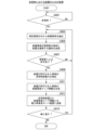
[バッテリの劣化診断と車両活用を推奨する処理]
図12は、車両監視サーバ装置300による給電車両の抽出と非常時の電力確保のための処理の流れの一例を示すフローチャートである。まず、給電車両抽出部328は、特定車両抽出部323により抽出された特定車両のうち、エネルギー残量が閾値以上の車両を、給電車両として抽出する(ステップS301)。提供部324は、給電車両に関する情報を生成し、電力事業者サーバ装置500に送信する(ステップS303)。
[Processing that diagnoses battery deterioration and recommends vehicle utilization]
FIG. 12 is a flowchart illustrating an example of a process flow for extracting a power supply vehicle and securing power in an emergency by the vehicle
次いで、マップ情報生成部325は、給電車両の位置をマップ化した給電車両マップ情報を生成する(ステップS305)。提供部324は、生成した給電車両マップ情報を、電力事業者サーバ装置500に送信する(ステップS307)。
Next, the map
次いで、給電処理部329は、劣化診断部327による劣化診断の結果に基づいて、特定場面において給電装置として使用した場合の非常時給電力を導出し、提供部324は、非常時給電力を示す情報を、電力事業者サーバ装置500に通知する(ステップS309)。
Next, the power
次いで、提供部324は、給電車両の管理者のユーザ端末装置200に対して、特定場面において給電装置としての使用を許可するか否かを確認する通知を送信する(ステップS311)。例えば、管理者により特定場面において給電装置として使用を許可することがユーザ端末装置200の操作部を介して入力された場合、ユーザ端末装置200は、その旨を示す情報を、車両監視サーバ装置300に送信する。車両監視サーバ装置300は、その旨を示す情報を受信すると、車両IDに対応付けて記憶部330に格納する。
Next, the providing
[非常時における給電のための処理]
図13は、車両監視サーバ装置300による非常時における給電のための処理の流れの一例を示すフローチャートである。まず、給電車両抽出部328は、非常時であるとの通知を受信したか否かを判定する(ステップS401)。非常時であるとの通知を受信した場合、給電車両抽出部328は、特定車両抽出部323により抽出された特定車両のうち、エネルギー残量が閾値以上の車両を、給電車両として抽出する(ステップS403)。次いで、提供部324は、供給車両の管理者のユーザ端末装置200に対して、供給車両を外部電源装置400に接続し給電装置として使用することを推奨する通知を送信する(ステップS405)。
[Processing for power supply in an emergency]
FIG. 13 is a flowchart illustrating an example of a process flow for power supply in an emergency by the vehicle
次いで、給電処理部329は、記憶部330を参照し、特定場面において給電装置として使用することが給電車両の管理者により許可されているか否かを判定する(ステップS407)。給電車両の管理者により給電装置として使用が許可されている場合、給電処理部329は、劣化診断部327による劣化診断の結果に基づいて、給電が許可された給電車両が特定場面において給電装置として使用された場合の非常時給電力を導出する(ステップS409)。なお、ステップS409の処理は、給電が許可された給電車両が複数台ある場合、それぞれの非常時給電力とその合計値とを導出する。
Next, the power
次いで、マップ情報生成部325は、給電が許可された全ての給電車両の位置をマップ化した給電車両マップ情報を生成する(ステップS411)。提供部324は、生成した非常時給電力(合計値を含む)と給電車両マップ情報とを、電力事業者サーバ装置500に送信する(ステップS413)。
Next, the map
次いで、給電処理部329は、非常時における給電のための処理を繰り返すか否かを判定する。例えば、給電処理部329は、非常時であるとの通知を受けた時から、数分単位で処理を所定回数繰り返す。繰り返す所定回数に達した場合、給電処理部329は、処理を終了する。一方、繰り返す所定回数に達していない場合、給電処理部329は、ステップS403に戻って処理を繰り返す。こうすることにより、徐々に、特定場面において給電装置として使用することが給電車両の管理者により許可される場合、後から許可された給電車両も、非常時給電力と給電車両マップ情報に反映することができる。
Next, the power
なお、車両10は、燃料によって稼働する内燃機関の稼働に応じて供給される電力、またはバッテリ(二次電池)から供給される電力によって駆動される電動機(電動モータ)によって走行するハイブリッド自動車や、PHEV(Plug-in Hybrid car)であってもよい。この場合、上述したエネルギー残量には、ガソリン残量も含まれる。また、これらハイブリッド自動車等が備えるバッテリの劣化診断については、上述したバッテリ40の劣化診断と同様の診断処理が行われる。
Note that the
以上説明したように、本実施形態の車両監視サーバ装置300は、一以上の車両と通信する通信部と、前記車両の識別情報と、前記車両の駆動源の始動情報とを、前記通信部を用いて前記車両から取得する取得部と、前記始動情報に基づいて、所定期間以上にわたって駆動源が始動されていない特定車両を抽出し、前記特定車両に対応する処理を行う処理部と、を備えることにより、使用されていない車両を有効に活用することができる。
As described above, the vehicle
[第2実施形態]
本実施形態に係る車両監視サーバ装置300Aは、FCV(Fuel Cell Vehicle:燃料電池自動車)を監視するものである。車両監視サーバ装置300Aは、第1実施形態に係る車両監視サーバ装置300と同様の機能構成を備えるものであり、以下異なる点について簡単に説明する。例えば、監視対象である燃料電池自動車は、燃料電池から供給される電力によって駆動される駆動源(例えば、電動モータ)によって走行する電動車両であり、バッテリ40に代えて、燃料電池を備える。エネルギー残量には、燃料電池から電力を供給するために消費される燃料(例えば、水素など)の残量が含まれる。劣化診断部327は、燃料電池の発電回数や総発電量などに基づいて、燃料電池の劣化診断を行う。また、FCVが二次電池を備えている場合、劣化診断部327は、燃料電池の劣化診断と、二次電池の劣化診断の双方を行ってよい、或いは二次電池の劣化診断のみ行ってよい。
[Second embodiment]
The vehicle monitoring server device 300A according to this embodiment monitors an FCV (Fuel Cell Vehicle). The vehicle monitoring server device 300A has the same functional configuration as the vehicle
第2実施形態に係る車両監視サーバ装置300Aでも、第1実施形態と同様の効果を奏することができる。 The vehicle monitoring server device 300A according to the second embodiment can also achieve the same effects as the first embodiment.
上記説明した実施形態は、以下のように表現することができる。
プログラムを記憶した記憶装置と、
ハードウェアプロセッサと、を備え、
前記ハードウェアプロセッサが前記記憶装置に記憶されたプログラムを実行することにより、
一以上の車両と通信し、
前記車両の識別情報と、前記車両の駆動源の始動情報とを、前記車両から取得し、
前記始動情報に基づいて、所定期間以上にわたって駆動源が始動されていない特定車両を抽出し、
前記特定車両に対応する処理を行う、
ように構成されている、車両監視装置。
The embodiment described above can be expressed as follows.
a storage device that stores the program;
comprising a hardware processor;
By the hardware processor executing a program stored in the storage device,
communicate with one or more vehicles;
obtaining identification information of the vehicle and starting information of a drive source of the vehicle from the vehicle;
Based on the starting information, extracting a specific vehicle whose drive source has not been started for a predetermined period or more,
performing processing corresponding to the specific vehicle;
A vehicle monitoring device configured as follows.
以上、本発明を実施するための形態について実施形態を用いて説明したが、本発明はこうした実施形態に何等限定されるものではなく、本発明の要旨を逸脱しない範囲内において種々の変形及び置換を加えることができる。 Although the mode for implementing the present invention has been described above using embodiments, the present invention is not limited to these embodiments in any way, and various modifications and substitutions can be made without departing from the gist of the present invention. can be added.
1…車両監視システム、10…車両、12…モータ、14…駆動輪、16…ブレーキ装置、20…車両センサ、30…PCU、40…バッテリ、42…バッテリセンサ、50…通信装置、60…HMI、70…充給電口、72…接続回路、80…GNSS受信機、100…情報提供装置、200…ユーザ端末装置、300…車両監視サーバ装置、310…通信部、320…制御部、321…第1取得部、322…データ管理部、323…特定車両抽出部、324…提供部、325…マップ情報生成部、326…第2取得部、327…劣化診断部、328…給電車両抽出部、329…給電処理部、330…記憶部、331…状況情報テーブル、332…連続IGオフ時間テーブル、333…充放電情報テーブル、334…劣化レベル対応情報、335…劣化診断結果テーブル、400…外部電源装置、500…電力事業者サーバ装置
DESCRIPTION OF
Claims (13)
前記車両の識別情報と、前記車両の駆動源の始動情報とを、前記通信部を用いて前記車両から取得する取得部と、
前記始動情報に基づいて、所定期間以上にわたって駆動源が始動されていない特定車両を抽出し、前記特定車両に対応する処理を行う処理部と、を備え、
前記取得部は、更に、前記車両の位置情報を取得し、
前記処理部は、前記位置情報に基づいて、前記特定車両の位置をマップ化した情報を生成する、
車両監視装置。 a communications unit that communicates with one or more vehicles;
an acquisition unit that acquires identification information of the vehicle and starting information of a drive source of the vehicle from the vehicle using the communication unit;
a processing unit that extracts a specific vehicle whose drive source has not been started for a predetermined period or more based on the starting information, and performs processing corresponding to the specific vehicle;
The acquisition unit further acquires position information of the vehicle,
The processing unit generates information mapping the location of the specific vehicle based on the location information.
Vehicle monitoring equipment.
前記車両の識別情報と、前記車両の駆動源の始動情報とを、前記通信部を用いて前記車両から取得する取得部と、
前記始動情報に基づいて、所定期間以上にわたって駆動源が始動されていない特定車両を抽出し、前記特定車両に対応する処理を行う処理部と、を備え、
前記車両の駆動源には、二次電池が含まれ、
前記取得部は、前記二次電池の充放電情報を更に取得し、
前記処理部は、前記車両の駆動源が始動されていない期間と前記充放電情報とに基づいて、前記車両の二次電池の劣化診断を行う、
車両監視装置。 a communications unit that communicates with one or more vehicles;
an acquisition unit that acquires identification information of the vehicle and starting information of a drive source of the vehicle from the vehicle using the communication unit;
a processing unit that extracts a specific vehicle whose drive source has not been started for a predetermined period or more based on the starting information, and performs processing corresponding to the specific vehicle;
The drive source of the vehicle includes a secondary battery,
The acquisition unit further acquires charging/discharging information of the secondary battery,
The processing unit performs a deterioration diagnosis of the secondary battery of the vehicle based on a period in which the drive source of the vehicle is not started and the charging/discharging information.
Vehicle monitoring equipment.
前記充放電情報を取得した複数の車両のうち、前記特定車両でない非特定車両の劣化診断を行うときの第1基準と異なる第2基準であって、前記第1基準に比べて精度の高い前記第2基準で、前記特定車両の劣化診断を行う、
請求項2に記載の車両監視装置。 The processing unit includes:
A second standard that is different from the first standard when diagnosing deterioration of a non-specified vehicle that is not the specified vehicle among the plurality of vehicles for which the charge/discharge information has been acquired, and that is more accurate than the first standard. performing a deterioration diagnosis of the specific vehicle based on a second standard;
The vehicle monitoring device according to claim 2 .
前記処理部は、前記特定車両の位置情報と、前記劣化診断の結果とに基づいて、前記特定車両の位置をマップ化した情報であって、前記劣化診断の結果を前記特定車両のマップ上の位置に対応付けて表示する情報を生成する、
請求項2または3に記載の車両監視装置。 The acquisition unit further acquires position information of the vehicle,
The processing unit is configured to map the position of the specific vehicle based on the location information of the specific vehicle and the result of the deterioration diagnosis, and to map the result of the deterioration diagnosis on the map of the specific vehicle. Generate information to be displayed in association with location,
The vehicle monitoring device according to claim 2 or 3 .
請求項2から4のうちいずれか一項に記載の車両監視装置。 The processing unit derives a supply power when used as a power supply device in a specific situation based on the result of the deterioration diagnosis.
The vehicle monitoring device according to any one of claims 2 to 4 .
前記車両の識別情報と、前記車両の駆動源の始動情報とを、前記通信部を用いて前記車両から取得する取得部と、
前記始動情報に基づいて、所定期間以上にわたって駆動源が始動されていない特定車両を抽出し、前記特定車両に対応する処理を行う処理部と、を備え、
前記通信部は、
前記特定車両を管理する管理者の端末装置と通信し、前記管理者の端末装置に対して、前記特定車両から外部電源装置に対して給電するよう推奨する通知を送信する、
車両監視装置。 a communications unit that communicates with one or more vehicles;
an acquisition unit that acquires identification information of the vehicle and starting information of a drive source of the vehicle from the vehicle using the communication unit;
a processing unit that extracts a specific vehicle whose drive source has not been started for a predetermined period or more based on the starting information, and performs processing corresponding to the specific vehicle;
The communication department includes:
communicating with a terminal device of an administrator who manages the specific vehicle, and transmitting a notification to the terminal device of the administrator recommending that power be supplied from the specific vehicle to the external power supply device;
Vehicle monitoring equipment.
前記取得部は、更に、前記第1特定車両の位置情報を取得し、
前記処理部は、前記第1特定車両の位置情報に基づいて、前記第1特定車両の位置をマップ化した情報を生成する、
請求項1から6のうちいずれか一項に記載の車両監視装置。 If the vehicle is managed by a first administrator and there are multiple first specific vehicles extracted as the specific vehicle,
The acquisition unit further acquires position information of the first specific vehicle,
The processing unit generates information in which the position of the first specific vehicle is mapped based on the position information of the first specific vehicle.
A vehicle monitoring device according to any one of claims 1 to 6 .
一以上の車両と通信し、
前記車両の識別情報と、前記車両の駆動源の始動情報とを、前記車両から取得し、
前記始動情報に基づいて、所定期間以上にわたって駆動源が始動されていない特定車両を抽出し、
前記特定車両に対応する処理を行い、
更に、前記車両の位置情報を取得し、
前記位置情報に基づいて、前記特定車両の位置をマップ化した情報を生成する、
車両監視方法。 The computer is
communicate with one or more vehicles;
obtaining identification information of the vehicle and starting information of a drive source of the vehicle from the vehicle;
Based on the starting information, extracting a specific vehicle whose drive source has not been started for a predetermined period or more,
Performing processing corresponding to the specific vehicle,
Furthermore, acquiring position information of the vehicle,
generating information mapping the location of the specific vehicle based on the location information;
Vehicle monitoring methods.
一以上の車両と通信し、
前記車両の識別情報と、前記車両の駆動源の始動情報とを、前記車両から取得し、
前記始動情報に基づいて、所定期間以上にわたって駆動源が始動されていない特定車両を抽出し、
前記特定車両に対応する処理を行い、
前記車両の駆動源には、二次電池が含まれ、
前記二次電池の充放電情報を更に取得し、
前記車両の駆動源が始動されていない期間と前記充放電情報とに基づいて、前記車両の二次電池の劣化診断を行う、
車両監視方法。 The computer is
communicate with one or more vehicles;
obtaining identification information of the vehicle and starting information of a drive source of the vehicle from the vehicle;
Based on the starting information, extracting a specific vehicle whose drive source has not been started for a predetermined period or more,
Performing processing corresponding to the specific vehicle,
The drive source of the vehicle includes a secondary battery,
further acquiring charging/discharging information of the secondary battery;
diagnosing deterioration of the secondary battery of the vehicle based on a period in which the drive source of the vehicle is not started and the charging/discharging information;
Vehicle monitoring methods.
一以上の車両と通信し、
前記車両の識別情報と、前記車両の駆動源の始動情報とを、前記車両から取得し、
前記始動情報に基づいて、所定期間以上にわたって駆動源が始動されていない特定車両を抽出し、
前記特定車両に対応する処理を行い、
前記特定車両を管理する管理者の端末装置と通信し、前記管理者の端末装置に対して、前記特定車両から外部電源装置に対して給電するよう推奨する通知を送信する、
車両監視方法。 The computer is
communicate with one or more vehicles;
obtaining identification information of the vehicle and starting information of a drive source of the vehicle from the vehicle;
Based on the starting information, extracting a specific vehicle whose drive source has not been started for a predetermined period or more,
Performing processing corresponding to the specific vehicle,
communicating with a terminal device of an administrator who manages the specific vehicle, and transmitting a notification to the terminal device of the administrator recommending that power be supplied from the specific vehicle to the external power supply device;
Vehicle monitoring methods.
一以上の車両と通信させ、
前記車両の識別情報と、前記車両の駆動源の始動情報とを、前記車両から取得させ、
前記始動情報に基づいて、所定期間以上にわたって駆動源が始動されていない特定車両を抽出させ、
前記特定車両に対応する処理を行わせ、
更に、前記車両の位置情報を取得させ、
前記位置情報に基づいて、前記特定車両の位置をマップ化した情報を生成させる、
プログラム。 to the computer,
communicate with one or more vehicles;
obtaining identification information of the vehicle and starting information of a drive source of the vehicle from the vehicle;
Based on the starting information, extracting a specific vehicle whose drive source has not been started for a predetermined period or more;
perform processing corresponding to the specific vehicle;
Furthermore, obtain position information of the vehicle,
Generating information mapping the location of the specific vehicle based on the location information;
program.
一以上の車両と通信させ、
前記車両の識別情報と、前記車両の駆動源の始動情報とを、前記車両から取得させ、
前記始動情報に基づいて、所定期間以上にわたって駆動源が始動されていない特定車両を抽出させ、
前記特定車両に対応する処理を行わせ、
前記車両の駆動源には、二次電池が含まれ、
前記二次電池の充放電情報を更に取得させ、
前記車両の駆動源が始動されていない期間と前記充放電情報とに基づいて、前記車両の二次電池の劣化診断を行わせる、
プログラム。 to the computer,
communicate with one or more vehicles;
obtaining identification information of the vehicle and starting information of a drive source of the vehicle from the vehicle;
Based on the starting information, extracting a specific vehicle whose drive source has not been started for a predetermined period or more;
perform processing corresponding to the specific vehicle;
The drive source of the vehicle includes a secondary battery,
Further acquiring charging/discharging information of the secondary battery,
Performing a deterioration diagnosis of the secondary battery of the vehicle based on a period in which the drive source of the vehicle is not started and the charging/discharging information;
program.
一以上の車両と通信させ、
前記車両の識別情報と、前記車両の駆動源の始動情報とを、前記車両から取得させ、
前記始動情報に基づいて、所定期間以上にわたって駆動源が始動されていない特定車両を抽出させ、
前記特定車両に対応する処理を行わせ、
前記特定車両を管理する管理者の端末装置と通信し、前記管理者の端末装置に対して、前記特定車両から外部電源装置に対して給電するよう推奨する通知を送信させる、
プログラム。 to the computer,
communicate with one or more vehicles;
obtaining identification information of the vehicle and starting information of a drive source of the vehicle from the vehicle;
Based on the starting information, extracting a specific vehicle whose drive source has not been started for a predetermined period or more;
perform processing corresponding to the specific vehicle;
communicating with a terminal device of an administrator who manages the specific vehicle, and causing the terminal device of the administrator to send a notification recommending that power be supplied from the specific vehicle to an external power supply device;
program.
Priority Applications (3)
| Application Number | Priority Date | Filing Date | Title |
|---|---|---|---|
| JP2020085996A JP7443155B2 (en) | 2020-05-15 | 2020-05-15 | Vehicle monitoring device, vehicle monitoring method, and program |
| CN202110468339.4A CN113676507A (en) | 2020-05-15 | 2021-04-22 | Vehicle monitoring device, vehicle monitoring method, and storage medium |
| US17/316,751 US20210358231A1 (en) | 2020-05-15 | 2021-05-11 | Vehicle monitoring device, vehicle monitoring method, and recording medium |
Applications Claiming Priority (1)
| Application Number | Priority Date | Filing Date | Title |
|---|---|---|---|
| JP2020085996A JP7443155B2 (en) | 2020-05-15 | 2020-05-15 | Vehicle monitoring device, vehicle monitoring method, and program |
Publications (2)
| Publication Number | Publication Date |
|---|---|
| JP2021179908A JP2021179908A (en) | 2021-11-18 |
| JP7443155B2 true JP7443155B2 (en) | 2024-03-05 |
Family
ID=78511644
Family Applications (1)
| Application Number | Title | Priority Date | Filing Date |
|---|---|---|---|
| JP2020085996A Active JP7443155B2 (en) | 2020-05-15 | 2020-05-15 | Vehicle monitoring device, vehicle monitoring method, and program |
Country Status (3)
| Country | Link |
|---|---|
| US (1) | US20210358231A1 (en) |
| JP (1) | JP7443155B2 (en) |
| CN (1) | CN113676507A (en) |
Families Citing this family (2)
| Publication number | Priority date | Publication date | Assignee | Title |
|---|---|---|---|---|
| JP7240368B2 (en) * | 2020-09-25 | 2023-03-15 | 本田技研工業株式会社 | battery controller |
| US11855469B1 (en) * | 2023-03-10 | 2023-12-26 | Beta Air, Llc | Systems and methods for bidirectional charging |
Citations (2)
| Publication number | Priority date | Publication date | Assignee | Title |
|---|---|---|---|---|
| JP2005038447A (en) | 2001-11-27 | 2005-02-10 | Fuji Xerox Co Ltd | Moving information processor and moving information processing method |
| JP2019219759A (en) | 2018-06-15 | 2019-12-26 | 本田技研工業株式会社 | Shared vehicle management system |
Family Cites Families (5)
| Publication number | Priority date | Publication date | Assignee | Title |
|---|---|---|---|---|
| US20090030712A1 (en) * | 2007-07-26 | 2009-01-29 | Bradley D. Bogolea | System and method for transferring electrical power between grid and vehicle |
| US8639409B2 (en) * | 2010-09-30 | 2014-01-28 | Hitachi, Ltd | System for managing electrical power distribution between infrastructure and electric vehicles |
| US9987940B2 (en) * | 2014-09-16 | 2018-06-05 | Honda Motor Co., Ltd. | Priority based vehicle control strategy |
| KR102644983B1 (en) * | 2017-01-03 | 2024-03-08 | 삼성전자주식회사 | Method and electronic device for mobile payment |
| JP6939057B2 (en) * | 2017-04-27 | 2021-09-22 | トヨタ自動車株式会社 | In-vehicle battery system and battery aging estimation method |
-
2020
- 2020-05-15 JP JP2020085996A patent/JP7443155B2/en active Active
-
2021
- 2021-04-22 CN CN202110468339.4A patent/CN113676507A/en active Pending
- 2021-05-11 US US17/316,751 patent/US20210358231A1/en active Pending
Patent Citations (2)
| Publication number | Priority date | Publication date | Assignee | Title |
|---|---|---|---|---|
| JP2005038447A (en) | 2001-11-27 | 2005-02-10 | Fuji Xerox Co Ltd | Moving information processor and moving information processing method |
| JP2019219759A (en) | 2018-06-15 | 2019-12-26 | 本田技研工業株式会社 | Shared vehicle management system |
Also Published As
| Publication number | Publication date |
|---|---|
| CN113676507A (en) | 2021-11-19 |
| JP2021179908A (en) | 2021-11-18 |
| US20210358231A1 (en) | 2021-11-18 |
Similar Documents
| Publication | Publication Date | Title |
|---|---|---|
| CN113085653B (en) | Storage battery information providing device, providing system, providing method, and storage medium | |
| US11709072B2 (en) | Information instrument, information providing system, information providing server, and information providing method | |
| US10942036B2 (en) | Information providing system, server, and information providing method | |
| JP7443155B2 (en) | Vehicle monitoring device, vehicle monitoring method, and program | |
| JP7015395B2 (en) | Vehicles, server devices, display control methods, and programs | |
| CN111002828B (en) | Diagnostic device, diagnostic method, and storage medium | |
| CN110962689B (en) | Diagnostic device, diagnostic system, diagnostic method, and storage medium | |
| US10829001B2 (en) | Power management system, server and vehicle | |
| WO2020045033A1 (en) | Presentation device, presentation method, and program | |
| JP2021197882A (en) | Vehicle diagnostic system, vehicle and vehicle diagnostic result display method | |
| JP7072597B2 (en) | Information providing device and information providing system | |
| JP2021086654A (en) | Battery status determination system and battery status determination method | |
| JP2022184645A (en) | Controller, electric power system, and program | |
| JP2021086191A (en) | Rental system, rental method, and program | |
| US20220297568A1 (en) | Management system and energy management method | |
| US20220194256A1 (en) | Server, vehicle, and vehicle diagnosis method | |
| JP2020077026A (en) | Location information providing system | |
| JP2020107183A (en) | Vehicle management system | |
| US20230013438A1 (en) | Electric power management system, electric power management server, and electric power management method | |
| US20220207578A1 (en) | Charging controller | |
| WO2023187966A1 (en) | Environment load evaluation device, environment load evaluation method, and program | |
| US20230014362A1 (en) | Electric power management system, electric power management server, and electric power management method | |
| JP7408711B2 (en) | Resistance calculation device, resistance calculation method and program | |
| JP7459841B2 (en) | Vehicle and charging method | |
| WO2023080255A1 (en) | Management system, housing device, control method, program, and storage medium |
Legal Events
| Date | Code | Title | Description |
|---|---|---|---|
| A621 | Written request for application examination |
Free format text: JAPANESE INTERMEDIATE CODE: A621 Effective date: 20221128 |
|
| A977 | Report on retrieval |
Free format text: JAPANESE INTERMEDIATE CODE: A971007 Effective date: 20230914 |
|
| A131 | Notification of reasons for refusal |
Free format text: JAPANESE INTERMEDIATE CODE: A131 Effective date: 20231003 |
|
| A521 | Request for written amendment filed |
Free format text: JAPANESE INTERMEDIATE CODE: A523 Effective date: 20231120 |
|
| TRDD | Decision of grant or rejection written | ||
| A01 | Written decision to grant a patent or to grant a registration (utility model) |
Free format text: JAPANESE INTERMEDIATE CODE: A01 Effective date: 20240206 |
|
| A61 | First payment of annual fees (during grant procedure) |
Free format text: JAPANESE INTERMEDIATE CODE: A61 Effective date: 20240221 |
|
| R150 | Certificate of patent or registration of utility model |
Ref document number: 7443155 Country of ref document: JP Free format text: JAPANESE INTERMEDIATE CODE: R150 |