JP7442072B2 - Three-dimensional displacement measurement method and three-dimensional displacement measurement device - Google Patents
Three-dimensional displacement measurement method and three-dimensional displacement measurement device Download PDFInfo
- Publication number
- JP7442072B2 JP7442072B2 JP2021536879A JP2021536879A JP7442072B2 JP 7442072 B2 JP7442072 B2 JP 7442072B2 JP 2021536879 A JP2021536879 A JP 2021536879A JP 2021536879 A JP2021536879 A JP 2021536879A JP 7442072 B2 JP7442072 B2 JP 7442072B2
- Authority
- JP
- Japan
- Prior art keywords
- dimensional
- camera
- cameras
- viewpoints
- subject
- Prior art date
- Legal status (The legal status is an assumption and is not a legal conclusion. Google has not performed a legal analysis and makes no representation as to the accuracy of the status listed.)
- Active
Links
- 238000006073 displacement reaction Methods 0.000 title claims description 191
- 238000005259 measurement Methods 0.000 title claims description 87
- 238000000691 measurement method Methods 0.000 title claims description 15
- 238000000034 method Methods 0.000 claims description 59
- 238000004364 calculation method Methods 0.000 claims description 13
- 238000003384 imaging method Methods 0.000 claims description 12
- 238000012545 processing Methods 0.000 description 121
- 230000008569 process Effects 0.000 description 28
- 238000010586 diagram Methods 0.000 description 27
- 230000015572 biosynthetic process Effects 0.000 description 13
- 230000035945 sensitivity Effects 0.000 description 13
- 238000003786 synthesis reaction Methods 0.000 description 13
- 230000001360 synchronised effect Effects 0.000 description 12
- 238000005516 engineering process Methods 0.000 description 4
- 238000011156 evaluation Methods 0.000 description 4
- 230000006870 function Effects 0.000 description 4
- 230000033001 locomotion Effects 0.000 description 4
- 239000011159 matrix material Substances 0.000 description 4
- 239000000470 constituent Substances 0.000 description 3
- 230000000694 effects Effects 0.000 description 3
- 238000012544 monitoring process Methods 0.000 description 3
- 238000005457 optimization Methods 0.000 description 3
- 230000036544 posture Effects 0.000 description 3
- 230000002123 temporal effect Effects 0.000 description 3
- 230000005540 biological transmission Effects 0.000 description 2
- 238000004891 communication Methods 0.000 description 2
- 238000007689 inspection Methods 0.000 description 2
- 238000012804 iterative process Methods 0.000 description 2
- 238000012986 modification Methods 0.000 description 2
- 230000004048 modification Effects 0.000 description 2
- 230000003287 optical effect Effects 0.000 description 2
- 230000003252 repetitive effect Effects 0.000 description 2
- 238000013519 translation Methods 0.000 description 2
- NAWXUBYGYWOOIX-SFHVURJKSA-N (2s)-2-[[4-[2-(2,4-diaminoquinazolin-6-yl)ethyl]benzoyl]amino]-4-methylidenepentanedioic acid Chemical compound C1=CC2=NC(N)=NC(N)=C2C=C1CCC1=CC=C(C(=O)N[C@@H](CC(=C)C(O)=O)C(O)=O)C=C1 NAWXUBYGYWOOIX-SFHVURJKSA-N 0.000 description 1
- 238000012935 Averaging Methods 0.000 description 1
- 230000001133 acceleration Effects 0.000 description 1
- 230000004075 alteration Effects 0.000 description 1
- FFBHFFJDDLITSX-UHFFFAOYSA-N benzyl N-[2-hydroxy-4-(3-oxomorpholin-4-yl)phenyl]carbamate Chemical compound OC1=C(NC(=O)OCC2=CC=CC=C2)C=CC(=C1)N1CCOCC1=O FFBHFFJDDLITSX-UHFFFAOYSA-N 0.000 description 1
- 230000008859 change Effects 0.000 description 1
- 238000006243 chemical reaction Methods 0.000 description 1
- 238000010801 machine learning Methods 0.000 description 1
- 239000000463 material Substances 0.000 description 1
- 230000007246 mechanism Effects 0.000 description 1
- 239000007787 solid Substances 0.000 description 1
- 230000003068 static effect Effects 0.000 description 1
- 230000009466 transformation Effects 0.000 description 1
- 230000007704 transition Effects 0.000 description 1
Images


Classifications
-
- G—PHYSICS
- G06—COMPUTING; CALCULATING OR COUNTING
- G06T—IMAGE DATA PROCESSING OR GENERATION, IN GENERAL
- G06T7/00—Image analysis
- G06T7/20—Analysis of motion
- G06T7/292—Multi-camera tracking
-
- G—PHYSICS
- G06—COMPUTING; CALCULATING OR COUNTING
- G06T—IMAGE DATA PROCESSING OR GENERATION, IN GENERAL
- G06T7/00—Image analysis
- G06T7/20—Analysis of motion
- G06T7/246—Analysis of motion using feature-based methods, e.g. the tracking of corners or segments
-
- G—PHYSICS
- G06—COMPUTING; CALCULATING OR COUNTING
- G06T—IMAGE DATA PROCESSING OR GENERATION, IN GENERAL
- G06T7/00—Image analysis
- G06T7/80—Analysis of captured images to determine intrinsic or extrinsic camera parameters, i.e. camera calibration
-
- G—PHYSICS
- G06—COMPUTING; CALCULATING OR COUNTING
- G06T—IMAGE DATA PROCESSING OR GENERATION, IN GENERAL
- G06T2207/00—Indexing scheme for image analysis or image enhancement
- G06T2207/10—Image acquisition modality
- G06T2207/10016—Video; Image sequence
- G06T2207/10021—Stereoscopic video; Stereoscopic image sequence
-
- G—PHYSICS
- G06—COMPUTING; CALCULATING OR COUNTING
- G06T—IMAGE DATA PROCESSING OR GENERATION, IN GENERAL
- G06T2207/00—Indexing scheme for image analysis or image enhancement
- G06T2207/10—Image acquisition modality
- G06T2207/10024—Color image
-
- G—PHYSICS
- G06—COMPUTING; CALCULATING OR COUNTING
- G06T—IMAGE DATA PROCESSING OR GENERATION, IN GENERAL
- G06T2207/00—Indexing scheme for image analysis or image enhancement
- G06T2207/30—Subject of image; Context of image processing
- G06T2207/30108—Industrial image inspection
- G06T2207/30164—Workpiece; Machine component
Description
本開示は、三次元変位計測方法及び三次元変位計測装置に関する。 The present disclosure relates to a three-dimensional displacement measuring method and a three-dimensional displacement measuring device.
コンピュータビジョンの分野における三次元再構成技術では、複数の二次元画像間で特徴点の対応付けを行い、カメラの位置、向き、及び被写体の三次元位置を推定する。また、三次元再構成技術では、カメラキャリブレーション及び三次元点群再構成が行われる。 Three-dimensional reconstruction technology in the field of computer vision associates feature points between multiple two-dimensional images to estimate the position and orientation of a camera and the three-dimensional position of a subject. Furthermore, in the three-dimensional reconstruction technique, camera calibration and three-dimensional point group reconstruction are performed.
例えば、特許文献1に記載の装置は、3台以上の複数カメラ間でキャリブレーションを行い、取得したカメラパラメータにより各カメラ座標系を任意視点の仮想カメラ座標系へ変換する。当該装置は、その仮想カメラ座標系において、座標変換後の画像間のブロックマッチングによる対応付けを行い、距離情報を推定する。 For example, the apparatus described in Patent Document 1 calibrates three or more cameras and converts each camera coordinate system into a virtual camera coordinate system of an arbitrary viewpoint using the acquired camera parameters. In the virtual camera coordinate system, the device performs correspondence between images after coordinate transformation by block matching, and estimates distance information.
このような、上記従来技術では、複数の視点から被写体を撮像することにより得られた複数の画像に基づいて、三次元空間における被写体の経時的な変位を効果的に計測することができない。 With the above-mentioned conventional technology, it is not possible to effectively measure the displacement of a subject in three-dimensional space over time based on a plurality of images obtained by capturing images of the subject from a plurality of viewpoints.
そこで、本開示は、複数の視点から被写体を撮像することにより得られた複数の画像に基づいて、三次元空間における被写体の経時的な変位を効果的に計測することができる技術を提供する。 Therefore, the present disclosure provides a technique that can effectively measure the displacement of a subject in three-dimensional space over time based on a plurality of images obtained by capturing images of the subject from a plurality of viewpoints.
本開示の一態様に係る三次元変位計測方法は、N(Nは1より大きい整数)台のカメラを含む複数のカメラによって互いに異なるM(MはNより大きい整数)個の視点において撮像されたM枚の校正用画像に基づいて、前記N台のカメラのカメラパラメータを算出するカメラ校正ステップと、(1)異なる時刻毎に前記N台のカメラのそれぞれによって被写体を撮像することで生成されるN枚の画像、及び、(2)前記カメラパラメータ、に基づいて、三次元空間における前記被写体の経時的な変位を計測する変位計測ステップと、を含む。 A three-dimensional displacement measurement method according to an aspect of the present disclosure includes images taken at M (M is an integer greater than N) different viewpoints from each other by a plurality of cameras including N (N is an integer greater than 1) cameras. a camera calibration step of calculating camera parameters of the N cameras based on M calibration images; and (1) images of the subject are generated by each of the N cameras at different times and (2) a displacement measuring step of measuring the displacement of the subject over time in three-dimensional space based on the N images and (2) the camera parameters.
本開示によれば、複数の視点から被写体を撮像することにより得られた複数の画像に基づいて、三次元空間における被写体の経時的な変位を効果的に計測することができる。 According to the present disclosure, it is possible to effectively measure the displacement of a subject in three-dimensional space over time based on a plurality of images obtained by capturing images of the subject from a plurality of viewpoints.
(本開示の基礎となった知見)
従来技術では、被写体の三次元形状を再構成(モデリング)することで、または再構成結果を用いることで三次元空間認識が実現される。被写体の三次元形状を再構成する三次元空間再構成装置は、同一の場面の映像を撮影する複数のカメラを含む撮像システムから提供される映像データと、校正によって得られた各カメラの位置、姿勢等(以下、「位置姿勢」という。)を示すカメラパラメータと、を用いてモデリングを行う。カメラの位置は視点に対応する。
(Findings that formed the basis of this disclosure)
In the conventional technology, three-dimensional spatial recognition is realized by reconstructing (modeling) the three-dimensional shape of a subject or by using the reconstruction result. A three-dimensional space reconstruction device that reconstructs the three-dimensional shape of a subject uses video data provided from an imaging system that includes multiple cameras that capture images of the same scene, the position of each camera obtained through calibration, Modeling is performed using camera parameters indicating posture, etc. (hereinafter referred to as "position and posture"). The camera position corresponds to the viewpoint.
また、構造物(例えばインフラ用の構造物)、機械部品等といった計測対象の変位を三次元空間において把握することが求められている。しかしながら、従来技術では、計測対象である被写体の三次元空間における経時的な変位を効果的に計測することができなかった。例えば、従来技術では、被写体の三次元空間における経時的な変位を計測するための処理負荷の低減は不十分であった。 Furthermore, there is a need to grasp the displacement of measurement targets such as structures (for example, infrastructure structures), mechanical parts, etc. in three-dimensional space. However, with the conventional technology, it has not been possible to effectively measure the temporal displacement of the object to be measured in three-dimensional space. For example, in the prior art, it has been insufficient to reduce the processing load for measuring the displacement of a subject in three-dimensional space over time.
一般的に、カメラ校正処理、及び、三次元変位計測処理では、視点数が多い、つまり、画像が多いほど処理負荷が大きくなる一方で精度が向上するというトレードオフの関係がある。このトレードオフの関係に対し、発明者らは、三次元変位計測の精度よりもカメラ校正の精度を優先すると、処理負荷を抑えつつ2つの処理全体としての精度が向上することを見出した。 Generally, in camera calibration processing and three-dimensional displacement measurement processing, there is a trade-off relationship in that the greater the number of viewpoints, that is, the greater the number of images, the greater the processing load, but the higher the accuracy. Regarding this trade-off relationship, the inventors have found that if the accuracy of camera calibration is prioritized over the accuracy of three-dimensional displacement measurement, the accuracy of the two processes as a whole can be improved while suppressing the processing load.
そこで、本開示の一態様に係る三次元変位計測方法は、N(Nは1より大きい整数)台のカメラを含む複数のカメラによって互いに異なるM(MはNより大きい整数)個の視点において撮像されたM枚の校正用画像に基づいて、前記N台のカメラのカメラパラメータを算出するカメラ校正ステップと、(1)異なる時刻毎に前記N台のカメラのそれぞれによって被写体を撮像することで生成されるN枚の画像、及び、(2)前記カメラパラメータ、に基づいて、三次元空間における前記被写体の経時的な変位を計測する変位計測ステップと、を含む。 Therefore, in a three-dimensional displacement measurement method according to an aspect of the present disclosure, images are captured at M (M is an integer greater than N) different viewpoints from each other using a plurality of cameras including N (N is an integer greater than 1) cameras. a camera calibration step of calculating camera parameters of the N cameras based on the M calibration images obtained; and (2) a displacement measuring step of measuring the displacement of the subject in three-dimensional space over time based on the N images taken and (2) the camera parameters.
これにより、三次元変位計測方法では、カメラパラメータの精度が向上するように三次元変位計測処理における視点数Nよりも多い視点数Mを、カメラ校正処理に用いることで、三次元変位計測処理における精度を向上させることができる。 As a result, in the three-dimensional displacement measurement method, the number of viewpoints M, which is larger than the number of viewpoints N in the three-dimensional displacement measurement processing, is used in the camera calibration processing so as to improve the accuracy of camera parameters. Accuracy can be improved.
また、例えば、本開示の一態様に係る三次元変位計測方法において、前記変位計測ステップは、前記N枚の画像に含まれる第1画像に含まれる、前記被写体の第1対応点と、前記N枚の画像に含まれる第2画像に含まれ且つ前記第1対応点に対応する第2対応点と、を求める対応点算出ステップと、前記カメラパラメータと、前記第1対応点と、前記第2対応点とに基づいて、前記三次元空間における前記被写体の三次元点を求める三次元点算出ステップと、前記異なる時刻に対応する複数の前記三次元点から、前記三次元点の経時的な変位を求める変位算出ステップと、を含んでもよい。 Further, for example, in the three-dimensional displacement measuring method according to one aspect of the present disclosure, the displacement measuring step may include first corresponding points of the subject included in a first image included in the N images; a corresponding point calculation step of calculating a second corresponding point included in a second image included in the images and corresponding to the first corresponding point, the camera parameter, the first corresponding point, and the second corresponding point; a three-dimensional point calculation step of calculating a three-dimensional point of the subject in the three-dimensional space based on the corresponding points; and a temporal displacement of the three-dimensional point from the plurality of three-dimensional points corresponding to the different times. The method may also include a displacement calculation step of calculating.
これにより、三次元変位計測方法では、例えば画像マッチングの手法及び三角測量の原理を用いて、カメラパラメータ、第1対応点及び第2対応点に基づいて、三次元点の経時的な変位を求めることで、被写体の三次元空間における変位を求めることができる。 As a result, in the three-dimensional displacement measurement method, for example, the displacement of a three-dimensional point over time is determined based on the camera parameters, the first corresponding point, and the second corresponding point, using the image matching method and the principle of triangulation. By doing so, the displacement of the subject in three-dimensional space can be determined.
また、例えば、本開示の一態様に係る三次元変位計測方法は、前記Nは、前記カメラパラメータと、前記変位の計測の精度と、に基づいて決定されてもよい。 Further, for example, in the three-dimensional displacement measurement method according to one aspect of the present disclosure, the N may be determined based on the camera parameter and the accuracy of the displacement measurement.
これにより、三次元変位計測方法では、変位計測ステップで行われる計測の精度を満たすように、カメラの視点数Nを定めることができる。よって、三次元変位計測方法は、精度よく被写体の三次元空間における変位を求めることができる。 Thereby, in the three-dimensional displacement measurement method, the number N of camera viewpoints can be determined so as to satisfy the accuracy of the measurement performed in the displacement measurement step. Therefore, the three-dimensional displacement measuring method can accurately determine the displacement of the subject in three-dimensional space.
また、本願発明者らは、カメラ校正に用いる視点を均等に配置するよりも、以下のように配置すれば、カメラ校正の精度が向上することを見出した。例えば、本開示の一態様に係る三次元変位計測方法は、前記N台のカメラは、互いに隣り合う第1カメラ及び第2カメラを含み、前記M個の視点は、前記第1カメラが配置される第1位置と、前記第2カメラが配置される第2位置との間の第1中点を含み、前記第1位置と前記第1中点との間の中点を第2中点とすると、前記M個の視点に含まれ且つ前記第2中点と前記第1位置との間に設けられる視点は、前記M個の視点に含まれ且つ前記第1中点と前記第2中点との間に設けられる視点よりも多くてもよい。 In addition, the inventors of the present invention have found that the accuracy of camera calibration can be improved by arranging the viewpoints as shown below, rather than arranging them evenly. For example, in the three-dimensional displacement measuring method according to one aspect of the present disclosure, the N cameras include a first camera and a second camera that are adjacent to each other, and the M viewpoints are located at the position where the first camera is arranged. a first midpoint between a first position where the second camera is located and a second position where the second camera is located, and a midpoint between the first position and the first midpoint as a second midpoint; Then, a viewpoint included in the M viewpoints and provided between the second midpoint and the first position is included in the M viewpoints and located between the first midpoint and the second midpoint. There may be more viewpoints than there are between them.
すなわち、この態様では、カメラ校正に使用する視点を、三次元変位計測に使用する視点の位置を基準として第2中点よりも近い範囲に、第2中点よりも遠い範囲よりも多く設定する。このような不均等な配置により、カメラ校正の精度が向上する。 That is, in this aspect, the number of viewpoints used for camera calibration is set in a range closer to the second midpoint than in a range farther from the second midpoint, based on the position of the viewpoint used for three-dimensional displacement measurement. . Such non-uniform placement improves the accuracy of camera calibration.
例えば、カメラ校正のための視点の不均等な配置では、前記カメラ校正ステップでは、前記第1中点と前記第2中点との間には、視点を設けなくてもよい。 For example, in the case of uneven placement of viewpoints for camera calibration, no viewpoint may be provided between the first midpoint and the second midpoint in the camera calibration step.
また、例えば、本開示の一態様に係る三次元変位計測装置は、N(Nは1より大きい整数)台のカメラを含む複数のカメラによって互いに異なるM(MはNより大きい整数)個の視点において撮像されたM枚の校正用画像に基づいて前記N台のカメラのカメラパラメータを算出するカメラ校正部と、(1)異なる時刻毎に前記N台のカメラのそれぞれによって被写体を撮像することで生成されるN枚の画像、及び、(2)前記カメラパラメータ、に基づいて、三次元空間における前記被写体の経時的な変位を計測する変位計測部と、を備える。 Further, for example, the three-dimensional displacement measuring device according to one aspect of the present disclosure uses a plurality of cameras including N (N is an integer greater than 1) cameras to provide M (M is an integer greater than N) different viewpoints. (1) a camera calibration unit that calculates camera parameters of the N cameras based on M calibration images taken at a time; The image forming apparatus includes a displacement measurement unit that measures displacement of the subject over time in a three-dimensional space based on the N images generated and (2) the camera parameters.
これにより、三次元変位計測装置は、本開示の一態様に係る三次元変位計測方法と同様の効果を奏することができる。 Thereby, the three-dimensional displacement measuring device can achieve the same effects as the three-dimensional displacement measuring method according to one aspect of the present disclosure.
以下、実施の形態について図面を参照しながら具体的に説明する。 Hereinafter, embodiments will be specifically described with reference to the drawings.
なお、以下で説明する実施の形態は、いずれも包括的または具体的な例を示すものである。以下の実施の形態で示される数値、形状、材料、構成要素、構成要素の配置位置及び接続形態、ステップ、ステップの順序などは、一例であり、請求の範囲を限定する主旨ではない。また、以下の実施の形態における構成要素のうち、最上位概念を示す独立請求項に記載されていない構成要素については、任意の構成要素として説明される。また、各図は、必ずしも厳密に図示したものではない。各図において、実質的に同一の構成については同一の符号を付し、重複する説明は省略又は簡略化する。 Note that the embodiments described below are all inclusive or specific examples. The numerical values, shapes, materials, components, arrangement positions and connection forms of the components, steps, order of steps, etc. shown in the following embodiments are merely examples, and do not limit the scope of the claims. Further, among the constituent elements in the following embodiments, constituent elements that are not described in the independent claims indicating the most significant concept will be described as arbitrary constituent elements. Further, each figure is not necessarily strictly illustrated. In each figure, substantially the same configurations are designated by the same reference numerals, and overlapping explanations will be omitted or simplified.
(実施の形態)
本実施の形態に係る三次元変位計測装置は、時刻間で座標軸の一致した時系列三次元モデルを再構成できる。ここで、本開示における三次元再構成を定義する。実空間上に存在する被写体を複数のカメラにより異なる視点で撮影した映像又は画像を多視点映像又は多視点画像と呼ぶ。つまり、多視点画像は、同一の被写体を異なる視点から撮影した複数の二次元画像を含む。また、時系列に撮影された多視点画像を多視点映像と呼ぶ。この多視点画像を用いて被写体を三次元空間に再構成することを三次元再構成と呼ぶ。
(Embodiment)
The three-dimensional displacement measuring device according to the present embodiment can reconstruct a time-series three-dimensional model whose coordinate axes coincide at different times. Here, three-dimensional reconstruction in this disclosure is defined. Videos or images of a subject existing in real space shot from different viewpoints by multiple cameras are called multi-view videos or multi-view images. That is, a multi-view image includes a plurality of two-dimensional images of the same subject taken from different viewpoints. Also, multi-view images captured in chronological order are called multi-view videos. Reconfiguring a subject in three-dimensional space using these multi-view images is called three-dimensional reconstruction.
具体的には、まず、三次元変位計測装置は、時刻毎に独立して三次元再構成を行うことで、各時刻の三次元モデルを取得する。次に、三次元変位計測装置は、静止カメラ及び静止物体(静止三次元点)を検出し、検出した静止カメラ及び静止物体を用いて、時刻間で三次元モデルの座標合せを行い、座標軸の一致した時系列三次元モデルを生成する。 Specifically, first, the three-dimensional displacement measuring device obtains a three-dimensional model at each time by independently performing three-dimensional reconstruction at each time. Next, the three-dimensional displacement measuring device detects a stationary camera and a stationary object (stationary three-dimensional point), aligns the coordinates of the three-dimensional model at different times using the detected stationary camera and stationary object, and aligns the coordinate axes. Generate a matched time series 3D model.
これにより、三次元変位計測装置は、カメラの固定/非固定又は被写体の移動/静止に関わらず、各時刻の被写体及びカメラの相対位置関係が高精度であり、かつ時間方向の推移情報を利用可能な時系列三次元モデルを生成できる。 As a result, the three-dimensional displacement measuring device can accurately determine the relative positional relationship between the subject and the camera at each time, regardless of whether the camera is fixed or not, or whether the subject is moving or stationary, and can utilize temporal transition information. It is possible to generate a time-series 3D model.
図1は、実施の形態における三次元変位計測が行われる際の概略図である。実施の形態における三次元変位計測方法において、被写体1001を、カメラ100-1及びカメラ100-2が撮影している。ここで、被写体1001は、所定の位置に固定されているコンプレッサ等でもよい。また、カメラ100-1及びカメラ100-2は、互いに異なる位置において被写体1001を撮影範囲に含むような向きで固定されている固定カメラでもよい。例えば、校正済みの1つまたは複数のカメラ(例えば固定カメラ)によって同一空間または同一の被写体1001が、多視点から撮影されることにより、撮影される空間または被写体1001が三次元再構成されることができる。すなわち、多視点から撮影された複数の二次元画像の間で、特徴点等の対応付けが行われることで、カメラの位置、カメラの向き、並びに、被写体1001の三次元変位または三次元位置が推定されることが可能である。つまり、三次元変位計測装置では、多視点から撮影された複数の二次元画像を用いて、カメラ校正及び被写体1001の三次元変位計測等が行われる。三次元変位計測装置では、さらに、被写体1001の三次元再構成が行われてもよい。 FIG. 1 is a schematic diagram when three-dimensional displacement measurement is performed in an embodiment. In the three-dimensional displacement measuring method in the embodiment, a subject 1001 is photographed by cameras 100-1 and 100-2. Here, the subject 1001 may be a compressor or the like fixed at a predetermined position. Furthermore, the camera 100-1 and the camera 100-2 may be fixed cameras that are fixed at different positions and oriented so that the subject 1001 is included in the photographing range. For example, by photographing the same space or the same subject 1001 from multiple viewpoints using one or more calibrated cameras (for example, fixed cameras), the photographed space or subject 1001 is three-dimensionally reconstructed. I can do it. That is, by associating feature points, etc. between multiple two-dimensional images taken from multiple viewpoints, the camera position, camera direction, and three-dimensional displacement or three-dimensional position of the subject 1001 can be determined. It is possible to estimate. That is, in the three-dimensional displacement measuring device, camera calibration, three-dimensional displacement measurement of the subject 1001, etc. are performed using a plurality of two-dimensional images taken from multiple viewpoints. The three-dimensional displacement measuring device may further perform three-dimensional reconstruction of the subject 1001.
三次元変位計測は、例えば、インフラ構造物点検システム等に有用である。例えば、計測装置が新幹線等の防音壁等の壁の振動を、壁の奥行方向に向かって計測するというニーズがある。また、計測装置がコンプレッサ等の動作において振動が発生する機器の変位を計測するというニーズがある。 Three-dimensional displacement measurement is useful for, for example, infrastructure inspection systems. For example, there is a need for a measuring device to measure vibrations of a wall such as a soundproof wall for a bullet train or the like toward the depth of the wall. Additionally, there is a need for a measuring device to measure the displacement of equipment that generates vibrations during operation, such as a compressor.
図2は、実施の形態における三次元モデリングの原理を示す図である。まず、本実施の形態における三次元モデリングを定義する。本実施の形態では、三次元変位計測装置が、実空間上に存在する被写体を複数のカメラによって異なる視点から撮影した二次元の多視点映像を用いて、被写体を三次元空間内に再構成することを三次元モデリングという。なお、以下では、三次元モデリングを三次元再構成とも言うことがある。 FIG. 2 is a diagram showing the principle of three-dimensional modeling in the embodiment. First, three-dimensional modeling in this embodiment will be defined. In this embodiment, a three-dimensional displacement measuring device reconstructs an object in three-dimensional space using two-dimensional multi-view images of an object existing in real space taken from different viewpoints by multiple cameras. This is called three-dimensional modeling. Note that, hereinafter, three-dimensional modeling may also be referred to as three-dimensional reconstruction.
図2に示されるように、少なくとも2つの視点のカメラ座標及びカメラパラメータを用いることで、点線で示された三角形が形成される。実施の形態における三次元変位計測方法では、各カメラで撮影された画像の画像面上の座標系で表された画像面上の各点は、この三角形を利用した三角測量の原理に基づいて、世界座標系を用いた三次元モデルとして再構成される。画像面上の座標系は、例えば、図2に示される画像面座標1または画像面座標2である。三次元モデルは、被写体が、世界座標系を用いて表される三次元空間内に再構成(つまり、三次元再構成)されたものである。三次元モデルは、多視点から撮影された複数の二次元画像に映る被写体上の複数の点それぞれの三次元位置を表している。ここで、三次元位置は、例えば、三次元空間における直交座標系(XYZ軸)で示される、X成分、Y成分及びZ成分からなる三値の情報で表される。なお、三次元モデル上の各点に対応する情報は、上記の各点の三次元位置を表す情報だけでなく、各点の色、並びに、各点及びその周辺の表面形状を表す情報を含んでもよい。 As shown in FIG. 2, by using the camera coordinates and camera parameters of at least two viewpoints, a triangle indicated by a dotted line is formed. In the three-dimensional displacement measurement method in the embodiment, each point on the image plane expressed by the coordinate system on the image plane of the image taken by each camera is calculated based on the principle of triangulation using this triangle. It is reconstructed as a three-dimensional model using the world coordinate system. The coordinate system on the image plane is, for example, image plane coordinate 1 or image plane coordinate 2 shown in FIG. A three-dimensional model is one in which a subject is reconstructed (that is, three-dimensionally reconstructed) in a three-dimensional space expressed using a world coordinate system. A three-dimensional model represents the three-dimensional position of each of a plurality of points on a subject that appear in a plurality of two-dimensional images photographed from multiple viewpoints. Here, the three-dimensional position is expressed, for example, by three-valued information consisting of an X component, a Y component, and a Z component, which is indicated by an orthogonal coordinate system (XYZ axes) in a three-dimensional space. Note that the information corresponding to each point on the three-dimensional model includes not only the information representing the three-dimensional position of each point mentioned above, but also information representing the color of each point and the surface shape of each point and its surroundings. But that's fine.
三次元モデリングに際して、各カメラのカメラパラメータは、予め取得されていてもよいし、三次元モデルの作成と同時に推定されてもよい。ここで、カメラパラメータは、内部パラメータ及び外部パラメータからなる。内部パラメータは、カメラの焦点距離、画像中心等を含み、外部パラメータは、カメラの三次元位置、カメラの三次元における向き等を含む。 During three-dimensional modeling, the camera parameters of each camera may be acquired in advance, or may be estimated at the same time as the three-dimensional model is created. Here, the camera parameters consist of internal parameters and external parameters. The intrinsic parameters include the focal length of the camera, the center of the image, etc., and the extrinsic parameters include the three-dimensional position of the camera, the three-dimensional orientation of the camera, and the like.
図2では、代表的なピンホールカメラモデルを例として用いている。この例では、カメラのレンズ歪みは考慮されていない。三次元モデリングに際して、レンズ歪みが考慮される場合は、三次元モデルに用いられる各点の位置として、各カメラで撮影された画像の画像面上の座標系における点の位置を歪みモデルにより正規化した補正位置が用いられる。 In FIG. 2, a typical pinhole camera model is used as an example. In this example, camera lens distortion is not taken into account. When lens distortion is taken into account during 3D modeling, the position of each point in the coordinate system on the image plane of the image taken by each camera is normalized using the distortion model as the position of each point used in the 3D model. The corrected position is used.
図3は、実施の形態における三次元変位計測の原理を示す図である。本開示の三次元変位計測方法について定義を行う。多視点から撮影された二次元画像を用いて被写体1001の三次元空間における変位を算出することを三次元変位計測という。図3では、三次元変位計測の仕組みが示される。少なくとも2つの視点におけるそれぞれのカメラ座標及びカメラパラメータを用いることで、図3において点線で示されたような三角形が形成される。この三角形が利用される三角測量の原理を元に、複数の視点において撮影され、画像面上の座標系で表された画像上の点が、世界座標系において再構成される。画像面上の座標系は、例えば、図3に示される画像面座標1または画像面座標2である。 FIG. 3 is a diagram showing the principle of three-dimensional displacement measurement in the embodiment. The three-dimensional displacement measurement method of the present disclosure will be defined. Calculating the displacement of the subject 1001 in three-dimensional space using two-dimensional images photographed from multiple viewpoints is called three-dimensional displacement measurement. FIG. 3 shows a mechanism for three-dimensional displacement measurement. By using respective camera coordinates and camera parameters for at least two viewpoints, a triangle as shown by the dotted line in FIG. 3 is formed. Based on the principle of triangulation in which triangles are used, points on an image taken from multiple viewpoints and expressed in a coordinate system on the image plane are reconstructed in the world coordinate system. The coordinate system on the image plane is, for example, image plane coordinate 1 or image plane coordinate 2 shown in FIG.
被写体1001の三次元モデルは、多視点から撮影された複数の二次元画像に映る被写体1001上の複数の点それぞれの三次元位置により示される。被写体1001が移動または振動する場合、時刻t及び時刻t+iのそれぞれにおいて、被写体1001上の三次元点の位置(Xt,Yt,Zt)及び(Xt+i,Yt+i,Zt+i)を再構成すると、時間iの間の変位(Xt+i-Xt,Yt+i-Yt,Zt+i-Zt)が算出される。三次元変位計測において、例えば、奥行き方向(Z成分)のみを計測することとしてもよい。すなわち、三次元変位計測において、いわゆるデプスマップを作成することとしてもよい。また、本開示の三次元変位計測は、X成分、Y成分、及びZ成分のうち任意の2成分における変位を計測してもよい。 A three-dimensional model of the subject 1001 is represented by the three-dimensional positions of a plurality of points on the subject 1001 that appear in a plurality of two-dimensional images photographed from multiple viewpoints. When the subject 1001 moves or vibrates, the positions (X t , Y t , Z t ) and (X t+i , Y t+i , Z t+i ) of the three-dimensional points on the subject 1001 are replayed at time t and time t+i , respectively. Once configured, the displacement (X t+i −X t , Y t+i −Y t , Z t+i −Z t ) during time i is calculated. In three-dimensional displacement measurement, for example, only the depth direction (Z component) may be measured. That is, in three-dimensional displacement measurement, a so-called depth map may be created. Furthermore, the three-dimensional displacement measurement of the present disclosure may measure displacement in any two components among the X component, Y component, and Z component.
なお、例えば、被写体1001がコンプレッサ等の振動体である場合、時刻差iは、振動体の共振周波数をサンプリングできる周波数の逆数である。しかし、時刻差iは、これに限定されない。例えば、被写体1001が構造物であり、構造物のクラックの成長を計測する場合、時刻差iは、構造物に求められる耐久年数に応じて決定される。 Note that, for example, when the subject 1001 is a vibrating body such as a compressor, the time difference i is the reciprocal of the frequency at which the resonant frequency of the vibrating body can be sampled. However, the time difference i is not limited to this. For example, when the subject 1001 is a structure and the growth of cracks in the structure is to be measured, the time difference i is determined according to the required lifespan of the structure.
また、上述の例では、時刻t及び時刻t+iにおいて三次元点の位置が再構成された。しかし、三次元点位置の再構成回数は、2回に限らず、時刻差i毎に3回以上であってもよい。さらに、三次元点位置の再構成回数が時刻差i毎に3回以上の場合、本開示の三次元変位計測は、三次元点の変位だけでなく、変位の速度及び加速度を算出してもよい。 Furthermore, in the above example, the positions of the three-dimensional points were reconstructed at time t and time t+i. However, the number of times the three-dimensional point position is reconstructed is not limited to two, but may be three or more times for each time difference i. Furthermore, when the number of reconstructions of the three-dimensional point position is three or more times for each time difference i, the three-dimensional displacement measurement of the present disclosure can calculate not only the displacement of the three-dimensional point but also the velocity and acceleration of the displacement. good.
三次元変位計測における具体的な計算は以下の通りである。まず、カメラ座標系1において、カメラの内部パラメータを表す行列をK1とし、外部パラメータのうち平行移動を表す並進ベクトルをT1とし、回転を表す回転行列をR1とする。また、カメラ座標系2において、カメラの内部パラメータを表す行列をK2とし、外部パラメータのうち平行移動を表す並進ベクトルをT2とし、回転を表す回転行列をR2とする。 The specific calculation for three-dimensional displacement measurement is as follows. First, in the camera coordinate system 1, a matrix representing internal parameters of the camera is K1 , a translation vector representing parallel movement among external parameters is T1 , and a rotation matrix representing rotation is R1 . In the camera coordinate system 2, a matrix representing internal parameters of the camera is K2 , a translation vector representing parallel movement among external parameters is T2 , and a rotation matrix representing rotation is R2 .
次に、画像マッチングにより、被写体1001上のある点について、画像面座標1と画像面座標2との間の対応点を算出する。ここで、画像マッチングでは、画像の中の矩形領域であるブロックの差分値が最小となる位置を探索するブロックマッチングが行われてもよい。具体的には、ブロックマッチングとして、それぞれの画像に含まれる対応付けられた矩形領域の一致度を、輝度差の総和(SAD:Sum of Absolute Difference)、または、輝度差の2乗和(SSD:Sum of Squared Difference)といった一致度評価関数によって評価し、一致度評価値が最大または最小になる位置を探索する。一致度評価関数として、相互相関(CC:Cross Correlation)または正規化相互相関(NCC:Normalized Cross Correlation)が用いられてもよい。また、画像マッチングでは、SIFT(Scale-Invariant Feature Transform)、SURF(Speeded Up Robust Features)等の、画像の小領域から特量ベクトルを算出し、その差分値が最小となる位置を探索する特徴量マッチングが行われてもよい。 Next, by image matching, a corresponding point between image plane coordinates 1 and image plane coordinates 2 is calculated for a certain point on the subject 1001. Here, in the image matching, block matching may be performed to search for a position where the difference value of a block that is a rectangular area in the image is the minimum. Specifically, as block matching, the degree of matching of associated rectangular areas included in each image is determined by the sum of brightness differences (SAD: Sum of Absolute Differences) or the sum of squared brightness differences (SSD: The position where the matching evaluation value is maximum or minimum is searched. As the match evaluation function, cross correlation (CC) or normalized cross correlation (NCC) may be used. In addition, in image matching, feature values such as SIFT (Scale-Invariant Feature Transform) and SURF (Speed Up Robust Features) are used to calculate a special vector from a small area of the image and search for the position where the difference value is the minimum. Matching may also be performed.
画像マッチングの際には、時刻tにおける、画像面座標1における対応点をa1,t=(x1,t,y1,t)、画像面座標2における対応点をb2,t=(x2,t,y2,t)とする。画像面座標1における対応点a1,tは、第1対応点の具体例であり、画像面座標2における対応点b2,tは、第2対応点の具体例である。また、時刻t+iにおける、画像面座標1における対応点をa1,t+i=(x1,t+i,y1,t+i)、画像面座標2における対応点をb2,t+i=(x2,t+i,y2,t+i)とする。なお、ここで説明された処理は、対応点算出ステップに対応する。 During image matching, the corresponding point at image plane coordinate 1 at time t is a 1,t = (x 1,t , y 1,t ), and the corresponding point at image plane coordinate 2 is b 2,t = ( x 2,t , y 2,t ). The corresponding point a 1,t at the image plane coordinate 1 is a specific example of the first corresponding point, and the corresponding point b 2,t at the image plane coordinate 2 is a specific example of the second corresponding point. Also, at time t+i, the corresponding point at image plane coordinate 1 is a 1,t+i = (x 1,t+i , y 1,t+i ), and the corresponding point at image plane coordinate 2 is b 2,t+i = (x 2,t+i , y2,t+i ). Note that the processing described here corresponds to the corresponding point calculation step.
そして、カメラの内部パラメータ及び外部パラメータを用いて、a1,t、b2,t、a1,t+i、b2,t+iのそれぞれに対応する三次元位置を表す三次元点を算出する。時刻tのa1,tに相当する三次元点をA1,t、時刻tのb2,tに相当する三次元点をB2,t、時刻t+iのa1,t+iに相当する三次元点をA1,t+i、時刻t+iのb2,t+iに相当する三次元点をB2,t+iとする。 Then, three-dimensional points representing three-dimensional positions corresponding to each of a 1,t , b 2,t , a 1,t+i , and b 2,t+i are calculated using the internal and external parameters of the camera. The three-dimensional point corresponding to a 1,t at time t is A 1,t , the three-dimensional point corresponding to b 2,t at time t is B 2,t , the three-dimensional point corresponding to a 1,t+i at time t+i Let the point be A 1,t+i and the three-dimensional point corresponding to b 2,t+ i at time t+i be B 2,t+i .
二次元画像上でのそれぞれの対応点と、それぞれの対応点に相当する三次元点との変換は、以下の式(1)~(4)によって計算される。 The conversion between each corresponding point on the two-dimensional image and the three-dimensional point corresponding to each corresponding point is calculated using the following equations (1) to (4).
a1,t=K1[R1|T1]A1,t 式(1)
b2,t=K2[R2|T2]B2,t 式(2)
a1,t+i=K1[R1|T1]A1,t+i 式(3)
b2,t+i=K2[R2|T2]B2,t+i 式(4)
a 1,t =K 1 [R 1 |T 1 ]A 1,t Formula (1)
b 2,t =K 2 [R 2 |T 2 ]B 2,t Formula (2)
a 1,t+i =K 1 [R 1 |T 1 ]A 1,t+i Formula (3)
b 2,t+i =K 2 [R 2 |T 2 ]B 2,t+i Formula (4)
このとき、二次元画像上での対応点に相当する三次元点A1,t及びB2,tは、世界座標系で同一の点であるが、式(1)及び式(2)を用いて算出された三次元点A1,t及びB2,tは必ずしも一致しない。同様に、三次元点A1,t+i及びB2,t+iは、世界座標系で同一の点であるが、式(3)及び式(4)を用いて算出された三次元点A1,t+i及びB2,t+iは必ずしも一致しない。その場合、式(5)及び式(6)に示されるように、三次元点A1,t及びB2,tの間の中点、または、三次元点A1,t+i及びB2,t+iの間の中点を算出することで、二次元画像上での対応点に相当する三次元点を算出してもよい。 At this time, the three-dimensional points A 1, t and B 2, t , which correspond to corresponding points on the two-dimensional image, are the same point in the world coordinate system, but using equations (1) and (2), The calculated three-dimensional points A 1,t and B 2,t do not necessarily match. Similarly, the three-dimensional points A 1,t+i and B 2,t+i are the same point in the world coordinate system, but the three-dimensional points A 1,t+i are calculated using equations (3) and (4). and B 2,t+i do not necessarily match. In that case, as shown in equations (5) and (6), the midpoint between the three-dimensional points A 1,t and B 2,t , or the three-dimensional points A 1,t+i and B 2,t+i A three-dimensional point corresponding to a corresponding point on the two-dimensional image may be calculated by calculating the midpoint between the two-dimensional images.
(Xt,Yt,Zt)=(A1,t+B2,t)/2 式(5)
(Xt+i,Yt+i,Zt+i)=(A1,t+i+B2,t+i)/2 式(6)
(X t , Y t , Z t )=(A 1,t +B 2,t )/2 Equation (5)
(X t+i , Y t+i , Z t+i )=(A 1,t+i +B 2,t+i )/2 Formula (6)
なお、二次元画像上での対応点に相当する三次元点が一致しない場合の、三次元点の決定の仕方は、これに限定されない。三次元点A1,t及びB2,tのうちの一方、または、三次元点A1,t+i及びB2,t+iのうちの一方のみを、それぞれの時刻に対応する二次元画像上での対応点に相当する三次元点として利用することとしてもよい。また、式(5)及び式(6)では、2つの三次元点の間の中点を算出する方法を示したが、他の算出方法であってもよい。例えば、三次元点A1,t及びB2,tを加重平均することで得られた時刻tにおける三次元点、または、三次元点A1,t+i及びB2,t+iを加重平均することで得られた時刻t+iにおける三次元点を、それぞれの時刻に対応する三次元点として用いてもよい。なお、ここで説明された処理は、三次元点算出ステップに対応する。 Note that the method of determining the three-dimensional points when the three-dimensional points corresponding to the corresponding points on the two-dimensional image do not match is not limited to this. Only one of the three-dimensional points A 1, t and B 2, t , or one of the three-dimensional points A 1, t+i and B 2, t+i , is displayed on the two-dimensional image corresponding to each time. It may also be used as a three-dimensional point corresponding to a corresponding point. Furthermore, although Equation (5) and Equation (6) show a method of calculating the midpoint between two three-dimensional points, other calculation methods may be used. For example, a three-dimensional point at time t obtained by weighted averaging of three-dimensional points A 1, t and B 2, t , or a weighted average of three-dimensional points A 1, t+i and B 2, t+i. The obtained three-dimensional point at time t+i may be used as the three-dimensional point corresponding to each time. Note that the processing described here corresponds to a three-dimensional point calculation step.
なお、算出される三次元点は、被写体の特定の点に限らない。三次元点は、対応点から求められる限り、被写体の任意の点である。 Note that the calculated three-dimensional points are not limited to specific points on the subject. A three-dimensional point is any point on the object as long as it can be determined from corresponding points.
以上より、時刻tから時刻t+iまでの間の、三次元変位Vt,t+iは、式(7)により計算される。 From the above, the three-dimensional displacement V t,t+i from time t to time t+i is calculated using equation (7).
Vt,t+i=(Xt+i-Xt,Yt+i-Yt、Zt+i-Zt) 式(7) V t, t+i = (X t+i −X t , Y t+i −Y t , Z t+i −Z t ) Equation (7)
なお、ここで説明された処理は、変位算出ステップに対応する。 Note that the processing described here corresponds to the displacement calculation step.
また、上記の三次元変位計測の方法は、一例であり、これに限定されない。 Further, the above three-dimensional displacement measurement method is just an example, and is not limited thereto.
図4Aは、実施の形態におけるカメラの撮影周期と露光時間の一例を示す図である。また、図4Bは、実施の形態におけるカメラの撮影周期と露光時間の別の一例を示す図である。図4A及び図4Bの横方向は時間を示し、矩形信号が立っている時間はカメラ100-1またはカメラ100-2が露光していることを示す。カメラ100-1またはカメラ100-2により画像を取得する際、シャッタが開放されている時間を露光時間と呼ぶ。 FIG. 4A is a diagram illustrating an example of the photographing cycle and exposure time of the camera in the embodiment. Further, FIG. 4B is a diagram showing another example of the photographing cycle and exposure time of the camera in the embodiment. The horizontal direction in FIGS. 4A and 4B indicates time, and the time during which the rectangular signal is standing indicates that the camera 100-1 or the camera 100-2 is exposed. When acquiring an image with camera 100-1 or camera 100-2, the time during which the shutter is open is called exposure time.
露光時間中、レンズを通して撮像素子にさらされたシーンが画像として得られる。図4Aでは、視点の異なる2台のカメラ100-1、100-2で撮影されたフレームでは、露光時間が重複している。これにより2台のカメラ100-1、100-2により取得したフレームは、同一時刻のシーンを含んでいる同期フレームと判定される。 During the exposure time, an image of the scene exposed to the image sensor through the lens is obtained. In FIG. 4A, exposure times overlap in frames captured by two cameras 100-1 and 100-2 from different viewpoints. As a result, the frames acquired by the two cameras 100-1 and 100-2 are determined to be synchronous frames containing scenes at the same time.
一方、図4Bでは、2台のカメラ100-1、100-2で露光時間の重複が無いため、2台のカメラ100-1、100-2により取得したフレームは、同一時刻のシーンを含まない非同期フレームと判定される。図4Aのように、同期フレームを複数のカメラで撮影することを同期撮影と呼ぶ。 On the other hand, in FIG. 4B, since there is no overlap in exposure time between the two cameras 100-1 and 100-2, the frames acquired by the two cameras 100-1 and 100-2 do not include scenes at the same time. It is determined to be an asynchronous frame. As shown in FIG. 4A, photographing a synchronized frame with a plurality of cameras is called synchronous photographing.
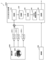
次に、本実施の形態に係る三次元変位計測装置の構成を説明する。図5は、実施の形態における三次元変位計測装置のブロック図である。図5に示す三次元再構成システム3は、複数のカメラ100-1~100-nと、三次元変位計測装置2000と、制御部300とを備える。また、三次元変位計測装置2000は、受信部210と、記憶部220と、取得部230と、三次元画像処理部240と、送信部250とを備える。
Next, the configuration of the three-dimensional displacement measuring device according to this embodiment will be explained. FIG. 5 is a block diagram of a three-dimensional displacement measuring device in an embodiment. The three-
複数のカメラ100-1~100-nは撮影空間1000にある被写体1001を撮影し、撮影された複数の映像である多視点映像を受信部210へ送信する。多視点映像の送信は、インターネットなどの公衆通信網、又は専用通信網のいずれを介してもよい。あるいは、多視点映像は、一度ハードディスクドライブ(HDD)、ソリッドステートドライブ(SSD)などの外部記憶装置に記憶され、必要な時に三次元変位計測装置2000に入力されてもよい。あるいは、多視点映像は、クラウドサーバ等の外部記憶装置に一旦ネットワークを介して送信され、記憶される。そして、必要な時に三次元変位計測装置2000へ送信されてもよい。
A plurality of cameras 100-1 to 100-n photograph a subject 1001 in a photographing
また、n台のカメラ100-1~100-nの各々は、監視カメラなどの固定カメラ、または、固定されていない非固定カメラである。つまり、n台のカメラ100-1~100-nは、例えば、それぞれ、互いに異なる位置において、互いに異なる姿勢で固定されている固定カメラであってもよく、または、ビデオカメラ、スマートフォンもしくはウェアラブルカメラなどのモバイルカメラであってもよく、撮影機能付きドローンなどの移動カメラであってもよい。なお、nは、2以上の整数である。 Further, each of the n cameras 100-1 to 100-n is a fixed camera such as a surveillance camera, or a non-fixed camera. In other words, the n cameras 100-1 to 100-n may be fixed cameras fixed at different positions and different postures, or may be video cameras, smartphones, wearable cameras, etc. It may be a mobile camera, or a mobile camera such as a drone with a shooting function. Note that n is an integer of 2 or more.
また、多視点映像には、映像又はフレームのヘッダ情報として、撮影したカメラを特定するカメラIDなどのカメラ特定情報が付加されてもよい。 Furthermore, camera identification information such as a camera ID that identifies the camera that took the image may be added to the multi-view video as header information of the video or frame.
複数のカメラ100-1~100-nを用いて、毎フレームで同じ時刻の被写体を撮影する同期撮影が行われてもよい。あるいは、複数のカメラ100-1~100-nに内蔵された時計の時刻を合せ、同期撮影せずに、映像又はフレーム毎に、撮影された画像に撮影時刻情報が付加されてもよいし、撮影順序を示すインデックス番号が付加されてもよい。 Synchronous photography may be performed using a plurality of cameras 100-1 to 100-n to photograph a subject at the same time in each frame. Alternatively, the time of the built-in clocks of the plurality of cameras 100-1 to 100-n may be synchronized, and the shooting time information may be added to the shot image for each video or frame without synchronous shooting. An index number indicating the photographing order may be added.
多視点映像の映像セット毎、映像毎、又はフレーム毎に、同期撮影されたか、非同期撮影されたかを示す情報がヘッダ情報として付加されてもよい。 Information indicating whether synchronous shooting or asynchronous shooting has been performed may be added as header information for each video set, video, or frame of multi-view video.
また、制御部300は、例えば、CPU(Central Processing Unit)を用いて実現され、記憶部220に記憶されるプログラムを読み出して実行する。制御部300は、三次元画像処理部240におけるカメラ校正、三次元モデリング及び三次元変位計測のうちの1つ以上の処理を実施するために、三次元再構成システム3によって用いられる、視点数及び視点位置を決定する。ここで、視点数とは、カメラ校正、三次元モデリング及び三次元変位計測のうちの1つ以上の処理で用いられる二次元画像を撮影する位置の数のことであり、具体的には、カメラの台数のことであってもよいし、固定カメラ及び移動カメラによって撮影が行われる地点の数のことであってもよい。また、視点位置とは、カメラ校正、三次元モデリング及び三次元変位計測のうちの1つ以上の処理で用いられる二次元画像を撮影する位置のことであり、具体的にはカメラの位置のことである。
Further, the
そして、受信部210は、カメラ100-1~100-nが撮影した多視点映像を受信し、受信した多視点映像を記憶部220に入力する。
Then, the receiving
記憶部220は、入力された多視点映像を記憶する。また、記憶部220には、撮影空間1000が撮影された映像データ、この映像データに付されるタイムスタンプなどのメタ情報、カメラ100-1~100-nのカメラパラメータ、及び、適用中のフレームレートまたは解像度等の撮影設定が一時的に記憶されている。また、記憶部220には、制御部300が読み出して実行するプログラムが記憶されている。記憶部220は、RAM、DRAM、SRAM等の揮発性メモリでもよい。また、記憶部220は、ROM、フラッシュメモリ等の不揮発性メモリで実現されてもよい。
The
取得部230は、記憶部220に記憶された複数の多視点映像からフレームを選択し、選択したフレームを多視点フレームセットとして三次元画像処理部240に入力する。
The
三次元画像処理部240は、入力された多視点フレームセットを用いて、カメラ校正を行い、カメラ校正の結果を用いて、被写体の三次元モデリングまたは被写体の三次元変位計測を行う。三次元画像処理部240は、カメラ校正を行った結果としてカメラパラメータを算出し、送信部250に出力する。
The three-dimensional
送信部250は、三次元画像処理部240が算出したカメラパラメータ、被写体の三次元モデル及び被写体の三次元変位のうちの少なくとも1つを、三次元変位計測装置2000の外部へ送信する。
The transmitting
受信部210、取得部230、三次元画像処理部240及び送信部250は、それぞれプロセッサ及びメモリによって実現されてもよい。また、受信部210、取得部230、三次元画像処理部240及び送信部250は、専用の回路によって実現されてもよい。
The receiving
図6は、実施の形態における三次元再構成システムのフローチャートである。 FIG. 6 is a flowchart of the three-dimensional reconstruction system in the embodiment.
まず、制御部300は、カメラ校正、三次元モデリングまたは三次元変位計測のうちの1つ以上の処理を実施するために、三次元再構成システム3によって用いられる、視点数及び視点位置を決定する(ステップS2100)。視点数及び視点位置の決定の詳細は後述される。
First, the
次に、カメラ100-1~100-nは、制御部300が決定した視点数及び視点位置に基づき、被写体の多視点映像を撮影する(ステップS2200)。 Next, the cameras 100-1 to 100-n shoot multi-view images of the subject based on the number of viewpoints and viewpoint positions determined by the control unit 300 (step S2200).
そして、受信部210は、カメラ100-1~100-nのうちの複数のカメラで撮影した多視点映像を受信し、記憶部220に入力する(ステップS2300)。
Then, the receiving
続いて、記憶部220は、入力された多視点映像を記憶する(ステップS2400)。
Subsequently, the
次に、取得部230は、制御部300が決定した視点数及び視点位置に基づいて、記憶された多視点映像からフレームを選択し、選択したフレームを多視点フレームセットとして三次元画像処理部240に入力する(ステップS2500)。
Next, the
ここで、多視点フレームセットは、カメラ100-1~100-nが撮影したすべての映像から、それぞれ1フレームずつ選択された複数のフレームによって構成されてもよい。また、多視点フレームセットは、カメラ100-1~100-nが撮影したすべての映像から、少なくとも1フレーム選択された複数のフレームにより構成されてもよい。また、多視点フレームセットは、多視点映像のうちから2つ以上の映像を選択し、選択された各映像から1フレームずつ選択された複数のフレームによって構成されてもよい。また、多視点フレームセットは、多視点映像のうちから2つ以上の映像を選択し、選択された各映像から少なくとも1フレーム選択された複数のフレームによって構成されてもよい。 Here, the multi-view frame set may be composed of a plurality of frames, one frame each selected from all the images taken by the cameras 100-1 to 100-n. Further, the multi-view frame set may be composed of a plurality of frames selected from at least one frame from all the images taken by the cameras 100-1 to 100-n. Further, the multi-view frame set may be configured by selecting two or more videos from among the multi-view videos and selecting one frame from each of the selected videos. Further, the multi-view frame set may be configured by selecting two or more videos from among the multi-view videos and selecting at least one frame from each of the selected videos.
なお、多視点フレームセットの各フレームにカメラ特定情報が付加されていない場合は、各フレームのヘッダ情報に個別にカメラ特定情報を付加してもよいし、多視点フレームセットのヘッダ情報に一括して、カメラ特定情報を付加してもよい。 Note that if camera specific information is not added to each frame of the multi-view frame set, camera specific information may be added to the header information of each frame individually, or it may be added all at once to the header information of the multi-view frame set. Camera specific information may also be added.
また、多視点フレームセットの各フレームに撮影時刻または撮影順を示すインデックス番号が付加されていない場合、各フレームのヘッダ情報に個別に撮影時刻または撮影順を示すインデックス番号を付加してもよい。また、同様の場合、多視点フレームセットのヘッダ情報に一括して撮影時刻または撮影順を示すインデックス番号を付加してもよい。 Furthermore, if an index number indicating the shooting time or shooting order is not added to each frame of the multi-view frame set, an index number indicating the shooting time or shooting order may be individually added to the header information of each frame. In the same case, an index number indicating the shooting time or shooting order may be added to the header information of the multi-view frame set all at once.
そして、三次元画像処理部240は、入力された多視点フレームセットを用いて、カメラ校正を行い、カメラ校正の結果を用いて三次元モデリングまたは三次元変位計測を行う(ステップS2600)。三次元モデリングまたは三次元変位計測の詳細は、後述される。
Then, the three-dimensional
また、ステップS2500及びS2600の処理は、多視点フレームセット毎に繰り返し行われる。ここで、繰り返し行われるステップS2500及びステップS2600において、カメラ校正が一回だけ行われることとしてもよい。その場合、最初に一回実施されたカメラ校正の結果を、繰り返し行われるステップS2500及びステップS2600で、繰り返し使用してもよい。 Further, the processing in steps S2500 and S2600 is repeatedly performed for each multi-view frame set. Here, camera calibration may be performed only once in step S2500 and step S2600, which are repeatedly performed. In that case, the results of the camera calibration performed once may be used repeatedly in the repeated steps S2500 and S2600.
続いて、送信部250は、カメラパラメータ、被写体の三次元モデルまたは被写体の三次元変位を、三次元変位計測装置2000の外部へ送信する(ステップS2700)。
Subsequently, the
ここで、三次元再構成システム3は、処理を終了する。
At this point, the three-
なお、ステップS2600で算出されたカメラパラメータ、被写体の三次元モデルまたは被写体の三次元変位は、ステップS2600より後の処理で利用されてもよい。 Note that the camera parameters, the three-dimensional model of the subject, or the three-dimensional displacement of the subject calculated in step S2600 may be used in processing subsequent to step S2600.
なお、ステップS2700で出力されたカメラパラメータ、被写体の三次元モデルまたは被写体の三次元変位は、記憶部220に記憶されてもよい。
Note that the camera parameters, the three-dimensional model of the subject, or the three-dimensional displacement of the subject output in step S2700 may be stored in the
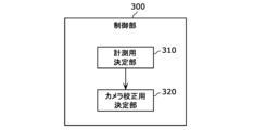
図7は、実施の形態における制御部のブロック図である。制御部300は、計測用決定部310及びカメラ校正用決定部320を備える。計測用決定部310及びカメラ校正用決定部320は、プロセッサ及びメモリで実現されてもよいし、専用の論理回路で実現されてもよい。
FIG. 7 is a block diagram of the control unit in the embodiment. The
計測用決定部310は、三次元再構成システム3が被写体1001の三次元変位計測を行う際に用いる二次元画像を撮影する視点の視点数、視点位置等を決定する。
The
また、カメラ校正用決定部320は、三次元再構成システム3がカメラ校正を行う際に用いる二次元画像を撮影する視点の視点数、視点位置等を決定する。
Further, the camera
なお、三次元再構成システム3が、カメラ校正、三次元モデリング及び三次元変位計測を行うために用いる視点数は、それぞれ異なってもよい。また、制御部300は、視点位置のみを決定してもよい。すなわち、計測用決定部310は、三次元再構成システム3が被写体1001の三次元変位計測を行う際に用いる二次元画像を撮影する視点の視点位置のみを決定してもよい。また、カメラ校正用決定部320は、三次元再構成システム3がカメラ校正を行う際に用いる二次元画像を撮影する視点の視点位置のみを決定してもよい。
Note that the number of viewpoints used by the three-
なお、制御部300は、三次元変位計測装置2000にカメラが導入される前に、カメラの視点数及び視点位置を決定してもよい。また、カメラは、制御部300が決定したカメラの視点数及び視点位置に応じて、導入されてもよい。
Note that the
なお、制御部300は、三次元変位計測に用いられる視点数Nと、カメラ校正に用いられる視点数Mとを、M>Nの関係を満たすように決定する。また、さらに、制御部300は、三次元変位計測に用いられる視点が、カメラ校正に用いられる視点に含まれる(すなわち2個の視点が一致する)ように、三次元変位計測に用いられる視点とカメラ校正に用いられる視点とを決定する。
Note that the
カメラ100-1~100-n、または、取得部230は、三次元変位計測に用いられるN個の視点として、N台の固定カメラを使用する。換言すれば、三次元変位計測のために、M-N個の視点においてカメラによる撮像はされない。また、カメラ校正に用いられるM個の視点のうち、三次元変位計測に用いられるN個の視点以外の(M-N)個の視点として、(M-N)台の固定カメラを使用してもよく、または、(M-N)台以下の移動カメラを使用してもよい。(M-N)台以下の移動カメラを使用する場合は、(M-N)台以下の移動カメラは、移動しながら撮影を行うことで、(M-N)個以上の視点からの撮影を実現する。また、カメラ校正に用いられるM個の視点のうち、三次元変位計測に用いられるN個の視点以外の(M-N)個の視点は、固定カメラと移動カメラとを組み合わせて実現されてもよい。
The cameras 100-1 to 100-n or the
次に、制御部300の動作を説明する。図8は、実施の形態における制御部の動作を表すフローチャートである。
Next, the operation of the
まず、計測用決定部310は、三次元変位計測の視点数及び視点位置を決定する(ステップS3100)。
First, the
次に、カメラ校正用決定部320は、カメラ校正の視点数及び視点位置を決定する(ステップS3200)。このとき、カメラ校正用決定部320は、三次元変位計測の視点数Nより、カメラ校正の視点数Mが多くなるように設定し、かつ、三次元変位計測の視点が、カメラ校正の視点に含まれるように設定する。
Next, the camera
ここで、制御部300は動作を終了する。なお、ステップS3100において、計測用決定部310は、三次元モデリングのための視点数及び視点位置の決定を行ってもよい。
At this point, the
次に、制御部300における視点の決定方法の一例を説明する。まず、図9を用いて、三次元変位計測のための視点数Nの決定について説明する。図9は、実施の形態における三次元変位計測の際に用いる基線長、撮像対象とカメラとの距離、及び、輻輳角を示す図である。図9では、撮像対象である被写体1001と、n台のカメラ100-1~100-nのうちの2台のカメラ100-1、100-2との位置関係が示されている。
Next, an example of a method for determining a viewpoint in the
制御部300は、三次元変位計測に用いられる視点数をN、被写体1001とカメラ100-1、100-2との距離をd、三次元モデリングまたは三次元変位計測の精度をΔzと設定する。これらの値は、任意に決定される。視点数Nは、三次元変位計測に使用されることが可能であるカメラの台数でもよいし、設定可能な範囲で最大の数でもよい。以下の説明では、視点数Nがカメラ100の台数nに等しいものとする。ただし、視点数Nはカメラ100の台数nと等しくなくてもよい。また、被写体1001とカメラ100-1、100-2との距離dは、撮影空間1000の大きさ、カメラ100-1、100-2によって撮影される二次元画像への被写体1001の映り方等のうちの少なくとも1つから決定されてもよい。ここで、距離dは、図9に示されるように、2台のカメラ100-1、100-2の位置を通る線から被写体1001までの最短距離である。ただし、距離dは、図9に示す例に限らない。例えば、距離dは、被写体1001から2台のカメラ100-1、100-2までの距離の平均値であってもよい。制御部300は、三次元モデリングまたは三次元変位計測の精度Δz、カメラの焦点距離f、カメラの素子間隔ΔH、被写体1001と2台のカメラ100-1、100-2との距離dを用いて、2台のカメラ100-1、100-2間の間隔である基線長Lを、式(8)で算出する。
The
L=(d×d×ΔH)/f×Δz 式(8) L=(d×d×ΔH)/f×Δz Formula (8)
例えば、三次元変位計測に用いられる視点数Nについて、N=2の場合は、三次元変位計測に使用されるカメラの台数は2台である。このとき、制御部300は、基線長L及び被写体とカメラとの距離dを、2台のカメラの視点位置を決定するための情報とする。
For example, when the number N of viewpoints used for three-dimensional displacement measurement is N=2, the number of cameras used for three-dimensional displacement measurement is two. At this time, the
三次元変位計測に用いられる視点数Nが2より大きいとき、制御部300は以下の計算を行う。まず、制御部300は、2台のカメラそれぞれの光軸の輻輳角をθとし、θを、基線長L及び距離dを用いて、式(9)で算出する。
When the number of viewpoints N used for three-dimensional displacement measurement is greater than two, the
θ=2arctan(L/2d) 式(9) θ=2arctan(L/2d) Formula (9)
また、制御部300は、値Pを式(10)で算出する。ここで、値Pは、輻輳角θに対応して定まる、三次元再構成システム3で利用されるカメラの台数を示す値である。
Further, the
P=floor(2π/θ) 式(10) P=floor(2π/θ) Formula (10)
PがNより大きい場合、制御部300は、Nを式(11)で算出する。
When P is larger than N, the
N=P 式(11) N=P formula (11)
以上のように、制御部300は、カメラパラメータ及び求められる精度Δzに基づいて、視点数Nを決定する。
As described above, the
また、基線長L、距離d、及び、輻輳角θを、カメラの視点位置を決定するための情報としてもよい。 Furthermore, the baseline length L, distance d, and convergence angle θ may be used as information for determining the viewpoint position of the camera.
なお、上記で説明した被写体1001及び2台のカメラ100-1、100-2の位置関係は、2台のカメラ100-1、100-2に限るものではなく、n台のカメラ100-1~100-nのうちの他の任意の2台の組み合わせについても同様である。 Note that the positional relationship between the subject 1001 and the two cameras 100-1 and 100-2 described above is not limited to the two cameras 100-1 and 100-2, but n cameras 100-1 to 100-2. The same applies to any other combination of two units among 100-n.
図10は、実施の形態におけるカメラ校正に用いる視点位置の決定方法を示す図である。なお、図10は、鉛直方向に沿って複数のカメラを見た図である。まず、制御部300は、カメラ校正に用いられる視点の視点間の輻輳角φを任意に設定する。ここで、θ>2π―(N-1)×θの場合、制御部300は、カメラ校正に用いられる視点数Mを、式(12)で算出する。
FIG. 10 is a diagram illustrating a method for determining a viewpoint position used for camera calibration in the embodiment. Note that FIG. 10 is a diagram of a plurality of cameras viewed along the vertical direction. First, the
M=N+floor(θ/φ)×(N-1) 式(12) M=N+floor(θ/φ)×(N-1) Formula (12)
ここで、三次元変位計測で使用するN個の視点のそれぞれの間に、floor(θ/φ)個ずつ視点が追加される。追加されるfloor(θ/φ)個の視点は、図10に示されるように、三次元変位計測で使用するN個の視点のそれぞれの間に追加される。例えば、制御部300は、視点を、視点位置p1と視点位置p2との中間位置cに1個または2個追加する。ここで、制御部300は、視点位置p1と中間位置cとの間を2等分した位置を位置p3とし、視点位置p2と中間位置cとの間を2等分した位置を位置p4とする。そして、制御部300は、視点位置p1と位置p3との間に、中間位置cに配置された視点数をfloor(θ/φ)個の視点から引いた数の視点を配置する。同様に、制御部300は、視点位置p2と位置p4との間に、中間位置cに配置された視点数を、floor(θ/φ)個の視点から引いた数の視点を配置する。このような配置方法によれば、例えば、追加する視点のうち大多数の視点が、三次元変位計測で使用する視点に対応する位置に配置されたカメラ同士の中点からみて、中点よりも三次元変位計測で使用する視点に対応する位置に配置されたカメラの方に近い位置に配置される。すなわち、位置p3(p4)と視点位置p1(p2)との間に配置される校正用の視点は、中間位置cと位置p3(p4)との間に配置される校正用の視点よりも多い。また、他の配置例では、位置p3(p4)と中間位置cとの間に校正用の視点が設けられない。
Here, floor (θ/φ) viewpoints are added between each of the N viewpoints used in three-dimensional displacement measurement. The additional floor(θ/φ) viewpoints are added between each of the N viewpoints used in three-dimensional displacement measurement, as shown in FIG. For example, the
このため、三次元変位計測方法では、カメラ校正に使用する視点を、三次元変位計測に使用する視点の位置を基準として位置p3(p4)よりも近い範囲に、位置p3(p4)よりも遠い範囲よりも多く設定する。このような不均等な配置により、カメラ校正の精度が向上する。 For this reason, in the three-dimensional displacement measurement method, the viewpoint used for camera calibration is set to a range closer than position p3 (p4) and farther than position p3 (p4) with respect to the position of the viewpoint used for three-dimensional displacement measurement. Set more than the range. Such non-uniform placement improves the accuracy of camera calibration.
次に、多視点フレームセットの詳細について説明する。図11は、実施の形態における多視点フレームセットの例を示す図である。ここでは、取得部230が、5台のカメラ100-1~100-5から1フレームずつを選択することで多視点フレームセットを決定する例を説明する。
Next, details of the multi-view frame set will be explained. FIG. 11 is a diagram illustrating an example of a multi-view frame set in the embodiment. Here, an example will be described in which the
また、複数のカメラが同期撮影することを仮定している。各フレームのヘッダ情報には、撮影されたカメラを特定するカメラIDがそれぞれ100-1~100-5として付与されている。また、各フレームのヘッダ情報には、各カメラ内での撮影順序を示すフレーム番号001~Qが付与されており、カメラ間で同じフレーム番号を持つフレームは同時刻の被写体1001が撮影されたことを示す。 Furthermore, it is assumed that multiple cameras perform synchronized shooting. The header information of each frame is given a camera ID, 100-1 to 100-5, that identifies the camera that took the image. In addition, the header information of each frame is given frame numbers 001 to Q indicating the shooting order within each camera, and frames with the same frame number between cameras indicate that the subject 1001 was shot at the same time. shows.
取得部230は、多視点フレームセット200-1~200-Qを三次元画像処理部240へ順次出力する。三次元画像処理部240は、繰り返し処理により多視点フレームセット200-1~200-Qを用いて、順次三次元モデリングまたは三次元変位計測を行う。
The
多視点フレームセット200-1は、カメラ100-1のフレーム番号001、カメラ100-2のフレーム番号001、カメラ100-3のフレーム番号001、カメラ100-4のフレーム番号001、カメラ100-5のフレーム番号001の5枚のフレームから構成される。多視点映像の最初のフレームの集合として、これら5枚のフレームが、三次元画像処理部240の繰り返し処理1で使用される。すなわち、繰り返し処理1では、フレーム番号001を撮影した時刻の三次元モデルが再構成され、または、三次元変位が計測される。
The multi-view frame set 200-1 includes frame number 001 of camera 100-1, frame number 001 of camera 100-2, frame number 001 of camera 100-3, frame number 001 of camera 100-4, and frame number 001 of camera 100-5. It consists of five frames with frame number 001. These five frames are used in repetitive processing 1 of the three-dimensional
図11に示す例では、多視点フレームセット200-2では、全てのカメラでフレーム番号が更新される。多視点フレームセット200-2は、カメラ100-1のフレーム番号002、カメラ100-2のフレーム番号002、カメラ100-3のフレーム番号002、カメラ100-4のフレーム番号002、カメラ100-5のフレーム番号002の5枚のフレームから構成される。これら5枚のフレームが、三次元画像処理部240の繰り返し処理2で使用される。すなわち、繰り返し処理2では、フレーム番号002を撮影した時刻の三次元モデルが再構成され、または、三次元変位が計測される。
In the example shown in FIG. 11, in the multi-view frame set 200-2, the frame numbers are updated for all cameras. The multi-view frame set 200-2 includes frame number 002 of camera 100-1, frame number 002 of camera 100-2, frame number 002 of camera 100-3, frame number 002 of camera 100-4, and frame number 002 of camera 100-5. It consists of five frames with frame number 002. These five frames are used in repetitive processing 2 of the three-dimensional
以下、繰り返し処理3以降でも、繰り返し処理2と同様に、全てのカメラでフレーム番号が更新される。これにより、三次元再構成システム3は、各時刻における被写体1001の三次元モデルを再構成することができ、また、各時刻における被写体1001の三次元変位を計測することができる。
Hereinafter, in the
ただし、各時刻で独立して三次元再構成を行うため、再構成された複数の三次元モデルの座標軸とスケールが一致しているとは限らない。つまり、動く被写体1001の三次元モデルを取得するためには、各時刻の座標軸及びスケールを合せる必要がある。 However, since three-dimensional reconstruction is performed independently at each time, the coordinate axes and scales of the multiple reconstructed three-dimensional models do not necessarily match. That is, in order to obtain a three-dimensional model of the moving subject 1001, it is necessary to match the coordinate axes and scales at each time.
その場合、各フレームには撮影時刻が付与されており、その撮影時刻を基に取得部230は、同期フレームと非同期フレームを組み合わせた多視点フレームセットを作成する。以下、2台のカメラ間での撮影時刻を用いた同期フレームと非同期フレームの判定方法を説明する。
In this case, each frame is given a shooting time, and based on the shooting time, the
カメラ100-1から選択したフレームの撮影時刻をT1とし、カメラ100-2から選択したフレームの撮影時刻をT2とし、カメラ100-1の露光時間をTE1とし、カメラ100-2の露光時間をTE2とする。ここで、撮影時刻T1、T2は、図4A及び図4Bの例で露光が開始された時刻、つまり矩形信号の立ち上がりの時刻を指している。 The shooting time of the frame selected from camera 100-1 is T1, the shooting time of the frame selected from camera 100-2 is T2, the exposure time of camera 100-1 is TE1, and the exposure time of camera 100-2 is TE2. shall be. Here, the photographing times T1 and T2 refer to the times at which exposure is started in the examples of FIGS. 4A and 4B, that is, the times at which the rectangular signal rises.
この場合、カメラ100-1の露光終了時刻はT1+TE1である。この時、式(13)又は式(14)が成立していれば、2台のカメラ100-1、100-2は、同じ時刻の被写体1001を撮影していることになり、2枚のフレームは同期フレームと判定される。 In this case, the exposure end time of camera 100-1 is T1+TE1. At this time, if equation (13) or equation (14) holds true, it means that the two cameras 100-1 and 100-2 are photographing the subject 1001 at the same time, and the two frames are is determined to be a synchronous frame.
T1≦T2≦T1+TE1 式(13)
T1≦T2+TE2≦T1+TE1 式(14)
T1≦T2≦T1+TE1 Formula (13)
T1≦T2+TE2≦T1+TE1 Formula (14)
なお、制御部300が決定した視点数及び視点位置に基づいて、カメラ100-1~100-nが多視点映像を撮影した場合、取得部230は、入力された多視点映像の本数と同数のフレームを多視点フレームセットとしてもよい。一方、カメラ100-1~100-nが、制御部300が決定した視点数または視点位置と関係なく、多視点映像を撮影した場合、取得部230が、制御部300が決定した視点数または視点位置に対応した映像を選択し、多視点フレームセットを作成することとしてもよい。
Note that when the cameras 100-1 to 100-n shoot multi-view videos based on the number of viewpoints and viewpoint positions determined by the
つまり、三次元変位計測装置2000は、異なる時刻毎に撮像されたN枚の画像を1セットとする。三次元変位計測装置2000は、複数セットのセット毎について、当該セットに含まれるN枚の画像とカメラパラメータとを用いて、当該セットの時刻における被写体1001の三次元位置を計測する。
In other words, the three-dimensional
図12は、実施の形態における三次元画像処理部のブロック図である。三次元画像処理部240は、カメラ校正部410及び三次元処理部420を備える。なお、三次元処理部420は、変位計測部の具体例である。
FIG. 12 is a block diagram of the three-dimensional image processing section in the embodiment. The three-dimensional
カメラ校正部410は、カメラ校正を行う。具体的には、カメラ校正部410は、複数のカメラ100-1~100-nのそれぞれの内部パラメータ、外部パラメータ及びレンズ歪み係数をカメラパラメータとして算出する。内部パラメータとは、カメラの焦点距離、収差、画像中心等の光学系の特性を示す。外部パラメータとは、三次元空間におけるカメラの位置及び姿勢を示す。
カメラ校正部410は、複数のカメラ100-1~100-nがチェッカボードの白黒の交点を撮影することにより得られたM枚のフレームであるM枚の校正用画像を用いて内部パラメータ、外部パラメータ及びレンズ歪み係数を別々に算出してもよいし、Structure from MotionのようにM枚のフレーム間の対応点を用いて内部パラメータ、外部パラメータ及びレンズ歪み係数を一括して算出し、全体最適化を行ってもよい。後者の場合のM枚のフレームは、チェッカボードが撮像された画像でなくてもよい。
The
三次元処理部420は、多視点フレームセットとカメラパラメータとを用いて、被写体1001の三次元モデリング、被写体1001の三次元変位計測等の三次元処理を行う。具体的には、三次元処理部420は、多視点フレームセット及びカメラ校正の結果を用いて、三次元モデリングとして、被写体1001のモデルを三次元点から生成する。三次元モデリングの代わりに、三次元処理部420は、三次元変位計測として、多視点フレームセット及びカメラ校正の結果を用いて、被写体1001の三次元変位を計測してもよい。三次元処理部420は、三次元変位を計測する際に、三次元モデリングで生成された被写体1001の三次元モデルの三次元点のデータを用いてもよい。ここで、三次元変位計測で利用される三次元点は、被写体1001の任意の点でもよい。
The three-
三次元画像処理部240、並びに、三次元画像処理部240を構成する、カメラ校正部410及び三次元処理部420は、プロセッサとメモリとによって実現される。また、これらは、専用の論理回路によって実現されてもよい。
The three-dimensional
図13は、実施の形態における三次元画像処理部の動作を示すフローチャートである。なお、図13に示す処理では、制御部300において決定された視点数の多視点フレームセットが用いられる。
FIG. 13 is a flowchart showing the operation of the three-dimensional image processing section in the embodiment. Note that in the process shown in FIG. 13, a multi-view frame set with the number of views determined by the
まず、カメラ校正部410は、制御部300が決定した視点数M及び視点位置に対応する多視点フレームセットを用いて、撮影が行われた各視点に存在するカメラのカメラパラメータを算出する(ステップS4100)。ここで、制御部300は、少なくともN台のカメラについてのみ、カメラパラメータを算出してもよい。なお、ステップS4100は、カメラ校正ステップの一例である。
First, the
次に、三次元処理部420は、制御部300が決定した視点数N及び視点位置に対応する多視点フレームセット、及び、カメラ校正部410が算出したカメラパラメータを用いて、被写体1001の三次元モデルを生成、または、被写体1001の三次元変位を計測する(ステップS4200)。ここで、三次元処理部420は、変位計測部の具体例である。なお、ステップS4200は、変位計測ステップの一例である。
Next, the three-
なお、本実施の形態で、基準として用いる視点数は、三次元モデリング又は三次元変位計測に用いられる視点数Nである。例えば、視点数Nは、撮影空間1000に常時設置されているカメラの数に等しい。
Note that in this embodiment, the number of viewpoints used as a reference is the number N of viewpoints used for three-dimensional modeling or three-dimensional displacement measurement. For example, the number of viewpoints N is equal to the number of cameras constantly installed in the
また、ステップS4100で算出されたカメラパラメータの精度は、ステップS4200で行われる被写体1001の三次元モデルの生成または被写体1001の三次元変位の計測の精度に大きな影響を及ぼす。よって、カメラパラメータの精度を高めるため、ステップS4100では、ステップS4200の視点数Nより多い視点数Mを使用する。このとき、カメラの台数は必ずしもM台でなくてもよい。M台未満の移動カメラによって、複数視点での撮影を行い、撮影された画像内の静止領域が使用されて、カメラ校正が行われてもよい。静止領域は、画像中の、静止物体が映っている領域であり、動物体が映っている動領域を除く領域である。 Further, the accuracy of the camera parameters calculated in step S4100 has a large influence on the accuracy of the generation of the three-dimensional model of the subject 1001 or the measurement of the three-dimensional displacement of the subject 1001 performed in step S4200. Therefore, in order to improve the accuracy of camera parameters, in step S4100, a number M of viewpoints that is greater than the number N of viewpoints in step S4200 is used. At this time, the number of cameras does not necessarily have to be M. Camera calibration may be performed using less than M moving cameras to capture images from multiple viewpoints and use static areas within the captured images. The still area is an area in an image where a stationary object is shown, excluding a moving area where a moving object is shown.
なお、三次元変位計測装置2000は、上述しているように三次元画像処理部240において、三次元変位計測の他に、三次元モデリングを行ってもよく、さらに自由視点映像生成を行ってもよい。
Note that the three-dimensional
以下、実施の形態における三次元変位計測装置2000で行われる自由視点映像生成について説明する。
Free viewpoint image generation performed by the three-dimensional
三次元変位計測装置2000は、時刻間で座標軸の一致した時系列三次元モデルを再構成できる。具体的には、まず、三次元変位計測装置2000は、時刻毎に独立して三次元再構成を行うことで、各時刻の三次元モデルを取得する。次に、三次元変位計測装置2000は、静止カメラ及び静止物体(静止三次元点)を検出し、検出した静止カメラ及び静止物体を用いて、時刻間で三次元モデルの座標合せを行い、座標軸の一致した時系列三次元モデルを生成する。
The three-dimensional
次に、三次元変位計測装置2000が自由視点映像生成を行う際の動作を説明する。図14は、本実施の形態に係る三次元変位計測装置2000が自由視点映像生成を行う際の動作を示すフローチャートである。
Next, the operation when the three-dimensional
まず、受信部210は、複数のカメラ100-1~100-nで撮影された多視点映像を受信する(S101)。記憶部220は、受信された多視点映像を記憶する(S102)。
First, the receiving
次に、取得部230は、多視点映像からフレームを選択し、多視点フレームセットとして三次元画像処理部240へ出力する(S103)。なお、ここで選択される多視点フレームセットは、図6のステップS2500で選択される多視点フレームセットと同様の構成を有していてもよい。
Next, the
次に、三次元画像処理部240は、多視点フレームセットを用いて、カメラ校正処理、三次元モデリング処理及び自由視点映像合成処理を実行することで自由視点映像を生成する(S104)。
Next, the three-dimensional
また、ステップS103及びS104の処理は、多視点フレームセット毎に繰り返し行われる。 Further, the processing in steps S103 and S104 is repeatedly performed for each multi-view frame set.
最後に、送信部250は、カメラパラメータ、被写体の三次元モデル及び自由視点映像の少なくとも1つを外部装置へ送信する(S105)。
Finally, the
次に、三次元画像処理部240による自由視点映像生成の詳細について説明する。
Next, details of free viewpoint video generation by the three-dimensional
制御部300は、図7~図10を用いて説明したように、カメラ校正部410及び三次元処理部420における各処理で最適な視点数を決定する。ここで決定する視点数とは、互いに異なる視点の数を示す。
The
カメラ校正処理において算出するカメラパラメータの精度は、三次元モデリング処理及び自由視点映像合成処理における精度に大きな影響を及ぼす。よって、制御部300は、三次元モデリング処理及び自由視点映像合成処理における精度を低下させないために、カメラパラメータの精度が向上するように三次元モデリング処理における視点数Nよりも多い視点数Mを、カメラ校正処理において用いる多視点フレームセットの視点数として決定する。つまり、制御部300は、n台のカメラ100-1~100-nにより撮像されたN枚のフレームに、a台の非固定カメラにより撮像されたk(kはa以上の整数)枚のフレームを加えたM枚のフレームを用いてカメラ校正部410にカメラ校正処理を実行させる。なお、a台の非固定カメラは、必ずしもk台でなくてもよく、a台の非固定カメラを移動させることによりk視点で撮像を行った結果得られた、k枚のフレーム(画像)であってもよい。
The accuracy of camera parameters calculated in camera calibration processing has a large effect on the accuracy in three-dimensional modeling processing and free viewpoint video synthesis processing. Therefore, in order not to reduce the accuracy in the three-dimensional modeling process and the free-viewpoint image synthesis process, the
また、自由視点映像合成処理において、実カメラによって得られた画像と、仮想視点の画像との対応位置の算出には、実カメラ台数が多いほど大きい処理負荷がかかるため、多くの処理時間を要する。一方で、n台のカメラ100-1~100-nのうち配置されている位置が近い複数のカメラにおいて得られた複数の画像間において、当該複数の画像から得られるテクスチャ情報が互いに似ている。このため、自由視点映像合成処理に、当該複数の画像の全てを用いても、当該複数の画像のうちの1つの画像を用いても、自由視点映像合成処理により得られる結果への精度はあまり変わらない。よって、制御部300は、三次元モデリング処理における視点数Nよりも少ない視点数lを、自由視点映像合成処理において用いる多視点フレームセットの視点数として決定する。
In addition, in free viewpoint video synthesis processing, calculating the corresponding position between the image obtained by the real camera and the image from the virtual viewpoint requires a lot of processing time because the larger the number of real cameras, the greater the processing load. . On the other hand, among the plurality of images obtained by the plurality of cameras arranged in close positions among the n cameras 100-1 to 100-n, the texture information obtained from the plurality of images is similar to each other. . Therefore, even if all of the plurality of images or one image from the plurality of images is used in the free-viewpoint video synthesis process, the accuracy of the results obtained by the free-viewpoint video synthesis process is low. does not change. Therefore, the
図15は、自由視点映像生成を行う際の三次元画像処理部240の動作を示すフローチャートである。
FIG. 15 is a flowchart showing the operation of the three-dimensional
まず、カメラ校正部410は、ステップS4100と同様に、互いに異なる位置に配置されるn台のカメラ100-1~100-nによって異なるM視点において撮像されたM枚の校正用画像を用いて複数のカメラ100-1~100-nのカメラパラメータを算出する(S310)。なお、ここでのM視点は、制御部300において決定された視点数に基づく。
First, as in step S4100, the
なお、カメラ校正部410は、固定カメラ及び非固定カメラを含むn台のカメラ100-1~100-nによって得られたM枚の校正用画像を用いてカメラ校正処理を行う。カメラ校正処理では、カメラの数が多いほどカメラ間の距離が近くなり、距離が近い複数のカメラの視野が近くなるため、距離が近い複数のカメラから得られる複数の画像の対応付けが容易になる。よって、カメラ校正部410は、カメラ校正を行う場合、撮影空間1000に常時設置されている固定カメラに加えて、非固定カメラを用いて視点数を増やす。
Note that the
非固定カメラは、少なくとも1台の移動カメラでもよく、非固定カメラとして移動カメラを使用する場合、撮像するタイミングが異なる画像が含まれることとなる。つまり、カメラ校正処理において用いられるM枚の校正用画像は、異なるタイミングで撮像された画像を含むことになる。言い換えると、M枚の校正用画像が構成するM視点の多視点フレームセットは、非同期撮影により得られたフレームを含む。このため、カメラ校正部410は、M枚の校正用画像のうちの静止物体が映っている領域である静止領域から得られる特徴点の画像間同士の対応点を利用してカメラ校正処理を行う。よって、カメラ校正部410は、静止領域に対応したカメラパラメータを算出する。静止領域は、M枚の校正用画像のうちの動物体が映っている動領域を除く領域である。フレームに映り込む動領域は、例えば、過去のフレームとの差分を計算したり、背景映像との差分を計算したり、機械学習により動物体の領域を自動検知するなどで検出される。
The non-fixed camera may be at least one moving camera, and when a moving camera is used as the non-fixed camera, images captured at different timings will be included. In other words, the M calibration images used in the camera calibration process include images captured at different timings. In other words, a multi-view frame set of M viewpoints constituted by M calibration images includes frames obtained by asynchronous imaging. For this reason, the
なお、カメラ校正部410は、三次元画像処理部240における自由視点映像生成処理において、ステップS310のカメラ校正処理を常に行わなくてもよく、所定の回数毎に1回行ってもよい。
Note that in the free viewpoint video generation process in the three-dimensional
次に、三次元処理部420は、n台のカメラ100-1~100-nのそれぞれによって撮像されたN枚の三次元処理用画像、及び、カメラ校正処理において得られたカメラパラメータ、を用いて三次元モデルを再構成する(S320)。つまり、三次元処理部420は、制御部300において決定された視点数Nに基づいて、N視点において撮像されたN枚の三次元処理用画像を用いて三次元モデルを再構成する。これにより、三次元処理部420は、N枚の三次元処理用画像における被写体を三次元点として再構成する。三次元モデリング処理において用いられるN枚の三次元処理用画像は、任意のタイミングでn台のカメラ100-1~100-nのそれぞれによって撮像された画像である。つまり、N枚の三次元処理用画像が構成するN視点の多視点フレームセットは、同期撮影により得られた多視点フレームセットである。このため、三次元処理部420は、N枚の三次元処理用画像のうち静止物体及び動物体を含む領域(つまり、全ての領域)を用いて三次元モデリング処理を行う。なお、三次元処理部420は、レーザスキャンを用いて被写体の三次元空間上の位置の計測結果を用いてもよいし、多視点ステレオ法のように複数のステレオ画像の対応点を用いて、被写体の三次元空間上の位置を算出してもよい。
Next, the three-
次に、三次元処理部420は、n台のカメラ100-1~100-nのうちの、l台のカメラのそれぞれによって撮像されたl枚の第3画像、カメラ校正処理において算出されたカメラパラメータ、及び、三次元モデリング処理において再構成された三次元モデル、を用いて自由視点映像を合成する(S330)。つまり、三次元処理部420は、制御部300において決定された視点数lに基づいて、l視点において撮像されたl枚の第3画像を用いて自由視点映像を合成する。具体的には、三次元処理部420は、カメラパラメータ及び三次元モデルにより求めた、実カメラの画像と仮想視点の画像との対応位置を基に、実カメラのテクスチャ情報を用いて仮想視点のテクスチャ情報を算出することで、自由視点映像を合成する。
Next, the three-
(効果など)
本実施の形態に係る三次元変位計測方法によれば、カメラパラメータの精度が向上するように三次元変位計測処理における視点数Nよりも多い視点数Mを、カメラ校正処理に用いることで、三次元変位計測処理における精度を向上させることができる。
(effects, etc.)
According to the three-dimensional displacement measurement method according to the present embodiment, the number of viewpoints M, which is larger than the number of viewpoints N in the three-dimensional displacement measurement processing, is used in the camera calibration processing to improve the accuracy of camera parameters. The accuracy in the original displacement measurement process can be improved.
また、本実施の形態に係る三次元変位計測方法によれば、精度が高いカメラパラメータ、第1対応点及び第2対応点に基づいて、画像マッチングの手法及び三角測量の原理を用いて、三次元点の経時的な変位を求める。このため、被写体の三次元空間における変位を効果的に求めることができる。 Further, according to the three-dimensional displacement measurement method according to the present embodiment, based on the highly accurate camera parameters, the first corresponding points, and the second corresponding points, the three-dimensional displacement measurement method is performed using the image matching method and the principle of triangulation. Find the displacement of the origin point over time. Therefore, the displacement of the subject in three-dimensional space can be effectively determined.
また、本実施の形態に係る三次元変位計測方法によれば、変位計測ステップで行われる計測の精度を満たすように、カメラの視点数Nを定めることができる。よって、三次元変位計測方法では、精度よく被写体の三次元空間における変位を求めることができる。 Further, according to the three-dimensional displacement measuring method according to the present embodiment, the number N of camera viewpoints can be determined so as to satisfy the accuracy of the measurement performed in the displacement measuring step. Therefore, with the three-dimensional displacement measuring method, the displacement of the subject in three-dimensional space can be determined with high accuracy.
本実施の形態に係る三次元変位計測装置2000によれば、カメラ校正処理において算出するカメラパラメータの精度が、三次元モデリング処理及び自由視点映像合成処理における精度に大きな影響を及ぼすことを考慮して、カメラパラメータの精度が向上するように三次元モデリング処理における視点数Nよりも多い視点数Mを、カメラ校正処理において用いる多視点フレームセットの視点数として決定する。このため、三次元モデリング処理及び自由視点映像合成処理における精度を向上させることができる。
According to the three-dimensional
また、本実施の形態に係る三次元変位計測装置2000によれば、三次元モデリング処理における視点数Nよりも少ない視点数lを、自由視点映像合成処理において用いる多視点フレームセットの視点数として決定することで、自由視点映像を生成するのに要する処理負荷を低減することができる。
Furthermore, according to the three-dimensional
(変形例)
図16は、三次元画像処理部の変形例のブロック図である。本実施の形態における変形例では、三次元画像処理部240Aは、カメラ校正部510及び三次元処理部520で構成されている。
(Modified example)
FIG. 16 is a block diagram of a modified example of the three-dimensional image processing section. In a modification of this embodiment, the three-dimensional
カメラ校正部510は、カメラ校正部410と機能、構成等は同一であるが、以下の点において異なる。カメラ校正部510は、カメラ校正部510の出力をフィードバックされた入力として受け付け、その入力に基づいて再度処理を行う。三次元処理部520は、三次元処理部420と機能及び構成は同一である。三次元処理部520は、カメラ校正部510から最終的に出力されたデータに基づいて、処理を行う。なお、カメラ校正部からの最終的な出力とは、例えば、カメラ校正部からの最初の出力を除いた出力である。
The
図17は、三次元画像処理部の変形例の動作を示すフローチャートである。 FIG. 17 is a flowchart showing the operation of a modified example of the three-dimensional image processing section.
まず、カメラ校正部510は、制御部300が決定した視点数及び視点位置に対応する多視点フレームセットを用いて、撮影が行われた各視点に存在するカメラのカメラパラメータを算出する(ステップS5100)。
First, the
次に、カメラ校正部510は、ステップS5100で行われたカメラ校正の結果の値を初期値として、制御部300が決定した視点数及び視点位置に対応する多視点フレームセットを用いて、撮影が行われた各視点に存在するカメラのカメラパラメータを算出する(ステップS5200)。
Next, the
そして、三次元処理部520は、制御部300が決定した視点数及び視点位置に対応する多視点フレームセット、及び、カメラ校正部510が算出したカメラパラメータを用いて、被写体1001の三次元モデリング、または、被写体の三次元変位計測を行う(ステップS5300)。
The three-
カメラ校正処理において、カメラ校正に使用されるカメラの台数が多いほど、カメラ間の距離が近くなる。距離が近いカメラ間では、カメラの視野に入る撮影空間1000の領域同士が近くなるため、カメラごとに撮影された画像同士の対応付けが容易になる。よって、カメラ校正を行う場合、撮影空間1000に常時設置されている固定カメラに加えて、非固定カメラを用いて、カメラ校正に用いられる視点の数を、固定カメラで実現される視点の数よりも増加させる。ここで、非固定カメラは、少なくとも1台の移動カメラでもよい。しかしながら、非固定カメラとして移動カメラを使用する場合、異なる視点において撮影された画像の撮影時刻が異なるため、撮影された画像の静止領域のみ対応したカメラパラメータが算出される。
In camera calibration processing, the greater the number of cameras used for camera calibration, the closer the distance between the cameras. When cameras are close to each other, the areas of the
このとき、算出されたカメラパラメータは、固定カメラで撮影された画像における動領域に対応しているとは限らない。ここで、動領域とは、画像中の、動物体が映っている領域である。また、Structure from Motionのような方式では、カメラパラメータの全体最適化が実施される。よって、この方式が用いられた場合は、固定カメラのみに着目すると、カメラパラメータが最適化されているとは限らない。 At this time, the calculated camera parameters do not necessarily correspond to the moving area in the image captured by the fixed camera. Here, the moving area is an area in an image where a moving object is shown. Furthermore, in a method such as Structure from Motion, overall optimization of camera parameters is performed. Therefore, when this method is used, camera parameters are not necessarily optimized if only fixed cameras are focused.
よって、本変形例では、ステップS5100とステップS5200との2つのステップにわたって、2段階のカメラ校正を実施する。 Therefore, in this modification, two-stage camera calibration is performed over two steps, step S5100 and step S5200.
まず、ステップS5100では、カメラ校正部510は、撮影空間1000に常時設置されているA台のカメラ以外の少なくとも1台のカメラで撮影された画像を含んだ、B個の視点が用いられる多視点フレームセットを用いて、大まかなカメラ校正を行う。
First, in step S5100, the
次に、ステップS5200では、カメラ校正部510は、撮影空間1000に常時設置されているA台のカメラで撮影された画像のみを用いて、カメラ校正部510が算出したカメラパラメータをA台のカメラ環境で最適化する。ここで、最適化とは、カメラパラメータ算出の際に副次的に得られた三次元点を、撮影された画像上に再投影し、その再投影点と画像上で検出された特徴点との誤差(再投影誤差)を評価値として、評価値を最小化する処理を行うことを指してもよい。
Next, in step S5200, the
なお、2段階目のカメラ校正で用いる視点数は、撮影空間1000に常時設置されるカメラ台数Aより大きくてもよい。また、2段階目のカメラ校正で用いられる視点数は、三次元画像処理(例えば三次元変位計測)で用いられる視点数よりも大きくてもよい。ただし、2段階目のカメラ校正で用いられる視点数は、三次元画像処理(例えば三次元変位計測)で用いられる視点数と等しくてもよいし、それよりも小さくてもよい。
Note that the number of viewpoints used in the second stage of camera calibration may be larger than the number A of cameras constantly installed in the
上記の三次元変位計測装置において、n台のカメラ100-1~100-nは、2つのカメラを有するステレオカメラを含んでいてもよい。ステレオカメラは、互いに略同じ方向を撮像する2つのカメラ、つまり、第1カメラ及び第2カメラを有し、2つのカメラの間の距離が所定距離以下である構成であればよい。このように、n台のカメラ100-1~100-nがステレオカメラにより構成された場合、n/2台の第1カメラと、n/2台の第2カメラとにより構成される。なお、ステレオカメラが有する2つのカメラは、一体化されていてもよいし、別体であってもよい。 In the three-dimensional displacement measuring device described above, the n cameras 100-1 to 100-n may include a stereo camera having two cameras. The stereo camera may have two cameras that capture images in substantially the same direction, that is, a first camera and a second camera, and the distance between the two cameras may be a predetermined distance or less. In this way, when n cameras 100-1 to 100-n are configured by stereo cameras, they are configured by n/2 first cameras and n/2 second cameras. Note that the two cameras included in the stereo camera may be integrated or separate.
また、ステレオカメラを構成する第1カメラ及び第2カメラは、互いに異なる感度で撮像してもよい。第1カメラは、第1の感度で撮像するカメラである。第2カメラは、第1の感度とは異なる第2の感度で撮像するカメラである。第1カメラと第2カメラとは、色感度が互いに異なるカメラである。 Further, the first camera and the second camera forming the stereo camera may take images with different sensitivities. The first camera is a camera that captures images with a first sensitivity. The second camera is a camera that captures images with a second sensitivity different from the first sensitivity. The first camera and the second camera are cameras with different color sensitivities.
三次元処理部は、n台のカメラ100-1~100-nの全てによって撮像されることにより得られたn枚の三次元処理用画像を用いて三次元モデルを再構成する。三次元処理部は、三次元モデリング処理において、輝度情報を使用するため、色感度の相違に関わらずn台のカメラ全てを使用して三次元モデルを高精度に算出することができる。 The three-dimensional processing unit reconstructs a three-dimensional model using n images for three-dimensional processing obtained by being captured by all of the n cameras 100-1 to 100-n. Since the three-dimensional processing unit uses luminance information in the three-dimensional modeling process, it is possible to calculate a three-dimensional model with high precision using all n cameras regardless of differences in color sensitivity.
三次元処理部は、n/2台の第1カメラまたはn/2台の第2カメラによって撮像されることにより得られた複数の画像であるn/2枚の第3画像、カメラ校正部により算出されたカメラパラメータ、及び、三次元処理部により再構成された三次元モデル、を用いて自由視点映像を合成する。三次元処理部は、自由視点映像生成処理において、n/2台の第1カメラ、及び、n/2台の第2カメラのどちらか一方によるn/2枚の画像を使用しても精度に及ぼす影響は小さい。そこで、三次元処理部は、撮影空間1000の状況に応じて、第1カメラと第2カメラとの一方で撮像されたn/2枚の画像を用いて、自由視点合成を実施する。例えば、n/2台の第1カメラは、赤系統の色感度が高いカメラであり、n/2台の第2カメラは、青系統の色感度が高いカメラであるとする。この場合、三次元処理部は、被写体が赤系統の色であれば、赤の色感度が高い第1カメラにより撮像された画像を用い、被写体が青系統の色であれば、青の色感度が高い第2カメラにより撮像された画像を用いて自由視点映像合成処理を実行するように、用いる画像を切り替える。
The three-dimensional processing unit generates n/2 third images, which are a plurality of images obtained by capturing images by n/2 first cameras or n/2 second cameras, by a camera calibration unit. A free viewpoint video is synthesized using the calculated camera parameters and the three-dimensional model reconstructed by the three-dimensional processing unit. The three-dimensional processing unit maintains accuracy even when using n/2 images from either the n/2 first cameras or the n/2 second cameras in free-viewpoint video generation processing. The impact is small. Therefore, the three-dimensional processing unit performs free viewpoint synthesis using n/2 images captured by either the first camera or the second camera, depending on the situation of the
三次元変位計測装置によれば、撮影空間の状況に応じて感度の異なる2種類のカメラから得られる2種類の画像のうちの一方の画像を用いて自由視点映像合成を行う。このため、精度よく自由視点映像を生成することができる。 According to the three-dimensional displacement measuring device, free viewpoint video synthesis is performed using one of two types of images obtained from two types of cameras with different sensitivities depending on the situation of the shooting space. Therefore, a free viewpoint video can be generated with high accuracy.
なお、第1カメラと第2カメラとは、色感度が互いに異なることに限らず、輝度感度が互いに異なるカメラであってもよい。この場合、三次元処理部は、昼間と夜間、晴天と曇天などの状況に応じて、カメラを切替えることができる。 Note that the first camera and the second camera are not limited to having mutually different color sensitivities, and may be cameras having mutually different luminance sensitivities. In this case, the three-dimensional processing unit can switch the camera depending on the situation, such as daytime and nighttime, sunny weather and cloudy weather.
なお、ステレオカメラを用いるとしたが、必ずしもステレオカメラを用いなくてもよい。よって、n台のカメラは、n/2台の第1カメラ、及び、n/2台の第2カメラにより構成されていることに限らずに、i台の第1カメラと、j台の第2カメラとにより構成されていてもよい。 Note that although a stereo camera is used, it is not always necessary to use a stereo camera. Therefore, the n cameras are not limited to n/2 first cameras and n/2 second cameras; It may be configured with two cameras.
複数のカメラ100-1~100-nは、固定カメラ及び非固定カメラにより構成されるとしたが、これに限らずに、全ての複数のカメラが固定カメラにより構成されてもよい。また、三次元モデリングで用いられるn枚の画像は、固定カメラにより撮像された画像であるとしたが、非固定カメラにより撮像された画像を含んでいてもよい。 Although the plurality of cameras 100-1 to 100-n are composed of fixed cameras and non-fixed cameras, the present invention is not limited to this, and all the plurality of cameras may be composed of fixed cameras. Further, although the n images used in three-dimensional modeling are images taken by a fixed camera, they may also include images taken by a non-fixed camera.
図18は、三次元空間認識の概要を示す図である。上述のように、校正済みのカメラ(例えば固定カメラ)を用いて同一空間を多視点から撮影することにより撮影する空間を三次元再構成できる(三次元空間再構成)。この三次元再構成されたデータを用いて、三次元変位計測等を行うことができる。これにより、次世代広域監視システム、及び三次元変位計測システムを実現できる。具体的には、車道における交差点等において、通行する車両10等を固定カメラ100-aまたは非固定カメラ100-bを用いて撮影し、車両10等の三次元変位を測定することが出来る。
FIG. 18 is a diagram showing an overview of three-dimensional space recognition. As described above, by photographing the same space from multiple viewpoints using a calibrated camera (for example, a fixed camera), the photographed space can be three-dimensionally reconstructed (three-dimensional spatial reconstruction). Using this three-dimensional reconstructed data, three-dimensional displacement measurement, etc. can be performed. This makes it possible to realize a next-generation wide-area monitoring system and a three-dimensional displacement measurement system. Specifically, at an intersection on a roadway or the like, the three-dimensional displacement of the
上記の三次元変位計測装置によれば、被写体の三次元変位計測を行い、さらに、被写体の三次元モデリングを行ってもよいとしたが、これに限らずに、被写体の三次元変位計測を行わずに被写体の三次元モデリングを行ってもよい。 According to the above-mentioned three-dimensional displacement measurement device, three-dimensional displacement measurement of the subject is performed, and three-dimensional modeling of the subject may also be performed, but the present invention is not limited to this. Three-dimensional modeling of the subject may also be performed.
本開示は、三次元変位計測方法及び三次元変位計測装置に適用でき、例えば、インフラ点検システム、産業用機械モニタリングシステム、三次元空間認識システム及び次世代監視システム等に適用できる。 The present disclosure can be applied to a three-dimensional displacement measuring method and a three-dimensional displacement measuring device, and can be applied to, for example, an infrastructure inspection system, an industrial machine monitoring system, a three-dimensional space recognition system, a next-generation monitoring system, and the like.
3 三次元再構成システム
10 車両
100-1~100-n カメラ
100-a 固定カメラ
100-b 非固定カメラ
200-1~200-Q 多視点フレームセット
210 受信部
220 記憶部
230 取得部
240、240A 三次元画像処理部
250 送信部
300 制御部
310 計測用決定部
320 カメラ校正用決定部
410、510 カメラ校正部
420、520 三次元処理部
1000 撮影空間
1001 被写体
2000 三次元変位計測装置
3 Three-
Claims (9)
(1)異なる時刻毎に前記N台のカメラのそれぞれによって被写体を撮像することで生成されるN枚の画像、及び、(2)前記カメラパラメータ、に基づいて、三次元空間における前記被写体の振動による前記被写体の経時的な変位を計測する変位計測ステップと、を含み、
前記異なる時刻は、前記被写体の振動の周波数に応じて設定される
三次元変位計測方法。 Based on M calibration images taken at mutually different M (M is an integer greater than N) viewpoints by a plurality of cameras including N (N is an integer greater than 1) cameras, a camera calibration step of calculating camera parameters of the camera;
(1) N images generated by imaging the subject by each of the N cameras at different times; and (2) vibration of the subject in three-dimensional space based on the camera parameters. a displacement measuring step of measuring the displacement of the subject over time ,
The different times are set according to the frequency of vibration of the subject.
Three-dimensional displacement measurement method.
請求項1に記載の三次元変位計測方法。 The three-dimensional displacement measuring method according to claim 1.
請求項2に記載の三次元変位計測方法。 The three-dimensional displacement measuring method according to claim 2.
前記N枚の画像に含まれる第1画像に含まれる、前記被写体の第1対応点と、前記N枚の画像に含まれる第2画像に含まれ且つ前記第1対応点に対応する第2対応点と、を求める対応点算出ステップと、
前記カメラパラメータと、前記第1対応点と、前記第2対応点とに基づいて、前記三次元空間における前記被写体の三次元点を求める三次元点算出ステップと、
前記異なる時刻に対応する複数の前記三次元点から、前記三次元点の経時的な変位を求める変位算出ステップと、を含む、
請求項1~3のいずれか1項に記載の三次元変位計測方法。 The displacement measurement step includes:
A first corresponding point of the subject included in a first image included in the N images, and a second corresponding point included in a second image included in the N images and corresponding to the first corresponding point. a corresponding point calculation step for determining the point and;
a three-dimensional point calculation step of calculating a three-dimensional point of the subject in the three-dimensional space based on the camera parameter, the first corresponding point, and the second corresponding point;
a displacement calculation step of calculating the displacement of the three-dimensional point over time from the plurality of three-dimensional points corresponding to the different times;
The three-dimensional displacement measuring method according to any one of claims 1 to 3 .
請求項1~4のいずれか1項に記載の三次元変位計測方法。 The N is determined based on the camera parameters and the accuracy of the displacement measurement.
The three-dimensional displacement measuring method according to any one of claims 1 to 4 .
前記M個の視点は、前記第1カメラが配置される第1位置と、前記第2カメラが配置される第2位置との間の第1中点を含み、
前記第1位置と前記第1中点との間の中点を第2中点とすると、前記M個の視点に含まれ且つ前記第2中点と前記第1位置との間に設けられる視点は、前記M個の視点に含まれ且つ前記第1中点と前記第2中点との間に設けられる視点よりも多い
請求項1~5のいずれか1項に記載の三次元変位計測方法。 The N cameras include a first camera and a second camera that are adjacent to each other,
The M viewpoints include a first midpoint between a first position where the first camera is placed and a second position where the second camera is placed,
If the midpoint between the first position and the first midpoint is a second midpoint, a viewpoint included in the M viewpoints and provided between the second midpoint and the first position The three-dimensional displacement measuring method according to any one of claims 1 to 5 , wherein there are more viewpoints included in the M viewpoints and provided between the first midpoint and the second midpoint. .
請求項6に記載の三次元変位計測方法。 The three-dimensional displacement measuring method according to claim 6 , wherein in the camera calibration step, no viewpoint is provided between the first midpoint and the second midpoint.
請求項1~7のいずれか1項に記載の三次元変位計測方法。 The three-dimensional displacement measuring method according to any one of claims 1 to 7.
(1)異なる時刻毎に前記N台のカメラのそれぞれによって被写体を撮像することで生成されるN枚の画像、及び、(2)前記カメラパラメータ、に基づいて、三次元空間における前記被写体の振動による前記被写体の経時的な変位を計測する変位計測部と、を備え、
前記異なる時刻は、前記被写体の振動の周波数に応じて設定される
三次元変位計測装置。 Based on M calibration images taken at mutually different M (M is an integer greater than N) viewpoints by a plurality of cameras including N (N is an integer greater than 1) cameras, a camera calibration unit that calculates camera parameters of the camera;
(1) N images generated by imaging the subject by each of the N cameras at different times; and (2) vibration of the subject in three-dimensional space based on the camera parameters. a displacement measurement unit that measures the displacement of the subject over time ,
The different times are set according to the frequency of vibration of the subject.
Three-dimensional displacement measurement device.
Priority Applications (1)
| Application Number | Priority Date | Filing Date | Title |
|---|---|---|---|
| JP2024016929A JP2024052755A (en) | 2019-07-30 | 2024-02-07 | Three-dimensional displacement measuring method and three-dimensional displacement measuring device |
Applications Claiming Priority (3)
| Application Number | Priority Date | Filing Date | Title |
|---|---|---|---|
| JP2019139581 | 2019-07-30 | ||
| JP2019139581 | 2019-07-30 | ||
| PCT/JP2020/026801 WO2021020062A1 (en) | 2019-07-30 | 2020-07-09 | Three-dimensional displacement measurement method and three-dimensional displacement measurement device |
Related Child Applications (1)
| Application Number | Title | Priority Date | Filing Date |
|---|---|---|---|
| JP2024016929A Division JP2024052755A (en) | 2019-07-30 | 2024-02-07 | Three-dimensional displacement measuring method and three-dimensional displacement measuring device |
Publications (3)
| Publication Number | Publication Date |
|---|---|
| JPWO2021020062A1 JPWO2021020062A1 (en) | 2021-02-04 |
| JPWO2021020062A5 JPWO2021020062A5 (en) | 2022-04-14 |
| JP7442072B2 true JP7442072B2 (en) | 2024-03-04 |
Family
ID=74230583
Family Applications (2)
| Application Number | Title | Priority Date | Filing Date |
|---|---|---|---|
| JP2021536879A Active JP7442072B2 (en) | 2019-07-30 | 2020-07-09 | Three-dimensional displacement measurement method and three-dimensional displacement measurement device |
| JP2024016929A Pending JP2024052755A (en) | 2019-07-30 | 2024-02-07 | Three-dimensional displacement measuring method and three-dimensional displacement measuring device |
Family Applications After (1)
| Application Number | Title | Priority Date | Filing Date |
|---|---|---|---|
| JP2024016929A Pending JP2024052755A (en) | 2019-07-30 | 2024-02-07 | Three-dimensional displacement measuring method and three-dimensional displacement measuring device |
Country Status (3)
| Country | Link |
|---|---|
| US (1) | US20220138971A1 (en) |
| JP (2) | JP7442072B2 (en) |
| WO (1) | WO2021020062A1 (en) |
Families Citing this family (2)
| Publication number | Priority date | Publication date | Assignee | Title |
|---|---|---|---|---|
| WO2020208686A1 (en) * | 2019-04-08 | 2020-10-15 | 日本電気株式会社 | Camera calibration device, camera calibration method, and non-transitory computer-readable medium having program stored thereon |
| US11941794B2 (en) * | 2019-08-19 | 2024-03-26 | Current Lighting Solutions, Llc | Commissioning of lighting system aided by augmented reality |
Citations (4)
| Publication number | Priority date | Publication date | Assignee | Title |
|---|---|---|---|---|
| WO2011030771A1 (en) | 2009-09-08 | 2011-03-17 | 株式会社パスコ | Method for measuring displacement, device for measuring displacement, and program for measuring displacement |
| CN102778207A (en) | 2012-07-10 | 2012-11-14 | 中联重科股份有限公司 | Measurement method, device and system for stress and strain of structural part |
| WO2018135510A1 (en) | 2017-01-19 | 2018-07-26 | パナソニック インテレクチュアル プロパティ コーポレーション オブ アメリカ | Three-dimensional reconstruction method and three-dimensional reconstruction device |
| JP2019074991A (en) | 2017-10-18 | 2019-05-16 | 株式会社富士通アドバンストエンジニアリング | Image processing program, image processing apparatus and image processing method |
Family Cites Families (1)
| Publication number | Priority date | Publication date | Assignee | Title |
|---|---|---|---|---|
| KR20160082659A (en) * | 2014-12-30 | 2016-07-08 | 순천대학교 산학협력단 | Method for the three-dimensional automatic measurement of structural vibration by multi-channel sequence digital images |
-
2020
- 2020-07-09 WO PCT/JP2020/026801 patent/WO2021020062A1/en active Application Filing
- 2020-07-09 JP JP2021536879A patent/JP7442072B2/en active Active
-
2022
- 2022-01-18 US US17/577,733 patent/US20220138971A1/en active Pending
-
2024
- 2024-02-07 JP JP2024016929A patent/JP2024052755A/en active Pending
Patent Citations (4)
| Publication number | Priority date | Publication date | Assignee | Title |
|---|---|---|---|---|
| WO2011030771A1 (en) | 2009-09-08 | 2011-03-17 | 株式会社パスコ | Method for measuring displacement, device for measuring displacement, and program for measuring displacement |
| CN102778207A (en) | 2012-07-10 | 2012-11-14 | 中联重科股份有限公司 | Measurement method, device and system for stress and strain of structural part |
| WO2018135510A1 (en) | 2017-01-19 | 2018-07-26 | パナソニック インテレクチュアル プロパティ コーポレーション オブ アメリカ | Three-dimensional reconstruction method and three-dimensional reconstruction device |
| JP2019074991A (en) | 2017-10-18 | 2019-05-16 | 株式会社富士通アドバンストエンジニアリング | Image processing program, image processing apparatus and image processing method |
Also Published As
| Publication number | Publication date |
|---|---|
| JP2024052755A (en) | 2024-04-12 |
| WO2021020062A1 (en) | 2021-02-04 |
| JPWO2021020062A1 (en) | 2021-02-04 |
| US20220138971A1 (en) | 2022-05-05 |
Similar Documents
| Publication | Publication Date | Title |
|---|---|---|
| JP7159057B2 (en) | Free-viewpoint video generation method and free-viewpoint video generation system | |
| JP6754992B2 (en) | 3D reconstruction method | |
| WO2021140886A1 (en) | Three-dimensional model generation method, information processing device, and program | |
| JP7143225B2 (en) | Three-dimensional reconstruction method and three-dimensional reconstruction apparatus | |
| CN110728715A (en) | Camera angle self-adaptive adjusting method of intelligent inspection robot | |
| JP7227969B2 (en) | Three-dimensional reconstruction method and three-dimensional reconstruction apparatus | |
| JP5725953B2 (en) | Imaging apparatus, control method therefor, and information processing apparatus | |
| JP2024052755A (en) | Three-dimensional displacement measuring method and three-dimensional displacement measuring device | |
| JP7170224B2 (en) | Three-dimensional generation method and three-dimensional generation device | |
| JP2020506487A (en) | Apparatus and method for obtaining depth information from a scene | |
| WO2021203883A1 (en) | Three-dimensional scanning method, three-dimensional scanning system, and computer readable storage medium | |
| JP6304244B2 (en) | 3D shape measuring apparatus, 3D shape measuring method, and 3D shape measuring program | |
| JP2008217243A (en) | Image creation device | |
| WO2020183711A1 (en) | Image processing device and three-dimensional measuring system | |
| JP3990271B2 (en) | Simple stereo image input device, method, program, and recording medium | |
| US20160044295A1 (en) | Three-dimensional shape measurement device, three-dimensional shape measurement method, and three-dimensional shape measurement program | |
| JP2004220312A (en) | Multi-viewpoint camera system | |
| WO2019211970A1 (en) | Three-dimensional reconstruction method and three-dimensional reconstruction device | |
| KR101857977B1 (en) | Image apparatus for combining plenoptic camera and depth camera, and image processing method | |
| KR20220078447A (en) | Operation method of image restoration apparatus for restoring low-density area | |
| KR102298047B1 (en) | Method of recording digital contents and generating 3D images and apparatus using the same | |
| WO2023095375A1 (en) | Three-dimensional model generation method and three-dimensional model generation device | |
| JP2015005200A (en) | Information processing apparatus, information processing system, information processing method, program, and memory medium | |
| WO2021100681A1 (en) | Three-dimensional model generation method and three-dimensional model generation device | |
| Wierzbicki et al. | Application of Stereo Cameras with Wide-Angle Lenses for the Indoor Mapping |
Legal Events
| Date | Code | Title | Description |
|---|---|---|---|
| A521 | Request for written amendment filed |
Free format text: JAPANESE INTERMEDIATE CODE: A523 Effective date: 20211110 |
|
| A621 | Written request for application examination |
Free format text: JAPANESE INTERMEDIATE CODE: A621 Effective date: 20230420 |
|
| TRDD | Decision of grant or rejection written | ||
| A01 | Written decision to grant a patent or to grant a registration (utility model) |
Free format text: JAPANESE INTERMEDIATE CODE: A01 Effective date: 20240109 |
|
| A61 | First payment of annual fees (during grant procedure) |
Free format text: JAPANESE INTERMEDIATE CODE: A61 Effective date: 20240207 |
|
| R151 | Written notification of patent or utility model registration |
Ref document number: 7442072 Country of ref document: JP Free format text: JAPANESE INTERMEDIATE CODE: R151 |