JP7441241B2 - Aerosol generator with illuminated status indicator - Google Patents
Aerosol generator with illuminated status indicator Download PDFInfo
- Publication number
- JP7441241B2 JP7441241B2 JP2021564275A JP2021564275A JP7441241B2 JP 7441241 B2 JP7441241 B2 JP 7441241B2 JP 2021564275 A JP2021564275 A JP 2021564275A JP 2021564275 A JP2021564275 A JP 2021564275A JP 7441241 B2 JP7441241 B2 JP 7441241B2
- Authority
- JP
- Japan
- Prior art keywords
- light
- aerosol
- generating device
- diffuser
- array
- Prior art date
- Legal status (The legal status is an assumption and is not a legal conclusion. Google has not performed a legal analysis and makes no representation as to the accuracy of the status listed.)
- Active
Links
- 239000000443 aerosol Substances 0.000 title claims description 171
- 239000000463 material Substances 0.000 claims description 58
- 230000003287 optical effect Effects 0.000 claims description 57
- 230000005540 biological transmission Effects 0.000 claims description 22
- 238000005253 cladding Methods 0.000 claims description 17
- 238000000034 method Methods 0.000 claims description 6
- 238000002834 transmittance Methods 0.000 claims description 3
- 239000000758 substrate Substances 0.000 description 29
- 238000010438 heat treatment Methods 0.000 description 20
- 238000004891 communication Methods 0.000 description 15
- 241000208125 Nicotiana Species 0.000 description 11
- 235000002637 Nicotiana tabacum Nutrition 0.000 description 11
- DNIAPMSPPWPWGF-UHFFFAOYSA-N Propylene glycol Chemical compound CC(O)CO DNIAPMSPPWPWGF-UHFFFAOYSA-N 0.000 description 9
- 238000010586 diagram Methods 0.000 description 9
- 238000003860 storage Methods 0.000 description 9
- GWOWBISZHLPYEK-UHFFFAOYSA-N 1,2,3-trichloro-5-(2,3-dichlorophenyl)benzene Chemical compound ClC1=CC=CC(C=2C=C(Cl)C(Cl)=C(Cl)C=2)=C1Cl GWOWBISZHLPYEK-UHFFFAOYSA-N 0.000 description 7
- 230000006870 function Effects 0.000 description 6
- 239000004033 plastic Substances 0.000 description 6
- 230000004048 modification Effects 0.000 description 5
- 238000012986 modification Methods 0.000 description 5
- 235000019505 tobacco product Nutrition 0.000 description 5
- SNICXCGAKADSCV-JTQLQIEISA-N (-)-Nicotine Chemical compound CN1CCC[C@H]1C1=CC=CN=C1 SNICXCGAKADSCV-JTQLQIEISA-N 0.000 description 4
- 239000003086 colorant Substances 0.000 description 4
- 229960002715 nicotine Drugs 0.000 description 4
- SNICXCGAKADSCV-UHFFFAOYSA-N nicotine Natural products CN1CCCC1C1=CC=CN=C1 SNICXCGAKADSCV-UHFFFAOYSA-N 0.000 description 4
- 230000002093 peripheral effect Effects 0.000 description 4
- 229920000515 polycarbonate Polymers 0.000 description 4
- 238000001429 visible spectrum Methods 0.000 description 4
- 229920004142 LEXAN™ Polymers 0.000 description 3
- 230000008901 benefit Effects 0.000 description 3
- 230000007423 decrease Effects 0.000 description 3
- 238000009792 diffusion process Methods 0.000 description 3
- 239000003571 electronic cigarette Substances 0.000 description 3
- 239000008263 liquid aerosol Substances 0.000 description 3
- 239000002184 metal Substances 0.000 description 3
- 239000003595 mist Substances 0.000 description 3
- 239000002245 particle Substances 0.000 description 3
- 230000004044 response Effects 0.000 description 3
- 230000008016 vaporization Effects 0.000 description 3
- PEDCQBHIVMGVHV-UHFFFAOYSA-N Glycerine Chemical compound OCC(O)CO PEDCQBHIVMGVHV-UHFFFAOYSA-N 0.000 description 2
- 239000004425 Makrolon Substances 0.000 description 2
- 230000009471 action Effects 0.000 description 2
- 238000003491 array Methods 0.000 description 2
- 230000008859 change Effects 0.000 description 2
- 235000019504 cigarettes Nutrition 0.000 description 2
- 239000011248 coating agent Substances 0.000 description 2
- 238000000576 coating method Methods 0.000 description 2
- 230000000694 effects Effects 0.000 description 2
- 239000000796 flavoring agent Substances 0.000 description 2
- 239000007788 liquid Substances 0.000 description 2
- 239000000203 mixture Substances 0.000 description 2
- 239000004417 polycarbonate Substances 0.000 description 2
- 150000003071 polychlorinated biphenyls Chemical class 0.000 description 2
- 230000008569 process Effects 0.000 description 2
- 238000012545 processing Methods 0.000 description 2
- 230000009467 reduction Effects 0.000 description 2
- 239000000779 smoke Substances 0.000 description 2
- 230000000391 smoking effect Effects 0.000 description 2
- 239000006200 vaporizer Substances 0.000 description 2
- 241000195940 Bryophyta Species 0.000 description 1
- 239000000654 additive Substances 0.000 description 1
- 238000012387 aerosolization Methods 0.000 description 1
- 238000000149 argon plasma sintering Methods 0.000 description 1
- 230000006399 behavior Effects 0.000 description 1
- 239000011230 binding agent Substances 0.000 description 1
- 230000033228 biological regulation Effects 0.000 description 1
- 235000019658 bitter taste Nutrition 0.000 description 1
- 230000004397 blinking Effects 0.000 description 1
- 239000006227 byproduct Substances 0.000 description 1
- 230000000711 cancerogenic effect Effects 0.000 description 1
- 239000002775 capsule Substances 0.000 description 1
- 231100000315 carcinogenic Toxicity 0.000 description 1
- 239000000969 carrier Substances 0.000 description 1
- 235000019506 cigar Nutrition 0.000 description 1
- 238000002485 combustion reaction Methods 0.000 description 1
- 238000010276 construction Methods 0.000 description 1
- 230000008878 coupling Effects 0.000 description 1
- 238000010168 coupling process Methods 0.000 description 1
- 238000005859 coupling reaction Methods 0.000 description 1
- 239000006185 dispersion Substances 0.000 description 1
- 239000000428 dust Substances 0.000 description 1
- 235000019634 flavors Nutrition 0.000 description 1
- 239000003897 fog Substances 0.000 description 1
- 235000013355 food flavoring agent Nutrition 0.000 description 1
- 239000003349 gelling agent Substances 0.000 description 1
- 235000011187 glycerol Nutrition 0.000 description 1
- 238000009499 grossing Methods 0.000 description 1
- 230000000977 initiatory effect Effects 0.000 description 1
- 238000003780 insertion Methods 0.000 description 1
- 230000037431 insertion Effects 0.000 description 1
- -1 it may be anodized Substances 0.000 description 1
- 230000004807 localization Effects 0.000 description 1
- 238000004519 manufacturing process Methods 0.000 description 1
- 230000013011 mating Effects 0.000 description 1
- 238000002156 mixing Methods 0.000 description 1
- 235000011929 mousse Nutrition 0.000 description 1
- 239000013307 optical fiber Substances 0.000 description 1
- 239000000123 paper Substances 0.000 description 1
- 239000011148 porous material Substances 0.000 description 1
- 239000000843 powder Substances 0.000 description 1
- 238000003825 pressing Methods 0.000 description 1
- 230000005855 radiation Effects 0.000 description 1
- 238000005096 rolling process Methods 0.000 description 1
- 230000003678 scratch resistant effect Effects 0.000 description 1
- 239000007787 solid Substances 0.000 description 1
- 239000008275 solid aerosol Substances 0.000 description 1
- 231100000331 toxic Toxicity 0.000 description 1
- 230000002588 toxic effect Effects 0.000 description 1
- 238000012546 transfer Methods 0.000 description 1
- 239000012780 transparent material Substances 0.000 description 1
- 238000009834 vaporization Methods 0.000 description 1
- 235000013311 vegetables Nutrition 0.000 description 1
- 230000000007 visual effect Effects 0.000 description 1
Images


Classifications
-
- A—HUMAN NECESSITIES
- A24—TOBACCO; CIGARS; CIGARETTES; SIMULATED SMOKING DEVICES; SMOKERS' REQUISITES
- A24F—SMOKERS' REQUISITES; MATCH BOXES; SIMULATED SMOKING DEVICES
- A24F40/00—Electrically operated smoking devices; Component parts thereof; Manufacture thereof; Maintenance or testing thereof; Charging means specially adapted therefor
- A24F40/60—Devices with integrated user interfaces
-
- A—HUMAN NECESSITIES
- A24—TOBACCO; CIGARS; CIGARETTES; SIMULATED SMOKING DEVICES; SMOKERS' REQUISITES
- A24F—SMOKERS' REQUISITES; MATCH BOXES; SIMULATED SMOKING DEVICES
- A24F40/00—Electrically operated smoking devices; Component parts thereof; Manufacture thereof; Maintenance or testing thereof; Charging means specially adapted therefor
- A24F40/40—Constructional details, e.g. connection of cartridges and battery parts
-
- A—HUMAN NECESSITIES
- A24—TOBACCO; CIGARS; CIGARETTES; SIMULATED SMOKING DEVICES; SMOKERS' REQUISITES
- A24F—SMOKERS' REQUISITES; MATCH BOXES; SIMULATED SMOKING DEVICES
- A24F40/00—Electrically operated smoking devices; Component parts thereof; Manufacture thereof; Maintenance or testing thereof; Charging means specially adapted therefor
- A24F40/70—Manufacture
-
- F—MECHANICAL ENGINEERING; LIGHTING; HEATING; WEAPONS; BLASTING
- F21—LIGHTING
- F21V—FUNCTIONAL FEATURES OR DETAILS OF LIGHTING DEVICES OR SYSTEMS THEREOF; STRUCTURAL COMBINATIONS OF LIGHTING DEVICES WITH OTHER ARTICLES, NOT OTHERWISE PROVIDED FOR
- F21V33/00—Structural combinations of lighting devices with other articles, not otherwise provided for
- F21V33/0004—Personal or domestic articles
-
- G—PHYSICS
- G02—OPTICS
- G02B—OPTICAL ELEMENTS, SYSTEMS OR APPARATUS
- G02B3/00—Simple or compound lenses
-
- G—PHYSICS
- G02—OPTICS
- G02B—OPTICAL ELEMENTS, SYSTEMS OR APPARATUS
- G02B5/00—Optical elements other than lenses
- G02B5/20—Filters
-
- A—HUMAN NECESSITIES
- A24—TOBACCO; CIGARS; CIGARETTES; SIMULATED SMOKING DEVICES; SMOKERS' REQUISITES
- A24F—SMOKERS' REQUISITES; MATCH BOXES; SIMULATED SMOKING DEVICES
- A24F40/00—Electrically operated smoking devices; Component parts thereof; Manufacture thereof; Maintenance or testing thereof; Charging means specially adapted therefor
- A24F40/20—Devices using solid inhalable precursors
-
- A—HUMAN NECESSITIES
- A24—TOBACCO; CIGARS; CIGARETTES; SIMULATED SMOKING DEVICES; SMOKERS' REQUISITES
- A24F—SMOKERS' REQUISITES; MATCH BOXES; SIMULATED SMOKING DEVICES
- A24F7/00—Mouthpieces for pipes; Mouthpieces for cigar or cigarette holders
-
- F—MECHANICAL ENGINEERING; LIGHTING; HEATING; WEAPONS; BLASTING
- F21—LIGHTING
- F21Y—INDEXING SCHEME ASSOCIATED WITH SUBCLASSES F21K, F21L, F21S and F21V, RELATING TO THE FORM OR THE KIND OF THE LIGHT SOURCES OR OF THE COLOUR OF THE LIGHT EMITTED
- F21Y2115/00—Light-generating elements of semiconductor light sources
- F21Y2115/10—Light-emitting diodes [LED]
Description
本開示は、点灯式ステータスインジケータを備えるエアロゾル発生装置に関する。本開示は、特に、ただし限定的にではなく、自蔵式であり得る携帯型エアロゾル発生装置に適用可能であり、より詳細には、タバコ又は他の適切な材料を、燃やすよりはむしろ、伝導、対流、及び/又は放射によって加熱して吸入用のエアロゾルを発生する装置に関する。 The present disclosure relates to an aerosol generation device with an illuminated status indicator. The present disclosure is particularly, but not exclusively, applicable to portable aerosol generating devices that may be self-contained, and more particularly, conductive aerosol generating devices, rather than burning tobacco or other suitable materials. , a device for heating by convection and/or radiation to generate an aerosol for inhalation.
(気化器としても知られる)リスク低減装置又はリスク修正装置の人気及び使用は、紙巻きタバコ、葉巻、シガリロ、及びローリングタバコなどの従来のタバコ製品の喫煙を止めようと望む常習的喫煙者を支援するための手助けとして、ここ数年で急速に成長してきた。従来のタバコ製品におけるようにタバコを燃やすのとは対照的に、エアロゾル基質を加熱又は撹拌して吸入用のエアロゾル及び/又は蒸気を発生させるための様々な装置及びシステムが入手可能である。 The popularity and use of risk reduction or risk modification devices (also known as vaporizers) assist regular smokers who wish to quit smoking traditional tobacco products such as cigarettes, cigars, cigarillos, and rolling cigarettes. It has grown rapidly over the past few years as a way to help people do this. Various devices and systems are available for heating or agitating an aerosol substrate to generate an aerosol and/or vapor for inhalation, as opposed to burning tobacco as in conventional tobacco products.
リスク低減装置又はリスク修正装置の一種には、加熱式基質エアロゾル発生装置又は加熱非燃焼式(heat-not-burn)装置がある。この種の装置は、典型的には湿った葉タバコである固体エアロゾル基質を、典型的には150℃~300℃の範囲の温度に加熱することによってエアロゾル及び/又は蒸気を発生させる。エアロゾル基質を燃焼させる又は燃やすのではなく加熱することにより、ユーザが求める成分は含むが、燃焼及び燃やすことによる有毒で発癌性の副生成物は含まないエアロゾル及び/又は蒸気が放出される。更に、エアロゾル基質、例えばタバコを加熱することによって発生するエアロゾル又は蒸気は、ユーザにとって不快であり得る燃焼及び焦げに起因する焦げ又は苦味を一般に含まない。つまり、エアロゾル基質は、煙及び/又は蒸気をユーザにとってより口当たりよくするために、従来のタバコ製品のタバコに一般に添加されている砂糖又は他の添加物を必要としない。 One type of risk reduction or modification device is a heated substrate aerosol generator or heat-not-burn device. This type of device generates an aerosol and/or vapor by heating a solid aerosol substrate, typically moist tobacco, to a temperature typically in the range of 150°C to 300°C. By burning, or heating rather than burning, the aerosol substrate, an aerosol and/or vapor is released that contains the components desired by the user, but is free of the toxic and carcinogenic by-products of combustion and burning. Furthermore, the aerosol or vapor generated by heating an aerosol substrate, such as tobacco, generally does not contain burnt or bitter tastes due to burning and scorching that may be unpleasant to the user. That is, the aerosol substrate does not require sugar or other additives that are commonly added to the tobacco of conventional tobacco products to make the smoke and/or vapor more palatable to the user.
一般に、「喫煙」セッションの際に使用するために、エアロゾル基質の一部分がエアロゾル発生装置において供給される。その部分が使用されると、例えば、その部分からのエアロゾル及び/又は蒸気の有用な放出が完了すると、ユーザのセッションは終了し、次のセッションを開始するために、エアロゾル発生装置にエアロゾル基質の新しい部分が供給される。携帯型エアロゾル発生装置は、ユーザによって一日中携帯されることが多く、エアロゾル及び/又は蒸気を発生させるために装置において利用可能なエネルギーの限界、例えばバッテリの容量などを条件として、複数セッション使用され得る。したがって、装置のバッテリレベルをユーザに示して、それにより、ユーザが装置を充電した状態に維持することができるようにすることが望ましい。また、例えばエアロゾル基質の部分を使い切るまでなどのセッションにおける残り時間、又は装置の加熱ステータス、又は任意の他の有用な情報(例えば、基質の正しい挿入、クロージャの開閉ステータス、エラーモード、無線通信モードなど)など、他の有用な情報をユーザに示すことも望ましい。 Generally, a portion of the aerosol substrate is provided in an aerosol generator for use during a "smoking" session. Once the part has been used, e.g., the useful release of aerosol and/or vapor from the part has been completed, the user's session ends and the aerosol generator is loaded with aerosol substrate to begin the next session. New parts will be supplied. Portable aerosol generation devices are often carried by the user throughout the day and may be used for multiple sessions, subject to limitations on the energy available in the device to generate aerosol and/or vapor, such as battery capacity. . It is therefore desirable to indicate the battery level of a device to a user so that the user can maintain the device in a charged state. Also, the remaining time in the session, e.g. until a portion of the aerosol substrate is used up, or the heating status of the device, or any other useful information (e.g. correct insertion of the substrate, opening/closing status of the closure, error mode, wireless communication mode) It is also desirable to show other useful information to the user, such as:
携帯型エアロゾル発生装置は、ユーザにとって極めて個人的なものであり、一日中頻繁に緊密に使用され、例えば、近くで取り扱われ、ユーザの顔に近くに寄せられる。したがって、装置の見た目及び感触は非常に重要であり、特に、ユーザが装置のオンオフなどの指示をどのように入力するか、また装置がどのように自らのステータスをユーザに示すかは重要である。そのため、装置のステータスインジケータの美的特性は重要である。同時に、エアロゾル発生装置は一般に小型であり、つまり、小型で正確且つ直感的なステータスインジケータを有することと、ステータスインジケータのあらゆる電力消費量が少ないことが確保されることとが望ましい場合がある。これらの要件は互いに矛盾することがあることが理解されよう。 Portable aerosol generating devices are highly personal to the user and are frequently used closely throughout the day, eg, being handled up close and held close to the user's face. Therefore, the look and feel of the device is very important, especially how the user inputs instructions such as turning the device on and off, and how the device indicates its status to the user. . Therefore, the aesthetic characteristics of device status indicators are important. At the same time, aerosol generating devices are generally small, meaning that it may be desirable to have small, accurate and intuitive status indicators, and to ensure that any power consumption of the status indicators is low. It will be appreciated that these requirements may be inconsistent with each other.
中国実用新案第207978948号明細書は、単一の発光ダイオード(LED)を組み込んだ電子タバコ装置を説明している。このLEDは、限られたステータス情報しかユーザに伝えられない。欧州特許第2727619号明細書は、同様に、単一のLEDを有する電子気化装置を説明している。点滅や複数色など、LEDを点灯させる様々なモードが説明されている。 China Utility Model No. 207978948 describes an electronic cigarette device incorporating a single light emitting diode (LED). This LED can only convey limited status information to the user. EP 2 727 619 likewise describes an electronic vaporizer with a single LED. Various modes for lighting the LEDs, such as blinking and multiple colors, are explained.
本開示の態様が添付の特許請求の範囲に提示される。 Aspects of the disclosure are presented in the appended claims.
本開示の一態様によれば、
不透明でない窓部を有する体部と、
体部の内側に配置された光源の配列と、
光源の配列と不透明でない窓部との間に配置された光拡散体と、
光源の間に延びる複数の壁と
を備える、エアロゾル発生装置が提供される。
According to one aspect of the present disclosure,
a body having a non-opaque fenestration;
an array of light sources placed inside the body;
a light diffuser disposed between the array of light sources and the non-opaque window;
and a plurality of walls extending between light sources.
エアロゾル発生装置に光拡散体と複数の壁とを設けることにより、光源の配列から不透明でない窓部を通して導かれた光が、隣接する光源の点灯される数が増えるにつれてサイズが滑らかに増大する光の塊として見えるようになり得る。壁は、個々の光源からの光が配列に沿って漏出することを制限し、一方、拡散体は、隣接又は近接する光源からの光を結合させて、窓部において連続した又は一様な光の領域として見えるようにする。これにより、エレガントで視覚的に魅力的な仕方で配列によって様々な情報をユーザに示すことができる。 By providing a light diffuser and a plurality of walls in the aerosol generator, the light guided from the array of light sources through the non-opaque window becomes light that smoothly increases in size as the number of adjacent light sources is lit. It can become visible as a clump. The walls restrict light from individual light sources from escaping along the array, while the diffuser combines light from adjacent or close sources to create continuous or uniform light at the window. Make it visible as an area. This allows the array to present various information to the user in an elegant and visually appealing manner.
任意選択で、複数の壁は光拡散材料を備える。光拡散体は、複数の壁と同じ光拡散材料を備え得る。一例では、光拡散体及び複数の壁は単一連続片を備える。 Optionally, the plurality of walls include light diffusing material. The light diffuser may include the same light diffusing material as the plurality of walls. In one example, the light diffuser and the plurality of walls comprise a single continuous piece.
任意選択で、光拡散材料は白色半透明材料である。光拡散材料はポリカーボネート材料とすることもできる。いくつかの例では、光拡散材料は、Makrolon(登録商標)又はLexan(登録商標)である。1つの特に好ましい例では、光拡散材料は、RTP(登録商標)0399X 120952 D S-27484 WHITEである。 Optionally, the light diffusing material is a white translucent material. The light diffusing material can also be a polycarbonate material. In some examples, the light diffusing material is Makrolon® or Lexan®. In one particularly preferred example, the light diffusing material is RTP® 0399X 120952 DS-27484 WHITE.
任意選択で、光源は不透明でない窓部に向けて光を導くように構成され得る。 Optionally, the light source may be configured to direct light towards a non-opaque window.
任意選択で、光拡散体は、光源からの光を受け、不透明でない窓部に向けて光を透過させるように構成され得る。 Optionally, the light diffuser may be configured to receive light from the light source and transmit the light toward the non-opaque window.
任意選択で、壁は、光源から斜めに放出された光を受けて、各光源からの光の配列に沿った漏出を制限するように構成され得る。 Optionally, the wall may be configured to receive light emitted obliquely from the light sources to limit leakage along the array of light from each light source.
任意選択で、光源の配列は直線配列である。例えば、光源の配列は、単一の(真っ直ぐな)線に構成される。配列の光源は発光ダイオード(LED)であり得る。 Optionally, the array of light sources is a linear array. For example, the array of light sources is arranged in a single (straight) line. The light source of the array may be a light emitting diode (LED).
任意選択で、複数の壁のうちの各壁は、配列の隣接する光源の間の光の直線経路を妨げるように延びる。 Optionally, each wall of the plurality of walls extends to impede a straight path of light between adjacent light sources of the array.
任意選択で、配列の各光源は、光拡散体及び複数の壁のうちの1つ又は複数によって、光源の配列から不透明でない窓部への最短の直接経路とは反対側を向く方向に面する光源の側を除いたすべての側において囲まれる。 Optionally, each light source in the array faces in a direction opposite to the shortest direct path from the array of light sources to the non-opaque window by the light diffuser and one or more of the plurality of walls. Surrounded on all sides except the light source side.
任意選択で、光源は約2mmの間隔で配置される。 Optionally, the light sources are spaced approximately 2 mm apart.
任意選択で、複数の壁のうちの各壁は、光源の配列から不透明でない窓部への最短の直接経路の方向に約0.5mmの長さを有する。 Optionally, each wall of the plurality of walls has a length of about 0.5 mm in the direction of the shortest direct path from the array of light sources to the non-opaque window.
任意選択で、光源は、不透明でない窓部の実質的に真後ろに配置される。 Optionally, the light source is positioned substantially directly behind the non-opaque window.
任意選択で、光拡散体は、光源の配列及び窓部に広がり得る。 Optionally, a light diffuser may span the array of light sources and the window.
任意選択で、光拡散体は、光源の配列及び窓部よりも大きい高さ及び幅を有し得る。 Optionally, the light diffuser may have a greater height and width than the array of light sources and the window.
任意選択で、光拡散体の少なくとも1つの表面がクラッディングを有する。任意選択で、光拡散体の少なくとも1つの表面はコーティングを有する。例えば、光拡散体の光拡散材料は、少なくとも1つの表面においてクラッディング又はコーティングされ得る。クラッディング又はコーティングは、光拡散体とは異なる屈折率を有し得る。 Optionally, at least one surface of the light diffuser has a cladding. Optionally, at least one surface of the light diffuser has a coating. For example, the light diffusing material of the light diffuser may be cladded or coated on at least one surface. The cladding or coating may have a different refractive index than the light diffuser.
任意選択で、光拡散体の少なくとも1つの表面は研磨面である。光拡散体の少なくとも1つの表面は平滑面又は鏡面であり得る。例えば、光拡散体の光拡散材料は、少なくとも1つの表面において研磨、平滑化、又は鏡面処理され得る。 Optionally, at least one surface of the light diffuser is polished. At least one surface of the light diffuser may be smooth or mirrored. For example, the light diffusing material of the light diffuser may be polished, smoothed, or mirror-treated on at least one surface.
任意選択で、光拡散体の少なくとも1つの表面は、白色である、又は白色に近い。例えば、光拡散体の光拡散材料は、少なくとも1つの表面において不透明、略不透明、又は半透明であり得る。 Optionally, at least one surface of the light diffuser is white or near white. For example, the light diffusing material of the light diffuser can be opaque, substantially opaque, or translucent on at least one surface.
任意選択で、光拡散体の少なくとも1つの表面は粗面である。光拡散体の少なくとも1つの表面は粗面又は艶消し面であり得る。例えば、光拡散体の光拡散材料は、少なくとも1つの表面において粗化され得る、粗くてもよい、又は艶消しされ得る。 Optionally, at least one surface of the light diffuser is roughened. At least one surface of the light diffuser can be rough or matte. For example, the light diffusing material of the light diffuser may be roughened, roughened, or matte on at least one surface.
いくつかの条件では、わずかに粗化された表面は、体部からの光の透過を高め、且つ体部内への光の透過を妨げ得る。反対に、平滑面は、体部からの光の透過を妨げ得る(つまり、体部内での光の保持)が、体部内への光の透過を高め得る。そのため、光源に最も近い光拡散体の表面は、光源から光拡散体への光の透過を高めるために、平滑とされ得るか研磨され得る。光源とは反対側を向いている表面は、装置から光を外部に向けて引き出すために粗化され得る。同様に、拡散体要素の縁部における表面は、光拡散体の側部からの光の漏出を減らすために、研磨又は平滑化され得る。側部表面は、側部における内部反射を増やし、側部からの光の漏出を更に減らすために、クラッディングが更に設けられ得る。クラッディングは、一般に、クラッディングが取り囲む材料の屈折率よりも低い屈折率を有する。 In some conditions, a slightly roughened surface can enhance the transmission of light from the body and impede the transmission of light into the body. Conversely, a smooth surface may impede transmission of light from the body (ie, retain light within the body) but may enhance transmission of light into the body. As such, the surface of the light diffuser closest to the light source may be smoothed or polished to enhance the transmission of light from the light source to the light diffuser. The surface facing away from the light source may be roughened to draw light outward from the device. Similarly, the surfaces at the edges of the diffuser element may be polished or smoothed to reduce light leakage from the sides of the light diffuser. The side surfaces may be further provided with cladding to increase internal reflection at the sides and further reduce leakage of light from the sides. The cladding generally has a refractive index that is lower than the refractive index of the material it surrounds.
任意選択で、エアロゾル発生装置は、光拡散体と体部の不透明でない窓部との間に配置された光学素子を備える。光学素子は、光のレンズ又は光のフィルタであり得る。光学素子は、400nm~700nmの透過帯域、又はその帯域内にあるなんらかの他の範囲の透過帯域を有し得る。上述したのと同様の理由で、光学素子の表面は、粗化、平滑化、又は研磨され得る。側部表面及び光源に最も近い表面は平滑化又は研磨され得る一方、光源から最も遠い表面(装置の外部に近い表面)は粗化され得る。また、クラッディングは、光学素子の縁部における内部反射を増やし、縁部における光の漏出を減らすために、光学素子の側部(又は縁部)において適用され得る。 Optionally, the aerosol generating device comprises an optical element disposed between the light diffuser and the non-opaque window of the body. The optical element can be a light lens or a light filter. The optical element may have a transmission band from 400 nm to 700 nm, or some other range within that band. For similar reasons to those discussed above, the surface of the optical element may be roughened, smoothed, or polished. The side surfaces and the surface closest to the light source may be smoothed or polished, while the surface furthest from the light source (closer to the exterior of the device) may be roughened. Cladding may also be applied at the sides (or edges) of the optical element to increase internal reflection at the edges of the optical element and reduce light leakage at the edges.
任意選択で、エアロゾル発生装置は電源を備える。電源は、電気的電源、例えばバッテリ又は電池であり得る。 Optionally, the aerosol generator comprises a power source. The power source may be an electrical power source, such as a battery or batteries.
任意選択で、エアロゾル発生装置は、閉位置と開位置との間で移動可能なクロージャを有し、好ましくは、クロージャは開位置と作動位置との間でも移動可能である。光源の配列は、クロージャの位置に応じて異なって点灯するように構成され得る。 Optionally, the aerosol generator has a closure movable between a closed position and an open position, preferably the closure is also movable between an open position and an activated position. The array of light sources may be configured to illuminate differently depending on the position of the closure.
任意選択で、光源の配列は、クロージャが閉位置にある状態では動作不能であり、クロージャが開位置、又は作動位置、又は開位置且つ作動位置にある状態では動作可能であるように構成される。 Optionally, the array of light sources is configured to be inoperable with the closure in the closed position and operable with the closure in the open position, or the activated position, or the open and activated position. .
本開示の別の態様によれば、上述のエアロゾル発生装置の動作方法が提供され、本方法は、光源の第1のグループを点灯することによってエアロゾル発生装置の第1のステータスを示すことと、光源の第2のグループを点灯することによってエアロゾル発生装置の第2のステータスを示すことであって、第1のグループが第2のグループとは少なくとも部分的に異なることとを含む。 According to another aspect of the present disclosure, a method of operating an aerosol generating device as described above is provided, the method comprising: indicating a first status of the aerosol generating device by illuminating a first group of light sources; indicating a second status of the aerosol generating device by illuminating a second group of light sources, the first group being at least partially different from the second group;
本開示の更に別の態様によれば、光源、光拡散体、及び壁、並びにそれらの相対的な位置関係を選択して、互いに隣接する光源の任意のグループが点灯されたときに不透明でない窓部を通して見ることができる光が、見える光の周辺を除いて一様に分布しているように見えるようにすることによる、上記のエアロゾル発生装置の製造方法が提供される。 In accordance with yet another aspect of the present disclosure, the light sources, light diffusers, and walls and their relative positions are selected so that when any group of light sources adjacent to each other is illuminated, the windows are not opaque. There is provided a method of manufacturing the above aerosol generating device by making the light visible through the part appear uniformly distributed except at the periphery of the visible light.
上記の各態様が、上記の他の態様に関連して言及された任意の1つ又は複数の特徴を含み得る。 Each aspect described above may include any one or more features mentioned in connection with other aspects described above.
「装置(apparatus)」、「装置(device)」、「プロセッサ」、「モジュール」などの語の使用は、特定のものではなく一般的なものであることが意図されている。本開示のこれらの特徴は、コンピュータ又は中央処理装置(CPU)などの個々の構成要素を使用して実装され得るが、他の適切な構成要素又は構成要素の組み合わせを使用して同様に良好に実装することもできる。例えば、1つ又は複数のハードワイヤード回路、例えば集積回路を使用して、また組み込みソフトウェアを使用して実装することができる。 The use of words such as "apparatus," "device," "processor," "module," and the like is intended to be general rather than specific. These features of the present disclosure may be implemented using individual components, such as a computer or central processing unit (CPU), but may be equally well implemented using other suitable components or combinations of components. It can also be implemented. For example, it can be implemented using one or more hardwired circuits, such as integrated circuits, and using embedded software.
本明細書で使用される場合、「を備える(comprising)」という用語は、「から少なくとも部分的に構成される(consisting at least in part of)」という意味であることに留意されたい。そのため、本明細書において「を備える(comprising)」という用語を含む記述を解釈する場合、それ以外の特徴又はその用語で前置された特徴も存在し得る。「を備える(comprise)」及び「を備える(comprises)」などの関連する用語も同様に解釈されたい。本明細書で使用される場合、名詞の後に続く「(複数可)((s))」は、その名詞の複数形及び/又は単数形を意味する。 Note that as used herein, the term "comprising" means "consisting at least in part of." Therefore, when interpreting statements that include the term "comprising" herein, other features or features prefixed by that term may also be present. Related terms such as "comprise" and "comprises" should be interpreted similarly. As used herein, "(s)" following a noun refers to the plural and/or singular form of that noun.
本明細書で使用される場合、「エアロゾル」という用語は、ミスト、霧、又は煙など、空気又はガス中に分散された粒子系を意味する。それに応じて、「エアロゾル化する(aerosolise)」(又は「エアロゾル化する(aerosolize)」)という用語は、エアロゾルにすること、及び/又はエアロゾルとして分散させることを意味する。誤解を回避するために、エアロゾルは、噴霧された、揮発された、又は気化された粒子を含むミスト又は液滴を一貫して説明するために使用される。エアロゾルはまた、噴霧された、揮発された、又は気化された粒子の任意の組み合わせを含むミスト又は液滴も含む。 As used herein, the term "aerosol" refers to a system of particles dispersed in air or gas, such as a mist, fog, or smoke. Accordingly, the term "aerosolize" (or "aerosolize") means to aerosolize and/or to disperse as an aerosol. For the avoidance of doubt, aerosol is used consistently to describe a mist or droplets containing atomized, volatilized or vaporized particles. Aerosols also include mist or droplets containing any combination of atomized, volatilized, or vaporized particles.
本明細書で使用される場合、「不透明でない(non-opaque)」という用語は、光の可視スペクトルにおいて透明又は半透明であることを意味し、好ましくは可視スペクトルにおける透過率が10%以下、より好ましくは5%以下、更に好ましくは2%以下、又は更には1%以下、例えば最大限でも約0.5%であることを意味する。光源の間の壁が不透明である場合、例えば、この不透明度は、隣接する光源の間で光が実質的に直接経路で進まないような不透明度である。不透明度は、材料の種類及び材料の厚さの両方、並びに光源の輝度に応じて変わる。このような状況では、目指しているのは、壁を通して光をできるだけ透過させないことである。 As used herein, the term "non-opaque" means transparent or translucent in the visible spectrum of light, preferably having a transmittance of 10% or less in the visible spectrum; This means more preferably 5% or less, even more preferably 2% or less, or even 1% or less, for example at most about 0.5%. If the walls between the light sources are opaque, for example, the opacity is such that light does not travel in a substantially direct path between adjacent light sources. Opacity varies depending on both material type and material thickness, as well as the brightness of the light source. In this situation, the aim is to transmit as little light as possible through the wall.
明確にするために、本明細書全体を通して、「高さ」は、装置の体部に対する垂直方向の寸法を指し、例えば、体部の上部と下部との間の距離が体部の高さである。「幅」は、体部の側壁に平行に測った距離であり、例えば、前から後ろまで、又は側部間で測った距離である(いずれの場合も、これは高さ寸法に直交する)。したがって、例えば、図1A及び図1Bに示す体部の細長い窓部は、幅よりも高さの方がはるかに大きい。「奥行き」は、装置の内部に向かって、又は内部から離れるように、体部の側壁に垂直に測った距離であり、そのため、例えば、内側ケーシングは外側ケーシングよりも装置の奥に配置され、光拡散体の壁は、拡散体の本体よりも奥に延びる。いずれの場合も、奥行き寸法は高さ寸法に直交する。加えて、奥行き寸法は、幅寸法の局所的な定義に直交である。 For clarity, throughout this specification, "height" refers to the vertical dimension of the device relative to the body, e.g., the distance between the top and bottom of the body is the height of the body. be. "Width" is the distance measured parallel to the side walls of the body, for example front to back or side to side (in both cases this is perpendicular to the height dimension) . Thus, for example, the elongated window portion of the body shown in FIGS. 1A and 1B is much larger in height than in width. "Depth" is the distance measured perpendicular to the side wall of the body toward or away from the interior of the device, so that, for example, the inner casing is located further into the device than the outer casing; The wall of the light diffuser extends deeper than the body of the diffuser. In either case, the depth dimension is perpendicular to the height dimension. Additionally, the depth dimension is orthogonal to the local definition of the width dimension.
次に、添付の図面を参照しながら、好ましい実施形態をあくまで例として説明する。 Preferred embodiments will now be described, by way of example only, with reference to the accompanying drawings, in which: FIG.
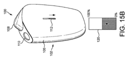
図1A、図1B、及び図2を参照すると、エアロゾル発生装置100が、様々な構成要素を収容する外側ケーシング105を備える体部102を有する。開口部110が体部102、例えば外側ケーシング105の側壁に設けられ、開口部110を通して、エアロゾル基質(図示せず)が加熱チャンバ114に挿入され得る。本実施形態では、エアロゾル基質は基質担体で供給される。基質担体は略細長く、エアロゾル基質は基質担体の第1の端部寄りに配置される。エアロゾル基質と基質担体の第2の端部との間には、基質担体は、例えば段ボール又はプラスチック材料のチューブの形態で導管を提供し、任意選択で、例えば基質担体の第2の端部に、その長さに沿ってフィルタが設けられる。エアロゾル基質が加熱チャンバ114で加熱されるとエアロゾル基質から発生するエアロゾル及び/又は蒸気は、導管を通して引き出され、基質担体の第2の端部からユーザが吸入することができ、基質担体の第2の端部は、エアロゾル基質が加熱チャンバ114に配置された状態において開口部110から突出するのに十分な長さを有する。
Referring to FIGS. 1A, 1B, and 2, an
エアロゾル発生装置100は、個人用吸入器装置、電子タバコ(又は電子シガレット)、気化器又はベイピング装置と記載されることもある。図示の実施形態では、エアロゾル発生装置100は、加熱非燃焼式(Heat not Burn、HnB)装置である。しかしながら、本開示において想定されるエアロゾル発生装置100は、従来のタバコ製品のようにタバコを燃焼させるのではなく、エアロゾル化可能な物質をより一般的に加熱又は撹拌して吸入用エアロゾルを発生させる。
エアロゾル基質及び基質担体は消耗品と呼ばれ得る。図示の実施形態では、消耗品は、加工されたタバコ材料、例えば、再構成されたタバコ(Reconstituted ToBacco、RTB)紙を圧着したシートや配向した条片に液体エアロゾル形成体を含浸させたものを含むロッドの形態であり得る。本実施形態における液体エアロゾル形成体は、植物性グリセリン(VG)を含むが、プロピレングリコール(PG)とVGとの混合物であってもよい。本実施形態では、消耗品は、香味料やニコチンを含まない純粋なVGを使用する。その代わりに、RTBに由来する揮発性の香味料やニコチンがエアロゾル形成体と同時に気化し、ユーザの吸入用として、結果として得られる凝縮エアロゾルに同伴される。しかしながら、他の実施形態では、消耗品はニコチンや他の香味料を含むエアロゾル形成体を有する。このような場合、消耗品は、一般に、エアロゾル形成体の液体を吸収するための他の固体多孔質物質を含み、例えば、ゲル化剤とタバコを含む場合も含まない場合もある適切なバインダとにより形成されたムースを含む。代替的な実施形態では、消耗品は、リザーバに貯蔵されたエアロゾル形成体を含むカプセルであり、気化チャンバを有し、気化チャンバによって、リザーバからの液体が、例えば、ウィック、熱伝達要素、又は少量の液体エアロゾル形成体を加熱された気化表面に運ぶ投与要素を介して、エアロゾル発生装置100によって加熱される。好ましくは、エアロゾル形成体はVG又はPG/VG混合物をニコチン及び/又は香味料と共に備える。
Aerosol substrates and substrate carriers may be referred to as consumables. In the illustrated embodiment, the consumable comprises a processed tobacco material, such as a pressed sheet or oriented strip of Reconstituted ToBacco (RTB) paper impregnated with a liquid aerosol former. It may be in the form of a rod containing. The liquid aerosol former in this embodiment contains vegetable glycerin (VG), but may be a mixture of propylene glycol (PG) and VG. In this embodiment, the consumable uses pure VG without flavoring or nicotine. Instead, the volatile flavor and nicotine derived from the RTB are co-vaporized with the aerosol former and entrained in the resulting condensed aerosol for inhalation by the user. However, in other embodiments, the consumable has an aerosol former that includes nicotine or other flavoring agent. In such cases, the consumable generally includes other solid porous materials for absorbing the liquid of the aerosol former, such as a gelling agent and a suitable binder that may or may not contain tobacco. Contains mousse formed by. In an alternative embodiment, the consumable is a capsule containing an aerosol former stored in a reservoir and having a vaporization chamber by which liquid from the reservoir is directed to a wick, a heat transfer element, or It is heated by the
図面によれば、体部102が実質的に丸みを帯びた縁部を有する四角柱の形状をしていることが分かる。しかしながら、これは必須ではなく、他の実施形態では、体部102は四角柱の形状を有しておらず、代わりに本明細書に記載されている様々な実施形態で説明されている内部構成要素を嵌合するのに適切な任意の形状をしている。
According to the drawings, it can be seen that the
体部102は、任意の適切な材料、又は実際には材料の層で形成され得る。図示の実施形態では、エアロゾル発生装置100は、外側ケーシング105によって覆われた内側ケーシング156を有する。内側ケーシング156をプラスチック材料とし、外側ケーシング105を金属とすることもできるし、内側ケーシング156を金属とし、外側ケーシング105をプラスチック材料とすることもできる、又は内側ケーシング156と外側ケーシング105との両方が実質的にプラスチック材料であってもよい。外側ケーシング105の材料が金属である場合、陽極酸化、粉体塗装、又は処理して、より傷つきにくくし、見苦しい摩耗や裂け目を防いでもよい。これにより、エアロゾル発生装置100は、「新しく」、且つより見た目の美しい外観を維持することができる。
図1Aの下の方に示すエアロゾル発生装置100の第1の端部104は、便宜上、エアロゾル発生装置100の底部、基部、又は下側端部として記載されている。図1Aの上の方に示すエアロゾル発生装置100の第2の端部106は、エアロゾル発生装置100の上端部又は上側端部として記載されている。使用中、ユーザは、典型的には、エアロゾル発生装置100を、第1の端部104を下向きに且つ/又はユーザの口に対して遠位位置に、そして第2の端部106を上向きに且つ/又はユーザの口に対して近接位置に向ける。したがって、開口部110は、エアロゾル発生装置100の第2の端部106に配置される。
The
エアロゾル発生装置100は、開口部110を覆うためのクロージャ108を有する。クロージャ108は、開口部110のための扉と見なされ得る。クロージャ108は、クロージャ108の位置に応じて開口部110が実質的に閉じたり開いたりするように、選択的に開口部110を覆ったり覆いを取ったりするように構成される。
より詳細には、クロージャ108は、図1Aに示すような閉位置と図1Bに示すような開位置との間を移動するように構成される。クロージャ108は、体部102の第2の端部106の上を閉位置と開位置との間で移動するように、つまりエアロゾル発生装置100の幅方向に移動するように構成される。閉位置では、図1Aに示すように、開口部110はクロージャ108によって少なくとも部分的に覆われる、又は閉塞される。好ましくは、開口部110はクロージャ108によって完全に覆われる。いくつかの実施形態では、クロージャ108が閉位置にあるとき、クロージャ108は、例えば、埃や湿気が開口部110に入るのを防ぐように、開口部110を覆うシールを形成する。開位置では、図1Bに示すように、開口部110はクロージャ108によって覆われていない、又は閉塞されていない。これは、クロージャ108が開口部110を閉塞しておらず、ユーザが開口部110にアクセスでき、特に、基質担体を加熱チャンバ114に挿入できることを意味する。
More particularly,
いくつかの実施形態では、クロージャ108はまた、更なる位置、例えば第3の位置又は作動位置を有し得る。例えば、クロージャ108が開位置にある状態で、クロージャ108を体部102に向けて押し下げることで、ユーザは作動位置にアクセスできる。つまり、ユーザは、開位置からクロージャ108を操作して作動位置にする。作動位置がユーザ入力をエアロゾル発生装置100に供給し、それに応じてエアロゾル発生装置100が、アクション、例えばエアロゾル基質を加熱してユーザが吸入するためのエアロゾルを発生させるプロセスを開始することを実行するように構成される。他の実施形態では、エアロゾル発生装置100はユーザ入力の代替的な形態に応じて作動するように構成される。例えば、クロージャ108が作動位置を持たない実施形態では、体部102の側部にボタンやスイッチが設けられ、ボタンを押したり、スイッチを切り替えたりすることでユーザ入力を開始できる。ユーザ入力を受けるための手段を提供する他の適切な方法は、異なる実施形態で提供される。
In some embodiments,
いくつかの実施形態では、エアロゾル発生装置100は、クロージャ108の移動又は位置を検出するように構成された検出器(図示せず)を有する。一実施形態では、検出器は、閉位置から開位置へのクロージャ108の移動を検出するように構成される。代替的な実施形態では、検出器は、例えば開位置におけるクロージャ108の絶対位置を検出するように構成される。更なる代替的な実施形態では、検出器は、クロージャ108が閉位置にいる場合と、クロージャ108が開位置にいる場合との両方を検出するように構成される。検出器は、開位置から作動位置へのクロージャ108の移動を検出するように更に構成され得る。クロージャの移動又は位置を検出するために、検出器はセンサを備える。センサは、クロージャ108の移動又は位置を検知するように構成される。センサは、好ましくは非接触型センサである。言い換えれば、検出器はクロージャ108の位置センサとして動作する。
In some embodiments,
検出器は、クロージャ108の位置を示す信号を出力するように構成される。信号は、クロージャ108が作動位置に移動することによって開始されるユーザ入力と同様に使用され得る。例えば、クロージャ108が閉位置から開位置に移動することで、エアロゾル発生装置100が作動し得る。
The detector is configured to output a signal indicative of the position of
不透明でない窓部112が、エアロゾル発生装置100の体部102を通ってエアロゾル発生装置100の側部に設けられる。不透明でない窓部112は、エアロゾル発生装置100の側壁の上、且つ側壁の幅の中央に、エアロゾル発生装置100の第2の端部106寄りに配置される。不透明でない窓部112は、エアロゾル発生装置100の体部102に開口部を備える。不透明でない窓部112は、半透明又は透明な材料で又は一切材料なしで覆われるか充填され得る。図示の実施形態では、窓部112は細長い形状をしている。窓部112は、直線状とすることも非直線状とすることもできる。矩形形状とすることもでき、好ましくは角が丸くなっており、例えば角がある曲率半径を有する。長い方の真っ直ぐな平行な縁部は、エアロゾル発生装置100の高さに平行に、例えば第1の端部104と第2の端部106との間の方向に延びる。不透明でない窓部の下側縁部はエアロゾル発生装置100の第1の端部104寄りであり、不透明でない窓部112の上側縁部はエアロゾル発生装置100の第2の端部106寄りである。窓部112の下側縁部が体部102の第1の端部104に対するのと比べて、窓部112の上側縁部は体部102の第2の端部106により近い。これにより、装置100の第1の端部104寄りに、窓部112がユーザの手によって遮られにくいように、装置100をユーザが握ることができる領域が提供され、ユーザは装置100を保持しながら、窓部112を介して表示される情報を観察できる。
A
不透明でない窓部112は、装置100の体部102の内部にある光源146から放出された光が、窓部112を通してユーザに見えるように構成される。一例として、光源146(例えば、RGB LED又は他の適切な光源)が、エアロゾル発生装置100のステータスを示すために体部102の内部に設けられ得る。これに関連して、ステータスは、バッテリ残量、ヒータステータス(例えば、オン、オフ、エラーなど)、装置ステータス(例えば、パフを吸う準備ができているかどうか)、又は他のステータスの指標、例えば、エラーモード、電源が枯渇するまでに消費された、若しくは残っているパフの数若しくは基質担体全体の指標などのうちの1つ又は複数を意味し得る。
図2は、より多くの内部構成要素が見えるようにした、エアロゾル発生装置100の切り欠き図である。図示のように、エアロゾル発生装置100は、加熱チャンバ114と、光拡散体118と、光学素子116と、電源120(例えば、バッテリ)と、PCB122及び126とを備える。
FIG. 2 is a cutaway view of
好ましい実施形態では、エアロゾル発生装置100は電気駆動式である。すなわち、電力を使用してエアロゾル基質を加熱するように構成されている。この目的のために、エアロゾル発生装置100は、電源120、例えばバッテリを有する。電源120は、PCB122及び126の一方又は両方に少なくとも部分的に収容され得る制御回路に結合される。また、制御回路は、少なくとも加熱チャンバ114とステータスインジケータの光源146とに結合される。ユーザが操作可能なクロージャ108は、制御回路を介して加熱チャンバ114及び/又は光源146に熱を供給するように構成されたヒータへの電源120の結合及び結合解除を引き起こすように構成され得る。
In a preferred embodiment,
一般に、窓部112と光拡散体118とは、互いに対応した形状及びサイズを有する。同様に、光源146は、窓部112と略同じ形状で、略同じサイズの領域にわたって構成される。換言すれば、光拡散体118は窓部を大きくはみ出して広がっておらず、光源146は窓部の実質的に真後ろ(窓部112よりも装置100の内部に近く、又は上述の用語で言えば「より奥」)に配置される。これにより、光源146が放出した光の大部分が光拡散体118によって拡散されて窓部112を透過するため(ケーシング105、156の内部で放出されるのではなく)、光源146が確実に窓部112を通して効率よく光を供給することを支援する。
Generally, the
加えて、光源146が窓部112と略同じサイズ及び形状の領域に広がっており、光拡散体118が窓部112と略対応する形状及びサイズ(例えば、少なくとも同じ大きさ)を有することは、放出された光が窓部112の実質的に全体を透過し得ることを意味する(例えば、窓部のその部分に対応する光源146が光を放出している場合)。
In addition, the fact that the
窓部112を透過する放出された光を最大化すること(光拡散体118も光源146を含む領域も窓部112よりも著しく大きくなることはない)と、確実に窓部112の全体が光を放出し得ること(光拡散体118も光源146を含む領域も窓部112よりも著しく小さくなることはない)との間でバランスがとられている。
Maximizing the emitted light transmitted through the window 112 (neither the area containing the
上述のように、窓部112、光拡散体118、及び光源146が配置されている領域は、いずれも互いに略対応する形状及びサイズを有して概して構成される。これらの要素はまとめて、ステータスインジケータの一部分を形成し、ステータスインジケータの構成に関する本検討では、窓部112、光拡散体118、及び光源146の構成の形状及びサイズが適宜適合されることを理解されたい。形状及びサイズが決定されると、ステータスインジケータを形成する要素の構成は、当業者にとっては難しいものではない。
As described above, the regions in which the
ステータスインジケータは一般に細長い。例えば、長さ方向及び幅方向を有し、幅が長さよりもはるかに小さい。例えば、長さは幅の3倍、5倍、10倍、25倍、又は更には50倍であり得る。いくつかの場合では長さ方向は直線であるが(例えば、図1A及び図1Bのように)、他の場合では、長さ方向は曲線、円弧、一連の円弧、一連の直線、分岐構造、螺旋、閉ループ、又はこれらの組み合わせであり得る。長さ方向がステータスインジケータの長さに沿って一定ではない場合(例えば、湾曲部分や角度がついている部分に起因して)、幅は長さ方向に対する横断方向として局所的に定義される。いくつかの場合では、例えば、ステータスインジケータの幅が広い部分では膨らみ、狭い部分では細くなるなど、幅がステータスインジケータの長さに沿って一定ではない場合がある。このような場合、ステータスインジケータの長さよりもはるかに狭くなるのは、ステータスインジケータの平均的な幅である。 Status indicators are generally elongated. For example, it has a length direction and a width direction, with the width being much smaller than the length. For example, the length can be 3 times, 5 times, 10 times, 25 times, or even 50 times the width. In some cases the length is a straight line (e.g., as in FIGS. 1A and 1B), but in other cases the length can be a curve, an arc, a series of arcs, a series of straight lines, a branched structure, It can be a helix, a closed loop, or a combination thereof. If the length direction is not constant along the length of the status indicator (eg, due to curved or angled sections), then the width is defined locally as transverse to the length direction. In some cases, the width may not be constant along the length of the status indicator, e.g., bulging out at wide parts of the status indicator and tapering at narrow parts. In such cases, it is the average width of the status indicator that is much narrower than the length of the status indicator.
図3を参照すると、エアロゾル発生装置100は、通信バス145によって互いに結合された、中央処理装置(CPU)130と、メモリ132と、ストレージ134と、加熱モジュール136と、検出器モジュール138と、通信インターフェース140と、ユーザ入力モジュール142と、ステータスインジケータモジュール144とを備える。
Referring to FIG. 3, the
CPU130は、コンピュータプロセッサ、例えばマイクロプロセッサである。CPU130は、メモリ132及びストレージ134に格納された命令を含むコンピュータ実行可能コードの形態の命令を実行するように構成される。CPU130によって実行される命令は、1つ又は複数の変数、例えばバッテリレベル及び/又は他のモジュールからの信号に応じてステータスインジケータモジュール144を制御するための命令など、エアロゾル発生装置100の他の構成要素の動作を調整するための命令を含む。一例では、ユーザがクロージャ108を作動位置に移動させて装置100を作動させると、検出器モジュール138がCPU130に割り込んで、エアロゾル発生装置100が作動されたことをCPU130に示す。追加的又は代替的に、装置100は、別のユーザ入力手段で作動させることもできる。この例では、CPU130は、加熱モジュール136が加熱チャンバ114を作動させてエアロゾルを発生させることを可能にし、したがって、装置100を作動させた状態でユーザがエアロゾルを吸入することを可能にするように構成される。この例では、CPU130は、加熱チャンバ114に熱を供給するように構成されたヒータのステータスをステータスインジケータが示すことができるように、ステータスインジケータモジュール144に命令を供給し得る。
メモリ132は、エアロゾル発生装置100に対してランダムアクセスメモリ(RAM)を提供する1つ又は複数のメモリユニットとして実装される。図示の実施形態では、メモリ132は、揮発性メモリ、例えばシステムオンチップ(SoC)アーキテクチャを用いてCPU130と共に統合されたオンチップRAMの形態の揮発性メモリである。しかしながら、他の実施形態では、メモリ132はCPU130とは分離されている。メモリ132は、CPU130が処理した命令をコンピュータ実行可能コードの形態で格納するように構成される。典型的には、コンピュータ実行可能コードの選択された要素のみが、任意の時間にメモリ132によって格納され、その選択された要素は、特定の時間に実行されているエアロゾル発生装置100の動作に不可欠な命令を定義する。換言すれば、コンピュータ実行可能コードはメモリ132に一時的に格納され、その間になんらかの特定のプロセスがCPU130で処理される。
ストレージ134は、エアロゾル発生装置100と一体的に、不揮発性のメモリの形態で設けられる。ストレージ134は、ほとんどの実施形態において、CPU130及びメモリ132と同じチップ上に、SoCアーキテクチャを使用して、例えばマルチプルタイムプログラマブル(MTP)アレイとして実装されることにより、埋め込まれる。しかしながら、他の実施形態では、ストレージ134は、内蔵又は外付けのフラッシュメモリなどである。ストレージ134は、CPU130が処理した命令を定義するコンピュータ実行可能コードを格納する。ストレージ134は、コンピュータ実行可能コードを永久的又は半永久的に、例えば上書きされるまで格納する。つまり、コンピュータ実行可能コードはストレージ134に非一次的に格納される。典型的には、ストレージ134によって格納されたコンピュータ実行可能コードは、一般に、CPU130、通信インターフェース140、及びエアロゾル発生装置100の動作に基本的な命令と、エアロゾル発生装置100のより高次の機能を実行するアプリケーション及びそのようなアプリケーションに関連するデータとに関する。
検出器モジュール138は検出器に結合される。検出器モジュール138は、クロージャ108の位置、ステータス、又は移動を示す信号を検出器から受信し、クロージャ108の位置、ステータス、及び/又は移動を示す信号をCPU130に供給する。例えば、クロージャ108が開位置にある場合、検出器モジュール138はCPU130に割り込んで、CPU130にクロージャ108が開位置にあることを示す。一例では、クロージャ108が開位置にある状態で、CPU130は、装置100の残りのバッテリレベルをユーザに示すように、ステータスインジケータモジュール144がステータスインジケータを動作させることを可能にするように構成される。
通信インターフェース140は、近距離無線通信、特に、Bluetooth(登録商標)通信をサポートする。特に、通信インターフェース140は、ユーザのパーソナルコンピューティングデバイスとの近距離無線通信接続を確立するように構成される。通信インターフェースは、いくつかの実施形態では、アンテナ(図示せず)に結合され、そのアンテナを介して、近距離無線通信接続を介して無線通信が送信及び受信される。また、通信インターフェースは、通信バス145を介してCPU130と通信するように構成される。
ユーザ入力モジュール142はユーザ入力デバイスに結合される。ユーザ入力デバイスは、ボタン若しくはスイッチ、又はユーザ入力のアクションを受け入れるための他の適切な装置であり得る。特に、ユーザ入力モジュール142は、クロージャ108が作動位置を有するように構成されておらず、エアロゾル発生装置100がユーザ入力デバイスを介してユーザによって作動される場合に設けられ得る。ユーザ入力モジュール142は、ユーザ入力デバイスに結合され、ユーザ入力デバイスの状態を示す信号を受信し、ユーザ入力を示す信号をCPU130に供給する。
ステータスインジケータモジュール144は、装置100のステータスに関する情報をユーザに供給するように構成される。本実施形態では、ステータスインジケータモジュール144は、LEDインターフェースを備える。ステータスインジケータモジュール144は、CPU130から装置100のステータスに関する情報を受信し、情報をユーザに表示するステータスインジケータの光源146の状態をCPU130に示すように構成される。
クロージャ108の位置及び/又はユーザ入力デバイスの提供によって、クロージャ108又はユーザ入力が複数の機能をトリガ又は提供する能力がもたらされる。これにより、ユーザエクスペリエンスが向上し、使い勝手が良くなる。クロージャ108が3つの位置を有する例では、3つの位置は、エアロゾル発生装置100が機能するための以下のステータスを提供する。
1)「オフ」、
2)「スタンバイ」又は「ロード」、及び
3)「作動」又は「使用」又は「エアロゾル化」。
The position of
1) "Off",
2) "Standby" or "Load" and 3) "Activate" or "Use" or "Aerosolization".
エアロゾル発生装置100には他の機能も可能であり得ることを当業者には理解されよう。例えば、1つの機能は温度調整を提供することもできるし、消耗品の残量表示を提供することもできるし、バッテリレベルの表示、又はペアレンタルロックの施錠若しくは解錠を提供することもできる。ステータスインジケータ及びステータスインジケータモジュール144は、これらの機能のいずれか1つ又はすべてのステータスを示すように構成され得ることを理解されよう。
Those skilled in the art will appreciate that other functions may be possible for the
図4は、ステータスインジケータの光源146及び光拡散体118の第1の好ましい実施形態の概略断面図を示している。光源146は、体部102の内部領域に配置される。光源146は配列で構成される。図示の実施形態では、光源146は8個の個別の光源146の直線配列で構成される。配列中の各光源146はLED、好ましくはRGB LEDである。RGB LEDは、白を含む任意の光の色を表示するために使用され得る。いくつかの例では、RGB LEDは、異なる色を表示してユーザに異なるパラメータを警告するために使用され得る。例えば、バッテリ寿命、加熱サイクルの残り時間、バッテリ充電の進行状況などは、すべて異なる色とすることができる。他の場合では、光源146は、単色で動作するように構成されたLED又は他の光源とすることができる。
FIG. 4 shows a schematic cross-sectional view of a first preferred embodiment of a status indicator
好ましい実施形態では、直線配列は、体部の不透明でない窓部112と整列するように構成され、これにより直線配列は体部102に対して垂直に配置される。代替的な実施形態では、光源146の配列は、体部102に対して傾斜又は水平に整列するように構成され得る。光源146は、点灯されると、概ね体部の窓部112に向かって光を放出するように構成される。光源146の二本線又は二次元配列が可能であり、更に複雑な多次元配列も可能であり得ることが理解されよう。また、光源146の配列は直線ではなく、曲線であってもよく、例えば1つ又は複数の曲線部分を形成してもよいことが理解されよう。
In a preferred embodiment, the linear array is configured to align with the
本開示の好ましい実施形態では、光源146は、10mm未満の間隔、好ましくは5mm未満の間隔、より好ましくは3mm未満の間隔、更に好ましくは2.5mm未満の間隔で配置される。好ましい実施形態では、光源146は、各光源146の中心間の間隔を約2mm(具体的には2.15mm)として等間隔に配置される。可能な代替策では、隣接する光源146の間の距離を、例えば一方向に漸増させて光源146の間隔をあけて配置することができる。
In preferred embodiments of the present disclosure, the
また、光拡散体118がエアロゾル発生装置100の内部領域に設けられる。図示の実施形態では、光拡散体118は、光源146の配列に整列し、光源146と窓部112との間に配置される。光拡散体118は、立方体又は四角柱の形状の本体148を有し、本体148のある面は窓部112に、本体148のある面は光源146の配列に面している。第1の好ましい実施形態では、光拡散体118の本体148は、窓部112の範囲を覆う(体部102の内側を向いた窓部112の側から)。
Additionally, a
光拡散体118の幅及び高さは、光拡散体118に入射する光源146のうちライトフィールドの割合を変えるように変化させることができる。より高さがあり、且つより幅広の光拡散体118は、光源146からより大きい割合の放出された光を受ける。つまり、光源146から窓部112への光路を横切る方向への光拡散体118の範囲が大きいほど、光源146からの光がより多く光拡散体118に入射し得る。光拡散体118の本体148は、高さ50mm未満、好ましくは高さ30mm未満、より好ましくは高さ20mm未満であり、第1の好ましい実施形態では高さ約16mm(具体的には16.6mm)である。光拡散体118の本体148は、幅10mm未満、好ましくは幅5mm未満、より好ましくは幅3mm未満、更により好ましくは、第1の好ましい実施形態によれば、幅約2.6mmである。
The width and height of the
光拡散体118の本体148は、奥行き3mm未満、好ましくは奥行き2mm未満、より好ましくは奥行き1mm未満、更に好ましくは奥行き0.75mm未満である。第1の好ましい実施形態では、光拡散体118の本体148は、奥行き約0.5mm(具体的には0.55mm)である。これに関連して、奥行きは、光源146から窓部112までの光路に沿った光拡散体118の範囲、具体的にはそのような光路の中で最も短いものであり得る。
The
ステータスインジケータのパラメータ(寸法、材料の種類、光源146の間隔及び数など)は、1つの要素の正確なサイズ及び形状が確定すると、他の要素のサイズに影響を与えるという意味で、すべて相互に関連している。一般に、1つの要素を大きくすると、他の要素も大きくなる。理論的には、限られたスケールファクタの範囲内で、比率を変えずに装置全体のサイズを拡大縮小できる。その際、重要なパラメータは光源146の間の間隔である。隣接する光源146の間に滑らかなぼかしをもたらすためには、間隔は大きくしすぎることはできず、さもないと隣接する光源146の間に目立った薄暗い継ぎ目ができる。このことは、明るめの光源146を使用すること、及び/又は光拡散体118の拡散性を変えることにより、ある程度バランスをとることができる。他の場合では、解決策は、光源146の中心間の間隔を約2mmに保ち、大型のステータスインジケータにはより多くの光源146を、小型のステータスインジケータにはより少ない光源146を設けることであり得る。
The parameters of the status indicator (such as dimensions, material type, spacing and number of
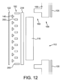
また、ステータスインジケータは、光源146の配列に面した光拡散体118の側部と、光源146の配列自体との間に延びる壁150を備える。この第1の好ましい実施形態では、壁150は、光拡散体118の本体148と同じ材料の壁であり、光拡散体118の本体148と単一構造の部分を形成する。換言すれば、壁150は、光拡散体118の本体148と壁150とが単一連続片を形成するように、光拡散体118の本体から突出する。図4~図9に示す第1の好ましい実施形態では、光拡散体118の本体148と壁150とを備える単一連続片は全体として光拡散体118と呼ばれる。光拡散体118の壁150は、配列の光源146の間に延びる。
The status indicator also includes a
壁150は、第1の実施形態の光拡散体118のうち、光拡散体118の本体148よりも光源146の配列の平面の近くに延びる部分を画定する。壁150は、光拡散体118の本体148よりも、体部102の窓部112から離れてエアロゾル発生装置100の内部により大きな奥行きで延びる。
よって、光拡散体118は、光源146から斜めに放出された光を、光源146に面する壁150の表面151で受けるように構成される。斜めに放出された光の光拡散体118への入射点は、壁150が設けられていない場合よりも光源146に近くなり得ることが理解されよう。図4及び図7に示すように、壁150は、隣接する光源146間の光路を完全に遮断しているが、壁150はそのような光路の一部のみを遮断するように広がってもよいし、全く遮断しないように広がってもよいことが理解されよう。
Therefore, the
また、光拡散体118は、配列の最上部の光源146の上方にある更なる壁150と、配列の最下部の光源146の下方にある別の更なる壁150とを備え得る。換言すれば、更なる壁150は、光源の配列の両端に設けられ得る。これらの更なる(又は周辺の)壁150は、配列の最上部及び最下部(例えば最端部)の光源146から斜めに放出された光であって、本来であれば光拡散体118の上方及び下方(例えば各端部)の周辺領域に漏出する光を受ける役割を果たす。また、光拡散体118は、図5の左端及び右端に示すように、光源146の間に配置された壁150に面する光拡散体118の側部の側縁から延びる壁150を備えていてもよく、光拡散体118の上部から下部に向かって(例えば、長さに沿って)延びる。これらは、側壁と呼ばれ得る。
The
光拡散体118の壁150は、光拡散体118の本体148から光源146の配列に向かって、奥行き2mm未満、好ましくは1mm未満、より好ましくは0.75mm未満で延びる。この第1の好ましい実施形態では、壁150は、光拡散体118の本体148から奥行き約0.5mm延びる。光拡散体118の壁150は、2mm厚未満、好ましくは1mm厚未満、より好ましくは0.5mm厚未満、更に好ましくは約0.1mm厚である。これに関連して、壁150の「厚さ」は、通常、上で定義したような長さ寸法であるが、いずれの場合においても、隣接する光源146の間の方向における壁150の寸法である。
The
光拡散体118は、光源146からの光を受け、窓部112に向けて光を透過するように構成される。したがって、光拡散体118は、光源146又は窓部112のいずれにも面していない1つ又は複数の表面から光が漏出するのを防ぐように構成されるのが有利であり得る。例えば、光拡散体118の上端及び下端の表面は、光拡散体118よりも屈折率の低い材料のクラッディングでクラッディングされ得る。光拡散体118の外部側面もクラッディングされ得る。光拡散体118とクラッディングとの境界面は、光拡散体118の材料及びクラッディングの材料の屈折率によって定義される臨界角よりも小さい角度で入射する光に対して、内部全反射を引き起こすように構成される。これにより、光拡散体118の上端及び下端、並びに/又は光拡散体118の側部から漏出し得る光の量を減らすことができ、よって窓部112を通してユーザに見えない光を生成するために浪費されるエネルギーを減らすことができる。代替的又は追加的に、光拡散体118の表面のうちの1つ又は複数の表面は、上記表面からの光の漏出を防止又は低減するために不透明又は半透明に仕上げられ得る。また、不透明又は半透明の表面は、あらゆる入射光の内部反射を拡散させ得る。
The
光拡散体118は、光を拡散するように構成される。光拡散体118は光拡散材料から作られ得る。また、光拡散体118は、透過した光の拡散を表面仕上げにより促進する不透明でない材料から作られ得る。材料、形状、寸法、表面仕上げ(研磨、艶消し、コーティング、処理、粗面化)、及びクラッディングを含むがこれらに限定されない、光拡散体118の様々な特性のバリエーションが、光の拡散又は散乱の度合いに影響する。第1の好ましい実施形態では、光拡散体118は、壁150とは反対側を向く光拡散体118の側部に粗面154を備える。この表面から放出された光は、光拡散体118から粗面154を通って窓部112に向かう際に拡散又は散乱される。第1の実施形態では、光拡散体118は拡散材料で作られる。つまり、光拡散体118の材料は、粗面154を有する代わりに、又は粗面154を有することに加えて、通過する光を散乱させるように構成されることで、そのバルク内(すなわち、材料の内部)で光を拡散させ得る。拡散体の内面151、すなわち光源146からの光が入射する壁150の表面は、光源146から光拡散体118への光の入射を促進するために、研磨され得る、又は光沢が施され得る。粗面は、例えば、VDI値が21~30になるように粗面化され得る。
いくつかの条件では、わずかに粗化された表面が体部からの光の透過を高め、体部内への光の透過を妨げ得る。反対に、平滑面は、体部からの光の透過を妨げ得る(つまり、体部内での光の保持)が、体部内への光の透過を高め得る。そのため、光源146に最も近い光拡散体118の表面は、光源146から光拡散体118への光の透過を高めるために、平滑とされ得るか研磨され得る。光源146とは反対側を向いている表面は、装置100から光を外部に向けて引き出すために、粗化され得る。同様に、光拡散体118の縁部における表面は、光拡散体118の側部からの光の漏出を減らすために、研磨又は平滑化され得る。側部表面は、側部における内部反射を増やし、側部からの光の漏出を更に減らすために、クラッディングが更に設けられ得る。クラッディングは、一般に、クラッディングが取り囲む材料の屈折率よりも低い屈折率を有する。
In some conditions, a slightly roughened surface may enhance the transmission of light from the body and impede the transmission of light into the body. Conversely, a smooth surface may impede transmission of light from the body (ie, retain light within the body) but may enhance transmission of light into the body. As such, the surface of
上述したのと同様の理由で、光学素子116の表面は、粗化、平滑化、又は研磨され得る。側部表面及び光源146に最も近い表面は平滑化又は研磨され得る一方、光源146から最も遠い表面(装置の外部に近い表面)は粗化され得る。また、クラッディング(図示せず)が、縁部における内部反射を増やし、光学素子116の縁部における光の漏出を減らすために、光学素子116の側部(又は縁部)において適用され得る。
For similar reasons discussed above, the surface of
光源146からの光を受けて、意図した目標物に向けて光を透過する光拡散体118は、両者の間に配置される。このような効果を達成するための簡単な構成は、光源146の配列、光拡散体118、及び不透明でない窓部112が実質的に平行に整列された図示の構成であり、光源146と不透明でない窓部112との間に光拡散体118がある。しかしながら、代替的な実施形態では、光源146からの光は、光拡散体118が光源146の配列と実質的に整列していなくても、光拡散体118が光を受け取るように、他の光学構成要素(レンズ、ミラー、光パイプ、光ファイバなど)によって屈折、反射、又は誘導され得る。同様に、光拡散体118から出た光は、光学構成要素によって屈折、反射、又は誘導されて、不透明でない窓部112へと導かれ得る。説明では、光拡散体118が光源146と不透明でない窓部112との間に配置されるように記述されているが、このような配置が想定されていることが理解されよう。
A
光拡散体118の好ましい実施形態の斜視図を図5に示す。図示の実施形態では、光拡散体118の壁150は、隣接する光源146の間に延び、光源146の配列に最も近い光拡散体118の本体148の表面の周辺の周りに延びるように構成される。好ましい実施形態では、光源146の間に延びる壁150は、光拡散体118の本体148の幅を横切って、光源146の直線配列の向きに垂直に延びる。
A perspective view of a preferred embodiment of
光拡散体118のこの好ましい構成は、光源146に面する側の光拡散材料に一連の空洞や凹みを画定する。光源146は、好ましくは、これらの凹部と整列するように構成される。好ましい実施形態では、壁150は、すべて同じ奥行きであり、これにより、「ライトボックス」又は「ケージ」の配列を画定し得、これは、光拡散体118が光源146を四方から囲むが、光源146の配列のうち光拡散体118の本体148から最も遠い側、すなわち光源146の側のうち、窓部112からも最も遠い側を除いて囲むように構成され得る。上記ライトボックスのそれぞれは、その内面151によって、光源146からの光、特にライトボックスの中に収まっている光源146からの光を受けることができる。好ましくは、各光源146に整列して1つのボックス又はケージが設けられる。
This preferred configuration of
好ましい実施形態による光拡散体118は、可視スペクトルの光学的透過率が10%~40%、より好ましくは20%~30%の半透明の白色プラスチック材料である。光拡散体118は、材料の光分散、材料の寸法及び構造、並びに/又は表面仕上げに応じて、光を拡散させたり、広げたりする働きをする。光拡散体118は、好ましくは、RTP(登録商標)0399X 120952 D S-27484 WHITE又は同等の透過性及び/又は拡散性を有する材料である。
The
光拡散体118は、拡散された光が体部102にある不透明でない窓部112を通して見えるように光源146からの光を受けて拡散させるように構成される。一般に、離散的な光源146の配列は、点灯すると、「ホットスポット」又は配列の点灯した光源146の位置に対応する高光強度の領域と、「コールドスポット」又は上記の光源146の間の空間に対応する低光強度の領域とが存在するライトフィールドを発生させる。光拡散体118は、光源146が放出する光を拡散させて、ホットスポットとコールドスポットとの間の光強度の差を小さくするように構成される。光の拡散により、光源146の離散的なセットによって生成された滑らかな可視光信号が得られ、このことはステータスインジケータの美的特性にとって望ましい。
ステータスインジケータは、一例では、窓部112を通して観察可能な光の帯のサイズを変化させることにより、ユーザに情報を伝えるように構成される。そのため、各光源146のライトフィールドを局在化させるようにステータスインジケータが構成されて、より多くの光源146が点灯すると、より大きな光の帯がユーザに観察可能となり、また単一の光源146又は光源146のサブセットが窓部112全体を照らすことがないようにすることが望ましい。このことを達成すること、並びにホットスポット及びコールドスポットを均すことが望ましい。光源146の間に延びる壁150を設けることにより、ステータスインジケータがこれらの要望を両方とも叶えることができるという利点がもたらされ得る。光拡散体118は、光源146から斜めに放出された光を、その突出した壁150によって吸収することにより、当該壁150が設けられていない場合に比べて、個々の各光源146からの光をより効果的に局在化させ得る。光拡散体118、特に光源146の間に延びる壁150という特徴を有するものは、これにより、配列の個々の光源146のライトフィールドを局在化させつつ、ステータスインジケータの可視信号にホットスポット及びコールドスポットが現れるのを抑えることができるステータスインジケータを提供する。他の特性の中でも、壁150の奥行き及び厚さの間の距離を変化させることにより、ステータスインジケータは、例えば光源146の配列におけるLEDの数及び間隔を制御できるようにすることにより、ユーザに所望の精度で情報を伝えるために適切な数の光源146を備え得る。また、点灯されたステータスインジケータの美的外観は、光源146の間のホットスポット及びコールドスポットを防ぎ、したがってユーザに滑らかに変化する視覚信号を提供することにより、そのように制御され得る。
The status indicator, in one example, is configured to convey information to the user by changing the size of a band of light observable through the
図6、図7、及び図8を参照すると、エアロゾル発生装置100は、外側ケーシング105と内側ケーシング156とを備える体部102を有する。また、エアロゾル発生装置100は光学素子116を備える。エアロゾル発生装置100の体部102は、光が透過し得る窓部112を有する。
Referring to FIGS. 6, 7, and 8, the
装置100の内側ケーシング156は、外側ケーシング105の開口部と整列した開口部を備えて、体部102の窓部112を形成する。内側ケーシング156と外側ケーシング105との整列した開口部と合わせて、装置100の内部に窓部112を設ける。
The
光学素子116は、窓部112において、光拡散体118と体部102の外側との間に配置されて設けられる。つまり、光学素子116が光拡散体118から受けた光は、不透明でない窓部112を通って外に透過される。光学素子116は、特定の波長の光をフィルタリングして除去するように、及び/又は、内側ケーシング156の開口部を通って透過した光が窓部112から装置100を出るように、光を集束させるように構成され得る。
The
光学素子116は光拡散体118とは別個の部分であり得る。光学素子116は、内側ケーシング156の開口部の上又は中にオーバーモールディングされ得る。代替的に、光学素子116は、光拡散体118上に、好ましくは光拡散体118の壁150が配置されている側とは反対側の光拡散体118の本体148上にツインショットメルドされ得る。他の代替策では、光学素子116は、体部102の内側ケーシング156と外側ケーシング105との間に光学素子116を配置することによって、又は外側ケーシング105の開口部の中に光学素子116を滑り嵌めすることによって、所定の位置に固定され得る。
光学素子の116は、可視スペクトラムの光透過率が20%超、好ましくは30%超、より好ましくは50%超の半透明材料であることが好ましく、好ましい実施形態では透過率が約75%である。光学素子116は、好ましくは、ポリカーボネート材料であり、例えば、Makrolon(登録商標)、RTP(登録商標)、Lexan(登録商標)、Covestro(登録商標)、最も好ましくはLexan(登録商標)GY5959X STD/Grade FXD171R/CMR#039216、又は同等の透過特性を有する材料である。光学素子116は、物体の透過率を最大化し、更なる光の拡散を防ぐために、研磨仕上げを有し得る。好ましくは、光学素子116は、ステータスインジケータが点灯していないときに、ユーザに対して目立ち過ぎない、又は目立たないように、つまり外側ケーシングと調和するように着色される。異なる実施形態では、光学素子116は、フィルタ、光レンズ、プリズム、又はこれらの組み合わせであり得ることが理解されよう。
いくつかの条件では、わずかに粗化された表面が体部からの光の透過を高め、体部内への光の透過を妨げ得る。反対に、平滑面は、体部からの光の透過を妨げ得る(つまり、体部内での光の保持)が、体部内への光の透過を高め得る。そのため、光源146に最も近い光拡散体118の表面は、光源146から光拡散体118への光の透過を高めるために、平滑とされ得るか研磨され得る。光源146とは反対側を向いている表面は、装置100から光を外部に向けて引き出すために、粗化され得る。同様に、光拡散体118の縁部における表面は、光拡散体118の側部からの光の漏出を減らすために、研磨又は平滑化され得る。側部表面は、側部における内部反射を増やし、側部からの光の漏出を更に減らすために、クラッディングが更に設けられ得る。クラッディングは、一般に、クラッディングが取り囲む材料の屈折率よりも低い屈折率を有する。
In some conditions, a slightly roughened surface may enhance the transmission of light from the body and impede the transmission of light into the body. Conversely, a smooth surface may impede transmission of light from the body (ie, retain light within the body) but may enhance transmission of light into the body. As such, the surface of
上述したのと同様の理由で、光学素子116の表面は、粗化、平滑化、又は研磨され得る。側部表面及び光源146に最も近い表面は平滑化又は研磨され得る一方、光源146から最も遠い表面(装置の外部に近い表面)は粗化され得る。また、クラッディング(図示せず)が、縁部における内部反射を増やし、光学素子116の縁部における光の漏出を減らすために、光学素子116の側部(又は縁部)において適用され得る。
For similar reasons discussed above, the surface of
光学素子は、高さ30mm未満、好ましくは高さ20mm未満、より好ましくは高さ17.5mm未満である。第1の好ましい実施形態では、光学素子116は、高さ約15mmである。光学素子116は、幅4mm未満、好ましくは幅3mm未満、より好ましくは幅2mm未満である。好ましい実施形態では、光学素子116は、幅約1mmである。光学素子116は、奥行き5mm未満、好ましくは奥行き4mm未満、より好ましくは奥行き2mm未満である。好ましい実施形態では、光学素子116は、奥行き約1.5mmである。
The optical element is less than 30 mm in height, preferably less than 20 mm in height, more preferably less than 17.5 mm in height. In a first preferred embodiment,
内側ケーシング156の開口部は、光学素子116が開口部内にしっかりと収まり得るように構成され得る。また、内側ケーシング156は、光拡散体118が開口部内にしっかりと収まるように構成され得る。したがって、図7を参照すると、内側ケーシング156の開口部は、光拡散体118と光学素子116との両方がしっかりと収まり得る凹部を提供するために、異なる奥行きの2つの異なるサイズの部分を備え得る。図示の実施形態では、開口部は、内側ケーシング156の外側ケーシング105に最も近い側に、第1の高さ、第1の幅、及び第1の奥行きを有する第1の部分158と、エアロゾル発生装置100の内部に最も近い側に、第2の高さ、第2の幅、及び第2の奥行きを有する第2の部分160とを有する。開口部の第1の部分158の寸法は、光学素子116が内部に滑り嵌めし得るように、光学素子116の寸法と実質的に一致する。開口部の第2の高さ、幅、及び奥行きは、好ましくは光拡散体118の高さ、幅、及び奥行きと一致して、光拡散体118が開口部の第1の部分158に配置された光学素子116と接しながら開口部の第2の部分160の内部に滑り嵌めし得るようになっている。開口部の第2の部分160の奥行きを規定する開口部の壁は、光拡散体118の全奥行きを受け入れることができる凹部を提供するために、内側ケーシング156の他の部分よりも装置100の内部に更に延び得る。換言すれば、内側ケーシング156は、光拡散体118が収まる凹部の周辺の周りにおいて、内側ケーシング156の他の領域よりも厚くなり得る。光学素子116は、内側ケーシング156の開口部の第1の部分158と同様の形状及び寸法の断面を有する角柱である。つまり、細長い矩形形状の断面を有する角柱である。このようにして、光学素子116又は光学フィルタは、内側ケーシング156の開口部の第1の部分158の中に滑り嵌めされ得る。
The opening in
光源146の直線配列は、PCB122の不透明でない窓部112に面する側で、PCB122に取り付けられる、且つ/又は電気的に接続される。光源146は等間隔で配置される。光拡散体118は、壁150が隣接する光源146の間に延び、光源146の間のPCB122上の位置においてPCB122に接するように構成され得る。したがって、光源146は、窓部112から最も離れた第1の側ではPCB122に囲まれ、他のすべての側では光拡散体118に囲まれる。
A linear array of
第1の好ましい実施形態では、光源146が取り付けられているPCB122の表面から体部102の外側までの距離は約3mmである。
In a first preferred embodiment, the distance from the surface of
ステータスインジケータのこの例では、LEDの直線配列が、順次且つ段階的に点灯するように構成され、よって、ステータスインジケータは、滑らかに変化し、窓部112を通してユーザが見ることのできる、装置100の状態を示す光の帯を提供できる。光源146の間に延びる壁150により、ユーザ装置100の内部から放出される光を局在化させつつ、ユーザが見ることのできる、滑らかに(つまり、ホットスポット及びコールドスポットがない状態で)光の帯を変化させることができる。これにより、分かりやすく、視覚的に魅力的な、ユーザへの情報の伝達が提供される。
In this example of a status indicator, a linear array of LEDs is configured to illuminate sequentially and in stages, such that the status indicator changes smoothly and is visible to the user through the
図9~図13を参照すると、第2の好ましい実施形態によるエアロゾル発生装置100は、光拡散体218及び光源146の間の壁250の構成が異なることを除いて、図4~図8を参照して説明した第1の実施形態のエアロゾル発生装置100と同一である。図9~図13では、第1の実施形態を説明する際に使用した参照数字が、同一又は類似の特徴を示すために使用される。
9-13, the
第2の好ましい実施形態では、光拡散体218がエアロゾル発生装置100の内部領域に設けられ、窓部112と整列される。図示の実施形態では、光拡散体218は、光源146の配列に整列し、光源146と窓部112との間に配置される。光拡散体218は、立方体又は四角柱の形状を有し、光拡散体218のある面は窓部112に、光拡散体218のある面は光源146の配列に面している。光拡散体218は、光源146の配列及び窓部112に広がっているため、光拡散体218は、窓部112及び配列の両方よりも大きい高さ及び幅を有し得る。光拡散体218の幅及び高さは、光拡散体218に入射する光源146のライトフィールドの割合を変えるように変化させることができる。より高さがあり、且つより幅広の光拡散体218は、光源146からより大きい割合の放出された光を受ける。
In a second preferred embodiment, a
第2の好ましい実施形態における光拡散体218は、好ましくは奥行き5mm未満、好ましくは奥行き3mm未満、より好ましくは奥行き2mm未満、更に好ましくは奥行き1mm未満である。第2の好ましい実施形態では、光拡散体の218は、奥行き約0.8mmである。光拡散体218は、高さ50mm未満、好ましくは高さ30mm未満、より好ましくは高さ20mm未満、更に好ましくは高さ約18.67mmである。光拡散体218は、幅10mm未満、好ましくは幅7.5mm未満、より好ましくは幅6mm未満、更により好ましくは幅約5.5mmである。
The
第2の好ましい実施形態による分岐器162が、光拡散体218とは別個に設けられる。分岐器162は、光拡散体218と光源146との間に配置される。分岐器162は光源146の間に延びる壁250を備える。また、分岐器162は、最上部の光源146及び最下部の光源146の上方にある壁250と、光源146の配列の周辺の周囲に延びる壁250とを備え、壁250は、図10の斜視図で示すように、単一の分岐器162の構造を形成するようになっている。図示の第2の好ましい実施形態では、隣接する光源146の間に配置された壁250が、隣接する光源146の間のすべての光路を遮るように延びる。
A
分岐器162の内壁250、例えば隣接する光源146の間に配置された内壁は、第1の奥行きを有していてもよく、光源146の配列の周辺の周囲に延びる分岐器162の周辺壁250は、第2の奥行きを有していてもよい。図示の実施形態では、第1の奥行きが第2の奥行きよりも小さく、光拡散体218が分岐器162の周辺壁250に接し、例えば、受光面251の縁部で分岐器162の周辺壁250に接触する。
An
第2の好ましい実施形態では、第1の奥行き(分岐器の内壁の奥行きに対応する)は約2mmである。第2の好ましい実施形態では、第2の奥行き(分岐器の周辺壁の奥行きに対応する)は約2.5mmである。分岐器162は、高さ50mm未満、好ましくは高さ30mm未満、より好ましくは高さ20mm未満、更に好ましくは高さ約18.67mmである。分岐器162は、幅10mm未満、好ましくは幅7.5mm未満、より好ましくは幅6mm未満、更により好ましくは幅約5.5mmである。
In a second preferred embodiment, the first depth (corresponding to the depth of the inner wall of the turnout) is approximately 2 mm. In a second preferred embodiment, the second depth (corresponding to the depth of the peripheral wall of the turnout) is approximately 2.5 mm. The
第2の好ましい実施形態では、光源146が取り付けられているPCB122の表面から体部102の外側までの距離は約4.5mmである。
In a second preferred embodiment, the distance from the surface of
第1の実施形態と同様に、ステータスインジケータのパラメータ(寸法、材料の種類、光源146の間隔及び数など)は、1つの要素の正確なサイズ及び形状が確定すると、他の要素のサイズに影響を与えるという意味で、すべて相互に関連している。一般に、1つの要素を大きくすると、他の要素も大きくなる。理論的には、限られたスケールファクタの範囲内で、比率を変えずに装置全体のサイズを拡大縮小できる。その際、重要なパラメータは光源146の間の間隔である。隣接する光源146の間に滑らかなぼかしをもたらすためには、間隔は大きくしすぎることはできず、さもないと隣接する光源146の間に目立った薄暗い継ぎ目ができる。このことは、明るめの光源146を使用すること、及び/又は光拡散体218の拡散性を変えることにより、ある程度バランスをとることができる。他の場合では、解決策は、光源146の中心間の間隔を約2mmに保ち、大型のステータスインジケータにはより多くの光源146を、小型のステータスインジケータにはより少ない光源146を設けることであり得る。
Similar to the first embodiment, the parameters of the status indicator (such as dimensions, material type, spacing and number of
第2の好ましい実施形態では、分岐器162は光拡散体の218よりも低い透過率を有する。好ましくは、分岐器162は不透明であり、不透明な材料から作られる。不透明な材料は、黒色プラスチック材料であってもよい。光源146の間に延びる不透明な壁250は、光源146からの光を局在化させる役割を果たし、例えば、単一の光源146が窓部112全体を照らすのを防ぐ。ライトフィールド中のホットスポットは光源146に整列して発生し、ライトフィールド中のコールドスポットは壁250に整列して発生している。
In a second preferred embodiment, the
光拡散体218は、光を拡散するように構成され、拡散材料及び/又は粗面254を備えて、それを通って透過した光を散乱させ得る(例えば、VDI値が21~30になるように)。光拡散体218の光源146の配列に最も近い表面は、光源146から光拡散体218への光の入射を促進するために、研磨され得る、又は光沢を施され得る。光拡散体218は、光源146の配列のライトフィールドのホットスポット及びコールドスポットを一緒に融合させたり、滑らかにしたりする利点を提供するように構成される。したがって、窓部112を通して観察される光信号は、滑らかな光の帯となり、ホットスポット及びコールドスポットのコントラストが実質的に又は完全に減少する。
第2の好ましい実施形態は、第1の好ましい実施形態に対して、各光源146から光の局在化を改善し得ることが理解されよう。第1の好ましい実施形態と比較して不利になり得る点は、第2の好ましい実施形態のステータスインジケータはより奥行きがあるため、体部102の内部に収めることが困難であり得る点である。
It will be appreciated that the second preferred embodiment may improve localization of light from each
図14は、閉位置におけるクロージャ108を示している。エアロゾル発生装置100は、この位置では「オフ」モードとなるように構成される。クロージャ108がこの位置にある状態では、ステータスインジケータは動作不能であるように構成される。好ましくは、このことは、光源146の配列が電源120から電力を引き出さないように構成されることを意味する。体部102の窓部112に光学素子116を設けることにより、クロージャ108が閉位置にある状態では、ユーザに対して窓部112を目立ち過ぎないように、又は見えないように見せることができる。
Figure 14 shows
本実施形態では、オフモードの場合、エアロゾル発生装置100は低消費電力モード又は無消費電力モードで稼働する。このモードでは、クロージャの108が開位置に移動したことを検出するために働いている機能は検出器モジュール138及び検出器だけである。そのため、ステータスインジケータは電源120から電力を引き出さず、エアロゾル発生装置100のステータスをユーザに示すように構成されていない。これには、エアロゾル発生装置100がユーザによって使用又は操作されていないときに、電源120からできるだけ少ない電力を引き出すという利点がある。他の実施形態では、ステータスインジケータが装置100のステータスをユーザに示す目的で、低電力モードで一部の電力を引き出すことができる。
In this embodiment, in the off mode, the
したがって、使用の際、クロージャ108が閉位置にある状態では、ステータスインジケータの光源146は光を放出しておらず、ステータスインジケータは点灯していない。
Thus, in use, with the
図15は、開位置におけるクロージャ108を示している。この構成では、エアロゾル発生装置100の制御電子装置は、クロージャ108がこの開位置にある状態でステータスインジケータが動作可能であるように、ステータスインジケータの光源146に電力を供給し得る。図示の実施形態では、開位置において、光源146は、電源120の電力レベルの表示をユーザに供給するように構成される。
Figure 15 shows
電源120、例えばバッテリが完全に充電されると、光を放出するためにスイッチを入れたすべての光源146によってステータスインジケータが完全に点灯するように構成される。電源120の残量が減ると、光源146の点灯数が減る。電源120の残量がなくなると、どの光源146も光を放出しない。充電量が少なくなると、1つ又は複数の光源146、好ましくはエアロゾル発生装置100の第1の端部104に最も近い光源146が、電源120が充電を必要としていることをユーザに示すために、点滅する又は瞬くように構成され得る。
When the
好ましい実施形態では、バッテリレベルが上昇して更なる光源146がスイッチオンされるにつれて、窓部112を通してユーザが見ることができ、窓部112の下部から窓部112の上部に向かって高さが増加する光の帯が示されるように、点灯している光源146の数が順次増加する。
In a preferred embodiment, as the battery level increases and additional
使用時には、クロージャ108が開位置にある状態では、ステータスインジケータの光源146がバッテリレベルに応じて光を放出する。光を放出している光源146の数は、バッテリに残っている電力に比例する。満充電から電池が消耗するのに伴い、直線配列の146の光源の146は、配列の上端から下端に向かって順次消灯する。最後の(一番下の)光源146が唯一の点灯された光源146である場合、これはバッテリレベルが閾値を下回ったことをユーザに示すために点滅し得る。また、光源146は、バッテリレベルが変化すると、点滅させたり、異なる色の光を連続的に放出させたりするように構成され得る。
In use, with the
図16に示すように、クロージャ108の第3の位置若しくは「作動」装置では、又は装置100の他の作動状態では、ステータスインジケータは第2の機能で動作するように任意選択で構成され得る。
In the third position or “actuated” device of the
この例では、エアロゾル発生装置100が作動した状態で、CPU130は、加熱モジュール136がエアロゾルを発生できるように、したがって、ユーザがエアロゾルを吸入できるように構成される。加えて、CPU130は、ユーザにセッションが始まったことを示すようにステータスインジケータを動作させるように構成される。
In this example, with the
図示の実施形態では、クロージャ108が作動位置にある状態では、ステータスインジケータは、ユーザセッションの残り時間、つまりユーザがエアロゾルを吸うための「パフ」ができる残り時間を示すように動作可能である。ユーザセッション開始時には、すべての光源146が光を放出しており、ユーザセッションにおける残り時間が減少するにつれて、光源146が上から下に向かって順次段階的に消灯していく、又は光を放出するのを停止する。代替策では、ステータスインジケータは、残り時間ではなく、残りのパフ数を示すように構成され得る。
In the illustrated embodiment, with the
図1~図16を参照して説明した実施形態の多くの異なる組み合わせを、修正せずに単独で使用し得る、及び/又は他の実施形態の特徴を組み込むために修正し得ることが当業者には理解されよう。 Those skilled in the art will appreciate that many different combinations of the embodiments described with reference to FIGS. 1-16 can be used alone without modification and/or modified to incorporate features of other embodiments. would be understood.
エアロゾル発生装置100を、「加熱式タバコ装置」、「加熱非燃焼式タバコ装置」、「タバコ製品気化用装置」などと等しく呼ぶことができ、これらの効果を実現するのに適切な装置として解釈される。本明細書に開示される特徴は、任意のエアロゾル基質を気化させるように設計された装置に等しく適用可能である。
本発明の説明された実施形態は、本発明がどのように実施され得るかの例に過ぎない。適切な技術及び知識を持つ者であれば、説明された実施形態の修正、変形、及び変更が想到されるはずである。これらの修正、変形、及び変更は、特許請求の範囲から逸脱することなく行うことができる。 The described embodiments of the invention are merely examples of how the invention may be implemented. Modifications, variations, and changes to the described embodiments will occur to those having appropriate skill and knowledge. These modifications, variations, and changes can be made without departing from the scope of the claims.
Claims (37)
単一の不透明でない窓部を有する体部と、
前記体部の内側に配置された光源の配列と、
前記光源の前記配列と前記単一の不透明でない窓部との間に配置された単一の光拡散体と、
前記光源の間に延びる複数の壁と
を備え、
前記光源の前記配列からの光が前記単一の光拡散体に入射して前記単一の不透明でない窓部に放出され
前記光源の前記配列が、前記エアロゾル発生装置のステータスに応じて順次点灯するように構成され、
前記光源の前記配列は、前記複数の壁から離隔するように配置され、
前記複数の壁の互いに対向する表面は平行であり、
前記複数の壁は、前記光源の前記配列を超えて前記単一の光拡散体に向けて延在する、エアロゾル発生装置。 An aerosol generator, comprising:
a body having a single non-opaque fenestration;
an array of light sources arranged inside the body;
a single light diffuser disposed between the array of light sources and the single non-opaque window;
a plurality of walls extending between the light sources;
Light from the array of light sources is incident on the single light diffuser and emitted into the single non-opaque window, and the array of light sources is sequentially illuminated depending on the status of the aerosol generating device. It is configured as follows,
the array of light sources is spaced apart from the plurality of walls;
mutually opposing surfaces of the plurality of walls are parallel;
The plurality of walls extend beyond the array of light sources toward the single light diffuser.
前記光拡散体は、白色半透明の光拡散材料を有する、エアロゾル発生装置。 The aerosol generator according to any one of claims 1 to 5,
The light diffuser is an aerosol generating device, wherein the light diffuser includes a white translucent light diffusing material.
(i)前記複数の壁を有し、(ii)前記光拡散体とは分離され、(iii)前記光拡散体より低い透過率を有する、分岐器を備えた、エアロゾル発生装置。 The aerosol generator according to any one of claims 1 to 6,
An aerosol generation device comprising: (i) a splitter having the plurality of walls, (ii) being separated from the light diffuser, and (iii) having a lower transmittance than the light diffuser.
前記分岐器は、不透明であり、不透明な材料から作られる、エアロゾル発生装置。 The aerosol generator according to claim 7,
The aerosol generating device, wherein the diverter is opaque and made from an opaque material.
前記光源の第2のグループを点灯することによって前記エアロゾル発生装置の第2のステータスを示すことであって、前記第1のグループが前記第2のグループとは少なくとも部分的に異なることと
を含む、請求項1~36のいずれか一項に記載のエアロゾル発生装置の動作方法。 indicating a first status of the aerosol generating device by illuminating the first group of light sources;
indicating a second status of the aerosol generating device by illuminating the second group of light sources, the first group being at least partially different from the second group; , a method for operating an aerosol generator according to any one of claims 1 to 36.
Priority Applications (2)
| Application Number | Priority Date | Filing Date | Title |
|---|---|---|---|
| JP2024021855A JP2024054358A (en) | 2019-05-03 | 2024-02-16 | Aerosol Generating Device with Illuminated Status Indicator |
| JP2024021853A JP7473752B2 (en) | 2019-05-03 | 2024-02-16 | Aerosol Generating Device with Illuminated Status Indicator |
Applications Claiming Priority (3)
| Application Number | Priority Date | Filing Date | Title |
|---|---|---|---|
| EP19172657 | 2019-05-03 | ||
| EP19172657.9 | 2019-05-03 | ||
| PCT/EP2020/062059 WO2020225099A1 (en) | 2019-05-03 | 2020-04-30 | Aerosol generation device with illuminated status indicator |
Related Child Applications (2)
| Application Number | Title | Priority Date | Filing Date |
|---|---|---|---|
| JP2024021853A Division JP7473752B2 (en) | 2019-05-03 | 2024-02-16 | Aerosol Generating Device with Illuminated Status Indicator |
| JP2024021855A Division JP2024054358A (en) | 2019-05-03 | 2024-02-16 | Aerosol Generating Device with Illuminated Status Indicator |
Publications (3)
| Publication Number | Publication Date |
|---|---|
| JP2022530260A JP2022530260A (en) | 2022-06-28 |
| JPWO2020225099A5 JPWO2020225099A5 (en) | 2023-01-31 |
| JP7441241B2 true JP7441241B2 (en) | 2024-02-29 |
Family
ID=66429209
Family Applications (3)
| Application Number | Title | Priority Date | Filing Date |
|---|---|---|---|
| JP2021564275A Active JP7441241B2 (en) | 2019-05-03 | 2020-04-30 | Aerosol generator with illuminated status indicator |
| JP2024021853A Active JP7473752B2 (en) | 2019-05-03 | 2024-02-16 | Aerosol Generating Device with Illuminated Status Indicator |
| JP2024021855A Pending JP2024054358A (en) | 2019-05-03 | 2024-02-16 | Aerosol Generating Device with Illuminated Status Indicator |
Family Applications After (2)
| Application Number | Title | Priority Date | Filing Date |
|---|---|---|---|
| JP2024021853A Active JP7473752B2 (en) | 2019-05-03 | 2024-02-16 | Aerosol Generating Device with Illuminated Status Indicator |
| JP2024021855A Pending JP2024054358A (en) | 2019-05-03 | 2024-02-16 | Aerosol Generating Device with Illuminated Status Indicator |
Country Status (6)
| Country | Link |
|---|---|
| EP (1) | EP3962306A1 (en) |
| JP (3) | JP7441241B2 (en) |
| KR (1) | KR20220003569A (en) |
| CN (1) | CN113747805A (en) |
| TW (1) | TWI739410B (en) |
| WO (1) | WO2020225099A1 (en) |
Families Citing this family (3)
| Publication number | Priority date | Publication date | Assignee | Title |
|---|---|---|---|---|
| WO2020225099A1 (en) | 2019-05-03 | 2020-11-12 | Jt International S.A. | Aerosol generation device with illuminated status indicator |
| CN116916775A (en) * | 2021-02-22 | 2023-10-20 | 日本烟草国际股份有限公司 | Aerosol generating device with light emitting indicator |
| WO2024049051A1 (en) * | 2022-08-30 | 2024-03-07 | Kt&G Corporation | Aerosol generating device and method of manufacturing outer cover for aerosol generating device |
Citations (24)
| Publication number | Priority date | Publication date | Assignee | Title |
|---|---|---|---|---|
| JP3063458U (en) | 1998-11-27 | 1999-11-05 | 京都電機器株式会社 | Thin uniform light source for image processing using LED |
| JP2003186427A (en) | 2001-12-20 | 2003-07-04 | Yazaki Corp | Lighting type display device |
| JP2006516764A (en) | 2003-01-30 | 2006-07-06 | タッチセンサー テクノロジーズ,エルエルシー | Integrated thin display |
| JP2007207572A (en) | 2006-02-01 | 2007-08-16 | Toshiba Corp | Light source device, back-light unit, and display device |
| JP2008268801A (en) | 2007-04-25 | 2008-11-06 | Calsonic Kansei Corp | Display device |
| JP2009128585A (en) | 2007-11-22 | 2009-06-11 | Sumitomo Wiring Syst Ltd | Luminaire |
| JP2011129536A (en) | 2011-03-08 | 2011-06-30 | Toshiba Corp | Electrical apparatus |
| CN103839491A (en) | 2012-11-27 | 2014-06-04 | 罗伯特·博世有限公司 | Display device, method used for displaying bar-shaped indicator and method used for manufacturing display device |
| CN203828076U (en) | 2014-04-10 | 2014-09-17 | 云南中烟工业有限责任公司 | Electronic cigarette with visible burning line |
| CN104575307A (en) | 2014-12-23 | 2015-04-29 | 深圳市奥拓电子股份有限公司 | LED display screen free from moire |
| CN204317509U (en) | 2014-12-18 | 2015-05-13 | 曾光垠 | A kind of touch control e cigarette |
| KR101550330B1 (en) | 2015-02-16 | 2015-09-14 | 주식회사알바트로스 | Electronic cigarette having residual quantity function |
| US20160331029A1 (en) | 2015-05-14 | 2016-11-17 | James E. Contreras | Electronic cigarette usage tracking system |
| JP2016212109A (en) | 2015-05-11 | 2016-12-15 | ビステオン グローバル テクノロジーズ インコーポレイテッド | Linear bar graph |
| CN107136573A (en) | 2017-05-12 | 2017-09-08 | 广东思格雷电子科技股份有限公司 | The electronic cigarette of light guide plate and application light guide plate |
| JP3213257U (en) | 2017-07-07 | 2017-10-26 | スミス テクノロジー カンパニー リミテッド | Battery rod and electronic cigarette |
| US20180020725A1 (en) | 2016-07-25 | 2018-01-25 | Ramon Alarcon | Electronic cigarette with illuminated tip |
| CN207151940U (en) | 2015-04-14 | 2018-03-30 | 惠州市吉瑞科技有限公司深圳分公司 | A kind of electronic cigarette packet |
| CN207613196U (en) | 2017-11-07 | 2018-07-17 | 东莞市宝威模具科技有限公司 | A kind of electronic cigarette light guide structure |
| CN108320674A (en) | 2018-04-11 | 2018-07-24 | 安徽大学 | A kind of LED display that can closely use |
| CN207855022U (en) | 2017-11-07 | 2018-09-14 | 深圳市艾维普思科技有限公司 | A kind of battery component and electronic cigarette |
| JP2018527906A (en) | 2015-07-07 | 2018-09-27 | ケイティー アンド ジー コーポレーション | Electronic Cigarette |
| CN207978948U (en) | 2017-05-12 | 2018-10-19 | 广东思格雷电子科技股份有限公司 | The electronic cigarette of light guide plate and application light guide plate |
| JP2019505077A (en) | 2016-02-15 | 2019-02-21 | エルジー イノテック カンパニー リミテッド | Ramp and vehicle equipped with the same |
Family Cites Families (5)
| Publication number | Priority date | Publication date | Assignee | Title |
|---|---|---|---|---|
| JPH08202296A (en) * | 1995-01-31 | 1996-08-09 | Hitachi Ltd | Method for lighting control panel for car |
| KR20120050568A (en) * | 2010-11-11 | 2012-05-21 | (주)데캉코리아 | Multi-function electronic cigarette |
| WO2013025921A1 (en) | 2011-08-16 | 2013-02-21 | Ploom, Inc. | Low temperature electronic vaporization device and methods |
| WO2018166914A1 (en) * | 2017-03-14 | 2018-09-20 | Philips Lighting Holding B.V. | A lighting module, a lighting system and a method of lighting |
| WO2020225099A1 (en) | 2019-05-03 | 2020-11-12 | Jt International S.A. | Aerosol generation device with illuminated status indicator |
-
2020
- 2020-04-30 WO PCT/EP2020/062059 patent/WO2020225099A1/en unknown
- 2020-04-30 CN CN202080031783.3A patent/CN113747805A/en active Pending
- 2020-04-30 KR KR1020217037883A patent/KR20220003569A/en active Search and Examination
- 2020-04-30 EP EP20721258.0A patent/EP3962306A1/en active Pending
- 2020-04-30 JP JP2021564275A patent/JP7441241B2/en active Active
- 2020-04-30 TW TW109114500A patent/TWI739410B/en active
-
2024
- 2024-02-16 JP JP2024021853A patent/JP7473752B2/en active Active
- 2024-02-16 JP JP2024021855A patent/JP2024054358A/en active Pending
Patent Citations (24)
| Publication number | Priority date | Publication date | Assignee | Title |
|---|---|---|---|---|
| JP3063458U (en) | 1998-11-27 | 1999-11-05 | 京都電機器株式会社 | Thin uniform light source for image processing using LED |
| JP2003186427A (en) | 2001-12-20 | 2003-07-04 | Yazaki Corp | Lighting type display device |
| JP2006516764A (en) | 2003-01-30 | 2006-07-06 | タッチセンサー テクノロジーズ,エルエルシー | Integrated thin display |
| JP2007207572A (en) | 2006-02-01 | 2007-08-16 | Toshiba Corp | Light source device, back-light unit, and display device |
| JP2008268801A (en) | 2007-04-25 | 2008-11-06 | Calsonic Kansei Corp | Display device |
| JP2009128585A (en) | 2007-11-22 | 2009-06-11 | Sumitomo Wiring Syst Ltd | Luminaire |
| JP2011129536A (en) | 2011-03-08 | 2011-06-30 | Toshiba Corp | Electrical apparatus |
| CN103839491A (en) | 2012-11-27 | 2014-06-04 | 罗伯特·博世有限公司 | Display device, method used for displaying bar-shaped indicator and method used for manufacturing display device |
| CN203828076U (en) | 2014-04-10 | 2014-09-17 | 云南中烟工业有限责任公司 | Electronic cigarette with visible burning line |
| CN204317509U (en) | 2014-12-18 | 2015-05-13 | 曾光垠 | A kind of touch control e cigarette |
| CN104575307A (en) | 2014-12-23 | 2015-04-29 | 深圳市奥拓电子股份有限公司 | LED display screen free from moire |
| KR101550330B1 (en) | 2015-02-16 | 2015-09-14 | 주식회사알바트로스 | Electronic cigarette having residual quantity function |
| CN207151940U (en) | 2015-04-14 | 2018-03-30 | 惠州市吉瑞科技有限公司深圳分公司 | A kind of electronic cigarette packet |
| JP2016212109A (en) | 2015-05-11 | 2016-12-15 | ビステオン グローバル テクノロジーズ インコーポレイテッド | Linear bar graph |
| US20160331029A1 (en) | 2015-05-14 | 2016-11-17 | James E. Contreras | Electronic cigarette usage tracking system |
| JP2018527906A (en) | 2015-07-07 | 2018-09-27 | ケイティー アンド ジー コーポレーション | Electronic Cigarette |
| JP2019505077A (en) | 2016-02-15 | 2019-02-21 | エルジー イノテック カンパニー リミテッド | Ramp and vehicle equipped with the same |
| US20180020725A1 (en) | 2016-07-25 | 2018-01-25 | Ramon Alarcon | Electronic cigarette with illuminated tip |
| CN107136573A (en) | 2017-05-12 | 2017-09-08 | 广东思格雷电子科技股份有限公司 | The electronic cigarette of light guide plate and application light guide plate |
| CN207978948U (en) | 2017-05-12 | 2018-10-19 | 广东思格雷电子科技股份有限公司 | The electronic cigarette of light guide plate and application light guide plate |
| JP3213257U (en) | 2017-07-07 | 2017-10-26 | スミス テクノロジー カンパニー リミテッド | Battery rod and electronic cigarette |
| CN207613196U (en) | 2017-11-07 | 2018-07-17 | 东莞市宝威模具科技有限公司 | A kind of electronic cigarette light guide structure |
| CN207855022U (en) | 2017-11-07 | 2018-09-14 | 深圳市艾维普思科技有限公司 | A kind of battery component and electronic cigarette |
| CN108320674A (en) | 2018-04-11 | 2018-07-24 | 安徽大学 | A kind of LED display that can closely use |
Also Published As
| Publication number | Publication date |
|---|---|
| WO2020225099A1 (en) | 2020-11-12 |
| CN113747805A (en) | 2021-12-03 |
| TW202042665A (en) | 2020-12-01 |
| KR20220003569A (en) | 2022-01-10 |
| JP2024054358A (en) | 2024-04-16 |
| JP2024054357A (en) | 2024-04-16 |
| JP7473752B2 (en) | 2024-04-23 |
| EP3962306A1 (en) | 2022-03-09 |
| TWI739410B (en) | 2021-09-11 |
| JP2022530260A (en) | 2022-06-28 |
Similar Documents
| Publication | Publication Date | Title |
|---|---|---|
| JP7441241B2 (en) | Aerosol generator with illuminated status indicator | |
| KR101720266B1 (en) | Fragrance discharge apparatus | |
| JP6636931B2 (en) | Aerosol delivery device with illuminated outer surface and related method | |
| CN104705793B (en) | The method and system of substance atomization | |
| EP3695736B1 (en) | Electronic cigarette, and control method thereof | |
| JP2017508525A (en) | LED module for aerosol generating device, aerosol generating device with LED module and method for illuminating vapor | |
| WO2014072824A2 (en) | Real time variable voltage programmable electronic cigarette system | |
| US20150128975A1 (en) | Packaging for Electronic Smoking Device | |
| US20220175044A1 (en) | Aerosol-generating system with chromatic recognition | |
| EP4054364A1 (en) | Aerosol delivery device/system | |
| KR20190143146A (en) | A fine particle generator | |
| US20230389617A1 (en) | Lighting unit for aerosol-generating systems | |
| EP3838019A1 (en) | An aerosol delivery device with visual feedback means | |
| JP2023542781A (en) | Aerosol generating equipment and aerosol generating articles | |
| JP7284818B2 (en) | Optical module and aerosol generator containing same | |
| CN210809317U (en) | Electronic cigarette | |
| WO2020245435A1 (en) | Aerosol generation device with tilted heating chamber | |
| KR20150025289A (en) | a electronic cicarette | |
| KR200478885Y1 (en) | Electronic cigar | |
| KR20130006877U (en) | Inhaling apparatus electricity supplying member case for the inhaling apparatus evaporating member case for the inhaling apparatus and inhaling material accommodating member case for the inhaling apparatus | |
| CN215117692U (en) | Multifunctional electronic cigarette vending machine | |
| CN210726679U (en) | Light-transmitting electronic cigarette | |
| US20240016212A1 (en) | Aerosol provision systems and methods | |
| CN212877587U (en) | Cigarette case with projection device | |
| CN112315024A (en) | Light-transmitting electronic cigarette |
Legal Events
| Date | Code | Title | Description |
|---|---|---|---|
| A521 | Request for written amendment filed |
Free format text: JAPANESE INTERMEDIATE CODE: A523 Effective date: 20230118 |
|
| A621 | Written request for application examination |
Free format text: JAPANESE INTERMEDIATE CODE: A621 Effective date: 20230118 |
|
| A871 | Explanation of circumstances concerning accelerated examination |
Free format text: JAPANESE INTERMEDIATE CODE: A871 Effective date: 20230118 |
|
| A131 | Notification of reasons for refusal |
Free format text: JAPANESE INTERMEDIATE CODE: A131 Effective date: 20230315 |
|
| A521 | Request for written amendment filed |
Free format text: JAPANESE INTERMEDIATE CODE: A523 Effective date: 20230512 |
|
| A131 | Notification of reasons for refusal |
Free format text: JAPANESE INTERMEDIATE CODE: A131 Effective date: 20230606 |
|
| A521 | Request for written amendment filed |
Free format text: JAPANESE INTERMEDIATE CODE: A523 Effective date: 20230719 |
|
| A131 | Notification of reasons for refusal |
Free format text: JAPANESE INTERMEDIATE CODE: A131 Effective date: 20230815 |
|
| A521 | Request for written amendment filed |
Free format text: JAPANESE INTERMEDIATE CODE: A523 Effective date: 20231013 |
|
| A131 | Notification of reasons for refusal |
Free format text: JAPANESE INTERMEDIATE CODE: A131 Effective date: 20231102 |
|
| A131 | Notification of reasons for refusal |
Free format text: JAPANESE INTERMEDIATE CODE: A131 Effective date: 20240110 |
|
| A521 | Request for written amendment filed |
Free format text: JAPANESE INTERMEDIATE CODE: A523 Effective date: 20240115 |
|
| TRDD | Decision of grant or rejection written | ||
| A01 | Written decision to grant a patent or to grant a registration (utility model) |
Free format text: JAPANESE INTERMEDIATE CODE: A01 Effective date: 20240119 |
|
| A61 | First payment of annual fees (during grant procedure) |
Free format text: JAPANESE INTERMEDIATE CODE: A61 Effective date: 20240216 |
|
| R150 | Certificate of patent or registration of utility model |
Ref document number: 7441241 Country of ref document: JP Free format text: JAPANESE INTERMEDIATE CODE: R150 |