JP7435776B2 - oral appliances - Google Patents

oral appliances Download PDF

Info

Publication number
JP7435776B2
JP7435776B2 JP2022532344A JP2022532344A JP7435776B2 JP 7435776 B2 JP7435776 B2 JP 7435776B2 JP 2022532344 A JP2022532344 A JP 2022532344A JP 2022532344 A JP2022532344 A JP 2022532344A JP 7435776 B2 JP7435776 B2 JP 7435776B2
Authority
JP
Japan
Prior art keywords
section
oral appliance
wiring
sensor
insulating layer
Prior art date
Legal status (The legal status is an assumption and is not a legal conclusion. Google has not performed a legal analysis and makes no representation as to the accuracy of the status listed.)
Active
Application number
JP2022532344A
Other languages
Japanese (ja)
Other versions
JPWO2021256080A1 (en
JPWO2021256080A5 (en
Inventor
亨 志牟田
純 ▲高▼木
智紀 高橋
Current Assignee (The listed assignees may be inaccurate. Google has not performed a legal analysis and makes no representation or warranty as to the accuracy of the list.)
Murata Manufacturing Co Ltd
Original Assignee
Murata Manufacturing Co Ltd
Priority date (The priority date is an assumption and is not a legal conclusion. Google has not performed a legal analysis and makes no representation as to the accuracy of the date listed.)
Filing date
Publication date
Application filed by Murata Manufacturing Co Ltd filed Critical Murata Manufacturing Co Ltd
Publication of JPWO2021256080A1 publication Critical patent/JPWO2021256080A1/ja
Publication of JPWO2021256080A5 publication Critical patent/JPWO2021256080A5/ja
Application granted granted Critical
Publication of JP7435776B2 publication Critical patent/JP7435776B2/en
Active legal-status Critical Current
Anticipated expiration legal-status Critical

Links

Images

Classifications

    • AHUMAN NECESSITIES
    • A61MEDICAL OR VETERINARY SCIENCE; HYGIENE
    • A61NELECTROTHERAPY; MAGNETOTHERAPY; RADIATION THERAPY; ULTRASOUND THERAPY
    • A61N5/00Radiation therapy
    • A61N5/06Radiation therapy using light
    • A61N5/0601Apparatus for use inside the body
    • A61N5/0603Apparatus for use inside the body for treatment of body cavities
    • AHUMAN NECESSITIES
    • A61MEDICAL OR VETERINARY SCIENCE; HYGIENE
    • A61BDIAGNOSIS; SURGERY; IDENTIFICATION
    • A61B5/00Measuring for diagnostic purposes; Identification of persons
    • A61B5/68Arrangements of detecting, measuring or recording means, e.g. sensors, in relation to patient
    • A61B5/6801Arrangements of detecting, measuring or recording means, e.g. sensors, in relation to patient specially adapted to be attached to or worn on the body surface
    • A61B5/6813Specially adapted to be attached to a specific body part
    • A61B5/6814Head
    • A61B5/682Mouth, e.g., oral cavity; tongue; Lips; Teeth
    • AHUMAN NECESSITIES
    • A61MEDICAL OR VETERINARY SCIENCE; HYGIENE
    • A61BDIAGNOSIS; SURGERY; IDENTIFICATION
    • A61B5/00Measuring for diagnostic purposes; Identification of persons
    • A61B5/145Measuring characteristics of blood in vivo, e.g. gas concentration, pH value; Measuring characteristics of body fluids or tissues, e.g. interstitial fluid, cerebral tissue
    • A61B5/14507Measuring characteristics of blood in vivo, e.g. gas concentration, pH value; Measuring characteristics of body fluids or tissues, e.g. interstitial fluid, cerebral tissue specially adapted for measuring characteristics of body fluids other than blood
    • AHUMAN NECESSITIES
    • A61MEDICAL OR VETERINARY SCIENCE; HYGIENE
    • A61BDIAGNOSIS; SURGERY; IDENTIFICATION
    • A61B5/00Measuring for diagnostic purposes; Identification of persons
    • A61B5/42Detecting, measuring or recording for evaluating the gastrointestinal, the endocrine or the exocrine systems
    • A61B5/4261Evaluating exocrine secretion production
    • A61B5/4277Evaluating exocrine secretion production saliva secretion
    • AHUMAN NECESSITIES
    • A61MEDICAL OR VETERINARY SCIENCE; HYGIENE
    • A61BDIAGNOSIS; SURGERY; IDENTIFICATION
    • A61B5/00Measuring for diagnostic purposes; Identification of persons
    • A61B5/45For evaluating or diagnosing the musculoskeletal system or teeth
    • A61B5/4538Evaluating a particular part of the muscoloskeletal system or a particular medical condition
    • A61B5/4542Evaluating the mouth, e.g. the jaw
    • AHUMAN NECESSITIES
    • A61MEDICAL OR VETERINARY SCIENCE; HYGIENE
    • A61BDIAGNOSIS; SURGERY; IDENTIFICATION
    • A61B5/00Measuring for diagnostic purposes; Identification of persons
    • A61B5/48Other medical applications
    • A61B5/4836Diagnosis combined with treatment in closed-loop systems or methods
    • AHUMAN NECESSITIES
    • A61MEDICAL OR VETERINARY SCIENCE; HYGIENE
    • A61BDIAGNOSIS; SURGERY; IDENTIFICATION
    • A61B90/00Instruments, implements or accessories specially adapted for surgery or diagnosis and not covered by any of the groups A61B1/00 - A61B50/00, e.g. for luxation treatment or for protecting wound edges
    • A61B90/90Identification means for patients or instruments, e.g. tags
    • A61B90/98Identification means for patients or instruments, e.g. tags using electromagnetic means, e.g. transponders
    • AHUMAN NECESSITIES
    • A61MEDICAL OR VETERINARY SCIENCE; HYGIENE
    • A61NELECTROTHERAPY; MAGNETOTHERAPY; RADIATION THERAPY; ULTRASOUND THERAPY
    • A61N5/00Radiation therapy
    • A61N5/06Radiation therapy using light
    • A61N5/067Radiation therapy using light using laser light
    • AHUMAN NECESSITIES
    • A61MEDICAL OR VETERINARY SCIENCE; HYGIENE
    • A61BDIAGNOSIS; SURGERY; IDENTIFICATION
    • A61B2560/00Constructional details of operational features of apparatus; Accessories for medical measuring apparatus
    • A61B2560/02Operational features
    • A61B2560/0242Operational features adapted to measure environmental factors, e.g. temperature, pollution
    • A61B2560/0247Operational features adapted to measure environmental factors, e.g. temperature, pollution for compensation or correction of the measured physiological value
    • AHUMAN NECESSITIES
    • A61MEDICAL OR VETERINARY SCIENCE; HYGIENE
    • A61BDIAGNOSIS; SURGERY; IDENTIFICATION
    • A61B2560/00Constructional details of operational features of apparatus; Accessories for medical measuring apparatus
    • A61B2560/04Constructional details of apparatus
    • A61B2560/0406Constructional details of apparatus specially shaped apparatus housings
    • AHUMAN NECESSITIES
    • A61MEDICAL OR VETERINARY SCIENCE; HYGIENE
    • A61BDIAGNOSIS; SURGERY; IDENTIFICATION
    • A61B2560/00Constructional details of operational features of apparatus; Accessories for medical measuring apparatus
    • A61B2560/04Constructional details of apparatus
    • A61B2560/0443Modular apparatus
    • AHUMAN NECESSITIES
    • A61MEDICAL OR VETERINARY SCIENCE; HYGIENE
    • A61BDIAGNOSIS; SURGERY; IDENTIFICATION
    • A61B2562/00Details of sensors; Constructional details of sensor housings or probes; Accessories for sensors
    • A61B2562/02Details of sensors specially adapted for in-vivo measurements
    • A61B2562/0209Special features of electrodes classified in A61B5/24, A61B5/25, A61B5/283, A61B5/291, A61B5/296, A61B5/053
    • A61B2562/0214Capacitive electrodes
    • AHUMAN NECESSITIES
    • A61MEDICAL OR VETERINARY SCIENCE; HYGIENE
    • A61BDIAGNOSIS; SURGERY; IDENTIFICATION
    • A61B2562/00Details of sensors; Constructional details of sensor housings or probes; Accessories for sensors
    • A61B2562/08Sensors provided with means for identification, e.g. barcodes or memory chips
    • AHUMAN NECESSITIES
    • A61MEDICAL OR VETERINARY SCIENCE; HYGIENE
    • A61BDIAGNOSIS; SURGERY; IDENTIFICATION
    • A61B2562/00Details of sensors; Constructional details of sensor housings or probes; Accessories for sensors
    • A61B2562/14Coupling media or elements to improve sensor contact with skin or tissue
    • AHUMAN NECESSITIES
    • A61MEDICAL OR VETERINARY SCIENCE; HYGIENE
    • A61BDIAGNOSIS; SURGERY; IDENTIFICATION
    • A61B5/00Measuring for diagnostic purposes; Identification of persons
    • A61B5/01Measuring temperature of body parts ; Diagnostic temperature sensing, e.g. for malignant or inflamed tissue
    • AHUMAN NECESSITIES
    • A61MEDICAL OR VETERINARY SCIENCE; HYGIENE
    • A61BDIAGNOSIS; SURGERY; IDENTIFICATION
    • A61B5/00Measuring for diagnostic purposes; Identification of persons
    • A61B5/08Detecting, measuring or recording devices for evaluating the respiratory organs
    • A61B5/082Evaluation by breath analysis, e.g. determination of the chemical composition of exhaled breath
    • AHUMAN NECESSITIES
    • A61MEDICAL OR VETERINARY SCIENCE; HYGIENE
    • A61BDIAGNOSIS; SURGERY; IDENTIFICATION
    • A61B5/00Measuring for diagnostic purposes; Identification of persons
    • A61B5/22Ergometry; Measuring muscular strength or the force of a muscular blow
    • A61B5/224Measuring muscular strength
    • A61B5/228Measuring muscular strength of masticatory organs, e.g. detecting dental force
    • AHUMAN NECESSITIES
    • A61MEDICAL OR VETERINARY SCIENCE; HYGIENE
    • A61BDIAGNOSIS; SURGERY; IDENTIFICATION
    • A61B5/00Measuring for diagnostic purposes; Identification of persons
    • A61B5/68Arrangements of detecting, measuring or recording means, e.g. sensors, in relation to patient
    • A61B5/6801Arrangements of detecting, measuring or recording means, e.g. sensors, in relation to patient specially adapted to be attached to or worn on the body surface
    • A61B5/6844Monitoring or controlling distance between sensor and tissue
    • AHUMAN NECESSITIES
    • A61MEDICAL OR VETERINARY SCIENCE; HYGIENE
    • A61NELECTROTHERAPY; MAGNETOTHERAPY; RADIATION THERAPY; ULTRASOUND THERAPY
    • A61N5/00Radiation therapy
    • A61N5/06Radiation therapy using light
    • A61N5/0601Apparatus for use inside the body
    • A61N5/0603Apparatus for use inside the body for treatment of body cavities
    • A61N2005/0606Mouth
    • AHUMAN NECESSITIES
    • A61MEDICAL OR VETERINARY SCIENCE; HYGIENE
    • A61NELECTROTHERAPY; MAGNETOTHERAPY; RADIATION THERAPY; ULTRASOUND THERAPY
    • A61N5/00Radiation therapy
    • A61N5/06Radiation therapy using light
    • A61N2005/0626Monitoring, verifying, controlling systems and methods
    • AHUMAN NECESSITIES
    • A61MEDICAL OR VETERINARY SCIENCE; HYGIENE
    • A61NELECTROTHERAPY; MAGNETOTHERAPY; RADIATION THERAPY; ULTRASOUND THERAPY
    • A61N5/00Radiation therapy
    • A61N5/06Radiation therapy using light
    • A61N2005/0635Radiation therapy using light characterised by the body area to be irradiated
    • A61N2005/0643Applicators, probes irradiating specific body areas in close proximity
    • A61N2005/0644Handheld applicators

Description

本発明は、口腔用本体装置に着脱可能に取り付けられる口腔器具に関する。 The present invention relates to an oral appliance that is detachably attached to an oral cavity main body device.

特許文献1には、口腔内水分測定器が開示されている。特許文献1に記載の口腔内水分測定器は、揺動部材と、揺動部材の先端に設けられた水分量検出部と、揺動部材を揺動方向の一方に付勢する付勢部材と、を備える。 Patent Document 1 discloses an intraoral moisture measuring device. The intraoral moisture measuring device described in Patent Document 1 includes a swinging member, a moisture amount detection section provided at the tip of the swinging member, and an urging member that urges the swinging member in one direction of swinging. , is provided.

国際公開第2015/125222号International Publication No. 2015/125222

近年、口腔用本体装置に着脱可能に取り付けられる口腔器具において、性能を向上させた口腔器具が求められている。 BACKGROUND ART In recent years, there has been a demand for oral appliances with improved performance that are removably attached to oral cavity main body devices.

本発明の一態様の口腔器具は、
口腔用本体装置に着脱可能に取り付けられるシート状の口腔器具であって、
口腔内の情報を取得する1つ又は複数のセンサ部、および口腔内にエネルギーを照射する1つ又は複数のエネルギー照射部のうち少なくとも1つを有する機能部と、
電気接続部を有する接続部と、
前記1つ又は複数のセンサ部および前記1つ又は複数のエネルギー照射部のうち少なくとも1つと前記電気接続部とを接続する配線を有する配線部と、
を備え、
前記機能部、前記接続部及び前記配線部は、少なくとも、
第1主面、および前記第1主面と反対側の第2主面を有する配線層と、
前記配線層の前記第1主面に配置される第1絶縁層、および前記配線層の前記第2主面に配置される第2絶縁層を有する複数の絶縁層と、
で構成されており、
前記機能部において、前記第1絶縁層の厚みは、前記第2絶縁層の厚みより小さい。
An oral appliance according to one aspect of the present invention includes:
A sheet-shaped oral appliance that is removably attached to an oral cavity main device,
a functional unit having at least one of one or more sensor units that acquire information in the oral cavity and one or more energy irradiation units that irradiate energy into the oral cavity;
a connection having an electrical connection;
a wiring section having wiring connecting at least one of the one or more sensor sections and the one or more energy irradiation sections to the electrical connection section;
Equipped with
The functional section, the connection section, and the wiring section include at least
a wiring layer having a first main surface and a second main surface opposite to the first main surface;
a plurality of insulating layers including a first insulating layer disposed on the first main surface of the wiring layer and a second insulating layer disposed on the second main surface of the wiring layer;
It consists of
In the functional section, the thickness of the first insulating layer is smaller than the thickness of the second insulating layer.

本発明によれば、口腔用本体装置に着脱可能に取り付けられる口腔器具において、性能を向上させた口腔器具を提供することができる。 According to the present invention, it is possible to provide an oral appliance with improved performance in an oral appliance that is detachably attached to an oral cavity main body device.

本発明に係る実施の形態1の口腔用装置の一例の概略斜視図である。1 is a schematic perspective view of an example of an oral cavity device according to Embodiment 1 of the present invention. 本発明に係る実施の形態1の口腔用装置の一例の概略斜視図である。1 is a schematic perspective view of an example of an oral cavity device according to Embodiment 1 of the present invention. 本発明に係る実施の形態1の口腔用装置を使用している状態の一例を示す概略図である。1 is a schematic diagram showing an example of a state in which the oral cavity device of Embodiment 1 according to the present invention is being used. 口腔器具の一例を示す概略図である。FIG. 1 is a schematic diagram showing an example of an oral appliance. 図4の口腔器具の一例を拡大して示す概略断面図である。FIG. 5 is a schematic cross-sectional view showing an example of the oral appliance of FIG. 4 in an enlarged manner. 口腔器具の一例の主要な構成を示すブロック図である。FIG. 1 is a block diagram showing the main configuration of an example of an oral appliance. 口腔用本体装置の一例の概略斜視図である。It is a schematic perspective view of an example of the main body device for oral cavity. 図7の口腔用本体装置の一例の概略分解図である。FIG. 8 is a schematic exploded view of an example of the oral cavity main body device of FIG. 7; 口腔用本体装置の一例の主要な構成を示すブロック図である。It is a block diagram showing the main composition of an example of the main body device for oral cavity. 着脱操作部に取り付けられた口腔器具の一例を拡大して示す概略部分拡大断面図である。FIG. 3 is a schematic partial enlarged sectional view showing an example of an oral appliance attached to the attachment/detachment operation section. 変形例1の着脱操作部を示す概略図である。7 is a schematic diagram showing an attachment/detachment operation section of Modification 1. FIG. 変形例1の口腔器具を示す概略図である。FIG. 3 is a schematic diagram showing an oral appliance of Modification 1. 変形例2の口腔器具を拡大して示す概略断面図である。FIG. 7 is an enlarged schematic cross-sectional view showing an oral appliance of Modification 2. 本発明に係る実施の形態2の口腔器具の一例を拡大して示す概略断面図である。It is a schematic sectional view which expands and shows an example of the oral appliance of Embodiment 2 based on this invention. 本発明に係る実施の形態3の口腔用装置の一例の概略斜視図である。It is a schematic perspective view of an example of the oral cavity apparatus of Embodiment 3 based on this invention. 本発明に係る実施の形態3の口腔用装置の一例の概略斜視図である。It is a schematic perspective view of an example of the oral cavity apparatus of Embodiment 3 based on this invention. 着脱操作部に取り付けられた口腔器具の一例を拡大して示す概略部分拡大断面図である。FIG. 3 is a schematic partial enlarged sectional view showing an example of an oral appliance attached to the attachment/detachment operation section. 図15Aの着脱操作部の概略分解断面図である。FIG. 15B is a schematic exploded cross-sectional view of the attachment/detachment operation section of FIG. 15A. 口腔器具の変形の一例を拡大して示す概略拡大断面図である。FIG. 3 is a schematic enlarged cross-sectional view showing an example of a modification of the oral appliance. 口腔器具の変形の一例を拡大して示す概略拡大断面図である。FIG. 3 is a schematic enlarged cross-sectional view showing an example of a modification of the oral appliance. 口腔器具の変形の一例を拡大して示す概略拡大断面図である。FIG. 3 is a schematic enlarged cross-sectional view showing an example of a modification of the oral appliance. 本発明に係る実施の形態4の口腔器具の一例を拡大して示す概略部分拡大断面図である。It is a schematic partial enlarged cross-sectional view which expands and shows an example of the oral cavity appliance of Embodiment 4 based on this invention. 本発明に係る実施の形態5の口腔用装置の一例の主要な構成を示すブロック図である。It is a block diagram which shows the main structure of an example of the oral cavity apparatus of Embodiment 5 based on this invention. 口腔器具の一例を示す概略図である。FIG. 1 is a schematic diagram showing an example of an oral appliance. 図19Aの口腔器具の一例の概略断面図である。FIG. 19B is a schematic cross-sectional view of the example oral appliance of FIG. 19A. 変形例3の口腔器具を示す概略図である。FIG. 7 is a schematic diagram showing an oral appliance of Modification 3. 図20Aの変形例3の口腔器具の概略断面図である。20A is a schematic cross-sectional view of an oral appliance according to modification example 3 of FIG. 20A. FIG. 本発明に係る実施の形態6の口腔用装置の一例の主要な構成を示すブロック図である。It is a block diagram which shows the main structure of an example of the oral cavity apparatus of Embodiment 6 based on this invention. 口腔器具の一例を示す概略図である。FIG. 1 is a schematic diagram showing an example of an oral appliance. 図22の口腔器具の一例の概略断面図である。FIG. 23 is a schematic cross-sectional view of the example oral appliance of FIG. 22; RFIDタグの一例の概略図である。FIG. 1 is a schematic diagram of an example of an RFID tag. RFIDタグの一例の概略回路図である。1 is a schematic circuit diagram of an example of an RFID tag. 着脱操作部に取り付けられた口腔器具の一例を拡大して示す概略部分拡大断面図である。FIG. 3 is a schematic partial enlarged sectional view showing an example of an oral appliance attached to the attachment/detachment operation section. 本発明に係る実施の形態7の口腔器具の一例を拡大して示す概略断面図である。It is a schematic sectional view which expands and shows an example of the oral cavity appliance of Embodiment 7 based on this invention. 本発明に係る実施の形態8の口腔器具の一例を示す概略図である。It is a schematic diagram showing an example of the oral appliance of Embodiment 8 concerning the present invention. 図28Aの口腔器具をA-A線で切断した概略断面図である。FIG. 28B is a schematic cross-sectional view of the oral appliance of FIG. 28A taken along line AA. 本発明に係る実施の形態8の口腔器具を測定部位に接触させた状態の一例を示す概略断面図である。It is a schematic sectional view showing an example of the state where oral appliance of Embodiment 8 concerning the present invention was brought into contact with a measurement part. 変形例4の口腔器具を示す概略図である。FIG. 7 is a schematic diagram showing an oral appliance of Modification 4. 図30Aの変形例4の口腔器具の概略断面図である。30B is a schematic cross-sectional view of the oral appliance of Modification 4 of FIG. 30A. FIG. 本発明に係る実施の形態9の口腔器具の一例の主要な構成を示すブロック図である。It is a block diagram showing the main composition of an example of the oral appliance of Embodiment 9 concerning the present invention. 本発明に係る実施の形態9の口腔器具の一例を示す概略図である。It is a schematic diagram showing an example of the oral appliance of Embodiment 9 concerning the present invention. 本発明に係る実施の形態9の口腔器具の一例を拡大して示す概略断面図である。It is a schematic sectional view which expands and shows an example of the oral cavity appliance of Embodiment 9 based on this invention. 変形例5の口腔器具を示す概略図である。FIG. 7 is a schematic diagram showing an oral appliance of modification 5. 図34の変形例5の口腔器具の概略断面図である。35 is a schematic cross-sectional view of the oral appliance of modification 5 of FIG. 34. FIG. 測定センサ部と補正センサ部の測定値の関係の一例を示すグラフである。It is a graph which shows an example of the relationship between the measured values of a measurement sensor part and a correction|amendment sensor part.

(本発明に至った経緯)
特許文献1に記載の水分測定器では、本体に対して揺動する揺動部材の先端側に設けられた水分量検出部(センサ部)を口腔内の測定部位に接触させることにより、口腔内の水分を測定している。また、特許文献1に記載の水分測定器においては、センサ部及び揺動部材を本体から着脱可能な着脱部(口腔器具)として構成している。これにより、測定器の衛生状態をより適切な状態に保っている。
(How the present invention was achieved)
In the moisture measuring device described in Patent Document 1, the moisture amount detection section (sensor section) provided at the tip side of the swinging member that swings with respect to the main body is brought into contact with the measurement site in the oral cavity, thereby detecting the amount of water in the oral cavity. Measuring the moisture content of Further, in the moisture measuring device described in Patent Document 1, the sensor section and the swinging member are configured as a detachable section (oral appliance) that can be attached and detached from the main body. This keeps the measuring instruments in a more appropriate sanitary condition.

このような装置においては、センサ部は絶縁体などで覆われているため、センサ部は絶縁体を介して測定部位に接触する。このため、絶縁体によってセンサ部の感度が低下する場合があり、センサ部の検知精度の向上が難しい。このような理由から、センサ部の検知精度を向上させることが求められている。 In such a device, the sensor section is covered with an insulator or the like, so the sensor section comes into contact with the measurement site via the insulator. Therefore, the sensitivity of the sensor section may be reduced by the insulator, making it difficult to improve the detection accuracy of the sensor section. For these reasons, it is desired to improve the detection accuracy of the sensor section.

また、口腔内に熱や光などのエネルギーを照射するエネルギー照射部を備える口腔器具においても、エネルギーの照射効率を向上させることが求められている。 Furthermore, it is also required to improve energy irradiation efficiency in oral appliances that include an energy irradiation section that irradiates energy such as heat and light into the oral cavity.

そこで、本発明者らは、センサ部とエネルギー照射部のうち少なくとも1つを含む機能部を覆う絶縁層の厚さを工夫することによって上記課題を解決することを検討し、以下の発明に至った。 Therefore, the present inventors considered solving the above problem by devising the thickness of the insulating layer covering the functional section including at least one of the sensor section and the energy irradiation section, and arrived at the following invention. Ta.

本発明の一態様の口腔器具は、
口腔用本体装置に着脱可能に取り付けられるシート状の口腔器具であって、
口腔内の情報を取得する1つ又は複数のセンサ部、および口腔内にエネルギーを照射する1つ又は複数のエネルギー照射部のうち少なくとも1つを有する機能部と、
電気接続部を有する接続部と、
前記1つ又は複数のセンサ部および前記1つ又は複数のエネルギー照射部のうち少なくとも1つと前記電気接続部とを接続する配線を有する配線部と、
を備え、
前記機能部、前記接続部及び前記配線部は、少なくとも、
第1主面、および前記第1主面と反対側の第2主面を有する配線層と、
前記配線層の前記第1主面に配置される第1絶縁層、および前記配線層の前記第2主面に配置される第2絶縁層を有する複数の絶縁層と、
で構成されており、
前記機能部において、前記第1絶縁層の厚みは、前記第2絶縁層の厚みより小さい。
An oral appliance according to one aspect of the present invention includes:
A sheet-shaped oral appliance that is removably attached to an oral cavity main device,
a functional unit having at least one of one or more sensor units that acquire information in the oral cavity and one or more energy irradiation units that irradiate energy into the oral cavity;
a connection having an electrical connection;
a wiring section having wiring connecting at least one of the one or more sensor sections and the one or more energy irradiation sections to the electrical connection section;
Equipped with
The functional section, the connection section, and the wiring section include at least
a wiring layer having a first main surface and a second main surface opposite to the first main surface;
a plurality of insulating layers including a first insulating layer disposed on the first main surface of the wiring layer and a second insulating layer disposed on the second main surface of the wiring layer;
It consists of
In the functional section, the thickness of the first insulating layer is smaller than the thickness of the second insulating layer.

このような構成により、口腔用本体装置に着脱可能に取り付けられる口腔器具において、性能を向上させることができる。 With such a configuration, the performance of the oral appliance that is detachably attached to the oral cavity main body device can be improved.

前記配線層及び前記複数の絶縁層は、積層されて構成されていてもよい。 The wiring layer and the plurality of insulating layers may be stacked.

このような構成により、口腔器具を口腔内に容易に挿入することができる。 Such a configuration allows the oral appliance to be easily inserted into the oral cavity.

配線部の厚みは、前記機能部の厚みより大きくてもよい。 The thickness of the wiring part may be greater than the thickness of the functional part.

このような構成により、配線部における機械的強度を向上させることができる。 With such a configuration, the mechanical strength of the wiring portion can be improved.

配線部は、前記複数の絶縁層に配置される1つ又は複数のシールド層を有していてもよい。 The wiring section may include one or more shield layers arranged on the plurality of insulating layers.

このような構成により、配線部から発生するノイズを抑制することができる。 With such a configuration, noise generated from the wiring portion can be suppressed.

配線部は、前記配線部の外周に配置される保護層を有していてもよい。 The wiring portion may include a protective layer disposed around the outer periphery of the wiring portion.

このような構成により、口腔器具を口腔内で使用しているときにユーザの歯などに接触することによる故障を抑制することができる。 With such a configuration, it is possible to suppress failures caused by contact with the user's teeth or the like when the oral appliance is used in the oral cavity.

前記1つ又は複数のセンサ部は、口腔内の測定部位の情報を取得するセンサ面を有し、
前記センサ面は、前記配線層の前記第1主面側に配置されていてもよい。
The one or more sensor units have a sensor surface that acquires information on the measurement site in the oral cavity,
The sensor surface may be arranged on the first main surface side of the wiring layer.

このような構成により、1つ又は複数のセンサ部の検知精度を向上させることができる。 With such a configuration, the detection accuracy of one or more sensor units can be improved.

前記1つ又は複数のエネルギー照射部は、前記配線層の前記第1主面側に配置されていてもよい。 The one or more energy irradiation parts may be arranged on the first main surface side of the wiring layer.

このような構成により、エネルギー照射部の照射効率を向上させることができる。 With such a configuration, the irradiation efficiency of the energy irradiation section can be improved.

前記機能部は、可撓性を有していてもよい。 The functional section may have flexibility.

このような構成により、機能部を測定部位又は照射部位に容易に接触させることができる。 With such a configuration, the functional section can be easily brought into contact with the measurement site or the irradiation site.

前記機能部において、前記第1絶縁層には、1つ又は複数の開口が設けられており、
前記1つ又は複数のセンサ部および前記1つ又は複数のエネルギー照射部のうち少なくとも1つは、前記1つ又は複数の開口から露出する領域に配置されていてもよい。
In the functional section, the first insulating layer is provided with one or more openings,
At least one of the one or more sensor parts and the one or more energy irradiation parts may be arranged in a region exposed from the one or more openings.

このような構成により、口腔器具の性能を更に向上させることができる。 With such a configuration, the performance of the oral appliance can be further improved.

前記1つ又は複数の開口内において、前記複数のセンサ部のうち隣り合う2つ以上のセンサ部は、空間を有して離れて配置されていてもよい。 In the one or more openings, two or more adjacent sensor parts among the plurality of sensor parts may be spaced apart from each other.

このような構成により、口腔器具の性能を更に向上させることができる。 With such a configuration, the performance of the oral appliance can be further improved.

前記口腔器具は、更に、前記1つ又は複数のセンサ部と異なる位置に配置され、前記1つ又は複数のセンサ部で取得した情報を補正するための補正情報を取得する補正センサ部を備えていてもよい。 The oral appliance further includes a correction sensor section that is disposed at a different position from the one or more sensor sections and that acquires correction information for correcting information obtained by the one or more sensor sections. It's okay.

このような構成により、1つ又は複数のセンサ部で取得した情報を補正するための補正情報を取得することができる。 With such a configuration, it is possible to obtain correction information for correcting information obtained by one or more sensor sections.

前記補正センサ部は、前記配線層において前記配線部と前記接続部とのうち少なくとも1つに配置されてもよい。 The correction sensor section may be arranged in at least one of the wiring section and the connection section in the wiring layer.

このような構成により、口腔外の情報を補正情報として取得することができる。 With such a configuration, extra-oral information can be acquired as correction information.

前記補正センサ部は、前記機能部の前記配線層において前記第1絶縁層に沿って前記1つ又は複数のセンサ部と並べて配置され、且つ前記1つ又は複数のセンサ部と異なる検出感度で口腔内の情報を取得するように構成されていてもよい。 The correction sensor section is arranged in the wiring layer of the functional section in parallel with the one or more sensor sections along the first insulating layer, and has a detection sensitivity different from that of the one or more sensor sections. It may be configured to obtain information within.

このような構成により、口腔内の情報から補正情報を取得することができる。 With such a configuration, correction information can be acquired from intraoral information.

前記電気接続部は、前記第1絶縁層と前記第2絶縁層とのうち少なくとも1つから露出する1つ又は複数の電極であってもよい。 The electrical connection portion may be one or more electrodes exposed from at least one of the first insulating layer and the second insulating layer.

このような構成により、口腔器具と口腔用本体装置との電気的接続を容易に行うことができる。 With such a configuration, electrical connection between the oral appliance and the oral cavity main body device can be easily established.

前記電気接続部は、RFIDタグであってもよい。 The electrical connection may be an RFID tag.

このような構成により、口腔器具と口腔用本体装置との電気的接続を容易に行うことができる。 With such a configuration, electrical connection between the oral appliance and the oral cavity main body device can be easily established.

前記口腔器具は、前記配線層の前記第1主面を外側に向けて配置し、前記配線層の前記第2主面を内側に向けて配置する袋状に構成されていてもよい。 The oral appliance may be configured in a bag shape, with the first main surface of the wiring layer facing outward and the second main surface of the wiring layer facing inside.

このような構成により、口腔器具を口腔用本体装置により強固に固定することができる。 With such a configuration, the oral appliance can be more firmly fixed to the oral cavity main body device.

以下、本発明の一実施形態を添付図面に従って説明する。なお、以下の説明は、本質的に例示に過ぎず、本開示、その適用物、あるいは、その用途を制限することを意図するものではない。さらに、図面は模式的なものであり、各寸法の比率等は現実のものとは必ずしも合致していない。 Hereinafter, one embodiment of the present invention will be described with reference to the accompanying drawings. Note that the following description is essentially just an example, and is not intended to limit the present disclosure, its applications, or its uses. Furthermore, the drawings are schematic, and the ratio of each dimension does not necessarily match the reality.

(実施の形態1)
[口腔用装置]
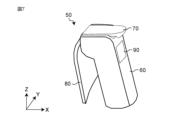
図1及び図2は、本発明に係る実施の形態1の口腔用装置1Aの一例の概略斜視図である。図1は、口腔用本体装置50に口腔器具10が取り付けられている状態を示す。図2は、口腔用本体装置50から口腔器具10が取り外されている状態を示す。図中のX,Y,Z方向は、それぞれ、口腔用装置1Aの長さ方向、幅方向、高さ方向を示す。
(Embodiment 1)
[Oral appliance]
1 and 2 are schematic perspective views of an example of an oral cavity device 1A according to Embodiment 1 of the present invention. FIG. 1 shows a state in which an oral appliance 10 is attached to an oral cavity main body device 50. FIG. 2 shows a state in which the oral appliance 10 is removed from the main body device 50 for the oral cavity. The X, Y, and Z directions in the figure indicate the length direction, width direction, and height direction of the oral cavity device 1A, respectively.

図1及び図2に示すように、口腔用装置1Aは、口腔器具10と、口腔用本体装置50と、を備える。口腔用装置1Aは、ディスポーザブルタイプの装置である。口腔用装置1Aにおいては、口腔内で使用される口腔器具10が口腔用本体装置50に対して着脱可能に取り付けられる。口腔器具10は、口腔用本体装置50に取り付けられて使用された後、口腔用本体装置50から取り外される。 As shown in FIGS. 1 and 2, the oral cavity device 1A includes an oral appliance 10 and an oral cavity main body device 50. The oral cavity device 1A is a disposable type device. In the oral cavity apparatus 1A, an oral appliance 10 used in the oral cavity is detachably attached to the oral cavity main body apparatus 50. After the oral appliance 10 is attached to the oral cavity main body device 50 and used, it is removed from the oral cavity main body device 50.

口腔用装置1Aは、口腔器具10を口腔内の部位に接触させて機能を実行する。機能は、例えば、センシング機能及び/又はエネルギー照射機能を含む。 The oral cavity device 1A performs its functions by bringing the oral appliance 10 into contact with a site within the oral cavity. The functions include, for example, sensing functions and/or energy emitting functions.

センシング機能は、口腔内の生体情報に関連する情報を取得する。生体情報とは、生体が発する種々の生理学的且つ解剖学的情報である。生体情報は、例えば、乾燥度(湿潤度、水分量)、舌圧、咬合力、咀嚼機能、嚥下機能、舌口唇運動機能、衛生状態不良、唾液成分、呼気ガス成分、体温、硬度などの情報である。生体情報に関連する情報とは、例えば、静電容量、インピーダンス(抵抗)、圧力、電位、色調、温度、硬度、振動などの情報である。口腔用装置1Aは、口腔器具10をユーザの口腔内の測定部位に接触させ、接触した測定部位の生体情報に関連する情報を取得する。口腔用装置1Aは、口腔器具10で取得した情報に基づいて、口腔用本体装置50で生体情報を取得することによって、口腔内の状態を測定する。口腔用本体装置50は、例えば、水分量、唾液の分泌量、咬合力、舌圧力、舌の色調及び/又は唾液中に含まれる各種物質の量を測定する。 The sensing function acquires information related to intraoral biometric information. Biological information refers to various physiological and anatomical information emitted by living organisms. Biological information includes, for example, dryness (humidity, water content), tongue pressure, bite force, masticatory function, swallowing function, tongue-lip movement function, poor hygiene, saliva components, exhaled gas components, body temperature, hardness, etc. It is. Information related to biological information is, for example, information such as capacitance, impedance (resistance), pressure, potential, color tone, temperature, hardness, and vibration. The oral cavity device 1A brings the oral appliance 10 into contact with a measurement site in the user's oral cavity, and acquires information related to biological information of the contacted measurement site. The oral cavity device 1A measures the state of the oral cavity by acquiring biological information with the oral cavity main body device 50 based on the information acquired with the oral appliance 10. The oral cavity main body device 50 measures, for example, water content, saliva secretion, bite force, tongue pressure, tongue color, and/or the amount of various substances contained in saliva.

エネルギー照射機能は、口腔内にエネルギーを照射する。エネルギーは、例えば、光、熱、超音波、電磁波などのエネルギーである。 The energy irradiation function irradiates energy into the oral cavity. The energy is, for example, light, heat, ultrasound, electromagnetic waves, or the like.

口腔用装置1Aは、例えば、湿潤計、咬合力計、舌圧計、レーザ治療器、温熱治療器、超音波エコー、超音波治療器、電磁波照射器として用いることができる。 The oral cavity device 1A can be used as, for example, a hygrometer, a bite force meter, a tongue pressure meter, a laser treatment device, a thermotherapy device, an ultrasound echo, an ultrasound treatment device, or an electromagnetic wave irradiation device.

実施の形態1では、口腔用装置1Aが湿潤計である例について説明する。 In Embodiment 1, an example in which the oral cavity device 1A is a hygrometer will be described.

図3は、本発明に係る実施の形態1の口腔用装置1Aを使用している状態の一例を示す概略図である。図3に示すように、口腔用装置1Aは、口腔器具10をユーザの口腔内の測定部位に接触させる。測定部位とは、例えば、口腔内の舌部、頬粘膜、口蓋などである。口腔器具10は、測定部位の形状に沿って変形することによって、測定部位に接触する。口腔用装置1Aは、口腔器具10を口腔内の測定部位に接触させた状態で測定を開始する。 FIG. 3 is a schematic diagram showing an example of a state in which the oral cavity device 1A according to the first embodiment of the present invention is used. As shown in FIG. 3, the oral cavity device 1A brings the oral appliance 10 into contact with the measurement site in the user's oral cavity. Examples of measurement sites include the tongue in the oral cavity, the buccal mucosa, and the roof of the mouth. The oral appliance 10 comes into contact with the measurement site by deforming along the shape of the measurement site. The oral cavity device 1A starts measurement with the oral appliance 10 in contact with the measurement site in the oral cavity.

[口腔器具]
図4は、口腔器具10の一例を示す概略図である。図5は、図4の口腔器具10の一例を拡大して示す概略断面図である。図6は、口腔器具10の一例の構成を示すブロック図である。
[Oral appliances]
FIG. 4 is a schematic diagram showing an example of the oral appliance 10. FIG. 5 is a schematic cross-sectional view showing an example of the oral appliance 10 of FIG. 4 in an enlarged manner. FIG. 6 is a block diagram showing the configuration of an example of the oral appliance 10.

図4-6に示すように、口腔器具10は、機能部20、配線部30及び接続部40を備える。 As shown in FIGS. 4-6, the oral appliance 10 includes a functional section 20, a wiring section 30, and a connecting section 40.

実施の形態1では、口腔器具10は、口腔用本体装置50に着脱可能なセンシングプローブとして構成されている。口腔器具10は、電気接続部を有するシート状を有する器具である。口腔器具10は、長手方向を有する矩形のシート状に形成されている。なお、口腔器具10は、シート状に形成されていればよく、矩形状に限定されない。 In the first embodiment, the oral appliance 10 is configured as a sensing probe that is detachable from the oral cavity main body device 50. The oral appliance 10 is a sheet-shaped appliance that has electrical connections. The oral appliance 10 is formed into a rectangular sheet shape having a longitudinal direction. Note that the oral appliance 10 only needs to be formed in a sheet shape, and is not limited to a rectangular shape.

電気接続部は、口腔用本体装置50と電気的に接続する。実施の形態1では、電気接続部は、1つ又は複数の電極41である。 The electrical connection portion electrically connects to the main body device 50 for oral cavity. In the first embodiment, the electrical connection is one or more electrodes 41.

口腔器具10は可撓性を有しており、変形可能である。口腔器具10においては、少なくとも機能部20が可撓性を有している。 The oral appliance 10 is flexible and deformable. In the oral appliance 10, at least the functional section 20 has flexibility.

<機能部>
機能部20は、センシング機能を発揮する部分であり、口腔器具10の先端側に設けられる。機能部20は、口腔内の情報を取得するセンサ部21を有する。センサ部21は、ユーザの口腔内の測定部位側に配置されるセンサ面21aを有している。機能部20は、センサ部21のセンサ面21a側を測定部位に面接触させることによって、口腔内の情報を取得する。実施の形態1では、センサ部21は、静電容量センサを有し、静電容量を取得する。
<Functional part>
The functional section 20 is a section that exhibits a sensing function, and is provided on the distal end side of the oral appliance 10. The functional unit 20 includes a sensor unit 21 that acquires information inside the oral cavity. The sensor section 21 has a sensor surface 21a arranged on the measurement site side in the user's oral cavity. The functional unit 20 acquires intraoral information by bringing the sensor surface 21a side of the sensor unit 21 into surface contact with the measurement site. In the first embodiment, the sensor section 21 includes a capacitance sensor and acquires capacitance.

機能部20は、口腔内の測定部位に接触するときに、測定部位の形状に沿って変形することができる。これにより、機能部20を口腔内の測定部位に容易に接触させることができる。具体的に説明すると、機能部20が測定部位の形状に沿って変形することによって、センサ部21のセンサ面21aが測定部位の形状にフィットする。これにより、センサ面21aの全体を測定部位に近づけて配置することができるため、センサ面21aの全体を用いて測定部位から口腔内の情報を容易に取得することができる。 When the functional section 20 comes into contact with a measurement site in the oral cavity, it can deform along the shape of the measurement site. Thereby, the functional section 20 can be easily brought into contact with the measurement site in the oral cavity. Specifically, by deforming the functional section 20 along the shape of the measurement site, the sensor surface 21a of the sensor section 21 fits the shape of the measurement site. Thereby, the entire sensor surface 21a can be placed close to the measurement site, so intraoral information can be easily acquired from the measurement site using the entire sensor surface 21a.

実施の形態1では、機能部20が可撓性を有する例について説明するが、これに限定されない。口腔器具10においては、少なくとも機能部20が可撓性を有していればよい。例えば、配線部30及び/又は接続部40が可撓性を有していてもよい。 In the first embodiment, an example in which the functional section 20 has flexibility will be described, but the present invention is not limited to this. In the oral appliance 10, it is sufficient that at least the functional part 20 has flexibility. For example, the wiring section 30 and/or the connection section 40 may have flexibility.

<配線部>
配線部30は、機能部20と接続部40との間に配置されている。配線部30は、機能部20と接続部40の電極41とを電気的に接続する配線31を有する。配線31は、導電性材料で形成されている。配線31の導電性材料としては、例えば、Cu,Al,Agなどが挙げられる。例えば、配線31は、配線導体パターンで形成されている。
<Wiring section>
The wiring section 30 is arranged between the functional section 20 and the connection section 40. The wiring section 30 has a wiring 31 that electrically connects the functional section 20 and the electrode 41 of the connection section 40 . The wiring 31 is made of a conductive material. Examples of the conductive material for the wiring 31 include Cu, Al, and Ag. For example, the wiring 31 is formed of a wiring conductor pattern.

また、配線部30は、配線部30の周囲を覆う保護層32を有する。保護層32は、口腔器具10を口腔内に配置したときに、歯が当たる部分に配置される。保護層32は、機能部20と接続部40との間に配置されていればよい。例えば、保護層32は、厚さ100μm以上10mm以下の保護膜で形成されている。保護膜は、例えば、樹脂、発泡体などの材料で形成されていてもよい。 Further, the wiring section 30 includes a protective layer 32 that covers the periphery of the wiring section 30 . The protective layer 32 is placed in the area that the teeth come into contact with when the oral appliance 10 is placed in the oral cavity. The protective layer 32 may be disposed between the functional section 20 and the connection section 40 . For example, the protective layer 32 is formed of a protective film with a thickness of 100 μm or more and 10 mm or less. The protective film may be made of a material such as resin or foam.

<接続部>
接続部40は、口腔用本体装置50に取り付けられる部分であり、口腔器具10の先端と反対側の後端側に設けられる。接続部40は、1つ又は複数の電極41を有する。実施の形態1では、接続部40は2つの電極41を有する。なお、電極41の数は2つに限定されない。
<Connection part>
The connecting portion 40 is a portion that is attached to the oral cavity main body device 50 and is provided on the rear end side of the oral appliance 10 on the opposite side from the tip. The connecting portion 40 has one or more electrodes 41 . In the first embodiment, the connecting portion 40 has two electrodes 41. Note that the number of electrodes 41 is not limited to two.

1つ又は複数の電極41は、導電性を有する材料で形成されている。電極41の材料としては、例えば、Cu,Al,SUSなどが挙げられる。また、電極41は、Au、Ag、塩化銀、Ti、Pt、カーボン、導電性ポリマー(例えば、PEDOTなど)などの腐食しにくい材料で形成されていてもよい。電極41は、Cuで形成され、Au,Niなどでめっきされていてもよい。 One or more electrodes 41 are made of a conductive material. Examples of the material for the electrode 41 include Cu, Al, and SUS. Further, the electrode 41 may be formed of a material that is hard to corrode, such as Au, Ag, silver chloride, Ti, Pt, carbon, or a conductive polymer (eg, PEDOT). The electrode 41 is made of Cu and may be plated with Au, Ni, or the like.

実施の形態1では、接続部40が口腔用本体装置50に取り付けられると、複数の電極41が口腔用本体装置50に設けられた複数の接続端子と物理的に接触することによって電気的に接続される。 In the first embodiment, when the connecting portion 40 is attached to the oral cavity main body device 50, the plurality of electrodes 41 are electrically connected by physically contacting the plurality of connection terminals provided on the oral cavity main body device 50. be done.

また、接続部40には、取付孔42が設けられている。取付孔42は、後述する着脱操作部70の突起73aが挿入される貫通孔である。実施の形態1では、2つの取付孔42が接続部40に設けられている。 Further, the connecting portion 40 is provided with a mounting hole 42 . The attachment hole 42 is a through hole into which a protrusion 73a of an attachment/detachment operation section 70, which will be described later, is inserted. In the first embodiment, two attachment holes 42 are provided in the connecting portion 40 .

なお、取付孔42は、貫通孔に限定されるものではなく、切り欠き、凹部であってもよい。取付孔42は、着脱操作部70の突起73aが挿入可能なサイズを有していればよい。また、接続部40には、1つ又は複数の取付孔42が設けられていればよい。 Note that the attachment hole 42 is not limited to a through hole, and may be a notch or a recess. The attachment hole 42 only needs to have a size that allows the projection 73a of the attachment/detachment operation section 70 to be inserted therein. Further, the connecting portion 40 may be provided with one or more attachment holes 42 .

図5に示すように、口腔器具10は、配線層11と、複数の絶縁層12,13と、で構成されている。実施の形態1では、配線層11及び複数の絶縁層12,13は、積層されて構成されている。また、複数の絶縁層12,13は、第1絶縁層12と、第2絶縁層13と、を有する。 As shown in FIG. 5, the oral appliance 10 includes a wiring layer 11 and a plurality of insulating layers 12 and 13. In the first embodiment, the wiring layer 11 and the plurality of insulating layers 12 and 13 are stacked. Further, the plurality of insulating layers 12 and 13 include a first insulating layer 12 and a second insulating layer 13.

<配線層>
配線層11は、センサ部21、配線31及び複数の電極41を含む。配線層11は、第1主面PS1と、第1主面PS1と反対側の第2主面PS2とを有する。口腔器具10において、第1主面PS1側は、口腔内の測定部位に接触する側である。実施の形態1では、センサ部21のセンサ面21aは、配線層11の第1主面PS1側に配置されている。
<Wiring layer>
The wiring layer 11 includes a sensor section 21, wiring 31, and a plurality of electrodes 41. The wiring layer 11 has a first main surface PS1 and a second main surface PS2 opposite to the first main surface PS1. In the oral appliance 10, the first principal surface PS1 side is the side that contacts the measurement site in the oral cavity. In the first embodiment, the sensor surface 21a of the sensor section 21 is arranged on the first principal surface PS1 side of the wiring layer 11.

配線層11の第1主面PS1側において、複数の電極41は第1絶縁層12から露出している。なお、複数の電極41は、第1絶縁層12と第2絶縁層13とのうち少なくとも1つから露出していればよい。 On the first main surface PS1 side of the wiring layer 11, the plurality of electrodes 41 are exposed from the first insulating layer 12. Note that the plurality of electrodes 41 only need to be exposed from at least one of the first insulating layer 12 and the second insulating layer 13.

配線層11の厚さは、1μm以上50μm以下が好ましい。より好ましくは、配線層11の厚さは、2μm以上25μm以下である。 The thickness of the wiring layer 11 is preferably 1 μm or more and 50 μm or less. More preferably, the thickness of the wiring layer 11 is 2 μm or more and 25 μm or less.

<複数の絶縁層>
複数の絶縁層12,13は、配線層11の第1主面PS1に配置される第1絶縁層12と、配線層11の第2主面PS2に配置される第2絶縁層13と、を有する。
<Multiple insulation layers>
The plurality of insulating layers 12 and 13 include a first insulating layer 12 arranged on the first main surface PS1 of the wiring layer 11 and a second insulating layer 13 arranged on the second main surface PS2 of the wiring layer 11. have

第1絶縁層12の厚みT1は、第2絶縁層13の厚みT2よりも小さい。第1絶縁層12の厚みT1は、第2絶縁層13の厚みT2の1/2倍以下である。好ましくは、機能部20における第1絶縁層12Aの厚みT1は、第2絶縁層13の厚みT2の1/8倍以下である。第1絶縁層12の厚みT1は、0.01μm以上25μm以下が好ましい。第2絶縁層13の厚みT2は、10μm以上200μm以下が好ましい。なお、第1絶縁層12の厚みT1とは、Z方向において配線層11の第1主面PS1よりも外側に位置する第1絶縁層12の厚みを意味する。第2絶縁層13の厚みT2とは、Z方向において配線層11の第2主面PS2よりも外側に位置する第2絶縁層13の厚みを意味する。 The thickness T1 of the first insulating layer 12 is smaller than the thickness T2 of the second insulating layer 13. The thickness T1 of the first insulating layer 12 is 1/2 or less of the thickness T2 of the second insulating layer 13. Preferably, the thickness T1 of the first insulating layer 12A in the functional section 20 is ⅛ times or less the thickness T2 of the second insulating layer 13. The thickness T1 of the first insulating layer 12 is preferably 0.01 μm or more and 25 μm or less. The thickness T2 of the second insulating layer 13 is preferably 10 μm or more and 200 μm or less. Note that the thickness T1 of the first insulating layer 12 means the thickness of the first insulating layer 12 located outside the first main surface PS1 of the wiring layer 11 in the Z direction. The thickness T2 of the second insulating layer 13 means the thickness of the second insulating layer 13 located outside the second main surface PS2 of the wiring layer 11 in the Z direction.

実施の形態1では、機能部20、配線部30及び接続部40にわたって第1絶縁層12の厚みT1が第2絶縁層13の厚みT2よりも小さくなっている例について説明するが、これに限定されない。少なくとも機能部20において、第1絶縁層12の厚みT1が第2絶縁層13の厚みT2よりも小さくなっていればよい。 In the first embodiment, an example will be described in which the thickness T1 of the first insulating layer 12 is smaller than the thickness T2 of the second insulating layer 13 over the functional section 20, the wiring section 30, and the connection section 40, but the present invention is not limited to this. Not done. At least in the functional section 20, the thickness T1 of the first insulating layer 12 may be smaller than the thickness T2 of the second insulating layer 13.

機能部20において、第1絶縁層12の厚みT1が第2絶縁層13の厚みT2よりも小さいことによって、配線層11の第1主面PS1側のセンサ部21による検知精度を向上させることができる。即ち、第1絶縁層12の厚みT1を小さくすることによって、第1絶縁層12がセンサ部21の情報取得に与える影響を小さくすることができる。具体的には、第1絶縁層12の厚みT1を小さくすることによって、センサ部21のセンサ面21aと測定部位との間の距離を小さくすることができる。これにより、センサ面21aによる情報の取得が容易となり、センサ部21の検知精度を向上させることができる。このように、第1絶縁層12の厚みT1を第2絶縁層13の厚みT2よりも小さくすることによって、機能部20を保護しつつ、センサ部21の検知精度を向上させることができる。また、第1絶縁層12の厚みT1を第2絶縁層13の厚みT2よりも小さくすることによって、第2主面側に比べて第1主面PS1側からの情報取得が容易となる。あるいは、第2絶縁層13の厚みT2をセンサ部21により検知できない程度の厚みに設計することによって、口腔器具10の検出方向を第1主面PS1側に限定することもできる。 In the functional section 20, since the thickness T1 of the first insulating layer 12 is smaller than the thickness T2 of the second insulating layer 13, the detection accuracy by the sensor section 21 on the first principal surface PS1 side of the wiring layer 11 can be improved. can. That is, by reducing the thickness T1 of the first insulating layer 12, the influence of the first insulating layer 12 on information acquisition by the sensor section 21 can be reduced. Specifically, by reducing the thickness T1 of the first insulating layer 12, the distance between the sensor surface 21a of the sensor section 21 and the measurement site can be reduced. This facilitates the acquisition of information by the sensor surface 21a and improves the detection accuracy of the sensor section 21. In this manner, by making the thickness T1 of the first insulating layer 12 smaller than the thickness T2 of the second insulating layer 13, the detection accuracy of the sensor unit 21 can be improved while protecting the functional unit 20. Further, by making the thickness T1 of the first insulating layer 12 smaller than the thickness T2 of the second insulating layer 13, it becomes easier to acquire information from the first main surface PS1 side than from the second main surface side. Alternatively, by designing the thickness T2 of the second insulating layer 13 to be so thick that it cannot be detected by the sensor section 21, the detection direction of the oral appliance 10 can be limited to the first principal surface PS1 side.

複数の絶縁層12,13は、絶縁材料で形成されている。絶縁材料としては、例えば、ポリエチレン(PE)、ポリプロピレン(PP)、ポリエチレンテレフタレート(PET)、ナイロン、ポリ塩化ビニル、ポリイミドなどが挙げられる。 The plurality of insulating layers 12 and 13 are made of an insulating material. Examples of the insulating material include polyethylene (PE), polypropylene (PP), polyethylene terephthalate (PET), nylon, polyvinyl chloride, and polyimide.

例えば、配線層11及び複数の絶縁層12,13は、フレキシブルプリント回路基板で形成される。 For example, the wiring layer 11 and the plurality of insulating layers 12 and 13 are formed of a flexible printed circuit board.

なお、上述した口腔器具10は一例であり、口腔器具10の構成はこれに限定されない。口腔器具10は、電気接続部を有するシート状の器具であればよい。あるいは、口腔器具10は、配線層11及び複数の絶縁層12,13に加えて、シールド層を有していてもよい。複数の絶縁層は、2つ以上の絶縁層を有していてもよい。 In addition, the oral appliance 10 mentioned above is an example, and the structure of the oral appliance 10 is not limited to this. The oral appliance 10 may be a sheet-shaped appliance that has an electrical connection. Alternatively, the oral appliance 10 may include a shield layer in addition to the wiring layer 11 and the plurality of insulating layers 12 and 13. The plurality of insulating layers may include two or more insulating layers.

[口腔用本体装置]
図7は、口腔用本体装置50の一例の概略斜視図である。図8は、図7の口腔用本体装置50の一例の概略分解図である。図9は、口腔用本体装置50の一例の構成を示すブロック図である。なお、以下では、口腔用本体装置50を本体装置50と称する場合がある。
[Oral main unit]
FIG. 7 is a schematic perspective view of an example of the oral cavity main body device 50. FIG. 8 is a schematic exploded view of an example of the oral cavity main body device 50 of FIG. 7. As shown in FIG. FIG. 9 is a block diagram showing the configuration of an example of the main body device 50 for oral cavity. Note that, hereinafter, the oral cavity main body device 50 may be referred to as the main body device 50.

図7-9に示すように、本体装置50は、本体部60、着脱操作部70、ガード80及び表示部90を備える。なお、実施の形態1では、本体装置50がガード80及び表示部90を備える例について説明するが、これに限定されない。ガード80及び表示部90は、必須の構成ではない。例えば、表示部90は、本体装置50とは別の装置に備えられていてもよい。 As shown in FIGS. 7-9, the main body device 50 includes a main body part 60, an attachment/detachment operation part 70, a guard 80, and a display part 90. In the first embodiment, an example in which the main body device 50 includes the guard 80 and the display section 90 will be described, but the present invention is not limited to this. Guard 80 and display section 90 are not essential components. For example, the display unit 90 may be provided in a device different from the main device 50.

本体装置50は、着脱操作部70に口腔器具10を着脱可能に取り付けることができる。また、本体装置50は、口腔器具10で取得した生体情報に関連する情報に基づいて、測定対象物の量を算出する。具体的には、本体装置50は、口腔器具10で取得した静電容量に基づいて水分量(湿潤度)を算出する。 In the main body device 50, the oral appliance 10 can be detachably attached to the attachment/detachment operation section 70. Furthermore, the main body device 50 calculates the amount of the object to be measured based on information related to the biological information acquired by the oral appliance 10. Specifically, the main device 50 calculates the amount of water (wetness) based on the capacitance acquired by the oral appliance 10.

<本体部>
本体部60は、本体装置50の本体部分である。本体部60は、長手方向を有する棒状部材で形成されている。本体部60は、ユーザによって把持される把持部61を有する。把持部61は、本体部60の外観形状によって形成されている。
<Body part>
The main body portion 60 is the main body portion of the main body device 50. The main body portion 60 is formed of a rod-shaped member having a longitudinal direction. The main body portion 60 has a grip portion 61 that is gripped by a user. The grip portion 61 is formed by the external shape of the main body portion 60 .

本体部60の一端側には、着脱操作部70が配置されている。本体部60には、ガード80及び表示部90が配置されている。 At one end of the main body section 60, an attachment/detachment operation section 70 is arranged. A guard 80 and a display section 90 are arranged on the main body section 60.

本体部60は、制御部62と、算出部63と、を備える。 The main body section 60 includes a control section 62 and a calculation section 63.

制御部62は、口腔用装置1Aを構成する構成要素を統括的に制御する。制御部62は、例えば、プログラムを記憶したメモリと、CPU(Central Processing Unit)などのプロセッサに対応する処理回路を備える。例えば、制御部62においては、プロセッサがメモリに記憶されたプログラムを実行する。 The control unit 62 centrally controls the components that constitute the oral cavity device 1A. The control unit 62 includes, for example, a memory storing a program and a processing circuit corresponding to a processor such as a CPU (Central Processing Unit). For example, in the control unit 62, a processor executes a program stored in a memory.

制御部62は、算出部63及び表示部90を制御する。 The control unit 62 controls the calculation unit 63 and the display unit 90.

算出部63は、口腔器具10で取得した情報に基づいて測定対象物の量を算出する。実施の形態1では、算出部63は、口腔器具10で取得した静電容量に基づいて水分量を算出する。 The calculation unit 63 calculates the amount of the object to be measured based on the information acquired by the oral appliance 10. In the first embodiment, the calculation unit 63 calculates the amount of water based on the capacitance acquired by the oral appliance 10.

算出部63は、半導体素子などで実現可能である。算出部63の機能は、ハードウェアのみで構成してもよいし、ハードウェアとソフトウェアとを組み合わせることにより実現してもよい。 The calculation unit 63 can be realized using a semiconductor device or the like. The function of the calculation unit 63 may be configured only by hardware, or may be realized by a combination of hardware and software.

実施の形態1では、算出部63は、水分量算出回路を有する。水分量算出回路は、口腔器具10で取得された静電容量から、静電容量と水分量の関係式に基づいて水分量を算出する。 In the first embodiment, the calculation unit 63 includes a moisture content calculation circuit. The water content calculation circuit calculates the water content from the capacitance acquired by the oral appliance 10 based on a relational expression between capacitance and water content.

算出部63で算出された水分量の情報は、表示部90に送信される。 The information on the moisture content calculated by the calculation unit 63 is transmitted to the display unit 90.

<着脱操作部>
着脱操作部70は、口腔器具10に対する力の付与と解放を操作することによって口腔器具10を本体部60に対して着脱可能に取り付けるように構成されている。実施の形態1では、着脱操作部70は、本体部60の延びる方向に対して交差する方向に、口腔器具10を着脱可能に取り付けるように構成されている。即ち、口腔器具10の着脱方向は、本体部60の延びる方向に対して交差する方向となっている。
<Attachment/detachment operation section>
The attachment/detachment operation unit 70 is configured to detachably attach the oral appliance 10 to the main body 60 by applying and releasing force to the oral appliance 10. In the first embodiment, the attachment/detachment operation section 70 is configured to detachably attach the oral appliance 10 in a direction intersecting the direction in which the main body section 60 extends. That is, the direction of attachment and detachment of the oral appliance 10 is a direction that intersects the direction in which the main body portion 60 extends.

着脱操作部70は、電気接続導体を有する。電気接続導体とは、口腔器具10と電気的に接続される導体である。具体的には、電気接続導体は、口腔器具10の電気接続部と電気的に接続される。実施の形態1では、電気接続導体は、1つ又は複数の接続端子71である。1つ又は複数の接続端子71は、導電性を有する材料で形成されている。1つ又は複数の接続端子71は、口腔器具10の接続部40に設けられた1つ又は複数の電極41と物理的に接触することによって電気的に接続される。 The attachment/detachment operation section 70 has an electrical connection conductor. The electrical connection conductor is a conductor that is electrically connected to the oral appliance 10. Specifically, the electrical connection conductor is electrically connected to an electrical connection of the oral appliance 10. In the first embodiment, the electrical connection conductor is one or more connection terminals 71. One or more connection terminals 71 are made of a conductive material. One or more connection terminals 71 are electrically connected by physically contacting one or more electrodes 41 provided on connection portion 40 of oral appliance 10 .

着脱操作部70は、口腔器具10の接続部40に対して力を付与することによって電極41と接続端子71とを電気的に接続した状態で口腔器具10を固定して取り付ける。また、着脱操作部70は、口腔器具10の接続部40に対して付与している力を解放することによって固定を解除して口腔器具10を取り外す。また、口腔器具10が取り外されたときに、電極41と接続端子71との電気的接続が解除されてもよい。 The attachment/detachment operation section 70 fixes and attaches the oral appliance 10 in a state in which the electrode 41 and the connection terminal 71 are electrically connected by applying force to the connection part 40 of the oral appliance 10 . Further, the attachment/detachment operation unit 70 releases the force applied to the connecting portion 40 of the oral appliance 10 to release the fixation and remove the oral appliance 10. Furthermore, when the oral appliance 10 is removed, the electrical connection between the electrode 41 and the connection terminal 71 may be released.

着脱操作部70は、口腔器具10を配置する配置面72と、配置面72に対して交差する方向に力を付与する押さえ部材73と、を有する。実施の形態1では、押さえ部材73は、配置面72の上方に配置されている。 The attachment/detachment operation section 70 has an arrangement surface 72 on which the oral appliance 10 is arranged, and a pressing member 73 that applies force in a direction crossing the arrangement surface 72. In the first embodiment, the pressing member 73 is arranged above the arrangement surface 72.

配置面72は、本体部60の一端側の端面に設けられている。配置面72は、口腔器具10がスライド移動可能な面である。配置面72は、本体部60の一端側の端面を凹状に窪ませて形成されていてもよいし、フラット面で形成されていてもよい。 The arrangement surface 72 is provided on the end surface of the main body portion 60 on one end side. The arrangement surface 72 is a surface on which the oral appliance 10 can slide. The arrangement surface 72 may be formed by recessing the end surface on one end side of the main body portion 60 into a concave shape, or may be formed as a flat surface.

配置面72には、1つ又は複数の接続端子71が配置されている。1つ又は複数の接続端子71は、口腔器具10が配置面72に配置されて固定されたときに1つ又は複数の電極41と対応する位置に配置されている。実施の形態1では、配置面72には、2つの接続端子71が配置されている。なお、接続端子71の数は2つに限定されない。 One or more connection terminals 71 are arranged on the arrangement surface 72 . The one or more connection terminals 71 are arranged at positions corresponding to the one or more electrodes 41 when the oral appliance 10 is arranged and fixed on the arrangement surface 72. In the first embodiment, two connection terminals 71 are arranged on the arrangement surface 72. Note that the number of connection terminals 71 is not limited to two.

配置面72には、押さえ部材73に向かって延びる位置決め部材72aが設けられている。位置決め部材72aは、配置面72上でのX方向の位置を決定している。位置決め部材72aは、例えば、配置面72に形成される段差によって形成されてもよいし、配置面72から押さえ部材73に向かって凸状に突出させて形成されていてもよい。例えば、口腔器具10をX方向にスライド移動させて配置面72に配置するとき、口腔器具10の接続部40の端部を位置決め部材72aに接触するまで口腔器具10をスライド移動させる。このように、口腔器具10を着脱操作部70に取り付ける際に、口腔器具10を位置決め部材72aに接触するまでスライド移動させることによって、口腔器具10のX方向の位置を容易に決定することができる。これにより、口腔器具10の電極41と配置面72に配置される接続端子71とが物理的に接触する位置での取り付けが容易となり、電気的接続を容易に行うことができる。 A positioning member 72a extending toward the pressing member 73 is provided on the arrangement surface 72. The positioning member 72a determines the position on the placement surface 72 in the X direction. The positioning member 72a may be formed, for example, by a step formed on the arrangement surface 72, or may be formed to protrude convexly from the arrangement surface 72 toward the pressing member 73. For example, when the oral appliance 10 is slid in the X direction and placed on the placement surface 72, the oral appliance 10 is slid until the end of the connecting portion 40 of the oral appliance 10 contacts the positioning member 72a. In this way, when attaching the oral appliance 10 to the attachment/detachment operation section 70, the position of the oral appliance 10 in the X direction can be easily determined by sliding the oral appliance 10 until it comes into contact with the positioning member 72a. . Thereby, the electrode 41 of the oral appliance 10 and the connection terminal 71 arranged on the arrangement surface 72 can be easily attached at a position where they physically contact each other, and electrical connection can be easily performed.

押さえ部材73は、口腔器具10に対する力の付与と解放とを操作可能な部材である。押さえ部材73は、配置面72に対して交差する方向に力を付与するように構成されている。これにより、押さえ部材73は、電極41と接続端子71とを電気的に接続した状態で、配置面72に口腔器具10を固定することができる。 The pressing member 73 is a member that can be operated to apply and release force to the oral cavity appliance 10. The pressing member 73 is configured to apply force in a direction crossing the arrangement surface 72. Thereby, the holding member 73 can fix the oral appliance 10 to the arrangement surface 72 in a state where the electrode 41 and the connecting terminal 71 are electrically connected.

押さえ部材73は、一端E1と他端E2とを有する板状の部材で形成されている。一端E1は配置面72側に設けられる。他端E2は、一端E1とは反対側に設けられる。押さえ部材73の一端E1と他端E2との間には、回転軸74が配置されている。押さえ部材73は、回転軸74を中心にして回転可能に構成されている。また、押さえ部材73の一端E1は、例えば、弾性体によって配置面72に近づく方向へ付勢されている。弾性体としては、例えば、ばね、ゴムなどが挙げられる。 The holding member 73 is formed of a plate-shaped member having one end E1 and the other end E2. One end E1 is provided on the arrangement surface 72 side. The other end E2 is provided on the opposite side to the one end E1. A rotating shaft 74 is arranged between one end E1 and the other end E2 of the holding member 73. The holding member 73 is configured to be rotatable around a rotating shaft 74. Further, one end E1 of the pressing member 73 is urged toward the arrangement surface 72 by, for example, an elastic body. Examples of the elastic body include springs and rubber.

押さえ部材73は、一端E1と回転軸74との間で、配置面72に向かって突出する突起73aを有する。突起73aは、口腔器具10の接続部40に設けられた取付孔42に挿入される。実施の形態1では、押さえ部材73は、押さえ部材73の一端E1に設けられる2つの突起73aを有する。なお、押さえ部材73は、1つ又は複数の突起73aを有していればよい。 The holding member 73 has a protrusion 73a that protrudes toward the arrangement surface 72 between one end E1 and the rotating shaft 74. The protrusion 73a is inserted into the attachment hole 42 provided in the connection part 40 of the oral appliance 10. In the first embodiment, the holding member 73 has two protrusions 73a provided at one end E1 of the holding member 73. Note that the holding member 73 only needs to have one or more protrusions 73a.

着脱操作部70においては、押さえ部材73の回転動作を操作することによって、口腔器具10に対する力の付与と解放とを操作している。具体的には、押さえ部材73を操作していない状態では、押さえ部材73の一端E1が弾性体の付勢力によって配置面72に近づく方向へ移動し、配置面72に配置された口腔器具10に対して押圧する。これにより、口腔器具10を配置面72と押さえ部材73とで挟むように固定し、口腔器具10を着脱操作部70に取り付けることができる。また、押さえ部材73の突起73aが接続部40の取付孔42に挿入されることによって、口腔器具10が着脱操作部70から外れないように固定することができる。 In the attachment/detachment operation unit 70, application and release of force to the oral appliance 10 are operated by operating the rotational movement of the holding member 73. Specifically, when the holding member 73 is not operated, one end E1 of the holding member 73 moves in a direction approaching the placement surface 72 due to the urging force of the elastic body, and the oral appliance 10 placed on the placement surface 72 is moved. Press against. Thereby, the oral appliance 10 can be fixed so as to be sandwiched between the placement surface 72 and the pressing member 73, and the oral appliance 10 can be attached to the attachment/detachment operation section 70. In addition, by inserting the protrusion 73a of the holding member 73 into the attachment hole 42 of the connecting portion 40, the oral appliance 10 can be fixed so as not to come off from the attachment/detachment operation portion 70.

口腔器具10を着脱操作部70から取り外すとき、押さえ部材73の他端E2を押し下げることによって、押さえ部材73の一端E1が配置面72から離れる方向に移動する。これにより、押さえ部材73による口腔器具10に対する押圧力を解除し、口腔器具10を着脱操作部70から取り外すことができる。このように、口腔器具10の取り外しを着脱操作部70の操作によって行うことができるため、使用済みの口腔器具10に触れずに、口腔器具10を容易に取り外すことができる。 When removing the oral appliance 10 from the attachment/detachment operation section 70, by pushing down the other end E2 of the holding member 73, one end E1 of the holding member 73 moves in a direction away from the placement surface 72. Thereby, the pressing force applied to the oral cavity appliance 10 by the holding member 73 is released, and the oral cavity appliance 10 can be removed from the attachment/detachment operation section 70. In this way, since the oral appliance 10 can be removed by operating the attachment/detachment operation section 70, the oral appliance 10 can be easily removed without touching the used oral appliance 10.

なお、実施の形態1では、押さえ部材73が弾性体によって付勢される例について説明したが、これに限定されない。押さえ部材73は弾性体以外の機構、例えば、ロック機構、スライド機構及び/又は電磁力などによって押さえ部材73を配置面72と交差する方向に力を付与してもよい。また、吸引部を設け、吸引力によって口腔器具10に対して力を付与してもよい。 In the first embodiment, an example in which the pressing member 73 is urged by an elastic body has been described, but the present invention is not limited to this. The pressing member 73 may apply a force to the pressing member 73 in a direction intersecting the arrangement surface 72 using a mechanism other than an elastic body, such as a locking mechanism, a sliding mechanism, and/or an electromagnetic force. Further, a suction section may be provided to apply force to the oral appliance 10 by suction force.

<ガード>
ガード80は、本体部60に配置され、把持部61を保護する。ガード80は、ユーザが口腔用装置1Aを使用する際に、唾液が把持部61を把持するユーザの手に付着することを抑制する。
<Guard>
The guard 80 is arranged on the main body 60 and protects the grip 61. The guard 80 suppresses saliva from adhering to the user's hand holding the grip portion 61 when the user uses the oral cavity device 1A.

実施の形態1では、ガード80は、口腔器具10が取り付けられる側の本体部60に配置されている。口腔器具10が取り付けられる側とは、口腔器具10の取り付け及び取り外しが行われる側を意味する。また、ガード80は、板状の部材で形成されている。 In the first embodiment, the guard 80 is arranged on the main body portion 60 on the side to which the oral appliance 10 is attached. The side on which the oral appliance 10 is attached means the side on which the oral appliance 10 is attached and removed. Further, the guard 80 is formed of a plate-shaped member.

<表示部>
表示部90は、本体部60に配置され、口腔用装置1Aの情報を表示する。口腔用装置1Aの情報は、例えば、測定対象の情報などを含む。
<Display section>
The display section 90 is arranged on the main body section 60 and displays information on the oral cavity device 1A. The information on the oral cavity device 1A includes, for example, information on the measurement target.

実施の形態1では、測定対象の情報は、水分量の情報である。例えば、算出部63は、口腔器具10で取得した静電容量に基づいて水分量を算出する。算出部63は、水分量の情報を表示部90に送信する。 In the first embodiment, the information on the measurement target is information on water content. For example, the calculation unit 63 calculates the amount of water based on the capacitance acquired by the oral appliance 10. The calculation unit 63 transmits information on the amount of water to the display unit 90.

表示部90は、例えば、ディスプレイである。 The display unit 90 is, for example, a display.

なお、本体装置50は、ユーザからの入力情報を入力する入力部を備えていてもよい。例えば、入力部は、ユーザからの入力を受け付ける1つ又は複数のボタンを有していてもよい。1つ又は複数のボタンは、例えば、電源ON/OFFを切り替える電源ボタン、測定を開始する測定開始ボタンなどを含んでいてもよい。 Note that the main device 50 may include an input unit for inputting information input from the user. For example, the input unit may have one or more buttons that accept input from the user. The one or more buttons may include, for example, a power button for switching power ON/OFF, a measurement start button for starting measurement, and the like.

[着脱操作部に取り付けられた口腔器具の一例]
着脱操作部70に取り付けられた口腔器具10の一例について図10を用いて説明する図10は、着脱操作部70に取り付けられた口腔器具10の一例を拡大して示す概略部分拡大断面図である。
[An example of an oral appliance attached to the detachable operation unit]
An example of the oral appliance 10 attached to the attachment/detachment operation section 70 will be described using FIG. 10 . FIG. 10 is a schematic partial enlarged sectional view showing an example of the oral appliance 10 attached to the attachment/detachment operation section 70.

図10に示すように、口腔器具10は、着脱操作部70の配置面72に配置される。具体的には、口腔器具10の接続部40が、位置決め部材72aに接触することによって位置決めされて配置面72に配置される。また、口腔器具10の接続部40は、位置決め部材72aによって電極41と接続端子71とが物理的に接触する位置に位置決めされる。これにより、口腔器具10の電極41と本体装置50の接続端子71とが電気的に接続される。口腔器具10の電極41と本体装置50の接続端子71とが電気的に接続された状態になると、本体装置50によって口腔器具10を使用することができる。 As shown in FIG. 10, the oral appliance 10 is placed on the placement surface 72 of the attachment/detachment operation section 70. Specifically, the connecting portion 40 of the oral appliance 10 is positioned and placed on the placement surface 72 by contacting the positioning member 72a. Further, the connecting portion 40 of the oral appliance 10 is positioned by the positioning member 72a at a position where the electrode 41 and the connecting terminal 71 are physically in contact with each other. Thereby, the electrode 41 of the oral appliance 10 and the connection terminal 71 of the main device 50 are electrically connected. When the electrode 41 of the oral appliance 10 and the connection terminal 71 of the main body device 50 are electrically connected, the oral appliance 10 can be used by the main body device 50.

押さえ部材73は、弾性体の付勢力によって口腔器具10の接続部40を配置面72に向かって押圧する。これにより、口腔器具10の接続部40は、配置面72と押さえ部材73との間に挟まれて固定される。 The pressing member 73 presses the connecting portion 40 of the oral appliance 10 toward the placement surface 72 by the urging force of the elastic body. Thereby, the connecting portion 40 of the oral appliance 10 is sandwiched and fixed between the placement surface 72 and the pressing member 73.

また、押さえ部材73の一端E1に設けられた突起73aが口腔器具10の接続部40の取付孔42に挿入される。これにより、口腔器具10が着脱操作部70から抜け落ちることを抑制することができる。 Further, a protrusion 73a provided at one end E1 of the holding member 73 is inserted into the attachment hole 42 of the connecting portion 40 of the oral appliance 10. Thereby, it is possible to suppress the oral appliance 10 from falling off from the attachment/detachment operation section 70.

このように、口腔器具10は、押さえ部材73による押圧力を付与されることによって電極41と接続端子71とを電気的に接続した状態で本体装置50に固定して取り付けられている。そして、押さえ部材73による押圧力の解放によって、固定を解除し、口腔器具10を本体装置50から容易に取り外すことができる。 In this way, the oral appliance 10 is fixedly attached to the main body device 50 with the electrode 41 and the connecting terminal 71 electrically connected by applying a pressing force from the pressing member 73. Then, by releasing the pressing force by the pressing member 73, the fixation is released and the oral appliance 10 can be easily removed from the main body device 50.

[効果]
実施の形態1に係る口腔器具10によれば、以下の効果を奏することができる。
[effect]
According to the oral cavity appliance 10 according to the first embodiment, the following effects can be achieved.

口腔器具10は、口腔用本体装置50に着脱可能に取り付けられるシート状の口腔器具である。口腔器具10は、機能部20、接続部40及び配線部30を備える。機能部20は、口腔内の情報を取得するセンサ部21を有する。接続部40は、電気接続部を有する。配線部30は、センサ部21と電気接続部とを接続する配線31を有する。機能部20、接続部40及び配線部30は、配線層11と、複数の絶縁層12,13と、で構成されている。配線層11は、第1主面PS1、および第1主面PS1と反対側の第2主面PS2を有する。複数の絶縁層12,13は、配線層11の第1主面PS1に配置される第1絶縁層12と、配線層11の第2主面PS2に配置される第2絶縁層13と、を有する。機能部20において、第1絶縁層12の厚みT1は、第2絶縁層13の厚みT2より小さい。 The oral appliance 10 is a sheet-like oral appliance that is detachably attached to the oral cavity main body device 50. The oral appliance 10 includes a functional section 20, a connecting section 40, and a wiring section 30. The functional unit 20 includes a sensor unit 21 that acquires information inside the oral cavity. Connection section 40 has an electrical connection section. The wiring section 30 has a wiring 31 that connects the sensor section 21 and the electrical connection section. The functional section 20, the connection section 40, and the wiring section 30 are composed of a wiring layer 11 and a plurality of insulating layers 12 and 13. The wiring layer 11 has a first main surface PS1 and a second main surface PS2 opposite to the first main surface PS1. The plurality of insulating layers 12 and 13 include a first insulating layer 12 arranged on the first main surface PS1 of the wiring layer 11 and a second insulating layer 13 arranged on the second main surface PS2 of the wiring layer 11. have In the functional section 20, the thickness T1 of the first insulating layer 12 is smaller than the thickness T2 of the second insulating layer 13.

このような構成により、口腔用本体装置50に着脱可能に取り付けられる口腔器具10の性能を向上させることができる。具体的には、第1絶縁層12の厚みT1を第2絶縁層13の厚みT2よりも小さくすることによって、配線層11の第1主面PS1側において、第1絶縁層12がセンサ部21に与える影響を小さくすることができる。これにより、機能部20を保護しつつ、センサ部21と測定部位との間の距離を小さくすることができ、センサ部21の感度を向上させることができる。その結果、センサ部21の検知精度を向上させることができる。 With such a configuration, the performance of the oral appliance 10 that is detachably attached to the oral cavity main body device 50 can be improved. Specifically, by making the thickness T1 of the first insulating layer 12 smaller than the thickness T2 of the second insulating layer 13, the first insulating layer 12 is connected to the sensor section 21 on the first principal surface PS1 side of the wiring layer 11. It is possible to reduce the impact on Thereby, the distance between the sensor section 21 and the measurement site can be reduced while protecting the functional section 20, and the sensitivity of the sensor section 21 can be improved. As a result, the detection accuracy of the sensor section 21 can be improved.

配線層11及び複数の絶縁層12,13は、積層されて構成されている。このような構成により、口腔器具10の厚みを薄くすることができ、口腔内への挿入が容易となる。口腔器具10を薄くすることができるため、例えば、顎関節症の患者など大きく開口できない人でも使用することができる。 The wiring layer 11 and the plurality of insulating layers 12 and 13 are stacked. With such a configuration, the thickness of the oral appliance 10 can be reduced, making it easy to insert it into the oral cavity. Since the oral appliance 10 can be made thin, it can be used even by people who cannot open their mouths wide, such as patients with temporomandibular joint disorders.

配線部30は、配線部30の外周に配置される保護層32を有する。このような構成により、口腔器具10を口腔内に挿入して使用するときに、保護層32がユーザの歯の当たる位置に配置される。これにより、保護層32によって配線部30を保護することができ、ユーザの歯が配線部30に接触することにより、配線31が断線するなどの故障を抑制することができる。 The wiring section 30 has a protective layer 32 disposed around the outer periphery of the wiring section 30 . With such a configuration, when the oral appliance 10 is inserted into the oral cavity and used, the protective layer 32 is placed at a position where it comes into contact with the user's teeth. Thereby, the wiring part 30 can be protected by the protective layer 32, and failures such as disconnection of the wiring 31 due to the user's teeth coming into contact with the wiring part 30 can be suppressed.

センサ部21は、口腔内の測定部位の情報を取得するセンサ面21aを有する。センサ面21aは、配線層11の第1主面PS1側に配置される。このような構成により、センサ部21の検知精度を更に向上させることができる。 The sensor section 21 has a sensor surface 21a that acquires information about a measurement site in the oral cavity. The sensor surface 21a is arranged on the first principal surface PS1 side of the wiring layer 11. With such a configuration, the detection accuracy of the sensor section 21 can be further improved.

口腔器具10において、少なくとも機能部20は可撓性を有する。このような構成により、口腔内の測定部位の形状に沿って機能部20を変形させて配置することができる。これにより、機能部20と測定部位との接触面積を増やすことができる。その結果、センサ部21を測定部位にフィットさせて口腔内の情報を取得することができるため、検知精度を向上させることができる。 In the oral appliance 10, at least the functional section 20 has flexibility. With such a configuration, the functional section 20 can be deformed and arranged along the shape of the measurement site in the oral cavity. Thereby, the contact area between the functional section 20 and the measurement site can be increased. As a result, it is possible to fit the sensor unit 21 to the measurement site and acquire information in the oral cavity, thereby improving detection accuracy.

電気接続部は、第1絶縁層12と第2絶縁層13とのうち少なくとも1つから露出する1つ又は複数の電極41である。このような構成により、口腔器具10と本体装置50との電気的接続を物理的接触によって容易に行うことができる。 The electrical connections are one or more electrodes 41 exposed from at least one of the first insulating layer 12 and the second insulating layer 13 . With such a configuration, electrical connection between the oral appliance 10 and the main body device 50 can be easily established through physical contact.

なお、実施の形態1では、口腔用装置1Aが口腔内の水分量を測定する口腔湿潤計である例について説明したが、これに限定されない。口腔用装置1Aは、口腔内の情報を取得する装置及び/又は口腔内にエネルギーを照射する装置であればよい。 In the first embodiment, an example in which the oral cavity device 1A is an oral moisture meter that measures the amount of water in the oral cavity has been described, but the present invention is not limited thereto. The oral cavity device 1A may be any device as long as it is a device that acquires information in the oral cavity and/or a device that irradiates energy into the oral cavity.

実施の形態1では、口腔器具10が可撓性を有する例について説明したが、これに限定されない。口腔器具10においては、可撓性は必須の構成ではない。口腔器具10は、可撓性を有していなくてもよい。 Although the first embodiment describes an example in which the oral appliance 10 has flexibility, the present invention is not limited thereto. Flexibility is not an essential feature of oral appliance 10. Oral appliance 10 does not have to be flexible.

実施の形態1では、口腔器具10が1つのセンサ部21を備える例について説明したが、これに限定されない。口腔器具10は、1つ又は複数のセンサ部21と1つ又は複数のエネルギー照射部のうち少なくとも1つを備えていればよい。 In the first embodiment, an example in which the oral appliance 10 includes one sensor section 21 has been described, but the present invention is not limited thereto. The oral appliance 10 may include at least one of one or more sensor sections 21 and one or more energy irradiation sections.

実施の形態1では、口腔器具10のセンサ部21が静電容量センサを有する例について説明したが、これに限定されない。例えば、センサ部21は、生体情報に関連する情報を取得できるセンサを有していればよい。例えば、センサ部21は、インピーダンス測定センサ、抵抗センサ、荷重センサ、湿度センサ、圧力センサ、カラーセンサ、温度センサ、硬度センサ、振動センサ、バイオセンサなどのうちの少なくともいずれか1つを有していればよい。 In Embodiment 1, an example has been described in which the sensor section 21 of the oral appliance 10 includes a capacitance sensor, but the present invention is not limited thereto. For example, the sensor unit 21 only needs to have a sensor that can acquire information related to biological information. For example, the sensor unit 21 includes at least one of an impedance measurement sensor, a resistance sensor, a load sensor, a humidity sensor, a pressure sensor, a color sensor, a temperature sensor, a hardness sensor, a vibration sensor, a biosensor, etc. That's fine.

実施の形態1では、算出部63が静電容量に基づく周波数の変化量に基づいて水分量を算出する例について説明したが、これに限定されない。算出部63は、口腔器具10で取得した情報に基づいて口腔内の情報を算出できればよい。 In the first embodiment, an example has been described in which the calculation unit 63 calculates the moisture content based on the amount of change in frequency based on capacitance, but the calculation unit 63 is not limited to this. The calculation unit 63 only needs to be able to calculate intraoral information based on the information acquired by the oral appliance 10.

実施の形態1では、口腔器具10に対する押さえ部材73による押圧力の付与と解放によって口腔器具10の取り付け及び取り外しを行う例について説明したが、これに限定されない。例えば、押さえ部材73による押圧力及び/又は電磁力によって口腔器具10の取り付け及び取り外しを行ってもよい。例えば、口腔器具10の電極41は、磁石に反応する金属で形成されていてもよい。磁石に反応する金属とは、例えば、鉄、コバルト、ニッケルなどである。また、本体装置50には磁石が設けられていてもよい。本体装置50に設けられた磁石の磁力によって、口腔器具10の電極41を配置面72に引き寄せてもよい。 In Embodiment 1, an example has been described in which the oral appliance 10 is attached and detached by applying and releasing a pressing force from the pressing member 73 to the oral appliance 10, but the present invention is not limited thereto. For example, the oral appliance 10 may be attached and detached by the pressing force and/or electromagnetic force by the holding member 73. For example, the electrodes 41 of the oral appliance 10 may be formed of a metal that is responsive to magnets. Examples of metals that react with magnets include iron, cobalt, and nickel. Furthermore, the main body device 50 may be provided with a magnet. The electrode 41 of the oral appliance 10 may be drawn to the placement surface 72 by the magnetic force of the magnet provided in the main device 50 .

実施の形態1では、口腔器具10の電気接続部が電極41であり、本体装置50の電気接続導体が接続端子71である例について説明したが、これに限定されない。また、「電気接続部と電気接続導体とを電気的に接続した状態」とは、電気接続部と電気接続導体とを物理的に接触させている状態に限定されない。「電気接続部と電気接続導体とを電気的に接続した状態」とは、電気接続部と電気接続導体とが非接触で電気的に接続されている状態を含んでもよい。例えば、RFIDタグなどの無線通信デバイスを用いて電気接続部と電気接続導体とを無線接続することによって、電気的接続を実現してもよい。 In the first embodiment, an example has been described in which the electrical connection portion of the oral appliance 10 is the electrode 41 and the electrical connection conductor of the main body device 50 is the connection terminal 71, but the present invention is not limited to this. Moreover, "the state in which the electrical connection part and the electrical connection conductor are electrically connected" is not limited to the state in which the electrical connection part and the electrical connection conductor are in physical contact. "A state in which the electrical connection part and the electrical connection conductor are electrically connected" may include a state in which the electrical connection part and the electrical connection conductor are electrically connected in a non-contact manner. For example, the electrical connection may be realized by wirelessly connecting the electrical connection part and the electrical connection conductor using a wireless communication device such as an RFID tag.

実施の形態1では、機能部20がセンサ部21を備える例について説明したが、これに限定されない。機能部20は、口腔内の情報を取得するセンサ部21、および口腔内にエネルギーを照射するエネルギー照射部22のうち少なくとも1つを含んでいればよい。 In the first embodiment, an example in which the functional section 20 includes the sensor section 21 has been described, but the present invention is not limited to this. The functional unit 20 may include at least one of a sensor unit 21 that acquires information inside the oral cavity, and an energy irradiation unit 22 that irradiates energy into the oral cavity.

実施の形態1では、機能部20が可撓性を有する例について説明したが、これに限定されない。口腔器具10においては、少なくとも機能部20が可撓性を有していればよい。例えば、口腔器具10の全体が可撓性を有していてもよい。 In the first embodiment, an example in which the functional section 20 has flexibility has been described, but the present invention is not limited thereto. In the oral appliance 10, it is sufficient that at least the functional part 20 has flexibility. For example, the entire oral appliance 10 may be flexible.

実施の形態1では、配線部30が保護層32を有する例について説明したが、これに限定されない。例えば、配線部30は保護層32を有していなくてもよい。 In the first embodiment, an example in which the wiring section 30 includes the protective layer 32 has been described, but the present invention is not limited to this. For example, the wiring section 30 does not need to have the protective layer 32.

(変形例1)
図11Aは、変形例1の押さえ部材73Aを示す概略図である。図11Bは、変形例1の口腔器具10Aを示す概略図である。図11Aに示すように、押さえ部材73AをZ方向から見たとき、2つの突起73aは、X方向に延びる中心線に対して左右非対称に配置されている。また、図11Bに示すように、口腔器具10AをZ方向から見て、接続部40Aにおける2つの取付孔42は、X方向に延びる中心線に対して左右非対称に配置されている。このような構成により、口腔器具10Aの取り付け方向を規定することができる。これにより、口腔器具10Aの表面と裏面とを間違えずに着脱操作部70Aに取り付けることができる。
(Modification 1)
FIG. 11A is a schematic diagram showing a pressing member 73A of modification example 1. FIG. 11B is a schematic diagram showing an oral appliance 10A of Modification 1. As shown in FIG. 11A, when the pressing member 73A is viewed from the Z direction, the two protrusions 73a are arranged asymmetrically with respect to the center line extending in the X direction. Moreover, as shown in FIG. 11B, when the oral appliance 10A is viewed from the Z direction, the two attachment holes 42 in the connecting portion 40A are arranged asymmetrically with respect to the center line extending in the X direction. With such a configuration, the mounting direction of the oral appliance 10A can be defined. Thereby, the front surface and the back surface of the oral appliance 10A can be attached to the attachment/detachment operation section 70A without making a mistake.

(変形例2)
図12は、変形例2の口腔器具10AAを拡大して示す概略断面図である。図12に示すように、口腔器具10AAの接続部40AAにおいては、電極41が第2絶縁層13から露出している。一方、電極41は、第1絶縁層12から露出していない。この場合、着脱操作部70では、押さえ部材73に接続端子71が配置されていてもよい。このような構成においても、口腔器具10AAと本体装置50とを電気的に接続することができる。
(Modification 2)
FIG. 12 is an enlarged schematic cross-sectional view showing an oral appliance 10AA of Modification 2. As shown in FIG. 12, the electrode 41 is exposed from the second insulating layer 13 at the connecting portion 40AA of the oral appliance 10AA. On the other hand, the electrode 41 is not exposed from the first insulating layer 12. In this case, in the attachment/detachment operation section 70, the connection terminal 71 may be arranged on the holding member 73. Even in such a configuration, the oral appliance 10AA and the main body device 50 can be electrically connected.

(実施の形態2)
本発明の実施の形態2に係る口腔器具について説明する。なお、実施の形態2では、主に実施の形態1と異なる点について説明する。実施の形態2においては、実施の形態1と同一又は同等の構成については同じ符号を付して説明する。また、実施の形態2では、実施の形態1と重複する記載は省略する。
(Embodiment 2)
An oral appliance according to Embodiment 2 of the present invention will be described. Note that in the second embodiment, differences from the first embodiment will be mainly explained. In the second embodiment, the same or equivalent configurations as those in the first embodiment will be described with the same reference numerals. Furthermore, in the second embodiment, descriptions that overlap with those in the first embodiment will be omitted.

実施の形態2の口腔器具の一例について、図13を用いて説明する。図13は、本発明に係る実施の形態2の口腔器具10Bの一例を拡大して示す概略断面図である。 An example of the oral appliance of Embodiment 2 will be described using FIG. 13. FIG. 13 is a schematic cross-sectional view showing an enlarged example of an oral appliance 10B according to Embodiment 2 of the present invention.

実施の形態2では、配線部30Bの厚みT4が機能部20の厚みT3より大きい点、複数のシールド層14,15を備える点で、実施の形態1と異なる。 The second embodiment differs from the first embodiment in that the thickness T4 of the wiring section 30B is larger than the thickness T3 of the functional section 20 and that a plurality of shield layers 14 and 15 are provided.

図13に示すように、口腔器具10Bにおいては、配線部30Bの厚みT4が機能部20の厚みT3より大きい。例えば、配線部30Bの厚みT4は、機能部20の厚みT3の2倍以上1000倍以下である。 As shown in FIG. 13, in the oral appliance 10B, the thickness T4 of the wiring portion 30B is larger than the thickness T3 of the functional portion 20. For example, the thickness T4 of the wiring portion 30B is greater than or equal to twice the thickness T3 of the functional portion 20 and less than or equal to 1000 times.

配線部30Bの厚みT4を機能部20の厚みT3よりも大きくすることによって、配線部30Bの強度を向上させることができる。 By making the thickness T4 of the wiring part 30B larger than the thickness T3 of the functional part 20, the strength of the wiring part 30B can be improved.

配線部30Bは、複数の絶縁層12,13,16,17に配置される複数のシールド層14,15を有する。配線部30Bは、配線層11、複数の絶縁層12,13,16,17及び複数のシールド層14,15が積層されて構成されている。 The wiring section 30B includes a plurality of shield layers 14 and 15 arranged on a plurality of insulating layers 12, 13, 16, and 17. The wiring section 30B is configured by laminating a wiring layer 11, a plurality of insulating layers 12, 13, 16, 17, and a plurality of shield layers 14, 15.

実施の形態2では、複数の絶縁層12,13,16,17は、第1絶縁層12及び第2絶縁層13に加えて、第3絶縁層16及び第4絶縁層17を含む。第1絶縁層12及び第3絶縁層16は、配線層11の第1主面PS1側に配置される。第2絶縁層13及び第4絶縁層17は、配線層11の第2主面PS2側に配置される。 In the second embodiment, the plurality of insulating layers 12, 13, 16, and 17 include a third insulating layer 16 and a fourth insulating layer 17 in addition to the first insulating layer 12 and the second insulating layer 13. The first insulating layer 12 and the third insulating layer 16 are arranged on the first main surface PS1 side of the wiring layer 11. The second insulating layer 13 and the fourth insulating layer 17 are arranged on the second main surface PS2 side of the wiring layer 11.

実施の形態2では、複数のシールド層14,15は、2つのシールド層を備える。具体的には、複数のシールド層14,15は、第1シールド層14と、第2シールド層15と、を備える。 In the second embodiment, the plurality of shield layers 14 and 15 include two shield layers. Specifically, the plurality of shield layers 14 and 15 include a first shield layer 14 and a second shield layer 15.

第1シールド層14は、配線層11の第1主面PS1側に配置されており、第1絶縁層12と第3絶縁層16との間に配置されている。具体的には、配線部30Bの配線層11の第1主面PS1側では、配線層11、第1絶縁層12、第1シールド層14及び第3絶縁層16の順に積層されている。 The first shield layer 14 is disposed on the first main surface PS1 side of the wiring layer 11, and is disposed between the first insulating layer 12 and the third insulating layer 16. Specifically, on the first main surface PS1 side of the wiring layer 11 of the wiring portion 30B, the wiring layer 11, the first insulating layer 12, the first shield layer 14, and the third insulating layer 16 are stacked in this order.

第2シールド層15は、配線層11の第2主面PS2側に配置されており、第2絶縁層13と第4絶縁層17との間に配置されている。具体的には、配線部30Bの配線層11の第2主面PS2側では、配線層11、第2絶縁層13、第2シールド層15及び第4絶縁層17の順に積層されている。 The second shield layer 15 is arranged on the second main surface PS2 side of the wiring layer 11, and is arranged between the second insulating layer 13 and the fourth insulating layer 17. Specifically, on the second principal surface PS2 side of the wiring layer 11 of the wiring portion 30B, the wiring layer 11, the second insulating layer 13, the second shield layer 15, and the fourth insulating layer 17 are stacked in this order.

複数のシールド層14,15は、GNDを形成している。複数のシールド層14,15は、例えば、Cu,Ag,Au,Alなどの金属又はカーボン材料で形成されている。第1シールド層14及び第2シールド層15の厚みは、それぞれ、1μm以上100μm以下である。 The plurality of shield layers 14 and 15 form GND. The plurality of shield layers 14 and 15 are made of, for example, a metal such as Cu, Ag, Au, or Al, or a carbon material. The thickness of the first shield layer 14 and the second shield layer 15 is 1 μm or more and 100 μm or less, respectively.

例えば、配線層11、複数の絶縁層12,13,16,17及び複数のシールド層14,15は、多層フレキシブルプリント回路基板で形成されていてもよい。あるいは、複数のシールド層14,15は、導電性不織布又は金属箔を複数の絶縁層12,13,16,17に貼付して形成されてもよい。あるいは、絶縁層とシールド層とが一体で形成される金属膜付きフィルムを用いて、複数の絶縁層12,13,16,17及び複数のシールド層14,15を形成し、配線層11に貼付されてもよい。 For example, the wiring layer 11, the plurality of insulating layers 12, 13, 16, 17, and the plurality of shield layers 14, 15 may be formed of a multilayer flexible printed circuit board. Alternatively, the plurality of shield layers 14 and 15 may be formed by attaching conductive nonwoven fabric or metal foil to the plurality of insulating layers 12, 13, 16, and 17. Alternatively, a plurality of insulating layers 12, 13, 16, 17 and a plurality of shield layers 14, 15 are formed using a film with a metal film in which an insulating layer and a shield layer are integrally formed, and are attached to the wiring layer 11. may be done.

[効果]
実施の形態2に係る口腔器具10Bによれば、以下の効果を奏することができる。
[effect]
According to the oral appliance 10B according to the second embodiment, the following effects can be achieved.

口腔器具10Bにおいて、配線部30Bの厚みT4は、機能部20の厚みT3より大きい。このような構成により、配線部30Bの機械的強度を向上させることができる。例えば、口腔器具10Bを口腔内に挿入したときに、配線部30Bがユーザの歯で噛まれたりすることがある。配線部30Bの厚みT4を厚くすることによって機械的強度を向上させることによって、配線部30Bの変形を抑制することができる。これにより、配線部30Bに外力がかかったときに配線31が断線するなどの故障の発生を抑制することができる。 In the oral appliance 10B, the thickness T4 of the wiring portion 30B is larger than the thickness T3 of the functional portion 20. With such a configuration, the mechanical strength of the wiring portion 30B can be improved. For example, when the oral appliance 10B is inserted into the oral cavity, the wiring portion 30B may be bitten by the user's teeth. By increasing the thickness T4 of the wiring portion 30B and improving the mechanical strength, deformation of the wiring portion 30B can be suppressed. Thereby, it is possible to suppress the occurrence of a failure such as disconnection of the wiring 31 when an external force is applied to the wiring portion 30B.

配線部30Bは、複数の絶縁層12,13に配置される複数のシールド層14,15を有する。このような構成により、配線部30Bから発生するノイズを抑制することができる。また、複数のシールド層14,15を金属やカーボンなどの剛性の高い材料で形成することによって、配線部30Bの機械的強度を更に向上させることができる。 The wiring section 30B includes a plurality of shield layers 14 and 15 arranged on a plurality of insulating layers 12 and 13. With such a configuration, noise generated from the wiring section 30B can be suppressed. Further, by forming the plurality of shield layers 14 and 15 from a highly rigid material such as metal or carbon, the mechanical strength of the wiring portion 30B can be further improved.

なお、実施の形態2では、配線部30Bが複数のシールド層14,15を有する例について説明したが、これに限定されない。例えば、配線部30Bは、複数のシールド層14,15を有していなくてもよい。 In addition, although the example in which the wiring part 30B has the several shield layer 14 and 15 was demonstrated in Embodiment 2, it is not limited to this. For example, the wiring section 30B does not need to have the plurality of shield layers 14 and 15.

実施の形態2では、配線部30Bが2つのシールド層14,15を有する例について説明したが、これに限定されない。配線部30Bは、1つ又は複数のシールド層を有していてもよい。 In the second embodiment, an example in which the wiring section 30B has two shield layers 14 and 15 has been described, but the present invention is not limited thereto. The wiring section 30B may have one or more shield layers.

実施の形態2では、第1シールド層14が第1絶縁層12と第3絶縁層16との間に配置され、第2シールド層15が第2絶縁層13と第4絶縁層17との間に配置される例について説明したが、これに限定されない。例えば、第1シールド層14は、配線層11と第1絶縁層12との間に配置されていてもよい。第2シールド層15は、配線層11と第2絶縁層13との間に配置されていてもよい。第1シールド層14及び/又は第2シールド層15は、配線層11内の配線31に隣接するGNDパターンとして形成されてもよい。 In the second embodiment, the first shield layer 14 is arranged between the first insulating layer 12 and the third insulating layer 16, and the second shield layer 15 is arranged between the second insulating layer 13 and the fourth insulating layer 17. Although an example has been described in which the device is placed in For example, the first shield layer 14 may be arranged between the wiring layer 11 and the first insulating layer 12. The second shield layer 15 may be arranged between the wiring layer 11 and the second insulating layer 13. The first shield layer 14 and/or the second shield layer 15 may be formed as a GND pattern adjacent to the wiring 31 in the wiring layer 11.

(実施の形態3)
本発明の実施の形態3に係る口腔用装置について説明する。なお、実施の形態3では、主に実施の形態1と異なる点について説明する。実施の形態3においては、実施の形態1と同一又は同等の構成については同じ符号を付して説明する。また、実施の形態3では、実施の形態1と重複する記載は省略する。
(Embodiment 3)
An oral cavity device according to Embodiment 3 of the present invention will be described. Note that in the third embodiment, differences from the first embodiment will be mainly explained. In Embodiment 3, the same or equivalent configurations as in Embodiment 1 will be described with the same reference numerals. Furthermore, in the third embodiment, descriptions that overlap with those in the first embodiment will be omitted.

実施の形態3の口腔用装置の一例について、図14A及び図14Bを用いて説明する。図14A及び図14Bは、本発明に係る実施の形態3の口腔用装置1Cの一例の概略斜視図である。なお、図14A及び図14Bでは、表示部90の表示を省略している。 An example of the oral cavity device of Embodiment 3 will be described using FIGS. 14A and 14B. 14A and 14B are schematic perspective views of an example of an oral cavity device 1C according to Embodiment 3 of the present invention. Note that the display on the display unit 90 is omitted in FIGS. 14A and 14B.

実施の形態3では、口腔用本体装置50Cの本体部60Cの延びる方向が、口腔器具10Cの着脱方向と同じである点、口腔器具10Cが変形した状態で着脱操作部70Cに取り付けられる点で、実施の形態1と異なる。 In Embodiment 3, the extending direction of the main body part 60C of the oral cavity main body device 50C is the same as the attachment/detachment direction of the oral appliance 10C, and the oral appliance 10C is attached to the attachment/detachment operation part 70C in a deformed state. This is different from Embodiment 1.

図14A及び図14Bに示すように、口腔用本体装置50Cの本体部60Cは、口腔器具10Cの着脱方向と同じ方向に延びる棒状の部材で形成されている。口腔器具10Cの着脱方向とは、図14A及び図14BにおいてX方向である。 As shown in FIGS. 14A and 14B, the main body portion 60C of the oral cavity main body device 50C is formed of a rod-shaped member extending in the same direction as the attachment/detachment direction of the oral appliance 10C. The attachment/detachment direction of the oral appliance 10C is the X direction in FIGS. 14A and 14B.

ガード80Cは、口腔器具10Cの着脱方向と交差する方向に突出する凸部により形成されている。ガード80Cは、本体部60Cにおいて、着脱操作部70Cが設けられている側と反対側に設けられている。ガード80Cは、把持部61Cよりも外側に突出している。また、ガード80Cには、唾液などの液体が把持部61Cに向かって流れることを抑制する傾斜面が形成されている。これにより、把持部61Cに唾液が流れることを抑制することができる。 The guard 80C is formed of a convex portion that protrudes in a direction intersecting the direction of attachment and detachment of the oral appliance 10C. The guard 80C is provided on the side of the main body 60C opposite to the side where the attachment/detachment operation section 70C is provided. The guard 80C projects further outward than the grip portion 61C. Further, the guard 80C is formed with an inclined surface that suppresses liquid such as saliva from flowing toward the grip portion 61C. Thereby, it is possible to suppress saliva from flowing into the grip portion 61C.

口腔器具10Cは、変形可能な長手方向を有するシート状に形成されている。実施の形態3では、口腔器具10Cの全体が可撓性を有している。即ち、口腔器具10Cにおいては、機能部20、配線部30及び接続部40が可撓性を有している。口腔器具10Cは、変形した状態で着脱操作部70Cに取り付けられる。 The oral appliance 10C is formed into a sheet shape having a deformable longitudinal direction. In Embodiment 3, the entire oral appliance 10C has flexibility. That is, in the oral appliance 10C, the functional section 20, the wiring section 30, and the connecting section 40 have flexibility. The oral appliance 10C is attached to the attachment/detachment operation section 70C in a deformed state.

図15Aは、着脱操作部70Cに取り付けられた口腔器具10Cの一例を拡大して示す概略部分拡大断面図である。図15Bは、図15Aの着脱操作部70Cの概略分解断面図である。なお、図15A及び図15Bは、口腔器具10C及び着脱操作部70CをYZ平面で切断したときの断面図を示している。 FIG. 15A is a schematic partial enlarged sectional view showing an example of the oral appliance 10C attached to the attachment/detachment operation section 70C. FIG. 15B is a schematic exploded cross-sectional view of the attachment/detachment operation section 70C of FIG. 15A. Note that FIGS. 15A and 15B show cross-sectional views of the oral appliance 10C and the attachment/detachment operation section 70C taken along the YZ plane.

図15A及び図15Bに示すように、着脱操作部70Cは、凹状又は凸状に湾曲する配置面72Cと、配置面72Cの形状に沿って凹状又は凸状に湾曲する押さえ部材73Cと、を有する。 As shown in FIGS. 15A and 15B, the attachment/detachment operation part 70C has an arrangement surface 72C that is curved in a concave or convex shape, and a pressing member 73C that is curved in a concave or convex shape along the shape of the arrangement surface 72C. .

配置面72Cは、凹状に湾曲して形成されている。具体的には、配置面72Cは、台形状に窪んで形成されている。配置面72Cは、平坦な底面72aaと、底面72aaに向かって傾斜して延びる複数の傾斜面72ab,72acと、を含む。配置面72Cの底面72aaには、複数の接続端子71が配置されている。 The arrangement surface 72C is formed in a concave curve. Specifically, the arrangement surface 72C is formed in a trapezoidal depression. The arrangement surface 72C includes a flat bottom surface 72aa and a plurality of inclined surfaces 72ab and 72ac that extend obliquely toward the bottom surface 72aa. A plurality of connection terminals 71 are arranged on the bottom surface 72aa of the arrangement surface 72C.

押さえ部材73Cは、配置面72Cの形状に沿って凸状に湾曲して形成されている。具体的には、押さえ部材73Cは、台形状に形成されている。押さえ部材73Cは、平坦な底面73caと、底面73caに向かって傾斜して延びる複数の傾斜面73cb,73ccと、を含む。 The pressing member 73C is curved in a convex shape along the shape of the arrangement surface 72C. Specifically, the holding member 73C is formed into a trapezoidal shape. The pressing member 73C includes a flat bottom surface 73ca and a plurality of sloped surfaces 7 3cb and 7 3c c extending obliquely toward the bottom surface 73ca.

図15Aに示すように、口腔器具10Cは、押さえ部材73Cによって押圧されることによって着脱操作部70Cに取り付けられる。口腔器具10Cは、押さえ部材73Cと配置面72Cとの間に挟まれることによって、押さえ部材73Cと配置面72Cの形状に沿って変形した状態で固定される。実施の形態3では、口腔器具10Cは、Z方向において下側に突出した台形状に変形する。 As shown in FIG. 15A, the oral appliance 10C is attached to the attachment/detachment operation section 70C by being pressed by the holding member 73C. The oral appliance 10C is held between the pressing member 73C and the placement surface 72C, and thereby is fixed in a deformed state along the shapes of the pressing member 73C and the placement surface 72C. In Embodiment 3, the oral appliance 10C is deformed into a trapezoid shape that protrudes downward in the Z direction.

具体的には、口腔器具10Cは、配置面72Cの底面72aaと押さえ部材73Cの底面73caとの間、配置面72Cの傾斜面72abと押さえ部材73Cの傾斜面73cbとの間、配置面72Cの傾斜面72acと押さえ部材73Cの傾斜面73ccとの間で挟持される。 Specifically, the oral appliance 10C is arranged between the bottom surface 72aa of the placement surface 72C and the bottom surface 73ca of the holding member 73C, between the inclined surface 72ab of the placement surface 72C and the inclined surface 73cb of the holding member 73C, and between the bottom surface 72aa of the placement surface 72C and the bottom surface 73ca of the holding member 73C. It is held between the inclined surface 72ac and the inclined surface 73cc of the holding member 73C.

口腔器具10Cの複数の電極41は、配置面72Cの底面72aaに配置された複数の接続端子71と物理的に接触することによって、複数の接続端子71に電気的に接続される。 The plurality of electrodes 41 of the oral appliance 10C are electrically connected to the plurality of connection terminals 71 by physically contacting the plurality of connection terminals 71 arranged on the bottom surface 72aa of the arrangement surface 72C.

このように、口腔器具10Cは、台形形状に変形して着脱操作部70Cに固定される。 In this way, the oral appliance 10C is deformed into a trapezoidal shape and fixed to the attachment/detachment operation section 70C.

[効果]
実施の形態3に係る口腔器具10Cによれば、以下の効果を奏することができる。
[effect]
According to the oral appliance 10C according to the third embodiment, the following effects can be achieved.

口腔器具10Cにおいては、機能部20、配線部30及び接続部40が可撓性を有している。このため、口腔器具10Cは、着脱操作部70Cの形状に沿って変形した状態で固定される。これにより、口腔器具10Cが垂れ下がることを抑制することができる。例えば、口腔器具10Cに唾液などが付着すると、唾液の重さによって口腔器具10Cが垂れ下がる場合がある。口腔器具10Cを台形状などの形状に変形させて取り付けておくことによって、口腔器具10Cが変形した形状を維持し、口腔器具10Cが垂れ下がることを抑制することができる。一方、口腔器具10Cを口腔内で使用するとき、口腔器具10Cを口腔内の接触部位の形状に沿って変形させることができる。これにより、測定精度又は照射精度を向上させることができる。 In the oral appliance 10C, the functional section 20, the wiring section 30, and the connecting section 40 have flexibility. Therefore, the oral appliance 10C is fixed in a deformed state along the shape of the attachment/detachment operation part 70C. Thereby, it is possible to suppress the oral appliance 10C from hanging down. For example, if saliva or the like adheres to the oral appliance 10C, the oral appliance 10C may sag due to the weight of the saliva. By deforming the oral appliance 10C into a shape such as a trapezoid and attaching it, it is possible to maintain the deformed shape of the oral appliance 10C and prevent the oral appliance 10C from sagging. On the other hand, when the oral appliance 10C is used in the oral cavity, the oral appliance 10C can be deformed to conform to the shape of the contact site in the oral cavity. Thereby, measurement accuracy or irradiation accuracy can be improved.

なお、実施の形態3では、口腔器具10Cの全体が可撓性を有している例について説明したが、これに限定されない。口腔器具10Cは、着脱操作部70Cに取り付けられているときに変形した状態で安定して固定されていればよく、口腔器具10Cの一部が可撓性を有していない部材で形成されていてもよい。 In addition, although the example in which the entire oral appliance 10C has flexibility has been described in Embodiment 3, the present invention is not limited thereto. The oral appliance 10C only needs to be stably fixed in a deformed state when attached to the attachment/detachment operation part 70C, and a part of the oral appliance 10C is formed of a non-flexible member. It's okay.

実施の形態3では、口腔器具10Cが下側に突出する台形形状に変形する例について説明したが、これに限定されない。例えば、口腔器具10Cは、X方向から見て、凹状又は凸状に変形していればよい。 In the third embodiment, an example has been described in which the oral appliance 10C is deformed into a trapezoidal shape that projects downward, but the present invention is not limited thereto. For example, the oral appliance 10C may be deformed into a concave or convex shape when viewed from the X direction.

図16A-16Cは、口腔器具10Cの変形の一例を拡大して示す概略拡大断面図である。なお、図16A-16Cは、口腔器具10Cの接続部40をYZ平面で切断したときの断面図を示している。図16Aに示すように、口腔器具10Cは、X方向から見て、下側に突出するU字状に変形してもよい。図16Bに示すように、口腔器具10Cは、X方向から見て、下側に突出するV字状に変形してもよい。図16Cに示すように、口腔器具10Cは、X方向から見て、上側に突出するU字状に変形してもよい。これらのような構成においても、口腔器具10Cが垂れ下がることを抑制することができる。 16A-16C are schematic enlarged cross-sectional views showing an example of a modification of the oral appliance 10C. Note that FIGS. 16A to 16C show cross-sectional views of the connecting portion 40 of the oral appliance 10C taken along the YZ plane. As shown in FIG. 16A, the oral appliance 10C may be deformed into a U-shape that projects downward when viewed from the X direction. As shown in FIG. 16B, the oral appliance 10C may be deformed into a V-shape that projects downward when viewed from the X direction. As shown in FIG. 16C, the oral appliance 10C may be deformed into a U-shape that projects upward when viewed from the X direction. Even in these configurations, it is possible to suppress the oral appliance 10C from hanging down.

(実施の形態4)
本発明の実施の形態4に係る口腔器具について説明する。なお、実施の形態4では、主に実施の形態1と異なる点について説明する。実施の形態4においては、実施の形態1と同一又は同等の構成については同じ符号を付して説明する。また、実施の形態4では、実施の形態1と重複する記載は省略する。
(Embodiment 4)
An oral appliance according to Embodiment 4 of the present invention will be described. Note that in the fourth embodiment, differences from the first embodiment will be mainly explained. In Embodiment 4, the same or equivalent configurations as in Embodiment 1 will be described with the same reference numerals. Furthermore, in the fourth embodiment, descriptions that overlap with those in the first embodiment will be omitted.

実施の形態4の口腔器具の一例について、図17を用いて説明する。図17は、本発明に係る実施の形態4の口腔器具10Dの一例を拡大して示す概略部分拡大断面図である。 An example of the oral appliance of Embodiment 4 will be described using FIG. 17. FIG. 17 is a schematic partially enlarged sectional view showing an example of an oral appliance 10D according to the fourth embodiment of the present invention.

実施の形態4では、電極41が第1絶縁層12と第2絶縁層13との両方から露出している点で、実施の形態1と異なる。 The fourth embodiment differs from the first embodiment in that the electrode 41 is exposed from both the first insulating layer 12 and the second insulating layer 13.

図17に示すように、口腔器具10Dの接続部40Dにおいては、電極41が第1絶縁層12と第2絶縁層13との両方から露出している。 As shown in FIG. 17, in the connecting portion 40D of the oral appliance 10D, the electrode 41 is exposed from both the first insulating layer 12 and the second insulating layer 13.

[効果]
実施の形態4に係る口腔器具10Dによれば、以下の効果を奏することができる。
[effect]
According to the oral appliance 10D according to the fourth embodiment, the following effects can be achieved.

口腔器具10Cにおいては、電極41は、第1絶縁層12と第2絶縁層13との両方から露出している。このような構成により、口腔器具10Cの取り付けの自由度を向上させることができる。例えば、着脱操作部70において、接続端子71が配置面72に設けられている場合、口腔器具10Dの電極41は、第1主面PS1側で接続端子71と物理的に接触することができる。着脱操作部70において、接続端子71が押さえ部材73に設けられる場合、口腔器具10Dの電極41は、第2主面PS2側で接続端子71と物理的に接触することができる。 In oral appliance 10C, electrode 41 is exposed from both first insulating layer 12 and second insulating layer 13. With such a configuration, the degree of freedom in attaching the oral appliance 10C can be improved. For example, in the attachment/detachment operation section 70, when the connection terminal 71 is provided on the arrangement surface 72, the electrode 41 of the oral appliance 10D can physically contact the connection terminal 71 on the first principal surface PS1 side. In the attachment/detachment operation section 70, when the connection terminal 71 is provided on the holding member 73, the electrode 41 of the oral appliance 10D can physically contact the connection terminal 71 on the second principal surface PS2 side.

あるいは、口腔器具10Dの上下面を入れ替えて着脱操作部70に取り付けることができる。これにより、口腔器具10Dを着脱操作部70に取り付ける際に、センサ部21のセンサ面21aを上側に向けて固定することもできるし、又はセンサ部21のセンサ面21aを下側に向けて固定することもできる。 Alternatively, the upper and lower surfaces of the oral appliance 10D can be switched and attached to the attachment/detachment operation section 70. Thereby, when attaching the oral appliance 10D to the attachment/detachment operation section 70, the sensor surface 21a of the sensor section 21 can be fixed with the sensor surface 21a facing upward, or the sensor surface 21a of the sensor section 21 can be fixed with the sensor surface 21a facing downward. You can also.

このように、電極41が第1絶縁層12と第2絶縁層13との両方から露出することによって、口腔器具10Dの取り付け方の自由度が向上する。 In this way, by exposing the electrode 41 from both the first insulating layer 12 and the second insulating layer 13, the degree of freedom in how to attach the oral appliance 10D is improved.

(実施の形態5)
本発明の実施の形態5に係る口腔用装置について説明する。なお、実施の形態5では、主に実施の形態1と異なる点について説明する。実施の形態5においては、実施の形態1と同一又は同等の構成については同じ符号を付して説明する。また、実施の形態5では、実施の形態1と重複する記載は省略する。
(Embodiment 5)
An oral cavity device according to Embodiment 5 of the present invention will be described. Note that in the fifth embodiment, differences from the first embodiment will be mainly explained. In the fifth embodiment, the same or equivalent configurations as those in the first embodiment will be described with the same reference numerals. Further, in the fifth embodiment, descriptions that overlap with those in the first embodiment will be omitted.

実施の形態5の口腔用装置の一例について、図18を用いて説明する。図18は、本発明に係る実施の形態5の口腔用装置1Eの一例の主要な構成を示すブロック図である。 An example of the oral cavity device of Embodiment 5 will be described using FIG. 18. FIG. 18 is a block diagram showing the main configuration of an example of an oral cavity device 1E according to Embodiment 5 of the present invention.

実施の形態5では、口腔器具10Eの機能部20Eがエネルギー照射部22を有する点、口腔用本体装置50Eがエネルギー照射部22の制御を行う点で、実施の形態1と異なる。 Embodiment 5 differs from Embodiment 1 in that a functional section 20E of an oral appliance 10E includes an energy irradiation section 22, and that an oral main body device 50E controls the energy irradiation section 22.

図18に示すように、口腔器具10Eにおいて、機能部20Eは、口腔内にエネルギーを照射するエネルギー照射部22を有する。実施の形態5では、口腔器具10Eがレーザ治療器である例を説明する。口腔器具10Eは、口腔用本体装置50Eに着脱可能に取り付けられて使用される。 As shown in FIG. 18, in the oral appliance 10E, the functional section 20E includes an energy irradiation section 22 that irradiates energy into the oral cavity. In Embodiment 5, an example will be described in which the oral appliance 10E is a laser treatment device. The oral appliance 10E is used by being detachably attached to the oral cavity main body device 50E.

図19Aは、口腔器具10Eの一例を示す概略図である。図19Bは、図19Aの口腔器具10Eの一例の概略断面図である。図19A及び図19Bに示すように、機能部20Eは、複数のエネルギー照射部22を有する。実施の形態5では、機能部20Eは、4つのエネルギー照射部22を有する。 FIG. 19A is a schematic diagram showing an example of an oral appliance 10E. FIG. 19B is a schematic cross-sectional view of an example oral appliance 10E of FIG. 19A. As shown in FIGS. 19A and 19B, the functional section 20E includes a plurality of energy irradiating sections 22. In the fifth embodiment, the functional section 20E includes four energy irradiation sections 22.

複数のエネルギー照射部22は、例えば、垂直共振器面発光レーザ(VCSEL:Vertical Cavity Surface Emitting LASER)である。複数のエネルギー照射部22は、配線層11の第1主面PS1に実装され、その上から第1絶縁層12Aで覆われている。第1絶縁層12Aは、配線層11の第1主面PS1に配置される絶縁体12aと、絶縁体12aに貼付される透明な樹脂フィルム12bと、を有する。絶縁体12aには、複数のエネルギー照射部22を収納する複数の穴12cが設けられている。機能部20Eにおいて、樹脂フィルム12bは、絶縁体12aに設けられた複数の穴12cを塞いでいる。複数のエネルギー照射部22からのレーザは、第1絶縁層12Aの樹脂フィルム12bを透過して口腔内の照射部位に照射される。 The plurality of energy irradiators 22 are, for example, vertical cavity surface emitting lasers (VCSELs). The plurality of energy irradiators 22 are mounted on the first main surface PS1 of the wiring layer 11, and covered with the first insulating layer 12A from above. The first insulating layer 12A includes an insulator 12a disposed on the first main surface PS1 of the wiring layer 11, and a transparent resin film 12b attached to the insulator 12a. The insulator 12a is provided with a plurality of holes 12c for accommodating a plurality of energy irradiators 22. In the functional section 20E, the resin film 12b closes a plurality of holes 12c provided in the insulator 12a. Lasers from the plurality of energy irradiators 22 pass through the resin film 12b of the first insulating layer 12A and are irradiated to the irradiation site in the oral cavity.

機能部20Eは、可撓性を有している。このため、機能部20Eは、口腔内の照射部位の形状に沿って変形することができる。 The functional section 20E has flexibility. Therefore, the functional part 20E can be deformed along the shape of the irradiation site in the oral cavity.

機能部20Eにおいて、第1絶縁層12Aの厚みT11は、第2絶縁層13の厚みT12より小さい。機能部20Eにおける第1絶縁層12Aの厚みT11は、第2絶縁層13の厚みT12の1/2倍以下である。好ましくは、機能部20Eにおける第1絶縁層12Aの厚みT11は、第2絶縁層13の厚みT12の1/8倍以下である。これにより、エネルギー照射部22のレーザの照射効率を向上させることができる。 In the functional section 20E, the thickness T11 of the first insulating layer 12A is smaller than the thickness T12 of the second insulating layer 13. The thickness T11 of the first insulating layer 12A in the functional section 20E is 1/2 or less of the thickness T12 of the second insulating layer 13. Preferably, the thickness T11 of the first insulating layer 12A in the functional section 20E is ⅛ times or less the thickness T12 of the second insulating layer 13. Thereby, the laser irradiation efficiency of the energy irradiation section 22 can be improved.

図18に戻って、口腔用本体装置50Eは、入力部91を備える。入力部91は、エネルギー照射部22を操作する入力情報を取得する。ユーザは、入力部91に入力情報を入力する。例えば、入力部91は、1つ又は複数の操作ボタン、タッチパネル、マイクなどであってもよい。入力部91に入力された入力情報は、制御部62に送信される。入力情報としては、例えば、レーザの照射、レーザの停止、タイマー、出力値などを含む。 Returning to FIG. 18, the oral cavity main body device 50E includes an input section 91. The input unit 91 acquires input information for operating the energy irradiation unit 22 . The user inputs input information into the input section 91. For example, the input unit 91 may be one or more operation buttons, a touch panel, a microphone, or the like. Input information input to the input section 91 is transmitted to the control section 62. The input information includes, for example, laser irradiation, laser stop, timer, output value, and the like.

制御部62は、入力部91から入力情報を受信し、入力情報に基づいて口腔器具10Eの動作を制御する。制御部62は、入力情報に基づいて、複数のエネルギー照射部22を制御する。例えば、入力部91にレーザ照射の入力情報が入力されると、制御部62は、口腔器具10Eの複数のエネルギー照射部22を制御し、複数のエネルギー照射部22からレーザを照射させる。 Control unit 62 receives input information from input unit 91 and controls the operation of oral appliance 10E based on the input information. The control unit 62 controls the plurality of energy irradiation units 22 based on input information. For example, when input information for laser irradiation is input to the input unit 91, the control unit 62 controls the plurality of energy irradiation units 22 of the oral appliance 10E, and causes the plurality of energy irradiation units 22 to irradiate laser.

[効果]
実施の形態5に係る口腔器具10Eによれば、以下の効果を奏することができる。
[effect]
According to the oral appliance 10E according to the fifth embodiment, the following effects can be achieved.

口腔器具10Eにおいて、機能部20Eは、口腔内にエネルギーを照射するエネルギー照射部22を備える。このような構成により、口腔内の照射部位にエネルギーを照射することができる。 In the oral appliance 10E, the functional section 20E includes an energy irradiation section 22 that irradiates energy into the oral cavity. With such a configuration, energy can be irradiated to the irradiation site within the oral cavity.

機能部20Eは、可撓性を有している。これにより、機能部20Eは、口腔内の照射部位の形状に沿って変形することができ、照射部位に適切に接触することができる。 The functional section 20E has flexibility. Thereby, the functional part 20E can be deformed along the shape of the irradiation site in the oral cavity, and can appropriately contact the irradiation site.

エネルギー照射部22は、配線層11の第1主面PS1側に配置される。機能部20Eにおいて、第1絶縁層12Aの厚みT11は、第2絶縁層13の厚みT12より小さい。これにより、エネルギー照射部22のレーザの照射効率を向上させることができる。第1絶縁層12Aの厚みT11を第2絶縁層13の厚みT12より小さくすることによって、第1絶縁層12Aがエネルギー照射部22からのレーザ照射に与える影響を小さくすることができる。具体的には、エネルギー照射部22と照射部位との間の距離を小さくすることができるため、エネルギー照射部22から照射されるレーザのロスを低減することができる。 The energy irradiation section 22 is arranged on the first principal surface PS1 side of the wiring layer 11. In the functional section 20E, the thickness T11 of the first insulating layer 12A is smaller than the thickness T12 of the second insulating layer 13. Thereby, the laser irradiation efficiency of the energy irradiation unit 22 can be improved. By making the thickness T11 of the first insulating layer 12A smaller than the thickness T12 of the second insulating layer 13, the influence of the first insulating layer 12A on laser irradiation from the energy irradiation section 22 can be reduced. Specifically, since the distance between the energy irradiation section 22 and the irradiation site can be reduced, the loss of the laser beam irradiated from the energy irradiation section 22 can be reduced.

なお、実施の形態5では、エネルギー照射部22が垂直共振器面発光レーザである例について説明したが、これに限定されない。エネルギー照射部22は、エネルギーを照射できればよい。 In the fifth embodiment, an example in which the energy irradiation section 22 is a vertical cavity surface emitting laser has been described, but the present invention is not limited to this. The energy irradiation unit 22 only needs to be able to irradiate energy.

実施の形態5では、機能部20Eが4つのエネルギー照射部22を有する例について説明したが、これに限定されない。機能部20Eは1つ又は複数のエネルギー照射部22を有していればよい。 In the fifth embodiment, an example has been described in which the functional section 20E includes four energy irradiation sections 22, but the present invention is not limited to this. The functional section 20E only needs to have one or more energy irradiation sections 22.

(変形例3)
図20Aは、変形例3の口腔器具10EAを示す概略図である。図20Bは、図20Aの変形例3の口腔器具10EAの概略断面図である。図20A及び図20Bに示すように、口腔器具10EAは、温熱治療器として用いられる。機能部20EAのエネルギー照射部22aは、シートヒータである。シートヒータは、抵抗体での発熱を利用して加熱を行う。また、口腔器具10EAは、エネルギー照射部22aで加熱される部分を除いて断熱材18で覆われていてもよい。口腔器具10EAにおいては、配線層11の第1主面PS1側は、断熱材18で覆われていない。
(Modification 3)
FIG. 20A is a schematic diagram showing an oral appliance 10EA of modification 3. FIG. 20B is a schematic cross-sectional view of the oral appliance 10EA of modification 3 of FIG. 20A. As shown in FIGS. 20A and 20B, the oral appliance 10EA is used as a thermotherapy device. The energy irradiation unit 22a of the functional unit 20EA is a seat heater. The seat heater performs heating using heat generated by a resistor. Further, the oral appliance 10EA may be covered with a heat insulating material 18 except for the portion heated by the energy irradiation section 22a. In the oral appliance 10EA, the first main surface PS1 side of the wiring layer 11 is not covered with the heat insulating material 18.

(実施の形態6)
本発明の実施の形態6に係る口腔用装置について説明する。なお、実施の形態6では、主に実施の形態1と異なる点について説明する。実施の形態6においては、実施の形態1と同一又は同等の構成については同じ符号を付して説明する。また、実施の形態6では、実施の形態1と重複する記載は省略する。
(Embodiment 6)
An oral cavity device according to Embodiment 6 of the present invention will be described. Note that in the sixth embodiment, differences from the first embodiment will be mainly explained. In the sixth embodiment, the same or equivalent configurations as those in the first embodiment will be described with the same reference numerals. Furthermore, in the sixth embodiment, descriptions that overlap with those in the first embodiment will be omitted.

実施の形態6の口腔用装置の一例について、図21を用いて説明する。図21は、本発明に係る実施の形態6の口腔用装置1Fの一例の主要な構成を示すブロック図である。 An example of the oral cavity device of Embodiment 6 will be described using FIG. 21. FIG. 21 is a block diagram showing the main configuration of an example of the oral cavity device 1F according to Embodiment 6 of the present invention.

実施の形態6では、口腔器具10Fの電気接続部がRFID(Radio Frequency Identification)タグ43である点、口腔用本体装置50Fの電気接続導体がアンテナ78である点で、実施の形態1と異なる。 The sixth embodiment differs from the first embodiment in that the electrical connection portion of the oral appliance 10F is an RFID (Radio Frequency Identification) tag 43, and the electrical connection conductor of the oral cavity main body device 50F is an antenna 78.

図21に示すように、口腔器具10Fにおいて、接続部40は、電気接続部としてRFIDタグ43を有する。RFIDタグ43は、口腔用本体装置50Fの電気接続導体と無線接続することによって電気的に接続される。即ち、RFIDタグ43は、口腔用本体装置50Fのアンテナ78と非接触で電気的に接続される。 As shown in FIG. 21, in the oral appliance 10F, the connection part 40F has an RFID tag 43 as an electrical connection part. The RFID tag 43 is electrically connected by wirelessly connecting to the electrical connection conductor of the oral cavity main device 50F. That is, the RFID tag 43 is electrically connected to the antenna 78 of the main oral cavity device 50F in a non-contact manner.

図22は、口腔器具10Fの一例を示す概略図である。図23は、図22の口腔器具10Fの一例の概略断面図である。図22及び図23に示すように、RFIDタグ43は、配線層11において接続部40Fに配置されている。RFIDタグ43は、複数の絶縁層12,13で覆われている。即ち、RFIDタグ43は、複数の絶縁層12,13から露出していない。 FIG. 22 is a schematic diagram showing an example of the oral appliance 10F. FIG. 23 is a schematic cross-sectional view of an example of the oral appliance 10F of FIG. 22. As shown in FIGS. 22 and 23, the RFID tag 43 is arranged at the connection portion 40F in the wiring layer 11. The RFID tag 43 is covered with a plurality of insulating layers 12 and 13. That is, the RFID tag 43 is not exposed from the plurality of insulating layers 12 and 13.

図24は、RFIDタグ43の一例の概略図である。図24に示すように、RFIDタグ43は、アンテナ44と、アンテナ44に接続されるICチップ45と、を有する。 FIG. 24 is a schematic diagram of an example of the RFID tag 43. As shown in FIG. 24, the RFID tag 43 includes an antenna 44 and an IC chip 45 connected to the antenna 44.

アンテナ44は、導電性の線状部材がコイル状に巻かれて形成されている。アンテナ44は、例えば、配線導体パターンで形成される。 The antenna 44 is formed by winding a conductive wire member into a coil shape. The antenna 44 is formed of, for example, a wiring conductor pattern.

ICチップ45は、例えば、入出力用の端子を有するRFICチップ(ベアチップ)をパッケージングしたものである。例えば、ICチップ45は、RFIDタグ用のRF回路やメモリ回路、制御回路等を実装したICチップである。ICチップ45は、配線31を介して機能部20のセンサ部21と接続されている。 The IC chip 45 is, for example, a packaged RFIC chip (bare chip) having input/output terminals. For example, the IC chip 45 is an IC chip on which an RF circuit for an RFID tag, a memory circuit, a control circuit, etc. are mounted. The IC chip 45 is connected to the sensor section 21 of the functional section 20 via the wiring 31.

図25は、RFIDタグ43の一例の概略回路図である。図25に示すように、ICチップ45には、アンテナ44が接続されている。アンテナ44には、チップキャパシタC1が並列接続されている。チップキャパシタC1は、例えば、積層型セラミックチップ部品である。アンテナ44と、チップキャパシタC1と、ICチップ45自身が持つ容量成分とによって、共振周波数を有するアンテナ共振回路が構成されている。なお、当該回路は、一例であって、RFIDタグ43の共振回路はこれに限定されない。 FIG. 25 is a schematic circuit diagram of an example of the RFID tag 43. As shown in FIG. 25, an antenna 44 is connected to the IC chip 45. A chip capacitor C1 is connected in parallel to the antenna 44. The chip capacitor C1 is, for example, a laminated ceramic chip component. The antenna 44, the chip capacitor C1, and the capacitance component of the IC chip 45 itself constitute an antenna resonant circuit having a resonant frequency. Note that this circuit is just an example, and the resonant circuit of the RFID tag 43 is not limited to this.

図26は、着脱操作部70Fに取り付けられた口腔器具10Fの一例を拡大して示す概略部分拡大断面図である。図26は、口腔器具10Fが着脱操作部70Fに取り付けられており、口腔器具10Fと本体装置50Fが非接触で電気的に接続されている状態を示す。 FIG. 26 is a schematic partial enlarged sectional view showing an example of the oral appliance 10F attached to the attachment/detachment operation section 70F. FIG. 26 shows a state in which the oral appliance 10F is attached to the attachment/detachment operation section 70F, and the oral appliance 10F and the main body device 50F are electrically connected in a non-contact manner.

図26に示すように、着脱操作部70Fは、アンテナ78を有する。本明細書では、アンテナ78を本体側アンテナ78と称する場合がある。なお、着脱操作部70Fは、接続端子71の代わりにアンテナ78を有する点を除いて、実施の形態1の着脱操作部70と同様の構成を有する。 As shown in FIG. 26, the attachment/detachment operation section 70F has an antenna 78. In this specification, the antenna 78 may be referred to as a main body antenna 78. Note that the attachment/detachment operation section 70F has the same configuration as the attachment/detachment operation section 70 of Embodiment 1, except that it has an antenna 78 instead of the connection terminal 71.

本体側アンテナ78は、導電性の線状部材がコイル状に巻かれて形成されている。本体側アンテナ78は、例えば、配線導体パターンで形成される。 The main body side antenna 78 is formed by winding a conductive wire member into a coil shape. The main body side antenna 78 is formed of, for example, a wiring conductor pattern.

本体側アンテナ78は、本体装置50Fの内部に収容されている。本体側アンテナ78は、配置面72の下方に配置されている。具体的には、口腔器具10Fが配置面72上に配置されて着脱操作部70Fに取り付けられている状態において、本体側アンテナ78は、RFIDタグ43のアンテナ44の下方に位置する。即ち、口腔器具10Fが配置面72上に配置されて着脱操作部70Fに取り付けられている状態において、本体側アンテナ78は、RFIDタグ43のアンテナ44と対向する。 The main body antenna 78 is housed inside the main body device 50F. The main body side antenna 78 is arranged below the arrangement surface 72. Specifically, when the oral appliance 10F is placed on the placement surface 72 and attached to the attachment/detachment operation section 70F, the main body antenna 78 is located below the antenna 44 of the RFID tag 43. That is, in a state where the oral appliance 10F is placed on the placement surface 72 and attached to the attachment/detachment operation section 70F, the main body antenna 78 faces the antenna 44 of the RFID tag 43.

口腔器具10Fのアンテナ44と本体装置50の本体側アンテナ78が対向しているとき、RFIDタグ43と本体側アンテナ78とが磁界結合する。これにより、アンテナ44に誘導電流が流れ、ICチップ45が動作する。これにより、口腔器具10Fを使用することができる。 When the antenna 44 of the oral appliance 10F and the main body side antenna 78 of the main body device 50 are facing each other, the RFID tag 43 and the main body side antenna 78 are magnetically coupled. As a result, an induced current flows through the antenna 44, and the IC chip 45 operates. Thereby, the oral appliance 10F can be used.

[効果]
実施の形態6に係る口腔器具10Fによれば、以下の効果を奏することができる。
[effect]
According to the oral appliance 10F according to the sixth embodiment, the following effects can be achieved.

口腔器具10Fの電気接続部は、RFIDタグ43である。口腔用本体装置50Fの電気接続導体は、アンテナ78である。口腔器具10Fは、RFIDタグ43と口腔用本体装置50Fのアンテナ78とを無線接続させることによって電気的に接続する。このような構成により、口腔器具10Fと口腔用本体装置50Fとの電気的接続を容易に行うことができる。 The electrical connection of the oral appliance 10F is the RFID tag 43. The electrical connection conductor of the main oral cavity device 50F is the antenna 78. The oral appliance 10F is electrically connected by wirelessly connecting the RFID tag 43 and the antenna 78 of the oral cavity main device 50F. Such a configuration allows easy electrical connection between the oral appliance 10F and the oral cavity main body device 50F.

(実施の形態7)
本発明の実施の形態7に係る口腔器具について説明する。なお、実施の形態7では、主に実施の形態1と異なる点について説明する。実施の形態7においては、実施の形態1と同一又は同等の構成については同じ符号を付して説明する。また、実施の形態7では、実施の形態1と重複する記載は省略する。
(Embodiment 7)
An oral appliance according to Embodiment 7 of the present invention will be described. Note that in the seventh embodiment, differences from the first embodiment will be mainly explained. In the seventh embodiment, the same or equivalent configurations as those in the first embodiment will be described with the same reference numerals. Furthermore, in the seventh embodiment, descriptions that overlap with those in the first embodiment will be omitted.

実施の形態7の口腔器具の一例について、図27を用いて説明する。図27は、本発明に係る実施の形態7の口腔器具10Gの一例を拡大して示す概略断面図である。なお、図27は、口腔器具10Gが着脱操作部70Gに取り付けられている状態の一例を示している。 An example of the oral appliance of Embodiment 7 will be described using FIG. 27. FIG. 27 is a schematic cross-sectional view showing an enlarged example of an oral appliance 10G according to Embodiment 7 of the present invention. Note that FIG. 27 shows an example of a state in which the oral appliance 10G is attached to the attachment/detachment operation section 70G.

実施の形態7では、口腔器具10Gが袋状に構成されている点で、実施の形態1と異なる。 Embodiment 7 differs from Embodiment 1 in that oral appliance 10G is configured in a bag shape.

図27に示すように、口腔器具10Gは、配線層11の第1主面PS1を外側に向けて配置し、配線層の第2主面PS2を内側に向けて配置する袋状に構成されている。具体的には、口腔器具10Gは、一端に開口を有する袋状に構成されている。 As shown in FIG. 27, the oral appliance 10G has a bag-like configuration in which the first main surface PS1 of the wiring layer 11 is arranged facing outward, and the second main surface PS2 of the wiring layer is arranged facing inside. There is. Specifically, the oral appliance 10G is configured in the shape of a bag having an opening at one end.

着脱操作部70Gは、口腔器具10Gが取り付けられる柱状部材79を有する。柱状部材79は、円柱状に形成されている。また、柱状部材79の先端は、半球状に形成されている。 The attachment/detachment operation section 70G has a columnar member 79 to which the oral appliance 10G is attached. The columnar member 79 is formed into a columnar shape. Further, the tip of the columnar member 79 is formed into a hemispherical shape.

口腔器具10Gは、柱状部材79に被せられることによって、着脱操作部70Gに取り付けられる。また、口腔器具10Gが柱状部材79に被せられると、口腔器具10Gの電極41が着脱操作部70Gの接続端子71と電気的に接続される。 The oral appliance 10G is attached to the attachment/detachment operation section 70G by being placed on the columnar member 79. Further, when the oral appliance 10G is placed on the columnar member 79, the electrode 41 of the oral appliance 10G is electrically connected to the connection terminal 71 of the attachment/detachment operation section 70G.

[効果]
実施の形態7に係る口腔器具10Gによれば、以下の効果を奏することができる。
[effect]
According to the oral cavity appliance 10G according to the seventh embodiment, the following effects can be achieved.

口腔器具10Gは、配線層11の第1主面PS1を外側に向けて配置し、配線層11の第2主面PS2を内側に向けて配置する袋状に構成されている。このような構成においても、着脱操作部70Gに口腔器具10Gを取り付けることができる。また、口腔器具10Gを口腔用本体装置により強固に固定することができる。 The oral appliance 10G is configured in a bag shape, with the first main surface PS1 of the wiring layer 11 facing outward and the second main surface PS2 of the wiring layer 11 facing inside. Even in such a configuration, the oral appliance 10G can be attached to the attachment/detachment operation section 70G. Moreover, the oral appliance 10G can be firmly fixed by the oral cavity main body device.

(実施の形態8)
本発明の実施の形態8に係る口腔器具について説明する。なお、実施の形態8では、主に実施の形態1と異なる点について説明する。実施の形態8においては、実施の形態1と同一又は同等の構成については同じ符号を付して説明する。また、実施の形態8では、実施の形態1と重複する記載は省略する。
(Embodiment 8)
An oral appliance according to Embodiment 8 of the present invention will be described. Note that in Embodiment 8, differences from Embodiment 1 will be mainly described. In Embodiment 8, the same or equivalent configurations as in Embodiment 1 will be described with the same reference numerals. Further, in the eighth embodiment, descriptions that overlap with those in the first embodiment will be omitted.

実施の形態8の口腔用器具の一例について、図28A及び図28Bを用いて説明する。図28Aは、本発明に係る実施の形態8の口腔器具10Hの一例を拡大して示す概略断面図である。図28Bは、図28Aの口腔器具10HをA-A線で切断した概略断面図である。 An example of the oral appliance of Embodiment 8 will be described using FIGS. 28A and 28B. FIG. 28A is a schematic cross-sectional view showing an enlarged example of an oral appliance 10H according to Embodiment 8 of the present invention. FIG. 28B is a schematic cross-sectional view taken along line AA of the oral appliance 10H of FIG. 28A.

実施の形態8では、機能部20Hにおいて第1絶縁層12Cに複数の開口12dが設けられており、複数のセンサ部21bが複数の開口12dから露出している点で、実施の形態1と異なる。 Embodiment 8 differs from Embodiment 1 in that a plurality of openings 12d are provided in the first insulating layer 12C in the functional section 20H, and a plurality of sensor sections 21b are exposed from the plurality of openings 12d. .

図28A及び図28Bに示すように、口腔器具10Hの機能部20Hにおいて、第1絶縁層12Cには、複数の開口12dが設けられている。複数のセンサ部21bは、複数の開口12dから露出する領域に配置されている。複数の開口12dから露出する領域とは、口腔器具10HをZ方向において、配線層11の第1主面PS1側から見て、複数の開口12dから露出する部分である。言い換えると、複数のセンサ部21bは、複数の開口12d内に配置されている。複数の開口12d内において、複数のセンサ部21bのうち隣り合う2つ以上のセンサ部21bは、空間S1を有して離れて配置されている。 As shown in FIGS. 28A and 28B, in the functional section 20H of the oral appliance 10H, the first insulating layer 12C is provided with a plurality of openings 12d. The plurality of sensor parts 21b are arranged in areas exposed from the plurality of openings 12d. The region exposed from the plurality of openings 12d is a portion exposed from the plurality of openings 12d when the oral appliance 10H is viewed from the first principal surface PS1 side of the wiring layer 11 in the Z direction. In other words, the plurality of sensor parts 21b are arranged within the plurality of openings 12d. In the plurality of openings 12d, two or more adjacent sensor parts 21b among the plurality of sensor parts 21b are arranged apart from each other with a space S1.

複数のセンサ部21bは、第1絶縁層12Cの外表面よりも内側に位置している。また、複数のセンサ部21bのセンサ面の一部は、第1絶縁層12Cによって覆われている。このため、複数のセンサ部21bのセンサ面上に配置される第1絶縁層12Cの一部によって段差12daが形成される。具体的には、段差12daは、第1絶縁層12Cにおいて開口12dを画定する部分によって形成される。 The plurality of sensor parts 21b are located inside the outer surface of the first insulating layer 12C. Moreover, a part of the sensor surface of the plurality of sensor parts 21b is covered with the first insulating layer 12C. Therefore, a step 12da is formed by a portion of the first insulating layer 12C disposed on the sensor surface of the plurality of sensor parts 21b. Specifically, the step 12da is formed by a portion of the first insulating layer 12C that defines the opening 12d.

実施の形態8では、第1絶縁層12Cには、4つの開口12dが設けられている。4つの開口12dから露出する領域のそれぞれには、2つのセンサ部21bが配置されている。4つの開口12d内のそれぞれにおいて、隣り合う2つのセンサ部21bが空間S1を有して離れて配置されている。言い換えると、隣り合う2つのセンサ部21bの間には、絶縁層及び配線層が配置されていない。 In the eighth embodiment, four openings 12d are provided in the first insulating layer 12C. Two sensor sections 21b are arranged in each of the regions exposed from the four openings 12d. In each of the four openings 12d, two adjacent sensor parts 21b are arranged apart from each other with a space S1. In other words, an insulating layer and a wiring layer are not arranged between two adjacent sensor parts 21b.

実施の形態8では、開口12dは、Y方向に長手方向を有する矩形状に形成されている。言い換えると、開口12dは、Y方向に延びるスリット状に形成されている。また、4つの開口12dは、X方向に並んで設けられている。開口12d内において、隣り合う2つのセンサ部21bは、Y方向に並べて配置されている。 In the eighth embodiment, the opening 12d is formed in a rectangular shape with its longitudinal direction in the Y direction. In other words, the opening 12d is formed in a slit shape extending in the Y direction. Moreover, the four openings 12d are provided in line in the X direction. Within the opening 12d, two adjacent sensor sections 21b are arranged side by side in the Y direction.

実施の形態8では、複数のセンサ部21bは、インピーダンス測定センサ、又は抵抗センサであり、電極を有する。電極は、板状の導電性材料で形成されている。電極は、例えば、Z方向から見て四角形状を有する。電極は、例えば、Au、Ag、塩化銀、Ti、Pt、カーボンなど腐食しにくい材料で形成されている。あるいは、電極は、例えば、Cu、Al、SUSなどで形成されていてもよい。電極は、めっきされていてもよい。 In the eighth embodiment, the plurality of sensor sections 21b are impedance measurement sensors or resistance sensors, and have electrodes. The electrode is made of a plate-shaped conductive material. For example, the electrode has a rectangular shape when viewed from the Z direction. The electrode is made of a material that is difficult to corrode, such as Au, Ag, silver chloride, Ti, Pt, and carbon. Alternatively, the electrode may be made of, for example, Cu, Al, SUS, or the like. The electrodes may be plated.

図29は、本発明に係る実施の形態8の口腔器具10Hを測定部位2に接触させた状態の一例を示す概略断面図である。図29に示す測定部位2は、舌部である。このため、測定部位2の表面には唾液層3が形成されている。唾液層3は、唾液を含む層である。 FIG. 29 is a schematic cross-sectional view showing an example of a state in which the oral appliance 10H of Embodiment 8 according to the present invention is brought into contact with the measurement site 2. The measurement site 2 shown in FIG. 29 is the tongue. Therefore, a saliva layer 3 is formed on the surface of the measurement site 2. The saliva layer 3 is a layer containing saliva.

図29に示すように、第1絶縁層12Cの厚みT1が第2絶縁層13の厚みT2よりも小さくすることによって、第1絶縁層12Cとセンサ部21bとの段差12daの高さを小さくすることができる。段差12daの高さとは、Z方向の長さである。このため、口腔器具10Hの機能部20Hを測定部位2に接触させたとき、測定部位2に対する複数のセンサ部21bの接触状態を安定させることができる。また、複数のセンサ部21bを測定部位2により近づけて配置することができる。これにより、複数のセンサ部21bの検出感度を向上させることができる。 As shown in FIG. 29, the height of the step 12da between the first insulating layer 12C and the sensor section 21b is reduced by making the thickness T1 of the first insulating layer 12C smaller than the thickness T2 of the second insulating layer 13. be able to. The height of the step 12da is the length in the Z direction. For this reason, when the functional part 20H of the oral appliance 10H is brought into contact with the measurement site 2, the state of contact of the plurality of sensor sections 21b with the measurement site 2 can be stabilized. Furthermore, the plurality of sensor sections 21b can be placed closer to the measurement site 2. Thereby, the detection sensitivity of the plurality of sensor sections 21b can be improved.

また、測定部位2の表面に唾液層3が存在する場合、唾液層3の厚みによって複数のセンサ部21bで取得される測定値が変わってくる。例えば、複数のセンサ部21bが抵抗センサである場合、唾液層3の厚みが薄いほど、抵抗値が大きくなる傾向にある。 Furthermore, when a saliva layer 3 exists on the surface of the measurement site 2, the measured values obtained by the plurality of sensor sections 21b vary depending on the thickness of the saliva layer 3. For example, when the plurality of sensor sections 21b are resistance sensors, the thinner the saliva layer 3 is, the larger the resistance value tends to be.

口腔器具10Hでは、開口12dにより形成される空間S1が唾液層3で満たされることによって、複数のセンサ部21bに接触する唾液層3の厚みを一定にすることができる。これにより、複数のセンサ部21で取得される測定値を安定化させることができる。 In the oral appliance 10H, the space S1 formed by the opening 12d is filled with the saliva layer 3, so that the thickness of the saliva layer 3 that contacts the plurality of sensor parts 21b can be made constant. Thereby, the measured values obtained by the plurality of sensor units 21 can be stabilized.

[効果]
実施の形態8に係る口腔器具10Hによれば、以下の効果を奏することができる。
[effect]
According to the oral appliance 10H according to the eighth embodiment, the following effects can be achieved.

口腔器具10Hの機能部20Hにおいて、第1絶縁層12Cには、複数の開口12dが設けられている。複数のセンサ部21bは、複数の開口12dから露出する領域に配置されている。このような構成により、測定部位2に対する複数のセンサ部21bの接触状態を安定させることができる。また、複数のセンサ部21bを測定部位2により近づけて配置することができる。これにより、複数のセンサ部21bの検出感度を向上させることができる。 In the functional section 20H of the oral appliance 10H, a plurality of openings 12d are provided in the first insulating layer 12C. The plurality of sensor parts 21b are arranged in areas exposed from the plurality of openings 12d. With such a configuration, the contact state of the plurality of sensor parts 21b with respect to the measurement site 2 can be stabilized. Furthermore, the plurality of sensor sections 21b can be placed closer to the measurement site 2. Thereby, the detection sensitivity of the plurality of sensor sections 21b can be improved.

複数の開口12d内において、複数のセンサ部21bのうち隣り合う2つ以上のセンサ部21bは、空間S1を有して離れて配置されている。このような構成により、例えば、測定部位2の表面に唾液層3が存在する場合でも、複数のセンサ部21bで取得される測定値を安定化させることができる。即ち、複数のセンサ部21bで取得される測定値のばらつきを抑制することができる。 In the plurality of openings 12d, two or more adjacent sensor parts 21b among the plurality of sensor parts 21b are arranged apart from each other with a space S1. With such a configuration, for example, even when the saliva layer 3 is present on the surface of the measurement site 2, the measured values obtained by the plurality of sensor sections 21b can be stabilized. That is, it is possible to suppress variations in the measured values obtained by the plurality of sensor units 21b.

また、機能部20Hが可撓性を有する場合、測定部位2に機能部20Hを接触させると、機能部20Hが変形する。このような構成においても、複数のセンサ部21bと測定部位2との間のギャップを小さくすることができるため、より精度の高い検出を行うことができる。 Moreover, when the functional part 20H has flexibility, when the functional part 20H is brought into contact with the measurement site 2, the functional part 20H deforms. Even in such a configuration, the gap between the plurality of sensor sections 21b and the measurement site 2 can be made small, so that detection with higher accuracy can be performed.

また、開口12dをスリット状に形成することによって、測定部位2が開口12d内に入ってくることを抑制することができる。これにより、開口12dによって形成される空間S1を唾液層3で満たしやすくなる。これにより、複数のセンサ部21bによる測定値のばらつきをより抑制することができる。 Further, by forming the opening 12d in a slit shape, it is possible to prevent the measurement site 2 from entering the opening 12d. This makes it easier to fill the space S1 formed by the opening 12d with the saliva layer 3. Thereby, it is possible to further suppress variations in measured values by the plurality of sensor sections 21b.

なお、実施の形態8では、第1絶縁層12Cに複数の開口12dが設けられている例について説明したが、これに限定されない。第1絶縁層12Cには、1つ又は複数の開口12dが設けられていればよい。 In the eighth embodiment, an example in which a plurality of openings 12d are provided in the first insulating layer 12C has been described, but the present invention is not limited to this. One or more openings 12d may be provided in the first insulating layer 12C.

実施の形態8では、開口12dがスリット状に形成される例について説明したが、これに限定されない。例えば、開口12dは、Z方向から見て、楕円形状、三角形状、四角形状、円形状などに形成されていてもよい。 In the eighth embodiment, an example in which the opening 12d is formed in a slit shape has been described, but the present invention is not limited to this. For example, the opening 12d may be formed in an elliptical shape, a triangular shape, a square shape, a circular shape, etc. when viewed from the Z direction.

実施の形態8では、開口12dから露出される領域に2つのセンサ部21が配置される例について説明したが、これに限定されない。開口12dから露出する領域には、1つ又は複数のセンサ部21が配置されていればよい。 In the eighth embodiment, an example has been described in which two sensor sections 21b are arranged in the area exposed from the opening 12d, but the present invention is not limited thereto. One or more sensor sections 21b may be disposed in the area exposed from the opening 12d.

実施の形態8では、開口12d内において、隣り合う2つのセンサ部21が空間S1を介して離れて配置される例について説明したが、これに限定されない。例えば、開口12d内において、2つ以上のセンサ部21bが絶縁体を介して離れて配置されていてもよい。 In the eighth embodiment, an example has been described in which two adjacent sensor sections 21b are arranged apart from each other with the space S1 in the opening 12d, but the present invention is not limited to this. For example, within the opening 12d, two or more sensor parts 21b may be arranged apart from each other with an insulator interposed therebetween.

実施の形態8では、複数のセンサ部21bの表面(センサ面)の一部が第1絶縁層12Cによって覆われている例について説明したが、これに限定されない。例えば、複数のセンサ部21の表面は、第1絶縁層12Cによって覆われていなくてもよい。 In the eighth embodiment, an example has been described in which a part of the surface (sensor surface) of the plurality of sensor parts 21b is covered with the first insulating layer 12C, but the present invention is not limited to this. For example, the surfaces of the plurality of sensor parts 21b may not be covered with the first insulating layer 12C.

実施の形態8では、複数のセンサ部21bがインピーダンス測定センサ又は抵抗センサである例について説明したが、これに限定されない。また、複数のセンサ部21bは、Z方向から見て四角形状を有する電極である例について説明したが、これに限定されない。 In the eighth embodiment, an example in which the plurality of sensor sections 21b are impedance measurement sensors or resistance sensors has been described, but the present invention is not limited to this. Further, although an example has been described in which the plurality of sensor parts 21b are electrodes having a rectangular shape when viewed from the Z direction, the present invention is not limited to this.

実施の形態8では、機能部20Hが複数のセンサ部21bを有する例について説明したが、これに限定されない。例えば、機能部20Hは1つ又は複数のエネルギー照射部を有していてもよい。 In the eighth embodiment, an example has been described in which the functional section 20H includes a plurality of sensor sections 21b, but the present invention is not limited to this. For example, the functional section 20H may include one or more energy irradiation sections.

実施の形態8では、センサ部21bがインピーダンス測定センサ、又は抵抗センサであり、電極を有する例について説明したが、これに限定されない。例えば、センサ部21bは、電極を有する他の任意のセンサであってもよい。あるいは、センサ部21bは、電極を有しないセンサであってもよい。 In the eighth embodiment, an example has been described in which the sensor section 21b is an impedance measurement sensor or a resistance sensor and has an electrode, but the sensor section 21b is not limited thereto. For example, the sensor section 21b may be any other sensor having electrodes. Alternatively, the sensor section 21b may be a sensor without electrodes.

(変形例4)
図30Aは、変形例4の口腔器具10HAを示す概略図である。図30Bは、図30Aの変形例4の口腔器具10HAの概略断面図である。図30A及び図30Bに示す口腔器具10HAは、高周波治療器として用いられる。機能部20HAは、複数のエネルギー照射部22bを有する。
(Modification 4)
FIG. 30A is a schematic diagram showing an oral appliance 10HA of modification example 4. FIG. 30B is a schematic cross-sectional view of the oral appliance 10HA of Modification 4 of FIG. 30A. The oral appliance 10HA shown in FIGS. 30A and 30B is used as a high frequency treatment device. The functional unit 20HA includes a plurality of energy irradiation units 22b.

口腔器具10HAにおいて、第1絶縁層12Dには、複数の開口12eが設けられている。機能部20HAの複数のエネルギー照射部22bは、それぞれ、複数の開口12eから露出している。 In the oral appliance 10HA, the first insulating layer 12D is provided with a plurality of openings 12e. The plurality of energy irradiation parts 22b of the functional part 20HA are each exposed through the plurality of openings 12e.

変形例4では、第1絶縁層12Dには、2つの開口12eが設けられている。2つの開口12eから露出する領域のそれぞれには、1つのエネルギー照射部22bが配置されている。 In Modification 4, two openings 12e are provided in the first insulating layer 12D. One energy irradiation section 22b is arranged in each of the regions exposed from the two openings 12e.

変形例4では、開口12eは、X方向に長手方向を有する矩形状に形成されている。言い換えると、開口12eは、X方向に延びるスリット状に形成されている。また、2つの開口12eは、Y方向に並んで設けられている。 In Modified Example 4, the opening 12e is formed in a rectangular shape having a longitudinal direction in the X direction. In other words, the opening 12e is formed in a slit shape extending in the X direction. Moreover, the two openings 12e are provided side by side in the Y direction.

変形例4では、複数のエネルギー照射部22bは、電極を有する。電極は、板状の導電性材料で形成されている。電極は、例えば、Z方向から見て、X方向に延びる矩形状を有する。電極を形成する材料は、実施の形態8のセンサ部21の電極と同様である。複数の電極には、高周波電流が供給される。高周波電流の供給は、本体装置50によって制御される。 In Modification 4, the plurality of energy irradiation parts 22b have electrodes. The electrode is made of a plate-shaped conductive material. For example, the electrode has a rectangular shape extending in the X direction when viewed from the Z direction. The material forming the electrodes is the same as the electrode of the sensor section 21b of the eighth embodiment. A high frequency current is supplied to the plurality of electrodes. The supply of high frequency current is controlled by the main device 50.

口腔器具10HAにおいても、第1絶縁層12Dの厚みT1を第2絶縁層13の厚みT2よりも小さくすることによって、複数のエネルギー照射部22bの電極面と第1絶縁層12の表面との段差12eaを小さくすることができる。このような構成により、測定部位2に対する複数のエネルギー照射部22bの接触状態を安定させることができる。また、複数のエネルギー照射部22bを測定部位2により近づけて配置することができる。これにより、複数のエネルギー照射部22bの照射効率を向上させることができる。 Also in the oral appliance 10HA, by making the thickness T1 of the first insulating layer 12D smaller than the thickness T2 of the second insulating layer 13, the contact between the electrode surfaces of the plurality of energy irradiating parts 22b and the surface of the first insulating layer 12D is reduced. The step 12ea can be made smaller. With such a configuration, the state of contact of the plurality of energy irradiators 22b with respect to the measurement site 2 can be stabilized. Furthermore, the plurality of energy irradiators 22b can be placed closer to the measurement site 2. Thereby, the irradiation efficiency of the plurality of energy irradiators 22b can be improved.

なお、変形例4においては、口腔器具10HAが高周波治療器である例を説明したが、これに限定されない。口腔器具10HAは低周波治療器であってもよい。この場合、複数の電極間に低周波電流を供給する。 In addition, in the modification 4, although the example where oral appliance 10HA is a high frequency treatment device was demonstrated, it is not limited to this. The oral appliance 10HA may be a low frequency treatment device. In this case, a low frequency current is supplied between the plurality of electrodes.

(実施の形態9)
本発明の実施の形態9に係る口腔器具について説明する。なお、実施の形態9では、主に実施の形態1と異なる点について説明する。実施の形態9においては、実施の形態1と同一又は同等の構成については同じ符号を付して説明する。また、実施の形態9では、実施の形態1と重複する記載は省略する。
(Embodiment 9)
An oral appliance according to Embodiment 9 of the present invention will be described. Note that in Embodiment 9, differences from Embodiment 1 will be mainly described. In Embodiment 9, the same or equivalent configurations as in Embodiment 1 will be described with the same reference numerals. Furthermore, in the ninth embodiment, descriptions that overlap with those in the first embodiment will be omitted.

実施の形態9の口腔用器具の一例について、図31-33を用いて説明する。図31は、本発明に係る実施の形態9の口腔器具10Iの一例の主要な構成を示すブロック図である。図32は、本発明に係る実施の形態9の口腔器具10Iの一例を示す概略図である。図33は、本発明に係る実施の形態9の口腔器具10Iの一例を拡大して示す概略断面図である。 An example of the oral appliance of Embodiment 9 will be explained using FIGS. 31-33. FIG. 31 is a block diagram showing the main configuration of an example of an oral appliance 10I according to the ninth embodiment of the present invention. FIG. 32 is a schematic diagram showing an example of an oral appliance 10I according to Embodiment 9 of the present invention. FIG. 33 is a schematic cross-sectional view showing an enlarged example of an oral appliance 10I according to the ninth embodiment of the present invention.

実施の形態9では、接続部40Iに補正センサ部21Bが配置されている点で、実施の形態1と異なる。 Embodiment 9 differs from Embodiment 1 in that a correction sensor section 21B is disposed at connection section 40I.

図31-33に示すように、口腔器具10Iは、測定センサ部21Aと、補正センサ部21Bと、を有する。実施の形態9では、測定センサ部21Aは、実施の形態1のセンサ部21と同様である。 As shown in FIGS. 31-33, the oral appliance 10I includes a measurement sensor section 21A and a correction sensor section 21B. In the ninth embodiment, the measurement sensor section 21A is the same as the sensor section 21 of the first embodiment.

<補正センサ部>
補正センサ部21Bは、測定センサ部21Aと異なる位置に配置され、測定センサ部21Aで取得した情報を補正するための補正情報を取得する。補正情報は、口腔外の情報である。
<Correction sensor section>
The correction sensor section 21B is arranged at a different position from the measurement sensor section 21A, and acquires correction information for correcting the information obtained by the measurement sensor section 21A. The correction information is extra-oral information.

補正センサ部21Bは、測定センサ部21Aと同様の構成を有する。実施の形態9では、測定センサ部21Aが静電容量センサであり、補正センサ部21Bは、測定センサ部21Aと同様の静電容量センサである。測定センサ部21Aが口腔内の測定部位2Aの静電容量を測定するのに対して、補正センサ部21Bは口腔外の雰囲気中の静電容量を測定する。 The correction sensor section 21B has the same configuration as the measurement sensor section 21A. In the ninth embodiment, the measurement sensor section 21A is a capacitance sensor, and the correction sensor section 21B is a capacitance sensor similar to the measurement sensor section 21A. While the measurement sensor section 21A measures the capacitance of the measurement site 2A in the oral cavity, the correction sensor section 21B measures the capacitance in the atmosphere outside the oral cavity.

測定センサ部21Aが配線層11において機能部20Iに配置されているのに対して、補正センサ部21Bは、配線層11において配線部30と接続部40Iとのうち少なくとも1つに配置されている。例えば、補正センサ部21Bは、配線層11において、配線部30、接続部40I又は配線部30と接続部40Iとに跨る部分に配置されていてもよい。実施の形態9では、補正センサ部21Bは、配線層11において接続部40Iに配置されている。このため、口腔器具10Iが使用されるとき、測定センサ部21Aが口腔内に配置される一方、補正センサ部21Bは口腔外に配置される。 While the measurement sensor section 21A is arranged in the functional section 20I in the wiring layer 11, the correction sensor section 21B is arranged in at least one of the wiring section 30 and the connection section 40I in the wiring layer 11. . For example, the correction sensor section 21B may be arranged in the wiring layer 11 at a portion spanning the wiring section 30, the connection section 40I, or the wiring section 30 and the connection section 40I. In the ninth embodiment, the correction sensor section 21B is arranged at the connection section 40I in the wiring layer 11. Therefore, when the oral appliance 10I is used, the measurement sensor section 21A is placed inside the oral cavity, while the correction sensor section 21B is placed outside the oral cavity.

口腔器具10Iの接続部40Iには、測定センサ部21Aに接続される2つの電極41aと、補正センサ部21Bに接続される2つの電極41bと、が配置されている。口腔器具10Iが本体装置50に取り付けられたとき、複数の電極41a,41bは、本体装置50の複数の接続端子71に電気的に接続される。 Two electrodes 41a connected to the measurement sensor section 21A and two electrodes 41b connected to the correction sensor section 21B are arranged in the connection section 40I of the oral appliance 10I. When the oral appliance 10I is attached to the main body device 50, the plurality of electrodes 41a, 41b are electrically connected to the plurality of connection terminals 71 of the main body device 50.

本体装置50は、口腔器具10Iと電気的に接続された状態で、測定センサ部21Aで取得した測定情報と、補正センサ部21Bで取得された補正情報と、を取得する。本体装置50は、測定センサ部21Aで取得した測定情報を、補正センサ部21Bで取得された補正情報に基づいて補正する。実施の形態9では、本体装置50は、測定センサ部21Aで取得した静電容量を、補正センサ部21Bで取得された静電容量に基づいて補正する。補正処理は、例えば、算出部63で行われてもよい。あるいは、本体装置50は、当該補正処理を行う補正処理部を更に有していてもよい。 The main body device 50 acquires measurement information acquired by the measurement sensor section 21A and correction information acquired by the correction sensor section 21B while being electrically connected to the oral appliance 10I. The main device 50 corrects the measurement information obtained by the measurement sensor section 21A based on the correction information obtained by the correction sensor section 21B. In the ninth embodiment, the main device 50 corrects the capacitance obtained by the measurement sensor section 21A based on the capacitance obtained by the correction sensor section 21B. The correction process may be performed by the calculation unit 63, for example. Alternatively, the main device 50 may further include a correction processing section that performs the correction processing.

[効果]
実施の形態9に係る口腔器具10Iによれば、以下の効果を奏することができる。
[effect]
According to the oral appliance 10I according to the ninth embodiment, the following effects can be achieved.

口腔器具10Iは、測定センサ部21Aと異なる位置に配置され、測定センサ部21Aで取得した情報を補正するための補正情報を取得する補正センサ部21Bを備える。このような構成により、測定センサ部21Aで取得した情報を補正する補正情報を取得することができる。口腔器具10Iの性能には個体ばらつきがあるため、ばらつきを抑えるために補正が有効である。口腔器具10Iにおいては、測定センサ部21Aとは異なる位置で補正情報を取得することができるため、測定センサ部21Aで取得した情報を補正するのに有用である。 The oral appliance 10I includes a correction sensor section 21B that is arranged at a different position from the measurement sensor section 21A and that acquires correction information for correcting the information obtained by the measurement sensor section 21A. With such a configuration, it is possible to obtain correction information for correcting information obtained by the measurement sensor section 21A. Since there are individual variations in the performance of the oral appliance 10I, correction is effective in suppressing variations. In the oral appliance 10I, correction information can be acquired at a position different from that of the measurement sensor section 21A, which is useful for correcting information acquired by the measurement sensor section 21A.

補正センサ部21Bは、配線層11において配線部30と接続部40Iとのうち少なくとも1つに配置される。このような構成により、口腔器具10Iを使用しているとき、補正センサ部21Bを口腔外に配置することができる。これにより、口腔外の情報を補正情報として取得することができる。 The correction sensor section 21B is arranged in at least one of the wiring section 30 and the connection section 40I in the wiring layer 11. With such a configuration, when the oral appliance 10I is used, the correction sensor section 21B can be placed outside the oral cavity. Thereby, extra-oral information can be acquired as correction information.

なお、実施の形態9では、口腔器具10Iが1つの測定センサ部21Aを有する例について説明したが、これに限定されない。口腔器具10Iは、1つ又は複数の測定センサ部21Aを有していればよい。 In addition, although the example in which the oral appliance 10I has one measurement sensor part 21A was described in Embodiment 9, it is not limited to this. The oral appliance 10I only needs to have one or more measurement sensor sections 21A.

実施の形態9では、口腔器具10Iが1つの補正センサ部21Bを有する例について説明したが、これに限定されない。口腔器具10Iは、1つ又は複数の補正センサ部21Bを有していればよい。 In Embodiment 9, an example has been described in which the oral appliance 10I has one correction sensor section 21B, but the present invention is not limited to this. The oral appliance 10I only needs to have one or more correction sensor sections 21B.

実施の形態9では、測定センサ部21A及び補正センサ部21Bが静電容量センサである例について説明したが、これに限定されない。実施の形態1と同様に、測定センサ部21A及び補正センサ部21Bとして、各種センサを使用することができる。 In Embodiment 9, an example has been described in which the measurement sensor section 21A and the correction sensor section 21B are capacitance sensors, but the present invention is not limited to this. As in the first embodiment, various sensors can be used as the measurement sensor section 21A and the correction sensor section 21B.

実施の形態9では、本体装置50が補正処理を行う例について説明したが、これに限定されない。例えば、口腔器具10Iが補正処理を行ってもよい。例えば、口腔器具10Iは、補正処理を行う補正処理回路を有していてもよい。 In the ninth embodiment, an example in which the main body device 50 performs the correction processing has been described, but the present invention is not limited to this. For example, the oral appliance 10I may perform the correction process. For example, the oral appliance 10I may include a correction processing circuit that performs correction processing.

実施の形態9では、接続部40Iが4つの電極41a,41bを有する例について説明したが、これに限定されない。例えば、測定センサ部21Aと補正センサ部21Bが電位センサである場合、正電極と電極とのうちいずれか一方を、測定センサ部21Aと補正センサ部21Bとで共用してもよい。 In Embodiment 9, an example has been described in which the connecting portion 40I has four electrodes 41a and 41b, but the present invention is not limited to this. For example, when the measurement sensor section 21A and the correction sensor section 21B are potential sensors, either the positive electrode or the negative electrode may be shared by the measurement sensor section 21A and the correction sensor section 21B.

(変形例5)
図34は、変形例5の口腔器具10IAを示す概略図である。図35は、図34の変形例5の口腔器具10IAの概略断面図である。図34及び図35に示すように、口腔器具10IAにおいては、補正センサ部21Cが配線層11において機能部20IAに並べて配置されている。また、補正センサ部21Cは、測定センサ部21Aと異なる検出感度で口腔内の情報を取得するように構成されている。これにより、第1絶縁層12の厚みT1のばらつきによる測定値のばらつきを抑制することができる。
(Modification 5)
FIG. 34 is a schematic diagram showing an oral appliance 10IA of modification example 5. FIG. 35 is a schematic cross-sectional view of the oral appliance 10IA of modification 5 of FIG. 34. As shown in FIGS. 34 and 35, in the oral appliance 10IA, the correction sensor section 21C is arranged in line with the functional section 20IA in the wiring layer 11. Further, the correction sensor section 21C is configured to acquire intraoral information with a detection sensitivity different from that of the measurement sensor section 21A. Thereby, variations in measured values due to variations in the thickness T1 of the first insulating layer 12 can be suppressed.

補正センサ部21Cは、測定センサ部21AとZ方向において重ならない位置に配置されている。具体的には、補正センサ部21Cは機能部20IAの配線層11において、前記第1絶縁層12に沿って測定センサ部21Aと並べて配置されている。変形例5においては、測定センサ部21Aと補正センサ部21Cとは、X方向に隣接して配置されている。なお、補正センサ部21Cと測定センサ部21Aとは、隣接せずに離れていてもよい。 The correction sensor section 21C is arranged at a position that does not overlap the measurement sensor section 21A in the Z direction. Specifically, the correction sensor section 21C is arranged in the wiring layer 11 of the functional section 20IA along the first insulating layer 12 in parallel with the measurement sensor section 21A. In modification 5, the measurement sensor section 21A and the correction sensor section 21C are arranged adjacent to each other in the X direction. Note that the correction sensor section 21C and the measurement sensor section 21A may be separated from each other without being adjacent to each other.

図35に示すように、口腔器具10IAにおいては、機能部20IAを口腔内の測定部位2Bに接触させる。測定部位2Bは、例えば、舌部である。測定センサ部21A及び補正センサ部21Cは、口腔内の測定部位2Bの情報を取得する。補正センサ部21Cは、測定センサ部21Aと異なる検出感度で口腔内の情報を取得するように構成されている。このため、測定センサ部21A及び補正センサ部21Cで取得した情報(測定値)は異なっている。 As shown in FIG. 35, in the oral appliance 10IA, the functional part 20IA is brought into contact with the measurement site 2B in the oral cavity. The measurement site 2B is, for example, a tongue. The measurement sensor section 21A and the correction sensor section 21C acquire information about the measurement site 2B in the oral cavity. The correction sensor section 21C is configured to acquire intraoral information with a detection sensitivity different from that of the measurement sensor section 21A. Therefore, the information (measured values) acquired by the measurement sensor section 21A and the correction sensor section 21C are different.

図36は、測定センサ部21Aと補正センサ部21Cの測定値の関係の一例を示すグラフである。図36に示すように、第1絶縁層12の厚みがt1のとき、測定センサ部21Aの測定値がXm1であり、補正センサ部21Cの測定値がXc1である。第1絶縁層12の厚みがt2のとき、測定センサ部21Aの測定値がXm2であり、補正センサ部21Cの測定値がXc2である。なお、t1<t2である。この場合、補正センサ部21Cは、(Xm2/Xc2)≠(Xm1/Xc1)を満たすように構成される。これにより、測定センサ部21Aの測定値Xmと補正センサ部21Cの測定値Xcとの比(Xm/Xc)を算出することによって、第1絶縁層12の厚みT1を推定することができ、補正することができる。 FIG. 36 is a graph showing an example of the relationship between the measured values of the measurement sensor section 21A and the correction sensor section 21C. As shown in FIG. 36, when the thickness of the first insulating layer 12 is t1, the measured value of the measurement sensor section 21A is Xm1, and the measured value of the correction sensor section 21C is Xc1. When the thickness of the first insulating layer 12 is t2, the measurement value of the measurement sensor section 21A is Xm2, and the measurement value of the correction sensor section 21C is Xc2. Note that t1<t2. In this case, the correction sensor section 21C is configured to satisfy (Xm2/Xc2)≠(Xm1/Xc1). Thereby, the thickness T1 of the first insulating layer 12 can be estimated by calculating the ratio (Xm/Xc) between the measured value Xm of the measurement sensor section 21A and the measured value Xc of the correction sensor section 21C, and the correction can do.

例えば、補正センサ部21Cが櫛歯電極を有する静電容量センサである場合、櫛歯のライン間隔及び/又はライン幅を変えることによって、補正センサ部21Cの検出感度を変更することができる。 For example, when the correction sensor section 21C is a capacitance sensor having comb-teeth electrodes, the detection sensitivity of the correction sensor section 21C can be changed by changing the line spacing and/or line width of the comb-teeth.

このように、口腔器具10IAにおいては、測定センサ部21Aと検出感度の異なる補正センサ部21Cを用いることによって、第1絶縁層12の厚みT1を推定し、補正することができる。これにより、第1絶縁層12の厚みT1のばらつきによる測定値のばらつきを抑制することができる。 In this manner, in the oral appliance 10IA, the thickness T1 of the first insulating layer 12 can be estimated and corrected by using the measurement sensor section 21A and the correction sensor section 21C having different detection sensitivities. Thereby, variations in measured values due to variations in the thickness T1 of the first insulating layer 12 can be suppressed.

本発明は、添付図面を参照しながら好ましい実施の形態に関連して充分に記載されているが、この技術に熟練した人々にとっては種々の変形や修正は明白である。そのような変形や修正は、添付した請求の範囲による本発明の範囲から外れない限りにおいて、その中に含まれると理解されるべきである。 Although the invention has been fully described with reference to preferred embodiments and with reference to the accompanying drawings, various variations and modifications will become apparent to those skilled in the art. It is to be understood that such variations and modifications are included insofar as they do not depart from the scope of the invention according to the appended claims.

本発明の口腔器具は、例えば、ディスポーザブルタイプの口腔用装置などに適用できる。 The oral appliance of the present invention can be applied to, for example, a disposable oral appliance.

1A,1B,1C,1D,1E,1F 口腔用装置
2,2A、2B 測定部位
3 唾液層
10,10A,10AA,10B,10C,10D,10E,10EA,10F,10G、10H,10HA,10I、10IA 口腔器具
11 配線層
12,12A、12B、12C、12D 第1絶縁層
12a 絶縁体
12b 樹脂フィルム
12c 穴
12d,12e 開口
12da,12ea 段差
13 第2絶縁層
14 第1シールド層
15 第2シールド層
16 第3絶縁層
17 第4絶縁層
18 断熱材
20,20E,20EA,20H,20HA,20I,20IA 機能部
21 センサ部
21A 測定センサ部
21B,21C 補正センサ部
21a センサ面
22,22a,22b エネルギー照射部
30,30B 配線部
31 配線
32 保護層
40,40A,40AA,40D,40E,40F,40I 接続部
41,41a,41b 電極(電気接続部)
42 取付孔
43 RFIDタグ(電気接続部)
44 アンテナ
45 ICチップ
46 第2センサ部
50,50C,50E、50F 口腔用本体装置
60,60C 本体部
61,61C 把持部
62 制御部
63 算出部
70,70A,70C,70F,70G 着脱操作部
71 接続端子(電気接続導体)
72 配置面
72a 位置決め部材
72aa 底面
72ab,72ac 傾斜面
73,73A,73C 押さえ部材
73a 突起
74 回転軸
78 アンテナ(電気接続導体)
79 柱状部材
80 ガード
90 表示部
91 入力部
1A, 1B, 1C, 1D, 1E, 1F Oral appliance 2, 2A, 2B Measurement site 3 Salivary layer 10, 10A, 10AA, 10B, 10C, 10D, 10E, 10EA, 10F, 10G, 10H, 10HA, 10I, 10IA Oral appliance 11 Wiring layer 12, 12A, 12B, 12C, 12D First insulating layer 12a Insulator 12b Resin film 12c Hole 12d, 12e Opening 12da, 12ea Step 13 Second insulating layer 14 First shield layer 15 Second shield layer 16 Third insulating layer 17 Fourth insulating layer 18 Heat insulating material 20, 20E, 20EA, 20H, 20HA, 20I, 20IA Functional section 21 Sensor section 21A Measurement sensor section 21B, 21C Correction sensor section 21a Sensor surface 22, 22a, 22b Energy Irradiation section 30, 30B Wiring section 31 Wiring 32 Protective layer 40, 40A, 40AA, 40D, 40E, 40F, 40I Connection section 41, 41a, 41b Electrode (electrical connection section)
42 Mounting hole 43 RFID tag (electrical connection part)
44 Antenna 45 IC chip 46 Second sensor section 50, 50C, 50E, 50F Oral main body device 60, 60C Main body section 61, 61C Grip section 62 Control section 63 Calculation section 70, 70A, 70C, 70F, 70G Attachment/detachment operation section 71 Connection terminal (electrical connection conductor)
72 Arrangement surface 72a Positioning member 72aa Bottom surface 72ab, 72ac Inclined surface 73, 73A, 73C Holding member 73a Projection 74 Rotation shaft 78 Antenna (electrical connection conductor)
79 Column member 80 Guard 90 Display section 91 Input section

Claims (16)

口腔用本体装置に着脱可能に取り付けられるシート状の口腔器具であって、
口腔内の情報を取得する1つ又は複数のセンサ部、および口腔内にエネルギーを照射する1つ又は複数のエネルギー照射部のうち少なくとも1つを有する機能部と、
電気接続部を有する接続部と、
前記1つ又は複数のセンサ部および前記1つ又は複数のエネルギー照射部のうち少なくとも1つと前記電気接続部とを接続する配線を有する配線部と、
を備え、
前記機能部、前記接続部及び前記配線部は、少なくとも、
第1主面、および前記第1主面と反対側の第2主面を有する配線層と、
前記配線層の前記第1主面に配置される第1絶縁層、および前記配線層の前記第2主面に配置される第2絶縁層を有する複数の絶縁層と、
で構成されており、
前記機能部において、前記第1絶縁層の厚みは、前記第2絶縁層の厚みより小さく、
前記機能部において、前記第1絶縁層には、1つ又は複数の開口が設けられており、
前記1つ又は複数のセンサ部および前記1つ又は複数のエネルギー照射部のうち少なくとも1つは、前記1つ又は複数の開口から露出する領域に配置されている、口腔器具。
A sheet-shaped oral appliance that is removably attached to an oral cavity main device,
a functional unit having at least one of one or more sensor units that acquire information in the oral cavity and one or more energy irradiation units that irradiate energy into the oral cavity;
a connection having an electrical connection;
a wiring section having wiring connecting at least one of the one or more sensor sections and the one or more energy irradiation sections to the electrical connection section;
Equipped with
The functional section, the connection section, and the wiring section include at least
a wiring layer having a first main surface and a second main surface opposite to the first main surface;
a plurality of insulating layers including a first insulating layer disposed on the first main surface of the wiring layer and a second insulating layer disposed on the second main surface of the wiring layer;
It consists of
In the functional part, the thickness of the first insulating layer is smaller than the thickness of the second insulating layer,
In the functional section, the first insulating layer is provided with one or more openings,
The oral appliance , wherein at least one of the one or more sensor portions and the one or more energy irradiation portions are disposed in a region exposed from the one or more openings .
口腔用本体装置に着脱可能に取り付けられるシート状の口腔器具であって、 A sheet-shaped oral appliance that is removably attached to an oral cavity main body device,
口腔内の情報を取得する1つ又は複数のセンサ部、および口腔内にエネルギーを照射する1つ又は複数のエネルギー照射部のうち少なくとも1つを有する機能部と、 a functional unit having at least one of one or more sensor units that acquire information in the oral cavity and one or more energy irradiation units that irradiate energy into the oral cavity;
電気接続部を有する接続部と、 a connection having an electrical connection;
前記1つ又は複数のセンサ部および前記1つ又は複数のエネルギー照射部のうち少なくとも1つと前記電気接続部とを接続する配線を有する配線部と、 a wiring section having wiring connecting at least one of the one or more sensor sections and the one or more energy irradiation sections to the electrical connection section;
前記1つ又は複数のセンサ部と異なる位置に配置され、前記1つ又は複数のセンサ部で取得した情報を補正するための補正情報を取得する補正センサ部と、 a correction sensor unit that is arranged at a different position from the one or more sensor units and acquires correction information for correcting information acquired by the one or more sensor units;
を備え、Equipped with
前記機能部、前記接続部及び前記配線部は、少なくとも、 The functional section, the connection section, and the wiring section include at least
第1主面、および前記第1主面と反対側の第2主面を有する配線層と、 a wiring layer having a first main surface and a second main surface opposite to the first main surface;
前記配線層の前記第1主面に配置される第1絶縁層、および前記配線層の前記第2主面に配置される第2絶縁層を有する複数の絶縁層と、 a plurality of insulating layers including a first insulating layer disposed on the first main surface of the wiring layer and a second insulating layer disposed on the second main surface of the wiring layer;
で構成されており、It consists of
前記機能部において、前記第1絶縁層の厚みは、前記第2絶縁層の厚みより小さい、口腔器具。 In the functional part, the thickness of the first insulating layer is smaller than the thickness of the second insulating layer.
口腔用本体装置に着脱可能に取り付けられるシート状の口腔器具であって、A sheet-shaped oral appliance that is removably attached to an oral cavity main device,
口腔内の情報を取得する1つ又は複数のセンサ部、および口腔内にエネルギーを照射する1つ又は複数のエネルギー照射部のうち少なくとも1つを有する機能部と、 a functional unit having at least one of one or more sensor units that acquire information in the oral cavity and one or more energy irradiation units that irradiate energy into the oral cavity;
電気接続部を有する接続部と、 a connection having an electrical connection;
前記1つ又は複数のセンサ部および前記1つ又は複数のエネルギー照射部のうち少なくとも1つと前記電気接続部とを接続する配線を有する配線部と、 a wiring section having wiring connecting at least one of the one or more sensor sections and the one or more energy irradiation sections to the electrical connection section;
を備え、Equipped with
前記機能部、前記接続部及び前記配線部は、少なくとも、 The functional section, the connection section, and the wiring section include at least
第1主面、および前記第1主面と反対側の第2主面を有する配線層と、 a wiring layer having a first main surface and a second main surface opposite to the first main surface;
前記配線層の前記第1主面に配置される第1絶縁層、および前記配線層の前記第2主面に配置される第2絶縁層を有する複数の絶縁層と、 a plurality of insulating layers including a first insulating layer disposed on the first main surface of the wiring layer and a second insulating layer disposed on the second main surface of the wiring layer;
で構成されており、It consists of
前記機能部において、前記第1絶縁層の厚みは、前記第2絶縁層の厚みより小さく、 In the functional part, the thickness of the first insulating layer is smaller than the thickness of the second insulating layer,
前記電気接続部は、RFIDタグである、口腔器具。 The oral appliance, wherein the electrical connection is an RFID tag.
前記配線層及び前記複数の絶縁層は、積層されて構成されている、
請求項1~3のいずれか一項に記載の口腔器具。
The wiring layer and the plurality of insulating layers are laminated,
The oral appliance according to any one of claims 1 to 3 .
前記配線部の厚みは、前記機能部の厚みより大きい、
請求項1~4のいずれか一項に記載の口腔器具。
The thickness of the wiring part is greater than the thickness of the functional part.
The oral appliance according to any one of claims 1 to 4 .
前記配線部は、前記複数の絶縁層に配置される1つ又は複数のシールド層を有する、
請求項1~のいずれか一項に記載の口腔器具。
The wiring section has one or more shield layers arranged on the plurality of insulating layers,
Oral appliance according to any one of claims 1 to 5 .
前記配線部は、前記配線部の外周に配置される保護層を有する、
請求項1~のいずれか一項に記載の口腔器具。
The wiring part has a protective layer disposed around the outer periphery of the wiring part,
Oral appliance according to any one of claims 1 to 6 .
前記保護層は、前記配線部の周囲を囲っている、
請求項に記載の口腔器具。
The protective layer surrounds the wiring portion,
An oral appliance according to claim 7 .
前記1つ又は複数のセンサ部は、口腔内の測定部位の情報を取得するセンサ面を有し、
前記センサ面は、前記配線層の前記第1主面側に配置される、
請求項1~のいずれか一項に記載の口腔器具。
The one or more sensor units have a sensor surface that acquires information on the measurement site in the oral cavity,
The sensor surface is arranged on the first main surface side of the wiring layer,
Oral appliance according to any one of claims 1 to 8 .
前記1つ又は複数のエネルギー照射部は、前記配線層の前記第1主面側に配置される、
請求項1~のいずれか一項に記載の口腔器具。
The one or more energy irradiation parts are arranged on the first main surface side of the wiring layer,
Oral appliance according to any one of claims 1 to 9 .
前記機能部は、可撓性を有する、
請求項1~10のいずれか一項に記載の口腔器具。
The functional section has flexibility,
Oral appliance according to any one of claims 1 to 10 .
前記1つ又は複数の開口内において、前記複数のセンサ部のうち隣り合う2つ以上のセンサ部は、空間を有して離れて配置されている、
請求項に記載の口腔器具。
In the one or more openings, two or more adjacent sensor parts among the plurality of sensor parts are spaced apart from each other,
An oral appliance according to claim 1 .
前記補正センサ部は、前記配線層において前記配線部と前記接続部とのうち少なくとも1つに配置される、
請求項に記載の口腔器具。
The correction sensor section is arranged in at least one of the wiring section and the connection section in the wiring layer.
An oral appliance according to claim 2 .
前記補正センサ部は、前記機能部の前記配線層において前記第1絶縁層に沿って前記1つ又は複数のセンサ部と並べて配置され、且つ前記1つ又は複数のセンサ部と異なる検出感度で口腔内の情報を取得するように構成される、
請求項に記載の口腔器具。
The correction sensor section is arranged in the wiring layer of the functional section in parallel with the one or more sensor sections along the first insulating layer, and has a detection sensitivity different from that of the one or more sensor sections. configured to retrieve information within the
An oral appliance according to claim 2 .
前記電気接続部は、前記第1絶縁層と前記第2絶縁層とのうち少なくとも1つから露出する1つ又は複数の電極である、
請求項1~14のいずれか一項に記載の口腔器具。
The electrical connection portion is one or more electrodes exposed from at least one of the first insulating layer and the second insulating layer.
Oral appliance according to any one of claims 1 to 14.
前記口腔器具は、前記配線層の前記第1主面を外側に向けて配置し、前記配線層の前記第2主面を内側に向けて配置する袋状に構成されている、
請求項1~15のいずれか一項に記載の口腔器具。
The oral appliance is configured in a bag shape, with the first main surface of the wiring layer facing outward and the second main surface of the wiring layer facing inside.
Oral appliance according to any one of claims 1 to 15 .
JP2022532344A 2020-06-19 2021-04-22 oral appliances Active JP7435776B2 (en)

Applications Claiming Priority (3)

Application Number Priority Date Filing Date Title
JP2020106459 2020-06-19
PCT/JP2021/016299 WO2021256080A1 (en) 2020-06-19 2021-04-22 Stomatological instrument

Publications (3)

Publication Number Publication Date
JPWO2021256080A1 JPWO2021256080A1 (en) 2021-12-23
JPWO2021256080A5 JPWO2021256080A5 (en) 2023-03-02
JP7435776B2 true JP7435776B2 (en) 2024-02-21

Family

ID=79267757

Family Applications (1)

Application Number Title Priority Date Filing Date
JP2022532344A Active JP7435776B2 (en) 2020-06-19 2021-04-22 oral appliances

Country Status (4)

Country Link
US (1) US20230048975A1 (en)
JP (1) JP7435776B2 (en)
CN (1) CN115666379A (en)
WO (1) WO2021256080A1 (en)

Citations (5)

* Cited by examiner, † Cited by third party
Publication number Priority date Publication date Assignee Title
US20020172917A1 (en) 1999-09-24 2002-11-21 Densen Cao Curing light
JP2009080091A (en) 2007-09-04 2009-04-16 Moritex Corp Capacitive moisture sensor
WO2015125222A1 (en) 2014-02-19 2015-08-27 株式会社らいふ Intraoral moisture meter
JP2019033965A (en) 2017-08-18 2019-03-07 株式会社Nttドコモ Oral cavity measuring system
US20200060550A1 (en) 2015-01-18 2020-02-27 Dentlytec G.P.L. Ltd. Intraoral scanner

Patent Citations (5)

* Cited by examiner, † Cited by third party
Publication number Priority date Publication date Assignee Title
US20020172917A1 (en) 1999-09-24 2002-11-21 Densen Cao Curing light
JP2009080091A (en) 2007-09-04 2009-04-16 Moritex Corp Capacitive moisture sensor
WO2015125222A1 (en) 2014-02-19 2015-08-27 株式会社らいふ Intraoral moisture meter
US20200060550A1 (en) 2015-01-18 2020-02-27 Dentlytec G.P.L. Ltd. Intraoral scanner
JP2019033965A (en) 2017-08-18 2019-03-07 株式会社Nttドコモ Oral cavity measuring system

Also Published As

Publication number Publication date
US20230048975A1 (en) 2023-02-16
JPWO2021256080A1 (en) 2021-12-23
WO2021256080A1 (en) 2021-12-23
CN115666379A (en) 2023-01-31

Similar Documents

Publication Publication Date Title
US20230121057A1 (en) Acoustic sensor assembly
EP2273917B1 (en) Dry electrode device and method of assembly
TWI312674B (en) A bio-monitoring apparatus
US6551256B1 (en) Snore sensor
JP2020520284A (en) Sensor system and manufacturing method thereof
JP7435776B2 (en) oral appliances
JPWO2020171029A1 (en) Measuring instrument
JPWO2021256080A5 (en)
EP3506822B1 (en) Sleep trainer with heart rate measurement band
KR20110047926A (en) Jaw structure of surgical instrument
JP3987639B2 (en) Bone mineral meter
JP7448008B2 (en) Oral main device
JPWO2021256222A5 (en)
JP6090826B2 (en) Eyelid pressure sensor
KR20110009527U (en) Jaw structure of surgical instrument
JP3133653U (en) Three-dimensional respiration sensor
JP2020057031A (en) Tactile presentation device
JPH11225976A (en) Detector fixing method and detector
KR100996289B1 (en) Electrode structure for physiological signals
JPH0335288Y2 (en)
TW202408613A (en) Extended wear microneedle apparatus
CN116802487A (en) Flexible sensor device for moisture detection
JP2002126101A (en) Electrotherapeutic instrument

Legal Events

Date Code Title Description
A521 Request for written amendment filed

Free format text: JAPANESE INTERMEDIATE CODE: A523

Effective date: 20221216

A621 Written request for application examination

Free format text: JAPANESE INTERMEDIATE CODE: A621

Effective date: 20221216

A131 Notification of reasons for refusal

Free format text: JAPANESE INTERMEDIATE CODE: A131

Effective date: 20231031

A521 Request for written amendment filed

Free format text: JAPANESE INTERMEDIATE CODE: A523

Effective date: 20231213

TRDD Decision of grant or rejection written
A01 Written decision to grant a patent or to grant a registration (utility model)

Free format text: JAPANESE INTERMEDIATE CODE: A01

Effective date: 20240109

A61 First payment of annual fees (during grant procedure)

Free format text: JAPANESE INTERMEDIATE CODE: A61

Effective date: 20240122

R150 Certificate of patent or registration of utility model

Ref document number: 7435776

Country of ref document: JP

Free format text: JAPANESE INTERMEDIATE CODE: R150