JP7435510B2 - Manufacturing method of fuel cell - Google Patents
Manufacturing method of fuel cell Download PDFInfo
- Publication number
- JP7435510B2 JP7435510B2 JP2021040489A JP2021040489A JP7435510B2 JP 7435510 B2 JP7435510 B2 JP 7435510B2 JP 2021040489 A JP2021040489 A JP 2021040489A JP 2021040489 A JP2021040489 A JP 2021040489A JP 7435510 B2 JP7435510 B2 JP 7435510B2
- Authority
- JP
- Japan
- Prior art keywords
- resin
- stainless steel
- resin frame
- fuel cell
- steel base
- Prior art date
- Legal status (The legal status is an assumption and is not a legal conclusion. Google has not performed a legal analysis and makes no representation as to the accuracy of the status listed.)
- Active
Links
- 239000000446 fuel Substances 0.000 title claims description 34
- 238000004519 manufacturing process Methods 0.000 title claims description 24
- 229920005989 resin Polymers 0.000 claims description 94
- 239000011347 resin Substances 0.000 claims description 94
- 239000000463 material Substances 0.000 claims description 48
- 229910001220 stainless steel Inorganic materials 0.000 claims description 48
- 239000010935 stainless steel Substances 0.000 claims description 47
- 238000000034 method Methods 0.000 claims description 31
- 238000003825 pressing Methods 0.000 claims description 27
- 239000004743 Polypropylene Substances 0.000 claims description 12
- -1 polypropylene Polymers 0.000 claims description 9
- 230000001678 irradiating effect Effects 0.000 claims description 8
- 229920001155 polypropylene Polymers 0.000 claims description 5
- 229920002292 Nylon 6 Polymers 0.000 claims description 3
- 239000004952 Polyamide Substances 0.000 claims description 3
- 229920003207 poly(ethylene-2,6-naphthalate) Polymers 0.000 claims description 3
- 229920002647 polyamide Polymers 0.000 claims description 3
- 229920006149 polyester-amide block copolymer Polymers 0.000 claims description 3
- 239000011112 polyethylene naphthalate Substances 0.000 claims description 3
- 229920000098 polyolefin Polymers 0.000 claims description 3
- 229920001955 polyphenylene ether Polymers 0.000 claims description 3
- 239000012790 adhesive layer Substances 0.000 description 14
- 238000001816 cooling Methods 0.000 description 11
- 239000000498 cooling water Substances 0.000 description 11
- 238000007789 sealing Methods 0.000 description 10
- 239000007789 gas Substances 0.000 description 9
- 239000012528 membrane Substances 0.000 description 9
- 239000010410 layer Substances 0.000 description 8
- 239000002737 fuel gas Substances 0.000 description 7
- 230000001590 oxidative effect Effects 0.000 description 7
- 239000000126 substance Substances 0.000 description 6
- 238000010586 diagram Methods 0.000 description 5
- 238000005304 joining Methods 0.000 description 5
- 238000002844 melting Methods 0.000 description 5
- 230000008018 melting Effects 0.000 description 5
- 239000007800 oxidant agent Substances 0.000 description 5
- 230000002093 peripheral effect Effects 0.000 description 5
- 238000012545 processing Methods 0.000 description 4
- 239000000654 additive Substances 0.000 description 3
- 238000007796 conventional method Methods 0.000 description 3
- 239000000835 fiber Substances 0.000 description 3
- 238000010438 heat treatment Methods 0.000 description 3
- 238000007731 hot pressing Methods 0.000 description 3
- 238000012360 testing method Methods 0.000 description 3
- 229920005992 thermoplastic resin Polymers 0.000 description 3
- 229910045601 alloy Inorganic materials 0.000 description 2
- 239000000956 alloy Substances 0.000 description 2
- 239000003054 catalyst Substances 0.000 description 2
- 230000000052 comparative effect Effects 0.000 description 2
- 238000009792 diffusion process Methods 0.000 description 2
- 230000000694 effects Effects 0.000 description 2
- 239000003792 electrolyte Substances 0.000 description 2
- 239000005518 polymer electrolyte Substances 0.000 description 2
- 238000004886 process control Methods 0.000 description 2
- 239000000758 substrate Substances 0.000 description 2
- 229920000049 Carbon (fiber) Polymers 0.000 description 1
- 229910017060 Fe Cr Inorganic materials 0.000 description 1
- 229910002544 Fe-Cr Inorganic materials 0.000 description 1
- 229910000990 Ni alloy Inorganic materials 0.000 description 1
- 229910000831 Steel Inorganic materials 0.000 description 1
- 239000006096 absorbing agent Substances 0.000 description 1
- 230000000996 additive effect Effects 0.000 description 1
- 230000032683 aging Effects 0.000 description 1
- 239000003963 antioxidant agent Substances 0.000 description 1
- 229910001566 austenite Inorganic materials 0.000 description 1
- 239000004917 carbon fiber Substances 0.000 description 1
- UPHIPHFJVNKLMR-UHFFFAOYSA-N chromium iron Chemical compound [Cr].[Fe] UPHIPHFJVNKLMR-UHFFFAOYSA-N 0.000 description 1
- VNNRSPGTAMTISX-UHFFFAOYSA-N chromium nickel Chemical compound [Cr].[Ni] VNNRSPGTAMTISX-UHFFFAOYSA-N 0.000 description 1
- 239000000805 composite resin Substances 0.000 description 1
- 239000000470 constituent Substances 0.000 description 1
- 239000002826 coolant Substances 0.000 description 1
- 238000013461 design Methods 0.000 description 1
- 230000005611 electricity Effects 0.000 description 1
- 238000003487 electrochemical reaction Methods 0.000 description 1
- 238000002474 experimental method Methods 0.000 description 1
- 239000003925 fat Substances 0.000 description 1
- 239000003063 flame retardant Substances 0.000 description 1
- 239000003365 glass fiber Substances 0.000 description 1
- 235000012209 glucono delta-lactone Nutrition 0.000 description 1
- 239000003112 inhibitor Substances 0.000 description 1
- 239000000314 lubricant Substances 0.000 description 1
- 229910000734 martensite Inorganic materials 0.000 description 1
- 239000003607 modifier Substances 0.000 description 1
- 239000003921 oil Substances 0.000 description 1
- 235000014593 oils and fats Nutrition 0.000 description 1
- 238000004881 precipitation hardening Methods 0.000 description 1
- 239000012495 reaction gas Substances 0.000 description 1
- 239000012779 reinforcing material Substances 0.000 description 1
- 238000011160 research Methods 0.000 description 1
- 239000010959 steel Substances 0.000 description 1
- 239000004094 surface-active agent Substances 0.000 description 1
- XLYOFNOQVPJJNP-UHFFFAOYSA-N water Substances O XLYOFNOQVPJJNP-UHFFFAOYSA-N 0.000 description 1
- 229910000859 α-Fe Inorganic materials 0.000 description 1
Images


Classifications
-
- H—ELECTRICITY
- H01—ELECTRIC ELEMENTS
- H01M—PROCESSES OR MEANS, e.g. BATTERIES, FOR THE DIRECT CONVERSION OF CHEMICAL ENERGY INTO ELECTRICAL ENERGY
- H01M8/00—Fuel cells; Manufacture thereof
- H01M8/02—Details
- H01M8/0271—Sealing or supporting means around electrodes, matrices or membranes
- H01M8/0273—Sealing or supporting means around electrodes, matrices or membranes with sealing or supporting means in the form of a frame
-
- B—PERFORMING OPERATIONS; TRANSPORTING
- B23—MACHINE TOOLS; METAL-WORKING NOT OTHERWISE PROVIDED FOR
- B23K—SOLDERING OR UNSOLDERING; WELDING; CLADDING OR PLATING BY SOLDERING OR WELDING; CUTTING BY APPLYING HEAT LOCALLY, e.g. FLAME CUTTING; WORKING BY LASER BEAM
- B23K26/00—Working by laser beam, e.g. welding, cutting or boring
- B23K26/352—Working by laser beam, e.g. welding, cutting or boring for surface treatment
-
- H—ELECTRICITY
- H01—ELECTRIC ELEMENTS
- H01M—PROCESSES OR MEANS, e.g. BATTERIES, FOR THE DIRECT CONVERSION OF CHEMICAL ENERGY INTO ELECTRICAL ENERGY
- H01M8/00—Fuel cells; Manufacture thereof
- H01M8/02—Details
- H01M8/0202—Collectors; Separators, e.g. bipolar separators; Interconnectors
- H01M8/0204—Non-porous and characterised by the material
- H01M8/0206—Metals or alloys
- H01M8/0208—Alloys
- H01M8/021—Alloys based on iron
-
- H—ELECTRICITY
- H01—ELECTRIC ELEMENTS
- H01M—PROCESSES OR MEANS, e.g. BATTERIES, FOR THE DIRECT CONVERSION OF CHEMICAL ENERGY INTO ELECTRICAL ENERGY
- H01M8/00—Fuel cells; Manufacture thereof
- H01M8/02—Details
- H01M8/0271—Sealing or supporting means around electrodes, matrices or membranes
- H01M8/028—Sealing means characterised by their material
- H01M8/0284—Organic resins; Organic polymers
-
- H—ELECTRICITY
- H01—ELECTRIC ELEMENTS
- H01M—PROCESSES OR MEANS, e.g. BATTERIES, FOR THE DIRECT CONVERSION OF CHEMICAL ENERGY INTO ELECTRICAL ENERGY
- H01M8/00—Fuel cells; Manufacture thereof
- H01M8/02—Details
- H01M8/0271—Sealing or supporting means around electrodes, matrices or membranes
- H01M8/0286—Processes for forming seals
-
- Y—GENERAL TAGGING OF NEW TECHNOLOGICAL DEVELOPMENTS; GENERAL TAGGING OF CROSS-SECTIONAL TECHNOLOGIES SPANNING OVER SEVERAL SECTIONS OF THE IPC; TECHNICAL SUBJECTS COVERED BY FORMER USPC CROSS-REFERENCE ART COLLECTIONS [XRACs] AND DIGESTS
- Y02—TECHNOLOGIES OR APPLICATIONS FOR MITIGATION OR ADAPTATION AGAINST CLIMATE CHANGE
- Y02E—REDUCTION OF GREENHOUSE GAS [GHG] EMISSIONS, RELATED TO ENERGY GENERATION, TRANSMISSION OR DISTRIBUTION
- Y02E60/00—Enabling technologies; Technologies with a potential or indirect contribution to GHG emissions mitigation
- Y02E60/30—Hydrogen technology
- Y02E60/50—Fuel cells
-
- Y—GENERAL TAGGING OF NEW TECHNOLOGICAL DEVELOPMENTS; GENERAL TAGGING OF CROSS-SECTIONAL TECHNOLOGIES SPANNING OVER SEVERAL SECTIONS OF THE IPC; TECHNICAL SUBJECTS COVERED BY FORMER USPC CROSS-REFERENCE ART COLLECTIONS [XRACs] AND DIGESTS
- Y02—TECHNOLOGIES OR APPLICATIONS FOR MITIGATION OR ADAPTATION AGAINST CLIMATE CHANGE
- Y02P—CLIMATE CHANGE MITIGATION TECHNOLOGIES IN THE PRODUCTION OR PROCESSING OF GOODS
- Y02P70/00—Climate change mitigation technologies in the production process for final industrial or consumer products
- Y02P70/50—Manufacturing or production processes characterised by the final manufactured product
Description
本開示は、燃料電池セルの製造方法に関する。 The present disclosure relates to a method for manufacturing a fuel cell.
燃料電池セルは、イオン透過性の電解質膜と、該電解質膜を挟持するアノード側触媒層(電極層)及びカソード側触媒層(電極層)とからなる膜電極接合体(MEA:Membrane Electrode Assembly)を備える。膜電極接合体の両側には、燃料ガスもしくは酸化剤ガスを提供するとともに電気化学反応によって生じた電気を集電するためのガス拡散層(GDL:Gas Diffusion Layer)が形成されている。GDLが両側に配置された膜電極接合体は、膜電極ガス拡散層接合体(MEGA:Membrane Electrode & Gas Diffusion Layer Assembly)と称される。MEGAの外周には、反応ガスの漏洩(いわゆるクロスリーク)、及び電極同士の電気的短絡を抑制するために、樹脂フレーム(枠体)が配置され、MEAは樹脂フレームに保持される。 A fuel cell is a membrane electrode assembly (MEA) consisting of an ion-permeable electrolyte membrane, an anode catalyst layer (electrode layer) and a cathode catalyst layer (electrode layer) that sandwich the electrolyte membrane. Equipped with. Gas diffusion layers (GDL) are formed on both sides of the membrane electrode assembly to provide fuel gas or oxidant gas and to collect electricity generated by an electrochemical reaction. A membrane electrode assembly in which GDLs are arranged on both sides is called a membrane electrode & gas diffusion layer assembly (MEGA). A resin frame (frame body) is arranged around the outer periphery of the MEGA in order to suppress leakage of reaction gas (so-called cross leak) and electrical short circuit between electrodes, and the MEA is held in the resin frame.
通常は、MEGAは樹脂フレームと共に、一対のセパレータに挟まれ、燃料電池セルが構成される。一般的に樹脂フレームとセパレータとのシール部には、樹脂フレームを構成する樹脂とは異なる材料で構成される接着層を設けることによりシール性が確保されている。 Usually, MEGA is sandwiched between a pair of separators together with a resin frame to form a fuel cell. Generally, sealability is ensured by providing an adhesive layer made of a material different from the resin constituting the resin frame at the sealing portion between the resin frame and the separator.
例えば、特許文献1には、アノードと、カソードと、前記アノードと前記カソードとの間に介在する中央領域および前記中央領域を囲む周縁領域を有する高分子電解質膜と、を具備する膜電極接合体と、前記膜電極接合体を挟持する一対のセパレータと、前記アノードを囲むとともに、前記周縁領域と前記アノード側の前記セパレータとの間に介在するアノード側シール部と、前記カソードを囲むとともに、前記周縁領域と前記カソード側の前記セパレータとの間に介在するカソード側シール部と、を具備し、前記アノード側シール部および前記カソード側シール部の少なくとも一方は、枠体と、前記枠体の前記周縁領域側に配された第1接着層と、前記枠体の前記セパレータ側に配された第2接着層と、を具備し、前記第1接着層は、融点T1を有する第1熱可塑性樹脂を含み、前記第2接着層は、融点T2を有する第2熱可塑性樹脂を含み、T1>T2を満たす、高分子電解質型燃料電池が開示されている。
For example,
本発明者らが、樹脂フレームとセパレータとのシール部において、樹脂フレームを構成する樹脂とは異なる材料で構成される接着層を設けることにより、シール性を確保する従来の方法では、接着層を設けることにより、コストが増加していると考えた。 In the conventional method, the present inventors ensured sealing performance by providing an adhesive layer made of a material different from the resin constituting the resin frame at the sealing part between the resin frame and the separator. It was thought that the cost would increase by providing this.
また、従来の接着層を設ける方法を検討したところ、樹脂フレームとセパレータとの接合が化学的な接合となるため、セパレータ表面に付着している油脂などの有機物や微小な無機物等の影響を受けやすくロバスト性が低く、工程管理が複雑になると考えた。 In addition, when considering the conventional method of providing an adhesive layer, we found that because the bond between the resin frame and the separator is a chemical bond, it is susceptible to the effects of organic substances such as oil and fats and minute inorganic substances that adhere to the separator surface. We thought that it would be easy to use, have low robustness, and complicate process control.
そこで、本開示の目的は、接着層を設けることなく、樹脂フレームと、セパレータとして一般的なステンレス基材とをシールすることが可能な、燃料電池セルの製造方法を提供することである。 Therefore, an object of the present disclosure is to provide a method for manufacturing a fuel cell that can seal a resin frame and a stainless steel base material commonly used as a separator without providing an adhesive layer.
本発明者らは、上記課題を解決するために鋭意研究を行ったところ、ステンレス基材のシール予定部に、特定の照射エネルギー密度でレーザ光を照射することにより、樹脂フレームと接合することができることを見出し、本開示に至った。 The present inventors conducted extensive research to solve the above problems and found that by irradiating the portion of the stainless steel base material to be sealed with laser light at a specific irradiation energy density, it could be bonded to the resin frame. We have discovered what we can do and have come to the present disclosure.
本実施形態の態様例は、以下の通りに記載される。
(1) ステンレス基材のシール予定部にレーザ光を照射する工程及び、
樹脂フレームと、ステンレス基材のレーザ光照射後のシール予定部とをプレスする工程を含み、
前記レーザ光の照射エネルギー密度が110mJ/mm2以上であり、
前記プレスが、樹脂フレームと、シール予定部とが接触する部分において、樹脂が溶融した状態で行われる、燃料電池セルの製造方法。
(2) 前記樹脂フレームが、ポリオレフィン、ポリエステル及びポリアミドから選択される少なくとも1種の樹脂を含む、(1)に記載の燃料電池セルの製造方法。
(3) 前記樹脂フレームが、ポリプロピレン、ポリエチレンナフタレート、ポリフェニレンエーテル及びポリアミド6から選択される少なくとも1種の樹脂を含む、(1)に記載の燃料電池セルの製造方法。
(4) 前記ステンレス基材が、セパレータである、(1)~(3)のいずれか1つに記載の燃料電池セルの製造方法。
(5) 前記プレスする工程が、シール予定部が対向するように配置されたレーザ光照射後のステンレス基材の間に樹脂フレームを配置し、樹脂フレームにステンレス基材を熱プレスする工程である、(1)~(4)のいずれか1つに記載の燃料電池セルの製造方法。
Example aspects of this embodiment are described as follows.
(1) A step of irradiating a portion of the stainless steel base material to be sealed with a laser beam, and
Including the process of pressing the resin frame and the part of the stainless steel base material to be sealed after laser light irradiation,
The irradiation energy density of the laser beam is 110 mJ/mm 2 or more,
A method for manufacturing a fuel cell, wherein the pressing is performed in a state where the resin is molten at a portion where the resin frame and the portion to be sealed are in contact.
(2) The method for manufacturing a fuel cell according to (1), wherein the resin frame contains at least one resin selected from polyolefin, polyester, and polyamide.
(3) The method for manufacturing a fuel cell according to (1), wherein the resin frame contains at least one resin selected from polypropylene, polyethylene naphthalate, polyphenylene ether, and polyamide 6.
(4) The method for manufacturing a fuel cell according to any one of (1) to (3), wherein the stainless steel base material is a separator.
(5) The pressing step is a step of arranging a resin frame between the stainless steel base materials after laser beam irradiation and heat pressing the stainless steel base materials onto the resin frame, which are arranged so that the parts to be sealed face each other. , the method for manufacturing a fuel cell according to any one of (1) to (4).
本開示により、接着層を設けることなく、樹脂フレームと、ステンレス基材とをシールすることが可能な、燃料電池セルの製造方法を提供できる。 According to the present disclosure, it is possible to provide a method for manufacturing a fuel cell that can seal a resin frame and a stainless steel base material without providing an adhesive layer.
本実施形態の一態様は、ステンレス基材のシール予定部にレーザ光を照射する工程及び、樹脂フレームと、ステンレス基材のレーザ光照射後のシール予定部とをプレスする工程を含み、前記レーザ光の照射エネルギー密度が110mJ/mm2以上であり、前記プレスが、樹脂フレームと、シール予定部とが接触する部分において、樹脂が溶融した状態で行われる、燃料電池セルの製造方法である。 One aspect of the present embodiment includes a step of irradiating a portion of the stainless steel base material to be sealed with a laser beam, and a step of pressing a resin frame and a portion of the stainless steel base material to be sealed after irradiation with the laser beam. In this method of manufacturing a fuel cell, the irradiation energy density of light is 110 mJ/mm 2 or more, and the pressing is performed in a state where the resin is molten at a portion where the resin frame and the portion to be sealed are in contact.
本実施形態によれば、接着層を設けることなく、樹脂フレームと、ステンレス基材とをシールすることが可能である。この理由を本発明者らは以下のように推測した。本実施形態では、ステンレス基材のシール予定部に照射エネルギー密度が110mJ/mm2以上のレーザ光を照射することにより、シール予定部に微細な凹凸が形成される。シール予定部に形成される凹凸は、ナノメートルオーダー、例えば凸部から凹部までの深さが30~100nmの凹凸である。溶融した状態の樹脂とシール予定部とをプレスすることにより、樹脂が凹凸に入り込み、その後冷却することにより樹脂が硬化し、樹脂フレームと、ステンレス基材とが接合されると推測した。 According to this embodiment, it is possible to seal the resin frame and the stainless steel base material without providing an adhesive layer. The present inventors speculated the reason for this as follows. In this embodiment, fine irregularities are formed in the sealing area by irradiating the sealing area of the stainless steel base material with a laser beam having an irradiation energy density of 110 mJ/mm 2 or more. The unevenness formed in the area to be sealed is on the order of nanometers, for example, the depth from the protrusion to the depression is 30 to 100 nm. It was assumed that by pressing the molten resin and the area to be sealed, the resin would penetrate into the irregularities, and then be cured by cooling, thereby joining the resin frame and the stainless steel base material.
以下、本実施形態について、詳細に説明する。 This embodiment will be described in detail below.
(ステンレス基材)
本実施形態で使用するステンレス基材は、燃料電池セルを構成するものであり、通常はセパレータである。
(Stainless steel base material)
The stainless steel base material used in this embodiment constitutes a fuel cell, and is usually a separator.
ステンレスとしては特に制限はなく、例えば、マルテンサイト系、フェライト系、オーステナイト系、オーステナイト・フェライト二相系、析出硬化系等のいずれであってもよい。ステンレスとしては、例えばFe-Cr合金のクロム鋼、Fe-Cr-Ni合金のクロム-ニッケル鋼の少なくとも一方であることが好ましい。ステンレスとしては具体的にはSUS201、202、301~305、316、317、329、403、405、420、及び430から選択される少なくとも1種のステンレスであることが好ましい。 The stainless steel is not particularly limited, and may be, for example, martensitic, ferritic, austenitic, austenite/ferrite two-phase, precipitation hardening, or the like. As the stainless steel, it is preferable to use at least one of, for example, chromium steel of Fe-Cr alloy and chromium-nickel steel of Fe-Cr-Ni alloy. Specifically, the stainless steel is preferably at least one type of stainless steel selected from SUS201, 202, 301 to 305, 316, 317, 329, 403, 405, 420, and 430.
ステンレス基材の厚さとしては、通常の燃料電池セルのセパレータと同程度の厚さであればよく、例えば0.1~0.5mmである。 The thickness of the stainless steel base material may be approximately the same as that of a normal fuel cell separator, for example, 0.1 to 0.5 mm.
ステンレス基材の形状としては、特に制限はないが、通常の燃料電池セルのセパレータとして採用されている形状とすることができる。 The shape of the stainless steel base material is not particularly limited, but may be any shape that is used as a separator for normal fuel cells.
ステンレス基材がセパレータである場合には、カソードセパレータでも、アノードセパレータであってもよい。また、カソードセパレータと、アノードセパレータとが一体となったセパレータであってもよい。なお、カソードセパレータとは、MEGAのカソード側に配置されるセパレータであり、アノードセパレータとは、MEGAのアノード側に配置されるセパレータである。本実施形態では、後述のようにシール予定部が対向するように配置されたレーザ光照射後のステンレス基材の間に樹脂フレームを配置し、熱プレスする工程を有することがあるが、この場合には、ステンレス基材としては、カソードセパレータ及びアノードセパレータを用いて、樹脂フレームを挟み込んだ状態で熱プレスを行うことが好ましい。 When the stainless steel base material is a separator, it may be a cathode separator or an anode separator. Alternatively, the cathode separator and the anode separator may be integrated into a separator. Note that the cathode separator is a separator placed on the cathode side of MEGA, and the anode separator is a separator placed on the anode side of MEGA. In this embodiment, as described later, a resin frame may be placed between the stainless steel substrates after irradiation with laser light, which are arranged so that the parts to be sealed face each other, and the resin frame is heat pressed. For this purpose, it is preferable to use a cathode separator and an anode separator as stainless steel base materials, and to perform hot pressing with a resin frame sandwiched therebetween.
セパレータとしては、樹脂フレームと接合される部分(シール予定部)を有しており、それ以外の構造、例えば流路部、貫通孔が設けられていてもよい。流路部としては、アノードセパレータでは燃料ガスが流れる燃料ガス流路が挙げられ、カソードセパレータでは、酸化剤ガスが流れる酸化剤ガス流路が挙げられる。また、流路部としては冷却媒体が流れる冷却水流路も挙げられる。貫通孔は複数設けられていてもよく、例えば、燃料ガスの供給口であるアノード側入口マニホルドの一部、燃料ガスの排出口であるアノード側出口マニホルドの一部、酸化剤ガスの供給口であるカソード側入口マニホルドの一部、酸化剤ガスの排出口であるカソード側出口マニホルドの一部、セルを冷却する冷却水の供給口である冷却水入口マニホルドの一部、又は冷却水の排出口である冷却水出口マニホルドの一部として作用するために設けられる。 The separator has a portion to be joined to the resin frame (sealing portion), and may have other structures such as a flow path portion and a through hole. Examples of the flow path portion include a fuel gas flow path through which fuel gas flows in the anode separator, and an oxidant gas flow path through which oxidant gas flows in the cathode separator. Further, the flow path portion may also include a cooling water flow path through which a cooling medium flows. A plurality of through holes may be provided, for example, a part of the anode side inlet manifold which is a fuel gas supply port, a part of an anode side outlet manifold which is a fuel gas discharge port, and a part of the oxidizing gas supply port. A portion of a cathode side inlet manifold, a portion of a cathode side outlet manifold that is an oxidant gas outlet, a portion of a cooling water inlet manifold that is a supply of cooling water for cooling the cell, or a cooling water outlet. The cooling water outlet manifold is provided to act as part of the cooling water outlet manifold.
(樹脂フレーム)
本実施形態で使用する樹脂フレームは、燃料電池セルを構成するものであり、通常は枠体とも呼ばれる、MEGAの外周に配置される部材であり、MEAを保持する部材である。
(resin frame)
The resin frame used in this embodiment constitutes a fuel cell, is a member that is usually also called a frame, and is placed around the outer periphery of the MEGA, and is a member that holds the MEA.
樹脂フレームは、例えば矩形状、略矩形状の外形を有する部材であり、主成分が樹脂である部材である。樹脂フレームは枠形状を有し、通常は中央部には矩形状、略矩形状の開口部が設けられている。燃料電池セルにおいて、該開口部にはMEGAが配置され、MEAの外周側の端部が例えば接着層を介して樹脂フレームに接着される。 The resin frame is a member having, for example, a rectangular or substantially rectangular outer shape, and is a member whose main component is resin. The resin frame has a frame shape, and usually has a rectangular or substantially rectangular opening in the center. In the fuel cell, the MEGA is disposed in the opening, and the outer peripheral end of the MEA is bonded to the resin frame via, for example, an adhesive layer.
また、樹脂フレームは開口部以外に、貫通孔が設けられていてもよい。貫通孔は複数設けられていてもよく、例えば、燃料ガスの供給口であるアノード側入口マニホルドの一部、燃料ガスの排出口であるアノード側出口マニホルドの一部、酸化剤ガスの供給口であるカソード側入口マニホルドの一部、酸化剤ガスの排出口であるカソード側出口マニホルドの一部、セルを冷却する冷却水の供給口である冷却水入口マニホルドの一部、又は冷却水の排出口である冷却水出口マニホルドの一部として作用するために設けられる。 Furthermore, the resin frame may be provided with through holes in addition to the openings. A plurality of through holes may be provided, for example, a part of the anode side inlet manifold which is a fuel gas supply port, a part of an anode side outlet manifold which is a fuel gas discharge port, and a part of the oxidizing gas supply port. A portion of a cathode side inlet manifold, a portion of a cathode side outlet manifold that is an oxidant gas outlet, a portion of a cooling water inlet manifold that is a supply of cooling water for cooling the cell, or a cooling water outlet. The cooling water outlet manifold is provided to act as part of the cooling water outlet manifold.
樹脂フレームに含まれる樹脂としては、樹脂フレームに求められる強度、耐熱性、剛性等の要求特性を満たすものであればよく、樹脂の種類、分子量等に特に制限はない。樹脂としては熱可塑性樹脂であることが好ましい態様の一つである。樹脂フレームが、ポリオレフィン、ポリエステル及びポリアミドから選択される少なくとも1種の樹脂を含むことが好ましい。また、樹脂フレームが、ポリプロピレン、ポリエチレンナフタレート、ポリフェニレンエーテル及びポリアミド6から選択される少なくとも1種の樹脂を含むことも好ましい態様の一つである。 The resin contained in the resin frame may be any resin that satisfies the required properties such as strength, heat resistance, and rigidity required for the resin frame, and there are no particular restrictions on the type of resin, molecular weight, etc. One preferred embodiment of the resin is a thermoplastic resin. Preferably, the resin frame contains at least one resin selected from polyolefin, polyester, and polyamide. It is also a preferred embodiment that the resin frame contains at least one resin selected from polypropylene, polyethylene naphthalate, polyphenylene ether, and polyamide 6.
樹脂の分子量としては、例えば重量平均分子量(Mw)が、10000~100000であることが好ましい。 As for the molecular weight of the resin, it is preferable that the weight average molecular weight (Mw) is, for example, 10,000 to 100,000.
樹脂フレームは、その構成成分として樹脂を含むが、樹脂のみから構成されていても、樹脂及び樹脂以外の成分から構成されていてもよい。樹脂以外の成分としては、例えば添加剤を含んでいてもよい。添加剤としては、熱老化防止剤、酸化防止剤、紫外線吸収剤、滑剤、補強材(ガラスファイバー、ウィスカー、有機繊維、炭素繊維など)、難燃剤、界面活性剤、表面改質剤等が挙げられる。添加剤は、樹脂フレームを構成する全材料を100質量%とした際に、50質量%以下、好ましくは0~5質量%含まれる。また、樹脂は、例えばアロイ構造等を有する、2種類以上の複合樹脂であってもよい。 Although the resin frame includes resin as its constituent component, it may be composed only of resin or may be composed of resin and components other than resin. Components other than the resin may include, for example, additives. Examples of additives include heat aging inhibitors, antioxidants, ultraviolet absorbers, lubricants, reinforcing materials (glass fibers, whiskers, organic fibers, carbon fibers, etc.), flame retardants, surfactants, surface modifiers, etc. It will be done. The additive is contained in an amount of 50% by mass or less, preferably 0 to 5% by mass, based on 100% by mass of all materials constituting the resin frame. Further, the resin may be a composite resin of two or more types having, for example, an alloy structure.
(レーザ光を照射する工程)
本実施形態の燃料電池セルの製造方法は、ステンレス基材のシール予定部にレーザ光を照射する工程を含む。該工程を照射工程とも記す。前記レーザ光の照射エネルギー密度は110mJ/mm2以上である。
(Process of irradiating laser light)
The method for manufacturing a fuel cell according to the present embodiment includes a step of irradiating a portion of the stainless steel base material to be sealed with laser light. This step is also referred to as an irradiation step. The irradiation energy density of the laser beam is 110 mJ/mm 2 or more.
照射工程では、ステンレス基材のシール予定部にレーザ光を照射する。シール予定部とは、樹脂フレームと接合する部分である。本実施形態では、シール予定部にレーザ光を照射することにより、シール予定部に微細な凹凸が形成される。シール予定部においてステンレス基材と樹脂フレームとが接合されることにより、樹脂フレームと、ステンレス基材とをシールすることが可能となる。 In the irradiation step, a portion of the stainless steel base material to be sealed is irradiated with laser light. The portion to be sealed is a portion to be joined to the resin frame. In this embodiment, fine irregularities are formed in the sealing area by irradiating the sealing area with a laser beam. By joining the stainless steel base material and the resin frame at the sealing portion, it becomes possible to seal the resin frame and the stainless steel base material.
照射工程で使用するレーザ(レーザ光の光源)としては、特に制限はなく、例えば、ファイバレーザ(Ybファイバレーザ)が挙げられる。 The laser (laser light source) used in the irradiation process is not particularly limited, and includes, for example, a fiber laser (Yb fiber laser).
前述のようにレーザ光の照射エネルギー密度が110mJ/mm2以上である。照射エネルギー密度の上限としては、例えば300mJ/mm2である。ステンレス基材と樹脂フレームとを強固に接合する観点から、照射エネルギー密度は、120mJ/mm2以上であることが好ましく、130mJ/mm2以上であることがより好ましく、140mJ/mm2以上であることが更に好ましく、150mJ/mm2以上であることが特に好ましい。照射エネルギー密度が大きくなると、相対的にコストが増加する傾向にあり、生産性が悪化する場合があるため、これらの観点からは、照射エネルギー密度は、295mJ/mm2以下であることが好ましく、290mJ/mm2以下であることがより好ましく、285mJ/mm2以下であることが更に好ましく、280mJ/mm2以下であることが特に好ましい。これらの数値範囲の上限値及び下限値は、それぞれ任意に組み合わせて好ましい範囲を規定することができる。
As mentioned above, the irradiation energy density of the laser beam is 110 mJ/mm 2 or more. The upper limit of the irradiation energy density is, for example, 300 mJ/mm 2 . From the viewpoint of firmly joining the stainless steel base material and the resin frame, the irradiation energy density is preferably 120 mJ/mm 2 or more, more preferably 130 mJ/mm 2 or more, and 140 mJ/mm 2 or more. More preferably, it is 150 mJ/
(プレスする工程)
本実施形態の燃料電池セルの製造方法は、樹脂フレームと、ステンレス基材のレーザ光照射後のシール予定部とをプレスする工程を含む。該工程をプレス工程とも記す。
前記プレスは、樹脂フレームと、シール予定部とが接触する部分において、樹脂が溶融した状態で行われる。プレス工程により、溶融した樹脂がシール予定部のレーザ光の照射によって形成された凹凸に入り込み、その後冷却することにより樹脂が硬化し、樹脂フレームと、ステンレス基材とが接合される。
(pressing process)
The method for manufacturing a fuel cell according to the present embodiment includes a step of pressing a resin frame and a portion of the stainless steel base material to be sealed after being irradiated with laser light. This process is also referred to as a press process.
The pressing is performed in a state where the resin is molten at the portion where the resin frame and the portion to be sealed are in contact. Through the pressing process, the molten resin enters the unevenness formed by the laser beam irradiation in the area to be sealed, and is then cooled to harden the resin, thereby joining the resin frame and the stainless steel base material.
前記プレスする工程が、シール予定部が対向するように配置されたレーザ光照射後のステンレス基材の間に樹脂フレームを配置し、樹脂フレームにステンレス基材を熱プレスする工程であることが好ましい態様の一つである。 It is preferable that the pressing step is a step of arranging a resin frame between the stainless steel base materials after laser beam irradiation and heat-pressing the stainless steel base materials on the resin frame, which are arranged so that the parts to be sealed face each other. This is one of the aspects.
また、プレス工程に用いられる樹脂フレームは、該工程に用いる前に、開口部にMEGAが配置されていることが好ましい態様の一つである。このような樹脂フレームを用い、ステンレス基材としてセパレータを用いた場合には、プレス工程後冷却し、溶融した樹脂を固化することにより、セパレータ/樹脂フレーム(MEGA)の層構成、或いはセパレータ/樹脂フレーム(MEGA)/セパレータの層構成を有する燃料電池セルを容易に形成することができる。 Furthermore, one preferable aspect is that MEGA is placed in the opening of the resin frame used in the pressing process before the resin frame is used in the pressing process. When such a resin frame is used and a separator is used as the stainless steel base material, the layer structure of the separator/resin frame (MEGA) or the separator/resin can be changed by cooling after the pressing process and solidifying the molten resin. A fuel cell having a frame (MEGA)/separator layer structure can be easily formed.
プレス工程は、樹脂を溶融するために、通常加熱条件下で行われる。加熱温度は樹脂によっても異なるが、通常は樹脂の融点-5℃~融点+40℃、好ましくは融点+10℃~融点+20℃である。樹脂がポリプロピレンである場合には通常は155~200℃、好ましくは170~180℃である。これらの数値範囲の上限値及び下限値は、それぞれ任意に組み合わせて好ましい範囲を規定することができる。 The pressing step is usually performed under heated conditions to melt the resin. The heating temperature varies depending on the resin, but is usually from -5°C to melting point +40°C, preferably from melting point +10°C to melting point +20°C. When the resin is polypropylene, the temperature is usually 155 to 200°C, preferably 170 to 180°C. The upper and lower limits of these numerical ranges can be arbitrarily combined to define a preferable range.
プレス圧力としては、例えば0.1~5MPaであり、好ましくは0.5~2MPaである。また、プレス時間としては、例えば1~30秒であり、好ましくは1~5秒である。これらの数値範囲の上限値及び下限値は、それぞれ任意に組み合わせて好ましい範囲を規定することができる。 The press pressure is, for example, 0.1 to 5 MPa, preferably 0.5 to 2 MPa. Further, the pressing time is, for example, 1 to 30 seconds, preferably 1 to 5 seconds. The upper and lower limits of these numerical ranges can be arbitrarily combined to define a preferable range.
(その他の工程)
本実施形態の燃料電池セルの製造方法は、照射工程、プレス工程以外の工程(その他の工程)として、プレス工程の後に行われる、樹脂を冷却し、固化するための冷却工程を通常有する。冷却工程は、自然冷却により行っても、強制冷却により行ってもよいが、自然冷却が好ましい。
(Other processes)
The fuel cell manufacturing method of this embodiment usually includes a cooling step for cooling and solidifying the resin, which is performed after the pressing step, as a step (other steps) other than the irradiation step and the pressing step. The cooling step may be performed by natural cooling or forced cooling, but natural cooling is preferable.
本実施形態の燃料電池セルの製造方法は、ステンレス基材(セパレータ)と、樹脂フレームとの接合(シール)が、上述の照射工程、プレス工程、及び通常行われる冷却工程により行われる以外は特に制限はなく、その他の工程としては、例えば従来の燃料電池セルの製造方法に従って実施することができる。また、燃料電池セルから、燃料電池を製造する方法も、従来の燃料電池の製造方法に従って実施することができる。 The fuel cell manufacturing method of the present embodiment is particularly applicable except that the joining (sealing) between the stainless steel base material (separator) and the resin frame is performed by the above-mentioned irradiation process, pressing process, and normally performed cooling process. There are no limitations, and other steps can be performed, for example, according to conventional fuel cell manufacturing methods. Further, a method for manufacturing a fuel cell from a fuel cell can also be carried out according to a conventional method for manufacturing a fuel cell.
本実施形態の燃料電池セルの製造方法は、接着層を設けることなく、樹脂フレームと、ステンレス基材とをシールすることが可能であり、接着層を設けるためのコストが不要である。また、本実施形態の燃料電池セルの製造方法は、樹脂フレームとステンレス基材との接合を、凹凸へ樹脂が入り込むことにより、物理的に達成することが可能であるため、ステンレス基材(セパレータ)表面に付着している油脂などの有機物や微小な無機物等の影響を受けづらく、ロバスト性が高く、工程管理が容易になるため好ましい。 The fuel cell manufacturing method of this embodiment can seal the resin frame and the stainless steel base material without providing an adhesive layer, and does not require the cost of providing an adhesive layer. In addition, in the fuel cell manufacturing method of this embodiment, it is possible to physically achieve the bonding between the resin frame and the stainless steel base material by the resin entering into the unevenness, so the stainless steel base material (separator ) It is preferable because it is less susceptible to the effects of organic substances such as oils and fats and minute inorganic substances adhering to the surface, has high robustness, and facilitates process control.
以下、実施例を挙げて本実施形態を説明するが、本開示はこれらの例によって限定されるものではない。 Hereinafter, the present embodiment will be described with reference to examples, but the present disclosure is not limited to these examples.
(基材)
ステンレス基材として、SUS304板材(20mm×50mm×0.1mm)を使用した。
(Base material)
A SUS304 plate material (20 mm x 50 mm x 0.1 mm) was used as the stainless steel base material.
(フィルム)
フィルムとしてポリプロピレンフィルム(PPフィルムとも記す)(三井化学東セロ製WH-OP HM-1)(20mm×10mm×0.25mm)を使用した。
(film)
A polypropylene film (also referred to as PP film) (WH-OP HM-1 manufactured by Mitsui Chemicals Tohcello) (20 mm x 10 mm x 0.25 mm) was used as the film.
(実験例)
Panasonic製スキャニングFAYbレーザー LP-MAを用いて、SUS304板材の端部10mmにレーザ光を照射し、レーザ加工した(図1参照)。
(Experiment example)
Using a scanning FAYb laser LP-MA manufactured by Panasonic, a 10 mm edge of the SUS304 plate was irradiated with laser light to perform laser processing (see FIG. 1).
レーザ加工した2枚のSUS304板材のレーザ加工部分を対向させ、その間にPPフィルムを配置し、挟み込んだ(図2参照)。 The laser-processed parts of two laser-processed SUS304 plates were placed opposite each other, and a PP film was placed and sandwiched between them (see FIG. 2).
PPフィルムが180℃になるように加熱し、治具を用いて2MPaで圧力を加えることにより熱プレスを行った(図3参照)。熱プレス後、PPフィルムが室温になるまで冷まし、サンプルを作製した。 Heat pressing was performed by heating the PP film to 180° C. and applying pressure at 2 MPa using a jig (see FIG. 3). After hot pressing, the PP film was cooled to room temperature to prepare a sample.
作成したサンプルのSUS304板材を、レーザ加工を行った端部から10mmで90°折り曲げ、テストピースを作製した(図4参照)。 The prepared sample SUS304 plate material was bent at 90° 10 mm from the laser-processed end to produce a test piece (see FIG. 4).
テストピースを、95℃温水中でオートグラフにて上下に引張、剥離強さ(剥離強度)を求めた(図4参照:図4の矢印は引張方向を意味する。)。 The test piece was pulled up and down in 95° C. warm water using an autograph to determine the peel strength (see FIG. 4: the arrow in FIG. 4 indicates the tensile direction).
レーザ光の照射エネルギー密度は、287mJ/mm2、177mJ/mm2、142mJ/mm2、110mJ/mm2、又は107mJ/mm2で行った。 The irradiation energy density of the laser beam was 287 mJ/mm 2 , 177 mJ/mm 2 , 142 mJ/mm 2 , 110 mJ/mm 2 , or 107 mJ/mm 2 .
照射エネルギー密度と、剥離強度との関係を図5に示す。図5では、十分な強度で接着されていると判断する剥離強度の下限を1とした際の相対値で、照射エネルギー密度と、剥離強度との関係を示した。照射エネルギー密度が287mJ/mm2、177mJ/mm2、142mJ/mm2、又は110mJ/mm2である例が実施例に相当し、107mJ/mm2である例が比較例に相当する。 FIG. 5 shows the relationship between irradiation energy density and peel strength. In FIG. 5, the relationship between the irradiation energy density and the peel strength is shown as a relative value when the lower limit of the peel strength that is determined to be bonded with sufficient strength is set to 1. Examples in which the irradiation energy density is 287 mJ/mm 2 , 177 mJ/mm 2 , 142 mJ/mm 2 , or 110 mJ/mm 2 correspond to Examples, and examples in which irradiation energy density is 107 mJ/mm 2 correspond to Comparative Examples.
実施例、比較例より、照射エネルギー密度が110mJ/mm2以上である場合に、剥離強度に優れることが確認された。また、照射エネルギー密度が110mJ/mm2以上である場合には、PPフィルムの加熱温度を180℃から165℃に変更した場合も、同様に剥離強度に優れるサンプルを作製できることが確認された。 From the Examples and Comparative Examples, it was confirmed that peel strength is excellent when the irradiation energy density is 110 mJ/mm 2 or more. Furthermore, it was confirmed that when the irradiation energy density is 110 mJ/mm2 or more , samples with excellent peel strength can be similarly produced even when the heating temperature of the PP film is changed from 180 °C to 165 °C.
以上、本実施形態を詳述したが、具体的な構成はこの実施形態に限定されるものではなく、本開示の要旨を逸脱しない範囲における設計変更があっても、それらは本開示に含まれるものである。 Although the present embodiment has been described in detail above, the specific configuration is not limited to this embodiment, and even if there are design changes within the scope of the gist of the present disclosure, they are included in the present disclosure. It is something.
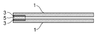
1・・・ステンレス基材(SUS304板材)
3・・・レーザ加工部
5・・・PPフィルム
7・・・治具
1... Stainless steel base material (SUS304 plate material)
3...
Claims (5)
樹脂フレームと、ステンレス基材のレーザ光照射後のシール予定部とをプレスする工程を含み、
前記レーザ光の照射エネルギー密度が110mJ/mm2以上であり、
前記プレスが、樹脂フレームと、シール予定部とが接触する部分において、樹脂が溶融した状態で行われる、燃料電池セルの製造方法。 A step of irradiating a portion of the stainless steel base material to be sealed with laser light;
Including the process of pressing the resin frame and the part of the stainless steel base material to be sealed after laser light irradiation,
The irradiation energy density of the laser beam is 110 mJ/mm 2 or more,
A method for manufacturing a fuel cell, wherein the pressing is performed in a state where the resin is molten at a portion where the resin frame and the portion to be sealed are in contact.
Priority Applications (2)
| Application Number | Priority Date | Filing Date | Title |
|---|---|---|---|
| JP2021040489A JP7435510B2 (en) | 2021-03-12 | 2021-03-12 | Manufacturing method of fuel cell |
| CN202210227295.0A CN115084571A (en) | 2021-03-12 | 2022-03-08 | Method for manufacturing fuel cell |
Applications Claiming Priority (1)
| Application Number | Priority Date | Filing Date | Title |
|---|---|---|---|
| JP2021040489A JP7435510B2 (en) | 2021-03-12 | 2021-03-12 | Manufacturing method of fuel cell |
Publications (2)
| Publication Number | Publication Date |
|---|---|
| JP2022139909A JP2022139909A (en) | 2022-09-26 |
| JP7435510B2 true JP7435510B2 (en) | 2024-02-21 |
Family
ID=83247192
Family Applications (1)
| Application Number | Title | Priority Date | Filing Date |
|---|---|---|---|
| JP2021040489A Active JP7435510B2 (en) | 2021-03-12 | 2021-03-12 | Manufacturing method of fuel cell |
Country Status (2)
| Country | Link |
|---|---|
| JP (1) | JP7435510B2 (en) |
| CN (1) | CN115084571A (en) |
Citations (7)
| Publication number | Priority date | Publication date | Assignee | Title |
|---|---|---|---|---|
| JP2007073422A (en) | 2005-09-08 | 2007-03-22 | Nissan Motor Co Ltd | Fuel cell stack and manufacturing method of separator for fuel cell |
| JP2010167475A (en) | 2009-01-26 | 2010-08-05 | Yamase Denki Kk | Metallic material joined with different kind of material and having airtightness in boundary therebetween, and method of manufacturing the same |
| JP2017027741A (en) | 2015-07-21 | 2017-02-02 | 日産自動車株式会社 | Method and device of evaluating gas barrier property of fuel cell, and method and device of manufacturing fuel cell |
| JP2017082339A (en) | 2016-12-28 | 2017-05-18 | 大日本印刷株式会社 | Stainless substrate |
| JP2019102339A (en) | 2017-12-05 | 2019-06-24 | トヨタ自動車株式会社 | Method of manufacturing fuel cell separator |
| JP2021034114A (en) | 2019-08-16 | 2021-03-01 | ソニー株式会社 | Magnetic recording medium, tape cartridge and data processing method |
| JP6879615B1 (en) | 2020-08-07 | 2021-06-02 | 睦月電機株式会社 | Method for manufacturing metal resin joints and metal resin joints |
Family Cites Families (13)
| Publication number | Priority date | Publication date | Assignee | Title |
|---|---|---|---|---|
| EP0997261B9 (en) * | 1999-01-28 | 2001-04-11 | Leister Process Technologies | Laser welding method and apparatus for joining a plurality of plastic articles with each other or with other materials |
| JP2008031393A (en) * | 2005-09-01 | 2008-02-14 | Orient Chem Ind Ltd | Laser ray transmitting colored resin composition and related art |
| JP2009078434A (en) * | 2007-09-26 | 2009-04-16 | Toyoda Gosei Co Ltd | Metal-resin composite molding and its manufacturing method |
| JP2013111881A (en) * | 2011-11-29 | 2013-06-10 | Polyplastics Co | Method of manufacturing metal component, and composite molding |
| JP2014004800A (en) * | 2012-06-27 | 2014-01-16 | Shin Kobe Electric Mach Co Ltd | Resin molded product obtained by integrating metal member and method for manufacturing the same |
| JP5843750B2 (en) * | 2012-12-14 | 2016-01-13 | ポリプラスチックス株式会社 | Metal part manufacturing method and composite molded body |
| CN103862619A (en) * | 2012-12-14 | 2014-06-18 | 宝理塑料株式会社 | Insert metal member for metal resin composite molded body, and metal resin composite molded body |
| JP6317064B2 (en) * | 2013-02-28 | 2018-04-25 | ダイセルポリマー株式会社 | Composite molded body and manufacturing method thereof |
| JP6417786B2 (en) * | 2014-08-22 | 2018-11-07 | オムロン株式会社 | Manufacturing method of bonded structure |
| CN105522780B (en) * | 2014-11-28 | 2017-08-04 | 比亚迪股份有限公司 | A kind of metal-resin composite and preparation method thereof |
| JP6103010B2 (en) * | 2015-09-15 | 2017-03-29 | 日立化成株式会社 | Method of roughening metal material |
| HUE055789T2 (en) * | 2016-09-30 | 2021-12-28 | Lg Chemical Ltd | Bonded structure of heterogeneous materials and method for manufacturing same |
| JP7017483B2 (en) * | 2018-07-20 | 2022-02-08 | トヨタ自動車株式会社 | Fuel cell manufacturing method and fuel cell |
-
2021
- 2021-03-12 JP JP2021040489A patent/JP7435510B2/en active Active
-
2022
- 2022-03-08 CN CN202210227295.0A patent/CN115084571A/en active Pending
Patent Citations (7)
| Publication number | Priority date | Publication date | Assignee | Title |
|---|---|---|---|---|
| JP2007073422A (en) | 2005-09-08 | 2007-03-22 | Nissan Motor Co Ltd | Fuel cell stack and manufacturing method of separator for fuel cell |
| JP2010167475A (en) | 2009-01-26 | 2010-08-05 | Yamase Denki Kk | Metallic material joined with different kind of material and having airtightness in boundary therebetween, and method of manufacturing the same |
| JP2017027741A (en) | 2015-07-21 | 2017-02-02 | 日産自動車株式会社 | Method and device of evaluating gas barrier property of fuel cell, and method and device of manufacturing fuel cell |
| JP2017082339A (en) | 2016-12-28 | 2017-05-18 | 大日本印刷株式会社 | Stainless substrate |
| JP2019102339A (en) | 2017-12-05 | 2019-06-24 | トヨタ自動車株式会社 | Method of manufacturing fuel cell separator |
| JP2021034114A (en) | 2019-08-16 | 2021-03-01 | ソニー株式会社 | Magnetic recording medium, tape cartridge and data processing method |
| JP6879615B1 (en) | 2020-08-07 | 2021-06-02 | 睦月電機株式会社 | Method for manufacturing metal resin joints and metal resin joints |
Also Published As
| Publication number | Publication date |
|---|---|
| CN115084571A (en) | 2022-09-20 |
| JP2022139909A (en) | 2022-09-26 |
Similar Documents
| Publication | Publication Date | Title |
|---|---|---|
| CN109148913B (en) | Fuel cell and method of manufacturing fuel cell | |
| US20110294033A1 (en) | Unitized electrochemical cell sub-assembly and the method of making the same | |
| WO2012137609A1 (en) | Electrolyte membrane-electrode assembly for fuel cells, and method for producing same | |
| JP2006310288A (en) | Mea, mea manufacturing method, and high polymer electrolyte fuel cell | |
| JP2008123883A (en) | Fuel cell, manufacturing method of fuel cell, and unit cell assembly | |
| US20190252694A1 (en) | Method for producing fuel cell module | |
| US8921010B2 (en) | Method of preparing a fuel cell unitized electrode assembly by ultrasonic welding | |
| JP2017079170A (en) | Electrolyte membrane-electrode structure with resin frame for fuel cell and method therefor | |
| JP6602244B2 (en) | Step MEA with resin frame for fuel cell and manufacturing method thereof | |
| JP6036536B2 (en) | Fuel cell frame | |
| JP7052442B2 (en) | How to make a fuel cell stack | |
| JP7435510B2 (en) | Manufacturing method of fuel cell | |
| JP7188365B2 (en) | Fuel cell and manufacturing method thereof | |
| JP7276206B2 (en) | Fuel cell and manufacturing method thereof | |
| JP2016170960A (en) | Fuel battery single cell | |
| JP7367711B2 (en) | Fuel cell manufacturing method and fuel cell | |
| CN113714209B (en) | Method for manufacturing fuel cell | |
| US11710842B2 (en) | Manufacturing method for fuel cell | |
| JP7205381B2 (en) | Fuel cell manufacturing method | |
| JP2013091254A (en) | Method for welding resin material, and device therefor | |
| JP2014099316A (en) | Assembly for fuel cell and method for manufacturing the same | |
| JP2020173899A (en) | Manufacturing method of fuel cell | |
| JP2019192326A (en) | Manufacturing method of fuel cell | |
| JP3660205B2 (en) | Fuel cell and manufacturing method thereof | |
| JP2021034144A (en) | Method for manufacturing fuel cell |
Legal Events
| Date | Code | Title | Description |
|---|---|---|---|
| A621 | Written request for application examination |
Free format text: JAPANESE INTERMEDIATE CODE: A621 Effective date: 20230323 |
|
| A977 | Report on retrieval |
Free format text: JAPANESE INTERMEDIATE CODE: A971007 Effective date: 20231129 |
|
| TRDD | Decision of grant or rejection written | ||
| A01 | Written decision to grant a patent or to grant a registration (utility model) |
Free format text: JAPANESE INTERMEDIATE CODE: A01 Effective date: 20240109 |
|
| A61 | First payment of annual fees (during grant procedure) |
Free format text: JAPANESE INTERMEDIATE CODE: A61 Effective date: 20240122 |
|
| R151 | Written notification of patent or utility model registration |
Ref document number: 7435510 Country of ref document: JP Free format text: JAPANESE INTERMEDIATE CODE: R151 |