JP7428552B2 - guide wire - Google Patents
guide wire Download PDFInfo
- Publication number
- JP7428552B2 JP7428552B2 JP2020041613A JP2020041613A JP7428552B2 JP 7428552 B2 JP7428552 B2 JP 7428552B2 JP 2020041613 A JP2020041613 A JP 2020041613A JP 2020041613 A JP2020041613 A JP 2020041613A JP 7428552 B2 JP7428552 B2 JP 7428552B2
- Authority
- JP
- Japan
- Prior art keywords
- resin layer
- guide wire
- proximal end
- coil body
- wire
- Prior art date
- Legal status (The legal status is an assumption and is not a legal conclusion. Google has not performed a legal analysis and makes no representation as to the accuracy of the status listed.)
- Active
Links
Images


Classifications
-
- A—HUMAN NECESSITIES
- A61—MEDICAL OR VETERINARY SCIENCE; HYGIENE
- A61M—DEVICES FOR INTRODUCING MEDIA INTO, OR ONTO, THE BODY; DEVICES FOR TRANSDUCING BODY MEDIA OR FOR TAKING MEDIA FROM THE BODY; DEVICES FOR PRODUCING OR ENDING SLEEP OR STUPOR
- A61M25/00—Catheters; Hollow probes
- A61M25/01—Introducing, guiding, advancing, emplacing or holding catheters
- A61M25/09—Guide wires
- A61M2025/09058—Basic structures of guide wires
- A61M2025/09083—Basic structures of guide wires having a coil around a core
- A61M2025/09091—Basic structures of guide wires having a coil around a core where a sheath surrounds the coil at the distal part
-
- A—HUMAN NECESSITIES
- A61—MEDICAL OR VETERINARY SCIENCE; HYGIENE
- A61M—DEVICES FOR INTRODUCING MEDIA INTO, OR ONTO, THE BODY; DEVICES FOR TRANSDUCING BODY MEDIA OR FOR TAKING MEDIA FROM THE BODY; DEVICES FOR PRODUCING OR ENDING SLEEP OR STUPOR
- A61M25/00—Catheters; Hollow probes
- A61M25/01—Introducing, guiding, advancing, emplacing or holding catheters
- A61M25/09—Guide wires
- A61M2025/09133—Guide wires having specific material compositions or coatings; Materials with specific mechanical behaviours, e.g. stiffness, strength to transmit torque
-
- A—HUMAN NECESSITIES
- A61—MEDICAL OR VETERINARY SCIENCE; HYGIENE
- A61M—DEVICES FOR INTRODUCING MEDIA INTO, OR ONTO, THE BODY; DEVICES FOR TRANSDUCING BODY MEDIA OR FOR TAKING MEDIA FROM THE BODY; DEVICES FOR PRODUCING OR ENDING SLEEP OR STUPOR
- A61M25/00—Catheters; Hollow probes
- A61M25/01—Introducing, guiding, advancing, emplacing or holding catheters
- A61M25/09—Guide wires
- A61M2025/09175—Guide wires having specific characteristics at the distal tip
-
- A—HUMAN NECESSITIES
- A61—MEDICAL OR VETERINARY SCIENCE; HYGIENE
- A61M—DEVICES FOR INTRODUCING MEDIA INTO, OR ONTO, THE BODY; DEVICES FOR TRANSDUCING BODY MEDIA OR FOR TAKING MEDIA FROM THE BODY; DEVICES FOR PRODUCING OR ENDING SLEEP OR STUPOR
- A61M2205/00—General characteristics of the apparatus
- A61M2205/02—General characteristics of the apparatus characterised by a particular materials
- A61M2205/0238—General characteristics of the apparatus characterised by a particular materials the material being a coating or protective layer
Landscapes
- Health & Medical Sciences (AREA)
- Life Sciences & Earth Sciences (AREA)
- Biophysics (AREA)
- Pulmonology (AREA)
- Engineering & Computer Science (AREA)
- Anesthesiology (AREA)
- Biomedical Technology (AREA)
- Heart & Thoracic Surgery (AREA)
- Hematology (AREA)
- Animal Behavior & Ethology (AREA)
- General Health & Medical Sciences (AREA)
- Public Health (AREA)
- Veterinary Medicine (AREA)
- Media Introduction/Drainage Providing Device (AREA)
Description
本発明は、ガイドワイヤに関する。 TECHNICAL FIELD The present invention relates to guidewires.
血管にカテーテル等の医療用デバイスを挿入する際に用いられるガイドワイヤが知られている。このようなガイドワイヤでは、曲げに対する柔軟性や復元性を有することのほか、カテーテルや内視鏡等の併用デバイスに対する摺動性の向上や、ガイドワイヤを破損しにくくすることによる安全性の向上が望まれている。例えば、特許文献1には、ガイドワイヤにおいて、ワイヤ本体の先端部の外周を覆う樹脂被覆層の基端側に、樹脂被覆層の基端部とワイヤ本体との間の段差空間を埋めるように設けられた環状部材を備えることが記載されている。例えば、特許文献2には、ガイドワイヤにおいて、コア部材と螺旋形コイルの間に配置された第1ポリマー層と、第1ポリマー層の外側表面の周囲に配置された第2ポリマー層とを備えることが記載されている。
2. Description of the Related Art Guide wires are known that are used when inserting medical devices such as catheters into blood vessels. In addition to having flexibility and restorability against bending, such guidewires also have improved sliding properties against combined devices such as catheters and endoscopes, and improved safety by making the guidewires less likely to break. is desired. For example,
しかし、特許文献1に記載のガイドワイヤでは、樹脂被覆層と環状部材との接触面の面積が小さいため、ガイドワイヤの長手方向に沿ったせん断応力が付与された際に、この接触面において樹脂被覆層と環状部材とが分離する虞があった。また、特許文献2に記載のガイドワイヤでは、螺旋形コイルの先端から基端までの全体が、第1ポリマー層と第2ポリマー層に覆われているため、曲げに対する柔軟性に劣るという課題があった。なお、このような課題は、血管系に限らず、リンパ腺系、胆道系、尿路系、気道系、消化器官系、分泌腺及び生殖器官等、人体内の各器官に挿入されるガイドワイヤに共通する。
However, in the guide wire described in
本発明は、上述の課題の少なくとも一部を解決するためになされたものであり、柔軟性を有すると共に、破損しづらく安全性を向上させたガイドワイヤを提供することを目的とする。 The present invention has been made to solve at least part of the above-mentioned problems, and an object of the present invention is to provide a guidewire that is flexible, difficult to break, and has improved safety.
本発明は、上述の課題の少なくとも一部を解決するためになされたものであり、以下の形態として実現することが可能である。 The present invention has been made to solve at least part of the above-mentioned problems, and can be realized as the following forms.
(1)本発明の一形態によれば、ガイドワイヤが提供される。このガイドワイヤは、コアワイヤと、前記コアワイヤの一部を被覆する第1の樹脂層と、前記コアワイヤの他の一部と、前記第1の樹脂層の外側に巻き回されたコイル体と、前記コイル体を被覆する第2の樹脂層と、を備え、前記コイル体の一部は、前記第1の樹脂層と前記第2の樹脂層に埋設されている、ガイドワイヤ。 (1) According to one embodiment of the present invention, a guidewire is provided. This guide wire includes a core wire, a first resin layer that covers a part of the core wire, another part of the core wire, a coil body wound around the outside of the first resin layer, and a first resin layer that covers a part of the core wire. a second resin layer covering a coil body, a part of the coil body being embedded in the first resin layer and the second resin layer.
この構成によれば、ガイドワイヤは、コイル体の一部が、第1の樹脂層と第2の樹脂層に埋設された構成を有している。すなわち、ガイドワイヤは、第1の樹脂層と第2の樹脂層とが、それぞれコイル体に接触した接触面において、コイル体を介して結合された部分(以降「間接結合部分」とも呼ぶ)と、第1の樹脂層と第2の樹脂層とが、第1及び第2の樹脂層の接触面において直接結合された部分(以降「直接結合部分」とも呼ぶ)と、を有する。このため、直接結合部分のみしか有さない構成と比較して、結合部分(換言すれば、第1の樹脂層と第2の樹脂層との結合に寄与する部材同士の接触面)の面積を大きくすることができ、第1の樹脂層と第2の樹脂層との結合強度を向上できる。また、第1の樹脂層と第2の樹脂層とがコイル体を介して結合された間接結合部分を有することによって、ガイドワイヤの長手方向に沿ったせん断応力が付与された場合であっても、第1の樹脂層と第2の樹脂層とが分離しづらい。さらに、第1の樹脂層と第2の樹脂層とに埋設されているのはコイル体の一部のみであるため、コイル体の先端から基端までの全体が樹脂層に埋設されている構成と比較して、曲げに対する柔軟性を付与することができる。これらの結果、本形態のガイドワイヤによれば、柔軟性を有すると共に、破損しづらく安全性を向上させたガイドワイヤを提供できる。 According to this configuration, the guide wire has a configuration in which a portion of the coil body is embedded in the first resin layer and the second resin layer. That is, the guide wire has a portion where the first resin layer and the second resin layer are bonded via the coil body (hereinafter also referred to as an "indirectly bonded portion") at the contact surfaces where the first resin layer and the second resin layer are in contact with the coil body. , the first resin layer and the second resin layer have a portion (hereinafter also referred to as a “directly bonded portion”) in which the first resin layer and the second resin layer are directly bonded at the contact surfaces of the first and second resin layers. Therefore, compared to a configuration that only has a direct bonding portion, the area of the bonding portion (in other words, the contact surface between the members that contribute to bonding the first resin layer and the second resin layer) is reduced. The bonding strength between the first resin layer and the second resin layer can be improved. Furthermore, since the first resin layer and the second resin layer have an indirect joint portion where the first resin layer and the second resin layer are joined via the coil body, even if shear stress is applied along the longitudinal direction of the guide wire, , the first resin layer and the second resin layer are difficult to separate. Furthermore, since only a portion of the coil body is buried in the first resin layer and the second resin layer, the entire coil body from the tip to the base end is buried in the resin layer. Flexibility against bending can be imparted compared to the above. As a result, according to the guide wire of this embodiment, it is possible to provide a guide wire that has flexibility, is difficult to break, and has improved safety.
(2)上記形態のガイドワイヤにおいて、前記第2の樹脂層は、前記第1の樹脂層よりも硬度が低くてもよい。
この構成によれば、第2の樹脂層は第1の樹脂層よりも硬度が低いため、第2の樹脂層と第2の樹脂層に被覆されたコイル体とを柔軟に構成することができ、ガイドワイヤの柔軟性をより一層向上できる。また、第1の樹脂層の硬度は、第2の樹脂層の硬度以上であるため、第1の樹脂層を、コイル体の一部と、コアワイヤの一部とを保護する保護部材として機能させることができる。
(2) In the guide wire of the above embodiment, the second resin layer may have a lower hardness than the first resin layer.
According to this configuration, since the second resin layer has lower hardness than the first resin layer, the second resin layer and the coil body covered with the second resin layer can be configured flexibly. , the flexibility of the guide wire can be further improved. Moreover, since the hardness of the first resin layer is greater than or equal to the hardness of the second resin layer, the first resin layer functions as a protective member that protects a part of the coil body and a part of the core wire. be able to.
(3)上記形態のガイドワイヤにおいて、前記第1の樹脂層の基端側の端部は、前記第2の樹脂層の基端側の端部よりも、前記コアワイヤの基端側に位置していてもよい。
この構成によれば、第1の樹脂層の基端側の端部は、第2の樹脂層の基端側の端部よりも、コアワイヤの基端側に位置している。このため、第1の樹脂層を、コイル体の基端側の端部と、コイル体の基端側の端部に対応するコアワイヤの一部とを保護する保護部材として機能させることができる。
(3) In the guide wire of the above embodiment, the proximal end of the first resin layer is located closer to the proximal side of the core wire than the proximal end of the second resin layer. You can leave it there.
According to this configuration, the proximal end of the first resin layer is located closer to the proximal end of the core wire than the proximal end of the second resin layer. Therefore, the first resin layer can function as a protection member that protects the proximal end of the coil body and a portion of the core wire corresponding to the proximal end of the coil body.
(4)上記形態のガイドワイヤにおいて、前記第1の樹脂層の基端側の端部は、前記コアワイヤの基端側に向かうにつれて厚さが薄くなっていてもよい。
この構成によれば、第1の樹脂層の基端側の端部は、コアワイヤの基端側に向かうにつれて厚さが薄くなっているため、カテーテルや内視鏡等の併用デバイスに対する引っ掛かりを抑制することができ、併用デバイスに対する摺動性を向上できる。
(4) In the guide wire of the above embodiment, the proximal end of the first resin layer may be thinner toward the proximal end of the core wire.
According to this configuration, the thickness of the proximal end of the first resin layer becomes thinner toward the proximal end of the core wire, which prevents it from being caught on a combined device such as a catheter or an endoscope. It is possible to improve the slidability with respect to the device used in combination.
(5)上記形態のガイドワイヤにおいて、前記第1の樹脂層は、基端側において、前記第1の樹脂層に前記コイル体の基端部の全てが埋設された内包部を有し、前記内包部の先端より先端側にのみ、前記第2の樹脂層が配置されていてもよい。
この構成によれば、第1の樹脂層は、基端側において、第1の樹脂層にコイル体の基端部の全てが埋設された内包部を有している。このため、第1の樹脂層の硬度を第2の樹脂層の硬度以上とすることで、コイル体の基端側の端部と、コイル体の基端部に対応するコアワイヤの一部とを保護する保護能力を向上できる。また、第1の樹脂層の基端側の端部の厚さを、基端側に向かうにつれて徐々に薄くする際の加工が容易となる。
(5) In the guide wire of the above embodiment, the first resin layer has an inner envelope portion on the proximal end side in which the entire proximal end portion of the coil body is embedded in the first resin layer, and The second resin layer may be disposed only on the distal end side of the inner packaging portion.
According to this configuration, the first resin layer has, on the proximal end side, an inner envelope portion in which the entire proximal end portion of the coil body is embedded in the first resin layer. Therefore, by making the hardness of the first resin layer higher than the hardness of the second resin layer, the proximal end of the coil body and the part of the core wire corresponding to the proximal end of the coil body can be separated. You can improve your protection ability. In addition, processing is facilitated when the thickness of the proximal end of the first resin layer is gradually reduced toward the proximal end.
(6)上記形態のガイドワイヤにおいて、前記コアワイヤは、前記第1の樹脂層の基端側の端部と接する位置に、拡径した突起部を有していてもよい。
この構成によれば、コアワイヤは、第1の樹脂層の基端側の端部と接する位置に、拡径した突起部を有している。このため、コアワイヤの突起部によって、第1の樹脂層の基端側の端部を保護することができ、第1の樹脂層の基端部の剥離を抑制できる。また、ガイドワイヤに対して長手方向に沿ったせん断応力が付与された際の素線(コイル体を構成する素線)の動きを、コアワイヤの突起部によって規制することができる。この結果、より一層破損しづらく安全性を向上させたガイドワイヤを提供できる。
(6) In the guide wire of the above embodiment, the core wire may have a protrusion with an enlarged diameter at a position in contact with the proximal end of the first resin layer.
According to this configuration, the core wire has a protrusion with an enlarged diameter at a position in contact with the proximal end of the first resin layer. Therefore, the protrusion of the core wire can protect the proximal end of the first resin layer, and prevent the proximal end of the first resin layer from peeling off. Further, the movement of the wire (the wire forming the coil body) when shear stress is applied to the guide wire in the longitudinal direction can be restricted by the protrusion of the core wire. As a result, it is possible to provide a guide wire that is more difficult to break and has improved safety.
(7)上記形態のガイドワイヤにおいて、前記突起部は、基端側から先端側にかけて外径が縮径した縮径部を有しており、前記第1の樹脂層の基端側の端部は、前記縮径部に接して設けられていてもよい。
この構成によれば、第1の樹脂層の基端側の端部は、突起部の縮径部に接して設けられている。このため、第1の樹脂層の基端側の端部を確実に保護することができると共に、ガイドワイヤに対して長手方向に沿ったせん断応力が付与された際の応力集中を抑制して、コアワイヤにキンクが生じる虞を低減できる。また、突起部よりも先端側においてコアワイヤが露出することに伴う段差の発生が抑制されるため、併用デバイスに対する引っ掛かりを抑制することができ、併用デバイスに対する摺動性を向上できる。
(7) In the guide wire of the above embodiment, the protrusion has a reduced diameter portion whose outer diameter decreases from the proximal end to the distal end, and the proximal end of the first resin layer may be provided in contact with the reduced diameter portion.
According to this configuration, the proximal end of the first resin layer is provided in contact with the reduced diameter portion of the protrusion. Therefore, the proximal end of the first resin layer can be reliably protected, and stress concentration when shear stress is applied to the guide wire in the longitudinal direction can be suppressed. It is possible to reduce the possibility that kinks will occur in the core wire. Further, since the occurrence of a step caused by the core wire being exposed on the tip side of the protrusion is suppressed, it is possible to suppress the wire from being caught on the combined device, and to improve the slidability with respect to the combined device.
(8)上記形態のガイドワイヤでは、さらに、前記第1の樹脂層よりも先端側において、前記コイル体と前記コアワイヤとの間に設けられ、前記コイル体の他の一部が埋設された規制部を備えてもよい。
この構成によれば、ガイドワイヤはさらに、第1の樹脂層よりも先端側において、コイル体とコアワイヤとの間に設けられ、コイル体の他の一部が埋設された規制部を備える。このため、ガイドワイヤに対して長手方向に沿ったせん断応力が付与された際の素線(コイル体を構成する素線)の動きを、規制部によって規制することで、より一層破損しづらく安全性を向上させたガイドワイヤを提供できる。
(8) In the guide wire of the above embodiment, a regulation further provided between the coil body and the core wire on the distal side side of the first resin layer, and in which another part of the coil body is embedded. It may also include a section.
According to this configuration, the guide wire further includes a regulating portion provided between the coil body and the core wire on the distal side of the first resin layer, and in which another part of the coil body is embedded. Therefore, by regulating the movement of the strands (the strands that make up the coil body) when shear stress is applied to the guide wire in the longitudinal direction, the movement of the strands (the strands that make up the coil body) is restricted by the regulating section, making it more difficult to break and safer. A guide wire with improved properties can be provided.
なお、本発明は、種々の態様で実現することが可能であり、例えば、ガイドワイヤ、複数の樹脂層により被覆されたコイル体、ガイドワイヤの製造方法、コイル体の製造方法などの形態で実現することができる。 Note that the present invention can be realized in various forms, such as a guide wire, a coil body covered with a plurality of resin layers, a method for manufacturing a guide wire, a method for manufacturing a coil body, etc. can do.
<第1実施形態>
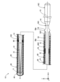
図1は、第1実施形態のガイドワイヤ1の構成を例示した説明図である。ガイドワイヤ1は、血管系、リンパ腺系、胆道系、尿路系、気道系、消化器官系、分泌腺及び生殖器官等、人体の各器官における生体管腔内に挿入される医療器具である。ガイドワイヤ1は、直接、上述した生体管腔内に挿入されてもよく、内視鏡を経由して生体管腔内に挿入されてもよい。ガイドワイヤ1は、コアワイヤ10と、コイル体20と、第2の樹脂層30と、先端接合部40と、第1の樹脂層50と、中間固定部60とを備えている。
<First embodiment>
FIG. 1 is an explanatory diagram illustrating the configuration of a
図1では、ガイドワイヤ1の中心に通る軸を軸線O(一点鎖線)で表す。図1の例では、軸線Oは、ガイドワイヤ1及び各構成部材の各中心を通る軸と一致している。しかし、軸線Oは、ガイドワイヤ1及び各構成部材の各中心軸と相違していてもよい。図1には、相互に直交するXYZ軸を図示する。X軸はガイドワイヤ1の長手方向(軸線O方向)に対応し、Y軸はガイドワイヤ1の高さ方向に対応し、Z軸はガイドワイヤ1の幅方向に対応する。図1の左側(-X軸方向)をガイドワイヤ1及び各構成部材の「先端側」と呼び、図1の右側(+X軸方向)をガイドワイヤ1及び各構成部材の「基端側」と呼ぶ。ガイドワイヤ1及び各構成部材について、先端側に位置する端部を「先端」と呼び、先端及びその近傍を「先端部」と呼ぶ。また、基端側に位置する端部を「基端」と呼び、基端及びその近傍を「基端部」と呼ぶ。先端側は生体内部へ挿入され、基端側は医師等の術者により操作される。これらの点は、図1以降においても共通する。
In FIG. 1, an axis passing through the center of the
コアワイヤ10は、基端側が太径で先端側が細径とされた、先細りした長尺形状の部材である。コアワイヤ10は、先端側から基端側に向かって順に、細径部11、第1縮径部12、第1太径部13、第2縮径部14、及び第2太径部15を有している。コアワイヤ10の各部における外径及び長さは、任意に決定できる。
The
細径部11は、コアワイヤ10の先端部に形成されている。細径部11は、コアワイヤ10の外径が最小の部分であり、略一定の外径を有する略円柱形状である。細径部11の先端には、先端接合部40が形成されている。第1縮径部12は、細径部11と第1太径部13との間に形成されている。第1縮径部12は、基端側から先端側に向かって外径が縮径したテーパー形状である。第1太径部13は、第1縮径部12と第2縮径部14との間に形成されている。第1太径部13は、細径部11の外径よりも大きな略一定の外径を有する略円柱形状である。第1太径部13の基端側の一部分は、第1の樹脂層50によって被覆されている。また、細径部11、第1縮径部12、及び第1太径部13の外周面は、コイル体20によって覆われている。
The
第2縮径部14は、第1太径部13と第2太径部15との間に形成されている。第2縮径部14は、基端側から先端側に向かって外径が縮径したテーパー形状である。第2太径部15は、コアワイヤ10の基端部に形成されている。第2太径部15は、コアワイヤ10の外径が最大の部分であり、略一定の外径を有する略円柱形状である。第2縮径部14及び第2太径部15は、コイル体20によって覆われておらず、術者がガイドワイヤ1を把持する際に用いられる。コアワイヤ10の各部(細径部11~第2太径部15)の外径及び長さは任意に決定できる。
The second reduced
コイル体20は、コアワイヤ10と第1の樹脂層50とに対して、素線21を螺旋状に巻き回して形成されている。コイル体20は、基端側から先端側に向かって略一定の外径を有する略円筒形状である。コイル体20は、先端側において、コアワイヤ10の細径部11、第1縮径部12、及び第1太径部13を、空間を空けて覆うように配置されている。また、コイル体20は、基端側において、第1の樹脂層50の外側(外周面)に食い込んだ状態で、第1の樹脂層50の外側を覆うように配置されている。なお、コイル体20は、コアワイヤ10の第2縮径部14及び第2太径部15には配置されていない。
The
本実施形態のコイル体20は、1本の素線21を単条に巻回して形成され、隣り合う素線21の間に隙間が形成された疎巻きの単条コイルである。なお、コイル体20は、複数本の素線21を多条に巻回して形成される多条コイルであってもよく、複数本の素線21を撚り合せた撚線を単条に巻回して形成される単条撚線コイルであってもよく、複数本の素線21を撚り合せた撚線を複数用い、各撚線を多条に巻回して形成される多条撚線コイルであってもよい。コイル体20の外径と内径とは、任意に決定できる。
The
コイル体20は、先端接合部40及び中間固定部60によって、コアワイヤ10に固定されている。先端接合部40は、コイル体20の先端部と、コアワイヤ10の細径部11の先端部とを接合する部材である。中間固定部60は、コイル体20の軸線O方向の中間部近傍において、コイル体20の一部分と、コアワイヤ10の第1太径部13の一部分とを固定する部材である。なお、ガイドワイヤ1には、コイル体20とコアワイヤ10とを固定するための中間固定部が、複数形成されていてもよい。
The
第1の樹脂層50は、コアワイヤ10の一部の外側(外周面)を被覆する樹脂の層である。具体的には、第1の樹脂層50は、コアワイヤ10の第1太径部13の基端側の一部分を被覆している。第1の樹脂層50は、第2の樹脂層30よりも硬度の高い樹脂材料、例えば硬質のウレタンにより形成できる。ここで「硬度」とは、マイクロビッカース硬さ試験機により測定されたマイクロビッカース硬度を用いる。
The
第1の樹脂層50は、食込部51と、肉薄部52とを有している。食込部51は、外側(外周面)にコイル体20の素線21が埋設された部分であり、素線21が埋設された凹部を除いて、略一定の外径を有している。図示の断面では、食込部51には、素線21の約半分が埋設されている。しかし、食込部51に埋設された素線21の割合は任意に変更してよい。肉薄部52は、第1の樹脂層50の基端側の端部、換言すれば、食込部51の基端側に設けられた部分であり、樹脂層の厚さが先端側から基端側に向かうにつれて徐々に薄くなっている部分である。本実施形態では、食込部51の軸線O方向の長さL1は、肉薄部52の軸線O方向の長さL2よりも長い。長さL1,L2は任意に決定できる。
The
第2の樹脂層30は、コイル体20の外側(外周面)を被覆する樹脂の層である。具体的には、第2の樹脂層30は、コイル体20の先端から基端までの全体と、先端接合部40と、第1の樹脂層50の食込部51とについて、それぞれの外側を被覆しており、第1の樹脂層50の肉薄部52の外側は被覆していない。第2の樹脂層30は、第1の樹脂層50よりも硬度の低い樹脂材料、例えば軟質のウレタンにより形成できる。
The
第2の樹脂層30のうち、コイル体20を被覆し、かつ、第1の樹脂層50を被覆しない部分には、陥没部31が形成されている。陥没部31は、隣り合う素線21の隙間に樹脂層が入り込んだ部分である。陥没部31を有することにより、第2の樹脂層30とコイル体20(具体的には素線21)との接触面積を増やすことができ、第2の樹脂層30とコイル体20との接合強度を向上できる。なお、第2の樹脂層30は、陥没部31を有していなくてもよい。また、第2の樹脂層30のうち、コイル体20と第1の樹脂層50との両方を被覆する部分では、隣り合う素線21の隙間において、第2の樹脂層30と第1の樹脂層50とが接触している。
A
このような構成を有することにより、本実施形態のガイドワイヤ1において、コイル体20の一部(具体的には、コイル体20の基端側の一部分)は、第2の樹脂層30と第1の樹脂層50とに埋設された構成となる。ガイドワイヤ1において、第1の樹脂層50の基端側の端部50pは、第2の樹脂層30の基端側の端部30pよりも基端側に位置している。
With such a configuration, in the
コアワイヤ10は、抗血栓性、可撓性、生体適合性を有することが好ましく、例えば、ステンレス合金(SUS304、SUS316等)、ニッケルチタン合金等の超弾性合金、ピアノ線、ニッケル-クロム系合金、コバルト合金、タングステン等の材料で形成できる。コイル体20の素線21は、SUS304、SUS316等のステンレス合金、ニッケルチタン合金等の超弾性合金、ピアノ線、ニッケル-クロム系合金、コバルト合金等の放射線透過性合金、金、白金、タングステン、これらの元素を含む合金(例えば、白金-ニッケル合金)等の放射線不透過性合金で形成できる。先端接合部40は、柔軟性を有することが好ましく、例えば、ポリウレタン、ポリウレタンエラストマー等の樹脂材料により形成できる。中間固定部60は、任意の接合剤、例えば、銀ロウ、金ロウ、亜鉛、Sn-Ag合金、Au-Sn合金等の金属はんだや、エポキシ系接着剤などの接着剤によって形成できる。なお、上述した各部材の材料はあくまで一例であり、上記以外の公知の材料によって形成されていてもよい。
The
ガイドワイヤ1は、例えば、次のようにして作製できる。まず、コアワイヤ10の第1太径部13の一部分に、第1の樹脂層50を形成する。次に、第1の樹脂層50の食込部51の外側(外周面)に、エポキシ系接着剤などの任意の接合剤を塗布する。次に、コアワイヤ10の細径部11~第1太径部13と、第1の樹脂層50の食込部51との外側に素線21を巻き回して、コイル体20を形成する。次に、先端接合部40と中間固定部60とを形成する。次に、コイル体20、先端接合部40、及び第1の樹脂層50の食込部51の外側(外周面)に、エポキシ系接着剤などの任意の接合剤を塗布する。次に、コイル体20、先端接合部40、及び第1の樹脂層50の食込部51の外側(外周面)に第2の樹脂層30を形成する。最後に、第2の樹脂層30の外側から加締め加工を施して、コイル体20、先端接合部40、及び第1の樹脂層50に対して、第2の樹脂層30を密着させる。なお、加締め加工は省略してもよい。
The
図2は、ガイドワイヤ1の一部分pa(図1)の拡大図である。上述したように、ガイドワイヤ1は、コイル体20の一部が、第1の樹脂層50と第2の樹脂層30に埋設された構成を有している(図1:長さL1部分)。すなわち、図2に示すように、ガイドワイヤ1は、第1の樹脂層50と第2の樹脂層30とが、それぞれコイル体20に接触した接触面において、コイル体20を介して結合された部分P1(以降「間接結合部分」とも呼ぶ)と、第1の樹脂層50と第2の樹脂層30とが、第1及び第2の樹脂層50,30の接触面において直接結合された部分P2(以降「直接結合部分」とも呼ぶ)と、を有する。また、上述したガイドワイヤ1の製造方法では、第2の樹脂層30の外側から加締め加工を施している。このため、ガイドワイヤ1において、第1の樹脂層50と第2の樹脂層30とは、間接結合部分P1における化学的結合力(接合剤による結合力)と、直接結合部分P2における化学的結合力(接合剤による結合力)と、コイル体20を介して向かい合う部分P3における機械的結合力と、により結合されている。
FIG. 2 is an enlarged view of a portion pa of the guidewire 1 (FIG. 1). As described above, the
以上のように、第1実施形態のガイドワイヤ1は、間接結合部分P1と、直接結合部分P2とを有しているため、直接結合部分のみしか有さない構成と比較して、結合部分(換言すれば、第1の樹脂層50と第2の樹脂層30との結合に寄与する部材同士の接触面)の面積を大きくすることができ、第1の樹脂層50と第2の樹脂層30との結合強度を向上できる。また、第1の樹脂層50と第2の樹脂層30とがコイル体20を介して結合された間接結合部分P1を有することによって、ガイドワイヤ1の長手方向(図2:X軸方向)に沿ったせん断応力SSが付与された場合であっても、第1の樹脂層50と第2の樹脂層30とが分離しづらい。さらに、第1の樹脂層50と第2の樹脂層30とに埋設されているのはコイル体20の一部のみであるため(図1:長さL1部分)、コイル体20の先端から基端までの全体が樹脂層に埋設されている構成と比較して、曲げに対する柔軟性を付与することができる。これらの結果、本実施形態のガイドワイヤ1によれば、柔軟性を有すると共に、破損しづらく安全性を向上させたガイドワイヤ1を提供できる。なお、本実施形態において「破損」とは、ガイドワイヤの構成部材について、一部分が剥離すること、部材同士が分離すること、ある部材が破断すること、の総称として用いる。
As described above, since the
また、第1実施形態のガイドワイヤ1において、第2の樹脂層30は第1の樹脂層50よりも硬度が低いため、第2の樹脂層30と第2の樹脂層30に被覆されたコイル体20とを柔軟に構成することができ、ガイドワイヤ1の柔軟性をより一層向上できる。また、第1の樹脂層50の硬度は、第2の樹脂層30の硬度以上であるため、第1の樹脂層50を、コイル体20の一部と、コアワイヤ10の一部とを保護する保護部材として機能させることができる。
Further, in the
さらに、第1実施形態のガイドワイヤ1において、第1の樹脂層50の基端側の端部50pは、第2の樹脂層30の基端側の端部30pよりも、コアワイヤ10の基端側に位置している(図1)。このため、第1の樹脂層50を、コイル体20の基端側の端部と、コイル体20の基端部に対応するコアワイヤ10の一部とを保護する保護部材として機能させることができる。また、第1の樹脂層50は、肉薄部52を有することによって、第1の樹脂層50の基端側の端部がコアワイヤ10の基端側に向かうにつれて厚さが薄くなっている。このため、カテーテルや内視鏡等の併用デバイスに対する引っ掛かりを抑制することができ、併用デバイスに対する摺動性を向上できる。
Furthermore, in the
<第2実施形態>
図3は、第2実施形態のガイドワイヤ1Aの構成を例示した説明図である。第2実施形態のガイドワイヤ1Aは、第1実施形態で説明した構成に加えてさらに、規制部70を備える。規制部70は、第1の樹脂層50よりも先端側において、コイル体20とコアワイヤ10(第1太径部13)との間に設けられている。規制部70の外側(外周面)には、コイル体20の素線21が埋設されている。規制部70は、素線21が埋設された凹部を除いて、略一定の外径を有している。本実施形態では、規制部70の軸線O方向の長さL3は、第1の樹脂層50の食込部51の長さL1よりも短く、肉薄部52の長さL2よりも長い。規制部70は、任意の接合剤、例えば、銀ロウ、金ロウ、亜鉛、Sn-Ag合金、Au-Sn合金等の金属はんだや、エポキシ系接着剤などの接着剤により形成できる。
<Second embodiment>
FIG. 3 is an explanatory diagram illustrating the configuration of a
このように、ガイドワイヤ1Aの構成は種々の変更が可能であり、規制部70を備えてもよい。図示の例では、規制部70の基端側の面は、第1の樹脂層50の先端側の面に接触しているが、規制部70は、第1の樹脂層50と離間して設けられてもよい。また、規制部70が設けられる長さL3は任意に決定でき、長さL1,L2との大小関係についても任意に変更できる。このような第2実施形態のガイドワイヤ1Aによっても、第1実施形態と同様の効果を奏することができる。
In this way, the configuration of the
図4は、第2実施形態のガイドワイヤ1Aの基端側の一部分を示す説明図である。第2実施形態のガイドワイヤ1Aは、第1の樹脂層50よりも先端側において、コイル体20とコアワイヤ10との間に設けられ、コイル体20の他の一部(図3:長さL3部分)が埋設された規制部70を備える。このため、ガイドワイヤ1Aに対して長手方向(X軸方向)に沿ったせん断応力SSが付与された際の、素線21(コイル体20を構成する素線21)の動きを、規制部70によって規制することで、素線21の動きの範囲を、規制部70よりも基端側の範囲AMに留めることができる。この結果、より一層破損しづらく安全性を向上させたガイドワイヤ1Aを提供できる。
FIG. 4 is an explanatory diagram showing a portion of the proximal end side of the
<第3実施形態>
図5は、第3実施形態のガイドワイヤ1Bの構成を例示した説明図である。第3実施形態のガイドワイヤ1Bは、第2実施形態で説明した構成において、第1の樹脂層50に代えて第1の樹脂層50Bを備え、第2の樹脂層30に代えて第2の樹脂層30Bを備える。
<Third embodiment>
FIG. 5 is an explanatory diagram illustrating the configuration of a
第1の樹脂層50Bは、食込部51よりも基端側、かつ、肉薄部52よりも先端側(換言すれば、食込部51と肉薄部52との間)に、内包部53を有している。内包部53には、コイル体20の基端部の全て、換言すれば、コイル体20の基端部においてコイル体20を形成する素線21の全てが埋設されている。内包部53は、略一定の外径を有しており、内包部53の外径は、第2の樹脂層30Bの外径が最大の部分と略同一である。図示の例では、内包部53の軸線O方向の長さL13は、食込部51の長さL11と略同一である。内包部53の外側(外周面)には、第2の樹脂層30Bが設けられておらず、内包部53の外側は外部に露出している。すなわち、内包部53の先端よりも先端側にのみ、第2の樹脂層30Bが配置されている。
The
このように、ガイドワイヤ1Bの構成は種々の変更が可能であり、第1の樹脂層50Bは、コイル体20の基端部の全てが埋設された内包部53を有していてもよい。図示の例では、略一定の外径を有する内包部53の基端側に、樹脂層の厚さが徐々に薄くなる肉薄部52を備えるとしたが、内包部53と肉薄部52とを一体的に構成してもよい。すなわち、内包部53において、樹脂層の厚さが徐々に薄くなる構成としてもよい。また、内包部53の外側(外周面)は、第2の樹脂層30Bにより覆われていてもよい。このような第3実施形態のガイドワイヤ1Bによっても、第1及び第2実施形態と同様の効果を奏することができる。
In this way, the configuration of the
また、第3実施形態のガイドワイヤ1Bによれば、第1の樹脂層50Bは、基端側において、第1の樹脂層50Bにコイル体20の基端部の全てが埋設された内包部53を有している。このため、第1の樹脂層50Bの硬度を第2の樹脂層30Bの硬度以上とすることで、コイル体20の基端側の端部と、コイル体20の基端側の端部に対応するコアワイヤ10の一部とを保護する保護能力を向上できる。また、第1の樹脂層50Bの基端側の端部の樹脂層の厚さを、基端側に向かうにつれて徐々に薄くする際の加工が容易となる。
Further, according to the
<第4実施形態>
図6は、第4実施形態のガイドワイヤ1Cの構成を例示した説明図である。図7は、第4実施形態のガイドワイヤ1Cの突起部16近傍の拡大図である。第4実施形態のガイドワイヤ1Cは、第3実施形態で説明した構成において、コアワイヤ10に代えてコアワイヤ10Cを備え、第1の樹脂層50Bに代えて第1の樹脂層50Cを備える。
<Fourth embodiment>
FIG. 6 is an explanatory diagram illustrating the configuration of a
コアワイヤ10Cは、第1実施形態で説明した細径部11~第2太径部15に加えてさらに、突起部16を有する。突起部16は、第1太径部13の基端側の端部近傍であって、第1の樹脂層50Cの基端側の端部50pと接する位置に設けられている。図7に示すように、突起部16の外径が最大の部分における突起部16の外径Φ2は、第1太径部13の外径Φ1よりも大きく、かつ、第1の樹脂層50Cの内包部53の外径Φ3よりも小さい。図7に示すように、突起部16は、基端側から先端側に向かって外径がΦ2からΦ1へと縮径した縮径部161と、基端側から先端側に向かって外径がΦ1からΦ2へと拡径した拡径部162とを有している。第1の樹脂層50Cは、第3実施形態で説明した構成において、肉薄部52に代えて肉薄部52Cを備える。肉薄部52Cは、基端側の端部50pが、突起部16の縮径部161上に位置している。すなわち、第1の樹脂層50Cの基端側の端部50pは、突起部16の縮径部161に接して設けられている。
The
このように、ガイドワイヤ1Cの構成は種々の変更が可能であり、突起部16を有するコアワイヤ10Cを備え、第1の樹脂層50Cの基端側の端部50pを、突起部16によって保護する構成を採用してもよい。突起部16の外径Φ2は、第1太径部13の外径Φ1よりも大きく、かつ、内包部53の外径Φ3よりも小さい限りにおいて任意に変更できる。このような第4実施形態のガイドワイヤ1Cによっても、第1~第3実施形態と同様の効果を奏することができる。
In this way, the configuration of the
また、第4実施形態のガイドワイヤ1Cによれば、コアワイヤ10Cは、第1の樹脂層50Cの基端側の端部50pと接する位置に、拡径した突起部16を有している。このため、コアワイヤ10Cの突起部16によって、第1の樹脂層50Cの基端側の端部50pを保護することができ、第1の樹脂層50Cの基端部50pの剥離を抑制できる。また、ガイドワイヤ1Cに対して長手方向(X軸方向)に沿ったせん断応力が付与された際の、素線21(コイル体20を構成する素線21)の動きを、コアワイヤ10Cの突起部16によって規制することができる。この結果、より一層破損しづらく安全性を向上させたガイドワイヤ1Cを提供できる。
Further, according to the
さらに、第4実施形態のガイドワイヤ1Cによれば、第1の樹脂層50Cの基端側の端部50pは、突起部16の縮径部161に接して設けられている。このため、第1の樹脂層50Cの基端側の端部50pを確実に保護することができると共に、ガイドワイヤ1Cに対して長手方向(X軸方向)に沿ったせん断応力が付与された際に、突起部16にかかる応力集中を抑制して、コアワイヤ10Cにキンクが生じる虞を低減できる。また、突起部16よりも先端側においてコアワイヤ10Cが露出することに伴う段差の発生が抑制されるため、併用デバイスに対する引っ掛かりを抑制することができ、併用デバイスに対する摺動性を向上できる。
Furthermore, according to the
<比較例>
図8は、比較例のガイドワイヤ1wの突起部16w近傍の拡大図である。比較例のガイドワイヤ1wは、第4実施形態の構成において、突起部16に代えて突起部16wを備え、肉薄部52Cに代えて肉薄部52wを備える。突起部16wは、第4実施形態で説明した縮径部161を有しておらず、第1の樹脂層50Cの肉薄部52wの基端部50pは、突起部16wの外径が最も大きい部分に配置されている。このような比較例のガイドワイヤ1wでは、ガイドワイヤ1wに対して長手方向(X軸方向)に沿ったせん断応力が付与された際に、突起部16wの角部EPに応力が集中して、コアワイヤ10Cにキンクが生じる虞がある。このため、第4実施形態で説明したように、第1の樹脂層50Cの基端側の端部50pは、突起部16の縮径部161に接して設けられていることが好ましい。
<Comparative example>
FIG. 8 is an enlarged view of the vicinity of the
図9は、比較例のガイドワイヤ1xの突起部16近傍の拡大図である。比較例のガイドワイヤ1xは、第4実施形態の構成において、第1の樹脂層50に代えて第1の樹脂層50xを備える。第1の樹脂層50xの基端側の端部50p(換言すれば、第1の樹脂層50xの肉薄部52の基端側の端部50p)は、第1太径部13に配置されており、突起部16の縮径部161に接して設けられていない。このような比較例のガイドワイヤ1xでは、突起部16よりも先端側において第1太径部13が露出しているため、突起部16が併用デバイスに引っ掛かる虞がある。換言すれば、比較例のガイドワイヤ1xでは、併用デバイスに対する摺動性に改善の余地がある。このため、第4実施形態で説明したように、第1の樹脂層50Cの基端側の端部50pは、突起部16の縮径部161に接して設けられていることが好ましい。
FIG. 9 is an enlarged view of the vicinity of the
図10は、比較例のガイドワイヤ1yの突起部16近傍の拡大図である。比較例のガイドワイヤ1yは、第4実施形態の構成において、第1の樹脂層50に代えて第1の樹脂層50yを備える。第1の樹脂層50yの基端側の端部50p(換言すれば、第1の樹脂層50xの肉薄部52の基端側の端部50p)は、突起部16の拡径部162に接して設けられている。このような比較例のガイドワイヤ1yでは、突起部16によって第1の樹脂層50yの基端側の端部50pが保護できず、第1の樹脂層50yの基端側の端部50pに剥離を生じる虞がある。このため、第4実施形態で説明したように、第1の樹脂層50Cの基端側の端部50pは、突起部16の縮径部161に接して設けられていることが好ましい。
FIG. 10 is an enlarged view of the vicinity of the
図11は、比較例のガイドワイヤ1zの突起部16z近傍の拡大図である。比較例のガイドワイヤ1zは、第4実施形態の構成において、突起部16に代えて突起部16zを備える。突起部16zの外径が最大の部分における突起部16zの外径Φ21は、第1の樹脂層50Cの内包部53の外径Φ3よりも大きい。このような比較例のガイドワイヤ1zでは、突起部16zが併用デバイスに引っ掛かる虞がある。換言すれば、比較例のガイドワイヤ1zでは、併用デバイスに対する摺動性に改善の余地がある。このため、第4実施形態で説明したように、突起部16の外径Φ2は、第1の樹脂層50Cの内包部53の外径Φ3よりも小さいことが好ましい。
FIG. 11 is an enlarged view of the vicinity of the
<第5実施形態>
図12は、第5実施形態のガイドワイヤ1Dの構成を例示した説明図である。第5実施形態のガイドワイヤ1Dは、第1実施形態で説明した構成において、第1の樹脂層50に代えて第1の樹脂層50Dを備える。第1の樹脂層50Dは、第2の樹脂層30と同一又は第2の樹脂層30よりも硬度の低い樹脂材料、例えば軟質のウレタンにより形成できる。このように、ガイドワイヤ1Dの構成は種々の変更が可能であり、第1の樹脂層50Dと第2の樹脂層30とが同じ材料により形成されてもよい。このような第5実施形態のガイドワイヤ1Dによっても、第1実施形態と同様の効果を奏することができる。
<Fifth embodiment>
FIG. 12 is an explanatory diagram illustrating the configuration of the
<第6実施形態>
図13は、第6実施形態のガイドワイヤ1Eの構成を例示した説明図である。第6実施形態のガイドワイヤ1Eは、第1実施形態で説明した構成において、第2の樹脂層30に代えて第2の樹脂層30Eを備える。第2の樹脂層30Eは、基端側の端部30pが、第1の樹脂層50の基端側の端部50pと略同一の場所に配置されている。すなわち、第2の樹脂層30Eは、第1の樹脂層50(食込部51及び肉薄部52)の外側(外周面)の全体を覆っている。このように、ガイドワイヤ1Eの構成は種々の変更が可能であり、第2の樹脂層30Eの基端側の端部30pは、第1の樹脂層50の基端側の端部50pと略同一の場所、又は、第1の樹脂層50の基端側の端部50pよりも基端側に配置されてもよい。このような第6実施形態のガイドワイヤ1Eによっても、第1実施形態と同様の効果を奏することができる。
<Sixth embodiment>
FIG. 13 is an explanatory diagram illustrating the configuration of a
<第7実施形態>
図14は、第7実施形態のガイドワイヤ1Fの構成を例示した説明図である。第7実施形態のガイドワイヤ1Fは、第1実施形態で説明した構成において、第1の樹脂層50に代えて第1の樹脂層50Fを備える。第1の樹脂層50Fは、第1実施形態で説明した肉薄部52を備えていない。このように、ガイドワイヤ1Fの構成は種々の変更が可能であり、肉薄部52がない第1の樹脂層50Fを用いてもよい。また、第1の樹脂層50Fの基端側の角部(図14:破線丸枠)には、任意の角度のRが付されていてもよい。このような第7実施形態のガイドワイヤ1Fによっても、第1実施形態と同様の効果を奏することができる。
<Seventh embodiment>
FIG. 14 is an explanatory diagram illustrating the configuration of the
<第8実施形態>
図15は、第8実施形態のガイドワイヤ1Gの構成を例示した説明図である。第8実施形態のガイドワイヤ1Gは、第4実施形態で説明した構成において、コアワイヤ10Cに代えてコアワイヤ10Gを備える。コアワイヤ10Gは、突起部16に代えて突起部16Gを備える。突起部16Gは、縮径部161と拡径部162とが丸みを帯びて、緩やかに接続されている。換言すれば、突起部16Gは、図示の断面において略半円形の形状を有している。このような第8実施形態のガイドワイヤ1Gによっても、第1~第4実施形態と同様の効果を奏することができる。
<Eighth embodiment>
FIG. 15 is an explanatory diagram illustrating the configuration of a
<本実施形態の変形例>
本発明は上記の実施形態に限られるものではなく、その要旨を逸脱しない範囲において種々の態様において実施することが可能であり、例えば次のような変形も可能である。
<Modification of this embodiment>
The present invention is not limited to the above-described embodiments, and can be implemented in various forms without departing from the spirit thereof. For example, the following modifications are also possible.
[変形例1]
上記第1~第8実施形態では、ガイドワイヤ1,1A~1Gの構成の一例を示した。しかし、ガイドワイヤ1の構成は種々の変更が可能である。例えば、ガイドワイヤ1は、細径部11及び第1縮径部12を有していなくてもよい。例えば、ガイドワイヤ1のコアワイヤ10は、異なる材料を用いて形成された複数のコアワイヤにより形成されてもよい。例えば、第2の樹脂層30は、先端接合部40を覆っていなくてもよく、コイル体20の全体を覆っていなくてもよい。例えば、第1の樹脂層50は、第2の樹脂層30と一体的に構成されていてもよい。例えば、第1の樹脂層50の基端側の端部50pは、コアワイヤ10の第2縮径部14に接して設けられていてもよい。
[Modification 1]
In the first to eighth embodiments described above, an example of the configuration of the
[変形例2]
上記第1~第8実施形態のガイドワイヤ1,1A~1Gの構成、及び上記変形例1のガイドワイヤ1,1A~1Gの構成は、適宜組み合わせてもよい。例えば、第1実施形態の構成において、内包部53(第3実施形態)を設けてもよく、突起部16(第4,8実施形態)を設けてもよい。例えば、第2,第3,第4実施形態で説明した構成において、第5実施形態の第1の樹脂層50Dを用いてもよく、第6実施形態の第2の樹脂層30Eを用いてもよく、第7実施形態の第1の樹脂層50Fを用いてもよい。
[Modification 2]
The configurations of the
以上、実施形態、変形例に基づき本態様について説明してきたが、上記した態様の実施の形態は、本態様の理解を容易にするためのものであり、本態様を限定するものではない。本態様は、その趣旨並びに特許請求の範囲を逸脱することなく、変更、改良され得ると共に、本態様にはその等価物が含まれる。また、その技術的特徴が本明細書中に必須なものとして説明されていなければ、適宜、削除することができる。 Although the present aspect has been described above based on the embodiments and modified examples, the embodiments of the above-described aspect are for facilitating understanding of the present aspect, and do not limit the present aspect. This aspect may be modified and improved without departing from the spirit and scope of the claims, and this aspect includes equivalents thereof. Furthermore, if the technical feature is not described as essential in this specification, it can be deleted as appropriate.
1,1A~1G,1w~1z…ガイドワイヤ
10,10C,10G…コアワイヤ
11…細径部
12…第1縮径部
13…第1太径部
14…第2縮径部
15…第2太径部
16,16G,16w,16z…突起部
20…コイル体
21…素線
30,30B,30E…第2の樹脂層
31…陥没部
40…先端接合部
50,50B~50D,50F,50x,50y…第1の樹脂層
51…食込部
52,52C,52w…肉薄部
53…内包部
60…中間固定部
70…規制部
161…縮径部
162…拡径部
1, 1A to 1G, 1w to 1z...
Claims (8)
コアワイヤと、
前記コアワイヤの一部を被覆する第1の樹脂層と、
前記コアワイヤの他の一部と、前記第1の樹脂層の外側に巻き回されたコイル体と、
前記コイル体を被覆する第2の樹脂層と、を備え、
前記コイル体の一部は、前記第1の樹脂層と前記第2の樹脂層に埋設されており、
前記ガイドワイヤは、前記第1の樹脂層と前記第2の樹脂層とが、それぞれ前記コイル体に接触した接触面において、前記コイル体を介して結合された部分である間接結合部分と、前記第1の樹脂層と前記第2の樹脂層とが、前記第1の樹脂層と前記第2の樹脂層との接触面において直接結合された部分である直接結合部分と、を有している、ガイドワイヤ。 A guide wire,
core wire and
a first resin layer covering a portion of the core wire;
another part of the core wire, a coil body wound around the outside of the first resin layer,
a second resin layer covering the coil body;
A portion of the coil body is embedded in the first resin layer and the second resin layer,
The guide wire includes: an indirect bonding portion where the first resin layer and the second resin layer are bonded via the coil body at contact surfaces where the first resin layer and the second resin layer respectively contact the coil body; The first resin layer and the second resin layer have a direct bonding portion that is a portion directly bonded at a contact surface between the first resin layer and the second resin layer. , guidewire.
前記第2の樹脂層は、前記第1の樹脂層よりも硬度が低い、ガイドワイヤ。 The guide wire according to claim 1,
In the guide wire, the second resin layer has a lower hardness than the first resin layer.
前記第1の樹脂層の基端側の端部は、前記第2の樹脂層の基端側の端部よりも、前記コアワイヤの基端側に位置している、ガイドワイヤ。 The guide wire according to claim 1 or claim 2,
The guide wire, wherein the proximal end of the first resin layer is located closer to the proximal end of the core wire than the proximal end of the second resin layer.
前記第1の樹脂層の基端側の端部は、前記コアワイヤの基端側に向かうにつれて厚さが薄くなっている、ガイドワイヤ。 The guide wire according to any one of claims 1 to 3,
In the guide wire, the proximal end of the first resin layer becomes thinner toward the proximal end of the core wire.
前記第1の樹脂層は、基端側において、前記第1の樹脂層に前記コイル体の基端部の全てが埋設された内包部を有し、
前記内包部の先端より先端側にのみ、前記第2の樹脂層が配置されている、ガイドワイヤ。 The guide wire according to any one of claims 1 to 4,
The first resin layer has, on the proximal end side, an inner envelope portion in which the entire proximal end portion of the coil body is embedded in the first resin layer;
The guide wire, wherein the second resin layer is disposed only on the distal side from the distal end of the internal capsule part.
前記コアワイヤは、前記第1の樹脂層の基端側の端部と接する位置に、拡径した突起部を有している、ガイドワイヤ。 The guide wire according to any one of claims 1 to 5,
The core wire is a guide wire, and the core wire has a protrusion with an enlarged diameter at a position in contact with a proximal end of the first resin layer.
前記突起部は、基端側から先端側にかけて外径が縮径した縮径部を有しており、
前記第1の樹脂層の基端側の端部は、前記縮径部に接して設けられている、ガイドワイヤ。 The guide wire according to claim 6,
The protrusion has a reduced diameter portion whose outer diameter decreases from the proximal end side to the distal end side,
In the guide wire, a proximal end portion of the first resin layer is provided in contact with the reduced diameter portion.
前記第1の樹脂層よりも先端側において、前記コイル体と前記コアワイヤとの間に設けられ、前記コイル体の他の一部が埋設された規制部を備える、ガイドワイヤ。 The guidewire according to any one of claims 1 to 7, further comprising:
A guide wire, comprising: a regulating portion provided between the coil body and the core wire on the distal side of the first resin layer, and in which another part of the coil body is embedded.
Priority Applications (5)
| Application Number | Priority Date | Filing Date | Title |
|---|---|---|---|
| JP2020041613A JP7428552B2 (en) | 2020-03-11 | 2020-03-11 | guide wire |
| PCT/JP2021/003202 WO2021181936A1 (en) | 2020-03-11 | 2021-01-29 | Guide wire |
| EP21768829.0A EP4119182A4 (en) | 2020-03-11 | 2021-01-29 | GUIDEWIRE |
| CN202180017041.XA CN115175723B (en) | 2020-03-11 | 2021-01-29 | Guide wire |
| US17/821,386 US20220395674A1 (en) | 2020-03-11 | 2022-08-22 | Guide wires |
Applications Claiming Priority (1)
| Application Number | Priority Date | Filing Date | Title |
|---|---|---|---|
| JP2020041613A JP7428552B2 (en) | 2020-03-11 | 2020-03-11 | guide wire |
Publications (2)
| Publication Number | Publication Date |
|---|---|
| JP2021142015A JP2021142015A (en) | 2021-09-24 |
| JP7428552B2 true JP7428552B2 (en) | 2024-02-06 |
Family
ID=77671387
Family Applications (1)
| Application Number | Title | Priority Date | Filing Date |
|---|---|---|---|
| JP2020041613A Active JP7428552B2 (en) | 2020-03-11 | 2020-03-11 | guide wire |
Country Status (5)
| Country | Link |
|---|---|
| US (1) | US20220395674A1 (en) |
| EP (1) | EP4119182A4 (en) |
| JP (1) | JP7428552B2 (en) |
| CN (1) | CN115175723B (en) |
| WO (1) | WO2021181936A1 (en) |
Families Citing this family (1)
| Publication number | Priority date | Publication date | Assignee | Title |
|---|---|---|---|---|
| WO2025197739A1 (en) * | 2024-03-22 | 2025-09-25 | 朝日インテック株式会社 | Guide wire |
Citations (5)
| Publication number | Priority date | Publication date | Assignee | Title |
|---|---|---|---|---|
| JP2005046603A (en) | 2003-07-17 | 2005-02-24 | Terumo Corp | Guide wire |
| WO2008100877A2 (en) | 2007-02-15 | 2008-08-21 | Vance Products Incorporated D/B/A, Cook Urological Incorporated | Dual stiffness wire guide |
| JP2008194185A (en) | 2007-02-09 | 2008-08-28 | Terumo Corp | Guide wire |
| WO2011118443A1 (en) | 2010-03-26 | 2011-09-29 | テルモ株式会社 | Guide wire |
| JP2011194065A (en) | 2010-03-19 | 2011-10-06 | Japan Lifeline Co Ltd | Medical guide wire |
Family Cites Families (9)
| Publication number | Priority date | Publication date | Assignee | Title |
|---|---|---|---|---|
| US6673025B1 (en) * | 1993-12-01 | 2004-01-06 | Advanced Cardiovascular Systems, Inc. | Polymer coated guidewire |
| WO1998055173A1 (en) * | 1997-06-04 | 1998-12-10 | Advanced Cardiovascular Systems, Inc. | Steerable guidewire with enhanced distal support |
| US7494474B2 (en) * | 1997-06-04 | 2009-02-24 | Advanced Cardiovascular Systems, Inc. | Polymer coated guidewire |
| EP1229957B1 (en) | 1999-11-16 | 2008-08-06 | Abbott Cardiovascular Systems, Inc. | Polymer coated guidewire |
| JP5526218B2 (en) | 2007-05-11 | 2014-06-18 | テルモ株式会社 | Guide wire |
| JP5441336B2 (en) * | 2007-05-11 | 2014-03-12 | テルモ株式会社 | Guide wire |
| JP5280666B2 (en) * | 2007-11-02 | 2013-09-04 | 株式会社パイオラックスメディカルデバイス | Guide wire |
| JP5913383B2 (en) * | 2012-02-01 | 2016-04-27 | 株式会社パイオラックスメディカルデバイス | Guide wire |
| CN112135655B (en) * | 2018-05-01 | 2023-06-13 | 朝日英达科株式会社 | guide wire |
-
2020
- 2020-03-11 JP JP2020041613A patent/JP7428552B2/en active Active
-
2021
- 2021-01-29 EP EP21768829.0A patent/EP4119182A4/en not_active Withdrawn
- 2021-01-29 CN CN202180017041.XA patent/CN115175723B/en active Active
- 2021-01-29 WO PCT/JP2021/003202 patent/WO2021181936A1/en not_active Ceased
-
2022
- 2022-08-22 US US17/821,386 patent/US20220395674A1/en not_active Abandoned
Patent Citations (5)
| Publication number | Priority date | Publication date | Assignee | Title |
|---|---|---|---|---|
| JP2005046603A (en) | 2003-07-17 | 2005-02-24 | Terumo Corp | Guide wire |
| JP2008194185A (en) | 2007-02-09 | 2008-08-28 | Terumo Corp | Guide wire |
| WO2008100877A2 (en) | 2007-02-15 | 2008-08-21 | Vance Products Incorporated D/B/A, Cook Urological Incorporated | Dual stiffness wire guide |
| JP2011194065A (en) | 2010-03-19 | 2011-10-06 | Japan Lifeline Co Ltd | Medical guide wire |
| WO2011118443A1 (en) | 2010-03-26 | 2011-09-29 | テルモ株式会社 | Guide wire |
Also Published As
| Publication number | Publication date |
|---|---|
| US20220395674A1 (en) | 2022-12-15 |
| WO2021181936A1 (en) | 2021-09-16 |
| CN115175723B (en) | 2024-08-02 |
| EP4119182A4 (en) | 2024-04-24 |
| CN115175723A (en) | 2022-10-11 |
| EP4119182A1 (en) | 2023-01-18 |
| JP2021142015A (en) | 2021-09-24 |
Similar Documents
| Publication | Publication Date | Title |
|---|---|---|
| US8585613B2 (en) | Guidewire | |
| US20090182246A1 (en) | Guide wire | |
| JPH06504706A (en) | catheter guide wire | |
| EP2937109B1 (en) | Guidewire | |
| EP3072549A1 (en) | Catheter | |
| US20120253321A1 (en) | Guidewire | |
| JP7428552B2 (en) | guide wire | |
| JP7269934B2 (en) | guide wire | |
| WO2020016986A1 (en) | Guide wire and guide wire manufacturing method | |
| US10792474B2 (en) | Guidewire | |
| JP2001009042A (en) | Catheter | |
| US12151069B2 (en) | Guide wire | |
| WO2022158418A1 (en) | Catheter | |
| JP7389123B2 (en) | guide wire | |
| WO2024116319A1 (en) | Medical device and method of manufacturing medical device | |
| US12544536B2 (en) | Electrode catheter | |
| JP7765278B2 (en) | Guidewire and method for manufacturing the guidewire | |
| US20250288780A1 (en) | Medical device | |
| US9855407B2 (en) | Guide wire | |
| US9014816B2 (en) | Medical lead with filler layer | |
| JP7366598B2 (en) | guide wire | |
| EP4147743B1 (en) | Guide wire | |
| WO2025239114A1 (en) | Catheter | |
| JP2004208704A (en) | Medical guidewire | |
| JP2024027763A (en) | Medical long body |
Legal Events
| Date | Code | Title | Description |
|---|---|---|---|
| A621 | Written request for application examination |
Free format text: JAPANESE INTERMEDIATE CODE: A621 Effective date: 20221122 |
|
| A131 | Notification of reasons for refusal |
Free format text: JAPANESE INTERMEDIATE CODE: A131 Effective date: 20230808 |
|
| A521 | Request for written amendment filed |
Free format text: JAPANESE INTERMEDIATE CODE: A523 Effective date: 20230927 |
|
| TRDD | Decision of grant or rejection written | ||
| A01 | Written decision to grant a patent or to grant a registration (utility model) |
Free format text: JAPANESE INTERMEDIATE CODE: A01 Effective date: 20240116 |
|
| A61 | First payment of annual fees (during grant procedure) |
Free format text: JAPANESE INTERMEDIATE CODE: A61 Effective date: 20240125 |
|
| R150 | Certificate of patent or registration of utility model |
Ref document number: 7428552 Country of ref document: JP Free format text: JAPANESE INTERMEDIATE CODE: R150 |