JP7425864B2 - gripper - Google Patents
gripper Download PDFInfo
- Publication number
- JP7425864B2 JP7425864B2 JP2022518694A JP2022518694A JP7425864B2 JP 7425864 B2 JP7425864 B2 JP 7425864B2 JP 2022518694 A JP2022518694 A JP 2022518694A JP 2022518694 A JP2022518694 A JP 2022518694A JP 7425864 B2 JP7425864 B2 JP 7425864B2
- Authority
- JP
- Japan
- Prior art keywords
- gripping
- gripper
- cam
- assembly
- drive mechanism
- Prior art date
- Legal status (The legal status is an assumption and is not a legal conclusion. Google has not performed a legal analysis and makes no representation as to the accuracy of the status listed.)
- Active
Links
- 230000007246 mechanism Effects 0.000 claims description 100
- 210000000078 claw Anatomy 0.000 claims description 49
- 239000000463 material Substances 0.000 claims description 25
- 238000013459 approach Methods 0.000 claims description 5
- 230000005540 biological transmission Effects 0.000 description 21
- 230000033001 locomotion Effects 0.000 description 13
- 238000000034 method Methods 0.000 description 12
- 229920002379 silicone rubber Polymers 0.000 description 12
- 230000005489 elastic deformation Effects 0.000 description 11
- 230000008569 process Effects 0.000 description 10
- 239000004945 silicone rubber Substances 0.000 description 9
- PPBRXRYQALVLMV-UHFFFAOYSA-N Styrene Chemical compound C=CC1=CC=CC=C1 PPBRXRYQALVLMV-UHFFFAOYSA-N 0.000 description 8
- 230000009471 action Effects 0.000 description 7
- 229920002725 thermoplastic elastomer Polymers 0.000 description 7
- 238000004519 manufacturing process Methods 0.000 description 6
- 239000000853 adhesive Substances 0.000 description 5
- 230000001070 adhesive effect Effects 0.000 description 5
- 230000008901 benefit Effects 0.000 description 4
- 238000005516 engineering process Methods 0.000 description 4
- 239000002184 metal Substances 0.000 description 4
- 239000004944 Liquid Silicone Rubber Substances 0.000 description 3
- 229920005560 fluorosilicone rubber Polymers 0.000 description 3
- 239000007787 solid Substances 0.000 description 3
- 239000005062 Polybutadiene Substances 0.000 description 2
- 229910000831 Steel Inorganic materials 0.000 description 2
- 239000002131 composite material Substances 0.000 description 2
- 238000006073 displacement reaction Methods 0.000 description 2
- 229920001971 elastomer Polymers 0.000 description 2
- 238000012423 maintenance Methods 0.000 description 2
- 238000012986 modification Methods 0.000 description 2
- 230000004048 modification Effects 0.000 description 2
- 238000000465 moulding Methods 0.000 description 2
- 239000010959 steel Substances 0.000 description 2
- 229920002943 EPDM rubber Polymers 0.000 description 1
- 244000043261 Hevea brasiliensis Species 0.000 description 1
- 238000005452 bending Methods 0.000 description 1
- 230000009286 beneficial effect Effects 0.000 description 1
- 230000008859 change Effects 0.000 description 1
- 238000006243 chemical reaction Methods 0.000 description 1
- 239000003795 chemical substances by application Substances 0.000 description 1
- 230000006835 compression Effects 0.000 description 1
- 238000007906 compression Methods 0.000 description 1
- 238000013461 design Methods 0.000 description 1
- 238000011161 development Methods 0.000 description 1
- 150000001993 dienes Chemical class 0.000 description 1
- 238000009826 distribution Methods 0.000 description 1
- 235000013399 edible fruits Nutrition 0.000 description 1
- 230000000694 effects Effects 0.000 description 1
- 235000013601 eggs Nutrition 0.000 description 1
- 239000013013 elastic material Substances 0.000 description 1
- 239000000806 elastomer Substances 0.000 description 1
- 238000005265 energy consumption Methods 0.000 description 1
- 239000011521 glass Substances 0.000 description 1
- 238000009776 industrial production Methods 0.000 description 1
- 229920003049 isoprene rubber Polymers 0.000 description 1
- 229920003052 natural elastomer Polymers 0.000 description 1
- 229920001194 natural rubber Polymers 0.000 description 1
- 239000004033 plastic Substances 0.000 description 1
- 229920002857 polybutadiene Polymers 0.000 description 1
- 229920002742 polystyrene-block-poly(ethylene/propylene) -block-polystyrene Polymers 0.000 description 1
- 238000003672 processing method Methods 0.000 description 1
- 239000011435 rock Substances 0.000 description 1
- 239000005060 rubber Substances 0.000 description 1
- 238000007789 sealing Methods 0.000 description 1
- 238000000926 separation method Methods 0.000 description 1
- 238000001179 sorption measurement Methods 0.000 description 1
- 229920003048 styrene butadiene rubber Polymers 0.000 description 1
- 229920000468 styrene butadiene styrene block copolymer Polymers 0.000 description 1
- 229920001935 styrene-ethylene-butadiene-styrene Polymers 0.000 description 1
- 239000000126 substance Substances 0.000 description 1
- 238000006467 substitution reaction Methods 0.000 description 1
- 238000013519 translation Methods 0.000 description 1
- 238000004073 vulcanization Methods 0.000 description 1
- 238000003466 welding Methods 0.000 description 1
Images


Classifications
-
- B—PERFORMING OPERATIONS; TRANSPORTING
- B25—HAND TOOLS; PORTABLE POWER-DRIVEN TOOLS; MANIPULATORS
- B25J—MANIPULATORS; CHAMBERS PROVIDED WITH MANIPULATION DEVICES
- B25J15/00—Gripping heads and other end effectors
- B25J15/02—Gripping heads and other end effectors servo-actuated
-
- B—PERFORMING OPERATIONS; TRANSPORTING
- B25—HAND TOOLS; PORTABLE POWER-DRIVEN TOOLS; MANIPULATORS
- B25J—MANIPULATORS; CHAMBERS PROVIDED WITH MANIPULATION DEVICES
- B25J15/00—Gripping heads and other end effectors
- B25J15/08—Gripping heads and other end effectors having finger members
- B25J15/12—Gripping heads and other end effectors having finger members with flexible finger members
-
- B—PERFORMING OPERATIONS; TRANSPORTING
- B25—HAND TOOLS; PORTABLE POWER-DRIVEN TOOLS; MANIPULATORS
- B25J—MANIPULATORS; CHAMBERS PROVIDED WITH MANIPULATION DEVICES
- B25J15/00—Gripping heads and other end effectors
- B25J15/02—Gripping heads and other end effectors servo-actuated
- B25J15/0206—Gripping heads and other end effectors servo-actuated comprising articulated grippers
- B25J15/0226—Gripping heads and other end effectors servo-actuated comprising articulated grippers actuated by cams
-
- B—PERFORMING OPERATIONS; TRANSPORTING
- B25—HAND TOOLS; PORTABLE POWER-DRIVEN TOOLS; MANIPULATORS
- B25J—MANIPULATORS; CHAMBERS PROVIDED WITH MANIPULATION DEVICES
- B25J15/00—Gripping heads and other end effectors
- B25J15/08—Gripping heads and other end effectors having finger members
-
- B—PERFORMING OPERATIONS; TRANSPORTING
- B65—CONVEYING; PACKING; STORING; HANDLING THIN OR FILAMENTARY MATERIAL
- B65G—TRANSPORT OR STORAGE DEVICES, e.g. CONVEYORS FOR LOADING OR TIPPING, SHOP CONVEYOR SYSTEMS OR PNEUMATIC TUBE CONVEYORS
- B65G47/00—Article or material-handling devices associated with conveyors; Methods employing such devices
- B65G47/74—Feeding, transfer, or discharging devices of particular kinds or types
- B65G47/90—Devices for picking-up and depositing articles or materials
- B65G47/908—Devices for picking-up and depositing articles or materials with inflatable picking-up means
Description
優先権の主張
本願は、2019年9月20日に出願された中国出願番号201921572514.9及び2019年9月20日に出願された中国出願番号201910894001.8に対する優先権を主張するものであり、その全体は参照により本明細書に組み込まれるものとする。
Claim of priority This application claims priority over China Application No. 201921572514.9 filed on September 20, 2019 and China Application No. 201910894001.8 filed on September 20, 2019. The entirety of this document is incorporated herein by reference.
本願は、物体挟持の技術分野に関し、特にグリッパーに関する。 TECHNICAL FIELD The present application relates to the technical field of object clamping, and particularly to grippers.
科学技術の発展に伴い、工業生産、日常生活において何らかの物体をグリッパーでピックアップする必要がある。グリッパーは、通常、駆動機構、伝動機構及びグリップ爪を含む。従来技術では、伝動機構及びグリップ爪は、いずれも剛性構造であり、剛性伝動機構がグリップ爪を動かして挟持動作を行う場合、グリップ爪の間の距離は一定であり、硬くない物体に損傷を及ぼす可能性が高い。すなわち、従来技術の剛性グリッパーを利用して比較的もろい物体(例えば、卵、ガラス瓶、果物など)をピックアップするとき、物体を損傷する可能性が高い。従来技術では、エアバッグ式グリッパーもあり、エアバッグ構造が異なる気圧で変形するという原理を利用して、物体の挟持を実現する。しかしながら、エアバッグ式グリッパーは、エアバッグの気密性に対する要件が極めて高く、成形プロセスが複雑であり、耐用年数が短い。また、可撓性指部を微小な寸法で製造することは難しいため、寸法が小さく、密集して配列された物品をピックアップするのに適していない。 With the development of science and technology, there is a need to pick up some objects with grippers in industrial production and daily life. A gripper typically includes a drive mechanism, a transmission mechanism, and a gripping pawl. In the conventional technology, both the transmission mechanism and the gripping claws have a rigid structure, and when the rigid transmission mechanism moves the gripping claws to perform a pinching operation, the distance between the gripping claws is constant, and there is no possibility of damaging a non-hard object. There is a high possibility that That is, when prior art rigid grippers are utilized to pick up relatively fragile objects (eg, eggs, glass bottles, fruit, etc.), there is a high possibility of damaging the objects. In the prior art, there is also an airbag type gripper, which utilizes the principle that the airbag structure deforms under different atmospheric pressures to realize the gripping of objects. However, airbag-type grippers have extremely high requirements for airbag airtightness, have a complicated molding process, and have a short service life. Furthermore, it is difficult to manufacture flexible fingers with minute dimensions, so they are not suitable for picking up articles that are small in size and closely arranged.
本願が、一定の寸法範囲内の物体をピックアップすることができるだけでなく、寸法が小さく、密集して配列された物品をピックアップすることもできるグリッパーを提供することを目的とする。 It is an object of the present application to provide a gripper that is not only able to pick up objects within a certain size range, but also able to pick up objects that are small in size and closely arranged.
本願の一態様は、グリッパーを提供し、前記グリッパーは、ハウジングと、前記ハウジング内に収容される駆動機構と、前記ハウジングの外部に部分的に設置され、少なくとも2つのグリップ爪を含むグリップ爪アセンブリとを含み、前記駆動機構は、前記グリップ爪アセンブリを動かして動作することにより、前記グリップ爪アセンブリを第1の変形状態と第2の変形状態との間で切り替えることができ、第1の変形状態では、前記少なくとも2つのグリップ爪は互いに接近し、第2の変形状態では、前記少なくとも2つのグリップ爪は互いに分離する。 One aspect of the present application provides a gripper, the gripper comprising a housing, a drive mechanism housed within the housing, and a gripping pawl assembly located partially externally of the housing and including at least two gripping pawls. and the drive mechanism is operable to move the gripping pawl assembly to switch the gripping pawl assembly between a first deformed state and a second deformed state, the first deformed In the second deformed state, the at least two gripping pawls approach each other, and in the second deformed state, the at least two gripping pawls separate from each other.
本願の実施例の技術的解決手段をより明確に説明するため、以下、実施例の説明に必要な図面を簡単に説明する。明らかなことに、以下に説明される図面は、単に本願の例又は実施例の一部にすぎず、当業者であれば、創造的な労力を要することなく、これらの図面に基づいて本願を他の類似するシナリオに応用することができる。 In order to more clearly explain the technical solutions of the embodiments of the present application, the drawings necessary for explaining the embodiments will be briefly described below. Obviously, the drawings described below are merely some examples or embodiments of the present application, and a person skilled in the art can develop the present application based on these drawings without any creative effort. It can be applied to other similar scenarios.
本願の目的、技術的解決手段及び利点をより明確にするため、以下、図面及び実施例を参照しながら、本願をさらに詳細に説明する。本明細書に説明された具体的な実施例は、本願を解釈するためのものにすぎず、本願を限定するものではないことを理解すべきである。 In order to make the objectives, technical solutions and advantages of the present application clearer, the present application will be described in more detail below with reference to drawings and examples. It is to be understood that the specific examples described herein are for the purpose of interpreting the present application only and are not intended to limit the present application.
逆に、本願は、特許請求の範囲によって定義された、本願の趣旨及び範囲で行われた任意の代替、修正、同等の方法及び解決手段を含む。さらに、公衆が本願をよりよく理解するため、以下の本願の詳細な説明において、いくつかの特定の詳細な部分を詳しく説明する。当業者であれば、これらの詳細な部分の説明がなくても本願を完全に理解することができる。 On the contrary, the present application covers any alternatives, modifications, equivalent methods and solutions made within the spirit and scope of the present application, as defined by the claims. Additionally, in order to provide the public with a better understanding of the present application, certain details are set forth in detail in the Detailed Description of the present application that follows. Those skilled in the art will be able to fully understand the present application without these detailed descriptions.
当業者であれば理解できるように、本願における「第1」及び「第2」などの用語は、異なる設備、モジュール又はパラメータなどを区別するためのものにすぎず、いかなる特定の技術的な意味を表すものではなく、それらの必然的な論理的順序を表すものでもない。 As can be understood by those skilled in the art, terms such as "first" and "second" in this application are only used to distinguish between different equipment, modules, parameters, etc., and do not have any specific technical meaning. They do not represent their necessary logical order.
従来技術では、物体をピックアップするグリッパーは、主に、伝動式グリッパー及びエアバッグ式グリッパーに分けられている。伝動式グリッパーは、通常、シリンダの圧力変化を剛性接続機構の運動動力源とすることにより、剛性接続機構が剛性グリップ爪を動かして挟持動作を行うことができる。しかしながら、剛性グリップ爪が剛性接続機構により挟持している間に、剛性グリップ爪の各指部の閉じた状態は毎回一致である。すなわち、1つの剛性グリップ爪は、1つの寸法の物体のみをマッチングして挟持することができ,例えば、直径が10mmの物体のみを挟持できる剛性グリップ爪は、直径が12mmの物体を挟持すると、物体を損傷する可能性がある。直径が10mmの物体のみを挟持できる剛性グリップ爪は、直径が8mmの物体を挟持すると、剛性グリップ爪の挟持力が不足するため、直径が8mmの物体を挟持することができない可能性がある。 In the prior art, grippers for picking up objects are mainly divided into transmission grippers and airbag grippers. A power transmission type gripper usually uses a pressure change in a cylinder as a power source for moving a rigid connecting mechanism, so that the rigid connecting mechanism can move a rigid gripping pawl to perform a clamping operation. However, the closed state of each finger of the rigid grip pawl is consistent every time the rigid grip pawl is clamped by the rigid connection mechanism. That is, one rigid gripping claw can match and grip an object of only one size. For example, a rigid gripping claw that can only grip an object with a diameter of 10 mm will hold an object with a diameter of 12 mm. May damage objects. Rigid grip claws that can only grip an object with a diameter of 10 mm may not be able to grip an object with a diameter of 8 mm because the gripping force of the rigid grip claws will be insufficient when gripping an object with a diameter of 8 mm.
エアバッグ式グリッパーは、通常、エアバッグ構造が異なる気圧で変形するという原理を利用して、物体の挟持動作を実現する。しかしながら、エアバッグ式グリッパーは、エアバッグの気密性に対する要件が極めて高く、成形プロセスが複雑であり、耐用年数が短い。また、可撓性指部を微小な寸法で製造することが難しいため、寸法が小さく、密集して配列された物品をピックアップするのに適していない。 Airbag-type grippers typically utilize the principle that the airbag structure deforms under different atmospheric pressures to achieve the gripping action of objects. However, airbag-type grippers have extremely high requirements for airbag airtightness, have a complicated molding process, and have a short service life. Furthermore, since it is difficult to manufacture flexible fingers with minute dimensions, they are not suitable for picking up articles that are small in size and closely arranged.
本願の実施例は、一定の寸法範囲内の物体をピックアップすることができるだけでなく、寸法が小さく、密集して配列された物品をピックアップすることもでき、物体を挟持する様々な操作状況に適応し、さらに物体挟持の操作効率を向上させることができるグリッパーに関する。そして、本願に係るグリッパーの挟持部は、可撓性を利用して物体を挟持することができ、すなわち、挟持部又はグリップ爪と物体との間の接触は、可撓性接触に属し、挟持力を一定の範囲内に制御することにより、剛性挟持部の大きすぎる挟持力による被挟持体への損傷を回避することができる。 The embodiments of the present application can not only pick up objects within a certain size range, but also pick up objects with small dimensions and densely arranged, and are adaptable to various operation situations in which objects are clamped. The present invention also relates to a gripper that can improve the efficiency of gripping an object. The gripping part of the gripper according to the present application can grip an object by utilizing its flexibility. That is, the contact between the gripping part or the gripping claws and the object belongs to flexible contact, and the gripping part or the gripping claw can grip the object. By controlling the force within a certain range, it is possible to avoid damage to the clamped object due to excessive clamping force of the rigid clamping parts.
図1は、本願のいくつかの実施例に係るグリッパーの正面図である。図2は、本願のいくつかの実施例に係るグリッパーの閉じた状態の正面図の断面図である。 FIG. 1 is a front view of a gripper according to some embodiments of the present application. FIG. 2 is a cross-sectional view of a closed front view of a gripper according to some embodiments of the present application.
以下、図1及び図2を参照しながら、本願の実施例に係るグリッパー100を詳細に説明する。以下の実施例は、本願を解釈するためのものにすぎず、本願を限定するものではないことに留意すべきである。
Hereinafter, a
本願のいくつかの実施例では、グリッパー100は、ハウジング110、駆動機構120及びグリップ爪アセンブリ150を含んでもよい。いくつかの実施例では、駆動機構120は、前記ハウジング110内に収容されてもよい。グリップ爪アセンブリ150は、前記ハウジング110の外部に部分的に設置されてもよい。駆動機構120は、前記グリップ爪アセンブリ150に接続されてもよい。いくつかの実施例では、前記接続は、粘着のような取り外し不能な固定接続であってもよい。いくつかの実施例では、前記接続は、ネジによる接続のような取り外し可能な固定接続であってもよい。いくつかの実施例では、駆動機構120は、前記グリップ爪アセンブリ150を直接動かして動作することにより、グリップ爪アセンブリ150を弾性変形させ、さらに前記グリップ爪アセンブリ150を第1の変形状態と第2の変形状態との間で切り替えることができる。本願の実施例は、グリップ爪アセンブリ150の弾性変形を利用して、一定の寸法範囲内の被挟持体を挟持することができる。例えば、直径が10mmの被挟持体のみを挟持できる剛性グリップ爪を本願の実施例における弾性変形を有するグリップ爪アセンブリ150に置き換えると、本願の実施例におけるグリップ爪アセンブリ150は、直径が8~10mmの被挟持体を挟持できるため、グリップ爪アセンブリ150の弾性変形は、グリッパーの実用性を向上させることができる。また、グリップ爪アセンブリ150が弾性を有するため、グリップ爪アセンブリ150は、壁厚が薄く、強度が弱いか又は内外面が損傷されやすい被挟持体への損傷を回避することができる。
In some embodiments of the present application,
いくつかの実施例では、第1の変形状態では、グリップ爪アセンブリ150の少なくとも2つのグリップ爪は、互いに接近して被挟持体を挟持することができる。第2の変形状態では、グリップ爪アセンブリ150の少なくとも2つのグリップ爪は、互いに分離して被挟持体を緩めることができる。いくつかの実施例では、第1の変形状態では、グリップ爪アセンブリ150の少なくとも2つのグリップ爪は、互いに分離して被挟持体を解放することができる。第2の変形状態では、グリップ爪アセンブリ150の少なくとも2つのグリップ爪は、互いに接近して被挟持体を挟持することができる。したがって、本願の実施例は、第1の変形状態及び第2の変形状態を使用してグリップ爪アセンブリ150の少なくとも2つのグリップ爪の相対的な位置関係を説明することにより、グリップ爪アセンブリ150が被挟持体を挟持すること、及びグリップ爪アセンブリ150が被挟持体を解放することを示す。本願の実施例は、第1の変形状態及び第2の変形状態でのグリップ爪アセンブリ150の少なくとも2つのグリップ爪の相対的な位置を限定しない。すなわち、本願の実施例における第1の変形状態と第2の変形状態とは、グリップ爪アセンブリ150の少なくとも2つのグリップ爪の2つの異なる相対的な位置関係を区別することができる。
In some embodiments, in the first deformed state, at least two gripping pawls of the gripping
いくつかの実施例では、ハウジング110は、駆動機構120を被覆してもよい。ハウジング110は、グリップ爪アセンブリ150を被覆してもよい。いくつかの実施例では、ハウジング110は、グリップ爪アセンブリ150の一部を被覆してもよい。本願に係るグリッパー100の作業環境が屋内、屋外、水中又は特殊な媒体などの特殊な環境であってもよいため、ハウジング110の材料は、グリッパー100の特殊な環境に従って決定されてもよい。本願の実施例は、ハウジング110の材料にいかなる制限も加えない。
In some embodiments,
いくつかの実施例では、駆動機構120は、前記ハウジング110内に収容されてもよい。例えば、駆動機構120は、前記ハウジング110内に完全に収容されてもよい。駆動機構120は、前記ハウジング110内に部分的に収容されてもよい。いくつかの実施例では、駆動機構120は、ハウジング110に接続されてもよい。前記接続は、螺合、係止のような取り外し可能な接続を含んでもよい。いくつかの実施例では、駆動機構120は、グリップ爪アセンブリ150に接続されてもよい。前記接続は、粘着のような固定接続であってもよい。駆動機構120は、グリップ爪アセンブリ150に動力を与えることができ、駆動機構120は、グリップ爪アセンブリ150を第1の変形状態と第2の変形状態との間で切り替えることができる。すなわち、駆動機構120は、グリップ爪アセンブリ150に被挟持体を締め付けさせるか、及び/又は被挟持体を解放することができる。本願の実施例では、駆動機構120は、空気圧駆動、電気駆動又は油圧駆動などを含んでもよい。従来技術では剛性伝動機構が剛性グリップ爪を動かして被挟持体を挟持することに比べて、本願の実施例に係るグリッパー100は、被挟持体を挟持する場合に伝動機構を必要としないことがある。したがって、本願の実施例に係るグリッパー100は、構造がより簡単であり、体積がより小さく、製造コストがより低い。同時に、伝動機構がある解決手段では、物体を挟持する過程において、伝動機構の動作中に摩擦が大きいため、駆動機構120にとって、伝動機構を動作させるのにより大きな力が必要である。したがって、本願の実施例に係るグリッパー100は、より省エネルギーであり、かつ耐用年数がより長い。また、伝動機構の動作中に摩擦が大きいため、伝動機構の部品を定期的に交換する必要があり、伝動機構の部品の価格が一般的に高いため、グリッパーの後期のメンテナンス費用の増加をもたらす。したがって、本願の実施例に係るグリッパー100は、耐用年数がより長く、より省エネルギーであり、より経済的であるという利点を有する。
In some embodiments,
いくつかの実施例では、グリップ爪アセンブリ150は、ハウジング110に回転可能に接続されてもよく、ピンによる接続などである。駆動機構120が、前記グリップ爪アセンブリ150を動かして第1の変形状態(又は第2の変形状態)から第2の変形状態(又は第1の変形状態)に切り替える場合、グリップ爪アセンブリ150の少なくとも2つのグリップ爪は、回転することができる。いくつかの実施例では、前記グリップ爪アセンブリ150は、少なくとも2つのグリップ爪を含んでもよく、例えば、前記グリップ爪アセンブリ150は、2つのグリップ爪を含んでもよい。例えば、グリップ爪アセンブリ150は、3つのグリップ爪を含んでもよい。また、例えば、グリップ爪アセンブリ150は、4つのグリップ爪を含んでもよい。本願の実施例に係るグリッパー100について、グリップ爪の数は限定されず、グリップ爪の数は、被挟持体の性質(例えば、形状など)に応じて設定されてもよい。エアバッグ式グリッパーと比べて、本願の実施例におけるグリップ爪アセンブリ150が少なくとも2つのグリップ爪の指部の末端により、被挟持体を挟持することができるため、本願の実施例に係るグリッパー100は、狭い空間で密集して配列された物体を挟持するのに適用することができる。いくつかの実施例では、グリップ爪アセンブリ150の複数のグリップ爪は、円周状に分布してもよく、円周状に均一に分布してもよい。本願の実施例に係るグリッパー100について、グリップ爪の分布は限定されず、グリップ爪アセンブリ150の複数のグリップ爪は、被挟持体を挟持することができればよい。
In some embodiments,
いくつかの実施例では、グリップ爪アセンブリ150が弾性変形するか又は2つの変形状態の間で切り替えることができるように、前記グリップ爪アセンブリ150は、可撓性材料であってもよい。いくつかの実施例では、可撓性材料自体の柔らかさ及び弾性を利用して、可撓性グリップ爪を外力作用で第1の変形状態から第2の変形状態に切り替えることができ、外力がなくなると、前記可撓性グリップ爪は、第1の変形状態に復帰することができる。いくつかの実施例では、グリップ爪アセンブリ150は、弾性金属片であってもよい。いくつかの実施例では、弾性金属片は、一定の弾性変形範囲内で曲げて変形することができ、弾性金属片が外力を受けるときに第1の外形状態から第2の外形状態に切り替えることができ、外力がなくなると、弾性金属片が第1の外形状態に自動的に復帰することができる。いくつかの実施例では、グリップ爪アセンブリ150は、さらに剛性材料を部分的に含んでもよく、グリップ爪アセンブリ150は、可撓性材料を部分的に含んでもよい。例えば、グリップ爪アセンブリ150における少なくとも1つのグリップ爪は、可撓性材料のみを含んでもよい。いくつかの実施例では、グリップ爪アセンブリ150における少なくとも1つのグリップ爪は、可撓性材料を少なくとも部分的に含んでもよい。いくつかの実施例では、グリップ爪アセンブリ150における少なくとも1つのグリップ爪は、可撓性材料のみを含んでもよい。いくつかの実施例では、グリップ爪アセンブリ150における少なくとも1つのグリップ爪が可撓性材料を部分的に含んでもよい場合、グリップ爪アセンブリ150のグリップ爪を弾性鋼片により接続することができる。いくつかの実施例では、弾性鋼片は、グリップ爪アセンブリ150に弾性を持たせることができ、グリップ爪の一部の可撓性材料は、グリップ爪アセンブリ150に可撓性を持たせることができ、グリップ爪アセンブリ150の可撓性により、グリップ爪アセンブリが被挟持体をピックアップする時に被挟持体を損傷することを回避することができる。
In some embodiments, the gripping
いくつかの実施例では、可撓性材料は、弾性材料のような一定の弾性を有する材料であってもよい。可撓性材料は、シリコーンゴムであってもよい。例えば、熱加硫型固体有機シリコーンゴム、フルオロシリコーンゴム、液状シリコーンゴムである。シリコーンゴムは、高低温安定性、広い硬度範囲(10~80ショア硬度)、耐化学品、高い密封特性、高い電気特性、耐圧縮変形などの優れた特性を有し、従来の有機エラストマーに比べて、シリコーンゴムは、特に加工製造しやすく、エネルギー消費量が小さい状況でプレス成形、圧延、押出されてもよく、製造効率が高い。引張強度は、一枚のシリコーンゴム材料サンプルを引き裂くときに各範囲単位に必要な力を指す。熱加硫型固体有機シリコーンゴムの引張強度範囲は、4.0~12.5MPaの間にあり、フルオロシリコーンゴムの引張強度範囲は、8.7~12.1MPaの間にあり、液状シリコーンゴムの引張強度範囲は、3.6~11.0MPaの間にある。伸び率とは、「限界破断伸び」又はサンプルが破断したときの元の長さに対する増加率を意味する。熱加硫型固体シリコーンゴムの一般的な伸び率範囲は、90~1120%の間にあり、フルオロシリコーンゴムの一般的な伸び率は、159~699%の間にあり、液状シリコーンゴムの一般的な伸び率は、220~900%の間にある。加工方法、硬化剤及び温度の異なる選択は、いずれもサンプルの伸び率を大幅に変更することができる。シリコーンゴムをグリップ爪アセンブリ150の材料として選択し、被挟持体の外表面又は内側面が複雑な輪郭である場合、シリコーンゴムは、大きく変形できるという特性を有し、対象物体の外表面又は内側面と効果的に貼り合わせることができるため、グリップ爪アセンブリ150に複雑な設計を予め行わずに挟持を実現することができる。いくつかの実施例では、グリップ爪アセンブリ150の材料は、ゴムであってもよい。例えば、天然ゴム、スチレンブタジエンゴム、ブタジエンゴム、イソプレンゴムなどである。いくつかの実施例では、グリップ爪アセンブリ150の材料は、熱可塑性エラストマー又は弾性複合材料であってもよい。例えば、グリップ爪アセンブリ150は、スチレン系TPE熱可塑性エラストマー(例えば、SBS、SEBS、SEPS、EPDM/スチレン、BR/スチレン、CI-IIR/スチレン、NP/スチレン)、オレフィン系TPE熱可塑性エラストマー(例えば、動的加硫型TPO)、ジエン系TPE熱可塑性エラストマーなどで製造されてもよい。また、例えば、グリップ爪アセンブリ150は、POE弾性複合材料などで製造されてもよい。本願の実施例に係るグリップ爪アセンブリ150は、可撓性材料で製造され、被挟持体を挟持する場合、グリップ爪アセンブリ150は、被挟持体との接触面積を増大させることにより、グリッパー100が被挟持体を挟持する過程において、被挟持体を落下しにくくすることができる。同時に、本願の実施例に係るグリップ爪アセンブリ150は、被挟持体へのグリップ爪アセンブリ150による挟持損傷を回避することもできる。
In some embodiments, the flexible material may be a material with a certain elasticity, such as an elastic material. The flexible material may be silicone rubber. Examples include heat-curable solid organic silicone rubber, fluorosilicone rubber, and liquid silicone rubber. Compared to conventional organic elastomers, silicone rubber has excellent properties such as high and low temperature stability, wide hardness range (10 to 80 Shore hardness), chemical resistance, high sealing properties, high electrical properties, and compression deformation resistance. Silicone rubber is particularly easy to process and manufacture, can be press-molded, rolled and extruded with low energy consumption, and has high manufacturing efficiency. Tensile strength refers to the force required for each area unit when tearing a single silicone rubber material sample. The tensile strength range of heat-curable solid organic silicone rubber is between 4.0 and 12.5 MPa, the tensile strength range of fluorosilicone rubber is between 8.7 and 12.1 MPa, and the tensile strength range of liquid silicone rubber is between 8.7 and 12.1 MPa. The tensile strength range of is between 3.6 and 11.0 MPa. Elongation refers to the "critical elongation at break" or the rate of increase relative to the original length when the sample breaks. The typical elongation range for heat-curable solid silicone rubber is between 90 and 1120%, the typical elongation range for fluorosilicone rubber is between 159 and 699%, and the typical elongation range for liquid silicone rubber is between 159 and 699%. The typical elongation rate is between 220 and 900%. Different choices of processing methods, curing agents and temperatures can all significantly alter the elongation rate of the sample. If silicone rubber is selected as the material of the
いくつかの実施例では、グリップ爪アセンブリ150の弾性変形の大きさは、グリップ爪の材料に関連することができる。例えば、グリップ爪の材料の弾性が高いほど、グリップ爪アセンブリ150が発生できる弾性変形が大きくなり、前記少なくとも2つのグリップ爪が発生できる相対変位が大きくなり、グリップ爪アセンブリ150が挟持できる被挟持体の寸法範囲が大きくなる。いくつかの実施例では、グリップ爪アセンブリ150の弾性変形の大きさは、駆動機構120が印加した力の大きさに関連することもできる。例えば、駆動機構120がシリンダである場合、グリップ爪アセンブリ150の弾性変形の大きさは、ピストンのストロークに関連する。いくつかの実施例では、駆動機構120がグリップ爪アセンブリ150に伝達する力が大きいほど、グリップ爪アセンブリ150が発生する弾性変形が大きくなり、前記少なくとも2つのグリップ爪が発生できる相対変位が大きくなる。例えば、駆動機構120がグリップ爪アセンブリ150に伝達する力が大きいほど、グリップ爪アセンブリ150の少なくとも2つのグリップ爪が互いに接近するとき、前記少なくとも2つのグリップ爪の間隔が小さくなる。また、例えば、駆動機構120がグリップ爪アセンブリ150に伝達する力が大きいほど、グリップ爪アセンブリ150の少なくとも2つのグリップ爪が互いに分離するとき、前記少なくとも2つのグリップ爪の間隔が大きくなる。いくつかの実施例では、グリップ爪アセンブリ150の弾性変形の大きさは、グリップ爪の末端(被挟持体を挟持するときに、主な挟持作用を果たすグリップ爪部位)の幾何学的特徴に関連することもできる。
In some examples, the amount of elastic deformation of the
本願の実施例に係るグリッパー100は、グリップ爪アセンブリ150の挟持方式にいかなる制限も加えない。いくつかの実施例では、グリッパー100は、グリップ爪アセンブリ150により被挟持体の外表面に接触して挟持することができる。いくつかの実施例では、グリッパー100は、グリップ爪アセンブリ150により被挟持体の内壁に接触してピックアップすることもでき、すなわち、グリップ爪アセンブリ150は、被挟持体の内側から被挟持体の内壁を支持して被挟持体をピックアップすることができる。例えば、被挟持体が内口径を有する物体(例えば、ビーカーなど)を含む場合、グリッパー100のグリップ爪アセンブリ150は、第1の変形状態(グリップ爪が互いに接近する)で被挟持体の内側に入ることができ、駆動機構120を起動すると、駆動機構120は、グリップ爪アセンブリ150を動かして第2の変形状態(グリップ爪が互いに分離する)に切り替えることができ、グリップ爪アセンブリ150が被挟持体の内壁に支持されると、被挟持体をピックアップすることができる。いくつかの実施例では、グリッパー100は、グリップ爪アセンブリ150の少なくとも1つのグリップ爪が被挟持体の外表面に接触し、かつグリップ爪アセンブリ150の少なくとも1つのグリップ爪が被挟持体の内壁に接触することにより、被挟持体を挟持することもできる。すなわち、グリッパー100は、グリップ爪アセンブリ150の少なくとも2つのグリップ爪がそれぞれ被挟持体(例えば、ビーカーなど)の内壁と外表面に接触することにより、被挟持体を挟持することができる。
The
いくつかの実施例では、グリッパー100は、接続アセンブリ130をさらに含んでもよい。前記接続アセンブリ130の一端は、前記駆動機構120に接続され、前記接続アセンブリ130の他端は、前記グリップ爪アセンブリ150に接続される。いくつかの実施例では、駆動機構120とグリップ爪アセンブリ150との間に設置された接続アセンブリ130が運動伝達又は運動変換に用いられるため、駆動機構150の運動は、グリップ爪アセンブリ150を動かして第1の変形状態から第2の変形状態に切り替えることができる。例えば、接続アセンブリ130は、駆動機構120の直線運動をグリップ爪アセンブリ150に伝達することができる。また、例えば、接続アセンブリ130は、駆動機構120の回転運動を直線運動に変換し、さらにグリップ爪アセンブリ150を動かして動作することができる。いくつかの実施例では、駆動機構が直線運動機構である場合、接続アセンブリ130は、駆動機構の直線運動をグリップ爪アセンブリ150に伝達する接続部材を含んでもよい。いくつかの実施例では、駆動機構が回転運動機構である場合、接続アセンブリ130は、カムリンクアセンブリを含んでもよい。以下、図面を参照して詳細に説明する。
In some examples,
本願の実施例に係るグリッパー100は、接続アセンブリ130にいかなる制限も加えない。本願の実施例に係るグリッパー100の駆動機構120及び接続アセンブリ130は、具体的な使用環境及び動作ニーズに応じて選択することができる。
いくつかの実施例では、前記駆動機構120は、直線駆動機構を含んでもよい。いくつかの実施例では、前記直線駆動機構は、シリンダピストン式駆動機構を含んでもよい。図2に示すように、駆動機構120は、直線駆動機構であり、駆動アセンブリ120は、シリンダケース121、シリンダピストンロッド122及びシリンダホルダ123を含んでもよい。シリンダケース121は、グリッパー100のハウジング110に固定接続されてもよい。いくつかの実施例では、固定接続は、溶接などを含んでもよい。シリンダケース121は、シリンダホルダ123及び取付ナット124によりグリッパー100のハウジング110に接続されてもよい。前記シリンダピストンロッド122は、駆動アセンブリ120の駆動作用で往復直線運動することができる。他のいくつかの実施例では、前記駆動機構は、回転駆動機構を含んでもよい。回転駆動機構の実施例では、グリップ爪アセンブリと駆動機構との間に運動変換機能を有する接続アセンブリを必要として、駆動機構の回転を直線運動に変換し、直線運動をグリップ爪アセンブリに伝達し、さらにグリップ爪アセンブリを2つの変形状態の間で切り替える。いくつかの実施例では、前記接続アセンブリは、カムアセンブリを含んでもよく、カムアセンブリは、駆動機構に接続される第1のカムを含んでもよく、グリップ爪アセンブリに接続される第2のカムをさらに含んでもよく、第1のカムと第2のカムとが嵌合されて、第1のカムの回転により第2のカムの直線運動を駆動することができる。
In some embodiments, the
図1及び図2に示すように、前記接続アセンブリ130は、接続部材を含んでもよい。前記接続部材の一端は、前記駆動機構120に固定接続されてもよく、例えば、前記接続部材の一端は、締付ナット125によりシリンダピストンロッド122に接続されてもよい。前記接続部材の他端は、前記少なくとも2つのグリップ爪に固定接続されてもよく、前記固定接続は、粘着などであってもよい。前記グリッパー100は、前記少なくとも2つのグリップ爪を前記ハウジング110に回転可能に固定する位置決め軸140をさらに含んでもよく、前記グリップ爪アセンブリ150が前記第1の変形状態から第2の変形状態に切り替えられると、前記少なくとも2つのグリップ爪は、前記位置決め軸140の周りを回転することができる。例えば、前記少なくとも2つのグリップ爪が前記位置決め軸140の周りを回転することができることは、前記少なくとも2つのグリップ爪の端部が位置決め軸140の周りを回転することができることを含んでもよい。
As shown in FIGS. 1 and 2, the
図2は、本願の実施例に記載のグリッパーの閉じた状態の正面図の断面図であり、グリッパー100は、2指グリッパーである。グリップ爪アセンブリ150の2つの端部にグリップ爪位置決め孔が形成されてもよく、ハウジング110にハウジング位置決め孔が形成されてもよく、前記位置決め軸140は、グリップ爪位置決め孔及びハウジング位置決め孔とマッチングすることができる。すなわち、グリップ爪アセンブリ150の2つの端部は、位置決め軸140によりハウジング110に回転可能に接続されてもよい。いくつかの実施例では、前記位置決め軸140の数は、前記グリップ爪アセンブリ150のグリップ爪の数と同じであってもよい。位置決め軸140の数は、グリップ爪の数に応じて決定することができ、このように、グリップ爪の挟持力を向上させることができる。位置決め軸140の数は、2個、3個又は4個などであってもよい。図2に示すように、グリッパー100は、2指グリッパーであり、グリップ爪アセンブリ150のグリップ爪の数は2個であり、位置決め軸140の数も2個であり、グリップ爪アセンブリ150の2つのグリップ爪は、グリップ爪接続部材151により接続される。前記接続は、一体接続であってもよく、粘着などであってもよい。図2は、本願のいくつかの実施例に示し、2指グリッパーの閉じた状態の正面図の断面図であり、前記接続部材の他端は、グリップ爪アセンブリ150のグリップ爪接続部材151に固定接続されてもよい。他のいくつかの実施例では、グリップ爪接続部材を採用せず、すなわち、グリップ爪アセンブリの各グリップ爪は、いずれも接続部材に直接接続されてもよい。駆動機構120のシリンダが起動され、シリンダピストンロッド122がシリンダケース121から伸び出すとき、シリンダピストンロッド122が、それに接続された接続部材を動かして外向きに押し、接続部材が、それに接続されたグリップ爪接続部材151を動かして外向きに押して、グリップ爪アセンブリ150が弾性変形し、グリップ爪アセンブリ150の2つの端部が位置決め軸140の周りを回転して、グリップ爪アセンブリ150の挟持端が開くというプロセスは、被挟持体を解放する。
FIG. 2 is a cross-sectional view of a closed front view of a gripper according to an embodiment of the present application, and the
いくつかの実施例では、前記接続アセンブリ130は、カム部及び接続ロッド131を含んでもよく、前記接続ロッド131の一端は、前記駆動機構120に接続されてもよく、駆動機構120は、直線駆動機構を含んでもよく、前記直線駆動機構は、シリンダピストン式駆動機構を含んでもよい。図3及び図4に示すように、駆動機構120は、シリンダケース121、シリンダピストンロッド122及びシリンダホルダ123を含んでもよい。シリンダケース121は、グリッパー100のハウジング110に固定接続されてもよい。固定接続は、溶接などであってもよい。シリンダケース121は、シリンダホルダ123及び取付ナット124によりグリッパー100のハウジング110に接続されてもよい。前記シリンダピストンロッド122は、駆動機構120の駆動作用で往復直線運動することができる。前記接続ロッド131の一端は、締付ナット125によりシリンダピストンロッド122に接続されてもよい。前記接続ロッド131の他端は、前記カム部に接続されてもよく、前記カム部は、前記グリップ爪アセンブリ150に当接してもよい。いくつかの実施例では、前記接続ロッド131は、前記カム部と噛合接続されてもよく、前記接続ロッド131は、第1の歯部を含んでもよく、前記カム部は、第2の歯部を含んでもよく、前記第1の歯部と前記第2の歯部が噛み合うことにより前記カム部を回転させることができる。いくつかの実施例では、前記第1の歯部及び前記第2の歯部は、複数の連続した歯を含んでもよい。駆動機構120の駆動ストロークは、接続アセンブリ130のストロークに影響を与えることができ、さらにグリップ爪アセンブリ150の弾性変形の程度に影響を与えることができる。したがって、本願の実施例は、連続した歯の数にいかなる制限も加えない。本願の実施例における連続した歯の数は、グリップ爪アセンブリ150の弾性変形の程度、駆動機構120の駆動ストローク及び/又は被挟持体の性質(例えば、被挟持体の寸法及び形状など)などに応じて選択することができる。いくつかの実施例では、前記カム部は、カム132を含んでもよく、前記カム132は、カム固定軸によりハウジング110に固定されてもよく、カム固定軸の周りを回転することができる。本願の実施例は、カム132の具体的な形状にいかなる制限も加えず、カム132は、実際の必要に応じて選択することができる。前記カム132は、第2の歯部を含んでもよく、前記第1の歯部と前記第2の歯部が噛み合うことにより前記カム132を回転させることができる。前記駆動機構120が前記接続ロッド131を駆動する場合、前記カム部(又はカム132)の回転により、前記グリップ爪アセンブリ150を動かして第1の変形状態と第2の変形状態との間で切り替えることができる。
In some embodiments, the
図3は、本願の他のいくつかの実施例に係るグリッパーの開いた状態の正面図の断面図である。図4は、本願の他のいくつかの実施例に係るグリッパーの閉じた状態の正面図の断面図である。 FIG. 3 is a cross-sectional view of an open front view of a gripper according to some other embodiments of the present application. FIG. 4 is a cross-sectional view of a closed front view of a gripper according to some other embodiments of the present application.
いくつかの実施例では、前記位置決め軸140の数は、前記グリップ爪アセンブリ150のグリップ爪の数と異なってもよい。図3及び図4に示すように、グリッパー100は、2指グリッパーである。前記グリップ爪アセンブリ150のグリップ爪の数は2個である。グリップ爪アセンブリ150の2つのグリップ爪は、グリップ爪接続部材151により接続されてもよい。前記接続は、一体接続であってもよく、粘着などであってもよい。グリップ爪接続部材151にグリップ爪位置決め孔が形成されてもよく、ハウジング110に1つのハウジング位置決め孔のみが形成されてもよく、前記グリッパー100は、位置決め軸140’をさらに含んでもよく、前記位置決め軸140’は、グリップ爪位置決め孔及びハウジング位置決め孔とマッチングすることができ、すなわち、前記位置決め軸140’は、前記ハウジング位置決め孔及び前記グリップ爪位置決め孔に固定接続されてもよい。本願の実施例では、グリップ爪アセンブリ150がグリップ爪接続部材151及び位置決め軸140’によりハウジング110に回転可能に接続されることは、同様に3指グリッパー、4指グリッパーなどの多指グリッパーに適用される。前記グリップ爪アセンブリ150は、位置決め軸140’によりハウジング110に回転可能に接続される。グリップ爪アセンブリ150が前記第1の変形状態(又は第2の変形状態)から第2の変形状態(又は第1の変形状態)に切り替えられると、前記2つのグリップ爪は、前記位置決め軸140’の周りを回転することができる。いくつかの実施例では、前記グリップ爪アセンブリ150の端部にスライダ133が設置されてもよく、スライダ133は、カム132に当接してもよい。いくつかの実施例では、前記スライダ133の材料は、剛性材料であってもよい。スライダ133の数は、グリップ爪アセンブリ150のグリップ爪の数と同じであってもよい。本願の実施例では、グリップ爪の挟持端は、グリップ爪アセンブリ150の被挟持体との接触端を指してもよい。グリップ爪の端部は、グリップ爪アセンブリ150の接触端に対向する他端を指すことができ、すなわち、グリップ爪の端部は、グリップ爪アセンブリ150の被挟持体と接触しない一端を指すことができる。スライダ133は、カム132の回転を直線運動に変換してグリップ爪アセンブリ150に伝達することにより、グリップ爪アセンブリ150を弾性変形させて第1の変形状態(又は第2の変形状態)から第2の変形状態(又は第1の変形状態)に切り替えることができる。
In some embodiments, the number of
図3は、2指グリッパーの開いた状態の正面図の断面図であり、駆動機構120が起動され、シリンダピストンロッド122がシリンダケース121から伸び出すと、シリンダピストンロッド122は、それに接続された接続ロッド131を動かして外向きに押す。接続ロッド131は、それと噛み合わされたカム132を動かしてカム固定軸の周りを回転させ、カム132は、回転中にスライダ133を外向きに押し、すなわち、カム固定軸とスライダ133との距離を増加させる。グリップ爪アセンブリ150が弾性変形して、グリップ爪アセンブリ150の2つの端部も下向きに押圧し、グリップ爪アセンブリ150のグリップ爪接続部材が位置決め軸140’の周りを回転して、グリップ爪アセンブリ150の挟持端が互いに接近するというプロセスは、被挟持体を挟持することができる。
FIG. 3 is a cross-sectional view of the open front view of the two-finger gripper, and when the
図4は、2指グリッパーの閉じた状態の正面図の断面図であり、駆動機構120が起動され、シリンダピストンロッド122がシリンダケース121に引っ込むと、シリンダピストンロッド122は、それに接続された接続ロッド131を動かして内向きに引っ張ることができる。接続ロッド131は、それと噛み合わされたカム132を動かしてカム固定軸の周りを回転させ、すなわち、カム固定軸とスライダ133との距離を短縮させることができる。カム132の回転中に、グリップ爪アセンブリ150が弾性変形するため、グリップ爪アセンブリ150のグリップ爪接続部材が位置決め軸140’の周りを回転すると同時に、グリップ爪アセンブリ150が、自体の弾性復帰力の作用で元の形状に復帰することができる。グリップ爪アセンブリ150の2つの端部が上向きに元の形状に復帰し、グリップ爪アセンブリ150の挟持端が開くというプロセスは、被挟持体を解放する。このプロセスにおいて、スライダ133は、グリップ爪アセンブリ150の弾性復帰力の作用でカム132側に移動することができ、スライダ133は、カム132の下端に当接するまで移動することができる。他の実施例では、当該グリッパーは、接続アセンブリを含まなくてもよく、直線運動する駆動機構は、直接的にグリップ爪アセンブリを動かして2つの変形状態の間で切り替え、さらに挟持又は解放の操作上の要件を満たす。
FIG. 4 is a cross-sectional view of the front view of the two-finger gripper in the closed state, when the
いくつかの実施例では、前記カム部は、同軸に固定されたカム及び歯車を含んでもよく、前記カムは、カム固定軸によりハウジング110に固定されてもよく、前記歯車は、歯車固定軸によりハウジング110に固定されてもよく、カム固定軸と歯車固定軸は、同軸に設置されてもよく、カム及び歯車は、いずれもカム固定軸及び/又は歯車固定軸の周りを回転することができる。本願の実施例は、カム及び歯車の具体的な形状にいかなる制限も加えず、カム及び歯車は、実際の必要に応じて選択することができる。前記歯車は、第2の歯部を含んでもよく、前記第1の歯部と前記第2の歯部が噛み合うことにより前記カムを回転させることができる。前記駆動機構120が前記接続ロッド131を駆動する場合、接続ロッド131の第1の歯部と歯車の第2の歯部との噛み合いにより、歯車を動かして回転させ、歯車とカムが同軸に設置されてもよいため、前記カムを動かして回転させ、カムとスライダ133が当接して前記グリップ爪アセンブリ150を動かして第1の変形状態と第2の変形状態との間で切り替えることができる。
In some embodiments, the cam portion may include a coaxially fixed cam and a gear, the cam may be fixed to the
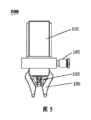
図5は、本願のいくつかの実施例に係る、離脱補助機構を有するグリッパーの正面図である。 FIG. 5 is a front view of a gripper with a detachment assist mechanism according to some embodiments of the present application.
本願の実施例に係るグリッパー100は、離脱補助装置160をさらに含んでもよい。グリッパー100を被挟持体から離脱させようとする場合、静電吸着などの原因でグリップ爪アセンブリ150を被挟持体からタイムリーに離脱させることができない可能性があり、ハウジング110に離脱補助装置160を設置することにより、グリッパー100を被挟持体から離脱させようとする場合、離脱補助装置160は、被挟持体をグリッパー100から離脱させることを補助することができる。
The
いくつかの実施例では、前記離脱補助装置160は、ガス噴出構造を含んでもよく、前記ガス噴出構造は、前記グリッパー100に設置されてもよく、また、使用状態では、前記ガス噴出構造は給排気装置に接続されてもよい。例えば、ガス噴出構造は、グリッパー100の外部に設置されたガス噴出ノズルであってもよく、取付又は使用状態では、ガス噴出ノズルは、給排気装置に接続される。具体的には、ガス噴出構造は、環状構造のノズルであってもよく、ノズルに環状に分布するガス噴出孔が形成される。取付状態では、ノズルがグリッパー100に固定接続されてもよく、環状構造のノズルがグリッパー100と同軸に設置されることにより、環状に分布するガス噴出孔は、ハウジング110の中心軸方向に沿って均一に分布し、グリップ爪アセンブリ150に向かう。グリップ爪アセンブリ150が開いた後、被挟持体とグリップ爪アセンブリ150が分離しないと、ガス噴出ノズルによりグリップ爪アセンブリ150と被挟持体との接触箇所にガスを噴出して、被挟持体に干渉を与えることにより、被挟持体を離脱させることができる。グリッパー100にガス噴出構造を設置することにより、被挟持体を離脱させる必要がある場合、ガス噴出構造を利用してグリップ爪アセンブリ150と被挟持体との接触箇所にガスを噴出することにより、グリップ爪アセンブリ150と被挟持体との離脱を補助する。
In some embodiments, the
いくつかの実施例では、前記離脱補助装置160は、伸縮可能なプッシュロッドを含んでもよく、前記伸縮可能なプッシュロッドは、前記グリッパー100に設置されてもよい。例えば、伸縮可能なプッシュロッドは、空気圧伸縮ロッドであってもよく、空気圧伸縮ロッドは、グリッパー100に取り付けられてもよく、グリッパー100と一体式構造を形成してもよい。グリップ爪アセンブリ150が開いた後、被挟持体とグリップ爪アセンブリ150が分離しないと、伸縮可能なプッシュロッドを伸び出させて、被挟持体と接触することにより、グリップ爪アセンブリ150を被挟持体から離脱させることができる。
In some embodiments, the
いくつかの実施例では、前記離脱補助装置160は、振動装置をさらに含んでもよく、前記グリッパー100は、前記振動装置に設置されてもよい。例えば、小型振動装置をグリッパー100に取り付けることができ、グリップ爪アセンブリ150が開いた後、被挟持体とグリップ爪アセンブリ150が分離しないと、小型振動装置でグリッパー100を振動させるか又は揺動させることにより、グリップ爪アセンブリ150を被挟持体から離脱させることができる。例えば、振動装置は、従来の携帯電話用の携帯電話振動器又は類似する機構又は装置であってもよい。
In some embodiments, the
本願の実施例では、プラスチックボトルのような一部の被挟持体が一定の粘性を有するため、グリッパー100が粘性のある被挟持体を所定の位置まで挟持して下ろす必要がある場合、粘性のある被挟持体が粘性によりグリップ爪に貼り付いて、グリップ爪アセンブリ150を被挟持体から離脱させることができなくなる可能性がある。このとき、離脱補助装置160により、粘性のある被挟持体をグリップ爪アセンブリ150から離脱させることができる。離脱補助装置160が設置されていないと、粘性のある被挟持体をグリップ爪アセンブリ150から手動で離脱させる必要があり、不要な人的資源を浪費するだけでなく、挟持効率にも影響を与える。したがって、離脱補助装置160は、グリッパー100の挟持効率を向上させ、グリッパー100の実用性を向上させることができる。
In the embodiment of the present application, some objects to be held, such as plastic bottles, have a certain viscosity. There is a possibility that a certain object to be held may stick to the gripping claws due to viscosity, making it impossible to remove the
本願に開示されたグリッパー100がもたらす可能性のある有益な効果は、以下の効果を含むが、これらに限定されない。
Potential beneficial effects of the
従来技術では剛性伝動機構が剛性グリップ爪を動かして被挟持体を挟持することに比べて、本願の実施例に係るグリッパー100は、被挟持体を挟持する場合に伝動機構を必要としないことがある。したがって、本願の実施例に係るグリッパー100は、構造がより簡単であり、体積がより小さく、製造コストがより低い。同時に、伝動機構の動作(被挟持体を挟持する)中に摩擦が大きいため、駆動機構120にとって、伝動機構を動作させるのにより大きな力が必要である。したがって、本願の実施例に係るリッパー100は、より省エネルギーであり、かつ耐用年数がより長い。また、伝動機構の動作中に摩擦が大きいため、伝動機構の部品を定期的に交換する必要があり、伝動機構の部品の価格が一般的に高いため、グリッパーの後期のメンテナンス費用の増加をもたらす。したがって、本願の実施例に係るグリッパー100は、耐用年数がより長く、より省エネルギーであり、より経済的であるという利点を有する。そして、本願の実施例に係るグリップ爪アセンブリ150は、可撓性材料で製造され、被挟持体を挟持する場合、グリップ爪アセンブリ150は、被挟持体との接触面積を増大させることにより、グリッパー100が被挟持体を挟持する過程において、被挟持体を落下しにくくすることができる。同時に、本願の実施例に係るグリップ爪アセンブリ150は、被挟持体へのグリップ爪アセンブリ150による挟持損傷を回避することもできる。また、本願の実施例に係るグリッパー100は、一定の寸法範囲内の物体をピックアップすることができるだけでなく、寸法が小さく、密集して配列された物品をピックアップすることもできる。
In contrast to conventional technology in which a rigid transmission mechanism moves rigid grip claws to grip an object to be held, the
以上は、本願の好ましい実施例にすぎず、本願を限定するものではなく、本願の精神及び原則内で行われたいかなる修正、同等置換及び改善などは、いずれも本願の保護範囲内に含まれるべきである。 The above are only preferred embodiments of the present application, and are not intended to limit the present application, and any modifications, equivalent substitutions, improvements, etc. made within the spirit and principles of the present application are all included within the protection scope of the present application. Should.
100 グリッパー
110 ハウジング、
120 駆動機構、
130 接続アセンブリ、
140、140’ 位置決め軸、
150 グリップ爪アセンブリ、
160 離脱補助装置、
121 シリンダケース、
122 シリンダピストンロッド、
123 シリンダホルダ、
124 取付ナット、
125 締付ナット、
131 接続ロッド、
132 カム、
133 スライダ、
151 グリップ爪接続部材
100
120 drive mechanism,
130 connection assembly;
140, 140' positioning axis,
150 grip pawl assembly,
160 Detachment aid device;
121 cylinder case,
122 cylinder piston rod,
123 cylinder holder,
124 mounting nut,
125 Tightening nut,
131 connecting rod,
132 Cam,
133 slider,
151 Grip claw connection member
Claims (12)
前記ハウジング内に収容される駆動機構と、
前記ハウジングの外部に部分的に設置され、少なくとも2つのグリップ爪を含むグリップ爪アセンブリと、
一端が前記駆動機構に接続され、他端が前記グリップ爪アセンブリに接続される接続アセンブリと、を含み、
前記駆動機構は、前記グリップ爪アセンブリを動かして動作することにより、前記グリップ爪アセンブリを第1の変形状態と第2の変形状態との間で切り替えることができ、
前記第1の変形状態では、前記少なくとも2つのグリップ爪は互いに接近し、前記第2の変形状態では、前記少なくとも2つのグリップ爪は互いに分離し、
前記接続アセンブリは、カム部及び接続ロッドを含み、前記接続ロッドの一端は、前記駆動機構に接続され、前記接続ロッドの他端は、前記カム部に接続され、前記カム部は、前記グリップ爪アセンブリに当接し、
前記駆動機構が前記接続ロッドを駆動する場合、前記カム部の回転により、前記グリップ爪アセンブリを動かして前記第1の変形状態と前記第2の変形状態との間で切り替えることができることを特徴とする、グリッパー。 housing and
a drive mechanism housed within the housing;
a gripping pawl assembly located partially on the exterior of the housing and including at least two gripping pawls;
a connection assembly connected at one end to the drive mechanism and at the other end to the grip pawl assembly;
The drive mechanism is operable to move the grip pawl assembly to switch the grip pawl assembly between a first deformed state and a second deformed state;
In the first deformed state, the at least two gripping pawls approach each other; in the second deformed state, the at least two gripping pawls separate from each other;
The connecting assembly includes a cam part and a connecting rod, one end of the connecting rod is connected to the drive mechanism, the other end of the connecting rod is connected to the cam part, and the cam part is connected to the gripping pawl. abuts the assembly;
When the drive mechanism drives the connecting rod, rotation of the cam portion can move the grip pawl assembly to switch between the first deformed state and the second deformed state. Yes, Gripper.
前記離脱補助装置は、前記グリッパーに設置され、使用状態で、給排気装置に接続されるガス噴出構造を含み、
あるいは、前記離脱補助装置は、前記グリッパーに設置される伸縮可能なプッシュロッドを含み、
あるいは、前記離脱補助装置は、前記グリッパーが設置される振動装置を含むことを特徴とする、請求項1に記載のグリッパー。 further including a disengagement aid;
The detachment auxiliary device includes a gas ejection structure installed in the gripper and connected to a supply/exhaust device in use,
Alternatively, the detachment assisting device includes an extendable push rod installed in the gripper,
Alternatively, the gripper according to claim 1, wherein the detachment assisting device includes a vibration device on which the gripper is installed.
Applications Claiming Priority (5)
| Application Number | Priority Date | Filing Date | Title |
|---|---|---|---|
| CN201910894001.8 | 2019-09-20 | ||
| CN201921572514.9 | 2019-09-20 | ||
| CN201921572514.9U CN210650716U (en) | 2019-09-20 | 2019-09-20 | Clamp |
| CN201910894001.8A CN110497434B (en) | 2019-09-20 | 2019-09-20 | Clamp |
| PCT/CN2020/116077 WO2021052448A1 (en) | 2019-09-20 | 2020-09-18 | Clamp |
Publications (2)
| Publication Number | Publication Date |
|---|---|
| JP2022549302A JP2022549302A (en) | 2022-11-24 |
| JP7425864B2 true JP7425864B2 (en) | 2024-01-31 |
Family
ID=74883898
Family Applications (1)
| Application Number | Title | Priority Date | Filing Date |
|---|---|---|---|
| JP2022518694A Active JP7425864B2 (en) | 2019-09-20 | 2020-09-18 | gripper |
Country Status (4)
| Country | Link |
|---|---|
| US (1) | US20220203558A1 (en) |
| EP (1) | EP4015165A4 (en) |
| JP (1) | JP7425864B2 (en) |
| WO (1) | WO2021052448A1 (en) |
Citations (4)
| Publication number | Priority date | Publication date | Assignee | Title |
|---|---|---|---|---|
| JP2009297886A (en) | 2008-06-17 | 2009-12-24 | Kitagawa Iron Works Co Ltd | Workpiece gripping device |
| CN106584498A (en) | 2016-11-23 | 2017-04-26 | 西北工业大学 | Grapping mechanism and method for spatial targets |
| JP2019018304A (en) | 2017-07-20 | 2019-02-07 | アイシン精機株式会社 | Gripping Hand |
| DE102018203788A1 (en) | 2018-03-13 | 2019-09-19 | Robert Bosch Gmbh | Device for gripping at least one object, in particular a pharmaceutical container |
Family Cites Families (13)
| Publication number | Priority date | Publication date | Assignee | Title |
|---|---|---|---|---|
| US4002245A (en) * | 1974-09-16 | 1977-01-11 | George Mink | Material handling apparatus having gripping means for moving articles in several directions |
| US4211123A (en) * | 1978-03-13 | 1980-07-08 | Mack Corporation | Motion conversion mechanism |
| US5895084A (en) * | 1997-02-19 | 1999-04-20 | Mauro; George | Cam operated microgripper |
| JP3292715B2 (en) * | 1999-10-12 | 2002-06-17 | エスエムシー株式会社 | Electric hand with buffer function |
| US20060161202A1 (en) * | 2003-05-26 | 2006-07-20 | Mitsubishi Denkli Kabushiki Kaisha | Electric tweezers |
| ATE429987T1 (en) * | 2007-03-14 | 2009-05-15 | Wafios Ag | GRIPPER DEVICE FOR GRABING AND HOLDING LONG-LONG WORKPIECES, ESPECIALLY IN BENDING MACHINES |
| JP5681271B1 (en) * | 2013-07-26 | 2015-03-04 | ファナック株式会社 | Robotic gripping device |
| US9914214B1 (en) * | 2016-02-22 | 2018-03-13 | X Development Llc | Preshaping for underactuated fingers |
| CN107671878B (en) * | 2017-11-16 | 2020-11-03 | 重庆大学 | Electrostatic adsorption type soft gripper with fin-like structure |
| CN108638115A (en) * | 2018-05-22 | 2018-10-12 | 苏州乔岳软件有限公司 | A kind of flexibility clamping jaw |
| CN110076808A (en) * | 2019-04-23 | 2019-08-02 | 苏州软体机器人科技有限公司 | A kind of external clamping fixture |
| CN110497434B (en) * | 2019-09-20 | 2023-06-30 | 北京软体机器人科技股份有限公司 | Clamp |
| CN210650716U (en) * | 2019-09-20 | 2020-06-02 | 苏州软体机器人科技有限公司 | Clamp |
-
2020
- 2020-09-18 EP EP20864365.0A patent/EP4015165A4/en active Pending
- 2020-09-18 WO PCT/CN2020/116077 patent/WO2021052448A1/en unknown
- 2020-09-18 JP JP2022518694A patent/JP7425864B2/en active Active
-
2022
- 2022-03-18 US US17/655,545 patent/US20220203558A1/en active Pending
Patent Citations (4)
| Publication number | Priority date | Publication date | Assignee | Title |
|---|---|---|---|---|
| JP2009297886A (en) | 2008-06-17 | 2009-12-24 | Kitagawa Iron Works Co Ltd | Workpiece gripping device |
| CN106584498A (en) | 2016-11-23 | 2017-04-26 | 西北工业大学 | Grapping mechanism and method for spatial targets |
| JP2019018304A (en) | 2017-07-20 | 2019-02-07 | アイシン精機株式会社 | Gripping Hand |
| DE102018203788A1 (en) | 2018-03-13 | 2019-09-19 | Robert Bosch Gmbh | Device for gripping at least one object, in particular a pharmaceutical container |
Also Published As
| Publication number | Publication date |
|---|---|
| JP2022549302A (en) | 2022-11-24 |
| EP4015165A4 (en) | 2022-10-26 |
| US20220203558A1 (en) | 2022-06-30 |
| WO2021052448A1 (en) | 2021-03-25 |
| EP4015165A1 (en) | 2022-06-22 |
Similar Documents
| Publication | Publication Date | Title |
|---|---|---|
| CN110497434B (en) | Clamp | |
| CN210650716U (en) | Clamp | |
| CN103659825B (en) | Bending self-locking pneumatic under-actuated robot finger device | |
| JP6976532B2 (en) | New flexible gripping head and its flexible gripping tool, and flexible gripping pen | |
| CN109048980A (en) | A kind of pneumatic software gripper of articulated type endoskeleton | |
| CN105643649A (en) | Six-joint three-finger manipulator for grabbing apples | |
| CN101554730A (en) | Articulated flexible manipulator | |
| CN107457797B (en) | Porous double-layer fluid self-adaptive robot hand device | |
| CN107175681A (en) | A kind of flexible three-finger configuration manipulator | |
| CN210100036U (en) | Internal stay formula anchor clamps with buffer structure | |
| JP7425864B2 (en) | gripper | |
| CN102756376A (en) | Finger device for underactuated robot adapting along with shapes automatically | |
| CN110497395A (en) | A kind of bidirectional-movement Pneumatic flexible actuator and its working method | |
| CN210525116U (en) | Internal stay formula anchor clamps with initiative extending structure | |
| CN205799474U (en) | Piston drives magnetic current flexible machine hand apparatus | |
| CN100348385C (en) | Pneumatic flexible finger prosthesis | |
| CN101104273A (en) | Pneumatic driving device | |
| CN202702248U (en) | Finger device for shape-following self-adapting underactuated robot | |
| CN206555222U (en) | A kind of Quick Release buckle and component | |
| JP2009039820A (en) | Gripping device and its control method | |
| JP2017098046A (en) | tool | |
| CN113967922B (en) | Full-flexible pneumatic soft bionic manipulator | |
| CN2790700Y (en) | Pneumatic flexible driver | |
| CN202394732U (en) | Electric driving device provided with clutch mechanism | |
| CN111941462B (en) | Line blocking structure for realizing rigidity change by utilizing friction coupling between fine lines and application thereof |
Legal Events
| Date | Code | Title | Description |
|---|---|---|---|
| A621 | Written request for application examination |
Free format text: JAPANESE INTERMEDIATE CODE: A621 Effective date: 20220520 |
|
| A977 | Report on retrieval |
Free format text: JAPANESE INTERMEDIATE CODE: A971007 Effective date: 20230427 |
|
| A131 | Notification of reasons for refusal |
Free format text: JAPANESE INTERMEDIATE CODE: A131 Effective date: 20230515 |
|
| A521 | Request for written amendment filed |
Free format text: JAPANESE INTERMEDIATE CODE: A523 Effective date: 20230803 |
|
| A131 | Notification of reasons for refusal |
Free format text: JAPANESE INTERMEDIATE CODE: A131 Effective date: 20230919 |
|
| A521 | Request for written amendment filed |
Free format text: JAPANESE INTERMEDIATE CODE: A523 Effective date: 20231218 |
|
| TRDD | Decision of grant or rejection written | ||
| A01 | Written decision to grant a patent or to grant a registration (utility model) |
Free format text: JAPANESE INTERMEDIATE CODE: A01 Effective date: 20240115 |
|
| A61 | First payment of annual fees (during grant procedure) |
Free format text: JAPANESE INTERMEDIATE CODE: A61 Effective date: 20240119 |
|
| R150 | Certificate of patent or registration of utility model |
Ref document number: 7425864 Country of ref document: JP Free format text: JAPANESE INTERMEDIATE CODE: R150 |