JP7422600B2 - Loop type heat pipe and its manufacturing method - Google Patents
Loop type heat pipe and its manufacturing method Download PDFInfo
- Publication number
- JP7422600B2 JP7422600B2 JP2020074370A JP2020074370A JP7422600B2 JP 7422600 B2 JP7422600 B2 JP 7422600B2 JP 2020074370 A JP2020074370 A JP 2020074370A JP 2020074370 A JP2020074370 A JP 2020074370A JP 7422600 B2 JP7422600 B2 JP 7422600B2
- Authority
- JP
- Japan
- Prior art keywords
- pair
- metal layer
- evaporator
- loop
- porous body
- Prior art date
- Legal status (The legal status is an assumption and is not a legal conclusion. Google has not performed a legal analysis and makes no representation as to the accuracy of the status listed.)
- Active
Links
- 238000004519 manufacturing process Methods 0.000 title claims description 10
- 229910052751 metal Inorganic materials 0.000 claims description 130
- 239000002184 metal Substances 0.000 claims description 130
- 239000007788 liquid Substances 0.000 claims description 61
- 239000012530 fluid Substances 0.000 claims description 42
- 239000011148 porous material Substances 0.000 claims description 26
- 238000000034 method Methods 0.000 claims description 7
- 238000005530 etching Methods 0.000 claims description 4
- 238000012986 modification Methods 0.000 description 8
- 230000004048 modification Effects 0.000 description 8
- 238000010586 diagram Methods 0.000 description 4
- 238000002347 injection Methods 0.000 description 4
- 239000007924 injection Substances 0.000 description 4
- 239000007790 solid phase Substances 0.000 description 4
- RYGMFSIKBFXOCR-UHFFFAOYSA-N Copper Chemical compound [Cu] RYGMFSIKBFXOCR-UHFFFAOYSA-N 0.000 description 3
- 229910052802 copper Inorganic materials 0.000 description 3
- 239000010949 copper Substances 0.000 description 3
- 230000000694 effects Effects 0.000 description 3
- 230000008016 vaporization Effects 0.000 description 3
- CSCPPACGZOOCGX-UHFFFAOYSA-N Acetone Chemical compound CC(C)=O CSCPPACGZOOCGX-UHFFFAOYSA-N 0.000 description 2
- QGZKDVFQNNGYKY-UHFFFAOYSA-N Ammonia Chemical compound N QGZKDVFQNNGYKY-UHFFFAOYSA-N 0.000 description 2
- 229910000861 Mg alloy Inorganic materials 0.000 description 2
- 229910052782 aluminium Inorganic materials 0.000 description 2
- XAGFODPZIPBFFR-UHFFFAOYSA-N aluminium Chemical compound [Al] XAGFODPZIPBFFR-UHFFFAOYSA-N 0.000 description 2
- 238000010030 laminating Methods 0.000 description 2
- 239000007791 liquid phase Substances 0.000 description 2
- 239000012466 permeate Substances 0.000 description 2
- 239000007787 solid Substances 0.000 description 2
- 239000000243 solution Substances 0.000 description 2
- 239000010935 stainless steel Substances 0.000 description 2
- 229910001220 stainless steel Inorganic materials 0.000 description 2
- 238000009834 vaporization Methods 0.000 description 2
- LFQSCWFLJHTTHZ-UHFFFAOYSA-N Ethanol Chemical compound CCO LFQSCWFLJHTTHZ-UHFFFAOYSA-N 0.000 description 1
- 229910021578 Iron(III) chloride Inorganic materials 0.000 description 1
- 229910021529 ammonia Inorganic materials 0.000 description 1
- 238000001816 cooling Methods 0.000 description 1
- 230000003247 decreasing effect Effects 0.000 description 1
- 230000000994 depressogenic effect Effects 0.000 description 1
- -1 fluorocarbons Chemical compound 0.000 description 1
- 238000010438 heat treatment Methods 0.000 description 1
- RBTARNINKXHZNM-UHFFFAOYSA-K iron trichloride Chemical compound Cl[Fe](Cl)Cl RBTARNINKXHZNM-UHFFFAOYSA-K 0.000 description 1
- 239000000463 material Substances 0.000 description 1
- 238000002844 melting Methods 0.000 description 1
- 230000008018 melting Effects 0.000 description 1
- 239000012071 phase Substances 0.000 description 1
- 238000003825 pressing Methods 0.000 description 1
- 238000007789 sealing Methods 0.000 description 1
- 238000006467 substitution reaction Methods 0.000 description 1
- XLYOFNOQVPJJNP-UHFFFAOYSA-N water Substances O XLYOFNOQVPJJNP-UHFFFAOYSA-N 0.000 description 1
Images


Classifications
-
- F—MECHANICAL ENGINEERING; LIGHTING; HEATING; WEAPONS; BLASTING
- F28—HEAT EXCHANGE IN GENERAL
- F28D—HEAT-EXCHANGE APPARATUS, NOT PROVIDED FOR IN ANOTHER SUBCLASS, IN WHICH THE HEAT-EXCHANGE MEDIA DO NOT COME INTO DIRECT CONTACT
- F28D15/00—Heat-exchange apparatus with the intermediate heat-transfer medium in closed tubes passing into or through the conduit walls ; Heat-exchange apparatus employing intermediate heat-transfer medium or bodies
- F28D15/02—Heat-exchange apparatus with the intermediate heat-transfer medium in closed tubes passing into or through the conduit walls ; Heat-exchange apparatus employing intermediate heat-transfer medium or bodies in which the medium condenses and evaporates, e.g. heat pipes
- F28D15/04—Heat-exchange apparatus with the intermediate heat-transfer medium in closed tubes passing into or through the conduit walls ; Heat-exchange apparatus employing intermediate heat-transfer medium or bodies in which the medium condenses and evaporates, e.g. heat pipes with tubes having a capillary structure
- F28D15/043—Heat-exchange apparatus with the intermediate heat-transfer medium in closed tubes passing into or through the conduit walls ; Heat-exchange apparatus employing intermediate heat-transfer medium or bodies in which the medium condenses and evaporates, e.g. heat pipes with tubes having a capillary structure forming loops, e.g. capillary pumped loops
-
- F—MECHANICAL ENGINEERING; LIGHTING; HEATING; WEAPONS; BLASTING
- F28—HEAT EXCHANGE IN GENERAL
- F28D—HEAT-EXCHANGE APPARATUS, NOT PROVIDED FOR IN ANOTHER SUBCLASS, IN WHICH THE HEAT-EXCHANGE MEDIA DO NOT COME INTO DIRECT CONTACT
- F28D15/00—Heat-exchange apparatus with the intermediate heat-transfer medium in closed tubes passing into or through the conduit walls ; Heat-exchange apparatus employing intermediate heat-transfer medium or bodies
- F28D15/02—Heat-exchange apparatus with the intermediate heat-transfer medium in closed tubes passing into or through the conduit walls ; Heat-exchange apparatus employing intermediate heat-transfer medium or bodies in which the medium condenses and evaporates, e.g. heat pipes
- F28D15/0266—Heat-exchange apparatus with the intermediate heat-transfer medium in closed tubes passing into or through the conduit walls ; Heat-exchange apparatus employing intermediate heat-transfer medium or bodies in which the medium condenses and evaporates, e.g. heat pipes with separate evaporating and condensing chambers connected by at least one conduit; Loop-type heat pipes; with multiple or common evaporating or condensing chambers
-
- F—MECHANICAL ENGINEERING; LIGHTING; HEATING; WEAPONS; BLASTING
- F28—HEAT EXCHANGE IN GENERAL
- F28D—HEAT-EXCHANGE APPARATUS, NOT PROVIDED FOR IN ANOTHER SUBCLASS, IN WHICH THE HEAT-EXCHANGE MEDIA DO NOT COME INTO DIRECT CONTACT
- F28D15/00—Heat-exchange apparatus with the intermediate heat-transfer medium in closed tubes passing into or through the conduit walls ; Heat-exchange apparatus employing intermediate heat-transfer medium or bodies
- F28D15/02—Heat-exchange apparatus with the intermediate heat-transfer medium in closed tubes passing into or through the conduit walls ; Heat-exchange apparatus employing intermediate heat-transfer medium or bodies in which the medium condenses and evaporates, e.g. heat pipes
- F28D15/04—Heat-exchange apparatus with the intermediate heat-transfer medium in closed tubes passing into or through the conduit walls ; Heat-exchange apparatus employing intermediate heat-transfer medium or bodies in which the medium condenses and evaporates, e.g. heat pipes with tubes having a capillary structure
- F28D15/046—Heat-exchange apparatus with the intermediate heat-transfer medium in closed tubes passing into or through the conduit walls ; Heat-exchange apparatus employing intermediate heat-transfer medium or bodies in which the medium condenses and evaporates, e.g. heat pipes with tubes having a capillary structure characterised by the material or the construction of the capillary structure
-
- H—ELECTRICITY
- H01—ELECTRIC ELEMENTS
- H01L—SEMICONDUCTOR DEVICES NOT COVERED BY CLASS H10
- H01L23/00—Details of semiconductor or other solid state devices
- H01L23/34—Arrangements for cooling, heating, ventilating or temperature compensation ; Temperature sensing arrangements
- H01L23/42—Fillings or auxiliary members in containers or encapsulations selected or arranged to facilitate heating or cooling
- H01L23/427—Cooling by change of state, e.g. use of heat pipes
Description
本開示は、ループ型ヒートパイプ及びその製造方法に関する。 The present disclosure relates to a loop-type heat pipe and a method for manufacturing the same.
電子機器に搭載されるCPU(Central Processing Unit)等の発熱部品を冷却するデバイスとして、ヒートパイプが知られている。ヒートパイプは、作動流体の相変化を利用して熱を輸送するデバイスである。 Heat pipes are known as devices for cooling heat generating components such as CPUs (Central Processing Units) installed in electronic devices. Heat pipes are devices that transport heat using phase changes in a working fluid.
ヒートパイプの一例として、発熱部品の熱により作動流体を気化させる蒸発器と、気化した作動流体を冷却して液化する凝縮器とを備え、蒸発器と凝縮器とがループ状の流路を形成する液管と蒸気管で接続されたループ型ヒートパイプが挙げられる。ループ型ヒートパイプでは、作動流体はループ状の流路を一方向に流れる。 An example of a heat pipe is a heat pipe that includes an evaporator that vaporizes a working fluid using the heat of a heat generating component, and a condenser that cools and liquefies the vaporized working fluid, and the evaporator and condenser form a loop-shaped flow path. An example of this is a loop-type heat pipe that is connected by a liquid pipe and a steam pipe. In a loop heat pipe, the working fluid flows in one direction through a loop-shaped flow path.
又、ループ型ヒートパイプの蒸発器や液管内には、多孔質体が設けられており、多孔質体に生じる毛細管力で液管内の作動流体を蒸発器に誘導し、蒸発器から液管に蒸気が逆流することを抑制している。多孔質体には多数の細孔が形成されている。各細孔は、金属層の一方の面側に形成された有底孔と他方の面側に形成された有底孔とが部分的に連通して形成されている(例えば、特許文献1、2参照)。
In addition, a porous body is provided in the evaporator and liquid tube of the loop heat pipe, and the working fluid in the liquid tube is guided to the evaporator by the capillary force generated in the porous body, and from the evaporator to the liquid tube. This prevents steam from flowing back. A large number of pores are formed in the porous body. Each pore is formed by partially communicating a bottomed hole formed on one side of the metal layer with a bottomed hole formed on the other side (for example,
従来のループ型ヒートパイプでは、適切な強度及び作動流体の流動性を得ながらの薄型化が困難である。 With conventional loop heat pipes, it is difficult to reduce the thickness of the heat pipe while obtaining appropriate strength and fluidity of the working fluid.
本開示は、適切な強度及び作動流体の流動性を得ながら薄型化できるループ型ヒートパイプ及びその製造方法を提供することを目的とする。 An object of the present disclosure is to provide a loop-type heat pipe that can be made thin while obtaining appropriate strength and fluidity of a working fluid, and a method for manufacturing the same.
本開示の一形態によれば、一対の最外金属層と、前記一対の最外金属層の間に設けられた中間金属層とからなり、作動流体を気化させる蒸発器と、前記作動流体を液化する凝縮器と、前記蒸発器と前記凝縮器とを接続する液管と、前記蒸発器と前記凝縮器とを接続し、前記液管と共にループ状の流路を形成する蒸気管と、を有し、前記中間金属層は、前記蒸発器、前記凝縮器、前記液管及び前記蒸気管の管壁の一部を構成する一対の壁部と、前記一対の壁部の間に設けられた多孔質体と、を有し、前記一対の壁部の間において、前記中間金属層は、前記一対の最外金属層の一方に対向する第1の面に、複数の第1の凹部と、隣り合う前記第1の凹部の間の第1の凸部とを有し、前記第1の凸部と前記一対の最外金属層の一方との間に、隣り合う前記第1の凹部が部分的に連通して形成された第1の隙間があり、前記多孔質体は、一方の面側から窪む複数の第1の有底孔と、他方の面側から窪む複数の第2の有底孔と、各々が前記第1の有底孔と前記第2の有底孔とが部分的に連通して形成された複数の細孔と、を備え、前記第1の凹部の深さは、前記第1の有底孔の深さよりも小さく、隣り合う前記第1の有底孔は前記第1の凹部及び前記第1の隙間を介して互いに連通しているループ型ヒートパイプが提供される。
According to one embodiment of the present disclosure, the evaporator includes a pair of outermost metal layers and an intermediate metal layer provided between the pair of outermost metal layers, and includes an evaporator that vaporizes a working fluid; A condenser that liquefies, a liquid pipe that connects the evaporator and the condenser, and a steam pipe that connects the evaporator and the condenser and forms a loop-shaped flow path together with the liquid pipe. and the intermediate metal layer is provided between a pair of walls forming part of the pipe walls of the evaporator, the condenser, the liquid pipe, and the steam pipe, and the pair of walls. a porous body, and between the pair of walls, the intermediate metal layer has a plurality of first recesses on a first surface facing one of the pair of outermost metal layers; a first convex portion between the adjacent first concave portions, and the adjacent first concave portions have a portion between the first convex portion and one of the pair of outermost metal layers. The porous body has a plurality of first bottomed holes recessed from one surface side and a plurality of second bottomed holes recessed from the other surface side. a bottomed hole, and a plurality of pores, each of which is formed by partially communicating the first bottomed hole and the second bottomed hole, and the depth of the first recess is is smaller than the depth of the first bottomed hole, and the adjacent first bottomed holes are loop-type heat pipes that communicate with each other via the first recess and the first gap. provided.
本開示によれば、適切な強度及び作動流体の流動性を得ながら薄型化できる。 According to the present disclosure, it is possible to reduce the thickness while obtaining appropriate strength and fluidity of the working fluid.
以下、図面を参照して発明を実施するための形態について説明する。なお、各図面において、同一構成部分には同一符号を付し、重複した説明を省略する場合がある。 Hereinafter, embodiments for carrying out the invention will be described with reference to the drawings. In addition, in each drawing, the same components are given the same reference numerals, and duplicate explanations may be omitted.
〈第1の実施の形態〉
[第1の実施の形態に係るループ型ヒートパイプの構造]
まず、第1の実施の形態に係るループ型ヒートパイプの構造について説明する。図1は、第1の実施の形態に係るループ型ヒートパイプを例示する平面模式図である。
<First embodiment>
[Structure of loop-type heat pipe according to first embodiment]
First, the structure of the loop heat pipe according to the first embodiment will be explained. FIG. 1 is a schematic plan view illustrating a loop-type heat pipe according to a first embodiment.
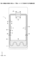
図1を参照するに、ループ型ヒートパイプ1は、蒸発器10と、凝縮器20と、蒸気管30と、液管40とを有する。ループ型ヒートパイプ1は、例えば、スマートフォンやタブレット端末等のモバイル型の電子機器2に収容することができる。
Referring to FIG. 1, the
ループ型ヒートパイプ1において、蒸発器10は、作動流体Cを気化させて蒸気Cvを生成する機能を有する。凝縮器20は、作動流体Cの蒸気Cvを液化させる機能を有する。蒸発器10と凝縮器20は、蒸気管30及び液管40により接続されており、蒸気管30及び液管40によって作動流体C又は蒸気Cvが流れるループである流路50が形成されている。
In the
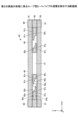
図2は、第1の実施の形態に係るループ型ヒートパイプの蒸発器及びその周囲の断面図である。図1及び図2に示すように、蒸発器10には、例えば4つの貫通孔10xが形成されている。蒸発器10に形成された各貫通孔10xと回路基板100に形成された各貫通孔100xにボルト150を挿入し、回路基板100の下面側からナット160で止めることにより、蒸発器10と回路基板100とが固定される。蒸発器10、凝縮器20、蒸気管30及び液管40は、上面1aと、上面1aとは反対側の下面1bとを有する。
FIG. 2 is a cross-sectional view of the evaporator and its surroundings of the loop heat pipe according to the first embodiment. As shown in FIGS. 1 and 2, the
回路基板100には、例えば、CPU等の発熱部品120がバンプ110により実装され、発熱部品120の上面が蒸発器10の下面1bと密着する。蒸発器10内の作動流体Cは、発熱部品120で発生した熱により気化し、蒸気Cvが生成される。
A
図1に示すように、蒸発器10に生成された蒸気Cvは、蒸気管30を通って凝縮器20に導かれ、凝縮器20において液化する。これにより、発熱部品120で発生した熱が凝縮器20に移動し、発熱部品120の温度上昇が抑制される。凝縮器20で液化した作動流体Cは、液管40を通って蒸発器10に導かれる。蒸気管30の幅W1は、例えば、8mm程度とすることができる。又、液管40の幅W2は、例えば、6mm程度とすることができる。
As shown in FIG. 1, the vapor Cv generated in the
作動流体Cの種類は特に限定されないが、蒸発潜熱によって発熱部品120を効率的に冷却するために、蒸気圧が高く、かつ蒸発潜熱が大きい流体を使用することが好ましい。そのような流体としては、例えば、アンモニア、水、フロン、アルコール、及びアセトンを挙げることができる。
Although the type of working fluid C is not particularly limited, it is preferable to use a fluid with high vapor pressure and large latent heat of vaporization in order to efficiently cool the
蒸発器10、凝縮器20、蒸気管30、及び液管40は、例えば、金属層が複数積層された構造とすることができる。後述のように、蒸発器10、凝縮器20、蒸気管30、及び液管40は、金属層61~63の3層が積層された構造を有する(図3~図5、図7参照)。蒸発器10、凝縮器20、蒸気管30、及び液管40において、金属層61及び63が最外金属層であり、金属層62が中間金属層である。但し、蒸発器10、凝縮器20、蒸気管30、及び液管40は、最外層となる一対の最外金属層と、最外金属層の間の1又は2以上の金属層が積層されてなる中間金属層とを備えていればよい。
The
金属層61~63は、例えば、熱伝導性に優れた銅層であって、固相接合等により互いに直接接合されている。金属層61~63の各々の厚さは、例えば、50μm~200μm程度とすることができる。なお、金属層61~63は銅層には限定されず、ステンレス層やアルミニウム層、マグネシウム合金層等から形成してもよい。金属層の積層数は限定されず、4層以上の金属層を積層してもよい。ループ型ヒートパイプ1の薄型化の観点から、金属層の数は少ない方が好ましく、3であることが特に好ましい。すなわち、中間金属層に含まれる金属層の数は1であることが特に好ましい。
The
蒸発器10、凝縮器20、蒸気管30、及び液管40は、それぞれ、作動流体C又はその蒸気Cvが流れる方向及び金属層61~63の積層方向の両方向に垂直な方向の両端部に、金属層61~63のすべてが積層されて構成された管壁90(図3、図6、図7参照)を有する。
The
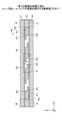
ここで、液管40の構造について説明する。図3~図5は、第1の実施の形態に係るループ型ヒートパイプの液管を例示する断面図である。図3は、図1中のIII-III線に沿う断面図である。図4は、図1中のIV-IV線に沿う断面図である。図5は、図3中の領域41の拡大図である。図3~図5において、金属層61~63の積層方向をZ方向、Z方向に垂直な平面内の任意の方向をX方向、この平面内においてX方向と直交する方向をY方向としている(他の図も同様)。又、本開示における平面視とは、Z方向からの平面視を意味する。
Here, the structure of the
図3に示すように、液管40の中間金属層(金属層62)には、管壁90の一部を構成する一対の壁部91と、一対の壁部91の間の多孔質体60とが設けられている。
As shown in FIG. 3, the intermediate metal layer (metal layer 62) of the
図3~図5に示すように、多孔質体60は、1層目の金属層61(一方の最外金属層)の下面及び3層目の金属層63(他方の最外金属層)の上面と接している。金属層61及び金属層63には、孔や溝は形成されていない。これに対して、多孔質体60を構成する2層目の金属層62には、上面側から厚さ方向の略中央部にかけて窪む有底孔62xと、下面側から厚さ方向の略中央部にかけて窪む有底孔62yとが、それぞれ複数個形成されている。
As shown in FIGS. 3 to 5, the
図3及び図4に示すように、有底孔62xと有底孔62yとは、平面視でX方向に交互に配置されている。又、有底孔62xと有底孔62yとは、平面視でY方向に交互に配置されている。X方向に交互に配置された有底孔62xと有底孔62yとは、平面視で部分的に重複しており、重複する部分は連通して細孔62zを形成している。又、Y方向に交互に配置された有底孔62xと有底孔62yとは、平面視で部分的に重複しており、重複する部分は連通して細孔62zを形成している。
As shown in FIGS. 3 and 4, the bottomed
有底孔62x及び62yの平面形状は、例えば、直径が100μm~300μm程度の円形とすることができるが、楕円形や多角形等の任意の形状として構わない。有底孔62x及び62yの深さは、例えば、金属層62の厚さの半分程度とすることができる。X方向に隣接する有底孔62xの間隔は、例えば、100μm~400μm程度とすることができる。Y方向に隣接する有底孔62xの間隔についても同様である。X方向に隣接する有底孔62yの間隔は、例えば、100μm~400μm程度とすることができる。Y方向に隣接する有底孔62yの間隔についても同様である。
The planar shape of the bottomed
有底孔62x及び62yの内壁面が湾曲面からなる凹形状とすることができる。湾曲面からなる凹形状としては、例えば、断面形状が略半円形や略半楕円形となる凹形状が挙げられる。しかし、これに限らず、有底孔62x及び62yの内壁は、底面側から開口側に向かって拡幅するテーパ形状とすることができる。有底孔62x及び62yの内壁は、底面に対して垂直であっても構わない。細孔62zの短手方向の幅は、例えば、10μm~50μm程度とすることができる。又、細孔62zの長手方向の幅は、例えば、50μm~150μm程度とすることができる。
The inner wall surfaces of the bottomed
図3及び図5に示すように、金属層62は、一対の壁部91の間において、金属層61に対向する上面に、複数の凹部81xと、隣り合う凹部81xの間の凸部82xとを有し、凸部82xと金属層61との間に隙間83xがある。又、金属層62は、一対の壁部91の間において、金属層63に対向する下面に、複数の凹部81yと、隣り合う凹部81yの間の凸部82yとを有し、凸部82yと金属層63との間に隙間83yがある。
As shown in FIGS. 3 and 5, the
Y方向に隣接する有底孔62xの間に凹部81x及び凸部82xが設けられていてもよく、Y方向に隣接する有底孔62yの間に凹部81y及び凸部82yが設けられていてもよい。すなわち、図4に示す断面において、凹部81x及び81yと、凸部82x及び82yとが設けられ、凸部82xと金属層61との間に隙間83xがあり、凸部82yと金属層63との間に隙間83yがあってもよい。
A
凹部81x及び81yの平面形状は、例えば、直径が10μm~50μm程度の円形とすることができるが、楕円形や多角形等の任意の形状として構わない。凹部81x及び81yの深さは、例えば、金属層62の厚さの5%~20%程度とすることができ、好ましくは10%程度とする。例えば、金属層62の厚さが100μmであれば、凹部81x及び81yの深さは、5μm~20μmとすることができ、好ましくは10μm程度とする。
The planar shape of the
隙間83x及び83yの大きさ、すなわち、凸部82xと金属層61との間の距離及び凸部82yと金属層63との間の距離は、例えば、0μm超5μm以下とすることができる。
The size of the
液管40において、細孔62zは有底孔62x又は62yを通じて他の細孔62zと連通しており、互いに連通する細孔62zは多孔質体60内に三次元的に広がっている。又、複数の有底孔62xの一部は凹部81x及び隙間83xを通じて他の有底孔62xと連通し、複数の有底孔62yの一部は凹部81y及び隙間83yを通じて他の有底孔62yと連通している。そのため、作動流体Cは、毛細管力により、互いに連通する細孔62z内を三次元的に広がる。
In the
多孔質体60を構成する有底孔62x及び62yの少なくとも一部は、凝縮器20内の流路50と連通している。これにより、作動流体Cが多孔質体60内に浸透することができる。
At least a portion of the bottomed
このように、液管40には多孔質体60が設けられており、多孔質体60は液管40に沿って蒸発器10の近傍まで延びている。これにより、多孔質体60に生じる毛細管力によって、液管40内の液相の作動流体Cが蒸発器10まで誘導される。
In this way, the
その結果、蒸発器10からのヒートリーク等によって液管40内を蒸気Cvが逆流しようとしても、多孔質体60から液相の作動流体Cに作用する毛細管力で蒸気Cvを押し戻すことができ、蒸気Cvの逆流を防止することが可能となる。
As a result, even if the vapor Cv tries to flow backward in the
なお、液管40には作動流体Cを注入するための注入口(図示せず)が形成されているが、注入口は封止部材により塞がれており、ループ型ヒートパイプ1内は気密に保たれる。
Note that the
次に、蒸発器10の構造について説明する。図6及び図7は、第1の実施の形態に係るループ型ヒートパイプの蒸発器を例示する図である。図6は平面図である。図7は、図6中のVII-VII線に沿う断面図である。図6では、蒸発器10内の多孔質体及び支柱の平面形状を示すため、一方の最外層となる金属層(図7に示す金属層61)の図示が省略されている。
Next, the structure of the
図6及び図7に示すように、蒸発器10の中間金属層(金属層62)には、管壁90の一部を構成する一対の壁部91と、一対の壁部91の間の多孔質体60とが設けられている。
As shown in FIGS. 6 and 7, the intermediate metal layer (metal layer 62) of the
図6に示すように、蒸発器10内の多孔質体60は、連結部60v及び突起部60wを備えている。
As shown in FIG. 6, the
連結部60vは、平面視において、X方向の最も液管40側(蒸発器10に液管40が接続されている側)に設けられ、Y方向に延びている。連結部60vの液管40側の面の一部は、蒸発器10の管壁90に接し、残りの一部は、液管40内の多孔質体60とつながっている。連結部60vの蒸気管30側の面の一部は、突起部60wと連結しており、残りの一部は空間70に接している。
The connecting
突起部60wは、平面視において、連結部60vから蒸気管30側に複数突起している。
A plurality of protruding
各々の突起部60wは所定間隔でY方向に並置されており、各々の突起部60wの蒸気管30側の端部は、蒸発器10の管壁90から離間している。そして、各々の突起部60wの蒸気管30側の端部は互いに連結されていない。一方で、各々の突起部60wの液管40側の端部は、連結部60vを介して連結されている。言い換えれば、蒸発器10内の多孔質体60は、平面視において、連結部60vと複数の突起部60wとを有する櫛歯状に形成されている。
The
蒸発器10内において、多孔質体60が設けられていない領域には空間70が形成されている。空間70は、蒸気管30の流路50とつながっている。
A
液管40側から作動流体Cが蒸発器10に導かれ、多孔質体60に浸透する。蒸発器10内で多孔質体60に浸透した作動流体Cは発熱部品120で発生した熱により気化して蒸気Cvが生成され、蒸気Cvは蒸発器10内の空間70を通って蒸気管30へ流れる。なお、図6及び図7において、突起部60w(櫛歯)の数を3つとしたのは一例であり、突起部60w(櫛歯)の数は適宜決定することができる。突起部60wと空間70との接触面積が増えれば作動流体Cが蒸発しやすくなり、圧力損失を低減できる。
The working fluid C is led to the evaporator 10 from the
蒸発器10内の多孔質体60は液管40内の多孔質体60と同様の構成を備える。すなわち、多孔質体60を構成する2層目の金属層62は、複数の有底孔62xと、複数の有底孔62yと、有底孔62xと有底孔62yとが部分的に連通して形成された複数の細孔62zとを有する。金属層62は、一対の壁部91の間において、金属層61に対向する上面に、複数の凹部81xと、隣り合う凹部81xの間の凸部82xとを有し、凸部82xと金属層61との間に隙間83xがある。又、金属層62は、一対の壁部91の間において、金属層63に対向する下面に、複数の凹部81yと、隣り合う凹部81yの間の凸部82yとを有し、凸部82yと金属層63との間に隙間83yがある。
The
蒸発器10においても、細孔62zは有底孔62x又は62yを通じて他の細孔62zと連通しており、互いに連通する細孔62zは多孔質体60内に三次元的に広がっている。又、複数の有底孔62xの一部は凹部81x及び隙間83xを通じて他の有底孔62xと連通し、複数の有底孔62yの一部は凹部81y及び隙間83yを通じて他の有底孔62yと連通している。そのため、作動流体Cは、毛細管力により、互いに連通する細孔62z内を三次元的に広がる。
Also in the
このように、多孔質体60を構成する金属層62には、複数の凹部81x、81yと、隣り合う凹部81x、81yの間の凸部82x、82yとが設けられ、凸部82xと金属層61との間には隙間83xがあり、凸部82yと金属層63との間には隙間83yがある。このため、作動流体Cは、毛細管力により、多孔質体60内を三次元的に広がる。従って、ループ型ヒートパイプ1によれば、適切な強度及び作動流体Cの流動性を得ながら、金属層の数を少なくして薄型化できる。
In this way, the
仮に、凹部81x、81yと、凸部82x、82yとを設けずに、薄型化のために金属層の数を3としたのでは、作動流体Cの流動性が低下してしまう。又、凹部81x、81yと、凸部82x、82yとを設けずに、薄型化のために金属層の数を3としつつ、適切な作動流体Cの流動性を得るために金属層61及び63にも多孔質体を形成した場合には、強度が低下してしまう。
If the number of metal layers were set to three in order to reduce the thickness without providing the
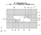
[第1の実施の形態に係るループ型ヒートパイプの製造方法]
次に、第1の実施の形態に係るループ型ヒートパイプの製造方法について、多孔質体の製造工程を中心に説明する。図8及び図9は、第1の実施の形態に係るループ型ヒートパイプの製造工程を例示する図である。図8及び図9は、図3に対応する断面を示す。図示を省略するが、図8及び図9に示す工程では、図4及び図7に対応する断面においても、図3に対応する断面と同様の処理が行われる。
[Method for manufacturing loop-type heat pipe according to first embodiment]
Next, the method for manufacturing the loop heat pipe according to the first embodiment will be explained, focusing on the manufacturing process of the porous body. 8 and 9 are diagrams illustrating the manufacturing process of the loop-type heat pipe according to the first embodiment. 8 and 9 show cross-sections corresponding to FIG. 3. Although not shown, in the steps shown in FIGS. 8 and 9, the same process as the cross section corresponding to FIG. 3 is performed on the cross section corresponding to FIG. 4 and FIG. 7.
まず、図8(a)に示す工程では、図1の平面形状に形成された金属シート620を準備する。そして、金属シート620の上面にレジスト層310を形成し、金属シート620の下面にレジスト層320を形成する。金属シート620は、最終的に金属層62となる部材であり、例えば、銅、ステンレス、アルミニウム、マグネシウム合金等から形成することができる。金属シート620の厚さは、例えば、50μm~200μm程度とすることができる。レジスト層310及び320としては、例えば、感光性のドライフィルムレジスト等を用いることができる。
First, in the step shown in FIG. 8(a), a
次に、図8(b)に示す工程では、金属シート620の多孔質体60を形成する領域において、レジスト層310を露光及び現像して、金属シート620の上面を選択的に露出する開口部310x及び311xを形成する。又、レジスト層320を露光及び現像して、金属シート620の下面を選択的に露出する開口部320y及び321yを形成する。開口部310xは有底孔62xの形成に用いられ、開口部320yは有底孔62yの形成に用いられる。開口部310x及び320yの形状及び配置は、図3及び図4に示した有底孔62x及び62yの形状及び配置に対応するように形成する。開口部311xは凹部81xの形成に用いられ、開口部321yは凹部81yの形成に用いられる。開口部311x及び321yの形状及び配置は、図3に示した凹部81x及び81yの形状及び配置に対応するように形成する。又、隣り合う開口部311xは、後述のハーフエッチングの際にレジスト層310の下で隣り合う凹部81x同士がつながる程度に近接して配置する。同様に、隣り合う開口部321yは、後述のハーフエッチングの際にレジスト層320の下で隣り合う凹部81y同士がつながる程度に近接して配置する。
Next, in the step shown in FIG. 8(b), the resist
次に、図8(c)に示す工程では、開口部310x及び311x内に露出する金属シート620を金属シート620の上面側からハーフエッチングすると共に、開口部320y及び321y内に露出する金属シート620を金属シート620の下面側からハーフエッチングする。これにより、金属シート620の上面側に有底孔62x及び凹部81xが形成され、下面側に有底孔62y及び凹部81yが形成される。又、表裏でX方向、Y方向に交互に配置された開口部310xと開口部320yとは、平面視で部分的に重複しているため、重複する部分が連通して細孔62zが形成される。金属シート620のハーフエッチングには、例えば、塩化第二鉄溶液を用いることができる。
Next, in the step shown in FIG. 8C, the
隣り合う凹部81xの間には凸部82xが形成され、隣り合う凹部81yの間には凸部82yが形成される。この時、レジスト層310の下で隣り合う凹部81x同士がつながり、凸部82xの先端は金属シート620の上面から後退する。従って、凸部82xとレジスト層310との間に隙間が形成される。同様に、レジスト層320の下で隣り合う凹部81y同士がつながり、凸部82yの先端は金属シート620の下面から後退する。従って、凸部82yとレジスト層320との間に隙間が形成される。
A
次に、図8(d)に示す工程では、レジスト層310及び320を剥離液により剥離する。これにより、金属層62が完成する。
Next, in the step shown in FIG. 8(d), the resist
次に、図9(a)に示す工程では、孔や溝が形成されていないベタ状の金属層61及び63を準備する。
Next, in the step shown in FIG. 9A,
次に、図9(b)に示す工程では、図9(a)に示す順番で各金属層を積層し、加圧及び加熱により固相接合を行う。これにより、隣接する金属層同士が直接接合され、蒸発器10、凝縮器20、蒸気管30、及び液管40を有するループ型ヒートパイプ1が完成し、液管40及び蒸発器10に多孔質体60が形成される。凸部82xの先端が金属層62の上面から後退しているため、凸部82xと金属層61との間に隙間83xが形成される。又、凸部82yの先端が金属層62の下面から後退しているため、凸部82yと金属層63との間に隙間83yが形成される。その後、真空ポンプ等を用いて液管40内を排気した後、図示しない注入口から液管40内に作動流体Cを注入し、その後注入口を封止する。
Next, in the step shown in FIG. 9(b), the metal layers are laminated in the order shown in FIG. 9(a), and solid phase bonding is performed by applying pressure and heating. As a result, the adjacent metal layers are directly joined to each other, and the
ここで、固相接合とは、接合対象物同士を溶融させることなく固相(固体)状態のまま加熱して軟化させ、更に加圧して塑性変形を与えて接合する方法である。なお、固相接合によって隣接する金属層同士を良好に接合できるように、金属層61~63の全ての材料を同一にすることが好ましい。 Here, solid phase bonding is a method in which the objects to be bonded are heated and softened in a solid state without melting each other, and are further pressurized to give plastic deformation to bond them. Note that it is preferable that all the metal layers 61 to 63 are made of the same material so that adjacent metal layers can be bonded well by solid phase bonding.
このように、各金属層の両面側から形成した有底孔を部分的に連通させて各金属層内に細孔を設ける構造とすることで、一定の大きさの細孔を金属層内に形成できる。これにより、細孔の大きさがばらついて細孔により発現する毛細管力が低下することを防止可能となり、蒸発器10から液管40に蒸気Cvが逆流することを抑制する効果を安定的に得ることができる。
In this way, by creating a structure in which pores are provided in each metal layer by partially communicating the bottomed holes formed from both sides of each metal layer, pores of a certain size can be created in the metal layer. Can be formed. This makes it possible to prevent the capillary force exerted by the pores from decreasing due to variations in the size of the pores, and to stably obtain the effect of suppressing the backflow of vapor Cv from the
なお、多孔質体60は、凝縮器20の一部にも設けられてよく、蒸気管30の一部にも設けられてよい。
Note that the
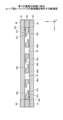
〈第2の実施の形態〉
第2の実施の形態では、液管40の構成が第1の実施の形態と相違する。第2の実施の形態において、既に説明した実施の形態と同一構成部についての説明は省略する場合がある。図10は、第2の実施の形態に係るループ型ヒートパイプの液管を例示する断面図である。図10は、図1中のIII-III線に沿う断面図に相当する。
<Second embodiment>
In the second embodiment, the configuration of the
第2の実施の形態では、図10に示すように、液管40内で、多孔質体60が両側の管壁90に接するようにして2箇所に設けられている。すなわち、多孔質体60が対をなして液管40内に設けられている。一方の多孔質体60が一方の壁部91と一体に形成され、他方の多孔質体60が他方の壁部91と一体に形成されている。2つの多孔質体60の間に、作動流体Cが流れる空間51が形成されている。空間51は、2つの多孔質体60の互いに対向する面と、金属層61の下面と、金属層63の上面とにより囲まれている。空間51は流路50の一部である。多孔質体60を構成する有底孔の少なくとも一部は、空間51と連通している。他の構成は第1の実施の形態と同様である。
In the second embodiment, as shown in FIG. 10,
第2の実施の形態によっても第1の実施の形態と同様の効果を得ることができる。又、作動流体Cが空間51内を流れることができる。
The second embodiment can also provide the same effects as the first embodiment. Additionally, the working fluid C can flow within the
〈第2の実施の形態の変形例〉
第2の実施の形態の変形例では、液管40の構成が第2の実施の形態と相違する。第2の実施の形態の変形例において、既に説明した実施の形態と同一構成部についての説明は省略する場合がある。図11は、第2の実施の形態の変形例に係るループ型ヒートパイプの液管を例示する断面図である。図11は、図1中のIII-III線に沿う断面図に相当する。
<Modification of the second embodiment>
In the modification of the second embodiment, the configuration of the
第2の実施の形態の変形例では、図11に示すように、液管40内で、多孔質体60が両側の管壁90から離間して設けられている。多孔質体60と一方の管壁90との間と、多孔質体60と他方の管壁90との間とに、作動流体Cが流れる空間51が形成されている。空間51は、管壁90及び多孔質体60の互いに対向する面と、金属層61の下面と、金属層63の上面とにより囲まれている。空間51は流路50の一部である。多孔質体60を構成する有底孔の少なくとも一部は、空間51と連通している。他の構成は第2の実施の形態と同様である。
In a modification of the second embodiment, as shown in FIG. 11, the
第2の実施の形態の変形例によっても第2の実施の形態と同様の効果を得ることができる。 The same effects as the second embodiment can also be obtained by the modification of the second embodiment.
以上、好ましい実施の形態等について詳説したが、上述した実施の形態等に制限されることはなく、特許請求の範囲に記載された範囲を逸脱することなく、上述した実施の形態等に種々の変形及び置換を加えることができる。 Although the preferred embodiments have been described in detail above, they are not limited to the embodiments described above, and various modifications may be made to the embodiments described above without departing from the scope of the claims. Variations and substitutions can be made.
1 ループ型ヒートパイプ
10 蒸発器
20 凝縮器
30 蒸気管
40 液管
50 流路
60 多孔質体
61~63 金属層
81x、81y 凹部
82x、82y 凸部
83x、83y 隙間
90 管壁
91 壁部
1
Claims (11)
作動流体を気化させる蒸発器と、
前記作動流体を液化する凝縮器と、
前記蒸発器と前記凝縮器とを接続する液管と、
前記蒸発器と前記凝縮器とを接続し、前記液管と共にループ状の流路を形成する蒸気管と、
を有し、
前記中間金属層は、
前記蒸発器、前記凝縮器、前記液管及び前記蒸気管の管壁の一部を構成する一対の壁部と、
前記一対の壁部の間に設けられた多孔質体と、
を有し、
前記一対の壁部の間において、前記中間金属層は、前記一対の最外金属層の一方に対向する第1の面に、複数の第1の凹部と、隣り合う前記第1の凹部の間の第1の凸部とを有し、
前記第1の凸部と前記一対の最外金属層の一方との間に、隣り合う前記第1の凹部が部分的に連通して形成された第1の隙間があり、
前記多孔質体は、
一方の面側から窪む複数の第1の有底孔と、
他方の面側から窪む複数の第2の有底孔と、
各々が前記第1の有底孔と前記第2の有底孔とが部分的に連通して形成された複数の細孔と、
を備え、
前記第1の凹部の深さは、前記第1の有底孔の深さよりも小さく、
隣り合う前記第1の有底孔は前記第1の凹部及び前記第1の隙間を介して互いに連通していることを特徴とするループ型ヒートパイプ。 consisting of a pair of outermost metal layers and an intermediate metal layer provided between the pair of outermost metal layers,
an evaporator that vaporizes the working fluid;
a condenser that liquefies the working fluid;
a liquid pipe connecting the evaporator and the condenser;
a steam pipe connecting the evaporator and the condenser and forming a loop-shaped flow path together with the liquid pipe;
has
The intermediate metal layer is
a pair of wall portions forming part of the pipe walls of the evaporator, the condenser, the liquid pipe, and the steam pipe;
a porous body provided between the pair of walls;
has
Between the pair of walls, the intermediate metal layer has a plurality of first recesses on a first surface facing one of the pair of outermost metal layers, and a space between the first recesses adjacent to each other. a first convex portion;
There is a first gap between the first convex portion and one of the pair of outermost metal layers , the first gap being formed by partially communicating the adjacent first concave portions ,
The porous body is
a plurality of first bottomed holes recessed from one surface side;
a plurality of second bottomed holes recessed from the other surface side;
a plurality of pores , each of which is formed by partially communicating the first bottomed hole and the second bottomed hole;
Equipped with
The depth of the first recess is smaller than the depth of the first bottomed hole,
The loop heat pipe is characterized in that the first bottomed holes adjacent to each other communicate with each other via the first recess and the first gap .
前記第2の凸部と前記一対の最外金属層の他方との間に第2の隙間があることを特徴とする請求項1に記載のループ型ヒートパイプ。 Between the pair of walls, the intermediate metal layer has a plurality of second recesses on a second surface facing the other of the pair of outermost metal layers, and a plurality of second recesses between the adjacent second recesses. and a second convex portion,
The loop-type heat pipe according to claim 1, wherein a second gap is provided between the second convex portion and the other of the pair of outermost metal layers.
前記一対の多孔質体の一方は、前記一対の壁部の一方と一体に形成され、
前記一対の多孔質体の他方は、前記一対の壁部の他方と一体に形成され、
前記一対の多孔質体の間に、前記作動流体が流れる空間を有することを特徴とする請求項1乃至5のいずれか1項に記載のループ型ヒートパイプ。 The porous body is provided in a pair within the liquid pipe,
One of the pair of porous bodies is formed integrally with one of the pair of walls,
The other of the pair of porous bodies is formed integrally with the other of the pair of walls,
The loop-type heat pipe according to any one of claims 1 to 5, further comprising a space between the pair of porous bodies, through which the working fluid flows.
前記一対の壁部の一方と前記多孔質体との間と、前記一対の壁部の他方と前記多孔質体との間とに、前記作動流体が流れる空間を有することを特徴とする請求項1乃至5のいずれか1項に記載のループ型ヒートパイプ。 the porous body is provided within the liquid pipe at a distance from the pair of walls;
Claim characterized in that a space is provided between one of the pair of wall portions and the porous body and between the other of the pair of wall portions and the porous body through which the working fluid flows. 6. The loop-type heat pipe according to any one of 1 to 5.
金属層から、前記蒸発器、前記凝縮器、前記液管及び前記蒸気管の管壁の一部を構成する一対の壁部と、前記一対の壁部の間に設けられた多孔質体と、を有する前記中間金属層を形成する工程を有し、
前記中間金属層を形成する工程は、
前記金属層をエッチングすることにより、前記金属層の一方の面に当該一方の面側から窪む複数の第1の有底孔と複数の第1の凹部とを形成し、前記金属層の他方の面に当該他方の面側から窪む複数の第2の有底孔と複数の第2の凹部とを形成する工程を有し、
前記第1の有底孔と前記第2の有底孔とが部分的に連通して細孔が形成され、
前記第1の凹部の深さは、前記第1の有底孔の深さよりも小さく、
前記第2の凹部の深さは、前記第2の有底孔の深さよりも小さく、
隣り合う前記第1の凹部の間に第1の凸部が形成され、
隣り合う前記第2の凹部の間に第2の凸部が形成され、
前記第1の凸部と前記一対の最外金属層の一方との間に、隣り合う前記第1の凹部が部分的に連通して形成された第1の隙間があり、
前記第2の凸部と前記一対の最外金属層の他方との間に、隣り合う前記第2の凹部が部分的に連通して形成された第2の隙間があり、
前記多孔質体は、
一方の面側から窪む複数の前記第1の有底孔と、
他方の面側から窪む複数の前記第2の有底孔と、
各々が前記第1の有底孔と前記第2の有底孔とが部分的に連通して形成された複数の細孔と、
を備え、
前記第1の凹部の深さは、前記第1の有底孔の深さよりも小さく、
隣り合う前記第1の有底孔は前記第1の凹部及び前記第1の隙間を介して互いに連通し、
隣り合う前記第2の有底孔は前記第2の凹部及び前記第2の隙間を介して互いに連通することを特徴とするループ型ヒートパイプの製造方法。 an evaporator comprising a pair of outermost metal layers and an intermediate metal layer provided between the pair of outermost metal layers; an evaporator that vaporizes a working fluid; a condenser that liquefies the working fluid; and a liquid pipe connecting the evaporator and the condenser, and a steam pipe connecting the evaporator and the condenser and forming a loop-shaped flow path together with the liquid pipe. There it is,
A pair of walls forming part of the pipe walls of the evaporator, the condenser, the liquid pipe, and the steam pipe from a metal layer, and a porous body provided between the pair of walls; forming the intermediate metal layer having
The step of forming the intermediate metal layer includes:
By etching the metal layer, a plurality of first bottomed holes and a plurality of first recesses are formed on one side of the metal layer, and the other side of the metal layer is etched. forming a plurality of second bottomed holes and a plurality of second recesses recessed from the other surface side on the surface;
The first bottomed hole and the second bottomed hole partially communicate with each other to form a pore,
The depth of the first recess is smaller than the depth of the first bottomed hole,
The depth of the second recess is smaller than the depth of the second bottomed hole,
A first convex portion is formed between the adjacent first concave portions,
A second convex portion is formed between the adjacent second concave portions,
There is a first gap between the first convex portion and one of the pair of outermost metal layers , the first gap being formed by partially communicating the adjacent first concave portions ,
There is a second gap between the second convex portion and the other of the pair of outermost metal layers , which is formed by partially communicating the adjacent second concave portions ;
The porous body is
a plurality of the first bottomed holes recessed from one surface side;
a plurality of second bottomed holes recessed from the other surface side;
a plurality of pores , each of which is formed by partially communicating the first bottomed hole and the second bottomed hole;
Equipped with
The depth of the first recess is smaller than the depth of the first bottomed hole,
The adjacent first bottomed holes communicate with each other via the first recess and the first gap,
A method for manufacturing a loop-type heat pipe , wherein the adjacent second bottomed holes communicate with each other via the second recess and the second gap .
Priority Applications (4)
| Application Number | Priority Date | Filing Date | Title |
|---|---|---|---|
| JP2020074370A JP7422600B2 (en) | 2020-04-17 | 2020-04-17 | Loop type heat pipe and its manufacturing method |
| US17/301,391 US11774182B2 (en) | 2020-04-17 | 2021-04-01 | Loop heat pipe |
| CN202110364846.3A CN113532167A (en) | 2020-04-17 | 2021-04-02 | Loop type heat pipe and manufacturing method thereof |
| EP21167966.7A EP3896381B1 (en) | 2020-04-17 | 2021-04-13 | Loop heat pipe and method for manufacturing loop heat pipe |
Applications Claiming Priority (1)
| Application Number | Priority Date | Filing Date | Title |
|---|---|---|---|
| JP2020074370A JP7422600B2 (en) | 2020-04-17 | 2020-04-17 | Loop type heat pipe and its manufacturing method |
Publications (3)
| Publication Number | Publication Date |
|---|---|
| JP2021173421A JP2021173421A (en) | 2021-11-01 |
| JP2021173421A5 JP2021173421A5 (en) | 2022-12-22 |
| JP7422600B2 true JP7422600B2 (en) | 2024-01-26 |
Family
ID=75497807
Family Applications (1)
| Application Number | Title | Priority Date | Filing Date |
|---|---|---|---|
| JP2020074370A Active JP7422600B2 (en) | 2020-04-17 | 2020-04-17 | Loop type heat pipe and its manufacturing method |
Country Status (4)
| Country | Link |
|---|---|
| US (1) | US11774182B2 (en) |
| EP (1) | EP3896381B1 (en) |
| JP (1) | JP7422600B2 (en) |
| CN (1) | CN113532167A (en) |
Citations (3)
| Publication number | Priority date | Publication date | Assignee | Title |
|---|---|---|---|---|
| JP2018096669A (en) | 2016-12-14 | 2018-06-21 | 新光電気工業株式会社 | Heat pipe and process of manufacture thereof |
| JP2019082309A (en) | 2017-10-27 | 2019-05-30 | 新光電気工業株式会社 | Loop type heat pipe and method for manufacturing loop type heat pipe |
| JP2020051638A (en) | 2018-09-25 | 2020-04-02 | 新光電気工業株式会社 | Loop type heat pipe |
Family Cites Families (8)
| Publication number | Priority date | Publication date | Assignee | Title |
|---|---|---|---|---|
| JPS57165294A (en) | 1981-04-06 | 1982-10-12 | Morohoshi Ink Kk | Composition of water overcoating liquid |
| JP6291000B2 (en) | 2016-09-01 | 2018-03-07 | 新光電気工業株式会社 | Loop heat pipe and manufacturing method thereof |
| US10352626B2 (en) * | 2016-12-14 | 2019-07-16 | Shinko Electric Industries Co., Ltd. | Heat pipe |
| JP6889093B2 (en) * | 2017-11-29 | 2021-06-18 | 新光電気工業株式会社 | Heat pipe and its manufacturing method |
| JP7028659B2 (en) * | 2018-01-30 | 2022-03-02 | 新光電気工業株式会社 | Manufacturing method of loop type heat pipe and loop type heat pipe |
| JP6400240B1 (en) | 2018-02-05 | 2018-10-03 | 新光電気工業株式会社 | Loop heat pipe and manufacturing method thereof |
| JP7015197B2 (en) | 2018-03-26 | 2022-02-02 | 新光電気工業株式会社 | Loop type heat pipe and its manufacturing method |
| JP7206649B2 (en) | 2018-06-29 | 2023-01-18 | 大日本印刷株式会社 | Vapor chamber, electronic device, and method for manufacturing vapor chamber |
-
2020
- 2020-04-17 JP JP2020074370A patent/JP7422600B2/en active Active
-
2021
- 2021-04-01 US US17/301,391 patent/US11774182B2/en active Active
- 2021-04-02 CN CN202110364846.3A patent/CN113532167A/en active Pending
- 2021-04-13 EP EP21167966.7A patent/EP3896381B1/en active Active
Patent Citations (3)
| Publication number | Priority date | Publication date | Assignee | Title |
|---|---|---|---|---|
| JP2018096669A (en) | 2016-12-14 | 2018-06-21 | 新光電気工業株式会社 | Heat pipe and process of manufacture thereof |
| JP2019082309A (en) | 2017-10-27 | 2019-05-30 | 新光電気工業株式会社 | Loop type heat pipe and method for manufacturing loop type heat pipe |
| JP2020051638A (en) | 2018-09-25 | 2020-04-02 | 新光電気工業株式会社 | Loop type heat pipe |
Also Published As
| Publication number | Publication date |
|---|---|
| EP3896381B1 (en) | 2023-11-08 |
| CN113532167A (en) | 2021-10-22 |
| US20210325121A1 (en) | 2021-10-21 |
| US11774182B2 (en) | 2023-10-03 |
| JP2021173421A (en) | 2021-11-01 |
| EP3896381A1 (en) | 2021-10-20 |
Similar Documents
| Publication | Publication Date | Title |
|---|---|---|
| US11131509B2 (en) | Loop heat pipe | |
| JP7015197B2 (en) | Loop type heat pipe and its manufacturing method | |
| JP7305512B2 (en) | Loop type heat pipe and its manufacturing method | |
| US10859319B2 (en) | Loop heat pipe | |
| CN109839019B (en) | Heat pipe and method for manufacturing the same | |
| JP7184594B2 (en) | loop heat pipe | |
| EP3575727B1 (en) | Loop-type heat pipe | |
| JP2020008249A (en) | Loop type heat pipe and method for manufacturing the same | |
| JP7353132B2 (en) | Loop type heat pipe and its manufacturing method | |
| JP7422600B2 (en) | Loop type heat pipe and its manufacturing method | |
| JP7372185B2 (en) | Loop type heat pipe and its manufacturing method | |
| JP7390252B2 (en) | loop heat pipe | |
| JP7394708B2 (en) | loop heat pipe | |
| JP7336416B2 (en) | loop heat pipe | |
| JP2024053369A (en) | LOOP HEAT PIPE AND METHOD FOR MANUFACTURING LOOP HEAT PIPE | |
| JP2020020566A (en) | Loop type heat pipe and method of manufacturing the same |
Legal Events
| Date | Code | Title | Description |
|---|---|---|---|
| A521 | Request for written amendment filed |
Free format text: JAPANESE INTERMEDIATE CODE: A523 Effective date: 20221214 |
|
| A621 | Written request for application examination |
Free format text: JAPANESE INTERMEDIATE CODE: A621 Effective date: 20221214 |
|
| A131 | Notification of reasons for refusal |
Free format text: JAPANESE INTERMEDIATE CODE: A131 Effective date: 20230815 |
|
| A977 | Report on retrieval |
Free format text: JAPANESE INTERMEDIATE CODE: A971007 Effective date: 20230818 |
|
| A521 | Request for written amendment filed |
Free format text: JAPANESE INTERMEDIATE CODE: A523 Effective date: 20230925 |
|
| TRDD | Decision of grant or rejection written | ||
| A01 | Written decision to grant a patent or to grant a registration (utility model) |
Free format text: JAPANESE INTERMEDIATE CODE: A01 Effective date: 20240109 |
|
| A61 | First payment of annual fees (during grant procedure) |
Free format text: JAPANESE INTERMEDIATE CODE: A61 Effective date: 20240116 |
|
| R150 | Certificate of patent or registration of utility model |
Ref document number: 7422600 Country of ref document: JP Free format text: JAPANESE INTERMEDIATE CODE: R150 |