JP7421069B2 - ultrasonic tonometer - Google Patents
ultrasonic tonometer Download PDFInfo
- Publication number
- JP7421069B2 JP7421069B2 JP2019219894A JP2019219894A JP7421069B2 JP 7421069 B2 JP7421069 B2 JP 7421069B2 JP 2019219894 A JP2019219894 A JP 2019219894A JP 2019219894 A JP2019219894 A JP 2019219894A JP 7421069 B2 JP7421069 B2 JP 7421069B2
- Authority
- JP
- Japan
- Prior art keywords
- ultrasound
- detection
- unit
- ultrasonic
- eye
- Prior art date
- Legal status (The legal status is an assumption and is not a legal conclusion. Google has not performed a legal analysis and makes no representation as to the accuracy of the status listed.)
- Active
Links
- 238000001514 detection method Methods 0.000 claims description 226
- 238000002604 ultrasonography Methods 0.000 claims description 161
- 230000004410 intraocular pressure Effects 0.000 claims description 51
- 230000005856 abnormality Effects 0.000 claims description 32
- 238000012544 monitoring process Methods 0.000 claims description 7
- 210000004087 cornea Anatomy 0.000 description 58
- 238000005259 measurement Methods 0.000 description 38
- 230000003287 optical effect Effects 0.000 description 32
- 230000005855 radiation Effects 0.000 description 22
- 238000006073 displacement reaction Methods 0.000 description 16
- 238000005286 illumination Methods 0.000 description 9
- 238000010586 diagram Methods 0.000 description 6
- 238000000034 method Methods 0.000 description 6
- 230000007423 decrease Effects 0.000 description 5
- 238000012545 processing Methods 0.000 description 5
- 230000002159 abnormal effect Effects 0.000 description 4
- 238000009530 blood pressure measurement Methods 0.000 description 4
- 238000004364 calculation method Methods 0.000 description 4
- 230000004397 blinking Effects 0.000 description 3
- 230000006870 function Effects 0.000 description 3
- 230000001678 irradiating effect Effects 0.000 description 3
- 230000003247 decreasing effect Effects 0.000 description 2
- 238000002347 injection Methods 0.000 description 2
- 239000007924 injection Substances 0.000 description 2
- 230000000903 blocking effect Effects 0.000 description 1
- 239000000919 ceramic Substances 0.000 description 1
- 238000006243 chemical reaction Methods 0.000 description 1
- 230000001276 controlling effect Effects 0.000 description 1
- 230000002596 correlated effect Effects 0.000 description 1
- 230000000875 corresponding effect Effects 0.000 description 1
- 230000007812 deficiency Effects 0.000 description 1
- 230000000994 depressogenic effect Effects 0.000 description 1
- 238000002474 experimental method Methods 0.000 description 1
- 239000002184 metal Substances 0.000 description 1
- 230000004493 normal intraocular pressure Effects 0.000 description 1
- 238000011022 operating instruction Methods 0.000 description 1
- 230000010355 oscillation Effects 0.000 description 1
- 230000002035 prolonged effect Effects 0.000 description 1
- 230000035807 sensation Effects 0.000 description 1
- 230000009466 transformation Effects 0.000 description 1
Images


Classifications
-
- A—HUMAN NECESSITIES
- A61—MEDICAL OR VETERINARY SCIENCE; HYGIENE
- A61B—DIAGNOSIS; SURGERY; IDENTIFICATION
- A61B8/00—Diagnosis using ultrasonic, sonic or infrasonic waves
- A61B8/10—Eye inspection
-
- A—HUMAN NECESSITIES
- A61—MEDICAL OR VETERINARY SCIENCE; HYGIENE
- A61B—DIAGNOSIS; SURGERY; IDENTIFICATION
- A61B8/00—Diagnosis using ultrasonic, sonic or infrasonic waves
- A61B8/08—Clinical applications
-
- A—HUMAN NECESSITIES
- A61—MEDICAL OR VETERINARY SCIENCE; HYGIENE
- A61B—DIAGNOSIS; SURGERY; IDENTIFICATION
- A61B8/00—Diagnosis using ultrasonic, sonic or infrasonic waves
- A61B8/54—Control of the diagnostic device
-
- A—HUMAN NECESSITIES
- A61—MEDICAL OR VETERINARY SCIENCE; HYGIENE
- A61B—DIAGNOSIS; SURGERY; IDENTIFICATION
- A61B8/00—Diagnosis using ultrasonic, sonic or infrasonic waves
- A61B8/58—Testing, adjusting or calibrating the diagnostic device
Landscapes
- Health & Medical Sciences (AREA)
- Life Sciences & Earth Sciences (AREA)
- Heart & Thoracic Surgery (AREA)
- Medical Informatics (AREA)
- Biophysics (AREA)
- Nuclear Medicine, Radiotherapy & Molecular Imaging (AREA)
- Pathology (AREA)
- Radiology & Medical Imaging (AREA)
- Engineering & Computer Science (AREA)
- Biomedical Technology (AREA)
- Veterinary Medicine (AREA)
- Physics & Mathematics (AREA)
- Molecular Biology (AREA)
- Surgery (AREA)
- Animal Behavior & Ethology (AREA)
- General Health & Medical Sciences (AREA)
- Public Health (AREA)
- Ophthalmology & Optometry (AREA)
- Eye Examination Apparatus (AREA)
- Ultra Sonic Daignosis Equipment (AREA)
Description
本開示は、超音波を用いて被検眼の眼圧を測定する超音波眼圧計に関する。 The present disclosure relates to an ultrasonic tonometer that measures the intraocular pressure of a subject's eye using ultrasound.
非接触式眼圧計としては、未だ空気噴射式眼圧計が一般的である。空気噴射式眼圧計は、角膜に空気を噴射したときの角膜の圧平状態と、角膜に噴射される空気圧とを検出することによって、所定の変形状態における空気圧を眼圧に換算していた。 Air injection tonometers are still common as non-contact tonometers. Air injection tonometers convert air pressure in a predetermined deformed state into intraocular pressure by detecting the applanation state of the cornea when air is injected onto the cornea and the air pressure injected to the cornea.
また、非接触式眼圧計としては、超音波を用いて眼圧を測定する超音波眼圧計が提案されている(特許文献1参照)。特許文献1の超音波式眼圧計は、角膜に超音波を放射したときの角膜の圧平状態と、角膜に噴射される放射圧とを検出することによって、所定の変形状態における放射圧を眼圧に換算するものである。 Further, as a non-contact tonometer, an ultrasonic tonometer that measures intraocular pressure using ultrasonic waves has been proposed (see Patent Document 1). The ultrasonic tonometer of Patent Document 1 detects the applanation state of the cornea when ultrasonic waves are emitted to the cornea and the radiation pressure injected to the cornea, thereby measuring the radiation pressure in a predetermined deformed state to the eye. It is converted into pressure.
また、超音波眼圧計としては、角膜からの反射波の特性(振幅、位相)と眼圧との関係に基づいて眼圧を測定する装置が提案されている(特許文献2参照)。 Furthermore, as an ultrasonic tonometer, a device has been proposed that measures intraocular pressure based on the relationship between the characteristics (amplitude, phase) of reflected waves from the cornea and intraocular pressure (see Patent Document 2).
特許文献1の装置では、超音波出力測定用の超音波センサが設けられ、超音波出力レベルが帰還制御される。 In the device of Patent Document 1, an ultrasonic sensor for measuring ultrasonic output is provided, and the ultrasonic output level is feedback-controlled.
しかしながら、特許文献1のような装置において、超音波センサによって超音波が遮られ、被検眼に対して十分に超音波を照射することができなかった。したがって、角膜に対して超音波を適正に照射できず、実際に角膜を扁平または陥没させる程度の超音波を被検眼に加えることはできなかった。 However, in the apparatus as disclosed in Patent Document 1, the ultrasonic waves are blocked by the ultrasonic sensor, and the eye to be examined cannot be sufficiently irradiated with the ultrasonic waves. Therefore, it was not possible to properly irradiate the cornea with ultrasound, and it was not possible to apply ultrasound to the subject's eye to the extent that the cornea was actually flattened or depressed.
本開示は、従来の問題点を鑑み、超音波の照射に影響を与えないように超音波出力を監視する超音波眼圧計を提供することを技術課題とする。 In view of the conventional problems, the technical problem of the present disclosure is to provide an ultrasonic tonometer that monitors ultrasonic output so as not to affect ultrasonic irradiation.
上記課題を解決するために、本開示は以下のような構成を備えることを特徴とする。 In order to solve the above problems, the present disclosure is characterized by having the following configuration.
(1) 被検眼の眼圧を測定するための超音波眼圧計であって、振動子を有し、前記被検眼に向けて超音波を発生させる超音波発生手段と、前記超音波発生手段の出力を検出する検出手段と、前記検出手段の検出信号を監視する制御手段と、を備え、前記検出手段は、前記超音波発生手段から前記被検眼に向けて照射される超音波の照射経路外に配置され、前記制御手段は、前記検出手段の検出信号の大きさに基づいて、前記超音波発生手段の異常の有無を判定することを特徴とする。
(2) 被検眼の眼圧を測定するための超音波眼圧計であって、振動子を有し、前記被検眼に向けて超音波を発生させる超音波発生手段と、前記超音波発生手段の出力を検出する検出手段と、前記検出手段の検出信号を監視する制御手段と、を備え、前記検出手段は、前記超音波発生手段から前記被検眼に向けて照射される超音波の照射経路外に配置され、前記制御手段は、前記検出手段の検出信号の周波数に基づいて、前記超音波発生手段の異常の有無を判定することを特徴とする。
(1) An ultrasonic tonometer for measuring the intraocular pressure of an eye to be examined, comprising: an ultrasonic generation means that has a vibrator and generates ultrasonic waves toward the eye to be examined; The detection means includes a detection means for detecting an output, and a control means for monitoring a detection signal of the detection means, and the detection means is configured to detect an area outside the irradiation path of the ultrasound irradiated from the ultrasound generation means toward the eye to be examined. The control means is characterized in that the control means determines whether or not there is an abnormality in the ultrasonic wave generation means based on the magnitude of the detection signal of the detection means .
(2) An ultrasonic tonometer for measuring the intraocular pressure of the eye to be examined, comprising: an ultrasonic generating means having a vibrator and generating ultrasonic waves toward the eye to be examined; The detection means includes a detection means for detecting an output, and a control means for monitoring a detection signal of the detection means, and the detection means is configured to detect an area outside the irradiation path of the ultrasound irradiated from the ultrasound generation means toward the eye to be examined. The control means is characterized in that the control means determines whether or not there is an abnormality in the ultrasonic wave generation means based on the frequency of the detection signal of the detection means.
<第1実施形態>
以下、本開示に係る第1実施形態について説明する。第1実施形態の超音波眼圧計は、被検眼の眼圧を非侵襲で測定する。超音波眼圧計は、例えば、被検眼に超音波を照射したときの角膜形状の変化、または超音波の反射波に基づいて、被検眼の眼圧を測定する。
<First embodiment>
Hereinafter, a first embodiment according to the present disclosure will be described. The ultrasonic tonometer of the first embodiment non-invasively measures the intraocular pressure of the eye to be examined. An ultrasonic tonometer measures the intraocular pressure of an eye to be examined based on, for example, a change in the shape of the cornea when the eye to be examined is irradiated with ultrasound or a reflected wave of the ultrasound.
超音波眼圧計は、例えば、超音波発生部(例えば、超音波ユニット100)と、検出部(例えば、検出部300)と、制御部(例えば、制御部70)を備える。超音波発生部は、例えば、振動子を有し、被検眼に向けて超音波を発生させる。検出部は、例えば、超音波発生部の出力を検出する。検出部は、例えば、超音波、放射圧、または振動子の振動状況などを検出する。制御部は、検出部の検出信号を受信する。 The ultrasonic tonometer includes, for example, an ultrasonic generation section (for example, the ultrasonic unit 100), a detection section (for example, the detection section 300), and a control section (for example, the control section 70). The ultrasound generator includes, for example, a vibrator, and generates ultrasound toward the eye to be examined. The detection unit detects, for example, the output of the ultrasonic generator. The detection unit detects, for example, ultrasonic waves, radiation pressure, or vibration conditions of the vibrator. The control section receives a detection signal from the detection section.
なお、検出部は、照射経路の外に配置される。照射経路は、超音波発生部から被検眼に向かう超音波の照射経路である。照射経路は、例えば、超音波発生部の前面と、超音波の照射スポット(または照射目標)を結ぶ範囲である。この範囲の外側に検出部が配置されることによって、検出部が被検眼に照射される超音波の障害となる可能性を低減できる。 Note that the detection unit is placed outside the irradiation path. The irradiation path is an irradiation path of ultrasound from the ultrasound generation unit toward the eye to be examined. The irradiation path is, for example, a range connecting the front surface of the ultrasound generator and the ultrasound irradiation spot (or irradiation target). By arranging the detection unit outside this range, it is possible to reduce the possibility that the detection unit will interfere with the ultrasonic waves irradiated to the subject's eye.
例えば、被検眼に対面する方向を超音波発生部の前方とした場合、検出部は、超音波発生部の側方または後方に配置されてもよい。この場合、検出部は、超音波発生部の側方または後方から超音波発生部の出力を検出する。もちろん、検出部は、超音波発生部の内側または内部に配置されてもよい。例えば、検出部は、超音波発生部の開口部(例えば、開口部110)に配置されてもよいし、超音波発生部に組み込まれていてもよい。 For example, when the direction facing the subject's eye is the front of the ultrasound generation section, the detection section may be placed on the side or rear of the ultrasound generation section. In this case, the detection section detects the output of the ultrasound generation section from the side or rear of the ultrasound generation section. Of course, the detection section may be placed inside or inside the ultrasound generation section. For example, the detection section may be placed in an opening (for example, the opening 110) of the ultrasound generation section, or may be incorporated into the ultrasound generation section.
なお、検出部は、超音波を検出する超音波センサであってもよい。この場合、検出部は、振動子から発せられる超音波を、超音波センサによって検出する。検出部は、照射経路外(超音波発生部の側方または後方など)に漏れた超音波を検出する。超音波センサは、照射経路の近く、または超音波発生部の後方に配置されると、超音波を検出し易い。 Note that the detection unit may be an ultrasonic sensor that detects ultrasonic waves. In this case, the detection unit detects ultrasonic waves emitted from the vibrator using an ultrasonic sensor. The detection unit detects ultrasound leaking outside the irradiation path (to the side or rear of the ultrasound generation unit, etc.). The ultrasonic sensor can easily detect ultrasonic waves when placed near the irradiation path or behind the ultrasonic generator.
なお、検出部は、変位センサであってもよい。この場合、検出部は、変位センサによって振動子の変位を検出する。制御部は、検出部によって検出された振動子の変位を監視する。なお、変位センサは、例えば、レーザ変位計のように光学的に変位を検出するものであってもよい。 Note that the detection section may be a displacement sensor. In this case, the detection unit detects the displacement of the vibrator using a displacement sensor. The control section monitors the displacement of the vibrator detected by the detection section. Note that the displacement sensor may be one that optically detects displacement, such as a laser displacement meter, for example.
なお、制御部は、検出部によって検出された検出信号の大きさ(強度)、振幅または周波数などに基づいて、超音波発生部の異常の有無を判定してもよい。例えば、制御部は、検出信号の強度、振幅、周波数などが所定範囲内であれば超音波発生部に異常はないと判定し、所定範囲よりも大きい、または小さい場合に超音波発生部に異常があると判定してもよい。これによって、超音波発生部の異常を自動的に判定することができる。 Note that the control section may determine whether or not there is an abnormality in the ultrasonic generation section based on the magnitude (intensity), amplitude, frequency, etc. of the detection signal detected by the detection section. For example, the control unit determines that there is no abnormality in the ultrasonic generator if the intensity, amplitude, frequency, etc. of the detection signal are within a predetermined range, and if the intensity, amplitude, frequency, etc. of the detection signal are within a predetermined range, the controller determines that there is an abnormality in the ultrasonic generator. It may be determined that there is. This makes it possible to automatically determine whether there is an abnormality in the ultrasonic generator.
また、制御部は、検出信号のイニシャル値と検出値との比較結果に基づいて、超音波発生部の異常の有無を判定してもよい。イニシャル値は、正常状態において検出部によって検出される検出信号の値(強度、振幅、または周波数など)である。検出値は、被検眼の検査時に検出部によって検出される検出信号の値である。イニシャル値は、例えば、超音波眼圧計に設けられた記憶部(例えば、記憶部74)に記憶される。制御部は、例えば、検出信号のイニシャル値と検出値の差が所定範囲内であれば超音波発生部に異常はないと判定し、差が所定範囲外であれば超音波発生部に異常があると判定してもよい。 Further, the control section may determine whether or not there is an abnormality in the ultrasonic wave generating section based on a comparison result between the initial value of the detection signal and the detected value. The initial value is the value (intensity, amplitude, frequency, etc.) of the detection signal detected by the detection unit in a normal state. The detection value is the value of a detection signal detected by the detection unit during the examination of the subject's eye. The initial value is stored, for example, in a storage unit (for example, storage unit 74) provided in the ultrasonic tonometer. For example, the control unit determines that there is no abnormality in the ultrasonic generator if the difference between the initial value of the detection signal and the detected value is within a predetermined range, and determines that there is an abnormality in the ultrasonic generator if the difference is outside the predetermined range. It may be determined that there is.
また、制御部は、検出部によって検出された検出信号の変化に基づいて、超音波発生部の異常の有無を判定してもよい。例えば、制御部は、検出部によって検出される検出信号が、所定量以上変化した場合に超音波発生部に異常があると判定してもよい。 Further, the control section may determine whether or not there is an abnormality in the ultrasonic generation section based on a change in the detection signal detected by the detection section. For example, the control unit may determine that there is an abnormality in the ultrasonic generator when the detection signal detected by the detection unit changes by a predetermined amount or more.
なお、制御部は、検出部の検出状態を表示部(例えば、表示部75)に表示させてもよい。検者は、表示部の検出状態を確認することによって、超音波が正常に照射されているか否か判断することができる。 Note that the control section may display the detection state of the detection section on the display section (for example, the display section 75). The examiner can determine whether or not the ultrasound is being irradiated normally by checking the detection state on the display unit.
なお、本装置は、さらに報知部を備えてもよい。報知部は、超音波の出力に異常があったことを検者に報知する。報知部は、例えば、表示部、スピーカー、振動装置、ランプ等であってもよい。例えば、制御部は、超音波発生部に異常があると判定した場合、ディスプレイへの表示、スピーカーからの音、振動装置の振動、またはランプの点灯などによって、検者に超音波発生部の異常を報知する。これによって、検者は、超音波が正常に照射されていないことを把握することができる。 Note that the present device may further include a notification section. The notification unit notifies the examiner that there is an abnormality in the output of the ultrasound waves. The notification unit may be, for example, a display unit, a speaker, a vibration device, a lamp, or the like. For example, if the control unit determines that there is an abnormality in the ultrasonic generator, the control unit may notify the examiner that there is an abnormality in the ultrasonic generator by displaying a display, sound from a speaker, vibration from a vibrating device, lighting a lamp, etc. Notify. This allows the examiner to understand that the ultrasound is not being irradiated normally.
また、制御部は、超音波発生部に異常があると判定した場合、被検眼の測定を中断させてもよい。これによって、不要な測定にかかる時間を削減できる。また、被検眼に不要な超音波を照射することを防げる。 Further, when the control unit determines that there is an abnormality in the ultrasound generating unit, the control unit may interrupt the measurement of the eye to be examined. This reduces the time required for unnecessary measurements. Further, it is possible to prevent unnecessary ultrasonic waves from being irradiated to the eye to be examined.
なお、制御部は、超音波発生部に異常があると判定した場合、超音波発生部の制御を変化させてもよい。例えば、制御部は、被検眼に加わる放射圧が正常になるように超音波発生部に加える電圧を自動で変化させてもよい。この場合、制御部は、検出部からの検出信号の値が正常値に戻るように超音波発生部に加える電圧を調整してもよい。これによって、超音波の出力が異常な場合であっても、すぐに正常な状態に戻して測定を行うことができる。もちろん、超音波発生部に対する自動調整の有無は任意に選択可能であってもよい。 Note that the control unit may change the control of the ultrasound generation unit when determining that there is an abnormality in the ultrasound generation unit. For example, the control unit may automatically change the voltage applied to the ultrasound generator so that the radiation pressure applied to the eye to be examined becomes normal. In this case, the control section may adjust the voltage applied to the ultrasonic generation section so that the value of the detection signal from the detection section returns to a normal value. As a result, even if the ultrasonic output is abnormal, it is possible to immediately restore the normal state and perform measurement. Of course, whether or not to automatically adjust the ultrasonic wave generator may be optionally selectable.
なお、制御部は、検出部によって検出された検出信号に基づいて、照射経路内の超音波の出力を推定してもよい。例えば、検出部の検出信号と、照射経路内を伝わる超音波の大きさとの相関関係を予め、この相関関係を表す数値テーブルを記憶部に記憶させておく。制御部は、記憶部に記憶された数値テーブルと、検出部の検出信号とに基づいて超音波の出力を算出する。これによって、制御部は、照射経路内を伝わる超音波の大きさを監視することができる。 Note that the control unit may estimate the output of the ultrasound in the irradiation path based on the detection signal detected by the detection unit. For example, a numerical table representing the correlation between the detection signal of the detection unit and the magnitude of the ultrasonic wave transmitted in the irradiation path is stored in advance in the storage unit. The control unit calculates the output of the ultrasound based on the numerical table stored in the storage unit and the detection signal from the detection unit. This allows the control unit to monitor the magnitude of the ultrasonic waves traveling within the irradiation path.
<第2実施形態>
以下、本開示に係る第2実施形態について説明する。第2実施形態の超音波眼圧計は、例えば、超音波発生部と、変形検出部(変形検出系260)と、制御部を備える。超音波発生部は、被検眼に向けて超音波を発生させる。変形検出部は、角膜の変形状態を検出する。変形検出部は、例えば、光学的に角膜の変形状態を検出する。例えば、変形検出部は、角膜が所定形状に変形した場合に検出信号の強度が最も大きくなるように設けられてもよい。また、変形検出部は、画像を撮影することによって角膜の変形状態を検出してもよい。制御部は、超音波発生部を制御する。
<Second embodiment>
A second embodiment according to the present disclosure will be described below. The ultrasonic tonometer of the second embodiment includes, for example, an ultrasonic wave generating section, a deformation detecting section (deformation detecting system 260), and a control section. The ultrasound generator generates ultrasound toward the subject's eye. The deformation detection section detects a deformed state of the cornea. For example, the deformation detection unit optically detects the deformation state of the cornea. For example, the deformation detection section may be provided so that the intensity of the detection signal becomes maximum when the cornea deforms into a predetermined shape. Further, the deformation detection section may detect the deformed state of the cornea by photographing an image. The control unit controls the ultrasonic generator.
制御部は、変形検出部によって得られた検出信号に基づいて、超音波発生部による超音波の照射を停止させる。例えば、制御部は、眼圧を測定できる形状まで角膜が変形したことを検出信号に基づいて検知した場合に、超音波の照射を停止させる。このように、検出信号に基づいて超音波の照射を停止させることによって、被検眼に必要以上に超音波を照射することを防止できる。これによって、被検者に不快感を与えないようにできる。 The control section causes the ultrasound generation section to stop irradiation of ultrasound based on the detection signal obtained by the deformation detection section. For example, when the control unit detects, based on the detection signal, that the cornea has deformed to a shape that allows measurement of intraocular pressure, it stops the irradiation of ultrasound. In this way, by stopping the ultrasonic irradiation based on the detection signal, it is possible to prevent the subject's eye from being irradiated with ultrasonic waves more than necessary. This makes it possible to avoid causing discomfort to the subject.
なお、眼圧を測定できる所定形状に角膜が変形したときに検出信号の強度が最大となるように変形検出部が調整されている場合、制御部は、検出信号の最大値に基づいて超音波の照射を停止させてもよい。ここで、最大値とは、例えば、変形検出部によって得られる検出信号全体の中で最大の強度である。例えば、制御部は、検出信号の最大値が出現した場合に超音波の照射を停止させてもよい。 Note that if the deformation detection unit is adjusted so that the intensity of the detection signal is maximized when the cornea is deformed into a predetermined shape that allows measurement of intraocular pressure, the control unit controls the ultrasonic wave based on the maximum value of the detection signal. The irradiation may be stopped. Here, the maximum value is, for example, the maximum intensity among the entire detection signals obtained by the deformation detection section. For example, the control unit may stop the ultrasonic irradiation when the maximum value of the detection signal appears.
例えば、制御部は、検出信号の極大値を最大値とみなし、超音波を停止させてもよい。ただし、変形検出部の誤検出によって検出信号の極大値が複数出現する場合があるため、制御部は、検出信号の極大値が最大値とみなせるかどうか確認するための処理を実行してもよい。 For example, the control unit may regard the local maximum value of the detection signal as the maximum value and may stop the ultrasound. However, since multiple local maximum values of the detection signal may appear due to erroneous detection by the deformation detection unit, the control unit may execute processing to check whether the local maximum value of the detection signal can be regarded as the maximum value. .
検出信号が最大値をとった後も超音波の照射が継続される場合、音響放射圧が大きくなり、角膜が所定形状からさらに大きく変形する。このため、検出信号が低下するはずである。したがって、制御部は、検出信号が極大値をとった後も超音波の照射を継続させ、検出信号の強度が所定量低下した場合に極大値を最大値とみなし、超音波の照射を停止させてもよい。これによって、誤検出された最大でない極大値に基づいて超音波を停止させてしまうことを防げる。 If ultrasound irradiation is continued even after the detection signal reaches its maximum value, the acoustic radiation pressure increases and the cornea deforms further from its predetermined shape. Therefore, the detection signal should decrease. Therefore, the control unit continues the ultrasonic irradiation even after the detection signal reaches the maximum value, and when the intensity of the detection signal decreases by a predetermined amount, the control unit regards the maximum value as the maximum value and stops the ultrasonic irradiation. You can. This prevents the ultrasonic wave from being stopped based on an erroneously detected local maximum value that is not the maximum value.
また、制御部は、検出信号が極大値をとった後、所定時間内に検出信号の最大値が更新されない場合、超音波の照射を停止させてもよい。つまり、検出信号の強度が所定時間減衰を続けている場合、制御部は、検出信号が減衰する前の時点で角膜が所定形状に変形したと判定し、超音波の照射を停止させてもよい。 Further, the control unit may stop the ultrasonic irradiation if the maximum value of the detection signal is not updated within a predetermined time after the detection signal takes the maximum value. In other words, if the intensity of the detection signal continues to attenuate for a predetermined period of time, the control unit may determine that the cornea has been deformed into a predetermined shape before the detection signal attenuates, and may stop the irradiation of ultrasound. .
なお、制御部は、検出信号が極大値をとるまでの超音波の照射時間に基づいて眼圧を算出してもよい。例えば、超音波の照射時間と、被検眼に生じる音響放射圧とは相関がある。したがって、制御部は、超音波の照射時間に対応する音響放射圧の大きさに基づいて、被検眼の眼圧を算出してもよい。例えば、角膜が所定形状に変形するときの音響放射圧の大きさを、各眼圧の被検眼に対して予め測定しておき、音響放射圧と眼圧の対応関係を記憶部に記憶させてもよい。そして、制御部は、記憶部に記憶された対応関係に基づいて被検眼の眼圧を決定してもよい。 Note that the control unit may calculate the intraocular pressure based on the ultrasonic irradiation time until the detection signal takes a maximum value. For example, there is a correlation between the ultrasound irradiation time and the acoustic radiation pressure generated in the eye to be examined. Therefore, the control unit may calculate the intraocular pressure of the eye to be examined based on the magnitude of the acoustic radiation pressure corresponding to the ultrasound irradiation time. For example, the magnitude of acoustic radiation pressure when the cornea deforms into a predetermined shape is measured in advance for each eye to be examined with each intraocular pressure, and the correspondence relationship between acoustic radiation pressure and intraocular pressure is stored in the storage unit. Good too. Then, the control unit may determine the intraocular pressure of the eye to be examined based on the correspondence stored in the storage unit.
なお、制御部は、検出信号が複数の極大値をとる場合、複数の極大値の中で最大の極大値(つまり、最大値)が出現した時刻を基準として眼圧を算出してもよい。つまり、検出信号が最大値をとったときの超音波の照射時間に基づいて眼圧を算出してもよい。また、制御部は、検出信号が複数の極大値をとった場合、検出信号が各極大値をとったときの照射時間の統計(例えば、平均など)に基づいて眼圧を算出してもよい。 In addition, when the detection signal takes a plurality of local maximum values, the control unit may calculate the intraocular pressure based on the time when the largest local maximum value (that is, the maximum value) among the plurality of local maximum values appears. That is, the intraocular pressure may be calculated based on the ultrasonic irradiation time when the detection signal takes the maximum value. In addition, when the detection signal takes a plurality of local maximum values, the control unit may calculate the intraocular pressure based on statistics (for example, an average) of the irradiation time when the detection signal takes each maximum value. .
<第3実施形態>
以下、本開示に係る第3実施形態について説明する。第3実施形態の超音波眼圧計は、超音波発生部と、制御部を備える。超音波発生部は、被検眼に向けて超音波を発生させる。制御部は、超音波発生部を制御する。制御部は、超音波発生部によって被検眼に超音波を照射させ、所定の照射時間が経過すると超音波の照射を停止させる。これによって、本装置は、被検者に与える不快感を低減できる。
<Third embodiment>
A third embodiment according to the present disclosure will be described below. The ultrasonic tonometer of the third embodiment includes an ultrasonic generator and a controller. The ultrasound generator generates ultrasound toward the subject's eye. The control unit controls the ultrasonic generator. The control unit causes the ultrasound generation unit to irradiate the subject's eye with ultrasound, and stops the irradiation of the ultrasound when a predetermined irradiation time has elapsed. Thereby, the present device can reduce the discomfort given to the subject.
なお、本装置は、被検眼の角膜の変形状態を検出する変形検出部をさらに備えてもよい。制御部は、変形検出部によって得られる検出信号に基づいて、眼圧が測定可能な所定形状に角膜が変形したか否かを判定してもよい。制御部は、角膜が所定形状に変形したことが検出された場合、変形検出部によって得られた検出信号に基づいて被検眼の眼圧を算出してもよい。また、制御部は、角膜が所定形状に変形したことが検出されなかった場合、次回照射する超音波の照射時間を変更してもよい。例えば、制御部は、次回の超音波の照射時間を長くしてもよい。 Note that the present device may further include a deformation detection section that detects a deformed state of the cornea of the eye to be examined. The control unit may determine whether the cornea has been deformed into a predetermined shape that allows measurement of intraocular pressure, based on the detection signal obtained by the deformation detection unit. When it is detected that the cornea has been deformed into a predetermined shape, the control section may calculate the intraocular pressure of the eye to be examined based on the detection signal obtained by the deformation detection section. Further, if it is not detected that the cornea has been deformed into a predetermined shape, the control unit may change the irradiation time of the next ultrasound. For example, the control unit may lengthen the next ultrasound irradiation time.
被検眼に超音波を照射する場合、照射時間が長いと被検者に不快感を与える可能性がある。例えば、10ミリ秒(msec)以上超音波を照射する場合、被検者に不快感を与える場合がある。そこで、制御部は、被検者に不快感を与えないように、1回目の測定では10msec以下で超音波の照射を行い、1回目の測定でピークが出なければ、2回目以降の測定で、10msec以上の超音波を照射してもよい。なお、1回目の測定において、制御部は、2msec以下で超音波の照射を行ってもよい。これによって、被検者に不快感を与える可能性をさらに低減できる。 When irradiating an eye to be examined with ultrasound, if the irradiation time is long, the patient may feel uncomfortable. For example, when irradiating ultrasonic waves for 10 milliseconds (msec) or more, the subject may feel uncomfortable. Therefore, in order to avoid causing discomfort to the subject, the control unit irradiates ultrasound for 10 msec or less during the first measurement, and if no peak appears during the first measurement, the second and subsequent measurements are performed. , ultrasonic waves of 10 msec or more may be irradiated. Note that in the first measurement, the control unit may irradiate the ultrasound for 2 msec or less. Thereby, the possibility of causing discomfort to the subject can be further reduced.
なお、制御部は、変形検出部によって角膜が所定形状に変形したことが検出された場合、変形検出部によって得られた検出信号に基づいて被検眼の眼圧を算出し、角膜が所定形状に変形したことが検出されなかった場合、次回の超音波の照射において照射出力を変更してもよい。このように、制御部は、測定可能となるまで徐々に超音波の出力を大きくすることによって、被検者に与える不快感を低減させてもよい。 Note that when the deformation detection section detects that the cornea has been deformed into a predetermined shape, the control section calculates the intraocular pressure of the eye to be examined based on the detection signal obtained by the deformation detection section, and causes the cornea to take the predetermined shape. If deformation is not detected, the irradiation output may be changed in the next ultrasound irradiation. In this way, the control unit may reduce the discomfort given to the subject by gradually increasing the output of the ultrasound until measurement becomes possible.
なお、制御部は、前回の照射から10msec以内に次の超音波を照射させてもよい。これによって、測定時間を短縮させることができる。また、制御部は、前回の照射から1~2msec程度間隔を空けて次の超音波を照射させてもよい。これによって、本装置は、被検者に不快感を与える可能性を低減できる。 Note that the control unit may irradiate the next ultrasonic wave within 10 msec from the previous irradiation. This allows the measurement time to be shortened. Further, the control unit may irradiate the next ultrasonic wave at an interval of about 1 to 2 msec from the previous irradiation. Thereby, the present device can reduce the possibility of causing discomfort to the subject.
<実施例>
以下、本開示に係る実施例について説明する。本実施例の超音波眼圧計は、例えば、超音波を用いて非接触にて被検眼の眼圧を測定する。
<Example>
Examples according to the present disclosure will be described below. The ultrasonic tonometer of this embodiment measures the intraocular pressure of the subject's eye in a non-contact manner using, for example, ultrasonic waves.
図1は、装置の外観を示している。超音波眼圧計1は、例えば、基台2と、測定部3と、顔支持部4、駆動部5等を備える。測定部3については後述する。顔支持部4は、被検眼の顔を支持する。顔支持部4は、例えば、基台2に設置される。駆動部5は、例えば、アライメントのために基台2に対して測定部3を移動させる。
FIG. 1 shows the external appearance of the device. The ultrasonic tonometer 1 includes, for example, a
図2は、測定部3の主な構成の概略図である。測定部3は、例えば、被検眼の測定・観察等を行う。測定部3は、例えば、超音波ユニット100と、光学ユニット200、検出部300等を備える。超音波ユニット100、光学ユニット200、検出部300について図2を用いて順に説明する。
FIG. 2 is a schematic diagram of the main configuration of the measuring
超音波ユニット100は、例えば、超音波を被検眼Eに照射する。例えば、超音波ユニット100は、角膜に対して超音波を照射し、角膜に音響放射圧を発生させる。音響放射圧は、例えば、音波の進む方向に働く力である。本実施例の超音波眼圧計1は、例えば、この音響放射圧を利用して、角膜を変形させる。超音波ユニット100は、例えば、超音波素子を備える。超音波素子は、例えば、超音波を発生させる。例えば、超音波素子は圧電素子(例えば、圧電セラミックス)、磁歪素子等であってもよい。
The
なお、超音波ユニット100は、開口部110を備えてもよい。例えば、開口部110は、後述の光学ユニット200からの光を通過させるように形成されてもよい。
Note that the
超音波ユニット100は、ボルト締めランジュバン型振動子(Bolt-clamped Langevin-type Transducer: BLT)であってもよい。BLTは、例えば、積層された2つの圧電素子を金属ブロックで挟み、それをボルト締めしたものである。これによって、圧電素子の引っ張り強度を強くし、発振による大きな引っ張り応力にも耐えられるようになる。また、超音波ユニット100は、パラメトリックスピーカーであってもよい。パラメトリックスピーカーは、例えば、複数の超音波素子を並列させた構成である。
The
光学ユニット200は、例えば、被検眼の観察、または測定等を行う。光学ユニット200は、例えば、対物系210、観察系220、固視標投影系230、指標投影系250、変形検出系260、ダイクロイックミラー201、ビームスプリッタ202、ビームスプリッタ203、ビームスプリッタ204等を備える。
The
対物系210は、例えば、光学ユニット200に測定部3の外からの光を取り込む、または光学ユニット200からの光を測定部3の外に照射するための光学系である。対物系210は、例えば、光学素子を備える。対物系210は、光学素子(対物レンズ、リレーレンズなど)を備えてもよい。
The
照明光学系240は、被検眼を照明する。照明光学系240は、例えば、被検眼を赤外光によって照明する。照明光学系240は、例えば、照明光源241を備える。照明光源241は、例えば、被検眼の斜め前方に配置される。照明光源241は、例えば、赤外光を出射する。照明光学系240は、複数の照明光源241を備えてもよい。
Illumination
観察系220は、例えば、被検眼の観察画像を撮影する。観察系220は、例えば、被検眼の前眼部画像を撮影する。観察系220は、例えば、受光レンズ221、受光素子222等を備える。観察系220は、例えば、被検眼によって反射した照明光源241からの光を受光する。観察系は、例えば、光軸O1を中心とする被検眼からの反射光束を受光する。例えば、被検眼からの反射光は、超音波ユニット100の開口部110を通り、対物系210、受光レンズ221を介して受光素子222に受光される。
The
固視標投影系230は、例えば、被検眼に固視標を投影する。固視標投影系230は、例えば、視標光源231、絞り232、投光レンズ233、絞り234等を備える。視標光源231からの光は、光軸O2に沿って絞り232、投光レンズ233、絞り232等を通り、ダイクロイックミラー201によって反射される。ダイクロイックミラー201は、例えば、固視標投影系230の光軸O2を光軸O1と同軸にする。ビームスプリッタ201によって反射された視標光源231からの光は、光軸O1に沿って対物系210を通り、被検眼に照射される。固視標投影系230の視標が被検者によって固視されることで、被検者の視線が安定する。
The fixation
指標投影系250は、例えば、被検眼に指標を投影する。指標投影系250は、被検眼にXYアライメント用の指標を投影する。指標投影系250は、例えば、指標光源(例えば、赤外光源であってもよい)251と、絞り252、投光レンズ253等を備える。指標光源251からの光は、光軸O3に沿って絞り252、投光レンズ253を通り、ビームスプリッタ202によって反射される。ビームスプリッタ202は、例えば、指標投影系250の光軸O3を光軸O1と同軸にする。ビームスプリッタ202によって反射された指標光源251の光は、光軸O1に沿って対物系210を通り、被検眼に照射される。被検眼に照射された指標光源251の光は、被検眼によって反射され、再び光軸O1に沿って対物系210と受光レンズ221等を通り、受光素子222によって受光される。受光素子によって受光された指標は、例えば、XYアライメントに利用される。この場合、例えば、指標投影系250および観察系220は、XYアライメント検出手段として機能する。
The
変形検出系260は、例えば、被検眼の角膜形状を検出する。変形検出系260は、例えば、被検眼の角膜の変形を検出する。変形検出系260は、例えば、受光レンズ261、絞り262、受光素子263等を備える。変形検出系260は、例えば、受光素子263によって受光された角膜反射光に基づいて、角膜の変形を検出してもよい。例えば、変形検出系260は、指標光源251からの光が被検眼の角膜によって反射した光を受光素子263で受光することによって角膜の変形を検出してもよい。例えば、角膜反射光は、光軸O1に沿って対物系210を通り、ビームスプリッタ202、ビームスプリッタ203によって反射される。そして、角膜反射光は、光軸O4に沿って受光レンズ261および絞り262を通過し、受光素子263によって受光される。
The
変形検出系260は、例えば、受光素子236の受光信号の大きさに基づいて角膜の変形状態を検出してもよい。例えば、変形検出系260は、受光素子236の受光量が最大となったときに角膜が圧平状態になったことを検出してもよい。この場合、例えば、変形検出系260は、被検眼の角膜が圧平状態になったときに受光量が最大となるように設定される。
The
なお、変形検出系260は、OCT又はシャインプルーフカメラ等の前眼部断面像撮像ユニットであってもよい。例えば、変形検出系260は、角膜の変形量または変形速度などを検出してもよい。
Note that the
角膜厚測定系270は、例えば、被検眼の角膜厚を測定する。角膜厚測定系270は、例えば、測定光源271と、投光レンズ272と、絞り273と、受光レンズ274と、受光素子275等を備えてもよい。光源271からの光は、例えば、光軸O5に沿って投光レンズ272、絞り273を通り、被検眼に照射される。そして、被検眼によって反射された反射光は、光軸O6に沿って受光レンズ274によって集光され、受光素子275によって受光される。
The corneal
Zアライメント検出系280は、例えば、Z方向のアライメント状態を検出する。Zアライメント検出系280は、例えば、受光素子281を備える。Zアライメント検出系280は、例えば、角膜からの反射光を検出することによって、Z方向のアライメント状態を検出してもよい。例えば、Zアライメント検出系は、光源271からの光が被検眼の角膜によって反射した反射光を受光してもよい。この場合、Zアライメント検出系280は、例えば、光源271からの光が被検眼の角膜によって反射してできた輝点を受光してもよい。このように、光源271は、Zアライメント検出用の光源として兼用されてもよい。例えば、角膜によって反射した光源271からの光は、光軸O6に沿ってビームスプリッタ204によって反射され、受光素子281によって受光される。
The Z
<検出部>
検出部300は、例えば、超音波ユニット100の出力を検出する。検出部300は、例えば、超音波センサ、変位センサ、圧力センサ等のセンサである。超音波センサは、超音波ユニット100から発生した超音波を検出する。変位センサは、超音波ユニット100の変位を検出する。変位センサは、変位を継続的に検出することによって、超音波ユニット100が超音波を発生させるときの振動を検出してもよい。
<Detection part>
The
図2に示すように、検出部300は、超音波の照射経路Aの外に配置される。照射経路Aは、例えば、超音波ユニットの前面Fと、超音波の照射目標Tiを結ぶ領域である。検出部300は、例えば、超音波ユニット100の側方または後方などに配置される。本実施例のように、検出部300が側方に配置される場合、観察系220での被検眼の観察を行い易い。検出部300として超音波センサが用いられる場合、検出部300は、超音波ユニット100の側方または後方から漏れる超音波を検出する。検出部300として変位センサが用いられる場合、検出部300は、超音波ユニット100の側方または後方から超音波ユニット100の変位を検出する。変位センサは、例えば、超音波ユニット100にレーザ光を照射し、反射したレーザ光に基づいて超音波ユニット100の変位を検出する。検出部300によって検出された検出信号は、制御部に送られる。
As shown in FIG. 2, the
<制御部>
次に、図3を用いて、制御系の構成について説明する。制御部70は、例えば、装置全体の制御、測定値の演算処理等を行う。制御部70は、例えば、一般的なCPU(Central Processing Unit)71、ROM72、RAM73等で実現される。ROM72には、端末装置10の動作を制御するための各種プログラム、初期値等が記憶されている。RAM73は、各種情報を一時的に記憶する。なお、制御部70は、1つの制御部または複数の制御部(つまり、複数のプロセッサ)によって構成されてもよい。制御部70は、例えば、記憶部74、表示部75、操作部76、超音波ユニット100、光学ユニット200、検出部300等と接続されてもよい。制御部70は、検出部300からの検出信号を受信する。
<Control unit>
Next, the configuration of the control system will be explained using FIG. 3. The
記憶部74は、電源の供給が遮断されても記憶内容を保持できる非一過性の記憶媒体である。例えば、ハードディスクドライブ、フラッシュROM、着脱可能なUSBメモリ等を記憶部74として使用することができる。
The
表示部75は、例えば、被検眼の測定結果を表示する。表示部75は、タッチパネル機能を備えてもよい。
The
操作部76は、検者による各種操作指示を受け付ける。操作部76は、入力された操作指示に応じた操作信号を制御部70に出力する。操作部76には、例えば、タッチパネル、マウス、ジョイスティック、キーボード等の少なくともいずれかのユーザーインターフェイスを用いればよい。なお、表示部75がタッチパネルである場合、表示部75は、操作部76として機能してもよい。
The operating
<制御動作>
以上のような構成を備える装置の制御動作について説明する。まず、制御部70は、顔支持部4に顔を支持された被検者の被検眼に対する測定部3のアライメントを行う。例えば、制御部70は、受光素子222によって取得される前眼部画像から指標投影系250による輝点を検出し、輝点の位置が所定の位置になるように駆動部5を駆動させる。もちろん、検者は、表示部75を見ながら、操作部76等を用いて被検眼に対するアライメントを手動で行ってもよい。制御部70は、駆動部5を駆動させると、前眼部画像の輝点の位置が所定の位置であるか否かによってアライメントの適否を判定する。
<Control operation>
The control operation of the device having the above configuration will be explained. First, the
被検眼Eに対するアライメント完了後、制御部70は、角膜厚測定系270によって角膜厚を測定する。例えば、制御部70は、受光素子275によって受光された受光信号に基づいて角膜厚を算出する。例えば、制御部70は、受光信号に基づいて、角膜表面の反射光によるピーク値と、角膜裏面の反射光のピーク値との位置関係から角膜厚を求めてもよい。制御部70は、例えば、求めた角膜厚を記憶部74等に記憶させる。
After completing the alignment for the eye E, the
続いて制御部70は、超音波ユニット100を用いて被検眼の眼圧を測定する。例えば、制御部70は、超音波素子に電圧を印加し、被検眼Eに超音波を照射する。制御部70は、例えば、超音波によって音響放射圧を生じさせることによって角膜を変形させる。そして、制御部70は、変形検出系260によって角膜の変形状態を検出する。例えば、制御部70は、受光素子263の受光信号に基づいて角膜が所定形状(圧平状態または扁平状態)に変形したことを検出する。
Subsequently, the
制御部70は、例えば、被検眼の角膜が所定形状に変形したときの音響放射圧に基づいて被検眼の眼圧を算出する。被検眼に加わる音響放射圧は超音波の照射時間と相関があり、超音波の照射時間が長くなるにつれて大きくなる。したがって、制御部70は、超音波の照射時間に基づいて、角膜が所定形状に変形したときの音響放射圧を求める。角膜が所定形状に変形するときの音響放射圧と、被検眼の眼圧との関係は、予め実験等によって求められ、記憶部74等に記憶される。制御部70は、角膜が所定形状に変形したときの音響放射圧と、記憶部74に記憶された関係に基づいて被検眼の眼圧を決定する。
The
もちろん、眼圧の算出方法は、上記に限らず、種々の方法が用いられてもよい。例えば、制御部70は、変形検出系260によって角膜の変形量を求め、変形量に換算係数を掛けることによって眼圧を求めてもよい。なお、制御部70は、例えば、記憶部74に記憶された角膜厚に応じて算出した眼圧値を補正してもよい。
Of course, the method for calculating intraocular pressure is not limited to the above method, and various methods may be used. For example, the
<超音波の照射制御>
以下、眼圧測定を行う際の超音波の照射制御について図4のフローチャートに基づいて説明する。図4は、角膜測定終了後から眼圧の算出前までの制御について示している。
<Ultrasonic irradiation control>
Ultrasonic irradiation control when measuring intraocular pressure will be described below based on the flowchart of FIG. 4. FIG. 4 shows control from after corneal measurement to before intraocular pressure calculation.
(ステップS1-1:超音波照射)
ステップS1-1において、制御部70は、超音波ユニット100によって超音波を発生させる。発生した超音波は、被検眼に照射される。超音波によって被検眼に音響放射圧が加わり、角膜が変形する。変形検出系260は、角膜の変形を検出し、検出信号を制御部70に送信する。
(Step S1-1: Ultrasonic irradiation)
In step S1-1, the
(ステップS1-2:検出信号の取得)
ステップS1-2において、制御部70は、変形検出系260から検出信号を取得する。
(Step S1-2: Acquisition of detection signal)
In step S1-2, the
(ステップS1-3:検出信号の低下判定)
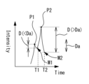
ステップS1-3において、制御部70は、検出信号が極大値をとった後、検出信号の強度が所定量低下したか否か判定する。例えば、図5に示すように、制御部70は、信号強度の極大値と、極大値をとった後の信号強度の最小値との差Dを、所定量Daと比較する。制御部70は、差Dが所定量Daよりも小さい場合はステップS1-4に進み、差Dが所定量Daよりも大きい場合はステップS1-5に進む。例えば、図5の時刻T1の場合、検出信号の極大値P1と、極大値P1の出現以降の最小値M1との差Dは、所定量Daよりも小さいため、制御部70はステップS1-4に進む。図5の時刻T2の場合、検出信号の最大値は、極大値P1よりも大きな極大値P2に更新されている。極大値P2と、極大値P2の出現以降の最小値M2との差Dは、所定量Daよりも大きいため、制御部70は、ステップS1-5に進む。
(Step S1-3: Decrease detection signal determination)
In step S1-3, the
(ステップS1-4:所定時間の経過判定)
ステップS1-4において、制御部70は、検出信号の最大値が更新されてから所定時間Taが経過したか否か判定する。例えば、図6に示すように、制御部70は、最大値が更新された時刻から現時点までの経過時間Tを、所定時間Taと比較する。制御部70は、経過時間Tが所定時間Taよりも長い場合はステップS1-5に進み、経過時間Tが所定時間Taよりも短い場合はステップS1-2に戻る。図6の時刻T4の場合、直近の最大値である極大値P1が検出された時刻T3からの経過時間Tbは、所定時間Taよりも短いため、制御部70はステップS1-2に戻る。図6の時刻T6の場合、直近の最大値である極大値P2が検出された時刻T5からの経過時間Tcは、所定時間Taよりも長いため、制御部70はステップS1-5に進む。
(Step S1-4: Determining the elapse of a predetermined time)
In step S1-4, the
(ステップS1-5:超音波停止)
ステップS1-5において、制御部70は、超音波ユニット100を制御して超音波を停止させ、眼圧の算出に移る。
(Step S1-5: Stop ultrasonic wave)
In step S1-5, the
以上のように、制御部70は、検出信号に基づいて超音波の照射を停止させることによって、被検眼に必要以上に超音波を照射させ、被検者に不快感を与える可能性を抑制できる。
As described above, by stopping the irradiation of ultrasound based on the detection signal, the
従来の空気噴出式の装置では、被検眼に余分な空気が噴射されることを防ぐため、角膜が所定形状に変形する前に空気噴出部の駆動を停止させ、その後はピストンの惰性によって空気を噴出させていた。しかし、超音波式の場合は、角膜の変形が始まった段階で超音波ユニット100の駆動を停止させると、すぐに超音波の照射が終わってしまい、角膜を所定状態まで変形させるだけの音響放射圧を得ることができない。そこで、本実施例のように、制御部70は、検出信号が極大値をとった後、所定量低下することを確認することによって、検出された極大値が誤検出によるものか、角膜が所定形状に変形したことによるものかを容易に判定することができる。これによって、超音波の照射時間が足らず、眼圧測定が不正確になる可能性を低減できる。
In conventional air-jet devices, in order to prevent excess air from being injected into the subject's eye, the drive of the air-jet part is stopped before the cornea is deformed into a predetermined shape, and the air is then pumped out by the inertia of the piston. He was squirting. However, in the case of the ultrasonic type, if the driving of the
なお、ステップS1-4のように、検出信号の最大値が更新されるまでの時間に制限を設けることによって、超音波の照射が不要に長引くことを防げる。 Note that by setting a limit on the time until the maximum value of the detection signal is updated as in step S1-4, it is possible to prevent the ultrasonic irradiation from being unnecessarily prolonged.
<超音波停止の変容例>
なお、制御部70は、眼圧測定を行う際の超音波の照射制御について図7のフローチャートに示すような制御動作を実行させてもよい。図7に示す制御動作は、図4の制御動作に対して超音波を停止させるタイミングが異なる。また、図7は、角膜測定終了後から眼圧の算出前までの制御について示している。
<Example of transformation of ultrasonic stop>
Note that the
(ステップS2-1:超音波照射)
ステップS2-1において、制御部70は、超音波ユニット100によって超音波を発生させる。発生した超音波は、被検眼に照射させる。超音波によって被検眼に音響放射圧が加わり、角膜が変形する。変形検出系260は、角膜の変形を検出し、検出信号を制御部70に送信する。
(Step S2-1: Ultrasonic irradiation)
In step S2-1, the
(ステップS2-2:超音波停止)
ステップS2-2において、制御部70は、所定の照射時間が経過すると、超音波ユニット100を制御して超音波を停止させる。
(Step S2-2: Stop ultrasonic waves)
In step S2-2, the
(ステップS2-3:極大値の有無判定)
ステップS2-3において、制御部70は、変形検出系260から受信した検出信号の変化を監視し、検出信号の極大値の有無を判定する。例えば、制御部70は、時間に対する検出信号のグラフの傾きを算出し、その正負に基づいて極大値の有無を判定する。もちろん、制御部70は、単に検出信号の強度の増減に基づいて極大値の有無を判定してもよい。なお、誤検出による極大値が出現する可能性もあるため、制御部70は、超音波の照射終了時点で最大となる極大値が有るか否かを判定してもよい。この場合、例えば、制御部70は、超音波の照射終了時点で最大となる極大値がないと判定した場合はステップS2-4に進み、最大となる極大値があると判定した場合は眼圧の算出に移る。なお、制御部70は、前述の実施例のように、検出信号が極大値をとった後に所定量低下したか否かを判定基準に用いてもよい。
(Step S2-3: Determining the presence or absence of local maximum value)
In step S2-3, the
(ステップS2-4:照射時間変更)
ステップS2-4において、制御部70は、検出信号にピークが出ていない場合、照射時間を長くする。例えば、図8に示すように、超音波の1回目の照射において、照射時間Tdで超音波を照射した場合、検出信号の極大値P1は検出されない。この場合、制御部70は、超音波の照射時間Tdを照射時間Teに変更する。本実施例において、照射時間Teは、本装置において測定可能な最大の眼圧を求めるための照射時間に設定される。
(Step S2-4: Change irradiation time)
In step S2-4, the
制御部70は、照射時間を変更すると、ステップS2-1に戻る。制御部70は、ステップS2-1、ステップS2-2において、再度、超音波ユニット100によって照射時間Teで超音波を照射する。上記のように、超音波の照射時間が最大に変更された場合、ステップS2-3において検出信号に極大値P1が出現する(図8参照)。
After changing the irradiation time, the
以上のように、予め設定された照射時間で超音波の照射を停止させることによって、正常な眼圧の被検者に与える不快感を低減することができる。 As described above, by stopping the ultrasonic irradiation after a preset irradiation time, it is possible to reduce the discomfort caused to a subject with normal intraocular pressure.
なお、制御部70は、上記のように、始めから最大の照射時間Teに変更しなくてもよく、ステップS2-1~S2-4の処理が繰り返される度、徐々に照射時間を長くしてもよい。これによって、本装置は、超音波が照射される感覚を被検者に徐々に覚えさせ、恐怖心の弱まった状態で測定を行うことができる。
Note that, as described above, the
なお、制御部70は、前回の超音波の照射から次回の超音波の照射までの照射間隔を10msec以内にしてもよい。これによって、被検眼に不快感を与えずに、より短時間で測定を行うことができる。
Note that the
なお、ステップS2-4において、測定時のアライメントがずれた場合、または被検者の瞬きなどによって正常に測定が行われなかった場合、制御部70は、超音波の照射時間を変更しなくてもよい。例えば、制御部70は、超音波照射時の観察系220によって撮影された前眼部画像、またはZアライメント検出系280の検出結果に基づいて、アライメントのずれ、または被検者の瞬きを検知してもよい。アライメントずれ、または瞬きが検出された場合、制御部70は、同じ照射時間で再度測定を行ってもよい。このように、制御部70は、角膜が変形しない要因が超音波の出力以外に考えられる場合、超音波の照射時間を維持することによって、次回の測定で必要以上に超音波を照射することを抑制できる。
Note that in step S2-4, if the alignment at the time of measurement deviates, or if the measurement is not performed normally due to the subject's blinking, etc., the
<超音波の監視>
次に、眼圧測定時における超音波出力の監視についての制御動作を図9のフローチャートに基づいて説明する。制御部70は、超音波ユニット100によって超音波を照射する際に、以下の処理を実行し、超音波出力を監視する。
<Ultrasonic monitoring>
Next, the control operation for monitoring the ultrasonic output during intraocular pressure measurement will be explained based on the flowchart of FIG. When the
(ステップS3-1:検出部による検出)
ステップS3-1において、検出部300は、超音波ユニット100の側面から漏れた超音波を検出し、検出信号を制御部70に送信する。なお、図10に示すように、制御部70は、検出信号を表示部75に表示してもよい。これによって、検者は、表示部75の検出状態を確認することで、超音波が正常に照射されているか否か判断することができる。
(Step S3-1: Detection by detection unit)
In step S3-1, the
(ステップS3-2:異常の有無判定)
ステップS3-2において、制御部70は、検出部300から受け取った検出信号の大きさに基づいて、超音波ユニット100の異常の有無を判定する。例えば、制御部70は、記憶部74記憶された検出信号のイニシャル値と、測定時の検出信号の検出値との比較結果に基づいて、超音波ユニット100の異常の有無を判定する。イニシャル値は、例えば、超音波ユニット100が正常な状態において検出部300によって検出される検出信号の値である。制御部70は、例えば、検出値とイニシャル値の差が正常範囲内であれば超音波ユニット100に異常はないと判定し、正常範囲外であれば超音波ユニット100に異常があると判定する。正常範囲は記憶部74に記憶されており、検者によって適宜設定可能であってもよい。超音波ユニット100に異常があると判定された場合はステップ3-3に進み、異常がないと判定された場合はステップ3-1に戻って超音波の検出を続ける。
(Step S3-2: Determine presence or absence of abnormality)
In step S3-2, the
(ステップS3-3:測定中止)
ステップS3-3において、制御部70は、超音波ユニット100による超音波の発生を中止させ、測定を中断する。これによって、不正確な測定にかかる時間を短縮できる。また、被検眼に不要な超音波を照射することを防げる。
(Step S3-3: Stop measurement)
In step S3-3, the
(ステップS3-4:報知)
ステップS3-4において、制御部70は、超音波ユニット100に異常があったことを検者に報知する。例えば、図10に示すように、制御部70は、超音波に異常がある旨の警告79を表示部75に表示させる。検者は、表示部75の表示を確認することによって、超音波が正常に照射されていないことを把握することができる。なお、表示部75への表示に限らず、制御部70は、スピーカーの音、振動装置の振動、またはランプの点灯などによって、検者に超音波ユニット100の異常を報知してもよい。
(Step S3-4: Notification)
In step S3-4, the
例えば、検出部300が照射経路A(図2参照)の中に配置される場合、検出部300によって超音波が乱れ、被検眼に対して十分な出力の超音波を照射することができない可能性があった。この場合、被検眼を十分に変形させることができず、眼圧を測定することが難しい。しかしながら、上記のように、検出部300を超音波の照射経路Aの外に配置することによって、被検者に照射される超音波が検出部300によって遮られることを抑制できる。したがって、超音波の出力を監視することに加え、被検眼を変形させるのに十分な超音波を照射できる。これによって、本装置は、超音波出力の過不足を監視することができ、安全に眼圧測定を行うことができる。
For example, if the
なお、制御部70は、超音波ユニット100に異常があると判定した場合、超音波ユニット100の制御を変化させてもよい。例えば、制御部70は、被検眼に加わる放射圧が正常になるように超音波ユニット100に加える電圧を自動で変化させてもよい。この場合、制御部70は、検出部300からの検出信号の値が正常値に戻るように超音波ユニット100に加える電圧を調整してもよい。これによって、制御部70は、超音波の出力が異常な場合であっても、すぐに正常な状態に戻して測定を行うことができる。もちろん、超音波ユニット100に対する自動調整の有無は任意に選択可能であってもよい。
Note that the
なお、以上の説明において、検出信号のイニシャル値との比較に基づいて超音波ユニット100の異常の有無を判定したが、これに限らない。例えば、検出信号の正常範囲が予め設定されており、検出信号が正常範囲内に入るか否かで超音波ユニット100の異常の有無を判定してもよい。
In addition, in the above description, the presence or absence of an abnormality in the
また、制御部70は、検出部300によって検出された検出信号の変化に基づいて、超音波ユニット100の異常の有無を判定してもよい。例えば、制御部70は、検出部300によって検出される検出信号が、所定の変化量より大きく変化した場合に超音波ユニット100に異常があると判定してもよい。例えば、検出信号が30%以上変化した場合に超音波ユニット100に異常があると判定してもよい。
Further, the
なお、制御部70は、検出部300によって検出された検出信号に基づいて、照射経路Aの中の超音波の出力を推定してもよい。例えば、超音波の照射目標Tiの位置に超音波センサを設置し、超音波センサによって検出される超音波の大きさと、検出部300によって検出される検出信号の大きさの相関関係を求め、この相関関係を表す数値テーブルを記憶部74に記憶させておく。この場合、制御部70は、記憶部74に記憶された数値テーブルに基づいて、検出部300の検出信号の大きさを超音波の出力値に換算する。これによって、制御部70は、照射経路Aの中を伝わる超音波の大きさを監視することができる。
Note that the
なお、以上の実施例は、超音波の出力が一定である場合を想定しているが、超音波の出力値を調整できる構成であってもよい。例えば、超音波の出力は徐々に大きくなるように出力されてもよい。このような場合、制御部70は、検出部300の検出信号に基づいて、超音波出力の変化を検出してもよい。
In addition, although the above embodiment assumes a case where the output of the ultrasonic waves is constant, a configuration in which the output value of the ultrasonic waves can be adjusted may be used. For example, the output of the ultrasonic wave may be gradually increased. In such a case, the
なお、図6のように、検出信号が複数の極大値(極大値P1,P2)をとる場合、制御部70は、最大の極大値(例えば、極大値P2)をとる時刻(例えば、時刻T5)を基準に眼圧を算出してもよいし、複数の極大値の各時刻(例えば、時刻T3,T5)の平均時刻等を基準として眼圧を算出してもよい。これらの眼圧の算出方法は、検者によって適宜設定可能であってもよい。
Note that, as shown in FIG. 6, when the detection signal takes a plurality of local maximum values (local maximum values P1, P2), the
なお、制御部70は、検出部300の検出結果を眼圧の測定に利用してもよい。例えば、制御部70は、超音波の照射時間に基づいて算出した眼圧を、検出部300によって得られた検出信号に基づいて補正してもよい。これによって、制御部70は、超音波ユニット100の出力が不安定な場合であっても、より正確に被検眼の眼圧を算出することができる。
Note that the
なお、制御部70は、被検眼によって反射した超音波に基づいて眼圧を測定してもよい。例えば、被検眼によって反射した超音波の特性変化に基づいて眼圧を測定してもよいし、被検眼によって反射した超音波から角膜の変形量を取得し、その変形量に基づいて眼圧を測定してもよい。
Note that the
1 超音波眼圧計
2 基台
3 測定部
4 顔支持部
70 制御部
100 超音波ユニット
200 光学ユニット
300 検出部
1
Claims (2)
振動子を有し、前記被検眼に向けて超音波を発生させる超音波発生手段と、
前記超音波発生手段の出力を検出する検出手段と、
前記検出手段の検出信号を監視する制御手段と、を備え、
前記検出手段は、前記超音波発生手段から前記被検眼に向けて照射される超音波の照射経路外に配置され、
前記制御手段は、前記検出手段の検出信号の大きさに基づいて、前記超音波発生手段の異常の有無を判定することを特徴とする超音波眼圧計。 An ultrasonic tonometer for measuring intraocular pressure of an eye to be examined,
an ultrasonic wave generating means having a vibrator and generating ultrasonic waves toward the eye to be examined;
detection means for detecting the output of the ultrasonic wave generation means;
Control means for monitoring the detection signal of the detection means,
The detection means is arranged outside the irradiation path of the ultrasound irradiated from the ultrasound generation means toward the eye to be examined ,
The ultrasonic tonometer, wherein the control means determines whether or not there is an abnormality in the ultrasonic wave generation means based on the magnitude of the detection signal of the detection means .
振動子を有し、前記被検眼に向けて超音波を発生させる超音波発生手段と、
前記超音波発生手段の出力を検出する検出手段と、
前記検出手段の検出信号を監視する制御手段と、を備え、
前記検出手段は、前記超音波発生手段から前記被検眼に向けて照射される超音波の照射経路外に配置され、
前記制御手段は、前記検出手段の検出信号の周波数に基づいて、前記超音波発生手段の異常の有無を判定することを特徴とする超音波眼圧計。 An ultrasonic tonometer for measuring intraocular pressure of an eye to be examined,
an ultrasonic wave generating means having a vibrator and generating ultrasonic waves toward the eye to be examined;
detection means for detecting the output of the ultrasonic wave generation means;
Control means for monitoring the detection signal of the detection means,
The detection means is arranged outside the irradiation path of the ultrasound irradiated from the ultrasound generation means toward the eye to be examined,
The ultrasonic tonometer, wherein the control means determines whether or not there is an abnormality in the ultrasonic wave generation means based on the frequency of the detection signal of the detection means .
Priority Applications (2)
| Application Number | Priority Date | Filing Date | Title |
|---|---|---|---|
| JP2019219894A JP7421069B2 (en) | 2019-12-04 | 2019-12-04 | ultrasonic tonometer |
| CN202011373365.0A CN112890870A (en) | 2019-12-04 | 2020-11-30 | Ultrasonic tonometer |
Applications Claiming Priority (1)
| Application Number | Priority Date | Filing Date | Title |
|---|---|---|---|
| JP2019219894A JP7421069B2 (en) | 2019-12-04 | 2019-12-04 | ultrasonic tonometer |
Publications (3)
| Publication Number | Publication Date |
|---|---|
| JP2021087636A JP2021087636A (en) | 2021-06-10 |
| JP2021087636A5 JP2021087636A5 (en) | 2022-11-10 |
| JP7421069B2 true JP7421069B2 (en) | 2024-01-24 |
Family
ID=76111344
Family Applications (1)
| Application Number | Title | Priority Date | Filing Date |
|---|---|---|---|
| JP2019219894A Active JP7421069B2 (en) | 2019-12-04 | 2019-12-04 | ultrasonic tonometer |
Country Status (2)
| Country | Link |
|---|---|
| JP (1) | JP7421069B2 (en) |
| CN (1) | CN112890870A (en) |
Families Citing this family (1)
| Publication number | Priority date | Publication date | Assignee | Title |
|---|---|---|---|---|
| JP7775126B2 (en) * | 2022-03-29 | 2025-11-25 | 株式会社トプコン | Ophthalmic device and non-contact sensor operation check method |
Citations (6)
| Publication number | Priority date | Publication date | Assignee | Title |
|---|---|---|---|---|
| JP2010068873A (en) | 2008-09-16 | 2010-04-02 | Nidek Co Ltd | Non-contact ultrasonic tonometer |
| JP2010082279A (en) | 2008-09-30 | 2010-04-15 | Nidek Co Ltd | Non-contact ultrasonic tonometer |
| JP2011000344A (en) | 2009-06-22 | 2011-01-06 | Nidek Co Ltd | Non-contact ultrasonic tonometer |
| JP2011045602A (en) | 2009-08-28 | 2011-03-10 | Nidek Co Ltd | Non-contact ultrasonic tonometer |
| JP2011212124A (en) | 2010-03-31 | 2011-10-27 | Nidek Co Ltd | Non-contact type ultrasonic tonometer |
| US20170280998A1 (en) | 2016-04-05 | 2017-10-05 | Adtex Inc. | Non contact eyeball vibration type tonometer |
Family Cites Families (1)
| Publication number | Priority date | Publication date | Assignee | Title |
|---|---|---|---|---|
| JPH05253190A (en) * | 1991-10-10 | 1993-10-05 | Massie Res Lab Inc | Non-contact type tonometer |
-
2019
- 2019-12-04 JP JP2019219894A patent/JP7421069B2/en active Active
-
2020
- 2020-11-30 CN CN202011373365.0A patent/CN112890870A/en active Pending
Patent Citations (6)
| Publication number | Priority date | Publication date | Assignee | Title |
|---|---|---|---|---|
| JP2010068873A (en) | 2008-09-16 | 2010-04-02 | Nidek Co Ltd | Non-contact ultrasonic tonometer |
| JP2010082279A (en) | 2008-09-30 | 2010-04-15 | Nidek Co Ltd | Non-contact ultrasonic tonometer |
| JP2011000344A (en) | 2009-06-22 | 2011-01-06 | Nidek Co Ltd | Non-contact ultrasonic tonometer |
| JP2011045602A (en) | 2009-08-28 | 2011-03-10 | Nidek Co Ltd | Non-contact ultrasonic tonometer |
| JP2011212124A (en) | 2010-03-31 | 2011-10-27 | Nidek Co Ltd | Non-contact type ultrasonic tonometer |
| US20170280998A1 (en) | 2016-04-05 | 2017-10-05 | Adtex Inc. | Non contact eyeball vibration type tonometer |
Also Published As
| Publication number | Publication date |
|---|---|
| CN112890870A (en) | 2021-06-04 |
| JP2021087636A (en) | 2021-06-10 |
Similar Documents
| Publication | Publication Date | Title |
|---|---|---|
| JP6236928B2 (en) | Non-contact ultrasonic tonometer | |
| JP7639685B2 (en) | Ultrasound tonometry | |
| JP7421069B2 (en) | ultrasonic tonometer | |
| JP2015085042A (en) | Non-contact ultrasonic tonometer | |
| JP2023138757A (en) | Ultrasonic tonometer and ultrasonic actuator | |
| JP7192272B2 (en) | ultrasonic tonometer | |
| JP7119597B2 (en) | ultrasonic tonometer | |
| EP3856040B1 (en) | Ultrasonic tonometer and ultrasonic actuator | |
| JP7247561B2 (en) | ultrasonic tonometer | |
| JPH08322803A (en) | Tonometer | |
| JP7259599B2 (en) | ultrasonic tonometer | |
| US12207880B2 (en) | Ultrasonic tonometer | |
| JP7706048B2 (en) | Ultrasonic tonometer and ultrasonic tonometer control program | |
| JPH05261068A (en) | Ophthalmologic device | |
| JP7606093B2 (en) | Ultrasonic tonometer and ultrasonic tonometer control program | |
| JP7375321B2 (en) | intraocular pressure measuring device | |
| JP6586599B2 (en) | Eye refractive power measuring device | |
| JP5378745B2 (en) | Non-contact ultrasonic tonometer | |
| JP2020005678A (en) | Ultrasonic tonometer | |
| EP4501213A1 (en) | Ultrasonic ophthalmic tonometer | |
| JP2021108816A (en) | Ultrasonic tonometer | |
| WO2022210016A1 (en) | Ultrasonic tonometer and ultrasonic tonometer control program | |
| JP2020018653A (en) | Ultrasonic tonometer | |
| JP7110680B2 (en) | non-contact ultrasonic tonometer |
Legal Events
| Date | Code | Title | Description |
|---|---|---|---|
| A521 | Request for written amendment filed |
Free format text: JAPANESE INTERMEDIATE CODE: A523 Effective date: 20221101 |
|
| A621 | Written request for application examination |
Free format text: JAPANESE INTERMEDIATE CODE: A621 Effective date: 20221101 |
|
| A977 | Report on retrieval |
Free format text: JAPANESE INTERMEDIATE CODE: A971007 Effective date: 20230426 |
|
| A131 | Notification of reasons for refusal |
Free format text: JAPANESE INTERMEDIATE CODE: A131 Effective date: 20230530 |
|
| A601 | Written request for extension of time |
Free format text: JAPANESE INTERMEDIATE CODE: A601 Effective date: 20230728 |
|
| A521 | Request for written amendment filed |
Free format text: JAPANESE INTERMEDIATE CODE: A523 Effective date: 20230929 |
|
| TRDD | Decision of grant or rejection written | ||
| A01 | Written decision to grant a patent or to grant a registration (utility model) |
Free format text: JAPANESE INTERMEDIATE CODE: A01 Effective date: 20231212 |
|
| A61 | First payment of annual fees (during grant procedure) |
Free format text: JAPANESE INTERMEDIATE CODE: A61 Effective date: 20231225 |
|
| R150 | Certificate of patent or registration of utility model |
Ref document number: 7421069 Country of ref document: JP Free format text: JAPANESE INTERMEDIATE CODE: R150 |