JP7420834B2 - Method of motion artifact detection - Google Patents
Method of motion artifact detection Download PDFInfo
- Publication number
- JP7420834B2 JP7420834B2 JP2021569335A JP2021569335A JP7420834B2 JP 7420834 B2 JP7420834 B2 JP 7420834B2 JP 2021569335 A JP2021569335 A JP 2021569335A JP 2021569335 A JP2021569335 A JP 2021569335A JP 7420834 B2 JP7420834 B2 JP 7420834B2
- Authority
- JP
- Japan
- Prior art keywords
- motion
- image
- processor
- pattern
- cnn
- Prior art date
- Legal status (The legal status is an assumption and is not a legal conclusion. Google has not performed a legal analysis and makes no representation as to the accuracy of the status listed.)
- Active
Links
- 230000033001 locomotion Effects 0.000 title claims description 188
- 238000000034 method Methods 0.000 title claims description 57
- 238000001514 detection method Methods 0.000 title claims description 15
- 238000013527 convolutional neural network Methods 0.000 claims description 70
- 239000011159 matrix material Substances 0.000 claims description 51
- 238000012549 training Methods 0.000 claims description 44
- 230000006870 function Effects 0.000 claims description 28
- 238000005070 sampling Methods 0.000 claims description 21
- 238000004590 computer program Methods 0.000 claims description 15
- 238000006073 displacement reaction Methods 0.000 claims description 12
- 238000003384 imaging method Methods 0.000 description 36
- 238000002595 magnetic resonance imaging Methods 0.000 description 20
- 238000010586 diagram Methods 0.000 description 9
- 238000012937 correction Methods 0.000 description 6
- 238000012545 processing Methods 0.000 description 6
- 238000013135 deep learning Methods 0.000 description 5
- 238000002059 diagnostic imaging Methods 0.000 description 5
- 238000013473 artificial intelligence Methods 0.000 description 4
- 238000005259 measurement Methods 0.000 description 4
- 230000003287 optical effect Effects 0.000 description 4
- 210000003484 anatomy Anatomy 0.000 description 2
- 238000004891 communication Methods 0.000 description 2
- 230000001419 dependent effect Effects 0.000 description 2
- 238000013461 design Methods 0.000 description 2
- 230000011218 segmentation Effects 0.000 description 2
- 230000002123 temporal effect Effects 0.000 description 2
- 101000863856 Homo sapiens Shiftless antiviral inhibitor of ribosomal frameshifting protein Proteins 0.000 description 1
- 241000699670 Mus sp. Species 0.000 description 1
- 230000002457 bidirectional effect Effects 0.000 description 1
- 230000005540 biological transmission Effects 0.000 description 1
- 238000004364 calculation method Methods 0.000 description 1
- 238000013170 computed tomography imaging Methods 0.000 description 1
- 230000007423 decrease Effects 0.000 description 1
- 230000008034 disappearance Effects 0.000 description 1
- 230000000694 effects Effects 0.000 description 1
- 230000005611 electricity Effects 0.000 description 1
- 230000005284 excitation Effects 0.000 description 1
- 239000000835 fiber Substances 0.000 description 1
- 238000011423 initialization method Methods 0.000 description 1
- 230000002452 interceptive effect Effects 0.000 description 1
- 239000004973 liquid crystal related substance Substances 0.000 description 1
- 238000001208 nuclear magnetic resonance pulse sequence Methods 0.000 description 1
- 230000010355 oscillation Effects 0.000 description 1
- 239000002245 particle Substances 0.000 description 1
- 230000000644 propagated effect Effects 0.000 description 1
- 230000001902 propagating effect Effects 0.000 description 1
- 230000004044 response Effects 0.000 description 1
- 239000004065 semiconductor Substances 0.000 description 1
- 238000004088 simulation Methods 0.000 description 1
- 239000007787 solid Substances 0.000 description 1
- 238000002560 therapeutic procedure Methods 0.000 description 1
- 210000003813 thumb Anatomy 0.000 description 1
- 230000000007 visual effect Effects 0.000 description 1
Images


Classifications
-
- G—PHYSICS
- G16—INFORMATION AND COMMUNICATION TECHNOLOGY [ICT] SPECIALLY ADAPTED FOR SPECIFIC APPLICATION FIELDS
- G16H—HEALTHCARE INFORMATICS, i.e. INFORMATION AND COMMUNICATION TECHNOLOGY [ICT] SPECIALLY ADAPTED FOR THE HANDLING OR PROCESSING OF MEDICAL OR HEALTHCARE DATA
- G16H30/00—ICT specially adapted for the handling or processing of medical images
- G16H30/40—ICT specially adapted for the handling or processing of medical images for processing medical images, e.g. editing
-
- G—PHYSICS
- G06—COMPUTING; CALCULATING OR COUNTING
- G06T—IMAGE DATA PROCESSING OR GENERATION, IN GENERAL
- G06T7/00—Image analysis
- G06T7/0002—Inspection of images, e.g. flaw detection
- G06T7/0012—Biomedical image inspection
-
- A—HUMAN NECESSITIES
- A61—MEDICAL OR VETERINARY SCIENCE; HYGIENE
- A61B—DIAGNOSIS; SURGERY; IDENTIFICATION
- A61B5/00—Measuring for diagnostic purposes; Identification of persons
- A61B5/0033—Features or image-related aspects of imaging apparatus classified in A61B5/00, e.g. for MRI, optical tomography or impedance tomography apparatus; arrangements of imaging apparatus in a room
-
- A—HUMAN NECESSITIES
- A61—MEDICAL OR VETERINARY SCIENCE; HYGIENE
- A61B—DIAGNOSIS; SURGERY; IDENTIFICATION
- A61B5/00—Measuring for diagnostic purposes; Identification of persons
- A61B5/72—Signal processing specially adapted for physiological signals or for diagnostic purposes
- A61B5/7203—Signal processing specially adapted for physiological signals or for diagnostic purposes for noise prevention, reduction or removal
- A61B5/7207—Signal processing specially adapted for physiological signals or for diagnostic purposes for noise prevention, reduction or removal of noise induced by motion artifacts
-
- A—HUMAN NECESSITIES
- A61—MEDICAL OR VETERINARY SCIENCE; HYGIENE
- A61B—DIAGNOSIS; SURGERY; IDENTIFICATION
- A61B5/00—Measuring for diagnostic purposes; Identification of persons
- A61B5/72—Signal processing specially adapted for physiological signals or for diagnostic purposes
- A61B5/7235—Details of waveform analysis
- A61B5/7264—Classification of physiological signals or data, e.g. using neural networks, statistical classifiers, expert systems or fuzzy systems
- A61B5/7267—Classification of physiological signals or data, e.g. using neural networks, statistical classifiers, expert systems or fuzzy systems involving training the classification device
-
- G—PHYSICS
- G01—MEASURING; TESTING
- G01R—MEASURING ELECTRIC VARIABLES; MEASURING MAGNETIC VARIABLES
- G01R33/00—Arrangements or instruments for measuring magnetic variables
- G01R33/20—Arrangements or instruments for measuring magnetic variables involving magnetic resonance
- G01R33/44—Arrangements or instruments for measuring magnetic variables involving magnetic resonance using nuclear magnetic resonance [NMR]
- G01R33/48—NMR imaging systems
- G01R33/54—Signal processing systems, e.g. using pulse sequences ; Generation or control of pulse sequences; Operator console
- G01R33/56—Image enhancement or correction, e.g. subtraction or averaging techniques, e.g. improvement of signal-to-noise ratio and resolution
- G01R33/565—Correction of image distortions, e.g. due to magnetic field inhomogeneities
- G01R33/56509—Correction of image distortions, e.g. due to magnetic field inhomogeneities due to motion, displacement or flow, e.g. gradient moment nulling
-
- G—PHYSICS
- G06—COMPUTING; CALCULATING OR COUNTING
- G06N—COMPUTING ARRANGEMENTS BASED ON SPECIFIC COMPUTATIONAL MODELS
- G06N3/00—Computing arrangements based on biological models
- G06N3/02—Neural networks
- G06N3/04—Architecture, e.g. interconnection topology
- G06N3/045—Combinations of networks
-
- G—PHYSICS
- G06—COMPUTING; CALCULATING OR COUNTING
- G06N—COMPUTING ARRANGEMENTS BASED ON SPECIFIC COMPUTATIONAL MODELS
- G06N3/00—Computing arrangements based on biological models
- G06N3/02—Neural networks
- G06N3/08—Learning methods
-
- G—PHYSICS
- G06—COMPUTING; CALCULATING OR COUNTING
- G06T—IMAGE DATA PROCESSING OR GENERATION, IN GENERAL
- G06T5/00—Image enhancement or restoration
-
- G06T5/60—
-
- G—PHYSICS
- G16—INFORMATION AND COMMUNICATION TECHNOLOGY [ICT] SPECIALLY ADAPTED FOR SPECIFIC APPLICATION FIELDS
- G16H—HEALTHCARE INFORMATICS, i.e. INFORMATION AND COMMUNICATION TECHNOLOGY [ICT] SPECIALLY ADAPTED FOR THE HANDLING OR PROCESSING OF MEDICAL OR HEALTHCARE DATA
- G16H50/00—ICT specially adapted for medical diagnosis, medical simulation or medical data mining; ICT specially adapted for detecting, monitoring or modelling epidemics or pandemics
- G16H50/70—ICT specially adapted for medical diagnosis, medical simulation or medical data mining; ICT specially adapted for detecting, monitoring or modelling epidemics or pandemics for mining of medical data, e.g. analysing previous cases of other patients
-
- G—PHYSICS
- G06—COMPUTING; CALCULATING OR COUNTING
- G06T—IMAGE DATA PROCESSING OR GENERATION, IN GENERAL
- G06T2207/00—Indexing scheme for image analysis or image enhancement
- G06T2207/10—Image acquisition modality
- G06T2207/10072—Tomographic images
- G06T2207/10088—Magnetic resonance imaging [MRI]
-
- G—PHYSICS
- G06—COMPUTING; CALCULATING OR COUNTING
- G06T—IMAGE DATA PROCESSING OR GENERATION, IN GENERAL
- G06T2207/00—Indexing scheme for image analysis or image enhancement
- G06T2207/20—Special algorithmic details
- G06T2207/20081—Training; Learning
-
- G—PHYSICS
- G06—COMPUTING; CALCULATING OR COUNTING
- G06T—IMAGE DATA PROCESSING OR GENERATION, IN GENERAL
- G06T2207/00—Indexing scheme for image analysis or image enhancement
- G06T2207/20—Special algorithmic details
- G06T2207/20084—Artificial neural networks [ANN]
Description
本発明は、スキャニングイメージングシステムに関し、特に、入力画像における運動アーチファクト検出のための方法に関する。 FIELD OF THE INVENTION The present invention relates to scanning imaging systems, and in particular to methods for motion artifact detection in input images.
磁気共鳴イメージング(MRI)スキャン中に、送信機アンテナにより生成される高周波(RF)パルスは局所的な磁場に摂動を生じさせ、原子核スピンにより放出されたるRF信号は、受信機アンテナにより検出される。 During a magnetic resonance imaging (MRI) scan, radio frequency (RF) pulses generated by the transmitter antenna perturb the local magnetic field, and the RF signals emitted by the nuclear spins are detected by the receiver antenna. .
これらのRF信号は、MR画像を構成するために使用される。より長いスキャンの間、スキャンされた被検体は、内部又は外部の動きを有することがあり、かかる動きは、データを破損(corrupts)させるとともに、ブラー(blurs)又はアーチファクトをもつMR画像をもたらす。MR運動アーチファクトを低減し又は補正するために、数多くの方法が提案されている。しかしながら、これらの方法は、画像空間で処理を行い、影響を受けた画像に基づいて運動アーチファクトの特定のフィーチャを認識することを試みる。 These RF signals are used to construct MR images. During longer scans, the scanned object may have internal or external motion, which corrupts the data and results in MR images with blurs or artifacts. A number of methods have been proposed to reduce or correct MR motion artifacts. However, these methods operate in image space and attempt to recognize specific features of motion artifacts based on the affected image.
様々な実施形態が、独立請求項の主題によって説明されるように、入力画像における運動アーチファクト検出のための方法、医用システム、及びコンピュータプログラム製品を提供する。有利な実施形態は、従属請求項に記載されている。 Various embodiments provide a method, a medical system, and a computer program product for motion artifact detection in input images, as described by the subject matter of the independent claims. Advantageous embodiments are described in the dependent claims.
運動アーチファクトは、MRIにおける画像破損の最も多く生じる原因の1つである。ディープラーニング(DL)技術は、例えば、従来のMR画像再構成後、画像空間においてDLネットワークを適用することにより、MR画像の動き補正に適用されることができる。しかしながら、これらの技術は、k空間サンプリングパターンとそのタイミングに関する明示的な情報を捨ててしまうことがある。この情報のすべてではないが一部は、ノイズ値によって初期化された後、DLネットワークの畳み込みカーネルの訓練中に暗示的に学習される。これには、かなりの労力と大量のトレーニングデータが必要になりうる。本主題は、DLネットワークを設計し、それらのカーネルを初期化して、並進運動アーチファクトのような共通の運動アーチファクトを推定するためにかかるカーネルが予め訓練されるように、サンプリングパターンとそのタイミングの明示的知識を使用することにより、動き補正を一層改善することができる。アルゴリズムを用いて、シーケンスパラメータ及び予め規定された運動経路から直接的に、少ない努力でこれらのカーネルを計算することができる。この初期化は、訓練のための努力をかなり短縮することができ、これは、他の形態の動きに対処するために行われる。 Motion artifacts are one of the most common causes of image corruption in MRI. Deep learning (DL) techniques can be applied to motion compensation of MR images, for example by applying a DL network in image space after conventional MR image reconstruction. However, these techniques may discard explicit information about the k-space sampling pattern and its timing. Some, but not all, of this information is implicitly learned during training of the convolution kernel of the DL network after being initialized with noise values. This can require considerable effort and large amounts of training data. The subject matter is to design DL networks and initialize their kernels to specify sampling patterns and their timing so that such kernels are pre-trained to estimate common motion artifacts, such as translational motion artifacts. Motion correction can be further improved by using knowledge of the Using algorithms, these kernels can be computed directly from sequence parameters and predefined motion paths with little effort. This initialization can considerably shorten the training effort, which is done to accommodate other forms of movement.
一態様では、本発明は、運動アーチファクト検出のための医用イメージング方法に関する。本方法は、k空間取得特性を使用して、第1の初期運動パターンによって引き起こされる運動アーチファクトを有する動き破損画像(motion-corrupted image)を生成するステップであって、運動アーチファクトは、特徴行列及び動き破損画像の関数である、ステップと、畳み込みニューラルネットワーク(convolutional neural network,CNN)の少なくとも1つの特徴マップを、特徴行列の値で初期化するステップと、初期化されたCNNをトレーニング画像でトレーニングするステップであって、前記トレーニング画像は、運動アーチファクトを得るように、第2のパターン(タイプ)の動きによって破損されている、ステップと、前記トレーニングされたCNNを用いて入力画像内の運動アーチファクトを得るステップと、を有する。第1の初期タイプの運動パターンと第2の運動パターンは、(多重)変位によってかなり近似される。初期運動パターン(動きの第1の初期タイプ)及びアーチファクトに関して補正されるべき画像の運動パターン(動きの第2の訓練タイプ(パターン))の近似の精度は、プリセットされた所要の画質に関連する残差アーチファクトの予め決定されたレベルに依存する。 In one aspect, the invention relates to a medical imaging method for motion artifact detection. The method includes using k-space acquisition characteristics to generate a motion-corrupted image having motion artifacts caused by a first initial motion pattern, the motion artifacts comprising a feature matrix and initializing at least one feature map of a convolutional neural network (CNN), which is a function of the motion corrupted image, with values of a feature matrix; and training the initialized CNN with the training images. the training image is corrupted by a second pattern (type) of motion so as to obtain a motion artifact; and using the trained CNN to detect motion artifacts in the input image. and a step of obtaining. The first initial type of movement pattern and the second movement pattern are closely approximated by (multiple) displacements. The accuracy of the approximation of the initial motion pattern (first initial type of motion) and the motion pattern of the image to be corrected for artifacts (second training type of motion (pattern)) is related to a preset desired image quality. Depends on a predetermined level of residual artifacts.
現在の主題は、ネットワークが、解剖学的特性ではなく、アーチファクトの純粋な特性を学習することを導くことを可能にする。訓練の努力を低減するために、CNNは、MR運動アーチファクトの画像特徴を使用して、動き補正に関して初期化される。得られた運動アーチファクトは、例えば、入力画像内の運動アーチファクトを補正するために使用され得る。このことは、アーチファクト検出の精度、ゆえにMR動き補正の精度を高めることができる。本主題は、磁気共鳴画像における運動アーチファクトの自動補正を可能にすることができる。 The present subject matter allows the network to be guided to learn pure properties of artifacts rather than anatomical properties. To reduce the training effort, the CNN is initialized for motion correction using image features of MR motion artifacts. The resulting motion artifacts may be used, for example, to correct motion artifacts in the input image. This can increase the accuracy of artifact detection and therefore of MR motion correction. The present subject matter can enable automatic correction of motion artifacts in magnetic resonance images.
本主題は、k空間取得特性を用いることにより、アーチファクト情報の損失を防ぐことができる。特に、本主題は、k空間における連続した取得パターンによる任意の動きは、k空間における動き破壊の時間コヒーレンスに翻訳されること、これらのパターンは、画像ドメインにおける畳み込みネットワークによって「学習」することがはるかに困難であること、及び時間コヒーレンスに関する明示的な知識は、フーリエ再構成中に失われること、を考慮に入れている。 The present subject matter can prevent loss of artifact information by using k-space acquisition characteristics. In particular, the present subject is that any motion due to successive acquisition patterns in k-space is translated into a temporal coherence of motion disruptions in k-space, and that these patterns can be "learned" by convolutional networks in the image domain. It takes into account that it is much more difficult and that explicit knowledge about temporal coherence is lost during Fourier reconstruction.
例えば、訓練済みCNNは、遠隔コンピュータシステムによってアクセス可能であり(例えば、訓練済みCNNは、コンピュータシステム内に格納されることができる)、ここで、コンピュータシステムは、MR画像を受け取ると、訓練済みCNNを用いてMR画像内の運動アーチファクトを自動的に検出するように構成される。これは、訓練済みCNNを用いて、例えば異なるMRIシステム間で集中的かつ一貫したアーチファクト検出を可能にし得るので、有利であり得る。 For example, the trained CNN can be accessed by a remote computer system (e.g., the trained CNN can be stored within the computer system), where upon receiving an MR image, the computer system The CNN is configured to automatically detect motion artifacts in MR images. This may be advantageous as the trained CNN may be used to enable focused and consistent artifact detection, for example between different MRI systems.
k空間取得特性は、MRイメージングプロトコルに依存して決定され得る。イメージングプロトコル又はプロトコルは、検査に必要な画像(例えば、MR画像)を生成するために、撮像モダリティの技術的な設定の組又は取得パラメータの組を参照する。例えば、取得パラメータは、パルスシーケンスのタイプを示すことができる。例えば、本方法は、所与のMRイメージングプロトコルを提供することを含み、ここに、k空間取得特性は、所与のMRイメージングプロトコルを使用して決定されることができる。k空間特性は、k空間サンプリングパターン及びそのタイミングによって決定されることができる。被検体の変位dx(t)の組は、典型的な現実的な動き(例えば、最初のタイプの動き)を反映するように選択することができ、かかる動きは、例えば、任意の方向への一定の速度、初期の静止期間の後の新しい位置への高速な変位、振動、又はより複雑な動きに関する。dx(t)の最大振幅は、臨床撮像セットアップにおけるように、画像の視野(FOV)よりもはるかに小さくなり得る。dx(t)に対するすべての選択は、力学の法則に従うことができ、例えば、時間の連続的な2階微分可能な関数である。これは、動きによって引き起こされるアーチファクトが異なることを可能にしながら、一貫したデータ取得設定を使用することによって、アーチファクト検出の精度を更に高めることができるので、有利であり得る。また、訓練は、回転及び非剛体運動のアーチファクトの学習を可能にすることができる。 K-space acquisition characteristics can be determined depending on the MR imaging protocol. An imaging protocol or protocol refers to a set of technical settings of an imaging modality or a set of acquisition parameters to generate the images (eg, MR images) required for an examination. For example, the acquisition parameters can indicate the type of pulse sequence. For example, the method includes providing a given MR imaging protocol, where k-space acquisition characteristics can be determined using the given MR imaging protocol. K-space characteristics can be determined by the k-space sampling pattern and its timing. The set of displacements dx(t) of the subject can be selected to reflect typical realistic movements (e.g., the first type of movement), such movements being e.g. Concerning constant velocity, rapid displacement to a new position after an initial period of rest, oscillations, or more complex movements. The maximum amplitude of dx(t) can be much smaller than the field of view (FOV) of the image, as in a clinical imaging setup. All choices for dx(t) may follow the laws of mechanics, eg, being a continuous second-differentiable function of time. This can be advantageous as it allows for motion-induced artifacts to be different, while using consistent data acquisition settings can further increase the accuracy of artifact detection. Training can also enable learning of rotational and non-rigid motion artifacts.
一実施形態に従って、初期化することは、CNNの各特徴マップについて、異なる第1の初期運動パターンで特徴行列を決定することと、特徴行列の値を使用して前記特徴マップを初期化することとを含む。 According to one embodiment, initializing includes determining a feature matrix with a different first initial motion pattern for each feature map of the CNN, and initializing the feature map using the values of the feature matrix. including.
例えば、想定されるすべてのタイプの動きは、個々の特徴行列を生じる。この実施形態は、個々の動きを用いて、CNNの並列カーネルの個々のカーネル(又は特徴マップ)を初期化することを可能にする。好ましくは、大きな動きは、低解像度のカーネルに割り当てられることができ、逆に小さな動きは、高解像度カーネルに割り当てられることができる。例えば、第1の初期運動パターンは、初期化されるカーネルの解像度に基づいて決定される。初期化されるべきカーネルが、所定の解像度閾値よりも高い解像度を有する場合、第1の初期運動パターンは、所定の動き振幅閾値よりも小さい動き振幅又はシフトを有することができる。初期化されるべきカーネルが、所定の解像度閾値よりも小さい解像度を有する場合、第1の初期運動パターンは、所定の動き振幅閾値よりも高い動き振幅又はシフトを有することができる。別の例では、CNNのカーネルの各解像度について、それぞれの第1の動きタイプが定義され、運動アーチファクトを定義するために使用されることができる。これにより、CNNは、個々に正確な方法で初期化されるので、正確な運動アーチファクト検出が可能になりうる。 For example, all possible types of movement result in individual feature matrices. This embodiment allows the individual movements to be used to initialize the individual kernels (or feature maps) of the CNN's parallel kernels. Preferably, large movements can be assigned to low resolution kernels, and conversely small movements can be assigned to high resolution kernels. For example, the first initial motion pattern is determined based on the resolution of the kernel being initialized. If the kernel to be initialized has a resolution higher than a predetermined resolution threshold, the first initial motion pattern may have a motion amplitude or shift less than a predetermined motion amplitude threshold. If the kernel to be initialized has a resolution less than a predetermined resolution threshold, the first initial motion pattern may have a motion amplitude or shift higher than the predetermined motion amplitude threshold. In another example, for each resolution of the kernel of the CNN, a respective first motion type may be defined and used to define motion artifacts. This may allow accurate motion artifact detection since the CNN is initialized in an individually accurate manner.
一実施形態によれば、運動アーチファクトは、特徴行列と動き破損画像の乗算としてk空間で定義され、特徴マップは、CNNの乗算レイヤであり、CNNは、画像のk空間表現を入力として受信するように構成される。この実施形態は、CNNを実装して、完全にk空間(CNNはフーリエ変換(FT)レイヤを有する)で動作させ、測定画像のFTに対応して、測定データと直接供給されることを可能にしてもよい。本実施形態のCNNは、畳み込みカーネルの代わりに乗算レイヤを含み得る。 According to one embodiment, motion artifacts are defined in k-space as a multiplication of a feature matrix and a motion-corrupted image, and the feature map is a multiplication layer of a CNN, which receives as input a k-space representation of the image. It is configured as follows. This embodiment implements a CNN, allowing it to operate completely in k-space (the CNN has a Fourier Transform (FT) layer) and to be fed directly with the measurement data, corresponding to the FT of the measurement image. You can also do this. The CNN of this embodiment may include a multiplication layer instead of a convolution kernel.
一実施形態によれば、運動アーチファクトは、特徴行列及び動き破損画像の畳み込みとして画像空間内で定義され、特徴マップはCNNのカーネルであり、CNNは、入力画像として受信するように構成される。この実施形態は、CNNを実現して完全に画像空間で動作させ、測定された画像と共に直接送り出されることを可能にしてもよい。本実施形態のCNNは、畳み込みカーネルを含み得る。 According to one embodiment, the motion artifact is defined in image space as a convolution of a feature matrix and a motion-corrupted image, and the feature map is a kernel of a CNN, which the CNN is configured to receive as an input image. This embodiment may allow the CNN to be implemented to operate entirely in image space and to be sent out directly with the measured images. The CNN of this embodiment may include a convolution kernel.
他の実施形態では、CNNは、k空間及び画像空間をそれぞれ表すFTレイヤ及びFT-1レイヤを有することができ、CNNの各レイヤの特徴マップは、対応する空間において得られた特徴行列を使用して初期化される。次いで、CNNは、CNNの後続のレイヤにおいて、画像空間とk空間とを切り替えることを可能にしうる。 In other embodiments, the CNN can have FT and FT -1 layers representing k-space and image space, respectively, and the feature map of each layer of the CNN uses the feature matrix obtained in the corresponding space. It is initialized as The CNN may then allow switching between image space and k-space in subsequent layers of the CNN.
一実施形態によれば、第1の初期運動パターンは、それぞれの並進変位を特徴とする並進運動である。この実施形態は、並進運動が、MRスキャン中のすべての現在の動きの良好な第1の近似であり得るので、有利であり得る。従って、このタイプの運動のための訓練の努力及び量は、本主題によって低減されることができる。特に、本主題は、次の2つのケースに関係する努力を低減又は節約することができる:1)訓練データの計算は、通常、FT、k空間データ操作、及び画像当たりの逆FTを含む膨大な量の個々の画像に対関する運動アーチファクトのシミュレーションを伴う。2)また、実際の訓練では、訓練画像のランダムなサブセットを使用して、畳み込みカーネルを段階的に「教える(teach)」するためにかなりの努力が必要となりうる。 According to one embodiment, the first initial movement pattern is a translational movement characterized by respective translational displacements. This embodiment may be advantageous because translational motion may be a good first approximation of all current motion during an MR scan. Therefore, the training effort and amount for this type of exercise can be reduced by the present subject matter. In particular, the present subject matter can reduce or save effort related to the following two cases: 1) Training data computations are typically extensive, including FT, k-space data manipulation, and inverse FT per image. involves simulation of motion artifacts for a large amount of individual images. 2) Also, in actual training, considerable effort may be required to "teach" the convolution kernel step by step using a random subset of training images.
一実施形態によれば、第2の訓練運動パターンは、第1の初期運動パターンの組み合わせであり、各第1の初期運動パターンは、それぞれの並進変位によって特徴付けられる。 According to one embodiment, the second training movement pattern is a combination of first initial movement patterns, each first initial movement pattern being characterized by a respective translational displacement.
一実施形態によれば、入力画像内の運動アーチファクトは、第1の初期運動パターンと第2のトレーニング運動パターンとの組み合わせである運動、又は第2のトレーニング運動パターンによって引き起こされる。 According to one embodiment, the motion artifact in the input image is caused by a motion that is a combination of a first initial motion pattern and a second training motion pattern, or by a second training motion pattern.
一実施形態によれば、第1のタイプの動きは、第2のタイプの動きとは異なるか、又は同じである。第2のトレーニング運動パターンは、異なる第1の初期運動パターンとの組み合わせでありうる。 According to one embodiment, the first type of movement is different from or the same as the second type of movement. The second training movement pattern may be a combination with a different first initial movement pattern.
一実施形態によれば、k空間取得特性は、サンプリングのパターン及び/又はk空間のサンプリングのタイミングを有する。本主題は、例えば、サンプリングパターンとそのタイミングの明示的な知識を用いて、画像内の並進運動アーチファクトを推定するためにセットアップされ予め訓練されるように、CNNを設計し、初期化することができる。CNNは、更に、回転運動及びより複雑な運動に対処するように訓練されることができる。これは、完全に画像空間において処理を行われる他の方法とは対照的であり、前記他の方法は、k空間サンプリングパターンとそのタイミングに関する情報の少なくとも一部の損失をもたらす。k空間の2つのサンプリング点が同じ運動状態を表す確率が、サンプリング時間におけるそれらの距離とともに連続的に低下するという事実のために、前記他の方法では利用されることできない構造及び情報が存在する。前記他の方法の訓練中に、パターンとそのタイミングの暗黙の知識をネットワークに導入しても、それは間接的であるため十分でないか、あるいは効率的ではなく、従って非効率的であり、利用可能なすべての情報を利用できないことがある。 According to one embodiment, the k-space acquisition characteristic comprises a pattern of sampling and/or a timing of sampling of k-space. The subject matter can, for example, design and initialize a CNN to be set up and pre-trained to estimate translational artifacts in an image, with explicit knowledge of the sampling pattern and its timing. can. CNNs can also be trained to handle rotational and more complex motions. This is in contrast to other methods that operate entirely in image space, which result in a loss of at least some information about the k-space sampling pattern and its timing. Due to the fact that the probability that two sampling points in k-space represent the same state of motion decreases continuously with their distance in sampling time, there is structure and information that cannot be exploited otherwise. . Introducing tacit knowledge of patterns and their timing into the network during training of the other methods mentioned above is not sufficient or efficient as it is indirect and therefore inefficient and can be used Not all information may be available.
一実施形態によれば、動き破損画像Mの運動アーチファクトAは、特徴行列Kによる動き破損画像Mの畳み込みとして規定され、特徴行列Kは、K=FT-1(FT(D-δ)/FT(D))によって規定され、ここで、
![]()
![]()
一実施形態によれば、動き破損画像の運動アーチファクトは、k空間において、k空間における動き破損画像と特徴行列との乗算として定義され、特徴行列は、FT(D-δ)/FT(D)によって規定され、ここで、
![]()
![]()
一実施形態によれば、k空間表現は、2次元又は3次元表現である。 According to one embodiment, the k-space representation is a two-dimensional or three-dimensional representation.
一実施形態によれば、本方法は、磁気共鳴画像診断装置、MRI、システムから入力画像を受信するステップを更に有し、本方法は、MRIシステムの動作中に実行される。これにより、オンライン又はリアルタイムのアーチファクト補正方法が可能になりうる。 According to one embodiment, the method further comprises receiving input images from a magnetic resonance imaging apparatus, MRI system, and the method is performed during operation of the MRI system. This may enable online or real-time artifact correction methods.
本発明の他の態様は、そのカーネルの別個の初期化(特徴マップ)及びCNNの訓練を含む畳み込みニューラルネットワークの訓練に関する。本発明によるCNNの訓練は、従来の訓練と比較して、少ない労力及び時間しか必要としない。続いて、訓練済みCNNは、磁気共鳴画像の動き補正において用いられることができる。 Other aspects of the invention relate to training a convolutional neural network, including separate initialization of its kernel (feature map) and training of a CNN. Training a CNN according to the invention requires less effort and time compared to conventional training. The trained CNN can then be used in motion correction of magnetic resonance images.
別の態様では、本発明は、プロセッサによる実行のためのマシン実行可能命令を備え、前記マシン実行可能命令の実行が、前記プロセッサを前記実施形態のいずれかの方法にさせるコンピュータプログラム製品に関する。 In another aspect, the invention relates to a computer program product comprising machine-executable instructions for execution by a processor, the execution of the machine-executable instructions causing the processor to do the method of any of the embodiments.
別の態様では、本発明は、前記医用イメージングシステムは、少なくとも1つのプロセッサと、コンピュータプログラムコードを含む少なくとも1つのメモリとを有し、前記少なくとも1つのメモリ及び前記コンピュータプログラムコードは、前記少なくとも1つのプロセッサと共に、前記医用イメージングシステムに、前記実施形態のいずれかの方法の少なくとも一部を少なくとも実行させるように構成される医用分析システムに関する。 In another aspect, the invention provides that the medical imaging system has at least one processor and at least one memory containing computer program code, and the at least one memory and the computer program code The present invention relates to a medical analysis system configured to cause the medical imaging system to perform at least a portion of the method of any of the embodiments.
医用分析システムは、複数のMRIシステムに接続し、MRIシステムのMRIシステムからの入力画像を受信するように構成される。 The medical analysis system is configured to connect to a plurality of MRI systems and receive input images from the MRI systems.
別の態様では、本発明は、医用分析システムを備えるMRIシステムに関する。前記MRIシステムは、画像データを取得し、前記画像データのうちの初期画像を再構成するように構成され、前記初期画像は、前記医用分析システムによって処理されて、前記いずれかの請求項の方法の少なくとも一部を実行する。 In another aspect, the invention relates to an MRI system comprising a medical analysis system. The MRI system is configured to acquire image data and reconstruct an initial image of the image data, the initial image being processed by the medical analysis system to perform the method of any preceding claim. carry out at least some of the
組み合わせられた実施形態が相互に排他的でない限り、本発明の前述の実施形態の1つ又は複数が組み合わせされることができることを理解されたい。 It is to be understood that one or more of the above-described embodiments of the invention can be combined, provided that the combined embodiments are not mutually exclusive.
以下、本発明の好ましい実施形態を、単なる例として、図面を参照して説明する。 Preferred embodiments of the invention will now be described, by way of example only, with reference to the drawings.
以下では、図中の同じ番号の構成要素は、同様の構成要素であるか、又は同等の機能を果たす。前述した構成要素は、機能が同等である場合には、必ずしも後の図で説明されない。 In the following, like-numbered components in the figures are similar components or perform equivalent functions. The previously mentioned components are not necessarily described in subsequent figures if their functions are equivalent.
様々な構造、システム及び装置が、説明のみを目的として、また当業者に周知の詳細とともに本発明を不明瞭にしないように、図に概略的に描かれている。それにもかかわらず、開示された主題の例示的な例を記述し、説明するために、添付の図が含まれている。 Various structures, systems and devices are schematically depicted in the figures for purposes of explanation only and so as not to obscure the present invention with details that are well known to those skilled in the art. Nevertheless, the accompanying figures are included to describe and explain illustrative examples of the disclosed subject matter.
図1は、医用分析システム100の概略図である。医用分析システム100は、スキャンイメージングシステム(又は取得コンポーネント)101に接続するように構成される制御システム111を有する。制御システム111は、プロセッサ103、各々が医用システム100の1つ又は複数の構成要素と通信することができるメモリ107を有する。例えば、制御システム111の構成要素は、双方向システムバス109に結合される。
FIG. 1 is a schematic diagram of a
本明細書に記載される方法は、少なくとも部分的に非インタラクティブであり、コンピュータ化されたシステムによって自動化されていることが理解されるであろう。例えば、これらの方法は更に、ソフトウェア121(ファームウェアを含む)、ハードウェア、又はそれらの組み合わせにおいて実現されることができる。例示的な実施形態では、本明細書に記載する方法は、実行可能なプログラムとしてソフトウェアで実現され、パーソナルコンピュータ、ワークステーション、ミニコンピュータ、又はメインフレームコンピュータなどの特殊な又は汎用のデジタルコンピュータによって実行される。 It will be appreciated that the methods described herein are at least partially non-interactive and automated by computerized systems. For example, these methods may also be implemented in software 121 (including firmware), hardware, or a combination thereof. In an exemplary embodiment, the methods described herein are implemented in software as an executable program and executed by a specialized or general purpose digital computer, such as a personal computer, workstation, minicomputer, or mainframe computer. be done.
プロセッサ103は、特にメモリ107に記憶されたソフトウェアを実行するためのハードウェア装置である。プロセッサ103は、任意のカスタムメイド又は市販のプロセッサ、中央処理装置(CPU)、制御システム111に関連したいくつかのプロセッサの中の補助プロセッサ、半導体ベースのマイクロプロセッサ(マイクロチップ又はチップセットの形成)、マイクロプロセッサ、又は一般にソフトウェア命令を実行するための任意の装置とすることができる。プロセッサ103は、スキャンイメージングシステム101の動作を制御することができる。
メモリ107は、不揮発性メモリ素子(例えば、ランダムアクセスメモリ(DRAM、SRAM、SDRAMなどのRAM))及び不不揮発性メモリ素子(例えば、ROM、消去可能プログラマブル読み出し専用メモリ(EPROM)、電子的消去可能プログラマブル読み出し専用メモリ(EEPROM)、プログラマブル読み出し専用メモリ(PROM)など)の任意の1つ又は組み合わせを含むことができる。メモリ107は分散アーキテクチャを有することができ、この場合、様々なコンポーネントが互いに離れた場所に配置されているが、プロセッサ1によってアクセスすることができることに留意されたい。メモリ107は、医用分析システム100の少なくとも1つの他の構成要素に関連する命令又はデータを格納することができる。
制御システム111は、例えばユーザインタフェース129上に文字及び画像等を表示する表示装置125を更に有することができる。表示装置125は、タッチスクリーン表示装置でありうる。
The
医用分析システム100は、更に、医用分析システム100に電力供給するための電源108を有することができる。電源108は、例えば、バッテリ又は規格ACコンセントによって供給される電気のような外部ソースであってもよい。
スキャンイメージングシステム101は、MRI、CT、及びPET-CT撮像装置のうちの少なくとも1つを有することができる。制御システム111及びスキャニングイメージングシステム101は、一体部分であってもなくてもよい。他の言い方をすれば、制御システム111は、スキャンイメージングシステム101の外部であってもなくてもよい。
スキャンイメージングシステム101は、制御システム111に画像データを提供するようにスキャンイメージングシステム101を構成するために、プロセッサ103によって制御され得るコンポーネントを有する。スキャンイメージングシステム101の構成設定は、スキャンイメージングシステム101の動作を可能にし得る。スキャンイメージングシステム101の動作は、例えば、自動であってもよい。図1は、MRIシステムであるスキャニングイメージングシステム101の構成要素の一例を示す。
制御システム111とスキャニングイメージングシステム101との間の接続は、例えば、バスイーサネット接続、WAN接続、又はインターネット接続等を含みうる。
Connections between
一実施形態では、スキャンイメージングシステム101は、指定された測定値に応じて、画像などの出力データを提供するように構成されることができる。制御システム111は、スキャンイメージングシステム101からMR画像データなどのデータを受信するように構成されることができる。例えば、プロセッサ103は、そのような情報が表示装置125上に表示され得るように、互換性のあるデジタル形式でスキャンイメージングシステム101から情報を(自動的に、又は要求に応じて)受信するように構成されてもよい。そのような情報は、動作パラメータ、警報通知、及びスキャニングイメージングシステム101の使用、動作及び機能に関連する他の情報を含むことができる。
In one embodiment, scanning
医用分析システム100は、ネットワーク130を介して、他のスキャニングイメージングシステム131及び/又はデータベース133と通信するように構成されることができる。ネットワーク130は、例えば、無線ローカルエリアネットワーク(WLAN)接続、WAN(ワイドエリアネットワーク)接続LAN(ローカルエリアネットワーク)接続、又はそれらの組み合わせを含む。データベース133は、患者、スキャニングイメージングシステム、解剖学的構造、スキャンジオメトリ、スキャンパラメータ、スキャンなどに関する情報を含んでもよい。データベース133は、例えば、患者のEMR、放射線情報システムデータベース、医療画像データベース、PACS、病院情報システムデータベース及び/又はスキャンジオメトリを計画するために使用することができるデータを比較する他のデータベースを含むEMRデータベースを有することができる。データベース133は、例えば、訓練画像を有することができる。付加的に、又は代替的に、訓練画像は、制御システム111のローカル記憶装置(例えば、ディスク記憶装置又はメモリ)に記憶されることができる。
メモリ107は、人工知能(AI)コンポーネント150を更に含むことができる。AIコンポーネント150は、ソフトウェアコンポーネント121の一部であってもなくてもよい。AIコンポーネント150は、本主題に従ってCNNを訓練し、更なる使用のために訓練済みCNNを提供するように構成されることができる。例えば、制御システム111がスキャンイメージングシステム101の一部でない場合、訓練済みCNNは、スキャンイメージングシステム101によって再構成される画像内のアーチフキャットを検出するためにスキャンイメージングシステム101において使用され得るように、スキャンイメージングシステム101に提供されることができる。
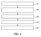
図2は、運動アーチファクト検出のための医用イメージング方法のフローチャートである。ステップ201において、動き破損画像Mを得ることができる。動き破損画像は、モデル化された画像又はシミュレートされた画像でありえ、例えば、これは、動きアーチファクトを有しない理想的な画像から開始して実行されることができる。動き破損画像は、所与のk空間取得特性から生じ得る。k空間取得特性は、例えば、サンプリングパターンx及びそのタイミングtを含むことができる。1又は複数のシフト関数dx(t)が、第1の初期運動パターンを記述する。第1の初期運動パターンは、並進変位関数dx(t)でありえ、この場合、tは、k空間がサンプリングされる際の全ての時間を含みうる。動き破損画像は、第1の初期運動パターンに起因する既知の運動アーチファクトを有する。 FIG. 2 is a flowchart of a medical imaging method for motion artifact detection. In step 201, a motion corrupted image M can be obtained. The motion corrupted image may be a modeled or simulated image; for example, this may be performed starting from an ideal image without motion artifacts. Motion corrupted images can result from given k-space acquisition characteristics. The k-space acquisition characteristics may include, for example, a sampling pattern x and its timing t. One or more shift functions dx(t) describe the first initial motion pattern. The first initial motion pattern may be a translational displacement function dx(t), where t may include all the times that k-space is sampled. The motion corrupted image has known motion artifacts due to the first initial motion pattern.
ステップ203では、運動アーチファクトAは、特徴行列と、動き破損画像Mとの関数として定義し又はモデル化されることができる。運動アーチファクトAは、k空間及び/又は画像空間において規定されることができる。一例において、動き破損画像Mの運動アーチファクトAは、動き破損画像Mの特徴行列との畳み込みとして画像空間においてモデル化されることができる。この場合、特徴行列は畳み込み行列である。別の例では、動き破損画像Mの運動アーチファクトAは、動き破損画像Mの特徴行列との乗算としてk空間においてモデル化されることができる。この場合、特徴行列は乗算行列である。 In step 203, the motion artifact A may be defined or modeled as a function of the feature matrix and the motion corrupted image M. Motion artifact A can be defined in k-space and/or image space. In one example, a motion artifact A of a motion-corrupted image M can be modeled in image space as a convolution with a feature matrix of the motion-corrupted image M. In this case, the feature matrix is a convolution matrix. In another example, the motion artifact A of the motion-corrupted image M can be modeled in k-space as a multiplication with the feature matrix of the motion-corrupted image M. In this case, the feature matrix is a multiplication matrix.
一例において、CNNの各特徴マップについて、ステップ201及び203が、それぞれ異なる第1の初期運動パターンを用いて繰り返されることができる。この結果、CNNの各特徴マップが、それぞれの特徴行列に関連付けられることになりうる。これらのマトリクスの第1の初期運動パターン間の差異は、例えば、特徴マップの解像度に基づいて定義されることができる。例えば、大きな運動は、低解像度の特徴マップに割り当てられ、逆に、小さな運動は、高解像度の特徴マップに割り当てられることができる。 In one example, for each feature map of the CNN, steps 201 and 203 may be repeated using a different first initial motion pattern. As a result, each feature map of the CNN may be associated with a respective feature matrix. The difference between the first initial motion patterns of these matrices can be defined, for example, based on the resolution of the feature map. For example, large motions can be assigned to low-resolution feature maps, and conversely, small motions can be assigned to high-resolution feature maps.
ステップ205で、CNNの少なくとも1つの特徴マップが、特徴行列の値で初期化されることができる。一例では、CNNの各フィルタカーネルは、特徴行列の値で初期化されることができる。これにより、CNNの訓練が改善され、ひいてはアーチファクト検出の精度が向上しうる。別の例では、CNNの第1レイヤの各フィルタカーネルが、特徴行列の値で初期化されることができる。これにより、CNNの訓練とアーチファクト検出の精度が更に向上しうる。別の例では、CNNの各フィルタカーネルについて、ステップ201~205が、異なる第1のタイプの運動に関して繰り返されることができ、その結果、各フィルタカーネルは、それぞれの特徴行列によって初期化される。例えば、異なる仮説シフト関数dx(t)を用いて複数の動き破損画像が得られることができ、それぞれの特徴行列が決定されることができる。これは、CNNの訓練とアーチファクト検出の精度を更に向上することができる。一例では、CNNの特徴マップは、それぞれの予め規定されたサイズを有することができる。別の例では、CNNの各特徴マップのサイズは、特徴マップを初期化するために使用される第1の初期運動パターンを使用して規定されることができる。これは、特徴マップが、第1の方向(例えば、x方向)において、第1の初期運動パターンの範囲よりも大きくないこと、及び第2の方向(例えば、y方向)において、特徴マップのサイズが、k空間タイミング及び取得パターンによって支配されること、を可能にし得る。これは、例えば、図5及び図6の「カーネル(kernel)K」を表す画像に示されており、ここで、画像の白ピクセルは、その「カーネルK」によって初期化されるべき特徴マップのサイズを決定するために使用されることができる。例えば、式(8)は、所与の動きに対してフル解像度でKを計算し、次いで、それが特徴マップのサイズに対応するように、それを関連するサポートにダウンサイジングする。縮小版は、CNNのその特徴マップを初期化するために使用されることがある。
At
初期化されたCNNは、訓練画像において、第2の訓練運動パターンによって引き起こされる運動アーチファクトを得るために、ステップ207において訓練されることができる。訓練画像の各々は、第2の訓練運動パターンによって引き起こされる運動アーチファクトを有している。一例では、第2の訓練運動パターンは、複数の第1の初期運動パターンの組み合わせでありえ、この場合、各々の第1の初期運動パターンは、それぞれの並進変位によって特徴付けられる。これは、初期化が訓練画像内の運動の少なくとも一部を既に考慮しているので、CNNの訓練及びアーチファクト検出の精度を改善することができる。訓練は、そのような初期化方法を使用することによって、迅速に収束することができる。
The initialized CNN can be trained in
訓練済みCNNを使用して、ステップ209において入力画像から運動アーチファクトを得ることができる。 The trained CNN can be used to obtain motion artifacts from the input image in step 209.
運動アーチファクトの取得は、例えば、入力画像が運動アーチファクトを有しているかどうかをCNNを使用して決定することを含み、運動アーチファクトを有している場合には、訓練済みCNNが提供する値を使用して運動アーチファクトが取得されることができる。例えば、訓練済みCNNは、多数のピクセル値を出力として提供することができ、この場合、各ピクセル値は、そのピクセル位置における運動アーチファクトコンテンツを示し、それはゼロであっても消失であってもよい。言い換えると、CNNは、測定された動き破損画像を入力として得、純粋な運動アーチファクトを出力として推定することができる。測定された画像から純粋なアーチファクトを減算して、補正画像を生成することができる。また,訓練済みCNNは,MRイメージング中に異常に発生する実際の動きを反映した値で初期化されるため,運動アーチファクトの検出を正確に行うことができる。これは、入力画像内の運動アーチファクトが、第1の初期運動パターンと第2の訓練運動パターンとの組み合わせである運動、又は第2の訓練運動パターンである運動によって引き起こされる場合に、特に有利であり得る。 Obtaining motion artifacts may include, for example, using a CNN to determine whether the input image has motion artifacts, and if so, determining the value provided by the trained CNN. Motion artifacts can be obtained using: For example, a trained CNN can provide as output a large number of pixel values, where each pixel value indicates the motion artifact content at that pixel location, which may be zero or a disappearance. . In other words, the CNN can take the measured motion-corrupted image as input and estimate the pure motion artifact as output. Pure artifacts can be subtracted from the measured image to generate a corrected image. Furthermore, since the trained CNN is initialized with values that reflect actual movements that occur abnormally during MR imaging, it is possible to accurately detect motion artifacts. This is particularly advantageous if the motion artifact in the input image is caused by a motion that is a combination of a first initial motion pattern and a second training motion pattern, or a motion that is a second training motion pattern. could be.
図3は、本主題の一例に従って畳み込み行列を決定する方法のフローチャートである。 FIG. 3 is a flowchart of a method for determining a convolution matrix according to an example of the present subject matter.
例えば、そのk空間データS=FT(I)を持つ理想的な画像Iが、並進変位関数dx(t)によって特徴付けられる動きを受けると仮定し、ここで、tは、k空間がサンプリングされる際の全ての時間を含む。動き破損画像Mは、ステップ301において、次のように決定され又は定義され得る:
![]()
![]()
なお、ステップ303において、上記(1)式の動き破損画像は、理想的な画像Iから画像Mに帰着する粒度(kernel D)の関数として、(2)式から(3)式を用いて以下のように規定されることができる。
![]()
![]()
Eの逆FTがD=FT-1(E)と表され、
![]()
![]()

![]()
![]()
この結果は、
![]()
![]()
畳み込み行列は、畳み込み定理を用いて、まずフーリエ変換の式(5)への適用により、ステップ307において決定されることができる。これは、式(6)、
![]()
![]()
更に畳み込み定理を使用して(6')式に逆FTを適用する。これにより式(7)が得られる。
![]()
![]()
![]()
![]()
式(8)の畳み込み行列Kは、各運動及び各イメージングプロトコルの組み合わせについて別々に決定されることができる。例えば、運動タイプは、dx(t)の値によって規定されるが、サンプリングパターン及びタイミングは、イメージングプロトコルの収集パラメータ(例えば、収集のタイプ)の組によって規定される。 The convolution matrix K in equation (8) can be determined separately for each movement and each imaging protocol combination. For example, the motion type is defined by the value of dx(t), whereas the sampling pattern and timing are defined by the set of acquisition parameters (eg, acquisition type) of the imaging protocol.
図4は、図3の方法をチェックし又は検証する方法のフローチャートである。図4は、式(8)に組み込まれているような動きを含む取得の例を使用することができる。このために、円盤をもつ理想的なファントム画像Iが、動き破損画像Mをシミュレートするために使用される。そして、選択された特定の運動dx(t)は、典型的なターボ係数、サンプリングパターン、タイミングを持つターボフィールドエコーシーケンスによる取得中に起こるものと仮定した。図4の方法は、例えば、各運動及びシーケンスパラメータの組に関して以下のステップを含むことができる。ステップ401において、シーケンスタイプ及びパラメータに基づいてk空間の各点にサンプリングの時間を割り当てる時間マップTが計算される。ステップ403で、運動dx(t)によってk空間に引き起こされる位相のマップが、式(2)の指数を使用して計算される。ステップ405において、式(2)及び式(3)を用いて、動き破損画像Mが計算される。ステップ407では、Mから理想的なファントム画像Iを引くことによって、グラウンドトゥルースアーチファクトA1が計算される。ステップ409では、CNNの初期化に使用される畳み込み行列Kが、式(8)を使用して計算される。ステップ411では、畳み込み行列K及び式(7)を使用して、純粋なアーチファクトA2が計算される。ステップ413では、A2からグラウンドトゥルースA1を減じた差が計算されることで、式(7)及び(8)の精度、したがって、図3の方法の精度が評価される。図5及び図6は、図4のステップで説明したように得られた画像を示す。
FIG. 4 is a flowchart of a method for checking or verifying the method of FIG. FIG. 4 can use an example of an acquisition involving motion as incorporated in equation (8). For this purpose, an ideal phantom image I with a disc is used to simulate a motion corrupted image M. The particular motion dx(t) selected was then assumed to occur during acquisition with a turbo field echo sequence with typical turbo coefficients, sampling patterns, and timing. The method of FIG. 4 may include, for example, the following steps for each motion and sequence parameter set. In
図5は、セグメント化されたデカルトk空間取得(解像度2562、TR 9ms、ターボ係数4、エコー間時間2ms)を有するTFEシーケンスに基づくチェック方法の結果を示す。k空間データの70%の取得後の5ピクセルの読み出し方向の突然の変位が仮定された。図5に示すように、時間マップ(timemap)は、k空間における4回(4-fold)セグメンテーションを可視化する。位相マップは、データの70%に対して平坦な位相を示し、データの残りの部分に関する変位のために、位相符号化方向の傾きの増加と共に読み出し方向に線形位相を示す。畳み込み行列Kを使用して計算される純粋なアーチファクト(artifact)A2は、例えばMRIシステム700によって測定された画像(image)Mから理想的な画像(ideal image)Iを減じることによって計算されるアーチファクト(artifact)A1とほぼ同一である。畳み込み行列Kは、規定された動きに似た5ピクセルずれた2行のピクセルを示す。
Figure 5 shows the results of a checking method based on a TFE sequence with segmented Cartesian k-space acquisition (resolution 256 2 , TR 9 ms, turbo factor 4, interecho time 2 ms). An abrupt displacement in the readout direction of 5 pixels after acquisition of 70% of the k-space data was assumed. As shown in FIG. 5, a timemap visualizes a 4-fold segmentation in k-space. The phase map shows a flat phase for 70% of the data and, due to the displacement with respect to the rest of the data, a linear phase in the readout direction with increasing slope in the phase encoding direction. The pure artifact A2 calculated using the convolution matrix K is the artifact calculated by subtracting the ideal image I from the image M measured by the
図6は、ターボ係数8(TR 17ms、エコー時間2ms)及び読み出し方向に10ピクセルずつの連続した動きのデータを示す。畳み込み行列Kは、10ピクセルの長い水平線によってこの動きに似ており、ここでは、より高いセグメント化のために、垂直方向に更に離間している。位相符号化方向における5ピクセルの付加的な動きが追加された。 FIG. 6 shows data for a turbo factor of 8 (TR 17 ms, echo time 2 ms) and continuous motion of 10 pixels in the readout direction. The convolution matrix K resembles this movement with long horizontal lines of 10 pixels, now further spaced vertically for higher segmentation. An additional motion of 5 pixels in the phase encoding direction was added.
図5及び図6の例では、畳み込み行列Kは、主に、特定のサンプリングパターンに依存する方法で位相符号化方向に複製される運動経路に類似する。いずれの例でも、カーネルを用いたアーチファクトの計算誤差は無視できる程度であり、式(7)、(8)の正しさを証明している。 In the examples of FIGS. 5 and 6, the convolution matrix K primarily resembles a motion path that is replicated in the phase encoding direction in a manner that depends on the particular sampling pattern. In both examples, the calculation error of artifacts using the kernel is negligible, proving the correctness of equations (7) and (8).
図7は、医用システム100の一例として、磁気共鳴イメージングシステム700を示す。磁気共鳴イメージングシステム700は、磁石704を有する。磁石704は、その中にボア706を有する超伝導円筒型の磁石である。異なる種類の磁石の使用も可能である;例えば、分割円筒形磁石といわゆるオープン磁石又は密閉磁石の両方を使用することも可能である。分割された円筒形磁石は、クライオスタットが磁石の等平面へのアクセスを可能にするために2つのセクションに分割されていることを除いて、標準の円筒形磁石に類似する。このような磁石は、例えば、荷電粒子ビーム治療と併せて使用されることができる。オープン磁石は、撮像すべき被検体718を受け入れるのに十分な大きさの空間をそれらの間に有する2つの磁石部を有し、その間には、ヘルムホルツコイルと同様の2つのセクションの配置がある。円筒形磁石のクライオスタットの内部には、超電導コイルの集合体がある。円筒状磁石704のボア706内には、磁場が磁気共鳴CTを実行するのに十分なほど強力かつ均一である撮像ゾーン又はボリューム又は解剖学的構造708が存在する。
FIG. 7 shows a magnetic
磁石のボア706内には、磁気共鳴データの取得中に、磁石704の撮像ボリューム又は検査ボリューム708内のターゲット領域の磁気スピンを空間的に符号化するために使用される、一組の磁場勾配コイル710も存在する。磁場勾配コイル710は、磁場勾配コイル電源712に接続される。磁場勾配コイル710は、例示であることが意図される。典型的には、磁場勾配コイル710は、3つの直交する空間方向における符号化のための3つの別個のコイルの組を有する。磁場勾配電源は、磁場勾配コイルに電流を供給する。磁場勾配コイル710に供給される電流は、時間の関数として制御され、ランプ状でもパルス状でもよい。
Within the
MRIシステム700は、更に、被検体718のところに且つ検査領域708に隣接して、RF励起パルスを生成するためのRFコイル714を有する。RFコイル714は、例えば、一組の表面コイル又は他の特殊化されたRFコイルを有することができる。RFコイル714は、RFパルスの送信並びに磁気共鳴信号の受信のために交互に使用されることができ、例えば、RFコイル714は、複数のRF送信コイルを有する送信アレイコイルとして実施されることができる。RFコイル714は、1つ又は複数のRF増幅器715に接続される。
磁場勾配コイル電源712及びRF増幅器715は、制御システム111のハードウェアインタフェースに接続される。制御システム111のメモリ107は、例えば、制御モジュールを有することができる。制御モジュールは、プロセッサ103が磁気共鳴イメージングシステム700の動作及び機能を制御することを可能にする、コンピュータ実行可能コードを有する。制御モジュールはまた、磁気共鳴データの取得など、磁気共鳴イメージングシステム700の基本的な動作を可能にする。当業者に理解されるように、本発明の態様は、装置、方法、又はコンピュータプログラム製品として具体化されることができる。従って、本発明の態様は、完全にハードウェアの実施形態、完全にソフトウェアの実施形態(ファームウェア、常駐ソフトウェア、マイクロコードなどを含む)、又は本明細書では一般に「回路」、「モジュール」又は「システム」と呼ぶことができるソフトウェアとハードウェアの態様を組み合わせた実施形態の形態をとることができる。更に、本発明の態様は、具体化されたコンピュータ実行可能コードをその上に有する1つ又は複数のコンピュータ可読媒体内に具体化されるコンピュータプログラム製品の形態をとることができる。
Magnetic field gradient
1つ又は複数のコンピュータ可読媒体の任意の組み合わせが利用されることができる。コンピュータ可読媒体は、コンピュータ可読信号媒体又はコンピュータ可読記憶媒体でありうる。本明細書で使用される「コンピュータ可読記憶媒体」は、コンピューティング装置のプロセッサによって実行可能な命令を記憶することができる任意の有形記憶媒体を包含する。コンピュータ可読記憶媒体は、コンピュータ可読の非一時的記憶媒体と呼ばれることもある。コンピュータ可読記憶媒体はまた、有形コンピュータ可読媒体と呼ばれうる。ある実施形態では、コンピュータ可読記憶媒体は、コンピューティング装置のプロセッサによってアクセス可能なデータを記憶することも可能である。コンピュータ可読記憶媒体の例としては、フロッピーディスク、磁気ハードディスクドライブ、ソリッドステートハードディスク、フラッシュメモリ、USBサムドライブ、ランダムアクセスメモリ、読み取り専用メモリ(ROM)、光ディスク、光磁気ディスク、及びプロセッサのレジスタファイルが挙げられるが、これらに限定されない。光ディスクの例としては、CD-ROM、CD-RW、CD-R、DVD-ROM、DVD-RW、又はDVD-Rディスクなどのコンパクトディスク(CD)及びデジタル多用途ディスク(DVD)がある。コンピュータ可読記憶媒体という語はまた、ネットワーク又は通信リンクを介してコンピュータ装置によってアクセスされることが可能な様々なタイプの記録媒体をさす。例えば、データは、モデムを介して、インターネットを介して、又はローカルエリアネットワークを介して取り出されることができる。コンピュータ可読媒体上に具体化されるコンピュータ実行可能コードは、無線、有線、光ファイバケーブル、RF等を含むがこれらに限定されない任意の適切な媒体、又は前述の任意の適切な組み合わせを用いて送信され得る。 Any combination of one or more computer readable media can be utilized. A computer readable medium may be a computer readable signal medium or a computer readable storage medium. As used herein, "computer-readable storage medium" includes any tangible storage medium that can store instructions executable by a processor of a computing device. Computer-readable storage media are also referred to as computer-readable non-transitory storage media. Computer-readable storage media can also be referred to as tangible computer-readable media. In some embodiments, a computer-readable storage medium can also store data that can be accessed by a processor of a computing device. Examples of computer readable storage media include floppy disks, magnetic hard disk drives, solid state hard disks, flash memory, USB thumb drives, random access memory, read only memory (ROM), optical disks, magneto-optical disks, and processor register files. These include, but are not limited to: Examples of optical discs include compact discs (CDs) and digital versatile discs (DVDs), such as CD-ROM, CD-RW, CD-R, DVD-ROM, DVD-RW, or DVD-R discs. The term computer-readable storage media also refers to various types of storage media that can be accessed by a computing device over a network or communication link. For example, data can be retrieved via a modem, via the Internet, or via a local area network. Computer-executable code embodied on a computer-readable medium can be transmitted using any suitable medium, including but not limited to wireless, wired, fiber optic cable, RF, etc., or any suitable combination of the foregoing. can be done.
コンピュータ可読信号媒体は例えば、ベースバンドで、又は搬送波の一部として、コンピュータ実行可能コードがその中に具体化された伝播されるデータ信号を含むことができる。そのような伝播信号は、電磁、光学、又はそれらの任意の適切な組み合わせを含むが、それらに限定されない、任意の様々な形態をとることができる。コンピュータ可読信号媒体は、任意のコンピュータ可読媒体でありえ、かかるコンピュータ可読媒体は、コンピュータ可読記憶媒体ではなく、命令実行システム、機器、又は装置によって、又はそれに関連して使用されるためのプログラムを通信、伝播、又は伝送することができる。 A computer-readable signal medium can include a propagated data signal with computer-executable code embodied therein, for example, at baseband or as part of a carrier wave. Such propagating signals can take any of a variety of forms, including, but not limited to, electromagnetic, optical, or any suitable combination thereof. A computer-readable signal medium can be any computer-readable medium that is not a computer-readable storage medium that carries a program for use by or in connection with an instruction execution system, apparatus, or device. , propagation, or transmission.
「コンピュータメモリ」又は「メモリ」は、コンピュータ可読記憶媒体の一例である。コンピュータメモリは、プロセッサに直接アクセス可能な任意のメモリである。「コンピュータ記憶装置」又は「記憶装置」は、コンピュータ可読記憶媒体の他の一例である。コンピュータ記憶装置は、任意の不揮発性コンピュータ可読記憶媒体である。ある実施形態では、コンピュータ記憶装置は、コンピュータメモリであってもよく、又はその逆であってもよい。 "Computer memory" or "memory" is an example of a computer-readable storage medium. Computer memory is any memory that is directly accessible to a processor. “Computer storage device” or “storage device” is another example of a computer-readable storage medium. Computer storage is any non-volatile computer-readable storage medium. In some embodiments, computer storage may be computer memory or vice versa.
本明細書で使用される「プロセッサ」は、プログラム又はマシン実行可能命令又はコンピュータ実行可能コードを実行することが可能な電子コンポーネントを包含する。「プロセッサ」を構成するコンピューティング装置への言及は、複数のプロセッサ又は処理コアを含みうるものとして解釈されるべきである。プロセッサは、例えば、マルチコアプロセッサであってもよい。プロセッサは、単一のコンピュータシステム内の、又は複数のコンピュータシステム間で分散されるプロセッサの集合を指すこともできる。コンピューティング装置という語は、プロセッサ又はプロセッサを構成するそれぞれのコンピューティング装置の集合又はネットワークを指すことができると解釈されるべきである。コンピュータ実行可能コードは、複数のプロセッサによって実行されることができ、かかる複数のプロセッサは、同一のコンピューティング装置内にありえ、又は複数のコンピューティング装置に分散されていてもよい。 A "processor" as used herein encompasses an electronic component capable of executing a program or machine-executable instructions or computer-executable code. References to a computing device that constitutes a "processor" should be construed as including multiple processors or processing cores. The processor may be, for example, a multi-core processor. A processor can also refer to a collection of processors within a single computer system or distributed among multiple computer systems. The term computing device should be understood to refer to a processor or a collection or network of respective computing devices that make up the processor. Computer-executable code may be executed by multiple processors, which may be within the same computing device or distributed among multiple computing devices.
コンピュータ実行可能コードは、マシン実行可能命令又はプロセッサに本発明の態様を実行させるプログラムを含むことができる。本発明の態様のための動作を実行するためのコンピュータ実行可能コードは、Java、Smalltalk、C++などのオブジェクト指向プログラミング言語及び「C」プログラミング言語又は類似のプログラミング言語などの従来の手続き型プログラミング言語を含み、マシン実行可能命令にコンパイルされた、1又は複数のプログラミング言語の任意の組み合わせで書くことができる。ある例では、コンピュータ実行可能コードは、高水準言語の形又は事前コンパイルされた形であってもよく、オンザフライでマシン実行可能命令を生成するインタプリタと共に使用されることもできる。 Computer-executable code may include machine-executable instructions or programs that cause a processor to perform aspects of the invention. Computer-executable code for performing operations for aspects of the invention may be implemented in object-oriented programming languages such as Java, Smalltalk, C++, and conventional procedural programming languages such as the "C" programming language or similar programming languages. and can be written in any combination of one or more programming languages, compiled into machine-executable instructions. In some examples, the computer-executable code may be in the form of a high-level language or pre-compiled, and may be used with an interpreter to generate machine-executable instructions on the fly.
コンピュータ実行可能コードは、完全にユーザのコンピュータ上で、部分的にユーザのコンピュータ上で、スタンドアロンのソフトウェアパッケージとして、部分的にユーザのコンピュータ上で且つ部分的にリモートのコンピュータ上で、又は全体的にリモートのコンピュータ又はサーバ上で、実行されることができる。後者の状況では、リモートコンピュータは、ローカルエリアネットワーク(LAN)又は広域ネットワーク(WAN)を含む任意のタイプのネットワークを介してユーザのコンピュータに接続されることができ、又は(例えば、インターネットサービスプロバイダを使用してインターネットを介して)外部コンピュータに接続されることができる。 The computer executable code may be executed entirely on a user's computer, partially on a user's computer, as a stand-alone software package, partially on a user's computer and partially on a remote computer, or entirely on a user's computer. can be executed on a remote computer or server. In the latter situation, the remote computer may be connected to the user's computer via any type of network, including a local area network (LAN) or wide area network (WAN), or may be connected to the user's computer (e.g., via an Internet service provider). (via the Internet) can be connected to an external computer.
本発明の態様は、本発明の実施形態による方法、装置(システム)、及びコンピュータプログラム製品のフローチャート図及び/又はブロック図を参照して説明される。各ブロック又はフローチャートのブロックの一部、図、及び/又はブロック図は、適用可能な場合、コンピュータ実行可能コードの形で、コンピュータプログラム命令によって実現可能であることが理解されるであろう。相互排他的でない場合には、異なるフローチャート、説明、及び/又はブロック図におけるブロックの組み合わせを組み合わせてもよいことが更に理解される。これらのコンピュータプログラム命令は、汎用コンピュータ、専用コンピュータ、又はその他のプログラム可能なデータ処理装置のプロセッサに提供されてマシンを作ることで、コンピュータやその他のプログラム可能なデータ処理装置のプロセッサを介して実行される命令が、フローチャート及び/又はブロック図のブロック又はブロックで指定された機能/動作を実施する手段を作り出す。 Aspects of the invention are described with reference to flowchart illustrations and/or block diagrams of methods, apparatus (systems), and computer program products according to embodiments of the invention. It will be understood that each block or portion of the blocks in the flowcharts, figures, and/or block diagrams, where applicable, can be implemented by computer program instructions in the form of computer executable code. It is further understood that combinations of blocks in different flowchart illustrations, illustrations, and/or block diagrams may be combined where not mutually exclusive. These computer program instructions are provided to the processor of a general purpose computer, special purpose computer, or other programmable data processing device to create a machine for execution through the processor of a computer or other programmable data processing device. The instructions provided create a means for performing the functions/acts specified in the blocks or blocks of the flowchart and/or block diagrams.
これらのコンピュータプログラム命令は、コンピュータ、他のプログラマブルデータ処理装置、又は他のデバイスに特定の方法で機能するように指示することができるコンピュータ可読媒体に記憶されることができ、その結果、コンピュータ可読媒体に記憶された命令は、フローチャート及び/又はブロック図の1又は複数のブロックで指定された機能/動作を実現する命令を含む製品を生成する。 These computer program instructions may be stored on a computer-readable medium capable of instructing a computer, other programmable data processing apparatus, or other device to function in a particular manner, such that the computer-readable The instructions stored on the medium produce a product that includes instructions for implementing the functions/acts specified in one or more blocks of the flowcharts and/or block diagrams.
コンピュータプログラム命令は、コンピュータ、他のプログラマブル装置、又は他のデバイス上で一連の動作ステップを実行させてコンピュータ実現プロセスを生成するように、コンピュータ、他のプログラマブルデータ処理装置、又は他のデバイスにロードされることができ、それにより、コンピュータ又は他のプログラマブル装置上で実行される命令が、フローチャート及び/又はブロック図の1又は複数のブロックに指定される機能/動作を実現するためのプロセスを提供する。 Computer program instructions can be loaded into a computer, other programmable data processing apparatus, or other device to cause a sequence of operational steps to be performed on the computer, other programmable apparatus, or other device to produce a computer-implemented process. instructions executed on a computer or other programmable device to provide a process for implementing the functions/acts specified in one or more blocks of the flowcharts and/or block diagrams. do.
ここで使用される「ユーザインタフェース」は、ユーザ又はオペレータがコンピュータ又はコンピュータシステムと対話することを可能にするインターフェースである。「ユーザインタフェース」は、「ヒューマンインターフェースデバイス」とも呼ばれる。ユーザインタフェースは、情報又はデータをオペレータに提供し、及び/又はオペレータから情報又はデータを受信することができる。ユーザインタフェースは、オペレータからの入力をコンピュータによって受け取ることを可能にし、コンピュータからユーザに出力を提供することができる。換言すれば、ユーザインタフェースは、オペレータがコンピュータを制御し又は操作することを可能にし、インターフェースは、コンピュータがオペレータの制御又は操作の効果を示すことを可能にする。ディスプレイ又はグラフィカルユーザインタフェース上のデータ又は情報の表示は、オペレータに情報を提供する一例である。キーボード、マウス、トラックボール、タッチパッド、ポインティングスティック、グラフィックスタブレット、ジョイスティック、ゲームパッド、ウェブカメラ、ヘッドセット、ギアスティック、スティック、ステアリングホイール、ペダル、有線グローブ、ダンスパッド、リモートコントロール、及び加速度計を通じたデータの受信は、すべて、オペレータからの情報又はデータの受信を可能にするユーザインタフェース構成要素の例である。 A "user interface" as used herein is an interface that allows a user or operator to interact with a computer or computer system. A "user interface" is also referred to as a "human interface device." The user interface may provide information or data to and/or receive information or data from the operator. The user interface allows the computer to receive input from an operator and provide output from the computer to a user. In other words, the user interface allows the operator to control or operate the computer, and the interface allows the computer to indicate the effects of the operator's control or operation. Displaying data or information on a display or graphical user interface is one example of providing information to an operator. Keyboards, mice, trackballs, touchpads, pointing sticks, graphics tablets, joysticks, gamepads, webcams, headsets, gear sticks, sticks, steering wheels, pedals, wired gloves, dance pads, remote controls, and accelerometers. Receiving data through are all examples of user interface components that enable receiving information or data from an operator.
本明細書で使用される「ハードウェアインタフェース」は、コンピュータシステムのプロセッサが外部コンピューティング装置及び/又は機器と対話する及び/又はそれを制御することを可能にするインターフェースを含む。ハードウェアインタフェースは、プロセッサが制御信号又は命令を外部コンピューティング装置及び/又は機器に送信することを可能にし得る。ハードウェアインタフェースはまた、プロセッサが外部コンピューティング装置及び/又は装置とデータを交換することを可能にしうる。ハードウェアインタフェースの例としては、ユニバーサルシリアルバス、IEEE1394ポート、パラレルポート、IEEE1284ポート、シリアルポート、RS-232ポート、IEEE-488ポート、Bluetooth接続、ワイヤレスローカルエリアネットワーク接続、TCP/IP接続、イーサネット接続、制御電圧インターフェース、MIDIインターフェース、アナログ入力インターフェース、及びデジタル入力インターフェースが挙げられるが、これらに限定されない。 As used herein, "hardware interface" includes an interface that allows a computer system's processor to interact with and/or control external computing devices and/or equipment. A hardware interface may enable the processor to send control signals or instructions to external computing devices and/or equipment. A hardware interface may also enable the processor to exchange data with external computing devices and/or devices. Examples of hardware interfaces include universal serial bus, IEEE1394 port, parallel port, IEEE1284 port, serial port, RS-232 port, IEEE-488 port, Bluetooth connection, wireless local area network connection, TCP/IP connection, and Ethernet connection. , control voltage interfaces, MIDI interfaces, analog input interfaces, and digital input interfaces.
本明細書で使用される「ディスプレイ」又は「ディスプレイ装置」は、画像又はデータを表示するように適応された出力デバイス又はユーザインタフェースを包含する。ディスプレイは、視覚的データ、聴覚データ、及び/又は触覚データを出力することができる。ディスプレイの例としては、コンピュータモニタ、テレビスクリーン、タッチスクリーン、触覚電子ディスプレイ、点字スクリーン、ブラウン管(CRT)、蓄積管、双安定ディスプレイ、電子ペーパー、ベクトルディスプレイ、フラットパネルディスプレイ、真空蛍光ディスプレイ(VF)、発光ダイオード(LED)ディスプレイ、エレクトロルミネッセンスディスプレイ(ELD)、プラズマディスプレイパネル(PDP)、液晶ディスプレイ(LCD)、有機発光ダイオードディスプレイ(OLED)、プロジェクタ、及びヘッドマウントディスプレイが挙げられるが、これらに限定されない。 A "display" or "display device" as used herein includes an output device or user interface adapted to display images or data. The display can output visual, auditory, and/or tactile data. Examples of displays include computer monitors, television screens, touch screens, tactile electronic displays, Braille screens, cathode ray tubes (CRTs), storage tubes, bistable displays, electronic paper, vector displays, flat panel displays, and vacuum fluorescent displays (VF). , light emitting diode (LED) displays, electroluminescent displays (ELD), plasma display panels (PDP), liquid crystal displays (LCD), organic light emitting diode displays (OLED), projectors, and head-mounted displays. Not done.
本発明は、図面及び前述の説明において詳細に図示され説明されてきたが、そのような図示及び説明は、説明的又は例示的であり、限定的ではないと考えられるべきである。本発明は開示された実施形態に限定されるものではない。 While the invention has been illustrated and described in detail in the drawings and foregoing description, such illustration and description are to be considered illustrative or exemplary and not restrictive. The invention is not limited to the disclosed embodiments.
開示された実施形態に対する他の変形は、図面、開示、及び添付の請求項の検討から、請求項に記載された発明を実施する際に当業者によって理解され、実施されることができる。請求項において、「含む、有する(comprising)」という語は、他の構成要素又はステップを除外するものではなく、不定冠詞「a」又は「an」は、複数性を除外するものではない。単一のプロセッサ又は他のユニットが、請求項に列挙されるいくつかの項目の機能を果たすことができる。特定の手段が相互に異なる従属請求項に記載されているという単なる事実は、これらの手段の組み合わせが有利に使用されることができないことを示すものではない。コンピュータプログラムは他のハードウェアと一緒に、又はその一部として供給される光記憶媒体又はソリッドステート媒体などの適切な媒体上に記憶/配布されことができるが、インターネット又は他の有線もしくは無線電気通信システムなどを介して、他の形態で配布されることもできる。請求項におけるいかなる参照符号も、範囲を限定するものとして解釈されるべきではない。 Other variations to the disclosed embodiments will be understood and can be practiced by those skilled in the art from a study of the drawings, the disclosure, and the appended claims in practicing the claimed invention. In the claims, the word "comprising" does not exclude other elements or steps, and the indefinite article "a" or "an" does not exclude plurality. A single processor or other unit may fulfill the functions of several items recited in the claims. The mere fact that certain measures are recited in mutually different dependent claims does not indicate that a combination of these measures cannot be used to advantage. The computer program may be stored/distributed on a suitable medium such as an optical storage medium or a solid-state medium provided together with or as part of other hardware, but not connected to the Internet or other wired or wireless electrical It may also be distributed in other forms, such as via communication systems. Any reference signs in the claims shall not be construed as limiting the scope.
100 医用システム
101 スキャンイメージングシステム
103 プロセッサ
107 メモリ
108 電源
109 バス
111 制御装置
121 ソフトウェア
125 ディスプレイ
129 ユーザインタフェース
150 AIコンポーネント
201-413 方法ステップ
700 磁気共鳴イメージングシステム
704 磁石
706 磁石のボア
708 撮像ゾーン
710 磁場勾配コイル
712 磁場勾配コイル電源
714 無線周波数コイル
715 RF増幅器
718 被検体
100
Claims (15)
前記プロセッサが、k空間サンプリングパターンとそのタイミングを表すk空間取得特性を使用して、第1の運動パターンに起因する運動アーチファクトを有する動き破損画像を生成するステップであって、前記運動アーチファクトは、特徴行列と前記動き破損画像の関数として規定される、ステップと、
前記プロセッサが、畳み込みニューラルネットワークの畳み込みカーネル又は乗算カーネルの出力を表す少なくとも1つの特徴マップを前記特徴行列の値で初期化するステップと、
前記プロセッサが、訓練画像により、初期化された畳み込みニューラルネットワーク(CNN)を訓練するステップであって、前記訓練画像は、運動アーチファクトを得るための第2の運動パターンによって破損されたものである、ステップと、
前記プロセッサが、訓練済みCNNを用いて、前記入力画像における運動アーチファクトを得るステップと、
を有する方法。 A method for a processor to detect motion artifacts in an input image, the method comprising:
the processor using k-space acquisition characteristics representative of a k-space sampling pattern and its timing to generate a motion corrupted image having motion artifacts due to the first motion pattern , the motion artifacts comprising: defined as a function of a feature matrix and the motion corrupted image;
the processor initializing at least one feature map representing the output of a convolution kernel or a multiplication kernel of a convolutional neural network with values of the feature matrix;
the processor training an initialized convolutional neural network (CNN) with a training image, the training image being corrupted by a second motion pattern to obtain a motion artifact; step and
the processor using a trained CNN to obtain motion artifacts in the input image;
How to have.
前記プロセッサが、k空間サンプリングパターンとそのタイミングを表すk空間取得特性を使用して、第1の運動パターンに起因する運動アーチファクトを有する動き破損画像を生成するステップであって、前記運動アーチファクトは、特徴行列と前記動き破損画像の関数として規定される、ステップと、
前記プロセッサが、畳み込みニューラルネットワークの畳み込みカーネル又は乗算カーネルを表す少なくとも1つの特徴マップを特徴行列の値で初期化するステップと、
前記プロセッサが、訓練画像により初期化された畳み込みニューラルネットワーク(CNN)を訓練するステップであって、前記訓練画像は、前記運動アーチファクトを得るために第2の運動パターンによって破損されている、ステップと、
を有する方法。 A method for training a convolutional neural network (CNN) for motion artifact detection, the method comprising:
the processor using k-space acquisition characteristics representative of a k-space sampling pattern and its timing to generate a motion corrupted image having motion artifacts due to the first motion pattern , the motion artifacts comprising: defined as a function of a feature matrix and the motion corrupted image;
the processor initializing at least one feature map representing a convolution kernel or a multiplication kernel of a convolutional neural network with values of a feature matrix;
the processor training a convolutional neural network (CNN) initialized with a training image, the training image being corrupted by a second motion pattern to obtain the motion artifact; ,
How to have.
Applications Claiming Priority (3)
| Application Number | Priority Date | Filing Date | Title |
|---|---|---|---|
| EP19176878.7A EP3745153A1 (en) | 2019-05-28 | 2019-05-28 | A method for motion artifact detection |
| EP19176878.7 | 2019-05-28 | ||
| PCT/EP2020/064376 WO2020239661A1 (en) | 2019-05-28 | 2020-05-25 | A method for motion artifact detection |
Publications (3)
| Publication Number | Publication Date |
|---|---|
| JP2022534031A JP2022534031A (en) | 2022-07-27 |
| JPWO2020239661A5 JPWO2020239661A5 (en) | 2023-05-24 |
| JP7420834B2 true JP7420834B2 (en) | 2024-01-23 |
Family
ID=66668764
Family Applications (1)
| Application Number | Title | Priority Date | Filing Date |
|---|---|---|---|
| JP2021569335A Active JP7420834B2 (en) | 2019-05-28 | 2020-05-25 | Method of motion artifact detection |
Country Status (5)
| Country | Link |
|---|---|
| US (1) | US20220215540A1 (en) |
| EP (2) | EP3745153A1 (en) |
| JP (1) | JP7420834B2 (en) |
| CN (1) | CN113892149A (en) |
| WO (1) | WO2020239661A1 (en) |
Families Citing this family (1)
| Publication number | Priority date | Publication date | Assignee | Title |
|---|---|---|---|---|
| CN115343623B (en) * | 2022-08-31 | 2023-06-16 | 中国长江三峡集团有限公司 | Online detection method and device for faults of electrochemical energy storage battery |
Citations (3)
| Publication number | Priority date | Publication date | Assignee | Title |
|---|---|---|---|---|
| US20060074604A1 (en) | 2004-09-24 | 2006-04-06 | International Business Machines (Ibm) Corporation | Identifying a state of a system using an artificial neural network generated model |
| JP2017157138A (en) | 2016-03-04 | 2017-09-07 | キヤノン株式会社 | Image recognition device, image recognition method and program |
| JP2018503152A (en) | 2015-04-02 | 2018-02-01 | ▲騰▼▲訊▼科技(深▲セン▼)有限公司 | Training method and apparatus for convolutional neural network model |
Family Cites Families (9)
| Publication number | Priority date | Publication date | Assignee | Title |
|---|---|---|---|---|
| WO2012145547A1 (en) * | 2011-04-19 | 2012-10-26 | University Of Virginia Patent Foundation | Interferometric magnetic resonance imaging system and related method |
| US8724881B2 (en) * | 2011-11-09 | 2014-05-13 | Siemens Aktiengesellschaft | Method and system for precise segmentation of the left atrium in C-arm computed tomography volumes |
| US10092199B2 (en) * | 2014-04-01 | 2018-10-09 | Siemens Healthcare Gmbh | MR imaging apparatus and method for generating a perfusion image with motion correction |
| CN108024757B (en) * | 2015-08-21 | 2020-10-30 | 上海联影医疗科技有限公司 | System and method for determining deflection angle in magnetic resonance imaging |
| US10074037B2 (en) * | 2016-06-03 | 2018-09-11 | Siemens Healthcare Gmbh | System and method for determining optimal operating parameters for medical imaging |
| EP3646288B1 (en) * | 2017-06-26 | 2022-09-07 | Elekta, Inc. | Method for improving cone-beam ct image quality using a deep convolutional neural network |
| JP6772112B2 (en) * | 2017-07-31 | 2020-10-21 | 株式会社日立製作所 | Medical imaging device and medical image processing method |
| EP3477583A1 (en) * | 2017-10-31 | 2019-05-01 | Koninklijke Philips N.V. | Deep-learning based processing of motion artifacts in magnetic resonance imaging data |
| US10698063B2 (en) * | 2017-11-01 | 2020-06-30 | Siemens Healthcare Gmbh | Motion artifact reduction of magnetic resonance images with an adversarial trained network |
-
2019
- 2019-05-28 EP EP19176878.7A patent/EP3745153A1/en not_active Withdrawn
-
2020
- 2020-05-25 US US17/613,101 patent/US20220215540A1/en active Pending
- 2020-05-25 EP EP20732740.4A patent/EP3977150A1/en active Pending
- 2020-05-25 WO PCT/EP2020/064376 patent/WO2020239661A1/en unknown
- 2020-05-25 CN CN202080039752.2A patent/CN113892149A/en active Pending
- 2020-05-25 JP JP2021569335A patent/JP7420834B2/en active Active
Patent Citations (3)
| Publication number | Priority date | Publication date | Assignee | Title |
|---|---|---|---|---|
| US20060074604A1 (en) | 2004-09-24 | 2006-04-06 | International Business Machines (Ibm) Corporation | Identifying a state of a system using an artificial neural network generated model |
| JP2018503152A (en) | 2015-04-02 | 2018-02-01 | ▲騰▼▲訊▼科技(深▲セン▼)有限公司 | Training method and apparatus for convolutional neural network model |
| JP2017157138A (en) | 2016-03-04 | 2017-09-07 | キヤノン株式会社 | Image recognition device, image recognition method and program |
Non-Patent Citations (3)
| Title |
|---|
| Daiki Tamada, 外4名,"Motion Artifact Reduction Using a Convolutional Neural Network for Dynamic Contrast Enhanced MR Imaging of the Liver",Magnetic Resonance in Medical Science,第19巻, 第1号,Japn Society for magnetic Resonance in Medicin (JSMRM),2019年04月26日,p.64-76 |
| G.A. Wright,"Magnetic resonance imaging",IEEE Signal Processing Magazine,IEEE,1997年01月,第14巻, 第1号,p.56-66 |
| 工藤博幸, 外1名,"MRIにおける静磁場不均一性と被写体の動きの推定",電子情報通信学会論文誌,日本,社団法人電子情報通信学会,1990年12月25日,第J73-D-II巻, 第12号,p.2039-2046 |
Also Published As
| Publication number | Publication date |
|---|---|
| JP2022534031A (en) | 2022-07-27 |
| US20220215540A1 (en) | 2022-07-07 |
| WO2020239661A1 (en) | 2020-12-03 |
| CN113892149A (en) | 2022-01-04 |
| EP3745153A1 (en) | 2020-12-02 |
| EP3977150A1 (en) | 2022-04-06 |
Similar Documents
| Publication | Publication Date | Title |
|---|---|---|
| JP7183265B2 (en) | Localization of Anatomical Landmarks with Artificial Intelligence | |
| US11249160B2 (en) | Image segmentation using reference gray scale values | |
| US11341616B2 (en) | Methods and system for selective removal of streak artifacts and noise from images using deep neural networks | |
| CN110476075A (en) | For the selection of the magnetic resonance fingerprint recognition dictionary of anatomic region | |
| JP6574439B2 (en) | Propeller magnetic resonance imaging | |
| CN110226098A (en) | Picture quality control in the magnetic resonance imaging of Dynamic constrasted enhancement | |
| JP7420834B2 (en) | Method of motion artifact detection | |
| US20230186532A1 (en) | Correction of magnetic resonance images using multiple magnetic resonance imaging system configurations | |
| US20220301687A1 (en) | Uncertainty maps for deep learning eletrical properties tomography | |
| US11906608B2 (en) | Automated detection of water-fat swaps in Dixon magnetic resonance imaging | |
| EP4306983A1 (en) | Making anatomical measurements using magnetic resonance imaging | |
| US20220248973A1 (en) | Deep learning of eletrical properties tomography | |
| JP7301144B2 (en) | Calculation of B0 images using multiple diffusion-weighted MR images | |
| JP7442545B2 (en) | Correction of magnetic resonance images using simulated magnetic resonance images | |
| EP4220212A1 (en) | Simulated computer tomographic imaging | |
| CN115552273A (en) | Machine learning based motion impairment data detection | |
| JP2024512439A (en) | Stepwise reconstruction of planning images for cardiac magnetic resonance imaging |
Legal Events
| Date | Code | Title | Description |
|---|---|---|---|
| A521 | Request for written amendment filed |
Free format text: JAPANESE INTERMEDIATE CODE: A523 Effective date: 20230516 |
|
| A621 | Written request for application examination |
Free format text: JAPANESE INTERMEDIATE CODE: A621 Effective date: 20230516 |
|
| A871 | Explanation of circumstances concerning accelerated examination |
Free format text: JAPANESE INTERMEDIATE CODE: A871 Effective date: 20230516 |
|
| A977 | Report on retrieval |
Free format text: JAPANESE INTERMEDIATE CODE: A971007 Effective date: 20230913 |
|
| A131 | Notification of reasons for refusal |
Free format text: JAPANESE INTERMEDIATE CODE: A131 Effective date: 20230926 |
|
| A521 | Request for written amendment filed |
Free format text: JAPANESE INTERMEDIATE CODE: A523 Effective date: 20231124 |
|
| TRDD | Decision of grant or rejection written | ||
| A01 | Written decision to grant a patent or to grant a registration (utility model) |
Free format text: JAPANESE INTERMEDIATE CODE: A01 Effective date: 20231214 |
|
| A61 | First payment of annual fees (during grant procedure) |
Free format text: JAPANESE INTERMEDIATE CODE: A61 Effective date: 20240111 |
|
| R150 | Certificate of patent or registration of utility model |
Ref document number: 7420834 Country of ref document: JP Free format text: JAPANESE INTERMEDIATE CODE: R150 |