JP7419866B2 - Inertial sensors, electronic devices, and mobile objects - Google Patents
Inertial sensors, electronic devices, and mobile objects Download PDFInfo
- Publication number
- JP7419866B2 JP7419866B2 JP2020026014A JP2020026014A JP7419866B2 JP 7419866 B2 JP7419866 B2 JP 7419866B2 JP 2020026014 A JP2020026014 A JP 2020026014A JP 2020026014 A JP2020026014 A JP 2020026014A JP 7419866 B2 JP7419866 B2 JP 7419866B2
- Authority
- JP
- Japan
- Prior art keywords
- movable body
- inertial sensor
- support beam
- axis
- substrate
- Prior art date
- Legal status (The legal status is an assumption and is not a legal conclusion. Google has not performed a legal analysis and makes no representation as to the accuracy of the status listed.)
- Active
Links
- 239000000758 substrate Substances 0.000 claims description 46
- 238000001514 detection method Methods 0.000 claims description 39
- 230000001133 acceleration Effects 0.000 description 12
- 238000006073 displacement reaction Methods 0.000 description 9
- 230000000694 effects Effects 0.000 description 8
- 230000008878 coupling Effects 0.000 description 6
- 238000010168 coupling process Methods 0.000 description 6
- 238000005859 coupling reaction Methods 0.000 description 6
- 239000011521 glass Substances 0.000 description 6
- 239000000463 material Substances 0.000 description 4
- XUIMIQQOPSSXEZ-UHFFFAOYSA-N Silicon Chemical compound [Si] XUIMIQQOPSSXEZ-UHFFFAOYSA-N 0.000 description 3
- 230000008859 change Effects 0.000 description 3
- 229910052710 silicon Inorganic materials 0.000 description 3
- 239000010703 silicon Substances 0.000 description 3
- XKRFYHLGVUSROY-UHFFFAOYSA-N Argon Chemical compound [Ar] XKRFYHLGVUSROY-UHFFFAOYSA-N 0.000 description 2
- IJGRMHOSHXDMSA-UHFFFAOYSA-N Atomic nitrogen Chemical compound N#N IJGRMHOSHXDMSA-UHFFFAOYSA-N 0.000 description 2
- 229910001413 alkali metal ion Inorganic materials 0.000 description 2
- 239000000919 ceramic Substances 0.000 description 2
- 238000005530 etching Methods 0.000 description 2
- 238000000034 method Methods 0.000 description 2
- RZVAJINKPMORJF-UHFFFAOYSA-N Acetaminophen Chemical compound CC(=O)NC1=CC=C(O)C=C1 RZVAJINKPMORJF-UHFFFAOYSA-N 0.000 description 1
- 241000251468 Actinopterygii Species 0.000 description 1
- ZOXJGFHDIHLPTG-UHFFFAOYSA-N Boron Chemical compound [B] ZOXJGFHDIHLPTG-UHFFFAOYSA-N 0.000 description 1
- 238000009623 Bosch process Methods 0.000 description 1
- 235000015842 Hesperis Nutrition 0.000 description 1
- 235000012633 Iberis amara Nutrition 0.000 description 1
- OAICVXFJPJFONN-UHFFFAOYSA-N Phosphorus Chemical compound [P] OAICVXFJPJFONN-UHFFFAOYSA-N 0.000 description 1
- 230000004913 activation Effects 0.000 description 1
- 229910052786 argon Inorganic materials 0.000 description 1
- 229910052785 arsenic Inorganic materials 0.000 description 1
- RQNWIZPPADIBDY-UHFFFAOYSA-N arsenic atom Chemical compound [As] RQNWIZPPADIBDY-UHFFFAOYSA-N 0.000 description 1
- 239000002585 base Substances 0.000 description 1
- 229910052796 boron Inorganic materials 0.000 description 1
- 239000005388 borosilicate glass Substances 0.000 description 1
- 238000010276 construction Methods 0.000 description 1
- 238000013016 damping Methods 0.000 description 1
- 230000006866 deterioration Effects 0.000 description 1
- 238000009792 diffusion process Methods 0.000 description 1
- 238000005516 engineering process Methods 0.000 description 1
- 239000001307 helium Substances 0.000 description 1
- 229910052734 helium Inorganic materials 0.000 description 1
- SWQJXJOGLNCZEY-UHFFFAOYSA-N helium atom Chemical compound [He] SWQJXJOGLNCZEY-UHFFFAOYSA-N 0.000 description 1
- 239000012535 impurity Substances 0.000 description 1
- 239000011261 inert gas Substances 0.000 description 1
- 230000007257 malfunction Effects 0.000 description 1
- 229910052751 metal Inorganic materials 0.000 description 1
- 239000002184 metal Substances 0.000 description 1
- 238000012544 monitoring process Methods 0.000 description 1
- 229910052757 nitrogen Inorganic materials 0.000 description 1
- 238000000059 patterning Methods 0.000 description 1
- 229910052698 phosphorus Inorganic materials 0.000 description 1
- 239000011574 phosphorus Substances 0.000 description 1
- 239000005297 pyrex Substances 0.000 description 1
- 230000001105 regulatory effect Effects 0.000 description 1
- 230000004044 response Effects 0.000 description 1
- 239000004984 smart glass Substances 0.000 description 1
- 229910001415 sodium ion Inorganic materials 0.000 description 1
- 239000000725 suspension Substances 0.000 description 1
Images


Classifications
-
- G—PHYSICS
- G01—MEASURING; TESTING
- G01P—MEASURING LINEAR OR ANGULAR SPEED, ACCELERATION, DECELERATION, OR SHOCK; INDICATING PRESENCE, ABSENCE, OR DIRECTION, OF MOVEMENT
- G01P15/00—Measuring acceleration; Measuring deceleration; Measuring shock, i.e. sudden change of acceleration
- G01P15/02—Measuring acceleration; Measuring deceleration; Measuring shock, i.e. sudden change of acceleration by making use of inertia forces using solid seismic masses
- G01P15/03—Measuring acceleration; Measuring deceleration; Measuring shock, i.e. sudden change of acceleration by making use of inertia forces using solid seismic masses by using non-electrical means
- G01P15/032—Measuring acceleration; Measuring deceleration; Measuring shock, i.e. sudden change of acceleration by making use of inertia forces using solid seismic masses by using non-electrical means by measuring the displacement of a movable inertial mass
-
- G—PHYSICS
- G01—MEASURING; TESTING
- G01P—MEASURING LINEAR OR ANGULAR SPEED, ACCELERATION, DECELERATION, OR SHOCK; INDICATING PRESENCE, ABSENCE, OR DIRECTION, OF MOVEMENT
- G01P15/00—Measuring acceleration; Measuring deceleration; Measuring shock, i.e. sudden change of acceleration
- G01P15/02—Measuring acceleration; Measuring deceleration; Measuring shock, i.e. sudden change of acceleration by making use of inertia forces using solid seismic masses
- G01P15/08—Measuring acceleration; Measuring deceleration; Measuring shock, i.e. sudden change of acceleration by making use of inertia forces using solid seismic masses with conversion into electric or magnetic values
- G01P15/125—Measuring acceleration; Measuring deceleration; Measuring shock, i.e. sudden change of acceleration by making use of inertia forces using solid seismic masses with conversion into electric or magnetic values by capacitive pick-up
-
- B—PERFORMING OPERATIONS; TRANSPORTING
- B60—VEHICLES IN GENERAL
- B60R—VEHICLES, VEHICLE FITTINGS, OR VEHICLE PARTS, NOT OTHERWISE PROVIDED FOR
- B60R21/00—Arrangements or fittings on vehicles for protecting or preventing injuries to occupants or pedestrians in case of accidents or other traffic risks
- B60R21/01—Electrical circuits for triggering passive safety arrangements, e.g. airbags, safety belt tighteners, in case of vehicle accidents or impending vehicle accidents
- B60R21/013—Electrical circuits for triggering passive safety arrangements, e.g. airbags, safety belt tighteners, in case of vehicle accidents or impending vehicle accidents including means for detecting collisions, impending collisions or roll-over
- B60R21/0132—Electrical circuits for triggering passive safety arrangements, e.g. airbags, safety belt tighteners, in case of vehicle accidents or impending vehicle accidents including means for detecting collisions, impending collisions or roll-over responsive to vehicle motion parameters, e.g. to vehicle longitudinal or transversal deceleration or speed value
-
- G—PHYSICS
- G01—MEASURING; TESTING
- G01P—MEASURING LINEAR OR ANGULAR SPEED, ACCELERATION, DECELERATION, OR SHOCK; INDICATING PRESENCE, ABSENCE, OR DIRECTION, OF MOVEMENT
- G01P15/00—Measuring acceleration; Measuring deceleration; Measuring shock, i.e. sudden change of acceleration
- G01P15/02—Measuring acceleration; Measuring deceleration; Measuring shock, i.e. sudden change of acceleration by making use of inertia forces using solid seismic masses
- G01P15/08—Measuring acceleration; Measuring deceleration; Measuring shock, i.e. sudden change of acceleration by making use of inertia forces using solid seismic masses with conversion into electric or magnetic values
-
- G—PHYSICS
- G01—MEASURING; TESTING
- G01P—MEASURING LINEAR OR ANGULAR SPEED, ACCELERATION, DECELERATION, OR SHOCK; INDICATING PRESENCE, ABSENCE, OR DIRECTION, OF MOVEMENT
- G01P15/00—Measuring acceleration; Measuring deceleration; Measuring shock, i.e. sudden change of acceleration
- G01P15/18—Measuring acceleration; Measuring deceleration; Measuring shock, i.e. sudden change of acceleration in two or more dimensions
-
- B—PERFORMING OPERATIONS; TRANSPORTING
- B60—VEHICLES IN GENERAL
- B60R—VEHICLES, VEHICLE FITTINGS, OR VEHICLE PARTS, NOT OTHERWISE PROVIDED FOR
- B60R21/00—Arrangements or fittings on vehicles for protecting or preventing injuries to occupants or pedestrians in case of accidents or other traffic risks
- B60R21/01—Electrical circuits for triggering passive safety arrangements, e.g. airbags, safety belt tighteners, in case of vehicle accidents or impending vehicle accidents
- B60R21/013—Electrical circuits for triggering passive safety arrangements, e.g. airbags, safety belt tighteners, in case of vehicle accidents or impending vehicle accidents including means for detecting collisions, impending collisions or roll-over
- B60R21/0132—Electrical circuits for triggering passive safety arrangements, e.g. airbags, safety belt tighteners, in case of vehicle accidents or impending vehicle accidents including means for detecting collisions, impending collisions or roll-over responsive to vehicle motion parameters, e.g. to vehicle longitudinal or transversal deceleration or speed value
- B60R2021/01325—Vertical acceleration
-
- G—PHYSICS
- G01—MEASURING; TESTING
- G01P—MEASURING LINEAR OR ANGULAR SPEED, ACCELERATION, DECELERATION, OR SHOCK; INDICATING PRESENCE, ABSENCE, OR DIRECTION, OF MOVEMENT
- G01P15/00—Measuring acceleration; Measuring deceleration; Measuring shock, i.e. sudden change of acceleration
- G01P15/02—Measuring acceleration; Measuring deceleration; Measuring shock, i.e. sudden change of acceleration by making use of inertia forces using solid seismic masses
- G01P15/08—Measuring acceleration; Measuring deceleration; Measuring shock, i.e. sudden change of acceleration by making use of inertia forces using solid seismic masses with conversion into electric or magnetic values
- G01P2015/0805—Measuring acceleration; Measuring deceleration; Measuring shock, i.e. sudden change of acceleration by making use of inertia forces using solid seismic masses with conversion into electric or magnetic values being provided with a particular type of spring-mass-system for defining the displacement of a seismic mass due to an external acceleration
- G01P2015/0822—Measuring acceleration; Measuring deceleration; Measuring shock, i.e. sudden change of acceleration by making use of inertia forces using solid seismic masses with conversion into electric or magnetic values being provided with a particular type of spring-mass-system for defining the displacement of a seismic mass due to an external acceleration for defining out-of-plane movement of the mass
- G01P2015/0825—Measuring acceleration; Measuring deceleration; Measuring shock, i.e. sudden change of acceleration by making use of inertia forces using solid seismic masses with conversion into electric or magnetic values being provided with a particular type of spring-mass-system for defining the displacement of a seismic mass due to an external acceleration for defining out-of-plane movement of the mass for one single degree of freedom of movement of the mass
- G01P2015/0831—Measuring acceleration; Measuring deceleration; Measuring shock, i.e. sudden change of acceleration by making use of inertia forces using solid seismic masses with conversion into electric or magnetic values being provided with a particular type of spring-mass-system for defining the displacement of a seismic mass due to an external acceleration for defining out-of-plane movement of the mass for one single degree of freedom of movement of the mass the mass being of the paddle type having the pivot axis between the longitudinal ends of the mass, e.g. see-saw configuration
-
- G—PHYSICS
- G01—MEASURING; TESTING
- G01P—MEASURING LINEAR OR ANGULAR SPEED, ACCELERATION, DECELERATION, OR SHOCK; INDICATING PRESENCE, ABSENCE, OR DIRECTION, OF MOVEMENT
- G01P15/00—Measuring acceleration; Measuring deceleration; Measuring shock, i.e. sudden change of acceleration
- G01P15/02—Measuring acceleration; Measuring deceleration; Measuring shock, i.e. sudden change of acceleration by making use of inertia forces using solid seismic masses
- G01P15/08—Measuring acceleration; Measuring deceleration; Measuring shock, i.e. sudden change of acceleration by making use of inertia forces using solid seismic masses with conversion into electric or magnetic values
- G01P2015/0862—Measuring acceleration; Measuring deceleration; Measuring shock, i.e. sudden change of acceleration by making use of inertia forces using solid seismic masses with conversion into electric or magnetic values being provided with particular means being integrated into a MEMS accelerometer structure for providing particular additional functionalities to those of a spring mass system
- G01P2015/0871—Measuring acceleration; Measuring deceleration; Measuring shock, i.e. sudden change of acceleration by making use of inertia forces using solid seismic masses with conversion into electric or magnetic values being provided with particular means being integrated into a MEMS accelerometer structure for providing particular additional functionalities to those of a spring mass system using stopper structures for limiting the travel of the seismic mass
-
- G—PHYSICS
- G01—MEASURING; TESTING
- G01P—MEASURING LINEAR OR ANGULAR SPEED, ACCELERATION, DECELERATION, OR SHOCK; INDICATING PRESENCE, ABSENCE, OR DIRECTION, OF MOVEMENT
- G01P15/00—Measuring acceleration; Measuring deceleration; Measuring shock, i.e. sudden change of acceleration
- G01P15/02—Measuring acceleration; Measuring deceleration; Measuring shock, i.e. sudden change of acceleration by making use of inertia forces using solid seismic masses
- G01P15/08—Measuring acceleration; Measuring deceleration; Measuring shock, i.e. sudden change of acceleration by making use of inertia forces using solid seismic masses with conversion into electric or magnetic values
- G01P2015/0862—Measuring acceleration; Measuring deceleration; Measuring shock, i.e. sudden change of acceleration by making use of inertia forces using solid seismic masses with conversion into electric or magnetic values being provided with particular means being integrated into a MEMS accelerometer structure for providing particular additional functionalities to those of a spring mass system
- G01P2015/0882—Measuring acceleration; Measuring deceleration; Measuring shock, i.e. sudden change of acceleration by making use of inertia forces using solid seismic masses with conversion into electric or magnetic values being provided with particular means being integrated into a MEMS accelerometer structure for providing particular additional functionalities to those of a spring mass system for providing damping of vibrations
Description
本発明は、慣性センサー、電子機器、及び移動体に関する。 The present invention relates to an inertial sensor, an electronic device, and a moving object.
近年、MEMS(Micro Electro Mechanical Systems)技術を用いて製造された慣性センサーが開発されている。このような慣性センサーとして、例えば特許文献1には、基板と、基板に対して鉛直方向に沿う回転軸まわりにシーソー揺動する可動体と、基板に設けられた検出電極と、を有し、可動体の互いに回転軸まわりの回転モーメントが異なる第1可動部及び第2可動部と、夫々に対向する位置に配置された第1検出電極及び第2検出電極と、の間の静電容量の変化に基づいて鉛直方向の加速度を検出することができる慣性センサーが記載されている。
また、この慣性センサーは、可動体が過度にシーソー揺動した際に、可動体の端部が基板と接触することを防ぐ突起が基板に設けられている。
In recent years, inertial sensors manufactured using MEMS (Micro Electro Mechanical Systems) technology have been developed. Such an inertial sensor, for example, in
Further, in this inertial sensor, a protrusion is provided on the substrate to prevent the end of the movable body from coming into contact with the substrate when the movable body swings excessively.
しかしながら、特許文献1に記載された慣性センサーは、過度のシーソー揺動によって可動体と突起とが衝突した時に、可動体及び突起の剛性が高いため、その衝撃を吸収することができず可動体や突起を破損してしまう虞があった。
However, in the inertial sensor described in
慣性センサーは、基板と、前記基板に設けられた固定部と、前記基板と対向し、第1支持梁を第1回転軸として変位可能な第1可動体と、第1方向に並んだ前記第1可動体と前記固定部とを接続する前記第1支持梁と、第2支持梁の変形により変位可能な第2可動体と、前記第1方向と交差する第2方向に並んだ前記第1可動体と前記第2可動体とを接続する前記第2支持梁と、前記基板又は前記第2可動体に設けられ、前記第1方向及び前記第2方向と交差する第3方向からの平面視で、前記第2可動体と重なり、前記第2可動体又は前記基板に向かって突出する突起と、を備えている。 The inertial sensor includes a substrate, a fixed part provided on the substrate, a first movable body facing the substrate and movable about a first support beam as a first rotation axis, and the first movable body arranged in a first direction. the first support beam that connects the first movable body and the fixed part; the second movable body that can be displaced by deformation of the second support beam; and the first movable body arranged in a second direction intersecting the first direction. The second support beam connecting the movable body and the second movable body, and the second support beam provided on the substrate or the second movable body, when viewed from a third direction intersecting the first direction and the second direction. and a protrusion that overlaps the second movable body and projects toward the second movable body or the substrate.
電子機器は、上記に記載の慣性センサーと、前記慣性センサーから出力された検出信号に基づいて制御を行う制御部と、を備えている。 The electronic device includes the inertial sensor described above and a control section that performs control based on a detection signal output from the inertial sensor.
移動体は、上記に記載の慣性センサーと、前記慣性センサーから出力された検出信号に基づいて制御を行う制御部と、を備えている。 The moving body includes the inertial sensor described above and a control section that performs control based on a detection signal output from the inertial sensor.
1.第1実施形態
先ず、第1実施形態に係る慣性センサー1について、鉛直方向(Z方向)の加速度を検出する加速度センサーを一例として挙げ、図1及び図2を参照して説明する。
なお、図1において、慣性センサー1の内部の構成を説明する便宜上、蓋5を取り外した状態を図示している。また、図1において、基板2の凹部21内の配線は、省略している。
1. First Embodiment First, an
Note that, in FIG. 1, the
また、説明の便宜上、各図には互いに直交する3つの軸として、X軸、Y軸、及びZ軸を図示している。また、X軸に沿った方向を「X方向」、Y軸に沿った方向を「Y方向」、Z軸に沿った方向を「Z方向」と言う。また、各軸方向の矢印先端側を「プラス側」、基端側を「マイナス側」、Z方向プラス側を「上」、Z方向マイナス側を「下」とも言う。また、Z方向は、鉛直方向に沿い、XY平面は、水平面に沿っている。また、本実施形態における第1方向とは、Y方向であり、第2方向とは、X方向であり、第3方向とは、Z方向である。 Furthermore, for convenience of explanation, each figure shows an X-axis, a Y-axis, and a Z-axis as three mutually orthogonal axes. Further, the direction along the X axis is referred to as the "X direction," the direction along the Y axis is referred to as the "Y direction," and the direction along the Z axis is referred to as the "Z direction." Further, the tip side of the arrow in each axis direction is also referred to as the "plus side," the proximal end side is also referred to as the "minus side," the positive side in the Z direction is also referred to as "upper," and the negative side in the Z direction is also referred to as "lower." Further, the Z direction is along the vertical direction, and the XY plane is along the horizontal plane. Further, in this embodiment, the first direction is the Y direction, the second direction is the X direction, and the third direction is the Z direction.
図1及び図2に示す慣性センサー1は、センサー素子3の鉛直方向(Z方向)の加速度を検出することができる。このような慣性センサー1は、基板2と、基板2上に配置されたセンサー素子3と、基板2に接合され、センサー素子3を覆う蓋5と、を有する。
The
基板2は、図1に示すように、X方向及びY方向に広がりを有し、Z方向を厚さとする。また、基板2は、図2に示すように、上面側に開口する凹部21が形成されている。この凹部21は、Z方向からの平面視で、センサー素子3を内側に内包し、センサー素子3よりも大きく形成されている。凹部21は、センサー素子3と基板2との接触を抑制する逃げ部として機能する。また、基板2は、凹部21の底面からセンサー素子3側に突出している固定部22と突起23とを有し、凹部21の底面に第1検出電極24、第2検出電極25、及びダミー電極26が配置されている。そして、固定部22の上面にセンサー素子3が接合されている。また、突起23は、Z方向からの平面視で、後述する第2可動体38と重なる位置に配置されている。
As shown in FIG. 1, the
突起23は、第1可動体31に過度なシーソー揺動が生じた際に第1可動体31と連結する第2可動体38と接触することにより、第1可動体31のそれ以上のシーソー揺動を規制するストッパーとして機能する。このような突起23を設けることにより、互いに電位が異なる第1可動体31と第1検出電極24及び第2検出電極25との過度な接近または広面積での接触を抑制することができ、第1可動体31と第1検出電極24及び第2検出電極25との間に生じる静電引力によって第1可動体31が第1検出電極24や第2検出電極25に引き付けられたまま戻らなくなる「スティッキング」の発生を効果的に抑制することができる。
The
基板2としては、例えば、Na+等の可動イオンであるアルカリ金属イオンを含むガラス材料、例えば、パイレックス(登録商標)ガラス、テンパックス(登録商標)ガラスのような硼珪酸ガラスで構成されたガラス基板を用いることができる。ただし、基板2としては、特に限定されず、例えば、シリコン基板やセラミックス基板を用いてもよい。
The
また、図1に示すように、基板2には、凹部21の底面に、平面視で、センサー素子3と重なっている第1検出電極24、第2検出電極25、及びダミー電極26が配置されている。
Further, as shown in FIG. 1, on the
蓋5は、図2に示すように、下面側に開口する凹部51が形成されている。蓋5は、凹部51内にセンサー素子3を収納して基板2の上面に接合されている。そして、蓋5及び基板2によって、その内側に、センサー素子3を収納する収納空間Sが形成されている。収納空間Sは、気密空間であり、窒素、ヘリウム、アルゴン等の不活性ガスが封入され、使用温度が-40℃~125℃程度で、ほぼ大気圧となっていることが好ましい。ただし、収納空間Sの雰囲気は、特に限定されず、例えば、減圧状態であってもよいし、加圧状態であってもよい。
As shown in FIG. 2, the
蓋5としては、例えば、シリコン基板を用いることができる。ただし、これに特に限定されず、例えば、ガラス基板やセラミックス基板を用いてもよい。また、基板2と蓋5との接合方法としては、特に限定されず、基板2や蓋5の材料によって適宜選択すればよく、例えば、陽極接合、プラズマ照射によって活性化させた接合面同士を接合させる活性化接合、ガラスフリット等の接合材による接合、基板2の上面及び蓋5の下面に成膜した金属膜同士を接合する拡散接合等を用いることができる。
As the
センサー素子3は、例えば、リン(P)、ボロン(B)、砒素(As)等の不純物がドープされた導電性のシリコン基板をエッチング、特に、深溝エッチング技術であるボッシュ・プロセスによってパターニングすることにより形成される。センサー素子3は、図1に示すように、固定部22の上面に接合されている保持部32と、保持部32に対してY軸に沿う第1回転軸としての回転軸J1まわりに変位可能な第1可動体31と、第1可動体31と保持部32とを接続する第1支持梁33と、保持部32に対してX軸に沿う第2回転軸としての回転軸J2まわりに変位可能な第2可動体38と、X方向に並んだ第1可動体31と第2可動体38とを接続する第2支持梁37と、を有する。固定部22と保持部32とは、例えば、陽極接合されており、第1支持梁33は、保持部32を介して、第1可動体31と固定部22とを接続していることとなる。
The
第1可動体31は、Z方向からの平面視で、X方向を長手方向とする長方形形状となっている。また、第1可動体31は、Z方向からの平面視で、Y軸に沿う回転軸J1を間に挟んで配置された第1質量部34及び第2質量部35と、第2質量部35に接続されている第3質量部36と、を有する。第1質量部34は、回転軸J1に対してX方向プラス側に位置し、第2質量部35及び第3質量部36は、回転軸J1に対してX方向マイナス側に位置する。また、第2質量部35及び第3質量部36は、第1質量部34よりもX方向に長く、Z方向の加速度Azが加わったときの回転軸J1まわりの回転モーメントが第1質量部34よりも大きい。
The first
この回転モーメントの差によって、加速度Azが加わった際に第1可動体31が回転軸J1まわりにシーソー揺動する。なお、シーソー揺動とは、第1質量部34がZ方向プラス側に変位すると、第2質量部35がZ軸方向マイナス側に変位し、反対に、第1質量部34がZ軸方向マイナス側に変位すると、第2質量部35がZ軸方向プラス側に変位することを意味する。
Due to this difference in rotational moment, the first
また、第1可動体31は、第1質量部34と第2質量部35とが第1連結部39によって連結され、第1質量部34と第2質量部35との間に位置する開口45を有する。そして、開口45内に保持部32及び第1支持梁33が配置されている。このように、第1可動体31の内側に保持部32及び第1支持梁33を配置することにより、センサー素子3の小型化を図ることができる。また、第1可動体31は、その全域に均一に形成されている複数の貫通孔を有する。これにより、粘性によるダンピングを低減することができる。ただし、貫通孔は、省略してもよいし、その配置が均一でなくてもよい。
Further, in the first
また、第1可動体31は、Y方向に並んだ第1連結部39と保持部32とが、Y方向に延在する第1支持梁33によって接続されている。そのため、第1支持梁33を回転軸J1として、第1可動体31を回転軸J1まわりにシーソー揺動で変位させることができる。
Further, in the first
第1質量部34は、2つの質量部で構成され、Y方向の中央部において、第2連結部40によって連結されている。第1質量部34は、第2連結部40のY方向の両側に、第2連結部40側からY方向に延在する第2可動体38が配置され、第2可動体38の第2連結部40側の端部のX方向の両側と、2つの質量部と、がそれぞれX方向に延在する第2支持梁37で接続されている。より具体的には、第2連結部40のY方向プラス側に配置された第2支持梁37は、X方向に並んだY方向プラス側に延在する第2可動体38と、第1質量部34の2つの質量部と、を接続し、第2連結部40のY方向マイナス側に配置された第2支持梁37は、X方向に並んだY方向マイナス側に延在する第2可動体38と、第1質量部34の2つの質量部と、を接続している。
The first
第2質量部35は、第1質量部34と同様に、2つの質量部で構成され、Y方向の中央部において、第2連結部40によって連結されている。第2質量部35は、第2連結部40のY方向の両側に、第2連結部40側からY方向に延在する第2可動体38が配置され、第2可動体38の第2連結部40側の端部のX方向の両側と、2つの質量部と、がそれぞれX方向に延在する第2支持梁37で接続されている。また、第2質量部35は、X方向マイナス側の端部が第3連結部41によって、第3質量部36と連結しており、第2質量部35と第3質量部との間には、第1質量部34と第2質量部35とのXY平面の面積を同等にするための開口46が設けられている。
Like the first
第1質量部34及び第2質量部35に配置された第2支持梁37は、X方向に延在している梁形状であるため、回転軸J1と交差するX軸に沿う回転軸J2として作用し、第2支持梁37に接続された第2可動体38を回転軸J2まわりに変位させることができる。また、Z方向からの平面視で、第2可動体38の第2支持梁37と接続している側とは反対側の先端部と重なる位置に、基板2に設けられた突起23が配置されている。
そのため、第1可動体31に過度なシーソー揺動が生じた際に第2可動体38と突起23とが接触すると、第2支持梁37が回転軸J2まわりにねじれるように変形し、突起23との衝撃を軽減することができ、第2可動体38や突起23の破損を低減した上で、第1可動体31のそれ以上のシーソー揺動を規制することができる。従って、第2支持梁37及び第2可動体38は、衝撃を吸収するダンパーとして機能する。
Since the
Therefore, when the second
なお、第2支持梁37の回転軸J2まわりのねじり剛性は、第1支持梁33の回転軸J1まわりのねじり剛性よりも高い。そのため、同じ力が加わった場合に、第1支持梁33による第1可動体31の変位量に対し、第2支持梁37の第2可動体38の変位量が小さくなるため、第2支持梁37と第2可動体38とによって、ストッパーとして機能させることができる。
Note that the torsional rigidity of the
本実施形態では、1つの第2支持梁37、第2可動体38、及び突起23を1組として4組配置されており、Z方向からの平面視で、回転軸J1と平行なY方向を挟み第1質量部34及び第2質量部35にそれぞれ2組配置され、第1質量部34及び第2質量部35では、第2連結部40を挟み、対向するように、2組の第2支持梁37、第2可動体38、及び突起23が配置されている。Y方向を挟み4組の第2支持梁37、第2可動体38、及び突起23が対称に配置されているため、回転軸J1まわりの不要な変位を生じ難く、また、X方向を挟み4組の第2支持梁37、第2可動体38、及び突起23が対称に配置されているため、回転軸J2まわりの不要な変位を生じ難くすることができる。
In this embodiment, four sets are arranged, with one
また、第2支持梁37の回転軸J2を、第1支持梁33のY軸に沿う回転軸J1と直交するX軸に沿う方向とすることで、ダンパー機能とストッパー機能とを備えた状態で、X方向からの耐衝撃性を向上することができる。つまり、第1支持梁33の回転軸J1と第2支持梁37の回転軸J2とをY軸に沿う方向とすると、X方向からの衝撃に対し、第1可動体31がX方向に大きく変位し、特性劣化を生じし易くなるためである。
Furthermore, by setting the rotation axis J2 of the
次に、凹部21の底面に配置された第1検出電極24、第2検出電極25、及びダミー電極26について説明する。
図1及び図2に示すように、Z方向からの平面視で、第1検出電極24は、第1質量部34と重なって配置され、第2検出電極25は、第2質量部35と重なって配置されている。これら第1検出電極24及び第2検出電極25は、加速度Azが加わっていない自然状態で後述する静電容量Ca,Cbが等しくなるように、Z方向からの平面視で、回転軸J1に対して略対称に設けられている。
Next, the
As shown in FIGS. 1 and 2, in plan view from the Z direction, the
また、ダミー電極26は、第2検出電極25よりもX方向マイナス側に位置し、第3質量部36と重なって設けられている。このように、凹部21の底面をダミー電極26で覆うことにより、基板2中のアルカリ金属イオンの移動に伴う凹部21の底面の帯電を抑制することができる。そのため、凹部21の底面と第2質量部35との間に第1可動体31の誤作動に繋がるような意図しない静電引力が生じることを効果的に抑制することができる。そのため、加速度Azをより精度よく検出することのできる慣性センサー1となる。
Further, the
図示しないが、慣性センサー1の駆動時には、図示しない配線を介してセンサー素子3に駆動電圧が印加され、第1検出電極24とQVアンプとが、第2検出電極25と別のQVアンプとが、それぞれ図示しない配線により接続される。これにより、第1質量部34と第1検出電極24との間に静電容量Caが形成され、第2質量部35と第2検出電極25との間に静電容量Cbが形成される。加速度Azが加わっていない自然状態では静電容量Ca,Cbが互いにほぼ等しい。
Although not shown, when the
慣性センサー1に加速度Azが加わると、第1可動体31が回転軸J1を中心にしてシーソー揺動する。この第1可動体31のシーソー揺動により、第1質量部34と第1検出電極24とのギャップと、第2質量部35と第2検出電極25とのギャップと、が逆相で変化し、これに応じて静電容量Ca,Cbが互いに逆相で変化する。そのため、慣性センサー1は、静電容量Ca,Cbの変化に基づいて加速度Azを検出することができる。
When acceleration Az is applied to the
本実施形態の慣性センサー1は、第1可動体31に設けられた第2支持梁37の変形により変位可能な第2可動体38と、基板2に設けられ、Z方向からの平面視で、第2可動体38と重なり、第2可動体38に向かって突出する突起23と、を備えている。そのため、第1可動体31に過度なシーソー揺動が生じた際に第2可動体38と突起23とが接触すると、第2支持梁37が回転軸J2まわりにねじれるように変形するので、突起23との衝撃を軽減することができ、第2可動体38や突起23の破損を低減することができる。
The
また、X方向に延在する複数の第2支持梁37を、第2連結部40を挟み、対向して配置することで、第2支持梁37のX方向の長さをより長くすることができ、突起23との衝撃をより軽減することができる。
Further, by arranging the plurality of second support beams 37 extending in the X direction to face each other with the second connecting
また、第2支持梁37のねじり剛性が第1支持梁33のねじり剛性よりも高いので、第2可動体38の変位量が第1可動体31の変位量より小さくなり、第1可動体31の過度なシーソー揺動を規制することができる。
Further, since the torsional rigidity of the
2.第2実施形態
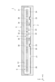
次に、第2実施形態に係る慣性センサー1aについて、図3を参照して説明する。なお、図3は、図1中のA-A線における断面図に相当する。
2. Second Embodiment Next, an
本実施形態の慣性センサー1aは、第1実施形態の慣性センサー1に比べ、センサー素子3aと基板2aの構造が異なること以外は、第1実施形態の慣性センサー1と同様である。なお、前述した第1実施形態との相違点を中心に説明し、同様の事項はその説明を省略する。
The
慣性センサー1aのセンサー素子3aは、図3に示すように、第2可動体38aに基板2aに向かって突出する突起23aが設けられている。そのため、第1可動体31に過度なシーソー揺動が生じた際に第2可動体38aに設けられた突起23aと、基板2aの凹部21の底面と、が接触することで、第1実施形態の慣性センサー1と同様の効果を得ることができる。
As shown in FIG. 3, the sensor element 3a of the
3.第3実施形態
次に、第3実施形態に係る慣性センサー1bについて、図4を参照して説明する。なお、図4は、図1中のB部の位置における平面図に相当する。
3. Third Embodiment Next, an
本実施形態の慣性センサー1bは、第1実施形態の慣性センサー1に比べ、第2可動体38bと第2連結部40bとの構造が異なること以外は、第1実施形態の慣性センサー1と同様である。なお、前述した第1実施形態との相違点を中心に説明し、同様の事項はその説明を省略する。
The
慣性センサー1bは、図4に示すように、第2可動体38bの第2支持梁37に接続する側に第2連結部40b側に突出する凸部42が設けられている。また、第2連結部40bの凸部42と対向する位置には、第2可動体38bの変位に伴い凸部42との接触を回避するために、凸部42側に開口する凹部43が設けられている。凸部42を設けることにより、第2可動体38bが回転軸J2まわりに変位する際に第2可動体38bと第2支持梁37との連結部分に生じる応力を凸部42と第2支持梁37との連結部分に分散できるので、連結部分に応力が集中するのを緩和することができ、連結部分での破損を抑制することができる。よって、慣性センサー1bは、第2支持梁37と第2可動体38bとの連結部分の機械的強度が向上し、且つ、第1実施形態の慣性センサー1と同様の効果を得ることができる。
As shown in FIG. 4, the
4.第4実施形態
次に、第4実施形態に係る慣性センサー1cについて、図5を参照して説明する。なお、図5は、図1中のB部の位置における平面図に相当する。
4. Fourth Embodiment Next, an
本実施形態の慣性センサー1cは、第1実施形態の慣性センサー1に比べ、第2可動体38cと第2連結部40cとの構造が異なること以外は、第1実施形態の慣性センサー1と同様である。なお、前述した第1実施形態との相違点を中心に説明し、同様の事項はその説明を省略する。
The
慣性センサー1cは、図5に示すように、第2可動体38cの第2支持梁37cに接続する側に第2連結部40c側に突出する凸部42cが設けられており、第2可動体38cと第2支持梁37cとの連結部分及び凸部42cと第2支持梁37cとの連結部分が曲面となっている。また、第2連結部40cの凸部42cと対向する位置には、第2可動体38cの変位に伴い凸部42cとの接触を回避するために、凸部42c側に開口し、凹内の2隅に曲面を有する凹部43cが設けられている。連結部分を曲面とすることにより、第2可動体38cが回転軸J2まわりに変位する際に第2支持梁37cと第2可動体38cとの連結部分や第2支持梁37cと凸部42cとの連結部分に応力が集中するのを緩和することができ、連結部分での破損を抑制することができる。よって、慣性センサー1cは、第2支持梁37cと第2可動体38cとの連結部分の機械的強度がより向上し、且つ、第1実施形態の慣性センサー1と同様の効果を得ることができる。
As shown in FIG. 5, the
5.第5実施形態
次に、第5実施形態に係る慣性センサー1dについて、図6を参照して説明する。なお、図6は、図1中のC部の位置における平面図に相当する。
5. Fifth Embodiment Next, an
本実施形態の慣性センサー1dは、第1実施形態の慣性センサー1に比べ、第1可動体31dと第2支持梁37dとの構造が異なること以外は、第1実施形態の慣性センサー1と同様である。なお、前述した第1実施形態との相違点を中心に説明し、同様の事項はその説明を省略する。
The
慣性センサー1dは、図6に示すように、第1可動体31dと第2支持梁37dとの連結部分が曲面となっている。また、第2支持梁37dを挟む両側の連結部分の曲面形状は、X軸に対して線対称である。なお、本実施形態では連結部分の曲面が、Z方向からの平面視で、1/4円形となっているが、これに限定されることはなく、半円形でも構わない。
連結部分を曲面とすることにより、第2可動体38が回転軸J2まわりに変位する際に連結部分に応力が集中するのを緩和することができ、連結部分での破損を抑制することができる。よって、慣性センサー1dは、第1可動体31dと第2支持梁37dとの連結部分の機械的強度が向上し、且つ、第1実施形態の慣性センサー1と同様の効果を得ることができる。
In the
By forming the connecting portion into a curved surface, stress concentration on the connecting portion can be alleviated when the second
6.第6実施形態
次に、第6実施形態に係る慣性センサー1eについて、図7を参照して説明する。なお、図7は、図1中のC部の位置における平面図に相当する。
6. Sixth Embodiment Next, an
本実施形態の慣性センサー1eは、第1実施形態の慣性センサー1に比べ、第1可動体31eと第2支持梁37eとの構造が異なること以外は、第1実施形態の慣性センサー1と同様である。なお、前述した第1実施形態との相違点を中心に説明し、同様の事項はその説明を省略する。
The
慣性センサー1eは、図7に示すように、第1可動体31eと第2支持梁37eとの連結部分が曲面となっている。また、第2支持梁37eを挟む両側の連結部分の曲面形状は、Z方向からの平面視で、第1可動体31eと第2支持梁37eとの空隙のY方向の長さや第2連結部40eと第2支持梁37eとの空隙のY方向の長さより大きい直径を有する円形であり、X軸に対して線対称である。なお、第2支持梁37dを挟む両側の連結部分の曲面形状は、同一直径の円形に限定されることはなく、直径が異なる円形でも構わない。
連結部分を曲面とすることにより、第2可動体38が回転軸J2まわりに変位する際に連結部分に応力が集中するのを緩和することができ、連結部分での破損を抑制することができる。よって、慣性センサー1eは、第1可動体31eと第2支持梁37eとの連結部分の機械的強度が向上し、且つ、第1実施形態の慣性センサー1と同様の効果を得ることができる。
In the
By forming the connecting portion into a curved surface, stress concentration on the connecting portion can be alleviated when the second
7.第7実施形態
次に、第7実施形態に係る慣性センサー1fについて、図8を参照して説明する。なお、図8は、図1中のD部の位置における平面図に相当する。
7. Seventh Embodiment Next, an
本実施形態の慣性センサー1fは、第1実施形態の慣性センサー1に比べ、第2可動体38fの構造が異なること以外は、第1実施形態の慣性センサー1と同様である。なお、前述した第1実施形態との相違点を中心に説明し、同様の事項はその説明を省略する。
The
慣性センサー1fは、図8に示すように、第2可動体38fの第2支持梁37が接続されている側とは反対側の端部に、第1可動体31に対向する切り欠き部44が設けられている。より詳細には、第2可動体38fの先端部のX方向の両側にそれぞれ切り欠き部44が設けられている。
第2可動体38fに切り欠き部44を設けることで、X方向やY方向からの衝撃等により第1可動体31と第2可動体38fとが衝突し、第1可動体31や第2可動体38fを破損するのを抑制することができる。よって、慣性センサー1fは、耐衝撃性に優れ、且つ、第1実施形態の慣性センサー1と同様の効果を得ることができる。
As shown in FIG. 8, the
By providing the
更に、第2可動体38fの第2支持梁37側の部分と切り欠き部44との連結部分は、第1可動体31側に凸の曲面である。これにより、X方向やY方向からの衝撃等により第1可動体31側に凸の曲面と第1可動体31とが衝突し、第1可動体31や第2可動体38fを破損するのを抑制することができる。
Further, the connecting portion between the second
8.第8実施形態
次に、第8実施形態に係る慣性センサー1gについて、図9を参照して説明する。なお、図9は、説明する便宜上、蓋5を取り外した状態を図示している。
8. Eighth Embodiment Next, an
本実施形態の慣性センサー1gは、第1実施形態の慣性センサー1に比べ、センサー素子3gの構造が異なること以外は、第1実施形態の慣性センサー1と同様である。なお、前述した第1実施形態との相違点を中心に説明し、同様の事項はその説明を省略する。
The
慣性センサー1gは、図9に示すように、第1可動体31gの第1質量部34g及び第2質量部35gに複数の第2可動体38gが第2連結部40gを挟み配置され、第1質量部34g及び第2質量部35gと第2可動体38gとが螺旋形状の第2支持梁37gで接続されている。第2支持梁37gは、渦巻きばねであり、第2可動体38gをZ方向に変位可能である。また、Z方向からの平面視で、第2可動体38gと重なる位置に、基板2から第2可動体38gに突出した突起23が配置されている。
そのため、第1可動体31gに過度なシーソー揺動が生じた際に第2可動体38gと突起23とが接触すると、第2支持梁37gが撓むように変形し、突起23との衝撃を軽減することができ、第2可動体38gや突起23の破損を低減した上で、第1可動体31gのそれ以上のシーソー揺動を規制することができる。よって、慣性センサー1gは、第2支持梁37g及び第2可動体38gが衝撃を吸収するダンパーとして機能し、第1実施形態の慣性センサー1と同様の効果を得ることができる。
As shown in FIG. 9, the
Therefore, when the second
9.第9実施形態
次に、第9実施形態に係る慣性センサー1~1gを備えている電子機器の一例として、スマートフォン1200を挙げて説明する。なお、以下の説明では、慣性センサー1を適用した構成を例示して説明する。
9. Ninth Embodiment Next, a
電子機器としてのスマートフォン1200は、図10に示すように、上述した慣性センサー1が組込まれている。慣性センサー1によって検出された加速度等の検出信号としての検出データは、スマートフォン1200の制御部1201に送信される。制御部1201は、CPU(Central Processing Unit)を含んで構成されており、受信した検出データからスマートフォン1200の姿勢や、挙動を認識して、表示部1208に表示されている表示画像を変化させたり、警告音や、効果音を鳴らしたり、振動モーターを駆動して本体を振動させることができる。換言すれば、スマートフォン1200のモーションセンシングを行い、計測された姿勢や、挙動から、表示内容を変えたり、音や、振動などを発生させたりすることができる。特に、ゲームのアプリケーションを実行する場合には、現実に近い臨場感を味わうことができる。
As shown in FIG. 10, a
なお、慣性センサー1~1gは、前述したスマートフォン1200の他にも、例えば、パーソナルコンピューター、ディジタルスチールカメラ、タブレット端末、時計、スマートウォッチ、インクジェットプリンター、ラップトップ型パーソナルコンピューター、テレビ、スマートグラス、HMD(ヘッドマウントディスプレイ)等のウェアラブル端末、ビデオカメラ、ビデオテープレコーダー、カーナビゲーション装置、ドライブレコーダー、ページャー、電子手帳、電子辞書、電子翻訳機、電卓、電子ゲーム機器、玩具、ワードプロセッサー、ワークステーション、テレビ電話、防犯用テレビモニター、電子双眼鏡、POS端末、医療機器、魚群探知機、各種測定機器、移動体端末基地局用機器、車両、鉄道車輌、航空機、ヘリコプター、船舶等の各種計器類、フライトシミュレーター、ネットワークサーバー等に適用することができる。
In addition to the above-mentioned
10.第10実施形態
次に、第10実施形態に係る慣性センサー1~1gを備えている移動体の一例として、自動車1500を挙げて説明する。なお、以下の説明では、慣性センサー1を適用した構成を例示して説明する。
10. Tenth Embodiment Next, an
移動体としての自動車1500は、図11に示すように、慣性センサー1が内蔵されており、例えば、慣性センサー1によって車体1501の移動や姿勢を検出することができる。慣性センサー1の検出信号は、車体1501の移動や姿勢を制御する制御部としての車体姿勢制御装置1502に供給され、車体姿勢制御装置1502は、その信号に基づいて車体1501の姿勢を検出し、検出結果に応じてサスペンションの硬軟を制御したり、個々の車輪1503のブレーキを制御したりすることができる。
As shown in FIG. 11, an
なお、慣性センサー1~1gは、他にもキーレスエントリーシステム、イモビライザー、カーナビゲーションシステム、カーエアコン、アンチロックブレーキシステム(ABS)、エアバック、タイヤ・プレッシャー・モニタリング・システム(TPMS:Tire Pressure Monitoring System)、エンジンコントロールシステム(エンジンシステム)、自動運転用慣性航法の制御機器、ハイブリッド自動車や電気自動車の電池モニター等の電子制御ユニット(ECU:Electronic Control Unit)等に広く適用できる。
また、慣性センサー1~1gは、上記の例示の他にも、例えば、二足歩行ロボットや電車などの移動や姿勢制御、ラジコン飛行機、ラジコンヘリコプター、及びドローンなどの遠隔操縦あるいは自律式の飛行体の移動や姿勢制御、農業機械、もしくは建設機械などの移動や姿勢制御、ロケット、人工衛星、船舶、及びAGV(無人搬送車)などの制御において利用することができる。
In addition to the above-mentioned examples, the
1,1a,1b,1c,1d,1e,1f,1g…慣性センサー、2…基板、3…センサー素子、5…蓋、21…凹部、22…固定部、23…突起、24…第1検出電極、25…第2検出電極、26…ダミー電極、31…第1可動体、32…保持部、33…第1支持梁、34…第1質量部、35…第2質量部、36…第3質量部、37…第2支持梁、38…第2可動体、39…第1連結部、40…第2連結部、41…第3連結部、42…凸部、43…凹部、44…切り欠き部、45,46…開口、51…凹部、1200…電子機器としてのスマートフォン、1500…移動体としての自動車、Ca,Cb…静電容量、J1…第1回転軸としての回転軸、J2…第2回転軸としての回転軸、S…収納空間。
DESCRIPTION OF
Claims (10)
前記Z軸に沿ったZ方向において前記第1検出電極に対向している第1可動体を含み、前記Y軸に沿った回転軸を中心として前記基板に対して揺動可能に設けられているセンサー素子と、
前記回転軸を中心とする前記センサー素子の回転を規制する突起と、
前記基板に接合されている保持部と、
前記保持部と前記第1可動体とを接続し、前記Y軸に沿ったY方向に延在している第1支持梁と、
を含み、
前記センサー素子は、
前記Z軸方向からの平面視において、前記突起に重なる位置に配置されている第2可動体を含み、
前記第1可動体は、
2つの質量部と、前記2つの質量部を連結し、前記X軸に沿ったX方向に延在している第2支持梁と、を含み、
前記第1支持梁を前記回転軸として揺動し、
前記第2可動体は、
前記Z方向からの平面視で、
前記2つの質量部の間に配置され、
前記第2支持梁から前記Y方向に延在している、
慣性センサー。 When three axes orthogonal to each other are defined as an X-axis, a Y-axis, and a Z-axis, a substrate perpendicular to the Z-axis and provided with a first detection electrode;
a first movable body that faces the first detection electrode in the Z direction along the Z axis, and is provided to be swingable with respect to the substrate about a rotation axis along the Y axis. a sensor element,
a protrusion that restricts rotation of the sensor element around the rotation axis;
a holding part joined to the substrate;
a first support beam connecting the holding part and the first movable body and extending in the Y direction along the Y axis;
including;
The sensor element is
including a second movable body disposed at a position overlapping the protrusion in a plan view from the Z-axis direction;
The first movable body is
two mass parts, and a second support beam connecting the two mass parts and extending in the X direction along the X axis,
Swinging using the first support beam as the rotation axis,
The second movable body is
In plan view from the Z direction,
disposed between the two mass parts,
extending in the Y direction from the second support beam ;
Inertial sensor.
前記第2可動体と前記第2支持梁との連結部分は、曲面である、
慣性センサー。 In claim 1 ,
a connecting portion between the second movable body and the second support beam is a curved surface;
Inertial sensor.
前記第1可動体と前記第2支持梁との連結部分は、曲面である、
慣性センサー。 In claim 1 or 2 ,
a connecting portion between the first movable body and the second support beam is a curved surface;
Inertial sensor.
前記第2可動体の前記第2支持梁側とは反対側の端部に、前記第1可動体に対向する切り欠き部が設けられている、
慣性センサー。 In any one of claims 1 to 3 ,
A notch facing the first movable body is provided at an end of the second movable body opposite to the second support beam side.
Inertial sensor.
前記第2可動体は、
前記Z方向からの平面視で、前記第2支持梁側と前記切り欠き部との間に、前記第1可動体側に凸の曲面が設けられている、
慣性センサー。 In claim 4 ,
The second movable body is
In plan view from the Z direction, a curved surface that is convex toward the first movable body is provided between the second support beam side and the notch,
Inertial sensor.
前記突起は、前記基板に設けられている、
慣性センサー。 In any one of claims 1 to 5 ,
The protrusion is provided on the substrate,
Inertial sensor.
前記基板に設けられている固定部を含み、
前記保持部は、前記固定部に接合されている、
慣性センサー。 In any one of claims 1 to 6 ,
including a fixing part provided on the substrate,
The holding part is joined to the fixing part,
Inertial sensor.
前記第2支持梁のねじり剛性は、前記第1支持梁のねじり剛性よりも高い、
慣性センサー。 In any one of claims 1 to 7 ,
The torsional rigidity of the second support beam is higher than the torsional rigidity of the first support beam.
Inertial sensor.
前記慣性センサーから出力された検出信号に基づいて制御を行う制御部と、
を含む、電子機器。 The inertial sensor according to any one of claims 1 to 8 ,
a control unit that performs control based on a detection signal output from the inertial sensor;
including electronic equipment.
前記慣性センサーから出力された検出信号に基づいて制御を行う制御部と、
を含む、移動体。 The inertial sensor according to any one of claims 1 to 8 ,
a control unit that performs control based on a detection signal output from the inertial sensor;
moving objects, including
Priority Applications (4)
| Application Number | Priority Date | Filing Date | Title |
|---|---|---|---|
| JP2020026014A JP7419866B2 (en) | 2020-02-19 | 2020-02-19 | Inertial sensors, electronic devices, and mobile objects |
| US17/178,575 US11579164B2 (en) | 2020-02-19 | 2021-02-18 | Inertial sensor, electronic device, and movable body |
| CN202110187850.7A CN113358900B (en) | 2020-02-19 | 2021-02-18 | Inertial sensor, electronic device, and moving object |
| JP2024001737A JP2024026688A (en) | 2020-02-19 | 2024-01-10 | Inertial sensors, electronic devices, and mobile objects |
Applications Claiming Priority (1)
| Application Number | Priority Date | Filing Date | Title |
|---|---|---|---|
| JP2020026014A JP7419866B2 (en) | 2020-02-19 | 2020-02-19 | Inertial sensors, electronic devices, and mobile objects |
Related Child Applications (1)
| Application Number | Title | Priority Date | Filing Date |
|---|---|---|---|
| JP2024001737A Division JP2024026688A (en) | 2020-02-19 | 2024-01-10 | Inertial sensors, electronic devices, and mobile objects |
Publications (3)
| Publication Number | Publication Date |
|---|---|
| JP2021131286A JP2021131286A (en) | 2021-09-09 |
| JP2021131286A5 JP2021131286A5 (en) | 2022-12-22 |
| JP7419866B2 true JP7419866B2 (en) | 2024-01-23 |
Family
ID=77273728
Family Applications (2)
| Application Number | Title | Priority Date | Filing Date |
|---|---|---|---|
| JP2020026014A Active JP7419866B2 (en) | 2020-02-19 | 2020-02-19 | Inertial sensors, electronic devices, and mobile objects |
| JP2024001737A Pending JP2024026688A (en) | 2020-02-19 | 2024-01-10 | Inertial sensors, electronic devices, and mobile objects |
Family Applications After (1)
| Application Number | Title | Priority Date | Filing Date |
|---|---|---|---|
| JP2024001737A Pending JP2024026688A (en) | 2020-02-19 | 2024-01-10 | Inertial sensors, electronic devices, and mobile objects |
Country Status (3)
| Country | Link |
|---|---|
| US (1) | US11579164B2 (en) |
| JP (2) | JP7419866B2 (en) |
| CN (1) | CN113358900B (en) |
Families Citing this family (1)
| Publication number | Priority date | Publication date | Assignee | Title |
|---|---|---|---|---|
| JP2022014567A (en) * | 2020-07-07 | 2022-01-20 | セイコーエプソン株式会社 | Inertial sensor and inertial measurement device |
Citations (2)
| Publication number | Priority date | Publication date | Assignee | Title |
|---|---|---|---|---|
| US20120216616A1 (en) | 2011-02-24 | 2012-08-30 | Freescale Semiconductor, Inc. | MEMS Device With Enhanced Resistance to Stiction |
| US20190120872A1 (en) | 2017-10-24 | 2019-04-25 | Nxp Usa, Inc. | Mems device with two-stage motion limit structure |
Family Cites Families (12)
| Publication number | Priority date | Publication date | Assignee | Title |
|---|---|---|---|---|
| DE19827688A1 (en) * | 1997-06-20 | 1999-01-28 | Aisin Seiki | Angular velocity sensor |
| JP3709847B2 (en) * | 2002-01-23 | 2005-10-26 | 株式会社村田製作所 | Electrostatic actuator |
| WO2006005417A1 (en) * | 2004-07-15 | 2006-01-19 | Sistec S.R.L. | Inertial sensor |
| JP5357166B2 (en) * | 2008-09-22 | 2013-12-04 | アルプス電気株式会社 | MEMS sensor and detection apparatus |
| JP2015072188A (en) * | 2013-10-03 | 2015-04-16 | セイコーエプソン株式会社 | Physical quantity detection element, physical quantity detection device, electronic apparatus and moving body |
| FI126598B (en) | 2014-02-26 | 2017-03-15 | Murata Manufacturing Co | Microelectromechanical device with motion limiter |
| US10190938B2 (en) | 2015-09-22 | 2019-01-29 | Murata Manufacturing Co., Ltd. | Semi-flexible proof-mass |
| JP2018044871A (en) | 2016-09-15 | 2018-03-22 | 株式会社日立製作所 | Acceleration sensor |
| JP6691882B2 (en) | 2017-03-03 | 2020-05-13 | 株式会社日立製作所 | Acceleration sensor |
| JP6911444B2 (en) * | 2017-03-27 | 2021-07-28 | セイコーエプソン株式会社 | Physical quantity sensors, electronics, and mobiles |
| JP2019045172A (en) * | 2017-08-30 | 2019-03-22 | セイコーエプソン株式会社 | Physical quantity sensor, composite sensor, inertial measurement unit, portable electronic equipment, electronic equipment, and mobile body |
| JP2019045171A (en) * | 2017-08-30 | 2019-03-22 | セイコーエプソン株式会社 | Physical quantity sensor, composite sensor, inertial measurement unit, portable electronic equipment, electronic equipment, and mobile body |
-
2020
- 2020-02-19 JP JP2020026014A patent/JP7419866B2/en active Active
-
2021
- 2021-02-18 CN CN202110187850.7A patent/CN113358900B/en active Active
- 2021-02-18 US US17/178,575 patent/US11579164B2/en active Active
-
2024
- 2024-01-10 JP JP2024001737A patent/JP2024026688A/en active Pending
Patent Citations (2)
| Publication number | Priority date | Publication date | Assignee | Title |
|---|---|---|---|---|
| US20120216616A1 (en) | 2011-02-24 | 2012-08-30 | Freescale Semiconductor, Inc. | MEMS Device With Enhanced Resistance to Stiction |
| US20190120872A1 (en) | 2017-10-24 | 2019-04-25 | Nxp Usa, Inc. | Mems device with two-stage motion limit structure |
Also Published As
| Publication number | Publication date |
|---|---|
| CN113358900B (en) | 2023-10-10 |
| JP2024026688A (en) | 2024-02-28 |
| JP2021131286A (en) | 2021-09-09 |
| CN113358900A (en) | 2021-09-07 |
| US11579164B2 (en) | 2023-02-14 |
| US20210255212A1 (en) | 2021-08-19 |
Similar Documents
| Publication | Publication Date | Title |
|---|---|---|
| US11435377B2 (en) | Inertial sensor, electronic apparatus, and vehicle | |
| JP2024026688A (en) | Inertial sensors, electronic devices, and mobile objects | |
| CN111751575A (en) | Inertial sensor, electronic apparatus, and moving object | |
| US20200241032A1 (en) | Inertial sensor, electronic device, and vehicle | |
| US11320451B2 (en) | Acceleration sensor, electronic device, and vehicle | |
| US11674975B2 (en) | Inertial sensor, electronic apparatus, and vehicle | |
| CN112147369B (en) | Inertial sensor, electronic device, and moving object | |
| JP7135901B2 (en) | Inertial sensors, electronics and vehicles | |
| JP7404649B2 (en) | Inertial sensors, electronic devices and mobile objects | |
| JP7331498B2 (en) | Inertial sensors, electronics and vehicles | |
| JP2021001853A (en) | Inertia sensor, electronic apparatus, and movable body | |
| JP2021006794A (en) | Inertial sensor, electronic apparatus, and movable body | |
| CN112305262B (en) | Inertial sensor, electronic apparatus, and moving object | |
| JP7383978B2 (en) | Physical quantity sensors, electronic devices and moving objects | |
| CN113567708B (en) | Physical quantity sensor, electronic device, and moving object | |
| JP2021139877A (en) | Physical quantity sensor, electronic apparatus, and movable body | |
| JP2021051040A (en) | Inertia sensor, electronic apparatus, and mobile body | |
| JP2021179335A (en) | Inertia sensor, electronic apparatus, and movable body | |
| JP2022022024A (en) | Inertial sensor, inertial measurement device, and inertial sensor manufacturing method |
Legal Events
| Date | Code | Title | Description |
|---|---|---|---|
| RD07 | Notification of extinguishment of power of attorney |
Free format text: JAPANESE INTERMEDIATE CODE: A7427 Effective date: 20200827 |
|
| RD04 | Notification of resignation of power of attorney |
Free format text: JAPANESE INTERMEDIATE CODE: A7424 Effective date: 20210916 |
|
| RD03 | Notification of appointment of power of attorney |
Free format text: JAPANESE INTERMEDIATE CODE: A7423 Effective date: 20211102 |
|
| A521 | Request for written amendment filed |
Free format text: JAPANESE INTERMEDIATE CODE: A523 Effective date: 20221212 |
|
| A621 | Written request for application examination |
Free format text: JAPANESE INTERMEDIATE CODE: A621 Effective date: 20221212 |
|
| A977 | Report on retrieval |
Free format text: JAPANESE INTERMEDIATE CODE: A971007 Effective date: 20230906 |
|
| A131 | Notification of reasons for refusal |
Free format text: JAPANESE INTERMEDIATE CODE: A131 Effective date: 20230919 |
|
| A521 | Request for written amendment filed |
Free format text: JAPANESE INTERMEDIATE CODE: A523 Effective date: 20231101 |
|
| TRDD | Decision of grant or rejection written | ||
| A01 | Written decision to grant a patent or to grant a registration (utility model) |
Free format text: JAPANESE INTERMEDIATE CODE: A01 Effective date: 20231212 |
|
| A61 | First payment of annual fees (during grant procedure) |
Free format text: JAPANESE INTERMEDIATE CODE: A61 Effective date: 20231225 |
|
| R150 | Certificate of patent or registration of utility model |
Ref document number: 7419866 Country of ref document: JP Free format text: JAPANESE INTERMEDIATE CODE: R150 |