JP7419645B2 - High-definition map data collection methods, devices, vehicles, equipment, and storage media - Google Patents
High-definition map data collection methods, devices, vehicles, equipment, and storage media Download PDFInfo
- Publication number
- JP7419645B2 JP7419645B2 JP2022166864A JP2022166864A JP7419645B2 JP 7419645 B2 JP7419645 B2 JP 7419645B2 JP 2022166864 A JP2022166864 A JP 2022166864A JP 2022166864 A JP2022166864 A JP 2022166864A JP 7419645 B2 JP7419645 B2 JP 7419645B2
- Authority
- JP
- Japan
- Prior art keywords
- data collection
- collected
- subproject
- collection
- project
- Prior art date
- Legal status (The legal status is an assumption and is not a legal conclusion. Google has not performed a legal analysis and makes no representation as to the accuracy of the status listed.)
- Active
Links
- 238000013480 data collection Methods 0.000 title claims description 123
- 238000000034 method Methods 0.000 title claims description 64
- 238000003860 storage Methods 0.000 title claims description 21
- 238000004590 computer program Methods 0.000 claims description 11
- 230000005540 biological transmission Effects 0.000 claims description 8
- 230000008569 process Effects 0.000 claims description 3
- 238000010586 diagram Methods 0.000 description 18
- 238000007726 management method Methods 0.000 description 12
- 238000004519 manufacturing process Methods 0.000 description 12
- 238000012545 processing Methods 0.000 description 10
- 238000004891 communication Methods 0.000 description 9
- 238000005516 engineering process Methods 0.000 description 6
- 230000006870 function Effects 0.000 description 3
- 230000003993 interaction Effects 0.000 description 3
- 238000012986 modification Methods 0.000 description 3
- 230000004048 modification Effects 0.000 description 3
- 230000003287 optical effect Effects 0.000 description 3
- 238000005065 mining Methods 0.000 description 2
- 238000006467 substitution reaction Methods 0.000 description 2
- 238000013459 approach Methods 0.000 description 1
- 238000003491 array Methods 0.000 description 1
- 238000013473 artificial intelligence Methods 0.000 description 1
- 238000004364 calculation method Methods 0.000 description 1
- 238000013461 design Methods 0.000 description 1
- 238000009826 distribution Methods 0.000 description 1
- 239000000835 fiber Substances 0.000 description 1
- 238000010801 machine learning Methods 0.000 description 1
- 230000004044 response Effects 0.000 description 1
- 239000004065 semiconductor Substances 0.000 description 1
- 230000001360 synchronised effect Effects 0.000 description 1
- 230000000007 visual effect Effects 0.000 description 1
Images


Classifications
-
- G—PHYSICS
- G01—MEASURING; TESTING
- G01C—MEASURING DISTANCES, LEVELS OR BEARINGS; SURVEYING; NAVIGATION; GYROSCOPIC INSTRUMENTS; PHOTOGRAMMETRY OR VIDEOGRAMMETRY
- G01C21/00—Navigation; Navigational instruments not provided for in groups G01C1/00 - G01C19/00
- G01C21/38—Electronic maps specially adapted for navigation; Updating thereof
- G01C21/3804—Creation or updating of map data
- G01C21/3833—Creation or updating of map data characterised by the source of data
- G01C21/3841—Data obtained from two or more sources, e.g. probe vehicles
-
- G—PHYSICS
- G01—MEASURING; TESTING
- G01C—MEASURING DISTANCES, LEVELS OR BEARINGS; SURVEYING; NAVIGATION; GYROSCOPIC INSTRUMENTS; PHOTOGRAMMETRY OR VIDEOGRAMMETRY
- G01C21/00—Navigation; Navigational instruments not provided for in groups G01C1/00 - G01C19/00
- G01C21/38—Electronic maps specially adapted for navigation; Updating thereof
- G01C21/3863—Structures of map data
- G01C21/387—Organisation of map data, e.g. version management or database structures
-
- G—PHYSICS
- G01—MEASURING; TESTING
- G01C—MEASURING DISTANCES, LEVELS OR BEARINGS; SURVEYING; NAVIGATION; GYROSCOPIC INSTRUMENTS; PHOTOGRAMMETRY OR VIDEOGRAMMETRY
- G01C21/00—Navigation; Navigational instruments not provided for in groups G01C1/00 - G01C19/00
- G01C21/38—Electronic maps specially adapted for navigation; Updating thereof
- G01C21/3804—Creation or updating of map data
- G01C21/3833—Creation or updating of map data characterised by the source of data
-
- G—PHYSICS
- G01—MEASURING; TESTING
- G01C—MEASURING DISTANCES, LEVELS OR BEARINGS; SURVEYING; NAVIGATION; GYROSCOPIC INSTRUMENTS; PHOTOGRAMMETRY OR VIDEOGRAMMETRY
- G01C21/00—Navigation; Navigational instruments not provided for in groups G01C1/00 - G01C19/00
- G01C21/26—Navigation; Navigational instruments not provided for in groups G01C1/00 - G01C19/00 specially adapted for navigation in a road network
- G01C21/34—Route searching; Route guidance
- G01C21/3407—Route searching; Route guidance specially adapted for specific applications
- G01C21/343—Calculating itineraries, i.e. routes leading from a starting point to a series of categorical destinations using a global route restraint, round trips, touristic trips
-
- G—PHYSICS
- G01—MEASURING; TESTING
- G01C—MEASURING DISTANCES, LEVELS OR BEARINGS; SURVEYING; NAVIGATION; GYROSCOPIC INSTRUMENTS; PHOTOGRAMMETRY OR VIDEOGRAMMETRY
- G01C21/00—Navigation; Navigational instruments not provided for in groups G01C1/00 - G01C19/00
- G01C21/26—Navigation; Navigational instruments not provided for in groups G01C1/00 - G01C19/00 specially adapted for navigation in a road network
- G01C21/34—Route searching; Route guidance
- G01C21/3453—Special cost functions, i.e. other than distance or default speed limit of road segments
- G01C21/3492—Special cost functions, i.e. other than distance or default speed limit of road segments employing speed data or traffic data, e.g. real-time or historical
-
- G—PHYSICS
- G01—MEASURING; TESTING
- G01C—MEASURING DISTANCES, LEVELS OR BEARINGS; SURVEYING; NAVIGATION; GYROSCOPIC INSTRUMENTS; PHOTOGRAMMETRY OR VIDEOGRAMMETRY
- G01C21/00—Navigation; Navigational instruments not provided for in groups G01C1/00 - G01C19/00
- G01C21/38—Electronic maps specially adapted for navigation; Updating thereof
- G01C21/3804—Creation or updating of map data
- G01C21/3807—Creation or updating of map data characterised by the type of data
- G01C21/3815—Road data
-
- G—PHYSICS
- G01—MEASURING; TESTING
- G01C—MEASURING DISTANCES, LEVELS OR BEARINGS; SURVEYING; NAVIGATION; GYROSCOPIC INSTRUMENTS; PHOTOGRAMMETRY OR VIDEOGRAMMETRY
- G01C21/00—Navigation; Navigational instruments not provided for in groups G01C1/00 - G01C19/00
- G01C21/38—Electronic maps specially adapted for navigation; Updating thereof
- G01C21/3804—Creation or updating of map data
- G01C21/3833—Creation or updating of map data characterised by the source of data
- G01C21/3837—Data obtained from a single source
-
- G—PHYSICS
- G01—MEASURING; TESTING
- G01C—MEASURING DISTANCES, LEVELS OR BEARINGS; SURVEYING; NAVIGATION; GYROSCOPIC INSTRUMENTS; PHOTOGRAMMETRY OR VIDEOGRAMMETRY
- G01C21/00—Navigation; Navigational instruments not provided for in groups G01C1/00 - G01C19/00
- G01C21/38—Electronic maps specially adapted for navigation; Updating thereof
- G01C21/3885—Transmission of map data to client devices; Reception of map data by client devices
- G01C21/3896—Transmission of map data from central databases
-
- G—PHYSICS
- G06—COMPUTING; CALCULATING OR COUNTING
- G06Q—INFORMATION AND COMMUNICATION TECHNOLOGY [ICT] SPECIALLY ADAPTED FOR ADMINISTRATIVE, COMMERCIAL, FINANCIAL, MANAGERIAL OR SUPERVISORY PURPOSES; SYSTEMS OR METHODS SPECIALLY ADAPTED FOR ADMINISTRATIVE, COMMERCIAL, FINANCIAL, MANAGERIAL OR SUPERVISORY PURPOSES, NOT OTHERWISE PROVIDED FOR
- G06Q50/00—Information and communication technology [ICT] specially adapted for implementation of business processes of specific business sectors, e.g. utilities or tourism
- G06Q50/40—Business processes related to the transportation industry
-
- G—PHYSICS
- G08—SIGNALLING
- G08G—TRAFFIC CONTROL SYSTEMS
- G08G1/00—Traffic control systems for road vehicles
- G08G1/01—Detecting movement of traffic to be counted or controlled
- G08G1/0104—Measuring and analyzing of parameters relative to traffic conditions
- G08G1/0108—Measuring and analyzing of parameters relative to traffic conditions based on the source of data
- G08G1/0112—Measuring and analyzing of parameters relative to traffic conditions based on the source of data from the vehicle, e.g. floating car data [FCD]
-
- G—PHYSICS
- G08—SIGNALLING
- G08G—TRAFFIC CONTROL SYSTEMS
- G08G1/00—Traffic control systems for road vehicles
- G08G1/01—Detecting movement of traffic to be counted or controlled
- G08G1/0104—Measuring and analyzing of parameters relative to traffic conditions
- G08G1/0125—Traffic data processing
- G08G1/0129—Traffic data processing for creating historical data or processing based on historical data
-
- G—PHYSICS
- G08—SIGNALLING
- G08G—TRAFFIC CONTROL SYSTEMS
- G08G1/00—Traffic control systems for road vehicles
- G08G1/01—Detecting movement of traffic to be counted or controlled
- G08G1/0104—Measuring and analyzing of parameters relative to traffic conditions
- G08G1/0125—Traffic data processing
- G08G1/0133—Traffic data processing for classifying traffic situation
-
- G—PHYSICS
- G08—SIGNALLING
- G08G—TRAFFIC CONTROL SYSTEMS
- G08G1/00—Traffic control systems for road vehicles
- G08G1/01—Detecting movement of traffic to be counted or controlled
- G08G1/0104—Measuring and analyzing of parameters relative to traffic conditions
- G08G1/0137—Measuring and analyzing of parameters relative to traffic conditions for specific applications
- G08G1/0141—Measuring and analyzing of parameters relative to traffic conditions for specific applications for traffic information dissemination
-
- G—PHYSICS
- G08—SIGNALLING
- G08G—TRAFFIC CONTROL SYSTEMS
- G08G1/00—Traffic control systems for road vehicles
- G08G1/09—Arrangements for giving variable traffic instructions
- G08G1/0962—Arrangements for giving variable traffic instructions having an indicator mounted inside the vehicle, e.g. giving voice messages
- G08G1/0968—Systems involving transmission of navigation instructions to the vehicle
- G08G1/096805—Systems involving transmission of navigation instructions to the vehicle where the transmitted instructions are used to compute a route
- G08G1/096827—Systems involving transmission of navigation instructions to the vehicle where the transmitted instructions are used to compute a route where the route is computed onboard
-
- G—PHYSICS
- G08—SIGNALLING
- G08G—TRAFFIC CONTROL SYSTEMS
- G08G1/00—Traffic control systems for road vehicles
- G08G1/09—Arrangements for giving variable traffic instructions
- G08G1/0962—Arrangements for giving variable traffic instructions having an indicator mounted inside the vehicle, e.g. giving voice messages
- G08G1/0968—Systems involving transmission of navigation instructions to the vehicle
- G08G1/096833—Systems involving transmission of navigation instructions to the vehicle where different aspects are considered when computing the route
- G08G1/096844—Systems involving transmission of navigation instructions to the vehicle where different aspects are considered when computing the route where the complete route is dynamically recomputed based on new data
Landscapes
- Engineering & Computer Science (AREA)
- Radar, Positioning & Navigation (AREA)
- Remote Sensing (AREA)
- Physics & Mathematics (AREA)
- General Physics & Mathematics (AREA)
- Automation & Control Theory (AREA)
- Chemical & Material Sciences (AREA)
- Analytical Chemistry (AREA)
- Databases & Information Systems (AREA)
- Business, Economics & Management (AREA)
- Tourism & Hospitality (AREA)
- Strategic Management (AREA)
- Health & Medical Sciences (AREA)
- General Health & Medical Sciences (AREA)
- Human Resources & Organizations (AREA)
- Marketing (AREA)
- Primary Health Care (AREA)
- Economics (AREA)
- Mathematical Physics (AREA)
- Navigation (AREA)
- Theoretical Computer Science (AREA)
- General Business, Economics & Management (AREA)
- Instructional Devices (AREA)
- Information Retrieval, Db Structures And Fs Structures Therefor (AREA)
- Operations Research (AREA)
Description
本開示は、コンピュータ技術の分野に関し、具体的には、ビッグデータ、自動運転、インテリジェント交通などの技術の分野に関し、特に、高精度地図のデータ収集方法、装置、車両、機器、及び記憶媒体に関する。 The present disclosure relates to the field of computer technology, specifically to the field of technology such as big data, autonomous driving, intelligent transportation, etc., and in particular to high-precision map data collection methods, devices, vehicles, equipment, and storage media. .
高精度地図は高精地図とも呼ばれ、自動運転車によって使用される。正確な車両位置情報と豊富な道路要素データ情報を備える高精度地図は、車が、勾配、曲率、進行方向などの複雑な道路情報を予知し、潜在的なリスクをよりよく回避するのに役立つ。高精度地図は、自動運転技術の重要な構成部分である。地図データ収集は、高精度地図を構築する基礎である。地図データ収集とは、車両グループが収集計画に従ってデータ収集を実施する生産プロセスを指す。 High-definition maps, also called high-definition maps, are used by self-driving cars. High-definition maps with accurate vehicle location information and rich road element data information can help cars predict complex road information such as slope, curvature, and direction of travel to better avoid potential risks. . High-definition maps are an important component of autonomous driving technology. Map data collection is the basis for constructing high-precision maps. Map data collection refers to the production process in which vehicle groups carry out data collection according to a collection plan.
関連技術では、一般的には、1台の車に2人という方式で地図データ収集を行う。 In related technology, map data is generally collected using two people per vehicle.
本開示は、データ収集方法、装置、機器、及び記憶媒体を提供する。 The present disclosure provides data collection methods, devices, equipment, and storage media.
本開示の一態様によれば、データ収集方法を提供し、サービス側によって生成された収集タスクを受信するステップであって、前記収集タスクは、収集すべき軌跡ポイントを含むステップと、前記収集すべき軌跡ポイントに基づいてナビゲーション経路を生成し、前記ナビゲーション経路を表示するステップと、車両が前記ナビゲーション経路に基づいて走行する時、収集された前記収集すべき軌跡ポイントにおける地図データを取得するステップと、を含む。 According to one aspect of the present disclosure, there is provided a data collection method, and the step of receiving a collection task generated by a service side, wherein the collection task includes a step of including trajectory points to be collected; generating a navigation route based on the trajectory points to be collected and displaying the navigation route; and acquiring map data at the trajectory points to be collected when the vehicle travels based on the navigation route. ,including.
本開示の別の態様によれば、データ収集方法を提供し、収集すべき軌跡ポイントを決定するステップと、前記収集すべき軌跡ポイントに基づいて、収集タスクを生成するステップであって、前記収集タスクは、前記収集すべき軌跡ポイントを含むステップと、前記収集タスクを車両側に送信するステップであって、前記収集タスクは、ナビゲーション経路を生成するために用いられ、前記ナビゲーション経路は、前記車両の走行をガイドし、前記収集すべき軌跡ポイントにおける地図データを収集するために用いられるステップと、を含む。 According to another aspect of the present disclosure, a data collection method is provided, the steps of determining trajectory points to be collected, and generating a collection task based on the trajectory points to be collected, the steps of: The task includes a step of including the trajectory points to be collected, and a step of transmitting the collection task to the vehicle, the collection task is used to generate a navigation route, and the navigation route is used to generate a navigation route for the vehicle. and collecting map data at the trajectory points to be collected.
本開示の別の態様によれば、データ収集装置を提供し、サービス側によって生成された収集タスクを受信するための受信モジュールであって、前記収集タスクは、収集すべき軌跡ポイントを含む受信モジュールと、前記収集すべき軌跡ポイントに基づいてナビゲーション経路を生成し、前記ナビゲーション経路を表示するための生成モジュールと、車両が前記ナビゲーション経路に基づいて走行する時、収集された前記収集すべき軌跡ポイントにおける地図データを取得するための取得モジュールと、を含む。 According to another aspect of the present disclosure, there is provided a receiving module for providing a data collection device and receiving a collection task generated by a service side, wherein the collection task includes a trajectory point to be collected. a generation module for generating a navigation route based on the trajectory points to be collected and displaying the navigation route; and the trajectory points to be collected collected when the vehicle travels based on the navigation route. an acquisition module for acquiring map data at.
本開示の別の態様によれば、データ収集装置を提供し、収集すべき軌跡ポイントを決定するための決定モジュールと、前記収集すべき軌跡ポイントに基づいて、収集タスクを生成するためのタスク生成モジュールであって、前記収集タスクは、前記収集すべき軌跡ポイントを含むタスク生成モジュールと、前記収集タスクを車両側に送信するための送信モジュールと、を含み、前記収集タスクは、ナビゲーション経路を生成するために用いられ、前記ナビゲーション経路は、前記車両の走行をガイドし、前記収集すべき軌跡ポイントにおける地図データを収集するために用いられる。 According to another aspect of the present disclosure, a data collection device is provided, a determination module for determining trajectory points to be collected, and a task generation for generating a collection task based on the trajectory points to be collected. A module, wherein the collection task includes a task generation module that includes the trajectory points to be collected, and a transmission module that transmits the collection task to the vehicle, and the collection task generates a navigation route. The navigation route is used to guide the travel of the vehicle and collect map data at the trajectory points to be collected.
本開示の別の態様によれば、電子機器を提供し、少なくとも一つのプロセッサと、前記少なくとも一つのプロセッサに通信接続されたメモリと、を含み、前記メモリに前記少なくとも一つのプロセッサにより実行可能な命令が記憶されており、前記命令が前記少なくとも一つのプロセッサにより実行されると、前記少なくとも一つのプロセッサが上記の任意の態様のいずれかに記載の方法を実行させる。 According to another aspect of the disclosure, an electronic device is provided, including at least one processor and a memory communicatively coupled to the at least one processor, the memory having an executable function executed by the at least one processor. Instructions are stored and, when executed by the at least one processor, cause the at least one processor to perform a method according to any of the aspects above.
本開示の別の態様によれば、コンピュータ命令が記憶されている非一時的なコンピュータ読み取り可能な記憶媒体を提供し、前記コンピュータ命令は、前記コンピュータに上記の任意の態様のいずれかに記載の方法を実行させる。 According to another aspect of the disclosure, there is provided a non-transitory computer-readable storage medium having computer instructions stored thereon, the computer instructions causing the computer to perform the operations described in any of the aspects above. Execute the method.
本開示の別の態様によれば、コンピュータプログラム製品を提供し、コンピュータプログラムを含み、前記コンピュータプログラムがプロセッサによって実行される時に上記の任意の態様のいずれかに記載の方法を実現する。 According to another aspect of the disclosure, a computer program product is provided, comprising a computer program, which when executed by a processor implements a method according to any of the aspects above.
本開示の別の態様によれば、自動運転車両を提供し、上記の任意の態様のいずれかに記載の電子機器を含む。 According to another aspect of the disclosure, an autonomous vehicle is provided and includes an electronic device according to any of the aspects above.
本開示の技術案によれば、データ収集効率を向上させることができる。 According to the technical proposal of the present disclosure, data collection efficiency can be improved.
本明細書で説明された内容は、本開示の実施例のキーまたは重要な特徴を特定することを意図しておらず、本開示の範囲を制限するためにも使用されないことを理解されたい。本開示の他の特徴は、以下の明細書を通じて容易に理解できる。 It is to be understood that what is described herein is not intended to identify key or important features of the embodiments of the present disclosure or to limit the scope of the present disclosure. Other features of the disclosure can be readily understood through the following specification.
図面は、本開示をより良く理解するためのものであり、本開示を限定しない。
以下、図面に基づいて、本開示の例示的な実施例を説明する。理解を容易にするために、本開示の実施例の様々な詳細が含まれており、それらは単なる例示と見なされるべきである。従って、当業者は、本開示の範囲及び精神から逸脱することなく、本明細書に記載の実施形態に対して様々な変更及び修正を行うことができることを認識するはずである。同様に、簡明のために、以下の説明では、よく知られた機能と構造の説明は省略される。 Hereinafter, exemplary embodiments of the present disclosure will be described based on the drawings. Various details of the embodiments of the disclosure are included to facilitate understanding and are to be considered as illustrative only. Accordingly, those skilled in the art will appreciate that various changes and modifications can be made to the embodiments described herein without departing from the scope and spirit of the disclosure. Similarly, in the interest of clarity, descriptions of well-known functions and structures are omitted in the following description.
関連技術では、一般的には、1台の車に2人の方式を使用して地図データ収集を行う。一人は運転を担当し、別の人は走行経路の計画を担当するともに、収集状態の監督管理を担当する。このような方式は、コストが高く、効率が低く、マイニング漏れの問題がさらに存在する。 Related techniques typically use a two-person, one-vehicle approach to map data collection. One person is in charge of driving, and another person is in charge of planning the driving route and supervising the collection status. Such a method is high in cost, low in efficiency, and has the problem of missing mining.
図1は本開示の第1の実施例の概略図である。本実施例データ収集方法を提供し、前記方法は、101~103を含む。
101、サービス側によって生成された収集タスクを受信し、前記収集タスクは、収集すべき軌跡ポイントを含む。
FIG. 1 is a schematic diagram of a first embodiment of the present disclosure. This embodiment provides a data collection method, the method comprising 101-103.
101, receiving a collection task generated by a service side, the collection task including trajectory points to be collected;
102、前記収集すべき軌跡ポイントに基づいてナビゲーション経路を生成し、前記ナビゲーション経路を表示する。 102. Generating a navigation route based on the trajectory points to be collected and displaying the navigation route.
103、車両が前記ナビゲーション経路に基づいて走行する時、収集された前記収集すべき軌跡ポイントにおける地図データを取得する。 103. Obtain map data at the trajectory points to be collected when the vehicle travels based on the navigation route.
本実施例の実行主体は、データ収集装置と呼ぶことができ、当該装置は、ソフトウェア、ハードウェア、又はソフトウェアとハードウェアの組み合わせであってもよい。当該装置は、電子機器に配置することができる。当該電子機器は、ユーザ端末であってもよく、ユーザ端末は、モバイル機器(携帯電話、タブレットコンピュータなど)、車載端末(車両機械など)などを含むことができる。 The execution entity of this embodiment can be called a data collection device, and the device may be software, hardware, or a combination of software and hardware. The device can be placed in an electronic device. The electronic device may be a user terminal, and the user terminal may include a mobile device (mobile phone, tablet computer, etc.), an in-vehicle terminal (vehicle machine, etc.), and the like.
車両機械を例とし、車両機械は、車両に搭載された車載インフォテインメント製品の略称を指し、車両機械は機能的に人と車、車と外部(車と車)の情報通信を実現することができる。 Taking vehicle machinery as an example, vehicle machinery is an abbreviation for in-vehicle infotainment products installed in vehicles, and vehicle machinery is functionally capable of realizing information communication between people and cars, and between cars and the outside (cars and cars). I can do it.
車両機械は、その上にインストールされたクライアントを介してサービス側と通信することができ、車両機械に搭載されたクライアントは、車両側と呼ぶことができる。 The vehicle machine can communicate with the service side via a client installed on it, and the client installed on the vehicle machine can be referred to as the vehicle side.
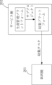
図2に示すように、サービス側202は、具体的には、収集プラットフォームと生産管理プラットフォームを含むことができ、生産管理プラットフォームは、データ収集サブプロジェクト(サブプロジェクトと略称することができ)を生成し、収集プラットフォームに送信することができ、収集プラットフォームは、サブプロジェクトに基づいて収集タスクを生成し、車両側201に送信することができる。車両側201は、収集タスクに基づいてナビゲーション経路を生成し、車両側がナビゲーション経路に基づいて走行するようにガイドすることができる。
As shown in FIG. 2, the
収集すべき軌跡ポイントとは、収集すべき地図データの軌跡ポイントを指し、収集すべき軌跡ポイントは、収集者から指定することができ、例えば、収集者が収集プラットフォームに登録した後、収集タスクを生成する時、収集タスクに収集すべき軌跡ポイントを指定し、収集すべき軌跡ポイントは、一般的には、複数であり、複数の収集すべき軌跡ポイントの収集順序を指定することもでき、例えば、収集された前後の順序によって、各収集すべき軌跡ポイントは、A点、B点、C点などを含む。 The trajectory points to be collected refer to the trajectory points of the map data to be collected, and the trajectory points to be collected can be specified by the collector. For example, after the collector registers on the collection platform, the collector can set the collection task. When generating, the trajectory points to be collected are specified in the collection task, and generally there are multiple trajectory points to be collected, and it is also possible to specify the collection order of the plurality of trajectory points to be collected, for example. , depending on the order in which they are collected, each trajectory point to be collected includes point A, point B, point C, etc.
収集タスクを取得した後、収集タスクの中の収集すべき軌跡ポイントに基づいてナビゲーション経路を生成することができる。具体的には、収集者が車両側で収集タスクを受信し、当該収集タスクを選択して実行した後、車両側は、当該収集タスクの実行命令に応答して、ナビゲーション経路を生成し、車両側の表示インターフェースで収集者に当該ナビゲーション経路を表示することができる。 After obtaining a collection task, a navigation route can be generated based on the trajectory points to be collected in the collection task. Specifically, after the collector receives a collection task on the vehicle side, selects and executes the collection task, the vehicle generates a navigation route in response to the command to execute the collection task, and The navigation route can be displayed to the collector on the side display interface.
その中、収集することができるタスクは、各収集すべき軌跡ポイントの収集順序を含むことができ、2つの点間のナビゲーション経路を順次に生成し、例えば、車両の開始点はO点で表示し、収集すべき軌跡ポイントが前後の順序に従ってA点、B点、C点であると仮定する場合、OA、AB、BCの間のナビゲーション経路を順次に生成する。 Among them, the tasks that can be collected can include the collection order of each trajectory point to be collected, and sequentially generate a navigation route between two points, for example, the starting point of the vehicle is indicated by point O. However, if it is assumed that the trajectory points to be collected are point A, point B, and point C according to the order of front and back, the navigation route between OA, AB, and BC is sequentially generated.
2つの点間のナビゲーション経路について、関連技術に基づいて実現することができ、例えば、車両側は、地図APPのサービス側にナビゲーション経路計画要求を送信することができ、地図APPのサービス側は、関連技術に基づいて2つの点間のナビゲーション経路を計画し、車両機械にフィードバックすることができる。 Regarding the navigation route between two points, it can be realized based on related technology, for example, the vehicle side can send a navigation route planning request to the service side of the map APP, and the service side of the map APP can: A navigation path between two points can be planned based on related technology and fed back to the vehicle machinery.
車両側は収集者にナビゲーション経路を表示した後、収集者は、ナビゲーション経路に基づいて車両がナビゲーション経路に沿って走行するように制御することができる。 After the vehicle side displays the navigation route to the collector, the collector can control the vehicle to travel along the navigation route based on the navigation route.
収集すべき軌跡ポイントに到着した時、対応する地図データを収集することができる。 When the trajectory point to be collected is reached, the corresponding map data can be collected.
その中、収集タスクは、センサータイプをさらに含むことができ、センサータイプに基づいて、対応するセンサーを選択してデータを収集し、例えば、センサータイプがレーザーレーダーである場合、レーザーレーダーを使用してデータを収集し、例えば、レーザーレーダーによって収集された周囲環境の点群であり、又は、センサータイプがカメラである場合、カメラを使用してデータを収集し、例えば、カメラによって収集された周囲環境の画像などである。理解できることは、センサータイプは、1つ又は複数であってもよく、1つ又は複数のセンサーを使用してデータ収集を行うことができ、1つ又は複数カテゴリの地図データを取得することができる。 Among them, the collection task can further include sensor type, and based on the sensor type, select the corresponding sensor to collect data, for example, if the sensor type is laser radar, use laser radar; Collect data using a camera, for example a point cloud of the surrounding environment collected by a laser radar; or, if the sensor type is a camera, collect data using a camera, for example a point cloud of the surrounding environment collected by a camera. These include images of the environment. It will be appreciated that the sensor type may be one or more, one or more sensors may be used to perform data collection, and one or more categories of map data may be obtained. .
本開示の技術案では、関するユーザ個人情報の収集、記憶、使用、加工、伝送、提供、及び開示などの処理は、すべて関連する法律および規定を満たし、公序良俗に違反しない。 In the technical solution of the present disclosure, the collection, storage, use, processing, transmission, provision, and disclosure of related user personal information will all comply with relevant laws and regulations and will not violate public order and morals.
本開示の実施例では、サービス側の収集タスクを受信し、収集タスクに基づいてナビゲーション経路を生成することによって、専任者がナビゲーション経路の計画を行う必要がなく、1台の車両に1人のデータ収集方式を実現し、データ収集効率を向上させることができる。 In the embodiment of the present disclosure, by receiving collection tasks from the service side and generating navigation routes based on the collection tasks, there is no need for a dedicated person to plan the navigation route, and one person per vehicle The data collection method can be realized and the data collection efficiency can be improved.
いくつかの実施例では、前記方法は、前記地図データを間引き処理して、間引きデータを取得するステップと、前記間引きデータを保存するステップと、をさらに含む。 In some embodiments, the method further includes the steps of decimating the map data to obtain decimated data, and storing the decimated data.
その中、間引き処理とは、地図データを間隔的に選択して、選択した地図データが元の地図データよりデータ量が少なくなるようにすることを指し、例えば、元の地図データが、A点の地図データ、B点の地図データ、C点の地図データ、D点の地図データを含む場合、抽出されたデータは、A点の地図データ、C点の地図データを含むことができる。 Among them, thinning processing refers to selecting map data at intervals so that the selected map data has a smaller amount of data than the original map data.For example, if the original map data is , map data of point B, map data of point C, and map data of point D, the extracted data can include map data of point A and map data of point C.
抽出されたデータを取得した後、抽出されたデータを保存することができる。例えば、メモリ又は不揮発性メモリに保存することができ、メモリは、例えば、ダブルレート同期ダイナミックランダムアクセスメモリ(Double Data Rate、DDR)であり、不揮発性メモリは、例えば、埋め込みマルチメディアメモリ(Embedded Multi Media Card、eMMC)である。 After obtaining the extracted data, the extracted data can be saved. For example, it can be stored in memory or non-volatile memory, where the memory is, for example, Double Rate Synchronous Dynamic Random Access Memory (DDR), and the non-volatile memory is, for example, Embedded Multimedia Memory (DDR). Media Card, eMMC).
地図データを間引き処理することによって、記憶量を下げることができ、完全なデータを保存するのではなく、データの機密性を向上させ、データ安全を確保することができる。 By thinning map data, the amount of storage can be reduced, rather than storing complete data, and data confidentiality can be improved and data security can be ensured.
いくつかの実施例では、前記方法は、
前記ナビゲーション経路において、特定の方式で、収集済み軌跡ポイントを表示するステップをさらに含む。
In some embodiments, the method includes:
The method further includes displaying collected trajectory points in a particular manner in the navigation path.
その中、特定の方式は、ハイライト表示などの、予め設定された表示方式である。 Among them, the specific method is a preset display method such as highlight display.
例えば、A点に対する地図データの収集を完了した後、ハイライト形式でA点を表示することができる。 For example, after completing the collection of map data for point A, point A can be displayed in a highlighted format.
特定の方式で収集済み軌跡ポイントを表示することによって、収集者が収集済みされた情報を直感的に知ることができ、収集者の後続の処理を容易にすることができる。 By displaying the collected trajectory points in a specific manner, the collector can intuitively know the collected information, which can facilitate the collector's subsequent processing.
いくつかの実施例では、前記収集タスクは、データ収集サブプロジェクトのサブプロジェクト範囲に基づいて生成され、前記方法は、前記収集済み軌跡ポイントに基づいて、収集済み軌跡を生成するステップと、前記収集済み軌跡を前記サービス側にアップロードするステップであって、前記収集済み軌跡は、前記サービス側内の前記サブプロジェクト範囲を更新するために用いられるステップと、をさらに含む。 In some examples, the collection task is generated based on a subproject scope of a data collection subproject, and the method includes the steps of: generating a collected trajectory based on the collected trajectory points; the collected trajectory is used to update the sub-project range within the service.
その中、サービス側は、データ収集サブプロジェクトを生成することができ、各サブプロジェクトは、1つのサブプロジェクト範囲に対応し、サブプロジェクト範囲は、特定の行政区、特定の多角形区域などであってもよい。サービス側は、道路網データを有して、サブプロジェクト範囲内の道路網データを取得することもできる。 Therein, the service side can generate data collection sub-projects, and each sub-project corresponds to one sub-project scope, and the sub-project scope may be a specific administrative region, a specific polygonal area, etc. Good too. The service side has road network data and can also acquire road network data within the scope of the subproject.
道路網(road network)とは、一定の区域内に、さまざまな道路で構成された相互連絡、網状分布に織り交ぜられたネットワークを指す。道路網データは、道路網を説明するために使用され、道路網に対応する道路データを含むことができる。 A road network refers to a network consisting of various roads that are interconnected and interwoven in a reticular distribution within a certain area. Road network data is used to describe a road network and may include road data corresponding to the road network.
収集済み軌跡ポイントを取得した後、各収集済み軌跡ポイントを収集済み軌跡に接続し、次に、収集済み軌跡とサブプロジェクト範囲内の道路をマッチングし、例えば、サブプロジェクト範囲内には、道路X、道路Y、及び道路Zが初期に含まれ、収集済み軌跡が道路Xとマッチングすると仮定すると、サブプロジェクト範囲を道路Y及び道路Zに更新することができる。その中、収集済み軌跡が道路とマッチングする時、さまざまな関連技術を使用してマッチングすることができ、例えば、収集済み軌跡がすべて特定の道路内に位置する場合、当該道路をマッチングされた道路とする。 After obtaining the collected trajectory points, connect each collected trajectory point to the collected trajectory, and then match the collected trajectory with the roads within the subproject range, for example, within the subproject range, road , road Y, and road Z are initially included, and assuming that the collected trajectory matches road X, the subproject scope can be updated to road Y and road Z. Among them, when the collected trajectories are matched with roads, various related techniques can be used for matching. For example, if the collected trajectories are all located within a certain road, the road can be matched with the road. shall be.
収集済み軌跡を生成し、収集済み軌跡に基づいてサブプロジェクト範囲を更新することによって、サブプロジェクト範囲の有効性を向上させ、収集タスクの更新を実現することができる。 By generating collected trajectories and updating subproject scopes based on the collected trajectories, the effectiveness of subproject scopes can be improved and the updating of collection tasks can be achieved.
上記の車両側の実行を例として説明し、サービス側の実行フローは以下の実施例を参照することができる。 The above execution on the vehicle side will be explained as an example, and the following embodiments can be referred to for the execution flow on the service side.
図3は本開示の第3の実施例の概略図である。本実施例はデータ収集方法を提供し、本実施例はサービス側の実行を例とし、前記方法は、301~303を含む。
301、収集すべき軌跡ポイントを決定する。
FIG. 3 is a schematic diagram of a third embodiment of the present disclosure. This embodiment provides a data collection method, this embodiment takes service-side execution as an example, and the method includes 301 to 303.
301, determining trajectory points to be collected;
302、前記収集すべき軌跡ポイントに基づいて、収集タスクを生成し、前記収集タスクは、前記収集すべき軌跡ポイントを含む。 302, generating a collection task based on the trajectory points to be collected, the collection task including the trajectory points to be collected;
303、前記収集タスクを車両側に送信し、前記収集タスクは、ナビゲーション経路を生成するために用いられ、前記ナビゲーション経路は、前記車両の走行をガイドし、前記収集すべき軌跡ポイントにおける地図データを収集するために用いられる。 303, transmitting the collection task to the vehicle side, the collection task is used to generate a navigation route, and the navigation route guides the travel of the vehicle and collects map data at the trajectory points to be collected. used for collecting.
その中、301~303の実行主体は、具体的には、サービス側の収集プラットフォームであってもよい。
Specifically, the
収集者は、収集すべき軌跡ポイントを指定することができ、例えば、収集プラットフォームは、データ収集サブプロジェクトを受信することができ、サブプロジェクトは、サブプロジェクト範囲(例えば、特定の行政区)を含むことができ、収集者は、当該サブプロジェクト範囲内に収集すべき軌跡ポイントを指定することができる。 The collector may specify trajectory points to collect; for example, the collection platform may receive a data collection subproject, and the subproject may include a subproject scope (e.g., a particular administrative region). The collector can specify the trajectory points to be collected within the scope of the subproject.
本開示の実施例では、収集タスク方式を車両側に送信して、車両側が収集タスクに基づいてナビゲーション経路を生成することができ、専任者がナビゲーション経路の計画を行う必要がなく、1台の車両に1人のデータ収集方式を実現し、データ収集効率を向上させることができる。 In the embodiments of the present disclosure, the collection task method can be transmitted to the vehicle side, and the vehicle side can generate a navigation route based on the collection task, and there is no need for a dedicated person to plan the navigation route. It is possible to implement a data collection method with one person per vehicle and improve data collection efficiency.
さらに、収集者が収集すべき軌跡ポイントを指定することによって、収集者の個性的な需要を満たすことができる。 Furthermore, the individual needs of the collector can be met by specifying the locus points to be collected by the collector.
いくつかの実施例では、前記方法は、
選択可能なデータ収集サブプロジェクトを表示するステップと、
前記選択可能なデータ収集サブプロジェクトの中で、使用されるデータ収集サブプロジェクトを選択するステップであって、前記使用されるデータ収集サブプロジェクトは、サブプロジェクト範囲を含むステップと、
前記使用されるデータ収集サブプロジェクトの前記サブプロジェクト範囲を表示するステップと、をさらに含む。
In some embodiments, the method includes:
displaying selectable data collection subprojects;
selecting a data collection subproject to be used from among the selectable data collection subprojects, the data collection subproject to be used includes a subproject range;
displaying the subproject scope of the used data collection subproject.
例えば、選択可能なデータ収集サブプロジェクトが、サブプロジェクト-1、サブプロジェクト-2、サブプロジェクト-3などを含む場合、これらの選択可能なサブプロジェクトを表示することができ、収集者は、自身の需要に応じて複数の選択可能なデータ収集サブプロジェクトの中から1つのサブプロジェクトを使用されるデータ収集サブプロジェクトとして選択することができ、例えば、サブプロジェクト-1を使用されるデータ収集サブプロジェクトとして選択する。 For example, if the selectable data collection subprojects include Subproject-1, Subproject-2, Subproject-3, etc., these selectable subprojects can be displayed and the collector can One subproject can be selected as the data collection subproject to be used from among multiple selectable data collection subprojects according to demand. For example, subproject-1 can be selected as the data collection subproject to be used. select.
各サブプロジェクトは、各自のサブプロジェクト範囲に対応することができ、例えば、サブプロジェクト-1のサブプロジェクト範囲は区域-1であり、サブプロジェクト-2のサブプロジェクト範囲は区域-2などである場合、サブプロジェクト-1が使用されるデータ収集サブプロジェクトである場合、収集者が区域-1に収集すべき軌跡ポイントを指定するように、区域-1を表示することができる。 Each sub-project can correspond to its own sub-project scope, for example, if sub-project-1's sub-project scope is Area-1, sub-project-2's sub-project scope is Area-2, etc. , if subproject-1 is the data collection subproject used, area-1 can be displayed such that the collector specifies the trajectory points to be collected in area-1.
選択可能なデータ収集サブプロジェクトを表示することによって、収集者に選択可能なサブプロジェクトを提供することができ、サブプロジェクト範囲を表示することによって、収集者がサブプロジェクト範囲内に収集すべき軌跡ポイントを指定することができる。 By displaying selectable data collection subprojects, you can provide the collector with selectable subprojects, and by displaying the subproject scope, you can provide the collector with trajectory points to collect within the subproject scope. can be specified.
上記の選択可能なデータ収集サブプロジェクト及びサブプロジェクト範囲を表示する操作は、具体的には、サービス側の収集プラットフォームによって実行することもできる。 Specifically, the operation of displaying the selectable data collection subprojects and subproject ranges can also be performed by the service-side collection platform.
いくつかの実施例では、前記方法は、
需要側のデータ収集需要に基づいて、データ収集プロジェクトを作成するステップであって、前記データ収集プロジェクトは、プロジェクト範囲を含むステップと、
前記プロジェクト範囲を複数のサブプロジェクト範囲に分割するステップと、
前記サブプロジェクト範囲に基づいて、前記選択可能なデータ収集サブプロジェクトを生成するステップと、をさらに含む。
In some embodiments, the method includes:
creating a data collection project based on a demand-side data collection demand, the data collection project including a project scope;
dividing the project scope into multiple sub-project scopes;
generating the selectable data collection subproject based on the subproject scope.
その中、データ収集プロジェクト(プロジェクトと略称することができる)を作成し、サブプロジェクトに分割する操作は、サービス側の生産管理プラットフォームによって実行することができる。 Therein, the operations of creating a data collection project (which can be abbreviated as project) and dividing it into subprojects can be performed by the production management platform on the service side.
その中、需要側は、データ収集需要を提供することができる、例えば、ある市(例えば、Q市を使用する)の地図データを収集する必要がある場合、生産管理プラットフォームはQ市に対応するデータ収集プロジェクトを作成することができ、プロジェクト範囲は、Q市の地理区域範囲である。 Among them, the demand side can provide data collection demand, for example, if it is necessary to collect map data of a certain city (for example, use Q city), the production management platform will correspond to Q city. A data collection project can be created, and the project scope is the geographical area of Q City.
生産管理プラットフォームがプロジェクト範囲を決定した後、それを分割することができ、例えば、Q市の地理区域範囲を行政区に従って分割し、例えば、全体のQ市の地理区域範囲を区域Q1、区域Q2などに分割する。 After the production management platform determines the project scope, it can be divided, for example, the geographical area range of Q city is divided according to administrative districts, for example, the entire geographical area range of Q city is divided into area Q1, area Q2, etc. Divide into.
各サブプロジェクト範囲(例えば、Q1、Q2)に対応して、対応するサブプロジェクトを生成することができる、例えば、Q1に対応するサブプロジェクト、Q2に対応するサブプロジェクトなどを生成し、これらのサブプロジェクトは、選択可能なサブプロジェクトとして収集者に提供することができる。 Corresponding to each subproject range (for example, Q1, Q2), a corresponding subproject can be generated. For example, a subproject corresponding to Q1, a subproject corresponding to Q2, etc. can be generated, and these subprojects can be generated. Projects can be offered to collectors as selectable subprojects.
プロジェクト範囲を分割することによって、サブプロジェクトを単位としてデータ収集を行って、柔軟性と実行可能性を向上させることができる。 By dividing the project scope, data collection can be done on a subproject basis, increasing flexibility and feasibility.
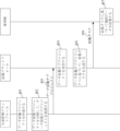
図4は本開示の第4の実施例の概略図である。本実施例はデータ収集方法を提供し、本実施例は、サービス側と車両側のインタラクションを例とし、サービス側は、生産管理プラットフォームと収集プラットフォームを含み、前記方法は、401~407を含む。
401、生産管理プラットフォームがデータ収集プロジェクトを作成する。
FIG. 4 is a schematic diagram of a fourth embodiment of the present disclosure. This embodiment provides a data collection method, this embodiment takes the interaction between the service side and the vehicle side as an example, the service side includes a production management platform and a collection platform, and the method includes 401 to 407.
401, the production management platform creates a data collection project.
402、生産管理プラットフォームがデータ収集プロジェクトを分割して、データ収集サブプロジェクトを取得する。 402, the production management platform divides the data collection project to obtain data collection subprojects.
403、生産管理プラットフォームがデータ収集サブプロジェクトを収集プラットフォームに伝送する。 403, the production management platform transmits the data collection sub-project to the collection platform.
404、収集プラットフォームがデータ収集サブプロジェクトを受信する。 404, the collection platform receives the data collection subproject.
405、収集プラットフォームがデータ収集サブプロジェクトに基づいて、収集タスクを生成する。 405, the collection platform generates a collection task based on the data collection subproject.
406、収集プラットフォームが収集タスクを車両側に送信する。 406, the collection platform sends the collection task to the vehicle side.
407、車両側が収集タスクに基づいて地図データを収集する。 407, the vehicle side collects map data based on the collection task.
その中、説明を簡略化するために、以下は、データ収集プロジェクトをプロジェクトと略称し、データ収集サブプロジェクトをサブプロジェクトと略称することを例として説明する。 In order to simplify the explanation, hereinafter, a data collection project will be abbreviated as a project, and a data collection subproject will be abbreviated as a subproject.
具体的には、図5aおよび図5bに示すように、生産管理プラットフォームは、501~505を実行することができ、
501、管理員登録。
Specifically, as shown in Figures 5a and 5b, the production management platform may perform 501-505;
501, administrator registration.
502、新規プロジェクト。 502, New project.
503、プロジェクト範囲作成。 503. Creation of project scope.
504、プロジェクト分割作成。 504, Create project division.
505、サブプロジェクトの伝送。 505, Subproject transmission.
その中、管理員とは、生産管理プラットフォームの使用者を指し、使用者が登録した後、プロジェクトを作成し、プロジェクトを分割して、サブプロジェクトを取得することができる。 Among them, the manager refers to a user of the production management platform, and after the user registers, the user can create a project, divide the project, and obtain subprojects.
具体的な各ステップの実行内容は、図5aおよび図5bの図面内容を参照することができる。 For the specific execution contents of each step, reference can be made to the drawing contents of FIGS. 5a and 5b.
具体的には、図6に示すように、収集プラットフォームは、601~603を実行することができ、
601、収集者ログイン。
Specifically, as shown in FIG. 6, the collection platform may perform 601-603;
601, Collector login.
602、サブプロジェクト受信。 602, Subproject received.
603、タスク作成。 603, task creation.
その中、収集者は、収集プラットフォームの使用者を指し、使用者が登録した後、サブプロジェクトを受信することができ、すなわち、この時、サブプロジェクトを受信することは、収集者が複数の選択可能なサブプロジェクトの中から選択されたサブプロジェクトを示す。 Therein, the collector refers to the user of the collection platform, and after the user registers, he can receive the sub-project, that is, at this time, receiving the sub-project is limited to the collector's multiple selections. Indicates a subproject selected from among possible subprojects.
具体的な各ステップの実行内容は、図6の図面内容を参照することができる。 The content of the drawing in FIG. 6 can be referred to for the specific execution content of each step.
具体的には、図7に示すように、車両側は、701を実行することができ、
701、車両側の収集。
Specifically, as shown in FIG. 7, the vehicle side can execute 701,
701, Vehicle side collection.
その中、車線収集の実行内容は、101~103に示すように、具体的な実行内容は、図7に示す図面内容を参照することができる。 Among them, the execution contents of lane collection are shown in 101 to 103, and the specific execution contents can be referred to the drawing contents shown in FIG. 7.
本実施例では、サービス側は、自身の道路網データに基づいて、プロジェクト、サブプロジェクト、及び収集タスクを生成することができ、道路網データを車両のビゲーションスタッフに送信する必要がないため、道路網データのオフラインの移動を回避することができ、リスクを管理および制御できる。車両側が収集タスクに基づいてナビゲーション経路を生成することができ、人為的にナビゲーションを行う必要がなく、コストを削減し、効率を向上させる。収集すべき軌跡ポイントの地図データを取得し、収集済み軌跡ポイントを表示することによって、マイニング漏れを回避することができる。 In this example, the service side can generate projects, subprojects, and collection tasks based on its own road network data, and there is no need to send the road network data to the vehicle's navigation staff, so the Offline movement of network data can be avoided and risks can be managed and controlled. The vehicle side can generate a navigation route based on the collected tasks, and there is no need to manually perform navigation, reducing costs and improving efficiency. By acquiring map data of trajectory points to be collected and displaying collected trajectory points, it is possible to avoid mining omissions.
図8は本開示の第8の実施例の概略図である。本実施例はデータ収集装置を提供する。図8に示すように、当該装置800は、受信モジュール801、生成モジュール802、及び取得モジュール803を含む。
FIG. 8 is a schematic diagram of an eighth embodiment of the present disclosure. This embodiment provides a data collection device. As shown in FIG. 8, the
受信モジュール801は、サービス側によって生成された収集タスクを受信するために用いられ、前記収集タスクは、収集すべき軌跡ポイントを含み、生成モジュール802は、前記収集すべき軌跡ポイントに基づいてナビゲーション経路を生成し、前記ナビゲーション経路を表示するために用いられ、取得モジュール803は、車両が前記ナビゲーション経路に基づいて走行する時、収集された前記収集すべき軌跡ポイントにおける地図データを取得するために用いられる。
The receiving
いくつかの実施例では、前記装置800は、前記地図データを間引き処理して、間引きデータを取得するための間引きモジュールと、前記間引きデータを保存するための保存モジュールと、をさらに含む。
In some embodiments, the
いくつかの実施例では、前記装置800は、前記ナビゲーション経路において、特定の方式で、収集済み軌跡ポイントを表示するための表示モジュールをさらに含む。
In some embodiments, the
いくつかの実施例では、前記収集タスクは、データ収集サブプロジェクトのサブプロジェクト範囲に基づいて生成され、前記装置は、前記収集済み軌跡ポイントに基づいて、収集済み軌跡を生成し、前記収集済み軌跡を前記サービス側にアップロードするための更新モジュールをさらに含み、前記収集済み軌跡は、前記サービス側内の前記サブプロジェクト範囲を更新するために用いられる。 In some examples, the collection task is generated based on a subproject scope of a data collection subproject, and the apparatus generates a collected trajectory based on the collected trajectory points, and the apparatus generates a collected trajectory based on the collected trajectory points. The method further includes an update module for uploading the collected trajectory to the service side, and the collected trajectory is used to update the sub-project scope in the service side.
本開示の実施例では、サービス側の収集タスクを受信し、収集タスクに基づいてナビゲーション経路を生成することによって、専任者がナビゲーション経路の計画を行う必要がなく、1台の車両に1人のデータ収集方式を実現し、データ収集効率を向上させることができる。 In the embodiment of the present disclosure, by receiving collection tasks from the service side and generating navigation routes based on the collection tasks, there is no need for a dedicated person to plan the navigation route, and one person per vehicle The data collection method can be realized and the data collection efficiency can be improved.
図9は本開示の第8の実施例の概略図である。本実施例はデータ収集装置を提供する。図9に示すように、当該装置900は、決定モジュール901、タスク生成モジュール902、及び送信モジュール903を含む。
FIG. 9 is a schematic diagram of an eighth embodiment of the present disclosure. This embodiment provides a data collection device. As shown in FIG. 9, the
決定モジュール901は、収集すべき軌跡ポイントを決定するために用いられ、タスク生成モジュール902は、前記収集すべき軌跡ポイントに基づいて、収集タスクを生成するために用いられ、前記収集タスクは、前記収集すべき軌跡ポイントを含み、送信モジュール903は、前記収集タスクを車両側に送信するために用いられ、前記収集タスクは、ナビゲーション経路を生成するために用いられ、前記ナビゲーション経路は、前記車両の走行をガイドし、前記収集すべき軌跡ポイントにおける地図データを収集するために用いられる。
A
いくつかの実施例では、前記決定モジュール901は、具体的には、収集者がサブプロジェクト範囲内で指定した収集すべき軌跡ポイントを取得するために用いられる。
In some embodiments, the
いくつかの実施例では、前記装置900は、選択可能なデータ収集サブプロジェクトを表示するための第1の表示モジュールと、前記選択可能なデータ収集サブプロジェクトの中で、使用されるデータ収集サブプロジェクトを選択するための選択モジュールであって、前記使用されるデータ収集サブプロジェクトは、サブプロジェクト範囲を含む選択モジュールと、前記使用されるデータ収集サブプロジェクトの前記サブプロジェクト範囲を表示するための第2の表示モジュールと、をさらに含む。
In some embodiments, the
いくつかの実施例では、前記装置900は、需要側のデータ収集需要に基づいて、データ収集プロジェクトを作成するための作成モジュールであって、前記データ収集プロジェクトは、プロジェクト範囲を含む作成モジュールと、前記プロジェクト範囲を複数のサブプロジェクト範囲に分割するための分割モジュールと、前記サブプロジェクト範囲に基づいて、前記選択可能なデータ収集サブプロジェクトを生成するためのサブプロジェクト生成モジュールと、をさらに含む。
In some embodiments, the
本開示の実施例では、収集タスク方式を車両側に送信して、車両側が収集タスクに基づいてナビゲーション経路を生成することができ、専任者がナビゲーション経路の計画を行う必要がなく、1台の車両に1人のデータ収集方式を実現し、データ収集効率を向上させることができる。 In the embodiments of the present disclosure, the collection task method can be transmitted to the vehicle side, and the vehicle side can generate a navigation route based on the collection task, and there is no need for a dedicated person to plan the navigation route. It is possible to implement a data collection method with one person per vehicle and improve data collection efficiency.
理解できることは、本開示の実施例では、異なる実施例の同じ又は類似する内容は互いに参照することができる。 It can be understood that in the embodiments of the present disclosure, the same or similar contents of different embodiments can be referred to with each other.
本開示の実施例における「第1」、「第2」などは、区別のためにのみ使用され、重要度の高低、タイミングの前後などを示さないことを理解されたい。 It should be understood that "first", "second", etc. in the embodiments of the present disclosure are used only for distinction, and do not indicate higher or lower importance, timing before or after, or the like.
本開示の技術案では、関するユーザ個人情報の収集、記憶、使用、加工、伝送、提供、及び開示などの処理は、すべて関連する法律および規定を満たし、公序良俗に違反しない。 In the technical solution of the present disclosure, the collection, storage, use, processing, transmission, provision, and disclosure of related user personal information will all comply with relevant laws and regulations and will not violate public order and morals.
本開示の実施例によれば、本開示は、電子機器、読み取り可能な記憶媒体、及びコンピュータプログラム製品をさらに提供し、本開示は、さらに、上記の電子機器を含む自動運転車両を提供する。 According to embodiments of the present disclosure, the present disclosure further provides an electronic device, a readable storage medium, and a computer program product, and the present disclosure further provides an autonomous vehicle including the above-described electronic device.
図10に示すように、本開示の実施例を実施するための電子機器のブロック図である。電子機器は、ラップトップコンピュータ、デスクトップコンピュータ、ワークステーション、携帯情報端末、サーバ、ブレードサーバ、大型コンピュータ、及び他の適切なコンピュータなどの様々な形式のデジタルコンピュータを表すことを目的とする。電子機器は、パーソナルデジタル処理、携帯電話、スマートフォン、ウェアラブルデバイス、他の同様の計算デバイスなどの様々な形式のモバイルデバイスを表すこともできる。本明細書で示されるコンポーネント、それらの接続と関係、及びそれらの機能は単なる例であり、本明細書の説明及び/又は要求される本開示の実現を制限することを意図したものではない。 FIG. 10 is a block diagram of an electronic device for implementing an embodiment of the present disclosure. Electronic equipment is intended to refer to various types of digital computers, such as laptop computers, desktop computers, workstations, personal digital assistants, servers, blade servers, large format computers, and other suitable computers. Electronic equipment may also represent various forms of mobile devices such as personal digital processing, mobile phones, smart phones, wearable devices, and other similar computing devices. The components depicted herein, their connections and relationships, and their functionality are merely examples and are not intended to limit the description herein and/or the required implementation of the present disclosure.
図10に示すように、電子機器1000は計算ユニット1001を含み、計算ユニット1001は、読み取り専用メモリ(ROM)1002に記憶されているコンピュータプログラムまたは記憶ユニット1008からランダムアクセスメモリ(RAM)1003にローディングされたコンピュータプログラムに基づいて、様々な適切な動作と処理を実行することができる。RAM1003には、電子機器1000が動作するに必要な様々なプログラムとデータも記憶することができる。計算ユニット1001、ROM1002、およびRAM1003は、バス1004を介してお互いに接続される。入出力(I/O)インターフェース1005もバス1004に接続される。
As shown in FIG. 10, the
電子機器1000内の複数のコンポーネントは、I/Oインターフェース1005に接続されており、キーボード、マウスなどの入力ユニット1006と、様々なタイプのディスプレイ、スピーカなどの出力ユニット1007と、ディスク、光ディスクなどの記憶ユニット1008と、およびネットワークカード、モデム、無線通信トランシーバなどの通信ユニット1009と、を含む。通信ユニット1009は、電子機器1000が、インターネットなどのコンピュータネットワーク、および/または様々な電気通信ネットワークを介して他の機器と情報/データを交換することを可能にする。
A plurality of components within the
計算ユニット1001は、様々な処理と計算能力を備える汎用および/または専用の処理コンポーネントである。計算ユニット1001のいくつかの例は、中央処理装置(CPU)、グラフィックス処理ユニット(GPU)、様々な専用の人工知能(AI)計算チップ、様々な機械学習モデルアルゴリズムを実行する計算ユニット、デジタル信号プロセッサ(DSP)、および任意の適切なプロセッサ、コントローラ、マイクロコントローラなどを含むが、これらに限定されない。計算ユニット1001は、データ収集方法などの上記の様々な方法と処理を実行する。例えば、いくつかの実施例では、データ収集方法は、記憶ユニット1008などの機械読み取り可能な媒体に有形的に含まれるコンピュータソフトウェアプログラムとして実現することができる。いくつかの実施例では、コンピュータプログラムの一部または全部は、ROM1002および/または通信ユニット1009を介して電子機器1000にローディングおよび/またはインストールされる。コンピュータプログラムがRAM1003にローディングされて計算ユニット1001によって実行される場合、上記のデータ収集方法の一つまたは複数のステップを実行することができる。代替的に、他の実施例では、計算ユニット1001は、他の任意の適切な方式(例えば、ファームウェアによって)を介してデータ収集方法を実行するように構成されることができる。
本明細書で説明されるシステムと技術の様々な実施方式は、デジタル電子回路システム、集積回路システム、フィールドプログラマブルゲートアレイ(FPGA)、特定用途向け集積回路(ASIC)、特定用途向け標準製品(ASSP)、システムオンチップシステム(SOC)、ローディングプログラマブルロジックデバイス(CPLD)、コンピュータハードウェア、ファームウェア、ソフトウェア、及び/又はそれらの組み合わせで実現することができる。これらの様々な実施方式は、一つ又は複数のコンピュータプログラムで実施されることを含むことができ、当該一つ又は複数のコンピュータプログラムは、少なくとも一つのプログラマブルプロセッサを含むプログラム可能なシステムで実行及び/又は解釈されることができ、当該プログラマブルプロセッサは、特定用途向け又は汎用プログラマブルプロセッサであってもよく、ストレージシステム、少なくとも一つの入力装置、及び少なくとも一つの出力装置からデータ及び命令を受信し、データ及び命令を当該ストレージシステム、当該少なくとも一つの入力装置、及び当該少なくとも一つの出力装置に伝送することができる。 Various implementations of the systems and techniques described herein include digital electronic circuit systems, integrated circuit systems, field programmable gate arrays (FPGAs), application specific integrated circuits (ASICs), and application specific standard products (ASSPs). ), system on a chip (SOC), loading programmable logic device (CPLD), computer hardware, firmware, software, and/or combinations thereof. These various implementation schemes may include being implemented in one or more computer programs, where the one or more computer programs are executed and executed on a programmable system including at least one programmable processor. The programmable processor may be an application-specific or general-purpose programmable processor, and receives data and instructions from a storage system, at least one input device, and at least one output device; Data and instructions can be transmitted to the storage system, the at least one input device, and the at least one output device.
本開示の方法を実施するためのプログラムコードは、一つまたは複数のプログラミング言語の任意の組み合わせを使用して作成することができる。これらのプログラムコードは、プログラムコードがプロセッサまたはコントローラによって実行される時にフローチャートおよび/またはブロック図に規定された機能/動作が実施されるように、汎用コンピュータ、専用コンピュータ、または他のプログラム可能なデータ処理装置のプロセッサまたはコントローラに提供することができる。プログラムコードは、完全に機械上で実行されたり、部分的に機械上で実行されたり、独立したソフトウェアパッケージとして部分的に機械上で実行され、部分的にリモート機械上実行されたり、または完全にリモート機械またはサーバ上で実行されたりすることができる。 Program code for implementing the methods of this disclosure may be written using any combination of one or more programming languages. These program codes may be executed by a general purpose computer, special purpose computer, or other programmable data processor such that when the program codes are executed by a processor or controller, the functions/operations set forth in the flowcharts and/or block diagrams are performed. The information may be provided to a processor or controller of a processing device. Program code may be executed entirely on a machine, partially on a machine, partially on a machine as a separate software package, partially on a remote machine, or completely on a machine. It can be executed on a remote machine or server.
本開示の文脈において、機械読み取り可能な媒体は、命令実行システム、装置、または機器の使用、または命令実行システム、装置または機器と組み合わせて使用するプログラムを含むか、または記憶することができる有形の媒体であってもよい。機械読み取り可能な媒体は、機械読み取り可能な信号媒体または機械読み取り可能な記憶媒体であってもよい。機械読み取り可能な媒体は、電子、磁気、光学、電磁気、赤外線、または半導体システム、装置または機器、または上記の内容の任意の適切な組み合わせを含むが、これらに限定されない。機械読み取り可能な記憶媒体のより具体的な例は、一つまたは複数のワイヤに基づく電気接続、ポータブルコンピュータディスク、ハードディスク、ランダムアクセスメモリ(RAM)、読み取り専用メモリ(ROM)、消去可能プログラマブル読み取り専用メモリ(EPROM またはフラッシュメモリ)、光ファイバ、ポータブルコンパクトディスク読み取り専用メモリ(CD-ROM)、光学記憶装置、磁気記憶装置、または上記の内容の任意の適切な組み合わせを含む。 In the context of this disclosure, a machine-readable medium is a tangible medium that contains or is capable of storing a program for use in or in conjunction with an instruction-execution system, device, or device. It may be a medium. A machine-readable medium may be a machine-readable signal medium or a machine-readable storage medium. Machine-readable media include, but are not limited to, electronic, magnetic, optical, electromagnetic, infrared, or semiconductor systems, devices, or equipment, or any suitable combination of the above. More specific examples of machine-readable storage media include an electrical connection based on one or more wires, a portable computer disk, a hard disk, random access memory (RAM), read-only memory (ROM), erasable programmable read-only memory, etc. memory (EPROM or flash memory), fiber optics, portable compact disk read only memory (CD-ROM), optical storage, magnetic storage, or any suitable combination of the above.
ユーザとのインタラクションを提供するために、コンピュータ上で、ここで説明されているシステム及び技術を実施することができ、当該コンピュータは、ユーザに情報を表示するためのディスプレイ装置(例えば、CRT(陰極線管)又はLCD(液晶ディスプレイ)モニタ)と、キーボード及びポインティングデバイス(例えば、マウス又はトラックボール)とを有し、ユーザは、当該キーボード及び当該ポインティングデバイスによって入力をコンピュータに提供することができる。他の種類の装置は、ユーザとのインタラクションを提供するために用いられることもでき、例えば、ユーザに提供されるフィードバックは、任意の形式のセンシングフィードバック(例えば、視覚フィードバック、聴覚フィードバック、又は触覚フィードバック)であってもよく、任意の形式(音響入力と、音声入力と、触覚入力とを含む)でユーザからの入力を受信することができる。 The systems and techniques described herein may be implemented on a computer to provide interaction with a user, and the computer may include a display device (e.g., a CRT) for displaying information to the user. computer (e.g., a mouse or trackball), and a keyboard and pointing device (e.g., a mouse or trackball) through which a user can provide input to the computer. Other types of devices may also be used to provide interaction with the user; for example, the feedback provided to the user may include any form of sensing feedback (e.g., visual feedback, auditory feedback, or tactile feedback). ), and can receive input from the user in any format (including acoustic input, voice input, and tactile input).
ここで説明されるシステム及び技術は、バックエンドコンポーネントを含むコンピューティングシステム(例えば、データサーバとする)、又はミドルウェアコンポーネントを含むコンピューティングシステム(例えば、アプリケーションサーバー)、又はフロントエンドコンポーネントを含むコンピューティングシステム(例えば、グラフィカルユーザインタフェース又はウェブブラウザを有するユーザコンピュータ、ユーザは、当該グラフィカルユーザインタフェース又は当該ウェブブラウザによってここで説明されるシステム及び技術の実施方式とインタラクションする)、又はこのようなバックエンドコンポーネントと、ミドルウェアコンポーネントと、フロントエンドコンポーネントの任意の組み合わせを含むコンピューティングシステムで実施することができる。任意の形式又は媒体のデジタルデータ通信(例えば、通信ネットワーク)によってシステムのコンポーネントを相互に接続されることができる。通信ネットワークの例は、ローカルエリアネットワーク(LAN)と、ワイドエリアネットワーク(WAN)と、インターネットと、を含む。 The systems and techniques described herein may be used in computing systems that include back-end components (e.g., data servers), or that include middleware components (e.g., application servers), or that include front-end components. a system (e.g., a user computer having a graphical user interface or web browser through which the user interacts with implementations of the systems and techniques described herein), or such back-end components; , middleware components, and front-end components. The components of the system may be interconnected by any form or medium of digital data communication (eg, a communication network). Examples of communication networks include local area networks (LANs), wide area networks (WANs), and the Internet.
コンピュータシステムは、クライアントとサーバとを含むことができる。クライアントとサーバは、一般に、互いに離れており、通常に通信ネットワークを介してインタラクションする。対応するコンピュータ上で実行され、互いにクライアント-サーバ関係を有するコンピュータプログラムによってクライアントとサーバとの関係が生成される。サーバは、クラウドサーバであってもよく、クラウド計算またはクラウドホストとも呼ばれ、クラウド計算サービスシステムの中の一つのホスト製品であり、従来の物理ホストとVPSサービス(「Virtual Private Server」、または「VPS」と略称する)に、存在する管理困難度が高く、業務拡張性が弱い欠陥を解決する。サーバは、分散システムのサーバであってもよく、またはブロックチェーンを組み合わせるサーバであってもよい。 A computer system can include clients and servers. Clients and servers are generally remote from each other and typically interact via a communications network. A client and server relationship is created by computer programs running on corresponding computers and having a client-server relationship with each other. The server may be a cloud server, also called cloud computing or cloud host, which is one host product in the cloud computing service system, which is different from traditional physical host and VPS service ("Virtual Private Server" or " VPS (abbreviated as "VPS"), which has a high degree of management difficulty and low business expandability. The server may be a server of a distributed system or a server that combines blockchains.
上記に示される様々な形式のフローを使用して、ステップを並べ替え、追加、又は削除することができることを理解されたい。例えば、本開示に記載されている各ステップは、並列に実行されてもよいし、順次的に実行されてもよいし、異なる順序で実行されてもよいが、本開示で開示されている技術案が所望の結果を実現することができれば、本明細書では限定されない。 It should be appreciated that steps can be reordered, added, or deleted using the various types of flows shown above. For example, each step described in this disclosure may be performed in parallel, sequentially, or in a different order, but the techniques disclosed in this disclosure may Any proposal is not limited herein as long as it can achieve the desired results.
上記の具体的な実施方式は、本開示に対する保護範囲の制限を構成するものではない。当業者は、設計要求と他の要因に基づいて、様々な修正、組み合わせ、サブコンビネーション、及び代替を行うことができる。任意の本開示の精神と原則内で行われる修正、同等の置換、及び改善などは、いずれも本開示の保護範囲内に含まれなければならない。 The above specific implementation modes do not constitute limitations on the protection scope of the present disclosure. Various modifications, combinations, subcombinations, and substitutions may be made by those skilled in the art based on design requirements and other factors. Any modifications, equivalent substitutions, improvements, etc. made within the spirit and principles of this disclosure shall be included within the protection scope of this disclosure.
Claims (18)
サービス側によって生成された収集タスクを受信するステップであって、前記収集タスクは、収集すべき軌跡ポイントを含むステップと、
前記収集すべき軌跡ポイントに基づいてナビゲーション経路を生成し、前記ナビゲーション経路を表示するステップと、
車両が前記ナビゲーション経路に基づいて走行する時、収集された前記収集すべき軌跡ポイントにおける地図データを取得するステップと、を含み、
前記サービス側は、
選択可能なデータ収集サブプロジェクトを表示するステップと、
前記選択可能なデータ収集サブプロジェクトの中で、使用されるデータ収集サブプロジェクトを選択するステップであって、前記使用されるデータ収集サブプロジェクトは、サブプロジェクト範囲を含むステップと、
前記使用されるデータ収集サブプロジェクトの前記サブプロジェクト範囲を表示するステップと、
収集者がサブプロジェクト範囲内で指定した収集すべき軌跡ポイントを取得するステップとによって、前記収集すべき軌跡ポイントを決定する、
高精度地図のデータ収集方法。 A data collection method for high-precision maps, the method comprising:
receiving a collection task generated by a service side, the collection task including trajectory points to be collected;
generating a navigation route based on the trajectory points to be collected and displaying the navigation route;
acquiring map data at the trajectory points to be collected when the vehicle travels based on the navigation route;
The service side is
displaying selectable data collection subprojects;
selecting a data collection subproject to be used from among the selectable data collection subprojects, the data collection subproject to be used includes a subproject range;
displaying the subproject scope of the used data collection subproject;
and determining the trajectory points to be collected specified by the collector within the scope of the sub-project;
High-definition map data collection method.
前記間引きデータを保存するステップと、をさらに含む、
請求項1に記載の高精度地図のデータ収集方法。 a step of thinning out the map data to obtain thinned data;
further comprising: storing the thinned data;
The high-precision map data collection method according to claim 1.
請求項1又は2に記載の高精度地図のデータ収集方法。 further comprising displaying collected trajectory points in a particular manner in the navigation path;
The method for collecting data on a high-precision map according to claim 1 or 2.
前記高精度地図のデータ収集方法は、
前記収集済み軌跡ポイントに基づいて、収集済み軌跡を生成するステップと、
前記収集済み軌跡を前記サービス側にアップロードするステップであって、前記収集済み軌跡は、前記サービス側内の前記サブプロジェクト範囲を更新するために用いられるステップと、をさらに含む、
請求項3に記載の高精度地図のデータ収集方法。 the collection task is generated based on a subproject scope of a data collection subproject;
The data collection method for the high-precision map is as follows:
generating a collected trajectory based on the collected trajectory points;
further comprising: uploading the collected trajectory to the service side, the collected trajectory being used to update the sub-project range within the service side;
The high-precision map data collection method according to claim 3.
収集すべき軌跡ポイントを決定するステップと、
前記収集すべき軌跡ポイントに基づいて、収集タスクを生成するステップであって、前記収集タスクは、前記収集すべき軌跡ポイントを含むステップと、
前記収集タスクを車両側に送信するステップであって、前記収集タスクは、ナビゲーション経路を生成するために用いられ、前記ナビゲーション経路は、前記車両の走行をガイドし、前記収集すべき軌跡ポイントにおける地図データを収集するために用いられるステップと、を含み、
前記収集すべき軌跡ポイントを決定するステップは、
選択可能なデータ収集サブプロジェクトを表示するステップと、
前記選択可能なデータ収集サブプロジェクトの中で、使用されるデータ収集サブプロジェクトを選択するステップであって、前記使用されるデータ収集サブプロジェクトは、サブプロジェクト範囲を含むステップと、
前記使用されるデータ収集サブプロジェクトの前記サブプロジェクト範囲を表示するステップと、
収集者がサブプロジェクト範囲内で指定した収集すべき軌跡ポイントを取得するステップとを含む、
高精度地図のデータ収集方法。 A data collection method for high-precision maps, the method comprising:
determining trajectory points to collect;
generating a collection task based on the trajectory points to be collected, the collection task including the trajectory points to be collected;
transmitting the collection task to the vehicle side, the collection task being used to generate a navigation route, the navigation route guiding the travel of the vehicle and a map at the trajectory points to be collected; steps used to collect data;
The step of determining trajectory points to be collected includes:
displaying selectable data collection subprojects;
selecting a data collection subproject to be used from among the selectable data collection subprojects, the data collection subproject to be used includes a subproject range;
displaying the subproject scope of the used data collection subproject;
and obtaining trajectory points to be collected specified by the collector within the scope of the sub-project.
High-definition map data collection method.
前記プロジェクト範囲を複数のサブプロジェクト範囲に分割するステップと、
前記サブプロジェクト範囲に基づいて、前記選択可能なデータ収集サブプロジェクトを生成するステップと、をさらに含む、
請求項5に記載の高精度地図のデータ収集方法。 creating a data collection project based on a demand-side data collection demand, the data collection project including a project scope;
dividing the project scope into multiple sub-project scopes;
further comprising: generating the selectable data collection subproject based on the subproject scope;
The high-precision map data collection method according to claim 5 .
サービス側によって生成された収集タスクを受信する受信モジュールであって、前記収集タスクは、収集すべき軌跡ポイントを含む受信モジュールと、
前記収集すべき軌跡ポイントに基づいてナビゲーション経路を生成し、前記ナビゲーション経路を表示する生成モジュールと、
車両が前記ナビゲーション経路に基づいて走行する時、収集された前記収集すべき軌跡ポイントにおける地図データを取得する取得モジュールと、を含み、
前記サービス側は、
選択可能なデータ収集サブプロジェクトを表示するステップと、
前記選択可能なデータ収集サブプロジェクトの中で、使用されるデータ収集サブプロジェクトを選択するステップであって、前記使用されるデータ収集サブプロジェクトは、サブプロジェクト範囲を含むステップと、
前記使用されるデータ収集サブプロジェクトの前記サブプロジェクト範囲を表示するステップと、
収集者がサブプロジェクト範囲内で指定した収集すべき軌跡ポイントを取得するステップとによって、前記収集すべき軌跡ポイントを決定する、
高精度地図の地図データ収集装置。 A map data collection device for high-precision maps,
a receiving module that receives a collection task generated by a service side, the collection task including trajectory points to be collected;
a generation module that generates a navigation route based on the trajectory points to be collected and displays the navigation route;
an acquisition module that acquires map data at the trajectory points to be collected when the vehicle travels based on the navigation route;
The service side is
displaying selectable data collection subprojects;
selecting a data collection subproject to be used from among the selectable data collection subprojects, the data collection subproject to be used includes a subproject range;
displaying the subproject scope of the used data collection subproject;
and determining the trajectory points to be collected specified by the collector within the scope of the sub-project;
Map data collection device for high-precision maps.
前記間引きデータを保存する保存モジュールと、をさらに含む、
請求項7に記載の高精度地図の地図データ収集装置。 a thinning module that thins out the map data to obtain thinned data;
further comprising a storage module that stores the thinned data;
The high-precision map map data collection device according to claim 7 .
請求項7又は8に記載の高精度地図の地図データ収集装置。 further comprising a display module for displaying collected trajectory points in a particular manner in the navigation path;
The map data collection device for high-precision maps according to claim 7 or 8 .
前記収集済み軌跡ポイントに基づいて、収集済み軌跡を生成し、前記収集済み軌跡を前記サービス側にアップロードする更新モジュールをさらに含み、前記収集済み軌跡は、前記サービス側内の前記サブプロジェクト範囲を更新する、
請求項9に記載の高精度地図の地図データ収集装置。 The collection task is generated based on the sub-project scope of the data collection sub-project, and the high-definition map data collection device is configured to:
The method further includes an update module that generates a collected trajectory based on the collected trajectory points and uploads the collected trajectory to the service side, and the collected trajectory updates the sub-project scope in the service side. do,
The high-precision map map data collection device according to claim 9 .
収集すべき軌跡ポイントを決定する決定モジュールと、
前記収集すべき軌跡ポイントに基づいて、収集タスクを生成するタスク生成モジュールであって、前記収集タスクは、前記収集すべき軌跡ポイントを含むタスク生成モジュールと、
前記収集タスクを車両側に送信する送信モジュールであって、前記収集タスクは、ナビゲーション経路を生成するために用いられ、前記ナビゲーション経路は、前記車両の走行をガイドし、前記収集すべき軌跡ポイントにおける地図データを収集するために用いられる送信モジュールと、
選択可能なデータ収集サブプロジェクトを表示する第1の表示モジュールと、
前記選択可能なデータ収集サブプロジェクトの中で、使用されるデータ収集サブプロジェクトを選択する選択モジュールであって、前記使用されるデータ収集サブプロジェクトは、サブプロジェクト範囲を含む選択モジュールと、
前記使用されるデータ収集サブプロジェクトの前記サブプロジェクト範囲を表示する第2の表示モジュールと、を含み、
前記決定モジュールは、収集者がサブプロジェクト範囲内で指定した収集すべき軌跡ポイントを取得する、
高精度地図のデータ収集装置。 A high-precision map data collection device,
a decision module that determines trajectory points to collect;
A task generation module that generates a collection task based on the trajectory points to be collected, wherein the collection task includes the trajectory points to be collected;
a transmission module that transmits the collection task to a vehicle side, the collection task is used to generate a navigation route, the navigation route guides the travel of the vehicle, and the collection task at the trajectory point to be collected; a transmission module used to collect map data;
a first display module displaying selectable data collection subprojects;
a selection module for selecting a data collection subproject to be used among the selectable data collection subprojects, the data collection subproject to be used includes a selection module including a subproject range;
a second display module that displays the subproject scope of the used data collection subproject;
The determination module obtains trajectory points to be collected specified by the collector within the sub-project scope;
High-precision map data collection device.
前記プロジェクト範囲を複数のサブプロジェクト範囲に分割する分割モジュールと、
前記サブプロジェクト範囲に基づいて、前記選択可能なデータ収集サブプロジェクトを生成するサブプロジェクト生成モジュールと、をさらに含む、
請求項11に記載の高精度地図のデータ収集装置。 A creation module that creates a data collection project based on a demand-side data collection demand, the data collection project comprising a creation module that includes a project scope;
a division module that divides the project scope into a plurality of sub-project scopes;
further comprising a subproject generation module that generates the selectable data collection subproject based on the subproject scope;
The high-precision map data collection device according to claim 11 .
少なくとも一つのプロセッサと、
前記少なくとも一つのプロセッサに通信接続されたメモリと、を含み、
前記メモリに前記少なくとも一つのプロセッサにより実行可能な命令が記憶されており、前記命令が前記少なくとも一つのプロセッサにより実行されると、前記少なくとも一つのプロセッサが請求項1に記載の高精度地図のデータ収集方法を実行する、
電子機器。 An electronic device,
at least one processor;
a memory communicatively coupled to the at least one processor;
The memory stores instructions executable by the at least one processor, and when the instructions are executed by the at least one processor, the at least one processor processes the high-definition map data according to claim 1. execute the collection method;
Electronics.
少なくとも一つのプロセッサと、
前記少なくとも一つのプロセッサに通信接続されたメモリと、を含み、
前記メモリに前記少なくとも一つのプロセッサにより実行可能な命令が記憶されており、前記命令が前記少なくとも一つのプロセッサにより実行されると、前記少なくとも一つのプロセッサが請求項5に記載の高精度地図のデータ収集方法を実行する、
電子機器。 An electronic device,
at least one processor;
a memory communicatively coupled to the at least one processor;
The memory stores instructions executable by the at least one processor, and when the instructions are executed by the at least one processor, the at least one processor processes the high-definition map data according to claim 5. execute the collection method;
Electronics.
前記コンピュータ命令は、コンピュータに請求項1に記載の高精度地図のデータ収集方法を実行させる、
コンピュータ命令が記憶されている非一時的なコンピュータ読み取り可能な記憶媒体。 a non-transitory computer-readable storage medium having computer instructions stored thereon;
The computer instructions cause the computer to execute the high-precision map data collection method according to claim 1.
A non-transitory computer-readable storage medium on which computer instructions are stored.
コンピュータプログラム。 realizing the high precision map data collection method according to claim 1 when executed by a processor;
computer program.
請求項13に記載の電子機器を含む、
車両。 A vehicle,
comprising the electronic device according to claim 13 ;
vehicle.
請求項14に記載の電子機器を含む、
サービス側プラットフォーム。 A service side platform,
comprising the electronic device according to claim 14 ;
Service side platform.
Applications Claiming Priority (2)
| Application Number | Priority Date | Filing Date | Title |
|---|---|---|---|
| CN202111334511.3A CN114323039B (en) | 2021-11-11 | 2021-11-11 | Data acquisition method and device for high-precision map, vehicle, equipment and storage medium |
| CN202111334511.3 | 2021-11-11 |
Publications (2)
| Publication Number | Publication Date |
|---|---|
| JP2023071599A JP2023071599A (en) | 2023-05-23 |
| JP7419645B2 true JP7419645B2 (en) | 2024-01-23 |
Family
ID=81044931
Family Applications (1)
| Application Number | Title | Priority Date | Filing Date |
|---|---|---|---|
| JP2022166864A Active JP7419645B2 (en) | 2021-11-11 | 2022-10-18 | High-definition map data collection methods, devices, vehicles, equipment, and storage media |
Country Status (5)
| Country | Link |
|---|---|
| US (1) | US20230147521A1 (en) |
| EP (1) | EP4180765A1 (en) |
| JP (1) | JP7419645B2 (en) |
| KR (1) | KR20230068994A (en) |
| CN (1) | CN114323039B (en) |
Citations (5)
| Publication number | Priority date | Publication date | Assignee | Title |
|---|---|---|---|---|
| JP2001153677A (en) | 2000-10-03 | 2001-06-08 | Pioneer Electronic Corp | Navigation device |
| JP2016217820A (en) | 2015-05-19 | 2016-12-22 | 日産自動車株式会社 | Route guide device |
| JP2016223790A (en) | 2015-05-27 | 2016-12-28 | 日産自動車株式会社 | Route guide device |
| JP2019194572A (en) | 2018-03-23 | 2019-11-07 | 西安理工大学 | Data collection method and collection device |
| JP2020153895A (en) | 2019-03-22 | 2020-09-24 | 株式会社ゼンリンデータコム | Route-related information acquisition device and route-related information acquisition method |
Family Cites Families (10)
| Publication number | Priority date | Publication date | Assignee | Title |
|---|---|---|---|---|
| CN102136162B (en) * | 2010-12-25 | 2015-11-18 | 江西九江供电公司 | A kind of power transmission line polling system |
| CN103455634A (en) * | 2013-09-24 | 2013-12-18 | 国家电网公司 | Electric power GIS (geographic information system) data collecting system and method based on mobile equipment |
| US10584971B1 (en) * | 2016-10-28 | 2020-03-10 | Zoox, Inc. | Verification and updating of map data |
| CN108267152B (en) * | 2016-12-31 | 2020-11-10 | 中国移动通信集团辽宁有限公司 | Method and device for determining navigation map |
| CN108932331B (en) * | 2018-07-05 | 2020-12-04 | 腾讯科技(北京)有限公司 | Map data updating method, device and system |
| US11118916B2 (en) * | 2019-02-14 | 2021-09-14 | Here Global B.V. | Method, apparatus, and system for providing a campaign management platform to discover map data |
| CN111192341A (en) * | 2019-12-31 | 2020-05-22 | 北京三快在线科技有限公司 | Method and device for generating high-precision map, automatic driving equipment and storage medium |
| US11604070B2 (en) * | 2020-03-31 | 2023-03-14 | GM Cruise Holdings LLC. | Map maintenance and verification |
| US20210302981A1 (en) * | 2020-03-31 | 2021-09-30 | Gm Cruise Holdings Llc | Proactive waypoints for accelerating autonomous vehicle testing |
| CN111928863A (en) * | 2020-08-20 | 2020-11-13 | 新石器慧义知行智驰(北京)科技有限公司 | High-precision map data acquisition method, device and system |
-
2021
- 2021-11-11 CN CN202111334511.3A patent/CN114323039B/en active Active
-
2022
- 2022-10-17 US US18/047,186 patent/US20230147521A1/en active Pending
- 2022-10-18 JP JP2022166864A patent/JP7419645B2/en active Active
- 2022-10-18 KR KR1020220134113A patent/KR20230068994A/en unknown
- 2022-10-19 EP EP22202441.6A patent/EP4180765A1/en not_active Withdrawn
Patent Citations (5)
| Publication number | Priority date | Publication date | Assignee | Title |
|---|---|---|---|---|
| JP2001153677A (en) | 2000-10-03 | 2001-06-08 | Pioneer Electronic Corp | Navigation device |
| JP2016217820A (en) | 2015-05-19 | 2016-12-22 | 日産自動車株式会社 | Route guide device |
| JP2016223790A (en) | 2015-05-27 | 2016-12-28 | 日産自動車株式会社 | Route guide device |
| JP2019194572A (en) | 2018-03-23 | 2019-11-07 | 西安理工大学 | Data collection method and collection device |
| JP2020153895A (en) | 2019-03-22 | 2020-09-24 | 株式会社ゼンリンデータコム | Route-related information acquisition device and route-related information acquisition method |
Also Published As
| Publication number | Publication date |
|---|---|
| CN114323039A (en) | 2022-04-12 |
| KR20230068994A (en) | 2023-05-18 |
| US20230147521A1 (en) | 2023-05-11 |
| CN114323039B (en) | 2023-10-27 |
| JP2023071599A (en) | 2023-05-23 |
| EP4180765A1 (en) | 2023-05-17 |
Similar Documents
| Publication | Publication Date | Title |
|---|---|---|
| CN101846527B (en) | Navigation apparatus and navigation method | |
| US20190325264A1 (en) | Machine learning a feature detector using synthetic training data | |
| CN107464018A (en) | A kind of Distribution path optimization method and device, computer equipment, storage medium | |
| CN106463056A (en) | Solution for highly customized interactive mobile maps | |
| JP2018528415A (en) | Navigation reference point identification and navigation method, apparatus, and storage medium | |
| WO2020168747A1 (en) | Human-machine interaction method and apparatus based on high-precision map | |
| CN107767116A (en) | Trip product automation method for pushing, system, storage medium and electronic equipment | |
| US20230058261A1 (en) | Navigation processing method and apparatus, service side device, intelligent terminal, and storage medium | |
| CN113135178A (en) | Parking route sharing method, device, equipment and storage medium | |
| CN111797184A (en) | Information display method, device, equipment and medium | |
| CN112579614A (en) | Map data acquisition method and device, electronic equipment and medium | |
| CN115410410A (en) | Parking space recommendation method, device, equipment and storage medium | |
| KR101571284B1 (en) | System for displaying urban planning information with user orientation | |
| JP7419645B2 (en) | High-definition map data collection methods, devices, vehicles, equipment, and storage media | |
| CN103167032A (en) | Map-aided indoor positioning background service system | |
| JP7397116B2 (en) | Map query methods, devices and electronic equipment | |
| JP7478831B2 (en) | Autonomous driving based riding method, device, equipment and storage medium | |
| JP7212709B2 (en) | MODELING ROUTE VERIFICATION METHOD, DEVICE, UNMANNED VEHICLE, AND STORAGE MEDIUM | |
| CN114428917A (en) | Map-based information sharing method, map-based information sharing device, electronic equipment and medium | |
| CN108286984A (en) | The update method and device and hybrid navigation system of a kind of map area information | |
| US20150277719A1 (en) | System and method for providing simplified path and points of interest user interfaces | |
| CN112148010A (en) | Automatic driving function control method, automatic driving function control device, electronic equipment and storage medium | |
| CN109409612B (en) | Path planning method, server and computer storage medium | |
| CN116734884A (en) | Map information display method and device and related equipment | |
| CN114166231A (en) | Crowdsourcing data acquisition method, apparatus, device, storage medium and program product |
Legal Events
| Date | Code | Title | Description |
|---|---|---|---|
| A621 | Written request for application examination |
Free format text: JAPANESE INTERMEDIATE CODE: A621 Effective date: 20221018 |
|
| A131 | Notification of reasons for refusal |
Free format text: JAPANESE INTERMEDIATE CODE: A131 Effective date: 20230801 |
|
| A521 | Request for written amendment filed |
Free format text: JAPANESE INTERMEDIATE CODE: A523 Effective date: 20231024 |
|
| TRDD | Decision of grant or rejection written | ||
| A01 | Written decision to grant a patent or to grant a registration (utility model) |
Free format text: JAPANESE INTERMEDIATE CODE: A01 Effective date: 20231212 |
|
| A61 | First payment of annual fees (during grant procedure) |
Free format text: JAPANESE INTERMEDIATE CODE: A61 Effective date: 20231222 |
|
| R150 | Certificate of patent or registration of utility model |
Ref document number: 7419645 Country of ref document: JP Free format text: JAPANESE INTERMEDIATE CODE: R150 |