JP7418081B2 - Image forming device, image forming method, and program - Google Patents
Image forming device, image forming method, and program Download PDFInfo
- Publication number
- JP7418081B2 JP7418081B2 JP2019195551A JP2019195551A JP7418081B2 JP 7418081 B2 JP7418081 B2 JP 7418081B2 JP 2019195551 A JP2019195551 A JP 2019195551A JP 2019195551 A JP2019195551 A JP 2019195551A JP 7418081 B2 JP7418081 B2 JP 7418081B2
- Authority
- JP
- Japan
- Prior art keywords
- image
- images
- inspection
- inspection device
- reading
- Prior art date
- Legal status (The legal status is an assumption and is not a legal conclusion. Google has not performed a legal analysis and makes no representation as to the accuracy of the status listed.)
- Active
Links
- 238000000034 method Methods 0.000 title claims description 61
- 238000007689 inspection Methods 0.000 claims description 200
- 238000004364 calculation method Methods 0.000 claims description 6
- 238000012545 processing Methods 0.000 description 44
- 238000004891 communication Methods 0.000 description 24
- 230000002950 deficient Effects 0.000 description 24
- 230000007547 defect Effects 0.000 description 17
- 238000012546 transfer Methods 0.000 description 17
- 230000006870 function Effects 0.000 description 9
- QNRRHYPPQFELSF-CNYIRLTGSA-N Laninamivir Chemical compound OC[C@@H](O)[C@@H](OC)[C@@H]1OC(C(O)=O)=C[C@H](N=C(N)N)[C@H]1NC(C)=O QNRRHYPPQFELSF-CNYIRLTGSA-N 0.000 description 8
- 238000001514 detection method Methods 0.000 description 8
- 239000000428 dust Substances 0.000 description 7
- 238000012935 Averaging Methods 0.000 description 5
- 238000010586 diagram Methods 0.000 description 5
- 238000003384 imaging method Methods 0.000 description 4
- 238000012790 confirmation Methods 0.000 description 3
- 238000002844 melting Methods 0.000 description 3
- 230000008018 melting Effects 0.000 description 3
- 238000004080 punching Methods 0.000 description 3
- 238000007405 data analysis Methods 0.000 description 2
- 238000010438 heat treatment Methods 0.000 description 2
- 238000003780 insertion Methods 0.000 description 2
- 230000037431 insertion Effects 0.000 description 2
- 238000011022 operating instruction Methods 0.000 description 2
- 238000012015 optical character recognition Methods 0.000 description 2
- 230000002093 peripheral effect Effects 0.000 description 2
- 238000012805 post-processing Methods 0.000 description 2
- 238000003825 pressing Methods 0.000 description 2
- 238000003708 edge detection Methods 0.000 description 1
- 238000005562 fading Methods 0.000 description 1
- 238000012840 feeding operation Methods 0.000 description 1
- 238000007730 finishing process Methods 0.000 description 1
- 229910052736 halogen Inorganic materials 0.000 description 1
- 150000002367 halogens Chemical class 0.000 description 1
- 238000010191 image analysis Methods 0.000 description 1
- 230000001678 irradiating effect Effects 0.000 description 1
- 239000000463 material Substances 0.000 description 1
- 238000005192 partition Methods 0.000 description 1
- 239000000843 powder Substances 0.000 description 1
- 238000013518 transcription Methods 0.000 description 1
- 230000035897 transcription Effects 0.000 description 1
- 238000011179 visual inspection Methods 0.000 description 1
Images


Classifications
-
- H—ELECTRICITY
- H04—ELECTRIC COMMUNICATION TECHNIQUE
- H04N—PICTORIAL COMMUNICATION, e.g. TELEVISION
- H04N1/00—Scanning, transmission or reproduction of documents or the like, e.g. facsimile transmission; Details thereof
- H04N1/00002—Diagnosis, testing or measuring; Detecting, analysing or monitoring not otherwise provided for
- H04N1/00026—Methods therefor
- H04N1/00045—Methods therefor using a reference pattern designed for the purpose, e.g. a test chart
-
- H—ELECTRICITY
- H04—ELECTRIC COMMUNICATION TECHNIQUE
- H04N—PICTORIAL COMMUNICATION, e.g. TELEVISION
- H04N1/00—Scanning, transmission or reproduction of documents or the like, e.g. facsimile transmission; Details thereof
- H04N1/00002—Diagnosis, testing or measuring; Detecting, analysing or monitoring not otherwise provided for
- H04N1/00026—Methods therefor
- H04N1/00037—Detecting, i.e. determining the occurrence of a predetermined state
-
- H—ELECTRICITY
- H04—ELECTRIC COMMUNICATION TECHNIQUE
- H04N—PICTORIAL COMMUNICATION, e.g. TELEVISION
- H04N1/00—Scanning, transmission or reproduction of documents or the like, e.g. facsimile transmission; Details thereof
- H04N1/00002—Diagnosis, testing or measuring; Detecting, analysing or monitoring not otherwise provided for
- H04N1/00071—Diagnosis, testing or measuring; Detecting, analysing or monitoring not otherwise provided for characterised by the action taken
- H04N1/0009—Storage
-
- H—ELECTRICITY
- H04—ELECTRIC COMMUNICATION TECHNIQUE
- H04N—PICTORIAL COMMUNICATION, e.g. TELEVISION
- H04N1/00—Scanning, transmission or reproduction of documents or the like, e.g. facsimile transmission; Details thereof
- H04N1/00002—Diagnosis, testing or measuring; Detecting, analysing or monitoring not otherwise provided for
- H04N1/00005—Diagnosis, testing or measuring; Detecting, analysing or monitoring not otherwise provided for relating to image data
-
- H—ELECTRICITY
- H04—ELECTRIC COMMUNICATION TECHNIQUE
- H04N—PICTORIAL COMMUNICATION, e.g. TELEVISION
- H04N1/00—Scanning, transmission or reproduction of documents or the like, e.g. facsimile transmission; Details thereof
- H04N1/00002—Diagnosis, testing or measuring; Detecting, analysing or monitoring not otherwise provided for
- H04N1/00007—Diagnosis, testing or measuring; Detecting, analysing or monitoring not otherwise provided for relating to particular apparatus or devices
- H04N1/00015—Reproducing apparatus
-
- H—ELECTRICITY
- H04—ELECTRIC COMMUNICATION TECHNIQUE
- H04N—PICTORIAL COMMUNICATION, e.g. TELEVISION
- H04N1/00—Scanning, transmission or reproduction of documents or the like, e.g. facsimile transmission; Details thereof
- H04N1/00002—Diagnosis, testing or measuring; Detecting, analysing or monitoring not otherwise provided for
- H04N1/00071—Diagnosis, testing or measuring; Detecting, analysing or monitoring not otherwise provided for characterised by the action taken
- H04N1/00082—Adjusting or controlling
- H04N1/00087—Setting or calibrating
-
- H—ELECTRICITY
- H04—ELECTRIC COMMUNICATION TECHNIQUE
- H04N—PICTORIAL COMMUNICATION, e.g. TELEVISION
- H04N1/00—Scanning, transmission or reproduction of documents or the like, e.g. facsimile transmission; Details thereof
- H04N1/00002—Diagnosis, testing or measuring; Detecting, analysing or monitoring not otherwise provided for
- H04N1/00092—Diagnosis, testing or measuring; Detecting, analysing or monitoring not otherwise provided for relating to the original or to the reproducing medium, e.g. imperfections or dirt
-
- H—ELECTRICITY
- H04—ELECTRIC COMMUNICATION TECHNIQUE
- H04N—PICTORIAL COMMUNICATION, e.g. TELEVISION
- H04N1/00—Scanning, transmission or reproduction of documents or the like, e.g. facsimile transmission; Details thereof
- H04N1/0035—User-machine interface; Control console
- H04N1/00405—Output means
- H04N1/00408—Display of information to the user, e.g. menus
- H04N1/00411—Display of information to the user, e.g. menus the display also being used for user input, e.g. touch screen
-
- H—ELECTRICITY
- H04—ELECTRIC COMMUNICATION TECHNIQUE
- H04N—PICTORIAL COMMUNICATION, e.g. TELEVISION
- H04N1/00—Scanning, transmission or reproduction of documents or the like, e.g. facsimile transmission; Details thereof
- H04N1/024—Details of scanning heads ; Means for illuminating the original
- H04N1/028—Details of scanning heads ; Means for illuminating the original for picture information pick-up
- H04N1/03—Details of scanning heads ; Means for illuminating the original for picture information pick-up with photodetectors arranged in a substantially linear array
- H04N1/031—Details of scanning heads ; Means for illuminating the original for picture information pick-up with photodetectors arranged in a substantially linear array the photodetectors having a one-to-one and optically positive correspondence with the scanned picture elements, e.g. linear contact sensors
-
- H—ELECTRICITY
- H04—ELECTRIC COMMUNICATION TECHNIQUE
- H04N—PICTORIAL COMMUNICATION, e.g. TELEVISION
- H04N1/00—Scanning, transmission or reproduction of documents or the like, e.g. facsimile transmission; Details thereof
- H04N1/23—Reproducing arrangements
- H04N1/2307—Circuits or arrangements for the control thereof, e.g. using a programmed control device, according to a measured quantity
-
- H—ELECTRICITY
- H04—ELECTRIC COMMUNICATION TECHNIQUE
- H04N—PICTORIAL COMMUNICATION, e.g. TELEVISION
- H04N2201/00—Indexing scheme relating to scanning, transmission or reproduction of documents or the like, and to details thereof
- H04N2201/0077—Types of the still picture apparatus
- H04N2201/0082—Image hardcopy reproducer
Description
本発明は、画像形成装置、画像形成方法、及び、プログラムに関するものである。 The present invention relates to an image forming apparatus, an image forming method, and a program.
近年、印刷装置により印刷されたシートを搬送中に検品装置によって検査可能とした印刷システムが知られている。印刷シートの検査では、検品装置が搬送された印刷シートの画像を読み取り、読み取った画像の画像解析により印刷シートが正常であるか否かを判定する。検品装置は、例えばバーコードや罫線の欠け、画像抜け、印刷不良、ページ抜け、色ずれなどを検出することが可能である。 2. Description of the Related Art In recent years, printing systems have been known in which a sheet printed by a printing device can be inspected by an inspection device while being transported. In the inspection of the printed sheet, an inspection device reads an image of the transported printed sheet, and determines whether the printed sheet is normal by analyzing the read image. The inspection device is capable of detecting, for example, missing barcodes or ruled lines, missing images, printing defects, missing pages, and color shifts.
画像解析に用いる正解画像(マスタ画像、リファレンス画像)を作成する方法として、事前に印刷した正解画像として十分な品位のある印刷シートを検品装置で読み取って用いる方法が知られる。検品装置上の、実際の検査工程で使用する読み取りセンサーを用いて正解画像を取得することにより、印刷シート搬送精度やセンサー読み取り精度に起因する検査誤判定を抑えることが可能となる。 As a method for creating a correct image (master image, reference image) used for image analysis, a method is known in which a preprinted sheet with sufficient quality as a correct image is read by an inspection device and used. By acquiring a correct image using the reading sensor used in the actual inspection process on the inspection device, it is possible to suppress incorrect inspection judgments caused by print sheet conveyance accuracy or sensor reading accuracy.
正解画像の取得時は、読み取る印刷シートが正解画像として十分な品位で印刷され、読み取りセンサーで正しく読み取る必要がある。例えば、印刷シートの紙粉が検品装置の読み取りセンサーに付着することで、読み取る画像上にスジが発生してしまうといったことが考えられる。スジの混入した画像を正解画像として用いた場合、例え印刷物に不良が発生していなくても印刷不良と誤検知してしまう可能性がある。特許文献1では、登録用の正解画像と不良検出用パターンを異なる紙に印刷し、不良検出用パターンを読み取り、不良がない画像を正解画像として登録する。
When acquiring a correct image, the printed sheet to be read must be printed with sufficient quality as a correct image and must be read correctly by the reading sensor. For example, it is conceivable that paper dust from a printed sheet may adhere to the reading sensor of the inspection device, resulting in streaks on the read image. If an image with streaks is used as the correct image, there is a possibility that it will be erroneously detected as a printing defect even if there is no defect in the printed material. In
しかしながら、不良検出用パターンの紙を読み取った場合に前述した紙粉に起因するスジが発生していなくても、正解画像の紙を読み取った場合に発生することが考えられる。そのため、特許文献1では、読み取った正解画像に画像不良が発生している場合に、画像不良を検出できないことがあった。これにより、画像不良が発生した画像が正解画像として登録されてしまうことがあった。
However, even if the streaks caused by the paper powder described above do not occur when reading the paper with the defect detection pattern, it is conceivable that the streaks may occur when reading the paper with the correct image. Therefore, in
上記の課題を解決するために、本発明の一態様に係る検品装置は以下のような構成を備える。すなわち、リファレンス画像を用いて、記録シート上に形成された画像を読み取り得られた画像を検査する検品装置であって、複数の記録シート上に形成された画像を読み取り得られた複数の画像を表示部へ表示させる表示制御手段と、前記表示制御手段によって前記表示部へ表示された複数の画像の中から、リファレンス画像として用いる複数の画像を、ユーザインタフェースを介して受け付ける受付手段とを有し、前記受付手段によって受け付けた複数の画像における対応する位置にある画素の値に重み付け演算を行い生成された画像を、検査対象画像の検査における前記リファレンス画像として用いることを特徴とする。
また、上記の課題を解決するために、本発明の一態様に係る検品装置は以下のような構成を備える。すなわち、複数の記録シート上に形成された画像を読み取り得られた複数の画像を表示部へ表示させる表示制御手段と、前記表示制御手段によって前記表示部へ表示された複数の画像の中から、リファレンス画像として用いる複数の画像を、ユーザインタフェースを介して受け付ける受付手段と、前記受付手段によって受け付けた複数の画像における対応する位置にある画素の値に重み付け演算を行いリファレンス画像を生成する生成手段と、前記生成手段によって生成されたリファレンス画像を用いて、記録シート上に形成された画像を読み取った検査対象画像を検査する検査手段とを有する。
In order to solve the above problems, an inspection device according to one aspect of the present invention has the following configuration. That is, it is an inspection device that reads images formed on a recording sheet using a reference image and inspects the resulting images. The apparatus includes a display control means for displaying on the display section, and an acceptance means for accepting, via a user interface, a plurality of images to be used as reference images from among the plurality of images displayed on the display section by the display control means. The method is characterized in that an image generated by performing a weighting operation on the values of pixels at corresponding positions in a plurality of images received by the receiving means is used as the reference image in the inspection of the image to be inspected.
Furthermore, in order to solve the above problems, an inspection device according to one aspect of the present invention has the following configuration. That is, a display control means reads images formed on a plurality of recording sheets and displays the obtained plurality of images on a display section, and from among the plurality of images displayed on the display section by the display control means, a receiving means that receives a plurality of images to be used as reference images via a user interface; and a generating means that generates a reference image by performing a weighting operation on the values of pixels at corresponding positions in the plurality of images received by the receiving means. and inspection means for inspecting an image to be inspected obtained by reading an image formed on a recording sheet using the reference image generated by the generation means.
本発明によれば、読取手段によって読み取られた画像を表示部に表示することで、検品処理に使用する正解画像を確認して選択することができ、画像不良が発生した画像を正解画像として登録されることを防ぐことができる。 According to the present invention, by displaying the image read by the reading means on the display unit, it is possible to check and select the correct image to be used in the inspection process, and the image in which an image defect has occurred is registered as the correct image. You can prevent this from happening.
以下、本発明を実施するための最良の形態について図面を用いて説明する。 DESCRIPTION OF THE PREFERRED EMBODIMENTS The best mode for carrying out the present invention will be described below with reference to the drawings.
以下の説明において、外部コントローラは、画像処理コントローラ、デジタルフロントエンド、プリントサーバ、DFEなどと呼ばれることもある。画像形成装置は、複合機、マルチファンクションペリフェラル、MFPと呼ばれることもある。 In the following description, the external controller may also be referred to as an image processing controller, digital front end, print server, DFE, etc. The image forming apparatus is sometimes called a multifunction peripheral, multifunction peripheral, or MFP.
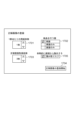
図1は、本実施形態に係る画像処理システムのハード構成の全体図である。画像処理システムは、画像形成装置101と外部コントローラ102を備える。画像形成装置101と外部コントローラ102は、内部LAN105とビデオケーブル106を介して通信可能に接続されている。外部コントローラ102は、外部LAN104を介してクライアントPC103と通信可能に接続されており、PC103から外部コントローラ102に対して印刷指示が行われる。
FIG. 1 is an overall diagram of the hardware configuration of an image processing system according to this embodiment. The image processing system includes an
クライアントPC103には、印刷データを外部コントローラ102で処理可能な印刷記述言語に変換する機能を有するプリンタドライバがインストールされている。印刷を行うユーザは、各種アプリケーションからプリンタドライバを介して印刷指示を行うことができる。プリンタドライバは、ユーザからの印刷指示に基づいて外部コントローラ102に対して印刷データを送信する。外部コントローラ102は、PC103から印刷指示を受け取ると、データ解析やラスタライズ処理を行い、画像形成装置101に対して印刷データを投入し印刷指示を行う。
A printer driver that has a function of converting print data into a print description language that can be processed by the
次に、画像形成装置101について説明する。画像形成装置101は、複数の異なる機能を持つ装置が接続され、製本などの複雑な印刷処理が可能なように構成されている。
Next, the
印刷装置107は、印刷装置107の下部にある給紙部から搬送される用紙に対してトナーを用いて画像を形成する。この印刷装置107の構成及び動作原理は次のとおりである。画像データに応じて変調された、レーザ光などの光線をポリゴンミラー等の回転多面鏡により反射して走査光として感光ドラムに照射する。このレーザ光により感光ドラム上に形成された静電潜像はトナーによって現像され、転写ドラムに貼り付けられた用紙に、そのトナー像を転写する。この一連の画像形成プロセスを、イエロー(Y)、マゼンタ(M)、シアン(C)、ブラック(K)のトナーに対して順次実行することにより、用紙上にフルカラー画像が形成される。フルカラー画像が形成された転写ドラム上の用紙は、定着器へ搬送される。定着器は、ローラーやベルト等を含み、ローラー内にハロゲンヒータなどの熱源を内蔵し、トナー像が転写された用紙上のトナーを、熱と圧力によって溶解して用紙に定着させる。
The
インサータ108は、挿入シートを挿入するためのインサータである。印刷装置107で印刷され搬送された用紙群に対して、任意の用紙の間にインサータ108から用紙を挿入することができる。
検品装置109は、搬送された用紙の画像を読み取り、予め登録された正解画像と比較することで、印刷された画像が正常かどうかを判定するための装置である。
The
大容量スタッカ110は、大容量のシートを積載することが可能な大容量スタッカである。フィニッシャ111は、搬送されたシートに対してフィニッシング処理を加えるフィニッシャである。フィニッシャ111は、ステイプルやパンチ、中綴じ製本などのフィニッシングを行うことが可能で、フィニッシング処理後の製本物を排紙トレイに排紙する。
The large-
なお、インサータ108と検品装置109の位置は、図1の順番に限定されず、検品装置109とスタッカ110の間にインサータ108を配置してもよい。
Note that the positions of the
図1で説明した印刷システムは、画像形成装置101に外部コントローラ102が接続された構成であるが、本実施例は、外部コントローラ102が接続された構成に限定されない。すなわち、画像形成装置101を外部LAN104に接続し、クライアントPC103から画像形成装置101へ、画像形成装置101が処理可能な印刷データを送信する構成でもよい。この場合、画像形成装置101において、データ解析やラスタライズ処理が行われ、印刷処理が実行される。
Although the printing system described in FIG. 1 has a configuration in which the
図2は、画像形成装置101、外部コントローラ102、及びクライアントPC103のシステム構成を表すブロック図である。
FIG. 2 is a block diagram showing the system configuration of the
まず画像形成装置101の印刷装置107の構成について説明する。画像形成装置101の印刷装置107は、通信I/F217、LANI/F218、ビデオI/F220、HDD221、CPU222、メモリ223、操作部224、ディスプレイ225で構成される。さらに画像形成装置101の印刷装置107は、原稿露光部226、レーザ露光部227、作像部228、定着部229、給紙部230を備える。それぞれの構成要素はシステムバス231を介して接続される。
First, the configuration of the
通信I/F217は、通信ケーブル254を介してインサータ108、検品装置109、大容量スタッカ110、及びフィニッシャ111と接続され、それぞれの装置の制御のための通信が行われる。LANI/F218は、内部LAN105を介して外部コントローラ102と接続され、印刷データなどの通信が行われる。ビデオI/F220は、ビデオケーブル106を介して外部コントローラ102と接続され、画像データなどの通信が行われる。
The communication I/
HDD221は、プログラムやデータが保存された記憶装置である。CPU222は、HDD221に保存されたプログラム等に基づいて、画像処理制御や印刷の制御を行う。メモリ223は、CPU222が各種処理を行う際に必要となるプログラムや、画像データが記憶され、ワークエリアとして動作する。操作部224は、ユーザからの各種設定の入力や操作の指示を受け付ける。ディスプレイ225には、画像処理装置の設定情報や印刷ジョブの処理状況などが表示される。
The
原稿露光部226は、コピー機能やスキャン機能を使用する際に原稿を読み込む処理を行う。ユーザにより設置された用紙に対して露光ランプを照らしながらCMOSイメージセンサまたはCISイメージセンサで画像を検知することで原稿データを読み込む。レーザ露光部227は、トナー像を転写するために感光ドラムにレーザ光を照射するための一次帯電や、レーザ露光を行う装置である。レーザ露光部227においては、まず感光ドラム表面を均一なマイナス電位に帯電させる一次帯電が行われる。次にレーザードライバーによってレーザ光を、ポリゴンミラーで反射角度を調節しながら感光ドラムに照射される。これにより照射した部分のマイナス電荷が中和され、静電潜像が形成される。作像部228は、用紙に対してトナーを転写するための装置であり、現像ユニット、転写ユニット、トナー補給部等により構成され、感光ドラム上のトナーを用紙に転写する。現像ユニットにおいては、現像シリンダーからマイナスに帯電したトナーを感光ドラム表面の静電潜像に付着させ、可視像化する。転写ユニットにおいては、一次転写ローラーにプラス電位を印可し感光ドラム表面のトナーを転写ベルトに転写する一次転写、二次転写外ローラーにプラス電位を印可し転写ベルト上のトナーを用紙に転写する二次転写が行われる。定着部229は、用紙上のトナーを熱と圧力で用紙に溶解固着するための装置であり、加熱ヒーター、定着ベルト、加圧ベルト等で構成される。給紙搬送部230は、用紙を給紙するための装置であり、ローラーや各種センサーにより用紙の給紙動作、搬送動作が制御される。
The
次に、画像形成装置101のインサータ108の構成について説明する。画像形成装置101のインサータ108は、通信I/F232、CPU233、メモリ234、給紙制御部235で構成され、それぞれの構成要素はシステムバス236を介して接続される。通信I/F232は、通信ケーブル254を介して印刷装置107と接続され、制御に必要な通信が行われる。CPU233は、メモリ234に格納された制御プログラムに応じて、給紙に必要な各種制御を行う。メモリ234は、制御プログラムが保存された記憶装置である。給紙制御部225は、CPU218からの指示に基づき、ローラーとセンサーを制御しながら、インサータの給紙部や印刷装置107から搬送された用紙の給紙、搬送を制御する。
Next, the configuration of the
次に、画像形成装置101の検品装置109の構成について説明する。画像形成装置101の検品装置109は、通信I/F237、CPU238、メモリ239、撮影部240、表示部241、操作部242で構成され、それぞれの構成要素はシステムバス243を介して接続される。通信I/F237は、通信ケーブル254を介して印刷装置107と接続され、制御に必要な通信が行われる。CPU238は、メモリ239に格納された制御プログラムに応じて、検品に必要な各種制御を行う。メモリ239は、制御プログラムが保存された記憶装置である。撮像部240は、CPU238の指示に基づき、搬送された用紙上に印刷されている画像をCISセンサで読み取る。なお、撮像部240は、搬送された用紙上に印刷されている画像を、カメラで撮影して画像を取得してもよい。また、撮像部240は、検査対象の印刷物だけでなく、正解画像登録時には正解画像候補となる印刷物の読み取りも行う。正解画像の候補となる印刷物は、印刷物1ページあたり複数部数印刷される。複数部数印刷されたページ間で対応する位置にある画素の画素値を平均化した画素値を正解画像の画素値にする。10部印刷された場合、10ページの対応する位置にある画素(例えば、画像の最も左上の画素)の画素値を平均化した画素値が、正解画像の画素値になる。これにより、印刷物に含まれる検査精度未満の微小な変動成分を極力排することが可能となる。
Next, the configuration of the
CPU238は、撮像部240によって撮像された画像と、メモリ239(記憶部)に記憶された正解画像とを比較し、印刷された画像が正常かどうかを判断する。表示部241は、検品結果や設定画面などが表示される。操作部242は、ユーザによって操作され、検品装置109の設定変更や正解画像の登録などの指示を受け付ける。
The
次に、画像形成装置101の大容量スタッカ110の構成について説明する。画像形成装置101の大容量スタッカ110は、通信I/F244、CPU245、メモリ246、排紙制御部247で構成され、それぞれの構成要素はシステムバス248を介して接続される。通信I/F244は、通信ケーブル254を介して印刷装置107と接続され、制御に必要な通信が行われる。CPU245は、メモリ246に格納された制御プログラムに応じて、排紙に必要な各種制御を行う。メモリ239は、制御プログラムが保存された記憶装置である。排紙制御部247は、CPU245からの指示に基づき、搬送された用紙をスタックトレイ、エスケープトレイ、または後続のフィニッシャ111に搬送する制御を行う。
Next, the configuration of the large-
次に、画像形成装置101のフィニッシャ111の構成について説明する。画像形成装置101のフィニッシャ111は、通信I/F249、CPU250、メモリ251、排紙制御部252、フィニッシング処理部253で構成され、それぞれの構成要素はシステムバス255を介して接続される。通信I/F249は、通信ケーブル254を介して印刷装置107と接続され、制御に必要な通信が行われる。CPU250は、メモリ251に格納された制御プログラムに応じて、フィニッシングや排紙に必要な各種制御を行う。メモリ251は、制御プログラムが保存された記憶装置である。排紙制御部252は、CPU251からの指示に基づき、用紙の搬送、排紙を制御する。フィニッシング処理部253は、CPU251からの指示に基づき、ステイプルやパンチ、中綴じ製本等のフィニッシング処理を制御する。
Next, the configuration of the
次に、外部コントローラ102の構成について説明する。外部コントローラ102は、CPU208、メモリ209、HDD210、キーボード211、ディスプレイ212、LANI/F213,LANI/F214、ビデオI/F215で構成され、システムバス216を通して接続されている。CPU208は、HDD210に保存されたプログラムやデータに基づいてクライアントPC103からの印刷データの受信、RIP処理、画像形成装置101への印刷データの送信などの処理を実行する。メモリ209は、CPU208が各種処理を行う際に必要なプログラムやデータが記憶され、ワークエリアとして動作する。HDD230には、印刷処理などの動作に必要なプログラムやデータが記憶される。キーボード211は、外部コントローラ102の操作指示を入力するための装置である。ディスプレイ212には、外部コントローラ102の実行アプリケーション等の情報を静止画や動画の映像信号により表示される。LANI/F213は、外部LAN104を介してクライアントPC103と接続され、印刷指示などの通信が行われる。LANI/F214は、内部LAN105を介して画像形成装置101と接続され、印刷指示などの通信が行われる。ビデオI/F215は、ビデオケーブル106を介して画像形成装置101と接続され、印刷データなどの通信が行われる。
Next, the configuration of the
次に、クライアントPC103の構成について説明する。クライアントPC103は、CPU201、メモリ202、HDD203、キーボード204、ディスプレイ205、LANI/F206で構成され、システムバス207を介して接続されている。CPU201は、HDD203に保存された文書処理プログラム等に基づいて印刷データの作成や印刷指示を実行する。またCPU201は、システムバスに接続される各デバイスを包括的に制御する。メモリ202は、CPU201が各種処理を行う際に必要となるプログラムやデータが記憶され、ワークエリアとして動作する。HDD203には、印刷処理などの動作に必要なプログラムやデータが記憶される。キーボード204は、PC103の操作指示を入力するための装置である。ディスプレイ205には、クライアントPC103の実行アプリケーション等の情報が静止画や動画の映像信号により表示される。LANI/F206は、外部LAN104と接続されており、印刷指示などの通信が行われる。
Next, the configuration of the
以上の説明において、外部コントローラ102と画像形成装置101は、内部LAN1905とビデオケーブル106が接続されているが、印刷に必要なデータの送受信が行える構成であればよく、例えば、ビデオケーブルのみの接続構成でもよい。また、メモリ202、メモリ209、メモリ223、メモリ234、メモリ239、メモリ249、メモリ251はそれぞれ、データやプログラムを保持するための記憶装置であればよい。たとえば、揮発性のRAM、不揮発性のROM、内蔵HDD、外付けHDD、USBメモリなどで代替した構成でもよい。
In the above description, the
図3は、画像形成装置101のメカ断面図である。印刷装置107は、シートに印刷する画像を形成する装置である。給紙デッキ301および302は、各種シートを収容しておくことが可能である。各給紙デッキでは、収容されたシートの最上位のシート一枚のみを分離し、シート搬送パス303へ搬送することが可能である。304~307は現像ステーションであり、カラー画像を形成するために、それぞれY、M、C、Kの有色トナーを用いてトナー像を形成する。ここで形成されたトナー像は中間転写ベルト308に一次転写され、中間転写ベルト308は時計回りに回転し、二次転写位置309でシート搬送パス303から搬送されてきたシートへとトナー像が転写される。表示装置225は、画像形成装置101の印刷状況や設定のための情報を表示する。トナー像をシートへ定着させるための定着ユニット311は、加圧ローラーと加熱ローラーを備え、各ローラーの間をシートが通過することにより、トナーを溶融・圧着することでシートにトナー像を定着させる。定着ユニット311を抜けたシートはシート搬送パス312を通って、搬送路315へと搬送される。シートの種類によって定着のためにさらに溶融・圧着が必要な場合は、定着ユニット311を通過した後、上のシート搬送パスを使って第二定着ユニット313へと搬送さる。そして、追加の溶融・圧着が施された後、シート搬送パス314を通って315へと搬送される。画像形成モードが両面の場合は、シート反転パス316へとシートを搬送し、シート反転パス316で反転した後、両面搬送パス317へとシートが搬送され、二次転写位置309で2面目の画像転写が行われる。
FIG. 3 is a mechanical sectional view of the
挿入シートを挿入するためのインサータ108は、インサータトレイ321を備え、シート搬送パス322を通じて給紙されたシートを搬送パスへ合流させる。これにより、印刷装置107から搬送される一連のシート群に、任意の位置でシートを挿入させて後続装置へ搬送させることが可能となる。
The
インサータ108を通過したシートは検品装置109へ搬送される。検品装置109内にはCIS(Contact Image Sensor)331、332(読取手段)が対向する形で配置される。CIS331は記録シートの上面を、CIS332は記録シートの下面を読み取るためのセンサーである。なお読み取るイメージセンサはCISではなく、ラインスキャンカメラでもよい。検品装置109は、シート搬送パス333に搬送されたシートが所定の位置に到達したタイミングで、CIS331、332を用いて記録シートの両面の画像を読み取り、画像が正常であるかを判断する。表示装置241には、検品装置109によって行われた検品結果などが表示される。
The sheet that has passed through the
大容量スタッカ110は、大容量のシートを積載することが可能である。大容量スタッカ110は、シートを積載するトレイとしてスタックトレイ341を有する。検品装置109を通過したシートは、シート搬送パス344を通して大容量スタッカ110に入力されてくる。シートは、シート搬送パス344からシート搬送パス345を経由して、スタックトレイ341に積載される。さらに、スタッカ340は、排紙トレイとしてエスケープトレイ346を有する。エスケープトレイ346は、検品装置109によって欠陥シートと判定されたシートを排出するために使用される排紙トレイである。エスケープトレイ346に出力する場合は、シート搬送パス344からシート搬送パス347を経由してエスケープトレイ346へシートが搬送される。なお、大容量スタッカ110の後段の後処理装置へシートを搬送する場合には、シート搬送パス348を経由してシートが搬送される。349はシートを反転するための反転部である。この反転部349は、シートをスタックトレイ341に積載する場合に使用される。入力されたシートの向きと出力時点でのシートの向きが同一となるように、スタックトレイ341に積載する場合には反転部349で一度シートを反転させる。エスケープトレイ346や、後続の後処理装置へ搬送する場合は、積載時にフリップせずにそのままシートを排出するため、反転部349での反転動作は行わない。
The large-
フィニッシャ111は、ユーザに指定された機能に応じ、搬送されたシートに対してフィニッシング処理を加えるである。フィニッシャ111は、具体的にはステイプル(1個所・2箇所綴じ)やパンチ(2穴・3穴)や中とじ製本等のフィニッシング機能を有する。フィニッシャ111は、2つの排紙トレイ351と352を備え、シート搬送パス353を経由して排紙トレイ351に出力される。ただし、シート搬送パス353は、ステイプル等のフィニッシング処理を行うことはできない。ステイプル等のフィニッシング処理を行う場合は、シート搬送パス354を経由して処理部355でユーザに指定されたフィニッシング機能が実行され、排紙トレイ352へ出力される。排紙トレイ351および352はそれぞれ昇降することが可能であり、排紙トレイ351を下降させ、処理部355でフィニッシング処理したシートを排紙トレイ351へ積載するように動作することも可能である。中とじ製本が指定された場合には中とじ処理部356で、シート中央にステイプル処理をした後、シートを二つ折りにしてシート搬送パス357を経由して中とじ製本トレイ358へ出力される。中とじ製本トレイ358は、ベルトコンベア構成になっており、中とじ製本トレイ358上に積載された中とじ製本束は左側へ搬送される構成となっている。
The
検品装置109は、予め設定された検査項目に従い、印刷装置107で印刷されたシート画像を検査する。シート画像の検査は、予め設定された正解画像と印刷されたシート画像とを比較して行われる。画像の比較方法には、画像位置ごとの画素値を比較する方法や、エッジ検出によるオブジェクトの位置の比較、OCR(Optical Character Recognition)による文字データの抽出などによる方法がある。検査項目には、印刷位置のずれ、画像の色合い、画像の濃度、スジやカスレ、印刷抜けなどがある。
The
以下、図4~図6を用いて正解画像の登録処理、および画像検査処理フローについて説明する。 The correct image registration process and image inspection process flow will be described below with reference to FIGS. 4 to 6.
図4(a)は、正解画像を登録する際に外部コントローラ102が行う処理の流れを示すフローチャートである。図4(a)のフローチャートを実行するためのプログラムはHDD210に記憶されており、メモリ209に読み出されCPU208によって実行される。
FIG. 4A is a flowchart showing the flow of processing performed by the
S4001で、外部コントローラ102は、N部の印刷ジョブの印刷指示を受信したかを判断する。S4001でN部の印刷指示を受信した場合は、S4002に進み、外部コントローラ102は、印刷装置107に対してN部の印刷データを投入し、印刷の実行を指示する。
In step S4001, the
図4(b)は、正解画像を登録する際に印刷装置107が行う処理の流れを示すフローチャートである。図4(b)のフローチャートを実行するためのプログラムはHDD221に記憶されており、メモリ223に読み出されCPU222によって実行される。
FIG. 4(b) is a flowchart showing the flow of processing performed by the
S4003で、印刷装置107は外部コントローラ102の印刷指示を受信するのを待つ。S4003で、外部コントローラ102からの印刷指示を受信した場合には、S4004に進み、印刷装置107は外部コントローラ102から受信したジョブを印刷する。外部コントローラ102から受信するジョブには、画像データの他に、給紙先や排紙先の情報も含まれる。印刷装置107は、外部コントローラ102から受信したジョブの内容に応じて、通信ケーブル254を介してインサータ108、検品装置109、大容量スタッカ110、フィニッシャ111を制御する。
In step S4003, the
図5は正解画像を登録する際に検品装置109が行う処理の流れを示すフローチャートである。図5のフローチャートを実行するためのプログラムは、メモリ246に記憶されており、検品装置109のCPU238によって実行される。
FIG. 5 is a flowchart showing the flow of processing performed by the
S501で、検品装置109は印刷設定を取得する。S501で取得する設定値には1部あたりの用紙枚数や検品を行う面、さらには用紙1枚あたり何枚の画像の画素値を平均化して正解画像を作成するかなどが含まれる。S502で、検品装置109は検品装置109に用紙が搬送されるのを待つ。S502で用紙が搬送された場合はS503に進み、用紙の画像をCIS231およびCIS232を使用して読み取り、検品装置109のメモリ239に保存する。次にS504で、検品装置109は、S501で取得した用紙枚数分の画像を読み取ったかを判断する。S504で、用紙枚数分の画像読み取りが完了していない場合はS502に進む。
In S501, the
S505で、S503で読みとった画像を、検品装置109の表示部241にプレビュー表示するためのプレビュー画像を生成し、S506で、表示部241にUI画面とともに表示させる表示制御を行う。この時、表示するUI画面の詳細については図10で後述する。S507で、すべての読み取り画像について正解画像として使用するようUI上から受け付けられたかどうかを判断する。すべての読み取り画像が受け付けられた場合はS508に進み、複数枚印刷されたページ間で対応する位置にある画素の画素値を平均化した正解画像を生成して本フローを終了する。
In S505, a preview image is generated to display the image read in S503 as a preview on the
S507で、一部の読み取り画像が正解画像として使用するように受付けられなかった場合は、S509で、追加で画像を取得するようにUI画面から選択されたかどうかを判断する。追加で画像を取得する場合はS501に進み、しない場合はS508に進む。S509でのUI画面表示については図11で後述する。 If some of the read images are not accepted for use as correct images in S507, it is determined in S509 whether or not additional images have been selected from the UI screen to be acquired. If additional images are to be acquired, the process advances to S501; otherwise, the process advances to S508. The UI screen display in S509 will be described later with reference to FIG.
図6は検品処理を行う際に検品装置109が行う処理の流れを示すフローチャートである。図6のフローチャートを実行するためのプログラムは、メモリ246に記憶されており、検品装置109のCPU238によって実行される。
FIG. 6 is a flowchart showing the flow of processing performed by the
S601で検品装置109は検品終了指示を受信したかを判断する。図13の1303の検品終了ボタンが選択されると、S601はYesと判定される。S601で検品終了指示を受信すると、検品装置109の処理を終了する。S601で検品終了指示を受信していない場合はS602に進む。
In S601, the
S602で、検品装置109に用紙が搬送されたかを判断する。S602で用紙が搬送されない場合はS601に進む。S602で用紙が搬送されたと判定されると、S603に進む。S603では、用紙の画像をCIS231およびCIS232を使用して読み取り、検品装置109のメモリ239に保存する。ここで、保存した画像は、図13の表示部1301に表示される。
In S602, it is determined whether the paper has been conveyed to the
次に、S604で、検品装置109はS603で読み取った画像と正解画像との比較を行う。正解画像は、図7のボタン703から検品装置109に対して登録された設定に基づく。S604で比較する項目は、図12の1201で設定された検品レベルや1202で設定された検品種別の項目である。次にS605に進み、S604の正解画像との比較の結果、正常画像であるか欠陥画像であるかを判断する。S605の処理では、読み取った画像の画質が、正解画像の画質を満たすか否かが判定される。
Next, in S604, the
S605で正常画像(検品OK)と判断された場合には、S606に進み、検品装置109の表示部241に検品結果がOKであることを表示する。図13はS606で表示される画面の一例である。
If it is determined in S605 that the image is normal (inspection OK), the process advances to S606, and the
次にS607に進み、検品装置109は、印刷装置107に対して、印刷シートを大容量スタッカ110のスタックトレイ341に排紙するよう指示する。ここで排紙される排紙先は、図15の設定部1503で設定された排紙先である。印刷装置107は、検品装置109に指示に基づき、大容量スタッカ110に対してスタックトレイ341に排紙するよう指示する。次に、S601に進み処理を継続する。
Next, the process advances to S607, and the
S605で欠陥画像(検品NG)と判断された場合には、S608に進み、検品装置109の表示部241に検品結果がNGであることを表示する。図14はS608で表示される画面の一例である。次にS609に進み、検品装置109は印刷装置107に対して、印刷シートを大容量スタッカ110のエスケープトレイ346に排紙するよう指示する。ここで排紙される排紙先は、図15の設定部1503で設定された検品NG時の排紙先である。印刷装置107は、検品装置109に指示に基づき、大容量スタッカ110に対してエスケープトレイ346に排紙するよう指示する。次に、S601に進み処理を継続する。
If it is determined in S605 that the image is defective (inspection NG), the process advances to S608, and the
図7~図15は、検品装置109の表示部241に表示される表示画面の一例であり、検品装置109のCPU238の指示に基づき表示される。
7 to 15 are examples of display screens displayed on the
図7は検品装置109の起動時に検品装置109の表示部241に表示される画面の一例である。表示部701には、正解画像が登録されていないため、検品を開始するために、正解画像の登録が必要である旨が表示されている(701)。正解画像が登録済みの場合は、検品開始可能である旨が表示される。表示部702には、登録済みの正解画像が表示される(702)。図7では正解画像が未登録のため、未登録である旨が表示されている。領域702は、正解画像以外にも、仕切り紙の設定などの検品の設定に関わる情報を表示しても良い。
FIG. 7 is an example of a screen displayed on the
ボタン703は、正解画像の登録画面を呼び出すためのボタンである。正解画像は検品装置109で読み取る画像と比較対象とする画像であり、あらかじめ目視や検品装置109により正常であると判定された印刷シートを読み取った画像が使用される。ボタン706は検品の設定画面を呼び出すためのボタンである。ユーザの検品目的に応じて検品の項目や検品の精度(正解画像との差異がどの程度で欠陥画像と判断するか)を設定する。ボタン707は、検品の開始を指示するためのボタンである。検品を開始すると、検品装置109は、送られてきたシート画像の検査を開始する。
A
図8は、正解画像を登録する際に、検品装置109の表示部241に表示される画面の一例である。図8の表示画面は、図7のボタン703が選択された際に表示される。設定部801は、検品を行う印刷ジョブの1部あたりの用紙枚数を設定するための設定部である。検品装置109には、1部あたり2枚以上の印刷ジョブである場合には、複数枚の画像を正解画像として登録することができる。
FIG. 8 is an example of a screen displayed on the
設定部802は、検品を行う面を設定するための設定部である。検品装置109が行う検品を両面にするか、表面のみにするか、裏面のみにするかを設定することができる。なお、印刷は片面の場合であっても、印刷されない面にゴミがついていないことを検査するために、両面の検査を行うよう設定する場合もある。ボタン803は、何枚のシート画像を取得して平均化した正解画像を生成するかを設定することができる。ボタン804は、正解画像の登録を指示するためのボタンである。ボタン804を押した後に、検品装置109は流れてきた正解画像が印字された用紙の画像を読み取り、正解画像として登録する。なお、PC103から外部コントローラ102へ正解画像データを送信し、印刷装置107で印刷した正解画像を検品装置109が読み取ってもよいし、正解画像が印刷された紙をインサータ108から挿入し、検品装置109が読み取ってもよい。
The
図9は、正解画像の読み取り中に検品装置109の表示部241に表示される画面の一例である。図9は、図8のボタン804を押すと表示される。設定部801、803で設定された枚数の読み取りが完了するまではこの画面が表示される。ボタン901は、正解画像の読み取り中止を指示するためのボタンである。ボタン901が押されると、正解画像の登録を行わずに図7の表示画面に戻る。
FIG. 9 is an example of a screen displayed on the
図10は、正解画像の読み取りが完了した後に検品装置109の表示部241に表示される画面の一例である。表示部1001には検品装置109で読み取った印刷シートのプレビュー画像が表示される。プレビュー画像が複数枚ある場合には、1002の切り替えボタンで表示する画像を切り替え、表と裏の両面の検品を行う場合には、1003の切り替えボタンで表裏を切り替えることができる。また、読み取った画像にゴミスジ等が混入していないかどうかを確認するために、画像拡縮ボタン1004で画像全体や、細部にゴミスジ等が混入していないかどうかを確認する。また、画像移動ボタン1009を指示すると、画像を拡大した後に、表示する領域を移動させることができる。なお、1002、1003、1004、1009の各操作ボタンは一例であり、これらの操作ボタンを表示せずに、フリック、ピンチ、スワイプ等のジェスチャー操作をそれぞれの操作に割り当ててもよい。
FIG. 10 is an example of a screen displayed on the
ボタン1005は、表示部1001の読み取り画像の確認後に、現在表示している画像を正解画像の候補画像として使用することを指示するためのボタンである。各取得画像について、ボタン1005が押されて使用すると選択された複数の画像間の対応する位置にある画素の平均値を算出し、正解画像が生成される。ボタン1006は、現在表示している画像を正解画像の候補画像として使用しない、すなわち、平均化処理に使用しないことを指示するためのボタンである。各取得画像について、ボタン1006が押されたものについてはそのまま破棄され、正解画像の生成に使用されない。なお、正解画像として使用する画像が1枚だけ選択された場合は、選択された1枚の画像を正解画像として登録する。また、正解画像として使用する画像を複数枚選択した場合、選択した複数枚の画像のうちメインとなる画像を選択し、選択したメインとなる画像の重みが大きくなるように、正解画像を生成する処理を行ってもよい。
A
ボタン1007は、各取得画像について一括で正解画像として使用することを指示するためのボタンであり、1008はすべての取得画像を破棄して正解画像の生成に使用しないことを指示するためのボタンである。一括使用ボタン1007が押されるか、あるいはすべての取得画像について、使用するボタン1005または使用しないボタン1006が選択完了されると、図11(a)の表示画面に進む。
図11(a)は、正解画像の取得後に表示される画面の一例である。図7の正解画像取得前の表示画面と比較して、表示部701には正解画像が登録されていることが表示される。また、表示部702には、登録された正解画像が表示される。なお、ここで表示される正解画像は、CIS331、332で読み取った複数枚のシート画像の対応する位置にある画素値を平均化して生成されたものである。
FIG. 11(a) is an example of a screen displayed after acquiring the correct image. In comparison with the display screen shown in FIG. 7 before acquiring the correct image, the
ボタン1101は、登録した正解画像をクリアするためのボタンである。正解画像がクリアされると、図7の表示画面に戻る。ボタン1102は、正解画像を追加登録するためのボタンである。図10において、一部の取得画像を破棄したものの、追加で正解画像候補を取得したい場合に、ボタン1102を押すことで追加取得することが可能となる。ボタン1102が押されると図11(b)の表示画面に進む。
A
図11(b)は、正解画像の追加登録を設定する画面の一例である。追加ページ指定ボタン1101は、追加取得するページを指定するためのボタンである。個別ページ追加ボタン1102は、1101で指定されたページを追加取得するように指示するためのボタンである。全ページ一括追加ボタン1103は、すべてのページを一括して追加取得するように指示するためのボタンである。表示部1104は、1102、1103で指定された追加取得ページを表示する。追加枚数指定ボタン1105は、追加取得するように指定されたページ毎に何枚取得するかを指定するためのボタンである。取得開始ボタン1106は、追加取得を開始するためのボタンである。ボタン1106が押され、指定された枚数の画像取得が完了すると、図10の表示画面に進む。
FIG. 11(b) is an example of a screen for setting additional registration of a correct image. The additional
図12は、検品の設定を行う際に検品装置109の表示部241に表示される画面の一例である。図12の表示画面は、図7のボタン706が押された際に表示される。設定部1201は、検品レベルを設定するための設定部である。設定部1201の設定により、検品の精度を変更することができる。検品装置109は、検品精度のレベルが高いほど、正解画像と読み取り画像のわずかな違いでも欠陥画像と判断する。
FIG. 12 is an example of a screen displayed on the
設定部1202は、検品種別を設定するための設定部である。ユーザの検品目的に応じて、検品の項目を設定することが可能である。図12は、位置、色合い、スジ、抜けは検品の対象とするが、濃度は検品の対象外とすることを示す。なお、本実施例の検品種別は一例である。
The
図13は検品開始後に検品装置109の表示部241に表示される画面の一例である。図13の表示画面は、図7のボタン707が押されると表示される。表示部1301には、検品装置109が最後に読み取った印刷シートの画像が表示される。表示部1302には、1301の読み取り画像と正解画像を比較した判定結果が表示される。図13の例では、正常画像と判定されたため、OKと表示されている。ボタン1303は、検品の終了を指示するためのボタンである。ボタン1303が押された場合には、検品装置109は検品処理を終了し、図7の表示画面に戻る。
FIG. 13 is an example of a screen displayed on the
図14は、最後に読み取った画像が欠陥画像と判定された場合の画面の一例である。読み取り画像1301と正解画像を比較した結果、欠陥画像と判定されたため、表示部1302にはNGの表示および、NGと判定した要因や位置が表示されている。図14は、スジ1405が検出されたため、欠陥画像と判断されたことが示されている。
FIG. 14 is an example of a screen when the last image read is determined to be a defective image. As a result of comparing the
図15は、外部コントローラ102のディスプレイ212に表示される検品ジョブの設定画面の一例である。図7~図14は、検品装置109に対して検品の設定を行う際の画面例であるが、検品装置109に正解画像の印刷シートや検品対象の印刷シートを流す指示は、外部コントローラ102から行う。なお、検品装置109の表示部241から、上述の検品の設定を行ってもよい。
FIG. 15 is an example of an inspection job setting screen displayed on the display 212 of the
設定部1501は、ジョブの部数を設定する設定部である。図15では、1000部のジョブを印刷する設定がされている。図15の例では、1部あたり1ページであり、1ジョブは、1000部からなる。なお、別の例として、1部あたり複数ページあってもよい。設定部1503は、検品ジョブの排紙先を設定する設定部である。ここでは、排紙先として大容量スタッカが設定され、検品で欠陥画像と判定された場合に排紙する排紙先としてエスケープトレイが設定されている。なお、この設定以外にも、たとえば検品OK時、NG時の排紙を同一のトレイに設定してもよい。この場合、不図示の検品結果一覧をもとに後から手作業で検品NGの印刷シートを抜き取ることになる。あるいは、同一トレイに排紙する場合は、OKとNGのシートをずらして排紙させて、後からNGの印刷シートの抜き取り作業を行う構成してもよい。
A
ボタン1504、1505は、検品ジョブをN部だけ印刷することを指示するボタンである。図8のボタン803で検品装置109に正解画像の登録開始を指示した後に、外部コントローラ102のボタン1504、1505で検品ジョブをN部印刷指示すると、印刷装置107による印刷処理および検品装置109による正解画像の読み込みが行われる。なお、本実施形態以外にも、図8のボタン803が押されると同時に、検品装置109から通信ケーブル254、内部LAN105を介し、外部コントローラ102に対して自動で検品ジョブをN部印刷指示するように構成してもよい。また、同様に図11の正解画像追加取得時にも、ボタン1106が押されると同時に、検品装置109から外部コントローラ102に対して特定のページを追加印刷指示するように構成されていてもよい。
ボタン1508は、検品ジョブの印刷開始を指示するためのボタンである。ボタン1508を選択することで印刷開始が指示されると、外部コントローラ102は図15の設定に基づき、検品ジョブを印刷装置107に投入する。図7のボタン707を選択し検品装置109に検品開始を指示した後に、ボタン1508で外部コントローラ102に検品ジョブの印刷開始を指示する。これにより、外部コントローラ102は印刷装置107に印刷データを投入し、印刷された印刷シートを検品装置109へ搬送することを指示する。検品装置109は印刷シートが搬送されたら印刷シートの画像を読み込み、検品処理が行われる。なお、本実施形態以外にも、1508ボタンが押されて検品ジョブの印刷開始が指示されると、外部コントローラ102から検品装置109に対して検品開始指示を行うように構成されていてもよい。この時、検品装置109から外部コントローラ102へ正解画像の登録がされているか否かを通知することで、正解画像未登録時に外部コントローラ102が印刷開始をしないように構成してもよい。
A
以上説明したように、本実施形態によれば正解画像登録時にCIS331、CIS332で読み取った画像をUI画面上にプレビュー表示することができる。これにより、ユーザは印刷シートの目視確認だけでなく、CIS331、CIS332で正しく正解画像が読み取られたかどうかを確認して正解画像候補として採用するかどうかを決定することが可能となる。
As described above, according to the present embodiment, images read by the
実施例1は、正解画像登録時にUI画面上にプレビュー表示することができ、正解画像が正しく読み取れたかどうかをユーザ自身で確認することができる。しかし、紙粉等により発生したスジによる読み取り不良を全ての正解画像に対してプレビューで確認するには、ユーザの手間がかかってしまう。 In the first embodiment, a preview can be displayed on the UI screen at the time of correct image registration, and the user can confirm whether or not the correct image has been read correctly. However, it takes time and effort for the user to preview all correct images for reading defects due to streaks caused by paper dust or the like.
そこで、本実施例では、CIS331、CIS332での正解画像の読み取り時に、読み取り不良が発生したかを画像処理により検知を行う。読み取り不良と検知された正解画像は、プレビュー表示から自動的に除外することで、ユーザがより簡単に正解画像を登録できる装置を実現する。
Therefore, in this embodiment, when reading correct images by the
以下、その装置の実施例詳細に関して説明する。なお、実施例1と同様な説明となる構成及び処理は割愛し、本実施例で特有な構成及び処理のみ説明を行う。 Hereinafter, details of an embodiment of the device will be described. Note that configurations and processes that are similar to those in the first embodiment will be omitted, and only configurations and processes that are unique to this embodiment will be explained.
本実施例は、実施例1で説明した図6の正解画像を登録する際の検品装置の処理の流れが異なる。本実施例において、正解画像を登録する際の検品装置109の処理の流れを図16に示す。図16は検品処理を行う際に検品装置109が行う処理の流れを示すフローチャートである。図16のフローチャートを実行するためのプログラムは、メモリ246に記憶されており、検品装置109のCPU238によって実行される。
This embodiment differs from the first embodiment in the processing flow of the inspection device when registering the correct image shown in FIG. 6. In this embodiment, FIG. 16 shows the flow of processing performed by the
S1601で検品装置109は印刷設定を取得する。S1601で取得する設定には図17に示すように1部あたりの用紙枚数や検品を行う面、さらには用紙1枚あたり何枚の画像を平均化して正解画像を作成するかなどが含まれる。また、読み取り画像にスジが含まれてしまった場合に自動的に正解画像の登録から除外するかを設定することができる。また、後述されるS1610からのフィーバック時には、印刷する枚数はS1610で既に使用すると設定された読み取り画像の枚数に応じて決定され、印刷する枚数は正解画像の登録枚数に対して不足する枚数となる。なお、以降で説明する処理は、読み取り画像にスジがあった場合に、自動的に正解画像の登録候補から除外する設定とする。除外しない設定の場合は第1の実施例と同様である。
In S1601, the
次に、S1602で検品装置109は検品装置109に用紙が搬送されるのを待つ。
Next, in step S1602, the
S1602で用紙が搬送された場合はS1603に進み、用紙の画像をCIS331およびCIS332を使用して読み取り、検品装置109のメモリ239に保存する。S1604で、検品装置109はメモリ239に保存された読み取り画像に不良画像検出処理を適用し、不良情報の生成を行う。不良画像検出で対象とする不良の一例としては、紙粉等による浮遊スジや固定スジであり、図20(a)は浮遊スジによる画像の一例を示し、図20(b)は原稿の縦線を示している。なお、浮遊スジを検出するアルゴリズムは公知の技術で構わない。一例としては、読み取り画像に対してフィルタ処理を行い、想定されるスジ幅の縦線の検出を行う。次に、検出された縦線に対して主走査方向の周囲の画素との輝度値の変化量および副走査方向の周囲の画素との輝度値の変化量を算出する。その算出結果と副走査方向への連続性から、スジの画素であるかを判定することができる。
If the paper is transported in S1602, the process advances to S1603, where the image of the paper is read using the
図18は、不良情報を管理するテーブルであり、不良情報は各読み取り画像に対して管理されるフラグであり、読み取り時に紙粉等によるスジが発生してしまった画像である場合は、1とする。ただし、これは一例であって、画像情報のヘッダー領域等を活用してフラグを画像情報毎に持たせても良い。 FIG. 18 is a table for managing defect information. The defect information is a flag that is managed for each read image. If the image has streaks due to paper dust or the like during reading, it is set to 1. do. However, this is just an example, and a flag may be provided for each piece of image information by utilizing the header area of the image information.
図16の説明に戻り、S1605で検品装置109は読み取り画像の不良情報を取得して、不良画像であるかを判定する。不良画像である場合にはS1607へ進む。不良画像ではない場合にはS1606へ進む。S1606で検品装置109の表示部241に、S1603で読みとった画像をプレビュー表示するためのプレビュー画像を生成する。次に、S1607で検品装置109はS1601で取得した用紙枚数分の画像を読み取ったかを判断する。S1607で、まだ用紙枚数分の画像読み取りが完了していない場合はS1602に進む。
Returning to the explanation of FIG. 16, in step S1605, the
S1608で、検品装置109はS1606で生成したプレビュー画像を含むUI画面を生成し、表示部241に表示する。この時表示するUI画面の詳細については図19で後述する。S1609で、検品装置109は全ての読み取り画像について正解画像として使用するかUI上から指示されたかどうかを判断する。全ての読み取り画像に対する使用可否を指示された場合は、S1610に進む。そうではない場合、S1609に進む。
In S1608, the
S1610で検品装置109はUI上で使用すると設定された読み取り画像の枚数が正解画像の取得枚数に達したかを判定する。使用すると設定された読み取り画像の枚数が正解画像取得枚数に達した場合、S1611に進み、読み取り画像を平均化した正解画像を生成して本フローを終了する。S1610で検品装置109は使用すると設定された読み取り画像の枚数が正解画像取得枚数に達していない場合、S1601に進む。なお、S1610の判定をもって、不足分を追加印刷するフローに入るように構成したが、S1605で不良画像と判定した場合には直ちに不足分を追加印刷するフローとしても良い。また、不良画像検出で不良と判定した印刷物を、正常と判定された印刷物と異なる排紙トレイに出力するように制御しても良い。このようにすると、後述する読み取り画像の使用有無の指定のために表示されるプレビュー画面と相関性が高くなり、より直感的に理解可能となる。
In step S1610, the
図19は、正解画像の読み取りが完了した後に検品装置109の表示部241に表示される画面の一例である。表示部1001には検品装置109で読み取った印刷シートのプレビュー画像が表示される。ここで表示され画像は、不良画像検出で不良画像であると判定された画像を除いた画像である点が第1の実施例とは異なる。プレビュー画像は、画像1901、画像1902,画像1903である。例として3つのプレビュー画像を同時に表示可能な構成としているが、これに限定されない。1901は1部目の印刷物のプレビュー画像である。1902は2部目の印刷物のプレビュー画像である。1903は4部目の印刷物のプレビュー画像である。これは、3部目の印刷物に関して、読み取り時に浮遊スジ等の発生により不良画像として判定された場合の例である。なお、インフォメーション表示部として1910を備えており、不良画像検出により自動的に正解画像の候補から除外された読み取り画像の情報が表示される。
FIG. 19 is an example of a screen displayed on the
ボタン1904~1909は、表示部1001の読み取り画像の確認後に、現在表示している画像を正解画像の候補画像として使用することを指示するためのボタンである。1901のプレビュー画像に対する正解画像の候補画像として使用するか使用しないかの指示ボタンが1904、1905である。同様にプレビュー画像1902に対しては、指示ボタン1906、1907となり、プレビュー画像1903に対しては、指示ボタン1908、1909となる。使用するボタン1904、1906、1908が押されたものについて、平均化がなされ、正解画像が生成される。使用しないボタン1905、1907、1909が押されたものについてはそのまま破棄され、正解画像としては使用されない。なお、使用するボタン、使用しないボタンのいずれのボタンも選択されなかった画像は、デフォルト設定(例えば、使用する)に従って、正解画像の生成を行う。
表示可能な全てのプレビュー画像に対して使用有無の指定が指定されると、図11の表示画面に進む。なお、図19は読み取った正解画像の候補を1枚ずつ表示しているが、確認方法として、平均化された正解画像を表示して確認しても良いし、その両方を表示しても良い。 When all displayable preview images are designated to be used or not, the process advances to the display screen shown in FIG. 11. Note that although FIG. 19 displays candidates for the read correct image one by one, as a confirmation method, the averaged correct image may be displayed for confirmation, or both may be displayed. .
以上説明したように、本実施例によれば、正解画像登録時にCIS331、CIS332で読み取った画像に対して不良画像検出を行い、読み取りの際に発生した不良の画像をプレビュー画像から除外することができる。これにより、ユーザの確認の手間を抑制することができる。
As explained above, according to this embodiment, defective images can be detected for images read by the
(その他の実施形態)
本発明は、上述の実施形態の1以上の機能を実現するプログラムを、ネットワーク又は記憶媒体を介してシステム又は装置に供給し、そのシステム又は装置のコンピュータにおける1つ以上のプロセッサーがプログラムを読出し実行する処理でも実現可能である。また、1以上の機能を実現する回路(例えば、ASIC)によっても実現可能である。
(Other embodiments)
The present invention provides a system or device with a program that implements one or more of the functions of the embodiments described above via a network or a storage medium, and one or more processors in the computer of the system or device reads and executes the program. This can also be achieved by processing. It can also be realized by a circuit (for example, ASIC) that realizes one or more functions.
Claims (13)
複数の記録シート上に形成された画像を読み取り得られた複数の画像を表示部へ表示させる表示制御手段と、
前記表示制御手段によって前記表示部へ表示された複数の画像の中から、リファレンス画像として用いる複数の画像を、ユーザインタフェースを介して受け付ける受付手段とを有し、
前記受付手段によって受け付けた複数の画像における対応する位置にある画素の値に重み付け演算を行い生成された画像を、検査対象画像の検査における前記リファレンス画像として用いる
ことを特徴とする検品装置。 An inspection device that reads an image formed on a recording sheet using a reference image and inspects the obtained image,
a display control means for reading images formed on a plurality of recording sheets and displaying the obtained plurality of images on a display section;
receiving means for receiving a plurality of images to be used as reference images from among the plurality of images displayed on the display unit by the display control means via a user interface ;
An inspection device characterized in that an image generated by performing a weighting calculation on the values of pixels at corresponding positions in a plurality of images received by the receiving means is used as the reference image in the inspection of the image to be inspected.
複数の記録シート上に形成された画像を読み取り得られた複数の画像を表示部へ表示させる表示制御ステップと、
前記表示制御ステップによって前記表示部へ表示された複数の画像の中から、リファレンス画像として用いる複数の画像を、ユーザインタフェースを介して受け付ける受付ステップとを有し、
前記受付ステップによって受け付けた複数の画像における対応する位置にある画素の値に重み付け演算を行い生成された画像を、検査対象画像の検査における前記リファレンス画像として用いる
ことを特徴とする検査方法。 An inspection method in an inspection device that reads an image formed on a recording sheet using a reference image and inspects the obtained image,
a display control step of reading images formed on a plurality of recording sheets and displaying the obtained plurality of images on a display section;
a receiving step of receiving, via a user interface , a plurality of images to be used as reference images from among the plurality of images displayed on the display unit in the display control step;
An inspection method characterized in that an image generated by performing a weighting calculation on the values of pixels at corresponding positions in the plurality of images received in the receiving step is used as the reference image in the inspection of the image to be inspected.
複数の記録シート上に形成された画像を読み取り得られた複数の画像を表示部へ表示させる表示制御手段と、
前記表示制御手段によって前記表示部へ表示された複数の画像の中から、リファレンス画像として用いる複数の画像を、ユーザインタフェースを介して受け付ける受付手段とを有し、
前記受付手段によって受け付けた複数の画像における対応する位置にある画素の値に重み付け演算を行い生成された画像を、検査対象画像の検査における前記リファレンス画像として用いる
ことを特徴とする検品システム。 An inspection system that reads an image formed on a recording sheet using a reference image and inspects the obtained image,
a display control means for reading images formed on a plurality of recording sheets and displaying the obtained plurality of images on a display section;
receiving means for receiving a plurality of images to be used as reference images from among the plurality of images displayed on the display unit by the display control means via a user interface ;
An inspection system characterized in that an image generated by performing a weighting calculation on the values of pixels at corresponding positions in a plurality of images received by the reception means is used as the reference image in the inspection of the image to be inspected.
前記表示制御手段によって前記表示部へ表示された複数の画像の中から、リファレンス画像として用いる複数の画像を、ユーザインタフェースを介して受け付ける受付手段と、
前記受付手段によって受け付けた複数の画像における対応する位置にある画素の値に重み付け演算を行いリファレンス画像を生成する生成手段と、
前記生成手段によって生成されたリファレンス画像を用いて、記録シート上に形成された画像を読み取った検査対象画像を検査する検査手段と
を有することを特徴とする検品装置。 a display control means for reading images formed on a plurality of recording sheets and displaying the obtained plurality of images on a display section;
a reception means for accepting, via a user interface, a plurality of images to be used as reference images from among the plurality of images displayed on the display unit by the display control means;
generating means for generating a reference image by performing a weighting operation on the values of pixels at corresponding positions in the plurality of images received by the receiving means ;
An inspection device comprising: an inspection device for inspecting an inspection target image obtained by reading an image formed on a recording sheet using the reference image generated by the generation device.
Priority Applications (4)
| Application Number | Priority Date | Filing Date | Title |
|---|---|---|---|
| JP2019195551A JP7418081B2 (en) | 2019-10-28 | 2019-10-28 | Image forming device, image forming method, and program |
| KR1020200137980A KR20210050468A (en) | 2019-10-28 | 2020-10-23 | Image forming apparatus to verify printed image with master image, image forming method, and storage medium |
| US17/081,297 US11418656B2 (en) | 2019-10-28 | 2020-10-27 | Image forming apparatus to verify printed image with master image, image forming method, and storage medium |
| US17/849,460 US20220329701A1 (en) | 2019-10-28 | 2022-06-24 | Image forming apparatus to verify printed image with master image, image forming method, and storage medium |
Applications Claiming Priority (1)
| Application Number | Priority Date | Filing Date | Title |
|---|---|---|---|
| JP2019195551A JP7418081B2 (en) | 2019-10-28 | 2019-10-28 | Image forming device, image forming method, and program |
Publications (3)
| Publication Number | Publication Date |
|---|---|
| JP2021067914A JP2021067914A (en) | 2021-04-30 |
| JP2021067914A5 JP2021067914A5 (en) | 2023-05-30 |
| JP7418081B2 true JP7418081B2 (en) | 2024-01-19 |
Family
ID=75586469
Family Applications (1)
| Application Number | Title | Priority Date | Filing Date |
|---|---|---|---|
| JP2019195551A Active JP7418081B2 (en) | 2019-10-28 | 2019-10-28 | Image forming device, image forming method, and program |
Country Status (3)
| Country | Link |
|---|---|
| US (2) | US11418656B2 (en) |
| JP (1) | JP7418081B2 (en) |
| KR (1) | KR20210050468A (en) |
Families Citing this family (3)
| Publication number | Priority date | Publication date | Assignee | Title |
|---|---|---|---|---|
| JP7418081B2 (en) * | 2019-10-28 | 2024-01-19 | キヤノン株式会社 | Image forming device, image forming method, and program |
| JP2021115756A (en) * | 2020-01-24 | 2021-08-10 | キヤノン株式会社 | Image formation device, information processing method and program |
| JP2023048841A (en) | 2021-09-28 | 2023-04-07 | キヤノン株式会社 | Image formation system and control method |
Citations (4)
| Publication number | Priority date | Publication date | Assignee | Title |
|---|---|---|---|---|
| JP2005271331A (en) | 2004-03-24 | 2005-10-06 | Fuji Xerox Co Ltd | Image inspection device |
| JP2013140040A (en) | 2011-12-28 | 2013-07-18 | Keyence Corp | Visual inspection device, visual inspection method and computer program |
| JP2018079581A (en) | 2016-11-14 | 2018-05-24 | コニカミノルタ株式会社 | Image formation apparatus, image abnormality detection apparatus, management apparatus and control program |
| JP2019132966A (en) | 2018-01-31 | 2019-08-08 | コニカミノルタ株式会社 | Image formation device |
Family Cites Families (25)
| Publication number | Priority date | Publication date | Assignee | Title |
|---|---|---|---|---|
| JP3716873B2 (en) * | 1996-03-26 | 2005-11-16 | グローリー工業株式会社 | Paper sheet identification device |
| US5999636A (en) * | 1997-10-10 | 1999-12-07 | Printprobe Technology, Llc | Apparatus and process for inspecting print material |
| MC2479A1 (en) * | 1998-09-07 | 1999-04-27 | Luigi Stringa | Automatic inspection of print quality by an elastic model |
| JP2001053973A (en) * | 1999-08-12 | 2001-02-23 | Pfu Ltd | Image reading device, its control method and recording medium |
| JP2005202469A (en) * | 2004-01-13 | 2005-07-28 | Fuji Xerox Co Ltd | Image processor, image processing method and program |
| US20070201066A1 (en) * | 2005-10-30 | 2007-08-30 | Asa Ziv | Density measurement, colorimetric data, and inspection of printed sheet using contact image sensor |
| JP2009115565A (en) * | 2007-11-06 | 2009-05-28 | Dainippon Printing Co Ltd | Inspection apparatus for punched piece |
| JP5531416B2 (en) | 2009-02-02 | 2014-06-25 | セイコーエプソン株式会社 | Printing apparatus and printing inspection method |
| US20100195139A1 (en) * | 2009-02-04 | 2010-08-05 | Microsoft Corporation | Print rendering verification |
| DE102010055974A1 (en) * | 2010-12-23 | 2012-06-28 | Giesecke & Devrient Gmbh | Method and device for determining a class reference data set for the classification of value documents |
| JP2012161974A (en) * | 2011-02-07 | 2012-08-30 | Konica Minolta Business Technologies Inc | Image forming system |
| DE102012215114B4 (en) * | 2012-08-24 | 2015-03-19 | Koenig & Bauer Aktiengesellschaft | Method for inspecting a printed product |
| JP6455016B2 (en) * | 2013-08-27 | 2019-01-23 | 株式会社リコー | Image inspection apparatus, image forming system, and image inspection method |
| JP2018034469A (en) * | 2016-09-01 | 2018-03-08 | 京セラドキュメントソリューションズ株式会社 | Image forming apparatus and image forming system |
| JP2019041204A (en) * | 2017-08-24 | 2019-03-14 | 王子ホールディングス株式会社 | Reference image data generation method, printed matter inspection method, and reference image data generation system |
| JP7021972B2 (en) * | 2018-02-16 | 2022-02-17 | 株式会社Screenホールディングス | Inspection equipment, inkjet printing equipment, and inspection methods |
| JP2019193978A (en) * | 2018-05-01 | 2019-11-07 | コニカミノルタ株式会社 | Image forming device |
| JP2020006603A (en) * | 2018-07-10 | 2020-01-16 | コニカミノルタ株式会社 | Image inspection system, image inspection method and image inspection program |
| JP7327918B2 (en) * | 2018-09-25 | 2023-08-16 | コニカミノルタ株式会社 | IMAGE INSPECTION SYSTEM, IMAGE INSPECTION METHOD, AND IMAGE INSPECTION PROGRAM |
| JP7147436B2 (en) * | 2018-09-28 | 2022-10-05 | コニカミノルタ株式会社 | Inspection device, image forming device, and program for inspection device |
| JP7151347B2 (en) * | 2018-10-03 | 2022-10-12 | コニカミノルタ株式会社 | Image forming system and control program |
| US11830192B2 (en) * | 2019-07-31 | 2023-11-28 | The Joan and Irwin Jacobs Technion-Cornell Institute | System and method for region detection in tissue sections using image registration |
| JP7466280B2 (en) * | 2019-09-05 | 2024-04-12 | キヤノン株式会社 | Inspection device, control method thereof, and program |
| JP7418081B2 (en) * | 2019-10-28 | 2024-01-19 | キヤノン株式会社 | Image forming device, image forming method, and program |
| JP7443022B2 (en) * | 2019-10-28 | 2024-03-05 | キヤノン株式会社 | Image forming device, image forming method, and program |
-
2019
- 2019-10-28 JP JP2019195551A patent/JP7418081B2/en active Active
-
2020
- 2020-10-23 KR KR1020200137980A patent/KR20210050468A/en not_active Application Discontinuation
- 2020-10-27 US US17/081,297 patent/US11418656B2/en active Active
-
2022
- 2022-06-24 US US17/849,460 patent/US20220329701A1/en active Pending
Patent Citations (4)
| Publication number | Priority date | Publication date | Assignee | Title |
|---|---|---|---|---|
| JP2005271331A (en) | 2004-03-24 | 2005-10-06 | Fuji Xerox Co Ltd | Image inspection device |
| JP2013140040A (en) | 2011-12-28 | 2013-07-18 | Keyence Corp | Visual inspection device, visual inspection method and computer program |
| JP2018079581A (en) | 2016-11-14 | 2018-05-24 | コニカミノルタ株式会社 | Image formation apparatus, image abnormality detection apparatus, management apparatus and control program |
| JP2019132966A (en) | 2018-01-31 | 2019-08-08 | コニカミノルタ株式会社 | Image formation device |
Also Published As
| Publication number | Publication date |
|---|---|
| US20210127018A1 (en) | 2021-04-29 |
| KR20210050468A (en) | 2021-05-07 |
| US20220329701A1 (en) | 2022-10-13 |
| US11418656B2 (en) | 2022-08-16 |
| JP2021067914A (en) | 2021-04-30 |
Similar Documents
| Publication | Publication Date | Title |
|---|---|---|
| JP7466280B2 (en) | Inspection device, control method thereof, and program | |
| US11528378B2 (en) | Image forming apparatus and image forming method to display a number of normal sheets together with a number of defective sheets | |
| JP7418081B2 (en) | Image forming device, image forming method, and program | |
| US11283955B2 (en) | Image forming apparatus and image forming method with image verification | |
| JP2024050927A (en) | Image forming apparatus, image forming method, and program | |
| JP7362438B2 (en) | System, system control method, and program | |
| JP2021115744A (en) | Image forming device, information processing method and program | |
| US11422754B2 (en) | Image forming apparatus, verification apparatus, information processing method, and storage medium | |
| JP2022131198A (en) | Printing system, control method therefor, and program | |
| JP2022128230A (en) | Printing system, printer and information processing device and control method therefor, and program | |
| JP7471841B2 (en) | Inspection system and method | |
| JP2021102322A (en) | Image formation apparatus, image formation method, and program | |
| US11822279B2 (en) | Image forming apparatus, information processing method, printing system, and storage medium for performing reprinting | |
| JP2021045922A (en) | Image forming apparatus, information processing method and program | |
| JP2021044672A (en) | Inspection device, information processing method, and program | |
| JP2021125786A (en) | Image forming apparatus, information processing method, and program | |
| JP2023049771A (en) | Printing system, printer, inspection device, control method thereof and program | |
| JP2023047419A (en) | Printing system and method for controlling the same, printer, and program | |
| JP2022148533A (en) | Printing system, control method and program thereof | |
| JP2021077937A (en) | Image forming apparatus, information processing method, and program | |
| JP2021079596A (en) | Image forming device, information processing method and program | |
| JP2023108683A (en) | Inspection system, printer, and control method of inspection system | |
| JP2021115756A (en) | Image formation device, information processing method and program | |
| JP2024022487A (en) | Inspection system and imaging system | |
| JP2023048244A (en) | Inspection system, image formation apparatus, control method of inspection system, control method of image formation apparatus and program |
Legal Events
| Date | Code | Title | Description |
|---|---|---|---|
| A621 | Written request for application examination |
Free format text: JAPANESE INTERMEDIATE CODE: A621 Effective date: 20221024 |
|
| A521 | Request for written amendment filed |
Free format text: JAPANESE INTERMEDIATE CODE: A523 Effective date: 20230522 |
|
| A977 | Report on retrieval |
Free format text: JAPANESE INTERMEDIATE CODE: A971007 Effective date: 20230713 |
|
| A131 | Notification of reasons for refusal |
Free format text: JAPANESE INTERMEDIATE CODE: A131 Effective date: 20230725 |
|
| A521 | Request for written amendment filed |
Free format text: JAPANESE INTERMEDIATE CODE: A523 Effective date: 20230919 |
|
| TRDD | Decision of grant or rejection written | ||
| A01 | Written decision to grant a patent or to grant a registration (utility model) |
Free format text: JAPANESE INTERMEDIATE CODE: A01 Effective date: 20231128 |
|
| RD01 | Notification of change of attorney |
Free format text: JAPANESE INTERMEDIATE CODE: A7421 Effective date: 20231213 |
|
| A61 | First payment of annual fees (during grant procedure) |
Free format text: JAPANESE INTERMEDIATE CODE: A61 Effective date: 20231227 |
|
| R151 | Written notification of patent or utility model registration |
Ref document number: 7418081 Country of ref document: JP Free format text: JAPANESE INTERMEDIATE CODE: R151 |