JP7416773B2 - Anvil assembly for linear surgical stapler - Google Patents
Anvil assembly for linear surgical stapler Download PDFInfo
- Publication number
- JP7416773B2 JP7416773B2 JP2021519872A JP2021519872A JP7416773B2 JP 7416773 B2 JP7416773 B2 JP 7416773B2 JP 2021519872 A JP2021519872 A JP 2021519872A JP 2021519872 A JP2021519872 A JP 2021519872A JP 7416773 B2 JP7416773 B2 JP 7416773B2
- Authority
- JP
- Japan
- Prior art keywords
- elongate member
- stapler
- anvil
- plate
- distal
- Prior art date
- Legal status (The legal status is an assumption and is not a legal conclusion. Google has not performed a legal analysis and makes no representation as to the accuracy of the status listed.)
- Active
Links
- 229920000642 polymer Polymers 0.000 claims description 64
- 238000000034 method Methods 0.000 claims description 38
- 239000000463 material Substances 0.000 claims description 32
- 238000004519 manufacturing process Methods 0.000 claims description 20
- 238000010304 firing Methods 0.000 description 49
- 230000007246 mechanism Effects 0.000 description 33
- 230000008569 process Effects 0.000 description 19
- 230000000903 blocking effect Effects 0.000 description 15
- 230000015572 biosynthetic process Effects 0.000 description 14
- 238000001746 injection moulding Methods 0.000 description 13
- 230000008878 coupling Effects 0.000 description 7
- 238000010168 coupling process Methods 0.000 description 7
- 238000005859 coupling reaction Methods 0.000 description 7
- 238000005520 cutting process Methods 0.000 description 7
- 239000012636 effector Substances 0.000 description 7
- 238000001356 surgical procedure Methods 0.000 description 7
- 239000002184 metal Substances 0.000 description 4
- 229910052751 metal Inorganic materials 0.000 description 4
- 230000004048 modification Effects 0.000 description 4
- 238000012986 modification Methods 0.000 description 4
- 238000004140 cleaning Methods 0.000 description 3
- 238000010276 construction Methods 0.000 description 3
- 238000003754 machining Methods 0.000 description 3
- 238000000465 moulding Methods 0.000 description 3
- 229920003023 plastic Polymers 0.000 description 3
- 239000004033 plastic Substances 0.000 description 3
- 230000005855 radiation Effects 0.000 description 3
- 230000003872 anastomosis Effects 0.000 description 2
- 230000002496 gastric effect Effects 0.000 description 2
- 239000007788 liquid Substances 0.000 description 2
- 230000004044 response Effects 0.000 description 2
- 230000000717 retained effect Effects 0.000 description 2
- 229910001220 stainless steel Inorganic materials 0.000 description 2
- 239000010935 stainless steel Substances 0.000 description 2
- 241000894006 Bacteria Species 0.000 description 1
- IAYPIBMASNFSPL-UHFFFAOYSA-N Ethylene oxide Chemical compound C1CO1 IAYPIBMASNFSPL-UHFFFAOYSA-N 0.000 description 1
- 229920000690 Tyvek Polymers 0.000 description 1
- 239000004775 Tyvek Substances 0.000 description 1
- 230000006978 adaptation Effects 0.000 description 1
- 230000000295 complement effect Effects 0.000 description 1
- 230000006866 deterioration Effects 0.000 description 1
- 238000009760 electrical discharge machining Methods 0.000 description 1
- 238000010894 electron beam technology Methods 0.000 description 1
- 238000002347 injection Methods 0.000 description 1
- 239000007924 injection Substances 0.000 description 1
- 238000005304 joining Methods 0.000 description 1
- 230000013011 mating Effects 0.000 description 1
- 150000002739 metals Chemical class 0.000 description 1
- 238000002324 minimally invasive surgery Methods 0.000 description 1
- 239000002861 polymer material Substances 0.000 description 1
- 230000002028 premature Effects 0.000 description 1
- 230000001737 promoting effect Effects 0.000 description 1
- 230000002441 reversible effect Effects 0.000 description 1
- 238000010079 rubber tapping Methods 0.000 description 1
- 230000001954 sterilising effect Effects 0.000 description 1
- 238000004659 sterilization and disinfection Methods 0.000 description 1
- 238000002604 ultrasonography Methods 0.000 description 1
- 210000000707 wrist Anatomy 0.000 description 1
Images


Classifications
-
- A—HUMAN NECESSITIES
- A61—MEDICAL OR VETERINARY SCIENCE; HYGIENE
- A61B—DIAGNOSIS; SURGERY; IDENTIFICATION
- A61B17/00—Surgical instruments, devices or methods, e.g. tourniquets
- A61B17/068—Surgical staplers, e.g. containing multiple staples or clamps
- A61B17/072—Surgical staplers, e.g. containing multiple staples or clamps for applying a row of staples in a single action, e.g. the staples being applied simultaneously
- A61B17/07207—Surgical staplers, e.g. containing multiple staples or clamps for applying a row of staples in a single action, e.g. the staples being applied simultaneously the staples being applied sequentially
-
- A—HUMAN NECESSITIES
- A61—MEDICAL OR VETERINARY SCIENCE; HYGIENE
- A61B—DIAGNOSIS; SURGERY; IDENTIFICATION
- A61B17/00—Surgical instruments, devices or methods, e.g. tourniquets
- A61B17/068—Surgical staplers, e.g. containing multiple staples or clamps
- A61B17/072—Surgical staplers, e.g. containing multiple staples or clamps for applying a row of staples in a single action, e.g. the staples being applied simultaneously
-
- A—HUMAN NECESSITIES
- A61—MEDICAL OR VETERINARY SCIENCE; HYGIENE
- A61B—DIAGNOSIS; SURGERY; IDENTIFICATION
- A61B17/00—Surgical instruments, devices or methods, e.g. tourniquets
- A61B17/11—Surgical instruments, devices or methods, e.g. tourniquets for performing anastomosis; Buttons for anastomosis
- A61B17/1114—Surgical instruments, devices or methods, e.g. tourniquets for performing anastomosis; Buttons for anastomosis of the digestive tract, e.g. bowels or oesophagus
-
- A—HUMAN NECESSITIES
- A61—MEDICAL OR VETERINARY SCIENCE; HYGIENE
- A61B—DIAGNOSIS; SURGERY; IDENTIFICATION
- A61B17/00—Surgical instruments, devices or methods, e.g. tourniquets
- A61B17/11—Surgical instruments, devices or methods, e.g. tourniquets for performing anastomosis; Buttons for anastomosis
- A61B17/115—Staplers for performing anastomosis in a single operation
-
- B—PERFORMING OPERATIONS; TRANSPORTING
- B21—MECHANICAL METAL-WORKING WITHOUT ESSENTIALLY REMOVING MATERIAL; PUNCHING METAL
- B21K—MAKING FORGED OR PRESSED METAL PRODUCTS, e.g. HORSE-SHOES, RIVETS, BOLTS OR WHEELS
- B21K5/00—Making tools or tool parts, e.g. pliers
-
- B—PERFORMING OPERATIONS; TRANSPORTING
- B23—MACHINE TOOLS; METAL-WORKING NOT OTHERWISE PROVIDED FOR
- B23H—WORKING OF METAL BY THE ACTION OF A HIGH CONCENTRATION OF ELECTRIC CURRENT ON A WORKPIECE USING AN ELECTRODE WHICH TAKES THE PLACE OF A TOOL; SUCH WORKING COMBINED WITH OTHER FORMS OF WORKING OF METAL
- B23H1/00—Electrical discharge machining, i.e. removing metal with a series of rapidly recurring electrical discharges between an electrode and a workpiece in the presence of a fluid dielectric
-
- B—PERFORMING OPERATIONS; TRANSPORTING
- B23—MACHINE TOOLS; METAL-WORKING NOT OTHERWISE PROVIDED FOR
- B23H—WORKING OF METAL BY THE ACTION OF A HIGH CONCENTRATION OF ELECTRIC CURRENT ON A WORKPIECE USING AN ELECTRODE WHICH TAKES THE PLACE OF A TOOL; SUCH WORKING COMBINED WITH OTHER FORMS OF WORKING OF METAL
- B23H3/00—Electrochemical machining, i.e. removing metal by passing current between an electrode and a workpiece in the presence of an electrolyte
-
- A—HUMAN NECESSITIES
- A61—MEDICAL OR VETERINARY SCIENCE; HYGIENE
- A61B—DIAGNOSIS; SURGERY; IDENTIFICATION
- A61B17/00—Surgical instruments, devices or methods, e.g. tourniquets
- A61B2017/00367—Details of actuation of instruments, e.g. relations between pushing buttons, or the like, and activation of the tool, working tip, or the like
-
- A—HUMAN NECESSITIES
- A61—MEDICAL OR VETERINARY SCIENCE; HYGIENE
- A61B—DIAGNOSIS; SURGERY; IDENTIFICATION
- A61B17/00—Surgical instruments, devices or methods, e.g. tourniquets
- A61B2017/00526—Methods of manufacturing
-
- A—HUMAN NECESSITIES
- A61—MEDICAL OR VETERINARY SCIENCE; HYGIENE
- A61B—DIAGNOSIS; SURGERY; IDENTIFICATION
- A61B17/00—Surgical instruments, devices or methods, e.g. tourniquets
- A61B17/068—Surgical staplers, e.g. containing multiple staples or clamps
- A61B17/072—Surgical staplers, e.g. containing multiple staples or clamps for applying a row of staples in a single action, e.g. the staples being applied simultaneously
- A61B2017/07214—Stapler heads
- A61B2017/0725—Stapler heads with settable gap between anvil and cartridge, e.g. for different staple heights at different shots
-
- A—HUMAN NECESSITIES
- A61—MEDICAL OR VETERINARY SCIENCE; HYGIENE
- A61B—DIAGNOSIS; SURGERY; IDENTIFICATION
- A61B17/00—Surgical instruments, devices or methods, e.g. tourniquets
- A61B17/068—Surgical staplers, e.g. containing multiple staples or clamps
- A61B17/072—Surgical staplers, e.g. containing multiple staples or clamps for applying a row of staples in a single action, e.g. the staples being applied simultaneously
- A61B2017/07214—Stapler heads
- A61B2017/07257—Stapler heads characterised by its anvil
- A61B2017/07264—Stapler heads characterised by its anvil characterised by its staple forming cavities, e.g. geometry or material
-
- A—HUMAN NECESSITIES
- A61—MEDICAL OR VETERINARY SCIENCE; HYGIENE
- A61B—DIAGNOSIS; SURGERY; IDENTIFICATION
- A61B17/00—Surgical instruments, devices or methods, e.g. tourniquets
- A61B17/068—Surgical staplers, e.g. containing multiple staples or clamps
- A61B17/072—Surgical staplers, e.g. containing multiple staples or clamps for applying a row of staples in a single action, e.g. the staples being applied simultaneously
- A61B2017/07214—Stapler heads
- A61B2017/07271—Stapler heads characterised by its cartridge
-
- A—HUMAN NECESSITIES
- A61—MEDICAL OR VETERINARY SCIENCE; HYGIENE
- A61B—DIAGNOSIS; SURGERY; IDENTIFICATION
- A61B17/00—Surgical instruments, devices or methods, e.g. tourniquets
- A61B17/068—Surgical staplers, e.g. containing multiple staples or clamps
- A61B17/072—Surgical staplers, e.g. containing multiple staples or clamps for applying a row of staples in a single action, e.g. the staples being applied simultaneously
- A61B2017/07214—Stapler heads
- A61B2017/07278—Stapler heads characterised by its sled or its staple holder
-
- A—HUMAN NECESSITIES
- A61—MEDICAL OR VETERINARY SCIENCE; HYGIENE
- A61B—DIAGNOSIS; SURGERY; IDENTIFICATION
- A61B17/00—Surgical instruments, devices or methods, e.g. tourniquets
- A61B17/068—Surgical staplers, e.g. containing multiple staples or clamps
- A61B17/072—Surgical staplers, e.g. containing multiple staples or clamps for applying a row of staples in a single action, e.g. the staples being applied simultaneously
- A61B2017/07214—Stapler heads
- A61B2017/07285—Stapler heads characterised by its cutter
-
- B—PERFORMING OPERATIONS; TRANSPORTING
- B29—WORKING OF PLASTICS; WORKING OF SUBSTANCES IN A PLASTIC STATE IN GENERAL
- B29C—SHAPING OR JOINING OF PLASTICS; SHAPING OF MATERIAL IN A PLASTIC STATE, NOT OTHERWISE PROVIDED FOR; AFTER-TREATMENT OF THE SHAPED PRODUCTS, e.g. REPAIRING
- B29C45/00—Injection moulding, i.e. forcing the required volume of moulding material through a nozzle into a closed mould; Apparatus therefor
- B29C45/14—Injection moulding, i.e. forcing the required volume of moulding material through a nozzle into a closed mould; Apparatus therefor incorporating preformed parts or layers, e.g. injection moulding around inserts or for coating articles
-
- B—PERFORMING OPERATIONS; TRANSPORTING
- B29—WORKING OF PLASTICS; WORKING OF SUBSTANCES IN A PLASTIC STATE IN GENERAL
- B29L—INDEXING SCHEME ASSOCIATED WITH SUBCLASS B29C, RELATING TO PARTICULAR ARTICLES
- B29L2031/00—Other particular articles
- B29L2031/753—Medical equipment; Accessories therefor
- B29L2031/7546—Surgical equipment
Description
胃腸吻合術などのいくつかの外科手術では、1つ以上の組織層をクランプし、クランプされた層を切断し、層を通してステープルを同時に駆動して、切断された端部の近くで、切断された組織層を互いに実質的にシールすることが望ましい場合がある。かかる手術で使用され得るそのような器具の1つは、直線状外科用ステープラであり、「直線状カッタ」とも称される。直線状外科用ステープラは、一般に、ステープルカートリッジ(又は「リロード」)を支持するように構成された遠位ジョーを有する第1の半体(「カートリッジ半体」又は「リロード半体」と称される)と、ステープル成形機構を有するアンビル表面を支持する遠位ジョーを有する第2の半体(「アンビル半体」と称される)と、を含む。ステープラは、ステープラ半体を互いに解放可能にクランプするように構成された可動クランプレバーを更に含む。ステープラ半体は、クランプレバーが閉鎖されたときに、2つの遠位ジョーの間に組織を受容し、クランプするように、互いに対して枢動するように構成される。ステープラの発射アセンブリは、クランプされた層を切断するように作動し、切断線の両側の組織を通してステープルを同時に駆動するように構成される。ステープラを発射した後、クランプレバーを開放し、ステープラ半体を分離して、切断されステープル留めされた組織を解放することができる。 In some surgical procedures, such as gastrointestinal anastomosis, one or more tissue layers are clamped, the clamped layers are cut, and a staple is simultaneously driven through the layers so that the staples close to the cut ends are cut. It may be desirable to substantially seal the tissue layers together. One such instrument that may be used in such surgeries is a linear surgical stapler, also referred to as a "linear cutter." Linear surgical staplers generally include a first half (referred to as the "cartridge half" or "reload half") having a distal jaw configured to support a staple cartridge (or "reload"). and a second half (referred to as the "anvil half") having a distal jaw supporting an anvil surface having a staple forming mechanism. The stapler further includes a movable clamp lever configured to releasably clamp the stapler halves together. The stapler halves are configured to pivot relative to each other to receive and clamp tissue between the two distal jaws when the clamp lever is closed. The firing assembly of the stapler is configured to operate to cut the clamped layers and simultaneously drive the staple through the tissue on either side of the cutting line. After firing the stapler, the clamp lever can be released and the stapler halves separated to release the cut and stapled tissue.
様々な種類の外科用ステープル留め器具及び関連構成要素が作製され使用されてきたが、本発明者ら以前には、添付の特許請求の範囲に記載されている発明を誰も作製又は使用したことがないものと考えられる。 Although various types of surgical stapling instruments and related components have been made and used, it is unclear that before us, anyone has made or used the invention described in the claims below. It is considered that there is no such thing.
本明細書に組み込まれていると共にその一部をなす添付の図面は、本発明の実施形態を示すものであり、上記の本発明の一般的説明、及び以下の実施形態の詳細な説明と共に、本発明の原理を説明する役割を果たすものである。
図面は、いかなる方式でも限定することを意図しておらず、本発明の様々な実施形態は、図面に必ずしも描写されていないものを含め、他の様々な方式で実施し得ることが企図される。本明細書に組み込まれ、その一部をなす添付図面は、本発明のいくつかの態様を図示したものであり、本説明文と共に本発明の原理を説明する役割を果たすものである。しかし、本発明が、示される正確な配置に限定されない点は理解される。 The drawings are not intended to be limiting in any way, and it is contemplated that the various embodiments of the invention may be implemented in various other ways, including those not necessarily depicted in the drawings. . The accompanying drawings, which are incorporated in and constitute a part of this specification, illustrate certain aspects of the invention and, together with the description, serve to explain the principles of the invention. However, it is understood that the invention is not limited to the precise arrangements shown.
本発明の特定の実施例の以下の説明文は、本発明の範囲を限定する目的で用いられるべきではない。本発明の他の実施例、特徴/機構、態様、実施形態、及び利点は、本発明を実施するために想到される最良の形態の1つを実例として示す以下の説明文より、当業者には明らかとなろう。理解されるように、本発明は、いずれも本発明から逸脱することなく、他の異なるかつ明白な態様が可能である。したがって、図面及び説明は、限定的な性質のものではなく、例示的な性質のものと見なされるべきである。 The following description of specific embodiments of the invention should not be used to limit the scope of the invention. Other examples, features/features, aspects, embodiments, and advantages of the invention will become apparent to those skilled in the art from the following description, which illustrates one of the best modes contemplated for carrying out the invention. will become clear. As will be understood, the invention is capable of other different and obvious embodiments, all without departing from the invention. Accordingly, the drawings and description are to be regarded in an illustrative rather than a restrictive nature.
本開示の明瞭さのために、「近位」及び「遠位」という用語は、遠位外科用エンドエフェクタを有する外科用器具を把持する外科医又は他のオペレータに対して本明細書で定義される。「近位」という用語は、外科医のより近くに配置された要素の位置を指し、「遠位」という用語は、外科用器具の外科用エンドエフェクタのより近くに且つ外科医からより遠くに配置された要素の位置を指す。また、図面を参照して「上部」、「下部」、「垂直」、「水平」などの空間的用語が本明細書で使用される限り、このような用語は例示的な記述目的にのみ使用され、限定的又は絶対的なことを意図していないことが理解されよう。その点において、本明細書に開示されるものなどの外科用器具を、本明細書で図示及び記載するものに限定されない様々な向き及び配置で使用してもよいことが理解される。 For clarity of this disclosure, the terms "proximal" and "distal" are defined herein with respect to a surgeon or other operator grasping a surgical instrument having a distal surgical end effector. Ru. The term "proximal" refers to the location of the element located closer to the surgeon, and the term "distal" refers to the location of the element located closer to the surgical end effector of the surgical instrument and farther from the surgeon. Points to the position of the element. Additionally, to the extent spatial terms such as "upper," "lower," "vertical," and "horizontal" are used herein with reference to the drawings, such terms are used for exemplary descriptive purposes only. It will be understood that the terms and conditions are not intended to be limiting or absolute. In that regard, it is understood that surgical instruments such as those disclosed herein may be used in a variety of orientations and configurations, not limited to those shown and described herein.
本明細書で使用される場合、任意の数値又は範囲の「約」又は「およそ」という用語は、構成要素の部分又は集合が、本明細書で記載されているその本来の目的のために機能することを可能とするような好適な寸法の許容範囲を示すものである。 As used herein, the term "about" or "approximately" in any numerical value or range means that a portion or collection of the components is functional for its intended purpose as described herein. The figure shows the preferred dimensional tolerances that allow for this.
I.例示的な直線状外科用ステープラ
A.直線状外科用ステープラの概説
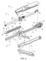
図1及び図2は、胃腸吻合術などの様々な切断及びステープル留め処置で使用するのに好適な、例示的な直線状外科用ステープラ(10)(「直線状カッタ」とも称される)を示す。直線状外科用ステープラ(10)は、それらの間に組織をクランプするために解放可能に連結するように構成されたカートリッジ半体(12)(「リロード半体」とも称される)及びアンビル半体(14)を含む。カートリッジ半体(12)は、発射アセンブリ(34)の一部分を摺動可能に保持する近位フレーム部分(18)と、ステープルカートリッジ(80)(又は「リロード部」)を支持する遠位ジョー部分(20)と、それらの間に内側に配置された一対の直立側部フランジ(22)と、を有する細長いカートリッジチャネル(16)を含む。
I. Exemplary Linear Surgical Stapler A. Overview of Linear Surgical Stapler FIGS. 1 and 2 illustrate an exemplary linear surgical stapler (10) ("linear cutter") suitable for use in various cutting and stapling procedures such as gastrointestinal anastomosis. ). A linear surgical stapler (10) includes a cartridge half (12) (also referred to as a "reload half") and an anvil half configured to releasably couple to clamp tissue therebetween. It includes a body (14). The cartridge halves (12) include a proximal frame portion (18) that slidably holds a portion of the firing assembly (34) and a distal jaw portion that supports the staple cartridge (80) (or “reload portion”). (20) and a pair of upright side flanges (22) disposed inwardly therebetween.
カートリッジ半体(12)は、側部フランジ(22)とほぼ整列してカートリッジチャネル(16)の下面に枢動可能に連結されたクランプレバー(24)を更に含む。クランプレバー(24)は、自由近位端部と、ピボットピン(28)を用いてカートリッジチャネル(16)に枢動可能に連結された遠位端部と、を有する細長いレバーアーム(26)を含む。一対の対向するジョー(30)(「フックラッチ」とも称される)は、カートリッジチャネル(16)の側部フランジ(22)に沿ってレバーアーム(26)の遠位端部から遠位に延びる。それぞれのジョー(30)は、閉鎖近位端部及び開放遠位端部を有し、アンビル半体(14)の対応のラッチ突起(56)と係合するように構成された上側及び下側カム表面を画定する、対応の細長いスロット(32)を含む。以下に記載されるように、クランプレバー(24)は、開放位置と閉鎖位置との間でカートリッジチャネル(16)に対して枢動して、アンビル半体(14)をカートリッジ半体(12)に対して解放可能にクランプし、それによって、それらの間に組織層を捕捉するように動作可能である。 The cartridge half (12) further includes a clamp lever (24) pivotally connected to the underside of the cartridge channel (16) in general alignment with the side flange (22). The clamp lever (24) includes an elongated lever arm (26) having a free proximal end and a distal end pivotally connected to the cartridge channel (16) using a pivot pin (28). include. A pair of opposing jaws (30) (also referred to as "hook latches") extend distally from the distal end of the lever arm (26) along the side flange (22) of the cartridge channel (16). . Each jaw (30) has a closed proximal end and an open distal end, and has upper and lower sides configured to engage a corresponding latch projection (56) of the anvil half (14). It includes a corresponding elongate slot (32) defining a cam surface. As described below, the clamp lever (24) pivots relative to the cartridge channel (16) between open and closed positions to clamp the anvil half (14) onto the cartridge half (12). and is operable to releasably clamp against and thereby capture a tissue layer therebetween.
図2に最もよく示されるように、カートリッジ半体(12)の発射アセンブリ(34)は、カートリッジチャネル(16)の近位フレーム部分(18)内に摺動可能に保持されたスライダブロック(36)と、スライダブロック(36)と移動可能に連結されたアクチュエータ(38)(又は「発射ノブ」)と、スライダブロック(36)から遠位方向に延び、ステープルカートリッジ(80)内に収容されたスレッド(100)(図3を参照)と連結するように構成された細長い作動ビーム(図示せず)と、を含む。本実施例のアクチュエータ(38)は、カートリッジ半体(12)の近位端部を中心にして枢動して、ステープラ(10)の「両側発射」を提供するように構成されている。具体的には、アクチュエータ(38)は、カートリッジ半体(12)のいずれかの側面に沿って配置されて、遠位発射ストロークを実行することができ、それにより、ステープラ(10)は、外科手術中に様々な配向で好都合に発射され得る。 As best shown in FIG. 2, the firing assembly (34) of the cartridge half (12) is attached to a slider block (36) slidably retained within the proximal frame portion (18) of the cartridge channel (16). ), an actuator (38) (or "firing knob") movably coupled to the slider block (36), and an actuator (38) (or "firing knob") extending distally from the slider block (36) and housed within the staple cartridge (80). an elongated working beam (not shown) configured to couple with a sled (100) (see FIG. 3). Actuator (38) in this example is configured to pivot about the proximal end of cartridge half (12) to provide "two-sided firing" of stapler (10). Specifically, the actuator (38) can be positioned along either side of the cartridge half (12) to perform a distal firing stroke, thereby causing the stapler (10) to It can be conveniently fired in a variety of orientations during surgery.
スライダブロック(36)は、図2及び図5Aに示される近位ホーム位置と、図5Bに示される遠位発射位置との間で、アクチュエータ(38)によって近位フレーム部分(18)内で移動可能に駆動されるように構成されている。近位ホーム位置では、スライダブロック(36)は、カートリッジチャネル(16)の近位端部に固定されたポスト(40)に当接する。ポスト(40)の自由端部は、横方向に延びるピボットピン(42)を支持する。以下に記載されるように、アクチュエータ(38)は、ステープラ半体(12、14)が互いに完全に連結され、クランプレバー(24)が閉鎖されたときに、遠位に駆動することができる。ステープラ(10)のいずれかの側面に沿ったアクチュエータ(38)の遠位前進は、スライダブロック(36)及び細長い作動ビームを遠位に駆動し、次にスレッド(100)を、ステープルカートリッジ(80)を通して遠位に駆動する。以下に記載されるように、ステープルカートリッジ(80)を通るスレッド(100)の遠位移動は、ステープラ半体(12、14)間にクランプされた組織の同時のステープル留め及び切断をもたらす。 Slider block (36) is moved within proximal frame portion (18) by actuator (38) between a proximal home position shown in FIGS. 2 and 5A and a distal firing position shown in FIG. 5B. The device is configured to be driven so that it can be driven. In the proximal home position, the slider block (36) abuts a post (40) secured to the proximal end of the cartridge channel (16). The free end of the post (40) supports a laterally extending pivot pin (42). As described below, the actuator (38) can be driven distally when the stapler halves (12, 14) are fully coupled together and the clamp lever (24) is closed. Distal advancement of the actuator (38) along either side of the stapler (10) drives the slider block (36) and elongated actuation beam distally, which in turn drives the sled (100) into the staple cartridge (80). ) is driven distally through. As described below, distal movement of thread (100) through staple cartridge (80) results in simultaneous stapling and cutting of tissue clamped between stapler halves (12, 14).
図1及び図2に最もよく示されるように、直線状外科用ステープラ(10)のアンビル半体(14)は、近位フレーム部分(52)及び遠位ジョー部分(54)を有する細長いアンビルチャネル(50)を含む。アンビルチャネル(50)は、アンビルチャネル(50)の内側部分からカートリッジ半体(12)に向かう方向に、横方向に延びる一対の突起(56)の形態のラッチ機構を更に含む。各ラッチ突起(56)は、以下に記載されるように、アンビル半体(14)がカートリッジ半体(12)と連結され、クランプレバー(24)が開放位置から閉鎖位置へと枢動されるときに、対応するクランプレバージョー(30)のスロット(32)内に捕捉されるように構成された円形回転キャップを含んでもよい。一対のフック(58)は、フレーム部分(52)の近位端部から近位に延び、カートリッジ半体(12)の近位ピボットピン(42)の反対側の外側端部を解放可能に捕捉するように構成されている。遠位ジョー部分(54)は、複数のステープル形成ポケット(図示せず)を有するアンビルプレート(60)の形態のアンビル表面を支持し、更に遠位先端部材(62)を支持する。ステープラ(10)の他のバージョンでは、アンビル表面は、アンビルチャネル(50)の遠位ジョー部分(54)と一体的に形成されてよく、又は他の方法で堅固に接続されてよい。本バージョンでは、アンビルチャネル(50)及びカートリッジチャネル(16)の各々は、ステンレス鋼などの金属で形成されたモノリス構造であり、それぞれのステープラ半体(12、14)に剛性を与える。 As best shown in FIGS. 1 and 2, the anvil half (14) of the linear surgical stapler (10) has an elongated anvil channel having a proximal frame portion (52) and a distal jaw portion (54). (50). The anvil channel (50) further includes a latching mechanism in the form of a pair of projections (56) extending laterally from the inner portion of the anvil channel (50) in a direction toward the cartridge half (12). Each latch projection (56) couples the anvil half (14) with the cartridge half (12) and pivots the clamp lever (24) from an open position to a closed position, as described below. Sometimes it may include a circular rotating cap configured to be captured within a slot (32) of a corresponding clamp lever jaw (30). A pair of hooks (58) extend proximally from the proximal end of frame portion (52) and releasably capture opposite outer ends of proximal pivot pin (42) of cartridge half (12). is configured to do so. Distal jaw portion (54) supports an anvil surface in the form of an anvil plate (60) having a plurality of staple forming pockets (not shown) and further supports distal tip member (62). In other versions of the stapler (10), the anvil surface may be integrally formed or otherwise rigidly connected to the distal jaw portion (54) of the anvil channel (50). In this version, each of the anvil channel (50) and cartridge channel (16) is a monolithic structure formed of metal, such as stainless steel, providing rigidity to each stapler half (12, 14).
本実施例のアンビル半体(14)は、アンビルチャネル(50)の内側部分に取り付けられたステープル高さ調整機構(64)を更に含む。ステープル高さ調整機構(64)は、例えば1つ以上のカム機構(図示せず)を介してアンビルプレート(60)と動作可能に連結され、ユーザにより係合可能な一対の突起(66)を含む。複数の所定の位置の間で突起(66)を長手方向に調整することにより、アンビルプレート(60)は、アンビルチャネル(50)の遠位ジョー部分(54)に対して横方向に移動する。これにより、形成されるステープルの高さを画定する、アンビルプレート(60)とステープルカートリッジ(80)のデッキ(94)との間の横方向間隙距離の調整が可能になる。より厚い組織をステープル留めするときには、より大きい間隙距離、したがってより大きいステープル高さが設定されてよい。逆に、より薄い組織をステープル留めするときには、より小さい間隙距離、したがってより小さいステープル高さが設定されてよい。ステープル高さ調整機構(64)は、いくつかのバージョンでは省かれてもよく、その場合、アンビル表面はアンビルチャネル(50)に対して固定されてよいことが理解されよう。例えば、アンビル表面は、遠位ジョー部分(54)と一体的に形成されてよく、ないしは別の方法で固定されてよい。 The anvil half (14) of this example further includes a staple height adjustment mechanism (64) attached to the inner portion of the anvil channel (50). Staple height adjustment mechanism (64) is operably coupled to anvil plate (60), e.g., via one or more cam mechanisms (not shown), and includes a pair of projections (66) that are engageable by a user. include. By longitudinally adjusting projection (66) between a plurality of predetermined positions, anvil plate (60) is moved laterally relative to distal jaw portion (54) of anvil channel (50). This allows adjustment of the lateral gap distance between the anvil plate (60) and the deck (94) of the staple cartridge (80), which defines the height of the staples that are formed. When stapling thicker tissue, a larger gap distance and therefore a larger staple height may be established. Conversely, when stapling thinner tissue, a smaller gap distance and therefore smaller staple height may be established. It will be appreciated that the staple height adjustment mechanism (64) may be omitted in some versions, in which case the anvil surface may be fixed relative to the anvil channel (50). For example, the anvil surface may be integrally formed or otherwise secured to the distal jaw portion (54).
図1及び図2に最もよく示されるように、直線状外科用ステープラ(10)は、ステープラ(10)の選択部分を覆い、使用中にオペレータによるステープラ(10)の効果的な把持及び操作を促進する複数のシュラウド(70、72、74)を更に含む。本実施例では、カートリッジ半体(12)は、カートリッジチャネル(16)の近位フレーム部分(18)の外向きの側面を覆う第1のシュラウド(70)を含む。カートリッジ半体(12)は、クランプレバー(24)の外向きの側面を覆い、カートリッジチャネル(16)及び第1のシュラウド(70)に対してクランプレバー(24)と共に枢動するように構成された第2のシュラウド(72)を更に含む。アンビル半体(14)は、近位フック(58)を含む、アンビルチャネル(50)の近位フレーム部分(52)の外向きの側面を覆う第3のシュラウド(74)を含む。各シュラウド(70、72、74)は、当業者に明らかな任意の好適な手段によって、ステープラ(10)のそれぞれの構成要素と連結されてもよい。更に、各シュラウド(70、72、74)は、1つ以上の材料で形成されてもよく、外科手術中にステープラ(10)の安全かつ効率的な使用を可能にするために、オペレータによってシュラウド(70、72、74)の効果的な把持を促進するのに好適なテクスチャリングが提供されてもよい。 As best shown in FIGS. 1 and 2, the linear surgical stapler (10) covers selected portions of the stapler (10) to facilitate effective grasping and manipulation of the stapler (10) by the operator during use. It further includes a plurality of promoting shrouds (70, 72, 74). In this example, the cartridge half (12) includes a first shroud (70) that covers the outwardly facing side of the proximal frame portion (18) of the cartridge channel (16). The cartridge half (12) covers the outwardly facing side of the clamp lever (24) and is configured to pivot therewith relative to the cartridge channel (16) and first shroud (70). further including a second shroud (72). Anvil half (14) includes a third shroud (74) that covers the outwardly facing side of the proximal frame portion (52) of the anvil channel (50), which includes the proximal hook (58). Each shroud (70, 72, 74) may be coupled to a respective component of the stapler (10) by any suitable means apparent to those skilled in the art. Additionally, each shroud (70, 72, 74) may be formed of one or more materials, and may be assembled by an operator to enable safe and efficient use of the stapler (10) during a surgical procedure. Suitable texturing may be provided to facilitate effective grasping of (70, 72, 74).
図2及び図3に示されるように、本実施例のステープルカートリッジ(80)は、カートリッジ本体(82)と、カートリッジ本体(82)の開放下側を覆うパン(84)と、カートリッジ本体(82)内に収容され、それぞれが対応のステープル(88)を駆動するように構成されている複数のステープルドライバ(86)と、を備えるアセンブリである。カートリッジ本体(82)は、カートリッジチャネル(16)の遠位ジョー部分(20)の対応する連結機構(図示せず)と解放可能に係合するように構成された連結機構(90)を有する近位端部と、テーパ状ノーズ(92)を画定する遠位端部と、を含む。カートリッジ本体(82)の上側は、長手方向スロット(96)と複数のステープル空洞(98)が開口する概ね平面状のデッキ(94)を画定する。それぞれのステープル空洞(98)は、対応のステープルドライバ(86)及びステープル(88)を収容する。図3に示すように、カートリッジ本体(82)の内部は、スレッド本体(102)及びナイフ部材(104)を含むスレッド(100)を摺動可能に収容する。スレッド本体(102)の外側部は、遠位に先細になる複数のカムランプ(106)を支持する。スレッド本体(102)の近位端部は、ステープルカートリッジ(80)がステープラ(10)のカートリッジ半体(12)に取り付けられたときに、発射アセンブリ(34)の細長い作動ビーム(又は「ナイフプッシャ」)(図示せず)の遠位端部と係止係合するように構成された下向きに延びるタブ(108)を含む。ナイフ部材(104)は、スレッド本体(102)の上側から上方に延び、組織を切断するように構成された遠位に向く刃先(110)を有する。 As shown in FIGS. 2 and 3, the staple cartridge (80) of this embodiment includes a cartridge body (82), a pan (84) that covers the open lower side of the cartridge body (82), and a cartridge body (82). ) a plurality of staple drivers (86), each being configured to drive a corresponding staple (88). The cartridge body (82) has a proximal coupling mechanism (90) configured to releasably engage a corresponding coupling mechanism (not shown) on the distal jaw portion (20) of the cartridge channel (16). a distal end defining a tapered nose (92). The upper side of the cartridge body (82) defines a generally planar deck (94) into which a longitudinal slot (96) and a plurality of staple cavities (98) open. Each staple cavity (98) accommodates a corresponding staple driver (86) and staple (88). As shown in FIG. 3, the interior of the cartridge body (82) slidably houses a sled (100) including a sled body (102) and a knife member (104). The outer portion of the sled body (102) supports a plurality of distally tapering cam ramps (106). The proximal end of the sled body (102) is connected to the elongated actuation beam (or "knife pusher") of the firing assembly (34) when the staple cartridge (80) is installed in the cartridge half (12) of the stapler (10). '') (not shown) that is configured to lockingly engage the distal end of a. Knife member (104) extends upwardly from the upper side of sled body (102) and has a distally directed cutting edge (110) configured to cut tissue.
スレッド(100)は、発射アセンブリ(34)の遠位作動に応答してカートリッジ本体(82)を通って遠位に移動するように構成されており、それにより、ナイフ部材(104)は、長手方向スロット(96)を通って遠位に移動して、ステープラ半体(12、14)間にクランプされた組織を切断する。同時に、カムランプ(106)は、カートリッジ本体(82)の対応の内部スロット(図示せず)を通って遠位に移動して、ステープルドライバ(86)及びステープル(88)を、ステープル空洞(98)を通って上方に作動させ、それにより、ステープル(88)の自由端部がクランプされた組織を貫通し、アンビルプレート(60)のステープル形成ポケットに対して変形させる。このようにして、発射アセンブリ(34)の遠位作動は、ステープラ半体(12、14)の遠位エンドエフェクタ部分間にクランプされた組織の同時切断及びステープル留めをもたらす。 The sled (100) is configured to move distally through the cartridge body (82) in response to distal actuation of the firing assembly (34) such that the knife member (104) Traveling distally through the directional slot (96) to cut the tissue clamped between the stapler halves (12, 14). Simultaneously, cam ramp (106) moves distally through a corresponding internal slot (not shown) in cartridge body (82) to drive staple driver (86) and staple (88) into staple cavity (98). actuated upwardly through the staple (88), thereby causing the free ends of the staples (88) to penetrate the clamped tissue and deform against the staple forming pockets of the anvil plate (60). In this manner, distal actuation of the firing assembly (34) results in simultaneous cutting and stapling of tissue clamped between the distal end effector portions of the stapler halves (12, 14).
直線状外科用ステープラ(10)及びステープルカートリッジ(80)は、2011年3月15日発行の「Surgical Stapling Instrument with Cutting Member Arrangement」と題する、米国特許第7,905,381号、2011年6月7日発行の「Surgical Stapler with Apparatus for Adjusting Staple Height」と題する、米国特許第7,954,686号、2013年1月8日発行の「Surgical Stapler Having A Closure Mechanism」と題する、米国特許第8,348,129号、及び/又は2014年7月29日発行の「Linear Cutting and Stapling Device with Selectively Disengageable Cutting Member」と題する、米国特許第8,789,740号、の1つ以上の教示に従って更に構成され、動作可能であってよい。これらの参考文献の各々の開示内容は参照により本明細書に組み込まれる。 The linear surgical stapler (10) and staple cartridge (80) are disclosed in U.S. Pat. US Pat. U.S. Patent No. 8 entitled ``Closure Mechanism.'' , 348,129, and/or U.S. Pat. Further in accordance with one or more of the teachings of No. may be configured and operational. The disclosure of each of these references is incorporated herein by reference.
B.直線状外科用ステープラの例示的な使用
図4A~図4Cは、外科手術中のステープラ半体(12、14)の例示的な連結を示す。図4Aに示すように、アンビル半体(14)の近位端部は、カートリッジ半体(12)の近位端部と位置合わせされ、それにより、カートリッジ半体(12)の近位ピボットピン(42)は、アンビル半体(14)の近位フック(58)によって受容される。クランプレバー(24)が開放位置にある状態で、アンビル半体(14)は、次いで、近位ピボットピン(42)を中心にしてカートリッジ半体(12)に向かって枢動して、アンビル半体(14)のラッチ突起をクランプレバージョー(30)のスロット(32)内へと方向付ける。一旦ラッチ突起(56)がクランプレバージョー(30)によって受容されると、クランプレバー(24)は、図4Bに示される部分的閉鎖位置に向かって枢動する。クランプレバー(24)のこの部分的閉鎖位置では、アンビル半体(14)は、カートリッジ半体(12)で部分的にクランプされ、それにより、ステープラ(10)は、半体(12、14)が互いに不必要に分離することなく片手で保持することが可能になる。更に、この状態では、ステープラ半体(12、14)の遠位部分は、互いから離間配置されたままで、遠位部分間の組織の位置付けを可能にする。組織は、この部分的にクランプされた状態の達成前又は達成時に、ステープラ半体(12、14)の遠位部分間に位置付けられ得ることが理解されよう。
B. Exemplary Use of a Straight Surgical Stapler FIGS. 4A-4C illustrate an exemplary coupling of stapler halves (12, 14) during a surgical procedure. As shown in FIG. 4A, the proximal end of the anvil half (14) is aligned with the proximal end of the cartridge half (12) such that the proximal pivot pin of the cartridge half (12) (42) is received by the proximal hook (58) of the anvil half (14). With the clamp lever (24) in the open position, the anvil half (14) is then pivoted about the proximal pivot pin (42) toward the cartridge half (12) to release the anvil half. Orient the latch projection of the body (14) into the slot (32) of the clamp lever jaw (30). Once the latch projection (56) is received by the clamp lever jaw (30), the clamp lever (24) pivots toward the partially closed position shown in FIG. 4B. In this partially closed position of the clamp lever (24), the anvil half (14) is partially clamped with the cartridge half (12), so that the stapler (10) can close the halves (12, 14) can be held with one hand without unnecessarily separating them from each other. Additionally, in this condition, the distal portions of the stapler halves (12, 14) remain spaced apart from each other, allowing for positioning of tissue between the distal portions. It will be appreciated that tissue may be positioned between the distal portions of the stapler halves (12, 14) before or upon achieving this partially clamped condition.
図4Cに示すように、クランプレバー(24)は、次いで、クランプレバージョー(30)のカム表面が、クランプレバージョー(30)のスロット(32)の閉鎖近位端部に対して近位にアンビル半体(14)のラッチ突起を引くように、その完全閉鎖位置に向かって更に枢動し、それによって、それらの間にしっかりと位置付けられた組織と共にステープラ半体(12、14)を完全にクランプする。ステープラ(10)の半体(12、14)が完全にクランプされた状態になったら、アクチュエータ(38)は、ステープルカートリッジ(80)を発射するように操作することができる。具体的には、図5A及び図5Bに示されるように、アクチュエータ(38)は、ステープラ(10)の外側部の1つに重なるように、ステープラ(10)の近位端部を中心にして枢動する。次いで、アクチュエータ(38)を、上述の方法で発射アセンブリ(34)を作動させるように遠位に駆動し、それによってクランプされた組織を同時に切断及びステープル留めする。遠位発射ストロークが完了すると、アクチュエータ(38)は、図2に示す近位ホーム位置に戻り、次いで、クランプレバー(24)を開いて、ステープラ半体(12、14)を互いに分離し、ステープル留めされ、切断された組織を解放することができる。 As shown in FIG. 4C, the clamp lever (24) is then positioned such that the cam surface of the clamp lever jaw (30) is proximal to the closed proximal end of the slot (32) of the clamp lever jaw (30). Further pivoting toward its fully closed position pulls the latching protrusion of the anvil halves (14), thereby fully locking the stapler halves (12, 14) with the tissue firmly positioned between them. Clamp on. Once the halves (12, 14) of the stapler (10) are in a fully clamped condition, the actuator (38) can be operated to fire the staple cartridge (80). Specifically, as shown in Figures 5A and 5B, the actuator (38) is centered around the proximal end of the stapler (10) so as to overlap one of the outer parts of the stapler (10). Pivot. Actuator (38) is then driven distally to actuate firing assembly (34) in the manner described above, thereby simultaneously cutting and stapling the clamped tissue. Upon completion of the distal firing stroke, the actuator (38) returns to the proximal home position shown in FIG. 2 and then opens the clamp lever (24) to separate the stapler halves (12, 14) from each other and release the staple The pinned and cut tissue can be released.
II.構造体プレート及び成形本体を有する例示的なステープラ半体
上述のように、直線状外科用ステープラ(10)のアンビル半体(14)は、両方ともアンビルチャネル(50)によって画定される近位フレーム部分(52)及び遠位ジョー部分(54)を含み、このアンビルチャネルは、全体的に金属で形成されたモノリス構造である。いくつかの例では、ステープラ半体の重量及び製造コストを最小限に抑えつつ、長手方向の剛性を高め、したがって遠位先端部のたわみに対する耐性を高める代替構成を有する直線状外科用ステープラ半体を提供することが望ましい場合がある。図6~図25に関連して以下に記載される各例示的なアンビル半体(200、300、400)は、脊柱プレートの形態の一対の細長い内側構造部材と、脊柱プレートの周りに形成され、脊柱プレートを少なくとも部分的に封入するポリマー本体と、を備えるハイブリッド構造を提示して、剛性が高く、軽量であり、製造コストが低いアンビル半体構造を提供することができる。図26A、図26Bに関連してより詳細に説明されるように、各例示的なアンビル半体(200、300、400)のポリマー本体は、射出成形プロセスによって形成されてもよく、これはオーバーモールド成形ステップ及びインサート成形ステップを含んでもよい。
II. Exemplary Stapler Halves Having Structural Plate and Shaped Body As mentioned above, the anvil halves (14) of the linear surgical stapler (10) both have proximal frames defined by anvil channels (50). The anvil channel is a monolithic structure formed entirely of metal, including a portion (52) and a distal jaw portion (54). In some instances, linear surgical stapler halves have alternative configurations that increase longitudinal stiffness and thus resistance to distal tip deflection while minimizing the weight and manufacturing costs of the stapler halves. It may be desirable to provide Each exemplary anvil half (200, 300, 400) described below in connection with FIGS. 6-25 includes a pair of elongated inner structural members in the form of a spinal column plate, and a pair of elongated inner structural members formed around the spinal column plate. , a polymer body at least partially encapsulating a spinal plate, and a polymer body that at least partially encapsulates a spinal plate can be presented to provide an anvil half structure that is stiff, lightweight, and low cost to manufacture. As described in more detail in connection with FIGS. 26A, 26B, the polymeric body of each exemplary anvil half (200, 300, 400) may be formed by an injection molding process, which It may also include a molding step and an insert molding step.
以下に記載される各例示的なアンビル半体(200、300、400)は、任意の好適なカートリッジ半体と共に使用して、直線状外科用ステープラを画定できることが理解されよう。例えば、アンビル半体(200、300、400)は、上述のカートリッジ半体(12)又は以下に記載されるカートリッジ半体(702、802)と共に使用してもよい。他の例では、アンビル半体(200、300、400)は、2018年8月13日に出願された「Firing System for Linear Surgical Stapler」と題する、米国特許出願第16/102,164号、2018年8月13日に出願された「Clamping Assembly for Linear Surgical Stapler」と題する、米国特許出願第16/102,170号、又は、本出願と同じ日付で出願された、「Closure Assembly for Linear Surgical Stapler」と題する、米国特許出願[Atty Dkt.END8625USNP]、に記載されている例示的なカートリッジ半体のいずれかと共に使用されてもよく、それらの開示内容は参照により本明細書に組み込まれる。更に、例示的なハイブリッド構造は、アンビル半体(200、300、400)との関連で本明細書に示され、記載されているが、そのようなハイブリッド構造体は、直線状外科用ステープラのカートリッジ半体に適用されてもよいことが理解されよう。 It will be appreciated that each exemplary anvil half (200, 300, 400) described below can be used with any suitable cartridge half to define a linear surgical stapler. For example, anvil halves (200, 300, 400) may be used with cartridge halves (12) described above or cartridge halves (702, 802) described below. In another example, the anvil halves (200, 300, 400) are described in U.S. patent application Ser. U.S. patent application Ser. l Stapler U.S. patent application entitled [Atty Dkt. END8625USNP], the disclosures of which are incorporated herein by reference. Additionally, although exemplary hybrid structures are shown and described herein in the context of anvil halves (200, 300, 400), such hybrid structures may be used in conjunction with linear surgical staplers. It will be appreciated that it may also be applied to cartridge halves.
A.隆起部分を有する構造体プレートを有する例示的なアンビル半体
図6は、脊柱プレート(202、204)の形態の一対の細長い内側構造部材と、脊柱プレート(202、204)の周りに成形されたポリマー本体(220)と、ポリマー本体(220)及び脊柱プレート(202、204)の遠位部分に連結されたアンビルプレート(240)とを有する、例示的なアンビル半体(200)を示す。図示されていないが、アンビル半体(200)は、ユーザによるアンビル半体(200)の効果的な把持を促進するために、脊柱プレート(202、204)及びポリマー本体(220)の近位部分の外向きの表面を覆う、上述のアンビルシュラウド(74)と同様であってもよいシュラウドを更に含んでもよい。
A. Exemplary Anvil Half Having a Structural Plate Having Raised Portions FIG. An exemplary anvil half (200) is shown having a polymeric body (220) and an anvil plate (240) connected to the polymeric body (220) and distal portions of the spinal plates (202, 204). Although not shown, the anvil half (200) includes proximal portions of the spinal plates (202, 204) and the polymer body (220) to facilitate effective grasping of the anvil half (200) by the user. It may further include a shroud, which may be similar to the anvil shroud (74) described above, covering the outwardly facing surface of the anvil shroud (74).
図6及び図7に最もよく示されるように、本実施例の脊柱プレート(202、204)は、互いに横方向に離間配置されており、アンビル半体(200)の長手方向軸に対して平行かつ等距離に配置され、アンビルプレート(240)によって画定される組織クランプ平面に対して横方向に配置されている。更に、脊柱プレート(202、204)は、ステンレス鋼などの好適に剛性の材料、又は当業者には明らかであろう、類似の又はより高い剛性の様々な他の材料から形成される。脊柱プレート(202、204)のためのそのような材料は、いくつかのバージョンでは金属などの非ポリマー材料を含んでもよく、他のバージョンではポリマー材料を含んでもよいことが理解されよう。脊柱プレート(202、204)のそのような配向及び構造は、アンビルプレート(240)に対する組織のクランプ中に、好適な剛性及び先端のたわみに対する耐性を有する支持構造体をアンビル半体(200)に提供すると共に、製造に対して費用対効果の高い軽量デバイスを提供する支持構造体の単純で最小の構成を維持する。本実施例の脊柱プレート(202、204)は、サイズ及び形状が同一であるが、脊柱プレート(202、204)は、他の実施例では、サイズ及び/又は形状が異なっていてもよい。 As best shown in FIGS. 6 and 7, the spinal plates (202, 204) of the present example are laterally spaced apart from each other and parallel to the longitudinal axis of the anvil half (200). and are disposed equidistantly and transversely to a tissue clamping plane defined by anvil plate (240). Additionally, the spinal plates (202, 204) are formed from suitably rigid materials such as stainless steel, or various other materials of similar or higher rigidity as would be apparent to those skilled in the art. It will be appreciated that such materials for the spinal plates (202, 204) may include non-polymeric materials such as metals in some versions, and polymeric materials in other versions. Such orientation and configuration of the spinal plates (202, 204) provides a support structure to the anvil half (200) with suitable stiffness and resistance to tip deflection during clamping of tissue to the anvil plate (240). while maintaining a simple and minimal configuration of the support structure that provides a lightweight device that is cost effective to manufacture. Although the spinal plates (202, 204) in this example are the same in size and shape, the spinal plates (202, 204) may be different in size and/or shape in other examples.
本実施例の各脊柱プレート(202、204)は、細長い近位プレート部分(206)と、細長い遠位プレート部分(208)と、その間に配置された隆起した内側プレート部分(210)とを含む。隆起した内側プレート部分(210)は、アンビル囲い板(図示せず)の肩状特徴部と整列し、その中に受容されるように構成される。各脊柱プレート(202、204)は、近位プレート部分(206)の近位端部に配置された近位穴(212)を更に含み、この近位穴は、第1の突起(図示せず)をその横方向に受容するように構成される。各脊柱プレート(202、204)は、内側プレート部分(210)の遠位端部にほぼ配置された遠位穴(214)を更に含み、この遠位穴は、第2の突起(図示せず)をその横方向に受容するように構成される。いくつかのバージョンでは、そのような横方向の突起は、例えば、参照により上記で組み込まれた、米国特許出願第16/102,164号及び米国特許出願第16/102,170号に開示されているように、ピンの形態であってもよく、それにより、ピンが脊柱プレート(202、204)及びポリマー本体(220)を通って横方向に延びる。他のバージョンでは、そのような横方向突起の一方又は両方は、ポリマー本体(220)によって画定されてもよい。使用時には、近位側方突起は、カートリッジ半体の近位端部によって解放可能に捕捉されるように構成され、遠位突起は、アンビル半体(200)をカートリッジ半体に対してクランプするために、カートリッジ半体のクランプレバーによって解放可能に捕捉されるように構成される。 Each spinal plate (202, 204) in this example includes an elongated proximal plate portion (206), an elongated distal plate portion (208), and a raised inner plate portion (210) disposed therebetween. . The raised inner plate portion (210) is configured to align with and be received within a shoulder feature of an anvil shroud (not shown). Each spinal plate (202, 204) further includes a proximal hole (212) located at the proximal end of the proximal plate portion (206), which proximal hole is connected to a first projection (not shown). ) in its lateral direction. Each spinal plate (202, 204) further includes a distal hole (214) located generally at the distal end of the inner plate portion (210), which distal hole has a second projection (not shown). ) in its lateral direction. In some versions, such lateral protrusions are disclosed, for example, in U.S. Patent Application No. 16/102,164 and U.S. Patent Application No. 16/102,170, incorporated by reference above. It may be in the form of a pin, such that the pin extends laterally through the spinal plates (202, 204) and the polymer body (220). In other versions, one or both such lateral projections may be defined by the polymeric body (220). In use, the proximal lateral projection is configured to be releasably captured by the proximal end of the cartridge half, and the distal projection clamps the anvil half (200) against the cartridge half. and is configured to be releasably captured by a clamp lever on the cartridge half.
図7及び図12に示すように、アンビルプレート(240)は、その中にナイフ部材(図示せず)を摺動可能に受容するように構成された長手方向スロット(242)と、ステープルカートリッジ(図示せず)によって射出されたステープルを変形させるように構成された複数のステープル形成ポケット(図示せず)を有するアンビル表面とを含む。そのようなステープル形成ポケットは、後述するアンビルプレート(900)のポケット(906a、906b)と同様であってもよい。アンビルプレート(240)は、アンビルプレート(240)が、脊柱プレート(202、204)の細長い遠位プレート部分(208)によって支持され、横方向に広がるように、脊柱プレート(202、204)に対して横方向に配向する。以下に説明するように、本実施例のアンビルプレート(240)は、ポリマー本体(220)の成形プロセス中にポリマー本体(220)がアンビルプレート(240)にしっかりと取り付けられるようにする追加の機構を含む。アンビル半体(200)のいくつかのバージョンでは、アンビルプレート(240)が省略されてもよく、アンビル表面及びステープル形成ポケットは、ポリマー本体(220)の対応する表面によって提供されてもよい。 As shown in FIGS. 7 and 12, the anvil plate (240) includes a longitudinal slot (242) configured to slidably receive a knife member (not shown) therein, and a staple cartridge (242) configured to slidably receive a knife member (not shown) therein. and an anvil surface having a plurality of staple forming pockets (not shown) configured to deform staples ejected by the anvil (not shown). Such staple forming pockets may be similar to pockets (906a, 906b) of anvil plate (900) described below. The anvil plate (240) is mounted relative to the spinal plate (202, 204) such that the anvil plate (240) is supported by and extends laterally by the elongated distal plate portion (208) of the spinal plate (202, 204). oriented laterally. As explained below, the anvil plate (240) of the present example includes additional features that allow the polymer body (220) to be securely attached to the anvil plate (240) during the molding process of the polymer body (220). including. In some versions of anvil half (200), anvil plate (240) may be omitted, and the anvil surface and staple forming pockets may be provided by corresponding surfaces of polymeric body (220).
図8~図10に示すように、ポリマー本体(220)は、各脊柱プレート(202、204)の少なくとも一部分を封入するように、脊柱プレート(202、204)の周りに形成されたモノリス構造である。具体的には、本実施例のポリマー本体(220)は、第1の脊柱プレート(202)の外面の全長に沿って長手方向に延びる第1の外壁(222)と、第2の脊柱プレート(204)の外面の全長に沿って長手方向に延びる対向する第2の外壁(224)とを含む。ポリマー本体(220)は、脊柱プレート(202、204)の対向する内面の間を横方向に広がると共に、脊柱プレート(202、204)の全長にわたって長手方向に延びる内壁(226)を更に含む。図12に最もよく示されるように、ポリマー本体(220)は、アンビル半体(200)の下側に沿って外壁(222、224)と内壁(226)とを接続する底壁(228)を更に含む。ポリマー本体(220)の遠位端部は、アンビル半体(200)の遠位端部で外壁(222、224)を内壁(226)と接続するテーパ状遠位先端部(230)を画定する。図6及び図10に最もよく示されるように、脊柱プレート(202、204)の隆起した内側部分(210)は、内側プレート部分(210)がポリマー本体(220)に対して露出したままになるように、外壁(222、224)及び内壁(226)の上面の上に延びる。ポリマー本体(220)は、様々なプラスチックなどの様々なポリマー材料を含んでもよく、例えば、図26A~図26Bに関連して後述するように、射出成形プロセスを介して脊柱プレート(202、204)及びアンビルプレート(240)に適用されてもよい。 As shown in FIGS. 8-10, the polymer body (220) is a monolithic structure formed around the spinal plates (202, 204) to encapsulate at least a portion of each spinal plate (202, 204). be. Specifically, the polymeric body (220) of this example includes a first outer wall (222) extending longitudinally along the entire length of the outer surface of the first spinal plate (202) and a second spinal plate (202). and an opposing second outer wall (224) extending longitudinally along the entire length of the outer surface of (204). The polymeric body (220) further includes an interior wall (226) that extends laterally between opposing inner surfaces of the spinal plates (202, 204) and extends longitudinally the entire length of the spinal plates (202, 204). As best shown in FIG. 12, the polymer body (220) includes a bottom wall (228) that connects the outer walls (222, 224) and the inner wall (226) along the underside of the anvil half (200). Including further. The distal end of the polymer body (220) defines a tapered distal tip (230) that connects the outer wall (222, 224) with the inner wall (226) at the distal end of the anvil half (200). . As best shown in FIGS. 6 and 10, the raised inner portions (210) of the spinal plates (202, 204) leave the inner plate portions (210) exposed to the polymeric body (220). , extending over the top surfaces of the outer walls (222, 224) and the inner wall (226). The polymeric body (220) may include various polymeric materials, such as various plastics, for example, to form the spinal plates (202, 204) through an injection molding process, as described below in connection with FIGS. 26A-26B. and anvil plate (240).
図11~図13に示すように、アンビルプレート(240)は、その近位端部及び遠位端部において、ポリマー本体(220)に固定される。図7及び図12に見られるように、アンビルプレート(240)の遠位部分は、ポリマー本体(220)の対応する部分が突出する一対の横方向に離間配置された遠位開口部(244)を含む。図7及び図11に示すように、アンビルプレート(24)は、ポリマー本体(220)のテーパ状遠位先端部(230)内に埋め込まれた角度付き遠位端部(246)を更に含む。アンビル半体(200)のいくつかのバージョンでは、遠位開口部(244)又は角度付き遠位端部(246)は、アンビルプレート(240)から省略されてもよい。図12及び図13に示すように、アンビルプレート(240)の近位端部は、アンビルプレート(240)の対向する横方向の縁部に形成された一対のノッチ(248)と、ノッチ(248)と長手方向スロット(242)との間に形成された一対の近位開口部(250)とを含む。図13に示すように、ポリマー本体(220)は、各ノッチ(248)及びそれぞれの近位開口部(250)を通って突出して、対応するポスト(232)を画定する。ポスト(232)は、アンビル半体(200)が直線状外科用ステープラのカートリッジ半体と連結されるときに、ステープルカートリッジ(図示せず)の一部と嵌合するように構成される。 As shown in FIGS. 11-13, anvil plate (240) is secured to polymer body (220) at its proximal and distal ends. As seen in FIGS. 7 and 12, the distal portion of the anvil plate (240) has a pair of laterally spaced distal openings (244) from which corresponding portions of the polymeric body (220) project. including. As shown in FIGS. 7 and 11, anvil plate (24) further includes an angled distal end (246) embedded within a tapered distal tip (230) of polymeric body (220). In some versions of anvil half (200), distal opening (244) or angled distal end (246) may be omitted from anvil plate (240). As shown in FIGS. 12 and 13, the proximal end of anvil plate (240) includes a pair of notches (248) formed in opposite lateral edges of anvil plate (240); ) and a pair of proximal openings (250) formed between the longitudinal slot (242). As shown in FIG. 13, the polymer body (220) projects through each notch (248) and a respective proximal opening (250) to define a corresponding post (232). Post (232) is configured to mate with a portion of a staple cartridge (not shown) when anvil half (200) is coupled with the cartridge half of a linear surgical stapler.
B.テーパ状の遠位部分を有する例示的な構造体プレート
図14は、上述のアンビル半体(200)の脊柱プレート(202、204)の各々に対して置換され得る例示的な代替的脊柱プレート(260)を示す。脊柱プレート(260)は、以下に別途記載されている以外は、脊柱プレート(202、204)と同様である。脊柱プレート(260)は、細長い近位プレート部分(262)と、細長い遠位プレート部分(264)と、その間にある隆起した内側プレート部分(266)と、を含む。脊柱プレート(202、204)の隆起した内側プレート部分(210)と同様に、隆起した内側プレート部分(266)は、上述のアンビルシュラウド(74)と同様でり得るシュラウドと整列し、シュラウドによって受容されるように構成される。本バージョンの隆起した内側部分(266)は、ユーザの1つ以上の指をその横方向に受容するように構成された指開口部(268)を含んで、使用中に対応するアンビル半体の効果的な把持を促進する。
B. Exemplary Structure Plate with Tapered Distal Portion FIG. 14 shows an exemplary alternative spinal plate (202, 204) that may be replaced for each of the spinal plates (202, 204) of the anvil half (200) described above. 260). Spinal plates (260) are similar to spinal plates (202, 204) except as otherwise described below. The spinal plate (260) includes an elongated proximal plate portion (262), an elongated distal plate portion (264), and a raised inner plate portion (266) therebetween. Like the raised inner plate portions (210) of the spinal plates (202, 204), the raised inner plate portions (266) are aligned with and received by the shroud, which may be similar to the anvil shroud (74) described above. configured so that The raised inner portion (266) of this version includes a finger aperture (268) configured to receive one or more fingers of a user laterally thereto, so that the corresponding anvil half is closed in use. Promotes effective grasping.
本バージョンの隆起した内側プレート部分(266)は、脊柱プレート(260)の最大の横方向の高さ(H1)を画定する。遠位プレート部分(264)は、遠位プレート部分(264)の近位端部における第2の横方向の高さ(H2)から、遠位プレート部分(264)の遠位端部における第3の横方向の高さ(H3)まで、遠位方向に一様に先細りする。第2の横方向の高さ(H2)は、最大の横方向の高さ(H1)よりも小さく、第3の横方向の高さ(H3)は、第2の横方向の高さ(H2)よりも小さい。本バージョンでは、遠位プレート部分(264)は、第3の横方向の高さ(H3)が脊柱プレート(260)の最小の横方向の高さであるようにテーパ状になっている。遠位プレート部分(264)のそのようなテーパ状の構成により、脊柱プレート(260)を、上述の脊柱プレート(202、204)のいずれかよりも少ない材料から形成することができ、一方、組織のクランプ中に所与の横方向荷重下での遠位プレート部分(264)の遠位先端部のたわみが、同じ横方向荷重下での脊柱プレート(202、204)の遠位プレート部分(208)の遠位先端部のたわみよりも大きくならないように、十分な剛性を維持する。 This version's raised medial plate portion (266) defines the maximum lateral height (H1) of the spinal plate (260). The distal plate portion (264) extends from a second lateral height (H2) at the proximal end of the distal plate portion (264) to a third lateral height (H2) at the distal end of the distal plate portion (264). tapers uniformly distally to a lateral height (H3) of . The second lateral height (H2) is less than the maximum lateral height (H1), and the third lateral height (H3) is less than the second lateral height (H2). ) is smaller than. In this version, the distal plate portion (264) is tapered such that the third lateral height (H3) is the minimum lateral height of the spinal plate (260). Such a tapered configuration of the distal plate portion (264) allows the spinal plate (260) to be formed from less material than either of the spinal plates (202, 204) described above, while reducing tissue The deflection of the distal tip of the distal plate portion (264) under a given lateral load during clamping is the same as the deflection of the distal tip of the distal plate portion (208) of the spinal plates (202, 204) under the same lateral load. ) to maintain sufficient stiffness to be no greater than the deflection of the distal tip.
C.隣接部材を有する例示的な構造体プレート
図15は、上述のアンビル半体(200)の脊柱プレート(202、204)に置換され得る別の例示的な一対の脊柱プレート(270、272)を示す。脊柱プレート(270、272)は、以下に別途記載された場合を除き、脊柱プレート(202、204)と同様である。各脊柱プレート(270、272)は、細長い近位プレート部分(274)と、細長い遠位プレート部分(276)と、隆起した内側プレート部分(278)とを含む。本バージョンの脊柱プレート(270、272)は、第1の脊柱プレート(270)の隆起した内側プレート部分(278)の平坦な側面から第2の脊柱プレート(272)の隆起した内側プレート部分(278)の平坦な側面まで横方向に延びる隣接部材(280)によって、互いに一体的に接続されている。図示の構成では、脊柱プレート(270、272)及び隣接部材(280)は、脊柱プレート(270、272)及び隣接部材(280)が平坦なモノリス構造を画定するように、共通の平面に配置される。更に、脊柱プレート(270、272)は、内側プレート部分(278)の隆起した湾曲面が互いに対向するように、隣接部材(280)のそれぞれの端部と接合される。
C. Exemplary Structural Plates with Adjacent Members FIG. 15 shows another exemplary pair of spinal plates (270, 272) that may replace the spinal plates (202, 204) of the anvil half (200) described above. . Spinal plates (270, 272) are similar to spinal plates (202, 204), except as otherwise noted below. Each spinal plate (270, 272) includes an elongated proximal plate portion (274), an elongated distal plate portion (276), and a raised inner plate portion (278). This version of the spinal plates (270, 272) runs from the flat side of the raised medial plate portion (278) of the first spinal plate (270) to the raised medial plate portion (278) of the second spinal plate (272). ) are integrally connected to each other by abutting members (280) extending laterally to the flat sides of the parts. In the illustrated configuration, the spinal plates (270, 272) and the adjacent members (280) are arranged in a common plane such that the spinal plates (270, 272) and the adjacent members (280) define a planar monolithic structure. Ru. Further, the spinal plates (270, 272) are joined to respective ends of the adjacent members (280) such that the raised curved surfaces of the inner plate portions (278) face each other.
脊柱プレート(270、272)を収容するアンビル半体の製造中に、各脊柱プレート(270、272)は、隣接部材(280)に対して上向きに曲げられ、それにより、脊柱プレート(270、272)が互いに平行に、かつ隣接部材(280)に対して横方向に延び、それによって、内側プレート部分(278)においてU字型断面を有する構造体を画定する。結果として得られる構造では、脊柱プレート(270、272)は、互いに横方向に離間配置されて、それらの間に成形されたポリマー本体(図示せず)を受容し、更に回転剛性を高めるために隣接部材(280)によって互いに一体的に接続される。本バージョンの各脊柱プレート(270、272)は、近位プレート部分(274)及び遠位プレート部分(276)に沿って長手方向に離間配置された複数の開口部(282)を更に含む。各開口部(282)は、本体形成プロセス中に、それを通してポリマー本体のそれぞれの突起を受容するように構成され、それによって、形成されたポリマー本体に対して脊柱プレート(270、272)をよりしっかりと固定する。 During manufacture of the anvil halves housing the spinal plates (270, 272), each spinal plate (270, 272) is bent upwardly relative to the adjacent member (280), thereby causing the spinal plates (270, 272) ) extend parallel to each other and transversely to the adjacent member (280), thereby defining a structure having a U-shaped cross-section at the inner plate portion (278). In the resulting structure, the spinal plates (270, 272) are laterally spaced apart from each other to receive a molded polymer body (not shown) therebetween to further increase rotational stiffness. They are integrally connected to each other by adjacent members (280). Each spinal plate (270, 272) of this version further includes a plurality of openings (282) spaced longitudinally along the proximal plate portion (274) and the distal plate portion (276). Each opening (282) is configured to receive a respective protrusion of the polymer body therethrough during the body formation process, thereby tightening the spinal plate (270, 272) relative to the formed polymer body. Fix firmly.
D.横方向タブ及び開口部を有する例示的な構造体プレート
図16、図17は、別の例示的な一対の脊柱プレート(290、292)の部分を示し、これは、以下に別途記載される場合を除き、上記のアンビル半体(200)の脊柱プレート(202、204)と同様であり得る。具体的には、第1の脊柱プレート(290)の細長い遠位プレート部分(294)は、細長い屈曲可能なタブ(296)の形態の突起を含み、第2の脊柱プレート(292)の細長い遠位プレート部分(294)は、長手方向スロット(297)の形態の開口部を含む。図17に示すように、対応するアンビル半体の製造中、脊柱プレート(270、272)は、互いに平行に配置され、屈曲タブ(296)の自由端部がスロット(297)によって受容されるように、第1の脊柱プレート(290)の屈曲可能なタブ(296)は、第2の脊柱プレート(292)に向かって曲げられる。これは、ポリマー本体(298)が脊柱プレート(290、292)を少なくとも部分的に封入するように形成されると、得られるアンビル半体の回転剛性を強化する、脊柱プレート(290、292)間の直接的な機械的連結を確立する。本実施例では、タブ(296)及びスロット(297)は、直線状外科用ステープラの発射中にナイフ部材(図示せず)の一部分をそれを通して摺動可能に受容するように構成された長手方向スロット(299)を収容するために、脊柱プレート(290、292)及びポリマー本体(298)の表面から離れて横方向に離間配置されている。隣接部材(280)及び/又はタブ(296)及びスロット(297)と同様の脊柱プレート連結機構が、本明細書に開示される例示的な構成のいずれかに組み込まれ得ることが理解されよう。
D. Exemplary Structure Plate with Lateral Tabs and Openings FIGS. 16 and 17 illustrate portions of another exemplary pair of spinal plates (290, 292), as otherwise described below. may be similar to the spinal plates (202, 204) of the anvil half (200) described above, except that. Specifically, the elongated distal plate portion (294) of the first spinal plate (290) includes a protrusion in the form of an elongated bendable tab (296) and the elongated distal plate portion (294) of the second spinal plate (292) includes a protrusion in the form of an elongated bendable tab (296). The positioning plate portion (294) includes an opening in the form of a longitudinal slot (297). As shown in FIG. 17, during manufacture of the corresponding anvil halves, the spinal plates (270, 272) are arranged parallel to each other such that the free ends of the flex tabs (296) are received by the slots (297). In, the bendable tab (296) of the first spinal plate (290) is bent toward the second spinal plate (292). This enhances the rotational stiffness of the resulting anvil halves when the polymer body (298) is formed to at least partially encapsulate the spinal plates (290, 292). Establish a direct mechanical connection. In this example, the tab (296) and slot (297) are longitudinally oriented and configured to slidably receive a portion of a knife member (not shown) therethrough during firing of a linear surgical stapler. Laterally spaced apart from the surfaces of the spinal plates (290, 292) and the polymer body (298) to accommodate the slots (299). It will be appreciated that spinal plate coupling mechanisms similar to abutment members (280) and/or tabs (296) and slots (297) may be incorporated into any of the exemplary configurations disclosed herein.
E.成形本体によって完全に封入された近位部分を有する構造体プレートを有する例示的なアンビル半体
図18は、以下に別途記載されることを除いて、上述のアンビル半体(200)と同様である直線状外科用ステープラの別の例示的なアンビル半体(300)を示す。アンビル半体(300)は、脊柱プレート(302、304)(図19参照)の形態の一対の細長い内側構造部材と、脊柱プレート(302、304)の周りに成形されたポリマー本体(320)と、ポリマー本体(320)及び脊柱プレート(302、304)の遠位部分と連結されたアンビルプレート(340)とを含む。以下でより詳細に説明するように、脊柱プレート(302、304)の近位プレート部分(306)は、ポリマー本体(320)によって完全に封入される。
E. Exemplary Anvil Half Having a Structure Plate Having a Proximal Portion Completely Enclosed by a Molded Body FIG. 18 is similar to the anvil half (200) described above, except as otherwise noted below. 3 illustrates another exemplary anvil half (300) of a linear surgical stapler. The anvil half (300) includes a pair of elongate inner structural members in the form of spinal plates (302, 304) (see FIG. 19) and a polymeric body (320) molded around the spinal plates (302, 304). , a polymer body (320) and an anvil plate (340) coupled to distal portions of spinal plates (302, 304). As described in more detail below, proximal plate portions (306) of spinal plates (302, 304) are completely encapsulated by a polymer body (320).
図19に最もよく示されるように、本実施例の脊柱プレート(302、304)は、互いに横方向に離間配置され、アンビル半体(300)の長手方向軸に平行に、かつそこから等距離に配置され、アンビルプレート(340)によって画定される組織クランプ平面に対して横方向に配置される。各脊柱プレート(302、304)は、細長い近位プレート部分(306)と、近位プレート部分(306)から直接延びる細長い遠位プレート部分(308)とを含む。各脊柱プレート(302、304)は、その長さに沿って離間配置された複数の横方向の開口部(310)を更に含む。各開口部(310)は、本体(320)と各脊柱プレート(302、304)との間の安全な接続を提供するために、ポリマー本体(320)の形成中に、その中にポリマー本体(320)のそれぞれの突起を受容するように構成される。いくつかのバージョンでは、近位に配置された一対の開口部(312)は、第1のピン(図示せず)を横方向に受容するように構成され、内側に配置された一対の開口部(314)は、第2のピン(図示せず)を横方向に受容するように構成される。そのようなピンは、例えば、上記に参照により組み込まれている、米国特許出願第16/102,164号及び米国特許出願第16/102,170号に開示されている方法で、直線状外科用ステープラのカートリッジ半体の対応する部分によって解放可能に捕捉されるように構成されてもよい。他のバージョンでは、そのようなピンによって別の方法で提供される構造は、開口部(312、314)を通って横方向に延びるポリマー本体(320)によって画定されてもよい。 As best shown in FIG. 19, the spinal plates (302, 304) of the present example are laterally spaced apart from each other, parallel to and equidistant from the longitudinal axis of the anvil half (300). and transversely to the tissue clamping plane defined by the anvil plate (340). Each spinal plate (302, 304) includes an elongated proximal plate portion (306) and an elongated distal plate portion (308) extending directly from the proximal plate portion (306). Each spinal plate (302, 304) further includes a plurality of lateral openings (310) spaced along its length. Each opening (310) has a polymeric body (320) therein during formation of the polymeric body (320) to provide a secure connection between the body (320) and each spinal plate (302, 304). 320). In some versions, a pair of proximally located openings (312) are configured to laterally receive a first pin (not shown) and a pair of medially located openings (312) are configured to laterally receive a first pin (not shown). (314) is configured to laterally receive a second pin (not shown). Such pins may be used in straight surgical applications, for example, in the manner disclosed in U.S. Patent Application No. 16/102,164 and U.S. Patent Application No. 16/102,170, incorporated by reference above. It may be configured to be releasably captured by a corresponding portion of a stapler cartridge half. In other versions, the structure otherwise provided by such pins may be defined by a polymeric body (320) extending laterally through the openings (312, 314).
アンビルプレート(340)は、アンビルプレート(340)が、その中にナイフ部材(図示せず)を摺動可能に受容するように構成された、図20に示す長手方向スロット(342)を含むという点で、上述のアンビルプレート(240)と同様である。図示されていないが、アンビルプレート(340)は、複数のステープル形成ポケットを更に含み、これは、後述するアンビルプレート(900)のポケット(906a、906b)と同様であり得る。図19及び図20に示すように、アンビルプレート(340)は、アンビルプレート(340)が、脊柱プレート(302、304)の細長い遠位プレート部分(308)によって支持され、横方向に広がるように、脊柱プレート(302、304)に対して横方向に配向される。本実施例のアンビルプレート(340)は、各々が、それぞれの脊柱プレート(302、304)の外部側面の一部分と重なるように構成された一対の側壁(244)を更に含む。各側壁(344)は、長手方向に沿って離間配置され、側壁(344)の自由端部に向かって開口している複数の横方向の開口部(346)を含む。各開口部(346)は、本体(320)の形成中にポリマー本体(320)のそれぞれの部分をその中に受容して、アンビルプレート(340)のポリマー本体(320)への確実な取り付けを提供するように構成される。 Anvil plate (340) includes a longitudinal slot (342), shown in FIG. 20, configured to slidably receive a knife member (not shown) therein. In this respect, it is similar to the anvil plate (240) described above. Although not shown, anvil plate (340) further includes a plurality of staple forming pockets, which may be similar to pockets (906a, 906b) of anvil plate (900) described below. As shown in FIGS. 19 and 20, anvil plate (340) is supported by elongated distal plate portions (308) of spinal plates (302, 304) and extends laterally. , oriented laterally to the spinal plates (302, 304). The anvil plate (340) of this example further includes a pair of side walls (244) each configured to overlap a portion of the exterior side of the respective spinal plate (302, 304). Each sidewall (344) includes a plurality of lateral openings (346) spaced longitudinally and open toward the free end of the sidewall (344). Each opening (346) receives a respective portion of polymer body (320) therein during formation of body (320) to ensure secure attachment of anvil plate (340) to polymer body (320). configured to provide.
図18、図20、及び図21に最もよく示されるように、ポリマー本体(320)は、ポリマー本体(320)の少なくとも近位部分が各脊柱プレート(302、304)を完全に封入するように、脊柱プレート(302、304)の周りに形成される。本実施例のポリマー本体(320)は、第1の脊柱プレート(302)の外面の全長に沿って長手方向に延びる第1の外壁(322)と、第2の脊柱プレート(304)の外面の全長に沿って長手方向に延びる対向する第2の外壁(324)とを含む。ポリマー本体(320)は、脊柱プレート(302、304)の対向する内面の間を横方向に広がり、かつ脊柱プレート(302、304)の全長にわたって長手方向に延びる内壁(326)を、更に含む。図18に最もよく示されるように、ポリマー本体(320)は、脊柱プレート(302、304)の全長にわたって長手方向に延び、外壁(322、324)及び内壁(326)と相互接続する上壁(328)を更に含む。図20に最もよく示されるように、ポリマー本体(320)は、近位プレート部分(306)の下端部に沿って長手方向に延び、外壁(322、324)及び内壁(326)と相互接続する底壁(330)を更に含む。 As best shown in FIGS. 18, 20, and 21, the polymer body (320) is arranged such that at least a proximal portion of the polymer body (320) completely encloses each spinal plate (302, 304). , formed around the spinal plates (302, 304). The polymeric body (320) of this example has a first outer wall (322) extending longitudinally along the entire length of the outer surface of the first spinal plate (302) and a first outer wall (322) extending longitudinally along the entire length of the outer surface of the second spinal plate (304). and an opposing second outer wall (324) extending longitudinally along the entire length. The polymeric body (320) further includes an interior wall (326) that extends laterally between opposing inner surfaces of the spinal plates (302, 304) and extends longitudinally the entire length of the spinal plates (302, 304). As best shown in FIG. 18, the polymer body (320) extends longitudinally the entire length of the spinal plates (302, 304) and includes an upper wall (320) that interconnects with the outer walls (322, 324) and the inner wall (326). 328). As best shown in FIG. 20, the polymer body (320) extends longitudinally along the lower end of the proximal plate portion (306) and interconnects with the outer walls (322, 324) and the inner wall (326). It further includes a bottom wall (330).
ポリマー本体(320)の外壁(322、324)、内壁(326)、上壁(328)、及び底壁(330)は、脊柱プレート(302、304)の近位端部で互いに連結して、脊柱プレート(302、304)の近位端部を超えて近位に延びる本体(320)の一部分を画定する。したがって、図18~図21を通して示すように、ポリマー本体(320)は、脊柱プレート(302、304)の近位プレート部分(306)を完全に封入する。更に、ポリマー本体(320)の外壁(322、324)及び内壁(326)は、脊柱プレート(302、304)の遠位端部で互いに結合して、脊柱プレート(302、304)の遠位端部を超えて遠位に延びるテーパ状遠位先端部(332)を画定する。したがって、ポリマー本体(320)は、アンビルプレート(340)と協働して、脊柱プレート(302、304)の遠位プレート部分(326)を完全に封入する。 The outer walls (322, 324), inner wall (326), top wall (328), and bottom wall (330) of the polymeric body (320) connect to each other at the proximal ends of the spinal plates (302, 304), and A portion of the body (320) is defined that extends proximally beyond the proximal ends of the spinal plates (302, 304). Thus, as shown through FIGS. 18-21, the polymer body (320) completely encapsulates the proximal plate portion (306) of the spinal plates (302, 304). Additionally, the outer walls (322, 324) and inner walls (326) of the polymeric body (320) join together at the distal ends of the spinal plates (302, 304) to form the distal ends of the spinal plates (302, 304). defining a tapered distal tip (332) extending distally beyond the section. Thus, polymer body (320) cooperates with anvil plate (340) to completely encapsulate distal plate portion (326) of spinal column plates (302, 304).
図18、20、及び21に示すように、本実施例のポリマー本体(320)は、長手方向に互いに離間配置された近位に配置されたスロット(334)及び内側に配置されたスロット(336)を更に含む。各スロット(334、336)は、上壁(328)、内壁(326)、及び底壁(330)を通って横方向に延びる。スロット(334、336)は、上述のアンビルシュラウド(74)と同様のシュラウド(図示せず)とのポリマー本体(320)との嵌合を容易にするように構成されてもよい。上述したアンビル半体(200)のポリマー本体(220)と同様に、ポリマー本体(320)は、任意の好適なポリマー材料から構成されてもよく、図26A~図26Bに関連して後述する例示的なプロセスなどの射出成形プロセスを介して、脊柱プレート(302、304)及びアンビルプレート(340)の周りに形成されてもよい。 As shown in FIGS. 18, 20, and 21, the polymer body (320) of the present example has proximally disposed slots (334) spaced longitudinally from each other and an internally disposed slot (336). ). Each slot (334, 336) extends laterally through the top wall (328), the interior wall (326), and the bottom wall (330). Slots (334, 336) may be configured to facilitate mating of polymeric body (320) with a shroud (not shown) similar to anvil shroud (74) described above. Similar to the polymeric body (220) of the anvil half (200) described above, the polymeric body (320) may be constructed from any suitable polymeric material, examples of which are described below in connection with FIGS. 26A-26B. The anvil plate (340) may be formed around the spinal column plates (302, 304) and anvil plate (340) through an injection molding process, such as an injection molding process.
F.一体型シュラウドを有する成形本体を有する例示的なアンビル半体
図22は、以下に別途記載された場合を除き、上述のアンビル半体(200、300)と同様である、直線状外科用ステープラの別の例示的なアンビル半体(400)を示す。アンビル半体(400)は、脊柱プレート(402、404)の形態の一対の細長い内側構造部材と、脊柱プレート(402、404)の周りに成形されたポリマー本体(420)と、ポリマー本体(420)及び脊柱プレート(402、404)の遠位部分と連結されたアンビルプレート(440)とを含む。以下でより詳細に説明するように、本実施例のポリマー本体(420)は、ポリマー本体(420)の他の部分と同時に形成される一体型シュラウド部分(438)を含む。
F. Exemplary Anvil Half Having a Molded Body with an Integral Shroud FIG. 22 illustrates a linear surgical stapler that is similar to the anvil halves (200, 300) described above, except as otherwise noted below. Another exemplary anvil half (400) is shown. The anvil half (400) includes a pair of elongated inner structural members in the form of spinal plates (402, 404), a polymeric body (420) molded around the spinal plates (402, 404), and a polymeric body (420) molded around the spinal plates (402, 404). ) and an anvil plate (440) coupled to distal portions of the spinal plates (402, 404). As described in more detail below, the polymer body (420) of this example includes an integral shroud portion (438) that is formed simultaneously with other portions of the polymer body (420).
本実施例の脊柱プレート(402、404)は、以下に別途説明する場合を除いて、上述のアンビル半体(300)の脊柱プレート(302、304)と実質的に類似している。図23に示すように、脊柱プレート(402、404)は、互いに横方向に離間配置され、アンビル半体(400)の長手方向軸に平行かつそこから等距離に配置され、アンビルプレート(440)によって画定される組織クランプ平面に対して横方向に配置される。各脊柱プレート(402、404)は、細長い近位プレート部分(406)と、近位プレート部分(406)から直接延びる細長い遠位プレート部分(408)とを含む。各脊柱プレート(402、404)は、その長さに沿って離間配置された複数の横方向の開口部(410)を更に含む。各開口部(410)は、本体(420)と各脊柱プレート(402、404)との間の確実な接続を提供するために、ポリマー本体(420)の形成中に、ポリマー本体(420)のそれぞれの突起をその横方向に受容するように構成される。いくつかのバージョンでは、近位に配置された一対の開口部(412)は、第1のピン(図示せず)をその横方向に受容するように構成されてもよく、内側に配置された一対の開口部(414)は、第2のピン(図示せず)をその横方向に受容するように構成されてもよい。そのようなピンは、例えば、上記に参照により組み込まれている、米国特許出願第16/102,164号及び米国特許出願第16/102,170号に開示されている方法で、直線状外科用ステープラのカートリッジ半体の対応する部分によって解放可能に捕捉されるように構成されてもよい。他のバージョンでは、そのようなピンによって別途提供される構造体は、ポリマー本体(420)によって画定されてもよい。 The spinal plates (402, 404) of this example are substantially similar to the spinal plates (302, 304) of the anvil half (300) described above, except as otherwise described below. As shown in FIG. 23, the spinal plates (402, 404) are laterally spaced apart from each other and are disposed parallel to and equidistant from the longitudinal axis of the anvil half (400), and the anvil plate (440) is disposed transversely to a tissue clamping plane defined by. Each spinal plate (402, 404) includes an elongated proximal plate portion (406) and an elongated distal plate portion (408) extending directly from the proximal plate portion (406). Each spinal plate (402, 404) further includes a plurality of lateral openings (410) spaced along its length. Each opening (410) is inserted into the polymer body (420) during formation of the polymer body (420) to provide a secure connection between the body (420) and each spinal plate (402, 404). It is configured to receive each protrusion in its lateral direction. In some versions, a pair of proximally disposed openings (412) may be configured to receive a first pin (not shown) laterally thereof, and a pair of proximally disposed apertures (412) may be configured to receive a first pin (not shown) laterally thereof; The pair of openings (414) may be configured to laterally receive a second pin (not shown). Such pins may be used in straight surgical applications, for example, in the manner disclosed in U.S. Patent Application No. 16/102,164 and U.S. Patent Application No. 16/102,170, incorporated by reference above. It may be configured to be releasably captured by a corresponding portion of a stapler cartridge half. In other versions, the structure otherwise provided by such pins may be defined by the polymer body (420).
アンビルプレート(440)は、上述のアンビルプレート(340)と実質的に類似している。アンビルプレート(440)は、図24に示す長手方向スロット(442)を含み、その中にナイフ部材(図示せず)を摺動可能に受容するように構成される。図示されていないが、アンビルプレート(440)は、複数のステープル形成ポケットを更に含み、これは、後述するアンビルプレート(900)のポケット(906a、906b)と同様であり得る。図23及び図24に最もよく示されるように、アンビルプレート(440)は、アンビルプレート(440)が細長い遠位プレート部分(408)の下縁部によって支持され、横方向に広がるように、脊柱プレート(402、404)に対して横方向に配向される。アンビルプレート(340)と同様に、アンビルプレート(440)は、各々が、それぞれの脊柱プレート(402、404)の外部側面の一部分と重なるように構成された一対の側壁(444)を更に含む。各側壁(444)は、長手方向に沿って離間配置され、側壁(444)の自由端部に開口する複数の横方向の開口部(446)を含む。各開口部(446)は、本体(420)の形成中に、ポリマー本体(420)のそれぞれの部分をその中に受容して、ポリマー本体(420)へのアンビルプレート(440)の確実な取り付けを提供するように構成される。 Anvil plate (440) is substantially similar to anvil plate (340) described above. Anvil plate (440) includes a longitudinal slot (442) shown in FIG. 24 and is configured to slidably receive a knife member (not shown) therein. Although not shown, anvil plate (440) further includes a plurality of staple forming pockets, which may be similar to pockets (906a, 906b) of anvil plate (900) described below. As best shown in FIGS. 23 and 24, the anvil plate (440) is mounted on the spinal column such that the anvil plate (440) is supported by the lower edge of the elongated distal plate portion (408) and extends laterally. oriented transversely to the plates (402, 404). Similar to anvil plate (340), anvil plate (440) further includes a pair of side walls (444) each configured to overlap a portion of the exterior side of a respective spinal plate (402, 404). Each sidewall (444) includes a plurality of lateral openings (446) spaced longitudinally apart and opening at a free end of the sidewall (444). Each opening (446) receives a respective portion of polymer body (420) therein to securely attach anvil plate (440) to polymer body (420) during formation of body (420). configured to provide.
図24及び図25に最もよく示されるように、ポリマー本体(420)は、ポリマー本体(420)が各脊柱プレート(402、404)の少なくとも一部分を封入するように、脊柱プレート(402、404)の周りに形成される。具体的には、本実施例のポリマー本体(420)は、第1の脊柱プレート(402)の外面の全長に沿って長手方向に延びる第1の外壁(422)と、第2の脊柱プレート(404)の外面の全長に沿って長手方向に延びる対向する第2の外壁(424)とを含む。ポリマー本体(420)は、脊柱プレート(402、404)の対向する内面の間に横方向に広がる複数の部分(426、428、430)を有する内壁を更に含む。具体的には、内壁は、遠位プレート部分(408)間で長手方向に延びる遠位内壁部分(426)と、近位プレート部分(406)の近位端部間に延びる近位内壁部分(428)と、遠位内壁部分(426)と近位内壁部分(428)との間で近位プレート部分(406)に沿って長手方向に離間配置された複数の内壁セグメント(430)と、を含む。図24に最もよく示されるように、ポリマー本体(420)は、近位プレート部分(406)に沿って長手方向に離間配置され、内壁セグメント(430)を第1及び第2の外壁(422、424)の下側と接続するように横方向に延びる複数の底壁セグメント(432)を更に含む。ポリマー本体(420)は、第1の外壁(422)、第2の外壁(424)、及び遠位内壁部分(426)をそれらの遠位端部で接合するテーパ状遠位先端部(434)を更に画定する。図22及び図25に最もよく示されるように、ポリマー本体(420)の上壁(436)は、遠位プレート部分(408)の上縁部に沿って長手方向に延び、外壁(422、424)の遠位部分と接合し、遠位内壁部分(426)と、テーパ状遠位先端部(434)とを接合する。 As best shown in FIGS. 24 and 25, the polymer body (420) is attached to the spinal plates (402, 404) such that the polymer body (420) encapsulates at least a portion of each spinal plate (402, 404). formed around. Specifically, the polymeric body (420) of the present example includes a first outer wall (422) extending longitudinally along the entire length of the outer surface of the first spinal plate (402) and a second spinal plate (402). an opposing second outer wall (424) extending longitudinally along the entire length of the outer surface of the second outer wall (404). The polymeric body (420) further includes an interior wall having a plurality of sections (426, 428, 430) that extend laterally between opposing inner surfaces of the spinal plates (402, 404). Specifically, the interior wall includes a distal interior wall portion (426) extending longitudinally between the distal plate portions (408) and a proximal interior wall portion (426) extending between the proximal ends of the proximal plate portions (406). 428); and a plurality of interior wall segments (430) spaced longitudinally along the proximal plate portion (406) between the distal interior wall portion (426) and the proximal interior wall portion (428). include. As best shown in FIG. 24, the polymer body (420) is longitudinally spaced apart along the proximal plate portion (406), connecting the inner wall segment (430) to the first and second outer walls (422, 424) further including a plurality of laterally extending bottom wall segments (432) to connect with the underside of the bottom wall segments (432). The polymer body (420) has a tapered distal tip (434) joining the first outer wall (422), the second outer wall (424), and the distal inner wall portion (426) at their distal ends. further define. As best shown in FIGS. 22 and 25, the top wall (436) of the polymer body (420) extends longitudinally along the top edge of the distal plate portion (408) and includes outer walls (422, 424). ) joins the distal inner wall portion (426) and the tapered distal tip (434).
本実施例のポリマー本体(420)は、上述のアンビルシュラウド(74)と概ね同様の形状であり、ポリマー本体(420)の残りの部分と一体的に形成された一体型シュラウド部分438)を更に含む。図24に示すように、一体型シュラウド部分(438)は、第1及び第2の外壁(422、424)の外側に配置され、長手方向に延びる。図24及び図25に最もよく示されるように、一体型シュラウド部分(438)は、その近位端部において外壁(422、424)と近位内壁部分(428)とを接合する。図22及び図25に最もよく示されるように、一体型シュラウド部分(438)は、その遠位端部において外壁(422、424)、遠位内壁部分(426)、及び上壁(436)と接合する。図25に示すように、一体型シュラウド部分(438)は、一体型シュラウド部分(438)の長さに沿って内壁セグメント(430)と接合する。このようにして、一体型シュラウド部分(438)は、脊柱プレート(402、404)の近位プレート部分(406)の上端を覆い、アンビル半体(400)の下側に向かって外壁(422、424)の周りを円周方向に包む。一体型シュラウド部分(438)は、外向きに突出した遠位肩部(439)を含む、ユーザのための把持機構を提供するために好適に形成されており、したがって、別個のシュラウド構造の必要性を排除する。アンビル半体(200、300)のポリマー本体(220、320)と同様に、ポリマー本体(420)は、任意の好適なポリマー材料を含んでもよく、図26A、図26Bに関連して以下に記載される例示的なプロセスなどの射出成形プロセスを介して、脊柱プレート(402、404)及びアンビルプレート(440)の周りに形成されてもよい。 The polymer body (420) of this example has a generally similar shape to the anvil shroud (74) described above, and further includes an integral shroud portion 438) integrally formed with the remainder of the polymer body (420). include. As shown in FIG. 24, an integral shroud portion (438) is disposed on the exterior of the first and second outer walls (422, 424) and extends longitudinally. As best shown in FIGS. 24 and 25, integral shroud portion (438) joins outer wall (422, 424) and proximal inner wall portion (428) at its proximal end. As best shown in FIGS. 22 and 25, the integral shroud portion (438) includes an outer wall (422, 424), a distal inner wall portion (426), and a top wall (436) at its distal end. Join. As shown in FIG. 25, integral shroud portion (438) joins inner wall segment (430) along the length of integral shroud portion (438). In this manner, the integral shroud portion (438) covers the upper end of the proximal plate portion (406) of the spinal column plates (402, 404) and extends toward the underside of the anvil half (400) from the outer wall (422, 424) in the circumferential direction. The integral shroud portion (438) is suitably shaped to provide a gripping mechanism for the user, including an outwardly projecting distal shoulder (439), thus eliminating the need for a separate shroud structure. Eliminate sex. Like the polymeric bodies (220, 320) of the anvil halves (200, 300), the polymeric bodies (420) may include any suitable polymeric material, described below in connection with FIGS. 26A, 26B. may be formed around the spinal column plates (402, 404) and anvil plate (440) through an injection molding process, such as the exemplary process described below.
G.構造体プレート及び成形本体を用いてステープラを作製するための例示的なプロセス
図26A、図26Bは、射出成形システム(500)を使用して、アンビル半体などの直線状外科用ステープラの一部分のポリマー本体を形成するための例示的なプロセスを示す。プロセス及びシステム(500)は、図18に関連して上述したアンビル半体(300)のポリマー本体(320)を形成するための脊柱プレート(302、304)及びアンビルプレート(340)と組み合わせて図示されている。しかしながら、プロセス及びシステム(500)は、上述の他の例示的なアンビル半体(200、400)のいずれかを形成するために実施されてもよいことも理解されよう。概略的に示す射出成形システム(500)は、一般に、第1の金型半体(502)、第2の金型半体(504)、金型半体(502、504)の間に画定された金型空洞(506)、及び材料供給部(508)を含み、射出成形の技術に精通した当業者には容易に明らかになるであろう図示されていない様々な他の構成要素を含む。材料供給部(508)は、プラスチックなどのポリマー材料を収容するように構成され、以下に説明するように、供給ライン(510)を介して、液体状のポリマー材料を金型空洞(506)に導くように更に構成される。
G. Exemplary Process for Making a Stapler Using a Structure Plate and a Molded Body FIGS. 26A, 26B illustrate a portion of a linear surgical stapler, such as an anvil half, using an injection molding system (500). 1 illustrates an exemplary process for forming a polymer body. The process and system (500) is shown in combination with spinal plates (302, 304) and anvil plate (340) to form the polymeric body (320) of the anvil half (300) described above in connection with FIG. has been done. However, it will also be appreciated that the process and system (500) may be practiced to form any of the other exemplary anvil halves (200, 400) described above. The schematically illustrated injection molding system (500) is generally defined between a first mold half (502), a second mold half (504), and mold halves (502, 504). and a material feed (508), as well as various other components not shown that will be readily apparent to those familiar with the art of injection molding. The material supply (508) is configured to contain a polymeric material, such as a plastic, and delivers liquid polymeric material to the mold cavity (506) via a supply line (510), as described below. Further configured to guide.
図26Aは、脊柱プレート(302、304)が金型空洞(506)内に配置され、脊柱プレート(302、304)が互いに平行に延び、互いに横方向に離間配置されている、例示的な形成プロセスの第1の段階を示す。アンビルプレート(340)は、アンビルプレート(340)が遠位プレート部分(308)を横切って横方向に延び、脊柱プレート(302、304)に対して横方向に延びるように、脊柱プレート(302、304)に対して位置付けられる。脊柱プレート(302、304)及びアンビルプレート(340)は、アンビルプレート(340)が上部に位置付けられ、脊柱プレート(302、304)が下部に位置付けられるように配向されているが、プレート(302、304、340)は他の実施例では他の配向で提供され得ることが理解されよう。いくつかのバージョンでは、後述するポケット(906a、906b)と同様のステープル形成ポケットは、射出成形プロセスの前にアンビルプレート(340)内に形成されてもよく、他のバージョンでは、アンビルプレート(340)内のそのようなステープル形成ポケットは、射出成形プロセス後に形成されてもよい。 FIG. 26A shows an exemplary formation in which the spinal plates (302, 304) are positioned within the mold cavity (506), the spinal plates (302, 304) extending parallel to each other and laterally spaced apart from each other. The first stage of the process is shown. The anvil plate (340) extends laterally across the distal plate portion (308) and extends laterally relative to the spinal plates (302, 304). 304). The spinal plates (302, 304) and the anvil plate (340) are oriented such that the anvil plate (340) is positioned on top and the spinal plate (302, 304) is positioned on the bottom; It will be appreciated that 304, 340) may be provided in other orientations in other embodiments. In some versions, staple-forming pockets similar to pockets (906a, 906b) described below may be formed within anvil plate (340) prior to the injection molding process; ) may be formed after the injection molding process.
脊柱プレート(302、304)及びアンビルプレート(340)が金型空洞(506)内に好適に位置付けられると、金型半体(502、504)は、図26Bに見られるように一緒にされる。次いで、液体ポリマー材料は、材料供給部(508)から供給ライン(510)を通り、金型空洞(506)内に導かれる。注入されたポリマー材料は、脊柱プレート(302、304)及びアンビルプレート(340)の選択部分の周りに封入され形成されて、上術のポリマー本体(320)の様々な部分を画定する。注入されたポリマー材料を金型空洞(506)内で硬化させ、次いで、金型半体(502、504)を分離して、ポリマー本体(320)を脊柱プレート(302、304)上にオーバーモールドし、上記の方法でアンビルプレート(340)と連結されるアンビル半体(300)を露出させる。図示されていないが、アンビル半体(300)が好適なカートリッジ半体と組み合わされる前に、当業者に明らかな様々な追加の仕上げステップをポリマー本体(320)上で実施して、外科用使用の準備が整った完全な直線状外科用ステープラを画定することができる。 Once the spinal column plates (302, 304) and anvil plate (340) are suitably positioned within the mold cavity (506), the mold halves (502, 504) are brought together as seen in FIG. 26B. . Liquid polymeric material is then directed from the material supply (508) through the supply line (510) and into the mold cavity (506). The injected polymeric material is encapsulated and formed around selected portions of the spinal plates (302, 304) and anvil plate (340) to define various portions of the supraoperative polymeric body (320). The injected polymeric material is allowed to harden within the mold cavity (506), then the mold halves (502, 504) are separated and the polymeric body (320) is overmolded onto the spinal plate (302, 304). and exposes the anvil half (300) which is connected to the anvil plate (340) in the manner described above. Although not shown, various additional finishing steps apparent to those skilled in the art may be performed on the polymeric body (320) before the anvil half (300) is assembled with a suitable cartridge half to facilitate surgical use. A complete straight surgical stapler can be defined that is ready for use.
III.分離可能なナイフポンプ及び一体型ドライバランプを備えるナイフ部材を有する例示的な発射アセンブリ
図2、図3に関連して上述したように、直線状外科用ステープラ(10)のカートリッジ半体(12)は、一体型ランプ(106)を有するスレッド(100)と、スレッド(100)に固定的に連結されたナイフ部材(104)とを備える発射アセンブリ(34)を利用する。ナイフ部材(104)及びランプ(106)を含むスレッド(100)は、ステープルカートリッジ(80)内に収容されており、ステープルカートリッジ(80)がカートリッジチャネル(16)の遠位フレーム部分(20)内に設置されたときに、カートリッジ半体(12)の細長い作動ビーム(又は「ナイフプッシャ」)の遠位端部と連結するように構成される。したがって、新しいステープルカートリッジ(80)が取り付けられるたびに、全く新しいスレッド(100)及びナイフ部材(104)も提供される。いくつかの例では、各ステープルカートリッジ(80)にフルセットのランプ(106)を有する独自のスレッド(100)を提供する必要性を排除するが、それでも各ステープルカートリッジ(80)に独自のナイフ部材を提供する、発射アセンブリ(34)の代替構成を提供することによって、製造コストを低減することができる。
III. Exemplary Firing Assembly Having a Knife Member with a Separable Knife Pump and an Integrated Driver Lamp Cartridge half (12) of a linear surgical stapler (10), as described above in connection with FIGS. 2 and 3 utilizes a firing assembly (34) comprising a sled (100) with an integral ramp (106) and a knife member (104) fixedly coupled to the sled (100). A sled (100) including a knife member (104) and a ramp (106) is housed within a staple cartridge (80), with the staple cartridge (80) disposed within a distal frame portion (20) of a cartridge channel (16). is configured to mate with the distal end of the elongated actuation beam (or "knife pusher") of the cartridge half (12) when installed in the cartridge half (12). Thus, each time a new staple cartridge (80) is installed, an entirely new thread (100) and knife member (104) are also provided. In some instances, this eliminates the need to provide each staple cartridge (80) with its own thread (100) with a full set of lamps (106), but still provides each staple cartridge (80) with its own knife member. Manufacturing costs can be reduced by providing alternative configurations of firing assembly (34) that provide.
図27~図30は、上述のステープラ(10)又は、米国特許出願第16/102,164号又は米国特許出願第16/102,170号などの、参照により本明細書に組み込まれた文献に開示された任意の例示的なステープラなどの、直線状外科用ステープラを用いて使用するのに適した例示的な発射アセンブリ(600)を示す。発射アセンブリ(600)は、細長い作動ビーム(602)(又は「ナイフプッシャ」)と、作動ビーム(602)の遠位端部(606)と解放可能に連結するように構成された発射部材(612)と、を含む。作動ビーム(602)は、上述のステープラ(10)のカートリッジチャネル(16)などの直線状外科用ステープラのカートリッジチャネル(図示せず)内に摺動可能に保持されるように構成される。発射部材(612)は、上述のステープルカートリッジアセンブリ(80)と同様であり得るステープルカートリッジ(図示せず)内に収容されるように構成される。 27-30 are referenced to the stapler (10) described above or to documents incorporated herein by reference, such as U.S. Patent Application No. 16/102,164 or U.S. Patent Application No. 16/102,170. 6 illustrates an example firing assembly (600) suitable for use with a linear surgical stapler, such as any of the example staplers disclosed. The firing assembly (600) includes an elongated actuation beam (602) (or "knife pusher") and a firing member (612) configured to releasably couple with a distal end (606) of the actuation beam (602). ) and including. Actuation beam (602) is configured to be slidably retained within a cartridge channel (not shown) of a linear surgical stapler, such as cartridge channel (16) of stapler (10) described above. Firing member (612) is configured to be housed within a staple cartridge (not shown), which may be similar to staple cartridge assembly (80) described above.
本実施例の作動ビーム(602)は、上述のステープラ(10)の発射ノブ(38)などの外科用ステープラの発射ノブ(図示せず)と動作可能に連結するように構成された近位端部(604)を含む。作動ビーム(602)の遠位端部(606)は、上向きに延びるタブ(608)と、上向きに延びるタブ(608)から遠位に延び、作動ビーム(602)の第1の側面から横方向にオフセットされている一体型の第1のランプ(610)と、を含む。図29及び図30に最もよく示されるように、発射部材(612)は、中央本体(614)と、中央本体(614)から上向きに突出する遠位に掃引されたナイフ(616)と、中央本体(614)の第2の横方向側部から横方向にオフセットされた一体型の第2のランプ(618)と、を含む。発射部材(612)の近位端部は、発射部材(612)を収容するステープルカートリッジ(図示せず)が、作動ビーム(602)を含むステープラカートリッジ半体(図示せず)に連結されたときに、作動ビーム(602)の上向きに延びるタブ(608)と嵌合するように構成された下向きに延びるタブ(620)を含む。 Actuation beam (602) of the present example has a proximal end configured to operably couple with a firing knob (not shown) of a surgical stapler, such as firing knob (38) of stapler (10) described above. (604). The distal end (606) of the actuation beam (602) has an upwardly extending tab (608) extending distally from the upwardly extending tab (608) and laterally from a first side of the actuation beam (602). an integral first lamp (610) that is offset to . As best shown in FIGS. 29 and 30, the firing member (612) includes a central body (614), a distally swept knife (616) projecting upwardly from the central body (614), and a central an integral second ramp (618) laterally offset from a second lateral side of the body (614). The proximal end of firing member (612) is connected to a staple cartridge (not shown) containing firing member (612) when coupled to a stapler cartridge half (not shown) that includes actuation beam (602). includes a downwardly extending tab (620) configured to mate with an upwardly extending tab (608) of actuation beam (602).
図27及び図28に示すように、作動ビーム(602)及び発射部材(612)は、第1のランプ(610)が発射アセンブリ(600)の第1の横方向の側面に沿って延び、そこから横方向にオフセットされるように、また、第2のランプ(618)が発射アセンブリ(600)の第2の横方向の側面に沿って延び、そこから横方向にオフセットされるように、互いに嵌合する。ランプ(610、618)は、上術のスレッド(100)のランプ(610、618)と機能的に類似しており、ランプ(610、618)は、ステープルカートリッジ(80)のステープルドライバ(86)を上向きに作動させるように構成されて、それによって、発射アセンブリ(600)の遠位前進に応答して、ステープル(88)を組織内に発射すると共に、ナイフ(616)が同時に組織を切断する。 As shown in FIGS. 27 and 28, the actuation beam (602) and firing member (612) are arranged such that a first lamp (610) extends along a first lateral side of the firing assembly (600). and such that the second ramp (618) extends along a second lateral side of the firing assembly (600) and is laterally offset therefrom. Fit together. The ramps (610, 618) are functionally similar to the ramps (610, 618) of the thread (100) above, and the ramps (610, 618) are similar to the ramps (610, 618) of the staple driver (86) of the staple cartridge (80). configured to actuate upwardly, thereby firing the staple (88) into the tissue and simultaneously causing the knife (616) to cut the tissue in response to distal advancement of the firing assembly (600). .
有利なことに、上述した作動ビーム(602)及び発射部材(612)の構成は、複雑な機械加工又は射出成形ステップを経ることなく、シートメタルのそれぞれのブランクから各構成要素(602、612)を形成することを可能にすることによって、簡略化された製造を提供する。特に、作動ビーム(602)は、第1のランプ(610)の上側の頂点(611)が作動ビーム(602)の上側から離れる方向を向いている第1のブランクとして最初に形成されてもよい。同様に、発射部材(612)は、第2ランプ(618)の上側の頂点(619)がナイフ(616)から離れる方向を向いている第2のブランクとして最初に形成されてもよい。続いて、第1のブランクを、第1のランプ(610)の上側の頂点(611)が作動ビーム(602)の上側に向くように曲げ、第2のブランクを、第2のランプ(618)の上側の頂点(619)がナイフ(616)に向くように曲げて、図27~図30に示す最終的な形状を得ることができる。この簡略化された製造方法は、部品量を低減し、製造コストを最小限に抑えると共に、独立した新しいナイフ(616)が各ステープルカートリッジ内に提供されることを可能にする発射アセンブリ(600)の構成を提供する。 Advantageously, the construction of the actuation beam (602) and firing member (612) described above allows each component (602, 612) to be manufactured from a respective blank of sheet metal without going through complex machining or injection molding steps. provides simplified manufacturing by allowing the formation of In particular, the working beam (602) may initially be formed as a first blank with the upper apex (611) of the first lamp (610) pointing away from the upper side of the working beam (602). . Similarly, the firing member (612) may initially be formed as a second blank with the upper apex (619) of the second ramp (618) pointing away from the knife (616). The first blank is then bent such that the upper apex (611) of the first lamp (610) points towards the upper side of the working beam (602) and the second blank is bent so that the upper apex (611) of the first lamp (610) points towards the upper side of the working beam (602) The upper vertex (619) of can be bent toward the knife (616) to obtain the final shape shown in FIGS. 27-30. This simplified manufacturing method reduces parts volume, minimizes manufacturing costs, and allows a separate new knife (616) to be provided within each staple cartridge (600). Provide the configuration.
IV.例示的なクランプレバーのブロック機構
直線状外科用ステープラ(10)に関連して上述したように、アンビル半体(14)は、カートリッジ半体(12)と組み立てられ、それにより、アンビル半体(14)のラッチ突起(56)はカートリッジチャネル(16)の側部フランジ(22)によって画定される垂直スロット内に受容される。次いで、クランプレバー(24)を開放位置から閉鎖位置へと枢動させてラッチ突起(56)を捕捉し、それによってアンビル半体(14)をカートリッジ半体(12)に対してクランプする。図4Aに示すように、クランプレバー(24)は、カートリッジチャネル(16)の垂直スロット及びクランプレバー(24)のジョー(30)によって好適に受容されるように、ラッチ突起(56)は開放位置に維持されなければならない。
IV. Exemplary Clamp Lever Blocking Mechanism As described above in connection with the linear surgical stapler (10), the anvil half (14) is assembled with the cartridge half (12) such that the anvil half ( The latch projection (56) of 14) is received within the vertical slot defined by the side flange (22) of the cartridge channel (16). Clamp lever (24) is then pivoted from an open position to a closed position to capture latch projection (56), thereby clamping anvil half (14) to cartridge half (12). As shown in FIG. 4A, the latching protrusion (56) is in the open position such that the clamp lever (24) is preferably received by the vertical slot of the cartridge channel (16) and the jaw (30) of the clamp lever (24). must be maintained.
いくつかの例では、アンビル半体のラッチ突起がカートリッジ半体の機構によって捕捉されるように、ステープラ半体が十分に接近するまで、クランプレバーが開放位置に維持され、閉鎖した状態で回転してないようにする機能を備えた直線状外科用ステープラを提供することが望ましい場合がある。以下に記載される例示的な直線状外科用ステープラ(700、800)は、そのような機能の例示的なバージョンを含む。 In some instances, the clamp lever is maintained in the open position and rotated closed until the stapler halves are close enough such that the latching protrusion on the anvil half is captured by the mechanism on the cartridge half. It may be desirable to provide a linear surgical stapler with the ability to prevent The exemplary linear surgical staplers (700, 800) described below include exemplary versions of such functionality.
A.横方向に延びるクランプレバーのブロック機構を有する例示的な直線状外科用ステープラ
図31は、同様の参照番号によって示されるように、上述のアンビル半体(200)と同様の機構を有するカートリッジ半体(702)及びアンビル半体(704)を有する例示的な直線状外科用ステープラ(700)を示す。カートリッジ半体(702)及びアンビル半体(704)は、ステープラ(10)の半体(10、12)と同様に、その遠位部分の間に組織をクランプするように、解放可能に互いに連結されるように構成される。カートリッジ半体(702)は、発射アセンブリ(図示せず)を摺動可能に収容するように構成された近位フレーム部分(708)と、ステープルカートリッジ(図示せず)を受容するように構成された遠位ジョー部分(710)と、を有する細長いカートリッジチャネル(706)を含む。近位フレーム部分(708)は、一対の横方向に対向する側部フランジ(712)と、側部フランジ(712)の遠位端部に配置された一対の垂直スロット(714)と、を含む。カートリッジ半体(702)は、近位フレーム部分(708)の遠位端部に枢動可能に連結されたクランプレバー(716)を更に含む。クランプレバー(716)は、上部カム面及び下部カム面を画定する湾曲したジョースロット(720)をそれぞれ有する一対の横方向に対向するジョー(718)(又は「フックラッチ」)を含む。
A. Exemplary Linear Surgical Stapler Having a Laterally Extending Clamp Lever Blocking Mechanism FIG. 31 shows a cartridge half having a mechanism similar to the anvil half (200) described above, as indicated by like reference numerals. 7 shows an exemplary linear surgical stapler (700) having an anvil half (702) and an anvil half (704). Cartridge half (702) and anvil half (704) are releasably coupled to each other to clamp tissue between their distal portions, similar to halves (10, 12) of stapler (10). configured to be used. Cartridge half (702) includes a proximal frame portion (708) configured to slidably house a firing assembly (not shown) and configured to receive a staple cartridge (not shown). a distal jaw portion (710); and an elongated cartridge channel (706). Proximal frame portion (708) includes a pair of laterally opposed side flanges (712) and a pair of vertical slots (714) located at a distal end of side flanges (712). . Cartridge half (702) further includes a clamp lever (716) pivotally coupled to the distal end of proximal frame portion (708). Clamp lever (716) includes a pair of laterally opposed jaws (718) (or "hook latches") each having a curved jaw slot (720) defining an upper cam surface and a lower cam surface.
図6~13に関連して上述した特徴に加えて、本実施例のアンビル半体(704)は、図7に示す、ポリマー本体(220)及び脊柱プレート(202、204)を通って横方向に延びるピン(722)の対向する横方向の端部によって画定される一対のラッチ突起を更に含む。アンビル半体(704)は、ピン(722)のそれぞれの露出した横方向の端部に隣接して、ポリマー本体(220)の各外壁(222、224)に配置されたブロック機構(724)を更に含む。各ブロック機構(724)は、ピン(722)と、カートリッジ半体(702)と向かい合うアンビル半体(704)の側面との間に配置され、それぞれの外壁(222、224)から横方向に外向きに突出する。 In addition to the features described above in connection with FIGS. 6-13, the anvil half (704) of the present example can be inserted laterally through the polymer body (220) and spinal plates (202, 204), as shown in FIG. further including a pair of latching protrusions defined by opposite lateral ends of the pin (722) extending into the pin (722). Anvil half (704) has a blocking mechanism (724) located on each outer wall (222, 224) of polymeric body (220) adjacent to each exposed lateral end of pin (722). Including further. Each blocking mechanism (724) is disposed between the pin (722) and the side of the anvil half (704) opposite the cartridge half (702) and laterally outwardly from the respective outer wall (222, 224). protrude in the direction
各ブロック機構(724)は、十分な横方向の厚さ及び横方向の高さで形成され、それにより、ブロック機構(724)の近位面がそれぞれのクランプレバージョー(718)の遠位先端部と係合するように構成され、それによってクランプレバー(716)が閉鎖位置に向かって回転するのを防止する。具体的には、ブロック機構(724)は、ステープラ半体(702、704)の遠位部分が、ピン(722)の対向する横方向の端部がカートリッジチャネル(706)の垂直スロット(714)内に受容される点に接近するまで、クランプレバー(716)の閉鎖を防止する。ステープラ半体(702、704)がこの近接状態に達すると、ピン(722)及びブロック機構(724)の対向する端部は、垂直スロット(714)内に配置され、クランプレバー(716)が枢動して閉じることができるように、ジョースロット(720)の開放端部と整列する。クランプレバー(716)が閉鎖されると、ピン(722)及びブロック機構(724)の露出した端部は、カム作用によってジョースロット(720)の閉鎖近位端部に向かって引かれ、これにより、アンビル半体(704)はカートリッジ半体(702)に対してクランプされてそれらの間の組織を圧縮する。 Each blocking mechanism (724) is formed with sufficient lateral thickness and lateral height such that the proximal surface of the blocking mechanism (724) is at the distal tip of the respective clamp lever jaw (718). clamp lever (716), thereby preventing rotation of the clamp lever (716) toward the closed position. Specifically, the blocking mechanism (724) allows the distal portions of the stapler halves (702, 704) to pass through the vertical slots (714) of the cartridge channel (706) such that the opposite lateral ends of the pins (722) clamp lever (716) is prevented from closing until the point at which it is received within is approached. When the stapler halves (702, 704) reach this proximity, the opposite ends of the pin (722) and blocking mechanism (724) are positioned within the vertical slot (714) and the clamp lever (716) is pivoted. Aligns with the open end of jaw slot (720) so that it can be moved closed. When clamp lever (716) is closed, pin (722) and the exposed end of blocking mechanism (724) are pulled toward the closed proximal end of jaw slot (720) by camming, thereby , anvil half (704) is clamped against cartridge half (702) to compress tissue therebetween.
B.逆カム機構を有する例示的な直線状外科用ステープラ
図32は、カートリッジ半体(802)及びアンビル半体(804)を有する別の例示的な直線状外科用ステープラ(800)を示し、両方とも概略的に示され、上記のステープラ(10、700)と同様の方法で、組織をそれらの間にクランプするように構成される。カートリッジ半体(802)は、上述のカートリッジチャネル(16、706)と同様であり得るカートリッジチャネル(図示せず)と、カートリッジチャネルと枢動可能に連結されたクランプレバー(806)と、を含む。クランプレバー(806)は、それぞれが上部カム面及び下部カム面を画定する湾曲したジョースロット(810)をそれぞれ有する一対の横方向に対向するジョー(808)を含む。各ジョー(808)は、以下に記載される方法で逆カム機構として機能するように構成された平坦な遠位先端部(812)を更に含む。
B. Exemplary Linear Surgical Stapler with Reverse Cam Mechanism FIG. 32 shows another exemplary linear surgical stapler (800) having a cartridge half (802) and an anvil half (804), both of which Schematically shown and configured to clamp tissue between them in a manner similar to the stapler (10, 700) described above. Cartridge half (802) includes a cartridge channel (not shown), which may be similar to cartridge channel (16, 706) described above, and a clamp lever (806) pivotally coupled to the cartridge channel. . Clamp lever (806) includes a pair of laterally opposed jaws (808) each having a curved jaw slot (810) defining an upper camming surface and a lower camming surface. Each jaw (808) further includes a flat distal tip (812) configured to function as a counter-cam mechanism in a manner described below.
アンビル半体(804)は、上術のアンビル半体(704)と同様の構造であり、ピン(722)と同様の横方向に延びるピン(814)を含む。アンビル半体(804)は、ピン(814)の露出した横方向端部に隣接する位置において、アンビル半体(804)の対向する外側部から横方向外側に延びる一対のブロック機構(816)を更に含む。各ブロック機構(816)は、対応するクランプレバージョー(808)の平坦な遠位先端部(812)に対してカム作用するように構成された丸みを帯びた先端部(818)を含み、それによって、ステープラ半体(802、804)の接近中にクランプレバー(806)を開放位置に向けて促す。更に、上述のブロック機構(724)と同様に、ブロック機構(816)は、ステープラ半体(802、804)の遠位部分が十分に近接するまで、クランプレバー(806)が閉鎖した状態で枢動するのをブロックするのに好適なサイズ及び形状であり、その結果、ピン(722)は、上述のカートリッジチャネル(706)の垂直スロット(714)と同様に、カートリッジチャネルの垂直スロット(図示せず)に受容される。 Anvil half (804) is of similar construction to the above-mentioned anvil half (704) and includes a laterally extending pin (814) similar to pin (722). Anvil half (804) has a pair of blocking mechanisms (816) extending laterally outwardly from opposite outer sides of anvil half (804) at a location adjacent the exposed lateral ends of pins (814). Including further. Each blocking mechanism (816) includes a rounded tip (818) configured to cam against a flat distal tip (812) of a corresponding clamp lever jaw (808). urges the clamp lever (806) toward the open position during approach of the stapler halves (802, 804). Further, similar to blocking mechanism (724) described above, blocking mechanism (816) is pivoted with clamp lever (806) closed until the distal portions of stapler halves (802, 804) are sufficiently approximated. The pin (722) is of a suitable size and shape to block the vertical slot (not shown) of the cartridge channel (722), similar to the vertical slot (714) of the cartridge channel (706) described above. ) be accepted.
V.アンビルポケットを形成する例示的な方法
従来、外科用ステープラのアンビル表面上のステープル形成ポケットは、精密スタンピング(又は「コイニング」)などの単一ステッププロセスによって形成されている。しかしながら、いくつかの例では、複数のステップでアンビル表面のポケットを形成することが望ましい場合がある。図35A、図35Bは、以下に詳細に説明するように、アンビル表面にポケットを形成するための第1のステップ及び第2のステップを実施する例示的なプロセスのステップを示す。本実施例では、アンビル表面は、アンビル半体(200、300、400)のポリマー本体(220、320、420)などの対応するアンビル半体の本体構造体に取り付け可能なアンビルプレート(900)の形態で示される。他の実施例では、ポケットが形成されるアンビル表面は、本体構造体自体によって提供されてもよい。
V. Exemplary Methods of Forming Anvil Pockets Traditionally, staple forming pockets on the anvil surface of surgical staplers have been formed by a single-step process such as precision stamping (or "coining"). However, in some instances it may be desirable to form pockets on the anvil surface in multiple steps. 35A, 35B illustrate exemplary process steps for implementing a first step and a second step for forming a pocket in an anvil surface, as described in detail below. In this example, the anvil surface includes an anvil plate (900) that is attachable to a corresponding anvil half body structure, such as a polymeric body (220, 320, 420) of an anvil half (200, 300, 400). Shown in form. In other examples, the anvil surface on which the pocket is formed may be provided by the body structure itself.
図33は、上述の例示的なアンビル半体(200、300、400、704、804)の任意のものなどの、直線状外科用ステープラのアンビル半体と共に使用するのに好適な例示的なアンビルプレート(900)の内側部分を示す。アンビルプレート(900)は、上面(902)と、上面(902)を通って延び、アンビルプレート(900)の底面(図示せず)に開口する長手方向スロット(904)と、長手方向スロット(904)の両側に沿って上面(902)に形成された複数のステープル形成ポケット(又は「アンビルポケット」)(906a、906b)と、を含む。長手方向スロット(904)は、上述の発射アセンブリ(600)のナイフ(616)などの発射アセンブリのナイフ部材を摺動可能に受容するように構成される。 FIG. 33 illustrates an exemplary anvil suitable for use with a linear surgical stapler anvil half, such as any of the exemplary anvil halves (200, 300, 400, 704, 804) described above. The inner part of the plate (900) is shown. The anvil plate (900) has a top surface (902), a longitudinal slot (904) extending through the top surface (902) and opening into a bottom surface (not shown) of the anvil plate (900); ) formed in the top surface (902) along opposite sides of the staple forming pockets (or "anvil pockets") (906a, 906b). Longitudinal slot (904) is configured to slidably receive a knife member of a firing assembly, such as knife (616) of firing assembly (600) described above.
図33及び図34に示されるように、アンビルポケット(906a、906b)は同様の形状で形成され、アンビルポケット(906a)は第1の方向に配向され、アンビルポケット(906b)は対向する第2の方向に配向される。したがって、ポケット(906a、906b)の各対は、協働して、ステープルカートリッジによって射出されたそれぞれのステープル(図示せず)を変形させるように構成される。図34に最もよく示されるように、アンビルポケット(906a、906b)のこの配置は、相補的な方向で提供されるアンビルポケット(906a、906b)の各対をもたらし、それにより、ポケット(906a)のテーパ部分がポケット(906b)のテーパ部分と並んで延びてその間に側壁(908)を画定する。 As shown in FIGS. 33 and 34, the anvil pockets (906a, 906b) are formed in a similar shape, with anvil pocket (906a) oriented in a first direction and anvil pocket (906b) in an opposing second direction. oriented in the direction of Accordingly, each pair of pockets (906a, 906b) is configured to cooperate to deform a respective staple (not shown) ejected by the staple cartridge. As best shown in FIG. 34, this arrangement of anvil pockets (906a, 906b) results in each pair of anvil pockets (906a, 906b) being provided in complementary orientations, such that pockets (906a, 906b) A tapered portion of the pocket (906b) extends alongside the tapered portion of the pocket (906b) to define a sidewall (908) therebetween.
図35Aは、アンビルプレート(900)にアンビルポケット(906a、906b)を形成するための例示的なプロセスの第1のステップを示しており、このプロセスでは、第1の製造方法が、アンビルプレート(900)の上面(902)に初期凹部(910a、910b)を形成するように実施される。第1の製造方法は、例えば、放電機械加工(EDM)又は電気化学的機械加工(ECM)を含んでもよい。図35Bは、例示的なポケット形成プロセスの第2のステップを示しており、第2の異なる製造方法が、初期凹部(910a、910b)を深くし、それによって凹部(910a、910b)をそれぞれの最終ポケット(906a、906b)に変換する。第2の製造方法は、例えば、コイニングの形態であってもよい。本バージョンでは、各初期凹部(910a、910b)の全体が、第2の製造方法によって実行されて、最終ポケット(906a、906b)をもたらす。 FIG. 35A shows a first step of an exemplary process for forming anvil pockets (906a, 906b) in an anvil plate (900), in which a first method of manufacturing 900) to form initial recesses (910a, 910b) in the upper surface (902). The first manufacturing method may include, for example, electrical discharge machining (EDM) or electrochemical machining (ECM). FIG. 35B illustrates a second step of an exemplary pocket formation process in which a second different manufacturing method deepens the initial recesses (910a, 910b), thereby increasing the depth of the recesses (910a, 910b) from each other. Convert to final pocket (906a, 906b). The second manufacturing method may be, for example, in the form of coining. In this version, each initial recess (910a, 910b) is performed in its entirety by a second manufacturing method resulting in the final pocket (906a, 906b).
図35A、図35Bに示すように、上述の例示的な2ステッププロセスは、その間に側壁(908)を有する正確に形成されたアンビルポケット(906a、906b)をもたらし、その形状及び完全性はポケット形成中に実質的に損なわれない。結果として、最終的な側壁(908)は、ポケット形成中に側壁(908)の上面がアンビルプレート(900)の上面(902)の下に凹んでいる劣化(又は「プルダウン」)を呈さず、これは使用中にステープルの最適な形成をもたらすことができる。したがって、上術のプロセスによる側壁「プルダウン」のこの緩和は、アンビルポケット(906a、906b)が使用中に一貫して最適に成形されたステープルを形成することを可能にする。様々な用途において、上述のプロセスは、側壁(908)のプルダウンを最小限に抑えつつ、約0.014インチ以上の深さを有するアンビルポケット(906a、906b)及び約0.010インチ以下の横方向の厚さを有する側壁(908)を製造するのに有効である。上述の例示的なポケット形成プロセスの他の利点には、製造工具に対する応力の低減、ECMなどの高価な機械加工プロセスの使用の最小化、及び単一の製造ステップを実施するポケット形成プロセスと比較して、より硬い材料からアンビルプレート(900)を形成する能力、が含まれる。 As shown in FIGS. 35A and 35B, the exemplary two-step process described above results in precisely formed anvil pockets (906a, 906b) with sidewalls (908) therebetween, the shape and integrity of which Virtually intact during formation. As a result, the final sidewall (908) does not exhibit deterioration (or "pull-down") where the top surface of the sidewall (908) is recessed below the top surface (902) of the anvil plate (900) during pocket formation; This can result in optimal formation of staples during use. This relaxation of the sidewall "pull down" by the surgical process thus allows the anvil pockets (906a, 906b) to consistently form optimally shaped staples during use. In various applications, the process described above can be used to form anvil pockets (906a, 906b) having a depth of about 0.014 inches or more and lateral sides of about 0.010 inches or less while minimizing sidewall (908) pulldown. This is useful for manufacturing sidewalls (908) having a directional thickness. Other advantages of the exemplary pocketing process described above include reduced stress on manufacturing tooling, minimizing the use of expensive machining processes such as ECM, and compared to pocketing processes that perform a single manufacturing step. and the ability to form the anvil plate (900) from a harder material.
VI.例示的な組み合わせ
以下の実施例は、本明細書の教示を組み合わせるか又は適用することができる、様々な非網羅的な方法に関する。以下の実施例は、本出願における又は本出願の後の書類提出におけるどの時点でも提示され得る、いずれの請求項の適用範囲をも限定することを目的としたものではないと理解されよう。一切の否定要素を意図するものではない。以下の実施例は、単なる例示の目的で与えられるものにすぎない。本明細書の様々な教示は、他の多くの方法で構成及び適用が可能であると考えられる。また、いくつかの変形では、以下の実施例において言及される特定の特徴を省略してよいことも考えられる。したがって、本発明者又は本発明者の利益の承継者により、後日、そうである旨が明示的に示されない限り、以下に言及される態様又は特徴のいずれも重要なものとして見なされるべきではない。以下に言及される特徴以外の更なる特徴を含む請求項が本出願において、又は本出願に関連する後の書類提出において示される場合、それらの更なる特徴は、特許性に関連するいかなる理由によっても追加されたものとして仮定されるべきではない。
VI. Exemplary Combinations The following examples relate to various non-exhaustive ways in which the teachings herein can be combined or applied. It will be understood that the following examples are not intended to limit the scope of any claims that may be presented at any time in this application or in subsequent filings of this application. This is not intended to be negative in any way. The following examples are given for illustrative purposes only. It is believed that the various teachings herein can be configured and applied in many other ways. It is also contemplated that in some variations certain features mentioned in the examples below may be omitted. Accordingly, no aspect or feature mentioned below should be regarded as critical unless expressly indicated to the contrary by the inventor or his successor in interest at a later date. . If claims containing further features other than those mentioned below appear in this application or in a subsequent filing in connection with this application, those further features may be excluded for any reason relating to patentability. should not be assumed to have been added.
(a)第1のステープラ半体と、(b)第1のステープラ半体と解放可能に結合するように構成された第2のステープラ半体と、を備える外科用ステープラであって、第2のステープラ半体は、(i)第1の細長い部材と、(ii)第2の細長い部材と、(iii)第1の細長い部材及び第2の細長い部材の各々の少なくとも一部分を封入するポリマー本体と、を備え、第1のステープラ半体又は第2のステープラ半体の一方が、ステープルカートリッジを受容するように構成された遠位部分を含み、第1のステープラ半体又は第2のステープラ半体の他方は、複数のステープル形成ポケットを有する遠位部分を含む、外科用ステープラ。 A surgical stapler comprising: (a) a first stapler half; and (b) a second stapler half configured to releasably couple with the first stapler half, the surgical stapler comprising: The stapler half includes: (i) a first elongate member; (ii) a second elongate member; and (iii) a polymeric body enclosing at least a portion of each of the first elongate member and the second elongate member. and one of the first stapler half or the second stapler half includes a distal portion configured to receive a staple cartridge; The other body includes a distal portion having a plurality of staple forming pockets.
第1の細長い部材と第2の細長い部材は、互いに平行である、実施例1に記載の外科用ステープラ。 The surgical stapler of Example 1, wherein the first elongate member and the second elongate member are parallel to each other.
第1の細長い部材と第2の細長い部材は、互いに横方向に離間配置されている、実施例1又は2に記載の外科用ステープラ。 The surgical stapler of Example 1 or 2, wherein the first elongate member and the second elongate member are laterally spaced from each other.
第1の細長い部材と第2の細長い部材は、同じ長さである、実施例1~3のいずれかに記載の外科用ステープラ。 The surgical stapler of any of Examples 1-3, wherein the first elongate member and the second elongate member are of the same length.
第1の細長い部材は第1のプレートを備え、第2の細長い部材は第2のプレートを備える、実施例1~4のいずれかに記載の外科用ステープラ。 The surgical stapler of any of Examples 1-4, wherein the first elongate member comprises a first plate and the second elongate member comprises a second plate.
ステープル形成ポケットはアンビル表面上に配置されており、アンビル表面は、第1のプレート及び第2のプレートに対して横方向に配向されている、実施例1~5のいずれかに記載の外科用ステープラ。 The surgical method according to any of Examples 1-5, wherein the staple forming pocket is disposed on the anvil surface, the anvil surface being oriented transversely to the first plate and the second plate. stapler.
第1の細長い部材及び第2の細長い部材の各々は、非ポリマー材料を含む、実施例1~6のいずれかに記載の外科用ステープラ。 The surgical stapler of any of Examples 1-6, wherein each of the first elongate member and the second elongate member comprises a non-polymeric material.
第1の細長い部材又は第2の細長い部材の少なくとも1つは、ステープル形成ポケットから離れて横方向に延びる隆起部分を含む、実施例1~7のいずれかに記載の外科用ステープラ。 The surgical stapler of any of Examples 1-7, wherein at least one of the first elongate member or the second elongate member includes a raised portion extending laterally away from the staple forming pocket.
第1の細長い部材及び第2の細長い部材の各々は、遠位に先細りする、実施例1~8のいずれかに記載の外科用ステープラ。 The surgical stapler according to any of Examples 1-8, wherein each of the first elongate member and the second elongate member taper distally.
第1の細長い部材と第2の細長い部材とは、隣接部材によって接続されており、隣接部材は、第1の細長い部材及び第2の細長い部材と一体的に形成されている、実施例1~9のいずれかに記載の外科用ステープラ。 Examples 1 to 1, wherein the first elongate member and the second elongate member are connected by an abutment member, the abutment member being integrally formed with the first elongate member and the second elongate member. 9. The surgical stapler according to any one of 9.
第1の細長い部材は、第1の細長い部材の長手方向軸に対して横方向に延びる突起を含み、第2の細長い部材は、突起を受容する開口部を含む、実施例1~10のいずれかに記載の外科用ステープラ。 Any of Examples 1-10, wherein the first elongate member includes a protrusion extending transversely to the longitudinal axis of the first elongate member, and the second elongate member includes an aperture for receiving the protrusion. Surgical stapler described in Crab.
第1の細長い部材は複数の第1の開口部を含み、第2の細長い部材は複数の第2の開口部を含み、ポリマー本体は、第1の開口部及び第2の開口部の各々の中に延びる、実施例1~11のいずれかに記載の外科用ステープラ。 The first elongate member includes a plurality of first apertures, the second elongate member includes a plurality of second apertures, and the polymer body includes a plurality of first apertures and a plurality of second apertures. The surgical stapler of any of Examples 1-11, extending into the surgical stapler of any of Examples 1-11.
ポリマー本体は、第1の細長い部材及び第2の細長い部材の全長にわたって延びる、実施例1~12のいずれかに記載の外科用ステープラ。 The surgical stapler of any of Examples 1-12, wherein the polymer body extends the entire length of the first elongate member and the second elongate member.
ポリマー本体は、第2のステープラ半体のテーパ状遠位先端部を画定する、実施例1~13のいずれかに記載の外科用ステープラ。 The surgical stapler of any of Examples 1-13, wherein the polymer body defines a tapered distal tip of the second stapler half.
ポリマー本体に固定されたアンビルプレートを更に備え、アンビルプレートは、複数のステープル形成ポケットを画定する、実施例1~14のいずれかに記載の外科用ステープラ。 The surgical stapler of any of Examples 1-14, further comprising an anvil plate secured to the polymeric body, the anvil plate defining a plurality of staple forming pockets.
(a)ステープルカートリッジを受け取るように構成された遠位部分を有する第1のステープラ半体と、(b)第1のステープラ半体と解放可能に連結するように構成された第2のステープラ半体と、を備える外科用ステープラであって、第2のステープラ半体が、(i)第1の細長い部材と、(ii)第2の細長い部材と、(iii)第1の細長い部材と第2の細長い部材との間に広がり、第1の細長い部材及び第2の細長い部材のそれぞれの外面に沿って延びるポリマー本体と、(iv)第2のステープラ半体の遠位部分に配置された複数のステープル形成ポケットと、を備える、外科用ステープラ。 (a) a first stapler half having a distal portion configured to receive a staple cartridge; and (b) a second stapler half configured to releasably couple with the first stapler half. a second stapler half comprising: (i) a first elongate member; (ii) a second elongate member; and (iii) a first elongate member and a first elongate member. (iv) a polymeric body extending between two elongated members and extending along an outer surface of each of the first and second elongated members; and (iv) disposed on a distal portion of the second stapler half. A surgical stapler comprising a plurality of staple forming pockets.
ポリマー本体は、第1の細長い部材を第2の細長い部材と連結する、実施例16に記載の外科用ステープラ。 The surgical stapler of Example 16, wherein the polymer body connects the first elongate member with the second elongate member.
第1の細長い部材は第1のプレートを備え、第2の細長い部材は第2のプレートを備える、実施例16又は17に記載の外科用ステープラ。 18. The surgical stapler of Example 16 or 17, wherein the first elongate member comprises a first plate and the second elongate member comprises a second plate.
外科用ステープラの一部分を製造する方法であって、(a)第1の細長い部材を金型内に位置付けることと、(b)第1の細長い部材に隣接して、金型内に第2の細長い部材を位置付けることと、(c)第1の細長い部材及び第2の細長い部材に対して横方向に、金型内にアンビルプレートを位置付けることであって、アンビルプレートは、複数のステープル形成ポケットを含む、アンビルプレートを位置付けることと、(d)ポリマー材料が、第1の細長い部材及び第2の細長い部材の各々の少なくとも一部分を封入する本体を形成するように、金型内にポリマー材料を注入することであって、本体はアンビルプレートに連結されている、ポリマー材料を注入することと、を含む、方法。 A method of manufacturing a portion of a surgical stapler comprising: (a) positioning a first elongate member within a mold; and (b) positioning a second elongate member within the mold adjacent to the first elongate member. (c) positioning an anvil plate within the mold transversely to the first elongate member and the second elongate member, the anvil plate having a plurality of staple forming pockets; (d) positioning a polymeric material within the mold such that the polymeric material forms a body enclosing at least a portion of each of the first elongated member and the second elongated member; Injecting a polymeric material, the body being coupled to an anvil plate.
第1の細長い部材に隣接して第2の細長い部材を位置付けることは、第2の細長い部材を第1の細長い部材に平行に位置付けることを含む、実施例19に記載の方法。 20. The method of Example 19, wherein positioning the second elongate member adjacent the first elongate member includes positioning the second elongate member parallel to the first elongate member.
VII.その他
本明細書に記載の教示、表現、実施形態、実施例などのうちの任意の1つ以上を、本明細書に記載の他の教示、表現、実施形態、実施例などのうちの任意の1つ以上と組み合わせることができることが理解されるべきである。したがって、上記の教示、表現、実施形態、実施例などは、互いに対して独立して考慮されるべきではない。本明細書の教示に照らして、本明細書の教示を組み合わせることができる様々な好適な方法が、当業者には容易に明らかとなろう。そのような修正及び変形は、「特許請求の範囲」内に含まれるように意図される。
VII. Others Any one or more of the teachings, representations, embodiments, examples, etc. described herein may be used in combination with any other teachings, representations, embodiments, examples, etc. described herein. It should be understood that one or more can be combined. Therefore, the above teachings, representations, embodiments, examples, etc. should not be considered independently of each other. In light of the teachings herein, various suitable ways in which the teachings herein may be combined will be readily apparent to those skilled in the art. Such modifications and variations are intended to be included within the scope of the claims.
更に、本明細書に記載する教示、表現、実施形態、実施例などのうちの任意の1つ以上は、以下に記載される教示、表現、実施形態、実施例などの任意の1つ以上と組み合わせることができる:2018年2月6日出願の、「Release Mechanism for Linear Surgical Stapler」と題する、米国特許出願第15/889,363号;同日出願の、「Lockout Assembly for Linear Surgical Stapler」と題する、同第15/889,370号、同日出願の、「Features to Align and Close Linear Surgical Stapler」と題する、同第15/889,374号;同日出願の、「Releasable Coupling Features for Proximal Portions of Linear Surgical Stapler」と題する、同第15/889,376号;同日出願の「Firing Lever Assembly for Linear Surgical Stapler」と題する、同第15/889,388号、同日出願の、「Clamping Mechanism for Linear Surgical Stapler」と題する、同第15/889,390号;2018年8月13日出願の、「Firing System for Linear Surgical Stapler」と題する、同第16/102,164号;同日出願の、「Clamping Assembly for Linear Surgical Stapler」と題する、同第16/102,170号題;及び本明細書と同日に出願された、「Closure Assembly for Linear Surgical Stapler」と題する、米国特許出願[Atty Dkt.END8625USNP]。これらの出願の各々の開示は、参照により本明細書に組み込まれる。 Furthermore, any one or more of the teachings, representations, embodiments, examples, etc. described herein may be combined with any one or more of the teachings, representations, embodiments, examples, etc. described below. Can be combined with: U.S. Patent Application No. 15/889,363, entitled "Release Mechanism for Linear Surgical Stapler," filed February 6, 2018; Al Stapler” , No. 15/889,374, entitled "Features to Align and Close Linear Surgical Stapler," filed on the same day; "Releasable Coupling Feature, filed on the same day. es for Proximal Portions of Linear Surgical No. 15/889,376, entitled "Firing Lever Assembly for Linear Surgical Stapler," filed on the same day; No. 15/889,388, filed on the same day, "Clamping Mechanism" for Linear Surgical Stapler” No. 15/889,390, filed on August 13, 2018, No. 16/102,164, entitled "Firing System for Linear Surgical Stapler"; No. 16/102,164, filed on August 13, 2018; ear No. 16/102,170 entitled ``Closure Assembly for Linear Surgical Stapler,'' filed on the same date as this specification; and U.S. Patent Application [Atty Dkt. END8625USNP]. The disclosures of each of these applications are incorporated herein by reference.
本明細書に参照により組み込まれると言及されるいかなる特許、公報、又はその他の開示内容も、全体的に又は部分的に、組み込まれる内容が現行の定義、見解、又は本開示に記載されるその他の開示内容とあくまで矛盾しない範囲でのみ本明細書に組み込まれると理解されるべきである。それ自体、また必要な範囲で、本明細書に明瞭に記載される開示内容は、参照により本明細書に組み込まれるあらゆる矛盾する記載に優先するものとする。参照により本明細書に組み込まれると言及されているが、現行の定義、見解、又は本明細書に記載される他の開示内容と矛盾する任意の内容、又はそれらの部分は、組み込まれた内容と現行の開示内容との間に矛盾が生じない範囲においてのみ、組み込まれるものとする。 Any patent, publication, or other disclosure referenced herein as incorporated by reference, in whole or in part, does not reflect the current definitions, views, or other disclosures set forth in this disclosure. It should be understood that this disclosure is incorporated herein only to the extent consistent with the disclosure thereof. As such, and to the extent necessary, disclosure expressly set forth herein shall supersede any conflicting statements incorporated herein by reference. Any content, or portions thereof, that is cited as being incorporated herein by reference but is inconsistent with current definitions, views, or other disclosures set forth herein shall not be incorporated by reference. and are incorporated only to the extent that there is no conflict between them and the current disclosure.
上記のデバイスの変形形態は、医療専門家により行われる従来の医療処置及び手術における用途のみではなく、ロボット支援された医療処置及び手術における用途をも有することができる。単に例として、本明細書の様々な教示は、Intuitive Surgical,Inc.,of Sunnyvale,CaliforniaによるDAVINCI(商標)システムなどのロボット外科用システムに容易に組み込むことができる。同様に、当業者であれば、本明細書の様々な教示は、以下のいずれかの様々な教示と容易に組み合わせることができることを認識するであろう:その開示が参照により本明細書に組み込まれる、1998年8月11日発行の、「Articulated Surgical Instrument For Performing Minimally Invasive Surgery With Enhanced Dexterity and Sensitivity」と題する、米国特許第5,792,135号;その開示は参照により本明細書に組み込まれる、1998年10月6日発行の、「Remote Center Positioning Device with Flexible Drive」と題する、米国特許第5,817,084号;その開示が参照により本明細書に組み込まれる、1999年3月2日発行の、「Automated Endoscope System for Optimal Positioning」と題する、米国特許第5,878,193号;その開示が参照により本明細書に組み込まれる、2001年5月15日発行の、「Robotic Arm DLUS for Performing Surgical Tasks」と題する、米国特許第6,231,565号;その開示が参照により本明細書に組み込まれる、2004年8月31日発行の、「Robotic Surgical Tool with Ultrasound Cauterizing and Cutting Instrument」と題する、米国特許第6,783,524号;その開示が参照により本明細書に組み込まれる、2002年4月2日発行の、「Alignment of Master and Slave in a Minimally Invasive Surgical Apparatus」と題する、米国特許第6,364,888号;その開示が参照により本明細書に組み込まれる、2009年4月28日発行の、「Mechanical Actuator Interface System for Robotic Surgical Tools」と題する、米国特許第7,524,320号;その開示が参照により本明細書に組み込まれる、2010年4月6日発行の、「Platform Link Wrist Mechanism」と題する、米国特許第7,691,098号;その開示が参照により本明細書に組み込まれる、2010年10月5日発行の、「Repositioning and Reorientation of Master/Slave Relationship in Minimally Invasive Telesurgery」と題する、米国特許第7,806,891号;その開示が参照により本明細書に組み込まれる、2014年9月30日発行の、「Automated End Effector Component Reloading System for Use with a Robotic System」と題する、米国特許第8,844,789号;その開示が参照により本明細書に組み込まれる、2014年8月2日発行の、「Robotically-Controlled Surgical Instruments」と題する、米国特許第8,820,605号;その開示が参照により本明細書に組み込まれる、2013年12月31日発行の、「Shiftable Drive Interface for Robotically-Controlled Surgical Tool」と題する、米国特許第8,616,431号;その開示が参照により本明細書に組み込まれる、2013年11月5日発行の、「Surgical Stapling Instruments with Cam-Driven Staple Deployment Arrangements」と題する、米国特許第8,573,461号;その開示が参照により本明細書に組み込まれる、2013年12月10日発行の、「Robotically-Controlled Motorized Surgical End Effector System with Rotary Actuated Closure Systems Having Variable Actuation Speeds」と題する、米国特許第8,602,288号;その開示が参照により本明細書に組み込まれる、2016年4月5日発行の、「Robotically-Controlled Surgical Instrument with Selectively Articulatable End Effector」と題する、米国特許第9,301,759号;その開示が参照により本明細書に組み込まれる、2014年7月22日発行の、「Robotically-Controlled Surgical End Effector System」と題する、米国特許第8,783,541号;その開示が参照により本明細書に組み込まれる、2013年7月9日発行の「Drive Interface for Operably Coupling a Manipulatable Surgical Tool to a Robot」と題する、米国特許第8,479,969号;その開示が参照により本明細書に組み込まれる、2014年8月12日発行の、「Robotically-Controlled Cable-Based Surgical End Effectors」と題する、米国特許第8,800,838号、及び/又はその開示が参照により本明細書に組み込まれる、2013年11月5日発行の、「Robotically-Controlled Surgical End Effector System with Rotary Actuated Closure Systems」と題する、米国特許第8,573,465号。 Variations of the devices described above may have application not only in conventional medical procedures and surgeries performed by medical professionals, but also in robot-assisted medical procedures and surgeries. By way of example only, various teachings herein are provided by Intuitive Surgical, Inc. , of Sunnyvale, California, can be easily incorporated into robotic surgical systems such as the DAVINCI™ system. Similarly, those skilled in the art will recognize that the various teachings herein can be readily combined with the various teachings of any of the following: "Articulated Surgical Instrument For Performing Minimally Invasive Surgery With Enhanced Dexterity and Sensi," published on August 11, 1998. U.S. Pat. , U.S. Pat. No. 5,817,084, entitled "Remote Center Positioning Device with Flexible Drive," issued October 6, 1998; March 2, 1999, the disclosure of which is incorporated herein by reference. No. 5,878,193, entitled "Automated Endoscope System for Optimal Positioning," issued May 15, 2001, the disclosure of which is incorporated herein by reference U.S. Pat. No. 6,231,565 entitled "Performing Surgical Tasks"; "Robotic Surgical Tool with Ultrasound Catering a nd Cutting Instrument” No. 6,783,524, entitled "Alignment of Master and Slave in a Minimally Invasive Surgical Apparatus," published April 2, 2002, the disclosure of which is incorporated herein by reference. No. 6,364,888; U.S. Pat. No. 7,524, entitled "Mechanical Actuator Interface System for Robotic Surgical Tools," issued April 28, 2009, the disclosure of which is incorporated herein by reference. No. 320; U.S. Pat. No. 7,691,098, entitled "Platform Link Wrist Mechanism," issued April 6, 2010, the disclosure of which is incorporated herein by reference; No. 7, entitled “Repositioning and Reorientation of Master/Slave Relationship in Minimally Invasive Telesurgery,” issued October 5, 2010, incorporated by reference No. 806,891; the disclosure of which is incorporated herein by reference. No. 8,844,789, entitled "Automated End Effector Component Reloading System for Use with a Robotic System," issued September 30, 2014; the disclosure of which is incorporated herein by reference. incorporated into No. 8,820,605, entitled "Robotically-Controlled Surgical Instruments," issued August 2, 2014; , U.S. Pat. No. 8,616,431, entitled "Shiftable Drive Interface for Robotically-Controlled Surgical Tool"; tapping Instruments U.S. Pat. zed Surgical End Effector No. 8,602,288, entitled "Rotary Actuated Closure Systems Having Variable Actuation Speeds"; otically-Controlled Surgical U.S. Pat. surgical End Effector System” No. 8,783,541, entitled "Drive Interface for Operably Coupling a Manipulatable Surgical Tool to a Robot," published July 9, 2013, the disclosure of which is incorporated herein by reference. do, U.S. Pat. No. 8,479,969; entitled "Robotically-Controlled Cable-Based Surgical End Effectors," issued Aug. 12, 2014, the disclosure of which is incorporated herein by reference. 800,838, and/or the disclosure of which is incorporated herein by reference. No. 8 U.S. Patent No. 8 entitled ``ems'' , No. 573, 465.
上述のデバイスのバージョンは、1回の使用後に廃棄されるように設計されていてもよく、複数回使用されるように設計されてもよい。いずれか又は両方の場合、バージョンは、少なくとも1回の使用後には、再使用のために再調整することができる。再調整は、デバイスの分解ステップ、それに続く特定の部品の洗浄又は交換ステップ、及びその後の再アセンブリステップの、任意の組み合わせを含んでもよい。具体的には、デバイスのいくつかのバージョンは分解することができ、また、デバイスの任意の数の特定の部分若しくは部品を、任意の組み合わせで選択的に交換又は取り外してもよい。特定の部品の洗浄及び/又は交換後、デバイスのいくつかのバージョンを、再調整用の施設において、又は処置の直前にユーザによってのいずれかで、その後の使用のために再組み立てすることができる。当業者であれば、デバイスの再調整において、分解、洗浄/交換、及び再組み立てのための様々な技術を利用することができることを理解するであろう。そのような技術の使用、及び結果として得られる再調整されたデバイスは、全て本発明の範囲内にある。 Versions of the devices described above may be designed to be discarded after a single use, or may be designed to be used multiple times. In either or both cases, the version can be readjusted for reuse after at least one use. Reconditioning may include any combination of disassembling the device, followed by cleaning or replacing certain parts, and subsequent reassembly. In particular, several versions of the device may be disassembled, and any number of particular parts or parts of the device may be selectively replaced or removed in any combination. After cleaning and/or replacing specific parts, versions of the device can be reassembled for subsequent use, either at the reconditioning facility or by the user immediately prior to the procedure. . Those skilled in the art will appreciate that in reconditioning a device, various techniques for disassembly, cleaning/replacement, and reassembly can be utilized. The use of such techniques, and the resulting reconditioned devices, are all within the scope of this invention.
単に例として、本明細書に記載されるバージョンは、処置の前及び/又は後に滅菌されてもよい。1つの滅菌技術では、デバイスをプラスチック製又はTYVEK製のバッグなど、閉鎖及びシールされた容器に配置する。次いで、容器及びデバイスを、γ線、X線、又は高エネルギ電子線などの、容器を透過し得る放射線場に配置してもよい。放射線は、デバイス上及び容器内の細菌を死滅させ得る。次いで、滅菌されたデバイスを、後の使用のために、滅菌容器内に保管してもよい。β線若しくはγ線、エチレンオキシド、又は水蒸気が挙げられるがこれらに限定されない、当該技術分野で既知のその他の任意の技術を用いて、デバイスを滅菌してもよい。 By way of example only, the versions described herein may be sterilized before and/or after treatment. One sterilization technique involves placing the device in a closed and sealed container, such as a plastic or TYVEK bag. The container and device may then be placed in a radiation field that can be transmitted through the container, such as gamma rays, x-rays, or high-energy electron beams. The radiation can kill bacteria on the device and in the container. The sterilized device may then be stored in a sterile container for later use. The device may be sterilized using any other technique known in the art, including, but not limited to, beta or gamma radiation, ethylene oxide, or steam.
以上、本発明の様々な実施形態を示し、記載したが、当業者による好適な改変により、本発明の範囲から逸脱することなく、本明細書に記載の方法及びシステムの更なる適応を実現することができる。そのような可能な改変のうちのいくつかについて述べたが、他の改変も当業者には明らかになるであろう。例えば、上術の実施例、実施形態、形状、材料、寸法、比率、ステップなどは例示的なものであって、必須のものではない。したがって、本発明の範囲は、以下の特許請求の範囲の観点から考慮されるべきものであり、本明細書及び図面に示され記載された構造及び動作の細部に限定されないものとして理解される。 Having thus shown and described various embodiments of the invention, suitable modifications by those skilled in the art will realize further adaptations of the methods and systems described herein without departing from the scope of the invention. be able to. Although some of such possible modifications have been described, other modifications will be apparent to those skilled in the art. For example, the examples, embodiments, shapes, materials, dimensions, proportions, steps, etc. described above are illustrative and not required. Accordingly, the scope of the invention is to be considered in the light of the following claims and is to be understood as not to be limited to the details of construction and operation shown and described in this specification and drawings.
〔実施の態様〕
(1) (a)第1のステープラ半体と、
(b)前記第1のステープラ半体に解放可能に結合するように構成された第2のステープラ半体と、を備える外科用ステープラであって、前記第2のステープラ半体は、
(i)第1の細長い部材と、
(ii)第2の細長い部材と、
(iii)前記第1の細長い部材及び前記第2の細長い部材の各々の少なくとも一部分を封入するポリマー本体と、を備え、
前記第1のステープラ半体又は前記第2のステープラ半体の一方は、ステープルカートリッジを受容するように構成された遠位部分を含み、前記第1のステープラ半体又は前記第2のステープラ半体の他方は、複数のステープル形成ポケットを有する遠位部分を含む、
外科用ステープラ。
(2) 前記第1の細長い部材と前記第2の細長い部材は、互いに平行である、実施態様1に記載の外科用ステープラ。
(3) 前記第1の細長い部材と前記第2の細長い部材は、互いに横方向に離間配置されている、実施態様1に記載の外科用ステープラ。
(4) 前記第1の細長い部材と前記第2の細長い部材は、同じ長さである、実施態様1に記載の外科用ステープラ。
(5) 前記第1の細長い部材は第1のプレートを備え、前記第2の細長い部材は第2のプレートを備える、実施態様1に記載の外科用ステープラ。
[Mode of implementation]
(1) (a) a first stapler half;
(b) a second stapler half configured to releasably couple to the first stapler half, the second stapler half comprising:
(i) a first elongated member;
(ii) a second elongated member;
(iii) a polymer body encapsulating at least a portion of each of the first elongate member and the second elongate member;
one of the first stapler half or the second stapler half includes a distal portion configured to receive a staple cartridge; the other includes a distal portion having a plurality of staple forming pockets;
Surgical stapler.
(2) The surgical stapler of embodiment 1, wherein the first elongate member and the second elongate member are parallel to each other.
3. The surgical stapler of embodiment 1, wherein the first elongate member and the second elongate member are laterally spaced from each other.
(4) The surgical stapler of embodiment 1, wherein the first elongate member and the second elongate member are of the same length.
5. The surgical stapler of embodiment 1, wherein the first elongate member comprises a first plate and the second elongate member comprises a second plate.
(6) 前記ステープル形成ポケットはアンビル表面上に配置されており、前記アンビル表面は、前記第1のプレート及び前記第2のプレートに対して横方向に配向されている、実施態様5に記載の外科用ステープラ。
(7) 前記第1の細長い部材及び前記第2の細長い部材の各々は、非ポリマー材料を含む、実施態様1に記載の外科用ステープラ。
(8) 前記第1の細長い部材又は前記第2の細長い部材の少なくとも1つは、前記ステープル形成ポケットから離れて横方向に延びる隆起部分を含む、実施態様1に記載の外科用ステープラ。
(9) 前記第1の細長い部材及び前記第2の細長い部材の各々は、遠位に先細りする、実施態様1に記載の外科用ステープラ。
(10) 前記第1の細長い部材と前記第2の細長い部材とは、隣接部材によって接続されており、前記隣接部材は、前記第1の細長い部材及び前記第2の細長い部材と一体的に形成されている、実施態様1に記載の外科用ステープラ。
(6) The staple forming pocket is disposed on an anvil surface, and the anvil surface is oriented transversely to the first plate and the second plate. Surgical stapler.
7. The surgical stapler of embodiment 1, wherein each of the first elongate member and the second elongate member comprises a non-polymeric material.
8. The surgical stapler of claim 1, wherein at least one of the first elongate member or the second elongate member includes a raised portion extending laterally away from the staple forming pocket.
(9) The surgical stapler of embodiment 1, wherein each of the first elongate member and the second elongate member taper distally.
(10) The first elongated member and the second elongated member are connected by an adjacent member, and the adjacent member is integrally formed with the first elongated member and the second elongated member. The surgical stapler according to embodiment 1, wherein the surgical stapler is
(11) 前記第1の細長い部材は、前記第1の細長い部材の長手方向軸に対して横方向に延びる突起を含み、前記第2の細長い部材は、前記突起を受容する開口部を含む、実施態様1に記載の外科用ステープラ。
(12) 前記第1の細長い部材は複数の第1の開口部を含み、前記第2の細長い部材は複数の第2の開口部を含み、前記ポリマー本体は、前記第1の開口部及び前記第2の開口部の各々の中に延びる、実施態様1に記載の外科用ステープラ。
(13) 前記ポリマー本体は、前記第1の細長い部材及び前記第2の細長い部材の全長にわたって延びる、実施態様1に記載の外科用ステープラ。
(14) 前記ポリマー本体は、前記第2のステープラ半体のテーパ状遠位先端部を画定する、実施態様1に記載の外科用ステープラ。
(15) 前記ポリマー本体に固定されたアンビルプレートを更に備え、前記アンビルプレートは、前記複数のステープル形成ポケットを画定する、実施態様1に記載の外科用ステープラ。
(11) the first elongate member includes a protrusion extending transversely to the longitudinal axis of the first elongate member, and the second elongate member includes an opening for receiving the protrusion; A surgical stapler according to embodiment 1.
(12) the first elongate member includes a plurality of first apertures, the second elongate member includes a plurality of second apertures, and the polymer body The surgical stapler of embodiment 1 extending into each of the second openings.
13. The surgical stapler of claim 1, wherein the polymer body extends the entire length of the first elongate member and the second elongate member.
14. The surgical stapler of claim 1, wherein the polymer body defines a tapered distal tip of the second stapler half.
15. The surgical stapler of claim 1, further comprising an anvil plate secured to the polymer body, the anvil plate defining the plurality of staple forming pockets.
(16) (a)ステープルカートリッジを受容するように構成された遠位部分を有する第1のステープラ半体と、
(b)前記第1のステープラ半体と解放可能に連結するように構成された第2のステープラ半体と、を備える外科用ステープラであって、前記第2のステープラ半体は、
(i)第1の細長い部材と、
(ii)第2の細長い部材と、
(iii)前記第1の細長い部材と前記第2の細長い部材との間に広がり、前記第1の細長い部材及び前記第2の細長い部材のそれぞれの外面に沿って延びるポリマー本体と、
(iv)前記第2のステープラ半体の遠位部分に配置された複数のステープル形成ポケットと、
を備える、外科用ステープラ。
(17) 前記ポリマー本体は、前記第1の細長い部材を前記第2の細長い部材と連結する、実施態様16に記載の外科用ステープラ。
(18) 前記第1の細長い部材は第1のプレートを備え、前記第2の細長い部材は第2のプレートを備える、実施態様16に記載の外科用ステープラ。
(19) 外科用ステープラの一部分を製造する方法であって、
(a)第1の細長い部材を金型内に位置付けることと、
(b)前記第1の細長い部材に隣接して、前記金型内に第2の細長い部材を位置付けることと、
(c)前記第1の細長い部材及び前記第2の細長い部材に対して横方向に、前記金型内にアンビルプレートを位置付けることであって、前記アンビルプレートは、複数のステープル形成ポケットを含む、アンビルプレートを位置付けることと、
(d)ポリマー材料が、前記第1の細長い部材及び前記第2の細長い部材の各々の少なくとも一部分を封入する本体を形成するように、前記金型内に前記ポリマー材料を注入することであって、前記本体は前記アンビルプレートに連結されている、ポリマー材料を注入することと、
を含む、方法。
(20) 前記第1の細長い部材に隣接して前記第2の細長い部材を位置付けることは、前記第2の細長い部材を前記第1の細長い部材に平行に位置付けることを含む、実施態様19に記載の方法。
(16) (a) a first stapler half having a distal portion configured to receive a staple cartridge;
(b) a second stapler half configured to releasably couple with the first stapler half, the second stapler half comprising:
(i) a first elongate member;
(ii) a second elongate member;
(iii) a polymeric body extending between the first elongate member and the second elongate member and extending along an outer surface of each of the first elongate member and the second elongate member;
(iv) a plurality of staple forming pockets located in a distal portion of the second stapler half;
A surgical stapler equipped with.
17. The surgical stapler of
18. The surgical stapler of
(19) A method of manufacturing a portion of a surgical stapler, the method comprising:
(a) positioning a first elongate member within the mold;
(b) positioning a second elongate member within the mold adjacent to the first elongate member;
(c) positioning an anvil plate within the mold transversely to the first elongate member and the second elongate member, the anvil plate including a plurality of staple forming pockets; positioning the anvil plate;
(d) injecting said polymeric material into said mold such that said polymeric material forms a body enclosing at least a portion of each of said first elongate member and said second elongate member; , the body is coupled to the anvil plate, injecting a polymeric material;
including methods.
(20) According to embodiment 19, positioning the second elongate member adjacent the first elongate member includes positioning the second elongate member parallel to the first elongate member. the method of.
Claims (18)
(b)前記第1のステープラ半体に解放可能に結合するように構成された第2のステープラ半体と、を備える外科用ステープラであって、前記第2のステープラ半体は、
(i)第1の細長い部材と、
(ii)第2の細長い部材と、
(iii)前記第1の細長い部材及び前記第2の細長い部材の各々の少なくとも一部分を封入するポリマー本体と、を備え、
前記第1のステープラ半体又は前記第2のステープラ半体の一方は、ステープルカートリッジを受容するように構成された遠位部分を含み、前記第1のステープラ半体又は前記第2のステープラ半体の他方は、複数のステープル形成ポケットを有する遠位部分を含み、
前記ポリマー本体は、前記第1の細長い部材の外面と密着し、長手方向に延びる第1の外壁と、前記第2の細長い部材の外面と密着し、前記長手方向に延びる第2の外壁と、前記第1の細長い部材の内面および前記第2の細長い部材の内面と密着し、前記第1の細長い部材の前記内面および前記第2の細長い部材の前記内面間を横方向に広がり、前記長手方向に延びる内壁と、前記第1の細長い部材の遠位面および前記第2の細長い部材の遠位面と密着する遠位端部と、を備え、
前記ポリマー本体の前記第1の外壁の外面が、前記第2のステープラ半体の遠位部分の第1の側面となっており、前記ポリマー本体の前記第2の外壁の外面が、前記第2のステープラ半体の遠位部分の第2の側面となっており、前記ポリマー本体の前記遠位端部が、前記第2のステープラ半体の遠位端部となっている、外科用ステープラ。 (a) a first stapler half;
(b) a second stapler half configured to releasably couple to the first stapler half, the second stapler half comprising:
(i) a first elongate member;
(ii) a second elongate member;
(iii) a polymer body encapsulating at least a portion of each of the first elongate member and the second elongate member;
one of the first stapler half or the second stapler half includes a distal portion configured to receive a staple cartridge; the other includes a distal portion having a plurality of staple forming pockets;
the polymer body has a first longitudinally extending outer wall in intimate contact with an outer surface of the first elongate member; a second longitudinally extending outer wall in intimate contact with an outer surface of the second elongate member; in intimate contact with the inner surface of the first elongate member and the inner surface of the second elongate member, extending laterally between the inner surface of the first elongate member and the inner surface of the second elongate member, and extending in the longitudinal direction; and a distal end portion in intimate contact with a distal surface of the first elongate member and a distal surface of the second elongate member;
The outer surface of the first outer wall of the polymeric body is a first side of the distal portion of the second stapler half, and the outer surface of the second outer wall of the polymeric body is the first side of the distal portion of the second stapler half. a second side of a distal portion of a stapler half, the distal end of the polymer body being a distal end of the second stapler half.
(b)前記第1のステープラ半体と解放可能に連結するように構成された第2のステープラ半体と、を備える外科用ステープラであって、前記第2のステープラ半体は、
(i)第1の細長い部材と、
(ii)第2の細長い部材と、
(iii)前記第1の細長い部材と前記第2の細長い部材との間に広がり、前記第1の細長い部材及び前記第2の細長い部材のそれぞれの外面に沿って延びるポリマー本体と、
(iv)前記第2のステープラ半体の遠位部分に配置された複数のステープル形成ポケットと、
を備え、
前記ポリマー本体は、前記第1の細長い部材の前記外面と密着し、長手方向に延びる第1の外壁と、前記第2の細長い部材の前記外面と密着し、前記長手方向に延びる第2の外壁と、前記第1の細長い部材の内面および前記第2の細長い部材の内面と密着し、前記第1の細長い部材の前記内面および前記第2の細長い部材の前記内面間を横方向に広がり、前記長手方向に延びる内壁と、前記第1の細長い部材の遠位面および前記第2の細長い部材の遠位面と密着する遠位端部と、を備え、
前記ポリマー本体の前記第1の外壁の外面が、前記第2のステープラ半体の遠位部分の第1の側面となっており、前記ポリマー本体の前記第2の外壁の外面が、前記第2のステープラ半体の遠位部分の第2の側面となっており、前記ポリマー本体の前記遠位端部が、前記第2のステープラ半体の遠位端部となっている、外科用ステープラ。 (a) a first stapler half having a distal portion configured to receive a staple cartridge;
(b) a second stapler half configured to releasably couple with the first stapler half, the second stapler half comprising:
(i) a first elongated member;
(ii) a second elongated member;
(iii) a polymer body extending between the first elongate member and the second elongate member and extending along an outer surface of each of the first elongate member and the second elongate member;
(iv) a plurality of staple forming pockets located in a distal portion of the second stapler half;
Equipped with
The polymer body has a first outer longitudinally extending wall in intimate contact with the outer surface of the first elongate member and a second outer longitudinally extending wall in intimate contact with the outer surface of the second elongate member. and in intimate contact with the inner surface of the first elongate member and the inner surface of the second elongate member and extending laterally between the inner surface of the first elongate member and the inner surface of the second elongate member; a longitudinally extending inner wall, and a distal end in intimate contact with a distal surface of the first elongate member and a distal surface of the second elongate member;
The outer surface of the first outer wall of the polymeric body is a first side of the distal portion of the second stapler half, and the outer surface of the second outer wall of the polymeric body is the first side of the distal portion of the second stapler half. a second side of a distal portion of a stapler half, the distal end of the polymer body being a distal end of the second stapler half.
(a)第1の細長い部材を金型内に位置付けることと、
(b)前記第1の細長い部材に隣接して、前記金型内に第2の細長い部材を位置付けることと、
(c)前記第1の細長い部材及び前記第2の細長い部材に対して横方向に、前記金型内にアンビルプレートを位置付けることであって、前記アンビルプレートは、複数のステープル形成ポケットを含む、アンビルプレートを位置付けることと、
(d)ポリマー材料が、前記第1の細長い部材及び前記第2の細長い部材の各々の少なくとも一部分を封入する本体を形成するように、前記金型内に前記ポリマー材料を注入することであって、前記本体は前記アンビルプレートに連結されている、ポリマー材料を注入することと、
を含む、方法。 A method of manufacturing a portion of a surgical stapler, the method comprising:
(a) positioning a first elongated member within a mold;
(b) positioning a second elongate member within the mold adjacent to the first elongate member;
(c) positioning an anvil plate within the mold transversely to the first elongate member and the second elongate member, the anvil plate including a plurality of staple forming pockets; positioning the anvil plate;
(d) injecting said polymeric material into said mold such that said polymeric material forms a body enclosing at least a portion of each of said first elongate member and said second elongate member; , the body is coupled to the anvil plate, injecting a polymeric material;
including methods.
Applications Claiming Priority (3)
| Application Number | Priority Date | Filing Date | Title |
|---|---|---|---|
| US16/157,599 | 2018-10-11 | ||
| US16/157,599 US11045193B2 (en) | 2018-10-11 | 2018-10-11 | Anvil assembly for linear surgical stapler |
| PCT/IB2019/058687 WO2020075130A1 (en) | 2018-10-11 | 2019-10-11 | Anvil assembly for linear surgical stapler |
Publications (2)
| Publication Number | Publication Date |
|---|---|
| JP2022504733A JP2022504733A (en) | 2022-01-13 |
| JP7416773B2 true JP7416773B2 (en) | 2024-01-17 |
Family
ID=68242810
Family Applications (1)
| Application Number | Title | Priority Date | Filing Date |
|---|---|---|---|
| JP2021519872A Active JP7416773B2 (en) | 2018-10-11 | 2019-10-11 | Anvil assembly for linear surgical stapler |
Country Status (6)
| Country | Link |
|---|---|
| US (2) | US11045193B2 (en) |
| EP (1) | EP3636166B1 (en) |
| JP (1) | JP7416773B2 (en) |
| CN (1) | CN112822986A (en) |
| BR (1) | BR112021006670A2 (en) |
| WO (1) | WO2020075130A1 (en) |
Families Citing this family (21)
| Publication number | Priority date | Publication date | Assignee | Title |
|---|---|---|---|---|
| US10898187B2 (en) | 2018-08-13 | 2021-01-26 | Ethicon Llc | Firing system for linear surgical stapler |
| US10905419B2 (en) | 2018-10-11 | 2021-02-02 | Ethicon Llc | Closure assembly for linear surgical stapler |
| US11229433B2 (en) | 2019-08-09 | 2022-01-25 | Cilag Gmbh International | Linear surgical stapler |
| USD954949S1 (en) | 2019-08-09 | 2022-06-14 | Cilag Gmbh International | Retainer for surgical staple cartridge |
| USD955575S1 (en) | 2019-08-09 | 2022-06-21 | Cilag Gmbh International | Staple cartridge assembly for linear surgical stapler |
| USD956230S1 (en) | 2019-08-09 | 2022-06-28 | Cilag Gmbh International | Staple cartridge assembly for linear surgical stapler |
| KR20220149564A (en) * | 2020-03-03 | 2022-11-08 | 보스톤 싸이엔티픽 싸이메드 인코포레이티드 | Systems, devices and related methods for engaging organizations |
| US11219454B2 (en) | 2020-05-29 | 2022-01-11 | Cilag Gmbh International | Pin trap mechanism for surgical linear cutter |
| US11224425B2 (en) | 2020-05-29 | 2022-01-18 | Cilag Gmbh International | Surgical linear cutter wishbone separation mechanism with detent |
| US20220142641A1 (en) * | 2020-11-10 | 2022-05-12 | Ethicon Llc | System and method for forming pockets in anvil of surgical stapler |
| GB2605979A (en) * | 2021-04-19 | 2022-10-26 | Gyrus Medical Ltd | Electrosurgical instrument |
| WO2023010304A1 (en) * | 2021-08-04 | 2023-02-09 | Covidien Lp | Surgical stapling instrument with clamp detection assembly |
| US20230107231A1 (en) | 2021-09-27 | 2023-04-06 | Cilag Gmbh International | Overlapping staple pattern for surgical stapler |
| US20230108568A1 (en) | 2021-09-27 | 2023-04-06 | Cilag Gmbh International | Staple and staple-forming pocket arrangements for surgical staplers |
| US20230101109A1 (en) * | 2021-09-29 | 2023-03-30 | Covidien Lp | Stapling device having actuation sled with knife guard |
| US11937812B2 (en) | 2021-09-30 | 2024-03-26 | Cilag Gmbh International | Lockout feature for linear surgical stapler cartridge |
| WO2023084386A1 (en) * | 2021-11-12 | 2023-05-19 | Covidien Lp | Surgical stapling device with firing lockout |
| EP4351437A1 (en) | 2022-03-29 | 2024-04-17 | Cilag GmbH International | Surgical stapler cartridge with support features |
| EP4308011A1 (en) | 2022-03-29 | 2024-01-24 | Cilag GmbH International | Surgical stapler cartridge with 3d printable features |
| CN116919502A (en) * | 2022-04-08 | 2023-10-24 | 西拉格国际有限公司 | End effector and open linear stapler with same |
| WO2023242702A1 (en) | 2022-06-14 | 2023-12-21 | Cilag Gmbh International | Linear surgical stapler |
Citations (1)
| Publication number | Priority date | Publication date | Assignee | Title |
|---|---|---|---|---|
| JP2005524476A (en) | 2002-05-10 | 2005-08-18 | タイコ ヘルスケア グループ エルピー | Electrosurgical stapling device |
Family Cites Families (61)
| Publication number | Priority date | Publication date | Assignee | Title |
|---|---|---|---|---|
| US4272002A (en) * | 1979-07-23 | 1981-06-09 | Lawrence M. Smith | Internal surgical stapler |
| EP0061466A1 (en) | 1980-09-18 | 1982-10-06 | Hospital Products Limited | Disposable surgical stapler |
| US4608981A (en) | 1984-10-19 | 1986-09-02 | Senmed, Inc. | Surgical stapling instrument with staple height adjusting mechanism |
| US4991764A (en) | 1989-01-23 | 1991-02-12 | Edward Weck Incorporated | Surgical stapling instrument |
| US4955959A (en) * | 1989-05-26 | 1990-09-11 | United States Surgical Corporation | Locking mechanism for a surgical fastening apparatus |
| US5083695A (en) | 1990-12-18 | 1992-01-28 | Minnesota Mining And Manufacturing Company | Stapler and firing device |
| US5141144A (en) | 1990-12-18 | 1992-08-25 | Minnesota Mining And Manufacturing Company | Stapler and firing device |
| US5395034A (en) * | 1991-11-07 | 1995-03-07 | American Cyanamid Co. | Linear surgical stapling instrument |
| US5657429A (en) | 1992-08-10 | 1997-08-12 | Computer Motion, Inc. | Automated endoscope system optimal positioning |
| WO1994026167A1 (en) | 1993-05-14 | 1994-11-24 | Sri International | Remote center positioner |
| US5452836A (en) * | 1994-02-07 | 1995-09-26 | Ethicon Endo-Surgery, Inc. | Surgical stapling instrument with improved jaw closure and staple firing actuator mechanism |
| US5489058A (en) | 1994-05-02 | 1996-02-06 | Minnesota Mining And Manufacturing Company | Surgical stapler with mechanisms for reducing the firing force |
| US5636779A (en) | 1994-12-13 | 1997-06-10 | United States Surgical Corporation | Apparatus for applying surgical fasteners |
| US5651491A (en) * | 1995-10-27 | 1997-07-29 | United States Surgical Corporation | Surgical stapler having interchangeable loading units |
| US5792135A (en) | 1996-05-20 | 1998-08-11 | Intuitive Surgical, Inc. | Articulated surgical instrument for performing minimally invasive surgery with enhanced dexterity and sensitivity |
| US6364888B1 (en) | 1996-09-09 | 2002-04-02 | Intuitive Surgical, Inc. | Alignment of master and slave in a minimally invasive surgical apparatus |
| US6331181B1 (en) | 1998-12-08 | 2001-12-18 | Intuitive Surgical, Inc. | Surgical robotic tools, data architecture, and use |
| US5911352A (en) | 1996-12-17 | 1999-06-15 | United States Surgical Corporation | Surgical stapling apparatus |
| US6231565B1 (en) | 1997-06-18 | 2001-05-15 | United States Surgical Corporation | Robotic arm DLUs for performing surgical tasks |
| US6459926B1 (en) | 1998-11-20 | 2002-10-01 | Intuitive Surgical, Inc. | Repositioning and reorientation of master/slave relationship in minimally invasive telesurgery |
| US7334717B2 (en) | 2001-10-05 | 2008-02-26 | Tyco Healthcare Group Lp | Surgical fastener applying apparatus |
| US6783524B2 (en) | 2001-04-19 | 2004-08-31 | Intuitive Surgical, Inc. | Robotic surgical tool with ultrasound cauterizing and cutting instrument |
| US6699235B2 (en) | 2001-06-29 | 2004-03-02 | Intuitive Surgical, Inc. | Platform link wrist mechanism |
| US9060770B2 (en) | 2003-05-20 | 2015-06-23 | Ethicon Endo-Surgery, Inc. | Robotically-driven surgical instrument with E-beam driver |
| US8449560B2 (en) * | 2004-03-09 | 2013-05-28 | Satiety, Inc. | Devices and methods for placement of partitions within a hollow body organ |
| US8008598B2 (en) * | 2005-07-27 | 2011-08-30 | Tyco Healthcare Group Lp | Method for forming staple pockets of a surgical stapler |
| US8800838B2 (en) | 2005-08-31 | 2014-08-12 | Ethicon Endo-Surgery, Inc. | Robotically-controlled cable-based surgical end effectors |
| US20110290856A1 (en) | 2006-01-31 | 2011-12-01 | Ethicon Endo-Surgery, Inc. | Robotically-controlled surgical instrument with force-feedback capabilities |
| US7845537B2 (en) | 2006-01-31 | 2010-12-07 | Ethicon Endo-Surgery, Inc. | Surgical instrument having recording capabilities |
| US8992422B2 (en) | 2006-03-23 | 2015-03-31 | Ethicon Endo-Surgery, Inc. | Robotically-controlled endoscopic accessory channel |
| US20110087276A1 (en) | 2009-10-09 | 2011-04-14 | Ethicon Endo-Surgery, Inc. | Method for forming a staple |
| US8684253B2 (en) | 2007-01-10 | 2014-04-01 | Ethicon Endo-Surgery, Inc. | Surgical instrument with wireless communication between a control unit of a robotic system and remote sensor |
| US8931682B2 (en) | 2007-06-04 | 2015-01-13 | Ethicon Endo-Surgery, Inc. | Robotically-controlled shaft based rotary drive systems for surgical instruments |
| US7905381B2 (en) | 2008-09-19 | 2011-03-15 | Ethicon Endo-Surgery, Inc. | Surgical stapling instrument with cutting member arrangement |
| US9179912B2 (en) | 2008-02-14 | 2015-11-10 | Ethicon Endo-Surgery, Inc. | Robotically-controlled motorized surgical cutting and fastening instrument |
| US8573465B2 (en) | 2008-02-14 | 2013-11-05 | Ethicon Endo-Surgery, Inc. | Robotically-controlled surgical end effector system with rotary actuated closure systems |
| US20090308907A1 (en) | 2008-06-12 | 2009-12-17 | Nalagatla Anil K | Partially reusable surgical stapler |
| US9386983B2 (en) | 2008-09-23 | 2016-07-12 | Ethicon Endo-Surgery, Llc | Robotically-controlled motorized surgical instrument |
| US8523041B2 (en) | 2008-12-25 | 2013-09-03 | Senko Medical Instruments Mfg. Co., Ltd. | Clamp member, clamp and anastomotic apparatus |
| US8365971B1 (en) | 2009-09-23 | 2013-02-05 | Cardica, Inc. | True multi-fire linear cutter |
| US8789740B2 (en) | 2010-07-30 | 2014-07-29 | Ethicon Endo-Surgery, Inc. | Linear cutting and stapling device with selectively disengageable cutting member |
| US9289209B2 (en) | 2011-06-09 | 2016-03-22 | Covidien Lp | Surgical fastener applying apparatus |
| US9451959B2 (en) | 2011-06-09 | 2016-09-27 | Covidien Lp | Surgical fastener applying apparatus |
| US9271728B2 (en) | 2011-06-09 | 2016-03-01 | Covidien Lp | Surgical fastener applying apparatus |
| US9539007B2 (en) | 2011-08-08 | 2017-01-10 | Covidien Lp | Surgical fastener applying aparatus |
| US9155537B2 (en) | 2011-08-08 | 2015-10-13 | Covidien Lp | Surgical fastener applying apparatus |
| US9724095B2 (en) * | 2011-08-08 | 2017-08-08 | Covidien Lp | Surgical fastener applying apparatus |
| CN103169516B (en) | 2011-12-22 | 2015-07-01 | 苏州天臣国际医疗科技有限公司 | Linear type suturing and cutting instrument used for surgery |
| US9987007B2 (en) | 2012-01-18 | 2018-06-05 | Covidien Lp | Surgical fastener applying apparatus |
| AU2013210064A1 (en) | 2012-01-18 | 2014-07-03 | Covidien Lp | Surgical fastener applying apparatus |
| CA2926782A1 (en) * | 2013-11-04 | 2015-05-07 | Covidien Lp | Surgical fastener applying apparatus |
| US11033264B2 (en) | 2013-11-04 | 2021-06-15 | Covidien Lp | Surgical fastener applying apparatus |
| JP2016534794A (en) | 2013-11-04 | 2016-11-10 | コヴィディエン リミテッド パートナーシップ | Surgical fastener application device |
| CN103750873B (en) * | 2014-01-29 | 2015-09-09 | 上海创亿医疗器械技术有限公司 | With the surgical stapling nail grooving of curved nail ditch |
| JP2017518803A (en) | 2014-05-15 | 2017-07-13 | コヴィディエン リミテッド パートナーシップ | Surgical fastener application device |
| US20170143336A1 (en) | 2014-05-15 | 2017-05-25 | Covidien Lp | Surgical fastener applying apparatus |
| PL236356B1 (en) | 2015-09-30 | 2021-01-11 | Konmex Spolka Z Ograniczona Odpowiedzialnoscia | Mechanism of indirect closure of a tool-cartridge linear stitching machine and the tool-cartridge linear stitching machine |
| US10772632B2 (en) * | 2015-10-28 | 2020-09-15 | Covidien Lp | Surgical stapling device with triple leg staples |
| US10682137B2 (en) | 2016-08-29 | 2020-06-16 | Ethicon Llc | Surgical stapler |
| US11039834B2 (en) * | 2018-08-20 | 2021-06-22 | Cilag Gmbh International | Surgical stapler anvils with staple directing protrusions and tissue stability features |
| US11045192B2 (en) * | 2018-08-20 | 2021-06-29 | Cilag Gmbh International | Fabricating techniques for surgical stapler anvils |
-
2018
- 2018-10-11 US US16/157,599 patent/US11045193B2/en active Active
-
2019
- 2019-10-10 EP EP19202542.7A patent/EP3636166B1/en active Active
- 2019-10-11 CN CN201980067038.1A patent/CN112822986A/en active Pending
- 2019-10-11 BR BR112021006670A patent/BR112021006670A2/en unknown
- 2019-10-11 JP JP2021519872A patent/JP7416773B2/en active Active
- 2019-10-11 WO PCT/IB2019/058687 patent/WO2020075130A1/en active Application Filing
-
2021
- 2021-05-27 US US17/331,920 patent/US20210346020A1/en active Pending
Patent Citations (1)
| Publication number | Priority date | Publication date | Assignee | Title |
|---|---|---|---|---|
| JP2005524476A (en) | 2002-05-10 | 2005-08-18 | タイコ ヘルスケア グループ エルピー | Electrosurgical stapling device |
Also Published As
| Publication number | Publication date |
|---|---|
| BR112021006670A2 (en) | 2021-07-06 |
| JP2022504733A (en) | 2022-01-13 |
| US20200113561A1 (en) | 2020-04-16 |
| CN112822986A (en) | 2021-05-18 |
| US20210346020A1 (en) | 2021-11-11 |
| EP3636166A3 (en) | 2020-07-29 |
| US11045193B2 (en) | 2021-06-29 |
| EP3636166B1 (en) | 2024-03-13 |
| EP3636166A2 (en) | 2020-04-15 |
| WO2020075130A1 (en) | 2020-04-16 |
Similar Documents
| Publication | Publication Date | Title |
|---|---|---|
| JP7416773B2 (en) | Anvil assembly for linear surgical stapler | |
| JP7423604B2 (en) | Firing system for linear surgical stapler | |
| CN106659499B (en) | Jaw opening feature for surgical stapler | |
| US10201348B2 (en) | Surgical stapler cartridge with compression features at staple driver edges | |
| JP7451509B2 (en) | Closure assembly for linear surgical stapler | |
| EP3993716B1 (en) | Surgical stapler cartridge retainer with ejector feature | |
| BR112021012671A2 (en) | CARTRIDGE RECEIVING GRIP FOR SURGICAL STAPLER AND ASSOCIATED METHOD OF MANUFACTURING WITH ME | |
| US10799257B2 (en) | Seal for surgical instrument | |
| JP2022515654A (en) | Multi-part jaw assembly for surgical clip appliers | |
| US20220330941A1 (en) | Features to enhance staple height consistency in curved surgical stapler | |
| EP3668412B1 (en) | End effectors | |
| JP2022515658A (en) | Surgical stapler knives and related manufacturing methods using MIM and HIP | |
| US11744585B2 (en) | Cartridge receiving jaw for surgical stapler and associated method of manufacture with stamping | |
| US11464508B2 (en) | Actuator retainer for surgical stapler | |
| US11166715B2 (en) | Actuator support structure for surgical stapler | |
| US20230301653A1 (en) | Surgical stapler anvil jaw with variable firing member slot | |
| US20230309996A1 (en) | Surgical stapler cartridge with support features |
Legal Events
| Date | Code | Title | Description |
|---|---|---|---|
| A621 | Written request for application examination |
Free format text: JAPANESE INTERMEDIATE CODE: A621 Effective date: 20220808 |
|
| A977 | Report on retrieval |
Free format text: JAPANESE INTERMEDIATE CODE: A971007 Effective date: 20230614 |
|
| A131 | Notification of reasons for refusal |
Free format text: JAPANESE INTERMEDIATE CODE: A131 Effective date: 20230627 |
|
| A521 | Request for written amendment filed |
Free format text: JAPANESE INTERMEDIATE CODE: A523 Effective date: 20230925 |
|
| TRDD | Decision of grant or rejection written | ||
| A01 | Written decision to grant a patent or to grant a registration (utility model) |
Free format text: JAPANESE INTERMEDIATE CODE: A01 Effective date: 20231205 |
|
| A61 | First payment of annual fees (during grant procedure) |
Free format text: JAPANESE INTERMEDIATE CODE: A61 Effective date: 20240104 |
|
| R150 | Certificate of patent or registration of utility model |
Ref document number: 7416773 Country of ref document: JP Free format text: JAPANESE INTERMEDIATE CODE: R150 |