JP7416014B2 - gaming machine - Google Patents
gaming machine Download PDFInfo
- Publication number
- JP7416014B2 JP7416014B2 JP2021079251A JP2021079251A JP7416014B2 JP 7416014 B2 JP7416014 B2 JP 7416014B2 JP 2021079251 A JP2021079251 A JP 2021079251A JP 2021079251 A JP2021079251 A JP 2021079251A JP 7416014 B2 JP7416014 B2 JP 7416014B2
- Authority
- JP
- Japan
- Prior art keywords
- ball
- special
- game ball
- display
- winning
- Prior art date
- Legal status (The legal status is an assumption and is not a legal conclusion. Google has not performed a legal analysis and makes no representation as to the accuracy of the status listed.)
- Active
Links
- 238000000034 method Methods 0.000 claims description 1705
- 230000008569 process Effects 0.000 claims description 1694
- 238000010304 firing Methods 0.000 claims description 256
- 230000008859 change Effects 0.000 claims description 134
- 230000009471 action Effects 0.000 claims description 97
- 230000001105 regulatory effect Effects 0.000 claims description 55
- 230000000694 effects Effects 0.000 description 966
- 230000000875 corresponding effect Effects 0.000 description 616
- 238000012545 processing Methods 0.000 description 596
- 238000001514 detection method Methods 0.000 description 510
- 238000003860 storage Methods 0.000 description 280
- 238000009826 distribution Methods 0.000 description 178
- 238000004519 manufacturing process Methods 0.000 description 154
- 230000033001 locomotion Effects 0.000 description 152
- 239000000872 buffer Substances 0.000 description 149
- 230000007246 mechanism Effects 0.000 description 124
- 230000006399 behavior Effects 0.000 description 108
- 230000006870 function Effects 0.000 description 96
- 238000011161 development Methods 0.000 description 89
- 238000004891 communication Methods 0.000 description 81
- 238000012544 monitoring process Methods 0.000 description 76
- 230000001960 triggered effect Effects 0.000 description 76
- 238000010586 diagram Methods 0.000 description 68
- 239000011347 resin Substances 0.000 description 64
- 229920005989 resin Polymers 0.000 description 64
- 230000007423 decrease Effects 0.000 description 62
- 230000001965 increasing effect Effects 0.000 description 59
- 230000002829 reductive effect Effects 0.000 description 57
- 230000004044 response Effects 0.000 description 57
- 239000004973 liquid crystal related substance Substances 0.000 description 49
- 230000015654 memory Effects 0.000 description 49
- 230000008901 benefit Effects 0.000 description 40
- 230000001276 controlling effect Effects 0.000 description 40
- 230000004913 activation Effects 0.000 description 33
- 230000005540 biological transmission Effects 0.000 description 33
- 230000002844 continuous effect Effects 0.000 description 29
- 230000001976 improved effect Effects 0.000 description 29
- 239000000463 material Substances 0.000 description 29
- 230000004397 blinking Effects 0.000 description 28
- 230000001681 protective effect Effects 0.000 description 28
- 230000009467 reduction Effects 0.000 description 28
- 238000006073 displacement reaction Methods 0.000 description 26
- 230000002093 peripheral effect Effects 0.000 description 23
- 239000000725 suspension Substances 0.000 description 21
- 239000011521 glass Substances 0.000 description 20
- 230000006872 improvement Effects 0.000 description 16
- 230000002265 prevention Effects 0.000 description 16
- 238000007789 sealing Methods 0.000 description 16
- 238000003825 pressing Methods 0.000 description 15
- 238000007599 discharging Methods 0.000 description 14
- 230000000007 visual effect Effects 0.000 description 14
- 238000004904 shortening Methods 0.000 description 13
- 238000005034 decoration Methods 0.000 description 12
- 239000007769 metal material Substances 0.000 description 12
- 230000007704 transition Effects 0.000 description 12
- 230000005856 abnormality Effects 0.000 description 11
- 238000013461 design Methods 0.000 description 11
- 238000005286 illumination Methods 0.000 description 11
- 238000004364 calculation method Methods 0.000 description 10
- 230000005611 electricity Effects 0.000 description 10
- 230000002441 reversible effect Effects 0.000 description 10
- 230000003068 static effect Effects 0.000 description 10
- 239000004020 conductor Substances 0.000 description 8
- 230000005284 excitation Effects 0.000 description 8
- 210000000887 face Anatomy 0.000 description 8
- 239000011295 pitch Substances 0.000 description 8
- 238000007747 plating Methods 0.000 description 8
- 238000011084 recovery Methods 0.000 description 8
- 230000000717 retained effect Effects 0.000 description 8
- 239000000758 substrate Substances 0.000 description 8
- 238000002834 transmittance Methods 0.000 description 8
- VYZAMTAEIAYCRO-UHFFFAOYSA-N Chromium Chemical compound [Cr] VYZAMTAEIAYCRO-UHFFFAOYSA-N 0.000 description 7
- 238000012790 confirmation Methods 0.000 description 7
- 238000005498 polishing Methods 0.000 description 7
- 229920000122 acrylonitrile butadiene styrene Polymers 0.000 description 6
- 230000002730 additional effect Effects 0.000 description 6
- 210000001508 eye Anatomy 0.000 description 6
- 210000003746 feather Anatomy 0.000 description 6
- 229910000838 Al alloy Inorganic materials 0.000 description 4
- 230000004308 accommodation Effects 0.000 description 4
- 238000009825 accumulation Methods 0.000 description 4
- 230000001174 ascending effect Effects 0.000 description 4
- 230000003247 decreasing effect Effects 0.000 description 4
- 230000007123 defense Effects 0.000 description 4
- 230000001934 delay Effects 0.000 description 4
- PCHJSUWPFVWCPO-UHFFFAOYSA-N gold Chemical compound [Au] PCHJSUWPFVWCPO-UHFFFAOYSA-N 0.000 description 4
- 239000010931 gold Substances 0.000 description 4
- 229910052737 gold Inorganic materials 0.000 description 4
- 230000001360 synchronised effect Effects 0.000 description 4
- 238000011144 upstream manufacturing Methods 0.000 description 4
- XLYOFNOQVPJJNP-UHFFFAOYSA-N water Substances O XLYOFNOQVPJJNP-UHFFFAOYSA-N 0.000 description 4
- 230000003213 activating effect Effects 0.000 description 3
- 230000003292 diminished effect Effects 0.000 description 3
- 230000002708 enhancing effect Effects 0.000 description 3
- 238000000605 extraction Methods 0.000 description 3
- 238000007667 floating Methods 0.000 description 3
- 230000009931 harmful effect Effects 0.000 description 3
- 210000003128 head Anatomy 0.000 description 3
- 238000012423 maintenance Methods 0.000 description 3
- 239000000203 mixture Substances 0.000 description 3
- 238000007517 polishing process Methods 0.000 description 3
- 238000002360 preparation method Methods 0.000 description 3
- 229920000178 Acrylic resin Polymers 0.000 description 2
- 239000004925 Acrylic resin Substances 0.000 description 2
- 241000251468 Actinopterygii Species 0.000 description 2
- 241000283153 Cetacea Species 0.000 description 2
- 230000015572 biosynthetic process Effects 0.000 description 2
- 210000000038 chest Anatomy 0.000 description 2
- 239000003086 colorant Substances 0.000 description 2
- 238000010924 continuous production Methods 0.000 description 2
- 230000006866 deterioration Effects 0.000 description 2
- 238000009434 installation Methods 0.000 description 2
- 239000007788 liquid Substances 0.000 description 2
- 230000007257 malfunction Effects 0.000 description 2
- 238000005259 measurement Methods 0.000 description 2
- 229910052751 metal Inorganic materials 0.000 description 2
- 239000002184 metal Substances 0.000 description 2
- 238000002156 mixing Methods 0.000 description 2
- 230000036961 partial effect Effects 0.000 description 2
- 229920000515 polycarbonate Polymers 0.000 description 2
- 239000004417 polycarbonate Substances 0.000 description 2
- 238000007781 pre-processing Methods 0.000 description 2
- 238000005096 rolling process Methods 0.000 description 2
- 230000008093 supporting effect Effects 0.000 description 2
- 210000003813 thumb Anatomy 0.000 description 2
- 239000002699 waste material Substances 0.000 description 2
- 101100400452 Caenorhabditis elegans map-2 gene Proteins 0.000 description 1
- 208000001613 Gambling Diseases 0.000 description 1
- 206010047571 Visual impairment Diseases 0.000 description 1
- 230000006378 damage Effects 0.000 description 1
- 230000007547 defect Effects 0.000 description 1
- 238000009795 derivation Methods 0.000 description 1
- 230000005281 excited state Effects 0.000 description 1
- 230000002349 favourable effect Effects 0.000 description 1
- 230000002452 interceptive effect Effects 0.000 description 1
- 238000011835 investigation Methods 0.000 description 1
- JEIPFZHSYJVQDO-UHFFFAOYSA-N iron(III) oxide Inorganic materials O=[Fe]O[Fe]=O JEIPFZHSYJVQDO-UHFFFAOYSA-N 0.000 description 1
- 230000000670 limiting effect Effects 0.000 description 1
- 239000002932 luster Substances 0.000 description 1
- 230000000737 periodic effect Effects 0.000 description 1
- 230000003014 reinforcing effect Effects 0.000 description 1
- 230000033764 rhythmic process Effects 0.000 description 1
- 230000000630 rising effect Effects 0.000 description 1
- 238000005728 strengthening Methods 0.000 description 1
- 230000002195 synergetic effect Effects 0.000 description 1
- 239000002023 wood Substances 0.000 description 1
Images


Classifications
-
- Y—GENERAL TAGGING OF NEW TECHNOLOGICAL DEVELOPMENTS; GENERAL TAGGING OF CROSS-SECTIONAL TECHNOLOGIES SPANNING OVER SEVERAL SECTIONS OF THE IPC; TECHNICAL SUBJECTS COVERED BY FORMER USPC CROSS-REFERENCE ART COLLECTIONS [XRACs] AND DIGESTS
- Y02—TECHNOLOGIES OR APPLICATIONS FOR MITIGATION OR ADAPTATION AGAINST CLIMATE CHANGE
- Y02E—REDUCTION OF GREENHOUSE GAS [GHG] EMISSIONS, RELATED TO ENERGY GENERATION, TRANSMISSION OR DISTRIBUTION
- Y02E60/00—Enabling technologies; Technologies with a potential or indirect contribution to GHG emissions mitigation
- Y02E60/10—Energy storage using batteries
Description
本発明は、パチンコ機等の遊技機に関するものである。 The present invention relates to gaming machines such as pachinko machines.
従来、パチンコ機など、遊技球を遊技領域へ発射して遊技を行う遊技機が知られている。 Conventionally, gaming machines such as pachinko machines that play games by shooting game balls into a gaming area are known.
例えば可変入球手段を備え、該可変入球手段の内部領域に入球した遊技球が、該内部領域内に設けられた特別入球手段(V入賞口)に入球した場合に、遊技者にとって有利な特別遊技状態が発生するパチンコ機が知られている(例えば、特許文献1参照)。 For example, if a game ball that is equipped with a variable ball entry means and enters an internal area of the variable ball entry means enters a special ball entry means (V winning hole) provided within the internal area, the player A pachinko machine that generates a special gaming state that is advantageous for players is known (for example, see Patent Document 1) .
しかしながら、従来の遊技機においては、遊技が単調になりやすく、さらなる興趣の向上が望まれていた。 However, in conventional gaming machines, the games tend to be monotonous, and there has been a desire for further improvement in interest.
本発明は、上記例示した問題点等を解決するためになされたものであり、その目的は、興趣の向上を図ることのできる遊技機を提供することにある。 The present invention has been made to solve the above-mentioned problems and the like, and its purpose is to provide a gaming machine that can increase interest .
上記の目的を達成するため、本発明に係る遊技機は、
遊技球を発射する発射手段と、
発射された遊技球が案内される遊技領域と、
前記遊技領域を流下する遊技球が内部領域へ入球可能な開状態と、前記遊技領域を流下する遊技球が前記内部領域へ入球不能な閉状態とに状態変化可能な開閉部材を有した可変入球手段と、
前記内部領域に入球した遊技球が入球可能な特別入球手段と、
前記特別入球手段に所定の入球が発生した場合に、遊技者に有利な特別遊技状態を付与可能な特別遊技状態付与手段と、を備えた遊技機であって、
前記可変入球手段は、特定領域を通過した遊技球のみが前記内部領域に入球可能に構成され、
本遊技機は、
前記特定領域を通過した遊技球が入球可能な第1契機入球手段と、
前記特定領域を通過した遊技球が入球可能な第2契機入球手段と、
前記特定領域を通過した遊技球が前記第2契機入球手段へ流下可能であり、前記第1契機入球手段へ流下不能な第1ルートと、
前記特定領域を通過した遊技球が前記第1契機入球手段へ流下可能であり、前記第2契機入球手段へ流下不能な第2ルートと、
遊技球の行き先を少なくとも前記第1ルート又は前記第2ルートへ振分け可能なルート振分け手段と、を備え、
少なくとも遊技者に有利な有利状態と、該有利状態よりも遊技者に有利でない非有利状態とに状態を変化させることで、前記特別入球手段へ流下可能な所定ルートへ流下した遊技球に対する価値を変化させ得る可変手段によって、前記可変入球手段の内部領域に入球した遊技球に対する価値を変化させ得るよう構成され、
前記可変手段は、前記第1契機入球手段又は前記第2契機入球手段への遊技球の入球に基づき実行される所定の抽選処理において所定の抽選結果が得られた場合に、所定の切替条件が成立することに基づいて前記有利状態を実行可能に構成され、
本遊技機において、
前記特定領域は、遊技球が1球ずつ通過可能かつ1箇所にのみ設けられ、
前記特定領域へ遊技球を1球ずつ案内可能な球通路が1箇所にのみ設けられ、
前記特定領域において、所定方向への遊技球の通過を許容する一方で、前記所定方向とは逆方向への遊技球の通過を規制する規制手段が設けられ、
前記第1契機入球手段及び前記第2契機入球手段へ入球した遊技球が、その後前記特別入球手段へ流下不能に構成され、
前記第1ルート又は前記第2ルートにおいて、遊技球の流下速度を遅延可能な遅延手段を備え、
前記特定領域を通過した遊技球が前記第2契機入球手段に入球した場合に、当該入球した遊技球の次の次の遊技球以降に前記特定領域を通過した遊技球に対し前記可変手段が作用して流下した遊技球に対する価値を変化させ得る構成となっており、
前記特定領域を通過し前記第1ルートを流下した遊技球が前記第2契機入球手段へ入球する場合と入球しない場合とがあるよう構成され、
前記特定領域を通過し前記第2ルートを流下した遊技球が前記第1契機入球手段へ入球する場合と入球しない場合とがあるよう構成されていることをその要旨としている。
In order to achieve the above object, the gaming machine according to the present invention includes:
a firing means for firing a game ball;
a game area where the fired game ball is guided;
It had an opening/closing member that can change its state between an open state in which a game ball flowing down the game area can enter the inner area and a closed state in which a game ball flowing down the game area cannot enter the inner area. variable entry means;
special ball entry means that allows a game ball to enter the inner area;
A gaming machine comprising a special gaming state providing means capable of providing a special gaming state advantageous to the player when a predetermined ball enters the special ball entering means,
The variable ball entry means is configured such that only game balls that have passed through a specific area can enter the internal area,
This gaming machine is
a first opportunity ball entry means that allows the game ball to enter after passing through the specific area;
a second opportunity ball entry means that allows the game ball to enter after passing through the specific area;
a first route through which the game ball that has passed through the specific area can flow down to the second opportunity ball entry means and cannot flow down to the first opportunity ball entry means;
a second route through which the game ball that has passed through the specific area can flow down to the first opportunity ball entry means and cannot flow down to the second opportunity ball entry means;
Route allocating means capable of allocating the destination of the game ball to at least the first route or the second route,
By changing the state to at least an advantageous state that is advantageous to the player and a non-advantageous state that is less advantageous to the player than the advantageous state, the value for the game ball that has flowed down to the predetermined route that can flow down to the special ball entry means. configured to be able to change the value of a game ball that has entered the internal area of the variable ball entry means by a variable means that can change the value of the game ball,
The variable means is configured to perform a predetermined lottery result when a predetermined lottery result is obtained in a predetermined lottery process that is executed based on the entry of a game ball into the first chance entry means or the second opportunity entry means. configured to be able to execute the advantageous state based on the establishment of a switching condition,
In this gaming machine,
The specific area is provided in only one place through which game balls can pass one by one,
A ball passage capable of guiding game balls one by one to the specific area is provided at only one location,
In the specific area, a regulating means is provided that allows the game ball to pass in a predetermined direction while restricting the game ball to pass in a direction opposite to the predetermined direction;
The game ball that enters the first opportunity ball entry means and the second opportunity ball entry means is configured to be unable to flow down to the special ball entry means thereafter;
In the first route or the second route, a delay means capable of delaying the falling speed of the game ball is provided,
When a game ball that has passed through the specific area enters the second opportunity ball entry means, the variable value is applied to game balls that have passed through the specific area after the next game ball after the game ball that entered the ball. It is structured so that the value of the falling game ball can be changed by the action of the means ,
A game ball that has passed through the specific area and flowed down the first route may or may not enter the second opportunity ball entry means,
The gist thereof is that the game ball that has passed through the specific area and flowed down the second route may or may not enter the first opportunity ball entry means .
本発明の遊技機によれば、興趣の向上を図ることができる。 According to the gaming machine of the present invention, it is possible to improve interest .
〔第1実施形態〕
以下、遊技機としてのパチンコ機の一実施形態を図面に基づいて詳細に説明する。図3等に示すように、パチンコ機10は、その外郭を構成する外枠11を備えており、この外枠11の一側部に内枠12が開閉可能に支持されている。但し、図3では便宜上、遊技盤30面上に配設される釘や役物、前面枠セット14に取付けられるガラスユニット137等を省略して示している。
[First embodiment]
Hereinafter, one embodiment of a pachinko machine as a gaming machine will be described in detail based on the drawings. As shown in FIG. 3 and the like, the
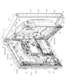
外枠11は、図6等に示すように、上辺枠構成部11a及び下辺枠構成部11bが木製の板材により構成され、左辺枠構成部11c及び右辺枠構成部11dがアルミニウム合金製の押出成形材により構成され、これら各枠構成部11a~11dがネジ等の離脱可能な締結具により全体として矩形枠状に組み付けられている。
As shown in FIG. 6 etc., the
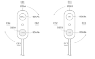
左辺枠構成部11cの上下端部には、それぞれ上ヒンジ81及び下ヒンジ82が取着されている(図1参照)。該上ヒンジ81及び下ヒンジ82にて、内枠12の上下部が回動可能に支持されており、これにより内枠12が開閉可能となる。そして、外枠11の内側に形成される空間部に内枠12等が収容される。
An
また、右辺枠構成部11dには、その幅方向後端部近傍から外枠11内側へ向け突出した延出壁部83が形成されている。延出壁部83は、内枠12の右側部背面側に設けられる施錠装置600(図6参照)に対応する上下区間全域を内枠12の背面側から覆っている(図5参照)。
Further, an extending
加えて、図3に示すように、延出壁部83の前面側には、施錠装置600の係止部材が係止される上下一対の受部84,85が設けられている。また、下側の受部85には、後述する内枠開放検知スイッチ92に当接する押圧部86が、外枠11内側に向けて突設されている。
In addition, as shown in FIG. 3, a pair of upper and
さらに、下辺枠構成部11bには樹脂製の幕板飾り87が取着されている。幕板飾り87の上面奥部には、上方に突出するリブ88が一体形成されている。これにより内枠12との間に隙間が形成されにくくなっている。
Further, a
図3に示すように、内枠12の開閉軸線は、パチンコ機10の正面からみて左側において上下に沿って設定されており、この開閉軸線を軸心として内枠12が前方側に開放できるようになっている。内枠12は、外形が矩形状をなす樹脂ベース38を主体に構成されており、該樹脂ベース38の中央部には略楕円形状の窓孔39が形成されている。
As shown in FIG. 3, the opening/closing axis of the
また、内枠12の前面側には前面枠セット14が開閉可能に取付けられている。前面枠セット14は、内枠12と同様に、パチンコ機10の正面から見て左側において上下に沿って設定された開閉軸線を軸心として前方側に開放できるようになっている。
Further, a front frame set 14 is attached to the front side of the
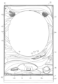
前面枠セット14は、内枠12と同様に外形が矩形状をなし、閉鎖状態においては内枠12の前面側ほぼ全域を覆う。前面枠セット14の中央部には略楕円形状の窓部101が形成されている。これにより、前面枠セット14の窓部101及び内枠12の窓孔39を介して、内枠12の後面に装着される遊技盤30(遊技領域)を外部から視認可能となる。遊技盤30の詳細な構成については後述する。
The front frame set 14 has a rectangular outer shape like the
図1,2に示すように、前面枠セット14の前面側には、その下部中央において球受皿としての下皿15が設けられており、排出口16より排出された遊技球が下皿15内に貯留可能になっている。また、下皿15の手前側には、下皿15内から遊技球を排出するための球抜きレバー25が設けられている。
As shown in FIGS. 1 and 2, on the front side of the front frame set 14, a
下皿15の左方には、演出ボタン125が設けられている。遊技者が演出ボタン125を押圧操作することで、後述する演出表示装置42等において所定の演出が行われたり、演出内容が変更されたりする。
A
下皿15の右方には、手前側に突出した遊技球発射ハンドル(以下、単に「ハンドル」という。)18が設けられている。ハンドル18には、図示しないタッチセンサや、ハンドル18の操作部の操作量を検出するための図示しない操作量検出手段(可変抵抗器)などが設けられている。
A game ball firing handle (hereinafter simply referred to as "handle") 18 is provided on the right side of the
そして、ハンドル18が右回りに回動操作されると、回動操作量に応じた強さで、後述する発射手段としての発射装置60によって遊技球が発射される。また、ハンドル18には、ハンドル18を握った右手の親指で押圧操作可能な発射禁止ボタン18aが設けられている。該発射禁止ボタン18aを押圧した状態においては、ハンドル18を握っていたとしても、発射装置60による遊技球の発射が禁止される。このため、遊技球の発射を禁止しつつハンドル18の回動操作を行ったり、ハンドル18を握った状態で、一時的に遊技球の発射を止めたりすることができる。
Then, when the
下皿15の上方には上皿19が設けられている。上皿19は、遊技球を一旦貯留し、一列に整列させながら後述する発射装置60の方へ案内する球受皿である。尚、上皿19が遊技球で満杯になった状態では、払出される遊技球は、後述する下皿連通路71及び排出口16を介して、下皿15へと案内される。
An
上皿19には球貸しボタン121と返却ボタン122が設けられている。これにより、遊技ホール等において、パチンコ機10の側方に配置されるカードユニット(球貸しユニット)に紙幣やカード等を投入した状態で球貸しボタン121が操作されると、その操作に応じて貸出球が上皿19に供給される。一方、返却ボタン122は、カードユニットに挿入されたカード等の返却を求める際に操作される。但し、カードユニットを介さずに球貸し装置等から上皿19に遊技球が直接貸し出されるパチンコ機、いわゆる現金機では球貸しボタン121及び返却ボタン122は不要である。
The
さらに、上皿19には、球抜きボタン123が設けられている。球抜きボタン123が押圧操作されることで、上皿19の球案内路の下流側に設けられ、下皿15に連通する連通孔(図示略)が開口し、上皿19に貯留されていた遊技球が下皿15へと案内される(落下する)。つまり、遊技者は、球抜きボタン123を操作することで、上皿19にある遊技球をいつでも下皿15に移すことができる。
Further, the
また、前面枠セット14の前面にはその周囲に各種ランプ等の発光手段が設けられている。これら発光手段は、大当たり時や所定のリーチ時等における遊技状態の変化に応じて点灯・点滅といった発光態様が変更制御され遊技中の演出効果を高める役割を果たすものである。 Furthermore, light emitting means such as various lamps are provided around the front surface of the front frame set 14. These light-emitting means play a role in enhancing the performance effect during the game by changing and controlling the light-emitting mode such as lighting or blinking according to changes in the game state such as when hitting a jackpot or when reaching a predetermined reach.
例えば、窓部101の周縁には、LED等の発光手段を内蔵した環状電飾部102が設けられている。また、該環状電飾部102の両側部には、所定のエラー時に点灯するエラー表示ランプ104が設けられている。尚、環状電飾部102のうち各エラー表示ランプ104の上方部位には、前面枠セット14の背面に設けられるスピーカSP(図3参照)に対応して細かな透孔が多数形成されている。
For example, on the periphery of the
前面枠セット14の背面側にはガラスユニット137が取付けられている。ガラスユニット137は、従来の前後一対の矩形状の板ガラスが前後対をなして別々に取着されるものではなく、全体として丸形をなし、アッセンブリ化された上で取付けられている。
A
また、図3に示すように、前面枠セット14の背面側には、窓部101の下方において、球通路ユニット70が設けられている。球通路ユニット70は、後述する払出機構部352から下皿15の排出口16へ繋がる下皿連通路71と、払出機構部352から上皿19へ繋がる上皿連通路73と備えている。
Further, as shown in FIG. 3, a
加えて、球通路ユニット70には、下皿連通路71内に位置する遊技球を検知する満杯検知スイッチ(図示略)が設けられている。該満杯検知スイッチの存在により、下皿15が遊技球で満杯になっていること(下皿15が遊技球で満杯となり、下皿連通路71において遊技球が滞留していること)を把握することができる。
In addition, the
次に、内枠12について図4等を参照して詳しく説明する。内枠12(樹脂ベース38)の前面下部、すなわち窓孔39(遊技盤30)の下方位置には、発射装置60及び該発射装置60より発射された直後の遊技球を案内する発射レール61が取付けられている。本実施形態では、発射装置60としてソレノイド式発射装置を採用している。
Next, the
尚、本実施形態では、上記満杯検知スイッチによって所定時間継続して遊技球が検知されることに基づき、発射装置60の打出しを禁止するといった制御が行われる。一方、下皿連通路71における遊技球の滞留が解消され、上記満杯検知スイッチにより遊技球が検知されなくなると(所定時間継続して検知されなくなると)発射装置60の打出しが許容される。
In this embodiment, based on the fact that the full detection switch detects a game ball continuously for a predetermined period of time, control is performed such as prohibiting the
また、発射装置60の上方には、球送り装置63が設けられている。球送り装置63は、ソレノイド等の駆動手段により、上皿19から案内される遊技球を1球ずつ発射装置60の発射位置へと案内する。
Further, above the
尚、図3及び図4中の符号67は後述する払出機構部352により払出された遊技球を内枠12の前方に案内するための払出通路であり、上皿連通路73(上皿19)に通じる通路と、下皿連通路71(下皿15)に通じる通路とに分かれている。
In addition, the
さらに、払出通路67の下方にはシャッタ68が設けられており、前面枠セット14を開放した状態では、バネ等の付勢力によりシャッタ68が前方に突出して払出通路67の出口をほぼ閉鎖するようになっている。
Further, a
一方、前面枠セット14を閉じた状態では、下皿連通路71の入口側後端部によってシャッタ68が押し開けられるようになっている。そして、前面枠セット14の閉状態においては、下皿連通路71及び上皿連通路73の入口部(球流入部)と払出通路67とが所定距離だけ離間した状態で隣接し、両者間の隙間を遊技球が通過可能となっている。これにより、上皿19及び上皿連通路73が遊技球で満杯となると、払出される遊技球が下皿連通路71側に流れ、下皿連通路71を通って下皿15に払出されることとなる。
On the other hand, when the front frame set 14 is closed, the
上述した通り、内枠12(樹脂ベース38)には、窓孔39の後側において遊技盤30が装着されている。遊技盤30は、その周縁部が内枠12(樹脂ベース38)の裏側に当接した状態で取着されている。従って、遊技領域となる遊技盤30の前面部の略中央部分が樹脂ベース38の窓孔39を通じて内枠12の前面側に露出した状態となっている。
As described above, the
ここで、遊技盤30の構成について図4を参照して詳しく説明する。遊技盤30には、内レール構成部51と外レール構成部52とからなり、発射装置60から発射された遊技球を遊技盤30上部へ案内するレール50が取付けられている。レール50を球通路としてもよい。これにより、ハンドル18の回動操作に伴い発射された遊技球は発射レール61及びレール50を通じて、遊技盤30とガラスユニット137との間に形成される遊技領域内に案内される。
Here, the configuration of the
内レール構成部51の先端部分(図4の左上部)には戻り球防止部材53が取着されている。これにより、一旦、レール50から遊技領域へと案内された遊技球が再度レール50内に戻ってしまうといった事態が防止される。また、外レール構成部52の略先端部(図4の右上部)には、返しゴム54が取着されている。所定以上の勢いで発射された遊技球は、返しゴム54に当たって例えば遊技盤30の略中央部側へ戻されることとなる。
A return
本実施形態では、外レール構成部52が遊技盤30の右上部で途絶え、内レール構成部51が遊技盤30の右下部で途絶えている。このため、遊技領域は、レール50及び樹脂ベース38の窓孔39の内周面により画定される。但し、発射装置60にて打出された遊技球が規制手段としての戻り球防止部材53を通過するまでは、レール50を逆流する場合があるため、内外レール構成部51,52の並行部分は遊技領域から除かれる。
In this embodiment, the
また、内枠12に設けられた発射レール61とレール50(外レール構成部52)との間には所定間隔の隙間があり、球通路ユニット70には、前記隙間より落下した遊技球を下皿15へと案内するファール球通路72が形成されている。戻り球防止部材53が配置された領域を特定領域としてもよい。仮に、発射装置60から発射された遊技球が戻り球防止部材53まで至らずファール球としてレール50を逆戻りする場合には、そのファール球がファール球通路72を介して下皿15に排出される。
In addition, there is a gap at a predetermined interval between the
また、遊技盤30には、一般入賞部31、可変入賞装置32、始動入球手段としての始動入賞部33(具体的には、第1始動入賞部33a及び第2始動入賞部33b)、スルーゲート34、可変入球手段としての中央入賞ユニット37等がルータ加工によって形成された貫通孔に配設され、遊技盤30前面側から取付けられている。
The
さらに、遊技盤30には、一般入賞部31等の各種入球手段に対応して、該各種入球手段へ入球した遊技球を検知する入球検知スイッチ(入球検知手段)が設けられている。
Furthermore, the
具体的には、図4に示すように、一般入賞部31に対応する位置には一般入賞スイッチ221が設けられ、可変入賞装置32に対応する位置にはカウントスイッチ223が設けられ、第1始動入賞部33aに対応する位置には第1始動入賞スイッチ224aが設けられ、第2始動入賞部33bに対応する位置には第2始動入賞スイッチ224bが設けられ、スルーゲート34に対応する位置にはスルーゲートスイッチ225が設けられている。
Specifically, as shown in FIG. 4, a general winning
周知の通り一般入賞部31、可変入賞装置32、始動入賞部33等の各種入賞手段に遊技球が入球(入賞)すると、各種検知スイッチにより検知され、上皿19又は下皿15へ所定数の賞球(遊技球)が払い出される。例えば始動入賞部33へ入球があった場合には3個、一般入賞部31へ入球があった場合には5個、可変入賞装置32へ入球があった場合には10個の賞球が払い出される。
As is well known, when a game ball enters (wins) into various winning means such as the general winning
その他に、遊技盤30にはアウト口36が設けられており、一般入賞部31等の各種入賞手段に入賞しなかった遊技球は、このアウト口36を通って遊技領域外へと排出される。また、遊技盤30には、遊技球の落下方向を適宜分散、調整等するために多数の釘が植設されているとともに、風車等の各種部材が配設されている。
In addition, the
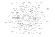
ここで、中央入賞ユニット37の構成について図4、及び、図40~図45等を参照して詳しく説明する。
Here, the configuration of the central winning
中央入賞ユニット37は、遊技領域(遊技盤30)の略中央部に配設されている。中央入賞ユニット37は、遊技領域を流下する遊技球が入球可能な内部領域401を形成するハウジング(センターフレーム)400と、該ハウジング400の前面側開口部に取付けられた前面パネル402とを備えている。前面パネル402は透明部材により構成されており、該前面パネル402を介して内部領域401が視認可能となっている。
The central winning
ハウジング400の上部には、遊技領域を流下する遊技球が内部領域401へ入球する入口部となる左右一対の入球開口部403が形成されている。また、中央入賞ユニット37には、入球開口部403を開閉するための左右一対の羽根部材404と、該羽根部材404を動作させるための羽根用ソレノイド405(図7参照)とが設けられている。「羽根部材404」が本実施形態における「開閉部材」を構成する。
A pair of left and right
各羽根部材404は、それぞれ対応する入球開口部403を閉鎖する閉位置と、開放する開位置との間を回動変位可能に設けられている。羽根部材404が閉位置に変位して、入球開口部403が閉鎖された場合には、中央入賞ユニット37が閉状態となり、遊技球が内部領域401へ進入不能(入球不能)となる。一方、羽根部材404が開位置へと変位して、入球開口部403が開放された場合には、中央入賞ユニット37が開状態となり、遊技球が内部領域401へ進入可能(入球可能)となる。
Each
尚、詳しくは後述するが、羽根部材404は、始動入賞部33(第1始動入賞部33a又は第2始動入賞部33b)へ入球があり、かつ、該入球に基づく当否抽選にて小当たり当選した場合に、所定時間だけ開状態となる。つまり、始動入賞部33(第1始動入賞部33a又は第2始動入賞部33b)への入球に基づく当否抽選にて小当たり当選した場合が本実施形態における所定の始動条件(開放契機)が成立した場合に相当する。また、本実施形態では、左右一対の羽根部材404は互いに同期して動作するように構成されており、一方が開位置となる場合には他方も開位置となり、一方が閉位置となる場合には他方も閉位置となる。
Although the details will be described later, the
一方、内部領域401は、入球開口部403から入球した遊技球が最初に案内されるルート振分けエリア406と、その下方位置に設けられた当否抽選エリア407と、さらにその下方位置に設けられた種別抽選領域としての種別抽選エリア408と、当否抽選エリア407の右方位置に設けられた役物作動抽選エリア409とに分かれている。
On the other hand, the
まずルート振分けエリア406について図40~図42等を参照して詳しく説明する。ルート振分けエリア406には、入球開口部403から内部領域401内に入球した遊技球を一旦ハウジング400の上部後壁部400a裏側へと案内しつつ該ルート振分けエリア406の左右方向中央部へ案内する導入通路601と、該ルート振分けエリア406の左右方向中央部に開口した導入通路601の出口部601aから導出される遊技球を下方へ落下させる落下通路602と、該落下通路602の下部に設けられたルート振分け手段としてのルート振分け部材603と、該ルート振分け部材603の左方位置に設けられ、遊技球を上記当否抽選エリア407へ案内可能な通常案内通路604と、ルート振分け部材603の右方位置に設けられ、遊技球を上記役物作動抽選エリア409へ案内可能な特別案内通路(スペシャル通路)605とを備えている。
First, the
本実施形態では、上記通常案内通路604等により「第1ルート」が構成され、特別案内通路605等により「第2ルート」が構成される。
In this embodiment, the
導入通路601の左右一対の入口部601bには、それぞれ入球開口部403から入球した遊技球の通過を検知する所定検知手段としての内部入球検知スイッチ437が設けられている。
A pair of left and
本実施形態では、左側の入球開口部403に入球した遊技球は必ず左側の入口部601bを通過し、右側の入球開口部403に入球した遊技球は必ず右側の入口部601bを通過する構成となっており、内部領域401に入球した遊技球は左右いずれかの内部入球検知スイッチ437によって必ず検知されるようになっている。
In this embodiment, a game ball that enters the left ball entry opening 403 always passes through the
また、本実施形態では、内部入球検知スイッチ437によって遊技球が検知された場合には所定個数(例えば10個)の賞球が払い出される。
Further, in this embodiment, when a game ball is detected by the internal ball
図42に示すように、ルート振分け部材603は、前後方向に延びる軸孔611aを有した筒状の軸部611と、該軸部611から上方に向けて突出する中央片部613と、軸部611から左方に向けて突出する左片部614と、該軸部611から右方に向けて突出する右片部615とを備えている。
As shown in FIG. 42, the
軸部611の軸孔611aには軸ピン610が挿通されている。軸ピン610は、落下通路602の背面側を画定する上部後壁部400aにその後端部が支持され、落下通路602の前面側を画定する前面パネル402(軸受孔402a)にその前端部が支持されている。これにより、ルート振分け部材603は、軸ピン610を中心として回動可能に軸支された状態となっている。
The
また、ルート振分け部材603の下方位置には、正面視略三角形状の突起部617が形成されている。そして、通常時には、図41(a)に示すように、ルート振分け部材603は、図示しない錘やコイルばね等の付勢手段(維持手段)により、中央片部613が左右方向中央位置(軸ピン610の位置)よりも右側に傾き、かつ、右片部615が水平方向よりも下方へ傾き、突起部617の右傾斜面に付勢された右傾斜状態で維持されている。
Further, a
かかる右傾斜状態においては、中央片部613の先端部613aが落下通路602の右側壁部602aに当接又は近接した状態となり、落下通路602を落下してくる遊技球が右側の特別案内通路605へ流下不能な状態となると共に、左側の通常案内通路604へ流下可能な状態となる。
In such a rightward tilted state, the
つまり、ルート振分け部材603が右傾斜状態にある通常時においては、ルート振分け部材603によって特別案内通路605が閉状態となる一方、通常案内通路604が開状態となり、落下通路602を落下してくる遊技球が、ルート振分け部材603の中央片部613の左側面及び左片部614の上面により構成される左側案内面に沿って、左側の通常案内通路604へ導かれることとなる。
In other words, under normal conditions when the
これに伴い、ルート振分け部材603は、左片部614に接触する遊技球から受ける力によって、上記付勢手段の付勢力に抗して反時計回り方向に回動する〔図41(b)参照〕。
Accordingly, the
これにより、所定時間、ルート振分け部材603は、中央片部613が左右方向中央位置(軸ピン610の位置)よりも左側に傾き、かつ、左片部614が水平方向よりも下方へ傾き、突起部617の左傾斜面に付勢された左傾斜状態となる。
As a result, for a predetermined period of time, the
かかる左傾斜状態においては、中央片部613の先端部613aが落下通路602の左側壁部602bに当接又は近接した状態となり、落下通路602を落下してくる遊技球が左側の通常案内通路604へ流下不能な状態となると共に、右側の特別案内通路605へ流下可能な状態となる。
In this left-leaning state, the
つまり、ルート振分け部材603が左傾斜状態にある所定時間の間は、ルート振分け部材603によって通常案内通路604が閉状態となる一方、特別案内通路605が開状態となる。これにより、このタイミングで落下通路602を落下してくる遊技球(例えば図41に示すように、通常案内通路604へ案内される第1の遊技球B1に連続して落下してきている第2の遊技球B2)があれば、該遊技球がルート振分け部材603の中央片部613の右側面及び右片部615の上面により構成される右側案内面に沿って、右側の特別案内通路605へ導かれることとなる。
That is, during a predetermined period of time when the
一旦、左傾斜状態となったルート振分け部材603は、上記付勢手段の付勢力により(右側の特別案内通路605へ遊技球が案内された場合には、右片部615に接触する遊技球から受ける力も加わり)時計回り方向に回動し、通常時の右傾斜状態に戻る〔図41(c)参照〕。
Once the
本実施形態では、ルート振分け部材603が第1姿勢である右傾斜姿勢にある状態が第1状態に相当し、ルート振分け部材603が第2姿勢である左傾斜姿勢にある状態が第2状態に相当する。また、本実施形態では、前記第1状態や前記第2状態など、ルート振分け部材603が通常案内通路604等よりなる第1ルートや、特別案内通路605等よりなる第2ルートなどへ遊技球を流下可能な状態が特定状態を構成する。勿論、特定状態は、これらに限定されるものではなく、他の構成を採用してもよい。
In this embodiment, the state in which the
次に役物作動抽選エリア409の構成について詳しく説明する。図40に示すように、役物作動抽選エリア409には、特別案内通路605によって導かれる遊技球が入球(通過)可能なスペシャルゲート650が設けられている。特別案内通路605及びスペシャルゲート650の通路幅は、遊技球が1球ずつ通過可能な幅に設定されている。また、スペシャルゲート650を通過した遊技球は、図示しない排出通路を介して内部領域401外(遊技盤30背面側)へ排出される。「スペシャルゲート650」が本実施形態における「契機入球手段」を構成する。
Next, the configuration of the accessory
スペシャルゲート650には、ここを通過する遊技球を検知するスペシャルゲートスイッチ651が設けられている。「スペシャルゲートスイッチ651」が本実施形態における「契機入球検知手段」を構成する。
The
このスペシャルゲートスイッチ651にて遊技球が検知された場合には、後述する可動役物722を作動させるか否かを決める作動アシスト抽選が行われる。そして、作動アシスト抽選にて当選した場合には、可動役物722が所定時間だけ作動する。可動役物722の構成及び動作態様についての詳細は後述する。
When a game ball is detected by this
尚、本実施形態では、スペシャルゲートスイッチ651によって遊技球が検知されても、賞球が払い出されない構成(賞球数0個)となっている。これに限らず、スペシャルゲートスイッチ651によって遊技球が検知された場合に、所定個数の賞球が払出される構成としてもよい。
In this embodiment, even if a game ball is detected by the
次に当否抽選エリア407の構成について詳しく説明する。当否抽選エリア407には、当否振分け手段としての回転体ユニット410が設けられている。回転体ユニット410は、ルート振分けエリア406から通常案内通路604を介して導かれる遊技球の行き先を、種別抽選エリア408又は内部領域401外のいずれかに振分ける機能を有する。尚、通常案内通路604の通路幅は、遊技球が1球ずつ通過可能な幅に設定されている。
Next, the configuration of the win/
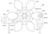
図43,図44に示すように、回転体ユニット410は、ベース部となるユニットベース411と、該ユニットベース411に対し、その上面側を覆うように取付けられるユニットカバー412とを備えている。
As shown in FIGS. 43 and 44, the
ユニットベース411には、その上面側に突出形成された設置台413上に略円盤状の回転体414が取付けられると共に、該回転体414を回転駆動させるための回転体モータ415が取付けられている。一方、ユニットベース411の下面側には、回転体モータ415の駆動力を回転体414に伝達するための歯車機構(図示略)などが設けられている。
A substantially disk-shaped
回転体414は、その上面部が前面側斜め上方を向くように、回転軸が鉛直方向に対し傾斜するように設置されている。回転体モータ415はステッピングモータにより構成され、主制御装置261から出力されるパルス信号により駆動制御される。かかる構成の下、回転体414は、常時一定方向(本実施形態では反時計回り方向)に一定周期で回転するよう構成されている。
The
回転体414には、その外周縁部3箇所に、それぞれ遊技球を1球ずつ受入れ可能なポケット部416が形成されている。該3個のポケット部416は、1つの特別ポケット部416aと、その他(2つ)の非特別ポケット部416bとに区別される。
The
非特別ポケット部416bは、回転体414の外周側及び上方に開口するとともに底壁部417を有している。かかる底壁部417の上面は回転体414の外周側に向けて下方傾斜している。
The
一方、特別ポケット部416aは回転体414の外周側、上方及び下方に開口しており、前記非特別ポケット部416bのような底壁部417は存在しない。加えて、特別ポケット部416aの周辺部は、その他の部位とは異なる着色の施された樹脂材料で構成されている。これにより、遊技者が特別ポケット部416aと非特別ポケット部416bと区別し易くなっている。
On the other hand, the
ユニットカバー412は、回転体414を囲むように配置される略円筒状の筒壁部431と、該筒壁部431の周囲から外周側に延出するように形成されたステージ部432とを備えている。
The
筒壁部431の上縁部は、ステージ部432の上面から上方に突出しており、その前側には、筒壁部431の内周側と外周側とを連通させるゲート部435が設けられている。
The upper edge of the
また、ステージ部432の上面は、遊技球が転動可能に構成されている。ステージ部432は、ゲート部435よりも後方に位置する部位が前方かつ筒壁部431側に向けて下方傾斜し、ゲート部435の前方に位置する部位が後方(ゲート部435側)に向けて下方傾斜している。
Further, the upper surface of the
これにより、当否抽選エリア407の背面側を画定するハウジング400の中部後壁部400bに開口した通常案内通路604の出口部604aから導出され、ステージ部432の後側に案内された遊技球は、回転体414側への動きを筒壁部431によって規制されつつ、ステージ部432上を時計回り又は反時計回りに手前側へ転動し、ゲート部435の前方で複数回左右に揺動する等してから、該ゲート部435と、回転体414のポケット部416(特別ポケット部416a又は非特別ポケット部416b)との相対位置が合致したときに、該ポケット部416内に進入することとなる。
As a result, the game balls led out from the
さらに、ユニットベース411には、回転体414の特別ポケット部416aに収容された遊技球を種別抽選エリア408へ案内するための第1V入賞通路427と、非特別ポケット部416bに収容された遊技球を内部領域401外へ排出するためのアウト通路428とが設けられている。
Furthermore, the
第1V入賞通路427は、回転体414の回転方向(反時計回り方向)に対しゲート部435よりもやや下流側、すなわちゲート部435の右方位置に形成されている。一方、アウト通路428は、第1V入賞通路427よりもさらに下流側、すなわち第1V入賞通路427の右奥方位置に形成されている。
The first
また、第1V入賞通路427の入口側は、設置台413の上面に開口しており、その上方を回転体414のポケット部416が通過可能に構成されている。そして、ゲート部435を介して回転体414の特別ポケット部416aに入球した遊技球は、回転体414の回転に伴って、該特別ポケット部416aと第1V入賞通路427の入口部との位置が合致した際に、特別ポケット部416aから下方に落下して第1V入賞通路427へ入球する。尚、第1V入賞通路427に対応する位置においては、ステージ部432の裏面より下方に突出した筒壁部431により、回転体414の側面側からの遊技球の脱落が規制されている。
Further, the entrance side of the first
一方、ゲート部435を介して遊技球が回転体414の非特別ポケット部416bに入球した場合、回転体414の回転に伴って、該非特別ポケット部416bと第1V入賞通路427の入口部との位置が合致したとしても、非特別ポケット部416bに設けられた底壁部417によって、非特別ポケット部416bに収容されている遊技球が第1V入賞通路427に落下(入球)しないようになっている。
On the other hand, when the game ball enters the
また、アウト通路428に対応する位置においては、筒壁部431の下縁部に切欠き部431aが形成されている。これにより、回転体414がさらに回転して、遊技球が収容された非特別ポケット部416bとアウト通路428との位置が合致すると、非特別ポケット部416bに収容されていた遊技球は、底壁部417の傾斜によって、回転体414の外周側へ移動し、筒壁部431の切欠き部431aを介してアウト通路428に落下(入球)することとなる。
Further, at a position corresponding to the
尚、ハウジング400には、第1V入賞通路427の出口部に接続される接続通路429が形成されており、該接続通路429により第1V入賞通路427と種別抽選エリア408とが連通状態となる。
Incidentally, the
また、第1V入賞通路427には、ここを通過する遊技球を検知する特別入球検知手段としての第1特別入球検知スイッチ461が設けられている。そして、第1V入賞通路427に遊技球が入球し、該遊技球が第1特別入球検知スイッチ461に検知されることによって、大当たり状態(特別遊技状態)を発生させる権利が付与されることとなる。従って、「第1V入賞通路427」が本実施形態における「特別入球手段」を構成する。
Further, the first
第1V入賞通路427に遊技球が入球して発生する大当たりにおいては、可変入賞装置32の大入賞口開閉部材32aが閉状態から開状態へ切換えられた後、規定時間の30秒が経過すること又は可変入賞装置32に規定個数の8個の遊技球が入賞することを条件に閉状態となるまでの一開閉動作を1回の特賞状態として、これが所定回数(所定ラウンド)繰り返し行われる。
In a jackpot that occurs when a game ball enters the
本実施形態では、大当たり状態の種別として、上記特賞状態(ラウンド)が3回繰り返される「3ラウンド大当たり」と、上記特賞状態(ラウンド)が7回繰り返される「7ラウンド大当たり」と、上記特賞状態(ラウンド)が15回繰り返される「15ラウンド大当たり」とが設定されている。 In this embodiment, the types of jackpot states include a "3 round jackpot" in which the above special prize state (round) is repeated 3 times, a "7 round jackpot" in which the above special prize state (round) is repeated 7 times, and a "7 round jackpot" in which the above special prize state (round) is repeated 7 times. A "15 round jackpot" in which (round) is repeated 15 times is set.
但し、詳しくは後述するが、本実施形態では、第1特別入球検知スイッチ461による入球検知が行われた場合に、即座に大当たり状態が開始されるのではなく、種別抽選エリア408で大当たり状態の種別が決定された後、大当たり状態が開始されるように構成されている。
However, as will be described in detail later, in this embodiment, when the first special ball
上記のとおり、本実施形態では、回転体414の特別ポケット部416aに入球し、第1V入賞通路427を通過することで第1特別入球検知スイッチ461に検知された遊技球が、種別抽選エリア408に案内されることとなる。
As described above, in this embodiment, the game ball that enters the
一方、アウト通路428には、ここを通過し内部領域401外に排出される遊技球を検知する非特別入球検知スイッチ462が設けられている。
On the other hand, the
また、筒壁部431の上縁部のうち、第1V入賞通路427及びアウト通路428の入口部上方を含む周方向所定区間には、筒壁部431の内周側に向け延出するように形成された張出し部440が設けられている。
Further, in a predetermined section in the circumferential direction of the upper edge of the
張出し部440は、その下方に位置する各ポケット部416の一部(回転体414の径方向半分程度の領域)を上方から覆うように構成されている。これにより、所定のポケット部416に入球した遊技球の上側に、さらに別の遊技球が乗り上げ、そのまま上下に重なった2つの遊技球が第1V入賞通路427或いはアウト通路428に対して連続で入球する、又は、何かしらの事情で遊技球が筒壁部431を飛び越えて、第1V入賞通路427及びアウト通路428と合致した位置にあるポケット部416に直接入球するといった事態を回避することができる。
The
また、図43~図45に示すように、回転体ユニット410の後部には、バイパス機構部721が設けられている。バイパス機構部721は、ステージ部432の最上流部に開口形成された開口収容部433に組付けられた可動体(可動部材)としての可動役物722と、該可動役物722を動作させる可動部材駆動手段としての可動役物用ソレノイド725とを備えている。可動役物用ソレノイド725は、可動体制御手段を構成する主制御装置261により駆動制御される。
Further, as shown in FIGS. 43 to 45, a
可動役物722は、上下方向にスライド(昇降)変位可能に組付けられている。そして、可動役物用ソレノイド725が非励磁状態となっている通常時において、可動役物722は、ほぼ全体が開口収容部433内に収容され、その上面がステージ部432の上面と略連続した状態となっている〔図44(a)、図45(a)参照〕。かかる可動役物722の収容状態が本実施形態における非有利状態に相当する。
The
一方、可動役物用ソレノイド725が励磁され、バイパス機構部721が作動状態となると、可動役物722は上昇し、その一部がステージ部432の上面より上方へ突出した突出状態となる〔図44(b),図45(b)参照〕。かかる可動役物722の動作が本実施形態における所定動作に相当し、可動役物722の作動状態が本実施形態における有利状態に相当する。
On the other hand, when the
可動役物722の上面には、その左右方向略中央部から左方に向けて緩やかに下方傾斜する左傾斜部727と、その左右方向略中央部から右方に向けて緩やかに下方傾斜する右傾斜部728とが形成されている。
On the upper surface of the
そして、可動役物722のほぼ全体が開口収容部433内に収容された通常時においては、可動役物722の上方位置においてハウジング400の中部後壁部400bに開口した通常案内通路604の出口部604aから導出された遊技球が、可動役物722上面の左傾斜部727又は右傾斜部728によって、ステージ部432の左方又は右方へ案内されることとなる。
In a normal state when the
また、図45(a),(b)に示すように、可動役物722の内部には、第2V入賞通路730が設けられている。第2V入賞通路730の通路幅は、遊技球を1球ずつ通過可能な幅に設定されている。
Further, as shown in FIGS. 45(a) and 45(b), a second
そして、可動役物722がステージ部432より突出した突出状態となると、該可動役物722が通常案内通路604の出口部604aの前方を塞ぎ、第2V入賞通路730の入口部730aと通常案内通路604の出口部604aとが相対向した状態となる〔図44(b),図45(b)参照〕。これにより、通常案内通路604から第2V入賞通路730へ遊技球が進入可能となり、両通路604,730は連通状態となる。
Then, when the
また、可動役物722がステージ部432より突出した突出状態において、第2V入賞通路730の出口部730bは、ハウジング400の中部後壁部400b裏側に形成されたバイパス通路737の入口部737aと相対向した状態となる。これにより、第2V入賞通路730からバイパス通路737へ遊技球が進入可能となり、両通路730,737は連通状態となる。
In addition, in the protruding state in which the
つまり、可動役物722がステージ部432より突出した突出状態となると、第2V入賞通路730を介して、通常案内通路604とバイパス通路737は、遊技球が通過可能な連通状態となる。
That is, when the
バイパス通路737の通路幅は、遊技球を1球ずつ通過可能な幅に設定されている。また、バイパス通路737の出口部737bは、15R入球口731の上方位置において、種別抽選エリア408の背面側を画定するハウジング400の下部後壁部400cに開口している。これにより、可動役物722がステージ部432より突出した突出状態においては、上記回転体ユニット410並びに後述する種別振分け機構部741を介することなく、通常案内通路604へ導かれる遊技球を直接、15R入球口731へ案内することができるようになる。つまり、可動役物722が作動することにより、回転体ユニット410並びに種別振分け機構部741による振分けを回避することができる。
The passage width of the
バイパス通路737には、ここを通過する遊技球を検知する特別入球検知手段としての第2特別入球検知スイッチ738が設けられている。そして、バイパス通路737に遊技球が入球し、該遊技球が第2特別入球検知スイッチ738に検知されることによって、大当たり状態(特別遊技状態)を発生させる権利が付与されることとなる。
A second special ball
但し、詳しくは後述するが、本実施形態では、第2特別入球検知スイッチ738による入球検知が行われた場合に、即座に大当たり状態が開始されるのではなく、遊技球が15R入球口731に入球した後、大当たり状態が開始されるように構成されている。
However, as will be described in detail later, in this embodiment, when the second special ball
また、第2V入賞通路730内に遊技球が残存している状態において、可動役物722が降下し収容状態に戻った場合には、該残存球は下部通路739を介してバイパス通路737へ案内され、上記第2特別入球検知スイッチ738に検知されるように構成されている。
In addition, when the
尚、本実施形態では、第1特別入球検知スイッチ461、又は、第2特別入球検知スイッチ738によって遊技球が検知された場合には、上皿19(又は下皿15)に対して10個の遊技球が払出される構成となっている。勿論、これらの入球検知スイッチに対応して払出される遊技球の個数は10個に限定されるものではなく、他の個数としてもよい。また、これらの入球検知スイッチによって遊技球が検知された場合に遊技球が払い出されない構成(賞球数0個)としてもよい。
In this embodiment, when a game ball is detected by the first special ball
以下、上記「第1V入賞通路427に遊技球が入球して発生する大当たり」及び「第2V入賞通路730を介してバイパス通路737に遊技球が入球して発生する大当たり」については、共通して「V入賞大当たり」と称する場合もある。
Hereinafter, the above-mentioned "jackpot that occurs when a game ball enters the 1st
次に種別抽選エリア408について詳しく説明する。種別抽選エリア408には、遊技球が入球した場合に「15ラウンド」の大当たり状態(15ラウンド大当たり)が付与される15R入球口731と、遊技球が入球した場合に「7ラウンド」の大当たり状態(7ラウンド大当たり)が付与される7R入球口732と、遊技球が入球した場合に「3ラウンド」の大当たり状態(3ラウンド大当たり)が付与される3R入球口733とが設けられている。ここで、「15R入球口731」、「7R入球口732」及び「3R入球口733」が本実施形態における「種別対応入球手段」を構成する。
Next, the
また、15R入球口731には、ここに入球した遊技球を検知する15R入球検知スイッチ734が設けられている。同様に、7R入球口732には、ここに入球した遊技球を検知する7R入球検知スイッチ735が設けられ、3R入球口733には、ここに入球した遊技球を検知する3R入球検知スイッチ736が設けられている。
Further, the 15R ball entry opening 731 is provided with a 15R ball
種別抽選エリア408には、第1V入賞通路427及び接続通路429を介して種別抽選エリア408に導かれる遊技球の行き先を、15R入球口731、7R入球口732、又は、3R入球口733のいずれかに振分ける種別振分け手段(種別決定手段)としての種別振分け機構部741が設けられている。
In the
種別振分け機構部741は、接続通路429の出口部429aから導出される遊技球が案内されるスタート台742と、該スタート台742を経由した遊技球が案内される第1渡し板744と、該第1渡し板744を通過した遊技球が案内される第2渡し板745と、該第2渡し板745を通過した遊技球が案内され、該遊技球を15R入球口731に案内する15R誘導通路746とを備えている。
The type
スタート台742は、種別抽選エリア408の左上部に設置され、上面が右方に向けて下方傾斜している。
The starting
第1渡し板744は、スタート台742の右方かつ若干下方位置に設置され、その左端部が前後方向を軸線方向として回動可能に軸支されており、右端側が自由端となるように設けられている。
The
第1渡し板744の回動軸は、ハウジング400の下部後壁部400c裏側にて、モータ等からなる図示しない揺動機構部に連結されており、該揺動機構部が主制御装置261によって駆動制御されることにより、第1渡し板744が上下に揺動変位するように構成されている。
The rotation axis of the
具体的に、第1渡し板744は、その上面が右方に向けて若干下方傾斜して、遊技球を第2渡し板745へ案内する先送り位置と、これよりも上面が大きく下方傾斜して、遊技球を3R入球口733へ案内する落下位置との間を変位可能に構成されている。
Specifically, the first spanning
そして、スタート台742を経由して第1渡し板744に案内された遊技球が第1渡し板744の右端部まで転動した際に、該第1渡し板744が上記先送り位置にあれば、該遊技球は第2渡し板745に案内される。
Then, when the game ball guided to the first spanning
一方、第1渡し板744に案内された遊技球が第1渡し板744の右端部まで転動した際に、該第1渡し板744が上記落下位置にあれば、該遊技球は3R入球口733に案内される。
On the other hand, when the game ball guided by the first spanning
つまり、第1渡し板744は、スタート台742を経由して案内される遊技球の行き先を3R入球口733、又は、第2渡し板745のどちらかに振分ける機能を有する。
In other words, the first passing
第2渡し板745は、第1渡し板744の右方かつ若干下方位置に設置され、その左端部が前後方向を軸線方向として回動可能に軸支されており、右端側が自由端となるように設けられている。
The second spanning
第2渡し板745の回動軸は、ハウジング400の下部後壁部400c裏側にて、モータ等からなる図示しない揺動機構部に連結されており、該揺動機構部が主制御装置261によって駆動制御されることにより、第2渡し板745が上下に揺動変位するように構成されている。
The rotation axis of the
具体的に、第2渡し板745は、その上面が右方に向けて若干下方傾斜して、15R誘導通路746へ遊技球を案内する先送り位置と、これよりも上面が大きく下方傾斜して、遊技球を7R入球口732へ案内する落下位置との間を変位可能に構成されている。
Specifically, the upper surface of the second spanning
そして、第2渡し板745に案内された遊技球が第2渡し板745の右端部まで転動した際に、該第2渡し板745が上記先送り位置にあれば、該遊技球は15R誘導通路746に案内される。
Then, when the game ball guided by the second spanning
一方、第2渡し板745に案内された遊技球が第2渡し板745の右端部まで転動した際に、該第2渡し板745が上記落下位置にあれば、該遊技球は7R入球口732に案内される。
On the other hand, when the game ball guided by the second spanning
つまり、第2渡し板745は、第1渡し板744を通過して案内される遊技球の行き先を7R入球口732、又は、15R誘導通路746のどちらかに振分ける機能を有する。
In other words, the second spanning
15R誘導通路746は、第2渡し板745の右方かつ若干下方位置に設置され、その上面が右方の15R入球口731に向けて下方傾斜している。
The
尚、本実施形態では、第1渡し板744と第2渡し板745とが異なる周期で揺動するように構成されている。例えば、第1渡し板744が第2渡し板745よりも若干早く揺動するように構成されている。
In this embodiment, the first spanning
また、本実施形態では、第1特別入球検知スイッチ461の入球検知が行われた後、15R入球検知スイッチ734、7R入球検知スイッチ735、又は、3R入球検知スイッチ736のいずれかの入球検知が行われた場合に、対応する種別の大当たり状態が開始されるようになっている。また、第2特別入球検知スイッチ738の入球検知が行われた後、15R入球検知スイッチ734の入球検知が行われた場合に、15ラウンド大当たりに対応する大当たり状態が開始されるようになっている。
Further, in this embodiment, after the first special ball
ここから遊技盤30の説明に戻る。図4に示すように、第1始動入賞部33aは、中央入賞ユニット37の左下方及び右下方に設けられている。また、第2始動入賞部33bは、中央入賞ユニット37の直下方に設けられている。
From here, we return to the explanation of the
さらに、第2始動入賞部33bは、その両側部に、開閉可能な一対の始動口開閉部材33cを備えている。本実施形態では、始動口開閉部材33cが閉状態となっている場合においては、遊技球が第2始動入賞部33bへ入球不能となるように構成されている。
Furthermore, the second starting prize part 33b is provided with a pair of opening/closable starting opening opening/
つまり、第1始動入賞部33aは、遊技球が常時入球可能となっているのに対し、第2始動入賞部33bは、遊技球がスルーゲート34を通過することに基づく入球アシスト抽選にて当選した場合に始動口開閉部材33cが開状態となり、遊技球が第2始動入賞部33bへ入球可能となる。
In other words, the first
これに限らず、始動口開閉部材33cが閉状態となっている場合において、遊技球が第2始動入賞部33bへ入球困難な状態となり、入球アシスト抽選にて当選した場合に始動口開閉部材33cが開状態となり、遊技球が第2始動入賞部33bへ入球容易となるような構成としてもよい。
Not limited to this, when the starting port opening/closing
上述したように、第1始動入賞部33aには、ここに入球した遊技球を検知する第1始動入賞スイッチ224aが設けられている。同様に、第2始動入賞部33bには、ここに入球した遊技球を検知する第2始動入賞スイッチ224bが設けられている。各始動入賞スイッチ224a,224bがそれぞれ本実施形態における「始動入球検知手段」を構成する。
As described above, the first starting
そして、詳しくは後述するが、第1始動入賞スイッチ224a又は第2始動入賞スイッチ224bにて遊技球が検知された場合には、遊技者に有利な「当たり」となるか、「外れ」となるか否かの当否抽選が行われる。
As will be described in detail later, if a game ball is detected by the first
当否抽選における「当たり」には、中央入賞ユニット37の羽根部材404が開放される「小当たり」と、可変入賞装置32の大入賞口開閉部材32aが開放される「大当たり」とがある。
The "win" in the win/fail lottery includes a "small win" in which the
加えて、第1始動入賞スイッチ224a又は第2始動入賞スイッチ224bによる入球検知に基づいて当否抽選が行われた場合には、後述する特別表示装置43にて、該当否抽選の結果を教示するための変動表示及び停止表示が行われる。
In addition, when a winning lottery is conducted based on ball entry detection by the first
尚、本実施形態では、第1始動入賞スイッチ224aによる入球検知が行われた場合と、第2始動入賞スイッチ224bによる入球検知が行われた場合とで、共通の当否抽選が行われると共に、共通の特別表示装置43において変動表示が行われるように構成されているが、第1始動入賞スイッチ224aによる検知に基づいて行われる当否抽選の結果を教示するための変動表示が行われる第1特別表示装置と、第2始動入賞スイッチ224bによる検知に基づいて行われる当否抽選の結果を教示するための変動表示が行われる第2特別表示装置とを別々に設けることとしてもよい。第1始動入賞スイッチ224a又は第2始動入賞スイッチ224bを第1又は第2の契機入球検知手段としてもよい。さらに、かかる構成を採用する場合、それぞれの変動表示が別々に保留記憶されるとともに、記憶された順番の通りに、或いは、一方が他方に優先されるようにして、対応する変動表示が消化されるように構成してもよい。加えて、かかる構成を採用する場合には、当否抽選にて当選した場合に付与される大当たり状態の種別の振分け割合を異ならせることとしてもよいし、同じとすることとしてもよい。
In addition, in this embodiment, a common winning lottery is performed in the case where the first
中央入賞ユニット37の左右両側方の遊技領域には、遊技球が流下可能な流下領域が形成されている。スルーゲート34は、中央入賞ユニット37の左右両側方の流下領域にそれぞれ配置され、ここを流下する遊技球が1球ずつ通過可能に構成されている。中央入賞ユニット37の右側方の流下領域を第1ルートとなる第1の流下ルートとし、左側方の流下領域を第2ルートとなる第2の流下ルートとしてもよい。また、スルーゲート34には、該スルーゲート34を通過する遊技球を検知するスルーゲートスイッチ225が設けられている。該スルーゲートスイッチ225にて遊技球が検知された場合には、第2始動入賞部33b(始動口開閉部材33c)を開状態とするか否かの入球アシスト抽選が行われる。そして、入球アシスト抽選にて当選した場合には、第2始動入賞部33b(始動口開閉部材33c)が規定時間だけ開状態とされる。
In the game areas on both the left and right sides of the central winning
遊技盤30の右上部には、スルーゲート34への入球(球通過)に基づいた入球アシスト抽選の抽選結果を表示するスルーゲート用表示装置(普通図柄表示装置)41、各始動入賞部33a,33bへの入球に基づいた当否抽選の抽選結果を表示する特別表示装置(特別図柄表示装置)43、及び、スペシャルゲート650への入球(球通過)に基づいた作動アシスト抽選の抽選結果を表示するスペシャルゲート用表示装置44が設けられている。「スペシャルゲート用表示装置44」が本実施形態における「表示手段」を構成する。
At the upper right of the
本実施形態において、スルーゲート用表示装置41は2つのランプによって構成され、第1表示手段を構成する特別表示装置43は8つのランプによって構成され、スペシャルゲート用表示装置44は2つのランプによって構成されている。
In this embodiment, the through
尚、これら表示装置41、43、44の構成については、上記構成に特に限定されるものではなく、例えば異なる数のランプ群によって構成されてもよいし、7セグメント表示装置、ドット表示装置、液晶表示装置等の異なる表示装置により構成されてもよい。
Note that the configurations of these
また、特別表示装置43においては、始動入賞部33(第1始動入賞部33a又は第2始動入賞部33b)に遊技球が入球すると、当否抽選の抽選結果を教示するための変動表示(切替表示)が開始され、所定時間後、該変動表示を停止する際に、当否抽選の結果に対応した態様が表示されるようになっている。第1始動入賞部33a又は第2始動入賞部33bを第1又は第2の契機入球手段としてもよい。さらに、特別表示装置43は、後述する主制御装置261によって直接的に表示内容が制御され、当否抽選の結果が確定的に表示されるようになっている。
In addition, in the
かかる当否抽選にて大当たり当選した場合には、可変入賞装置32の大入賞口開閉部材32aが閉状態から開状態へ切換えられた後、規定時間の30秒が経過すること又は可変入賞装置32に規定個数の8個の遊技球が入賞することを条件に閉状態となるまでの一開閉動作を1回の特賞状態として、これが15回(15ラウンド)繰り返される大当たり(以下、「直撃大当たり」と称する)が付与される。
If you win a jackpot in such a winning lottery, after the big winning opening opening/closing
尚、上述したように、本実施形態では、始動入賞部33(第1始動入賞部33a又は第2始動入賞部33b)への入球に基づく当否抽選にて「大当たり」に当選した場合だけでなく、回転体414の特別ポケット部416aを介して遊技球が第1V入賞通路427に入球し、該遊技球が第1特別入球検知スイッチ461に検知された場合や、可動役物722(第2V入賞通路730)を介して遊技球がバイパス通路737に入球し、該遊技球が第2特別入球検知スイッチ738に検知された場合にも大当たり状態(V入賞大当たり)が発生する。
As mentioned above, in this embodiment, only when a "big hit" is won in the lottery based on the ball entering the starting winning section 33 (the first
また、特別表示装置43の変動表示中に、新たに遊技球が始動入賞部33(第1始動入賞部33a又は第2始動入賞部33b)に入球した場合には、その分の変動表示は、その時点で行われている変動表示の終了後に行われる構成となっている。つまり、特別表示装置43の変動表示が待機(保留)されることとなる。この保留される変動表示の最大回数は、パチンコ機の機種毎に決められているが、本実施形態では第1始動入賞部33a及び第2始動入賞部33bに入球した遊技球に対応して、合計4回までの変動表示が保留される。
In addition, if a new game ball enters the starting winning section 33 (first
また、特別表示装置43の変動表示の保留回数は、特別表示装置43の近傍に設けられた特別表示装置用保留ランプ47にて点灯表示されるようになっている。本実施形態の特別表示装置用保留ランプ47は、4つのランプによって構成され、各ランプの点灯・消灯の状態を適宜切替えることで、保留の数を教示するようになっている。
Further, the number of hold times in the variable display of the
加えて、大当たり中や小当たり中に新たに遊技球が始動入賞部33に入賞した場合には、その分の変動表示についても保留され、該変動表示は大当たり状態や小当たり状態の終了後に実行される。 In addition, if a new game ball enters the starting prize section 33 during a jackpot or small win, the variable display for that amount will also be suspended, and the variable display will be executed after the jackpot or small win state ends. be done.
スルーゲート用表示装置41においては、遊技球がスルーゲート34を通過すると、入球アシスト抽選の抽選結果を表示するための変動表示(切替表示)が開始され、所定時間後、該変動表示を停止する際に、入球アシスト抽選の結果に対応した態様が表示されるようになっている。ここで入球アシスト抽選の抽選結果が始動口開閉部材33cの開放に対応した当選結果であった場合には、スルーゲート用表示装置41にて所定の停止結果が表示されて変動表示が停止された後に、始動口開閉部材33cが開放される。また、スルーゲート用表示装置41は、後述する主制御装置261によって直接的に表示内容が制御され、入球アシスト抽選の結果が確定的に表示されるようになっている。
In the through
また、スルーゲート用表示装置41の変動表示中に、新たに遊技球がスルーゲート34を通過した場合には、その分の変動表示は、その時点で行われている変動表示の終了後に行われる構成となっている。つまり、スルーゲート用表示装置41の変動表示が待機(保留)されることとなる。この保留される変動表示の最大回数は、パチンコ機の機種毎に決められているが、本実施形態では4回まで保留され、その保留回数がスルーゲート用表示装置41の近傍に設けられたスルーゲート用保留ランプ48にて点灯表示されるようになっている。本実施形態のスルーゲート用保留ランプ48は、4つのランプによって構成され、各ランプの点灯・消灯の状態を適宜切替えることで、保留の数を教示するようになっている。
Additionally, if a new game ball passes through the through
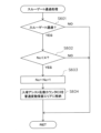
スペシャルゲート用表示装置44においては、遊技球がスペシャルゲート650を通過すると、作動アシスト抽選の抽選結果を表示するための変動表示(切替表示)が開始され、所定時間後、該変動表示を停止する際に、作動アシスト抽選の結果に対応した態様が表示されるようになっている。ここで作動アシスト抽選の抽選結果が可動役物722を作動させる当選結果であった場合には、スペシャルゲート用表示装置44にて所定の停止結果が表示されて変動表示が停止された後に、可動役物722が作動する。また、スペシャルゲート用表示装置44は、後述する主制御装置261によって直接的に表示内容が制御され、作動アシスト抽選の結果が確定的に表示されるようになっている。
In the special
尚、詳しくは後述するが、本実施形態では、スペシャルゲート用表示装置44の変動表示中や可動役物722の作動中において、新たに遊技球がスペシャルゲート650を通過し、スペシャルゲートスイッチ651により検知されたとしても、その分の変動表示(作動アシスト抽選結果)は保留されない構成となっている。
Although details will be described later, in this embodiment, a game ball newly passes through the
また、中央入賞ユニット37の上部には演出表示装置42が設けられている。演出表示装置42は、液晶表示装置によって構成され、後述するサブ制御装置262及び表示制御装置45によって表示内容が制御される。演出表示装置42においては、特別表示装置43にて表示される変動表示や抽選結果に対応させるように、主制御装置261からのコマンドに基づき、サブ制御装置262によって補助的な表示内容が決定され、後述する表示制御装置45によって表示が行われる。
Furthermore, an
可変入賞装置32は、遊技領域(遊技盤30)の下部中央に配置されている。また、可変入賞装置32は、通常は遊技球が入賞できない閉状態になっており、大当たり状態の発生の際に、大入賞口開閉部材32aが開放され、遊技球が大入賞口へ入賞可能な開状態とされる。
The variable
次に、パチンコ機10の背面構成について図5、図6等を参照して説明する。パチンコ機10の背面には、各種制御基板が上下左右に並べられるようにして、一部前後に重ねられるようにして配置されており、さらに、遊技球を供給する遊技球供給装置(払出機構)や樹脂製の保護カバー等が取り付けられている。払出機構及び保護カバーは1ユニットとして一体化されており、一般に樹脂部分を裏パックと称することもあるため、ここではそのユニットを「裏パックユニット203」と称する。
Next, the back configuration of the
まず、遊技盤30の背面構成について説明する。図6に示すように、遊技盤30の背面には、中央入賞ユニット37等を背後から覆う樹脂製のフレームカバー213が後方に突出して設けられている。また、フレームカバー213の背面側には、表示制御装置45及びサブ制御装置262が着脱可能に取り付けられている。
First, the back structure of the
表示制御装置45は基板ボックス45aに収容されてフレームカバー213の背面側に固定されている。サブ制御装置262は基板ボックス262aに収容されて表示制御装置45(基板ボックス45a)の背面側に固定されている。また、基板ボックス45a,262aは透明樹脂材料等により構成され、内部が視認可能となっている。
The
フレームカバー213の下方には裏枠セット215が、一般入賞部31、可変入賞装置32及び始動入賞部33等を背後から覆うようにして遊技盤30に取付けられている。裏枠セット215は、各種入賞手段に入賞した遊技球を回収するための球回収機構を備えている(図示略)。この球回収機構により回収された遊技球は、後述する排出通路部217に案内され、排出通路部217の排出シュートからパチンコ機10外部に排出される。
A back frame set 215 is attached to the
また、本実施形態では、裏枠セット215が主制御装置261の取付台として機能する。より詳しくは、主制御装置261を搭載した基板ボックス263が、裏枠セット215に対し回動可能に軸支され、後方に開放可能となっている。
Further, in this embodiment, the back frame set 215 functions as a mounting base for the
主制御装置261は透明樹脂材料等よりなる基板ボックス263に収容されている。基板ボックス263は、ボックスベースと該ボックスベースの開口部を覆うボックスカバーとを備え、これらボックスベースとボックスカバーとが封印部材によって連結されている。封印部材によって連結された基板ボックス263は、所定の痕跡を残さなければ開封できない構成となっている。これにより、基板ボックス263が不正に開封された旨を容易に発見することができる。
The
さらに、裏枠セット215には、一般入賞スイッチ221、カウントスイッチ223及びスルーゲートスイッチ225と、それぞれケーブルコネクタを介して電気的に接続される第1盤面中継基板(図示略)が設けられている。この第1盤面中継基板は、一般入賞スイッチ221等と主制御装置261とを中継するものであり、ケーブルコネクタを介して主制御装置261と電気的に接続されている。
Furthermore, the back frame set 215 is provided with a first board relay board (not shown) that is electrically connected to the
また、裏枠セット215には、中央入賞ユニット37に設けられた各種スイッチと、それぞれケーブルコネクタを介して電気的に接続される第2盤面中継基板(図示略)が設けられている。具体的に、第2盤面中継基板は、内部入球検知スイッチ437、第1特別入球検知スイッチ461、非特別入球検知スイッチ462、ラウンド入球検知スイッチ(15R入球検知スイッチ734、7R入球検知スイッチ735、3R入球検知スイッチ736)、第2特別入球検知スイッチ738、及び、スペシャルゲートスイッチ651と、それぞれ電気的に接続されている。この第2盤面中継基板は、中央入賞ユニット37に設けられた各種スイッチと、主制御装置261とを中継するものであり、第1盤面中継基板と同様、ケーブルコネクタを介して主制御装置261と電気的に接続されている。
Further, the back frame set 215 is provided with a second panel relay board (not shown) that is electrically connected to various switches provided in the central winning
これに対し、始動入賞部33a,33bへの入球を検知する始動入賞スイッチ224a,224bは、中継基板を経ることなくコネクタケーブルを介して直接、主制御装置261に接続されている。
On the other hand, the
上記構成の下、各種入球検知スイッチにて各々検知された検出結果は、主制御装置261に取り込まれる。そして、該主制御装置261よりその都度の入賞状況に応じた払出指令(遊技球の払出個数)が払出制御装置311に送信され、該払出制御装置311からの出力信号に基づき所定数の遊技球の払出しが実施される(スルーゲートスイッチ225、非特別入球検知スイッチ462、ラウンド入球検知スイッチ734、735、736、及び、スペシャルゲートスイッチ651により検知された場合を除く。)。
Under the above configuration, the detection results detected by the various ball entry detection switches are taken into the
この他、遊技盤30の裏面には、図示は省略するが、可変入賞装置32にて大入賞口開閉部材32aを開閉駆動する大入賞口用ソレノイドが設けられ、第2始動入賞部33bにて一対の始動口開閉部材33cを開閉駆動する始動口用ソレノイドが設けられている。また、裏枠セット215には、これらソレノイドと主制御装置261とを中継する第3盤面中継基板(図示略)も設けられている。
In addition, although not shown in the drawings, on the back side of the
次に、裏パックユニット203の構成を説明する。図5に示すように、裏パックユニット203は、樹脂成形された裏パック351と、遊技球の払出機構部352とを一体化したものである。また、裏パックユニット203は、内枠12の左側部(図5では右側)に対して開閉可能に支持されており、上下方向に沿って延びる開閉軸線を軸心として後方に開放できるようになっている。加えて、裏パックユニット203の左上部(図5では右上部)には外部端子板240が設けられている。
Next, the configuration of the
外部端子板240は、遊技ホールのホールコンピュータなどへの各種情報送信を中継するためのものであり、複数の外部接続端子が設けられている。便宜上、符号は付さないが、例えば現在の遊技状態(大当たり状態や時間短縮モード等)に関する情報を出力するための端子、後述する開放検知スイッチ91,92によって検知される前面枠セット14や内枠12の開放に関する情報を出力するための端子、入球エラー、下皿満杯エラー、タンク球無しエラー、払出しエラーなど各種エラー状態に関する情報を出力するための端子、払出制御装置311から払出される賞球数に関する情報を出力するための端子などが設けられている。
The external
裏パック351は例えばABS樹脂により一体成形されており、パチンコ機10の後方に突出して略直方体形状をなす保護カバー部354を備えている。保護カバー部354は左右側面及び上面が閉塞され且つ下面のみが開放された形状をなし、少なくともフレームカバー213を覆うのに十分な大きさを有する。但し、本実施形態では、保護カバー部354が基板ボックス263の上部及び右部(図5では左側の部位)も合わせて覆う構成となっている。これにより、裏パックユニット203の閉鎖状態において、基板ボックス263の右部に設けられた封印部材、及び主制御装置261の上縁部に沿って設けられた端子部(基板側コネクタ)が覆われることとなる。
The
払出機構部352は、保護カバー部354を迂回するようにして配設されている。すなわち、保護カバー部354の上方には、上側に開口したタンク355が設けられており、このタンク355には遊技ホールの島設備から供給される遊技球が逐次補給される。タンク355の下方には、例えば横方向2列の球通路を有し下流側に向けて緩やかに傾斜するタンクレール356が連結され、さらにタンクレール356の下流側には縦向きにケースレール357が連結されている。払出装置358はケースレール357の最下流部に設けられ、払出モータ等の所定の電気的構成により必要個数の遊技球の払出が適宜行われる。そして、払出装置358より払出された遊技球は上皿19等に供給される。
The
また、払出機構部352には、払出制御装置311から払出装置358への払出指令の信号を中継する払出中継基板381が設置されると共に、外部より主電源を取り込む電源スイッチ基板382が設置されている。電源スイッチ基板382には、電圧変換器を介して例えば交流24Vの主電源が供給され、電源スイッチ382aの切替操作により電源ON又は電源OFFされる。
Further, the
裏パックユニット203(基板ボックス263)の下方には、内枠12の左側部(図5では右側)にて軸支され、後方に開放可能な下枠セット251が設けられている。図6に示すように、下枠セット251には、上述した球回収機構により回収された遊技球が流入する排出通路部217が形成され、排出通路部217の最下流部には、遊技球をパチンコ機10外部へ排出する排出シュート(図示略)が形成されている。
A lower frame set 251 is provided below the back pack unit 203 (board box 263), which is pivotally supported on the left side (right side in FIG. 5) of the
つまり、一般入賞部31等の各入賞手段に入賞した遊技球は、裏枠セット215の球回収機構を介して集合し、さらに排出通路部217の排出シュートを通じてパチンコ機10外部に排出される。なお、アウト口36も同様に排出通路部217に通じており、何れの入賞手段にも入賞しなかった遊技球も排出シュートを介してパチンコ機10外部に排出される。
That is, the game balls won by each winning means such as the general winning
尚、本実施形態では、裏パックユニット203と下枠セット251とが別体として構成され、それぞれ独立して開閉可能であるが、裏パックユニット203と下枠セット251とが一体的に形成されることとしてもよい。
In this embodiment, the
また、図5に示すように、下枠セット251の背面側には、払出制御装置311、発射制御装置312、電源装置313及びカードユニット接続基板314が前後に重ねられた状態で着脱可能に取り付けられている。
Further, as shown in FIG. 5, on the back side of the lower frame set 251, a
発射制御装置312及び電源装置313は基板ボックス313aに収容されて下枠セット251の背面側に固定されている。尚、発射制御装置312及び電源装置313は、便宜上それぞれ独立した制御装置として説明するが、実際には1つの基板(プリント基板)により構成される。
The
また、払出制御装置311は、基板ボックス311aに収容されて、基板ボックス313a(発射制御装置312及び電源装置313)の背面側に固定されている。尚、払出制御装置311が収容される基板ボックス311aには、上述した主制御装置261が収容される基板ボックス263と同様に封印部材が設けられ、基板ボックス311aの開封された痕跡が残るようになっている。
Moreover, the
加えて、カードユニット接続基板314は、基板ボックス314aに収容されて、基板ボックス313a(発射制御装置312及び電源装置313)の背面側に固定されている。
In addition, the card
なお、上記各基板ボックス311a,313a,314aは透明樹脂材料等により構成されており、内部が視認可能となっている。
Note that each of the
また、払出制御装置311には基板ボックス311aから外方に突出する状態復帰スイッチ321が設けられている。例えば、払出モータ部の球詰まり等、払出エラーの発生時において状態復帰スイッチ321が押下されると、払出モータが正逆回転され、球詰まりの解消(正常状態への復帰)が図られる。
Further, the
さらに、電源装置313には基板ボックス313aから外方に突出するRAM消去スイッチ323が設けられている。本パチンコ機10はバックアップ機能を有しており、万一停電が発生した際でも停電時の状態を保持し、停電からの復帰(復電)の際には停電時の状態に復帰させることができる。従って、通常手順で(例えば遊技ホールの営業終了時に)電源遮断すると電源遮断前の状態が記憶保持されることから、電源投入時に初期状態に戻したい場合には、RAM消去スイッチ323を押しながら電源を投入する。
Further, the
また、図6に示すように、内枠12の右側部背面側には施錠装置600が設けられている。施錠装置600は、前面枠セット14の前面側に露出するシリンダ錠600a(図1等参照)を備えており、該シリンダ錠600aの鍵穴に鍵を挿入し、一方に回動操作することで内枠12を解錠でき、他方に回動操作することで前面枠セット14を解錠できるようになっている。本実施形態では、内枠12は外枠11に対し施錠され、前面枠セット14は内枠12に対し施錠される。
Further, as shown in FIG. 6, a
尚、上記のように、外枠11の右辺枠構成部11dには、施錠装置600に対応する上下区間全域を内枠12の背面側から覆う延出壁部83が形成されている(図5参照)。これにより、外枠11の背面側から線材等を進入させ、該線材等により施錠装置600を操作することが困難となる。結果として、防御性能の向上を図ることができる。さらに、延出壁部83は、裏パックユニット203及び下枠セット251の右端部(図5では左側の端部)を背面側から覆う構成となっており、内枠12の閉状態においては、裏パックユニット203及び下枠セット251を開放できない構成となっている。
As described above, the right
また、図4に示すように、内枠12の前面側右下部(発射装置60の右側)には、前面枠セット14の開放を検知するための前面枠開放検知スイッチ91が設けられ、図5に示すように、内枠12の背面側右下部(図5では左下)には、内枠12の開放を検知するための内枠開放検知スイッチ92が設けられている。前面枠開放検知スイッチ91及び内枠開放検知スイッチ92は、それぞれスイッチ本体部に対して出没可能な検知部を備えており、前面枠開放検知スイッチ91は検知部が前方に向くように設けられ、内枠開放検知スイッチ92は検知部が後方へ向くように設けられる。そして、検知部がスイッチ本体部から突出した状態にある場合にはオン信号を主制御装置261に出力し、検知部がスイッチ本体部側に押圧され、スイッチ本体部に没入した状態ではオフ信号を主制御装置261に出力する構成となっている。つまり、前面枠開放検知スイッチ91は前面枠セット14の閉鎖時において検知部が前面枠セット14の背面で押圧されてオフ状態となり、前面枠セット14の開放時には、検知部が突出状態に戻ってオン状態となる。同様に、内枠開放検知スイッチ92は内枠12の閉鎖時において検知部が外枠11の受部85に一体形成された押圧部86によって押圧されてオフ状態となり、内枠12の開放時には検知部が突出状態に戻ってオン状態となる。
Further, as shown in FIG. 4, a front frame
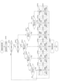
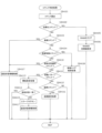
次に、パチンコ機10の電気的構成について説明する。図7は、本パチンコ機10の電気的構成を示すブロック図である。主制御装置261(主基板)には、演算装置である1チップマイコンとしてのCPU501が搭載されている。主制御装置261が本実施形態における特別遊技状態付与手段や開閉制御手段などを構成する。
Next, the electrical configuration of the
CPU501には、該CPU501により実行される各種の制御プログラムや固定値データを記憶したROM502と、そのROM502内に記憶される制御プログラムの実行に際して各種のデータ等を一時的に記憶するメモリであるRAM503と、割込回路やタイマ回路、データ送受信回路などの各種回路等が内蔵されている。但し、CPU、ROM及びRAMが1チップ化されておらず、それぞれの機能毎にチップ化されている構成であってもよい。
The
RAM503は、CPU501の内部レジスタの内容やCPU501により実行される制御プログラムの戻り先番地などが記憶されるスタックエリアと、各種フラグ及びカウンタ、I/O等の値が記憶される作業エリア(作業領域)と、バックアップエリア503aとを備えている。
The
また、RAM503は、パチンコ機10の電源のオフ後においても電源装置313からバックアップ電圧が供給されてデータを保持(バックアップ)できる構成となっており、スタックエリア、作業エリア及びバックアップエリア503aに記憶されるすべてのデータがバックアップされるようになっている。
Furthermore, the
バックアップエリア503aは、停電などの発生により電源が切断された場合において、電源の再入時にパチンコ機10の状態を電源切断前の状態に復帰させるべく、電源切断時(停電発生時を含む。以下同様)のスタックポインタや、各レジスタ、I/O等の値を記憶しておくエリアである。バックアップエリア503aへの書き込みは、メイン処理によって電源切断時に実行され、逆にバックアップエリア503aに書き込まれた各値の復帰は、電源入時(停電解消による電源入を含む。以下同様)のメイン処理において実行される。なお、CPU501のNMI端子(ノンマスカブル割込端子)には、停電等の発生による電源断時に、後述する停電監視回路542から出力される停電信号SK1が入力されるように構成されており、停電の発生により、停電処理(NMI割込み処理)が即座に実行される。
The
なお、少なくともスタックエリアとバックアップエリア503aとに記憶されるデータをバックアップすれば、必ずしもすべてのエリアに記憶されるデータをバックアップする必要はない。例えば、スタックエリアとバックアップエリア503aとに記憶されるデータをバックアップし、作業エリアに記憶されるデータをバックアップしない構成としてもよい。
Note that it is not necessary to back up the data stored in all areas, as long as the data stored in at least the stack area and the
かかるROM502及びRAM503を内蔵したCPU501には、アドレスバス及びデータバス等で構成されるバスライン504を介して入出力ポート505が接続されている。入出力ポート505には、後述するRAM消去スイッチ回路543、払出制御装置311、サブ制御装置262、スルーゲート用表示装置41、特別表示装置43、スペシャルゲート用表示装置44等が接続されている。この構成により、上述したスルーゲート用表示装置41、特別表示装置43及びスペシャルゲート用表示装置44は、主制御装置261により直接的に制御される。一方、演出表示装置42は、サブ制御装置262を介して制御される。
An input/
その他、便宜上、各種中継基板等の図示は省略するが、入出力ポート505には、一般入賞スイッチ221、カウントスイッチ223、始動入賞スイッチ224a,224b、スルーゲートスイッチ225、内部入球検知スイッチ437、特別入球検知スイッチ461,738、非特別入球検知スイッチ462、ラウンド入球検知スイッチ734、735、736、スペシャルゲートスイッチ651などの所定検知手段を構成し得る各種検知スイッチや、各種基板、羽根部材404を開閉させる羽根用ソレノイド405、回転体414を回転させる回転体モータ415、可動役物722を上下動させる可動役物用ソレノイド725、第1渡し板744及び第2渡し板745を揺動させるモータなどの各種電気部品が接続されている。つまり、主制御装置261には、各種ケーブルコネクタのコネクタを接続するための複数の端子部(基板側コネクタ)が設けられているが、これら端子部等により、入出力ポート505が構成される。
In addition, although illustrations of various relay boards etc. are omitted for convenience, the input/
サブ制御手段としてのサブ制御装置262(サブ制御基板)は、演算装置であるCPU551、該CPU551により実行される各種の制御プログラムや固定値データを記憶したROM552、該ROM552内に記憶される制御プログラムの実行に際して各種のデータ等を一時的に記憶するメモリであるRAM553、入出力ポート554、バスライン555を備えるとともに、その他にも図示しない割込回路やタイマ回路、データ送受信回路などの各種回路等を備えている。RAM553は、CPU551による各種プログラムの実行時に使用されるワークデータやフラグを一時的に記憶するメモリである。
The sub-control device 262 (sub-control board) as a sub-control means includes a
入出力ポート554には、バスライン555を介してCPU551、ROM552、RAM553が接続されるとともに、表示制御装置45が接続されている。さらに、入出力ポート554には、スピーカSP、演出ボタン125、各種電飾部及びランプ102、104が接続されている。
The
サブ制御装置262のCPU551は、例えば主制御装置261から送信される指令信号(例えば変動パターンコマンドなどの演出パターンコマンド)に基づいて表示制御装置45に表示制御を実行させ、演出表示装置42に表示させる。なお、上述したように、本実施形態では、主制御装置261が制御する特別表示装置43にて当たりか否かを表示するようになっており、サブ制御装置262が制御する演出表示装置42では、前記特別表示装置43の表示に合わせた表示が行われる。
The
また、払出制御装置311は、払出装置358により賞球や貸し球の払出制御を行うものである。演算装置であるCPU511は、そのCPU511により実行される制御プログラムや固定値データ等を記憶したROM512と、ワークメモリ等として使用されるRAM513とを備えている。
Further, the
払出制御装置311のRAM513は、主制御装置261のRAM503と同様に、CPU511の内部レジスタの内容やCPU511により実行される制御プログラムの戻り先番地などが記憶されるスタックエリアと、各種フラグ及びカウンタ、I/O等の値が記憶される作業エリア(作業領域)と、バックアップエリア513aとを備えている。
The
RAM513は、パチンコ機10の電源のオフ後においても電源装置313からバックアップ電圧が供給されてデータを保持(バックアップ)できる構成となっており、スタックエリア、作業エリア及びバックアップエリア513aに記憶されるすべてのデータがバックアップされるようになっている。なお、少なくともスタックエリアとバックアップエリア513aとに記憶されるデータをバックアップすれば、必ずしもすべてのエリアに記憶されるデータをバックアップする必要はない。例えば、スタックエリアとバックアップエリア513aとに記憶されるデータをバックアップし、作業エリアに記憶されるデータをバックアップしない構成としてもよい。
The
バックアップエリア513aは、停電などの発生により電源が切断された場合において、電源の再入時にパチンコ機10の状態を電源切断前の状態に復帰させるべく、電源切断時のスタックポインタや、各レジスタ、I/O等の値を記憶しておくエリアである。このバックアップエリア513aへの書き込みは、メイン処理によって電源切断時に実行され、バックアップエリア513aに書き込まれた各値の復帰は電源入時のメイン処理において実行される。なお、主制御装置261のCPU501と同様、CPU511のNMI端子にも、停電等の発生による電源遮断時に停電監視回路542から停電信号SK1が入力されるように構成されており、その停電信号SK1がCPU511へ入力されると、停電時処理としてのNMI割込み処理が即座に実行される。
The
作業エリアには、払出制御装置311による賞球の払出許可が設定される払出許可フラグと、主制御装置261から送信されたコマンドを受信した場合に設定されるコマンド受信フラグと、主制御装置261から送信されたコマンドが記憶されるコマンドバッファとが設けられている。
In the work area, a payout permission flag is set to allow the
払出許可フラグは、賞球の払出許可を設定するフラグであり、主制御装置261から賞球の払出を許可する特定のコマンドが送信され、その特定のコマンドを受信した場合にオンされ、初期設定の処理又は電源遮断前へ復帰された場合にオフされる。本実施形態では、特定のコマンドは、払出制御装置311のRAM513の初期処理の指示をする払出初期化コマンドと、賞球の払出を指示する賞球コマンドと、主制御装置261が復電された場合に送信される払出復帰コマンドの3つである。
The payout permission flag is a flag that sets permission to pay out the prize ball, and is turned on when a specific command to permit the payout of the prize ball is transmitted from the
コマンド受信フラグは、払出制御装置311がコマンドを受信したか否かを確認するフラグであり、いずれかのコマンドを受信した場合にオンされ、払出許可フラグと同様に、初期設定の処理又は電源遮断前へ復帰された場合にオフされるとともに、コマンド判定処理により受信されたコマンドの判定が行われた場合にオフされる。
The command reception flag is a flag that confirms whether or not the
コマンドバッファは、主制御装置261から送信されるコマンドを一時的に記憶するリングバッファで構成されている。リングバッファは所定の記憶領域を有しており、その記憶領域の始端から終端に至るまで規則性をもってコマンドが記憶され、全ての記憶領域にコマンドが記憶された場合には、記憶領域の始端に戻りコマンドが更新されるよう構成されている。よって、コマンドが記憶された場合及びコマンドが読み出された場合に、コマンドバッファにおける記憶ポインタ及び読出ポインタが更新され、その各ポインタに基づきコマンドの記憶と読み出しとが行われる。
The command buffer is composed of a ring buffer that temporarily stores commands sent from the
かかるROM512及びRAM513を内蔵したCPU511には、アドレスバス及びデータバスで構成されるバスライン514を介して入出力ポート515が接続されている。入出力ポート515には、RAM消去スイッチ回路543、主制御装置261、発射制御装置312、払出装置358等がそれぞれ接続されている。
An input/
カードユニット接続基板314は、パチンコ機10前面の貸球操作部(球貸しボタン121及び返却ボタン122)と、遊技ホール等にてパチンコ機10の側方に配置されるカードユニット(球貸しユニット)とにそれぞれ電気的に接続され、遊技者による球貸し操作の指令を取り込んでそれをカードユニットに出力するものである。なお、カードユニットを介さずに球貸し装置等から上皿19に遊技球が直接貸し出される現金機では、カードユニット接続基板314を省略することも可能である。
The card
発射制御装置312は、発射装置60による遊技球の発射を許可又は禁止するものであり、発射装置60は、所定条件が整っている場合に駆動が許可される。具体的には、払出制御装置311から発射許可信号が出力されていること、遊技者がハンドル18をタッチしていることをセンサ信号により検出していること、発射を停止させる発射禁止ボタン18a(図1参照)が操作されていないことを条件に、発射装置60が駆動され、ハンドル18の操作量に応じた強度で遊技球が所定間隔で発射される。本実施形態では、約0.6秒間隔(1分間あたり約100発程度)で発射できるよう構成されている。
The
表示制御装置45は、サブ制御装置262からの指示に従い、演出表示装置42における装飾図柄の変動表示を実行するものである。この表示制御装置45は、CPU521と、プログラムROM522と、ワークRAM523と、ビデオRAM524と、キャラクタROM525と、ビデオディスプレイプロセッサ(VDP)526と、入力ポート527と、出力ポート529と、バスライン530,531とを備えている。入力ポート527にはサブ制御装置262の入出力ポート554が接続されている。また、入力ポート527には、バスライン530を介して、CPU521、プログラムROM522、ワークRAM523、VDP526が接続されている。また、VDP526にはバスライン531を介して出力ポート529が接続されており、その出力ポート529には液晶表示装置たる演出表示装置42が接続されている。
The
表示制御装置45のCPU521は、サブ制御装置262から送信される表示コマンドを、入力ポート527を介して受信するとともに、受信コマンドを解析し又は受信コマンドに基づき所定の演算処理を行ってVDP526の制御(具体的にはVDP526に対する内部コマンドの生成)を実施する。これにより、演出表示装置42における表示制御を行う。
The
プログラムROM522は、そのCPU521により実行される各種の制御プログラムや固定値データを記憶するメモリであり、ワークRAM523は、CPU521による各種プログラムの実行時に使用されるワークデータやフラグを一時的に記憶するメモリである。
The
ビデオRAM524は、演出表示装置42に表示される表示データを記憶するメモリであり、このビデオRAM524の内容を書き替えることにより、演出表示装置42の表示内容が変更される。キャラクタROM525は、演出表示装置42に表示される図柄などのキャラクタデータを記憶するメモリである。
The
VDP526は、演出表示装置42に組み込まれたLCDドライバ(液晶駆動回路)を直接操作する一種の描画回路である。VDP526はICチップ化されているため「描画チップ」とも呼ばれ、その実体は、描画処理専用のファームウェアを内蔵したマイコンチップとでも言うべきものである。VDP526は、CPU521、ビデオRAM524等のそれぞれのタイミングを調整してデータの読み書きに介在するとともに、ビデオRAM524に記憶される表示データを所定のタイミングで読み出して演出表示装置42に表示させる。
The
また、電源装置313は、パチンコ機10の各部に電力を供給する電源部541と、停電等による電源遮断を監視する停電監視回路542と、RAM消去スイッチ323に接続されてなるRAM消去スイッチ回路543とを備えている。
Further, the
電源部541は、図示しない電源経路を通じて、主制御装置261や払出制御装置311等に対して各々に必要な動作電源を供給する。その概要としては、電源部541は、外部より供給される交流24ボルト電源を取り込み、各種スイッチやモータ等を駆動する+12V電源、ロジック用の+5V電源、RAMバックアップ用のバックアップ電源などを生成し、これら+12V電源、+5V電源及びバックアップ電源を主制御装置261や払出制御装置311等に対して供給する。なお、発射制御装置312に対しては払出制御装置311を介して動作電源(+12V電源、+5V電源等)が供給される。同様に、各種スイッチやモータ等には、これらが接続される制御装置を介して動作電源が供給されることとなる。
The
停電監視回路542は、停電等の発生による電源断時に、主制御装置261のCPU501及び払出制御装置311のCPU511の各NMI端子へ停電信号SK1を出力する回路である。停電監視回路542は、電源部541から出力される最大電圧である直流安定24ボルトの電圧を監視し、この電圧が22ボルト未満になった場合に停電(電源断)の発生と判断して、停電信号SK1を主制御装置261及び払出制御装置311へ出力する。この停電信号SK1の出力によって、主制御装置261及び払出制御装置311は、停電の発生を認識し、停電時処理(NMI割込み処理)を実行する。
The power
なお、電源部541は、直流安定24ボルトの電圧が22ボルト未満になった後においても、かかる停電時処理の実行に充分な時間の間、制御系の駆動電圧である5ボルトの出力を正常値に維持するように構成されている。よって、主制御装置261及び払出制御装置311は、停電時処理を正常に実行し完了することができる。
Note that even after the stable DC voltage of 24 volts becomes less than 22 volts, the
RAM消去スイッチ回路543は、RAM消去スイッチ323のスイッチ信号を取り込み、そのスイッチ323の状態に応じて主制御装置261のRAM503及び払出制御装置311のRAM513のバックアップデータをクリアする回路である。RAM消去スイッチ323が押下された際、RAM消去スイッチ回路543は、RAM消去信号SK2を主制御装置261及び払出制御装置311に出力する。RAM消去スイッチ323が押下された状態でパチンコ機10の電源が投入されると(停電解消による電源入を含む)、主制御装置261及び払出制御装置311においてそれぞれのRAM503,513のデータがクリアされる。
The RAM erase
次に、上記の如く構成されたパチンコ機10の動作について説明する。本実施形態では、主制御手段としての主制御装置261に設けられたCPU501は、遊技に際し各種カウンタ情報を用いて抽選を行うこととしている。具体的には、図8に示すように、始動入賞スイッチ224a,224bの検知に基づいて、可変入賞装置32(大入賞口開閉部材32a)を開放させる大当たりや、中央入賞ユニット37(羽根部材404)を開放させる小当たりを発生させるか否かを決める当否抽選に使用する当否乱数カウンタC1と、特別表示装置43にて行われる変動表示の時間(変動時間)の決定に使用する変動時間選択カウンタC2と、当否乱数カウンタC1の初期値設定に使用する初期値乱数カウンタCINIと、スルーゲートスイッチ225の検知に基づいて、第2始動入賞部33b(始動口開閉部材33c)を開状態とするか否かを決める入球アシスト抽選に使用する入球アシスト乱数カウンタC3と、スペシャルゲートスイッチ651の検知に基づいて、可動役物722を作動させるか否かを決める作動アシスト抽選に使用する作動アシスト乱数カウンタC4とを用いることとしている。
Next, the operation of the
カウンタC1,C2,CINI,C3,C4は、その更新の都度前回値に1が加算され、上限値に達した後、下限値である0に戻るループカウンタとなっている。各カウンタは定期的に更新され、その更新値がRAM503の所定領域に設定されたカウンタ用バッファに適宜格納される(乱数初期値カウンタCINIを除く)。 The counters C1, C2, CINI, C3, and C4 are loop counters in which 1 is added to the previous value each time they are updated, and after reaching the upper limit value, the counters return to 0, which is the lower limit value. Each counter is updated regularly, and the updated value is appropriately stored in a counter buffer set in a predetermined area of the RAM 503 (except for the random number initial value counter CINI).
RAM503には、当否乱数カウンタC1及び変動時間選択カウンタC2の各値が記憶される保留記憶エリアとしての特別変動保留エリアと、入球アシスト乱数カウンタC3の値が記憶される普通変動保留エリアとが設けられている。特別変動保留エリア及び普通変動保留エリアは、両者とも1つの実行エリアと4つの保留エリア(保留第1~保留第4エリア)とを備えている。
The
また、特別変動保留エリアの各保留エリアには、第1及び第2始動入賞部33a、33bへの遊技球の入賞履歴に合わせて、当否乱数カウンタC1及び変動時間選択カウンタC2の値等が時系列的に格納される。かかる構成を採用することで、上記のように特別表示装置43における変動表示を合計4回まで保留可能としている。
In addition, in each holding area of the special fluctuation holding area, the values of the win/fail random number counter C1 and the variable time selection counter C2, etc. Stored sequentially. By adopting such a configuration, it is possible to suspend the variable display on the
さらに、普通変動保留エリアの各保留エリアには、スルーゲート34への遊技球の通過履歴に合わせて、入球アシスト乱数カウンタC3の値が時系列的に格納される。かかる構成を採用することで、上記のようにスルーゲート用表示装置41における変動表示を4回まで保留可能としている。
Furthermore, in each holding area of the normal fluctuation holding area, the value of the ball entry assist random number counter C3 is stored in chronological order according to the passing history of the game ball to the through
各カウンタについて詳しく説明すると、当否乱数カウンタC1は、例えば0~399の範囲内で順に1ずつ加算され、終値としての上限値(つまり399)に達した後、始値としての下限値である0に戻る構成となっている。通常、当否乱数カウンタC1が1周した場合、その時点の初期値乱数カウンタCINIの値が該当否乱数カウンタC1の次の初期値として読み込まれる。なお、初期値乱数カウンタCINIは、当否乱数カウンタC1と同様のループカウンタであり(値=0~399)、タイマ割込み毎に1回更新されると共に通常処理の残余時間内で繰り返し更新される。一方、当否乱数カウンタC1は定期的に(本実施形態ではタイマ割込み毎に1回)更新され、当否乱数カウンタC1の値が当否乱数カウンタバッファに格納される。そして、遊技球が第1始動入賞部33a又は第2始動入賞部33bに入賞したタイミング(第1始動入賞スイッチ224a又は第2始動入賞スイッチ224bに検知されたタイミング)で、当否乱数カウンタバッファに格納されている当否乱数カウンタC1の値が、特別変動保留エリアに格納される。
To explain each counter in detail, the win/fail random number counter C1 is sequentially incremented by 1 within the range of 0 to 399, for example, and after reaching the upper limit value as the closing price (that is, 399), the lower limit value as the opening price is 0. It is configured to return to . Normally, when the win/fail random number counter C1 completes one round, the value of the initial value random number counter CINI at that time is read as the next initial value of the applicable random number counter C1. Note that the initial value random number counter CINI is a loop counter (value=0 to 399) similar to the win/fail random number counter C1, and is updated once for each timer interrupt and repeatedly updated within the remaining time of normal processing. On the other hand, the win/fail random number counter C1 is updated periodically (once for each timer interrupt in this embodiment), and the value of the win/fail random number counter C1 is stored in the win/fail random number counter buffer. Then, at the timing when the game ball wins the first
本実施形態では、特別変動保留エリアに格納された当否乱数カウンタC1の値に基づいて行われる当否抽選では、「小当たり」、「大当たり」、「外れ」のいずれかの抽選結果が得られる。大当たり抽選や小当たり抽選に係る当否抽選処理が本実施形態における開放抽選処理を構成する。 In this embodiment, in the winning/failure lottery performed based on the value of the winning/failing random number counter C1 stored in the special fluctuation holding area, a lottery result of "small win", "big win", or "miss" is obtained. The win/fail lottery process related to the jackpot lottery and the small win lottery constitutes the open lottery process in this embodiment.
具体的に、本実施形態では、「大当たり」となる乱数の値の数は1つで、その値は「0」である。すなわち、1/400の確率で「大当たり」に当選し、特別表示装置43において「大当たり」に対応する態様(点灯するランプの組合わせ)で停止表示が行われ、15ラウンドの大当たり状態が発生することとなる。
Specifically, in this embodiment, the number of random number values that result in a "jackpot" is one, and that value is "0". That is, the probability of winning a "jackpot" is 1/400, and a stop display is performed on the
また、「小当たり」となる乱数の値の数は398個で、その値は「2~399」である。すなわち、398/400の確率で「小当たり」に当選する。 Further, the number of random number values that result in a "small win" is 398, and the values are "2 to 399". In other words, the probability of winning a "small win" is 398/400.
特に、本実施形態の「小当たり」には、中央入賞ユニット37の羽根部材404が0.5秒間開放される「ショート小当たり」と、羽根部材404が1.5秒間開放される「ロング小当たり」とが存在する。このため、当否乱数カウンタC1の値のうち「2~21」が「ロング小当たり」に対応し、「22~399」が「ショート小当たり」に対応している。
In particular, the "small win" of this embodiment includes a "short small win" in which the
そして、「ショート小当たり」に当選すると、特別表示装置43において「ショート小当たり」に対応する態様(点灯するランプの組合わせ)で停止表示が行われ、羽根部材404が0.5秒間開放することとなる。また、「ロング小当たり」に当選すると、特別表示装置43において「ロング小当たり」に対応する態様(点灯するランプの組合わせ)で停止表示が行われ、羽根部材404が1.5秒間開放することとなる。ここで、小当たり抽選や大当たり抽選を実行すると共に、羽根部材404等の開閉部材の開閉パターンを決定する主制御装置261の機能により本実施形態における開閉パターン決定手段が構成される。
When a "short small win" is won, a stop display is performed on the
また、当否乱数カウンタC1の値のうち「1」は「外れ」に対応する値であり、「外れ」の場合には、特別表示装置43において、「外れ」に対応する態様(点灯するランプの組合わせ)で停止表示が行われる。
Further, among the values of the win/fail random number counter C1, "1" is a value corresponding to "miss", and in the case of "miss", the
尚、本実施形態では、ROM502において、当否乱数カウンタC1の値が「小当たり」や「大当たり」に対応するか否かの判定を行う際に参照される当否判定テーブルが設けられている。
In this embodiment, the
また、本実施形態では、大当たり状態の終了後、特別表示装置43において変動表示が4回行われる間は、特別表示装置43における変動表示の時間(変動時間)が短縮される遊技状態が付与される。尚、かかる遊技状態は、大当たり状態の終了後、次の大当たり状態が発生しなくても、特別表示装置43にて4回の変動表示が行われた時点で終了し、その後、通常の遊技状態に戻る。
Furthermore, in this embodiment, after the end of the jackpot state, while the variable display is performed four times on the
以下、特別表示装置43の変動時間が短縮される遊技状態を「時間短縮モード」と称し、変動時間が短縮されない通常の変動表示が行われる通常の遊技状態を「通常モード」と称する。「時間短縮モード」及び「通常モード」における特別表示装置43の具体的な変動時間については後述する。
Hereinafter, a gaming state in which the varying time of the
さらに、「時間短縮モード」においては、第2始動入賞部33bの始動口開閉部材33cが比較的頻繁に開放され、遊技球を第2始動入賞部33bへ入球させやすい「高入球状態」となる。これにより、始動口開閉部材33cがほとんど開放されず、遊技球を第2始動入賞部33bへ入球させにくい「低入球状態」となる「通常モード」に比べ、「時間短縮モード」においては、遊技球を第2始動入賞部33bへと入球させ易くなっている。
Furthermore, in the "time reduction mode", the starting port opening/closing
具体的に、「通常モード」においては、遊技球がスルーゲート34を通過することに基づいて行われる入球アシスト抽選の結果を表示するためのスルーゲート用表示装置41の変動時間が10秒で、入球アシスト抽選にて当選した場合の始動口開閉部材33cの開放時間が0.4秒である。一方、「時間短縮モード」においては、スルーゲート用表示装置41の変動時間が0.5秒で、入球アシスト抽選にて当選した場合の始動口開閉部材33cの開放時間が2秒である。
Specifically, in the "normal mode", the fluctuation time of the
つまり、「時間短縮モード」は、「通常モード」に比べ、スルーゲート用表示装置41の変動時間が短く、かつ、始動口開閉部材33cの開放時間が長くなる。始動口開閉部材33cが開状態となっている時間帯が長くなるため、第2始動入賞部33bに対して遊技球が頻繁に入球するようになり、当否抽選が連続してなされるとともに、玉持ちのよい状態となる。
That is, in the "time reduction mode", the fluctuation time of the through
このように、「時間短縮モード」では、保留されている特別表示装置43の変動表示が連続して小当たりに当選する場合には(羽根部材404を一旦閉じて、変動表示を行ってから、開放するといった流れは同じであるものの、変動時間が短いことから)、羽根部材404がほぼ連続して(立て続けに)開放されることとなる。このため、中央入賞ユニット37の内部領域401に対して複数の遊技球をまとめて入球させ易くなっている。
In this way, in the "time saving mode", if the pending variable display on the
尚、本実施形態では、始動入賞部33への入球に基づく当否抽選にて「大当たり」や「小当たり(ショート小当たり及びロング小当たり)」に当選する確率、並びに、「小当たり(ショート小当たり及びロング小当たり)」の発生時における羽根部材404の開放時間については、いずれのモード(時間短縮モード及び通常モード)においても同一となっている。
In addition, in this embodiment, the probability of winning a "big hit" or "small win (short small win and long small win)" in the lottery based on the ball entering the starting prize winning section 33, and the probability of winning a "small win (short small win)" The opening time of the
また、スルーゲート34への遊技球の通過に基づいて行われる入球アシスト抽選の当選確率や、スペシャルゲートスイッチ651への遊技球の通過に基づいて行われる作動アシスト抽選の当選確率についても、いずれのモードにおいても同一となっている。
Furthermore, the probability of winning the entry assist lottery based on the passing of a game ball to the through
変動時間選択カウンタC2は、例えば0~9の範囲内で順に1ずつ加算され、上限値(つまり9)に達した後、下限値である0に戻る構成となっている。変動時間選択カウンタC2は定期的に(本実施形態ではタイマ割込み毎に1回)更新され、変動時間選択カウンタバッファに変動時間選択カウンタC2の値が格納される。そして、遊技球が第1始動入賞部33a又は第2始動入賞部33bに入賞したタイミング(第1始動入賞スイッチ224a又は第2始動入賞スイッチ224bに検知されたタイミング)で、変動時間選択カウンタバッファに格納されている変動時間選択カウンタC2の値がRAM503の特別変動保留エリアに格納される。
The variable time selection counter C2 is configured such that it is incremented by 1 in sequence within the range of 0 to 9, for example, and returns to 0, which is the lower limit, after reaching the upper limit (that is, 9). The variable time selection counter C2 is updated periodically (once per timer interrupt in this embodiment), and the value of the variable time selection counter C2 is stored in the variable time selection counter buffer. Then, at the timing when the game ball wins the first
本実施形態では、「通常モード」における当否抽選にて「小当たり」した場合の特別表示装置43の変動時間は「2秒」又は「3秒」に設定されている。尚、変動時間選択カウンタC2の値が「2秒変動」及び「3秒変動」のどちらに対応するのかを判定する際に参照される変動時間選択テーブルは予めROM502に記憶されている。従って、変動時間選択テーブル等を記憶するROM502が本実施形態における第1変動パターン記憶手段を構成する。
In this embodiment, the fluctuation time of the
また、「通常モード」における当否抽選にて「大当たり」又は「外れ」となる場合の特別表示装置43の変動時間は「7秒」となっている。
In addition, the variation time of the
一方、「時間短縮モード」における特別表示装置43の変動時間は、当否抽選の結果(「小当たり」、「大当たり」又は「外れ」)に関係なく、一律「0.1秒」となっている。尚、特別表示装置43に係る変動時間は、本実施形態に係る2秒変動、3秒変動、7秒変動及び0.1秒変動の4つに限定されるものではなく、異なる変動時間を採用してもよい。
On the other hand, the fluctuation time of the
また、各カウンタの大きさや範囲は一例にすぎず任意に変更できる。但し、当否乱数カウンタC1、及び、変動時間選択カウンタC2の大きさは何れも異なる素数とし、いかなる場合にも同期しない数値としておくのが望ましい。 Furthermore, the size and range of each counter are merely examples and can be changed arbitrarily. However, it is desirable that the sizes of the random number counter C1 and the variable time selection counter C2 are different prime numbers, and are not synchronized in any case.
また、入球アシスト乱数カウンタC3は、例えば0~9の範囲内で順に1ずつ加算され、上限値(つまり9)に達した後、下限値である0に戻るループカウンタとして構成されている。入球アシスト乱数カウンタC3は定期的に(本実施形態ではタイマ割込み毎に1回)更新され、遊技球が左右何れかのスルーゲート34を通過した時に入球アシスト乱数カウンタC3の値が取得される。
Further, the ball entry assist random number counter C3 is configured as a loop counter that increments one by one within the range of 0 to 9, for example, and returns to the lower limit of 0 after reaching the upper limit (that is, 9). The ball entering assist random number counter C3 is updated periodically (once per timer interrupt in this embodiment), and the value of the ball entering assist random number counter C3 is acquired when the game ball passes through either the left or right through
通常、当選となる乱数の値の数は8つあり、その範囲は「1~8」である。そして、入球アシスト乱数カウンタC3の値が取得された場合、スルーゲート用表示装置41において変動表示が所定時間行われた後、当選又は外れに対応する態様(点灯するランプの組合わせ)で停止表示が行われ、当選した場合には第2始動入賞部33b(始動口開閉部材33c)が所定時間の間、開状態となる。
Normally, there are eight random number values that can be won, and the range is from 1 to 8. When the value of the entry assist random number counter C3 is acquired, the through
また、作動アシスト乱数カウンタC4は、例えば0~19の範囲内で順に1ずつ加算され、上限値(つまり19)に達した後、下限値である0に戻るループカウンタとして構成されている。作動アシスト乱数カウンタC4は定期的に(本実施形態ではタイマ割込み毎に1回)更新され、遊技球がスペシャルゲート650を通過した時に作動アシスト乱数カウンタC4の値が取得される。
Further, the operation assist random number counter C4 is configured as a loop counter that increments one by one within the range of 0 to 19, for example, and returns to the lower limit value of 0 after reaching the upper limit value (ie, 19). The operation assist random number counter C4 is updated regularly (in this embodiment, once for each timer interrupt), and when the game ball passes through the
通常、当選となる乱数の値の数は15個あり、その範囲は「1~15」である。そして、作動アシスト乱数カウンタC4の値が取得された場合、スペシャルゲート用表示装置44において変動表示が所定時間行われた後、当選又は外れに対応する態様(点灯するランプの組合わせ)で停止表示が行われ、当選した場合にはバイパス機構部721の可動役物722が所定時間の間、突出状態となる。従って、作動アシスト抽選が本実施形態における作動抽選処理を構成し、作動アシスト抽選を実行する主制御装置261の機能により「抽選処理実行手段」や「状態抽選手段」が構成される。
Usually, there are 15 winning random number values, and the range is 1 to 15. When the value of the operation assist random number counter C4 is acquired, the special
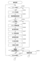
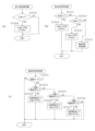
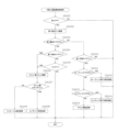
次いで、主制御装置261内のCPU501により実行される各制御処理を、フローチャートを参照しながら説明する。かかるCPU501の処理としては大別して、電源投入に伴い起動されるメイン処理と、定期的に(本実施形態では2msec周期で)起動されるタイマ割込み処理と、NMI端子(ノンマスカブル端子)への停止信号の入力により起動されるNMI割込み処理とがある。説明の便宜上、ここでは、先ずタイマ割込み処理とNMI割込み処理とを説明し、その後でメイン処理を説明する。
Next, each control process executed by the
図11は、タイマ割込み処理を示すフローチャートであり、本処理は主制御装置261のCPU501により例えば2msec毎に実行される。
FIG. 11 is a flowchart showing timer interrupt processing, and this processing is executed by the
図11において、先ずステップS301では、各種入賞スイッチの読み込み処理を実行する。すなわち、主制御装置261に接続されている各種スイッチ(但し、RAM消去スイッチ323を除く。)の状態を読み込むと共に、該スイッチの状態を判定して検知情報を保存する。尚、スイッチの検知に応じて遊技球の払出しが行われる場合には、これに対応する賞球カウンタの値を加算して、本処理を終了する。一方、検出信号の入力がなされていないと判定された場合には、そのまま本処理を終了する。なお、後述する通常処理の外部出力処理において、各賞球カウンタの値に基づく賞球コマンドが払出制御装置311へ出力される。また、この賞球コマンドの出力に際して、各賞球カウンタの値がリセットされる。
In FIG. 11, first in step S301, a process of reading various winning switches is executed. That is, it reads the states of various switches (excluding the RAM erase switch 323) connected to the
ステップS302では乱数初期値更新処理を実行する。具体的には、乱数初期値カウンタCINIを1インクリメントすると共に、そのカウンタ値が最大値(本例では399)に達した際0にクリアする。 In step S302, a random number initial value update process is executed. Specifically, the random number initial value counter CINI is incremented by 1, and when the counter value reaches the maximum value (399 in this example), it is cleared to 0.
また、ステップS303では乱数更新処理を実行する。具体的には、当否乱数カウンタC1、変動時間選択カウンタC2、入球アシスト乱数カウンタC3、及び、作動アシスト乱数カウンタC4をそれぞれ1インクリメントすると共に、それらのカウンタ値が最大値(本実施形態ではそれぞれ「399」,「9」,「9」,「19」)に達した際それぞれ0にクリアする。そして、各カウンタC1,C2,C3,C4の更新値を、RAM503の該当するバッファ領域に格納する。
Furthermore, in step S303, random number update processing is executed. Specifically, the win/fail random number counter C1, variable time selection counter C2, entry assist random number counter C3, and actuation assist random number counter C4 are each incremented by 1, and the counter values are set to the maximum value (in this embodiment, each "399", "9", "9", "19"), each is cleared to 0. Then, the updated values of each counter C1, C2, C3, and C4 are stored in the corresponding buffer area of the
その後、ステップS304において、始動入賞部33(第1始動入賞部33a又は第2始動入賞部33b)への入賞に伴う始動入賞処理を実行し、ステップS305において、スルーゲート34への遊技球の通過に伴うスルーゲート通過処理を実行し、ステップS306において、中央入賞ユニット37の内部領域401への入球に伴う入球カウント処理を実行する。
Thereafter, in step S304, a starting winning process is executed in conjunction with winning in the starting winning part 33 (first
続くステップS307においては、第1特別入球検知スイッチ461による検知(回転体414の特別ポケット部416aを介しての第1V入賞通路427への入球)、又は、第2特別入球検知スイッチ738による検知(可動役物722の第2V入賞通路730を介してのバイパス通路737への入球)に伴う特別入賞処理を実行する。
In the subsequent step S307, detection is performed by the first special ball entry detection switch 461 (ball entry into the first
さらに、ステップS308において、非特別入球検知スイッチ462による検知(回転体414の非特別ポケット部416bを介してのアウト通路428への入球)に伴う非特別入賞処理を実行し、ステップS309において、スペシャルゲート650への遊技球の通過に伴うスペシャルゲート通過処理を実行する。
Furthermore, in step S308, a non-special winning process is executed in response to detection by the non-special ball entry detection switch 462 (ball entering the
その後、ステップS310において、ラウンド入球検知スイッチ734、735、736による検知(15R入球口731、7R入球口732、3R入球口733への入球)に伴う種別入球処理を実行し、タイマ割込み処理を一旦終了する。
After that, in step S310, the type ball entry process is executed in accordance with the detection by the round ball entry detection switches 734, 735, and 736 (ball entry into the 15R
ここで、ステップS304の始動入賞処理について図13のフローチャートを参照して説明する。 Here, the starting winning process in step S304 will be explained with reference to the flowchart of FIG. 13.
尚、特別変動保留エリアの実行エリア及び各保留エリアには、当否乱数カウンタC1の値を記憶する当否乱数記憶エリア、変動時間選択カウンタC2の値を記憶する変動時間乱数記憶エリア、保留された変動表示が第1始動入賞部33a又は第2始動入賞部33bいずれの始動入賞部33への入球に基づくものであるか否かを判別するための始動入賞判別フラグが設けられている。
The execution area of the special fluctuation holding area and each holding area include a win/fail random number storage area for storing the value of the win/fail random number counter C1, a variable time random number storage area for storing the value of the variable time selection counter C2, and a suspended fluctuation. A starting winning determination flag is provided for determining whether the display is based on the ball entering the starting winning section 33, either the first
また、本実施形態における特別変動保留エリアには、上述した当否乱数カウンタC1や変動時間選択カウンタC2の値を記憶する領域とは別に、始動入賞部33への入球に基づく当否抽選において「大当たり」に当選したことを示す大当たり発生フラグ、「外れ」たことを示す外れフラグ、「ロング小当たり」に当選したことを示すロング小当たり発生フラグ、「ショート小当たり」に当選したことを示すショート小当たり発生フラグが設けられている。加えて、特別表示装置43における変動時間を示す2秒変動フラグ、3秒変動フラグ、7秒変動フラグが設けられている。
In addition, in the special fluctuation reservation area in this embodiment, apart from the area for storing the values of the above-mentioned win/fail random number counter C1 and fluctuation time selection counter C2, in the win/fail lottery based on the ball entering the starting winning section 33, "jackpot" is included. A jackpot flag indicating that you have won ``, a losing flag indicating that you have won, a long small win flag indicating that you have won a ``long small win,'' a short flag that indicates that you have won a short small win. A small hit occurrence flag is provided. In addition, a 2-second variation flag, a 3-second variation flag, and a 7-second variation flag indicating the variation time on the
先ず、ステップS501では、第1及び第2始動入賞部33a、33bへの遊技球の入球を契機とする変動表示の保留数をカウントする保留カウンタNaの値が上限値(本実施形態では「4」)未満であるか否かを判別する。該ステップS501で否定判別された場合には、そのまま本処理を終了する。
First, in step S501, the value of the holding counter Na that counts the number of holdings of the variable display triggered by the entry of game balls into the first and second
一方、ステップS501で肯定判別された場合には、ステップS502において、遊技球が第1始動入賞部33aに入賞したか否かを第1始動入賞スイッチ224aの検知情報により判別する。該ステップS502で否定判別された場合には、後述するステップS509に移行する。一方、ステップS502で肯定判別された場合、ステップS503に進み、保留カウンタNaを1インクメントする。
On the other hand, when an affirmative determination is made in step S501, it is determined in step S502 whether or not the game ball has won the first
続くステップS504では、上記ステップS303の乱数更新処理で更新した当否乱数カウンタC1及び変動時間選択カウンタC2の各値を、特別変動保留エリアの空いている保留エリアのうち最初のエリアに格納する。ここで、所定の大当たり状態中に、大当たりに対応する各種カウンタ値が特別変動保留エリアに記憶された場合に所定の条件が満たされることとしてもよい。又は、所定の大当たり状態中において、大当たりに対応する各種カウンタ値が特別変動保留エリアに記憶された場合に所定の割合、例えば60%の確率で所定の条件が満たされることとしてもよい。 In the following step S504, the respective values of the win/fail random number counter C1 and the variable time selection counter C2 updated in the random number updating process of step S303 are stored in the first area among the vacant holding areas in the special variable holding area. Here, the predetermined condition may be satisfied when various counter values corresponding to a jackpot are stored in the special fluctuation holding area during a predetermined jackpot state. Alternatively, during a predetermined jackpot state, when various counter values corresponding to a jackpot are stored in the special fluctuation holding area, the predetermined condition may be satisfied at a predetermined rate, for example, with a probability of 60%.
ステップS505では、当否乱数カウンタC1及び変動時間選択カウンタC2の各値が記憶された保留エリアの始動入賞判別フラグをオンにする。尚、本実施形態の始動入賞判別フラグは、保留された変動表示が第1始動入賞部33aへの入球に基づくものである場合にオン設定され、第2始動入賞部33bへの入球に基づくものである場合にオフ設定される。
In step S505, the starting winning determination flag of the holding area in which the values of the winning/losing random number counter C1 and the variable time selection counter C2 are stored is turned on. In addition, the starting winning prize determination flag of this embodiment is set to ON when the suspended variable display is based on the ball entering the first
続くステップS506では、新たに特別変動保留エリアに記憶された当否乱数カウンタC1の値が「小当たり」や「大当たり」に対応する値であるか否かを判別する当否判定処理を行う。尚、当否判定処理の詳細については後述する。 In the subsequent step S506, a win/fail determination process is performed to determine whether the value of the win/fail random number counter C1 newly stored in the special fluctuation holding area is a value corresponding to a "small win" or "big win". Note that details of the validity determination process will be described later.
続くステップS507では、新たに特別変動保留エリアに記憶された変動時間選択カウンタC2の値に基づいて、特別表示装置43における変動時間を判別する変動時間判定処理を行う。尚、変動時間判定処理の詳細については後述する。
In the subsequent step S507, a variation time determination process is performed to determine the variation time in the
その後、ステップS508では、先発コマンドの設定処理を行う。尚、先発コマンドには、保留記憶された変動情報(変動表示の内容を決定するために使用される所定情報)が第1始動入賞部33a又は第2始動入賞部33bのどちらへの入球に基づく変動情報であるかを示す情報、「小当たり」や「大当たり」を示す情報、変動時間を示す情報などが含まれ、次回の外部出力処理(ステップS201参照)にてサブ制御装置262に出力される。
Thereafter, in step S508, the first command setting process is performed. In addition, in the starting command, the stored fluctuation information (predetermined information used to determine the contents of the fluctuation display) is determined whether the ball enters the first
ここで、ステップS506の当否判定処理の詳細について、図14を参照して説明する。尚、本実施形態では、当否判定処理において小当たりの種別(ロング小当たり、ショート小当たり)についても決定する構成となっている。 Here, details of the validity determination process in step S506 will be explained with reference to FIG. 14. In this embodiment, the type of small win (long small win, short small win) is also determined in the success/failure determination process.
先ず、ステップS5101では、新たに特別変動保留エリアに記憶された当否乱数カウンタC1の値が「大当たり」に対応する値である「0」と一致するか否かを判別する。尚、所定の大当たり状態中において、例えば確変大当たりなど、その終了後に高確率モードや高サポートモード等の特定の遊技モードが付与され得る特定の大当たりに対応する各種カウンタ値が特別変動保留エリアに記憶された場合に所定の条件が満たされることとしてもよい。そして、ステップS5101で肯定判別された場合、すなわち、大当たり状態が発生すると判別された場合には、ステップS5102において大当たり発生フラグをオンにした後、本処理を終了する。 First, in step S5101, it is determined whether the value of the win/fail random number counter C1 newly stored in the special fluctuation holding area matches "0", which is the value corresponding to "jackpot". In addition, during a predetermined jackpot state, various counter values corresponding to specific jackpots, such as certain variable jackpots, which may be given a specific game mode such as a high probability mode or a high support mode after the end of the jackpot, are stored in the special fluctuation holding area. A predetermined condition may be satisfied if the Then, if an affirmative determination is made in step S5101, that is, if it is determined that a jackpot condition will occur, the jackpot occurrence flag is turned on in step S5102, and then the process ends.
また、ステップS5101で否定判別された場合には、ステップS5103において、新たに特別変動保留エリアに記憶された当否乱数カウンタC1の値が「外れ」に対応する値である「1」と一致するか否かを判別する。該ステップS5103で肯定判別された場合、すなわち、「外れ」であると判別された場合には、ステップS5104において外れフラグをオンにした後、本処理を終了する。 Further, if a negative determination is made in step S5101, in step S5103, the value of the win/fail random number counter C1 newly stored in the special fluctuation holding area matches "1", which is the value corresponding to "miss". Determine whether or not. If an affirmative determination is made in step S5103, that is, if it is determined that it is "missing", the missing flag is turned on in step S5104, and then this process is ended.
一方、ステップS5103で否定判別された場合、すなわち「小当たり」であると判別された場合には、ステップS5105において、新たに特別変動保留エリアに記憶された当否乱数カウンタC1の値が「ロング小当たり」に対応する値である「2~21」のいずれかと一致するか否かを判別する。ステップS5105で肯定判別された場合には、ステップS5106においてロング小当たり発生フラグをオンにした後、本処理を終了する。 On the other hand, if a negative determination is made in step S5103, that is, if it is determined that it is a "long small win", in step S5105, the value of the win/fail random number counter C1 newly stored in the special fluctuation holding area is changed to "long small win". It is determined whether or not it matches any of the values "2 to 21" corresponding to "win". If an affirmative determination is made in step S5105, the long small hit occurrence flag is turned on in step S5106, and then this process is ended.
また、ステップS5105で否定判別された場合、すなわち、「ショート小当たり」であると判別された場合には、ステップS5107において、ショート小当たり発生フラグをオンにした後、本処理を終了する。 Further, if a negative determination is made in step S5105, that is, if it is determined that it is a "short small win", the short small win occurrence flag is turned on in step S5107, and then this process is ended.
次に、ステップS507の変動時間判定処理について、図15を参照して説明する。このステップS507の変動時間判定処理等を実行する機能により本実施形態における第1変動パターン選出手段が構成される。 Next, the variation time determination process in step S507 will be described with reference to FIG. 15. The function of executing the fluctuation time determination process and the like in step S507 constitutes the first fluctuation pattern selection means in this embodiment.
先ず、ステップS5201では、時間短縮モードであるか否かを判別する。ステップS5201で肯定判別された場合には、ステップS5202において、特別表示装置43において行われる変動表示の変動時間が0.1秒であることを示す0.1秒変動フラグをオンに設定してから、本処理を終了する。つまり、時間短縮モードであれば、当否抽選の結果が大当たり、ロング小当たり、ショート小当たり、外れのいずれであっても、対応する変動表示の変動時間は一律0.1秒とされる。
First, in step S5201, it is determined whether the mode is a time reduction mode. If an affirmative determination is made in step S5201, in step S5202, a 0.1 second fluctuation flag indicating that the fluctuation time of the fluctuation display performed on the
一方、ステップS5201で否定判別された場合には、ステップS5203において、直前に行われた当否判定処理にて、ロング小当たり発生フラグが設定されたか否かを判別する。ステップS5203で肯定判別された場合、すなわち、「ロング小当たり」であると判別された場合には、ステップS5204において、新たに特別変動保留エリアに記憶された変動時間選択カウンタC2の値が「0、1」のどちらかと一致するか否かを判別する。 On the other hand, if a negative determination is made in step S5201, it is determined in step S5203 whether or not a long small hit occurrence flag was set in the right/fail determination process that was performed immediately before. If an affirmative determination is made in step S5203, that is, if it is determined that it is a "long small win," in step S5204, the value of the fluctuation time selection counter C2 newly stored in the special fluctuation holding area is set to "0. , 1''.
ステップS5204で否定判別された場合、すなわち、変動時間選択カウンタC2の値が「2~9」のいずれかである場合には、ステップS5205において、特別表示装置43にて行われる変動表示の変動時間が3秒であることを示す3秒変動フラグをオンにした後、本処理を終了する。一方、ステップS5204で肯定判別された場合には、ステップS5206において、特別表示装置43において行われる変動表示の変動時間が2秒であることを示す2秒変動フラグをオンにした後、本処理を終了する。
If a negative determination is made in step S5204, that is, if the value of the variable time selection counter C2 is one of "2 to 9", in step S5205, the variable time of the variable display performed on the
また、ステップS5203で否定判別された場合には、ステップS5207において、ショート小当たり発生フラグがオンであるか否かを判別する。ステップS5207で肯定判別された場合、すなわち、「ショート小当たり」が発生する場合には、ステップS5208において、新たに特別変動保留エリアに記憶された変動時間選択カウンタC2の値が「0、1」のどちらかと一致するか否かを判別する。 Further, if a negative determination is made in step S5203, it is determined in step S5207 whether or not the short small hit occurrence flag is on. If an affirmative determination is made in step S5207, that is, if a "short small hit" occurs, then in step S5208, the value of the variable time selection counter C2 newly stored in the special variable holding area is set to "0, 1". Determine whether it matches either of the two.
ステップS5208で肯定判別された場合には、上記ステップS5205において、特別表示装置43において行われる変動表示の変動時間が3秒であることを示す3秒変動フラグをオン設定してから、本処理を終了する。一方、ステップS5208で否定判別された場合、上記ステップS5206において、特別表示装置43において行われる変動表示の変動時間が2秒であることを示す2秒変動フラグをオン設定してから、本処理を終了する。すなわち、「ショート小当たり」が発生する場合よりも、「ロング小当たり」が発生する場合の方が、長めの変動時間(3秒)が選択される可能性が高くなっている。
If an affirmative determination is made in step S5208, in step S5205, a 3-second fluctuation flag indicating that the fluctuation time of the fluctuation display performed on the
また、ステップS5207で否定判別された場合、すなわち、「大当たり」又は「外れ」の場合には、ステップS5209において、特別表示装置43において行われる変動表示の変動時間が7秒であることを示す7秒変動フラグをオンにしてから、本処理を終了する。
In addition, if a negative determination is made in step S5207, that is, in the case of a "jackpot" or "miss", in step S5209, a 7 seconds display is displayed indicating that the variation time of the variation display performed on the
図13の説明に戻り、ステップS508の処理の後、又は、ステップS502で否定判別された場合には、ステップS509において、遊技球が第2始動入賞部33bに入賞したか否かを第2始動入賞スイッチ224bの検知情報により判別する。該ステップS509で否定判別された場合には、そのまま本処理を終了する。一方、肯定判別された場合には、ステップS510において、保留カウンタNaを1インクメントする。
Returning to the explanation of FIG. 13, after the process in step S508, or if a negative determination is made in step S502, in step S509, it is determined whether or not the game ball has won in the second starting winning section 33b. This is determined based on the detection information of the winning
続くステップS511では、当否乱数カウンタC1及び変動時間選択カウンタC2の各値を、特別変動保留エリアの空いている保留エリアのうち最初のエリアに格納する。ステップS512では、当否判定処理を行う。尚、ステップS512の当否判定処理は、上記ステップS506の当否判定処理と同様であり、詳細な説明は省略する。 In the following step S511, each value of the win/fail random number counter C1 and the variable time selection counter C2 is stored in the first area among the vacant holding areas of the special variable holding area. In step S512, a validity determination process is performed. Note that the validity determination process in step S512 is the same as the validity determination process in step S506 above, and detailed description thereof will be omitted.
続くステップS513では、変動時間判定処理を行う。尚、ステップS513の当否判定処理は、上記ステップS507の変動時間判定処理と同様であり、詳細な説明は省略する。ステップS513の後、ステップS514において、先発コマンドの設定処理を行い、本処理を終了する。 In the following step S513, a fluctuation time determination process is performed. Note that the validity determination process in step S513 is the same as the variation time determination process in step S507, and detailed description thereof will be omitted. After step S513, in step S514, a first command setting process is performed, and this process ends.
次に、ステップS305のスルーゲート通過処理について図16のフローチャートを参照して説明する。 Next, the through gate passing process in step S305 will be explained with reference to the flowchart of FIG. 16.
ステップS601では、遊技球がスルーゲート34を通過したか否かをスルーゲートスイッチ225の検知情報により判別する。
In step S601, it is determined whether the game ball has passed through the through
ステップS601で否定判別された場合、そのまま本処理を終了する。一方、ステップS601にて肯定判別された場合、すなわち、遊技球がスルーゲート34を通過したと判別されると、ステップS602において、スルーゲート用表示装置41にて行われる変動表示の保留数をカウントする普通保留カウンタNcの値が上限値(本実施形態では4)未満であるか否かを判別する。ここで否定判別された場合には、そのまま本処理を終了する。一方、ステップS602で肯定判別された場合、すなわち、スルーゲート34への遊技球の通過が確認され、且つ、普通保留カウンタNcの値が4未満であることを条件にステップS603に進み、普通保留カウンタNcを1インクリメントする。
If a negative determination is made in step S601, the process is immediately terminated. On the other hand, if an affirmative determination is made in step S601, that is, if it is determined that the game ball has passed through the through
また、続くステップS604では、当否に関わる乱数を取得する。具体的には、上記ステップS303の乱数更新処理で更新した入球アシスト乱数カウンタC3の値を、RAM503の普通変動保留エリアの空き記憶エリアのうち最初のエリアに格納する。その後、スルーゲート通過処理を終了する。
Further, in the subsequent step S604, a random number related to validity is acquired. Specifically, the value of the input assist random number counter C3 updated in the random number update process of step S303 is stored in the first area of the free storage areas in the normal fluctuation holding area of the
次に、ステップS306の入球カウント処理について、図17を参照して説明する。先ず、ステップS7201では、導入通路601の入口部601bに設けられた内部入球検知スイッチ437の検知があるか否かを判別することにより、遊技球が中央入賞ユニット37の内部領域401に入球したか否かを判別する。該ステップS7201で否定判別された場合には、そのまま本処理を終了する。
Next, the ball entry counting process in step S306 will be explained with reference to FIG. 17. First, in step S7201, a game ball enters the
一方、ステップS7201で肯定判別された場合、ステップS7202において、サブ制御装置262に対して、遊技球が中央入賞ユニット37の内部領域401に入球したことを伝える入球コマンドを設定する。尚、サブ制御装置262側において、入球コマンドを受信した場合には、入球効果音を出力するとともに、図示しない入球ランプを点灯・点滅させ、遊技者に対し入球があった旨を報知するように構成されている。
On the other hand, if an affirmative determination is made in step S7201, a ball entry command is set for the
その後、ステップS7203において、内部領域401における遊技球の数を把握するための残存球監視カウンタの値を1加算する。続くステップS7204では、残存球監視処理で参酌される監視タイマの設定処理を行う。本実施形態では、内部入球検知スイッチ437の検知がある毎に監視タイマに「10000」がセットされる。また、既に監視タイマに所定の数値が設定されている場合であっても、「10000」が上書きされる。尚、監視タイマは、4mec毎に行われる通常処理(後述するステップS212の残存球監視処理)で1ずつ減算される。該ステップS7204の後、本処理を終了する。
Thereafter, in step S7203, the value of the remaining ball monitoring counter for grasping the number of game balls in the
次に、ステップS307の特別入賞処理について、図18を参照して説明する。先ず、ステップS7301では、第1特別入球検知スイッチ461又は第2特別入球検知スイッチ738による遊技球の検知情報があるか否かを判別する。ステップS7301で否定判別された場合には、そのまま本処理を終了する。
Next, the special winning process in step S307 will be explained with reference to FIG. First, in step S7301, it is determined whether there is detection information of a game ball by the first special ball
一方、ステップS7301で肯定判別された場合には、ステップS7302において、後述する大当たり中フラグを参酌し、大当たり状態中であるか否かを判別する。該ステップS7302で肯定判別された場合には、そのまま本処理を終了する。すなわち、大当たり状態中においては、回転体414の特別ポケット部416aを介して遊技球が第1V入賞通路427に入球し、該遊技球が第1特別入球検知スイッチ461に検知された場合や、可動役物722(第2V入賞通路730)を介して遊技球がバイパス通路737に入球し、該遊技球が第2特別入球検知スイッチ738に検知された場合であっても、その分の大当たり状態を発生させる権利は付与されないようになっている。
On the other hand, if an affirmative determination is made in step S7301, it is determined in step S7302 whether or not a jackpot state is in progress, with reference to a jackpot flag to be described later. If an affirmative determination is made in step S7302, the process is immediately terminated. That is, during the jackpot state, if a game ball enters the first
一方、ステップS7302で否定判別された場合には、ステップS7303において、第1特別入球検知スイッチ461又は第2特別入球検知スイッチ738の入球検知が行われたことを示す特別入賞フラグが既にオンされているか否かを判別する。ステップS7303で肯定判別された場合には、そのまま本処理を終了する。すなわち、既に大当たり状態を発生させることが決定されている(大当たり状態を発生させる権利が付与されている)状態においては、重ねて第1特別入球検知スイッチ461又は第2特別入球検知スイッチ738の入球検知が行われたとしても、その分の大当たりは無効とされる。
On the other hand, if a negative determination is made in step S7302, in step S7303, the special winning flag indicating that the first special ball entering
一方、ステップS7303で否定判別された場合には、ステップS7304で特別入賞フラグをオンにしてから、本処理を終了する。 On the other hand, if the determination in step S7303 is negative, the special winning flag is turned on in step S7304, and then the process ends.
尚、本実施形態では、第1特別入球検知スイッチ461の入球検知が行われた段階では、大当たり状態を発生される権利が付与されるだけで、どの種別の大当たり状態が付与されるかまでは決定されていないため、種別が決定されるまでは大当たり状態は開始されないように構成されている。
In this embodiment, at the stage when the first special ball
同様に、第2特別入球検知スイッチ738の入球検知が行われた段階では、大当たり状態を発生される権利が付与されるだけで、未だ遊技球が15R入球口731に入球していない状態であるため、遊技球が15R入球口731に入球し「15ラウンド大当たり」が確定するまでは大当たり状態は開始されないように構成されている。
Similarly, at the stage when the second special ball
次に、ステップS308の非特別入賞処理について図19を参照して説明する。先ず、ステップS7401では、非特別入球検知スイッチ462による遊技球の検知情報があるか否かを判別する。すなわちアウト通路428を介して、遊技球が中央入賞ユニット37(内部領域401)外に排出されるか否かを判別する。ステップS7401で否定判別された場合には、そのまま本処理を終了する。一方、ステップS7401で肯定判別された場合には、ステップS7402において残存球監視カウンタの値を1減算してから、本処理を終了する。
Next, the non-special winning process in step S308 will be explained with reference to FIG. 19. First, in step S7401, it is determined whether or not there is detection information of a game ball by the non-special ball
次に、ステップS309のスペシャルゲート通過処理について図20のフローチャートを参照して説明する。 Next, the special gate passing process in step S309 will be explained with reference to the flowchart of FIG. 20.
ステップS7501では、遊技球がスペシャルゲート650を通過したか否かをスペシャルゲートスイッチ651の検知情報により判別する。ステップS7501で否定判別された場合には、そのまま本処理を終了する。
In step S7501, it is determined whether the game ball has passed through the
一方、ステップS7501にて肯定判別された場合、すなわち遊技球がスペシャルゲート650を通過したと判別されると、ステップS7502において、後述する第3表示中フラグがオンであるか否か、すなわちスペシャルゲート用表示装置44にて変動表示中であるか否かを判別する。該ステップS7502で肯定判別された場合には、そのまま本処理を終了する。
On the other hand, if an affirmative determination is made in step S7501, that is, if it is determined that the game ball has passed through the
一方、ステップS7502にて否定判別された場合には、ステップS7503において、後述する役物作動中フラグがオンであるか否か、すなわち可動役物722が作動中(突出状態)であるか否かを判別する。該ステップS7503で肯定判別された場合には、そのまま本処理を終了する。
On the other hand, if a negative determination is made in step S7502, it is determined in step S7503 whether or not the accessory in operation flag, which will be described later, is on, that is, whether the
これにより、スペシャルゲート用表示装置44の変動表示中や可動役物722の作動中において、遊技球がスペシャルゲート650を通過し、該遊技球がスペシャルゲートスイッチ651に検知されたとしても、その分の作動アシスト抽選は無効となり、可動役物722を作動させる権利が新たに付与されないように構成されている。
As a result, even if a game ball passes through the
一方、ステップS7503で否定判別された場合には、ステップS7504において、上記ステップS303の乱数更新処理で更新した作動アシスト乱数カウンタC4の値を、RAM503に設定された所定の作動アシスト乱数格納エリアに格納する。
On the other hand, if a negative determination is made in step S7503, in step S7504, the value of the operation assist random number counter C4 updated in the random number update process of step S303 is stored in a predetermined operation assist random number storage area set in the
続くステップS7505において、スペシャルゲート通過フラグをオンし、ステップS7506において、残存球監視カウンタの値を1減算した後、本処理を終了する。 In the following step S7505, the special gate passage flag is turned on, and in step S7506, the value of the remaining ball monitoring counter is subtracted by 1, and then this process is ended.
次に、ステップS310の種別入球処理について図21を参照して説明する。先ず、ステップS7601では、特別入賞フラグがオン設定されているか否かを判別する。ステップS7601で否定判別された場合には、そのまま本処理を終了する。 Next, the type entry process of step S310 will be described with reference to FIG. 21. First, in step S7601, it is determined whether the special winning flag is set to on. If a negative determination is made in step S7601, the process ends immediately.
一方、ステップS7601で肯定判別された場合には、ステップS7602において、15R入球検知スイッチ734の入球検知が行われたか否かを判別する。ステップS7602で肯定判別された場合には、ステップS7603において、15ラウンド大当たりであることを示す15R大当たりフラグをオン設定する。その後、ステップS7604において、残存球監視カウンタの値を1減算してから、本処理を終了する。
On the other hand, if an affirmative determination is made in step S7601, it is determined in step S7602 whether or not the 15R ball
また、ステップS7602で否定判別された場合には、ステップS7605において、7R入球検知スイッチ735の入球検知が行われたか否かを判別する。ステップS7605で肯定判別された場合には、ステップS7606において、7ラウンド大当たりであることを示す7R大当たりフラグをオン設定する。その後、ステップS7604において、残存球監視カウンタの値を1減算してから、本処理を終了する。
Further, if a negative determination is made in step S7602, it is determined in step S7605 whether or not the 7R ball
また、ステップS7605で否定判別された場合には、ステップS7608において、3R入球検知スイッチ736の入球検知が行われたか否かを判別する。ステップS7608で否定判別された場合には、そのまま本処理を終了する。一方、ステップS7608で肯定判別された場合には、ステップS7609において、3ラウンド大当たりであることを示す3R大当たりフラグをオン設定する。その後、ステップS7604において、残存球監視カウンタの値を1減算してから、本処理を終了する。
If the determination in step S7605 is negative, it is determined in step S7608 whether or not the 3R ball
次にNMI割込み処理について説明する。図12は、NMI割込み処理を示すフローチャートであり、本処理は、主制御装置261のCPU501により停電の発生等によるパチンコ機10の電源断時に実行される。このNMI割込みにより、電源断時の主制御装置261の状態がRAM503のバックアップエリア503aに記憶される。
Next, NMI interrupt processing will be explained. FIG. 12 is a flowchart showing NMI interrupt processing, and this processing is executed by the
すなわち、停電の発生等によりパチンコ機10の電源が遮断されると、停電信号SK1が停電監視回路542から主制御装置261内のCPU501のNMI端子に出力される。すると、CPU501は実行中の制御を中断してNMI割込み処理を開始し、ステップS401において、電源断の発生情報の設定として電源断の発生情報をRAM503のバックアップエリア503aに記憶してNMI割込み処理を終了する。
That is, when the power to the
なお、上記のNMI割込み処理は払出制御装置311でも同様に実行され、かかるNMI割込みにより、電源断の発生情報がRAM513のバックアップエリア513aに記憶される。すなわち、停電の発生等によりパチンコ機10の電源が遮断されると、停電信号SK1が停電監視回路542から払出制御装置311内のCPU511のNMI端子に出力され、CPU511は実行中の制御を中断して図12のNMI割込み処理を開始する。その内容は上記説明の通りである。
Note that the above NMI interrupt processing is similarly executed by the
次に、主制御装置261内のCPU501により実行されるメイン処理の流れを図9のフローチャートを参照しながら説明する。このメイン処理は電源投入時のリセットに伴い起動される。
Next, the flow of the main processing executed by the
先ず、ステップS101では、電源投入に伴う初期設定処理を実行する。具体的には、スタックポインタに予め決められた所定値を設定すると共に、サブ側の制御装置(サブ制御装置262,払出制御装置311等)が動作可能な状態になるのを待つために例えば1秒程度、ウェイト処理を実行する。続くステップS102では、RAMアクセスを許可する。 First, in step S101, an initial setting process is executed when the power is turned on. Specifically, in addition to setting a predetermined value in the stack pointer, for example, 1. Execute wait processing for about seconds. In the following step S102, RAM access is permitted.
その後、CPU501内のRAM503に関してデータバックアップの処理を実行する。つまり、ステップS103では、電源装置313に設けたRAM消去スイッチ323が押下(ON)されているか否かを判別し、押下されていれば、バックアップデータをクリア(消去)するべく、ステップS111へ移行する。一方、RAM消去スイッチ323が押下されていなければ、続くステップS104で、RAM503のバックアップエリア503aに電源断の発生情報が設定されているか否かを判別する。ここで、設定されていなければ、バックアップデータは記憶されていないので、この場合もステップS111へ移行する。バックアップエリア503aに電源断の発生情報が設定されていれば、ステップS105でRAM判定値を算出し、続くステップS106では、そのRAM判定値が電源断時に保存したRAM判定値と一致するか否か、すなわちバックアップの有効性を判別する。ここで算出したRAM判定値が電源断時に保存したRAM判定値と一致しなければ、バックアップされたデータは破壊されているので、この場合もステップS111へ移行する。
Thereafter, data backup processing is executed regarding the
ステップS111の処理では、サブ側の制御装置となるサブ制御装置262及び払出制御装置311等を初期化するために、初期化コマンドを送信する。その後、RAMの初期化処理(ステップS112等)に移行する。なお、RAM判定値は、例えばRAM503の作業領域アドレスにおけるチェックサム値である。このRAM判定値に代えて、RAM503の所定のエリアに書き込まれたキーワードが正しく保存されているか否かによりバックアップの有効性を判断することも可能である。
In the process of step S111, an initialization command is transmitted in order to initialize the
上述したように、本パチンコ機10では、例えばホールの営業開始時など、電源投入時に初期状態に戻したい場合にはRAM消去スイッチ323を押しながら電源が投入される。従って、RAM消去スイッチ323がONされていれば、RAMの初期化処理(ステップS112等)に移行する。また、電源断の発生情報が設定されていない場合や、RAM判定値(チェックサム値等)によりバックアップの異常が確認された場合も同様にRAM503の初期化処理(ステップS112等)に移行する。つまり、ステップS112ではRAM503の使用領域を0にクリアし、続くステップS113ではRAM503の初期値を設定する。その後、ステップS114で割込み許可を設定し、後述する通常処理に移行する。
As described above, in this
一方、RAM消去スイッチ323が押されていない場合(ステップS103:NO)には、電源断の発生情報が設定されていること、及びRAM判定値(チェックサム値等)が正常であることを条件に、復電時の処理(電源断復旧時の処理)を実行する。つまり、ステップS107では、電源断前のスタックポインタを復帰させ、ステップS108では、電源断の発生情報をクリアする。ステップS109では、サブ側の制御装置を電源断時の遊技状態に復帰させるコマンドを送信し、ステップS110では、使用レジスタをRAM503のバックアップエリア503aから復帰させる。その後、ステップS114で割込み許可を設定し、後述する通常処理に移行する。
On the other hand, if the RAM erase
次に、通常処理の流れを図10のフローチャートを参照しながら説明する。この通常処理では遊技の主要な処理が実行される。その概要として、ステップS201~S212の処理が4msec周期の定期処理として実行され、その残余時間でステップS215の初期値乱数カウンタ更新処理が実行される構成となっている。 Next, the flow of normal processing will be explained with reference to the flowchart of FIG. In this normal processing, the main processing of the game is executed. As an overview, the process of steps S201 to S212 is executed as a regular process with a period of 4 msec, and the initial value random number counter update process of step S215 is executed in the remaining time.
先ずステップS201では、前回の処理で更新された特別表示装置43や第2始動入賞部33b等の設定内容に基づいた制御信号を各装置に送信したり、コマンド等の出力データをサブ側の各制御装置に送信したりする外部出力処理を実行する。
First, in step S201, a control signal based on the settings of the
例えば演出表示装置42において変動表示を開始する際には、サブ制御装置262に対し変動パターンコマンドが送信される。つまり、変動パターンコマンドは、特別表示装置43にて行われる表示に合わせた表示演出を演出表示装置42にて行わせるためにサブ制御装置262に出力される指令信号である。これに対し、変動パターンコマンドを入力したサブ制御装置262は、かかるコマンドに基づいて、演出表示装置42の表示態様を決定し、該表示態様を演出表示装置42において表示するように表示制御装置45に対し指示を出す。
For example, when starting a variable display on the
一方、演出表示装置42における変動表示を停止する際には、サブ制御装置262に対し確定コマンドが送信される。これに対し、確定コマンドを入力したサブ制御装置262は、かかるコマンドに基づいて、演出表示装置42にて行われている変動表示(表示演出)を終了すべく、表示制御装置45に対し指示を出す。
On the other hand, when stopping the variable display on the
但し、本実施形態では、後述するように、大当たり状態中である場合や、大当たり状態の権利が付与されているが未だ大当たり状態が開始されていない状態である場合、中央入賞ユニット37が開放中(小当たり状態中)である場合には、特別表示装置43における変動時間を計測する第1表示タイマの減算処理が行われない構成となっているため(図23参照)、仮に特別表示装置43(演出表示装置42)の変動表示中に第1特別入球検知スイッチ461又は第2特別入球検知スイッチ738の入球検知が行われ、特別入賞フラグがオンされた場合には、該特別入賞フラグに係るV入賞大当たりが終了するまでは、サブ制御装置262に対し確定コマンドが送信されず、大当たり終了後に送信されることとなる。
However, in this embodiment, as will be described later, if the jackpot is in progress, or if the right to jackpot has been granted but the jackpot has not yet started, the central winning
ステップS202では、払出制御装置311より受信した賞球計数信号を読み込む。次に、ステップS203では、払出制御装置311より受信した払出異常信号を読み込む。
In step S202, the prize ball count signal received from the
続くステップS204では、V入賞大当たり設定処理を実行する。この処理では、中央入賞ユニット37の内部領域401に入球した遊技球が、回転体414の特別ポケット部416aを介して遊技球が第1V入賞通路427に入球し、該遊技球が第1特別入球検知スイッチ461に検知されることや、可動役物722(第2V入賞通路730)を介して遊技球がバイパス通路737に入球し、該遊技球が第2特別入球検知スイッチ738に検知されることに基づき発生する大当たりの設定などが行われる。このV入賞大当たり設定処理の詳細は後述する。
In the subsequent step S204, a V winning jackpot setting process is executed. In this process, the game ball that entered the
ステップS205では、第1表示制御処理を実行する。この処理では、特別表示装置43においてどのような表示を行うか、該特別表示装置43の制御内容の設定が行われると共に、当たり判定や演出表示装置42における演出パターンの設定などが行われる。この第1表示制御処理の詳細は後述する。尚、第1表示制御処理を実行する主制御装置261の機能により本実施形態における第1表示制御手段が構成される。
In step S205, a first display control process is executed. In this process, what kind of display is to be performed on the
ステップS206では、可変入賞装置制御処理を実行する。この処理では、可変入賞装置32においてどのような制御を行うか、該可変入賞装置32の制御内容の設定が行われる。これにより、大当たり状態(特別遊技状態)となった場合には、可変入賞装置32(大入賞口開閉部材32a)の開閉処理が所定回数繰り返し実行される。可変入賞装置制御処理の詳細は後述する。
In step S206, variable prize winning device control processing is executed. In this process, what kind of control is to be performed in the variable winning
ステップS207では、羽根部材開閉処理を実行する。この処理では、中央入賞ユニット37の羽根部材404(羽根用ソレノイド405)の制御内容の設定が行われる。羽根部材開閉処理の詳細については後述する。
In step S207, a blade member opening/closing process is executed. In this process, the control details of the blade member 404 (blade solenoid 405) of the central winning
ステップS208では、第2表示制御処理を実行する。この処理では、スルーゲート用表示装置41おいてどのような表示を行うか、該スルーゲート用表示装置41の制御内容の設定などが行われる。この第2表示制御処理の詳細は後述する。
In step S208, a second display control process is executed. In this process, what kind of display is to be performed on the
ステップS209では、始動入賞部制御処理を実行する。この処理では、第2始動入賞部33bの始動口開閉部材33cの制御内容の設定が行われる。始動入賞部制御処理の詳細は後述する。
In step S209, a starting prize winning section control process is executed. In this process, the control details of the starting port opening/closing
ステップS210では、第3表示制御処理を実行する。この処理では、スペシャルゲート用表示装置44おいてどのような表示を行うか、該スペシャルゲート用表示装置44の制御内容の設定などが行われる。この第3表示制御処理の詳細は後述する。尚、第3表示制御処理を実行する主制御装置261の機能により本実施形態における表示制御手段が構成される。
In step S210, a third display control process is executed. In this process, what kind of display is to be performed on the special
ステップS211では、中央入賞ユニット37に係る役物駆動制御処理を実行する。この処理では、回転体ユニット410に係る駆動制御処理や、バイパス機構部721に係る駆動制御処理、種別振分け機構部741に係る駆動制御処理などが行われる。
In step S211, accessory drive control processing related to the central winning
例えば回転体ユニット410に係る駆動制御処理においては、回転体414を反時計回り方向に一定速度で回転させる等の制御が行われ、種別振分け機構部741に係る駆動制御処理においては、第1渡し板744及び第2渡し板745を所定のリズムで揺動させる等の制御が行われる。
For example, in the drive control process related to the
また、バイパス機構部721に係る駆動制御処理においては、所定条件の成立時において可動役物722を突出させる等の制御が行われる。尚、バイパス機構部721に係る駆動制御処理(以下、「バイパス機構制御処理」という。)の詳細については後述する。
Further, in the drive control process related to the
ステップS212では、残存球監視処理を実行する。この処理では、遊技球が中央入賞ユニット37の内部領域401に存在しているか否かを確認する処理が行われる。残存球監視処理の詳細は後述する。
In step S212, remaining ball monitoring processing is executed. In this process, a process is performed to confirm whether or not a game ball exists in the
その後は、ステップS213において、RAM503のバックアップエリア503aに電源断の発生情報が設定されているか否かを判別する。ここでバックアップエリア503aに電源断の発生情報が設定されていなければ、ステップS214で、次の通常処理の実行タイミングに至ったか否か、すなわち前回の通常処理の開始から所定時間(本実施の形態では4msec)が経過したか否かを判別する。そして、既に所定時間が経過していれば、ステップS214で肯定判別されてステップS201へ移行し、上記ステップS201以降の処理を繰り返し実行する。
Thereafter, in step S213, it is determined whether power-off occurrence information is set in the
一方、ステップS214で否定判別された場合、ステップS215に進み、乱数初期値カウンタCINIの更新を実行する。具体的には、乱数初期値カウンタCINIを1インクリメントすると共に、そのカウンタ値が最大値(本例では399)に達した際0にクリアする。そして、この処理の後、ステップS213に移行する。つまり、ステップS214の判別の時点で、前回の通常処理の開始から未だに所定時間が経過していなければ、次の通常処理の実行タイミングに至るまでの残余時間内において、乱数初期値カウンタCINIの更新を繰り返し実行されることとなる。 On the other hand, if a negative determination is made in step S214, the process proceeds to step S215, where the random number initial value counter CINI is updated. Specifically, the random number initial value counter CINI is incremented by 1, and when the counter value reaches the maximum value (399 in this example), it is cleared to 0. After this process, the process moves to step S213. In other words, at the time of determination in step S214, if the predetermined time has not yet passed since the start of the previous normal process, the random number initial value counter CINI is updated within the remaining time until the execution timing of the next normal process. will be executed repeatedly.
ここで、ステップS201~S212の各処理の実行時間は遊技の状態に応じて変化するため、次の通常処理の実行タイミングに至るまでの残余時間は一定ではなく変動する。故に、かかる残余時間を使用して乱数初期値カウンタCINIの更新を繰り返し実行することにより、乱数初期値カウンタCINI(すなわち当否乱数カウンタC1の初期値)をランダムに更新することができる。 Here, since the execution time of each process in steps S201 to S212 changes depending on the state of the game, the remaining time until the execution timing of the next normal process is not constant but fluctuates. Therefore, by repeatedly updating the random number initial value counter CINI using this remaining time, it is possible to randomly update the random number initial value counter CINI (that is, the initial value of the random number counter C1).
さて、RAM503のバックアップエリア503aに電源断の発生情報が設定されていれば(ステップS213:YES)、電源が遮断されたことになるので、電源断時の停電処理としてステップS216以降の処理が行われる。停電処理は、まずステップS216において各割込み処理の発生を禁止し、ステップS217において、CPU501が使用している各レジスタの内容をスタックエリアに退避し、ステップS218において、スタックポインタの値をバックアップエリア503aに記憶する。その後、ステップS219において、電源が遮断されたことを示す電源断通知コマンドを他の制御装置(払出制御装置311等)に対して送信する。そして、ステップS220でRAM判定値を算出し、バックアップエリア503aに保存する。RAM判定値は、例えば、RAM503の作業領域アドレスにおけるチェックサム値である。その後、ステップS221でRAMアクセスを禁止して、電源が完全に遮断して処理が実行できなくなるまで無限ループを継続する。
Now, if the power-off occurrence information is set in the
なお、ステップS213の処理は、ステップS201~S212で行われる遊技の状態変化に対応した一連の処理の終了時、又は、残余時間内に行われるステップS215の処理の1サイクルの終了時となるタイミングで実行されている。よって、主制御装置261の通常処理において、各処理の終了時に電源断の発生情報を確認しているので、各処理が途中の場合と比較してRAM503のバックアップエリア503aに記憶するデータ量が少なくなり、容易に記憶することができる。また、電源遮断前の状態に復帰する場合には、バックアップエリア503aに記憶されているデータ量が少ないので、容易に復帰させることができ、主制御装置261の処理の負担を軽減することができる。さらに、データの記憶前に割込み処理の発生を禁止(ステップS216)するので、電源が遮断されたときのデータが変更されることを防止でき、電源遮断前の状態を確実に記憶することができる。
Note that the process in step S213 is performed at a timing that is the end of a series of processes corresponding to changes in the state of the game performed in steps S201 to S212, or the end of one cycle of the process in step S215 that is performed within the remaining time. is being executed. Therefore, in the normal processing of the
次に、ステップS204のV入賞大当たり設定処理について、図22を参照して説明する。 Next, the V winning jackpot setting process in step S204 will be explained with reference to FIG. 22.
先ず、ステップS1501では、第1特別入球検知スイッチ461又は第2特別入球検知スイッチ738によって遊技球が検知されたことを示す特別入賞フラグ(図18の特別入賞処理参照)がオンであるか否かを判別する。該ステップS1501で否定判別された場合には、そのまま本処理を終了する。
First, in step S1501, it is determined whether the special winning flag (see special winning processing in FIG. 18) indicating that a game ball has been detected by the first special ball entering
一方、ステップS1501で肯定判別された場合には、ステップS1503に進み、15R入球検知スイッチ734によって遊技球が検知されたことを示す15R大当たりフラグがオン設定されているか否かを判別する。
On the other hand, if an affirmative determination is made in step S1501, the process proceeds to step S1503, and it is determined whether or not a 15R jackpot flag indicating that a game ball has been detected by the 15R ball
ステップS1503で肯定判別された場合には、ステップS1504において、大当たり状態における残りラウンド数を把握するためのラウンド数カウンタに「15」を設定した後、ステップS1505へ移行する。 If an affirmative determination is made in step S1503, in step S1504, a round number counter for grasping the remaining number of rounds in the jackpot state is set to "15", and then the process moves to step S1505.
ステップS1505では、特別入賞フラグをオフすると共に、大当たり状態中であることを示す大当たり中フラグをオン設定する。その後、続くステップS1506において、可変入賞装置32の開閉制御中であることを示す第1可変フラグをオン設定し、ステップS1507において、可変入賞装置32の開閉制御に使用される第1可変タイマに「7500」を設定し、ステップS1508において、入賞カウンタに「8」を設定してから、本処理を終了する。
In step S1505, the special winning flag is turned off, and the jackpot flag indicating that the jackpot is in progress is set on. Thereafter, in the subsequent step S1506, the first variable flag indicating that the opening/closing control of the variable
また、ステップS1503で否定判別された場合には、ステップS1509において、7R入球検知スイッチ735によって遊技球が検知されたことを示す7R大当たりフラグがオン設定されているか否かを判別する。ステップS1509で肯定判別された場合には、ステップS1510において、ラウンド数カウンタに「7」を設定した後、ステップS1505へ移行し、上記同様の処理を行う。
Further, when a negative determination is made in step S1503, it is determined in step S1509 whether or not a 7R jackpot flag indicating that a game ball has been detected by the 7R ball
また、ステップS1509で否定判別された場合には、ステップS1513において、3R入球検知スイッチ736によって遊技球が検知されたことを示す3R大当たりフラグがオン設定されているか否かを判別する。ステップS1513で否定判別された場合には、そのまま本処理を終了する。
Further, when a negative determination is made in step S1509, it is determined in step S1513 whether or not a 3R jackpot flag indicating that a game ball has been detected by the 3R ball
一方、ステップS1513で肯定判別された場合には、ステップS1514において、ラウンド数カウンタに「3」を設定した後、ステップS1505へ移行し、上記同様の処理を行う。 On the other hand, if an affirmative determination is made in step S1513, the round number counter is set to "3" in step S1514, and then the process proceeds to step S1505, where the same processing as described above is performed.
次に、ステップS205の第1表示制御処理について図23のフローチャートを参照して説明する。 Next, the first display control process in step S205 will be explained with reference to the flowchart of FIG. 23.
先ず、ステップS801では、大当たり中フラグを参照し、大当たり状態中であるか否かを判別する。ステップS801で肯定判別された場合、すなわち大当たり状態中である場合には、そのまま本処理を終了する。つまり、大当たり状態中においては、新たに変動表示を開始させることもなく、既に開始されている変動表示を終了させることもない。 First, in step S801, a jackpot flag is referred to to determine whether or not a jackpot is in progress. If an affirmative determination is made in step S801, that is, if the jackpot is in progress, the process ends immediately. That is, during the jackpot state, a new variable display is not started, and a variable display that has already been started is not ended.
尚、大当たり状態中には、大当たり状態(特別遊技状態)の最中、並びに、大当たり状態開始前のオープニング期間、及び、大当たり状態終了後のエンディング期間が含まれる。一般に、オープニング期間(例えば特別表示装置43にて変動表示が大当たりに対応する態様にて停止表示されてから、可変入賞装置32にて最初の開放が開始されるまでの間の期間)には、演出表示装置42にて大当たり状態の開始を知らせる表示が行われる。一方、エンディング期間(可変入賞装置32にて最終ラウンドの開放が終了した後の所定期間)には、演出表示装置42にて大当たり状態の終了や大当たり後に付与されるモードを知らせる表示が行われる。
Incidentally, the jackpot state includes the middle of the jackpot state (special game state), the opening period before the start of the jackpot state, and the ending period after the end of the jackpot state. Generally, during the opening period (for example, the period from when the variable display is stopped and displayed in a manner corresponding to a jackpot on the
ステップS801で否定判別された場合には、ステップS802において、特別入賞フラグがオンであるか否かを判別する。尚、特別入賞フラグは、第1特別入球検知スイッチ461又は第2特別入球検知スイッチ738によって遊技球が検知された際にオン設定され(特別入賞処理のステップS7304参照)、大当たり中フラグがオンされる際にオフされる(V入賞大当たり設定処理のステップS1505参照)。該ステップS802で肯定判別された場合には、そのまま本処理を終了する。つまり、大当たり状態を発生させる権利が付与されているが未だ大当たり状態が開始されていない状態においては、新たに変動表示を開始させることもなく、既に開始されている変動表示を終了させることもない。
If a negative determination is made in step S801, it is determined in step S802 whether or not the special winning flag is on. The special winning flag is set to ON when a game ball is detected by the first special ball entering
一方、ステップS802で否定判別された場合には、ステップS803において、小当たり開放中フラグがオン設定されているか否かを判別する。尚、詳しくは後述するが、小当たり開放中フラグは、中央入賞ユニット37の羽根部材404が開放されている状態、すなわち小当たり状態中にオンとなる。
On the other hand, if a negative determination is made in step S802, it is determined in step S803 whether or not the small win opening flag is set on. As will be described in detail later, the small win open flag is turned on when the
ステップS803で肯定判別された場合には、そのまま本処理を終了する。つまり、中央入賞ユニット37の開放中(小当たり状態中)においては、新たに変動表示を開始させることもなく、既に開始されている変動表示を終了させることもない。
If an affirmative determination is made in step S803, the process ends immediately. That is, while the central winning
一方、ステップS803で否定判別された場合には、ステップS804において、第1表示中フラグの設定状況を見て、特別表示装置43にて変動表示中であるか否かを判別する。第1表示中フラグがオン設定されている場合には変動表示中とみなされ、第1表示中フラグがオフされている場合には、変動表示が行われていない状態にあるとみなされる。尚、詳しくは後述するが、第1表示中フラグは、特別表示装置43の変動表示を開始する際(ステップS808参照)にオンにされ、特別表示装置43の変動表示が停止表示される際(ステップS812参照)にオフにされる。
On the other hand, if a negative determination is made in step S803, then in step S804, the setting status of the first display flag is checked to determine whether or not the
そして、ステップS804で否定判別された場合、すなわち、大当たり状態中でもなく、大当たり状態の権利が付与されているが未だ大当たり状態が開始されていない状態でもなく、中央入賞ユニット37の開放中(小当たり状態中)でもなく、特別表示装置43の変動表示中でもない場合には、ステップS805に進み、始動入賞部33への入球を契機とする変動表示の保留数をカウントする保留カウンタNaの値が0よりも大きいか否かを判別する。ステップS805で否定判定された場合、すなわち、変動表示が1つも保留記憶されていない場合には、そのまま本処理を終了する。
If a negative determination is made in step S804, that is, the jackpot state is not in progress, the right to the jackpot state has been granted but the jackpot state has not yet started, and the central winning
一方、ステップS805で肯定判別された場合、すなわち、変動表示が1つでも保留記憶されている場合には、ステップS806において、保留カウンタNaの値から1を減算する。 On the other hand, if an affirmative determination is made in step S805, that is, if at least one variable display is stored on hold, 1 is subtracted from the value of the hold counter Na in step S806.
続くステップS807では、特別変動保留エリアに格納されたデータをシフトさせる処理を実行する。このシフト処理は、特別変動保留エリアの保留第1~第4エリアに格納されているデータを実行エリア側に順にシフトさせる処理であって、保留第1エリア→実行エリア、保留第2エリア→保留第1エリア、保留第3エリア→保留第2エリア、保留第4エリア→保留第3エリアといった具合に各エリア内のデータがシフトされる。尚、該シフト処理においては、当否乱数カウンタC1や変動時間選択カウンタC2の値だけでなく、大当たり発生フラグ、外れフラグ、ロング小当たり発生フラグ、ショート小当たり発生フラグ、2秒変動フラグ、3秒変動フラグ、7秒変動フラグのオン・オフの設定状態についてもシフトされる。 In the following step S807, processing for shifting the data stored in the special fluctuation holding area is executed. This shift process is a process that sequentially shifts the data stored in the first to fourth pending areas of the special fluctuation holding area to the execution area side, from the first pending area to the execution area, and from the second pending area to the pending area. The data in each area is shifted in the following order: first area, third reserved area → second reserved area, fourth reserved area → third reserved area. In addition, in this shift process, not only the values of the win/fail random number counter C1 and the fluctuation time selection counter C2, but also the values of the jackpot occurrence flag, the miss flag, the long small win occurrence flag, the short small win occurrence flag, the 2 second fluctuation flag, and the 3 second The on/off settings of the fluctuation flag and the 7-second fluctuation flag are also shifted.
続くステップS808では変動表示設定処理が行われる。ここで、変動表示設定処理の詳細について、図24を参照して説明する。 In the following step S808, variable display setting processing is performed. Here, details of the variable display setting process will be explained with reference to FIG. 24.
先ず、ステップS901では、特別変動保留エリアの実行エリアにおける大当たり発生フラグがオン設定されているか否かを判別することで「大当たり」に対応する変動情報であるか否かを判別する。尚、変形例として、始動入賞処理の当否判定処理と同様にして、もう一度、当否判定テーブルを参酌し、特別変動保留エリアの実行エリアに記憶された当否乱数カウンタC1の値が大当たりに対応する値である「0」であるか否かを判別することとしてもよい。 First, in step S901, it is determined whether the fluctuation information corresponds to a "jackpot" by determining whether or not the jackpot occurrence flag in the execution area of the special fluctuation holding area is set on. As a modified example, in the same manner as the winning/failure judgment process of the starting prize winning process, the value of the winning/failure random number counter C1 stored in the execution area of the special fluctuation holding area is determined to be a value corresponding to a jackpot by once again considering the winning/failure judgment table. It may be determined whether or not the value is "0".
ステップS901で肯定判別された場合、すなわち当否抽選にて「大当たり」に当選した場合には、ステップS902において、当否抽選にて「大当たり」に当選したこと(「直撃大当たり」したこと)を示す直撃大当たりフラグをオン設定する。ステップS902の後、ステップS903において、特別変動保留エリアの実行エリアにおける7秒変動フラグがオン設定されているか否かを判別する。 If an affirmative determination is made in step S901, that is, if you win a "big hit" in the winning/failure lottery, then in step S902, a direct hit indicating that you have won a "jackpot" in the winning/failure lottery (a "direct jackpot"). Set the jackpot flag on. After step S902, in step S903, it is determined whether the 7-second fluctuation flag in the execution area of the special fluctuation holding area is set on.
ステップS903で肯定判別された場合、ステップS904において、大当たりとなる変動パターン(大当たり変動パターン)を決定し、さらに、該変動パターン(変動情報)をサブ制御装置262にも送信するべく、変動パターンコマンドの設定を行う。続くステップS905では、特別表示装置43の変動制御に使用される第1表示タイマに対して、7秒に相当する値「1750」をセットする。尚、第1表示タイマとは、特別表示装置43における変動時間(変動表示の残余時間)を計測する手段であり、変動表示開始から所定時間が経過したか否かを判別する際に参酌される。ステップS905の後、ステップS938へ移行する。
If an affirmative determination is made in step S903, in step S904, a fluctuation pattern that results in a jackpot (jackpot fluctuation pattern) is determined, and a fluctuation pattern command is sent to send the fluctuation pattern (fluctuation information) also to the
また、ステップS903で否定判別された場合には、ステップS906において、変動時間を短縮して大当たりとなる変動パターン(大当たり短縮パターン)を決定し、さらに、該変動パターン(変動情報)をサブ制御装置262にも送信するべく、変動パターンコマンドの設定を行う。続くステップS907では、特別表示装置43の変動制御に使用される第1表示タイマに対して、0.1秒に相当する値「25」をセットする。ステップS907の後、ステップS938へ移行する。
In addition, when a negative determination is made in step S903, in step S906, a fluctuation pattern that shortens the fluctuation time and becomes a jackpot (jackpot shortening pattern) is determined, and the fluctuation pattern (fluctuation information) is transmitted to the sub-control device. The variable pattern command is set so that it can also be sent to H.262. In the subsequent step S907, a value "25" corresponding to 0.1 second is set for the first display timer used for fluctuation control of the
また、ステップS901で否定判別された場合には、ステップS908において、特別変動保留エリアの実行エリアにおける外れフラグがオン設定されているか否かを判別することで「外れ」か否かを判別する。尚、変形例として、始動入賞処理の当否判定処理と同様にして、もう一度、実行エリアの当否乱数カウンタC1の値が「1」であるか否かを判別することで「外れ」か否かを判別することとしてもよい。 Further, if a negative determination is made in step S901, in step S908, it is determined whether or not the execution area of the special fluctuation holding area is "missing" by determining whether the outgoing flag in the execution area is set on. In addition, as a modified example, in the same way as the win/fail determination process of the starting winning process, it is determined whether the win/fail random number counter C1 in the execution area is "1" or not, thereby determining whether or not the win is "lost". It may also be determined.
ステップS908で肯定判別された場合、すなわち「外れ」である場合には、ステップS909において、特別変動保留エリアの実行エリアにおける7秒変動フラグがオン設定されているか否かを判別する。ステップS909で肯定判別された場合には、ステップS910において、外れとなる変動パターン(外れ変動パターン)を決定し、さらに、該変動パターンをサブ制御装置262にも送信するべく、変動パターンコマンドの設定を行う。その後、ステップS911で、第1表示タイマに対して7秒に相当する値「1750」をセットしてから、ステップS938へ移行する。
If an affirmative determination is made in step S908, that is, if the result is "missing", it is determined in step S909 whether or not the 7-second fluctuation flag in the execution area of the special fluctuation holding area is set on. If an affirmative determination is made in step S909, in step S910, a fluctuation pattern that is an outlier (an outlier fluctuation pattern) is determined, and a fluctuation pattern command is set to transmit the fluctuation pattern to the
また、ステップS909で否定判別された場合には、ステップS912において、変動時間を短縮して外れとなる変動パターン(外れ短縮パターン)を決定し、さらに、該変動パターン(変動情報)をサブ制御装置262にも送信するべく、変動パターンコマンドの設定を行う。続くステップS913では、特別表示装置43の変動制御に使用される第1表示タイマに対して、0.1秒に相当する値「25」をセットする。ステップS913の後、ステップS938へ移行する。
Further, if a negative determination is made in step S909, in step S912, a fluctuation pattern that results in a failure by shortening the fluctuation time (deviation shortened pattern) is determined, and the fluctuation pattern (variation information) is transmitted to the sub-control device. The variable pattern command is set so that it can also be sent to H.262. In the following step S913, a value "25" corresponding to 0.1 seconds is set for the first display timer used for fluctuation control of the
また、ステップS908で否定判別された場合、すなわち「小当たり」である場合には、ステップS914において羽根開放フラグをオンにする。続くステップS915では、特別変動保留エリアの実行エリアにおけるロング小当たり発生フラグがオンであるか否かを判別する。尚、変形例として、始動入賞処理の当否判定処理と同様にして、もう一度、実行エリアにおける変動時間選択カウンタC2の値が「2~21」のいずれかと一致するか否かを判別することで「ロング小当たり」に当選したか否かを判別することとしてもよい。 Further, if a negative determination is made in step S908, that is, if it is a "small hit", the blade release flag is turned on in step S914. In the following step S915, it is determined whether the long small hit occurrence flag in the execution area of the special fluctuation holding area is on. In addition, as a modified example, in the same manner as the propriety determination process of the starting winning process, it is determined once again whether or not the value of the variable time selection counter C2 in the execution area matches any one of "2 to 21". It may also be determined whether or not a "long small win" has been won.
ステップS915で肯定判別された場合、すなわち、「ロング小当たり」である場合には、ステップS916において、実行エリアの3秒変動フラグがオン設定されているか否かを判別する。ステップS916で肯定判別された場合には、ステップS917において、特別表示装置43にて3秒間の変動表示が行われた後に羽根部材404が1.5秒間開放される変動パターン(ロング小当たり3秒変動パターン)を決定し、さらに、該変動パターンをサブ制御装置262にも送信するべく、変動パターンコマンドの設定を行う。
If an affirmative determination is made in step S915, that is, if it is a "long small win", it is determined in step S916 whether or not the 3-second fluctuation flag in the execution area is set on. If an affirmative determination is made in step S916, in step S917, the
続くステップS918では、第1表示タイマに対して3秒に相当する値「750」をセットする。さらに、ステップS919では、羽根部材404の開閉制御に使用される開閉制御タイマに対して3秒に相当する「750」をセットする。これによって、特別表示装置43で3秒間の変動表示が行われた後に羽根部材404が開放されることとなる。その後、ステップS938に移行する。
In the following step S918, a value "750" corresponding to 3 seconds is set in the first display timer. Furthermore, in step S919, the opening/closing control timer used to control opening/closing of the
また、ステップS916で否定判別された場合には、ステップS920において、実行エリアの2秒変動フラグがオン設定されているか否かを判別する。ステップS920で肯定判別された場合には、ステップS921において、特別表示装置43にて2秒間の変動表示が行われた後に羽根部材404が1.5秒間開放される変動パターン(ロング小当たり2秒変動パターン)を決定し、さらに、該変動パターンをサブ制御装置262にも送信するべく、変動パターンコマンドの設定を行う。
Further, if a negative determination is made in step S916, it is determined in step S920 whether or not the 2-second fluctuation flag of the execution area is set to on. If an affirmative determination is made in step S920, in step S921, the
続くステップS922では、第1表示タイマに対して2秒に相当する値「500」をセットする。さらに、ステップS923では、開閉制御タイマに対して2秒に相当する「500」をセットする。これによって、特別表示装置43で2秒間の変動表示が行われた後に羽根部材404が開放されることとなる。その後、ステップS938に移行する。
In the following step S922, a value "500" corresponding to 2 seconds is set in the first display timer. Furthermore, in step S923, the opening/closing control timer is set to "500", which corresponds to 2 seconds. As a result, the
また、ステップS920で否定判別された場合には、ステップS924において、変動時間を短縮してロング小当たりとなる変動パターン(ロング小当たり短縮パターン)を決定し、さらに、該変動パターン(変動情報)をサブ制御装置262にも送信するべく、変動パターンコマンドの設定を行う。
In addition, when a negative determination is made in step S920, in step S924, a fluctuation pattern (long small hit shortening pattern) that shortens the fluctuation time and results in a long small win is determined, and further, the fluctuation pattern (variation information) is determined. A variation pattern command is set in order to send the same to the
続くステップS925では、第1表示タイマに対して0.1秒に相当する値「25」をセットする。さらに、ステップS926では、開閉制御タイマに対して0.1秒に相当する「25」をセットする。これによって、特別表示装置43で0.1秒間の変動表示が行われた後に羽根部材404が開放されることとなる。その後、ステップS938に移行する。
In the following step S925, a value "25" corresponding to 0.1 seconds is set in the first display timer. Furthermore, in step S926, the opening/closing control timer is set to "25", which corresponds to 0.1 second. As a result, the
また、ステップS915で否定判別された場合、すなわち、「ショート小当たり」である場合には、ステップS927において、実行エリアの3秒変動フラグがオン設定されているか否かを判別する。ステップS927で肯定判別された場合には、ステップS928において、特別表示装置43にて3秒間の変動表示が行われた後に羽根部材404が1.5秒間開放される変動パターン(ショート小当たり3秒変動パターン)を決定し、さらに、該変動パターンをサブ制御装置262にも送信するべく、変動パターンコマンドの設定を行う。
Further, if a negative determination is made in step S915, that is, if it is a "short small win", it is determined in step S927 whether or not the 3-second variation flag in the execution area is set on. If an affirmative determination is made in step S927, in step S928, the
続くステップS929では、第1表示タイマに対して3秒に相当する値「750」をセットする。さらに、ステップS930では、羽根部材404の開閉制御に使用される開閉制御タイマに対して3秒に相当する「750」をセットする。これによって、特別表示装置43で3秒間の変動表示が行われた後に羽根部材404が開放されることとなる。その後、ステップS938に移行する。
In the following step S929, a value "750" corresponding to 3 seconds is set in the first display timer. Further, in step S930, an opening/closing control timer used to control opening/closing of the
また、ステップS927で否定判別された場合には、ステップS931において、実行エリアの2秒変動フラグがオン設定されているか否かを判別する。ステップS931で肯定判別された場合には、ステップS932において、特別表示装置43にて2秒間の変動表示が行われた後に羽根部材404が1.5秒間開放される変動パターン(ショート小当たり2秒変動パターン)を決定し、さらに、該変動パターンをサブ制御装置262にも送信するべく、変動パターンコマンドの設定を行う。
Further, if a negative determination is made in step S927, it is determined in step S931 whether or not the 2-second variation flag of the execution area is set to on. If an affirmative determination is made in step S931, in step S932, the
続くステップS933では、第1表示タイマに対して2秒に相当する値「500」をセットする。さらに、ステップS934では、開閉制御タイマに対して2秒に相当する「500」をセットする。これによって、特別表示装置43で2秒間の変動表示が行われた後に羽根部材404が開放されることとなる。その後、ステップS938に移行する。
In the following step S933, a value "500" corresponding to 2 seconds is set in the first display timer. Furthermore, in step S934, the opening/closing control timer is set to "500", which corresponds to 2 seconds. As a result, the
また、ステップS931で否定判別された場合には、ステップS935において、変動時間を短縮してショート小当たりとなる変動パターン(ショート小当たり短縮パターン)を決定し、さらに、該変動パターン(変動情報)をサブ制御装置262にも送信するべく、変動パターンコマンドの設定を行う。
In addition, when a negative determination is made in step S931, in step S935, a fluctuation pattern (short small hit shortening pattern) that shortens the fluctuation time and results in a short small win is determined, and further, the fluctuation pattern (variation information) is determined. A variation pattern command is set in order to send the same to the
続くステップS936では、第1表示タイマに対して0.1秒に相当する値「25」をセットする。さらに、ステップS937では、開閉制御タイマに対して0.1秒に相当する「25」をセットする。これによって、特別表示装置43で0.1秒間の変動表示が行われた後に羽根部材404が開放されることとなる。その後、ステップS938に移行する。
In the following step S936, a value "25" corresponding to 0.1 seconds is set in the first display timer. Furthermore, in step S937, the opening/closing control timer is set to "25", which corresponds to 0.1 second. As a result, the
ステップS938では、特別表示装置43にて変動表示中であることを示す第1表示中フラグをオン設定する。ステップS938の後、本処理を終了する。
In step S938, the first display flag indicating that variable display is in progress on the
図23の説明に戻り、ステップS804で肯定判別された場合、すなわち変動表示中である場合には、ステップS809に進み、第1表示タイマ減算処理を行う。つまり、4msec毎に第1表示タイマの値が1ずつ減算されていく。 Returning to the explanation of FIG. 23, if an affirmative determination is made in step S804, that is, if variable display is in progress, the process advances to step S809, and a first display timer subtraction process is performed. That is, the value of the first display timer is decremented by 1 every 4 msec.
続いてステップS810に進み、上記減算後の第1表示タイマの値を参酌して所定の変動時間が経過したか否かを判別する。このとき、所定の変動時間が経過した時すなわち第1表示タイマの値が「0」となった時にステップS810が肯定判別されることになる。 Next, the process proceeds to step S810, and it is determined whether or not a predetermined variable time has elapsed, taking into account the value of the first display timer after the above-mentioned subtraction. At this time, when the predetermined variable time has elapsed, that is, when the value of the first display timer becomes "0", an affirmative determination is made in step S810.
ステップS810で否定判別された場合には、ステップS811において、特別表示装置43の変動表示(切替表示)を継続して行うための切替表示設定を行い、本処理を終了する。尚、切替表示設定の設定内容に基づき、次回の通常処理における外部出力処理において、特別表示装置43に対し切替表示を行う旨の制御信号が出力される。具体的には、点灯されるランプの組合わせを順次切り替えていくよう設定する。これによって、第1表示制御処理のタイミング、すなわち4msec毎に特別表示装置43の変動表示(切替表示)が実現される。
If a negative determination is made in step S810, in step S811, a switching display setting is performed to continue the variable display (switching display) of the
一方、ステップS810で肯定判別された場合、すなわち、特別表示装置43における変動表示の停止タイミングに至った場合には、ステップS812において第1表示中フラグをオフする。
On the other hand, if an affirmative determination is made in step S810, that is, if it is time to stop the variable display on the
続くステップS813では、特別表示装置43にて停止表示を行うための停止表示設定を行う。この停止表示設定の設定内容に基づき、次回の通常処理における外部出力処理において、特別表示装置43に対し停止表示を行う旨の制御信号が出力される。すなわち、「大当たり」である場合には、特別表示装置43を構成する複数のランプを「大当たり」に対応する態様(組合わせ)で停止表示(例えば数秒間だけ点灯)させ、「外れ」である場合には「外れ」に対応する態様で停止表示させ、「ロング小当たり」である場合には「ロング小当たり」に対応する態様でを停止表示させ、「ショート小当たり」である場合には「ショート小当たり」に対応する態様で停止表示させる。
In the following step S813, stop display settings are made to perform a stop display on the
さらに、ステップS813に係る停止表示設定処理においては、サブ制御装置262に対し演出表示装置42の停止表示を行う旨の確定コマンドを送信するための設定処理を行う。
Furthermore, in the stop display setting process related to step S813, a setting process is performed to send a confirmation command to the
そして、続くステップS814において、判別情報設定処理を行った後、本処理を終了する。 Then, in the subsequent step S814, after performing discrimination information setting processing, the present processing ends.
ここで、判別情報設定処理について、図25を参照して詳しく説明する。先ずステップS1001では、直撃大当たりフラグがオン設定されているか否かを判別する。ステップS1001で肯定判別された場合、すなわち、当否抽選にて大当たりに当選したと判別された場合には、ステップS1002以降の大当たり設定を行う。 Here, the discrimination information setting process will be explained in detail with reference to FIG. 25. First, in step S1001, it is determined whether the direct hit jackpot flag is set to on. If an affirmative determination is made in step S1001, that is, if it is determined that a jackpot has been won in the win/fail lottery, jackpot settings are performed from step S1002 onwards.
具体的には、ステップS1002において、特別遊技状態としての大当たり状態中か否かを示す大当たり中フラグをオン設定する。続くステップS1003では、可変入賞装置32が開状態中であるか否かを示す第1可変フラグをオン設定する。尚、本実施形態では、第1可変フラグがオンされた場合に、可変入賞装置32が開状態とされる。
Specifically, in step S1002, a jackpot flag indicating whether or not a jackpot state is in progress as a special gaming state is set on. In the subsequent step S1003, a first variable flag indicating whether or not the variable
続いて、ステップS1004において、可変入賞装置32の開放時間等を計測する手段であり、開放開始から規定時間が経過したか否かを示す第1可変タイマの設定を行う。本例では、第1可変タイマに対して30秒に相当する「7500」が値として設定される。これにより、1ラウンドあたりの最大開放時間(可変入賞装置32が開状態とされる最長時間)が30秒となる。
Subsequently, in step S1004, a first variable timer is set, which is a means for measuring the opening time of the variable
次に、ステップS1005において、大当たり状態中に実行されるラウンドの回数(特賞状態発生回数、つまり可変入賞装置32の開閉処理の実行回数)を示すラウンド数カウンタの設定を行う。ここでは、「直撃大当たり」に対応して、総ラウンド数を示す「15」が値として設定される。
Next, in step S1005, a round number counter indicating the number of rounds to be executed during the jackpot state (the number of times the special prize state has occurred, that is, the number of times the opening/closing process of the variable winning
続くステップS1006では、可変入賞装置32に入球した遊技球の数をカウントする入賞カウンタの設定処理を行う。本例では、1ラウンドあたりの最大入球個数を示す「8」が値として設定される。その後、本処理を終了する。尚、タイマ割込み処理のスイッチ読み込み処理(図11のステップS301参照)に際して、可変入賞装置32への入球があったか否かをカウントスイッチ223の検知情報により判別し、可変入賞装置32への入球があったと判別されると、入賞カウンタの値が1減算される。
In the subsequent step S1006, a winning counter is set to count the number of game balls that have entered the variable winning
また、ステップS1001において否定判別された場合、すなわち当否抽選にて大当たりに当選していないと判別された場合には、ステップS1007へ移行する。 Further, if a negative determination is made in step S1001, that is, if it is determined that the jackpot has not been won in the win/fail lottery, the process moves to step S1007.
ステップS1007では、変動回数カウンタの設定の有無を判別する。変動回数カウンタとは、時間短縮モード(高入球状態)の継続期間を計測するための手段である。本実施形態において、時間短縮モードは、大当たり状態終了後、特別表示装置43において変動表示が4回行われるまでとなっており、後述するように大当たり終了後にカウンタ値として「4」が設定される。
In step S1007, it is determined whether or not a variation counter is set. The variation counter is a means for measuring the duration of the time reduction mode (high ball entry state). In this embodiment, the time saving mode is such that after the end of the jackpot state, the variable display is performed four times on the
ここで、変動回数カウンタのカウンタ値が「0」の場合には、そのまま本処理を終了する。一方、変動回数カウンタが設定されている場合(カウンタ値が「0」以外の場合)には、時間短縮モード中とみなし、ステップS1008において、変動回数カウンタの値を1減算する処理を行い、ステップS1009へ移行する。 Here, if the counter value of the fluctuation number counter is "0", this process is immediately terminated. On the other hand, if the fluctuation number counter is set (if the counter value is other than "0"), it is assumed that the time reduction mode is in progress, and in step S1008, the value of the fluctuation number counter is subtracted by 1, and step The process moves to S1009.
ステップS1009では、変動回数カウンタのカウンタ値が「0」か否かを判別する。つまり、今回の変動表示が、大当たりの終了後(時間短縮モードの付与後)、4回目の変動表示であったか否かを判別する。ここで、変動回数カウンタの値が「0」であれば、ステップS1010において時間短縮モードフラグをオフする処理を行い、ステップS1011において通常モードフラグをオンする処理を行い、本処理を終了する。一方、ステップS1009で、変動回数カウンタのカウンタ値が「0」ではないと判別された場合には、そのまま本処理を終了する。 In step S1009, it is determined whether the counter value of the variation counter is "0". That is, it is determined whether or not the current variable display is the fourth variable display after the end of the jackpot (after the time reduction mode is applied). Here, if the value of the fluctuation number counter is "0", processing is performed to turn off the time reduction mode flag in step S1010, processing to turn on the normal mode flag is performed in step S1011, and the present processing ends. On the other hand, if it is determined in step S1009 that the counter value of the fluctuation number counter is not "0", the process is immediately terminated.
次に、上記ステップS206の可変入賞装置制御処理について図26を参照して説明する。 Next, the variable prize winning device control process in step S206 will be explained with reference to FIG. 26.
まず、ステップS1201において大当たり中フラグを参酌し、大当たり中か否かを判別する。ここで否定判別された場合には、そのまま本処理を終了する。 First, in step S1201, it is determined whether or not there is a jackpot by considering the jackpot flag. If a negative determination is made here, the process is immediately terminated.
ステップS1201で肯定判別された場合、ステップS1202において、第1可変タイマのカウント値を1減算する。続くステップS1203では、第1可変フラグがオンであるか否かを判別する。 If an affirmative determination is made in step S1201, the count value of the first variable timer is subtracted by 1 in step S1202. In the following step S1203, it is determined whether the first variable flag is on.
ステップS1203で肯定判別された場合、すなわち、可変入賞装置32が開状態である場合には、ステップS1204に進み、第1可変タイマのカウント値が「0」であるか否かを判別する。すなわち、該ステップS1204では、第1可変フラグがオンされるときに設定される1ラウンドあたりの可変入賞装置32の開放時間が残されているか否かを判別する。
If an affirmative determination is made in step S1203, that is, if the variable
ステップS1204にて否定判別された場合には、ステップS1205に進み、入賞カウンタの値が「0」であるか否かを判別する。すなわち、可変入賞装置32へ入賞した遊技球の球数が1ラウンドあたりの規定個数(本例では8個)に達したか否かを判別する。ステップS1205にて否定判別された場合、すなわち、可変入賞装置32を閉状態とするタイミング(ラウンド終了のタイミング)が未だ到来していない場合には、本処理を終了する。
If a negative determination is made in step S1204, the process advances to step S1205, and it is determined whether or not the value of the prize winning counter is "0". That is, it is determined whether the number of game balls that have entered the variable winning
一方、ステップS1204又はステップS1205にて肯定判別された場合には、ステップS1206に進み、ラウンド数カウンタのカウンタ値が「0」であるか否かを判別する。すなわち、ラウンド数(可変入賞装置32の開放回数)が規定回数に達したか否かを判別する。
On the other hand, if an affirmative determination is made in step S1204 or step S1205, the process advances to step S1206, and it is determined whether the counter value of the round number counter is "0". That is, it is determined whether the number of rounds (the number of times the variable winning
ステップS1206で肯定判別された場合には、ステップS1207において終了設定処理を行い、本処理を終了する。該終了設定処理の詳細は後述する。 If an affirmative determination is made in step S1206, end setting processing is performed in step S1207, and this processing ends. Details of the termination setting process will be described later.
ステップS1206で否定判別された場合、すなわちラウンド数が規定回数に達していない場合には、ステップS1208において、ラウンド送り処理を行い、本処理を終了する。ラウンド送り処理では、ラウンド数カウンタの値を1減算する。つまり、実行したラウンド数が、事前に設定された規定回数に達するまで可変入賞装置32の開閉処理が繰り返し行われる。また、ラウンド送り処理では、第1可変フラグをオフにするとともに、第1可変タイマに対して、次のラウンドが開始されるまでのウエイト時間(インターバル時間)をセットする。
If a negative determination is made in step S1206, that is, if the number of rounds has not reached the predetermined number, round forwarding processing is performed in step S1208, and the present processing ends. In the round feed process, the value of the round number counter is subtracted by 1. In other words, the opening/closing process of the variable
そして、上記ステップS1203にて否定判別された場合、すなわち、ラウンド間のインターバル期間中である場合には、ステップS1209に進み、第1可変タイマの値が「0」であるか否かを判別する。 If a negative determination is made in step S1203, that is, if it is during the interval period between rounds, the process proceeds to step S1209, and it is determined whether or not the value of the first variable timer is "0". .
ステップS1209にて肯定判別された場合、すなわちインターバル期間が終了し、次のラウンドを開始するタイミングに至った場合には、ステップS1210においてラウンド開始処理を行う。ラウンド開始処理では、第1可変フラグをオンにするとともに、第1可変タイマに対して1ラウンドあたりの可変入賞装置32の開放時間(本例では「7500」)を設定し、入賞カウンタに対して1ラウンドあたりの最大入賞個数(本例では「8」)を設定する。ステップS1209にて否定判別された場合、又は、ステップS1210にてラウンド開始処理が完了した場合には、本処理を終了する。
If an affirmative determination is made in step S1209, that is, if the interval period has ended and it is time to start the next round, round start processing is performed in step S1210. In the round start process, the first variable flag is turned on, the opening time of the variable winning
尚、第1可変フラグのオンオフ状況に基づき、次回の通常処理の外部出力処理において、可変入賞装置32に対し各種制御信号が出力される。第1可変フラグがオンの場合には可変入賞装置32を開放する旨の制御信号が出力され、可変入賞装置32が開状態となる。一方、第1可変フラグがオフの場合には可変入賞装置32を閉鎖する旨の制御信号が出力され、可変入賞装置32が閉状態となる。
Based on the on/off status of the first variable flag, various control signals are output to the variable winning
ここで、ステップS1207の終了設定処理について、図27を参照して説明する。先ず、ステップS1301では、第1可変フラグをオフする。続くステップS1302では、大当たり中フラグをオフする。その後、ステップS1303において、時間短縮モードフラグをオン設定する。すなわち、本実施形態では、「直撃大当たり」、並びに、「V入賞大当たり(「15ラウンド大当たり」、「7ラウンド大当たり」、及び、「3ラウンド大当たり」)の全ての大当たり種別の大当たり状態終了後において、時間短縮モードが付与されるように構成されている。 Here, the termination setting process in step S1207 will be explained with reference to FIG. 27. First, in step S1301, the first variable flag is turned off. In the following step S1302, the jackpot flag is turned off. After that, in step S1303, the time reduction mode flag is set to ON. That is, in this embodiment, after the jackpot state of all the jackpot types of "direct hit jackpot" and "V prize winning jackpot ("15 round jackpot", "7 round jackpot", and "3 round jackpot") ends. , and is configured to be provided with a time saving mode.
ステップS1303の後、ステップS1304において、通常モードフラグをオフし、ステップS1305において、変動回数カウンタに「4」を設定してからステップS1306に移行する。すなわち、大当たり終了後は、変動表示が4回行われるまでの間、時間短縮モードとなる。ステップS1306では、各種大当たりフラグをオフする処理を行う。ステップS1306の後、本処理を終了する。 After step S1303, in step S1304, the normal mode flag is turned off, and in step S1305, the variation counter is set to "4", and then the process moves to step S1306. That is, after the end of the jackpot, the time reduction mode is maintained until the variable display is performed four times. In step S1306, processing is performed to turn off various jackpot flags. After step S1306, this process ends.
次に、ステップS207の羽根部材開閉処理について、図28を参照して説明する。先ず、ステップS1801では、羽根開放フラグ(変動表示設定処理のステップS914参照)がオンされているか否かを判別する。ステップS1801で否定判別された場合には、そのまま本処理を終了する。 Next, the blade member opening/closing process in step S207 will be described with reference to FIG. 28. First, in step S1801, it is determined whether the blade opening flag (see step S914 of the variable display setting process) is turned on. If a negative determination is made in step S1801, the process ends immediately.
一方、ステップS1801で肯定判別された場合には、ステップS1802において、羽根部材404が開放中であることを示す小当たり開放中フラグがオンであるか否かを判別する。該ステップS1802で否定判別された場合、すなわち、「小当たり」の当選によってこれから羽根部材404を開放する場合には、ステップS1803に移行する。
On the other hand, if an affirmative determination is made in step S1801, it is determined in step S1802 whether or not a small hit opening flag indicating that the
ステップS1803では、開閉制御タイマの値が「0」であるか否かを判別する。尚、上述したように、変動表示設定処理に際して「小当たり」に当選したと判別された場合に、開閉制御タイマに対し、特別表示装置43にて行われる変動表示の変動時間と同じ時間に相当する値が設定される(ステップS919、ステップS923、ステップS926、ステップS930、ステップS934、ステップS937参照)。このため、対応する変動表示の終了と同時に、該判別においても肯定判別されることとなる。
In step S1803, it is determined whether the value of the opening/closing control timer is "0". Furthermore, as mentioned above, when it is determined that a "small win" has been won during the variable display setting process, the opening/closing control timer is set to the same time as the variation time of the variable display performed on the
ステップS1803で否定判別された場合、ステップS1804において、開閉制御タイマの値を1減算し、本処理を終了する。一方、ステップS1803で肯定判別された場合、すなわち、羽根部材404を開放するタイミングが到来した場合には、ステップS1805において、小当たり開放中フラグをオンにするとともに、ステップS1806において、羽根部材404を開状態とさせる処理を行う。
If a negative determination is made in step S1803, the value of the opening/closing control timer is subtracted by 1 in step S1804, and this processing is ended. On the other hand, if an affirmative determination is made in step S1803, that is, if the timing to release the
その後、ステップS1807において、特別変動保留エリアの実行エリアのロング小当たり発生フラグがオン設定されているか否かを判別する。ステップS1807で肯定判別された場合には、ステップS1808において、開閉制御タイマに対して1.5秒に相当する値「375」を設定し、本処理を終了する。 Thereafter, in step S1807, it is determined whether the long small hit occurrence flag in the execution area of the special fluctuation holding area is set to on. If an affirmative determination is made in step S1807, a value "375" corresponding to 1.5 seconds is set for the opening/closing control timer in step S1808, and this processing is ended.
一方、ステップS1807で否定判別された場合には、ステップS1809において、開閉制御タイマに対して0.5秒に相当する値「125」を設定し、本処理を終了する。 On the other hand, if a negative determination is made in step S1807, a value "125" corresponding to 0.5 seconds is set for the opening/closing control timer in step S1809, and this processing is ended.
また、ステップS1802で肯定判別された場合には、ステップS1810において、開閉制御タイマの値が「0」であるか否かを判別する。ステップS1810で否定判別された場合には、ステップS1811において、開閉制御タイマの値を1減算し、本処理を終了する。 Further, if an affirmative determination is made in step S1802, it is determined in step S1810 whether or not the value of the opening/closing control timer is "0". If a negative determination is made in step S1810, the value of the opening/closing control timer is subtracted by 1 in step S1811, and this processing is ended.
一方、ステップS1810で肯定判別された場合、すなわち、羽根部材404を閉状態とするタイミングが到来した場合には、ステップS1812において、小当たり開放中フラグをオフし、ステップS1813において、羽根開放フラグをオフし、ステップS1814において、羽根部材404を閉状態とさせる処理を行ってから、本処理を終了する。従って、ステップS207の羽根部材開閉処理を実行する機能が本実施形態における可変入球手段の開閉動作を所定回数実行可能(可変入球手段を所定の態様で開放する開放遊技状態を実行可能)な開閉制御手段を構成することとなる。
On the other hand, if an affirmative determination is made in step S1810, that is, if the timing to close the
次に、前記ステップS208の第2表示制御処理について図29のフローチャートを参照して説明する。 Next, the second display control process in step S208 will be explained with reference to the flowchart of FIG. 29.
先ずステップS2101では、スルーゲート用表示装置41にて変動表示中であるか否かを示す第2表示中フラグの設定状況を見てスルーゲート用表示装置41による変動表示(切換表示)中であるか否かを判別する。詳しくは、第2表示中フラグがオンである場合にはスルーゲート用表示装置41において変動表示中であるとみなされ、第2表示中フラグがオフである場合には、スルーゲート用表示装置41において変動表示が停止した状態にあたる停止表示中であるとみなされる。
First, in step S2101, the setting status of the second display flag indicating whether or not the
ステップS2101で否定判別された場合には、ステップS2102に進み、普通保留カウンタNcの値が0よりも大きいか否かを判別する。このとき、普通保留カウンタNcの値が0である場合には、そのまま本処理を終了する。 If a negative determination is made in step S2101, the process advances to step S2102, and it is determined whether the value of the normal hold counter Nc is greater than zero. At this time, if the value of the normal hold counter Nc is 0, the process is immediately terminated.
また、変動表示中でなく且つ普通保留カウンタNcの値が0よりも大きければ、ステップS2103に進む。ステップS2103では、普通保留カウンタNcから1を減算する。ステップS2104では、普通変動保留エリアに格納されたデータをシフトさせる処理を実行する。このデータシフト処理は、普通変動保留エリアの保留第1~第4エリアに格納されているデータを実行エリア側に順にシフトさせる処理であって、保留第1エリア→実行エリア、保留第2エリア→保留第1エリア、保留第3エリア→保留第2エリア、保留第4エリア→保留第3エリアといった具合に各エリア内のデータがシフトされる。 If the variable display is not in progress and the value of the normal hold counter Nc is greater than 0, the process advances to step S2103. In step S2103, 1 is subtracted from the normal hold counter Nc. In step S2104, processing for shifting the data stored in the normal fluctuation holding area is executed. This data shift processing is a process that sequentially shifts the data stored in the first to fourth pending areas of the normal fluctuation holding area to the execution area side: first pending area → execution area, second pending area → The data in each area is shifted in the following order: first reserved area, third reserved area → second reserved area, fourth reserved area → third reserved area.
その後、ステップS2105では、開始設定処理を実行する。この処理では、スルーゲート用表示装置41において変動表示(切換表示)を行う条件が成立したことを示す処理を行う。詳しくは、第2表示中フラグをオンにするとともに、第2表示タイマの設定処理が行われる。第2表示タイマとは、スルーゲート用表示装置41にて行われる変動表示の変動時間(残余時間)を計測する手段であり、変動表示開始から所定時間が経過したか否かを判別する際に参酌される。
Thereafter, in step S2105, start setting processing is executed. In this process, a process is performed to indicate that a condition for performing a variable display (switching display) on the through
本実施形態では、高入球状態である時間短縮モードと、通常モードとではスルーゲート用表示装置41における変動表示の変動時間が異なっており、時間短縮モードにおいては、第2表示タイマに対して0.5秒に相当する値「125」が設定され、通常モードにおいては、第2表示タイマに対して5秒に相当する値「1250」が設定される。大当たりのうち、例えば確変大当たりなど終了後に高確率モードや高サポートモード等の特定の遊技モードが付与され得る特定の大当たりの遊技状態中又はその開放期間を所定の開放遊技状態としてもよい。尚、大当たり状態中においては、通常モードと同様に第2表示タイマに対して「1250」が設定される。
In this embodiment, the fluctuation time of the variable display on the through
そして、ステップS2105の終了後、第2表示制御処理を終了する。尚、該開始設定処理における設定に基づき、次回の通常処理の外部出力処理において、スルーゲート用表示装置41に対し変動表示(切換表示)を開始する旨の制御信号が出力された場合には、スルーゲート用表示装置41において変動表示(切換表示)が開始される。
Then, after step S2105 ends, the second display control process ends. Furthermore, if a control signal to start a variable display (switching display) is output to the through
また、ステップS2101で肯定判別された場合、すなわちスルーゲート用表示装置41にて変動表示中である場合には、ステップS2106に進み、第2表示タイマ減算処理を行う。この処理が1回行われる毎に第2表示タイマのカウント値が1減算される。
Further, if an affirmative determination is made in step S2101, that is, if variable display is being performed on the through
続いてステップS2107に進み、第2表示タイマのカウント値が「0」であるか否かを判別する。すなわち、変動時間が経過したか否かを判別する。ステップS2107で肯定判別された場合には、ステップS2108において第2表示中フラグをオフし、ステップS2109においてスルーゲート用表示装置41にて停止表示を行うための停止表示設定を行う。そして、この停止表示設定の設定内容に基づき、次回の通常処理における外部出力処理において、スルーゲート用表示装置41に対し停止表示を行う旨の制御信号が出力される。
Subsequently, the process advances to step S2107, and it is determined whether the count value of the second display timer is "0". That is, it is determined whether the variable time has elapsed. If an affirmative determination is made in step S2107, the second display flag is turned off in step S2108, and a stop display setting for performing a stop display on the through
なお、上述したように、普通変動保留エリアの実行エリアに格納されている入球アシスト乱数カウンタC3の値に基づいて当選か否かが判別される。具体的には、入球アシスト乱数カウンタC3の数値0~9のうち「1~8」が当たり値である。
Note that, as described above, it is determined whether or not the winning result is based on the value of the input assist random number counter C3 stored in the execution area of the normal fluctuation holding area. Specifically, among the
続いてステップS2110に進み、判別情報設定処理を行い、本処理を終了する。この処理において、停止表示が当選に対応する場合には、第2始動入賞部33b(始動口開閉部材33c)の開閉処理を行うための設定処理を行う。具体的には、第2可変フラグをオンにして、第2可変タイマに開放時間を設定する。
Next, the process advances to step S2110, where discrimination information setting processing is performed, and this processing ends. In this process, if the stop display corresponds to winning, a setting process is performed to open and close the second start prize part 33b (start opening/closing
第2可変フラグとは、第2始動入賞部33b(始動口開閉部材33c)が開状態中であるか否かを判別するための判別情報である。
The second variable flag is discrimination information for determining whether or not the second starting prize part 33b (starting port opening/closing
第2可変タイマとは、第2始動入賞部33bの開放時間(残余時間)を計測する手段であり、開放開始から規定時間が経過したか否かを判別する際に参酌される。本実施形態では、高入球状態である時間短縮モードと、通常モードとでは第2始動入賞部33b(始動口開閉部材33c)の開放時間が異なっており、時間短縮モードにおいては、第2可変タイマに対して2秒に相当する値「500」が設定され、通常モードにおいては、第2可変タイマに対して0.4秒に相当する値「100」が設定される。尚、大当たり状態中においては、通常モードと同様に第2可変タイマに対して「100」が設定される。
The second variable timer is a means for measuring the opening time (remaining time) of the second starting winning part 33b, and is taken into consideration when determining whether or not a specified time has elapsed from the start of opening. In this embodiment, the opening time of the second starting winning part 33b (starting port opening/closing
一方、ステップS2107で否定判別された場合には、ステップS2111において、スルーゲート用表示装置41の変動表示(切替表示)を継続して行うための切替表示設定を行い、本処理を終了する。そして、この切替表示設定の設定内容に基づき、次回の通常処理における外部出力処理において、スルーゲート用表示装置41に対し切替表示を行う旨の制御信号が出力される。具体的には、点灯されるランプの組合わせを順次切り替えていくよう設定する。これによって、第2表示制御処理のタイミング、すなわち4msec毎にスルーゲート用表示装置41の変動表示(切換表示)が実現される。
On the other hand, if the determination in step S2107 is negative, in step S2111, a switching display setting is performed to continue the variable display (switching display) of the through
次に上記ステップS209の始動入賞部制御処理について、図30のフローチャートを参照して説明する。 Next, the startup winning section control process in step S209 will be explained with reference to the flowchart in FIG. 30.
まず、ステップS2201において第2始動入賞部33b(始動口開閉部材33c)が開状態であるか否かを示す第2可変フラグがオンであるか否かを判別する。ここで、第2可変フラグがオンではない(第2始動入賞部33bが閉状態である)と判別された場合、そのまま本処理を終了する。
First, in step S2201, it is determined whether or not the second variable flag indicating whether or not the second starting prize part 33b (starting port opening/closing
一方、上記ステップS2201において肯定判別された場合、すなわち第2可変フラグがオンである場合は第2始動入賞部33bが開状態であるとみなし、ステップS2202において第2可変タイマ減算処理を行う。この処理が1回行われる毎に第2可変タイマの値が1ずつ減算されていく。 On the other hand, if an affirmative determination is made in step S2201, that is, if the second variable flag is on, it is assumed that the second start winning part 33b is in an open state, and a second variable timer subtraction process is performed in step S2202. Each time this process is performed, the value of the second variable timer is decremented by one.
続いてステップS2203に進み、上記減算後の第2可変タイマの値を参酌して、規定された開放時間が経過したか否かを判別する。ここでは、規定された開放時間を経過した時、すなわち第2可変タイマの値が「0」となった時にステップS2203が肯定判別される。ここで否定判別された場合には、そのまま本処理を終了する。 Next, the process proceeds to step S2203, in which it is determined whether or not the specified open time has elapsed, with reference to the value of the second variable timer after the above-mentioned subtraction. Here, an affirmative determination is made in step S2203 when the specified opening time has elapsed, that is, when the value of the second variable timer becomes "0". If a negative determination is made here, the process is immediately terminated.
一方、ステップS2203で肯定判別された場合にはステップS2204へ移行し、ステップS2204にて終了設定処理を行ってから、本処理を終了する。ステップS2204の終了設定処理では、第2可変フラグをオフする処理が行われる。 On the other hand, if an affirmative determination is made in step S2203, the process moves to step S2204, where an end setting process is performed, and then this process ends. In the termination setting process of step S2204, a process of turning off the second variable flag is performed.
尚、第2可変フラグのオンオフ状況に基づき、次回の通常処理の外部出力処理において、第2始動入賞部33bに対し各種制御信号が出力される。第2可変フラグがオンの場合には第2始動入賞部33b(始動口用ソレノイド)に対し始動口開閉部材33cを開放する旨の駆動信号が出力され、第2始動入賞部33bが開状態となる。一方、第2可変フラグがオフの場合には第2始動入賞部33bに対し始動口開閉部材33cを閉鎖する旨の駆動信号が出力され、第2始動入賞部33bが閉状態となる。
In addition, based on the on/off state of the second variable flag, various control signals are outputted to the second start winning part 33b in the external output process of the next normal process. When the second variable flag is on, a drive signal to open the starting port opening/closing
次に、前記ステップS210の第3表示制御処理について図31のフローチャートを参照して説明する。 Next, the third display control process in step S210 will be explained with reference to the flowchart of FIG. 31.
先ずステップS2301では、スペシャルゲート用表示装置44にて変動表示中であるか否かを示す第3表示中フラグの設定状況を見てスペシャルゲート用表示装置44による変動表示(切換表示)中であるか否かを判別する。詳しくは、第3表示中フラグがオンである場合にはスペシャルゲート用表示装置44において変動表示中であるとみなされ、第3表示中フラグがオフである場合には、スペシャルゲート用表示装置44において変動表示が停止した状態にあたる停止表示中であるとみなされる。
First, in step S2301, the setting status of the third display flag indicating whether or not the special
ステップS2301で否定判別された場合には、ステップS2302に進み、スペシャルゲート通過フラグがオンであるか否かを判別する。該ステップS2302において否定判別された場合、すなわちスペシャルゲート通過フラグがオンでない場合には、そのまま本処理を終了する。 If a negative determination is made in step S2301, the process advances to step S2302, and it is determined whether the special gate passing flag is on. If a negative determination is made in step S2302, that is, if the special gate passing flag is not on, the process is immediately terminated.
一方、変動表示中でなく且つスペシャルゲート通過フラグがオンであれば、ステップS2303に進み、スペシャルゲート通過フラグをオフとする。続くステップS2304では、開始設定処理を実行する。この処理では、スペシャルゲート用表示装置44において変動表示(切換表示)を行う条件が成立したことを示す処理を行う。詳しくは、第3表示中フラグをオンにするとともに、第3表示タイマの設定処理が行われる。第3表示タイマとは、スペシャルゲート用表示装置44にて行われる変動表示の変動時間(残余時間)を計測する手段であり、変動表示開始から所定時間が経過したか否かを判別する際に参酌される。
On the other hand, if the variable display is not in progress and the special gate passing flag is on, the process advances to step S2303 and the special gate passing flag is turned off. In the following step S2304, start setting processing is executed. In this process, a process is performed to indicate that a condition for performing a variable display (switching display) on the special
本実施形態では、遊技状態が時間短縮モードであるか、通常モードであるかにかかわらず、変動表示の変動時間が一律に1秒とされており、第3表示タイマに対して1秒に相当する値「250」が設定される。 In this embodiment, regardless of whether the gaming state is in the time reduction mode or the normal mode, the fluctuation time of the fluctuation display is uniformly set to 1 second, which corresponds to 1 second for the third display timer. The value "250" is set.
そして、ステップS2304の終了後、第3表示制御処理を終了する。尚、該開始設定処理における設定に基づき、次回の通常処理の外部出力処理において、スペシャルゲート用表示装置44に対し変動表示(切換表示)を開始する旨の制御信号が出力された場合には、スペシャルゲート用表示装置44において変動表示(切換表示)が開始される。
Then, after step S2304 ends, the third display control process ends. Note that, based on the settings in the start setting process, when a control signal to start a variable display (switching display) is output to the special
また、ステップS2301で肯定判別された場合、すなわちスペシャルゲート用表示装置44にて変動表示中である場合には、ステップS2306に進み、第3表示タイマ減算処理を行う。この処理が1回行われる毎に第3表示タイマのカウント値が1減算される。
Further, if an affirmative determination is made in step S2301, that is, if variable display is being performed on the special
続いてステップS2307に進み、第3表示タイマのカウント値が「0」であるか否か、すなわち、変動時間が経過したか否かを判別する。ステップS2307で肯定判別された場合には、ステップS2308において第3表示中フラグをオフし、ステップS2309においてスペシャルゲート用表示装置44にて停止表示を行うための停止表示設定を行う。そして、この停止表示設定の設定内容に基づき、次回の通常処理における外部出力処理において、スペシャルゲート用表示装置44に対し停止表示を行う旨の制御信号が出力される。
Next, the process advances to step S2307, and it is determined whether the count value of the third display timer is "0", that is, whether the variable time has elapsed. If the determination in step S2307 is affirmative, the third display flag is turned off in step S2308, and in step S2309, a stop display setting is made to perform a stop display on the special
なお、上述したように、上記作動アシスト乱数格納エリアに格納されている作動アシスト乱数カウンタC4の値に基づいて当選か否かが判別される。具体的には、作動アシスト乱数カウンタC4の数値0~19のうち「1~15」が当たり値である。
As described above, it is determined whether or not the prize is won based on the value of the operation assist random number counter C4 stored in the operation assist random number storage area. Specifically, among the
続いてステップS2310に進み、判別情報設定処理を行い、本処理を終了する。この処理において、停止表示が当選に対応する場合には、バイパス機構部721の可動役物722の駆動処理を行うための設定処理を行う。具体的には、役物作動中フラグをオンにして、役物作動タイマに作動時間を設定する。
Next, the process advances to step S2310, where discrimination information setting processing is performed, and this processing ends. In this process, if the stop display corresponds to winning, a setting process for driving the
役物作動中フラグとは、可動役物722が作動中であるか否かを判別するための判別情報である。
The accessory in operation flag is discrimination information for determining whether or not the
役物作動タイマとは、可動役物722の作動時間(残余時間)を計測する手段であり、作動開始から規定時間が経過したか否かを判別する際に参酌される。本実施形態では、役物作動タイマに対して4秒に相当する値「1000」が設定される。
The accessory activation timer is a means for measuring the operating time (remaining time) of the
一方、ステップS2307で否定判別された場合には、ステップS2111において、スペシャルゲート用表示装置44の変動表示(切替表示)を継続して行うための切替表示設定を行い、本処理を終了する。そして、この切替表示設定の設定内容に基づき、次回の通常処理における外部出力処理において、スペシャルゲート用表示装置44に対し切替表示を行う旨の制御信号が出力される。具体的には、点灯されるランプの組合わせを順次切り替えていくよう設定する。これによって、第3表示制御処理のタイミング、すなわち4msec毎にスペシャルゲート用表示装置44の変動表示(切換表示)が実現される。
On the other hand, if a negative determination is made in step S2307, then in step S2111 a switching display setting is performed to continue the variable display (switching display) on the special
次に、上記ステップS211の役物駆動制御処理において行われるバイパス機構制御処理について図32のフローチャートを参照して説明する。 Next, the bypass mechanism control process performed in the accessory drive control process of step S211 will be described with reference to the flowchart of FIG. 32.
まず、ステップS2401において可動役物722が作動状態であるか否かを示す役物作動中フラグがオンであるか否かを判別する。ここで、役物作動中フラグがオンではない(可動役物722が収容状態である)と判別された場合、そのまま本処理を終了する。
First, in step S2401, it is determined whether the accessory in operation flag indicating whether the
一方、上記ステップS2401において肯定判別された場合、すなわち役物作動中フラグがオンである場合は可動役物722が突出状態であるとみなし、ステップS2402において役物作動タイマ減算処理を行う。この処理が1回行われる毎に役物作動タイマの値が1ずつ減算されていく。
On the other hand, if an affirmative determination is made in step S2401, that is, if the accessory operating flag is on, it is assumed that the
続いてステップS2403に進み、上記減算後の役物作動タイマの値を参酌して、規定された突出時間が経過したか否かを判別する。ここでは、規定された突出時間を経過した時、すなわち役物作動タイマの値が「0」となった時にステップS2403が肯定判別される。ここで否定判別された場合には、そのまま本処理を終了する。 Next, the process proceeds to step S2403, in which it is determined whether or not the specified projection time has elapsed, with reference to the value of the accessory activation timer after the above-mentioned subtraction. Here, an affirmative determination is made in step S2403 when the predetermined projection time has elapsed, that is, when the value of the accessory activation timer becomes "0". If a negative determination is made here, the process is immediately terminated.
一方、ステップS2403で肯定判別された場合にはステップS2404へ移行し、ステップS2404にて終了設定処理を行ってから、本処理を終了する。ステップS2404の終了設定処理では、役物作動中フラグをオフする処理が行われる。 On the other hand, if the determination in step S2403 is affirmative, the process moves to step S2404, where an end setting process is performed, and then this process ends. In the termination setting process of step S2404, a process of turning off the accessory operating flag is performed.
尚、役物作動中フラグのオンオフ状況に基づき、次回の通常処理の外部出力処理において、バイパス機構部721(可動役物用ソレノイド725)に対し各種制御信号が出力される。役物作動中フラグがオンの場合には、可動役物用ソレノイド725を励磁状態にする駆動信号が出力され、可動役物722が突出状態となる。一方、役物作動中フラグがオフの場合には、可動役物用ソレノイド725を非励磁状態にする駆動信号が出力され、可動役物722が収容状態となる。
Based on the on/off status of the accessory operating flag, various control signals are output to the bypass mechanism section 721 (movable accessory solenoid 725) in the next external output process of normal processing. When the accessory operating flag is on, a drive signal that turns the
次に、ステップS212の残存球監視処理について図33を参照して説明する。先ず、ステップS7101では、内部領域401内に残存する遊技球の数を特定するため、残存球監視カウンタの値が「0」であるか否かを判別する。
Next, the remaining ball monitoring process in step S212 will be described with reference to FIG. 33. First, in step S7101, in order to specify the number of game balls remaining in the
尚、「残存球監視カウンタ」は、上述したように、内部入球検知スイッチ437の検知に基づいて1加算され、非特別入球検知スイッチ462、15R入球検知スイッチ734、7R入球検知スイッチ735、3R入球検知スイッチ736、及び、スペシャルゲートスイッチ651の検知に基づいて1減算される。
As described above, the "remaining ball monitoring counter" is incremented by 1 based on the detection of the internal ball entering
ステップS7101で肯定判別された場合、すなわち内部領域401内に遊技球が残存していない場合には、そのまま本処理を終了する。
If an affirmative determination is made in step S7101, that is, if there are no game balls remaining in the
一方、ステップS7101で否定判別された場合には、ステップS7102において、内部領域401に対して遊技球が最後に入球してから所定時間が経過したか否かを判別するための監視タイマの値が「0」であるか否かを判別する。
On the other hand, if a negative determination is made in step S7101, in step S7102, the value of a monitoring timer for determining whether a predetermined time has elapsed since the game ball last entered the
ステップS7102で否定判別された場合には、ステップS7103において監視タイマの値を1減算してから本処理を終了する。尚、本実施形態では、内部領域401への入球があった際に、監視タイマに「10000」がセットされる。このため、内部領域401に最後の入球があってから40秒後に監視タイマが「0」になる。また、本実施形態では、遊技球が内部領域401に入球してから排出されるまでの時間(具体的には、遊技球が内部入球検知スイッチ437に検知されてから、該遊技球が非特別入球検知スイッチ462、15R入球検知スイッチ734、7R入球検知スイッチ735、3R入球検知スイッチ736、又は、スペシャルゲートスイッチ651に検知されるまでの時間)が、概ね8秒~30秒となっている。
If a negative determination is made in step S7102, the value of the monitoring timer is subtracted by 1 in step S7103, and then the process ends. In this embodiment, when a ball enters the
一方、ステップS7102で肯定判別された場合、つまり遊技球が内部領域401に入球してから排出されるまでの時間として想定された時間を大幅に経過しても残存球監視カウンタの値が「0」にならない場合には、内部領域401内において球詰まりが発生しているとみなし、ステップS7104においてエラー報知処理を行う。例えばエラー表示ランプ104を点灯したり、エラー報知の音声を出力したり、遊技球の発射を禁止する等の制御を行う。その後、本処理を終了する。
On the other hand, if the determination in step S7102 is affirmative, that is, the value of the remaining ball monitoring counter is " 0'', it is assumed that a ball jam has occurred in the
次に、払出制御装置311内のCPU511により実行される払出制御について説明する。説明の便宜上、まず図34を参照して受信割込み処理を説明し、その後、図35を参照してメイン処理を説明する。
Next, the payout control executed by the
図34は、払出制御装置311により実行される受信割込み処理を示すフローチャートである。受信割込み処理は、主制御装置261から送信されるコマンドを払出制御装置311が受信した場合に割り込んで実行される処理である。主制御装置261から送信されたコマンドが受信されたことを払出制御装置311が確認すると、払出制御装置311内のCPU511により実行される他の処理を一端待機させ、受信割込み処理が実行される。受信割込み処理が実行されると、まずステップS3001において主制御装置261から送信されたコマンドをRAM513のコマンドバッファに記憶し、ステップS3002において主制御装置261からコマンドが送信されたことを記憶するためにコマンド受信フラグをオンして、本受信割込み処理を終了する。上述したように、コマンドがコマンドバッファに記憶される場合には、記憶ポインタが参照されて所定の記憶領域に記憶されると共に、次に受信したコマンドを次の記憶領域に記憶させるために記憶ポインタが更新される。
FIG. 34 is a flowchart showing the reception interrupt process executed by the
なお、本実施形態では、主制御装置261から送信されるコマンドの受信処理は、そのコマンドが受信されたときに実行される割込処理で行われるものとしたが、例えば図36に示したタイマ割込処理において、コマンド判定処理(ステップS3201)が行われる前に、コマンドが受信されたか否かを確認し、コマンドが受信されている場合にはそのコマンドをRAM513のコマンドバッファへ記憶してコマンド受信フラグをオンするとともに、コマンドが受信されていない場合にはコマンド判定処理へ移行するものとしてもよい。かかる場合には、所定間隔毎に入出力ポートのコマンド入力に対応するポートを確認することで、コマンドが受信されたか否かを確認する。
Note that in this embodiment, the reception process of the command transmitted from the
次に、払出制御装置311のメイン処理について図35を参照して説明する。図35は、払出制御装置311のメイン処理を示すフローチャートであり、このメイン処理は電源投入時のリセットに伴い起動される。
Next, the main processing of the
先ず始めに、ステップS3101では、電源投入に伴う初期設定処理を実行する。具体的には、スタックポインタに予め決められた所定値を設定すると共に、割込みモードを設定する。そして、続くステップS3103でRAMアクセスを許可すると共に、ステップS3104で外部割込みベクタの設定を行う。 First, in step S3101, initial setting processing upon power-on is executed. Specifically, a predetermined value is set in the stack pointer, and an interrupt mode is set. Then, in the subsequent step S3103, RAM access is permitted, and in step S3104, an external interrupt vector is set.
その後、ステップS3106では、RAM513のバックアップエリア513aに電源断の発生情報が設定されているか否かを判別する。そして、バックアップエリア513aに電源断の発生情報が設定されていれば、ステップS3107でRAM判定値を算出し、続くステップS3108で、そのRAM判定値が電源断時に保存したRAM判定値と一致するか否か、すなわちバックアップの有効性を判別する。RAM判定値は、例えばRAM513の作業領域アドレスにおけるチェックサム値である。なお、RAM513の所定のエリアに書き込まれたキーワードが正しく保存されているか否かによりバックアップの有効性を判断することも可能である。
Thereafter, in step S3106, it is determined whether power-off occurrence information is set in the
ステップS3106で電源断の発生情報が設定されていない場合や、ステップS3108でRAM判定値(チェックサム値等)によりバックアップの異常が確認された場合には、ステップS3115以降のRAM513の初期化処理へ移行する。
If the power-off occurrence information is not set in step S3106, or if an abnormality in backup is confirmed by the RAM judgment value (checksum value, etc.) in step S3108, proceed to the
ステップS3115ではRAM513の全領域を0にクリアし、ステップS3116ではRAM513の初期値を設定する。その後、ステップS3117ではCPU周辺デバイスの初期設定を行い、ステップS3114へ移行して割込みを許可する。
In step S3115, the entire area of the
一方、ステップS3106で電源断の発生情報が設定されていること、及びステップS3108でRAM判定値(チェックサム値等)が正常であることを条件に、復電時の処理(電源断復旧時の処理)を実行する。つまり、ステップS3109で電源断前のスタックポインタを復帰させ、ステップS3110で電源断の発生情報をクリアし、ステップS3111で賞球の払出を許可する払出許可フラグをクリアする。また、ステップS3112では、CPU周辺デバイスの初期設定を行い、ステップS3113では、使用レジスタをRAM513のバックアップエリア513aから復帰させる。さらに、ステップS3114では、割込みを許可する。
On the other hand, on condition that the power-off occurrence information is set in step S3106 and that the RAM judgment value (checksum value, etc.) is normal in step S3108, process). That is, in step S3109, the stack pointer before the power cut is restored, in step S3110, the information on the occurrence of the power cut is cleared, and in step S3111, the payout permission flag that permits the payout of prize balls is cleared. Further, in step S3112, the CPU peripheral devices are initialized, and in step S3113, the used registers are restored from the
ステップS3114で割込みが許可された後は、ステップS3122の処理において、バックアップエリア513aに電源断の発生情報が設定されているか否かを判別する。ここで、電源断の発生情報が設定されていれば、電源が遮断されたことになるので、電源断時の停電処理としてステップS3123以降の処理が行われる。停電処理は、まずステップS3123において各割込み処理の発生を禁止し、次のステップS3124において後述するコマンド判定処理を実行する。その後、ステップS3125でCPU511が使用している各レジスタの内容をスタックエリアに退避し、ステップS3126でスタックポインタの値をバックアップエリア513aに記憶し、ステップS3127でRAM判定値を算出してバックアップエリア513aに保存し、ステップS3128でRAMアクセスを禁止して、電源が完全に遮断して処理が実行できなくなるまで無限ループを継続する。ここで、RAM判定値は、例えば、RAM513のバックアップされるスタックエリア及び作業エリアにおけるチェックサム値である。
After the interrupt is permitted in step S3114, in the process of step S3122, it is determined whether power-off occurrence information is set in the
なお、ステップS3122の処理は、電源投入時に行われる処理の終了後に電源断の発生情報を確認しているので、各処理が途中の場合と比較してRAM513のバックアップエリア513aに記憶するデータ量が少なくなり、容易に記憶することができる。また、電源遮断前の状態に復帰する場合には、バックアップエリア513aに記憶されているデータ量が少ないので、容易に復帰させることができ、払出制御装置311の処理の負担を軽減することができる。
Note that in the process of step S3122, information on the occurrence of power-off is checked after the process performed at power-on is completed, so the amount of data stored in the
次に、図36のフローチャートを参照して、払出制御装置311のタイマ割込み処理を説明する。このタイマ割込み処理は、定期的に(本実施形態では2msec周期で)起動される。
Next, timer interrupt processing of the
タイマ割込み処理では、まず、ステップS3201において、主制御装置261からのコマンドを取得し、そのコマンドの判定処理を行う。
In the timer interrupt process, first, in step S3201, a command from the
ここで、ステップS3201のコマンド判定処理について、図37を参照して説明する。 Here, the command determination process in step S3201 will be described with reference to FIG. 37.
まず、ステップS3301では、コマンド受信フラグがオンされているか否かを判別する。コマンド受信フラグは、上述した受信割込み処理(図34参照)において主制御装置261から送信されたコマンドを受信したときにオンされる。
First, in step S3301, it is determined whether the command reception flag is turned on. The command reception flag is turned on when a command transmitted from the
ステップS3301においてコマンド受信フラグがオフと判別されれば、新たなコマンドを主制御装置261から受信していないので、そのまま本処理を終了する。一方、ステップS3301でコマンド受信フラグがオンと判別されれば、ステップS3302において、その受信したコマンドをRAM513から読み出し、ステップS3303においてコマンド受信フラグをオフする。ステップS3303においてコマンド受信フラグをオフすることにより、新たにコマンドが受信されるまで、ステップS3302~ステップS3311の処理をスキップできるので、払出制御装置311の制御を軽減することもできる。
If it is determined in step S3301 that the command reception flag is off, this process ends because no new command has been received from the
ステップS3304~ステップS3306の処理でRAM513から読み出されたコマンドの種類が判別される。ステップS3304では主制御装置261から送信されたコマンドが払出初期化コマンドであるか否かが判別され、ステップS3305では払出復帰コマンドであるか否かが判別され、ステップS3306では賞球コマンドであるか否かが判別される。
The type of command read from the
主制御装置261から送信されたコマンドが払出初期化コマンドであれば、ステップS3307で既に払出許可フラグがオンされているか否かが判別され、払出許可フラグがオフされていれば、電源投入時に主制御装置261からRAM513の初期化が指示されていることになるので、ステップS3308でRAM513のスタックエリア以外となる作業領域(エリア)を0にクリアし、ステップS3309でRAM513の初期値を設定する。その後、ステップS3311で払出許可フラグをオンして、賞球の払出許可が設定される。
If the command sent from the
上述したように、主制御装置261は、払出初期化コマンドを送信した後に、RAM503の初期化処理を行っており、払出制御装置311は、払出初期化コマンドを受信した後に、RAM513の初期化処理を行っているので、RAM503が初期化されるタイミングと、RAM513が初期化されるタイミングとが略同時期となる。よって、初期化のタイミングがずれることにより、主制御装置261から送信されるコマンドを払出制御装置311が受信したとしても、RAM513が初期化されてしまい、受信したコマンドに対応する制御が行えない等の弊害の発生を防止することができる。また、RAM513が初期化された後に、払出許可フラグをオンするので、賞球の払出許可を確実に設定することができる。
As described above, the
一方、ステップS3307で既に払出許可フラグがオンされていれば、RAM513の作業領域のクリアと、RAM513の初期化処理とを行わずに、本コマンド判定処理を終了する。すなわちステップS3307の処理は、払出許可フラグが設定された状態でRAM513が初期化されることを禁止している。なお、払出初期化コマンドは、電源投入時にRAM消去スイッチ323がオンされている場合のみ送信されるコマンドであるので、払出許可フラグがオンされた状態で受信することはなく、かかる場合には、ノイズなどの影響によって払出制御装置311が払出初期化コマンドとして認識してしまったことが考えられる。よって、払出許可フラグがオンされている状態で、RAM513の作業領域のクリア(ステップS3308)と、RAM513の初期値設定(ステップS3309)を実行すると、賞球が残っている場合に払出されないなどの弊害が生じて遊技者に損失を与えてしまうが、払出許可フラグがオンされている状態で、RAM513が初期化されることを防止しているので、遊技者に損失を与えることを防止できる。
On the other hand, if the payout permission flag has already been turned on in step S3307, the command determination process is ended without clearing the work area of the
また、主制御装置261から送信されたコマンドが払出復帰コマンドであれば(ステップS3304:NO、ステップS3305:YES)、主制御装置261及び払出制御装置311が電源遮断前の状態に復帰するので、賞球の払出を許可するためにステップS3311で払出許可フラグをオンする。すなわち、電源断の発生情報があり、主制御装置261と払出制御装置311が電源遮断前の状態に復帰した場合には、賞球の払出が許可される。ステップS3311の処理において払出許可フラグがオンされると、コマンドバッファの所定の記憶領域に記憶されたコマンドに基づく処理が終わったことになるので、読出ポインタが次の記憶領域に対応した読出ポインタに更新される。
Further, if the command sent from the
さらに、主制御装置261から送信されたコマンドが賞球コマンドであれば(ステップS3305:NO、ステップS3306:YES)、ステップS3310において、受信した賞球個数を総賞球個数に加算して記憶し、賞球の払出を許可するためにステップS3311で払出許可フラグをオンする。この際、払出制御装置311は、コマンドバッファ(リングバッファ)に記憶された賞球コマンドを順次読み出し、該コマンドに対応する賞球個数を、所定のバッファ領域に記憶される総賞球個数に加算して記憶する。主制御装置261から送信される賞球コマンドに基づいて賞球個数に対応した賞球の払出しが行われるので、賞球コマンドは、賞球コマンドは賞球の払出しを指示する払出指示コマンドである。また、賞球コマンドが受信された場合には、即座に払出許可が設定されるので、入賞に対して早期に賞球の払出しを行うことができる。ステップS3311の処理において払出許可フラグがオンされると、コマンドバッファの所定の記憶領域に記憶されたコマンドに基づく処理が終わったことになるので、読出ポインタが次の記憶領域に対応した読出ポインタに更新される。
Furthermore, if the command transmitted from the
なお、主制御装置261から送信されたコマンドが払出初期化コマンドでもなく(ステップS3304:NO)、払出復帰コマンドでもなく(ステップS3305:NO)、賞球コマンドでもなければ(ステップS3306:NO)、払出許可フラグをオンすることなく、コマンド判定処理を終了する。
Note that if the command transmitted from the
ここで、図36のフローチャートに戻って説明する。コマンド判定処理が終わると、ステップS3202において、コマンド判定処理で払出許可フラグがオンされたか否かが判別される。ここで、払出許可フラグがオンされていなければ、そのまま本処理を終了する。つまり、主制御装置261からコマンドが送信される前に賞球の払出しが行われることを防止することができる。
Here, the explanation will be returned to the flowchart of FIG. 36. When the command determination process is completed, it is determined in step S3202 whether or not the payout permission flag has been turned on in the command determination process. Here, if the payout permission flag is not turned on, the process is directly ended. In other words, it is possible to prevent the prize ball from being paid out before the command is transmitted from the
一方、ステップS3202で肯定判別されれば、ステップS3203で発射制御装置312に対して発射許可の設定を行い、ステップS3204で状態復帰スイッチ321をチェックして、状態復帰動作開始と判定した場合に状態復帰動作を実行する。この処理により、例えば払出モータの球詰まり等、払出エラーの発生時において状態復帰スイッチ321が押下されると、払出モータが正逆回転され、球詰まりの解消(正常状態への復帰)が図られる。
On the other hand, if an affirmative determination is made in step S3202, launch permission is set for the
その後、ステップS3205では、下皿15の状態の変化に応じて下皿満杯状態又は下皿満杯解除状態の設定を実行する。すなわち、下皿満杯スイッチの検知信号により下皿15の満杯状態を判別し、下皿満杯になった時、下皿満杯状態の設定を実行し、下皿満杯でなくなった時、下皿満杯解除状態の設定を実行する。また、ステップS3206では、タンク球の状態の変化に応じてタンク球無し状態(球切れ状態)又はタンク球無し解除状態(球有り状態)の設定を実行する。すなわち、タンク球無しスイッチの検知信号によりタンク球無し状態を判別し、タンク球無しになった特、タンク球無し状態の設定を実行し、タンク球無しでなくなった特、タンク球無し解除状態の設定を実行する。
Thereafter, in step S3205, the lower tray full state or lower tray full release state is set depending on the change in the state of the
その後、ステップS3207では、例えばエラー状態のように報知すべき状態の有無を判別し、報知すべき状態が有る場合には報知する。 After that, in step S3207, it is determined whether there is a condition that should be notified, such as an error condition, and if there is a condition that should be notified, it is notified.
続いて賞球及び貸球の払出制御処理を実行する。詳しくは、ステップS3208で払出個数設定処理を行い、ステップS3209においてモータ制御状態取得処理を行い、ステップS3210においてモータ駆動処理を行う。 Subsequently, a payout control process for prize balls and rental balls is executed. Specifically, a payout number setting process is performed in step S3208, a motor control state acquisition process is performed in step S3209, and a motor drive process is performed in step S3210.
ステップS3211では、状態復帰スイッチ321をチェックして球抜き不可状態でないこと、及び球抜き動作開始でないことを条件に、払出モータ358aを駆動させ球抜き処理を実行する。続くステップS3212では、球詰まり状態であることを条件にバイブレータ360の制御(バイブモータ制御)を実行する。その後、本タイマ割込み処理の先頭に戻る。
In step S3211, the dispensing
次に、サブ制御装置262の通常処理ついて図38を参照しつつ詳しく説明する。先ずステップS3901では、入出力ポート554のコマンド入力に対応するポートを確認し、主制御装置261から送信されたコマンドが受信されているか否かを判別する。
Next, the normal processing of the
コマンドが受信されている場合には、ステップS3902においてそのコマンドをRAM553のコマンドバッファへ記憶する。RAM553のコマンドバッファは、主制御装置261から送信されるコマンドを一時的に記憶するリングバッファで構成されている。リングバッファは所定の記憶領域を有しており、その記憶領域の始端から終端に至るまで規則性をもってコマンドが記憶され、全ての記憶領域にコマンドが記憶された場合には、記憶領域の始端に戻りコマンドが更新されるよう構成されている。よって、コマンドが記憶された場合及びコマンドが読み出された場合に、コマンドバッファにおける記憶ポインタ及び読出ポインタが更新され、その各ポインタに基づきコマンドの記憶と読み出しとが行われる。
If a command has been received, the command is stored in the command buffer of
続くステップS3903では、先発コマンドに含まれる変動情報を、RAM553に設けられた保留情報格納エリアに格納する保留情報格納処理を行う。尚、先発コマンドには、上記のように、第1始動入賞部33a又は第2始動入賞部33bいずれの始動入賞部33への入球を契機とする変動表示であるか(始動入賞判別フラグの設定)を示す情報、大当たりに対応する変動情報であるか(大当たり発生フラグの設定)を示す情報、ロング小当たりやショート小当たりに対応する変動表示であるか(ロング小当たり発生フラグやショート小当たり発生フラグの設定)を示す情報、外れに対応する変動表示であるか否か(外れフラグの設定)を示す情報、変動表示の変動時間(2秒変動フラグ、3秒変動フラグ、7秒変動フラグ、0.1秒変動フラグの設定)を示す情報が含まれる。
In the subsequent step S3903, pending information storage processing is performed to store the variation information included in the preceding command in a pending information storage area provided in the
また、保留情報格納エリアは、主制御装置261の特別変動保留エリアと同様に、4つの保留エリア(保留第1~保留第4エリア)と、1つの実行エリアとを備えている。保留情報格納エリアには、変動表示(特別変動保留エリアに記憶された情報)に基づく先発コマンドの受信履歴に合わせて、先発コマンドに含まれる変動情報が時系列的に格納される。該構成を採用することで、主制御装置261の特別変動保留エリアに記憶された変動情報を、サブ制御装置262においても把握することができる。
Further, the hold information storage area, like the special variable hold area of the
ここで、ステップS3903の保留情報格納処理について、図39を参照して説明する。 Here, the pending information storage process in step S3903 will be described with reference to FIG. 39.
先ず、ステップS4101では、先発コマンドを受信したか否か(先発コマンドがRAM553のコマンドバッファに記憶されたか否か)を判別する。ステップS4101で肯定判別された場合には、ステップS4102において、保留情報格納エリアに保留記憶されている変動情報の保留数をカウントする保留カウンタNpを1インクメントする。 First, in step S4101, it is determined whether a preceding command has been received (whether or not the preceding command has been stored in the command buffer of the RAM 553). If the determination in step S4101 is affirmative, in step S4102, a pending counter Np that counts the number of pending changes in the variable information stored in the pending information storage area is incremented by 1.
続くステップS4103では、先発コマンドに含まれる大当たりか否かの情報、小当たりか否かの情報、変動時間の情報等を含む変動情報を、保留情報格納エリアの空いている保留エリアのうち最初のエリアに記憶する。その後、ステップS4104において、演出表示内容の決定に際して用いられる各種カウンタの値を取得し、該値を変動情報が記憶されたのと同じ保留エリアに記憶する。 In the following step S4103, the fluctuation information including information on whether or not it is a jackpot, information on whether or not it is a small win, information on fluctuation time, etc. included in the first command is stored in the first vacant holding area of the holding information storage area. Store in area. Thereafter, in step S4104, the values of various counters used in determining the contents of the effect display are obtained, and the values are stored in the same holding area where the fluctuation information is stored.
ステップS4104の処理を行った後、又は、ステップS4101で否定判別された場合には、ステップS4105に移行し、変動パターンコマンドを受信したか否か(変動パターンコマンドがRAM553のコマンドバッファに記憶されたか否か)を判別する。該ステップS4105で肯定判別された場合には、ステップS4106において、保留カウンタNpの値を1減算する。 After performing the process in step S4104, or if a negative determination is made in step S4101, the process moves to step S4105, and it is determined whether the fluctuation pattern command has been received (or whether the fluctuation pattern command has been stored in the command buffer of the RAM 553). whether or not). If the determination in step S4105 is affirmative, one is subtracted from the value of the pending counter Np in step S4106.
ステップS4106の後、ステップS4107において、保留情報格納エリアに格納されたデータをシフトさせる処理を実行する。このデータシフト処理は、保留情報格納エリアの第1~第4保留エリアに格納されているデータ(フラグ情報も含む)を実行エリア側に順にシフトさせる処理であって、第1保留エリア→実行エリア、第2保留エリア→第1保留エリア、第3保留エリア→第2保留エリア、第4保留エリア→第3保留エリアといった具合に各エリア内のデータがシフトされる。 After step S4106, in step S4107, a process of shifting the data stored in the pending information storage area is executed. This data shift processing is a process of sequentially shifting the data (including flag information) stored in the first to fourth holding areas of the holding information storage area to the execution area side, from the first holding area to the execution area. , the data in each area is shifted in the following order: second reservation area → first reservation area, third reservation area → second reservation area, fourth reservation area → third reservation area.
ステップS4107の処理を行った後、又は、ステップS4105で否定判別された場合には、本処理を終了する。 After performing the process in step S4107, or if a negative determination is made in step S4105, this process ends.
図38の説明に戻り、ステップS3903の後又はステップS3901で否定判別された場合には、ステップS3904へと移行し、次の通常処理の実行タイミングに至ったか否か、すなわち前回の通常処理の開始から所定時間(本例では1msec)が経過したか否かを判別する。そして、既に所定時間が経過していればステップS3905へ移行し、一方、前回の通常処理の開始から未だに所定時間が経過していなければ、ステップS3911へと移行する。 Returning to the explanation of FIG. 38, after step S3903 or if a negative determination is made in step S3901, the process moves to step S3904, and it is determined whether or not the execution timing of the next normal process has arrived, that is, the start of the previous normal process. It is determined whether a predetermined time (1 msec in this example) has elapsed since then. If the predetermined time has already passed, the process moves to step S3905; on the other hand, if the predetermined time has not yet passed since the start of the previous normal process, the process moves to step S3911.
ステップS3905では、演出表示内容の決定に際して用いられる各種カウンタの更新処理を実行する。続くステップS3906では表示設定処理を行う。ここでは、基本的に変動パターンコマンドの受信に際してRAM553のコマンドバッファに格納された情報に基づき、表示制御装置45へ出力する表示コマンドを生成する等の各種の演算処理及びコマンドの出力設定を行う。従って、ここで演出表示装置42において表示する表示態様が決定される。この際、サブ制御装置262は、各種演出の種別(変動種別)と変動パターンコマンドとを対応付けるテーブルに基づいて処理を行う。
In step S3905, updating processing of various counters used in determining the contents of the effect display is executed. In the following step S3906, display setting processing is performed. Here, basically, various calculation processes such as generating a display command to be output to the
尚、表示コマンドは、例えば変動表示の開始から終了までの一連の表示演出を指定するためのコマンドや、大当たり中の表示演出を指定するためのコマンドであり、RAM553のコマンドバッファに格納された情報に基づいてその都度必要な表示コマンドが生成される。通常、サブ制御装置262にて生成される変動表示に関わる表示コマンドは大別して通常変動データ群やリーチ演出データ群などからなり、基本的にはこれらデータ群を構成する各データが上記変動時間タイマを基に予め決められた時間順序に則して順次出力されることで、各種変動パターンに応じた表示演出が行われる。例えば、通常変動データ群が通常変動データ1,通常変動データ2,・・・,通常変動データmからなり、リーチ演出データ群がリーチ演出データ1,リーチ演出データ2,・・・,リーチ演出データnからなる場合には、通常変動の開始に伴い通常変動データ1→2→・・・→mの順でデータ出力が順次行われ、それに引き続きリーチ演出の開始に伴いリーチ演出データ1→2→・・・→nの順でデータ出力が順次行われる。
Note that the display command is, for example, a command for specifying a series of display effects from the start to the end of a variable display, or a command for specifying a display effect during a jackpot, and the information stored in the command buffer of the
表示制御装置45は、サブ制御装置262からの指令に応じて描画処理を行い、演出表示装置42での変動表示等を開始する。なお、主制御装置261から変動パターンコマンドが一旦受信されると、確定コマンドを受信するまでの間、サブ制御装置262と表示制御装置45との協働のもとに演出表示が継続される。そして、確定コマンドを受信した場合には、演出表示装置42における変動表示を停止する。
The
また、該ステップS3906では、演出ボタン125の操作の有無についても確認し、演出ボタン125の操作が確認された場合には、これに応じた設定を行う。さらに、本実施形態では、終了設定処理において変動回数カウンタに「4」が設定された場合や、判別情報設定処理において変動回数カウンタの値が1減算された場合に、その旨を含むコマンドが主制御装置261からサブ制御装置262に出力され、サブ制御装置262では、該コマンド情報に基づいて、演出表示装置42にて時間短縮モードの残り回数を表示する構成となっている。
In step S3906, it is also confirmed whether or not the
加えて、該ステップS3906において、遊技球がスペシャルゲート650を通過したことに基づき主制御装置261から出力される作動予告コマンドをサブ制御装置262が受信した場合には、可動役物722が作動する激熱タイムであることを予告する作動予告演出を行う構成としてもよい。
In addition, in step S3906, if the
例えば何秒後に可動役物722が作動するといったことを報知する演出や、ルート振分け部材603によって、どのタイミングで遊技球が通常案内通路604へ案内された場合には、可動役物722がより良いタイミングで作動することなどを報知する演出などが行われる。
For example, the
ステップS3907のランプ設定処理では、中央入賞ユニット37にて行われる演出や、演出表示装置42で行われる表示演出に同期させるべく、ランプ・電飾類の点灯パターンを設定する。
In the lamp setting process of step S3907, lighting patterns of lamps and electric decorations are set in order to synchronize with the presentation performed by the central winning
ステップS3908の音声設定処理では、中央入賞ユニット37にて行われる演出や、演出表示装置42で行われる表示演出に同期させるべく、スピーカ24の出力パターンを設定する。また、エラー発生の報知等、音声に関するコマンドが主制御装置261から送信されてきた場合には、これらの制御を行うための設定もステップS3908で行われる。
In the audio setting process of step S3908, the output pattern of the
ステップS3909では、客待ち演出(例えば、演出表示装置42において特別表示装置43の変動表示に対応する表示演出が行われていない状態で所定時間が経過すると表示されるように設定されているデモ画面表示)の制御設定等その他の処理を行う。
In step S3909, a customer waiting effect (for example, a demo screen that is set to be displayed after a predetermined time has elapsed without a display effect corresponding to the variable display of the
ステップ3910では、上記ステップS3905~3909の設定内容に基づいた制御信号を各装置に送信する外部出力処理を実行する。例えば、特別表示装置43の変動表示に対応する表示演出を演出表示装置42に行わせる際に、表示コマンドを表示制御装置45に送信する。
In step 3910, external output processing is executed to transmit a control signal to each device based on the settings in steps S3905 to 3909. For example, when causing the
1msec毎に行われるステップS3905~S3910の処理が実行された後、又は、上記ステップS3904で否定判別された場合には、ステップS3911に移行し、RAM553に電源断の発生情報が記憶されているか否かを判別する。尚、電源断の発生情報は、主制御装置261から電源断コマンドを受信した場合に記憶される。
After the processes of steps S3905 to S3910, which are performed every 1 msec, are executed, or if a negative determination is made in the above step S3904, the process moves to step S3911, and it is determined whether or not power-off occurrence information is stored in the
電源断の発生情報が記憶されていない場合には、ステップS3912に進み、RAM553が破壊されているか否かが判別される。ここでRAM553が破壊されていなければ、ステップS3901の処理へ戻り、繰り返し通常処理が実行される。一方、RAM553が破壊されていれば、以降の処理の実行を停止させるために、処理を無限ループする。
If the power-off occurrence information is not stored, the process advances to step S3912, and it is determined whether the
一方、ステップS3911で電源断の発生情報が記憶されると判別された場合、ステップS3913において電源断処理を実行する。電源断処理では、割り込み処理の発生を禁止すると共に、各出力ポートをオフする。また、電源断の発生情報の記憶も消去する。電源断処理の実行後は、処理を無限ループする。 On the other hand, if it is determined in step S3911 that the power-off occurrence information is stored, power-off processing is executed in step S3913. In the power-off processing, generation of interrupt processing is prohibited and each output port is turned off. It also erases the memory of the power-off occurrence information. After executing the power-off process, the process loops infinitely.
以上詳述したように、本実施形態によれば、遊技領域内に発射された遊技球が始動入賞部33(第1始動入賞部33a又は第2始動入賞部33b)に入球し、かつ、該入球に基づく当否抽選にて小当たり当選した場合に、中央入賞ユニット37の羽根部材404が開閉動作し、入球開口部403が所定時間だけ開状態となる。
As detailed above, according to the present embodiment, the game ball launched into the gaming area enters the starting winning section 33 (the first
そして、入球開口部403が開状態とされた場合に、該入球開口部403を介して中央入賞ユニット37の内部領域401に入球した遊技球は、導入通路601を介して落下通路602へ案内される。
When the ball entry opening 403 is in the open state, the game ball that enters the
該落下通路602を落下した遊技球は、その行き先を、ルート振分け部材603によって、当否抽選エリア407へ案内可能な通常案内通路604、又は、役物作動抽選エリア409へ案内可能な特別案内通路605へ振り分けられる。
The destination of the game ball that has fallen down the falling
但し、通常時、ルート振分け部材603は、右傾斜状態にあり、右側の特別案内通路605を閉状態としているため、落下通路602を落下してくる遊技球は、左側の通常案内通路604へ導かれることとなる。
However, under normal conditions, the
そして、遊技球が通常案内通路604へ導かれると、ルート振分け部材603は、接触する遊技球から受ける力によって所定時間、左傾斜状態となる。従って、このタイミングで落下通路602を落下してくる遊技球があれば、該遊技球は特別案内通路605へ導かれることとなる。
Then, when the game ball is guided to the
通常案内通路604へ導かれた遊技球は、当否抽選エリア407に導かれ、回転体ユニット410(回転体414)によって、その行き先を振り分けられる。ここで、第1V入賞通路427に遊技球が入球し、該遊技球が第1特別入球検知スイッチ461に検知された場合には、大当たり状態(V入賞大当たり)を発生させる権利が付与されることとなる。
The game balls guided to the
その後、第1特別入球検知スイッチ461に検知された遊技球は、種別抽選エリア408に案内され、大当たり種別の決定に供される。そして、ここで大当たり種別(ラウンド数)が決定された後、大当たり状態が開始される。
Thereafter, the game ball detected by the first special ball
一方、特別案内通路605へ導かれた遊技球は、役物作動抽選エリア409へ案内され、スペシャルゲート650を通過する。そして、スペシャルゲート650のスペシャルゲートスイッチ651によって遊技球が検知されると、作動アシスト抽選が行われ、該作動アシスト抽選にて当選した場合には、可動役物722が所定時間だけ作動する。
On the other hand, the game ball guided to the
可動役物722が作動状態となり、ステージ部432より突出した状態となると、可動役物722内の第2V入賞通路730を介して、通常案内通路604とバイパス通路737が連通状態となる。
When the
そして、可動役物722の作動状態中に第2V入賞通路730へ遊技球が入球した場合、該遊技球はバイパス通路737へ導かれ、該遊技球が第2特別入球検知スイッチ738に検知されることによって、大当たり状態(V入賞大当たり)を発生させる権利が付与されることとなる。
When a game ball enters the second
その後、バイパス通路737を介して、遊技球が15R入球口731に入球すると、15R大当たりが開始される。
Thereafter, when the game ball enters the
つまり、可動役物722が作動状態(突出状態)となった場合には、回転体ユニット410並びに種別振分け機構部741を介することなく、通常案内通路604へ導かれた遊技球が直接、15R入球口731へ案内されることとなる。
In other words, when the
以下、本実施形態の主な作用効果について述べる。上記のとおり、本実施形態では、中央入賞ユニット37の内部領域401に可動役物722を備えることにより、内部領域401に入球した遊技球の挙動に変化を生じさせることができる。特に本実施形態では、可動役物722が作動状態となることで、V入賞大当たりの発生期待度を高める遊技演出を行うことができる。結果として、遊技者にとっての興趣の向上を図ることができる。
The main effects of this embodiment will be described below. As described above, in this embodiment, by providing the
また、本実施形態では、中央入賞ユニット37の内部領域401のスペシャルゲート650(スペシャルゲートスイッチ651)にて遊技球が検知された場合に、可動役物722を作動させるか否かを決める作動アシスト抽選が行われ、該作動アシスト抽選にて当選した場合に可動役物722が作動するよう構成されている。
In addition, in this embodiment, when a game ball is detected at the special gate 650 (special gate switch 651) in the
これにより、可動役物722が定期的又は継続的に常時可動することもなく、また、スペシャルゲートスイッチ651による入球検知に合わせて毎回動作を行うこともなくなるため、可動役物722に関連する演出の単調化を抑制し、可動役物722が動作することに対する遊技者の期待感を高めることができる。
As a result, the
また、可動役物722の動作契機を検出する契機入球手段(スペシャルゲート650)を中央入賞ユニット37の内部領域401に備えることにより、内部領域401に入球した遊技球の挙動に基づいて、可動役物722が有利状態となるか否か等が決定される構成となるため、中央入賞ユニット37の内部領域401における遊技球の挙動に遊技者がより注視するようになり、さらなる興趣の向上を図ることができる。
In addition, by providing the
加えて、本実施形態では、スペシャルゲート650を通過した遊技球が内部領域401外へ排出され、第1V入賞通路427等へ流下不能(入球不能)な構成となっている。仮にスペシャルゲート650を通過した遊技球が第1V入賞通路427等へ向け流下するよう構成されている場合には、該遊技球に対し可動役物722が作用するタイミングが常に一定になってしまうおそれがある。結果として、可動役物722が作用した結果が常に同じ結果となってしまい、遊技者の興趣が低下するおそれがある。さらに、可動役物722の動作タイミングに合わせて、遊技機を振動させるなどの不正行為が行われやすくなるおそれがある。また、スペシャルゲート650を介さず、通常案内通路604を介して第1V入賞通路427等へ向け流下している他の遊技球の邪魔をしてしまうおそれもある。これに対し、本実施形態によれば、スペシャルゲート650を通過する遊技球と、可動役物722が作用する遊技球とが常に異なるものとなるため、上記種々の不具合の発生を抑制することができる。
In addition, in this embodiment, the game ball that has passed through the
さらに、本実施形態においては、中央入賞ユニット37の内部領域401に入球した遊技球の行き先を、当否抽選エリア407へ案内可能な通常案内通路604、又は、役物作動抽選エリア409(スペシャルゲート650)へ案内可能な特別案内通路605へ振り分けるルート振分け部材603を備えている。
Furthermore, in this embodiment, the destination of the game ball that has entered the
そして、例えば中央入賞ユニット37の内部領域401へ2つの遊技球が連続して入球した場合に、先行する1つ目の遊技球が通常案内通路604へ案内され、後続の2つ目の遊技球が特別案内通路605へ案内される構成となっている。これにより、内部領域401へ2つの遊技球が連続して入球した場合に、遊技球を通常案内通路604及び特別案内通路605の両者へそれぞれ向かわせることが可能となるため、可動役物722の作用効果がより奏功することとなる。
For example, when two game balls enter the
但し、本実施形態では、発射装置60によって0.6秒間隔で遊技球が発射される構成の下、「ショート小当たり」時には、中央入賞ユニット37の羽根部材404が0.5秒間開放され、「ロング小当たり」時には、羽根部材404が1.5秒間開放される構成となっている。これにより、中央入賞ユニット37(羽根部材404)が開状態となる1回の開状態期間中に、該中央入賞ユニット37に対し複数の遊技球が連続して入球するといった遊技者に有利な状況が頻繁には発生しにくい構成となっている。
However, in this embodiment, under the configuration in which the game ball is fired by the
かかる構成の下、仮に複数の遊技球が同時期(例えば羽根部材404の1回の開状態期間中)に連続して中央入賞ユニット37へ入球しなければ、可動役物722の作用(アシスト)を受けて、より高確率で遊技球がV入賞しないような構成となっている場合には、複数の遊技球が同時期に連続して中央入賞ユニット37へ入球しなかった段階で遊技者の期待感が薄れ、興趣が低下するおそれがある。
Under such a configuration, if a plurality of game balls do not enter the central winning
これに対し、本実施形態では、所定の遊技球がスペシャルゲート650を通過してから、スペシャルゲート用表示装置44にて行われる変動表示の変動時間(可動役物722が作動開始するまでの時間)として「1秒」が設定されると共に、作動開始後の可動役物722の作動時間として「4秒」が設定されている。
On the other hand, in the present embodiment, after a predetermined game ball passes through the
これにより、例えばスペシャルゲート650に入球した遊技球と共に、他の遊技球が中央入賞ユニット37に入球しなかったり、スペシャルゲート650に入球した遊技球と共に中央入賞ユニット37に入球した他の遊技球がV入賞しなかった場合でも、その後に中央入賞ユニット37に入球した遊技球に対して、より高確率でV入賞するチャンスが与えられることとなる。
As a result, for example, other game balls may not enter the
つまり、スペシャルゲート650を通過した遊技球と同時期(例えば羽根部材404の1回の開状態期間中)に中央入賞ユニット37へ入球した遊技球以外の遊技球に対しても、より高確率でV入賞するチャンスが与えられる構成となっている。
In other words, the probability is higher for game balls other than game balls that entered the central winning
より具体的には、例えば中央入賞ユニット37(羽根部材404)の1回の開状態期間中に2つの遊技球が内部領域401に入球し、先行する1つ目の遊技球(最初に特定領域としての入口部601bを通過した遊技球)が通常案内通路604に流下し、後続の2つ目の遊技球(次に入口部601bを通過した遊技球)が特別案内通路605に流下して、その後、特別案内通路605へ流下した遊技球がスペシャルゲート650を通過して可動役物722が作動する場合において、通常案内通路604へ流下した遊技球が可動役物722を通過する時点では、可動役物722が未だ作動せず、通常案内通路604へ流下した遊技球が可動役物722の作用(アシスト)を受けず、V入賞しなかった場合でも、その後、中央入賞ユニット37(羽根部材404)の次の開状態期間中に内部領域401へ入球した遊技球(次の次に入口部601を通過した遊技球)が通常案内通路604へ流下し、可動役物722の作用により、V入賞するチャンスが与えられることとなる。
More specifically, for example, two game balls enter the
勿論、上記構成に代えて、スペシャルゲート用表示装置44にて行われる変動表示の変動時間(可動役物722が作動開始するまでの時間)や、作動開始後の可動役物722の作動時間など、各種設定時間を上記設定時間とは異なる時間に設定し、所定の遊技球がスペシャルゲート650を通過した後、比較的長い期間を経て(例えば1分以上後に)内部領域401へ入球した遊技球が通常案内通路604へ流下し、可動役物722の作用により、V入賞するチャンスが与えられる構成としてもよい。
Of course, in place of the above configuration, the variation time of the variable display performed on the special gate display device 44 (the time until the
このような構成とすることにより、遊技者は、遊技球がスペシャルゲート650を通過したことを確認した後段階であっても、中央入賞ユニット37へ遊技球を入球させようと積極的に遊技を行うことが可能となる。結果として、遊技者にとっての興趣の向上を図ることができる。
With this configuration, even after the player has confirmed that the game ball has passed through the
尚、上述した実施形態の記載内容に限定されず、例えば次のように実施してもよい。ここで、以下の各構成を個別に上記実施形態に対して適用してもよく、一部又は全部を任意に組み合わせて上記実施形態に対して適用してもよい。また、上記実施形態に示した各種構成の全て又は一部を任意に組み合わせることも可能である。 Note that the present invention is not limited to the contents described in the embodiment described above, and may be implemented as follows, for example. Here, each of the following configurations may be applied individually to the above embodiment, or a part or all of them may be arbitrarily combined and applied to the above embodiment. Further, it is also possible to arbitrarily combine all or part of the various configurations shown in the above embodiments.
(a)上記実施形態に係るパチンコ機10は、始動入賞部33への入球に基づく当否抽選にて大当たり当選した場合に、可変入賞装置32が開閉する大当たり状態(直撃大当たり)が発生するタイプの遊技機(いわゆる旧第1種パチンコ機)の機能と、始動入賞部33への入球に基づく当否抽選にて小当たり当選した場合に開状態となる中央入賞ユニット37を備え、該中央入賞ユニット37内に入球した遊技球が第1V入賞通路427等に入球して大当たり状態(V入賞大当たり)が発生するタイプの遊技機(いわゆる旧第2種パチンコ機)の機能とを兼ね備えた、いわゆる1種2種混合機である。
(a) The
これに限らず、所定の遊技価値が付与される他のタイプのパチンコ機として実施してもよい。遊技価値には、例えば遊技者に払出される賞球等の遊技媒体、大当たり中に付与される特賞状態(ラウンド)、大当たり終了後に付与される高確率モード等の遊技モードなどが含まれる。また、パチンコ機以外にも、アレンジボール機、雀球等の各種遊技機として実施することも可能である。 The present invention is not limited to this, and may be implemented as another type of pachinko machine that is given a predetermined game value. The gaming value includes, for example, gaming media such as prize balls paid out to the player, a special prize state (round) awarded during a jackpot, and a gaming mode such as a high probability mode awarded after the jackpot. In addition to the pachinko machine, it is also possible to implement various game machines such as an arrangement ball machine and a mahjong ball machine.
例えば、始動入賞部33へ遊技球が入球した場合に所定の抽選処理を行うことなく(又は当選確率100%の抽選処理を行ってもよい。)、始動入賞部33への入球に基づき、中央入賞ユニット37が開状態となり、該中央入賞ユニット37内に入球した遊技球が第1V入賞通路427等に入球して大当たり状態が発生するタイプの遊技機(いわゆる旧第2種パチンコ機)として実施してもよい。
For example, when a game ball enters the starting winning section 33, without performing a predetermined lottery process (or a lottery process with a winning probability of 100% may be performed), based on the ball entering the starting winning section 33. , a type of gaming machine in which the central winning
また、可変入賞装置32に代えて、可変入球手段としての中央入賞ユニット37が開閉する大当たり状態が発生する構成としてもよい。かかる場合、可変入賞装置32を省略した構成としてもよい。つまり、所定の始動入球手段への入球に基づく当否抽選にて大当たり当選した場合に、所定の可変入球手段(特定領域としての大入賞口)が開閉する大当たり状態が発生するタイプの遊技機において、前記可変入球手段の内部領域に可動体を備えた構成としてもよい。
Further, instead of the variable winning
また、始動入賞部33への入球に基づく当否抽選にて大当たり当選した場合に開状態となる中央入賞ユニット37等の可変入球手段を備え、該可変入球手段内に入球した遊技球がV入賞口等の特別入球手段に入球した場合に特定の遊技価値が付与されるタイプの遊技機として実施してもよい。つまり、このようなタイプの遊技機において、前記可変入球手段の内部領域に可動体を備えた構成としてもよい。
In addition, the game ball is provided with a variable ball entry means such as a central winning
また、上記実施形態に係る中央入賞ユニット37では、左側の入球開口部403に入球した遊技球は特定領域を構成する左側の入口部601bを必ず通過し、右側の入球開口部403に入球した遊技球は特定領域を構成する右側の入口部601bを必ず通過する構成となっており、内部領域401に入球した遊技球は所定検知手段を構成する左右いずれかの内部入球検知スイッチ437によって必ず検知されるようになっている。但し、特定領域や所定検知手段が設けられる位置や数など、特定領域や所定検知手段に係る各種構成は、上記入口部601bや内部入球検知スイッチ437に係る構成に限定されるものではなく、他の構成を採用してもよい。例えば導入通路601の1つの出口部601aを特定領域とし、ここに所定検知手段としての内部入球検知スイッチ437を配置した構成とするなど、1又は複数の特定領域や所定検知手段を左右の入口部601bとは異なる位置に設けた構成としてもよい。
In addition, in the central winning
また、中央入賞ユニット37において、左右一対の入球開口部403等(左右一対の羽根部材404や、導入通路601及びその左右一対の入口部601bを含む。)のうち一方を省略した構成としてもよい。例えば左側の入球開口部403等(左側の羽根部材404や、導入通路601の左側部分及びその左側の入口部601bを含む。)を省略し、右側の入球開口部403等(右側の羽根部材404や、導入通路601の右側部分及びその右側の入口部601bを含む。)だけが設けられた構成としてもよい。これにより、遊技球が1球ずつ通過可能かつ1箇所にのみ設けられた特定領域としての出口部601aへ遊技球を1球ずつ案内可能な球通路(導入通路601の右側部分)が1箇所にのみに設けられた構成となる。つまり、前記1箇所の球通路を通過しない遊技球は、出口部601aを通過して内部領域401へ入球不能な構成となる。また、球通路(導入通路601の右側部分)は、所定の強度(右打ち)で発射され中央入賞ユニット37の上方を飛び越した遊技球のみが通過可能な位置に設けられていることとなる。
Furthermore, in the central winning
これに代えて又は加えて、中央入賞ユニット37の左右両側のうちの一方側(例えば右側)の外側位置(羽根部材404よりも外側位置)において、該一方側の入球開口部403等(一方側の羽根部材404や、導入通路601の一方側部分及びその一方側の入口部601bを含む。)へ遊技球を1球ずつ案内可能な球通路(球通路を有する球通路部材など)を設けた構成としてもよい。
Instead of or in addition to this, at an outer position (outer position than the blade member 404) on one side (for example, right side) of the left and right sides of the central winning
また、導入通路601の出口部601aや入口部601b等の特定領域において、所定方向(内部領域401側)への遊技球の通過を許容する一方で、前記所定方向とは逆方向への遊技球の通過を規制する規制手段(遊技球から受ける力によって、第1の状態から第2の状態へ状態変化する弁状部材など)を備えた構成としてもよい。
In addition, in specific areas such as the
尚、パチンコ機10に係る各種抽選(ソフト的な抽選処理や機械的機構による抽選など)に係る当選確率については、機種毎に適宜設定されるものであり、任意の値を採用することができる。また、遊技盤30の盤面構成等についても適宜、変更可能であることはいうまでもない。
The winning probabilities for various types of lottery (soft lottery processing, mechanical mechanism lottery, etc.) related to the
また、遊技球を遊技機内で循環させる等して遊技者に対し直接的に払い出さないタイプの遊技機、いわゆる封入式のパチンコ機として実施してもよい。 Furthermore, the present invention may be implemented as a type of game machine in which the game balls are circulated within the game machine and are not directly paid out to the player, a so-called enclosed type pachinko machine.
(b)大当たりの種別(ラウンド数や構成内容など)は、上記実施形態に限定されるものではなく、異なる構成を採用してもよい。 (b) The type of jackpot (number of rounds, configuration details, etc.) is not limited to the above embodiment, and a different configuration may be adopted.
例えば上記実施形態では、大当たり状態の種別として、特賞状態(ラウンド)が3回繰り返される「3ラウンド大当たり」と、特賞状態(ラウンド)が7回繰り返される「7ラウンド大当たり」と、特賞状態(ラウンド)が15回繰り返される「15ラウンド大当たり」とが設定されているが、これに限らず、ラウンド数が異なる他の大当たり状態が発生する構成としてもよい。 For example, in the above embodiment, the types of jackpot states include a "3 round jackpot" in which the special prize state (round) is repeated three times, a "7 round jackpot" in which the special prize state (round) is repeated seven times, and a "7 round jackpot" in which the special prize state (round) is repeated seven times. ) is repeated 15 times, which is a "15 round jackpot", but this is not limiting, and other jackpot states with different numbers of rounds may occur.
勿論、複数種別の大当たり状態が発生可能な遊技機ではなく、大当たり状態が1種別(例えば15ラウンド大当たり)だけしか発生しない遊技機として実施してもよい。 Of course, instead of being a gaming machine that can generate multiple types of jackpot states, it may be implemented as a gaming machine that only generates one type of jackpot state (for example, a 15-round jackpot).
(c)大当たり状態の終了後に付与される遊技モードの構成(付与期間や構成内容など)は、上記実施形態に限定されるものではなく、異なる構成を採用してもよい。 (c) The configuration of the game mode awarded after the end of the jackpot state (granting period, configuration details, etc.) is not limited to the above embodiment, and a different configuration may be adopted.
例えば上記実施形態では、大当たり状態の終了後、特別表示装置43において変動表示が4回行われる間、特別表示装置43における変動表示の時間(変動時間)が短縮される時間短縮モードが付与される構成となっているが、時間短縮モードの付与期間は、これに限定されるものではない。例えば大当たり状態の終了後、次の大当たり状態が発生するまでの間、時間短縮モードが継続される構成としてもよい。
For example, in the above embodiment, after the end of the jackpot state, a time reduction mode is provided in which the time of the variable display (variation time) on the
また、大当たり状態の終了後の遊技モードとして、時間短縮モードに代えて又は加えて、大当たり状態(直撃大当たり)の当選確率が高確率となる高確率モードなどが付与される構成としてもよい。時間短縮モードや高確率モードなど特定の遊技モードを特別遊技状態としてもよい。大当たり状態の終了後に高確率モードが付与され得る権利を有した大当たり、いわゆる確変大当たりが発生する際には特別表示装置43等にて該確変大当たりに対応する特定態様で停止表示が行われるようにしてもよい。勿論、大当たり状態の終了後に時間短縮モードや高確率モード等が付与されない構成の遊技機として実施してもよい。
Furthermore, as the game mode after the end of the jackpot state, instead of or in addition to the time reduction mode, a high probability mode or the like may be provided in which the probability of winning the jackpot state (direct hit jackpot) is high. A specific game mode such as a time saving mode or a high probability mode may be set as a special game state. When a jackpot that has the right to be given a high probability mode after the end of the jackpot state, a so-called probability variable jackpot, occurs, a stop display is performed on the
また、上記実施形態では、スルーゲート34への遊技球の通過に基づいて行われる入球アシスト抽選の当選確率や、スペシャルゲートスイッチ651への遊技球の通過に基づいて行われる作動アシスト抽選の当選確率については、いずれのモードにおいても同一となるよう構成されている。
Furthermore, in the above embodiment, the probability of winning the entry assist lottery based on the passing of the game ball to the through
これに限らず、大当たり状態の終了後の遊技モードとして、上記時間短縮モード若しくは上記高確率モードに代えて又は加えて、入球アシスト抽選の当選確率や、作動アシスト抽選の当選確率、小当たり(特にロング小当たり)の当選確率などが、通常モードよりも高確率となるモード(高サポートモード)が行われる構成としてもよい。これらの高サポートモードの少なくとも1つを特定の遊技モードとしてもよい。 Not limited to this, as a game mode after the end of the jackpot state, instead of or in addition to the above-mentioned time reduction mode or the above-mentioned high probability mode, the winning probability of the entry assist lottery, the winning probability of the operation assist lottery, the small winning ( In particular, a mode (high support mode) may be implemented in which the probability of winning (especially long small win) is higher than the normal mode. At least one of these high support modes may be a specific game mode.
(d)役物作動抽選(役物作動抽選エリア409等)に関連する構成は、上記実施形態に限定されるものではない。
(d) The configuration related to the accessory activation lottery (accessory
(d-1)例えば上記実施形態では、役物作動抽選エリア409に設けられたスペシャルゲート650(スペシャルゲートスイッチ651)にて遊技球が検知された場合に、可動役物722を作動させるか否かを決める作動アシスト抽選が行われ、該作動アシスト抽選にて当選した場合に、作動条件が成立し、可動役物722が作動するように構成されている。
(d-1) For example, in the above embodiment, when a game ball is detected by the special gate 650 (special gate switch 651) provided in the accessory
これに限らず、例えば抽選処理を行うことなく、スペシャルゲートスイッチ651にて遊技球が検知された場合に、必ず作動条件が成立し、可動役物722が作動する構成としてもよい。
For example, the present invention is not limited to this, and the configuration may be such that when a game ball is detected by the
また、スペシャルゲートスイッチ651により検知された遊技球の数を計数する計数手段を備え、その計数値が所定数以上となった場合に作動条件が成立し、可動役物722が作動する構成としてもよい。又は、スペシャルゲートスイッチ651により検知された遊技球の数を計数する計数手段を備え、その計数値が所定数以上となった場合に所定の抽選処理を実行して所定の抽選結果が得られた場合に、作動条件が成立し、可動役物722が作動する構成としてもよい。
In addition, it may be configured to include a counting means for counting the number of game balls detected by the
(d-2)また、可動役物722を作動させるか否かを決める作動アシスト抽選をソフト的な抽選処理ではなく、中央入賞ユニット37の内部領域401にクルーン等の機械的抽選機構を備え、遊技球の挙動に基づいて抽選を行う構成としてもよい。但し、ソフト的に抽選処理を行う方が、中央入賞ユニット37の構成の簡素化を図る上では好ましい。
(d-2) In addition, the operation assist lottery for determining whether or not to operate the
例えば、役物作動抽選エリア409において、遊技球が必ずスペシャルゲート650(スペシャルゲートスイッチ651)を通過するのではなく、遊技球が所定の割合でスペシャルゲート650を通過し得る(又は通過しない)構成としてもよい。
For example, in the accessory
(d-3)また、上記実施形態では、可動役物722の動作契機を検出するための契機入球手段(スペシャルゲート)が中央入賞ユニット37の内部領域401に設けられた構成となっているが、契機入球手段(スペシャルゲート)が設けられる位置は、これに限定されるものではなく、異なる位置でもよい。
(d-3) Furthermore, in the above embodiment, an opportunity entry means (special gate) for detecting an operation opportunity of the
例えば中央入賞ユニット37において、内部領域401とは異なる第2の内部領域(羽根部材404により開閉される入球開口部403とは異なる入口部から入球可能な領域)を備え、該第2の内部領域に契機入球手段(スペシャルゲート)が設けられた構成としてもよい。
For example, the central winning
(d-4)また、スルーゲート34のように、中央入賞ユニット37外の遊技領域内に契機入球手段(スペシャルゲート)を備え、遊技領域を流下する遊技球が入球(通過)可能な構成としてもよい。尚、契機入球手段に係る構成は、入球した遊技球が通過可能なスルーゲート等の入球手段に限定されず、入球した遊技球が遊技領域外へ排出される入賞口等の入球手段でもよい。そして、所定のスルーゲートや所定の入賞口などへの遊技球の入球に基づき、所定の抽選処理が実行され、所定の抽選結果(当選結果)が得られた場合など、所定の作動条件が成立した場合に、可動役物722が作動する構成としてもよい。例えば後述するように抽選無効期間において始動入賞部33a,33b(始動入賞スイッチ224a,224b)にて遊技球が検知された場合に、可動役物722を作動させるか否かを決める作動アシスト抽選が行われ、該作動アシスト抽選にて当選した場合に、作動条件が成立し、可動役物722が作動する構成としてもよい。
(d-4) Also, like the through
また、中央入賞ユニット37(内部領域401)へ入球し、特別案内通路605へ案内された遊技球が、スペシャルゲート650を通過し、スペシャルゲートスイッチ651により検知された後、遊技盤30背面側へ排出されるのではなく、中央入賞ユニット37外の遊技領域内へ再び戻る構成としてもよい。
In addition, the game ball that enters the central winning unit 37 (inner area 401) and is guided to the
また、中央入賞ユニット37(内部領域401)へ入球し、特別案内通路605へ案内された遊技球が、所定の球検知手段に検知されることなく、該特別案内通路605を通過して、中央入賞ユニット37外の遊技領域内へ再び戻り、その後、中央入賞ユニット37外の遊技領域内に設けられた契機入球手段(スペシャルゲート等)へ入球可能に構成され、ここで契機入球検知手段(スペシャルゲートスイッチ等)により検知され得る構成としてもよい。
In addition, the game ball that enters the central winning unit 37 (inner area 401) and is guided to the
但し、可動役物722の動作契機を検出する契機入球手段(スペシャルゲート)が中央入賞ユニット37外に配置されている場合には、線材等を用いて契機入球検知手段(スペシャルゲートスイッチ)に誤検知させ、可動役物722を作動させる不正行為が行われやすくなるおそれがあるため、かかる観点からみれば、契機入球手段(スペシャルゲート)が中央入賞ユニット37内に配置されていることがより好ましい。
However, if the opportunity ball entry detection means (special gate) for detecting the movement trigger of the
(d-5)上記実施形態では、遊技球がスペシャルゲート650を通過すると、スペシャルゲート用表示装置44において変動表示が開始され、所定時間後、作動アシスト抽選の抽選結果に対応した態様で停止表示が行われ、ここで作動アシスト抽選の抽選結果が当選結果であった場合には、その後、可動役物722が作動するよう構成されている。
(d-5) In the above embodiment, when the game ball passes through the
これに限らず、作動アシスト抽選の抽選結果を表示するための表示手段(スペシャルゲート用表示装置44)を省略した構成としてもよい。 The present invention is not limited to this, and the configuration may be such that the display means (special gate display device 44) for displaying the lottery results of the operation assist lottery is omitted.
また、上記実施形態では、スペシャルゲート用表示装置44における変動表示の変動時間が一律(1秒)となっているが、これに限らず、変動表示の時間が異なる複数通りの変動パターンを備えた構成としてもよい。
Further, in the embodiment described above, the variation time of the variation display on the special
例えば主制御装置261において、変動表示の時間が異なる複数通りの変動パターンを記憶する変動パターン記憶手段と、スペシャルゲートスイッチ651により遊技球が検知されることに基づき、前記変動パターン記憶手段に記憶された複数通りの変動パターンの中からいずれか1つを選出可能な変動パターン選出手段とを備え、前記変動パターン選出手段により選出された変動パターンに基づき、スペシャルゲート用表示装置44を制御する構成としてもよい。
For example, the
これにより、スペシャルゲート用表示装置44において変動表示が開始されてから停止表示がなされるまでの変動時間を可変とすることができる。ひいては、スペシャルゲートスイッチ651により遊技球が検知されてから、実際に可動役物722が作動状態(有利状態)となるまでの作動開始期間を可変とすることとができる。
Thereby, the varying time from when the variable display starts until the stop display is made on the special
(d-6)上記実施形態では、スペシャルゲート用表示装置44の変動表示中や可動役物722の作動中において、新たに遊技球がスペシャルゲート650を通過し、スペシャルゲートスイッチ651により検知されたとしても、その分の変動表示(作動アシスト抽選結果)は保留されない構成となっている。つまり、その分の作動アシスト抽選は無効となり、可動役物722を作動させる権利が新たに付与されないように構成されている。
(d-6) In the above embodiment, during the variable display of the special
これに限らず、スペシャルゲート用表示装置44の変動表示中や可動役物722の作動中において、新たに遊技球がスペシャルゲート650を通過し、スペシャルゲートスイッチ651により検知された場合に、所定回数分の変動表示(作動アシスト抽選結果)を保留可能な保留手段(変動保留エリア)を備えた構成としてもよい。
Not limited to this, when a game ball newly passes through the
ここで、前記保留手段(変動保留エリア)は、例えば上記実施形態において入球アシスト乱数カウンタC3の値を記憶する普通変動保留エリアなどと同様に、1つの実行エリアと複数の保留エリアとを備え、該複数の保留エリアに、スペシャルゲート650への遊技球の通過履歴に合わせて、作動アシスト乱数カウンタC4の値が時系列的に格納される構成としてもよい。勿論、前記保留手段に格納される情報は、作動アシスト乱数カウンタC4の値のみに限定されるものではなく、他の情報が格納される構成としてもよい。
Here, the holding means (fluctuating holding area) includes one execution area and a plurality of holding areas, similar to, for example, the normal changing holding area that stores the value of the input assist random number counter C3 in the above embodiment. , the values of the operation assist random number counter C4 may be stored in the plurality of holding areas in chronological order according to the history of passage of game balls to the
(e)ルート振分け(ルート振分けエリア406等)に関連する構成は、上記実施形態に限定されるものではない。
(e) The configuration related to route distribution (
(e―1)例えば上記実施形態のルート振分け部材603は、揺動可能に軸支されると共に、通常時には、図示しないコイルばね等の付勢手段により右傾斜状態で維持され、落下通路602を落下してくる遊技球が、左側の通常案内通路604へ流下可能な状態となっている。そして、かかる状態で、落下通路602を落下してくる遊技球が左側の通常案内通路604へ導かれた場合には、ルート振分け部材603は、左片部614に接触する遊技球から受ける力によって、上記付勢手段の付勢力に抗して反時計回り方向に回動し、所定時間、左傾斜状態となり、落下通路602を落下してくる遊技球が右側の特別案内通路605へ流下可能な状態となるよう構成されている。
(e-1) For example, the
ルート振分け手段の構成(形状や動作態様など)は、これに限定されるものではなく、他の構成を採用してもよい。 The configuration (shape, operation mode, etc.) of the route distribution means is not limited to this, and other configurations may be adopted.
例えばルート振分け部材603の軸部611に軸ピン610が固定されると共に、該軸部611が上部後壁部400aの背面側へ突出し、さらに図46に示すように、該突出した軸ピン610の後端部から下方へ延出形成された作用片800を備えると共に、該作用片800を左右から支持する維持手段としての一対のコイルばね801,802を備え、ルート振分け部材603が、通常時、中央片部613が左右方向中央位置(軸ピン610の位置)にて左右に傾きのない平衡状態(基準姿勢)に維持される構成としてもよい。
For example, the
かかる構成とすることにより、通常時、平衡状態にあるルート振分け部材603に対し遊技球が落下してきた場合、該遊技球が左側の通常案内通路604へ導かれるか、又は、右側の特別案内通路605へ導かれるかわからない状態となっている。
With this configuration, when a game ball falls to the
そして、平衡状態にあるルート振分け部材603に対し落下してきた遊技球が、例えば右側の特別案内通路605へ導かれた場合には、ルート振分け部材603は、右片部615に接触する遊技球から受ける力によって、一旦、時計回り方向に回動し、第1状態(第1姿勢)である右傾斜状態〔図41(a)参照〕となった後、一対のコイルばね801,802の弾性力により、反時計回り方向に回動し、第2状態(第2姿勢)である左傾斜状態〔図41(b)参照〕となる。その後、再度、右傾斜状態となるといったように、ルート振分け部材603は、複数回左右に揺動した後、一対のコイルばね801,802の弾性力により、平衡状態に戻る。
When a game ball that has fallen to the
同様に、平衡状態にあるルート振分け部材603に対し落下してきた遊技球が、例えば左側の通常案内通路604へ導かれた場合には、ルート振分け部材603は、左片部614に接触する遊技球から受ける力によって、一旦、反時計回り方向に回動し、左傾斜状態となった後、一対のコイルばね801,802の弾性力により、時計回り方向に回動し、右傾斜状態となる。その後、再度、左傾斜状態となるといったように、ルート振分け部材603は、複数回左右に揺動した後、一対のコイルばね801,802の弾性力により、平衡状態に戻る。
Similarly, when a game ball that has fallen to the
かかる構成の下、平衡状態にあるルート振分け部材603に対し2つの遊技球が連続して落下してきた場合において、例えば先行の1つ目の遊技球が左側の通常案内通路604へ導かれた場合には、後続の2つ目の遊技球は右側の特別案内通路605へ導かれることとなる。逆に、先行の1つ目の遊技球が右側の特別案内通路605へ導かれた場合には、後続の2つ目の遊技球は左側の通常案内通路604へ導かれることとなる。
Under such a configuration, when two game balls fall successively to the
尚、上記構成によれば、ルート振分け部材603を駆動する駆動手段を備えることなく、比較的簡単な構成を採用しつつ、連続して落下してくる複数の遊技球を交互に異なるルートへ振り分ける構成を実現することができる。結果として、構成や制御の簡素化、コンパクト化等を図ることができる。
In addition, according to the above configuration, a plurality of continuously falling game balls can be alternately distributed to different routes while adopting a relatively simple configuration without providing a driving means for driving the
(e―2)図46に例示したルート振分け部材603において、上記一対のコイルばね801,802に代えて、作用片800の下端部に錘を取り付ける等して、通常時はルート振分け部材603に平衡状態を維持させつつ、遊技球の作用により、ルート振分け部材603が自由揺動可能となる構成としてもよい。
(e-2) In the
(e―3)図46に例示したルート振分け部材603において、上記一対のコイルばね801,802に代えて、ルート振分け部材603を揺動させるモータ等の駆動手段(振分駆動手段)を備え、ルート振分け部材603が右傾斜状態と左傾斜状態との間で定期的又は継続的に揺動する構成としてもよい。また、通常時は、ルート振分け部材603等のルート振分け手段が停止状態にあり、所定の駆動条件が成立し特定状態となった場合においてのみ所定の作動状態となる構成としてもよい。
(e-3) In the
(e―4)ルート振分け手段は、動作するものでなくてもよく、例えばハウジング400等に固定されたものや一体に設けられたものであってもよい。つまり、遊技球のランダムな挙動により、ルートが振分けられる構成としてもよい。その他、ルート振分け手段が設けられる位置や数など、ルート振分け手段に係る他の各種構成についても、上記実施形態に限定されるものではなく、異なる構成を採用してもよい。例えば1又は複数のルート振分け手段を上記実施形態とは異なる位置(上記中央入賞ユニット37とは異なる他の可変入球手段)に設けた構成としてもよい。
(e-4) The route distribution means does not have to be movable, and may be fixed to the
(f)各種案内ルートの構成は上記実施形態に限定されるものではない。 (f) The configurations of various guide routes are not limited to the above embodiments.
(f-1)例えば上記実施形態では、特に言及していないが、上記実施形態に係る構成においては、ルート振分け部材603によって遊技球が通常案内通路604へ案内された時点から、該遊技球が可動役物722(通常案内通路604の出口部604a)に至るまでの可動体到達時間よりも、ルート振分け部材603によって遊技球が特別案内通路605へ案内された時点から、該遊技球がペシャルゲート650(スペシャルゲートスイッチ651)に至り、可動役物722が有利状態となるまでの有利状態到達時間が短くなるよう構成することが好ましい。
(f-1) For example, although not specifically mentioned in the above embodiment, in the configuration according to the above embodiment, from the time when the game ball is guided to the
仮にルート振分け部材603によって遊技球が通常案内通路604へ案内された時点から、該遊技球が可動役物722(通常案内通路604の出口部604a)に至るまでの可動体到達時間よりも、ルート振分け部材603によって遊技球が特別案内通路605へ案内された時点から、該遊技球がスペシャルゲート650に至り、可動役物722が有利状態となるまでの有利状態到達時間が長くなるよう構成されている場合には、中央入賞ユニット37の内部領域401へ2つの遊技球が連続して入球し、先行の1つ目の遊技球がルート振分け部材603によって通常案内通路604へ振分けられ、後続の2つ目の遊技球が特別案内通路605に振分けられた場合に、遊技者は可動役物722が作動するタイミングより先に遊技球が可動役物722に到達してしまうことがわかってしまうため、興趣が著しく低下するおそれがある。
If the time required for the game ball to reach the movable accessory 722 (the
尚、通常案内通路604へ案内された遊技球が可動役物722に至る可動体到達時間を長くするには、例えば通常案内通路604の通過に要する遊技球の移動距離を長くすることが一例として考えられる。また、これに代えて又は加えて、例えば遊技球の通過を遅らせる遅延手段を通常案内通路604に設置する構成を採用してもよい。
In addition, in order to lengthen the time required for the game ball guided to the
ここで、遅延手段としては、例えばステージやクルーンなど、遊技球が同じ場所を何回か往復したり、周回した後に先に進むような構成や、リブ等により遊技球の勢いを止めつつ時間をかけて遊技球が先に進むような構成などが一例として挙げられる。 Here, as a delay means, for example, a stage or a croon, etc., where the game ball goes back and forth in the same place several times, or a configuration in which the game ball moves forward after going around the same place, or a rib, etc., that stops the momentum of the game ball and delays the time. An example is a configuration in which the game ball advances forward.
(f-2)例えば上記実施形態では、ルート振分け部材603によって振り分けられた遊技球を契機入球手段(スペシャルゲート)へ案内する第2ルート(契機入球案内ルート)として、遊技球をスペシャルゲート650へ案内する特別案内通路605が1ルートだけ設けられた構成となっているが、これに限らず、遊技球がルート振分け部材603から契機入球手段(スペシャルゲート)に至るまでに要する時間が異なる複数の第2ルート(契機入球案内ルート)を備えた構成としてもよい。
(f-2) For example, in the above embodiment, the second route (opportunity entry ball guidance route) for guiding the game balls sorted by the
複数の第2ルート(契機入球案内ルート)を備えることにより、遊技球がルート振分け部材603により振り分けられた時点(所定の契機)から、実際に可動役物722が作動状態(有利状態)となるまでの期間を可変とすることができる。
By providing a plurality of second routes (opportunity ball entry guidance routes), the
また、上記構成によれば、遊技球がルート振分け部材603により振り分けられた時点から契機入球手段(スペシャルゲート)に至るまでの期間を、遊技球の挙動に基づく機械的構成により可変とすることができるため、遊技者が中央入賞ユニット37の内部領域401における遊技球の挙動により注視するようになり、さらなる興趣の向上を図ることができる。
Further, according to the above configuration, the period from the time when the game balls are distributed by the
より具体的な構成として、例えば図47に示すように、ルート振分け部材603によって遊技球が通常案内通路604へ案内された時点から、該遊技球が可動役物722(通常案内通路604の出口部604a)に至る可動体到達時間よりも、ルート振分け部材603によって遊技球が振り分けられた時点から、該遊技球が第1の契機入球手段(第1のスペシャルゲート650A)に至り、可動役物722が作動状態となるまでの有利状態到達時間が長い第1の第2ルート(第1の特別案内通路605A)と、第2の契機入球手段(第2のスペシャルゲート650B)に至る有利状態到達時間が短い第2の第2ルート(第2の特別案内通路605B)とを備えた構成としてもよい。ここで、「第1の第2ルート(第1の特別案内通路605A)」が「第1の流下ルート」を構成し、「第2の第2ルート(第2の特別案内通路605B)」が「第2の流下ルート」を構成する(以下同様)。
As a more specific configuration, for example, as shown in FIG. 604a), from the time when the game ball is distributed by the
図47に示す例では、第1のスペシャルゲート650Aにおいて、ここを通過する遊技球を検知する第1のスペシャルゲートスイッチ651Aが設けられ、第2のスペシャルゲート650Bにおいて、ここを通過する遊技球を検知する第2のスペシャルゲートスイッチ651Bが設けられている。ここで「第1のスペシャルゲートスイッチ651A」が「第1の契機入球検知手段」を構成し、「第2のスペシャルゲートスイッチ651B」が「第2の契機入球検知手段」を構成する(以下同様)。
In the example shown in FIG. 47, the first
各特別案内通路605A,605B及びスペシャルゲート650A,650Bの通路幅は、遊技球が1球ずつ通過可能な幅に設定されている。また、各スペシャルゲート650A,650Bを通過した遊技球は、図示しない排出通路を介して内部領域401外へ排出される。
The passage width of each
また、第2の特別案内通路605Bの入口部には、該入口部を開閉可能なスライド部材655が設けられている。スライド部材655は、前後方向にスライド変位可能に設けられており、前方へ突出した位置へ変位することにより第2の特別案内通路605Bの入口部を閉鎖した閉状態となり、後方へ退避した位置へ変位することにより第2の特別案内通路605Bの入口部を開放した開状態となる。
Further, a
そして、スライド部材655が閉状態となっている場合には、上流側ルート振分け手段としてのルート振分け部材603によって振り分けられた遊技球は、スライド部材655の上面を通過し、第1の特別案内通路605Aへ案内される。一方、スライド部材655が開状態となっている場合には、ルート振分け部材603によって振り分けられた遊技球は、第2の特別案内通路605Bへ案内される。
When the
ここで、スライド部材655がスライド変位動作を常時繰り返し行っている構成としてもよいし、スライド部材655の状態が定期的に又はランダムに変更される構成としてもよい。また、特定状態において、スライド部材655が開状態となる割合と、閉状態となる割合が異なるように制御されてもよい。
Here, a configuration may be adopted in which the
つまり、スライド部材655が、本実施形態における契機ルート変更手段(下流側ルート振分け手段)を構成し、遊技球の行き先を「第1の第2ルート(第1の特別案内通路605A)」又は「第2の第2ルート(第2の特別案内通路605B)」へ変更可能としている。尚、ルート振分け部材603等のルート振分け手段が、スライド部材655のように所定のルートを開閉する構成となっていてもよい。
In other words, the
そして、各スペシャルゲートスイッチ651A,651Bにて遊技球が検知された場合には、それぞれ可動役物722を作動させるか否かを決める作動アシスト抽選が行われる。ここで、作動アシスト抽選にて当選した場合には、可動役物722が所定時間だけ作動する。尚、特定状態において、遊技球が第1のスペシャルゲートスイッチ651Aに検知された場合と、遊技球が第2のスペシャルゲートスイッチ651Bに検知された場合とで、作動アシスト抽選における当選確率が異なる構成としてもよい。つまり、遊技球が「第1の第2ルート(第1の特別案内通路605A)」へ流下した場合と、遊技球が「第2の第2ルート(第2の特別案内通路605B)」へ流下した場合とで、可動役物722が所定の作動状態となり得る割合が異なる構成としてもよい。
When a game ball is detected by each of the
また、図47に示す例では、第1の特別案内通路605Aにおいて、リブ653A,653Bと突設することにより、遊技球の移動経路となる第1の特別案内通路605Aの通路長を長くすると共に、遊技球の勢いを止めつつ時間をかけて遊技球が先に進むような構成となっている。
In addition, in the example shown in FIG. 47, by protruding
尚、上記リブ653A,653Bに代えて又は加えて、遊技球の通過を遅らせる他の遅延手段(例えばステージやクルーンなど、遊技球が同じ場所を何回か往復したり、周回した後に先に進むような機構)を第1の特別案内通路605Aの途中に配置した構成をとしてもよい。
In addition, instead of or in addition to the
また、図47に示す例では、第1の特別案内通路605A及び第2の特別案内通路605Bそれぞれに対応して個別にスペシャルゲート650A,650B(スペシャルゲートスイッチ651A,651B)が設けられた構成となっているが、これに代えて、第1の特別案内通路605A又は第2の特別案内通路605Bをそれぞれ通過する遊技球が1つのスペシャルゲート(スペシャルゲートスイッチ)に向けて移動し、同一のスペシャルゲートスイッチにより検知される構成としてもよい。
Furthermore, in the example shown in FIG. 47,
また、図47に示す例では、遊技球が「第1の第2ルート(第1の特別案内通路605A)」へ流下した場合には、該遊技球が必ず第1のスペシャルゲート650A(第1のスペシャルゲートスイッチ651A)を通過し、遊技球が「第2の第2ルート(第2の特別案内通路605B)」へ流下した場合には、該遊技球が必ず第2のスペシャルゲート650B(第2のスペシャルゲートスイッチ651B)を通過する構成となっているが、これに限らず、遊技球が所定の割合で契機入球手段としての第1のスペシャルゲート650Aや第2のスペシャルゲート650Bを通過し得る(又は通過しない)構成としてもよい。加えて、遊技球が「第1の第2ルート(第1の特別案内通路605A)」へ流下した場合と、遊技球が「第2の第2ルート(第2の特別案内通路605B)」へ流下した場合とで、遊技球が契機入球手段を通過し得る割合(可動役物722が所定の作動状態となり得る割合)が異なる構成としてもよい。
In addition, in the example shown in FIG. 47, when the game ball flows down to the "first second route (first
(f-3)上記(f-2)に記載したような複数の第2ルート(契機入球案内ルート)を備えた構成は、上記(e―1)~(e―3)に例示したルート振分け部材603に係る構成の下で、より奏功することとなる。
(f-3) A configuration with a plurality of second routes (opportunity ball entry guidance routes) as described in (f-2) above is the route exemplified in (e-1) to (e-3) above. The configuration related to the
仮にルート振分け部材603によって遊技球が通常案内通路604へ案内された時点から、該遊技球が可動役物722に至るまでの可動体到達時間よりも、ルート振分け部材603によって遊技球が特別案内通路605へ案内された時点から、該遊技球がスペシャルゲート650に至り、可動役物722が有利状態となるまでの有利状態到達時間が長くなるよう構成されている場合には、中央入賞ユニット37の内部領域401へ2つの遊技球が連続して入球し、先行の1つ目の遊技球がルート振分け部材603によって通常案内通路604へ振分けられ、後続の2つ目の遊技球が特別案内通路605に振分けられた場合に、遊技者は可動役物722が作動するタイミングより先に遊技球が可動役物722に到達してしまうことがわかってしまうため、興趣が著しく低下するおそれがある。
If the
逆に、上記構成の下、先行の1つ目の遊技球がルート振分け部材603によって特別案内通路605へ振分けられ、後続の2つ目の遊技球が通常案内通路604に振分けられた場合には、大当たり状態の発生期待度が高まり、遊技者は、期待感を持って特別案内通路605へ案内された遊技球の挙動を注視することとなる。
Conversely, under the above configuration, if the first game ball in advance is distributed to the
一方、ルート振分け部材603によって遊技球が通常案内通路604へ案内された時点から、該遊技球が可動役物722に至るまでの可動体到達時間よりも、ルート振分け部材603によって遊技球が特別案内通路605へ案内された時点から、該遊技球がスペシャルゲート650に至り、可動役物722が有利状態となるまでの有利状態到達時間が短くなるよう構成されている場合には、中央入賞ユニット37の内部領域401へ2つの遊技球が連続して入球し、先行の1つ目の遊技球がルート振分け部材603によって特別案内通路605へ振分けられ、後続の2つ目の遊技球が通常案内通路604に振分けられた場合に、比較的長期間、可動役物722が有利状態に維持されない限り、可動役物722の有利状態が終了するタイミングよりも後に、遊技球が可動役物722に到達することがわかってしまうため、興趣が著しく低下するおそれがある。
On the other hand, the
逆に、上記構成の下、先行の1つ目の遊技球がルート振分け部材603によって通常案内通路604へ振分けられ、後続の2つ目の遊技球が特別案内通路605に振分けられた場合には、大当たり状態の発生期待度が高まり、遊技者は、期待感を持って特別案内通路605へ案内された遊技球の挙動を注視することとなる。
Conversely, under the above configuration, if the first game ball in advance is distributed to the
従って、上記のように複数の第2ルート(契機入球案内ルート)を備えた構成とすれば、中央入賞ユニット37の内部領域401へ2つの遊技球が連続して入球し、先行の1つ目の遊技球が通常案内通路604又は特別案内通路605のいずれに振分けられた場合でも、後続の2つ目の遊技球が「有利状態到達時間が長い第1の第2ルート(第1の特別案内通路605A)」又は「有利状態到達時間が短い第2の第2ルート(第2の特別案内通路605B)」のいずれに振分けられるかによって、可動役物722が作動するタイミングと、遊技球が可動役物722に到達するタイミングとが合う可能性が残されるため、遊技者は、大当たり状態の発生への期待感を持って遊技球の挙動を注視することができる。
Therefore, if the configuration is provided with a plurality of second routes (opportunity ball entry guidance routes) as described above, two game balls enter the
(g)当否抽選(当否抽選エリア407等)に関連する構成は、上記実施形態に限定されるものではない。
(g) The configuration related to the win/fail lottery (win/
(g-1)例えば上記実施形態では、当否振分け手段としての回転体ユニット410(回転体414)が設けられている。回転体414には、大当たり用の1つの特別ポケット部416aと、外れ用の2つの非特別ポケット部416bとを備え、反時計回り方向に一定速度で回転している。
(g-1) For example, in the above embodiment, a rotating body unit 410 (rotating body 414) is provided as a success/failure sorting means. The
これに限らず、例えば回転体414のポケット部416a及び非特別ポケット部416bの数及び比率を変更し、大当たり抽選の当選確率が異なるようにしてもよい。
For example, the number and ratio of the
(g-2)また、回転体414において、例えば3R大当たり用の特別ポケット部416a、及び、7R大当たり用の特別ポケット部416aを備え、当否抽選エリア407において、大当たりの種別抽選を併せて行う構成としてもよい。かかる場合、種別抽選エリア408を省略した構成としてもよい。
(g-2) In addition, the
(g-3)回転体414に代えて、クルーンなど他の当否抽選機構を備えた構成としてもよい。
(g-3) Instead of the
(h)種別抽選(種別抽選エリア408等)の構成は、上記実施形態に限定されるものではない。
(h) The configuration of the type lottery (
(h-1)種別抽選エリア408には、遊技球の行き先を、15R入球口731、7R入球口732、又は、3R入球口733のいずれかに振分ける種別振分け手段(種別決定手段)としての種別振分け機構部741が設けられている。
(h-1) The
種別振分け機構部741に代えて、クルーンなど他の種別抽選機構を備えた構成としてもよい。
In place of the type
(h-2)種別抽選エリア408を省略し、例えば第1V入賞通路427等の特別入球手段に遊技球が入球した場合に、付与する大当たり状態の種別を決定する構成としてもよい。つまり、大当たり状態の種別を決定する種別決定をソフト的な決定処理により行う構成としてもよい。
(h-2) The
(i)中央入賞ユニット37や内部領域401に係る構成は、上記実施形態に限定されるものではない。
(i) The configurations of the central winning
例えばルート振分けエリア406(ルート振分け部材603)や、役物作動抽選エリア409(スペシャルゲート650)を省略した構成としてもよい。かかる場合、例えば内部入球検知スイッチ437により入球検知された場合に、可動役物722を作動させるか否かの作動アシスト抽選を行う構成としてもよい。
For example, the configuration may be such that the route distribution area 406 (route distribution member 603) and the accessory activation lottery area 409 (special gate 650) are omitted. In such a case, for example, when the ball entry is detected by the internal ball
但し、内部入球検知スイッチ437の入球検知に基づき、可動役物722が所定動作を行うように構成されているだけである場合には、中央入賞ユニット37の内部領域401へ入球する遊技球に対して毎回同じタイミングで可動役物722が動作することとなる。
However, if the
そのため、かかる場合には、上述した変動時間を可変とする構成など、動作タイミングを可変とする各種構成を併せて採用することが好ましい。 Therefore, in such a case, it is preferable to also employ various configurations that make the operation timing variable, such as the configuration that makes the fluctuation time variable as described above.
(j)遊技球がスペシャルゲート650を通過することに基づき状態変化する可動体の構成(位置や形状、動作態様、有利状態など)は、上記実施形態の可動役物722に係る構成に限定されるものではなく、開閉部材など他の構成を採用してもよい。
(j) The configuration of the movable body whose state changes based on the game ball passing through the special gate 650 (position, shape, operating mode, advantageous state, etc.) is limited to the configuration related to the
(j-1)例えば上記実施形態に係る可動役物722は、作動状態(有利状態)となることにより、回転体ユニット410による当否抽選、及び、種別振分け機構部741による種別抽選を回避して、通常案内通路604へ導かれる遊技球を直接、15R入球口731へ案内することができるように構成されている。
(j-1) For example, the
つまり、可動役物722が作動状態(有利状態)となっている場合には、可動役物722が非作動状態(非有利状態)となっている場合よりも、V入賞大当たりしやすくなるよう構成されると共に、複数種別の特別遊技状態(15R大当たり、7R大当たり、3R大当たり)のうち遊技者にとって最も有利な15R大当たりに対応する15R入球口731へ遊技球が入球容易となるよう構成されている。
In other words, when the
これに限らず、回転体ユニット410による当否抽選のみを回避して、大当たり状態を発生させる権利だけを付与した状態で、種別抽選エリア408の入口部へ遊技球を案内するような構成としてもよい。
The present invention is not limited to this, and a configuration may be adopted in which the game ball is guided to the entrance of the
(j-2)また、可動体を種別抽選エリア408に設け、該可動体が有利状態に状態変化した場合に、種別振分け機構部741による種別抽選を回避して、遊技球を15R入球口731へ案内するような構成としてもよい。
(j-2) Also, a movable body is provided in the
(j-3)回転体ユニット410(回転体414)を、本実施形態における可動体として用いてもよい。例えば通常時に一定速度で回転している回転体414が、遊技球がスペシャルゲート650を通過することに基づき有利状態に状態変化して、大当たり用の特別ポケット部416aがゲート部435に対応する位置で一旦停止する、又は、大当たり用の特別ポケット部416aがゲート部435に対応する位置を非常に低速で移動するような構成としてもよい。
(j-3) The rotating body unit 410 (rotating body 414) may be used as the movable body in this embodiment. For example, the
(j-4)回転体414において、例えば3R大当たり用の特別ポケット部416a、7R大当たり用の特別ポケット部416a、及び、15R大当たり用の特別ポケット部416aを備え、該回転体414を、通常時(非有利状態)には、15R大当たり用の特別ポケット部416aがゲート部435に対応する位置を非常に高速で移動するように制御して、該15R大当たり用の特別ポケット部416aに対し遊技球が入球することを困難とすると共に、遊技球がスペシャルゲート650を通過することに基づき有利状態になった場合には、15R大当たり用の特別ポケット部416aがゲート部435に対応する位置で一旦停止する、又は、15R大当たり用の特別ポケット部416aがゲート部435に対応する位置を通常速度で移動するような制御を行う構成としてもよい。
(j-4) The
(j-5)種別振分け機構部741(第1渡し板744、第2渡し板745)を、本実施形態における可動体として用いてもよい。
(j-5) The type sorting mechanism section 741 (first spanning
例えば通常時に揺動している第1渡し板744及び第2渡し板745が、遊技球がスペシャルゲート650を通過することに基づき有利状態に状態変化して、先送り位置で一旦停止する、又は、先送り位置にある時間が多くなる等して、遊技球が15R入球口731へ入球容易となるような構成としてもよい。
For example, the
(j-6)また、上記可動体(可動役物722、回転体414、種別振分け機構部741など)の作動状態(有利状態)が複数通り設定された構成としてもよい。また、それが所定の作動抽選処理の抽選結果により決定される構成としてもよい。このように可動体を作動状態(有利状態)とする際、複数の作動パターンのうちのいずれの作動パターンを実行するかを決定する機能により本実施形態における作動パターン決定手段が構成される。
(j-6) Furthermore, a configuration may be adopted in which a plurality of operating states (advantageous states) of the movable bodies (
さらに、可動役物722等の可動体が所定の作動状態(有利状態)に制御されている場合には、可動役物722等の可動体が前記所定の有利状態とならないように制御されている場合よりも、特別入球手段(V入賞通路427,730等)に入球しやすくなり、V入賞大当たりしやすくなるよう構成されてもよい。また、可動役物722等の可動体が所定の作動状態(有利状態)に制御されている場合には、可動役物722等の可動体が前記所定の有利状態とならないように制御されている場合よりも、複数種別の特別遊技状態(例えば15R大当たり、7R大当たり、3R大当たり)のうち所定の種別の特別遊技状態(例えば遊技者にとって最も有利な15R大当たり)になりやすい構成としてもよい。
Furthermore, when the movable body such as the
(k)上記実施形態では、特に言及していないが、作動アシスト抽選により当選結果が得られた場合において、可動役物722が作動する前の作動開始期間中に、演出表示装置42等の演出手段において、可動役物722が作動状態となることを示唆する先行演出としてのオープニング演出を実行可能な構成としてもよい。
(k) Although not specifically mentioned in the above embodiment, in the case where a winning result is obtained by the operation assist lottery, the effect of the
尚、かかるオープニング演出は、スペシャルゲート用表示装置44において変動表示が行われ、作動アシスト抽選の抽選結果に対応した態様で停止表示が行われる場合には、停止表示後に行われる。一方、スペシャルゲート用表示装置44を省略した構成(変動表示を行わない構成)においては、作動アシスト抽選により当選結果が得られた後に行われることとなる。
Incidentally, such opening performance is performed after the stop display when a variable display is performed on the special
(k-1)上記構成に加えて、主制御装置261又はサブ制御装置262において、オープニング演出の演出時間を定める演出パターンを複数通り記憶する演出パターン記憶手段と、作動条件の成立(例えば作動アシスト抽選により当選結果が得られた場合)に基づき、演出パターン記憶手段に記憶された複数通りの演出パターンの中からいずれか1つを選出可能な演出パターン選出手段と、該演出パターン選出手段により選出された演出パターンに基づき所定の演出手段を制御可能な演出制御手段とを備えた構成としてもよい。
(k-1) In addition to the above configuration, the
かかる構成により、所定の契機(例えば作動条件の成立時)から、実際に可動役物722が有利状態となるまでの作動開始期間(例えばオープニング期間)を可変とすることができる。
With this configuration, the operation start period (for example, opening period) from a predetermined trigger (for example, when an operation condition is satisfied) until the
(k-2)上記オープニング演出等の演出を行うことなく、所定の契機(例えば作動条件の成立時)から、実際に可動役物722が有利状態となるまでの作動開始期間を可変としてもよい。
(k-2) Without performing a performance such as the above-mentioned opening performance, the operation start period from a predetermined opportunity (for example, when an activation condition is established) until the
例えば主制御装置261において、作動条件の成立時から可動役物722が作動状態となるまでの作動開始期間を定める作動パターンを複数通り記憶する作動パターン記憶手段と、スペシャルゲートスイッチ651により遊技球が検知されることに基づき、前記作動パターン記憶手段に記憶された複数通りの作動パターンの中からいずれか1つを選出可能な作動パターン選出手段と、該作動パターン選出手段により選出された作動パターンに基づき可動役物722を制御可能な制御手段とを備えた構成としてもよい。
For example, the
(l)可動役物722等の可動体を用いた遊技演出のみならず、他の遊技演出を行う構成としてもよい。
(l) In addition to the game performance using movable bodies such as the
(l-1)例えば第1V入賞通路427等へ案内されることなく、アウト通路428(非特別入球検知スイッチ462)や特別案内通路605(スペシャルゲートスイッチ651)などの排出ルート(第2ルート)を介して内部領域401外に排出される遊技球が検知されることに基づき、所定条件が成立した場合に、遊技者に有利な特定処理を実行可能な構成としてもよい。かかる処理を実行する主制御装置261等の機能により本実施形態における特定処理実行手段が構成される。
(l-1) For example, without being guided to the 1st
これにより、第1V入賞通路427等へ向けて案内される遊技球の挙動のみならず、排出ルート(第2ルート)を介して排出される遊技球を利用して、新たな遊技性を付与することができ、遊技者にとっての興趣の飛躍的な向上を図ることができる。
As a result, not only the behavior of the game balls guided toward the 1st
(l-2)例えば非特別入球検知スイッチ462やスペシャルゲートスイッチ651などの球検知手段(排出球検知手段)により検知された遊技球の数を計数する計数手段を備え、その計数値が所定数以上となった場合に所定条件が成立し、又は、その計数値が所定数以上となった場合に所定の抽選処理を実行して所定の抽選結果が得られた場合に所定条件が成立し、遊技者に有利な特定処理を実行する構成としてもよい。
(l-2) For example, it is equipped with a counting means for counting the number of game balls detected by the ball detecting means (discharged ball detecting means) such as the non-special entering
なお、かかる特定処理としては、例えば可動役物722が作動状態となる場合に該作動状態となる時間を長くする処理や、作動アシスト抽選における当選確率を高くする処理、回転体414の特別ポケット部416aに対し遊技球を入球しやすく処理、種別抽選エリア408において遊技球が15R入球口731へ案内されやすくなる処理などが挙げられる。
In addition, such specific processing includes, for example, processing to lengthen the time that the
(m)中央入賞ユニット37の羽根部材404の小当たり開放態様(開閉パターン)や、可変入賞装置32の大入賞口開閉部材32aの大当たり開放態様(開閉パターン)は、上記実施形態に限定されるものではない。
(m) The small winning opening mode (opening/closing pattern) of the
(m-1)例えば上記実施形態では、羽根部材404の開閉パターンとして、「ショート小当たり」と「ロング小当たり」の2つの開閉パターンを備えた構成となっているが、これに限らず、1又は3つ以上の開閉パターンを備えた構成としてもよい。
(m-1) For example, in the above embodiment, the
(m-2)上記実施形態では、「ショート小当たり」時に、中央入賞ユニット37の羽根部材404が0.5秒間開放され、「ロング小当たり」時に、羽根部材404が1.5秒間開放される構成となっているが、羽根部材404の1回の開放態様(開放時間)は、上記実施形態に限定されるものではなく、開放時間の異なる他の開放態様を備えた構成としてもよい。
(m-2) In the above embodiment, the
(m-3)上記実施形態では、1回の小当たり発生(第1始動入賞スイッチ224a又は第2始動入賞スイッチ224bによる入球検知に基づき行われる1回の当否抽選の結果)につき、羽根部材404の開閉動作(開放動作)が1回(1ラウンド)だけ行われる構成となっているが、これに限らず、1回の小当たり発生につき、羽根部材404の開閉動作が2回以上(複数ラウンド)行われる構成としてもよい。
(m-3) In the above embodiment, the blade member Although the configuration is such that the opening/closing operation (opening operation) of the
(m-4)例えば羽根部材404の開閉動作が1回(1ラウンド)行われる第1の開閉パターンと、羽根部材404の開閉動作が2回(2ラウンド)行われる第2の開閉パターンとを備えた構成のように、開閉動作回数(ラウンド数)が異なる複数の開閉パターンが実行され得る構成としてもよい。但し、複数の開閉パターンのうち所定の開閉パターン(例えば1.5秒間開放のロング小当たり)が行われる場合には、前記所定の開閉パターンが行われない場合(例えば0.5秒間開放のショート小当たりが行われる場合)よりも、可動役物722等の可動体が所定の有利状態になりやすい構成となっていることが好ましい。
(m-4) For example, a first opening/closing pattern in which the opening/closing operation of the
(n)中央入賞ユニット37の内部領域401における残存球を考慮して、上記実施形態では、残存球監視処理(ステップS212)を行う構成となっている。また、第1表示制御処理(ステップS205)において、中央入賞ユニット37の羽根部材404が小当たり開放中か否かを判別し、小当たり開放中であれば、新たに変動表示を開始させることもなく、既に開始されている変動表示を終了させることもない構成となっている。
(n) In consideration of the remaining balls in the
これらの構成に代えて又は加えて、中央入賞ユニット37の羽根部材404の小当たり開放中において、始動入賞部33(第1始動入賞部33a又は第2始動入賞部33b)にて遊技球が検知された場合には大当たり抽選や小当たり抽選を実行しない構成としてもよい。つまり、抽選無効期間が設定される構成としてもよい。
Instead of or in addition to these configurations, a game ball is detected by the starting winning section 33 (first
尚、残存球の排出期間を考慮し、前記抽選無効期間には、開放遊技状態としての羽根部材404の開放期間(小当たり開放期間)に加えて、該開放期間の終了後(羽根部材404の閉鎖後)の所定期間が含まれることとしてもよい。勿論、抽選無効期間は、これに限定されるものではなく、これとは異なる期間としてもよい。例えば遊技球が始動入賞部33に入球してから小当たり開放が開始されるまでの間も抽選無効期間に含まれることとしてもよい。また、所定の当たり状態中(可変入球手段の開閉制御中)においても所定の抽選処理が行われるタイプの遊技機等においては、抽選無効期間が、所定の可変入球手段に所定の開放を実行させている所定期間(抽選期間)であってもよい。
In addition, in consideration of the period for discharging the remaining balls, the lottery invalid period includes, in addition to the period in which the
前記抽選無効期間が設定されたパチンコ機においては、例えば上記ステップS304の始動入賞処理を開始する前に抽選無効期間中であるか否かを判定し、抽選無効期間である場合には、前記始動入賞処理において当否乱数カウンタC1等の各種カウンタ値を記憶することなく、始動入賞部33に係る賞球の払出し設定(賞球コマンドの設定)のみを行う一方、抽選無効期間でない場合には、前記始動入賞処理へ移行する構成としてもよい。 In the pachinko machine for which the lottery invalidation period has been set, for example, before starting the start-up winning process in step S304, it is determined whether or not the lottery is in the invalidation period, and if it is the lottery invalidation period, the start-up In the prize-winning process, only the payout setting of the prize balls (setting of the prize ball command) related to the starting prize winning section 33 is performed without storing various counter values such as the win/fail random number counter C1. It is also possible to have a configuration in which the process moves to the start winning process.
また、かかる構成を採用する場合には、上記スペシャルゲート650(スペシャルゲートスイッチ651)に係る作動アシスト抽選に代えて又は加えて、前記抽選無効期間中において、始動入賞部33(第1始動入賞部33a又は第2始動入賞部33b)にて遊技球が検知された場合に、可動役物722を作動させるか否かを決める作動アシスト抽選が行われ、該作動アシスト抽選にて当選した場合に可動役物722が作動する構成としてもよい。
In addition, when adopting such a configuration, in place of or in addition to the operation assist lottery related to the special gate 650 (special gate switch 651), during the lottery invalidation period, the startup prize section 33 (first
尚、始動入賞部33に係る作動アシスト抽選を行う場合には、役物作動抽選エリア409(スペシャルゲート650やスペシャルゲートスイッチ651)及びこれに関連する構成を省略した構成としてもよい。
In addition, when performing the operation assist lottery related to the starting winning part 33, it is also possible to omit the accessory operation lottery area 409 (the
ここで、図11に示すタイマ割込み処理において、ステップS304の始動入賞処理を開始する前に実行可能な始動入賞前処理の一例について、図48のフローチャートを参照して説明する。 Here, in the timer interrupt process shown in FIG. 11, an example of the start-up winning pre-processing that can be executed before starting the starting winning process of step S304 will be described with reference to the flowchart of FIG. 48.
まず、ステップS7700において、所定のフラグ等を参照して抽選無効期間中であるか否かを判定する。尚、本例では、中央入賞ユニット37の小当たり開放期間及び該小当たり開放期間の終了後の所定期間が抽選無効期間として設定されている。ここで、否定判別された場合、すなわち抽選無効期間でない場合には、そのまま本処理を終了し、上記ステップS304の始動入賞処理へ移行する。
First, in step S7700, a predetermined flag or the like is referred to to determine whether or not the lottery is in an invalid lottery period. In this example, the small winning opening period of the central winning
一方、ステップS7700において、肯定判別された場合すなわち抽選無効期間である場合には、ステップS7701において、遊技球が第1始動入賞部33a又は第2始動入賞部33bに入賞したか否かを第1始動入賞スイッチ224a又は第2始動入賞スイッチ224bの検知情報により判別する。該ステップS7701で否定判別された場合には、そのまま本処理を終了し、上記ステップS304の始動入賞処理へ移行する。
On the other hand, if an affirmative determination is made in step S7700, that is, if it is the lottery invalid period, then in step S7701, the first This is determined based on the detection information of the
一方、ステップS7701で肯定判別された場合、すなわち遊技球が第1始動入賞部33a又は第2始動入賞部33bに入賞したと判別されると、ステップS7702において、上記第3表示中フラグがオンであるか否か、すなわち上記スペシャルゲート用表示装置44にて変動表示中であるか否かを判別する。該ステップS7702で肯定判別された場合には、そのまま本処理を終了し、上記ステップS304の始動入賞処理へ移行する。
On the other hand, if an affirmative determination is made in step S7701, that is, if it is determined that the game ball has won the first
一方、ステップS7702にて否定判別された場合には、ステップS7703において、上記役物作動中フラグがオンであるか否か、すなわち可動役物722が作動中であるか否かを判別する。該ステップS7703で肯定判別された場合には、そのまま本処理を終了し、上記ステップS304の始動入賞処理へ移行する。
On the other hand, if a negative determination is made in step S7702, it is determined in step S7703 whether or not the accessory object in operation flag is on, that is, whether or not the
これにより、スペシャルゲート用表示装置44の変動表示中や可動役物722の作動中において、遊技球が第1始動入賞部33a又は第2始動入賞部33bに入賞し、該遊技球が第1始動入賞スイッチ224a又は第2始動入賞スイッチ224bに検知されたとしても、その分の作動アシスト抽選は無効となり、可動役物722を作動させる権利が新たに付与されないように構成されている。
As a result, during the variable display of the special
これに限らず、スペシャルゲート用表示装置44の変動表示中や可動役物722の作動中において、新たに遊技球が第1始動入賞部33a又は第2始動入賞部33bに入賞し、第1始動入賞スイッチ224a又は第2始動入賞スイッチ224bにより検知された場合に、所定回数分の変動表示(作動アシスト抽選結果)を保留可能な保留手段(変動保留エリア)を備えた構成としてもよい。
Not limited to this, during the variable display of the special
ここで、前記保留手段(変動保留エリア)は、例えば上記実施形態において当否乱数カウンタC1及び変動時間選択カウンタC2の各値等を記憶する特別変動保留エリアなどと同様に、1つの実行エリアと複数の保留エリアとを備え、該複数の保留エリアに、始動入賞部33a,33bへの遊技球の入賞履歴に合わせて、作動アシスト乱数カウンタC4や変動時間選択カウンタC2の各値等が時系列的に格納される構成としてもよい。勿論、前記保留手段に格納される情報は、作動アシスト乱数カウンタC4や変動時間選択カウンタC2の各値のみに限定されるものではなく、他の情報が格納される構成としてもよい。
Here, the holding means (fluctuation holding area) includes one execution area and a plurality of In the plurality of holding areas, the values of the operation assist random number counter C4 and the variable time selection counter C2 are displayed in chronological order according to the winning history of game balls to the
一方、ステップS7703で否定判別された場合には、ステップS7704において、上記ステップS303の乱数更新処理で更新した作動アシスト乱数カウンタC4及び変動時間選択カウンタC2の各値を、RAM503に設定された抽選無効期間用の乱数格納エリアに格納する。
On the other hand, if a negative determination is made in step S7703, in step S7704, the values of the operation assist random number counter C4 and the variable time selection counter C2 updated in the random number updating process of step S303 are set to the lottery invalidation set in the
続くステップS7705において、抽選無効期間用の始動入賞判別フラグをオンし、ステップS7706において、新たに抽選無効期間用の乱数格納エリアに記憶された作動アシスト乱数カウンタC4の値がアシスト当選に対応する値であるか否かを判別する当否判定処理を行う。ここで作動アシスト乱数カウンタC4の値がアシスト当選に対応する値である場合、すなわち作動アシスト当選した場合が本例における所定の条件を満たした場合に相当する。 In the subsequent step S7705, the starting winning determination flag for the lottery invalid period is turned on, and in step S7706, the value of the operation assist random number counter C4 newly stored in the random number storage area for the lottery invalid period is a value corresponding to the assist winning. A validity determination process is performed to determine whether or not. Here, when the value of the actuation assist random number counter C4 is a value corresponding to an assist win, that is, when an actuation assist win is achieved, this corresponds to a case where the predetermined condition in this example is satisfied.
本例では、上記抽選無効期間用の乱数格納エリアに格納されている作動アシスト乱数カウンタC4の値に基づいて当選か否かが判別される。具体的には、作動アシスト乱数カウンタC4の数値「0~19」のうち「1~5」が当たり値である。すなわち、アシスト当選確率は5/20となる。勿論、これに限定されるものではなく、これとは異なる当選確率でアシスト当選する構成としてもよい。 In this example, it is determined whether or not the lottery is won based on the value of the operation assist random number counter C4 stored in the random number storage area for the lottery invalidation period. Specifically, among the numerical values "0 to 19" of the operation assist random number counter C4, "1 to 5" are the winning values. In other words, the assist winning probability is 5/20. Of course, the present invention is not limited to this, and a configuration may be adopted in which the assisted winning is performed with a different probability of winning.
続くステップS7707では、抽選無効期間用の乱数格納エリアに記憶された変動時間選択カウンタC2の値に基づいて、第2表示手段を構成する図示しない無効期間用表示装置における変動時間を決定する変動時間決定処理を行い、その後、本処理を終了する。従って、ステップS7707の変動時間決定処理等を実行する機能により本例における第2変動パターン選出手段が構成される。 In the following step S7707, a variable time is determined based on the value of the variable time selection counter C2 stored in the random number storage area for the lottery invalid period to determine the variable time in the invalid period display device (not shown) constituting the second display means. A determination process is performed, and then this process ends. Therefore, the second fluctuation pattern selection means in this example is constituted by the function of executing the fluctuation time determination process and the like in step S7707.
尚、変動時間選択カウンタC2の値と、無効期間用表示装置における変動時間との対応関係は、図示しない抽選無効期間用の変動時間選択テーブルとして予めROM502に記憶されている。従って、前記変動時間選択テーブル等を記憶するROM502が本例における第2変動パターン記憶手段を構成する。
Note that the correspondence between the value of the variable time selection counter C2 and the variable time on the invalid period display device is stored in advance in the
例えば変動時間選択カウンタC2の値が「0~9」のうち、「0~2」のいずれかである場合には、無効期間用表示装置にて行われる変動表示の変動時間は3秒と設定され、「3~5」のいずれかである場合には、無効期間用表示装置にて行われる変動表示の変動時間が5秒と設定され、「6~9」のいずれかである場合には、無効期間用表示装置にて行われる変動表示の変動時間が7秒と設定される。 For example, if the value of the fluctuation time selection counter C2 is one of "0 to 2" from "0 to 9", the fluctuation time of the fluctuation display performed on the invalid period display device is set to 3 seconds. If the value is one of "3 to 5", the fluctuation time of the fluctuation display performed on the invalid period display device is set to 5 seconds, and if it is any of "6 to 9", , the variable time of the variable display performed on the invalid period display device is set to 7 seconds.
次に上記無効期間用表示装置に関連して図10の通常処理において行われる第4表示制御処理について図49のフローチャートを参照して説明する。尚、第4表示制御処理を実行する主制御装置261の機能により本例における第2表示制御手段が構成される。
Next, the fourth display control process performed in the normal process of FIG. 10 in relation to the invalid period display device will be described with reference to the flowchart of FIG. 49. Note that the function of the
先ずステップS7801では、無効期間用表示装置にて変動表示中であるか否かを示す第4表示中フラグの設定状況を見て無効期間用表示装置による変動表示中であるか否かを判別する。詳しくは、第4表示中フラグがオンである場合には無効期間用表示装置において変動表示中であるとみなされ、第4表示中フラグがオフである場合には、無効期間用表示装置において変動表示が停止した状態にあたる停止表示中であるとみなされる。無効期間用表示装置とスペシャルゲート用表示装置44とを共通化してもよい。
First, in step S7801, it is determined whether or not the display device for the invalid period is displaying a variable display by checking the setting status of the fourth display flag indicating whether the display device for the invalid period is displaying a variable display. . Specifically, when the fourth display flag is on, it is assumed that the display device for the invalid period is displaying a variable display, and when the fourth display flag is off, the display device for the invalid period is considered to be displaying a variable display. It is considered that the display is in a stopped state, which means that the display is stopped. The invalid period display device and the special
ステップS7801で否定判別された場合には、ステップS7802に進み、抽選無効期間用の始動入賞判別フラグがオンであるか否かを判別する。該ステップS7802において否定判別された場合、すなわち抽選無効期間用の始動入賞判別フラグがオンでない場合には、そのまま本処理を終了する。 If a negative determination is made in step S7801, the process advances to step S7802, and it is determined whether or not the starting winning determination flag for the lottery invalidation period is on. If a negative determination is made in step S7802, that is, if the starting winning determination flag for the lottery invalidation period is not on, the process is immediately terminated.
一方、変動表示中でなく且つ抽選無効期間用の始動入賞判別フラグがオンであれば、ステップS7803に進み、抽選無効期間用の始動入賞判別フラグをオフとする。続くステップS7804では、開始設定処理を実行する。この処理では、無効期間用表示装置において変動表示を行う条件が成立したことを示す処理を行う。詳しくは、第4表示中フラグをオンにするとともに、第4表示タイマの設定処理が行われる。第4表示タイマとは、無効期間用表示装置にて行われる変動表示の変動時間(残余時間)を計測する手段であり、変動表示開始から所定時間が経過したか否かを判別する際に参酌される。 On the other hand, if the starting prize determination flag for the lottery invalid period is not in the fluctuating display and is on, the process advances to step S7803, and the starting winning prize determining flag for the lottery invalid period is turned off. In the following step S7804, start setting processing is executed. In this process, a process is performed to indicate that a condition for performing a variable display on the invalid period display device is satisfied. Specifically, the fourth display flag is turned on, and the fourth display timer is set. The fourth display timer is a means for measuring the fluctuation time (remaining time) of the fluctuation display performed on the invalid period display device, and is used as a reference when determining whether a predetermined time has elapsed from the start of the fluctuation display. be done.
本実施形態では、上記ステップS7707の変動時間決定処理において決定された変動時間に対応する値が第4表示タイマに設定される。つまり、3秒に相当する値「750」、5秒に相当する値「1250」、又は、7秒に相当する値「1750」が第4表示タイマに対し設定される。 In this embodiment, a value corresponding to the variation time determined in the variation time determination process of step S7707 is set in the fourth display timer. That is, the value "750" corresponding to 3 seconds, the value "1250" corresponding to 5 seconds, or the value "1750" corresponding to 7 seconds is set for the fourth display timer.
そして、ステップS7804の終了後、第4表示制御処理を終了する。尚、該開始設定処理における設定に基づき、次回の通常処理の外部出力処理において、無効期間用表示装置に対し変動表示を開始する旨の制御信号が出力された場合には、無効期間用表示装置において変動表示が開始される。 Then, after step S7804 ends, the fourth display control process ends. Based on the settings in the start setting process, if a control signal to start variable display is output to the invalid period display device in the next external output process of normal processing, the invalid period display device The variable display starts at .
また、ステップS7801で肯定判別された場合、すなわち無効期間用表示装置にて変動表示中である場合には、ステップS7806に進み、第4表示タイマ減算処理を行う。この処理が1回行われる毎に第4表示タイマのカウント値が1減算される。 Further, if an affirmative determination is made in step S7801, that is, if variable display is being performed on the invalid period display device, the process advances to step S7806, and a fourth display timer subtraction process is performed. Each time this process is performed, the count value of the fourth display timer is decremented by 1.
続いてステップS7807に進み、第4表示タイマのカウント値が「0」であるか否か、すなわち、変動時間が経過したか否かを判別する。ステップS7807で肯定判別された場合には、ステップS7808において第4表示中フラグをオフし、ステップS7809において無効期間用表示装置にて停止表示を行うための停止表示設定を行う。そして、この停止表示設定の設定内容に基づき、次回の通常処理における外部出力処理において、無効期間用表示装置に対し停止表示を行う旨の制御信号が出力される。 Next, the process advances to step S7807, and it is determined whether the count value of the fourth display timer is "0", that is, whether the variable time has elapsed. If an affirmative determination is made in step S7807, the fourth displaying flag is turned off in step S7808, and in step S7809, a stop display setting is performed to perform a stop display on the invalid period display device. Then, based on the setting contents of the stop display setting, a control signal to perform a stop display is output to the invalid period display device in the external output process in the next normal process.
続いてステップS7810に進み、判別情報設定処理を行い、本処理を終了する。この処理において、停止表示が当選に対応する場合には、バイパス機構部721の可動役物722の駆動処理を行うための設定処理を行う。具体的には、上記役物作動中フラグをオンにして、上記役物作動タイマに作動時間を設定する。本実施形態では、役物作動タイマに対して12秒に相当する値「3000」が設定される。これにより、可動役物722が所定の作動状態(有利状態)に制御される。尚、この設定内容に基づき可動役物722の駆動処理を行う主制御装置261の機能により本例における可動体制御手段が構成される。
Next, the process advances to step S7810, where discrimination information setting processing is performed, and this processing ends. In this process, if the stop display corresponds to winning, a setting process for driving the
一方、ステップS7807で否定判別された場合には、ステップS7811において、無効期間用表示装置の変動表示を継続して行うための切替表示設定を行い、本処理を終了する。そして、この切替表示設定の設定内容に基づき、次回の通常処理における外部出力処理において、無効期間用表示装置に対し切替表示を行う旨の制御信号が出力される。これによって、第4表示制御処理のタイミング、すなわち4msec毎に無効期間用表示装置の変動表示が実現される。 On the other hand, if a negative determination is made in step S7807, then in step S7811, a switching display setting is performed to continue the variable display of the invalid period display device, and the process ends. Then, based on the settings of this switching display setting, a control signal to perform switching display is output to the invalid period display device in the next external output process in normal processing. As a result, variable display of the invalid period display device is realized at the timing of the fourth display control process, that is, every 4 msec.
従って、ステップS7704の乱数格納処理(作動アシスト乱数カウンタC4の格納)やステップS7706の当否判定処理等により本例における作動抽選処理(作動アシスト抽選)が構成され、この作動抽選処理を実行する主制御装置261の機能により抽選処理実行手段(無効期間抽選処理実行手段)が構成される。
Therefore, the random number storage process in step S7704 (storage of the actuation assist random number counter C4), the validity determination process in step S7706, etc. constitute the actuation lottery process (actuation assist lottery) in this example, and the main control that executes this actuation lottery process The functions of the
また、ステップS7704の乱数格納処理(変動時間選択カウンタC2の格納)やステップS7707の変動時間決定処理等を実行する主制御装置261の機能により本例における設定時間選出手段が構成される。
Further, the function of the
上述したように、本例によれば、始動入賞部33への遊技球の入球に基づいて中央入賞ユニット37に所定の開放を実行させている小当たり開放期間及び該小当たり開放期間の終了後の所定期間(残存球監視期間中)を抽選無効期間とし、該抽選無効期間内に新たに始動入賞部33へ遊技球が入球した場合に、可動役物722を作動させるか否かを決める作動アシスト抽選が行われ、該作動アシスト抽選にて当選した場合に可動役物722が作動する構成となっている。
As described above, according to this example, the small winning opening period in which the central winning
これにより、従来では開放契機等が得られない中央入賞ユニット37の開放期間中においても、始動入賞部33への遊技球の入球に基づいて、可動役物722が所定動作をする遊技者に有利な状態が発生し得る。
As a result, even during the opening period of the central winning
従来、遊技者の中には、遊技球が始動入賞部33へ入球した時点で、該始動入球に係る中央入賞ユニット37の開放タイミングでは、遊技球がV入賞しないことが分かると、中央入賞ユニット37の開放期間中に無駄に遊技球が始動入賞部33へ入球してしまわないように、その時点で遊技球の発射を一旦止めてしまう遊技者などもいる。
Conventionally, some players have thought that when a game ball enters the starting winning part 33, if it is found that the gaming ball will not win a V prize at the opening timing of the central winning
これに対し、本例によれば、始動入賞部33へ遊技球が入球した後、そのような状況にあっても、遊技者は、可動役物722によるアシストを受けるべく、新たに始動入賞部33へ遊技球が入球することを求めて、継続して遊技球を発射し続けるようになるため、遊技機の稼働率の低下を抑制することができる。
On the other hand, according to this example, after the game ball enters the starting winning section 33, even in such a situation, the player can newly start winning in order to receive assistance from the
さらに、始動入賞部33へ遊技球が入球するタイミングが中央入賞ユニット37の開放期間中か否かによって、遊技者に付与される利益が異なるため、遊技の多様化を図ることができる。
Further, since the profit given to the player differs depending on whether or not the timing at which the game ball enters the starting winning section 33 is during the open period of the central winning
結果として、遊技者にとっての興趣の飛躍的な向上を図ることができる。 As a result, the player's interest can be dramatically improved.
尚、本例に係る構成の下、役物作動タイマや第4表示タイマに比較的小さな値を設定した場合には、所定の抽選無効期間中に始動入賞部33へ遊技球が入球した直後に可動役物722が作動可能となり、前記抽選無効期間前の小当たり開放中に中央入賞ユニット37へ入球した遊技球に対して可動役物722が作用し得る構成となる。
In addition, under the configuration according to this example, if a relatively small value is set for the accessory activation timer and the fourth display timer, immediately after the game ball enters the starting winning part 33 during the predetermined lottery invalidation period. The
一方、役物作動タイマや第4表示タイマに比較的大きな値を設定した場合には、所定の抽選無効期間の終了以降に、中央入賞ユニット37へ入球した遊技球に対し可動役物722が作用し得る構成となる。これにより、抽選無効期間内に遊技球が始動入賞部33に入球した時点において、中央入賞ユニット37の内部領域401に遊技球が存在していなくても、その後、所定のタイミングで開放した中央入賞ユニット37に入球した遊技球に対して可動役物722が作用し、V入賞するするチャンスが与えられることとなる。
On the other hand, if a relatively large value is set for the accessory activation timer or the fourth display timer, the
結果として、遊技者は、抽選無効期間内に遊技球が始動入賞部33に入球したことを確認した後段階であっても、中央入賞ユニット37へ遊技球を入球させようと積極的に遊技を行うことが可能となる。結果として、遊技者にとっての興趣の向上を図ることができる。
As a result, even after the player has confirmed that the game ball has entered the starting winning unit 33 within the lottery invalidation period, the player may actively try to enter the gaming ball into the central winning
[付記]
以下、上記実施形態から把握できる技術的思想について、その効果とともに記載する。
[Additional notes]
The technical ideas that can be understood from the above embodiments will be described below along with their effects.
従来課題A.従来、遊技機の一種として、遊技球を遊技領域へ発射して遊技を行うパチンコ機が知られている。例えば始動入球手段へ遊技球が入球することに基づき開状態となる可変入球手段を備え、該可変入球手段の内部領域に入球した遊技球が、該内部領域内に設けられた特別入球手段(V入賞口)に入球した場合に、遊技者にとって有利な特別遊技状態が発生するパチンコ機が知られている(例えば、特開平11-197312号公報参照)。 Conventional issue A. 2. Description of the Related Art Conventionally, as a type of gaming machine, a pachinko machine is known in which a game is played by shooting game balls into a gaming area. For example, a variable ball entering means is provided which becomes an open state based on a game ball entering the starting ball entering means, and a game ball that enters an internal area of the variable ball entering means is provided within the internal area. Pachinko machines are known in which a special game state advantageous to the player occurs when a ball enters a special ball entry means (V winning hole) (for example, see Japanese Patent Laid-Open No. 11-197312).
このようなパチンコ機の中には、可変入球手段の内部領域に入球した遊技球の挙動に変化を生じさせる可動体を備えたものもある。 Some of these pachinko machines are equipped with a movable body that causes a change in the behavior of game balls that enter the internal area of the variable ball entry means.
しかしながら、従来の遊技機においては、例えば可動体が遊技とは無関係に定期的又は継続的に所定動作を行っているか、又は、可変入球手段が開状態となるのに合わせて毎回、可動体が所定動作を行うといったように、可動体に関連する演出が単調となり、可動体が動作することに対する遊技者の興味(ドキドキ感)が薄れがちであった。かかる点で、さらなる興趣の向上が望まれていた。 However, in conventional gaming machines, for example, the movable body periodically or continuously performs a predetermined operation unrelated to the game, or the movable body The effects related to the movable body became monotonous, such as the player performing a predetermined action, and the player's interest (excitement) in the movement of the movable body tended to fade. In this respect, further improvement in interest was desired.
本発明は、上記例示した問題点等を解決するためになされたものであり、その目的は、興趣の飛躍的な向上を図ることのできる遊技機を提供することにある。 The present invention has been made to solve the above-mentioned problems and the like, and its purpose is to provide a gaming machine that can dramatically increase interest.
手段A1.遊技球を発射する発射手段と、
発射された遊技球が案内される遊技領域と、
前記遊技領域を流下する遊技球が内部領域へ入球可能な開状態と、前記遊技領域を流下する遊技球が内部領域へ入球不能な閉状態とに状態変化可能な開閉部材を有し、特定領域を通過した遊技球のみが前記内部領域に入球可能な可変入球手段と、
前記内部領域に入球した遊技球が入球(又は通過)可能な特別入球手段と、
前記特別入球手段に遊技球が入球した場合に、遊技者に有利な特別遊技状態を付与可能な特別遊技状態付与手段とを備えた遊技機であって、
前記可変入球手段の内部領域において、少なくとも遊技者に有利な有利状態(特別状態)と、該有利状態よりも遊技者に有利でない非有利状態(通常状態)とに状態変化可能に設けられ、遊技球の挙動に変化を生じさせ得る(遊技球に作用し得る)可動体と、
遊技球が入球(又は通過)可能に設けられた契機入球手段と、
前記契機入球手段に入球した遊技球を検知可能な契機入球検知手段と、
前記契機入球検知手段の入球検知に基づいて所定の作動抽選処理を実行可能な抽選処理実行手段と、
少なくとも前記作動抽選処理により所定の抽選結果(当選結果)が得られた場合に、前記可動体に所定動作をさせる所定の前記有利状態とする制御を実行可能な可動体制御手段とを備えていることを特徴とする遊技機。
Means A1. a firing means for firing a game ball;
a game area where the fired game ball is guided;
It has an opening/closing member that can change its state between an open state in which a game ball flowing down the gaming area can enter the internal area, and a closed state in which the gaming ball flowing down the gaming area cannot enter the internal area, variable ball entry means that allows only game balls that have passed through a specific region to enter the internal region;
A special ball entry means that allows a game ball that enters the internal area to enter (or pass through);
A gaming machine comprising a special gaming state imparting means capable of imparting a special gaming state advantageous to the player when a game ball enters the special ball entering means,
In the internal region of the variable ball entry means, the variable ball entry means is provided so as to be changeable between at least an advantageous state (special state) that is advantageous to the player and a non-advantageous state (normal state) that is less advantageous to the player than the advantageous state; A movable body that can cause a change in the behavior of the game ball (that can act on the game ball),
an opportunity ball entry means provided to allow the game ball to enter (or pass through);
an opportunity ball entry detection means capable of detecting a game ball that has entered the opportunity ball entry means;
Lottery processing execution means capable of executing a predetermined operation lottery processing based on ball entry detection by the opportunity ball entry detection means;
At least a movable body control means capable of executing control to cause the movable body to perform a predetermined operation to bring the movable body into the predetermined advantageous state when a predetermined lottery result (winning result) is obtained by the activation lottery process. A gaming machine characterized by:
上記手段A1によれば、可変入球手段の内部領域に可動体を備えることにより、内部領域に入球した遊技球の挙動に変化を生じさせることができる。例えば可動体が所定の有利状態となることで、特別入球手段への入球期待度が高まるなど、特別遊技状態の付与等に対する遊技者の期待感を高める遊技演出を行うことができる。結果として、遊技者にとっての興趣の向上を図ることができる。 According to the above means A1, by providing the movable body in the inner region of the variable ball entry means, it is possible to cause a change in the behavior of the game ball that enters the inner region. For example, by bringing the movable body into a predetermined advantageous state, it is possible to perform a game performance that increases the player's expectations for the granting of a special game state, such as increasing the expectation that the ball will enter the special ball entry means. As a result, it is possible to improve the interest of the player.
また、本手段においては、可動体を所定の有利状態とするか否か等を抽選により決定する構成となっている。これにより、例えば可動体が定期的又は継続的に常時動作を行うこともなく、可変入球手段が開状態となることなど、所定の契機に合わせて毎回、所定の動作を行うこともなくなるため、可動体に関連する演出の単調化を抑制し、可動体が動作することに対する遊技者の期待感を高めることができる。 Moreover, in this means, it is configured to determine by lottery whether or not the movable body is to be brought into a predetermined advantageous state. As a result, for example, the movable body does not perform regular or continuous operations, and it also eliminates the need to perform predetermined actions every time in response to a predetermined opportunity, such as when the variable ball entrance means is in an open state. , it is possible to suppress monotony of effects related to the movable body and increase the player's expectations for the movement of the movable body.
特に本手段においては、可動体を所定の有利状態とするか否か等の決定を抽選処理実行手段(作動抽選処理)によりソフト的に行う構成となっている。これにより、遊技球の挙動に基づいて抽選を行う機械的抽選機構等のような複雑な機構を新たに設ける必要がなく、構成の簡素化を図ることができる。 Particularly, in this means, decisions such as whether or not to put the movable body in a predetermined advantageous state are made by software by the lottery processing execution means (operation lottery processing). Thereby, there is no need to newly provide a complicated mechanism such as a mechanical lottery mechanism that performs a lottery based on the behavior of the game balls, and the configuration can be simplified.
尚、ここで「契機入球手段」の配置位置としては、例えば「前記可変入球手段の前記内部領域内」、「前記可変入球手段のうち前記内部領域とは異なる領域内」、「前記可変入球手段外の前記遊技領域内」などが挙げられる。 Here, the placement position of the "opportunistic ball entry means" includes, for example, "inside the internal region of the variable ball entry means", "in a region different from the internal region of the variable ball entry means", and "inside the internal region of the variable ball entry means". ``within the gaming area outside the variable ball entry means.''
手段A2.前記契機入球手段は、前記特定領域を通過した遊技球が入球可能に構成されていることを特徴とする手段A1に記載の遊技機。 Means A2. The game machine according to means A1, wherein the opportunity ball entry means is configured to allow a game ball to enter after passing through the specific area.
上記手段A2によれば、可動体の動作契機を検出する契機入球手段(契機入球検知手段)を可変入球手段の内部領域に備えることにより、内部領域に入球した遊技球の挙動に基づいて、可動体が所定の有利状態となるか否か等が決定される構成となるため、可変入球手段の内部領域における遊技球の挙動に遊技者がより注視するようになり、さらなる興趣の向上を図ることができる。 According to the above means A2, by providing an opportunity ball entry means (an opportunity ball entry detection means) for detecting a motion trigger of the movable body in the internal area of the variable ball entry means, the behavior of the game ball that enters the internal area can be adjusted. Based on this, it is determined whether the movable body will be in a predetermined advantageous state, etc., so that the player pays more attention to the behavior of the game ball in the internal area of the variable ball entry means, which increases the interest. It is possible to improve the
尚、仮に可動体の動作契機を検出する契機入球手段(契機入球検知手段)が可変入球手段(内部領域)外に配置されている場合には、線材等を用いて契機入球検知手段に誤検知させ、可動体を作動させる不正行為が行われやすくなるおそれがある。 In addition, if the triggered ball entry means (triggered ball entry detection means) for detecting the movement trigger of the movable body is placed outside the variable ball entry means (inner area), the triggered ball entry detection means can be used using a wire or the like. There is a risk that fraudulent acts such as causing the device to make a false positive detection and activating the movable body may be more likely to occur.
これに対し、上記手段A2によれば、契機入球手段を可変入球手段の内部領域に備えることにより、上述した不具合の発生を抑制することができる。 On the other hand, according to the above-mentioned means A2, by providing the trigger ball entry means in the internal area of the variable ball entry means, it is possible to suppress the occurrence of the above-mentioned problems.
手段A3.前記契機入球手段へ入球(又は通過)した遊技球が前記特別入球手段へ流下不能(入球不能)に構成されていることを特徴とする手段A1又はA2に記載の遊技機。 Means A3. The gaming machine according to means A1 or A2, characterized in that the game ball that enters (or passes through) the opportunity ball entry means cannot flow down (or cannot enter) into the special ball entry means.
仮に契機入球手段を通過した遊技球が特別入球手段へ向け流下するよう構成されている場合には、該遊技球に対し可動体が作用するタイミングが常に一定になってしまうおそれがある。結果として、可動体が作用した結果が常に同じ結果となってしまい、遊技者の興趣が低下するおそれがある。さらに、可動体の動作タイミングに合わせて、遊技機を振動させるなどの不正行為が行われやすくなるおそれがある。また、契機入球手段を介さず、特別入球手段へ向け流下している他の遊技球の邪魔をしてしまうおそれもある。 If the game ball that has passed through the opportunity ball entry means is configured to flow down toward the special ball entry means, there is a risk that the timing at which the movable body acts on the game ball will always be constant. As a result, the result of the action of the movable body will always be the same, and there is a risk that the player's interest will decrease. Furthermore, there is a risk that fraudulent acts such as vibrating the gaming machine in synchronization with the timing of the movement of the movable body may become more likely. In addition, there is a risk that other game balls flowing down toward the special ball entry means without passing through the opportunity ball entry means may be obstructed.
これに対し、上記手段A3によれば、契機入球手段へ入球等する遊技球と、可動体が作用する遊技球とが常に異なるものとなるため、上記種々の不具合の発生を抑制することができる。 On the other hand, according to the above means A3, the game ball that enters the opportunity ball entry means and the game ball on which the movable body acts are always different, so that the occurrence of the various problems described above can be suppressed. I can do it.
手段A4.前記特定領域を通過した遊技球を前記特別入球手段へ流下可能であり、前記契機入球手段へ流下不能な第1ルートと、
前記特定領域を通過した遊技球を前記契機入球手段へ流下可能であり、前記特別入球手段へ流下不能な第2ルートと、
特定状態において、遊技球の行き先を少なくとも前記第1ルート又は前記第2ルートへ振分け可能なルート振分け手段とを備え、
前記可動体は、前記第1ルートへ流下した遊技球の挙動に変化を生じさせ得るものであることを特徴とする手段A1乃至A3のいずれかに記載の遊技機。
Means A4. a first route that allows game balls that have passed through the specific area to flow down to the special ball entry means, but not to flow down to the opportunity ball entry means;
a second route that allows game balls that have passed through the specific area to flow down to the opportunity ball entry means, but not to flow down to the special ball entry means;
and route allocating means capable of allocating the destination of the game ball to at least the first route or the second route in a specific state,
The gaming machine according to any one of means A1 to A3, wherein the movable body is capable of causing a change in the behavior of the game ball flowing down the first route.
上記各手段に係る構成の下、仮に可変入球手段に対し同時期に複数(例えば2つ)の遊技球が入球した場合(2つの遊技球がほとんど間隔を空けずに連続して流下していく連球状態を含む。以下同様。)等、遊技者に有利な状況が発生した場合であっても、これら複数の遊技球がすべて契機入球手段に向かってしまっては、いくら可動体が有利状態になったとしても、遊技球が1球も特別入球手段に入球しないなどの不具合が生じるおそれがある。 Under the configuration of each of the above means, if a plurality (for example, two) of game balls enter the variable ball entry means at the same time (two game balls flow down continuously with almost no gap between them) Even if a situation that is advantageous to the player occurs, such as a situation in which the player continues to play consecutive balls, the movable body will Even if the player is in an advantageous state, there is a risk that a problem may occur, such as not a single game ball entering the special ball entry means.
これに対し、上記手段A4によれば、例えば可変入球手段の内部領域へ2つの遊技球が同時期に連続して入球した場合に、先行する1つ目の遊技球が第1ルート又は第2ルートの一方に流下し、後続の2つ目の遊技球が他方のルートに流下するといったように、遊技球を特別入球手段及び契機入球手段の両者へそれぞれ向かわせることが可能となるため、上記可動体を設けた作用効果がより奏功することとなる。 On the other hand, according to the means A4, for example, when two game balls consecutively enter the internal area of the variable ball entry means at the same time, the first game ball that precedes the first route or It is possible to direct the game ball to both the special ball entry means and the opportunity ball entry means, such that the game ball flows down one of the second routes and the subsequent second game ball flows down the other route. Therefore, the effect of providing the movable body becomes more effective.
尚、「前記特定領域を通過した遊技球を前記特別入球手段へ流下可能な第1の流下ルート(第1の前記第1ルート)と、前記特定領域を通過した遊技球を前記第1の流下ルート(第1の前記第1ルート)よりも高確率で前記特別入球手段へ流下可能な第2の流下ルート(第2の前記第1ルート)とを備える構成とした場合には、全体として特別入球手段へ流下する遊技球の割合が多くなってしまうため、このような場合には、遊技者と遊技ホールとの利益の均衡に鑑み、必然的に特別遊技状態の発生確率を低く設定しなければならず、遊技者にとっての興趣を低下させるおそれがある。 In addition, "a first flow route (first route) that allows game balls that have passed through the specific area to flow down to the special ball entry means; and a first route that allows game balls that have passed through the specific area to flow down to the special ball entry means. In the case of a configuration including a second downstream route (the second said first route) that allows the ball to flow down to the special entrance means with a higher probability than the downstream route (the first said first route), the overall As a result, the proportion of game balls that flow down to the special ball entry means increases. must be set, which may reduce interest for players.
手段A5.前記特定領域を通過した遊技球が前記契機入球手段に入球した場合に、該遊技球の次の次以降に、前記特定領域を通過した遊技球に対し前記可動体が作用し得る構成となっていることを特徴とする手段A1乃至A4のいずれかに記載の遊技機。 Means A5. A configuration in which when a game ball that has passed through the specific area enters the opportunity ball entry means, the movable body can act on the game ball that has passed through the specific area after the game ball passes through the specific area. The gaming machine according to any one of means A1 to A4, characterized in that:
尚、遊技球が所定間隔で断続的に発射されるパチンコ機等の遊技機においては、可変入球手段が開状態となる1回の開状態期間中に、該可変入球手段に対し複数の遊技球が連続して入球するといった遊技者に有利な状況は頻繁には発生しにくい。特に、遊技ホールにおいて遊技盤の釘調整が行われ、可変入球手段に対し遊技球が入球しにくくなっている状況下においては、そのような遊技者に有利な状況が全く発生しないこともあり得る。 In addition, in a game machine such as a pachinko machine in which game balls are fired intermittently at predetermined intervals, a plurality of shots are fired to the variable ball entry means during one open state period in which the variable ball entry means is in the open state. Situations advantageous to the player, such as game balls hitting the ball consecutively, do not occur frequently. In particular, in a situation where the nails of the game board are adjusted in the game hall, making it difficult for the game ball to enter the variable ball entry means, such a situation that is advantageous to the player may not occur at all. could be.
つまり、複数の遊技球が同時期(例えば可変入球手段の1回の開状態期間中)に連続して可変入球手段へ入球しなければ、可動体の作用(アシスト)を受ける等して、より高確率で遊技球が特別入球手段へ入球しないように構成された遊技機においては、複数の遊技球が同時期に連続して可変入球手段へ入球しなかった段階で遊技者の期待感が薄れ、興趣が低下するおそれがある。 In other words, if multiple game balls do not enter the variable ball entry means consecutively at the same time (for example, during one open state period of the variable ball entry means), they will be affected by the action (assist) of the movable body. Therefore, in a gaming machine configured to prevent game balls from entering the special ball entry means with a higher probability, when a plurality of game balls do not enter the variable ball entry means in succession at the same time, There is a risk that players' expectations will fade and their interest will decline.
これに対し、上記手段A5によれば、契機入球手段に入球した遊技球と同時期に(連球状態で)入球した遊技球以外の遊技球に対しても、より高確率で特別入球手段へ入球するチャンスが与えられることとなる。 On the other hand, according to the above means A5, even game balls other than game balls that entered the game ball that entered the opportunity ball entry means at the same time (in a continuous ball state) can be treated with a higher probability. The player is given a chance to enter the ball into the ball entry means.
つまり、たとえ契機入球手段に入球した遊技球と共に、他の遊技球が可変入球手段に入球しなかったり、契機入球手段に入球した遊技球と共に可変入球手段に入球した他の遊技球が特別入球手段に入球しなかった場合でも、その後に可変入球手段に入球した遊技球に対して、より高確率で特別入球手段へ入球するチャンスが与えられることとなる。 In other words, even if other game balls do not enter the variable ball entry means together with the game ball that entered the opportunity ball entry means, or even if a game ball that entered the opportunity ball entry means enters the variable ball entry means together with the game ball that entered the opportunity ball entry means. Even if other game balls do not enter the special ball entry means, game balls that subsequently enter the variable ball entry means are given a higher probability of entering the special ball entry means. That will happen.
これにより、遊技者は、遊技球が契機入球手段に入球したことを確認した後段階であっても、可変入球手段へ遊技球を入球させようと積極的に遊技を行うことが可能となる。結果として、遊技者にとっての興趣の向上を図ることができる。 As a result, even after the player has confirmed that the game ball has entered the trigger ball entry means, the player cannot actively play the game in an attempt to cause the game ball to enter the variable ball entry means. It becomes possible. As a result, it is possible to improve the interest of the player.
例えば、上記手段A5によれば、可変入球手段の所定の開状態期間中に2つの遊技球が内部領域に入球し、先行する1つ目の遊技球(最初に特定領域を通過した遊技球)が第1ルート又は第2ルートの一方に流下し、後続の2つ目の遊技球(次に特定領域を通過した遊技球)が他方のルートに流下して、その後、第2ルートへ流下した遊技球が契機入球手段へ入球して可動体が作動する場合において、第1ルートへ流下した遊技球が可動体を通過する時点では、可動体が未だ作動せず、第1ルートへ流下した遊技球が特別入球手段へ入球しなかった場合でも、その後、可変入球手段の次の開状態期間中に内部領域へ入球した遊技球(次の次に特定領域を通過した遊技球)が第1ルートへ流下し、可動体の作用により、特別入球手段へ入球するチャンスが与えられる構成とすることも可能となる。 For example, according to the means A5, two game balls enter the internal area during the predetermined open state period of the variable ball entry means, and the preceding first game ball (the game ball that passed through the specific area first) The ball) flows down either the first route or the second route, and the subsequent second game ball (the game ball that passed through the specific area next) flows down the other route, and then goes to the second route. In the case where the game ball that has flown down enters the trigger ball entry means and the movable body is activated, the movable body has not yet operated and the movable body has not yet operated at the time when the game ball that has flowed down to the first route passes the movable body. Even if the game ball that flows down to the special ball entry means does not enter the special ball entry means, after that, the game ball that enters the internal area during the next open state period of the variable ball entry means (the game ball that passes through the specific area next time) It is also possible to adopt a configuration in which the game ball) flows down to the first route and is given a chance to enter the special ball entry means by the action of the movable body.
従って、上記手段A5を、「前記特定領域を通過した遊技球が前記契機入球手段に入球した場合に、該遊技球が通過した開閉部材の開状態期間の次以降の開状態期間に開閉部材を通過した遊技球に対し前記可動体が作用し得る構成となっていることを特徴とする手段A1乃至A4のいずれかに記載の遊技機。」と換言してもよい。 Therefore, the above means A5 is defined as "When a game ball that has passed through the specific area enters the opportunity ball entry means, the opening/closing member through which the game ball has passed is opened and closed during an open state period subsequent to the open state period of the open/close member through which the game ball has passed. The game machine according to any one of means A1 to A4, characterized in that the movable body is configured to act on a game ball that has passed through the member.
尚、上記手段A5に係る構成は、上記各手段に係る構成の下、契機入球手段に遊技球が入球した時点から可動体が作動開始するまでの時間や、作動開始後の可動体の作動期間等を調整することにより、同時期に複数の遊技球を可変入球手段へ入球させなくとも、容易に実現することができる。 In addition, the structure related to the above means A5 is based on the structure related to each of the above means, and the time from the time when a game ball enters the opportunity ball entry means until the movable body starts operating, and the time from the time when the movable body starts operating after the start of the operation. By adjusting the operating period etc., it is possible to easily achieve this without having to enter a plurality of game balls into the variable ball entry means at the same time.
手段A6.前記契機入球検知手段により遊技球が検知されることに基づき変動表示を開始し、前記作動抽選処理の抽選結果に基づく所定態様で停止表示を行う表示手段と、
前記可動体制御手段は、
前記表示手段において停止表示がなされた後、前記可動体を前記所定の有利状態とする制御を実行可能に構成されていることを特徴とする手段A1乃至A5のいずれかに記載の遊技機。
Means A6. Display means that starts a variable display based on the detection of a game ball by the opportunity ball entry detection means, and performs a stop display in a predetermined manner based on the lottery result of the activated lottery process;
The movable body control means includes:
The gaming machine according to any one of means A1 to A5, characterized in that the gaming machine is configured to be able to execute control to bring the movable body into the predetermined advantageous state after the display means displays a stop indication.
仮に可動体が突然、何の前触れもなく作動した場合、それまで可動体を注視していなかった遊技者は、状況を把握できずに混乱するおそれがある。 If the movable body suddenly operates without any warning, the player who has not been paying attention to the movable body until then may not be able to grasp the situation and may become confused.
これに対し、上記手段A6によれば、上記表示手段を備えることで、事前に可動体が所定の有利状態となる可能性があることを遊技者に対し認識させることができる。結果として、可動体を用いた遊技演出の注目度を高め、遊技者にとってのさらなる興趣の向上を図ることができる。 On the other hand, according to the means A6, by providing the display means, it is possible to make the player aware in advance that there is a possibility that the movable body will be in a predetermined advantageous state. As a result, it is possible to increase the attention of the game performance using the movable body, and to further improve the interest for the players.
手段A7.前記変動表示の時間が異なる複数通りの変動パターンを記憶する変動パターン記憶手段と、
前記契機入球検知手段により遊技球が検知されることに基づき、前記変動パターン記憶手段に記憶された複数通りの変動パターンの中からいずれか1つを選出可能な変動パターン選出手段と、
前記変動パターン選出手段により選出された変動パターンに基づき、前記表示手段を制御する表示制御手段とを備えたことを特徴とする手段A6に記載の遊技機。
Means A7. a fluctuation pattern storage means for storing a plurality of fluctuation patterns with different times of the fluctuation display;
Variation pattern selection means capable of selecting one of the plurality of variation patterns stored in the variation pattern storage means based on the detection of a game ball by the opportunity ball entry detection means;
The gaming machine according to means A6, further comprising display control means for controlling the display means based on the variation pattern selected by the variation pattern selection means.
上記手段A7によれば、表示手段において変動表示が開始されてから停止表示がなされるまでの変動時間を可変とすることができる。ひいては、契機入球検知手段により遊技球が検知されてから、実際に可動体が有利状態となるまでの作動開始期間を可変とすることとができる。 According to the above means A7, it is possible to make the variable time variable from when the variable display starts until the stop display is made on the display means. Furthermore, the operation start period from when the game ball is detected by the opportunity ball detection means until the movable body actually becomes in an advantageous state can be made variable.
これにより、可動体が常に一定のタイミングで動作を行うといったことがなくなるため、可動体を用いた遊技演出の単調化を抑制することができる。結果として、遊技者にとってのさらなる興趣の向上を図ることができる。 This eliminates the need for the movable body to always operate at a fixed timing, so it is possible to suppress monotony of game performance using the movable body. As a result, it is possible to further improve the interest for the players.
加えて、本手段によれば、可動体の動作タイミングを遊技者に把握されにくくなる。ひいては、そのタイミングに合わせて遊技機を振動させるなどの不正行為が行われるおそれを低減することができる。 In addition, according to the present means, it becomes difficult for the player to grasp the operation timing of the movable body. Furthermore, it is possible to reduce the risk of fraudulent acts such as vibrating the gaming machine in accordance with the timing.
手段A8.前記可動体が前記所定の有利状態に制御されている場合には、前記可動体が前記所定の有利状態とならないように制御されている場合よりも、遊技球が前記特別入球手段へ入球容易となるよう構成されていることを特徴とする手段A1乃至A7のいずれかに記載の遊技機。 Means A8. When the movable body is controlled to be in the predetermined advantageous state, the game ball enters the special ball entry means more easily than when the movable body is controlled not to be in the predetermined advantageous state. The gaming machine according to any one of means A1 to A7, characterized in that the gaming machine is configured to be easy to use.
上記手段A8によれば、可動体が所定の有利状態となれば、特別入球手段への入球期待度が高まるため、特別遊技状態の付与等に対する遊技者の期待感を高める遊技演出を行うことができる。 According to the means A8, when the movable body is in a predetermined advantageous state, the expectation level of the ball entering the special ball entry means increases, so a game performance is performed that increases the player's expectations for the granting of the special game state, etc. be able to.
結果として、可変入球手段の内部領域における遊技球の挙動に遊技者がより注視するようになり、さらなる興趣の向上を図ることができる。 As a result, the player will be able to pay closer attention to the behavior of the game ball in the internal area of the variable ball entry means, thereby further increasing the player's interest.
手段A9.前記特別遊技状態付与手段は、遊技者に付与される遊技価値が異なる複数種別の前記特別遊技状態を付与可能に構成され、
前記特別入球手段に遊技球が入球した場合に、付与する一の遊技価値を決定する種別決定手段を備え、
前記可動体が前記所定の有利状態に制御されている場合には、前記可動体が前記所定の有利状態とならないように制御されている場合よりも、前記複数種別の特別遊技状態のうちの所定の種別(例えば複数種別の特別遊技状態のうち遊技者にとって最も有利な種別)の前記特別遊技状態が前記種別決定手段によって決定されやすい構成となっていることを特徴とする手段A1乃至A8のいずれかに記載の遊技機。
Means A9. The special gaming state granting means is configured to be able to grant a plurality of types of special gaming states with different gaming values to be given to the player,
comprising a type determining means for determining a gaming value to be given when a game ball enters the special ball entering means,
When the movable body is controlled to be in the predetermined advantageous state, the predetermined advantageous state of the plurality of types of special game states is higher than when the movable body is controlled not to be in the predetermined advantageous state. Any of the means A1 to A8 characterized in that the special gaming state of the type (for example, the most advantageous type for the player among the plurality of types of special gaming states) is configured to be easily determined by the type determining means. A gaming machine described in Crab.
上記手段A9によれば、特別遊技状態の種別の決定が、可変入球手段の内部領域における遊技球の挙動に基づき行われることとなる。 According to the means A9, the type of special game state is determined based on the behavior of the game ball in the internal area of the variable ball entry means.
また、可動体が所定の有利状態に制御されている場合には、複数種別の特別遊技状態のうちの所定の種別の特別遊技状態に決定されやすい構成となるため、特別遊技状態の付与(より遊技価値の高い種別の特別遊技状態の付与)等に対する遊技者の期待感を高める遊技演出を行うことができる。 In addition, when the movable body is controlled to a predetermined advantageous state, the configuration is such that a predetermined type of special game state among multiple types of special game states is easily determined. It is possible to perform a game performance that increases a player's expectations for the provision of a special game state of a type with a high game value.
結果として、可変入球手段の内部領域における遊技球の挙動に遊技者がより注視するようになり、さらなる興趣の向上を図ることができる。 As a result, the player will be able to pay closer attention to the behavior of the game ball in the internal area of the variable ball entry means, thereby further increasing the player's interest.
尚、「遊技価値」には、例えば払出され得る賞球の数、特別遊技状態中に行われる特賞状態の回数(ラウンド数)、特別遊技状態後に付与される遊技モード(高確率モード等)などが含まれる。 In addition, "gaming value" includes, for example, the number of prize balls that can be paid out, the number of special prize states (number of rounds) performed during the special game state, the game mode (high probability mode, etc.) that is given after the special game state, etc. is included.
手段A10.前記遊技領域を流下する遊技球が入球可能な始動入球手段と、
前記始動入球手段への遊技球の入球に基づき、所定の始動条件(開放契機)が成立した場合、前記可変入球手段(開閉部材)の開閉動作を所定回数実行可能な開閉制御手段とを備えていることを特徴とする手段A1乃至A9のいずれかに記載の遊技機。
Means A10. a starting ball entering means into which a game ball flowing down the gaming area can enter;
Opening/closing control means capable of performing an opening/closing operation of the variable ball entry means (opening/closing member) a predetermined number of times when a predetermined starting condition (opening trigger) is established based on entry of a game ball into the starting ball entry means; A gaming machine according to any one of means A1 to A9, characterized in that the gaming machine is equipped with the following.
尚、「前記始動入球手段への遊技球の入球に基づき、所定の始動条件(開放契機)が成立した場合」には、例えば「前記始動入球手段に入球した遊技球を検知可能な始動入球検知手段」を備えた構成の下、「前記始動入球検知手段により遊技球が検知された場合」や、「前記始動入球検知手段の入球検知に基づいて所定の始動抽選を行い、該始動抽選により所定の抽選結果(当選結果)が得られた場合」などが含まれる。 In addition, if "a predetermined starting condition (opening trigger) is satisfied based on the entry of a game ball into the starting ball entering means", for example, "the game ball entering the starting ball entering means can be detected". Under the configuration, "when a game ball is detected by the starting ball entering detection means" and "a predetermined starting lottery based on the ball entering detection by the starting ball entering detection means" This includes cases where a predetermined lottery result (winning result) is obtained through the initial lottery.
手段A11.前記遊技領域を流下する遊技球が入球可能な始動入球手段と、
前記始動入球手段への遊技球の入球に基づき、所定の開放契機が成立した場合に、前記可変入球手段(開閉部材)を所定の態様で開放する開放遊技状態を実行可能な開閉制御手段とを備え、
前記可動体制御手段は、
少なくとも前記始動入球手段への遊技球の入球に基づいて前記可変入球手段に所定の開放を実行させている所定の前記開放遊技状態中に前記始動入球手段へ遊技球が入球し所定の条件を満たした場合に付与可能な利益として前記可動体に前記所定動作をさせる前記所定の有利状態とする制御を実行可能に構成されていることを特徴とする手段A1乃至A10のいずれかに記載の遊技機。
Means A11. a starting ball entering means into which a game ball flowing down the gaming area can enter;
Opening/closing control capable of executing an open game state in which the variable ball entering means (opening/closing member) is opened in a predetermined manner when a predetermined opening trigger is established based on the entry of a game ball into the starting ball entry means. and means;
The movable body control means includes:
A game ball enters the starting ball entering means during the predetermined opening game state in which the variable ball entering means is caused to execute a predetermined opening based on the entry of the game ball into the starting ball entering means. Any one of the means A1 to A10 is configured to be able to perform control to bring the movable body into the predetermined advantageous state by causing the movable body to perform the predetermined action as a benefit that can be given when a predetermined condition is satisfied. The gaming machine described in .
上記手段A11によれば、従来では開放契機等が得られない開放遊技状態中(可変入球手段の開放期間中)においても、始動入球手段への遊技球の入球に基づいて、可動体が所定動作をする遊技者に有利な状態が発生し得る。 According to the means A11, even during an open game state (during the open period of the variable ball entry means) in which no release opportunity etc. can be obtained conventionally, the movable body is activated based on the entry of the game ball into the starting ball entry means. A situation may occur that is advantageous to a player who performs a predetermined action.
従来、遊技者の中には、遊技球が始動入球手段へ入球した時点で、該始動入球に係る可変入球手段の開放タイミングでは、遊技球が特別入球手段へ入球できないことが分かると、開放遊技状態中(可変入球手段の開放期間中)に無駄に遊技球が始動入球手段へ入球してしまわないように、その時点で遊技球の発射を一旦止めてしまう遊技者などもいる。 Conventionally, some players have thought that when a game ball enters the starting ball entering means, the game ball cannot enter the special ball entering means at the opening timing of the variable ball entering means related to the starting ball entering means. When this is known, the game ball launch is temporarily stopped at that point to prevent the game ball from entering the starting ball entry means unnecessarily during the open game state (during the open period of the variable ball entry means). There are also players.
これに対し、本手段によれば、始動入球手段へ遊技球が入球した後、そのような状況にあっても、遊技者は、可動体によるアシストを受けるべく、新たに始動入球手段へ遊技球が入球することを求めて、継続して遊技球を発射し続けるようになるため、遊技機の稼働率の低下を抑制することができる。 On the other hand, according to the present means, after the game ball enters the starting ball entering means, even in such a situation, the player can newly enter the starting ball entering means in order to receive assistance from the movable body. Since the game ball continues to be fired in search of the game ball entering the ball, it is possible to suppress a decrease in the operating rate of the game machine.
さらに、始動入球手段へ遊技球が入球するタイミングが開放遊技状態中(可変入球手段の開放期間中)か否かによって、遊技者に付与される利益が異なるため、遊技の多様化を図ることができる。 Furthermore, the benefits given to the player differ depending on whether the timing at which the game ball enters the starting ball entry means is in the open gaming state (during the open period of the variable ball entry means), so it is possible to diversify the game. can be achieved.
結果として、遊技者にとっての興趣の飛躍的な向上を図ることができる。 As a result, the player's interest can be dramatically improved.
従来課題B.従来、遊技機の一種として、遊技球を遊技領域へ発射して遊技を行うパチンコ機が知られている。例えば始動入球手段へ遊技球が入球することに基づき開状態となる可変入球手段を備え、該可変入球手段の内部領域に入球した遊技球が、該内部領域内に設けられた特別入球手段(V入賞口)に入球した場合に、遊技者にとって有利な特別遊技状態が発生するパチンコ機が知られている(例えば、特開平11-197312号公報参照)。 Conventional issue B. 2. Description of the Related Art Conventionally, as a type of gaming machine, a pachinko machine is known in which a game is played by shooting game balls into a gaming area. For example, a variable ball entering means is provided which becomes an open state based on a game ball entering the starting ball entering means, and a game ball that enters an internal area of the variable ball entering means is provided within the internal area. Pachinko machines are known in which a special game state advantageous to the player occurs when a ball enters a special ball entry means (V winning hole) (for example, see Japanese Patent Laid-Open No. 11-197312).
このようなパチンコ機の中には、可変入球手段の内部領域に入球した遊技球の挙動に変化を生じさせる可動体を備えたものもある。 Some of these pachinko machines are equipped with a movable body that causes a change in the behavior of game balls that enter the internal area of the variable ball entry means.
しかしながら、従来の遊技機においては、例えば可変入球手段の内部領域における遊技球の挙動とは無関係に可動体が定期的又は継続的に所定動作を行っているなど、可動体に関連する演出が単調となり、可動体に対する遊技者の興味が薄れがちであった。かかる点で、さらなる興趣の向上が望まれていた。 However, in conventional gaming machines, effects related to the movable body, such as the movable body periodically or continuously performing a predetermined operation regardless of the behavior of the game ball in the internal area of the variable ball entry means, are The game became monotonous, and the player's interest in the movable body tended to fade. In this respect, further improvement in interest was desired.
本発明は、上記例示した問題点等を解決するためになされたものであり、その目的は、興趣の飛躍的な向上を図ることのできる遊技機を提供することにある。 The present invention has been made to solve the above-mentioned problems and the like, and its purpose is to provide a gaming machine that can dramatically increase interest.
手段B1.遊技球を発射する発射手段と、
発射された遊技球が案内される遊技領域と、
前記遊技領域を流下する遊技球が内部領域へ入球可能な開状態と、前記遊技領域を流下する遊技球が内部領域へ入球不能な閉状態とに状態変化可能な開閉部材を有し、特定領域を通過した遊技球のみが前記内部領域に入球可能な可変入球手段と、
前記内部領域に入球した遊技球が入球(又は通過)可能な特別入球手段と、
前記特別入球手段に遊技球が入球した場合に、遊技者に有利な特別遊技状態を付与可能な特別遊技状態付与手段とを備えた遊技機であって、
前記可変入球手段の内部領域において、少なくとも遊技者に有利な有利状態(特別状態)と、該有利状態よりも遊技者に有利でない非有利状態(通常状態)とに状態変化可能に設けられ、遊技球の挙動に変化を生じさせ得る(遊技球に作用し得る)可動体と、
前記特定領域を通過した遊技球が入球(又は通過)可能な契機入球手段と、
前記契機入球手段への遊技球の入球に基づき、所定の作動条件が成立した場合に、前記可動体に所定動作をさせる所定の前記有利状態とする制御を実行可能な可動体制御手段とを備えていることを特徴とする遊技機。
Means B1. a firing means for firing a game ball;
a game area where the fired game ball is guided;
It has an opening/closing member that can change its state between an open state in which a game ball flowing down the gaming area can enter the internal area, and a closed state in which the gaming ball flowing down the gaming area cannot enter the internal area, variable ball entry means that allows only game balls that have passed through a specific region to enter the internal region;
A special ball entry means that allows a game ball that enters the internal area to enter (or pass through);
A gaming machine comprising a special gaming state imparting means capable of imparting a special gaming state advantageous to the player when a game ball enters the special ball entering means,
In the internal region of the variable ball entry means, the variable ball entry means is provided so as to be changeable between at least an advantageous state (special state) that is advantageous to the player and a non-advantageous state (normal state) that is less advantageous to the player than the advantageous state; A movable body that can cause a change in the behavior of the game ball (that can act on the game ball),
an opportunity ball entry means that allows the game ball to enter (or pass through) the specific area;
a movable body control means capable of executing control to cause the movable body to perform a predetermined operation to bring the movable body into the predetermined advantageous state when a predetermined operating condition is established based on the entry of a game ball into the trigger ball entry means; A game machine characterized by comprising:
上記手段B1によれば、可変入球手段の内部領域に可動体を備えることにより、内部領域に入球した遊技球の挙動に変化を生じさせることができる。例えば可動体が所定の有利状態となることで、特別入球手段への入球期待度が高まるなど、特別遊技状態の付与等に対する遊技者の期待感を高める遊技演出を行うことができる。結果として、遊技者にとっての興趣の向上を図ることができる。 According to the above means B1, by providing the movable body in the internal area of the variable ball entry means, it is possible to cause a change in the behavior of the game ball that enters the internal area. For example, by bringing the movable body into a predetermined advantageous state, it is possible to perform a game performance that increases the player's expectations for the granting of a special game state, such as increasing the expectation that the ball will enter the special ball entry means. As a result, it is possible to improve the interest of the player.
特に本手段においては、可動体の動作契機を検出する契機入球手段(契機入球検知手段)を可変入球手段の内部領域に備えることにより、内部領域に入球した遊技球の挙動に基づいて、可動体が所定の有利状態となるか否か等が決定される構成となるため、可変入球手段の内部領域における遊技球の挙動に遊技者がより注視するようになる。結果として、遊技者にとっての興趣の飛躍的な向上を図ることができる。 In particular, in this means, by providing an opportunity ball entry means (an opportunity ball entry detection means) for detecting an action trigger of the movable body in the internal area of the variable ball entry means, based on the behavior of the game ball that enters the internal area. As a result, it is determined whether or not the movable body is in a predetermined advantageous state, so that the player pays more attention to the behavior of the game ball in the internal area of the variable ball entry means. As a result, the player's interest can be dramatically improved.
尚、仮に可動体の動作契機を検出する契機入球手段(契機入球検知手段)が可変入球手段(内部領域)外に配置されている場合には、線材等を用いて契機入球検知手段に誤検知させ、可動体を作動させる不正行為が行われやすくなるおそれがある。 In addition, if the triggered ball entry means (triggered ball entry detection means) for detecting the movement trigger of the movable body is placed outside the variable ball entry means (inner area), the triggered ball entry detection means can be used using a wire or the like. There is a risk that fraudulent acts such as causing the device to make a false positive detection and activating the movable body may be more likely to occur.
これに対し、本手段によれば、契機入球手段を可変入球手段の内部領域に備えることにより、上述した不具合の発生を抑制することができる。 In contrast, according to the present means, the occurrence of the above-mentioned problems can be suppressed by providing the trigger ball entry means in the internal area of the variable ball entry means.
手段B2.前記特定領域を通過した遊技球を検知可能な所定検知手段を備え、
前記契機入球手段は、前記所定検知手段により検知された遊技球が入球可能となる、前記所定検知手段よりも下流側位置に設けられていることを特徴とする手段B1に記載の遊技機。
Means B2. comprising a predetermined detection means capable of detecting a game ball that has passed through the specific area,
The game machine according to means B1, characterized in that the opportunity ball entry means is provided at a position downstream of the predetermined detection means, where the game ball detected by the predetermined detection means can enter. .
仮に上記所定検知手段の検知に基づき可動体が所定動作を行うよう構成されている場合には、可変入球手段(内部領域)へ入球する遊技球に対して毎回同じタイミングで可動体が動作することとなる。 If the movable body is configured to perform a predetermined operation based on the detection by the predetermined detection means, the movable body will operate at the same timing every time with respect to a game ball that enters the variable ball entry means (internal area). I will do it.
そのため、可動体に関連する演出が単調になると共に、遊技者によって可動体の動作タイミングが把握されやすくなり、そのタイミングに合わせて遊技機を振動させるなどの不正行為が行われるおそれがある。 As a result, the performance related to the movable body becomes monotonous, and the timing of the operation of the movable body is easily grasped by the player, and there is a risk of fraudulent acts such as vibrating the gaming machine in accordance with the timing.
これに対し、上記手段B2によれば、可動体に関連する演出の単調化を抑制すると共に、上述したような不正行為を抑制することができる。 On the other hand, according to the above-mentioned means B2, it is possible to suppress the monotony of the performance related to the movable body, and to suppress the above-mentioned fraudulent acts.
手段B3.前記契機入球手段に入球した遊技球を検知可能な契機入球検知手段を備え、
前記契機入球検知手段により遊技球が検知された場合に、前記作動条件が成立し得ることを特徴とする手段B1又はB2に記載の遊技機。
Means B3. comprising an opportunity ball entry detection means capable of detecting a game ball that has entered the opportunity ball entry means;
The gaming machine according to means B1 or B2, wherein the operating condition can be satisfied when a game ball is detected by the opportunity ball entry detection means.
上記手段B3によれば、可動体を所定の有利状態とするか否か等の決定をソフト的な抽選処理により実行する必要がないため、制御処理の簡素化を図ることができる。 According to the means B3, it is not necessary to perform a software lottery process to determine whether or not to put the movable body in a predetermined advantageous state, so that the control process can be simplified.
手段B4.前記契機入球手段に入球した遊技球を検知可能な契機入球検知手段と、
前記契機入球検知手段の入球検知に基づいて所定の作動抽選処理を実行可能な抽選処理実行手段とを備え、
少なくとも前記作動抽選処理により所定の抽選結果(当選結果)が得られた場合に、前記作動条件が成立するよう構成されていることを特徴とする手段B1又はB2に記載の遊技機。
Means B4. an opportunity ball entry detection means capable of detecting a game ball that has entered the opportunity ball entry means;
and a lottery process execution means capable of executing a predetermined operation lottery process based on the ball entry detection by the opportunity ball entry detection means,
The gaming machine according to means B1 or B2, characterized in that the operating condition is satisfied at least when a predetermined lottery result (winning result) is obtained by the operating lottery process.
上記手段B4によれば、可動体を所定の有利状態とするか否か等の決定を抽選処理実行手段(作動抽選処理)によりソフト的に行う構成となっている。 According to the means B4, the determination as to whether or not to bring the movable body into a predetermined advantageous state is performed by software by the lottery process execution means (operation lottery process).
これにより、所定の契機に合わせて毎回動作を行うこともなくなるため、可動体に関連する演出の単調化を抑制し、可動体が動作することに対する遊技者の期待感を高めることができる。結果として、遊技者にとっての興趣の飛躍的な向上を図ることができる。 This eliminates the need to perform an action every time in response to a predetermined opportunity, so it is possible to suppress monotony of effects related to the movable body and increase the player's expectations for the movement of the movable body. As a result, the player's interest can be dramatically improved.
手段B5.前記契機入球手段へ入球(又は通過)した遊技球が前記特別入球手段へ流下不能(入球不能)に構成されていることを特徴とする手段B1乃至B4のいずれかに記載の遊技機。 Means B5. The game according to any one of means B1 to B4, characterized in that the game ball that enters (or passes through) the opportunity ball entry means cannot flow down (or cannot enter) the special ball entry means. Machine.
仮に契機入球手段を通過した遊技球が特別入球手段へ向け流下するよう構成されている場合には、該遊技球に対し可動体が作用するタイミングが常に一定になってしまうおそれがある。結果として、可動体が作用した結果が常に同じ結果となってしまい、遊技者の興趣が低下するおそれがある。さらに、可動体の動作タイミングに合わせて、遊技機を振動させるなどの不正行為が行われやすくなるおそれがある。また、契機入球手段を介さず、特別入球手段へ向け流下している他の遊技球の邪魔をしてしまうおそれもある。 If the game ball that has passed through the opportunity ball entry means is configured to flow down toward the special ball entry means, there is a risk that the timing at which the movable body acts on the game ball will always be constant. As a result, the result of the action of the movable body will always be the same, and there is a risk that the player's interest will decrease. Furthermore, there is a risk that fraudulent acts such as vibrating the gaming machine in synchronization with the timing of the movement of the movable body may become more likely. In addition, there is a risk that other game balls flowing down toward the special ball entry means without passing through the opportunity ball entry means may be obstructed.
これに対し、上記手段B5によれば、契機入球手段へ入球等する遊技球と、可動体が作用する遊技球とが常に異なるものとなるため、上記種々の不具合の発生を抑制することができる。 On the other hand, according to the means B5, the game ball that enters the opportunity ball entry means and the game ball on which the movable body acts are always different, so that the occurrence of the various problems described above can be suppressed. I can do it.
手段B6.前記特定領域を通過した遊技球を前記特別入球手段へ流下可能であり、前記契機入球手段へ流下不能な第1ルートと、
前記特定領域を通過した遊技球を前記契機入球手段へ流下可能であり、前記特別入球手段へ流下不能な第2ルートと、
特定状態において、遊技球の行き先を少なくとも前記第1ルート又は前記第2ルートへ振分け可能なルート振分け手段とを備え、
前記可動体は、前記第1ルートへ流下した遊技球の挙動に変化を生じさせ得るものであることを特徴とする手段B1乃至B5のいずれかに記載の遊技機。
Means B6. a first route that allows game balls that have passed through the specific area to flow down to the special ball entry means, but not to flow down to the opportunity ball entry means;
a second route that allows game balls that have passed through the specific area to flow down to the opportunity ball entry means, but not to flow down to the special ball entry means;
and route allocating means capable of allocating the destination of the game ball to at least the first route or the second route in a specific state,
The gaming machine according to any one of means B1 to B5, wherein the movable body is capable of causing a change in the behavior of the game ball flowing down the first route.
上記各手段に係る構成の下、仮に可変入球手段に対し同時期に複数(例えば2つ)の遊技球が入球した場合(2つの遊技球がほとんど間隔を空けずに連続して流下していく連球状態を含む。以下同様。)等、遊技者に有利な状況が発生した場合であっても、これら複数の遊技球がすべて契機入球手段に向かってしまっては、いくら可動体が有利状態になったとしても、遊技球が1球も特別入球手段に入球しないなどの不具合が生じるおそれがある。 Under the configuration of each of the above means, if a plurality (for example, two) of game balls enter the variable ball entry means at the same time (two game balls flow down continuously with almost no gap between them) Even if a situation that is advantageous to the player occurs, such as a situation in which the player continues to play consecutive balls, the movable body will Even if the player is in an advantageous state, there is a risk that a problem may occur, such as not a single game ball entering the special ball entry means.
これに対し、上記手段B6によれば、例えば可変入球手段の内部領域へ2つの遊技球が同時期に連続して入球した場合に、先行する1つ目の遊技球が第1ルート又は第2ルートの一方に流下し、後続の2つ目の遊技球が他方のルートに流下するといったように、遊技球を特別入球手段及び契機入球手段の両者へそれぞれ向かわせることが可能となるため、上記可動体を設けた作用効果がより奏功することとなる。 On the other hand, according to the means B6, for example, when two game balls consecutively enter the internal area of the variable ball entry means at the same time, the first game ball that precedes the ball enters the first route or It is possible to direct the game ball to both the special ball entry means and the opportunity ball entry means, such that the game ball flows down one of the second routes and the subsequent second game ball flows down the other route. Therefore, the effect of providing the movable body becomes more effective.
手段B7.遊技球が前記ルート振分け手段から前記契機入球手段に至るまでに要する時間が異なるように構成された複数の前記第2ルートを備えていることを特徴とする手段B6に記載の遊技機。 Means B7. The game machine according to means B6, characterized in that the game machine is provided with a plurality of the second routes configured such that the time required for the game ball to reach the opportunity ball entry means from the route allocating means is different.
仮に遊技球がルート振分け手段により振り分けられた時点から可動体が毎回一定のタイミングで動作を行うように構成されている場合には、可動体に関連する演出が単調になると共に、遊技者によって可動体の動作タイミングが把握されやすくなり、そのタイミングに合わせて遊技機を振動させるなどの不正行為が行われるおそれがある。 If the movable body is configured to move at a fixed timing every time from the time when the game balls are distributed by the route distribution means, the effects related to the movable body will become monotonous, and the movement of the movable body by the player may become monotonous. It becomes easier to grasp the timing of body movements, and there is a risk that fraudulent acts such as vibrating a gaming machine in accordance with the timing may occur.
これに対し、上記手段B7によれば、遊技球がルート振分け手段により振り分けられた時点から可動体が所定の有利状態となるまでの作動開始期間を可変とすることができる。 On the other hand, according to the means B7, the operation start period from the time when the game balls are distributed by the route distribution means until the movable body reaches a predetermined advantageous state can be made variable.
これにより、可動体が常に一定のタイミングで動作を行うといったことがなくなるため、可動体を用いた遊技演出の単調化を抑制することができる。結果として、遊技者にとってのさらなる興趣の向上を図ることができる。 This eliminates the need for the movable body to always operate at a fixed timing, so it is possible to suppress monotony of game performance using the movable body. As a result, it is possible to further improve the interest for the players.
加えて、本手段によれば、可動体の動作タイミングを遊技者に把握されにくくなる。ひいては、そのタイミングに合わせて遊技機を振動させるなどの不正行為が行われるおそれを低減することができる。 In addition, according to the present means, it becomes difficult for the player to grasp the operation timing of the movable body. Furthermore, it is possible to reduce the risk of fraudulent acts such as vibrating the gaming machine in accordance with the timing.
尚、「遊技球が前記ルート振分け手段から前記契機入球手段に至るまでに要する時間が異なる」ことには、例えば「前記ルート振分け手段から前記契機入球手段までの距離が異なる」ことなどが含まれる。 In addition, "the time required for the game ball to reach the opportunity ball entry means from the route distribution means is different" includes, for example, "the distance from the route distribution means to the opportunity ball entry means is different". included.
また、「複数の第2ルート」それぞれに対応して個別に契機入球手段(契機入球検知手段)が設けられた構成としてもよいし、「複数の第2ルート」をそれぞれ通過する遊技球が1つの契機入球手段(契機入球検知手段)に向けて移動し、同一の契機入球検知手段により検知される構成としてもよい。 Further, a configuration may be adopted in which a chance ball entry means (a chance ball entry detection means) is provided individually corresponding to each of the "plurality of second routes", or a game ball that passes through each of the "plurality of second routes". may be configured to move toward a single ball opportunity entry means (original ball entry detection means) and be detected by the same opportunity ball entry detection means.
例えば「第1の契機入球手段へと遊技球を流下可能な第1の前記第2ルートと、第2の契機入球手段へと遊技球を流下可能な第2の前記第2ルートとを備えた」構成としてもよい。 For example, "a first said second route that allows a game ball to flow down to a first opportunity ball entering means, and a second said second route that allows a game ball to flow down to a second opportunity ball entry means". It may also be configured as "equipped".
さらに、遊技球の行き先を少なくとも「第1の前記第2ルート」又は「第2の前記第2ルート」へ定期的に又はランダムに変更可能な契機ルート変更手段(下流側ルート振分け手段)を備えた構成としてもよい。かかる構成によれば、遊技球の挙動を多様化することができ、遊技者にとっての興趣の向上を図ることができる。 Furthermore, it includes trigger route changing means (downstream route distribution means) capable of periodically or randomly changing the destination of the game ball to at least the "first said second route" or "second said second route". It is also possible to have a different configuration. According to this configuration, it is possible to diversify the behavior of the game ball, and it is possible to improve the interest for the player.
手段B8.前記ルート振分け手段によって遊技球が前記第1ルートへ流下した時点から、該遊技球が前記可動体に至るまでの可動体到達時間よりも、前記ルート振分け手段によって遊技球が前記第2ルートへ流下した時点から、該遊技球が前記契機入球手段(契機入球検知手段)に至り、前記可動体が所定の有利状態となるまでの有利状態到達時間が長い第1の前記第2ルートと、前記可動体到達時間よりも前記有利状態到達時間が短い第2の前記第2ルートとを備えていることを特徴とする手段B6に記載の遊技機。 Means B8. The game ball flows down to the second route by the route allocating means from the time when the game ball reaches the movable body from the time the game ball flows down to the first route by the route allocating means to the time the game ball reaches the movable body. a first route that takes a long time to reach an advantageous state from when the game ball reaches the opportunity ball entry means (opportunity ball entry detection means) and the movable body reaches a predetermined advantageous state; The gaming machine according to means B6, further comprising a second route in which the advantageous state arrival time is shorter than the movable body arrival time.
仮にルート振分け手段によって遊技球が第1ルートへ流下した時点から、該遊技球が可動体に至るまでの可動体到達時間よりも、ルート振分け手段によって遊技球が第2ルートへ流下した時点から、該遊技球が契機入球手段に至り、可動体が所定の有利状態となるまでの有利状態到達時間が長くなるよう構成されている場合には、可変入球手段の内部領域へ2つの遊技球が連続して入球し、先行の1つ目の遊技球がルート振分け手段によって第1ルートへ振分けられ、後続の2つ目の遊技球が第2ルートに振分けられた場合に、遊技者は可動体が作動するタイミングより先に遊技球が可動体に到達してしまうことがわかってしまうため、興趣が著しく低下するおそれがある。 If the time from the time when the game ball flows down to the first route by the route distribution means until the game ball reaches the movable body is longer than the time from the time when the game ball flows down to the second route by the route distribution means, If the game ball reaches the trigger ball entry means and the movable body is configured to take a long time to reach a predetermined advantageous state, two game balls enter the internal area of the variable ball entry means. enters the game ball consecutively, the first game ball that precedes it is distributed to the first route by the route distribution means, and the second game ball that follows is distributed to the second route, the player Since it is known that the game ball will reach the movable body before the timing when the movable body is activated, there is a risk that interest will be significantly reduced.
逆に、ルート振分け手段によって遊技球が第1ルートへ流下した時点から、該遊技球が可動体に至るまでの可動体到達時間よりも、ルート振分け手段によって遊技球が第2ルートへ流下した時点から、該遊技球が契機入球手段に至り、可動体が所定の有利状態となるまでの有利状態到達時間が短くなるよう構成されている場合には、可変入球手段の内部領域へ2つの遊技球が連続して入球し、先行の1つ目の遊技球がルート振分け手段によって第2ルートへ振分けられ、後続の2つ目の遊技球が第1ルートに振分けられた場合に、比較的長期間、可動体が有利状態に維持されない限り、可動体の有利状態が終了するタイミングよりも後に、遊技球が可動体に到達することがわかってしまうため、興趣が著しく低下するおそれがある。 Conversely, the time when the game ball flows down to the second route by the route distribution means is longer than the time it takes for the game ball to reach the movable body from the time the game ball flows down to the first route by the route distribution means. If the game ball reaches the trigger ball entry means and the movable body reaches a predetermined advantageous state, the time required to reach the advantageous state is shortened. When game balls enter the ball consecutively, the first game ball ahead is distributed to the second route by the route distribution means, and the second game ball that follows is distributed to the first route. Unless the movable body is maintained in an advantageous state for a certain period of time, the game ball will reach the movable body after the timing when the movable body's advantageous state ends, which may significantly reduce interest. .
これに対し、上記手段B8によれば、可変入球手段の内部領域へ2つの遊技球が連続して入球し、先行の1つ目の遊技球が第1ルート又は第2ルートのいずれに振分けられた場合でも、後続の2つ目の遊技球が「有利状態到達時間が長い第1の前記第2ルート」又は「有利状態到達時間が短い第2の前記第2ルート」のいずれに振分けられるかによって、可動体が作動するタイミングと、遊技球が可動体に到達するタイミングとが合う可能性が残されるため、遊技者は、特別遊技状態の発生への期待感を持って遊技球の挙動を注視することができる。 On the other hand, according to the means B8, two game balls enter the internal area of the variable ball entry means in succession, and the first game ball that precedes the ball enters either the first route or the second route. Even if it is sorted, the subsequent second game ball will be sorted to either the "first said second route that takes a long time to reach an advantageous state" or the "second said second route that takes a short time to reach an advantageous state." Depending on whether the movable body is activated or not, there is a possibility that the timing at which the movable body operates coincides with the timing at which the game ball reaches the movable body, so the player may play the game ball with a sense of expectation that a special gaming state will occur. You can watch the behavior closely.
手段B9.前記特定領域を通過した遊技球が前記契機入球手段に入球した場合に、該遊技球の次の次以降に、前記特定領域を通過した遊技球に対し前記可動体が作用し得る構成となっていることを特徴とする手段B1乃至B8のいずれかに記載の遊技機。 Means B9. A configuration in which when a game ball that has passed through the specific area enters the opportunity ball entry means, the movable body can act on the game ball that has passed through the specific area after the game ball passes through the specific area. The gaming machine according to any one of means B1 to B8, characterized in that:
尚、遊技球が所定間隔で断続的に発射されるパチンコ機等の遊技機においては、可変入球手段が開状態となる1回の開状態期間中に、該可変入球手段に対し複数の遊技球が連続して入球するといった遊技者に有利な状況は頻繁には発生しにくい。特に、遊技ホールにおいて遊技盤の釘調整が行われ、可変入球手段に対し遊技球が入球しにくくなっている状況下においては、そのような遊技者に有利な状況が全く発生しないこともあり得る。 In addition, in a game machine such as a pachinko machine in which game balls are fired intermittently at predetermined intervals, a plurality of shots are fired to the variable ball entry means during one open state period in which the variable ball entry means is in the open state. Situations advantageous to the player, such as game balls hitting the ball consecutively, do not occur frequently. In particular, in a situation where the nails of the game board are adjusted in the game hall, making it difficult for the game ball to enter the variable ball entry means, such a situation that is advantageous to the player may not occur at all. could be.
つまり、複数の遊技球が同時期(例えば可変入球手段の1回の開状態期間中)に連続して可変入球手段へ入球しなければ、可動体の作用(アシスト)を受ける等して、より高確率で遊技球が特別入球手段へ入球しないように構成された遊技機においては、複数の遊技球が同時期に連続して可変入球手段へ入球しなかった段階で遊技者の期待感が薄れ、興趣が低下するおそれがある。 In other words, if multiple game balls do not enter the variable ball entry means consecutively at the same time (for example, during one open state period of the variable ball entry means), they will be affected by the action (assist) of the movable body. Therefore, in a gaming machine configured to prevent game balls from entering the special ball entry means with a higher probability, when a plurality of game balls do not enter the variable ball entry means in succession at the same time, There is a risk that players' expectations will fade and their interest will decline.
これに対し、上記手段B9によれば、契機入球手段に入球した遊技球と同時期に(連球状態で)入球した遊技球以外の遊技球に対しても、より高確率で特別入球手段へ入球するチャンスが与えられることとなる。 On the other hand, according to the means B9, even game balls other than game balls that entered the game ball that entered the opportunity ball entry means at the same time (in a continuous ball state) can be treated with a higher probability. The player is given a chance to enter the ball into the ball entry means.
つまり、たとえ契機入球手段に入球した遊技球と共に、他の遊技球が可変入球手段に入球しなかったり、契機入球手段に入球した遊技球と共に可変入球手段に入球した他の遊技球が特別入球手段に入球しなかった場合でも、その後に可変入球手段に入球した遊技球に対して、より高確率で特別入球手段へ入球するチャンスが与えられることとなる。 In other words, even if other game balls do not enter the variable ball entry means together with the game ball that entered the opportunity ball entry means, or even if a game ball that entered the opportunity ball entry means enters the variable ball entry means together with the game ball that entered the opportunity ball entry means. Even if other game balls do not enter the special ball entry means, game balls that subsequently enter the variable ball entry means are given a higher probability of entering the special ball entry means. That will happen.
これにより、遊技者は、遊技球が契機入球手段に入球したことを確認した後段階であっても、可変入球手段へ遊技球を入球させようと積極的に遊技を行うことが可能となる。結果として、遊技者にとっての興趣の向上を図ることができる。 As a result, even after the player has confirmed that the game ball has entered the trigger ball entry means, the player cannot actively play the game in an attempt to cause the game ball to enter the variable ball entry means. It becomes possible. As a result, it is possible to improve the interest of the player.
例えば、上記手段B9によれば、可変入球手段の所定の開状態期間中に2つの遊技球が内部領域に入球し、先行する1つ目の遊技球(最初に特定領域を通過した遊技球)が第1ルート又は第2ルートの一方に流下し、後続の2つ目の遊技球(次に特定領域を通過した遊技球)が他方のルートに流下して、その後、第2ルートへ流下した遊技球が契機入球手段へ入球して可動体が作動する場合において、第1ルートへ流下した遊技球が可動体を通過する時点では、可動体が未だ作動せず、第1ルートへ流下した遊技球が特別入球手段へ入球しなかった場合でも、その後、可変入球手段の次の開状態期間中に内部領域へ入球した遊技球(次の次に特定領域を通過した遊技球)が第1ルートへ流下し、可動体の作用により、特別入球手段へ入球するチャンスが与えられる構成とすることも可能となる。 For example, according to the means B9, two game balls enter the internal area during the predetermined open state period of the variable ball entry means, and the first game ball that precedes (the game ball that passed through the specific area first) The ball) flows down either the first route or the second route, and the subsequent second game ball (the game ball that passed through the specific area next) flows down the other route, and then goes to the second route. In the case where the game ball that has flown down enters the trigger ball entry means and the movable body is activated, the movable body has not yet operated and the movable body has not yet operated at the time when the game ball that has flowed down to the first route passes the movable body. Even if the game ball that flows down to the special ball entry means does not enter the special ball entry means, after that, the game ball that enters the internal area during the next open state period of the variable ball entry means (the game ball that passes through the specific area next time) It is also possible to adopt a configuration in which the game ball) flows down to the first route and is given a chance to enter the special ball entry means by the action of the movable body.
従って、上記手段B9を、「前記特定領域を通過した遊技球が前記契機入球手段に入球した場合に、該遊技球が通過した開閉部材の開状態期間の次以降の開状態期間に開閉部材を通過した遊技球に対し前記可動体が作用し得る構成となっていることを特徴とする手段B1乃至B8のいずれかに記載の遊技機。」と換言してもよい。 Therefore, the above-mentioned means B9 is defined as "When a game ball that has passed through the specific area enters the opportunity ball entry means, the opening/closing member through which the game ball has passed is opened and closed during an open state period subsequent to the open state period of the opening/closing member through which the game ball has passed. The game machine according to any one of means B1 to B8, characterized in that the movable body is configured to act on a game ball that has passed through the member.
尚、上記手段B9に係る構成は、上記各手段に係る構成の下、契機入球手段に遊技球が入球した時点から可動体が作動開始するまでの時間や、作動開始後の可動体の作動期間等を調整することにより、同時期に複数の遊技球を可変入球手段へ入球させなくとも、容易に実現することができる。 In addition, the structure related to the above means B9 is based on the structure related to each of the above means, and the time from the time when the game ball enters the opportunity ball entry means until the movable body starts operating, and the time from the time when the movable body starts operating, and the time when the movable body starts operating after the start of the operation. By adjusting the operating period etc., it is possible to easily achieve this without having to enter a plurality of game balls into the variable ball entry means at the same time.
手段B10.前記可動体が前記所定の有利状態に制御されている場合には、前記可動体が前記所定の有利状態とならないように制御されている場合よりも、遊技球が前記特別入球手段へ入球容易となるよう構成されていることを特徴とする手段B1乃至B9のいずれかに記載の遊技機。 Means B10. When the movable body is controlled to be in the predetermined advantageous state, the game ball enters the special ball entry means more easily than when the movable body is controlled not to be in the predetermined advantageous state. The gaming machine according to any one of means B1 to B9, characterized in that the gaming machine is configured to be easy to use.
上記手段B10によれば、可動体が所定の有利状態となれば、特別入球手段への入球期待度が高まるため、特別遊技状態の付与等に対する遊技者の期待感を高める遊技演出を行うことができる。 According to the means B10, when the movable body is in a predetermined advantageous state, the expectation level of the ball entering the special ball entry means increases, so a game performance is performed that increases the player's expectations for the granting of the special gaming state, etc. be able to.
結果として、可変入球手段の内部領域における遊技球の挙動に遊技者がより注視するようになり、さらなる興趣の向上を図ることができる。 As a result, the player will be able to pay closer attention to the behavior of the game ball in the internal area of the variable ball entry means, thereby further increasing the player's interest.
手段B11.前記特別遊技状態付与手段は、遊技者に付与される遊技価値が異なる複数種別の前記特別遊技状態を付与可能に構成され、
前記特別入球手段に遊技球が入球した場合に、付与する一の遊技価値を決定する種別決定手段を備え、
前記可動体が前記所定の有利状態に制御されている場合には、前記可動体が前記所定の有利状態とならないように制御されている場合よりも、前記複数種別の特別遊技状態のうちの所定の種別(例えば複数種別の特別遊技状態のうち遊技者にとって最も有利な種別)の前記特別遊技状態が前記種別決定手段によって決定されやすい構成となっていることを特徴とする手段B1乃至B10のいずれかに記載の遊技機。
Means B11. The special gaming state granting means is configured to be able to grant a plurality of types of special gaming states with different gaming values to be given to the player,
comprising a type determining means for determining a gaming value to be given when a game ball enters the special ball entering means,
When the movable body is controlled to be in the predetermined advantageous state, the predetermined advantageous state of the plurality of types of special game states is higher than when the movable body is controlled not to be in the predetermined advantageous state. Any of the means B1 to B10 is characterized in that the special gaming state of the type (for example, the most advantageous type for the player among the plurality of types of special gaming states) is configured to be easily determined by the type determining means. A gaming machine described in Crab.
上記手段B10によれば、特別遊技状態の種別の決定が、可変入球手段の内部領域における遊技球の挙動に基づき行われることとなる。 According to the means B10, the type of special game state is determined based on the behavior of the game ball in the internal area of the variable ball entry means.
また、可動体が所定の有利状態に制御されている場合には、複数種別の特別遊技状態のうちの所定の種別の特別遊技状態に決定されやすい構成となるため、特別遊技状態の付与(より遊技価値の高い種別の特別遊技状態の付与)等に対する遊技者の期待感を高める遊技演出を行うことができる。 In addition, when the movable body is controlled to a predetermined advantageous state, the configuration is such that a predetermined type of special game state among multiple types of special game states is easily determined. It is possible to perform a game performance that increases a player's expectations for the provision of a special game state of a type with a high game value.
結果として、可変入球手段の内部領域における遊技球の挙動に遊技者がより注視するようになり、さらなる興趣の向上を図ることができる。 As a result, the player will be able to pay closer attention to the behavior of the game ball in the internal area of the variable ball entry means, thereby further increasing the player's interest.
尚、「遊技価値」には、例えば払出され得る賞球の数、特別遊技状態中に行われる特賞状態の回数(ラウンド数)、特別遊技状態後に付与される遊技モード(高確率モード等)などが含まれる。 In addition, "gaming value" includes, for example, the number of prize balls that can be paid out, the number of special prize states (number of rounds) performed during the special game state, the game mode (high probability mode, etc.) that is given after the special game state, etc. is included.
手段B12.前記遊技領域を流下する遊技球が入球可能な始動入球手段と、
前記始動入球手段への遊技球の入球に基づき、所定の始動条件(開放契機)が成立した場合、前記可変入球手段(開閉部材)の開閉動作を所定回数実行可能な開閉制御手段とを備えていることを特徴とする手段B1乃至B11のいずれかに記載の遊技機。
Means B12. a starting ball entering means into which a game ball flowing down the gaming area can enter;
Opening/closing control means capable of performing an opening/closing operation of the variable ball entry means (opening/closing member) a predetermined number of times when a predetermined starting condition (opening trigger) is established based on entry of a game ball into the starting ball entry means; A gaming machine according to any one of means B1 to B11, characterized in that the gaming machine is equipped with the following.
尚、「前記始動入球手段への遊技球の入球に基づき、所定の始動条件(開放契機)が成立した場合」には、例えば「前記始動入球手段に入球した遊技球を検知可能な始動入球検知手段」を備えた構成の下、「前記始動入球検知手段により遊技球が検知された場合」や、「前記始動入球検知手段の入球検知に基づいて所定の始動抽選を行い、該始動抽選により所定の抽選結果(当選結果)が得られた場合」などが含まれる。 In addition, if "a predetermined starting condition (opening trigger) is satisfied based on the entry of a game ball into the starting ball entering means", for example, "the game ball entering the starting ball entering means can be detected". Under the configuration, "when a game ball is detected by the starting ball entering detection means" and "a predetermined starting lottery based on the ball entering detection by the starting ball entering detection means" This includes cases where a predetermined lottery result (winning result) is obtained through the initial lottery.
手段B13.前記遊技領域を流下する遊技球が入球可能な始動入球手段と、
前記始動入球手段への遊技球の入球に基づき、所定の開放契機が成立した場合に、前記可変入球手段(開閉部材)を所定の態様で開放する開放遊技状態を実行可能な開閉制御手段とを備え、
前記可動体制御手段は、
少なくとも前記始動入球手段への遊技球の入球に基づいて前記可変入球手段に所定の開放を実行させている所定の前記開放遊技状態中に前記始動入球手段へ遊技球が入球し所定の条件を満たした場合に付与可能な利益として前記可動体に前記所定動作をさせる前記所定の有利状態とする制御を実行可能に構成されていることを特徴とする手段B1乃至B12のいずれかに記載の遊技機。
Means B13. a starting ball entering means into which a game ball flowing down the gaming area can enter;
Opening/closing control capable of executing an open game state in which the variable ball entering means (opening/closing member) is opened in a predetermined manner when a predetermined opening trigger is established based on the entry of a game ball into the starting ball entry means. and means;
The movable body control means includes:
A game ball enters the starting ball entering means during the predetermined opening game state in which the variable ball entering means is caused to execute a predetermined opening based on the entry of the game ball into the starting ball entering means. Any one of the means B1 to B12 is configured to be able to perform control to cause the movable body to perform the predetermined action to bring the movable body into the predetermined advantageous state as a benefit that can be given when a predetermined condition is satisfied. The gaming machine described in .
上記手段B13によれば、従来では開放契機等が得られない開放遊技状態中(可変入球手段の開放期間中)においても、始動入球手段への遊技球の入球に基づいて、可動体が所定動作をする遊技者に有利な状態が発生し得る。 According to the means B13, even during the open game state (during the open period of the variable ball entry means) in which no release opportunity etc. can be obtained conventionally, the movable body is activated based on the entry of the game ball into the starting ball entry means. A situation may occur that is advantageous to a player who performs a predetermined action.
従来、遊技者の中には、遊技球が始動入球手段へ入球した時点で、該始動入球に係る可変入球手段の開放タイミングでは、遊技球が特別入球手段へ入球できないことが分かると、開放遊技状態中(可変入球手段の開放期間中)に無駄に遊技球が始動入球手段へ入球してしまわないように、その時点で遊技球の発射を一旦止めてしまう遊技者などもいる。 Conventionally, some players have thought that when a game ball enters the starting ball entering means, the game ball cannot enter the special ball entering means at the opening timing of the variable ball entering means related to the starting ball entering means. When this is known, the game ball launch is temporarily stopped at that point to prevent the game ball from entering the starting ball entry means unnecessarily during the open game state (during the open period of the variable ball entry means). There are also players.
これに対し、本手段によれば、始動入球手段へ遊技球が入球した後、そのような状況にあっても、遊技者は、可動体によるアシストを受けるべく、新たに始動入球手段へ遊技球が入球することを求めて、継続して遊技球を発射し続けるようになるため、遊技機の稼働率の低下を抑制することができる。 On the other hand, according to the present means, after the game ball enters the starting ball entering means, even in such a situation, the player can newly enter the starting ball entering means in order to receive assistance from the movable body. Since the game ball continues to be fired in search of the game ball entering the ball, it is possible to suppress a decrease in the operating rate of the game machine.
さらに、始動入球手段へ遊技球が入球するタイミングが開放遊技状態中(可変入球手段の開放期間中)か否かによって、遊技者に付与される利益が異なるため、遊技の多様化を図ることができる。 Furthermore, the benefits given to the player differ depending on whether the timing at which the game ball enters the starting ball entry means is in the open gaming state (during the open period of the variable ball entry means), so it is possible to diversify the game. can be achieved.
結果として、遊技者にとっての興趣の飛躍的な向上を図ることができる。 As a result, the player's interest can be dramatically improved.
従来課題C.従来、遊技機の一種として、遊技球を遊技領域へ発射して遊技を行うパチンコ機が知られている。例えば始動入球手段へ遊技球が入球することに基づき開状態となる可変入球手段を備え、該可変入球手段の内部領域に入球した遊技球が、該内部領域内に設けられた特別入球手段(V入賞口)に入球した場合に、遊技者にとって有利な特別遊技状態が発生するパチンコ機が知られている(例えば、特開平11-197312号公報参照)。 Conventional issue C. 2. Description of the Related Art Conventionally, as a type of gaming machine, a pachinko machine is known in which a game is played by shooting game balls into a gaming area. For example, a variable ball entering means is provided which becomes an open state based on a game ball entering the starting ball entering means, and a game ball that enters an internal area of the variable ball entering means is provided within the internal area. Pachinko machines are known in which a special game state advantageous to the player occurs when a ball enters a special ball entry means (V winning hole) (for example, see Japanese Patent Laid-Open No. 11-197312).
このようなパチンコ機の中には、可変入球手段の内部領域に入球した遊技球の挙動に変化を生じさせる可動体を備えたものもある。 Some of these pachinko machines are equipped with a movable body that causes a change in the behavior of game balls that enter the internal area of the variable ball entry means.
しかしながら、従来の遊技機においては、例えば可変入球手段に対し同時期に複数の遊技球が連続して入球するといった遊技者に有利な状況が発生した場合であっても、これら複数の遊技球の入球タイミングによって、複数の遊技球がすべて特別入球手段に向かってしまったり、複数の遊技球がすべて特別入球手段に向かわず、排出部や非特別入球手段などに案内されてしまうといった不具合が生じやすい構成となっていた。 However, in conventional gaming machines, even if a situation advantageous to the player occurs, such as when multiple game balls consecutively enter the variable ball entry means at the same time, these multiple game balls Depending on the timing of ball entry, all of the game balls may end up heading for the special ball entry means, or all of the game balls may not go to the special ball entry means and may instead be guided to the ejection section or non-special ball entry means. The configuration made it easy for problems such as storage to occur.
通常、パチンコ機等の遊技機においては、特別遊技状態の権利が得られている状態において、新たに遊技球が特別入球手段に入球したとしても、その分の特別遊技状態は付与されないよう構成されている。 Normally, in gaming machines such as pachinko machines, even if a new game ball enters the special ball entry means when the right to a special gaming state has been obtained, the special gaming state will not be granted. It is configured.
そのため、仮に2つの遊技球が連続して特別入球手段に入球したとしても、2つ分の特別遊技状態が付与されるわけではなく、1つ分の特別遊技状態が発生するだけであるため、遊技者は、損した、無駄になった、もったいない等といったネガティブな感情を抱くおそれがあった。 Therefore, even if two game balls consecutively enter the special ball entry means, two special game states will not be granted, but only one special game state will occur. Therefore, the player may feel negative feelings such as loss, waste, waste, etc.
結果として、特別遊技状態が付与されるといった遊技者にとって好ましい状況が発生したにもかかわらず、興趣が低下してしまうといった事態を招くことが懸念される。 As a result, there is a concern that even though a favorable situation for the player, such as being granted a special gaming state, has occurred, the player's interest may be reduced.
逆に、複数の遊技球がすべて排出部等へ案内されてしまった場合には、折角、可変入球手段に対し同時期に複数の遊技球が入球したのだから、特別入球手段へ遊技球を入球させることに対して有利に働くであろうといった遊技者の期待感に対し全く寄与せず、興趣が低下するおそれがあった。 On the other hand, if all the game balls have been guided to the ejection section etc., since multiple game balls entered the variable ball entry means at the same time, the game ball is not allowed to enter the special ball entry means. This does not contribute at all to the player's expectation that the game will be advantageous in letting the ball enter the ball, and there is a risk that the player's interest will decrease.
かかる意味で、さらなる興趣の向上が望まれていた。 In this sense, further improvement in interest was desired.
本発明は、上記例示した問題点等を解決するためになされたものであり、その目的は、可変入球手段に対し複数の遊技球が入球した場合における興趣の飛躍的な向上を図ることのできる遊技機を提供することにある。 The present invention has been made in order to solve the above-mentioned problems, and its purpose is to dramatically improve the interest when a plurality of game balls enter the variable ball entry means. Our goal is to provide gaming machines that allow you to:
手段C1.遊技球を発射する発射手段と、
発射された遊技球が案内される遊技領域と、
前記遊技領域を流下する遊技球が内部領域へ入球可能な開状態と、前記遊技領域を流下する遊技球が内部領域へ入球不能な閉状態とに状態変化可能な開閉部材を有し、特定領域を通過した遊技球のみが前記内部領域に入球可能な可変入球手段と、
前記内部領域に入球した遊技球が入球(又は通過)可能な特別入球手段と、
前記特別入球手段に遊技球が入球した場合に、遊技者に有利な特別遊技状態を付与可能な特別遊技状態付与手段とを備えた遊技機であって、
前記特定領域を通過した遊技球が入球(又は通過)可能な契機入球手段と、
前記特定領域を通過した遊技球を前記特別入球手段へ流下可能であり、前記契機入球手段へ流下不能な第1ルートと、
前記特定領域を通過した遊技球を前記契機入球手段へ流下可能であり、前記特別入球手段へ流下不能な第2ルートと、
特定状態において、遊技球の行き先を少なくとも前記第1ルート又は前記第2ルートへ振分け可能なルート振分け手段と、
前記可変入球手段の内部領域において、少なくとも遊技者に有利な有利状態(特別状態)と、該有利状態よりも遊技者に有利でない非有利状態(通常状態)とに状態変化可能に設けられ、前記第1ルートへ流下した遊技球の挙動に変化を生じさせ得る(遊技球に作用し得る)可動体とを備え、
前記契機入球手段への遊技球の入球に基づき、所定の作動条件が成立した場合に、前記可動体に所定動作をさせる所定の前記有利状態とする制御を実行可能な可動体制御手段とを備えたことを特徴とする遊技機。
Means C1. a firing means for firing a game ball;
a game area where the fired game ball is guided;
It has an opening/closing member that can change its state between an open state in which a game ball flowing down the gaming area can enter the internal area, and a closed state in which the gaming ball flowing down the gaming area cannot enter the internal area, variable ball entry means that allows only game balls that have passed through a specific region to enter the internal region;
A special ball entry means that allows a game ball that enters the internal area to enter (or pass through);
A gaming machine comprising a special gaming state imparting means capable of imparting a special gaming state advantageous to the player when a game ball enters the special ball entering means,
an opportunity ball entry means that allows the game ball to enter (or pass through) the specific area;
a first route that allows game balls that have passed through the specific area to flow down to the special ball entry means, but not to flow down to the opportunity ball entry means;
a second route that allows game balls that have passed through the specific area to flow down to the opportunity ball entry means, but not to flow down to the special ball entry means;
Route allocating means capable of allocating the destination of the game ball to at least the first route or the second route in a specific state;
In the internal region of the variable ball entry means, the variable ball entry means is provided so as to be changeable between at least an advantageous state (special state) that is advantageous to the player and a non-advantageous state (normal state) that is less advantageous to the player than the advantageous state; A movable body that can cause a change in the behavior of the game ball that has flowed down to the first route (that can act on the game ball),
a movable body control means capable of executing control to cause the movable body to perform a predetermined operation to bring the movable body into the predetermined advantageous state when a predetermined operating condition is established based on the entry of a game ball into the trigger ball entry means; A gaming machine characterized by being equipped with.
尚、「前記契機入球手段への遊技球の入球に基づき、所定の作動条件が成立した場合」には、例えば「前記契機入球手段に入球した遊技球を検知可能な契機入球検知手段」を備えた構成の下、「前記契機入球検知手段により遊技球が検知された場合」や、「前記契機入球検知手段の入球検知に基づいて所定の作動抽選を行い、該作動抽選により所定の抽選結果(当選結果)が得られた場合」などが含まれる。 In addition, "when a predetermined operating condition is established based on the entry of a game ball into the opportunity ball entry means", for example, "a game ball that enters the opportunity ball entrance means can be detected" ``When a game ball is detected by the opportunity ball entry detection means,'' or ``A predetermined operation lottery is performed based on the ball entry detection by the opportunity ball entry detection means. This includes cases where a predetermined lottery result (winning result) is obtained through an activated lottery.
上記手段C1によれば、可変入球手段の内部領域に可動体を備えることにより、内部領域に入球した遊技球の挙動に変化を生じさせることができる。例えば可動体が所定の有利状態となることで、特別入球手段への入球期待度が高まるなど、特別遊技状態の付与等に対する遊技者の期待感を高める遊技演出を行うことができる。結果として、遊技者にとっての興趣の向上を図ることができる。 According to the above means C1, by providing the movable body in the inner region of the variable ball entry means, it is possible to cause a change in the behavior of the game ball that enters the inner region. For example, by bringing the movable body into a predetermined advantageous state, it is possible to perform a game performance that increases the player's expectations for the granting of a special game state, such as increasing the expectation that the ball will enter the special ball entry means. As a result, it is possible to improve the interest of the player.
特に本手段においては、可変入球手段の内部領域に入球した遊技球の行き先を第1ルート又は第2ルートへ振分け可能なルート振分け手段を備えた構成となっている。 In particular, this means is configured to include route allocating means capable of allocating the destination of the game ball that has entered the internal area of the variable ball entering means to the first route or the second route.
これにより、例えば可変入球手段の内部領域へ2つの遊技球が同時期に連続して入球した場合に、先行する1つ目の遊技球が第1ルート又は第2ルートの一方に流下し、後続の2つ目の遊技球が他方のルートに流下するといったように、遊技球を特別入球手段及び契機入球手段の両者へそれぞれ向かわせることが可能となるため、上記可動体を設けた作用効果がより奏功することとなる。 As a result, for example, when two game balls consecutively enter the internal area of the variable ball entry means at the same time, the first game ball that precedes will flow down to either the first route or the second route. The above-mentioned movable body is provided in order to make it possible to direct the game ball to both the special ball entry means and the opportunity ball entry means, such that the subsequent second game ball flows down the other route. This will result in more effective effects.
結果として、可変入球手段の内部領域へ同時期に複数の遊技球を入球させることで特別遊技状態の発生期待度が向上するかもしれないといった、遊技者の期待感を高めることができる。 As a result, it is possible to increase the player's expectation that the occurrence of a special game state may be improved by entering a plurality of game balls into the internal area of the variable ball entry means at the same time.
さらに、可変入球手段の内部領域へ2球連続して遊技球が入球した場合に、先行する1つ目の遊技球と、後続の2つ目の遊技球がそれぞれどちらのルートに流下するかによって、結果が異なってくるため、遊技者は、期待感を持って、ルート振分け手段によって振分けられる遊技球の挙動をより注視するようになる。結果として、さらなる興趣の向上を図ることができる。 Furthermore, when two game balls enter the internal area of the variable ball entry means in succession, which route will the first game ball that precedes and the second game ball that follows flow down? Since the results will vary depending on the route, the player will have a sense of anticipation and will pay closer attention to the behavior of the game balls distributed by the route distribution means. As a result, it is possible to further improve interest.
手段C2.前記ルート振分け手段(ルート振分け機構やルート振分け部材など)は、
遊技球を前記第1ルートへと流下可能な第1状態と、遊技球を前記第2ルートへと流下可能な第2状態とに状態変化可能に構成され、
前記ルート振分け手段を前記第1状態に維持可能な維持手段を備え、
前記第1状態に維持された前記ルート振分け手段によって遊技球が前記第1ルートへと流下した場合に、該遊技球から受ける力によって、前記ルート振分け手段が前記第2状態に変化するよう構成されていることを特徴とする手段C1に記載の遊技機。
Means C2. The route distribution means (route distribution mechanism, route distribution member, etc.)
The state can be changed between a first state in which the game ball can flow down the first route and a second state in which the game ball can flow down the second route,
comprising a maintenance means capable of maintaining the route distribution means in the first state,
When the game ball flows down to the first route due to the route allocating means maintained in the first state, the route allocating means is configured to change to the second state due to the force received from the game ball. The gaming machine according to means C1, characterized in that:
上記手段C2に係る構成の下、上記可動体を作動させるためには、遊技球を契機入球手段へ入球させる必要があり、遊技球を契機入球手段へ入球させるためには、ルート振分け手段を第2状態に変化させ、遊技球が第2ルートへ案内される必要がある。 Under the configuration according to the means C2, in order to operate the movable body, it is necessary to cause the game ball to enter the opportunity ball entry means, and in order to cause the game ball to enter the opportunity ball entry means, it is necessary to enter the game ball into the opportunity ball entry means. It is necessary to change the sorting means to the second state and guide the game ball to the second route.
つまり、可動体を作動させるためには、少なくとも2つの遊技球を連続して可変入球手段へ入球させ、先行する1つ目の遊技球が、第1状態に維持されたルート振分け手段によって第1ルートへと流下し、後続の2つ目の遊技球が、第2状態に変化したルート振分け手段によって第2ルートへと流下する必要がある。 In other words, in order to operate the movable body, at least two game balls are successively entered into the variable ball entry means, and the first game ball that precedes the variable ball entry means is maintained in the first state by the route distribution means. It is necessary for the subsequent second game ball to flow down to the second route by the route allocating means changed to the second state.
結果として、可変入球手段の内部領域に対し遊技球を1つ入球させた場合よりも複数入球させた場合の方が遊技者にとって有利になるといった遊技性をより確実なものとすることができる。 As a result, it is possible to ensure a more reliable gaming property in which it is more advantageous for the player to enter a plurality of game balls than to enter one game ball into the internal area of the variable ball entry means. I can do it.
尚、上記手段C2のより具体的な構成としては、例えば「手段C2.前記ルート振分け手段は、
遊技球を前記第1ルートへと流下可能な第1姿勢と、遊技球を前記第2ルートへと流下可能な第2姿勢とに姿勢変化可能に構成されたルート振分け部材であって、
前記ルート振分け部材を前記第1姿勢に維持可能な維持手段(付勢手段など)を備え、
前記第1姿勢に維持された前記ルート振分け部材によって遊技球が前記第1ルートへと流下した場合に、該遊技球から受ける力によって、前記ルート振分け部材が(例えば付勢手段の付勢力に抗して)前記第2姿勢に変化するよう構成されていることを特徴とする手段C1に記載の遊技機。」などが挙げられる。
In addition, as a more specific configuration of the means C2, for example, "Means C2. The route distribution means is
A route distribution member configured to be able to change its posture between a first posture in which the game ball can flow down the first route and a second posture in which the game ball can flow down the second route,
comprising a maintaining means (biasing means, etc.) capable of maintaining the route distribution member in the first posture;
When the game ball flows down to the first route by the route distribution member maintained in the first attitude, the force received from the game ball causes the route distribution member to (for example, resist the urging force of the urging means). The gaming machine according to means C1, characterized in that the gaming machine is configured so as to change to the second attitude. ” etc.
手段C3.前記ルート振分け手段によって遊技球が前記第1ルートへ流下した時点から、該遊技球が前記可動体に至るまでの可動体到達時間よりも、前記ルート振分け手段によって遊技球が前記第2ルートへ流下した時点から、該遊技球が前記契機入球手段(契機入球検知手段)に至り、前記可動体が所定の有利状態となるまでの有利状態到達時間が短くなるよう構成されていることを特徴とする手段C2に記載の遊技機。 Means C3. The game ball flows down to the second route by the route allocating means from the time when the game ball reaches the movable body from the time the game ball flows down to the first route by the route allocating means to the time the game ball reaches the movable body. From the moment when the game ball reaches the opportunity ball entry means (the opportunity ball entry detection means) and the movable body reaches a predetermined advantageous state, the time required to reach the advantageous state is shortened. The gaming machine according to means C2.
仮にルート振分け手段によって遊技球が第1ルートへ流下した時点から、該遊技球が可動体に至るまでの可動体到達時間よりも、ルート振分け手段によって遊技球が第2ルートへ流下した時点から、該遊技球が契機入球手段に至り、可動体が有利状態となるまでの有利状態到達時間が長くなるよう構成されている場合には、可変入球手段の内部領域へ2つの遊技球が連続して入球し、先行の1つ目の遊技球がルート振分け手段によって第1ルートへ振分けられ、後続の2つ目の遊技球が第2ルートに振分けられた場合に、遊技者は可動体が作動するタイミングより先に遊技球が可動体に到達してしまうことがわかってしまうため、興趣が著しく低下するおそれがある。 If the time from the time when the game ball flows down to the first route by the route distribution means until the game ball reaches the movable body is longer than the time from the time when the game ball flows down to the second route by the route distribution means, If the game ball reaches the opportunity ball entry means and the movable body is configured to take a long time to reach an advantageous state, two game balls may be consecutively entered into the internal area of the variable ball entry means. When the first game ball that precedes the game ball is distributed to the first route by the route distribution means and the second game ball that follows is distributed to the second route, the player Since it is known that the game ball will reach the movable body before the timing when the is activated, there is a risk that the game's interest will be significantly reduced.
これに対し、上記手段C3によれば、上記不具合の発生を抑制し、遊技者にとっての興趣の低下抑制を図ることができる。 On the other hand, according to the above means C3, it is possible to suppress the occurrence of the above-mentioned problems and to suppress the decrease in interest for the players.
尚、上記「有利状態到達時間」は、上記「可動体到達時間」よりも短くなっていればよく、例えばルート振分け手段から直接、契機入球手段に入球する構成(契機入球手段までの距離がゼロとなる構成など)をも含む趣旨である。 Note that the above-mentioned "advantageous state arrival time" only needs to be shorter than the above-mentioned "movable object arrival time", for example, a configuration in which the ball enters the opportunity ball entry means directly from the route distribution means (a configuration in which the ball enters the opportunity ball entry means directly) This is intended to include configurations in which the distance is zero, etc.).
また、「可動体到達時間」を長くするには、例えば「第1ルート」の通過に要する遊技球の移動距離を長くすることが一例として考えられる。 Further, one possible way to lengthen the "movable body arrival time" is to lengthen the moving distance of the game ball required to pass through the "first route", for example.
また、これに代えて又は加えて、例えば遊技球の通過を遅らせる遅延手段を「第1ルート」に設置する構成を採用してもよい。ここで、遅延手段としては、例えばステージやクルーンなど、遊技球が同じ場所を何回か往復したり、周回した後に先に進むような構成や、リブ等により遊技球の勢いを止めつつ時間をかけて遊技球が先に進むような構成などが一例として挙げられる。 Moreover, instead of or in addition to this, a configuration may be adopted in which, for example, a delay means for delaying the passage of the game ball is installed in the "first route." Here, as a delay means, for example, a stage or a croon, etc., where the game ball goes back and forth in the same place several times, or a configuration in which the game ball moves forward after going around the same place, or a rib, etc., that stops the momentum of the game ball and delays the time. An example is a configuration in which the game ball advances forward.
加えて、「前記ルート振分け手段によって遊技球が前記第2ルートへ流下した時点から、該遊技球が前記契機入球手段(契機入球検知手段)に至り、前記可動体が所定の有利状態となった後、該有利状態が終了するまでの有利終了到達時間よりも、前記ルート振分け手段によって遊技球が前記第1ルートへ流下した時点から、該遊技球が前記可動体に至るまでの可動体到達時間が短くなるよう構成されていること」が好ましい。 In addition, "from the time when the game ball flows down to the second route by the route allocating means, the game ball reaches the opportunity ball entry means (the opportunity ball entry detection means), and the movable body is in a predetermined advantageous state. The movable body from the time when the game ball flows down to the first route by the route allocating means until the game ball reaches the movable body It is preferable that the arrival time is shortened.
仮に上記「有利終了到達時間」よりも上記「可動体到達時間」が長い場合には、可変入球手段の内部領域へ2つの遊技球が連続して入球し、先行の1つ目の遊技球がルート振分け手段によって第1ルートへ振分けられ、後続の2つ目の遊技球が第2ルートに振分けられた場合に、遊技者は可動体の有利状態が終了するタイミングよりも後に、遊技球が可動体に到達することがわかってしまうため、興趣が著しく低下するおそれがある。 If the above-mentioned "movable body arrival time" is longer than the above-mentioned "advantageous end arrival time", two game balls will consecutively enter the internal area of the variable ball entry means, and the first game of the preceding one will be played. When the ball is distributed to the first route by the route distribution means, and the subsequent second game ball is distributed to the second route, the player can distribute the game ball after the timing when the advantageous state of the movable object ends. Since it is known that the movable object is reached, there is a risk that interest will be significantly reduced.
手段C4.前記ルート振分け手段(ルート振分け機構やルート振分け部材など)は、
少なくとも遊技球を前記第1ルートへと流下可能な第1状態と、遊技球を前記第2ルートへと流下可能な第2状態とに状態変化可能に構成され、
前記ルート振分け手段を状態変化させる所定動作を定期的又は継続的に行う振分駆動手段を備えたことを特徴とする手段C1に記載の遊技機。
Means C4. The route distribution means (route distribution mechanism, route distribution member, etc.)
The state can be changed at least into a first state in which the game ball can flow down to the first route, and a second state in which the game ball can flow down to the second route,
The gaming machine according to means C1, characterized in that the gaming machine is provided with a distribution driving means that periodically or continuously performs a predetermined operation of changing the state of the route distribution means.
仮に可変入球手段の内部領域へ2つの遊技球が連続して入球した場合に、先行の1つ目の遊技球が必ず第1ルート又は第2ルートのいずれか一方に振分けられ、後続の2つ目の遊技球が他方のルートに振分けられる構成となっている場合には、予め設定された上記「有利状態到達時間」と上記「可動体到達時間」との関係によって、連続して入球した2つの遊技球がルート振分け手段により交互に振り分けられた時点で、その後の結果が決まってしまうため、遊技者の興趣が低下するおそれがある。 If two game balls enter the internal area of the variable ball entry means in succession, the first game ball that precedes it will always be distributed to either the first route or the second route, and the subsequent game ball will be distributed to either the first route or the second route. If the configuration is such that the second game ball is sorted to the other route, it will be consecutively entered depending on the relationship between the preset "advantageous state arrival time" and the "movable object arrival time". As soon as the two played game balls are alternately distributed by the route distribution means, the subsequent result is determined, which may reduce the player's interest.
これに対し、上記手段C4によれば、可変入球手段の内部領域へ2つの遊技球が連続して入球した場合でも、先行の1つ目の遊技球が第1ルート又は第2ルートのいずれに振分けられるか決められていないため、上述したような不具合の発生を抑制することができる。 On the other hand, according to the means C4, even if two game balls enter the internal area of the variable ball entry means in succession, the first game ball that precedes the ball enters the first route or the second route. Since it is not decided which one to allocate, the occurrence of the above-mentioned problems can be suppressed.
結果として、遊技者は、特別遊技状態の発生への期待感を持って遊技球の挙動を注視することができ、興趣の低下を抑制することができる。 As a result, the player can watch the behavior of the game ball with anticipation for the occurrence of a special gaming state, and can suppress a decline in interest.
手段C5.前記ルート振分け手段(ルート振分け機構やルート振分け部材など)は、
少なくとも遊技球を前記第1ルートへと流下可能な第1状態と、遊技球を前記第2ルートへと流下可能な第2状態とに状態変化可能に構成され、
前記ルート振分け手段を前記第1状態と前記第2状態との間の基準状態に維持可能な維持手段を備え、
前記ルート振分け手段が前記基準状態に維持されている状態においては、前記第1ルート及び前記第2ルートのいずれのルートにも遊技球を流下可能な状態となっており、
前記基準状態に維持された前記ルート振分け手段によって遊技球が前記第1ルートへと流下した場合には、該遊技球から受ける力によって、前記ルート振分け手段が前記第2状態に変化し、
前記基準状態に維持された前記ルート振分け手段によって遊技球が前記第2ルートへと流下した場合には、該遊技球から受ける力によって、前記ルート振分け手段が前記第1状態に変化するよう構成されていることを特徴とする手段C1に記載の遊技機。
Means C5. The route distribution means (route distribution mechanism, route distribution member, etc.)
The state can be changed at least into a first state in which the game ball can flow down to the first route, and a second state in which the game ball can flow down to the second route,
comprising a maintenance means capable of maintaining the route distribution means in a reference state between the first state and the second state;
When the route allocating means is maintained in the standard state, the game ball can flow down either of the first route and the second route,
When the game ball flows down to the first route by the route allocating means maintained in the reference state, the route allocating means changes to the second state due to the force received from the game ball,
When the game ball flows down to the second route due to the route allocating means maintained in the reference state, the route allocating means is configured to change to the first state due to the force received from the game ball. The gaming machine according to means C1, characterized in that:
上記手段C5によれば、上記手段C4と同様の作用効果が奏される。特に本手段によれば、ルート振分け手段を駆動する駆動手段を備える必要がないため、比較的簡単な構成を採用しつつ、連続して流下してくる複数(2つ)の遊技球を交互に異なるルートに流下させる構成を実現することができる。結果として、構成や制御の簡素化、コンパクト化等を図ることができる。 According to the above means C5, the same effects as the above means C4 are achieved. In particular, according to the present means, since there is no need to provide a driving means for driving the route distribution means, it is possible to adopt a relatively simple configuration and alternately move a plurality of (two) game balls that continuously flow down. It is possible to realize a configuration in which the water flows down different routes. As a result, the configuration and control can be simplified and made more compact.
尚、上記手段C5のより具体的な構成としては、例えば「手段C5.前記ルート振分け手段は、
少なくとも遊技球を前記第1ルートへと流下可能な第1姿勢と、遊技球を前記第2ルートへと流下可能な第2姿勢とに姿勢変化可能に構成されたルート振分け部材であって、
前記ルート振分け部材を前記第1姿勢と前記第2姿勢との間の基準姿勢に維持可能な維持手段(付勢手段など)を備え、
前記ルート振分け部材が前記基準姿勢に維持されている状態においては、前記第1ルート及び前記第2ルートのいずれのルートにも遊技球を流下可能な状態となっており、
前記基準姿勢に維持された前記ルート振分け部材によって遊技球が前記第1ルートへと流下した場合には、該遊技球から受ける力によって、前記ルート振分け部材が前記第2姿勢に変化し、
前記基準姿勢に維持された前記ルート振分け部材によって遊技球が前記第2ルートへと流下した場合には、該遊技球から受ける力によって、前記ルート振分け部材が前記第1姿勢に変化するよう構成されていることを特徴とする手段C1に記載の遊技機。」などが挙げられる。
In addition, as a more specific configuration of the means C5, for example, "Means C5. The route distribution means is
A route distribution member configured to be able to change its posture between at least a first posture in which a game ball can flow down to the first route and a second posture in which a game ball can flow down to the second route,
comprising a maintaining means (biasing means, etc.) capable of maintaining the route distribution member in a reference posture between the first posture and the second posture;
In a state where the route distribution member is maintained in the reference posture, the game ball can flow down either of the first route and the second route,
When the game ball flows down to the first route due to the route distribution member maintained in the standard posture, the route distribution member changes to the second posture due to the force received from the game ball,
When the game ball flows down to the second route due to the route distribution member maintained in the reference posture, the route distribution member is configured to change to the first posture due to the force received from the game ball. The gaming machine according to means C1, characterized in that: ” etc.
手段C6.前記ルート振分け手段によって遊技球が前記第1ルートへ流下した時点から、該遊技球が前記可動体に至るまでの可動体到達時間よりも、前記ルート振分け手段によって遊技球が前記第2ルートへ流下した時点から、該遊技球が前記契機入球手段(契機入球検知手段)に至り、前記可動体が有利状態となるまでの有利状態到達時間が長い第1の前記第2ルートと、前記可動体到達時間よりも前記有利状態到達時間が短い第2の前記第2ルートとを備えていることを特徴とする手段C4又はC5に記載の遊技機。 Means C6. The game ball flows down to the second route by the route allocating means from the time when the game ball reaches the movable body from the time the game ball flows down to the first route by the route allocating means to the time the game ball reaches the movable body. From the time when the game ball reaches the opportunity ball entry means (opportunity ball entry detection means), the second route takes a long time to reach an advantageous state until the movable body enters an advantageous state; The gaming machine according to means C4 or C5, further comprising: a second route in which the advantageous state arrival time is shorter than the physical arrival time.
仮にルート振分け手段によって遊技球が第1ルートへ流下した時点から、該遊技球が可動体に至るまでの可動体到達時間よりも、ルート振分け手段によって遊技球が第2ルートへ流下した時点から、該遊技球が契機入球手段に至り、可動体が有利状態となるまでの有利状態到達時間が長くなるよう構成されている場合には、可変入球手段の内部領域へ2つの遊技球が連続して入球し、先行の1つ目の遊技球がルート振分け手段によって第1ルートへ振分けられ、後続の2つ目の遊技球が第2ルートに振分けられた場合に、遊技者は可動体が作動するタイミングより先に遊技球が可動体に到達してしまうことがわかってしまうため、興趣が著しく低下するおそれがある。 If the time from the time when the game ball flows down to the first route by the route distribution means until the game ball reaches the movable body is longer than the time from the time when the game ball flows down to the second route by the route distribution means, If the game ball reaches the opportunity ball entry means and the movable body is configured to take a long time to reach an advantageous state, two game balls may be consecutively entered into the internal area of the variable ball entry means. When the first game ball that precedes the game ball is distributed to the first route by the route distribution means and the second game ball that follows is distributed to the second route, the player Since it is known that the game ball will reach the movable body before the timing when the is activated, there is a risk that the game's interest will be significantly reduced.
逆に、ルート振分け手段によって遊技球が第1ルートへ流下した時点から、該遊技球が可動体に至るまでの可動体到達時間よりも、ルート振分け手段によって遊技球が第2ルートへ流下した時点から、該遊技球が契機入球手段に至り、可動体が有利状態となるまでの有利状態到達時間が短くなるよう構成されている場合には、可変入球手段の内部領域へ2つの遊技球が連続して入球し、先行の1つ目の遊技球がルート振分け手段によって第2ルートへ振分けられ、後続の2つ目の遊技球が第1ルートに振分けられた場合に、比較的長期間、可動体が有利状態に維持されない限り、可動体の有利状態が終了するタイミングよりも後に、遊技球が可動体に到達することがわかってしまうため、興趣が著しく低下するおそれがある。 Conversely, the time when the game ball flows down to the second route by the route distribution means is longer than the time it takes for the game ball to reach the movable body from the time the game ball flows down to the first route by the route distribution means. If the structure is such that the time required for the movable body to reach an advantageous state from when the game ball reaches the opportunity ball entry means to reach the advantageous state is shortened, the two game balls enter the internal area of the variable ball entry means. balls enter the ball consecutively, the first game ball that precedes it is distributed to the second route by the route distribution means, and the second game ball that follows is distributed to the first route. Unless the movable body is maintained in an advantageous state for a certain period of time, it will be known that the game ball will reach the movable body after the timing when the movable body's advantageous state ends, which may significantly reduce interest.
これに対し、上記手段C6によれば、可変入球手段の内部領域へ2つの遊技球が連続して入球し、先行の1つ目の遊技球が第1ルート又は第2ルートのいずれに振分けられた場合でも、後続の2つ目の遊技球が「有利状態到達時間が長い第1の前記第2ルート」又は「有利状態到達時間が短い第2の前記第2ルート」のいずれに振分けられるかによって、可動体が作動するタイミングと、遊技球が可動体に到達するタイミングとが合う可能性が残されるため、遊技者は、特別遊技状態の発生への期待感を持って遊技球の挙動を注視することができる。 On the other hand, according to the means C6, two game balls enter the internal area of the variable ball entry means in succession, and the first game ball that precedes the ball enters either the first route or the second route. Even if it is sorted, the subsequent second game ball will be sorted to either the "first said second route that takes a long time to reach an advantageous state" or the "second said second route that takes a short time to reach an advantageous state." Depending on whether the movable body is activated or not, there is a possibility that the timing at which the movable body operates coincides with the timing at which the game ball reaches the movable body, so the player may play the game ball with a sense of expectation that a special gaming state will occur. You can watch the behavior closely.
尚、「第1の前記第2ルート」及び「第2の前記第2ルート」それぞれに対応して個別に契機入球手段(契機入球検知手段)が設けられた構成としてもよいし、「第1の前記第2ルート」又は「第2の前記第2ルート」をそれぞれ通過する遊技球が1つの契機入球手段(契機入球検知手段)に向けて移動し、同一の契機入球検知手段により検知される構成としてもよい。 It should be noted that a configuration may be adopted in which separate ball opportunity means (moment ball entry detection means) are provided corresponding to each of the "first said second route" and "second said second route", or " A game ball passing through the "first said second route" or "second said second route" respectively moves toward one opportunity ball entry means (opportunity ball entry detection means), and the same opportunity ball entry detection means It may be configured to be detected by means.
例えば「第1の契機入球手段へと遊技球を流下可能な第1の前記第2ルートと、第2の契機入球手段へと遊技球を流下可能な第2の前記第2ルートとを備えた」構成としてもよい。 For example, "a first said second route that allows a game ball to flow down to a first opportunity ball entering means, and a second said second route that allows a game ball to flow down to a second opportunity ball entry means". It may also be configured as "equipped".
さらに、遊技球の行き先を少なくとも「第1の前記第2ルート」又は「第2の前記第2ルート」へ定期的に又はランダムに変更可能な契機ルート変更手段(下流側ルート振分け手段)を備えた構成としてもよい。かかる構成によれば、遊技球の挙動を多様化することができ、遊技者にとっての興趣の向上を図ることができる。 Furthermore, it includes trigger route changing means (downstream route distribution means) capable of periodically or randomly changing the destination of the game ball to at least the "first said second route" or "second said second route". It is also possible to have a different configuration. According to this configuration, it is possible to diversify the behavior of the game ball, and it is possible to improve the interest for the player.
手段C7.前記契機入球手段へ入球(又は通過)した遊技球が前記特別入球手段へ流下不能(入球不能)に構成されていることを特徴とする手段C1乃至C6のいずれかに記載の遊技機。 Means C7. The game according to any one of means C1 to C6, characterized in that the game ball that enters (or passes through) the opportunity ball entry means cannot flow down (or cannot enter) into the special ball entry means. Machine.
仮に契機入球手段を通過した遊技球が特別入球手段へ向け流下するよう構成されている場合には、該遊技球に対し可動体が作用するタイミングが常に一定になってしまうおそれがある。結果として、可動体が作用した結果が常に同じ結果となってしまい、遊技者の興趣が低下するおそれがある。さらに、可動体の動作タイミングに合わせて、遊技機を振動させるなどの不正行為が行われやすくなるおそれがある。また、契機入球手段を介さず、特別入球手段へ向け流下している他の遊技球の邪魔をしてしまうおそれもある。 If the game ball that has passed through the opportunity ball entry means is configured to flow down toward the special ball entry means, there is a risk that the timing at which the movable body acts on the game ball will always be constant. As a result, the result of the action of the movable body will always be the same, and there is a risk that the player's interest will decrease. Furthermore, there is a risk that fraudulent acts such as vibrating the gaming machine in synchronization with the timing of the movement of the movable body may become more likely. In addition, there is a risk that other game balls flowing down toward the special ball entry means without passing through the opportunity ball entry means may be obstructed.
これに対し、上記手段C7によれば、契機入球手段へ入球等する遊技球と、可動体が作用する遊技球とが常に異なるものとなるため、上記種々の不具合の発生を抑制することができる。 On the other hand, according to the above means C7, the game ball that enters the opportunity ball entry means and the game ball on which the movable body acts are always different, so that the occurrence of the various problems described above can be suppressed. I can do it.
手段C8.前記特定領域を通過した遊技球が前記契機入球手段に入球した場合に、該遊技球の次の次以降に、前記特定領域を通過した遊技球に対し前記可動体が作用し得る構成となっていることを特徴とする手段C1乃至C7のいずれかに記載の遊技機。 Means C8. A configuration in which when a game ball that has passed through the specific area enters the opportunity ball entry means, the movable body can act on the game ball that has passed through the specific area after the game ball passes through the specific area. The gaming machine according to any one of means C1 to C7, characterized in that:
尚、遊技球が所定間隔で断続的に発射されるパチンコ機等の遊技機においては、可変入球手段が開状態となる1回の開状態期間中に、該可変入球手段に対し複数の遊技球が連続して入球するといった遊技者に有利な状況は頻繁には発生しにくい。特に、遊技ホールにおいて遊技盤の釘調整が行われ、可変入球手段に対し遊技球が入球しにくくなっている状況下においては、そのような遊技者に有利な状況が全く発生しないこともあり得る。 In addition, in a game machine such as a pachinko machine in which game balls are fired intermittently at predetermined intervals, a plurality of shots are fired to the variable ball entry means during one open state period in which the variable ball entry means is in the open state. Situations advantageous to the player, such as game balls hitting the ball consecutively, do not occur frequently. In particular, in a situation where the nails of the game board are adjusted in the game hall, making it difficult for the game ball to enter the variable ball entry means, such a situation that is advantageous to the player may not occur at all. could be.
つまり、複数の遊技球が同時期(例えば可変入球手段の1回の開状態期間中)に連続して可変入球手段へ入球しなければ、可動体の作用(アシスト)を受ける等して、より高確率で遊技球が特別入球手段へ入球しないように構成された遊技機においては、複数の遊技球が同時期に連続して可変入球手段へ入球しなかった段階で遊技者の期待感が薄れ、興趣が低下するおそれがある。 In other words, if multiple game balls do not enter the variable ball entry means consecutively at the same time (for example, during one open state period of the variable ball entry means), they will be affected by the action (assist) of the movable body. Therefore, in a gaming machine configured to prevent game balls from entering the special ball entry means with a higher probability, when a plurality of game balls do not enter the variable ball entry means in succession at the same time, There is a risk that players' expectations will fade and their interest will decline.
これに対し、上記手段C8によれば、契機入球手段に入球した遊技球と同時期に(連球状態で)入球した遊技球以外の遊技球に対しても、より高確率で特別入球手段へ入球するチャンスが与えられることとなる。 On the other hand, according to the means C8, even game balls other than the game balls that entered the timing ball entry means and the game balls that entered the ball at the same time (in a continuous ball state) can be treated with a higher probability. The player is given a chance to enter the ball into the ball entry means.
つまり、たとえ契機入球手段に入球した遊技球と共に、他の遊技球が可変入球手段に入球しなかったり、契機入球手段に入球した遊技球と共に可変入球手段に入球した他の遊技球が特別入球手段に入球しなかった場合でも、その後に可変入球手段に入球した遊技球に対して、より高確率で特別入球手段へ入球するチャンスが与えられることとなる。 In other words, even if other game balls do not enter the variable ball entry means together with the game ball that entered the opportunity ball entry means, or even if a game ball that entered the opportunity ball entry means enters the variable ball entry means together with the game ball that entered the opportunity ball entry means. Even if other game balls do not enter the special ball entry means, game balls that subsequently enter the variable ball entry means are given a higher probability of entering the special ball entry means. That will happen.
これにより、遊技者は、遊技球が契機入球手段に入球したことを確認した後段階であっても、可変入球手段へ遊技球を入球させようと積極的に遊技を行うことが可能となる。結果として、遊技者にとっての興趣の向上を図ることができる。 As a result, even after the player has confirmed that the game ball has entered the trigger ball entry means, the player cannot actively play the game in an attempt to cause the game ball to enter the variable ball entry means. It becomes possible. As a result, it is possible to improve the interest of the player.
例えば、上記手段C8によれば、可変入球手段の所定の開状態期間中に2つの遊技球が内部領域に入球し、先行する1つ目の遊技球(最初に特定領域を通過した遊技球)が第1ルート又は第2ルートの一方に流下し、後続の2つ目の遊技球(次に特定領域を通過した遊技球)が他方のルートに流下して、その後、第2ルートへ流下した遊技球が契機入球手段へ入球して可動体が作動する場合において、第1ルートへ流下した遊技球が可動体を通過する時点では、可動体が未だ作動せず、第1ルートへ流下した遊技球が特別入球手段へ入球しなかった場合でも、その後、可変入球手段の次の開状態期間中に内部領域へ入球した遊技球(次の次に特定領域を通過した遊技球)が第1ルートへ流下し、可動体の作用により、特別入球手段へ入球するチャンスが与えられる構成とすることも可能となる。 For example, according to the means C8, two game balls enter the internal area during the predetermined open state period of the variable ball entry means, and the first game ball (the game ball that passed through the specific area first) The ball) flows down either the first route or the second route, and the subsequent second game ball (the game ball that passed through the specific area next) flows down the other route, and then goes to the second route. In the case where the game ball that has flown down enters the trigger ball entry means and the movable body is activated, the movable body has not yet operated and the movable body has not yet operated at the time when the game ball that has flowed down to the first route passes the movable body. Even if the game ball that flows down to the special ball entry means does not enter the special ball entry means, after that, the game ball that enters the internal area during the next open state period of the variable ball entry means (the game ball that passes through the specific area next time) It is also possible to adopt a configuration in which the game ball) flows down to the first route and is given a chance to enter the special ball entry means by the action of the movable body.
従って、上記手段C8を、「前記特定領域を通過した遊技球が前記契機入球手段に入球した場合に、該遊技球が通過した開閉部材の開状態期間の次以降の開状態期間に開閉部材を通過した遊技球に対し前記可動体が作用し得る構成となっていることを特徴とする手段C1乃至C7のいずれかに記載の遊技機。」と換言してもよい。 Therefore, the above-mentioned means C8 is defined as "When a game ball that has passed through the specific area enters the opportunity ball entry means, the opening/closing member through which the game ball has passed is opened/closed in an open state period subsequent to the open state period." The game machine according to any one of means C1 to C7, characterized in that the movable body is configured to act on a game ball that has passed through the member.''
尚、上記手段C8に係る構成は、上記各手段に係る構成の下、契機入球手段に遊技球が入球した時点から可動体が作動開始するまでの時間や、作動開始後の可動体の作動期間等を調整することにより、同時期に複数の遊技球を可変入球手段へ入球させなくとも、容易に実現することができる。 In addition, the structure related to the above means C8 is based on the structure related to each of the above means, and the time from the time when a game ball enters the opportunity ball entry means until the movable body starts operating, and the time of the movable body after the start of operation. By adjusting the operating period etc., it is possible to easily achieve this without having to enter a plurality of game balls into the variable ball entry means at the same time.
手段C9.前記可動体が前記所定の有利状態に制御されている場合には、前記可動体が前記所定の有利状態とならないように制御されている場合よりも、遊技球が前記特別入球手段へ入球容易となるよう構成されていることを特徴とする手段C1乃至C8のいずれかに記載の遊技機。 Means C9. When the movable body is controlled to be in the predetermined advantageous state, the game ball enters the special ball entry means more easily than when the movable body is controlled not to be in the predetermined advantageous state. The gaming machine according to any one of means C1 to C8, characterized in that it is configured to be easy to play.
上記手段C9によれば、可動体が所定の有利状態となれば、特別入球手段への入球期待度が高まるため、特別遊技状態の付与等に対する遊技者の期待感を高める遊技演出を行うことができる。 According to the means C9, when the movable body is in a predetermined advantageous state, the expectation of the ball entering the special ball entry means increases, so a game performance is performed that increases the player's expectations for the granting of the special game state, etc. be able to.
結果として、可変入球手段の内部領域における遊技球の挙動に遊技者がより注視するようになり、さらなる興趣の向上を図ることができる。 As a result, the player will be able to pay closer attention to the behavior of the game ball in the internal area of the variable ball entry means, thereby further increasing the player's interest.
手段C10.前記特別遊技状態付与手段は、遊技者に付与される遊技価値が異なる複数種別の前記特別遊技状態を付与可能に構成され、
前記特別入球手段に遊技球が入球した場合に、付与する一の遊技価値を決定する種別決定手段を備え、
前記可動体が前記所定の有利状態に制御されている場合には、前記可動体が前記所定の有利状態とならないように制御されている場合よりも、前記複数種別の特別遊技状態のうちの所定の種別(例えば複数種別の特別遊技状態のうち遊技者にとって最も有利な種別)の前記特別遊技状態が前記種別決定手段によって決定されやすい構成となっていることを特徴とする手段C1乃至C9のいずれかに記載の遊技機。
Means C10. The special gaming state granting means is configured to be able to grant a plurality of types of special gaming states with different gaming values to be given to the player,
comprising a type determining means for determining a gaming value to be given when a game ball enters the special ball entering means,
When the movable body is controlled to be in the predetermined advantageous state, the predetermined advantageous state of the plurality of types of special game states is higher than when the movable body is controlled not to be in the predetermined advantageous state. Any of the means C1 to C9 characterized in that the special gaming state of the type (for example, the most advantageous type for the player among the plurality of types of special gaming states) is configured to be easily determined by the type determining means. A gaming machine described in Crab.
上記手段C10によれば、特別遊技状態の種別の決定が、可変入球手段の内部領域における遊技球の挙動に基づき行われることとなる。 According to the means C10, the type of special game state is determined based on the behavior of the game ball in the internal area of the variable ball entry means.
また、可動体が所定の有利状態に制御されている場合には、複数種別の特別遊技状態のうちの所定の種別の特別遊技状態に決定されやすい構成となるため、特別遊技状態の付与(より遊技価値の高い種別の特別遊技状態の付与)等に対する遊技者の期待感を高める遊技演出を行うことができる。 In addition, when the movable body is controlled to a predetermined advantageous state, the configuration is such that a predetermined type of special game state among multiple types of special game states is easily determined. It is possible to perform a game performance that increases a player's expectations for the provision of a special game state of a type with a high game value.
結果として、可変入球手段の内部領域における遊技球の挙動に遊技者がより注視するようになり、さらなる興趣の向上を図ることができる。 As a result, the player will be able to pay closer attention to the behavior of the game ball in the internal area of the variable ball entry means, thereby further increasing the player's interest.
尚、「遊技価値」には、例えば払出され得る賞球の数、特別遊技状態中に行われる特賞状態の回数(ラウンド数)、特別遊技状態後に付与される遊技モード(高確率モード等)などが含まれる。 In addition, "gaming value" includes, for example, the number of prize balls that can be paid out, the number of special prize states (number of rounds) performed during the special game state, the game mode (high probability mode, etc.) that is given after the special game state, etc. is included.
手段C11.前記遊技領域を流下する遊技球が入球可能な始動入球手段と、
前記始動入球手段への遊技球の入球に基づき、所定の始動条件(開放契機)が成立した場合、前記可変入球手段(開閉部材)の開閉動作を所定回数実行可能な開閉制御手段とを備えていることを特徴とする手段C1乃至C10のいずれかに記載の遊技機。
Means C11. a starting ball entering means into which a game ball flowing down the gaming area can enter;
Opening/closing control means capable of performing an opening/closing operation of the variable ball entry means (opening/closing member) a predetermined number of times when a predetermined starting condition (opening trigger) is established based on entry of a game ball into the starting ball entry means; A gaming machine according to any one of means C1 to C10, characterized in that the gaming machine is equipped with the following.
尚、「前記始動入球手段への遊技球の入球に基づき、所定の始動条件(開放契機)が成立した場合」には、例えば「前記始動入球手段に入球した遊技球を検知可能な始動入球検知手段」を備えた構成の下、「前記始動入球検知手段により遊技球が検知された場合」や、「前記始動入球検知手段の入球検知に基づいて所定の始動抽選を行い、該始動抽選により所定の抽選結果(当選結果)が得られた場合」などが含まれる。 In addition, if "a predetermined starting condition (opening trigger) is satisfied based on the entry of a game ball into the starting ball entering means", for example, "the game ball entering the starting ball entering means can be detected". Under the configuration, "when a game ball is detected by the starting ball entering detection means" and "a predetermined starting lottery based on the ball entering detection by the starting ball entering detection means" This includes cases where a predetermined lottery result (winning result) is obtained through the initial lottery.
手段C12.前記遊技領域を流下する遊技球が入球可能な始動入球手段と、
前記始動入球手段への遊技球の入球に基づき、所定の開放契機が成立した場合に、前記可変入球手段(開閉部材)を所定の態様で開放する開放遊技状態を実行可能な開閉制御手段とを備え、
前記可動体制御手段は、
少なくとも前記始動入球手段への遊技球の入球に基づいて前記可変入球手段に所定の開放を実行させている所定の前記開放遊技状態中に前記始動入球手段へ遊技球が入球し所定の条件を満たした場合に付与可能な利益として前記可動体に前記所定動作をさせる前記所定の有利状態とする制御を実行可能に構成されていることを特徴とする手段C1乃至C11のいずれかに記載の遊技機。
Means C12. a starting ball entering means into which a game ball flowing down the gaming area can enter;
Opening/closing control capable of executing an open game state in which the variable ball entering means (opening/closing member) is opened in a predetermined manner when a predetermined opening trigger is established based on the entry of a game ball into the starting ball entry means. and means;
The movable body control means includes:
A game ball enters the starting ball entering means during the predetermined opening game state in which the variable ball entering means is caused to execute a predetermined opening based on the entry of the game ball into the starting ball entering means. Any one of the means C1 to C11 is configured to be able to perform control to bring the movable body into the predetermined advantageous state by causing the movable body to perform the predetermined action as a benefit that can be given when a predetermined condition is satisfied. The gaming machine described in .
上記手段C12によれば、従来では開放契機等が得られない開放遊技状態中(可変入球手段の開放期間中)においても、始動入球手段への遊技球の入球に基づいて、可動体が所定動作をする遊技者に有利な状態が発生し得る。 According to the means C12, even during the open game state (during the open period of the variable ball entry means) in which no release opportunity etc. can be obtained conventionally, the movable body is activated based on the entry of the game ball into the starting ball entry means. A situation may occur that is advantageous to a player who performs a predetermined action.
従来、遊技者の中には、遊技球が始動入球手段へ入球した時点で、該始動入球に係る可変入球手段の開放タイミングでは、遊技球が特別入球手段へ入球できないことが分かると、開放遊技状態中(可変入球手段の開放期間中)に無駄に遊技球が始動入球手段へ入球してしまわないように、その時点で遊技球の発射を一旦止めてしまう遊技者などもいる。 Conventionally, some players have thought that when a game ball enters the starting ball entering means, the game ball cannot enter the special ball entering means at the opening timing of the variable ball entering means related to the starting ball entering means. When this is known, the game ball launch is temporarily stopped at that point to prevent the game ball from entering the starting ball entry means unnecessarily during the open game state (during the open period of the variable ball entry means). There are also players.
これに対し、本手段によれば、始動入球手段へ遊技球が入球した後、そのような状況にあっても、遊技者は、可動体によるアシストを受けるべく、新たに始動入球手段へ遊技球が入球することを求めて、継続して遊技球を発射し続けるようになるため、遊技機の稼働率の低下を抑制することができる。 On the other hand, according to the present means, after the game ball enters the starting ball entering means, even in such a situation, the player can newly enter the starting ball entering means in order to receive assistance from the movable body. Since the game ball continues to be fired in search of the game ball entering the ball, it is possible to suppress a decrease in the operating rate of the game machine.
さらに、始動入球手段へ遊技球が入球するタイミングが開放遊技状態中(可変入球手段の開放期間中)か否かによって、遊技者に付与される利益が異なるため、遊技の多様化を図ることができる。 Furthermore, the benefits given to the player differ depending on whether the timing at which the game ball enters the starting ball entry means is in the open gaming state (during the open period of the variable ball entry means), so it is possible to diversify the game. can be achieved.
結果として、遊技者にとっての興趣の飛躍的な向上を図ることができる。 As a result, the player's interest can be dramatically improved.
従来課題D.従来、遊技機の一種として、遊技球を遊技領域へ発射して遊技を行うパチンコ機が知られている。例えば始動入球手段へ遊技球が入球することに基づき開状態となる可変入球手段を備え、該可変入球手段の内部領域に入球した遊技球が、該内部領域内に設けられた特別入球手段(V入賞口)に入球した場合に、遊技者にとって有利な特別遊技状態が発生するパチンコ機が知られている(例えば、特開平11-197312号公報参照)。 Conventional issue D. 2. Description of the Related Art Conventionally, as a type of gaming machine, a pachinko machine is known in which a game is played by shooting game balls into a gaming area. For example, a variable ball entering means is provided which becomes an open state based on a game ball entering the starting ball entering means, and a game ball that enters an internal area of the variable ball entering means is provided within the internal area. Pachinko machines are known in which a special game state advantageous to the player occurs when a ball enters a special ball entry means (V winning hole) (for example, see Japanese Patent Laid-Open No. 11-197312).
このようなパチンコ機の中には、可変入球手段の内部領域に入球した遊技球の挙動に変化を生じさせる可動体を備えたものもある。 Some of these pachinko machines are equipped with a movable body that causes a change in the behavior of game balls that enter the internal area of the variable ball entry means.
しかしながら、従来の遊技機においては、例えば可変入球手段の内部領域へ遊技球が入球することなどを契機として可動体が毎回一定のタイミングで動作を行うように構成されていた。 However, in conventional gaming machines, the movable body is configured to operate at a constant timing each time, for example, when a game ball enters the internal area of the variable ball entry means.
そのため、従来では、遊技者によって可動体の動作タイミングが把握されてしまい、そのタイミングに合わせて遊技機を振動させるなどの不正行為が行われる可能性があった。 Therefore, in the past, there was a possibility that the player could grasp the timing of the movement of the movable body and commit fraudulent acts such as vibrating the gaming machine in accordance with the timing.
また、可動体に関連する演出が単調になりやすく、かかる点で、さらなる興趣の向上が望まれていた。 Furthermore, the effects associated with movable objects tend to be monotonous, and in this respect, further improvement in interest has been desired.
本発明は、上記例示した問題点等を解決するためになされたものであり、その目的は、不正行為を抑制すると共に、興趣の向上を図ることのできる遊技機を提供することにある。 The present invention was made in order to solve the above-mentioned problems, and its purpose is to provide a gaming machine that can suppress fraudulent activities and increase interest.
手段D1.遊技球を発射する発射手段と、
発射された遊技球が案内される遊技領域と、
前記遊技領域を流下する遊技球が内部領域へ入球可能な開状態と、前記遊技領域を流下する遊技球が内部領域へ入球不能な閉状態とに状態変化可能な開閉部材を有し、特定領域を通過した遊技球のみが前記内部領域に入球可能な可変入球手段と、
前記内部領域に入球した遊技球が入球(又は通過)可能な特別入球手段と、
前記特別入球手段に遊技球が入球した場合に、遊技者に有利な特別遊技状態を付与可能な特別遊技状態付与手段とを備えた遊技機であって、
前記可変入球手段の内部領域において、少なくとも遊技者に有利な有利状態(特別状態)と、該有利状態よりも遊技者に有利でない非有利状態(通常状態)とに状態変化可能に設けられ、遊技球の挙動に変化を生じさせ得る(遊技球に作用し得る)可動体と、
少なくとも所定の作動条件が成立した場合(例えば所定の球検知手段により遊技球が検知された場合)に、前記可動体に所定動作をさせる所定の前記有利状態とする制御を実行可能な可動体制御手段とを備え、
少なくとも所定の契機(例えば前記作動条件の成立時)から前記可動体が前記所定の有利状態となるまでの期間を可変としたことを特徴とする遊技機。
Means D1. a firing means for firing a game ball;
a game area where the fired game ball is guided;
It has an opening/closing member that can change its state between an open state in which a game ball flowing down the gaming area can enter the internal area, and a closed state in which the gaming ball flowing down the gaming area cannot enter the internal area, variable ball entry means that allows only game balls that have passed through a specific region to enter the internal region;
A special ball entry means that allows a game ball that enters the internal area to enter (or pass through);
A gaming machine comprising a special gaming state imparting means capable of imparting a special gaming state advantageous to the player when a game ball enters the special ball entering means,
In the internal region of the variable ball entry means, the variable ball entry means is provided so as to be changeable between at least an advantageous state (special state) that is advantageous to the player and a non-advantageous state (normal state) that is less advantageous to the player than the advantageous state; A movable body that can cause a change in the behavior of the game ball (that can act on the game ball),
Movable body control capable of executing control to cause the movable body to perform a predetermined operation to bring the movable body into a predetermined advantageous state when at least a predetermined operating condition is satisfied (for example, when a game ball is detected by a predetermined ball detection means). and means;
A gaming machine characterized in that a period from at least a predetermined trigger (for example, when the operating condition is met) until the movable body reaches the predetermined advantageous state is variable.
上記手段D1によれば、可変入球手段の内部領域に可動体を備えることにより、内部領域に入球した遊技球の挙動に変化を生じさせることができる。例えば可動体が所定の有利状態となることで、特別入球手段への入球期待度が高まるなど、特別遊技状態の付与等に対する遊技者の期待感を高める遊技演出を行うことができる。結果として、遊技者にとっての興趣の向上を図ることができる。 According to the means D1, by providing the movable body in the internal area of the variable ball entry means, it is possible to cause a change in the behavior of the game ball that enters the internal area. For example, by bringing the movable body into a predetermined advantageous state, it is possible to perform a game performance that increases the player's expectations for the granting of a special game state, such as increasing the expectation that the ball will enter the special ball entry means. As a result, it is possible to improve the interest of the player.
特に本手段においては、所定の契機(例えば前記作動条件の成立時)から、実際に可動体が所定の有利状態となるまでの期間(例えばオープニング期間)を可変としたことにより、可動体が毎回一定のタイミングで動作を行うといったことがなくなるため、可動体を用いた遊技演出の単調化を抑制することができる。結果として、遊技者にとってのさらなる興趣の向上を図ることができる。 In particular, in this means, by making the period from a predetermined trigger (for example, when the above-mentioned operating condition is met) until the movable body actually reaches a predetermined advantageous state (for example, the opening period) variable, the movable body is activated every time. Since movements are not performed at fixed timings, it is possible to suppress monotony of game performance using movable bodies. As a result, it is possible to further improve the interest for the players.
加えて、可動体の動作タイミングを遊技者に把握されてしまうおそれを低減することができる。ひいては、そのタイミングに合わせて遊技機を振動させるなどの不正行為が行われるおそれを低減することができる。 In addition, it is possible to reduce the possibility that the player will know the timing of the operation of the movable body. Furthermore, it is possible to reduce the risk of fraudulent acts such as vibrating the gaming machine in accordance with the timing.
手段D2.前記特定領域を通過した遊技球が入球(又は通過)可能な契機入球手段と、
前記契機入球手段に入球した遊技球を検知可能な契機入球検知手段とを備え、
前記契機入球検知手段により遊技球が検知されることに基づき、前記作動条件が成立可能に構成されていることを特徴とする手段D1に記載の遊技機。
Means D2. an opportunity ball entry means that allows the game ball to enter (or pass through) the specific area;
an opportunity ball entry detection means capable of detecting a game ball that has entered the opportunity ball entry means;
The gaming machine according to means D1, characterized in that the operating condition can be established based on the detection of a game ball by the opportunity ball entry detection means.
可動体の動作契機となる契機入球手段が仮に可変入球手段(内部領域)外に配置されている場合には、線材等を用いて契機入球検知手段に誤検知させ、可動体を作動させる不正行為が行われやすくなるおそれがある。 If the trigger ball entry means that triggers the operation of the movable body is placed outside the variable ball entry means (inner area), a wire or the like can be used to cause the trigger ball entry detection means to make a false detection and activate the movable body. This may make it easier for fraudulent acts to occur.
これに対し、上記手段D2によれば、内部領域に入球した遊技球の挙動に起因して、可動体が作動する構成となるため、上述したような不具合の発生を抑制することができる。 On the other hand, according to the above-mentioned means D2, the movable body is configured to operate due to the behavior of the game ball that has entered the internal area, so it is possible to suppress the occurrence of the above-mentioned problems.
ここで、例えば「前記契機入球検知手段により遊技球が検知された場合に、前記作動条件が成立する構成」とすれば、可動体を所定の有利状態とするのか否か等の決定をソフト的な抽選処理により実行する必要がないため、制御処理の簡素化を図ることができる。加えて、前記抽選処理に係るプログラムを改ざんした不正ROM等を取付けるなどの不正行為を抑制することもできる。 Here, for example, if it is set as "a configuration in which the operating condition is satisfied when a game ball is detected by the opportunity ball entry detection means", the software can decide whether or not to put the movable body in a predetermined advantageous state. Since it is not necessary to perform the random selection process, the control process can be simplified. In addition, it is also possible to suppress fraudulent acts such as installing a fraudulent ROM or the like in which the program related to the lottery process has been tampered with.
手段D3.少なくとも前記作動条件の成立時から前記可動体が前記所定の有利状態となるまでの作動開始期間を定める作動パターンを複数通り記憶する作動パターン記憶手段と、
前記契機入球検知手段により遊技球が検知されることに基づき、前記作動パターン記憶手段に記憶された複数通りの作動パターンの中からいずれか1つを選出可能な作動パターン選出手段とを備えたことを特徴とする手段D2に記載の遊技機。
Means D3. an operation pattern storage means for storing a plurality of operation patterns that define an operation start period from at least the establishment of the operation condition until the movable body reaches the predetermined advantageous state;
and actuation pattern selection means capable of selecting any one of the plurality of actuation patterns stored in the actuation pattern storage means based on the detection of a game ball by the opportunity ball entry detection means. The gaming machine according to means D2, characterized in that:
上記手段D3によれば、作動開始期間(例えばオープニング期間)を複数パターン用意しておき、この中から所定の作動開始期間をソフト的に選出する構成となっている。結果として、より容易に上記作動開始期間の多様化を図ることができる。ひいては、より容易に、所定の契機から可動体が所定の有利状態となるまでの期間の多様化を図ることができ、上記手段D1等に係る作用効果をより高めることができる。 According to the means D3, a plurality of patterns of operation start periods (for example, opening periods) are prepared, and a predetermined operation start period is selected from these patterns by software. As a result, it is possible to more easily diversify the operation start period. As a result, it is possible to more easily diversify the period from a predetermined opportunity until the movable body reaches a predetermined advantageous state, and the effects of the means D1 and the like can be further enhanced.
さらに、本手段によれば、可変入球手段に複雑な機械的選出機構を設ける必要もなく、可変入球手段の構造の簡素化を図ることができる。 Furthermore, according to this means, there is no need to provide the variable ball entry means with a complicated mechanical selection mechanism, and the structure of the variable ball entry means can be simplified.
手段D4.前記作動開始期間中において、少なくとも前記可動体が前記所定の有利状態となることを示唆する先行演出(オープニング演出)を実行可能な演出手段と、
前記複数通りの作動パターンに対応した演出パターンを複数通り記憶する演出パターン記憶手段と、
前記作動パターン選出手段により選出された作動パターンに対応する演出パターンに基づき前記演出手段を制御可能な演出制御手段とを備えたことを特徴とする手段D3に記載の遊技機。
Means D4. During the operation start period, a performance means capable of performing at least a preliminary performance (opening performance) that suggests that the movable body will be in the predetermined advantageous state;
performance pattern storage means for storing a plurality of performance patterns corresponding to the plurality of operation patterns;
The gaming machine according to means D3, further comprising performance control means capable of controlling the performance means based on a performance pattern corresponding to the operation pattern selected by the operation pattern selection means.
上記手段D4によれば、可動体が所定の有利状態となることを示唆する先行演出が行われることで、可動体が所定の有利状態となることを事前に遊技者に対し認識させることができる。 According to the above-mentioned means D4, by performing a preliminary effect suggesting that the movable body will be in a predetermined advantageous state, it is possible to make the player recognize in advance that the movable body will be in a predetermined advantageous state. .
さらに、遊技者は、可動体が所定の有利状態となるタイミングがわからない状態でドキドキしながら、頼むから自身に有利なタイミングで可動体が所定の有利状態となってくれといった期待感を持って、遊技球の挙動と共に、可動体に関連する遊技演出を注視することとなり、さらなる興趣の向上を図ることができる。 Furthermore, the player is nervous because he or she does not know when the movable body will be in a predetermined advantageous state, and has a sense of expectation that the movable body will be in a predetermined advantageous state at a timing that is advantageous to him. In addition to the behavior of the game ball, the game effect related to the movable body can be watched closely, making it possible to further improve interest.
尚、作動条件の成立時から可動体が所定の有利状態となるまでの作動開始期間を可変とした構成においては、作動開始期間が比較的長くなった場合に、作動条件が成立したにもかかわらず、可動体が所定の有利状態とならないのではないか等といった不安感や憤りを遊技者に抱かせるおそれがある。 In addition, in a configuration in which the operation start period from when the actuation condition is satisfied until the movable body reaches a predetermined advantageous state is variable, if the operation start period is relatively long, even if the actuation condition is satisfied, First, there is a risk that the player may feel anxious or angry that the movable body may not be in a predetermined advantageous state.
これに対し、本手段によれば、このような不具合の発生を抑制することができ、遊技者にとっての興趣の低下を抑制することができる。 On the other hand, according to the present means, it is possible to suppress the occurrence of such problems, and it is possible to suppress a decrease in interest for players.
手段D5.前記契機入球検知手段の入球検知に基づいて所定の作動抽選処理を実行可能な抽選処理実行手段を備え、
少なくとも前記作動抽選処理により所定の抽選結果(当選結果)が得られた場合に、前記作動条件が成立するよう構成されていることを特徴とする手段D2乃至手段D4のいずれかに記載の遊技機。
Means D5. comprising a lottery processing execution means capable of executing a predetermined operation lottery processing based on the ball entry detection by the opportunity ball entry detection means,
The gaming machine according to any one of means D2 to D4, characterized in that the operating condition is satisfied at least when a predetermined lottery result (winning result) is obtained by the operating lottery process. .
上記手段D5によれば、可動体を所定の有利状態とするか否か等の決定を抽選処理実行手段(作動抽選処理)によりソフト的に行う構成となっている。 According to the means D5, the determination as to whether or not to put the movable body in a predetermined advantageous state is performed by software by the lottery process execution means (operation lottery process).
これにより、所定の契機に合わせて毎回動作を行うこともなくなるため、可動体に関連する演出の単調化を抑制し、可動体が動作することに対する遊技者の期待感を高めることができる。結果として、遊技者にとっての興趣の飛躍的な向上を図ることができる。 This eliminates the need to perform an action every time in response to a predetermined opportunity, so it is possible to suppress monotony of effects related to the movable body and increase the player's expectations for the movement of the movable body. As a result, the player's interest can be dramatically improved.
手段D6.前記契機入球検知手段により遊技球が検知されることに基づき変動表示を開始し、前記作動抽選処理の抽選結果に基づく所定態様で停止表示を行う表示手段と、
前記変動表示の時間が異なる複数通りの変動パターンを記憶する変動パターン記憶手段と、
前記契機入球検知手段により遊技球が検知されることに基づき、前記変動パターン記憶手段に記憶された複数通りの変動パターンの中からいずれか1つを選出可能な変動パターン選出手段と、
前記変動パターン選出手段により選出された変動パターンに基づき、前記表示手段を制御する表示制御手段とを備え、
前記可動体制御手段は、
前記表示手段において停止表示がなされた後、前記可動体を前記所定の有利状態とする制御を実行可能に構成されていることを特徴とする手段D2乃至D5のいずれかに記載の遊技機。
Means D6. Display means that starts a variable display based on the detection of a game ball by the opportunity ball entry detection means, and performs a stop display in a predetermined manner based on the lottery result of the activated lottery process;
Fluctuation pattern storage means for storing a plurality of fluctuation patterns with different times of the fluctuation display;
Variation pattern selection means capable of selecting one of the plurality of variation patterns stored in the variation pattern storage means based on the detection of a game ball by the opportunity ball entry detection means;
Display control means for controlling the display means based on the variation pattern selected by the variation pattern selection means,
The movable body control means includes:
The gaming machine according to any one of means D2 to D5, characterized in that the gaming machine is configured to be capable of executing control to bring the movable body into the predetermined advantageous state after the stop display is displayed on the display means.
上記手段D6によれば、上記表示手段を備えることで、事前に可動体が所定の有利状態となる可能性があることを遊技者に対し認識させることができる。 According to the means D6, by providing the display means, it is possible to make the player aware in advance that the movable body may be in a predetermined advantageous state.
さらに、遊技者は、可動体が所定の有利状態になるかどうか分からない状態でドキドキしながら、有利状態となってくれといった期待感を持って、遊技球の挙動と共に、変動表示を注視することとなり、さらなる興趣の向上を図ることができる。 Furthermore, the player is nervous because he or she does not know whether the movable object will be in a predetermined advantageous state or not, but he or she watches the behavior of the game ball and the fluctuation display with a sense of expectation that the movable body will be in a predetermined advantageous state. Therefore, it is possible to further improve interest.
結果として、可動体に関連する遊技演出の注目度を高め、遊技者にとってのさらなる興趣の向上を図ることができる。 As a result, it is possible to increase the attention of the game performance related to the movable body and further improve the interest for the players.
加えて、上記手段D6によれば、表示手段において変動表示が開始されてから停止表示がなされるまでの変動時間を可変とすることができる。ひいては、契機入球検知手段により遊技球が検知されてから、実際に可動体が所定の有利状態となるまでの作動開始期間を可変とすることとができる。 In addition, according to the means D6, it is possible to make variable the variable time from the start of variable display to the stop display on the display means. Furthermore, the operation start period from when the game ball is detected by the opportunity ball detection means until the movable body actually reaches a predetermined advantageous state can be made variable.
結果として、より容易に上記作動開始期間の多様化を図ることができる。ひいては、より容易に、所定の契機から可動体が所定の有利状態となるまでの期間の多様化を図ることができ、上記手段D1等に係る作用効果をより高めることができる。 As a result, it is possible to more easily diversify the operation start period. As a result, it is possible to more easily diversify the period from a predetermined trigger until the movable body reaches a predetermined advantageous state, and the effects of the means D1 and the like can be further enhanced.
手段D7.前記特定領域を通過した遊技球を前記特別入球手段へ流下可能であり、前記契機入球手段へ流下不能な第1ルートと、
前記特定領域を通過した遊技球を前記契機入球手段へ流下可能であり、前記特別入球手段へ流下不能な第2ルートと、
特定状態において、遊技球の行き先を少なくとも前記第1ルート又は前記第2ルートへ振分け可能なルート振分け手段とを備え、
前記可動体は、前記第1ルートへ流下した遊技球の挙動に変化を生じさせ得るものであることを特徴とする手段D2乃至D6のいずれかに記載の遊技機。
Means D7. a first route that allows game balls that have passed through the specific area to flow down to the special ball entry means, but not to flow down to the opportunity ball entry means;
a second route that allows game balls that have passed through the specific area to flow down to the opportunity ball entry means, but not to flow down to the special ball entry means;
and route allocating means capable of allocating the destination of the game ball to at least the first route or the second route in a specific state,
The gaming machine according to any one of means D2 to D6, wherein the movable body is capable of causing a change in the behavior of the game ball flowing down the first route.
仮に可変入球手段に対し同時期に複数(例えば2つ)の遊技球が入球した場合(2つの遊技球がほとんど間隔を空けずに連続して流下していく連球状態を含む。以下同様。)等、遊技者に有利な状況が発生した場合であっても、これら複数の遊技球がすべて契機入球手段に向かってしまっては、いくら可動体が有利状態になったとしても、遊技球が1球も特別入球手段に入球しないなどの不具合が生じるおそれがある。 If a plurality of (for example, two) game balls enter the variable ball entry means at the same time (including a continuous ball situation in which two game balls flow down continuously with almost no gap between them). (Similarly.) Even if an advantageous situation occurs for the player, if all of these multiple game balls head toward the opportunity ball entry means, no matter how advantageous the movable body is, There is a risk that a problem may occur, such as not a single game ball entering the special ball entry means.
これに対し、上記手段D7によれば、例えば可変入球手段の内部領域へ2つの遊技球が同時期に連続して入球した場合に、先行する1つ目の遊技球が第1ルート又は第2ルートの一方に流下し、後続の2つ目の遊技球が他方のルートに流下するといったように、遊技球を特別入球手段及び契機入球手段の両者へそれぞれ向かわせることが可能となるため、上記可動体を設けた作用効果がより奏功することとなる。 On the other hand, according to the means D7, for example, when two game balls consecutively enter the internal area of the variable ball entry means at the same time, the first game ball that precedes the first route or It is possible to direct the game ball to both the special ball entry means and the opportunity ball entry means, such that the game ball flows down one of the second routes and the subsequent second game ball flows down the other route. Therefore, the effect of providing the movable body becomes more effective.
尚、遊技球がルート振分け手段によって第2ルートへ振分けられることが、上記「所定の契機」となることしてもよい。 Note that the above-mentioned "predetermined opportunity" may be that the game ball is distributed to the second route by the route distribution means.
手段D8.前記ルート振分け手段(ルート振分け機構やルート振分け部材など)は、
遊技球を前記第1ルートへと流下可能な第1状態と、遊技球を前記第2ルートへと流下可能な第2状態とに状態変化可能に構成され、
前記ルート振分け手段を状態変化させる所定動作を定期的又は継続的に行う振分駆動手段を備え、
前記特定領域を通過した遊技球が前記ルート振分け手段から前記契機入球手段に至るまでに要する時間が異なるように構成された複数の前記第2ルートを備えていることを特徴とする手段D7に記載の遊技機。
Means D8. The route distribution means (route distribution mechanism, route distribution member, etc.)
The state can be changed between a first state in which the game ball can flow down the first route and a second state in which the game ball can flow down the second route,
comprising a distribution driving means that periodically or continuously performs a predetermined operation of changing the state of the route distribution means,
Means D7 comprises a plurality of the second routes configured such that the time required for the game ball passing through the specific area to reach the opportunity ball entry means from the route distribution means is different. The game machine described.
仮に遊技球がルート振分け手段により振り分けられた時点から可動体が毎回一定のタイミングで動作を行うように構成されている場合には、可動体に関連する演出が単調になると共に、遊技者によって可動体の動作タイミングが把握されやすくなり、そのタイミングに合わせて遊技機を振動させるなどの不正行為が行われるおそれがある。 If the movable body is configured to move at a fixed timing every time from the time when the game balls are distributed by the route distribution means, the effects related to the movable body will become monotonous, and the movement of the movable body by the player may become monotonous. It becomes easier to grasp the timing of body movements, and there is a risk that fraudulent acts such as vibrating a gaming machine in accordance with the timing may occur.
これに対し、上記手段D8によれば、第2ルートを複数備えることにより、遊技球がルート振分け手段により振り分けられた時点から契機入球手段に至るまでの期間を可変とすることができる。 On the other hand, according to the means D8, by providing a plurality of second routes, it is possible to make the period from the time when the game balls are distributed by the route distribution means to the opportunity ball entry means variable.
ひいては、遊技球がルート振分け手段により振り分けられた時点(所定の契機)から、実際に可動体が有利状態となるまでの期間を可変とすることができる。 Furthermore, the period from the time when the game balls are distributed by the route distribution means (predetermined trigger) until the movable body actually becomes in an advantageous state can be made variable.
また、本手段によれば、遊技球がルート振分け手段により振り分けられた時点から契機入球手段に至るまでの期間を、遊技球の挙動に基づく機械的構成により可変とすることができるため、遊技者が可変入球手段の内部領域における遊技球の挙動により注視するようになり、さらなる興趣の向上を図ることができる。 Furthermore, according to the present means, the period from the time when the game balls are distributed by the route distribution means to the opportunity ball entry means can be made variable by the mechanical configuration based on the behavior of the game balls. This allows the player to pay more attention to the behavior of the game ball in the internal area of the variable ball entry means, thereby further increasing interest.
尚、「遊技球が前記ルート振分け手段から前記契機入球手段に至るまでに要する時間が異なる」ことには、例えば「前記ルート振分け手段から前記契機入球手段までの距離が異なる」ことなどが含まれる。 In addition, "the time required for the game ball to reach the opportunity ball entry means from the route distribution means is different" includes, for example, "the distance from the route distribution means to the opportunity ball entry means is different". included.
また、「複数の第2ルート」それぞれに対応して個別に契機入球手段(契機入球検知手段)が設けられた構成としてもよいし、「複数の第2ルート」をそれぞれ通過する遊技球が1つの契機入球手段(契機入球検知手段)に向けて移動し、同一の契機入球検知手段により検知される構成としてもよい。 Further, a configuration may be adopted in which a chance ball entry means (a chance ball entry detection means) is provided individually corresponding to each of the "plurality of second routes", or a game ball that passes through each of the "plurality of second routes". may be configured to move toward a single ball opportunity entry means (original ball entry detection means) and be detected by the same opportunity ball entry detection means.
例えば「第1の契機入球手段へと遊技球を流下可能な第1の前記第2ルートと、第2の契機入球手段へと遊技球を流下可能な第2の前記第2ルートとを備えた」構成としてもよい。 For example, "a first said second route that allows a game ball to flow down to a first opportunity ball entering means, and a second said second route that allows a game ball to flow down to a second opportunity ball entry means". It may also be configured as "equipped".
さらに、遊技球の行き先を少なくとも「第1の前記第2ルート」又は「第2の前記第2ルート」へ定期的に又はランダムに変更可能な契機ルート変更手段(下流側ルート振分け手段)を備えた構成としてもよい。かかる構成によれば、遊技球の挙動を多様化することができ、遊技者にとっての興趣の向上を図ることができる。 Furthermore, it includes trigger route changing means (downstream route distribution means) capable of periodically or randomly changing the destination of the game ball to at least the "first said second route" or "second said second route". It is also possible to have a different configuration. According to this configuration, it is possible to diversify the behavior of the game ball, and it is possible to improve the interest for the player.
手段D9.前記複数の第2ルートとして、
前記ルート振分け手段によって遊技球が前記第1ルートへ流下した時点から、該遊技球が前記可動体に至るまでの可動体到達時間よりも、前記ルート振分け手段によって遊技球が前記第2ルートへ流下した時点から、該遊技球が前記契機入球手段(契機入球検知手段)に至り、前記可動体が前記所定の有利状態となるまでの有利状態到達時間が長い第1の前記第2ルートと、前記可動体到達時間よりも前記有利状態到達時間が短い第2の前記第2ルートとを備えていることを特徴とする手段D8に記載の遊技機。
Means D9. As the plurality of second routes,
The game ball flows down to the second route by the route allocating means from the time when the game ball reaches the movable body from the time the game ball flows down to the first route by the route allocating means to the time the game ball reaches the movable body. A first route that takes a long time to reach an advantageous state from when the game ball reaches the opportunity ball entry means (opportunity ball entry detection means) and the movable body reaches the predetermined advantageous state; , and a second route in which the advantageous state arrival time is shorter than the movable body arrival time.
仮にルート振分け手段によって遊技球が第1ルートへ流下した時点から、該遊技球が可動体に至るまでの可動体到達時間よりも、ルート振分け手段によって遊技球が第2ルートへ流下した時点から、該遊技球が契機入球手段に至り、可動体が所定の有利状態となるまでの有利状態到達時間が長くなるよう構成されている場合には、可変入球手段の内部領域へ2つの遊技球が連続して入球し、先行の1つ目の遊技球がルート振分け手段によって第1ルートへ振分けられ、後続の2つ目の遊技球が第2ルートに振分けられた場合に、遊技者は可動体が作動するタイミングより先に遊技球が可動体に到達してしまうことがわかってしまうため、興趣が著しく低下するおそれがある。 If the game ball reaches the movable object from the time when the game ball flows down to the first route by the route allocating means, then from the time when the game ball flows down to the second route by the route allocating means, When the game ball reaches the trigger ball entry means and the movable body is configured to take a long time to reach a predetermined advantageous state, two game balls enter the internal area of the variable ball entry means. enters the game ball consecutively, the first game ball that precedes it is distributed to the first route by the route distribution means, and the second game ball that follows is distributed to the second route, the player Since it is known that the game ball will reach the movable body before the timing when the movable body is activated, there is a risk that interest will be significantly reduced.
逆に、ルート振分け手段によって遊技球が第1ルートへ流下した時点から、該遊技球が可動体に至るまでの可動体到達時間よりも、ルート振分け手段によって遊技球が第2ルートへ流下した時点から、該遊技球が契機入球手段に至り、可動体が所定の有利状態となるまでの有利状態到達時間が短くなるよう構成されている場合には、可変入球手段の内部領域へ2つの遊技球が連続して入球し、先行の1つ目の遊技球がルート振分け手段によって第2ルートへ振分けられ、後続の2つ目の遊技球が第1ルートに振分けられた場合に、比較的長期間、可動体が所定の有利状態に維持されない限り、可動体の有利状態が終了するタイミングよりも後に、遊技球が可動体に到達することがわかってしまうため、興趣が著しく低下するおそれがある。 Conversely, the time when the game ball flows down to the second route by the route distribution means is longer than the time it takes for the game ball to reach the movable body from the time the game ball flows down to the first route by the route distribution means. If the game ball reaches the trigger ball entry means and the movable body reaches a predetermined advantageous state, the time required to reach the advantageous state is shortened. When game balls enter the ball consecutively, the first game ball ahead is distributed to the second route by the route distribution means, and the second game ball that follows is distributed to the first route. Unless the movable body is maintained in a predetermined advantageous state for a certain period of time, the game ball may arrive at the movable body after the timing when the movable body's advantageous state ends, which may significantly reduce interest. There is.
これに対し、上記手段D9によれば、可変入球手段の内部領域へ2つの遊技球が連続して入球し、先行の1つ目の遊技球が第1ルート又は第2ルートのいずれに振分けられた場合でも、後続の2つ目の遊技球が「有利状態到達時間が長い第1の前記第2ルート」又は「有利状態到達時間が短い第2の前記第2ルート」のいずれに振分けられるかによって、可動体が作動するタイミングと、遊技球が可動体に到達するタイミングとが合う可能性が残されるため、遊技者は、特別遊技状態の発生への期待感を持って遊技球の挙動を注視することができる。 On the other hand, according to the above-mentioned means D9, two game balls enter the internal area of the variable ball entry means in succession, and the first game ball that precedes the ball enters either the first route or the second route. Even if it is sorted, the subsequent second game ball will be sorted to either the "first said second route that takes a long time to reach an advantageous state" or the "second said second route that takes a short time to reach an advantageous state." Depending on whether the movable body is activated or not, there is a possibility that the timing at which the movable body operates coincides with the timing at which the game ball reaches the movable body, so the player may play the game ball with a sense of expectation that a special gaming state will occur. You can watch the behavior closely.
尚、「第2の前記第2ルート」は、「第1の前記第2ルート」よりも遊技球が通過に要する時間が短くなっていればよく、例えばルート振分け手段から直接、契機入球手段に入球する構成(契機入球手段までの距離がゼロとなる構成など)をも含む趣旨である。 In addition, the "second said second route" only needs to take a shorter time for the game ball to pass than the "first said second route"; This is intended to include configurations in which the ball enters the ball (such as a configuration in which the distance to the timing means for entering the ball is zero).
また、遊技球が「第1の前記第2ルート」の通過に要する時間を長くするには、例えば「第1の前記第2ルート」の通過に要する遊技球の移動距離を長くすることが一例として考えられる。 In addition, one way to increase the time required for the game ball to pass through the "first said second route" is to lengthen the travel distance of the game ball required to pass through the "first said second route". It can be considered as
また、これに代えて又は加えて、例えば遊技球の通過を遅らせる遅延手段を「第1の前記第2ルート」に設置する構成を採用してもよい。ここで、遅延手段としては、例えばステージやクルーンなど、遊技球が同じ場所を何回か往復したり、周回した後に先に進むような構成や、リブ等により遊技球の勢いを止めつつ時間をかけて遊技球が先に進むような構成などが一例として挙げられる。 Furthermore, instead of or in addition to this, a configuration may be adopted in which, for example, a delay means for delaying the passage of the game ball is installed on the "first said second route". Here, as a delay means, for example, a stage or a croon, etc., where the game ball goes back and forth in the same place several times, or a configuration in which the game ball moves forward after going around the same place, or a rib, etc., that stops the momentum of the game ball and delays the time. An example is a configuration in which the game ball advances forward.
さらに、上記のような遅延手段を「第1ルート」内に設置して、遊技球が「第2の前記第2ルート」の通過に要する時間よりも、第1ルートへ流下した遊技球が可動体に至る可動体到達時間が長くなる構成としてもよい。 Furthermore, by installing a delay means as described above in the "first route", the game ball that has flown down to the first route is movable longer than the time required for the game ball to pass through the "second route". A configuration may be adopted in which the time taken for the movable body to reach the body is longer.
手段D10.前記契機入球手段へ入球(又は通過)した遊技球が前記特別入球手段へ流下不能(入球不能)に構成されていることを特徴とする手段D2乃至D9のいずれかに記載の遊技機。 Means D10. The game according to any one of means D2 to D9, characterized in that the game ball that enters (or passes through) the opportunity ball entry means cannot flow down (or cannot enter) into the special ball entry means. Machine.
仮に契機入球手段を通過した遊技球が特別入球手段へ向け流下するよう構成されている場合には、該遊技球に対し可動体が作用するタイミングが常に一定になってしまうおそれがある。結果として、可動体が作用した結果が常に同じ結果となってしまい、遊技者の興趣が低下するおそれがある。さらに、可動体の動作タイミングに合わせて、遊技機を振動させるなどの不正行為が行われやすくなるおそれがある。また、契機入球手段を介さず、特別入球手段へ向け流下している他の遊技球の邪魔をしてしまうおそれもある。 If the game ball that has passed through the opportunity ball entry means is configured to flow down toward the special ball entry means, there is a risk that the timing at which the movable body acts on the game ball will always be constant. As a result, the result of the action of the movable body will always be the same, and there is a risk that the player's interest will decrease. Furthermore, there is a risk that fraudulent acts such as vibrating the gaming machine in synchronization with the timing of the movement of the movable body may become more likely. In addition, there is a risk that other game balls flowing down toward the special ball entry means without passing through the opportunity ball entry means may be obstructed.
これに対し、上記手段D10によれば、契機入球手段へ入球等する遊技球と、可動体が作用する遊技球とが常に異なるものとなるため、上記種々の不具合の発生を抑制することができる。 On the other hand, according to the means D10, the game ball that enters the opportunity ball entry means and the game ball on which the movable body acts are always different, so that the occurrence of the various problems described above can be suppressed. I can do it.
手段D11.前記特定領域を通過した遊技球が前記契機入球手段に入球した場合に、該遊技球の次の次以降に、前記特定領域を通過した遊技球に対し前記可動体が作用し得る構成となっていることを特徴とする手段D2乃至D10のいずれかに記載の遊技機。 Means D11. A configuration in which when a game ball that has passed through the specific area enters the opportunity ball entry means, the movable body can act on the game ball that has passed through the specific area after the game ball passes through the specific area. The gaming machine according to any one of means D2 to D10, characterized in that:
尚、遊技球が所定間隔で断続的に発射されるパチンコ機等の遊技機においては、可変入球手段が開状態となる1回の開状態期間中に、該可変入球手段に対し複数の遊技球が連続して入球するといった遊技者に有利な状況は頻繁には発生しにくい。特に、遊技ホールにおいて遊技盤の釘調整が行われ、可変入球手段に対し遊技球が入球しにくくなっている状況下においては、そのような遊技者に有利な状況が全く発生しないこともあり得る。 In addition, in a game machine such as a pachinko machine in which game balls are fired intermittently at predetermined intervals, a plurality of shots are fired to the variable ball entry means during one open state period in which the variable ball entry means is in the open state. Situations advantageous to the player, such as game balls hitting the ball consecutively, do not occur frequently. In particular, in a situation where the nails of the game board are adjusted in the game hall, making it difficult for the game ball to enter the variable ball entry means, such a situation that is advantageous to the player may not occur at all. could be.
つまり、複数の遊技球が同時期(例えば可変入球手段の1回の開状態期間中)に連続して可変入球手段へ入球しなければ、可動体の作用(アシスト)を受ける等して、より高確率で遊技球が特別入球手段へ入球しないように構成された遊技機においては、複数の遊技球が同時期に連続して可変入球手段へ入球しなかった段階で遊技者の期待感が薄れ、興趣が低下するおそれがある。 In other words, if multiple game balls do not enter the variable ball entry means consecutively at the same time (for example, during one open state period of the variable ball entry means), they will be affected by the action (assist) of the movable body. Therefore, in a gaming machine configured to prevent game balls from entering the special ball entry means with a higher probability, when a plurality of game balls do not enter the variable ball entry means in succession at the same time, There is a risk that players' expectations will fade and their interest will decline.
これに対し、上記手段D11によれば、契機入球手段に入球した遊技球と同時期に(連球状態で)入球した遊技球以外の遊技球に対しても、より高確率で特別入球手段へ入球するチャンスが与えられることとなる。 On the other hand, according to the means D11, even game balls other than game balls that entered the game ball that entered the opportunity ball entry means at the same time (in a consecutive ball state) are treated with a higher probability of being treated as special. The player is given a chance to enter the ball into the ball entry means.
つまり、たとえ契機入球手段に入球した遊技球と共に、他の遊技球が可変入球手段に入球しなかったり、契機入球手段に入球した遊技球と共に可変入球手段に入球した他の遊技球が特別入球手段に入球しなかった場合でも、その後に可変入球手段に入球した遊技球に対して、より高確率で特別入球手段へ入球するチャンスが与えられることとなる。 In other words, even if other game balls do not enter the variable ball entry means together with the game ball that entered the opportunity ball entry means, or even if a game ball that entered the opportunity ball entry means enters the variable ball entry means together with the game ball that entered the opportunity ball entry means. Even if other game balls do not enter the special ball entry means, game balls that subsequently enter the variable ball entry means are given a higher probability of entering the special ball entry means. That will happen.
これにより、遊技者は、遊技球が契機入球手段に入球したことを確認した後段階であっても、可変入球手段へ遊技球を入球させようと積極的に遊技を行うことが可能となる。結果として、遊技者にとっての興趣の向上を図ることができる。 As a result, even after the player has confirmed that the game ball has entered the trigger ball entry means, the player cannot actively play the game in an attempt to cause the game ball to enter the variable ball entry means. It becomes possible. As a result, it is possible to improve the interest of the player.
例えば、上記手段D11によれば、可変入球手段の所定の開状態期間中に2つの遊技球が内部領域に入球し、先行する1つ目の遊技球(最初に特定領域を通過した遊技球)が第1ルート又は第2ルートの一方に流下し、後続の2つ目の遊技球(次に特定領域を通過した遊技球)が他方のルートに流下して、その後、第2ルートへ流下した遊技球が契機入球手段へ入球して可動体が作動する場合において、第1ルートへ流下した遊技球が可動体を通過する時点では、可動体が未だ作動せず、第1ルートへ流下した遊技球が特別入球手段へ入球しなかった場合でも、その後、可変入球手段の次の開状態期間中に内部領域へ入球した遊技球(次の次に特定領域を通過した遊技球)が第1ルートへ流下し、可動体の作用により、特別入球手段へ入球するチャンスが与えられる構成とすることも可能となる。 For example, according to the means D11, two game balls enter the internal area during the predetermined open state period of the variable ball entry means, and the first game ball (the game ball that passed through the specific area first) The ball) flows down either the first route or the second route, and the subsequent second game ball (the game ball that passed through the specific area next) flows down the other route, and then goes to the second route. In the case where the game ball that has flown down enters the trigger ball entry means and the movable body is activated, the movable body has not yet operated and the movable body has not yet operated at the time when the game ball that has flowed down to the first route passes the movable body. Even if the game ball that flows down to the special ball entry means does not enter the special ball entry means, after that, the game ball that enters the internal area during the next open state period of the variable ball entry means (the game ball that passes through the specific area next time) It is also possible to adopt a configuration in which the game ball) flows down to the first route and is given a chance to enter the special ball entry means by the action of the movable body.
従って、上記手段D11を、「前記特定領域を通過した遊技球が前記契機入球手段に入球した場合に、該遊技球が通過した開閉部材の開状態期間の次以降の開状態期間に開閉部材を通過した遊技球に対し前記可動体が作用し得る構成となっていることを特徴とする手段D2乃至D10のいずれかに記載の遊技機。」と換言してもよい。 Therefore, the means D11 is defined as "When a game ball that has passed through the specific area enters the opportunity ball entry means, the opening/closing member through which the game ball has passed is opened/closed in an open state period following the open state period of the opening/closing member through which the game ball has passed. The game machine according to any one of means D2 to D10, characterized in that the movable body is configured to act on a game ball that has passed through the member.''
尚、上記手段D11に係る構成は、上記各手段に係る構成の下、契機入球手段に遊技球が入球した時点から可動体が作動開始するまでの時間や、作動開始後の可動体の作動期間等を調整することにより、同時期に複数の遊技球を可変入球手段へ入球させなくとも、容易に実現することができる。 In addition, the structure related to the above means D11 is based on the structure related to each of the above means, and the time from the time when a game ball enters the opportunity ball entry means until the movable body starts operating, and the time of the movable body after the start of operation. By adjusting the operating period etc., it is possible to easily achieve this without having to enter a plurality of game balls into the variable ball entry means at the same time.
手段D12.前記可動体が前記所定の有利状態に制御されている場合には、前記可動体が前記所定の有利状態とならないように制御されている場合よりも、遊技球が前記特別入球手段へ入球容易となるよう構成されていることを特徴とする手段D1乃至D11のいずれかに記載の遊技機。 Means D12. When the movable body is controlled to be in the predetermined advantageous state, the game ball enters the special ball entry means more easily than when the movable body is controlled not to be in the predetermined advantageous state. The gaming machine according to any one of means D1 to D11, characterized in that it is configured to be easy to play.
上記手段D12によれば、可動体が所定の有利状態となれば、特別入球手段への入球期待度が高まるため、特別遊技状態の付与等に対する遊技者の期待感を高める遊技演出を行うことができる。 According to the means D12, when the movable body is in a predetermined advantageous state, the expectation level of the ball entering the special ball entry means increases, so a game performance is performed that increases the player's expectations for the granting of the special gaming state, etc. be able to.
結果として、可変入球手段の内部領域における遊技球の挙動に遊技者がより注視するようになり、さらなる興趣の向上を図ることができる。 As a result, the player will be able to pay closer attention to the behavior of the game ball in the internal area of the variable ball entry means, thereby further increasing the player's interest.
手段D13.前記特別遊技状態付与手段は、遊技者に付与される遊技価値が異なる複数種別の前記特別遊技状態を付与可能に構成され、
前記特別入球手段に遊技球が入球した場合に、付与する一の遊技価値を決定する種別決定手段を備え、
前記可動体が前記所定の有利状態に制御されている場合には、前記可動体が前記所定の有利状態とならないように制御されている場合よりも、前記複数種別の特別遊技状態のうちの所定の種別(例えば複数種別の特別遊技状態のうち遊技者にとって最も有利な種別)の前記特別遊技状態が前記種別決定手段によって決定されやすい構成となっていることを特徴とする手段D1乃至D12のいずれかに記載の遊技機。
Means D13. The special gaming state granting means is configured to be able to grant a plurality of types of special gaming states with different gaming values to be given to the player,
comprising a type determining means for determining a gaming value to be given when a game ball enters the special ball entering means,
When the movable body is controlled to be in the predetermined advantageous state, the predetermined advantageous state of the plurality of types of special game states is higher than when the movable body is controlled not to be in the predetermined advantageous state. Any of the means D1 to D12 characterized in that the special gaming state of the type (for example, the most advantageous type for the player among the plurality of types of special gaming states) is configured to be easily determined by the type determining means. A gaming machine described in Crab.
上記手段D13によれば、特別遊技状態の種別の決定が、可変入球手段の内部領域における遊技球の挙動に基づき行われることとなる。 According to the means D13, the type of special game state is determined based on the behavior of the game ball in the internal area of the variable ball entry means.
また、可動体が所定の有利状態に制御されている場合には、複数種別の特別遊技状態のうちの所定の種別の特別遊技状態に決定されやすい構成となるため、特別遊技状態の付与(より遊技価値の高い種別の特別遊技状態の付与)等に対する遊技者の期待感を高める遊技演出を行うことができる。 In addition, when the movable body is controlled to a predetermined advantageous state, the configuration is such that a predetermined type of special game state among multiple types of special game states is easily determined. It is possible to perform a game performance that increases a player's expectations for the provision of a special game state of a type with a high game value.
結果として、可変入球手段の内部領域における遊技球の挙動に遊技者がより注視するようになり、さらなる興趣の向上を図ることができる。 As a result, the player will be able to pay closer attention to the behavior of the game ball in the internal area of the variable ball entry means, thereby further increasing the player's interest.
尚、「遊技価値」には、例えば払出され得る賞球の数、特別遊技状態中に行われる特賞状態の回数(ラウンド数)、特別遊技状態後に付与される遊技モード(高確率モード等)などが含まれる。 In addition, "gaming value" includes, for example, the number of prize balls that can be paid out, the number of special prize states (number of rounds) performed during the special game state, the game mode (high probability mode, etc.) that is given after the special game state, etc. is included.
手段D14.前記遊技領域を流下する遊技球が入球可能な始動入球手段と、
前記始動入球手段への遊技球の入球に基づき、所定の始動条件(開放契機)が成立した場合、前記可変入球手段(開閉部材)の開閉動作を所定回数実行可能な開閉制御手段とを備えていることを特徴とする手段D1乃至D13のいずれかに記載の遊技機。
Means D14. a starting ball entering means into which a game ball flowing down the gaming area can enter;
Opening/closing control means capable of performing an opening/closing operation of the variable ball entry means (opening/closing member) a predetermined number of times when a predetermined starting condition (opening trigger) is established based on entry of a game ball into the starting ball entry means; A gaming machine according to any one of means D1 to D13, characterized in that the gaming machine is equipped with the following.
尚、「前記始動入球手段への遊技球の入球に基づき、所定の始動条件(開放契機)が成立した場合」には、例えば「前記始動入球手段に入球した遊技球を検知可能な始動入球検知手段」を備えた構成の下、「前記始動入球検知手段により遊技球が検知された場合」や、「前記始動入球検知手段の入球検知に基づいて所定の始動抽選を行い、該始動抽選により所定の抽選結果(当選結果)が得られた場合」などが含まれる。 In addition, if "a predetermined starting condition (opening trigger) is satisfied based on the entry of a game ball into the starting ball entering means", for example, "the game ball entering the starting ball entering means can be detected". Under the configuration, "when a game ball is detected by the starting ball entering detection means" and "a predetermined starting lottery based on the ball entering detection by the starting ball entering detection means" This includes cases where a predetermined lottery result (winning result) is obtained through the initial lottery.
手段D15.前記遊技領域を流下する遊技球が入球可能な始動入球手段と、
前記始動入球手段への遊技球の入球に基づき、所定の開放契機が成立した場合に、前記可変入球手段(開閉部材)を所定の態様で開放する開放遊技状態を実行可能な開閉制御手段とを備え、
前記可動体制御手段は、
少なくとも前記始動入球手段への遊技球の入球に基づいて前記可変入球手段に所定の開放を実行させている所定の前記開放遊技状態中に前記始動入球手段へ遊技球が入球し所定の条件を満たした場合に付与可能な利益として前記可動体に前記所定動作をさせる前記所定の有利状態とする制御を実行可能に構成されていることを特徴とする手段D1乃至D14のいずれかに記載の遊技機。
Means D15. a starting ball entering means into which a game ball flowing down the gaming area can enter;
Opening/closing control capable of executing an open game state in which the variable ball entering means (opening/closing member) is opened in a predetermined manner when a predetermined opening trigger is established based on the entry of a game ball into the starting ball entry means. and means;
The movable body control means includes:
A game ball enters the starting ball entering means during the predetermined opening game state in which the variable ball entering means is caused to execute a predetermined opening based on the entry of the game ball into the starting ball entering means. Any one of the means D1 to D14 is configured to be able to perform control to bring the movable body into the predetermined advantageous state by causing the movable body to perform the predetermined operation as a benefit that can be given when a predetermined condition is satisfied. The gaming machine described in .
上記手段D15によれば、従来では開放契機等が得られない開放遊技状態中(可変入球手段の開放期間中)においても、始動入球手段への遊技球の入球に基づいて、可動体が所定動作をする遊技者に有利な状態が発生し得る。 According to the means D15, even during an open game state (during the open period of the variable ball entry means) in which a release opportunity etc. cannot be obtained conventionally, the movable body is activated based on the entry of the game ball into the starting ball entry means. A situation may occur that is advantageous to a player who performs a predetermined action.
従来、遊技者の中には、遊技球が始動入球手段へ入球した時点で、該始動入球に係る可変入球手段の開放タイミングでは、遊技球が特別入球手段へ入球できないことが分かると、開放遊技状態中(可変入球手段の開放期間中)に無駄に遊技球が始動入球手段へ入球してしまわないように、その時点で遊技球の発射を一旦止めてしまう遊技者などもいる。 Conventionally, some players have thought that when a game ball enters the starting ball entering means, the game ball cannot enter the special ball entering means at the opening timing of the variable ball entering means related to the starting ball entering means. When this is known, the game ball launch is temporarily stopped at that point to prevent the game ball from entering the starting ball entry means unnecessarily during the open game state (during the open period of the variable ball entry means). There are also players.
これに対し、本手段によれば、始動入球手段へ遊技球が入球した後、そのような状況にあっても、遊技者は、可動体によるアシストを受けるべく、新たに始動入球手段へ遊技球が入球することを求めて、継続して遊技球を発射し続けるようになるため、遊技機の稼働率の低下を抑制することができる。 On the other hand, according to the present means, after the game ball enters the starting ball entering means, even in such a situation, the player can newly enter the starting ball entering means in order to receive assistance from the movable body. Since the game ball continues to be fired in search of the game ball entering the ball, it is possible to suppress a decrease in the operating rate of the game machine.
さらに、始動入球手段へ遊技球が入球するタイミングが開放遊技状態中(可変入球手段の開放期間中)か否かによって、遊技者に付与される利益が異なるため、遊技の多様化を図ることができる。 Furthermore, the benefits given to the player differ depending on whether the timing at which the game ball enters the starting ball entry means is in the open gaming state (during the open period of the variable ball entry means), so it is possible to diversify the game. can be achieved.
結果として、遊技者にとっての興趣の飛躍的な向上を図ることができる。 As a result, the player's interest can be dramatically improved.
従来課題E.従来、遊技機の一種として、遊技球を遊技領域へ発射して遊技を行うパチンコ機が知られている。例えば始動入球手段へ遊技球が入球することに基づき開状態となる可変入球手段を備え、該可変入球手段の内部領域に入球した遊技球が、該内部領域内に設けられた特別入球手段(V入賞口)に入球した場合に、遊技者にとって有利な特別遊技状態が発生するパチンコ機が知られている(例えば、特開平11-197312号公報参照)。 Conventional issue E. 2. Description of the Related Art Conventionally, as a type of gaming machine, a pachinko machine is known in which a game is played by shooting game balls into a gaming area. For example, a variable ball entering means is provided which opens when a game ball enters the starting ball entering means, and a game ball that enters an internal area of the variable ball entering means is provided within the internal area. Pachinko machines are known in which a special game state advantageous to the player occurs when a ball enters a special ball entry means (V winning hole) (for example, see Japanese Patent Laid-Open No. 11-197312).
このようなパチンコ機の中には、例えば可変入球手段の内部領域に入球した遊技球を前記特別入球手段へ向かわせる案内ルートを備えると共に、該案内ルートから外れた遊技球を内部領域外へ排出するための外れルート(排出ルート)を備えたものがある。 Some of these pachinko machines include, for example, a guide route for directing game balls that have entered the internal area of the variable ball entry means toward the special ball entry means, and a guide route for directing game balls that have deviated from the guide route to the internal area. Some have a release route (discharge route) for discharging to the outside.
しかしながら、従来では、折角、可変入球手段の内部領域に遊技球が入球したにもかかわらず、一旦、案内ルートから外れ、外れルートに案内された遊技球は、その後、可変入球手段内の遊技に何ら寄与せず、ただ排出されてしまうだけであった。かかる点において、さらなる興趣の向上が望まれていた。 However, in the past, even though the game ball entered the internal area of the variable ball entry means, the game ball once deviated from the guide route and was guided to the deviated route. It made no contribution to the game and was simply thrown away. In this respect, further improvement in interest was desired.
本発明は、上記例示した問題点等を解決するためになされたものであり、その目的は、興趣の飛躍的な向上を図ることのできる遊技機を提供することにある。 The present invention has been made to solve the above-mentioned problems and the like, and its purpose is to provide a gaming machine that can dramatically increase interest.
手段E1.遊技球を発射する発射手段と、
発射された遊技球が案内される遊技領域と、
前記遊技領域を流下する遊技球が内部領域へ入球可能な開状態と、前記遊技領域を流下する遊技球が内部領域へ入球不能な閉状態とに状態変化可能な開閉部材を有し、特定領域を通過した遊技球のみが前記内部領域に入球可能な可変入球手段と、
前記内部領域に入球した遊技球が入球(又は通過)可能な特別入球手段と、
前記特別入球手段に遊技球が入球した場合に、遊技者に有利な特別遊技状態を付与可能な特別遊技状態付与手段とを備えた遊技機であって、
前記特定領域を通過した遊技球を前記特別入球手段へ流下可能な第1ルート(案内ルート)と、
前記第1ルートへ流下しない遊技球を前記内部領域外へ排出可能な第2ルート(排出ルート)と、
前記第2ルートを通過した遊技球を検知可能な球検知手段(排出球検知手段)と、
前記球検知手段により遊技球が検知されることに基づき所定条件が成立した場合において、遊技者に有利な特定処理を実行可能な特定処理実行手段とを備えていることを特徴とする遊技機。
Means E1. a firing means for firing a game ball;
a game area where the fired game ball is guided;
It has an opening/closing member that can change its state between an open state in which a game ball flowing down the gaming area can enter the internal area, and a closed state in which the gaming ball flowing down the gaming area cannot enter the internal area, variable ball entry means that allows only game balls that have passed through a specific region to enter the internal region;
A special ball entry means that allows a game ball that enters the internal area to enter (or pass through);
A gaming machine comprising a special gaming state imparting means capable of imparting a special gaming state advantageous to the player when a game ball enters the special ball entering means,
a first route (guidance route) that allows game balls that have passed through the specific area to flow down to the special ball entry means;
a second route (discharge route) capable of discharging game balls that do not flow down to the first route out of the internal area;
Ball detection means (discharged ball detection means) capable of detecting game balls that have passed through the second route;
A gaming machine characterized by comprising: a specific processing execution means capable of executing a specific processing advantageous to a player when a predetermined condition is satisfied based on the detection of a game ball by the ball detection means.
上記手段E1によれば、第2ルート(排出ルート)を介して排出される遊技球が検知されることに基づき、例えば特別遊技状態を発生しやすくするなど、遊技者に有利な特定処理が実行される。 According to the means E1, based on the detection of game balls ejected via the second route (ejection route), specific processing advantageous to the player, such as making it easier to generate a special gaming state, is executed. be done.
これにより、第1ルート(案内ルート)を介して特別入球手段へ向けて流下する遊技球の挙動のみならず、第2ルートを介して排出される遊技球を利用して、新たな遊技性を付与することができ、遊技者にとっての興趣の飛躍的な向上を図ることができる。 As a result, not only the behavior of the game balls flowing down towards the special ball entry means via the first route (guidance route), but also the behavior of the game balls ejected via the second route can be used to create new gameplay. This can dramatically increase the interest of players.
手段E2.前記球検知手段により遊技球が検知された場合に、前記所定条件が成立するよう構成されていることを特徴とする手段E1に記載の遊技機。 Means E2. The gaming machine according to means E1, characterized in that the predetermined condition is satisfied when a game ball is detected by the ball detection means.
上記手段E2によれば、球検知手段により遊技球が検知されるごとに毎回、遊技者に有利な特定処理を実行可能となるため、遊技者にとっての興趣の飛躍的な向上を図ることができる。 According to the means E2, it becomes possible to execute specific processing advantageous to the player each time a game ball is detected by the ball detection means, so that the interest for the player can be dramatically improved. .
手段E3.前記球検知手段による検知に基づいて所定の抽選処理を実行可能な抽選処理実行手段を備え、
少なくとも前記抽選処理により所定の抽選結果(当選結果)が得られた場合に、前記所定条件が成立するよう構成されていることを特徴とする手段E1に記載の遊技機。
Means E3. comprising lottery processing execution means capable of executing a predetermined lottery processing based on detection by the ball detection means,
The gaming machine according to means E1, characterized in that the predetermined condition is satisfied at least when a predetermined lottery result (winning result) is obtained in the lottery process.
上記手段E3によれば、球検知手段により遊技球が検知されるごとに毎回、遊技者に有利な特定処理を実行することもなくなるため、特定処理の単調化を抑制し、特定処理が実行されることに対する遊技者の期待感を高めることができる。結果として、遊技者にとっての興趣の飛躍的な向上を図ることができる。 According to the means E3, it is no longer necessary to execute specific processing advantageous to the player every time a game ball is detected by the ball detection means, so that the specific processing is suppressed from becoming monotonous and the specific processing is executed. It is possible to increase the player's expectations for the game. As a result, the player's interest can be dramatically improved.
手段E4.前記球検知手段により検知された遊技球の数を計数する計数手段を備え、
前記計数手段により計数された遊技球の数が所定数以上となった場合に、前記所定条件が成立するよう構成されていることを特徴とする手段E1に記載の遊技機。
Means E4. comprising a counting means for counting the number of game balls detected by the ball detecting means,
The gaming machine according to means E1, characterized in that the gaming machine is configured such that the predetermined condition is satisfied when the number of game balls counted by the counting means exceeds a predetermined number.
上記手段E4によれば、第1ルート(案内ルート)から外れ、第2ルート(排出ルート)に流れる遊技球の数が比較的多くなった場合においても、遊技者にとっての興趣の低下を抑制することができる。 According to the means E4, even when the number of game balls that deviate from the first route (guide route) and flow to the second route (discharge route) becomes relatively large, a decrease in interest for the player is suppressed. be able to.
手段E5.前記球検知手段により検知された遊技球の数を計数する計数手段と、
前記計数手段により計数された遊技球の数が所定数以上となった場合に、所定の抽選処理を実行可能な抽選処理実行手段とを備え、
少なくとも前記抽選処理により所定の抽選結果(当選結果)が得られた場合に、前記所定条件が成立するよう構成されていることを特徴とする手段E1に記載の遊技機。
Means E5. Counting means for counting the number of game balls detected by the ball detection means;
A lottery process execution means capable of executing a predetermined lottery process when the number of game balls counted by the counting means exceeds a predetermined number,
The gaming machine according to means E1, characterized in that the predetermined condition is satisfied at least when a predetermined lottery result (winning result) is obtained in the lottery process.
上記手段E5によれば、球検知手段により検知された遊技球の数が所定数以上となるごとに毎回、遊技者に有利な特定処理を実行することもなくなるため、上記手段E3と同様の作用効果が奏される。 According to the means E5, there is no need to execute specific processing advantageous to the player every time the number of game balls detected by the ball detection means exceeds a predetermined number, so that it has the same effect as the means E3. The effect is produced.
手段E6.前記可変入球手段の内部領域において、少なくとも遊技者に有利な有利状態(特別状態)と、該有利状態よりも遊技者に有利でない非有利状態(通常状態)とに状態変化可能に設けられ、遊技球の挙動に変化を生じさせ得る(遊技球に作用し得る)可動体を備え、
前記特定処理実行手段は、
前記所定条件が成立した場合に、前記可動体に所定動作をさせる所定の有利状態とする制御を実行可能な可動体制御手段を備えていることを特徴とする手段E1乃至E5のいずれかに記載の遊技機。
Means E6. In the internal region of the variable ball entry means, the variable ball entry means is provided so as to be changeable between at least an advantageous state (special state) that is advantageous to the player and a non-advantageous state (normal state) that is less advantageous to the player than the advantageous state; Equipped with a movable body that can cause a change in the behavior of the game ball (that can act on the game ball),
The specific processing execution means is
Any one of the means E1 to E5 is characterized in that the movable body control means is equipped with a movable body control means capable of executing control to cause the movable body to perform a predetermined operation to bring the movable body into a predetermined advantageous state when the predetermined condition is satisfied. gaming machines.
上記手段E6によれば、可変入球手段の内部領域に可動体を備えることにより、内部領域に入球した遊技球の挙動に変化を生じさせることができる。例えば可動体が所定の有利状態となることで、特別入球手段への入球期待度が高まるなど、特別遊技状態の付与等に対する遊技者の期待感を高める遊技演出を行うことができる。結果として、遊技者にとっての興趣の向上を図ることができる。 According to the means E6, by providing the movable body in the internal area of the variable ball entry means, it is possible to cause a change in the behavior of the game ball that enters the internal area. For example, by bringing the movable body into a predetermined advantageous state, it is possible to perform a game performance that increases the player's expectations for the granting of a special game state, such as increasing the expectation that the ball will enter the special ball entry means. As a result, it is possible to improve the interest of the player.
手段E7.特定状態において、遊技球の行き先を少なくとも前記第1ルート又は前記第2ルートへ振分け可能なルート振分け手段を備え、
前記可動体は、前記第1ルートへ流下した遊技球の挙動に変化を生じさせ得るものであることを特徴とする手段E6に記載の遊技機。
Means E7. comprising route allocating means capable of allocating the destination of the game ball to at least the first route or the second route in a specific state;
The gaming machine according to means E6, wherein the movable body is capable of causing a change in the behavior of the game ball that has flown down the first route.
上記手段E6に係る構成の下、例えば上記所定条件の成立間近において、仮に可変入球手段に対し同時期に複数(例えば2つ)の遊技球が入球した場合(2つの遊技球がほとんど間隔を空けずに連続して流下していく連球状態を含む。以下同様。)等、遊技者に有利な状況が発生した場合であっても、これら複数の遊技球がすべて第2ルート(排出ルート)に向かってしまっては、いくら可動体が有利状態になったとしても、遊技球が1球も特別入球手段に入球しないなどの不具合が生じるおそれがある。 Under the configuration according to the means E6, if, for example, a plurality of (for example, two) game balls enter the variable ball entry means at the same time when the above predetermined condition is about to be met (the two game balls are almost spaced apart from each other) Even if a situation that is advantageous to the player occurs, such as a situation in which the balls continue to flow down without leaving a gap (the same applies hereinafter), all of these multiple game balls will be sent to the second route (discharge). If the ball goes towards the special ball entry means, there is a risk that even if the movable body is in an advantageous state, a problem may occur, such as not a single game ball entering the special ball entry means.
これに対し、上記手段E7によれば、例えば可変入球手段の内部領域へ2つの遊技球が同時期に連続して入球した場合に、先行する1つ目の遊技球が第1ルート又は第2ルートの一方に流下し、後続の2つ目の遊技球が他方のルートに流下するといったように、一方の遊技球を第1ルートへ向かわせることが可能となるため、上記可動体を設けた作用効果がより奏功することとなる。 On the other hand, according to the means E7, for example, when two game balls consecutively enter the internal area of the variable ball entry means at the same time, the first game ball that precedes the first route or Since it is possible to direct one game ball to the first route, such as flowing down one of the second routes and the second subsequent game ball flowing down the other route, the above-mentioned movable body The provided effects will be more successful.
結果として、遊技者は、ルート振分け手段によって振分けられる遊技球の挙動に期待感を持って注視するようになり、さらなる興趣の向上を図ることができる。 As a result, the player will be able to watch with anticipation the behavior of the game balls distributed by the route distribution means, thereby further increasing his interest.
手段E8.前記可動体が前記所定の有利状態に制御されている場合には、前記可動体が前記所定の有利状態とならないように制御されている場合よりも、遊技球が前記特別入球手段へ入球容易となるよう構成されていることを特徴とする手段E6又はE7に記載の遊技機。 Means E8. When the movable body is controlled to be in the predetermined advantageous state, the game ball enters the special ball entry means more easily than when the movable body is controlled not to be in the predetermined advantageous state. The gaming machine according to means E6 or E7, characterized in that the gaming machine is configured to be easy to use.
上記手段E8によれば、可動体が所定の有利状態となれば、特別入球手段への入球期待度が高まるため、特別遊技状態の付与等に対する遊技者の期待感を高める遊技演出を行うことができる。 According to the means E8, when the movable body is in a predetermined advantageous state, the expectation level of the ball entering the special ball entry means increases, so a game performance is performed that increases the player's expectations for the granting of the special gaming state, etc. be able to.
結果として、可変入球手段の内部領域における遊技球の挙動に遊技者がより注視するようになり、さらなる興趣の向上を図ることができる。 As a result, the player will be able to pay closer attention to the behavior of the game ball in the internal area of the variable ball entry means, thereby further increasing the player's interest.
手段E9.前記特別遊技状態付与手段は、遊技者に付与される遊技価値が異なる複数種別の前記特別遊技状態を付与可能に構成され、
前記特別入球手段に遊技球が入球した場合に、付与する一の遊技価値を決定する種別決定手段を備え、
前記可動体が前記所定の有利状態に制御されている場合には、前記可動体が前記所定の有利状態とならないように制御されている場合よりも、前記複数種別の特別遊技状態のうちの所定の種別(例えば複数種別の特別遊技状態のうち遊技者にとって最も有利な種別)の前記特別遊技状態が前記種別決定手段によって決定されやすい構成となっていることを特徴とする手段E6又はE7に記載の遊技機。
Means E9. The special gaming state granting means is configured to be able to grant a plurality of types of special gaming states with different gaming values to be given to the player,
comprising a type determining means for determining a gaming value to be given when a game ball enters the special ball entering means,
When the movable body is controlled to be in the predetermined advantageous state, the predetermined advantageous state of the plurality of types of special game states is higher than when the movable body is controlled not to be in the predetermined advantageous state. The means E6 or E7 is characterized in that the special gaming state of the type (for example, the most advantageous type for the player among a plurality of types of special gaming states) is configured to be easily determined by the type determining means. gaming machines.
上記手段E9によれば、特別遊技状態の種別の決定が、可変入球手段の内部領域における遊技球の挙動に基づき行われることとなる。 According to the means E9, the type of special game state is determined based on the behavior of the game ball in the internal area of the variable ball entry means.
また、可動体が所定の有利状態に制御されている場合には、複数種別の特別遊技状態のうちの所定の種別の特別遊技状態に決定されやすい構成となるため、特別遊技状態の付与(より遊技価値の高い種別の特別遊技状態の付与)等に対する遊技者の期待感を高める遊技演出を行うことができる。 In addition, when the movable body is controlled to a predetermined advantageous state, the configuration is such that a predetermined type of special game state among multiple types of special game states is easily determined. It is possible to perform a game performance that increases a player's expectations for the provision of a special game state of a type with a high game value.
結果として、可変入球手段の内部領域における遊技球の挙動に遊技者がより注視するようになり、さらなる興趣の向上を図ることができる。 As a result, the player will be able to pay closer attention to the behavior of the game ball in the internal area of the variable ball entry means, thereby further increasing the player's interest.
尚、「遊技価値」には、例えば払出され得る賞球の数、特別遊技状態中に行われる特賞状態の回数(ラウンド数)、特別遊技状態後に付与される遊技モード(高確率モード等)などが含まれる。 In addition, "gaming value" includes, for example, the number of prize balls that can be paid out, the number of special prize states (number of rounds) performed during the special game state, the game mode (high probability mode, etc.) that is given after the special game state, etc. is included.
手段E10.前記特定領域を通過した遊技球が前記球検知手段により検知され、前記所定条件が成立した場合に、該遊技球の次の次以降に、前記特定領域を通過した遊技球に対し前記可動体が作用し得る構成となっていることを特徴とする手段E6乃至E9のいずれかに記載の遊技機。 Means E10. When a game ball that has passed through the specific area is detected by the ball detection means and the predetermined condition is met, the movable body will be activated to the next game ball that has passed through the specific area. The gaming machine according to any one of means E6 to E9, characterized in that the gaming machine is configured to be operable.
尚、遊技球が所定間隔で断続的に発射されるパチンコ機等の遊技機においては、可変入球手段が開状態となる1回の開状態期間中に、該可変入球手段に対し複数の遊技球が連続して入球するといった遊技者に有利な状況は頻繁には発生しにくい。特に、遊技ホールにおいて遊技盤の釘調整が行われ、可変入球手段に対し遊技球が入球しにくくなっている状況下においては、そのような遊技者に有利な状況が全く発生しないこともあり得る。 In addition, in a game machine such as a pachinko machine in which game balls are fired intermittently at predetermined intervals, a plurality of shots are fired to the variable ball entry means during one open state period in which the variable ball entry means is in the open state. Situations advantageous to the player, such as game balls hitting the ball consecutively, do not occur frequently. In particular, in a situation where the nails of the game board are adjusted in the game hall, making it difficult for the game ball to enter the variable ball entry means, such a situation that is advantageous to the player may not occur at all. could be.
つまり、複数の遊技球が同時期(例えば可変入球手段の1回の開状態期間中)に連続して可変入球手段へ入球しなければ、可動体の作用(アシスト)を受ける等して、より高確率で遊技球が特別入球手段へ入球しないように構成された遊技機においては、複数の遊技球が同時期に連続して可変入球手段へ入球しなかった段階で遊技者の期待感が薄れ、興趣が低下するおそれがある。 In other words, if multiple game balls do not enter the variable ball entry means consecutively at the same time (for example, during one open state period of the variable ball entry means), they will be affected by the action (assist) of the movable body. Therefore, in a gaming machine configured to prevent game balls from entering the special ball entry means with a higher probability, when a plurality of game balls do not enter the variable ball entry means in succession at the same time, There is a risk that players' expectations will fade and their interest will decline.
これに対し、上記手段E10によれば、所定条件の成立に(最後に)関わった遊技球と同時期に(連球状態で)入球した遊技球以外の遊技球に対しても、より高確率で特別入球手段へ入球するチャンスが与えられることとなる。 On the other hand, according to the means E10, the game ball other than the game ball that entered the ball at the same time (in a continuous ball state) as the game ball that was involved in the establishment of the predetermined condition (last) also has a higher The player will be given a chance to enter the ball into the special ball entry method with probability.
つまり、たとえ所定条件の成立に(最後に)関わった遊技球と共に、他の遊技球が可変入球手段に入球しなかったり、所定条件の成立に(最後に)関わった遊技球と共に可変入球手段に入球した他の遊技球が特別入球手段に入球しなかった場合でも、その後に可変入球手段に入球した遊技球に対して、より高確率で特別入球手段へ入球するチャンスが与えられることとなる。 In other words, even if other game balls do not enter the variable entry ball means together with the game balls that were involved in (last) the establishment of the predetermined condition, or even if the game balls that were involved in the establishment of the predetermined condition (last) and the other game balls do not enter the variable entry means, Even if other game balls that entered the ball means do not enter the special ball entry means, game balls that subsequently enter the variable ball entry means will have a higher probability of entering the special ball entry means. This will give you a chance to play the ball.
これにより、遊技者は、所定条件が成立したことを確認した後段階であっても、可変入球手段へ遊技球を入球させようと積極的に遊技を行うことが可能となる。結果として、遊技者にとっての興趣の向上を図ることができる。 Thereby, even after confirming that the predetermined condition has been met, the player can actively play the game in order to cause the game ball to enter the variable ball entry means. As a result, it is possible to improve the interest of the player.
従って、上記手段E10を、「前記特定領域を通過した遊技球が前記球検知手段により検知され、前記所定条件が成立した場合に、該遊技球が通過した開閉部材の開状態期間の次以降の開状態期間に開閉部材を通過した遊技球に対し前記可動体が作用し得る構成となっていることを特徴とする手段E6乃至E9のいずれかに記載の遊技機。」と換言してもよい。 Therefore, the above-mentioned means E10 is defined as ``When the game ball that has passed through the specific area is detected by the ball detection means and the predetermined condition is met, the opening/closing member through which the game ball has passed is in the open state. The game machine according to any one of means E6 to E9, characterized in that the movable body is configured to act on a game ball that has passed through the opening/closing member during the open state period. .
尚、上記手段E10に係る構成は、上記各手段に係る構成の下、前記所定条件が成立した時点から可動体が作動開始するまでの時間や、作動開始後の可動体の作動期間等を調整することにより、同時期に複数の遊技球を可変入球手段へ入球させなくとも、容易に実現することができる。 Note that the configuration related to the above means E10 adjusts the time from the time when the predetermined condition is established until the movable body starts operating, the operating period of the movable body after the start of operation, etc. under the configuration related to each of the above-mentioned means. By doing so, it can be easily realized without having to enter a plurality of game balls into the variable ball entry means at the same time.
手段E11.前記遊技領域を流下する遊技球が入球可能な始動入球手段と、
前記始動入球手段への遊技球の入球に基づき、所定の開放契機が成立した場合に、前記可変入球手段(開閉部材)を所定の態様で開放する開放遊技状態を実行可能な開閉制御手段とを備え、
前記可動体制御手段は、
少なくとも前記始動入球手段への遊技球の入球に基づいて前記可変入球手段に所定の開放を実行させている所定の前記開放遊技状態中に前記始動入球手段へ遊技球が入球し所定の条件を満たした場合に付与可能な利益として前記可動体に前記所定動作をさせる前記所定の有利状態とする制御を実行可能に構成されていることを特徴とする手段E6乃至E10のいずれかに記載の遊技機。
Means E11. a starting ball entering means into which a game ball flowing down the gaming area can enter;
Opening/closing control capable of executing an open game state in which the variable ball entering means (opening/closing member) is opened in a predetermined manner when a predetermined opening trigger is established based on the entry of a game ball into the starting ball entry means. and means;
The movable body control means includes:
A game ball enters the starting ball entering means during the predetermined opening game state in which the variable ball entering means is caused to execute a predetermined opening based on the entry of the game ball into the starting ball entering means. Any one of the means E6 to E10 is configured to be able to execute control to cause the movable body to perform the predetermined operation as a benefit that can be given when a predetermined condition is satisfied, and to bring the movable body into the predetermined advantageous state. The gaming machine described in .
上記手段E11によれば、従来では開放契機等が得られない開放遊技状態中(可変入球手段の開放期間中)においても、始動入球手段への遊技球の入球に基づいて、可動体が所定動作をする遊技者に有利な状態が発生し得る。 According to the means E11, even during an open game state (during the open period of the variable ball entry means) in which a release opportunity etc. cannot be obtained conventionally, the movable body is activated based on the entry of the game ball into the starting ball entry means. A situation may occur that is advantageous to a player who performs a predetermined action.
従来、遊技者の中には、遊技球が始動入球手段へ入球した時点で、該始動入球に係る可変入球手段の開放タイミングでは、遊技球が特別入球手段へ入球できないことが分かると、開放遊技状態中(可変入球手段の開放期間中)に無駄に遊技球が始動入球手段へ入球してしまわないように、その時点で遊技球の発射を一旦止めてしまう遊技者などもいる。 Conventionally, some players have thought that when a game ball enters the starting ball entering means, the game ball cannot enter the special ball entering means at the opening timing of the variable ball entering means related to the starting ball entering means. When this is known, the game ball launch is temporarily stopped at that point to prevent the game ball from entering the starting ball entry means unnecessarily during the open game state (during the open period of the variable ball entry means). There are also players.
これに対し、本手段によれば、始動入球手段へ遊技球が入球した後、そのような状況にあっても、遊技者は、可動体によるアシストを受けるべく、新たに始動入球手段へ遊技球が入球することを求めて、継続して遊技球を発射し続けるようになるため、遊技機の稼働率の低下を抑制することができる。 On the other hand, according to the present means, after the game ball enters the starting ball entering means, even in such a situation, the player can newly enter the starting ball entering means in order to receive assistance from the movable body. Since the game ball continues to be fired in search of the game ball entering the ball, it is possible to suppress a decrease in the operating rate of the game machine.
さらに、始動入球手段へ遊技球が入球するタイミングが開放遊技状態中(可変入球手段の開放期間中)か否かによって、遊技者に付与される利益が異なるため、遊技の多様化を図ることができる。 Furthermore, the benefits given to the player differ depending on whether the timing at which the game ball enters the starting ball entry means is in the open gaming state (during the open period of the variable ball entry means), so it is possible to diversify the game. can be achieved.
結果として、遊技者にとっての興趣の飛躍的な向上を図ることができる。 As a result, the player's interest can be dramatically improved.
手段E12.前記遊技領域を流下する遊技球が入球可能な始動入球手段と、
前記始動入球手段への遊技球の入球に基づき、所定の始動条件(開放契機)が成立した場合、前記可変入球手段(開閉部材)の開閉動作を所定回数実行可能な開閉制御手段とを備えていることを特徴とする手段E1乃至E10のいずれかに記載の遊技機。
Means E12. a starting ball entering means into which a game ball flowing down the gaming area can enter;
Opening/closing control means capable of performing an opening/closing operation of the variable ball entry means (opening/closing member) a predetermined number of times when a predetermined starting condition (opening trigger) is established based on entry of a game ball into the starting ball entry means; A gaming machine according to any one of means E1 to E10, characterized in that the gaming machine is equipped with the following.
尚、「前記始動入球手段への遊技球の入球に基づき、所定の始動条件(開放契機)が成立した場合」には、例えば「前記始動入球手段に入球した遊技球を検知可能な始動入球検知手段」を備えた構成の下、「前記始動入球検知手段により遊技球が検知された場合」や、「前記始動入球検知手段の入球検知に基づいて所定の始動抽選を行い、該始動抽選により所定の抽選結果(当選結果)が得られた場合」などが含まれる。 In addition, if "a predetermined starting condition (opening trigger) is satisfied based on the entry of a game ball into the starting ball entering means", for example, "the game ball entering the starting ball entering means can be detected". Under the configuration, "when a game ball is detected by the starting ball entering detection means" and "a predetermined starting lottery based on the ball entering detection by the starting ball entering detection means" This includes cases where a predetermined lottery result (winning result) is obtained through the initial lottery.
従来課題F.従来、遊技機の一種として、遊技球を遊技領域へ発射して遊技を行うパチンコ機が知られている。例えば始動入球手段へ遊技球が入球することに基づき開状態となる可変入球手段を備え、該可変入球手段の内部領域に入球した遊技球が、該内部領域内に設けられた特別入球手段(V入賞口)に入球した場合に、遊技者にとって有利な特別遊技状態が発生するパチンコ機が知られている(例えば、特開平11-197312号公報参照)。 Conventional issue F. 2. Description of the Related Art Conventionally, as a type of gaming machine, a pachinko machine is known in which a game is played by shooting game balls into a gaming area. For example, a variable ball entering means is provided which becomes an open state based on a game ball entering the starting ball entering means, and a game ball that enters an internal area of the variable ball entering means is provided within the internal area. Pachinko machines are known in which a special game state advantageous to the player occurs when a ball enters a special ball entry means (V winning hole) (for example, see Japanese Patent Laid-Open No. 11-197312).
このようなパチンコ機の中には、可変入球手段の内部領域に入球した遊技球の挙動に変化を生じさせる可動体を備えたものもある。 Some of these pachinko machines are equipped with a movable body that causes a change in the behavior of game balls that enter the internal area of the variable ball entry means.
しかしながら、従来の可変入球手段は、例えば左右両側など、複数箇所に入賞口(特定領域)が設けられていたため、可変入球手段に対し同時期に複数方向から遊技球が入球する場合があった。 However, since conventional variable ball entry means have multiple winning holes (specific areas), such as on both the left and right sides, game balls may enter the variable ball entry means from multiple directions at the same time. there were.
そのため、たとえ可変入球手段に対し遊技者に有利なタイミングで複数の遊技球が入球した場合であっても、遊技球の入球タイミングによっては、これらが互いに邪魔しあい、1球も特別入球手段に向かわないなど、遊技者が望むルートへ遊技球が流下せず、遊技者の興趣が低下するおそれがある。 Therefore, even if multiple game balls enter the variable ball entry means at a timing advantageous to the player, depending on the timing of the entry of the game balls, they may interfere with each other, and even one ball may be specially entered. There is a risk that the game ball will not flow down the route desired by the player, such as not heading toward the ball means, and the player's interest will decrease.
本発明は、上記例示した問題点等を解決するためになされたものであり、その目的は、興趣の飛躍的な向上を図ることのできる遊技機を提供することにある。 The present invention has been made to solve the above-mentioned problems and the like, and its purpose is to provide a gaming machine that can dramatically increase interest.
手段F1.遊技球を発射する発射手段と、
発射された遊技球が案内される遊技領域と、
前記遊技領域を流下する遊技球が内部領域へ入球可能な開状態と、前記遊技領域を流下する遊技球が内部領域へ入球不能な閉状態とに状態変化可能な開閉部材を有し、特定領域を通過した遊技球のみが前記内部領域に入球可能な可変入球手段と、
前記内部領域に入球した遊技球が入球(又は通過)可能な特別入球手段と、
前記特別入球手段に遊技球が入球した場合に、遊技者に有利な特別遊技状態を付与可能な特別遊技状態付与手段とを備えた遊技機であって、
前記特定領域を通過した遊技球が入球(又は通過)可能な契機入球手段と、
前記特定領域を通過した遊技球を前記特別入球手段へ流下可能な第1ルートと、
前記第1ルートへ流下しない遊技球を前記契機入球手段へ流下可能な第2ルートと、
遊技球の行き先を少なくとも前記第1ルート又は前記第2ルートへ振分け可能なルート振分け手段と、
少なくとも遊技者に有利な有利状態(特別状態)と、該有利状態よりも遊技者に有利でない非有利状態(通常状態)とに状態変化可能に設けられ、前記第1ルートへ流下した遊技球の挙動に変化を生じさせ得る(遊技球に作用し得る)可動体と、
前記契機入球手段への遊技球の入球に基づき、所定の作動条件が成立した場合に、前記可動体に所定動作をさせる所定の前記有利状態とする制御を実行可能な可動体制御手段とを備え、
前記特定領域は、遊技球が1球ずつ通過可能かつ1箇所にのみ設けられ、
前記特定領域へ遊技球を1球ずつ案内可能な球通路が1箇所にのみ設けられていることを特徴とする遊技機。
Means F1. a firing means for firing a game ball;
a game area where the fired game ball is guided;
It has an opening/closing member that can change its state between an open state in which a game ball flowing down the gaming area can enter the internal area, and a closed state in which the gaming ball flowing down the gaming area cannot enter the internal area, variable ball entry means that allows only game balls that have passed through a specific region to enter the internal region;
A special ball entry means that allows a game ball that enters the internal area to enter (or pass through);
A gaming machine comprising a special gaming state imparting means capable of imparting a special gaming state advantageous to the player when a game ball enters the special ball entering means,
an opportunity ball entry means that allows the game ball to enter (or pass through) the specific area;
a first route that allows game balls that have passed through the specific area to flow down to the special ball entry means;
a second route that allows game balls that do not flow down to the first route to flow down to the opportunity ball entry means;
route allocating means capable of allocating the destination of the game ball to at least the first route or the second route;
The game ball is provided so that its state can change between at least an advantageous state (special state) that is more advantageous to the player and a non-advantageous state (normal state) that is less advantageous to the player than the advantageous state, and the game ball that has flowed down to the first route. A movable body that can cause a change in behavior (that can act on the game ball),
a movable body control means capable of executing control to cause the movable body to perform a predetermined operation to bring the movable body into the predetermined advantageous state when a predetermined operating condition is established based on the entry of a game ball into the trigger ball entry means; Equipped with
The specific area is provided in only one place through which game balls can pass one by one,
A game machine characterized in that a ball passage capable of guiding game balls one by one to the specific area is provided at only one location.
尚、「前記契機入球手段への遊技球の入球に基づき、所定の作動条件が成立した場合」には、例えば「前記契機入球手段に入球した遊技球を検知可能な契機入球検知手段」を備えた構成の下、「前記契機入球検知手段により遊技球が検知された場合」や、「前記契機入球検知手段の入球検知に基づいて所定の作動抽選を行い、該作動抽選により所定の抽選結果(当選結果)が得られた場合」などが含まれる。 In addition, "when a predetermined operating condition is established based on the entry of a game ball into the opportunity ball entry means", for example, "a game ball that enters the opportunity ball entrance means can be detected" ``When a game ball is detected by the opportunity ball entry detection means,'' or ``A predetermined operation lottery is performed based on the ball entry detection by the opportunity ball entry detection means. This includes cases where a predetermined lottery result (winning result) is obtained through an activated lottery.
上記手段F1によれば、可変入球手段の内部領域に可動体を備えることにより、内部領域に入球した遊技球の挙動に変化を生じさせることができる。例えば可動体が所定の有利状態となることで、特別入球手段への入球期待度が高まるなど、特別遊技状態の付与等に対する遊技者の期待感を高める遊技演出を行うことができる。結果として、遊技者にとっての興趣の向上を図ることができる。 According to the means F1, by providing a movable body in the inner region of the variable ball entry means, it is possible to cause a change in the behavior of the game ball that enters the inner region. For example, by bringing the movable body into a predetermined advantageous state, it is possible to perform a game performance that increases the player's expectations for the granting of a special game state, such as increasing the expectation that the ball will enter the special ball entry means. As a result, it is possible to improve the interest of the player.
また、本手段においては、可動体の動作契機を検出する契機入球手段を可変入球手段の内部領域に備えることにより、内部領域に入球した遊技球の挙動に基づいて、可動体が所定の有利状態となるか否か等が決定される構成となるため、可変入球手段の内部領域における遊技球の挙動に遊技者がより注視するようになる。結果として、遊技者にとっての興趣の飛躍的な向上を図ることができる。 In addition, in this means, by providing the trigger ball entry means for detecting the movement trigger of the movable body in the internal area of the variable ball entry means, the movable body moves in a predetermined manner based on the behavior of the game ball that enters the internal area. Since the configuration is such that it is determined whether or not the game will be in an advantageous state, the player pays more attention to the behavior of the game ball in the internal area of the variable ball entry means. As a result, the player's interest can be dramatically improved.
特に本手段においては、可変入球手段の内部領域に入球した遊技球の行き先を第1ルート又は第2ルートへ振分け可能なルート振分け手段を備えた構成となっている。 In particular, this means is configured to include route allocating means capable of allocating the destination of the game ball that has entered the internal area of the variable ball entering means to the first route or the second route.
これにより、例えば可変入球手段の内部領域へ2つの遊技球が同時期に連続して入球した場合に、先行する1つ目の遊技球が第1ルート又は第2ルートの一方に流下し、後続の2つ目の遊技球が他方のルートに流下するといったように、遊技球を特別入球手段及び契機入球手段の両者へそれぞれ向かわせることが可能となるため、上記可動体を設けた作用効果がより奏功することとなる。 As a result, for example, when two game balls consecutively enter the internal area of the variable ball entry means at the same time, the first game ball that precedes will flow down to either the first route or the second route. The above-mentioned movable body is provided in order to make it possible to direct the game ball to both the special ball entry means and the opportunity ball entry means, such that the subsequent second game ball flows down the other route. This will result in more effective effects.
結果として、可変入球手段の内部領域へ同時期に複数の遊技球を入球させることで特別遊技状態の発生期待度が向上するかもしれないといった、遊技者の期待感を高めることができる。 As a result, it is possible to increase the player's expectation that the occurrence of a special game state may be improved by entering a plurality of game balls into the internal area of the variable ball entry means at the same time.
加えて、本手段では、特定領域が、遊技球が1球ずつ通過可能かつ1箇所にのみ設けられると共に、該特定領域へ遊技球を1球ずつ案内可能な球通路が1箇所にのみ設けられているため、遊技球を1球ずつルート振分け手段へ適切に案内することができる。これにより、上記作用効果がより確実に奏されることとなる。 In addition, with this means, the specific area is provided in only one place through which the game balls can pass one by one, and the ball path that can guide the game balls one by one to the specific area is provided in only one place. Therefore, the game balls can be appropriately guided one by one to the route distribution means. Thereby, the above-mentioned effects will be more reliably achieved.
さらに、可変入球手段の内部領域へ2球連続して遊技球が入球した場合に、先行する1つ目の遊技球と、後続の2つ目の遊技球がそれぞれどちらのルートに流下するかによって、結果が異なってくるため、遊技者は、期待感を持って、ルート振分け手段によって振分けられる遊技球の挙動をより注視するようになる。結果として、さらなる興趣の向上を図ることができる。 Furthermore, when two game balls enter the internal area of the variable ball entry means in succession, which route will the first game ball that precedes and the second game ball that follows flow down? Since the results will vary depending on the route, the player will have a sense of anticipation and will pay closer attention to the behavior of the game balls distributed by the route distribution means. As a result, it is possible to further improve interest.
手段F2.前記球通路を通過しない遊技球が前記特定領域を通過不能に構成されていることを特徴とする手段F1に記載の遊技機。 Means F2. The gaming machine according to means F1, characterized in that a game ball that does not pass through the ball path cannot pass through the specific area.
仮に球通路を通過しない遊技球が特定領域を通過可能に構成されている場合には、球通路を通過しない遊技球が、球通路を通過して特定領域へ向け流下している他の遊技球の邪魔をしてしまうおそれがある。これに対し、上記手段F2によれば、球通路を通過しない限り、遊技球が特定領域を通過できないようになるため、上記不具合の発生を抑制し、上記手段F1の作用効果をより高めることができる。 If a game ball that does not pass through the ball path is configured to be able to pass through a specific area, the game ball that does not pass through the ball path will pass through the ball path and flow down toward the specific area. There is a risk that it may interfere with On the other hand, according to the means F2, the game ball cannot pass through the specific area unless it passes through the ball path, so it is possible to suppress the occurrence of the above problem and further enhance the effect of the means F1. can.
手段F3.前記球通路は、前記可変入球手段外において、前記開閉部材よりも左側又は右側の一方に設けられていることを特徴とする手段F1又はF2に記載の遊技機。 Means F3. The gaming machine according to means F1 or F2, wherein the ball passage is provided on either the left side or the right side of the opening/closing member outside the variable ball entrance means.
上記手段F3によれば、遊技球を1球ずつ開閉部材へ案内することができる。これにより、複数の遊技球が同時に開閉部材に入球して球噛みする等の不具合を抑制することができる。 According to the means F3, the game balls can be guided one by one to the opening/closing member. Thereby, it is possible to suppress problems such as a plurality of game balls entering the opening/closing member at the same time and causing the balls to bite.
手段F4.前記球通路は、前記発射手段によって所定の強度で発射された遊技球のみが通過可能に設けられていることを特徴とする手段F1乃至F3のいずれかに記載の遊技機。 Means F4. The game machine according to any one of means F1 to F3, wherein the ball passage is provided so that only game balls shot with a predetermined intensity by the shooting means can pass therethrough.
上記手段F4によれば、発射手段によって所定の強度(例えば右打ち)で発射された遊技球のみが通過可能な位置(例えば可変入球手段の右側)にのみ球通路が設けられることにより、上記手段F1等の作用効果をより高めることができる。 According to the means F4, the ball path is provided only at a position (for example, on the right side of the variable ball entry means) through which only the game ball fired with a predetermined intensity (for example, right-handed) by the firing means can pass. The effects of the means F1 etc. can be further enhanced.
手段F5.前記特定領域において、所定方向への遊技球の通過を許容する一方で、前記所定方向とは逆方向への遊技球の通過を規制する規制手段を備えたことを特徴とする手段F1乃至F4のいずれかに記載の遊技機。 Means F5. Means F1 to F4, characterized in that the means F1 to F4 are provided with a regulating means for allowing the game ball to pass in a predetermined direction while regulating the pass of the game ball in a direction opposite to the predetermined direction in the specific area. The gaming machine described in any of the above.
上記手段F5によれば、例えば2つの遊技球が連続して球通路を通過する場合に、先行する1つ目の遊技球の挙動等により、該先行する1つ目の遊技球と、後続の2つ目の遊技球とが衝突する等して互いに邪魔しあうような不具合の発生を抑制することができる。結果として、上記手段F1等の作用効果をより高めることができる。ここで上記規制手段には、遊技球から受ける力によって、第1の状態から第2の状態へ状態変化するものなども含まれる。 According to the means F5, for example, when two game balls pass through the ball path in succession, the behavior of the first game ball, etc. that precedes the first game ball and the following game ball. It is possible to suppress the occurrence of problems such as the second game ball colliding with each other and interfering with each other. As a result, the effects of the means F1 and the like can be further enhanced. Here, the above-mentioned regulating means includes one whose state changes from the first state to the second state depending on the force received from the game ball.
手段F6.前記契機入球手段へ入球(又は通過)した遊技球が前記特別入球手段へ流下不能(入球不能)に構成されていることを特徴とする手段F1乃至F5のいずれかに記載の遊技機。 Means F6. The game according to any one of means F1 to F5, characterized in that the game ball that enters (or passes through) the opportunity ball entry means cannot flow down (or cannot enter) into the special ball entry means. Machine.
仮に契機入球手段を通過した遊技球が特別入球手段へ向け流下するよう構成されている場合には、該遊技球に対し可動体が作用するタイミングが常に一定になってしまうおそれがある。結果として、可動体が作用した結果が常に同じ結果となってしまい、遊技者の興趣が低下するおそれがある。さらに、可動体の動作タイミングに合わせて、遊技機を振動させるなどの不正行為が行われやすくなるおそれがある。また、契機入球手段を介さず、特別入球手段へ向け流下している他の遊技球の邪魔をしてしまうおそれもある。 If the game ball that has passed through the opportunity ball entry means is configured to flow down toward the special ball entry means, there is a risk that the timing at which the movable body acts on the game ball will always be constant. As a result, the result of the action of the movable body will always be the same, and there is a risk that the player's interest will decrease. Furthermore, there is a risk that fraudulent acts such as vibrating the gaming machine in synchronization with the timing of the movement of the movable body may become more likely. In addition, there is a risk that other game balls flowing down toward the special ball entry means without passing through the opportunity ball entry means may be obstructed.
これに対し、上記手段F6によれば、契機入球手段へ入球等する遊技球と、可動体が作用する遊技球とが常に異なるものとなるため、上記種々の不具合の発生を抑制することができる。 On the other hand, according to the means F6, the game ball that enters the opportunity ball entry means and the game ball on which the movable body acts are always different, so that the occurrence of the various problems described above can be suppressed. I can do it.
手段F7.前記特定領域を通過した遊技球が前記契機入球手段に入球した場合に、該遊技球の次の次以降に、前記特定領域を通過した遊技球に対し前記可動体が作用し得る構成となっていることを特徴とする手段F1乃至F6のいずれかに記載の遊技機。 Means F7. A configuration in which when a game ball that has passed through the specific area enters the opportunity ball entry means, the movable body can act on the game ball that has passed through the specific area after the game ball passes through the specific area. The gaming machine according to any one of means F1 to F6, characterized in that:
尚、遊技球が所定間隔で断続的に発射されるパチンコ機等の遊技機においては、可変入球手段が開状態となる1回の開状態期間中に、該可変入球手段に対し複数の遊技球が連続して入球するといった遊技者に有利な状況は頻繁には発生しにくい。特に、遊技ホールにおいて遊技盤の釘調整が行われ、可変入球手段に対し遊技球が入球しにくくなっている状況下においては、そのような遊技者に有利な状況が全く発生しないこともあり得る。 In addition, in a game machine such as a pachinko machine in which game balls are fired intermittently at predetermined intervals, a plurality of shots are fired to the variable ball entry means during one open state period in which the variable ball entry means is in the open state. Situations advantageous to the player, such as game balls hitting the ball consecutively, do not occur frequently. In particular, in a situation where the nails of the game board are adjusted in the game hall, making it difficult for the game ball to enter the variable ball entry means, such a situation that is advantageous to the player may not occur at all. could be.
つまり、複数の遊技球が同時期(例えば可変入球手段の1回の開状態期間中)に連続して可変入球手段へ入球しなければ、可動体の作用(アシスト)を受ける等して、より高確率で遊技球が特別入球手段へ入球しないように構成された遊技機においては、複数の遊技球が同時期に連続して可変入球手段へ入球しなかった段階で遊技者の期待感が薄れ、興趣が低下するおそれがある。 In other words, if multiple game balls do not enter the variable ball entry means consecutively at the same time (for example, during one open state period of the variable ball entry means), they will be affected by the action (assist) of the movable body. Therefore, in a gaming machine configured to prevent game balls from entering the special ball entry means with a higher probability, when a plurality of game balls do not enter the variable ball entry means in succession at the same time, There is a risk that players' expectations will fade and their interest will decline.
これに対し、上記手段F7によれば、契機入球手段に入球した遊技球と同時期に(連球状態で)入球した遊技球以外の遊技球に対しても、より高確率で特別入球手段へ入球するチャンスが与えられることとなる。 On the other hand, according to the means F7, even game balls other than game balls that entered the game ball that entered the timing ball entry means at the same time (in a continuous ball state) can be treated with a higher probability. The player is given a chance to enter the ball into the ball entry means.
つまり、たとえ契機入球手段に入球した遊技球と共に、他の遊技球が可変入球手段に入球しなかったり、契機入球手段に入球した遊技球と共に可変入球手段に入球した他の遊技球が特別入球手段に入球しなかった場合でも、その後に可変入球手段に入球した遊技球に対して、より高確率で特別入球手段へ入球するチャンスが与えられることとなる。 In other words, even if other game balls do not enter the variable ball entry means together with the game ball that entered the opportunity ball entry means, or even if a game ball that entered the opportunity ball entry means enters the variable ball entry means together with the game ball that entered the opportunity ball entry means. Even if other game balls do not enter the special ball entry means, game balls that subsequently enter the variable ball entry means are given a higher probability of entering the special ball entry means. That will happen.
これにより、遊技者は、遊技球が契機入球手段に入球したことを確認した後段階であっても、可変入球手段へ遊技球を入球させようと積極的に遊技を行うことが可能となる。結果として、遊技者にとっての興趣の向上を図ることができる。 As a result, even after the player has confirmed that the game ball has entered the trigger ball entry means, the player cannot actively play the game in an attempt to cause the game ball to enter the variable ball entry means. It becomes possible. As a result, it is possible to improve the interest of the player.
例えば、上記手段F7によれば、可変入球手段の所定の開状態期間中に2つの遊技球が内部領域に入球し、先行する1つ目の遊技球(最初に特定領域を通過した遊技球)が第1ルート又は第2ルートの一方に流下し、後続の2つ目の遊技球(次に特定領域を通過した遊技球)が他方のルートに流下して、その後、第2ルートへ流下した遊技球が契機入球手段へ入球して可動体が作動する場合において、第1ルートへ流下した遊技球が可動体を通過する時点では、可動体が未だ作動せず、第1ルートへ流下した遊技球が特別入球手段へ入球しなかった場合でも、その後、可変入球手段の次の開状態期間中に内部領域へ入球した遊技球(次の次に特定領域を通過した遊技球)が第1ルートへ流下し、可動体の作用により、特別入球手段へ入球するチャンスが与えられる構成とすることも可能となる。 For example, according to the means F7, two game balls enter the internal area during the predetermined open state period of the variable ball entry means, and the preceding first game ball (the game ball that passed through the specific area first) The ball) flows down either the first route or the second route, and the subsequent second game ball (the game ball that passed through the specific area next) flows down the other route, and then goes to the second route. In the case where the game ball that has flown down enters the trigger ball entry means and the movable body is activated, the movable body has not yet operated and the movable body has not yet operated at the time when the game ball that has flowed down to the first route passes the movable body. Even if the game ball that flows down to the special ball entry means does not enter the special ball entry means, after that, the game ball that enters the internal area during the next open state period of the variable ball entry means (the game ball that passes through the specific area next time) It is also possible to adopt a configuration in which the game ball) flows down to the first route and is given a chance to enter the special ball entry means by the action of the movable body.
従って、上記手段F7を、「前記特定領域を通過した遊技球が前記契機入球手段に入球した場合に、該遊技球が通過した開閉部材の開状態期間の次以降の開状態期間に開閉部材を通過した遊技球に対し前記可動体が作用し得る構成となっていることを特徴とする手段F1乃至F6のいずれかに記載の遊技機。」と換言してもよい。 Therefore, the means F7 is defined as "When a game ball that has passed through the specific area enters the opportunity ball entry means, the opening/closing member through which the game ball has passed is opened/closed in an open state period subsequent to the open state period of the opening/closing member through which the game ball has passed." The game machine according to any one of means F1 to F6, characterized in that the movable body is configured to act on a game ball that has passed through the member.''
尚、上記手段F7に係る構成は、上記各手段に係る構成の下、契機入球手段に遊技球が入球した時点から可動体が作動開始するまでの時間や、作動開始後の可動体の作動期間等を調整することにより、同時期に複数の遊技球を可変入球手段へ入球させなくとも、容易に実現することができる。 In addition, the structure related to the above means F7 is based on the structure related to each of the above means, the time from the time when a game ball enters the opportunity ball entry means until the movable body starts operating, and the time from the time when the game ball enters the opportunity ball entry means to the time when the movable body starts operating. By adjusting the operating period etc., it is possible to easily achieve this without having to enter a plurality of game balls into the variable ball entry means at the same time.
手段F8.前記可動体が前記所定の有利状態に制御されている場合には、前記可動体が前記所定の有利状態とならないように制御されている場合よりも、遊技球が前記特別入球手段へ入球容易となるよう構成されていることを特徴とする手段F1乃至F7のいずれかに記載の遊技機。 Means F8. When the movable body is controlled to be in the predetermined advantageous state, the game ball enters the special ball entry means more easily than when the movable body is controlled not to be in the predetermined advantageous state. The gaming machine according to any one of means F1 to F7, characterized in that the gaming machine is configured to be easy to play.
上記手段F8によれば、可動体が所定の有利状態となれば、特別入球手段への入球期待度が高まるため、特別遊技状態の付与等に対する遊技者の期待感を高める遊技演出を行うことができる。 According to the means F8, when the movable body is in a predetermined advantageous state, the expectation level of the ball entering the special ball entry means increases, so a game performance is performed that increases the player's expectations for the granting of the special gaming state, etc. be able to.
結果として、可変入球手段の内部領域における遊技球の挙動に遊技者がより注視するようになり、さらなる興趣の向上を図ることができる。 As a result, the player will be able to pay closer attention to the behavior of the game ball in the internal area of the variable ball entry means, thereby further increasing the player's interest.
手段F9.前記特別遊技状態付与手段は、遊技者に付与される遊技価値が異なる複数種別の前記特別遊技状態を付与可能に構成され、
前記特別入球手段に遊技球が入球した場合に、付与する一の遊技価値を決定する種別決定手段を備え、
前記可動体が前記所定の有利状態に制御されている場合には、前記可動体が前記所定の有利状態とならないように制御されている場合よりも、前記複数種別の特別遊技状態のうちの所定の種別(例えば複数種別の特別遊技状態のうち遊技者にとって最も有利な種別)の前記特別遊技状態が前記種別決定手段によって決定されやすい構成となっていることを特徴とする手段F1乃至F8のいずれかに記載の遊技機。
Means F9. The special gaming state granting means is configured to be able to grant a plurality of types of special gaming states with different gaming values to be given to the player,
comprising a type determining means for determining a gaming value to be given when a game ball enters the special ball entering means,
When the movable body is controlled to be in the predetermined advantageous state, the predetermined advantageous state of the plurality of types of special game states is higher than when the movable body is controlled not to be in the predetermined advantageous state. Any of the means F1 to F8 characterized in that the special gaming state of the type (for example, the most advantageous type for the player among the plurality of types of special gaming states) is configured to be easily determined by the type determining means. A gaming machine described in Crab.
上記手段F9によれば、特別遊技状態の種別の決定が、可変入球手段の内部領域における遊技球の挙動に基づき行われることとなる。 According to the means F9, the type of special game state is determined based on the behavior of the game ball in the internal area of the variable ball entry means.
また、可動体が所定の有利状態に制御されている場合には、複数種別の特別遊技状態のうちの所定の種別の特別遊技状態に決定されやすい構成となるため、特別遊技状態の付与(より遊技価値の高い種別の特別遊技状態の付与)等に対する遊技者の期待感を高める遊技演出を行うことができる。 In addition, when the movable body is controlled to a predetermined advantageous state, the configuration is such that a predetermined type of special game state among multiple types of special game states is easily determined. It is possible to perform a game performance that increases a player's expectations for the provision of a special game state of a type with a high game value.
結果として、可変入球手段の内部領域における遊技球の挙動に遊技者がより注視するようになり、さらなる興趣の向上を図ることができる。 As a result, the player will be able to pay closer attention to the behavior of the game ball in the internal area of the variable ball entry means, thereby further increasing the player's interest.
尚、「遊技価値」には、例えば払出され得る賞球の数、特別遊技状態中に行われる特賞状態の回数(ラウンド数)、特別遊技状態後に付与される遊技モード(高確率モード等)などが含まれる。 In addition, "gaming value" includes, for example, the number of prize balls that can be paid out, the number of special prize states (number of rounds) performed during the special game state, the game mode (high probability mode, etc.) that is given after the special game state, etc. is included.
手段F10.前記遊技領域を流下する遊技球が入球可能な始動入球手段と、
前記始動入球手段への遊技球の入球に基づき、所定の始動条件(開放契機)が成立した場合、前記可変入球手段(開閉部材)の開閉動作を所定回数実行可能な開閉制御手段とを備えていることを特徴とする手段F1乃至F9のいずれかに記載の遊技機。
Means F10. a starting ball entering means into which a game ball flowing down the gaming area can enter;
Opening/closing control means capable of performing an opening/closing operation of the variable ball entry means (opening/closing member) a predetermined number of times when a predetermined starting condition (opening trigger) is established based on entry of a game ball into the starting ball entry means; A gaming machine according to any one of means F1 to F9, characterized in that the gaming machine is equipped with the following.
尚、「前記始動入球手段への遊技球の入球に基づき、所定の始動条件(開放契機)が成立した場合」には、例えば「前記始動入球手段に入球した遊技球を検知可能な始動入球検知手段」を備えた構成の下、「前記始動入球検知手段により遊技球が検知された場合」や、「前記始動入球検知手段の入球検知に基づいて所定の始動抽選を行い、該始動抽選により所定の抽選結果(当選結果)が得られた場合」などが含まれる。 In addition, if "a predetermined starting condition (opening trigger) is satisfied based on the entry of a game ball into the starting ball entering means", for example, "the game ball entering the starting ball entering means can be detected". Under the configuration, "when a game ball is detected by the starting ball entering detection means" and "a predetermined starting lottery based on the ball entering detection by the starting ball entering detection means" This includes cases where a predetermined lottery result (winning result) is obtained through the initial lottery.
手段F11.前記遊技領域を流下する遊技球が入球可能な始動入球手段と、
前記始動入球手段への遊技球の入球に基づき、所定の開放契機が成立した場合に、前記可変入球手段(開閉部材)を所定の態様で開放する開放遊技状態を実行可能な開閉制御手段とを備え、
前記可動体制御手段は、
少なくとも前記始動入球手段への遊技球の入球に基づいて前記可変入球手段に所定の開放を実行させている所定の前記開放遊技状態中に前記始動入球手段へ遊技球が入球し所定の条件を満たした場合に付与可能な利益として前記可動体に前記所定動作をさせる前記所定の有利状態とする制御を実行可能に構成されていることを特徴とする手段F1乃至F10のいずれかに記載の遊技機。
Means F11. a starting ball entering means into which a game ball flowing down the gaming area can enter;
Opening/closing control capable of executing an open game state in which the variable ball entering means (opening/closing member) is opened in a predetermined manner when a predetermined opening trigger is established based on the entry of a game ball into the starting ball entry means. and means;
The movable body control means includes:
A game ball enters the starting ball entering means during the predetermined opening game state in which the variable ball entering means is caused to execute a predetermined opening based on the entry of the game ball into the starting ball entering means. Any of the means F1 to F10 is configured to be able to perform control to bring the movable body into the predetermined advantageous state by causing the movable body to perform the predetermined action as a benefit that can be given when a predetermined condition is satisfied. The gaming machine described in .
上記手段F11によれば、従来では開放契機等が得られない開放遊技状態中(可変入球手段の開放期間中)においても、始動入球手段への遊技球の入球に基づいて、可動体が所定動作をする遊技者に有利な状態が発生し得る。 According to the means F11, even during the open game state (during the open period of the variable ball entry means) in which no release opportunity etc. can be obtained conventionally, the movable body is activated based on the entry of the game ball into the starting ball entry means. A situation may occur that is advantageous to a player who performs a predetermined action.
従来、遊技者の中には、遊技球が始動入球手段へ入球した時点で、該始動入球に係る可変入球手段の開放タイミングでは、遊技球が特別入球手段へ入球できないことが分かると、開放遊技状態中(可変入球手段の開放期間中)に無駄に遊技球が始動入球手段へ入球してしまわないように、その時点で遊技球の発射を一旦止めてしまう遊技者などもいる。 Conventionally, some players have thought that when a game ball enters the starting ball entering means, the game ball cannot enter the special ball entering means at the opening timing of the variable ball entering means related to the starting ball entering means. When this is known, the game ball launch is temporarily stopped at that point in order to prevent the game ball from entering the starting ball entry means unnecessarily during the open gaming state (during the open period of the variable ball entry means). There are also players.
これに対し、本手段によれば、始動入球手段へ遊技球が入球した後、そのような状況にあっても、遊技者は、可動体によるアシストを受けるべく、新たに始動入球手段へ遊技球が入球することを求めて、継続して遊技球を発射し続けるようになるため、遊技機の稼働率の低下を抑制することができる。 On the other hand, according to the present means, after the game ball enters the starting ball entering means, even in such a situation, the player can newly enter the starting ball entering means in order to receive assistance from the movable body. Since the game ball continues to be fired in search of the game ball entering the ball, it is possible to suppress a decrease in the operating rate of the game machine.
さらに、始動入球手段へ遊技球が入球するタイミングが開放遊技状態中(可変入球手段の開放期間中)か否かによって、遊技者に付与される利益が異なるため、遊技の多様化を図ることができる。 Furthermore, the benefits given to the player differ depending on whether the timing at which the game ball enters the starting ball entry means is in the open gaming state (during the open period of the variable ball entry means), so it is possible to diversify the game. can be achieved.
結果として、遊技者にとっての興趣の飛躍的な向上を図ることができる。 As a result, the player's interest can be dramatically improved.
従来課題G.従来、遊技機の一種として、遊技球を遊技領域へ発射して遊技を行うパチンコ機が知られている。例えば始動入球手段へ遊技球が入球することに基づき開状態となる可変入球手段を備え、該可変入球手段の内部領域に入球した遊技球が、該内部領域内に設けられた特別入球手段(V入賞口)に入球した場合に、遊技者にとって有利な特別遊技状態が発生するパチンコ機が知られている(例えば、特開平11-197312号公報参照)。 Conventional issue G. 2. Description of the Related Art Conventionally, as a type of gaming machine, a pachinko machine is known in which a game is played by shooting game balls into a gaming area. For example, a variable ball entering means is provided which becomes an open state based on a game ball entering the starting ball entering means, and a game ball that enters an internal area of the variable ball entering means is provided within the internal area. Pachinko machines are known in which a special game state advantageous to the player occurs when a ball enters a special ball entry means (V winning hole) (for example, see Japanese Patent Laid-Open No. 11-197312).
このようなパチンコ機の中には、可変入球手段の内部領域に入球した遊技球の挙動に変化を生じさせる可動体を備えたものもある。 Some of these pachinko machines are equipped with a movable body that causes a change in the behavior of game balls that enter the internal area of the variable ball entry means.
しかしながら、従来の遊技機においては、例えば可変入球手段の内部領域へ遊技球が入球することなどを契機として毎回、可動体が所定動作を行うといったように、可動体に関連する演出が単調となり、可動体が動作することに対する遊技者の興味(ドキドキ感)が薄れがちであった。かかる点で、さらなる興趣の向上が望まれていた。 However, in conventional gaming machines, the performance related to the movable body is monotonous, such as the movable body performing a predetermined action every time, for example, when a game ball enters the internal area of the variable ball entry means. As a result, the player's interest (feeling of excitement) in the movement of the movable body tends to fade. In this respect, further improvement in interest was desired.
本発明は、上記例示した問題点等を解決するためになされたものであり、その目的は、興趣の向上を図ることのできる遊技機を提供することにある。 The present invention has been made to solve the above-mentioned problems and the like, and its purpose is to provide a gaming machine that can increase interest.
手段G1.遊技球を発射する発射手段と、
発射された遊技球が案内される遊技領域と、
前記遊技領域を流下する遊技球が内部領域へ入球可能な開状態と、前記遊技領域を流下する遊技球が内部領域へ入球不能な閉状態とに状態変化可能な開閉部材を有し、特定領域を通過した遊技球のみが前記内部領域に入球可能な可変入球手段と、
前記特定領域を通過した遊技球が入球(又は通過)可能な特別入球手段と、
前記特別入球手段に遊技球が入球した場合に、遊技者に有利な特別遊技状態を付与可能な特別遊技状態付与手段とを備えた遊技機であって、
前記特定領域を通過した遊技球が入球(又は通過)可能な第1の契機入球手段と、
前記第1の契機入球手段に入球した遊技球を検知可能な第1の契機入球検知手段と、
前記特定領域を通過した遊技球が入球(又は通過)可能な第2の契機入球手段と、
前記第2の契機入球手段に入球した遊技球を検知可能な第2の契機入球検知手段と、
前記特定領域を通過した遊技球を前記第1の契機入球手段へ流下可能な第1の流下ルートと、
前記特定領域を通過した遊技球を前記第2の契機入球手段へ流下可能な第2の流下ルートと、
前記特定領域を通過した遊技球の行き先を少なくとも前記第1の流下ルート又は前記第2の流下ルートへ振分け可能なルート振分け手段(下流側ルート振分け手段)と、
少なくとも遊技者に有利な有利状態と、該有利状態よりも遊技者に有利でない非有利状態とに状態変化可能に設けられ、前記特定領域を通過した遊技球の挙動に変化を生じさせ得る可動体と、
前記第1の契機入球手段又は前記第2の契機入球手段への遊技球の入球に基づき、所定の作動条件が成立した場合に、前記可動体に所定動作をさせる所定の前記有利状態とする制御を実行可能な可動体制御手段とを備え、
特定状態において、遊技球が前記第1の流下ルートへ流下した場合と、遊技球が前記第2の流下ルートへ流下した場合とで、前記所定の有利状態となり得る割合が異なるようにしたことを特徴とする遊技機。
Means G1. a firing means for firing a game ball;
a game area where the fired game ball is guided;
It has an opening/closing member that can change its state between an open state in which a game ball flowing down the gaming area can enter the internal area, and a closed state in which the gaming ball flowing down the gaming area cannot enter the internal area, variable ball entry means that allows only game balls that have passed through a specific region to enter the internal region;
special ball entry means that allows the game ball to enter (or pass through) the specific area;
A gaming machine comprising a special gaming state imparting means capable of imparting a special gaming state advantageous to the player when a game ball enters the special ball entering means,
a first opportunity ball entry means that allows the game ball to enter (or pass through) after passing through the specific area;
a first opportunity ball entry detection means capable of detecting a game ball that has entered the first opportunity ball entry means;
a second opportunity ball entry means that allows the game ball to enter (or pass through) after passing through the specific area;
a second opportunity ball entry detection means capable of detecting a game ball that has entered the second opportunity ball entry means;
a first flow route that allows a game ball that has passed through the specific area to flow down to the first opportunity ball entry means;
a second flow route that allows the game balls that have passed through the specific area to flow down to the second opportunity ball entry means;
Route distribution means (downstream route distribution means) capable of distributing the destination of the game ball that has passed through the specific area to at least the first downstream route or the second downstream route;
A movable body that is capable of changing its state at least between an advantageous state that is more advantageous to the player and a non-advantageous state that is less advantageous to the player than the advantageous state, and that can cause a change in the behavior of the game ball that has passed through the specific area. and,
the predetermined advantageous state in which the movable body is caused to perform a predetermined operation when a predetermined operating condition is established based on the entry of a game ball into the first opportunity ball entry means or the second opportunity ball entry means; A movable body control means capable of controlling the movable body,
In a specific state, the rate at which the predetermined advantageous state can be reached is different depending on whether the game ball flows down to the first downstream route and the case where the game ball flows down to the second downstream route. A gaming machine with special features.
尚、「前記第1の契機入球手段又は前記第2の契機入球手段への遊技球の入球に基づき、所定の作動条件が成立した場合」には、例えば「前記第1の契機入球検知手段又は前記第2の契機入球検知手段により遊技球が検知された場合」や、「前記第1の契機入球検知手段又は前記第2の契機入球検知手段の入球検知に基づいて所定の作動抽選を行い、該作動抽選により所定の抽選結果(当選結果)が得られた場合」などが含まれる。 In addition, when "a predetermined operating condition is established based on the entry of the game ball into the first opportunity ball entering means or the second opportunity ball entering means", for example, "the first opportunity entry means" "When a game ball is detected by the ball detection means or the second opportunity ball entry detection means," or "based on the ball entry detection by the first opportunity ball entry detection means or the second opportunity ball entry detection means." This includes cases where a predetermined lottery result is obtained through a predetermined lottery result (winning result).
上記手段G1によれば、可変入球手段の内部領域に可動体を備えることにより、内部領域に入球した遊技球の挙動に変化を生じさせることができる。例えば可動体が所定の有利状態となることで、特別入球手段への入球期待度が高まるなど、特別遊技状態の付与等に対する遊技者の期待感を高める遊技演出を行うことができる。結果として、遊技者にとっての興趣の向上を図ることができる。 According to the means G1, by providing the movable body in the internal area of the variable ball entry means, it is possible to cause a change in the behavior of the game ball that enters the internal area. For example, by bringing the movable body into a predetermined advantageous state, it is possible to perform a game performance that increases the player's expectations for the granting of a special game state, such as increasing the expectation that the ball will enter the special ball entry means. As a result, it is possible to improve the interest of the player.
また、本手段においては、可動体の動作契機を検出する各種契機入球手段(各種契機入球検知手段)を可変入球手段の内部領域に備えることにより、内部領域に入球した遊技球の挙動に基づいて、可動体が所定の有利状態となるか否か等が決定される構成となるため、可変入球手段の内部領域における遊技球の挙動に遊技者がより注視するようになる。結果として、遊技者にとっての興趣の飛躍的な向上を図ることができる。 In addition, in this means, by providing various opportunity ball entry means (various opportunity ball entry detection means) for detecting movement triggers of the movable body in the internal area of the variable ball entry means, the game ball that enters the internal area can be detected. Since it is determined based on the behavior whether or not the movable body will be in a predetermined advantageous state, the player pays more attention to the behavior of the game ball in the internal area of the variable ball entry means. As a result, the player's interest can be dramatically improved.
さらに、本手段においては、遊技球が第1の流下ルートへ流下した場合と、遊技球が第2の流下ルートへ流下した場合とで、所定の有利状態となり得る割合が異なるように構成されている。これにより、遊技者が可変入球手段の内部領域における遊技球の挙動により注視するようになり、さらなる興趣の向上を図ることができる。 Furthermore, the present means is configured such that the rate at which the predetermined advantageous state can be achieved is different between when the game ball flows down to the first downstream route and when the game ball flows down to the second downstream route. There is. This allows the player to pay closer attention to the behavior of the game ball in the internal area of the variable ball entry means, thereby further increasing interest.
手段G2.前記特定領域を通過した遊技球が前記第1の流下ルートを流下して前記第1の契機入球手段へ至るまでに要する時間又は距離と、前記特定領域を通過した遊技球が前記第2の流下ルートを流下して前記第2の契機入球手段へ至るまでに要する時間又は距離とが異なるように構成されていることを特徴とする手段G1に記載の遊技機。 Means G2. The time or distance required for the game ball that has passed through the specific area to flow down the first flow route and reach the first opportunity ball entry means, and The gaming machine according to means G1, characterized in that the time or distance required for the ball to flow down the downstream route and reach the second opportunity entry means is different.
上記手段G2によれば、遊技球が第1の流下ルートへ流下した場合と、遊技球が第2の流下ルートへ流下した場合とで、可動体が所定の有利状態となり得るまでの期間を可変とすることができる。 According to the means G2, the period until the movable body can reach a predetermined advantageous state is variable between when the game ball flows down to the first downstream route and when the game ball flows down to the second downstream route. It can be done.
これにより、可動体が常に一定のタイミングで動作を行うといったことがなくなるため、可動体を用いた遊技演出の単調化を抑制することができる。結果として、遊技者にとってのさらなる興趣の向上を図ることができる。 This eliminates the need for the movable body to always operate at a fixed timing, so it is possible to suppress monotony of game performance using the movable body. As a result, it is possible to further improve the interest for the players.
手段G3.前記第1の流下ルート又は前記第2の流下ルートにおいて、遊技球の流下を遅らせる遅延手段を備えたことを特徴とする手段G1又はG2に記載の遊技機。 Means G3. The gaming machine according to means G1 or G2, further comprising a delay means for delaying the falling of the game ball in the first falling route or the second falling route.
上記手段G3によれば、第1の流下ルートや第2の流下ルートの長さが比較的短い場合であっても、上記遅延手段を備えることにより、遊技球が所定位置に到達するまで時間等を比較的長くすることができる。結果として、遊技スペースの有効利用を図ることができる。ここで、遅延手段としては、例えばステージやクルーンなど、遊技球が同じ場所を何回か往復したり、周回した後に先に進むような構成や、リブ等により遊技球の勢いを止めつつ時間をかけて遊技球が先に進むような構成などが一例として挙げられる。 According to the means G3, even if the lengths of the first downstream route and the second downstream route are relatively short, by providing the above delay means, it takes a long time until the game ball reaches the predetermined position. can be relatively long. As a result, it is possible to effectively utilize the gaming space. Here, as a delay means, for example, a stage or a croon, etc., where the game ball goes back and forth in the same place several times, or a configuration in which the game ball moves forward after going around the same place, or a rib, etc., that stops the momentum of the game ball and delays the time. An example is a configuration in which the game ball advances forward.
手段G4.前記第1の契機入球検知手段又は前記第2の契機入球検知手段の入球検知に基づいて所定の作動抽選処理を実行可能な抽選処理実行手段を備え、
少なくとも前記作動抽選処理により所定の抽選結果(当選結果)が得られた場合に、前記所定の作動条件が成立するよう構成され、
前記特定状態において、遊技球が前記第1の契機入球検知手段により検知された場合と、前記第2の契機入球検知手段に検知された場合とで、前記所定の抽選結果が得られる割合が異なるように構成されていることを特徴とする手段G1乃至G3のいずれかに記載の遊技機。
Means G4. comprising a lottery processing execution means capable of executing a predetermined operation lottery process based on ball entry detection by the first opportunity ball entry detection means or the second opportunity ball entry detection means,
The predetermined operating condition is configured to be satisfied at least when a predetermined lottery result (winning result) is obtained by the operating lottery process,
In the specific state, the rate at which the predetermined lottery result is obtained when a game ball is detected by the first opportunity ball entry detection means and when it is detected by the second opportunity ball entry detection means. The gaming machine according to any one of means G1 to G3, characterized in that the gaming machine is configured such that the numbers are different from each other.
上記手段G4によれば、可動体を所定の有利状態とするか否か等の決定を抽選処理実行手段(作動抽選処理)によりソフト的に行う構成となっている。 According to the means G4, the determination as to whether or not to bring the movable body into a predetermined advantageous state is performed by software by the lottery process execution means (operation lottery process).
これにより、所定の契機に合わせて毎回動作を行うこともなくなるため、可動体に関連する演出の単調化を抑制し、可動体が動作することに対する遊技者の期待感を高めることができる。結果として、遊技者にとっての興趣の飛躍的な向上を図ることができる。 This eliminates the need to perform an action every time in response to a predetermined opportunity, so it is possible to suppress monotony of effects related to the movable body and increase the player's expectations for the movement of the movable body. As a result, the player's interest can be dramatically improved.
さらに、本手段においては、遊技球が第1の契機入球検知手段により検知された場合と、第2の契機入球検知手段に検知された場合とで、所定の抽選結果が得られる割合が異なるように構成されているため、遊技者が可変入球手段の内部領域における遊技球の挙動により注視するようになり、さらなる興趣の向上を図ることができる。 Furthermore, in the present means, the percentage of obtaining the predetermined lottery result is different between when the game ball is detected by the first chance ball entering detection means and when the game ball is detected by the second chance ball entry detection means. Since they are configured differently, the player will be able to pay closer attention to the behavior of the game ball in the internal area of the variable ball entry means, thereby further increasing interest.
手段G5.前記ルート振分け手段は、
遊技球を前記第1の流下ルートへと流下可能な第1状態と、遊技球を前記第2の流下ルートへと流下可能な第2状態とに状態変化可能に構成され、
前記特定状態において、前記ルート振分け手段が前記第1状態となる割合と、前記第2状態となる割合が異なるようにしたことを特徴とする手段G1乃至G4のいずれかに記載の遊技機。
Means G5. The route distribution means is
The state can be changed between a first state in which the game ball can flow down to the first flow route and a second state in which the game ball can flow down to the second flow route,
The gaming machine according to any one of means G1 to G4, characterized in that in the specific state, the rate at which the route distribution means is in the first state and the rate at which it is in the second state are different.
上記手段G5によれば、遊技球の挙動を多様化することができ、遊技者が可変入球手段の内部領域における遊技球の挙動により注視するようになるため、さらなる興趣の向上を図ることができる。加えて、前記ルート振分け手段が前記第1状態となる割合、及び、前記第2状態となる割合が定期的に又はランダムに変更可能な構成としてもよい。 According to the above means G5, the behavior of the game ball can be diversified, and the player will be able to pay more attention to the behavior of the game ball in the internal area of the variable ball entry means, so that it is possible to further improve interest. can. In addition, a configuration may be adopted in which the rate at which the route distribution means is in the first state and the rate at which the route distribution unit is in the second state can be changed periodically or randomly.
手段G6.前記特定領域を通過した遊技球を前記特別入球手段へ流下可能な所定ルートと、
前記特定状態において、遊技球の行き先を少なくとも前記所定ルートへ振分け可能なルート振分け手段(上流側ルート振分け手段)とを備え、
前記可動体は、前記所定ルートへ流下した遊技球の挙動に変化を生じさせ得るものであることを特徴とする手段G1乃至G5のいずれかに記載の遊技機。
Means G6. a predetermined route that allows game balls that have passed through the specific area to flow down to the special ball entry means;
In the specific state, the game ball includes a route allocating means (upstream route allocating means) capable of allocating the destination of the game ball to at least the predetermined route,
The gaming machine according to any one of means G1 to G5, wherein the movable body is capable of causing a change in the behavior of the game ball that has flown down the predetermined route.
上記各手段に係る構成の下、仮に可変入球手段に対し同時期に複数(例えば2つ)の遊技球が入球した場合(2つの遊技球がほとんど間隔を空けずに連続して流下していく連球状態を含む。以下同様。)等、遊技者に有利な状況が発生した場合であっても、これら複数の遊技球がすべて契機入球手段に向かってしまっては、いくら可動体が有利状態になったとしても、遊技球が1球も特別入球手段に入球しないなどの不具合が生じるおそれがある。 Under the configuration of each of the above means, if a plurality (for example, two) of game balls enter the variable ball entry means at the same time (two game balls flow down continuously with almost no gap between them) Even if a situation that is advantageous to the player occurs, such as a situation in which the player continues to play consecutive balls, the movable body will Even if the player is in an advantageous state, there is a risk that a problem may occur, such as not a single game ball entering the special ball entry means.
これに対し、上記手段G6によれば、例えば可変入球手段の内部領域へ2つの遊技球が同時期に連続して入球した場合に、先行する1つ目の遊技球が所定ルート、又は、第1の流下ルート若しくは第2の流下ルートの一方に流下し、後続の2つ目の遊技球が他方のルートに流下するといったように、遊技球を特別入球手段及び契機入球手段の両者へそれぞれ向かわせることが可能となるため、上記可動体を設けた作用効果がより奏功することとなる。 On the other hand, according to the means G6, for example, when two game balls consecutively enter the internal area of the variable ball entry means at the same time, the first game ball that precedes the predetermined route or , the game ball is flown down either the first flow route or the second flow route, and the subsequent second game ball is flown down the other route. Since it becomes possible to direct the object to both directions, the effect of providing the above-mentioned movable body becomes more effective.
手段G7.前記契機入球手段(前記第1の契機入球手段及び/又は前記第2の契機入球手段)へ入球(又は通過)した遊技球が前記特別入球手段へ流下不能(入球不能)に構成されていることを特徴とする手段G1乃至G6のいずれかに記載の遊技機。 Means G7. The game ball that enters (or passes through) the opportunity ball entry means (the first opportunity ball entry means and/or the second opportunity ball entry means) cannot flow down to the special ball entry means (ball cannot enter). A gaming machine according to any one of means G1 to G6, characterized in that the gaming machine is configured as follows.
仮に契機入球手段を通過した遊技球が特別入球手段へ向け流下するよう構成されている場合には、該遊技球に対し可動体が作用するタイミングが常に一定になってしまうおそれがある。結果として、可動体が作用した結果が常に同じ結果となってしまい、遊技者の興趣が低下するおそれがある。さらに、可動体の動作タイミングに合わせて、遊技機を振動させるなどの不正行為が行われやすくなるおそれがある。また、契機入球手段を介さず、特別入球手段へ向け流下している他の遊技球の邪魔をしてしまうおそれもある。 If the game ball that has passed through the opportunity ball entry means is configured to flow down toward the special ball entry means, there is a risk that the timing at which the movable body acts on the game ball will always be constant. As a result, the result of the action of the movable body will always be the same, and there is a risk that the player's interest will decrease. Furthermore, there is a risk that fraudulent acts such as vibrating the gaming machine in synchronization with the timing of the movement of the movable body may become more likely. In addition, there is a risk that other game balls flowing down toward the special ball entry means without passing through the opportunity ball entry means may be obstructed.
これに対し、上記手段G7によれば、契機入球手段へ入球等する遊技球と、可動体が作用する遊技球とが常に異なるものとなるため、上記種々の不具合の発生を抑制することができる。 On the other hand, according to the means G7, the game ball that enters the opportunity ball entry means and the game ball that is acted upon by the movable body are always different, so that the occurrence of the various problems described above can be suppressed. I can do it.
手段G8.前記特定領域を通過した遊技球が前記契機入球手段(前記第1の契機入球手段又は前記第2の契機入球手段)に入球した場合に、該遊技球の次の次以降に、前記特定領域を通過した遊技球に対し前記可動体が作用し得る構成となっていることを特徴とする手段G1乃至G7のいずれかに記載の遊技機。 Means G8. When a game ball that has passed through the specific area enters the opportunity ball entry means (the first opportunity ball entry means or the second opportunity ball entry means), the next time the game ball enters the ball, The gaming machine according to any one of means G1 to G7, characterized in that the movable body is configured to act on the game ball that has passed through the specific area.
尚、遊技球が所定間隔で断続的に発射されるパチンコ機等の遊技機においては、可変入球手段が開状態となる1回の開状態期間中に、該可変入球手段に対し複数の遊技球が連続して入球するといった遊技者に有利な状況は頻繁には発生しにくい。特に、遊技ホールにおいて遊技盤の釘調整が行われ、可変入球手段に対し遊技球が入球しにくくなっている状況下においては、そのような遊技者に有利な状況が全く発生しないこともあり得る。 In addition, in a game machine such as a pachinko machine in which game balls are fired intermittently at predetermined intervals, a plurality of shots are fired to the variable ball entry means during one open state period in which the variable ball entry means is in the open state. Situations advantageous to the player, such as game balls hitting the ball consecutively, do not occur frequently. In particular, in a situation where the nails of the game board are adjusted in the game hall, making it difficult for the game ball to enter the variable ball entry means, such a situation that is advantageous to the player may not occur at all. could be.
つまり、複数の遊技球が同時期(例えば可変入球手段の1回の開状態期間中)に連続して可変入球手段へ入球しなければ、可動体の作用(アシスト)を受ける等して、より高確率で遊技球が特別入球手段へ入球しないように構成された遊技機においては、複数の遊技球が同時期に連続して可変入球手段へ入球しなかった段階で遊技者の期待感が薄れ、興趣が低下するおそれがある。 In other words, if multiple game balls do not enter the variable ball entry means consecutively at the same time (for example, during one open state period of the variable ball entry means), they will be affected by the action (assist) of the movable body. Therefore, in a gaming machine configured to prevent game balls from entering the special ball entry means with a higher probability, when a plurality of game balls do not enter the variable ball entry means in succession at the same time, There is a risk that players' expectations will fade and their interest will decline.
これに対し、上記手段G8によれば、契機入球手段に入球した遊技球と同時期に(連球状態で)入球した遊技球以外の遊技球に対しても、より高確率で特別入球手段へ入球するチャンスが与えられることとなる。 On the other hand, according to the means G8, a game ball other than the game ball that entered the timing ball entry means and the game ball that entered the ball at the same time (in a continuous ball state) can be treated with a higher probability. The player is given a chance to enter the ball into the ball entry means.
つまり、たとえ契機入球手段に入球した遊技球と共に、他の遊技球が可変入球手段に入球しなかったり、契機入球手段に入球した遊技球と共に可変入球手段に入球した他の遊技球が特別入球手段に入球しなかった場合でも、その後に可変入球手段に入球した遊技球に対して、より高確率で特別入球手段へ入球するチャンスが与えられることとなる。 In other words, even if other game balls do not enter the variable ball entry means together with the game ball that entered the opportunity ball entry means, or even if a game ball that entered the opportunity ball entry means enters the variable ball entry means together with the game ball that entered the opportunity ball entry means. Even if other game balls do not enter the special ball entry means, game balls that subsequently enter the variable ball entry means are given a higher probability of entering the special ball entry means. That will happen.
これにより、遊技者は、遊技球が契機入球手段に入球したことを確認した後段階であっても、可変入球手段へ遊技球を入球させようと積極的に遊技を行うことが可能となる。結果として、遊技者にとっての興趣の向上を図ることができる。 As a result, even after the player has confirmed that the game ball has entered the trigger ball entry means, the player cannot actively play the game in an attempt to cause the game ball to enter the variable ball entry means. It becomes possible. As a result, it is possible to improve the interest of the player.
例えば、上記手段G8によれば、可変入球手段の所定の開状態期間中に2つの遊技球が内部領域に入球し、先行する1つ目の遊技球(最初に特定領域を通過した遊技球)が所定ルート、又は、第1の流下ルート若しくは第2の流下ルートの一方に流下し、後続の2つ目の遊技球(次に特定領域を通過した遊技球)が他方のルートに流下して、その後、第1の流下ルート若しくは第2の流下ルートへ流下した遊技球が契機入球手段(第1の契機入球手段又は第2の契機入球手段)へ入球して可動体が作動する場合において、所定ルートへ流下した遊技球が可動体を通過する時点では、可動体が未だ作動せず、所定ルートへ流下した遊技球が特別入球手段へ入球しなかった場合でも、その後、可変入球手段の次の開状態期間中に内部領域へ入球した遊技球(次の次に特定領域を通過した遊技球)が所定ルートへ流下し、可動体の作用により、特別入球手段へ入球するチャンスが与えられる構成とすることも可能となる。 For example, according to the means G8, two game balls enter the internal area during the predetermined open state period of the variable ball entry means, and the first game ball (the game ball that passed through the specific area first) The ball) flows down a predetermined route, or one of the first downstream route or the second downstream route, and the subsequent second game ball (the game ball that passed the specific area next) flows down the other route. After that, the game ball that has flown down to the first falling route or the second falling route enters the opportunity ball entry means (the first opportunity ball entry means or the second opportunity ball entry means) and enters the movable body. is activated, the movable body is not yet activated at the time when the game ball that has flown down the predetermined route passes the movable body, and even if the game ball that has flown down the predetermined route does not enter the special ball entry means. Then, during the next open state period of the variable ball entry means, the game ball that enters the internal area (the next game ball that passed through the specific area) flows down to a predetermined route, and due to the action of the movable body, a special It is also possible to provide a configuration in which a chance is given for the ball to enter the ball entry means.
従って、上記手段G8を、「前記特定領域を通過した遊技球が前記契機入球手段(前記第1の契機入球手段又は前記第2の契機入球手段)に入球した場合に、該遊技球が通過した開閉部材の開状態期間の次以降の開状態期間に開閉部材を通過した遊技球に対し前記可動体が作用し得る構成となっていることを特徴とする手段G1乃至G7のいずれかに記載の遊技機。」と換言してもよい。 Therefore, the above means G8 is defined as "When a game ball that has passed through the specific area enters the opportunity ball entry means (the first opportunity ball entry means or the second opportunity ball entry means), the game ball Any of the means G1 to G7 characterized in that the movable body is configured to be able to act on the game ball that has passed through the opening/closing member during an open state period subsequent to the open state period of the opening/closing member through which the ball has passed. It may also be stated as "A gaming machine described in the above."
尚、上記手段G8に係る構成は、上記各手段に係る構成の下、契機入球手段に遊技球が入球した時点から可動体が作動開始するまでの時間や、作動開始後の可動体の作動期間等を調整することにより、同時期に複数の遊技球を可変入球手段へ入球させなくとも、容易に実現することができる。 In addition, the configuration related to the above means G8 is based on the configuration related to each of the above-mentioned means, and the time from the time when a game ball enters the trigger ball entry means until the movable body starts operating, and the time from when the movable body starts operating after the start of operation. By adjusting the operating period etc., it is possible to easily achieve this without having to enter a plurality of game balls into the variable ball entry means at the same time.
手段G9.前記可動体が前記所定の有利状態に制御されている場合には、前記可動体が前記所定の有利状態とならないように制御されている場合よりも、遊技球が前記特別入球手段へ入球容易となるよう構成されていることを特徴とする手段G1乃至G8のいずれかに記載の遊技機。 Means G9. When the movable body is controlled to be in the predetermined advantageous state, the game ball enters the special ball entry means more easily than when the movable body is controlled not to be in the predetermined advantageous state. The gaming machine according to any one of means G1 to G8, characterized in that it is configured to be easy to play.
上記手段G9によれば、可動体が所定の有利状態となれば、特別入球手段への入球期待度が高まるため、特別遊技状態の付与等に対する遊技者の期待感を高める遊技演出を行うことができる。 According to the means G9, when the movable body is in a predetermined advantageous state, the expectation level of the ball entering the special ball entry means increases, so a game performance is performed that increases the player's expectations for the granting of the special gaming state, etc. be able to.
結果として、可変入球手段の内部領域における遊技球の挙動に遊技者がより注視するようになり、さらなる興趣の向上を図ることができる。 As a result, the player will be able to pay closer attention to the behavior of the game ball in the internal area of the variable ball entry means, thereby further increasing the player's interest.
手段G10.前記特別遊技状態付与手段は、遊技者に付与される遊技価値が異なる複数種別の前記特別遊技状態を付与可能に構成され、
前記特別入球手段に遊技球が入球した場合に、付与する一の遊技価値を決定する種別決定手段を備え、
前記可動体が前記所定の有利状態に制御されている場合には、前記可動体が前記所定の有利状態とならないように制御されている場合よりも、前記複数種別の特別遊技状態のうちの所定の種別(例えば複数種別の特別遊技状態のうち遊技者にとって最も有利な種別)の前記特別遊技状態が前記種別決定手段によって決定されやすい構成となっていることを特徴とする手段G1乃至G9のいずれかに記載の遊技機。
Means G10. The special gaming state granting means is configured to be able to grant a plurality of types of special gaming states with different gaming values to be given to the player,
comprising a type determining means for determining a gaming value to be given when a game ball enters the special ball entering means,
When the movable body is controlled to be in the predetermined advantageous state, the predetermined advantageous state of the plurality of types of special game states is higher than when the movable body is controlled not to be in the predetermined advantageous state. Any of the means G1 to G9 characterized in that the special gaming state of the type (for example, the most advantageous type for the player among the plurality of types of special gaming states) is configured to be easily determined by the type determining means. A gaming machine described in Crab.
上記手段G10によれば、特別遊技状態の種別の決定が、可変入球手段の内部領域における遊技球の挙動に基づき行われることとなる。 According to the means G10, the type of special game state is determined based on the behavior of the game ball in the internal area of the variable ball entry means.
また、可動体が所定の有利状態に制御されている場合には、複数種別の特別遊技状態のうちの所定の種別の特別遊技状態に決定されやすい構成となるため、特別遊技状態の付与(より遊技価値の高い種別の特別遊技状態の付与)等に対する遊技者の期待感を高める遊技演出を行うことができる。 In addition, when the movable body is controlled to a predetermined advantageous state, the configuration is such that a predetermined type of special game state among multiple types of special game states is easily determined. It is possible to perform a game performance that increases a player's expectations for the provision of a special game state of a type with a high game value.
結果として、可変入球手段の内部領域における遊技球の挙動に遊技者がより注視するようになり、さらなる興趣の向上を図ることができる。 As a result, the player will be able to pay closer attention to the behavior of the game ball in the internal area of the variable ball entry means, thereby further increasing the player's interest.
尚、「遊技価値」には、例えば払出され得る賞球の数、特別遊技状態中に行われる特賞状態の回数(ラウンド数)、特別遊技状態後に付与される遊技モード(高確率モード等)などが含まれる。 In addition, "gaming value" includes, for example, the number of prize balls that can be paid out, the number of special prize states (number of rounds) performed during the special game state, the game mode (high probability mode, etc.) that is given after the special game state, etc. is included.
手段G11.前記遊技領域を流下する遊技球が入球可能な始動入球手段と、
前記始動入球手段への遊技球の入球に基づき、所定の始動条件(開放契機)が成立した場合、前記可変入球手段(開閉部材)の開閉動作を所定回数実行可能な開閉制御手段とを備えていることを特徴とする手段G1乃至G10のいずれかに記載の遊技機。
Means G11. a starting ball entering means into which a game ball flowing down the gaming area can enter;
Opening/closing control means capable of performing an opening/closing operation of the variable ball entry means (opening/closing member) a predetermined number of times when a predetermined starting condition (opening trigger) is established based on entry of a game ball into the starting ball entry means; A gaming machine according to any one of means G1 to G10, characterized in that the gaming machine is equipped with the following.
尚、「前記始動入球手段への遊技球の入球に基づき、所定の始動条件(開放契機)が成立した場合」には、例えば「前記始動入球手段に入球した遊技球を検知可能な始動入球検知手段」を備えた構成の下、「前記始動入球検知手段により遊技球が検知された場合」や、「前記始動入球検知手段の入球検知に基づいて所定の始動抽選を行い、該始動抽選により所定の抽選結果(当選結果)が得られた場合」などが含まれる。 In addition, if "a predetermined starting condition (opening trigger) is satisfied based on the entry of a game ball into the starting ball entering means", for example, "the game ball entering the starting ball entering means can be detected". Under the configuration, "when a game ball is detected by the starting ball entering detection means" and "a predetermined starting lottery based on the ball entering detection by the starting ball entering detection means" This includes cases where a predetermined lottery result (winning result) is obtained through the initial lottery.
手段G12.前記遊技領域を流下する遊技球が入球可能な始動入球手段と、
前記始動入球手段への遊技球の入球に基づき、所定の開放契機が成立した場合に、前記可変入球手段(開閉部材)を所定の態様で開放する開放遊技状態を実行可能な開閉制御手段とを備え、
前記可動体制御手段は、
少なくとも前記始動入球手段への遊技球の入球に基づいて前記可変入球手段に所定の開放を実行させている所定の前記開放遊技状態中に前記始動入球手段へ遊技球が入球し所定の条件を満たした場合に付与可能な利益として前記可動体に前記所定動作をさせる前記所定の有利状態とする制御を実行可能に構成されていることを特徴とする手段G1乃至G11のいずれかに記載の遊技機。
Means G12. a starting ball entering means into which a game ball flowing down the gaming area can enter;
Opening/closing control capable of executing an open game state in which the variable ball entering means (opening/closing member) is opened in a predetermined manner when a predetermined opening trigger is established based on the entry of a game ball into the starting ball entry means. and means;
The movable body control means includes:
A game ball enters the starting ball entering means during the predetermined opening game state in which the variable ball entering means is caused to execute a predetermined opening based on the entry of the game ball into the starting ball entering means. Any one of the means G1 to G11 is configured to be able to perform control to bring the movable body into the predetermined advantageous state by causing the movable body to perform the predetermined action as a benefit that can be given when a predetermined condition is satisfied. The gaming machine described in .
上記手段G12によれば、従来では開放契機等が得られない開放遊技状態中(可変入球手段の開放期間中)においても、始動入球手段への遊技球の入球に基づいて、可動体が所定動作をする遊技者に有利な状態が発生し得る。 According to the means G12, even during the open game state (during the open period of the variable ball entry means) in which no release opportunity etc. can be obtained conventionally, the movable body A situation may occur that is advantageous to a player who performs a predetermined action.
従来、遊技者の中には、遊技球が始動入球手段へ入球した時点で、該始動入球に係る可変入球手段の開放タイミングでは、遊技球が特別入球手段へ入球できないことが分かると、開放遊技状態中(可変入球手段の開放期間中)に無駄に遊技球が始動入球手段へ入球してしまわないように、その時点で遊技球の発射を一旦止めてしまう遊技者などもいる。 Conventionally, some players have thought that when a game ball enters the starting ball entering means, the game ball cannot enter the special ball entering means at the opening timing of the variable ball entering means related to the starting ball entering means. When this is known, the game ball launch is temporarily stopped at that point to prevent the game ball from entering the starting ball entry means unnecessarily during the open game state (during the open period of the variable ball entry means). There are also players.
これに対し、本手段によれば、始動入球手段へ遊技球が入球した後、そのような状況にあっても、遊技者は、可動体によるアシストを受けるべく、新たに始動入球手段へ遊技球が入球することを求めて、継続して遊技球を発射し続けるようになるため、遊技機の稼働率の低下を抑制することができる。 On the other hand, according to the present means, after the game ball enters the starting ball entering means, even in such a situation, the player can newly enter the starting ball entering means in order to receive assistance from the movable body. Since the game ball continues to be fired in search of the game ball entering the ball, it is possible to suppress a decrease in the operating rate of the game machine.
さらに、始動入球手段へ遊技球が入球するタイミングが開放遊技状態中(可変入球手段の開放期間中)か否かによって、遊技者に付与される利益が異なるため、遊技の多様化を図ることができる。 Furthermore, the benefits given to the player differ depending on whether the timing at which the game ball enters the starting ball entry means is in the open gaming state (during the open period of the variable ball entry means), so it is possible to diversify the game. can be achieved.
結果として、遊技者にとっての興趣の飛躍的な向上を図ることができる。 As a result, the player's interest can be dramatically improved.
従来課題H.従来、遊技機の一種として、遊技球を遊技領域へ発射して遊技を行うパチンコ機が知られている。例えば始動入球手段へ遊技球が入球することに基づき開状態となる可変入球手段を備え、該可変入球手段の内部領域に入球した遊技球が、該内部領域内に設けられた特別入球手段(V入賞口)に入球した場合に、遊技者にとって有利な特別遊技状態が発生するパチンコ機が知られている(例えば、特開平11-197312号公報参照)。 Conventional subject H. 2. Description of the Related Art Conventionally, as a type of gaming machine, a pachinko machine is known in which a game is played by shooting game balls into a gaming area. For example, a variable ball entering means is provided which becomes an open state based on a game ball entering the starting ball entering means, and a game ball that enters an internal area of the variable ball entering means is provided within the internal area. Pachinko machines are known in which a special game state advantageous to the player occurs when a ball enters a special ball entry means (V winning hole) (for example, see Japanese Patent Laid-Open No. 11-197312).
このようなパチンコ機の中には、可変入球手段の内部領域に入球した遊技球の挙動に変化を生じさせる可動体を備えたものもある。 Some of these pachinko machines are equipped with a movable body that causes a change in the behavior of game balls that enter the internal area of the variable ball entry means.
しかしながら、従来の遊技機においては、例えば可変入球手段の内部領域へ遊技球が入球することなどを契機として可動体が毎回一定のタイミングで動作を行うように構成されていた。 However, in conventional gaming machines, the movable body is configured to operate at a constant timing each time, for example, when a game ball enters the internal area of the variable ball entry means.
そのため、従来では、遊技者によって可動体の動作タイミングが把握されてしまい、例えばそのタイミングに合わせて遊技機を振動させるなどの不正行為が行われる可能性があった。 Therefore, conventionally, the timing of the movement of the movable body could be grasped by the player, and there was a possibility that a fraudulent act could be carried out, for example, by vibrating the gaming machine in accordance with the timing.
また、可動体に関連する演出が単調になりやすく、かかる点で、さらなる興趣の向上が望まれていた。 Furthermore, the effects associated with movable objects tend to be monotonous, and in this respect, further improvement in interest has been desired.
本発明は、上記例示した問題点等を解決するためになされたものであり、その目的は、不正行為を抑制すると共に、興趣の向上を図ることのできる遊技機を提供することにある。 The present invention was made in order to solve the above-mentioned problems, and its purpose is to provide a gaming machine that can suppress fraudulent activities and increase interest.
手段H1.遊技球を発射する発射手段と、
発射された遊技球が案内される遊技領域と、
前記遊技領域を流下する遊技球が内部領域へ入球可能な開状態と、前記遊技領域を流下する遊技球が内部領域へ入球不能な閉状態とに状態変化可能な開閉部材を有し、特定領域を通過した遊技球のみが前記内部領域に入球可能な可変入球手段と、
前記内部領域に入球した遊技球が入球(又は通過)可能な特別入球手段と、
前記特別入球手段に遊技球が入球した場合に、遊技者に有利な特別遊技状態を付与可能な特別遊技状態付与手段とを備えた遊技機であって、
前記特定領域を通過した遊技球が入球(又は通過)可能な契機入球手段と、
少なくとも遊技者に有利な有利状態(特別状態)と、該有利状態よりも遊技者に有利でない非有利状態(通常状態)とに状態変化可能に設けられ、前記特定領域を通過した遊技球の挙動に変化を生じさせ得る(遊技球に作用し得る)可動体と、
前記契機入球手段への遊技球の入球に基づき、所定の作動条件が成立した場合に、前記可動体に所定動作をさせる所定の前記有利状態とする制御を実行可能な可動体制御手段と、
前記開閉部材の開閉制御を行う際、複数の開閉パターンのうちのいずれの開閉パターンを実行するかを決定する開閉パターン決定手段とを備えていることを特徴とする遊技機。
Means H1. a firing means for firing a game ball;
a game area where the fired game ball is guided;
It has an opening/closing member that can change its state between an open state in which a game ball flowing down the gaming area can enter the internal area, and a closed state in which the gaming ball flowing down the gaming area cannot enter the internal area, variable ball entry means that allows only game balls that have passed through a specific region to enter the internal region;
A special ball entry means that allows a game ball that enters the internal area to enter (or pass through);
A gaming machine comprising a special gaming state imparting means capable of imparting a special gaming state advantageous to the player when a game ball enters the special ball entering means,
an opportunity ball entry means that allows the game ball to enter (or pass through) the specific area;
The behavior of the game ball that passes through the specific area is provided so that the state can change between at least an advantageous state (special state) that is advantageous to the player and a non-advantageous state (normal state) that is less advantageous to the player than the advantageous state. A movable body that can cause a change in (that can act on the game ball);
a movable body control means capable of executing control to cause the movable body to perform a predetermined operation to bring the movable body into the predetermined advantageous state when a predetermined operating condition is established based on the entry of a game ball into the trigger ball entry means; ,
A gaming machine characterized by comprising: opening/closing pattern determining means for determining which opening/closing pattern to execute among a plurality of opening/closing patterns when performing opening/closing control of the opening/closing member.
尚、「前記契機入球手段への遊技球の入球に基づき、所定の作動条件が成立した場合」には、例えば「前記契機入球手段に入球した遊技球を検知可能な契機入球検知手段」を備えた構成の下、「前記契機入球検知手段により遊技球が検知された場合」や、「前記契機入球検知手段の入球検知に基づいて所定の作動抽選を行い、該作動抽選により所定の抽選結果(当選結果)が得られた場合」などが含まれる。 In addition, "when a predetermined operating condition is established based on the entry of a game ball into the opportunity ball entry means", for example, "a game ball that enters the opportunity ball entrance means can be detected" ``When a game ball is detected by the opportunity ball entry detection means,'' or ``A predetermined operation lottery is performed based on the ball entry detection by the opportunity ball entry detection means. This includes cases where a predetermined lottery result (winning result) is obtained through an activated lottery.
上記手段H1によれば、可変入球手段の内部領域に可動体を備えることにより、内部領域に入球した遊技球の挙動に変化を生じさせることができる。例えば可動体が所定の有利状態となることで、特別入球手段への入球期待度が高まるなど、特別遊技状態の付与等に対する遊技者の期待感を高める遊技演出を行うことができる。結果として、遊技者にとっての興趣の向上を図ることができる。 According to the above means H1, by providing the movable body in the inner region of the variable ball entry means, it is possible to cause a change in the behavior of the game ball that enters the inner region. For example, by bringing the movable body into a predetermined advantageous state, it is possible to perform a game performance that increases the player's expectations for the granting of a special game state, such as increasing the expectation that the ball will enter the special ball entry means. As a result, it is possible to improve the interest of the player.
また、本手段においては、可動体の動作契機を検出する契機入球手段を可変入球手段の内部領域に備えることにより、内部領域に入球した遊技球の挙動に基づいて、可動体が所定の有利状態となるか否か等が決定される構成となるため、可変入球手段の内部領域における遊技球の挙動に遊技者がより注視するようになる。結果として、遊技者にとっての興趣の飛躍的な向上を図ることができる。 In addition, in this means, by providing the trigger ball entry means for detecting the movement trigger of the movable body in the internal area of the variable ball entry means, the movable body moves in a predetermined manner based on the behavior of the game ball that enters the internal area. Since the configuration is such that it is determined whether or not the game will be in an advantageous state, the player pays more attention to the behavior of the game ball in the internal area of the variable ball entry means. As a result, the player's interest can be dramatically improved.
特に本手段においては、可変入球手段(開閉部材)の開閉パターンが複数設けられることで、遊技球が可変入球手段へ入球するタイミングが変化するため、仮に可動体が所定の契機から毎回一定のタイミングで動作を行うように構成されていたとしても、可変入球手段の内部領域へ入球した遊技球に対し可動体が作用するタイミングが異なるようになる。結果として、可動体の動作タイミングに合わせて遊技機を振動させるなどの不正行為が行われるおそれを低減することができる。 In particular, in this means, by providing a plurality of opening/closing patterns of the variable ball entry means (opening/closing member), the timing at which the game ball enters the variable ball entry means changes. Even if the movable body is configured to operate at a constant timing, the timing at which the movable body acts on the game ball that enters the internal area of the variable ball entry means will vary. As a result, it is possible to reduce the risk of fraudulent acts such as vibrating the gaming machine in synchronization with the timing of the movement of the movable body.
尚、特別入球手段への入球率等を変更する場合、例えば可動体の作動パターンを複数設け、該パターンの選択確率を変更して特別入球手段への入球率等を変更する方法も考えられるが、所定の動作を行うことにより遊技球の挙動に変化を加える可動体の動作態様を変更して、特別入球手段への入球率を所望の入球率に調整する等といった作業は非常に難しく、何度も試行錯誤を繰り返す必要がある。この点、本手段によれば、特別入球手段への入球率等の変更をより容易に行うことができる。 In addition, when changing the rate of balls entering the special ball entering means, etc., for example, there is a method of providing a plurality of operating patterns of the movable body and changing the selection probability of the pattern to change the rate of balls entering the special ball entering means, etc. It is also possible to change the operation mode of a movable body that changes the behavior of a game ball by performing a predetermined action, and adjust the rate of balls entering the special ball entry means to a desired ball entry rate. The work is extremely difficult and requires repeated trial and error. In this respect, according to the present means, it is possible to more easily change the rate of balls entering the special ball entering means.
手段H2.前記複数の開閉パターンのうち所定の開閉パターンが行われる場合には、前記所定の開閉パターンが行われない場合よりも、前記可動体が前記所定の有利状態になりやすい構成となっていることを特徴とする手段H1に記載の遊技機。 Means H2. When a predetermined opening/closing pattern among the plurality of opening/closing patterns is performed, the movable body is configured to be more likely to be in the predetermined advantageous state than when the predetermined opening/closing pattern is not performed. A gaming machine according to feature H1.
上記手段H2によれば、例えば開閉部材の開放する割合が比較的多い所定の開閉パターンが行われた場合には、同時期により多くの遊技球を可変入球手段内へ入球させることが可能となるため、可動体が所定の有利状態になりやすい構成との相乗効果により、特別入球手段への入球期待度が高まるなど、特別遊技状態の付与等に対する遊技者の期待感を高める遊技演出を行うことができる。結果として、遊技者にとっての興趣の向上を図ることができる。 According to the above means H2, for example, if a predetermined opening/closing pattern in which the opening/closing member is opened at a relatively high rate is performed, more game balls can enter the variable ball entry means at the same time. Therefore, due to the synergistic effect with the configuration in which the movable body is likely to be in a predetermined advantageous state, the expectation level of the ball entering the special entry means is increased, and the game increases the player's expectations for the granting of the special gaming state, etc. Can perform. As a result, it is possible to improve the interest of the player.
手段H3.前記契機入球手段への入球に基づき所定の作動抽選処理を実行可能な抽選処理実行手段と、
前記契機入球手段への入球に基づき変動表示を開始し、前記作動抽選処理の抽選結果に基づく所定態様で停止表示を行う表示手段と、
前記表示手段における変動表示を所定回数、保留可能な保留手段とを備え、
少なくとも前記作動抽選処理により所定の抽選結果(当選結果)が得られた場合に、前記作動条件が成立するよう構成されていることを特徴とする手段H1又は手段H2に記載の遊技機。
Means H3. Lottery processing execution means capable of executing a predetermined operation lottery processing based on the ball entering the opportunity ball entry means;
Display means that starts a variable display based on the entry of a ball into the triggered ball entry means, and performs a stop display in a predetermined manner based on the lottery result of the operation lottery process;
a holding means capable of holding the fluctuating display on the display means for a predetermined number of times;
The gaming machine according to means H1 or H2, characterized in that the operating condition is satisfied at least when a predetermined lottery result (winning result) is obtained by the operating lottery process.
上記手段H3によれば、可動体が所定の契機に合わせて毎回動作を行うこともなくなるため、上記手段H1等の作用効果を高めると共に、可動体に関連する演出の単調化を抑制し、可動体が動作することに対する遊技者の期待感を高めることができる。 According to the above means H3, the movable body does not need to perform an action every time in accordance with a predetermined opportunity, so that the effect of the above means H1 etc. is enhanced, and the monotony of the performance related to the movable body is suppressed. It is possible to increase the player's expectations regarding the movement of the body.
加えて、本手段においては、保留手段を備えることにより、可動体が動作する頻度を増やすことができる。結果として、遊技者にとっての興趣の向上を図ることができる。 In addition, in this means, by providing the holding means, it is possible to increase the frequency at which the movable body operates. As a result, it is possible to improve the interest of the player.
手段H4.前記可動体を前記有利状態とする際、複数の作動パターンのうちのいずれの作動パターンを実行するかを決定する作動パターン決定手段を備えていることを特徴とする手段H1乃至H3のいずれかに記載の遊技機。 Means H4. Any one of the means H1 to H3 is characterized in that it includes an operation pattern determining means for determining which of a plurality of operation patterns is to be executed when the movable body is brought into the advantageous state. The game machine described.
上記手段H4によれば、可動体の作動パターンが複数設けられることで、上記手段H1等の作用効果をより高めることができる。尚、特別入球手段への入球率を所望の入球率に調整する等といった作業は非常に難しい反面、遊技球の挙動が多様化し、興趣の向上を図ることができると共に、上述したような不正行為を抑制することができる。 According to the means H4, by providing a plurality of operating patterns of the movable body, the effects of the means H1 and the like can be further enhanced. Although it is extremely difficult to adjust the ball entry rate into the special ball entry means to a desired ball entry rate, it is possible to diversify the behavior of the game ball and improve the interest, as described above. It is possible to suppress fraudulent acts.
手段H5.前記複数の開閉パターンのうち、少なくとも1つの開閉パターンは、複数の開閉動作を含むものであることを特徴とする手段H1乃至H4のいずれかに記載の遊技機。 Means H5. The gaming machine according to any one of means H1 to H4, wherein at least one opening/closing pattern among the plurality of opening/closing patterns includes a plurality of opening/closing operations.
上記手段H5によれば、開閉部材が開放する割合が比較的多くなるため、より多くの遊技球を同時期に可変入球手段内へ入球させることができる。結果として、特別入球手段への入球期待度が高まるなど、特別遊技状態の付与等に対する遊技者の期待感を高める遊技演出を行うことができる。 According to the means H5, since the opening/closing member opens relatively more often, more game balls can be entered into the variable ball entry means at the same time. As a result, it is possible to perform a game performance that increases the player's expectations for the granting of a special game state, such as increasing the expectation of the ball entering the special ball entry means.
手段H6.前記複数の開閉動作のうち、少なくとも1つの開閉動作は、前記発射手段による遊技球の発射間隔(例えば0.6秒)よりも長い開放時間を有するものであることを特徴とする手段H5に記載の遊技機。 Means H6. According to means H5, at least one opening/closing operation among the plurality of opening/closing operations has an opening time longer than a firing interval (for example, 0.6 seconds) of the game ball by the firing means. gaming machines.
上記手段H6によれば、上記手段H5の作用効果をより高めることができる。 According to the means H6, the effect of the means H5 can be further enhanced.
手段H7.前記特定領域を通過した遊技球を前記特別入球手段へ流下可能な第1ルートと、
前記特定領域を通過した遊技球を前記契機入球手段へ流下可能な第2ルートと、
特定状態において、遊技球の行き先を少なくとも前記第1ルート又は前記第2ルートへ振分け可能なルート振分け手段とを備え、
前記可動体は、前記第1ルートへ流下した遊技球の挙動に変化を生じさせ得るものであることを特徴とする手段H1乃至H6のいずれかに記載の遊技機。
Means H7. a first route that allows game balls that have passed through the specific area to flow down to the special ball entry means;
a second route that allows game balls that have passed through the specific area to flow down to the opportunity ball entry means;
and route allocating means capable of allocating the destination of the game ball to at least the first route or the second route in a specific state,
The gaming machine according to any one of means H1 to H6, wherein the movable body is capable of causing a change in the behavior of the game ball flowing down the first route.
上記各手段に係る構成の下、仮に可変入球手段に対し同時期に複数(例えば2つ)の遊技球が入球した場合(2つの遊技球がほとんど間隔を空けずに連続して流下していく連球状態を含む。以下同様。)等、遊技者に有利な状況が発生した場合であっても、これら複数の遊技球がすべて契機入球手段に向かってしまっては、いくら可動体が有利状態になったとしても、遊技球が1球も特別入球手段に入球しないなどの不具合が生じるおそれがある。 Under the configuration of each of the above means, if a plurality (for example, two) of game balls enter the variable ball entry means at the same time (two game balls flow down continuously with almost no gap between them) Even if a situation that is advantageous to the player occurs, such as a situation in which the player continues to play consecutive balls, the movable body will Even if the player is in an advantageous state, there is a risk that a problem may occur, such as not a single game ball entering the special ball entry means.
これに対し、上記手段H7によれば、例えば可変入球手段の内部領域へ2つの遊技球が同時期に連続して入球した場合に、先行する1つ目の遊技球が第1ルート又は第2ルートの一方に流下し、後続の2つ目の遊技球が他方のルートに流下するといったように、遊技球を特別入球手段及び契機入球手段の両者へそれぞれ向かわせることが可能となるため、上記可動体を設けた作用効果がより奏功することとなる。 On the other hand, according to the means H7, for example, when two game balls consecutively enter the internal area of the variable ball entry means at the same time, the first game ball that precedes the first route or It is possible to direct the game ball to both the special ball entry means and the opportunity ball entry means, such that the game ball flows down one of the second routes and the subsequent second game ball flows down the other route. Therefore, the effect of providing the movable body becomes more effective.
さらに、可変入球手段の内部領域へ2球連続して遊技球が入球した場合に、先行する1つ目の遊技球と、後続の2つ目の遊技球がそれぞれどちらのルートに流下するかによって、結果が異なってくるため、遊技者は、期待感を持って、ルート振分け手段によって振分けられる遊技球の挙動をより注視するようになる。結果として、さらなる興趣の向上を図ることができる。 Furthermore, when two game balls enter the internal area of the variable ball entry means in succession, which route will the first game ball that precedes and the second game ball that follows flow down? Since the results will vary depending on the route, the player will have a sense of anticipation and will pay closer attention to the behavior of the game balls distributed by the route distribution means. As a result, it is possible to further improve interest.
手段H8.前記契機入球手段へ入球(又は通過)した遊技球が前記特別入球手段へ流下不能(入球不能)に構成されていることを特徴とする手段H1乃至H7のいずれかに記載の遊技機。 Means H8. The game according to any one of means H1 to H7, characterized in that the game ball that enters (or passes through) the opportunity ball entry means cannot flow down (or cannot enter) into the special ball entry means. Machine.
仮に契機入球手段を通過した遊技球が特別入球手段へ向け流下するよう構成されている場合には、該遊技球に対し可動体が作用するタイミングが常に一定になってしまうおそれがある。結果として、可動体が作用した結果が常に同じ結果となってしまい、遊技者の興趣が低下するおそれがある。さらに、可動体の動作タイミングに合わせて、遊技機を振動させるなどの不正行為が行われやすくなるおそれがある。また、契機入球手段を介さず、特別入球手段へ向け流下している他の遊技球の邪魔をしてしまうおそれもある。 If the game ball that has passed through the opportunity ball entry means is configured to flow down toward the special ball entry means, there is a risk that the timing at which the movable body acts on the game ball will always be constant. As a result, the result of the action of the movable body will always be the same, and there is a risk that the player's interest will decrease. Furthermore, there is a risk that fraudulent acts such as vibrating the gaming machine in synchronization with the timing of the movement of the movable body may become more likely. In addition, there is a risk that other game balls flowing down toward the special ball entry means without passing through the opportunity ball entry means may be obstructed.
これに対し、上記手段H8によれば、契機入球手段へ入球等する遊技球と、可動体が作用する遊技球とが常に異なるものとなるため、上記種々の不具合の発生を抑制することができる。 On the other hand, according to the means H8, the game ball that enters the opportunity ball entry means and the game ball on which the movable body acts are always different, so that the occurrence of the various problems described above can be suppressed. I can do it.
手段H9.前記特定領域を通過した遊技球が前記契機入球手段に入球した場合に、該遊技球の次の次以降に、前記特定領域を通過した遊技球に対し前記可動体が作用し得る構成となっていることを特徴とする手段H1乃至H8のいずれかに記載の遊技機。 Means H9. A configuration in which when a game ball that has passed through the specific area enters the opportunity ball entry means, the movable body can act on the game ball that has passed through the specific area after the game ball passes through the specific area. The gaming machine according to any one of means H1 to H8, characterized in that:
尚、遊技球が所定間隔で断続的に発射されるパチンコ機等の遊技機においては、可変入球手段が開状態となる1回の開状態期間中に、該可変入球手段に対し複数の遊技球が連続して入球するといった遊技者に有利な状況は頻繁には発生しにくい。特に、遊技ホールにおいて遊技盤の釘調整が行われ、可変入球手段に対し遊技球が入球しにくくなっている状況下においては、そのような遊技者に有利な状況が全く発生しないこともあり得る。 In addition, in a game machine such as a pachinko machine in which game balls are fired intermittently at predetermined intervals, a plurality of shots are fired to the variable ball entry means during one open state period in which the variable ball entry means is in the open state. Situations advantageous to the player, such as game balls hitting the ball consecutively, do not occur frequently. In particular, in a situation where the nails of the game board are adjusted in the game hall, making it difficult for the game ball to enter the variable ball entry means, such a situation that is advantageous to the player may not occur at all. could be.
つまり、複数の遊技球が同時期(例えば可変入球手段の1回の開状態期間中)に連続して可変入球手段へ入球しなければ、可動体の作用(アシスト)を受ける等して、より高確率で遊技球が特別入球手段へ入球しないように構成された遊技機においては、複数の遊技球が同時期に連続して可変入球手段へ入球しなかった段階で遊技者の期待感が薄れ、興趣が低下するおそれがある。 In other words, if multiple game balls do not enter the variable ball entry means consecutively at the same time (for example, during one open state period of the variable ball entry means), they will be affected by the action (assist) of the movable body. Therefore, in a gaming machine configured to prevent game balls from entering the special ball entry means with a higher probability, when a plurality of game balls do not enter the variable ball entry means in succession at the same time, There is a risk that players' expectations will fade and their interest will decline.
これに対し、上記手段H9によれば、契機入球手段に入球した遊技球と同時期に(連球状態で)入球した遊技球以外の遊技球に対しても、より高確率で特別入球手段へ入球するチャンスが与えられることとなる。 On the other hand, according to the above-mentioned means H9, even for game balls other than game balls that entered the game ball that entered the opportunity ball entry means at the same time (in a continuous ball state), there is a higher probability that a special The player is given a chance to enter the ball into the ball entry means.
つまり、たとえ契機入球手段に入球した遊技球と共に、他の遊技球が可変入球手段に入球しなかったり、契機入球手段に入球した遊技球と共に可変入球手段に入球した他の遊技球が特別入球手段に入球しなかった場合でも、その後に可変入球手段に入球した遊技球に対して、より高確率で特別入球手段へ入球するチャンスが与えられることとなる。 In other words, even if other game balls do not enter the variable ball entry means together with the game ball that entered the opportunity ball entry means, or even if a game ball that entered the opportunity ball entry means enters the variable ball entry means together with the game ball that entered the opportunity ball entry means. Even if other game balls do not enter the special ball entry means, game balls that subsequently enter the variable ball entry means are given a higher probability of entering the special ball entry means. That will happen.
これにより、遊技者は、遊技球が契機入球手段に入球したことを確認した後段階であっても、可変入球手段へ遊技球を入球させようと積極的に遊技を行うことが可能となる。結果として、遊技者にとっての興趣の向上を図ることができる。 As a result, even after the player has confirmed that the game ball has entered the trigger ball entry means, the player cannot actively play the game in an attempt to cause the game ball to enter the variable ball entry means. It becomes possible. As a result, it is possible to improve the interest of the player.
例えば、上記手段H9によれば、可変入球手段の所定の開状態期間中に2つの遊技球が内部領域に入球し、先行する1つ目の遊技球(最初に特定領域を通過した遊技球)が第1ルート又は第2ルートの一方に流下し、後続の2つ目の遊技球(次に特定領域を通過した遊技球)が他方のルートに流下して、その後、第2ルートへ流下した遊技球が契機入球手段へ入球して可動体が作動する場合において、第1ルートへ流下した遊技球が可動体を通過する時点では、可動体が未だ作動せず、第1ルートへ流下した遊技球が特別入球手段へ入球しなかった場合でも、その後、可変入球手段の次の開状態期間中に内部領域へ入球した遊技球(次の次に特定領域を通過した遊技球)が第1ルートへ流下し、可動体の作用により、特別入球手段へ入球するチャンスが与えられる構成とすることも可能となる。 For example, according to the means H9, two game balls enter the internal area during the predetermined open state period of the variable ball entry means, and the first game ball (the game ball that passed through the specific area first) The ball) flows down either the first route or the second route, and the subsequent second game ball (the game ball that passed through the specific area next) flows down the other route, and then goes to the second route. In the case where the game ball that has flown down enters the trigger ball entry means and the movable body is activated, the movable body has not yet operated and the movable body has not yet operated at the time when the game ball that has flowed down to the first route passes the movable body. Even if the game ball that flows down to the special ball entry means does not enter the special ball entry means, after that, the game ball that enters the internal area during the next open state period of the variable ball entry means (the game ball that passes through the specific area next time) It is also possible to adopt a configuration in which the game ball) flows down to the first route and is given a chance to enter the special ball entry means by the action of the movable body.
従って、上記手段H9を、「前記特定領域を通過した遊技球が前記契機入球手段に入球した場合に、該遊技球が通過した開閉部材の開状態期間の次以降の開状態期間に開閉部材を通過した遊技球に対し前記可動体が作用し得る構成となっていることを特徴とする手段H1乃至H8のいずれかに記載の遊技機。」と換言してもよい。 Therefore, the above-mentioned means H9 is defined as "When a game ball that has passed through the specific area enters the opportunity ball entry means, the opening/closing member through which the game ball has passed is opened/closed in an open state period subsequent to the open state period of the open/close member through which the game ball has passed." A game machine according to any one of means H1 to H8, characterized in that the movable body is configured to act on a game ball that has passed through the member.''
尚、上記手段H9に係る構成は、上記各手段に係る構成の下、契機入球手段に遊技球が入球した時点から可動体が作動開始するまでの時間や、作動開始後の可動体の作動期間等を調整することにより、同時期に複数の遊技球を可変入球手段へ入球させなくとも、容易に実現することができる。 In addition, the configuration related to the above means H9 is based on the structure related to each of the above means, and the time from the time when a game ball enters the opportunity ball entry means until the movable body starts operating, and the time from the time when the movable body starts operating after the start of the operation. By adjusting the operating period etc., it is possible to easily achieve this without having to enter a plurality of game balls into the variable ball entry means at the same time.
手段H10.前記可動体が前記所定の有利状態に制御されている場合には、前記可動体が前記所定の有利状態とならないように制御されている場合よりも、遊技球が前記特別入球手段へ入球容易となるよう構成されていることを特徴とする手段H1乃至H9のいずれかに記載の遊技機。 Means H10. When the movable body is controlled to be in the predetermined advantageous state, the game ball enters the special ball entry means more easily than when the movable body is controlled not to be in the predetermined advantageous state. The gaming machine according to any one of means H1 to H9, characterized in that it is configured to be easy to play.
上記手段H10によれば、可動体が所定の有利状態となれば、特別入球手段への入球期待度が高まるため、特別遊技状態の付与等に対する遊技者の期待感を高める遊技演出を行うことができる。 According to the means H10, when the movable body is in a predetermined advantageous state, the expectation of the ball entering the special ball entry means increases, so a game performance is performed that increases the player's expectations for the granting of the special game state, etc. be able to.
結果として、可変入球手段の内部領域における遊技球の挙動に遊技者がより注視するようになり、さらなる興趣の向上を図ることができる。 As a result, the player will be able to pay closer attention to the behavior of the game ball in the internal area of the variable ball entry means, thereby further increasing the player's interest.
手段H11.前記特別遊技状態付与手段は、遊技者に付与される遊技価値が異なる複数種別の前記特別遊技状態を付与可能に構成され、
前記特別入球手段に遊技球が入球した場合に、付与する一の遊技価値を決定する種別決定手段を備え、
前記可動体が前記所定の有利状態に制御されている場合には、前記可動体が前記所定の有利状態とならないように制御されている場合よりも、前記複数種別の特別遊技状態のうちの所定の種別(例えば複数種別の特別遊技状態のうち遊技者にとって最も有利な種別)の前記特別遊技状態が前記種別決定手段によって決定されやすい構成となっていることを特徴とする手段H1乃至H10のいずれかに記載の遊技機。
Means H11. The special gaming state granting means is configured to be able to grant a plurality of types of special gaming states with different gaming values to be given to the player,
comprising a type determining means for determining a gaming value to be given when a game ball enters the special ball entering means,
When the movable body is controlled to be in the predetermined advantageous state, the predetermined advantageous state of the plurality of types of special game states is higher than when the movable body is controlled not to be in the predetermined advantageous state. Any of the means H1 to H10 characterized in that the special gaming state of the type (for example, the most advantageous type for the player among the plurality of types of special gaming states) is configured to be easily determined by the type determining means. A gaming machine described in Crab.
上記手段H11によれば、特別遊技状態の種別の決定が、可変入球手段の内部領域における遊技球の挙動に基づき行われることとなる。 According to the means H11, the type of special game state is determined based on the behavior of the game ball in the internal area of the variable ball entry means.
また、可動体が所定の有利状態に制御されている場合には、複数種別の特別遊技状態のうちの所定の種別の特別遊技状態に決定されやすい構成となるため、特別遊技状態の付与(より遊技価値の高い種別の特別遊技状態の付与)等に対する遊技者の期待感を高める遊技演出を行うことができる。 In addition, when the movable body is controlled to a predetermined advantageous state, the configuration is such that a predetermined type of special game state among multiple types of special game states is easily determined. It is possible to perform a game performance that increases a player's expectations for the provision of a special game state of a type with a high game value.
結果として、可変入球手段の内部領域における遊技球の挙動に遊技者がより注視するようになり、さらなる興趣の向上を図ることができる。 As a result, the player will be able to pay closer attention to the behavior of the game ball in the internal area of the variable ball entry means, thereby further increasing the player's interest.
尚、「遊技価値」には、例えば払出され得る賞球の数、特別遊技状態中に行われる特賞状態の回数(ラウンド数)、特別遊技状態後に付与される遊技モード(高確率モード等)などが含まれる。 In addition, "gaming value" includes, for example, the number of prize balls that can be paid out, the number of special prize states (number of rounds) performed during the special game state, the game mode (high probability mode, etc.) that is given after the special game state, etc. is included.
手段H12.前記遊技領域を流下する遊技球が入球可能な始動入球手段と、
前記始動入球手段への遊技球の入球に基づき、所定の始動条件(開放契機)が成立した場合、前記可変入球手段(開閉部材)の開閉動作を所定回数実行可能な開閉制御手段とを備えていることを特徴とする手段H1乃至H11のいずれかに記載の遊技機。
Means H12. a starting ball entering means into which a game ball flowing down the gaming area can enter;
Opening/closing control means capable of performing an opening/closing operation of the variable ball entry means (opening/closing member) a predetermined number of times when a predetermined starting condition (opening trigger) is established based on entry of a game ball into the starting ball entry means; A gaming machine according to any one of means H1 to H11, characterized in that the gaming machine is equipped with the following.
尚、「前記始動入球手段への遊技球の入球に基づき、所定の始動条件(開放契機)が成立した場合」には、例えば「前記始動入球手段に入球した遊技球を検知可能な始動入球検知手段」を備えた構成の下、「前記始動入球検知手段により遊技球が検知された場合」や、「前記始動入球検知手段の入球検知に基づいて所定の始動抽選を行い、該始動抽選により所定の抽選結果(当選結果)が得られた場合」などが含まれる。 In addition, if "a predetermined starting condition (opening trigger) is satisfied based on the entry of a game ball into the starting ball entering means", for example, "the game ball entering the starting ball entering means can be detected". Under the configuration, "when a game ball is detected by the starting ball entering detection means" and "a predetermined starting lottery based on the ball entering detection by the starting ball entering detection means" This includes cases where a predetermined lottery result (winning result) is obtained through the initial lottery.
手段H13.前記遊技領域を流下する遊技球が入球可能な始動入球手段と、
前記始動入球手段への遊技球の入球に基づき、所定の開放契機が成立した場合に、前記可変入球手段(開閉部材)を所定の態様で開放する開放遊技状態を実行可能な開閉制御手段とを備え、
前記可動体制御手段は、
少なくとも前記始動入球手段への遊技球の入球に基づいて前記可変入球手段に所定の開放を実行させている所定の前記開放遊技状態中に前記始動入球手段へ遊技球が入球し所定の条件を満たした場合に付与可能な利益として前記可動体に前記所定動作をさせる前記所定の有利状態とする制御を実行可能に構成されていることを特徴とする手段H1乃至H12のいずれかに記載の遊技機。
Means H13. a starting ball entering means into which a game ball flowing down the gaming area can enter;
Opening/closing control capable of executing an open game state in which the variable ball entering means (opening/closing member) is opened in a predetermined manner when a predetermined opening trigger is established based on the entry of a game ball into the starting ball entry means. and means;
The movable body control means includes:
A game ball enters the starting ball entering means during the predetermined opening game state in which the variable ball entering means is caused to execute a predetermined opening based on the entry of the game ball into the starting ball entering means. Any one of the means H1 to H12 is characterized in that it is configured to be able to perform control to bring the movable body into the predetermined advantageous state by causing the movable body to perform the predetermined action as a benefit that can be given when a predetermined condition is satisfied. The gaming machine described in .
上記手段H13によれば、従来では開放契機等が得られない開放遊技状態中(可変入球手段の開放期間中)においても、始動入球手段への遊技球の入球に基づいて、可動体が所定動作をする遊技者に有利な状態が発生し得る。 According to the means H13, even during the open game state (during the open period of the variable ball entry means) in which no release opportunity etc. can be obtained conventionally, the movable body is activated based on the entry of the game ball into the starting ball entry means. A situation may occur that is advantageous to a player who performs a predetermined action.
従来、遊技者の中には、遊技球が始動入球手段へ入球した時点で、該始動入球に係る可変入球手段の開放タイミングでは、遊技球が特別入球手段へ入球できないことが分かると、開放遊技状態中(可変入球手段の開放期間中)に無駄に遊技球が始動入球手段へ入球してしまわないように、その時点で遊技球の発射を一旦止めてしまう遊技者などもいる。 Conventionally, some players have thought that when a game ball enters the starting ball entering means, the game ball cannot enter the special ball entering means at the opening timing of the variable ball entering means related to the starting ball entering means. When this is known, the game ball launch is temporarily stopped at that point to prevent the game ball from entering the starting ball entry means unnecessarily during the open game state (during the open period of the variable ball entry means). There are also players.
これに対し、本手段によれば、始動入球手段へ遊技球が入球した後、そのような状況にあっても、遊技者は、可動体によるアシストを受けるべく、新たに始動入球手段へ遊技球が入球することを求めて、継続して遊技球を発射し続けるようになるため、遊技機の稼働率の低下を抑制することができる。 On the other hand, according to the present means, after the game ball enters the starting ball entering means, even in such a situation, the player can newly enter the starting ball entering means in order to receive assistance from the movable body. Since the game ball continues to be fired in search of the game ball entering the ball, it is possible to suppress a decrease in the operating rate of the game machine.
さらに、始動入球手段へ遊技球が入球するタイミングが開放遊技状態中(可変入球手段の開放期間中)か否かによって、遊技者に付与される利益が異なるため、遊技の多様化を図ることができる。 Furthermore, the benefits given to the player differ depending on whether the timing at which the game ball enters the starting ball entry means is in the open gaming state (during the open period of the variable ball entry means), so it is possible to diversify the game. can be achieved.
結果として、遊技者にとっての興趣の飛躍的な向上を図ることができる。 As a result, the player's interest can be dramatically improved.
従来課題I.従来、遊技機の一種として、遊技球を遊技領域へ発射して遊技を行うパチンコ機が知られている。例えば始動入球手段へ遊技球が入球することに基づき開状態となる可変入球手段を備え、該可変入球手段の内部領域に入球した遊技球が、該内部領域内に設けられた特別入球手段(V入賞口)に入球した場合に、遊技者にとって有利な特別遊技状態が発生するパチンコ機が知られている(例えば、特開平11-197312号公報参照)。 Conventional issues I. 2. Description of the Related Art Conventionally, as a type of gaming machine, a pachinko machine is known in which a game is played by shooting game balls into a gaming area. For example, a variable ball entering means is provided which becomes an open state based on a game ball entering the starting ball entering means, and a game ball that enters an internal area of the variable ball entering means is provided within the internal area. Pachinko machines are known in which a special game state advantageous to the player occurs when a ball enters a special ball entry means (V winning hole) (for example, see Japanese Patent Laid-Open No. 11-197312).
しかしながら、このようなパチンコ機においては、可変入球手段の内部領域へ遊技球を入球させるため、始動入球手段へ遊技球が入球した後も遊技球を遊技領域へ発射し続ける必要がある。かかる場合、従来では、既に可変入球手段は開放しているので、このタイミングで新たに始動入球手段へ遊技球が入球したとしても、開放契機等は得られず、賞球が付与されるだけであった。そのため、遊技者の興趣が低下するおそれがあり、さらなる興趣の向上が望まれていた。 However, in such a pachinko machine, in order to cause the game ball to enter the internal area of the variable ball entry means, it is necessary to continue firing the game ball into the gaming area even after the game ball enters the starting ball entry means. be. In such a case, conventionally, the variable ball entry means has already been released, so even if a game ball newly enters the starting ball entry means at this timing, no opening opportunity etc. is obtained and the prize ball is not awarded. It was just that. As a result, there is a risk that players' interest in the game may decline, and further improvement in interest has been desired.
本発明は、上記例示した問題点等を解決するためになされたものであり、その目的は、遊技者にとっての興趣の飛躍的な向上を図ることのできる遊技機を提供することにある。 The present invention has been made to solve the above-mentioned problems, and its purpose is to provide a gaming machine that can dramatically increase the interest of players.
手段I1.遊技球を発射する発射手段と、
発射された遊技球が案内される遊技領域と、
前記遊技領域を流下する遊技球が内部領域へ入球可能な開状態と、前記遊技領域を流下する遊技球が内部領域へ入球不能な閉状態とに状態変化可能な開閉部材を有し、特定領域を通過した遊技球のみが前記内部領域に入球可能な可変入球手段と、
前記内部領域に入球した遊技球が入球(又は通過)可能な特別入球手段と、
前記特別入球手段に遊技球が入球した場合に、遊技者に有利な特別遊技状態を付与可能な特別遊技状態付与手段とを備えた遊技機であって、
前記遊技領域を流下する遊技球が入球可能な始動入球手段と、
前記始動入球手段への遊技球の入球に基づき、所定の開放契機が成立した場合に、前記可変入球手段(開閉部材)を所定の態様で開放する開放遊技状態を実行可能な開閉制御手段と、
前記可変入球手段の内部領域において、少なくとも遊技者に有利な有利状態(特別状態)と、該有利状態よりも遊技者に有利でない非有利状態(通常状態)とに状態変化可能に設けられ、遊技球の挙動に変化を生じさせ得る(遊技球に作用し得る)可動体と、
少なくとも前記始動入球手段への遊技球の入球に基づいて前記可変入球手段に所定の開放を実行させている所定の前記開放遊技状態中に前記始動入球手段へ遊技球が入球し所定の条件を満たした場合に付与可能な利益として前記可動体に所定動作をさせる所定の前記有利状態とする制御を実行可能な可動体制御手段とを備えていることを特徴とする遊技機。
Means I1. a firing means for firing a game ball;
a game area where the fired game ball is guided;
It has an opening/closing member that can change its state between an open state in which a game ball flowing down the gaming area can enter the internal area, and a closed state in which the gaming ball flowing down the gaming area cannot enter the internal area, variable ball entry means that allows only game balls that have passed through a specific region to enter the internal region;
A special ball entry means that allows a game ball that enters the internal area to enter (or pass through);
A gaming machine comprising a special gaming state imparting means capable of imparting a special gaming state advantageous to the player when a game ball enters the special ball entering means,
a starting ball entering means into which a game ball flowing down the gaming area can enter;
Opening/closing control capable of executing an open game state in which the variable ball entering means (opening/closing member) is opened in a predetermined manner when a predetermined opening trigger is established based on the entry of a game ball into the starting ball entry means. means and
In the internal region of the variable ball entry means, the variable ball entry means is provided so as to be changeable between at least an advantageous state (special state) that is advantageous to the player and a non-advantageous state (normal state) that is less advantageous to the player than the advantageous state; A movable body that can cause a change in the behavior of the game ball (that can act on the game ball),
A game ball enters the starting ball entering means during the predetermined opening game state in which the variable ball entering means is caused to execute a predetermined opening based on the entry of the game ball into the starting ball entering means. A gaming machine comprising a movable body control means capable of executing control to bring the movable body into a predetermined advantageous state by causing the movable body to perform a predetermined operation as a benefit that can be given when a predetermined condition is satisfied.
尚、「前記始動入球手段への遊技球の入球に基づき、所定の開放契機が成立した場合」には、例えば「前記始動入球手段に入球した遊技球を検知可能な始動入球検知手段」を備えた構成の下、「前記始動入球検知手段により遊技球が検知された場合」や、「前記始動入球検知手段の入球検知に基づいて所定の始動抽選を行い、該始動抽選により所定の抽選結果(当選結果)が得られた場合」などが含まれる。 In addition, when "a predetermined opening trigger is established based on the entry of a game ball into the starting ball entering means", for example, "a starting entering ball capable of detecting the game ball that has entered the starting ball entering means" ``When a game ball is detected by the starting ball entering detecting means'' or ``a predetermined starting lottery is conducted based on the ball entering detection by the starting ball entering detecting means'', This includes cases where a predetermined lottery result (winning result) is obtained in the initial lottery.
上記手段I1によれば、可変入球手段の内部領域に可動体を備えることにより、内部領域に入球した遊技球の挙動に変化を生じさせることができる。例えば可動体が所定の有利状態となることで、特別入球手段への入球期待度が高まるなど、特別遊技状態の付与等に対する遊技者の期待感を高める遊技演出を行うことができる。結果として、遊技者にとっての興趣の向上を図ることができる。 According to the above means I1, by providing the movable body in the inner region of the variable ball entry means, it is possible to cause a change in the behavior of the game ball that enters the inner region. For example, by bringing the movable body into a predetermined advantageous state, it is possible to perform a game performance that increases the player's expectations for the granting of a special game state, such as increasing the expectation that the ball will enter the special ball entry means. As a result, it is possible to improve the interest of the player.
加えて、本手段では、始動入球手段への遊技球の入球に基づいて可変入球手段に所定の開放を実行させている所定の開放遊技状態中に新たに始動入球手段へ遊技球が入球し所定の条件を満たした場合に付与可能な利益として可動体に所定動作をさせる所定の有利状態とする制御を実行可能な構成となっている。 In addition, in this means, a game ball is newly inserted into the starting ball entering means during a predetermined opening game state in which the variable entering ball means is caused to execute a predetermined release based on the entry of the game ball into the starting ball entering means. The configuration is such that control can be executed to bring the movable body into a predetermined advantageous state by causing the movable body to perform a predetermined action as a benefit that can be given when a ball enters the ball and satisfies a predetermined condition.
これにより、従来では開放契機等が得られない開放遊技状態中(可変入球手段の開放期間中)においても、始動入球手段への遊技球の入球に基づいて、可動体が所定動作をする遊技者に有利な状態が発生し得る。 As a result, the movable body performs a predetermined operation based on the entry of the game ball into the starting ball entry means even during the open game state (during the release period of the variable ball entry means) in which release opportunities etc. cannot be obtained conventionally. A situation may arise that is advantageous to a player who does.
従来、遊技者の中には、遊技球が始動入球手段へ入球した時点で、該始動入球に係る可変入球手段の開放タイミングでは、遊技球が特別入球手段へ入球できないことが分かると、開放遊技状態中(可変入球手段の開放期間中)に無駄に遊技球が始動入球手段へ入球してしまわないように、その時点で遊技球の発射を一旦止めてしまう遊技者などもいる。 Conventionally, some players have thought that when a game ball enters the starting ball entering means, the game ball cannot enter the special ball entering means at the opening timing of the variable ball entering means related to the starting ball entering means. When this is known, the game ball launch is temporarily stopped at that point to prevent the game ball from entering the starting ball entry means unnecessarily during the open gaming state (during the open period of the variable ball entry means). There are also players.
これに対し、本手段によれば、始動入球手段へ遊技球が入球した後、そのような状況にあっても、遊技者は、可動体によるアシストを受けるべく、新たに始動入球手段へ遊技球が入球することを求めて、継続して遊技球を発射し続けるようになるため、遊技機の稼働率の低下を抑制することができる。 On the other hand, according to the present means, after the game ball enters the starting ball entering means, even in such a situation, the player can newly enter the starting ball entering means in order to receive assistance from the movable body. Since the game ball continues to be fired in search of the game ball entering the ball, it is possible to suppress a decrease in the operating rate of the game machine.
さらに、始動入球手段へ遊技球が入球するタイミングが開放遊技状態中(可変入球手段の開放期間中)か否かによって、遊技者に付与される利益が異なるため、遊技の多様化を図ることができる。 Furthermore, the benefits given to the player differ depending on whether the timing at which the game ball enters the starting ball entry means is in the open gaming state (during the open period of the variable ball entry means), so it is possible to diversify the game. can be achieved.
結果として、遊技者にとっての興趣の飛躍的な向上を図ることができる。 As a result, the player's interest can be dramatically improved.
手段I2.前記可動体制御手段は、前記所定の開放遊技状態の終了後の所定期間中に前記始動入球手段へ遊技球が入球し所定の条件を満たした場合に、前記可動体に前記所定動作をさせる前記所定の有利状態とする制御を実行可能に構成されていることを特徴とする手段I1に記載の遊技機。 Means I2. The movable body control means causes the movable body to perform the predetermined operation when a game ball enters the starting ball entry means and a predetermined condition is satisfied during a predetermined period after the end of the predetermined open game state. The gaming machine according to means I1, characterized in that the gaming machine is configured to be able to execute control to bring the predetermined advantageous state into the predetermined advantageous state.
従来、パチンコ機においては、可変入球手段が開状態となった時点(又は開状態となった可変入球手段の内部領域に遊技球が入球した時点)から所定時間内は、可変入球手段の内部領域に入球したが未だ排出されていない遊技球(残存球)が所定の検出スイッチにより検出されるのを待つための待機時間(残存球監視期間)として設定されている。 Conventionally, in a pachinko machine, a variable ball entry device is used for a predetermined period of time from the time when the variable ball entry device is in the open state (or from the time the game ball enters the internal area of the variable ball entry device that is in the open state). This is set as a standby time (remaining ball monitoring period) for waiting for a predetermined detection switch to detect a game ball (remaining ball) that has entered the internal area of the means but has not yet been ejected.
しかしながら、従来は、この残存球監視期間中に、新たに遊技球が始動入球手段へ入球した場合には、賞球の払出し等は行われるものの、該入球に基づく抽選等が行われず、可変入球手段が開状態とならないように構成されている。 However, conventionally, if a new game ball enters the starting ball entry means during this remaining ball monitoring period, prize balls will be paid out, but a lottery based on the entered ball will not be held. , the variable ball entry means is configured so as not to be in an open state.
これに対し、上記手段I2によれば、所定の開放遊技状態の終了後の所定期間(残存球監視期間中)においても、始動入球手段への遊技球の入球に基づいて、可動体が所定動作をする遊技者に有利な状態が発生し得る。結果として、上記手段I1に係る作用効果をさらに高めることができる。 On the other hand, according to the means I2, even during a predetermined period after the end of the predetermined open game state (during the remaining ball monitoring period), the movable body is activated based on the entry of the game ball into the starting ball entry means. A situation may occur that is advantageous to a player who performs a predetermined action. As a result, the effects of the above means I1 can be further enhanced.
手段I3.前記始動入球手段へ遊技球が入球してから、前記可変入球手段(開閉部材)の開放が開始されるまでの時間が複数通りに変化し得る構成となっていることを特徴とする手段I1又はI2に記載の遊技機。 Means I3. The present invention is characterized in that the time from when a game ball enters the starting ball entry means to when the variable ball entry means (opening/closing member) starts to open can be changed in a plurality of ways. A gaming machine according to means I1 or I2.
仮に始動入球手段へ遊技球が入球してから、可変入球手段の開放が開始されるまでの時間が常に一定となっている場合には、遊技球が始動入球手段へ入球した時点で、該始動入球に係る可変入球手段の開放タイミングでは、遊技球が特別入球手段へ入球できないこと等が遊技者に容易に把握されてしまい、その時点で遊技球の発射を一旦止めてしまう遊技者などが現れるおそれがある。 If the time from when a game ball enters the starting ball entering means until the opening of the variable ball entering means is always constant, the game ball enters the starting ball entering means. At this point, the player can easily understand that the game ball cannot enter the special ball entry means at the opening timing of the variable ball entry means related to the starting ball entry, and at that point, the player cannot release the game ball. There is a possibility that some players may stop playing for a while.
また、始動入球手段へ遊技球が入球してから、可変入球手段の開放が開始されるまでの時間が常に一定となっている場合には、可変入球手段の開放タイミングが遊技者に容易に把握されてしまい、そのタイミングに合わせて遊技球を発射するなどの行為が容易に行われるおそれがある。 Furthermore, if the time from when a game ball enters the starting ball entry means until the opening of the variable ball entry means is always constant, the opening timing of the variable ball entry means may be controlled by the player. There is a risk that the player will easily be able to grasp the timing of the game, and that actions such as shooting game balls at the same time will be easily performed.
これに対し、上記手段I3によれば、可変入球手段の開放タイミングが変化し、可変入球手段が常に一定のタイミングで開放するといったことがなくなるため、可変入球手段に係る遊技演出の単調化を抑制することができる。結果として、遊技者にとってのさらなる興趣の向上を図ることができる。 On the other hand, according to the above means I3, the opening timing of the variable ball entry means changes, and the variable ball entry means does not always open at a constant timing, so the game performance related to the variable ball entry means is monotonous. It is possible to suppress the As a result, it is possible to further improve the interest for the players.
加えて、本手段によれば、可変入球手段の開放タイミングを遊技者に把握されにくくなる。これにより、可変入球手段の開放タイミングに合わせて遊技球を発射するなどの行為が行われるおそれを低減することができる。また、遊技者が継続して遊技球を発射し続けるようになるため、遊技機の稼働率の低下を抑制することができる。 In addition, according to the present means, it becomes difficult for the player to grasp the opening timing of the variable ball entry means. Thereby, it is possible to reduce the possibility that an action such as firing a game ball in accordance with the opening timing of the variable ball entry means will be performed. Furthermore, since the player continues to shoot game balls, it is possible to suppress a decrease in the operating rate of the gaming machine.
手段I4.前記始動入球手段へ遊技球が入球することに基づき変動表示を開始し、所定の開放抽選処理の抽選結果に基づく所定態様で停止表示を行う第1表示手段と、
前記第1表示手段に係る変動表示の時間が異なる複数通りの変動パターンを記憶する第1変動パターン記憶手段と、
前記始動入球手段へ遊技球が入球することに基づき、前記第1変動パターン記憶手段に記憶された複数通りの変動パターンの中からいずれか1つを選出可能な第1変動パターン選出手段と、
前記第1変動パターン選出手段により選出された変動パターンに基づき、前記第1表示手段を制御する第1表示制御手段とを備え、
前記開閉制御手段は、
前記第1表示手段において停止表示がなされた後、前記可変入球手段(開閉部材)を開放する前記開放遊技状態を実行可能に構成されていることを特徴とする手段I3に記載の遊技機。
Means I4. a first display means that starts a variable display based on the game ball entering the starting ball entry means, and performs a stop display in a predetermined manner based on a lottery result of a predetermined opening lottery process;
a first fluctuation pattern storage means for storing a plurality of fluctuation patterns having different times of fluctuation display related to the first display means;
a first variation pattern selection means capable of selecting one of the plurality of variation patterns stored in the first variation pattern storage means based on the entry of a game ball into the starting ball entry means; ,
a first display control means for controlling the first display means based on the variation pattern selected by the first variation pattern selection means;
The opening/closing control means is
The game machine according to means I3, characterized in that the game machine is configured to be able to execute the open game state in which the variable ball entry means (opening/closing member) is opened after the first display means displays a stop indication.
上記手段I4によれば、第1表示手段において変動表示が開始されてから停止表示がなされるまでの変動時間を可変とすることができる。これを利用して、始動入球手段へ遊技球が入球してから、可変入球手段の開放が開始されるまでの時間を可変とすることとができる。 According to the above means I4, it is possible to make the variable time variable from when the variable display starts until the stop display is made on the first display means. Utilizing this, it is possible to make variable the time from when a game ball enters the starting ball entering means until opening of the variable ball entering means is started.
結果として、比較的簡単な処理で上記手段I3に係る構成を実現することができ、制御の簡素化を図ることができる。 As a result, the configuration related to the means I3 described above can be realized through relatively simple processing, and control can be simplified.
手段I5.前記所定の開放遊技状態中(及び/又は、その終了後の所定期間中)に前記始動入球手段へ遊技球が入球することに基づいて所定の作動抽選処理を実行可能な抽選処理実行手段を備え、
少なくとも前記作動抽選処理により所定の抽選結果(当選結果)が得られた場合に、前記所定の条件が満たされ得る構成としたことを特徴とする手段I1乃至I4のいずれかに記載の遊技機。
Means I5. Lottery processing execution means capable of executing a predetermined operating lottery processing based on a game ball entering the starting ball entry means during the predetermined open game state (and/or during a predetermined period after the end thereof); Equipped with
The gaming machine according to any one of means I1 to I4, characterized in that the predetermined condition is satisfied at least when a predetermined lottery result (winning result) is obtained by the activated lottery process.
仮に所定の開放遊技状態中(及び/又は、その終了後の所定期間中)に始動入球手段へ遊技球が入球した場合に毎回、可動体が動作する構成となっている場合には、遊技球が始動入球手段へ入球した時点で、該始動入球に係る可動体の動作タイミングでは、遊技球が特別入球手段へ入球できないこと等が遊技者に容易に把握されてしまい、その時点で遊技球の発射を一旦止めてしまう遊技者などが現れるおそれがある。 If the movable body is configured to operate every time a game ball enters the starting ball entry means during a predetermined open game state (and/or during a predetermined period after the end of the state), At the time when the game ball enters the starting ball entry means, the player can easily understand that the game ball cannot enter the special ball entry means at the timing of the movement of the movable body related to the starting ball entry. , there is a risk that some players may temporarily stop shooting the game balls at that point.
上記手段I5によれば、所定の開放遊技状態中(及び/又は、その終了後の所定期間中)に始動入球手段へ遊技球が入球した場合に毎回、可動体が動作することもなくなるため、可動体に関連する演出の単調化を抑制し、可動体が動作することに対する遊技者の期待感を高めることができる。結果として、遊技者にとっての興趣の飛躍的な向上を図ることができる。 According to the above means I5, the movable body does not operate every time a game ball enters the starting ball entry means during a predetermined open game state (and/or during a predetermined period after its termination). Therefore, it is possible to suppress monotony of effects related to the movable body and increase the player's expectations for the movement of the movable body. As a result, the player's interest can be dramatically improved.
手段I6.前記所定の開放遊技状態中(及び/又は、その終了後の所定期間中)に前記始動入球手段へ遊技球が入球してから、前記可動体の前記所定動作が開始されるまでの時間(前記可動体が前記所定の有利状態となるまでの時間)が複数通りに変化し得る構成となっていることを特徴とする手段I1乃至I3のいずれかに記載の遊技機。 Means I6. The time from when a game ball enters the starting ball entry means during the predetermined open game state (and/or during a predetermined period after the end thereof) until the predetermined operation of the movable body starts. The gaming machine according to any one of means I1 to I3, characterized in that (the time it takes for the movable body to reach the predetermined advantageous state) can be changed in a plurality of ways.
仮に所定の開放遊技状態中(及び/又は、その終了後の所定期間中)に始動入球手段へ遊技球が入球してから、可動体の所定動作が開始されるまでの時間が常に一定となっている場合には、遊技球が始動入球手段へ入球した時点で、該始動入球に係る可動体の動作タイミングでは、遊技球が特別入球手段へ入球できないこと等が遊技者に容易に把握されてしまい、その時点で遊技球の発射を一旦止めてしまう遊技者などが現れるおそれがある。 Even if the time from when a game ball enters the starting ball entry means during a predetermined open game state (and/or during a predetermined period after the end of the state) until the predetermined operation of the movable body is started is always constant. In this case, when the game ball enters the starting ball entry means, the game ball cannot enter the special ball entry means at the timing of the operation of the movable body related to the starting ball entry means. There is a risk that some players may easily notice this, and at that point some players may temporarily stop shooting game balls.
また、所定の開放遊技状態中(及び/又は、その終了後の所定期間中)に始動入球手段へ遊技球が入球してから、可動体の所定動作が開始されるまでの時間が常に一定となっている場合には、可動体の動作タイミングが遊技者に容易に把握されてしまい、そのタイミングに合わせて遊技球を発射するなどの行為が容易に行われるおそれがある。 In addition, the time from when the game ball enters the starting ball entering means during the predetermined open game state (and/or during the predetermined period after the end of the state) until the predetermined operation of the movable body is started is always If the timing is constant, the player may easily grasp the timing of the movement of the movable body, and may easily perform actions such as firing a game ball in accordance with the timing.
これに対し、上記手段I6によれば、可動体の動作タイミングが変化し、可動体が常に一定のタイミングで動作を行うといったことがなくなるため、可動体を用いた遊技演出の単調化を抑制することができる。結果として、遊技者にとってのさらなる興趣の向上を図ることができる。 On the other hand, according to the above means I6, the operation timing of the movable body changes and the movable body does not always operate at a constant timing, so that monotony of game performance using the movable body is suppressed. be able to. As a result, it is possible to further improve the interest for the players.
加えて、本手段によれば、可動体の動作タイミングを遊技者に把握されにくくなる。これにより、可動体の動作タイミングに合わせて遊技球を発射するなどの行為が行われるおそれを低減することができる。また、遊技者が継続して遊技球を発射し続けるようになるため、遊技機の稼働率の低下を抑制することができる。 In addition, according to the present means, it becomes difficult for the player to grasp the operation timing of the movable body. Thereby, it is possible to reduce the possibility that an action such as firing a game ball in accordance with the operation timing of the movable body will be performed. Furthermore, since the player continues to shoot game balls, it is possible to suppress a decrease in the operating rate of the gaming machine.
手段I7.前記所定の開放遊技状態中(及び/又は、その終了後の所定期間中)に前記始動入球手段へ遊技球が入球してから、前記可動体の前記所定動作が開始されるまでの時間を、前記所定の開放遊技状態中(及び/又は、その終了後の所定期間中)に前記始動入球手段へ遊技球が入球することに基づき、予め設定された複数の設定時間の中からいずれか1つを選出可能な設定時間選出手段を備えていることを特徴とする手段I6に記載の遊技機。 Means I7. The time from when a game ball enters the starting ball entry means during the predetermined open game state (and/or during a predetermined period after the end thereof) until the predetermined operation of the movable body starts. from among a plurality of preset times based on the game ball entering the starting ball entry means during the predetermined open game state (and/or during a predetermined period after the end of the state). The gaming machine according to means I6, characterized in that it is equipped with a set time selection means that can select any one of them.
上記手段I7によれば、比較的簡単な処理で上記手段I6に係る構成を実現することができ、制御の簡素化を図ることができる。 According to the above means I7, the configuration related to the above means I6 can be realized with relatively simple processing, and control can be simplified.
手段I8.前記所定の開放遊技状態中(及び/又は、その終了後の所定期間中)に前記始動入球手段へ遊技球が入球することに基づき変動表示を開始し、所定の作動抽選処理の抽選結果に基づく所定態様で停止表示を行う第2表示手段と、
前記第2表示手段に係る変動表示の時間が異なる複数通りの変動パターンを記憶する第2変動パターン記憶手段と、
前記所定の開放遊技状態中(及び/又は、その終了後の所定期間中)に前記始動入球手段へ遊技球が入球することに基づき、前記第2変動パターン記憶手段に記憶された複数通りの変動パターンの中からいずれか1つを選出可能な第2変動パターン選出手段と、
前記第2変動パターン選出手段により選出された変動パターンに基づき、前記第2表示手段を制御する第2表示制御手段とを備え、
前記可動体制御手段は、
前記第2表示手段において停止表示がなされた後、前記可動体を前記所定の有利状態とする制御を実行可能に構成されていることを特徴とする手段I6に記載の遊技機。
Means I8. A variable display is started based on the game ball entering the starting ball entry means during the predetermined open game state (and/or during a predetermined period after the end thereof), and the lottery result of the predetermined operation lottery process is started. a second display means that performs a stop display in a predetermined manner based on;
a second variation pattern storage means for storing a plurality of variation patterns having different times of variation display related to the second display means;
A plurality of patterns stored in the second fluctuation pattern storage means based on the game ball entering the starting ball entry means during the predetermined open game state (and/or during a predetermined period after the end thereof) second fluctuation pattern selection means capable of selecting one of the fluctuation patterns;
a second display control means for controlling the second display means based on the variation pattern selected by the second variation pattern selection means;
The movable body control means includes:
The gaming machine according to means I6, characterized in that the gaming machine is configured to be able to execute control to bring the movable body into the predetermined advantageous state after the stop display is displayed on the second display means.
上記手段I8によれば、第2表示手段を備えることで、事前に可動体が所定の有利状態となる可能性があることを遊技者に対し認識させることができる。 According to the means I8, by providing the second display means, it is possible to make the player aware in advance that there is a possibility that the movable body will be in a predetermined advantageous state.
さらに、遊技者は、可動体が所定の有利状態になるかどうか分からない状態でドキドキしながら、有利状態となってくれといった期待感を持って、遊技球の挙動と共に、変動表示を注視することとなり、さらなる興趣の向上を図ることができる。 Furthermore, the player is nervous because he or she does not know whether the movable object will be in a predetermined advantageous state or not, but he or she watches the behavior of the game ball and the fluctuation display with a sense of expectation that the movable body will be in a predetermined advantageous state. Therefore, it is possible to further improve interest.
結果として、可動体に関連する遊技演出の注目度を高め、遊技者にとってのさらなる興趣の向上を図ることができる。 As a result, it is possible to increase the attention of the game performance related to the movable body and further improve the interest for the players.
加えて、上記手段I8によれば、第2表示手段において変動表示が開始されてから停止表示がなされるまでの変動時間を可変とすることができる。これを利用して、所定の開放遊技状態中(及び/又は、その終了後の所定期間中)に始動入球手段へ遊技球が入球してから、可動体の所定動作が開始されるまでの時間を可変とすることとができる。 In addition, according to the above means I8, it is possible to make variable the variable time from the start of the variable display to the stop display on the second display means. Utilizing this, from the time the game ball enters the starting ball entry means during the predetermined open game state (and/or during the predetermined period after the end of the state) until the predetermined operation of the movable body starts. The time can be made variable.
結果として、比較的簡単な処理で上記手段I6に係る構成を実現することができ、制御の簡素化を図ることができる。 As a result, the configuration related to the means I6 can be realized through relatively simple processing, and control can be simplified.
手段I9.前記所定の開放遊技状態(及び/又は、その終了後の所定期間)の終了以降に、前記特定領域を通過した遊技球に対し前記可動体が作用し得る構成となっていることを特徴とする手段I1乃至I8のいずれかに記載の遊技機。 Means I9. After the end of the predetermined open game state (and/or a predetermined period after the end), the movable body is configured to be able to act on the game ball that has passed through the specific area. A gaming machine according to any one of means I1 to I8.
可動体の作用(アシスト)を受けて、より高確率に遊技球が特別入球手段へ入球可能に構成された遊技機においては、所定の開放遊技状態中(及び/又は、その終了後の所定期間中)に遊技球が始動入球手段に入球した時点(作動アシスト抽選時)において、内部領域に遊技球が存在していない段階で遊技者の期待感が薄れ、興趣が低下するおそれがある。 In a game machine configured to allow a game ball to enter the special ball entry means with a higher probability under the action (assist) of a movable body, during a predetermined open play state (and/or after the end of the play state) When a game ball enters the starting ball entering means during a predetermined period (at the time of actuation assist lottery), there is a risk that the player's expectations will fade and interest will decline when there are no game balls in the internal area. There is.
これに対し、上記手段I9によれば、所定の開放遊技状態中(及び/又は、その終了後の所定期間中)に遊技球が始動入球手段に入球した時点において、内部領域に遊技球が存在していなくても、その後、所定のタイミングで開放した可変入球手段に入球した遊技球に対して、より高確率で特別入球手段へ入球するチャンスが与えられることとなる。 On the other hand, according to the means I9, at the time when the game ball enters the starting ball entering means during the predetermined open game state (and/or during the predetermined period after the end), the game ball is placed in the internal area. Even if the game ball does not exist, a game ball that subsequently enters the variable ball entry means opened at a predetermined timing will be given a chance to enter the special ball entry means with a higher probability.
これにより、遊技者は、所定の開放遊技状態中(及び/又は、その終了後の所定期間中)に遊技球が始動入球手段に入球したことを確認した後段階であっても、可変入球手段へ遊技球を入球させようと積極的に遊技を行うことが可能となる。結果として、遊技者にとっての興趣の向上を図ることができる。 As a result, the player can change the variable even after confirming that the game ball has entered the starting ball entry means during the predetermined open game state (and/or during the predetermined period after the end of the state). It becomes possible to actively play the game in order to cause the game ball to enter the ball entering means. As a result, it is possible to improve the interest of the player.
手段I10.前記可動体が前記所定の有利状態に制御されている場合には、前記可動体が前記所定の有利状態とならないように制御されている場合よりも、遊技球が前記特別入球手段へ入球容易となるよう構成されていることを特徴とする手段I1乃至I9のいずれかに記載の遊技機。 Means I10. When the movable body is controlled to be in the predetermined advantageous state, the game ball enters the special ball entry means more easily than when the movable body is controlled not to be in the predetermined advantageous state. The gaming machine according to any one of means I1 to I9, characterized in that the gaming machine is configured to be easy to play.
上記手段I10によれば、可動体が所定の有利状態となれば、特別入球手段への入球期待度が高まるため、特別遊技状態の付与等に対する遊技者の期待感を高める遊技演出を行うことができる。 According to the means I10, when the movable body is in a predetermined advantageous state, the expectation of the ball entering the special ball entry means increases, so a game performance is performed that increases the player's expectations for the granting of the special gaming state, etc. be able to.
結果として、可変入球手段の内部領域における遊技球の挙動に遊技者がより注視するようになり、さらなる興趣の向上を図ることができる。 As a result, the player will be able to pay closer attention to the behavior of the game ball in the internal area of the variable ball entry means, thereby further increasing the player's interest.
手段I11.前記特別遊技状態付与手段は、遊技者に付与される遊技価値が異なる複数種別の前記特別遊技状態を付与可能に構成され、
前記特別入球手段に遊技球が入球した場合に、付与する一の遊技価値を決定する種別決定手段を備え、
前記可動体が前記所定の有利状態に制御されている場合には、前記可動体が前記所定の有利状態とならないように制御されている場合よりも、前記複数種別の特別遊技状態のうちの所定の種別(例えば複数種別の特別遊技状態のうち遊技者にとって最も有利な種別)の前記特別遊技状態が前記種別決定手段によって決定されやすい構成となっていることを特徴とする手段I1乃至I10のいずれかに記載の遊技機。
Means I11. The special gaming state granting means is configured to be able to grant a plurality of types of special gaming states with different gaming values to be given to the player,
comprising a type determining means for determining a gaming value to be given when a game ball enters the special ball entering means,
When the movable body is controlled to be in the predetermined advantageous state, the predetermined advantageous state of the plurality of types of special game states is higher than when the movable body is controlled not to be in the predetermined advantageous state. Any of the means I1 to I10 is characterized in that the special gaming state of the type (for example, the most advantageous type for the player among the plurality of types of special gaming states) is configured to be easily determined by the type determining means. A gaming machine described in Crab.
上記手段I11によれば、特別遊技状態の種別の決定が、可変入球手段の内部領域における遊技球の挙動に基づき行われることとなる。 According to the means I11, the type of special game state is determined based on the behavior of the game ball in the internal area of the variable ball entry means.
また、可動体が所定の有利状態に制御されている場合には、複数種別の特別遊技状態のうちの所定の種別の特別遊技状態に決定されやすい構成となるため、特別遊技状態の付与(より遊技価値の高い種別の特別遊技状態の付与)等に対する遊技者の期待感を高める遊技演出を行うことができる。 In addition, when the movable body is controlled to a predetermined advantageous state, the configuration is such that a predetermined type of special game state among multiple types of special game states is easily determined. It is possible to perform a game performance that increases a player's expectations for the provision of a special game state of a type with a high game value.
結果として、可変入球手段の内部領域における遊技球の挙動に遊技者がより注視するようになり、さらなる興趣の向上を図ることができる。 As a result, the player will be able to pay closer attention to the behavior of the game ball in the internal area of the variable ball entry means, thereby further increasing the player's interest.
尚、「遊技価値」には、例えば払出され得る賞球の数、特別遊技状態中に行われる特賞状態の回数(ラウンド数)、特別遊技状態後に付与される遊技モード(高確率モード等)などが含まれる。 In addition, "gaming value" includes, for example, the number of prize balls that can be paid out, the number of special prize states (number of rounds) performed during the special game state, the game mode (high probability mode, etc.) that is given after the special game state, etc. is included.
尚、上記手段A1~手段A11のいずれかの一部又は全部の構成を有した遊技機に対し、上記手段A1~手段A11のいずれかの一部又は全部の構成、上記手段B1~手段B13のいずれかの一部又は全部の構成、上記手段C1~手段C12のいずれかの一部又は全部の構成、上記手段D1~手段D15のいずれかの一部又は全部の構成、上記手段E1~手段E12のいずれかの一部又は全部の構成、上記手段F1~手段F11のいずれかの一部又は全部の構成、上記手段G1~手段G12のいずれかの一部又は全部の構成、上記手段H1~手段H13のいずれかの一部又は全部の構成、及び、上記手段I1~手段I11のいずれかの一部又は全部の構成のうちのいずれか少なくとも1つの構成を任意に組み合わせて実施してもよい。 In addition, for a gaming machine having a configuration of a part or all of any of the means A1 to A11, a configuration of a part or all of any of the means A1 to A11, and a configuration of the means B1 to B13. The configuration of a part or all of any of the above means C1 to C12, the configuration of a part or all of any of the above means D1 to D15, the above means E1 to E12 A part or all of any of the means F1 to F11, a part or all of the means G1 to G12, a part or all of the means H1 to G12, The configuration of a part or all of any of H13 and a part or all of any of the means I1 to I11 may be implemented in any combination.
同様に、上記手段B1~手段B13のいずれかの一部又は全部の構成を有した遊技機に対し、上記手段A1~手段A11のいずれかの一部又は全部の構成、上記手段B1~手段B13のいずれかの一部又は全部の構成、上記手段C1~手段C12のいずれかの一部又は全部の構成、上記手段D1~手段D15のいずれかの一部又は全部の構成、上記手段E1~手段E12のいずれかの一部又は全部の構成、上記手段F1~手段F11のいずれかの一部又は全部の構成、上記手段G1~手段G12のいずれかの一部又は全部の構成、上記手段H1~手段H13のいずれかの一部又は全部の構成、及び、上記手段I1~手段I11のいずれかの一部又は全部の構成のうちのいずれか少なくとも1つの構成を任意に組み合わせて実施してもよい。 Similarly, for a gaming machine having a configuration of a part or all of any of the means B1 to B13, a configuration of a part or all of any of the means A1 to A11, and a configuration of a part or all of the above means B1 to B13. A part or all of any of the means C1 to C12, a part or all of the means D1 to D15, a part or all of the means E1 to D15 A configuration of a part or all of any of the means F1 to F11, a configuration of a part or all of any of the means G1 to G12, a configuration of a part or all of the means H1 to G12, The structure of a part or all of any of the means H13 and the structure of a part or all of any of the means I1 to I11 may be implemented in any combination. .
同様に、上記手段C1~手段C12のいずれかの一部又は全部の構成を有した遊技機に対し、上記手段A1~手段A11のいずれかの一部又は全部の構成、上記手段B1~手段B13のいずれかの一部又は全部の構成、上記手段C1~手段C12のいずれかの一部又は全部の構成、上記手段D1~手段D15のいずれかの一部又は全部の構成、上記手段E1~手段E12のいずれかの一部又は全部の構成、上記手段F1~手段F11のいずれかの一部又は全部の構成、上記手段G1~手段G12のいずれかの一部又は全部の構成、上記手段H1~手段H13のいずれかの一部又は全部の構成、及び、上記手段I1~手段I11のいずれかの一部又は全部の構成のうちのいずれか少なくとも1つの構成を任意に組み合わせて実施してもよい。 Similarly, for a gaming machine having a configuration of a part or all of any of the means C1 to C12, a configuration of a part or all of any of the means A1 to A11, and a configuration of a part or all of the means B1 to B13. A part or all of any of the means C1 to C12, a part or all of the means D1 to D15, a part or all of the means E1 to D15 A configuration of a part or all of any of the means F1 to F11, a configuration of a part or all of any of the means G1 to G12, a configuration of a part or all of the means H1 to G12, At least one of the configurations of a part or all of any of the means H13 and a part or all of any of the means I1 to I11 may be implemented in any combination. .
同様に、上記手段D1~手段D15のいずれかの一部又は全部の構成を有した遊技機に対し、上記手段A1~手段A11のいずれかの一部又は全部の構成、上記手段B1~手段B13のいずれかの一部又は全部の構成、上記手段C1~手段C12のいずれかの一部又は全部の構成、上記手段D1~手段D15のいずれかの一部又は全部の構成、上記手段E1~手段E12のいずれかの一部又は全部の構成、上記手段F1~手段F11のいずれかの一部又は全部の構成、上記手段G1~手段G12のいずれかの一部又は全部の構成、上記手段H1~手段H13のいずれかの一部又は全部の構成、及び、上記手段I1~手段I11のいずれかの一部又は全部の構成のうちのいずれか少なくとも1つの構成を任意に組み合わせて実施してもよい。 Similarly, for a gaming machine having a configuration of a part or all of any of the means D1 to D15, a configuration of a part or all of any of the means A1 to A11, and a configuration of a part or all of the means B1 to B13. A part or all of any of the means C1 to C12, a part or all of the means D1 to D15, a part or all of the means E1 to D15 A configuration of a part or all of any of the means F1 to F11, a configuration of a part or all of any of the means G1 to G12, a configuration of a part or all of the means H1 to G12, At least one of the configurations of a part or all of any of the means H13 and a part or all of any of the means I1 to I11 may be implemented in any combination. .
同様に、上記手段E1~手段E12のいずれかの一部又は全部の構成を有した遊技機に対し、上記手段A1~手段A11のいずれかの一部又は全部の構成、上記手段B1~手段B13のいずれかの一部又は全部の構成、上記手段C1~手段C12のいずれかの一部又は全部の構成、上記手段D1~手段D15のいずれかの一部又は全部の構成、上記手段E1~手段E12のいずれかの一部又は全部の構成、上記手段F1~手段F11のいずれかの一部又は全部の構成、上記手段G1~手段G12のいずれかの一部又は全部の構成、上記手段H1~手段H13のいずれかの一部又は全部の構成、及び、上記手段I1~手段I11のいずれかの一部又は全部の構成のうちのいずれか少なくとも1つの構成を任意に組み合わせて実施してもよい。 Similarly, for a gaming machine having a configuration of a part or all of any of the means E1 to E12, a configuration of a part or all of any of the means A1 to A11, and a configuration of a part or all of the means B1 to B13. A part or all of any of the means C1 to C12, a part or all of the means D1 to D15, a part or all of the means E1 to D15 A configuration of a part or all of any of the means F1 to F11, a configuration of a part or all of any of the means G1 to G12, a configuration of a part or all of the means H1 to G12, At least one of the configurations of a part or all of any of the means H13 and a part or all of any of the means I1 to I11 may be implemented in any combination. .
同様に、上記手段F1~手段F11のいずれかの一部又は全部の構成を有した遊技機に対し、上記手段A1~手段A11のいずれかの一部又は全部の構成、上記手段B1~手段B13のいずれかの一部又は全部の構成、上記手段C1~手段C12のいずれかの一部又は全部の構成、上記手段D1~手段D15のいずれかの一部又は全部の構成、上記手段E1~手段E12のいずれかの一部又は全部の構成、上記手段F1~手段F11のいずれかの一部又は全部の構成、上記手段G1~手段G12のいずれかの一部又は全部の構成、上記手段H1~手段H13のいずれかの一部又は全部の構成、及び、上記手段I1~手段I11のいずれかの一部又は全部の構成のうちのいずれか少なくとも1つの構成を任意に組み合わせて実施してもよい。 Similarly, for a gaming machine having a configuration of a part or all of any of the means F1 to F11, a configuration of a part or all of any of the means A1 to A11, and a configuration of a part or all of the means B1 to B13. A part or all of any of the means C1 to C12, a part or all of the means D1 to D15, a part or all of the means E1 to D15 A configuration of a part or all of any of the means F1 to F11, a configuration of a part or all of any of the means G1 to G12, a configuration of a part or all of the means H1 to G12, At least one of the configurations of a part or all of any of the means H13 and a part or all of any of the means I1 to I11 may be implemented in any combination. .
同様に、上記手段G1~手段G12のいずれかの一部又は全部の構成を有した遊技機に対し、上記手段A1~手段A11のいずれかの一部又は全部の構成、上記手段B1~手段B13のいずれかの一部又は全部の構成、上記手段C1~手段C12のいずれかの一部又は全部の構成、上記手段D1~手段D15のいずれかの一部又は全部の構成、上記手段E1~手段E12のいずれかの一部又は全部の構成、上記手段F1~手段F11のいずれかの一部又は全部の構成、上記手段G1~手段G12のいずれかの一部又は全部の構成、上記手段H1~手段H13のいずれかの一部又は全部の構成、及び、上記手段I1~手段I11のいずれかの一部又は全部の構成のうちのいずれか少なくとも1つの構成を任意に組み合わせて実施してもよい。 Similarly, for a gaming machine having a configuration of a part or all of any of the means G1 to G12, a configuration of a part or all of any of the means A1 to A11, and a configuration of a part or all of the means B1 to B13. A part or all of any of the means C1 to C12, a part or all of the means D1 to D15, a part or all of the means E1 to D15 A configuration of a part or all of any of the means F1 to F11, a configuration of a part or all of any of the means G1 to G12, a configuration of a part or all of the means H1 to G12, At least one of the configurations of a part or all of any of the means H13 and a part or all of any of the means I1 to I11 may be implemented in any combination. .
同様に、上記手段H1~手段H13のいずれかの一部又は全部の構成を有した遊技機に対し、上記手段A1~手段A11のいずれかの一部又は全部の構成、上記手段B1~手段B13のいずれかの一部又は全部の構成、上記手段C1~手段C12のいずれかの一部又は全部の構成、上記手段D1~手段D15のいずれかの一部又は全部の構成、上記手段E1~手段E12のいずれかの一部又は全部の構成、上記手段F1~手段F11のいずれかの一部又は全部の構成、上記手段G1~手段G12のいずれかの一部又は全部の構成、上記手段H1~手段H13のいずれかの一部又は全部の構成、及び、上記手段I1~手段I11のいずれかの一部又は全部の構成のうちのいずれか少なくとも1つの構成を任意に組み合わせて実施してもよい。 Similarly, for a gaming machine having a configuration of a part or all of any of the means H1 to H13, a configuration of a part or all of any of the means A1 to A11, and a configuration of a part or all of the means B1 to B13. A part or all of any of the means C1 to C12, a part or all of the means D1 to D15, a part or all of the means E1 to D15 A configuration of a part or all of any of the means F1 to F11, a configuration of a part or all of any of the means G1 to G12, a configuration of a part or all of the means H1 to G12, At least one of the configurations of a part or all of any of the means H13 and a part or all of any of the means I1 to I11 may be implemented in any combination. .
同様に、上記手段I1~手段I11のいずれかの一部又は全部の構成を有した遊技機に対し、上記手段A1~手段A11のいずれかの一部又は全部の構成、上記手段B1~手段B13のいずれかの一部又は全部の構成、上記手段C1~手段C12のいずれかの一部又は全部の構成、上記手段D1~手段D15のいずれかの一部又は全部の構成、上記手段E1~手段E12のいずれかの一部又は全部の構成、上記手段F1~手段F11のいずれかの一部又は全部の構成、上記手段G1~手段G12のいずれかの一部又は全部の構成、上記手段H1~手段H13のいずれかの一部又は全部の構成、及び、上記手段I1~手段I11のいずれかの一部又は全部の構成のうちのいずれか少なくとも1つの構成を任意に組み合わせて実施してもよい。 Similarly, for a gaming machine having a configuration of a part or all of any of the means I1 to I11, a configuration of a part or all of any of the means A1 to A11, and a configuration of a part or all of the above means B1 to B13. A part or all of any of the means C1 to C12, a part or all of the means D1 to D15, a part or all of the means E1 to D15 A configuration of a part or all of any of the means F1 to F11, a configuration of a part or all of any of the means G1 to G12, a configuration of a part or all of the means H1 to G12, At least one of the configurations of a part or all of any of the means H13 and a part or all of any of the means I1 to I11 may be implemented in any combination. .
以下に、上記各手段が適用される各種遊技機の基本構成を示す。 Below, the basic configurations of various gaming machines to which the above-mentioned means are applied are shown.
(イ)上記各手段における前記遊技機は弾球遊技機であること。より詳しい態様例としては、「遊技者が操作する操作手段(遊技球発射ハンドル)と、該操作手段の操作に基づいて遊技球を弾いて発射する発射手段(発射モータ等)と、該発射された遊技球が案内される遊技領域と、前記遊技領域内に配置された各入球手段(一般入賞口、可変入賞装置、作動口等)とを備えた弾球遊技機」が挙げられる。 (a) The gaming machine in each of the above means is a pinball gaming machine. As a more detailed example of the aspect, "an operating means (game ball firing handle) operated by a player, a firing means (such as a firing motor) that flicks and fires a game ball based on the operation of the operating means, and a A pinball game machine that includes a game area where game balls are guided, and ball entry means (general winning hole, variable winning device, operating hole, etc.) arranged in the game area.
(ロ)上記各手段における前記遊技機は略鉛直方向に延びる遊技領域を備えた弾球遊技機であること。より詳しい態様例としては、「遊技者が操作する操作手段(遊技球発射ハンドル)と、該操作手段の操作に基づいて遊技球を弾いて発射する発射手段(発射モータ等)と、該発射された遊技球が案内され、略鉛直方向に沿って延びる所定の遊技領域(例えば遊技領域は遊技盤面等により構成される)と、前記遊技領域内に配置された各入球手段(一般入賞口、可変入賞装置、作動口等)とを備え、前記遊技領域を流下する遊技球の挙動を視認可能に構成されてなる弾球遊技機」が挙げられる。 (b) The gaming machine in each of the above means is a pinball gaming machine having a gaming area extending substantially vertically. As a more detailed example of the aspect, "an operating means (game ball firing handle) operated by a player, a firing means (such as a firing motor) that flicks and fires a game ball based on the operation of the operating means, and a A predetermined game area (for example, the game area is composed of a game board surface, etc.) in which the game ball is guided and extends substantially vertically, and each ball entry means (general winning hole, A pinball game machine is equipped with a variable prize winning device, an operating port, etc., and is configured such that the behavior of game balls flowing down the game area can be visually recognized.
(ハ)上記各手段における前記遊技機、又は、上記各弾球遊技機は、パチンコ機又はパチンコ機に準ずる遊技機であること。 (c) The gaming machine or each pinball gaming machine in each of the above means is a pachinko machine or a gaming machine similar to a pachinko machine.
〔第2実施形態〕
以下、第2実施形態に係るパチンコ遊技機(以下、単に「パチンコ機」という)10について図面を参照して詳しく説明する。但し、上述した第1実施形態と重複する部分(同一の構成要素や同一の処理内容等)については、同一の部材名称、同一の符号を用いて説明する。尚、本発明に係る遊技機(第2実施形態に係るパチンコ機10)は、本発明の「回転手段」としての「回転体」を備えている。
[Second embodiment]
Hereinafter, a pachinko gaming machine (hereinafter simply referred to as "pachinko machine") 10 according to a second embodiment will be described in detail with reference to the drawings. However, parts that overlap with the first embodiment described above (same components, same processing contents, etc.) will be described using the same member names and the same symbols. Note that the gaming machine according to the present invention (
図50はパチンコ機10の正面図であり、図51は斜視図であり、図52は内枠12及び前面枠セット14を開放した状態を示す斜視図である。図53は内枠12及び遊技盤30等の構成を示す正面図である。図54はパチンコ機10の背面図であり、図55は内枠12及び裏パックユニット203等を開放した状態を示す斜視図である。但し、図52では便宜上、遊技盤30面上に配設される経路変更手段としての釘や各種役物、前面枠セット14に取付けられるガラスユニット137等を省略して示している。
FIG. 50 is a front view of the
図52等に示すように、パチンコ機10は、該パチンコ機10の外郭を構成する外枠11を備えており、この外枠11の一側部に内枠12が開閉可能に支持されている。
As shown in FIG. 52 etc., the
外枠11は、図55等に示すように、上辺枠構成部11a及び下辺枠構成部11bが木製の板材により構成され、左辺枠構成部11c及び右辺枠構成部11dがアルミニウム合金製の押出成形材により構成され、これら各枠構成部11a~11dがネジ等の離脱可能な締結具により全体として矩形枠状に組み付けられている。
As shown in FIG. 55, etc., the
左辺枠構成部11cの上下端部には、それぞれ上ヒンジ81及び下ヒンジ82が取着されている(図50参照)。該上ヒンジ81及び下ヒンジ82にて、内枠12の上下部が回動可能に支持されており、これにより内枠12が開閉可能となる。そして、外枠11の内側に形成される空間部に内枠12等が収容される。
An
また、右辺枠構成部11dには、その幅方向後端部近傍から外枠11内側へ向け突出した延出壁部83が形成されている。延出壁部83は、内枠12の右側部背面側に設けられる施錠装置600(図54参照)に対応する上下区間全域を内枠12の背面側から覆っている(図54参照)。加えて、図52に示すように、延出壁部83の前面側には、施錠装置600の係止部材が係止される上下一対の受部84,85が設けられている。また、下側の受部85には、後述する内枠開放検知スイッチ92に当接する押圧部86が、外枠11内側に向けて突設されている。
Further, an extending
さらに、下辺枠構成部11bには樹脂製の幕板飾り87が取着されている。幕板飾り87の上面奥部には、上方に突出するリブ88が一体形成されている。これにより内枠12との間に隙間が形成されにくくなっている。
Further, a
図52に示すように、内枠12の開閉軸線は、パチンコ機10の正面からみて左側において上下に沿って設定されており、この開閉軸線を軸心として内枠12が前方側に開放できるようになっている。内枠12は、外形が矩形状をなす樹脂ベース38を主体に構成されており、該樹脂ベース38の中央部には略楕円形状の窓孔39が形成されている。
As shown in FIG. 52, the opening/closing axis of the
また、内枠12の前面側には前面枠セット14が開閉可能に取付けられている。前面枠セット14は、内枠12と同様に、パチンコ機10の正面から見て左側において上下に沿って設定された開閉軸線を軸心として前方側に開放できるようになっている。
Further, a front frame set 14 is attached to the front side of the
前面枠セット14は、内枠12と同様に外形が矩形状をなし、閉鎖状態においては内枠12の前面側ほぼ全域を覆う。前面枠セット14の中央部には略楕円形状の窓部101が形成されている。これにより、前面枠セット14の窓部101及び内枠12の窓孔39を介して、内枠12の後面に装着される遊技盤30(遊技領域)を外部から視認可能となる。遊技盤30の詳細な構成については後述する。
The front frame set 14 has a rectangular outer shape like the
図50に示すように、前面枠セット14の前面側には、その下部中央において球受皿としての下皿15が設けられており、排出口16より排出された遊技球が下皿15内に貯留可能になっている。また、下皿15の手前側には、下皿15内から遊技球を排出するための球抜きレバー25が設けられている。
As shown in FIG. 50, on the front side of the front frame set 14, a
加えて、下皿15の左部には、遊技者が操作可能な操作手段としての演出ボタン125が設けられている。演出ボタン125は、遊技者が押圧操作(下方に向かって押す操作)可能に構成されている。また、下皿15の内部には、演出ボタン125の押圧操作を検出するための操作検出手段としての操作検出スイッチ(図示略)が設けられている。そして、演出ボタン125が押圧操作された場合には、前記操作検出スイッチから後述するサブ制御装置262へ操作検出信号が出力される。これにより、遊技者が演出ボタン125を押圧操作することで、後述するように演出表示装置42等において所定の演出が行われたり、演出内容が変更されたりする。
In addition, a
下皿15の右方には、手前側に突出した遊技球発射ハンドル(以下、単に「ハンドル」という。)18が設けられている。尚、遊技者が操作可能な操作手段としてのハンドル18は、例えば前面枠セット14に固定された基部、該基部に対して回動可能に組付けられた第1の操作部としての回転操作部、該回転操作部の操作量を検出する操作量検出手段としての可変抵抗器、遊技球を遊技領域へ発射させる否かを選択可能な第2の操作部としての発射停止スイッチなどを備えている。
A game ball firing handle (hereinafter simply referred to as "handle") 18 is provided on the right side of the
下皿15の上方には上皿19が設けられている。上皿19は、遊技球を一旦貯留し、一列に整列させながら後述する発射手段としての遊技球発射装置(以下、単に「発射装置」という。)60の方へ案内する球受皿である。尚、上皿19が遊技球で満杯になった状態では、払出される遊技球は、後述する下皿連通路71及び排出口16を介して、下皿15へと案内される。
An
上皿19には、遊技者が操作可能な操作手段として球貸しボタン121と返却ボタン122とが設けられている。これにより、遊技ホール等において、パチンコ機10の側方に配置されるカードユニット(球貸しユニット)に紙幣やカード等を投入した状態で球貸しボタン121が操作されると、その操作に応じて貸出球が上皿19に供給される。尚、遊技ホールで使用される遊技球には、その所有を明確にするため、該遊技ホールを特定可能な所定の情報が刻印等により記載されており、他の遊技ホールから持ち込んだ遊技球を使用する不正行為等を防止している。また、返却ボタン122は、カードユニットに挿入されたカード等の返却を求める際に操作される。但し、カードユニットを介さずに球貸し装置等から上皿19に遊技球が直接貸し出されるパチンコ機、いわゆる現金機では球貸しボタン121及び返却ボタン122は不要である。
The
さらに、上皿19には、遊技者が操作可能な操作手段として球抜きボタン123が設けられている。球抜きボタン123が押圧操作されることで、上皿19の球案内路の下流側に設けられ、下皿15に連通する連通孔(図示略)が開口し、上皿19に貯留されていた遊技球が下皿15へと案内される(落下する)。つまり、遊技者は、球抜きボタン123を操作することで、上皿19にある遊技球をいつでも下皿15に移すことができる。
Further, the
また、前面枠セット14の前面にはその周囲に各種ランプ等の発光手段が設けられている。これら発光手段は、大当たり時や所定のリーチ時等における遊技状態の変化に応じて点灯、点滅といった発光態様が変更制御され遊技中の演出効果を高める役割を果たすものである。例えば、窓部101の周縁には、LED等の発光手段を内蔵した枠ランプ102が設けられている。また、該枠ランプ102の両側部には、所定のエラー時に点灯するエラー表示ランプ104が設けられている。尚、枠ランプ102のうち各エラー表示ランプ104の上方部位には、前面枠セット14の背面に設けられるスピーカSP(図52参照)に対応して細かな透孔が多数形成されている。
Furthermore, light emitting means such as various lamps are provided around the front surface of the front frame set 14. These light emitting means play a role in enhancing the performance effect during the game by changing and controlling the light emitting mode such as lighting or blinking according to changes in the gaming state such as when hitting a jackpot or when reaching a predetermined reach. For example, a
前面枠セット14の背面側にはガラスユニット137が取付けられている。ガラスユニット137は、従来の前後一対の矩形状の板ガラスが前後対をなして別々に取着されるものではなく、全体として丸形をなし、アッセンブリ化された上で取付けられている。
A
また、図52に示すように、前面枠セット14の背面側には、窓部101の下方において、球通路ユニット70が設けられている。球通路ユニット70は、後述する払出機構部352から下皿15の排出口16へ繋がる下皿連通路71と、払出機構部352から上皿19へ繋がる上皿連通路73と備えている。
Further, as shown in FIG. 52, a
加えて、球通路ユニット70には、下皿連通路71内に位置する遊技球を検知する満杯検知スイッチ(図示略)が設けられている。該満杯検知スイッチの存在により、下皿15が遊技球で満杯になっていること(下皿15が遊技球で満杯となり、下皿連通路71において遊技球が滞留していること)を把握することができる。
In addition, the
次に、内枠12について図53を参照して説明する。内枠12(樹脂ベース38)の前面下部、すなわち窓孔39(遊技盤30)の下方位置には、発射装置60及び該発射装置60より発射された直後の遊技球を案内する発射レール61が取付けられている。本実施形態では、発射装置60として、可動部材としてのプランジャを有したソレノイド式発射装置を採用している。
Next, the
尚、本実施形態では、上記満杯検知スイッチによって所定時間継続して遊技球が検知されることに基づき、発射装置60の打出しを禁止するといった制御が行われる。一方、下皿連通路71における遊技球の滞留が解消され、上記満杯検知スイッチにより遊技球が検知されなくなると(所定時間継続して検知されなくなると)発射装置60の打出しが許容される。
In the present embodiment, control is performed to prohibit the
発射装置60の上方には、球送り装置63が設けられている。球送り装置63は、ソレノイド等の駆動手段により、上皿19から案内される遊技球を1球ずつ発射装置60の発射位置へと案内する。
A
また、図52及び図53中の符号67は、後述する払出機構部352により払出された遊技球を内枠12の前方に案内するための払出通路であり、上皿連通路73(上皿19)に通じる通路と、下皿連通路71(下皿15)に通じる通路とに分かれている。
Further,
さらに、払出通路67の下方にはシャッタ68が設けられており、前面枠セット14を開放した状態では、バネ等の付勢力によりシャッタ68が前方に突出して払出通路67の出口をほぼ閉鎖するようになっている。
Further, a
一方、前面枠セット14を閉じた状態では、下皿連通路71及び上皿連通路73の入口側後端部によってシャッタ68が押し開けられるようになっている。そして、前面枠セット14の閉状態においては、下皿連通路71及び上皿連通路73の各入口部と払出通路67とが所定距離だけ離間した状態で隣接し、両者間の隙間を遊技球が通過可能となっている。
On the other hand, when the front frame set 14 is closed, the
また、下皿連通路71の入口部と上皿連通路73の入口部とが隣接して設けられていることにより、上皿19及び上皿連通路73が遊技球で満杯となると、払出される遊技球が下皿連通路71側に流れ(下皿連通路71の入口側に溢れ)、下皿連通路71を通って下皿15に払出されることとなる。
In addition, since the entrance of the lower
上述した通り、内枠12(樹脂ベース38)には、窓孔39の後側において遊技盤30が装着されている。遊技盤30は、その周縁部が内枠12(樹脂ベース38)の裏側に当接した状態で取着されている。従って、遊技領域となる遊技盤30の前面部の略中央部分が樹脂ベース38の窓孔39を通じて内枠12の前面側に露出した状態となっている。
As described above, the
ここで、遊技盤30の構成について図53を参照して説明する。尚、本実施形態における遊技盤30は、例えばポリカーボネートやアクリル樹脂、ABS樹脂等の光透過性(透光性)を有する樹脂材料によって平板状に形成された透光性部材である透明板をベース(遊技盤本体)として構成されている。ここで「透明」とは、遊技盤30の後方領域に存在する物体を完全に透過した状態で視認し得ることのみを意味するものではなく、少なくとも一部の光を透過し物体の存在が分かる程度のいわゆる半透明の状態をも含むものであってもよい。
Here, the configuration of the
かかる構成により、遊技者は、遊技盤30の後方領域に配置されたランプや表示装置などの各種物体を、該遊技盤30を通して、遊技盤30の前方から視認可能となる。例えば本実施形態では、図53に示すように、遊技領域のうちの所定領域の後方位置において、発光手段として複数のLEDを実装したLED基板48A,48B,48Cが配置されており、遊技者は、該LEDから発せられる光を、遊技盤30を通して、遊技盤30の前方から視認可能となる。尚、LED基板48A等は、各種遊技演出に対応して所定の発光態様で点灯・点滅制御され、遊技中の演出効果を高める役割を果たす。
With this configuration, the player can view various objects such as lamps and display devices arranged in the rear area of the
また、遊技盤30には、帯状の金属板により形成された内レール構成部51及び外レール構成部52とからなり、発射装置60から発射された遊技球を遊技盤30上部へ案内する案内手段としてのレール50が取付けられている。これにより、ハンドル18の回動操作に伴い発射された遊技球は発射レール61及びレール50を通じて、遊技盤30とガラスユニット137との間に形成される遊技領域内に案内される。
Furthermore, the
内レール構成部51の先端部分(図53の左上部)には戻り球防止部材53が取着されている。これにより、一旦、レール50から遊技領域へと案内された遊技球が再度レール50内に戻ってしまうといった事態が防止される。また、外レール構成部52の略先端部(図53の右上部)には、返しゴム54が取着されている。これにより、所定以上の勢いで発射された遊技球は、移動規制手段としての返しゴム54に当たって遊技盤30の略中央部側へ戻されることとなる。
A return
本実施形態では、外レール構成部52が遊技盤30の右上部で途絶え、内レール構成部51が遊技盤30の右下部で途絶えている。このため、遊技領域は、レール50及び樹脂ベース38の窓孔39の内周面により画定される。但し、発射装置60にて打出された遊技球が、戻り規制手段としての戻り球防止部材53を通過するまでは、レール50を逆流する場合があるため、内外レール構成部51,52の並行部分は遊技領域から除かれる。
In this embodiment, the
また、内枠12に設けられた発射レール61とレール50(外レール構成部52)との間には所定間隔の隙間があり、球通路ユニット70には、前記隙間より落下した遊技球を下皿15へと案内するファール球通路72が形成されている。これにより、仮に、発射装置60から発射された遊技球が戻り球防止部材53まで至らずファール球としてレール50を逆戻りする場合には、そのファール球がファール球通路72を介して下皿15に排出される。
In addition, there is a gap at a predetermined interval between the
遊技盤30には、一般入賞口(一般入賞部)31、可変入賞装置(大入賞口)32、上始動入賞口33YA、下始動入賞口33YB、スルーゲート34、可変表示装置ユニット35、第1特別表示装置43L及び第2特別表示装置43R等が上記透明板に貫通形成された取付孔に対し嵌め込まれるようにして配設されている。
The
さらに、遊技盤30の前方領域、すなわち遊技盤30の前面側に形成される遊技領域内には、所定領域において遊技球の落下方向を振分けたり、所定位置へ遊技球を誘導したりするため、多数の釘49や風車57等が配設されている。風車57は、自身に対し相対移動する遊技球が接触することによって回転し遊技球の流下に作用する回転体であり、回転状態と停止状態とに状態変化する。例えば風車57は、遊技盤30に対し直接的又は間接的に後端側が固定された軸部材と、該軸部材の前端側が挿通される中央筒部と、該中央筒部から径方向外側へ向け延出形成された被作用部としての複数の接触片と、中央筒部の前端部に設けられた正面視円形板状の装飾円板部とを有し、接触片に対し遊技球が接触し外力を受けることにより、該外力によって前後方向を軸方向として回転する。勿論、風車57の構成は、これに限定されず他の構成を採用してもよい。
Furthermore, in the front area of the
遊技領域へ案内された遊技球は、それぞれ釘49等によって流下方向や回転方向を変えられながら様々な経路を通り流下していく。そして、遊技領域へ案内された複数の遊技球のうちのいくつかは、様々な経路を通り相対移動しながら風車57へ案内され、該風車57によって落下ルートが左右に振り分けられることとなる。ここで、遊技球が風車57の左側を通る第1の態様となり、遊技球が第1の近接状態で接触片に作用する場合には、風車57が第1の動作態様である反時計周り方向への回転動作を行う。一方、遊技球が風車57の右側を通る第2の態様となり、遊技球が第2の近接状態で接触片に作用する場合には、風車57が第2の動作態様である時計周り方向への回転動作を行う。
The game balls guided to the game area flow down through various paths while having their flow direction and rotation direction changed by
かかる構成の下、例えば可変表示装置ユニット35の左側方領域に設けられた風車57(以下、左風車57という。)によって右側へ振分けられた遊技球は、該左風車57によって左側へ振分けられた遊技球に比べ、釘49等によって上始動入賞口33YAの方へ案内されやすくなる。一方、可変表示装置ユニット35の右側方領域に設けられた風車57(以下、右風車57という。)によって右側へ振分けられた遊技球は、該右風車57によって左側へ振分けられた遊技球に比べ、可変入賞装置32へ案内されやすくなる。
Under such a configuration, for example, game balls distributed to the right side by a windmill 57 (hereinafter referred to as the left windmill 57) provided in the left side area of the
また、本実施形態では、左風車57が反時計周り方向へ回転して遊技球が左風車57の左側を通り抜ける場合よりも、左風車57が時計周り方向へ回転して遊技球が左風車57の右側を通り抜ける場合の方が上始動入賞口33YAへ案内される遊技球の割合が多いなる一方、左風車57が時計周り方向へ回転して遊技球が左風車57の右側を通り抜ける場合よりも、左風車57が反時計周り方向へ回転して遊技球が左風車57の左側を通り抜ける場合の方が一般入賞口31へ案内される遊技球の割合は多くなる。
Furthermore, in this embodiment, the
上述したように、本実施形態では、遊技領域が左右方向に広く拡張されている場合であっても、風車57等を備えることにより、遊技球を上始動入賞口33YAや可変入賞装置32等の方へと案内することが容易となるように構成されている。また、このように上始動入賞口33YAや可変入賞装置32等への入賞が適度な確率で発生するように、遊技盤30においては予め釘49等の調整が行われている。
As described above, in this embodiment, even if the gaming area is widely expanded in the left and right direction, by providing the
尚、本実施形態では、可変表示装置ユニット35の左側方領域及び右側方領域にそれぞれ風車57が設けられた構成となっているが、これに限らず、左風車57又は右風車57の一方のみ備えた構成としてもよい。また、本実施形態のように、遊技盤30が透明板をベースに構成されている場合には、装飾円板部など風車57の少なくとも一部を透光性樹脂材料等によって透光部として構成してもよい。風車57と遊技球との相対位置関係は、風車57の少なくとも一部と遊技球の少なくとも一部とが重ならない非近接状態である第1位置関係と、風車57の少なくとも一部と遊技球の少なくとも一部とが重なる近接状態である第2位置関係とに変化する。そのため、透光部を備えた場合、遊技球が風車57を通過していない第1位置関係では、遊技盤30を透過した光が風車57の透光部を介して遊技者に視認可能されることとなる。一方、遊技球が風車57を通過している第2位置関係では、風車57の透光部と重なる遊技球の一部によって、遊技盤30を透過した光の一部が遮られると共に、透光部を通して遊技球の一部に対し前方から外光等の光が照射されることとなる。
In this embodiment, the
また、遊技盤30には、一般入賞口31等の各種入賞口(入球手段)に対応して、該各種入賞口へ入賞した遊技球を検出する検出手段としての入賞検出スイッチが設けられている。具体的には、図53に示すように、一般入賞口31に対応する位置には一般入賞スイッチ221が設けられ、可変入賞装置32にはカウントスイッチ223が設けられている。また、上始動入賞口33YAには第1始動入賞スイッチ224Aが設けられ、下始動入賞口33YBには第2始動入賞スイッチ224Bが設けられている。さらに、スルーゲート34に対応する位置にはスルーゲートスイッチ225が設けられている。
In addition, the
周知の通り一般入賞口31、可変入賞装置32、上始動入賞口33YA、下始動入賞口33YBなどの各種入賞口に遊技球が入賞(入球)すると、各種検出スイッチにより検出され、上皿19(又は下皿15)へ所定数の賞球が払い出される。例えば、上始動入賞口33YAへの入賞があった場合には3個、下始動入賞口33YBへの入賞があった場合には1個、一般入賞口31への入賞があった場合には10個、可変入賞装置32への入賞があった場合には15個の遊技球が上皿19(下皿15)に払出される。ここで、上始動入賞口33YAが第1始動入球手段を構成し、下始動入賞口33YBが第2始動入球手段を構成し、可変入賞装置32が特定入球手段を構成してもよい。また、上始動入賞口33YAなどの所定の入賞口に遊技球が入賞する状態を有利状態としてもよい。例えば上始動入賞口33YAへ遊技球が入賞し3個の賞球が払い出される状態を第1の有利状態とし、一般入賞口31へ遊技球が入賞し10個の賞球が払い出される状態を第2の有利状態としてもよい。その他に、遊技盤30にはアウト口36が設けられており、一般入賞口31等の各種入賞口に入賞しなかった遊技球は、このアウト口36を通って遊技領域外へと排出される。
As is well known, when a game ball wins (balls entered) into various winning holes such as the general winning
可変入賞装置32は、遊技球が入賞可能な大入賞口(符号略)と、該大入賞口を開閉する開閉部材として矩形平板状の開閉板(大入賞口開閉部材)32aと、該開閉板32aを開閉駆動する大入賞口用ソレノイド(図示略)とを備えている。
The
可変入賞装置32は、所定条件が成立していない通常時には、遊技球が大入賞口へ入賞不能な閉状態となっている一方、後述する大当たりや小当たりが発生した場合など、所定条件が成立した場合には、大入賞口用ソレノイドを励磁することにより、開閉板32aがその下辺を回動軸として前方へ傾倒し、遊技球が大入賞口へ入賞可能な開状態となる。
In normal times when a predetermined condition is not met, the variable winning
上始動入賞口33YAは、遊技球が常時入賞可能となっている。これに対し、下始動入賞口33YBには、開閉式の入賞補助装置として開閉役物37Yが設けられている。
The upper starting prize opening 33YA allows game balls to be won at all times. On the other hand, the lower starting prize opening 33YB is provided with an opening/
開閉役物37Yは、下端側を軸として左右方向に回動変位する開閉部材としての左右一対の可動羽根37Yaと、該可動羽根37Yaを開閉駆動する始動入賞口用ソレノイド(図示略)とを備え、該可動羽根37Yaが所定条件の成立に応じて開閉動作することにより、遊技領域を流下する遊技球が下始動入賞口33YBへ入賞可能な開状態と、遊技球が下始動入賞口33YBへ入賞不能な閉状態との間で状態変化可能に構成されている。
The opening/
上述したように、上始動入賞口33YAや下始動入賞口33YBには、それぞれ入賞した遊技球を検出する検出手段としての第1始動入賞スイッチ224Aや第2始動入賞スイッチ224Bが設けられている。そして、該始動入賞スイッチ224A,224Bにて遊技球が検出された場合に、大当たり状態等を発生させるか否かの当否抽選が行われるとともに、特別表示装置43L、43Rや後述する演出表示装置42において変動表示や所定の演出が行われる構成となっている。ここで、当否抽選にて当選した場合には、大当たり状態等が付与される。
As described above, the upper start winning hole 33YA and the lower starting winning hole 33YB are provided with a first
以下、本実施形態における大当たり種別について詳しく説明する。図86に示すように、本実施形態では、大当たり種別として、「16R確変大当たりA」、「16R確変大当たりB」、「4R確変大当たりA」、「4R確変大当たりB」、「16R通常大当たりA」、「16R通常大当たりB」、「4R通常大当たりA」、「4R通常大当たりB」及び「JUB(Jump Up Bonus)大当たり」がある。 Hereinafter, the jackpot type in this embodiment will be explained in detail. As shown in FIG. 86, in this embodiment, the jackpot types are "16R probability variable jackpot A", "16R probability variation jackpot B", "4R probability variation jackpot A", "4R probability variation jackpot B", "16R normal jackpot A" , "16R normal jackpot B", "4R normal jackpot A", "4R normal jackpot B", and "JUB (Jump Up Bonus) jackpot".
「16R確変大当たりA」の大当たり状態においては、「長開放」を1回の特賞状態として、これが16回(16ラウンド)繰り返し行われる。 In the jackpot state of "16R Probable Variable Jackpot A", this is repeated 16 times (16 rounds) with "Long Open" as one special prize state.
本実施形態において、「長開放」とは、可変入賞装置32の開閉板32aが閉状態から開状態へ切換えられた後、規定時間の30秒が経過すること又は可変入賞装置32に規定個数の10個の遊技球が入賞することを条件に閉状態となるまでの一開閉動作をいう。
In this embodiment, "long open" means that a prescribed time of 30 seconds has elapsed after the opening/
「16R確変大当たりB」の大当たり状態においては、「長開放」を1回の特賞状態として、これが4回(4ラウンド)繰り返し行われた後、さらに「短開放」を1回の特賞状態として、これが12回(12ラウンド)繰り返し行われる。 In the jackpot state of "16R Probable Variable Jackpot B", "Long Open" is set as one special prize state, and after this is repeated 4 times (4 rounds), "Short Open" is further set as one special prize state, This is repeated 12 times (12 rounds).
本実施形態において、「短開放」とは、可変入賞装置32の開閉板32aが閉状態から開状態へ切換えられた後、規定時間の0.4秒が経過すること又は可変入賞装置32に規定個数の3個の遊技球が入賞することを条件に閉状態となるまでの一開閉動作をいう。
In this embodiment, "short opening" means that a specified time of 0.4 seconds has passed after the opening/
尚、本実施形態では、遊技者のハンドル18の操作に基づき、発射装置60から「0.6秒」に1個の割合で遊技球が遊技領域に向けて発射される構成となっている。これに対して、上記「短開放」では、開閉板32aの開放規定時間が0.4秒となっている。つまり、「短開放」の場合には、遊技球の発射周期よりも1回の開閉板32aの開放時間が短くなっている。従って、1回の「短開放」だけでは、1個の遊技球すら入賞しない場合もある。このため、「短開放」に対応した上記2つの閉鎖条件のうち入賞個数に係る条件(入賞個数3個)に基づいて開閉板32aが閉鎖されることはほとんどなく、一旦開放された開閉板32aは、通常、規定時間(0.4秒)の経過に基づいて閉鎖されることとなる。これにより、「短開放」の実行期間においては、その都度、実行期間が変化することが回避されている。
In this embodiment, the game ball is fired from the
「4R確変大当たりA」及び「4R確変大当たりB」の大当たり状態においては、「長開放」を1回の特賞状態として、これが4回(4ラウンド)繰り返し行われる。 In the jackpot states of "4R definite variable jackpot A" and "4R definite variable jackpot B", this is repeated four times (4 rounds) with "long opening" as one special prize condition.
「16R通常大当たりA」の大当たり状態においては、「長開放」を1回の特賞状態として、これが8回(8ラウンド)繰り返し行われた後、さらに「短開放」を1回の特賞状態として、これが8回(8ラウンド)繰り返し行われる。 In the jackpot state of "16R normal jackpot A", "long open" is set as one special prize state, and after this is repeated 8 times (8 rounds), "short open" is further set as one special prize state, This is repeated eight times (eight rounds).
「16R通常大当たりB」の大当たり状態においては、「長開放」を1回の特賞状態として、これが4回(4ラウンド)繰り返し行われた後、さらに「短開放」を1回の特賞状態として、これが12回(12ラウンド)繰り返し行われる。 In the jackpot state of "16R normal jackpot B", the "long open" is set as one special prize state, and after this is repeated 4 times (4 rounds), the "short open" is set as one special prize state, This is repeated 12 times (12 rounds).
「4R通常大当たりA」及び「4R通常大当たりB」の大当たり状態においては、「長開放」を1回の特賞状態として、これが4回(4ラウンド)繰り返し行われる。 In the jackpot states of "4R normal jackpot A" and "4R normal jackpot B", this is repeated four times (four rounds) with "long open" as one special prize state.
「JUB大当たり」の大当たり状態においては、「短開放」を1回の特賞状態として、これが5回繰り返し行われた後、さらに「長開放」を1回の特賞状態として、これが15回繰り返し行われる。換言すれば、1ラウンド目に5回の「短開放」が行われ、2ラウンド目~16ラウンド目にそれぞれ「長開放」が行われることとなる。 In the jackpot state of "JUB jackpot", "short opening" is set as one special prize state, and this is repeated 5 times, and then "long opening" is set as one special prize state, and this is repeated 15 times. . In other words, five "short releases" are performed in the first round, and "long releases" are performed in each of the second to 16th rounds.
また、上記各種「確変大当たり」及び「JUB大当たり」が発生した場合には、その大当たり状態の終了後の抽選モードとして「高確率モード(高確率状態)」が付与される。一方、各種「通常大当たり」が発生した場合には、その大当たり状態の終了後に「低確率モード(低確率状態)」が付与される。 In addition, when the above-mentioned various "probability variable jackpots" and "JUB jackpots" occur, a "high probability mode (high probability state)" is provided as a lottery mode after the jackpot state ends. On the other hand, when various "normal jackpots" occur, a "low probability mode (low probability state)" is given after the jackpot state ends.
「高確率モード」とは、通常時に設定される「低確率モード」に比べ、大当たり確率がアップした状態をいう。大当たり終了後に設定された「高確率モード」は、次回の大当たり状態が発生するまで継続する。 "High probability mode" refers to a state in which the jackpot probability is increased compared to the "low probability mode" that is normally set. The "high probability mode" set after the end of the jackpot continues until the next jackpot occurs.
また、上記各種大当たりの終了後には、特別表示装置43L、43Rにて所定回数の変動表示が行なわれる間、又は、次回の大当たり状態が発生するまでの間、開閉役物37Yに係る入賞サポートモードとして「高サポートモード(高入球状態)」が付与される。
In addition, after the above-mentioned various jackpots are completed, the winning support mode related to the opening/
「高サポートモード」とは、通常時に設定される「低サポートモード(低入球状態)」に比べ、下始動入賞口33YBの開閉役物37Yにおける単位時間あたりの閉状態に対する開状態の割合が多くなった状態をいう。
"High support mode" means that the ratio of the open state to the closed state per unit time of the opening/
例えば「高サポートモード」としては、(1)後述の普通図柄表示装置41における変動表示時間が「低サポートモード」時よりも短い状態、(2)開閉役物37Yの可動羽根37Yaの一回の開放時間(規定時間)が「低サポートモード」時に比べて長い状態、(3)可動羽根37Yaの一回の開放につき入賞可能となる遊技球の規定個数が「低サポートモード」時に比べて多い状態、(4)スルーゲート34を遊技球が通過することに起因した開閉役物37Yの開放抽選により当選結果が得られた場合一回につき行う可動羽根37Yaの開閉処理の実行回数が「低サポートモード」時に比べて多い状態、(5)開閉役物37Yの開放抽選における当選確率が「低サポートモード」時の当選確率よりも高い状態とすることなどが挙げられる。本実施形態における高サポートモードでは、上記(1)、(2)、(5)の構成を採用している。勿論、これに限らず、「高サポートモード」として、構成(1)~(5)のいずれか1つ、又は、これら構成(1)~(5)の任意の組合せを採用してもよい。これにより、下始動入賞口33YBに対し遊技球が頻繁に入賞しやすくなり、大当たり抽選の実行される回数が増えると共に、球持ちのよい状態となる。
For example, the "high support mode" includes (1) a state in which the fluctuating display time on the normal
また、本実施形態では、「高サポートモード」が付与された状態では、後述するように変動パターンテーブルを「高サポートモード」用のテーブルに変更することで、第1及び第2特別表示装置43L、43R(演出表示装置42)における変動表示時間が「低サポートモード」時よりも短い状態となるように構成されている。
In addition, in this embodiment, when the "high support mode" is assigned, by changing the fluctuation pattern table to a table for the "high support mode" as described later, the first and second
本実施形態では、「16R確変大当たりA」及び「4R確変大当たりA」の終了後には、次回の大当たり状態が発生するまでの間、「高サポートモード」が付与される。該「高サポートモード」を以下、「次回まで・高サポートモード」という。 In this embodiment, after the end of "16R probability variable jackpot A" and "4R probability variable jackpot A", a "high support mode" is provided until the next jackpot state occurs. The "high support mode" is hereinafter referred to as "until next time/high support mode."
「16R確変大当たりB」及び「4R確変大当たりB」の終了後には、特別表示装置43L、43Rにて「20回」、「30回」、「40回」又は「50回」の変動表示が行なわれる間、「高サポートモード」が付与される。該「高サポートモード」を以下、それぞれ「20回・高サポートモード」、「30回・高サポートモード」、「40回・高サポートモード」又は「50回・高サポートモード」という。
After the completion of "16R Probable Variable Jackpot B" and "4R Probable Variable Jackpot B", a variable display of "20 times", "30 times", "40 times" or "50 times" is performed on the
「16R通常大当たりA」及び「4R通常大当たりA」の終了後には、特別表示装置43L、43Rにて「30回」の変動表示が行なわれる間、「高サポートモード」が付与される。該「高サポートモード」を以下、「30回・高サポートモードS」という。
After the completion of "16R normal jackpot A" and "4R normal jackpot A", "high support mode" is given while "30 times" variable display is performed on
「16R通常大当たりB」及び「4R通常大当たりB」の終了後には、「20回・高サポートモード」、「30回・高サポートモード」、「40回・高サポートモード」又は「50回・高サポートモード」が付与される。 After the end of "16R normal jackpot B" and "4R normal jackpot B", "20 times high support mode", "30 times high support mode", "40 times high support mode" or "50 times high support mode" "Support mode" will be added.
「JUB大当たり」の終了後には、「次回まで・高サポートモード」が付与される。 After the “JUB Jackpot” ends, “Until next time/High support mode” will be given.
本実施形態では、上記各種モードが組み合わさることで、様々な遊技状態が発生することとなる。 In this embodiment, various gaming states occur by combining the various modes described above.
例えば「高確率モード」と「高サポートモード」が付与された状態となれば、いわゆる「確変状態(確率変動状態)」となる。 For example, if a state is given a "high probability mode" and a "high support mode", it becomes a so-called "probability variable state".
「低確率モード」と「低サポートモード」とが付与された状態となれば、いわゆる「通常状態」となる。 A state in which "low probability mode" and "low support mode" are added becomes a so-called "normal state."
「低確率モード」と「高サポートモード」が付与された状態となれば、いわゆる「時短状態(時間短縮状態)」となる。 When the "low probability mode" and "high support mode" are added, it becomes a so-called "time saving state".
「高確率モード」と「低サポートモード」とが付与された状態となれば、いわゆる「潜確状態(潜伏確変状態)」となる。つまり、「潜確状態」となると、単に大当たり確率が高められるだけで、表面上は「通常状態」の場合と何ら変わりのない状態となるため、「高確率モード」が付与されている状態を遊技者が認識しにくい状態となる。 When a state is provided with a "high probability mode" and a "low support mode", it becomes a so-called "potential state (potential probability variable state)". In other words, in the "potential state", the probability of winning a jackpot is simply increased, and on the surface it is no different from the "normal state", so the state with the "high probability mode" This makes it difficult for the player to recognize the situation.
また、本実施形態では、上記各種「大当たり」とは別に、上記当否抽選にて所定の結果が得られた場合に「小当たり」が発生する構成となっている。小当たり状態においては、「短開放」を1回の特賞状態として、これが5回(5ラウンド)繰り返し行われる。但し、小当たり状態終了後に付与される抽選モード及び入賞サポートモードは、小当たり状態発生前の元のモードである。例えば、小当たり状態発生前の抽選モードが「高確率モード」であれば、小当たり状態終了後にも「高確率モード」が維持される。 Furthermore, in this embodiment, in addition to the above-mentioned various "big wins", a "small win" is generated when a predetermined result is obtained in the win/fail lottery. In the small winning state, "short opening" is treated as one special prize state, and this is repeated five times (5 rounds). However, the lottery mode and winning support mode that are awarded after the small winning state ends are the original modes before the small winning state occurred. For example, if the lottery mode before the small winning state is "high probability mode", the "high probability mode" is maintained even after the small winning state ends.
尚、詳しくは後述するが、本実施形態では、遊技球が上始動入賞口33YAに入賞した場合と、下始動入賞口33YBに入賞した場合とで、当否抽選にて当選した場合に付与される大当たり種別の振分けが異なるようになっている。上始動入賞口33YAへの遊技球の入賞を契機とする当否抽選に当選した場合には、「16R確変大当たりA」、「16R確変大当たりB」、「4R確変大当たりA」、「4R確変大当たりB」、「16R通常大当たりA」、「16R通常大当たりB」及び「4R通常大当たりB」のいずれかに振分けられ、下始動入賞口33YBへの遊技球の入賞を契機とする当否抽選に当選した場合には、「16R確変大当たりA」、「4R確変大当たりA」、「4R通常大当たりA」及び「JUB大当たり」のいずれかに振分けられることとなる。また、「小当たり」に関しても、下始動入賞口33YBへの遊技球の入賞を契機とする当否抽選に当選した場合のみ発生する構成となっている。 Although the details will be described later, in this embodiment, the prize is awarded when the game ball is won in the winning lottery in the case where the game ball enters the upper start winning hole 33YA and when the game ball enters the lower start winning hole 33YB. The distribution of jackpot types is different. If you win the lottery triggered by the winning of a game ball in the upper starting winning slot 33YA, "16R definite strange jackpot A", "16R sure strange jackpot B", "4R sure strange jackpot A", "4R sure strange jackpot B" ”, “16R regular jackpot A”, “16R regular jackpot B”, and “4R regular jackpot B”, and if you win the lottery triggered by the winning of a game ball in the lower starting winning slot 33YB. The winnings will be divided into one of the following: "16R Probable Variable Jackpot A," "4R Probable Variable Jackpot A," "4R Regular Jackpot A," and "JUB Jackpot." Furthermore, the "small win" is configured to occur only when a winning lottery is triggered by a game ball landing in the lower starting prize opening 33YB.
第1及び第2特別表示装置43L、43Rは、それぞれ2つのセグメント表示装置により構成され、遊技盤30の下部に設置されている。各セグメント表示装置には、それぞれ8個の表示用セグメントが設けられている。各表示用セグメントは、LEDからなる個別の光源を有しており、それら個別の光源がオンオフ制御されることで、任意の1個の表示用セグメントのみを点灯させることができるとともに、任意の組み合わせの表示用セグメントを点灯させることができる。これにより、各セグメント表示装置には、それぞれ個別に所定の記号(アルファベットや数字を含む)が表示されることとなる。
The first and second
そして、上始動入賞口33YAへの遊技球の入賞を契機として第1特別表示装置43Lにて変動表示が行われ、下始動入賞口33YBへの遊技球の入賞を契機として第2特別表示装置43Rにて変動表示が行われる構成となっている。尚、特別表示装置43L、43Rは、後述する主制御装置261によって表示内容が直接的に制御される。
Then, a variable display is performed on the first
また、第1及び第2特別表示装置43L、43Rにて変動表示が行われた後、該変動表示が停止したときの表示態様により、大当たり抽選に当選したか否か等が確定的に表示される。例えば、上始動入賞口33YAに遊技球が入賞すると、対応する第1特別表示装置43Lにて高速で変動表示がなされ、所定時間が経過すると、いずれかの表示態様を停止表示(例えば数秒間停止)する。そして、大当たり抽選に当選した場合には、各種大当たりに対応する数値等(図86参照)が変動停止時に表示され、大当たり状態が発生する。
In addition, after the variable display is performed on the first and second
図86に示すように、例えば「16R確変大当たりA」に当選した場合には、第1又は第2特別表示装置43L、43Rにおいて「9-」が停止表示され、「50回・高サポートモード」付きの「16R確変大当たりB」に当選した場合には、第1又は第2特別表示装置43L、43Rにおいて「84」が停止表示される。また、「JUB大当たり」に当選した場合には、第1又は第2特別表示装置43L、43Rにおいて「1.-」が停止表示され、「小当たり」に当選した場合には、第1又は第2特別表示装置43L、43Rにおいて「1-」が停止表示される。ここで、「JUB大当たり」に係る停止態様「1.-」と、「小当たり」に係る停止態様「1-」のように、「JUB大当たり」の演出効果を高める上では、両者の停止態様が紛らわしい構成となっていることが好ましい。
As shown in FIG. 86, for example, if you win "16R Probable Jackpot A", "9-" is stopped and displayed on the first or second
勿論、各種当たりに対応する特別表示装置43L、43Rの停止態様は、上記態様に限定されるものではない。例えば、1つの当たり種別を示す第1又は第2特別表示装置43L、43Rの停止態様が1つではなく複数存在してもよい。例えば「16R確変大当たりA」に当選した場合には、第1又は第2特別表示装置43L、43Rにおいて「91」,「92」,「93」,・・・のいずれかが選択されて停止表示される構成としてもよい。
Of course, the manner in which the
尚、1つの当たり種別を示す第1又は第2特別表示装置43L、43Rの停止態様が複数存在している場合においても、「JUB大当たり」に係る複数の停止態様と、「小当たり」に係る複数の停止態様とが紛らわしい構成となっていることが好ましい。例えば、「JUB大当たり」に係る複数の停止態様として「-1.」,「-2」,「-3.」,「-4」,・・・のいずれかが停止表示され、「小当たり」に係る複数の停止態様として「-1」,「-2.」,「-3」,「-4.」,・・・のいずれかが停止表示される構成してもよい。かかる構成では、所定の表示用セグメント(ここでは「.」)が点灯した特定記号(ここでは「1」,「2」,「3」,・・・)と、点灯していない特定記号のペアのうちの一方が「JUB大当たり」に係る複数の停止態様に含まれ、他方が「小当たり」に係る複数の停止態様に含まれると共に、それらが交互に入れ違いになった構成となっている。
In addition, even if there are multiple stop modes of the first or second
また、任意又は全ての表示用セグメントにおいて表示される色を適宜変更可能な構成としてもよい。 Furthermore, a configuration may be adopted in which the colors displayed in any or all display segments can be changed as appropriate.
また、第1又は第2特別表示装置43L、43Rの変動表示中に新たに遊技球が始動入賞口33YA,33YBに入賞した場合には、その分の変動表示は、その時点で行われている変動表示の終了後に行われる構成となっている。つまり、変動表示が待機(保留)されることとなる。この保留される変動表示の最大回数は、パチンコ機の機種毎に決められているが、本実施形態では、上始動入賞口33YAに入賞した遊技球、及び下始動入賞口33YBに入賞した遊技球に対応して、それぞれ4回までの変動表示(合計8回の変動表示)が保留される。また、その保留回数が第1保留ランプ46a、第2保留ランプ46bにて点灯表示されるようになっている。尚、大当たり状態中に新たに遊技球が始動入賞口33YA,33YBに入賞した場合、その分の変動表示についても保留される。
In addition, if a new game ball enters the starting winning hole 33YA, 33YB during the variable display of the first or second
尚、基本的に、上始動入賞口33YAへの入賞を契機とする変動表示は、対応する遊技球が上始動入賞口33YAへ入賞した順に記憶されるとともに入賞した順に消化され、下始動入賞口33YBへの入賞を契機とする変動表示は、対応する遊技球が下始動入賞口33YBへ入賞した順に記憶されるとともに入賞した順に消化される。但し、上始動入賞口33YAへの入賞を契機とする変動表示、及び、下始動入賞口33YBへの入賞を契機とする変動表示の両方が保留されている場合(第1保留ランプ46a及び第2保留ランプ46bがそれぞれ1つ以上点灯している場合)には、下始動入賞口33YBへの入賞を契機とする変動表示が優先的に消化される。すなわち、下始動入賞口33YBへの入賞を契機とする変動表示が全て消化された状態でなければ、上始動入賞口33YAへの入賞を契機とする変動表示が行われない構成となっている。例えば、第1保留ランプ46aが1つ点灯している状態において、下始動入賞口33YBに遊技球が入賞し、第2保留ランプ46bが1つ点灯した場合、上始動入賞口33YAへの入賞を契機とする変動表示が後回しにされ、先に下始動入賞口33YBへの入賞を契機とする変動表示が行われることとなる。以下、説明の便宜上、上始動入賞口33YAへの入賞を契機とする変動表示を「第1変動表示」とも称し、下始動入賞口33YBへの入賞を契機とする変動表示を「第2変動表示」とも称する。
Basically, the fluctuating display that is triggered by a winning in the upper starting winning hole 33YA is stored in the order in which the corresponding game ball enters the upper starting winning hole 33YA, and is digested in the order in which it is won, and is displayed in the lower starting winning hole. The variable display triggered by winning in 33YB is stored in the order in which the corresponding game ball wins in the lower starting winning hole 33YB, and is digested in the order in which the winnings are won. However, if both the variable display triggered by a winning in the upper start winning hole 33YA and the variable display triggered by a win in the lower start winning hole 33YB are suspended (the first holding lamp 46a and the second If one or more of the holding
また、スルーゲート34は、遊技領域を流下する遊技球が1球ずつ通過可能に構成されている。詳しくは後述するが、スルーゲート34は、該スルーゲート34を通過する遊技球を検出可能なスルーゲートスイッチ225を備えており、該スルーゲートスイッチ225にて遊技球が検出された場合に、開閉役物37Y(下始動入賞口33YB)を開状態とするか否かの開放抽選が行われるとともに、普通図柄表示装置41にて変動表示が行われる構成となっている。そして、開放抽選にて当選した場合には、開閉役物37Yが規定時間だけ開状態とされる。
Further, the through
可変表示装置ユニット35には、スルーゲート34の通過を契機として変動表示する普通図柄表示装置41と、第1及び第2特別表示装置43L、43Rによる変動表示に合わせて変動表示する演出表示装置42とが設けられている。
The variable
さらに、可変表示装置ユニット35には、演出表示装置42にて行われている変動表示が上始動入賞口33YA及び下始動入賞口33YBのうちどちらの入賞に対応するものであるかを示す変動特定ランプ40が設けられている。
Further, the variable
普通図柄表示装置41は、普通図柄として「○」又は「×」を点灯表示可能に構成されており、遊技球がスルーゲート34を通過する毎に例えば普通図柄を「○」→「×」→「○」→・・・という具合に高速で変動表示する。そして、その変動表示が「○」図柄(当選図柄)で数秒間停止した場合には、下始動入賞口33YBの開閉役物37Yが所定時間だけ開状態となる。この普通図柄表示装置41は、後述する主制御装置261によって直接的に表示内容が制御される。
The normal
また、普通図柄表示装置41の変動表示中に、新たに遊技球がスルーゲート34を通過した場合には、その分の変動表示は、その時点で行われている変動表示の終了後に行われる構成となっている。つまり、変動表示が待機(保留)されることとなる。この保留される変動表示の最大回数は、パチンコ機の機種毎に決められているが、本実施形態では4回まで保留され、その保留回数が保留ランプ44にて点灯表示されるようになっている。
In addition, if a new game ball passes through the through
演出表示装置42は液晶表示装置により構成されており、後述するサブ制御装置262及び表示制御装置45によって表示内容が制御される。すなわち、演出表示装置42においては、第1及び第2特別表示装置43L、43Rにて表示される結果に対応させるように、主制御装置261からのコマンドに基づき、サブ制御装置262によって補助的な表示内容が決定され、後述する表示制御装置45によって表示が行われる。
The
演出表示装置42には、図92に示すように、例えば上、中及び下の3つの図柄表示領域が設けられ、各図柄表示領域において複数種類の図柄(数字)が順次表示され(変動表示され)、その後、図柄表示領域毎に順番に(例えば、上図柄表示領域→下図柄表示領域→中図柄表示領域の順に)図柄が停止表示されるようになっている。例えば、主制御装置261にて上記各種「確変大当たり」又は各種「通常大当たり」が確定すると、第1又は第2特別表示装置43L、43Rにて大当たりに対応する表示がなされるとともに、演出表示装置42にて図柄が大当たりに対応する組合わせで停止表示され(例えば、上図柄表示領域、中図柄表示領域、及び下図柄表示領域にて停止表示される図柄が同一となり)、大当たり状態が開始される。なお、「JUB大当たり」又は「小当たり」の場合、後述するように演出表示装置42にて停止表示される図柄の組合わせは、大当たりに対応するものではない。
As shown in FIG. 92, the
また、図柄が大当たりに対応する組合わせで停止表示される場合には、その前段階として、例えば、上図柄表示領域及び下図柄表示領域において同一の図柄が停止表示されることとなる。このように上図柄表示領域及び下図柄表示領域にて同一図柄が停止表示されるとともに、中図柄表示領域において未だ変動表示が行われている状態がリーチ状態である。 Further, when symbols are stopped and displayed in a combination corresponding to a jackpot, as a preliminary step, for example, the same symbol is stopped and displayed in the upper symbol display area and the lower symbol display area. In this way, the state in which the same symbol is stopped and displayed in the upper symbol display area and the lower symbol display area, and the variable display is still being performed in the middle symbol display area is the ready-to-win state.
尚、リーチ状態が発生しても、大当たり状態が発生しない場合には、上図柄表示領域及び下図柄表示領域において停止表示された図柄とは異なる図柄が中図柄表示領域において停止表示される。また、各種「確変大当たり」又は各種「通常大当たり」となる場合には、上記のように演出表示装置42においてゾロ目の数字が停止表示されるのではあるが、本実施形態では 停止表示された図柄の種類によっては、大当たり終了後に付与される遊技状態(「高確率モード」か否か等)が判別不能となっている。
Note that even if a ready-to-win state occurs, if a jackpot state does not occur, a symbol different from the symbols stopped and displayed in the upper symbol display area and the lower symbol display area is stopped and displayed in the middle symbol display area. In addition, in the case of various "probable jackpots" or various "regular jackpots", the number of zeros is stopped and displayed on the
また、「JUB大当たり」又は「小当たり」となる場合には、ゾロ目ではなく、予め定められた特定の数字の組合わせ(以下、チャンス図柄と称する)が停止表示される。例えば、本実施形態では、上・中・下図柄表示領域において、「3」・「4」・「1」が停止表示される。これにより、遊技者は、チャンス図柄が停止表示された場合に、より遊技者に有利な「JUB大当たり」と、それほど有利ではない「小当たり」との区別をつけることができず、「JUB大当たり」が発生することの期待を抱くことができるので、遊技者の趣向低下を抑制することができる。 In addition, in the case of a "JUB jackpot" or "small win", a predetermined specific combination of numbers (hereinafter referred to as a chance symbol) is stopped and displayed instead of a double. For example, in this embodiment, "3", "4", and "1" are stopped and displayed in the upper, middle, and lower symbol display areas. As a result, when the chance symbols are stopped and displayed, the player is unable to distinguish between a "JUB jackpot" that is more advantageous to the player and a "small win" that is not as advantageous. ” can be expected to occur, so it is possible to suppress a decline in player interest.
勿論、「JUB大当たり」となる場合と、「小当たり」となる場合とで、上・中・下図柄表示領域に停止表示される特定の数字の組合わせが異なる構成としてもよい。また、「JUB大当たり」又は「小当たり」となる場合に、予め定められた特定の数字の組合わせではなく、表面上、外れ時と同様に、ランダムな外れの組合わせで停止表示されるようにしてもよい。 Of course, the combination of specific numbers that are stopped and displayed in the upper, middle, and lower symbol display areas may be different depending on whether it is a "JUB jackpot" or a "small win." In addition, in the case of a "JUB jackpot" or "small win", instead of a predetermined specific combination of numbers, the display will stop at a random winning combination, just like when you win. You can also do this.
また、演出表示装置42では、上記保留ランプ46a,46bに対応して、特別表示装置43L,43Rにおける変動表示の保留数が表示される構成となっている(図92等参照)。
Furthermore, the
尚、本実施形態では、前面枠セット14を閉鎖した際、該前面枠セット14によって特別表示装置43L,43R及び保留ランプ46a,46bが覆われた状態となり、遊技者によって視認不能な状態となる。従って、遊技者は、専ら演出表示装置42の表示内容(図柄表示や保留表示等)によって遊技状態や抽選結果等を把握することとなる。
In this embodiment, when the front frame set 14 is closed, the
勿論、特別表示装置43L,43R及び保留ランプ46L,46Rの構成は、このような構成に限定されるものではなく、他の構成を採用してもよい。例えば、特別表示装置43L,43R等が視認可能な構成となっていてもよい。但し、特別表示装置43L、43Rは、上記のように遊技領域の下隅といった遊技者の目につきにくい目立たない場所に設けられるとともに、その表示部の大きさも小さく、判別用の文字が停止表示される時間も比較的短い。従って、特別表示装置43L、43Rから目を離さず、注意深く観察していなければ、付与さえる遊技状態を把握することは実質的に不可能である。
Of course, the configurations of the
変動特定ランプ40は、発光色が青色のLED及び発光色が赤色のLEDを備えており、演出表示装置42において、上始動入賞口33YAへの入賞を契機とする変動表示が行われている場合には青色に発光し、下始動入賞口33YBへの入賞を契機とする変動表示が行われている場合には赤色に発光する。
The fluctuation
次に可変表示装置ユニット35の構成について詳しく説明する。本実施形態では、図56,57に示すように、センターフレーム47が遊技盤30の前面側に固定され、フレームカバー213が遊技盤30の裏面に固定されることによって、可変表示装置ユニット35として一体化される構成となっている。
Next, the configuration of the
フレームカバー213には、その中央部に矩形状の開口部213a(図55参照)が形成されており、その背面側に液晶表示装置たる演出表示装置42が着脱自在に取付けられている。演出表示装置42の液晶表示部42aは、発光手段としてのバックライトの前面側に、各種透光性部材が積層されてなる液晶パネルが配設された公知のものである。
A
センターフレーム47は、その中央に略円形状の開口部751が形成された枠体形状をなし、該開口部751を介して演出表示装置42の液晶表示部42aが視認可能となる。
The
尚、センターフレーム47は、単一部材から構成されているわけではなく、例えばベース部材に対し、メッキ等の施された各種装飾部材や、LED等の光を透過する透明樹脂製のレンズ部材などが組付けられてなる。
Note that the
センターフレーム47の下辺部47bの上面には、左右方向に沿ってステージ部770が設けられている。ステージ部770には、左右方向に沿って緩やかな起伏が形成されている。
A
ステージ部770の後壁部772の中央部には、前方に向け開口し、遊技球が落下可能な落下孔774が形成されている。また、ステージ部770の中央部の下方(内部)には、前記落下孔774に通じる連通路775が設けられている。連通路775の他方側は、センターフレーム47の下辺部47bの前側に開口し、落下孔774へ落下した遊技球を遊技盤30面上へ排出するための排出口776となっている。なお、センターフレーム47が遊技盤30に配設された状態では、図53に示すように、排出口776は上始動入賞口33YAの上方に位置する。
A
ステージ部770の中央部には、落下孔774の前方位置において、奥側へ緩やかに下り傾斜となった誘導溝778が形成されている。これにより、ステージ部770から落下孔774へ遊技球が落下可能な構成となっている。
A
センターフレーム47の左辺部47cには、その内部に、遊技球を通過させる球通路(ワープ流路)764が形成されている。球通路764の入口部764aは、センターフレーム47の左辺部47cの上下方向略中央部に開口している一方、出口部764bは、センターフレーム47の下辺部47bの上面(ステージ部770)に向け開口している。この球通路764により、遊技盤30面上を流下する遊技球をセンターフレーム47内のステージ部770上へ案内することができる。
A ball passage (warp passage) 764 through which game balls pass is formed inside the
ステージ部770上に案内された遊技球は、ステージ部770上を転動した後、前方から遊技盤30面上に転落したり、上述した落下孔774へ落下したりする。このうち、落下孔774へ落下した遊技球は、連通路775を介して遊技盤30面上へ案内される。排出口776から排出された遊技球は比較的高い確率で上始動入賞口33YAに入球する。
After the game ball guided onto the
また、可変表示装置ユニット35には、センターフレーム47とフレームカバー213との間において、上部演出役物ユニット761及び下部演出役物ユニット762が配設されている。
Further, in the variable
具体的に、上部演出役物ユニット761は、センターフレーム47の上辺部47a裏側に配設されており、通常時(図56参照)には、上辺部47a等によって、そのほぼ全体が覆われ、一部のみが遊技者に視認可能な状態となっている。
Specifically, the upper
また、下部演出役物ユニット762は、センターフレーム47の下辺部47b裏側に配設されており、通常時(図56参照)には、下辺部47b等によって、そのほぼ全体が覆われ、一部のみが遊技者に視認可能な状態となっている。
Further, the lower
ここで、上部演出役物ユニット761及び下部演出役物ユニット762の構成について詳しく説明する。まず上部演出役物ユニット761について図面を参照して詳しく説明する。
Here, the configurations of the upper
図56~図58に示すように、上部演出役物ユニット761は、センターフレーム47の上辺部47aの裏側に設けられている。
As shown in FIGS. 56 to 58, the upper
上部演出役物ユニット761は、フレームカバー213の前面上部に配設されたユニットベース部810と、該ユニットベース部810に対し揺動可能に設けられた上可動役物811と、該上可動役物811を揺動させるための揺動駆動機構812とを備えている。
The upper
揺動駆動機構812は、上可動役物811を支持する支持アーム814と、該支持アーム814を駆動させる駆動源となる揺動用モータ815とを備えている。
The
そして、揺動用モータ815の駆動に基づき、支持アーム814が回動変位することにより、上可動役物811は、その大部分がセンターフレーム47の上辺部47a裏側に位置し遊技者に視認困難な待機状態(図56参照)と、その大部分が演出表示装置42の表示部42aの前面側に位置し遊技者に視認容易な露出状態(図58参照)との間で揺動変位可能となる。演出表示装置42の液晶表示部42aの前方領域が本実施形態における演出領域(所定領域)を構成する。
As the
上記揺動用モータ815は、印加される駆動パルス信号によって回転制御されるステッピングモータであり、駆動パルス信号を調整することにより、上可動役物811(支持アーム814)の回動変位量を制御できる。同時に、入力される駆動パルス信号数を監視することによって基準位置からの上可動役物811(支持アーム814)の回動変位量を把握することができる。尚、図示は省略するが、揺動駆動機構812には、支持アーム814の回動位置を検出するための位置検出センサなどが設けられている。
The
ここで、上可動役物811について図101~図105を参照して詳しく説明する。上可動役物811は、支持アーム814の先端部に固定されたベース部817と、該ベース部817の前面側において回転可能に支持された上回転体820とを備えている。上回転体820は演出用の回転体であり、第1回転手段としての第1回転体を構成する。
Here, the upper
ベース部817は、正面視略円形状をなし、その中央部には支軸部818が前方へ向け突出形成されている。支軸部818は、前面側が閉塞しかつ背面側が開口した略円筒状に形成されている。
The
ベース部817の裏側には、上回転体用駆動モータ821が取付固定されている。上回転体用駆動モータ821の回動軸821aの前端部には、ピニオン歯車821bが取付固定されている。そして、ピニオン歯車821bを介して上回転体用駆動モータ821の駆動力が上回転体820へ伝達される。
On the back side of the
ベース部817の前面部には、円環状のカバー体822が取付固定されている。カバー体822の中央部には、円形状の開口部822aが形成されている。
An
上回転体820は、主に回転基板823と、その前面側にて環状配置された6個の可動片825とからなる。
The upper
回転基板823は、前後方向に延びる円筒部826と、該円筒部826の外周壁部から径方向外側に向け放射状に延出形成された6本の延出片827とを有している。6本の延出片827は、円筒部826の周方向に等間隔(60°間隔)で設けられている。
The
円筒部826は、ベース部817の支軸部818に外嵌されている。これにより、回転基板823は、ベース部817に対し回転可能に軸支された状態となる。尚、図示は省略するが、円筒部826又は支軸部818には、ベース部817(支軸部818)からの回転基板823(円筒部826)の脱落を防止するための規制手段が設けられている。
The
各延出片827には、前後方向に貫通しかつ回転基板823の径方向に沿って形成されたスリット829が開口形成されている。各延出片827の先端部近傍裏面には、それぞれ円柱状のピニオン支軸830が後方へ向け突出形成されている。
Each extending
回転基板823の円筒部826には、円環状の中央歯車部材831が後方から外嵌されている。
An annular
中央歯車部材831には、その前側に設けられた大径歯車部831aと、後側に設けられた小径歯車部831bが前後に段をなすように一体的に形成されている。
The
また、ピニオン支軸830には、それぞれピニオン歯車832が外嵌され、中央歯車部材831の大径歯車部831aに噛合されている。
Further, a
さらに、回転基板823の裏側には、円環状の押え板835が取付けられている(図105参照)。押え板835の円形開口部835aは、中央歯車部材831の小径歯車部831bより僅かに大径で該小径歯車部831bを挿通し得るとともに、大径歯車部831aよりも小径となっている。
Furthermore, an
これにより、押え板835が、上記6個のピニオン歯車832及び大径歯車部831aを後方から覆うとともに小径歯車部831bを挿通しながら、ピニオン支軸830の先端に固定されている。これにより、中央歯車部材831が回転基板823の円筒部826の周りに回転自在に保持された状態となる。
As a result, the
中央歯車部材831の小径歯車部831bには、上回転体用駆動モータ821のピニオン歯車821bが噛合されている。これにより、上回転体用駆動モータ821の回転が中央歯車部材831に伝達される。
A
つまり、ピニオン歯車821b、中央歯車部材831、ピニオン歯車832等により、上記上回転体用駆動モータ821の動力を上回転体820に伝達して可動片825をスライド動作させると共に回転基板823を回転させるように駆動する主動力伝達機構が構成される。
That is, the
さらに、回転基板823の円筒部826の後端には第2駆動ギア841が取付固定されている。図105に示すように、第2駆動ギア841には、第2伝達ギア842に噛合されている。第2伝達ギア842は、オイルダンパ843に連結されている。オイルダンパ843には、後方から支持部材844が嵌着され、該支持部材844は、ベース部817に取付固定されている。
Further, a
これにより、回転基板823が所定レベル以下の低トルクでは回転しないように制動される構成となっている。ここで、第2駆動ギア841や第2伝達ギア842等により、オイルダンパ843の力を上回転体820に伝達して上回転体820の動作を規制する規制動力伝達機構が構成される。
As a result, the rotating
尚、上記規制動力伝達機構は、上記主動力伝達機構とは連結されておらず、回転基板823を介することなく、上回転体用駆動モータ821とオイルダンパ843との間で、直接的に動力が伝達されないよう構成されている。
The regulating power transmission mechanism is not connected to the main power transmission mechanism, and directly transmits power between the upper rotating
図101等を見て分かるとおり、上回転体820は、1つの花をモチーフとして形成されたものであり、各可動片825は、それぞれ1枚の花弁を模して形成されている。
As can be seen from FIG. 101 and the like, the upper
各可動片825は、透光性を有する透明樹脂材料により形成されている。但し、各可動片825の一般部(後述する拡大レンズ部828を除く部分)の表面には、図示しない微細な凹凸部が形成されている。これにより、可動片825の一般部は、後方に位置する演出表示装置42の表示部(液晶表示部)42aから発せられる光を拡散して透過し全体が均一に面発光した状態となる一方、該可動片825の一般部を介して、表示部42aに表示された表示対象(対象物)を識別することは困難な構成となっている。
Each
これに対し、6枚の可動片825のうち、1つの可動片825には、拡大レンズ部828が形成されている。これ以降、拡大レンズ部828を有した可動片825を他の可動片825と区別する場合には、「特定可動片825A」と称することもある。可動片825や拡大レンズ部828が本実施形態における透光部を構成する。
On the other hand, a magnifying
特定可動片825Aの拡大レンズ部828は、後方に位置する対象物を拡大表示して遊技者に視認させることができる。例えば遊技者は、演出表示装置42の表示部42aに表示される文字やキャラクタ等の表示対象を、拡大レンズ部828を介して拡大して視認することができる。
The magnifying
可動片825の裏面には、直線状に延びるラック部838が一体形成されている。ラック部838は、回転基板823の延出片827のスリット829に挿し込まれている。これにより、可動片825が回転基板823の径方向(延出片827の延在方向)に沿ってスライド可能となる。尚、図示は省略するが、ラック部838又はスリット829には、回転基板823からの可動片825の脱落を防止するための規制手段が設けられている。
A
可動片825のラック部838は、延出片827の裏面にてピニオン歯車832と噛合されている。これにより、可動片825は、上回転体用駆動モータ821の動力が主動力伝達機構を介して伝達されることで、延出片827のスリット829に沿って、すなわち回転基板823の径方向に沿ってスライド変位可能となる。
The
かかる構成の下、上回転体820は、待機状態にある通常時においては、放射状に並ぶ6個の延出片827においてそれぞれ可動片825が径方向最内側までスライド変位した縮径状態となっている(図101,102参照)。
With this configuration, when the upper
尚、上回転体820の縮径状態では、6個の可動片825の基端部がそれぞれ回転基板823の円筒部826の外周部に略当接した状態となっていると共に、各可動片825の基端側の両側縁部がそれぞれ隣接する可動片825の基端側側縁部と略当接した状態となっている。
In addition, in the diameter-reduced state of the upper
一方、所定の演出が実行される際、上回転体820は、放射状に並ぶ6個の延出片827においてそれぞれ可動片825が同時に径方向外側に向けて放射状にスライド変位することにより拡径する(図103,104参照)。
On the other hand, when a predetermined performance is executed, the upper
また、ベース部817の背面側には、サブ制御装置262からの指示を受けて、上回転体用駆動モータ821を制御するモータ制御基板(モータドライバ)845が取付けられている。
Further, a motor control board (motor driver) 845 is attached to the back side of the
上回転体用駆動モータ821は、モータ制御基板845を介して印加される駆動パルス信号によって回転制御されるステッピングモータであり、入力パルス数に応じて回転角度が変化する。つまり、駆動パルス信号を調整することにより、上回転体820の回動変位量や回転速度を制御できる。同時に、入力される駆動パルス信号数を監視することによって基準位置からの上回転体820の回動変位量を把握することができる。
The upper rotating
より詳しくは、図105に示すように、ベース部817の前面に、上回転体820(回転基板823)の回転位置を検出するための位置検出センサ846が取着されている。本実施形態では、位置検出センサ846として、発光素子と受光素子とを離間して対向配置した公知のフォトセンサを採用している。
More specifically, as shown in FIG. 105, a
これに対応して、回転基板823(本実施形態では第2駆動ギア841)の背面側には遮光片847が突出形成されている。そして、位置検出センサ846により遮光片847が検出されることにより、上回転体820が基準位置にあることが把握される。
Correspondingly, a
本実施形態では、図101に示すように、上回転体820の正面視において、特定可動片825Aが水平方向右側に配置される位置が基準位置となる。
In this embodiment, as shown in FIG. 101, the reference position is the position where the specific
また、図示は省略するが、ベース部817には、サブ制御装置262からの指示を受けて、位置検出センサ846の監視制御などを行う上部役物制御基板が配設されている。
Further, although not shown, an upper accessory control board is provided on the
かかる構成の下、360パルスの励磁信号(駆動パルス信号)で上回転体用駆動モータ821が1回転すると仮定した場合、1パルスの励磁信号に基づく角度変化(1ステップあたりの角度変化)は1°となる。つまり、本実施形態ではタイマ割込みが2msecに設定されているため、上回転体用駆動モータ821が1回転するには、最短で720msec(=2msec×360パルス)を要することとなる。
Under such a configuration, if it is assumed that the upper rotating
さらに、上回転体用駆動モータ821のピニオン歯車821bと、中央歯車部材831の小径歯車部831bのギヤ比(歯車比)を1:4と仮定した場合、上記のように上回転体用駆動モータ821が360パルスの励磁信号で1回転する構成の下では、上回転体820は、最短で2880msec(=2msec×360パルス×4)で1回転することとなる。
Further, if it is assumed that the gear ratio (gear ratio) between the
但し、1パルスの励磁信号に基づく角度変化量や、ピニオン歯車821bと小径歯車部831bとのギヤ比などは、上記例示した値に限定されるものではなく、異なる構成を採用してもよい。
However, the amount of angular change based on the one-pulse excitation signal, the gear ratio between the
尚、図103等に示すように、上回転体820の回転停止時において、6つの可動片825が、それぞれ上回転体820の回転方向(本実施形態では時計回り方向)6箇所に設定された所定の停止位置EA1~EA6(具体的には、上回転体820の右側に位置する第1停止位置EA1、右斜め下側に位置する第2停止位置EA2、左斜め下側に位置する第3停止位置EA3、左側に位置する第4停止位置EA4、左斜め上側に位置する第5停止位置EA5、又は、右斜め上側に位置する第6停止位置EA6)のいずれかに停止するように構成されている。
As shown in FIG. 103 and the like, when the upper
ここで、上記のように構成された上回転体820の動作態様について説明する。図101,図102等に示すように、役物演出が行われない通常時は、6枚の可動片825がそれぞれ上回転体820の径方向内側スライド限界位置に位置した状態となっている。つまり、上回転体820が最も縮径した状態となっている。
Here, the operation mode of the upper
かかる状態において、上回転体用駆動モータ821を正回転させると、ピニオン歯車821bを介して、まず中央歯車部材831が正面視時計回り方向へ回転をはじめる。
In this state, when the upper rotating
尚、回転開始当初は、上記規制動力伝達機構を介して回転基板823に対し、オイルダンパ843の制動力が加えられているため、回転基板823は停止したまま動かない。
At the beginning of rotation, the braking force of the
一方、中央歯車部材831が正面視時計回り方向へ回転することで、大径歯車部831aに噛合された6個のピニオン歯車832がそれぞれ回転する。そして、これら各ピニオン歯車832と噛合されたラック部838を介して6個の可動片825に対しそれぞれ動力が伝達され、該6個の可動片825がそれぞれ延出片827のスリット829に沿って、上回転体820の径方向外側に向け放射状にスライド変位しいく。つまり、上回転体820が拡径していく。
On the other hand, as the
そして、図103,図104等に示すように、6枚の可動片825がそれぞれ上回転体820の径方向外側スライド限界位置まで達し、上回転体820が最も拡径した状態となると、回転基板823に対し回転動力が伝達されることとなる。そして、そのトルクが所定レベルを超えると、回転基板823が正面視時計回り方向へ回転をはじめる。
Then, as shown in FIGS. 103, 104, etc., when the six
その後、上回転体用駆動モータ821が停止すると、上回転体820は停止し、6つの可動片825が、それぞれ上記停止位置EA1~EA6のいずれかに停止する。
Thereafter, when the upper rotating
また、役物演出が終了し、通常時へ戻る際には、まず上回転体用駆動モータ821を逆回転させ、ピニオン歯車821bを介して、中央歯車部材831を正面視反時計回り方向へ回転させる。
Furthermore, when returning to normal operation after the end of the performance, the upper rotating
尚、かかる場合においても、中央歯車部材831の回転開始当初は、上記規制動力伝達機構を介して回転基板823に対し、オイルダンパ843の制動力が加えられているため、回転基板823は停止したまま動かず、可動片825のみが動作する。
Even in such a case, when the
これにより、中央歯車部材831の大径歯車部831aに噛合された6個のピニオン歯車832がそれぞれ回転する。そして、これら各ピニオン歯車832と噛合されたラック部838を介して6個の可動片825に対しそれぞれ動力が伝達され、該6個の可動片825がそれぞれ延出片827のスリット829に沿って、上回転体820の径方向内側に向けスライド変位しいき、上回転体820が縮径していく。
As a result, the six pinion gears 832 meshed with the large-
その後、6枚の可動片825がそれぞれ上回転体820の径方向内側スライド限界位置までスライド変位した段階で上回転体用駆動モータ821を停止させる。これにより、上回転体820が通常時の縮径状態に戻る。
Thereafter, when the six
次に下部演出役物ユニット762について図面を参照して詳しく説明する。図56~図58に示すように、下部演出役物ユニット762は、センターフレーム47の下辺部47bの裏側に設けられている。
Next, the lower
下部演出役物ユニット762は、フレームカバー213の前面下部を覆うように配設されたユニットベース部850と、該ユニットベース部850の裏面側において上下動可能に設けられた下可動役物851と、該下可動役物851を上下動させるための上下駆動機構852とを備えている。
The lower
下可動役物851は、上下方向に沿って変位可能に設けられたスライドベース部853と、該スライドベース部853から上方に向け突出形成された左右一対の支柱部854A,854Bと、該支柱部854A,854Bの上端部にそれぞれ設けられた下回転体用駆動モータ855A,855B〔図107参照〕と、該駆動モータ855A,855Bの回転軸の前端部に取付固定された正面視略長方形状の下回転体856A,856Bと、該駆動モータ855A,855Bの背面側に設けられたモータ制御基板(モータドライバ)857A,857B〔図107参照〕とを備えている。下回転体856A,856Bはそれぞれ演出用の回転体であり、第2回転手段としての第2回転体を構成する。
The lower
図106に示すように、左側の下回転体856A(以下、「左下回転体856A」という。)には、その長手方向一端側において正面視円形状の第1情報記載部856Aaが設けられ、その長手方向他端側において正面視円形状の第2情報記載部856Abが設けられている。情報記載部856Aa,856Abは本実施形態における被作用部を構成する。
As shown in FIG. 106, the left lower
両情報記載部856Aa,856Abは、透光性を有する素材により構成されており、後方に位置する演出表示装置42の表示部(液晶表示部)42aから発せられる光を所定の透過率で透過可能に構成されている。
Both information writing sections 856Aa and 856Ab are made of a translucent material and can transmit light emitted from the display section (liquid crystal display section) 42a of the
本実施形態の第1情報記載部856Aaには、比較的光透過率が高く色鮮やかな有色透明(例えばレインボー柄)の背景構成部に対しくっきりとした文字で「SMALL」と記載され(以下、かかる記載を「強・SMALL」と称する場合もある。)、第2情報記載部856Abには、比較的光透過率が低い暗色半透明の背景構成部に対しくすんだ文字で「SMALL」と記載されている(以下、かかる記載を「弱・SMALL」と称する場合もある。)。 In the first information writing section 856Aa of the present embodiment, "SMALL" is written in clear letters against a background component that has a relatively high light transmittance and is brightly colored and transparent (for example, a rainbow pattern) (hereinafter referred to as "SMALL"). (This description is sometimes referred to as "Strong/SMALL.") The second information writing section 856Ab has "SMALL" written in dull letters against a dark semi-transparent background component with relatively low light transmittance. (Hereinafter, such description may be referred to as "weak/SMALL".)
一方、両情報記載部856Aa,856Abを除く、左下回転体856Aの一般部は、透光性を有しない素材により被覆されており、演出表示装置42の表示部42aから発せられる光を透過させない遮光部となっている。
On the other hand, the general part of the lower left
また、上記左下回転体856Aと同様に、右側の下回転体856B(以下、「右下回転体856B」という。)には、図106に示すように、その長手方向一端側において正面視円形状の第1情報記載部856Baが設けられ、その長手方向他端側において正面視円形状の第2情報記載部856Bbが設けられている。情報記載部856Ba,856Bbは本実施形態における被作用部を構成する。
Similarly to the lower left
上記左下回転体856Aに係る両情報記載部856Aa,856Abと同様、右下回転体856Bに係る両情報記載部856Ba,856Bbは、透光性を有する素材により構成されており、後方に位置する演出表示装置42の表示部(液晶表示部)42aから発せられる光を所定の透過率で透過可能に構成されている。
Similar to both information writing parts 856Aa and 856Ab related to the lower left
本実施形態の第1情報記載部856Baには、比較的光透過率が高く色鮮やかな有色透明(例えばレインボー柄)の背景構成部に対しくっきりとした文字で「BIG」と記載され(以下、かかる記載を「強・BIG」と称する場合もある。)、第2情報記載部856Bbには、比較的光透過率が低い暗色半透明の背景構成部に対しくすんだ文字で「BIG」と記載されている(以下、かかる記載を「弱・BIG」と称する場合もある。)。 In the first information writing section 856Ba of the present embodiment, "BIG" is written in clear letters against a background component that has a relatively high light transmittance and is brightly colored and transparent (for example, a rainbow pattern) (hereinafter referred to as "BIG"). (This description is sometimes referred to as "Strong/BIG.") The second information writing section 856Bb has "BIG" written in dull letters against a dark semi-transparent background component with relatively low light transmittance. (hereinafter, such description may be referred to as "weak/BIG").
一方、両情報記載部856Ba,856Bbを除く、右下回転体856Bの一般部は、透光性を有しない素材により被覆されており、演出表示装置42の表示部42aから発せられる光を透過させない遮光部となっている。
On the other hand, the general part of the lower right
尚、下回転体用駆動モータ855A,855Bは、それぞれ印加される駆動パルス信号によって回転制御されるステッピングモータであり、駆動パルス信号を調整することにより、下回転体856A,856Bの回転量を制御できる。同時に、入力される駆動パルス信号数を監視することによって基準位置からの下回転体856A,856Bの回転変位量を把握することができる。
Note that the
より詳しくは、図107に示すように、下回転体用駆動モータ855A,855Bの下面に、下回転体856A,856Bの回転位置を検出するための位置検出センサ858A,858Bが取着されている。本実施形態では、位置検出センサ858A,858Bとして、発光素子と受光素子とを離間して対向配置した公知のフォトセンサを採用している。
More specifically, as shown in FIG. 107,
これに対応して、下回転体856A,856Bの背面側(側縁部近傍)には遮光片859A,859Bが突出形成されている。そして、位置検出センサ858A,858Bにより遮光片859A,859Bが検出されることにより、下回転体856A,856Bが基準位置にあることが把握される。
Correspondingly,
本実施形態では、図106に示すように、下回転体856A,856Bの長手方向が上下方向に沿い、かつ、第1情報記載部856Aa,856Ba側が第2情報記載部856Ab,856Bb側よりも上位となる位置が基準位置となる。
In this embodiment, as shown in FIG. 106, the longitudinal direction of the lower
さて、上下駆動機構852は、ユニットベース部850に配設された上下駆動用モータ860と、スライドベース部853の右側縁部に設けられたラック部861とにより構成されている。そして、上下駆動用モータ860の回転軸に取付固定されたピニオン歯車860aと、スライドベース部853のラック部861と噛合されている。
Now, the
尚、図示は省略するが、ユニットベース部850には、上下方向に沿って延びる案内溝部が形成され、スライドベース部853には前記案内溝部に組付けられる突条部が形成されている。これにより、スライドベース部853が上下動する際の左右方向への位置ズレが規制されている。つまり、前記案内溝部及び前記突条部により、下可動役物851(下回転体856A,856B)を案内する案内手段が構成されることとなる。
Although not shown in the drawings, the
かかる構成の下、上下駆動用モータ860が回転することで、下可動役物851が上下方向に沿ってスライド変位可能となる。
With this configuration, by rotating the
通常時、下可動役物851は、下回転体856A,856Bの大部分がセンターフレーム47の下辺部47b裏側の待機位置に位置し遊技者に視認困難な待機状態(図56参照)となっている。そして、上下駆動用モータ860が正回転して、スライドベース部853が上方向に向かってスライド変位することにより、下可動役物851は、下回転体856A,856Bの全体が演出表示装置42の表示部42aの前面側に位置し遊技者に視認容易な露出状態(図58参照)となる。
Normally, the lower
また、この状態から、上下駆動用モータ860が逆回転して、スライドベース部853が下方向に向かってスライド変位することにより、下可動役物851は、通常時の待機状態に戻る。
Further, from this state, the
尚、上下駆動用モータ860は、印加される駆動パルス信号によって回転制御されるステッピングモータであり、駆動パルス信号を調整することにより、下可動役物851(下回転体856A,856B)の上下移動量を制御できる。同時に、入力される駆動パルス信号数を監視することによって基準位置からの下可動役物851の上下変位量を把握することができる。
The
より詳しくは、ユニットベース部850には、下可動役物851の上下位置を検出するための位置検出センサ863が取着されている。本実施形態では、位置検出センサ863として、発光素子と受光素子とを離間して対向配置した公知のフォトセンサを採用している。
More specifically, a
これに対応して、スライドベース部853には、ラック部861の下端部において遮光片864が突出形成されている。そして、位置検出センサ863により遮光片864が検出されることにより、下可動役物851(スライドベース部853)が基準位置にあることが把握される。本実施形態では、図56に示すように、下可動役物851が上記待機状態となる位置が基準位置(待機位置)となる。
Correspondingly, a
ここで、図示は省略するが、下可動役物851(下回転体856A,856B)の所定量以上の移動を規制可能なストッパ等の移動規制手段を備えた構成としてもよい。
Here, although not shown in the drawings, it may be configured to include a movement regulating means such as a stopper capable of regulating the movement of the lower movable accessory 851 (lower
また、図示は省略するが、ユニットベース部850には、サブ制御装置262からの指示を受けて、上下駆動用モータ860の駆動制御や位置検出センサ863の監視制御などを行う下部役物制御基板が配設されている。
Although not shown, the
かかる構成の下、本実施形態では、上回転体820及び下回転体856A,856Bがそれぞれ回転しながら又は停止時において、上回転体820と左下回転体856A又は右下回転体856Bとの位置関係が、上回転体820の少なくとも一部と左下回転体856A又は右下回転体856Bの少なくとも一部とが重ならない第1位置関係(非近接状態)と、上回転体820の少なくとも一部と左下回転体856A又は右下回転体856Bの少なくとも一部とが重なる第2位置関係(近接状態)とに変化するように構成されている。そして、後述するように、所定条件の成立時(高サポートモードが継続する場合)には、非成立時に比べ、上回転体820と下回転体856A,856Bとが第2位置関係(近接状態)となる割合が多くなるように構成されている。
With this configuration, in this embodiment, the positional relationship between the upper
具体的に、左下回転体856Aの回転停止時において、第1情報記載部856Aa(強・SMALL)及び第2情報記載部856Ab(弱・SMALL)が、それぞれ左下回転体856Aの回転方向(本実施形態では時計回り方向)4箇所に設定された所定の停止位置EB1~EB4(具体的には、図106に示すように、左下回転体856Aの上側に位置する第1停止位置EB1、右側に位置する第2停止位置EB2、下側に位置する第3停止位置EB3、又は、左側に位置する第4停止位置EB4)のいずれかに停止するように構成されている。
Specifically, when the lower left
そして、第1情報記載部856Aa(強・SMALL)又は第2情報記載部856Ab(弱・SMALL)が第1停止位置EB1に停止し、かつ、上回転体820の特定可動片825Aが第4停止位置EA4に停止した場合には、該特定可動片825Aの拡大レンズ部828を介して、第1停止位置EB1に停止した第1情報記載部856Aa(強・SMALL)又は第2情報記載部856Ab(弱・SMALL)が拡大表示されて、遊技者に視認されることとなる(図110,図111参照)。
Then, the first information writing section 856Aa (strong/SMALL) or the second information writing section 856Ab (weak/SMALL) stops at the first stop position EB1, and the specific
このような上回転体820と左下回転体856Aの相対位置関係が本実施形態における第1の第2位置関係に相当する。また、拡大レンズ部828が第1情報記載部856Aa(強・SMALL)又は第2情報記載部856Ab(弱・SMALL)を拡大表示する態様が本実施形態における第1の態様に相当し、上回転体820の特定可動片825Aを第4停止位置EA4に停止させる上回転体820の動作態様が本実施形態における第1の動作態様に相当する。
Such a relative positional relationship between the upper
また、右下回転体856Bの回転停止時において、第1情報記載部856Ba(強・BIG)及び第2情報記載部856Bb(弱・BIG)が、それぞれ右下回転体856Bの回転方向(本実施形態では反時計回り方向)4箇所に設定された所定の停止位置EC1~EC4(具体的には、図106に示すように、右下回転体856Bの上側に位置する第1停止位置EC1、左側に位置する第2停止位置EC2、下側に位置する第3停止位置EC3、又は、右側に位置する第4停止位置EC4)のいずれかに停止するように構成されている。
In addition, when the rotation of the lower right
そして、第1情報記載部856Ba(強・BIG)又は第2情報記載部856Bb(弱・BIG)が第1停止位置EC1に停止し、かつ、上回転体820の特定可動片825Aが第1停止位置EA1に停止した場合には、該特定可動片825Aの拡大レンズ部828を介して、第1停止位置EC1に停止した第1情報記載部856Ba(強・BIG)又は第2情報記載部856Bb(弱・BIG)が拡大表示されて、遊技者に視認されることとなる(図112,図113参照)。
Then, the first information writing section 856Ba (strong/BIG) or the second information writing section 856Bb (weak/BIG) stops at the first stop position EC1, and the specific
このような上回転体820と右下回転体856Bの相対位置関係が本実施形態における第2の第2位置関係に相当する。また、拡大レンズ部828が第1情報記載部856Ba(強・BIG)又は第2情報記載部856Bb(弱・BIG)を拡大表示する態様が本実施形態における第2の態様に相当し、上回転体820の特定可動片825Aを第1停止位置EA1に停止させる上回転体820の動作態様が本実施形態における第2の動作態様に相当する。
Such a relative positional relationship between the upper
尚、本実施形態では、各種テーブル構成により、第1情報記載部856Aa(強・SMALL)又は第2情報記載部856Ab(弱・SMALL)が第1停止位置EB1に停止し、かつ、上回転体820の特定可動片825Aが第4停止位置EA4に停止した場合、つまり特定可動片825Aの拡大レンズ部828を介して、第1停止位置EB1に停止した第1情報記載部856Aa(強・SMALL)又は第2情報記載部856Ab(弱・SMALL)が拡大表示された場合よりも、第1情報記載部856Ba(強・BIG)又は第2情報記載部856Bb(弱・BIG)が第1停止位置EC1に停止し、かつ、上回転体820の特定可動片825Aが第1停止位置EA1に停止した場合、つまり特定可動片825Aの拡大レンズ部828を介して、第1停止位置EC1に停止した第1情報記載部856Ba(強・BIG)又は第2情報記載部856Bb(弱・BIG)が拡大表示された場合には、後述するように、高サポートモードの継続といった、遊技者に有利な所定の有利状態となる割合が多くなるように構成されている。さらには、遊技者に有利な第1の有利状態(高サポートモードの「+10回」継続)よりも、該第1の有利状態よりも遊技者に有利な第2の有利状態(高サポートモードの「次回まで」継続)となる割合が多くなるように構成されている。
In this embodiment, due to various table configurations, the first information writing section 856Aa (strong/SMALL) or the second information writing section 856Ab (weak/SMALL) stops at the first stop position EB1, and the upper rotating body When the specific
次に、パチンコ機10の背面構成について図54、図55等を参照して説明する。パチンコ機10の背面には、各種制御基板が上下左右に並べられるようにして、一部前後に重ねられるようにして配置されており、さらに、遊技球を供給する遊技球供給装置(払出機構)や樹脂製の保護カバー等が取り付けられている。払出機構及び保護カバーは1ユニットとして一体化されており、一般に樹脂部分を裏パックと称することもあるため、ここではそのユニットを「裏パックユニット203」と称する。
Next, the back structure of the
まず、遊技盤30の背面構成について図55等を参照して説明する。上述したように、遊技盤30中央の貫通孔に対応して配設された可変表示装置ユニット35(図53参照)の背面側には、センターフレーム47を背後から覆う樹脂製のフレームカバー213が後方に突出して設けられている。また、フレームカバー213の背面側には、フレームカバー213の開口部から前方に臨む液晶表示装置たる演出表示装置42、表示制御装置45及びサブ制御装置262が前後に重ねられた状態で着脱可能に取り付けられている。
First, the back structure of the
演出表示装置42は、該演出表示装置42の表示部(液晶画面)をパチンコ機10の前面側に露出させるための開口部が形成された収容ボックス(符号略)に収容されてフレームカバー213の背面側に固定されている。表示制御装置45は基板ボックス45aに収容されて演出表示装置42(収容ボックス)の背面側に固定されている。サブ制御装置262は基板ボックス262aに収容されて表示制御装置45(基板ボックス45a)の背面側に固定されている。基板ボックス45a,262aは透明樹脂材料等により構成され、内部が視認可能となっている。尚、フレームカバー213内には、センターフレーム47に内蔵されたLED等を駆動するLED制御基板等が配設されている。
The
フレームカバー213の下方には裏枠セット215が、一般入賞口31、可変入賞装置32、始動入賞口33YA,33YB等を背後から覆うようにして遊技盤30に取付けられている。裏枠セット215は、上記各種入賞口やアウト口36など異なる経路を通って遊技盤30の前面側から背面側へ移動した遊技球を回収するための球回収機構を備えている(図示略)。この球回収機構により回収された遊技球は、後述する排出通路部217に案内され、排出通路部217の排出シュートからパチンコ機10外部に排出される。
A back frame set 215 is attached to the
また、図示は省略するが、裏枠セット215には、一般入賞スイッチ221、カウントスイッチ223及びスルーゲートスイッチ225とケーブルコネクタを介して電気的に接続される第1盤面中継基板が設けられている。この第1盤面中継基板は、一般入賞スイッチ221等と、主制御装置261とを中継するものであり、ケーブルコネクタを介して主制御装置261と電気的に接続されている。
Although not shown, the back frame set 215 is provided with a first board relay board that is electrically connected to the general winning
これに対し、始動入賞口33YA,33YBへの入賞を検出する始動入賞スイッチ224A,224Bは中継基板を経ることなくコネクタケーブルを介して直接主制御装置261に接続されている。
On the other hand, the
各種入賞検出スイッチにて各々検出された検出結果は、主制御装置261に取り込まれる。そして、該主制御装置261よりその都度の入賞状況に応じた払出指令(遊技球の払出個数)が払出制御装置311に送信され、該払出制御装置311からの出力信号に基づき所定数の遊技球の払出しが実施される(スルーゲートスイッチ225により検出された場合を除く。)
また、本実施形態では、裏枠セット215が主制御装置261の取付台として機能する。より詳しくは、主制御装置261を搭載した基板ボックス263が、裏枠セット215に対し回動可能に軸支され、後方に開放可能となっている。
The detection results detected by the various winning detection switches are taken into the
Further, in this embodiment, the back frame set 215 functions as a mounting base for the
主制御装置261は透明樹脂材料等よりなる基板ボックス263に収容されている。基板ボックス263は、ボックスベースと該ボックスベースの開口部を覆うボックスカバーとを備え、これらボックスベースとボックスカバーとが封印部材によって連結されている。封印部材によって連結された基板ボックス263は、所定の痕跡を残さなければ開封できない構成となっている。これにより、基板ボックス263が不正に開封された旨を容易に発見することができる。
The
次に、裏パックユニット203の構成を説明する。図54に示すように、裏パックユニット203は、樹脂成形された裏パック351と、遊技球の払出機構部352とを一体化したものである。また、裏パックユニット203は、内枠12の左側部(図54では右側)に対して開閉可能に支持されており、上下方向に沿って延びる開閉軸線を軸心として後方に開放できるようになっている。加えて、裏パックユニット203の左上部(図54では右上部)には外部中継端子板240が設けられている。
Next, the configuration of the
外部中継端子板240は、遊技ホールのホールコンピュータなどへの各種情報送信を中継するためのものであり、複数の外部接続端子が設けられている。便宜上、符号は付さないが、例えば現在の遊技状態(大当たり状態や高確率モード等)に関する情報を出力するための端子、後述する開放検知スイッチ91,92によって検出される前面枠セット14や内枠12の開放に関する情報を出力するための端子、入賞エラー、下皿満タンエラー、タンク球無しエラー、払出しエラーなど各種エラー状態に関する情報を出力するための端子、払出制御装置311から払出される賞球数に関する情報を出力するための端子などが設けられている。
The external
但し、本実施形態においては、「小当たり」に関する情報を出力するための端子は設けられておらず、「小当たり」の発生情報が出力されない構成となっている。本実施形態では、「高サポートモード」中は、「小当たり」が比較的頻繁に発生しやすくなっているため、「小当たり」が発生する度に、常に、発生情報を出力していては、出力信号の著しい増加を招くおそれがある。従って、例えば「低サポートモード」中など、このような不具合が比較的起きにくい場合には、「小当たり」の発生情報を出力するような構成としてもよい。 However, in this embodiment, a terminal for outputting information regarding a "small win" is not provided, and the configuration is such that no information on the occurrence of a "small win" is output. In this embodiment, during the "high support mode", "small wins" tend to occur relatively frequently, so occurrence information is not always output every time a "small win" occurs. , this may lead to a significant increase in the output signal. Therefore, when such a problem is relatively unlikely to occur, such as during a "low support mode", the configuration may be such that information on the occurrence of a "small hit" is output.
また、「JUB大当たり」の発生情報の出力は、例えば「JUB大当たり」に係る5回の「短開放」の終了後、すなわち「小当たり」の場合と区別ができない状況を脱した後に、例えば後述するオープニングコマンドの出力(大当たり報知演出)等を行うタイミングにおいて、「JUB大当たり」の発生が確定した状態で行うことが好ましい。未だ「小当たり」の場合と区別ができない状況において、「JUB大当たり」の発生情報だけが先に出力されてしまうと、パチンコ機10に対応してホールの島設備に設置された情報表示機器等を見て、遊技者が事前に「JUB大当たり」の発生を把握してしまい、「JUB大当たり」の演出効果が薄れるおそれがある。
In addition, the output of the occurrence information of the "JUB jackpot" is performed, for example, after the five "short openings" related to the "JUB jackpot" have finished, that is, after the situation is no longer distinguishable from the case of a "small win", for example, as described below. It is preferable to perform the output of the opening command (jackpot notification effect) with the occurrence of the "JUB jackpot" confirmed. In a situation where it is still not possible to distinguish between a "small win" and a "JUB jackpot" occurrence information, if only the "JUB jackpot" occurrence information is output first, the information display equipment installed in the hall's island equipment corresponding to the
裏パック351は例えばABS樹脂により一体成形されており、パチンコ機10の後方に突出して略直方体形状をなす保護カバー部354を備えている。保護カバー部354は左右側面及び上面が閉塞され且つ下面のみが開放された形状をなし、少なくともフレームカバー213を覆うのに十分な大きさを有する。但し、本実施形態では、保護カバー部354が基板ボックス263の上部及び右部(図54では左側の部位)も合わせて覆う構成となっている。これにより、裏パックユニット203の閉鎖状態において、基板ボックス263の右部に設けられた封印部材、及び主制御装置261の上縁部に沿って設けられた端子部(基板側コネクタ)が覆われることとなる。
The
払出機構部352は、保護カバー部354を迂回するようにして配設されている。すなわち、保護カバー部354の上方には、上側に開口したタンク355が設けられており、このタンク355には遊技ホールの島設備から供給される遊技球が逐次補給される。タンク355の下方には、例えば遊技球を横向きに流下させる2列の球通路を有し下流側に向けて緩やかに傾斜するタンクレール356が連結され、さらにタンクレール356の下流側には遊技球を縦向きに流下させるケースレール357が連結されている。払出装置358はケースレール357の最下流部に設けられ、払出モータ等の所定の電気的構成により必要個数の遊技球の払出が適宜行われる。そして、払出装置358より払出された遊技球は上皿19等に供給される。
The
また、払出機構部352には、払出制御装置311から払出装置358への払出指令の信号を中継する払出中継基板381が設置されると共に、外部より主電源を取り込む電源スイッチ基板382が設置されている。電源スイッチ基板382には、電圧変換器を介して例えば交流24Vの主電源が供給され、電源スイッチ382aの切替操作により電源ON又は電源OFFされる。
Further, the
裏パックユニット203(基板ボックス263)の下方には、内枠12の左側部(図54では右側)にて軸支され、後方に開放可能な下枠セット251が設けられている。図55に示すように、下枠セット251には、上述した球回収機構により回収された遊技球が流入する後方案内手段としての排出通路部217が形成され、該排出通路部217の最下流部には、遊技球をパチンコ機10外部へ排出する排出シュート(図示略)が形成されている。遊技球は遊技領域を流下する回転体である。遊技球は遊技領域において釘49や風車57等に接触して影響を受けながら回転して流下する。そして、一般入賞口31等の各入賞口に入賞した遊技球は、裏枠セット215の球回収機構を介して集合し、さらに排出通路部217の排出シュートを通じてパチンコ機10外部に排出される。なお、アウト口36も同様に排出通路部217に通じており、何れの入賞口にも入賞しなかった遊技球も排出シュートを介してパチンコ機10外部に排出される。尚、本実施形態では、裏パックユニット203と下枠セット251とが別体として構成され、それぞれ独立して開閉可能であるが、裏パックユニット203と下枠セット251とが一体的に形成されることとしてもよい。
A lower frame set 251 is provided below the back pack unit 203 (board box 263), which is pivotally supported on the left side (right side in FIG. 54) of the
また、図54に示すように、下枠セット251の背面側には、払出制御手段としての払出制御装置311、発射制御装置312、電源装置313及びカードユニット接続基板314が前後に重ねられた状態で着脱可能に取り付けられている。
Further, as shown in FIG. 54, on the back side of the lower frame set 251, a
発射制御装置312及び電源装置313は基板ボックス313aに収容されて下枠セット251の背面側に固定されている。尚、発射制御装置312及び電源装置313は、便宜上それぞれ独立した制御装置として説明するが、実際には1つの基板(プリント基板)により構成される。
The
また、払出制御装置311は、基板ボックス311aに収容されて、基板ボックス313a(発射制御装置312及び電源装置313)の背面側に固定されている。尚、払出制御装置311が収容される基板ボックス311aには、上述した主制御装置261が収容される基板ボックス263と同様に封印部材が設けられ、基板ボックス311aの開封された痕跡が残るようになっている。
Moreover, the
加えて、カードユニット接続基板314は、基板ボックス314aに収容されて、基板ボックス313a(発射制御装置312及び電源装置313)の背面側に固定されている。
In addition, the card
なお、上記各基板ボックス311a,313a,314aは透明樹脂材料等により構成されており、内部が視認可能となっている。
Note that each of the
また、払出制御装置311には基板ボックス311aから外方に突出する状態復帰スイッチ321が設けられている。例えば、払出モータ部の球詰まり等、払出エラーの発生時において状態復帰スイッチ321が押下されると、払出モータが正逆回転され、球詰まりの解消(正常状態への復帰)が図られる。
Further, the
さらに、電源装置313には基板ボックス313aから外方に突出するRAM消去スイッチ323が設けられている。本パチンコ機10はバックアップ機能を有しており、万一停電が発生した際でも停電時の状態を保持し、停電からの復帰(復電)の際には停電時の状態に復帰させることができる。従って、通常手順で(例えば遊技ホールの営業終了時に)電源遮断すると電源遮断前の状態が記憶保持されることから、電源投入時に初期状態に戻したい場合には、RAM消去スイッチ323を押しながら電源を投入する。
Further, the
また、図55に示すように、内枠12の右側部背面側には施錠装置600が設けられている。施錠装置600は、前面枠セット14の前面側に露出するシリンダ錠600a(図50等参照)を備えており、該シリンダ錠600aの鍵穴に鍵を挿入し、一方に回動操作することで内枠12を解錠でき、他方に回動操作することで前面枠セット14を解錠できるようになっている。本実施形態では、内枠12は外枠11に対し施錠され、前面枠セット14は内枠12に対し施錠される。
Further, as shown in FIG. 55, a
尚、上記のように、外枠11の右辺枠構成部11dには、施錠装置600に対応する上下区間全域を内枠12の背面側から覆う延出壁部83が形成されている(図54参照)。これにより、外枠11の背面側から線材等を進入させ、該線材等により施錠装置600を操作することが困難となる。結果として、防御性能の向上を図ることができる。さらに、延出壁部83は、裏パックユニット203及び下枠セット251の右端部(図54では左側の端部)を背面側から覆う構成となっており、内枠12の閉状態においては、裏パックユニット203及び下枠セット251を開放できない構成となっている。
As described above, the right
また、本実施形態では、前面枠セット14の補強フレームや、施錠装置600、レール構成部51,52、左右の枠構成部11c,11dなど、導電性金属材料等により形成された各種導電部材をはじめ、タンク355やタンクレール356、ケースレール357など、導電性樹脂材料等により形成された各種導電部材が図示しない所定のアース端子に対し電気的に接続されている。尚、一般に遊技球は金属材料よりなり、その表面に研磨加工やメッキ加工が施され、光を反射する光沢を有していると共に、導電性を有している。従って、遊技球が前記各種導電部材に接触することにより、遊技球に帯電した静電気を逃がすことができる。
In addition, in this embodiment, various conductive members made of conductive metal materials, such as the reinforcing frame of the front frame set 14, the
また、図53に示すように、内枠12の前面側右下部(発射装置60の右側)には、前面枠セット14の開放を検知するための前面枠開放検知スイッチ91が設けられ、図54に示すように、内枠12の背面側右下部(図54では左下)には、内枠12の開放を検知するための内枠開放検知スイッチ92が設けられている。前面枠開放検知スイッチ91及び内枠開放検知スイッチ92は、それぞれスイッチ本体部に対して出没可能な検知部を備えており、前面枠開放検知スイッチ91は検知部が前方に向くように設けられ、内枠開放検知スイッチ92は検知部が後方へ向くように設けられる。そして、検知部がスイッチ本体部から突出した状態にある場合にはオン信号を主制御装置261に出力し、検知部がスイッチ本体部側に押圧され、スイッチ本体部に没入した状態ではオフ信号を主制御装置261に出力する構成となっている。つまり、前面枠開放検知スイッチ91は前面枠セット14の閉鎖時において検知部が前面枠セット14の背面で押圧されてオフ状態となり、前面枠セット14の開放時には、検知部が突出状態に戻ってオン状態となる。同様に、内枠開放検知スイッチ92は内枠12の閉鎖時において検知部が外枠11の受部85に一体形成された押圧部86によって押圧されてオフ状態となり、内枠12の開放時には検知部が突出状態に戻ってオン状態となる。
Further, as shown in FIG. 53, a front frame
次に、パチンコ機10の電気的構成について説明する。図59は、本パチンコ機10の電気的構成を示すブロック図である。主制御装置261(主基板)には、演算装置である1チップマイコンとしてのCPU501が搭載されている。CPU501には、該CPU501により実行される各種の制御プログラムや固定値データを記憶したROM502と、そのROM502内に記憶される制御プログラムの実行に際して各種のデータ等を一時的に記憶するメモリであるRAM503と、割込回路やタイマ回路、データ送受信回路などの各種回路等が内蔵されている。但し、CPU、ROM及びRAMが1チップ化されておらず、それぞれの機能毎にチップ化されている構成であってもよい。
Next, the electrical configuration of the
RAM503は、CPU501の内部レジスタの内容やCPU501により実行される制御プログラムの戻り先番地などが記憶されるスタックエリアと、各種フラグ及びカウンタ、I/O等の値が記憶される作業エリア(作業領域)と、バックアップエリア503aとを備えている。
The
また、RAM503は、パチンコ機10の電源のオフ後においても電源装置313からバックアップ電圧が供給されてデータを保持(バックアップ)できる構成となっており、スタックエリア、作業エリア及びバックアップエリア503aに記憶されるすべてのデータがバックアップされるようになっている。
Furthermore, the
バックアップエリア503aは、停電などの発生により電源が切断された場合において、電源の再入時にパチンコ機10の状態を電源切断前の状態に復帰させるべく、電源切断時(停電発生時を含む。以下同様)のスタックポインタや、各レジスタ、I/O等の値を記憶しておくエリアである。バックアップエリア503aへの書き込みは、メイン処理によって電源切断時に実行され、逆にバックアップエリア503aに書き込まれた各値の復帰は、電源入時(停電解消による電源入を含む。以下同様)のメイン処理において実行される。なお、CPU501のNMI端子(ノンマスカブル割込端子)には、停電等の発生による電源断時に、後述する停電監視回路542から出力される停電信号SK1が入力されるように構成されており、停電の発生により、停電処理(NMI割込み処理)が即座に実行される。
The
なお、少なくともスタックエリアとバックアップエリア503aとに記憶されるデータをバックアップすれば、必ずしもすべてのエリアに記憶されるデータをバックアップする必要はない。例えば、スタックエリアとバックアップエリア503aとに記憶されるデータをバックアップし、作業エリアに記憶されるデータをバックアップしない構成としてもよい。
Note that it is not necessary to back up the data stored in all areas, as long as the data stored in at least the stack area and the
かかるROM502及びRAM503を内蔵したCPU501には、アドレスバス及びデータバス等で構成されるバスライン504を介して入出力ポート505が接続されている。入出力ポート505には、後述するRAM消去スイッチ回路543、払出制御装置311、サブ制御装置262、第1及び第2特別表示装置43L、43R、普通図柄表示装置41等が接続されている。この構成により、上述した特別表示装置43L、43R及び普通図柄表示装置41は、主制御装置261により直接的に制御される。一方、表示手段としての演出表示装置42は、サブ制御装置262を介して制御される。サブ制御装置262が本実施形態における発光制御手段を構成する。
An input/
その他、便宜上、各種中継基板等の図示は省略するが、入出力ポート505には、一般入賞スイッチ221、カウントスイッチ223、始動入賞ユニットスイッチ224A,224B、スルーゲートスイッチ225などの各種検出スイッチや、各種基板などの各種電気部品が接続されている。つまり、主制御装置261には、各種ケーブルコネクタのコネクタを接続するための複数の端子部(基板側コネクタ)が設けられているが、これら端子部等により、入出力ポート505が構成される。
In addition, although illustrations of various relay boards etc. are omitted for convenience, the input/
サブ制御装置262(サブ制御基板)は、演算装置であるCPU551、該CPU551により実行される各種の制御プログラムや固定値データを記憶したROM552、該ROM552内に記憶される制御プログラムの実行に際して各種のデータ等を一時的に記憶するメモリであるRAM553、入出力ポート554、バスライン555を備えるとともに、その他にも図示しない割込回路やタイマ回路、データ送受信回路などの各種回路等を備えている。RAM553は、CPU551による各種プログラムの実行時に使用されるワークデータやフラグを一時的に記憶するメモリである。
The sub-control device 262 (sub-control board) includes a
入出力ポート554には、バスライン555を介してCPU551、ROM552、RAM553が接続されるとともに、表示制御装置45が接続されている。さらに、入出力ポート554には、スピーカSP、演出ボタン125、演出役物ユニット761,762、各種電飾部及びランプ102,104が接続されている。
The
サブ制御装置262のCPU551は、例えば主制御装置261から送信されるコマンド(例えば変動パターンコマンド)に基づいて表示制御装置45に表示制御を実行させ、演出表示装置42に表示させる。なお、上記のように、本実施形態では、主制御装置261が制御する第1及び第2特別表示装置43L、43Rにて大当たりか否か等を表示するようになっており、サブ制御装置262が制御する演出表示装置42では、前記特別表示装置43L、43Rの表示に合わせた表示が行われる。また、サブ制御装置262は、上部演出役物ユニット761及び下部演出役物ユニット762の駆動制御を行う。
The
また、払出制御装置311は、払出装置358により賞球や貸し球の払出制御を行うものである。演算装置であるCPU511は、そのCPU511により実行される制御プログラムや固定値データ等を記憶したROM512と、ワークメモリ等として使用されるRAM513とを備えている。
Further, the
払出制御装置311のRAM513は、主制御装置261のRAM503と同様に、CPU511の内部レジスタの内容やCPU511により実行される制御プログラムの戻り先番地などが記憶されるスタックエリアと、各種フラグ及びカウンタ、I/O等の値が記憶される作業エリア(作業領域)と、バックアップエリア513aとを備えている。
The
RAM513は、パチンコ機10の電源のオフ後においても電源装置313からバックアップ電圧が供給されてデータを保持(バックアップ)できる構成となっており、スタックエリア、作業エリア及びバックアップエリア513aに記憶されるすべてのデータがバックアップされるようになっている。なお、少なくともスタックエリアとバックアップエリア513aとに記憶されるデータをバックアップすれば、必ずしもすべてのエリアに記憶されるデータをバックアップする必要はない。例えば、スタックエリアとバックアップエリア513aとに記憶されるデータをバックアップし、作業エリアに記憶されるデータをバックアップしない構成としてもよい。
The
バックアップエリア513aは、停電などの発生により電源が切断された場合において、電源の再入時にパチンコ機10の状態を電源切断前の状態に復帰させるべく、電源切断時のスタックポインタや、各レジスタ、I/O等の値を記憶しておくエリアである。このバックアップエリア513aへの書き込みは、メイン処理によって電源切断時に実行され、バックアップエリア513aに書き込まれた各値の復帰は電源入時のメイン処理において実行される。なお、主制御装置261のCPU501と同様、CPU511のNMI端子にも、停電等の発生による電源遮断時に停電監視回路542から停電信号SK1が入力されるように構成されており、その停電信号SK1がCPU511へ入力されると、停電時処理としてのNMI割込み処理が即座に実行される。
The
作業エリアには、払出制御装置311による賞球の払出許可が設定される払出許可フラグと、主制御装置261から送信されたコマンドを受信した場合に設定されるコマンド受信フラグと、主制御装置261から送信されたコマンドが記憶されるコマンドバッファとが設けられている。
In the work area, a payout permission flag is set to allow the
払出許可フラグは、賞球の払出許可を設定するフラグであり、主制御装置261から賞球の払出を許可する特定のコマンドが送信され、その特定のコマンドを受信した場合にオンされ、初期設定の処理又は電源遮断前へ復帰された場合にオフされる。本実施形態では、特定のコマンドは、払出制御装置311のRAM513の初期処理の指示をする払出初期化コマンドと、賞球の払出を指示する賞球コマンドと、主制御装置261が復電された場合に送信される払出復帰コマンドの3つである。
The payout permission flag is a flag that sets permission to pay out the prize ball, and is turned on when a specific command to permit the payout of the prize ball is transmitted from the
コマンド受信フラグは、払出制御装置311がコマンドを受信したか否かを確認するフラグであり、いずれかのコマンドを受信した場合にオンされ、払出許可フラグと同様に、初期設定の処理又は電源遮断前へ復帰された場合にオフされるとともに、コマンド判定処理により受信されたコマンドの判定が行われた場合にオフされる。
The command reception flag is a flag that confirms whether or not the
コマンドバッファは、主制御装置261から送信されるコマンドを一時的に記憶するリングバッファで構成されている。
The command buffer is composed of a ring buffer that temporarily stores commands sent from the
かかるROM512及びRAM513を内蔵したCPU511には、アドレスバス及びデータバスで構成されるバスライン514を介して入出力ポート515が接続されている。入出力ポート515には、RAM消去スイッチ回路543、主制御装置261、発射制御装置312、払出装置358等がそれぞれ接続されている。
An input/
カードユニット接続基板314は、パチンコ機10前面の貸球操作部(球貸しボタン121及び返却ボタン122)と、遊技ホール等にてパチンコ機10の側方に配置されるカードユニット(球貸しユニット)とにそれぞれ電気的に接続され、遊技者による球貸し操作の指令を取り込んでそれをカードユニットに出力するものである。なお、カードユニットを介さずに球貸し装置等から上皿19に遊技球が直接貸し出される現金機では、カードユニット接続基板314を省略することも可能である。
The card
発射制御装置312は、発射装置60による遊技球の発射を許可又は禁止するものであり、発射装置60は、所定条件が整っている場合に駆動が許可される。具体的には、払出制御装置311から発射許可信号が出力されていること、遊技者がハンドル18をタッチしていることをセンサ信号により検出していること、発射を停止させる発射停止スイッチが操作されていないことを条件に、発射装置60が駆動され、ハンドル18の操作量に応じた強度で遊技球が発射される。これにより、遊技者は、遊技領域へ案内される遊技球の移動量や動作態様を変化させることができる。
The
表示制御装置45は、サブ制御装置262からの指示に従い、演出表示装置42における装飾図柄の変動表示を実行するものである。この表示制御装置45は、CPU521と、プログラムROM522と、ワークRAM523と、ビデオRAM524と、キャラクタROM525と、ビデオディスプレイプロセッサ(VDP)526と、入力ポート527と、出力ポート529と、バスライン530,531とを備えている。入力ポート527にはサブ制御装置262の入出力ポート554が接続されている。また、入力ポート527には、バスライン530を介して、CPU521、プログラムROM522、ワークRAM523、VDP526が接続されている。また、VDP526にはバスライン531を介して出力ポート529が接続されており、その出力ポート529には液晶表示装置たる演出表示装置42が接続されている。
The
表示制御装置45のCPU521は、サブ制御装置262から送信される表示コマンドを、入力ポート527を介して受信するとともに、受信コマンドを解析し又は受信コマンドに基づき所定の演算処理を行ってVDP526の制御(具体的にはVDP526に対する内部コマンドの生成)を実施する。これにより、演出表示装置42における表示制御を行う。
The
プログラムROM522は、そのCPU521により実行される各種の制御プログラムや固定値データを記憶するメモリであり、ワークRAM523は、CPU521による各種プログラムの実行時に使用されるワークデータやフラグを一時的に記憶するメモリである。
The
ビデオRAM524は、演出表示装置42に表示される表示データを記憶するメモリであり、このビデオRAM524の内容を書き替えることにより、演出表示装置42の表示内容が変更される。キャラクタROM525は、演出表示装置42に表示される図柄などのキャラクタデータを記憶するメモリである。
The
VDP526は、演出表示装置42に組み込まれたLCDドライバ(液晶駆動回路)を直接操作する一種の描画回路である。VDP526はICチップ化されているため「描画チップ」とも呼ばれ、その実体は、描画処理専用のファームウェアを内蔵したマイコンチップとでも言うべきものである。VDP526は、CPU521、ビデオRAM524等のそれぞれのタイミングを調整してデータの読み書きに介在するとともに、ビデオRAM524に記憶される表示データを所定のタイミングで読み出して演出表示装置42に表示させる。
The
また、電源装置313は、パチンコ機10の各部に電力を供給する電源部541と、停電等による電源遮断を監視する停電監視回路542と、RAM消去スイッチ323に接続されてなるRAM消去スイッチ回路543とを備えている。
Further, the
電源部541は、図示しない電源経路を通じて、主制御装置261や払出制御装置311等に対して各々に必要な動作電源を供給する。その概要としては、電源部541は、外部より供給される交流24ボルト電源を取り込み、各種スイッチやモータ等を駆動する+12V電源、ロジック用の+5V電源、RAMバックアップ用のバックアップ電源などを生成し、これら+12V電源、+5V電源及びバックアップ電源を主制御装置261や払出制御装置311等に対して供給する。なお、発射制御装置312に対しては払出制御装置311を介して動作電源(+12V電源、+5V電源等)が供給される。同様に、各種スイッチやモータ等には、これらが接続される制御装置を介して動作電源が供給されることとなる。
The
停電監視回路542は、停電等の発生による電源断時に、主制御装置261のCPU501及び払出制御装置311のCPU511の各NMI端子へ停電信号SK1を出力する回路である。停電監視回路542は、電源部541から出力される最大電圧である直流安定24ボルトの電圧を監視し、この電圧が22ボルト未満になった場合に停電(電源断)の発生と判断して、停電信号SK1を主制御装置261及び払出制御装置311へ出力する。この停電信号SK1の出力によって、主制御装置261及び払出制御装置311は、停電の発生を認識し、停電時処理(NMI割込み処理)を実行する。
The power
なお、電源部541は、直流安定24ボルトの電圧が22ボルト未満になった後においても、かかる停電時処理の実行に充分な時間の間、制御系の駆動電圧である5ボルトの出力を正常値に維持するように構成されている。よって、主制御装置261及び払出制御装置311は、停電時処理を正常に実行し完了することができる。
Note that even after the stable DC voltage of 24 volts becomes less than 22 volts, the
RAM消去スイッチ回路543は、RAM消去スイッチ323のスイッチ信号を取り込み、そのスイッチ323の状態に応じて主制御装置261のRAM503及び払出制御装置311のRAM513のバックアップデータをクリアする回路である。RAM消去スイッチ323が押下された際、RAM消去スイッチ回路543は、RAM消去信号SK2を主制御装置261及び払出制御装置311に出力する。RAM消去スイッチ323が押下された状態でパチンコ機10の電源が投入されると(停電解消による電源入を含む)、主制御装置261及び払出制御装置311においてそれぞれのRAM503,513のデータがクリアされる。
The RAM erase
次に、上記の如く構成されたパチンコ機10の動作について説明する。
Next, the operation of the
本実施形態では、主制御装置261に設けられたCPU501は、遊技に際し各種カウンタ情報を用いて抽選を行うこととしている。具体的には、図60に示すように、大当たり状態を発生させるか否かの大当たり抽選(当否抽選)に使用する大当たり乱数カウンタCB1と、大当たり種別の決定に使用する大当たり種別決定カウンタCB2と、演出表示装置42を外れ変動させる際にリーチ状態を発生させるか否かの決定や、発生させるリーチの種別の決定等に使用するリーチ選択カウンタCB3と、大当たり乱数カウンタCB1の初期値設定に使用する初期値乱数カウンタCINIと、第1及び第2特別表示装置43L、43R(演出表示装置42)の変動表示時間の決定や、演出表示装置42における変動パターン(演出パターン)の決定等に使用する変動種別カウンタCS1,CS2と、普通図柄表示装置41の抽選(下始動入賞口33YBの開閉役物37Yを開状態とするか否かの開放抽選)に使用する普通図柄乱数カウンタCB4とを用いることとしている。
In this embodiment, the
カウンタCB1,CB2,CB3,CINI,CS1,CS2,CB4は、その更新の都度前回値に1が加算され、上限値に達した後、下限値である0に戻るループカウンタとなっている。各カウンタは定期的に更新され、その更新値がRAM503の所定領域に設定されたカウンタ用バッファに適宜格納される(乱数初期値カウンタCINIを除く)。 The counters CB1, CB2, CB3, CINI, CS1, CS2, and CB4 are loop counters in which 1 is added to the previous value each time they are updated, and after reaching the upper limit value, the counters return to 0, which is the lower limit value. Each counter is updated regularly, and the updated value is appropriately stored in a counter buffer set in a predetermined area of the RAM 503 (except for the random number initial value counter CINI).
RAM503には、大当たり乱数カウンタCB1、大当たり種別決定カウンタCB2、及びリーチ選択カウンタCB3の各値が記憶される特別変動保留エリアと、普通図柄乱数カウンタCB4の値が記憶される普通変動保留エリアとが設けられている。普通変動保留エリアは、1つの実行エリアと4つの保留エリア(保留第1~保留第4エリア)とを備えている。
The
また、特別変動保留エリアは、それぞれ4つの保留エリア(保留第1~保留第4エリア)を備える第1特別変動保留エリア及び第2特別変動保留エリアと、1つの実行エリアとを備えている。 Further, the special fluctuation reservation area includes a first special fluctuation reservation area and a second special fluctuation reservation area each having four reservation areas (first reservation area to fourth reservation area), and one execution area.
第1特別変動保留エリアの各保留エリアには、上始動入賞口33YAへの遊技球の入賞履歴に合わせて、大当たり乱数カウンタCB1、大当たり種別決定カウンタCB2、及びリーチ選択カウンタCB3の各値が時系列的に格納される。 In each holding area of the first special fluctuation holding area, the values of the jackpot random number counter CB1, the jackpot type determination counter CB2, and the reach selection counter CB3 are set according to the winning history of game balls to the upper starting prize opening 33YA. Stored sequentially.
第2特別変動保留エリアの各保留エリアには、下始動入賞口33YBへの遊技球の入賞履歴に合わせて、大当たり乱数カウンタCB1、大当たり種別決定カウンタCB2、及びリーチ選択カウンタCB3の各値が時系列的に格納される。 In each holding area of the second special fluctuation holding area, each value of the jackpot random number counter CB1, the jackpot type determination counter CB2, and the reach selection counter CB3 is set according to the winning history of the game ball to the lower starting prize opening 33YB. Stored sequentially.
普通変動保留エリアの各保留エリアには、スルーゲート34への遊技球の通過履歴に合わせて、普通図柄乱数カウンタCB4の値が時系列的に格納される。
In each holding area of the normal fluctuation holding area, the value of the normal symbol random number counter CB4 is stored in chronological order according to the passing history of the game ball to the through
かかる構成を採用することで、上記のように特別表示装置43L、43R及び普通図柄表示装置41における変動表示をそれぞれ4回まで保留可能としている。
By adopting such a configuration, the variable display on the
各カウンタについて詳しく説明すると、大当たり乱数カウンタCB1は、例えば0~599の範囲内で順に1ずつ加算され、終値としての上限値(つまり599)に達した後、始値としての下限値である0に戻る構成となっている。通常、大当たり乱数カウンタCB1が1周した場合、その時点の初期値乱数カウンタCINIの値が該大当たり乱数カウンタCB1の次の初期値として読み込まれる。なお、初期値乱数カウンタCINIは、大当たり乱数カウンタCB1と同様のループカウンタであり(値=0~599)、タイマ割込み毎に1回更新されると共に通常処理の残余時間内で繰り返し更新される。一方、大当たり乱数カウンタCB1は定期的に(本実施形態ではタイマ割込み毎に1回)更新され、大当たり乱数カウンタCB1の値が大当たり乱数カウンタバッファに格納される。そして、遊技球が上始動入賞口33YA又は下始動入賞口33YBに入賞したタイミングで、大当たり乱数カウンタバッファに格納されている大当たり乱数カウンタCB1の値が、第1特別変動保留エリア又は第2特別変動保留エリアに格納される。従って、かかる処理が各種抽選の一部を構成することとなる。 To explain each counter in detail, the jackpot random number counter CB1 is sequentially incremented by 1 within the range of 0 to 599, for example, and after reaching the upper limit value as the closing value (that is, 599), the lower limit value as the opening value is 0. It is configured to return to . Normally, when the jackpot random number counter CB1 completes one round, the value of the initial value random number counter CINI at that time is read as the next initial value of the jackpot random number counter CB1. Note that the initial value random number counter CINI is a loop counter (value=0 to 599) similar to the jackpot random number counter CB1, and is updated once for each timer interrupt and repeatedly updated within the remaining time of normal processing. On the other hand, the jackpot random number counter CB1 is updated regularly (once per timer interrupt in this embodiment), and the value of the jackpot random number counter CB1 is stored in the jackpot random number counter buffer. Then, at the timing when the game ball enters the upper starting winning hole 33YA or the lower starting winning hole 33YB, the value of the jackpot random number counter CB1 stored in the jackpot random number counter buffer is changed to the first special fluctuation holding area or the second special fluctuation Stored in the holding area. Therefore, such processing constitutes a part of various lottery games.
大当たりとなる乱数の値は、「低確率モード」と「高確率モード」とで2種類設定されており、本実施形態では、「低確率モード」であれば大当たりとなる乱数の値の数は2つで、その値は「7、307」であり、「高確率モード」であれば大当たりとなる乱数の値の数は20で、その値は「7~16、307~316」である。すなわち、「低確率モード」においては1/300の確率で当否抽選に当選し(大当たり状態が発生し)、「高確率モード」においては1/30の確率で当否抽選に当選することとなる。 There are two types of random number values that result in a jackpot: "low probability mode" and "high probability mode." In this embodiment, in the "low probability mode," the number of random number values that result in a jackpot is set as "low probability mode" and "high probability mode." 2, the value is "7, 307", and in the "high probability mode", the number of random number values that will be a jackpot is 20, and the values are "7 to 16, 307 to 316". That is, in the "low probability mode", there is a probability of 1/300 to win the lottery (a jackpot state occurs), and in the "high probability mode", the probability is 1/30 to win the lottery.
本実施形態では、ROM502に対し、大当たり乱数カウンタCB1の値が大当たりに対応するか否かの判定を行う際に参照される当否判定テーブルが設けられている。尚、本実施形態では、当否判定テーブルが2つ存在し、「7、307」を記憶した第1当否判定テーブルと、「7~16、307~316」を記憶した第2当否判定テーブルとがある。
In this embodiment, the
また、本実施形態では、大当たり乱数カウンタCB1の値は、「小当たり」を判定する場合にも使用される。「小当たり」となる乱数の値の数は50で、その値は「101~125、401~425」である。すなわち、1/12の確率で当否抽選に当選(小当たり状態が発生)することとなる。 Further, in this embodiment, the value of the jackpot random number counter CB1 is also used when determining a "small win". The number of random number values that result in a "small win" is 50, and the values are "101-125, 401-425". In other words, the probability of winning the lottery is 1/12 (a small winning state occurs).
大当たり種別決定カウンタCB2は、例えば0~19の範囲内で順に1ずつ加算され、上限値(つまり19)に達した後、下限値である0に戻る構成となっている。本実施形態では、大当たり種別決定カウンタCB2によって、大当たり種別、すなわち「16R確変大当たりA」、「16R確変大当たりB」、「4R確変大当たりA」、「4R確変大当たりB」、「16R通常大当たりA」、「16R通常大当たりB」、「4R通常大当たりA」、「4R通常大当たりB」又は「JUB大当たり」のいずれを付与するかが決定されるようになっている。 The jackpot type determination counter CB2 is configured to increment sequentially by 1 within the range of, for example, 0 to 19, and after reaching the upper limit value (that is, 19), returns to 0, which is the lower limit value. In this embodiment, the jackpot type determination counter CB2 determines the jackpot type, that is, "16R probability variable jackpot A", "16R probability variation jackpot B", "4R probability variation jackpot A", "4R probability variation jackpot B", "16R normal jackpot A" , "16R normal jackpot B", "4R normal jackpot A", "4R normal jackpot B", or "JUB jackpot" is determined.
尚、ROM502には、大当たり種別決定カウンタCB2の値がいずれの大当たりに対応するかの判定を行う際に参照される大当たり種別判定テーブルが設けられている。また、上記のように、本実施形態では、遊技球が上始動入賞口33YAへ入賞した場合と、下始動入賞口33YBへ入賞した場合とで、大当たり種別の振り分けが異なっている。すなわち、本実施形態では、大当たり種別判定テーブルが2つ存在し、遊技球が上始動入賞口33YAへ入賞した場合に参酌される第1大当たり種別判定テーブルと、遊技球が下始動入賞口33YBへ入賞した場合に参酌される第2大当たり種別判定テーブルとがある。
The
具体的には、遊技球が上始動入賞口33YAへ入賞した場合、第1大当たり種別判定テーブル(図87参照)を参酌して、大当たり種別決定カウンタCB2の値が「0,1」であれば「16R確変大当たりA」の付与が決定される。 Specifically, when the game ball enters the upper starting prize opening 33YA, with reference to the first jackpot type determination table (see FIG. 87), if the value of the jackpot type determination counter CB2 is "0, 1". The granting of “16R Probable Variable Jackpot A” is determined.
また、大当たり種別決定カウンタCB2の値が「2」であれば、「20回・高サポートモード」付き「16R確変大当たりB」の付与が決定され、「3」であれば「30回・高サポートモード」付き「16R確変大当たりB」の付与が決定され、「4」であれば「40回・高サポートモード」付き「16R確変大当たりB」の付与が決定され、「5」であれば「50回・高サポートモード」付き「16R確変大当たりB」の付与が決定される。 In addition, if the value of the jackpot type determination counter CB2 is "2", it is decided to award "16R probability variable jackpot B" with "20 times/high support mode", and if it is "3", it is decided to give "30 times/high support mode". It is decided to award "16R Probable Variable Jackpot B" with "Mode", and if it is "4", it is decided to award "16R Probable Variable Jackpot B" with "40 times/high support mode", and if it is "5", it is decided to award "16R Probable Variable Jackpot B" with "50 It has been decided that ``16R Probable Variable Jackpot B'' with ``Numbers and High Support Mode'' will be awarded.
大当たり種別決定カウンタCB2の値が「6」であれば「4R確変大当たりA」の付与が決定される。 If the value of the jackpot type determination counter CB2 is "6", it is determined that "4R probability variable jackpot A" will be awarded.
大当たり種別決定カウンタCB2の値が「7」であれば、「20回・高サポートモード」付き「4R確変大当たりB」の付与が決定され、「8」であれば「30回・高サポートモード」付き「4R確変大当たりB」の付与が決定され、「9」であれば「40回・高サポートモード」付き「4R確変大当たりB」の付与が決定され、「10」であれば「50回・高サポートモード」付き「4R確変大当たりB」の付与が決定される。 If the value of the jackpot type determination counter CB2 is "7", it is decided to award "4R probability variable jackpot B" with "20 times/high support mode", and if it is "8", it is decided to award "30 times/high support mode". It is decided to award "4R probability variable jackpot B" with "9", if it is "9", it is decided to award "4R probability variable jackpot B" with "40 times/high support mode", and if it is "10", it is decided to award "4R probability variable jackpot B" with "50 times/high support mode". It is decided to award "4R Probable Variable Jackpot B" with "High Support Mode".
大当たり種別決定カウンタCB2の値が「11」であれば「16R通常大当たりA」の付与が決定される。 If the value of the jackpot type determination counter CB2 is "11", it is determined that "16R normal jackpot A" will be awarded.
大当たり種別決定カウンタCB2の値が「12」であれば、「20回・高サポートモード」付き「16R通常大当たりB」の付与が決定され、「13」であれば「30回・高サポートモード」付き「16R通常大当たりB」の付与が決定され、「14」であれば「40回・高サポートモード」付き「16R通常大当たりB」の付与が決定され、「15」であれば「50回・高サポートモード」付き「16R通常大当たりB」の付与が決定される。 If the value of jackpot type determination counter CB2 is "12", it is decided to award "16R normal jackpot B" with "20 times/high support mode", and if it is "13", "30 times/high support mode" is awarded. If it is "14", it is decided to award "16R normal jackpot B" with "40 times/high support mode", and if it is "15", it is decided to award "16R normal jackpot B" with "50 times/high support mode". It is decided to award "16R normal jackpot B" with "high support mode".
大当たり種別決定カウンタCB2の値が「16」であれば、「20回・高サポートモード」付き「4R通常大当たりB」の付与が決定され、「17」であれば「30回・高サポートモード」付き「4R通常大当たりB」の付与が決定され、「18」であれば「40回・高サポートモード」付き「4R通常大当たりB」の付与が決定され、「19」であれば「50回・高サポートモード」付き「4R通常大当たりB」の付与が決定される。 If the value of the jackpot type determination counter CB2 is "16", it is decided to award "4R normal jackpot B" with "20 times/high support mode", and if it is "17", it is decided to award "30 times/high support mode". If it is "18", it is decided to award "4R normal jackpot B" with "40 times/high support mode", and if it is "19", it is decided to award "4R normal jackpot B" with "50 times/high support mode". It is decided to award "4R normal jackpot B" with "high support mode".
すなわち、上始動入賞口33YAへの入賞を契機とする当否抽選に当選した場合には、10%の確率で「16R確変大当たりA」となり、20%の確率で「16R確変大当たりB」となり、5%の確率で「4R確変大当たりA」となり、20%の確率で「4R確変大当たりB」となり、5%の確率で「16R通常大当たりA」となり、20%の確率で「16R通常大当たりB」となり、20%の確率で「4R通常大当たりB」となる。 In other words, if you win the lottery triggered by winning in the upper starting prize opening 33YA, there is a 10% probability that it will be a "16R probability variable jackpot A", a 20% probability that it will be a "16R probability variable jackpot B", and a 5 % probability is "4R Probable Variable Jackpot A", 20% probability is "4R Probable Variable Jackpot B", 5% probability is "16R Normal Jackpot A", and 20% probability is "16R Normal Jackpot B". , there is a 20% probability of "4R normal jackpot B".
一方、遊技球が下始動入賞口33YBへ入賞した場合には、第2大当たり種別判定テーブル(図88参照)を参酌して、大当たり種別決定カウンタCB2の値が「0~9」であれば「16R確変大当たりA」の付与が決定され、「10,11」であれば「4R確変大当たりA」の付与が決定され、「12,13」であれば「4R通常大当たりA」の付与が決定され、「14」であれば、「20回・高サポートモード」付き「4R通常大当たりB」の付与が決定され、「15」であれば「30回・高サポートモード」付き「4R通常大当たりB」の付与が決定され、「16」であれば「40回・高サポートモード」付き「4R通常大当たりB」の付与が決定され、「17」であれば「50回・高サポートモード」付き「4R通常大当たりB」の付与が決定され、「18,19」であれば「JUB大当たり」の付与が決定される。 On the other hand, when the game ball enters the lower start prize opening 33YB, with reference to the second jackpot type determination table (see FIG. 88), if the value of the jackpot type determination counter CB2 is "0 to 9", " If it is "10, 11", it is decided to award "4R probability variable jackpot A", and if it is "12, 13", it is decided to award "4R regular jackpot A". If it is "14", it is decided to give "4R normal jackpot B" with "20 times/high support mode", and if it is "15", it is decided to give "4R normal jackpot B" with "30 times/high support mode". If it is "16", it is decided to award "4R normal jackpot B" with "40 times / high support mode", and if it is "17", it is decided to give "4R normal jackpot B" with "50 times / high support mode". If it is "18, 19", it is decided to award "Normal jackpot B", and if it is "18, 19", it is decided to award "JUB jackpot".
すなわち、下始動入賞口33YBへの入賞を契機とする当否抽選に当選した場合には、50%の確率で「16R確変大当たりA」となり、10%の確率で「4R確変大当たりA」となり、10%の確率で「4R通常大当たりA」となり、20%の確率で「4R通常大当たりB」となり、10%の確率で「JUB大当たり」となる。 In other words, if you win the lottery triggered by winning in the lower starting prize opening 33YB, there is a 50% probability that it will be a "16R probability variable jackpot A", a 10% probability that it will be a "4R probability variable jackpot A", and a 10% probability. % probability will be "4R normal jackpot A", 20% probability will be "4R normal jackpot B", and 10% probability will be "JUB jackpot".
尚、大当たり種別決定カウンタCB2は定期的に(本実施形態ではタイマ割込み毎に1回)更新され、大当たり種別決定カウンタCB2の値が大当たり種別決定カウンタバッファに格納される。そして、遊技球が上始動入賞口33YA又は下始動入賞口33YBに入賞したタイミングで、大当たり種別決定カウンタバッファに格納されている大当たり種別決定カウンタCB2の値がRAM503の特別変動保留エリア(第1特別変動保留エリア又は第2特別変動保留エリア)に格納される。 The jackpot type determination counter CB2 is updated regularly (once per timer interrupt in this embodiment), and the value of the jackpot type determination counter CB2 is stored in the jackpot type determination counter buffer. Then, at the timing when the game ball enters the upper start winning hole 33YA or the lower start winning hole 33YB, the value of the jackpot type determination counter CB2 stored in the jackpot type determination counter buffer is changed to the special fluctuation holding area (first special (Fluctuation Holding Area or Second Special Fluctuation Holding Area).
また、リーチ選択カウンタCB3は、例えば0~238の範囲内で順に1ずつ加算され、上限値(つまり238)に達した後、下限値である0に戻る構成となっている。本実施形態では、リーチ選択カウンタCB3によって、装飾図柄に関してリーチが発生した後、最終停止図柄がリーチ図柄の前後に1つだけずれて停止する「前後外れリーチ」と、同じくリーチ発生した後最終停止図柄がリーチ図柄の前後以外で停止する「前後外れ以外リーチ」と、リーチが発生しない「完全外れ」とを抽選することとしている。本実施形態では、ROM502に対し、リーチ選択カウンタCB3の値がリーチ状態の発生に対応する値であるか否か及びいずれのリーチに対応するかの判定を行う際に参照されるリーチ判定テーブルが設けられている。リーチ判定テーブルには「0~238」の値が記憶され、CB3=0,1が前後外れリーチに該当し、CB3=2~21が前後外れ以外リーチに該当し、CB3=22~238が完全外れに該当する構成となっている。
Furthermore, the reach selection counter CB3 is configured to be incremented by 1 in sequence within the range of, for example, 0 to 238, and after reaching the upper limit value (that is, 238), returns to 0, which is the lower limit value. In the present embodiment, the reach selection counter CB3 determines the "out-of-front reach" in which the final stop symbol shifts by one position before and after the reach symbol and stops after the reach occurs with respect to the decorative symbol, and the final stop after the reach occurs in the same way. We will draw a lottery between ``reach except before and after,'' where the symbol stops at a point other than before and after the reach symbol, and ``completely miss,'' where no reach occurs. In the present embodiment, the
リーチ選択カウンタCB3は定期的に(本実施形態ではタイマ割込み毎に1回)更新され、リーチ選択カウンタバッファにリーチ選択カウンタCB3の値が格納される。そして、遊技球が上始動入賞口33YA又は下始動入賞口33YBに入賞したタイミングで、リーチ選択カウンタバッファに格納されているリーチ選択カウンタCB3の値がRAM503の特別変動保留エリア(第1特別変動保留エリア又は第2特別変動保留エリア)に格納される。
The reach selection counter CB3 is updated periodically (once per timer interrupt in this embodiment), and the value of the reach selection counter CB3 is stored in the reach selection counter buffer. Then, at the timing when the game ball enters the upper starting prize opening 33YA or the lower starting winning opening 33YB, the value of the reach selection counter CB3 stored in the reach selection counter buffer is changed to the special fluctuation holding area (first special fluctuation holding area) of the
また、2つの変動種別カウンタCS1,CS2のうち、一方の変動種別カウンタCS1は、例えば0~198の範囲内で順に1ずつ加算され、上限値(つまり198)に達した後、下限値である0に戻る構成となっており、他方の変動種別カウンタCS2は、例えば0~240の範囲内で順に1ずつ加算され、上限値(つまり240)に達した後、下限値である0に戻る構成となっている。以下の説明では、CS1を「第1変動種別カウンタ」、CS2を「第2変動種別カウンタ」ともいう。図60中でもこのように表記した。 Further, among the two variation type counters CS1 and CS2, one variation type counter CS1 is sequentially incremented by 1 within the range of 0 to 198, and after reaching the upper limit value (that is, 198), the lower limit value is added. The other variation type counter CS2 is incremented by 1 in sequence within the range of 0 to 240, for example, and returns to 0, which is the lower limit, after reaching the upper limit (that is, 240). It becomes. In the following description, CS1 is also referred to as a "first variation type counter" and CS2 is also referred to as a "second variation type counter." This is also indicated in FIG. 60.
例えば通常状態に係る確変大当たり時・変動パターンテーブル(図90参照)においては、第1変動種別カウンタCS1によって、いわゆるノーマルリーチ、スーパーリーチ、プレミアムリーチ等、装飾図柄のリーチ種別やその他大まかな変動態様が決定され、第2変動種別カウンタCS2によって、変動時間など、より細かな変動態様が決定される。従って、これらの変動種別カウンタCS1,CS2を組合わせることで、変動パターンの多様化を容易に実現することができる。勿論、第1変動種別カウンタCS1だけで変動態様を決定したり等することも可能である。 For example, in the probability variable jackpot/variation pattern table (see FIG. 90) related to the normal state, the first variation type counter CS1 determines the reach type of decorative symbols such as normal reach, super reach, premium reach, and other rough fluctuation patterns. The second variation type counter CS2 determines more detailed variation aspects such as variation time. Therefore, by combining these variation type counters CS1 and CS2, it is possible to easily realize diversification of variation patterns. Of course, it is also possible to determine the variation mode using only the first variation type counter CS1.
尚、ノーマルリーチは、装飾図柄の変動以外には特段の演出表示がなされないリーチパターンである。スーパーリーチは、装飾図柄の変動表示中(リーチ状態成立後)において、装飾図柄以外にも、演出表示装置42にキャラクタ等が表示され、これにより遊技者に対し期待感を抱かせるリーチパターンである。プレミアムリーチは、大当たり状態が発生する際にのみ導出され得る演出態様であり、装飾図柄の変動表示中(リーチ状態成立後)において、装飾図柄以外に、スーパーリーチとは異なるパターンのキャラクタ等が表示される態様で行われ、これにより遊技者に対し期待感を抱かせるリーチパターンである。
Note that the normal reach is a reach pattern in which no special effects are displayed other than the variation of decorative symbols. Super reach is a reach pattern in which characters and the like are displayed on the
また、変動種別カウンタCS1,CS2は、後述する通常処理が1回実行される毎に1回更新され、該通常処理の残余時間内でも繰り返し更新される。そして、演出表示装置42による装飾図柄の変動開始時における変動パターン決定に際してCS1,CS2のバッファ値が取得される。
Further, the variation type counters CS1 and CS2 are updated once every time a normal process (described later) is executed once, and are repeatedly updated within the remaining time of the normal process. Then, the buffer values of CS1 and CS2 are acquired when the
なお、各カウンタの大きさや範囲は一例にすぎず任意に変更できる。但し、大当たり乱数カウンタCB1、リーチ選択カウンタCB3、変動種別カウンタCS1,CS2の大きさは何れも異なる素数とし、いかなる場合にも同期しない数値としておくのが望ましい。 Note that the size and range of each counter are merely examples and can be changed arbitrarily. However, it is desirable that the sizes of the jackpot random number counter CB1, reach selection counter CB3, and fluctuation type counters CS1 and CS2 are all different prime numbers, and are not synchronized in any case.
また、普通図柄乱数カウンタCB4は、例えば0~9の範囲内で順に1ずつ加算され、上限値(つまり9に達した後、下限値である0に戻るループカウンタとして構成されている。普通図柄乱数カウンタCB4は定期的に(本実施形態ではタイマ割込み毎に1回)更新され、遊技球がスルーゲート34を通過した時に普通図柄乱数カウンタCB4の値が取得される。
In addition, the normal symbol random number counter CB4 is configured as a loop counter that sequentially increments by 1 within the range of 0 to 9, for example, and returns to the lower limit of 0 after reaching the upper limit (that is, 9). The random number counter CB4 is updated regularly (in this embodiment, once for each timer interrupt), and when the game ball passes through the through
そして、当選となる普通図柄乱数カウンタCB4の値が取得された場合、普通図柄表示装置41において変動表示が所定時間行われた後、当選に対応する図柄(本例では「○」)が停止表示され、下始動入賞口33YBの開閉役物37Yが所定時間の間、開状態となる。
Then, when the value of the normal symbol random number counter CB4 that results in a winning is acquired, after a fluctuating display is performed on the normal
本実施形態では、「低サポートモード」において、当選となる乱数の値は「0,1」の2個である。一方、「高サポートモード」において、当選となる乱数の値は、「0~7」の8個である。つまり、「低サポートモード」時には1/5の確率で開閉役物37Yが開状態となり、「高サポートモード」時には4/5の確率で開閉役物37Yが開状態となる。
In this embodiment, in the "low support mode", there are two winning random numbers, "0 and 1". On the other hand, in the "high support mode", the winning random number values are eight from "0 to 7". That is, in the "low support mode", the opening/
次いで、主制御装置261内のCPU501により実行される各制御処理を、フローチャートを参照しながら説明する。かかるCPU501の処理としては大別して、電源投入に伴い起動されるメイン処理と、定期的に(本実施形態では2msec周期で)起動されるタイマ割込み処理と、NMI端子(ノンマスカブル端子)への停止信号の入力により起動されるNMI割込み処理とがあり、説明の便宜上ここでは、先ずタイマ割込み処理とNMI割込み処理とを説明し、その後でメイン処理を説明する。
Next, each control process executed by the
NMI割込み処理は、主制御装置261のCPU501により停電の発生等によるパチンコ機10の電源断時に実行される。このNMI割込みにより、電源断時の主制御装置261の状態がRAM503のバックアップエリア503aに記憶される。
The NMI interrupt process is executed by the
すなわち、停電の発生等によりパチンコ機10の電源が遮断されると、停電信号SK1が停電監視回路542から主制御装置261内のCPU501のNMI端子に出力される。すると、CPU501は実行中の制御を中断してNMI割込み処理を開始し、電源断の発生情報の設定として電源断の発生情報をRAM503のバックアップエリア503aに記憶してNMI割込み処理を終了する。
That is, when the power to the
尚、上記のNMI割込み処理は払出制御装置311でも同様に実行され、かかるNMI割込みにより、電源断の発生情報がRAM513のバックアップエリア513aに記憶される。すなわち、停電の発生等によりパチンコ機10の電源が遮断されると、停電信号SK1が停電監視回路542から払出制御装置311内のCPU511のNMI端子に出力され、CPU511は実行中の制御を中断してNMI割込み処理を開始する。その内容は上記説明の通りである。
The above NMI interrupt processing is similarly executed by the
図63は、タイマ割込み処理を示すフローチャートであり、本処理は主制御装置261のCPU501により例えば2msec毎に実行される。
FIG. 63 is a flowchart showing timer interrupt processing, and this processing is executed by the
図63において、先ずステップSB301では、各種入賞検出スイッチの読み込み処理を実行する。ここでは主制御装置261に接続されている各種入賞検出スイッチ(一般入賞スイッチ221、カウントスイッチ223、始動入賞スイッチ224A,224B、スルーゲートスイッチ225)の状態を読み込むと共に、該スイッチの状態を判定して検知情報を保存する。
In FIG. 63, first at step SB301, a process of reading various winning detection switches is executed. Here, the states of various winning detection switches (general winning
ステップSB302では乱数初期値更新処理を実行する。具体的には、乱数初期値カウンタCINIを1インクリメントすると共に、そのカウンタ値が上限値(本例では599)に達した際0にクリアする。 In step SB302, random number initial value updating processing is executed. Specifically, the random number initial value counter CINI is incremented by 1, and when the counter value reaches the upper limit value (599 in this example), it is cleared to 0.
また、ステップSB303では乱数更新処理を実行する。具体的には、大当たり乱数カウンタCB1、大当たり種別決定カウンタCB2、リーチ選択カウンタCB3及び普通図柄乱数カウンタCB4をそれぞれ1インクリメントすると共に、それらのカウンタ値が上限値に達した際それぞれ0にクリアする。そして、各カウンタCB1,CB2,CB3,CB4の更新値を、RAM503の該当するバッファ領域に格納する。
Furthermore, in step SB303, random number update processing is executed. Specifically, the jackpot random number counter CB1, the jackpot type determination counter CB2, the reach selection counter CB3, and the normal symbol random number counter CB4 are each incremented by 1, and when their counter values reach the upper limit value, they are each cleared to 0. Then, the updated values of each counter CB1, CB2, CB3, and CB4 are stored in the corresponding buffer area of the
その後、ステップSB304では、始動入賞口33YA,33YBへの入賞に伴う始動入賞処理を実行し、ステップSB305では、スルーゲート34への遊技球の通過に伴うスルーゲート通過処理を実行する。その後、タイマ割込み処理を一旦終了する。
Thereafter, in step SB304, a starting winning process is executed in response to a winning to the starting winning openings 33YA and 33YB, and in step SB305, a through gate passing process is executed as the game ball passes through the through
ここで、ステップSB304の始動入賞処理について図64のフローチャートを参照して説明する。尚、特別変動保留エリアの実行エリア及び各保留エリアには、大当たり乱数カウンタCB1の値を記憶する大当たり乱数記憶エリア、大当たり種別決定カウンタCB2の値を記憶する大当たり種別乱数記憶エリア、リーチ選択カウンタCB3の値を記憶するリーチ乱数記憶エリアが設けられている。 Here, the starting winning process in step SB304 will be explained with reference to the flowchart of FIG. 64. In addition, the execution area of the special fluctuation holding area and each holding area include a jackpot random number storage area that stores the value of the jackpot random number counter CB1, a jackpot type random number storage area that stores the value of the jackpot type determination counter CB2, and a reach selection counter CB3. A reach random number storage area is provided to store the value of .
先ず、ステップSB501では、遊技球が下始動入賞口33YBに入賞したか否かを第2始動入賞スイッチ224Bの検知情報に基づき判定する。該ステップSB501で肯定判定された場合、ステップSB502において、下始動入賞口33YBへの入賞を契機とする変動表示の保留数をカウントする下保留カウンタNbの値が上限値(本実施形態では「4」)未満であるか否かを判定する。該ステップSB502で否定判定された場合には、ステップSB509へ移行する。一方、ステップSB502で肯定判定された場合には、ステップSB503に進み、下保留カウンタNbを1インクメントする。
First, in step SB501, it is determined based on the detection information of the second
続くステップSB504では、上記ステップSB303の乱数更新処理で更新した大当たり乱数カウンタCB1、大当たり種別決定カウンタCB2、及びリーチ選択カウンタCB3の各値を、第2特別変動保留エリアの空いている保留エリアのうち最初のエリアに格納する。ステップSB504の後、ステップSB505に移行する。 In the following step SB504, the values of the jackpot random number counter CB1, the jackpot type determination counter CB2, and the reach selection counter CB3 updated in the random number update process of step SB303 are set among the vacant reservation areas in the second special fluctuation reservation area. Store in the first area. After step SB504, the process moves to step SB505.
ステップSB505では、新たに第2特別変動保留エリアに記憶された大当たり乱数カウンタCB1の値が大当たりに対応する値であるか否かを判定する大当たり判定処理を行う。尚、大当たり判定処理の詳細については後述する。 In step SB505, a jackpot determination process is performed to determine whether the value of the jackpot random number counter CB1 newly stored in the second special fluctuation holding area is a value corresponding to a jackpot. The details of the jackpot determination process will be described later.
続くステップSB506では、ステップSB505で大当たり乱数カウンタCB1の値が大当たりに対応する値であると判定された場合に、新たに第2特別変動保留エリアに記憶された大当たり種別決定カウンタCB2の値に基づいて、大当たりの種別を判定する第2大当たり種別判定処理を行う。 In the following step SB506, when it is determined in step SB505 that the value of the jackpot random number counter CB1 is a value corresponding to a jackpot, the value of the jackpot type determination counter CB2 newly stored in the second special fluctuation holding area is used. Then, a second jackpot type determination process is performed to determine the type of jackpot.
ここでは、先ず直前に行われた大当たり判定処理にて、大当たり当選フラグが設定されたか否かを判定し、否定判定された場合には、そのまま本処理を終了する。一方、肯定判定された場合には、上記第2大当たり種別判定テーブルを参酌し、新たに第2特別変動保留エリアに記憶された大当たり種別決定カウンタCB2の値が、「16R確変大当たりA」に対応する値「0~9」のいずれかであった場合には、「16R確変大当たりAフラグ」をオンにし、「4R確変大当たりA」に対応する値「10,11」のいずれかであった場合には、「4R確変大当たりAフラグ」をオンにし、「4R通常大当たりA」に対応する値「12,13」のいずれかであった場合には、「4R通常大当たりAフラグ」をオンにし、「4R通常大当たりB」に対応する値「14~17」のいずれかであった場合には「4R通常大当たりBフラグ」をオンにし、「JUB大当たり」に対応する値「18,19」のいずれかであった場合には、「JUB大当たりフラグ」をオンにする。 Here, first, it is determined whether or not the jackpot winning flag was set in the jackpot determination process that was performed immediately before, and if the determination is negative, the process is immediately terminated. On the other hand, if the determination is affirmative, the value of the jackpot type determination counter CB2 newly stored in the second special fluctuation holding area corresponds to "16R probability variable jackpot A" with reference to the second jackpot type determination table. If the value is one of "0 to 9", turn on the "16R Probable Variable Jackpot A Flag", and if the value is either "10, 11" corresponding to "4R Probable Variable Jackpot A" , turn on the "4R Probable Jackpot A Flag", and if the value is either "12, 13" corresponding to "4R Normal Jackpot A", turn on the "4R Normal Jackpot A Flag", If it is one of the values ``14 to 17'' corresponding to ``4R normal jackpot B'', turn on the ``4R normal jackpot B flag'' and select one of the values ``18, 19'' corresponding to ``JUB jackpot''. If so, turn on the "JUB jackpot flag".
尚、ここで「16R確変大当たりA」、「4R確変大当たりA」又は「JUB大当たり」に当選した場合、すなわち大当たり終了後に「次回まで・高サポートモード」が付与される場合には、大当たり終了後の所定期間(本実施形態では変動表示20回分)、付与された「高サポートモード」が「次回まで・高サポートモード」であることを報知しない非報知演出を行なうか否かの演出抽選が例えば1/100程度の抽選確率で行なわれる。そして、抽選結果として、非報知演出が行なわれることが決定された場合には、非報知演出実行フラグがオンにされる。 In addition, if you win "16R definite strange jackpot A", "4R sure strange jackpot A" or "JUB jackpot" here, that is, if "until next time / high support mode" is given after the jackpot ends, after the jackpot ends. For a predetermined period of time (20 variable displays in this embodiment), for example, a production lottery is held to determine whether or not to perform a non-announcement production that does not notify that the assigned "high support mode" is "until next time/high support mode". The lottery is held with a probability of about 1/100. If it is determined as a result of the lottery that a non-notification performance will be performed, a non-notification performance execution flag is turned on.
続くステップSB507では、ステップSB505で大当たり乱数カウンタCB1の値が大当たりに対応する値ではないと判定された場合に、新たに第2特別変動保留エリアに記憶されたリーチ選択カウンタCB3の値に基づいて、リーチの種別を判定するリーチ判定処理を行う。尚、リーチ判定処理の詳細については後述する。 In the following step SB507, if it is determined in step SB505 that the value of the jackpot random number counter CB1 is not a value corresponding to a jackpot, the value of the reach selection counter CB3 newly stored in the second special fluctuation holding area is used. , performs reach determination processing to determine the type of reach. Note that details of the reach determination process will be described later.
さらに続くステップSB508では、保留制御コマンドの設定処理を行う。保留制御コマンドとは、第2特別変動保留エリアに保留記憶された各種保留情報(変動表示の内容を決定するために使用される情報)を事前にサブ制御装置262に対して知らせるためのコマンドである。本処理にて設定された保留制御コマンドは、次回の外部出力処理(ステップSB201参照)にてサブ制御装置262に出力される。保留制御コマンドには、例えば保留情報として、上記大当たり判定処理や大当たり種別判定処理の結果を示す情報、始動入賞口33YA,33YBどちらの入賞を契機とする変動表示であるかを示す情報などが含まれる。
Further, in step SB508, a holding control command setting process is performed. The hold control command is a command for informing the
ここで、ステップSB505の大当たり判定処理の詳細について、図65を参照して説明する。 Here, details of the jackpot determination process in step SB505 will be explained with reference to FIG. 65.
先ず、ステップSB5101では、新たに第2特別変動保留エリアに記憶された大当たり乱数カウンタCB1の値が、第1当否判定テーブルに記憶された大当たりに対応する値「7」、「307」のどちらかと一致するか否かを判定する。尚、図65では便宜上、該ステップSB5101の処理を簡略化して記載しているが、実際には、大当たり乱数カウンタCB1の値が「7」であるか否かを判定するとともに、該判定で否定判定された場合には、大当たり乱数カウンタCB1の値が「307」であるか否かを判定し、これらどちらかの判定で肯定判定された場合に、該ステップSB5101で肯定判定され、どちらの判定においても否定判定された場合に、該ステップSB5101で否定判定されることとなる。 First, in step SB5101, the value of the jackpot random number counter CB1 newly stored in the second special fluctuation holding area is determined to be either "7" or "307" corresponding to the jackpot stored in the first judgment table. Determine if they match. In addition, in FIG. 65, the process of step SB5101 is simplified for convenience, but in reality, it is determined whether the value of the jackpot random number counter CB1 is "7" and if the determination is negative. If it is determined, it is determined whether the value of the jackpot random number counter CB1 is "307" or not, and if an affirmative determination is made in either of these determinations, an affirmative determination is made in step SB5101, and which determination is made. If a negative determination is made in step SB5101, a negative determination is made in step SB5101.
ステップSB5101で肯定判定された場合、すなわち大当たり状態が発生すると判定された場合には、ステップSB5102において大当たり当選フラグをオンにした後、ステップSB5105へ移行する。ステップSB5102において第1の遊技価値(第1の特別遊技状態)に相当する大当たり状態を発生させる主制御装置261の機能により本実施形態における第1の遊技価値付与手段(第1の特別遊技状態発生手段)が構成される。
If an affirmative determination is made in step SB5101, that is, if it is determined that a jackpot state will occur, the jackpot winning flag is turned on in step SB5102, and then the process proceeds to step SB5105. In step SB5102, the function of the
一方、ステップSB5101で否定判定された場合には、ステップSB5103において、後述する抽選モードフラグの値を基に、「高確率モード」中であるか否かを判定する。 On the other hand, if a negative determination is made in step SB5101, it is determined in step SB5103 whether or not the "high probability mode" is in progress based on the value of a lottery mode flag, which will be described later.
ステップSB5103で肯定判定された場合、すなわち「高確率モード」中である場合には、ステップSB5104において、新たに第2特別変動保留エリアに記憶された大当たり乱数カウンタCB1の値が、第2当否判定テーブルに記憶された大当たりに対応する値のうち、上記「7」、「307」を除く、「8~16、308~316」のいずれかであるか否かを判定する。尚、該判定処理に際しても、実際には、上記のように大当たり乱数カウンタCB1の値と大当たりに対応する各値とが一致するか否かを1つずつ判定する。 If an affirmative determination is made in step SB5103, that is, if the "high probability mode" is in progress, in step SB5104, the value of the jackpot random number counter CB1 newly stored in the second special fluctuation holding area is used for the second validity determination. Among the values corresponding to jackpots stored in the table, it is determined whether it is any one of "8 to 16, 308 to 316" excluding the above "7" and "307". In this determination process, it is actually determined one by one whether the value of the jackpot random number counter CB1 and each value corresponding to a jackpot match, as described above.
該ステップSB5104で肯定判定された場合、すなわち「高確率モード」中においては大当たり状態が発生すると判定された場合には、ステップSB5102において大当たり当選フラグをオンにした後、そのまま本処理を終了する。 If an affirmative determination is made in step SB5104, that is, if it is determined that a jackpot state will occur during the "high probability mode," the jackpot winning flag is turned on in step SB5102, and the process is then terminated.
ステップSB5101やステップSB5104の判定処理が本実施形態における第1の抽選を構成し、これを実行する主制御装置261の機能により第1の抽選手段が構成される。
The determination processing in step SB5101 and step SB5104 constitutes the first lottery in this embodiment, and the function of the
ステップSB5103又はステップSB5104で否定判定された場合、すなわち「大当たり」でない場合には、ステップSB5105へ移行する。 If a negative determination is made in step SB5103 or step SB5104, that is, if it is not a "big hit", the process moves to step SB5105.
また、ステップSB5105では、新たに第2特別変動保留エリアに記憶された大当たり乱数カウンタCB1の値が、小当たりに対応する値「101~125、401~425」と一致するか否かを判定する。 Further, in step SB5105, it is determined whether the value of the jackpot random number counter CB1 newly stored in the second special fluctuation holding area matches the value "101 to 125, 401 to 425" corresponding to a small win. .
ステップSB5105で肯定判定された場合、すなわち小当たり状態が発生すると判定された場合には、ステップSB5106において小当たり当選フラグをオンにした後、本処理を終了する。一方、ステップSB5105で否定判定された場合には、そのまま本処理を終了する。 If an affirmative determination is made in step SB5105, that is, if it is determined that a small winning state will occur, the small winning winning flag is turned on in step SB5106, and then this process is ended. On the other hand, if a negative determination is made in step SB5105, the process is immediately terminated.
ステップSB5105の判定処理が本実施形態における第2の抽選を構成し、これを実行する主制御装置261の機能により第2の抽選手段が構成される。また、ステップSB5106において第2の遊技価値(第2の特別遊技状態)に相当する小当たり状態を発生させる主制御装置261の機能により本実施形態における第2の遊技価値付与手段(第2の特別遊技状態発生手段)が構成される。
The determination process in step SB5105 constitutes the second lottery in this embodiment, and the function of the
次に、ステップSB507のリーチ判定処理について図66を参照して説明する。 Next, the reach determination process in step SB507 will be described with reference to FIG. 66.
先ず、ステップSB5301では、直前に行われた大当たり判定処理にて、当選フラグ(大当たり当選フラグ又は小当たり当選フラグ)が設定されたか否かを判定する。ステップSB5301で肯定判定された場合、すなわち大当たり状態又は小当たり状態が発生する場合には、そのまま本処理を終了する。 First, in step SB5301, it is determined whether a winning flag (big hit winning flag or small winning winning flag) was set in the jackpot determining process performed immediately before. When an affirmative determination is made in step SB5301, that is, when a jackpot state or a small win state occurs, the process is immediately ended.
一方、ステップSB5301で肯定判定された場合、すなわち当たり状態が発生しない場合には、ステップSB5302において、リーチ判定テーブルを参酌し、新たに第2特別変動保留エリアに記憶されたリーチ選択カウンタCB3の値が、「前後外れリーチ」に対応する値「0、1」のどちらかと一致するか否かを判定する。ステップSB5302で肯定判定された場合には、ステップSB5303において、前後外れリーチの発生を示す前後外れフラグをオンにした後、本処理を終了する。 On the other hand, if an affirmative determination is made in step SB5301, that is, if a winning state does not occur, then in step SB5302, the value of the reach selection counter CB3 is newly stored in the second special fluctuation holding area with reference to the reach determination table. It is determined whether or not the value matches one of the values "0, 1" corresponding to "front/back off reach". When an affirmative determination is made in step SB5302, in step SB5303, a front-back off-reach flag indicating the occurrence of a front-back off reach is turned on, and then this process is ended.
一方、ステップSB5302で否定判定された場合には、ステップSB5304において、リーチ判定テーブルを参酌し、新たに第2特別変動保留エリアに記憶されたリーチ選択カウンタCB3の値が、「前後外れ以外リーチ」に対応する値「2~21」のいずれかと一致するか否かを判定する。該ステップSB5304で肯定判定された場合には、ステップSB5305において前後外れ以外フラグをオンにした後、本処理を終了する。 On the other hand, if a negative determination is made in step SB5302, in step SB5304, the reach determination table is taken into account and the value of the reach selection counter CB3 newly stored in the second special fluctuation holding area is determined to be "reach other than front and back". It is determined whether the value matches any one of the values "2 to 21" corresponding to "." If an affirmative determination is made in step SB5304, the flag other than front and back out is turned on in step SB5305, and then the process ends.
また、ステップSB5304で否定判定された場合、すなわち「完全外れ」となる場合には、そのまま本処理を終了する。 Further, if a negative determination is made in step SB5304, that is, if the result is "completely missed", the process is immediately terminated.
図64の説明に戻り、ステップSB508の処理の後、又は、ステップSB501で否定判定された場合には、ステップSB509において、遊技球が上始動入賞口33YAに入賞したか否かを第1始動入賞スイッチ224Aの検出情報に基づき判定する。該ステップSB509で否定判定された場合には、そのまま本処理を終了する。一方、肯定判定された場合には、ステップSB510において、上始動入賞口33YAへの入賞を契機とする変動表示の保留数をカウントする上保留カウンタNaの値が上限値(本実施形態では「4」)未満であるか否かを判定する。該ステップSB510で否定判定された場合には、そのまま本処理を終了する。一方、ステップSB510で肯定判定された場合には、ステップSB511に進み、上保留カウンタNaを1インクメントする。
Returning to the explanation of FIG. 64, after the process in step SB508, or if a negative determination is made in step SB501, in step SB509, it is determined whether the game ball has entered the upper starting prize opening 33YA or not. The determination is made based on the detection information of the
続くステップSB512では、大当たり乱数カウンタCB1、大当たり種別決定カウンタCB2、及びリーチ選択カウンタCB3の各値を、第1特別変動保留エリアの空いている保留エリアのうち最初のエリアに格納する。ステップSB512の後、ステップSB513に移行する。 In the following step SB512, each value of the jackpot random number counter CB1, the jackpot type determination counter CB2, and the reach selection counter CB3 is stored in the first area among the vacant reservation areas of the first special fluctuation reservation area. After step SB512, the process moves to step SB513.
ステップSB513では、新たに第1特別変動保留エリアに記憶された大当たり乱数カウンタCB1の値が大当たりに対応する値であるか否かを判定する大当たり判定処理を行う。尚、ステップSB513の大当たり判定処理は、小当たり判定を除き、上記ステップSB505の大当たり判定処理と同様であり、処理の対象となる変動表示に関する情報が、上始動入賞口33YAへの入賞に基づくものであるといった点が異なるだけであるため、便宜上、詳細な説明は省略する。 In step SB513, a jackpot determination process is performed to determine whether the value of the jackpot random number counter CB1 newly stored in the first special fluctuation holding area is a value corresponding to a jackpot. Incidentally, the jackpot determination process in step SB513 is the same as the jackpot determination process in step SB505 above, except for the small hit determination, and the information regarding the variable display to be processed is based on the winning in the upper starting winning opening 33YA. Since the only difference is that , a detailed explanation will be omitted for convenience.
続くステップSB514では、ステップSB513で大当たり乱数カウンタCB1の値が大当たりに対応する値であると判定された場合に、新たに第1特別変動保留エリアに記憶された大当たり種別決定カウンタCB2の値に基づいて、大当たりの種別を判定する第1大当たり種別判定処理を行う。 In the following step SB514, when it is determined in step SB513 that the value of the jackpot random number counter CB1 is a value corresponding to a jackpot, the value of the jackpot type determination counter CB2 newly stored in the first special fluctuation holding area is used. Then, a first jackpot type determination process is performed to determine the type of jackpot.
ここでは、先ず直前に行われた大当たり判定処理にて、大当たり当選フラグが設定されたか否かを判定し、否定判定された場合には、そのまま本処理を終了する。一方、肯定判定された場合には、上記第1大当たり種別判定テーブルを参酌し、新たに第1特別変動保留エリアに記憶された大当たり種別決定カウンタCB2の値が、「16R確変大当たりA」に対応する値「0,1」のいずれかであった場合には「16R確変大当たりAフラグ」をオンにし、「16R確変大当たりB」に対応する値「2~5」のいずれかであった場合には「16R確変大当たりBフラグ」をオンにし、「4R確変大当たりA」に対応する値「6」であった場合には「4R確変大当たりAフラグ」をオンにし、「4R確変大当たりB」に対応する値「7~10」のいずれかであった場合には「4R確変大当たりBフラグ」をオンにし、「16R通常大当たりA」に対応する値「11」であった場合には「16R通常大当たりAフラグ」をオンにし、「16R通常大当たりB」に対応する値「12~15」のいずれかであった場合には「16R通常大当たりBフラグ」をオンにし、「4R通常大当たりB」に対応する値「16~19」のいずれかであった場合には「4R通常大当たりBフラグ」をオンにする。 Here, first, it is determined whether or not the jackpot winning flag was set in the jackpot determination process that was performed immediately before, and if the determination is negative, the process is immediately terminated. On the other hand, if the determination is affirmative, the value of the jackpot type determination counter CB2 newly stored in the first special fluctuation holding area corresponds to "16R probability variable jackpot A" with reference to the above-mentioned first jackpot type judgment table. If the value is either “0, 1”, turn on the “16R Probable Variable Jackpot A Flag”, and if the value is one of “2 to 5” corresponding to “16R Probable Variable Jackpot B” turns on the "16R definite variable jackpot B flag", and if the value is "6" corresponding to "4R definite variable jackpot A", turns on the "4R definite variable jackpot A flag", corresponding to "4R definite variable jackpot B" If the value is "7 to 10", turn on the "4R Probable Variable Jackpot B flag", and if the value is "11" corresponding to "16R normal jackpot A", turn on the "16R normal jackpot". A flag" is turned on, and if the value is one of "12 to 15" corresponding to "16R normal jackpot B", turn on the "16R normal jackpot B flag" and correspond to "4R normal jackpot B". If the value is one of "16 to 19", the "4R normal jackpot B flag" is turned on.
尚、ここで「16R確変大当たりA」又は「4R確変大当たりA」に当選した場合、すなわち大当たり終了後に「次回まで・高サポートモード」が付与される場合には、ステップSB506と同様、上記非報知演出を行なうか否かの演出抽選が行なわれる。そして、抽選結果として、非報知演出が行なわれることが決定された場合には、非報知演出実行フラグがオンにされる。 In addition, if you win "16R Probable Variable Jackpot A" or "4R Probable Variable Jackpot A" here, that is, if "High Support Mode Until Next Time" is granted after the jackpot ends, the above-mentioned non-announcement will be made as in step SB506. A lottery will be held to decide whether or not to perform the performance. If it is determined as a result of the lottery that a non-notification performance will be performed, a non-notification performance execution flag is turned on.
続くステップSB515では、ステップSB513で大当たり乱数カウンタCB1の値が大当たりに対応する値ではないと判定された場合に、新たに第1特別変動保留エリアに記憶されたリーチ選択カウンタCB3の値に基づいて、リーチの種別を判定するリーチ判定処理を行う。尚、ステップSB515のリーチ判定処理は、上記ステップSB507のリーチ判定処理と同様であり、処理の対象となる変動表示に関する情報が、上始動入賞口33YAへの球に基づくものであるといった点が異なるだけであるため、便宜上、詳細な説明は省略する。 In the following step SB515, when it is determined in step SB513 that the value of the jackpot random number counter CB1 is not a value corresponding to a jackpot, the value of the reach selection counter CB3 newly stored in the first special fluctuation holding area is used. , performs reach determination processing to determine the type of reach. The reach determination process in step SB515 is similar to the reach determination process in step SB507, except that the information regarding the variable display that is the target of the process is based on the ball hitting the upper starting prize opening 33YA. For convenience, detailed explanation will be omitted.
さらに続くステップSB516では、保留制御コマンドの設定処理を行う。その後、本処理を終了する。尚、ステップSB516の保留制御コマンドの設定処理は、上記ステップSB508の保留制御コマンドの設定処理と同様であり、処理の対象となる変動表示に関する情報が、上始動入賞口33YAへの球に基づくものであるといった点が異なるだけであるため、便宜上、詳細な説明は省略する。 In the subsequent step SB516, a holding control command setting process is performed. After that, this process ends. The setting process of the hold control command in step SB516 is the same as the setting process of the hold control command in step SB508, and the information regarding the variable display to be processed is based on the ball to the upper starting prize opening 33YA. Since the only difference is that , a detailed explanation will be omitted for convenience.
次に、ステップSB305のスルーゲート通過処理について図67のフローチャートを参照して説明する。 Next, the through gate passing process in step SB305 will be explained with reference to the flowchart of FIG. 67.
ステップSB601では、遊技球がスルーゲート34を通過したか否かをスルーゲートスイッチ225の検出情報により判定する。
In step SB601, it is determined whether the game ball has passed through the through
ステップSB601で否定判定された場合、そのまま本処理を終了する。一方、ステップSB601にて肯定判定された場合、すなわち、遊技球がスルーゲート34を通過したと判定されると、ステップSB602において、普通図柄表示装置41にて行われる変動表示の保留数をカウントする普通保留カウンタNcの値が上限値(本実施形態では4)未満であるか否かを判定する。ここで否定判定された場合には、そのまま本処理を終了する。一方、ステップSB602で肯定判定された場合、すなわち、スルーゲート34への遊技球の通過が確認され、且つ、普通保留カウンタNcの値<4であることを条件にステップSB603に進み、普通保留カウンタNcを1インクリメントする。
If a negative determination is made in step SB601, the process is immediately terminated. On the other hand, if an affirmative determination is made in step SB601, that is, if it is determined that the game ball has passed through the through
また、続くステップSB604では、当否に関わる乱数を取得する。具体的には、上記ステップSB303の乱数更新処理で更新した普通図柄乱数カウンタCB4の値を、RAM503の普通変動保留エリアの空き記憶エリアのうち最初のエリアに格納する。その後、スルーゲート通過処理を終了する。従って、ステップSB604の処理が第3当否抽選の一部を構成することとなる。
Further, in the subsequent step SB604, a random number related to validity is acquired. Specifically, the value of the normal symbol random number counter CB4 updated in the random number update process of step SB303 is stored in the first area among the free storage areas of the normal fluctuation reservation area of the
次に、主制御装置261内のCPU501により実行されるメイン処理の流れを図61のフローチャートを参照しながら説明する。このメイン処理は電源投入時のリセットに伴い起動される。
Next, the flow of the main processing executed by the
先ず、ステップSB101では、電源投入に伴う初期設定処理を実行する。具体的には、スタックポインタに予め決められた所定値を設定すると共に、サブ側の制御装置(サブ制御装置262,払出制御装置311等)が動作可能な状態になるのを待つために例えば1秒程度、ウエイト処理を実行する。続くステップSB102では、RAMアクセスを許可する。 First, in step SB101, an initial setting process is executed when the power is turned on. Specifically, in addition to setting a predetermined value in the stack pointer, for example, 1. Executes wait processing for about seconds. In the following step SB102, RAM access is permitted.
その後、CPU501内のRAM503に関してデータバックアップの処理を実行する。つまり、ステップSB103では、電源装置313に設けたRAM消去スイッチ323が押下(ON)されているか否かを判定し、押下されていれば、バックアップデータをクリア(消去)するべく、ステップSB112へ移行する。一方、RAM消去スイッチ323が押下されていなければ、続くステップSB104で、RAM503のバックアップエリア503aに電源断の発生情報が設定されているか否かを判定する。ここで、設定されていなければ、バックアップデータは記憶されていないので、この場合もステップSB112へ移行する。バックアップエリア503aに電源断の発生情報が設定されていれば、ステップSB105でRAM判定値を算出し、続くステップSB106では、そのRAM判定値が電源断時に保存したRAM判定値と一致するか否か、すなわちバックアップの有効性を判定する。ここで算出したRAM判定値が電源断時に保存したRAM判定値と一致しなければ、バックアップされたデータは破壊されているので、この場合もステップSB112へ移行する。
Thereafter, data backup processing is executed regarding the
ステップSB112の処理では、サブ側の制御装置となるサブ制御装置262及び払出制御装置311等を初期化するために、初期化コマンドを送信する。なお、初期化コマンドを受信したサブ制御装置262は、後述するように自身の初期化処理を実行し、初期設定である「通常状態」に対応する遊技状態判定値Xjの値「0」を遊技状態格納エリアに記憶する。
In the process of step SB112, an initialization command is transmitted in order to initialize the
その後、RAMの初期化処理(ステップSB113等)に移行する。なお、RAM判定値は、例えばRAM503の作業領域アドレスにおけるチェックサム値である。このRAM判定値に代えて、RAM503の所定のエリアに書き込まれたキーワードが正しく保存されているか否かによりバックアップの有効性を判断することも可能である。
Thereafter, the process moves to RAM initialization processing (step SB113, etc.). Note that the RAM judgment value is, for example, a checksum value at the work area address of the
上述したように、本パチンコ機10では、例えばホールの営業開始時など、電源投入時に初期状態に戻したい場合にはRAM消去スイッチ323を押しながら電源が投入される。従って、RAM消去スイッチ323がONされていれば、RAMの初期化処理(ステップSB113等)に移行する。また、電源断の発生情報が設定されていない場合や、RAM判定値(チェックサム値等)によりバックアップの異常が確認された場合も同様にRAM503の初期化処理(ステップSB113等)に移行する。つまり、ステップSB113ではRAM503の使用領域を0にクリアし、続くステップSB114ではRAM503の初期値を設定する。その後、ステップSB115で割込み許可を設定し、後述する通常処理に移行する。
As described above, in this
一方、RAM消去スイッチ323が押されていない場合(ステップSB103:NO)には、電源断の発生情報が設定されていること、及びRAM判定値(チェックサム値等)が正常であることを条件に、復電時の処理(電源断復旧時の処理)を実行する。つまり、ステップSB107では、電源断前のスタックポインタを復帰させ、ステップSB108では、電源断の発生情報をクリアする。
On the other hand, if the RAM erase
ステップSB109では、RAM503に記憶された電源断時の遊技状態を把握するための遊技状態チェック処理を実行する。
In step SB109, a game status check process is executed to ascertain the game status stored in the
続くステップSB110では、サブ側の制御装置となるサブ制御装置262及び払出制御装置311等を電源断時の遊技状態に復帰させる復帰コマンドを送信する。尚、サブ制御装置262に送信する復帰コマンドには、上記遊技状態チェック処理にて特定した電源断時の遊技状態に係る情報(後述する遊技状態判定値Xj)が含まれる。
In the subsequent step SB110, a return command is sent to return the
ステップSB111では、使用レジスタをRAM503のバックアップエリア503aから復帰させる。その後、ステップSB115で割込み許可を設定し、後述する通常処理に移行する。
In step SB111, the used register is restored from the
ここで、ステップSB109の遊技状態チェック処理について図68,69を参照して説明する。図68は、遊技状態チェック処理を示すフローチャートであり、図69は、後述する抽選モードフラグ、サポートモードフラグ、遊技状態特定カウンタKj及び遊技状態判定値Xjの対応関係を示す説明図である。尚、遊技状態チェック処理は、後述する変動表示設定処理(ステップSB807)や、当たり終了設定処理(ステップSB1216)においても実行される。 Here, the game status check process in step SB109 will be explained with reference to FIGS. 68 and 69. FIG. 68 is a flowchart showing a gaming state check process, and FIG. 69 is an explanatory diagram showing the correspondence among a lottery mode flag, a support mode flag, a gaming state specific counter Kj, and a gaming state determination value Xj, which will be described later. Note that the game state check process is also executed in the variable display setting process (step SB807) and the winning end setting process (step SB1216), which will be described later.
図68に示すように、ステップSB1901では、RAM503にバックアップ記憶された電源断時の遊技状態に係る各種情報の読込み処理を実行する。具体的には、抽選モードフラグの値、サポートモードフラグの値、及び、遊技状態特定カウンタKjの値をそれぞれRAM503から読み込む。
As shown in FIG. 68, in step SB1901, a process of reading various information related to the gaming state at the time of power-off, which is backed up and stored in the
抽選モードフラグとは、抽選モードが「低確率モード」又は「高確率モード」のどちらであるかを判定するための状態判定情報であり、そのフラグ値として、抽選モードが「低確率モード」の場合には「50(H)」が設定され、「高確率モード」の場合には「53(H)」が設定される。尚、抽選モードフラグにおける上位4ビットの値「5」は、ノイズ対策用に一律に付加されたものあって、特に遊技状態を判別するためのものではない。 The lottery mode flag is state determination information for determining whether the lottery mode is "low probability mode" or "high probability mode", and the flag value indicates whether the lottery mode is "low probability mode". In the case of "high probability mode", "50 (H)" is set, and in the case of "high probability mode", "53 (H)" is set. Incidentally, the value "5" of the upper four bits in the lottery mode flag is uniformly added as a countermeasure against noise, and is not particularly used to determine the gaming state.
サポートモードフラグとは、入賞サポートモードがどのような状態にあるかを判定するための状態判定情報であり、そのフラグ値として、入賞サポートモードが「低サポートモード」である場合には「A0(H)」が設定される。尚、サポートモードフラグにおける上位4ビットの値「A」は、ノイズ対策用に一律に付加されたものあって、特に遊技状態を判別するためのものではない。 The support mode flag is state determination information for determining what state the winning support mode is in. As the flag value, if the winning support mode is "low support mode", "A0 ( H)" is set. Incidentally, the value "A" of the upper four bits in the support mode flag is uniformly added as a noise countermeasure, and is not specifically used to determine the gaming state.
また、入賞サポートモードが「20回・高サポートモード」、「30回・高サポートモード」、「40回・高サポートモード」又は「50回・高サポートモード」である場合には、フラグ値として「A1(H)」が設定される。 In addition, if the winning support mode is "20 times/high support mode", "30 times/high support mode", "40 times/high support mode" or "50 times/high support mode", the flag value is "A1(H)" is set.
また、入賞サポートモードが「30回・高サポートモードS」の場合には、フラグ値として「A2(H)」が設定され、「次回まで・高サポートモード」である場合には、フラグ値として「A3(H)」が設定される。 In addition, when the winning support mode is "30 times/high support mode S", "A2 (H)" is set as the flag value, and when it is "until next time/high support mode", the flag value is set. "A3(H)" is set.
遊技状態特定カウンタKjとは、大当たり終了後の変動表示の実行回数を計数し、遊技状態の切替えタイミングを特定するための状態判定情報であり、大当たり終了時に所定の初期値が設定され、変動表示が1回行われる毎に1ずつ減算される。例えば、後述するように遊技状態特定カウンタKjの初期値として「50」が設定され、その後、該カウンタKjの値が「31」となっていれば、その時点の変動表示は、大当たり終了後、20回目の変動表示であると特定することができる。 The gaming state specific counter Kj is state determination information for counting the number of executions of the fluctuating display after the end of the jackpot and specifying the switching timing of the gaming state.When the jackpot ends, a predetermined initial value is set and the fluctuating display is subtracted by 1 each time it is performed. For example, as will be described later, if "50" is set as the initial value of the gaming state specific counter Kj, and then the value of the counter Kj becomes "31", the fluctuation display at that point will be as follows: It can be specified that this is the 20th fluctuation display.
本実施形態では、「16R確変大当たりB」、「4R確変大当たりB」、「16R通常大当たりB」又は「4R通常大当たりB」に当選した場合、すなわち大当たり終了後に「20回・高サポートモード」、「30回・高サポートモード」、「40回・高サポートモード」又は「50回・高サポートモード」が付与される場合には、初期値として「50」が設定される。 In this embodiment, if you win "16R Probable Variable Jackpot B", "4R Probable Variable Jackpot B", "16R Normal Jackpot B" or "4R Normal Jackpot B", in other words, after the jackpot ends, "20 times/high support mode", When "30 times/high support mode", "40 times/high support mode", or "50 times/high support mode" is provided, "50" is set as the initial value.
また、「16R通常大当たりA」又は「4R通常大当たりA」に当選した場合、すなわち大当たり終了後に「30回・高サポートモードS」が付与される場合には、初期値として「30」が設定される。 In addition, if you win "16R normal jackpot A" or "4R normal jackpot A", that is, if "30 times/high support mode S" is awarded after the jackpot ends, "30" is set as the initial value. Ru.
また、「16R確変大当たりA」、「4R確変大当たりA」又は「JUB大当たり」に当選した場合、すなわち大当たり終了後に「次回まで・高サポートモード」が付与される場合には、初期値として「0」が設定される。但し、上記非報知演出実行フラグがオンとされ、非報知演出が実行される場合には、初期値として「30」が設定される。非報知演出実行フラグは、初期値設定後、オフとされる。 In addition, if you win "16R Probable Variable Jackpot A", "4R Probable Variable Jackpot A", or "JUB Jackpot", that is, if you are granted "Until next time/High support mode" after the jackpot ends, the initial value will be "0". " is set. However, when the non-notification performance execution flag is turned on and the non-notification performance is executed, "30" is set as the initial value. The non-notification performance execution flag is turned off after the initial value is set.
図68の説明に戻り、ステップSB1902では、ステップSB1901にて読み込んだ抽選モードフラグの値と、サポートモードフラグの値とを加算する。 Returning to the explanation of FIG. 68, in step SB1902, the value of the lottery mode flag read in step SB1901 and the value of the support mode flag are added.
続くステップSB1903では、ステップSB1902にて算出した加算値と、所定のマスク値(本実施形態では「07(H)」)との論理積をとって、下位3ビットのデータを取出し、所定の作業エリアに遊技状態判定値Xjとしてセットする。 In the following step SB1903, the addition value calculated in step SB1902 is ANDed with a predetermined mask value (in this embodiment, "07 (H)"), the lower 3 bits of data are extracted, and the data is processed for a predetermined operation. Set the game state determination value Xj in the area.
ステップSB1904では、遊技状態判定値Xjの値が「1」か否かを判定する。すなわち抽選モードが「低確率モード」で、かつ、入賞サポートモードが「20回・高サポートモード」、「30回・高サポートモード」、「40回・高サポートモード」又は「50回・高サポートモード」の状態であるか否かを判定する。 In step SB1904, it is determined whether the value of the gaming state determination value Xj is "1". In other words, the lottery mode is "low probability mode" and the winning support mode is "20 times/high support mode", "30 times/high support mode", "40 times/high support mode", or "50 times/high support mode". mode.
ここで否定判定された場合には、ステップSB1905へ移行し、遊技状態判定値Xjの値が「4」か否かを判定する。すなわち抽選モードが「高確率モード」で、かつ、入賞サポートモードが「20回・高サポートモード」、「30回・高サポートモード」、「40回・高サポートモード」又は「50回・高サポートモード」の状態であるか否かを判定する。 If a negative determination is made here, the process moves to step SB1905, and it is determined whether the value of the gaming state determination value Xj is "4" or not. In other words, the lottery mode is "high probability mode" and the winning support mode is "20 times/high support mode", "30 times/high support mode", "40 times/high support mode", or "50 times/high support mode". mode.
ステップSB1904、又は、ステップSB1905で肯定判定された場合には、ステップSB1909へ移行する。一方、ステップSB1905で否定判定された場合には、ステップSB1906へ移行する。 If an affirmative determination is made in step SB1904 or step SB1905, the process moves to step SB1909. On the other hand, if a negative determination is made in step SB1905, the process moves to step SB1906.
ステップSB1906では、遊技状態判定値Xjの値が「2」か否かを判定する。すなわち抽選モードが「低確率モード」で、かつ、入賞サポートモードが「30回・高サポートモードS」の状態であるか否かを判定する。 In step SB1906, it is determined whether the value of the gaming state determination value Xj is "2". That is, it is determined whether the lottery mode is "low probability mode" and the winning support mode is "30 times/high support mode S".
ここで否定判定された場合には、ステップSB1907へ移行し、遊技状態判定値Xjの値が「5」か否かを判定する。すなわち抽選モードが「高確率モード」で、かつ、入賞サポートモードが「30回・高サポートモードS」の状態であるか否かを判定する。 If a negative determination is made here, the process moves to step SB1907, and it is determined whether or not the value of the gaming state determination value Xj is "5". That is, it is determined whether the lottery mode is "high probability mode" and the winning support mode is "30 times/high support mode S".
ステップSB1906、又は、ステップSB1907で肯定判定された場合には、ステップSB1912へ移行する。一方、ステップSB1907で否定判定された場合には、ステップSB1908へ移行する。 If an affirmative determination is made in step SB1906 or step SB1907, the process moves to step SB1912. On the other hand, if a negative determination is made in step SB1907, the process moves to step SB1908.
ステップSB1908では、遊技状態判定値Xjの値が「6」か否かを判定する。すなわち抽選モードが「高確率モード」で、かつ、入賞サポートモードが「次回まで・高サポートモード」の状態であるか否かを判定する。 In step SB1908, it is determined whether the value of the gaming state determination value Xj is "6". That is, it is determined whether the lottery mode is the "high probability mode" and the winning support mode is the "until next time/high support mode".
ここで肯定判定された場合には、ステップSB1914へ移行する。一方、否定判定された場合には、ステップSB1916へ移行し、この遊技状態判定値Xjの値「6」をRAM503の所定エリアに記憶して、本処理を終了する。
If an affirmative determination is made here, the process moves to step SB1914. On the other hand, if the determination is negative, the process moves to step SB1916, stores the value "6" of the gaming state determination value Xj in a predetermined area of the
さて上記ステップSB1904、又は、ステップSB1905で肯定判定され、移行したステップSB1909では、遊技状態特定カウンタKjの値が「31」であるか否かを判定する。すなわち大当たり終了後の変動表示が20回目であるか否かを判定する。ここで肯定判定された場合にはステップSB1913へ移行し、否定判定された場合にはステップSB1910へ移行する。 Now, an affirmative determination is made in step SB1904 or step SB1905, and in step SB1909, it is determined whether the value of the gaming state specific counter Kj is "31". That is, it is determined whether or not the fluctuating display after the end of the jackpot is the 20th time. If the determination is affirmative here, the process moves to step SB1913, and if the determination is negative, the process moves to step SB1910.
ステップSB1910では、遊技状態特定カウンタKjの値が「21」であるか否かを判定する。すなわち大当たり終了後の変動表示が30回目であるか否かを判定する。ここで肯定判定された場合にはステップSB1913へ移行し、否定判定された場合には、ステップSB1911へ移行する。 In step SB1910, it is determined whether the value of the gaming state specific counter Kj is "21". That is, it is determined whether or not the fluctuating display after the end of the jackpot is the 30th time. If the determination is affirmative here, the process moves to step SB1913, and if the determination is negative, the process moves to step SB1911.
ステップSB1911では、遊技状態特定カウンタKjの値が「11」であるか否かを判定する。すなわち大当たり終了後の変動表示が40回目であるか否かを判定する。ここで肯定判定された場合にはステップSB1913へ移行し、否定判定された場合にはステップSB1912へ移行する。 In step SB1911, it is determined whether the value of the gaming state specific counter Kj is "11". That is, it is determined whether or not the fluctuating display after the end of the jackpot is the 40th time. If the determination is affirmative here, the process moves to step SB1913, and if the determination is negative, the process moves to step SB1912.
ステップSB1912では、遊技状態特定カウンタKjの値が「1」であるか否かを判定する。すなわち「50回目(初期値「50」の場合)」又は「30回目(初期値「30」の場合)」であるか否かを判定する。 In step SB1912, it is determined whether the value of the gaming state specific counter Kj is "1". That is, it is determined whether it is the "50th time (in the case of the initial value "50")" or the "30th time (in the case of the initial value "30")".
ここで否定判定された場合にはステップSB1916へ移行し、遊技状態判定値Xjの値(「1」、「4」、「2」又は「5」)をRAM503の所定エリアに記憶して、本処理を終了する。
If a negative determination is made here, the process moves to step SB1916, stores the value of the gaming state determination value Xj ("1", "4", "2" or "5") in a predetermined area of the
一方、ステップSB1912にて肯定判定された場合、すなわち遊技状態特定カウンタKjの値が「1」である場合には、ステップSB1913へ移行し、遊技状態判定値Xjの値を「7」に変更する。その後、ステップSB1916へ移行し、この遊技状態判定値Xjの値「7」をRAM503の所定エリアに記憶して、本処理を終了する。
On the other hand, if an affirmative determination is made in step SB1912, that is, if the value of the gaming state specific counter Kj is "1", the process moves to step SB1913, and the value of the gaming state determination value Xj is changed to "7". . Thereafter, the process moves to step SB1916, where the value "7" of the gaming state determination value Xj is stored in a predetermined area of the
さて上記ステップSB1908で肯定判定され、移行したステップSB1914では、遊技状態特定カウンタKjの値が「0」であるか否かを判定する。すなわち入賞サポートモードが、上記非報知演出の行われない「次回まで・高サポートモード」であるか否かを判定する。ここで肯定判定された場合には、遊技状態判定値Xjの値「6」をRAM503の所定エリアに記憶して、本処理を終了する。
Now, an affirmative determination is made in step SB1908, and in step SB1914, it is determined whether the value of the gaming state specific counter Kj is "0". That is, it is determined whether the winning support mode is the "until next time/high support mode" in which the non-notification effect is not performed. If an affirmative determination is made here, the value "6" of the gaming state determination value Xj is stored in a predetermined area of the
一方、ステップSB1914にて否定判定された場合、すなわち非報知演出が行われる「次回まで・高サポートモード」である場合には、ステップSB1915へ移行し、遊技状態判定値Xjの値を「5」に変更する。その後、ステップSB1916へ移行し、この遊技状態判定値Xjの値「5」をRAM503の所定エリアに記憶して、本処理を終了する。これにより、「次回まで・高サポートモード」の状態であっても所定回数(本実施形態では20回)の間は、抽選モードが「高確率モード」で、かつ、入賞サポートモードが「30回・高サポートモードS」の状態と同様の演出が行われることとなる。
On the other hand, if a negative determination is made in step SB1914, that is, if it is the "until next time/high support mode" where a non-notification effect is performed, the process moves to step SB1915, and the value of the gaming state determination value Xj is set to "5". Change to Thereafter, the process moves to step SB1916, where the value "5" of the gaming state determination value Xj is stored in a predetermined area of the
次に、通常処理の流れを図62のフローチャートを参照しながら説明する。この通常処理では遊技の主要な処理が実行される。その概要として、ステップSB201~SB210の処理が4msec周期の定期処理として実行され、その残余時間でステップSB211,ステップSB212のカウンタ更新処理が実行される構成となっている。 Next, the flow of normal processing will be explained with reference to the flowchart of FIG. 62. In this normal processing, the main processing of the game is executed. As an overview, the process of steps SB201 to SB210 is executed as a regular process with a period of 4 msec, and the counter update process of steps SB211 and SB212 is executed in the remaining time.
先ずステップSB201では、前回の処理で更新された特別表示装置43L、43Rや開閉役物37Y等の制御内容に基づいた制御信号を各装置に送信したり、コマンド等の出力データをサブ側の各制御装置に送信したりする外部出力処理を実行する。以下により詳しい具体例をいくつか挙げる。
First, in step SB201, control signals based on the control contents of the
例えば、上記各種検出スイッチの検知情報を基に、一般入賞口31など各種入賞口への遊技球の入賞の有無を判定し、入賞有りの場合には該入賞に対応した個数に対応する賞球払出コマンドを払出制御装置311に対して送信する。
For example, based on the detection information of the various detection switches described above, it is determined whether or not game balls have entered various winning holes such as the general winning
また、エラー表示ランプ104を点滅させるためのコマンドなどが設定されている場合には、サブ制御装置262に対し該コマンドを出力する。
Further, if a command for blinking the
また、外部出力処理では、上記抽選モードフラグや後述する大当たり中フラグなど各種情報を参酌して、遊技状態を把握させるための情報が遊技ホールのホールコンピュータへ外部出力される。さらには、ホールコンピュータへのエラー情報などの出力もこの出力処理において実行される。 In addition, in the external output process, information for understanding the gaming state is externally output to the hall computer of the game hall, taking into consideration various information such as the lottery mode flag and the jackpot flag described later. Furthermore, output of error information and the like to the hall computer is also executed in this output process.
例えば、入賞エラーが検出された場合には、外部中継端子板240の所定の端子を介して、遊技ホールのホールコンピュータへオン信号(パルス信号)が出力され、入賞エラーがない場合には、オフ信号が出力される。
For example, if a winning error is detected, an on signal (pulse signal) is output to the hall computer of the game hall via a predetermined terminal of the external
また、演出表示装置42による装飾図柄の変動表示に際して、変動パターンコマンド、図柄コマンド等をサブ制御装置262に送信する。これに対し、変動パターンコマンド、図柄コマンド等を入力したサブ制御装置262は、かかる各種コマンドに基づいて、演出表示装置42の変動態様を決定し、該変動態様を演出表示装置42において表示(変動表示)するように表示制御装置45に対し指示を出す。
Further, when displaying decorative patterns in a variable manner by the
ステップSB202では、変動種別カウンタCS1,CS2の更新を実行する。より具体的には、他のカウンタと同様に、変動種別カウンタCS1,CS2を1インクリメントすると共に、それらのカウンタ値が上限値(本実施形態では198,240)に達した際、それぞれ0にクリアする。そして、変動種別カウンタCS1,CS2の更新値を、RAM503の該当するバッファ領域に格納する。
In step SB202, the variation type counters CS1 and CS2 are updated. More specifically, like the other counters, the fluctuation type counters CS1 and CS2 are incremented by 1, and when their counter values reach their upper limit values (198, 240 in this embodiment), they are each cleared to 0. do. Then, the updated values of the variation type counters CS1 and CS2 are stored in the corresponding buffer area of the
続くステップSB203では、払出制御装置311より受信した賞球計数信号を読み込む。次に、ステップSB204では、払出制御装置311より受信した払出異常信号を読み込む。
In the following step SB203, the prize ball counting signal received from the
その後、ステップSB205では、第1表示制御処理を実行する。この処理では、第1及び第2特別表示装置43L、43Rにおいてどのような制御を行うか該特別表示装置43L、43Rの制御内容の設定が行われると共に、大当たり判定や演出表示装置42における装飾図柄の変動パターンの設定などが行われる。この第1表示制御処理の詳細は後述する。
Thereafter, in step SB205, a first display control process is executed. In this process, what kind of control is to be performed on the first and second
ステップSB206では、可変入賞装置制御処理を実行する。この処理では、可変入賞装置32においてどのような制御を行うか該可変入賞装置32の制御内容の設定が行われる。これにより、大当たり状態や小当たり状態となった場合には、可変入賞装置32の開閉板32aの開閉処理が所定回数繰り返し実行される。可変入賞装置制御処理の詳細は後述する。
In step SB206, variable prize winning device control processing is executed. In this process, the control contents of the variable winning
ステップSB207では、第2表示制御処理を実行する。この処理では、普通図柄表示装置41おいてどのような制御を行うか該普通図柄表示装置41の制御内容の設定などが行われる。この第2表示制御処理の詳細は後述する。
In step SB207, a second display control process is executed. In this process, settings such as what kind of control is to be performed on the normal
ステップSB208では、開閉役物制御処理を実行する。この処理では、開閉役物37Yにおいてどのような制御を行うか該開閉役物37Yの制御内容の設定が行われる。この開閉役物制御処理の詳細は後述する。
In step SB208, opening/closing accessory control processing is executed. In this process, the control contents of the opening/
その後は、ステップSB209において、RAM503のバックアップエリア503aに電源断の発生情報が設定されているか否かを判定する。ここでバックアップエリア503aに電源断の発生情報が設定されていなければ、ステップSB210で、次の通常処理の実行タイミングに至ったか否か、すなわち前回の通常処理の開始から所定時間(本実施の形態では4msec)が経過したか否かを判定する。そして、既に所定時間が経過していれば、ステップSB201へ移行し、上記ステップSB201以降の処理を繰り返し実行する。
Thereafter, in step SB209, it is determined whether power-off occurrence information is set in the
一方、前回の通常処理の開始から未だに所定時間が経過していなければ、次の通常処理の実行タイミングに至るまでの残余時間内において、乱数初期値カウンタCINI及び変動種別カウンタCS1,CS2の更新を繰り返し実行する(ステップSB211,ステップSB212)。 On the other hand, if the predetermined time has not yet passed since the start of the previous normal process, the random number initial value counter CINI and the fluctuation type counters CS1 and CS2 are updated within the remaining time until the next normal process execution timing. It is executed repeatedly (step SB211, step SB212).
つまり、ステップSB211では、乱数初期値カウンタCINIの更新を実行する。具体的には、乱数初期値カウンタCINIを1インクリメントすると共に、そのカウンタ値が上限値(本例では599)に達した際0にクリアする。 That is, in step SB211, the random number initial value counter CINI is updated. Specifically, the random number initial value counter CINI is incremented by 1, and when the counter value reaches the upper limit value (599 in this example), it is cleared to 0.
また、ステップSB212では、変動種別カウンタCS1,CS2の更新を実行する(前記ステップSB202と同様)。具体的には、変動種別カウンタCS1,CS2を1インクリメントすると共に、それらのカウンタ値が上限値(本例では198,240)に達した際それぞれ0にクリアする。そして、変動種別カウンタCS1,CS2の変更値を、RAM503の該当するバッファ領域に格納する。
Furthermore, in step SB212, the variation type counters CS1 and CS2 are updated (same as step SB202). Specifically, the variation type counters CS1 and CS2 are incremented by 1, and when the counter values reach the upper limit values (198, 240 in this example), they are each cleared to 0. Then, the changed values of the variation type counters CS1 and CS2 are stored in the corresponding buffer area of the
ここで、ステップSB201~SB209の各処理の実行時間は遊技の状態に応じて変化するため、次の通常処理の実行タイミングに至るまでの残余時間は一定ではなく変動する。故に、かかる残余時間を使用して乱数初期値カウンタCINIの更新を繰り返し実行することにより、乱数初期値カウンタCINI(すなわち大当たり乱数カウンタCB1の初期値)をランダムに更新することができ、同様に変動種別カウンタCS1,CS2についてもランダムに更新することができる。 Here, since the execution time of each process of steps SB201 to SB209 changes depending on the state of the game, the remaining time until the execution timing of the next normal process is not constant but fluctuates. Therefore, by repeatedly updating the random number initial value counter CINI using this remaining time, the random number initial value counter CINI (i.e., the initial value of the jackpot random number counter CB1) can be randomly updated, and fluctuations can be similarly The type counters CS1 and CS2 can also be updated randomly.
さて、RAM503のバックアップエリア503aに電源断の発生情報が設定されていれば(ステップSB209:YES)、電源が遮断されたことになるので、電源断時の停電処理としてステップSB213以降の処理が行われる。停電処理は、まずステップSB213において各割込み処理の発生を禁止し、ステップSB214において、CPU501が使用している各レジスタの内容をスタックエリアに退避し、ステップSB215において、スタックポインタの値をバックアップエリア503aに記憶する。その後、ステップSB216において、電源が遮断されたことを示す電源断通知コマンドを他の制御装置(払出制御装置311等)に対して送信する。そして、ステップSB217でRAM判定値を算出し、バックアップエリア503aに保存する。RAM判定値は、例えば、RAM503の作業領域アドレスにおけるチェックサム値である。その後、ステップSB218でRAMアクセスを禁止して、電源が完全に遮断して処理が実行できなくなるまで無限ループを継続する。
Now, if the power-off occurrence information is set in the
なお、ステップSB209の処理は、ステップSB201~SB208で行われる遊技の状態変化に対応した一連の処理の終了時、又は、残余時間内に行われるステップSB211,SB212の処理の1サイクルの終了時となるタイミングで実行されている。よって、主制御装置261の通常処理において、各処理の終了時に電源断の発生情報を確認しているので、各処理が途中の場合と比較してRAM503のバックアップエリア503aに記憶するデータ量が少なくなり、容易に記憶することができる。また、電源遮断前の状態に復帰する場合には、バックアップエリア503aに記憶されているデータ量が少ないので、容易に復帰させることができ、主制御装置261の処理の負担を軽減することができる。さらに、データの記憶前に割込み処理の発生を禁止(ステップSB213)するので、電源が遮断されたときのデータが変更されることを防止でき、電源遮断前の状態を確実に記憶することができる。
Note that the process in step SB209 is performed at the end of a series of processes corresponding to changes in the state of the game performed in steps SB201 to SB208, or at the end of one cycle of the processes in steps SB211 and SB212 performed within the remaining time. It is executed at the appropriate timing. Therefore, in the normal processing of the
次に、前記ステップSB205の第1表示制御処理について図70のフローチャートを参照して説明する。 Next, the first display control process in step SB205 will be explained with reference to the flowchart of FIG. 70.
図70において、ステップSB801では、詳しくは後述する各種当たり中フラグ(大当たり中フラグ及び小当たり中フラグ)を参照し、今現在、当たり中(大当たり状態中又は小当たり状態中)であるか否かを判定する。尚、当たり状態(大当たり状態及び小当たり状態)中には、当たり状態の最中と当たり状態終了後の所定時間とが含まれる。ここで言う当たり状態終了後の所定時間とは、当たり状態終了後、通常遊技(特別表示装置43L、43Rにおける変動表示)が開始されるまでの時間であり、一般にこの時間帯は、演出表示装置42にて当たり状態の終了や当たり後に付与される各種遊技状態や各種モードを示す表示などが行われる。また、特別表示装置43L、43R、及び演出表示装置42にて変動表示が当たりに対応する態様にて停止表示されてから可変入賞装置32が開放されるまでの間の期間(一般にこの時間帯は演出表示装置42にて当たり状態の開始を示す表示が行われる)についても当たり中に含まれる。
In FIG. 70, in step SB801, various winning medium flags (medium jackpot flag and medium winning flag), which will be described in detail later, are referred to to determine whether or not it is currently a winning state (in a jackpot state or a small winning state). Determine. Note that the winning state (big winning state and small winning state) includes the middle of the winning state and a predetermined time after the winning state ends. The predetermined time after the winning state ends is the time from when the winning state ends until the normal game (variable display on the
ステップSB801で肯定判定された場合、すなわち当たり状態中である場合には、そのまま本処理を終了する、一方、ステップSB801で否定判定された場合には、ステップSB802において、詳しくは後述する第1表示中フラグの設定状況を見て、第1又は第2特別表示装置43L、43R(演出表示装置42)にて変動表示中であるか否かを判定する。詳しくは、第1表示中フラグが設定されている場合(オン状態の場合)には変動表示中とみなされ、第1表示中フラグが解除されている場合(オフ状態の場合)には、変動表示が停止した状態にあたる停止表示中であるとみなされる。尚、詳しくは後述するが、第1表示中フラグは、第1及び第2特別表示装置43L、43Rの変動表示を開始する際(ステップSB920参照、ステップSB807参照)にオンにされ、第1及び第2特別表示装置43L、43Rの変動表示が停止表示される際(ステップSB814参照)にオフにされる。
If an affirmative determination is made in step SB801, that is, if the winning state is in progress, this process is immediately terminated.On the other hand, if a negative determination is made in step SB801, a first display is displayed in step SB802, which will be described in detail later. It is determined whether or not the first or second
そして、ステップSB802で否定判定された場合、すなわち、当たり状態中でなくさらに変動表示中でもない場合には、ステップSB803に進み、下始動入賞口33YBへの入賞を契機とする変動表示(第2変動表示)の保留数をカウントする下保留カウンタNbの値が0よりも大きいか否かを判定する。 If a negative determination is made in step SB802, that is, if the winning state is not in progress and the fluctuating display is not in progress, the process proceeds to step SB803, where the fluctuating display (second fluctuating It is determined whether the value of the lower suspension counter Nb that counts the number of suspensions (display) is greater than 0.
ステップSB803で肯定判定された場合、すなわち、第2変動表示が1つでも保留記憶されている場合には、ステップSB804において、下保留カウンタNbから1を減算する。尚、本実施形態では、ステップSB803の判定処理により、第2変動表示が保留記憶されている場合には、第1変動表示を実行することなく第2変動表示を実行することとなる。つまり、第2変動表示よりも第1変動表示の方が早くに保留記憶された場合であっても、第2変動表示を優先して消化する(第1変動表示を後回しにする)構成となっている。 If an affirmative determination is made in step SB803, that is, if at least one second variable display is held and stored, 1 is subtracted from the lower holding counter Nb in step SB804. Note that in this embodiment, if the second variable display is held and stored as a result of the determination process in step SB803, the second variable display is executed without executing the first variable display. In other words, even if the first variable display is stored earlier than the second variable display, the second variable display is prioritized and consumed (the first variable display is postponed). ing.
続くステップSB805では、第2特別変動保留エリアに格納されたデータをシフトさせる処理を実行する。このデータシフト処理は、第2特別変動保留エリアの保留第1~第4エリアに格納されているデータを実行エリア側に順にシフトさせる処理であって、保留第1エリア→実行エリア、保留第2エリア→保留第1エリア、保留第3エリア→保留第2エリア、保留第4エリア→保留第3エリアといった具合に各エリア内のデータがシフトされる。ステップSB805の後、ステップSB806において、第2保留ランプ46bを点灯・消灯させる処理や、変動特定ランプ40を赤色に発光させる処理を行ってから、ステップSB807に移行する。
In the following step SB805, processing for shifting the data stored in the second special fluctuation holding area is executed. This data shift process is a process of sequentially shifting the data stored in the first to fourth pending areas of the second special fluctuation holding area to the execution area side, from the first pending area to the execution area, and then to the second pending area. The data in each area is shifted in the following order: area→first pending area, third pending area→second pending area, fourth pending area→third pending area. After step SB805, in step SB806, the process of turning on and off the
また、ステップSB803で否定判定された場合、すなわち、第2変動表示が1つも保留記憶されていない場合には、ステップSB808において、上始動入賞口33YAへの入賞を契機とする変動表示(第1変動表示)の保留数をカウントする上保留カウンタNaが0よりも大きいか否かを判定する。該ステップSB808で否定判定された場合には、そのまま本処理を終了する。 In addition, if a negative determination is made in step SB803, that is, if no second variable display is stored in storage, in step SB808, the variable display (first It is determined whether an upper suspension counter Na for counting the number of suspensions (variable display) is greater than 0 or not. If a negative determination is made in step SB808, the process is immediately terminated.
一方、ステップSB808で肯定判定された場合には、ステップSB809において、上保留カウンタNaから1を減算する。続くステップSB810では、第1特別変動保留エリアに格納されたデータをシフトさせる処理を実行する。このデータシフト処理は、第1特別変動保留エリアの保留第1~第4エリアに格納されているデータを実行エリア側に順にシフトさせる処理であって、保留第1エリア→実行エリア、保留第2エリア→保留第1エリア、保留第3エリア→保留第2エリア、保留第4エリア→保留第3エリアといった具合に各エリア内のデータがシフトされる。ステップSB810の後、ステップSB811において、第1保留ランプ46aを点灯・消灯させる処理や、変動特定ランプ40を青色に発光させる処理を行ってから、ステップSB807に移行する。尚、本実施形態では、特別変動保留エリアの実行エリアは1つであり、第1特別変動保留エリア及び第2特別変動保留エリアに格納されているデータは、該データに基づく変動表示を行う際に、共通の実行エリアにシフトされることとなる。
On the other hand, if an affirmative determination is made in step SB808, 1 is subtracted from the upper hold counter Na in step SB809. In the following step SB810, processing for shifting the data stored in the first special fluctuation holding area is executed. This data shift processing is a process of sequentially shifting the data stored in the first to fourth pending areas of the first special fluctuation holding area to the execution area side, from the first pending area to the execution area, and then to the second pending area. The data in each area is shifted in the following order: area→first pending area, third pending area→second pending area, fourth pending area→third pending area. After step SB810, in step SB811, the process of turning on and off the first holding lamp 46a and the process of causing the
ステップSB807では変動表示設定処理が行われる。ここで、変動表示設定処理の詳細について、図72を参照して説明する。 In step SB807, variable display setting processing is performed. Here, details of the variable display setting process will be explained with reference to FIG. 72.
先ずステップSB900において遊技状態チェック処理を実行する。尚、該遊技状態チェック処理は、上記ステップSB109の遊技状態チェック処理(図68参照)と同様の処理であるため、詳細な説明は省略する。 First, in step SB900, a game status check process is executed. It should be noted that the gaming status check process is similar to the gaming status checking process in step SB109 (see FIG. 68), so a detailed explanation will be omitted.
続いて、ステップSB901では、上記小当たり当選フラグがオンであるか否かを判定することで、変動表示が小当たりに対応するものであるか否かを判定する。 Subsequently, in step SB901, it is determined whether the variable display corresponds to a small win by determining whether or not the small win winning flag is on.
ここで小当たりに対応するものであると判断された場合にはステップSB910へ移行する。一方、小当たりでないと判断された場合には、ステップSB902へ移行する。 If it is determined that the win corresponds to a small win, the process moves to step SB910. On the other hand, if it is determined that it is not a small hit, the process moves to step SB902.
ステップSB902では、上記大当たり当選フラグがオンであるか否かを判定することで、変動表示が大当たりに対応するものであるか否かを判定する。 In step SB902, it is determined whether the variable display corresponds to a jackpot by determining whether or not the jackpot winning flag is on.
ここで大当たりに対応するものであると判断された場合にはステップSB903へ移行する。一方、大当たりでも小当たりでもないと判断された場合、すなわち外れである場合には、ステップSB912へ移行する。 If it is determined that this corresponds to a jackpot, the process moves to step SB903. On the other hand, if it is determined that it is neither a big hit nor a small hit, that is, if it is a loss, the process moves to step SB912.
ステップSB903では、上記各種確変大当たりフラグ(「16R確変大当たりAフラグ」、「16R確変大当たりBフラグ」、「4R確変大当たりAフラグ」、「4R確変大当たりBフラグ」)のいずれかがオンであるか否かを判定することで、変動表示が「確変大当たり」に対応したものであるか否かを判定する。 In step SB903, it is determined whether any of the various probability variable jackpot flags ("16R probability variation jackpot A flag", "16R probability variation jackpot B flag", "4R probability variation jackpot A flag", "4R probability variation jackpot B flag") is on. By determining whether or not the variable display corresponds to a "probable variable jackpot", it is determined whether or not the variable display corresponds to a "probable variable jackpot".
ステップSB903で肯定判定された場合、すなわち「確変大当たり」である場合には、ステップSB904にて「確変大当たり」に対応する変動パターンテーブルを参酌して変動パターンを決定し、変動パターンコマンドに設定する。続けて、ステップSB905にて「確変大当たり」に対応する図柄テーブルを参酌して大当たり図柄(本実施形態では奇数図柄か偶数図柄であるか)を決定し、これに対応する図柄コマンド(本実施形態では、後述する「BZ1」又は「BZ2」)を設定する。その後、ステップSB920へ移行する。 If an affirmative determination is made in step SB903, that is, if it is a "probable variable jackpot", a variation pattern is determined in consideration of the variation pattern table corresponding to the "probable variable jackpot" in step SB904, and is set in the variation pattern command. . Next, in step SB905, the jackpot symbol (in this embodiment, whether it is an odd number symbol or an even number symbol) is determined by considering the symbol table corresponding to the "probable variable jackpot", and the corresponding symbol command (in this embodiment) is determined. Now, set "BZ1" or "BZ2" (described later). After that, the process moves to step SB920.
ステップSB903で否定判定された場合には、ステップSB906に移行し、上記各種通常大当たりフラグ(「16R通常大当たりAフラグ」、「16R通常大当たりBフラグ」、「4R通常大当たりAフラグ」、「4R通常大当たりBフラグ」)のいずれかがオンであるか否かを判定することで、変動表示が「通常大当たり」に対応したものであるか否かを判定する。該ステップSB906で肯定判定された場合、すなわち「通常大当たり」である場合には、ステップSB907にて「通常大当たり」に対応する変動パターンテーブルを参酌して変動パターンを決定し、変動パターンコマンドに設定する。続けて、ステップSB908にて「通常大当たり」に対応する図柄テーブルを参酌して大当たり図柄(本実施形態では奇数図柄か偶数図柄であるか)を決定し、これに対応する図柄コマンド(本実施形態では、後述する「BZ1」又は「BZ2」)を設定する。その後、ステップSB920へ移行する。 If a negative determination is made in step SB903, the process moves to step SB906, and the various normal jackpot flags ("16R normal jackpot A flag", "16R normal jackpot B flag", "4R normal jackpot A flag", "4R normal jackpot A flag", "4R normal jackpot flag", "4R normal jackpot A flag", "4R normal jackpot A flag", By determining whether any of the "Jackpot B Flag") is on, it is determined whether the variable display corresponds to the "Normal Jackpot". If an affirmative determination is made in step SB906, that is, if it is a "normal jackpot", a fluctuation pattern is determined in consideration of the fluctuation pattern table corresponding to the "normal jackpot" in step SB907, and is set in the fluctuation pattern command. do. Subsequently, in step SB908, the jackpot symbol (in this embodiment, whether it is an odd number symbol or an even number symbol) is determined by considering the symbol table corresponding to the "normal jackpot", and the corresponding symbol command (in this embodiment) is determined. Now, set "BZ1" or "BZ2" (described later). After that, the process moves to step SB920.
但し、本実施形態では、上述したように演出表示装置42において停止表示された図柄の種類によっては、大当たり終了後に付与される抽選モード等の遊技状態が判別不能となっている。つまり、「確変大当たり」であれば「奇数図柄」が停止表示され、「通常大当たり」であれば「偶数図柄」が停止表示されるといったように、変動パターンや停止図柄と、大当たり種別との関係が明確に対応付けられているわけではなく、本実施形態では、あくまでも上記各種テーブルにより、例えば「確変大当たり」であれば「奇数図柄」で停止表示されやすいなど、各種大当たりの種別によって所定の変動パターンや図柄の出現率が異なるようにテーブル分けされているだけである。従って、例えば大当たり時には「確変大当たり」や「通常大当たり」などの大当たり種別に関係なく、1つの大当たりテーブルを基に変動パターンや停止図柄を選出する構成としてもよい。
However, in this embodiment, as described above, depending on the type of symbols stopped and displayed on the
また、ステップSB906で否定判定された場合には、ステップSB909に移行し、JUB大当たりフラグがオンであるか否かを判定することで、変動表示が「JUB大当たり」に対応したものであるか否かを判定する。該ステップSB909で肯定判定された場合、すなわち「JUB大当たり」である場合には、ステップSB910へ移行する。 Further, if a negative determination is made in step SB906, the process moves to step SB909, and it is determined whether or not the JUB jackpot flag is on, thereby determining whether the variable display corresponds to "JUB jackpot". Determine whether If an affirmative determination is made in step SB909, that is, if it is a "JUB jackpot", the process moves to step SB910.
ステップSB910においては、「JUB大当たり」及び「小当たり」に対応する変動パターンテーブルを参酌して変動パターンを決定し、変動パターンコマンドに設定する。その後、ステップSB911にてチャンス図柄に対応する図柄コマンド(本実施形態では、後述する「BZ6」)を設定して、ステップSB920へ移行する。 In step SB910, a variation pattern is determined with reference to the variation pattern table corresponding to "JUB jackpot" and "small win", and is set in the variation pattern command. Thereafter, in step SB911, a symbol command (in this embodiment, "BZ6", which will be described later) corresponding to the chance symbol is set, and the process proceeds to step SB920.
また、ステップSB902で否定判定された場合、すなわち「外れ」である場合には、ステップSB912において、前後外れフラグがオンであるか否かを判定する。 Further, if a negative determination is made in step SB902, that is, if it is "missing", it is determined in step SB912 whether or not the front and rear missing flags are on.
ステップSB912で肯定判定された場合、すなわち、「前後外れリーチ」である場合には、ステップSB913にて「前後外れリーチ」に対応する変動パターンテーブルを参酌して変動パターンを決定し、変動パターンコマンドに設定するとともに前後外れフラグをオフする。続けてステップSB914にて前後外れ図柄に対応する図柄コマンド(本実施形態では、後述する「BZ3」)に設定する。その後、ステップSB920へ移行する。 If an affirmative determination is made in step SB912, that is, in the case of "out-of-front reach", in step SB913, a fluctuation pattern is determined by taking into account the fluctuation pattern table corresponding to "out-of-front reach", and the fluctuation pattern command is , and turn off the front and back out-of-line flags. Continuously, in step SB914, a symbol command (in this embodiment, "BZ3", which will be described later) corresponding to the front-back out-of-place symbol is set. After that, the process moves to step SB920.
一方、ステップ912で否定判定された場合、ステップSB915において、前後外れ以外フラグがオンであるか否かを判定する。該ステップSB915で肯定判定された場合、すなわち、「前後外れ以外リーチ」である場合には、ステップSB916にて「前後外れ以外リーチ」に対応する変動パターンテーブルを参酌して変動パターンを決定し、変動パターンコマンドに設定するとともに前後外れ以外フラグをオフする。続けて、ステップSB917にて前後外れ以外図柄に対応する図柄コマンド(本実施形態では、後述する「BZ4」)に設定する。その後、ステップSB920へ移行する。 On the other hand, if a negative determination is made in step 912, it is determined in step SB915 whether or not the flag other than front/rear deviation is on. If an affirmative determination is made in step SB915, that is, if it is a "reach other than front/back off", a fluctuation pattern is determined in step SB916 with reference to the fluctuation pattern table corresponding to "reach other than front/back off"; Set it to the fluctuation pattern command and turn off the flags other than those that are out of order. Subsequently, in step SB917, a symbol command (in this embodiment, "BZ4", which will be described later) corresponding to a symbol other than front and back off is set. After that, the process moves to step SB920.
また、ステップSB915で否定判定された場合、すなわち「完全外れ」である場合には、ステップSB918にて「完全外れ」に対応する変動パターンテーブルを参酌して外れ変動パターンを決定し、変動パターンコマンドに設定する。続けて、ステップSB919にて完全外れ図柄に対応する図柄コマンド(本実施形態では、後述する「BZ5」)に設定する。その後、ステップSB920へ移行する。 Further, if a negative determination is made in step SB915, that is, if it is a "completely off", then in step SB918, an outlier variation pattern is determined by taking into consideration the variation pattern table corresponding to "completely off", and the variation pattern command is Set to . Subsequently, in step SB919, a symbol command (in this embodiment, "BZ5" to be described later) corresponding to a completely missed symbol is set. After that, the process moves to step SB920.
ここで、便宜上、変動パターンテーブル及び変動パターンコマンドについて説明する。本実施形態では、上述した「確変大当たり」に対応する変動パターンテーブル(以下、確変大当たり時・変動パターンテーブルという)、「通常大当たり」に対応する変動パターンテーブル、「JUB大当たり」及び「小当たり」に対応する変動パターンテーブル、「前後外れリーチ」に対応する変動パターンテーブル、「前後外れ以外リーチ」に対応する変動パターンテーブル、並びに、「完全外れ」に対応する変動パターンテーブル(以下、完全外れ時・変動パターンテーブルという)がそれぞれ遊技状態(遊技状態判定値Xjの値「0」~「7」)に応じて複数設けられている。 Here, for convenience, the variation pattern table and variation pattern command will be explained. In this embodiment, a fluctuation pattern table corresponding to the above-mentioned "probable variable jackpot" (hereinafter referred to as "probable variable jackpot/variable pattern table"), a variable pattern table corresponding to "normal jackpot", "JUB jackpot" and "small win" are used. , a fluctuation pattern table corresponding to "reach outside the front and back", a fluctuation pattern table corresponding to "reach other than the front and back", and a fluctuation pattern table corresponding to "completely off" (hereinafter referred to as "reach when completely off"). A plurality of variable pattern tables (referred to as variable pattern tables) are provided depending on the gaming status (values of gaming status determination value Xj "0" to "7").
例えば、確変大当たり時・変動パターンテーブルに関しては、図89(a)に示すように、基準アドレスとなる「100番地」において、遊技状態判定値Xjの値が「0」の「通常状態」に対応する確変大当たり時・変動パターンテーブルが記憶されている。
For example, regarding the probability variable jackpot/variation pattern table, as shown in FIG. 89(a), at "
同様に「101番地」において、遊技状態判定値Xjの値が「1」に対応する確変大当たり時・変動パターンテーブルが記憶され、「102番地」において、遊技状態判定値Xjの値が「2」に対応する確変大当たり時・変動パターンテーブルが記憶され、「103番地」において、遊技状態判定値Xjの値が「3」に対応する確変大当たり時・変動パターンテーブルが記憶され、「104番地」において、遊技状態判定値Xjの値が「4」に対応する確変大当たり時・変動パターンテーブルが記憶され、「105番地」において、遊技状態判定値Xjの値が「5」に対応する確変大当たり時・変動パターンテーブルが記憶され、「106番地」において、遊技状態判定値Xjの値が「6」に対応する確変大当たり時・変動パターンテーブルが記憶され、「107番地」において、遊技状態判定値Xjの値が「7」に対応する確変大当たり時・変動パターンテーブルが記憶されている。
Similarly, at "
また、完全外れ時・変動パターンテーブルに関しては、図89(b)に示すように、基準アドレスとなる「700番地」において、遊技状態判定値Xjの値が「0」の「通常状態」に対応する完全外れ時・変動パターンテーブルが記憶されている。 In addition, regarding the complete failure/fluctuation pattern table, as shown in FIG. 89(b), at "address 700" which is the reference address, the value of the gaming state judgment value Xj is "0", which corresponds to the "normal state". A completely off time/fluctuation pattern table is stored.
同様に「701番地」において、遊技状態判定値Xjの値が「1」に対応する完全外れ時・変動パターンテーブルが記憶され、「702番地」において、遊技状態判定値Xjの値が「2」に対応する完全外れ時・変動パターンテーブルが記憶され、「703番地」において、遊技状態判定値Xjの値が「3」に対応する完全外れ時・変動パターンテーブルが記憶され、「704番地」において、遊技状態判定値Xjの値が「4」に対応する完全外れ時・変動パターンテーブルが記憶され、「705番地」において、遊技状態判定値Xjの値が「5」に対応する完全外れ時・変動パターンテーブルが記憶され、「706番地」において、遊技状態判定値Xjの値が「6」に対応する完全外れ時・変動パターンテーブルが記憶され、「707番地」において、遊技状態判定値Xjの値が「7」に対応する完全外れ時・変動パターンテーブルが記憶されている。 Similarly, at "address 701", a complete failure/fluctuation pattern table corresponding to the value of gaming state judgment value Xj of "1" is stored, and at "address 702", the value of gaming state judgment value Xj is "2". A complete loss/fluctuation pattern table corresponding to "703" is stored, a complete loss/fluctuation pattern table corresponding to the gaming state judgment value "3" is stored at "address 704", , when the gaming state judgment value Xj corresponds to "4", the variation pattern table is stored, and at "address 705", when the gaming state judgment value Xj corresponds to "5", the completely off state/ A fluctuation pattern table is stored, and at "address 706", a fluctuation pattern table for when the gaming state determination value Xj is completely off corresponding to "6" is stored; A completely off time/fluctuation pattern table corresponding to the value "7" is stored.
図示は省略するが、その他の上記「通常大当たり」に対応する変動パターンテーブル、「JUB大当たり」及び「小当たり」に対応する変動パターンテーブル、「前後外れリーチ」に対応する変動パターンテーブル、並びに、「前後外れ以外リーチ」に対応する変動パターンテーブルに関しても、上記確変大当たり時・変動パターンテーブル、及び、完全外れ時・変動パターンテーブルの場合と同様に、遊技状態判定値Xjの値「0」~「7」対応する複数のテーブル群が所定の基準アドレスから連番で格納されている。 Although not shown, there are other fluctuation pattern tables corresponding to the above-mentioned "normal jackpot", fluctuation pattern tables corresponding to "JUB jackpot" and "small win", fluctuation pattern tables corresponding to "foreign and off reach", and As for the fluctuation pattern table corresponding to "reach other than front and back misses", as in the case of the above-mentioned variable pattern table for variable jackpot and fluctuating pattern table for complete miss, the value of the gaming state judgment value Xj is "0" ~ A plurality of table groups corresponding to "7" are stored in consecutive numbers starting from a predetermined reference address.
従って、上記ステップSB904、ステップSB907、ステップSB910、ステップSB913、ステップSB916、ステップSB918において変動パターンを決定する際には、まず上記遊技状態チェック処理(ステップSB900)において特定した遊技状態判定値Xjを基に、複数のテーブル群の中から所定の遊技状態(遊技状態判定値Xjの値「0」~「7」)に対応するテーブルを選出する処理を行う。この際、基準アドレス(例えば確変大当たり時・変動パターンテーブルの場合には「100番地」)に対し、遊技状態判定値Xjの値を加算することで、選出すべきテーブルの格納されたアドレスを特定することができる。つまり、遊技状態判定値Xjの値がそのままオフセット値の役割を果たす。 Therefore, when determining the fluctuation pattern in step SB904, step SB907, step SB910, step SB913, step SB916, and step SB918, first, based on the gaming state determination value Xj specified in the gaming state check process (step SB900), Next, a process is performed to select a table corresponding to a predetermined gaming state (values of gaming state determination value Xj from "0" to "7") from a plurality of table groups. At this time, the address where the table to be selected is stored is specified by adding the value of the gaming state judgment value can do. In other words, the value of the gaming state determination value Xj plays the role of the offset value as it is.
そして、選択された変動パターンテーブル(例えば、「100番地」に格納された「通常状態(Xj=0)」に対応する確変大当たり時・変動パターンテーブル:図90参照)を基に変動パターンを決定し、これに対応する変動パターンコマンドを設定する。
Then, the fluctuation pattern is determined based on the selected fluctuation pattern table (for example, the variable jackpot time fluctuation pattern table corresponding to the "normal state (Xj = 0)" stored in "
本実施形態における変動パターンコマンドは、2バイト構成からなり、上位バイトにおける上位4ビットが、遊技状態を特定する情報によって構成されている。本実施形態では、上記遊技状態判定値Xjの値がそのまま設定される。また、上位バイトの下位4ビットが、大当たり種別などを特定する情報によって構成されて、下位バイトの8ビットが、変動パターン(変動時間やリーチ種別等)を特定する情報によって構成されている。 The variable pattern command in this embodiment is composed of 2 bytes, and the upper 4 bits of the upper byte are composed of information specifying the gaming state. In this embodiment, the value of the gaming state determination value Xj is set as is. Furthermore, the lower 4 bits of the upper byte are made up of information that specifies the jackpot type, etc., and the 8 bits of the lower byte are made up of information that specifies the fluctuation pattern (fluctuation time, reach type, etc.).
例えば、通常状態(Xj=0)に係る確変大当たり時・変動パターンテーブル〔図89(a)参照〕を参照して判るとおり、通常状態に係る確変大当たり時・変動パターンコマンドでは、上位バイトにおける上位4ビットに遊技状態判定値Xjの値である「0」が設定され、続く下位4ビットに「確変大当たり」を示す「F」が設定されている。そして、残りの下位バイトの8ビットに対し、RAM503のカウンタ用バッファに格納されている変動種別カウンタCS1,CS2の値に対応した変動パターンを特定する値が設定される。尚、サブ制御装置262には、これらの変動パターンコマンドと装飾図柄の変動態様(演出パターン)との関係がテーブルで記憶されており、変動パターンコマンドを受信すると、該変動パターンコマンドに対応する変動パターン(演出パターン)が実行可能となる。
For example, as can be seen by referring to the variable probability jackpot/variation pattern table related to the normal state (Xj=0) [see Figure 89(a)], in the probability variable jackpot/variation pattern command related to the normal state, the upper 4 bits are set to "0" which is the value of the gaming state determination value Xj, and the following 4 bits are set to "F" indicating "probability variable jackpot". Then, the remaining 8 bits of the lower byte are set with values that specify the fluctuation pattern corresponding to the values of the fluctuation type counters CS1 and CS2 stored in the counter buffer of the
次に、図柄コマンドについて詳しく説明する。図柄コマンドは、サブ制御装置262に停止図柄を決定させるためのコマンドである。本実施形態では、奇数大当たり図柄の組合わせ、偶数大当たり図柄の組合わせ、前後外れ図柄の組合わせ、前後外れ以外図柄の組合わせ、完全外れ図柄の組合わせ、チャンス図柄の組合わせという6つの区分を指定するものである。これらの区分は、例えば、「BZ1」,「BZ2」,「BZ3」,「BZ4」,「BZ5」,「BZ6」で示され、この内のいずれかが図柄コマンドとして設定される。一方、サブ制御装置262には、これらのコマンドと停止図柄との関係がテーブルで記憶されている。そして、サブ制御装置262は、図柄コマンドに対応する停止図柄を表示する。
Next, the symbol commands will be explained in detail. The symbol command is a command for causing the
奇数大当たり図柄の組合わせは、1,3,5,7,9の数字のゾロ目からなる図柄の組合わせであり、奇数大当たり図柄の組合わせに対応する図柄コマンドには「BZ1」が設定される。そして、サブ制御装置262は、図柄コマンドに奇数大当たり図柄を示す「BZ1」が設定されている場合、1,3,5,7,9の数字のゾロ目からなる図柄の組合わせのうちの一つを停止図柄として決定する。
The combination of odd jackpot symbols is a combination of symbols consisting of the
偶数大当たり図柄の組合わせは、0,2,4,6,8の数字のゾロ目からなる図柄の組合わせであり、偶数大当たり図柄の組合わせに対応する図柄コマンドには「BZ2」が設定される。そして、サブ制御装置262は、図柄コマンドに偶数大当たり図柄を示す「BZ2」が設定されている場合、0,2,4,6,8の数字のゾロ目からなる図柄の組合わせのうちの一つを停止図柄として決定する。
The combination of even jackpot symbols is a combination of symbols consisting of the
前後外れ図柄の組合わせは、リーチ発生した後、最終停止図柄がリーチ図柄の前後に1つだけずれて停止する「前後外れリーチ」に対応するものであり、前後外れ図柄の組合わせに対応する図柄コマンドには「BZ3」が設定される。 The combination of front and back off symbols corresponds to the "front and back off reach" in which after a reach occurs, the final stop symbol is shifted by one position before and after the reach symbol and stops, and corresponds to the combination of front and back off symbols. “BZ3” is set in the symbol command.
前後外れ以外図柄の組合わせは、リーチ発生した後、最終停止図柄がリーチ図柄の前後以外で停止する「前後外れ以外リーチ」に対応するものであり、前後外れ以外図柄の組合わせに対応する図柄コマンドには「BZ4」が設定される。 The combination of symbols other than front and back off corresponds to the "reach other than front and back" where the final stop symbol stops at a position other than the front and back of the reach symbol after the reach occurs, and the combination of symbols other than front and rear off is the pattern that corresponds to the combination of symbols other than front and back off. "BZ4" is set in the command.
完全外れ図柄の組合わせは、リーチ発生しない「完全外れ」に対応するものであり、完全外れ図柄の組合わせに対応する図柄コマンドには「BZ5」が設定される。 The combination of complete miss symbols corresponds to a "complete miss" in which no reach occurs, and "BZ5" is set in the symbol command corresponding to the complete miss symbol combination.
また、チャンス図柄の組合わせに対応する図柄コマンドには「BZ6」が設定される。ちなみに、チャンス図柄は1種類であり、本例では、上述したように各図柄表示領域にて停止表示される装飾図柄が上から「3」・「4」・「1」となっている。 Moreover, "BZ6" is set to the symbol command corresponding to the combination of chance symbols. Incidentally, there is only one type of chance symbol, and in this example, as described above, the decorative symbols that are stopped and displayed in each symbol display area are "3", "4", and "1" from the top.
なお、詳しくは後述するが、図柄コマンドに「BZ3」~「BZ5」が設定されている場合、サブ制御装置262は、対応するRAM553のカウンタ用バッファに格納されている図柄の組合わせを停止図柄として決定する。具体的には、前後外れ図柄の組合わせを示す「BZ3」が図柄コマンドに設定されると、該図柄コマンドを受信したサブ制御装置262は、RAM553の前後外れリーチ図柄バッファに格納されている前後外れリーチに対応する図柄の組合わせを停止図柄として決定する。前後外れ以外図柄の組合わせを示す「BZ4」が図柄コマンドに設定されると、RAM553の前後外れ以外リーチ図柄バッファに格納されている前後外れ以外リーチに対応する図柄の組合わせを、サブ制御装置262が停止図柄として決定する。完全外れ図柄の組合わせを示す「BZ5」が図柄コマンドに設定されると、RAM553の完全外れ図柄バッファに格納されている完全外れに対応する図柄の組合わせを、サブ制御装置262が停止図柄として決定する。
Although details will be described later, when "BZ3" to "BZ5" are set in the symbol command, the
また、図柄コマンドに「BZ6」が設定されている場合、サブ制御装置262は、装飾図柄の組合わせとしてチャンス図柄を選択する。
Further, when "BZ6" is set in the symbol command, the
尚、上述したように設定された変動パターンコマンド及び図柄コマンドは、後述する外部出力処理(ステップSB201)において出力される。そして、これらのコマンドを入力したサブ制御装置262は、かかるコマンドに基づいて、演出表示装置42の変動態様を決定し、該変動態様を演出表示装置42において表示(変動表示)するように表示制御装置45に対し指示を出す。
Incidentally, the variation pattern command and symbol command set as described above are output in an external output process (step SB201) which will be described later. Then, the
さて、ステップSB920では、特別表示装置43L、43Rにおいて変動表示を行う条件が成立したことを示す開始設定処理を行う。この開始設定処理では、特別表示装置43L、43Rにて変動表示中であるか否かを示す第1表示中フラグがオンにされるとともに、第1表示タイマの設定処理が行われる。
Now, in step SB920, a start setting process is performed to indicate that the conditions for performing variable display on the
第1表示タイマとは、特別表示装置43L、43Rにおける変動時間(変動表示の残余時間)を計測する手段であり、変動表示開始から所定時間が経過したか否かを判定する際に参酌される。
The first display timer is a means for measuring the fluctuation time (remaining time of the fluctuation display) in the
本実施形態における特別表示装置43L、43Rの変動表示時間は、上記変動種別カウンタCS1,CS2により選出される装飾図柄の変動パターンに対応した値が設定される。このような第1表示タイマの設定に基づき、次回の通常処理の外部出力処理において、特別表示装置43L、43Rに対し変動表示を開始する旨の制御信号が出力された場合には、特別表示装置43L、43Rにおいて変動表示が開始される。そして、ステップSB920の終了後、変動表示設定処理を終了する。
The variable display time of the
図70の説明に戻り、ステップSB802で肯定判定された場合、すなわち変動表示中である場合には、ステップSB812に進み、第1表示タイマ減算処理を行う。この処理が1回行われる毎に第1表示タイマの値が4msecずつ減算されていく。例えば変動時間が10秒(10000msec)の場合には、第1表示タイマに対して「2500」が設定され、4msec毎に1減算される。 Returning to the explanation of FIG. 70, if an affirmative determination is made in step SB802, that is, if variable display is in progress, the process proceeds to step SB812, where a first display timer subtraction process is performed. Each time this process is performed, the value of the first display timer is decremented by 4 msec. For example, when the fluctuation time is 10 seconds (10000 msec), "2500" is set for the first display timer, and 1 is subtracted every 4 msec.
続いてステップSB813に進み、上記減算後の第1表示タイマの値を参酌して所定の変動時間が経過したか否かを判定する。このとき、所定の変動時間が経過した時すなわち第1表示タイマの値が「0」となった時にステップSB813が肯定判定される。 Next, the process proceeds to step SB813, where it is determined whether or not a predetermined variable time has elapsed, taking into consideration the value of the first display timer after the above-mentioned subtraction. At this time, when the predetermined variable time has elapsed, that is, when the value of the first display timer becomes "0", an affirmative determination is made in step SB813.
ステップSB813で否定判定された場合には、ステップSB817において、特別表示装置43L、43Rの変動表示を継続して行うための切替表示設定を行い、本処理を終了する。尚、切替表示設定の設定内容に基づき、次回の通常処理における外部出力処理において、特別表示装置43L、43Rに対し切替表示を行う旨の制御信号が出力される。これによって、第1表示制御処理のタイミング、すなわち4ms毎に特別表示装置43L、43Rの切替表示(変動表示)が実現される。
When a negative determination is made in step SB813, in step SB817, switching display settings are made to continue the variable display of the
一方、ステップSB813で肯定判定された場合には、ステップSB814において第1表示中フラグを解除(オフ)し、ステップSB815において特別表示装置43L、43Rにて停止表示を行うための停止表示設定を行う。
On the other hand, if an affirmative determination is made in step SB813, the first display flag is canceled (turned off) in step SB814, and a stop display setting for performing a stop display is performed on the
尚、上記停止表示設定の設定内容に基づき、次回の通常処理における外部出力処理において、特別表示装置43L、42Rに対し停止表示を行う旨の制御信号が出力される。例えば、「16R確変大当たりA」である場合には「9-」を停止表示(例えば数秒間だけ点灯)させる。
In addition, based on the setting contents of the above-mentioned stop display setting, a control signal to perform a stop display is output to the
続いて、ステップSB816において変動終了時設定処理を行った後、本処理を終了する。ここで、変動終了時設定処理について、図71を参照して説明する。 Subsequently, in step SB816, a variation end setting process is performed, and then this process is ended. Here, the variation end setting process will be explained with reference to FIG. 71.
先ず、ステップSB1001において、上記大当たり当選フラグ及び小当たり当選フラグを参酌し、停止表示が大当たり又は小当たりに対応するか否かを判定する。ここで、大当たり又は小当たりに対応する場合には、ステップSB1002へ移行し、当たり設定を行う。具体的には、大当たり中フラグ、小当たり中フラグ、第1可変フラグ、第1可変タイマ、開放数カウンタ及び入賞カウンタVx等の設定処理を行う。そして、ステップSB1002の終了後、変動終了時設定処理を終了する。 First, in step SB1001, it is determined whether the stop display corresponds to a jackpot or a small win, taking into account the jackpot winning flag and the small winning winning flag. Here, if it corresponds to a big win or a small win, the process moves to step SB1002, and win settings are made. Specifically, setting processing is performed for the medium jackpot flag, medium small win flag, first variable flag, first variable timer, open number counter, winning counter Vx, etc. After step SB1002 is completed, the variation end time setting process is ended.
大当たり中フラグとは、大当たり状態中か否かを判定するための状態判定情報であり、ここでは大当たり状態の発生を示す「1」がフラグ値として設定される(オンされる)。 The jackpot flag is state determination information for determining whether or not the jackpot state is in progress, and here, "1" indicating the occurrence of the jackpot state is set as the flag value (turned on).
小当たり中フラグとは、小当たり状態中か否かを判定するための状態判定情報であり、ここでは大当たり中フラグと同様、小当たり状態の発生を示す「1」がフラグ値として設定される(オンされる)。 The small hit medium flag is state determination information for determining whether or not a small win is in progress. Here, like the jackpot medium flag, "1" indicating the occurrence of a small win is set as the flag value. (turned on).
第1可変フラグとは、可変入賞装置32が開状態中であるか否かを判定するための状態判定情報である。
The first variable flag is state determination information for determining whether or not the variable
第1可変タイマとは、可変入賞装置32の開放時間(特賞状態の発生時間)や各特賞状態間のインターバル等を計測するための計測手段であり、開閉板32aの開放開始又は開放終了から規定時間が経過したか否かを判定する際等に参酌される。ステップSB1002の当たり設定処理では、開閉パターン制御テーブル(図91参照)を参酌して、各種当たりに対応した所定値が設定される。例えば、「16R確変大当たりA」のように初回が上記「長開放」の場合には、第1可変タイマに「7500」が設定され、「JUB大当たり」のように初回が上記「短開放」の場合には、第1可変タイマに「100」が設定される。これにより、開閉板32aの1開閉動作あたりの最大開放時間(規定時間)が「30秒」又は「0.4秒」に設定されることとなる。
The first variable timer is a measuring means for measuring the open time of the variable winning device 32 (time when the special prize state occurs), the interval between each special prize state, etc., and is defined from the start or end of opening of the opening/
尚、開閉パターン制御テーブルには、図91に示すように、各種当たり状態における特賞状態の発生回数(ラウンド数)、各特賞状態(各ラウンド)における開閉板32aの開放時間、各特賞状態間のインターバル時間などが予め設定されている。
In addition, as shown in FIG. 91, the opening/closing pattern control table includes the number of times the special prize state occurs in each winning state (number of rounds), the opening time of the opening/
開放数カウンタとは、大当たり状態中又は小当たり状態中に実行される特賞状態の発生回数、つまり可変入賞装置32の開閉処理(「長開放」又は「短開放」)の実行回数を判定するための状態判定情報である。ステップSB1002の当たり設定処理では、開閉パターン制御テーブルを参酌して、各種当たりに対応した初期値が設定される。例えば、「16R確変大当たりA」の場合には、16回を示す「16」が設定され、「JUB大当たり」の場合には、5回の「短開放」と15回の「長開放」の合計である20回を示す「20」が初期値として設定される。
The open number counter is used to determine the number of times the special prize state occurs during the jackpot state or the small win state, that is, the number of times the opening/closing process (“long open” or “short open”) of the variable winning
入賞カウンタVxとは、可変入賞装置32へ入賞した遊技球の数を計数する入賞計数手段である。本実施形態では、タイマ割込み処理のスイッチ読み込み処理(図63参照)に際して、可変入賞装置32への入賞があったか否かをカウントスイッチ223の検出情報に基づき判定し、可変入賞装置32への入賞があったと判定されると、入賞カウンタVxの値が1加算される。
The winning counter Vx is a winning counting means that counts the number of game balls that have won into the variable winning
また、ステップSB1002の当たり設定処理では、開閉パターン制御テーブルを参酌して、開閉板32aの1開閉動作(一回の特賞状態)あたりの可変入賞装置32への最大入賞予定数である規定個数K1の設定を行う。規定個数K1は、上述したとおり、「長開放」又は「短開放」といった開放種別(一回の開閉動作に係る開閉部材の動作態様)ごとに予め定められている。例えば「長開放」であれば規定個数K1として「10」、「短開放」であれば規定個数K1として「3」が設定される。
In addition, in the win setting process of step SB1002, the specified number K1 is the maximum expected number of prizes to be won to the variable winning
ステップSB1002の当たり設定処理では、大当たり又は小当たりの開始を告げるオープニングコマンドの設定なども行われる。但し、「JUB大当たり」の場合には、5回の「短開放」の終了後(後述するステップSB1217の特賞状態開始処理等)にオープニングコマンドの設定が行われる。これにより、「JUB大当たり」の場合には、5回の「短開放」の終了後に大当たり報知演出等が行われることとなり、ここまでは、小当たりの場合と区別ができないようになっている。 In the win setting process at step SB1002, an opening command that announces the start of a big win or a small win is also set. However, in the case of a "JUB jackpot", the opening command is set after five "short openings" (such as special prize state start processing in step SB1217, which will be described later). As a result, in the case of a "JUB jackpot", the jackpot notification performance etc. will be performed after the five "short openings" are completed, and up to this point, it cannot be distinguished from the case of a small win.
さて、ステップSB1001において、大当たり又は小当たりに対応しない、すなわち上記大当たり当選フラグ及び小当たり当選フラグがオフであると判定された場合には、ステップSB1003へ移行する。 Now, in step SB1001, if it is determined that it does not correspond to a jackpot or a small win, that is, the jackpot winning flag and the small winning winning flag are off, the process moves to step SB1003.
ステップSB1003では、サポート回数カウンタのカウンタ値が「0」か否かを判定する。サポート回数カウンタとは、「高サポートモード」の継続期間(変動表示何回分か)を計測するための手段であり、後述するように大当たり終了後に、各種大当たりに対応する値がカウンタ値として設定される。 In step SB1003, it is determined whether the counter value of the support number counter is "0". The support counter is a means to measure the duration of the "high support mode" (how many times the fluctuation is displayed), and as described later, after the jackpot ends, the values corresponding to various jackpots are set as the counter value. Ru.
ここで、サポート回数カウンタのカウンタ値が「0」の場合には、そのまま本処理を終了する。一方、サポート回数カウンタが設定されている場合(カウンタ値が「0」以外の場合)には、高サポートモードの設定中とみなし、ステップSB1004において、サポート回数カウンタの値を1減算する処理を行う。ステップSB1004では、上記遊技状態特定カウンタKjの値を1減算する処理も併せて行う。その後、ステップSB1005へ移行する。 Here, if the counter value of the support number counter is "0", this process is immediately terminated. On the other hand, if the support number counter is set (if the counter value is other than "0"), it is assumed that the high support mode is being set, and in step SB1004, the value of the support number counter is subtracted by 1. . In step SB1004, a process of subtracting 1 from the value of the gaming state specific counter Kj is also performed. Thereafter, the process moves to step SB1005.
ステップSB1005では、サポート回数カウンタのカウンタ値が「0」か否かを判定する。つまり、今回の変動表示が、大当たり終了後(高サポートモードの付与後)、所定回数目の変動表示であったか否かを判定する。ここで、サポート回数カウンタの値が「0」であれば、ステップSB1006においてサポートモードフラグの値を「低サポートモード」を示す「A0(H)」に切替える処理を行い、本処理を終了する。 In step SB1005, it is determined whether the counter value of the support number counter is "0". That is, it is determined whether or not the current variable display is the predetermined number of variable displays after the end of the jackpot (after the high support mode is applied). Here, if the value of the support number counter is "0", processing is performed to switch the value of the support mode flag to "A0 (H)" indicating "low support mode" in step SB1006, and this processing is ended.
一方、ステップSB1005で、サポート回数カウンタのカウンタ値が「0」でないと判定された場合には、そのまま本処理を終了する。 On the other hand, if it is determined in step SB1005 that the counter value of the support number counter is not "0", the process is immediately terminated.
次に、上記ステップSB206の可変入賞装置制御処理について図73のフローチャートを参照して説明する。 Next, the variable prize winning device control process of step SB206 will be explained with reference to the flowchart of FIG. 73.
まずステップSB1201において大当たり中フラグ又は小当たり中フラグがオンであるか否かを判定する。ここで否定判定された場合には、本処理をそのまま終了する。 First, in step SB1201, it is determined whether the medium jackpot flag or the medium small win flag is on. If a negative determination is made here, the process is directly terminated.
ステップSB1202で肯定判定された場合には、続くステップSB1202において、上記第1可変タイマのカウント値を1減算する。 If an affirmative determination is made in step SB1202, the count value of the first variable timer is subtracted by 1 in the subsequent step SB1202.
続くステップSB1203では、第1可変フラグがオンであるか否かを判定する。ここで肯定判定された場合、すなわち可変入賞装置32が開状態である場合には、ステップSB1204に進み、第1可変タイマのカウント値が「0」であるか否か、すなわち開閉板32aの1開閉動作(「長開放」又は「短開放」)あたりの開放時間(規定時間「30秒」又は「0.4秒」)が残されているか否かを判定する。
In the following step SB1203, it is determined whether the first variable flag is on. If an affirmative determination is made here, that is, if the variable
ステップSB1204にて否定判定された場合には、ステップSB1205に進み、入賞カウンタVxの値が規定個数K1以上であるか否か、すなわち1回の特賞状態で可変入賞装置32へ入賞した遊技球の球数が最大入賞予定数(規定個数「10個」又は「3個」)に達したか否かを判定する。ステップSB1205にて否定判定された場合、すなわち可変入賞装置32を閉状態とするタイミング(特賞状態終了のタイミング)が未だ到来していない場合には、そのまま本処理を終了する。
If a negative determination is made in step SB1204, the process proceeds to step SB1205, where it is determined whether or not the value of the winning counter Vx is greater than or equal to the specified number K1, that is, the number of game balls that have won into the variable winning
一方、ステップSB1204又はステップSB1205にて肯定判定された場合には、ステップSB1206に進み、第1可変タイマの設定処理を行う。 On the other hand, if an affirmative determination is made in step SB1204 or step SB1205, the process proceeds to step SB1206, where a first variable timer setting process is performed.
ここで、第1可変タイマには、特賞状態の終了から所定時間が経過したか否か(例えば大当たりや小当たりの終了から所定時間が経過したか否か、所定の特賞状態の終了から次の特賞状態が開始されるまでのインターバルが経過したか否か等)を判定するため、上記開閉パターン制御テーブルを参酌して、所定値(例えば「3秒」に相当する値「750」、又は、「1秒」に相当する「250」)がセットされる。 Here, the first variable timer indicates whether a predetermined time has elapsed since the end of the special prize state (for example, whether a predetermined time has elapsed since the end of a jackpot or small win, or whether the next time has passed since the end of a predetermined special prize state). In order to determine whether the interval until the start of the special prize state has elapsed, etc., a predetermined value (for example, a value "750" corresponding to "3 seconds") or "250" corresponding to "1 second") is set.
その後、ステップSB1207に進み、開放数カウンタのカウンタ値が「0」であるか否か、すなわち特賞状態(「長開放」や「短開放」)の実行回数が規定回数に達したか否かを判定する。 After that, the process proceeds to step SB1207, where it is determined whether the counter value of the open number counter is "0", that is, whether the number of executions of the special prize state ("long open" or "short open") has reached the specified number of times. judge.
ステップSB1207で肯定判定された場合には、ステップSB1210において開放終了設定処理を行い、本処理を終了する。ステップSB1210の終了設定処理では、第1可変フラグをオフするとともに、当たり終了フラグをオンする。 If an affirmative determination is made in step SB1207, an open end setting process is performed in step SB1210, and this process ends. In the end setting process of step SB1210, the first variable flag is turned off and the winning end flag is turned on.
ステップSB1207で否定判定された場合、すなわち特賞状態(「長開放」や「短開放」)の実行回数が規定回数に達していない場合には、ステップSB1211において、特賞送り処理を行い、本処理を終了する。 If a negative determination is made in step SB1207, that is, if the number of executions of the special prize state (“long release” or “short release”) has not reached the specified number of times, special prize sending processing is performed in step SB1211, and this processing is continued. finish.
ステップSB1211の特賞送り処理では、開放数カウンタの値を1減算すると共に、第1可変フラグをオフにする。これにより、特賞状態の実行回数が上記規定回数に達するまで上記開閉処理が繰り返し行われることとなる。 In the special prize sending process of step SB1211, the value of the open number counter is subtracted by 1, and the first variable flag is turned off. As a result, the opening/closing process is repeated until the number of executions of the special prize state reaches the specified number of times.
さて、上記ステップSB1203にて否定判定された場合、すなわち特賞状態終了後の所定時間内(当たり終了後の所定時間内、又は、特賞状態間のインターバル中)である場合には、ステップSB1212に進み、第1可変タイマの値が「0」であるか否かを判定する。 Now, if a negative determination is made in step SB1203, that is, within a predetermined time after the end of the special prize state (within a predetermined time after the end of winning, or during the interval between special prize states), the process advances to step SB1212. , it is determined whether the value of the first variable timer is "0".
ステップSB1212にて肯定判定された場合、すなわち特賞状態の終了から所定時間が経過し、次の過程(次の特賞状態の開始、又は、通常遊技の開始)へ移行するタイミングに至った場合には、ステップSB1215へ移行する。一方、ステップSB1212にて否定判定された場合には、そのまま本処理を終了する。 If an affirmative determination is made in step SB1212, that is, if a predetermined period of time has passed since the end of the special prize state and it is time to move to the next process (start of the next special prize state or start of the normal game), , the process moves to step SB1215. On the other hand, if a negative determination is made in step SB1212, the process is immediately terminated.
ステップSB1215では、上記当たり終了フラグを参酌して、大当たり状態又は小当たり状態を終了するか否かを判定する。 In step SB1215, it is determined whether or not to end the jackpot state or small win state, taking into consideration the winning end flag.
ステップSB1215で肯定判定された場合には、ステップSB1216において当たり終了設定処理を行った後、本処理を終了する。 If an affirmative determination is made in step SB1215, a winning end setting process is performed in step SB1216, and then this process is ended.
一方、ステップSB1215で否定判定された場合には、ステップSB1217において特賞状態開始処理を行った後、本処理を終了する。 On the other hand, if a negative determination is made in step SB1215, special prize state start processing is performed in step SB1217, and then this processing is ended.
ステップSB1216の当たり終了設定処理では、大当たり中フラグ又は小当たり中フラグをオフするとともに、抽選モードフラグの切替処理、サポートモードフラグの切替処理、サポート回数カウンタの設定処理、遊技状態通知コマンドの設定処理、大当たり又は小当たりの終了を告げるエンディングコマンドの設定処理などが行われる。 In the win end setting process of step SB1216, the medium jackpot flag or the medium small win flag is turned off, and the lottery mode flag switching process, the support mode flag switching process, the support number counter setting process, and the game status notification command setting process , setting processing of an ending command that announces the end of the jackpot or small win, etc. are performed.
抽選モードフラグの切替処理では、上述した各種大当たりフラグに基づいて、抽選モードフラグの切替設定が行われる。これにより、大当たり終了後に「高確率モード」が設定される場合(各種「確変大当たりフラグ」又は「JUB大当たりフラグ」がオン)には、「高確率モード」の発生を示す「53(H)」がフラグ値として設定される。一方、「低確率モード」が設定される場合(各種「通常大当たりフラグ」がオン)には、「低確率モード」の発生を示す「50(H)」がフラグ値として設定される。 In the lottery mode flag switching process, the lottery mode flag is switched and set based on the various jackpot flags described above. As a result, when the "high probability mode" is set after the jackpot ends (various "probability variable jackpot flag" or "JUB jackpot flag" is turned on), "53 (H)" indicating the occurrence of "high probability mode" is set as a flag value. On the other hand, when the "low probability mode" is set (various "normal jackpot flags" are on), "50 (H)" indicating the occurrence of the "low probability mode" is set as the flag value.
但し、小当たり当選フラグがオンの場合には、抽選モードフラグの切替処理は行われず、元のモードに係るフラグ値がそのまま設定される。例えば小当たり状態の発生前に「高確率モード」が設定されている場合(抽選モードフラグのフラグ値「53(H)」)には、小当たり終了後も、そのまま「高確率モード(抽選モードフラグのフラグ値「53(H)」)が設定される。 However, when the small winning winning flag is on, the lottery mode flag switching process is not performed, and the flag value related to the original mode is set as is. For example, if the "high probability mode" is set before the occurrence of a small win (the flag value of the lottery mode flag is "53 (H)"), even after the small win ends, the "high probability mode" (lottery mode The flag value "53 (H)") of the flag is set.
サポートモードフラグの切替処理では、上述した各種大当たりフラグに基づいて、サポートモードフラグの切替設定が行なわれる。これにより、大当たり終了後に「20回・高サポートモード」、「30回・高サポートモード」、「40回・高サポートモード」又は「50回・高サポートモード」が付与される場合にはフラグ値として「A1(H)」が設定され、「30回・高サポートモードS」の場合にはフラグ値として「A2(H)」が設定され、「次回まで・高サポートモード」である場合にはフラグ値として「A3(H)」が設定される。 In the support mode flag switching process, the support mode flag is switched and set based on the various jackpot flags described above. As a result, if "20 times high support mode", "30 times high support mode", "40 times high support mode" or "50 times high support mode" is given after the jackpot ends, the flag value will be "A1 (H)" is set as the flag value, "A2 (H)" is set as the flag value in the case of "30 times/high support mode S", and "A2 (H)" is set as the flag value in the case of "until next time/high support mode". "A3(H)" is set as the flag value.
サポート回数カウンタの設定処理では、上述した各種大当たりフラグに基づいて、サポート回数カウンタの切換設定が行われる。これにより、大当たり終了後に「20回・高サポートモード」、「30回・高サポートモード」、「40回・高サポートモード」又は「50回・高サポートモード」が付与される場合には、サポート回数カウンタの値としてそれぞれ変動表示20回分に相当する「20」、変動表示30回分に相当する「30」、変動表示40回分に相当する「40」又は変動表示50回分に相当する「50」が設定される。また、「30回・高サポートモードS」が付与される場合には、サポート回数カウンタの値として変動表示30回分に相当する「30」が設定される。「次回まで・高サポートモード」が付与される場合には、サポート回数カウンタの値に、事実上到達し得ない値(例えば、変動表示99999回分に相当する「99999」)が設定される。 In the support number counter setting process, the support number counter is switched and set based on the various jackpot flags described above. As a result, if "20 times high support mode", "30 times high support mode", "40 times high support mode" or "50 times high support mode" is granted after the jackpot ends, the support As the value of the number counter, "20" corresponds to 20 times of fluctuation display, "30" corresponds to 30 times of fluctuation display, "40" corresponds to 40 times of fluctuation display, or "50" corresponds to 50 times of fluctuation display. Set. Further, when "30 times/high support mode S" is provided, "30" corresponding to 30 times of variable display is set as the value of the support number counter. When the "until next time/high support mode" is provided, the value of the support number counter is set to a value that is virtually impossible to reach (for example, "99999" corresponding to 99999 times of fluctuation display).
遊技状態通知コマンドとは、サブ制御装置262に対し、大当たり終了後に設定される遊技状態を通知するためのコマンドである。該コマンドを設定するにあたり、まず遊技状態チェック処理を行う。該遊技状態チェック処理は上記ステップSB109の遊技状態チェック処理(図68参照)と同様であるため、ここでの詳細な説明は省略する。
The gaming state notification command is a command for notifying the
そして、遊技状態通知コマンドには、上記遊技状態チェック処理により把握された新たな遊技状態に係る遊技状態判定値Xjが含まれる。後述するように、これを受信したサブ制御装置262は、自身の把握している遊技状態(遊技状態判定値Xj)を新たな遊技状態(遊技状態判定値Xj)に切換える。尚、遊技状態通知コマンドを省略し、これに代えて、例えば大当たり状態の終了を告げるエンディングコマンド等に遊技状態判定値Xjが含まれる構成としてもよい。
The gaming status notification command includes a gaming status determination value Xj related to the new gaming status ascertained through the gaming status checking process. As will be described later, the
尚、大当たり当選フラグ、小当たり当選フラグ、各種「大当たりフラグ」に関しては、上記抽選モードフラグの切替処理など各種処理の終了後、オフされる。また、図71の変動終了時設定処理において当たり設定(ステップSB1002)が行われた場合に、抽選モードフラグを一度リセットし(「50(H)」を設定する)、大当たり中又は小当たり中は「高確率モード」が中断する構成としてもよい。 Incidentally, the jackpot winning flag, the small winning winning flag, and various "jackpot flags" are turned off after various processes such as the above lottery mode flag switching process are completed. In addition, when the winning setting (step SB1002) is performed in the fluctuation end setting process in FIG. A configuration may also be adopted in which the "high probability mode" is interrupted.
ステップSB1217の特賞状態開始処理では、第1可変フラグをオンにするとともに、上記開閉パターン制御テーブルを参酌して、次の特賞状態に係る開放時間(「7500」又は「100」)を第1可変タイマに設定すると共に、次の特賞状態に係る規定個数K1の設定を行なう。さらに入賞カウンタVxの値を「0」にリセットする。 In the special prize state start process of step SB1217, the first variable flag is turned on, and the opening time ("7500" or "100") related to the next special prize state is set to the first variable with reference to the opening/closing pattern control table. In addition to setting the timer, the specified number K1 for the next special prize state is also set. Furthermore, the value of the prize winning counter Vx is reset to "0".
尚、第1可変フラグのオンオフ状況に基づき、次回の通常処理の外部出力処理において、可変入賞装置32に対し各種制御信号が出力される。第1可変フラグがオンの場合には可変入賞装置32に対し開閉板32aを開放する旨の制御信号が出力され、大入賞口が開状態となる。一方、第1可変フラグがオフの場合には可変入賞装置32に対し開閉板32aを閉鎖する旨の制御信号が出力され、大入賞口が閉状態となる。
Based on the on/off status of the first variable flag, various control signals are output to the variable winning
次に、前記ステップSB207の第2表示制御処理について図74のフローチャートを参照して説明する。 Next, the second display control process in step SB207 will be explained with reference to the flowchart of FIG. 74.
図74において、ステップSB2101では、普通図柄表示装置41にて変動表示中であるか否かを示す第2表示中フラグの設定状況を見て普通図柄表示装置41による変動表示中であるか否かを判定する。詳しくは、第2表示中フラグがオンである場合には普通図柄表示装置41において変動表示中であるとみなされ、第2表示中フラグがオフである場合には、普通図柄表示装置41において変動表示が停止した状態にあたる停止表示中であるとみなされる。
In FIG. 74, in step SB2101, it is determined whether or not the normal
ステップSB2101で否定判定された場合には、ステップSB2102に進み、普通保留カウンタNcの値が0よりも大きいか否かを判定する。このとき、普通保留カウンタNcの値が0である場合には、そのまま本処理を終了する。 If a negative determination is made in step SB2101, the process proceeds to step SB2102, where it is determined whether the value of the normal hold counter Nc is greater than 0 or not. At this time, if the value of the normal hold counter Nc is 0, the process is immediately terminated.
また、変動表示中でなく且つ普通保留カウンタNcの値>0であれば、ステップSB2103に進む。ステップSB2103では、普通保留カウンタNcから1を減算する。ステップSB2104では、普通変動保留エリアに格納されたデータをシフトさせる処理を実行する。このデータシフト処理は、普通変動保留エリアの保留第1~第4エリアに格納されているデータを実行エリア側に順にシフトさせる処理であって、保留第1エリア→実行エリア、保留第2エリア→保留第1エリア、保留第3エリア→保留第2エリア、保留第4エリア→保留第3エリアといった具合に各エリア内のデータがシフトされる。 Further, if the variable display is not in progress and the value of the normal hold counter Nc is >0, the process advances to step SB2103. In step SB2103, 1 is subtracted from the normal hold counter Nc. In step SB2104, processing for shifting the data stored in the normal fluctuation holding area is executed. This data shift processing is a process that sequentially shifts the data stored in the first to fourth pending areas of the normal fluctuation holding area to the execution area side: first pending area → execution area, second pending area → The data in each area is shifted in the following order: first reserved area, third reserved area → second reserved area, fourth reserved area → third reserved area.
その後、ステップSB2105では、開始設定処理を実行する。この処理では、普通図柄表示装置41において変動表示を行う条件が成立したことを示す処理を行う。詳しくは、第2表示中フラグをオンにするとともに、第2表示タイマの設定処理が行われる。第2表示タイマとは、普通図柄表示装置41にて行われる変動表示の変動時間(残余時間)を計測する手段であり、変動表示開始から所定時間が経過したか否かを判定する際に参酌される。
Thereafter, in step SB2105, start setting processing is executed. In this process, a process is performed to indicate that the conditions for performing a variable display on the normal
本実施形態では、「低サポートモード」中において、普通図柄表示装置41にて行われる変動表示の変動時間が2秒と設定されているため、第2表示タイマには「500」が設定される。また、「高サポートモード」中においては、普通図柄表示装置41にて行われる変動表示の変動時間が0.4秒と設定されているため、第2表示タイマに「100」が設定される。
In this embodiment, in the "low support mode", the fluctuation time of the fluctuation display performed on the normal
該開始設定処理における設定に基づき、次回の通常処理の外部出力処理において、普通図柄表示装置41に対し変動表示を開始する旨の制御信号が出力された場合には、普通図柄表示装置41において変動表示が開始される。上述したように普通図柄表示装置41は、普通図柄として「○」又は「×」を点灯表示するように構成されており、表示されているのが「○」であれば「×」、「×」であれば「○」へ切換え表示する。そして、ステップSB2105の終了後、第2表示制御処理を終了する。
Based on the settings in the start setting process, if a control signal to start variable display is output to the normal
さて、ステップSB2101で肯定判定された場合、すなわち普通図柄表示装置41にて変動表示中である場合には、ステップSB2106に進み、第2表示タイマ減算処理を行う。この処理が1回行われる毎に第2表示タイマのカウント値が1減算される。
Now, if an affirmative determination is made in step SB2101, that is, if variable display is being performed on the normal
続いてステップSB2107に進み、第2表示タイマのカウント値が「0」であるか否か、すなわち、変動時間が経過したか否かを判定する。ステップSB2107で肯定判定された場合には、ステップSB2108において第2表示中フラグをオフし、ステップSB2109において普通図柄表示装置41にて停止表示を行うための普通図柄停止表示設定を行う。そして、この普通図柄停止表示設定の設定内容に基づき、次回の通常処理における外部出力処理において、普通図柄表示装置41に対し停止表示を行う旨の制御信号が出力される。すなわち、当選である場合には「○」図柄(当選図柄)を停止表示(例えば数秒間だけ点灯)させ、外れである場合には「×」図柄を停止表示させる。
The process then proceeds to step SB2107, where it is determined whether the count value of the second display timer is "0", that is, whether the variable time has elapsed. When an affirmative determination is made in step SB2107, the second displaying flag is turned off in step SB2108, and in step SB2109, the normal symbol stop display setting for performing a stop display on the normal
なお、上述したように、普通変動保留エリアの実行エリアに格納されている普通図柄乱数カウンタCB4の値に基づいて当選か否かが判定される。 In addition, as mentioned above, it is determined whether or not it is a win based on the value of the normal symbol random number counter CB4 stored in the execution area of the normal fluctuation holding area.
具体的には、普通図柄乱数カウンタCB4の数値0~9のうち、当選値は「低サポートモード」において「0,1」の2個であり、「高サポートモード」において「0~7」の8個である。
Specifically, among the
続いてステップSB2110に進み、変動終了時設定処理を行い、本処理を終了する。この処理において、停止表示が当選に対応する場合には、開閉役物37Yの開閉処理を行うための設定処理を行う。具体的には、第2可変フラグをオンにして、第2可変タイマに開放時間を設定する。
Next, the process advances to step SB2110, where a variation end setting process is performed, and this process ends. In this process, if the stop display corresponds to winning, a setting process for opening/closing the opening/
第2可変フラグとは、開閉役物37Yが開状態中であるか否かを判定するための状態判定情報である。
The second variable flag is state determination information for determining whether the opening/
第2可変タイマとは、開閉役物37Yの開放時間(残余時間)を計測する手段であり、開放開始から規定時間が経過したか否かを判定する際に参酌される。尚、本実施形態では、「高サポートモード」と「低サポートモード」とで開閉役物37Yの開放時間が異なり、「高サポートモード」においては、第2可変タイマに対して「1000」が設定され、「低サポートモード」においては、第2可変タイマに対して「100」が設定される。
The second variable timer is a means for measuring the opening time (remaining time) of the opening/
一方、ステップSB2107で否定判定された場合には、ステップSB2111において、普通図柄表示装置41の変動表示を継続して行うための切替表示設定を行い、本処理を終了する。そして、この切替表示設定の設定内容に基づき、次回の通常処理における外部出力処理において、普通図柄表示装置41に対し切替表示を行う旨の制御信号が出力される。具体的には、現在の点灯が「○」であれば「×」、「×」であれば「○」へ切換え表示する。これによって、第2表示制御処理のタイミング、すなわち4ms毎に普通図柄表示装置41の変動表示が実現される。
On the other hand, if a negative determination is made in step SB2107, a switching display setting is performed in step SB2111 to continue the variable display of the normal
次に上記ステップSB208の開閉役物制御処理について図75のフローチャートを参照して説明する。 Next, the opening/closing accessory control process in step SB208 will be described with reference to the flowchart of FIG. 75.
まず、ステップSB2201において開閉役物37Yが開状態であるか否かを示す第2可変フラグがオンであるか否かを判定する。ここで、第2可変フラグがオンではない(開閉役物37Yが閉状態である)と判定された場合、そのまま本処理を終了する。
First, in step SB2201, it is determined whether the second variable flag indicating whether the opening/
一方、上記ステップSB2201において肯定判定された場合、すなわち第2可変フラグがオンである場合は開閉役物37Yが開状態であるとみなし、ステップSB2202において第2可変タイマ減算処理を行う。この処理が1回行われる毎に第2可変タイマの値が1ずつ減算されていく。
On the other hand, if an affirmative determination is made in step SB2201, that is, if the second variable flag is on, it is assumed that the opening/
続いてステップSB2203に進み、上記減算後の第2可変タイマの値を参酌して、規定された開放時間が経過したか否かを判定する。ここでは、規定された開放時間を経過した時、すなわち第2可変タイマの値が「0」となった時にステップSB2203が肯定判定される。ここで否定判定された場合には、そのまま本処理を終了する。 The process then proceeds to step SB2203, where it is determined whether or not the specified open time has elapsed, with reference to the value of the second variable timer after the above-mentioned subtraction. Here, an affirmative determination is made in step SB2203 when the specified opening time has elapsed, that is, when the value of the second variable timer becomes "0". If a negative determination is made here, the process is immediately terminated.
一方、ステップSB2203で肯定判定された場合にはステップSB2204へ移行し、ステップSB2204にて終了設定処理を行ってから、本処理を終了する。ステップSB2204の終了設定処理では、第2可変フラグをオフする処理が行われる。 On the other hand, if an affirmative determination is made in step SB2203, the process moves to step SB2204, where an end setting process is performed, and then this process ends. In the termination setting process of step SB2204, a process of turning off the second variable flag is performed.
尚、第2可変フラグのオンオフ状況に基づき、次回の通常処理の外部出力処理において、開閉役物37Yに対し各種制御信号が出力される。第2可変フラグがオンの場合には開閉役物37Yに対し可動羽根37Yaを開放する旨の制御信号が出力され、開閉役物37Yが開状態となる。一方、第2可変フラグがオフの場合には開閉役物37Yに対し可動羽根37Yaを閉鎖する旨の制御信号が出力され、開閉役物37Yが閉状態となる。これにより、下始動入賞口33YBへの遊技球の入賞が不可能となる。
Based on the on/off status of the second variable flag, various control signals are output to the opening/
次に、払出制御装置311内のCPU511により実行される払出制御について説明する。説明の便宜上、まず図76を参照して受信割込み処理を説明し、その後、図77を参照してメイン処理を説明する。
Next, the payout control executed by the
図76は、払出制御装置311により実行される受信割込み処理を示すフローチャートである。受信割込み処理は、主制御装置261から送信されるコマンドを払出制御装置311が受信した場合に割り込んで実行される処理である。主制御装置261から送信されたコマンドが受信されたことを払出制御装置311が確認すると、払出制御装置311内のCPU511により実行される他の処理を一端待機させ、受信割込み処理が実行される。受信割込み処理が実行されると、まずステップSB3001において主制御装置261から送信されたコマンドをRAM513のコマンドバッファに記憶し、ステップSB3002において主制御装置261からコマンドが送信されたことを記憶するためにコマンド受信フラグをオンして、本受信割込み処理を終了する。上述したように、コマンドがコマンドバッファに記憶される場合には、記憶ポインタが参照されて所定の記憶領域に記憶されると共に、次に受信したコマンドを次の記憶領域に記憶させるために記憶ポインタが更新される。
FIG. 76 is a flowchart showing the reception interrupt process executed by the
なお、本実施形態では、主制御装置261から送信されるコマンドの受信処理は、そのコマンドが受信されたときに実行される割込処理で行われるものとしたが、例えば、図78に示したタイマ割込処理において、コマンド判定処理(ステップSB3201)が行われる前に、コマンドが受信されたか否かを確認し、コマンドが受信されている場合にはそのコマンドをRAM513のコマンドバッファへ記憶してコマンド受信フラグをオンするとともに、コマンドが受信されていない場合にはコマンド判定処理へ移行するものとしてもよい。かかる場合には、所定間隔毎に入出力ポートのコマンド入力に対応するポートを確認することで、コマンドが受信されたか否かを確認する。
Note that in this embodiment, the reception process of the command transmitted from the
次に、払出制御装置311のメイン処理について図77を参照して説明する。図77は、払出制御装置311のメイン処理を示すフローチャートであり、このメイン処理は電源投入時のリセットに伴い起動される。
Next, the main processing of the
先ず始めに、ステップSB3101では、電源投入に伴う初期設定処理を実行する。具体的には、スタックポインタに予め決められた所定値を設定すると共に、割込みモードを設定する。そして、ステップSB3103でRAMアクセスを許可すると共に、ステップSB3104で外部割込みベクタの設定を行う。 First, in step SB3101, initial setting processing upon power-on is executed. Specifically, a predetermined value is set in the stack pointer, and an interrupt mode is set. Then, in step SB3103, RAM access is permitted, and in step SB3104, an external interrupt vector is set.
その後、ステップSB3106では、RAM513のバックアップエリア513aに電源断の発生情報が設定されているか否かを判定する。そして、バックアップエリア513aに電源断の発生情報が設定されていれば、ステップSB3107でRAM判定値を算出し、続くステップSB3108で、そのRAM判定値が電源断時に保存したRAM判定値と一致するか否か、すなわちバックアップの有効性を判定する。RAM判定値は、例えばRAM513の作業領域アドレスにおけるチェックサム値である。なお、RAM513の所定のエリアに書き込まれたキーワードが正しく保存されているか否かによりバックアップの有効性を判断することも可能である。
Thereafter, in step SB3106, it is determined whether power-off occurrence information is set in the
ステップSB3106で電源断の発生情報が設定されていない場合や、ステップSB3108でRAM判定値(チェックサム値等)によりバックアップの異常が確認された場合には、ステップSB3115以降のRAM513の初期化処理へ移行する。
If power-off occurrence information is not set in step SB3106, or if a backup abnormality is confirmed by the RAM judgment value (checksum value, etc.) in step SB3108, proceed to the
ステップSB3115ではRAM513の全領域を0にクリアし、ステップSB3116ではRAM513の初期値を設定する。その後、ステップSB3117ではCPU周辺デバイスの初期設定を行い、ステップSB3114へ移行して割込みを許可する。
In step SB3115, the entire area of the
一方、ステップSB3106で電源断の発生情報が設定されていること、及びステップSB3108でRAM判定値(チェックサム値等)が正常であることを条件に、復電時の処理(電源断復旧時の処理)を実行する。つまり、ステップSB3109で電源断前のスタックポインタを復帰させ、ステップSB3110で電源断の発生情報をクリアし、ステップSB3111で賞球の払出を許可する払出許可フラグをクリアする。また、ステップSB3112では、CPU周辺デバイスの初期設定を行い、ステップSB3113では、使用レジスタをRAM513のバックアップエリア513aから復帰させる。さらに、ステップSB3114では、割込みを許可する。
On the other hand, on the condition that the power outage occurrence information is set in step SB3106 and that the RAM judgment value (checksum value, etc.) is normal in step SB3108, process). That is, in step SB3109, the stack pointer before the power cut is restored, in step SB3110, the power cut-off occurrence information is cleared, and in step SB3111, the payout permission flag that allows the payout of prize balls is cleared. Further, in step SB3112, the CPU peripheral devices are initialized, and in step SB3113, the used registers are restored from the
ステップSB3114で割込みが許可された後は、ステップSB3122の処理において、バックアップエリア513aに電源断の発生情報が設定されているか否かを判定する。ここで、電源断の発生情報が設定されていれば、電源が遮断されたことになるので、電源断時の停電処理としてステップSB3123以降の処理が行われる。停電処理は、まずステップSB3123において各割込み処理の発生を禁止し、次のステップSB3124において後述するコマンド判定処理を実行する。その後、ステップSB3125でCPU511が使用している各レジスタの内容をスタックエリアに退避し、ステップSB3126でスタックポインタの値をバックアップエリア513aに記憶し、ステップSB3127でRAM判定値を算出してバックアップエリア513aに保存し、ステップSB3128でRAMアクセスを禁止して、電源が完全に遮断して処理が実行できなくなるまで無限ループを継続する。ここで、RAM判定値は、例えば、RAM513のバックアップされるスタックエリア及び作業エリアにおけるチェックサム値である。
After the interrupt is permitted in step SB3114, in the process of step SB3122, it is determined whether power-off occurrence information is set in the
なお、ステップSB3122の処理は、電源投入時に行われる処理の終了後に電源断の発生情報を確認しているので、各処理が途中の場合と比較してRAM513のバックアップエリア513aに記憶するデータ量が少なくなり、容易に記憶することができる。また、電源遮断前の状態に復帰する場合には、バックアップエリア513aに記憶されているデータ量が少ないので、容易に復帰させることができ、払出制御装置311の処理の負担を軽減することができる。
Note that the process in step SB3122 checks the power-off occurrence information after the process performed at power-on is completed, so the amount of data stored in the
次に、図78のフローチャートを参照して、払出制御装置311のタイマ割込み処理を説明する。このタイマ割込み処理は、定期的に(本実施形態では2msec周期で)起動される。
Next, timer interrupt processing of the
タイマ割込み処理では、まず、主制御装置261からのコマンドを取得し、そのコマンドの判定処理を行う(ステップSB3201)。このコマンド判定処理について図79を参照して以下に説明する。
In the timer interrupt processing, first, a command from the
図79は、払出制御装置311により行われるコマンド判定処理を示すフローチャートである。コマンド判定処理(ステップSB3124,SB3201)では、まず、ステップSB3301においてコマンド受信フラグがオンされているか否かを判定する。コマンド受信フラグは、上述した受信割込み処理(図76参照)において主制御装置261から送信されたコマンドを受信したときにオンされる。
FIG. 79 is a flowchart showing command determination processing performed by the
ステップSB3301においてコマンド受信フラグがオフと判定されれば、新たなコマンドを主制御装置261から受信していないので、そのまま本処理を終了する。一方、ステップSB3301でコマンド受信フラグがオンと判定されれば、ステップSB3302において、その受信したコマンドをRAM513から読み出し、ステップSB3303においてコマンド受信フラグをオフする。ステップSB3303においてコマンド受信フラグをオフすることにより、新たにコマンドが受信されるまで、ステップSB3302~ステップSB3311の処理をスキップできるので、払出制御装置311の制御を軽減することもできる。
If it is determined in step SB3301 that the command reception flag is off, this process ends because no new command has been received from
ステップSB3304~ステップSB3306の処理でRAM513から読み出されたコマンドの種類が判定される。ステップSB3304では主制御装置261から送信されたコマンドが払出初期化コマンドであるか否かが判定され、ステップSB3305では払出復帰コマンドであるか否かが判定され、ステップSB3306では賞球コマンドであるか否かが判定される。
The type of command read out from the
主制御装置261から送信されたコマンドが払出初期化コマンドであれば、ステップSB3307で既に払出許可フラグがオンされているか否かが判定され、払出許可フラグがオフされていれば、電源投入時に主制御装置261からRAM513の初期化が指示されていることになるので、ステップSB3308でRAM513のスタックエリア以外となる作業領域(エリア)を0にクリアし、ステップSB3309でRAM513の初期値を設定する。その後、ステップSB3311で払出許可フラグをオンして、賞球の払出許可が設定される。
If the command sent from the
上述したように、主制御装置261は、払出初期化コマンドを送信した後に、RAM503の初期化処理を行っており、払出制御装置311は、払出初期化コマンドを受信した後に、RAM513の初期化処理を行っているので、RAM503が初期化されるタイミングと、RAM513が初期化されるタイミングとが略同時期となる。よって、初期化のタイミングがずれることにより、主制御装置261から送信されるコマンドを払出制御装置311が受信したとしても、RAM513が初期化されてしまい、受信したコマンドに対応する制御が行えない等の弊害の発生を防止することができる。また、RAM513が初期化された後に、払出許可フラグをオンするので、賞球の払出許可を確実に設定することができる。
As described above, the
一方、ステップSB3307で既に払出許可フラグがオンされていれば、RAM513の作業領域のクリアと、RAM513の初期化処理とを行わずに、本コマンド判定処理を終了する。すなわちステップSB3307の処理は、払出許可フラグが設定された状態でRAM513が初期化されることを禁止している。なお、払出初期化コマンドは、電源投入時にRAM消去スイッチ323がオンされている場合のみ送信されるコマンドであるので、払出許可フラグがオンされた状態で受信することはなく、かかる場合には、ノイズなどの影響によって払出制御装置311が払出初期化コマンドとして認識してしまったことが考えられる。よって、払出許可フラグがオンされている状態で、RAM513の作業領域のクリア(ステップSB3308)と、RAM513の初期値設定(ステップSB3309)を実行すると、賞球が残っている場合に払出されないなどの弊害が生じて遊技者に損失を与えてしまうが、払出許可フラグがオンされている状態で、RAM513が初期化されることを防止しているので、遊技者に損失を与えることを防止できる。
On the other hand, if the payout permission flag has already been turned on in step SB3307, this command determination process is ended without clearing the work area of the
また、主制御装置261から送信されたコマンドが払出復帰コマンドであれば(ステップSB3304:NO、ステップSB3305:YES)、主制御装置261及び払出制御装置311が電源遮断前の状態に復帰するので、賞球の払出を許可するためにステップSB3311で払出許可フラグをオンする。すなわち、電源断の発生情報があり、主制御装置261と払出制御装置311が電源遮断前の状態に復帰した場合には、賞球の払出が許可される。ステップSB3311の処理において払出許可フラグがオンされると、コマンドバッファの所定の記憶領域に記憶されたコマンドに基づく処理が終わったことになるので、読出ポインタが次の記憶領域に対応した読出ポインタに更新される。
Further, if the command sent from the
さらに、主制御装置261から送信されたコマンドが賞球コマンドであれば(ステップSB3305:NO、ステップSB3306:YES)、ステップSB3310において、受信した賞球個数を総賞球個数に加算して記憶し、賞球の払出を許可するためにステップSB3311で払出許可フラグをオンする。この際、払出制御装置311は、コマンドバッファ(リングバッファ)に記憶された賞球コマンドを順次読み出し、該コマンドに対応する賞球個数を、所定のバッファ領域に記憶される総賞球個数に加算して記憶する。主制御装置261から送信される賞球コマンドに基づいて賞球個数に対応した賞球の払出しが行われるので、賞球コマンドは、賞球コマンドは賞球の払出しを指示する払出指示コマンドである。また、賞球コマンドが受信された場合には、即座に払出許可が設定されるので、入賞に対して早期に賞球の払出しを行うことができる。ステップSB3311の処理において払出許可フラグがオンされると、コマンドバッファの所定の記憶領域に記憶されたコマンドに基づく処理が終わったことになるので、読出ポインタが次の記憶領域に対応した読出ポインタに更新される。
Furthermore, if the command transmitted from the
なお、主制御装置261から送信されたコマンドが払出初期化コマンドでもなく(ステップSB3304:NO)、払出復帰コマンドでもなく(ステップSB3305:NO)、賞球コマンドでもなければ(ステップSB3306:NO)、払出許可フラグをオンすることなく、コマンド判定処理を終了する。
Note that if the command transmitted from the
ここで、図78のフローチャートに戻って説明する。コマンド判定処理が終わると、ステップSB3202において、コマンド判定処理で払出許可フラグがオンされたか否かが判定される。ここで、払出許可フラグがオンされていなければ、そのまま本処理を終了する。つまり、主制御装置261からコマンドが送信される前に賞球の払出しが行われることを防止することができる。
Here, the explanation will be returned to the flowchart of FIG. 78. When the command determination process is completed, it is determined in step SB3202 whether or not the payout permission flag has been turned on in the command determination process. Here, if the payout permission flag is not turned on, the process is directly ended. In other words, it is possible to prevent the prize ball from being paid out before the command is transmitted from the
一方、ステップSB3202で肯定判定されれば、ステップSB3203で発射制御装置312に対して発射許可の設定を行い、ステップSB3204で状態復帰スイッチ321をチェックして、状態復帰動作開始と判定した場合に状態復帰動作を実行する。この処理により、例えば払出モータの球詰まり等、払出エラーの発生時において状態復帰スイッチ321が押下されると、払出モータが正逆回転され、球詰まりの解消(正常状態への復帰)が図られる。
On the other hand, if an affirmative determination is made in step SB3202, launch permission is set for the
その後、ステップSB3205では、下皿15の状態の変化に応じて下皿満タン状態又は下皿満タン解除状態の設定を実行する。すなわち、下皿満タンスイッチの検出信号により下皿15の満タン状態を判定し、下皿満タンになった時、下皿満タン状態の設定を実行し、下皿満タンでなくなった時、下皿満タン解除状態の設定を実行する。また、ステップSB3206では、タンク球の状態の変化に応じてタンク球無し状態(球切れ状態)又はタンク球無し解除状態(球有り状態)の設定を実行する。すなわち、タンク球無しスイッチの検出信号によりタンク球無し状態を判定し、タンク球無しになった特、タンク球無し状態の設定を実行し、タンク球無しでなくなった特、タンク球無し解除状態の設定を実行する。
Thereafter, in step SB3205, the lower tray full state or lower tray full release state is set depending on the change in the state of the
その後、ステップSB3207では、例えばエラー状態のように報知すべき状態の有無を判定し、報知すべき状態が有る場合には報知する。 After that, in step SB3207, it is determined whether there is a condition that should be notified, such as an error condition, and if there is a condition that should be notified, it is notified.
続いて賞球及び貸球の払出制御処理を実行する。詳しくは、ステップSB3208で払出個数設定処理を行い、ステップSB3209においてモータ制御状態取得処理を行い、ステップSB3210においてモータ駆動処理を行う。 Subsequently, a payout control process for prize balls and rental balls is executed. Specifically, a payout number setting process is performed in step SB3208, a motor control state acquisition process is performed in step SB3209, and a motor drive process is performed in step SB3210.
ステップSB3211では、状態復帰スイッチ321をチェックして球抜き不可状態でないこと、及び球抜き動作開始でないことを条件に、払出モータ358aを駆動させ球抜き処理を実行する。続くステップSB3212では、球詰まり状態であることを条件にバイブレータ360の制御(バイブモータ制御)を実行する。その後、本タイマ割込み処理の先頭に戻る。
In step SB3211, the dispensing
次に、サブ制御装置262の通常処理について図80を参照しつつ説明する。尚、この通常処理は、定期的に(本実施形態では2msec周期で)起動されるタイマ割込み処理である。
Next, normal processing of the
この通常処理では、先ずステップSB3901において、入出力ポート554のコマンド入力に対応するポートを確認し、主制御装置261から送信されたコマンドが受信されているか否かを判定する。
In this normal processing, first, in step SB3901, the port corresponding to the command input of the input/
コマンドが受信されている場合には、ステップSB3902においてそのコマンドをRAM553のコマンドバッファへ記憶する。RAM553のコマンドバッファは、主制御装置261から送信されるコマンドを一時的に記憶するリングバッファで構成されている。
If a command has been received, the command is stored in the command buffer of
尚、リングバッファは所定の記憶領域を有しており、その記憶領域の始端から終端に至るまで規則性をもってコマンドが記憶され、全ての記憶領域にコマンドが記憶された場合には、記憶領域の始端に戻りコマンドが更新されるよう構成されている。よって、コマンドが記憶された場合及びコマンドが読み出された場合に、コマンドバッファにおける記憶ポインタ及び読出ポインタが更新され、その各ポインタに基づきコマンドの記憶と読み出しとが行われる。 Note that the ring buffer has a predetermined storage area, and commands are stored with regularity from the beginning to the end of the storage area, and when commands are stored in all storage areas, the storage area is It is configured to return to the starting point and update the command. Therefore, when a command is stored or read, the storage pointer and read pointer in the command buffer are updated, and the command is stored and read based on each pointer.
続くステップSB3903では、コマンド判定処理を行う。ここで、コマンド判定処理について図83を参照して説明する。 In the following step SB3903, command determination processing is performed. Here, the command determination process will be explained with reference to FIG. 83.
まずステップSB4101において、その受信したコマンドをRAM553のコマンドバッファから読み出す。続くステップSB4102では該コマンドが初期化コマンドであるか否かが判定され、ステップSB4103では復帰コマンドであるか否かが判定され、ステップSB4104では保留制御コマンドであるか否かが判定され、ステップSB4110では遊技状態通知コマンドであるか否かが判定され、ステップSB4111では変動パターンコマンドであるか否かが判定され、ステップSB4112では図柄コマンドであるか否かが判定される。 First, in step SB4101, the received command is read from the command buffer of RAM553. In subsequent step SB4102, it is determined whether the command is an initialization command, in step SB4103 it is determined whether or not it is a return command, in step SB4104 it is determined whether or not it is a pending control command, and in step SB4110 In step SB4111, it is determined whether or not it is a gaming state notification command, and in step SB4112, it is determined whether or not it is a symbol command.
主制御装置261から送信されたコマンドが初期化コマンドであれば、電源投入時に主制御装置261からRAM553の初期化が指示されていることになるので、ステップSB4105でRAM553をクリアし、ステップSB4106でRAM553の初期値を設定する。これにより、RAM553の遊技状態情報格納エリアには、初期設定である「通常状態」に対応する遊技状態判定値Xjの値「0」が記憶される。その後、本処理を終了する。
If the command sent from the
また、主制御装置261から送信されたコマンドが復帰コマンドであれば(ステップSB4102:NO、ステップSB4103:YES)、主制御装置261が電源遮断前の状態に復帰するので、バックアップ機能を持たないサブ制御装置262は、ステップSB4107にて、該復帰コマンドに含まれる遊技状態判定値Xjの値(「0」~「7」のいずれか)を読み出し、RAM553の遊技状態情報格納エリアに記憶する。その後、本処理を終了する。
Furthermore, if the command sent from the
さらに、主制御装置261から送信されたコマンドが保留制御コマンドであれば(ステップSB4103:NO、ステップSB4104:YES)、ステップSB4108において、該保留制御コマンドに含まれる各種情報(大当たり判定情報や大当たり種別情報、始動入賞口33YA,33YBどちらの入賞を契機とする変動表示であるかを示す情報など)をサブ変動保留エリアに格納する格納処理を行い、本処理を終了する。
Furthermore, if the command transmitted from the
サブ変動保留エリアは、主制御装置261の特別変動保留エリアに対応して設けられている。つまり、サブ変動保留エリアは、上始動入賞口33YAに対応する第1サブ変動保留エリア及び下始動入賞口33YBに対応する第2サブ変動保留エリアと、1つのサブ実行エリアとを備え、該2つのサブ変動保留エリアは、それぞれ4つの保留エリア(保留第1~保留第4エリア)を備えている。
The sub-fluctuation reservation area is provided corresponding to the special fluctuation reservation area of the
各保留エリアには、保留制御コマンドの受信履歴(受信順序)や、該保留制御コマンドに含まれる遊技球の入賞履歴(始動入賞口33YA,33YBどちらへの入賞に基づくものなのか等)に従って、演出表示装置42にて実行される変動表示に関連する情報(大当たり判定情報や大当たり種別情報など)が時系列的に格納される。これにより、サブ制御装置262は、変動表示の保留数やその内容を把握することができる。
In each holding area, according to the reception history (reception order) of the holding control command and the winning history of the game ball included in the holding control command (whether the winning is based on which of the starting winning openings 33YA and 33YB, etc.), Information (such as jackpot determination information and jackpot type information) related to the variable display executed by the
主制御装置261から送信されたコマンドが遊技状態通知コマンドであれば(ステップSB4104:NO、ステップSB4110:YES)、ステップSB4107にて、該遊技状態通知コマンドに含まれる遊技状態判定値Xjの値(「0」~「7」のいずれか)を読み出し、RAM553の遊技状態情報格納エリアに記憶する。その後、本処理を終了する。
If the command sent from the
主制御装置261から送信されたコマンドが変動パターンコマンドであれば(ステップSB4110:NO、ステップSB4111:YES)、演出表示装置42にて変動表示を開始するタイミングであるので、ステップSB4113にて開始設定処理を行い、ステップSB4114へ移行する。
If the command sent from the
ステップSB4113の開始設定処理では、演出表示装置42にて行う変動表示に係る各種設定を行う。
In the start setting process of step SB4113, various settings related to the variable display performed on the
この開始設定処理では、まず主制御装置261の特別変動保留エリアの場合と同様、サブ変動保留エリアに格納されたデータをサブ実行エリア側へ順にシフトさせる処理を実行する。続いて、上記受信した変動パターンコマンドに対応する変動時間を変動表示タイマに設定する。変動表示タイマは、演出表示装置42における変動時間(変動表示の残余時間)を計測する手段であり、変動表示開始から所定時間が経過したか否かを判定する際に参酌される。
In this start setting process, first, as in the case of the special fluctuation holding area of the
また、開始設定処理では、演出表示装置42にて変動表示中であるか否かを判定する際に参酌される変動表示中フラグがオンされる。
In addition, in the start setting process, a variable display flag is turned on, which is taken into consideration when determining whether or not the
本実施形態では、変動パターンコマンドに記憶された変動パターン情報に基づき、装飾図柄の変動表示に係る演出パターンを選出し、当たり種別情報(「外れ」を含む)に基づき、変動時間経過後に停止表示する停止図柄(停止図柄の組合わせ)を決定する。ここで決定された演出パターンや停止図柄に関する情報は、サブ変動保留エリアのサブ実行エリアに追記される。尚、変動時間情報と演出パターンとの対応関係や、大当たり種別情報と停止図柄との対応関係は、サブ制御装置262のROM552にテーブルで記憶されている。
In this embodiment, based on the variation pattern information stored in the variation pattern command, a production pattern related to the variation display of decorative symbols is selected, and the display is stopped after the variation time has elapsed based on the hit type information (including "miss"). Determine the stopping symbols (combination of stopping symbols) to be executed. Information regarding the production pattern and stop symbols determined here is added to the sub-execution area of the sub-variation holding area. Note that the correspondence between variable time information and performance patterns and the correspondence between jackpot type information and stopped symbols are stored in the
尚、サブ制御装置262においても、主制御装置261と同様、「確変大当たり」に対応する変動パターン、「通常大当たり」に対応する変動パターン、「JUB大当たり」及び「小当たり」に対応する変動パターン、「前後外れリーチ」に対応する変動パターン、「前後外れ以外リーチ」に対応する変動パターン、並びに、「完全外れ」に対応する変動パターンに関して、それぞれ遊技状態判定値Xjの値「0」~「7」対応する複数のテーブル群が所定の基準アドレスから連番で格納されている。
In addition, in the
つまり、サブ制御装置262は、演出表示装置42における表示態様の決定に際し、変動パターンコマンドに含まれる遊技状態判定値Xjを基に、複数のテーブル群の中から所定の遊技状態(遊技状態判定値Xjの値「0」~「7」)に対応するテーブルを選出することとなる。この際、基準アドレスに対し、遊技状態判定値Xjの値を加算することで、選出すべきテーブルの格納されたアドレスを特定することに関しては、上記変動パターンテーブルを選出する際と同様である。
That is, when determining the display mode on the
主制御装置261から送信されたコマンドが図柄コマンドであれば(ステップSB4111:NO、ステップSB4112:YES)、ステップSB4116において図柄設定処理を行い、本処理を終了する。
If the command transmitted from the
ステップSB4116の図柄設定処理では、サブ変動保留エリアの保留エリアに記憶された当たり種別情報に基づいて、後述するRAM553のカウンタ用バッファ(図81参照)に格納された図柄を、演出表示装置42に停止表示させる停止図柄として、上記サブ実行エリアに設定する。
In the symbol setting process of step SB4116, the symbols stored in the counter buffer (see FIG. 81) of the
より詳しくは、図柄コマンドに「BZ1」が設定されている場合、1,3,5,7,9のゾロ目のいずれかの図柄の組合わせを停止図柄として決定する。一方、図柄コマンドに「BZ2」が設定されている場合、0,2,4,6,8のゾロ目のいずれかの図柄の組合わせを停止図柄として決定する。また、図柄コマンドに「BZ3」が設定されている場合、前後外れリーチ図柄バッファに格納されている図柄の組合わせを停止図柄として決定する。図柄コマンドに「BZ4」が設定されている場合、前後外れ以外リーチ図柄バッファに格納されている図柄の組合わせを停止図柄として決定する。図柄コマンドに「BZ5」が設定されている場合、完全外れ図柄バッファに格納されている図柄の組合わせを停止図柄として決定する。図柄コマンドに「BZ6」が設定されている場合、演出表示装置42の上・中・下図柄表示領域に対応して「3」・「4」・「1」の図柄の組合わせを停止図柄として決定する。
More specifically, when "BZ1" is set in the symbol command, a combination of any one of the 1st, 3rd, 5th, 7th, and 9th symbols is determined as the stop symbol. On the other hand, when "BZ2" is set in the symbol command, a combination of any one of the zero, 2, 4, 6, and 8 symbols is determined as the stop symbol. In addition, when "BZ3" is set in the symbol command, the combination of symbols stored in the front and back out-of-reach symbol buffer is determined as the stop symbol. When "BZ4" is set in the symbol command, the combination of symbols stored in the reach symbol buffer other than front and back out is determined as a stop symbol. When "BZ5" is set in the symbol command, the combination of symbols stored in the completely missed symbol buffer is determined as the stop symbol. When “BZ6” is set in the symbol command, the combination of symbols “3”, “4”, and “1” is set as a stop symbol in accordance with the upper, middle, and lower symbol display areas of the
さて、ステップSB4114では、変動パターンコマンドに含まれる遊技状態判定値Xjの値と、RAM553の遊技状態情報格納エリアに格納された遊技状態判定値Xjの値とが一致するか否かを判定する。ここで、両者の値が一致していれば、そのまま処理を終了する。
Now, in step SB4114, it is determined whether or not the value of the gaming state determination value Xj included in the variable pattern command matches the value of the gaming state determination value Xj stored in the gaming state information storage area of the
一方、両者の値が異なっていれば、ステップSB4115にて状態エラーフラグをオンすると共に、ステップSB4117にて、新たに受信した変動パターンコマンドに含まれる遊技状態判定値Xjの値を適正値とみなし、該遊技状態判定値Xjの値を遊技状態情報格納エリアに記憶する。その後、本処理を終了する。状態エラーフラグがオンされることにより、両者の値が異なっている場合には、その旨がエラー表示ランプ104などにより報知されることとなる。勿論、エラー報知手段は、エラー表示ランプ104に限られるものではなく、演出表示装置42やスピーカSP等によりエラー報知を行う構成としてもよい。
On the other hand, if the two values are different, the status error flag is turned on at step SB4115, and at step SB4117, the value of the gaming status determination value Xj included in the newly received fluctuation pattern command is regarded as the appropriate value. , the value of the gaming state determination value Xj is stored in the gaming state information storage area. After that, this process ends. If the two values are different by turning on the status error flag, this fact will be notified by the
尚、近年の遊技機は主制御装置等がバックアップ機能を備えていることから、停電等により電源が遮断された場合においても、その時の遊技モード(遊技状態)等をはじめとする各種データが記憶保持できるため、仮に高確率モード中に電源が遮断されてしまったとしても、電源復旧時には、遊技者は高確率モードのまま遊技を再開することができる。 In recent years, gaming machines have a backup function in their main controllers, so even if the power is cut off due to a power outage, various data including the gaming mode (gaming state) at that time will be stored. Since the power can be maintained, even if the power is cut off during the high probability mode, the player can resume playing the game in the high probability mode when the power is restored.
しかしながら、上記バックアップ機能を利用すると、遊技ホールにおいて、営業開始時から遊技機を高確率モードに設定しておく行為、俗に言う「モーニング」が可能となる。このような行為は、遊技ホールとって営業開始時の集客力を高めるために行われるのであるが、遊技者の射幸心を悪戯に仰ぐおそれがある。上記行為の設定方法としては種々の方法が考えられるが、一例としては、前日の営業終了時点で遊技モードが高確率モードであった遊技機を初期化リセットしない方法が挙げられる。また、本実施形態のように、パチンコ機の電源投入時等において、サブ制御装置に対し主制御装置から遊技モードに関する情報(遊技状態判定値Xj)が復帰コマンド等により送信される構成においては、電源投入時等において、主制御装置とサブ制御装置とを繋ぐケーブルコネクタを取外しておけば、サブ制御装置は、主制御装置により設定される実際の遊技モードを把握できず、初期設定の遊技モードすなわち「通常モード」に係る制御を行うこととなる。 However, by using the backup function described above, it becomes possible to set the gaming machines in the high probability mode from the beginning of business at the gaming hall, which is commonly called "morning." Such acts are carried out by the game hall in order to increase its ability to attract customers at the start of business, but there is a risk that the gambling spirit of the players may be turned into a prank. Various methods can be considered to set the above action, but one example is a method of not initializing and resetting a gaming machine whose gaming mode was the high probability mode at the end of business on the previous day. Furthermore, in a configuration such as the present embodiment, in which information regarding the gaming mode (gaming state determination value Xj) is transmitted from the main controller to the sub-control device by a return command or the like when the pachinko machine is powered on, etc. If the cable connector connecting the main controller and sub-control device is removed when the power is turned on, etc., the sub-control device will not be able to grasp the actual gaming mode set by the main controller, and will not be able to grasp the initial gaming mode. In other words, control related to the "normal mode" is performed.
一般的な遊技機では、液晶表示装置等の表示演出手段において演出を行うにあたり、その表示態様(例えば背景色など)を通常モード中と高確率モード中とで異ならせることにより、遊技者等が現状の遊技モードを把握することを容易にしている。 In general gaming machines, when performing effects on a display effect means such as a liquid crystal display device, the display mode (for example, background color, etc.) is made different between the normal mode and the high probability mode, so that players, etc. This makes it easy to understand the current game mode.
また、一般的に、液晶表示装置等を制御するサブ制御装置はバックアップ機能を備えていないため、電源が切れると、初期設定の遊技モード(「通常モード」)に係る制御を行うこととなる。 Further, since the sub-control device that controls the liquid crystal display device and the like generally does not have a backup function, when the power is turned off, control related to the initial setting gaming mode ("normal mode") is performed.
従って、これを利用すれば、主制御装置により設定される実際の遊技モードが高確率モードにも拘らず、液晶表示装置の表示態様等を通常モード中のものとすることが可能となる。そうなると、現在の遊技モードを、液晶表示装置等を一目見ただけでは容易に判断できなくなるため、所定の調査等による本行為の確認も実質的に困難となる。 Therefore, by utilizing this, it is possible to set the display mode of the liquid crystal display device to be in the normal mode even though the actual gaming mode set by the main controller is the high probability mode. In this case, the current gaming mode cannot be easily determined just by looking at the liquid crystal display device, etc., and it becomes substantially difficult to confirm this action through a predetermined investigation or the like.
特に、本実施形態の「潜伏確変状態」のように、「通常モード」と表面上、区別し難い高確率モードが設定される遊技機では、該高確率モードが上記行為により遊技ホールの営業開始時から設定されてしまうと、液晶表示装置の表示態様等からは実際の遊技モードが判別不能となってしまう。 In particular, in a gaming machine where a high probability mode that is superficially difficult to distinguish from the "normal mode", such as the "latent probability variable state" of the present embodiment, is set, the high probability mode is activated by the above action, and the gaming hall starts operating. If the game mode is set from time to time, it becomes impossible to determine the actual game mode from the display mode of the liquid crystal display device.
これに対し、本実施形態では、上述したように、変動パターンコマンドに含まれる遊技状態判定値Xjの値と、RAM553の遊技状態情報格納エリアに格納された遊技状態判定値Xjの値とが異なっていれば、その旨をエラー報知すると共に、新たに受信した変動パターンコマンドに含まれる遊技状態判定値Xjの値を遊技状態情報格納エリアに記憶する。つまり、サブ制御装置262は、その時点の適切な遊技モードを把握することができることができる。これにより、仮に上記「モーニング」等の行為が行われ、主制御装置261により設定される実際の遊技モードが高確率モードにも拘らず、サブ制御装置262における演出態様が通常モード中の態様となっていたとしても、変動パターンコマンドを受信した場合には、遊技モードが違っていることが報知され、該変動パターンコマンドに含まれる遊技状態判定値Xjに対応する演出態様となる。結果として、遊技ホールによる上記「モーニング」等の行為を抑制することができる。
On the other hand, in this embodiment, as described above, the value of the gaming state determination value Xj included in the fluctuation pattern command and the value of the gaming state determination value Xj stored in the gaming state information storage area of the
図80の説明に戻り、ステップSB3903の後又はステップSB3901で否定判定された場合には、ステップSB3904へと移行し、次の通常処理の実行タイミングに至ったか否か、すなわち前回の通常処理の開始から所定時間(本例では1msec)が経過したか否かを判定する。そして、既に所定時間が経過していればステップSB3905へ移行し、一方、前回の通常処理の開始から未だに所定時間が経過していなければ、ステップSB3912へと移行する。 Returning to the explanation of FIG. 80, after step SB3903 or if a negative determination is made in step SB3901, the process moves to step SB3904, and it is determined whether the execution timing of the next normal process has arrived, that is, the start of the previous normal process. It is determined whether a predetermined time (1 msec in this example) has elapsed since then. Then, if the predetermined time has already passed, the process moves to step SB3905, whereas if the predetermined time has not yet passed since the start of the previous normal process, the process moves to step SB3912.
ステップSB3905では、各種カウンタの更新処理を実行する。サブ制御装置262のCPU551は、装飾図柄の表示に際し各種カウンタ情報を用いる。具体的には、図81に示すように、大当たり時装飾図柄カウンタCB5と、役物演出カウンタCB8と、上図柄表示領域、中図柄表示領域、及び下図柄表示領域の各外れ図柄の設定に使用する上・中・下の各外れ図柄カウンタCL,CM,CRとを用いることとしている。
In step SB3905, updating processing of various counters is executed. The
外れ図柄カウンタCL,CM,CRは、CPU551内のRレジスタ(リフレッシュレジスタ)を用いてレジスタ値が加算され、結果的に数値がランダムに変化する構成となっている。これらカウンタの値は適宜、RAM553のカウンタ用バッファに格納される。
The missing symbol counters CL, CM, and CR are configured such that register values are added using the R register (refresh register) in the
大当たり時装飾図柄カウンタCB5は、大当たり(「確変大当たり」又は「通常大当たり」)の際、演出表示装置42に停止表示される図柄(大当たり図柄)を決定するためのものである。本実施形態では、大当たり図柄として、5通りの奇数図柄と、5通りの偶数図柄が設定されている。従って、大当たり時装飾図柄カウンタCB5としては、5個(0~4)のカウンタ値が用意されている。すなわち、大当たり時装飾図柄カウンタCB5は、0~4の範囲内で順に1ずつ加算され、上限値(つまり4)に達した後0に戻る構成となっている。そして、主制御装置261から送信された図柄コマンドが奇数大当たり図柄の組合わせを示す「BZ1」である場合、図示しないテーブル(カウンタ値と装飾図柄とを対応付けるテーブル)に基づいて、例えば、カウンタ値が0であれば「1」(のゾロ目)、1であれば「3」(のゾロ目)、2であれば「5」(のゾロ目)、3であれば「7」(のゾロ目)、4であれば「9」(のゾロ目)という具合に、奇数大当たり図柄の組合わせを決定する。
The jackpot decorative symbol counter CB5 is for determining the symbol (jackpot symbol) that is stopped and displayed on the
また、図柄コマンドが偶数大当たり図柄の組合わせを示す「BZ2」である場合、図示しないテーブル(カウンタ値と装飾図柄とを対応付けるテーブル)に基づいて、例えば、カウンタ値が0であれば「0」(のゾロ目)、1であれば「2」(のゾロ目)、2であれば「4」(のゾロ目)、3であれば「6」(のゾロ目)、4であれば「8」(のゾロ目)という具合に偶数大当たり図柄の組合わせを決定する。 Also, if the symbol command is "BZ2" indicating a combination of even jackpot symbols, based on a table (not shown) (a table that associates counter values and decorative symbols), for example, if the counter value is 0, "0" If it is 1, it will be “2”, if it is 2, it will be “4”, if it is 3, it will be “6”, if it is 4, it will be “ A combination of even jackpot symbols is determined, such as ``8'' (double number).
大当たり時装飾図柄カウンタCB5は、ステップSB3905のカウンタ更新処理にて定期的に更新され、上述したようにサブ制御装置262が図柄コマンドを受信するタイミングでRAM553のカウンタ用バッファから読み出す。なお、本実施形態では大当たり時装飾図柄カウンタCB5はRAM553の大当たり時装飾図柄カウンタバッファに格納されるものとしたが、バッファに格納せず、図柄コマンドを受信したタイミングなどでカウンタ値を参照するようにしてもよい。
The jackpot decorative symbol counter CB5 is periodically updated in the counter update process of step SB3905, and is read from the counter buffer of the
役物演出カウンタCB8は、後述する役物演出(付加演出)の実行の有無及びその種別を決定するためのものである。役物演出カウンタCB8としては、400個(0~399)のカウンタ値が用意されている。すなわち、役物演出カウンタCB8は、0~399の範囲内で順に1ずつ加算され、上限値(つまり399)に達した後0に戻る構成となっている。 The accessory production counter CB8 is for determining whether or not to perform an accessory production (additional production), which will be described later, and its type. As the accessory production counter CB8, 400 counter values (0 to 399) are prepared. That is, the accessory effect counter CB8 is configured to be incremented by 1 in sequence within the range of 0 to 399, and return to 0 after reaching the upper limit (that is, 399).
役物演出カウンタCB8は、ステップSB3905のカウンタ更新処理にて定期的に更新され、RAM553の役物演出カウンタバッファに格納される。そして、後述するステップSB3910の役物演出設定処理において参酌される。
The accessory performance counter CB8 is periodically updated in the counter update process of step SB3905 and stored in the accessory performance counter buffer of the
上・中・下の各外れ図柄カウンタCL,CM,CRは、大当たり抽選が「外れ」となった場合に上・中・下の図柄表示領域の各停止図柄(外れ図柄の組合わせ)を決定するものであり、各列では10個の装飾図柄の何れかが表示されることから、各々に10個(0~9)のカウンタ値が用意されている。上・外れ図柄カウンタCLにより上図柄表示領域の停止図柄が決定され、中・外れ図柄カウンタCMにより中図柄表示領域の停止図柄が決定され、下・外れ図柄カウンタCRにより下図柄表示領域の停止図柄が決定される。 The upper, middle, and lower losing symbol counters CL, CM, and CR determine the stopping symbols (combinations of losing symbols) in the upper, middle, and lower symbol display areas when the jackpot lottery results in a "losing" drawing. Since each column displays one of 10 decorative symbols, 10 counter values (0 to 9) are prepared for each column. The upper/missing symbol counter CL determines the stopping symbol in the upper symbol display area, the middle/missing symbol counter CM determines the stopping symbol in the middle symbol display area, and the lower/missing symbol counter CR determines the stopping symbol in the lower symbol display area. is determined.
本実施形態では、CPU551に内蔵のRレジスタの数値を用いることにより各カウンタCL,CM,CRの値をランダムに更新する構成としている。すなわち、各外れ図柄カウンタCL,CM,CRの更新時には、前回値にRレジスタの下位3ビットの値が加算され、その加算結果が上限値を超えた場合に10減算されて今回値が決定される。各外れ図柄カウンタCL,CM,CRは更新時期が重ならないようにして更新され、それら外れ図柄カウンタCL,CM,CRの組合わせが、RAM553の前後外れリーチ図柄バッファ、前後外れ以外リーチ図柄バッファ及び完全外れ図柄バッファの何れかに格納される。
In this embodiment, the values of the counters CL, CM, and CR are randomly updated by using the numerical values of the R register built into the
ここで、各外れ図柄カウンタCL,CM,CRの更新処理を詳しく説明する。図82に示すように、ステップSB4001では、上・外れ図柄カウンタCLの更新時期か否かを判定し、ステップSB4002では、中・外れ図柄カウンタCMの更新時期か否かを判定する。なお、上・中・下の各外れ図柄カウンタCL,CM,CRが1回の更新処理で1つずつ順に更新されるように構成する。したがって、前回の更新処理において下・外れ図柄カウンタCRが更新されている場合、ステップSB4001で肯定判断されることになる。また、前回の更新処理において上・外れ図柄カウンタCLが更新されている場合、ステップSB4002で肯定判断されることになる。そして、上・外れ図柄カウンタCLの更新時期(ステップSB4001がYES)であればステップSB4003に進み、上・外れ図柄カウンタCLを更新する。また、中・外れ図柄カウンタCMの更新時期(ステップSB4002がYES)であればステップSB4004に進み、中・外れ図柄カウンタCMを更新する。さらに、下・外れ図柄カウンタCRの更新時期(ステップSB4001、SB4002が共にNO)であればステップSB4005に進み、下・外れ図柄カウンタCRを更新する。ステップSB4003~SB4005の外れ図柄カウンタCL,CM,CRの更新では、前回のカウンタ値にRレジスタの下位3ビットの値を加算すると共にその加算結果が上限値を超えた場合に10を減算して、その演算結果を、外れ図柄カウンタCL,CM,CRの今回値とする。 Here, the updating process of each losing symbol counter CL, CM, CR will be explained in detail. As shown in FIG. 82, in step SB4001, it is determined whether it is time to update the top/miss symbol counter CL, and in step SB4002, it is determined whether it is time to update the center/miss symbol counter CM. The upper, middle, and lower missed symbol counters CL, CM, and CR are configured to be updated one by one in one update process. Therefore, if the down/out symbol counter CR has been updated in the previous update process, an affirmative determination will be made in step SB4001. Further, if the top/miss symbol counter CL has been updated in the previous update process, an affirmative determination is made in step SB4002. Then, if it is time to update the top/miss symbol counter CL (step SB4001 is YES), the process advances to step SB4003, and the top/miss symbol counter CL is updated. If it is time to update the center/out symbol counter CM (step SB4002 is YES), the process advances to step SB4004, and the center/out symbol counter CM is updated. Further, if it is time to update the down/out symbol counter CR (both steps SB4001 and SB4002 are NO), the process advances to step SB4005, and the down/out symbol counter CR is updated. In updating the missing symbol counters CL, CM, and CR in steps SB4003 to SB4005, the value of the lower 3 bits of the R register is added to the previous counter value, and if the addition result exceeds the upper limit value, 10 is subtracted. , the calculation results are set as the current values of the losing symbol counters CL, CM, and CR.
上記CL,CM,CRの更新処理によれば、上・中・下の各外れ図柄カウンタCL,CM,CRが1回の更新処理で1つずつ順に更新され、各カウンタ値の更新時期が重なることはない。これにより、更新処理を3回実行する毎に外れ図柄カウンタCL,CM,CRの1セット分が更新されるようになっている。 According to the above update process of CL, CM, and CR, each of the upper, middle, and lower missed symbol counters CL, CM, and CR are updated one by one in one update process, and the update timing of each counter value overlaps. Never. As a result, one set of missed symbol counters CL, CM, and CR are updated every time the update process is executed three times.
その後、ステップSB4006では、上記更新した外れ図柄カウンタCL,CM,CRの組合わせがリーチ図柄の組合わせ(上図柄表示領域の図柄と下図柄表示領域の図柄とが同じで、上下の図柄表示領域の図柄と中図柄表示領域の図柄とが異なっている)になっているか否かを判定し、リーチ図柄の組合わせである場合(ステップSB4006がYES)、さらにステップSB4007では、それが前後外れリーチであるか否かを判定する。外れ図柄カウンタCL,CM,CRが前後外れリーチ(前後外れ図柄)の組合わせである場合(ステップSB4007がYES)、ステップSB4008に進み、そのときの外れ図柄カウンタCL,CM,CRの組合わせをRAM553の前後外れリーチ図柄バッファに格納する。外れ図柄カウンタCL,CM,CRが前後外れ以外リーチ(前後外れ以外図柄)の組合わせである場合(ステップSB4007がNO)には、ステップSB4009に進み、そのときの外れ図柄カウンタCL,CM,CRの組合わせをRAM553の前後外れ以外リーチ図柄バッファに格納する。
After that, in step SB4006, the combination of the updated missed symbol counters CL, CM, and CR is a combination of reach symbols (the symbols in the upper symbol display area and the symbols in the lower symbol display area are the same, and the upper and lower symbol display areas If it is a combination of reachable symbols (YES in step SB4006), further in step SB4007, it is determined whether or not the symbol is different from the symbol in the middle symbol display area. Determine whether or not. If the missed symbol counters CL, CM, and CR are a combination of front and back missed reach (front and back missed symbols) (step SB4007 is YES), proceed to step SB4008, and check the combination of the missed symbol counters CL, CM, and CR at that time. It is stored in the front and back out-of-reach symbol buffers in the
また、リーチ図柄以外の組合わせである場合(ステップSB4006がNO)、ステップSB4010に進み、外れ図柄カウンタCL,CM,CRの組合わせが外れ図柄の組合わせになっているか否かを判定し、外れ図柄(完全外れ図柄)の組合わせになっていれば(ステップSB4010がYES)、ステップSB4011に進み、そのときの外れ図柄カウンタCL,CM,CRの組合わせをRAM553の完全外れ図柄バッファに格納する。なお、ステップSB4006、ステップSB4010が共にNOの場合は、上・中・下で図柄が揃っている、すなわち大当たり図柄の組合わせに相当するが、かかる場合、外れ図柄カウンタCL,CM,CRをバッファに格納することなくそのまま本処理を終了する。
In addition, if the combination is other than the reach symbol (step SB4006 is NO), the process advances to step SB4010, and it is determined whether the combination of the losing symbol counters CL, CM, and CR is a winning symbol combination, If it is a combination of losing symbols (completely missing symbols) (step SB4010 is YES), the process advances to step SB4011, and the combination of the missing symbol counters CL, CM, CR at that time is stored in the completely missing symbol buffer of the
尚、本実施形態において、「JUB大当たり」の場合に停止表示されるチャンス図柄は、装飾図柄の組合わせが1パターン(「3」・「4」・「1」)であるため、装飾図柄の表示に際しカウンタ情報を用いる必要はない。 In addition, in this embodiment, since the chance pattern that is stopped and displayed in the case of "JUB jackpot" has one combination of decorative patterns ("3", "4", "1"), There is no need to use counter information for display.
図80の説明に戻り、ステップSB3907では演出表示装置42にて各種表示を行うための表示設定処理を行う。該表示設定処理では、主として演出表示装置42にて装飾図柄の変動表示等を行うための変動表示設定処理や、保留表示を行うための保留表示設定処理などが行われる。
Returning to the explanation of FIG. 80, in step SB3907, display setting processing for performing various displays on the
まず変動表示設定処理について図84を参照して説明する。図84に示すように、ステップSB4301では、上記変動表示中フラグの設定状況を見て、演出表示装置42にて変動表示中であるか否かを判定する。詳しくは、変動表示中フラグが設定されている場合(オン状態の場合)には変動表示中とみなされ、変動表示中フラグが解除されている場合(オフ状態の場合)には、変動表示が停止した状態にあたる停止表示中であるとみなされる。尚、変動表示中フラグは、上述したとおり演出表示装置42の変動表示を開始する際(ステップSB4113の開始設定処理)にオンにされ、演出表示装置42の変動表示が停止表示される際(ステップSB4305参照)にオフにされる。
First, the variable display setting process will be explained with reference to FIG. 84. As shown in FIG. 84, in step SB4301, the setting status of the variable display flag is checked to determine whether or not the
ここで肯定判定された場合、すなわち変動開始時又は変動中である場合には、ステップSB4302に進み、否定判定された場合には、そのまま本処理を終了する。 If an affirmative determination is made here, that is, if the fluctuation has started or if the fluctuation is in progress, the process advances to step SB4302, and if a negative determination is made, the present process is directly ended.
ステップSB4302では、変動表示タイマ減算処理を行う。この処理が1回行われる毎に表示タイマの値が4msecずつ減算されていく。例えば変動時間が10秒(10000msec)の場合には、変動表示タイマに対して「2500」が設定され、4msec毎に1減算される。 In step SB4302, a variable display timer subtraction process is performed. Each time this process is performed, the value of the display timer is decremented by 4 msec. For example, if the fluctuation time is 10 seconds (10000 msec), "2500" is set for the fluctuation display timer, and 1 is subtracted every 4 msec.
続いてステップSB4303に進み、上記減算後の変動表示タイマの値を参酌して所定の変動時間が経過したか否かを判定する。このとき、所定の変動時間が経過した時すなわち変動表示タイマの値が「0」となった時にステップSB4303が肯定判定される。 The process then proceeds to step SB4303, where it is determined whether a predetermined fluctuation time has elapsed, taking into consideration the value of the fluctuation display timer after the above-mentioned subtraction. At this time, when the predetermined fluctuation time has elapsed, that is, when the value of the fluctuation display timer becomes "0", an affirmative determination is made in step SB4303.
ステップSB4303で否定判定された場合には、ステップSB4304において、演出表示装置42の変動表示を実行するための変動実行処理を行い、本処理を終了する。
If a negative determination is made in step SB4303, a variation execution process is performed in step SB4304 to execute a variation display on the
この変動実行処理では、例えばRAM553のサブ変動保留エリアの実行エリアに格納された各種情報に基づき、表示制御装置45へ出力する表示コマンドを生成する等の各種の演算処理及びコマンドの出力設定を行う。
In this variation execution process, various calculation processes such as generating a display command to be output to the
これによって、表示制御装置45は、サブ制御装置262からの指令に応じて描画処理を行い、演出表示装置42での図柄の変動表示を開始する。そして、主制御装置261から変動パターンコマンドが一旦受信されると、該変動パターンコマンドに対応する変動表示の変動時間が経過するまで(ステップSB4113の開始設定処理で設定された変動表示タイマの値が「0」になるまで)の間、サブ制御装置262と表示制御装置45との協働のもとに図柄の変動表示が継続される。
Thereby, the
一方、ステップSB4303で肯定判定された場合、すなわち変動表示タイマの値が「0」であると判定された場合には、ステップSB4305において演出表示装置42にて停止表示を行うための停止表示設定を行い、本処理を終了する。該停止表示設定では、変動表示中フラグを解除(オフ)すると共に、表示制御装置45に対し演出表示装置42における変動表示の停止を指示する停止コマンドの設定等が行われる。
On the other hand, if an affirmative determination is made in step SB4303, that is, if it is determined that the value of the variable display timer is "0", in step SB4305, the stop display setting for performing a stop display on the
尚、ステップSB4304の変動実行処理では、演出表示装置42における表示態様を遊技状態の種別に応じた態様(演出モード)で行うための演出モード切換設定処理も合わせて行なわれる。
In addition, in the variation execution processing of step SB4304, production mode switching setting processing for performing the display mode on the
本実施形態における演出モードは、遊技状態(遊技状態判定値Xjの値)に応じて、「高サポートモード」が付与されていない「通常モード」、「高サポートモード」が付与された状態であって、かつ、その継続期間が不明な「チャンスモード」、「次回まで・高サポートモード」が付与された状態であって、かつ、それを遊技者に対し明示的に報知する「ゴールドモード」の間で切替設定される。 The performance mode in this embodiment is a state in which a "normal mode" is not provided with a "high support mode" and a state in which a "high support mode" is provided, depending on the gaming state (value of the gaming state determination value Xj). ``Chance mode'', which has an unknown duration, and ``Until next time/high support mode'', and ``Gold mode'' which explicitly informs the player. It is set to switch between.
より詳しくは、RAM553の遊技状態情報格納エリアに格納された遊技状態判定値Xjの値が「0」の場合、すなわち「低確率モード」と「低サポートモード」とが付与されている状態では、演出表示装置42における演出モードが「通常モード」に設定される(図92参照)。
More specifically, when the value of the gaming state determination value Xj stored in the gaming state information storage area of the
また、遊技状態判定値Xjの値が「3」の場合、すなわち所定期間の「高サポートモード」の終了後、「高確率モード」と「低サポートモード」とが付与された状態には、いわゆる「潜確状態」となるため、かかる場合にも、表面上は「通常状態」の場合と何ら変わりのない状態とするため、演出表示装置42における演出モードが「通常モード」に設定される。
In addition, when the value of the gaming state judgment value Since the state is in a "potential state", even in such a case, the performance mode in the
RAM553の遊技状態情報格納エリアに格納された遊技状態判定値Xjの値が「1」、「2」、「4」、「5」又は「7」の場合、すなわち「20回・高サポートモード」、「30回・高サポートモード」、「40回・高サポートモード」、「50回・高サポートモード」、「30回・高サポートモードS」、「次回まで・高サポートモード」の非報知演出、又は、後述する「サポート継続演出」の期間中には、演出表示装置42における演出モードが「チャンスモード」に設定される(図94参照)。
When the value of the gaming state determination value Xj stored in the gaming state information storage area of the
RAM553の遊技状態情報格納エリアに格納された遊技状態判定値Xjの値が「6」の場合、すなわち「次回まで・高サポートモード」が付与されている状態(非報知演出期間を除く)には、演出表示装置42における演出モードが「ゴールドモード」に設定される(図95参照)。
When the value of the gaming state judgment value Xj stored in the gaming state information storage area of the
次に、保留表示設定処理について図85を参照して詳しく説明する。まずステップSB4501において、サブ変動保留エリアのうち、下始動入賞口33YBに対応する第2サブ変動保留エリアの保留第1~第4エリアに格納された当たり種別情報が小当たりに対応する情報(小当たり情報)であるか否かを判定する。 Next, the hold display setting process will be explained in detail with reference to FIG. 85. First, in step SB4501, the winning type information stored in the reservation first to fourth areas of the second sub-variation reservation area corresponding to the lower start prize opening 33YB among the sub-variation reservation areas is information corresponding to a small win (small win). (win information).
ここで否定判別された場合、すなわち小当たり情報が含まれていない場合には、ステップSB4502において、通常保留表示更新処理を行う。図92に示すように、通常の保留表示では、第1保留表示領域W3a及び第2保留表示領域W3bにおいて、それぞれ4つの保留エリア(保留第1~保留第4エリア)に対応する保留画像TA1~TA4,TB1~TB4が表示される。通常は、各保留画像TA1~TA4,TB1~TB4として、円形状の保留ランプを模した「保留ランプ画像」が表示される構成となっている。 If a negative determination is made here, that is, if small win information is not included, normal pending display update processing is performed in step SB4502. As shown in FIG. 92, in the normal hold display, hold images TA1 to TA1 corresponding to four hold areas (hold first to fourth hold areas) are displayed in the first hold display area W3a and the second hold display area W3b, respectively. TA4, TB1 to TB4 are displayed. Normally, a "holding lamp image" imitating a circular holding lamp is displayed as each holding image TA1 to TA4, TB1 to TB4.
そして、ステップSB4502の通常保留表示更新処理では、サブ変動保留エリアにおける保留数の増減に応じて、点灯態様又は消灯態様で表示される保留画像TA1~TA4,TB1~TB4の数を増減させる表示更新処理を行うこととなる。 Then, in the normal hold display update process of step SB4502, the display is updated to increase or decrease the number of hold images TA1 to TA4, TB1 to TB4 displayed in a lighting mode or a light out mode, in accordance with an increase or decrease in the number of hold images in the sub-variable hold area. Processing will be carried out.
一方、ステップSB4501において肯定判別された場合、すなわち第2サブ変動保留エリアの保留第1~第4エリアのいずれかに小当たり情報が含まれている場合には、ステップSB4503において、保留表示変更処理を行い、その後、本処理を終了する。 On the other hand, if an affirmative determination is made in step SB4501, that is, if small hit information is included in any of the reservation first to fourth areas of the second sub-variation reservation area, reservation display change processing is performed in step SB4503. After that, this process ends.
ステップSB4503の保留表示変更処理が行われることにより、第2保留表示領域W3bに表示される4つの保留画像TB1~TB4のうち、上記小当たり情報を含む保留エリアに対応する保留画像TB1~TB4のいずれかが、通常保留表示時の「保留ランプ画像」から「星型画像」に差し替えられる。例えば図97に示した例では、第3保留画像TB3が「星型画像」に変更されている。 By performing the pending display change process in step SB4503, among the four pending images TB1 to TB4 displayed in the second pending display area W3b, the pending images TB1 to TB4 corresponding to the pending area containing the above-mentioned small winning information are One of them is replaced with the "star-shaped image" from the "holding lamp image" that is normally displayed on hold. For example, in the example shown in FIG. 97, the third pending image TB3 has been changed to a "star-shaped image".
図80の説明に戻り、ステップSB3908のランプ設定処理では、演出表示装置42で行われる表示演出に同期させるべく、ランプ・電飾類の点灯パターンを設定する。
Returning to the explanation of FIG. 80, in the lamp setting process of step SB3908, lighting patterns of lamps and electric decorations are set in order to synchronize with the display effect performed on the
ステップSB3909の音声設定処理では、演出表示装置42で行われる表示演出に同期させるべく、スピーカSPの出力パターンを設定する。また、エラー発生の報知等、音声に関するコマンドが主制御装置261から送信されてきた場合には、これらの制御を行うための設定もステップSB3909で行われる。
In the audio setting process of step SB3909, the output pattern of the speaker SP is set in order to synchronize with the display performance performed by the
ステップSB3910では、役物演出設定処理を実行する。役物演出設定処理では、上部演出役物ユニット761や下部演出役物ユニット762を用いた役物演出に関する各種設定を行う。尚、役物演出設定処理は、後述するサポート継続演出(ルーレット演出)が行なわれる際に、付加演出として行われる処理であり、サポート継続演出(ルーレット演出)が実行される場合においてのみ実行される処理である。ステップSB3910の役物演出設定処理の詳細については後述する。
In step SB3910, accessory effect setting processing is executed. In the accessory performance setting process, various settings regarding the accessory performance using the upper
ステップSB3911では、客待ち演出(例えば演出表示装置42の変動表示が行われていない状態で所定時間が経過すると表示されるように設定されているデモ画面表示)の制御設定等その他の処理を行う。 In step SB3911, other processes such as control settings for customer waiting effects (for example, a demo screen display that is set to be displayed after a predetermined time has elapsed with no variable display on the effect display device 42) are performed. .
ステップ3912では、上記ステップSB3905~SB3911の設定内容に基づいた制御信号を各装置に送信する外部出力処理を実行する。例えば、演出表示装置42による装飾図柄の変動表示に際して表示コマンドを表示制御装置45に送信する。また、役物演出を実行する際には、演出役物ユニット761,762等に対しモータ制御信号(駆動パルス信号)など各種制御信号を出力する。
In step 3912, external output processing is executed to transmit a control signal to each device based on the settings in steps SB3905 to SB3911. For example, a display command is transmitted to the
1msec毎に行われるステップSB3905~SB3912の処理が実行された後、又は、上記ステップSB3904で否定判定された場合には、ステップSB3913に移行し、RAM553に電源断の発生情報が記憶されているか否かを判定する。尚、電源断の発生情報は、主制御装置261から電源断コマンドを受信した場合に記憶される。
After the processes in steps SB3905 to SB3912, which are performed every 1 msec, are executed, or if a negative determination is made in step SB3904, the process moves to step SB3913, and it is determined whether the
電源断の発生情報が記憶されていない場合には、ステップSB3914に進み、RAM553が破壊されているか否かが判定される。ここでRAM553が破壊されていなければ、ステップSB3901の処理へ戻り、繰り返し通常処理が実行される。一方、RAM553が破壊されていれば、以降の処理の実行を停止させるために、処理を無限ループする。
If the power-off occurrence information is not stored, the process advances to step SB3914, where it is determined whether the
一方、ステップSB3913で電源断の発生情報が記憶されると判定された場合、ステップSB3915において電源断処理を実行する。電源断処理では、割り込み処理の発生を禁止すると共に、各出力ポートをオフする。また、電源断の発生情報の記憶も消去する。電源断処理の実行後は、処理を無限ループする。 On the other hand, if it is determined in step SB3913 that the power-off occurrence information is stored, power-off processing is executed in step SB3915. In the power-off processing, generation of interrupt processing is prohibited and each output port is turned off. It also erases the memory of the power-off occurrence information. After executing the power-off process, the process loops infinitely.
次に演出表示装置42の表示部42aにおける表示態様等について、遊技者による遊技の流れと共に説明する。
Next, the display mode etc. on the
演出表示装置42の表示部42aには、通常状態(遊技状態判定値Xjの値が「0」の場合)において、上、中及び下の3つの図柄表示領域からなる変動表示領域W1が設定されている(図92参照)。また、変動表示領域W1の下側には、遊技者に対し遊技球の発射態様を指示(推奨)する指示表示領域W2が設定されると共に、さらにその下側には変動表示の保留数を示す保留表示領域W3が設定されている。
In the
保留表示領域W3は、サブ変動保留エリアに対応して設定されている。つまり、保留表示領域W3は、第1サブ変動保留エリア及び第2サブ変動保留エリアに対応して、第1保留表示領域W3a及び第2保留表示領域W3bとに区分けされている。そして、各保留表示領域W3a,W3bには、それぞれ4つの保留エリア(保留第1~保留第4エリア)に対応する保留画像TA1~TA4,TB1~TB4が表示される(図92参照)。 The hold display area W3 is set corresponding to the sub-variable hold area. That is, the hold display area W3 is divided into a first hold display area W3a and a second hold display area W3b, corresponding to the first sub-change hold area and the second sub-change hold area. In each of the hold display areas W3a and W3b, hold images TA1 to TA4 and TB1 to TB4 corresponding to four hold areas (first hold area to fourth hold area) are displayed (see FIG. 92).
保留画像TA1~TA4,TB1~TB4は、通常時(非保留時)には、消灯態様で表示されており(網掛け部分参照)、所定の保留エリアに変動表示が保留された場合に、該保留エリアに対応する保留画像TA1~TA4,TB1~TB4が点灯態様に切替表示される構成となっている(白抜き部分参照)。 Holding images TA1 to TA4 and TB1 to TB4 are displayed in an off state (see the shaded area) during normal times (when not on hold), and when a variable display is held in a predetermined holding area, the corresponding The pending images TA1 to TA4 and TB1 to TB4 corresponding to the pending area are switched to be displayed in a lighting mode (see the white portion).
図92に示す例では、第1保留表示領域W3aの第1保留画像TA1及び第2保留画像TA2が点灯態様で表示され、残りの保留画像TA3,TA4,TB1~TB4が消灯態様で表示された状態が示されている。すなわち、第1サブ変動保留エリアの保留第1エリアと保留第2エリアに変動表示が保留され、現在の変動表示の保留数が上始動入賞口33YAに係る「2」個の状態であることが示されている。 In the example shown in FIG. 92, the first pending image TA1 and the second pending image TA2 in the first pending display area W3a are displayed in a lit mode, and the remaining pending images TA3, TA4, TB1 to TB4 are displayed in a non-lit mode. The condition is shown. In other words, the fluctuation display is held in the reservation first area and the reservation second area of the first sub-variation reservation area, and the current number of reservations in the fluctuation display is "2" related to the upper starting prize opening 33YA. It is shown.
通常状態においては、遊技者が可変表示装置ユニット35の左側方領域に向けて遊技球を発射する行為(かかる行為を以下、「左打ち」という)を推奨するように指示表示領域W2に「←左打ち」と表示される。これに従い、遊技者は「左打ち」して遊技を行う。 In the normal state, the instruction display area W2 is displayed with "← "Left-handed" is displayed. Accordingly, the player plays the game by "hitting to the left."
「左打ち」した場合、遊技球の多くは、上記釘等によって、可変表示装置ユニット35の下側に位置する上始動入賞口33YAの方へと誘導される。そのうち、いくつの遊技球が上始動入賞口33YAへ入賞することとなる。
When "hitting to the left", most of the game balls are guided toward the upper starting prize opening 33YA located on the lower side of the
尚、本実施形態では、下始動入賞口33YB(開閉役物37Y)の開放契機となるスルーゲート34が、可変表示装置ユニット35の右側方領域、すなわち可変表示装置ユニット35の左側方領域を流下した遊技球が到達不能な位置に配置されているため、遊技者が「左打ち」を続けた場合、開閉役物37Yが開放されることはなく、遊技球が下始動入賞口33YBへ入賞することはない。
In the present embodiment, the through
つまり、通常状態においては、「左打ち」して遊技を行った方が、遊技をより有利に進めることができるよう設定されている。 In other words, in the normal state, the game is set so that it is more advantageous to play the game by "hitting to the left".
遊技球が上始動入賞口33YAへ入賞すると、演出表示装置42の変動表示領域W1においては、上記各図柄表示領域毎に複数種類の装飾図柄が変動表示される。本実施形態では、「1」~「9」の数字の付された装飾図柄Zが表示される。各種装飾図柄Zは、数字の昇順又は降順に周期性をもって右から左へとスクロール変動表示される、これにより一連の図柄列が構成されている。
When the game ball enters the upper starting prize opening 33YA, in the variable display area W1 of the
かかる場合、上図柄表示領域においては、各種装飾図柄Zが降順(付された数字が減る順)に表示され、中図柄表示領域及び下図柄表示領域においては、同じく各種装飾図柄Zが昇順(付された数字が増える順)に表示される。そして、所定時間が経過すると、上図柄表示領域→下図柄表示領域→中図柄表示領域の順に変動表示が停止し、各図柄表示領域に装飾図柄Zが停止表示される。 In such a case, in the upper pattern display area, the various decorative patterns Z are displayed in descending order (in order of decreasing numbers), and in the middle and lower pattern display areas, the various decorative patterns Z are displayed in ascending order (in the order of decreasing numbers). displayed in increasing order). Then, when a predetermined period of time has elapsed, the variable display stops in the order of upper symbol display area → lower symbol display area → middle symbol display area, and decorative symbols Z are stopped and displayed in each symbol display area.
上始動入賞口33YAへの遊技球の入賞に基づき、大当たり抽選に当選した場合には、リーチ状態を経て、所定の大当たりライン上に、大当たりの組合わせの装飾図柄Zが停止表示される。尚、本実施形態の通常状態では、上記大当たりラインは、左・中・右の縦ライン及び斜めの2本のラインによって構成されている(5ラインと称される)。従って、上・中・下図柄表示領域において、大当たりの組合わせの装飾図柄Zが前記5つのラインのいずれかのライン上に3つ並んで停止表示されると、大当たり状態の発生が確定する。 When a jackpot lottery is won based on the winning of a game ball to the upper starting winning hole 33YA, a decorative pattern Z of a jackpot combination is stopped and displayed on a predetermined jackpot line after reaching a reach state. In the normal state of this embodiment, the jackpot line is composed of left, middle, and right vertical lines and two diagonal lines (referred to as 5 lines). Therefore, when three decorative symbols Z of a jackpot combination are stopped and displayed in line on any of the five lines in the upper, middle, and lower symbol display areas, the occurrence of a jackpot condition is confirmed.
大当たり状態が発生した場合には、可変入賞装置32の開閉板32aが開放し、大入賞口へ遊技球が入賞可能な状態となると共に、演出表示装置42の表示部42aにおいて所定の大当たり演出が開始される。ここで、大当たりラウンド数が表示されるようにしてもよい。
When a jackpot state occurs, the opening/
但し、本実施形態では、可変入賞装置32が、可変表示装置ユニット35の右側方領域(可変表示装置ユニット35の左側方領域を流下した遊技球が到達不能な位置)に配置されているため、遊技者が「左打ち」を続けた場合、可変入賞装置32へ遊技球を入賞させることができない。そのため、図93に示すように、大当たり演出が開始されると、指示表示領域W2には、遊技者が可変表示装置ユニット35の右側方領域に向けて遊技球を発射する行為(かかる行為を以下、「右打ち」という)を推奨するように、「右打ち→」と表示される。これに従い、遊技者は、遊技球が可変表示装置ユニット35の上方を通過し、可変表示装置ユニット35の右側方領域へ向かうよう、「左打ち」から「右打ち」に切替えて大当たり遊技を行う。
However, in this embodiment, since the variable
ここで「右打ち」した場合、遊技球の多くは、上記釘等によって、可変入賞装置32の方へと誘導され、可変入賞装置32へ入賞することとなる。これにより、遊技者はより多くの遊技球を獲得することができる。
In the case of "hitting to the right" here, most of the game balls will be guided toward the variable winning
一方、可変入賞装置32へ入賞せず、該可変入賞装置32を素通りした遊技球は、上記釘等によって、上始動入賞口33YAや下始動入賞口33YBへ向けて流下することとなる。
On the other hand, game balls that do not win into the variable winning
また、可変表示装置ユニット35の右側方領域には、可変入賞装置32までの流下途中において、下始動入賞口33YB(開閉役物37Y)の開放契機となるスルーゲート34が設けられており、いくつの遊技球がスルーゲート34を通過することとなる。
In addition, in the right side area of the
ここで、遊技球がスルーゲート34を通過することに起因して行われる開放抽選に当選した場合には、開閉役物37Yが開状態となり、下始動入賞口33YBへ遊技球が入賞することが可能となる。
Here, if the game ball passes through the through
大当たり終了後は、特別表示装置43L、43R(演出表示装置42)にて所定回数の変動表示が行なわれる間、又は、次回の大当たり状態が発生するまでの間、開閉役物37Yに係る入賞サポートモードとして「高サポートモード」が付与される。
After the jackpot ends, the winning support related to the opening/
これに伴い、演出表示装置42の表示部42aでは、「高サポートモード」に係る所定のサポート演出(「チャンスモード」演出、又は「ゴールドモード」演出)が行われると共に、変動表示領域W1が縮小表示される。なお、縮小された変動表示領域W1では、上記上・中・下の図柄表示領域が、左・中・右の図柄表示領域に切替り、大当たりラインが1ラインとなる。
Accordingly, on the
また、かかるサポート演出中、演出表示装置42の表示部42aにおいては、サポート回数表示領域W4が設定される(図94,95参照)。サポート回数表示領域W4には、見かけ上、付与することが確定しているサポート回数が表示される。従って、例えば内部抽選では「50回」のサポート回数の付与が確定している場合であっても、演出上、当初は「20回」と表示される。
Further, during the support performance, a support number display area W4 is set on the
より具体的には、「16R通常大当たりB」又は「4R通常大当たりB」に当選し、「20回・高サポートモード」、「30回・高サポートモード」、「40回・高サポートモード」又は「50回・高サポートモード」が付与される場合、すなわち遊技状態判定値Xjの値が「1」の場合には、サポート回数表示領域W4には当初、「20回」と表示される。そして、変動表示が1回行われる毎に、その値が1ずつ減算表示されていく。 More specifically, if you win "16R normal jackpot B" or "4R normal jackpot B" and win "20 times high support mode", "30 times high support mode", "40 times high support mode" or When the "50 times/high support mode" is granted, that is, when the value of the gaming state determination value Xj is "1", "20 times" is initially displayed in the support number display area W4. Then, each time the variable display is performed, the value is subtracted by 1 and displayed.
同様に、「16R確変大当たりB」又は「4R確変大当たりB」に当選し、「20回・高サポートモード」、「30回・高サポートモード」、「40回・高サポートモード」又は「50回・高サポートモード」が付与される場合、すなわち遊技状態判定値Xjの値が「4」の場合にも、サポート回数表示領域W4には当初、「20回」と表示される。そして、変動表示が1回行われる毎に、その値が1ずつ減算表示されていく。 Similarly, if you win "16R Probable Variable Jackpot B" or "4R Probable Variable Jackpot B", you can win "20 times high support mode", "30 times high support mode", "40 times high support mode" or "50 times high support mode". - Even when the "high support mode" is provided, that is, when the value of the gaming state determination value Xj is "4", "20 times" is initially displayed in the support number display area W4. Then, each time the variable display is performed, the value is subtracted by 1 and displayed.
一方、「16R通常大当たりA」又は「4R通常大当たりA」に当選し、「30回・高サポートモードS」が付与される場合、すなわち遊技状態判定値Xjの値が「2」又は「5」の場合(非報知演出の場合のXj=「5」を除く)には、サポート回数表示領域W4には当初、「30回」と表示される。そして、変動表示が1回行われる毎に、その値が1ずつ減算表示されていく。 On the other hand, if "16R normal jackpot A" or "4R normal jackpot A" is won and "30 times/high support mode S" is awarded, that is, the value of gaming state judgment value Xj is "2" or "5". In the case of (excluding Xj=“5” in the case of non-notification effect), “30 times” is initially displayed in the support number display area W4. Then, each time the variable display is performed, the value is subtracted by 1 and displayed.
また、「16R確変大当たりA」、「4R確変大当たりA」又は「JUB大当たり」に当選し、「次回まで・高サポートモード」が付与される場合には、すなわち遊技状態判定値Xjの値が「6」の場合には、サポート回数表示領域W4には当初から「次回まで」と表示される。但し、上記非報知演出が行われる場合には、サポート回数表示領域W4には当初、「30回」と表示される。そして、変動表示が1回行われる毎に、その値が1ずつ減算表示されていく。 In addition, if you win "16R Probable Variable Jackpot A", "4R Probable Variable Jackpot A" or "JUB Jackpot" and are granted "Until next time/high support mode", that is, the value of the gaming state judgment value Xj is " 6", "until next time" is displayed in the support count display area W4 from the beginning. However, when the above-mentioned non-notification effect is performed, "30 times" is initially displayed in the support number display area W4. Then, each time the variable display is performed, the value is subtracted by 1 and displayed.
上述したとおり、「高サポートモード」が付与されている間は、遊技球が下始動入賞口33YBへ入賞しやすい状態となるため、大当たり遊技が終了した場合であっても、遊技者は開閉役物37Yの開放契機を得るべく、「右打ち」を継続して行うことが好ましい。つまり、「高サポートモード」中は、「右打ち」して遊技を行った方が、遊技をより有利に進めることができるよう設定されている。従って、「高サポートモード」中の演出表示装置42の指示表示領域W2には、遊技者に対し「右打ち」を推奨すべく、「右打ち→」と表示される。
As mentioned above, while the "high support mode" is provided, the game ball will be in a state where it is easy to win into the lower start winning hole 33YB, so even if the jackpot game ends, the player can not open or close the winning combination. It is preferable to continue "hitting to the right" in order to obtain an opportunity to open
尚、本実施形態では、「高サポートモード」の一般回変動時(サポート回数表示領域W4における回数表示が終了値の「1回」となっていない変動時)、すなわち遊技状態判定値Xjの値が「1」、「2」、「4」、「5」の場合における変動時間が、各遊技状態判定値Xjに基づき選択される変動パターンテーブルによって「1秒」と設定されている(大当たり時を除く)。そして、サポート演出中の演出表示装置42の表示部42aでは、これに合せた表示演出がサブ制御装置262により決定され、実行される。
In this embodiment, when the normal number of times changes in the "high support mode" (when the number of times displayed in the support number display area W4 does not show the end value "1 time"), that is, the value of the gaming state judgment value Xj The fluctuation time when is "1", "2", "4", and "5" is set to "1 second" by the fluctuation pattern table selected based on each gaming state judgment value Xj (at the time of jackpot except for). Then, on the
また、「高サポートモード」の特定回変動時(サポート回数表示領域W4における回数表示が終了値の「1回」となっている変動時、つまり大当たり終了後から「20回目」、「30回目」、「40回目」又は「50回目」にあたる変動時)、すなわち遊技状態判定値Xjの値が「7」の場合における変動時間が、該遊技状態判定値Xjの値「7」に基づき選択される変動パターンテーブルによって「25秒」と設定されている(大当たり時を除く)。そして、サポート演出中の演出表示装置42の表示部42aでは、これに合せた表示演出がサブ制御装置262により決定され、実行される。
Also, when the "high support mode" changes a specific number of times (when the number of times displayed in the support number display area W4 is the ending value "1 time", that is, the "20th time" or "30th time" after the end of the jackpot) , the "40th" or "50th" variation time), that is, the variation time when the value of the gaming state determination value Xj is "7" is selected based on the value "7" of the gaming state determination value Xj. It is set to "25 seconds" according to the fluctuation pattern table (excluding when there is a jackpot). Then, on the
上記特定回変動時(25秒変動)の演出表示装置42の表示部42aでは、「高サポートモード」が継続するか否かを抽選で決定するような、遊技者の興趣を盛り上げるサポート継続演出が行なわれる。
On the
例えば本実施形態では、上記特定回変動時の表示演出(サポート継続演出)として、ルーレット演出が行われる。該ルーレット演出では、図96に示すように、ルーレット図柄TRが表示される。ルーレット図柄TRには、サポート回数がここで終了することを示す「終了」、サポート回数がさらに10回が加算されることを示す「+10回」、サポート回数が次回大当たりまで続くことを示す「次回まで」といった項目が記載されている。 For example, in this embodiment, a roulette effect is performed as the display effect (support continuation effect) at the time of the above-mentioned specific times variation. In the roulette effect, as shown in FIG. 96, a roulette symbol TR is displayed. The roulette symbol TR includes "end" indicating that the number of supports ends here, "+10 times" indicating that 10 more times will be added to the number of supports, and "next time" indicating that the number of supports will continue until the next jackpot. Items such as "until" are listed.
ルーレット演出では、ルーレット図柄TRが回転し、矢印TYの示す位置に停止した項目により、その後の遊技状態が決定されるといった演出がなされる。 In the roulette effect, the roulette symbol TR rotates and the subsequent gaming state is determined by the item that stops at the position indicated by the arrow TY.
ここで、いずれの項目に停止するかは、大当たり抽選時に決定された「高サポートモード」の付与数(「20回」、「30回」、「40回」、「50回」又は「次回まで」)と、その時点のサポート付与回数(サポート回数カウンタの値)によって決定される。そして、決定された項目がサポート回数表示領域W4に表示される。 Here, the item to stop at depends on the number of grants of "high support mode" determined at the time of jackpot lottery ("20 times", "30 times", "40 times", "50 times") or "until next time". ”) and the number of support grants at that time (the value of the support number counter). The determined item is then displayed in the support count display area W4.
例えば、「50回・高サポートモード」付きの「16R通常大当たりB」に当選し、サポート回数表示領域W4に当初「20回」と表示された後、該ルーレット演出に至った場合には、上限が「次回まで」ではなく、サポート付与回数は残り「30回」あるので、「+10回」の項目が選択される。 For example, if you win "16R normal jackpot B" with "50 times/high support mode" and after "20 times" is initially displayed in the support number display area W4, if you reach the roulette effect, the upper limit is not "until next time" and there are "30" remaining support grants, so the item "+10 times" is selected.
また、例えば「30回・高サポートモード」付きの「4R通常大当たりA」に当選し、サポート回数表示領域W4に当初「30回」と表示された後、該ルーレット演出に至った場合には、上限が「次回まで」ではなく、サポート付与回数の残りがないため、「終了」の項目が選択される。 For example, if you win "4R normal jackpot A" with "30 times/high support mode" and after "30 times" is initially displayed in the support number display area W4, the roulette effect is reached, Since the upper limit is not "until next time" and there are no more support grants left, the "End" item is selected.
また、例えば「次回まで・高サポートモード」付きの「16R確変大当たりA」に当選し、非報知演出が行われ(遊技状態判定値Xjの値が「5」となり)、サポート回数表示領域W4に当初「30回」と表示された後、該ルーレット演出に至った場合には、上限が「次回まで」であるので、「次回まで」の項目が選択される。 Also, for example, if you win "16R Probable Jackpot A" with "Until Next Time/High Support Mode", a non-announcement effect is performed (the value of the gaming state judgment value Xj becomes "5"), and the number of support display area W4 is displayed. When the roulette effect is reached after "30 times" is initially displayed, the upper limit is "until next time", so the item "until next time" is selected.
さて「高サポートモード」が終了し、「低サポートモード」に戻ると、演出表示装置42の表示部42aにおける表示態様は、通常状態と同様の状態に戻る(図92参照)。従って、表示部42aの指示表示領域W2には「←左打ち」と表示される。
Now, when the "high support mode" ends and returns to the "low support mode", the display mode on the
但し、本実施形態では、「高サポートモード」中に小当たり当選し、下始動入賞口33YBに係る第2サブ変動保留エリアのいずれかの保留エリアに小当たり情報が格納されている場合には、第2保留表示領域W3bに表示されている保留画像TB1~TB4のうち、小当たり情報を格納した保留エリアに対応する保留画像TB1~TB4の表示態様が、通常態様とは異なる態様の画像に変更される(図97参照)。図97に示した例では、第3保留画像TB3が「星型画像」に変更されている。本実施形態では、これと共に、指示表示領域W2において「右打ち→」と表示される。 However, in this embodiment, if a small hit is won during the "high support mode" and the small win information is stored in any of the holding areas of the second sub-variation holding area related to the lower starting winning opening 33YB, , among the pending images TB1 to TB4 displayed in the second pending display area W3b, the display mode of the pending images TB1 to TB4 corresponding to the pending area storing the small winning information is changed to an image in a mode different from the normal mode. (See FIG. 97). In the example shown in FIG. 97, the third pending image TB3 has been changed to a "star-shaped image". In this embodiment, along with this, "Right hit →" is displayed in the instruction display area W2.
このため、「高サポートモード」が終了し、「低サポートモード」に戻った場合でも、保留エリアに小当たり情報が格納されていれば、上記表示が行われ、遊技者に対して小当たりが発生することが示唆されることとなる。 Therefore, even if the "high support mode" ends and returns to the "low support mode", if small win information is stored in the hold area, the above display will be displayed and the player will receive a small win. This suggests that this will occur.
上述したとおり、小当たり状態における可変入賞装置32の開放時間は極めて短いため、「左打ち」している状態から、小当たり発生後に「右打ち」へ切換えていたのでは間に合わず、可変入賞装置32へ遊技球を入賞させるためには、予め「右打ち」しておく必要がある。この点、本実施形態では、上記小当たり示唆により、遊技者は、小当たりが発生することを把握できるため、予め準備ができ、小当たりの取りこぼしが少なくなる。
As mentioned above, the opening time of the variable winning
尚、上述したように、上記サポート継続演出(ルーレット演出)が行われる場合には、付加演出として上部演出役物ユニット761や下部演出役物ユニット762を用いた役物演出が行われる場合もある。
As described above, when the support continuous performance (roulette performance) is performed, a performance using the upper
ここで、ステップSB3910の役物演出設定処理について図98,99のフローチャートを参照して説明する。 Here, the accessory effect setting process in step SB3910 will be explained with reference to the flowcharts of FIGS. 98 and 99.
まずステップSB6001において、上記遊技状態判定値Xjの値を参酌して、今回の変動回がルーレット演出(サポート継続演出)の実行回であるか否かを判別する。 First, in step SB6001, it is determined whether or not the current variation is the execution time of the roulette performance (support continuous performance), taking into consideration the value of the gaming state determination value Xj.
ここで、否定判別された場合、すなわちルーレット演出の実行回でない場合には、ステップSB6002において、後述する演出状態フラグJFの値を「0」にリセットして、そのまま本処理を終了する。 Here, if the determination is negative, that is, if it is not the time to perform the roulette effect, in step SB6002, the value of the effect state flag JF, which will be described later, is reset to "0", and the process is immediately terminated.
演出状態フラグJFは、付加演出(主に演出役物ユニット761,762を用いた役物演出)の演出状態を判別するための判別情報である。
The performance state flag JF is discrimination information for determining the performance state of the additional performance (mainly the performance performance using the
一方、ステップSB6001において肯定判別された場合、すなわち今回の変動回がルーレット演出の実行回である場合には、ステップSB6003へ移行する。 On the other hand, if an affirmative determination is made in step SB6001, that is, if the current variation is the execution time of the roulette effect, the process moves to step SB6003.
ステップSB6003では、演出状態フラグJFの値を参酌して、現在、付加演出の開始前段階(JF=0)であるか否かを判別する。ここで、否定判別された場合、すなわち付加演出の開始後(JF≧1)である場合には、ステップSB6006へ移行する。 In step SB6003, it is determined whether or not the additional performance is currently in the pre-start stage (JF=0), taking into account the value of the performance status flag JF. Here, if a negative determination is made, that is, if the additional effect has started (JF≧1), the process moves to step SB6006.
一方、ステップSB6003において肯定判別された場合、すなわち付加演出の開始前段階である場合には、ステップSB6004へ移行する。 On the other hand, if an affirmative determination is made in step SB6003, that is, if it is before the start of additional effects, the process moves to step SB6004.
ステップSB6004では、RAM553の役物演出カウンタバッファに格納された上記役物演出カウンタCB8の値を基に、役物演出の実行の有無及びその種別を決定する演出決定処理を行う。
At step SB6004, based on the value of the accessory performance counter CB8 stored in the accessory performance counter buffer of the
役物演出カウンタCB8の値と、役物演出の実行の有無及びその種別との対応関係は、役物演出パターン決定テーブルとして、サブ制御装置262のROM552に記憶されている。
The correspondence between the value of the accessory performance counter CB8 and whether or not the accessory performance is executed and its type is stored in the
本実施形態では、演出表示装置42のルーレット演出において、最終的に矢印TYの示す位置に停止するルーレット図柄TRの確定表示項目に対応して、複数の役物演出パターン決定テーブルが設定されている。
In this embodiment, in the roulette performance of the
具体的には、サポート回数がここで終了することを示す「終了」、サポート回数がさらに10回が加算されることを示す「+10回」、サポート回数が次回大当たりまで続くことを示す「次回まで」といった3つの確定表示項目に対応して、「終了」時・役物演出パターン決定テーブル、「+10回」時・役物演出パターン決定テーブル、「次回まで」時・役物演出パターン決定テーブルの3つのテーブルが用意されている。 Specifically, "End" indicates that the number of supports ends here, "+10" indicates that 10 more times will be added to the number of supports, and "Until next time" indicates that the number of supports will continue until the next jackpot. Corresponding to the three confirmed display items, such as ``end'', role model performance pattern determination table, ``+10 times'', role model performance pattern determination table, and ``until next time'', role model performance pattern determination table. There are 3 tables available.
尚、各テーブルにおいて、各種演出パターン等が選択される割合は、「終了」時に対応するものか、「+10回」時に対応するものか、「次回まで」時に対応するものかによって異なる。そして、サポート回数が継続される場合、さらには「次回まで」時に対応したものである場合には、「終了」時の場合よりも、役物演出の実行の有無、さらには後述する発展演出パターンが行われる割合が高まるように、各種テーブルは構成されている。 In each table, the rate at which various presentation patterns are selected differs depending on whether they correspond to "end", "+10 times", or "until next time". If the number of support is continued, or if it corresponds to "until next time", than in the case of "end", whether or not to execute the role performance, and furthermore, the development performance pattern described later. The various tables are configured to increase the rate at which this is done.
例えばルーレット演出における確定表示項目が「終了」となる場合には、図100(a)に示すような『「終了」時・役物演出パターン決定テーブル』が参照される。この場合、役物演出カウンタCB8の値がCB8=0~249の場合には「役物演出なし」が選択され、付加演出として役物演出は行われない。 For example, when the confirmed display item in the roulette performance is "end", the "end"/accessory performance pattern determination table as shown in FIG. 100(a) is referred to. In this case, when the value of the accessory performance counter CB8 is CB8=0 to 249, "no accessory performance" is selected, and no accessory performance is performed as an additional performance.
一方、役物演出カウンタCB8の値がCB8=250~399の場合には、「役物演出あり」が選択され、付加演出として役物演出が実行される。このうち、CB8=250~299の場合には「発展なしパターン」の役物演出が実行され、CB8=300~329の場合には「第1発展パターン」の役物演出が実行され、CB8=330~359の場合には「第2発展パターン」の役物演出が実行され、CB8=360~379の場合には「第3発展パターン」の役物演出が実行され、CB8=380~389の場合には「第4発展パターン」の役物演出が実行され、CB8=390~399の場合には「第5発展パターン」の役物演出が実行される。尚、これら第1~第5発展パターンの役物演出の詳細については後述する。 On the other hand, when the value of the accessory effect counter CB8 is CB8=250 to 399, "with accessory effect" is selected, and the accessory effect is executed as an additional effect. Among these, when CB8=250 to 299, the "no development pattern" accessory effect is executed, and when CB8=300 to 329, the "first development pattern" accessory effect is executed, and when CB8= In the case of 330 to 359, the accessory production of the "second development pattern" is executed, and in the case of CB8 = 360 to 379, the accessory production of the "third development pattern" is executed, and in the case of CB8 = 380 to 389. If CB8=390 to 399, the accessory effect of the "fourth development pattern" is executed, and if CB8=390 to 399, the accessory effect of the "fifth development pattern" is executed. Note that the details of the accessory effects of these first to fifth development patterns will be described later.
また、ルーレット演出における確定表示項目が「次回まで」となる場合には、図100(b)に示すような『「次回まで」時・役物演出パターン決定テーブル』が参照される。この場合、役物演出カウンタCB8の値がCB8=0~9の場合には「役物演出なし」が選択され、付加演出として役物演出は行われない。 Further, when the confirmed display item in the roulette performance is "until next time", the "until next time" time/accessory performance pattern determination table as shown in FIG. 100(b) is referred to. In this case, when the value of the accessory performance counter CB8 is CB8=0 to 9, "no accessory performance" is selected, and no accessory performance is performed as an additional performance.
一方、役物演出カウンタCB8の値がCB8=10~399の場合には、「役物演出あり」が選択され、付加演出として役物演出が実行される。このうち、CB8=10~99の場合には「発展なしパターン」の役物演出が実行され、CB8=100~199の場合には「第1発展パターン」の役物演出が実行され、CB8=200~249の場合には「第2発展パターン」の役物演出が実行され、CB8=250~299の場合には「第3発展パターン」の役物演出が実行され、CB8=300~349の場合には「第4発展パターン」の役物演出が実行され、CB8=350~399の場合には「第5発展パターン」の役物演出が実行される。 On the other hand, when the value of the accessory effect counter CB8 is CB8=10 to 399, "with accessory effect" is selected, and the accessory effect is executed as an additional effect. Among these, when CB8=10 to 99, the "no development pattern" accessory effect is executed, and when CB8=100 to 199, the "first development pattern" accessory effect is executed, and CB8= In the case of CB8=200-249, the accessory effect of the "second development pattern" is executed, and in the case of CB8=250-299, the accessory effect of the "third development pattern" is executed, and when CB8=300-349. If CB8=350 to 399, the accessory effect of the "fourth development pattern" is executed, and if CB8=350 to 399, the accessory effect of the "fifth development pattern" is executed.
尚、ルーレット演出における確定表示項目が「+10回」となる場合に参照される『「+10回」時・役物演出パターン決定テーブル』の具体的な内容については、図示を省略するが、上述した『「終了」時・役物演出パターン決定テーブル』や『「次回まで」時・役物演出パターン決定テーブル』とは内容の異なるテーブルが設定されている。 Note that the specific contents of the "+10 times" character performance pattern determination table, which is referred to when the confirmed display item in the roulette performance is "+10 times", are omitted from illustration, but are similar to those mentioned above. A table with contents different from the ``'End'' time/Accessory effect performance pattern determination table'' and the ``'Until next time'' time/Accessory effect performance pattern determination table'' is set.
ここで、上記「役物演出なし」が選択された場合には、役物演出パターンフラグPFの値に「0」を設定する。役物演出パターンフラグPFは、役物演出パターンを判別するための判別情報である。 Here, when the above-mentioned "no accessory effect" is selected, the value of the accessory effect pattern flag PF is set to "0". The accessory performance pattern flag PF is discrimination information for determining the accessory performance pattern.
同様に、「発展なしパターン」の役物演出が選択された場合には、役物演出パターンフラグPFの値に「1」を設定する。「第1発展パターン」の役物演出が選択された場合には、役物演出パターンフラグPFの値に「2」を設定する。「第2発展パターン」の役物演出が選択された場合には、役物演出パターンフラグPFの値に「3」を設定する。「第3発展パターン」の役物演出が選択された場合には、役物演出パターンフラグPFの値に「4」を設定する。「第4発展パターン」の役物演出が選択された場合には、役物演出パターンフラグPFの値に「5」を設定する。「第5発展パターン」の役物演出が選択された場合には、役物演出パターンフラグPFの値に「6」を設定する。 Similarly, when the "undeveloped pattern" accessory performance is selected, the value of the accessory performance pattern flag PF is set to "1". When the accessory performance of the "first development pattern" is selected, the value of the accessory performance pattern flag PF is set to "2". When the accessory performance of the "second development pattern" is selected, the value of the accessory performance pattern flag PF is set to "3". When the accessory performance of the "third development pattern" is selected, the value of the accessory performance pattern flag PF is set to "4". When the accessory performance of the "fourth development pattern" is selected, the value of the accessory performance pattern flag PF is set to "5". When the accessory performance of the "fifth development pattern" is selected, the value of the accessory performance pattern flag PF is set to "6".
従って、サブ制御装置262は、ステップSB6004の演出決定処理を行う際には、まず上記ルーレット演出における確定表示項目に係る情報を基に、上記複数の役物演出パターン決定テーブル群の中から所定の確定表示項目に対応する役物演出パターン決定テーブルを選出し、該選出したテーブルを基に役物演出パターンを決定することとなる。この際、決定された結果は、RAM553内の所定の記憶エリアに記憶される。
Therefore, when performing the performance determination process in step SB6004, the
そして、続くステップSB6005において開始要求設定処理を行った後、本処理を終了する。 Then, in the following step SB6005, a start request setting process is performed, and then this process ends.
ステップSB6005の開始要求設定処理においては、演出状態フラグJFの値として、役物演出の開始要求期間中であることを示す「1」を設定すると共に、操作有効タイマSTの値に所定値(本実施形態では5秒)を設定する。 In the start request setting process of step SB6005, the value of the performance state flag JF is set to "1" indicating that the start request period for the accessory performance is in progress, and the value of the operation effective timer ST is set to a predetermined value (main In the embodiment, it is set to 5 seconds).
尚、操作有効タイマSTは、上記演出ボタン125の操作有効期間を計測するためのタイマである。
Note that the operation valid timer ST is a timer for measuring the operation valid period of the
さらに、この開始要求設定処理においては、演出表示装置42の表示部42aにおいて開始要求表示演出を行うための表示設定処理を行う。
Furthermore, in this start request setting process, a display setting process for performing a start request display effect on the
かかる表示設定処理が行われることで、演出表示装置42の表示部42aにおいては、ルーレット演出に加えて、例えば「ボタンを押してください」等の文字が表示されるなど、遊技者に演出ボタン125の操作を促す表示演出が実行される。
By performing this display setting process, in addition to the roulette effect, characters such as "Please press the button" are displayed on the
さて、上記ステップSB6003にて否定判定されて移行するステップSB6006においては、演出状態フラグJFの値を参酌して、現在、役物演出の開始要求期間中(JF=1)であるか否かを判別する。ここで、否定判別された場合、すなわち役物演出の開始要求期間中でない場合(JF≧2)には、ステップSB6012へ移行する。 Now, in Step SB6006, which is proceeded to after a negative determination is made in Step SB6003, it is determined whether or not it is currently in the period for requesting the start of the accessory performance (JF=1), taking into account the value of the production status flag JF. Discern. Here, if a negative determination is made, that is, if it is not during the period for requesting the start of the accessory production (JF≧2), the process moves to step SB6012.
一方、ステップSB6006において肯定判別された場合、すなわち現在、役物演出の開始要求期間中である場合には、ステップSB6007において、上記操作有効タイマSTの値が「0」であるか否かを判別する。 On the other hand, if an affirmative determination is made in step SB6006, that is, if it is currently in the period for requesting the start of the accessory performance, it is determined in step SB6007 whether or not the value of the operation valid timer ST is "0". do.
ここで、肯定判別された場合、すなわち操作有効タイマSTの値が「0」である場合には、役物演出の開始要求期間中に遊技者が演出ボタン125を押圧操作せず、操作有効期間が経過したとして、ステップSB6008に移行する。
Here, if the determination is affirmative, that is, if the value of the operation valid timer ST is "0", the player does not press the
ステップSB6008においては、演出状態フラグJFの値として、役物演出がこれ以上進展しないことを意味する「9」を設定して、本処理を終了する。 In step SB6008, the value of the performance state flag JF is set to "9", which means that the accessory performance will not progress any further, and the process ends.
一方、ステップSB6007において否定判別された場合、すなわち操作有効タイマSTの値が「0」でない場合には、ステップSB6009に移行する。 On the other hand, if a negative determination is made in step SB6007, that is, if the value of the operation valid timer ST is not "0", the process moves to step SB6009.
ステップSB6009においては、ボタン操作フラグBFの値を参酌して、役物演出の開始要求期間中(操作有効期間中)に遊技者が演出ボタン125を押圧操作した(BF=1)か否かを判別する。 In step SB6009, taking into account the value of the button operation flag BF, it is determined whether or not the player pressed the performance button 125 (BF=1) during the period of requesting the start of the accessory performance (during the valid operation period). Discern.
ボタン操作フラグBFは、操作有効期間中に演出ボタン125が押圧操作されたか否かを判別するための判別情報であり、操作有効期間中に押圧操作された場合には、その値が「1」に設定され、押圧操作されていない間は、その値が「0」に維持される。
The button operation flag BF is discrimination information for determining whether or not the
ステップSB6009において否定判別された場合、すなわち演出ボタン125が押圧操作されていない場合には、そのまま本処理を終了する。一方、肯定判別された場合、すなわち演出ボタン125が押圧操作された場合には、ステップSB6010において演出パターン設定処理を行う。
If a negative determination is made in step SB6009, that is, if the
ステップSB6010の演出パターン設定処理においては、演出状態フラグJFの値として、上記ステップSB6004の演出決定処理において選出された演出パターンに対応する値を設定する。 In the performance pattern setting process of step SB6010, a value corresponding to the performance pattern selected in the performance determination process of step SB6004 is set as the value of the performance status flag JF.
具体的には、役物演出パターンフラグPFの値を参酌して、「役物演出なし」が選択された場合には、演出状態フラグJFの値に「2」を設定する。一方、「役物演出あり(発展なしパターン、第1発展パターン、第2発展パターン、第3発展パターン、第4発展パターン又は第5発展パターン)」が選択された場合には、演出状態フラグJFの値に「3」を設定する。 Specifically, in consideration of the value of the accessory effect pattern flag PF, if "no accessory effect" is selected, the value of the effect state flag JF is set to "2". On the other hand, if "Accessory effect is included (no development pattern, first development pattern, second development pattern, third development pattern, fourth development pattern, or fifth development pattern)" is selected, the performance state flag JF Set the value to "3".
その後、ステップSB6011において、ボタン操作フラグBFの値を「0」にリセットし、本処理を終了する。 Thereafter, in step SB6011, the value of the button operation flag BF is reset to "0", and this processing is ended.
さて、上記ステップSB6006にて否定判別され移行するステップSB6012においては、演出状態フラグJFの値を参酌して、付加演出の演出パターンが「役物演出なし(JF=2)」であるか否かを判別する。 Now, in step SB6012 to which the process proceeds after a negative determination is made in step SB6006, it is determined whether or not the performance pattern of the additional performance is "no accessory performance (JF=2)", taking into account the value of the performance status flag JF. Determine.
ここで、肯定判別された場合、すなわち演出パターンが「役物演出なし」である場合には、ステップSB6013において報知設定処理を行う。 Here, if the determination is affirmative, that is, if the performance pattern is "no accessory performance", notification setting processing is performed in step SB6013.
かかる報知設定処理が行われることで、演出表示装置42の表示部42aにおいては、例えば「動かず残念」等の文字が表示されるなど、役物演出が行われない旨を報知する報知演出が実行される。
By performing this notification setting process, the
その後、ステップSB6014において、演出状態フラグJFの値として、役物演出がこれ以上進展しないことを意味する「9」を設定して、本処理を終了する。 Thereafter, in step SB6014, the value of the performance state flag JF is set to "9", which means that the accessory performance will not progress any further, and the process ends.
一方、ステップSB6012において否定判別された場合には、ステップSB6015へ移行し、演出状態フラグJFの値が「3」であるか否かを判別する。 On the other hand, if a negative determination is made in step SB6012, the process moves to step SB6015, and it is determined whether or not the value of the production state flag JF is "3".
ここで肯定判別された場合には、演出パターンが「役物演出あり(JF=3)」であるが、現在は役物駆動演出の開始前段階であるとみなし、ステップSB6016において上役物駆動設定処理を行い、本処理を終了する。 If an affirmative determination is made here, it is assumed that although the production pattern is "with accessory production (JF = 3)", it is currently in the stage before starting the production of the accessory drive, and in step SB6016 Perform setting processing and end this processing.
ステップSB6016の上役物駆動設定処理において、サブ制御装置262は、まずROM552から、上役物演出の動作進行プロセスを規定した上役物演出制御データを読出し、これをRAM553の所定エリアに格納する。
In the superior object drive setting process of step SB6016, the
その後、本処理が行われる毎に、サブ制御装置262は、上役物演出制御データに含まれる複数の動作プロセスデータをタイムテーブルに則して順次読出すと共に、該動作プロセスデータにより規定される動作時間を所定のプロセスタイマに設定し、該プロセスタイマの値を基に動作時間を管理しつつ、該動作プロセスデータに対応する処理を実行していく。
Thereafter, each time this process is performed, the
複数の動作プロセスデータには、例えば上部演出役物ユニット761の揺動駆動機構812(揺動用モータ815)を駆動制御して、上可動役物811を降下させたり、上昇させたり、停止させたりする等の動作プロセスを規定したデータや、上回転体用駆動モータ821を駆動制御して、上回転体820を回転させたり停止させたりする等の動作プロセスを規定したデータなどが含まれている。
The plurality of motion process data includes, for example, drive control of the swing drive mechanism 812 (swing motor 815) of the upper
これにより、本実施形態においては、演出パターンが「役物演出あり」の場合、遊技者が演出ボタン125を押圧操作することで、まず上可動役物811が待機位置(センターフレーム47の上辺部47a裏側)から下方の演出位置へ降下する動作を行う(図56,図58参照)。
As a result, in this embodiment, when the performance pattern is "with accessory performance", when the player presses the
そして、上可動役物811が演出位置へ降下し、演出表示装置42の表示部42aの一部を覆うように停止した後、上回転体820が回転を開始する。本実施形態では、上回転体820が時計回り方向に一定速度で回転するように設定されている。
Then, after the upper
同時に、表示部42aにおいて、上記ルーレット図柄TR(図96参照)は縮小表示され、上回転体820の背後に隠れた状態となり、遊技者に視認困難な状態となる。
At the same time, on the
さらに、図108に示すように、表示部42aには、上記ルーレット図柄TRの周囲において、特定可動片825Aの拡大レンズ部828の旋回軌道EFに沿って各種表示対象が表示される。例えば図108に示す例では、拡大レンズ部828の旋回軌道EFに沿って、複数の星型発光点EGが点滅しながら表示されている。これにより、拡大レンズ部828が通過する位置にある表示対象(例えば星型発光点EG)は、該拡大レンズ部828を介して拡大表示されて、遊技者に視認されることとなる。勿論、ここで表示される表示対象は、図108に例示した星型発光点EGに限定されるものではなく、異なる他の表示対象が表示される構成としてもよい。
Furthermore, as shown in FIG. 108, various display objects are displayed on the
尚、ここで上回転体820が回転を開始する際には、所定のプロセスタイマの値に、上記各種演出パターン(動作プロセスデータ)に基づいた所定の値が設定される。そして、一旦、上回転体820が回転を開始すると、プロセスタイマの値が「0」になるまでの間、回転が継続される。尚、プロセスタイマの減算処理は、上記通常処理内のその他の処理(ステップSB3911)にて別途行われる。
Note that when the upper
上回転体820が定速回転状態となってから所定時間経過後(一連の回転開始動作の終了後)、サブ制御装置262は、演出状態フラグJFの値として、役物演出の実行開始後であることを示す「4」を設定すると共に、操作有効タイマSTの値に所定値(本実施形態では5秒)を設定する。
After a predetermined period of time has passed since the upper
同時に、演出表示装置42の表示部42aにおいて発展要求表示演出を行うための表示設定処理を行う。
At the same time, display setting processing for performing a development request display effect is performed on the
かかる表示設定処理が行われることで、演出表示装置42の表示部42aにおいては、上記表示対象等に加えて、例えば「ボタンを押してください」等の文字が表示されるなど、遊技者に演出ボタン125の操作を促す表示演出が実行される。
By performing this display setting process, in addition to the above-mentioned display target, the
さて、上記ステップSB6015にて否定判別され移行したステップSB6017においては、演出状態フラグJFの値を参酌して、現在、役物演出の実行開始後かつ演出発展前段階の演出初期状態(JF=4)であるか否かを判別する。 Now, in step SB6017 to which the transition is made after a negative determination is made in step SB6015, taking into account the value of the performance state flag JF, the current performance initial state (JF=4 ).
尚、本実施形態では、役物演出の実行開始後かつ演出発展前段階の演出初期状態における演出態様は、「第1発展パターン」、「第2発展パターン」、「第3発展パターン」、「第4発展パターン」又は「第5発展パターン」のいずれが設定された場合においても同一となっている。 In the present embodiment, the performance modes in the initial state of the performance after the start of execution of the role performance and before the development of the performance are "first development pattern", "second development pattern", "third development pattern", and " This is the same regardless of whether the "fourth development pattern" or the "fifth development pattern" is set.
ここで、否定判別された場合、すなわち役物演出の演出初期状態でない場合(JF≧5)には、ステップSB6030へ移行する。 Here, if a negative determination is made, that is, if the performance is not in the initial state of the accessory performance (JF≧5), the process moves to step SB6030.
一方、ステップSB6017において肯定判別された場合、すなわち役物演出の初期状態(上回転体820の単独回転状態)である場合には、ステップSB6018において、上記操作有効タイマSTの値が「0」であるか否かを判別する。 On the other hand, if an affirmative determination is made in step SB6017, that is, in the initial state of the accessory performance (independently rotating state of the upper rotating body 820), in step SB6018, the value of the operation valid timer ST is set to "0". Determine whether it exists or not.
ここで、肯定判別された場合、すなわち操作有効タイマSTの値が「0」である場合には、役物演出の初期状態中に遊技者が演出ボタン125を押圧操作せず、操作有効期間が経過したとして、ステップSB6019に移行する。
Here, if the determination is affirmative, that is, if the value of the operation valid timer ST is "0", the player does not press the
ステップSB6019においては、演出状態フラグJFの値として、役物演出がこれ以上進展しないことを意味する「9」を設定して、本処理を終了する。 In step SB6019, the value of the performance state flag JF is set to "9", which means that the accessory performance will not progress any further, and the process ends.
一方、ステップSB6018において否定判別された場合、すなわち操作有効タイマSTの値が「0」でない場合には、ステップSB6020に移行する。 On the other hand, if a negative determination is made in step SB6018, that is, if the value of the operation valid timer ST is not "0", the process moves to step SB6020.
ステップSB6020においては、ボタン操作フラグBFの値を参酌して、役物演出の初期状態中(操作有効期間中)に遊技者が演出ボタン125を押圧操作した(BF=1)か否かを判別する。 In step SB6020, it is determined whether or not the player pressed the performance button 125 (BF=1) during the initial state of the accessory performance (during the valid operation period), taking into consideration the value of the button operation flag BF. do.
ステップSB6020において否定判別された場合、すなわち演出ボタン125が押圧操作されていない場合には、そのまま本処理を終了する。一方、肯定判別された場合、すなわち演出ボタン125が押圧操作された場合には、ステップSB6021において、役物演出パターンフラグPFの値が「発展なしパターン(下役物演出なしパターン)」に対応する「1」であるか否かを判別する。
If a negative determination is made in step SB6020, that is, if the
ここで肯定判別された場合、すなわち演出パターンが「発展なしパターン」である場合には、ステップSB6022において発展なし演出設定処理を行う。 If an affirmative determination is made here, that is, if the effect pattern is a "no-development pattern," a no-development effect setting process is performed in step SB6022.
かかる発展なし演出設定処理が行われることで、演出表示装置42の表示部42aにおいては、例えば「発展せず残念」等の文字が表示されるなど、発展演出が行われない旨を報知する報知演出が実行される。
By performing such a no-development effect setting process, the
その後、ステップSB6023において、演出状態フラグJFの値として、役物演出がこれ以上進展しないことを意味する「9」を設定して、本処理を終了する。 Thereafter, in step SB6023, the value of the performance state flag JF is set to "9", which means that the accessory performance will not progress any further, and this process ends.
さて、ステップSB6021において否定判別された場合には、ステップSB6024へ移行し、役物演出パターンフラグPFの値が「第1発展パターン(拡大停止なしパターン)」に対応する「2」であるか否かを判別する。 Now, if a negative determination is made in step SB6021, the process moves to step SB6024, and whether or not the value of the accessory production pattern flag PF is "2" corresponding to the "first development pattern (pattern without enlargement stop)" is determined. Determine whether
ここで肯定判別された場合、すなわち発展演出パターンが「第1発展パターン」である場合には、ステップSB6025において第1発展演出設定処理を行い、本処理を終了する。 If an affirmative determination is made here, that is, if the developed effect pattern is the "first developed pattern," a first developed effect setting process is performed in step SB6025, and the present process is ended.
第1発展演出設定処理において、サブ制御装置262は、まず演出状態フラグJFの値として、役物演出の発展後を意味する「7」を設定する。
In the first advanced performance setting process, the
続いて、サブ制御装置262は、ROM552から、第1発展パターンに対応した上可動役物811(上回転体820)及び下可動役物851(左右の下回転体856A,856B)の動作進行プロセスを規定した第1発展演出制御データを読出し、これをRAM553の所定エリアに格納する。
Subsequently, the
その後、本処理が行われる毎に、サブ制御装置262は、第1発展演出制御データに含まれる複数の動作プロセスデータをタイムテーブルに則して順次読出すと共に、該動作プロセスデータにより規定される動作時間を所定のプロセスタイマに設定し、該プロセスタイマの値を基に動作時間を管理しつつ、該動作プロセスデータに対応する処理を実行していく。
Thereafter, each time this process is performed, the
尚、以下の各種発展演出パターンにおいても同様であるが、複数の動作プロセスデータには、例えば上回転体用駆動モータ821を駆動制御して、上回転体820を回転させたり停止させたりする等の動作プロセスを規定したデータや、下部演出役物ユニット762の上下駆動機構852(上下駆動用モータ860)を駆動制御して、下可動役物851を上昇させたり、降下させたり、停止させたりする等の動作プロセスを規定したデータ、下回転体用駆動モータ855A,855Bを駆動制御して、下回転体856A,856Bを回転させたり停止させたりする等の動作プロセスを規定したデータなどが含まれている。
Note that, although the same applies to the following various development effect patterns, the plurality of operation process data includes, for example, controlling the
つまり、サブ制御装置262は、前記第1発展演出制御データに基づき、上回転体820及び左右の下回転体856A,856Bの回転位置情報(駆動パルス信号数に基づく回転変位量)並びに上記プロセスタイマの値などを参酌しつつ、第1発展パターンに対応した上可動役物811及び下可動役物851の動作制御を実行していくこととなる。
That is, the
尚、以下の各種発展演出パターンにおいても同様であるが、上記プロセスタイマの減算処理は、上記通常処理内のその他の処理(ステップSB3911)にて別途行われる。また、本処理において行われた各種設定処理の内容に基づき、次回の外部出力処理(ステップ3912)において、上可動役物811や下可動役物851に対し順次、制御信号が出力され、上可動役物811や下可動役物851に係る各種制御が行われることとなる。そして、各種発展演出パターンに対応した上可動役物811及び下可動役物851の動作制御が開始されると、上記プロセスタイマの値が「0」になるまでの間、該動作制御が継続して行われることとなる。
Note that, although the same applies to the following various advanced effect patterns, the process timer subtraction process is separately performed in other processes (step SB3911) within the normal process. In addition, in the next external output process (step 3912), control signals are sequentially output to the upper
かかる構成の下、本実施形態において第1発展演出パターンが実行された場合(以下の各種発展演出パターンが実行された場合においても同様)には、まず特定可動片825Aの拡大レンズ部828を視認可能な程度に、上回転体820の回転速度を低下させる制御が行われる。同時に、発展報知演出として、スピーカSPから所定の音声(例えば「ビッグ・オア・スモール」等と叫ぶ音声)の出力処理を実行するための設定処理を行う。かかる設定処理に基づき、上記ステップSB3909の音声設定処理によってスピーカSPの出力制御処理が行われる。
Under such a configuration, when the first advanced effect pattern is executed in this embodiment (the same applies when the following various advanced effect patterns are executed), first, the magnifying
続いて、下可動役物851を、センターフレーム47の下辺部47b裏側の待機位置(図56参照)から上昇させつつ、左右の下回転体856A,856Bを回転させる制御が行われる。
Subsequently, control is performed to rotate the left and right lower
ここで、左下回転体856Aは時計回り方向に一定速度で回転し、右下回転体856Bは反時計回り方向に一定速度で回転するように構成されている。また、下回転体856A,856Bの回転速度は、遊技者が上記各情報記載部856Aa,856Ab,856Ba,856Bbに記載された「SMALL」や「BIG」の文字等を視認可能な程度に、比較的低速に設定されている。
Here, the lower left
その後、左右の下回転体856A,856Bが演出表示装置42の表示部42a前方の所定の演出位置まで到達すると、下回転体856A,856Bの回転動作を維持したまま、下可動役物851の上昇動作のみを停止させる。これにより、回転する上回転体820の可動片825の旋回軌道よりも後方位置において、左右の下回転体856A,856Bがそれぞれ回転している状態となる(図58等参照)。
After that, when the left and right lower
かかる状態において、上回転体820及び下回転体856A,856Bはそれぞれ回転しながら、上回転体820と左下回転体856A又は右下回転体856Bとの位置関係が、上回転体820の少なくとも一部と左下回転体856A又は右下回転体856Bの少なくとも一部とが重ならない状態と、上回転体820の少なくとも一部と左下回転体856A又は右下回転体856Bの少なくとも一部とが重なる状態とに変化する。
In this state, while the upper
そして、第1発展演出パターンでは、図109に示すように、最終的に上回転体820の特定可動片825Aの拡大レンズ部828の停止位置が、左下回転体856Aの第1情報記載部856Aa(強・SMALL)及び第2情報記載部856Ab(弱・SMALL)のいずれの停止位置とも一致せず、かつ、右下回転体856Bの第1情報記載部856Ba(強・BIG)及び第2情報記載部856Bb(弱・BIG)のいずれの停止位置とも一致しない状態(以下、かかる状態を「拡大表示なし停止状態」という。)となるように、上回転体820及び左右の下回転体856A,856Bが停止し、演出を終える。
In the first development effect pattern, as shown in FIG. 109, the final stop position of the magnifying
但し、「拡大表示なし停止状態」となる上回転体820及び左右の下回転体856A,856Bの停止態様の組合せは、図109に例示した組合せに限定されるものではなく、これとは異なる組合せで上回転体820及び左右の下回転体856A,856Bが停止する構成としてもよい。この際、これらの停止態様の組合せパターンを、上記役物演出カウンタCB8の値に基づき決定するようにしてもよい。
However, the combination of the stopping states of the upper
さて、ステップSB6024において否定判別された場合には、ステップSB6026へ移行し、役物演出パターンフラグPFの値が「第2発展パターン(弱・SMALL拡大停止パターン)」に対応する「3」であるか否かを判別する。 Now, if a negative determination is made in step SB6024, the process moves to step SB6026, and the value of the accessory production pattern flag PF is "3", which corresponds to the "second development pattern (weak/SMALL expansion stop pattern)". Determine whether or not.
ここで肯定判別された場合、すなわち発展演出パターンが「第2発展パターン」である場合には、ステップSB6027において第2発展演出設定処理を行い、本処理を終了する。 If an affirmative determination is made here, that is, if the development effect pattern is the "second development pattern," a second development effect setting process is performed in step SB6027, and the present process ends.
第2発展演出設定処理において、サブ制御装置262は、まず演出状態フラグJFの値として、役物演出の発展後を意味する「7」を設定する。
In the second advanced effect setting process, the
続いて、サブ制御装置262は、ROM552から、第2発展パターンに対応した上可動役物811(上回転体820)及び下可動役物851(左右の下回転体856A,856B)の動作進行プロセスを規定した第2発展演出制御データを読出し、これをRAM553の所定エリアに格納する。
Subsequently, the
その後、本処理が行われる毎に、サブ制御装置262は、第2発展演出制御データに含まれる複数の動作プロセスデータをタイムテーブルに則して順次読出すと共に、該動作プロセスデータにより規定される動作時間を所定のプロセスタイマに設定し、該プロセスタイマの値を基に動作時間を管理しつつ、該動作プロセスデータに対応する処理を実行していく。
Thereafter, each time this process is performed, the
つまり、サブ制御装置262は、前記第2発展演出制御データに基づき、上回転体820及び左右の下回転体856A,856Bの回転位置情報(駆動パルス信号数に基づく回転変位量)並びに上記プロセスタイマの値などを参酌しつつ、第2発展パターンに対応した上可動役物811及び下可動役物851の動作制御を実行していくこととなる。
That is, the
かかる構成の下、本実施形態において第2発展動作パターンが実行された場合には、上記第1発展演出パターンが実行された場合と同様の動作制御が行われた後、図110に示すように、最終的に上回転体820の特定可動片825Aの停止位置と、左下回転体856Aの第2情報記載部856Ab(弱・SMALL)の停止位置とが一致した状態、すなわち上回転体820の特定可動片825Aが第4停止位置EA4に停止し、かつ、左下回転体856Aの第2情報記載部856Ab(弱・SMALL)が第1停止位置EB1に停止した状態(以下、かかる状態を「弱・SMALL拡大停止状態」という。)となるように、上回転体820及び左右の下回転体856A,856Bが停止し、演出を終える。
Under such a configuration, when the second advanced motion pattern is executed in this embodiment, the same motion control as when the first advanced effect pattern is executed, and then as shown in FIG. , the state where the stop position of the specific
但し、「弱・SMALL拡大停止状態」となる場合における右下回転体856Bの停止態様は、図110に例示した態様に限定されるものではなく、これとは異なる態様で右下回転体856Bが停止する構成としてもよい。この際、この停止態様を上記役物演出カウンタCB8の値に基づき決定するようにしてもよい。
However, the manner in which the lower right
さて、ステップSB6026において否定判別された場合には、ステップSB6028へ移行し、役物演出パターンフラグPFの値が「第3発展パターン(強・SMALL拡大停止パターン)」に対応する「4」であるか否かを判別する。 Now, if a negative determination is made in step SB6026, the process moves to step SB6028, and the value of the accessory production pattern flag PF is "4", which corresponds to the "third development pattern (strong/SMALL expansion stop pattern)". Determine whether or not.
ここで肯定判別された場合、すなわち発展演出パターンが「第3発展パターン」である場合には、ステップSB6029において第3発展演出設定処理を行い、本処理を終了する。 If an affirmative determination is made here, that is, if the developed effect pattern is the "third developed pattern," a third developed effect setting process is performed in step SB6029, and the present process is ended.
第3発展演出設定処理において、サブ制御装置262は、まず演出状態フラグJFの値として、役物演出の発展後を意味する「7」を設定する。
In the third advanced performance setting process, the
続いて、サブ制御装置262は、ROM552から、第3発展パターンに対応した上可動役物811(上回転体820)及び下可動役物851(左右の下回転体856A,856B)の動作進行プロセスを規定した第3発展演出制御データを読出し、これをRAM553の所定エリアに格納する。
Subsequently, the
その後、本処理が行われる毎に、サブ制御装置262は、第3発展演出制御データに含まれる複数の動作プロセスデータをタイムテーブルに則して順次読出すと共に、該動作プロセスデータにより規定される動作時間を所定のプロセスタイマに設定し、該プロセスタイマの値を基に動作時間を管理しつつ、該動作プロセスデータに対応する処理を実行していく。
Thereafter, each time this process is performed, the
つまり、サブ制御装置262は、前記第3発展演出制御データに基づき、上回転体820及び左右の下回転体856A,856Bの回転位置情報(駆動パルス信号数に基づく回転変位量)並びに上記プロセスタイマの値などを参酌しつつ、第3発展パターンに対応した上可動役物811及び下可動役物851の動作制御を実行していくこととなる。
That is, the
かかる構成の下、本実施形態において第3発展動作パターンが実行された場合には、上記第1発展演出パターンが実行された場合と同様の動作制御が行われた後、図111に示すように、最終的に上回転体820の特定可動片825Aの停止位置と、左下回転体856Aの第1情報記載部856Aa(強・SMALL)の停止位置とが一致した状態、すなわち上回転体820の特定可動片825Aが第4停止位置EA4に停止し、かつ、左下回転体856Aの第1情報記載部856Aa(強・SMALL)が第1停止位置EB1に停止した状態(以下、かかる状態を「強・SMALL拡大停止状態」という。)となるように、上回転体820及び左右の下回転体856A,856Bが停止し、演出を終える。
Under such a configuration, when the third advanced motion pattern is executed in this embodiment, after the same motion control as when the first advanced effect pattern is executed, as shown in FIG. , the state where the stop position of the specific
但し、「強・SMALL拡大停止状態」となる場合における右下回転体856Bの停止態様は、図111に例示した態様に限定されるものではなく、これとは異なる態様で右下回転体856Bが停止する構成としてもよい。この際、この停止態様を上記役物演出カウンタCB8の値に基づき決定するようにしてもよい。
However, the manner in which the lower right
さて、ステップSB6028において否定判別された場合には、ステップSB6030へ移行し、役物演出パターンフラグPFの値が「第4発展パターン(弱・BIG拡大停止パターン)」に対応する「5」であるか否かを判別する。 Now, if a negative determination is made in step SB6028, the process moves to step SB6030, and the value of the accessory production pattern flag PF is "5", which corresponds to the "fourth development pattern (weak/BIG expansion stop pattern)". Determine whether or not.
ここで肯定判別された場合、すなわち発展演出パターンが「第4発展パターン」である場合には、ステップSB6031において第4発展演出設定処理を行い、本処理を終了する。 If an affirmative determination is made here, that is, if the developed effect pattern is the "fourth developed pattern," a fourth developed effect setting process is performed in step SB6031, and the present process is ended.
第4発展演出設定処理において、サブ制御装置262は、まず演出状態フラグJFの値として、役物演出の発展後を意味する「7」を設定する。
In the fourth development effect setting process, the
続いて、サブ制御装置262は、ROM552から、第4発展パターンに対応した上可動役物811(上回転体820)及び下可動役物851(左右の下回転体856A,856B)の動作進行プロセスを規定した第4発展演出制御データを読出し、これをRAM553の所定エリアに格納する。
Subsequently, the
その後、本処理が行われる毎に、サブ制御装置262は、第4発展演出制御データに含まれる複数の動作プロセスデータをタイムテーブルに則して順次読出すと共に、該動作プロセスデータにより規定される動作時間を所定のプロセスタイマに設定し、該プロセスタイマの値を基に動作時間を管理しつつ、該動作プロセスデータに対応する処理を実行していく。
Thereafter, each time this process is performed, the
つまり、サブ制御装置262は、前記第4発展演出制御データに基づき、上回転体820及び左右の下回転体856A,856Bの回転位置情報(駆動パルス信号数に基づく回転変位量)並びに上記プロセスタイマの値などを参酌しつつ、第4発展パターンに対応した上可動役物811及び下可動役物851の動作制御を実行していくこととなる。
That is, the
かかる構成の下、本実施形態において第4発展動作パターンが実行された場合には、上記第1発展演出パターンが実行された場合と同様の動作制御が行われた後、図112に示すように、最終的に上回転体820の特定可動片825Aの停止位置と、右下回転体856Bの第2情報記載部856Bb(弱・BIG)の停止位置とが一致した状態、すなわち上回転体820の特定可動片825Aが第1停止位置EA1に停止し、かつ、右下回転体856Bの第2情報記載部856Bb(弱・BIG)が第1停止位置EC1に停止した状態(以下、かかる状態を「弱・BIG拡大停止状態」という。)となるように、上回転体820及び左右の下回転体856A,856Bが停止し、演出を終える。
Under such a configuration, when the fourth advanced motion pattern is executed in this embodiment, the same motion control as when the first advanced effect pattern is executed, and then as shown in FIG. , the state where the stop position of the specific
但し、「弱・BIG拡大停止状態」となる場合における左下回転体856Aの停止態様は、図112に例示した態様に限定されるものではなく、これとは異なる態様で左下回転体856Aが停止する構成としてもよい。この際、この停止態様を上記役物演出カウンタCB8の値に基づき決定するようにしてもよい。
However, the manner in which the lower left
さて、ステップSB6030において否定判別された場合には、ステップSB6032へ移行し、役物演出パターンフラグPFの値が「第5発展パターン(強・BIG拡大停止パターン)」に対応する「6」であるか否かを判別する。 Now, if a negative determination is made in step SB6030, the process moves to step SB6032, and the value of the accessory production pattern flag PF is "6", which corresponds to the "fifth development pattern (strong/BIG expansion stop pattern)". Determine whether or not.
ここで肯定判別された場合、すなわち発展演出パターンが「第5発展パターン」である場合には、ステップSB6033において第5発展演出設定処理を行い、本処理を終了する。 If an affirmative determination is made here, that is, if the developed effect pattern is the "fifth developed pattern," a fifth developed effect setting process is performed in step SB6033, and the present process is ended.
第5発展演出設定処理において、サブ制御装置262は、まず演出状態フラグJFの値として、役物演出の発展後を意味する「7」を設定する。
In the fifth development effect setting process, the
続いて、サブ制御装置262は、ROM552から、第5発展パターンに対応した上可動役物811(上回転体820)及び下可動役物851(左右の下回転体856A,856B)の動作進行プロセスを規定した第5発展演出制御データを読出し、これをRAM553の所定エリアに格納する。
Subsequently, the
その後、本処理が行われる毎に、サブ制御装置262は、第5発展演出制御データに含まれる複数の動作プロセスデータをタイムテーブルに則して順次読出すと共に、該動作プロセスデータにより規定される動作時間を所定のプロセスタイマに設定し、該プロセスタイマの値を基に動作時間を管理しつつ、該動作プロセスデータに対応する処理を実行していく。
Thereafter, each time this process is performed, the
つまり、サブ制御装置262は、前記第5発展演出制御データに基づき、上回転体820及び左右の下回転体856A,856Bの回転位置情報(駆動パルス信号数に基づく回転変位量)並びに上記プロセスタイマの値などを参酌しつつ、第5発展パターンに対応した上可動役物811及び下可動役物851の動作制御を実行していくこととなる。
That is, the
かかる構成の下、本実施形態において第5発展動作パターンが実行された場合には、上記第1発展演出パターンが実行された場合と同様の動作制御が行われた後、図113に示すように、最終的に上回転体820の特定可動片825Aの停止位置と、右下回転体856Bの第1情報記載部856Ba(強・BIG)の停止位置とが一致した状態、すなわち上回転体820の特定可動片825Aが第1停止位置EA1に停止し、かつ、右下回転体856Bの第1情報記載部856Ba(強・BIG)が第1停止位置EC1に停止した状態(以下、かかる状態を「強・BIG拡大停止状態」という。)となるように、上回転体820及び左右の下回転体856A,856Bが停止し、演出を終える。
Under such a configuration, when the fifth advanced motion pattern is executed in this embodiment, after the same motion control as when the first advanced effect pattern is executed, as shown in FIG. , the state where the stop position of the specific
但し、「強・BIG拡大停止状態」となる場合における左下回転体856Aの停止態様は、図113に例示した態様に限定されるものではなく、これとは異なる態様で左下回転体856Aが停止する構成としてもよい。この際、この停止態様を上記役物演出カウンタCB8の値に基づき決定するようにしてもよい。
However, the manner in which the lower left
さて、上記ステップSB6017にて否定判別され移行したステップSB6035においては、演出状態フラグJFの値を参酌して、現在、役物演出の発展状態中(JF=5)であるか否かを判別する。ここで否定判別された場合には、そのまま本処理を終了する。 Now, in step SB6035 to which the judgment is negative in step SB6017 and the transition is made, it is determined whether or not the role performance is currently in the developing state (JF=5), taking into consideration the value of the production state flag JF. . If a negative determination is made here, the process is immediately terminated.
一方、ステップSB6035において肯定判別された場合、すなわち役物演出の発展状態中(上回転体820及び左右の下回転体856A,856Bの動作中)である場合には、ステップSB6036へ移行する。
On the other hand, if an affirmative determination is made in step SB6035, that is, if the accessory performance is in the developing state (the upper
ステップSB6036においては、上記プロセスタイマの値が「0」であるか否かを判別する。ここで否定判別された場合には、そのまま本処理を終了する。 In step SB6036, it is determined whether the value of the process timer is "0". If a negative determination is made here, the process is immediately terminated.
一方、ステップSB6036において肯定判別された場合、すなわち役物演出の終了タイミングである場合には、ステップSB6037において終了設定処理を行い、本処理を終了する。 On the other hand, if an affirmative determination is made in step SB6036, that is, if it is the end timing of the accessory performance, end setting processing is performed in step SB6037, and the present processing is ended.
ステップSB6037の終了設定処理において、サブ制御装置262は、まず演出状態フラグJFの値として、役物演出がこれ以上進展しないことを意味する「9」を設定する。
In the end setting process of step SB6037, the
続いて、サブ制御装置262は、ROM552から、役物演出の終了プロセスを規定した役物演出終了制御データを読出し、これをRAM553の所定エリアに格納する。
Subsequently, the
これに基づき、上回転体820(上回転体用駆動モータ821)の停止処理、下回転体856A,856B(下回転体用駆動モータ855A,855B)の停止処理、上可動役物811を待機位置へ上昇させる動作設定処理、下可動役物851を待機位置へ降下させる動作設定処理などが順次行われ、役物演出が終了する。
Based on this, the upper rotary body 820 (upper rotary body drive motor 821) is stopped, the lower
以上詳述したように、本実施形態によれば、所定領域において移動可能かつ所定態様で回転可能な第2回転体が第1回転体に対し相対移動可能に構成されると共に、所定領域正面視における第1回転体と第2回転体との相対位置関係が、第1回転体の少なくとも一部と第2回転体の少なくとも一部とが重ならない第1位置関係と、第1回転体の少なくとも一部と第2回転体の少なくとも一部とが重なる第2位置関係とに変化可能な構成の下、第1位置関係においては、第1回転体の透光部を通して発光手段から出射された光の少なくとも一部が視認可能となり、第2位置関係においては、第1回転体の透光部と重なる第2回転体の少なくとも一部によって発光手段から出射された光の少なくとも一部が遮蔽可能となるよう構成されている。 As described in detail above, according to the present embodiment, the second rotating body that is movable in a predetermined area and rotatable in a predetermined manner is configured to be movable relative to the first rotating body, and The relative positional relationship between the first rotating body and the second rotating body in is a first positional relationship in which at least a portion of the first rotating body and at least a portion of the second rotating body do not overlap; Under a configuration that can be changed to a second positional relationship in which a portion of the second rotating body overlaps with at least a portion of the second rotating body, in the first positional relationship, light emitted from the light emitting means through the transparent portion of the first rotating body becomes visible, and in the second positional relationship, at least a portion of the light emitted from the light emitting means can be blocked by at least a portion of the second rotating body that overlaps with the transparent portion of the first rotating body. It is configured to be.
このように、相対位置関係が変化する2つの回転体(第1回転体と第2回転体)が重なり合ったり、離間したりする動作を行うことで、より躍動感のある遊技演出を実行することが可能となる。 In this way, the two rotating bodies (the first rotating body and the second rotating body) whose relative positional relationship changes overlap and move apart, thereby providing a more dynamic game performance. becomes possible.
特に本実施形態では、第1回転体と第2回転体の相対位置関係の変化により、発光手段から出射された光の少なくとも一部を透過させたり、遮蔽したりすることができる。つまり、発光手段を点灯・点滅させる制御等を行うことなく、発光手段から出射された光の視認態様を変化させることができる。 In particular, in this embodiment, by changing the relative positional relationship between the first rotating body and the second rotating body, at least a portion of the light emitted from the light emitting means can be transmitted or blocked. In other words, the visual recognition mode of the light emitted from the light emitting means can be changed without controlling the light emitting means to turn on or blink.
これにより、第1回転体及び第2回転体の動作演出と共に、光による演出を行うことができる。結果として、遊技演出の多様化を図り、遊技者にとっての興趣の飛躍的な向上を図ることができる。 Thereby, it is possible to perform motion effects of the first rotating body and the second rotating body as well as effects using light. As a result, it is possible to diversify the game performance and dramatically increase the interest for the players.
尚、上述した実施形態の記載内容に限定されず、例えば次のように実施してもよい。ここで、以下の各構成を個別に上記実施形態に対して適用してもよく、一部又は全部を任意に組み合わせて上記実施形態に対して適用してもよい。また、上記実施形態に示した各種構成の全て又は一部を任意に組み合わせることも可能である。 Note that the present invention is not limited to the contents described in the embodiment described above, and may be implemented as follows, for example. Here, each of the following configurations may be applied individually to the above embodiment, or a part or all of them may be arbitrarily combined and applied to the above embodiment. Further, it is also possible to arbitrarily combine all or part of the various configurations shown in the above embodiments.
(a)上記実施形態に係るパチンコ機10は、始動入賞口33YA,33YBへの入球に基づく当否抽選にて大当たり当選した場合に、可変入賞装置32が開閉する大当たり状態が発生する第1タイプの遊技機である。
(a) The
これに限らず、所定の遊技価値が付与される他のタイプのパチンコ機として実施してもよい。尚、遊技価値には、例えば遊技者に払出される賞球等の遊技媒体、大当たり中に付与される特賞状態(ラウンド)、大当たり終了後に付与される高確率モード等の遊技モードなどが含まれる。また、パチンコ機以外にも、アレンジボール機、雀球等の各種遊技機として実施することも可能である。 The present invention is not limited to this, and may be implemented as another type of pachinko machine that is given a predetermined game value. Note that the gaming value includes, for example, gaming media such as prize balls paid out to players, special prize states (rounds) awarded during jackpots, gaming modes such as high probability modes awarded after jackpots, etc. . In addition to the pachinko machine, it is also possible to implement various game machines such as an arrangement ball machine and a mahjong ball machine.
例えば所定の始動入賞部への入球に基づく当否抽選にて小当たり当選した場合に開状態となる可変入賞装置を備え、該可変入賞装置内に入球した遊技球が所定の特別入賞部(V入賞口)に入球して大当たり状態が発生する第2タイプの遊技機として実施してもよい。ここで、始動入賞部へ遊技球が入球した場合に所定の抽選処理を行うことなく(又は当選確率100%の抽選処理を行ってもよい。)、始動入賞部への入球に基づき、可変入賞装置が開状態となり、該可変入賞装置内に入球した遊技球がV入賞口等に入球して大当たり状態が発生する構成としてもよい。 For example, it is equipped with a variable winning device that opens when a small win is won in a lottery based on the ball entering a predetermined starting winning section, and the game ball that enters the variable winning device is placed in a predetermined special winning section ( It may also be implemented as a second type gaming machine in which a jackpot state occurs when a ball enters the V-winning slot. Here, when a game ball enters the starting winning section, without performing a predetermined lottery process (or a lottery process with a winning probability of 100% may be performed), based on the ball entering the starting winning section, It may be configured such that the variable winning device is in an open state, and a game ball that enters the variable winning device enters a V winning hole or the like to generate a jackpot state.
また、上記第1タイプの遊技機の機能と、上記第2タイプの遊技機の機能とを兼ね備えた第3タイプの遊技機(例えば、いわゆる1種2種混合機)として実施してもよい。
Furthermore, it may be implemented as a third type gaming machine (for example, a so-called 1
尚、パチンコ機に係る各種抽選(ソフト的な抽選処理や機械的機構による抽選など)に係る当選確率については、機種毎に適宜設定されるものであり、任意の値を採用することができる。また、後述するように遊技盤30の盤面構成等についても適宜、変更可能であることはいうまでもない。
It should be noted that the winning probabilities associated with various types of lottery related to pachinko machines (soft lottery processing, mechanical mechanism lottery, etc.) are appropriately set for each model, and any value can be adopted. Furthermore, as will be described later, it goes without saying that the board configuration of the
また、遊技球を遊技機内で循環させる等して遊技者に対し直接的に払い出さないタイプの遊技機、いわゆる封入式のパチンコ機として実施してもよい。 Furthermore, the present invention may be implemented as a type of game machine in which the game balls are circulated within the game machine and are not directly paid out to the player, a so-called enclosed type pachinko machine.
(b)大当たりの種別(ラウンド数や構成内容など)は、上記実施形態に限定されるものではなく、異なる構成を採用してもよい。 (b) The type of jackpot (number of rounds, configuration details, etc.) is not limited to the above embodiment, and a different configuration may be adopted.
例えば上記実施形態では、16回の特賞状態(ラウンド)が行われる16R大当たりや、4回の特賞状態(ラウンド)が行われる4R大当たりなどが設定されているが、これに限らず、ラウンド数が異なる他の大当たり状態が発生する構成としてもよい。 For example, in the above embodiment, a 16R jackpot in which 16 special prize states (rounds) occur, a 4R jackpot in which 4 special prize states (rounds) occur, etc. are set, but the number of rounds is not limited to this. It is also possible to have a configuration in which other different jackpot states occur.
勿論、複数種別の大当たり状態が発生可能な遊技機ではなく、大当たり状態が1種別(例えば15R大当たり)だけしか発生しない遊技機として実施してもよい。 Of course, instead of being a gaming machine that can generate multiple types of jackpot states, it may be implemented as a gaming machine that only generates one type of jackpot state (for example, a 15R jackpot).
(c)大当たり状態の終了後に付与される遊技モードの構成(付与期間や構成内容など)は、上記実施形態に限定されるものではなく、異なる構成を採用してもよい。 (c) The configuration of the game mode awarded after the end of the jackpot state (granting period, configuration details, etc.) is not limited to the above embodiment, and a different configuration may be adopted.
例えば上記実施形態では、大当たり種別に関係なく、大当たり終了後に「高サポートモード」が必ず付与される構成となっているが、これに限らず、大当たり種別によって「高サポートモード」が付与されない構成としてもよい。 For example, in the above embodiment, the "high support mode" is always given after the jackpot ends regardless of the jackpot type, but the configuration is not limited to this, and the "high support mode" is not given depending on the jackpot type. Good too.
また、抽選モード(「高確率モード」又は「低確率モード」)の切替えが行われず、入賞サポートモード(「高サポートモード」又は「低サポートモード」)の切替えのみが行われるパチンコ機として実施してもよい。また、賞球の払出しに、代えて又は加えて、遊技者が獲得した賞球に相当するポイントを磁気カード等の記憶媒体に付与する構成のパチンコ機として実施してもよい。高サポートモードや高確率モードなど特定の遊技モードを特別遊技状態としてもよい。 In addition, the pachinko machine will not switch between lottery modes ("high probability mode" or "low probability mode"), but will only switch between winning support modes ("high support mode" or "low support mode"). You can. Further, instead of or in addition to paying out prize balls, the pachinko machine may be configured to provide points corresponding to the prize balls won by the player to a storage medium such as a magnetic card. A specific game mode such as a high support mode or a high probability mode may be set as a special game state.
(d)遊技盤に関連する構成は、上記実施形態に限定されるものではない。例えば上記実施形態に係る遊技盤30は、透光性部材である透明板をベースとして構成されているが、これに限らず、透光性を有しない木材等の不透明部材により構成されていてもよい。
(d) The configuration related to the game board is not limited to the above embodiment. For example, the
(d-1)上記実施形態では、遊技領域のうちの所定領域の後方位置において、複数のLEDを実装したLED基板48A,48B,48Cが配置され、各種発光演出を実行可能な構成となっている。これに限らず、LED基板48A等に代えて又は加えて、遊技盤30の後方位置において、ランプや液晶表示装置など他の発光手段を配置した構成としてもよい。
(d-1) In the above embodiment, the
(d-2)上記実施形態に代えて又は加えて、遊技盤30の上下左右の各端面のうちの少なくとも1箇所において、該端面に相対向するようにランプやLED等の発光手段を配置し、該発光手段から発せられた光が遊技盤30内に入射されると共に、その光の一部が遊技盤30の前面部の所定位置から出射され、遊技者に視認可能となるような構成としてもよい。つまり、遊技盤30を発光部材や導光部材として機能させる構成としてもよい。勿論、遊技盤30の前面部(又は後面部)の正面視第1位置から入射した光の一部が遊技盤30の前面部の正面視第2位置から出射され、遊技者に視認可能となるような構成としてもよい。
(d-2) In place of or in addition to the above embodiment, a light emitting device such as a lamp or an LED is arranged at at least one of the top, bottom, left and right end faces of the
(d-3)上記実施形態に係る演出表示装置42の表示部42aに代えて、遊技盤30の後方位置において、遊技領域の裏側略全域又は遊技盤30の裏側略全域にわたる大きさの表示画面を有する表示装置を備えた構成としてもよい。
(d-3) In place of the
また、遊技盤30において、演出表示装置42取付用の開口部を設けることなく、該演出表示装置42の表示部42aの前面側を覆うように遊技盤30が配設された構成としてもよい。この際、演出表示装置42の前方領域となる遊技盤30の前面部に釘等を配置して、ここを遊技球が流下可能な領域としてもよい。勿論、ここを遊技球が流下不能な領域としてもよい。
Further, the
(e)第1回転手段の構成は、上記実施形態の第1回転体としての上回転体820に限定されるものではない。
(e) The configuration of the first rotating means is not limited to the upper
(e―1)例えば上記実施形態では、第1回転手段(第1回転体)である上回転体820が演出領域(所定領域)となる演出表示装置42の表示部(液晶表示部)42aの前面側において回転動作を行うように構成されているが、第1回転手段が回転動作を行う領域は、これに限定されるものではない。
(e-1) For example, in the above embodiment, the upper
例えば、センターフレーム47の前面領域において、第1回転手段が回転動作を行う構成を採用してもよい。ここで、第1回転手段の回動軸が固定された構成としてもよいし、第1回転手段の回転軸の位置が変位可能な構成を採用してもよい。
For example, a configuration may be adopted in which the first rotating means rotates in the front area of the
また、可変入賞装置32等の各種入賞装置の内部領域において、第1回転手段が回転動作を行う構成を採用してもよい。ここで、第1回転手段の回動軸が固定された構成としてもよいし、第1回転手段の回転軸の位置が変位可能な構成を採用してもよい。
Further, a configuration may be adopted in which the first rotating means performs a rotation operation in an internal area of various winning devices such as the variable winning
また、遊技盤30の前面領域(遊技領域)において、第1回転手段が回転動作を行う構成を採用してもよい。ここで、第1回転手段の回動軸が固定された構成としてもよいし、第1回転手段の回転軸の位置が変位可能な構成を採用してもよい。
Further, in the front area (gaming area) of the
(e―2)第1回転手段(第1回転体)の移動機構は上記実施形態に限定されるものではない。例えば上記実施形態では、支持アーム814が揺動変位することにより、上回転体820(上可動役物811)が、センターフレーム47の上辺部47a裏側の待機位置と、演出表示装置42の表示部42a前面側の演出位置とに変位する構成となっている。
(e-2) The moving mechanism of the first rotating means (first rotating body) is not limited to the above embodiment. For example, in the above embodiment, as the
これに限らず、例えば上回転体820(上可動役物811)の位置が上下方向や左右方向など直線的に待機位置と演出位置との間を変位する構成としてもよいし、直線的動作や曲線的動作など複数の動きを組み合わせて待機位置と演出位置との間を変位する構成としてもよい。勿論、移動することなく、第1回転手段が所定位置において回転可能に軸支(固定)された構成としてもよい。 However, the present invention is not limited to this. For example, the position of the upper rotary body 820 (upper movable accessory 811) may be configured to linearly move between the standby position and the performance position, such as in the vertical direction or the horizontal direction, or may be configured to move in a linear manner. It may be configured to move between the standby position and the presentation position by combining a plurality of movements such as curvilinear movements. Of course, the first rotating means may be rotatably supported (fixed) at a predetermined position without moving.
(e―3)第1回転手段(第1回転体)の形状や、透光部に係る構成は上記実施形態に限定されるものではない。例えば上記実施形態では、上回転体820が、透光部として花弁を模した6個の可動片825を備えた構成となっているが、透光部の数や配置、形状等は、これに限定されるものではなく、他の構成を採用してもよい。透光部を1つだけ備えた構成としてもよい。
(e-3) The shape of the first rotating means (first rotating body) and the configuration related to the light-transmitting portion are not limited to the above embodiments. For example, in the above embodiment, the upper
また、上記実施形態では、透光部である可動片825が上回転体820の径方向にスライド変位して、該上回転体820が拡径したり縮径したりする構成となっているが、これに限らず、透光部が、第1回転手段の径方向に変位しない構成、つまり第1回転手段の大きさが変化しない構成としてもよい。例えば第1回転手段を正面視円形状の円盤体としてもよい。
Further, in the above embodiment, the
また、上記実施形態では、各可動片825の一般部が、表示部42aに表示される表示対象を識別困難な半透明部材により構成されているが、これに限らず、表示部42aに表示される表示対象を識別可能な透明部材により構成してもよい。
Further, in the above embodiment, the general part of each
また、可動片825を透光素材により形成する必要はなく、可動片825を遮光素材により形成した構成としてもよい。かかる場合、各特定可動片825において、光を透過(視認)可能な貫通孔や切欠き部が形成された構成としてもよい。また、正面視円形状の円盤体の周方向に等間隔で透光部となる所定個数の貫通孔等が形成された第1回転手段を採用してもよい。つまり、光の透過率の異なる部位が存在する第1回転手段であってもよい。
Further, the
(e―4)上記実施形態では、第2回転手段(第2回転体)である左右の下回転体856A,856Bの被作用部(情報記載部856Aa,856Ab,856Ba,856Bb)に対し作用する作用部として、6枚の可動片825のうち、1つの可動片825(特定可動片825A)において、拡大レンズ部828が形成されている。
(e-4) In the above embodiment, it acts on the acted parts (information writing parts 856Aa, 856Ab, 856Ba, 856Bb) of the left and right lower
これに限らず、拡大レンズ部828を省略した構成としてもよい。また、拡大レンズ部828に代えて又は加えて、作用部として縮小レンズ部を備えた構成としてもよい。これを用いて、例えば左右の下回転体856A,856Bの被作用部(情報記載部856Aa,856Ab,856Ba,856Bb)が縮小表示されるような外れ演出等を行う構成としてもよい。
The configuration is not limited to this, and the configuration may be such that the magnifying
(e―5)第1回転手段(第1回転体)の回転駆動源は上記実施形態に限定されるものではない。例えば上記実施形態では、上回転体820が上回転体用駆動モータ821を駆動源として回転する構成となっているが、これに限らず、回転駆動源として、ソレノイド等の他のアクチュエータを採用してもよい。
(e-5) The rotational drive source of the first rotating means (first rotating body) is not limited to the above embodiment. For example, in the above embodiment, the upper
また、遊技領域へ打ち込まれる遊技球を利用して回転する構成を採用してもよい。例えばアウト口36内に水車のような回転駆動部材を配置すると共に、該回転駆動部材の力を第1回転手段に対し伝達する駆動伝達機構を配置し、アウト口36から頻繁に排出されるアウト球を利用して、第1回転手段を回転駆動する構成としてもよい。また、遊技領域の所定位置を流下する遊技球を利用して、第1回転手段が回転する構成としてもよい。要するに、発射手段により遊技領域内へ発射された遊技球を利用して第1回転手段が回転可能となる構成であれば、どのような構成であってもよい。
Further, a configuration may be adopted in which the game ball is rotated using a game ball that is driven into the game area. For example, a rotary drive member such as a water wheel is disposed inside the
(f)第2回転手段の構成は、上記実施形態の第2回転体としての左下回転体856Aや右下回転体856Bに限定されるものではない。
(f) The configuration of the second rotating means is not limited to the lower left
(f-1)例えば上記実施形態では、第2回転手段(第2回転体)として正面視略長方形状の板状の下回転体856A,856Bを採用しているが、第2回転手段の数や形状、情報記載部に係る構成などは、上記実施形態に限定されるものではない。
(f-1) For example, in the above embodiment, the plate-shaped lower
例えば左下回転体856A又は右下回転体856Bのいずれか一方を省略し、第2回転手段を1つだけ備えた構成としてもよい。また、第2回転手段を3つ以上備えた構成としてもよい。
For example, either the lower left
第2回転手段として、例えば前後方向を軸方向として回転可能な正面視円形状の回転体を備え、該回転体に1又は3つ以上の情報記載部を備えた構成としてもよい。 The second rotating means may include, for example, a rotating body that is circular in front view and is rotatable with the front-rear direction as an axial direction, and the rotating body may include one or more information writing sections.
(f-2)第2回転手段として、例えば球状など異なる他の形状の回転体を採用してもよい。 (f-2) As the second rotating means, a rotating body having a different shape such as a spherical shape may be employed.
例えば図114に示すように、第2回転手段(第2回転体)に係る可動役物として、図示しない移動用駆動手段により移動可能に設けられた所定の支柱部880と、該支柱部880の上端部に設けられた収容部881と、該収容部881内に収容された球状の第2回転手段(球状体)としての球部材882と、該球部材882の姿勢や向きなどを制御するための複数のアクチュエータ(図示略)等からなる回転用駆動手段とを備えた可動役物を採用してもよい。
For example, as shown in FIG. 114, as a movable accessory related to the second rotating means (second rotating body), there is a
図114に例示した可動役物においては、収容体881の前面部に開口形成された開口部883を介して、球部材882の表面の複数箇所(例えば4箇所)に設けられた情報記載部884のうちの1つが視認可能となる。かかる情報記載部884には、例えば「アタリ」や「ハズレ」等といった文字情報が記載されていてもよい。
In the movable accessory illustrated in FIG. 114,
ここで、上記球部材882を透光性部材により構成してもよい。そして、収容部881後方に配置された所定の発光手段から出射された光が、収容部881の背面開口部(図示略)を介して球部材882内に入射し、開口部883を介して遊技者に視認可能となるようにしてもよい。
Here, the
又は、球部材882を金属素材により構成してもよいし、球部材882の表面にメッキ加工等を施した構成としてもよい。そして、所定の発光手段から出射された光(窓部101を介してパチンコ機10の外部から入射する光などを含む。)が、開口部883を介して前方から球部材882に照射され、ここで反射された光を遊技者が視認可能となる構成としてもよい。
Alternatively, the
(f―3)上記実施形態では、下回転体856A,856Bが前後方向を軸方向として回転可能に構成されているが、第2回転手段の回転軸方向は、これに限定されるものではない。
(f-3) In the above embodiment, the lower
例えば図114に例示した第2回転手段としての球部材882において、上下方向や水平方向、斜め方向を回転軸方向として回転させる構成としてもよい。さらに、第2回転手段の回転軸方向(姿勢)が変化可能な構成としてもよい。例えば図114に示した例において、収容部881の8つのコーナー部に球部材882を支持可能な球受け部材(図示略)を備え、該球受け部材を制御することにより、該球受け部材を介して球部材882の三次元的な姿勢制御を行う構成としてもよい。
For example, the
(f―4)上記実施形態における下回転体856A,856Bの情報記載部856Aa,856Ab,856Ba,856Bbは、透光性を有する素材により構成され、後方に位置する演出表示装置42の表示部42aから発せられる光を所定の透過率で透過可能に構成されている。
(f-4) The information writing sections 856Aa, 856Ab, 856Ba, and 856Bb of the lower
これに限らず、少なくとも情報記載部856Aa等(下回転体856A,856B全体でもよい。)が、透光性を有しない不透明材料(例えば金属材料)により構成されていてもよい。さらに、情報記載部856Aa等に対し研磨加工やメッキ加工等が行われることで、光を反射可能な反射部としてもよい。
However, the present invention is not limited thereto, and at least the information writing section 856Aa and the like (or the entire lower
そして、所定の発光手段から出射された光(窓部101を介してパチンコ機10の外部から入射する光などを含む。)が、上回転体820の可動片825を介して前方から情報記載部856Aa等に照射される構成としてもよい。
The light emitted from the predetermined light emitting means (including light incident from outside the
さらに、拡大レンズ部828を介して、情報記載部856Aa等に記載された情報を遊技者が視認可能となる構成としてもよい。
Furthermore, a configuration may be adopted in which the player can visually recognize the information written in the information writing section 856Aa or the like through the magnifying
また、情報記載部856Aa等が、外側に向け凸となるように球面状に湾曲形成されている構成としてもよい。かかる構成とすれば、パチンコ機10の前面側から入射する光のみならず、遊技盤30の側方など多方向から照射される光をパチンコ機10の前面側へ反射させることができる。
Further, the information writing portion 856Aa and the like may be configured to be curved into a spherical shape so as to be convex toward the outside. With this configuration, not only light incident from the front side of the
(f―5)第2回転手段(第2回転体)の移動機構は上記実施形態に限定されるものではない。例えば上記実施形態では、下可動役物851を上下動させる上下駆動機構852を備え、下回転体856A,856Bが、センターフレーム47の下辺部47b裏側の待機位置と、演出表示装置42の表示部42a前面側の演出位置との間を上下方向に変位する構成となっている。
(f-5) The moving mechanism of the second rotating means (second rotating body) is not limited to the above embodiment. For example, in the embodiment described above, the lower
これに限らず、例えば下回転体856A,856B(下可動役物851)の位置が上下方向のみならず、左右方向や前後方向などにも移動可能な構成としてもよい。
However, the present invention is not limited to this, and, for example, the lower
加えて、前後方向へ移動可能な構成の下では、例えば下回転体856A,856B(下可動役物851)が、遊技盤30の前方領域から後方領域へ移動可能な構成としてもよい。さらに、下回転体856A,856B(下可動役物851)が、遊技盤30の後方領域において、上下方向や左右方向へ移動可能な構成としてもよい。この際、遊技盤30の後方領域へ移動した下回転体856A,856Bを所定位置まで案内可能な後方案内手段としてのガイド部材を備えた構成としてもよい。
In addition, in a configuration that is movable in the front-rear direction, for example, the lower
さらに、左下回転体856A及び右下回転体856Bがそれぞれ独立して個別に移動可能かつ両者が相対移動可能な構成としてもよい。勿論、それぞれが個別に上下方向や左右方向、前後方向等へ移動可能な構成としてもよい。また、それぞれが個別に遊技盤30の前方領域から後方領域へ移動可能な構成としてもよいし、それぞれが個別に遊技盤30の後方領域にて移動可能に構成されていてもよい。
Further, the lower left
また、下回転体856A,856Bの移動経路や移動速度、回転速度などが複数通り(複数パターン)設定され、下回転体856A,856Bの移動経路や移動速度、回転速度などが適宜変化する構成としてもよい。加えて、下回転体856A,856Bが移動する経路を変更する処理を実行可能な経路変更手段を備えた構成としてもよい。例えば移動経路を変更するための所定の抽選を行い、この抽選の結果に基づき、下回転体856A,856Bの移動経路を決定する構成としてもよい。
In addition, the moving path, moving speed, rotational speed, etc. of the lower
(f―6)第2回転手段(第2回転体)の回転駆動源は上記実施形態に限定されるものではない。例えば上記実施形態では、下回転体856A,856Bが下回転体用駆動モータ855A,855Bを駆動源として回転する構成となっているが、これに限らず、回転駆動源として、例えばソレノイドなど他のアクチュエータを採用してもよい。
(f-6) The rotational drive source of the second rotating means (second rotating body) is not limited to the above embodiment. For example, in the above embodiment, the lower
また、下回転体856A,856Bに接触可能かつ下回転体856A,856Bの動きに変化を生じさせ得る所定の可動部材を備え、該可動部材から受ける力により、下回転体856A,856Bが移動する構成としてもよい。
Further, a predetermined movable member that can contact the lower
例えば停止状態にある下回転体856A,856Bに対し、所定の可動部材(例えばハンマー型役物など)を衝突させることにより、下回転体856A,856Bの移動動作や回転動作が開始するような構成としてもよい。
For example, by colliding a predetermined movable member (for example, a hammer-shaped accessory) with the lower
(f―7)上記実施形態では、第2回転手段である下回転体856A,856Bが演出領域(所定領域)となる演出表示装置42の表示部(液晶表示部)42aの前面側において回転動作を行うように構成されているが、第1回転手段と同様、第2回転手段が回転動作を行う領域は、これに限定されるものではない。
(f-7) In the above embodiment, the lower
例えばセンターフレーム47の前面領域や、可変入賞装置32等の各種入賞装置の内部領域、遊技盤30の前面領域(遊技領域)において、第2回転手段が回転可能かつ移動可能な構成を採用してもよい。また、遊技盤30の後方領域において、第2回転手段が回転動作を行う構成としてもよい。
For example, in the front area of the
(g)第1回転手段及び第2回転手段(上回転体820及び下回転体856A,856B)を用いた回転体演出が行われる時期など、回転体演出に係る構成は、上記実施形態に限定されるものではなく、他の構成を採用してもよい。
(g) The configuration related to the rotating body effect, such as the timing when the rotating body effect is performed using the first rotating means and the second rotating means (the upper
(g-1)上記実施形態では、サポート継続演出(ルーレット演出)が行われる場合の付加演出として上回転体820及び下回転体856A,856Bを用いた回転体演出が行われる構成となっているが、これに限らず、例えばリーチ演出の付加演出など、異なる場面で上回転体820及び下回転体856A,856Bを用いた回転体演出が行われる構成としてもよい。
(g-1) In the above embodiment, a rotating body effect using the upper
例えば上記発展なしパターン(下役物演出なしの上回転体820のみの回転演出)を、遊技者に大当たり抽選の当選を告知する一発告知演出等に使用してもよい。
For example, the above-mentioned pattern without development (rotation performance of only the upper
(g-2)上記実施形態では、大当たり終了後のサポートモードの継続の有無の抽選(サポート回数)の抽選演出を行う構成となっているが、これに限らず、大当たり抽選と同時に又は大当たり中において、所定の入球手段への入球を契機として、これに基づいて大当たり状態の種別(ラウンド数)を決定する種別抽選が行われるとともに、当該抽選の結果を教示するための演出として、例えば上記各種発展演出パターン(上回転体820及び下回転体856A,856Bを用いた演出)のような回転体演出が行われる構成としてもよい。
(g-2) In the above embodiment, the lottery performance is performed to determine whether or not to continue the support mode after the jackpot (number of times of support); , a type lottery is held to determine the type of jackpot state (number of rounds) based on the entry of a ball into a predetermined ball entry means, and as a performance for teaching the result of the lottery, for example, A configuration may also be adopted in which rotating body effects such as the various advanced effect patterns described above (effects using the upper
また、大当たり状態中又はその最後に回転体演出を行う場合において、例えば大当たり状態中に所定の入球手段へ入球した際に保留された抽選結果が大当たり当選結果を含むものである場合(いわゆる保留連が発生する場合)には、左下回転体856Aの両情報記載部856Aa,856Ab(又は右下回転体856Bの両情報記載部856Ba,856Bb)のうち、第1情報記載部856Aaの「強・SMALL」(又は第1情報記載部856Baの「強・BIG」)が拡大停止表示される構成、若しくは、拡大停止表示されやすくなる構成としてもよい。一方、保留された抽選結果に大当たり当選結果が含まれない場合(いわゆる保留連が発生しない場合)には、第2情報記載部856Abの「弱・SMALL」(又は第2情報記載部856Bbの「弱・BIG」)が拡大停止表示される構成、若しくは、拡大停止表示されやすくなる構成としてもよい。
In addition, when performing a rotating body performance during or at the end of a jackpot state, for example, if the lottery result that was suspended when the ball entered a predetermined entry means during the jackpot state includes a jackpot winning result (so-called pending series). occurs), the first information writing section 856Aa of both information writing sections 856Aa, 856Ab of the lower left
(g-3)上記実施形態では、高サポートモードの付与が継続される期待度(遊技価値が付与され得る期待度)に応じて、役物演出、さらには発展演出(上回転体820及び下回転体856A,856Bを用いた回転体演出)が行われる割合が変化するように構成されている。
(g-3) In the above embodiment, depending on the degree of expectation that the high support mode will continue to be provided (the degree of expectation that gaming value can be provided), the role production, and furthermore the development production (the upper
これに限らず、例えば所定の抽選処理により当選結果が得られた場合(大当たりや小当たり、高確率モード、高サポートモードなどの遊技価値が付与される旨の結果)が得られた場合には、当選結果が得られない場合よりも、役物演出、さらには発展演出(上回転体820及び下回転体856A,856Bを用いた回転体演出)が行われる割合が多くなる構成としてもよい。
This is not limited to this, but for example, if a winning result is obtained through a predetermined lottery process (result of being awarded gaming value such as a jackpot, small win, high probability mode, high support mode, etc.), , a configuration may be adopted in which the percentage of role performance and further development performance (rotating body performance using upper
また、高サポートモードの付与が継続される場合(遊技価値が付与される場合)のみ、又は、所定の抽選処理により当選結果が得られた場合(大当たりや小当たり、高確率モード、高サポートモードなどの遊技価値が付与される旨の結果)が得られた場合にのみ、役物演出又はその発展演出(上回転体820及び下回転体856A,856Bを用いた回転体演出)が確定演出として行われる構成としてもよい。 In addition, only when the grant of high support mode continues (when the game value is granted), or when a winning result is obtained through the prescribed lottery process (big win, small win, high probability mode, high support mode Only when a result that a game value is given such as It is also possible to have a configuration in which this is done.
(h)上記実施形態では、第2回転手段である左右の下回転体856A,856Bの被作用部(情報記載部856Aa,856Ab,856Ba,856Bb)に対し、第1回転手段である上回転体820の作用部(拡大レンズ部828)が作用する構成となっているが、第1回転手段と第2回転手段とが互いに作用する構成は、これに限定されるものではなく、他の構成を採用してもよい。 (h) In the above embodiment, the upper rotary body, which is the first rotation means, is 820 (magnifying lens section 828) acts, but the structure in which the first rotation means and the second rotation means act on each other is not limited to this, and other structures may be used. May be adopted.
(h-1)例えば第1回転手段である上回転体820の被作用部に対し、第2回転手段である下回転体856A,856Bが作用する構成としてもよい。具体的な構成として、例えば上回転体820において、「拡大レンズ部828」に代えて被作用部として「特定情報記載部(例えば「当たり」等の文字)」を設け、左下回転体856Aにおいて、「第1情報記載部856Aa」に代えて第1の作用部として「縮小レンズ部」を設けると共に、「第2情報記載部856Ab」に代えて第2の作用部として「拡大レンズ部」を設けた構成の下、上回転体820よりも前方位置にて左下回転体856Aが回転及び停止するよう構成し、上回転体820及び左下回転体856Aの停止時において、前記特定情報記載部(「当たり」等の文字)が「拡大レンズ部」によって拡大表示されたり、「縮小レンズ部」によって縮小表示されるような演出を行う構成としてもよい。
(h-1) For example, a configuration may be adopted in which the lower
さらに、ここで第1の態様で作用する場合(「縮小レンズ部」によって縮小表示される場合)よりも、第2の態様で作用する場合(「拡大レンズ部」によって拡大表示される場合)の方が、遊技者に有利な所定の有利状態となる割合が多くなる構成としてもよい。又は、第1の態様で作用する場合よりも、第2の態様で作用する場合の方が、第1の有利状態よりも遊技者に有利な第2の有利状態となる割合が多くなるように構成してもよい。 Furthermore, here, the case where it acts in the second manner (when the display is enlarged by the "magnifying lens section") is better than the case where it operates in the first manner (when the display is reduced in size by the "reducing lens section"). A configuration may be adopted in which the ratio of a predetermined advantageous state advantageous to the player increases. Or, when the game operates in the second manner, the ratio of the second advantageous state that is more advantageous to the player than the first advantageous state is higher than when the game operates in the first manner. may be configured.
(h-2)上記実施形態では、特に言及していないが、第1回転手段である上回転体820と、第2回転手段である左右の下回転体856A,856Bとが近接状態においても互いに離間した状態を維持するように構成されている。
(h-2) Although not specifically mentioned in the above embodiment, the upper
これに限らず、例えば第1回転手段である上回転体820と、第2回転手段である左右の下回転体856A,856Bとが近接状態において接触可能となった構成としてもよい。
However, the present invention is not limited to this. For example, the upper
例えば上回転体820及び下回転体856A,856Bの停止時において、下回転体856A,856Bの情報記載部856Aa等の周縁部に対し、上回転体820の作用部(拡大レンズ部828)の周縁部が接触する構成としてもよい。これにより、下回転体856A,856Bの情報記載部856Aa等の周縁部と、上回転体820の作用部(拡大レンズ部828)の周縁部との間に隙間が生じにくくなる。結果として、該隙間から光が漏れて、該漏れた光によって情報記載部856Aa等が視認しづらくなったり、情報記載部856Aa等の輝度が低下するなどの不具合の発生を抑制することができる。
For example, when the upper
(i)上記実施形態では、演出用の操作手段としての遊技者が押圧操作可能な演出ボタン125が設けられている。操作手段の構成及びこれを用いた演出は、上記実施形態に限定されるものではない。
(i) In the above embodiment, a
(i-1)上記実施形態では、遊技者により演出ボタン125が操作されたことを契機として、第2回転手段である下回転体856A,856Bが動作を開始し、発展演出(上回転体820及び下回転体856A,856Bを用いた回転体演出)が行われる構成となっている。これに限らず、操作手段が操作されたことを契機とすることなく、所定の演出プログラムに則して発展演出が開始される構成としてもよい。
(i-1) In the above embodiment, when the player operates the
(i-2)遊技者が操作した操作手段の操作態様に応じて、下回転体856A,856Bの動作態様が変化可能な構成としてもよい。
(i-2) The operating mode of the lower
例えば下回転体856A,856Bの左右方向の移動量を調節可能な第1の操作部としてスライドレバーを備えると共に、下回転体856A,856Bの上昇動作の開始タイミング及び停止タイミングを決定可能な第2の操作部として演出ボタン125とを備え、下回転体856A,856Bが回転動作を行う座標位置を上下左右2次元的に調整可能な構成としてもよい。
For example, a slide lever is provided as a first operation part that can adjust the amount of movement of the lower
また、上記発展演出を行う段階において、下回転体856A,856Bが上昇する動作に絡めて、表示部42aにキャラクタを表示しつつ、下回転体856A,856Bを下方へ押し下げて発展演出の実行を阻止しようとする表示演出を行うとともに、これに対抗して、該下方へ押し下げられそうになっている下回転体856A,856Bを、遊技者が演出ボタン125を連打することにより、くい止めるような演出を行う構成としてもよい。
In addition, at the stage of performing the above-mentioned development effect, in conjunction with the movement of the lower
(i-3)演出領域へ案内された下回転体856A,856Bが所定領域外(待機位置)へ戻ることを規制可能な戻り規制手段(例えばラチェット機構)を備えた構成としてもよい。これにより、演出領域において、下回転体856A,856Bがより安定して動作することができるようになる。
(i-3) A configuration may be provided with a return regulating means (for example, a ratchet mechanism) capable of regulating the return of the lower
(j)上記実施形態では、所定の演出プログラムに則して、上回転体820及び下回転体856A,856Bの動作制御(モータ制御等)を行うことにより、回転体演出に係る種々の演出が行われる構成となっている。
(j) In the above embodiment, various performances related to the rotating body performance are performed by controlling the operation (motor control, etc.) of the upper
これに限らず、演出領域(所定領域)において所定位置を通過する下回転体856A,856Bを検出可能な検出手段を備え、下回転体856A,856Bが前記検出手段により検出されることに基づき、回転体演出に係る種々の演出を実行可能な構成としてもよい。
The present invention is not limited to this, and includes a detection means capable of detecting the lower
例えば上述したように下回転体856A,856Bが回転動作を行う座標位置を遊技者が上下左右2次元的に決定可能な構成とした場合において、遊技者によって決定された下回転体856A,856Bの座標位置を複数の検出手段により特定し、該特定された座標位置に合わせて、上回転体820の回転態様や拡大レンズ部828の停止位置を変更可能な構成としてもよい。
For example, when the player is configured to be able to determine the coordinate position at which the lower
尚、検出手段としては、下回転体856A,856Bを検出可能なものであれば、どのようなタイプのものでも可能であるが、演出領域が遊技者の視認可能な領域であることを考慮して、例えば測距センサなど、下回転体856A,856Bの有無を非接触で検出可能なタイプのものであることが好ましい。
Note that any type of detection means may be used as long as it is capable of detecting the lower
(k)上記実施形態では、特に言及していないが、上回転体820や下回転体856A,856Bなどの回転体においては、回転時の摩擦等により静電気が帯電するおそれがある。これに鑑み、上回転体820や下回転体856A,856Bなどに帯電した静電気を逃がすアース構造を備えた構成としてもよい。
(k) Although not specifically mentioned in the above embodiment, there is a possibility that the rotating bodies such as the upper
例えば上回転体820や下回転体856A,856Bにおいて、導電性を有する導電部を備えると共に、センターフレーム47等など演出領域(所定領域)外において、導電性を有する所定の導電部材を備え、上回転体820や下回転体856A,856Bの待機状態等において、上回転体820や下回転体856A,856Bの導電部が、センターフレーム47等の導電部材に接触する構成としてもよい。そして、センターフレーム47等の導電部材を図示しない所定のアース端子に対し電気的に接続しておくことにより、上回転体820や下回転体856A,856Bに帯電する静電気を除去することができる。
For example, the upper
ここで、比較的簡素に構成されている下回転体856A,856Bに関しては、少なくとも一部又は全部を導電性金属材料により形成した構成としてもよい。これに代えて又は加えて、下回転体856A,856Bの表面にメッキ加工等を施した構成としてもよい。
Here, the lower
また、下回転体856A,856Bが所定の待機位置から前記演出領域(所定領域)へ移動する経路の一部に沿って、導電性材料よりなる長尺状の導電部材が配設されている構成としてもよい。
Further, a long conductive member made of a conductive material is disposed along a part of the path along which the lower
さらに、下回転体856A,856Bのうち、少なくとも導電部材と接触する導電部については、外側に凸となるように球面状に湾曲形成された構成としてもよい。つまり半球凸状の導電部を備えた構成としてもよい。
Further, among the lower
[付記]
以下、上記実施形態から把握できる技術的思想について、その効果とともに記載する。
[Additional notes]
The technical ideas that can be understood from the above embodiments will be described below along with their effects.
従来課題VA.従来、遊技機の一種として、遊技球を遊技領域へ発射して遊技を行うパチンコ機が知られている。例えば所定の入球手段に遊技球が入球することに基づき抽選を行い、該抽選により所定の結果が得られた場合に、遊技者に有利な遊技状態が発生するパチンコ機が知られている。 Conventional subject VA. 2. Description of the Related Art Conventionally, as a type of gaming machine, a pachinko machine is known in which a game is played by shooting game balls into a gaming area. For example, a pachinko machine is known in which a lottery is drawn based on a game ball entering a predetermined ball entry means, and when a predetermined result is obtained from the lottery, a gaming state advantageous to the player occurs. .
このようなパチンコ機の中には、回転手段が回転することにより演出効果を生じさせるものもある(例えば特開2015-100385号公報参照)。 Among such pachinko machines, there are machines that produce a presentation effect by rotating the rotating means (for example, see Japanese Patent Application Laid-Open No. 2015-100385).
しかしながら、従来の遊技機においては、例えば回転手段が1つだけ設けられ、該回転手段に搭載された発光手段が、回転手段の回転に合わせて点灯・点滅するだけで、回転手段の演出が単調になりやすく、さらなる興趣の向上が望まれていた。 However, in conventional gaming machines, for example, only one rotating means is provided, and the light emitting means mounted on the rotating means simply lights up and flashes in accordance with the rotation of the rotating means, making the performance of the rotating means monotonous. There was a desire for further improvement in interest.
本発明は、上記例示した問題点等を解決するためになされたものであり、その目的は、興趣の向上を図ることのできる遊技機を提供することにある。 The present invention has been made to solve the above-mentioned problems and the like, and its purpose is to provide a gaming machine that can increase interest.
手段VA1.遊技領域を前面側に有する遊技盤と、
所定の契機に基づき抽選を行う抽選手段と、
前記抽選により当選結果が得られた場合に、所定の遊技価値を付与可能な遊技価値付与手段とを備えた遊技機において、
所定領域において前後方向(遊技者の視線方向)を軸方向として回転可能かつ少なくとも所定の回転状態と所定の停止状態とに状態変化可能に構成され、光を透過可能な透光部を有した第1回転手段と、
所定の光を出射可能な発光手段とを備え、
前記所定領域において移動可能かつ所定態様で回転可能な第2回転手段が前記第1回転手段に対し相対移動可能に構成され、
所定領域正面視における前記第1回転手段と前記第2回転手段との相対位置関係が、
前記第1回転手段の少なくとも一部と前記第2回転手段の少なくとも一部とが重ならない第1位置関係(非近接状態)と、前記第1回転手段の少なくとも一部と前記第2回転手段の少なくとも一部とが重なる第2位置関係(近接状態)とに変化可能に構成され、
前記第1位置関係においては、
前記第1回転手段の透光部を通して前記発光手段から出射された光の少なくとも一部が視認可能となり、
前記第2位置関係においては、
前記第1回転手段の透光部と重なる前記第2回転手段の少なくとも一部によって前記発光手段から出射された光の少なくとも一部が遮蔽可能となるよう構成されていることを特徴とする遊技機。
Means VA1. a game board having a game area on the front side;
a lottery means for performing a lottery based on a predetermined opportunity;
A gaming machine comprising a gaming value imparting means capable of imparting a predetermined gaming value when a winning result is obtained in the lottery,
A second player that is configured to be rotatable in a predetermined area with the front-rear direction (direction of the player's line of sight) as an axial direction and to be able to change its state between at least a predetermined rotational state and a predetermined stopped state, and has a transparent portion that can transmit light. one rotation means;
and a light emitting means capable of emitting a predetermined light,
A second rotating means that is movable in the predetermined area and rotatable in a predetermined manner is configured to be movable relative to the first rotating means,
The relative positional relationship between the first rotation means and the second rotation means in a front view of the predetermined area is,
a first positional relationship (non-adjacent state) in which at least a portion of the first rotation means and at least a portion of the second rotation means do not overlap; and a first positional relationship between at least a portion of the first rotation means and at least a portion of the second rotation means. and a second positional relationship (proximity state) in which at least a portion thereof overlaps with each other.
In the first positional relationship,
At least a portion of the light emitted from the light emitting means is made visible through the transparent part of the first rotating means,
In the second positional relationship,
A game machine characterized in that the gaming machine is configured such that at least a portion of the light emitted from the light emitting device can be blocked by at least a portion of the second rotating device that overlaps with a transparent portion of the first rotating device. .
尚、上記「所定の契機」としては、例えば「遊技領域内に設けられた所定の入球手段へ遊技球が入球すること」等が態様例として挙げられる(以下の各種手段においても同様)。 In addition, examples of the above-mentioned "predetermined trigger" include "the game ball entering a predetermined ball entry means provided within the gaming area" (the same applies to the various means described below). .
また、「遊技価値」を付与することには、例えば賞球等の遊技媒体の払出しを行うことや、遊技者に有利な特別遊技状態(当たり状態や遊技モードなど)を付与することなどが含まれる(以下の各種手段でも同様)。 In addition, providing "gaming value" includes, for example, paying out game media such as prize balls, and providing special gaming conditions (such as winning conditions and game modes) that are advantageous to the player. (The same applies to the various methods below).
また、第2回転手段が「所定態様で回転可能」な構成には、例えば第1回転手段と同様、第2回転手段が前後方向を軸方向として回転可能な構成が含まれる(以下の各種手段でも同様)。勿論、これとは異なる態様で第2回転手段が回転可能な構成としてもよい(以下の各種手段でも同様)。例えば、第2回転手段が左右方向を軸方向として回転可能な構成としてもよい。 Furthermore, the configuration in which the second rotation means is "rotatable in a predetermined manner" includes, for example, a configuration in which the second rotation means is rotatable with the front-rear direction as the axial direction, similar to the first rotation means (the following various means But the same). Of course, the second rotation means may be configured to be rotatable in a manner different from this (the same applies to various means described below). For example, the second rotating means may be configured to be rotatable with the left-right direction as the axial direction.
また、「第2回転手段が第1回転手段に対し相対移動可能」な構成とは、例えば前後方向に見た所定領域正面視(遊技盤正面視)において、第1回転手段の中心位置(回転軸の位置)を基準として、第2回転手段の中心位置(回転軸の位置)が上下方向や左右方向などへ移動可能な構成を意味している(以下の各種手段でも同様)。従って、所定領域正面視において、第1回転手段の中心位置と第2回転手段の中心位置の位置関係が変化しないもの、つまり2つの回転手段の中心が前後方向同一軸線上に並ぶように配設され、正面視における位置関係が固定され、2つの回転手段の相対位置関係が周方向へのみ変化するような構成のものは含まれない。 Furthermore, the configuration in which "the second rotating means is movable relative to the first rotating means" means, for example, the center position (rotational This refers to a configuration in which the center position (position of the rotation axis) of the second rotation means can be moved in the vertical direction, left and right direction, etc., with reference to the position of the axis (the position of the axis) (the same applies to the various means described below). Therefore, when the predetermined area is viewed from the front, the positional relationship between the center position of the first rotation means and the center position of the second rotation means does not change, that is, the centers of the two rotation means are arranged on the same axis in the front and back direction. It does not include a structure in which the positional relationship in front view is fixed and the relative positional relationship between the two rotating means changes only in the circumferential direction.
上記手段VA1によれば、相対位置関係が変化する2つの回転手段(第1回転手段と第2回転手段)が重なり合ったり、離間したりする動作を行うことで、より躍動感のある遊技演出を実行することが可能となる。 According to the means VA1, the two rotating means (the first rotating means and the second rotating means) whose relative positional relationship changes overlap or separate, thereby providing a more dynamic game performance. It becomes possible to execute.
特に本手段では、第1回転手段と第2回転手段の相対位置関係の変化により、発光手段から出射された光の少なくとも一部を透過させたり、遮蔽したりすることができる。つまり、発光手段を点灯・点滅させる制御等を行うことなく、発光手段から出射された光の視認態様を変化させることができる。 In particular, with this means, by changing the relative positional relationship between the first rotating means and the second rotating means, at least a part of the light emitted from the light emitting means can be transmitted or blocked. In other words, the visual recognition mode of the light emitted from the light emitting means can be changed without controlling the light emitting means to turn on or blink.
これにより、第1回転手段及び第2回転手段の動作演出と共に、光による演出を行うことができる。結果として、遊技演出の多様化を図り、遊技者にとっての興趣の飛躍的な向上を図ることができる。 Thereby, it is possible to perform an operation effect using light as well as an operation effect of the first rotation means and the second rotation means. As a result, it is possible to diversify the game performance and dramatically increase the interest for the players.
尚、回転手段を用いて遊技演出を行う演出装置の1つとして、回転手段に複数の発光手段を搭載し、該回転手段を回転させながら、発光手段を所定のパターンで点滅させることにより、残像として文字や図形などを表示させるバーサライタ等が知られている。 In addition, as one of the production devices that perform game production using a rotating means, a plurality of light emitting means are mounted on the rotating means, and by blinking the light emitting means in a predetermined pattern while rotating the rotating means, an afterimage is generated. Versawriters and the like that display characters, figures, etc. are known as such.
ところが、バーサライタ等のように、回転手段に複数の発光手段を搭載する構成では、回転手段が大型化・重量化してしまい、回転手段の動作性が低下するおそれがある。 However, in a configuration such as a versatile lighter in which a plurality of light emitting means are mounted on a rotating means, the rotating means becomes large and heavy, and the operability of the rotating means may deteriorate.
さらに、回転駆動される回転手段に複数の発光手段を搭載する場合には、通常、回転手段に搭載された発光手段と、回転手段の外部に設置された制御機器との間を接続する信号線や動力線をスリップリング等を介して電気的に接続しなければならず、配線や制御が複雑化するおそれがある。 Furthermore, when a plurality of light emitting means are mounted on a rotationally driven rotating means, a signal line is usually connected between the light emitting means mounted on the rotating means and a control device installed outside the rotating means. The power line must be electrically connected via a slip ring or the like, which may complicate wiring and control.
このため、このような演出装置においては、回転手段の動作性が低く、回転手段の動作演出が単調になりやすかった。 Therefore, in such a performance device, the operability of the rotating means is low, and the motion performance of the rotating means tends to be monotonous.
これに対し、本手段によれば、2つの回転手段の相対位置関係の変化により、発光手段から出射される光の視認態様を変化させることができるため、回転手段に発光手段を搭載することなく、回転手段の大型化や重量化を抑制し、各回転手段の動作性を高めることができる。 In contrast, according to the present means, the visual recognition mode of the light emitted from the light emitting means can be changed by changing the relative positional relationship between the two rotating means, so there is no need to mount the light emitting means on the rotating means. , it is possible to suppress the increase in size and weight of the rotating means, and improve the operability of each rotating means.
尚、仮に1つの回転手段を用いて、光の視認態様の切換え速度(回転手段の外周部の速度)を速めるために、回転手段の径を大きくした場合には、慣性等の影響により、回転手段やモータ等に係る負荷が大きくなるおそれがある。 In addition, if one rotating means is used and the diameter of the rotating means is increased in order to increase the switching speed of the visual recognition mode of light (the speed of the outer circumference of the rotating means), the rotation There is a risk that the load on the means, motor, etc. will increase.
これに対し、本手段によれば、2つの回転手段を重ねることで、回転手段やモータ等に係る負荷を増大させることなく、光の視認態様の切換え速度を速めることが可能となる。結果として、回転手段やモータ等の耐久性の向上を図ることができる。 In contrast, according to the present means, by overlapping the two rotating means, it is possible to increase the switching speed of the visual recognition mode of light without increasing the load on the rotating means, motor, etc. As a result, the durability of the rotating means, motor, etc. can be improved.
手段VA2.前記第1回転手段と前記第2回転手段とが第1の前記第2位置関係(近接状態)となった場合よりも、
前記第1回転手段と前記第2回転手段とが第2の前記第2位置関係(近接状態)となった場合の方が、
遊技者に有利な所定の有利状態となる割合が多くなるように構成されていることを特徴とする手段VA1に記載の遊技機。
Means VA2. than when the first rotation means and the second rotation means are in the first second positional relationship (close state),
When the first rotation means and the second rotation means are in a second positional relationship (close state),
The gaming machine according to means VA1, characterized in that the gaming machine is configured so that a predetermined advantageous state advantageous to the player occurs at a higher rate.
上記手段VA2によれば、2つの回転手段の位置関係(近接状態)の違いにより、所定の有利状態となる割合が変化するといった遊技演出を行うことができる。 According to the means VA2, it is possible to perform a game performance in which the ratio of a predetermined advantageous state is changed depending on the difference in the positional relationship (adjacent state) of the two rotating means.
結果として、遊技者が期待感を持って第2回転手段の動作等を注視するようになり、遊技者にとっての興趣の向上を図ることができる。 As a result, the player will watch the operation of the second rotating means with anticipation, and the player's interest can be improved.
手段VA3.遊技者に有利な第1の有利状態と、該第1の有利状態よりも遊技者に有利な第2の有利状態とが発生可能に構成され、
前記第1回転手段と前記第2回転手段とが第1の前記第2位置関係(近接状態)となった場合よりも、
前記第1回転手段と前記第2回転手段とが第2の前記第2位置関係(近接状態)となった場合の方が、
前記第1の有利状態よりも前記第2の有利状態となる割合が多くなるように構成されていることを特徴とする手段VA1に記載の遊技機。
Means VA3. A first advantageous state that is advantageous to the player and a second advantageous state that is more advantageous to the player than the first advantageous state can occur,
than when the first rotation means and the second rotation means are in the first second positional relationship (close state),
When the first rotation means and the second rotation means are in a second positional relationship (close state),
The gaming machine according to means VA1, characterized in that the gaming machine is configured so that the second advantageous state occurs more often than the first advantageous state.
上記手段VA3によれば、上記手段VA2と同様の作用効果が奏される。 According to the means VA3, the same effects as the means VA2 are achieved.
手段VA4.所定条件の成立時には、非成立時に比べ、
前記第1回転手段と前記第2回転手段とが前記第2位置関係(近接状態)となる割合(頻度)が多くなるよう構成されていることを特徴とする手段VA1乃至手段VA3のいずれかに記載の遊技機。
Means VA4. When the predetermined condition is met, compared to when it is not met,
Any one of means VA1 to means VA3 is characterized in that the first rotation means and the second rotation means are configured such that a ratio (frequency) of the second positional relationship (close state) is increased. The game machine described.
上記手段VA4によれば、所定条件の成立時(例えば所定の抽選処理により当選結果が得られた場合)には、非成立時(例えば所定の抽選処理により当選結果が得られない場合)に比べ、第1回転手段と第2回転手段とが第2位置関係(近接状態)となる割合が多くなる。 According to the means VA4, when a predetermined condition is met (for example, when a winning result is obtained by a predetermined lottery process), compared to when the predetermined condition is not met (for example, when a winning result is not obtained by a predetermined lottery process). , the first rotation means and the second rotation means are more likely to be in the second positional relationship (close state).
つまり、遊技状況に応じて、第1回転手段と第2回転手段とが第2位置関係となる割合が変化することとなる。結果として、遊技にメリハリができ、遊技者にとっての興趣の向上を図ることができる。 In other words, the rate at which the first rotation means and the second rotation means have the second positional relationship changes depending on the gaming situation. As a result, the game can be varied and the player's interest can be improved.
手段VA5.前記所定領域において複数の前記第2回転手段が個別に移動可能かつ前記複数の第2回転手段同士が相対移動可能に構成され、
前記複数の第2回転手段が前記第1回転手段に対し個別に作用可能(第1回転手段の少なくとも一部と第2回転手段の少なくとも一部とが個別に近接可能)に構成されていることを特徴とする手段VA1乃至VA4のいずれかに記載の遊技機。
Means VA5. The plurality of second rotation means are configured to be movable individually in the predetermined region, and the plurality of second rotation means are movable relative to each other,
The plurality of second rotation means are configured to be able to act individually on the first rotation means (at least a part of the first rotation means and at least a part of the second rotation means can be approached individually). The gaming machine according to any one of means VA1 to VA4, characterized by:
上記手段VA5によれば、互いに相対移動可能な複数の第2回転手段を備えると共に、これらが第1回転手段に対し個別に作用可能に構成されていることにより、遊技演出のさらなる多様化を図ることができる。結果として、遊技者にとってのさらなる興趣の向上を図ることができる。 According to the means VA5, a plurality of second rotation means that are movable relative to each other are provided, and these are configured to be able to act on the first rotation means individually, thereby further diversifying game performances. be able to. As a result, it is possible to further improve the interest for the players.
ここで、例えば複数の第2回転手段のうちの所定の第2回転手段が他の第2回転手段に対し作用可能な構成としてもよい。これにより、遊技演出のさらなる多様化を図ることができる。 Here, for example, a predetermined second rotation means among the plurality of second rotation means may be configured to be able to act on other second rotation means. Thereby, further diversification of game performance can be achieved.
手段VA6.前記第1回転手段は、所定個数N個(Nは1以上の整数)の前記透光部が、該第1回転手段の周方向に所定間隔をあけて等間隔(例えば回転軸を中心に所定角度360°/N個の等角度間隔)に配置され、
前記発光手段を制御可能な発光制御手段を備え、
前記発光制御手段は、前記発光手段の点滅制御を実行可能に構成されていることを特徴とする手段VA1乃至VA5のいずれかに記載の遊技機。
Means VA6. The first rotating means has a predetermined number N (N is an integer of 1 or more) of the transparent parts arranged at equal intervals at predetermined intervals in the circumferential direction of the first rotating means (for example, at predetermined intervals around the rotation axis). arranged at an angle of 360°/N equal angular intervals),
comprising a light emission control means capable of controlling the light emission means,
The gaming machine according to any one of means VA1 to VA5, wherein the light emission control means is configured to be able to perform blinking control of the light emission means.
上記手段VA6によれば、第1回転手段の回転周期や発光手段の点滅周期を調整(変更)することにより、ストロボ現象(ワゴンホイール効果)等を利用した回転手段演出を行うことが可能となり、回転手段(透光部)の見かけ上の動作態様を変化させることができる。結果として、遊技演出の多様化を図ることができ、遊技者にとっての興趣の向上を図ることができる。 According to the means VA6, by adjusting (changing) the rotation period of the first rotation means and the flashing period of the light emitting means, it is possible to perform a rotation means effect using a strobe phenomenon (wagon wheel effect), etc. The apparent operating mode of the rotating means (light-transmitting portion) can be changed. As a result, it is possible to diversify the game performance and improve the interest for the players.
ここで、「点滅制御」とは、発光手段が点灯状態と消灯状態とを周期的に繰り返す制御をいう。 Here, "blinking control" refers to control in which the light emitting means periodically repeats a lighting state and a non-lighting state.
例えばN個の透光部が前記所定間隔分の距離を移動する透光部移動周期(透光部が1形成ピッチ間隔分だけ移動する周期)よりも、発光手段の点滅周期が短くなる点滅制御を実行した場合には、所定のタイミングで発光手段が点灯して遊技者が視認した透光部は、次に発光手段が点灯するタイミングにおいては、未だ1形成ピッチ間隔分の距離に到達していない手前側位置で視認されることとなる。 For example, blinking control in which the blinking cycle of the light emitting means is shorter than the light-transmitting part movement cycle in which the N light-transmitting parts move a distance corresponding to the predetermined interval (the cycle in which the light-transmitting parts move by one formation pitch interval). In the case where the light-emitting means lights up at a predetermined timing and the player visually recognizes the light-transmitting part, the light-transmitting part that is visually recognized by the player has not yet reached the distance of one formation pitch interval when the light-emitting means lights up next time. It will be visible from the front side position.
かかる構成とすれば、見かけ上、回転手段(透光部)が実際の回転方向とは逆方向へ回転しているように見えるストロボ現象(ワゴンホイール効果)を生じさせることができる。これにより、例えば正方向へ回転している回転手段が突然、急反転したかのように遊技者に錯覚させる視覚的効果などを生じさせることができる。 With such a configuration, it is possible to produce a strobe phenomenon (wagon wheel effect) in which the rotating means (light-transmitting portion) appears to be rotating in a direction opposite to the actual rotating direction. As a result, it is possible to create a visual effect that gives the player the illusion that the rotating means, which is rotating in the forward direction, suddenly reverses itself.
尚、モータ等を用いた回転手段の回転駆動制御には機械的な限界がある。このため、動作態様等によっては、その動作が緩慢に見えてしまい、遊技者の興趣を低下させるおそれがある。 Note that there is a mechanical limit to controlling the rotational drive of the rotating means using a motor or the like. Therefore, depending on the mode of operation, the operation may appear slow, which may reduce the player's interest.
例えば正方向へ回転している回転手段(モータ)の回転方向を、減速期間を設けることなく逆方向へ急反転させる駆動制御を行うことは、慣性等の影響より極めて難しい。加えて、回転手段(モータ)の回転方向を急反転させた場合には、回転手段やモータ等に係る負荷が著しく大きくなるおそれがある。ひいては、回転手段とモータの組付け状態にガタツキが生じるなど、耐久性が低下するおそれがある。 For example, it is extremely difficult to perform drive control to suddenly reverse the rotation direction of a rotating means (motor) that is rotating in the forward direction to the opposite direction without providing a deceleration period due to the influence of inertia and the like. In addition, if the direction of rotation of the rotating means (motor) is suddenly reversed, there is a risk that the load on the rotating means, motor, etc. will become significantly large. As a result, there is a risk that durability may be reduced due to looseness in the assembled state of the rotating means and the motor.
これに対し、上記構成によれば、回転手段やモータ等に係る負荷を増やすことなく、例えば正方向へ回転している回転手段が突然、急反転したかのような演出を行うことができる。結果として、遊技演出の多様化を図ることができ、遊技者にとっての興趣の向上を図ることができる。 On the other hand, according to the above configuration, it is possible to perform an effect as if, for example, the rotating means rotating in the forward direction suddenly reversed, without increasing the load on the rotating means, the motor, etc. As a result, it is possible to diversify the game performance and improve the interest for the players.
手段VA7.所定領域正面視における前記第2回転手段の径が、少なくとも前記第1回転手段の径より小さくなっていることを特徴とする手段VA1乃至VA6のいずれかに記載の遊技機。 Means VA7. The gaming machine according to any one of means VA1 to VA6, characterized in that a diameter of the second rotating means when viewed from the front of the predetermined area is smaller than at least a diameter of the first rotating means.
仮に所定領域を移動する第2回転手段の径が比較的大きい場合には、慣性等の影響により、駆動機構等に係る負荷が大きくなると共に、第2回転手段の移動制御を行いにくくなるおそれがある。 If the diameter of the second rotating means that moves in a predetermined area is relatively large, the load on the drive mechanism etc. will increase due to the influence of inertia, etc., and there is a risk that it will be difficult to control the movement of the second rotating means. be.
この点、上記手段VA7によれば、制動性を高め、上記不具合の発生を抑制することができる。 In this regard, according to the above-mentioned means VA7, braking performance can be improved and the occurrence of the above-mentioned problems can be suppressed.
手段VA8.前記第2回転手段は、照射された光を反射可能な反射部を少なくとも一部に有し(第2回転手段の少なくとも一部が光を反射可能に構成され)、
前記第2位置関係においては、
前記第1回転手段の透光部と重なる前記第2回転手段の反射部の少なくとも一部に対し、前記第1回転手段の透光部を通して前方から光(遊技機外部から照射される光を含む)が照射可能に構成されていることを特徴とする手段VA1乃至VA7のいずれかに記載の遊技機。
Means VA8. The second rotating means has at least a part of the reflecting part capable of reflecting the irradiated light (at least a part of the second rotating means is configured to be able to reflect the light),
In the second positional relationship,
Light (including light irradiated from outside the gaming machine) from the front through the transparent part of the first rotating means is applied to at least a part of the reflective part of the second rotating means that overlaps with the transparent part of the first rotating means. ) The gaming machine according to any one of means VA1 to VA7, characterized in that it is configured to be able to irradiate.
手段VA8によれば、手段VB1と同様の作用効果が奏される。 According to the means VA8, the same effects as the means VB1 are achieved.
ここで、手段VA8に係る構成の下、手段VB3と同様、「前記第1回転手段は、光を透過可能な所定の透光性部材の前面側において回転可能に設けられていること」としてもよい。これにより、手段VB3と同様の作用効果が奏される。 Here, under the configuration according to means VA8, similarly to means VB3, "the first rotation means is rotatably provided on the front side of a predetermined translucent member that can transmit light". good. Thereby, the same effect as the means VB3 is achieved.
ここで、手段VA8に係る構成の下、手段VB4と同様、「少なくとも前記反射部(前記第2回転手段の少なくとも一部)は、金属材料により構成されていること」としてもよい。これにより、手段VB4と同様の作用効果が奏される。 Here, under the configuration according to means VA8, similarly to means VB4, "at least the reflecting section (at least a part of the second rotating means) may be made of a metal material". Thereby, the same effect as the means VB4 is achieved.
ここで、手段VA8に係る構成の下、手段VB5と同様、「少なくとも前記反射部(前記第2回転手段の少なくとも一部)は、研磨加工が施されていること」としてもよい。これにより、手段VB5と同様の作用効果が奏される。 Here, under the configuration according to means VA8, as with means VB5, "at least the reflecting portion (at least a part of the second rotating means) may be subjected to polishing". Thereby, the same effect as the means VB5 is achieved.
ここで、手段VA8に係る構成の下、手段VB6と同様、「少なくとも前記反射部(前記第2回転手段の少なくとも一部)は、メッキ加工(例えばクロムメッキ等)が施されていること」としてもよい。これにより、手段VB6と同様の作用効果が奏される。 Here, under the configuration according to means VA8, similarly to means VB6, "at least the reflecting portion (at least a part of the second rotating means) is plated (for example, chrome plating, etc.)" Good too. Thereby, the same effect as the means VB6 is achieved.
ここで、手段VA8に係る構成の下、手段VB7と同様、「少なくとも前記反射部(前記第2回転手段の少なくとも一部)は、(外側に凸となる球面状に)湾曲形成されていること」としてもよい。これにより、手段VB7と同様の作用効果が奏される。 Here, under the configuration according to means VA8, similarly to means VB7, "at least the reflecting portion (at least a part of the second rotating means) is formed to be curved (in a spherical shape convex to the outside)." ”. Thereby, the same effect as the means VB7 is achieved.
ここで、手段VA8に係る構成の下、手段VB8と同様、「少なくとも前記反射部(前記第2回転手段の少なくとも一部)は、所定の情報(文字等)が記載された情報記載部を備えていること」としてもよい。これにより、手段VB8と同様の作用効果が奏される。 Here, under the configuration according to means VA8, similarly to means VB8, "at least the reflecting section (at least a part of the second rotating means) includes an information writing section in which predetermined information (such as characters) is written. It may also be written as ``to be present''. Thereby, the same effect as the means VB8 is achieved.
手段VA9.遊技者が操作可能な操作手段を備え、
遊技者が操作した前記操作手段の操作態様に応じて、前記第2回転手段の動作態様が変化可能に構成されていることを特徴とする手段VA1乃至VA8のいずれかに記載の遊技機。
Means VA9. Equipped with operation means that can be operated by the player,
The gaming machine according to any one of means VA1 to VA8, characterized in that the operating mode of the second rotating means is configured to be changeable depending on the operating mode of the operating means operated by the player.
手段VA9によれば、手段VC1と同様の作用効果が奏される。 According to the means VA9, the same effects as the means VC1 are achieved.
ここで、手段VA9に係る構成の下、手段VC2と同様、「遊技者により前記操作手段が操作されることに基づき、前記第2回転手段が所定の動作を開始すること」としてもよい。これにより、手段VC2と同様の作用効果が奏される。 Here, under the configuration related to means VA9, similarly to means VC2, "the second rotation means may start a predetermined operation based on the operation of the operation means by the player". Thereby, the same effect as the means VC2 is achieved.
ここで、手段VA9に係る構成の下、手段VC3と同様、「少なくとも前記操作手段の操作変位量に基づき、前記第2回転手段の移動量(上下方向への移動量及び左右方向への移動量)が変化可能に構成されていること」としてもよい。これにより、手段VC3と同様の作用効果が奏される。 Here, under the configuration according to means VA9, similarly to means VC3, "the amount of movement of the second rotation means (the amount of movement in the vertical direction and the amount of movement in the left and right directions) is calculated based on at least the amount of operation displacement of the operation means. ) may be configured to be changeable. Thereby, the same effect as the means VC3 is achieved.
ここで、手段VA9に係る構成の下、手段VC4と同様、「前記第2回転手段の所定量以上の移動を規制可能な移動規制手段を備えたこと」としてもよい。これにより、手段VC4と同様の作用効果が奏される。 Here, under the configuration related to means VA9, similarly to means VC4, it may be possible to include "movement regulating means capable of regulating the movement of the second rotating means by a predetermined amount or more." Thereby, the same effect as the means VC4 is achieved.
ここで、手段VA9に係る構成の下、手段VC5と同様、「前記第2回転手段を前記所定領域へ案内する案内手段を備えていること」としてもよい。これにより、手段VC5と同様の作用効果が奏される。 Here, under the configuration according to means VA9, it may be provided that "guiding means for guiding the second rotation means to the predetermined area is provided" similarly to means VC5. Thereby, the same effect as the means VC5 is achieved.
ここで、手段VA9に係る構成の下、手段VC6と同様、「前記所定領域へ案内された前記第2回転手段が前記所定領域外(待機位置)へ戻ることを規制可能な戻り規制手段を備えていること」としてもよい。これにより、手段VC6と同様の作用効果が奏される。 Here, under the configuration according to the means VA9, similarly to the means VC6, "a return regulating means capable of regulating the return of the second rotating means guided to the predetermined area to outside the predetermined area (standby position) is provided. It may also be written as ``to be present''. Thereby, the same effect as the means VC6 is achieved.
ここで、手段VA9に係る構成の下、手段VC7と同様、「前記操作手段は、少なくとも前記第2回転手段の移動量を変更可能な第1の操作部と、前記第2回転手段に所定の動作を実行させるか否かを選択可能な第2の操作部とを備えていること」としてもよい。これにより、手段VC7と同様の作用効果が奏される。 Here, under the configuration according to the means VA9, similar to the means VC7, "the operating means includes at least a first operating section capable of changing the amount of movement of the second rotating means, and a predetermined amount of movement of the second rotating means." and a second operation section that allows selection of whether or not to execute the operation. Thereby, the same effect as the means VC7 is achieved.
手段VA10.前記所定領域において、
所定位置を通過した前記第2回転手段を検出可能な検出手段を備え、
前記第2回転手段が前記検出手段により検出されたことに基づき、所定の演出を実行可能に構成されていることを特徴とする手段VA1乃至VA9のいずれかに記載の遊技機。
Means VA10. In the predetermined area,
comprising a detection means capable of detecting the second rotation means passing a predetermined position,
The gaming machine according to any one of means VA1 to VA9, characterized in that the second rotation means is configured to be able to perform a predetermined performance based on the detection by the detection means.
手段VA10によれば、手段VD1と同様の作用効果が奏される。 According to the means VA10, the same effects as the means VD1 are achieved.
ここで、手段VA10に係る構成の下、手段VD2と同様、「所定の光を出射可能な発光手段を備え、前記検出手段により前記第2回転手段が検出されたことに基づき、前記発光手段の発光態様を変更可能な構成としたこと」としてもよい。これにより、手段VD2と同様の作用効果が奏される。 Here, under the configuration according to means VA10, similarly to means VD2, "a light emitting means capable of emitting a predetermined light is provided, and based on the detection of the second rotation means by the detection means, the light emitting means is activated." It is also possible to adopt a configuration in which the light emission mode can be changed. Thereby, the same effect as the means VD2 is achieved.
加えて、手段VD3と同様、「前記発光手段として所定の表示手段を備え、前記発光手段の発光態様として、前記表示手段の表示態様を変更可能な構成としたこと」としてもよい。これにより、手段VD3と同様の作用効果が奏される。 In addition, similar to the means VD3, the light emitting means may include a predetermined display means, and the display mode of the display means may be changed as the light emitting mode of the light emitting means. Thereby, the same effect as the means VD3 is achieved.
ここで、手段VA10に係る構成の下、手段VD5と同様、「前記所定領域において前記検出手段を複数箇所に備え、前記複数箇所の検出手段のいずれに前記第2回転手段が検出されたかによって、異なる演出を実行可能に構成されていること」としてもよい。これにより、手段VD5と同様の作用効果が奏される。 Here, under the configuration according to means VA10, similarly to means VD5, "the detection means are provided at a plurality of locations in the predetermined area, and depending on which of the plurality of detection means the second rotation means is detected, It may also be defined as "configured to be able to execute different effects." Thereby, the same effect as the means VD5 is achieved.
ここで、手段VA10に係る構成の下、手段VD6と同様、「前記所定領域において複数の前記第2回転手段が個別に移動可能かつ個別に前記所定位置を通過可能に構成されていること」としてもよい。これにより、手段VD6と同様の作用効果が奏される。 Here, under the configuration according to means VA10, similarly to means VD6, "the plurality of second rotation means are configured to be individually movable in the predetermined area and to be able to individually pass through the predetermined position" Good too. Thereby, the same effect as the means VD6 is achieved.
手段VA11.前記第2回転手段は、導電性を有する導電部を少なくとも一部に有し(前記第2回転手段の少なくとも一部が導電性材料により構成され)、
前記第2位置関係(近接状態)において、前記第1回転手段の少なくとも一部と前記第2回転手段の少なくとも一部とが接触可能又は近接可能に構成され、
前記第1位置関係(非近接状態)において、前記第2回転手段の導電部が、導電性を有する所定の導電部材と接触可能に構成されていることを特徴とする手段VA1乃至VA10のいずれかに記載の遊技機。
Means VA11. The second rotating means has at least a part thereof a conductive part having conductivity (at least a part of the second rotating means is made of a conductive material),
In the second positional relationship (close state), at least a portion of the first rotation means and at least a portion of the second rotation means are configured to be able to come into contact with each other or come close to each other,
Any one of the means VA1 to VA10, characterized in that, in the first positional relationship (non-adjacent state), the conductive part of the second rotation means is configured to be able to come into contact with a predetermined conductive member having conductivity. The gaming machine described in .
手段VA11によれば、手段VE1と同様の作用効果が奏される。 According to the means VA11, the same effects as the means VE1 are achieved.
ここで、手段VA11に係る構成の下、手段VE2と同様、「前記導電部材を前記所定領域とは異なる領域(所定領域外)に備えたこと」としてもよい。これにより、手段VE2と同様の作用効果が奏される。 Here, under the configuration according to means VA11, similarly to means VE2, "the conductive member may be provided in a region different from the predetermined region (outside the predetermined region)". Thereby, the same effect as the means VE2 is achieved.
ここで、手段VA11に係る構成の下、手段VE3と同様、「前記第2回転手段が所定の待機位置から前記所定領域へ移動する経路の一部に沿って、前記導電部材が配設されていること」としてもよい。これにより、手段VE3と同様の作用効果が奏される。 Here, under the configuration according to means VA11, similar to means VE3, "the conductive member is disposed along a part of the path along which the second rotating means moves from the predetermined standby position to the predetermined area. You can also say "to be there". Thereby, the same effect as the means VE3 is achieved.
ここで、手段VA11に係る構成の下、手段VE4と同様、「前記導電部材は、前記第2回転手段が移動する経路の少なくとも所定区間に沿って配設された長尺状部材であること」としてもよい。これにより、手段VE4と同様の作用効果が奏される。 Here, under the configuration according to means VA11, similarly to means VE4, "the conductive member is an elongated member disposed along at least a predetermined section of the path along which the second rotating means moves." You can also use it as Thereby, the same effect as the means VE4 is achieved.
ここで、手段VA11に係る構成の下、手段VE5と同様、「少なくとも前記導電部(前記第2回転手段の少なくとも一部)は、(外側に凸となる球面状に)湾曲形成されていること」としてもよい。これにより、手段VE5と同様の作用効果が奏される。 Here, under the configuration according to the means VA11, as in the means VE5, "at least the conductive portion (at least a part of the second rotating means) is formed in a curved shape (in a spherical shape convex to the outside)". ”. Thereby, the same effect as the means VE5 is achieved.
手段VA12.前記第1回転手段及び前記第2回転手段のうちの一方の回転手段は、他方の回転手段から作用を受ける被作用部を少なくとも1つ備え、
前記他方の回転手段が前記一方の回転手段の被作用部に対し所定の態様で作用する場合には、該所定の態様に応じた動作態様で前記一方の回転手段が所定の動作を実行可能に構成されていることを特徴とする手段VA1乃至VA11のいずれかに記載の遊技機。
Means VA12. One of the first rotation means and the second rotation means includes at least one actuated portion that receives an action from the other rotation means,
When the other rotating means acts in a predetermined manner on the actuated portion of the one rotating means, the one rotating means can perform the predetermined operation in an operation manner corresponding to the predetermined manner. A gaming machine according to any one of means VA1 to VA11, characterized in that:
手段VA12によれば、手段VF1と同様の作用効果が奏される。 According to the means VA12, the same effects as the means VF1 are achieved.
ここで、手段VA12に係る構成の下、手段VF2と同様、「前記一方の回転手段は、前記他方の回転手段が前記被作用部に対し第1の態様で作用する場合には、該第1の態様に応じた第1の動作態様で動作を行い、前記他方の回転手段が前記被作用部に対し第2の態様で作用する場合には、該第2の態様に応じた第2の動作態様で動作を行うよう構成されていること」としてもよい。これにより、手段VF2と同様の作用効果が奏される。 Here, under the configuration according to means VA12, as with means VF2, "when the other rotating means acts on the acted part in a first manner, the one rotating means when the other rotating means acts on the acted part in a second manner, a second operation according to the second aspect; It may also be defined as ``configured to perform an operation in accordance with the mode.'' Thereby, the same effect as the means VF2 is achieved.
ここで、手段VA12に係る構成の下、手段VF3と同様、「前記一方の回転手段が前記第1の動作態様で動作を行う場合よりも、前記一方の回転手段が前記第2の動作態様で動作を行う場合の方が、遊技者に有利な所定の有利状態となる割合が多くなるように構成されていること」としてもよい。これにより、手段VF3と同様の作用効果が奏される。 Here, under the configuration according to means VA12, similar to means VF3, "the one rotating means operates in the second operating mode more than the one rotating means operates in the first operating mode." It may be configured such that the rate of a predetermined advantageous state advantageous to the player is greater when the player performs the action. Thereby, the same effect as the means VF3 is achieved.
ここで、手段VA12に係る構成の下、手段VF4と同様、「遊技者に有利な第1の有利状態と、該第1の有利状態よりも遊技者に有利な第2の有利状態とが発生可能に構成され、前記一方の回転手段が前記第1の動作態様で動作を行う場合よりも、前記一方の回転手段が前記第2の動作態様で動作を行う場合の方が、前記第1の有利状態よりも前記第2の有利状態となる割合が多くなるように構成されていること」としてもよい。これにより、手段VF4と同様の作用効果が奏される。 Here, under the configuration according to the means VA12, as in the means VF4, "a first advantageous state that is advantageous to the player and a second advantageous state that is more advantageous to the player than the first advantageous state occur" When the one rotating means operates in the second operating mode than when the one rotating means operates in the first operating mode. It may be configured such that the second advantageous state occurs more often than the advantageous state. Thereby, the same effect as the means VF4 is achieved.
ここで、手段VA12に係る構成の下、手段VF5と同様、「前記他方の回転手段が、前記一方の回転手段の被作用部に対し接触可能に構成されていること」としてもよい。これにより、手段VF5と同様の作用効果が奏される。 Here, under the configuration related to the means VA12, similarly to the means VF5, "the other rotating means may be configured to be able to come into contact with the operated portion of the one rotating means". Thereby, the same effect as the means VF5 is achieved.
ここで、手段VA12に係る構成の下、手段VF6と同様、「前記第2回転手段に接触可能かつ該第2回転手段の動きに変化を生じさせ得る所定の可動部材を備えたこと」としてもよい。これにより、手段VF6と同様の作用効果が奏される。 Here, under the configuration related to the means VA12, similarly to the means VF6, "a predetermined movable member capable of contacting the second rotating means and capable of causing a change in the movement of the second rotating means" may also be provided. good. Thereby, the same effect as the means VF6 is achieved.
手段VA13.前記遊技盤は、透光性部材により構成され、その後方領域の少なくとも一部を前方より視認可能に構成され、
前記第1回転手段は、前記遊技盤の前方領域にて回転可能に構成され、
前記第2回転手段は、前記遊技盤の前方領域から後方領域へ移動可能、かつ、前記遊技盤の後方領域にて移動可能に構成されていることを特徴とする手段VA1乃至VA12のいずれかに記載の遊技機。
Means VA13. The game board is made of a translucent member, and at least a part of the rear area thereof is configured to be visible from the front,
The first rotation means is configured to be rotatable in a front area of the game board,
Any one of means VA1 to VA12, characterized in that the second rotation means is configured to be movable from the front area to the rear area of the game board, and movable in the rear area of the game board. The game machine described.
手段VA13によれば、手段VG1と同様の作用効果が奏される。 According to the means VA13, the same effects as the means VG1 are achieved.
ここで、手段VA13に係る構成の下、手段VG2と同様、「前記所定領域において複数の前記第2回転手段が個別に移動可能かつ前記複数の第2回転手段同士が相対移動可能に構成され、前記複数の第2回転手段が個別に前記遊技盤の前方領域から後方領域へ移動可能、かつ、前記遊技盤の後方領域にて移動可能に構成されていること」としてもよい。これにより、手段VG2と同様の作用効果が奏される。 Here, under the configuration according to means VA13, similarly to means VG2, "the plurality of second rotation means are configured to be movable individually in the predetermined area, and the plurality of second rotation means are configured to be movable relative to each other," The plurality of second rotating means may be configured to be individually movable from the front area to the rear area of the game board, and movable in the rear area of the game board. Thereby, the same effect as the means VG2 is achieved.
ここで、手段VA13に係る構成の下、手段VG3と同様、「前記第2回転手段が前記遊技盤の前方領域から後方領域へ移動可能な経路が複数設けられていること」としてもよい。これにより、手段VG3と同様の作用効果が奏される。 Here, under the configuration according to means VA13, similarly to means VG3, "a plurality of paths by which the second rotating means can move from the front area to the rear area of the game board may be provided". Thereby, the same effect as the means VG3 is achieved.
ここで、手段VA13に係る構成の下、手段VG4と同様、「前記遊技盤の前方領域において、前記第2回転手段が移動する経路を変更可能な経路変更手段を備えたこと」としてもよい。これにより、手段VG4と同様の作用効果が奏される。 Here, under the configuration related to the means VA13, similarly to the means VG4, it may be possible to ``equip a path changing means that can change the path of movement of the second rotation means in the front area of the game board''. Thereby, the same effect as the means VG4 is achieved.
ここで、手段VA13に係る構成の下、手段VG5と同様、「前記遊技盤の後方領域へ移動した前記第2回転手段を所定位置まで案内可能な後方案内手段を備えていること」としてもよい。これにより、手段VG5と同様の作用効果が奏される。 Here, under the configuration according to means VA13, similarly to means VG5, it may be provided that "a rear guide means capable of guiding the second rotating means that has moved to the rear area of the game board to a predetermined position" may be provided. . Thereby, the same effect as the means VG5 is achieved.
ここで、手段VA13に係る構成の下、手段VG6と同様、「前記第2回転手段の回転軸方向が変化可能に構成されていること」としてもよい。これにより、手段VG6と同様の作用効果が奏される。 Here, under the configuration related to the means VA13, similarly to the means VG6, "the direction of the rotation axis of the second rotating means may be configured to be changeable" may be used. Thereby, the same effect as the means VG6 is achieved.
従来課題VB.従来、遊技機の一種として、遊技球を遊技領域へ発射して遊技を行うパチンコ機が知られている。例えば所定の入球手段に遊技球が入球することに基づき抽選を行い、該抽選により所定の結果が得られた場合に、遊技者に有利な遊技状態が発生するパチンコ機が知られている。 Conventional assignment VB. 2. Description of the Related Art Conventionally, as a type of gaming machine, a pachinko machine is known in which a game is played by shooting game balls into a gaming area. For example, a pachinko machine is known in which a lottery is drawn based on a game ball entering a predetermined ball entry means, and when a predetermined result is obtained from the lottery, a gaming state advantageous to the player occurs. .
このようなパチンコ機の中には、回転手段が回転することにより演出効果を生じさせるものもある(例えば特開2015-100385号公報参照)。例えば回転手段を回転させながら、該回転手段に搭載した発光手段を点灯・点滅等させる演出を行うものがある。 Among such pachinko machines, there are machines that produce a performance effect by rotating the rotating means (for example, see Japanese Patent Application Laid-open No. 2015-100385). For example, there are devices that perform effects such as lighting up or blinking light emitting means mounted on the rotating means while rotating the rotating means.
これに代えて、例えば回転手段と発光手段とを別々に設け、発光手段の前方位置にて回転手段を回転させて種々の遊技演出を行う構成とすることも考えられる。 Instead of this, for example, it is conceivable to provide a rotating means and a light emitting means separately, and to perform various game effects by rotating the rotating means at a position in front of the light emitting means.
しかしながら、かかる構成の下、仮に回転手段の少なくとも一部が、光を通さない遮光材料により形成されている場合、遊技者の目には、当該部分の前面側意匠面が暗く映り、当該意匠面が視認しづらくなるおそれがある。 However, under such a configuration, if at least a part of the rotating means is formed of a light-shielding material that does not transmit light, the front design surface of the part will appear dark to the player's eyes, and the design surface will appear dark to the player's eyes. may become difficult to see.
結果として、回転手段の意匠性が低下し、ひいては遊技者にとっての興趣が低下するおそれがある。 As a result, the design of the rotating means may be degraded, and the player's interest may be diminished.
本発明は、上記例示した問題点等を解決するためになされたものであり、その目的は、興趣の向上を図ることのできる遊技機を提供することにある。 The present invention has been made to solve the above-mentioned problems and the like, and its purpose is to provide a gaming machine that can increase interest.
手段VB1.遊技領域を前面側に有する遊技盤と、
所定の契機に基づき抽選を行う抽選手段と、
前記抽選により当選結果が得られた場合に、所定の遊技価値を付与可能な遊技価値付与手段とを備えた遊技機において、
所定領域において前後方向(遊技者の視線方向)を軸方向として回転可能かつ少なくとも所定の回転状態と所定の停止状態とに状態変化可能に構成され、光を透過可能な透光部を有した第1回転手段を備え、
前記所定領域において移動可能かつ所定態様で回転可能な第2回転手段が前記第1回転手段に対し相対移動可能に構成され、
所定領域正面視(遊技盤正面視)における前記第1回転手段と前記第2回転手段との相対位置関係が、
前記第1回転手段の少なくとも一部と前記第2回転手段の少なくとも一部とが重ならない第1位置関係(非近接状態)と、前記第1回転手段の少なくとも一部と前記第2回転手段の少なくとも一部とが重なる第2位置関係(近接状態)とに変化可能に構成され、
前記第2回転手段は、照射された光を反射可能な反射部を少なくとも一部に有し(第2回転手段の少なくとも一部が光を反射可能に構成され)、
前記第2位置関係においては、
前記第1回転手段の透光部と重なる前記第2回転手段の反射部の少なくとも一部に対し、前記第1回転手段の透光部を通して前方から光(遊技機外部から照射される光を含む)が照射可能に構成されていることを特徴とする遊技機。
Means VB1. a game board having a game area on the front side;
a lottery means for performing a lottery based on a predetermined opportunity;
A gaming machine comprising a gaming value imparting means capable of imparting a predetermined gaming value when a winning result is obtained in the lottery,
A second player that is configured to be rotatable in a predetermined area with the front-rear direction (direction of the player's line of sight) as an axial direction and to be able to change its state between at least a predetermined rotational state and a predetermined stopped state, and has a transparent portion that can transmit light. Equipped with one rotation means,
A second rotating means that is movable in the predetermined area and rotatable in a predetermined manner is configured to be movable relative to the first rotating means,
The relative positional relationship between the first rotation means and the second rotation means in a front view of a predetermined area (game board front view) is
a first positional relationship (non-adjacent state) in which at least a portion of the first rotation means and at least a portion of the second rotation means do not overlap; and a first positional relationship between at least a portion of the first rotation means and at least a portion of the second rotation means. and a second positional relationship (proximity state) in which at least a portion thereof overlaps with each other.
The second rotating means has at least a part of the reflecting part capable of reflecting the irradiated light (at least a part of the second rotating means is configured to be able to reflect the light),
In the second positional relationship,
Light (including light irradiated from outside the gaming machine) from the front through the transparent part of the first rotating means is applied to at least a part of the reflective part of the second rotating means that overlaps with the transparent part of the first rotating means. ) is configured to be able to irradiate the game machine.
上記手段VB1によれば、相対位置関係が変化する2つの回転手段(第1回転手段と第2回転手段)が重なり合ったり、離間したりする動作を行うことで、より躍動感のある遊技演出を実行することが可能となる。 According to the means VB1, the two rotating means (the first rotating means and the second rotating means) whose relative positional relationship changes overlap or separate, thereby providing a more dynamic game performance. It becomes possible to execute.
さらに、本手段によれば、第1回転手段の少なくとも一部と第2回転手段の少なくとも一部とが重なる第2位置関係(近接状態)においては、第1回転手段の透光部と重なる第2回転手段の反射部の少なくとも一部に対し、第1回転手段の透光部を通して前方から光(遊技機外部から照射される光を含む)が照射される構成となっている。 Furthermore, according to the present means, in the second positional relationship (close state) in which at least a portion of the first rotation means and at least a portion of the second rotation means overlap, the second rotation means overlaps with the transparent portion of the first rotation means. Light (including light irradiated from outside the gaming machine) is irradiated from the front through the transparent portion of the first rotation means onto at least a portion of the reflection portion of the second rotation means.
これにより、仮に第2回転手段の少なくとも一部が、光を通さない遮光材料により形成されている場合であっても、遊技者の目に、当該部分の前面側意匠面が暗く映り、当該意匠面が視認しづらくなるといった不具合は発生しにくくなる。 As a result, even if at least a part of the second rotating means is formed of a light-shielding material that does not transmit light, the front design surface of the part appears dark to the player's eyes, and the design Problems such as surfaces becoming difficult to visually recognize are less likely to occur.
結果として、意匠性の低下抑制を図り、ひいては遊技者にとっての興趣の向上を図ることができる。 As a result, it is possible to suppress the deterioration of the design quality and, in turn, to improve the interest for the players.
手段VB2.所定の光を出射可能な発光手段を備え、
前記第1位置関係(非近接状態)においては、
前記第1回転手段の透光部を通して前記発光手段から出射された光の少なくとも一部が視認可能となり、
前記第2位置関係(近接状態)においては、
前記第1回転手段の透光部と重なる前記第2回転手段の少なくとも一部によって前記発光手段から出射された光の少なくとも一部が遮蔽可能となるよう構成されていることを特徴とする手段VB1に記載の遊技機。
Means VB2. Equipped with a light emitting means capable of emitting a predetermined light,
In the first positional relationship (non-proximity state),
At least a portion of the light emitted from the light emitting means is made visible through the transparent part of the first rotating means,
In the second positional relationship (proximity state),
Means VB1 characterized in that it is configured such that at least a part of the light emitted from the light emitting means can be blocked by at least a part of the second rotating means that overlaps with the transparent part of the first rotating means. The gaming machine described in .
上記手段VB2によれば、第1回転手段と第2回転手段の相対位置関係の変化により、発光手段から出射された光の少なくとも一部を透過させたり、遮蔽したりすることができる。つまり、発光手段を点灯・点滅させる制御等を行うことなく、発光手段から出射された光の視認態様を変化させることができる。 According to the means VB2, at least a portion of the light emitted from the light emitting means can be transmitted or blocked by changing the relative positional relationship between the first rotating means and the second rotating means. In other words, the visual recognition mode of the light emitted from the light emitting means can be changed without controlling the light emitting means to turn on or blink.
これにより、第1回転手段及び第2回転手段の動作演出と共に、光による演出を行うことができる。結果として、遊技演出の多様化を図り、遊技者にとっての興趣の飛躍的な向上を図ることができる。 Thereby, it is possible to perform an operation effect using light as well as an operation effect of the first rotation means and the second rotation means. As a result, it is possible to diversify the game performance and dramatically increase the interest for the players.
ここで、手段VB2に係る構成の下、手段VA2と同様、「前記第1回転手段と前記第2回転手段とが第1の前記第2位置関係(近接状態)となった場合よりも、前記第1回転手段と前記第2回転手段とが第2の前記第2位置関係(近接状態)となった場合の方が、遊技者に有利な所定の有利状態となる割合が多くなるように構成されていること」としてもよい。これにより、手段VA2と同様の作用効果が奏される。 Here, under the configuration according to the means VB2, similarly to the means VA2, "the first rotation means and the second rotation means are in a first second positional relationship (close state). The configuration is configured such that when the first rotation means and the second rotation means are in the second second positional relationship (proximate state), a predetermined advantageous state advantageous to the player is achieved at a higher rate. It may also be used as "that which is being done." Thereby, the same effects as the means VA2 are achieved.
ここで、手段VB2に係る構成の下、手段VA3と同様、「遊技者に有利な第1の有利状態と、該第1の有利状態よりも遊技者に有利な第2の有利状態とが発生可能に構成され、前記第1回転手段と前記第2回転手段とが第1の前記第2位置関係(近接状態)となった場合よりも、前記第1回転手段と前記第2回転手段とが第2の前記第2位置関係(近接状態)となった場合の方が、前記第1の有利状態よりも前記第2の有利状態となる割合が多くなるように構成されていること」としてもよい。これにより、手段VA3と同様の作用効果が奏される。 Here, under the configuration according to the means VB2, as in the means VA3, "a first advantageous state that is advantageous to the player and a second advantageous state that is more advantageous to the player than the first advantageous state occur" The first rotation means and the second rotation means are configured so that the first rotation means and the second rotation means are in a first second positional relationship (adjacent state). The configuration is such that when the second positional relationship (proximity state) is reached, the second advantageous state occurs more often than the first advantageous state. good. Thereby, the same effect as the means VA3 is achieved.
ここで、手段VB2に係る構成の下、手段VA4と同様、「所定条件の成立時には、非成立時に比べ、前記第1回転手段と前記第2回転手段とが前記第2位置関係(近接状態)となる割合(頻度)が多くなるよう構成されていること」としてもよい。これにより、手段VA4と同様の作用効果が奏される。 Here, under the configuration according to the means VB2, as in the means VA4, "when the predetermined condition is satisfied, the first rotation means and the second rotation means are in the second positional relationship (close state) when the predetermined condition is satisfied, compared to when the predetermined condition is not satisfied. It is also possible to say that the configuration is such that the ratio (frequency) of Thereby, the same effects as the means VA4 are achieved.
ここで、手段VB2に係る構成の下、手段VA5と同様、「前記所定領域において複数の前記第2回転手段が個別に移動可能かつ前記複数の第2回転手段同士が相対移動可能に構成され、前記複数の第2回転手段が前記第1回転手段に対し個別に作用可能(第1回転手段の少なくとも一部と第2回転手段の少なくとも一部とが個別に近接可能)に構成されていること」としてもよい。これにより、手段VA5と同様の作用効果が奏される。 Here, under the configuration according to means VB2, similar to means VA5, "the plurality of second rotation means are configured to be movable individually in the predetermined area and the plurality of second rotation means are configured to be movable relative to each other," The plurality of second rotation means are configured to be able to act individually on the first rotation means (at least a part of the first rotation means and at least a part of the second rotation means can be approached individually). ”. Thereby, the same effect as the means VA5 is achieved.
ここで、手段VB2に係る構成の下、手段VA6と同様、「前記第1回転手段は、所定個数N個(Nは1以上の整数)の前記透光部が、該第1回転手段の周方向に所定間隔をあけて等間隔(例えば回転軸を中心に所定角度360°/N個の等角度間隔)に配置され、前記発光手段を制御可能な発光制御手段を備え、前記発光制御手段は、前記発光手段の点滅制御を実行可能に構成されていること」としてもよい。これにより、手段VA6と同様の作用効果が奏される。 Here, under the configuration according to the means VB2, similar to the means VA6, "the first rotating means has a predetermined number N (N is an integer of 1 or more) of the light-transmitting parts around the circumference of the first rotating means. light emission control means arranged at equal intervals at predetermined intervals in the direction (for example, at a predetermined angle of 360°/N equal angular intervals around the rotation axis) and capable of controlling the light emission means; , the light emitting means may be configured to be able to perform blinking control of the light emitting means. Thereby, the same effect as the means VA6 is achieved.
ここで、手段VB2に係る構成の下、手段VA7と同様、「所定領域正面視における前記第2回転手段の径が、少なくとも前記第1回転手段の径より小さくなっていること」としてもよい。これにより、手段VA7と同様の作用効果が奏される。 Here, under the configuration according to the means VB2, similarly to the means VA7, "the diameter of the second rotating means in the predetermined region viewed from the front may be smaller than at least the diameter of the first rotating means". Thereby, the same effect as the means VA7 is achieved.
手段VB3.前記第1回転手段は、光を透過可能な所定の透光性部材の前面側において回転可能に設けられていることを特徴とする手段VB1又はVB2に記載の遊技機。 Means VB3. The gaming machine according to means VB1 or VB2, wherein the first rotation means is rotatably provided on the front side of a predetermined translucent member through which light can pass.
発光手段と第1回転手段との間に透光性部材が配設されている場合、発光手段から出射される光の輝度は、透光性部材を通過することにより低下する。 When a light-transmitting member is disposed between the light-emitting means and the first rotation means, the brightness of the light emitted from the light-emitting means is reduced by passing through the light-transmitting member.
例えば電飾装置のように、発光手段としてのLED等の前面側において、カバー部材等の透光性部材が配設された構成においては、LED等から出射される光の輝度は、カバー部材等を通過することにより低下する。 For example, in an illumination device, in a configuration in which a translucent member such as a cover member is disposed on the front side of an LED as a light emitting means, the brightness of light emitted from the LED etc. It decreases by passing through.
同様に、液晶表示装置のように、発光手段としてのバックライトの前面側に、各種透光性部材が積層されてなる液晶パネルが配設された構成においては、バックライトから出射される光の輝度は、各種透光性部材を通過することにより低下する。 Similarly, in a structure such as a liquid crystal display device, in which a liquid crystal panel made of various translucent members is disposed on the front side of a backlight as a light emitting means, the light emitted from the backlight is The brightness decreases as the light passes through various translucent members.
従って、本手段VB3に係る構成の下においては、上記手段VB1等の作用効果がより奏功することとなる。 Therefore, under the configuration according to the present means VB3, the effects of the means VB1 and the like described above are more effective.
手段VB4.少なくとも前記反射部(前記第2回転手段の少なくとも一部)は、金属材料により構成されていることを特徴とする手段VB1乃至VB3のいずれかに記載の遊技機。 Means VB4. The gaming machine according to any one of means VB1 to VB3, wherein at least the reflecting portion (at least a part of the second rotating means) is made of a metal material.
上記手段VB4によれば、第2回転手段の剛性を高め、耐久性や耐摩耗性を高めることができる。さらに、第2回転手段の所定部位を研磨加工するだけで、反射部を形成することができ、製造工程の簡素化を図ることができる。また、反射部(第2回転手段の少なくとも一部)に錆止め処理等が行われた構成としてもよい。 According to the above means VB4, the rigidity of the second rotating means can be increased, and the durability and wear resistance can be improved. Furthermore, the reflective portion can be formed by simply polishing a predetermined portion of the second rotating means, thereby simplifying the manufacturing process. Further, a configuration may be adopted in which the reflecting portion (at least a portion of the second rotating means) is subjected to rust prevention treatment or the like.
手段VB5.少なくとも前記反射部(前記第2回転手段の少なくとも一部)は、研磨加工が施されていることを特徴とする手段VB1乃至VB4のいずれかに記載の遊技機。 Means VB5. The gaming machine according to any one of means VB1 to VB4, wherein at least the reflecting portion (at least a part of the second rotating means) is subjected to a polishing process.
上記手段VB5によれば、研磨加工(鏡面仕上げ)が行われることで、より光沢のある反射部を形成することができる。結果として、上記手段VB1等の作用効果をより高めることができる。 According to the above-mentioned means VB5, by performing polishing (mirror finish), a more glossy reflective portion can be formed. As a result, the effects of the means VB1 and the like can be further enhanced.
手段VB6.少なくとも前記反射部(前記第2回転手段の少なくとも一部)は、メッキ加工(例えばクロムメッキ等)が施されていることを特徴とする手段VB1乃至VB5のいずれかに記載の遊技機。 Means VB6. The gaming machine according to any one of means VB1 to VB5, characterized in that at least the reflecting portion (at least a part of the second rotating means) is plated (for example, chrome plating, etc.).
上記手段VB6によれば、反射部における光の反射率を高めることができ、上記手段VB1等の作用効果をより高めることができる。 According to the means VB6, it is possible to increase the reflectance of light in the reflecting portion, and the effects of the means VB1 and the like can be further enhanced.
手段VB7.少なくとも前記反射部(前記第2回転手段の少なくとも一部)は、(外側に凸となる球面状に)湾曲形成されていることを特徴とする手段VB1乃至VB6のいずれかに記載の遊技機。 Means VB7. The gaming machine according to any one of means VB1 to VB6, wherein at least the reflecting portion (at least a part of the second rotating means) is curved (in a spherical shape convex to the outside).
上記手段VB7によれば、遊技機前面側(遊技機外部)から照射される光のみならず、遊技盤の側方など多方向から照射される光を遊技機前面側へ反射させることができる。結果として、上記手段VB1等の作用効果をより高めることができる。 According to the means VB7, not only light emitted from the front side of the gaming machine (outside the gaming machine) but also light emitted from multiple directions such as the side of the gaming board can be reflected to the front side of the gaming machine. As a result, the effects of the means VB1 and the like can be further enhanced.
手段VB8.少なくとも前記反射部(前記第2回転手段の少なくとも一部)は、所定の情報(文字等)が記載された情報記載部を備えていることを特徴とする手段VB1乃至VB7のいずれかに記載の遊技機。 Means VB8. According to any one of the means VB1 to VB7, at least the reflecting part (at least a part of the second rotating means) includes an information writing part in which predetermined information (such as characters) is written. Game machine.
上記手段VB8によれば、反射部の情報記載部に記載された所定の情報を、遊技者が、第1回転手段の透光部を通して視認可能となる。 According to the means VB8, the predetermined information written in the information writing section of the reflective section can be visually recognized by the player through the transparent section of the first rotating means.
これにより、2つの回転手段(第1回転手段と第2回転手段)を用いた遊技演出を、さらに多様化することができ、上記手段VB1の作用効果をより高めることができる。 Thereby, it is possible to further diversify the game performance using the two rotating means (the first rotating means and the second rotating means), and the effect of the means VB1 can be further enhanced.
手段VB9.遊技者が操作可能な操作手段を備え、
遊技者が操作した前記操作手段の操作態様に応じて、前記第2回転手段の動作態様が変化可能に構成されていることを特徴とする手段VB1乃至VB8のいずれかに記載の遊技機。
Means VB9. Equipped with operation means that can be operated by the player,
The gaming machine according to any one of means VB1 to VB8, characterized in that the operation mode of the second rotation means is configured to be changeable according to the operation mode of the operation means operated by the player.
手段VB9によれば、手段VC1と同様の作用効果が奏される。 According to the means VB9, the same effects as the means VC1 are achieved.
ここで、手段VB9に係る構成の下、手段VC2と同様、「遊技者により前記操作手段が操作されることに基づき、前記第2回転手段が所定の動作を開始すること」としてもよい。これにより、手段VC2と同様の作用効果が奏される。 Here, under the configuration related to means VB9, similarly to means VC2, "the second rotation means may start a predetermined operation based on the operation of the operation means by the player". Thereby, the same effect as the means VC2 is achieved.
ここで、手段VB9に係る構成の下、手段VC3と同様、「少なくとも前記操作手段の操作変位量に基づき、前記第2回転手段の移動量(上下方向への移動量及び左右方向への移動量)が変化可能に構成されていること」としてもよい。これにより、手段VC3と同様の作用効果が奏される。 Here, under the configuration related to the means VB9, similarly to the means VC3, "the amount of movement of the second rotation means (the amount of movement in the vertical direction and the amount of movement in the left and right directions) is calculated based on at least the amount of operation displacement of the operation means. ) may be configured to be changeable. Thereby, the same effect as the means VC3 is achieved.
ここで、手段VB9に係る構成の下、手段VC4と同様、「前記第2回転手段の所定量以上の移動を規制可能な移動規制手段を備えたこと」としてもよい。これにより、手段VC4と同様の作用効果が奏される。 Here, under the configuration related to the means VB9, it may be provided that, similarly to the means VC4, "movement regulating means capable of regulating the movement of the second rotating means by a predetermined amount or more" is provided. Thereby, the same effect as the means VC4 is achieved.
ここで、手段VB9に係る構成の下、手段VC5と同様、「前記第2回転手段を前記所定領域へ案内する案内手段を備えていること」としてもよい。これにより、手段VC5と同様の作用効果が奏される。 Here, under the configuration related to the means VB9, it may be provided that "guiding means for guiding the second rotation means to the predetermined area is provided" similarly to the means VC5. Thereby, the same effect as the means VC5 is achieved.
ここで、手段VB9に係る構成の下、手段VC6と同様、「前記所定領域へ案内された前記第2回転手段が前記所定領域外(待機位置)へ戻ることを規制可能な戻り規制手段を備えていること」としてもよい。これにより、手段VC6と同様の作用効果が奏される。 Here, under the configuration according to the means VB9, similar to the means VC6, "the second rotating means guided to the predetermined area is provided with a return regulating means capable of regulating returning outside the predetermined area (standby position). It may also be written as ``to be present''. Thereby, the same effect as the means VC6 is achieved.
ここで、手段VB9に係る構成の下、手段VC7と同様、「前記操作手段は、少なくとも前記第2回転手段の移動量を変更可能な第1の操作部と、前記第2回転手段に所定の動作を実行させるか否かを選択可能な第2の操作部とを備えていること」としてもよい。これにより、手段VC7と同様の作用効果が奏される。 Here, under the configuration according to means VB9, as with means VC7, "the operating means includes at least a first operating section capable of changing the amount of movement of the second rotating means, and a predetermined amount of movement of the second rotating means." and a second operation section that allows selection of whether or not to execute the operation. Thereby, the same effect as the means VC7 is achieved.
手段VB10.前記所定領域において、
所定位置を通過した前記第2回転手段を検出可能な検出手段を備え、
前記第2回転手段が前記検出手段により検出されたことに基づき、所定の演出を実行可能に構成されていることを特徴とする手段VB1乃至VB9のいずれかに記載の遊技機。
Means VB10. In the predetermined area,
comprising a detection means capable of detecting the second rotation means passing a predetermined position,
The gaming machine according to any one of means VB1 to VB9, characterized in that the second rotation means is configured to be able to perform a predetermined performance based on the detection by the detection means.
手段VB10によれば、手段VD1と同様の作用効果が奏される。 According to the means VB10, the same effects as the means VD1 are achieved.
ここで、手段VB10に係る構成の下、手段VD2と同様、「所定の光を出射可能な発光手段を備え、前記検出手段により前記第2回転手段が検出されたことに基づき、前記発光手段の発光態様を変更可能な構成としたこと」としてもよい。これにより、手段VD2と同様の作用効果が奏される。 Here, under the configuration according to means VB10, similarly to means VD2, "a light emitting means capable of emitting a predetermined light is provided, and based on the detection of the second rotation means by the detection means, the light emitting means is activated." It is also possible to adopt a configuration in which the light emission mode can be changed. Thereby, the same effect as the means VD2 is achieved.
加えて、手段VD3と同様、「前記発光手段として所定の表示手段を備え、前記発光手段の発光態様として、前記表示手段の表示態様を変更可能な構成としたこと」としてもよい。これにより、手段VD3と同様の作用効果が奏される。 In addition, similar to the means VD3, the light emitting means may include a predetermined display means, and the display mode of the display means may be changed as the light emitting mode of the light emitting means. Thereby, the same effect as the means VD3 is achieved.
ここで、手段VB10に係る構成の下、手段VD5と同様、「前記所定領域において前記検出手段を複数箇所に備え、前記複数箇所の検出手段のいずれに前記第2回転手段が検出されたかによって、異なる演出を実行可能に構成されていること」としてもよい。これにより、手段VD5と同様の作用効果が奏される。 Here, under the configuration according to means VB10, similarly to means VD5, "the detection means are provided at a plurality of locations in the predetermined area, and depending on which of the plurality of detection means the second rotation means is detected, It may also be defined as "configured to be able to execute different effects." Thereby, the same effect as the means VD5 is achieved.
ここで、手段VB10に係る構成の下、手段VD6と同様、「前記所定領域において複数の前記第2回転手段が個別に移動可能かつ個別に前記所定位置を通過可能に構成されていること」としてもよい。これにより、手段VD6と同様の作用効果が奏される。 Here, under the configuration according to means VB10, similarly to means VD6, "the plurality of second rotation means are configured to be individually movable in the predetermined area and to be able to individually pass through the predetermined position" Good too. Thereby, the same effect as the means VD6 is achieved.
手段VB11.前記第2回転手段は、導電性を有する導電部を少なくとも一部に有し(前記第2回転手段の少なくとも一部が導電性材料により構成され)、
前記第2位置関係(近接状態)において、前記第1回転手段の少なくとも一部と前記第2回転手段の少なくとも一部とが接触可能又は近接可能に構成され、
前記第1位置関係(非近接状態)において、前記第2回転手段の導電部が、導電性を有する所定の導電部材と接触可能に構成されていることを特徴とする手段VB1乃至VB10のいずれかに記載の遊技機。
Means VB11. The second rotating means has at least a part thereof a conductive part having conductivity (at least a part of the second rotating means is made of a conductive material),
In the second positional relationship (proximate state), at least a portion of the first rotation means and at least a portion of the second rotation means are configured to be able to come into contact with each other or come close to each other,
Any of the means VB1 to VB10, characterized in that in the first positional relationship (non-adjacent state), the conductive part of the second rotation means is configured to be able to come into contact with a predetermined conductive member having conductivity. The gaming machine described in .
手段VB11によれば、手段VE1と同様の作用効果が奏される。 According to the means VB11, the same effects as the means VE1 are achieved.
ここで、手段VB11に係る構成の下、手段VE2と同様、「前記導電部材を前記所定領域とは異なる領域(所定領域外)に備えたこと」としてもよい。これにより、手段VE2と同様の作用効果が奏される。 Here, under the configuration according to the means VB11, similarly to the means VE2, "the conductive member may be provided in a region different from the predetermined region (outside the predetermined region)". Thereby, the same effect as the means VE2 is achieved.
ここで、手段VB11に係る構成の下、手段VE3と同様、「前記第2回転手段が所定の待機位置から前記所定領域へ移動する経路の一部に沿って、前記導電部材が配設されていること」としてもよい。これにより、手段VE3と同様の作用効果が奏される。 Here, under the configuration according to means VB11, similar to means VE3, "the conductive member is disposed along a part of the path along which the second rotating means moves from the predetermined standby position to the predetermined area. You can also say "to be there". Thereby, the same effect as the means VE3 is achieved.
ここで、手段VB11に係る構成の下、手段VE4と同様、「前記導電部材は、前記第2回転手段が移動する経路の少なくとも所定区間に沿って配設された長尺状部材であること」としてもよい。これにより、手段VE4と同様の作用効果が奏される。 Here, under the configuration according to means VB11, similarly to means VE4, "the conductive member is an elongated member disposed along at least a predetermined section of the path along which the second rotating means moves." You can also use it as Thereby, the same effect as the means VE4 is achieved.
ここで、手段VB11に係る構成の下、手段VE5と同様、「少なくとも前記導電部(前記第2回転手段の少なくとも一部)は、(外側に凸となる球面状に)湾曲形成されていること」としてもよい。これにより、手段VE5と同様の作用効果が奏される。 Here, under the configuration according to the means VB11, as in the means VE5, "at least the conductive portion (at least a part of the second rotating means) is formed in a curved shape (in a spherical shape convex to the outside)." ”. Thereby, the same effect as the means VE5 is achieved.
手段VB12.前記第1回転手段及び前記第2回転手段のうちの一方の回転手段は、他方の回転手段から作用を受ける被作用部を少なくとも1つ備え、
前記他方の回転手段が前記一方の回転手段の被作用部に対し所定の態様で作用する場合には、該所定の態様に応じた動作態様で前記一方の回転手段が所定の動作を実行可能に構成されていることを特徴とする手段VB1乃至VB11のいずれかに記載の遊技機。
Means VB12. One of the first rotation means and the second rotation means includes at least one actuated portion that receives an action from the other rotation means,
When the other rotating means acts in a predetermined manner on the actuated portion of the one rotating means, the one rotating means can perform the predetermined operation in an operation manner corresponding to the predetermined manner. A gaming machine according to any one of means VB1 to VB11, characterized in that:
手段VB12によれば、手段VF1と同様の作用効果が奏される。 According to the means VB12, the same effects as the means VF1 are achieved.
ここで、手段VB12に係る構成の下、手段VF2と同様、「前記一方の回転手段は、前記他方の回転手段が前記被作用部に対し第1の態様で作用する場合には、該第1の態様に応じた第1の動作態様で動作を行い、前記他方の回転手段が前記被作用部に対し第2の態様で作用する場合には、該第2の態様に応じた第2の動作態様で動作を行うよう構成されていること」としてもよい。これにより、手段VF2と同様の作用効果が奏される。 Here, under the configuration according to the means VB12, similarly to the means VF2, "when the other rotating means acts on the acted part in a first manner, the one rotating means when the other rotating means acts on the acted part in a second manner, a second operation according to the second aspect; It may also be defined as ``configured to perform an operation in accordance with the mode.'' Thereby, the same effect as the means VF2 is achieved.
ここで、手段VB12に係る構成の下、手段VF3と同様、「前記一方の回転手段が前記第1の動作態様で動作を行う場合よりも、前記一方の回転手段が前記第2の動作態様で動作を行う場合の方が、遊技者に有利な所定の有利状態となる割合が多くなるように構成されていること」としてもよい。これにより、手段VF3と同様の作用効果が奏される。 Here, under the configuration according to means VB12, similar to means VF3, "the one rotation means operates in the second operation mode more than the one rotation means operates in the first operation mode. It may be configured such that the rate of a predetermined advantageous state advantageous to the player is greater when the player performs the action. Thereby, the same effect as the means VF3 is achieved.
ここで、手段VB12に係る構成の下、手段VF4と同様、「遊技者に有利な第1の有利状態と、該第1の有利状態よりも遊技者に有利な第2の有利状態とが発生可能に構成され、前記一方の回転手段が前記第1の動作態様で動作を行う場合よりも、前記一方の回転手段が前記第2の動作態様で動作を行う場合の方が、前記第1の有利状態よりも前記第2の有利状態となる割合が多くなるように構成されていること」としてもよい。これにより、手段VF4と同様の作用効果が奏される。 Here, under the configuration according to the means VB12, as in the means VF4, a first advantageous state that is advantageous to the player and a second advantageous state that is more advantageous to the player than the first advantageous state occur. When the one rotating means operates in the second operating mode than when the one rotating means operates in the first operating mode. It may be configured such that the second advantageous state occurs more often than the advantageous state. Thereby, the same effect as the means VF4 is achieved.
ここで、手段VB12に係る構成の下、手段VF5と同様、「前記他方の回転手段が、前記一方の回転手段の被作用部に対し接触可能に構成されていること」としてもよい。これにより、手段VF5と同様の作用効果が奏される。 Here, under the configuration related to the means VB12, similarly to the means VF5, "the other rotating means may be configured to be able to come into contact with the operated portion of the one rotating means". Thereby, the same effect as the means VF5 is achieved.
ここで、手段VB12に係る構成の下、手段VF6と同様、「前記第2回転手段に接触可能かつ該第2回転手段の動きに変化を生じさせ得る所定の可動部材を備えたこと」としてもよい。これにより、手段VF6と同様の作用効果が奏される。 Here, under the configuration related to the means VB12, similarly to the means VF6, "a predetermined movable member capable of contacting the second rotating means and capable of causing a change in the movement of the second rotating means" may also be provided. good. Thereby, the same effect as the means VF6 is achieved.
手段VB13.前記遊技盤は、透光性部材により構成され、その後方領域の少なくとも一部を前方より視認可能に構成され、
前記第1回転手段は、前記遊技盤の前方領域にて回転可能に構成され、
前記第2回転手段は、前記遊技盤の前方領域から後方領域へ移動可能、かつ、前記遊技盤の後方領域にて移動可能に構成されていることを特徴とする手段VB1乃至VB12のいずれかに記載の遊技機。
Means VB13. The game board is made of a translucent member, and at least a part of the rear area thereof is configured to be visible from the front,
The first rotation means is configured to be rotatable in a front area of the game board,
Any one of the means VB1 to VB12, characterized in that the second rotating means is configured to be movable from the front area to the rear area of the game board, and movable in the rear area of the game board. The game machine described.
手段VB13によれば、手段VG1と同様の作用効果が奏される。 According to the means VB13, the same effects as the means VG1 are achieved.
ここで、手段VB13に係る構成の下、手段VG2と同様、「前記所定領域において複数の前記第2回転手段が個別に移動可能かつ前記複数の第2回転手段同士が相対移動可能に構成され、前記複数の第2回転手段が個別に前記遊技盤の前方領域から後方領域へ移動可能、かつ、前記遊技盤の後方領域にて移動可能に構成されていること」としてもよい。これにより、手段VG2と同様の作用効果が奏される。 Here, under the configuration according to means VB13, similarly to means VG2, "the plurality of second rotation means are configured to be movable individually in the predetermined area, and the plurality of second rotation means are configured to be movable relative to each other," The plurality of second rotating means may be configured to be individually movable from the front area to the rear area of the game board, and movable in the rear area of the game board. Thereby, the same effect as the means VG2 is achieved.
ここで、手段VB13に係る構成の下、手段VG3と同様、「前記第2回転手段が前記遊技盤の前方領域から後方領域へ移動可能な経路が複数設けられていること」としてもよい。これにより、手段VG3と同様の作用効果が奏される。 Here, under the configuration according to means VB13, similarly to means VG3, "a plurality of paths by which the second rotating means can move from the front area to the rear area of the game board may be provided". Thereby, the same effect as the means VG3 is achieved.
ここで、手段VB13に係る構成の下、手段VG4と同様、「前記遊技盤の前方領域において、前記第2回転手段が移動する経路を変更可能な経路変更手段を備えたこと」としてもよい。これにより、手段VG4と同様の作用効果が奏される。 Here, under the configuration related to the means VB13, similarly to the means VG4, it may be provided that "a path changing means capable of changing the path of movement of the second rotating means is provided in the front area of the game board". Thereby, the same effect as the means VG4 is achieved.
ここで、手段VB13に係る構成の下、手段VG5と同様、「前記遊技盤の後方領域へ移動した前記第2回転手段を所定位置まで案内可能な後方案内手段を備えていること」としてもよい。これにより、手段VG5と同様の作用効果が奏される。 Here, under the configuration according to means VB13, similarly to means VG5, it may be provided that "rearward guiding means capable of guiding the second rotating means that has moved to the rear region of the game board to a predetermined position" may be provided. . Thereby, the same effect as the means VG5 is achieved.
ここで、手段VB13に係る構成の下、手段VG6と同様、「前記第2回転手段の回転軸方向が変化可能に構成されていること」としてもよい。これにより、手段VG6と同様の作用効果が奏される。 Here, under the configuration related to the means VB13, it may be possible that "the direction of the rotation axis of the second rotation means is configured to be changeable" similarly to the means VG6. Thereby, the same effect as the means VG6 is achieved.
従来課題VC.従来、遊技機の一種として、遊技球を遊技領域へ発射して遊技を行うパチンコ機が知られている。例えば所定の入球手段に遊技球が入球することに基づき抽選を行い、該抽選により所定の結果が得られた場合に、遊技者に有利な遊技状態が発生するパチンコ機が知られている。 Conventional issue VC. 2. Description of the Related Art Conventionally, as a type of gaming machine, a pachinko machine is known in which a game is played by shooting game balls into a gaming area. For example, a pachinko machine is known in which a lottery is drawn based on a game ball entering a predetermined ball entry means, and when a predetermined result is obtained from the lottery, a gaming state advantageous to the player occurs. .
このようなパチンコ機の中には、回転手段が回転することにより演出効果を生じさせるものもある(例えば特開2015-100385号公報参照)。 Among such pachinko machines, there are machines that produce a presentation effect by rotating the rotating means (for example, see Japanese Patent Application Laid-Open No. 2015-100385).
しかしながら、従来の遊技機においては、例えば所定の演出条件が成立した場合に、予め設定された動作で回転手段が回転動作を行う構成となっていた。このため、回転手段の演出が単調になりやすく、回転手段が動作することに対する遊技者の興味が薄れがちであった。かかる点で、さらなる興趣の向上が望まれていた。 However, in conventional gaming machines, the rotating means performs a rotating operation in a preset operation when, for example, a predetermined performance condition is satisfied. For this reason, the performance of the rotating means tends to become monotonous, and the player's interest in the operation of the rotating means tends to fade. In this respect, further improvement in interest was desired.
本発明は、上記例示した問題点等を解決するためになされたものであり、その目的は、興趣の向上を図ることのできる遊技機を提供することにある。 The present invention has been made to solve the above-mentioned problems and the like, and its purpose is to provide a gaming machine that can increase interest.
手段VC1.遊技領域を前面側に有する遊技盤と、
所定の契機に基づき抽選を行う抽選手段と、
前記抽選により当選結果が得られた場合に、所定の遊技価値を付与可能な遊技価値付与手段とを備えた遊技機において、
所定領域において前後方向(遊技者の視線方向)を軸方向として回転可能かつ少なくとも所定の回転状態と所定の停止状態とに状態変化可能に構成された第1回転手段を備え、
前記所定領域において移動可能かつ所定態様で回転可能な第2回転手段が前記第1回転手段に対し相対移動可能に構成され、
所定領域正面視(遊技盤正面視)における前記第1回転手段と前記第2回転手段との相対位置関係が、
前記第1回転手段の少なくとも一部と前記第2回転手段の少なくとも一部とが重ならない第1位置関係(非近接状態)と、前記第1回転手段の少なくとも一部と前記第2回転手段の少なくとも一部とが重なる第2位置関係(近接状態)とに変化可能に構成され、
遊技者が操作可能な操作手段を備え、
遊技者が操作した前記操作手段の操作態様に応じて、前記第2回転手段の動作態様が変化可能に構成されていることを特徴とする遊技機。
Means VC1. a game board having a game area on the front side;
a lottery means for performing a lottery based on a predetermined opportunity;
A gaming machine comprising a gaming value imparting means capable of imparting a predetermined gaming value when a winning result is obtained in the lottery,
a first rotating means configured to be rotatable in a predetermined area with the front-rear direction (direction of the player's line of sight) as an axial direction and changeable in state at least between a predetermined rotating state and a predetermined stopped state;
A second rotating means that is movable in the predetermined area and rotatable in a predetermined manner is configured to be movable relative to the first rotating means,
The relative positional relationship between the first rotation means and the second rotation means in a front view of a predetermined area (game board front view) is
a first positional relationship (non-adjacent state) in which at least a portion of the first rotation means and at least a portion of the second rotation means do not overlap; and a first positional relationship between at least a portion of the first rotation means and at least a portion of the second rotation means. and a second positional relationship (proximity state) in which at least a portion thereof overlaps with each other.
Equipped with operation means that can be operated by the player,
A gaming machine characterized in that the operating mode of the second rotating means is configured to be changeable depending on the operating mode of the operating means operated by a player.
上記手段VC1によれば、相対位置関係が変化する2つの回転手段(第1回転手段と第2回転手段)が重なり合ったり、離間したりする動作を行うことで、より躍動感のある遊技演出を実行することが可能となる。 According to the means VC1, the two rotating means (the first rotating means and the second rotating means) whose relative positional relationship changes overlap or separate, thereby providing a more dynamic game performance. It becomes possible to execute.
さらに、本手段によれば、遊技者が操作した操作手段の操作態様に応じて、第2回転手段の動作態様が変化するよう構成されている。ひいては、第1回転手段と第2回転手段の相対位置関係を変化させることができる。結果として、遊技者は自身が遊技に能動的に参加しているという意識を強め、興趣の向上を図ることができる。 Further, according to the present means, the operating mode of the second rotating means is configured to change depending on the operating mode of the operating means operated by the player. Furthermore, the relative positional relationship between the first rotation means and the second rotation means can be changed. As a result, the player becomes more aware that he or she is actively participating in the game, and can improve his or her interest in the game.
ここで、「操作手段の操作態様」には、例えば操作回数や操作変位量などが含まれる。例えばボタン式操作手段を押下操作した操作回数や、ジョグダイヤルやスライドレバー等の可動式操作手段の操作変位量などが含まれる。 Here, the "operation mode of the operating means" includes, for example, the number of operations and the amount of operation displacement. For example, the information includes the number of times a button-type operating means is pressed and the amount of operation displacement of a movable operating means such as a jog dial or a slide lever.
手段VC2.遊技者により前記操作手段が操作されることに基づき、前記第2回転手段が所定の動作を開始することを特徴とする手段VC1に記載の遊技機。 Means VC2. The gaming machine according to means VC1, wherein the second rotation means starts a predetermined operation based on the operation of the operation means by the player.
上記手段VC2によれば、それまで待機状態にあった第2回転手段の動作開始タイミングを遊技者自身が決定できるようになる。これにより、遊技者は自身が遊技に能動的に参加しているという意識を強め、さらなる興趣の向上を図ることができる。 According to the means VC2, the player himself can determine the timing for starting the operation of the second rotating means, which has been in a standby state until then. This strengthens the player's awareness that he or she is actively participating in the game, thereby further increasing interest in the game.
手段VC3.少なくとも前記操作手段の操作変位量に基づき、前記第2回転手段の移動量(上下方向への移動量及び左右方向への移動量)が変化可能に構成されていることを特徴とする手段VC1又はVC2に記載の遊技機。 Means VC3. means VC1 or A gaming machine described in VC2.
上記手段VC3によれば、遊技者は第2回転手段の移動量を操作手段の操作変位量に基づき変化させることができるようになる。これにより、遊技者は自身が遊技に能動的に参加しているという意識を強め、さらなる興趣の向上を図ることができる。 According to the means VC3, the player can change the amount of movement of the second rotating means based on the amount of operational displacement of the operating means. This strengthens the player's awareness that he or she is actively participating in the game, thereby further increasing interest in the game.
手段VC4.前記第2回転手段の所定量以上の移動を規制可能な移動規制手段を備えたことを特徴とする手段VC1乃至VC3のいずれかに記載の遊技機。 Means VC4. The game machine according to any one of the means VC1 to VC3, characterized in that the game machine includes a movement regulating means capable of regulating the movement of the second rotating means by a predetermined amount or more.
上記手段VC1等に係る構成の下、仮に第2回転手段の移動量を遊技者が思ったとおりに変化させることができる構成とした場合には、開発者が予定していた移動量以上に第2回転手段を移動させようとする遊技者が現れるおそれがある。第2回転手段を所定量以上、移動させようとした場合には、第2回転手段が所定部位に衝突し該第2回転手段又は該所定部位が破損等してしまうおそれがある。 Under the configuration related to the above-mentioned means VC1, etc., if the configuration is such that the amount of movement of the second rotation means can be changed as desired by the player, the amount of movement of the second rotation means will be greater than the amount of movement planned by the developer. There is a possibility that a player may try to move the two-rotation means. If an attempt is made to move the second rotating means by a predetermined amount or more, there is a risk that the second rotating means will collide with a predetermined portion and the second rotating means or the predetermined portion may be damaged.
これに対し、上記手段VC4によれば、上記移動規制手段を備えることにより、上述したような不具合の発生を低減することができる。 On the other hand, according to the means VC4, by providing the movement restricting means, the occurrence of the above-mentioned problems can be reduced.
手段VC5.前記第2回転手段を前記所定領域へ案内する案内手段を備えていることを特徴とする手段VC1乃至VC4のいずれかに記載の遊技機。 Means VC5. The game machine according to any one of means VC1 to VC4, further comprising a guide means for guiding the second rotating means to the predetermined area.
上記手段VC1等に係る構成の下、仮に第2回転手段の移動量を遊技者が思ったとおりに変化させることができる構成とした場合には、第1回転手段の演出領域となる所定領域へ第2回転手段が適切に案内されないおそれがある。 Under the configuration related to the above-mentioned means VC1 etc., if a configuration is adopted in which the movement amount of the second rotation means can be changed as desired by the player, the movement distance of the second rotation means can be changed to a predetermined area that becomes the production area of the first rotation means. There is a risk that the second rotating means will not be guided appropriately.
これに対し、上記手段VC5によれば、上記案内手段を備えることにより、上述したような不具合の発生を低減することができる。 On the other hand, according to the means VC5, the occurrence of the above-described problems can be reduced by providing the guide means.
手段VC6.前記所定領域へ案内された前記第2回転手段が前記所定領域外(待機位置)へ戻ることを規制可能な戻り規制手段を備えていることを特徴とする手段VC3乃至VC5のいずれかに記載の遊技機。 Means VC6. The means according to any one of the means VC3 to VC5, characterized in that the second rotating means guided to the predetermined area is provided with a return regulating means capable of regulating return to outside the predetermined area (standby position). Game machine.
上記手段VC1等に係る構成の下、仮に第2回転手段を遊技者が思ったとおりに動作させることができる構成とした場合には、一旦、所定領域へ案内された前記第2回転手段が再び所定領域外(待機位置)へ戻ってしまい、回転手段演出が適切に行われないといった事態が発生するおそれがある。 Under the configuration of the above means VC1 etc., if the second rotation means is configured to be able to operate as the player desires, the second rotation means once guided to the predetermined area will be rotated again. There is a possibility that a situation may occur in which the rotating means returns to the outside of the predetermined area (standby position) and the rotating means performance is not performed appropriately.
これに対し、上記手段VC6によれば、上記戻り規制手段を備えることにより、上述したような不具合の発生を低減することができる。 On the other hand, according to the means VC6, by providing the return regulating means, the occurrence of the above-mentioned problems can be reduced.
手段VC7.前記操作手段は、少なくとも前記第2回転手段の移動量を変更可能な第1の操作部と、前記第2回転手段に所定の動作を実行させるか否かを選択可能な第2の操作部とを備えていることを特徴とする手段VC1乃至VC6のいずれかに記載の遊技機。 Means VC7. The operation means includes at least a first operation part that can change the amount of movement of the second rotation means, and a second operation part that can select whether or not to cause the second rotation means to perform a predetermined operation. A gaming machine according to any one of means VC1 to VC6, characterized in that the gaming machine is equipped with the following.
上記手段VC7によれば、遊技者は自身で多くの動作決定を行うことができるようになり、自身が遊技に能動的に参加しているという意識をさらに強め、さらなる興趣の向上を図ることができる。 According to the above-mentioned means VC7, the player can now make many decisions on his/her own, thereby further strengthening the sense that he/she is actively participating in the game, and further improving his/her interest in the game. can.
手段VC8.所定の光を出射可能な発光手段を備え、
前記第1回転手段は、光を透過可能な透光部を備え、
前記第1位置関係(非近接状態)においては、
前記第1回転手段の透光部を通して前記発光手段から出射された光の少なくとも一部が視認可能となり、
前記第2位置関係(近接状態)においては、
前記第1回転手段の透光部と重なる前記第2回転手段の少なくとも一部によって前記発光手段から出射された光の少なくとも一部が遮蔽可能となるよう構成されていることを特徴とする手段VC1乃至VC7のいずれかに記載の遊技機。
Means VC8. Equipped with a light emitting means capable of emitting a predetermined light,
The first rotation means includes a transparent part that can transmit light,
In the first positional relationship (non-proximity state),
At least a portion of the light emitted from the light emitting means is made visible through the transparent part of the first rotating means,
In the second positional relationship (proximity state),
Means VC1 characterized in that it is configured such that at least a part of the light emitted from the light emitting means can be blocked by at least a part of the second rotating means that overlaps with the transparent part of the first rotating means. The gaming machine described in any one of VC7 to VC7.
上記手段VC8によれば、第1回転手段と第2回転手段の相対位置関係の変化により、発光手段から出射された光の少なくとも一部を透過させたり、遮蔽したりすることができる。つまり、発光手段を点灯・点滅させる制御等を行うことなく、発光手段から出射された光の視認態様を変化させることができる。 According to the means VC8, at least a part of the light emitted from the light emitting means can be transmitted or blocked by changing the relative positional relationship between the first rotating means and the second rotating means. In other words, the visual recognition mode of the light emitted from the light emitting means can be changed without controlling the light emitting means to turn on or blink.
これにより、第1回転手段及び第2回転手段の動作演出と共に、光による演出を行うことができる。結果として、遊技演出の多様化を図り、遊技者にとっての興趣の飛躍的な向上を図ることができる。 Thereby, it is possible to perform an operation effect using light as well as an operation effect of the first rotation means and the second rotation means. As a result, it is possible to diversify the game performance and dramatically increase the interest for the players.
ここで、手段VC8に係る構成の下、手段VA2と同様、「前記第1回転手段と前記第2回転手段とが第1の前記第2位置関係(近接状態)となった場合よりも、前記第1回転手段と前記第2回転手段とが第2の前記第2位置関係(近接状態)となった場合の方が、遊技者に有利な所定の有利状態となる割合が多くなるように構成されていること」としてもよい。これにより、手段VA2と同様の作用効果が奏される。 Here, under the configuration according to the means VC8, similarly to the means VA2, "the first rotation means and the second rotation means are in a first positional relationship (close state), The configuration is configured such that when the first rotation means and the second rotation means are in the second second positional relationship (proximate state), a predetermined advantageous state advantageous to the player is achieved at a higher rate. It may also be used as "that which is being done." Thereby, the same effects as the means VA2 are achieved.
ここで、手段VC8に係る構成の下、手段VA3と同様、「遊技者に有利な第1の有利状態と、該第1の有利状態よりも遊技者に有利な第2の有利状態とが発生可能に構成され、前記第1回転手段と前記第2回転手段とが第1の前記第2位置関係(近接状態)となった場合よりも、前記第1回転手段と前記第2回転手段とが第2の前記第2位置関係(近接状態)となった場合の方が、前記第1の有利状態よりも前記第2の有利状態となる割合が多くなるように構成されていること」としてもよい。これにより、手段VA3と同様の作用効果が奏される。 Here, under the configuration according to the means VC8, as in the means VA3, "a first advantageous state that is advantageous to the player and a second advantageous state that is more advantageous to the player than the first advantageous state occur" The first rotation means and the second rotation means are configured so that the first rotation means and the second rotation means are in a first second positional relationship (adjacent state). The configuration is such that when the second positional relationship (proximity state) is reached, the second advantageous state occurs more often than the first advantageous state. good. Thereby, the same effect as the means VA3 is achieved.
ここで、手段VC8に係る構成の下、手段VA4と同様、「所定条件の成立時には、非成立時に比べ、前記第1回転手段と前記第2回転手段とが前記第2位置関係(近接状態)となる割合(頻度)が多くなるよう構成されていること」としてもよい。これにより、手段VA4と同様の作用効果が奏される。 Here, under the configuration according to the means VC8, as in the means VA4, "when the predetermined condition is satisfied, the first rotation means and the second rotation means are in the second positional relationship (close state) when the predetermined condition is satisfied, compared to when the predetermined condition is not satisfied. It is also possible to say that the configuration is such that the ratio (frequency) of Thereby, the same effects as the means VA4 are achieved.
ここで、手段VC8に係る構成の下、手段VA5と同様、「前記所定領域において複数の前記第2回転手段が個別に移動可能かつ前記複数の第2回転手段同士が相対移動可能に構成され、前記複数の第2回転手段が前記第1回転手段に対し個別に作用可能(第1回転手段の少なくとも一部と第2回転手段の少なくとも一部とが個別に近接可能)に構成されていること」としてもよい。これにより、手段VA5と同様の作用効果が奏される。 Here, under the configuration according to means VC8, similarly to means VA5, "the plurality of second rotation means are configured to be movable individually in the predetermined area, and the plurality of second rotation means are configured to be movable relative to each other," The plurality of second rotation means are configured to be able to act individually on the first rotation means (at least a part of the first rotation means and at least a part of the second rotation means can be approached individually). ”. Thereby, the same effect as the means VA5 is achieved.
ここで、手段VC8に係る構成の下、手段VA6と同様、「前記第1回転手段は、所定個数N個(Nは1以上の整数)の前記透光部が、該第1回転手段の周方向に所定間隔をあけて等間隔(例えば回転軸を中心に所定角度360°/N個の等角度間隔)に配置され、前記発光手段を制御可能な発光制御手段を備え、前記発光制御手段は、前記発光手段の点滅制御を実行可能に構成されていること」としてもよい。これにより、手段VA6と同様の作用効果が奏される。 Here, under the configuration according to the means VC8, similar to the means VA6, "the first rotating means has a predetermined number N (N is an integer of 1 or more) of the light-transmitting parts that are arranged around the first rotating means. light emission control means arranged at equal intervals at predetermined intervals in the direction (for example, at a predetermined angle of 360°/N equal angular intervals around the rotation axis) and capable of controlling the light emission means; , the light emitting means may be configured to be able to perform blinking control of the light emitting means. Thereby, the same effect as the means VA6 is achieved.
ここで、手段VC8に係る構成の下、手段VA7と同様、「所定領域正面視における前記第2回転手段の径が、少なくとも前記第1回転手段の径より小さくなっていること」としてもよい。これにより、手段VA7と同様の作用効果が奏される。 Here, under the configuration according to the means VC8, similarly to the means VA7, "the diameter of the second rotating means in the predetermined area viewed from the front may be smaller than at least the diameter of the first rotating means". Thereby, the same effect as the means VA7 is achieved.
手段VC9.前記第1回転手段は、光を透過可能な透光部を備え、
前記第2回転手段は、照射された光を反射可能な反射部を少なくとも一部に有し(第2回転手段の少なくとも一部が光を反射可能に構成され)、
前記第2位置関係においては、
前記第1回転手段の透光部と重なる前記第2回転手段の反射部の少なくとも一部に対し、前記第1回転手段の透光部を通して前方から光(遊技機外部から照射される光を含む)が照射可能に構成されていることを特徴とする手段VC1乃至VC8のいずれかに記載の遊技機。
Means VC9. The first rotation means includes a transparent part that can transmit light,
The second rotating means has at least a part of the reflecting part capable of reflecting the irradiated light (at least a part of the second rotating means is configured to be able to reflect the light),
In the second positional relationship,
Light (including light irradiated from outside the gaming machine) from the front through the transparent part of the first rotating means is applied to at least a part of the reflective part of the second rotating means that overlaps with the transparent part of the first rotating means. ), the gaming machine according to any one of means VC1 to VC8, characterized in that it is configured to be able to irradiate.
手段VC9によれば、手段VB1と同様の作用効果が奏される。 According to the means VC9, the same effects as the means VB1 are achieved.
ここで、手段VC9に係る構成の下、手段VB3と同様、「前記第1回転手段は、光を透過可能な所定の透光性部材の前面側において回転可能に設けられていること」としてもよい。これにより、手段VB3と同様の作用効果が奏される。 Here, under the configuration according to means VC9, similarly to means VB3, "the first rotating means is rotatably provided on the front side of a predetermined translucent member that can transmit light". good. Thereby, the same effect as the means VB3 is achieved.
ここで、手段VC9に係る構成の下、手段VB4と同様、「少なくとも前記反射部(前記第2回転手段の少なくとも一部)は、金属材料により構成されていること」としてもよい。これにより、手段VB4と同様の作用効果が奏される。 Here, under the configuration according to means VC9, similarly to means VB4, "at least the reflecting section (at least a part of the second rotating means) may be made of a metal material". Thereby, the same effect as the means VB4 is achieved.
ここで、手段VC9に係る構成の下、手段VB5と同様、「少なくとも前記反射部(前記第2回転手段の少なくとも一部)は、研磨加工が施されていること」としてもよい。これにより、手段VB5と同様の作用効果が奏される。 Here, under the configuration according to the means VC9, "at least the reflecting portion (at least a part of the second rotating means) may be subjected to a polishing process" similarly to the means VB5. Thereby, the same effect as the means VB5 is achieved.
ここで、手段VC9に係る構成の下、手段VB6と同様、「少なくとも前記反射部(前記第2回転手段の少なくとも一部)は、メッキ加工(例えばクロムメッキ等)が施されていること」としてもよい。これにより、手段VB6と同様の作用効果が奏される。 Here, under the configuration according to means VC9, similarly to means VB6, "at least the reflecting portion (at least a part of the second rotating means) is plated (for example, chrome plating, etc.)" Good too. Thereby, the same effect as the means VB6 is achieved.
ここで、手段VC9に係る構成の下、手段VB7と同様、「少なくとも前記反射部(前記第2回転手段の少なくとも一部)は、(外側に凸となる球面状に)湾曲形成されていること」としてもよい。これにより、手段VB7と同様の作用効果が奏される。 Here, under the configuration according to means VC9, similarly to means VB7, "at least the reflecting portion (at least a part of the second rotating means) is formed in a curved shape (in a spherical shape convex to the outside)." ”. Thereby, the same effect as the means VB7 is achieved.
ここで、手段VC9に係る構成の下、手段VB8と同様、「少なくとも前記反射部(前記第2回転手段の少なくとも一部)は、所定の情報(文字等)が記載された情報記載部を備えていること」としてもよい。これにより、手段VB8と同様の作用効果が奏される。 Here, under the configuration according to the means VC9, similarly to the means VB8, "at least the reflecting section (at least a part of the second rotating means) includes an information writing section in which predetermined information (such as characters) is written. It may also be written as ``to be present''. Thereby, the same effect as the means VB8 is achieved.
手段VC10.前記所定領域において、
所定位置を通過した前記第2回転手段を検出可能な検出手段を備え、
前記第2回転手段が前記検出手段により検出されたことに基づき、所定の演出を実行可能に構成されていることを特徴とする手段VC1乃至VC9のいずれかに記載の遊技機。
Means VC10. In the predetermined area,
comprising a detection means capable of detecting the second rotation means passing a predetermined position,
The gaming machine according to any one of the means VC1 to VC9, characterized in that the second rotation means is configured to be able to perform a predetermined performance based on the detection by the detection means.
手段VC10によれば、手段VD1と同様の作用効果が奏される。 According to the means VC10, the same effects as the means VD1 are achieved.
ここで、手段VC10に係る構成の下、手段VD2と同様、「所定の光を出射可能な発光手段を備え、前記検出手段により前記第2回転手段が検出されたことに基づき、前記発光手段の発光態様を変更可能な構成としたこと」としてもよい。これにより、手段VD2と同様の作用効果が奏される。 Here, under the configuration according to the means VC10, similarly to the means VD2, "a light emitting means capable of emitting a predetermined light is provided, and based on the detection of the second rotation means by the detection means, the light emitting means is activated." It is also possible to adopt a configuration in which the light emission mode can be changed. Thereby, the same effect as the means VD2 is achieved.
加えて、手段VD3と同様、「前記発光手段として所定の表示手段を備え、前記発光手段の発光態様として、前記表示手段の表示態様を変更可能な構成としたこと」としてもよい。これにより、手段VD3と同様の作用効果が奏される。 In addition, similar to the means VD3, the light emitting means may include a predetermined display means, and the display mode of the display means may be changed as the light emitting mode of the light emitting means. Thereby, the same effect as the means VD3 is achieved.
ここで、手段VC10に係る構成の下、手段VD5と同様、「前記所定領域において前記検出手段を複数箇所に備え、前記複数箇所の検出手段のいずれに前記第2回転手段が検出されたかによって、異なる演出を実行可能に構成されていること」としてもよい。これにより、手段VD5と同様の作用効果が奏される。 Here, under the configuration according to means VC10, similarly to means VD5, "the detection means are provided at a plurality of locations in the predetermined area, and depending on which of the plurality of detection means the second rotation means is detected, It may also be defined as "configured to be able to execute different effects." Thereby, the same effect as the means VD5 is achieved.
ここで、手段VC10に係る構成の下、手段VD6と同様、「前記所定領域において複数の前記第2回転手段が個別に移動可能かつ個別に前記所定位置を通過可能に構成されていること」としてもよい。これにより、手段VD6と同様の作用効果が奏される。 Here, under the configuration according to means VC10, similarly to means VD6, "the plurality of second rotation means are configured to be individually movable in the predetermined area and to be able to individually pass through the predetermined position" Good too. Thereby, the same effect as the means VD6 is achieved.
手段VC11.前記第2回転手段は、導電性を有する導電部を少なくとも一部に有し(前記第2回転手段の少なくとも一部が導電性材料により構成され)、
前記第2位置関係(近接状態)において、前記第1回転手段の少なくとも一部と前記第2回転手段の少なくとも一部とが接触可能又は近接可能に構成され、
前記第1位置関係(非近接状態)において、前記第2回転手段の導電部が、導電性を有する所定の導電部材と接触可能に構成されていることを特徴とする手段VC1乃至VC10のいずれかに記載の遊技機。
Means VC11. The second rotating means has at least a part thereof a conductive part having conductivity (at least a part of the second rotating means is made of a conductive material),
In the second positional relationship (proximate state), at least a portion of the first rotation means and at least a portion of the second rotation means are configured to be able to come into contact with each other or come close to each other,
Any one of the means VC1 to VC10, characterized in that, in the first positional relationship (non-adjacent state), the conductive part of the second rotation means is configured to be able to come into contact with a predetermined conductive member having conductivity. The gaming machine described in .
手段VC11によれば、手段VE1と同様の作用効果が奏される。 According to the means VC11, the same effects as the means VE1 are achieved.
ここで、手段VC11に係る構成の下、手段VE2と同様、「前記導電部材を前記所定領域とは異なる領域(所定領域外)に備えたこと」としてもよい。これにより、手段VE2と同様の作用効果が奏される。 Here, under the configuration according to the means VC11, similarly to the means VE2, "the conductive member may be provided in a region different from the predetermined region (outside the predetermined region)". Thereby, the same effect as the means VE2 is achieved.
ここで、手段VC11に係る構成の下、手段VE3と同様、「前記第2回転手段が所定の待機位置から前記所定領域へ移動する経路の一部に沿って、前記導電部材が配設されていること」としてもよい。これにより、手段VE3と同様の作用効果が奏される。 Here, under the configuration according to the means VC11, as in the means VE3, "the conductive member is disposed along a part of the path along which the second rotating means moves from the predetermined standby position to the predetermined area. You can also say "to be there". Thereby, the same effect as the means VE3 is achieved.
ここで、手段VC11に係る構成の下、手段VE4と同様、「前記導電部材は、前記第2回転手段が移動する経路の少なくとも所定区間に沿って配設された長尺状部材であること」としてもよい。これにより、手段VE4と同様の作用効果が奏される。 Here, under the configuration according to means VC11, similarly to means VE4, "the conductive member is an elongated member disposed along at least a predetermined section of the path along which the second rotating means moves." You can also use it as Thereby, the same effect as the means VE4 is achieved.
ここで、手段VC11に係る構成の下、手段VE5と同様、「少なくとも前記導電部(前記第2回転手段の少なくとも一部)は、(外側に凸となる球面状に)湾曲形成されていること」としてもよい。これにより、手段VE5と同様の作用効果が奏される。 Here, under the configuration according to means VC11, similarly to means VE5, "at least the conductive portion (at least a part of the second rotating means) is formed in a curved shape (in a spherical shape convex to the outside)." ”. Thereby, the same effect as the means VE5 is achieved.
手段VC12.前記第1回転手段及び前記第2回転手段のうちの一方の回転手段は、他方の回転手段から作用を受ける被作用部を少なくとも1つ備え、
前記他方の回転手段が前記一方の回転手段の被作用部に対し所定の態様で作用する場合には、該所定の態様に応じた動作態様で前記一方の回転手段が所定の動作を実行可能に構成されていることを特徴とする手段VC1乃至VC11のいずれかに記載の遊技機。
Means VC12. One of the first rotation means and the second rotation means includes at least one actuated portion that receives an action from the other rotation means,
When the other rotating means acts in a predetermined manner on the actuated portion of the one rotating means, the one rotating means can perform the predetermined operation in an operation manner corresponding to the predetermined manner. A gaming machine according to any one of means VC1 to VC11, characterized in that:
手段VC12によれば、手段VF1と同様の作用効果が奏される。 According to the means VC12, the same effects as the means VF1 are achieved.
ここで、手段VC12に係る構成の下、手段VF2と同様、「前記一方の回転手段は、前記他方の回転手段が前記被作用部に対し第1の態様で作用する場合には、該第1の態様に応じた第1の動作態様で動作を行い、前記他方の回転手段が前記被作用部に対し第2の態様で作用する場合には、該第2の態様に応じた第2の動作態様で動作を行うよう構成されていること」としてもよい。これにより、手段VF2と同様の作用効果が奏される。 Here, under the configuration related to the means VC12, similarly to the means VF2, "when the other rotating means acts on the acted part in a first manner, the one rotating means when the other rotating means acts on the acted part in a second manner, a second operation according to the second aspect; It may also be defined as ``configured to perform an operation in accordance with the mode.'' Thereby, the same effect as the means VF2 is achieved.
ここで、手段VC12に係る構成の下、手段VF3と同様、「前記一方の回転手段が前記第1の動作態様で動作を行う場合よりも、前記一方の回転手段が前記第2の動作態様で動作を行う場合の方が、遊技者に有利な所定の有利状態となる割合が多くなるように構成されていること」としてもよい。これにより、手段VF3と同様の作用効果が奏される。 Here, under the configuration related to means VC12, similar to means VF3, "the one rotation means operates in the second operation mode more than the one rotation means operates in the first operation mode". It may be configured such that a predetermined advantageous state advantageous to the player is more likely to occur when the player performs the action. Thereby, the same effect as the means VF3 is achieved.
ここで、手段VC12に係る構成の下、手段VF4と同様、「遊技者に有利な第1の有利状態と、該第1の有利状態よりも遊技者に有利な第2の有利状態とが発生可能に構成され、前記一方の回転手段が前記第1の動作態様で動作を行う場合よりも、前記一方の回転手段が前記第2の動作態様で動作を行う場合の方が、前記第1の有利状態よりも前記第2の有利状態となる割合が多くなるように構成されていること」としてもよい。これにより、手段VF4と同様の作用効果が奏される。 Here, under the configuration according to the means VC12, similarly to the means VF4, "a first advantageous state that is advantageous to the player and a second advantageous state that is more advantageous to the player than the first advantageous state occur." When the one rotating means operates in the second operating mode than when the one rotating means operates in the first operating mode. It may be configured such that the second advantageous state occurs more often than the advantageous state. Thereby, the same effect as the means VF4 is achieved.
ここで、手段VC12に係る構成の下、手段VF5と同様、「前記他方の回転手段が、前記一方の回転手段の被作用部に対し接触可能に構成されていること」としてもよい。これにより、手段VF5と同様の作用効果が奏される。 Here, under the configuration related to the means VC12, similarly to the means VF5, "the other rotating means may be configured to be able to come into contact with the operated portion of the one rotating means". Thereby, the same effect as the means VF5 is achieved.
ここで、手段VC12に係る構成の下、手段VF6と同様、「前記第2回転手段に接触可能かつ該第2回転手段の動きに変化を生じさせ得る所定の可動部材を備えたこと」としてもよい。これにより、手段VF6と同様の作用効果が奏される。 Here, under the structure related to the means VC12, similarly to the means VF6, "a predetermined movable member capable of contacting the second rotating means and capable of causing a change in the movement of the second rotating means" is also provided. good. Thereby, the same effect as the means VF6 is achieved.
手段VC13.前記遊技盤は、透光性部材により構成され、その後方領域の少なくとも一部を前方より視認可能に構成され、
前記第1回転手段は、前記遊技盤の前方領域にて回転可能に構成され、
前記第2回転手段は、前記遊技盤の前方領域から後方領域へ移動可能、かつ、前記遊技盤の後方領域にて移動可能に構成されていることを特徴とする手段VC1乃至VC12のいずれかに記載の遊技機。
Means VC13. The game board is made of a translucent member, and at least a part of the rear area thereof is configured to be visible from the front,
The first rotation means is configured to be rotatable in a front area of the game board,
Any one of the means VC1 to VC12, wherein the second rotating means is configured to be movable from the front area to the rear area of the game board, and movable in the rear area of the game board. The game machine described.
手段VC13によれば、手段VG1と同様の作用効果が奏される。 According to the means VC13, the same effects as the means VG1 are achieved.
ここで、手段VC13に係る構成の下、手段VG2と同様、「前記所定領域において複数の前記第2回転手段が個別に移動可能かつ前記複数の第2回転手段同士が相対移動可能に構成され、前記複数の第2回転手段が個別に前記遊技盤の前方領域から後方領域へ移動可能、かつ、前記遊技盤の後方領域にて移動可能に構成されていること」としてもよい。これにより、手段VG2と同様の作用効果が奏される。 Here, under the configuration according to means VC13, similarly to means VG2, "the plurality of second rotation means are configured to be movable individually in the predetermined area, and the plurality of second rotation means are configured to be movable relative to each other," The plurality of second rotating means may be configured to be individually movable from the front area to the rear area of the game board, and movable in the rear area of the game board. Thereby, the same effect as the means VG2 is achieved.
ここで、手段VC13に係る構成の下、手段VG3と同様、「前記第2回転手段が前記遊技盤の前方領域から後方領域へ移動可能な経路が複数設けられていること」としてもよい。これにより、手段VG3と同様の作用効果が奏される。 Here, under the configuration related to the means VC13, similarly to the means VG3, "a plurality of paths by which the second rotation means can move from the front area to the rear area of the game board may be provided". Thereby, the same effect as the means VG3 is achieved.
ここで、手段VC13に係る構成の下、手段VG4と同様、「前記遊技盤の前方領域において、前記第2回転手段が移動する経路を変更可能な経路変更手段を備えたこと」としてもよい。これにより、手段VG4と同様の作用効果が奏される。 Here, under the configuration related to the means VC13, similarly to the means VG4, it may be possible to ``equip a path changing means that can change the path of movement of the second rotating means in the front area of the game board''. Thereby, the same effect as the means VG4 is achieved.
ここで、手段VC13に係る構成の下、手段VG5と同様、「前記遊技盤の後方領域へ移動した前記第2回転手段を所定位置まで案内可能な後方案内手段を備えていること」としてもよい。これにより、手段VG5と同様の作用効果が奏される。 Here, under the configuration related to means VC13, similarly to means VG5, it may be provided that "a rearward guiding means capable of guiding the second rotating means that has moved to the rear area of the game board to a predetermined position" may be provided. . Thereby, the same effect as the means VG5 is achieved.
ここで、手段VC13に係る構成の下、手段VG6と同様、「前記第2回転手段の回転軸方向が変化可能に構成されていること」としてもよい。これにより、手段VG6と同様の作用効果が奏される。 Here, under the configuration related to the means VC13, it may be possible that "the rotation axis direction of the second rotation means is configured to be changeable" similarly to the means VG6. Thereby, the same effect as the means VG6 is achieved.
従来課題VD.従来、遊技機の一種として、遊技球を遊技領域へ発射して遊技を行うパチンコ機が知られている。例えば所定の入球手段に遊技球が入球することに基づき抽選を行い、該抽選により所定の結果が得られた場合に、遊技者に有利な遊技状態が発生するパチンコ機が知られている。 Conventional assignment VD. 2. Description of the Related Art Conventionally, as a type of gaming machine, a pachinko machine is known in which a game is played by shooting game balls into a gaming area. For example, a pachinko machine is known in which a lottery is drawn based on a game ball entering a predetermined ball entry means, and when a predetermined result is obtained from the lottery, a gaming state advantageous to the player occurs. .
このようなパチンコ機の中には、回転手段が回転することにより演出効果を生じさせるものもある(例えば特開2015-100385号公報参照)。 Among such pachinko machines, there are machines that produce a presentation effect by rotating the rotating means (for example, see Japanese Patent Application Laid-Open No. 2015-100385).
しかしながら、従来の遊技機においては、例えば回転手段が1つだけ設けられ、該回転手段が所定の回転動作を行ったり、該回転手段に搭載された発光手段が点灯・点滅するだけであった。このため、回転手段の演出が単調になりやすく、さらなる興趣の向上が望まれていた。 However, in conventional gaming machines, for example, only one rotating means is provided, and the rotating means only performs a predetermined rotational operation, and the light emitting means mounted on the rotating means only lights up or flashes. For this reason, the performance of the rotating means tends to be monotonous, and further improvement in interest has been desired.
これに鑑み、例えば回転手段を含む複数の可動体を連動させる演出を行うことが考えられるが、このような構成とした場合には、複数の可動体の動作ズレ等により、複数の可動体を、遊技者に視認させたい演出態様で連動させたり停止させたりすることができない状態が生じるおそれがある。このような状態が生じた場合には、遊技者にとっての興趣が著しく低下するおそれがある。 In view of this, it is conceivable to create an effect in which multiple movable bodies including rotating means are linked together, but in such a configuration, the multiple movable bodies may , there is a possibility that a situation may arise in which it is not possible to link or stop the production mode that the player wants to see. If such a situation occurs, there is a risk that the player's interest in the game will be significantly reduced.
本発明は、上記例示した問題点等を解決するためになされたものであり、その目的は、興趣の向上を図ることのできる遊技機を提供することにある。 The present invention has been made to solve the above-mentioned problems and the like, and its purpose is to provide a gaming machine that can increase interest.
手段VD1.遊技領域を前面側に有する遊技盤と、
所定の契機に基づき抽選を行う抽選手段と、
前記抽選により当選結果が得られた場合に、所定の遊技価値を付与可能な遊技価値付与手段とを備えた遊技機において、
所定領域において前後方向(遊技者の視線方向)を軸方向として回転可能かつ少なくとも所定の回転状態と所定の停止状態とに状態変化可能に構成された第1回転手段を備え、
前記所定領域において移動可能かつ所定態様で回転可能な第2回転手段が前記第1回転手段に対し相対移動可能に構成され、
所定領域正面視(遊技盤正面視)における前記第1回転手段と前記第2回転手段との相対位置関係が、
前記第1回転手段の少なくとも一部と前記第2回転手段の少なくとも一部とが重ならない第1位置関係(非近接状態)と、前記第1回転手段の少なくとも一部と前記第2回転手段の少なくとも一部とが重なる第2位置関係(近接状態)とに変化可能に構成され、
前記所定領域において、
所定位置を通過した前記第2回転手段を検出可能な検出手段を備え、
前記第2回転手段が前記検出手段により検出されたことに基づき、所定の演出を実行可能に構成されていることを特徴とする遊技機。
Means VD1. a game board having a game area on the front side;
a lottery means for performing a lottery based on a predetermined opportunity;
A gaming machine comprising a gaming value imparting means capable of imparting a predetermined gaming value when a winning result is obtained in the lottery,
a first rotating means configured to be rotatable in a predetermined area with the front-rear direction (direction of the player's line of sight) as an axial direction and changeable in state at least between a predetermined rotating state and a predetermined stopped state;
A second rotating means that is movable in the predetermined area and rotatable in a predetermined manner is configured to be movable relative to the first rotating means,
The relative positional relationship between the first rotation means and the second rotation means in a front view of a predetermined area (game board front view) is
a first positional relationship (non-adjacent state) in which at least a portion of the first rotation means and at least a portion of the second rotation means do not overlap; and a first positional relationship between at least a portion of the first rotation means and at least a portion of the second rotation means. and a second positional relationship (proximity state) in which at least a portion thereof overlaps with each other.
In the predetermined area,
comprising a detection means capable of detecting the second rotation means passing a predetermined position,
A gaming machine characterized in that the second rotation means is configured to be able to perform a predetermined performance based on the detection by the detection means.
上記手段VD1によれば、相対位置関係が変化する2つの回転手段(第1回転手段と第2回転手段)が重なり合ったり、離間したりする動作を行うことで、より躍動感のある遊技演出を実行することが可能となる。 According to the means VD1, the two rotating means (the first rotating means and the second rotating means) whose relative positional relationship changes are overlapped or separated, thereby providing a more dynamic game performance. It becomes possible to execute.
但し、第2回転手段が所定領域を移動する構成の下では、組付け誤差や経年劣化等により、該第2回転手段が位置ズレを起こすおそれがある。このような位置ズレが生じた場合には、第1回転手段と第2回転手段との相対位置関係が適切な位置関係とならず、上述したような演出効果が適切に生じないおそれがある。 However, in a configuration in which the second rotating means moves within a predetermined area, there is a risk that the second rotating means may become misaligned due to assembly errors, deterioration over time, or the like. If such a positional shift occurs, the relative positional relationship between the first rotating means and the second rotating means may not be appropriate, and there is a possibility that the above-mentioned presentation effect may not be produced appropriately.
尚、従来では、可動体の位置を把握するため、待機位置(基準位置)にある可動体を検出する検出手段が設けられている場合が多い。しかし、かかる構成だけでは、実際に演出が行われる演出領域(所定領域)における可動体の位置を把握することができないため、上記課題で述べたような不具合が発生するおそれがある。 Note that conventionally, in order to grasp the position of the movable body, a detection means for detecting the movable body at a standby position (reference position) is often provided. However, with this configuration alone, it is not possible to grasp the position of the movable body in the performance area (predetermined area) where the performance is actually performed, so there is a risk that the problems described in the above problem may occur.
これに対し、上記手段VD1によれば、演出領域となる所定領域において、所定位置を通過した第2回転手段を検出可能な検出手段を備え、該検出手段により第2回転手段が検出されたことに基づき、所定の演出を実行可能な構成となっている。 On the other hand, according to the means VD1, the detection means capable of detecting the second rotation means passing a predetermined position is provided in the predetermined area serving as the production area, and the second rotation means is detected by the detection means. Based on this, the system is configured to be able to perform predetermined effects.
これにより、所定領域における演出実行時おいて、回転手段の動作態様と所定の演出の開始タイミング等とにタイムラグが生じにくくなり、上記不具合の発生を抑制することできる。 Thereby, when performing a performance in a predetermined area, a time lag is less likely to occur between the operation mode of the rotating means and the start timing of a predetermined performance, and it is possible to suppress the occurrence of the above-mentioned problems.
結果として、遊技者にとっての興趣の低下抑制を図ることができる。 As a result, it is possible to suppress a decline in interest for players.
手段VD2.所定の光を出射可能な発光手段を備え、
前記検出手段により前記第2回転手段が検出されたことに基づき、前記発光手段の発光態様を変更可能な構成としたことを特徴とする手段VC1に記載の遊技機。
Means VD2. Equipped with a light emitting means capable of emitting a predetermined light,
The gaming machine according to means VC1, characterized in that the light emitting mode of the light emitting means can be changed based on the detection of the second rotation means by the detection means.
上記手段VD2によれば、発光手段の発光態様が変更されるといった視覚的効果が生じる演出を適切なタイミングで実行することができる。 According to the means VD2, it is possible to perform an effect that produces a visual effect such as changing the light emission mode of the light emitting means at an appropriate timing.
手段VD3.前記発光手段として所定の表示手段を備え、
前記発光手段の発光態様として、前記表示手段の表示態様を変更可能な構成としたことを特徴とする手段VD2に記載の遊技機。
Means VD3. A predetermined display means is provided as the light emitting means,
The gaming machine according to means VD2, characterized in that the display mode of the display means can be changed as the light emission mode of the light emission means.
上記手段VD3によれば、表示手段の表示態様が変更されるといった視覚的効果が生じる演出を適切なタイミングで実行することができる。 According to the means VD3, it is possible to perform an effect that produces a visual effect such as changing the display mode of the display means at an appropriate timing.
手段VD4.前記第1回転手段は、光を透過可能な透光部を備え、
前記第1位置関係(非近接状態)においては、
前記第1回転手段の透光部を通して前記発光手段から出射された光の少なくとも一部が視認可能となり、
前記第2位置関係(近接状態)においては、
前記第1回転手段の透光部と重なる前記第2回転手段の少なくとも一部によって前記発光手段から出射された光の少なくとも一部が遮蔽可能となるよう構成されていることを特徴とする手段VD2又はVD3のいずれかに記載の遊技機。
Means VD4. The first rotation means includes a transparent part that can transmit light,
In the first positional relationship (non-proximity state),
At least a portion of the light emitted from the light emitting means is made visible through the transparent part of the first rotating means,
In the second positional relationship (proximity state),
Means VD2 characterized in that it is configured such that at least a part of the light emitted from the light emitting means can be blocked by at least a part of the second rotating means that overlaps with the transparent part of the first rotating means. or the gaming machine described in any one of VD3.
上記手段VD4によれば、第1回転手段と第2回転手段の相対位置関係の変化により、発光手段から出射された光の少なくとも一部を透過させたり、遮蔽したりすることができる。つまり、発光手段を点灯・点滅させる制御等を行うことなく、発光手段から出射された光の視認態様を変化させることができる。 According to the means VD4, at least a portion of the light emitted from the light emitting means can be transmitted or blocked by changing the relative positional relationship between the first rotating means and the second rotating means. In other words, the visual recognition mode of the light emitted from the light emitting means can be changed without controlling the light emitting means to turn on or blink.
これにより、第1回転手段及び第2回転手段の動作演出と共に、光による演出を行うことができる。結果として、遊技演出の多様化を図り、遊技者にとっての興趣の飛躍的な向上を図ることができる。 Thereby, it is possible to perform an operation effect using light as well as an operation effect of the first rotation means and the second rotation means. As a result, it is possible to diversify the game performance and dramatically increase the interest for the players.
ここで、手段VD4に係る構成の下、手段VA2と同様、「前記第1回転手段と前記第2回転手段とが第1の前記第2位置関係(近接状態)となった場合よりも、前記第1回転手段と前記第2回転手段とが第2の前記第2位置関係(近接状態)となった場合の方が、遊技者に有利な所定の有利状態となる割合が多くなるように構成されていること」としてもよい。これにより、手段VA2と同様の作用効果が奏される。 Here, under the configuration related to the means VD4, similarly to the means VA2, "the first rotation means and the second rotation means are in a first second positional relationship (close state). The configuration is configured such that when the first rotation means and the second rotation means are in the second second positional relationship (proximate state), a predetermined advantageous state advantageous to the player is achieved at a higher rate. It may also be used as "that which is being done." Thereby, the same effects as the means VA2 are achieved.
ここで、手段VD4に係る構成の下、手段VA3と同様、「遊技者に有利な第1の有利状態と、該第1の有利状態よりも遊技者に有利な第2の有利状態とが発生可能に構成され、前記第1回転手段と前記第2回転手段とが第1の前記第2位置関係(近接状態)となった場合よりも、前記第1回転手段と前記第2回転手段とが第2の前記第2位置関係(近接状態)となった場合の方が、前記第1の有利状態よりも前記第2の有利状態となる割合が多くなるように構成されていること」としてもよい。これにより、手段VA3と同様の作用効果が奏される。 Here, under the configuration according to means VD4, as in means VA3, "a first advantageous state that is advantageous to the player and a second advantageous state that is more advantageous to the player than the first advantageous state occur." The first rotation means and the second rotation means are configured so that the first rotation means and the second rotation means are in a first second positional relationship (adjacent state). The configuration is such that when the second positional relationship (proximity state) is reached, the second advantageous state occurs more often than the first advantageous state. good. Thereby, the same effect as the means VA3 is achieved.
ここで、手段VD4に係る構成の下、手段VA4と同様、「所定条件の成立時には、非成立時に比べ、前記第1回転手段と前記第2回転手段とが前記第2位置関係(近接状態)となる割合(頻度)が多くなるよう構成されていること」としてもよい。これにより、手段VA4と同様の作用効果が奏される。 Here, under the configuration related to the means VD4, similarly to the means VA4, "when the predetermined condition is satisfied, compared to when the predetermined condition is not satisfied, the first rotation means and the second rotation means are in the second positional relationship (close state)." It is also possible to say that the configuration is such that the ratio (frequency) of Thereby, the same effects as the means VA4 are achieved.
ここで、手段VD4に係る構成の下、手段VA5と同様、「前記所定領域において複数の前記第2回転手段が個別に移動可能かつ前記複数の第2回転手段同士が相対移動可能に構成され、前記複数の第2回転手段が前記第1回転手段に対し個別に作用可能(第1回転手段の少なくとも一部と第2回転手段の少なくとも一部とが個別に近接可能)に構成されていること」としてもよい。これにより、手段VA5と同様の作用効果が奏される。 Here, under the configuration according to means VD4, similarly to means VA5, "the plurality of second rotation means are configured to be movable individually in the predetermined area and the plurality of second rotation means are configured to be movable relative to each other," The plurality of second rotation means are configured to be able to act individually on the first rotation means (at least a part of the first rotation means and at least a part of the second rotation means can be approached individually). ”. Thereby, the same effect as the means VA5 is achieved.
ここで、手段VD4に係る構成の下、手段VA6と同様、「前記第1回転手段は、所定個数N個(Nは1以上の整数)の前記透光部が、該第1回転手段の周方向に所定間隔をあけて等間隔(例えば回転軸を中心に所定角度360°/N個の等角度間隔)に配置され、前記発光手段を制御可能な発光制御手段を備え、前記発光制御手段は、前記発光手段の点滅制御を実行可能に構成されていること」としてもよい。これにより、手段VA6と同様の作用効果が奏される。 Here, under the configuration according to the means VD4 and similar to the means VA6, "the first rotating means has a predetermined number N (N is an integer of 1 or more) of the light-transmitting parts around the first rotating means. light emission control means arranged at equal intervals at predetermined intervals in the direction (for example, at a predetermined angle of 360°/N equal angular intervals around the rotation axis) and capable of controlling the light emission means; , the light emitting means may be configured to be able to perform blinking control of the light emitting means. Thereby, the same effect as the means VA6 is achieved.
ここで、手段VD4に係る構成の下、手段VA7と同様、「所定領域正面視における前記第2回転手段の径が、少なくとも前記第1回転手段の径より小さくなっていること」としてもよい。これにより、手段VA7と同様の作用効果が奏される。 Here, under the configuration according to the means VD4, similarly to the means VA7, "the diameter of the second rotating means in the predetermined area viewed from the front may be smaller than at least the diameter of the first rotating means". Thereby, the same effect as the means VA7 is achieved.
手段VD5.前記所定領域において前記検出手段を複数箇所に備え、
前記複数箇所の検出手段のいずれに前記第2回転手段が検出されたかによって、異なる演出を実行可能に構成されていることを特徴とする手段VD1乃至VD4のいずれかに記載の遊技機。
Means VD5. The detection means are provided at a plurality of locations in the predetermined area,
The game machine according to any one of means VD1 to VD4, characterized in that it is configured to be able to perform different effects depending on which of the plurality of detection means detects the second rotating means.
上記手段VD5によれば、遊技演出を多様化することができ、さらなる興趣の向上を図ることができる。 According to the above-mentioned means VD5, it is possible to diversify the game performance and further improve the interest.
手段VD6.前記所定領域において複数の前記第2回転手段が個別に移動可能かつ個別に前記所定位置を通過可能に構成されていることを特徴とする手段VD1乃至VD5のいずれかに記載の遊技機。 Means VD6. The game machine according to any one of means VD1 to VD5, characterized in that the plurality of second rotation means are configured to be individually movable in the predetermined area and individually passable through the predetermined position.
上記手段VD6によれば、遊技演出を多様化することができ、さらなる興趣の向上を図ることができる。 According to the means VD6, it is possible to diversify the game performance and further improve the interest.
手段VD7.前記第1回転手段は、光を透過可能な透光部を備え、
前記第2回転手段は、照射された光を反射可能な反射部を少なくとも一部に有し(第2回転手段の少なくとも一部が光を反射可能に構成され)、
前記第2位置関係においては、
前記第1回転手段の透光部と重なる前記第2回転手段の反射部の少なくとも一部に対し、前記第1回転手段の透光部を通して前方から光(遊技機外部から照射される光を含む)が照射可能に構成されていることを特徴とする手段VD1乃至VD6のいずれかに記載の遊技機。
Means VD7. The first rotation means includes a transparent part that can transmit light,
The second rotating means has at least a part of the reflecting part capable of reflecting the irradiated light (at least a part of the second rotating means is configured to be able to reflect the light),
In the second positional relationship,
Light (including light irradiated from outside the gaming machine) from the front through the transparent part of the first rotating means is applied to at least a part of the reflective part of the second rotating means that overlaps with the transparent part of the first rotating means. ), the gaming machine according to any one of means VD1 to VD6, characterized in that it is configured to be able to irradiate.
手段VD7によれば、手段VB1と同様の作用効果が奏される。 According to the means VD7, the same effects as the means VB1 are achieved.
ここで、手段VD7に係る構成の下、手段VB3と同様、「前記第1回転手段は、光を透過可能な所定の透光性部材の前面側において回転可能に設けられていること」としてもよい。これにより、手段VB3と同様の作用効果が奏される。 Here, under the configuration according to means VD7, similarly to means VB3, "the first rotation means is rotatably provided on the front side of a predetermined translucent member that can transmit light". good. Thereby, the same effect as the means VB3 is achieved.
ここで、手段VD7に係る構成の下、手段VB4と同様、「少なくとも前記反射部(前記第2回転手段の少なくとも一部)は、金属材料により構成されていること」としてもよい。これにより、手段VB4と同様の作用効果が奏される。 Here, under the configuration according to means VD7, similarly to means VB4, "at least the reflecting section (at least a part of the second rotating means) may be made of a metal material". Thereby, the same effect as the means VB4 is achieved.
ここで、手段VD7に係る構成の下、手段VB5と同様、「少なくとも前記反射部(前記第2回転手段の少なくとも一部)は、研磨加工が施されていること」としてもよい。これにより、手段VB5と同様の作用効果が奏される。 Here, under the configuration according to the means VD7, "at least the reflecting portion (at least a part of the second rotating means) may be subjected to polishing processing" similarly to the means VB5. Thereby, the same effect as the means VB5 is achieved.
ここで、手段VD7に係る構成の下、手段VB6と同様、「少なくとも前記反射部(前記第2回転手段の少なくとも一部)は、メッキ加工(例えばクロムメッキ等)が施されていること」としてもよい。これにより、手段VB6と同様の作用効果が奏される。 Here, under the configuration according to means VD7, as in means VB6, "at least the reflecting portion (at least a part of the second rotating means) is plated (for example, chrome plating, etc.)" Good too. Thereby, the same effect as the means VB6 is achieved.
ここで、手段VD7に係る構成の下、手段VB7と同様、「少なくとも前記反射部(前記第2回転手段の少なくとも一部)は、(外側に凸となる球面状に)湾曲形成されていること」としてもよい。これにより、手段VB7と同様の作用効果が奏される。 Here, under the configuration according to means VD7, similarly to means VB7, "at least the reflecting portion (at least a part of the second rotating means) is formed in a curved shape (in a spherical shape convex outward)." ”. Thereby, the same effect as the means VB7 is achieved.
ここで、手段VD7に係る構成の下、手段VB8と同様、「少なくとも前記反射部(前記第2回転手段の少なくとも一部)は、所定の情報(文字等)が記載された情報記載部を備えていること」としてもよい。これにより、手段VB8と同様の作用効果が奏される。 Here, under the configuration according to means VD7, similarly to means VB8, "at least the reflecting section (at least a part of the second rotating means) includes an information writing section in which predetermined information (characters, etc.) is written. It may also be written as ``to be present''. Thereby, the same effect as the means VB8 is achieved.
手段VD8.遊技者が操作可能な操作手段を備え、
遊技者が操作した前記操作手段の操作態様に応じて、前記第2回転手段の動作態様が変化可能に構成されていることを特徴とする手段VD1乃至VD7のいずれかに記載の遊技機。
Means VD8. Equipped with operation means that can be operated by the player,
The game machine according to any one of means VD1 to VD7, characterized in that the operation mode of the second rotation means is configured to be changeable according to the operation mode of the operation means operated by the player.
手段VD8によれば、手段VC1と同様の作用効果が奏される。 According to the means VD8, the same effects as the means VC1 are achieved.
ここで、手段VD8に係る構成の下、手段VC2と同様、「遊技者により前記操作手段が操作されることに基づき、前記第2回転手段が所定の動作を開始すること」としてもよい。これにより、手段VC2と同様の作用効果が奏される。 Here, under the configuration related to the means VD8, similarly to the means VC2, it may be possible that "the second rotation means starts a predetermined operation based on the operation of the operation means by the player". Thereby, the same effect as the means VC2 is achieved.
ここで、手段VD8に係る構成の下、手段VC3と同様、「少なくとも前記操作手段の操作変位量に基づき、前記第2回転手段の移動量(上下方向への移動量及び左右方向への移動量)が変化可能に構成されていること」としてもよい。これにより、手段VC3と同様の作用効果が奏される。 Here, under the configuration related to means VD8, similarly to means VC3, "the amount of movement of the second rotation means (the amount of movement in the vertical direction and the amount of movement in the horizontal direction ) may be configured to be changeable. Thereby, the same effect as the means VC3 is achieved.
ここで、手段VD8に係る構成の下、手段VC4と同様、「前記第2回転手段の所定量以上の移動を規制可能な移動規制手段を備えたこと」としてもよい。これにより、手段VC4と同様の作用効果が奏される。 Here, under the configuration related to the means VD8, it is also possible to "equip a movement regulating means capable of regulating the movement of the second rotating means by a predetermined amount or more", similarly to the means VC4. Thereby, the same effect as the means VC4 is achieved.
ここで、手段VD8に係る構成の下、手段VC5と同様、「前記第2回転手段を前記所定領域へ案内する案内手段を備えていること」としてもよい。これにより、手段VC5と同様の作用効果が奏される。 Here, under the configuration related to the means VD8, it may be provided that "guiding means for guiding the second rotation means to the predetermined area is provided" similarly to the means VC5. Thereby, the same effect as the means VC5 is achieved.
ここで、手段VD8に係る構成の下、手段VC6と同様、「前記所定領域へ案内された前記第2回転手段が前記所定領域外(待機位置)へ戻ることを規制可能な戻り規制手段を備えていること」としてもよい。これにより、手段VC6と同様の作用効果が奏される。 Here, under the configuration according to the means VD8, like the means VC6, "a return regulating means capable of regulating the return of the second rotating means guided to the predetermined area to outside the predetermined area (standby position) is provided. It may also be written as ``to be present''. Thereby, the same effect as the means VC6 is achieved.
ここで、手段VD8に係る構成の下、手段VC7と同様、「前記操作手段は、少なくとも前記第2回転手段の移動量を変更可能な第1の操作部と、前記第2回転手段に所定の動作を実行させるか否かを選択可能な第2の操作部とを備えていること」としてもよい。これにより、手段VC7と同様の作用効果が奏される。 Here, under the configuration according to means VD8, similar to means VC7, "the operating means includes at least a first operating part capable of changing the amount of movement of the second rotating means, and a predetermined amount of movement of the second rotating means." and a second operation section that allows selection of whether or not to execute the operation. Thereby, the same effect as the means VC7 is achieved.
手段VD9.前記第2回転手段は、導電性を有する導電部を少なくとも一部に有し(前記第2回転手段の少なくとも一部が導電性材料により構成され)、
前記第2位置関係(近接状態)において、前記第1回転手段の少なくとも一部と前記第2回転手段の少なくとも一部とが接触可能又は近接可能に構成され、
前記第1位置関係(非近接状態)において、前記第2回転手段の導電部が、導電性を有する所定の導電部材と接触可能に構成されていることを特徴とする手段VD1乃至VD8のいずれかに記載の遊技機。
Means VD9. The second rotating means has at least a part thereof a conductive part having conductivity (at least a part of the second rotating means is made of a conductive material),
In the second positional relationship (proximate state), at least a portion of the first rotation means and at least a portion of the second rotation means are configured to be able to come into contact with each other or come close to each other,
Any one of the means VD1 to VD8, characterized in that, in the first positional relationship (non-adjacent state), the conductive part of the second rotation means is configured to be able to come into contact with a predetermined conductive member having conductivity. The gaming machine described in .
手段VD9によれば、手段VE1と同様の作用効果が奏される。 According to the means VD9, the same effects as the means VE1 are achieved.
ここで、手段VD9に係る構成の下、手段VE2と同様、「前記導電部材を前記所定領域とは異なる領域(所定領域外)に備えたこと」としてもよい。これにより、手段VE2と同様の作用効果が奏される。 Here, under the configuration according to means VD9, similarly to means VE2, "the conductive member may be provided in a region different from the predetermined region (outside the predetermined region)". Thereby, the same effect as the means VE2 is achieved.
ここで、手段VD9に係る構成の下、手段VE3と同様、「前記第2回転手段が所定の待機位置から前記所定領域へ移動する経路の一部に沿って、前記導電部材が配設されていること」としてもよい。これにより、手段VE3と同様の作用効果が奏される。 Here, under the configuration according to means VD9, similar to means VE3, "the conductive member is disposed along a part of the path along which the second rotating means moves from the predetermined standby position to the predetermined area. You can also say "to be there". Thereby, the same effect as the means VE3 is achieved.
ここで、手段VD9に係る構成の下、手段VE4と同様、「前記導電部材は、前記第2回転手段が移動する経路の少なくとも所定区間に沿って配設された長尺状部材であること」としてもよい。これにより、手段VE4と同様の作用効果が奏される。 Here, under the configuration according to means VD9, similarly to means VE4, "the conductive member is an elongated member disposed along at least a predetermined section of the path along which the second rotating means moves." You can also use it as Thereby, the same effect as the means VE4 is achieved.
ここで、手段VD9に係る構成の下、手段VE5と同様、「少なくとも前記導電部(前記第2回転手段の少なくとも一部)は、(外側に凸となる球面状に)湾曲形成されていること」としてもよい。これにより、手段VE5と同様の作用効果が奏される。 Here, under the configuration according to means VD9, as in means VE5, "at least the conductive portion (at least a part of the second rotating means) is formed in a curved shape (in a spherical shape convex to the outside)". ”. Thereby, the same effect as the means VE5 is achieved.
手段VD10.前記第1回転手段及び前記第2回転手段のうちの一方の回転手段は、他方の回転手段から作用を受ける被作用部を少なくとも1つ備え、
前記他方の回転手段が前記一方の回転手段の被作用部に対し所定の態様で作用する場合には、該所定の態様に応じた動作態様で前記一方の回転手段が所定の動作を実行可能に構成されていることを特徴とする手段VD1乃至VD9のいずれかに記載の遊技機。
Means VD10. One of the first rotation means and the second rotation means includes at least one actuated portion that receives an action from the other rotation means,
When the other rotating means acts in a predetermined manner on the actuated portion of the one rotating means, the one rotating means can perform the predetermined operation in an operation manner corresponding to the predetermined manner. A gaming machine according to any one of means VD1 to VD9, characterized in that:
手段VD10によれば、手段VF1と同様の作用効果が奏される。 According to the means VD10, the same effects as the means VF1 are achieved.
ここで、手段VD10に係る構成の下、手段VF2と同様、「前記一方の回転手段は、前記他方の回転手段が前記被作用部に対し第1の態様で作用する場合には、該第1の態様に応じた第1の動作態様で動作を行い、前記他方の回転手段が前記被作用部に対し第2の態様で作用する場合には、該第2の態様に応じた第2の動作態様で動作を行うよう構成されていること」としてもよい。これにより、手段VF2と同様の作用効果が奏される。 Here, under the configuration according to the means VD10, similarly to the means VF2, "when the other rotating means acts on the acted part in a first manner, the one rotating means when the other rotating means acts on the acted part in a second manner, a second operation according to the second aspect; It may also be defined as ``configured to perform an operation in accordance with the mode.'' Thereby, the same effect as the means VF2 is achieved.
ここで、手段VD10に係る構成の下、手段VF3と同様、「前記一方の回転手段が前記第1の動作態様で動作を行う場合よりも、前記一方の回転手段が前記第2の動作態様で動作を行う場合の方が、遊技者に有利な所定の有利状態となる割合が多くなるように構成されていること」としてもよい。これにより、手段VF3と同様の作用効果が奏される。 Here, under the configuration according to means VD10, similar to means VF3, "the one rotation means operates in the second operation mode more than the one rotation means operates in the first operation mode. It may be configured such that the rate of a predetermined advantageous state advantageous to the player is greater when the player performs the action. Thereby, the same effect as the means VF3 is achieved.
ここで、手段VD10に係る構成の下、手段VF4と同様、「遊技者に有利な第1の有利状態と、該第1の有利状態よりも遊技者に有利な第2の有利状態とが発生可能に構成され、前記一方の回転手段が前記第1の動作態様で動作を行う場合よりも、前記一方の回転手段が前記第2の動作態様で動作を行う場合の方が、前記第1の有利状態よりも前記第2の有利状態となる割合が多くなるように構成されていること」としてもよい。これにより、手段VF4と同様の作用効果が奏される。 Here, under the configuration according to the means VD10, as in the means VF4, "a first advantageous state that is advantageous to the player and a second advantageous state that is more advantageous to the player than the first advantageous state occur" When the one rotating means operates in the second operating mode than when the one rotating means operates in the first operating mode. It may be configured such that the second advantageous state occurs more often than the advantageous state. Thereby, the same effect as the means VF4 is achieved.
ここで、手段VD10に係る構成の下、手段VF5と同様、「前記他方の回転手段が、前記一方の回転手段の被作用部に対し接触可能に構成されていること」としてもよい。これにより、手段VF5と同様の作用効果が奏される。 Here, under the configuration related to the means VD10, similarly to the means VF5, "the other rotating means may be configured to be able to come into contact with the operated portion of the one rotating means". Thereby, the same effect as the means VF5 is achieved.
ここで、手段VD10に係る構成の下、手段VF6と同様、「前記第2回転手段に接触可能かつ該第2回転手段の動きに変化を生じさせ得る所定の可動部材を備えたこと」としてもよい。これにより、手段VF6と同様の作用効果が奏される。 Here, under the structure related to the means VD10, similarly to the means VF6, "a predetermined movable member capable of contacting the second rotating means and capable of causing a change in the movement of the second rotating means" may also be provided. good. Thereby, the same effect as the means VF6 is achieved.
手段VD11.前記遊技盤は、透光性部材により構成され、その後方領域の少なくとも一部を前方より視認可能に構成され、
前記第1回転手段は、前記遊技盤の前方領域にて回転可能に構成され、
前記第2回転手段は、前記遊技盤の前方領域から後方領域へ移動可能、かつ、前記遊技盤の後方領域にて移動可能に構成されていることを特徴とする手段VD1乃至VD10のいずれかに記載の遊技機。
Means VD11. The game board is made of a translucent member, and at least a part of the rear area thereof is configured to be visible from the front,
The first rotation means is configured to be rotatable in a front area of the game board,
Any one of the means VD1 to VD10, characterized in that the second rotating means is configured to be movable from the front area to the rear area of the game board, and movable in the rear area of the game board. The game machine described.
手段VD11によれば、手段VG1と同様の作用効果が奏される。 According to the means VD11, the same effects as the means VG1 are achieved.
ここで、手段VD11に係る構成の下、手段VG2と同様、「前記所定領域において複数の前記第2回転手段が個別に移動可能かつ前記複数の第2回転手段同士が相対移動可能に構成され、前記複数の第2回転手段が個別に前記遊技盤の前方領域から後方領域へ移動可能、かつ、前記遊技盤の後方領域にて移動可能に構成されていること」としてもよい。これにより、手段VG2と同様の作用効果が奏される。 Here, under the configuration according to means VD11, similarly to means VG2, "the plurality of second rotation means are configured to be movable individually in the predetermined area, and the plurality of second rotation means are configured to be movable relative to each other," The plurality of second rotating means may be configured to be individually movable from the front area to the rear area of the game board, and movable in the rear area of the game board. Thereby, the same effect as the means VG2 is achieved.
ここで、手段VD11に係る構成の下、手段VG3と同様、「前記第2回転手段が前記遊技盤の前方領域から後方領域へ移動可能な経路が複数設けられていること」としてもよい。これにより、手段VG3と同様の作用効果が奏される。 Here, under the configuration related to the means VD11, similarly to the means VG3, "a plurality of paths by which the second rotating means can move from the front area to the rear area of the game board may be provided". Thereby, the same effect as the means VG3 is achieved.
ここで、手段VD11に係る構成の下、手段VG4と同様、「前記遊技盤の前方領域において、前記第2回転手段が移動する経路を変更可能な経路変更手段を備えたこと」としてもよい。これにより、手段VG4と同様の作用効果が奏される。 Here, under the configuration related to the means VD11, similarly to the means VG4, "a path changing means capable of changing the moving path of the second rotating means may be provided in the front area of the game board". Thereby, the same effect as the means VG4 is achieved.
ここで、手段VD11に係る構成の下、手段VG5と同様、「前記遊技盤の後方領域へ移動した前記第2回転手段を所定位置まで案内可能な後方案内手段を備えていること」としてもよい。これにより、手段VG5と同様の作用効果が奏される。 Here, under the configuration related to the means VD11, similarly to the means VG5, it may be provided that "a rearward guiding means capable of guiding the second rotating means that has moved to the rear area of the game board to a predetermined position" may be provided. . Thereby, the same effect as the means VG5 is achieved.
ここで、手段VD11に係る構成の下、手段VG6と同様、「前記第2回転手段の回転軸方向が変化可能に構成されていること」としてもよい。これにより、手段VG6と同様の作用効果が奏される。 Here, under the configuration related to the means VD11, "the direction of the axis of rotation of the second rotating means may be configured to be changeable" similarly to the means VG6. Thereby, the same effect as the means VG6 is achieved.
従来課題VE.従来、遊技機の一種として、遊技球を遊技領域へ発射して遊技を行うパチンコ機が知られている。例えば所定の入球手段に遊技球が入球することに基づき抽選を行い、該抽選により所定の結果が得られた場合に、遊技者に有利な遊技状態が発生するパチンコ機が知られている。 Conventional subject VE. 2. Description of the Related Art Conventionally, as a type of gaming machine, a pachinko machine is known in which a game is played by shooting game balls into a gaming area. For example, a pachinko machine is known in which a lottery is drawn based on a game ball entering a predetermined ball entry means, and when a predetermined result is obtained from the lottery, a gaming state advantageous to the player occurs. .
このようなパチンコ機の中には、回転手段が回転することにより演出効果を生じさせるものもある(例えば特開2015-100385号公報参照)。 Among such pachinko machines, there are machines that produce a presentation effect by rotating the rotating means (for example, see Japanese Patent Application Laid-Open No. 2015-100385).
しかしながら、回転手段においては、回転時の摩擦等により静電気が帯電するおそれがある。そして、この回転手段が移動可能に構成されている場合には、該回転手段が他の電気機器(他の回転手段を含む)と接触又は近接した場合に、該電気機器に対し静電気が流れ、該電気機器自体は勿論のこと、遊技機に対し多大な影響を与えるおそれがある。 However, the rotating means may be charged with static electricity due to friction during rotation. When the rotating means is configured to be movable, when the rotating means contacts or comes close to another electrical device (including other rotating means), static electricity flows to the electrical device. Not only the electrical equipment itself but also the gaming machine may be affected greatly.
例えば表示装置の画面の乱れや、制御信号へのノイズ混入等などが懸念されると共に、ひどい場合には、電気機器が損傷を受けたり、電気機器等が誤動作するといった種々の不具合が発生するおそれがある。 For example, there are concerns about disturbances in the screen of the display device, noise mixing into control signals, etc., and in severe cases, various problems such as damage to electrical equipment or malfunction of electrical equipment may occur. There is.
結果として、遊技演出が適切に行われず、遊技者にとっての興趣が低下するおそれがある。 As a result, the game performance may not be performed appropriately, and the player's interest may be reduced.
本発明は、上記例示した問題点等を解決するためになされたものであり、その目的は、興趣の向上を図ることのできる遊技機を提供することにある。 The present invention has been made to solve the above-mentioned problems and the like, and its purpose is to provide a gaming machine that can increase interest.
手段VE1.遊技領域を前面側に有する遊技盤と、
所定の契機に基づき抽選を行う抽選手段と、
前記抽選により当選結果が得られた場合に、所定の遊技価値を付与可能な遊技価値付与手段とを備えた遊技機において、
所定領域において前後方向(遊技者の視線方向)を軸方向として回転可能かつ少なくとも所定の回転状態と所定の停止状態とに状態変化可能に構成された第1回転手段を備え、
前記所定領域において移動可能かつ所定態様で回転可能な第2回転手段が前記第1回転手段に対し相対移動可能に構成され、
所定領域正面視(遊技盤正面視)における前記第1回転手段と前記第2回転手段との相対位置関係が、
前記第1回転手段の少なくとも一部と前記第2回転手段の少なくとも一部とが重ならない第1位置関係(非近接状態)と、前記第1回転手段の少なくとも一部と前記第2回転手段の少なくとも一部とが重なる第2位置関係(近接状態)とに変化可能に構成され、
前記第2回転手段は、導電性を有する導電部を少なくとも一部に有し(前記第2回転手段の少なくとも一部が導電性材料により構成され)、
前記第2位置関係(近接状態)において、前記第1回転手段の少なくとも一部と前記第2回転手段の少なくとも一部とが接触可能又は近接可能に構成され、
前記第1位置関係(非近接状態)において、前記第2回転手段の導電部が、導電性を有する所定の導電部材と接触可能に構成されていることを特徴とする遊技機。
Means VE1. a game board having a game area on the front side;
a lottery means for performing a lottery based on a predetermined opportunity;
A gaming machine comprising a gaming value imparting means capable of imparting a predetermined gaming value when a winning result is obtained in the lottery,
a first rotating means configured to be rotatable in a predetermined area with the front-rear direction (direction of the player's line of sight) as an axial direction and changeable in state at least between a predetermined rotating state and a predetermined stopped state;
A second rotating means that is movable in the predetermined area and rotatable in a predetermined manner is configured to be movable relative to the first rotating means,
The relative positional relationship between the first rotation means and the second rotation means in a front view of a predetermined area (game board front view) is
a first positional relationship (non-adjacent state) in which at least a portion of the first rotation means and at least a portion of the second rotation means do not overlap; and a first positional relationship between at least a portion of the first rotation means and at least a portion of the second rotation means. and a second positional relationship (proximity state) in which at least a portion thereof overlaps with each other.
The second rotating means has at least a part thereof a conductive part having conductivity (at least a part of the second rotating means is made of a conductive material),
In the second positional relationship (proximate state), at least a portion of the first rotation means and at least a portion of the second rotation means are configured to be able to come into contact with each other or come close to each other,
A gaming machine characterized in that, in the first positional relationship (non-proximity state), the conductive part of the second rotating means is configured to be able to come into contact with a predetermined conductive member having conductivity.
上記手段VE1によれば、相対位置関係が変化する2つの回転手段(第1回転手段と第2回転手段)が重なり合ったり、離間したりする動作を行うことで、より躍動感のある遊技演出を実行することが可能となる。 According to the means VE1, the two rotating means (the first rotating means and the second rotating means) whose relative positional relationship changes overlap or separate, thereby providing a more dynamic game performance. It becomes possible to execute.
さらに、本手段によれば、第2回転手段が導電部を少なくとも一部に有し、該第2回転手段の導電部と接触可能な導電部材(アース部材)を備えた構成となっている。 Furthermore, according to the present means, the second rotating means has a conductive portion in at least a portion thereof, and is configured to include a conductive member (earth member) that can come into contact with the conductive portion of the second rotating means.
これにより、第2回転手段に帯電した静電気を導電部材を介して逃がすことができ、静電気に起因した上記種々の不具合の発生を抑制することができる。 Thereby, the static electricity charged in the second rotating means can be released through the conductive member, and the occurrence of the various problems described above due to static electricity can be suppressed.
ひいては、可動役物や表示装置など各種演出装置の誤作動を抑制することができ、遊技者にとっての興趣の低下抑制を図ることができる。 Furthermore, malfunctions of various performance devices such as movable accessories and display devices can be suppressed, and a decrease in interest for players can be suppressed.
手段VE2.前記導電部材を前記所定領域とは異なる領域(所定領域外)に備えたことを特徴とする手段VE1に記載の遊技機。 Means VE2. The gaming machine according to means VE1, characterized in that the conductive member is provided in a region different from the predetermined region (outside the predetermined region).
仮に演出領域となる所定領域内に上記導電部材を配設した場合には、該導電部材が遊技者の目に触れてしまうため、意匠性が低下するおそれがある。 If the conductive member is disposed within a predetermined area serving as a production area, the conductive member will come into contact with the player's eyes, which may reduce the design quality.
これに対し、上記手段VE2によれば、このような不具合の発生を抑制することができる。 On the other hand, according to the means VE2, the occurrence of such problems can be suppressed.
手段VE3.前記第2回転手段が所定の待機位置から前記所定領域へ移動する経路の一部に沿って、前記導電部材が配設されていることを特徴とする手段VE1又はVE2に記載の遊技機。 Means VE3. The gaming machine according to means VE1 or VE2, wherein the conductive member is disposed along a part of the path along which the second rotation means moves from a predetermined standby position to the predetermined area.
上記手段VE3によれば、第1回転手段と接触等し得る前段階の移動途中において、第2回転手段に帯電した静電気を逃がすことができ、上記手段VE1等の作用効果をより高めることができる。 According to the means VE3, the static electricity charged in the second rotating means can be released during the movement before coming into contact with the first rotating means, and the effect of the means VE1 etc. can be further enhanced. .
手段VE4.前記導電部材は、前記第2回転手段が移動する経路の少なくとも所定区間に沿って配設された長尺状部材であることを特徴とする手段VE1乃至VE3のいずれかに記載の遊技機。 Means VE4. The gaming machine according to any one of means VE1 to VE3, wherein the conductive member is an elongated member disposed along at least a predetermined section of a path along which the second rotating means moves.
上記手段VE4によれば、第2回転手段が導電部材に接触しやすくなり、より確実に静電気を逃がすことができる。 According to the above means VE4, the second rotating means can easily come into contact with the conductive member, and static electricity can be more reliably released.
手段VE5.少なくとも前記導電部(前記第2回転手段の少なくとも一部)は、(外側に凸となる球面状に)湾曲形成されていることを特徴とする手段VE1乃至VE4のいずれかに記載の遊技機。 Means VE5. The gaming machine according to any one of means VE1 to VE4, wherein at least the conductive part (at least a part of the second rotating means) is curved (in a spherical shape convex to the outside).
上記手段VE5によれば、第2回転手段の導電部と、所定の導電部材との接触面積を小さくし、第2回転手段の移動時における摩擦抵抗を小さくすることができる。結果として、第2回転手段を円滑に移動させることができ、遊技者にとっての興趣の低下抑制を図ることができる。 According to the means VE5, the contact area between the conductive portion of the second rotating means and the predetermined conductive member can be reduced, and the frictional resistance during movement of the second rotating means can be reduced. As a result, it is possible to move the second rotating means smoothly, and it is possible to suppress a decrease in interest for the player.
手段VE6.所定の光を出射可能な発光手段を備え、
前記第1回転手段は、光を透過可能な透光部を備え、
前記第1位置関係(非近接状態)においては、
前記第1回転手段の透光部を通して前記発光手段から出射された光の少なくとも一部が視認可能となり、
前記第2位置関係(近接状態)においては、
前記第1回転手段の透光部と重なる前記第2回転手段の少なくとも一部によって前記発光手段から出射された光の少なくとも一部が遮蔽可能となるよう構成されていることを特徴とする手段VE1乃至VE5のいずれかに記載の遊技機。
Means VE6. Equipped with a light emitting means capable of emitting a predetermined light,
The first rotation means includes a transparent part that can transmit light,
In the first positional relationship (non-proximity state),
At least a portion of the light emitted from the light emitting means is made visible through the transparent part of the first rotating means,
In the second positional relationship (proximity state),
Means VE1 characterized in that it is configured such that at least a part of the light emitted from the light emitting means can be blocked by at least a part of the second rotating means that overlaps with the transparent part of the first rotating means. The gaming machine according to any one of VE5 to VE5.
上記手段VE6によれば、第1回転手段と第2回転手段の相対位置関係の変化により、発光手段から出射された光の少なくとも一部を透過させたり、遮蔽したりすることができる。つまり、発光手段を点灯・点滅させる制御等を行うことなく、発光手段から出射された光の視認態様を変化させることができる。 According to the means VE6, at least a part of the light emitted from the light emitting means can be transmitted or blocked by changing the relative positional relationship between the first rotating means and the second rotating means. In other words, the visual recognition mode of the light emitted from the light emitting means can be changed without controlling the light emitting means to turn on or blink.
これにより、第1回転手段及び第2回転手段の動作演出と共に、光による演出を行うことができる。結果として、遊技演出の多様化を図り、遊技者にとっての興趣の飛躍的な向上を図ることができる。 Thereby, it is possible to perform an operation effect using light as well as an operation effect of the first rotation means and the second rotation means. As a result, it is possible to diversify the game performance and dramatically increase the interest for the players.
ここで、手段VE6に係る構成の下、手段VA2と同様、「前記第1回転手段と前記第2回転手段とが第1の前記第2位置関係(近接状態)となった場合よりも、前記第1回転手段と前記第2回転手段とが第2の前記第2位置関係(近接状態)となった場合の方が、遊技者に有利な所定の有利状態となる割合が多くなるように構成されていること」としてもよい。これにより、手段VA2と同様の作用効果が奏される。 Here, under the configuration according to the means VE6, similarly to the means VA2, "the first rotation means and the second rotation means are in a first second positional relationship (close state). The configuration is configured such that when the first rotation means and the second rotation means are in the second second positional relationship (proximate state), a predetermined advantageous state advantageous to the player is achieved at a higher rate. It may also be used as "that which is being done." Thereby, the same effects as the means VA2 are achieved.
ここで、手段VE6に係る構成の下、手段VA3と同様、「遊技者に有利な第1の有利状態と、該第1の有利状態よりも遊技者に有利な第2の有利状態とが発生可能に構成され、前記第1回転手段と前記第2回転手段とが第1の前記第2位置関係(近接状態)となった場合よりも、前記第1回転手段と前記第2回転手段とが第2の前記第2位置関係(近接状態)となった場合の方が、前記第1の有利状態よりも前記第2の有利状態となる割合が多くなるように構成されていること」としてもよい。これにより、手段VA3と同様の作用効果が奏される。 Here, under the configuration according to the means VE6, as in the means VA3, "a first advantageous state that is advantageous to the player and a second advantageous state that is more advantageous to the player than the first advantageous state occur" The first rotation means and the second rotation means are configured so that the first rotation means and the second rotation means are in a first second positional relationship (adjacent state). The configuration is such that when the second positional relationship (proximity state) is reached, the second advantageous state occurs more often than the first advantageous state. good. Thereby, the same effect as the means VA3 is achieved.
ここで、手段VE6に係る構成の下、手段VA4と同様、「所定条件の成立時には、非成立時に比べ、前記第1回転手段と前記第2回転手段とが前記第2位置関係(近接状態)となる割合(頻度)が多くなるよう構成されていること」としてもよい。これにより、手段VA4と同様の作用効果が奏される。 Here, under the configuration according to the means VE6, similarly to the means VA4, "when the predetermined condition is satisfied, the first rotation means and the second rotation means are in the second positional relationship (close state) when the predetermined condition is satisfied, compared to when the predetermined condition is not satisfied. It is also possible to say that the configuration is such that the ratio (frequency) of Thereby, the same effects as the means VA4 are achieved.
ここで、手段VE6に係る構成の下、手段VA5と同様、「前記所定領域において複数の前記第2回転手段が個別に移動可能かつ前記複数の第2回転手段同士が相対移動可能に構成され、前記複数の第2回転手段が前記第1回転手段に対し個別に作用可能(第1回転手段の少なくとも一部と第2回転手段の少なくとも一部とが個別に近接可能)に構成されていること」としてもよい。これにより、手段VA5と同様の作用効果が奏される。 Here, under the configuration according to the means VE6, as in the means VA5, "the plurality of second rotation means are configured to be movable individually in the predetermined area, and the plurality of second rotation means are configured to be movable relative to each other," The plurality of second rotation means are configured to be able to act individually on the first rotation means (at least a part of the first rotation means and at least a part of the second rotation means can be approached individually). ”. Thereby, the same effect as the means VA5 is achieved.
ここで、手段VE6に係る構成の下、手段VA6と同様、「前記第1回転手段は、所定個数N個(Nは1以上の整数)の前記透光部が、該第1回転手段の周方向に所定間隔をあけて等間隔(例えば回転軸を中心に所定角度360°/N個の等角度間隔)に配置され、前記発光手段を制御可能な発光制御手段を備え、前記発光制御手段は、前記発光手段の点滅制御を実行可能に構成されていること」としてもよい。これにより、手段VA6と同様の作用効果が奏される。 Here, under the configuration according to the means VE6, similar to the means VA6, "the first rotating means has a predetermined number N (N is an integer of 1 or more) of the light-transmitting parts around the first rotating means. light emission control means arranged at equal intervals at predetermined intervals in the direction (for example, at a predetermined angle of 360°/N equal angular intervals around the rotation axis) and capable of controlling the light emission means; , the light emitting means may be configured to be able to perform blinking control of the light emitting means. Thereby, the same effect as the means VA6 is achieved.
ここで、手段VE6に係る構成の下、手段VA7と同様、「所定領域正面視における前記第2回転手段の径が、少なくとも前記第1回転手段の径より小さくなっていること」としてもよい。これにより、手段VA7と同様の作用効果が奏される。 Here, under the configuration according to the means VE6, similarly to the means VA7, "the diameter of the second rotating means in the predetermined area viewed from the front may be smaller than at least the diameter of the first rotating means". Thereby, the same effect as the means VA7 is achieved.
手段VE7.前記第1回転手段は、光を透過可能な透光部を備え、
前記第2回転手段は、照射された光を反射可能な反射部を少なくとも一部に有し(第2回転手段の少なくとも一部が光を反射可能に構成され)、
前記第2位置関係においては、
前記第1回転手段の透光部と重なる前記第2回転手段の反射部の少なくとも一部に対し、前記第1回転手段の透光部を通して前方から光(遊技機外部から照射される光を含む)が照射可能に構成されていることを特徴とする手段VE1乃至VE6のいずれかに記載の遊技機。
Means VE7. The first rotation means includes a transparent part that can transmit light,
The second rotating means has at least a part of the reflecting part capable of reflecting the irradiated light (at least a part of the second rotating means is configured to be able to reflect the light),
In the second positional relationship,
Light (including light irradiated from outside the gaming machine) from the front through the transparent part of the first rotating means is applied to at least a part of the reflective part of the second rotating means that overlaps with the transparent part of the first rotating means. ), the gaming machine according to any one of means VE1 to VE6, characterized in that it is configured to be able to irradiate.
手段VE7によれば、手段VB1と同様の作用効果が奏される。 According to the means VE7, the same effects as the means VB1 are achieved.
ここで、手段VE7に係る構成の下、手段VB3と同様、「前記第1回転手段は、光を透過可能な所定の透光性部材の前面側において回転可能に設けられていること」としてもよい。これにより、手段VB3と同様の作用効果が奏される。 Here, under the configuration according to means VE7, similarly to means VB3, "the first rotating means is rotatably provided on the front side of a predetermined translucent member that can transmit light". good. Thereby, the same effect as the means VB3 is achieved.
ここで、手段VE7に係る構成の下、手段VB4と同様、「少なくとも前記反射部(前記第2回転手段の少なくとも一部)は、金属材料により構成されていること」としてもよい。これにより、手段VB4と同様の作用効果が奏される。 Here, under the configuration according to the means VE7, similarly to the means VB4, "at least the reflecting section (at least a part of the second rotating means) may be made of a metal material". Thereby, the same effect as the means VB4 is achieved.
ここで、手段VE7に係る構成の下、手段VB5と同様、「少なくとも前記反射部(前記第2回転手段の少なくとも一部)は、研磨加工が施されていること」としてもよい。これにより、手段VB5と同様の作用効果が奏される。 Here, under the configuration according to means VE7, similarly to means VB5, "at least the reflecting portion (at least a part of the second rotating means) may be subjected to polishing". Thereby, the same effect as the means VB5 is achieved.
ここで、手段VE7に係る構成の下、手段VB6と同様、「少なくとも前記反射部(前記第2回転手段の少なくとも一部)は、メッキ加工(例えばクロムメッキ等)が施されていること」としてもよい。これにより、手段VB6と同様の作用効果が奏される。 Here, under the configuration according to means VE7, similarly to means VB6, "at least the reflecting portion (at least a part of the second rotating means) is plated (for example, chrome plating, etc.)" Good too. Thereby, the same effect as the means VB6 is achieved.
ここで、手段VE7に係る構成の下、手段VB7と同様、「少なくとも前記反射部(前記第2回転手段の少なくとも一部)は、(外側に凸となる球面状に)湾曲形成されていること」としてもよい。これにより、手段VB7と同様の作用効果が奏される。 Here, under the configuration according to the means VE7, similarly to the means VB7, "at least the reflecting portion (at least a part of the second rotating means) is formed in a curved shape (in a spherical shape convex to the outside)." ”. Thereby, the same effect as the means VB7 is achieved.
ここで、手段VE7に係る構成の下、手段VB8と同様、「少なくとも前記反射部(前記第2回転手段の少なくとも一部)は、所定の情報(文字等)が記載された情報記載部を備えていること」としてもよい。これにより、手段VB8と同様の作用効果が奏される。 Here, under the configuration according to the means VE7, similarly to the means VB8, "at least the reflecting section (at least a part of the second rotating means) includes an information writing section in which predetermined information (such as characters) is written. It may also be written as ``to be present''. Thereby, the same effect as the means VB8 is achieved.
手段VE8.遊技者が操作可能な操作手段を備え、
遊技者が操作した前記操作手段の操作態様に応じて、前記第2回転手段の動作態様が変化可能に構成されていることを特徴とする手段VE1乃至VE7のいずれかに記載の遊技機。
Means VE8. Equipped with operation means that can be operated by the player,
The gaming machine according to any one of means VE1 to VE7, characterized in that the operation mode of the second rotation means is configured to be changeable according to the operation mode of the operation means operated by the player.
手段VE8によれば、手段VC1と同様の作用効果が奏される。 According to the means VE8, the same effects as the means VC1 are achieved.
ここで、手段VE8に係る構成の下、手段VC2と同様、「遊技者により前記操作手段が操作されることに基づき、前記第2回転手段が所定の動作を開始すること」としてもよい。これにより、手段VC2と同様の作用効果が奏される。 Here, under the configuration related to the means VE8, similarly to the means VC2, it may be possible that "the second rotation means starts a predetermined operation based on the operation of the operation means by the player". Thereby, the same effect as the means VC2 is achieved.
ここで、手段VE8に係る構成の下、手段VC3と同様、「少なくとも前記操作手段の操作変位量に基づき、前記第2回転手段の移動量(上下方向への移動量及び左右方向への移動量)が変化可能に構成されていること」としてもよい。これにより、手段VC3と同様の作用効果が奏される。 Here, under the configuration according to the means VE8, similarly to the means VC3, "the amount of movement of the second rotation means (the amount of movement in the vertical direction and the amount of movement in the left and right directions) is determined based on at least the amount of operation displacement of the operation means. ) may be configured to be changeable. Thereby, the same effect as the means VC3 is achieved.
ここで、手段VE8に係る構成の下、手段VC4と同様、「前記第2回転手段の所定量以上の移動を規制可能な移動規制手段を備えたこと」としてもよい。これにより、手段VC4と同様の作用効果が奏される。 Here, under the configuration related to the means VE8, it may be provided that, similarly to the means VC4, "movement regulating means capable of regulating the movement of the second rotating means by a predetermined amount or more" is provided. Thereby, the same effect as the means VC4 is achieved.
ここで、手段VE8に係る構成の下、手段VC5と同様、「前記第2回転手段を前記所定領域へ案内する案内手段を備えていること」としてもよい。これにより、手段VC5と同様の作用効果が奏される。 Here, under the configuration related to the means VE8, it may be provided that "guiding means for guiding the second rotation means to the predetermined area is provided" similarly to the means VC5. Thereby, the same effect as the means VC5 is achieved.
ここで、手段VE8に係る構成の下、手段VC6と同様、「前記所定領域へ案内された前記第2回転手段が前記所定領域外(待機位置)へ戻ることを規制可能な戻り規制手段を備えていること」としてもよい。これにより、手段VC6と同様の作用効果が奏される。 Here, under the configuration according to the means VE8, similarly to the means VC6, "the second rotating means guided to the predetermined area is provided with a return regulating means capable of regulating returning to outside the predetermined area (standby position)." It may also be written as ``to be present''. Thereby, the same effect as the means VC6 is achieved.
ここで、手段VE8に係る構成の下、手段VC7と同様、「前記操作手段は、少なくとも前記第2回転手段の移動量を変更可能な第1の操作部と、前記第2回転手段に所定の動作を実行させるか否かを選択可能な第2の操作部とを備えていること」としてもよい。これにより、手段VC7と同様の作用効果が奏される。 Here, under the configuration according to means VE8, similarly to means VC7, "the operating means includes at least a first operating part capable of changing the amount of movement of the second rotating means, and a predetermined amount of movement of the second rotating means." and a second operation section that allows selection of whether or not to execute the operation. Thereby, the same effect as the means VC7 is achieved.
手段VE9.前記所定領域において、
所定位置を通過した前記第2回転手段を検出可能な検出手段を備え、
前記第2回転手段が前記検出手段により検出されたことに基づき、所定の演出を実行可能に構成されていることを特徴とする手段VE1乃至VE8のいずれかに記載の遊技機。
Means VE9. In the predetermined area,
comprising a detection means capable of detecting the second rotation means passing a predetermined position,
The gaming machine according to any one of means VE1 to VE8, characterized in that the second rotation means is configured to be able to perform a predetermined performance based on the detection by the detection means.
手段VE9によれば、手段VD1と同様の作用効果が奏される。 According to the means VE9, the same effects as the means VD1 are achieved.
ここで、手段VE9に係る構成の下、手段VD2と同様、「所定の光を出射可能な発光手段を備え、前記検出手段により前記第2回転手段が検出されたことに基づき、前記発光手段の発光態様を変更可能な構成としたこと」としてもよい。これにより、手段VD2と同様の作用効果が奏される。 Here, under the configuration according to the means VE9, similarly to the means VD2, "a light emitting means capable of emitting a predetermined light is provided, and based on the detection of the second rotation means by the detection means, the light emitting means is activated." It is also possible to adopt a configuration in which the light emission mode can be changed. Thereby, the same effect as the means VD2 is achieved.
加えて、手段VD3と同様、「前記発光手段として所定の表示手段を備え、前記発光手段の発光態様として、前記表示手段の表示態様を変更可能な構成としたこと」としてもよい。これにより、手段VD3と同様の作用効果が奏される。 In addition, similar to the means VD3, the light emitting means may include a predetermined display means, and the display mode of the display means may be changed as the light emitting mode of the light emitting means. Thereby, the same effect as the means VD3 is achieved.
ここで、手段VE9に係る構成の下、手段VD5と同様、「前記所定領域において前記検出手段を複数箇所に備え、前記複数箇所の検出手段のいずれに前記第2回転手段が検出されたかによって、異なる演出を実行可能に構成されていること」としてもよい。これにより、手段VD5と同様の作用効果が奏される。 Here, under the configuration according to means VE9, similarly to means VD5, "the detection means are provided at a plurality of locations in the predetermined area, and depending on which of the plurality of detection means the second rotation means is detected, It may also be defined as "configured to be able to execute different effects." Thereby, the same effect as the means VD5 is achieved.
ここで、手段VE9に係る構成の下、手段VD6と同様、「前記所定領域において複数の前記第2回転手段が個別に移動可能かつ個別に前記所定位置を通過可能に構成されていること」としてもよい。これにより、手段VD6と同様の作用効果が奏される。 Here, under the configuration according to means VE9, similarly to means VD6, "the plurality of second rotation means are configured to be individually movable in the predetermined area and to be able to individually pass through the predetermined position" Good too. Thereby, the same effect as the means VD6 is achieved.
手段VE10.前記第1回転手段及び前記第2回転手段のうちの一方の回転手段は、他方の回転手段から作用を受ける被作用部を少なくとも1つ備え、
前記他方の回転手段が前記一方の回転手段の被作用部に対し所定の態様で作用する場合には、該所定の態様に応じた動作態様で前記一方の回転手段が所定の動作を実行可能に構成されていることを特徴とする手段VE1乃至VE9のいずれかに記載の遊技機。
Means VE10. One of the first rotation means and the second rotation means includes at least one actuated portion that receives an action from the other rotation means,
When the other rotating means acts in a predetermined manner on the actuated portion of the one rotating means, the one rotating means can perform the predetermined operation in an operation manner corresponding to the predetermined manner. A gaming machine according to any one of means VE1 to VE9, characterized in that:
手段VE10によれば、手段VF1と同様の作用効果が奏される。 According to the means VE10, the same effects as the means VF1 are achieved.
ここで、手段VE10に係る構成の下、手段VF2と同様、「前記一方の回転手段は、前記他方の回転手段が前記被作用部に対し第1の態様で作用する場合には、該第1の態様に応じた第1の動作態様で動作を行い、前記他方の回転手段が前記被作用部に対し第2の態様で作用する場合には、該第2の態様に応じた第2の動作態様で動作を行うよう構成されていること」としてもよい。これにより、手段VF2と同様の作用効果が奏される。 Here, under the configuration according to the means VE10, similarly to the means VF2, "when the other rotating means acts on the acted part in a first manner, the one rotating means when the other rotating means acts on the acted part in a second manner, a second operation according to the second aspect; It may also be defined as ``configured to perform an operation in accordance with the mode.'' Thereby, the same effect as the means VF2 is achieved.
ここで、手段VE10に係る構成の下、手段VF3と同様、「前記一方の回転手段が前記第1の動作態様で動作を行う場合よりも、前記一方の回転手段が前記第2の動作態様で動作を行う場合の方が、遊技者に有利な所定の有利状態となる割合が多くなるように構成されていること」としてもよい。これにより、手段VF3と同様の作用効果が奏される。 Here, under the configuration according to means VE10, similarly to means VF3, "the one rotating means operates in the second operating mode more than the one rotating means operates in the second operating mode. It may be configured such that the rate of a predetermined advantageous state advantageous to the player is greater when the player performs the action. Thereby, the same effect as the means VF3 is achieved.
ここで、手段VE10に係る構成の下、手段VF4と同様、「遊技者に有利な第1の有利状態と、該第1の有利状態よりも遊技者に有利な第2の有利状態とが発生可能に構成され、前記一方の回転手段が前記第1の動作態様で動作を行う場合よりも、前記一方の回転手段が前記第2の動作態様で動作を行う場合の方が、前記第1の有利状態よりも前記第2の有利状態となる割合が多くなるように構成されていること」としてもよい。これにより、手段VF4と同様の作用効果が奏される。 Here, under the configuration according to the means VE10, as in the means VF4, "a first advantageous state that is advantageous to the player and a second advantageous state that is more advantageous to the player than the first advantageous state occur." When the one rotating means operates in the second operating mode than when the one rotating means operates in the first operating mode. It may be configured such that the second advantageous state occurs more often than the advantageous state. Thereby, the same effect as the means VF4 is achieved.
ここで、手段VE10に係る構成の下、手段VF5と同様、「前記他方の回転手段が、前記一方の回転手段の被作用部に対し接触可能に構成されていること」としてもよい。これにより、手段VF5と同様の作用効果が奏される。 Here, under the configuration according to the means VE10, similarly to the means VF5, "the other rotating means may be configured to be able to come into contact with the operated portion of the one rotating means". Thereby, the same effect as the means VF5 is achieved.
ここで、手段VE10に係る構成の下、手段VF6と同様、「前記第2回転手段に接触可能かつ該第2回転手段の動きに変化を生じさせ得る所定の可動部材を備えたこと」としてもよい。これにより、手段VF6と同様の作用効果が奏される。 Here, under the structure related to the means VE10, similarly to the means VF6, "a predetermined movable member that can come into contact with the second rotating means and can cause a change in the movement of the second rotating means" can also be used. good. Thereby, the same effect as the means VF6 is achieved.
手段VE11.前記遊技盤は、透光性部材により構成され、その後方領域の少なくとも一部を前方より視認可能に構成され、
前記第1回転手段は、前記遊技盤の前方領域にて回転可能に構成され、
前記第2回転手段は、前記遊技盤の前方領域から後方領域へ移動可能、かつ、前記遊技盤の後方領域にて移動可能に構成されていることを特徴とする手段VE1乃至VE10のいずれかに記載の遊技機。
Means VE11. The game board is made of a translucent member, and at least a part of the rear area thereof is configured to be visible from the front,
The first rotation means is configured to be rotatable in a front area of the game board,
Any one of the means VE1 to VE10, characterized in that the second rotating means is configured to be movable from the front area to the rear area of the game board, and movable in the rear area of the game board. The game machine described.
手段VE11によれば、手段VG1と同様の作用効果が奏される。 According to the means VE11, the same effects as the means VG1 are achieved.
ここで、手段VE11に係る構成の下、手段VG2と同様、「前記所定領域において複数の前記第2回転手段が個別に移動可能かつ前記複数の第2回転手段同士が相対移動可能に構成され、前記複数の第2回転手段が個別に前記遊技盤の前方領域から後方領域へ移動可能、かつ、前記遊技盤の後方領域にて移動可能に構成されていること」としてもよい。これにより、手段VG2と同様の作用効果が奏される。 Here, under the configuration according to means VE11, similarly to means VG2, "the plurality of second rotation means are configured to be movable individually in the predetermined area, and the plurality of second rotation means are configured to be movable relative to each other," The plurality of second rotating means may be configured to be individually movable from the front area to the rear area of the game board, and movable in the rear area of the game board. Thereby, the same effect as the means VG2 is achieved.
ここで、手段VE11に係る構成の下、手段VG3と同様、「前記第2回転手段が前記遊技盤の前方領域から後方領域へ移動可能な経路が複数設けられていること」としてもよい。これにより、手段VG3と同様の作用効果が奏される。 Here, under the configuration according to the means VE11, similarly to the means VG3, "a plurality of paths by which the second rotation means can move from the front area to the rear area of the game board may be provided". Thereby, the same effect as the means VG3 is achieved.
ここで、手段VE11に係る構成の下、手段VG4と同様、「前記遊技盤の前方領域において、前記第2回転手段が移動する経路を変更可能な経路変更手段を備えたこと」としてもよい。これにより、手段VG4と同様の作用効果が奏される。 Here, under the configuration related to the means VE11, similarly to the means VG4, it may be provided that "a path changing means capable of changing the path of movement of the second rotation means is provided in the front area of the game board". Thereby, the same effect as the means VG4 is achieved.
ここで、手段VE11に係る構成の下、手段VG5と同様、「前記遊技盤の後方領域へ移動した前記第2回転手段を所定位置まで案内可能な後方案内手段を備えていること」としてもよい。これにより、手段VG5と同様の作用効果が奏される。 Here, under the configuration according to means VE11, similarly to means VG5, it may be provided that "a rearward guiding means capable of guiding the second rotating means that has moved to the rear region of the game board to a predetermined position" may be provided. . Thereby, the same effect as the means VG5 is achieved.
ここで、手段VE11に係る構成の下、手段VG6と同様、「前記第2回転手段の回転軸方向が変化可能に構成されていること」としてもよい。これにより、手段VG6と同様の作用効果が奏される。 Here, under the configuration related to the means VE11, it may be possible that "the direction of the rotation axis of the second rotating means is configured to be changeable" similarly to the means VG6. Thereby, the same effect as the means VG6 is achieved.
従来課題VF.従来、遊技機の一種として、遊技球を遊技領域へ発射して遊技を行うパチンコ機が知られている。例えば所定の入球手段に遊技球が入球することに基づき抽選を行い、該抽選により所定の結果が得られた場合に、遊技者に有利な遊技状態が発生するパチンコ機が知られている。 Conventional assignment VF. 2. Description of the Related Art Conventionally, as a type of gaming machine, a pachinko machine is known in which a game is played by shooting game balls into a gaming area. For example, a pachinko machine is known in which a lottery is drawn based on a game ball entering a predetermined ball entry means, and when a predetermined result is obtained from the lottery, a gaming state advantageous to the player occurs. .
このようなパチンコ機の中には、回転手段が回転することにより演出効果を生じさせるものもある(例えば特開2015-100385号公報参照)。 Among such pachinko machines, there are machines that produce a presentation effect by rotating the rotating means (for example, see Japanese Patent Application Laid-Open No. 2015-100385).
しかしながら、従来の遊技機においては、例えば回転手段が1つだけ設けられ、該回転手段に搭載された発光手段が、回転手段の回転に合わせて点灯・点滅するだけで、回転手段の演出が単調になりやすく、さらなる興趣の向上が望まれていた。 However, in conventional gaming machines, for example, only one rotating means is provided, and the light emitting means mounted on the rotating means simply lights up and flashes in accordance with the rotation of the rotating means, making the performance of the rotating means monotonous. There was a desire for further improvement in interest.
これに対し、複数の回転手段を設けることも考えられるが、これらが互いに影響を及ぼすことなく無関係に、単に回転等しているだけであると、回転手段の演出が単調になりやすく、さらなる興趣の向上が望まれていた。 On the other hand, it is conceivable to provide multiple rotating means, but if these simply rotate independently without affecting each other, the performance of the rotating means tends to be monotonous, and it becomes more interesting. It was hoped that improvements would be made.
本発明は、上記例示した問題点等を解決するためになされたものであり、その目的は、興趣の向上を図ることのできる遊技機を提供することにある。 The present invention has been made to solve the above-mentioned problems and the like, and its purpose is to provide a gaming machine that can increase interest.
手段VF1.遊技領域を前面側に有する遊技盤と、
所定の契機に基づき抽選を行う抽選手段と、
前記抽選により当選結果が得られた場合に、所定の遊技価値を付与可能な遊技価値付与手段とを備えた遊技機において、
所定領域において前後方向(遊技者の視線方向)を軸方向として回転可能かつ少なくとも所定の回転状態と所定の停止状態とに状態変化可能に構成された第1回転手段を備え、
前記所定領域において移動可能かつ所定態様で回転可能な第2回転手段が前記第1回転手段に対し相対移動可能に構成され、
所定領域正面視(遊技盤正面視)における前記第1回転手段と前記第2回転手段との相対位置関係が、
前記第1回転手段の少なくとも一部と前記第2回転手段の少なくとも一部とが重ならない第1位置関係(非近接状態)と、前記第1回転手段の少なくとも一部と前記第2回転手段の少なくとも一部とが重なる第2位置関係(近接状態)とに変化可能に構成され、
前記第1回転手段及び前記第2回転手段のうちの一方の回転手段は、他方の回転手段から作用を受ける被作用部を少なくとも1つ備え、
前記他方の回転手段が前記一方の回転手段の被作用部に対し所定の態様で作用する場合には、該所定の態様に応じた動作態様で前記一方の回転手段が所定の動作を実行可能に構成されていることを特徴とする遊技機。
Means VF1. a game board having a game area on the front side;
a lottery means for performing a lottery based on a predetermined opportunity;
A gaming machine comprising a gaming value imparting means capable of imparting a predetermined gaming value when a winning result is obtained in the lottery,
a first rotating means configured to be rotatable in a predetermined area with the front-rear direction (direction of the player's line of sight) as an axial direction and changeable in state at least between a predetermined rotating state and a predetermined stopped state;
A second rotating means that is movable in the predetermined area and rotatable in a predetermined manner is configured to be movable relative to the first rotating means,
The relative positional relationship between the first rotation means and the second rotation means in a front view of a predetermined area (game board front view) is
a first positional relationship (non-adjacent state) in which at least a portion of the first rotation means and at least a portion of the second rotation means do not overlap; and a first positional relationship between at least a portion of the first rotation means and at least a portion of the second rotation means. and a second positional relationship (proximity state) in which at least a portion thereof overlaps with each other.
One of the first rotation means and the second rotation means includes at least one actuated portion that receives an action from the other rotation means,
When the other rotating means acts in a predetermined manner on the actuated portion of the one rotating means, the one rotating means can perform the predetermined operation in an operation manner corresponding to the predetermined manner. A gaming machine characterized by the following configuration.
上記手段VF1によれば、相対位置関係が変化する2つの回転手段(第1回転手段と第2回転手段)が重なり合ったり、離間したりする動作を行うことで、より躍動感のある遊技演出を実行することが可能となる。 According to the means VF1, the two rotating means (the first rotating means and the second rotating means) whose relative positional relationship changes overlap or separate, thereby creating a more dynamic game performance. It becomes possible to execute.
さらに、本手段VF1によれば、一方の回転手段(例えば第2回転手段)の被作用部に対し、他方の回転手段(例えば第1回転手段)が所定の態様で作用する場合には、該所定の態様に応じた動作態様で前記一方の回転手段が所定の動作を実行可能に構成されている。 Furthermore, according to the present means VF1, when the other rotating means (for example, the first rotating means) acts in a predetermined manner on the acted part of one rotating means (for example, the second rotating means), the The one rotating means is configured to be able to execute a predetermined operation in an operation mode corresponding to a predetermined mode.
つまり、一方の回転手段の被作用部に対し他方の回転手段が作用する態様の違いにより、一方の回転手段が異なる態様で動作することとなる。 In other words, one rotating means operates in a different manner due to a difference in the manner in which the other rotating means acts on the acted part of one rotating means.
結果として、2つの回転手段(第1回転手段と第2回転手段)の動作態様の多様化を図ることができ、遊技者にとっての興趣の向上を図ることができる。 As a result, it is possible to diversify the operating modes of the two rotating means (the first rotating means and the second rotating means), and it is possible to improve the interest for the player.
手段VF2.前記一方の回転手段は、
前記他方の回転手段が前記被作用部に対し第1の態様で作用する場合には、該第1の態様に応じた第1の動作態様で動作を行い、
前記他方の回転手段が前記被作用部に対し第2の態様で作用する場合には、該第2の態様に応じた第2の動作態様で動作を行うよう構成されていることを特徴とする手段VF1に記載の遊技機。
Means VF2. The one rotating means is
When the other rotating means acts on the acted part in a first mode, it operates in a first operation mode corresponding to the first mode;
When the other rotating means acts on the operated portion in a second manner, the rotating means is configured to operate in a second operation manner corresponding to the second manner. The gaming machine described in means VF1.
上記手段VF2によれば、上記手段VF1の作用効果をより高めることができる。 According to the means VF2, the effect of the means VF1 can be further enhanced.
手段VF3.前記一方の回転手段が前記第1の動作態様で動作を行う場合よりも、前記一方の回転手段が前記第2の動作態様で動作を行う場合の方が、
遊技者に有利な所定の有利状態となる割合が多くなるように構成されていることを特徴とする手段VF2に記載の遊技機。
Means VF3. When the one rotating means operates in the second operating mode than when the one rotating means operates in the first operating mode,
The gaming machine according to means VF2, characterized in that the gaming machine is configured such that a predetermined advantageous state advantageous to the player occurs at a higher rate.
上記手段VF3によれば、回転手段の動作態様の違いにより、所定の有利状態となる割合が変化するといった遊技演出を行うことができる。結果として、遊技者が期待感を持って回転手段の動作等を注視するようになり、遊技者にとっての興趣の向上を図ることができる。 According to the means VF3, it is possible to perform a game effect in which the rate of achieving a predetermined advantageous state changes depending on the operating mode of the rotating means. As a result, the player watches the operation of the rotating means with anticipation, and the player's interest can be improved.
手段VF4.遊技者に有利な第1の有利状態と、該第1の有利状態よりも遊技者に有利な第2の有利状態とが発生可能に構成され、
前記一方の回転手段が前記第1の動作態様で動作を行う場合よりも、前記一方の回転手段が前記第2の動作態様で動作を行う場合の方が、
前記第1の有利状態よりも前記第2の有利状態となる割合が多くなるように構成されていることを特徴とする手段VF2に記載の遊技機。
Means VF4. A first advantageous state that is advantageous to the player and a second advantageous state that is more advantageous to the player than the first advantageous state can occur,
When the one rotating means operates in the second operating mode than when the one rotating means operates in the first operating mode,
The gaming machine according to means VF2, characterized in that the gaming machine is configured so that the second advantageous state occurs more often than the first advantageous state.
上記手段VF4によれば、上記手段VF3と同様の作用効果が奏される。 According to the means VF4, the same effects as those of the means VF3 are achieved.
手段VF5.前記他方の回転手段が、前記一方の回転手段の被作用部に対し接触可能に構成されていることを特徴とする手段VF1乃至VF4のいずれかに記載の遊技機。 Means VF5. The game machine according to any one of means VF1 to VF4, characterized in that the other rotating means is configured to be able to come into contact with an actuated portion of the one rotating means.
仮に被作用部が光を透過可能な透光部として構成されている場合において、他方の回転手段と一方の回転手段の被作用部との間に隙間が生じてしまうと、該隙間から光が漏れてしまい、該漏れた光によって被作用部が視認しづらくなったり、被作用部自身の輝度が低下するなどの不具合が発生するおそれがある。 If the actuated part is configured as a translucent part that can transmit light, and a gap is created between the actuated part of the other rotating means and one rotating means, the light will pass through the gap. The leaked light may cause problems such as making it difficult to see the affected part or reducing the brightness of the affected part itself.
これに対し、上記手段VF5によれば、このような不具合の発生を抑制することができる。 On the other hand, according to the above-mentioned means VF5, the occurrence of such a problem can be suppressed.
手段VF6.前記第2回転手段に接触可能かつ該第2回転手段の動きに変化を生じさせ得る所定の可動部材を備えたことを特徴とする手段VF1乃至VF5のいずれかに記載の遊技機。 Means VF6. The gaming machine according to any one of means VF1 to VF5, characterized in that it includes a predetermined movable member capable of contacting the second rotating means and causing a change in the movement of the second rotating means.
上記手段VF6によれば、可動体が第2回転手段に接触することにより、第2回転手段の動作態様が変化するよう構成されている。結果として、回転手段等の動作態様が多様化し、遊技者にとっての興趣の向上を図ることができる。 According to the means VF6, the operating mode of the second rotating means changes when the movable body comes into contact with the second rotating means. As a result, the operating modes of the rotating means etc. are diversified, and it is possible to improve the interest for the players.
例えば停止状態にある第2回転手段に対し、所定の可動部材(例えばハンマー型役物)を作用させることを契機として、第2回転手段が動作を開始するような構成としてもよい。 For example, the second rotating means may be configured to start operating when a predetermined movable member (for example, a hammer-shaped accessory) acts on the second rotating means that is in a stopped state.
手段VF7.所定の光を出射可能な発光手段を備え、
前記第1回転手段は、光を透過可能な透光部を備え、
前記第1位置関係(非近接状態)においては、
前記第1回転手段の透光部を通して前記発光手段から出射された光の少なくとも一部が視認可能となり、
前記第2位置関係(近接状態)においては、
前記第1回転手段の透光部と重なる前記第2回転手段の少なくとも一部によって前記発光手段から出射された光の少なくとも一部が遮蔽可能となるよう構成されていることを特徴とする手段VF1乃至VF6のいずれかに記載の遊技機。
Means VF7. Equipped with a light emitting means capable of emitting a predetermined light,
The first rotation means includes a transparent part that can transmit light,
In the first positional relationship (non-proximity state),
At least a portion of the light emitted from the light emitting means is made visible through the transparent part of the first rotating means,
In the second positional relationship (proximity state),
Means VF1 characterized in that it is configured such that at least a part of the light emitted from the light emitting means can be blocked by at least a part of the second rotating means that overlaps with the transparent part of the first rotating means. The gaming machine described in any one of VF6 to VF6.
上記手段VF7によれば、第1回転手段と第2回転手段の相対位置関係の変化により、発光手段から出射された光の少なくとも一部を透過させたり、遮蔽したりすることができる。つまり、発光手段を点灯・点滅させる制御等を行うことなく、発光手段から出射された光の視認態様を変化させることができる。 According to the means VF7, at least a part of the light emitted from the light emitting means can be transmitted or blocked by changing the relative positional relationship between the first rotating means and the second rotating means. In other words, the visual recognition mode of the light emitted from the light emitting means can be changed without controlling the light emitting means to turn on or blink.
これにより、第1回転手段及び第2回転手段の動作演出と共に、光による演出を行うことができる。結果として、遊技演出の多様化を図り、遊技者にとっての興趣の飛躍的な向上を図ることができる。 Thereby, it is possible to perform an operation effect using light as well as an operation effect of the first rotation means and the second rotation means. As a result, it is possible to diversify the game performance and dramatically increase the interest for the players.
ここで、手段VF7に係る構成の下、手段VA2と同様、「前記第1回転手段と前記第2回転手段とが第1の前記第2位置関係(近接状態)となった場合よりも、前記第1回転手段と前記第2回転手段とが第2の前記第2位置関係(近接状態)となった場合の方が、遊技者に有利な所定の有利状態となる割合が多くなるように構成されていること」としてもよい。これにより、手段VA2と同様の作用効果が奏される。 Here, under the configuration according to the means VF7, similarly to the means VA2, "the first rotation means and the second rotation means are in a first second positional relationship (close state). The configuration is configured such that when the first rotation means and the second rotation means are in the second second positional relationship (proximate state), a predetermined advantageous state advantageous to the player is achieved at a higher rate. It may also be used as "that which is being done." Thereby, the same effects as the means VA2 are achieved.
ここで、手段VF7に係る構成の下、手段VA3と同様、「遊技者に有利な第1の有利状態と、該第1の有利状態よりも遊技者に有利な第2の有利状態とが発生可能に構成され、前記第1回転手段と前記第2回転手段とが第1の前記第2位置関係(近接状態)となった場合よりも、前記第1回転手段と前記第2回転手段とが第2の前記第2位置関係(近接状態)となった場合の方が、前記第1の有利状態よりも前記第2の有利状態となる割合が多くなるように構成されていること」としてもよい。これにより、手段VA3と同様の作用効果が奏される。 Here, under the configuration according to means VF7, as in means VA3, "a first advantageous state that is advantageous to the player and a second advantageous state that is more advantageous to the player than the first advantageous state occur" The first rotation means and the second rotation means are configured so that the first rotation means and the second rotation means are in a first second positional relationship (adjacent state). The configuration is such that when the second positional relationship (proximity state) is reached, the second advantageous state occurs more often than the first advantageous state. good. Thereby, the same effect as the means VA3 is achieved.
ここで、手段VF7に係る構成の下、手段VA4と同様、「所定条件の成立時には、非成立時に比べ、前記第1回転手段と前記第2回転手段とが前記第2位置関係(近接状態)となる割合(頻度)が多くなるよう構成されていること」としてもよい。これにより、手段VA4と同様の作用効果が奏される。 Here, under the configuration related to the means VF7, as in the means VA4, "when the predetermined condition is satisfied, the first rotation means and the second rotation means are in the second positional relationship (close state) compared to when the predetermined condition is not satisfied. It is also possible to say that the configuration is such that the ratio (frequency) of Thereby, the same effects as the means VA4 are achieved.
ここで、手段VF7に係る構成の下、手段VA5と同様、「前記所定領域において複数の前記第2回転手段が個別に移動可能かつ前記複数の第2回転手段同士が相対移動可能に構成され、前記複数の第2回転手段が前記第1回転手段に対し個別に作用可能(第1回転手段の少なくとも一部と第2回転手段の少なくとも一部とが個別に近接可能)に構成されていること」としてもよい。これにより、手段VA5と同様の作用効果が奏される。 Here, under the configuration according to means VF7, similar to means VA5, "the plurality of second rotation means are configured to be movable individually in the predetermined area, and the plurality of second rotation means are configured to be movable relative to each other," The plurality of second rotation means are configured to be able to act individually on the first rotation means (at least a part of the first rotation means and at least a part of the second rotation means can be approached individually). ”. Thereby, the same effect as the means VA5 is achieved.
ここで、手段VF7に係る構成の下、手段VA6と同様、「前記第1回転手段は、所定個数N個(Nは1以上の整数)の前記透光部が、該第1回転手段の周方向に所定間隔をあけて等間隔(例えば回転軸を中心に所定角度360°/N個の等角度間隔)に配置され、前記発光手段を制御可能な発光制御手段を備え、前記発光制御手段は、前記発光手段の点滅制御を実行可能に構成されていること」としてもよい。これにより、手段VA6と同様の作用効果が奏される。 Here, under the configuration according to the means VF7, similar to the means VA6, "the first rotating means has a predetermined number N (N is an integer of 1 or more) of the light-transmitting parts," light emission control means arranged at equal intervals at predetermined intervals in the direction (for example, at a predetermined angle of 360°/N equal angular intervals around the rotation axis) and capable of controlling the light emission means; , the light emitting means may be configured to be able to perform blinking control of the light emitting means. Thereby, the same effect as the means VA6 is achieved.
ここで、手段VF7に係る構成の下、手段VA7と同様、「所定領域正面視における前記第2回転手段の径が、少なくとも前記第1回転手段の径より小さくなっていること」としてもよい。これにより、手段VA7と同様の作用効果が奏される。 Here, under the configuration related to the means VF7, similarly to the means VA7, it may be possible that "the diameter of the second rotating means in the predetermined area viewed from the front is smaller than at least the diameter of the first rotating means". Thereby, the same effect as the means VA7 is achieved.
手段VF8.前記第1回転手段は、光を透過可能な透光部を備え、
前記第2回転手段は、照射された光を反射可能な反射部を少なくとも一部に有し(第2回転手段の少なくとも一部が光を反射可能に構成され)、
前記第2位置関係においては、
前記第1回転手段の透光部と重なる前記第2回転手段の反射部の少なくとも一部に対し、前記第1回転手段の透光部を通して前方から光(遊技機外部から照射される光を含む)が照射可能に構成されていることを特徴とする手段VF1乃至VF7のいずれかに記載の遊技機。
Means VF8. The first rotation means includes a transparent part that can transmit light,
The second rotating means has at least a part of the reflecting part capable of reflecting the irradiated light (at least a part of the second rotating means is configured to be able to reflect the light),
In the second positional relationship,
Light (including light irradiated from outside the gaming machine) from the front through the transparent part of the first rotating means is applied to at least a part of the reflective part of the second rotating means that overlaps with the transparent part of the first rotating means. ), the gaming machine according to any one of means VF1 to VF7, characterized in that it is configured to be able to irradiate.
手段VF8によれば、手段VB1と同様の作用効果が奏される。 According to the means VF8, the same effects as the means VB1 are achieved.
ここで、手段VF8に係る構成の下、手段VB3と同様、「前記第1回転手段は、光を透過可能な所定の透光性部材の前面側において回転可能に設けられていること」としてもよい。これにより、手段VB3と同様の作用効果が奏される。 Here, under the configuration according to means VF8, similarly to means VB3, "the first rotating means is rotatably provided on the front side of a predetermined translucent member that can transmit light". good. Thereby, the same effect as the means VB3 is achieved.
ここで、手段VF8に係る構成の下、手段VB4と同様、「少なくとも前記反射部(前記第2回転手段の少なくとも一部)は、金属材料により構成されていること」としてもよい。これにより、手段VB4と同様の作用効果が奏される。 Here, under the configuration according to the means VF8, similarly to the means VB4, "at least the reflecting section (at least a part of the second rotating means) may be made of a metal material". Thereby, the same effect as the means VB4 is achieved.
ここで、手段VF8に係る構成の下、手段VB5と同様、「少なくとも前記反射部(前記第2回転手段の少なくとも一部)は、研磨加工が施されていること」としてもよい。これにより、手段VB5と同様の作用効果が奏される。 Here, under the configuration according to means VF8, similarly to means VB5, "at least the reflecting portion (at least a part of the second rotating means) may be subjected to polishing". Thereby, the same effect as the means VB5 is achieved.
ここで、手段VF8に係る構成の下、手段VB6と同様、「少なくとも前記反射部(前記第2回転手段の少なくとも一部)は、メッキ加工(例えばクロムメッキ等)が施されていること」としてもよい。これにより、手段VB6と同様の作用効果が奏される。 Here, under the configuration according to means VF8, similarly to means VB6, "at least the reflecting portion (at least a part of the second rotating means) is plated (for example, chrome plating, etc.)" Good too. Thereby, the same effect as the means VB6 is achieved.
ここで、手段VF8に係る構成の下、手段VB7と同様、「少なくとも前記反射部(前記第2回転手段の少なくとも一部)は、(外側に凸となる球面状に)湾曲形成されていること」としてもよい。これにより、手段VB7と同様の作用効果が奏される。 Here, under the configuration according to means VF8, similarly to means VB7, "at least the reflecting portion (at least a part of the second rotating means) is formed to be curved (in a spherical shape convex to the outside)." ”. Thereby, the same effect as the means VB7 is achieved.
ここで、手段VF8に係る構成の下、手段VB8と同様、「少なくとも前記反射部(前記第2回転手段の少なくとも一部)は、所定の情報(文字等)が記載された情報記載部を備えていること」としてもよい。これにより、手段VB8と同様の作用効果が奏される。 Here, under the configuration according to means VF8, similarly to means VB8, "at least the reflecting section (at least a part of the second rotating means) includes an information writing section in which predetermined information (such as characters) is written. It may also be written as ``to be present''. Thereby, the same effect as the means VB8 is achieved.
手段VF9.遊技者が操作可能な操作手段を備え、
遊技者が操作した前記操作手段の操作態様に応じて、前記第2回転手段の動作態様が変化可能に構成されていることを特徴とする手段VF1乃至VF8のいずれかに記載の遊技機。
Means VF9. Equipped with operation means that can be operated by the player,
The game machine according to any one of means VF1 to VF8, characterized in that the operation mode of the second rotation means is configured to be changeable according to the operation mode of the operation means operated by the player.
手段VF9によれば、手段VC1と同様の作用効果が奏される。 According to the means VF9, the same effects as the means VC1 are achieved.
ここで、手段VF9に係る構成の下、手段VC2と同様、「遊技者により前記操作手段が操作されることに基づき、前記第2回転手段が所定の動作を開始すること」としてもよい。これにより、手段VC2と同様の作用効果が奏される。 Here, under the configuration related to means VF9, similarly to means VC2, "the second rotation means may start a predetermined operation based on the operation of the operation means by the player". Thereby, the same effect as the means VC2 is achieved.
ここで、手段VF9に係る構成の下、手段VC3と同様、「少なくとも前記操作手段の操作変位量に基づき、前記第2回転手段の移動量(上下方向への移動量及び左右方向への移動量)が変化可能に構成されていること」としてもよい。これにより、手段VC3と同様の作用効果が奏される。 Here, under the configuration related to the means VF9, similarly to the means VC3, "the amount of movement of the second rotation means (the amount of movement in the vertical direction and the amount of movement in the left and right directions) is calculated based on at least the amount of operation displacement of the operation means. ) may be configured to be changeable. Thereby, the same effect as the means VC3 is achieved.
ここで、手段VF9に係る構成の下、手段VC4と同様、「前記第2回転手段の所定量以上の移動を規制可能な移動規制手段を備えたこと」としてもよい。これにより、手段VC4と同様の作用効果が奏される。 Here, under the configuration related to the means VF9, it is also possible to "equip a movement regulating means capable of regulating the movement of the second rotating means by a predetermined amount or more", similarly to the means VC4. Thereby, the same effect as the means VC4 is achieved.
ここで、手段VF9に係る構成の下、手段VC5と同様、「前記第2回転手段を前記所定領域へ案内する案内手段を備えていること」としてもよい。これにより、手段VC5と同様の作用効果が奏される。 Here, under the configuration related to the means VF9, it may be provided that "guiding means for guiding the second rotating means to the predetermined area is provided" similarly to the means VC5. Thereby, the same effect as the means VC5 is achieved.
ここで、手段VF9に係る構成の下、手段VC6と同様、「前記所定領域へ案内された前記第2回転手段が前記所定領域外(待機位置)へ戻ることを規制可能な戻り規制手段を備えていること」としてもよい。これにより、手段VC6と同様の作用効果が奏される。 Here, under the configuration according to the means VF9, similarly to the means VC6, "the second rotating means guided to the predetermined area is provided with a return regulating means capable of regulating returning to outside the predetermined area (standby position)." It may also be written as ``to be present''. Thereby, the same effect as the means VC6 is achieved.
ここで、手段VF9に係る構成の下、手段VC7と同様、「前記操作手段は、少なくとも前記第2回転手段の移動量を変更可能な第1の操作部と、前記第2回転手段に所定の動作を実行させるか否かを選択可能な第2の操作部とを備えていること」としてもよい。これにより、手段VC7と同様の作用効果が奏される。 Here, under the configuration according to means VF9, similar to means VC7, "the operating means includes at least a first operating section capable of changing the amount of movement of the second rotating means, and a predetermined amount of movement of the second rotating means." and a second operation section that allows selection of whether or not to execute the operation. Thereby, the same effect as the means VC7 is achieved.
手段VF10.前記所定領域において、
所定位置を通過した前記第2回転手段を検出可能な検出手段を備え、
前記第2回転手段が前記検出手段により検出されたことに基づき、所定の演出を実行可能に構成されていることを特徴とする手段VF1乃至VF9のいずれかに記載の遊技機。
Means VF10. In the predetermined area,
comprising a detection means capable of detecting the second rotation means passing a predetermined position,
The gaming machine according to any one of means VF1 to VF9, characterized in that the second rotation means is configured to be able to perform a predetermined performance based on the detection by the detection means.
手段VF10によれば、手段VD1と同様の作用効果が奏される。 According to the means VF10, the same effects as the means VD1 are achieved.
ここで、手段VF10に係る構成の下、手段VD2と同様、「所定の光を出射可能な発光手段を備え、前記検出手段により前記第2回転手段が検出されたことに基づき、前記発光手段の発光態様を変更可能な構成としたこと」としてもよい。これにより、手段VD2と同様の作用効果が奏される。 Here, under the configuration according to means VF10, similarly to means VD2, "a light emitting means capable of emitting a predetermined light is provided, and based on the detection of the second rotation means by the detection means, the light emitting means is activated." It is also possible to adopt a configuration in which the light emission mode can be changed. Thereby, the same effect as the means VD2 is achieved.
加えて、手段VD3と同様、「前記発光手段として所定の表示手段を備え、前記発光手段の発光態様として、前記表示手段の表示態様を変更可能な構成としたこと」としてもよい。これにより、手段VD3と同様の作用効果が奏される。 In addition, similar to the means VD3, the light emitting means may include a predetermined display means, and the display mode of the display means may be changed as the light emitting mode of the light emitting means. Thereby, the same effect as the means VD3 is achieved.
ここで、手段VF10に係る構成の下、手段VD5と同様、「前記所定領域において前記検出手段を複数箇所に備え、前記複数箇所の検出手段のいずれに前記第2回転手段が検出されたかによって、異なる演出を実行可能に構成されていること」としてもよい。これにより、手段VD5と同様の作用効果が奏される。 Here, under the configuration according to means VF10, similarly to means VD5, "the detection means are provided at a plurality of locations in the predetermined area, and depending on which of the plurality of detection means the second rotation means is detected, It may also be defined as "configured to be able to execute different effects." Thereby, the same effect as the means VD5 is achieved.
ここで、手段VF10に係る構成の下、手段VD6と同様、「前記所定領域において複数の前記第2回転手段が個別に移動可能かつ個別に前記所定位置を通過可能に構成されていること」としてもよい。これにより、手段VD6と同様の作用効果が奏される。 Here, under the configuration according to means VF10, similarly to means VD6, "the plurality of second rotation means are configured to be individually movable in the predetermined area and to be able to individually pass through the predetermined position" Good too. Thereby, the same effect as the means VD6 is achieved.
手段VF11.前記第2回転手段は、導電性を有する導電部を少なくとも一部に有し(前記第2回転手段の少なくとも一部が導電性材料により構成され)、
前記第2位置関係(近接状態)において、前記第1回転手段の少なくとも一部と前記第2回転手段の少なくとも一部とが接触可能又は近接可能に構成され、
前記第1位置関係(非近接状態)において、前記第2回転手段の導電部が、導電性を有する所定の導電部材と接触可能に構成されていることを特徴とする手段VF1乃至VF10のいずれかに記載の遊技機。
Means VF11. The second rotating means has at least a part thereof a conductive part having conductivity (at least a part of the second rotating means is made of a conductive material),
In the second positional relationship (proximate state), at least a portion of the first rotation means and at least a portion of the second rotation means are configured to be able to come into contact with each other or come close to each other,
Any one of the means VF1 to VF10, characterized in that, in the first positional relationship (non-adjacent state), the conductive part of the second rotation means is configured to be able to come into contact with a predetermined conductive member having conductivity. The gaming machine described in .
手段VF11によれば、手段VE1と同様の作用効果が奏される。 According to the means VF11, the same effects as the means VE1 are achieved.
ここで、手段VF11に係る構成の下、手段VE2と同様、「前記導電部材を前記所定領域とは異なる領域(所定領域外)に備えたこと」としてもよい。これにより、手段VE2と同様の作用効果が奏される。 Here, under the configuration according to means VF11, similarly to means VE2, "the conductive member may be provided in a region different from the predetermined region (outside the predetermined region)". Thereby, the same effect as the means VE2 is achieved.
ここで、手段VF11に係る構成の下、手段VE3と同様、「前記第2回転手段が所定の待機位置から前記所定領域へ移動する経路の一部に沿って、前記導電部材が配設されていること」としてもよい。これにより、手段VE3と同様の作用効果が奏される。 Here, under the configuration according to means VF11, similar to means VE3, "the conductive member is disposed along a part of the path along which the second rotating means moves from the predetermined standby position to the predetermined area. You can also say "to be there". Thereby, the same effect as the means VE3 is achieved.
ここで、手段VF11に係る構成の下、手段VE4と同様、「前記導電部材は、前記第2回転手段が移動する経路の少なくとも所定区間に沿って配設された長尺状部材であること」としてもよい。これにより、手段VE4と同様の作用効果が奏される。 Here, under the configuration according to means VF11, similarly to means VE4, "the conductive member is an elongated member disposed along at least a predetermined section of the path along which the second rotating means moves" You can also use it as Thereby, the same effect as the means VE4 is achieved.
ここで、手段VF11に係る構成の下、手段VE5と同様、「少なくとも前記導電部(前記第2回転手段の少なくとも一部)は、(外側に凸となる球面状に)湾曲形成されていること」としてもよい。これにより、手段VE5と同様の作用効果が奏される。 Here, under the configuration according to the means VF11, as in the means VE5, "at least the conductive portion (at least a part of the second rotating means) is formed in a curved shape (in a spherical shape convex to the outside)." ”. Thereby, the same effect as the means VE5 is achieved.
手段VF12.前記遊技盤は、透光性部材により構成され、その後方領域の少なくとも一部を前方より視認可能に構成され、
前記第1回転手段は、前記遊技盤の前方領域にて回転可能に構成され、
前記第2回転手段は、前記遊技盤の前方領域から後方領域へ移動可能、かつ、前記遊技盤の後方領域にて移動可能に構成されていることを特徴とする手段VF1乃至VF11のいずれかに記載の遊技機。
Means VF12. The game board is made of a translucent member, and at least a part of the rear area thereof is configured to be visible from the front,
The first rotation means is configured to be rotatable in a front area of the game board,
Any one of the means VF1 to VF11, characterized in that the second rotating means is configured to be movable from the front area to the rear area of the game board, and movable in the rear area of the game board. The game machine described.
手段VF12によれば、手段VG1と同様の作用効果が奏される。 According to the means VF12, the same effects as the means VG1 are achieved.
ここで、手段VF12に係る構成の下、手段VG2と同様、「前記所定領域において複数の前記第2回転手段が個別に移動可能かつ前記複数の第2回転手段同士が相対移動可能に構成され、前記複数の第2回転手段が個別に前記遊技盤の前方領域から後方領域へ移動可能、かつ、前記遊技盤の後方領域にて移動可能に構成されていること」としてもよい。これにより、手段VG2と同様の作用効果が奏される。 Here, under the configuration according to means VF12, similarly to means VG2, "the plurality of second rotation means are configured to be movable individually in the predetermined area, and the plurality of second rotation means are configured to be movable relative to each other," The plurality of second rotating means may be configured to be individually movable from the front area to the rear area of the game board, and movable in the rear area of the game board. Thereby, the same effect as the means VG2 is achieved.
ここで、手段VF12に係る構成の下、手段VG3と同様、「前記第2回転手段が前記遊技盤の前方領域から後方領域へ移動可能な経路が複数設けられていること」としてもよい。これにより、手段VG3と同様の作用効果が奏される。 Here, under the configuration related to the means VF12, similarly to the means VG3, "a plurality of paths by which the second rotation means can move from the front area to the rear area of the game board may be provided". Thereby, the same effect as the means VG3 is achieved.
ここで、手段VF12に係る構成の下、手段VG4と同様、「前記遊技盤の前方領域において、前記第2回転手段が移動する経路を変更可能な経路変更手段を備えたこと」としてもよい。これにより、手段VG4と同様の作用効果が奏される。 Here, under the configuration related to the means VF12, similarly to the means VG4, "a path changing means capable of changing the moving path of the second rotating means may be provided in the front area of the game board". Thereby, the same effect as the means VG4 is achieved.
ここで、手段VF12に係る構成の下、手段VG5と同様、「前記遊技盤の後方領域へ移動した前記第2回転手段を所定位置まで案内可能な後方案内手段を備えていること」としてもよい。これにより、手段VG5と同様の作用効果が奏される。 Here, under the configuration related to the means VF12, similarly to the means VG5, it may be possible to ``equip a rearward guiding means capable of guiding the second rotating means that has moved to the rear area of the game board to a predetermined position.'' . Thereby, the same effect as the means VG5 is achieved.
ここで、手段VF12に係る構成の下、手段VG6と同様、「前記第2回転手段の回転軸方向が変化可能に構成されていること」としてもよい。これにより、手段VG6と同様の作用効果が奏される。 Here, under the configuration related to the means VF12, "the direction of the rotation axis of the second rotation means may be configured to be changeable", similarly to the means VG6. Thereby, the same effect as the means VG6 is achieved.
従来課題VG.従来、遊技機の一種として、遊技球を遊技領域へ発射して遊技を行うパチンコ機が知られている。例えば所定の入球手段に遊技球が入球することに基づき抽選を行い、該抽選により所定の結果が得られた場合に、遊技者に有利な遊技状態が発生するパチンコ機が知られている。 Conventional assignment VG. 2. Description of the Related Art Conventionally, as a type of gaming machine, a pachinko machine is known in which a game is played by shooting game balls into a gaming area. For example, a pachinko machine is known in which a lottery is drawn based on a game ball entering a predetermined ball entry means, and when a predetermined result is obtained from the lottery, a gaming state advantageous to the player occurs. .
このようなパチンコ機の中には、回転手段が回転することにより演出効果を生じさせるものもある(例えば特開2015-100385号公報参照)。 Among such pachinko machines, there are machines that produce a presentation effect by rotating the rotating means (for example, see Japanese Patent Application Laid-Open No. 2015-100385).
しかしながら、従来の遊技機においては、例えば回転手段が1つだけ設けられ、該回転手段が所定の回転動作を行ったり、該回転手段に搭載された発光手段が点灯・点滅するだけであった。このため、回転手段の演出が単調になりやすく、さらなる興趣の向上が望まれていた。 However, in conventional gaming machines, for example, only one rotating means is provided, and the rotating means only performs a predetermined rotational operation, and the light emitting means mounted on the rotating means only lights up or flashes. For this reason, the performance of the rotating means tends to be monotonous, and further improvement in interest has been desired.
これに鑑み、相対変位可能な複数の回転手段を用いて演出を行うことが考えられるが、このような構成とした場合には、1つの回転手段の配置や動作によって、他の回転手段の動作が制限され、ダイナミックな演出を行うことが困難となるおそれがある。 In view of this, it is conceivable to use a plurality of rotating means capable of relative displacement to create a performance, but in such a configuration, the arrangement and operation of one rotating means will affect the operation of the other rotating means. This may make it difficult to create a dynamic performance.
結果として、回転手段を用いた演出が単調になりやすく、さらなる興趣の向上が望まれていた。 As a result, performances using rotating means tend to become monotonous, and further improvement in interest has been desired.
本発明は、上記例示した問題点等を解決するためになされたものであり、その目的は、興趣の向上を図ることのできる遊技機を提供することにある。 The present invention has been made to solve the above-mentioned problems and the like, and its purpose is to provide a gaming machine that can increase interest.
手段VG1.遊技領域を前面側に有する遊技盤と、
所定の契機に基づき抽選を行う抽選手段と、
前記抽選により当選結果が得られた場合に、所定の遊技価値を付与可能な遊技価値付与手段とを備えた遊技機において、
所定領域において前後方向(遊技者の視線方向)を軸方向として回転可能かつ少なくとも所定の回転状態と所定の停止状態とに状態変化可能に構成された第1回転手段を備え、
前記所定領域において移動可能かつ所定態様で回転可能な第2回転手段が前記第1回転手段に対し相対移動可能に構成され、
所定領域正面視における前記第1回転手段と前記第2回転手段との相対位置関係が、
前記第1回転手段の少なくとも一部と前記第2回転手段の少なくとも一部とが重ならない第1位置関係(非近接状態)と、前記第1回転手段の少なくとも一部と前記第2回転手段の少なくとも一部とが重なる第2位置関係(近接状態)とに変化可能に構成され、
前記遊技盤は、透光性部材により構成され、その後方領域の少なくとも一部を前方より視認可能に構成され、
前記第1回転手段は、前記遊技盤の前方領域にて回転可能に構成され、
前記第2回転手段は、前記遊技盤の前方領域から後方領域へ移動可能、かつ、前記遊技盤の後方領域にて移動可能に構成されていることを特徴とする遊技機。
Means VG1. a game board having a game area on the front side;
a lottery means for performing a lottery based on a predetermined opportunity;
A gaming machine comprising a gaming value imparting means capable of imparting a predetermined gaming value when a winning result is obtained in the lottery,
a first rotating means configured to be rotatable in a predetermined area with the front-rear direction (direction of the player's line of sight) as an axial direction and changeable in state at least between a predetermined rotating state and a predetermined stopped state;
A second rotating means that is movable in the predetermined area and rotatable in a predetermined manner is configured to be movable relative to the first rotating means,
The relative positional relationship between the first rotation means and the second rotation means in a front view of the predetermined area is,
a first positional relationship (non-adjacent state) in which at least a portion of the first rotation means and at least a portion of the second rotation means do not overlap; and a first positional relationship between at least a portion of the first rotation means and at least a portion of the second rotation means. and a second positional relationship (proximity state) in which at least a portion thereof overlaps with each other.
The game board is made of a translucent member, and at least a part of the rear area thereof is configured to be visible from the front,
The first rotation means is configured to be rotatable in a front area of the game board,
A game machine characterized in that the second rotation means is configured to be movable from a front area to a rear area of the game board, and movable in the rear area of the game board.
上記手段VG1によれば、相対位置関係が変化する2つの回転手段(第1回転手段と第2回転手段)が重なり合ったり、離間したりする動作を行うことで、より躍動感のある遊技演出を実行することが可能となる。 According to the means VG1, the two rotating means (the first rotating means and the second rotating means) whose relative positional relationship changes overlap or separate, thereby providing a more dynamic game performance. It becomes possible to execute.
尚、ここで仮に第1回転手段と第2回転手段の両者を遊技盤の前方領域(又は後方領域)にまとめて配置した場合には、前後スペースの関係で両回転手段をすれ違わせることができないなど、両回転手段の動作に制限がかかるおそれがある。 Incidentally, if both the first rotation means and the second rotation means are arranged together in the front area (or rear area) of the game board, it is not possible to allow the two rotation means to pass each other due to the front and rear space. There is a risk that the operation of both rotating means may be restricted.
この点、本手段VG1によれば、第2回転手段が、遊技盤の前方領域から後方領域へ移動可能、かつ、遊技盤の後方領域にて移動可能に構成されているため、遊技盤の前方領域に配置された第1回転手段によって制約を受けることなく、第2回転手段を、遊技盤の後方位置にて自由に動作させることができる。 In this regard, according to the present means VG1, the second rotating means is configured to be movable from the front area of the game board to the rear area and movable in the rear area of the game board, so that The second rotating means can be freely operated at the rear position of the game board without being restricted by the first rotating means arranged in the area.
また、このような第2回転手段の動作を、遊技者は、透光性部材よりなる遊技盤を介して視認することができる。 Further, the player can visually confirm the operation of the second rotating means through the game board made of a translucent member.
結果として、よりダイナミックでかつより多彩な遊技演出を行うことが可能となり、遊技者にとってのさらなる興趣の向上を図ることができる。 As a result, it becomes possible to perform more dynamic and more diverse game presentations, and it is possible to further improve the interest for the players.
手段VG2.前記所定領域において複数の前記第2回転手段が個別に移動可能かつ前記複数の第2回転手段同士が相対移動可能に構成され、
前記複数の第2回転手段が個別に前記遊技盤の前方領域から後方領域へ移動可能、かつ、前記遊技盤の後方領域にて移動可能に構成されていることを特徴とする手段VG1に記載の遊技機。
Means VG2. The plurality of second rotation means are configured to be movable individually in the predetermined region, and the plurality of second rotation means are movable relative to each other,
Means VG1 according to the means VG1, characterized in that the plurality of second rotation means are configured to be individually movable from the front area to the rear area of the game board, and movable in the rear area of the game board. Game machine.
上記手段VG2によれば、互いに相対移動可能な複数の第2回転手段を備えると共に、これらが個別に遊技盤の後方領域へ移動可能に構成されていることにより、遊技演出のさらなる多様化を図ることができる。結果として、遊技者にとってのさらなる興趣の向上を図ることができる。 According to the means VG2, a plurality of second rotation means that are movable relative to each other are provided, and these are configured to be movable individually to the rear area of the game board, thereby further diversifying game effects. be able to. As a result, it is possible to further improve the interest for the players.
手段VG3.前記第2回転手段が前記遊技盤の前方領域から後方領域へ移動可能な経路が複数設けられていることを特徴とする手段VG1又はVG2に記載の遊技機。 Means VG3. The game machine according to means VG1 or VG2, characterized in that a plurality of paths are provided through which the second rotating means can move from the front area to the rear area of the game board.
上記手段VG3によれば、第2回転手段の動作態様が多様化し、さらなる興趣の向上を図ることができる。 According to the means VG3, the operation mode of the second rotating means is diversified, and it is possible to further improve the interest.
手段VG4.前記遊技盤の前方領域において、前記第2回転手段が移動する経路を変更可能な経路変更手段を備えたことを特徴とする手段VG1乃至VG3のいずれかに記載の遊技機。 Means VG4. The game machine according to any one of means VG1 to VG3, characterized in that the game machine is provided with a path changing device capable of changing the path of movement of the second rotating device in the front area of the game board.
上記手段VG4によれば、第2回転手段の動作態様をさらに多様化することができ、さらなる興趣の向上を図ることができる。 According to the means VG4, the operation mode of the second rotating means can be further diversified, and the interest can be further improved.
手段VG5.前記遊技盤の後方領域へ移動した前記第2回転手段を所定位置まで案内可能な後方案内手段を備えていることを特徴とする手段VG1乃至VG4のいずれかに記載の遊技機。 Means VG5. The game machine according to any one of means VG1 to VG4, further comprising a rear guide means capable of guiding the second rotation means that has moved to a rear region of the game board to a predetermined position.
遊技盤の後方領域には、表示装置や演出装置など多くの機器が配設されているため、遊技盤の前方領域に比べ、可動体を移動させるためのスペースに限りがあり、より正確に第2回転手段を移動させることが求められる。 In the rear area of the game board, many devices such as display devices and presentation devices are installed, so compared to the front area of the game board, there is limited space for moving movable objects. It is required to move the rotation means twice.
これに対し、上記手段VG5によれば、上記後方案内手段を備えることにより、第2回転手段を所定位置まで正確に案内することができる。 On the other hand, according to the means VG5, by providing the rear guide means, it is possible to accurately guide the second rotation means to a predetermined position.
手段VG6.前記第2回転手段の回転軸方向が変化可能に構成されていることを特徴とする手段VG1乃至VG5のいずれかに記載の遊技機。 Means VG6. The gaming machine according to any one of means VG1 to VG5, characterized in that the direction of the rotation axis of the second rotation means is configured to be changeable.
仮に回転軸方向が固定され、単に回転方向が変化する演出が行われるだけでは遊技演出が単調となるおそれがある。 If the direction of the rotation axis is fixed and the direction of rotation is simply changed, the game performance may become monotonous.
これに対し、上記手段VG6によれば、回転軸方向が変化可能に構成されていることで、より多様な演出を実行可能となり、さらなる興趣の向上を図ることができる。 On the other hand, according to the means VG6, since the rotation axis direction is configured to be changeable, it is possible to perform more diverse performances, and further improve interest.
手段VG7.所定の光を出射可能な発光手段を備え、
前記第1回転手段は、光を透過可能な透光部を備え、
前記第1位置関係(非近接状態)においては、
前記第1回転手段の透光部を通して前記発光手段から出射された光の少なくとも一部が視認可能となり、
前記第2位置関係(近接状態)においては、
前記第1回転手段の透光部と重なる前記第2回転手段の少なくとも一部によって前記発光手段から出射された光の少なくとも一部が遮蔽可能となるよう構成されていることを特徴とする手段VG1乃至VG6のいずれかに記載の遊技機。
Means VG7. Equipped with a light emitting means capable of emitting a predetermined light,
The first rotation means includes a transparent part that can transmit light,
In the first positional relationship (non-proximity state),
At least a portion of the light emitted from the light emitting means is made visible through the transparent part of the first rotating means,
In the second positional relationship (proximity state),
Means VG1 characterized in that it is configured such that at least a part of the light emitted from the light emitting means can be blocked by at least a part of the second rotating means that overlaps with the transparent part of the first rotating means. The gaming machine described in any one of VG6 to VG6.
上記手段VG7によれば、第1回転手段と第2回転手段の相対位置関係の変化により、発光手段から出射された光の少なくとも一部を透過させたり、遮蔽したりすることができる。つまり、発光手段を点灯・点滅させる制御等を行うことなく、発光手段から出射された光の視認態様を変化させることができる。 According to the means VG7, at least a portion of the light emitted from the light emitting means can be transmitted or blocked by changing the relative positional relationship between the first rotating means and the second rotating means. In other words, the visual recognition mode of the light emitted from the light emitting means can be changed without controlling the light emitting means to turn on or blink.
これにより、第1回転手段及び第2回転手段の動作演出と共に、光による演出を行うことができる。結果として、遊技演出の多様化を図り、遊技者にとっての興趣の飛躍的な向上を図ることができる。 Thereby, it is possible to perform an operation effect using light as well as an operation effect of the first rotation means and the second rotation means. As a result, it is possible to diversify the game performance and dramatically increase the interest for the players.
ここで、手段VG7に係る構成の下、手段VA2と同様、「前記第1回転手段と前記第2回転手段とが第1の前記第2位置関係(近接状態)となった場合よりも、前記第1回転手段と前記第2回転手段とが第2の前記第2位置関係(近接状態)となった場合の方が、遊技者に有利な所定の有利状態となる割合が多くなるように構成されていること」としてもよい。これにより、手段VA2と同様の作用効果が奏される。 Here, under the configuration according to the means VG7, similarly to the means VA2, "the first rotation means and the second rotation means are in a first second positional relationship (close state). The configuration is configured such that when the first rotation means and the second rotation means are in the second second positional relationship (proximate state), a predetermined advantageous state advantageous to the player is achieved at a higher rate. It may also be used as "that which is being done." Thereby, the same effects as the means VA2 are achieved.
ここで、手段VG7に係る構成の下、手段VA3と同様、「遊技者に有利な第1の有利状態と、該第1の有利状態よりも遊技者に有利な第2の有利状態とが発生可能に構成され、前記第1回転手段と前記第2回転手段とが第1の前記第2位置関係(近接状態)となった場合よりも、前記第1回転手段と前記第2回転手段とが第2の前記第2位置関係(近接状態)となった場合の方が、前記第1の有利状態よりも前記第2の有利状態となる割合が多くなるように構成されていること」としてもよい。これにより、手段VA3と同様の作用効果が奏される。 Here, under the configuration according to means VG7, similarly to means VA3, "a first advantageous state that is advantageous to the player and a second advantageous state that is more advantageous to the player than the first advantageous state occur." The first rotation means and the second rotation means are configured so that the first rotation means and the second rotation means are in a first second positional relationship (adjacent state). The configuration is such that when the second positional relationship (proximity state) is reached, the second advantageous state occurs more often than the first advantageous state. good. Thereby, the same effect as the means VA3 is achieved.
ここで、手段VG7に係る構成の下、手段VA4と同様、「所定条件の成立時には、非成立時に比べ、前記第1回転手段と前記第2回転手段とが前記第2位置関係(近接状態)となる割合(頻度)が多くなるよう構成されていること」としてもよい。これにより、手段VA4と同様の作用効果が奏される。 Here, under the configuration according to means VG7, as in means VA4, "when the predetermined condition is satisfied, the first rotation means and the second rotation means are in the second positional relationship (proximity state) compared to when the predetermined condition is not satisfied. It is also possible to say that the configuration is such that the ratio (frequency) of Thereby, the same effects as the means VA4 are achieved.
ここで、手段VG7に係る構成の下、手段VA5と同様、「前記所定領域において複数の前記第2回転手段が個別に移動可能かつ前記複数の第2回転手段同士が相対移動可能に構成され、前記複数の第2回転手段が前記第1回転手段に対し個別に作用可能(第1回転手段の少なくとも一部と第2回転手段の少なくとも一部とが個別に近接可能)に構成されていること」としてもよい。これにより、手段VA5と同様の作用効果が奏される。 Here, under the configuration according to means VG7, similar to means VA5, "the plurality of second rotation means are configured to be movable individually in the predetermined area, and the plurality of second rotation means are configured to be movable relative to each other," The plurality of second rotation means are configured to be able to act individually on the first rotation means (at least a part of the first rotation means and at least a part of the second rotation means can be approached individually). ”. Thereby, the same effect as the means VA5 is achieved.
ここで、手段VG7に係る構成の下、手段VA6と同様、「前記第1回転手段は、所定個数N個(Nは1以上の整数)の前記透光部が、該第1回転手段の周方向に所定間隔をあけて等間隔(例えば回転軸を中心に所定角度360°/N個の等角度間隔)に配置され、前記発光手段を制御可能な発光制御手段を備え、前記発光制御手段は、前記発光手段の点滅制御を実行可能に構成されていること」としてもよい。これにより、手段VA6と同様の作用効果が奏される。 Here, under the configuration according to means VG7, similar to means VA6, "the first rotating means has a predetermined number of N pieces (N is an integer of 1 or more) of the light-transmitting parts around the first rotating means. light emission control means arranged at equal intervals at predetermined intervals in the direction (for example, at a predetermined angle of 360°/N equal angular intervals around the rotation axis) and capable of controlling the light emission means; , the light emitting means may be configured to be able to perform blinking control of the light emitting means. Thereby, the same effect as the means VA6 is achieved.
ここで、手段VG7に係る構成の下、手段VA7と同様、「所定領域正面視における前記第2回転手段の径が、少なくとも前記第1回転手段の径より小さくなっていること」としてもよい。これにより、手段VA7と同様の作用効果が奏される。 Here, under the configuration according to means VG7, similarly to means VA7, "the diameter of the second rotating means in the predetermined region viewed from the front may be smaller than at least the diameter of the first rotating means". Thereby, the same effect as the means VA7 is achieved.
手段VG8.前記第1回転手段は、光を透過可能な透光部を備え、
前記第2回転手段は、照射された光を反射可能な反射部を少なくとも一部に有し(第2回転手段の少なくとも一部が光を反射可能に構成され)、
前記第2位置関係においては、
前記第1回転手段の透光部と重なる前記第2回転手段の反射部の少なくとも一部に対し、前記第1回転手段の透光部を通して前方から光(遊技機外部から照射される光を含む)が照射可能に構成されていることを特徴とする手段VG1乃至VG7のいずれかに記載の遊技機。
Means VG8. The first rotation means includes a transparent part that can transmit light,
The second rotating means has at least a part of the reflecting part capable of reflecting the irradiated light (at least a part of the second rotating means is configured to be able to reflect the light),
In the second positional relationship,
Light (including light irradiated from outside the gaming machine) from the front through the transparent part of the first rotating means is applied to at least a part of the reflective part of the second rotating means that overlaps with the transparent part of the first rotating means. ), the gaming machine according to any one of means VG1 to VG7, characterized in that it is configured to be able to irradiate.
手段VG8によれば、手段VB1と同様の作用効果が奏される。 According to the means VG8, the same effects as the means VB1 are achieved.
ここで、手段VG8に係る構成の下、手段VB3と同様、「前記第1回転手段は、光を透過可能な所定の透光性部材の前面側において回転可能に設けられていること」としてもよい。これにより、手段VB3と同様の作用効果が奏される。 Here, under the configuration according to means VG8, similarly to means VB3, "the first rotating means is rotatably provided on the front side of a predetermined translucent member that can transmit light". good. Thereby, the same effect as the means VB3 is achieved.
ここで、手段VG8に係る構成の下、手段VB4と同様、「少なくとも前記反射部(前記第2回転手段の少なくとも一部)は、金属材料により構成されていること」としてもよい。これにより、手段VB4と同様の作用効果が奏される。 Here, under the configuration according to means VG8, similarly to means VB4, "at least the reflecting section (at least a part of the second rotating means) may be made of a metal material". Thereby, the same effect as the means VB4 is achieved.
ここで、手段VG8に係る構成の下、手段VB5と同様、「少なくとも前記反射部(前記第2回転手段の少なくとも一部)は、研磨加工が施されていること」としてもよい。これにより、手段VB5と同様の作用効果が奏される。 Here, under the configuration according to means VG8, "at least the reflecting portion (at least a part of the second rotating means) may be subjected to a polishing process" similarly to means VB5. Thereby, the same effect as the means VB5 is achieved.
ここで、手段VG8に係る構成の下、手段VB6と同様、「少なくとも前記反射部(前記第2回転手段の少なくとも一部)は、メッキ加工(例えばクロムメッキ等)が施されていること」としてもよい。これにより、手段VB6と同様の作用効果が奏される。 Here, under the configuration according to means VG8, similarly to means VB6, "at least the reflecting portion (at least a part of the second rotating means) is plated (for example, chrome plating, etc.)" Good too. Thereby, the same effect as the means VB6 is achieved.
ここで、手段VG8に係る構成の下、手段VB7と同様、「少なくとも前記反射部(前記第2回転手段の少なくとも一部)は、(外側に凸となる球面状に)湾曲形成されていること」としてもよい。これにより、手段VB7と同様の作用効果が奏される。 Here, under the configuration according to means VG8, similarly to means VB7, "at least the reflecting portion (at least a part of the second rotating means) is formed in a curved shape (in a spherical shape convex to the outside)." ”. Thereby, the same effect as the means VB7 is achieved.
ここで、手段VG8に係る構成の下、手段VB8と同様、「少なくとも前記反射部(前記第2回転手段の少なくとも一部)は、所定の情報(文字等)が記載された情報記載部を備えていること」としてもよい。これにより、手段VB8と同様の作用効果が奏される。 Here, under the configuration according to means VG8, similarly to means VB8, "at least the reflecting section (at least a part of the second rotating means) includes an information writing section in which predetermined information (characters, etc.) is written." It may also be written as ``to be present''. Thereby, the same effect as the means VB8 is achieved.
手段VG9.遊技者が操作可能な操作手段を備え、
遊技者が操作した前記操作手段の操作態様に応じて、前記第2回転手段の動作態様が変化可能に構成されていることを特徴とする手段VG1乃至VG8のいずれかに記載の遊技機。
Means VG9. Equipped with operation means that can be operated by the player,
The game machine according to any one of means VG1 to VG8, characterized in that the operation mode of the second rotation means is configured to be changeable according to the operation mode of the operation means operated by the player.
手段VG9によれば、手段VC1と同様の作用効果が奏される。 According to the means VG9, the same effects as the means VC1 are achieved.
ここで、手段VG9に係る構成の下、手段VC2と同様、「遊技者により前記操作手段が操作されることに基づき、前記第2回転手段が所定の動作を開始すること」としてもよい。これにより、手段VC2と同様の作用効果が奏される。 Here, under the configuration related to means VG9, similarly to means VC2, "the second rotation means may start a predetermined operation based on the operation of the operation means by the player". Thereby, the same effect as the means VC2 is achieved.
ここで、手段VG9に係る構成の下、手段VC3と同様、「少なくとも前記操作手段の操作変位量に基づき、前記第2回転手段の移動量(上下方向への移動量及び左右方向への移動量)が変化可能に構成されていること」としてもよい。これにより、手段VC3と同様の作用効果が奏される。 Here, under the structure related to the means VG9, similarly to the means VC3, "the amount of movement of the second rotating means (the amount of movement in the vertical direction and the amount of movement in the horizontal direction ) may be configured to be changeable. Thereby, the same effect as the means VC3 is achieved.
ここで、手段VG9に係る構成の下、手段VC4と同様、「前記第2回転手段の所定量以上の移動を規制可能な移動規制手段を備えたこと」としてもよい。これにより、手段VC4と同様の作用効果が奏される。 Here, under the configuration related to the means VG9, it is also possible to ``equip a movement restricting means capable of restricting the movement of the second rotating means by a predetermined amount or more'', similarly to the means VC4. Thereby, the same effect as the means VC4 is achieved.
ここで、手段VG9に係る構成の下、手段VC5と同様、「前記第2回転手段を前記所定領域へ案内する案内手段を備えていること」としてもよい。これにより、手段VC5と同様の作用効果が奏される。 Here, under the configuration related to the means VG9, it may be provided that "guiding means for guiding the second rotation means to the predetermined area is provided" similarly to the means VC5. Thereby, the same effect as the means VC5 is achieved.
ここで、手段VG9に係る構成の下、手段VC6と同様、「前記所定領域へ案内された前記第2回転手段が前記所定領域外(待機位置)へ戻ることを規制可能な戻り規制手段を備えていること」としてもよい。これにより、手段VC6と同様の作用効果が奏される。 Here, under the configuration according to the means VG9, like the means VC6, "a return regulating means capable of regulating the return of the second rotating means guided to the predetermined area to outside the predetermined area (standby position) is provided. It may also be written as ``to be present''. Thereby, the same effect as the means VC6 is achieved.
ここで、手段VG9に係る構成の下、手段VC7と同様、「前記操作手段は、少なくとも前記第2回転手段の移動量を変更可能な第1の操作部と、前記第2回転手段に所定の動作を実行させるか否かを選択可能な第2の操作部とを備えていること」としてもよい。これにより、手段VC7と同様の作用効果が奏される。 Here, under the configuration according to means VG9, similar to means VC7, "the operating means includes at least a first operating part capable of changing the amount of movement of the second rotating means, and a predetermined amount of movement of the second rotating means." and a second operation section that allows selection of whether or not to execute the operation. Thereby, the same effect as the means VC7 is achieved.
手段VG10.前記所定領域において、
所定位置を通過した前記第2回転手段を検出可能な検出手段を備え、
前記第2回転手段が前記検出手段により検出されたことに基づき、所定の演出を実行可能に構成されていることを特徴とする手段VG1乃至VG9のいずれかに記載の遊技機。
Means VG10. In the predetermined area,
comprising a detection means capable of detecting the second rotation means passing a predetermined position,
The gaming machine according to any one of means VG1 to VG9, characterized in that the second rotation means is configured to be able to perform a predetermined performance based on the detection by the detection means.
手段VG10によれば、手段VD1と同様の作用効果が奏される。 According to the means VG10, the same effects as the means VD1 are achieved.
ここで、手段VG10に係る構成の下、手段VD2と同様、「所定の光を出射可能な発光手段を備え、前記検出手段により前記第2回転手段が検出されたことに基づき、前記発光手段の発光態様を変更可能な構成としたこと」としてもよい。これにより、手段VD2と同様の作用効果が奏される。 Here, under the configuration according to means VG10, similarly to means VD2, "a light emitting means capable of emitting a predetermined light is provided, and based on the detection of the second rotation means by the detection means, the light emitting means is activated." It is also possible to adopt a configuration in which the light emission mode can be changed. Thereby, the same effect as the means VD2 is achieved.
加えて、手段VD3と同様、「前記発光手段として所定の表示手段を備え、前記発光手段の発光態様として、前記表示手段の表示態様を変更可能な構成としたこと」としてもよい。これにより、手段VD3と同様の作用効果が奏される。 In addition, similar to the means VD3, the light emitting means may include a predetermined display means, and the display mode of the display means may be changed as the light emitting mode of the light emitting means. Thereby, the same effect as the means VD3 is achieved.
ここで、手段VG10に係る構成の下、手段VD5と同様、「前記所定領域において前記検出手段を複数箇所に備え、前記複数箇所の検出手段のいずれに前記第2回転手段が検出されたかによって、異なる演出を実行可能に構成されていること」としてもよい。これにより、手段VD5と同様の作用効果が奏される。 Here, under the configuration according to means VG10, similarly to means VD5, "the detection means are provided at a plurality of locations in the predetermined area, and depending on which of the plurality of detection means the second rotation means is detected, It may also be defined as "configured to be able to execute different effects." Thereby, the same effect as the means VD5 is achieved.
ここで、手段VG10に係る構成の下、手段VD6と同様、「前記所定領域において複数の前記第2回転手段が個別に移動可能かつ個別に前記所定位置を通過可能に構成されていること」としてもよい。これにより、手段VD6と同様の作用効果が奏される。 Here, under the configuration according to means VG10, similarly to means VD6, "the plurality of second rotation means are configured to be individually movable in the predetermined area and to be able to individually pass through the predetermined position" Good too. Thereby, the same effect as the means VD6 is achieved.
手段VG11.前記第2回転手段は、導電性を有する導電部を少なくとも一部に有し(前記第2回転手段の少なくとも一部が導電性材料により構成され)、
前記第2位置関係(近接状態)において、前記第1回転手段の少なくとも一部と前記第2回転手段の少なくとも一部とが接触可能又は近接可能に構成され、
前記第1位置関係(非近接状態)において、前記第2回転手段の導電部が、導電性を有する所定の導電部材と接触可能に構成されていることを特徴とする手段VG1乃至VG10のいずれかに記載の遊技機。
Means VG11. The second rotating means has at least a part thereof a conductive part having conductivity (at least a part of the second rotating means is made of a conductive material),
In the second positional relationship (proximate state), at least a portion of the first rotation means and at least a portion of the second rotation means are configured to be able to come into contact with each other or come close to each other,
Any one of the means VG1 to VG10, characterized in that, in the first positional relationship (non-adjacent state), the conductive part of the second rotation means is configured to be able to come into contact with a predetermined conductive member having conductivity. The gaming machine described in .
手段VG11によれば、手段VE1と同様の作用効果が奏される。 According to the means VG11, the same effects as the means VE1 are achieved.
ここで、手段VG11に係る構成の下、手段VE2と同様、「前記導電部材を前記所定領域とは異なる領域(所定領域外)に備えたこと」としてもよい。これにより、手段VE2と同様の作用効果が奏される。 Here, under the configuration according to the means VG11, similarly to the means VE2, "the conductive member may be provided in a region different from the predetermined region (outside the predetermined region)". Thereby, the same effect as the means VE2 is achieved.
ここで、手段VG11に係る構成の下、手段VE3と同様、「前記第2回転手段が所定の待機位置から前記所定領域へ移動する経路の一部に沿って、前記導電部材が配設されていること」としてもよい。これにより、手段VE3と同様の作用効果が奏される。 Here, under the configuration according to means VG11, similarly to means VE3, "the conductive member is disposed along a part of the path along which the second rotating means moves from the predetermined standby position to the predetermined area. You can also say "to be there". Thereby, the same effect as the means VE3 is achieved.
ここで、手段VG11に係る構成の下、手段VE4と同様、「前記導電部材は、前記第2回転手段が移動する経路の少なくとも所定区間に沿って配設された長尺状部材であること」としてもよい。これにより、手段VE4と同様の作用効果が奏される。 Here, under the configuration according to means VG11, similarly to means VE4, "the conductive member is an elongated member disposed along at least a predetermined section of the path along which the second rotating means moves." You can also use it as Thereby, the same effect as the means VE4 is achieved.
ここで、手段VG11に係る構成の下、手段VE5と同様、「少なくとも前記導電部(前記第2回転手段の少なくとも一部)は、(外側に凸となる球面状に)湾曲形成されていること」としてもよい。これにより、手段VE5と同様の作用効果が奏される。 Here, under the configuration according to means VG11, similarly to means VE5, "at least the conductive portion (at least a part of the second rotating means) is formed in a curved shape (in a spherical shape convex to the outside)." ”. Thereby, the same effect as the means VE5 is achieved.
手段VG12.前記第1回転手段及び前記第2回転手段のうちの一方の回転手段は、他方の回転手段から作用を受ける被作用部を少なくとも1つ備え、
前記他方の回転手段が前記一方の回転手段の被作用部に対し所定の態様で作用する場合には、該所定の態様に応じた動作態様で前記一方の回転手段が所定の動作を実行可能に構成されていることを特徴とする手段VG1乃至VG11のいずれかに記載の遊技機。
Means VG12. One of the first rotation means and the second rotation means includes at least one actuated portion that receives an action from the other rotation means,
When the other rotating means acts in a predetermined manner on the actuated portion of the one rotating means, the one rotating means can perform the predetermined operation in an operation manner corresponding to the predetermined manner. A gaming machine according to any one of means VG1 to VG11, characterized in that:
手段VG12によれば、手段VF1と同様の作用効果が奏される。 According to the means VG12, the same effects as the means VF1 are achieved.
ここで、手段VG12に係る構成の下、手段VF2と同様、「前記一方の回転手段は、前記他方の回転手段が前記被作用部に対し第1の態様で作用する場合には、該第1の態様に応じた第1の動作態様で動作を行い、前記他方の回転手段が前記被作用部に対し第2の態様で作用する場合には、該第2の態様に応じた第2の動作態様で動作を行うよう構成されていること」としてもよい。これにより、手段VF2と同様の作用効果が奏される。 Here, under the structure related to the means VG12, similarly to the means VF2, "when the other rotating means acts on the acted part in a first manner, the one rotating means when the other rotating means acts on the acted part in a second manner, a second operation according to the second aspect; It may also be defined as ``configured to perform an operation in accordance with the mode.'' Thereby, the same effect as the means VF2 is achieved.
ここで、手段VG12に係る構成の下、手段VF3と同様、「前記一方の回転手段が前記第1の動作態様で動作を行う場合よりも、前記一方の回転手段が前記第2の動作態様で動作を行う場合の方が、遊技者に有利な所定の有利状態となる割合が多くなるように構成されていること」としてもよい。これにより、手段VF3と同様の作用効果が奏される。 Here, under the configuration related to means VG12, similar to means VF3, "the one rotation means operates in the second operation mode more than the one rotation means operates in the first operation mode". It may be configured such that the rate of a predetermined advantageous state advantageous to the player is greater when the player performs the action. Thereby, the same effect as the means VF3 is achieved.
ここで、手段VG12に係る構成の下、手段VF4と同様、「遊技者に有利な第1の有利状態と、該第1の有利状態よりも遊技者に有利な第2の有利状態とが発生可能に構成され、前記一方の回転手段が前記第1の動作態様で動作を行う場合よりも、前記一方の回転手段が前記第2の動作態様で動作を行う場合の方が、前記第1の有利状態よりも前記第2の有利状態となる割合が多くなるように構成されていること」としてもよい。これにより、手段VF4と同様の作用効果が奏される。 Here, under the configuration according to means VG12, as in means VF4, "a first advantageous state that is advantageous to the player and a second advantageous state that is more advantageous to the player than the first advantageous state occur." When the one rotating means operates in the second operating mode than when the one rotating means operates in the first operating mode. It may be configured such that the second advantageous state occurs more often than the advantageous state. Thereby, the same effect as the means VF4 is achieved.
ここで、手段VG12に係る構成の下、手段VF5と同様、「前記他方の回転手段が、前記一方の回転手段の被作用部に対し接触可能に構成されていること」としてもよい。これにより、手段VF5と同様の作用効果が奏される。 Here, under the configuration related to the means VG12, similarly to the means VF5, "the other rotating means may be configured to be able to come into contact with the operated portion of the one rotating means". Thereby, the same effect as the means VF5 is achieved.
ここで、手段VG12に係る構成の下、手段VF6と同様、「前記第2回転手段に接触可能かつ該第2回転手段の動きに変化を生じさせ得る所定の可動部材を備えたこと」としてもよい。これにより、手段VF6と同様の作用効果が奏される。 Here, under the structure related to the means VG12, similarly to the means VF6, "a predetermined movable member capable of contacting the second rotating means and capable of causing a change in the movement of the second rotating means" may also be provided. good. Thereby, the same effect as the means VF6 is achieved.
尚、上記手段VA1~手段VA13のいずれかの一部又は全部の構成を有した遊技機に対し、上記手段VA1~手段VA13のいずれかの一部又は全部の構成、上記手段VB1~手段VB13のいずれかの一部又は全部の構成、上記手段VC1~手段VC13のいずれかの一部又は全部の構成、上記手段VD1~手段VD11のいずれかの一部又は全部の構成、上記手段VE1~手段VE11のいずれかの一部又は全部の構成、上記手段VF1~手段VF12のいずれかの一部又は全部の構成、及び、上記手段VG1~手段VG12のいずれかの一部又は全部の構成のうちのいずれか少なくとも1つの構成を任意に組み合わせて実施してもよい。 In addition, for a gaming machine having a configuration of a part or all of any of the means VA1 to VA13, a configuration of a part or all of any of the means VA1 to VA13, and a configuration of the means VB1 to VB13. The configuration of a part or all of any of the above means VC1 to VC13, the structure of a part or all of any of the above means VD1 to VD11, the above means VE1 to VE11 Any part or all of any of the above means VF1 to means VF12, and any part or all of any of the above means VG1 to means VG12. or at least one configuration may be arbitrarily combined and implemented.
同様に、上記手段VB1~手段VB13のいずれかの一部又は全部の構成を有した遊技機に対し、上記手段VA1~手段VA13のいずれかの一部又は全部の構成、上記手段VB1~手段VB13のいずれかの一部又は全部の構成、上記手段VC1~手段VC13のいずれかの一部又は全部の構成、上記手段VD1~手段VD11のいずれかの一部又は全部の構成、上記手段VE1~手段VE11のいずれかの一部又は全部の構成、上記手段VF1~手段VF12のいずれかの一部又は全部の構成、及び、上記手段VG1~手段VG12のいずれかの一部又は全部の構成のうちのいずれか少なくとも1つの構成を任意に組み合わせて実施してもよい。 Similarly, for a gaming machine having a configuration of a part or all of any of the means VB1 to VB13, a configuration of a part or all of any of the means VA1 to VA13, or a configuration of a part or all of the means VB1 to VB13, a part or all of any of the means VC1 to VC13, a part or all of any of the means VD1 to VD11, a part or all of the means VE1 to VD11; The configuration of a part or all of any of VE11, the configuration of a part or all of any of the means VF1 to VF12, and the configuration of part or all of any of the means VG1 to VG12. Any combination of at least one of the configurations may be implemented.
同様に、上記手段VC1~手段VC13のいずれかの一部又は全部の構成を有した遊技機に対し、上記手段VA1~手段VA13のいずれかの一部又は全部の構成、上記手段VB1~手段VB13のいずれかの一部又は全部の構成、上記手段VC1~手段VC13のいずれかの一部又は全部の構成、上記手段VD1~手段VD11のいずれかの一部又は全部の構成、上記手段VE1~手段VE11のいずれかの一部又は全部の構成、上記手段VF1~手段VF12のいずれかの一部又は全部の構成、及び、上記手段VG1~手段VG12のいずれかの一部又は全部の構成のうちのいずれか少なくとも1つの構成を任意に組み合わせて実施してもよい。 Similarly, for a gaming machine having a configuration of a part or all of any of the means VC1 to VC13, a configuration of a part or all of any of the means VA1 to VA13, and a configuration of a part or all of the means VB1 to VB13. a part or all of any of the means VC1 to VC13, a part or all of any of the means VD1 to VD11, a part or all of the means VE1 to VD11; The configuration of a part or all of any of VE11, the configuration of a part or all of any of the means VF1 to VF12, and the configuration of part or all of any of the means VG1 to VG12. Any combination of at least one of the configurations may be implemented.
同様に、上記手段VD1~手段VD11のいずれかの一部又は全部の構成を有した遊技機に対し、上記手段VA1~手段VA13のいずれかの一部又は全部の構成、上記手段VB1~手段VB13のいずれかの一部又は全部の構成、上記手段VC1~手段VC13のいずれかの一部又は全部の構成、上記手段VD1~手段VD11のいずれかの一部又は全部の構成、上記手段VE1~手段VE11のいずれかの一部又は全部の構成、上記手段VF1~手段VF12のいずれかの一部又は全部の構成、及び、上記手段VG1~手段VG12のいずれかの一部又は全部の構成のうちのいずれか少なくとも1つの構成を任意に組み合わせて実施してもよい。 Similarly, for a gaming machine having a configuration of a part or all of any of the means VD1 to VD11, a configuration of a part or all of any of the means VA1 to VA13, and a configuration of a part or all of the means VB1 to VB13. a part or all of any of the means VC1 to VC13, a part or all of any of the means VD1 to VD11, a part or all of the means VE1 to VD11; The configuration of a part or all of any of VE11, the configuration of a part or all of any of the means VF1 to VF12, and the configuration of part or all of any of the means VG1 to VG12. Any combination of at least one of the configurations may be implemented.
同様に、上記手段VE1~手段VE11のいずれかの一部又は全部の構成を有した遊技機に対し、上記手段VA1~手段VA13のいずれかの一部又は全部の構成、上記手段VB1~手段VB13のいずれかの一部又は全部の構成、上記手段VC1~手段VC13のいずれかの一部又は全部の構成、上記手段VD1~手段VD11のいずれかの一部又は全部の構成、上記手段VE1~手段VE11のいずれかの一部又は全部の構成、上記手段VF1~手段VF12のいずれかの一部又は全部の構成、及び、上記手段VG1~手段VG12のいずれかの一部又は全部の構成のうちのいずれか少なくとも1つの構成を任意に組み合わせて実施してもよい。 Similarly, for a gaming machine having a configuration of a part or all of any of the means VE1 to VE11, a configuration of a part or all of any of the means VA1 to VA13, and a configuration of a part or all of the means VB1 to VB13. a part or all of any of the means VC1 to VC13, a part or all of any of the means VD1 to VD11, a part or all of the means VE1 to VD11; The configuration of a part or all of any of VE11, the configuration of a part or all of any of the means VF1 to VF12, and the configuration of part or all of any of the means VG1 to VG12. Any combination of at least one of the configurations may be implemented.
同様に、上記手段VF1~手段VF12のいずれかの一部又は全部の構成を有した遊技機に対し、上記手段VA1~手段VA13のいずれかの一部又は全部の構成、上記手段VB1~手段VB13のいずれかの一部又は全部の構成、上記手段VC1~手段VC13のいずれかの一部又は全部の構成、上記手段VD1~手段VD11のいずれかの一部又は全部の構成、上記手段VE1~手段VE11のいずれかの一部又は全部の構成、上記手段VF1~手段VF12のいずれかの一部又は全部の構成、及び、上記手段VG1~手段VG12のいずれかの一部又は全部の構成のうちのいずれか少なくとも1つの構成を任意に組み合わせて実施してもよい。 Similarly, for a gaming machine having a configuration of a part or all of any of the means VF1 to VF12, a configuration of a part or all of any of the means VA1 to VA13, and a configuration of a part or all of the means VB1 to VB13. a part or all of any of the means VC1 to VC13, a part or all of any of the means VD1 to VD11, a part or all of the means VE1 to VD11; The configuration of a part or all of any of VE11, the configuration of a part or all of any of the means VF1 to VF12, and the configuration of part or all of any of the means VG1 to VG12. Any combination of at least one of the configurations may be implemented.
同様に、上記手段VG1~手段VG12のいずれかの一部又は全部の構成を有した遊技機に対し、上記手段VA1~手段VA13のいずれかの一部又は全部の構成、上記手段VB1~手段VB13のいずれかの一部又は全部の構成、上記手段VC1~手段VC13のいずれかの一部又は全部の構成、上記手段VD1~手段VD11のいずれかの一部又は全部の構成、上記手段VE1~手段VE11のいずれかの一部又は全部の構成、上記手段VF1~手段VF12のいずれかの一部又は全部の構成、及び、上記手段VG1~手段VG12のいずれかの一部又は全部の構成のうちのいずれか少なくとも1つの構成を任意に組み合わせて実施してもよい。 Similarly, for a gaming machine having a configuration of a part or all of any of the means VG1 to VG12, a configuration of a part or all of any of the means VA1 to VA13, and a configuration of a part or all of the means VB1 to VB13. a part or all of any of the means VC1 to VC13, a part or all of any of the means VD1 to VD11, a part or all of the means VE1 to VD11; The configuration of a part or all of any of VE11, the configuration of a part or all of any of the means VF1 to VF12, and the configuration of part or all of any of the means VG1 to VG12. Any combination of at least one of the configurations may be implemented.
以下に、上記各手段が適用される各種遊技機の基本構成を示す。 Below, the basic configurations of various gaming machines to which the above-mentioned means are applied are shown.
(イ)上記各手段における前記遊技機は弾球遊技機であること。より詳しい態様例としては、「遊技者が操作する操作手段(発射ハンドル等)と、該操作手段の操作に基づいて遊技球を弾いて発射する発射手段(発射装置等)と、該発射された遊技球が案内される遊技領域(遊技盤等)と、該遊技領域へ案内される複数の遊技球のうちのいずれかが入球可能な所定の入球手段(一般入賞口、可変入賞装置、始動入賞口等)とを備え、前記遊技領域を流下する遊技球を視認可能に構成されてなる弾球遊技機」が挙げられる。 (a) The gaming machine in each of the above means is a pinball gaming machine. As a more detailed example, "an operating means (such as a firing handle) operated by a player, a firing means (such as a firing device) that flicks and fires a game ball based on the operation of the operating means, and A game area (game board, etc.) into which game balls are guided, and a predetermined ball entry means (general prize opening, variable prize winning device, ``a pinball game machine'' which is equipped with a starting prize opening, etc.) and is configured such that game balls flowing down the game area can be visually recognized.
(ロ)上記各手段における前記遊技機、又は、上記各弾球遊技機は、パチンコ機又はパチンコ機に準ずる遊技機であること。 (b) The gaming machine or each pinball gaming machine in each of the above means is a pachinko machine or a gaming machine similar to a pachinko machine.
〔第3実施形態〕
以下、第3実施形態に係るパチンコ遊技機(以下、単に「パチンコ機」という)10について図面を参照して詳しく説明する。但し、上述した第1,第2実施形態と重複する部分(同一の構成要素や同一の処理内容等)については、同一の部材名称、同一の符号を用いて説明する。
[Third embodiment]
Hereinafter, a pachinko game machine (hereinafter simply referred to as "pachinko machine") 10 according to a third embodiment will be described in detail with reference to the drawings. However, parts that overlap with those of the first and second embodiments described above (same components, same processing contents, etc.) will be described using the same member names and the same reference numerals.
尚、本発明に係る遊技機(第3実施形態に係るパチンコ機10)は、本発明の第1計数手段としての第1計数機能部、本発明の第2計数手段としての第2計数機能部、本発明の減算手段としての減算機能部、本発明の情報設定手段としての情報設定機能部、本発明の演出実行手段としての演出実行機能部、本発明の更新手段としての更新機能部、本発明の継続手段としての継続機能部、本発明の特定対応表示実行手段としての特定対応表示実行機能部を有する。
The gaming machine according to the present invention (the
「所定遊技状態」は、第2遊技回動作が行われ得る遊技状態であればよく、本発明の主旨を実現可能であれば、例えば通常状態、遊技者に有利な小当たり状態又はその間に所定数を上限として保留された所定の抽選を行う権利に基づきその終了後に実行され得る所定期間の通常状態、遊技者に有利な大当たり状態又はその間に所定数を上限として保留された所定の抽選を行う権利に基づきその終了後に実行され得る所定期間の通常状態、変動表示時間が通常状態よりも短くかつ所定の入球手段へ遊技球が入球可能又は入球容易となる入球サポート付き時間短縮状態又はその間に所定数を上限として保留された所定の抽選を行う権利に基づきその終了後に実行され得る所定期間の通常状態、変動表示時間が通常状態よりも短くかつ所定の入球手段へ遊技球が入球不能又は入球困難となる入球サポートなし時間短縮状態又はその間に所定数を上限として保留された所定の抽選を行う権利に基づきその終了後に実行され得る所定期間の通常状態、抽選確率が通常状態よりも高くなる高確率状態又はその間に所定数を上限として保留された所定の抽選を行う権利に基づきその終了後に実行され得る所定期間の通常状態又は時間短縮状態など、いかなるものであってもよい。 The "predetermined gaming state" may be any gaming state in which the second gaming operation can be performed, and may be, for example, a normal state, a small win state advantageous to the player, or a predetermined state in between. A normal state for a predetermined period that can be executed after the end of the right to hold a predetermined lottery with an upper limit of the number, a jackpot state advantageous to the player, or a predetermined lottery with a predetermined upper limit of a predetermined number held during that period. A normal state for a predetermined period of time that can be executed after the end of the normal state based on the right, and a time shortened state with ball entry support in which the variable display time is shorter than the normal state and the game ball can enter or easily enters the predetermined ball entry means. Or, the normal state for a predetermined period that can be executed after the end of the predetermined lottery based on the right to hold a predetermined lottery with a predetermined number as an upper limit, the variable display time is shorter than the normal state, and the game ball enters the predetermined ball entry means. A normal state for a predetermined period of time that can be carried out based on the right to hold a predetermined lottery with a predetermined upper limit during the shortened time without ball entry support where it is impossible or difficult to enter the ball, and the lottery probability is Any state of high probability that is higher than the normal state, or a normal state of a predetermined period of time or a shortened time state that may be executed after its termination based on the right to hold a predetermined number of draws reserved up to a predetermined number during that period. Good too.
「第1計数手段」は、第2遊技回動作に対応して設定された数値を基に計数が可能なものであればよく、本発明の主旨を実現可能であれば、例えば電気的な記憶領域としてのRAM、バッファ等に設定されたカウンタ、複数のアドレスからなるエリア、ポインタ、機械式の計数装置など、いかなるものであってもよい。 The "first counting means" may be any device that can count based on the numerical value set corresponding to the second game operation, and if it can realize the gist of the present invention, it may be, for example, an electrical storage device. It may be anything, such as a RAM as an area, a counter set in a buffer, an area consisting of a plurality of addresses, a pointer, a mechanical counting device, etc.
勿論、「減算手段」は、これらに設定された数値情報を減算可能であればよく、本発明の主旨を実現可能であれば、いかなるものであってもよい。 Of course, the "subtraction means" may be of any type as long as it can subtract the numerical information set therein, and as long as it can realize the gist of the present invention.
「減算条件」は、その条件が成立することに基づいて第1計数手段に設定された数値を減算させるものであればよく、本発明の主旨を実現可能であれば、例えば第2遊技回動作が停止すること、第2遊技回動作の停止が確定すること、第2遊技回動作の停止後所定期間が経過することなど、いかなるものであってもよい。 The "subtraction condition" may be one that causes the numerical value set in the first counting means to be subtracted based on the fulfillment of the condition, and if the gist of the present invention can be realized, for example, the second game operation It may be anything, such as stopping the second game round, confirming the stop of the second game round, or elapse of a predetermined period of time after the second game round has stopped.
「特定条件」は、その条件が成立することに基づいて対応する特定遊技状態を発生させるものであればよく、本発明の主旨を実現可能であれば、いかなるものであってもよい。また、その条件としては、所定の入賞領域に遊技球が入球すること、その入球に基づいて所定の確率で抽選を行い所定の結果となること、その抽選を行う権利を所定数を上限として保留しその保留された権利において所定の結果となること、遊技者が所定の操作手段に所定操作を行うこと、その操作に基づいて所定の確率で抽選を行い所定の結果となること、所定の入球領域に複数の遊技球が入球すること、所定の遊技回動作が行われること、所定期間が経過すること、所定の演出が所定回数行われること、所定の計数値が上限値に達することなど、いかなるものであってもよい。 The "specific condition" may be anything that causes a corresponding specific gaming state to occur based on the fulfillment of the condition, and may be any condition as long as it can realize the gist of the present invention. In addition, the conditions are that a game ball enters a predetermined winning area, that a lottery is drawn with a predetermined probability based on the ball that enters the ball and that a predetermined result is achieved, and that the right to conduct the lottery is limited to a predetermined number of players. the player performs a predetermined operation on a predetermined operation means, a lottery is drawn with a predetermined probability based on that operation and a predetermined result is obtained, A plurality of game balls enter the ball entry area, a predetermined game action is performed, a predetermined period of time passes, a predetermined performance is performed a predetermined number of times, a predetermined count value reaches the upper limit. It can be anything, including reaching something.
「第2計数手段」は、設定された数値を基に計数が可能なものであればよく、本発明の主旨を実現可能であれば、電気的な記憶領域としてのRAM、バッファ等に設定されたカウンタ、複数のアドレスからなるエリア、ポインタ、機械式の計数装置など、いかなるものであってもよい。また、そこに記憶される数値情報としては、複数回の遊技回数に対応した数値情報、外れ変動の実行回数に対応した数値情報、リーチ変動の実行回数に対応した数値情報、複数回の遊技条件の成立に対応した数値情報、所定期間の時間情報に対応した数値情報、遊技に使用された所定の遊技球数に対応した数値情報、所定の入球手段に入球した遊技球数に対応した数値情報、所定の操作手段の操作回数に対応した数値情報、払出しが行われた遊技球数に対応した数値情報など、いかなるものであってもよい。 The "second counting means" may be any device that can count based on a set numerical value, and may be set in a RAM, a buffer, etc. as an electrical storage area, as long as the gist of the present invention can be realized. It may be any type of counter, an area consisting of multiple addresses, a pointer, a mechanical counting device, etc. In addition, the numerical information stored therein includes numerical information corresponding to the number of times of multiple games, numerical information corresponding to the number of executions of the winning variation, numerical information corresponding to the number of executions of the reach variation, and numerical information corresponding to the number of executions of the multiple play conditions. Numerical information corresponding to the establishment of , Numerical information corresponding to time information of a predetermined period, Numerical information corresponding to a predetermined number of game balls used in the game, Numerical information corresponding to the number of game balls that entered a predetermined ball entry means It may be any kind of information, such as numerical information, numerical information corresponding to the number of operations of a predetermined operating means, numerical information corresponding to the number of game balls paid out, etc.
勿論、「情報設定手段」及び「更新手段」は、これらの数値情報を設定又は更新可能なものであればよく、本発明の主旨を実現可能であれば、いかなるものであってもよい。また、「特定対応表示実行手段」は、これらの数値情報に対応した特定対応表示を実行可能なものであればよく、本発明の主旨を実現可能であれば、例えばアニメーション表示、キャラクタ表示、アイコン表示、静止画表示など、いかなるものであってもよい。 Of course, the "information setting means" and the "updating means" may be any means as long as they can set or update these numerical information, and can realize the gist of the present invention. Further, the "specific correspondence display execution means" may be any device that can execute a specific correspondence display corresponding to these numerical information, such as animation display, character display, icon It may be of any type, such as a display or a still image display.
「更新条件」は、その条件が成立することに基づいて第2計数手段に設定された数値を更新させるものであればよく、本発明の主旨を実現可能であれば、例えば遊技回動作が停止すること、遊技回動作の停止が確定すること、遊技回動作の停止後所定期間が経過すること、遊技回動作が終了すること、遊技回動作が始動すること、遊技回動作の始動条件が成立すること、所定時間が経過すること、所定数の遊技球が発射又は払い出されること、所定の入球手段に所定数の遊技球が入球すること、所定の操作手段が所定回数操作されることなど、いかなるものであってもよい。 The "update condition" may be anything that updates the numerical value set in the second counting means based on the fulfillment of the condition, and if it is possible to realize the gist of the present invention, for example, the gaming operation is stopped. The stopping of the gaming rotation is confirmed, the predetermined period of time has passed after the gaming rotation has stopped, the gaming rotation has ended, the gaming rotation has started, and the conditions for starting the gaming rotation have been met. A predetermined number of game balls are fired or paid out, a predetermined number of game balls enter a predetermined ball entry means, and a predetermined operation means is operated a predetermined number of times. It can be anything.
さて、図117等に示すように、パチンコ機10は、該パチンコ機10の外郭を構成する外枠11を備えており、この外枠11の一側部に内枠12が開閉可能に支持されている。但し、図117では便宜上、遊技盤30面上に配設される遊技部材(釘や役物等)や、前面枠14に取付けられるガラスユニット137等を省略して示している。
Now, as shown in FIG. 117 etc., the
外枠11は、図120等に示すように、上辺枠構成部11a及び下辺枠構成部11bが木製の板材により構成され、左辺枠構成部11c及び右辺枠構成部11dがアルミニウム合金製の押出成形材により構成され、これら各枠構成部11a~11dがネジ等の離脱可能な締結具により全体として矩形枠状に組み付けられている。
As shown in FIG. 120 etc., the
左辺枠構成部11cの上下端部には、それぞれ上ヒンジ81及び下ヒンジ82が取着されている(図115参照)。該上ヒンジ81及び下ヒンジ82にて、内枠12の上下部が回動可能に支持されており、これにより内枠12が開閉可能となる。そして、外枠11の内側に形成される空間部に内枠12等が収容される。
An
右辺枠構成部11dには、その幅方向後端部近傍から外枠11内側へ向け突出した延出壁部83が形成されている。延出壁部83は、内枠12の右側部背面側に設けられる施錠装置600(図120参照)に対応する上下区間全域を内枠12の背面側から覆っている(図119参照)。加えて、図117に示すように、延出壁部83の前面側には、施錠装置600の係止部材が係止される上下一対の受部84,85が設けられている。また、下側の受部85には、後述する内枠開放検知スイッチ92に当接する押圧部86が、外枠11内側に向けて突設されている。
An extending
下辺枠構成部11bには樹脂製の幕板飾り87が取着されている。幕板飾り87の上面奥部には、上方に突出するリブ88が一体形成されている。これにより内枠12との間に隙間が形成されにくくなる。
A
図117に示すように、内枠12の開閉軸線は、パチンコ機10の正面からみて左側において上下に沿って設定されており、この開閉軸線を軸心として内枠12が前方側に開放できるようになっている。内枠12は、外形が矩形状をなす樹脂ベース38を主体に構成されており、該樹脂ベース38の中央部には略楕円形状の窓孔39が形成されている。
As shown in FIG. 117, the opening/closing axis of the
内枠12の前面側には前面枠14が開閉可能に取付けられている。前面枠14は、内枠12と同様に、パチンコ機10の正面から見て左側において上下に沿って設定された開閉軸線を軸心として前方側に開放できるようになっている。尚、前面枠14は、内枠12を介してではなく、外枠11に直接開放可能に支持されるように構成してもよい。
A
前面枠14は、内枠12と同様に外形が矩形状をなし、閉鎖状態においては内枠12の前面側ほぼ全域を覆う。前面枠14の中央部には略楕円形状の窓部101が形成されている。これにより、前面枠14の窓部101及び内枠12の窓孔39を介して、内枠12の後面に装着される遊技盤30(遊技領域)を外部から視認可能となる。遊技盤30の詳細については後述する。
The
図115等に示すように、前面枠14の前面側には、その下部中央において球受皿としての下皿15が設けられており、下払出口16より排出された遊技球が下皿15内に貯留可能になっている。また、下皿15の手前側には、下皿15内から遊技球を排出するための球抜きレバー25が設けられている。
As shown in FIG. 115 etc., a
下皿15の右方には、手前側に突出した操作手段としての遊技球発射ハンドル(以下、単に「ハンドル」と称する。)18が設けられている。尚、ハンドル18には、遊技者が回転操作可能な回転操作部18aをはじめ、ハンドル18に人手が触れたことを検知可能なタッチセンサ(図示略)や、回転操作部18aの操作量を検知するための可変抵抗器(図示略)などが設けられている。かかる構成の下、回転操作部18aが右回りに回動操作されると、該回動操作量に応じた強さで、後述する発射装置60によって遊技球が発射される。
A game ball firing handle (hereinafter simply referred to as "handle") 18 is provided on the right side of the
また、ハンドル18には、回転操作部18aを握った右手の親指で押圧操作可能なストップレバー18bが設けられている。該ストップレバー18bを押圧した状態においては、ハンドル18を握っていたとしても、発射装置60による遊技球の発射が禁止される。このため、遊技球の発射を禁止しつつ回転操作部18aの回動操作を行ったり、ハンドル18を握った状態で、一時的に遊技球の発射を止めたりすることができる。
Further, the
図116に示すように、下皿15の上方には、遊技球を貯留可能な上皿19が設けられている。上皿19は、上払出口17から払出された遊技球を一旦貯留し、一列に整列させながら発射装置60の方へ案内する球受皿である。尚、上皿19が遊技球で満杯になった状態で払出される遊技球は、後述する下皿連通路71及び下払出口16を介して、下皿15へと案内される。
As shown in FIG. 116, an
上皿19の前縁部上面には、貸出スイッチ121、返却スイッチ122、及び、残高表示部124が設けられている。通常、遊技ホール等においては、パチンコ機10の左側方にCRユニット(図示略)が配置される。そして、CRユニットに対して残高のある遊技カードが挿入された状態で貸出スイッチ121が操作されると、その操作に応じて貸出球が上皿19に供給される。一方、返却スイッチ122は、CRユニットに挿入されたカード等の返却を求める際に操作される。また、残高表示部124では、CRユニットに挿入されているカードの残高がいくらあるのかが表示される。
A
さらに、上皿19の前縁部上面には、球抜きボタン123が設けられている。球抜きボタン123は、出没可能に構成されており、常には図示しない付勢手段によって上方へと付勢されている。かかる構成の下、球抜きボタン123が押圧操作されることで、上皿19と下皿15との間が開通し、上皿19に貯留されていた遊技球が下皿15へと案内されるようになっている。つまり、遊技者は、球抜きボタン123を操作することで、上皿19にある遊技球をいつでも下皿15に移すことができる。
Furthermore, a
加えて、上皿19の前縁部上面には、演出ボタン125及び十字ボタン126が設けられている。演出ボタン125や十字ボタン126を操作することで、後述する演出表示装置42等において、所定の演出が行われたり、表示内容が変更されたりする。
In addition, an
前面枠14の前面には、各種ランプ等の発光手段が設けられている。これら発光手段は、遊技状態の変化等に応じて発光態様が変更制御され遊技中の演出効果を高める役割を果たすものである。例えば、窓部101の周縁には、LED等の発光手段を内蔵した電飾部102が設けられている。また、電飾部102の両側部には、所定のエラー時に点灯するエラー表示ランプ104が設けられている。尚、電飾部102の上部には、前面枠14の背面に設けられるスピーカSP(図117参照)に対応した微細な透孔が多数形成されている。
The front side of the
前面枠14の背面側には、ガラスユニット137が取付けられている。ガラスユニット137は、従来の前後一対の矩形状の板ガラスが前後対をなして別々に取着されるものではなく、全体として丸形をなし、アッセンブリ化された上で取付けられている。
A
次に、内枠12について図118を参照して説明する。上述した通り、内枠12には、窓孔39の後側において、遊技盤30が装着されている。遊技盤30は、その周縁部が樹脂ベース38の裏側に当接した状態で取着されている。従って、遊技領域となる遊技盤30の前面部の略中央部分が樹脂ベース38の窓孔39を通じて内枠12の前面側に露出した状態となっている。
Next, the
また、内枠12(樹脂ベース38)の前面下部、すなわち窓孔39の下方位置には、発射手段としての発射装置60、及び、該発射装置60によって発射された直後の遊技球を案内する発射レール61が取付けられている。本実施形態では、発射装置60としてソレノイド式発射装置を採用している。さらに、発射装置60の上方には、上皿19から案内される遊技球を1球ずつ発射装置60の発射位置へと案内する球送り装置63が設けられている。
Further, at the lower front of the inner frame 12 (resin base 38), that is, at a position below the
次に、遊技盤30(遊技領域)の構成について図118を参照して説明する。遊技盤30には、発射装置60から発射された遊技球を遊技盤30上部へ案内するレール50が取付けられている。これにより、ハンドル18の回動操作に伴い発射された遊技球は、発射レール61及びレール50を通じて、遊技盤30とガラスユニット137との間に形成される遊技領域内に案内される。レール50は、内レール構成部51と外レール構成部52とからなる。
Next, the configuration of the game board 30 (game area) will be explained with reference to FIG. 118. A
内レール構成部51の先端部分(図118の左上部)には戻り球防止部材53が取着されている。これにより、一旦、レール50から遊技領域へと案内された遊技球が再度レール50内に戻ってしまうといった事態が防止される。また、外レール構成部52の略先端部(図118の右上部)には、返しゴム54が取着されている。これにより、所定以上の勢いで発射された遊技球は、返しゴム54に当たって例えば遊技盤30の略中央部側へ戻されることとなる。
A return
本実施形態では、外レール構成部52が遊技盤30の右上部で途絶え、内レール構成部51が遊技盤30の右下部で途絶えている。このため、遊技領域は、レール50及び樹脂ベース38の窓孔39の内周面により画定される。但し、発射装置60にて打出された遊技球が、戻り球防止部材53を通過するまでは、レール50を逆流する場合があるため、内外レール構成部51,52の並行部分は遊技領域から除かれる。
In this embodiment, the
遊技領域には、左一般入賞部31A,右一般入賞部31B、第1特別可変入球手段としての第1可変入賞装置(大当たり可変入賞装置)32A、第2特別可変入球手段としての第2可変入賞装置(小当たり可変入賞装置)32B、第1始動入球手段としての第1始動入賞部33WA、第2始動入球手段としての第2始動入賞部33WB、契機入球手段としてのスルーゲート34、可変表示装置ユニット35等が配設されている。以下、詳しく説明する。
The gaming area includes a left general winning section 31A, a right general winning
遊技領域の略中央部には、可変表示装置ユニット35が配設され、その下方位置には、第1始動入賞部33WAが配設されている。
A variable
可変表示装置ユニット35には、各種表示演出を行う演出表示手段としての演出表示装置42が設けられると共に、該演出表示装置42を囲むようにセンターフレーム47が設けられている。センターフレーム47は、その中央に開口部が形成された枠体形状をなし、該開口部を介して演出表示装置42の表示部が視認可能となる。
The variable
センターフレーム47の下辺部上面には、遊技球が転動可能なステージ部770が設けられている。ステージ部770の中央部には、前方へ向け緩やかに下方傾斜した案内溝774が形成されている。図118に示すように、センターフレーム47が遊技盤30に配設された状態において、案内溝774は第1始動入賞部33WAの直上方に位置している。
A
センターフレーム47の左辺部には、その内部に、遊技球を通過させる球通路(ワープ流路)775が形成されている。球通路775の入口部は、センターフレーム47の左辺部中央左側(遊技盤30面側)に開口形成されている。一方、球通路775の出口部は、センターフレーム47の左辺部下端右側(ステージ部770側)に開口形成されている。かかる球通路775により、遊技盤30面上を流下する遊技球をセンターフレーム47内のステージ部770上へ案内することができる。
A ball passage (warp passage) 775 through which game balls pass is formed inside the left side of the
球通路775等を介して、ステージ部770上に案内された遊技球は、ステージ部770上を転動した後、ステージ部770の前縁部から遊技盤30面上に転落したり、案内溝774を介して遊技盤30面上へ排出されたりする。このうち、案内溝774を介して排出された遊技球は、比較的高い確率で第1始動入賞部33WAに入球可能となる。
The game ball guided onto the
第1始動入賞部33WAは、遊技盤30の前面部から前方へ突出するように設けられ、その上側に遊技球が常時入球可能な入賞口(第1始動入賞口)が開口している。また、第1始動入賞部33WAに対応する位置には、第1始動入賞口から入球した遊技球を検知可能な第1始動入賞スイッチ224aが設けられている。
The first starting winning part 33WA is provided so as to protrude forward from the front surface of the
かかる構成の下、第1始動入賞部33WAに遊技球が入球し、第1始動入賞スイッチ224aにより遊技球が検知された場合には、大当たり状態を発生させるか否かの第1当否抽選(大当たり抽選)等が行われると共に、後述する第1特別図柄表示装置43Aにて変動表示が行われる。
Under such a configuration, when a game ball enters the first start-up winning section 33WA and the game ball is detected by the first start-up winning
本実施形態では、第1始動入賞部33WAに遊技球が入球し第1始動入賞スイッチ224aにより遊技球が検知されることが「第1始動条件の成立」に相当し、これに基づき第1特別図柄表示装置43Aにて変動表示が行われることが「第1遊技回動作」に相当し、これらの制御を行う後述する主制御装置261の機能により「第1実行手段」が構成される。
In the present embodiment, the fact that a game ball enters the first starting winning part 33WA and the gaming ball is detected by the first
第1始動入賞部33WAの下方位置には、第1可変入賞装置32Aが配設されている。第1可変入賞装置32Aは、遊技球が入球可能な大入賞口32Aaと、該大入賞口32Aaを開閉する大入賞口シャッタ32Abと、該大入賞口シャッタ32Abを開閉駆動する大入賞口用ソレノイド(図示略)と、大入賞口32Aaに入球した遊技球を検知可能な大入賞口カウントスイッチ222とを備えている。
A first variable winning
かかる構成の下、第1可変入賞装置32Aは、通常時、大入賞口シャッタ32Abが上下に沿って大入賞口32Aaを閉塞し、遊技領域を流下する遊技球が大入賞口32Aaへ入球不能な閉状態となっている。また、かかる閉状態においては、大入賞口シャッタ32Abの前方を遊技球が流下可能となっている。
Under this configuration, in the first variable winning
一方、大当たり状態が発生した場合には、第1可変入賞装置32Aは、大入賞口シャッタ32Abがその下辺を回動軸として前方へ傾倒し、遊技領域を流下する遊技球が大入賞口32Aaへ入球可能な開状態となる。尚、本実施形態では、大当たり状態が発生した場合に第1可変入賞装置32Aを開閉制御する主制御装置261の機能により「第1開閉制御手段」が構成される。
On the other hand, when a jackpot state occurs, the first variable winning
遊技領域の左側領域(可変表示装置ユニット35の左下方)には、遊技領域の周縁部に沿って複数の左一般入賞部31Aが配設されている。左一般入賞部31Aは、遊技盤30の前面部から前方へ突出するように設けられ、その上側に遊技球が常時入球可能な入賞口(一般入賞口)が開口している。また、左一般入賞部31Aに対応する位置には、一般入賞口から入球した遊技球を検知可能な左一般入賞スイッチ221aが設けられている。
In the left side area of the game area (lower left of the variable display unit 35), a plurality of left general winning parts 31A are arranged along the peripheral edge of the game area. The left general winning section 31A is provided so as to protrude forward from the front surface of the
遊技領域の右側領域(可変表示装置ユニット35の右側方)には、該領域を流下する遊技球が1球ずつ通過可能なスルーゲート34が設けられている。スルーゲート34には、ここを通過する遊技球を検知可能なスルーゲートスイッチ225が設けられている。尚、本実施形態では、遊技領域の左側領域が第1の領域を構成し、遊技領域の右側領域が第2の領域を構成する。
A through
そして、スルーゲート34を遊技球が通過した場合(スルーゲートスイッチ225にて遊技球が検知された場合)には、第2始動入賞部33WBを開状態とするか否かの始動入球サポート抽選が行われると共に、後述する普通図柄表示装置41にて該始動入球サポート抽選の結果を教示するための変動表示が行われる。ここで、始動入球サポート抽選にて当選した場合には、該変動表示の終了後に第2始動入賞部33WBが規定時間だけ開状態とされる。
Then, when the game ball passes through the through gate 34 (when the game ball is detected by the through gate switch 225), the starting ball entry support lottery determines whether or not to open the second starting winning section 33WB. At the same time, a variable display for teaching the result of the starting ball support lottery is performed on the normal
さらに、遊技領域の右側領域(可変表示装置ユニット35の右側方)には、スルーゲート34よりも下流側領域において、右一般入賞部31Bが配設されている。右一般入賞部31Bは、遊技盤30の前面部から前方へ突出するように設けられ、その上側に遊技球が常時入球可能な入賞口(一般入賞口)が開口している。また、右一般入賞部31Bに対応する位置には、一般入賞口から入球した遊技球を検知可能な右一般入賞スイッチ221bが設けられている。
Further, in the right side area of the gaming area (to the right side of the variable display unit 35), a right general
また、遊技領域の右側領域下方(可変表示装置ユニット35の右下方)には、右一般入賞部31Bよりも下流側において、第2始動入賞部33WBが配設されている。本実施形態における第2始動入賞部33WBは、遊技球が入球可能な開状態と、遊技球が入球不能な閉状態とに状態変化する可変入賞装置である。
Further, in the lower right area of the gaming area (lower right side of the variable display unit 35), a second start winning part 33WB is arranged downstream of the right general winning
詳しくは、第2始動入賞部33WBは、遊技球が入球可能な第2始動入賞口33WBaと、該第2始動入賞口33WBaの左右両側にそれぞれ設けられた開閉部材としての左右一対の羽根部材33WBbと、該一対の羽根部材33WBbを開閉駆動する始動入賞口用ソレノイド(図示略)と、該第2始動入賞口33WBaに入球した遊技球を検知可能な第2始動入賞スイッチ224bとを備えている。
Specifically, the second starting winning part 33WB includes a second starting winning opening 33WBa into which a game ball can enter, and a pair of left and right wing members as opening/closing members provided on the left and right sides of the second starting winning opening 33WBa, respectively. 33WBb, a starting winning hole solenoid (not shown) that opens and closes the pair of blade members 33WBb, and a second
一対の羽根部材33WBbはそれぞれ回動可能に軸支されており、通常時には、互いに近接した閉位置(閉状態)に維持されている。また、第2始動入賞部33WBの直上方位置には、閉状態にある一対の羽根部材33WBb間への遊技球の進入を防止する進入防止部材145が設けられている。これにより、通常時、第2始動入賞部33WBは、遊技領域を流下する遊技球が第2始動入賞口33WBaへ入球不能な閉状態となっている。 The pair of blade members 33WBb are each rotatably supported, and are normally maintained in a closed position (closed state) close to each other. In addition, an entry prevention member 145 is provided at a position directly above the second starting winning part 33WB to prevent the game ball from entering between the pair of blade members 33WBb in the closed state. As a result, in normal times, the second starting winning part 33WB is in a closed state in which a game ball flowing down the gaming area cannot enter the second starting winning opening 33WBa.
一方、後述するように所定の開放条件が成立した場合には、一対の羽根部材33WBbがそれぞれ、互いの先端部が離間するように回動変位して開位置(開状態)となる。これにより、進入防止部材145と各羽根部材33WBbの先端部との間に遊技球が通過可能な隙間が形成され、第2始動入賞部33WBは、遊技領域を流下する遊技球が第2始動入賞口33WBaへ入球可能な開状態となる。 On the other hand, when a predetermined opening condition is satisfied as will be described later, the pair of blade members 33WBb are each rotated so that their tips are separated from each other and enter the open position (open state). As a result, a gap through which a game ball can pass is formed between the entry prevention member 145 and the tip of each blade member 33WBb, and the second start prize winning section 33WB allows the game ball flowing down the gaming area to enter the second starting prize. The ball is in an open state in which the ball can enter the mouth 33WBa.
かかる構成の下、開状態となった第2始動入賞部33WBに遊技球が入球し、第2始動入賞スイッチ224bにより遊技球が検知された場合には、大当たり状態を発生させるか否かの第1当否抽選(大当たり抽選)や、小当たり状態を発生させるか否かの第2当否抽選(小当たり抽選)等が行われると共に、後述する第2特別図柄表示装置43Bにて変動表示が行われる。つまり、第2当否抽選(小当たり抽選)は、第2始動入賞部33WBへ遊技球が入球した場合のみ行われる。
Under such a configuration, when a game ball enters the second starting winning part 33WB that is in the open state and the gaming ball is detected by the second
本実施形態では、第2始動入賞部33WBに遊技球が入球し第2始動入賞スイッチ224bにより遊技球が検知されることが「第2始動条件の成立」に相当し、これに基づき第2特別図柄表示装置43Bにて変動表示が行われることが「第2遊技回動作」に相当し、これらの制御を行う後述する主制御装置261の機能により「第2実行手段」が構成される。
In this embodiment, the fact that a game ball enters the second start winning part 33WB and the game ball is detected by the second
また、第1特別遊技状態としての大当たり状態を発生させる主制御装置261の機能により「第1特別遊技状態発生手段」が構成され、第2特別遊技状態としての小当たり状態を発生させる主制御装置261の機能により「第2特別遊技状態発生手段」が構成される。このうち、後述する特定入球部320cへの遊技球の入賞を契機に大当たりを発生させる主制御装置261の機能により「特定入球部第1特別遊技状態発生手段」が構成される。
Furthermore, the function of the
以下、説明の便宜上、第1始動入賞部33WA又は第2始動入賞部33WBへの入球を契機に発生する大当たりを「直撃大当たり」と称する場合もある。また、第1始動入賞部33WAへの入球を契機とする変動表示を「第1変動表示」とも称し、第2始動入賞部33WBへの入球を契機とする変動表示を「第2変動表示」とも称する。また、第1変動表示の変動時間を「第1変動時間」と称し、第2変動表示の変動時間を「第2変動時間」と称する。 Hereinafter, for convenience of explanation, a jackpot that occurs when a ball enters the first starting winning section 33WA or the second starting winning section 33WB may be referred to as a "direct jackpot." In addition, the fluctuating display triggered by the ball entering the first starting winning part 33WA is also referred to as the "first fluctuating display", and the fluctuating display triggered by the ball hitting the second starting winning part 33WB is called the "second fluctuating display". ” is also called. Further, the fluctuation time of the first fluctuation display will be referred to as the "first fluctuation time", and the fluctuation time of the second fluctuation display will be referred to as the "second fluctuation time".
遊技領域の右側領域下方(可変表示装置ユニット35の右下方)には、第2始動入賞部33WBよりも下流側において、第2可変入賞装置32Bが配設されている。
A second variable winning
第2可変入賞装置32Bは、その一部が遊技盤30の前面部から前方へ突出するように設けられ、該突出部分の上面部において、内部領域320aへ遊技球を入球させるための入球開口部320bが形成されている。本実施形態における第2可変入賞装置32Bの前面カバー部材(符号略)は、透明部材で形成されており、遊技者が内部領域320aを視認可能となっている。
The second variable winning
また、第2可変入賞装置32Bは、入球開口部320bを開閉させる開閉部材318と、該開閉部材318を開閉動作させるソレノイド(図示略)とを備え、該ソレノイドを駆動制御し開閉部材318を開閉させることで、遊技領域を流下する遊技球が内部領域320aへ入球可能な開状態と、遊技領域を流下する遊技球が内部領域320aへ入球不能な閉状態とに状態変化可能に構成されている。
In addition, the second variable winning
本実施形態では、通常時、第2可変入賞装置32Bは閉状態に維持され、後述する小当たり状態が発生した場合に、開状態へ状態変化可能に構成されている。尚、本実施形態では、小当たり状態が発生した場合に第2可変入賞装置32Bを開閉制御する主制御装置261の機能により「第2開閉制御手段」が構成される。
In this embodiment, the second variable
開閉部材318は、前後方向にスライド変位可能に設けられている。開閉部材318の上面は、右から左に向かって下方傾斜しており、開閉部材318が閉位置にあり、入球開口部320bが閉鎖された状態においては、開閉部材318の上面部が遊技球を左方(遊技盤30中央側)へ誘導する誘導路となる。
The opening/closing
ここで、該誘導路を転動する遊技球を減速させるための減速手段(例えば誘導路を挟む前後の壁部において複数の突起が交互に突出形成された構成など)を設けた構成としてもよい。これにより、小当たり発生時に、より多くの遊技球を内部領域320aへ入球させることが可能となる。
Here, a structure may be provided in which a deceleration means (for example, a structure in which a plurality of protrusions are alternately formed protruding from the front and rear walls sandwiching the guideway) is provided for decelerating the game ball rolling on the guideway. . This allows more game balls to enter the
そして、開閉部材318が閉位置にある通常時には、遊技球が開閉部材318の上面(誘導路)を右から左へ転動し、左端から遊技盤32面上へ落下し、第1可変入賞装置32Aの方へ流下する。
When the opening/closing
一方、開閉部材318が開位置へ退避し、入球開口部320bが開放状態となった場合には、遊技領域を流下する遊技球や誘導路上を転動している遊技球が内部領域320aへ入球可能となる。
On the other hand, when the opening/closing
第2可変入賞装置32Bの内部領域320aには、所定の流下経路に沿って、内部領域320aに入球した全ての遊技球を検知可能な入球カウントスイッチ223aと、該入球カウントスイッチ223aに検知された遊技球が入球可能な特定入球部(V入賞領域)320cと、特定入球部320cに入球した遊技球を検知する特定入球検知スイッチ(V入賞スイッチ)223bと、特定入球部320cを開閉可能な開閉弁319と、開閉弁319を開閉動作させるソレノイド(図示略)と、特定入球部320cへ入球しなかった遊技球が案内される非特定入球部320dと、非特定入球部320dに入球した遊技球を検知する非特定入球検知スイッチ223cとを備えている。
The
開閉弁319は、回動可能に軸支され、特定入球部320cへの入球を規制する閉位置と、特定入球部320cへの入球を許容する開位置とに変位可能に構成されている。
The on-off valve 319 is rotatably supported on a shaft and is configured to be movable between a closed position that restricts the ball from entering the specific
かかる構成の下、内部領域320aに入球した遊技球が、特定入球部320cの位置まで流下した際、開閉弁319が開位置にあり特定入球部320cが開状態となっていれば、該遊技球は特定入球部320c内に落下する。
Under such a configuration, when the game ball that has entered the
一方、内部領域320aに入球した遊技球が、特定入球部320cの位置まで流下した際、開閉弁319が閉位置にあり特定入球部320cが閉状態となっていれば、該遊技球は特定入球部320cに落下することなく、開閉弁319上を通過して、非特定入球部320dへと案内される。
On the other hand, when the game ball that has entered the
そして、小当たり状態が発生した際に、第2可変入賞装置32Bの内部領域320aに入球した遊技球が特定入球部320cに入球した場合には、第1可変入賞装置32Aが開状態とされる大当たり状態が発生するようになっている。以下、特定入球部(V入賞領域)320cへの遊技球の入賞(V入賞)を契機に発生する大当たりを「V入賞大当たり」と称する場合もある。
When a small winning state occurs, if the game ball that entered the
尚、本実施形態において、第2可変入賞装置32Bの特定入球部320cは、基本的に開放状態とされており、第2可変入賞装置32Bの入球開口部320bが開放される小当たり状態において、1個の遊技球が特定入球部320c内に入球し、その遊技球が特定入球検知スイッチ223bにより検出されると、開閉弁319が閉鎖状態に駆動制御され、これ以降に特定入球部320c上に誘導された遊技球は、非特定入球部320dへ誘導されることとなる。非特定入球部320dに入球した遊技球は、非特定入球部320dに設けられた非特定入球検知スイッチ223cにより検出される。
In addition, in this embodiment, the specific
小当たり状態において開放された第2可変入賞装置32Bは、特定入球検知スイッチ223bおよび非特定入球検知スイッチ223cにより検出された球の合計個数が4個に達すると、開閉部材318により入球開口部320bが閉鎖され、遊技球が入球不能な閉状態とされる。特定入球部320cと非特定入球部320dとは、下方において合流する構成とされており、その合流された排出通路を通り、第2可変入賞装置32Bの内部領域320aに流入した遊技球は、遊技盤30裏側へ排出される。
The second variable winning
尚、本実施形態では、小当り状態が発生して第2可変入賞装置32Bの入球開口部320bが開放される期間中においては、平均4個程度の遊技球が第2可変入賞装置32B内に進入可能なように設計されている。そして、第2可変入賞装置32B内に遊技球が進入可すると、遊技球が必ず(ほぼ100%)特定入球部320cに進入するように設計されている。従って、遊技者が遊技球を発射しない場合、及び、遊技者が右打ちしない場合を除き、右打ちをすれば、ほぼ100%の確率で遊技球が特定入球部320cに入賞して大当りが発生することとなる。
In addition, in this embodiment, during the period when a small winning state occurs and the ball entry opening 320b of the second variable winning
周知の通り、一般入賞部31A,31B、可変入賞装置32A,32B、始動入賞部33WA,33WB等の各種入賞部に遊技球が入球(入賞)すると、各種入賞スイッチにより検知され、上皿19(又は下皿15)へ所定数の賞球が払い出される。
As is well known, when a game ball enters (wins) into various winning sections such as general winning
本実施形態では、左一般入賞部31Aへ入球した場合には10個、右一般入賞部31Bへ入球した場合には3個、第1可変入賞装置32A(大入賞口32Aa)へ入球した場合には15個、第2可変入賞装置32B(特定入球部320c又は非特定入球部320d)へ入球した場合には5個、第1始動入賞部33WAへ入球した場合には3個、第2始動入賞部33WBへ入球した場合には3個の遊技球(賞球)が払出されるように構成されている。
In this embodiment, 10 balls enter the left general winning
その他に、遊技盤30には、遊技領域の最下部に対応してアウト口36が設けられており、一般入賞部31a,31b等の各種入賞部に入賞しなかった遊技球は、このアウト口36を通って遊技領域外(遊技盤30裏側)へと排出される。また、遊技盤30には、遊技球の落下方向を適宜分散、調整等するために多数の釘や、風車等の各種部材が配設されている。
In addition, the
ここで、本実施形態のパチンコ機10における各種遊技状態について説明する。先ず本実施形態における大当たりの種別について説明する。本実施形態では、大当たり種別として、「15ラウンド大当たり」、「8ラウンド大当たり」及び「4ラウンド大当たり」が設定されている。
Here, various gaming states in the
以下、「15ラウンド大当たり」を「15R大当たり」と言い、図面では簡略化して「15RS」と記載する。同様に、「8ラウンド大当たり」を「8R大当たり」と言い、図面では簡略化して「8RS」と記載する。また、「4ラウンド大当たり」を「4R大当たり」と言い、図面では簡略化して「4RS」と記載する。 Hereinafter, the "15 round jackpot" will be referred to as the "15R jackpot", and will be simplified as "15RS" in the drawings. Similarly, the "8 round jackpot" is called the "8R jackpot" and is simply written as "8RS" in the drawings. Further, the "4 round jackpot" is referred to as the "4R jackpot", and is simply written as "4RS" in the drawings.
「15R大当たり」の大当たり状態においては、大当たり開放動作が15回(15ラウンド)繰り返し行われる。尚、「大当たり開放動作」とは、例えば第1可変入賞装置32Aの大入賞口シャッタ32Abが閉状態から開状態へ切替えられた後、規定時間の30秒が経過すること又は第1可変入賞装置32Aに規定個数の8個の遊技球が入賞することを条件に閉状態となるまでの一開閉動作をいう(以下同様)。
In the jackpot state of "15R jackpot", the jackpot release operation is repeated 15 times (15 rounds). In addition, the "jackpot opening operation" means, for example, after the big winning opening shutter 32Ab of the first variable winning
「8R大当たり」の大当たり状態においては、大当たり開放動作が8回(8ラウンド)繰り返し行われ、「4R大当たり」の大当たり状態においては、大当たり開放動作が4回(4ラウンド)繰り返し行われる。 In the jackpot state of "8R jackpot", the jackpot release operation is repeated 8 times (8 rounds), and in the jackpot state of "4R jackpot", the jackpot release action is repeated 4 times (4 rounds).
但し、詳しくは後述するが、本実施形態に係る「V入賞大当たり」については、第2可変入賞装置32Bが開状態となる小当たり状態が第1ラウンドに相当することから、上記「大当たり開放動作(第1可変入賞装置32Aの開放)」は、それぞれ1ラウンド分、少なくなる。つまり「V入賞大当たり」により「15R大当たり」が発生した場合には上記「大当たり開放動作」が「14回」設定され、「8R大当たり」が発生した場合には上記「大当たり開放動作」が「7回」設定され、「4R大当たり」が発生した場合には上記「大当たり開放動作」が「3回」設定される。
However, as will be described in detail later, regarding the "V winning jackpot" according to this embodiment, since the small winning state in which the second variable winning
また、本実施形態では、遊技球が第1始動入賞部33WAに入賞した場合と、第2始動入賞部33WBに入賞した場合とで、当否抽選にて当選した場合に付与される大当たり種別の振分けが異なる。第1始動入賞部33WAへの入球を契機とする当否抽選に当選した場合には、「15R大当たり」又は「4R大当たり」のどちらかに振分けられる(後述する時短Bモード中は除く)。また、第2始動入賞部33WBへの入球を契機とする当否抽選に当選した場合には、「15R大当たり」、「8R大当たり」又は「4R大当たり」のいずれかに振分けられることとなる。 In addition, in this embodiment, the jackpot type that is awarded when the game ball is won in the winning lottery is divided between when the game ball enters the first starting winning section 33WA and when it enters the second starting winning section 33WB. are different. If you win the lottery triggered by the ball entering the first starting winning section 33WA, you will be divided into either "15R jackpot" or "4R jackpot" (excluding during time saving B mode which will be described later). In addition, if you win the lottery based on the entry of the ball into the second starting winning section 33WB, you will be divided into one of the "15R jackpot", "8R jackpot", or "4R jackpot".
次に第2始動入賞部33WBに係る始動入球サポート状態について説明する。本実施形態における始動入球サポート状態は、第2始動入賞部33WBの羽根部材33WBbが比較的頻繁に開放され、遊技球が第2始動入賞部33WBへ入球し易くなる「高入球状態(高サポート状態)」と、該「高入球状態」よりも羽根部材33WBbが開放される割合が少なく、遊技球が第2始動入賞部33WBへ入球し難くなる「低入球状態(低サポート状態)」とに切替え設定される。 Next, the starting ball entry support state related to the second starting winning part 33WB will be explained. The starting ball entry support state in this embodiment is a "high ball entry state" in which the blade member 33WBb of the second starting winning part 33WB is opened relatively frequently and the game ball easily enters the second starting winning part 33WB. "High support state)" and "Low ball entry state (Low support state)" in which the proportion of the blade member 33WBb being released is lower than in the "High ball entry state" and it is difficult for the game ball to enter the second starting winning part 33WB. status).
尚、「高入球状態」としては、(1)普通図柄表示装置41における変動表示時間が「低入球状態」時よりも短い状態、(2)第2始動入賞部33WBの一回の開放時間(規定時間)が「低入球状態」時に比べて長い状態、(3)第2始動入賞部33WBの一回の開放につき入球可能となる遊技球の規定個数が「低入球状態」時に比べて多い状態、(4)始動入球サポート抽選の当選一回あたりの第2始動入賞部33WBの開放回数が「低入球状態」時に比べて多い状態、(5)始動入球サポート抽選の当選確率が「低入球状態」時よりも高い状態とすることなどが挙げられる。本実施形態における「高入球状態」は、上記(1)、(2)、(5)の構成を採用している。勿論、これに限らず、「高入球状態」として、構成(1)~(5)のいずれか1つ、又は、これら構成(1)~(5)の任意の組合せを採用してもよい。
In addition, the "high ball entry state" includes (1) a state where the fluctuating display time on the normal
具体的に、本実施形態では、始動入球サポート抽選に当選した場合の第2始動入賞部33WBの開放が、「低入球状態」では0.2秒×2回であり、「高入球状態」では1.8秒×2回である。これにより、「高入球状態」では、第2始動入賞部33WBに対し遊技球が頻繁に入賞しやすくなる。 Specifically, in this embodiment, when winning the starting ball entry support lottery, the second starting winning part 33WB is opened for 0.2 seconds x 2 times in the "low entering ball state" and in the "high entering ball state". In "state", it is 1.8 seconds x 2 times. As a result, in the "high winning ball state", it becomes easy for game balls to win frequently in the second starting winning section 33WB.
尚、本実施形態では、「高入球状態」が「第2始動条件の成立を容易にする第1補助状態」に相当し、「低入球状態」が「第2始動条件の成立を困難にする第2補助状態」に相当し、第2始動入賞部33WBの羽根部材33WBb及びこれらを駆動制御する主制御装置261の機能により「補助手段」が構成される。
In this embodiment, the "high ball entry state" corresponds to "the first auxiliary state that makes it easier to satisfy the second starting condition," and the "low ball entry state" corresponds to "the first auxiliary state that makes it easier to meet the second starting condition." The function of the blade member 33WBb of the second starting winning part 33WB and the
次に、特別図柄表示装置43a,43bの変動表示が行われる際の各種遊技状態(各種遊技モード)について説明する。 Next, various game states (various game modes) when the special symbol display devices 43a, 43b are displayed in a variable manner will be explained.
本実施形態では、所定遊技状態である遊技モードとして、「通常モード」、「始動入球サポートあり変動時間短縮モード(以下、「時短Aモード」という。)」、及び、「始動入球サポートなし変動時間短縮モード(以下、「時短Bモード」という。)」の3つの遊技モードが切替え設定される構成となっている。 In this embodiment, the game modes that are predetermined game states are "normal mode", "fluctuating time reduction mode with starting ball entry support (hereinafter referred to as "time saving A mode")", and "no starting ball entry support". The configuration is such that three game modes can be switched and set: variable time reduction mode (hereinafter referred to as "time saving B mode").
「通常モード」では、特別図柄表示装置43A,43Bの変動表示が通常時間で行われる「通常変動状態」となり、かつ、始動入球サポート状態が「低入球状態」となる。
In the "normal mode", the special
「時短Aモード」では、特別図柄表示装置43A,43Bの変動表示が通常時間よりも短い時間で行われる「変動時間短縮状態」となり、かつ、始動入球サポート状態が「高入球状態」となる。また、「通常変動状態」と「変動時間短縮状態」は、後述するように変動時間決定テーブルを変更することで切替えられる。
In the "time saving A mode", the variable display of the special
「時短Aモード」は、大当たり状態の終了後に付与される遊技モードであり、特別図柄表示装置43A,43Bにおける変動表示(主として第2特別図柄表示装置43Bにおける第2変動表示)が予め設定された所定回数だけ行われると終了し、その後、「通常モード」に移行する。
"Time saving A mode" is a game mode that is given after the end of the jackpot state, and the variable display on the special
尚、本実施形態では、「15R大当たり」、「8R大当たり」又は「4R大当たり」のいずれの大当たり状態が発生した場合においても、該大当たり状態の終了後に、所定回数の「時短Aモード」が付与される構成となっている。具体的には、「15R大当たり」又は「8R大当たり」の終了後には、継続期間が変動表示7回分の「時短Aモード」が付与され、「4R大当たり」の終了後には、継続期間が変動表示1回分の「時短Aモード」が付与される。 In addition, in this embodiment, even if any jackpot condition such as "15R jackpot", "8R jackpot" or "4R jackpot" occurs, after the jackpot condition ends, "time saving A mode" is given a predetermined number of times. The configuration is as follows. Specifically, after the end of the "15R jackpot" or "8R jackpot", a "time saving A mode" with a duration of 7 variable displays will be given, and after the end of the "4R jackpot", the duration will be a variable display. One time of "Time-saving A mode" will be granted.
「時短Bモード」では、特別図柄表示装置43A,43Bの変動表示が通常時間よりも短い時間で行われる「変動時間短縮状態」となり、かつ、始動入球サポート状態が「低入球状態」となる。本実施形態では、「時短Bモード」に設定されている状態が特定遊技状態に相当する。
In the "time saving B mode", the variable display of the special
「時短Bモード」は、第2始動入賞部33WBへの入球に基づき「通常モード」中に行われる第3当否抽選(時短当たり抽選)に当選した場合に付与される遊技モードであり、特別図柄表示装置43A,43Bにおける変動表示(主として第1特別図柄表示装置43Aにおける第1変動表示)が予め設定された所定回数だけ行われると終了し、その後、「通常モード」に移行する。
"Time-saving B mode" is a game mode that is given when you win the third winning lottery (time-saving winning lottery) held during "normal mode" based on the ball entering the second starting winning part 33WB, and is a special game mode. When the variable display on the
但し、上述したとおり、「通常モード」及び「時短Bモード」においては、第2始動入賞部33WBに係る始動入球サポート状態が「高入球状態」とならず、遊技球が第2始動入賞部33WBへ入球し難い「低入球状態」となるため、第2当否抽選(小当たり抽選)の結果に基づく小当たり状態は実質的には発生しないようになっている。仮に、小当たり状態が発生したとしても、後述するように「通常モード」及び「時短Bモード」における第2可変入賞装置32Bの小当たり開放動作は、0.1秒の開放が2回行われるだけであるため、実質的に遊技球が第2可変入賞装置32Bへ入球することは困難となる。
However, as mentioned above, in the "normal mode" and "time saving B mode", the starting ball support state related to the second starting winning part 33WB does not become the "high hitting ball state", and the game ball does not enter the second starting winning ball state. Since the ball is in a "low ball entry state" in which it is difficult for the ball to enter part 33WB, a small winning state based on the result of the second winning lottery (small winning lottery) does not substantially occur. Even if a small winning state occurs, as will be described later, the small winning release operation of the second variable winning
また、詳しくは後述するが、本実施形態では、演出表示装置42において、現在の遊技状態(遊技モード)に対応した各種表示演出が行われる。例えば「通常モード」において第1始動入賞部33WAへの入球に基づき行われる「通常ステージ演出」、継続期間が変動表示1回分の「時短Aモード」が付与されている場合に行われる「バトルステージ演出」、継続期間が変動表示7回分の「時短Aモード」が付与されている場合に行われる「ラッシュステージ演出」、「時短Aモード(バトルステージ演出又はラッシュステージ演出)」の終了後に行われ得る「継続チャンスステージ演出」、「時短Bモード」が付与されている場合において第1始動入賞部33WAへの入球に基づき行われる「ラッキーステージ演出」などがある。
Further, although details will be described later, in this embodiment, various display effects corresponding to the current gaming state (gaming mode) are performed on the
図118に示すように、遊技領域の右上部外側には、スルーゲート34への遊技球の通過に基づいて行われる始動入球サポート抽選の結果を教示するための普通表示手段としての普通図柄表示装置41と、第1始動入賞部33WAへの入球を契機として行われる第1当否抽選(大当たり抽選)の結果を教示するための第1特別表示手段としての第1特別図柄表示装置43Aと、第2始動入賞部33WBへの入球を契機として行われる第1当否抽選(大当たり抽選)、第2当否抽選(小当たり抽選)及び第3当否抽選(時短当たり抽選)の結果を教示するための第2特別表示手段としての第2特別図柄表示装置43Bとが、パチンコ機10の前方から視認可能に設けられている。
As shown in FIG. 118, on the outside of the upper right corner of the game area, a normal symbol is displayed as a normal display means for teaching the result of the starting ball support lottery, which is performed based on the passage of the game ball to the through
普通図柄表示装置41は、2個のLED(普図ランプ)により構成されている。普通図柄表示装置41では、スルーゲート34への遊技球の通過を契機として、例えば右側の普図ランプが点滅表示(変動表示)される。そして、普通図柄表示装置41にて変動表示が所定時間行われた後、始動入球サポート抽選の結果に基づいて、変動表示を停止させる。つまり、変動表示が停止したときの点灯態様(点灯している普図ランプの組合わせ)と、始動入球サポート抽選の各種結果とが対応付けられており、変動表示が停止したときの点灯態様により、始動入球サポート抽選の結果が確定的に表示される。例えば、左右の普図ランプを両方とも点灯させることで「当選」を示し、左側の普図ランプのみを点灯させることで「外れ」を示す。
The normal
第1特別図柄表示装置43Aは、4個のLED(第1特図ランプ)により構成されている。第1特別図柄表示装置43Aでは、第1始動入賞部33WAへの入球を契機として、第1特図ランプの切替表示(第1変動表示)が行われる。
The first special
そして、第1特別図柄表示装置43Aにて特定遊技である第1変動表示が所定時間行われる特定遊技状態が発生した後、第1当否抽選(大当たり抽選)の結果に基づいて、第1変動表示が停止されることとなる。つまり、第1変動表示が停止したときの点灯態様(点灯している特図ランプの組合わせ)と、第1当否抽選(大当たり抽選)の各種結果とが対応付けられており、第1変動表示が停止したときの点灯態様により、第1当否抽選(大当たり抽選)の結果、すなわち「大当たり」又は「外れ」であることが確定的に表示される。
Then, after a specific game state occurs in which a first variable display, which is a specific game, is performed for a predetermined time on the first special
第2特別図柄表示装置43Bは、4個のLED(第2特図ランプ)により構成されている。第2特別図柄表示装置43Bでは、第2始動入賞部33WBへの入球を契機として、第2特図ランプの切替表示(第2変動表示)が行われる。
The second special
そして、第2特別図柄表示装置43Bにて特定遊技である第2変動表示が所定時間行われる特定遊技状態が発生した後、第1当否抽選(大当たり抽選)、第2当否抽選(小当たり抽選)又は第3当否抽選(時短当たり抽選)の結果に基づいて、第2変動表示が停止されることとなる。つまり、第2変動表示が停止したときの点灯態様(点灯している特図ランプの組合わせ)と、第1~第3当否抽選の各種結果とが対応付けられており、第2変動表示が停止したときの点灯態様により、第1~第3当否抽選の結果、すなわち「大当たり」、「小当たり」、「時短当たり」又は「外れ」であることが確定的に表示される。本実施形態では、第2変動表示が停止することが所定の更新条件の成立に相当し、「時短当たり」に当選した場合が特定条件が成立した場合に相当する。
Then, after a specific game state occurs in which a second variable display, which is a specific game, is performed for a predetermined time on the second special
さらに、第1特別図柄表示装置43A及び第2特別図柄表示装置43Bにおいては、停止させる点灯態様(停止態様)によって、大当たり種別(「15R大当たり」、「8R大当たり」、及び、「4R大当たり」のうちいずれであるか)についても教示される。また、第2特別図柄表示装置43Bにおいては、停止させる点灯態様(停止態様)によって、時短当たり種別(「30回時短当たり」、「40回時短当たり」、及び、「50回時短当たり」のうちいずれであるか)についても教示される。尚、各種大当たりや小当たり、各種時短当たり、外れであることをそれぞれ教示する特別図柄表示装置43A,43Bの停止態様は1つではなく複数存在し、それらのいずれかが選択されて停止表示される。
Furthermore, in the first special
また、第1特別図柄表示装置43A及び第2特別図柄表示装置43Bにおける停止表示は規定時間維持され、その期間(変動インターバル)の経過後、次の変動表示を開始可能に構成されている。
Further, the stop display on the first special
さらに、第1特別図柄表示装置43A又は第2特別図柄表示装置43Bにおける停止表示後、規定時間が経過しても、次の変動表示が行われない場合には、該第1特別図柄表示装置43A又は第2特別図柄表示装置43Bにおいて、当否抽選の結果を示す点灯態様から、変動表示が行われていない待機状態であることを示す点灯態様へと切替えられるように構成されている。これに限らず、当否抽選の結果を示す点灯態様がそのまま維持される構成としてもよい。
Furthermore, after the stop display on the first special
さらに、本実施形態では、第1変動表示の実行中に、特定条件や更新条件となる第1始動入賞部33WAへの遊技球の入球があった場合には、該入球に対応する第1変動表示が保留記憶され、実行中の第1変動表示の停止表示後に、保留記憶されていた第1変動表示が開始されるようになっている。同様に、第2変動表示の実行中に、特定条件や更新条件となる第2始動入賞部33WBへの遊技球の入球があった場合には、該入球に対応する第2変動表示が保留記憶され、実行中の第2変動表示の停止表示後に、保留記憶されていた第2変動表示が開始されるようになっている。 Furthermore, in the present embodiment, when a game ball enters the first starting prize winning section 33WA, which is a specific condition or an update condition, while the first variable display is being executed, a game ball corresponding to the entering ball enters the One fluctuating display is stored on hold, and after the first fluctuating display being executed is stopped, the first fluctuating display that has been stored on hold is started. Similarly, during execution of the second variable display, if a game ball enters the second starting winning part 33WB that is a specific condition or an update condition, the second variable display corresponding to the entered ball is displayed. After the second variable display that is being held and stored is stopped, the second variable display that has been held and stored is started.
加えて、普通図柄表示装置41における変動表示中にスルーゲート34への遊技球の通過があった場合には、該通過に対応する変動表示が保留記憶され、実行中の変動表示の停止表示後に、保留記憶されていた変動表示が開始されるようになっている。
In addition, if a game ball passes through the through
また、本実施形態では、普通図柄表示装置41、第1特別図柄表示装置43A、及び、第2特別図柄表示装置43Bに隣接するようにして、普通図柄表示装置41の変動表示が保留記憶されていることを示す普通保留表示装置44と、第1変動表示が保留記憶されていること(第1変動表示を実行させる権利を得ていること)を報知又は示唆可能な第1保留表示手段としての第1保留表示装置46Aと、第2変動表示が保留記憶されていること(第2変動表示を実行させる権利を得ていること)を報知又は示唆可能な第2保留表示手段としての第2保留表示装置46Bとが設けられている。本実施形態では、第1特別図柄表示装置43A、第2特別図柄表示装置43B、第1保留表示装置46A、第2保留表示装置46B、普通図柄表示装置41、及び、普通保留表示装置44は、後述する主制御手段としての主制御装置261により直接的に表示制御される。
Further, in this embodiment, the variable display of the normal
普通保留表示装置44は、2個のLED(普通保留ランプ)により構成されている。本実施形態では、スルーゲート34への遊技球の通過に基づいて行われる普通図柄表示装置41の変動表示を4回分まで保留記憶可能に構成されている。例えば、普通図柄表示装置41の変動表示が1回分保留されている場合には、左側の普通保留ランプが点灯し、2回分保留されている場合には、左右の普通保留ランプが点灯し、3回分保留されている場合には、左側の普通保留ランプが点滅するとともに、右側の普通保留ランプが点灯し、4回分保留されている場合には、左右の普通保留ランプが点滅する。尚、大当たり状態中に新たに遊技球がスルーゲート34を通過した場合、その分の変動表示についても保留され得る。
The normal
第1保留表示装置46Aは、2個のLED(第1保留ランプ)によって構成されている。本実施形態では、第1始動入賞部33WAへの遊技球の入球に基づく第1変動表示を4回分まで保留記憶可能に構成されている。例えば、第1変動表示が1回分保留されている場合には、左側の第1保留ランプが点灯し、第1変動表示が2回分保留されている場合には、左右の第1保留ランプが点灯し、第1変動表示が3回分保留されている場合には、左側の第1保留ランプが点滅するとともに、右側の第1保留ランプが点灯し、第1変動表示が4回分保留されている場合には、左右の第1保留ランプが点滅する。第1変動表示が複数保留記憶されている場合には、保留記憶された順番で(先に保留されたものから)第1変動表示が順次消化されることとなる。
The first
第2保留表示装置46Bは、2個のLED(第2保留ランプ)によって構成されている。本実施形態では、第2始動入賞部33WBへの遊技球の入球に基づく第2変動表示を4回分まで保留記憶可能に構成されている。例えば、第2変動表示が1回分保留されている場合には、左側の第2保留ランプが点灯し、第2変動表示が2回分保留されている場合には、左右の第2保留ランプが点灯し、第2変動表示が3回分保留されている場合には、左側の第2保留ランプが点滅するとともに、右側の第2保留ランプが点灯し、第2変動表示が4回分保留されている場合には、左右の第2保留ランプが点滅する。第2変動表示が複数保留記憶されている場合には、保留記憶された順番で(先に保留されたものから)第2変動表示が順次消化されることとなる。
The second
尚、大当たり状態中に新たに遊技球が始動入賞部33Wa,33Wbに入賞した場合、その分の変動表示についても保留される。但し、本実施形態では、後述するように大当たり状態においては、「右打ち」を行うとともに、遊技領域の右側領域下方位置に設けられた第2始動入賞部33WBには遊技球が比較的入球し易くなっていることから、基本的に、大当たり状態終了後は、第2変動表示が保留記憶された状態となる。 Incidentally, when a new game ball enters the starting winning section 33Wa, 33Wb during the jackpot state, the variable display for that amount is also suspended. However, in this embodiment, as will be described later, in a jackpot state, a "right-handed hit" is performed, and the game ball relatively enters the second starting prize part 33WB provided at the lower position of the right side area of the game area. Basically, after the jackpot state ends, the second variable display is held and stored.
上述したように、基本的には、第1始動入賞部33WAへの入球を契機とする第1変動表示は、対応する遊技球が第1始動入賞部33WAへ入賞した順に記憶されるとともに入賞した順に消化され、第2始動入賞部33WBへの入球を契機とする第2変動表示は、対応する遊技球が第2始動入賞部33WBへ入賞した順に記憶されるとともに入賞した順に消化される。但し、第1始動入賞部33WAへの入球を契機とする第1変動表示、及び、第2始動入賞部33WBへの入球を契機とする第2変動表示の両方が保留されている場合(第1保留ランプ及び第2保留ランプがそれぞれ1つ以上点灯している場合)には、第2始動入賞部33WBへの入球を契機とする第2変動表示が優先的に消化される。すなわち、第2始動入賞部33WBへの入球を契機とする第2変動表示が全て消化された状態でなければ、第1始動入賞部33WAへの入球を契機とする第1変動表示が行われない構成となっている。例えば、第1保留表示装置46Aの第1保留ランプが1つ点灯している状態において、第2始動入賞部33WBに遊技球が入賞し、第2保留表示装置46Bの第2保留ランプが1つ点灯した場合、第1始動入賞部33WAへの入球を契機とする第1変動表示が後回しにされ、先に第2始動入賞部33WBへの入球を契機とする第2変動表示が行われることとなる。
As mentioned above, basically, the first variable display triggered by a ball entering the first starting winning section 33WA is stored in the order in which the corresponding game ball enters the first starting winning section 33WA and winning a prize. The second variable display triggered by the ball entering the second starting winning section 33WB is stored in the order in which the corresponding game ball enters the second starting winning section 33WB, and is digested in the order in which the winning ball enters the second starting winning section 33WB. . However, if both the first variable display triggered by the ball entering the first starting winning section 33WA and the second variable display triggered by the ball entering the second starting winning section 33WB are suspended ( When one or more of the first holding lamp and one or more of the second holding lamps are lit), the second variable display triggered by the ball entering the second starting winning section 33WB is preferentially digested. That is, if the second variable display triggered by the ball entering the second starting winning section 33WB has not been fully digested, the first variable display triggered by the ball entering the first starting winning section 33WA will not be displayed. It is configured so that it does not get damaged. For example, in a state where one first hold lamp of the first
また、可変表示装置ユニット35の演出表示装置42は、液晶表示部を有する液晶表示装置により構成されており、後述するサブ制御装置262及び表示制御装置45によって表示内容が制御される。すなわち、演出表示装置42においては、特別図柄表示装置43A,43B等にて表示される結果に対応させるように、主制御装置261からのコマンドに基づき、サブ制御装置262によって補助的な表示内容が決定され、後述する表示制御装置45によって表示が行われる。本実施形態では、演出表示装置42並びにこれを制御するサブ制御装置262及び表示制御装置45により「特定対応表示実行機能部」が構成される。
Further, the
演出表示装置42は、第1特別図柄表示装置43A及び第2特別図柄表示装置43Bによる変動表示に合わせた変動対応演出表示としての演出変動表示(装飾図柄の変動表示)を実行可能に構成されている。
The
例えば本実施形態では、図159に示すように、演出表示装置42には、上、中、下の3つの図柄表示領域(上図柄表示領域、中図柄表示領域、下図柄表示領域)が設けられ、各図柄表示領域において複数種類の装飾図柄(1~9の数字が付された図柄)が順次表示され(変動表示され)、その後、図柄表示領域毎に順番に(例えば上図柄表示領域→下図柄表示領域→中図柄表示領域の順に)装飾図柄が停止表示されるようになっている。
For example, in this embodiment, as shown in FIG. 159, the
そして、主制御装置261にて大当たり状態の発生が確定すると、第1又は第2特別図柄表示装置43A,43Bにて大当たりに対応する表示がなされるとともに、演出表示装置42にて装飾図柄が大当たりに対応する組合わせで停止表示され(例えば、上図柄表示領域、中図柄表示領域、及び下図柄表示領域において所定の有効ライン上に同一の装飾図柄が並ぶようにして停止表示され)、大当たり状態が開始される。
When the
また、装飾図柄が大当たりに対応する組合わせで停止表示される場合には、その前段階として、例えば、上図柄表示領域及び下図柄表示領域において同一の装飾図柄が所定の有効ライン上に停止表示されることとなる。このように上図柄表示領域及び下図柄表示領域にて所定の有効ライン上に同一図柄が停止表示されるとともに、中図柄表示領域において未だ変動表示が行われている状態がリーチ状態である。勿論、リーチ状態が発生したからといって、必ずしも大当たり状態となるわけではなく、外れる場合もある。 In addition, when the decorative symbols are stopped and displayed in a combination that corresponds to a jackpot, as a preliminary step, for example, the same decorative symbols are stopped and displayed on a predetermined active line in the upper symbol display area and the lower symbol display area. It will be done. In this way, a state in which the same symbol is stopped and displayed on a predetermined active line in the upper symbol display area and the lower symbol display area, and a variable display is still being performed in the middle symbol display area is the ready-to-reach state. Of course, even if a reach state occurs, it does not necessarily mean a jackpot state, and there may be cases where the player misses the jackpot.
本実施形態では、リーチ状態が発生した後、中図柄表示領域において、上図柄表示領域及び下図柄表示領域において停止表示された装飾図柄(リーチ図柄)と同じ装飾図柄が同じ有効ライン上に停止表示された場合(同じ数字のゾロ目の装飾図柄が停止表示された場合)に、大当たり状態が付与される。但し、本実施形態では 停止表示された装飾図柄の種類によっては、大当たりの種別は判別不能となっている。 In this embodiment, after a reach state occurs, in the middle symbol display area, the same decorative symbol as the decorative symbol (reach symbol) that was stopped and displayed in the upper symbol display area and the lower symbol display area is stopped and displayed on the same active line. A jackpot condition is given when the number is stopped (the decorative pattern of the same number is stopped and displayed). However, in this embodiment, the type of jackpot cannot be determined depending on the type of decorative pattern that is stopped and displayed.
尚、「小当たり」又は「時短当たり」の場合、演出表示装置42にて停止表示される図柄の組合わせは、大当たりに対応するもの(同じ数字のゾロ目)とは異なる。例えば各図柄表示領域にて停止表示される装飾図柄の数字が「3・4・1」など、外れ図柄のように見える組合せとなっている。これにより、停止表示された装飾図柄の組合せでは、「小当たり」や「時短当たり」と判別できない構成となっている。勿論、これに限らず、「小当たり」又は「時短当たり」の場合に、演出表示装置42にて停止表示される図柄の組合わせが同じ数字のゾロ目であってもよい。
In addition, in the case of a "small hit" or "time saving win", the combination of symbols stopped and displayed on the
図117に示すように、前面枠14の背面側には、窓部101の下方において、球通路ユニット70が設けられている。球通路ユニット70は、後述する払出機構部352から下皿15の下払出口16へ繋がる下皿連通路71と、払出機構部352から上皿19へ繋がる上皿連通路73と備えている。また、内枠12の前面側に設けられた発射レール61とレール50(外レール構成部52)との間には所定間隔の隙間があり、前面枠14の球通路ユニット70には、前記隙間より落下した遊技球を下皿15へと案内するファール球通路72が形成されている。これにより、仮に発射装置60から発射された遊技球が戻り球防止部材53まで至らずファール球としてレール50を逆戻りする場合には、そのファール球がファール球通路72を介して下皿15に排出される。
As shown in FIG. 117, a
さらに、上皿19と、球送り装置63との間を連通させ、上皿19に貯留された遊技球を球送り装置63へと案内する発射球通路74が設けられている。加えて、発射球通路74には、下皿連通路71と連通する連通孔(図示略)が形成されるとともに、該連通孔を開閉させる第1シャッタ(図示略)が設けられている。第1シャッタは、図示しない付勢手段によって常には連通孔を閉鎖する閉位置側へと付勢されている。さらに、第1シャッタは、上記球抜きボタン123と連動し、球抜きボタン123が押圧操作された場合には、連通孔を開口させる開位置へと変位するように構成されている。
Furthermore, a
図116に示すように、下皿15には、下皿15に貯留されている遊技球をパチンコ機10の外部へと排出可能な排出口15aが形成されるとともに、該排出口15aを開閉させる第2シャッタ15bが設けられている。第2シャッタ15bは、図示しない付勢手段によって常には排出口15aを閉鎖する閉位置側へと付勢されている。さらに、第2シャッタ15bは、球抜きレバー25と連動するように構成されており、例えば球抜きレバー25が左方へスライド操作された場合には、排出口15aを開口させる開位置へと変位するように構成されている。
As shown in FIG. 116, the
図117及び図118中の符号67は後述する払出機構部352により払出された遊技球を内枠12の前方に案内するための払出通路であり、上皿連通路73(上皿19)に通じる通路と、下皿連通路71(下皿15)に通じる通路とに分かれている。
さらに、払出通路67の下方にはシャッタ68が設けられており、前面枠14を開放した状態では、バネ等の付勢力によりシャッタ68が前方に突出して払出通路67の出口をほぼ閉鎖するようになっている。
Further, a
一方、前面枠14を閉じた状態では、下皿連通路71の入口側後端部によってシャッタ68が押し開けられるようになっている。また、下皿連通路71の入口部(球流入部)と上皿連通路73の入口部(球流入部)が隣接して設けられている。さらに、前面枠14の閉状態において前記両入口部と払出通路67とが所定距離だけ離間しており、両者間の隙間を遊技球が通過可能となっている。このため、上皿19及び上皿連通路73が遊技球で満杯となると、払出される遊技球が下皿連通路71側に流れ(下皿連通路71の入口側に溢れ)、下皿連通路71を通って下皿15に払出されることとなる。
On the other hand, when the
加えて、球通路ユニット70には、下皿連通路71内に位置する遊技球を検知する満杯検知スイッチ(図示略)が設けられている。該満杯検知スイッチの存在により、下皿15が遊技球で満杯になっていること(下皿15が遊技球で満杯となり、下皿連通路71において遊技球が滞留していること)を把握することができる。本実施形態では、満杯検知スイッチによって所定時間継続して遊技球が検知されることに基づき、演出表示装置42における表示や音声等を用いて下皿15が満杯であることを教示するエラー報知の制御が行われる。尚、下皿連通路71における遊技球の滞留が解消され、満杯検知スイッチにより遊技球が検知されなくなると(所定時間継続して検知されなくなると)エラー報知の状態が解除される。
In addition, the
次に、パチンコ機10の背面構成について図119,図120等を参照して説明する。パチンコ機10の背面には、各種制御基板が上下左右に並べられるようにして、一部前後に重ねられるようにして配置されており、さらに、遊技球を供給する遊技球供給装置(払出機構)や樹脂製の保護カバー等が取り付けられている。払出機構及び保護カバーは1ユニットとして一体化されており、一般に樹脂部分を裏パックと称することもあるため、ここではそのユニットを「裏パックユニット203」と称する。
Next, the back configuration of the
まず、遊技盤30の背面構成について説明する。図120に示すように、遊技盤30中央の貫通孔に対応して配設された可変表示装置ユニット35(図118参照)の背面側には、センターフレーム47を背後から覆う樹脂製のフレームカバー213が後方に突出して設けられている。また、フレームカバー213の背面側には、フレームカバー213の開口部から前方に臨む液晶表示装置たる演出表示装置42、表示制御装置45及びサブ制御装置262が前後に重ねられた状態で着脱可能に取り付けられている。
First, the back structure of the
演出表示装置42は、該演出表示装置42の液晶表示部をパチンコ機10の前面側に露出させるための開口部が形成された収容ボックス42aに収容されてフレームカバー213の背面側に固定されている。表示制御装置45は基板ボックス45aに収容されて演出表示装置42(収容ボックス42a)の背面側に固定されている。サブ制御装置262は基板ボックス262aに収容されて表示制御装置45(基板ボックス45a)の背面側に固定されている。尚、フレームカバー213内には、センターフレーム47に内蔵されたLED等を駆動するLED制御基板等が配設されている。また、収容ボックス42a及び基板ボックス45a,262aは透明樹脂材料等により構成され、内部が視認可能となっている。
The
フレームカバー213の下方には裏枠セット215が、一般入賞部31A,31B、可変入賞装置32A,32B、及び、始動入賞部33WA,33WB等を背後から覆うようにして遊技盤30に取付けられている。裏枠セット215は、各種入賞部に入賞した遊技球を回収するための球回収機構を備えている(図示略)。この球回収機構により回収された遊技球は、後述する排出通路部217に案内され、排出通路部217の排出シュートからパチンコ機10外部に排出される。
Below the
また、本実施形態では、裏枠セット215が主制御装置261の取付台として機能する。より詳しくは、主制御装置261を搭載した基板ボックス263が、裏枠セット215に対し回動可能に軸支され、後方に開放可能となっている。
Further, in this embodiment, the back frame set 215 functions as a mounting base for the
主制御装置261は透明樹脂材料等よりなる基板ボックス263に収容されている。基板ボックス263は、ボックスベースと該ボックスベースの開口部を覆うボックスカバーとを備え、これらボックスベースとボックスカバーとが封印部材によって連結されている。封印部材によって連結された基板ボックス263は、所定の痕跡を残さなければ開封できない構成となっている。これにより、基板ボックス263が不正に開封された旨を容易に発見することができる。
The
また、図示は省略するが、裏枠セット215には、一般入賞スイッチ221a,221b、大入賞口カウントスイッチ222、入球カウントスイッチ223a、特定入球検知スイッチ223b、非特定入球検知スイッチ223c、始動入賞スイッチ224a,224b、及び、スルーゲートスイッチ225とケーブルコネクタを介して電気的に接続される第1盤面中継基板が設けられている。この第1盤面中継基板は、一般入賞スイッチ221a,221b等と、主制御装置261とを中継するものであり、ケーブルコネクタを介して主制御装置261と電気的に接続されている。これに対し、始動入賞部33WA,WBへの入賞を検知する始動入賞スイッチ224a,224bは、中継基板を経ることなくコネクタケーブルを介して直接、主制御装置261に接続されている。
Although not shown, the
各種入球検知スイッチにて各々検知された検知結果は、主制御装置261に取り込まれる。そして、該主制御装置261よりその都度の入賞状況に応じた払出指令(遊技球の払出個数)が払出制御装置311に送信され、該払出制御装置311からの出力信号に基づき所定数の遊技球の払出しが実施される(スルーゲートスイッチ225により検知された場合を除く)。
The detection results detected by the various ball entry detection switches are taken into the
この他、図示は省略するが、遊技盤30の裏面には、各種モータやソレノイドと主制御装置261とを中継する第2盤面中継基板なども設けられている。
In addition, although not shown, a second board relay board that relays various motors and solenoids to the
次に、裏パックユニット203の構成を説明する。図119に示すように、裏パックユニット203は、樹脂成形された裏パック351と、遊技球の払出機構部352とを一体化したものである。また、裏パックユニット203は、内枠12の左側部(図119では右側)に対して開閉可能に支持されており、上下方向に沿って延びる開閉軸線を軸心として後方に開放できるようになっている。加えて、裏パックユニット203の左上部(図119では右上部)には外部端子板240が設けられている。
Next, the configuration of the
外部端子板240は、遊技ホールのホールコンピュータなどへの各種情報送信を中継するためのものであり、複数の外部接続端子が設けられている。便宜上、符号は付さないが、例えば大当たり状態の発生など現在の遊技状態に関する各種情報を出力するための端子、後述する開放検知スイッチ91、92によって検知される前面枠14や内枠12の開放に関する情報を出力するための端子、入球エラー、下皿満タンエラー、タンク球無しエラー、払出しエラーなど各種エラー状態に関する情報を出力するための端子、払出制御装置311から払出される賞球数に関する情報を出力するための端子などが設けられている。
The external
裏パック351は例えばABS樹脂により一体成形されており、パチンコ機10の後方に突出して略直方体形状をなす保護カバー部354を備えている。保護カバー部354は左右側面及び上面が閉塞され且つ下面のみが開放された形状をなし、少なくともフレームカバー213を覆うのに十分な大きさを有する。但し、本実施形態では、保護カバー部354が基板ボックス263の上部及び右部(図119では左側の部位)も合わせて覆う構成となっている。これにより、裏パックユニット203の閉鎖状態において、基板ボックス263の右部に設けられた封印部材、及び主制御装置261の上縁部に沿って設けられた端子部(基板側コネクタ)が覆われることとなる。
The
払出機構部352は、保護カバー部354を迂回するようにして配設されている。すなわち、保護カバー部354の上方には、上側に開口したタンク355が設けられており、このタンク355には遊技ホールの島設備から供給される遊技球が逐次補給される。タンク355の下方には、例えば横方向2列の球通路を有し下流側に向けて緩やかに傾斜するタンクレール356が連結され、タンクレール356の下流側には縦向きにケースレール357が連結されている。払出装置358はケースレール357の最下流部に設けられ、払出モータ等の所定の電気的構成により必要個数の遊技球の払出が適宜行われる。そして、払出装置358より払出された遊技球は上皿19等に供給される。
The
また、払出機構部352には、払出制御装置311から払出装置358への払出指令の信号を中継する払出中継基板381が設置されると共に、外部より主電源を取り込む電源スイッチ基板382が設置されている。電源スイッチ基板382には、電圧変換器を介して例えば交流24Vの主電源が供給され、電源スイッチ382aの切替操作により電源ON又は電源OFFされる。
Further, the
裏パックユニット203(基板ボックス263)の下方には、内枠12の左側部(図119では右側)にて軸支され、後方に開放可能な下枠セット251が設けられている。図120に示すように、下枠セット251には、上述した球回収機構により回収された遊技球が流入する排出通路部217が形成され、該排出通路部217の最下流部には、遊技球をパチンコ機10外部へ排出する排出シュート(図示略)が形成されている。つまり、一般入賞部31a等の各入賞部に入賞した遊技球は、裏枠セット215の球回収機構を介して集合し、さらに排出通路部217の排出シュートを通じてパチンコ機10外部に排出される。なお、アウト口36も同様に排出通路部217に通じており、何れの入賞部にも入賞しなかった遊技球も排出シュートを介してパチンコ機10外部に排出される。尚、本実施形態では、裏パックユニット203と下枠セット251とが別体として構成され、それぞれ独立して開閉可能であるが、裏パックユニット203と下枠セット251とが一体的に形成されることとしてもよい。
A lower frame set 251 is provided below the back pack unit 203 (board box 263), which is pivotally supported on the left side (right side in FIG. 119) of the
また、図119に示すように、下枠セット251の背面側には、電源・発射制御装置310、払出制御装置311、及び、CRユニット接続基板314が前後に重ねられた状態で着脱可能に取り付けられている。電源・発射制御装置310は、発射制御回路312と、電源回路313とを備え、基板ボックス313aに収容されて下枠セット251の背面側に固定されている。
Further, as shown in FIG. 119, a power supply/launch control device 310, a
また、払出制御装置311は、基板ボックス311aに収容されて、基板ボックス313a(電源・発射制御装置310)の背面側に固定されている。払出制御装置311が収容される基板ボックス311aには、上述した主制御装置261が収容される基板ボックス263と同様に封印部材が設けられ、基板ボックス311aの開封された痕跡が残るようになっている。
Moreover, the
加えて、CRユニット接続基板314は、基板ボックス314aに収容されて、基板ボックス313a(電源・発射制御装置310)の背面側に固定されている。なお、上記各基板ボックス311a,313a,314aは透明樹脂材料等により構成されており、内部が視認可能となっている。
In addition, the CR
また、払出制御装置311には基板ボックス311aから外方に突出する状態復帰スイッチ321が設けられている。例えば、払出モータの球詰まり等、払出エラーの発生時において状態復帰スイッチ321が押下されると、払出モータが正逆回転され、球詰まりの解消(正常状態への復帰)が図られる。
Further, the
さらに、電源回路313には基板ボックス313aから外方に突出するRAM消去スイッチ323が設けられている。本パチンコ機10はバックアップ機能を有しており、万一停電が発生した際でも停電時の状態を保持し、停電からの復帰(復電)の際には停電時の状態に復帰させることができる。従って、通常手順で(例えば遊技ホールの営業終了時に)電源遮断すると電源遮断前の状態が記憶保持されることから、電源投入時に初期状態に戻したい場合には、RAM消去スイッチ323を押しながら電源を投入する。
Furthermore, the
また、図120に示すように、内枠12の右側部背面側には施錠装置600が設けられている。施錠装置600は、前面枠14の前面側に露出するシリンダ錠600a(図115等参照)を備えており、該シリンダ錠600aの鍵穴に鍵を挿入し、一方に回動操作することで内枠12を解錠でき、他方に回動操作することで前面枠14を解錠できるようになっている。本実施形態では、内枠12は外枠11に対し施錠され、前面枠14は内枠12に対し施錠される。
Further, as shown in FIG. 120, a
尚、上記のように、外枠11の右辺枠構成部11dには、施錠装置600に対応する上下区間全域を内枠12の背面側から覆う延出壁部83が形成されている(図119参照)。これにより、外枠11の背面側から線材等を進入させ、該線材等により施錠装置600を操作することが困難となる。結果として、防御性能の向上を図ることができる。さらに、延出壁部83は、裏パックユニット203及び下枠セット251の右端部(図119では左側の端部)を背面側から覆う構成となっており、内枠12の閉状態においては、裏パックユニット203及び下枠セット251を開放できない構成となっている。
As described above, the right
また、図118に示すように、内枠12の前面側右下部(発射装置60の右側)には、前面枠14の開放を検知するための前面枠開放検知スイッチ91が設けられ、図119に示すように、内枠12の背面側右下部(図119では左下)には、内枠12の開放を検知するための内枠開放検知スイッチ92が設けられている。前面枠開放検知スイッチ91及び内枠開放検知スイッチ92は、それぞれスイッチ本体部に対して出没可能な検知部を備えており、前面枠開放検知スイッチ91は検知部が前方に向くように設けられ、内枠開放検知スイッチ92は検知部が後方へ向くように設けられる。そして、検知部がスイッチ本体部から突出した状態にある場合にはオン信号を主制御装置261に出力し、検知部がスイッチ本体部側に押圧され、スイッチ本体部に没入した状態ではオフ信号を主制御装置261に出力する構成となっている。つまり、前面枠開放検知スイッチ91は前面枠14の閉鎖時において検知部が前面枠14の背面で押圧されてオフ状態となり、前面枠14の開放時には、検知部が突出状態に戻ってオン状態となる。同様に、内枠開放検知スイッチ92は内枠12の閉鎖時において検知部が外枠11の受部85に一体形成された押圧部86によって押圧されてオフ状態となり、内枠12の開放時には検知部が突出状態に戻ってオン状態となる。
Further, as shown in FIG. 118, a front frame
次に、パチンコ機10の電気的構成について説明する。図121は、本パチンコ機10の電気的構成を示すブロック図である。主制御装置261には、演算装置である1チップマイコンとしてのCPU501が搭載されている。CPU501には、該CPU501により実行される各種の制御プログラムや固定値データを記憶したROM502と、そのROM502内に記憶される制御プログラムの実行に際して各種のデータ等を一時的に記憶するメモリであるRAM503と、割込回路やタイマ回路、データ送受信回路などの各種回路等が内蔵されている。但し、CPU、ROM及びRAMが1チップ化されておらず、それぞれの機能毎にチップ化されている構成であってもよい。
Next, the electrical configuration of the
RAM503は、CPU501の内部レジスタの内容やCPU501により実行される制御プログラムの戻り先番地などが記憶されるスタックエリアと、各種フラグ及びカウンタ、I/O等の値が記憶される作業エリア(作業領域)と、バックアップエリア503aとを備えている。
The
また、RAM503は、パチンコ機10の電源のオフ後においても、電源回路313からバックアップ電圧が供給されてデータを保持(バックアップ)できる構成となっており、スタックエリア、作業エリア及びバックアップエリア503aに記憶されるすべてのデータがバックアップされるようになっている。
In addition, the
バックアップエリア503aは、停電などの発生により電源が切断された場合において、電源の再入時にパチンコ機10の状態を電源切断前の状態に復帰させるべく、電源切断時(停電発生時を含む。以下同様)のスタックポインタや、各レジスタ、I/O等の値を記憶しておくエリアである。バックアップエリア503aへの書き込みは、メイン処理によって電源切断時に実行され、逆にバックアップエリア503aに書き込まれた各値の復帰は、電源入時(停電解消による電源入を含む。以下同様)のメイン処理において実行される。なお、CPU501のNMI端子(ノンマスカブル割込端子)には、停電等の発生による電源断時に、後述する停電監視回路542から出力される停電信号SK1が入力されるように構成されており、停電の発生により、停電処理(NMI割込み処理)が即座に実行される。
The
なお、少なくともスタックエリアとバックアップエリア503aとに記憶されるデータをバックアップすれば、必ずしもすべてのエリアに記憶されるデータをバックアップする必要はない。例えば、スタックエリアとバックアップエリア503aとに記憶されるデータをバックアップし、作業エリアに記憶されるデータをバックアップしない構成としてもよい。
Note that it is not necessary to back up the data stored in all areas, as long as the data stored in at least the stack area and the
かかるROM502及びRAM503を内蔵したCPU501には、アドレスバス及びデータバス等で構成されるバスライン504を介して入出力ポート505が接続されている。入出力ポート505には、後述するRAM消去スイッチ回路543、払出制御装置311、サブ制御装置262、特別図柄表示装置43A,43B、普通図柄表示装置41等が接続されている。この構成により、上述した特別図柄表示装置43A,43B及び普通図柄表示装置41は、主制御装置261により直接的に制御される。一方、演出表示装置42は、サブ制御装置262を介して制御される。
An input/
その他、便宜上、各種中継基板等の図示は省略するが、入出力ポート505には、一般入賞スイッチ221a,221b、大入賞口カウントスイッチ222、入球カウントスイッチ223a、特定入球検知スイッチ223b、非特定入球検知スイッチ223c、始動入賞スイッチ224a,224b、スルーゲートスイッチ225等の各種検知スイッチや、電源・発射制御装置310、払出制御装置311、サブ制御装置262等の各種基板や、保留表示装置46A,46B、普通保留表示装置44等の情報表示装置や、可変入賞装置32A,32Bに設けられた各種ソレノイド、第2始動入賞部33WBを動作させるソレノイド等の各種電気部品が接続されている。つまり、主制御装置261には、各種ケーブルコネクタのコネクタを接続するための複数の端子部(基板側コネクタ)が設けられているが、これら端子部等により、入出力ポート505が構成される。
In addition, although illustrations of various relay boards etc. are omitted for convenience, the input/
サブ制御手段としてのサブ制御装置262(サブ制御基板)は、演算装置であるCPU551、該CPU551により実行される各種の制御プログラムや固定値データを記憶したROM552、該ROM552内に記憶される制御プログラムの実行に際して各種のデータ等を一時的に記憶するメモリであるRAM553、入出力ポート554、バスライン555を備えるとともに、その他にも図示しない割込回路やタイマ回路、データ送受信回路などの各種回路等を備えている。RAM553は、CPU551による各種プログラムの実行時に使用されるワークデータやフラグを一時的に記憶するメモリである。
The sub-control device 262 (sub-control board) as a sub-control means includes a
入出力ポート554には、バスライン555を介してCPU551、ROM552、RAM553が接続されるとともに、表示制御装置45が接続されている。さらに、入出力ポート554には、スピーカSP、演出ボタン125、十字ボタン126、電飾部102、及び、エラー表示ランプ104等が接続されている。
The
サブ制御装置262のCPU551は、例えば主制御装置261から送信される指令信号(例えば変動パターンコマンド)に基づいて表示制御装置45に表示制御を実行させ、演出表示装置42に表示させる。なお、上記のように、本実施形態では、主制御装置261が制御する特別図柄表示装置43A,43Bにて大当たりに当選したことを教示するようになっており、サブ制御装置262が制御する演出表示装置42では、特別図柄表示装置43A,43Bにおける特別図柄の変動表示に合わせて、演出表示として装飾図柄の変動表示等が行われる。
The
また、払出制御装置311は、払出装置358により賞球や貸し球の払出制御を行うものである。演算装置であるCPU511は、そのCPU511により実行される制御プログラムや固定値データ等を記憶したROM512と、ワークメモリ等として使用されるRAM513とを備えている。
Further, the
払出制御装置311のRAM513は、主制御装置261のRAM503と同様に、CPU511の内部レジスタの内容やCPU511により実行される制御プログラムの戻り先番地などが記憶されるスタックエリアと、各種フラグ及びカウンタ、I/O等の値が記憶される作業エリア(作業領域)と、バックアップエリア513aとを備えている。
The
RAM513は、パチンコ機10の電源のオフ後においても電源回路313からバックアップ電圧が供給されてデータを保持(バックアップ)できる構成となっており、スタックエリア、作業エリア及びバックアップエリア513aに記憶されるすべてのデータがバックアップされるようになっている。なお、少なくともスタックエリアとバックアップエリア513aとに記憶されるデータをバックアップすれば、必ずしもすべてのエリアに記憶されるデータをバックアップする必要はない。例えば、スタックエリアとバックアップエリア513aとに記憶されるデータをバックアップし、作業エリアに記憶されるデータをバックアップしない構成としてもよい。
The
バックアップエリア513aは、停電などの発生により電源が切断された場合において、電源の再入時にパチンコ機10の状態を電源切断前の状態に復帰させるべく、電源切断時のスタックポインタや、各レジスタ、I/O等の値を記憶しておくエリアである。このバックアップエリア513aへの書き込みは、メイン処理によって電源切断時に実行され、バックアップエリア513aに書き込まれた各値の復帰は電源入時のメイン処理において実行される。なお、主制御装置261のCPU501と同様、CPU511のNMI端子にも、停電等の発生による電源遮断時に停電監視回路542から停電信号SK1が入力されるように構成されており、その停電信号SK1がCPU511へ入力されると、停電時処理としてのNMI割込み処理が即座に実行される。
The
作業エリアには、払出制御装置311による賞球の払出許可が設定される払出許可フラグと、主制御装置261から送信されたコマンドを受信した場合に設定されるコマンド受信フラグと、主制御装置261から送信されたコマンドが記憶されるコマンドバッファとが設けられている。
In the work area, a payout permission flag is set to allow the
払出許可フラグは、賞球の払出許可を設定するフラグであり、主制御装置261から賞球の払出を許可する特定のコマンドが送信され、その特定のコマンドを受信した場合にオンされ、初期設定の処理又は電源遮断前へ復帰された場合にオフされる。本実施形態では、特定のコマンドは、払出制御装置311のRAM513の初期処理の指示をする払出初期化コマンドと、賞球の払出を指示する賞球コマンドと、主制御装置261が復電された場合に送信される払出復帰コマンドの3つである。
The payout permission flag is a flag that sets permission to pay out the prize ball, and is turned on when a specific command to permit the payout of the prize ball is transmitted from the
コマンド受信フラグは、払出制御装置311がコマンドを受信したか否かを確認するフラグであり、いずれかのコマンドを受信した場合にオンされ、払出許可フラグと同様に、初期設定の処理又は電源遮断前へ復帰された場合にオフされるとともに、コマンド判定処理により受信されたコマンドの判定が行われた場合にオフされる。
The command reception flag is a flag that confirms whether or not the
コマンドバッファは、主制御装置261から送信されるコマンドを一時的に記憶するリングバッファで構成されている。リングバッファは所定の記憶領域を有しており、その記憶領域の始端から終端に至るまで規則性をもってコマンドが記憶され、全ての記憶領域にコマンドが記憶された場合には、記憶領域の始端に戻りコマンドが更新されるよう構成されている。よって、コマンドが記憶された場合及びコマンドが読み出された場合に、コマンドバッファにおける記憶ポインタ及び読出ポインタが更新され、その各ポインタに基づきコマンドの記憶と読み出しとが行われる。
The command buffer is composed of a ring buffer that temporarily stores commands sent from the
かかるROM512及びRAM513を内蔵したCPU511には、アドレスバス及びデータバスで構成されるバスライン514を介して入出力ポート515が接続されている。入出力ポート515には、RAM消去スイッチ回路543、主制御装置261、電源・発射制御装置310(発射制御回路312)、払出装置358、CRユニット接続基板314等がそれぞれ接続されている。
An input/
CRユニット接続基板314は、パチンコ機10前面の貸球操作部(貸出スイッチ121及び返却スイッチ122)と、遊技ホール等にてパチンコ機10の側方に配置されるCRユニット(カードリーダーユニット、球貸しユニット)と、払出制御装置311とにそれぞれ電気的に接続されている。そして、遊技者による貸球操作部、又は、CRユニットへの球貸し操作に関する情報がCRユニットに入力され、かつ、CRユニットに挿入されている記録媒体であるカードに遊技価値の残高が記憶されている場合には、カードの残高が減算されるとともに、減算に対応する数の遊技球の払出要求信号が払出制御装置311に出力される。なお、CRユニットの記録媒体は、カードタイプに限定されず、コインタイプやスティックタイプのものであってもよい。
The CR
また、払出制御装置311は、CRユニット接続基板314と、CRユニットとが電気的に接続されていることを示すCRユニット接続信号を電源・発射制御装置310の発射制御回路312に対して定期的(例えば、2msec毎)に出力するように構成されている。
Further, the
電源・発射制御装置310の発射制御回路312は、発射装置60による遊技球の発射を許可又は禁止するものである。発射制御回路312には、ハンドル18、払出制御装置311、主制御装置261が電気的に接続されている。また、発射制御回路312は、ハンドル18から、回転操作部18aの回動操作量(回転角度)を示す可変抵抗器からのダイヤル位置信号と、遊技者がハンドル18をタッチしていることを示すタッチセンサからのタッチ信号と、遊技者がストップレバー18bを操作していないことを示す発射スイッチ信号とを入力可能に構成されている。さらに、発射制御回路312は、払出制御装置311から、CRユニット接続基板314と、CRユニットとが電気的に接続されていることを示すCRユニット接続信号を入力可能に構成されている。
The
そして、発射制御回路312は、タッチ信号、発射スイッチ信号、及び、CRユニット接続信号が入力されていることを条件に、発射状態信号を主制御装置261に出力し、主制御装置261では、発射状態信号が入力されていることを条件に、発射許可信号、及び、球送り信号を発射制御回路312に出力する。主制御装置261は、発射状態信号が入力されている状態において、0.6秒間隔で、発射許可信号が出力されるようになっている。
Then, the firing
また、発射制御回路312は、球送り信号が入力された場合に、球送り装置63を駆動させ、遊技球を発射位置に送るように構成されている。尚、球送り装置63に設けられ、発射位置に遊技球が存在するか否かを検知可能な準備球検知センサによって発射位置に既に遊技球が存在すると検知される状態においては、球送り装置63を駆動させない(球送り信号を受信しても、遊技球を発射位置に送らない)ようになっている。
Further, the firing
さらに、発射制御回路312は、タッチ信号、発射スイッチ信号、CRユニット接続信号、ダイヤル位置信号、及び、発射許可信号が入力されていることを条件に、発射装置60(発射ソレノイド)を駆動させるように構成されている。これにより、発射位置にセットされた遊技球が、発射装置60により、ダイヤル位置信号に基づく強さで打ち出されるようになっている。
Furthermore, the firing
また、電源回路313は、パチンコ機10の各部に電力を供給する電源部541と、停電等による電源遮断を監視する停電監視回路542と、RAM消去スイッチ323に接続されてなるRAM消去スイッチ回路543とを備えている。
Further, the
電源部541は、図示しない電源経路を通じて、主制御装置261や払出制御装置311等に対して各々に必要な動作電源を供給する。その概要としては、電源部541は、外部より供給される交流24ボルト電源を取り込み、各種スイッチやモータ等を駆動する+12V電源、ロジック用の+5V電源、RAMバックアップ用のバックアップ電源などを生成し、これら+12V電源、+5V電源及びバックアップ電源を主制御装置261や払出制御装置311等に対して供給する。なお、各種スイッチやモータ等には、これらが接続される制御装置を介して動作電源が供給されることとなる。
The
停電監視回路542は、停電等の発生による電源断時に、主制御装置261のCPU501及び払出制御装置311のCPU511の各NMI端子へ停電信号SK1を出力する回路である。停電監視回路542は、電源部541から出力される最大電圧である直流安定24ボルトの電圧を監視し、この電圧が22ボルト未満になった場合に停電(電源断)の発生と判断して、停電信号SK1を主制御装置261及び払出制御装置311へ出力する。この停電信号SK1の出力によって、主制御装置261及び払出制御装置311は、停電の発生を認識し、停電時処理(NMI割込み処理)を実行する。
The power
なお、電源部541は、直流安定24ボルトの電圧が22ボルト未満になった後においても、かかる停電時処理の実行に充分な時間の間、制御系の駆動電圧である5ボルトの出力を正常値に維持するように構成されている。よって、主制御装置261及び払出制御装置311は、停電時処理を正常に実行し完了することができる。
Note that even after the stable DC voltage of 24 volts becomes less than 22 volts, the
RAM消去スイッチ回路543は、RAM消去スイッチ323のスイッチ信号を取り込み、そのスイッチ323の状態に応じて主制御装置261のRAM503及び払出制御装置311のRAM513のバックアップデータをクリアする回路である。RAM消去スイッチ323が押下された際、RAM消去スイッチ回路543は、RAM消去信号SK2を主制御装置261及び払出制御装置311に出力する。RAM消去スイッチ323が押下された状態でパチンコ機10の電源が投入されると(停電解消による電源入を含む)、主制御装置261及び払出制御装置311においてそれぞれのRAM503,513のデータがクリアされる。
The RAM erase
表示制御装置45は、サブ制御装置262からの指示に従い、演出表示装置42における装飾図柄の変動表示を実行するものである。この表示制御装置45は、CPU521と、プログラムROM522と、ワークRAM523と、ビデオRAM524と、キャラクタROM525と、ビデオディスプレイプロセッサ(VDP)526と、入力ポート527と、出力ポート529と、バスライン530,531とを備えている。入力ポート527にはサブ制御装置262の入出力ポート554が接続されている。また、入力ポート527には、バスライン530を介して、CPU521、プログラムROM522、ワークRAM523、VDP526が接続されている。また、VDP526にはバスライン531を介して出力ポート529が接続されており、その出力ポート529には液晶表示装置たる演出表示装置42が接続されている。
The
表示制御装置45のCPU521は、サブ制御装置262から送信される表示コマンドを、入力ポート527を介して受信するとともに、受信コマンドを解析し又は受信コマンドに基づき所定の演算処理を行ってVDP526の制御(VDP526に対する内部コマンドの生成)を実施する。これにより、演出表示装置42における表示制御を行う。
The
プログラムROM522は、そのCPU521により実行される各種の制御プログラムや固定値データを記憶するメモリであり、ワークRAM523は、CPU521による各種プログラムの実行時に使用されるワークデータやフラグを一時的に記憶するメモリである。
The
ビデオRAM524は、演出表示装置42に表示される表示データを記憶するメモリであり、このビデオRAM524の内容を書き替えることにより、演出表示装置42の表示内容が変更される。キャラクタROM525は、演出表示装置42に表示される図柄などのキャラクタデータを記憶するメモリである。
The
VDP526は、演出表示装置42に組み込まれたLCDドライバ(液晶駆動回路)を直接操作する一種の描画回路である。VDP526はICチップ化されているため「描画チップ」とも呼ばれ、その実体は、描画処理専用のファームウェアを内蔵したマイコンチップとでも言うべきものである。VDP526は、CPU521、ビデオRAM524等のそれぞれのタイミングを調整してデータの読み書きに介在するとともに、ビデオRAM524に記憶される表示データを所定のタイミングで読み出して演出表示装置42に表示させる。
The
次に、上記の如く構成されたパチンコ機10の動作について説明する。本実施形態では、主制御装置261に設けられたCPU501は、遊技に際し各種カウンタ情報を用いて抽選を行うこととしている。具体的には、図122に示すように、大当たり状態等を発生させるか否かの当否抽選に使用する当否乱数生成手段としての当否乱数カウンタCC1と、大当たり種別の決定(種別抽選)に使用する種別決定カウンタCC2と、演出表示装置42においてリーチ状態を発生させるか否かの決定等に使用する変動選択カウンタCC3と、当否乱数カウンタCC1の初期値設定に使用する初期値乱数カウンタCINIと、特別図柄表示装置43A,43B(演出表示装置42)の変動表示時間の決定等に使用する第1変動種別カウンタCS1及び第2変動種別カウンタCS2と、第2始動入賞部33WBを開状態とさせるか否かの始動入球サポート抽選に使用する普通図柄乱数カウンタCC4とを用いることとしている。尚、変動選択カウンタCC3は、演出表示装置42の装飾図柄を外れ変動させる際のリーチパターンの抽選にも使用される。また、変動種別カウンタCS1、CS2は、演出表示装置42における演出パターン選択(装飾図柄の変動パターン選択など)にも使用される。
Next, the operation of the
カウンタCC1,CC2,CC3,CINI,CS1,CS2,CC4は、その更新の都度前回値に1が加算され、上限値に達した後、下限値である0に戻るループカウンタとなっている。各カウンタは定期的に更新され、その更新値がRAM503の所定領域に設定されたカウンタ用バッファに適宜格納される(乱数初期値カウンタCINIを除く)。 The counters CC1, CC2, CC3, CINI, CS1, CS2, and CC4 are loop counters in which 1 is added to the previous value each time they are updated, and after reaching the upper limit value, the counters return to 0, which is the lower limit value. Each counter is updated regularly, and the updated value is appropriately stored in a counter buffer set in a predetermined area of the RAM 503 (except for the random number initial value counter CINI).
RAM503には、当否乱数カウンタCC1、種別決定カウンタCC2、及び、変動選択カウンタCC3の各値が記憶される保留記憶手段としての特別変動保留エリアと、普通図柄乱数カウンタCC4の値が記憶される普通変動保留エリアとが設けられている。
The
特別変動保留エリアは、それぞれ4つの保留エリア(保留第1~保留第4エリア)を備える第1特別変動保留エリア及び第2特別変動保留エリアと、1つの実行エリアとを備えている。 The special fluctuation reservation area includes a first special fluctuation reservation area and a second special fluctuation reservation area each having four reservation areas (first to fourth reservation areas), and one execution area.
第1特別変動保留エリアの各保留エリアには、第1始動入賞部33WAへの入賞履歴に合わせて、当否乱数カウンタCC1、種別決定カウンタCC2、及び変動選択カウンタCC3の各値が時系列的に格納される。本実施形態では、主制御装置261のRAM503に設けられた第1特別変動保留エリアが「第1始動条件の成立を所定の上限値(4つ)まで記憶可能な第1記憶手段(第1保留手段)」を構成する。
In each holding area of the first special fluctuation holding area, each value of the win/fail random number counter CC1, type determination counter CC2, and fluctuation selection counter CC3 is displayed in chronological order according to the winning history in the first starting winning part 33WA. Stored. In this embodiment, the first special fluctuation holding area provided in the
第2特別変動保留エリアの各保留エリアには、第2始動入賞部33WBへの入賞履歴に合わせて、当否乱数カウンタCC1、種別決定カウンタCC2、及び変動選択カウンタCC3の各値が時系列的に格納される。本実施形態では、主制御装置261のRAM503に設けられた第2特別変動保留エリアが「第2始動条件の成立を所定の上限値(4つ)まで記憶可能な第2記憶手段(第2保留手段)」を構成する。
In each holding area of the second special fluctuation holding area, each value of the win/fail random number counter CC1, type determination counter CC2, and fluctuation selection counter CC3 is displayed in chronological order according to the winning history in the second starting winning part 33WB. Stored. In this embodiment, the second special fluctuation holding area provided in the
尚、本実施形態では、特別変動保留エリアの実行エリアは1つであり、第1特別変動保留エリア及び第2特別変動保留エリアに格納されているデータは、該データに基づく変動表示を行う際に、共通の実行エリアにシフトされることとなる。 In this embodiment, there is one execution area of the special fluctuation holding area, and the data stored in the first special fluctuation holding area and the second special fluctuation holding area are used when performing a fluctuation display based on the data. Then, they will be shifted to a common execution area.
普通変動保留エリアは、4つの保留エリア(保留第1~保留第4エリア)と、1つの実行エリアとを備えている。普通変動保留エリアの各保留エリアには、スルーゲート34への遊技球の通過履歴に合わせて、普通図柄乱数カウンタCC4の値が時系列的に格納される。
The normal fluctuation holding area includes four holding areas (first holding area to fourth holding area) and one execution area. In each holding area of the normal fluctuation holding area, the value of the normal symbol random number counter CC4 is stored in chronological order according to the passing history of the game ball to the through
かかる構成を採用することで、第1特別図柄表示装置43Aにおける第1変動表示、第2特別図柄表示装置43Bにおける第2変動表示、及び、普通図柄表示装置41における変動表示をそれぞれ4回まで保留可能としている。
By adopting such a configuration, the first variable display on the first special
各カウンタについて詳しく説明すると、当否乱数カウンタCC1は、例えば0~599の範囲内で順に1ずつ加算され、終値としての上限値(つまり599)に達した後、始値としての下限値である0に戻る構成となっている。通常、当否乱数カウンタCC1が1周した場合、その時点の初期値乱数カウンタCINIの値が該当否乱数カウンタCC1の次の初期値として読み込まれる。なお、初期値乱数カウンタCINIは、当否乱数カウンタCC1と同様のループカウンタであり(値=0~599)、タイマ割込み毎に1回更新されると共に通常処理の残余時間内で繰り返し更新される。一方、当否乱数カウンタCC1は定期的に(本実施形態ではタイマ割込み毎に1回)更新され、当否乱数カウンタCC1の値が当否乱数カウンタバッファに格納される。そして、遊技球が第1始動入賞部33WA又は第2始動入賞部33WBに入賞したタイミングで、当否乱数カウンタバッファに格納されている当否乱数カウンタCC1の値が特別変動保留エリア(第1特別変動保留エリア又は第2特別変動保留エリア)に格納される。 To explain each counter in detail, the win/fail random number counter CC1 is incremented by 1 within the range of 0 to 599, for example, and after reaching the upper limit value as the closing price (that is, 599), the lower limit value as the opening price is 0. It is configured to return to . Normally, when the win/fail random number counter CC1 completes one round, the value of the initial value random number counter CINI at that time is read as the next initial value of the corresponding random number counter CC1. Note that the initial value random number counter CINI is a loop counter (value=0 to 599) similar to the win/fail random number counter CC1, and is updated once for each timer interrupt and repeatedly updated within the remaining time of normal processing. On the other hand, the win/fail random number counter CC1 is updated periodically (once per timer interrupt in this embodiment), and the value of the win/fail random number counter CC1 is stored in the win/fail random number counter buffer. Then, at the timing when the game ball wins in the first starting winning section 33WA or the second starting winning section 33WB, the value of the winning/losing random number counter CC1 stored in the winning/losing random number counter buffer is changed to the special fluctuation holding area (first special fluctuation holding area). area or second special fluctuation holding area).
本実施形態では、第1当否抽選(大当たり抽選)の当選確率が遊技モード(「通常モード」、「時短Aモード」及び「時短Bモード」のいずれかの遊技モード)に応じて変化するようなことはなく、大当たり状態となる当否乱数カウンタCC1の値の数は3つで、その値は「7,207,407」である。すなわち、第1の当選確率である1/200の確率で第1当否抽選(大当たり抽選)に当選し、大当たり状態が発生することとなる。尚、本実施形態では、第1当否抽選(大当たり抽選)を行う主制御装置261の機能により「第1抽選手段」が構成される。
In this embodiment, the probability of winning the first win/fail lottery (jackpot lottery) changes depending on the game mode (any of the game modes "normal mode", "time-saving A mode", and "time-saving B mode"). There is no problem, and the number of values of the win/fail random number counter CC1 that becomes a jackpot is three, and the value is "7,207,407". That is, the first winning lottery (big winning lottery) is won with a probability of 1/200, which is the first winning probability, and a jackpot state occurs. In this embodiment, the "first lottery means" is configured by the function of the
同様に、第2当否抽選(小当たり抽選)の当選確率が遊技モード(「通常モード」、「時短Aモード」及び「時短Bモード」のいずれかの遊技モード)に応じて変化するようなことはなく、小当たりとなる当否乱数カウンタCC1の値の数は84個で、その値は「9~50,409~450」である。すなわち第2の当選確率である84/600(≒約1/7)の確率で第2当否抽選(小当たり抽選)に当選し、小当たり状態が発生することとなる。尚、本実施形態では、第2当否抽選(小当たり抽選)を行う主制御装置261の機能により「第2抽選手段」が構成される。
Similarly, the winning probability of the second lottery (small winning lottery) changes depending on the game mode (any of the game modes "normal mode", "time-saving A mode", and "time-saving B mode"). There are no small wins, and the number of values of the win/fail random number counter CC1 that results in a small win is 84, and the values are "9-50, 409-450". That is, the second winning lottery (small winning lottery) is won with a probability of 84/600 (≈approximately 1/7), which is the second winning probability, and a small winning state occurs. In this embodiment, the "second lottery means" is configured by the function of the
また、第3当否抽選(時短当たり抽選)は、第2始動入賞部33WBへの遊技球の入球に基づき「通常モード」中にのみ行われるものである。つまり、第3当否抽選(時短当たり抽選)は、実質的に「時短Aモード」終了時に保留記憶されている残りの第2変動表示の実行中(残り保留消化中)にのみ行われるものである。従って、本実施形態では、「時短Aモード(バトルステージ演出又はラッシュステージ演出)」の終了後に「第2変動表示の残り保留消化(継続チャンスステージ演出)」が行われている状態が「所定遊技状態」に相当する。 Further, the third winning/failure drawing (time-saving winning drawing) is carried out only during the "normal mode" based on the entry of game balls into the second starting winning section 33WB. In other words, the third winning/failure lottery (time-saving winning lottery) is conducted only while the remaining second variable display that is stored on hold at the end of the "time-saving A mode" is being executed (remaining pending is being used up). . Therefore, in this embodiment, the state in which the "remaining hold of the second variable display (continuation chance stage performance)" is being performed after the end of the "time saving A mode (battle stage performance or rush stage performance)" is the state in which the "predetermined game corresponds to "state".
時短当たりとなる当否乱数カウンタCC1の値の数は60個で、その値は「211~230,311~330,511~530」である。すなわち1/10の確率で第3当否抽選(時短当たり抽選)に当選し、「時短Bモード」が発生する権利が得られることとなる。 The number of values of the win/fail random number counter CC1 that results in a time saving win is 60, and the values are "211 to 230, 311 to 330, and 511 to 530". In other words, the player will win the third lottery (time-saving winning lottery) with a probability of 1/10, and will be entitled to the "time-saving B mode".
より詳しくは、当否乱数カウンタCC1の値が「211~230」である場合は、「30回時短当たり」が発生し、当否乱数カウンタCC1の値が「311~330」である場合は、「40回時短当たり」が発生し、当否乱数カウンタCC1の値が「511~530」である場合は、「50回時短当たり」が発生する。 More specifically, if the value of the win/fail random number counter CC1 is "211 to 230", "30 time saving wins" will occur, and if the value of the win/fail random number counter CC1 is "311 to 330", "40 If a "time saving win" occurs and the value of the win/fail random number counter CC1 is "511 to 530", a "50 time saving win" occurs.
尚、後述するように、第3当否抽選(時短当たり抽選)は、第2始動入賞部33WBへの入球に基づいて行われる第1当否抽選(大当たり抽選)及び第2当否抽選(小当たり抽選)にて当選しなかった場合に実行される。 As will be described later, the third lottery (time-saving lottery) is the first lottery (big prize lottery) and the second lottery (small prize lottery) conducted based on the balls entered into the second starting winning section 33WB. ) will be executed if the winner is not selected.
ROM502には、当否乱数カウンタCC1の値がいずれかの当たりに対応するか否かの判定を行う際に参照される当否判定テーブルが設けられている。本実施形態では、第1始動入賞部33WAへの入球に対応した第1当否判定テーブル(「通常モード」、「時短Aモード」及び「時短Bモード」共通の第1当否判定テーブル)と、第2始動入賞部33WBへの入球に対応した第2当否判定テーブル(「時短Aモード」及び「時短Bモード」共通の小当たり判定を含む第2当否判定テーブル、並びに、「通常モード」用の小当たり判定及び時短当たり判定を含む第2当否判定テーブル)とがある。
The
種別決定カウンタCC2は、例えば0~19の範囲内で順に1ずつ加算され、上限値(つまり19)に達した後、下限値である0に戻る構成となっている。 The type determination counter CC2 is configured such that, for example, the number is sequentially incremented by 1 within the range of 0 to 19, and after reaching the upper limit (that is, 19), returns to 0, which is the lower limit.
ROM502には、種別決定カウンタCC2の値がいずれの大当たり種別に対応するかの判定を行う際に参照される種別判定テーブルが設けられている。本実施形態では、第1始動入賞部33WAへの入球に対応した第1種別判定テーブルと、第2始動入賞部33WBへの入球に対応した第2種別判定テーブルとが設けられている。
The
そして、当否抽選にて大当たりに当選した場合に、種別決定カウンタCC2の値に基づいて付与される大当たり状態の種別が決定され(種別抽選が行われ)、決定された種別の大当たり状態が付与されることとなる。 Then, when a jackpot is won in the lottery, the type of jackpot state to be awarded is determined based on the value of the type determination counter CC2 (a type lottery is performed), and the jackpot state of the determined type is awarded. The Rukoto.
本実施形態では、「通常モード(時短Aモードについても同様)」において、第1始動入賞部33WAへの入球を契機とする第1当否抽選(大当たり抽選)にて直撃大当たり当選した場合には、5%の割合で「15R大当たり」となり、95%の割合で「4R大当たり」となる。 In this embodiment, in the "normal mode (the same applies to time-saving A mode)", if a direct jackpot is won in the first winning/failure lottery (jackpot lottery) triggered by the ball entering the first starting winning section 33WA, , 5% of the time it becomes a "15R jackpot" and 95% of the time it becomes a "4R jackpot".
一方、「時短Bモード」において、第1始動入賞部33WAへの入球を契機とする第1当否抽選(大当たり抽選)にて直撃大当たり当選した場合には、100%の割合で「15R大当たり」となる(「4R大当たり」の割合は0%)。 On the other hand, in the "time saving B mode", if you win a direct jackpot in the first lottery (jackpot lottery) triggered by the ball entering the first starting winning section 33WA, you will receive a "15R jackpot" at a rate of 100%. (The percentage of "4R jackpot" is 0%).
これに対し、遊技モードに関係なく、第2始動入賞部33WBへの入球を契機とする第1当否抽選(大当たり抽選)にて直撃大当たり当選した場合、及び、小当たりを経由して第2可変入賞装置32Bの特定入球部(V入賞領域)320cへの入球に基づいてV入賞大当たりが発生する場合には、40%の割合で「15R大当たり」となり、10%の割合で「8R大当たり」となり、50%の割合で「4R大当たり」となる。
On the other hand, regardless of the game mode, if you win a direct jackpot in the first lottery (jackpot lottery) triggered by the ball entering the second starting prize winning section 33WB, and if you win the second prize via a small prize, When a V winning jackpot occurs based on a ball hitting the specific ball winning area (V winning area) 320c of the
尚、種別決定カウンタCC2は定期的に(本実施形態ではタイマ割込み毎に1回)更新され、種別決定カウンタCC2の値が種別決定カウンタバッファに格納される。そして、遊技球が第1始動入賞部33WA又は第2始動入賞部33WBに入賞したタイミングで、種別決定カウンタバッファに格納されている種別決定カウンタCC2の値がRAM503の特別変動保留エリア(第1特別変動保留エリア又は第2特別変動保留エリア)に格納される。 Note that the type determination counter CC2 is updated periodically (once per timer interrupt in this embodiment), and the value of the type determination counter CC2 is stored in the type determination counter buffer. Then, at the timing when the game ball wins in the first start-up winning section 33WA or the second start-up winning section 33WB, the value of the type determination counter CC2 stored in the type determination counter buffer changes to the special fluctuation holding area (first special (Fluctuation Holding Area or Second Special Fluctuation Holding Area).
変動選択カウンタCC3は、例えば0~238の範囲内で順に1ずつ加算され、上限値(つまり238)に達した後、下限値である0に戻る構成となっている。本実施形態では、変動選択カウンタCC3によって、装飾図柄に関してリーチ状態が発生した後、最終停止図柄がリーチ図柄の前後に1つだけずれて停止する「前後外れリーチ」と、同じくリーチ状態が発生した後、最終停止図柄がリーチ図柄の前後以外で停止する「前後外れ以外リーチ」と、リーチ状態が発生しない「外れ(完全外れ)」とを抽選することとしている。 The variable selection counter CC3 is configured to increment sequentially by 1 within the range of, for example, 0 to 238, and after reaching the upper limit (that is, 238), returns to 0, which is the lower limit. In the present embodiment, after the fluctuation selection counter CC3 generates a reach state with respect to a decorative symbol, the final stop symbol is shifted by one position before or after the reach symbol and stops, which is a "reach behind or behind", and a reach state is also generated. After that, the final stop symbol stops at a position other than before or after the reach symbol, ``reach other than before or after,'' and ``reach,'' in which no reach state occurs, is selected by lottery.
ROM502には、変動選択カウンタCC3の値と各種リーチパターンとの対応関係を記憶しているリーチ判定テーブルが設けられている。
The
変動選択カウンタCC3は定期的に(本実施形態ではタイマ割込み毎に1回)更新され、変動選択カウンタバッファに変動選択カウンタCC3の値が格納される。そして、遊技球が第1始動入賞部33WA又は第2始動入賞部33WBに入賞したタイミングで、変動選択カウンタバッファに格納されている変動選択カウンタCC3の値がRAM503の特別変動保留エリア(第1特別変動保留エリア又は第2特別変動保留エリア)に格納される。 The variation selection counter CC3 is updated periodically (once per timer interrupt in this embodiment), and the value of the variation selection counter CC3 is stored in the variation selection counter buffer. Then, at the timing when the game ball wins in the first starting prize winning section 33WA or the second starting winning section 33WB, the value of the fluctuation selection counter CC3 stored in the fluctuation selection counter buffer is changed to the special fluctuation holding area (first special (Fluctuation Holding Area or Second Special Fluctuation Holding Area).
また、2つの変動種別カウンタCS1、CS2のうち、一方の変動種別カウンタCS1は、例えば0~255の範囲内で順に1ずつ加算され、上限値(つまり255)に達した後、下限値である0に戻る構成となっており、他方の変動種別カウンタCS2は、例えば0~31の範囲内で順に1ずつ加算され、上限値(つまり31)に達した後、下限値である0に戻る構成となっている。 Further, among the two variation type counters CS1 and CS2, one variation type counter CS1 is sequentially incremented by 1 within the range of 0 to 255, and after reaching the upper limit value (that is, 255), the lower limit value is added. The other variation type counter CS2 is incremented by 1 in sequence within the range of 0 to 31, for example, and returns to 0, which is the lower limit, after reaching the upper limit (that is, 31). It becomes.
加えて、特別図柄表示装置43A,43Bにおける変動表示の変動時間と、演出表示装置42における変動表示の大まかな変動パターン(ノーマルリーチ、スーパーリーチ、プレミアムリーチ等のリーチパターン)とが変動パターンテーブルによって対応付けられており、特別図柄表示装置43A,43Bの変動時間が決まれば、演出表示装置42の変動パターンも決まるようになっている。
In addition, the fluctuation time of the fluctuation display on the special
例えば、第1変動種別カウンタCS1に基づいて変動時間が決定され、第2変動種別カウンタCS2によって、特別図柄表示装置43A,43Bにおける停止表示態様が決定されるように構成してもよい。例えば「15R大当たり」に対応する場合には、「15R大当たり」に対応する停止表示態様のうちいずれかを決定する。尚、変動時間や変動パターンを決定するために使用されるカウンタ等は、上記構成に限定されるものではなく、機種毎に適宜変更可能である。
For example, the variation time may be determined based on the first variation type counter CS1, and the stop display mode in the special
また、変動種別カウンタCS1,CS2は、後述する通常処理が1回実行される毎に1回更新され、該通常処理の残余時間内でも繰り返し更新される。本実施形態では、変動種別カウンタCS1,CS2の値に関しても、遊技球が第1始動入賞部33WA又は第2始動入賞部33WBに入賞したタイミングで、RAM503の変動種別カウンタ用バッファに格納されている変動種別カウンタCS1,CS2の値が、RAM503の特別変動保留エリアに格納される。
Further, the variation type counters CS1 and CS2 are updated once every time a normal process (described later) is executed once, and are repeatedly updated within the remaining time of the normal process. In this embodiment, the values of the fluctuation type counters CS1 and CS2 are also stored in the fluctuation type counter buffer of the
このように、始動入賞のタイミングで、変動種別カウンタCS1,CS2の値を取得しておくことで、保留記憶された第1変動表示の第1変動時間、及び、第2変動表示の第2変動時間を、変動開始前に把握する(先読みする)ことができ、該情報を利用して、各種演出等を行うことが可能となる。尚、変動時間を先読みして演出を行うといった構成を必要としない場合には、演出表示装置42による装飾図柄の変動開始時における変動パターン決定に際して変動種別カウンタCS1,CS2のバッファ値が取得されることとしてもよい。
In this way, by acquiring the values of the variation type counters CS1 and CS2 at the timing of the start winning, the first variation time of the first variation display and the second variation of the second variation display that have been stored on hold can be stored. The time can be grasped (pre-read) before the fluctuation starts, and using this information, it is possible to perform various effects. In addition, if a configuration in which the variation time is predicted and the effect is performed is not required, the buffer values of the variation type counters CS1 and CS2 are acquired when the
なお、各カウンタの大きさや範囲は一例にすぎず任意に変更できる。但し、当否乱数カウンタCC1、種別決定カウンタCC2、変動選択カウンタCC3、変動種別カウンタCS1、CS2の大きさは何れも異なる素数とし、いかなる場合にも同期しない数値としておくのが望ましい。 Note that the size and range of each counter are merely examples and can be changed arbitrarily. However, it is desirable that the sizes of the random number counter CC1, the type determination counter CC2, the variation selection counter CC3, and the variation type counters CS1 and CS2 are all different prime numbers, and are not synchronized in any case.
また、普通図柄乱数カウンタCC4は、例えば0~29の範囲内で順に1ずつ加算され、上限値(つまり29)に達した後、下限値である0に戻るループカウンタとして構成されている。普通図柄乱数カウンタCC4は定期的に(本実施形態ではタイマ割込み毎に1回)更新され、遊技球がスルーゲート34を通過した時に普通図柄乱数カウンタCC4の値が取得される。
Further, the normal symbol random number counter CC4 is configured as a loop counter that is sequentially incremented by 1 within the range of 0 to 29, for example, and returns to 0, which is the lower limit, after reaching the upper limit (ie, 29). The normal symbol random number counter CC4 is updated regularly (once per timer interrupt in this embodiment), and the value of the normal symbol random number counter CC4 is acquired when the game ball passes through the through
そして、当選となる普通図柄乱数カウンタCC4の値が取得された場合、普通図柄表示装置41において変動表示が所定時間行われた後(普通図柄表示装置41を構成する普図ランプが交互に点滅した後)、当選に対応する態様(点灯パターン)で停止表示され、第2始動入賞部33WBがそのときの遊技モードに応じたパターンで開放される。
When the value of the normal symbol random number counter CC4 that results in a winning is acquired, after the variable display is performed on the normal
本実施形態では、「低入球状態」において、当選となる乱数の値は「0,1」の2個である。一方、「高入球状態」において、当選となる乱数の値は、「0~27」の28個である。つまり、「低入球状態」時には1/15の確率で第2始動入賞部33WBが開状態となり、「高入球状態」時には14/15の確率で第2始動入賞部33WBが開状態となる。 In this embodiment, in the "low ball entry state", there are two winning random numbers, "0 and 1". On the other hand, in the "high ball entry state", the winning random number values are 28 from "0 to 27". In other words, in the "low ball entry state", the second starting winning part 33WB will be in the open state with a probability of 1/15, and in the "high ball entering state", the second starting winning part 33WB will be in the open state with a probability of 14/15. .
ROM502には、普通図柄乱数カウンタCC4の値が当選に対応するか否かの判定を行う際に参照されるサポート判定テーブルが設けられている。本実施形態では、「低入球状態」に対応した第1サポート判定テーブルと、「高入球状態」に対応した第2サポート判定テーブルとが設定されている。
The
次いで、主制御装置261内のCPU501により実行される各制御処理を、フローチャートを参照しながら説明する。かかるCPU501の処理としては大別して、電源投入に伴い起動されるメイン処理と、定期的に(本実施形態では2msec周期で)起動されるタイマ割込み処理と、NMI端子(ノンマスカブル端子)への停止信号の入力により起動されるNMI割込み処理とがあり、説明の便宜上ここでは、先ずタイマ割込み処理とNMI割込み処理とを説明し、その後でメイン処理を説明する。
Next, each control process executed by the
図125は、タイマ割込み処理を示すフローチャートであり、本処理は主制御装置261のCPU501により例えば2msec毎に実行される。先ずステップSC301では、各種入賞スイッチの読み込み処理を実行する。すなわち、主制御装置261に接続されている各種スイッチ(但し、RAM消去スイッチ323を除く)の状態を読み込むと共に、該スイッチの状態を判定して検知情報(入賞検知情報)を保存する。一方、検知情報がない場合には、そのまま次の処理に移行する。
FIG. 125 is a flowchart showing timer interrupt processing, and this processing is executed by the
尚、各種入賞スイッチの検知情報があった場合、対応する賞球カウンタの値を加算する。また、後述する通常処理の外部出力処理において、各賞球カウンタの値に基づく賞球コマンドが払出制御装置311へ出力され、賞球コマンドに基づいて賞球が付与される(遊技球が払出される)。さらに、この賞球コマンドの出力に際して、各賞球カウンタの値がリセットされる。
In addition, when there is detection information of various winning switches, the value of the corresponding prize ball counter is added. In addition, in the external output processing of the normal processing described later, a prize ball command based on the value of each prize ball counter is output to the
ステップSC302では乱数初期値更新処理を実行する。具体的には、乱数初期値カウンタCINIを1インクリメントすると共に、そのカウンタ値が最大値に達した際0にクリアする。 In step SC302, random number initial value updating processing is executed. Specifically, the random number initial value counter CINI is incremented by 1, and when the counter value reaches the maximum value, it is cleared to 0.
また、ステップSC303では乱数更新処理を実行する。具体的には、当否乱数カウンタCC1、種別決定カウンタCC2、変動選択カウンタCC3、及び普通図柄乱数カウンタCC4をそれぞれ1インクリメントすると共に、それらのカウンタ値が最大値に達した際それぞれ0にクリアする。そして、各カウンタCC1,CC2,CC3,CC4の更新値を、RAM503の該当するバッファ領域に格納する。
Furthermore, in step SC303, random number update processing is executed. Specifically, the win/fail random number counter CC1, type determination counter CC2, variation selection counter CC3, and normal symbol random number counter CC4 are each incremented by 1, and when their counter values reach the maximum value, they are each cleared to 0. Then, the updated values of each counter CC1, CC2, CC3, CC4 are stored in the corresponding buffer area of the
その後、ステップSC304では、第1始動入賞部33WAや第2始動入賞部33WBへの遊技球の入球(入賞)に伴う始動入賞処理を実行し、ステップSC305では、スルーゲート34への遊技球の通過に伴うスルーゲート通過処理を実行する。続くステップSC306では、電源・発射制御装置310の発射制御回路312に対して発射許可信号を送信する等の処理を行うための発射許可コマンド設定処理を行う。さらに、ステップSC307では、第2可変入賞装置32Bの内部領域320aに遊技球が残存しているか否かの確認を行う残存球監視処理を行う。その後、タイマ割込み処理を一旦終了する。
After that, in step SC304, a starting winning process is executed when the game ball enters the first starting winning part 33WA or the second starting winning part 33WB (winning), and in step SC305, the starting winning process is executed when the gaming ball enters the through
ここで、ステップSC304の始動入賞処理について図127のフローチャートを参照して説明する。尚、RAM503には、第1始動入賞部33WAへの入球を契機とする第1変動表示の保留数をカウントする第1保留カウンタNa、及び、第2始動入賞部33WBへの入球を契機とする第2変動表示の保留数をカウントする第2保留カウンタNbが設けられている。
Here, the starting winning process in step SC304 will be explained with reference to the flowchart in FIG. 127. In addition, the
また、特別変動保留エリアの実行エリア及び各保留エリアには、当否乱数カウンタCC1の値を記憶する当否乱数記憶エリア、種別決定カウンタCC2の値を記憶する当選種別乱数記憶エリア、変動選択カウンタCC3の値を記憶するリーチ乱数記憶エリア、第1変動種別カウンタCS1の値を記憶する第1変動種別乱数記憶エリア、第2変動種別カウンタCS2の値を記憶する第2変動種別乱数記憶エリア、及び、変動表示開始時における遊技モードを特定するための遊技モード情報を記憶するモード記憶エリアなど各種記憶エリアが設けられている。 In addition, the execution area of the special fluctuation holding area and each holding area include a win/fail random number storage area that stores the value of the win/fail random number counter CC1, a winning type random number storage area that stores the value of the type determination counter CC2, and a win/fail random number storage area that stores the value of the type determination counter CC2. A reach random number storage area that stores the value, a first fluctuation type random number storage area that stores the value of the first fluctuation type counter CS1, a second fluctuation type random number storage area that stores the value of the second fluctuation type counter CS2, and a fluctuation type random number storage area that stores the value of the second fluctuation type counter CS2. Various storage areas are provided, including a mode storage area for storing game mode information for specifying the game mode at the start of display.
先ず、ステップSC501では、遊技球が第2始動入賞部33WBに入賞したか否かを第2始動入賞スイッチ224bの検知情報により判別する。該ステップSC501で肯定判別された場合、ステップSC502において、第1計数機能部である第2保留カウンタNbの値が上限値(本実施形態では「4」)未満であるか否かを判別する。ステップSC501又はSC502で否定判別された場合には、ステップSC510に移行する。一方、ステップSC502で肯定判別された場合には、ステップSC503に進み、第2保留カウンタNbを1インクメントする。
First, in step SC501, it is determined whether or not the game ball has won in the second starting winning section 33WB based on the detection information of the second
続くステップSC504では、第2変動表示の保留数が1つ増えたことに対応する第2保留表示装置46B(第2保留ランプ)の加算表示処理を行う。つまり、第2保留ランプが消灯状態であった場合には点灯させるための処理を行う。
In the subsequent step SC504, an addition display process is performed on the second
ステップSC504の後、情報設定機能部であるステップSC505の処理において、当否乱数カウンタCC1、種別決定カウンタCC2、変動選択カウンタCC3、及び、変動種別カウンタCS1,CS2の各値(当否乱数カウンタバッファ、種別決定カウンタバッファ、変動選択カウンタバッファ、及び、各変動種別カウンタバッファに記憶されている各値)を、第2特別変動保留エリアの空いている保留エリアのうち最初の保留エリア(当否乱数記憶エリア、当選種別乱数記憶エリア、リーチ乱数記憶エリア、並びに、第1及び第2変動種別乱数記憶エリア)に格納する。同時に、この第2変動表示が開始される際の遊技モードを特定し、その遊技モード情報をモード記憶エリアに格納する。ステップSC505の後、ステップSC506に移行する。 After step SC504, in the process of step SC505 which is an information setting function section, each value of the win/fail random number counter CC1, type determination counter CC2, fluctuation selection counter CC3, and fluctuation type counters CS1, CS2 (win/fail random number counter buffer, type The values stored in the decision counter buffer, fluctuation selection counter buffer, and each fluctuation type counter buffer) are stored in the first reservation area (win/fail random number storage area, The winning type random number storage area, the reach random number storage area, and the first and second fluctuation type random number storage areas). At the same time, the game mode when this second variable display is started is specified, and the game mode information is stored in the mode storage area. After step SC505, the process moves to step SC506.
ステップSC506では、新たに第2特別変動保留エリアに記憶された当否乱数カウンタCC1の値が各種当たり(大当たり、小当たり、時短当たり)に対応する値であるか否かを判別する第2当否判定処理を行う。 In step SC506, a second win/fail determination is made to determine whether the value of the win/fail random number counter CC1 newly stored in the second special fluctuation holding area is a value corresponding to various wins (big win, small win, time-saving win). Perform processing.
ここで、ステップSC506の第2当否判定処理の詳細について、図128(b)を参照して説明する。 Here, details of the second validity determination process in step SC506 will be explained with reference to FIG. 128(b).
先ず、ステップSC5111では、遊技モードに対応する第2当否判定テーブルを参酌して、新たに第2特別変動保留エリアに記憶された当否乱数カウンタCC1の値が、大当たりに対応する値「7」,「207」,「407」のいずれかと一致するか否かを判別する。ステップSC5111で肯定判別された場合には、ステップSC5112において、第2特別変動保留エリアのうち対応する保留エリアの大当たり予定フラグをオンにした後、本処理を終了する。 First, in step SC5111, with reference to the second win/fail judgment table corresponding to the gaming mode, the value of the win/fail random number counter CC1 newly stored in the second special fluctuation holding area is set to "7", which corresponds to a jackpot. It is determined whether it matches either "207" or "407". When an affirmative determination is made in step SC5111, in step SC5112, the jackpot schedule flag of the corresponding reservation area among the second special fluctuation reservation areas is turned on, and then this process is ended.
一方、ステップSC5111で否定判別された場合には、ステップSC5113において、遊技モードに対応する第2当否判定テーブルを参酌して、新たに第2特別変動保留エリアに記憶された当否乱数カウンタCC1の値が、小当たりに対応する値「9~50,409~450」のいずれかと一致するか否かを判別する。ステップSC5113で肯定判別された場合には、ステップSC5114において、第2特別変動保留エリアのうち対応する保留エリアの小当たり予定フラグをオンにした後、本処理を終了する。 On the other hand, when a negative determination is made in step SC5111, in step SC5113, the value of the win/fail random number counter CC1 newly stored in the second special fluctuation holding area is determined with reference to the second win/fail determination table corresponding to the gaming mode. It is determined whether or not it matches any of the values "9 to 50, 409 to 450" corresponding to a small win. When an affirmative determination is made in step SC5113, in step SC5114, the small winning schedule flag of the corresponding reservation area among the second special fluctuation reservation areas is turned on, and then this process is ended.
一方、ステップSC5113で否定判別された場合には、ステップSC5115において時短当否判定処理を実行した後、本処理を終了する。 On the other hand, if a negative determination is made in step SC5113, a time saving appropriateness determination process is executed in step SC5115, and then this process is ended.
ここで、ステップSC5115の時短当否判定処理の詳細について、図128(c)を参照して説明する。 Here, the details of the time saving propriety determination process in step SC5115 will be explained with reference to FIG. 128(c).
先ず、ステップSC5121において、新たに第2特別変動保留エリアに記憶された変動情報が「通常モード」にて行われる変動表示であるか否かを判定する。ステップSC5121において否定判別された場合には、そのまま本処理を終了する。 First, in step SC5121, it is determined whether the variation information newly stored in the second special variation holding area is a variation display performed in the "normal mode". If a negative determination is made in step SC5121, the process is immediately terminated.
ステップSC5121で肯定判別された場合、すなわち「通常モード」で行われる第2変動表示である場合には、ステップSC5122へ移行する。 If an affirmative determination is made in step SC5121, that is, if the second variable display is performed in the "normal mode", the process moves to step SC5122.
ステップSC5122では、「通常モード」に対応する第2当否判定テーブルを参酌して、新たに第2特別変動保留エリアに記憶された当否乱数カウンタCC1の値が、「30回時短当たり」に対応する値「211~230」のいずれかと一致するか否かを判別する。 In step SC5122, the value of the win/fail random number counter CC1 newly stored in the second special fluctuation holding area corresponds to "30 time saving wins" with reference to the second win/fail determination table corresponding to the "normal mode". It is determined whether the value matches any of the values "211 to 230".
ステップSC5122で肯定判別された場合には、ステップSC5123において、第2特別変動保留エリアのうち対応する保留エリアの30回時短当たり予定フラグをオンにした後、本処理を終了する。 When an affirmative determination is made in step SC5122, in step SC5123, the 30 time saving per plan flag of the corresponding holding area among the second special fluctuation holding areas is turned on, and then this process is ended.
ステップSC5122で否定判別された場合には、ステップSC5124において、「通常モード」に対応する第2当否判定テーブルを参酌して、新たに第2特別変動保留エリアに記憶された当否乱数カウンタCC1の値が、「40回時短当たり」に対応する値「311~330」のいずれかと一致するか否かを判別する。 If the determination in step SC5122 is negative, in step SC5124, the value of the random number counter CC1 is newly stored in the second special fluctuation holding area, with reference to the second validity determination table corresponding to the "normal mode". It is determined whether or not the value matches any one of the values "311 to 330" corresponding to "40 times saving time".
ステップSC5124で肯定判別された場合には、ステップSC5125において、第2特別変動保留エリアのうち対応する保留エリアの40回時短当たり予定フラグをオンにした後、本処理を終了する。 When an affirmative determination is made in step SC5124, in step SC5125, the 40 time saving per plan flag of the corresponding holding area among the second special fluctuation holding areas is turned on, and then this process is ended.
ステップSC5124で否定判別された場合には、ステップSC5126において、「通常モード」に対応する第2当否判定テーブルを参酌して、新たに第2特別変動保留エリアに記憶された当否乱数カウンタCC1の値が、「50回時短当たり」に対応する値「511~530」のいずれかと一致するか否かを判別する。 If the determination in step SC5124 is negative, in step SC5126, the value of the random number counter CC1 is newly stored in the second special fluctuation holding area, with reference to the second validity determination table corresponding to the "normal mode". It is determined whether or not the value matches any one of the values "511 to 530" corresponding to "50 time reductions".
ステップSC5126で肯定判別された場合には、ステップSC5127において、第2特別変動保留エリアのうち対応する保留エリアの50回時短当たり予定フラグをオンにした後、本処理を終了する。一方、ステップSC5126で否定判定された場合には、そのまま本処理を終了する。 When an affirmative determination is made in step SC5126, in step SC5127, the 50 time saving per schedule flag of the corresponding holding area among the second special fluctuation holding areas is turned on, and then this process is ended. On the other hand, if a negative determination is made in step SC5126, the process is directly terminated.
図127の説明に戻り、ステップSC506に続くステップSC507では、ステップSC506で当否乱数カウンタCC1の値が大当たりに対応する値であると判定された場合に、新たに第2特別変動保留エリアに記憶された種別決定カウンタCC2の値に基づいて、大当たり種別を判別する第2種別判定処理を行う。 Returning to the explanation of FIG. 127, in step SC507 following step SC506, if it is determined in step SC506 that the value of the win/fail random number counter CC1 is a value corresponding to a jackpot, the value is newly stored in the second special fluctuation holding area. A second type determination process is performed to determine the jackpot type based on the value of the type determination counter CC2.
ここで、ステップSC507の第2種別判定処理について、図129(b)を参照して説明する。第2種別判定処理では、先ずステップSC5300では、直前に行われた第2当否判定処理にて、大当たり予定フラグがオン設定されたか否かを判別する。ステップSC5300で否定判別された場合には、そのまま本処理を終了する。 Here, the second type determination process in step SC507 will be explained with reference to FIG. 129(b). In the second type determination process, first, in step SC5300, it is determined whether or not the jackpot schedule flag was set on in the second success/failure determination process performed immediately before. If a negative determination is made in step SC5300, the process is immediately terminated.
一方、ステップSC5300で肯定判別された場合には、ステップSC5301において、第2種別判定テーブルを参酌して、新たに第2特別変動保留エリアに記憶された種別決定カウンタCC2の値が、「15R大当たり」に対応する値「0~7」と一致するか否かを判別する。ステップSC5301で肯定判別された場合には、ステップSC5302において、第2特別変動保留エリアのうち対応する保留エリアの15R大当たりフラグをオンにしてから、本処理を終了する。 On the other hand, if an affirmative determination is made in step SC5300, in step SC5301, the value of the type determination counter CC2 newly stored in the second special fluctuation holding area is determined to be "15R jackpot" with reference to the second type determination table. It is determined whether or not the value matches the value "0 to 7" corresponding to "." When an affirmative determination is made in step SC5301, in step SC5302, the 15R jackpot flag of the corresponding reservation area among the second special fluctuation reservation areas is turned on, and then this process is ended.
一方、ステップSC5301で否定判別された場合には、ステップSC5303において、第2種別判定テーブルを参酌して、新たに第2特別変動保留エリアに記憶された種別決定カウンタCC2の値が、「8R大当たり」に対応する「8~17」であるか否かを判別する。ステップSC5303で肯定判別された場合には、ステップSC5304において、第2特別変動保留エリアのうち対応する保留エリアの8R大当たりフラグをオンにしてから、本処理を終了する。 On the other hand, when a negative determination is made in step SC5301, in step SC5303, the value of the type determination counter CC2 newly stored in the second special fluctuation holding area is determined to be "8R jackpot" with reference to the second type determination table. It is determined whether the number is "8 to 17" corresponding to "." When an affirmative determination is made in step SC5303, in step SC5304, the 8R jackpot flag of the corresponding reservation area among the second special fluctuation reservation areas is turned on, and then this process is ended.
一方、ステップSC5303で否定判別された場合、すなわち、種別決定カウンタCC2の値が「18,19」である場合には、ステップSC5305において、第2種別判定テーブルを参酌して、新たに第2特別変動保留エリアに記憶された第2特別変動保留エリアのうち対応する保留エリアの4R大当たりフラグをオンにしてから、本処理を終了する。 On the other hand, if a negative determination is made in step SC5303, that is, if the value of the type determination counter CC2 is "18, 19", in step SC5305, a new second special After turning on the 4R jackpot flag of the corresponding reservation area among the second special fluctuation reservation areas stored in the fluctuation reservation area, this process ends.
図127の説明に戻り、ステップSC507に続くステップSC508では、第2変動表示の第2変動時間を判定する第2変動時間判定処理を行う。ここで、該第2変動変動表示開始時の遊技モードが「通常モード」である場合には、「通常モード」用の第2通常変動時間決定テーブルを参照し、第1変動種別カウンタCS1の値に基づいて第2変動時間を把握する。該第2変動変動表示開始時の遊技モードが「時短Aモード」である場合には、「時短Aモード」用の第2短縮変動時間決定テーブルを参照し、第1変動種別カウンタCS1の値に基づいて第2変動時間を把握する。また、該第2変動変動表示開始時の遊技モードが「時短Bモード」である場合には、「時短Bモード」用の第2短縮変動時間決定テーブルを参照し、第1変動種別カウンタCS1の値に基づいて第2変動時間を把握する。ここで把握された変動時間は、第2特別変動保留エリアのうち対応する保留エリアに記憶される。但し、ここで同保留エリアの第1変動種別カウンタCS1の値は消去しない。 Returning to the explanation of FIG. 127, in step SC508 following step SC507, a second fluctuation time determination process is performed to determine the second fluctuation time of the second fluctuation display. Here, if the gaming mode at the start of the second fluctuation display is the "normal mode", the second normal fluctuation time determination table for the "normal mode" is referred to, and the value of the first fluctuation type counter CS1 is The second fluctuation time is grasped based on. If the gaming mode at the start of the second fluctuation display is "time saving A mode", refer to the second shortening fluctuation time determination table for "time saving A mode" and set the value of the first fluctuation type counter CS1. Based on this, the second fluctuation time is grasped. In addition, if the gaming mode at the start of the second fluctuation display is the "time saving B mode", the second fluctuation fluctuation time determination table for the "time saving B mode" is referred to, and the first fluctuation type counter CS1 is set. The second fluctuation time is grasped based on the value. The fluctuation time grasped here is stored in the corresponding holding area of the second special fluctuation holding area. However, the value of the first variation type counter CS1 of the reservation area is not deleted here.
尚、本実施形態では、上述した「通常モード」用の第2通常変動時間決定テーブル、並びに、「時短Aモード」用の第2短縮変動時間決定テーブル、及び「時短Bモード」用の第2短縮変動時間決定テーブルとして、それぞれ「大当たり用」、「小当たり用」、「時短当たり用」及び「外れ用」のテーブルが設けられている。 In addition, in this embodiment, the second normal variable time determination table for the above-mentioned "normal mode", the second reduced variable time determination table for the "time saving A mode", and the second reduced variable time determination table for the "time saving B mode" are used. As shortening fluctuation time determination tables, tables for "big win", "small win", "time saving win", and "missing" tables are provided, respectively.
さらに、本実施形態では、主制御装置261のRAM503において、遊技モードの判定に際して参照するモード記憶エリアが設けられている。モード記憶エリアには、「通常モード」に対応する「11」、「時短Aモード」に対応する「21」、「時短Bモード」に対応する「31」のいずれかの値が記憶される。
Furthermore, in this embodiment, the
これに対応して、サブ制御装置262のRAM553においても、サブ制御装置262が遊技モードの判定に際して参照するモード記憶エリアが設けられている。主制御装置261において設定された遊技モード情報は、遊技モードが切替え設定される毎に次回の外部出力処理(ステップSC201参照)にてサブ制御装置262に出力される。
Correspondingly, the
ステップSC508に続くステップSC509では、先発コマンドの設定処理を行う。尚、この先発コマンドには、第2当否判定処理、第2種別判定処理、及び、第2変動時間判定処理の結果を示す変動情報(変動表示の内容を決定するために使用される情報)や、第1始動入賞部33WA又は第2始動入賞部33WBのどちらへの入球を契機とする変動情報であるのかを示す情報、第2変動表示開始時における遊技モードを特定するための遊技モード情報などが含まれ、次回の外部出力処理(ステップSC201参照)にてサブ制御装置262に出力される。
In step SC509 following step SC508, a process for setting the first command is performed. Note that this preceding command includes fluctuation information (information used to determine the contents of the fluctuation display) indicating the results of the second validity judgment process, the second type judgment process, and the second variation time judgment process. , information indicating whether the fluctuation information is triggered by the entry of the ball into either the first starting winning section 33WA or the second starting winning section 33WB, and gaming mode information for specifying the gaming mode at the start of the second variable display. etc., and is output to the
ステップSC509の処理の後、又は、ステップSC501、或いは、ステップSC502で否定判別された場合には、ステップSC510において、遊技球が第1始動入賞部33WAに入賞したか否かを第1始動入賞スイッチ224aの検知情報により判別する。該ステップSC510で否定判別された場合には、そのまま本処理を終了する。 After the process of step SC509, or if a negative determination is made in step SC501 or step SC502, in step SC510, it is determined whether or not the game ball has won in the first starting winning section 33WA. The determination is made based on the detection information of 224a. If a negative determination is made at step SC510, the process is immediately terminated.
一方、ステップSC510で肯定判別された場合には、ステップSC511において、第1始動入賞部33WAへの入球を契機とする第1変動表示の保留数をカウントする第2計数機能部である第1保留カウンタNaの値が上限値(本実施形態では「4」)未満であるか否かを判別する。該ステップSC511で否定判別された場合には、そのまま本処理を終了する。一方、ステップSC511で肯定判別された場合には、ステップSC512に進み、第1保留カウンタNaを1インクメントする。 On the other hand, if an affirmative determination is made in step SC510, in step SC511, the first counting function part which is the second counting function part counts the number of reservations in the first variable display triggered by the entry of the ball into the first starting winning part 33WA. It is determined whether the value of the hold counter Na is less than the upper limit value ("4" in this embodiment). If a negative determination is made in step SC511, the process is immediately terminated. On the other hand, if an affirmative determination is made in step SC511, the process proceeds to step SC512, where the first suspension counter Na is incremented by one.
続くステップSC513では、数値情報(特定数値情報)である第1変動表示の保留数が1つ増えたことに対応する第1保留表示装置46A(第1保留ランプ)の加算表示処理を行う。つまり、左右一対の第1保留ランプが両方とも消灯状態であった場合には左側の第1保留ランプを点灯させ、左側の第1保留ランプが点灯状態であり右側の第1保留ランプが消灯状態であった場合には左右両方の第1保留ランプを点灯させ、左右両方の第1保留ランプが点灯状態であった場合には右側の第1保留ランプを点灯させたまま左側の第1保留ランプを点滅させ、左側の第1保留ランプが点滅状態であり右側の第1保留ランプが点灯状態であった場合には左右両方の第1保留ランプを点滅させるための処理を行う。
In the subsequent step SC513, an addition display process is performed on the first
ステップSC513の後、情報設定機能部であるステップSC514の処理において、当否乱数カウンタCC1、種別決定カウンタCC2、変動選択カウンタCC3、及び、変動種別カウンタCS1,CS2の各値を、第1特別変動保留エリアの空いている保留エリア(当否乱数記憶エリア、当選種別乱数記憶エリア、リーチ乱数記憶エリア、及び、第1及び第2変動種別乱数記憶エリア)に格納する。同時に、現在の変動回数カウンタA,Bの値等を基に、この第1変動表示が開始される際の遊技モードを特定し、その遊技モード情報をモード記憶エリアに格納する。ステップSC514の後、ステップSC515に移行する。 After step SC513, in the process of step SC514, which is an information setting function section, each value of the win/fail random number counter CC1, type determination counter CC2, fluctuation selection counter CC3, and fluctuation type counters CS1 and CS2 is set to the first special fluctuation hold. It is stored in vacant holding areas (win/fail random number storage area, winning type random number storage area, reach random number storage area, and first and second fluctuation type random number storage areas). At the same time, based on the current values of the number of fluctuation counters A, B, etc., the game mode when this first fluctuation display is started is specified, and the game mode information is stored in the mode storage area. After step SC514, the process moves to step SC515.
ステップSC515では、新たに第1特別変動保留エリアに記憶された当否乱数カウンタCC1の値が大当たりに対応する値であるか否かを判別する第1当否判定処理を行う。 In step SC515, a first win/fail determination process is performed to determine whether the value of the win/fail random number counter CC1 newly stored in the first special fluctuation holding area is a value corresponding to a jackpot.
ここで、ステップSC515の第1当否判定処理の詳細について、図128(a)を参照して説明する。 Here, details of the first validity determination process in step SC515 will be described with reference to FIG. 128(a).
先ず、ステップSC5101では、第1当否判定テーブルを参酌して、新たに第1特別変動保留エリアに記憶された当否乱数カウンタCC1の値が、大当たりに対応する値「7」,「207」,「407」のいずれかと一致するか否かを判別する。ステップSC5101で肯定判別された場合には、ステップSC5102において、第1特別変動保留エリアのうち対応する保留エリアの大当たり予定フラグをオンにした後、本処理を終了する。一方、ステップSC5101で否定判別された場合には、そのまま本処理を終了する。 First, in step SC5101, with reference to the first win/fail determination table, the value of the win/fail random number counter CC1 newly stored in the first special fluctuation holding area is changed to the values "7", "207", " 407''. When an affirmative determination is made in step SC5101, in step SC5102, the jackpot schedule flag of the corresponding reservation area among the first special fluctuation reservation areas is turned on, and then this process is ended. On the other hand, if a negative determination is made in step SC5101, the process is directly terminated.
図127の説明に戻り、ステップSC515に続くステップSC516では、ステップSC515で当否乱数カウンタCC1の値が大当たりに対応する値であると判定された場合に、新たに第1特別変動保留エリアに記憶された種別決定カウンタCC2の値に基づいて、大当たり種別を判別する第1種別判定処理を行う。 Returning to the explanation of FIG. 127, in step SC516 following step SC515, if it is determined in step SC515 that the value of the win/fail random number counter CC1 is a value corresponding to a jackpot, the value is newly stored in the first special fluctuation holding area. A first type determination process is performed to determine the jackpot type based on the value of the type determination counter CC2.
ここで、ステップSC516の第1種別判定処理について、図129(a)を参照して説明する。先ず、ステップSC5201では、直前に行われた第1当否判定処理にて、大当たり予定フラグがオン設定されたか否かを判別する。ステップSC5201で否定判別された場合には、そのまま本処理を終了する。 Here, the first type determination process in step SC516 will be described with reference to FIG. 129(a). First, in step SC5201, it is determined whether or not the jackpot schedule flag was set on in the first success/failure determination process performed immediately before. If a negative determination is made in step SC5201, the process is immediately terminated.
一方、ステップSC5201で肯定判別された場合には、ステップSC5202において、第1種別判定テーブルを参酌し、新たに第1特別変動保留エリアに記憶された種別決定カウンタCC2の値が、「15R大当たり」に対応する値「0」と一致するか否かを判別する。ステップSC5202で肯定判別された場合には、ステップSC5203において15R大当たりフラグをオンにしてから、本処理を終了する。 On the other hand, if the determination in step SC5201 is affirmative, in step SC5202, the value of the type determination counter CC2 newly stored in the first special fluctuation holding area is determined as "15R jackpot" with reference to the first type determination table. It is determined whether or not it matches the value "0" corresponding to . If an affirmative determination is made in step SC5202, the 15R jackpot flag is turned on in step SC5203, and then the process ends.
一方、ステップSC5202で否定判別された場合には、ステップSC5204において、4R大当たりフラグをオンにしてから、本処理を終了する。 On the other hand, if a negative determination is made in step SC5202, the 4R jackpot flag is turned on in step SC5204, and then the process ends.
図127の説明に戻り、ステップSC516に続くステップSC517では、ステップSC515で当否乱数カウンタCC1の値が大当たりに対応する値ではない(外れである)と判定された場合に、新たに第1特別変動保留エリアに記憶された変動選択カウンタCC3の値に基づいて、リーチの種別を判別するリーチ判定処理を行う。 Returning to the explanation of FIG. 127, in step SC517 following step SC516, if it is determined in step SC515 that the value of the win/fail random number counter CC1 is not a value corresponding to a jackpot (missing), a new first special variation is added. Based on the value of the variation selection counter CC3 stored in the holding area, a reach determination process is performed to determine the type of reach.
ここで、ステップSC517のリーチ判定処理について、図130を参照して説明する。先ず、ステップSC5401では、直前に行われた第1当否判定処理にて、大当たり予定フラグが設定されたか否かを判別する。ステップSC5401で肯定判別された場合には、そのまま本処理を終了する。 Here, the reach determination process in step SC517 will be explained with reference to FIG. 130. First, in step SC5401, it is determined whether or not a jackpot schedule flag was set in the first success/failure determination process performed immediately before. If an affirmative determination is made in step SC5401, the process is immediately terminated.
一方、ステップSC5401で否定判別された場合、すなわち、外れとなる場合には、ステップSC5402において、リーチ判定テーブルを参酌し、新たに特別変動保留エリアに記憶された変動選択カウンタCC3の値が、「前後外れリーチ」に対応する値「0、1」のどちらかと一致するか否かを判別する。ステップSC5402で肯定判別された場合には、ステップSC5403において、前後外れリーチの発生を示す前後フラグをオンにした後、本処理を終了する。 On the other hand, if a negative determination is made in step SC5401, that is, if the result is a failure, then in step SC5402, the value of the fluctuation selection counter CC3 newly stored in the special fluctuation holding area is set to " It is determined whether the value matches either the value "0 or 1" corresponding to "front/back off reach". If an affirmative determination is made in step SC5402, a front/rear flag indicating the occurrence of a front/back off reach is turned on in step SC5403, and then this process is ended.
一方、ステップSC5402で否定判別された場合には、ステップSC5404において、リーチ判定テーブルを参酌し、新たに特別変動保留エリアに記憶された変動選択カウンタCC3の値が、「前後外れ以外リーチ」に対応する値「2~21」のいずれかと一致するか否かを判別する。該ステップSC5404で肯定判別された場合には、ステップSC5405において前後以外フラグをオンにした後、本処理を終了する。 On the other hand, when a negative determination is made in step SC5402, in step SC5404, the value of the fluctuation selection counter CC3 newly stored in the special fluctuation holding area corresponds to "reach other than front and back" with reference to the reach determination table. It is determined whether the value matches any of the values "2 to 21". If an affirmative determination is made in step SC5404, the flag other than before and after is turned on in step SC5405, and then this process is ended.
また、ステップSC5404で否定判別された場合、すなわち、リーチ状態を経ることなく変動表示が終了する「完全外れ」となる場合には、そのまま本処理を終了する。 Further, if a negative determination is made in step SC5404, that is, if the variable display ends without passing through the ready-to-reach state, which is a "completely missed" state, the process is immediately ended.
図127の説明に戻り、ステップSC517に続くステップSC518では、第1変動表示の第1変動時間を判定する第1変動時間判定処理を行う。つまり、該第1変動変動表示開始時の遊技モードが「通常モード」である場合には、「通常モード」用の第1通常変動時間決定テーブルを参照して、第1変動種別カウンタCS1の値に基づいて第1変動時間を把握する。該第1変動変動表示開始時の遊技モードが「時短Aモード」である場合には、「時短Aモード」用の第1短縮変動時間決定テーブルを参照し、第1変動種別カウンタCS1の値に基づいて第1変動時間を把握する。該第1変動変動表示開始時の遊技モードが「時短Bモード」である場合には、「時短Bモード」用の第1短縮変動時間決定テーブルを参照し、第1変動種別カウンタCS1の値に基づいて第1変動時間を把握する。ここで把握された変動時間は、第1特別変動保留エリアのうち対応する保留エリアに記憶される。但し、ここで同保留エリアの第1変動種別カウンタCS1の値は消去しない。 Returning to the explanation of FIG. 127, in step SC518 following step SC517, a first variation time determination process is performed to determine the first variation time of the first variation display. In other words, if the gaming mode at the start of the first fluctuation display is the "normal mode", the value of the first fluctuation type counter CS1 is determined by referring to the first normal fluctuation time determination table for the "normal mode". The first fluctuation time is grasped based on. If the gaming mode at the start of the first fluctuation display is "time saving A mode", refer to the first shortening fluctuation time determination table for "time saving A mode" and set the value of the first fluctuation type counter CS1. Based on this, the first fluctuation time is grasped. If the gaming mode at the start of the first fluctuation display is the "time saving B mode", the value of the first fluctuation type counter CS1 is set with reference to the first shortening fluctuation time determination table for the "time saving B mode". Based on this, the first fluctuation time is grasped. The fluctuation time grasped here is stored in the corresponding reservation area of the first special fluctuation reservation area. However, the value of the first variation type counter CS1 of the reservation area is not deleted here.
尚、本実施形態では、上述した「通常モード」用の第1通常変動時間決定テーブル、並びに、「時短Aモード」用の第1短縮変動時間決定テーブル、及び「時短Bモード」用の第1短縮変動時間決定テーブルとして、それぞれ「大当たり用」、「前後外れリーチ用」、「前後以外外れリーチ用」及び「完全外れ用」のテーブルが設けられている。また、例えば「完全外れ用」の変動時間決定テーブルに関して、「保留数1個及び2個用(通常変動時間)」、「保留数3個用(短縮変動時間)」、「保留数4個用(短縮変動時間)」などの変動時間決定テーブルを設け、第1特別変動保留エリアに保留記憶された変動表示の保留数に応じて、参照する変動時間決定テーブル(変動時間)を変更する構成としてもよい。これにより、保留記憶された第1変動表示が順次実行されている状態においては、その時点で保留記憶されている実行予定の第1変動表示の数に応じて、外れ時用の第1変動表示の短縮時間を設定することができる。ここで、例えば所定の変動表示を実行する際に「保留数4個用」の変動時間決定テーブルを参照する状況において、該変動表示が大当たり等の各種当たりに対応する変動表示である場合には、「大当たり用」の変動時間決定テーブルを優先する構成としてもよい。 In addition, in this embodiment, the first normal variable time determination table for the above-mentioned "normal mode", the first reduced variable time determination table for the "time saving A mode", and the first reduced variable time determination table for the "time saving B mode" are used. As shortening variation time determination tables, there are provided tables for "jackpot hit", "front/back off reach", "other than front/back off reach", and "complete miss" tables. For example, regarding the variable time determination table for "completely removed", "for 1 and 2 pending items (normal variable time)", "for 3 pending items (reduced variable time)", and "for 4 pending items". (Reduced Fluctuation Time)" is provided, and the fluctuation time determination table (variation time) to be referred to is changed according to the number of pending fluctuation displays stored in the first special fluctuation holding area. Good too. As a result, in a state where the first variable display that has been stored on hold is being executed sequentially, the first variable display for when it is off is displayed according to the number of first variable displays that are scheduled to be executed and stored on hold at that time. You can set a shortened time. Here, for example, in a situation where the variable time determination table for "4 pending items" is referred to when executing a predetermined variable display, if the variable display is a variable display corresponding to various wins such as a jackpot, , a configuration may be adopted in which priority is given to the "jackpot" variable time determination table.
ステップSC518の後、ステップSC519において、先発コマンドの設定処理を行い、本処理を終了する。尚、この先発コマンドには、第1当否判定処理、第1種別判定処理、リーチ判定処理、及び、第1変動時間判定処理の結果を示す変動情報(変動表示の内容を決定するために使用される情報)や、第1始動入賞部33WA又は第2始動入賞部33WBのどちらへの入球を契機とする変動情報であるのかを示す情報、第1変動表示開始時における遊技モードを特定するための遊技モード情報などが含まれ、次回の外部出力処理(ステップSC201参照)にてサブ制御装置262に出力される。
After step SC518, in step SC519, a first command setting process is performed, and this process ends. Note that this first command includes fluctuation information (used to determine the contents of the fluctuation display) indicating the results of the first validity judgment process, the first type judgment process, the reach judgment process, and the first variation time judgment process. information), information indicating whether the fluctuating information is triggered by the entry of the ball into the first starting winning section 33WA or the second starting winning section 33WB, and identifying the gaming mode at the start of the first variable display. This includes game mode information, etc., and is output to the
尚、本実施形態では、第1始動入賞部33WA又は第2始動入賞部33WBに遊技球が入球すると、当否乱数カウンタCC1の値等が直接、特別変動保留エリアに記憶され、その後、当否判定処理等が実行される構成となっているが、特にこのような構成に限定されるものではない。例えば、当否乱数カウンタCC1の値等を取得した際にこれらのカウンタ値を一時的に記憶する仮記憶エリアを設け、該仮記憶エリアに記憶された情報に関し、当否判定処理等を実行した後、対応する特別変動保留エリアの保留エリアに記憶する構成を採用してもよい。 In addition, in this embodiment, when a game ball enters the first start-up winning section 33WA or the second start-up winning section 33WB, the value of the win/fail random number counter CC1, etc. is directly stored in the special fluctuation holding area, and then the win/fail judgment is performed. Although the configuration is such that processing and the like are executed, the configuration is not particularly limited to this. For example, when obtaining the values of the random number counter CC1, etc., a temporary storage area is provided to temporarily store these counter values, and after performing a validity judgment process etc. on the information stored in the temporary storage area, A configuration may be adopted in which the information is stored in the holding area of the corresponding special fluctuation holding area.
次に、ステップSC305のスルーゲート通過処理について図131のフローチャートを参照して説明する。 Next, the through gate passing process in step SC305 will be explained with reference to the flowchart of FIG. 131.
ステップSC601では、遊技球がスルーゲート34を通過したか否かをスルーゲートスイッチ225の検知情報により判別する。ステップSC601で否定判別された場合、そのまま本処理を終了する。
In step SC601, it is determined whether the game ball has passed through the through
一方、ステップSC601にて肯定判別された場合、すなわち、遊技球がスルーゲート34を通過したと判別されると、ステップSC602において、普通図柄表示装置41にて行われる変動表示の保留数をカウントする普通保留カウンタNcの値が上限値(本実施形態では4)未満であるか否かを判別する。ここで否定判別された場合には、そのまま本処理を終了する。一方、ステップSC602で肯定判別された場合、すなわち、スルーゲート34への遊技球の通過が確認され、且つ、普通保留カウンタNcの値<4であることを条件にステップSC603に進み、普通保留カウンタNcを1インクリメントする。
On the other hand, if an affirmative determination is made in step SC601, that is, if it is determined that the game ball has passed through the through
また、続くステップSC604では、普通図柄表示装置41における変動表示の保留数が1つ増えたことに対応する普通保留表示装置44(普通保留ランプ)の加算表示処理を行う。つまり、左右一対の普通保留ランプが両方とも消灯状態であった場合には左側の普通保留ランプを点灯させ、左側の普通保留ランプが点灯状態であり右側の普通保留ランプが消灯状態であった場合には左右両方の普通保留ランプを点灯させ、左右両方の普通保留ランプが点灯状態であった場合には右側の普通保留ランプを点灯させたまま左側の普通保留ランプを点滅させ、左側の普通保留ランプが点滅状態であり右側の普通保留ランプが点灯状態であった場合には左右両方の普通保留ランプを点滅させるための処理を行う。
Further, in the following step SC604, an addition display process is performed on the normal holding display device 44 (normal holding lamp) corresponding to the increase in the holding number of the variable display on the normal
ステップSC604の後、ステップSC605において、当否に関わる乱数を取得する。具体的には、上記ステップSC303の乱数更新処理で更新した普通図柄乱数カウンタCC4の値を、RAM503の普通変動保留エリアの空き記憶エリアのうち最初のエリアに格納する。その後、スルーゲート通過処理を終了する。
After step SC604, in step SC605, a random number related to validity is obtained. Specifically, the value of the normal symbol random number counter CC4 updated in the random number update process of step SC303 is stored in the first area among the free storage areas of the normal fluctuation reservation area of the
次に、ステップSC306の発射許可コマンド設定処理について、図132を参照して説明する。 Next, the firing permission command setting process in step SC306 will be explained with reference to FIG. 132.
先ず、ステップSC701では、発射制御回路312から発射状態信号を受信している状態であることを示す発射許可フラグがオン設定されているか否かを判別する。尚、発射状態信号は、発射制御回路312が、ハンドル18からのタッチ信号、及び、発射スイッチ信号と、払出制御装置311からのCRユニット接続信号とを受信している場合に、発射制御回路312から主制御装置261に送信されるようになっている。
First, in step SC701, it is determined whether a launch permission flag indicating that a launch status signal is being received from the
ステップSC701で肯定判別された場合には、ステップSC702において、発射状態信号を受信しているか否かを判別する。ステップSC702で否定判別された場合、ステップSC703において、発射許可フラグをオフしてから、本処理を終了する。 If an affirmative determination is made in step SC701, it is determined in step SC702 whether or not a firing state signal is being received. If a negative determination is made in step SC702, the launch permission flag is turned off in step SC703, and then the process ends.
一方、ステップSC702で肯定判別された場合には、ステップSC704において、遊技球の発射間隔を計るために使用される発射タイマの値が「0」であるか否かを判別する。ステップSC704で否定判別された場合には、ステップSC707において、発射タイマの値を1減算してから、本処理を終了する。 On the other hand, if an affirmative determination is made in step SC702, it is determined in step SC704 whether or not the value of a firing timer used to measure the firing interval of game balls is "0". If a negative determination is made in step SC704, the value of the firing timer is subtracted by 1 in step SC707, and then the present process is ended.
一方、ステップSC704で肯定判別された場合には、ステップSC705において、主制御装置261から、発射制御回路312に対して発射許可信号を送信する。続くステップSC706では、発射許可フラグをオフする。ステップSC706の後、本処理を終了する。
On the other hand, if the determination in step SC704 is affirmative, the
また、ステップSC701で否定判別された場合には、ステップSC708において、発射状態信号を受信しているか否かを判別する。ステップSC708で否定判別された場合には、そのまま本処理を終了する。一方、ステップSC708で肯定判別された場合には、ステップSC709において、発射許可フラグをオン設定する。 If the determination in step SC701 is negative, it is determined in step SC708 whether or not a firing state signal is being received. If a negative determination is made in step SC708, the process is immediately terminated. On the other hand, if the determination in step SC708 is affirmative, the launch permission flag is set to ON in step SC709.
続くステップSC710では、発射制御回路312に対して球送り信号を送信する。さらに、ステップSC711において、発射タイマに対して0.6秒に相当する「300」を設定する。これにより、球送り装置63により遊技球が発射位置に確実にセットされてから、遊技球が発射装置60により打出されるように構成されるとともに、主制御装置261が発射制御回路312から発射状態信号を受信し続けている状態において、主制御装置261から発射許可信号が0.6秒間隔で送信され、0.6秒間隔で遊技球が発射装置60により発射されるようになっている。ステップSC711の後、本処理を終了する。
In the following step SC710, a ball sending signal is transmitted to the
尚、発射制御回路312では、主制御装置261から発射許可信号を受信した場合に、ハンドル18、及び、払出制御装置311から、タッチ信号、発射スイッチ信号、及び、CRユニット接続信号の全てを受信しているか否かを判別し、肯定判別された場合に、発射装置60(発射ソレノイド)を駆動させ、遊技球を発射させるための発射処理が行われるようになっている。尚、発射制御回路312は、ダイヤル位置信号に基づいて、遊技球の発射強さ(発射速度)に関する発射装置60の調節制御を行う。これにより、遊技球が、調節された強さで発射装置60により打ち出されるようになっている。
Note that when the
また、発射制御回路312は、主制御装置261から球送り信号を受信した場合に、発射レール61のうち発射装置60にて遊技球が発射されることとなる発射位置に遊技球がセットされていることを検知する準備球検知センサを確認し、発射位置に遊技球がセットされていないことが確認された場合には、球送り装置63を駆動させ、遊技球を発射位置にセットするための球送り処理を行う。
Further, when the
図126は、NMI割込み処理を示すフローチャートであり、本処理は、主制御装置261のCPU501により停電の発生等によるパチンコ機10の電源断時に実行される。このNMI割込みにより、電源断時の主制御装置261の状態がRAM503のバックアップエリア503aに記憶される。
FIG. 126 is a flowchart showing NMI interrupt processing, and this processing is executed by the
すなわち、停電の発生等によりパチンコ機10の電源が遮断されると、停電信号SK1が停電監視回路542から主制御装置261内のCPU501のNMI端子に出力される。すると、CPU501は実行中の制御を中断してNMI割込み処理を開始し、ステップSC401において、電源断の発生情報の設定として電源断の発生情報をRAM503のバックアップエリア503aに記憶してNMI割込み処理を終了する。
That is, when the power to the
なお、上記のNMI割込み処理は払出制御装置311でも同様に実行され、かかるNMI割込みにより、電源断の発生情報がRAM513のバックアップエリア513aに記憶される。すなわち、停電の発生等によりパチンコ機10の電源が遮断されると、停電信号SK1が停電監視回路542から払出制御装置311内のCPU511のNMI端子に出力され、CPU511は実行中の制御を中断してNMI割込み処理を開始する。その内容は上記説明の通りである。
Note that the above NMI interrupt processing is similarly executed by the
次に、主制御装置261内のCPU501により実行されるメイン処理の流れを図123のフローチャートを参照しながら説明する。このメイン処理は電源投入時のリセットに伴い起動される。
Next, the flow of the main processing executed by the
先ず、ステップSC101では、電源投入に伴う初期設定処理を実行する。具体的には、スタックポインタに予め決められた所定値を設定すると共に、サブ側の制御装置(サブ制御装置262,払出制御装置311等)が動作可能な状態になるのを待つために例えば1秒程度、ウェイト処理を実行する。続くステップSC102では、RAMアクセスを許可する。 First, in step SC101, an initial setting process is executed when the power is turned on. Specifically, in addition to setting a predetermined value in the stack pointer, for example, 1. Execute wait processing for about seconds. In the following step SC102, RAM access is permitted.
その後、CPU501内のRAM503に関してデータバックアップの処理を実行する。つまり、ステップSC103では、電源・発射制御装置310の電源回路313に設けたRAM消去スイッチ323が押下(ON)されているか否かを判別し、押下されていれば、バックアップデータをクリア(消去)するべく、ステップSC112へ移行する。一方、RAM消去スイッチ323が押下されていなければ、続くステップSC104で、RAM503のバックアップエリア503aに電源断の発生情報が設定されているか否かを判別する。ここで、設定されていなければ、バックアップデータは記憶されていないので、この場合もステップSC112へ移行する。バックアップエリア503aに電源断の発生情報が設定されていれば、ステップSC105でRAM判定値を算出し、続くステップSC106では、そのRAM判定値が電源断時に保存したRAM判定値と一致するか否か、すなわちバックアップの有効性を判別する。ここで算出したRAM判定値が電源断時に保存したRAM判定値と一致しなければ、バックアップされたデータは破壊されているので、この場合もステップSC112へ移行する。
Thereafter, data backup processing is executed regarding the
ステップSC112の処理では、サブ制御装置262及び払出制御装置311等を初期化するために、初期化コマンドを送信する。その後、RAMの初期化処理(ステップSC113等)に移行する。なお、RAM判定値は、例えばRAM503の作業領域アドレスにおけるチェックサム値である。このRAM判定値に代えて、RAM503の所定のエリアに書き込まれたキーワードが正しく保存されているか否かによりバックアップの有効性を判断することも可能である。
In the process of step SC112, an initialization command is transmitted in order to initialize the
上述したように、本パチンコ機10では、例えばホールの営業開始時など、電源投入時に初期状態に戻したい場合にはRAM消去スイッチ323を押しながら電源が投入される。従って、RAM消去スイッチ323がONされていれば、RAMの初期化処理(ステップSC113等)に移行する。また、電源断の発生情報が設定されていない場合や、RAM判定値(チェックサム値等)によりバックアップの異常が確認された場合も同様にRAM503の初期化処理(ステップSC113等)に移行する。つまり、ステップSC113ではRAM503の使用領域を0にクリアし、続くステップSC114ではRAM503の初期値を設定する。その後、ステップSC111で割込み許可を設定し、後述する通常処理に移行する。
As described above, in this
一方、RAM消去スイッチ323が押されていない場合(ステップSC103:NO)には、電源断の発生情報が設定されていること、及びRAM判定値(チェックサム値等)が正常であることを条件に、復電時の処理(電源断復旧時の処理)を実行する。つまり、ステップSC107では、電源断前のスタックポインタを復帰させ、ステップSC108では、電源断の発生情報をクリアする。
On the other hand, if the RAM erase
ステップSC109では、サブ側の制御装置を電源断時の遊技状態に復帰させるコマンドを送信する。ステップSC110では、使用レジスタをRAM503のバックアップエリア503aから復帰させる。その後、ステップSC111で割込み許可を設定し、後述する通常処理に移行する。
In step SC109, a command is sent to return the sub-side control device to the gaming state at power-off. In step SC110, the used register is restored from the
次に、通常処理の流れを図124のフローチャートを参照しながら説明する。この通常処理では遊技の主要な処理が実行される。その概要として、ステップSC201~SC211の処理が4msec周期の定期処理として実行され、その残余時間でステップSC212,ステップSC213のカウンタ更新処理が実行される構成となっている。 Next, the flow of normal processing will be explained with reference to the flowchart of FIG. 124. In this normal processing, the main processing of the game is executed. As a general outline, the process of steps SC201 to SC211 is executed as a regular process with a period of 4 msec, and the counter update process of steps SC212 and SC213 is executed in the remaining time.
先ずステップSC201では、前回の通常処理で更新された特別図柄表示装置43A,43Bや第2始動入賞部33WB等の設定内容に基づいた制御信号を各装置に送信したり、コマンド等の出力データをサブ側の各制御装置に送信したりする外部出力処理を実行する。
First, in step SC201, control signals based on the settings of the special
例えば、特別図柄表示装置43A,43Bにおける変動表示を開始させる場合に、演出表示装置42における装飾図柄の変動表示等による演出を開始させるべく、変動パターンコマンドをサブ制御装置262に送信する。変動パターンコマンドを入力したサブ制御装置262は、かかる各種コマンドに基づいて、演出表示装置42の表示態様(変動時間や演出パターンなど)を決定し、該表示態様を演出表示装置42において表示するように表示制御装置45に対し指示を出す。
For example, when starting the variable display on the special
変動パターンコマンドには、ノーマルリーチ、スーパーリーチ、プレミアムリーチといった装飾図柄の変動パターンを特定する情報が含まれている。一方、サブ制御装置262には、これらの変動パターンコマンドと装飾図柄の変動パターンとの関係がテーブルで記憶されている。そして、サブ制御装置262は、変動パターンコマンドに基づいて、装飾図柄の変動パターン等を決定し、表示制御装置45や音声等の制御を行う。
The variation pattern command includes information for specifying variation patterns of decorative patterns such as normal reach, super reach, and premium reach. On the other hand, the
ここで、装飾図柄の変動パターンについて説明する。「ノーマルリーチ」は、装飾図柄の変動表示以外には特段の演出表示がされないリーチパターンである。「スーパーリーチ」は、装飾図柄の変動表示中(リーチ状態成立後)において、装飾図柄以外にも、演出表示装置42にキャラクタ等が表示され、これにより遊技者に対し期待感を抱かせるリーチパターンである。「プレミアムリーチ」は、大当たり状態が発生する際にのみ導出され得る演出態様であり、装飾図柄の変動表示中(リーチ状態成立後)において、装飾図柄以外に、スーパーリーチとは異なるパターンのキャラクタ等が表示される態様で行われ、これにより遊技者に対し期待感を抱かせるリーチパターンである。加えて、「完全外れ」は、いずれのリーチ状態にもならずに、装飾図柄の変動表示が停止表示される変動パターンである。
Here, the variation pattern of decorative patterns will be explained. "Normal reach" is a reach pattern in which no special effects are displayed other than the fluctuating display of decorative symbols. "Super Reach" is a reach pattern in which characters, etc. are displayed on the
また、サブ制御装置262は、変動パターンコマンドに含まれる変動パターン、及び、変動時間の情報に基づき、演出表示装置42における装飾図柄の変動表示の停止図柄(停止図柄の組合わせ)を決定して、変動時間経過後に停止表示させる。つまり、大当たり(「15R大当たり」、「8R大当たり」、「4R大当たり」)に当選した場合には、1~9のいずれか同じ数字のゾロ目からなる装飾図柄の組合わせ(大当たり図柄の組合わせ)で変動表示が停止表示される。
Further, the
前後外れ図柄の組合わせは、リーチ発生した後、最終停止図柄がリーチ図柄の前後に1つだけずれて停止する「前後外れリーチ」に対応するものである。前後外れ以外図柄の組合わせは、リーチ発生した後、最終停止図柄がリーチ図柄の前後以外で停止する「前後外れ以外リーチ」に対応するものである。完全外れ図柄の組合わせは、リーチすら発生しない「完全外れ」に対応するものである。 The combination of the front and back off symbols corresponds to the "front and back off reach" in which after the reach occurs, the final stop symbol is shifted by one position before and after the reach symbol and stops. The combination of symbols other than front and back off corresponds to "reach other than front and back off" in which the final stop symbol stops at a position other than the front and back of the reach symbol after the reach occurs. The combination of complete miss symbols corresponds to a "complete miss" in which even reach does not occur.
尚、主制御装置261において、大当たり図柄の組合わせ、前後外れ図柄の組合わせ、前後外れ以外図柄の組合わせ、及び、完全外れ図柄の組合わせのいずれかを指定する図柄コマンドを設定し、変動パターンコマンドとともにサブ制御装置262に出力するような構成としてもよい。
In addition, in the
図124の説明に戻り、ステップSC202では、変動種別カウンタCS1、CS2の更新を実行する。より具体的には、他のカウンタと同様に、変動種別カウンタCS1、CS2を1インクリメントすると共に、それらのカウンタ値が上限値(本実施形態では255、31)に達した際、それぞれ0にクリアする。そして、変動種別カウンタCS1,CS2の更新値を、RAM503の該当するバッファ領域に格納する。
Returning to the explanation of FIG. 124, in step SC202, the variation type counters CS1 and CS2 are updated. More specifically, like other counters, the fluctuation type counters CS1 and CS2 are incremented by 1, and when their counter values reach their upper limit values (255, 31 in this embodiment), they are cleared to 0. do. Then, the updated values of the variation type counters CS1 and CS2 are stored in the corresponding buffer area of the
続くステップSC203では、払出制御装置311より受信した賞球計数信号を読み込む。次に、ステップSC204では、払出制御装置311より受信した払出異常信号を読み込む。
In the following step SC203, the prize ball counting signal received from the
その後、ステップSC205では、第2特別表示制御処理を実行する。この処理では、第2特別図柄表示装置43Bに関する制御が行われると共に、各種当たり(大当たり、小当たり、時短当たり)の判定や、第2特別図柄表示装置43B及び演出表示装置42における変動表示の設定などが行われる。この第2特別表示制御処理の詳細は後述する。
Thereafter, in step SC205, a second special display control process is executed. In this process, control regarding the second special
さらに、ステップSC206では、第1特別表示制御処理を実行する。この処理では、第1特別図柄表示装置43Aに関する制御が行われると共に、大当たりの判定や第1特別図柄表示装置43A及び演出表示装置42における変動表示(演出表示装置42における装飾図柄の変動パターン)の設定などが行われる。この第1特別表示制御処理の詳細は後述する。
Furthermore, in step SC206, a first special display control process is executed. In this process, control regarding the first special
ステップSC207では、可変入賞装置制御処理を実行する。この処理では、第1可変入賞装置32A及び第2可変入賞装置32Bに関する制御が行われる。可変入賞装置制御処理の詳細は後述する。
In step SC207, variable prize winning device control processing is executed. In this process, control regarding the first variable winning
ステップSC208では、普通表示制御処理を実行する。この処理では、普通図柄表示装置41に関する制御が行われる。この普通表示制御処理の詳細は後述する。
In step SC208, normal display control processing is executed. In this process, control regarding the normal
ステップSC209では、始動入賞部制御処理を実行する。この処理では、開閉する羽根部材33WBbを具備する第2始動入賞部33WBに関する制御が行われる。この始動入賞部制御処理の詳細は後述する。 In step SC209, starting winning section control processing is executed. In this process, control is performed regarding the second starting winning part 33WB, which includes the blade member 33WBb that opens and closes. The details of this starting winning section control process will be described later.
その後は、ステップSC210において、RAM503のバックアップエリア503aに電源断の発生情報が設定されているか否かを判別する。ここでバックアップエリア503aに電源断の発生情報が設定されていなければ、ステップSC211で、次の通常処理の実行タイミングに至ったか否か、すなわち前回の通常処理の開始から所定時間(本例では4msec)が経過したか否かを判別する。そして、既に所定時間が経過していれば、ステップSC201へ移行し、上記ステップSC201以降の処理を繰り返し実行する。
Thereafter, in step SC210, it is determined whether power-off occurrence information is set in the
一方、前回の通常処理の開始から未だに所定時間が経過していなければ、次の通常処理の実行タイミングに至るまでの残余時間内において、乱数初期値カウンタCINI及び変動種別カウンタCS1、CS2の更新を繰り返し実行する(ステップSC212、ステップSC213)。 On the other hand, if the predetermined time has not yet passed since the start of the previous normal process, the random number initial value counter CINI and the fluctuation type counters CS1 and CS2 are updated within the remaining time until the next normal process execution timing. It is executed repeatedly (step SC212, step SC213).
つまり、ステップSC212では、乱数初期値カウンタCINIの更新を実行する。具体的には、乱数初期値カウンタCINIを1インクリメントすると共に、そのカウンタ値が最大値(本例では599)に達した際0にクリアする。 That is, in step SC212, the random number initial value counter CINI is updated. Specifically, the random number initial value counter CINI is incremented by 1, and when the counter value reaches the maximum value (599 in this example), it is cleared to 0.
また、ステップSC213では、変動種別カウンタCS1、CS2の更新を実行する(前記ステップSC202と同様)。具体的には、変動種別カウンタCS1,CS2を1インクリメントすると共に、それらのカウンタ値が最大値(本例では255,31)に達した際それぞれ0にクリアする。そして、変動種別カウンタCS1,CS2の変更値を、RAM503の該当するバッファ領域に格納する。
Furthermore, in step SC213, the variation type counters CS1 and CS2 are updated (same as step SC202). Specifically, the variation type counters CS1 and CS2 are incremented by 1, and when the counter values reach the maximum values (255 and 31 in this example), they are cleared to 0, respectively. Then, the changed values of the variation type counters CS1 and CS2 are stored in the corresponding buffer area of the
ここで、ステップSC201~SC210の各処理の実行時間は遊技の状態に応じて変化するため、次の通常処理の実行タイミングに至るまでの残余時間は一定ではなく変動する。故に、かかる残余時間を使用して乱数初期値カウンタCINIの更新を繰り返し実行することにより、乱数初期値カウンタCINI(すなわち当否乱数カウンタCC1の初期値)をランダムに更新することができ、同様に変動種別カウンタCS1、CS2についてもランダムに更新することができる。 Here, since the execution time of each process in steps SC201 to SC210 changes depending on the state of the game, the remaining time until the execution timing of the next normal process is not constant but fluctuates. Therefore, by repeatedly updating the random number initial value counter CINI using this remaining time, it is possible to randomly update the random number initial value counter CINI (that is, the initial value of the win/fail random number counter CC1), and similarly, the random number initial value counter CINI can be updated randomly. The type counters CS1 and CS2 can also be updated randomly.
また、RAM503のバックアップエリア503aに電源断の発生情報が設定されていれば(ステップSC210:YES)、電源が遮断されたことになるので、電源断時の停電処理としてステップSC214以降の処理が行われる。停電処理は、まずステップSC214において各割込み処理の発生を禁止し、ステップSC215において、CPU501が使用している各レジスタの内容をスタックエリアに退避し、ステップSC216において、スタックポインタの値をバックアップエリア503aに記憶する。
Further, if the power-off occurrence information is set in the
その後、ステップSC217において、電源が遮断されたことを示す電源断通知コマンドを他の制御装置(払出制御装置311等)に対して送信する。そして、ステップSC218でRAM判定値を算出し、バックアップエリア503aに保存する。RAM判定値は、例えば、RAM503の作業領域アドレスにおけるチェックサム値である。その後、ステップSC219でRAMアクセスを禁止して、電源が完全に遮断して処理が実行できなくなるまで無限ループを継続する。
Thereafter, in step SC217, a power-off notification command indicating that the power has been cut off is transmitted to other control devices (such as the payout control device 311). Then, in step SC218, a RAM determination value is calculated and saved in the
なお、ステップSC210の処理は、ステップSC201~SC209で行われる遊技の状態変化に対応した一連の処理の終了時、又は、残余時間内に行われるステップSC212、SC213の処理の1サイクルの終了時となるタイミングで実行されている。よって、主制御装置261の通常処理において、各処理の終了時に電源断の発生情報を確認しているので、各処理が途中の場合と比較してRAM503のバックアップエリア503aに記憶するデータ量が少なくなり、容易に記憶することができる。また、電源遮断前の状態に復帰する場合には、バックアップエリア503aに記憶されているデータ量が少ないので、容易に復帰させることができ、主制御装置261の処理の負担を軽減することができる。さらに、データの記憶前に割込み処理の発生を禁止(ステップSC214)するので、電源が遮断されたときのデータが変更されることを防止でき、電源遮断前の状態を確実に記憶することができる。
Note that the process in step SC210 is performed at the end of a series of processes corresponding to changes in the state of the game performed in steps SC201 to SC209, or at the end of one cycle of the processes in steps SC212 and SC213 performed within the remaining time. It is executed at the appropriate timing. Therefore, in the normal processing of the
次に、前記ステップSC206の第1特別表示制御処理について図133のフローチャートを参照して説明する。 Next, the first special display control process in step SC206 will be explained with reference to the flowchart of FIG. 133.
先ず、ステップSC800では、第1特別図柄表示装置43Aの第1変動表示の後に設定される変動インターバルの残り時間を計測するための変動インターバルタイマの値が「0」であるか否かを判別する。
First, in step SC800, it is determined whether the value of the variable interval timer for measuring the remaining time of the variable interval set after the first variable display on the first special
ステップSC800で否定判別された場合、すなわち、変動インターバルの期間内である場合には、ステップSC819において、変動インターバルタイマの値を減算してから、本処理を終了する。つまり、例えば変動インターバルを1秒(1000msec)として、変動インターバルタイマに「249(ステップSC800の前にステップSC819が行われる構成とする場合には「250」)」が設定されていた場合には、該処理において、4msec毎に変動インターバルタイマの値が「1」減算され、1秒後に「0」となる。 If a negative determination is made in step SC800, that is, if it is within the period of the fluctuation interval, the value of the fluctuation interval timer is subtracted in step SC819, and then the process ends. In other words, for example, if the fluctuation interval is 1 second (1000 msec) and the fluctuation interval timer is set to "249 ("250" if the configuration is such that step SC819 is performed before step SC800)", In this process, the value of the variable interval timer is subtracted by "1" every 4 msec, and becomes "0" after 1 second.
一方、ステップSC800で肯定判別された場合、すなわち、変動インターバルではない場合には、ステップSC801において、詳しくは後述する当たり状況記憶エリアを参照し、今現在、大当たり状態及び小当たり状態以外の状態であるか否かを判別する。 On the other hand, if an affirmative determination is made in step SC800, that is, if it is not a variable interval, then in step SC801, the winning situation storage area, which will be described in detail later, is referred to, and the current state is other than the jackpot state or small win state. Determine whether it exists or not.
尚、大当たり状態中には、第1特別図柄表示装置43A、又は、第2特別図柄表示装置43Bにおいて大当たりに対応する表示態様が停止表示されてから第1可変入賞装置32Aが開放されるまでの間のオープニング期間と、第1可変入賞装置32Aが開状態とされるラウンド期間と、ラウンド期間とラウンド期間の間において第1可変入賞装置32Aが閉状態とされるインターバル期間と、最終ラウンドの後、第1特別図柄表示装置43A又は第2特別図柄表示装置43Bにて変動表示が開始可能となるまでのエンディング期間とが含まれる。
In addition, during the jackpot state, the period from when the display mode corresponding to the jackpot is stopped on the first special
また、小当たり状態中には、第2可変入賞装置32Bが開状態とされるラウンド期間と、ラウンド期間とラウンド期間の間において第2可変入賞装置32Bが閉状態とされるインターバル期間とが含まれる。
In addition, the small winning state includes a round period in which the second variable winning
本実施形態の当たり状況記憶エリアは、大当たり状態や小当たり状態以外の状態のときには「0」が記憶されており、大当たり状態においては、オープニング期間及びインターバル期間のときに「1」、ラウンド期間のときに「2」、エンディング期間のときに「3」が記憶されている。また、小当たり状態においては、第1ラウンドのときに「4」、第1ラウンドの後のインターバル期間のときに「5」、第2ラウンドのときに「6」が記憶されている。すなわち、該ステップSC801では、当たり状況記憶エリアに「0」が記憶されているか否かを判別して、大当たり状態中又は小当たり状態中であるか否かを判別する。 In the winning situation storage area of this embodiment, "0" is stored in states other than the jackpot state and small win state, and in the jackpot state, "1" is stored during the opening period and the interval period, and "1" is stored during the round period. "2" is stored at times, and "3" is stored during the ending period. In addition, in the small winning state, "4" is stored in the first round, "5" is stored in the interval period after the first round, and "6" is stored in the second round. That is, in step SC801, it is determined whether "0" is stored in the winning situation storage area, and it is determined whether the winning state is in a jackpot state or a small winning state.
ステップSC801で否定判別された場合、すなわち、大当たり状態又は小当たり状態中である場合には、そのまま本処理を終了する。一方、ステップSC801で肯定判別された場合には、ステップSC802において、第2特別図柄表示装置43Bにて第2変動表示中であることを示す特図2表示中フラグがオン設定されているか否かを判別する。ステップSC802で肯定判別された場合には、そのまま本処理を終了する。
If a negative determination is made in step SC801, that is, if the game is in a jackpot state or a small win state, the process is directly ended. On the other hand, if an affirmative determination is made in step SC801, it is determined in step SC802 whether or not the special figure 2 displaying flag indicating that the second variable display is being displayed on the second special
ステップSC802で否定判別された場合には、ステップSC803に進み、第2始動入賞部33WBへの入球を契機とする第2変動表示の保留数をカウントする第2保留カウンタNbが0よりも大きいか否かを判別する。 If a negative determination is made in step SC802, the process proceeds to step SC803, where the second holding counter Nb that counts the number of holdings in the second variable display triggered by the ball entering the second starting winning section 33WB is larger than 0. Determine whether or not.
ステップSC803で否定判別された場合には、ステップSC804において、第1特別図柄表示装置43Aにて第1変動表示中であることを示す特図1表示中フラグがオン設定されているか否かを判別する。
If a negative determination is made in step SC803, it is determined in step SC804 whether or not the
ステップSC804で否定判別された場合、すなわち大当たり状態又は小当たり状態中ではなく、さらに第1変動表示中又は第2変動表示中でもなく、第2変動表示が1つも保留記憶されていない場合に、ステップSC805に進み、第1始動入賞部33WAへの入球を契機とする第1変動表示の保留数をカウントする第1保留カウンタNaが0よりも大きいか否かを判別する。 If a negative determination is made in step SC804, that is, if the jackpot state or small win state is not in progress, the first variation display is not in progress or the second variation display is not in progress, and no second variation display is stored in storage, step Proceeding to SC805, it is determined whether the first suspension counter Na, which counts the number of suspensions in the first variable display triggered by the entry of the ball into the first starting winning section 33WA, is greater than zero.
つまり、第2特別図柄表示装置43Bにて第2変動表示中である場合、又は、第2変動表示が1つでも保留記憶されている場合には、第1特別図柄表示装置43Aにおいて新たに第1変動表示を開始させることができないように構成されている。
In other words, if the second variable display is being displayed on the second special
そして、ステップSC805で肯定判別された場合には、更新機能部又は減算機能部となるステップSC806の処理において、第1保留カウンタNaから1を減算する。続くステップSC807では、第1特別変動保留エリアに格納されたデータをシフトさせる処理を実行する。このデータシフト処理は、第1特別変動保留エリアの保留第1~第4エリアに格納されているデータを実行エリア側に順にシフトさせる処理であって、保留第1エリア→実行エリア、保留第2エリア→保留第1エリア、保留第3エリア→保留第2エリア、保留第4エリア→保留第3エリアといった具合に各エリア内のデータがシフトされる。 If an affirmative determination is made in step SC805, 1 is subtracted from the first pending counter Na in the process of step SC806, which serves as an update function section or a subtraction function section. In the following step SC807, processing for shifting the data stored in the first special fluctuation holding area is executed. This data shift processing is a process of sequentially shifting the data stored in the first to fourth pending areas of the first special fluctuation holding area to the execution area side, from the first pending area to the execution area, and then to the second pending area. The data in each area is shifted in the following order: area→first pending area, third pending area→second pending area, fourth pending area→third pending area.
ステップSC807の後、ステップSC808において、第1変動表示の保留数が1つ減ったことに対応する第1保留表示装置46A(第1保留ランプ)の減算表示処理を行う。つまり、左右一対の第1保留ランプが両方とも点滅状態であった場合には左側の第1保留ランプを点滅させたまま右側の第1保留ランプを点灯させ、左側の第1保留ランプが点滅状態であり右側の第1保留ランプが点灯状態であった場合には左右両方の第1保留ランプを点灯させ、左右両方の第1保留ランプが点灯状態であった場合には左側の第1保留ランプを点灯させたまま右側の第1保留ランプを消灯させ、左側の第1保留ランプが点灯状態であり右側の第1保留ランプが消灯状態であった場合には左右両方の第1保留ランプを消灯させるための処理を行う。ステップSC808の後、ステップSC809において第1変動表示設定処理を行ってから、本処理を終了する。
After step SC807, in step SC808, subtraction display processing is performed on the first
一方、上記ステップSC805で否定判別された場合には、ステップSC811において、第1特別図柄表示装置43A及び第2特別図柄表示装置43Bの両方において、それぞれ変動表示が行われていない変動待機状態であることに対応する表示態様(例えば、下列の右から1番目及び2番目の第1特図ランプ、又は、第2特図ランプのみが点灯する態様)を導出するための待機表示設定(サブ制御装置262へ出力する待機表示コマンドの設定等)を行った後、本処理を終了する。
On the other hand, when a negative determination is made in step SC805, in step SC811, both the first special
つまり、本実施形態の第1特別図柄表示装置43A及び第2特別図柄表示装置43Bは、変動停止後、その停止態様が変動インターバルの間は(当否抽選の結果を示す態様で)維持されることとなるが、変動インターバルが終了すると、変動待機状態であることを示す表示態様に切替えられるようになっている。
In other words, the first special
尚、演出表示装置42において変動待機状態であることを示す表示態様には、第1待機表示態様と、第2待機表示態様とがあり、待機表示コマンドを受けたサブ制御装置262は、先ず、演出表示装置42の明るさが保たれたまま、装飾図柄の変動表示の停止表示態様がほぼそのまま維持される第1待機表示態様とするとともに、第1待機表示態様が導出されてからの時間を計測する待機時間計測タイマに対し、所定時間に対応する値(例えば、30秒に対応する値)を設定するように構成してもよい。さらに、待機時間計測タイマの値が所定時間毎に減算されて「0」になった場合に、演出表示装置42の明るさが暗くされ、表示態様も簡略化される(例えば、装飾図柄が表示されない等)第2待機表示態様とされるように構成してもよい。
In addition, the display modes indicating that the
ここで、ステップSC809の第1変動表示設定処理の詳細について図134を参照して説明する。 Here, details of the first variable display setting process in step SC809 will be explained with reference to FIG. 134.
先ず、ステップSC900では、特別変動保留エリアの実行エリアに記憶されている当否乱数カウンタCC1の値が大当たりに対応する「7」であるか否かを判別する。尚、ステップSC900において、特別変動保留エリアの実行エリアの大当たり予定フラグがオン設定されているか否かを判別することで、大当たりに対応する第1変動表示であるか否かを判別することとしてもよい。 First, in step SC900, it is determined whether the value of the win/fail random number counter CC1 stored in the execution area of the special fluctuation holding area is "7", which corresponds to a jackpot. In addition, in step SC900, by determining whether or not the jackpot schedule flag in the execution area of the special fluctuation holding area is set to on, it may be determined whether or not the first fluctuation display corresponds to a jackpot. good.
ステップSC900で肯定判別された場合には、ステップSC901において、モード記憶エリアに、「時短Bモード」に対応する「31」が記憶されているか否かを判別する。 When an affirmative determination is made in step SC900, it is determined in step SC901 whether or not "31" corresponding to "time saving B mode" is stored in the mode storage area.
ステップSC901で肯定判別された場合には、ステップSC902において、特別変動保留エリアの実行エリアに15R大当たりフラグをオンにしてから、ステップSC903へ移行する。 When an affirmative determination is made in step SC901, the 15R jackpot flag is turned on in the execution area of the special fluctuation reservation area in step SC902, and then the process proceeds to step SC903.
ステップSC901で否定判別された場合には、ステップSC904に移行し、特別変動保留エリアの実行エリアにおいて、既に15R大当たりフラグがオン設定されているか否か判別する。ステップSC904において、肯定判別された場合にはステップSC903へ移行する。 When a negative determination is made in step SC901, the process moves to step SC904, and it is determined whether or not the 15R jackpot flag has already been set on in the execution area of the special fluctuation holding area. If the determination in step SC904 is affirmative, the process moves to step SC903.
ステップSC903においては、15R大当たりパターン設定処理を行う。15R大当たりパターン設定処理は、第1特別図柄表示装置43A及び演出表示装置42において、実行エリアに記憶された変動情報に対応する変動表示及び演出表示を実行させるための処理である(後述する各種パターン設定処理についても同様)。ここでは、15R大当たりに対応する変動パターンテーブルを参酌して、第1特別図柄表示装置43A及び演出表示装置42の変動パターン(変動表示時間、停止態様、演出パターン等)を決定し、変動パターンコマンドの設定等を行う。
In step SC903, 15R jackpot pattern setting processing is performed. The 15R jackpot pattern setting process is a process for causing the first special
具体的に、ステップSC903の15R大当たりパターン設定処理(後述するステップSC905,SC907,SC909,SC910の各種パターン設定処理においても同様)では、先ずモード記憶エリアを確認して遊技モードを把握する。ここでモード記憶エリアに、「通常モード」に対応する「11」が記憶されている場合には、第1変動時間の設定に際して参照される第1変動時間決定テーブルとして、該パターン設定処理に対応する「通常モード」用の第1通常変動時間決定テーブルが選択される。また、「時短Aモード」に対応する「21」が記憶されている場合には、該パターン設定処理に対応する「時短Aモード」用の第1短縮変動時間決定テーブルが選択される。「時短Bモード」に対応する「31」が記憶されている場合には、該パターン設定処理に対応する「時短Bモード」用の第1短縮変動時間決定テーブルが選択される。 Specifically, in the 15R jackpot pattern setting process at step SC903 (the same applies to various pattern setting processes at steps SC905, SC907, SC909, and SC910 described later), first, the mode storage area is checked to understand the game mode. Here, if "11" corresponding to "normal mode" is stored in the mode storage area, the first variable time determination table that is referred to when setting the first variable time corresponds to the pattern setting process. The first normal variable time determination table for the "normal mode" is selected. Further, if "21" corresponding to "time saving A mode" is stored, the first shortened variable time determination table for "time saving A mode" corresponding to the pattern setting process is selected. If "31" corresponding to "time saving B mode" is stored, the first shortened variable time determination table for "time saving B mode" corresponding to the pattern setting process is selected.
そして、選択された第1変動時間決定テーブルを参照し、特別変動保留エリアの実行エリアに記憶されている第1変動種別カウンタCS1の値に基づいて、第1変動時間を決定する。決定された第1変動時間は、特別変動保留エリアの実行エリアに対応付けて記憶される。 Then, with reference to the selected first variable time determination table, the first variable time is determined based on the value of the first variable type counter CS1 stored in the execution area of the special variable holding area. The determined first fluctuation time is stored in association with the execution area of the special fluctuation reservation area.
さらに、第1変動時間と変動パターンとに基づいてリーチパターンを決定する。例えば大当たり用の第1通常変動時間決定テーブルが参照され、第1変動時間が22秒に決定された場合にはノーマルリーチが設定され、30秒又は35秒に決定された場合には、スーパーリーチが設定され、40秒に決定された場合には、プレミアムリーチが設定される。 Furthermore, a reach pattern is determined based on the first variation time and the variation pattern. For example, the first normal variable time determination table for jackpot is referred to, and if the first variable time is determined to be 22 seconds, normal reach is set, and if it is determined to be 30 seconds or 35 seconds, super reach is set. If set and determined to be 40 seconds, premium reach is set.
そして、第1変動表示であること、15R大当たりであること、決定されたリーチパターン、遊技モード情報、及び、変動時間などを含む各種情報を変動パターンコマンドに設定する。また、15R大当たりパターン設定処理では、大当たりに対応する第1変動表示が行われていることを示す特図1大当たり変動フラグをオン設定する。 Then, various information including the first variable display, the 15R jackpot, the determined reach pattern, game mode information, variable time, etc. are set in the variable pattern command. In addition, in the 15R jackpot pattern setting process, the special figure 1 jackpot variation flag indicating that the first variation display corresponding to the jackpot is being performed is set to ON.
また、本実施形態では、主制御装置261側で演出表示装置42のリーチパターンを決定しているが、主制御装置261の負担軽減を図るべく、主制御装置261ではリーチパターンを決定せず、変動パターンコマンドに、第1変動表示又は第2変動表示のどちらであるかの情報や、変動パターンを示す情報(15R大当たり、8R大当たり、4R大当たり、小当たり、前後外れリーチ、前後以外外れリーチ、完全外れのいずれであるかの判別がつく情報)、変動時間を示す情報などが含まれるよう構成し、サブ制御装置262側で演出表示装置42のリーチパターンを決定する構成としてもよい。
Further, in this embodiment, the reach pattern of the
ステップSC903の後、ステップSC911において、第1特別図柄表示装置43Aにおける第1変動表示中であること示す特図1表示中フラグをオン設定し、ステップSC912において、第1変動表示の残り時間を計測する特図1表示タイマに対し、第1変動時間に対応する値を設定してから、本処理を終了する。
After step SC903, in step SC911, the special figure 1 displaying flag indicating that the first variable display is being displayed on the first special
また、ステップSC904で否定判別された場合には、ステップSC905において、4R大当たりパターン設定処理を行う。ここでは、4R大当たりに対応する変動パターンテーブルを参酌して、第1特別図柄表示装置43A及び演出表示装置42の変動パターン(変動表示時間、停止態様、演出パターン等)を決定し、変動パターンコマンドの設定等を行う。また、4R大当たりパターン設定処理では、大当たりに対応する第1変動表示が行われていることを示す特図1大当たり変動フラグをオン設定する。
Moreover, when a negative determination is made in step SC904, a 4R jackpot pattern setting process is performed in step SC905. Here, with reference to the variation pattern table corresponding to the 4R jackpot, the variation pattern (variation display time, stop mode, production pattern, etc.) of the first special
ステップSC905の後、ステップSC911において、特図1表示中フラグをオン設定し、ステップSC912において、特図1表示タイマに対し第1変動時間に対応する値を設定してから、本処理を終了する。 After step SC905, in step SC911, the special figure 1 displaying flag is set on, and in step SC912, a value corresponding to the first variable time is set for the special figure 1 display timer, and then this process is ended. .
また、ステップSC900で否定判別された場合には、ステップSC906において、特別変動保留エリアの実行エリアを参酌し、前後フラグ(図130のリーチ判定処理参照)がオンであるか否かを判別する。ステップSC906で肯定判別された場合、すなわち、「前後外れリーチ」である場合には、ステップSC907にて前後リーチパターン設定処理(変動パターンコマンドの設定等)を行った後、ステップSC911、ステップSC912を経て、本処理を終了する。 Further, when a negative determination is made in step SC900, in step SC906, it is determined whether or not the preceding and following flags (see reach determination processing in FIG. 130) are on, taking into account the execution area of the special fluctuation reservation area. If an affirmative determination is made in step SC906, that is, in the case of "out-of-front reach", step SC907 performs front and rear reach pattern setting processing (setting of variable pattern commands, etc.), and then steps SC911 and SC912 are performed. After that, this process ends.
また、ステップSC906で否定判別された場合には、ステップSC908において、特別変動保留エリアの実行エリアを参酌し、前後以外フラグがオンであるか否かを判別する。ステップSC908で肯定判別された場合、すなわち、「前後外れ以外リーチ」である場合には、ステップSC909にて前後以外リーチパターン設定処理(変動パターンコマンドの設定等)を行った後、ステップSC911、ステップSC912を経て、本処理を終了する。 If a negative determination is made in step SC906, it is determined in step SC908 whether or not the flag other than the preceding and following flags is on, taking into account the execution area of the special fluctuation reservation area. If an affirmative determination is made in step SC908, that is, if it is a "reach other than front/back off", a reach pattern setting process other than front/back is performed at step SC909 (setting of a fluctuation pattern command, etc.), and then step SC911 and step After passing through SC912, this process ends.
また、ステップSC908で否定判別された場合、すなわち「完全外れ」である場合には、ステップSC910にて外れ変動パターン設定処理(変動パターンコマンドの設定等)を行った後、ステップSC911、ステップSC912を経て、本処理を終了する。 In addition, if a negative determination is made in step SC908, that is, if it is "completely off", then step SC910 performs off fluctuation pattern setting processing (setting of a fluctuation pattern command, etc.), and then steps SC911 and SC912 are performed. After that, this process ends.
尚、上述したように、本実施形態では、第1始動入賞部33WAへの入球に基づいて、大当たりとなるか否かの第1当否抽選(大当たり抽選)が行われるものの、小当たりとなるか否かの第2当否抽選(小当たり抽選)や時短当たりとなるか否かの第3当否抽選(時短当たり抽選)は行われないように構成されている。 In addition, as mentioned above, in this embodiment, although the first winning lottery (jackpot lottery) is performed to determine whether or not it will be a jackpot based on the ball entering the first starting winning section 33WA, it will be a small winning. The configuration is such that the second lottery (small winning lottery) to determine whether or not it will be a win or the third lottery (a time-saving winning lottery) to determine whether or not it will be a time-saving win is not performed.
図133の説明に戻り、ステップSC804で肯定判別された場合、すなわち第1変動表示中である場合には、ステップSC812に進み、特図1表示タイマの減算処理を行う。この処理が1回行われる毎に特図1表示タイマの値が4msec分ずつ減算されていく。例えば変動時間が6秒(6000msec)の場合には、特図1表示タイマに対して「1500」が設定され、4msec毎に1減算される。 Returning to the explanation of FIG. 133, if an affirmative determination is made in step SC804, that is, if the first variable display is in progress, the process proceeds to step SC812, where the special figure 1 display timer is subtracted. Each time this process is performed, the value of the special figure 1 display timer is subtracted by 4 msec. For example, when the fluctuation time is 6 seconds (6000 msec), "1500" is set for the special figure 1 display timer, and 1 is subtracted every 4 msec.
続いてステップSC813に進み、上記減算後の特図1表示タイマの値を参酌して所定の変動時間が経過したか否かを判別する。このとき、所定の変動時間が経過した時すなわち特図1表示タイマの値が「0」となった場合にステップSC813が肯定判別される。 Subsequently, the process proceeds to step SC813, and it is determined whether or not a predetermined variable time has elapsed by taking into consideration the value of the special figure 1 display timer after the above-mentioned subtraction. At this time, when the predetermined variable time has elapsed, that is, when the value of the special figure 1 display timer becomes "0", an affirmative determination is made in step SC813.
ステップSC813で否定判別された場合には、ステップSC818において、第1特別図柄表示装置43Aの切替表示(変動表示)を継続して行うための切替表示設定を行う。尚、切替表示設定の設定内容に基づき、次回の通常処理における外部出力処理において、第1特別図柄表示装置43Aに対し切替表示を行う旨の制御信号が出力される。これによって、第1特別表示制御処理のタイミング、すなわち4ms毎に第1特別図柄表示装置43Aの切替表示(変動表示)が実現される。ステップSC818の後、本処理を終了する。
If a negative determination is made in step SC813, a switching display setting is performed in step SC818 to continue the switching display (fluctuating display) of the first special
一方、ステップSC813で肯定判別された場合には、ステップSC814において特図1表示中フラグをオフし、ステップSC815において第1特別図柄表示装置43Aにて停止表示を行うための特図1停止表示設定を行う。この特図1停止表示設定の設定内容に基づき、次回の通常処理における外部出力処理において、第1特別図柄表示装置43Aに対し停止表示を行う旨の制御信号が出力される。すなわち、第1特別図柄表示装置43Aにおいて、第1変動表示設定処理にて設定された各大当たり種別や外れ等に対応する態様が停止表示されることとなる。
On the other hand, if an affirmative determination is made in step SC813, the special figure 1 displaying flag is turned off in step SC814, and special figure 1 stop display setting is made to perform a stop display on the first special
また、ステップSC815の後、ステップSC816において、サブ制御装置262に対して、演出表示装置42の停止表示を行わせる特図1停止コマンドの設定を行う。これにより、第1特別図柄表示装置43A及び演出表示装置42の停止タイミングの同期が確実に図られる。但し、演出表示装置42の停止態様については変動表示の開始時に出力された変動パターンコマンドによって既にサブ制御装置262で決定されているため、再度演出表示装置42の停止態様に関する情報を付加する必要はない。また、繰り返しとなるが、特別図柄表示装置43A,43Bによる停止表示が主となる表示であり、演出表示装置42による装飾図柄の表示はあくまでも補助的なもの(演出用)となっている。
Further, after step SC815, in step SC816, a special figure 1 stop command is set for the
続いて、ステップSC817において、当たり状態の初期設定や遊技モードの切替設定を行うための特図1判別情報設定処理を行ってから、本処理を終了する。 Subsequently, in step SC817, a special figure 1 discrimination information setting process for initializing the winning state and switching the game mode is performed, and then this process ends.
ここで、ステップSC817の特図1判別情報設定処理について、図135を参照して説明する。 Here, the special figure 1 discrimination information setting process of step SC817 will be explained with reference to FIG. 135.
先ず、ステップSC1001において、特別変動保留エリアの実行エリアを参照し、特図1大当たり変動フラグがオン設定されているか否かを判別する。
First, in step SC1001, the execution area of the special fluctuation reservation area is referred to, and it is determined whether the
ステップSC1001で肯定判別された場合には、ステップSC1002において特図1大当たり変動フラグをオフし、ステップSC1003において大当たり状態中であることを示す大当たり中フラグ(第1特別変動保留エリアに記憶されていた第1変動表示で大当たりしたことを示す特図1大当たり中フラグ)をオンする。 If an affirmative determination is made in step SC1001, the special figure 1 jackpot fluctuation flag is turned off in step SC1002, and in step SC1003, the jackpot flag (stored in the first special fluctuation reservation area) indicating that the jackpot is in the state is turned off. Turn on the special figure 1 jackpot flag (indicating that you hit the jackpot in the first variable display).
さらに、ステップSC1004において、大当たり状態中に実行されるラウンドの回数(第1可変入賞装置32Aの開放回数)を判別するためのラウンド数カウンタに対し、特別変動保留エリアの実行エリアに設定された各種大当たりフラグに対応する値(15R大当たりに対応する「15」、又は、4R大当たりに対応する「4」)を設定する。
Furthermore, in step SC1004, the round number counter for determining the number of rounds to be executed during the jackpot state (the number of openings of the first variable
続くステップSC1005では、当たり状況記憶エリアに対して「1」を設定する。さらに、ステップSC1006では、当たり状態中の制御(第1可変入賞装置32Aの開閉制御)に用いられる特別可変タイマに対して所定値(本実施形態では8秒のオープニング期間に対応する値「2000」)を設定する。続いて、ステップSC1007では、第1可変入賞装置32Aに入球した遊技球の数をカウントするための第1入賞カウンタに対して、1ラウンドあたりの最大入球個数である8個を示す「8」を設定する。
In the following step SC1005, "1" is set in the winning situation storage area. Furthermore, in step SC1006, a predetermined value (in this embodiment, a value "2000" corresponding to the opening period of 8 seconds) is set for a special variable timer used for control during the winning state (opening/closing control of the first variable winning
尚、第1入賞カウンタの値は、タイマ割込み処理のスイッチ読み込み処理(図125参照)に際して、第1可変入賞装置32Aへの入球があったか否かを大入賞口カウントスイッチ222の検知情報により判別し、第1可変入賞装置32Aへの入球があったと判別されると1減算される。
The value of the first winning counter is determined by the detection information of the big winning
それから、ステップSC1008において、サブ制御装置262に対して当たり状態の開始を伝えるためのオープニングコマンドを設定した後、本処理を終了する。尚、オープニングコマンドには、当たり種別の情報等が含まれ、サブ制御装置262でも当たり状態の全ラウンド数等が把握できるようになっている。
Then, in step SC1008, an opening command is set to notify the
また、ステップSC1001で否定判別された場合には、ステップSC1013において、変動インターバルタイマに対して変動インターバル(例えば、1秒)に相当する値を設定する。尚、演出表示装置42では、基本的に、特別図柄表示装置43A,43Bの変動表示の停止表示のタイミングで装飾図柄の変動表示が停止表示され、変動インターバルが終わるまで(次回の特別図柄表示装置43A,43Bの変動表示が開始されるまで)は、停止表示された装飾図柄が表示され続ける。そして、変動インターバルが終わり、変動表示が保留記憶されている場合には、特別図柄表示装置43A,43Bにおける変動表示と、演出表示装置42における変動表示とが同時に開始される。一方、変動インターバルが終わっても、変動表示が保留記憶されていない場合には、演出表示装置42における停止図柄がしばらく導出され続け、その後、遊技を待機する表示(デモ画面表示)に切替わる。
Further, if a negative determination is made in step SC1001, a value corresponding to a variable interval (for example, 1 second) is set in the variable interval timer in step SC1013. In addition, in the
ステップSC1013の後、ステップSC1014において、モード記憶エリアに「21」が記憶されているか否か、すなわち「時短Aモード」中であるか否かを判別する。 After step SC1013, in step SC1014, it is determined whether "21" is stored in the mode storage area, that is, whether or not the "time saving A mode" is in progress.
ステップSC1014で肯定判別された場合には、ステップSC1015において、第1変動回数カウンタAの値を1減算する。第1変動回数カウンタAは、「時短Aモード」の継続期間(上限となるまでの残りの変動回数)を計測するためのものである。 If an affirmative determination is made in step SC1014, the value of the first variation counter A is subtracted by 1 in step SC1015. The first fluctuation number counter A is for measuring the duration of the "time saving A mode" (the remaining number of fluctuations until reaching the upper limit).
尚、本実施形態では、後述するように、全ての種別の大当たり終了後に、「時短Aモード」が変動表示1回分又は7回分の期間付与されることから、大当たり終了時に、第1変動回数カウンタAに対して「1」又は「7」が設定される。 In addition, in this embodiment, as will be described later, after the end of all types of jackpots, the "time saving A mode" is provided for a period of one or seven fluctuation displays, so when the jackpot ends, the first fluctuation number counter "1" or "7" is set for A.
続くステップSC1016では、第1変動回数カウンタAの値が「0」であるか否かを判別する。ステップSC1016で否定判別された場合には、そのまま本処理を終了する。一方、ステップSC1016で肯定判別された場合には、ステップSC1017において、モード記憶エリアに対し、「通常モード」であることを示す「11」を設定する。すなわち、第1特別図柄表示装置43A及び第2特別図柄表示装置43Bにおいて行われた第1変動表示及び第2変動表示の実行回数の合計が「1回」又は「7回」となった時点で「時短Aモード」が終了し、「通常モード」へと移行することとなるようになっている。
In the following step SC1016, it is determined whether the value of the first variation counter A is "0". If a negative determination is made in step SC1016, the process is immediately terminated. On the other hand, if the determination in step SC1016 is affirmative, in step SC1017, "11" indicating the "normal mode" is set in the mode storage area. That is, at the time when the total number of executions of the first variable display and the second variable display performed in the first special
ステップSC1017の後、ステップSC1018において、サブ制御装置262に対して「通常モード」への移行(「時短Aモード」の終了)を知らせる時短Aモード終了コマンドの設定を行う。継続機能部であるサブ制御装置262の機能により「時短Aモード」が付与されている期間中、ラッシュステージ演出やバトルステージ演出を継続して実行する構成としてもよい。その後、本処理を終了する。
After step SC1017, in step SC1018, a time-saving A mode end command is set to notify the
また、ステップSC1014で否定判別された場合には、ステップSC1019において、モード記憶エリアに「31」が記憶されているか否か、すなわち「時短Bモード」中であるか否かを判別する。 If a negative determination is made in step SC1014, it is determined in step SC1019 whether "31" is stored in the mode storage area, that is, whether or not the "time saving B mode" is in progress.
ステップSC1019で肯定判別された場合には、ステップSC1020において、第2変動回数カウンタBの値を1減算する。第2変動回数カウンタBは、「時短Bモード」の継続期間(上限となるまでの残りの変動回数)を計測するためのものである。 If an affirmative determination is made in step SC1019, the value of the second variation counter B is subtracted by 1 in step SC1020. The second fluctuation number counter B is for measuring the duration of the "time saving B mode" (the remaining number of fluctuations until reaching the upper limit).
尚、本実施形態では、時短当たりが発生した場合に、「時短Bモード」が変動表示「30回」分、「40回」分又は「50回」分の期間付与されることから、時短当たり時に、第2変動回数カウンタBに対して特定数値情報として「30」、「40」又は「50」が設定される。かかる機能により本実施形態における情報設定機能部が構成される。 In addition, in this embodiment, when a time-saving win occurs, the "time-saving B mode" is given for a period of "30 times", "40 times", or "50 times" in the variable display. At times, "30", "40", or "50" is set for the second variation counter B as specific numerical information. This function constitutes the information setting function section in this embodiment.
続くステップSC1021では、第2変動回数カウンタBの値が「0」であるか否かを判別する。ステップSC1021で否定判別された場合には、そのまま本処理を終了する。一方、ステップSC1021で肯定判別された場合には、ステップSC1022において、モード記憶エリアに対し、「通常モード」であることを示す「11」を設定する。すなわち、第1特別図柄表示装置43A及び第2特別図柄表示装置43Bにおいて行われた第1変動表示及び第2変動表示の実行回数の合計が「30回」、「40回」又は「50回」となった時点で「時短Bモード」が終了し、「通常モード」へと移行するようになっている。
In the following step SC1021, it is determined whether the value of the second variation counter B is "0". If a negative determination is made in step SC1021, the process is immediately terminated. On the other hand, if an affirmative determination is made in step SC1021, "11" indicating the "normal mode" is set in the mode storage area in step SC1022. That is, the total number of executions of the first variable display and the second variable display performed in the first special
ステップSC1022の後、ステップSC1023において、サブ制御装置262に対して「通常モード」への移行(「時短Bモード」の終了)を知らせる時短Bモード終了コマンドの設定を行った後、本処理を終了する。
After step SC1022, in step SC1023, a time-saving B mode end command is set to notify the
次に、通常処理(図124参照)の第2特別表示制御処理(ステップSC205)について、図136を参照して説明する。尚、本実施形態では、第2特別図柄表示装置43Bに関しては、第2変動表示の変動インターバルは設定されないように構成されている。勿論、第2変動表示の変動インターバルが設定される構成としてもよい。
Next, the second special display control process (step SC205) of the normal process (see FIG. 124) will be described with reference to FIG. 136. In this embodiment, the second special
先ず、ステップSC1601では、当たり状況記憶エリアの値が「0」であるか否か、すなわち、大当たり状態及び小当たり状態以外の状態であるか否かを判別する。ステップSC1601で否定判別された場合、すなわち、大当たり状態又は小当たり状態中である場合には、そのまま本処理を終了する。 First, in step SC1601, it is determined whether or not the value of the winning situation storage area is "0", that is, whether the winning state is in a state other than the jackpot state or the small winning state. If a negative determination is made in step SC1601, that is, if the game is in a jackpot state or a small win state, the process is directly ended.
一方、ステップSC1601で肯定判別された場合には、ステップSC1603において、第2特別図柄表示装置43Bにて第2変動表示中であることを示す特図2表示中フラグがオン設定されているか否かを判別する。
On the other hand, if an affirmative determination is made in step SC1601, it is determined in step SC1603 whether or not the special figure 2 displaying flag indicating that the second variable display is being displayed on the second special
ステップSC1603で否定判別された場合、すなわち大当たり状態又は小当たり状態中ではなく、さらに第2変動表示中でもない場合には、ステップSC1604に進み、第2始動入賞部33WBへの入球を契機とする第2変動表示の保留数をカウントする第2保留カウンタNbが0よりも大きいか否かを判別する。つまり、第2保留カウンタNbの値が減算されて「0」となるまでの所定状態中は第2変動表示に係る表示演出が継続して行われることとなる。該ステップSC1604で否定判別された場合には、そのまま本処理を終了する。 If a negative determination is made in step SC1603, that is, if the jackpot or small win is not in progress, and if the second variable display is not in progress, the process proceeds to step SC1604, where the entry of the ball into the second starting winning section 33WB is the trigger. It is determined whether a second suspension counter Nb that counts the number of suspensions in the second variable display is greater than zero. In other words, during the predetermined state until the value of the second hold counter Nb is subtracted and becomes "0", the display performance related to the second variable display will continue to be performed. If a negative determination is made in step SC1604, the process is immediately terminated.
一方、ステップSC1604で肯定判別された場合には、更新機能部又は減算機能部となるステップSC1605の処理において、第2保留カウンタNbから1を減算する。続くステップSC1606では、第2特別変動保留エリアに格納されたデータをシフトさせる処理を実行する。このデータシフト処理は、第2特別変動保留エリアの保留第1~第4エリアに格納されているデータを実行エリア側に順にシフトさせる処理であって、保留第1エリア→実行エリア、保留第2エリア→保留第1エリア、保留第3エリア→保留第2エリア、保留第4エリア→保留第3エリアといった具合に各エリア内のデータがシフトされる。 On the other hand, if an affirmative determination is made in step SC1604, 1 is subtracted from the second pending counter Nb in the process of step SC1605, which serves as an update function section or a subtraction function section. In the following step SC1606, processing for shifting the data stored in the second special fluctuation holding area is executed. This data shift process is a process of sequentially shifting the data stored in the first to fourth pending areas of the second special fluctuation holding area to the execution area side, from the first pending area to the execution area, and then to the second pending area. The data in each area is shifted in the following order: area→first pending area, third pending area→second pending area, fourth pending area→third pending area.
ステップSC1606の後、ステップSC1607において、第2変動表示の保留数が1つ減ったことに対応する第2保留表示装置46B(第2保留ランプ)の減算表示処理を行う。つまり、第2保留ランプを消灯させるための処理を行う。ステップSC1607の後、ステップSC1608において第2変動表示設定処理を行ってから、本処理を終了する。
After step SC1606, in step SC1607, subtraction display processing is performed on the second
ここで、ステップSC1608の第2変動表示設定処理の詳細について、図137を参照して説明する。 Here, details of the second variable display setting process in step SC1608 will be explained with reference to FIG. 137.
先ず、ステップSC1701では、特別変動保留エリアの実行エリアに記憶されている当否乱数カウンタCC1の値が大当たりに対応する「7」であるか否かを判別する。尚、ステップSC1701において、特別変動保留エリアの実行エリアの大当たり予定フラグがオン設定されているか否かを判別することで、大当たりに対応する第2変動表示であるか否かを判別することとしてもよい。 First, in step SC1701, it is determined whether the value of the win/fail random number counter CC1 stored in the execution area of the special fluctuation holding area is "7", which corresponds to a jackpot. In addition, in step SC1701, by determining whether or not the jackpot schedule flag in the execution area of the special fluctuation holding area is set to on, it is also possible to determine whether or not the second fluctuation display corresponds to a jackpot. good.
ステップSC1701で肯定判別された場合には、ステップSC1702において、大当たりに対応する第2変動表示が行われていることを示す特図2大当たり変動フラグをオン設定する。続くステップSC1703では、特別変動保留エリアの実行エリアに15R大当たりフラグがオン設定されているか否かを判別する。ステップSC1703で肯定判別された場合には、ステップSC1704で15R大当たりパターン設定処理を行う。
If an affirmative determination is made in step SC1701, then in step SC1702, a
また、ステップSC1703で否定判別された場合には、ステップSC1705で、8R大当たりフラグがオン設定されているか否かを判別する。ステップSC1705で肯定判別された場合には、ステップSC1706において、8R大当たりパターン設定処理を行い、ステップSC1705で否定判別された場合には、ステップSC1707において、4R大当たりパターン設定処理を行う。 Further, if a negative determination is made in step SC1703, it is determined in step SC1705 whether or not the 8R jackpot flag is set on. If a positive determination is made in step SC1705, an 8R jackpot pattern setting process is performed in step SC1706, and if a negative determination is made in step SC1705, a 4R jackpot pattern setting process is performed in step SC1707.
上記第1変動表示設定処理の場合と同様、各種パターン設定処理は、第2特別図柄表示装置43B及び演出表示装置42において、実行エリアに記憶された変動情報に対応する変動表示及び演出表示を実行させるための処理であり、ここでは、各種当たりに対応する変動パターンテーブルを参酌して、第2特別図柄表示装置43B及び演出表示装置42の変動パターン(変動表示時間、停止態様、演出パターン等)を決定し、変動パターンコマンドの設定等を行う。
As in the case of the first variable display setting process, various pattern setting processes execute variable display and effect display corresponding to the variable information stored in the execution area in the second special
つまり、ステップSC1704、ステップSC1706、ステップSC1707に係る各パターン設定処理においては、第2変動時間の設定に際して参照される第2変動時間決定テーブルとして、モード記憶エリアに「通常モード」に対応する「11」が記憶されている場合には、該パターン設定処理に対応する「通常モード」用の第2通常変動時間決定テーブルが選択される。また、「時短Aモード」に対応する「21」が記憶されている場合には、該パターン設定処理に対応する「時短Aモード」用の第2短縮変動時間決定テーブルが選択される。「時短Bモード」に対応する「31」が記憶されている場合には、該パターン設定処理に対応する「時短Bモード」用の第2短縮変動時間決定テーブルが選択される。 That is, in each pattern setting process related to step SC1704, step SC1706, and step SC1707, "11 ” is stored, the second normal variable time determination table for the “normal mode” corresponding to the pattern setting process is selected. Further, if "21" corresponding to "time saving A mode" is stored, the second shortened variable time determination table for "time saving A mode" corresponding to the pattern setting process is selected. If "31" corresponding to "time saving B mode" is stored, the second shortened variable time determination table for "time saving B mode" corresponding to the pattern setting process is selected.
続いて、選択された第2変動時間決定テーブルを参照し、特別変動保留エリアの実行エリアに記憶されている第1変動種別カウンタCS1の値に基づいて、第2変動時間を決定する。決定された第2変動時間は、特別変動保留エリアの実行エリアに対応付けて記憶される。 Subsequently, with reference to the selected second variable time determination table, the second variable time is determined based on the value of the first variable type counter CS1 stored in the execution area of the special variable holding area. The determined second fluctuation time is stored in association with the execution area of the special fluctuation reservation area.
そして、第2変動表示であること、大当たり種別情報、遊技モード情報、及び、変動時間などを含む各種情報を変動パターンコマンドに設定する。 Then, various information including the second variable display, jackpot type information, game mode information, variable time, etc. are set in the variable pattern command.
尚、本実施形態では、演出表示装置42において、第2変動表示に対応するリーチ演出等は行われないようになっている。但し、上記のとおり、第2始動入賞部33WBへの入賞履歴に合わせて、第2特別変動保留エリアの各保留エリアに変動選択カウンタCC3の値を格納しているため、第1変動表示に対応する場合と同様に、演出表示装置42において、第2変動表示に対応するリーチ演出等が実行される構成としてもよい。例えば操作手段を用いた遊技者の選択によりリーチ演出等が実行されるか否かを決定する構成としてもよい。
In this embodiment, the
ステップSC1704、ステップSC1706、又は、ステップSC1707の後、ステップSC1710において、第2特別図柄表示装置43Bにおける第2変動表示中であること示す特図2表示中フラグをオン設定し、ステップSC1711において、第2変動表示の残り時間を計測する特図2表示タイマに対し、第2変動時間に対応する値を設定してから、本処理を終了する。
After step SC1704, step SC1706, or step SC1707, in step SC1710, the
また、ステップSC1701で否定判別された場合には、ステップSC1712において、特別変動保留エリアの実行エリアに記憶されている当否乱数カウンタCC1の値が小当たりに対応する値であるか否かを判別する。尚、ステップSC1712において、特別変動保留エリアの実行エリアの小当たり予定フラグがオン設定されているか否かを判別することで、小当たりに対応する第2変動表示であるか否かを判別することとしてもよい。 Further, if a negative determination is made in step SC1701, it is determined in step SC1712 whether the value of the win/fail random number counter CC1 stored in the execution area of the special fluctuation holding area is a value corresponding to a small win. . In addition, in step SC1712, by determining whether or not the small hit schedule flag in the execution area of the special fluctuation holding area is set to on, it is determined whether or not the second fluctuation display corresponds to a small win. You can also use it as
ステップSC1712で肯定判別された場合には、ステップSC1713において、小当たりに対応する第2変動表示が行われていることを示す小当たり変動フラグをオン設定する。そして、続くステップSC1709において、小当たりパターン設定処理(変動パターンコマンドの設定等)を行った後、ステップSC1710、ステップSC1711を経て、本処理を終了する
小当たりパターン設定処理では、第2変動時間の設定に際して参照される第2変動時間決定テーブルとして、モード記憶エリアに「通常モード」に対応する「11」が記憶されている場合には、該小当たりパターン設定処理に対応する「通常モード」用の第2通常変動時間決定テーブルが選択される。また、モード記憶エリアに「時短Aモード」に対応する「21」が記憶されている場合には、該小当たりパターン設定処理に対応する「時短Aモード」用の第2短縮変動時間決定テーブルが選択される。モード記憶エリアに「時短Bモード」に対応する「31」が記憶されている場合には、該小当たりパターン設定処理に対応する「時短Bモード」用の第2短縮変動時間決定テーブルが選択される。
If an affirmative determination is made in step SC1712, then in step SC1713, a small win fluctuation flag indicating that a second fluctuation display corresponding to a small win is being performed is set on. Then, in the following step SC1709, after performing a small winning pattern setting process (setting of a fluctuation pattern command, etc.), this process is ended through steps SC1710 and step SC1711.In the small winning pattern setting process, the second fluctuation time If "11" corresponding to "normal mode" is stored in the mode storage area as the second variable time determination table referred to during setting, the "normal mode" table corresponding to the small winning pattern setting process is stored. The second normal variable time determination table is selected. In addition, when "21" corresponding to "time saving A mode" is stored in the mode storage area, the second shortened variable time determination table for "time saving A mode" corresponding to the small winning pattern setting process is stored. selected. If "31" corresponding to "time saving B mode" is stored in the mode storage area, the second shortened variable time determination table for "time saving B mode" corresponding to the small winning pattern setting process is selected. Ru.
そして、選択された第2変動時間決定テーブルを参照し、特別変動保留エリアの実行エリアに記憶されている第1変動種別カウンタCS1の値に基づいて、第2変動時間を決定する。決定された第2変動時間は、特別変動保留エリアの実行エリアに対応付けて記憶される。さらに、第2変動表示であること、変動パターン(小当たりであること)を示す情報、遊技モード情報、及び、変動時間を含む情報を変動パターンコマンドに設定する。 Then, with reference to the selected second variable time determination table, the second variable time is determined based on the value of the first variable type counter CS1 stored in the execution area of the special variable holding area. The determined second fluctuation time is stored in association with the execution area of the special fluctuation reservation area. Furthermore, information including the second variable display, the variable pattern (small win), game mode information, and variable time is set in the variable pattern command.
また、ステップSC1712で否定判別された場合には、ステップSC1717において、特別変動保留エリアの実行エリアに記憶されている当否乱数カウンタCC1の値が時短当たりに対応する値であるか否かを判別する。尚、ステップSC1717において、特別変動保留エリアの実行エリアの時短当たり予定フラグがオン設定されているか否かを判別することで、時短当たりに対応する第2変動表示であるか否かを判別することとしてもよい。 Further, when a negative determination is made in step SC1712, it is determined in step SC1717 whether or not the value of the win/fail random number counter CC1 stored in the execution area of the special fluctuation holding area is a value corresponding to the time saving win. . In addition, in step SC1717, it is determined whether or not the time-saving winning schedule flag in the execution area of the special fluctuation holding area is set to on, thereby determining whether or not the second variation display corresponds to the time-saving winning. You can also use it as
ステップSC1717で肯定判別された場合には、ステップSC1718において、時短当たりに対応する第2変動表示が行われていることを示す時短当たり変動フラグをオン設定する。そして、続くステップSC1719において、時短当たりパターン設定処理(変動パターンコマンドの設定等)を行った後、ステップSC1710、ステップSC1711を経て、本処理を終了する。 When an affirmative determination is made in step SC1717, in step SC1718, a time-saving win fluctuation flag indicating that a second fluctuation display corresponding to a time-saving win is being performed is set to ON. Then, in the subsequent step SC1719, a time saving per pattern setting process (setting of variable pattern commands, etc.) is performed, and then this process is completed through steps SC1710 and step SC1711.
時短当たりパターン設定処理では、第2変動時間の設定に際して参照される第2変動時間決定テーブルとして、モード記憶エリアに「通常モード」に対応する「11」が記憶されている場合には、該時短当たりパターン設定処理に対応する「通常モード」用の第2通常変動時間決定テーブルが選択される。また、モード記憶エリアに「時短Aモード」に対応する「21」が記憶されている場合には、該時短当たりパターン設定処理に対応する「時短Aモード」用の第2短縮変動時間決定テーブルが選択される。モード記憶エリアに「時短Bモード」に対応する「31」が記憶されている場合には、該時短当たりパターン設定処理に対応する「時短Bモード」用の第2短縮変動時間決定テーブルが選択される。 In the time saving per pattern setting process, if "11" corresponding to "normal mode" is stored in the mode storage area as the second variable time determination table that is referred to when setting the second variable time, the time saving pattern is set. A second normal variable time determination table for "normal mode" corresponding to the winning pattern setting process is selected. In addition, when "21" corresponding to "time saving A mode" is stored in the mode storage area, the second reduction variable time determination table for "time saving A mode" corresponding to the time saving per pattern setting process is stored. selected. If "31" corresponding to "time saving B mode" is stored in the mode storage area, the second reduction variable time determination table for "time saving B mode" corresponding to the time saving per pattern setting process is selected. Ru.
そして、選択された第2変動時間決定テーブルを参照し、特別変動保留エリアの実行エリアに記憶されている第1変動種別カウンタCS1の値に基づいて、第2変動時間を決定する。決定された第2変動時間は、特別変動保留エリアの実行エリアに対応付けて記憶される。さらに、第2変動表示であること、変動パターン(時短当たりであること)を示す情報、遊技モード情報、及び、変動時間を含む情報を変動パターンコマンドに設定する。 Then, with reference to the selected second variable time determination table, the second variable time is determined based on the value of the first variable type counter CS1 stored in the execution area of the special variable holding area. The determined second fluctuation time is stored in association with the execution area of the special fluctuation reservation area. Further, information including the second variable display, the variable pattern (time saving win), game mode information, and variable time is set in the variable pattern command.
図136の説明に戻り、ステップSC1603で肯定判別された場合、すなわち第2変動表示中である場合には、ステップSC1609に進み、特図2表示タイマの減算処理を行う。 Returning to the explanation of FIG. 136, if an affirmative determination is made in step SC1603, that is, if the second variable display is in progress, the process proceeds to step SC1609, where the special figure 2 display timer is subtracted.
続いてステップSC1610に進み、上記減算後の特図2表示タイマの値を参酌して所定の変動時間が経過したか否かを判別する。このとき、所定の変動時間が経過した時すなわち特図2表示タイマの値が「0」となった場合にステップSC1610が肯定判別される。 Subsequently, the process proceeds to step SC1610, and it is determined whether or not a predetermined variable time has elapsed, with reference to the value of the special figure 2 display timer after the above-mentioned subtraction. At this time, when the predetermined variable time has elapsed, that is, when the value of the special figure 2 display timer becomes "0", an affirmative determination is made in step SC1610.
ステップSC1610で否定判別された場合には、ステップSC1615において、第2特別図柄表示装置43Bの切替表示(第2変動表示)を継続して行うための切替表示設定を行う。尚、切替表示設定の設定内容に基づき、次回の通常処理における外部出力処理において、第2特別図柄表示装置43Bに対し切替表示を行う旨の制御信号が出力される。これによって、第2特別表示制御処理のタイミング、すなわち4ms毎に第2特別図柄表示装置43Bの切替表示(変動表示)が実現される。ステップSC1615の後、本処理を終了する。
If a negative determination is made in step SC1610, a switching display setting is performed in step SC1615 to continue the switching display (second variable display) of the second special
一方、ステップSC1610で肯定判別された場合には、ステップSC1611において特図2表示中フラグをオフし、ステップSC1612において第2特別図柄表示装置43Bにて停止表示を行うための特図2停止表示設定を行う。この特図2停止表示設定の設定内容に基づき、次回の通常処理における外部出力処理において、第2特別図柄表示装置43Bに対し停止表示を行う旨の制御信号が出力される。すなわち、第2特別図柄表示装置43Bにおいて、第2変動表示設定処理にて設定された各種大当たりや小当たり、各種時短当たり、外れ等に対応する態様が停止表示されることとなる。
On the other hand, if an affirmative determination is made in step SC1610, the special figure 2 displaying flag is turned off in step SC1611, and in step SC1612, special figure 2 stop display setting is made to perform a stop display on the second special
また、ステップSC1612の後、ステップSC1613において、サブ制御装置262に対して、演出表示装置42の停止表示を行わせる特図2停止コマンドの設定を行う。これにより、第2特別図柄表示装置43B及び演出表示装置42の停止タイミングの同期が確実に図られる。
Further, after step SC1612, in step SC1613, a special figure 2 stop command is set for the
続いて、ステップSC1614において、当たり状態の初期設定や遊技モードの切替設定を行うための特図2判別情報設定処理を行ってから、本処理を終了する。 Subsequently, in step SC1614, a special figure 2 discrimination information setting process is performed to initialize the winning state and change the game mode, and then this process ends.
ここで、ステップSC1614の特図2判別情報設定処理について、図138を参照して説明する。先ず、ステップSC1801において、特別変動保留エリアの実行エリアを参照し、小当たり変動フラグがオン設定されているか否かを判別する。ステップSC1801で肯定判別された場合には、ステップSC1802において小当たり変動フラグをオフし、ステップSC1803において小当たり状態中であることを示す小当たり中フラグをオンする。さらに、ステップSC1804において、小当たり状態中に実行されるラウンドの回数(第2可変入賞装置32Bの開放回数)を判別するためのラウンド数カウンタに「2」を設定する。
Here, the special figure 2 discrimination information setting process of step SC1614 will be explained with reference to FIG. 138. First, in step SC1801, the execution area of the special fluctuation holding area is referred to, and it is determined whether the small winning fluctuation flag is set on. If an affirmative determination is made in step SC1801, the small win fluctuation flag is turned off in step SC1802, and the small win medium flag indicating that the small win is in the state is turned on in step SC1803. Furthermore, in step SC1804, "2" is set in a round number counter for determining the number of rounds executed during the small winning state (number of times the second variable winning
続くステップSC1805では、当たり状況記憶エリアに対して小当たり状態の第1ラウンド中であることを示す「4」を設定する。さらに、ステップSC1806では、モード記憶エリアに記憶されている値が「21」であるか否かを判別する。ステップSC1806で肯定判別された場合、すなわち、「時短Aモード」である場合(高入球状態である場合)には、ステップSC1807において、当たり状態中の制御(可変入賞装置32A,32Bの開閉制御)に用いられる特別可変タイマに対して、1.6秒の開放期間に対応する値「400」を設定する。一方、ステップSC1806で否定判別された場合(低入球状態である場合)には、ステップSC1808において、特別可変タイマに対し、0.1秒の開放時間に対応する値「25」を設定する。
In the following step SC1805, "4" is set in the winning situation storage area, indicating that the first round of a small winning state is in progress. Further, in step SC1806, it is determined whether the value stored in the mode storage area is "21". If an affirmative determination is made in step SC1806, that is, in the case of the "time saving A mode" (in the case of high ball entry state), in step SC1807, control during the winning state (opening/closing control of variable winning
ステップSC1807又はステップSC1808の後、ステップSC1809では、第2可変入賞装置32Bに入球した遊技球の数をカウントするための第2入賞カウンタに対して、1ラウンドあたりの最大入球個数である4個を示す「4」を設定する。
After step SC1807 or step SC1808, in step SC1809, the second winning counter for counting the number of game balls that have entered the second variable winning
尚、第2入賞カウンタの値は、タイマ割込み処理のスイッチ読み込み処理(図125参照)に際して、第2可変入賞装置32Bへの入球があったか否かを入球カウントスイッチ223aの検知情報により判別し、第2可変入賞装置32Bへの入球があったと判別されると1減算される。
The value of the second winning counter is determined by determining whether or not a ball has entered the second variable winning
続くステップSC1810では、第2可変入賞装置32Bを開放させるための第2開放処理を行う。
In the following step SC1810, a second opening process is performed to open the second variable winning
さらに、ステップSC1811では、変動回数カウンタの減算処理を行う。本実施形態では、小当たりに当選しただけでは遊技モードの変更はないことから、「時短Aモード」又は「時短Bモード」が設定されている場合には、この減算処理によって、小当たりの変動表示が終了した段階でも「時短Aモード」又は「時短Bモード」の残り継続回数を1回分減らす処理を行う。 Furthermore, in step SC1811, a process of subtracting the variation counter is performed. In this embodiment, since there is no change in the game mode just by winning a small win, if the "time saving A mode" or "time saving B mode" is set, the change in the small win will be changed by this subtraction process. Even when the display ends, processing is performed to reduce the remaining number of continuations of "time saving A mode" or "time saving B mode" by one.
尚、この変動回数カウンタの減算処理は、現在の遊技モードが「通常モード」である場合(モード記憶エリアに「11」が記憶されている場合)に行われず、スキップされるように構成されている。 It should be noted that this process of subtracting the number of fluctuations counter is configured so that it is not performed and is skipped when the current gaming mode is the "normal mode" (when "11" is stored in the mode storage area). There is.
つまり、この変動回数カウンタの減算処理では、まずモード記憶エリアに「21」又は「31」が記憶されているか否か、すなわち現在の遊技モードが「時短Aモード」又は「時短Bモード」であるか否かを判定し、肯定判別された場合にのみ、変動回数カウンタ(第1変動回数カウンタA又は第2変動回数カウンタB)の値を1減算する処理を実行することとなる。 In other words, in this process of subtracting the number of fluctuations counter, first check whether "21" or "31" is stored in the mode storage area, that is, whether the current gaming mode is "time saving A mode" or "time saving B mode". Only when the determination is affirmative, the process of subtracting 1 from the value of the variation counter (first variation counter A or second variation counter B) is executed.
続くステップSC1812では、サブ制御装置262に対して小当たり状態の開始を伝えるための小当たり開始コマンドを設定する。その後、本処理を終了する。この小当たり開始コマンドには、小当たりに関する各種情報(例えばV大当たり状態が発生した場合の大当たり種別など)等が含まれ、サブ制御装置262でも小当たり状態の進行状況が把握できるようになっている。
In the following step SC1812, a small win start command is set to notify the
ステップSC1801で否定判別された場合には、ステップSC1813において、特別変動保留エリアの実行エリアを参照し、特図2大当たり変動フラグがオン設定されているか否かを判別する。
When a negative determination is made in step SC1801, the execution area of the special fluctuation reservation area is referred to in step SC1813, and it is determined whether the
ステップSC1813で肯定判別された場合には、ステップSC1814において特図2大当たり変動フラグをオフし、ステップSC1815において大当たり状態中であることを示す大当たり中フラグ(第2特別変動保留エリアに記憶されていた第2変動表示で大当たりしたことを示す特図2大当たり中フラグ)をオンする。 If an affirmative determination is made in step SC1813, the special figure 2 jackpot fluctuation flag is turned off in step SC1814, and in step SC1815, the jackpot flag (stored in the second special fluctuation holding area) indicating that the jackpot is in the state is turned off. Turn on the special figure 2 jackpot flag (indicating that you hit the jackpot in the second variable display).
続くステップSC1816において、特別変動保留エリアの実行エリアに設定された各種大当たりフラグを参照して、大当たり状態中に実行されるラウンドの回数(第1可変入賞装置32Aの開放回数)を判別するためのラウンド数カウンタに、各種大当たりに対応する値を設定する。
In the subsequent step SC1816, a process for determining the number of rounds to be executed during the jackpot state (the number of times the first variable winning
例えば15R大当たりフラグがオン設定されている場合には、ラウンド数カウンタに「15」を設定する。8R大当たりフラグがオン設定されている場合には、ラウンド数カウンタに「8」を設定する。4R大当たりフラグがオン設定されている場合には、ラウンド数カウンタに「4」を設定する。 For example, when the 15R jackpot flag is set on, the round number counter is set to "15". When the 8R jackpot flag is set on, "8" is set in the round number counter. When the 4R jackpot flag is set on, the round number counter is set to "4".
その後、ステップSC1817において、当たり状況記憶エリアに対して「1」を設定する。さらに、ステップSC1818では、特別可変タイマに対して、例えば8秒のオープニング期間に対応する値「2000」を設定する。続いて、ステップSC1819では、第1可変入賞装置32Aに入球した遊技球の数をカウントするための第1入賞カウンタに対して「8」を設定する。それから、ステップSC1820において、オープニングコマンドを設定し、本処理を終了する。
Thereafter, in step SC1817, "1" is set in the winning situation storage area. Furthermore, in step SC1818, a value "2000" corresponding to an opening period of 8 seconds, for example, is set in the special variable timer. Subsequently, in step SC1819, "8" is set for the first winning counter for counting the number of game balls that have entered the first variable winning
一方、ステップSC1813で否定判別された場合には、ステップSC1821において、特別変動保留エリアの実行エリアを参照し、時短当たり変動フラグがオン設定されているか否かを判別する。 On the other hand, when a negative determination is made in step SC1813, in step SC1821, the execution area of the special fluctuation holding area is referred to, and it is determined whether or not the time saving per fluctuation flag is set on.
ステップSC1821で肯定判別された場合には、ステップSC1822において時短当たり変動フラグをオフし、ステップSC1823においてモード記憶エリアに対して「時短Bモード」に対応する値「31」を設定する。これにより、遊技モードが内部的に「通常モード」から「時短Bモード」へ切替設定されることとなる。 If an affirmative determination is made in step SC1821, the time saving per change flag is turned off in step SC1822, and a value "31" corresponding to "time saving B mode" is set in the mode storage area in step SC1823. As a result, the gaming mode is internally switched from the "normal mode" to the "time saving B mode".
続くステップSC1824では、「時短Bモード」の継続期間(上限となるまでの残りの変動回数)の計測に用いられる第2変動回数カウンタBに対し、当選した時短当たり種別に対応する値を設定する。 In the following step SC1824, a value corresponding to the won time-saving winning type is set for the second fluctuation number counter B used to measure the duration of the "time-saving B mode" (remaining number of fluctuations until reaching the upper limit). .
詳しくは、特別変動保留エリアの実行エリアに設定された各種時短当たり予定フラグを参酌して、「30回時短当たり」に当選した場合には、第2変動回数カウンタBの値に「30」と設定し、「40回時短当たり」に当選した場合には、第2変動回数カウンタBの値に「40」と設定し、「50回時短当たり」に当選した場合には、第2変動回数カウンタBの値に「50」と設定する。 In detail, if you take into account the various time-saving winning schedule flags set in the execution area of the special fluctuation holding area and win the "30 time-saving winnings", the value of the second fluctuation number counter B will be set to "30". If you win the "40 time saving win", set the value of the second variation counter B to "40", and if you win the "50 time saving win", set the value of the second variation counter B to "40". Set the value of B to "50".
その後、本処理を終了する。尚、本実施形態では、この段階においては、サブ制御装置262に対して「時短Bモード」を発生させる旨のコマンド等を送信しない構成となっている。つまり、この段階においては、演出表示装置42等において、「時短Bモード」に係る演出を行うことなく、「時短Bモード」が付与された旨を遊技者は認知困難な構成となっている。
After that, this process ends. In this embodiment, the configuration is such that, at this stage, no command or the like to generate the "time-saving B mode" is sent to the
また、ステップSC1821で否定判別された場合には、ステップSC1827において、モード記憶エリアに「21」が記憶されているか否か、すなわち現在の遊技モードが「時短Aモード」であるか否かを判別する。 Further, if a negative determination is made in step SC1821, it is determined in step SC1827 whether "21" is stored in the mode storage area, that is, whether the current gaming mode is "time saving A mode". do.
ステップSC1827で肯定判別された場合には、ステップSC1828において、「時短Aモード」の継続期間(上限となるまでの残りの変動回数)の計測に用いられる第1変動回数カウンタAの値を1減算する。 If an affirmative determination is made in step SC1827, in step SC1828, the value of the first fluctuation number counter A used to measure the duration of the "time saving A mode" (remaining number of fluctuations until reaching the upper limit) is subtracted by 1. do.
尚、本実施形態における第1変動回数カウンタAは、「時短Aモード」終了時に保留記憶されている残りの第2変動表示の実行期間(残り保留消化期間、最大で4回)の計測にも用いられる。 Note that the first variation counter A in this embodiment also measures the remaining execution period of the second variation display (remaining pending consumption period, maximum 4 times) that is stored on hold at the end of the "time saving A mode". used.
続くステップSC1829では、第1変動回数カウンタAの値が「0」であるか否かを判別する。ステップSC1829で否定判別された場合には、そのまま本処理を終了する。 In the following step SC1829, it is determined whether the value of the first variation counter A is "0". If a negative determination is made in step SC1829, the process is immediately terminated.
一方、ステップSC1829で肯定判別された場合には、ステップSC1830において、モード記憶エリアに対し、「通常モード」であることを示す「11」を設定する。すなわち、第1特別図柄表示装置43A及び第2特別図柄表示装置43Bにて行われた第1変動表示及び第2変動表示の実行回数の合計が「1回」又は「7回」となった時点で「時短Aモード」が終了し、「通常モード」へと移行することとなる。
On the other hand, if an affirmative determination is made in step SC1829, "11" indicating the "normal mode" is set in the mode storage area in step SC1830. That is, when the total number of executions of the first variable display and the second variable display performed on the first special
ステップSC1830の後、ステップSC1831において、第2保留カウンタNbの値が「0」よりも大きいか否かを判別する。つまり、第2特別変動保留エリアに第2変動表示が保留記憶されているか否かを判別する。 After step SC1830, in step SC1831, it is determined whether the value of the second suspension counter Nb is greater than "0". That is, it is determined whether or not the second variable display is held and stored in the second special change holding area.
ステップSC1831で否定判別された場合、すなわち第2特別変動保留エリアに第2変動表示が保留されていない場合には、ステップSC1832において、サブ制御装置262に対して「通常モード」への移行(「時短Aモード」の終了)を知らせる「時短Aモード」終了コマンドの設定を行ってから、本処理を終了する。
If a negative determination is made in step SC1831, that is, if the second fluctuation display is not held in the second special fluctuation holding area, in step SC1832, the
一方、ステップSC1831において肯定判別された場合、すなわち第2特別変動保留エリアに第2変動表示が保留されている場合には、ステップSC1833へ移行し、第1変動回数カウンタAに対し、現在の第2保留カウンタNbの値(現在の第2特別変動保留エリアに保留記憶された第2変動表示の保留数、最大で「4」)を設定する。これにより、「継続チャンスステージ演出」が連続して実行される期間(変動表示回数)が設定される。 On the other hand, if an affirmative determination is made in step SC1831, that is, if the second variation display is pending in the second special variation pending area, the process moves to step SC1833, and the current 2. Set the value of the hold counter Nb (the number of holds of the second variable display stored in the current second special change hold area, 4 at the maximum). As a result, a period (number of variable display times) during which the "continuation chance stage performance" is continuously performed is set.
従って、本実施形態では「継続チャンスステージ演出」が「特定演出」に相当し、「継続チャンスステージ演出」を実行するサブ制御装置262の機能により「演出実行機能部」が構成される。また、本実施形態では、第1変動回数カウンタAの値が減算されて特定値「0」となるまでの残り保留消化期間中が「所定状態中」に相当し、この期間中に「継続チャンスステージ演出」を継続して実行するサブ制御装置262の機能により「継続機能部」が構成されることとなる。
Therefore, in this embodiment, the "continuation chance stage performance" corresponds to the "specific performance", and the function of the
続くステップSC1834において、「継続チャンスステージ演出」に係る演出開始設定処理(例えばサブ制御装置262に対して「継続チャンスステージ演出」を実行させるための演出開始コマンドの設定など)を行ってから、本処理を終了する。
In the following step SC1834, the production start setting process related to the "continuation chance stage production" is performed (for example, setting a production start command for causing the
また、ステップSC1827で否定判別された場合には、ステップSC1835において、モード記憶エリアに「31」が記憶されているか否か、すなわち現在の遊技モードが「時短Bモード」であるか否かを判別する。 Further, if a negative determination is made in step SC1827, it is determined in step SC1835 whether "31" is stored in the mode storage area, that is, whether the current gaming mode is "time saving B mode". do.
ステップSC1835で肯定判別された場合には、ステップSC1836において、第2変動回数カウンタBの値を1減算した後(時短Bモードの継続期間を内部的に更新した後)、ステップSC1837へ移行する。一方、ステップSC1835で否定判別された場合には、そのままステップSC1837へ移行する。本実施形態では、かかる第2変動回数カウンタBを減算する処理機能により「更新機能部」が構成される。 If an affirmative determination is made in step SC1835, the value of the second variation counter B is subtracted by 1 in step SC1836 (after the duration of the time-saving B mode is internally updated), and then the process moves to step SC1837. On the other hand, if a negative determination is made in step SC1835, the process directly proceeds to step SC1837. In this embodiment, the processing function for subtracting the second variation counter B constitutes an "update function section".
ステップSC1837では、第1変動回数カウンタAの値が0より大きいか否か、すなわち現在の遊技モードが「通常モード」であるか「時短Bモード」であるかを問わず、「継続チャンスステージ演出」中であるか否か判別する。ここで否定判別された場合には、そのまま本処理を終了する。 In step SC1837, regardless of whether the value of the first variation counter A is greater than 0, that is, whether the current gaming mode is the "normal mode" or the "time saving B mode", the "continuation chance stage production" is executed. ” is inside. If a negative determination is made here, the process is immediately terminated.
一方、ステップSC1837において肯定判別された場合には、ステップSC1838において、第1変動回数カウンタAの値を1減算した後、ステップSC1839へ移行する。 On the other hand, if an affirmative determination is made in step SC1837, the value of the first variation counter A is subtracted by 1 in step SC1838, and then the process moves to step SC1839.
ステップSC1839では、第1変動回数カウンタAの値が「0」であるか否かを判別する。ステップSC1839において、否定判別された場合には、そのまま本処理を終了する。 In step SC1839, it is determined whether the value of the first variation counter A is "0". If a negative determination is made in step SC1839, the process is immediately terminated.
一方、ステップSC1839で肯定判別された場合、すなわち「継続チャンスステージ演出」の終了タイミングである場合には、「継続チャンスステージ演出」に係る演出終了設定処理(例えばサブ制御装置262に対して「継続チャンスステージ演出」を終了させるための演出終了コマンドの設定など)を行ってから、本処理を終了する。
On the other hand, if an affirmative determination is made in step SC1839, that is, if it is the end timing of the "continuation chance stage performance", the performance end setting process related to the "continuation chance stage performance" (for example, the
本実施形態では、第1変動回数カウンタA及びこれに係る各種機能により第1計数機能部が構成され、第2変動回数カウンタB及びこれに係る各種機能により第2計数機能部が構成される。 In this embodiment, the first variation counter A and various functions related thereto constitute a first counting function section, and the second variation counter B and various functions related thereto constitute a second counting function section.
また、本実施形態では、第2特別図柄表示装置43Bの第2変動表示の終了が所定の減算条件の成立に相当し、第1変動回数カウンタAを減算する処理機能により減算機能部が構成される。
Furthermore, in this embodiment, the end of the second variable display of the second special
次に、第1可変入賞装置32A及び第2可変入賞装置32Bを開閉させるための上記ステップSC207の可変入賞装置制御処理について図139のフローチャートを参照して説明する。
Next, the variable winning device control process in step SC207 for opening and closing the first variable winning
まず、ステップSC1201では、当たり状況記憶エリアに設定されている値が「0」であるか否かを判別することで、当たり状態以外の状態であるか否かを判別する。ステップSC1201で肯定判別された場合、すなわち当たり状態ではない場合には、そのまま本処理を終了する。ちなみに、大当たり状態又は小当たり状態の開始時にあっては、上記特図1判別情報設定処理及び特図2判別情報設定処理にて、当たり状況記憶エリアに「1」又は「4」が設定されている。 First, in step SC1201, it is determined whether the value set in the winning status storage area is "0" or not, thereby determining whether the game is in a state other than the winning state. If an affirmative determination is made in step SC1201, that is, if there is no winning state, the process is immediately terminated. By the way, at the start of the jackpot state or the small win state, "1" or "4" is set in the winning situation storage area in the above-mentioned special figure 1 discrimination information setting process and special figure 2 discrimination information setting process. There is.
一方、ステップSC1201で否定判別された場合、すなわち当たり状態中である場合(当たり状況記憶エリアに「1」~「6」のいずれかが設定されている場合)には、ステップSC1202に移行し、特別可変タイマの値を1減算する。続くステップSC1203では、特別可変タイマの値が「0」であるか否かを判別する。ステップSC1203で肯定判別された場合には、ステップSC1204において、当たり状況記憶エリアにおいて「1」が設定されているか否かを判別する。 On the other hand, if a negative determination is made in step SC1201, that is, if the winning state is in progress (if any of "1" to "6" is set in the winning status storage area), the process moves to step SC1202, Subtract 1 from the value of the special variable timer. In the following step SC1203, it is determined whether the value of the special variable timer is "0". When an affirmative determination is made in step SC1203, it is determined in step SC1204 whether or not "1" is set in the winning situation storage area.
ステップSC1204で肯定判別された場合には、ステップSC1205において、当たり状況記憶エリアに対して「2」を設定する。続くステップSC1206では、特別可変タイマに対して、第1可変入賞装置32Aの開状態を維持する時間(30秒)に対応する値「7500」を設定する。
If an affirmative determination is made in step SC1204, "2" is set in the winning situation storage area in step SC1205. In the following step SC1206, a value "7500" corresponding to the time (30 seconds) for maintaining the first variable winning
ステップSC1206の後、ステップSC1207では、第1可変入賞装置32Aを開状態とさせる第1開放処理を行い、ステップSC1208では、サブ制御装置262に対してラウンドを開始する旨の情報を伝えるラウンドコマンドを設定する。その後、本処理を終了する。
After step SC1206, in step SC1207, a first opening process is performed to open the first variable winning
また、ステップSC1204で否定判別された場合には、ステップSC1209において、当たり状況記憶エリアにおいて「5」が設定されているか否かを判別する。尚、本実施形態では、小当たり状態の第1ラウンドと、第2ラウンドとの間のインターバル期間において当たり状況記憶エリアに「5」が設定されている。 If the determination in step SC1204 is negative, it is determined in step SC1209 whether "5" is set in the winning situation storage area. In this embodiment, "5" is set in the winning situation storage area during the interval period between the first round in the small winning state and the second round.
ステップSC1209で否定判別された場合には、ステップSC1210において、当たり状況記憶エリアにおいて「3」が設定されているか否かを判別する。尚、詳しくは後述するが、大当たり状態における全ラウンドが終了し、エンディング期間が開始される際に、当たり状況記憶エリアに対して「3」が設定されることとなる。ステップSC1210で否定判別された場合、すなわち未だ大当たり状態を終了させる時期ではない場合には、ステップSC1211において、当たり状況記憶エリアにおいて「6」が設定されているか否かを判別する。本実施形態では、小当たり状態の第2ラウンドにおいて当たり状況記憶エリアに「6」が設定されている。 If a negative determination is made in step SC1209, it is determined in step SC1210 whether or not "3" is set in the winning situation storage area. As will be described in detail later, when all rounds in the jackpot state end and the ending period begins, "3" will be set in the winning situation storage area. If a negative determination is made in step SC1210, that is, if it is not yet time to end the jackpot state, it is determined in step SC1211 whether or not "6" is set in the winning situation storage area. In this embodiment, "6" is set in the winning situation storage area in the second round of the small winning state.
ステップSC1211で否定判別された場合、ステップSC1212において、ラウンド数カウンタの値を1減算する。続くステップSC1213では、ラウンド数カウンタの値が「0」であるか否かを判別する。ステップSC1213で否定判別された場合、すなわち未だ実行するべきラウンドが残されている場合には、ステップSC1214において、当たり状況記憶エリアにおいて「4」が設定されているか否かを判別する。本実施形態では、小当たり状態の第1ラウンドにおいて当たり状況記憶エリアに「4」が設定されている。 If a negative determination is made in step SC1211, the value of the round number counter is subtracted by 1 in step SC1212. In the following step SC1213, it is determined whether the value of the round number counter is "0". If a negative determination is made in step SC1213, that is, if there are still rounds to be executed, it is determined in step SC1214 whether "4" is set in the winning situation storage area. In this embodiment, "4" is set in the winning situation storage area in the first round of the small winning state.
ステップSC1214で否定判別された場合、すなわち当たり状況記憶エリアに「2」が設定されている場合には、ステップSC1215に移行し、当たり状況記憶エリアに対して「1」を設定する。その後、ステップSC1216において、特別可変タイマに対してインターバルの時間(1秒)に対応する値「250」を設定する。 If a negative determination is made in step SC1214, that is, if "2" is set in the winning situation storage area, the process moves to step SC1215, and "1" is set in the winning situation storage area. Thereafter, in step SC1216, a value "250" corresponding to the interval time (1 second) is set in the special variable timer.
続くステップSC1217では、第1入賞カウンタに対して「8」を設定する。さらに、ステップSC1218において、第1可変入賞装置32Aを閉状態とさせる第1閉鎖処理を行い、ステップSC1219において、サブ制御装置262に対してインターバルを開始する旨の情報を伝えるインターバルコマンドを設定する。その後、本処理を終了する。
In the following step SC1217, "8" is set for the first winning counter. Further, in step SC1218, a first closing process is performed to close the first variable winning
また、ステップSC1214で肯定判別された場合、すなわち小当たり状態の第1ラウンドが終了した場合には、ステップSC1220において、当たり状況記憶エリアに対して「5」を設定する。その後、ステップSC1221において、特別可変タイマに対してインターバルの時間(0.1秒)に対応する値「25」を設定する。 Further, if an affirmative determination is made in step SC1214, that is, if the first round in the small winning state has ended, "5" is set in the winning situation storage area in step SC1220. Thereafter, in step SC1221, a value "25" corresponding to the interval time (0.1 seconds) is set for the special variable timer.
続くステップSC1222では、第2入賞カウンタに対して「4」を設定する。さらに、ステップSC1223において、第2可変入賞装置32Bを閉状態とさせる第2閉鎖処理を行ってから、本処理を終了する。
In the following step SC1222, "4" is set for the second winning counter. Furthermore, in step SC1223, a second closing process is performed to close the second variable winning
また、ステップSC1203で否定判別された場合、すなわち第1可変入賞装置32A又は第2可変入賞装置32Bの開状態又は閉状態を維持するべき時間(開放時間又は閉鎖時間)が残っている場合には、ステップSC1224に移行し、第2可変入賞装置32Bの内部領域320aに設けられた特定入球部320cに遊技球が入球したか否かを判別する。尚、詳しくは後述するが、該処理では、特定入球部320cに入球した遊技球を検知する特定入球検知スイッチ223bによる検知が行われた場合にオン設定される特定入賞フラグがオン設定されているか否かを判別することで、特定入球部320cに遊技球が入球したか否かの判別を行っている。
In addition, if a negative determination is made in step SC1203, that is, if there is still time (open time or closed time) for maintaining the open state or closed state of the first variable winning
ステップSC1224で否定判別された場合、ステップSC1225において、現在の当たり状態中の可変入賞装置32A,32Bに対応する入賞カウンタ(大当たり状態中である場合には第1入賞カウンタ、小当たり状態中である場合には第2入賞カウンタ)の値が「0」であるか否かを判別する。尚、上述したように、各入賞カウンタには、当たり状態の開始時又はインターバルの開始時において、1回のラウンドあたりの入賞数の上限値(規定個数「8」個又は「4」個)が設定される。そして、可変入賞装置32A,32Bに遊技球が1つ入球する毎に1減算される。
If a negative determination is made in step SC1224, in step SC1225, the winning counters corresponding to the
ステップSC1225で否定判別された場合には、そのまま本処理を終了する。一方、ステップSC1225で肯定判別された場合、すなわちラウンドの設定期間の経過を待たずにラウンドの終了契機が訪れた場合には、上記ステップSC1211に移行する。これにより、1回のラウンド中に第1可変入賞装置32A又は第2可変入賞装置32Bに対して遊技球が上限まで(8個又は4個)入球した場合には、開放期間の上限(30秒、1.6秒、又は、0.1秒)が経過していなくてもその時点で速やかにラウンドが終了することとなる。
If a negative determination is made in step SC1225, the process is immediately terminated. On the other hand, if an affirmative determination is made in step SC1225, that is, if the opportunity to end the round comes before the set period of the round has elapsed, the process moves to step SC1211. As a result, if the game balls enter the first variable winning
また、ステップSC1224で肯定判別された場合、すなわち小当たり状態において、遊技球が特定入球部320cに入球することを契機としてV入賞大当たりが発生するような場合には、ステップSC1226において、大当たり状態に継続させるための特定入賞処理を行ってから、本処理を終了する。尚、特定入賞処理の詳細については後述する。
Further, if an affirmative determination is made in step SC1224, that is, in a small winning state, when a game ball enters the specific
また、ステップSC1213で肯定判別された場合、すなわち大当たり状態における全ラウンドが消化された場合には、ステップSC1227に移行し、当たり状況記憶エリアに対して「3」を設定する。その後、ステップSC1228において、特別可変タイマに対してエンディングの時間(10秒)に対応する値「2500」を設定する。 Further, if an affirmative determination is made in step SC1213, that is, if all rounds in the jackpot state have been played, the process moves to step SC1227, and "3" is set in the winning situation storage area. Thereafter, in step SC1228, a value "2500" corresponding to the ending time (10 seconds) is set in the special variable timer.
ステップSC1228の後、ステップSC1229において、第1入賞カウンタに対して「7」を設定する。尚、ステップSC1225で肯定判別された後の流れでステップSC1227以降のエンディングを設定する処理が行われる場合、第1入賞カウンタの値は「0」になっている。そして、エンディング期間の開始時に第1入賞カウンタの値をそのまま「0」にしておくと、4msec後の可変入賞装置制御処理において、いきなりステップSC1225で肯定判別されてしまい、エンディング期間を全うさせることができない。このため、ステップSC1229で第1入賞カウンタに対して「0」以外の仮の数値(本例では「7」)を入れておくことで、エンディング期間を全うさせるようになっている。勿論、別の方法で、エンディング期間を全うさせるように構成してもよい。 After step SC1228, in step SC1229, "7" is set for the first winning counter. In addition, when the process of setting the ending after step SC1227 is performed after the affirmative determination is made in step SC1225, the value of the first prize winning counter is "0". If the value of the first winning counter is set to "0" at the start of the ending period, in the variable winning device control process after 4 msec, an affirmative determination will suddenly be made in step SC1225, making it impossible to complete the ending period. Can not. Therefore, by entering a temporary value other than "0" ("7" in this example) into the first prize winning counter in step SC1229, the ending period is made to complete. Of course, another method may be used to complete the ending period.
ステップSC1229の後、ステップSC1230では、第1可変入賞装置32Aを閉状態とさせる第1閉鎖処理を行い、続くステップSC1231では、サブ制御装置262に対してエンディングを開始する旨の情報を伝えるエンディングコマンドを設定する。その後、本処理を終了する。
After step SC1229, in step SC1230, a first closing process is performed to close the first variable
また、ステップSC1210で肯定判別された場合、すなわちエンディング期間が終了して大当たり状態を終了させる時期が到来した場合には、ステップSC1232に移行し、終了設定処理を行う。 Further, when an affirmative determination is made in step SC1210, that is, when the ending period has ended and the time has come to end the jackpot state, the process moves to step SC1232 and an end setting process is performed.
ここで、終了設定処理について、図141を参照して説明する。先ず、ステップSC1401では、大当たり中フラグ(特図1大当たり中フラグ、特図2大当たり中フラグ又は後述するV入賞大当たり中フラグのいずれか)がオン設定されているか否かを判別する。ステップSC1401で肯定判別された場合には、ステップSC1403において、モード記憶エリアに対して「時短Aモード」に対応する値「21」を記憶する。これにより、大当たり状態終了後に「時短Aモード」が付与されることとなる。
Here, the termination setting process will be explained with reference to FIG. 141. First, in step SC1401, it is determined whether or not a jackpot flag (any of the
続くステップSC1404では、サブ制御装置262に対して「時短Aモード」を開始させること(「ラッシュステージ演出」又は「バトルステージ演出」への移行)を伝える時短Aモード開始コマンドを設定する。演出実行機能部としてのサブ制御装置262の演出実行処理により、特定演出としてラッシュステージ演出やバトルステージ演出を実行する構成としてもよい。ステップSC1404の後、ステップSC1407において、オン設定されている大当たり中フラグ(特図1大当たり中フラグ、特図2大当たり中フラグ又はV入賞大当たり中フラグのいずれか)をオフする。
In the subsequent step SC1404, a time-saving A mode start command is set to notify the
続くステップSC1408では、当たり状況記憶エリアに対して当たり状態以外の状態であることを示す値「0」を設定する。さらに、ステップSC1409において、サブ制御装置262に対して大当たり状態が終了することを伝える大当たり終了コマンドを設定する。その後、ステップSC1410において、第1変動回数カウンタAに対して、大当たり種別に対応した「時短Aモード」の上限となる変動回数値「1」又は「7」を設定してから、本処理を終了する。
In the following step SC1408, a value "0" indicating a state other than a winning state is set in the winning state storage area. Furthermore, in step SC1409, a jackpot end command is set to notify the
また、ステップSC1401で否定判別された場合、すなわち、小当たり状態であった場合には、ステップSC1411において、第2可変入賞装置32Bの内部領域320aに存在する遊技球の数を計数する入球カウンタを確認し、内部領域320aに存在する遊技球が「0」であるか否かを判別する。
Further, if a negative determination is made in step SC1401, that is, if it is a small winning state, in step SC1411, a ball entry counter that counts the number of game balls existing in the
ステップSC1411で肯定判別された場合、ステップSC1412において、小当たり中フラグをオフし、ステップSC1413において、当たり状況記憶エリアに対して「0」を設定し、ステップSC1414において、サブ制御装置262に対して小当たり状態が終了することを伝える小当たり終了コマンドを設定する。 If an affirmative determination is made in step SC1411, the small winning flag is turned off in step SC1412, "0" is set in the winning situation storage area in step SC1413, and "0" is set in the winning situation storage area in step SC1414. Set a small win end command to notify the end of the small win state.
その後、ステップSC1415において、第1変動回数カウンタAの値が「0」であるか否かを判別する。尚、「時短Aモード」の継続期間は、第1変動表示及び第2変動表示が合計で「1回」若しくは「7回」行われるまで、又は、大当たり状態が発生するまでとなっているため、小当たりに対応する第2変動表示が終了し、小当たりが開始される際に、第1変動回数カウンタAの値が1減算されている(ステップSC1811参照)。該ステップSC1415では、「時短Aモード」の変動回数の上限に達したか(「1回」若しくは「7回」が終了したか)否かの判別を行っている。 Thereafter, in step SC1415, it is determined whether the value of the first variation counter A is "0". In addition, the duration of the "time saving A mode" is until the first variable display and the second variable display are performed "1 time" or "7 times" in total, or until a jackpot condition occurs. , when the second fluctuation display corresponding to the small win ends and the small win starts, the value of the first fluctuation number counter A is decremented by 1 (see step SC1811). In step SC1415, it is determined whether the upper limit of the number of fluctuations in the "time saving A mode" has been reached ("1 time" or "7 times" has ended).
ステップSC1415で肯定判別された場合には、ステップSC1416において、モード記憶エリアに対して「通常モード」に対応する値「11」を設定し、ステップSC1417において時短Aモード終了コマンドを設定してから、本処理を終了する。 If an affirmative determination is made in step SC1415, a value "11" corresponding to "normal mode" is set in the mode storage area in step SC1416, and a time saving A mode end command is set in step SC1417. This process ends.
一方、ステップSC1415で否定判別された場合には、ステップSC1420において、第2変動回数カウンタBの値が「0」であるか否かを判別する。尚、「時短Bモード」の継続期間は、第1変動表示及び第2変動表示が合計で「30回」、「40」若しくは「50回」行われるまで、又は、大当たり状態が発生するまでとなっているため、小当たりに対応する第2変動表示が終了し、小当たりが開始される際に、第2変動回数カウンタBの値が1減算されている(ステップSC1811参照)。該ステップSC1420では、「時短Bモード」の変動回数の上限に達したか(「30回」、「40」若しくは「50回」が終了したか)否かの判別を行っている。 On the other hand, if a negative determination is made in step SC1415, it is determined in step SC1420 whether or not the value of the second variation counter B is "0". In addition, the duration of "Time Saving B Mode" is until the first variable display and the second variable display are performed "30", "40" or "50 times" in total, or until a jackpot condition occurs. Therefore, when the second fluctuation display corresponding to the small win ends and the small win starts, the value of the second fluctuation number counter B is decremented by 1 (see step SC1811). In step SC1420, it is determined whether the upper limit of the number of fluctuations in the "time saving B mode" has been reached ("30", "40" or "50" has ended).
ステップSC1420で肯定判別された場合には、ステップSC1421において、モード記憶エリアに対して「通常モード」に対応する値「11」を設定し、ステップSC1422において時短Bモード終了コマンドを設定してから、本処理を終了する。 If an affirmative determination is made in step SC1420, a value "11" corresponding to "normal mode" is set in the mode storage area in step SC1421, and a time-saving B mode end command is set in step SC1422. This process ends.
また、ステップSC1411で否定判別された場合には、ステップSC1418において、第2可変入賞装置32Bの内部領域320aにおける遊技球の監視を引き続き行うための残球監視フラグをオン設定してから、本処理を終了する。つまり、内部領域320aに遊技球が残存している場合には、小当たり状態(の第2ラウンド)が終了するタイミングとなっても、小当たり状態が終了しないように構成されている。
In addition, if a negative determination is made in step SC1411, in step SC1418, the remaining ball monitoring flag is set to ON to continue monitoring the game balls in the
ここで、タイマ割込み処理(図125参照)の残存球監視処理(ステップSC307)について、図142を参照して説明する。 Here, the remaining ball monitoring process (step SC307) of the timer interrupt process (see FIG. 125) will be described with reference to FIG. 142.
先ず、ステップSC1301では、第2可変入賞装置32Bの内部領域320aに遊技球が入球したか否かを、内部領域320aの入球開口部320bの近傍に設置された入球カウントスイッチ223aの検知情報に基づいて判別する。ステップSC1301で肯定判別された場合には、ステップSC1302において、内部領域320aに存在する遊技球を計数する入球カウンタの値を1加算する。
First, in step SC1301, whether or not a game ball has entered the
続くステップSC1303では、残存球監視処理に使用される監視タイマに対し、只今、入球カウントスイッチ223aに検知された遊技球が内部領域320aから排出されていて当然となるだけの予め定められた時間に対応する値を設定する。本実施形態では、内部領域320aに入球した遊技球が内部領域320aから排出までに不具合がなければ2秒を超えることがないように構成されており、ステップSC1303では、監視タイマに対し、3秒に相当する「750」が設定される。
In the following step SC1303, the monitoring timer used for the remaining ball monitoring process is set to a predetermined time period that is enough to make it obvious that the game ball detected by the entering
ステップSC1303の後、又は、ステップSC1301で否定判別された場合には、ステップSC1304において、特定入球部320cに遊技球が入球したか否かを、特定入球検知スイッチ223bの検知情報に基づいて判別する。ステップSC1304で肯定判別された場合には、ステップSC1305において、特定入賞フラグをオン設定する。続くステップSC1306では、入球カウンタの値を1減算する。
After step SC1303, or if a negative determination is made in step SC1301, in step SC1304, it is determined whether or not a game ball has entered the specific
ステップSC1306の後、又は、ステップSC1304で否定判別された場合には、ステップSC1307において、非特定入球部320dに遊技球が入球したか否かを、非特定入球検知スイッチ223cの検知情報に基づいて判別する。ステップSC1307で肯定判別された場合には、ステップSC1308において、入球カウンタの値を1減算する。
After step SC1306, or if a negative determination is made in step SC1304, in step SC1307, whether or not a game ball has entered the non-specific
ステップSC1308の後、又は、ステップSC1307で否定判別された場合には、ステップSC1309において、入球カウンタの値が「0」であるか否かを判別する。ステップSC1309で否定判別された場合には、ステップSC1310において、監視タイマの値が「0」であるか否かを判別する。ステップSC1310において否定判別された場合には、ステップSC1311において、監視タイマの値を1減算してから、本処理を終了する。 After step SC1308, or if a negative determination is made in step SC1307, it is determined in step SC1309 whether or not the value of the ball entry counter is "0". If a negative determination is made in step SC1309, it is determined in step SC1310 whether or not the value of the monitoring timer is "0". If a negative determination is made in step SC1310, the value of the monitoring timer is subtracted by 1 in step SC1311, and then the process is ended.
一方、ステップSC1310において肯定判別された場合、すなわち、第2可変入賞装置32Bの内部領域320aから全ての遊技球が排出されている筈のタイミングになっても、未だに遊技球が残存していると判別される場合には、ステップSC1312においてエラー処理(例えば、エラー表示ランプ104の点灯、データランプのエラー表示、ホールコンピュータへの通報など)を行ってから、本処理を終了する。
On the other hand, if an affirmative determination is made in step SC1310, that is, even if all the game balls are supposed to have been ejected from the
また、ステップSC1309で肯定判別された場合には、ステップSC1313において、小当たり状態を終了させる際に設定される場合がある残球監視フラグがオンされているか否かを判別する。ステップSC1313で否定判別された場合には、そのまま本処理を終了する。 If the determination in step SC1309 is affirmative, it is determined in step SC1313 whether or not a remaining ball monitoring flag, which may be set when ending the small winning state, is turned on. If a negative determination is made in step SC1313, the process is immediately terminated.
一方、ステップSC1313で肯定判別された場合には、ステップSC1314において、残球監視フラグをオフする。続くステップSC1315では、大当たり中フラグ(V入賞大当たり中フラグ)がオン設定されているか否かを判別する。ステップSC1315で肯定判別された場合、すなわち小当たり状態において特定入球部320cに遊技球が入球してV入賞大当たりが発生している場合には、そのまま本処理を終了する。
On the other hand, if the determination in step SC1313 is affirmative, the remaining ball monitoring flag is turned off in step SC1314. In the following step SC1315, it is determined whether or not the jackpot flag (V winning jackpot flag) is set on. If an affirmative determination is made in step SC1315, that is, if a game ball enters the specific
一方、ステップSC1315で否定判別された場合には、小当たり状態を終了させる処理が未だ行われていないことから、ステップSC1316において小当たり中フラグをオフし、ステップSC1317において当たり状況記憶エリアに対して「0」を記憶し、ステップSC1318において小当たり終了コマンドを設定する。 On the other hand, if a negative determination is made in step SC1315, since the process to end the small winning state has not been performed yet, the small winning flag is turned off in step SC1316, and the winning situation storage area is stored in step SC1317. "0" is stored, and a small winning end command is set in step SC1318.
その後、ステップSC1319において、第1変動回数カウンタAの値が「0」であるか否かを判別する。ステップSC1319で肯定判別された場合には、ステップSC1320において、モード記憶エリアに対して「通常モード」に対応する値「11」を設定し、ステップSC1321において時短Aモード終了コマンドを設定してから、本処理を終了する。 Thereafter, in step SC1319, it is determined whether the value of the first variation counter A is "0". If an affirmative determination is made in step SC1319, a value "11" corresponding to "normal mode" is set in the mode storage area in step SC1320, and a time-saving A mode end command is set in step SC1321. This process ends.
一方、ステップSC1319で否定判別された場合には、ステップSC1325において、第2変動回数カウンタBの値が「0」であるか否かを判別する。ステップSC1325で肯定判別された場合には、ステップSC1326において、モード記憶エリアに対して「通常モード」に対応する値「11」を設定し、ステップSC1327において時短Bモード終了コマンドを設定してから、本処理を終了する。また、ステップSC1325で否定判別された場合には、そのまま本処理を終了する。 On the other hand, if a negative determination is made in step SC1319, it is determined in step SC1325 whether or not the value of the second variation counter B is "0". If an affirmative determination is made in step SC1325, a value "11" corresponding to "normal mode" is set in the mode storage area in step SC1326, and a time-saving B mode end command is set in step SC1327. This process ends. Further, if a negative determination is made in step SC1325, the process is directly terminated.
図139の可変入賞装置制御処理の説明に戻り、ステップSC1209で肯定判別された場合、すなわち、小当たり状態の第1ラウンド終了後のインターバル期間が終了した場合には、ステップSC1233において、当たり状況記憶エリアに対して小当たり状態の第2ラウンドに対応する値「6」を設定し、ステップSC1234において、特別可変タイマに対して、第2可変入賞装置32Bの開放時間に対応する値を設定する。ここで、遊技モードが「時短Aモード」である場合には開放時間「1.6秒」に対応する値「400」を設定し、遊技モードが「通常モード」又は「時短Bモード」である場合には、開放時間「0.1秒」に対応する値「25」を設定する。さらに、ステップSC1235において、第2可変入賞装置32Bを開状態とさせる第2開放処理を行ってから、本処理を終了する。
Returning to the explanation of the variable winning device control process in FIG. 139, if an affirmative determination is made in step SC1209, that is, if the interval period after the end of the first round in the small winning state has ended, in step SC1233, the winning situation is stored. A value "6" corresponding to the second round of the small winning state is set for the area, and in step SC1234, a value corresponding to the open time of the second variable winning
また、ステップSC1211で肯定判別された場合、すなわち、小当たり状態の第2ラウンド(最終ラウンド)が終了した場合には、ステップSC1236において、第2可変入賞装置32Bを閉状態とさせる第2閉鎖処理を行う。その後、ステップSC1232において、終了設定処理を行ってから、本処理を終了する。
Further, if an affirmative determination is made in step SC1211, that is, if the second round (final round) in the small winning state has ended, in step SC1236, a second closing process is performed in which the second variable winning
次に、可変入賞装置制御処理(図139)のステップSC1224で、特定入球部320cへの入球があったことを示す特定入賞フラグがオン設定されていると判別された場合に行われる特定入賞処理(ステップSC1226)について、図140を参照して説明する。
Next, in step SC1224 of the variable winning device control process (FIG. 139), a specific winning flag is determined to be set on, which indicates that a ball has entered the specific
先ず、ステップSC1901では、特定入賞フラグをオフする。続くステップSC1902では、大当たり中フラグがオン設定されているか否か(本例では小当たり状態中に特定入球部320cに遊技球が2球続けて入る等した場合に、V入賞大当たり中フラグがオンされている可能性がある)を判別する。ステップSC1902で肯定判別された場合には、そのまま本処理を終了する。
First, in step SC1901, the specific winning flag is turned off. In the following step SC1902, whether or not the jackpot flag is set to on (in this example, if two game balls enter the specific
一方、ステップSC1902で否定判別された場合には、ステップSC1903において、第2可変入賞装置32Bを閉鎖させる第2閉鎖処理を行う。さらに、ステップSC1904において、小当たり中フラグをオフし、ステップSC1905において大当たり中フラグ(V入賞大当たり中フラグ)をオンする。つまり、小当たり状態中に特定入球部320cに遊技球が入球した場合、直ちに小当たり状態を終了させるとともに、大当たり状態を開始させるようになっている。
On the other hand, if a negative determination is made in step SC1902, a second closing process is performed in step SC1903 to close the second variable winning
その後、ステップSC1906において、大当たり種別に対応する値をラウンド数カウンタに設定するラウンド数カウンタ設定処理を行う。この処理では、まず大当たり種別決定処理を行う。大当たり種別決定処理では、上記ステップSC507の第2種別判定処理に用いられた第2種別判定テーブルを参酌して、第2可変入賞装置32Bの特定入球部320cへの入球に基づいて取得された種別決定カウンタCC2の値が、「15R大当たり」に対応する値「0~7」、「8R大当たり」に対応する「8~17」、「4R大当たり」に対応する「18,19」のいずれであるかを判別し、大当たり種別を決定する。
Thereafter, in step SC1906, a round number counter setting process is performed in which a value corresponding to the jackpot type is set in the round number counter. In this process, first, a jackpot type determination process is performed. In the jackpot type determination process, the jackpot type determination process takes into consideration the second type determination table used in the second type determination process in step SC507, and is acquired based on the ball entering the specific
そして、決定された大当たり種別に対応するラウンド数を、ラウンド数カウンタにラウンド数が設定する。但し、本実施形態では、小当たり状態が第1ラウンドに相当することから、ここではラウンド数カウンタに対し残りのラウンド数が設定される。 Then, the round number corresponding to the determined jackpot type is set in the round number counter. However, in this embodiment, since the small winning state corresponds to the first round, the remaining number of rounds is set to the round number counter here.
例えば、決定された大当たり種別が「15R大当たり」である場合にはラウンド数カウンタに「14」を設定し、「8R大当たり」である場合にはラウンド数カウンタに「7」を設定し、「4R大当たり」である場合にはラウンド数カウンタに「3」を設定する。 For example, if the determined jackpot type is "15R jackpot", the round number counter is set to "14", and if it is "8R jackpot", the round number counter is set to "7", and "4R jackpot" is set to "7". If it is a jackpot, the round number counter is set to 3.
尚、本実施形態では、小当たり当選し、開状態とされた第2可変入賞装置32Bに入球した遊技球が特定入球部320cに入球することで、第2ラウンド以降の第1可変入賞装置32Aが開状態とされる大当たり状態に継続する構成となっているため、特定入球部320cに遊技球が入球することなく小当たり状態が終了した場合には、大当たり状態は付与されず、大当たり状態後の遊技モードの変更も行われないようになっている。
In addition, in this embodiment, the game ball that has won a small hit and entered the second variable winning
ステップSC1906の後、ステップSC1909において、当たり状況記憶エリアに対して「1」を設定する。さらに、ステップSC1910において、特別可変タイマに対して大当たり状態の発生を教示するためのオープニング期間に相当する「500」を設定する。その後、ステップSC1911において、第1入賞カウンタに「8」を設定し、ステップSC1912において、サブ制御装置262に対して、特定入球部320cに遊技球が入球したことでV入賞大当たり状態が発生することを伝える特定入賞コマンドを設定してから、本処理を終了する。
After step SC1906, in step SC1909, "1" is set in the winning situation storage area. Furthermore, in step SC1910, "500" is set to the special variable timer, which corresponds to an opening period for teaching the occurrence of a jackpot state. Thereafter, in step SC1911, "8" is set in the first winning counter, and in step SC1912, a V winning jackpot state occurs for the
次に、通常処理(図124参照)のステップSC208の普通表示制御処理について図143を参照して説明する。 Next, the normal display control process in step SC208 of the normal process (see FIG. 124) will be described with reference to FIG. 143.
先ず、ステップSC2101では、普通図柄表示装置41の変動表示の後に設定されるインターバル(普図インターバル)の残り時間を計測するための普図インターバルタイマの値が「0」であるか否かを判別する。ステップSC2101で否定判別された場合、すなわち、普図インターバルである場合には、ステップSC2116において、普図インターバルタイマの値を減算してから、本処理を終了する。つまり、例えば、普図インターバルを1秒(1000msec)として、普図インターバルタイマに「249(ステップSC2101の前にステップSC2116が行われる構成とする場合には「250」)」が設定されていた場合には、該処理において、4msec毎に普図インターバルタイマの値が「1」減算され、1秒後に「0」となる。
First, in step SC2101, it is determined whether the value of the regular pattern interval timer for measuring the remaining time of the interval (normal pattern interval) set after the variable display of the normal
一方、ステップSC2101で肯定判別された場合、すなわち、普図インターバル期間ではない場合には、ステップSC2102において、第2始動入賞部33WB(羽根部材33WBb)の開閉制御の最中であることを示すサポート期間中フラグがオン設定されているか否かを判別する。ステップSC2102で肯定判別された場合には、そのまま本処理を終了する。 On the other hand, if an affirmative determination is made in step SC2101, that is, if it is not the regular pattern interval period, in step SC2102, the support that indicates that the opening/closing control of the second starting prize part 33WB (blade member 33WBb) is in progress. Determine whether or not the period flag is set on. If an affirmative determination is made in step SC2102, the process is immediately terminated.
一方、ステップSC2102で否定判別された場合には、ステップSC2103において、普通図柄表示装置41にて変動表示中であるか否かを示す普図表示中フラグがオンであるか否かを判別する。尚、普図表示中フラグがオンである場合には普通図柄表示装置41において変動表示中であるとみなされる。
On the other hand, if a negative determination is made in step SC2102, it is determined in step SC2103 whether or not the normal symbol display flag indicating whether or not the normal
ステップSC2103で否定判別された場合には、ステップSC2104に進み、普通保留カウンタNcの値が0よりも大きいか否かを判別する。ステップSC2104で否定判別された場合、すなわち、普通図柄表示装置41の変動表示が1つも保留されていない場合には、そのまま本処理を終了する。尚、例えば、ステップSC2104で否定判別された場合に、普通図柄表示装置41において、変動表示が行われていない変動待機状態であることに対応する表示態様を導出するための待機表示設定を行うこととしてもよい。つまり、普通図柄表示装置41は、変動停止後、その停止態様が普図インターバル期間の間は(始動入球サポート抽選の結果を示す態様で)維持されることとなるが、普図インターバル期間が終了すると、変動待機状態であることを示す表示態様に切替えられるように構成してもよい。
If a negative determination is made in step SC2103, the process proceeds to step SC2104, where it is determined whether the value of the normal hold counter Nc is greater than 0 or not. If a negative determination is made in step SC2104, that is, if no variable display on the normal
一方、ステップSC2104で肯定判別された場合には、更新機能部又は減算機能部となるステップSC2105の処理において、普通保留カウンタNcから1を減算する。続くステップSC2106では、普通変動保留エリアに格納されたデータをシフトさせる処理を実行する。このデータシフト処理は、普通変動保留エリアの保留第1~第4エリアに格納されているデータを実行エリア側に順にシフトさせる処理であって、保留第1エリア→実行エリア、保留第2エリア→保留第1エリア、保留第3エリア→保留第2エリア、保留第4エリア→保留第3エリアといった具合に各エリア内のデータがシフトされる。 On the other hand, if an affirmative determination is made in step SC2104, 1 is subtracted from the normal hold counter Nc in the process of step SC2105, which serves as an update function section or a subtraction function section. In the following step SC2106, a process of shifting the data stored in the normal fluctuation holding area is executed. This data shift processing is a process that sequentially shifts the data stored in the first to fourth pending areas of the normal fluctuation holding area to the execution area side: first pending area → execution area, second pending area → The data in each area is shifted in the following order: first reserved area, third reserved area → second reserved area, fourth reserved area → third reserved area.
その後、ステップSC2107では、普通図柄表示装置41の変動表示を設定し、開始させるための普図変動設定処理を実行する。
Thereafter, in step SC2107, a normal pattern fluctuation setting process is executed to set and start the variable display of the normal
ここで、普図変動設定処理について、図144を参照して説明する。先ず、ステップSC2301では、普通図柄表示装置41における普通図柄の変動表示中であることを示す普図表示中フラグをオン設定する。続くステップSC2302では、当たり状況記憶エリアを参照し、「0」が記憶されているか否か、すなわち、今現在、当たり状態以外の状態であるか否かを判別する。ステップSC2302で肯定判別された場合、つまり当たり状態ではない場合には、ステップSC2303において、モード記憶エリアに「21」の値が記憶されているか否か、すなわち「時短Aモード(高入球状態)」であるか否かを判別する。
Here, the ordinary figure fluctuation setting process will be explained with reference to FIG. 144. First, in step SC2301, a normal symbol display flag indicating that the normal symbol is being displayed in a variable manner on the normal
ステップSC2303で肯定判別された場合には、ステップSC2304において、普通図柄表示装置41にて行われる変動表示の変動時間(残余時間)を計測する普図表示タイマに対し、普通図柄の変動表示時間を0.4秒にするべく「100」を設定する。
If an affirmative determination is made in step SC2303, in step SC2304, the normal symbol display timer that measures the variation time (remaining time) of the variable display performed on the normal
一方、ステップSC2302、又は、ステップSC2303で否定判別された場合、つまり当たり状態である場合又は高入球状態でない場合には、ステップSC2307において、普図表示タイマに対し、普通図柄の変動表示時間を6秒にするために「1500」を設定する。 On the other hand, if a negative determination is made in step SC2302 or step SC2303, that is, if it is in a winning state or if it is not in a high ball hit state, in step SC2307, the normal symbol display timer is set to display the variable display time of the normal symbol. Set "1500" to make it 6 seconds.
その後、ステップSC2305において、普通変動保留エリアの実行エリアの普通図柄乱数カウンタCC4が当選値(「低入球状態」の場合には「0,1」、「高入球状態」の場合には「0~27」)であるか否かを判別する。ステップSC2305で否定判別された場合には、そのまま本処理を終了する。 After that, in step SC2305, the normal symbol random number counter CC4 in the execution area of the normal fluctuation holding area is set to the winning value ("0, 1" in the case of "low ball entry state", "1" in the case of "high ball entry state"). 0 to 27''). If a negative determination is made in step SC2305, the process is immediately terminated.
一方、ステップSC2305で肯定判別された場合、すなわち第2始動入賞部33WBを開状態とするか否かの始動入球サポート抽選に当選した場合には、ステップSC2306において、始動入球サポート抽選に当選したことを示す入球サポートフラグをオン設定する。ステップSC2306の後、本処理を終了する。 On the other hand, if an affirmative determination is made in step SC2305, that is, if the starting ball entry support lottery is won to decide whether or not to open the second starting prize section 33WB, the starting ball entry support lottery is won in step SC2306. Turn on the entry support flag to indicate that the player has received the ball. After step SC2306, this process ends.
図143の説明に戻り、ステップSC2107の後、ステップSC2108において、普通図柄表示装置41の変動表示の保留数が1つ減ったことに対応する普通保留表示装置44(普通保留ランプ)の減算表示処理を行う。つまり、左右一対の普通保留ランプが両方とも点滅状態であった場合には左側の普通保留ランプを点滅させたまま右側の普通保留ランプを点灯させ、左側の普通保留ランプが点滅状態であり右側の普通保留ランプが点灯状態であった場合には左右両方の普通保留ランプを点灯させ、左右両方の普通保留ランプが点灯状態であった場合には左側の普通保留ランプを点灯させたまま右側の普通保留ランプを消灯させ、左側の普通保留ランプが点灯状態であり右側の普通保留ランプが消灯状態であった場合には左右両方の普通保留ランプを消灯させるための処理を行う。ステップSC2108の後、本処理を終了する。
Returning to the explanation of FIG. 143, after step SC2107, in step SC2108, a subtraction display process is performed on the normal holding display device 44 (normal holding lamp) corresponding to the fact that the number of holdings in the variable display on the normal
また、ステップSC2103で肯定判別された場合、すなわち普通図柄表示装置41にて変動表示中である場合には、ステップSC2109に進み、普図表示タイマを減算する処理を行う。この処理が1回行われる毎に普図表示タイマのカウント値が1減算される。
Moreover, when an affirmative determination is made in step SC2103, that is, when the normal
続いてステップSC2110に進み、普図表示タイマのカウント値が「0」であるか否か、すなわち変動時間が経過したか否かを判別する。ステップSC2110で肯定判別された場合には、ステップSC2111において普図表示中フラグをオフし、ステップSC2112において普通図柄表示装置41にて停止表示を行うための普図停止表示設定を行う。つまり、始動入球サポート抽選に当選した場合(入球サポートフラグがオン設定されている場合)には、普通図柄表示装置41の左右一対の普図ランプの両方を点灯させ、外れである場合には左側の普図ランプのみを点灯させる。
The process then proceeds to step SC2110, where it is determined whether the count value of the regular figure display timer is "0", that is, whether the variable time has elapsed. When an affirmative determination is made in step SC2110, the normal symbol displaying flag is turned off in step SC2111, and in step SC2112, a normal symbol stop display setting is performed for performing a stop display on the normal
続いてステップSC2113に進み、普図判別情報設定処理を行う。ここで、普図判別情報設定処理について、図145を参照して説明する。 Subsequently, the process advances to step SC2113, where ordinary figure discrimination information setting processing is performed. Here, the ordinary figure discrimination information setting process will be explained with reference to FIG. 145.
先ず、ステップSC2401では、入球サポートフラグがオン設定されているか否かを判別する。ステップSC2401で否定判別された場合には、そのまま本処理を終了する。一方、ステップSC2401で肯定判別された場合には、ステップSC2402において、第2始動入賞部33WBが開状態中であるか否かを判別するための普通可変フラグをオン設定する。 First, in step SC2401, it is determined whether the ball entry support flag is set to on. If a negative determination is made in step SC2401, the process is immediately terminated. On the other hand, if an affirmative determination is made in step SC2401, then in step SC2402, a normal variable flag for determining whether or not the second starting winning part 33WB is in the open state is set on.
続くステップSC2403では、モード記憶エリアにおいて「21」が記憶されているか否か、すなわち「時短Aモード(高入球状態)」であるか否かを判別する。ステップSC2403で肯定判別された場合には、ステップSC2404において、第2始動入賞部33WBの開放時間(残余時間)を計測するための普通可変タイマに対し、第2始動入賞部33WBの開放時間を1.8秒にするべく「450」を設定する。 In the following step SC2403, it is determined whether or not "21" is stored in the mode storage area, that is, whether or not it is the "time saving A mode (high ball entry state)". If an affirmative determination is made in step SC2403, in step SC2404, the open time of the second start winning part 33WB is set to 1 for the normal variable timer for measuring the open time (remaining time) of the second start winning part 33WB. .Set "450" to make it 8 seconds.
さらに、ステップSC2405では、第2始動入賞部33WBを開放させる回数(残り回数)を計数する開放回数カウンタに対し、第2始動入賞部33WBを2回開放させるべく「2」を設定する。 Furthermore, in step SC2405, "2" is set to the opening number counter that counts the number of times the second starting winning part 33WB is opened (remaining number of times) in order to open the second starting winning part 33WB twice.
一方、ステップSC2403で否定判別された場合、すなわち「時短Aモード(高入球状態)」でない場合には、ステップSC2406において、普通可変タイマに対し、第2始動入賞部33WBの開放時間を0.2秒にするべく「50」を設定する。続く、ステップSC2407では、開放回数カウンタに対し、第2始動入賞部33WBを2回開放させるべく「2」を設定する。 On the other hand, if a negative determination is made in step SC2403, that is, if it is not the "time-saving A mode (high ball entry state)", in step SC2406, the open time of the second start winning part 33WB is set to 0. Set "50" to make it 2 seconds. Subsequently, in step SC2407, the opening number counter is set to "2" in order to open the second starting winning part 33WB twice.
ステップSC2405の後、又は、ステップSC2407の後、ステップSC2408において、入球サポートフラグをオフし、ステップSC2409において、サポート期間中フラグをオンにする。さらに、ステップSC2410において、第2始動入賞部33WBを開状態とする設定を行ってから、本処理を終了する。 After step SC2405 or after step SC2407, the entry support flag is turned off in step SC2408, and the support period flag is turned on in step SC2409. Furthermore, in step SC2410, the second starting winning part 33WB is set to be in an open state, and then this process is ended.
図143の説明に戻り、ステップSC2113の後、ステップSC2114において、普図インターバルタイマに対して普図インターバル期間(例えば、1秒)に相当する値を設定してから、本処理を終了する。 Returning to the explanation of FIG. 143, after step SC2113, in step SC2114, a value corresponding to the general pattern interval period (for example, 1 second) is set for the general pattern interval timer, and then this process is ended.
また、ステップSC2110で否定判別された場合には、ステップSC2115において、普通図柄表示装置41の変動表示(左右一対の普図ランプを交互に点灯させる切替表示)を継続して行うための切替表示設定を行う。尚、切替表示設定の設定内容に基づき、次回の通常処理における外部出力処理において、普通図柄表示装置41に対し切替表示を行う旨の制御信号が出力される。これによって、普通表示制御処理のタイミング、すなわち4ms毎に普通図柄表示装置41の切替表示(変動表示)が実現される。ステップSC2115の後、本処理を終了する。
Further, if a negative determination is made in step SC2110, in step SC2115, switching display settings are made to continue the variable display (switching display in which a pair of left and right normal symbol lamps are alternately lit) of the normal
次に、通常処理(図124参照)のステップSC209の始動入賞部制御処理について図146のフローチャートを参照して説明する。 Next, the startup winning section control process in step SC209 of the normal process (see FIG. 124) will be described with reference to the flowchart in FIG. 146.
先ず、ステップSC2201では、サポート期間中フラグがオンであるか否かを判別する。ステップSC2201で否定判別された場合にはそのまま本処理を終了する。一方、ステップSC2201で肯定判別された場合には、ステップSC2202において、普通可変タイマの値を1減算する。 First, in step SC2201, it is determined whether the support period flag is on. If a negative determination is made in step SC2201, the process is immediately terminated. On the other hand, if an affirmative determination is made in step SC2201, the value of the normal variable timer is subtracted by 1 in step SC2202.
続くステップSC2203では、普通可変タイマの値が「0」であるか否かを判別する。ステップSC2203で否定判別された場合、すなわち第2始動入賞部33WBの開閉の状態を維持する期間である場合には、そのまま本処理を終了する。 In the following step SC2203, it is determined whether the value of the normal variable timer is "0". If a negative determination is made in step SC2203, that is, if it is the period during which the open/closed state of the second starting winning part 33WB is maintained, this process is ended as is.
一方、ステップSC2203で肯定判別された場合には、ステップSC2204において、普通可変フラグがオンであるか否かを判別する。ステップSC2204で肯定判別された場合、すなわち現在、第2始動入賞部33WBが開状態にあって、閉状態とするタイミングが到来した場合には、ステップSC2205において、普通可変フラグをオフする。続くステップSC2206では、開放回数カウンタの値を1減算し、ステップSC2207では、第2始動入賞部33WBを閉状態とする設定を行う。 On the other hand, if an affirmative determination is made in step SC2203, it is determined in step SC2204 whether or not the normal variable flag is on. If an affirmative determination is made in step SC2204, that is, if the second starting winning part 33WB is currently in the open state and the timing to close it has arrived, the normal variable flag is turned off in step SC2205. In the following step SC2206, the value of the opening number counter is subtracted by 1, and in step SC2207, the second starting winning part 33WB is set to be in the closed state.
その後、ステップSC2208において、開放回数カウンタの値が「0」であるか否かを判別する。ステップSC2208で肯定判別された場合には、ステップSC2209においてサポート期間中フラグをオフしてから、本処理を終了する。 Thereafter, in step SC2208, it is determined whether the value of the open count counter is "0". If an affirmative determination is made in step SC2208, the support period flag is turned off in step SC2209, and then the process ends.
一方、ステップSC2208で否定判別された場合、すなわち、第2始動入賞部33WBが複数回開放されるうちの残り回数がある場合には、ステップSC2210で普通可変タイマに対してインターバル時間に相当する値(例えば「250」)を設定してから、本処理を終了する。 On the other hand, if a negative determination is made in step SC2208, that is, if there is a remaining number of times when the second starting winning part 33WB is opened multiple times, in step SC2210, a value corresponding to the interval time is set for the normal variable timer. (for example, "250"), and then ends this process.
また、ステップSC2204で否定判別された場合、すなわち第2始動入賞部33WBが複数回開放される間のインターバル期間(第2始動入賞部33WBは閉状態)にあって、インターバル期間を終了させるタイミングが到来した場合には、ステップSC2211で普通可変フラグをオン設定する。さらに、ステップSC2212において、モード記憶エリアに「21」が記憶されているか否かを判別する。ステップSC2212で肯定判別された場合には、ステップSC2213において、普通可変タイマに対して1.8秒の開放時間に相当する値「450」を設定する。一方、ステップSC2212で否定判別された場合には、ステップSC2214において、普通可変タイマに対して0.2秒の開放時間に相当する値「50」を設定する。 Further, if a negative determination is made in step SC2204, that is, in the interval period between when the second starting winning part 33WB is opened a plurality of times (the second starting winning part 33WB is in a closed state), the timing to end the interval period is determined. If it has arrived, the normal variable flag is set on in step SC2211. Furthermore, in step SC2212, it is determined whether "21" is stored in the mode storage area. If an affirmative determination is made in step SC2212, a value "450" corresponding to an open time of 1.8 seconds is set for the normal variable timer in step SC2213. On the other hand, if a negative determination is made in step SC2212, a value "50" corresponding to an open time of 0.2 seconds is set for the normal variable timer in step SC2214.
ステップSC2213、又は、ステップSC2214の後、ステップSC2215において、第2始動入賞部33WBを開状態とする設定を行う。その後、本処理を終了する。尚、第2始動入賞部33WBが開状態とされている場合に、第2始動入賞部33WBに対して遊技球が規定数(例えば4個)入球した場合には、第2始動入賞部33WBが直ちに閉状態とされるように構成してもよい。 After step SC2213 or step SC2214, in step SC2215, the second start winning part 33WB is set to open state. After that, this process ends. In addition, when the second starting winning part 33WB is in the open state, if a specified number of game balls (for example, 4 balls) enter the second starting winning part 33WB, the second starting winning part 33WB It may be configured so that it is immediately brought into the closed state.
次に、払出制御装置311内のCPU511により実行される払出制御について説明する。説明の便宜上、まず図147を参照して受信割込み処理を説明し、その後、図148を参照してメイン処理を説明する。
Next, the payout control executed by the
図147は、払出制御装置311により実行される受信割込み処理を示すフローチャートである。受信割込み処理は、主制御装置261から送信されるコマンドを払出制御装置311が受信した場合に割り込んで実行される処理である。主制御装置261から送信されたコマンドが受信されたことを払出制御装置311が確認すると、払出制御装置311内のCPU511により実行される他の処理を一端待機させ、受信割込み処理が実行される。
FIG. 147 is a flowchart showing the reception interrupt process executed by the
受信割込み処理が実行されると、まずステップSC3001において主制御装置261から送信されたコマンドをRAM513のコマンドバッファに記憶し、ステップSC3002において主制御装置261からコマンドが送信されたことを記憶するためにコマンド受信フラグをオンして、本受信割込み処理を終了する。上述したように、コマンドがコマンドバッファに記憶される場合には、記憶ポインタが参照されて所定の記憶領域に記憶されると共に、次に受信したコマンドを次の記憶領域に記憶させるために記憶ポインタが更新される。
When the reception interrupt processing is executed, first, in step SC3001, the command sent from the
なお、本実施形態では、主制御装置261から送信されるコマンドの受信処理は、そのコマンドが受信されたときに実行される割込処理で行われるものとしたが、例えば、図149に示したタイマ割込処理において、コマンド判定処理(ステップSC3201)が行われる前に、コマンドが受信されたか否かを確認し、コマンドが受信されている場合にはそのコマンドをRAM513のコマンドバッファへ記憶してコマンド受信フラグをオンするとともに、コマンドが受信されていない場合にはコマンド判定処理へ移行するものとしてもよい。かかる場合には、所定間隔毎に入出力ポートのコマンド入力に対応するポートを確認することで、コマンドが受信されたか否かを確認する。
Note that in this embodiment, the reception process of the command transmitted from the
次に、払出制御装置311のメイン処理について図148を参照して説明する。図148は、払出制御装置311のメイン処理を示すフローチャートであり、このメイン処理は電源投入時のリセットに伴い起動される。
Next, the main processing of the
先ず始めに、ステップSC3101では、電源投入に伴う初期設定処理を実行する。具体的には、スタックポインタに予め決められた所定値を設定すると共に、割込みモードを設定する。そして、ステップSC3103でRAMアクセスを許可すると共に、ステップSC3104で外部割込みベクタの設定を行う。 First, in step SC3101, initial setting processing upon power-on is executed. Specifically, a predetermined value is set in the stack pointer, and an interrupt mode is set. Then, in step SC3103, RAM access is permitted, and in step SC3104, an external interrupt vector is set.
その後、ステップSC3106では、RAM513のバックアップエリア513aに電源断の発生情報が設定されているか否かを判別する。そして、バックアップエリア513aに電源断の発生情報が設定されていれば、ステップSC3107でRAM判定値を算出し、続くステップSC3108で、そのRAM判定値が電源断時に保存したRAM判定値と一致するか否か、すなわちバックアップの有効性を判別する。RAM判定値は、例えばRAM513の作業領域アドレスにおけるチェックサム値である。なお、RAM513の所定のエリアに書き込まれたキーワードが正しく保存されているか否かによりバックアップの有効性を判断することも可能である。
Thereafter, in step SC3106, it is determined whether power-off occurrence information is set in the
ステップSC3106で電源断の発生情報が設定されていない場合や、ステップSC3108でRAM判定値(チェックサム値等)によりバックアップの異常が確認された場合には、ステップSC3115以降のRAM513の初期化処理へ移行する。
If the power-off occurrence information is not set in step SC3106, or if a backup abnormality is confirmed by the RAM judgment value (checksum value, etc.) in step SC3108, proceed to the
ステップSC3115ではRAM513の全領域を0にクリアし、ステップSC3116ではRAM513の初期値を設定する。その後、ステップSC3117ではCPU周辺デバイスの初期設定を行い、ステップSC3114へ移行して割込みを許可する。
In step SC3115, the entire area of
一方、ステップSC3106で電源断の発生情報が設定されていること、及びステップSC3108でRAM判定値(チェックサム値等)が正常であることを条件に、復電時の処理(電源断復旧時の処理)を実行する。つまり、ステップSC3109で電源断前のスタックポインタを復帰させ、ステップSC3110で電源断の発生情報をクリアし、ステップSC3111で賞球の払出を許可する払出許可フラグをクリアする。また、ステップSC3112では、CPU周辺デバイスの初期設定を行い、ステップSC3113では、使用レジスタをRAM513のバックアップエリア513aから復帰させる。さらに、ステップSC3114では、割込みを許可する。
On the other hand, on the condition that the power-off occurrence information is set in step SC3106 and that the RAM judgment value (checksum value, etc.) is normal in step SC3108, process). That is, in step SC3109, the stack pointer before the power cut is restored, in step SC3110, the power cut-off occurrence information is cleared, and in step SC3111, the payout permission flag that permits the payout of prize balls is cleared. Further, in step SC3112, the CPU peripheral devices are initialized, and in step SC3113, the used registers are restored from the
ステップSC3114で割込みが許可された後は、ステップSC3122の処理において、バックアップエリア513aに電源断の発生情報が設定されているか否かを判別する。ここで、電源断の発生情報が設定されていれば、電源が遮断されたことになるので、電源断時の停電処理としてステップSC3123以降の処理が行われる。停電処理は、まずステップSC3123において各割込み処理の発生を禁止し、次のステップSC3124において後述するコマンド判定処理を実行する。その後、ステップSC3125でCPU511が使用している各レジスタの内容をスタックエリアに退避し、ステップSC3126でスタックポインタの値をバックアップエリア513aに記憶し、ステップSC3127でRAM判定値を算出してバックアップエリア513aに保存し、ステップSC3128でRAMアクセスを禁止して、電源が完全に遮断して処理が実行できなくなるまで無限ループを継続する。ここで、RAM判定値は、例えば、RAM513のバックアップされるスタックエリア及び作業エリアにおけるチェックサム値である。
After the interrupt is permitted in step SC3114, in the process of step SC3122, it is determined whether power-off occurrence information is set in the
なお、ステップSC3122の処理は、電源投入時に行われる処理の終了後に電源断の発生情報を確認しているので、各処理が途中の場合と比較してRAM513のバックアップエリア513aに記憶するデータ量が少なくなり、容易に記憶することができる。また、電源遮断前の状態に復帰する場合には、バックアップエリア513aに記憶されているデータ量が少ないので、容易に復帰させることができ、払出制御装置311の処理の負担を軽減することができる。
Note that in the process of step SC3122, information on the occurrence of power-off is confirmed after the process performed at power-on is completed, so the amount of data stored in the
次に、図149のフローチャートを参照して、払出制御装置311のタイマ割込み処理を説明する。このタイマ割込み処理は、定期的に(本実施形態では2msec周期で)起動される。
Next, timer interrupt processing of the
タイマ割込み処理では、まず、主制御装置261からのコマンドを取得し、そのコマンドの判定処理を行う(ステップSC3201)。このコマンド判定処理について図150を参照して以下に説明する。
In the timer interrupt process, first, a command from the
図150は、払出制御装置311により行われるコマンド判定処理を示すフローチャートである。コマンド判定処理(ステップSC3124,SC3201)では、まず、ステップSC3301においてコマンド受信フラグがオンされているか否かを判別する。コマンド受信フラグは、上述した受信割込み処理(図147参照)において主制御装置261から送信されたコマンドを受信したときにオンされる。
FIG. 150 is a flowchart showing command determination processing performed by the
ステップSC3301においてコマンド受信フラグがオフと判別されれば、新たなコマンドを主制御装置261から受信していないので、そのまま本処理を終了する。一方、ステップSC3301でコマンド受信フラグがオンと判別されれば、ステップSC3302において、その受信したコマンドをRAM513から読み出し、ステップSC3303においてコマンド受信フラグをオフする。ステップSC3303においてコマンド受信フラグをオフすることにより、新たにコマンドが受信されるまで、ステップSC3302~ステップSC3311の処理をスキップできるので、払出制御装置311の制御を軽減することもできる。
If it is determined in step SC3301 that the command reception flag is off, this process ends because no new command has been received from
ステップSC3304~ステップSC3306の処理でRAM513から読み出されたコマンドの種類が判別される。ステップSC3304では主制御装置261から送信されたコマンドが払出初期化コマンドであるか否かが判別され、ステップSC3305では払出復帰コマンドであるか否かが判別され、ステップSC3306では賞球コマンドであるか否かが判別される。
The type of command read from the
主制御装置261から送信されたコマンドが払出初期化コマンドであれば、ステップSC3307で既に払出許可フラグがオンされているか否かが判別され、払出許可フラグがオフされていれば、電源投入時に主制御装置261からRAM513の初期化が指示されていることになるので、ステップSC3308でRAM513のスタックエリア以外となる作業領域(エリア)を0にクリアし、ステップSC3309でRAM513の初期値を設定する。その後、ステップSC3311で払出許可フラグをオンして、賞球の払出許可が設定される。
If the command sent from the
上述したように、主制御装置261は、払出初期化コマンドを送信した後に、RAM503の初期化処理を行っており、払出制御装置311は、払出初期化コマンドを受信した後に、RAM513の初期化処理を行っているので、RAM503が初期化されるタイミングと、RAM513が初期化されるタイミングとが略同時期となる。よって、初期化のタイミングがずれることにより、主制御装置261から送信されるコマンドを払出制御装置311が受信したとしても、RAM513が初期化されてしまい、受信したコマンドに対応する制御が行えない等の弊害の発生を防止することができる。また、RAM513が初期化された後に、払出許可フラグをオンするので、賞球の払出許可を確実に設定することができる。
As described above, the
一方、ステップSC3307で既に払出許可フラグがオンされていれば、RAM513の作業領域のクリアと、RAM513の初期化処理とを行わずに、本コマンド判定処理を終了する。すなわちステップSC3307の処理は、払出許可フラグが設定された状態でRAM513が初期化されることを禁止している。なお、払出初期化コマンドは、電源投入時にRAM消去スイッチ323がオンされている場合のみ送信されるコマンドであるので、払出許可フラグがオンされた状態で受信することはなく、かかる場合には、ノイズなどの影響によって払出制御装置311が払出初期化コマンドとして認識してしまったことが考えられる。よって、払出許可フラグがオンされている状態で、RAM513の作業領域のクリア(ステップSC3308)と、RAM513の初期値設定(ステップSC3309)を実行すると、賞球が残っている場合に払出されないなどの弊害が生じて遊技者に損失を与えてしまうが、払出許可フラグがオンされている状態で、RAM513が初期化されることを防止しているので、遊技者に損失を与えることを防止できる。
On the other hand, if the payout permission flag has already been turned on in step SC3307, the command determination process is ended without clearing the work area of the
また、主制御装置261から送信されたコマンドが払出復帰コマンドであれば(ステップSC3304:NO、ステップSC3305:YES)、主制御装置261及び払出制御装置311が電源遮断前の状態に復帰するので、賞球の払出を許可するためにステップSC3311で払出許可フラグをオンする。すなわち、電源断の発生情報があり、主制御装置261と払出制御装置311が電源遮断前の状態に復帰した場合には、賞球の払出が許可される。ステップSC3311の処理において払出許可フラグがオンされると、コマンドバッファの所定の記憶領域に記憶されたコマンドに基づく処理が終わったことになるので、読出ポインタが次の記憶領域に対応した読出ポインタに更新される。
Further, if the command sent from the
さらに、主制御装置261から送信されたコマンドが賞球コマンドであれば(ステップSC3305:NO、ステップSC3306:YES)、ステップSC3310において、受信した賞球個数を総賞球個数に加算して記憶し、賞球の払出を許可するためにステップSC3311で払出許可フラグをオンする。この際、払出制御装置311は、コマンドバッファ(リングバッファ)に記憶された賞球コマンドを順次読み出し、該コマンドに対応する賞球個数を、所定のバッファ領域に記憶される総賞球個数に加算して記憶する。主制御装置261から送信される賞球コマンドに基づいて賞球個数に対応した賞球の払出しが行われるので、賞球コマンドは、賞球コマンドは賞球の払出しを指示する払出指示コマンドである。また、賞球コマンドが受信された場合には、即座に払出許可が設定されるので、入賞に対して早期に賞球の払出しを行うことができる。ステップSC3311の処理において払出許可フラグがオンされると、コマンドバッファの所定の記憶領域に記憶されたコマンドに基づく処理が終わったことになるので、読出ポインタが次の記憶領域に対応した読出ポインタに更新される。
Furthermore, if the command transmitted from the
なお、主制御装置261から送信されたコマンドが払出初期化コマンドでもなく(ステップSC3304:NO)、払出復帰コマンドでもなく(ステップSC3305:NO)、賞球コマンドでもなければ(ステップSC3306:NO)、払出許可フラグをオンすることなく、コマンド判定処理を終了する。
Note that if the command transmitted from the
ここで、図149のフローチャートに戻って説明する。コマンド判定処理が終わると、ステップSC3202において、CRユニット接続基板314から、CRユニットと電気的に接続されていることを示すCRユニット接続信号を受信しているか否かを判別する。ステップSC3202で肯定判別された場合には、ステップSC3203において、CRユニットと電気的に接続されていることを示すCRユニット接続信号を電源・発射制御装置310の発射制御回路312に送信する。
Here, the explanation will be returned to the flowchart of FIG. 149. When the command determination processing is completed, in step SC3202, it is determined whether or not a CR unit connection signal indicating that the CR unit is electrically connected is received from the CR
ステップSC3203の後、又は、ステップSC3202で否定判別された場合には、ステップSC3204において、コマンド判定処理で払出許可フラグがオンされたか否かが判別される。ここで、払出許可フラグがオンされていなければ、そのまま本処理を終了する。つまり、主制御装置261からコマンドが送信される前に賞球の払出しが行われることを防止することができる。
After step SC3203, or if a negative determination is made in step SC3202, it is determined in step SC3204 whether or not the payout permission flag has been turned on in the command determination process. Here, if the payout permission flag is not turned on, the process is directly ended. In other words, it is possible to prevent the prize ball from being paid out before the command is transmitted from the
一方、ステップSC3204で肯定判別されれば、ステップSC3205で状態復帰スイッチ321をチェックして、状態復帰動作開始と判定した場合に状態復帰動作を実行する。この処理により、例えば払出モータの球詰まり等、払出エラーの発生時において状態復帰スイッチ321が押下されると、払出モータが正逆回転され、球詰まりの解消(正常状態への復帰)が図られる。
On the other hand, if an affirmative determination is made in step SC3204, the
その後、ステップSC3206では、下皿15の状態の変化に応じて下皿満タン状態又は下皿満タン解除状態の設定を実行する。すなわち、満杯検知スイッチの検知信号により下皿15の満タン状態を判別し、下皿満タンになった時、下皿満タン状態の設定を実行し、下皿満タンでなくなった時、下皿満タン解除状態の設定を実行する。また、ステップSC3207では、タンク球の状態の変化に応じてタンク球無し状態(球切れ状態)又はタンク球無し解除状態(球有り状態)の設定を実行する。すなわち、タンク球無しスイッチの検知信号によりタンク球無し状態を判別し、タンク球無しになった特、タンク球無し状態の設定を実行し、タンク球無しでなくなった特、タンク球無し解除状態の設定を実行する。
Thereafter, in step SC3206, the lower tray full state or lower tray full release state is set depending on the change in the state of the
その後、ステップSC3208では、例えばエラー状態のように報知すべき状態の有無を判別し、報知すべき状態が有る場合には報知する。 Thereafter, in step SC3208, it is determined whether there is a condition that should be notified, such as an error condition, and if there is a condition that should be notified, it is notified.
続いて賞球及び貸球の払出制御処理を実行する。詳しくは、ステップSC3209で払出個数設定処理を行い、ステップSC3210においてモータ制御状態取得処理を行い、ステップSC3211においてモータ駆動処理を行う。 Subsequently, a payout control process for prize balls and rental balls is executed. Specifically, a payout number setting process is performed in step SC3209, a motor control state acquisition process is performed in step SC3210, and a motor drive process is performed in step SC3211.
ステップSC3212では、状態復帰スイッチ321をチェックして球抜き不可状態でないこと、及び球抜き動作開始でないことを条件に、払出モータを駆動させ球抜き処理を実行する。続くステップSC3213では、球詰まり状態であることを条件にバイブレータの制御(バイブモータ制御)を実行する。その後、本タイマ割込み処理の先頭に戻る。
In step SC3212, the dispensing motor is driven to execute the ball discharging process on the condition that the
次に、サブ制御装置262の通常処理ついて図151を参照しつつ説明する。先ずステップSC3901では、入出力ポート554のコマンド入力に対応するポートを確認し、主制御装置261から送信されたコマンドが受信されているか否かを判別する。
Next, normal processing of the
コマンドが受信されている場合には、ステップSC3902においてそのコマンドをRAM553のコマンドバッファへ記憶する。RAM553のコマンドバッファは、主制御装置261から送信されるコマンドを一時的に記憶するリングバッファで構成されている。
If a command has been received, the command is stored in the command buffer of
尚、リングバッファは所定の記憶領域を有しており、その記憶領域の始端から終端に至るまで規則性をもってコマンドが記憶され、全ての記憶領域にコマンドが記憶された場合には、記憶領域の始端に戻りコマンドが更新されるよう構成されている。よって、コマンドが記憶された場合及びコマンドが読み出された場合に、コマンドバッファにおける記憶ポインタ及び読出ポインタが更新され、その各ポインタに基づきコマンドの記憶と読み出しとが行われる。 Note that the ring buffer has a predetermined storage area, and commands are stored with regularity from the beginning to the end of the storage area, and when commands are stored in all storage areas, the storage area is It is configured to return to the starting point and update the command. Therefore, when a command is stored or read, the storage pointer and read pointer in the command buffer are updated, and the command is stored and read based on each pointer.
続くステップSC3903では、主制御装置261から出力された先発コマンドの情報を、サブ制御装置262のRAM553に設けられた保留情報記憶エリアに格納する保留情報格納処理を行う。尚、先発コマンドには、上記のように、第1始動入賞部33WA又は第2始動入賞部33WBのいずれの入球を契機とする変動表示であるかを示す情報、大当たりや小当たりに対応する変動情報であるかを示す情報、大当たり種別を示す情報、リーチの種別を示す情報、変動表示開始時における遊技モードを特定するための遊技モード情報、及び、変動時間を示す情報等が含まれる。
In the subsequent step SC3903, a pending information storage process is performed in which information on the preceding command output from the
サブ制御装置262の保留情報記憶エリアは、主制御装置261の特別変動保留エリア(第1特別変動保留エリア及び第2特別変動保留エリア)と同様に、それぞれ4つの保留エリア(保留第1~保留第4エリア)を備える第1保留情報記憶エリア及び第2保留情報記憶エリアと、1つの実行エリアとを備えている。
The reservation information storage area of the
第1保留情報記憶エリアには、第1変動表示(第1特別変動保留エリアに記憶された情報)に基づく先発コマンドの受信履歴に合わせて、大当たりか否かの情報、大当たり種別、リーチパターン、遊技モード情報、及び、変動時間等の変動表示に関する情報(変動情報)が時系列的に格納される。また、第2保留情報記憶エリアには、第2変動表示(第2特別変動保留エリアに記憶された情報)に基づく先発コマンドの受信履歴に合わせて、大当たりか否かの情報、大当たり種別、小当たりか否かの情報、時短当たりか否かの情報、遊技モード情報、及び、変動時間等の変動表示に関する情報(変動情報)が時系列的に格納される。かかる構成を採用することで、第1始動入賞部33WAへの入球を契機とする第1変動表示に関する変動情報、及び、第2始動入賞部33WBへの入球を契機とする第2変動表示に関する変動情報をそれぞれ保留記憶することができる。結果的に、主制御装置261の特別変動保留エリアの実行エリアだけでなく、第1及び第2特別変動保留エリアの各保留エリアに記憶された変動情報についても、サブ制御装置262において把握することが可能となっている。
The first pending information storage area contains information on whether or not it is a jackpot, jackpot type, reach pattern, according to the reception history of the first command based on the first variable display (information stored in the first special variable pending area). Game mode information and information regarding variable display such as variable time (variation information) are stored in chronological order. In addition, in the second pending information storage area, information on whether or not there is a jackpot, the type of jackpot, the small Information on whether or not it is a win, information on whether or not it is a time-saving win, game mode information, and information regarding a variable display such as a variable time (variation information) are stored in chronological order. By adopting such a configuration, the fluctuation information regarding the first fluctuation display triggered by the ball entering the first starting prize part 33WA, and the second fluctuating display triggered by the ball entering the second starting winning part 33WB. It is possible to suspend and store the variation information related to each. As a result, the
ここで保留情報格納処理について、図154を参照して説明する。先ず、ステップSC4101では、第1変動表示の先発コマンドを受信したか否か(第1変動表示の先発コマンドがRAM553のコマンドバッファに記憶されたか否か)を判別する。 Here, the pending information storage process will be explained with reference to FIG. 154. First, in step SC4101, it is determined whether the preceding command of the first variable display has been received (whether or not the preceding command of the first variable display has been stored in the command buffer of the RAM 553).
ステップSC4101で肯定判別された場合には、ステップSC4102において、第1保留情報記憶エリアに保留記憶されている変動情報の保留数をカウントする第1変動保留カウンタNdを1インクメントする。 When an affirmative determination is made in step SC4101, in step SC4102, a first variable pending counter Nd that counts the number of pending changes in the variable information stored in the first pending information storage area is incremented by one.
続くステップSC4103では、先発コマンドに含まれる大当たりか否かの情報、大当たり種別の情報、リーチパターン、遊技モード情報、第1変動時間の情報等を、第1保留情報記憶エリアの空いている保留エリアのうち最初のエリアに記憶する。 In the following step SC4103, information on whether or not it is a jackpot, information on jackpot type, reach pattern, game mode information, first variable time information, etc. included in the starting command are stored in an empty holding area of the first holding information storage area. It is stored in the first area.
また、続くステップSC4104では、予告情報格納処理を行う。すなわち本実施形態では、連続する複数の変動表示において互いに関連する演出表示を意図的に導出する(所謂、「連続予告」が行われる)場合がある。ここでは、連続予告を行うか否かを決定するための連続予告カウンタの値、及び、連続予告の種別を決定するための予告種別カウンタの値を取得し、該カウンタ値を第1保留情報記憶エリアのうち上記ステップSC4103にて変動情報を新たに記憶した保留エリアに記憶する。 Further, in the following step SC4104, advance notice information storage processing is performed. That is, in this embodiment, mutually related effect displays may be intentionally derived in a plurality of consecutive variable displays (so-called "continuous notice" is performed). Here, the value of the continuous notice counter for determining whether to give continuous notices and the value of the notice type counter for determining the type of continuous notices are acquired, and the counter values are stored in the first pending information storage. Among the areas, the fluctuation information is stored in the newly stored holding area in step SC4103.
連続予告カウンタは、例えば0~49の範囲内で順に1ずつ加算され、上限値(つまり49)に達した後、下限値である0に戻るループカウンタとして構成されている。連続予告カウンタは定期的に更新され、その都度、対応するカウンタバッファ(連続予告カウンタバッファ)に連続予告カウンタの値が記憶される。 The continuous notice counter is configured as a loop counter that is sequentially incremented by 1 within the range of 0 to 49, for example, and returns to the lower limit of 0 after reaching the upper limit (that is, 49). The continuous notice counter is updated periodically, and the value of the continuous notice counter is stored in the corresponding counter buffer (continuous notice counter buffer) each time.
予告種別カウンタは、例えば0~9の範囲内で順に1ずつ加算され、上限値(つまり9)に達した後、下限値である0に戻るループカウンタとして構成されている。予告種別カウンタは定期的に更新され、その都度、対応するカウンタバッファ(予告種別カウンタバッファ)に予告種別カウンタの値が記憶される。 The notice type counter is configured as a loop counter that is incremented by 1 within the range of 0 to 9, for example, and returns to the lower limit of 0 after reaching the upper limit (that is, 9). The notice type counter is updated periodically, and the value of the notice type counter is stored in the corresponding counter buffer (notice type counter buffer) each time.
そして、該予告情報格納処理において、保留情報記憶エリアに変動情報が格納されると、連続予告カウンタバッファ及び予告種別カウンタバッファに記憶されている連続予告カウンタの値及び予告種別カウンタの値が取得されることとなる。さらに、保留情報記憶エリアの各保留エリア及び実行エリアには、連続予告が導出されることが決定された場合にオンされる連続予告フラグがそれぞれ設けられている。 In the notice information storage process, when the fluctuation information is stored in the pending information storage area, the values of the continuous notice counter and the notice type counter stored in the continuous notice counter buffer and the notice type counter buffer are acquired. The Rukoto. Furthermore, each suspension area and execution area of the suspension information storage area is provided with a continuous notice flag that is turned on when it is determined that a continuous notice will be derived.
また、本実施形態では、ROM552に対し、連続予告を行うか否かの決定に際して参酌される予告当否判定テーブルと、連続予告の態様の決定に際して参酌される予告テーブルとが設けられている。予告当否判定テーブル及び予告テーブルはそれぞれ複数設けられており、変動情報に応じて、参酌される予告当否判定テーブル及び予告テーブルが選択される。
Further, in this embodiment, the
ステップSC4104の後、ステップSC4105では、連続予告を実行するか否かを決定する連続予告抽選処理を行う。ステップSC4105の連続予告抽選処理では、既に連続予告フラグがオン設定された保留エリアが存在するか否かを確認する。そこで連続予告フラグが設定された保留エリアの存在が確認されない場合であって、さらに、保留第1エリアにおいて完全外れ(リーチ状態が発生しない外れ)に対応する変動情報のみが記憶されている場合に、連続予告の抽選を行うようになっている。その一方で、連続予告フラグが設定された保留エリアの存在が確認された場合には、連続予告の抽選を行わないようになっている。 After step SC4104, in step SC4105, a continuous notice lottery process is performed to determine whether or not to execute continuous notices. In the continuous notice lottery process in step SC4105, it is checked whether there is a reservation area in which the continuous notice flag has already been set to ON. Therefore, in the case where the existence of the holding area in which the continuous notice flag is set is not confirmed, and furthermore, in the case where only the fluctuation information corresponding to a complete failure (missing without a reach state) is stored in the first holding area, , a continuous preview lottery will be held. On the other hand, if the existence of a reservation area with a continuous notice flag set is confirmed, the continuous notice lottery will not be held.
尚、ステップSC4105の連続予告抽選処理では、第1変動保留カウンタNdの値が「2」以上である場合に、第1保留情報記憶エリアに新たに記憶された連続予告カウンタの値に基づいて、大当たり種別やリーチパターンや遊技モードにそれぞれ対応する予告当否判定テーブル(大当たりに対応するものの方が外れに対応するものよりも当選し易い)を参照し、連続予告を実行するか否かを決定する。さらに、連続予告を実行することが決定された場合には、第1保留情報記憶エリアに新たに記憶された予告種別カウンタの値に基づいて、大当たり種別やリーチパターンや遊技モードに対応する予告テーブルを参照し、連続予告を実行するか否かを決定する。加えて、第1保留情報記憶エリアの保留エリアのうち変動情報が記憶されている全ての保留エリアの連続予告フラグをオンにする。但し、実行エリアの連続予告フラグはオンにしない。 In addition, in the continuous notice lottery process of step SC4105, when the value of the first variable pending counter Nd is "2" or more, based on the value of the continuous notice counter newly stored in the first pending information storage area, Determine whether or not to execute consecutive notices by referring to the notice judgment table corresponding to the jackpot type, reach pattern, and game mode (those that correspond to jackpots are more likely to win than those that correspond to misses). . Furthermore, when it is decided to execute continuous notices, a notice table corresponding to the jackpot type, reach pattern, and game mode is created based on the value of the notice type counter newly stored in the first pending information storage area. , and decide whether to execute continuous notice. In addition, the continuous notice flags of all the holding areas in the first holding information storage area in which change information is stored are turned on. However, the continuous notice flag in the execution area is not turned on.
ステップSC4105の後、ステップSC4106では、演出表示装置42において第1変動表示が保留記憶されていることを示す特定対応表示である保留アイコンを1つ追加表示するための保留アイコン設定処理を行う。詳しくは後述するが、本実施形態では、演出表示装置42に、「浮き輪」を模した保留アイコンH461(図159等参照)が表示される。一方、本実施形態では、第2変動表示に対応する保留アイコンは表示されない構成となっている。
After step SC4105, in step SC4106, a hold icon setting process is performed to additionally display one hold icon, which is a specific corresponding display indicating that the first variable display is held and stored on the
また、保留アイコンH461は、対応する第1変動表示の大当たり期待度を示唆する態様で導出される場合がある。以下、かかる態様の保留アイコンH461を「先読み保留アイコンH463」とも称する。本実施形態の先読み保留アイコンH463(図159等参照)は、キャラクタが「浮き輪」を使用している態様で導出される。さらに、先読み保留アイコンH463のキャラクタは複数種類用意されており、先読み保留アイコンH463のパターンと、大当たり状態発生への当選期待度(大当たり期待度)とが対応付けられている。これにより、先読み保留アイコンH463は、その態様によって大当たり期待度に関するランク付けがなされることとなり、先読み保留アイコンH463を導出させることによって、大当たり期待度を示唆する(先読み保留予告演出を行う)ように構成されている。 Further, the pending icon H461 may be derived in a manner that suggests the jackpot expectation level of the corresponding first variable display. Hereinafter, such a hold icon H461 will also be referred to as a "preread hold icon H463." The prefetch pending icon H463 (see FIG. 159, etc.) of this embodiment is derived in a manner in which the character uses a "floating ring." Further, a plurality of types of characters are prepared for the pre-reading pending icon H463, and the pattern of the pre-reading pending icon H463 is associated with the winning expectation level (jackpot expectation level) for occurrence of a jackpot state. As a result, the prefetch pending icon H463 is ranked in terms of the jackpot expectation level depending on its aspect, and by deriving the prefetch pending icon H463, it is possible to suggest the jackpot expectation level (perform a prefetch pending preview effect). It is configured.
また、先読み保留アイコンH463が導出される場合には、該先読み保留アイコンH463に対応する第1変動表示が消化されるまでの間に、該先読み保留アイコンH463のパターンが変化する(保留変化演出が導出される)場合がある。つまり、ステップSC4106の保留アイコン設定処理では、先読み保留アイコンH463を導出させるか否かの抽選が行われ、否当選の場合には、保留アイコンH461のパターンがデフォルト(浮き輪のみ)のものに決定される。一方、当選の場合には、保留変化演出を行うか否かの抽選が行われ、当選の場合には、対応する保留エリアの保留変化フラグをオン設定するとともに、先読み保留アイコンH463のパターンとして、最終的に表示される可能性のある上限パターンと、上限パターンよりも大当たり期待度の低い(低ランクの)態様であって、最初に表示される仮パターンとを決定する。尚、仮パターンでは、最初はデフォルトの保留アイコンH461を表示するにとどめるといった選択肢が存在するように構成してもよい。一方、否当選の場合には、先読み保留アイコンH463のパターンとして1つのパターンを決定する。 In addition, when the prefetch pending icon H463 is derived, the pattern of the prefetch pending icon H463 changes until the first variable display corresponding to the prefetch pending icon H463 is digested (the pending change effect is derived). That is, in the hold icon setting process of step SC4106, a lottery is performed to determine whether or not to derive the prefetch hold icon H463, and in the case of failure, the pattern of the hold icon H461 is determined to be the default (float only). be done. On the other hand, in the case of winning, a lottery is held to determine whether or not to perform the holding change effect, and in the case of winning, the holding change flag of the corresponding holding area is set to ON, and as a pattern of the pre-read holding icon H463, An upper limit pattern that may be finally displayed and a provisional pattern that is displayed first and have a lower jackpot expectation (lower rank) than the upper limit pattern are determined. Note that the temporary pattern may be configured such that there is an option to initially display only the default hold icon H461. On the other hand, in the case of a failed election, one pattern is determined as the pattern of the prefetch pending icon H463.
そして、基本的には、演出表示装置42の保留表示領域HW3に表示されている保留アイコンH461のうち一番右側のものの右側に並ばせるようにして、決定されたパターンの保留アイコンH461を表示させるといった処理が行われる。また、本実施形態では、ステップSC4106において、保留表示領域HW3に先読み保留アイコンH463が導出される場合に、先読み保留演出中フラグがオン設定されるようになっている。
Basically, the hold icons H461 of the determined pattern are displayed so as to be lined up to the right of the rightmost one of the hold icons H461 displayed in the hold display area HW3 of the
ステップSC4106の後、又は、ステップSC4101で否定判別された場合には、ステップSC4107において、第2変動表示の先発コマンドを受信したか否か(第2変動表示の先発コマンドがRAM553のコマンドバッファに記憶されたか否か)を判別する。ステップSC4107で否定判別された場合には、そのまま本処理を終了する。 After step SC4106, or if a negative determination is made in step SC4101, in step SC4107, it is determined whether the preceding command of the second variable display has been received (the preceding command of the second variable display is stored in the command buffer of the RAM 553). (whether or not). If a negative determination is made in step SC4107, the process is immediately terminated.
一方、ステップSC4107で肯定判別された場合には、ステップSC4108において、第2保留情報記憶エリアに保留記憶されている第2変動情報の保留数をカウントする第2変動保留カウンタNeを1インクリメントする。 On the other hand, when an affirmative determination is made in step SC4107, in step SC4108, a second variable hold counter Ne that counts the number of holds of the second variable information held and stored in the second hold information storage area is incremented by one.
その後、ステップSC4109では、先発コマンドに含まれる大当たりか否かの情報、大当たり種別の情報、小当たりか否かの情報、時短当たりか否かの情報、遊技モード情報、及び、第2変動時間の情報等を、第2保留情報記憶エリアの空いている保留エリアのうち最初のエリアに記憶する。ステップSC4109の後、本処理を終了する。 Thereafter, in step SC4109, information on whether or not it is a jackpot, information on the type of jackpot, information on whether or not it is a small win, information on whether or not it is a time saving win, game mode information, and information on the second variable time included in the first command. Information etc. are stored in the first area among the vacant reservation areas in the second reservation information storage area. After step SC4109, this process ends.
図151の説明に戻り、ステップSC3903の後又はステップSC3901で否定判別された場合には、ステップSC3904へと移行し、次の通常処理の実行タイミングに至ったか否か、すなわち前回の通常処理の開始から所定時間(本例では2msec)が経過したか否かを判別する。そして、既に所定時間が経過していればステップSC3905へ移行し、一方、前回の通常処理の開始から未だに所定時間が経過していなければ、ステップSC3913へと移行する。 Returning to the explanation of FIG. 151, after step SC3903 or if a negative determination is made in step SC3901, the process moves to step SC3904, and it is determined whether the execution timing of the next normal process has arrived, that is, the start of the previous normal process. It is determined whether a predetermined time (2 msec in this example) has elapsed since then. Then, if the predetermined time has already passed, the process moves to step SC3905, whereas if the predetermined time has not yet passed since the start of the previous normal process, the process moves to step SC3913.
ステップSC3905では、各種カウンタの更新処理を実行する。サブ制御装置262のCPU551は、装飾図柄の表示に際し各種カウンタ情報を用いる。具体的には、図152に示すように、大当たり時装飾図柄カウンタCOと、上図柄表示領域、中図柄表示領域及び下図柄表示領域の各外れ図柄の設定に使用する上・中・下の各図柄カウンタCL,CM,CRとを用いることとしている。図柄カウンタCL,CM,CRは、CPU551内のRレジスタ(リフレッシュレジスタ)を用いてレジスタ値が加算され、結果的に数値がランダムに変化する構成となっている。これらカウンタの値は適宜、RAM553のカウンタ用バッファに格納される。
In step SC3905, updating processing of various counters is executed. The
大当たり時装飾図柄カウンタCOは、大当たり状態が発生する際に、演出表示装置42に停止表示される図柄(大当たり図柄)を決定するためのものである。本実施形態では、大当たり時装飾図柄カウンタCOとして、9個(0~8)のカウンタ値が用意されている。すなわち、大当たり時装飾図柄カウンタCOは、0~8の範囲内で順に1ずつ加算され、上限値(つまり8)に達した後0に戻る構成となっている。
The jackpot decorative symbol counter CO is for determining the symbol (jackpot symbol) that is stopped and displayed on the
そして、主制御装置261から大当たりに対応する変動パターンコマンドを受信した場合、カウンタ値と装飾図柄とを対応付けるテーブルに基づいて、例えばカウンタ値が0であれば「1」(のゾロ目)、1であれば「2」(のゾロ目)という具合に、大当たり図柄の組合わせを決定する。
When a fluctuation pattern command corresponding to a jackpot is received from the
この大当たり時装飾図柄カウンタCOはステップSC3905のカウンタ更新処理にて定期的に更新され、後述するようにサブ制御装置262が変動パターンコマンドを受信するタイミングでRAM553のカウンタ用バッファから読み出す。尚、本実施形態では大当たり時装飾図柄カウンタCOはRAM553の大当たり時装飾図柄カウンタバッファに格納されるものとしたが、バッファに格納せず、変動パターンコマンドを受信したタイミングなどでカウンタ値を参照するようにしてもよい。
This jackpot decorative symbol counter CO is periodically updated in the counter update process of step SC3905, and is read from the counter buffer of the
上・中・下の各図柄カウンタCL,CM,CRは、当否抽選が外れとなったときに、上・中・下の図柄表示領域の各停止図柄の組合わせを決定するものであり、各列では9個の装飾図柄の何れかが表示されることから、各々に9個(0~8)のカウンタ値が用意されている。上図柄カウンタCLにより上図柄表示領域の停止図柄が決定され、中図柄カウンタCMにより中図柄表示領域の停止図柄が決定され、下図柄カウンタCRにより下図柄表示領域の停止図柄が決定される。 The upper, middle, and lower symbol counters CL, CM, and CR are used to determine the combination of each stopped symbol in the upper, middle, and lower symbol display areas when the lottery results in a loss. Since any of nine decorative patterns are displayed in each column, nine counter values (0 to 8) are prepared for each column. The upper symbol counter CL determines the stopping symbols in the upper symbol display area, the middle symbol counter CM determines the stopping symbols in the middle symbol display area, and the lower symbol counter CR determines the stopping symbols in the lower symbol display area.
本実施形態では、CPU551に内蔵のRレジスタの数値を用いることにより各カウンタCL,CM,CRの値をランダムに更新する構成としている。すなわち各図柄カウンタCL,CM,CRの更新時には、前回値にRレジスタの下位3ビットの値が加算され、その加算結果が上限値を超えた場合に8減算されて今回値が決定される。各図柄カウンタCL,CM,CRは更新時期が重ならないようにして更新され、それら図柄カウンタCL,CM,CRの組合わせが、RAM553の前後外れリーチ図柄バッファ、前後外れ以外リーチ図柄バッファ、及び完全外れ図柄バッファの何れかに格納される。
In this embodiment, the values of the counters CL, CM, and CR are randomly updated by using the numerical values of the R register built into the
ここで、各図柄カウンタCL,CM,CRの更新処理を詳しく説明する。図153に示すように、ステップSC4001では、上図柄カウンタCLの更新時期か否かを判別し、ステップSC4002では、中図柄カウンタCMの更新時期か否かを判別する。なお、上・中・下の各図柄カウンタCL,CM,CRが1回の更新処理で1つずつ順に更新されるように構成する。したがって、前回の更新処理において下図柄カウンタCRが更新されている場合、ステップSC4001で肯定判断されることになる。また、前回の更新処理において上図柄カウンタCLが更新されている場合、ステップSC4002で肯定判断されることになる。そして、上図柄カウンタCLの更新時期(ステップSC4001がYES)であればステップSC4003に進み、上図柄カウンタCLを更新する。また、中図柄カウンタCMの更新時期(ステップSC4002がYES)であればステップSC4004に進み、中図柄カウンタCMを更新する。さらに、下図柄カウンタCRの更新時期(ステップSC4001、S4002が共にNO)であればステップSC4005に進み、下図柄カウンタCRを更新する。ステップSC4003~SC4005の図柄カウンタCL,CM,CRの更新では、前回のカウンタ値にRレジスタの下位3ビットの値を加算すると共にその加算結果が上限値を超えた場合に8を減算して、その演算結果を、図柄カウンタCL,CM,CRの今回値とする。 Here, the updating process of each symbol counter CL, CM, CR will be explained in detail. As shown in FIG. 153, in step SC4001, it is determined whether or not it is time to update the upper symbol counter CL, and in step SC4002, it is determined whether or not it is time to update the middle symbol counter CM. The upper, middle, and lower symbol counters CL, CM, and CR are configured to be updated one by one in one update process. Therefore, if the lower symbol counter CR has been updated in the previous update process, an affirmative determination will be made in step SC4001. Further, if the upper symbol counter CL has been updated in the previous update process, an affirmative determination is made in step SC4002. If it is time to update the upper symbol counter CL (step SC4001 is YES), the process advances to step SC4003 and the upper symbol counter CL is updated. Further, if it is time to update the medium symbol counter CM (step SC4002 is YES), the process advances to step SC4004 and the medium symbol counter CM is updated. Furthermore, if it is time to update the lower symbol counter CR (steps SC4001 and S4002 are both NO), the process advances to step SC4005 and the lower symbol counter CR is updated. In updating the symbol counters CL, CM, and CR in steps SC4003 to SC4005, the value of the lower 3 bits of the R register is added to the previous counter value, and if the addition result exceeds the upper limit value, 8 is subtracted, The calculation results are set as the current values of the symbol counters CL, CM, and CR.
上記CL,CM,CRの更新処理によれば、上・中・下の各図柄カウンタCL,CM,CRが1回の更新処理で1つずつ順に更新され、各カウンタ値の更新時期が重なることはない。これにより、更新処理を3回実行する毎に図柄カウンタCL,CM,CRの1セット分が更新されるようになっている。 According to the above update process of CL, CM, and CR, the upper, middle, and lower symbol counters CL, CM, and CR are updated one by one in one update process, and the update timing of each counter value overlaps. There isn't. As a result, one set of symbol counters CL, CM, and CR are updated every time the update process is executed three times.
その後、ステップSC4006では、上記更新した図柄カウンタCL,CM,CRの組合わせが、当たり図柄の組合わせ(上下の図柄表示領域の図柄と中図柄表示領域の図柄とが同じとなる大当たり図柄の組合わせや、所定の小当たり図柄の組合せ、所定の時短当たり図柄の組合せ)であるか否かを判別する。ステップSC4006で肯定判別された場合には、図柄カウンタCL,CM,CRの組合わせをRAM553に記憶することなく、そのまま本処理を終了する。
Thereafter, in step SC4006, the combination of the updated symbol counters CL, CM, and CR is changed to the combination of winning symbols (the combination of jackpot symbols in which the symbols in the upper and lower symbol display areas and the symbols in the middle symbol display area are the same). A combination of a predetermined small winning symbol, a predetermined time saving winning symbol combination) is determined. If an affirmative determination is made in step SC4006, the process is ended without storing the combination of symbol counters CL, CM, and CR in the
一方、ステップSC4006で否定判別された場合には、ステップSC4007において、上記更新した図柄カウンタCL,CM,CRの組合わせがリーチ図柄の組合わせ(上図柄表示領域の図柄と下図柄表示領域の図柄とが同じで、上下の図柄表示領域の図柄と中図柄表示領域の図柄とが異なっている)になっているか否かを判別し、リーチ図柄の組合わせである場合(ステップSC4007がYES)には、ステップSC4008において、図柄カウンタCL,CM,CRの組合わせが前後外れ図柄(前後外れリーチ)の組合わせであるか否かを判別する。図柄カウンタCL,CM,CRが前後外れ図柄の組合わせである場合(ステップSC4008がYES)、ステップSC4009に進み、そのときの図柄カウンタCL,CM,CRの組合わせをRAM553の前後外れリーチ図柄バッファに格納して、本処理を終了する。図柄カウンタCL,CM,CRが前後外れ以外図柄(前後外れ以外リーチ)の組合わせである場合(ステップSC4008がNO)には、ステップSC4010に進み、そのときの図柄カウンタCL,CM,CRの組合わせをRAM553の前後外れ以外リーチ図柄バッファに格納して、本処理を終了する。
On the other hand, if a negative determination is made in step SC4006, in step SC4007, the combination of the updated symbol counters CL, CM, and CR is a combination of reach symbols (a symbol in the upper symbol display area and a symbol in the lower symbol display area). are the same, and the symbols in the upper and lower symbol display areas are different from the symbols in the middle symbol display area), and if it is a combination of reach symbols (step SC4007 is YES), In step SC4008, it is determined whether or not the combination of symbol counters CL, CM, CR is a combination of front and back off symbols (front and back off reach). If the symbol counters CL, CM, CR are a combination of front and back off reach symbols (step SC4008 is YES), the process advances to step SC4009, and the combination of symbol counters CL, CM, CR at that time is stored in the front and back off reach symbol buffer of the
また、リーチ図柄以外の組合わせである場合(ステップSC4007がNO)には、図柄カウンタCL,CM,CRの組合わせが外れ図柄(完全外れ図柄)の組合わせになっているため、ステップSC4011において、そのときの図柄カウンタCL,CM,CRの組合わせをRAM553の完全外れ図柄バッファに格納して、本処理を終了する。
In addition, if the combination is other than the reach symbol (NO in step SC4007), the combination of symbol counters CL, CM, CR is a combination of missing symbols (completely missing symbols), so in step SC4011 , the combination of symbol counters CL, CM, and CR at that time is stored in the completely missed symbol buffer of the
図151の説明に戻り、ステップSC3906では保留処理を行う。以下、保留処理について図155を参照して説明する。 Returning to the explanation of FIG. 151, in step SC3906, suspension processing is performed. The reservation process will be described below with reference to FIG. 155.
先ず、ステップSC4201では、第1変動表示の変動パターンコマンドを受信したか否か(第1変動表示の変動パターンコマンドがRAM553のコマンドバッファに記憶されたか否か)を判別する。ステップSC4201で肯定判別された場合には、更新機能部又は減算機能部となるステップSC4202の処理において、第2計数機能部である第1変動保留カウンタNdの値を1減算する。 First, in step SC4201, it is determined whether or not the variation pattern command for the first variation display has been received (whether or not the variation pattern command for the first variation display has been stored in the command buffer of the RAM 553). If an affirmative determination is made in step SC4201, in the process of step SC4202, which serves as an update function unit or a subtraction function unit, the value of the first fluctuation pending counter Nd, which is a second counting function unit, is subtracted by 1.
続くステップSC4203では、第1保留情報記憶エリアに格納されたデータをシフトさせる処理を実行する。このデータシフト処理は、第1保留情報記憶エリアの保留第1~第4エリアに格納されているデータ(連続予告フラグも含む)を実行エリア側に順にシフトさせる処理であって、保留第1エリア→実行エリア、保留第2エリア→保留第1エリア、保留第3エリア→保留第2エリア、保留第4エリア→保留第3エリアといった具合に各エリア内のデータがシフトされる。 In the following step SC4203, processing for shifting the data stored in the first pending information storage area is executed. This data shift processing is a process of sequentially shifting the data stored in the first to fourth pending areas of the first pending information storage area (including the continuous notice flag) to the execution area side, and Data in each area is shifted in the following order: → execution area, second pending area → first pending area, third pending area → second pending area, fourth pending area → third pending area.
ステップSC4203の後、ステップSC4204において、連続予告に使用される表示演出の種別を決定する予告設定処理が行われる。ステップSC4204の予告設定処理では、保留情報記憶エリアの実行エリアの連続予告フラグ(ステップSC4105の連続予告抽選処理参照)がオンであるか否かを判別し、否定判別された場合には、連続予告は行われないため、そのまま本処理を終了する。一方、肯定判別された場合には、変動パターンコマンドの変動情報に基づき、大当たりか否か、大当たりの場合には種別は何か、大当たりではない場合には、リーチパターンは何か、遊技モードは何か等を判別し、それぞれに対応するテーブルを参照して、連続予告の種別を決定する。ここで決定された種別の連続予告は、対応する変動表示に際して所期のタイミングで導出されることとなる。 After step SC4203, in step SC4204, a preview setting process is performed to determine the type of display effect used for continuous previews. In the notice setting process of step SC4204, it is determined whether the continuous notice flag in the execution area of the pending information storage area (see the continuous notice lottery process of step SC4105) is on, and if the determination is negative, the continuous notice flag is turned on. Since this is not performed, the process ends immediately. On the other hand, if the determination is positive, based on the fluctuation information of the fluctuation pattern command, whether it is a jackpot or not, if it is a jackpot, what type is it, and if it is not a jackpot, what is the reach pattern, and the game mode. The type of continuous notice is determined by referring to the corresponding table. The continuous notice of the type determined here will be derived at the desired timing when the corresponding variable display is displayed.
ステップSC4204の後、ステップSC4205において、演出表示装置42に表示されている保留アイコンH461をシフトさせるための保留アイコンシフト処理を行う。尚、保留情報記憶エリアの各保留エリア、及び、実行エリアには、保留アイコンH461の種別を記憶する保留アイコン記憶エリアが設けられており、該保留アイコンH461に関する情報についても、上記した保留情報記憶エリアのデータシフト処理にてシフトされるようになっている。
After step SC4204, in step SC4205, a pending icon shift process is performed to shift the pending icon H461 displayed on the
該保留アイコンシフト処理は、かかるデータシフトに応じて保留アイコンH461を再描画させるための処理であり、演出表示装置42では、第1変動表示が1つ消化される(実行される)毎に、最も左に位置していた保留アイコンH461が消去されるとともに、その右側に配置されていた保留アイコンH461が一つ左にシフトされる(表示場所が移動する)ようになっている。
The pending icon shift process is a process for redrawing the pending icon H461 in accordance with the data shift, and in the
尚、本実施形態では、ステップSC4205において、保留アイコンH461を再描画する処理に先立って、保留変化フラグがオン設定されている保留エリアが存在する場合には、先読み保留アイコンH463の保留変化演出を行うか否かの抽選が行われ、当選した場合に、先読み保留アイコンH463のパターンを高ランクのものに変化させる(但し、上限パターンのランクは越えない)ようになっている。加えて、保留変化フラグがオン設定されている保留エリアが存在しないと判別される場合には、先読み保留演出中フラグがオフされる。さらに、先読み保留アイコンH463のパターンを変化させることで、該先読み保留アイコンH463が上限パターンに達した場合には、先読み保留演出中フラグがオフされるとともに、保留変化フラグがオフされるようになっている。 In this embodiment, in step SC4205, prior to the process of redrawing the hold icon H461, if there is a hold area in which the hold change flag is set to ON, the hold change effect of the pre-read hold icon H463 is executed. A lottery is held to decide whether or not to proceed, and if the winner is selected, the pattern of the prefetch pending icon H463 is changed to a higher rank one (however, the rank of the upper limit pattern is not exceeded). In addition, when it is determined that there is no holding area in which the holding change flag is set to ON, the pre-reading holding effect flag is turned OFF. Furthermore, by changing the pattern of the prefetch hold icon H463, when the prefetch hold icon H463 reaches the upper limit pattern, the prefetch hold effect flag is turned off, and the hold change flag is turned off. ing.
ステップSC4205の後、又は、ステップSC4201で否定判別された場合には、ステップSC4206において、第2変動表示の変動パターンコマンドを受信したか否か(第2変動表示の変動パターンコマンドがRAM553のコマンドバッファに記憶されたか否か)を判別する。ステップSC4206で否定判別された場合には、そのまま本処理を終了する。 After step SC4205, or if a negative determination is made in step SC4201, step SC4206 determines whether the fluctuation pattern command of the second fluctuation display has been received (the fluctuation pattern command of the second fluctuation display is stored in the command buffer of the RAM 553). (whether or not it has been stored). If a negative determination is made in step SC4206, the process is immediately terminated.
一方、ステップSC4206で肯定判別された場合には、更新機能部又は減算機能部となるステップSC4207の処理において、第1計数機能部である第2変動保留カウンタNeの値を1減算する。続くステップSC4208では、第2保留情報記憶エリアに格納されたデータをシフトさせる処理を実行する。このデータシフト処理は、第2保留情報記憶エリアの保留第1エリアに格納されているデータを実行エリアにシフトさせる。ステップSC4208の後、本処理を終了する。 On the other hand, if an affirmative determination is made in step SC4206, in the process of step SC4207, which is an update function unit or a subtraction function unit, the value of the second fluctuation pending counter Ne, which is a first counting function unit, is subtracted by 1. In the following step SC4208, processing for shifting the data stored in the second pending information storage area is executed. This data shift processing shifts the data stored in the first pending area of the second pending information storage area to the execution area. After step SC4208, this process ends.
図151の説明に戻り、ステップSC3907では表示設定処理を行う。ここでは、RAM553のコマンドバッファに格納された情報に基づき、表示制御装置45へ出力する表示コマンドを生成する等の各種の演算処理及びコマンドの出力設定を行う。つまり、ここで、演出表示装置42において表示する表示態様が決定される。例えば変動パターンコマンドを受信した場合、サブ制御装置262は、変動種別、変動時間、及び停止図柄等に基づいて、対応するテーブルを参照し、装飾図柄の変動表示の表示パターン等を決定する。そして、決定事項を表示コマンドとして表示制御装置45に出力する等の制御を行う。
Returning to the explanation of FIG. 151, in step SC3907, display setting processing is performed. Here, various calculation processes such as generating a display command to be output to the
尚、表示制御装置45は、サブ制御装置262からの指令に応じて描画処理を行い、演出表示装置42での装飾図柄の変動表示等を開始する。また、主制御装置261から変動パターンコマンドが一旦受信されると、該変動パターンに対応する変動時間が経過するまでの間、サブ制御装置262と表示制御装置45との協働のもとに装飾図柄の変動表示(演出変動表示)等が継続される。
Note that the
また、第1変動表示に対応する演出変動表示を開始させる際には、保留情報記憶エリアの実行エリアの連続予告フラグがオンである場合に、変動パターンコマンドの変動情報に基づき、各状況に対応するテーブルを参照して、第1変動表示に対応する演出変動表示に導出させる連続予告の種別を決定したり、連続予告とは別の予告演出の導出を決定したり、演出ボタン125等の操作に対応する表示を行ったりする。さらに、該ステップSC3907の表示設定処理では、大当たり中の演出制御を行う処理(当たり表示処理)についても行われる。
In addition, when starting the effect variation display corresponding to the first variation display, if the continuous notice flag in the execution area of the pending information storage area is on, each situation will be responded to based on the variation information of the variation pattern command. The user can refer to the table to determine the type of continuous notice to be derived into the effect variable display corresponding to the first variable display, decide to derive a different notice effect from the continuous notice, operate the
ここで、ステップSC3907の表示設定処理において行われる変動表示設定処理について、図157を参照して説明する。本実施形態の演出表示装置42では、基本的に、第1特別図柄表示装置43Aの第1変動表示に対応する第1演出変動表示(第1変動対応演出表示)、又は、第2特別図柄表示装置43Bの第2変動表示に対応する第2演出変動表示(第2変動対応演出表示)が行われる。
Here, the variable display setting process performed in the display setting process of step SC3907 will be described with reference to FIG. 157. In the
先ず、ステップSC4501では、第2変動表示に対応する変動パターンコマンド(以下、第2変動パターンコマンドという。)を受信したか否かを判別する。尚、第1変動パターンコマンド及び第2変動パターンコマンドに含まれる各種変動情報は、対応する保留情報記憶エリアの実行エリアに記憶されるように構成してもよいし、別途の記憶エリアに記憶されるように構成してもよい。さらに、例えば保留処理(図155参照)において第2変動パターンコマンドを受信したことに対応する処理を行った場合に第2変動受信フラグをオンし、ステップSC4501で肯定判別された場合に、第2変動受信フラグがオフされるような構成とし、ステップSC4501では、第2変動受信フラグを確認することで、第2変動パターンコマンドを受信したか否かの判別を行うこととしてもよい。 First, in step SC4501, it is determined whether a fluctuation pattern command corresponding to the second fluctuation display (hereinafter referred to as a second fluctuation pattern command) has been received. Note that various types of variation information included in the first variation pattern command and the second variation pattern command may be configured to be stored in the execution area of the corresponding pending information storage area, or may be stored in a separate storage area. It may be configured so that Furthermore, for example, when processing corresponding to reception of the second variation pattern command is performed in the hold process (see FIG. 155), the second variation reception flag is turned on, and when an affirmative determination is made in step SC4501, the second variation pattern command is turned on. The configuration may be such that the fluctuation reception flag is turned off, and in step SC4501, it may be determined whether or not the second fluctuation pattern command has been received by checking the second fluctuation reception flag.
ステップSC4501で肯定判別された場合には、ステップSC4502において、モード記憶エリアに「21」が記憶されているか否か、すなわち現在(変動開始時)の遊技モードが「時短Aモード」であるか否かを判別する。 If an affirmative determination is made in step SC4501, it is determined in step SC4502 whether "21" is stored in the mode storage area, that is, whether the current gaming mode (at the start of variation) is "time saving A mode". Determine whether
ステップSC4502で肯定判別された場合には、ステップSC4503において、第2変動パターンコマンドに含まれる各種情報(例えば大当たりか否かの情報、小当たりか否かの情報、大当たり種別、遊技モード情報、及び、第2変動時間等)に基づいて、演出パターン(第2演出変動表示のパターン)を決定する特別第2演出変動表示設定処理を行い、ステップSC4506へ移行する。特別第2演出変動表示設定処理では、図161,162に示す「ラッシュステージ演出」や「バトルステージ演出」に対応する表示設定処理が行われる。 If an affirmative determination is made in step SC4502, in step SC4503, various information included in the second variation pattern command (for example, information on whether or not it is a jackpot, information on whether or not it is a small win, jackpot type, game mode information, , second variation time, etc.), a special second performance variation display setting process is performed to determine a production pattern (pattern of second performance variation display), and the process moves to step SC4506. In the special second performance variation display setting process, display setting processes corresponding to the "rush stage performance" and "battle stage performance" shown in FIGS. 161 and 162 are performed.
また、ステップSC4502で否定判別された場合には、ステップSC4504において、継続演出フラグがオン設定されているか否かを判別する。尚、継続演出フラグは、サブ制御装置262が主制御装置261から「継続チャンスステージ演出」に係る演出開始コマンドを受信した際にオン設定され、「継続チャンスステージ演出」に係る演出終了コマンドを受信した際にオフ設定される。
Further, if a negative determination is made in step SC4502, it is determined in step SC4504 whether or not the continuation effect flag is set on. The continuation production flag is set to ON when the
ステップSC4504において否定判別された場合には、そのまま、ステップSC4506へ移行する。 If a negative determination is made in step SC4504, the process directly proceeds to step SC4506.
一方、ステップSC4504において肯定判別された場合、すなわち「継続チャンスステージ演出」の実行中(開始時を含む)である場合には、ステップSC4505において、第2変動パターンコマンドに含まれる各種情報(例えば大当たりか否かの情報、大当たり種別、小当たりか否かの情報、時短当たりか否かの情報、時短当たり種別、遊技モード情報、及び、第2変動時間等)に基づいて、演出パターン(第2演出変動表示のパターン)を決定する通常第2演出変動表示設定処理を行い、ステップSC4506へ移行する。通常第2演出変動表示設定処理では、図163に示す「継続チャンスステージ演出」に対応する表示設定処理が行われる。尚、本実施形態では、「通常モード」において第2変動表示が行われた場合には、演出表示装置42において、「通常ステージ演出」が行われることとなる。
On the other hand, if an affirmative determination is made in step SC4504, that is, if the "continuous chance stage performance" is being executed (including at the start), in step SC4505, various information included in the second variation pattern command (for example, jackpot Based on the production pattern (second variable time, etc.) A normal second performance variation display setting process is performed to determine a performance variation display pattern), and the process moves to step SC4506. In the normal second performance variation display setting process, a display setting process corresponding to the "continuation chance stage performance" shown in FIG. 163 is performed. In this embodiment, when the second variable display is performed in the "normal mode", the "normal stage performance" is performed on the
その後、ステップSC4506において、第1変動表示に対応する変動パターンコマンド(以下、第1変動パターンコマンドという。)を受信したか否かを判別する。ステップSC4506で否定判別された場合には、そのまま本処理を終了する。 Thereafter, in step SC4506, it is determined whether a fluctuation pattern command corresponding to the first fluctuation display (hereinafter referred to as the first fluctuation pattern command) has been received. If a negative determination is made in step SC4506, the process is immediately terminated.
一方、ステップSC4506で肯定判別された場合には、ステップSC4507において、モード記憶エリアに「31」が記憶されているか否か、すなわち現在(変動開始時)の遊技モードが「時短Bモード」であるか否かを判別する。 On the other hand, if an affirmative determination is made in step SC4506, it is determined in step SC4507 whether "31" is stored in the mode storage area, that is, the current gaming mode (at the start of variation) is "time saving B mode". Determine whether or not.
ステップSC4507で肯定判別された場合には、ステップSC4508において、第1変動パターンコマンドに含まれる各種情報(例えば大当たりか否かの情報、大当たり種別、遊技モード情報、及び、第1変動時間等)に基づいて、第1演出変動表示のパターンを決定する特別第1演出変動表示設定処理を行い、本処理を終了する。特別第1演出変動表示設定処理では、図164に示す「ラッキーステージ演出」に対応する表示設定処理が行われる。本実施形態では「ラッキーステージ演出」が「特定対応表示」に相当し、「ラッキーステージ演出」中の「時短Bモード」で行われる遊技が「特定遊技」を構成する。 If an affirmative determination is made in step SC4507, in step SC4508, various information included in the first variation pattern command (for example, information on whether or not it is a jackpot, jackpot type, gaming mode information, first variation time, etc.) Based on this, a special first performance variation display setting process is performed to determine the pattern of the first performance variation display, and the present process ends. In the special first effect variation display setting process, a display setting process corresponding to the "lucky stage effect" shown in FIG. 164 is performed. In this embodiment, the "lucky stage performance" corresponds to the "specific correspondence display", and the game played in the "time saving B mode" in the "lucky stage performance" constitutes the "specific game".
また、ステップSC4507で否定判別された場合には、ステップSC4510において、第1変動パターンコマンドに含まれる各種情報(例えば大当たりか否かの情報、大当たり種別、遊技モード情報、及び、第1変動時間等)に基づいて、第1演出変動表示のパターンを決定する通常第1演出変動表示設定処理を行い、そのまま本処理を終了する。通常第1演出変動表示設定処理では、図159に示す「通常ステージ演出」に対応する表示設定処理が行われる。 Further, if a negative determination is made in step SC4507, in step SC4510, various information included in the first variation pattern command (for example, information on whether or not it is a jackpot, jackpot type, gaming mode information, first variation time, etc.) ), a normal first performance variation display setting process is performed to determine the pattern of the first performance variation display, and the present process is immediately terminated. In the normal first performance variation display setting process, a display setting process corresponding to the "normal stage performance" shown in FIG. 159 is performed.
尚、本実施形態では、「時短Aモード」において第1変動表示が行われた場合には、第1変動回数カウンタAの減算処理など内部処理は行われるものの、演出表示装置42において「ラッシュステージ演出」や「バトルステージ演出」は行われず、「通常ステージ演出」が行われることとなる。
In this embodiment, when the first fluctuation display is performed in the "time saving A mode", although internal processing such as subtraction processing of the first fluctuation number counter A is performed, the "rush stage" is displayed in the
次に、ステップSC3907の表示設定処理において行われる当たり表示処理について、図156を参照して説明する。 Next, the winning display processing performed in the display setting processing of step SC3907 will be described with reference to FIG. 156.
先ず、ステップSC4701では、主制御装置261から大当たり状態の開始を告げるオープニングコマンドを受信したか否かを判別する。ステップSC4701で肯定判別された場合には、ステップSC4702において、残りのラウンド数を把握するためのラウンド把握カウンタに対し、オープニングコマンドに含まれる大当たり種別情報に基づいて、「15R大当たり」であれば「15」を設定し、「8R大当たり」であれば「8」を設定し、「4R大当たり」であれば「4」を設定する。
First, in step SC4701, it is determined whether an opening command indicating the start of a jackpot state has been received from the
その後、ステップSC4703において、オープニング演出の設定(演出表示装置42の画像、スピーカSPの音声、各種ランプの点灯態様の設定)を行ってから、本処理を終了する。本実施形態では、ラウンド把握カウンタの値が「15」、「8」又は「4」の場合には8秒間のオープニング演出を行うこととなる。尚、サブ制御装置262には、大当たり種別と、残りラウンド数と、大当たり状態中の各種演出態様との対応関係を記憶するテーブル等が設けられており、該テーブルを参照して対応する演出を選択し、それを実行させることとなる。
Thereafter, in step SC4703, the opening performance is set (the image of the
また、ステップSC4701で否定判別された場合には、ステップSC4704において特定入賞コマンドを受信したか否かを判別する。ステップSC4704で肯定判別された場合、すなわち第2可変入賞装置32Bの特定入球部320cへの入球に基づいて大当たり状態が発生する場合には、ステップSC4702において、ラウンド把握カウンタに対し、特定入賞コマンドに含まれる大当たり種別情報に基づいて、「15R大当たり」であれば「14」を設定し、「8R大当たり」であれば「7」を設定し、「4R大当たり」であれば「3」を設定する。
Further, if a negative determination is made in step SC4701, it is determined in step SC4704 whether or not a specific winning command has been received. If an affirmative determination is made in step SC4704, that is, if a jackpot state occurs based on the ball entering the specific
その後、ステップSC4703において、オープニング演出の設定を行ってから、本処理を終了する。本実施形態では、ラウンド把握カウンタの値が「14」、「7」又は「3」の場合には2秒間のオープニング演出を行うこととなる。 After that, in step SC4703, the opening effect is set, and then this process ends. In this embodiment, when the value of the round grasp counter is "14," "7," or "3," a two-second opening performance is performed.
また、ステップSC4704で否定判別された場合には、ステップSC4705において、ラウンドコマンドを受信したか否かを判別する。ステップSC4705で肯定判別された場合、ステップSC4706において、最大で30秒になるラウンド中の演出の設定を行ってから、本処理を終了する。 Further, if a negative determination is made in step SC4704, it is determined in step SC4705 whether or not a round command has been received. When an affirmative determination is made in step SC4705, in step SC4706, the performance during the round is set for a maximum of 30 seconds, and then the present process is ended.
ステップSC4705で否定判別された場合、ステップSC4707において、インターバルコマンドを受信したか否かを判別する。ステップSC4707で肯定判別された場合、ステップSC4708でラウンド把握カウンタを1減算し、ステップSC4709で4秒のインターバル中の演出の設定を行ってから、本処理を終了する。 If a negative determination is made in step SC4705, it is determined in step SC4707 whether or not an interval command has been received. When an affirmative determination is made in step SC4707, the round grasp counter is decremented by 1 in step SC4708, and the performance during the 4-second interval is set in step SC4709, and then this process is ended.
ステップSC4707で否定判別された場合、ステップSC4710においてエンディングコマンドを受信したか否かを判別する。ステップSC4710で肯定判別された場合、ステップSC4711でラウンド把握カウンタを1減算し、ステップSC4712で10秒のエンディング演出の設定を行ってから、本処理を終了する。 If a negative determination is made in step SC4707, it is determined in step SC4710 whether or not an ending command has been received. If an affirmative determination is made in step SC4710, the round grasp counter is decremented by 1 in step SC4711, a 10-second ending effect is set in step SC4712, and then this process is ended.
ステップSC4710で否定判別された場合、ステップSC4713において大当たり終了コマンドを受信したか否かを判別する。ステップSC4713で肯定判別された場合には、ステップSC4714において、大当たり表示終了処理を行い、本処理を終了する。 If a negative determination is made in step SC4710, it is determined in step SC4713 whether or not a jackpot end command has been received. When an affirmative determination is made in step SC4713, a jackpot display end process is performed in step SC4714, and the present process is ended.
大当たり表示終了処理では、エンディング表示を直ちに終了させるとともに、このタイミングで、時短Aモード開始コマンドを受信しているので、かかるコマンドに基づいて、「時短Aモード」に対応する「ラッシュステージ演出」又は「バトルステージ演出」の開始設定処理が行われる。 In the jackpot display termination process, the ending display is immediately terminated, and at this timing, the time-saving A mode start command is received, so based on this command, the "rush stage production" corresponding to the "time-saving A mode" or Start setting processing for "battle stage production" is performed.
また、ステップSC4713で否定判別された場合には、ステップSC4715において、小当たり開始コマンドを受信したか否かを判別する。ステップSC4715で肯定判別された場合には、ステップSC4716において、小当たり状態中の演出表示等を導出するための小当たり演出設定を行ってから、本処理を終了する。 Moreover, when a negative determination is made in step SC4713, it is determined in step SC4715 whether or not a small winning start command has been received. If an affirmative determination is made in step SC4715, then in step SC4716, a small win effect setting for deriving the effect display etc. during the small win state is performed, and then this process is ended.
ステップSC4715で否定判別された場合には、ステップSC4717において、小当たり終了コマンドを受信したか否かを判別する。ステップSC4717で否定判別された場合には、そのまま本処理を終了する。一方、ステップSC4717で肯定判別された場合には、ステップSC4718において、小当たり演出表示を直ちに終了させる小当たり表示終了処理を行う。ステップSC4718の後、本処理を終了する。 If a negative determination is made in step SC4715, it is determined in step SC4717 whether or not a small winning end command has been received. If a negative determination is made in step SC4717, the process is immediately terminated. On the other hand, if an affirmative determination is made in step SC4717, a small win display ending process is performed in step SC4718 to immediately end the small win effect display. After step SC4718, this process ends.
図151の説明に戻り、ステップSC3908では、演出表示装置42の変動表示の停止に関する変動停止処理を実行する。ここで、変動停止処理について、図158を参照して説明する。
Returning to the explanation of FIG. 151, in step SC3908, a fluctuation stop process regarding stopping the fluctuation display of the
先ず、ステップSC4401では、特図2停止コマンドを受信したか否かを判別する。ステップSC4401で肯定判別された場合には、ステップSC4402において、第2演出変動表示の導出中であるか否かを判別する。ステップSC4402で肯定判別された場合、ステップSC4403において、第2演出変動表示を停止表示させる処理を行う。ステップSC4403の後、後述するステップSC4407に移行する。一方、ステップSC4402で否定判別された場合には、そのままステップSC4407に移行する。
First, in step SC4401, it is determined whether a
また、ステップSC4401で否定判別された場合には、ステップSC4404において、特図1停止コマンドを受信したか否かを判別する。ステップSC4404で肯定判別された場合には、ステップSC4405において、第1演出変動表示の導出中であるか否かを判別する。ステップSC4405で肯定判別された場合には、ステップSC4406において、第1演出変動表示を停止させる処理を行う。ステップSC4406の後、ステップSC4407に移行する。一方、ステップSC4405で否定判別された場合には、そのままステップSC4407に移行する。 Moreover, when a negative determination is made in step SC4401, it is determined in step SC4404 whether or not a special figure 1 stop command has been received. If an affirmative determination is made in step SC4404, it is determined in step SC4405 whether or not the first effect variation display is being derived. If an affirmative determination is made in step SC4405, processing is performed to stop the first effect variation display in step SC4406. After step SC4406, the process moves to step SC4407. On the other hand, if a negative determination is made in step SC4405, the process directly proceeds to step SC4407.
ステップSC4403若しくはステップSC4406の後、又は、ステップSC4404で否定判別された場合には、ステップSC4407において、時短Aモード終了コマンド又は時短Bモード終了コマンドを受信したか否かを判別する。ステップSC4407で否定判別された場合には、そのまま本処理を終了する。 After step SC4403 or step SC4406, or if a negative determination is made in step SC4404, it is determined in step SC4407 whether or not a time saving A mode end command or a time saving B mode end command has been received. If a negative determination is made in step SC4407, the process is immediately terminated.
一方、ステップSC4407で肯定判別された場合、すなわち「時短Aモード」又は「時短Bモード」における第1変動表示及び第2変動表示の実行回数の合計が所定回数に達した場合には、ステップSC4408において、演出表示装置42にて行われている表示演出を通常モードに対応する「通常ステージ演出」に変更させる処理を行う。その後、本処理を終了する。
On the other hand, if an affirmative determination is made in step SC4407, that is, if the total number of executions of the first variable display and the second variable display in "time saving A mode" or "time saving B mode" reaches a predetermined number, step SC4408 In this step, a process is performed to change the display performance being performed on the
次に、遊技の進行に伴う演出表示装置42における演出表示態様の変化等について、遊技者が行う遊技の流れと共に説明する。演出表示装置42の表示画面には、現在の遊技状態(遊技モード等)に対応した各種表示演出が行われる。
Next, changes in the effect display mode on the
通常状態(「通常モード」において第1始動入賞部33WAへの入球に基づき第1変動表示が行われ得る遊技状態)では、演出表示装置42において「通常ステージ演出」が行われる。
In the normal state (the gaming state in which the first variable display can be performed based on the ball entering the first starting winning section 33WA in the "normal mode"), the "normal stage performance" is performed on the
図159に示すように、「通常ステージ演出」では、演出表示装置42の表示画面の大部分において、装飾図柄が変動表示される変動表示領域HW1が設定されている。
As shown in FIG. 159, in the "normal stage production", a variable display area HW1 in which decorative symbols are displayed in a variable manner is set in most of the display screen of the
上述したように、本実施形態では、この変動表示領域HW1において、上、中、下の3つの図柄表示領域(上図柄表示領域、中図柄表示領域、下図柄表示領域)が設定され、各図柄表示領域において複数種類の装飾図柄(1~9の数字が付された図柄)がスクロール変動表示される。 As described above, in this embodiment, in this variable display area HW1, upper, middle, and lower three symbol display areas (upper symbol display area, middle symbol display area, and lower symbol display area) are set, and each symbol A plurality of types of decorative patterns (designs numbered 1 to 9) are scrollably displayed in the display area.
変動表示領域HW1の上側には、遊技者に対し遊技球の発射態様を指示(推奨)する指示表示領域HW2が設定されると共に、変動表示領域HW1の下側には、変動表示の保留数を明示する保留表示領域HW3が設定されている。 An instruction display area HW2 is set above the variable display area HW1 for instructing (recommending) the firing mode of the game ball to the player, and a pending number of variable displays is set below the variable display area HW1. A hold display area HW3 to be specified is set.
通常状態においては、遊技者が可変表示装置ユニット35の左側領域に向けて遊技球を発射する行為(かかる行為を以下、「左打ち」という。)を推奨するように指示表示領域HW2に「←左打ち」と表示される。これに従い、遊技者は「左打ち」して遊技を行う。 In the normal state, the instruction display area HW2 displays "← "Left-handed" is displayed. Accordingly, the player plays the game by "hitting to the left."
また、保留表示領域HW3には、「浮き輪」を模した保留アイコンH461が表示される。本実施形態の保留表示領域HW3は、保留情報記憶エリアの実行エリアに対応する実行対応エリアH462aと、第1保留情報記憶エリアの各保留エリアに対応する保留対応エリアH462bとを備えており、最大で5つの保留アイコンH461を表示可能となっている。 Further, in the hold display area HW3, a hold icon H461 resembling a "floating ring" is displayed. The hold display area HW3 of this embodiment includes an execution compatible area H462a corresponding to the execution area of the hold information storage area, and a hold compatible area H462b corresponding to each hold area of the first hold information storage area. 5 pending icons H461 can be displayed.
遊技者が「左打ち」した場合、遊技球の多くは、上記釘等によって、可変表示装置ユニット35の下側に位置する第1始動入賞部33WAの方へと誘導される。そのうち、いくつかの遊技球が第1始動入賞部33WAへ入賞することとなる。
When the player "hits to the left", most of the game balls are guided toward the first starting winning part 33WA located below the
尚、本実施形態では、第2始動入賞部33WB、及び、その一対の羽根部材33WBbの開放契機となるスルーゲート34が、可変表示装置ユニット35の右側領域に配置されている。つまり、可変表示装置ユニット35の左側領域を流下した遊技球が到達不能な位置に第2始動入賞部33WB及びスルーゲート34が配置されているため、遊技者が「左打ち」を続けた場合、一対の羽根部材33WBbが開放されることはなく、遊技球が第2始動入賞部33WBへ入賞することはない。
In this embodiment, the through
また、仮に通常状態において、遊技者が可変表示装置ユニット35の右側領域に向けて遊技球を発射する行為(かかる行為を以下、「右打ち」という)をしたとしても、上述した本実施形態に係る構成の下では、遊技球が第2始動入賞部33WBに入賞する可能性はほとんどない。つまり、本実施形態に係るパチンコ機10は、通常状態において、遊技者が「左打ち」して遊技を行った方が、遊技をより有利に進めることができるように構成されている。
Further, even if the player performs an act of firing a game ball toward the right side area of the
遊技球が第1始動入賞部33WAへ入賞すると、演出表示装置42の変動表示領域HW1においては、上記各図柄表示領域に複数種類の装飾図柄が変動表示される。本実施形態では、「1」~「9」の数字の付された装飾図柄が表示される。各種装飾図柄は、数字の昇順又は降順に周期性をもって右から左へとスクロール変動表示される、これにより一連の図柄列が構成されている。
When the game ball enters the first starting winning section 33WA, in the variable display area HW1 of the
上図柄表示領域においては、各種装飾図柄が降順(付された数字が減る順)に表示され、中図柄表示領域及び下図柄表示領域においては、同じく各種装飾図柄が昇順(付された数字が増える順)に表示される。そして、所定時間が経過すると、上図柄表示領域→下図柄表示領域→中図柄表示領域の順に変動表示が停止し、各図柄表示領域に装飾図柄が停止表示される。 In the upper pattern display area, various decorative patterns are displayed in descending order (the number attached increases), and in the middle and lower pattern display areas, the various decorative patterns are displayed in ascending order (the number attached increases) (in order). Then, when a predetermined period of time has elapsed, the variable display stops in the order of the upper symbol display area → the lower symbol display area → the middle symbol display area, and the decorative symbols are stopped and displayed in each symbol display area.
そして、第1始動入賞部33WAへの入球に基づき、大当たり抽選に当選した場合には、リーチ状態を経て、所定の大当たりライン上に、大当たりの組合わせの装飾図柄が停止表示される。尚、本実施形態の通常状態では、上記大当たりラインは、左・中・右の縦ライン及び斜めの2本のラインによって構成されている(5ラインと称される)。従って、上・中・下図柄表示領域において、大当たりの組合わせの装飾図柄が前記5つのラインのいずれかのライン上に3つ並んで停止表示されると、大当たり状態の発生が確定する。 When a jackpot lottery is won based on the ball entering the first starting winning section 33WA, the decorative symbols of the jackpot combination are stopped and displayed on a predetermined jackpot line after reaching a reach state. In the normal state of this embodiment, the jackpot line is composed of left, middle, and right vertical lines and two diagonal lines (referred to as 5 lines). Therefore, in the upper, middle, and lower symbol display areas, when three decorative symbols of a jackpot combination are lined up and displayed on any one of the five lines, the occurrence of a jackpot condition is confirmed.
大当たり状態が発生した場合には、第1可変入賞装置32Aの大入賞口シャッタ32Abが開放し、大入賞口32Aaへ遊技球が入球可能な状態となると共に、演出表示装置42において所定の大当たり演出が開始される(図160参照)。
When a jackpot state occurs, the jackpot shutter 32Ab of the first variable winning
但し、ここで、仮に遊技者が「左打ち」を続けた場合、第1可変入賞装置32Aへ向け遊技球を流下させ入賞させることは可能であるものの、大当たり種別に拘わらず大当たり終了後に付与される「時短Aモード」の開始時には、第2始動入賞部33WBへの入球に基づく第2変動表示の保留記憶が全くなく、大当たり終了後に第1変動表示が開始されたしまうこととなる。
However, here, if the player continues to "hit left", it is possible to make the game ball flow down towards the first variable winning
上述したように、本実施形態では、第1変動表示で直撃大当たりに当選するよりも、第2変動表示で直撃大当たりに当選する方が遊技者にとって有利な遊技状態が付与されやすくなると共に、比較的当選しやすくV入賞大当たりの発生契機となる小当たり状態の抽選が第2始動入賞部33WBへの入球に基づく第2変動表示のみで行われる構成となっているため、大当たり終了後の「時短Aモード」において第1変動表示が行われてしまうと、遊技者にとって不利益となる。 As described above, in this embodiment, winning a direct jackpot in the second variable display is more likely to provide an advantageous gaming state to the player than winning a direct jackpot in the first variable display, and Since the small winning state lottery, which is easy to win and triggers the occurrence of the V-winning jackpot, is configured to be performed only on the second variable display based on the ball entering the second starting winning section 33WB, after the jackpot ends, " If the first variable display is performed in "Time Saving Mode A", it will be disadvantageous for the player.
そのため、本実施形態では、図160に示すように、大当たり演出が開始されると、指示表示領域HW2には、遊技者に対し「右打ち」を推奨するように、「右打ち→」と表示される。これに従い、遊技者は、遊技球が可変表示装置ユニット35の上方を通過し、可変表示装置ユニット35の右側領域へ向かうよう、遊技球の発射態様を「左打ち」から「右打ち」に切替えて大当たり遊技を行う。
Therefore, in this embodiment, as shown in FIG. 160, when the jackpot effect is started, the instruction display area HW2 displays "Right hit →" to recommend "Right hit" to the player. be done. Accordingly, the player switches the firing mode of the game ball from "left-handed" to "right-handed" so that the game ball passes above the
ここで遊技者が「右打ち」した場合、多くの遊技球は、上記釘等によって案内されつつ、第1可変入賞装置32Aの方へと流下し、第1可変入賞装置32Aへ入賞することとなる。これにより、遊技者はより多くの遊技球を獲得することができる。
Here, if the player hits the right ball, many of the game balls will flow down toward the first variable winning
また、可変表示装置ユニット35の右側領域には、第1可変入賞装置32Aまでの流下経路途中において、スルーゲート34や第2始動入賞部33WBなどが設けられており、大当たり状態中において、いくつの遊技球がスルーゲート34を通過したり、該通過を契機に開放される第2始動入賞部33WBへ入賞したりすることとなる。
In addition, in the right side area of the variable
本実施形態では、遊技球がスルーゲート34を通過することに基づき行われる始動入球サポート抽選に当選した場合に、一対の羽根部材33WBbが開状態となり、第2始動入賞部33WBへ遊技球が入球可能となる。
In this embodiment, when the game ball passes through the through
これにより、大当たり状態中に第2変動表示が保留記憶され、大当たり終了後の「時短Aモード」の開始時において、第1変動表示よりも優先して、第2変動表示が直に開始され得る状態となる。 As a result, the second variable display is stored on hold during the jackpot state, and at the start of the "time saving A mode" after the jackpot ends, the second variable display can be started immediately with priority over the first variable display. state.
ここで、本実施形態では、第1始動入賞部33WAへの入球に基づく「通常モード」中の当否抽選により「15R大当たり」に当選した場合には、該「15R大当たり」の終了後に「変動表示7回分の時短Aモード」が付与される。そして、「変動表示7回分の時短Aモード」が付与される場合には、図161に示すように、演出表示装置42では「ラッシュステージ演出」が行われる。
Here, in the present embodiment, if a "15R jackpot" is won by a lottery in the "normal mode" based on the ball entering the first starting winning section 33WA, after the "15R jackpot" ends, "variable" A mode that saves time for 7 times will be given. When the "time-saving A mode for 7 variable displays" is provided, the "rush stage performance" is performed on the
一方、第1始動入賞部33WAへの入球に基づく「通常モード」中の当否抽選により「4R大当たり」に当選した場合には、該「4R大当たり」の終了後に「変動表示1回分の時短Aモード」が付与される。そして、「変動表示1回分の時短Aモード」が付与される場合には、図162に示すように、演出表示装置42では「バトルステージ演出」が行われる。
On the other hand, if the "4R jackpot" is won by a lottery in the "normal mode" based on the ball entering the first starting winning section 33WA, after the "4R jackpot" ends, "time saving A for one variable display" mode" is assigned. Then, when the "time-saving A mode for one variable display" is provided, the "battle stage performance" is performed on the
「ラッシュステージ演出」及び「バトルステージ演出」では、変動表示領域HW1が下方へ縮小表示される。尚、縮小された変動表示領域HW1では、上記上・中・下の図柄表示領域が、左・中・右の図柄表示領域に切替り、大当たりラインが1ラインとなる。そして、その背景画面には、各種キャラクタ等が表示されるなど、「ラッシュステージ演出」や「バトルステージ演出」に係る各種表示演出が行われる。 In the "rush stage performance" and the "battle stage performance", the variable display area HW1 is displayed in a reduced size downward. In the reduced variable display area HW1, the upper, middle, and lower symbol display areas are switched to the left, middle, and right symbol display areas, and the jackpot line becomes one line. Then, on the background screen, various display effects related to the "rush stage effect" and the "battle stage effect" are performed, such as various characters and the like being displayed.
例えば「ラッシュステージ演出」では、図161に示すように、その継続期間中(7回分の変動表示が実行される期間中)、連続して海中を進むアニメーション(連続演出)が導出されるとともに、魚群が通り過ぎたり、翻ったりするような表示態様によって「小当たり」を教示したり、クジラ等の大きな生物の登場、宝箱の発見等の表示態様によって「大当たり」を教示するようになっている。 For example, in the "rush stage production", as shown in Fig. 161, during its duration (during the period in which seven variable displays are executed), an animation (continuous production) of moving underwater continuously is derived, and A ``small win'' is taught by a display mode such as a school of fish passing by or fluttering, and a ``big win'' is taught by a display mode such as the appearance of a large creature such as a whale or the discovery of a treasure chest.
また、「バトルステージ演出」では、図162に示すように、人型キャラクタが登場し、敵と戦うアニメーションが導出されるとともに、その戦いに勝利したり、敗北したりすることにより、「小当たり」や「大当たり」に当選したか否か教示するようになっている。 In addition, in the "battle stage production", as shown in Figure 162, a humanoid character appears and an animation of fighting the enemy is derived, and by winning or losing the battle, a "small win" is generated. ” and whether or not you won a “jackpot.”
尚、「ラッシュステージ演出」及び「バトルステージ演出」においては、上記各種演出により「小当たり」や「大当たり」に当選したことが教示されるため、縮小された変動表示領域HW1をも省略し、装飾図柄が変動表示されない構成としてもよい。また、「ラッシュステージ演出」及び「バトルステージ演出」においては、装飾図柄が表示される図柄演出モードと、装飾図柄が表示されないアニメ演出モードとを、遊技者が選択可能な構成としてもよい。 In addition, in the "rush stage production" and "battle stage production", since it is taught that a "small win" or "big win" has been won by the above various productions, the reduced variable display area HW1 is also omitted, A configuration may also be adopted in which the decorative patterns are not displayed in a variable manner. Further, in the "rush stage performance" and the "battle stage performance", a configuration may be adopted in which the player can select a pattern performance mode in which decorative symbols are displayed and an animation performance mode in which decorative symbols are not displayed.
また、「ラッシュステージ演出」及び「バトルステージ演出」においては、より多くの遊技球を第2始動入賞部33WBへ入賞させ、より多くの第2変動表示を保留記憶させるべく、指示表示領域HW2には、大当たり時と同様、遊技者に対し「右打ち」を推奨するように、「右打ち→」と表示される。 In addition, in the "rush stage performance" and "battle stage performance", in order to make more game balls enter the second starting prize winning section 33WB and to suspend and store more second variable displays, the instruction display area HW2 is As in the case of a jackpot, "Right hit →" is displayed to encourage the player to "Right hit".
尚、「ラッシュステージ演出」及び「バトルステージ演出」では、演出表示装置42に保留表示領域HW3は設定されず、第2保留表示装置46B(第2変動表示)に対応する保留表示(保留アイコンの導出)は行われない構成となっている。
In addition, in the "rush stage performance" and "battle stage performance", the hold display area HW3 is not set on the
ここで、仮に保留記憶された第1変動表示が存在したとしても、かかる第1変動表示に対応する保留アイコンも表示されない。上述したように、第2変動表示の実行中に、特定条件となる第1始動入賞部33WAへの遊技球の入球があった場合には、該入球に対応する第1変動表示が保留記憶されると共に、主制御装置261からサブ制御装置262へ第1変動表示に係る先発コマンドが送信され、サブ制御装置262の第1保留情報記憶エリアに第1変動表示に関する情報が格納されるが、「ラッシュステージ演出」等の期間中は、第1変動表示に対応する保留アイコンも表示されない。但し、ここで第1変動表示に対応する保留アイコンが表示はされていないものの、更新条件となる次なる第1始動入賞部33WAへの遊技球の入球があった場合には、第1保留情報記憶エリアのデータの更新処理は実行される。そして、「ラッシュステージ演出」等が終了し、「通常モード」に戻ると、その時点で第1保留情報記憶エリアに格納されている第1変動表示に係る保留アイコンが表示されることとなる。
Here, even if there is a first variable display that has been stored on hold, the hold icon corresponding to the first variable display is not displayed. As described above, if a game ball enters the first starting winning part 33WA that meets the specific condition while the second variable display is being executed, the first variable display corresponding to the entered ball is suspended. At the same time, the leading command related to the first variable display is transmitted from the
また、「ラッシュステージ演出」及び「バトルステージ演出」の実行中においては、小当たり状態が発生し得る「時短Aモード」中に行われるものであり、その間は、第2可変入賞装置32Bの特定入球部320cへ遊技球を入球させることで大当たり状態の発生を狙うといった遊技性であることから、基本的に、第1当否抽選(大当たり抽選)で大当たりに当選したか否かを示唆する装飾図柄を表示しないようになっている。その代わりに、簡易的な表示で小当たりの当選を教示してもよいし、該教示はランプの発光態様や音声態様で行い、演出表示装置42では、第2変動表示の消化に応じて、時短Aモードの残り回数のカウント表示を更新するのみとしてもよい。加えて、第2変動表示で直撃大当たりに当選した場合には、第2演出変動表示として装飾図柄が表示され、大当たり図柄の組合わせで停止表示される構成としてもよい。
In addition, during the execution of the "rush stage performance" and "battle stage performance", they are performed during the "time saving A mode" in which a small winning state may occur, and during that time, the second variable
「時短Aモード(ラッシュステージ演出又はバトルステージ演出)」中において、遊技球が第2始動入賞部33WBへ入球した場合には、第1当否抽選(大当たり抽選)及び第2当否抽選(小当たり抽選)が行われ、その結果が、縮小された変動表示領域HW1に表示される。 During the "time saving A mode (rush stage performance or battle stage performance)", if the game ball enters the second starting winning part 33WB, the first winning/failure drawing (big winning drawing) and the second winning/failure drawing (small winning drawing) A lottery is held, and the results are displayed in the reduced variable display area HW1.
尚、「時短Aモード(ラッシュステージ演出又はバトルステージ演出)」中において、遊技者が「右打ち」している間は、遊技球が第1始動入賞部33WAへ入球することがほとんどない一方、高入球状態にある第2始動入賞部33WBに対しては短期間のうちに多くの遊技球が入球しやすく、第2変動表示の保留記憶数がすぐに上限に達しやすい。そのため、遊技者の中には、第2変動表示の保留記憶数が上限に達している状態で、例えばリーチ演出など比較的、演出時間の長い第2変動表示が開始されると、遊技球の発射態様を「右打ち」から「左打ち」に切替え、その間に第1始動入賞部33WAへ遊技球を入球させる者もいる。このため、遊技者の関心の度合いが高く遊技価値の高い「時短Aモード」中において、第1変動表示の保留記憶といった、遊技者の関心の度合いが低く、あまり遊技価値の高くない状態も重ねて発生し得る。勿論、第2変動表示の実行中に第1変動表示が開始されることはないが、この間に第1変動表示を保留記憶させておくことで、「継続チャンスステージ演出」の終了後に、すぐに保留記憶された第1変動表示が開始されるため、演出を途切れさせないようにすることができる。 In addition, during the "time saving A mode (rush stage performance or battle stage performance)", while the player is "hitting right", the game ball almost never enters the first starting winning part 33WA. , it is easy for many game balls to enter the second starting winning part 33WB in a high ball entry state in a short period of time, and the number of reserved storage numbers for the second variable display is likely to reach the upper limit quickly. Therefore, some players may think that when the number of pending memories for the second variable display has reached the upper limit and the second variable display, which has a relatively long presentation time, such as a reach effect, is started, the game ball Some players switch the firing mode from "right-handed" to "left-handed" and enter the game ball into the first starting winning section 33WA during that time. For this reason, during the "time saving A mode" where the player's level of interest is high and the gaming value is high, there are also situations where the player's level of interest is low and the gaming value is not very high, such as the suspended memory of the first variable display. can occur. Of course, the first variable display will not start while the second variable display is being executed, but by storing and storing the first variable display during this time, it will be displayed immediately after the "continuation chance stage production" ends. Since the first variable display that has been stored on hold is started, it is possible to prevent the performance from being interrupted.
そして、比較的当選しやすい小当たり状態に当選した場合には、第2可変入賞装置32Bの入球開口部320bが開放され、遊技球が内部領域320aへ入球可能な開状態となる。さらに、第2可変入賞装置32Bの内部領域320aに入球した遊技球が特定入球部320cに入球した場合には、V入賞大当たりが発生し、第1可変入賞装置32Aが開状態とされると共に、上記同様、演出表示装置42において所定の大当たり演出が開始される(図160参照)。
If the player wins a small winning state in which winning is relatively easy, the ball entrance opening 320b of the second variable winning
一方、図165(a)に示すように、「時短Aモード(ラッシュステージ演出又はバトルステージ演出)」中に、大当たり状態が発生することなく、「時短Aモード」が終了し、遊技モードが「通常モード」に切替わると、演出表示装置42においては、「ラッシュステージ演出」又は「バトルステージ演出」が終了し、「時短Aモード」中において第2始動入賞部33WBへの入球に基づき保留記憶された第2変動表示に基づく「継続チャンスステージ演出」が開始される(図163参照)。
On the other hand, as shown in FIG. 165(a), during the "time saving A mode (rush stage performance or battle stage performance)", the "time saving A mode" ends without a jackpot state occurring, and the game mode changes to " When switching to the "normal mode," the "rush stage performance" or "battle stage performance" ends in the
ここで、仮に「時短Aモード(ラッシュステージ演出又はバトルステージ演出)」の終了時において、第2始動入賞部33WBへの入球に基づく第2変動表示が1つも保留記憶されていない場合には、「継続チャンスステージ演出」は実行されない。また、「継続チャンスステージ演出」の継続期間は、「時短Aモード(ラッシュステージ演出又はバトルステージ演出)」の終了時に保留記憶されている第2変動表示の保留数に応じて異なる。従って、本実施形態では、最大で変動表示4回分の継続期間が付与され得ることとなる。 Here, if at the end of the "time saving A mode (rush stage performance or battle stage performance)", there is no second variable display based on the ball entering the second starting winning section 33WB stored in reserve. , "continuation chance stage production" is not executed. Further, the duration of the "continuation chance stage performance" differs depending on the number of pending second variable displays stored at the end of the "time saving A mode (rush stage performance or battle stage performance)". Therefore, in the present embodiment, a duration for up to four variable displays can be provided.
例えば「継続チャンスステージ演出」では、図163に示すように、「ラッシュステージ演出」と同様、その継続期間中(最大で4回分の変動表示が実行される期間中)、連続して海中を進むアニメーション(連続演出)が導出されるとともに、魚群が通り過ぎたり、翻ったりするような表示態様によって「小当たり」を教示したり、クジラ等の大きな生物の登場、宝箱の発見等の表示態様によって「大当たり」を教示するようになっている。 For example, in the "continuous chance stage production", as shown in Figure 163, similar to the "rush stage production", during the duration (during the period in which a maximum of 4 variable displays are executed), the player moves underwater continuously. Animation (continuous performance) is derived, and "small wins" are taught by display formats such as schools of fish passing by or fluttering, and "small wins" are taught by display formats such as the appearance of large creatures such as whales and the discovery of treasure chests. It is designed to teach you how to hit the jackpot.
また、「継続チャンスステージ演出」が開始されると、「時短Aモード(高入球状態)」が終了するため、遊技者に「左打ち」を推奨するように、指示表示領域HW2には「←左打ち」と表示される。これにより、遊技者は、「時短Aモード(ラッシュステージ演出又はバトルステージ演出)」の終了と共に、遊技態様を変更することが可能となり、遊技球を無駄に消費してしまう等の不具合の発生を抑制することができる。 In addition, when the "continuous chance stage production" starts, the "time-saving A mode (high ball entry state)" ends, so the instruction display area HW2 is displayed with " ← “Left-handed” is displayed. As a result, the player can change the game mode as soon as the "time saving A mode (rush stage performance or battle stage performance)" ends, thereby preventing problems such as wasting game balls. Can be suppressed.
上述したように、本実施形態において「ラッシュステージ演出」が行われる場合には、変動表示7回分の「ラッシュステージ演出」と、最大で保留数4回分の「継続チャンスステージ演出」とが実行される期間内において、最大で変動表示11回分(7回+4回)の小当たり抽選が行われる。 As described above, when the "rush stage performance" is performed in this embodiment, the "rush stage performance" for 7 variable displays and the "continuation chance stage performance" for a maximum of 4 times are executed. During the period, a maximum of 11 (7 + 4) small winning lottery tickets will be held for variable display.
一方、「バトルステージ演出」が行われる場合には、変動表示1回分の「バトルステージ演出」と、最大で保留数4回分の「継続チャンスステージ演出」とが実行される期間内において、最大で変動表示5回分(1回+4回)の小当たり抽選が行われる。 On the other hand, when a "Battle Stage Production" is performed, the "Battle Stage Production" for one fluctuating display and the "Continuation Chance Stage Production" for a maximum of 4 times are executed, up to a maximum of 4 times. A small winning lottery will be held for 5 variable displays (1 time + 4 times).
尚、上述したように、本実施形態では、小当たり当選確率が約1/7に設定されると共に、「時短Aモード」中に小当たり状態が発生し、第2可変入賞装置32Bが開状態となれば、ほぼ100%の確率で、遊技球が特定入球部320cに入球可能となるため、「ラッシュステージ演出(15R大当たり又は8R大当たり)」が実行される場合には、次回の大当たりを続けて獲得可能な遊技者に有利な状態となりやすい一方、「バトルステージ演出(4R大当たり)」が実行された場合には、次回の大当たりを続けて獲得することが困難な遊技者にあまり有利でない状態となりやすい。
As described above, in this embodiment, the small winning probability is set to about 1/7, and the small winning state occurs during the "time saving A mode", and the second variable winning
但し、本実施形態では、「継続チャンスステージ演出」の実行期間中において、すなわち通常状態での第2変動表示の残り保留の消化中において、大当たり抽選にも、小当たり抽選にも当選しなかった場合には、時短当たり抽選が行われる構成となっている。 However, in this embodiment, during the execution period of the "continuous chance stage production", that is, while the remaining pending display of the second variable display in the normal state is being used up, neither the jackpot lottery nor the small prize lottery was won. In this case, the structure is such that a time-saving winning lottery is held.
ここで、時短当たりに当選した場合には、遊技モードが内部的に「通常モード」から、当選した時短当たり種別(「30回時短当たり」、「40回時短当たり」又は「50回時短当たり」)に対応した回数の「時短Bモード」に切替え設定される。 Here, if you win a time-saving win, the game mode will internally change from "normal mode" to the winning time-saving win type ("30 time-saving wins," "40 time-saving wins," or "50 time-saving wins.") ) is set to switch to the "time saving B mode" the number of times corresponding to the number of times.
しかしながら、「時短Bモード」は「高入球状態」とならない遊技モードであり、大当たりや小当たりなど比べて遊技者にとって関心の度合いの低い遊技状態である。そのため、「継続チャンスステージ演出」の実行中において「時短Bモード」に当選した場合であっても、この時点における遊技者の関心は、主に次回の大当たり状態を獲得できるか否かにあるため、「継続チャンスステージ演出」を中断して又は「継続チャンスステージ演出」に割り込むように、「継続チャンスステージ演出」よりも優先して「時短Bモード」に当選した旨を報知する報知演出が行われる構成となっている場合には、遊技者にとっての興趣が低下するおそれがある。 However, the "time-saving B mode" is a game mode that does not result in a "high ball entry state", and is a game state that is less interesting to the player than jackpots, small wins, etc. Therefore, even if the player wins the "time-saving B mode" during the execution of the "continuous chance stage production", the player's interest at this point is mainly in whether or not they can win the next jackpot. , a notification performance that notifies you that you have won the "time saving B mode" is carried out with priority over the "continuation chance stage performance" so as to interrupt the "continuation chance stage performance" or interrupt the "continuation chance stage performance". If the configuration is such that the player is not interested in the game, there is a risk that the player will be less interested in the game.
そのため、本実施形態では、図165(b)に示すように、「継続チャンスステージ演出」の実行中において「時短Bモード」に当選し、遊技モードが内部的に「通常モード」から「時短Bモード」に切替ったとしても、その旨は、第2変動表示の残り保留がすべて消化されるまでは、演出表示装置42においては報知されず、「継続チャンスステージ演出」が継続して行われる。
Therefore, in this embodiment, as shown in FIG. 165(b), when the "time saving B mode" is won during the execution of the "continuous chance stage performance", the game mode is internally changed from "normal mode" to "time saving B mode". Even if the mode is switched to "Continuation Chance Stage Production", the effect will not be notified on the
但し、第2変動表示の残り保留の消化に合わせて、上記時短当たり種別に対応して設定された回数の「時短Bモード」の設定値が減算(更新)される。例えば「時短Bモード」が設定された後、第2変動表示が1回行われると、その設定値は1減算された値となる。 However, in accordance with the expiration of the remaining reservation in the second variable display, the setting value of the "time saving B mode" is subtracted (updated) by the number of times set corresponding to the time saving winning type. For example, if the second variable display is performed once after the "time saving B mode" is set, the set value becomes a value subtracted by 1.
そして、大当たり状態を獲得することなく、「継続チャンスステージ演出」が終了した場合に、遊技モードが「通常モード」であれば、演出表示装置42においては、「通常ステージ演出」が実行される。
Then, when the "continuous chance stage performance" ends without acquiring a jackpot state, if the game mode is the "normal mode", the "normal stage performance" is executed on the
一方、「継続チャンスステージ演出」が終了した場合に、遊技モードが「時短Bモード」であれば、図164に示すように、演出表示装置42において「ラッキーステージ演出」が実行される。
On the other hand, when the "continuation chance stage performance" ends, if the game mode is the "time saving B mode", the "lucky stage performance" is executed on the
尚、本実施形態では、「継続チャンスステージ演出」の終了後に、「通常ステージ演出」へ移行するのか、又は、「ラッキーステージ演出」へ移行するのかといった、遊技を盛り上げるための振分け演出が行われる構成となっている。 In addition, in this embodiment, after the "continuation chance stage performance" ends, a distribution performance is performed to liven up the game, such as whether to shift to a "normal stage performance" or a "lucky stage performance". The structure is as follows.
さらに、ここで「継続チャンスステージ演出」中の時短当たり抽選において当選せず、「継続チャンスステージ演出」終了後に「通常モード(通常ステージ演出)」へ移行する場合と、時短当たり抽選において当選し、「継続チャンスステージ演出」終了後に「時短Bモード(ラッキーステージ演出)」へ移行する場合とで異なる演出が実行される構成となっている。例えば時短当たり抽選に当選している場合には、「復活モード」など、遊技を盛り上げる演出を介して、「ラッキーステージ演出」へ移行するような演出が行われる。 Furthermore, if you do not win in the time-saving lottery during the "continuous chance stage production" and move to "normal mode (normal stage production)" after the "continuous chance stage production" ends, and if you win in the time-saving lottery, The configuration is such that a different performance is executed when transitioning to the "time saving B mode (lucky stage performance)" after the end of the "continuous chance stage performance". For example, if the player wins the time-saving lottery, a performance such as a "resurrection mode" to enliven the game is performed, and then a transition to a "lucky stage performance" is performed.
かかる構成により、仮に「ラッシュステージ演出」等によって遊技者に有利な状態に移行しなかった場合でも、遊技者に新たな希望を抱かせ、遊技意欲の向上を図ることができる。結果として、遊技者に期待感を持たせる演出を段階的に行うことができ、遊技者にとっての興趣の向上を図ることができる。 With this configuration, even if the state does not shift to an advantageous state for the player due to the "rush stage performance" or the like, it is possible to give the player new hope and improve his desire to play. As a result, it is possible to provide a step-by-step performance that gives the player a sense of expectation, thereby increasing the player's interest.
「ラッキーステージ演出」では、演出表示装置42において変動表示領域HW1が設定され、基本的に「通常モード」と同じ装飾図柄の変動表示となっており、背景表示のみが異なるようになっている。つまり、変動表示領域HW1の上側の指示表示領域HW2には、「←左打ち」と表示される。
In the "lucky stage performance", a variable display area HW1 is set in the
また、変動表示領域HW1の下側の保留表示領域HW3には、第1変動表示の保留数に対応した数の保留アイコンH461が明示される。尚、「継続チャンスステージ演出」が終了した時点で第1変動表示が保留記憶されている場合、変動表示領域HW1における表示態様は、装飾図柄が変動表示される変動演出態様となり、第1変動表示が保留記憶されていない場合、変動表示領域HW1における表示態様は、装飾図柄が停止表示された停止演出態様となる。 Further, in the hold display area HW3 below the variable display area HW1, hold icons H461 of a number corresponding to the number of holds in the first variable display are clearly displayed. In addition, if the first variable display is held and stored at the time when the "continuation chance stage performance" ends, the display mode in the variable display area HW1 will be a variable display mode in which decorative symbols are displayed in a variable manner, and the first variable display If it is not stored on hold, the display mode in the variable display area HW1 becomes a stop performance mode in which decorative symbols are stopped and displayed.
また、「ラッキーステージ演出」では、演出表示装置42において回数表示領域HW4が設定される(図164参照)。回数表示領域HW4には、現時点における「ラッキーステージ演出」の残り継続期間に相当する変動表示回数(第2変動回数カウンタBの数値)が明示されている。従って、第2変動回数カウンタBの値が「28」である場合には、回数表示領域HW4には「あと28回」と表示される。 Furthermore, in the "lucky stage performance", a number of times display area HW4 is set in the performance display device 42 (see FIG. 164). In the frequency display area HW4, the number of variable displays (the value of the second variable frequency counter B) corresponding to the remaining duration of the current "lucky stage performance" is clearly displayed. Therefore, when the value of the second variable number counter B is "28", "28 more times" is displayed in the number display area HW4.
これにより、遊技者は、「ラッキーステージ演出」において回数表示領域HW4に明示された数値を見ることにより、「時短Bモード」を発生させた特定条件が、どのタイミングの第2変動表示において成立していたかを逆算により把握することが可能となる。結果として、遊技者にとっての興趣の低下抑制を図ることができる。 As a result, by looking at the numerical value clearly displayed in the number of times display area HW4 in the "Lucky Stage Performance", the player can determine at which timing in the second variable display the specific condition that caused the "Time Saving B Mode" to occur. It is possible to understand by back calculation how much time has passed. As a result, it is possible to suppress a decline in interest for players.
そして、第1変動表示が1回行われる毎に、その値(第2変動回数カウンタBの数値)が1ずつ減算表示されていく。その後、設定された変動表示回数(第2変動回数カウンタBの数値)が0となると、「「ラッキーステージ演出」が終了し、「通常モード(図159参照)」に戻る。 Then, each time the first variation display is performed, the value (the numerical value of the second variation counter B) is subtracted by 1 and displayed. Thereafter, when the set number of variable displays (the value of the second variable number counter B) becomes 0, the "Lucky Stage Performance" ends and the mode returns to the "Normal Mode (see FIG. 159)."
一方、「時短Bモード(ラッキーステージ演出)」中において、第1始動入賞部33WAへの遊技球の入賞に基づき大当たり当選した場合には、必ず「15R大当たり」が付与される。ひいては、該「15R大当たり」の終了後に「ラッシュステージ演出(変動表示7回分の「時短Aモード」)」が付与される。 On the other hand, during the "time saving B mode (lucky stage performance)", if a jackpot is won based on the winning of the game ball in the first starting winning section 33WA, a "15R jackpot" is always awarded. Furthermore, after the end of the "15R jackpot", a "rush stage performance ("time-saving A mode" for 7 variable displays)" is given.
図151の説明に戻り、ステップSC3909のランプ設定処理では、演出表示装置42で行われる表示演出に同期させるべく、ランプ・電飾類の点灯パターンを設定する。
Returning to the explanation of FIG. 151, in the lamp setting process of step SC3909, lighting patterns of lamps and electric decorations are set in order to synchronize with the display effect performed on the
ステップSC3910の音声設定処理では、演出表示装置42で行われる演出表示に同期させるべく、スピーカSPの出力パターンを設定する。また、エラー発生の報知等、音声に関するコマンドが主制御装置261から送信されてきた場合には、これらの制御を行うための設定もステップSC3910で行われる。
In the audio setting process of step SC3910, the output pattern of the speaker SP is set in order to synchronize with the effect display performed on the
ステップSC3911では、客待ち演出の制御設定等その他の処理を行う。つまり、遊技者が遊技していない状態が規定時間継続した場合に、客寄せモード又は省エネモードに移行する構成であって、演出表示装置42では、客待ち演出として、装飾図柄が表示されない(代わりに一連の動画が表示される、或いは、静止画が表示される)、画面が暗めになる等するデモ画面表示が導出されるようになっている。
In step SC3911, other processes such as control settings for customer waiting effects are performed. In other words, if the player does not play for a specified period of time, the mode shifts to the customer attracting mode or the energy saving mode, and the
ステップSC3912では、上記ステップSC3905~SC3911の設定内容に基づいた制御信号を各装置に送信する外部出力処理を実行する。例えば、演出表示装置42による装飾図柄の変動表示に際して表示コマンドを表示制御装置45に送信する。
In step SC3912, external output processing is executed to transmit a control signal to each device based on the settings in steps SC3905 to SC3911. For example, a display command is transmitted to the
2msec毎に行われるステップSC3905~SC3912の処理が実行された後、又は、上記ステップSC3904で否定判別された場合には、ステップSC3913に移行し、RAM553に電源断の発生情報が記憶されているか否かを判別する。尚、電源断の発生情報は、主制御装置261から電源断コマンドを受信した場合に記憶される。
After the processes of steps SC3905 to SC3912, which are performed every 2 msec, are executed, or if a negative determination is made in step SC3904, the process moves to step SC3913, and it is determined whether the
電源断の発生情報が記憶されていない場合には、ステップSC3914に進み、RAM553が破壊されているか否かが判別される。ここでRAM553が破壊されていなければ、ステップSC3901の処理へ戻り、繰り返し通常処理が実行される。一方、RAM553が破壊されていれば、以降の処理の実行を停止させるために、処理を無限ループする。
If the power-off occurrence information is not stored, the process advances to step SC3914, where it is determined whether the
一方、ステップSC3913で電源断の発生情報が記憶されると判別された場合、ステップSC3915において電源断処理を実行する。電源断処理では、割り込み処理の発生を禁止すると共に、各出力ポートをオフする。また、電源断の発生情報の記憶も消去する。電源断処理の実行後は、処理を無限ループする。 On the other hand, if it is determined in step SC3913 that the power-off occurrence information is stored, power-off processing is executed in step SC3915. In the power-off processing, generation of interrupt processing is prohibited and each output port is turned off. It also erases the memory of the power-off occurrence information. After executing the power-off process, the process loops infinitely.
以上詳述したように、パチンコ機等の遊技機においては、遊技者にとって有利度合いが異なる複数の遊技状態があり、それらが重複して発生した場合には、それを遊技者へ好適に報知することが求められる。 As detailed above, in gaming machines such as pachinko machines, there are a plurality of gaming states that have different degrees of advantage for the player, and if these occur overlappingly, this is appropriately notified to the player. That is required.
一例として、本実施形態のような所謂1種2種混合機と称されるパチンコ機10では、第2始動入賞部33WBへ遊技球を入球させることが困難な通常状態(低入球状態)においては、左打ちして第1始動入賞部33WAに遊技球を入球させて、大当たり状態を狙うといった遊技性となる。
As an example, in the
一方、大当たり状態の終了後に付与され得る、第2始動入賞部33WBへ遊技球を入球させやすい高入球状態においては、右打ちして第2始動入賞部33WBに遊技球を入球させて小当たり状態を発生させ、開放された第2可変入賞装置32B内の特定入球部320cへ遊技球を入球させ、大当たり状態を狙うといった遊技性となる。
On the other hand, in a high ball state where it is easy to make the game ball enter the second starting prize part 33WB, which can be awarded after the end of the jackpot state, the game ball is hit right and the game ball enters the second starting winning part 33WB. The game is such that a small winning state is generated, a game ball is made to enter a specific
かかる構成の下、本実施形態では、さらに大当たり状態の終了後の高入球状態(時短Aモード)において、演出表示装置42において所定の演出(ラッシュステージ演出等)を実行すると共に、該高入球状態の終了後、該高入球状態中に第2始動入賞部33WBへ入球し保留記憶された第2変動表示の実行中(第2変動表示の残り保留の消化中)において、演出表示装置42において継続演出(継続チャンスステージ演出)を実行して、遊技者の興趣の向上を図っている。
Under such a configuration, in the present embodiment, in the high-hitting ball state (time-saving A mode) after the end of the jackpot state, a predetermined performance (rush stage performance, etc.) is executed on the
さらに、本実施形態では、さらなる興趣の向上を図るべく、継続演出を実行している間に、大当たりや小当たり、高入球状態等よりも遊技者に有利とは言えない特定遊技状態(高入球状態とならない時短Bモード)を発生させる抽選を行う構成となっている。 Furthermore, in this embodiment, in order to further improve interest, while the continuous performance is being executed, a specific gaming state (high performance) that cannot be said to be more advantageous to the player than a jackpot, small win, high ball entry state, etc. The configuration is such that a lottery is performed to generate a time-saving B mode in which the ball does not enter the ball state.
しかしながら、かかる特定遊技状態(時短Bモード)は、大当たりや小当たり等と比べて遊技者にとって関心の度合いの低い遊技状態であるため、仮に継続演出の実行中において特定遊技状態(時短Bモード)に当選した場合であっても、該継続演出(継続チャンスステージ演出)よりも優先して(例えば該継続演出を中断して又は該継続演出に割り込むようにして)特定遊技状態に当選した旨を報知する報知演出が行われる構成としてしまうと、遊技者にとっての興趣が低下するおそれがある。 However, such a specific gaming state (time-saving B mode) is a gaming state that has a lower level of interest for the player compared to jackpots, small wins, etc., so if the specific gaming state (time-saving B mode) is Even if you win, the fact that you have won a specific gaming state will be given priority over the continuous performance (continuation chance stage performance) (for example, by interrupting the continuous performance or interrupting the continuous performance). If the configuration is such that a notification effect is performed, there is a risk that the player's interest will decrease.
これに対し、本実施形態では、本実施形態では、「ラッシュステージ演出」終了後の「継続チャンスステージ演出」の実行期間中において、大当たり抽選にも、小当たり抽選にも当選しなかった場合には、「時短Bモード」を発生可能な時短当たり抽選が行われる構成となっている。 On the other hand, in this embodiment, if the player does not win either the jackpot lottery or the small prize lottery during the execution period of the "continuous chance stage production" after the end of the "rush stage production", The configuration is such that a time-saving winning lottery is held that can generate a "time-saving B mode."
そして、「時短Bモード(ラッキーステージ演出)」中において、第1始動入賞部33WAへの遊技球の入賞に基づき大当たり当選した場合には、必ず「15R大当たり」が付与され、ひいては、その終了後に「ラッシュステージ演出(変動表示7回分の「時短Aモード」)」が付与される構成となっている。 Then, during the "time saving B mode (lucky stage performance)", if you win a jackpot based on the winning of the game ball in the first starting winning section 33WA, you will always be given a "15R jackpot", and furthermore, after the end of the The configuration is such that ``Rush stage production ('Time-saving A mode' for 7 variable displays)'' is provided.
これにより、大当たり当選や小当たり当選しなかった場合においても、少なくとも「通常モード」より遊技者に有利な「時短Bモード」が付与され得ることで、遊技者の落胆を軽減すると共に、遊技者に新たな希望を抱かせ、遊技意欲の向上を図ることができる。結果として、遊技者にとっての興趣の向上を図ることができる。 As a result, even if the player does not win a jackpot or a small jackpot, the "time-saving B mode", which is more advantageous to the player than the "normal mode", can be provided at least, reducing the disappointment of the player, and It is possible to give new hope to players and improve their desire to play. As a result, it is possible to improve the interest of the player.
加えて、本実施形態では、「継続チャンスステージ演出」を実行中の第2変動表示の実行中(第2変動表示の残り保留記憶消化中など)において、「時短Bモード」の時短当たり抽選に当選した場合であっても、「時短Bモード」の継続期間を計測するための第2変動回数カウンタBの減算処理を行うなど、内部的には「時短Bモード」を進行させるが、これに対応する報知表示などを演出表示装置42においては実行せず、「継続チャンスステージ演出」の終了後に、その時点における残り回数分の「時短Bモード」に対応する「ラッキーステージ演出」を実行する構成となっている。
In addition, in this embodiment, during the execution of the second variable display during the execution of the "continuous chance stage production" (e.g. while the remaining pending memory of the second variable display is being used up), the time-saving winning lottery of the "time-saving B mode" is performed. Even if you win, the "Time Saving B Mode" will progress internally, such as by subtracting the second fluctuation counter B to measure the duration of the "Time Saving B Mode". A configuration in which the "lucky stage performance" corresponding to the "time saving B mode" corresponding to the remaining number of times at that point is executed after the "continuation chance stage performance" ends without executing the corresponding notification display etc. on the
結果として、遊技者にとって、より関心の度合いの高い「継続チャンスステージ演出」を優先して行うことができ、遊技者にとっての興趣の低下抑制を図ることができる。 As a result, it is possible to give priority to the "continuation chance stage performance" which is of higher interest to the player, and it is possible to suppress a decline in interest for the player.
また、本実施形態では、「継続チャンスステージ演出」を実行中の第2変動表示の実行中(第2変動表示の残り保留記憶消化中など)において、時短当たり抽選に当選せず、「継続チャンスステージ演出」の終了後に「通常モード(通常ステージ演出)」に移行する場合の遊技態様(遊技球の発射態様:左打ち)と、時短当たり抽選に当選し、「継続チャンスステージ演出」の終了後に「時短Bモード(ラッキーステージ演出)」に移行する場合の遊技態様(遊技球の発射態様:左打ち)とが同一となっている。これにより、遊技者は、時短当たり当選したか否かに拘わらず、「継続チャンスステージ演出」の終了と共に、遊技態様を決定(変更)することが可能となり、遊技球を無駄に消費してしまう等の不具合の発生を抑制することができる。結果として、興趣の低下抑制を図ることができる。 In addition, in this embodiment, while the second variable display is being executed while the "continuation chance stage production" is being executed (e.g. while the remaining pending memory of the second variation display is being used up), the time-saving winning lottery is not won, and the "continuation chance stage production" is being executed. The game mode when switching to "Normal mode (normal stage production)" after the end of "Stage production" (game ball firing mode: left-handed hit), and after winning the time-saving lottery and after the "Continuation chance stage production" ends. The game mode (game ball launch mode: left-handed hit) when shifting to the "time saving B mode (lucky stage performance)" is the same. As a result, the player can decide (change) the game mode as soon as the "continuous chance stage performance" ends, regardless of whether or not he has won a time-saving hit, which will lead to unnecessary consumption of game balls. The occurrence of such problems can be suppressed. As a result, it is possible to suppress a decline in interest.
尚、上述した実施形態の記載内容に限定されず、例えば次のように実施してもよい。ここで、以下の各構成を個別に上記実施形態に対して適用してもよく、一部又は全部を任意に組み合わせて上記実施形態に対して適用してもよい。また、上記実施形態に示した各種構成の全て又は一部を任意に組み合わせることも可能である。 Note that the present invention is not limited to the contents described in the embodiment described above, and may be implemented as follows, for example. Here, each of the following configurations may be applied individually to the above embodiment, or a part or all of them may be arbitrarily combined and applied to the above embodiment. Further, it is also possible to arbitrarily combine all or part of the various configurations shown in the above embodiments.
(a)上記実施形態に係るパチンコ機10とは異なるタイプのパチンコ機として実施してもよい。また、パチンコ機以外にも、アレンジボール機、雀球等の各種遊技機として実施することも可能である。
(a) It may be implemented as a different type of pachinko machine from the
例えば上記実施形態では、始動入球サポート状態(高入球状態又は低入球状態)の切替えが行われるパチンコ機となっている。これに代えて又は加えて、抽選モード(高確率モード又は低確率モード)の切替えが行われるパチンコ機として実施してもよい。また、賞球の払出しに、代えて又は加えて、遊技者が獲得した賞球に相当するポイントを磁気カード等の記憶媒体に付与する構成のパチンコ機として実施してもよい。 For example, in the above embodiment, the pachinko machine is configured to switch between the starting ball entry support state (high ball entry state or low ball entry state). Instead or in addition to this, it may be implemented as a pachinko machine in which the lottery mode (high probability mode or low probability mode) is switched. Furthermore, instead of or in addition to paying out prize balls, the pachinko machine may be configured to provide points corresponding to the prize balls won by the player to a storage medium such as a magnetic card.
また、遊技球を遊技機内で循環させる等して遊技者に対し直接的に払い出さないタイプの遊技機、いわゆる封入式のパチンコ機として実施してもよい。 Furthermore, the present invention may be implemented as a type of game machine in which the game balls are circulated within the game machine and are not directly paid out to the player, a so-called enclosed type pachinko machine.
(b)遊技盤30の盤面上の構成(可変入賞装置32A,32B、始動入賞部33WA,33WB、スルーゲート34等の配置や数など)は上記実施形態に限定されるものではなく、異なる他の構成を採用してもよい。
(b) The configuration on the board surface of the game board 30 (the arrangement and number of the
例えば上記実施形態では、スルーゲート34や第2始動入賞部33WBが、可変表示装置ユニット35の右側領域(可変表示装置ユニット35の左側領域を流下した遊技球が到達不能な位置)に配置されているが、これに限らず、例えば第2始動入賞部33WBを第1始動入賞部33WAの下方位置に配置した構成としてもよい。
For example, in the embodiment described above, the through
また、可変表示装置ユニット35の右側領域を流下した遊技球が到達不能な位置に第1始動入賞部33WAを配置した構成としてもよいし、可変表示装置ユニット35の左側領域を流下した遊技球が到達不能な位置に第1可変入賞装置32Aや第2可変入賞装置32Bを配置した構成としてもよい。
Alternatively, the first starting winning part 33WA may be arranged in a position where the game balls that have flown down the right side area of the
また、スルーゲート34や第2始動入賞部33WB、第1可変入賞装置32A、第2可変入賞装置32Bの上下位置関係は、上記実施形態に限定されるものではなく、異なる配置構成を採用してもよい。例えば第2始動入賞部33WBの上流側に第1可変入賞装置32Aを配置した構成としてもよい。
In addition, the vertical positional relationship of the through
また、可変表示装置ユニット35の右側領域に設けられた右一般入賞部31Bを省略した構成としてもよい。
Further, a configuration may be adopted in which the right general
(c)第2可変入賞装置32Bの構成は、上記実施形態に限定されるものではなく、他の構成を採用してもよい。
(c) The configuration of the second variable
例えば上記実施形態では、小当り状態が発生して第2可変入賞装置32Bの入球開口部320bが開放されると、ほぼ100%の割合で遊技球が特定入球部320cに入賞して大当りが発生する構成となっているが、これに限らず、第2可変入賞装置32Bの内部に所定の振分け機構を設け、第2可変入賞装置32Bへ遊技球が入球した場合でも、所定の割合で特定入球部320cへ入賞せず、外れが発生する構成としてもよい。
For example, in the embodiment described above, when a small winning state occurs and the
(d)各種当たり(大当たり、小当たり、時短当たり)に係る構成は、上記実施形態に限定されるものではなく、他の異なる構成を採用してもよい。 (d) The configuration related to various wins (big win, small win, time-saving win) is not limited to the above embodiment, and other different configurations may be adopted.
例えば上記実施形態では、「15R大当たり」、「8R大当たり」及び「4R大当たり」の3種類の大当たりが設定されているが、これに限らず、ラウンド数や開放時間、終了後に付与される遊技モードなどが異なる他の大当たり状態が発生する構成としてもよい。 For example, in the above embodiment, three types of jackpots are set: "15R jackpot", "8R jackpot", and "4R jackpot", but the number of rounds, opening time, and game mode awarded after the end are not limited to these. It is also possible to have a configuration in which other jackpot states with different conditions occur.
また、上記実施形態では、遊技球が第1始動入賞部33WAに入賞した場合と、第2始動入賞部33WBに入賞した場合とで、当否抽選にて当選した場合に付与される大当たり種別の振分けが異なる構成となっているが、その割合は上記実施形態に限定されるものではなく、異なる振分け割合であってもよい。 In addition, in the above embodiment, the jackpot type that is awarded when the game ball is won in the winning lottery is divided between when the game ball enters the first starting winning section 33WA and when it enters the second starting winning section 33WB. However, the ratio is not limited to the above embodiment, and may be a different distribution ratio.
また、遊技球が第1始動入賞部33WAに入賞した場合と、第2始動入賞部33WBに入賞した場合とで、当否抽選にて当選した場合に付与される大当たり種別の振分け割合が同じ構成であってもよい。 In addition, the distribution ratio of the jackpot type awarded when winning in the winning lottery is the same when the game ball enters the first starting winning section 33WA and when it enters the second starting winning section 33WB. There may be.
勿論、複数種別の大当たり状態が発生可能な遊技機ではなく、大当たり状態が1種別(例えば15R大当たり)だけしか発生しない遊技機として実施してもよい。 Of course, instead of being a gaming machine that can generate multiple types of jackpot states, it may be implemented as a gaming machine that only generates one type of jackpot state (for example, a 15R jackpot).
また、小当たりに関して、ラウンド数や開放時間などが異なる複数種別の小当たり状態が発生可能な遊技機としてもよい。 Further, regarding the small winnings, a gaming machine may be used that can generate multiple types of small winning states with different numbers of rounds, opening times, and the like.
また、時短当たりに関して、上記実施形態では「30回時短当たり」、「40回時短当たり」及び「50回時短当たり」の3種類の時短当たりが設定されているが、これに限らず、付与される時短回数などが異なる他の時短当たりが設定されていてもよい。 Regarding time-saving wins, in the above embodiment, three types of time-saving wins are set: "per 30 time savings," "per 40 time savings," and "per 50 time savings." However, the present invention is not limited to this. Other time saving wins with different number of times saving may be set.
また、上記実施形態では、時短当たり抽選を行うにあたり、大当たり抽選や小当たり抽選で用いられる当否乱数カウンタCC1を使用する構成となっているが、これに限らず、時短当たり抽選用の乱数カウンタを設け、大当たり抽選や小当たり抽選に当選しなかった場合に、別途、時短当たり抽選を行う構成としてもよい。また、時短当たりの当否抽選と、種別抽選とを別々に行う構成としてもよい。 In addition, in the above embodiment, when performing the time-saving winning lottery, the winning/losing random number counter CC1 used in the jackpot lottery and the small winning lottery is used, but the random number counter CC1 for the time-saving winning lottery is not limited to this. It is also possible to have a configuration in which a time-saving winning lottery is performed separately when a jackpot lottery or a small winning lottery is not won. Alternatively, the time-saving winning lottery and the type lottery may be performed separately.
尚、パチンコ機おける各種抽選(ソフト的な抽選処理や機械的機構による抽選など)に係る当選確率については、機種毎に適宜設定されるものであり、任意の値を採用することができる。 It should be noted that the probability of winning for various types of lottery in pachinko machines (soft lottery processing, mechanical mechanism lottery, etc.) is appropriately set for each machine type, and any value can be adopted.
(e)各種遊技モード(通常モード、時短Aモード、時短Bモード)に係る構成は、上記実施形態に限定されるものではなく、他の異なる構成を採用してもよい。 (e) The configurations related to the various game modes (normal mode, time saving A mode, time saving B mode) are not limited to the above embodiments, and other different configurations may be adopted.
例えば上記実施形態では、大当たり種別に関係なく、大当たり終了後に「時短Aモード(始動入球サポートあり変動時間短縮モード)」が必ず付与される構成となっているが、これに限らず、大当たり種別によっては、「時短Aモード」が付与されず、「通常モード」や「時短Bモード(始動入球サポートなし変動時間短縮モード)」が付与される構成としてもよい。 For example, in the above embodiment, the "time saving A mode (fluctuating time saving mode with start ball entry support)" is always provided after the jackpot ends regardless of the jackpot type, but the invention is not limited to this, and the jackpot type Depending on the situation, the configuration may be such that the "time-saving A mode" is not provided, but the "normal mode" or the "time-saving B mode (fluctuating time-saving mode without starting pitch support)" is provided.
また、上記実施形態では、入賞サポートモード(「高サポートモード」又は「低サポートモード」)の切替えのみが行われる構成となっているが、これに代えて又は加えて、抽選モード(「高確率モード」又は「低確率モード」)の切替えが行われる構成としてもよい。 In addition, in the above embodiment, only the winning support mode ("high support mode" or "low support mode") is switched, but instead of or in addition to this, the lottery mode ("high probability support mode") is switched. It is also possible to adopt a configuration in which switching is performed between "mode" or "low probability mode").
(f)各種演出表示(例えば通常ステージ演出、バトルステージ演出、ラッシュステージ演出、継続チャンスステージ演出、ラッキーステージ演出など)に係る構成は、上記実施形態に限定されるものではなく、他の異なる構成を採用してもよい。 (f) Configurations related to various performance displays (for example, normal stage performance, battle stage performance, rush stage performance, continuous chance stage performance, lucky stage performance, etc.) are not limited to the above embodiments, and other different configurations may be used. may be adopted.
例えば「ラッキーステージ演出」において、「ラッシュステージ演出」のように、複数回の変動表示に跨る連続演出を実行する構成としてもよい。 For example, in the "lucky stage performance", a continuous performance may be executed over multiple variable displays, such as a "rush stage performance".
また、上記実施形態では、特に言及していないが、複数回の変動表示に跨る連続演出を実行する場合において、各回の変動パターン抽選等を行うことなく、該連続演出の継続期間中の一連の変動パターン(例えば変動表示30回分の外れ変動用の変動パターン)を定めた変動パターンテーブルを用いて、演出変動表示を行う構成としてもよい。 In addition, although not specifically mentioned in the above embodiment, when performing a continuous performance spanning multiple fluctuating displays, a series of fluctuating displays during the duration of the continuous performance can be performed without performing a fluctuating pattern lottery each time. It is also possible to perform a variable effect display using a variable pattern table that defines a variable pattern (for example, a variable pattern for out-of-line variations for 30 variable displays).
より詳しくは、連続演出の継続期間中における各変動表示の動作時間を定めた変動パターンテーブル(例えば第1変動回の変動時間「5秒」、第2変動回の変動時間「7秒」、・・・、第30変動回の変動時間「10秒」などと変動表示30回分の変動時間を定めた変動パターンテーブル)を用いて、一連の演出変動表示を行う構成としてもよい。つまり、実行予定の変動表示の数に応じて、所定の変動表示の時間(外れ変動用の変動時間)を設定する構成としてもよい。 More specifically, there is a variation pattern table that determines the operation time of each variation display during the continuous performance period (for example, the variation time of the first variation time is "5 seconds", the variation time of the second variation time is "7 seconds", etc. . . , a variation pattern table that defines the variation time for the 30th variation display such as "10 seconds" for the 30th variation display) may be used to perform a series of effect variation displays. In other words, a configuration may be adopted in which a predetermined time period for a predetermined variable display (variable time for a missed variation) is set depending on the number of variable displays scheduled to be executed.
そして、この一連の演出変動表示が行われている期間中の所定回の変動表示において、大当たりに当選した場合には、上記変動表示30回分の外れ変動用の変動パターンを定めた変動パターンテーブルを無視して、大当たり用の変動パターンテーブルを参酌して取得した変動パターンで変動表示を実行する構成としてもよい。 If a jackpot is won in a predetermined number of fluctuating displays during the period in which this series of fluctuating displays is being performed, a fluctuating pattern table that defines a fluctuating pattern for losing fluctuations for the 30 fluctuating displays is created. It may be configured to ignore this and perform a variable display using a variable pattern obtained by taking into account a variable pattern table for jackpots.
(g)上記実施形態では、「継続チャンスステージ演出」の終了後に、「通常ステージ演出」へ移行するのか、又は、「ラッキーステージ演出」へ移行するのかといった、遊技を盛り上げるための振分け演出が行われる構成となっているが、これに限らず、振分け演出を省略した構成としてもよい。 (g) In the above embodiment, after the end of the "continuous chance stage performance", distribution performances are performed to liven up the game, such as whether to transition to the "normal stage performance" or to the "lucky stage performance". However, the configuration is not limited to this, and a configuration may be adopted in which the distribution effect is omitted.
また、上記実施形態では、ここで「継続チャンスステージ演出」中の時短当たり抽選において当選せず、「継続チャンスステージ演出」終了後に「通常モード(通常ステージ演出)」へ移行する場合と、時短当たり抽選において当選し、「継続チャンスステージ演出」終了後に「時短Bモード(ラッキーステージ演出)」へ移行する場合とで異なる演出が実行される構成となっているが、これに限らず、「継続チャンスステージ演出」終了後に「通常モード(通常ステージ演出)」へ移行する場合と、「時短Bモード(ラッキーステージ演出)」へ移行する場合で同一の演出が実行される構成としてもよい。 In addition, in the above embodiment, there is a case where the player does not win in the time-saving lottery during the "continuous chance stage performance" and shifts to "normal mode (normal stage performance)" after the "continuous chance stage performance" ends, and a case where the time-saving prize is won. The configuration is such that a different performance will be executed depending on when you win the lottery and move to "Time Saving B Mode (Lucky Stage Production)" after the "Continuation Chance Stage Production" ends, but this is not limited to the "Continuation Chance Stage Production". The same performance may be performed when transitioning to the "normal mode (normal stage performance)" and when transitioning to the "time saving B mode (lucky stage performance)" after the completion of the "stage performance".
(h)特定演出に係る構成は、上記実施形態に限定されるものではなく、他の構成を採用してもよい。例えば上記実施形態における特定演出としての「継続チャンスステージ演出」では、その継続期間中(最大で4回分の変動表示が実行される期間中)、連続して海中を進むアニメーション(連続演出)が導出される構成となっている。 (h) The configuration related to the specific effect is not limited to the above embodiment, and other configurations may be adopted. For example, in the "continuous chance stage production" as a specific production in the above embodiment, an animation (continuous production) of continuously moving underwater is derived during the duration (during the period in which variable displays are executed up to four times). The configuration is as follows.
これに限らず、特定演出は、少なくとも遊技者がその期間であると認識できればよく、例えば文字による示唆や、特定画像(各種キャラクタや背景画像)の表示などであってもよい。 The specific effect is not limited to this, as long as the player can at least recognize the period, and may be, for example, a text suggestion or a display of a specific image (various characters or background images).
また、特定演出の終了に基づいて行われる「ラッキーステージ演出」は、特定演出が終了したら直ちに実行されてもよいし、所定期間の間に特定演出の終了に係る各種処理を実行した後に実行される構成としてもよい。 Furthermore, the "lucky stage performance" that is performed based on the end of a specific performance may be executed immediately after the specific performance ends, or may be performed after various processes related to the end of the specific performance have been performed during a predetermined period of time. A configuration may also be used.
(i)各種計数手段(第1計数手段、第2計数手段)の構成は上記実施形態に限定されるものではなく、他の構成を採用してもよい。 (i) The configurations of the various counting means (first counting means, second counting means) are not limited to the above embodiments, and other configurations may be adopted.
例えば上記実施形態では、各変動回数カウンタA,Bに対し数値データを設定し、これを減算することにより、残り変動回数を把握する構成となっているが、これに限らず、各種計数対象を計数可能な構成であれば、いかなる構成を採用してもよい。例えば変動表示が1回行われる毎にフラグを立て、そのフラグの数を計数することにより、各種計数対象の数を把握可能な構成としてもよい。 For example, in the above embodiment, numerical data is set for each variation counter A, B, and by subtracting this, the remaining number of variations is grasped. Any configuration may be adopted as long as it can be counted. For example, a configuration may be adopted in which the number of various counting targets can be grasped by setting a flag each time a variable display is performed and counting the number of flags.
また、上記実施形態における第1変動回数カウンタAは、「時短Aモード」の継続期間(上限となるまでの残りの変動回数)の計測、及び、「時短Aモード」終了時に保留記憶されている残りの第2変動表示の実行期間(残り保留消化期間、最大で4回)の計測に兼用される構成となっているが、それぞれ別々の計数カウンタを設けてもよい。 In addition, the first fluctuation number counter A in the above embodiment measures the duration of the "time saving A mode" (remaining number of fluctuations until reaching the upper limit) and is stored on hold at the end of the "time saving A mode". Although it is configured to be used for measuring the remaining execution period of the second variable display (the remaining pending consumption period, up to 4 times), separate counting counters may be provided for each.
また、上記実施形態では、「時短Bモード」の継続期間(上限となるまでの残りの変動回数)を計測するにあたり、第2変動回数カウンタBに所定の上限値(例えば30回)を設定し、これを減算することで、残り変動回数を把握する構成となっているが、これに限らず、第2変動回数カウンタBの値を加算していき、所定の上限値(例えば30回)と比較することで、残りの変動回数を把握する構成としてもよい。かかる場合、所定の記憶エリアに記憶された設定値(上限値)が、第2変動表示が行われる毎に更新(減算)されることとなる。そして、「時短Aモード」の終了時に設定値が0よりも大きければ「ラッキーステージ演出」を実行し、0よりも小さければ実行しない構成としてもよい。 Furthermore, in the above embodiment, when measuring the duration of the "time saving B mode" (the remaining number of fluctuations until reaching the upper limit), a predetermined upper limit value (for example, 30 times) is set in the second fluctuation number counter B. By subtracting this value, the remaining number of fluctuations can be grasped, but the present invention is not limited to this, and the value of the second fluctuation number counter B can be added to a predetermined upper limit (for example, 30 times). A configuration may be adopted in which the remaining number of fluctuations can be grasped by comparing. In such a case, the set value (upper limit value) stored in the predetermined storage area will be updated (subtracted) every time the second variable display is performed. Then, at the end of the "time saving A mode", if the set value is greater than 0, the "lucky stage effect" is executed, and if it is smaller than 0, it is not executed.
(j)上記実施形態に加えて、「時短当たり」に当選した場合に、演出表示装置42とは別に、その旨を報知又は示唆する手段を備えた構成としてもよい。例えば「時短当たり」が発生する旨の示唆を枠ランプ102などによって行う構成としてもよい。これにより、「時短当たり」に発展するのではないかという期待感を遊技者に抱かせることができ、遊技者にとってのさらなる興趣の向上を図ることができる。また、音声発生手段としてのスピーカSPを用いて示唆等する構成としてもよい。
(j) In addition to the above embodiment, when a "time saving win" is won, a configuration may be provided which notifies or suggests that fact, separately from the
[付記]
以下、上記実施形態から把握できる技術的思想について、その効果とともに記載する。
[Additional notes]
The technical ideas that can be understood from the above embodiments will be described below along with their effects.
従来課題WA.従来、遊技機には、複数の有利度合いの異なる遊技状態があり、各々の発生条件が成立すると、それに応じた遊技状態が発生する。 Conventional subject WA. Conventionally, gaming machines have a plurality of gaming states with different degrees of advantage, and when each occurrence condition is satisfied, a corresponding gaming state occurs.
遊技機の一種として、遊技球を遊技領域へ発射して遊技を行い、所定の入球手段に遊技球が入球することに基づき抽選を行い、該抽選により所定の結果が得られた場合に、遊技者に有利な遊技状態が発生するパチンコ機が知られている(例えば特開2013-31769号公報参照)。 As a type of gaming machine, a game is played by shooting a game ball into a game area, and a lottery is performed based on the game ball entering a predetermined ball entry means, and when a predetermined result is obtained from the lottery. , Pachinko machines that generate gaming conditions advantageous to players are known (for example, see Japanese Patent Application Laid-Open No. 2013-31769).
パチンコ機における通常状態、電サポ(電チューサポート)付き時短状態、電サポなし時短状態、時短付き確変状態、時短なし確変状態などの遊技状態は、基本的に単独で成立していて、その間に条件が成立することで、より上位の遊技状態に移行又は下位の遊技状態に移行するものである。 The gaming states of a pachinko machine, such as the normal state, the time-saving state with electric support (electronic support), the time-saving state without electric support, the definite variable state with time-saving, and the definite variable state without time-saving, are basically established independently, and between them, When the conditions are satisfied, the game state moves to a higher level game state or to a lower game state.
また、遊技機によっては、所定の遊技状態の実行中に、より上位の遊技状態が重複して発生する場合もある。 Furthermore, depending on the gaming machine, a higher level gaming state may occur overlappingly while a predetermined gaming state is being executed.
この場合、より上位の遊技状態が発生することは、遊技者にとって望ましいことなので、より上位の遊技状態に対応した報知又はより上位の遊技状態と重複した旨を示す報知を行えば、遊技者により高い興趣を提供することができる。 In this case, it is desirable for the player that a higher-ranking gaming state occurs, so if a notification corresponding to a higher-ranking gaming state or a notification indicating that it overlaps with a higher-ranking gaming state is provided, the player will be more It can provide a high level of interest.
しかし、より下位の遊技状態が途中で重複する遊技機は前例がなく、かかる遊技機においては、遊技者の興趣を低下させることなく好適な報知を行うことが必要となる。 However, there is no precedent for a gaming machine in which lower-level gaming states overlap in the middle, and in such a gaming machine, it is necessary to appropriately notify the players without reducing their interest.
例えばパチンコ機の一種として、1種2種混合機と称されるパチンコ機が知られている。かかるパチンコ機は、例えば遊技球を遊技領域の左側領域へ発射(左打ち)して狙う第1始動入球手段と、該第1始動入球手段への遊技球の入球に基づいて第1変動表示を行う第1表示装置と、該第1変動表示を所定回数保留可能な第1保留手段と、遊技球を遊技領域の右側領域へ発射(右打ち)して狙う第2始動入球手段と、該第2始動入球手段への遊技球の入球に基づいて第2変動表示を行う第2表示装置と、該第2変動表示を所定回数保留可能な第2保留手段と、第2始動入球手段へ遊技球が入球可能な開状態と入球不能な閉状態とに変化する開閉部材とを備え、第1始動入球手段又は第2始動入球手段への遊技球の入球に基づいて大当たり抽選を行い、該抽選により所定の結果が得られた場合に、遊技者に有利な大当たり状態を発生可能に構成されると共に、第2始動入球手段への遊技球の入球に基づいて小当たり抽選を行い、該抽選により所定の結果が得られた場合に、所定の可変入賞装置が開放する小当たり状態を発生可能に構成され、該可変入賞装置へ入球した遊技球が特定入球手段(V入賞口)へ入球した場合に大当たり状態を発生可能に構成されている。
For example, as a type of pachinko machine, a pachinko machine called a 1
一般に、このようなパチンコ機では、第2始動入球手段へ遊技球を入球させることが困難な通常状態(低サポート状態)においては、左打ちして第1始動入球手段に遊技球を入球させて、大当たり状態を狙うといった遊技性となる。 Generally, in such a pachinko machine, in a normal state (low support state) in which it is difficult to enter the game ball into the second starting ball entering means, the game ball is hit left-handed and the game ball enters the first starting ball entering means. The gameplay is to let the ball hit and aim for a jackpot.
一方、大当たり状態の終了後に付与され得る、第2始動入球手段へ遊技球を入球させやすい高サポート状態においては、右打ちして第2始動入球手段に遊技球を入球させて小当たり状態を発生させ、開放された可変入賞装置内の特定入球手段(V入賞口)へ遊技球を入球させ、大当たり状態を狙うといった遊技性となる。 On the other hand, in a high support state that can be given after the end of the jackpot state, where it is easy for the game ball to enter the second starting ball entering means, hit the right hand and let the game ball enter the second starting ball entering means. The game is such that a winning state is generated, a game ball is entered into a specific ball entering means (V winning hole) in the opened variable winning device, and a jackpot state is aimed at.
かかる構成の下、近年では、大当たり状態の終了後の高サポート状態において、可変表示手段において所定の演出(ラッシュ演出等)を実行すると共に、該高サポート状態の終了後、該高サポート状態中に第2始動入球手段へ入球し保留記憶された第2変動表示の実行中(第2変動表示の残り保留の消化中)において、可変表示手段において継続演出(継続チャンス演出等)を実行して、遊技者の興趣の向上を図っている遊技機も見受けられる。 Under such a configuration, in recent years, in the high support state after the end of the jackpot state, a predetermined effect (rush effect, etc.) is executed on the variable display means, and after the end of the high support state, during the high support state, During the execution of the second variable display that has entered the second starting ball entering means and is stored on hold (while the remaining hold of the second variable display is being used up), a continuation effect (continuation chance effect, etc.) is executed on the variable display means. Some gaming machines are also designed to increase the interest of players.
さらに、さらなる興趣の向上を図るべく、継続演出を実行している間に、大当たりや小当たり、高サポート状態等よりも遊技者に有利とは言えない特定遊技状態(例えば高サポート状態とならない時間短縮モードなど)を発生させる抽選を行う構成を付加することも考えられる。 Furthermore, in order to further improve interest, during the execution of continuous performance, specific game states (for example, periods during which high support states are not reached) that are less advantageous to the player than jackpots, small wins, high support states, etc. It is also conceivable to add a configuration that performs a lottery that generates a shortcut mode, etc.).
しかしながら、かかる特定遊技状態は、大当たりや小当たり等と比べて遊技者にとって関心の度合いの低い遊技状態であるため、仮に継続演出の実行中において特定遊技状態に当選した場合であっても、該継続演出よりも優先して(例えば該継続演出を中断して又は該継続演出に割り込むようにして)特定遊技状態に当選した旨を報知する報知演出が行われる構成としてしまうと、遊技者にとっての興趣が低下するおそれがある。 However, such a specific gaming state is a gaming state in which the level of interest for the player is lower compared to jackpots, small wins, etc., so even if the player wins the specific gaming state during the execution of the continuous performance, the corresponding If the configuration is such that a notification effect that notifies the player that he or she has won a specific gaming state is given priority over the continuous effect (for example, by interrupting the continuous effect or interrupting the continuous effect), it would be a problem for the player. Interest may decrease.
そのため、従来のパチンコ機においては、遊技者にとってのさらなる興趣の向上が求められている。 Therefore, in conventional pachinko machines, there is a need to further improve the interest for players.
本発明は、上記例示した問題点等を解決するためになされたものであり、その目的は、有利度合いの異なる遊技状態が重複した場合に好適な報知を行うことができ、さらに遊技者にとっての興趣の向上等を図ることのできる遊技機を提供することにある。 The present invention has been made in order to solve the above-mentioned problems, etc., and its purpose is to be able to provide appropriate notification when gaming states with different degrees of advantage overlap, and to provide further benefits to players. An object of the present invention is to provide a gaming machine that can improve interest.
手段WA1.第1始動条件の成立で第1遊技回動作を実行可能な第1実行手段と、
前記第1始動条件とは異なる第2始動条件の成立で第2遊技回動作を実行可能な第2実行手段と、
前記第1始動条件の成立を所定の上限値まで記憶可能な第1記憶手段と、
前記第2始動条件の成立を所定の上限値まで記憶可能な第2記憶手段と、
前記第2始動条件の成立を容易にする第1補助状態と前記第2始動条件の成立を困難にする第2補助状態とに状態を切替え可能な補助手段と、を備えた遊技機であって、
所定遊技状態における前記第2遊技回動作に対応した計数を実行可能な第1計数手段と、
所定の減算条件の成立に基づいて前記第1計数手段の所定数値情報を減算可能な減算手段と、
前記所定遊技状態における前記第2遊技回動作の実行中に、対応する演出として特定演出を実行可能な演出実行手段と、
前記特定演出を実行中の前記第2遊技回動作の実行中において、特定遊技を実行可能な特定遊技状態を発生可能な特定条件が成立した場合に、前記特定遊技に対応した計数を実行可能な第2計数手段に特定数値情報を設定可能な情報設定手段と、
所定の更新条件の成立に基づいて前記第2計数手段の特定数値情報を更新する更新手段と、
前記特定演出を実行中の前記第2遊技回動作の実行中において、前記特定条件が成立した場合に、少なくとも前記第1計数手段が減算されて特定値になるまでの所定状態中は前記特定演出を継続して実行可能な継続手段と、
前記特定演出を実行中の前記第2遊技回動作の実行中において前記特定条件が成立した場合に前記第2計数手段に特定数値情報を設定するが該設定された前記第2計数手段の特定数値情報に対応した特定対応表示を実行せず、前記特定演出を実行中の前記第2遊技回動作の実行中において前記更新条件が成立した場合に前記第2計数手段の特定数値情報を更新するが該更新された前記第2計数手段の特定数値情報に対応した特定対応表示を実行せず、前記特定演出の終了に基づいてその時点の前記第2計数手段の数値情報に対応した前記特定対応表示を実行する特定対応表示実行手段と、を備えたことを特徴とする遊技機。
Means WA1. a first execution means capable of executing a first game operation when a first starting condition is satisfied;
a second execution means capable of executing a second game round operation upon establishment of a second starting condition different from the first starting condition;
a first storage means capable of storing the establishment of the first starting condition up to a predetermined upper limit;
a second storage means capable of storing the establishment of the second starting condition up to a predetermined upper limit;
A gaming machine comprising: an auxiliary means capable of switching a state between a first auxiliary state that makes it easier to satisfy the second starting condition and a second auxiliary state that makes it difficult to satisfy the second starting condition. ,
a first counting means capable of executing counting corresponding to the second gaming operation in a predetermined gaming state;
a subtraction means capable of subtracting predetermined numerical information of the first counting means based on establishment of a predetermined subtraction condition;
performance execution means capable of executing a specific performance as a corresponding performance during execution of the second game operation in the predetermined gaming state;
During execution of the second game operation during execution of the specific performance, if a specific condition that can generate a specific game state in which the specific game can be executed is satisfied, counting corresponding to the specific game can be executed. Information setting means capable of setting specific numerical information to the second counting means;
updating means for updating specific numerical information of the second counting means based on establishment of a predetermined update condition;
If the specific condition is satisfied during the execution of the second game operation during which the specific effect is being executed, the specific effect is executed during the predetermined state at least until the first counting means is subtracted to a specific value. A means of continuation that can be carried out continuously,
When the specific condition is satisfied during the execution of the second game operation during the execution of the specific performance, specific numerical information is set in the second counting means, and the specific numerical value of the second counting means is set. The specific numerical information of the second counting means is updated when the update condition is satisfied during the execution of the second game operation while the specific performance is being executed without executing a specific correspondence display corresponding to the information. The specific response display corresponding to the updated specific numerical information of the second counting means is not executed, and the specific response display corresponding to the numerical information of the second counting means at that time is performed based on the end of the specific effect. A gaming machine characterized by comprising: specific correspondence display execution means for executing.
上記手段WA1によれば、特定演出(継続チャンス演出など)を実行中の第2遊技回動作の実行中(第2遊技回動作の残り保留記憶消化中など)において、特定遊技を実行可能な特定遊技状態(例えば高サポート状態とならない時間短縮モードなど)を発生可能な特定条件が成立した場合であっても、特定遊技状態に係る第2遊技回動作の計数を開始するなど、内部的には特定遊技状態を進行させるが、これに対応する報知演出などの特定対応表示は実行せず、特定演出の終了後に、その時点における残り回数分の特定対応表示を実行する構成となっている。 According to the above-mentioned means WA1, during the execution of the second game operation during which the specific performance (continuation chance performance, etc.) is being executed (e.g., while the remaining pending memory of the second game operation is being used up), a specific game that can be executed is specified. Even if a specific condition that can generate a gaming state (for example, a time reduction mode that does not result in a high support state) is satisfied, internal operations such as starting the counting of the second gaming operation related to the specific gaming state A specific game state is advanced, but specific response displays such as notification performances corresponding to this are not executed, and after the end of the specific performance, specific response displays are executed for the remaining number of times at that point.
結果として、より下位の遊技状態が途中で重複する場合においても、遊技者にとって、より関心の度合いの高い特定演出を優先して行うことができ、遊技者にとっての興趣の低下抑制を図りつつ好適な報知を行うことができる。 As a result, even if lower-level game states overlap in the middle, it is possible to give priority to a specific performance that is of higher interest to the player, which is preferable while suppressing a decline in interest for the player. It is possible to make notifications.
手段WA2.遊技球を発射する発射手段と、
発射された遊技球が案内される遊技領域と、
前記遊技領域のうち、少なくとも第1の領域を通過するように前記発射手段によって発射(例えば「左打ち」)された遊技球が到達可能な位置において、該遊技球が入球可能に設けられた第1始動入球手段と、
前記遊技領域のうち、少なくとも第2の領域を通過するように前記発射手段によって発射(例えば「右打ち」)された遊技球が到達可能な位置において、該遊技球が入球可能に設けられた第2始動入球手段と、
前記第1始動入球手段又は第2始動入球手段への遊技球の入球に起因して第1の当選確率で第1当否抽選(例えば大当たり抽選)を行う第1抽選手段と、
前記第2始動入球手段への遊技球の入球に起因して、前記第1の当選確率より高い第2の当選確率で第2当否抽選(例えば小当たり抽選)を行う第2抽選手段と、
前記第1遊技回動作としての第1変動表示を行った後、前記第1始動条件の成立となる前記第1始動入球手段への遊技球の入球に起因した前記第1当否抽選の抽選結果に基づく特定態様で停止表示を行う前記第1実行手段としての第1特別表示手段と、
前記第2遊技回動作としての第2変動表示を行った後、前記第2始動条件の成立となる前記第2始動入球手段への遊技球の入球に起因した前記第1当否抽選又は前記第2当否抽選の抽選結果に基づく特定態様で停止表示を行う前記第2実行手段としての第2特別表示手段と、
前記第1当否抽選により当選結果が得られた場合に、遊技者に有利な第1特別遊技状態(例えば遊技者が多数個の遊技球を取得する大当たり状態)を発生させる第1特別遊技状態発生手段と、
前記第2当否抽選により当選結果が得られた場合に、前記第1特別遊技状態よりも遊技者に有利でない第2特別遊技状態(例えば小当たり状態)を発生させる第2特別遊技状態発生手段と、
少なくとも前記第2の領域を通過するように前記発射手段によって発射された遊技球が到達可能な位置に設けられると共に、該第2の領域を流下する遊技球が入球可能な開状態と、遊技球が入球不能な閉状態との間で変位可能な少なくとも1つの開閉部材を有した第1特別可変入球手段(例えば大当たり入賞装置)と、
少なくとも前記第2の領域を通過するように前記発射手段によって発射された遊技球が到達可能な位置に設けられると共に、該第2の領域を流下する遊技球が入球可能な開状態と、遊技球が入球不能な閉状態との間で変位可能な少なくとも1つの開閉部材を有した第2特別可変入球手段(例えば小当たり入賞装置)と、
前記第1特別遊技状態が発生した場合において、前記第1特別可変入球手段を開閉制御する第1開閉制御手段と、
前記第2特別遊技状態が発生した場合において、前記第2特別可変入球手段を開閉制御する第2開閉制御手段と、
前記第2特別可変入球手段に入球した遊技球が入球可能な特定入球部と、
前記特定入球部へ遊技球が入球した場合に、前記第1特別遊技状態を発生させる特定入球部第1特別遊技状態発生手段とを備えたことを特徴とする手段WA1に記載の遊技機。
Means WA2. a firing means for firing a game ball;
a game area where the fired game ball is guided;
A game ball is provided at a position within the game area that can be reached by a game ball fired (for example, "left-handed") by the firing means so as to pass through at least the first area. a first starting ball entry means;
A game ball is provided in the game area so that the game ball can enter the game area at a position that can be reached by a game ball fired (for example, "hit right") by the firing means so as to pass through at least a second area. a second starting ball entry means;
a first lottery means that performs a first lottery (for example, a jackpot lottery) with a first winning probability due to the entry of a game ball into the first starting ball entering means or the second starting ball entering means;
a second lottery means that performs a second lottery (for example, a small winning lottery) with a second winning probability higher than the first winning probability due to the entry of the game ball into the second starting ball entry means; ,
After performing the first variable display as the first game round operation, the first winning/failure lottery is caused by the entry of a game ball into the first starting ball entry means where the first starting condition is satisfied. a first special display means as the first execution means that performs a stop display in a specific manner based on the result;
After performing the second variable display as the second game round operation, the first winning/failure lottery or the a second special display means as the second execution means that performs a stop display in a specific manner based on the lottery result of the second lottery;
When a winning result is obtained in the first lottery, a first special game state is generated that causes a first special game state advantageous to the player (for example, a jackpot state in which the player obtains a large number of game balls). means and
a second special game state generating means for generating a second special game state (for example, a small winning state) that is less advantageous to the player than the first special game state when a winning result is obtained in the second win/fail lottery; ,
A game ball is provided at a position that can be reached by a game ball fired by the firing means so as to pass through at least the second area, and an open state in which a game ball flowing down the second area can enter; a first special variable ball entry means (for example, a jackpot winning device) having at least one opening/closing member that can be displaced between a closed state in which a ball cannot enter;
A game ball is provided at a position that can be reached by a game ball fired by the firing means so as to pass through at least the second area, and an open state in which a game ball flowing down the second area can enter; a second special variable ball entry means (for example, a small winning prize device) having at least one opening/closing member that can be displaced between a closed state in which a ball cannot enter;
a first opening/closing control means that controls opening and closing of the first special variable ball entry means when the first special game state occurs;
a second opening/closing control means that controls opening and closing of the second special variable ball entry means when the second special game state occurs;
a specific ball entry section into which a game ball that enters the second special variable ball entry means can enter;
The game according to means WA1, characterized in that the game comprises a specific ball entry section first special game state generating means that generates the first special gaming state when a game ball enters the specific ball entry section. Machine.
上記手段WA2によれば、通常時、遊技者は、第1の領域(第1始動入球手段)に向けて遊技球を発射する第1の発射態様で遊技を行いつつ、第1特別遊技状態が発生した以降は、第2の領域(第2始動入球手段)に向けて遊技球を発射する第2の発射態様に切替えて遊技を行うといったように、遊技状態に応じて遊技者に発射態様を変更させる構成となっている。 According to the means WA2, normally, the player is in the first special game state while playing the game in the first firing mode in which the game ball is fired toward the first area (first starting ball entering means). After this occurs, the game ball is fired to the player according to the game state, such as switching to the second firing mode in which the game ball is fired towards the second area (second starting ball entry means) and playing the game. It is configured to change the aspect.
これにより、上記手段WA1に係る構成をより簡素化な構成で実現できると共に、遊技の多様化を図ることができる。結果として、遊技者にとっての興趣の向上を図ることができる。 As a result, the configuration related to the means WA1 can be realized with a simpler configuration, and the games can be diversified. As a result, it is possible to improve the interest of the player.
手段WA3.前記第2の領域を通過するように前記発射手段によって発射された遊技球のみが到達可能な位置に設けられた契機入球手段(例えばスルーゲート)を備え、
前記補助手段は、
前記契機入球手段への遊技球の入球又は通過に起因して所定開放条件が成立した場合に、前記第2補助状態(低サポート状態)として、遊技球が入球不能又は入球困難な閉状態と、前記第1補助状態(高サポート状態)として、遊技球が入球可能又は入球容易な開状態との間で変位可能な少なくとも1つの開閉部材であることを特徴とする手段WA2に記載の遊技機。
Means WA3. comprising an opportunity ball entering means (for example, a through gate) provided at a position where only the game ball fired by the firing means can reach the second area,
The auxiliary means is
When the predetermined release condition is satisfied due to the game ball entering or passing through the opportunity ball entry means, the second auxiliary state (low support state) is such that the game ball cannot enter or is difficult to enter. Means WA2 characterized in that it is at least one opening/closing member that can be displaced between a closed state and an open state in which a game ball can enter or can easily enter as the first auxiliary state (high support state). The gaming machine described in .
上記手段WA3によれば、第2の領域を通過するように発射手段によって発射された遊技球のみが到達可能な位置において契機入球手段が設けられることで、上記手段WA2の作用効果をより確実なものとすることができる。 According to the means WA3, the trigger ball entry means is provided at a position that can only be reached by the game ball fired by the firing means so as to pass through the second area, thereby ensuring the effect of the means WA2. It can be made into something.
手段WA4.前記第1特別遊技状態発生手段は、
遊技者に対し付与される遊技価値(例えば高サポート状態、サポート回数、ラウンド数等)の異なる複数種類の前記第1特別遊技状態を発生可能に構成され、
前記第1始動入球手段への遊技球の入球に起因した前記第1当否抽選に基づき発生する前記第1特別遊技状態よりも、前記第2始動入球手段への遊技球の入球に起因した前記第1当否抽選に基づき発生する前記第1特別遊技状態、及び、前記特定入球部への遊技球の入球に起因して発生する前記第1特別遊技状態の方が、遊技者により有利な遊技価値(例えば高サポート状態)の付与される割合が大きくなるよう構成されていることを特徴とする手段WA2又は手段WA3に記載の遊技機。
Means WA4. The first special game state generating means is
configured to be able to generate a plurality of types of the first special gaming states with different gaming values (for example, high support state, number of supports, number of rounds, etc.) given to the player;
The entry of the game ball into the second starting ball entering means is more important than the first special gaming state that occurs based on the first winning/failure lottery resulting from the entering of the game ball into the first starting ball entering means. The first special gaming state that occurs based on the first winning/failure drawing that occurred, and the first special gaming state that occurs due to the entry of the game ball into the specific ball entry section, The gaming machine according to the means WA2 or WA3, characterized in that the gaming machine is configured such that the proportion of more advantageous gaming value (for example, high support state) is provided is increased.
上記手段WA4によれば、第1始動入球手段へ遊技球が入球した場合よりも、第2始動入球手段へ遊技球が入球した場合及び特定入球部へ遊技球が入球した場合の方が、より遊技価値の高い第1特別遊技状態に当選する確率(振分確率)が高くなる。 According to the means WA4, when the game ball enters the second starting ball entering means and when the game ball enters the specific ball entering section than when the gaming ball enters the first starting ball entering means. In this case, the probability (allocation probability) of winning the first special game state with higher gaming value is higher.
結果として、所定開放条件が成立している場合においては、より多くの遊技球を第2始動入球手段へ入球させやすい状態となるため、遊技者は、より有利な遊技価値を有する第1特別遊技状態をより多く得ることが可能となる。 As a result, when the predetermined release condition is satisfied, it becomes easier for more game balls to enter the second starting ball entry means, so the player can enter the first ball entry means with more advantageous gaming value. It becomes possible to obtain more special game states.
手段WA5.前記第1記憶手段として、前記第1始動入球手段への遊技球の入球に起因した前記第1当否抽選の抽選結果を記憶し、該抽選結果に基づき前記第1特別表示手段にて実行される第1変動表示を、すでに実行されている第1変動表示の終了後まで待機させる第1保留手段と、
前記第2記憶手段として、前記第2始動入球手段への遊技球の入球に起因した前記第1当否抽選又は前記第2当否抽選の抽選結果を記憶し、該抽選結果に基づき前記第2特別表示手段にて実行される第2変動表示を、すでに実行されている第2変動表示の終了後まで待機させる第2保留手段とを備え、
前記第1保留手段及び前記第2保留手段により待機される変動表示がある場合には、前記第2保留手段により待機される変動表示を優先して実行することを特徴とする手段WA2乃至手段WA4のいずれかに記載の遊技機。
Means WA5. The first storage means stores a lottery result of the first win/fail lottery caused by the entry of a game ball into the first starting ball entry means, and the first special display means executes the lottery based on the lottery result. a first holding means for causing the first variable display to wait until after the first variable display that has already been executed;
The second storage means stores the lottery results of the first win/fail lottery or the second win/fail lottery resulting from the entry of game balls into the second starting ball entry means, and stores the lottery results of the first win/fail lottery or the second win/fail lottery based on the lottery results. and second holding means for making the second variable display executed by the special display means wait until after the second variable display that has already been executed is completed,
Means WA2 to WA4 characterized in that when there is a variable display that is put on hold by the first holding means and the second holding means, the variable display that is put on hold by the second holding means is executed with priority. A gaming machine described in any of the above.
上記手段WA5によれば、第2の領域(第2始動入球手段)に向けて遊技球を発射する第2の発射態様で遊技を行っている場合において、より短期間により多くの遊技球を第2始動入球手段へ入球させ、より短期間により多くの第1当否抽選及び第2当否抽選を実行することができる。結果として、さらなる興趣の向上を図ることができる。 According to the means WA5, when playing a game in the second firing mode in which game balls are fired toward the second area (second starting ball entry means), more game balls can be fired in a shorter period of time. By allowing the balls to enter the second starting ball entry means, it is possible to execute more first and second winning lots in a shorter period of time. As a result, it is possible to further improve interest.
手段WA6.前記特定対応表示実行手段は、前記特定対応表示を実行する場合において、その時点の前記第2計数手段の数値情報に対応した数値を明示することを特徴とする手段WA1乃至WA5のいずれかに記載の遊技機。 Means WA6. Said specific correspondence display execution means, when executing said specific correspondence display, specifies a numerical value corresponding to the numerical information of said second counting means at that time, as described in any one of means WA1 to WA5. gaming machines.
上記手段WA6によれば、後述する手段WB1と同様の作用効果が奏される。 According to the means WA6, the same effects as the means WB1 described later are achieved.
手段WA7.前記特定演出を実行中の前記第2遊技回動作の実行中において、前記特定条件が成立した場合における前記特定演出の終了後の遊技態様と、前記特定演出を実行中の前記第2遊技回動作の実行中において、前記特定条件が成立しなかった場合における前記特定演出の終了後の遊技態様とが同一であることを特徴とする手段WA1乃至WA6のいずれかに記載の遊技機。 Means WA7. A gaming mode after the end of the specific performance when the specific condition is satisfied during the execution of the second game round operation during the execution of the specific performance, and the second game round operation during the execution of the specific performance. The gaming machine according to any one of means WA1 to WA6, wherein the gaming mode after the end of the specific performance is the same as the gaming mode when the specific condition is not satisfied during the execution of the specific effect.
上記手段WA7によれば、後述する手段WC1と同様の作用効果が奏される。 According to the means WA7, the same effects as the means WC1 described later are achieved.
手段WA8.前記特定演出を実行中の前記第2遊技回動作の実行中において、前記特定条件が成立した場合と、前記特定条件が成立しなかった場合とで、前記特定演出の終了後の演出表示態様が異なるように構成されていることを特徴とする手段WA1乃至WA7のいずれかに記載の遊技機。 Means WA8. During the execution of the second game operation during which the specific effect is being executed, the effect display mode after the end of the specific effect is different depending on whether the specific condition is satisfied or the specific condition is not satisfied. A gaming machine according to any one of means WA1 to WA7, characterized in that the gaming machine is configured differently.
上記手段WA8によれば、後述する手段WD1と同様の作用効果が奏される。 According to the means WA8, the same effects as the means WD1 described later are achieved.
手段WA9.前記特定遊技状態中においては、実行予定の遊技回動作の数に応じて所定の遊技回動作の時間を設定することを特徴とする手段WA1乃至WA8のいずれかに記載の遊技機。 Means WA9. The gaming machine according to any one of means WA1 to WA8, characterized in that during the specific gaming state, a time period for a predetermined gaming operation is set according to the number of gaming operations scheduled to be executed.
上記段WA9によれば、後述する手段WE1と同様の作用効果が奏される。 According to the stage WA9, the same effects as the means WE1 described later are achieved.
手段WA10.前記特定演出を実行中の前記第2遊技回動作の実行中において、前記特定条件が成立した場合に、前記特定対応表示とは別に、その旨を報知又は示唆可能な手段、を備えたことを特徴とする手段WA1乃至WA9のいずれかに記載の遊技機。 Means WA10. In addition to the specific correspondence display, means capable of notifying or suggesting that when the specific condition is satisfied during execution of the second game round operation during execution of the specific performance is provided. A gaming machine according to any one of characterized means WA1 to WA9.
上記WA10によれば、後述する手段WF1と同様の作用効果が奏される。 According to WA10, the same effects as the means WF1 described later are achieved.
従来課題WB.従来、遊技機には、複数の有利度合いの異なる遊技状態があり、各々の発生条件が成立すると、それに応じた遊技状態が発生する。 Conventional assignment WB. Conventionally, gaming machines have a plurality of gaming states with different degrees of advantage, and when each occurrence condition is satisfied, a corresponding gaming state occurs.
遊技機の一種として、遊技球を遊技領域へ発射して遊技を行い、所定の入球手段に遊技球が入球することに基づき抽選を行い、該抽選により所定の結果が得られた場合に、遊技者に有利な遊技状態が発生するパチンコ機が知られている(例えば特開2013-31769号公報参照)。 As a type of gaming machine, a game is played by shooting a game ball into a game area, and a lottery is performed based on the game ball entering a predetermined ball entry means, and when a predetermined result is obtained from the lottery. , Pachinko machines that generate gaming conditions advantageous to players are known (for example, see Japanese Patent Application Laid-Open No. 2013-31769).
パチンコ機における通常状態、電サポ(電チューサポート)付き時短状態、電サポなし時短状態、時短付き確変状態、時短なし確変状態などの遊技状態は、基本的に単独で成立していて、その間に条件が成立することで、より上位の遊技状態に移行又は下位の遊技状態に移行するものである。 The gaming states of a pachinko machine, such as the normal state, the time-saving state with electric support (electronic support), the time-saving state without electric support, the definite variable state with time-saving, and the definite variable state without time-saving, are basically established independently, and between them, When the conditions are satisfied, the game state moves to a higher level game state or to a lower game state.
また、遊技機によっては、所定の遊技状態の実行中に、より上位の遊技状態が重複して発生する場合もある。 Furthermore, depending on the gaming machine, a higher level gaming state may occur overlappingly while a predetermined gaming state is being executed.
この場合、より上位の遊技状態が発生することは、遊技者にとって望ましいことなので、より上位の遊技状態に対応した報知又はより上位の遊技状態と重複した旨を示す報知を行えば、遊技者により高い興趣を提供することができる。 In this case, it is desirable for the player that a higher-ranking gaming state occurs, so if a notification corresponding to a higher-ranking gaming state or a notification indicating that it overlaps with a higher-ranking gaming state is provided, the player will be more It can provide a high level of interest.
しかし、より下位の遊技状態が途中で重複する遊技機は前例がなく、かかる遊技機においては、遊技者の興趣を低下させることなく好適な報知を行うことが必要となる。 However, there is no precedent for a gaming machine in which lower-level gaming states overlap in the middle, and in such a gaming machine, it is necessary to appropriately notify the players without reducing their interest.
例えば、上記従来課題WAに記載した1種2種混合機に係る構成の下、近年では、大当たり状態の終了後の高サポート状態において、可変表示手段において所定の演出(ラッシュ演出等)を実行すると共に、該高サポート状態の終了後、該高サポート状態中に第2始動入球手段へ入球し保留記憶された第2変動表示の実行中(第2変動表示の残り保留の消化中)において、可変表示手段において継続演出(継続チャンス演出等)を実行して、遊技者の興趣の向上を図っている遊技機も見受けられる。 For example, in recent years, under the configuration of the 1 type and 2 type mixer described in the above conventional problem WA, in a high support state after the end of the jackpot state, a predetermined effect (rush effect, etc.) is executed on the variable display means. At the same time, after the end of the high support state, during the execution of the second fluctuation display that entered the second starting ball entry means and was stored in the hold during the high support state (while the remaining hold of the second fluctuation display is being used up). Some gaming machines are also seen in which a continuous effect (continuous chance effect, etc.) is executed on a variable display means to improve the player's interest.
さらに、さらなる興趣の向上を図るべく、継続演出を実行している間に、大当たりや小当たり、高サポート状態等よりも遊技者に有利とは言えない特定遊技状態(例えば高サポート状態とならない時間短縮モードなど)を発生させる抽選を行う構成を付加することも考えられる。 Furthermore, in order to further improve interest, during the execution of continuous performance, specific game states (for example, periods during which high support states are not reached) that are less advantageous to the player than jackpots, small wins, high support states, etc. It is also conceivable to add a configuration that performs a lottery that generates a shortcut mode, etc.).
しかしながら、かかる特定遊技状態は、大当たりや小当たり等と比べて遊技者にとって関心の度合いの低い遊技状態であるため、仮に継続演出の実行中において特定遊技状態に当選した場合であっても、該継続演出よりも優先して(例えば該継続演出を中断して又は該継続演出に割り込むようにして)特定遊技状態に当選した旨を報知する報知演出が行われる構成としてしまうと、遊技者にとっての興趣が低下するおそれがある。 However, such a specific gaming state is a gaming state in which the level of interest for the player is lower compared to jackpots, small wins, etc., so even if the player wins the specific gaming state during the execution of the continuous performance, the corresponding If the configuration is such that a notification effect that notifies the player that he or she has won a specific gaming state is given priority over the continuous effect (for example, by interrupting the continuous effect or interrupting the continuous effect), it would be a problem for the player. Interest may decrease.
これに対し、例えば継続演出(継続チャンス演出など)を実行中の第2変動表示の実行中(第2変動表示の残り保留記憶消化中など)において、特定遊技状態(例えば高サポート状態とならない時間短縮モードなど)を発生可能な特定条件が成立した場合に、特定遊技状態に係る第2変動表示の計数を開始するなど、内部的には特定遊技状態を進行させるが、これに対応する報知演出などの特定対応表示は実行せず、継続演出の終了後に、その時点における残り回数分の特定対応表示を実行する構成とした場合には、継続演出の終了後、唐突に特定対応表示が開始される構成となってしまうおそれがある。 On the other hand, for example, during the execution of the second variable display (e.g., while the remaining pending memory of the second variable display is being used) while a continuous effect (continuous chance effect, etc.) When a specific condition that allows a shortcut mode (such as a shortened mode) to occur is satisfied, the specific gaming state is internally advanced, such as by starting counting on the second variable display related to the specific gaming state, but the corresponding notification effect is If the configuration is such that the specific response display is not executed, but the specific response display is executed for the remaining number of times after the continuous performance ends, the specific response display will suddenly start after the continuous performance ends. There is a risk that the configuration may end up being
また、仮に特定対応表示において、更新された計数手段の数値情報(例えば「29」)に対応した数値ではない偽りの値を表示する演出等(例えば「残り10回?」等の表示演出)を行う構成となっている場合には、遊技者は、特定遊技状態を発生させた特定条件が、どのタイミングの第2変動表示において成立していたか把握できず、不信感を抱くおそれがある。 In addition, in the specific correspondence display, if there is an effect that displays a false value that does not correspond to the updated numerical information of the counting means (for example, ``29'') (for example, a display effect such as ``10 times remaining?'') In such a case, the player may not be able to grasp at which timing of the second variable display the specific condition that caused the specific gaming state was established, and may feel distrustful.
そのため、従来のパチンコ機においては、遊技者にとってのさらなる興趣の向上が求められている。 Therefore, in conventional pachinko machines, there is a need to further improve the interest for players.
本発明は、上記例示した問題点等を解決するためになされたものであり、その目的は、有利度合いの異なる遊技状態が重複した場合に好適な報知を行うことができ、さらに遊技者にとっての興趣の向上等を図ることのできる遊技機を提供することにある。 The present invention has been made in order to solve the above-mentioned problems, etc., and its purpose is to be able to provide appropriate notification when gaming states with different degrees of advantage overlap, and to provide further benefits to players. An object of the present invention is to provide a gaming machine that can improve interest.
手段WB1.第1始動条件の成立で第1遊技回動作を実行可能な第1実行手段と、
前記第1始動条件とは異なる第2始動条件の成立で第2遊技回動作を実行可能な第2実行手段と、
前記第1始動条件の成立を所定の上限値まで記憶可能な第1記憶手段と、
前記第2始動条件の成立を所定の上限値まで記憶可能な第2記憶手段と、
前記第2始動条件の成立を容易にする第1補助状態と前記第2始動条件の成立を困難にする第2補助状態とに状態を切替え可能な補助手段と、を備えた遊技機であって、
所定遊技状態における前記第2遊技回動作に対応した計数を実行可能な第1計数手段と、
所定の減算条件の成立に基づいて前記第1計数手段の所定数値情報を減算可能な減算手段と、
前記所定遊技状態における前記第2遊技回動作の実行中に、対応する演出として特定演出を実行可能な演出実行手段と、
前記特定演出を実行中の前記第2遊技回動作の実行中において、特定遊技を実行可能な特定遊技状態を発生可能な特定条件が成立した場合に、前記特定遊技に対応した計数を実行可能な第2計数手段に特定数値情報を設定可能な情報設定手段と、
所定の更新条件の成立に基づいて前記第2計数手段の特定数値情報を更新する更新手段と、
前記特定演出を実行中の前記第2遊技回動作の実行中において、前記特定条件が成立した場合に、少なくとも前記第1計数手段が減算されて特定値になるまでの所定状態中は前記特定演出を継続して実行可能な継続手段と、
前記特定演出を実行中の前記第2遊技回動作の実行中において前記特定条件が成立した場合に前記第2計数手段に特定数値情報を設定するが該設定された前記第2計数手段の特定数値情報に対応した特定対応表示を実行せず、前記特定演出を実行中の前記第2遊技回動作の実行中において前記更新条件が成立した場合に前記第2計数手段の特定数値情報を更新するが該更新された前記第2計数手段の特定数値情報に対応した特定対応表示を実行せず、前記特定演出の終了に基づいてその時点の前記第2計数手段の数値情報に対応した前記特定対応表示を実行する特定対応表示実行手段と、を備え、
前記特定対応表示実行手段は、前記特定対応表示を実行する場合において、その時点の前記第2計数手段の数値情報に対応した数値を明示することを特徴とする遊技機。
Means WB1. a first execution means capable of executing a first game operation when a first starting condition is satisfied;
a second execution means capable of executing a second game round operation upon establishment of a second starting condition different from the first starting condition;
a first storage means capable of storing the establishment of the first starting condition up to a predetermined upper limit;
a second storage means capable of storing the establishment of the second starting condition up to a predetermined upper limit;
A gaming machine comprising: an auxiliary means capable of switching a state between a first auxiliary state that makes it easier to satisfy the second starting condition and a second auxiliary state that makes it difficult to satisfy the second starting condition. ,
a first counting means capable of executing counting corresponding to the second gaming operation in a predetermined gaming state;
a subtraction means capable of subtracting predetermined numerical information of the first counting means based on establishment of a predetermined subtraction condition;
performance execution means capable of executing a specific performance as a corresponding performance during execution of the second game operation in the predetermined gaming state;
During execution of the second game operation during execution of the specific performance, if a specific condition that can generate a specific game state in which the specific game can be executed is satisfied, counting corresponding to the specific game can be executed. Information setting means capable of setting specific numerical information to the second counting means;
updating means for updating specific numerical information of the second counting means based on establishment of a predetermined update condition;
If the specific condition is satisfied during the execution of the second game operation during which the specific effect is being executed, the specific effect is executed during the predetermined state at least until the first counting means is subtracted to a specific value. A means of continuation that can be carried out continuously,
When the specific condition is satisfied during the execution of the second game operation during the execution of the specific performance, specific numerical information is set in the second counting means, and the specific numerical value of the second counting means is set. The specific numerical information of the second counting means is updated when the update condition is satisfied during the execution of the second game operation while the specific performance is being executed without executing a specific correspondence display corresponding to the information. The specific response display corresponding to the updated specific numerical information of the second counting means is not executed, and the specific response display corresponding to the numerical information of the second counting means at that time is performed based on the end of the specific effect. a specific response display execution means for executing;
A gaming machine characterized in that, when executing the specific correspondence display, the specific correspondence display execution means clearly displays a numerical value corresponding to the numerical information of the second counting means at that time.
上記手段WB1によれば、上記手段WA1と同様の作用効果が奏される。加えて、本手段では、特定対応表示を実行する場合において、更新された第2計数手段の数値情報(例えば「29」)に対応した数値を明示する(例えば「残り29回」等の表示演出を行う)構成となっている。 According to the means WB1, the same effects as those of the means WA1 are achieved. In addition, in the case of executing a specific correspondence display, this means clearly indicates a numerical value corresponding to the updated numerical information (for example, "29") of the second counting means (for example, a display effect such as "29 times remaining") ) is configured.
これにより、遊技者は、特定対応表示において明示された数値を見ることにより、特定遊技状態を発生させた特定条件が、どのタイミングの第2遊技回動作において成立していたかを逆算により把握することが可能となる。結果として、遊技者にとっての興趣の低下抑制を図ることができる。 As a result, by looking at the numerical value specified in the specific correspondence display, the player can calculate backwards to determine at which timing the second gaming operation the specific condition that caused the specific gaming state was established. becomes possible. As a result, it is possible to suppress a decline in interest for players.
手段WB2.遊技球を発射する発射手段と、
発射された遊技球が案内される遊技領域と、
前記遊技領域のうち、少なくとも第1の領域を通過するように前記発射手段によって発射(例えば「左打ち」)された遊技球が到達可能な位置において、該遊技球が入球可能に設けられた第1始動入球手段と、
前記遊技領域のうち、少なくとも第2の領域を通過するように前記発射手段によって発射(例えば「右打ち」)された遊技球が到達可能な位置において、該遊技球が入球可能に設けられた第2始動入球手段と、
前記第1始動入球手段又は第2始動入球手段への遊技球の入球に起因して第1の当選確率で第1当否抽選(例えば大当たり抽選)を行う第1抽選手段と、
前記第2始動入球手段への遊技球の入球に起因して、前記第1の当選確率より高い第2の当選確率で第2当否抽選(例えば小当たり抽選)を行う第2抽選手段と、
前記第1遊技回動作としての第1変動表示を行った後、前記第1始動条件の成立となる前記第1始動入球手段への遊技球の入球に起因した前記第1当否抽選の抽選結果に基づく特定態様で停止表示を行う前記第1実行手段としての第1特別表示手段と、
前記第2遊技回動作としての第2変動表示を行った後、前記第2始動条件の成立となる前記第2始動入球手段への遊技球の入球に起因した前記第1当否抽選又は前記第2当否抽選の抽選結果に基づく特定態様で停止表示を行う前記第2実行手段としての第2特別表示手段と、
前記第1当否抽選により当選結果が得られた場合に、遊技者に有利な第1特別遊技状態(例えば遊技者が多数個の遊技球を取得する大当たり状態)を発生させる第1特別遊技状態発生手段と、
前記第2当否抽選により当選結果が得られた場合に、前記第1特別遊技状態よりも遊技者に有利でない第2特別遊技状態(例えば小当たり状態)を発生させる第2特別遊技状態発生手段と、
少なくとも前記第2の領域を通過するように前記発射手段によって発射された遊技球が到達可能な位置に設けられると共に、該第2の領域を流下する遊技球が入球可能な開状態と、遊技球が入球不能な閉状態との間で変位可能な少なくとも1つの開閉部材を有した第1特別可変入球手段(例えば大当たり入賞装置)と、
少なくとも前記第2の領域を通過するように前記発射手段によって発射された遊技球が到達可能な位置に設けられると共に、該第2の領域を流下する遊技球が入球可能な開状態と、遊技球が入球不能な閉状態との間で変位可能な少なくとも1つの開閉部材を有した第2特別可変入球手段(例えば小当たり入賞装置)と、
前記第1特別遊技状態が発生した場合において、前記第1特別可変入球手段を開閉制御する第1開閉制御手段と、
前記第2特別遊技状態が発生した場合において、前記第2特別可変入球手段を開閉制御する第2開閉制御手段と、
前記第2特別可変入球手段に入球した遊技球が入球可能な特定入球部と、
前記特定入球部へ遊技球が入球した場合に、前記第1特別遊技状態を発生させる特定入球部第1特別遊技状態発生手段とを備えたことを特徴とする手段WA1に記載の遊技機。
Means WB2. a firing means for firing a game ball;
a game area where the fired game ball is guided;
A game ball is provided at a position within the game area that can be reached by a game ball fired (for example, "left-handed") by the firing means so as to pass through at least the first area. a first starting ball entry means;
A game ball is provided in the game area so that the game ball can enter the game area at a position that can be reached by a game ball fired (for example, "hit right") by the firing means so as to pass through at least a second area. a second starting ball entry means;
a first lottery means that performs a first lottery (for example, a jackpot lottery) with a first winning probability due to the entry of a game ball into the first starting ball entering means or the second starting ball entering means;
a second lottery means that performs a second lottery (for example, a small winning lottery) with a second winning probability higher than the first winning probability due to the entry of the game ball into the second starting ball entry means; ,
After performing the first variable display as the first game round operation, the first winning/failure lottery is caused by the entry of a game ball into the first starting ball entry means where the first starting condition is satisfied. a first special display means as the first execution means that performs a stop display in a specific manner based on the result;
After performing the second variable display as the second game round operation, the first winning/failure lottery or the a second special display means as the second execution means that performs a stop display in a specific manner based on the lottery result of the second lottery;
When a winning result is obtained in the first lottery, a first special game state is generated that causes a first special game state advantageous to the player (for example, a jackpot state in which the player obtains a large number of game balls). means and
a second special game state generating means for generating a second special game state (for example, a small winning state) that is less advantageous to the player than the first special game state when a winning result is obtained in the second win/fail lottery; ,
A game ball is provided at a position that can be reached by a game ball fired by the firing means so as to pass through at least the second area, and an open state in which a game ball flowing down the second area can enter; a first special variable ball entry means (for example, a jackpot winning device) having at least one opening/closing member that can be displaced between a closed state in which a ball cannot enter;
A game ball is provided at a position that can be reached by a game ball fired by the firing means so as to pass through at least the second area, and an open state in which a game ball flowing down the second area can enter; a second special variable ball entry means (for example, a small winning prize device) having at least one opening/closing member that can be displaced between a closed state in which a ball cannot enter;
a first opening/closing control means that controls opening and closing of the first special variable ball entry means when the first special game state occurs;
a second opening/closing control means that controls opening and closing of the second special variable ball entry means when the second special game state occurs;
a specific ball entry section into which a game ball that enters the second special variable ball entry means can enter;
The game according to means WA1, characterized in that the game comprises a specific ball entry section first special game state generating means that generates the first special gaming state when a game ball enters the specific ball entry section. Machine.
上記手段WB2によれば、上記手段WA2と同様の作用効果が奏される。 According to the means WB2, the same effects as the means WA2 are achieved.
手段WB3.前記第2の領域を通過するように前記発射手段によって発射された遊技球のみが到達可能な位置に設けられた契機入球手段(例えばスルーゲート)を備え、
前記補助手段は、
前記契機入球手段への遊技球の入球又は通過に起因して所定開放条件が成立した場合に、前記第2補助状態(低サポート状態)として、遊技球が入球不能又は入球困難な閉状態と、前記第1補助状態(高サポート状態)として、遊技球が入球可能又は入球容易な開状態との間で変位可能な少なくとも1つの開閉部材であることを特徴とする手段WB2に記載の遊技機。
Means WB3. comprising an opportunity ball entering means (for example, a through gate) provided at a position where only the game ball fired by the firing means can reach the second area,
The auxiliary means is
When the predetermined release condition is satisfied due to the game ball entering or passing through the opportunity ball entry means, the second auxiliary state (low support state) is such that the game ball cannot enter or is difficult to enter. Means WB2 characterized in that it is at least one opening/closing member that can be displaced between a closed state and an open state in which a game ball can enter or easily enter, as the first auxiliary state (high support state). The gaming machine described in .
上記手段WB3によれば、上記手段WA3と同様の作用効果が奏される。 According to the means WB3, the same effects as those of the means WA3 are achieved.
手段WB4.前記第1特別遊技状態発生手段は、
遊技者に対し付与される遊技価値(例えば高サポート状態、サポート回数、ラウンド数等)の異なる複数種類の前記第1特別遊技状態を発生可能に構成され、
前記第1始動入球手段への遊技球の入球に起因した前記第1当否抽選に基づき発生する前記第1特別遊技状態よりも、前記第2始動入球手段への遊技球の入球に起因した前記第1当否抽選に基づき発生する前記第1特別遊技状態、及び、前記特定入球部への遊技球の入球に起因して発生する前記第1特別遊技状態の方が、遊技者により有利な遊技価値(例えば高サポート状態)の付与される割合が大きくなるよう構成されていることを特徴とする手段WB2又は手段WB3に記載の遊技機。
Means WB4. The first special game state generating means is
configured to be able to generate a plurality of types of the first special gaming states with different gaming values (for example, high support state, number of supports, number of rounds, etc.) given to the player;
The entry of the game ball into the second starting ball entering means is more important than the first special gaming state that occurs based on the first winning/failure lottery resulting from the entering of the game ball into the first starting ball entering means. The first special gaming state that occurs based on the first winning/failure drawing that occurred, and the first special gaming state that occurs due to the entry of the game ball into the specific ball entry section, The gaming machine according to means WB2 or WB3, characterized in that the gaming machine is configured such that the proportion of more advantageous gaming value (for example, high support state) is provided is increased.
上記手段WB4によれば、上記手段WA4と同様の作用効果が奏される。 According to the means WB4, the same effects as the means WA4 are achieved.
手段WB5.前記第1記憶手段として、前記第1始動入球手段への遊技球の入球に起因した前記第1当否抽選の抽選結果を記憶し、該抽選結果に基づき前記第1特別表示手段にて実行される第1変動表示を、すでに実行されている第1変動表示の終了後まで待機させる第1保留手段と、
前記第2記憶手段として、前記第2始動入球手段への遊技球の入球に起因した前記第1当否抽選又は前記第2当否抽選の抽選結果を記憶し、該抽選結果に基づき前記第2特別表示手段にて実行される第2変動表示を、すでに実行されている第2変動表示の終了後まで待機させる第2保留手段とを備え、
前記第1保留手段及び前記第2保留手段により待機される変動表示がある場合には、前記第2保留手段により待機される変動表示を優先して実行することを特徴とする手段WB2乃至手段WB4のいずれかに記載の遊技機。
Means WB5. The first storage means stores a lottery result of the first win/fail lottery caused by the entry of a game ball into the first starting ball entry means, and the first special display means executes the lottery based on the lottery result. a first holding means for causing the first variable display to wait until after the first variable display that has already been executed;
The second storage means stores the lottery results of the first win/fail lottery or the second win/fail lottery resulting from the entry of game balls into the second starting ball entry means, and stores the lottery results of the first win/fail lottery or the second win/fail lottery based on the lottery results. and second holding means for making the second variable display executed by the special display means wait until after the second variable display that has already been executed is completed,
Means WB2 to means WB4 characterized in that, when there is a variable display held by the first holding means and the second holding means, the variable display held by the second holding means is executed with priority. A gaming machine described in any of the above.
上記手段WB5によれば、上記手段WA5と同様の作用効果が奏される。 According to the means WB5, the same effects as those of the means WA5 are achieved.
手段WB6.前記特定演出を実行中の前記第2遊技回動作の実行中において、前記特定条件が成立した場合における前記特定演出の終了後の遊技態様と、前記特定演出を実行中の前記第2遊技回動作の実行中において、前記特定条件が成立しなかった場合における前記特定演出の終了後の遊技態様とが同一であることを特徴とする手段WB1乃至WB5のいずれかに記載の遊技機。 Means WB6. A gaming mode after the end of the specific performance when the specific condition is satisfied during the execution of the second game round operation during the execution of the specific performance, and the second game round operation during the execution of the specific performance. The gaming machine according to any one of means WB1 to WB5, wherein the gaming mode after the end of the specific effect is the same as the gaming mode when the specific condition is not satisfied during the execution of the specific effect.
上記手段WB6によれば、後述する手段WC1と同様の作用効果が奏される。 According to the means WB6, the same effects as the means WC1 described later are achieved.
手段WB7.前記特定演出を実行中の前記第2遊技回動作の実行中において、前記特定条件が成立した場合と、前記特定条件が成立しなかった場合とで、前記特定演出の終了後の演出表示態様が異なるように構成されていることを特徴とする手段WB1乃至WB6のいずれかに記載の遊技機。 Means WB7. During the execution of the second game operation during which the specific effect is being executed, the effect display mode after the end of the specific effect is different depending on whether the specific condition is satisfied or the specific condition is not satisfied. A gaming machine according to any one of means WB1 to WB6, characterized in that the gaming machine is configured differently.
上記手段WB7によれば、後述する手段WD1と同様の作用効果が奏される。 According to the means WB7, the same effects as the means WD1 described later are achieved.
手段WB8.前記特定遊技状態中においては、実行予定の遊技回動作の数に応じて所定の遊技回動作の時間を設定することを特徴とする手段WB1乃至WB7のいずれかに記載の遊技機。 Means WB8. The gaming machine according to any one of means WB1 to WB7, characterized in that during the specific gaming state, a time period for a predetermined gaming operation is set according to the number of gaming operations scheduled to be executed.
上記段WB8によれば、後述する手段WE1と同様の作用効果が奏される。 According to the stage WB8, the same effects as the means WE1 described later are achieved.
手段WB9.前記特定演出を実行中の前記第2遊技回動作の実行中において、前記特定条件が成立した場合に、前記特定対応表示とは別に、その旨を報知又は示唆可能な手段、を備えたことを特徴とする手段WB1乃至WB8のいずれかに記載の遊技機。 Means WB9. In addition to the specific correspondence display, means capable of notifying or suggesting that when the specific condition is satisfied during execution of the second game round operation during execution of the specific performance is provided. A gaming machine according to any one of characterized means WB1 to WB8.
上記WB9によれば、後述する手段WF1と同様の作用効果が奏される。 According to the above-mentioned WB9, the same effects as the means WF1 described later are achieved.
従来課題WC.従来、遊技機には、複数の有利度合いの異なる遊技状態があり、各々の発生条件が成立すると、それに応じた遊技状態が発生する。 Conventional issue WC. Conventionally, gaming machines have a plurality of gaming states with different degrees of advantage, and when each occurrence condition is satisfied, a corresponding gaming state occurs.
遊技機の一種として、遊技球を遊技領域へ発射して遊技を行い、所定の入球手段に遊技球が入球することに基づき抽選を行い、該抽選により所定の結果が得られた場合に、遊技者に有利な遊技状態が発生するパチンコ機が知られている(例えば特開2013-31769号公報参照)。 As a type of gaming machine, a game is played by shooting a game ball into a game area, and a lottery is performed based on the game ball entering a predetermined ball entry means, and when a predetermined result is obtained from the lottery. , Pachinko machines that generate gaming conditions advantageous to players are known (for example, see Japanese Patent Application Laid-Open No. 2013-31769).
パチンコ機における通常状態、電サポ(電チューサポート)付き時短状態、電サポなし時短状態、時短付き確変状態、時短なし確変状態などの遊技状態は、基本的に単独で成立していて、その間に条件が成立することで、より上位の遊技状態に移行又は下位の遊技状態に移行するものである。 The gaming states of a pachinko machine, such as the normal state, the time-saving state with electric support (electronic support), the time-saving state without electric support, the definite variable state with time-saving, and the definite variable state without time-saving, are basically established independently, and between them, When the conditions are satisfied, the game state moves to a higher level game state or to a lower game state.
また、遊技機によっては、所定の遊技状態の実行中に、より上位の遊技状態が重複して発生する場合もある。 Furthermore, depending on the gaming machine, a higher level gaming state may occur overlappingly while a predetermined gaming state is being executed.
この場合、より上位の遊技状態が発生することは、遊技者にとって望ましいことなので、より上位の遊技状態に対応した報知又はより上位の遊技状態と重複した旨を示す報知を行えば、遊技者により高い興趣を提供することができる。 In this case, it is desirable for the player that a higher-ranking gaming state occurs, so if a notification corresponding to a higher-ranking gaming state or a notification indicating that it overlaps with a higher-ranking gaming state is provided, the player will be more It can provide a high level of interest.
しかし、より下位の遊技状態が途中で重複する遊技機は前例がなく、かかる遊技機においては、遊技者の興趣を低下させることなく好適な報知を行うことが必要となる。 However, there is no precedent for a gaming machine in which lower-level gaming states overlap in the middle, and in such a gaming machine, it is necessary to appropriately notify the players without reducing their interest.
例えば、上記従来課題WAに記載した1種2種混合機に係る構成の下、近年では、大当たり状態の終了後の高サポート状態において、可変表示手段において所定の演出(ラッシュ演出等)を実行すると共に、該高サポート状態の終了後、該高サポート状態中に第2始動入球手段へ入球し保留記憶された第2変動表示の実行中(第2変動表示の残り保留の消化中)において、可変表示手段において継続演出(継続チャンス演出等)を実行して、遊技者の興趣の向上を図っている遊技機も見受けられる。 For example, in recent years, under the configuration of the 1 type and 2 type mixer described in the above conventional problem WA, in a high support state after the end of a jackpot state, a predetermined effect (such as a rush effect) is executed on the variable display means. At the same time, after the end of the high support state, during the execution of the second fluctuation display that entered the second starting ball entry means and was stored in the hold during the high support state (while the remaining hold of the second fluctuation display is being used up). Some gaming machines are also seen in which a continuous effect (continuous chance effect, etc.) is executed on a variable display means to improve player's interest.
さらに、さらなる興趣の向上を図るべく、継続演出を実行している間に、大当たりや小当たり、高サポート状態等よりも遊技者に有利とは言えない特定遊技状態(例えば高サポート状態とならない時間短縮モードなど)を発生させる抽選を行う構成を付加することも考えられる。 Furthermore, in order to further improve interest, during the execution of continuous performance, specific game states (for example, periods during which high support states are not reached) that are less advantageous to the player than jackpots, small wins, high support states, etc. It is also conceivable to add a configuration that performs a lottery that generates a shortcut mode, etc.).
しかしながら、かかる特定遊技状態は、大当たりや小当たり等と比べて遊技者にとって関心の度合いの低い遊技状態であるため、仮に継続演出の実行中において特定遊技状態に当選した場合であっても、該継続演出よりも優先して(例えば該継続演出を中断して又は該継続演出に割り込むようにして)特定遊技状態に当選した旨を報知する報知演出が行われる構成としてしまうと、遊技者にとっての興趣が低下するおそれがある。 However, such a specific gaming state is a gaming state in which the level of interest for the player is lower compared to jackpots, small wins, etc., so even if the player wins the specific gaming state during the execution of the continuous performance, the corresponding If the configuration is such that a notification effect that notifies the player that he or she has won a specific gaming state is given priority over the continuous effect (for example, by interrupting the continuous effect or interrupting the continuous effect), it would be a problem for the player. Interest may decrease.
加えて、例えば継続演出(継続チャンス演出等)を実行中の第2変動表示の実行中(第2変動表示の残り保留記憶消化中など)において、特定遊技状態(例えば高サポート状態とならない時間短縮モードなど)を発生可能な特定条件が成立した場合と、特定条件が成立しなかった場合とで、継続演出の終了後の遊技態様(例えば遊技球の発射態様)が異なる場合には、遊技者は、継続演出の終了と共に、遊技態様を決定(変更)することができず、遊技球を無駄に消費してしまう等の不具合の発生するおそれがある。 In addition, for example, during the execution of the second variable display during the execution of a continuous effect (continuous chance effect, etc.) (e.g. while the remaining pending memory of the second variable display is being used up), the time during which a specific gaming state (for example, a high support state) does not occur can be shortened. If the game mode after the end of the continuous performance (for example, the game ball launch mode) is different depending on whether a specific condition that allows a game to occur (e.g. mode, etc.) is satisfied and a case where the specific condition is not satisfied, the player When the continuous performance ends, the game mode cannot be determined (changed), and there is a risk that problems such as game balls will be wasted.
そのため、従来のパチンコ機においては、遊技者にとってのさらなる興趣の向上が求められている。 Therefore, in conventional pachinko machines, there is a need to further improve the interest for players.
本発明は、上記例示した問題点等を解決するためになされたものであり、その目的は、有利度合いの異なる遊技状態が重複した場合に好適な報知を行うことができ、さらに遊技者にとっての興趣の向上等を図ることのできる遊技機を提供することにある。 The present invention has been made in order to solve the above-mentioned problems, etc., and its purpose is to be able to provide appropriate notification when gaming states with different degrees of advantage overlap, and to provide further benefits to players. An object of the present invention is to provide a gaming machine that can improve interest.
手段WC1.第1始動条件の成立で第1遊技回動作を実行可能な第1実行手段と、
前記第1始動条件とは異なる第2始動条件の成立で第2遊技回動作を実行可能な第2実行手段と、
前記第1始動条件の成立を所定の上限値まで記憶可能な第1記憶手段と、
前記第2始動条件の成立を所定の上限値まで記憶可能な第2記憶手段と、
前記第2始動条件の成立を容易にする第1補助状態と前記第2始動条件の成立を困難にする第2補助状態とに状態を切替え可能な補助手段と、を備えた遊技機であって、
所定遊技状態における前記第2遊技回動作に対応した計数を実行可能な第1計数手段と、
所定の減算条件の成立に基づいて前記第1計数手段の所定数値情報を減算可能な減算手段と、
前記所定遊技状態における前記第2遊技回動作の実行中に、対応する演出として特定演出を実行可能な演出実行手段と、
前記特定演出を実行中の前記第2遊技回動作の実行中において、特定遊技を実行可能な特定遊技状態を発生可能な特定条件が成立した場合に、前記特定遊技に対応した計数を実行可能な第2計数手段に特定数値情報を設定可能な情報設定手段と、
所定の更新条件の成立に基づいて前記第2計数手段の特定数値情報を更新する更新手段と、
前記特定演出を実行中の前記第2遊技回動作の実行中において、前記特定条件が成立した場合に、少なくとも前記第1計数手段が減算されて特定値になるまでの所定状態中は前記特定演出を継続して実行可能な継続手段と、
前記特定演出を実行中の前記第2遊技回動作の実行中において前記特定条件が成立した場合に前記第2計数手段に特定数値情報を設定するが該設定された前記第2計数手段の特定数値情報に対応した特定対応表示を実行せず、前記特定演出を実行中の前記第2遊技回動作の実行中において前記更新条件が成立した場合に前記第2計数手段の特定数値情報を更新するが該更新された前記第2計数手段の特定数値情報に対応した特定対応表示を実行せず、前記特定演出の終了に基づいてその時点の前記第2計数手段の数値情報に対応した前記特定対応表示を実行する特定対応表示実行手段と、を備え、
前記特定演出を実行中の前記第2遊技回動作の実行中において、前記特定条件が成立した場合における前記特定演出の終了後の遊技態様と、前記特定演出を実行中の前記第2遊技回動作の実行中において、前記特定条件が成立しなかった場合における前記特定演出の終了後の遊技態様とが同一であることを特徴とする遊技機。
Means WC1. a first execution means capable of executing a first game operation when a first starting condition is satisfied;
a second execution means capable of executing a second game round operation upon establishment of a second starting condition different from the first starting condition;
a first storage means capable of storing the establishment of the first starting condition up to a predetermined upper limit;
a second storage means capable of storing the establishment of the second starting condition up to a predetermined upper limit;
A gaming machine comprising: an auxiliary means capable of switching a state between a first auxiliary state that makes it easier to satisfy the second starting condition and a second auxiliary state that makes it difficult to satisfy the second starting condition. ,
a first counting means capable of executing counting corresponding to the second gaming operation in a predetermined gaming state;
a subtraction means capable of subtracting predetermined numerical information of the first counting means based on establishment of a predetermined subtraction condition;
performance execution means capable of executing a specific performance as a corresponding performance during execution of the second game operation in the predetermined gaming state;
During execution of the second game operation during execution of the specific performance, if a specific condition that can generate a specific game state in which the specific game can be executed is satisfied, counting corresponding to the specific game can be executed. Information setting means capable of setting specific numerical information to the second counting means;
updating means for updating specific numerical information of the second counting means based on establishment of a predetermined update condition;
If the specific condition is satisfied during the execution of the second game operation during which the specific effect is being executed, the specific effect is executed during the predetermined state at least until the first counting means is subtracted to a specific value. A means of continuation that can be carried out continuously,
When the specific condition is satisfied during the execution of the second game operation during the execution of the specific performance, specific numerical information is set in the second counting means, and the specific numerical value of the second counting means is set. The specific numerical information of the second counting means is updated when the update condition is satisfied during the execution of the second game operation while the specific performance is being executed without executing a specific correspondence display corresponding to the information. The specific response display corresponding to the updated specific numerical information of the second counting means is not executed, and the specific response display corresponding to the numerical information of the second counting means at that time is performed based on the end of the specific effect. a specific response display execution means for executing;
A gaming mode after the end of the specific performance when the specific condition is satisfied during the execution of the second game round operation during the execution of the specific performance, and the second game round operation during the execution of the specific performance. A gaming machine characterized in that the game mode after the end of the specific performance is the same when the specific condition is not satisfied during the execution of the game.
上記手段WC1によれば、上記手段WA1と同様の作用効果が奏される。加えて、本手段では、特定演出を実行中の第2遊技回動作の実行中において、特定条件が成立した場合における特定演出の終了後の遊技態様(例えば遊技球の発射態様)と、特定条件が成立しなかった場合における特定演出の終了後の遊技態様とが同一となっている。 According to the means WC1, the same effects as the means WA1 are achieved. In addition, in this means, during the execution of the second game operation during the execution of the specific effect, the game mode after the end of the specific effect (for example, the shooting mode of the game ball) when the specific condition is satisfied, and the specific condition The game mode after the end of the specific performance in the case where the above is not established is the same.
これにより、遊技者は、特定条件が成立しているか否かに拘わらず、特定演出の終了と共に、遊技態様を決定(変更)することが可能となり、遊技球を無駄に消費してしまう等の不具合の発生を抑制することができる。結果として、興趣の低下抑制を図ることができる。 As a result, the player can decide (change) the game mode as soon as the specific performance ends, regardless of whether the specific conditions are met or not. The occurrence of defects can be suppressed. As a result, it is possible to suppress a decline in interest.
手段WC2.遊技球を発射する発射手段と、
発射された遊技球が案内される遊技領域と、
前記遊技領域のうち、少なくとも第1の領域を通過するように前記発射手段によって発射(例えば「左打ち」)された遊技球が到達可能な位置において、該遊技球が入球可能に設けられた第1始動入球手段と、
前記遊技領域のうち、少なくとも第2の領域を通過するように前記発射手段によって発射(例えば「右打ち」)された遊技球が到達可能な位置において、該遊技球が入球可能に設けられた第2始動入球手段と、
前記第1始動入球手段又は第2始動入球手段への遊技球の入球に起因して第1の当選確率で第1当否抽選(例えば大当たり抽選)を行う第1抽選手段と、
前記第2始動入球手段への遊技球の入球に起因して、前記第1の当選確率より高い第2の当選確率で第2当否抽選(例えば小当たり抽選)を行う第2抽選手段と、
前記第1遊技回動作としての第1変動表示を行った後、前記第1始動条件の成立となる前記第1始動入球手段への遊技球の入球に起因した前記第1当否抽選の抽選結果に基づく特定態様で停止表示を行う前記第1実行手段としての第1特別表示手段と、
前記第2遊技回動作としての第2変動表示を行った後、前記第2始動条件の成立となる前記第2始動入球手段への遊技球の入球に起因した前記第1当否抽選又は前記第2当否抽選の抽選結果に基づく特定態様で停止表示を行う前記第2実行手段としての第2特別表示手段と、
前記第1当否抽選により当選結果が得られた場合に、遊技者に有利な第1特別遊技状態(例えば遊技者が多数個の遊技球を取得する大当たり状態)を発生させる第1特別遊技状態発生手段と、
前記第2当否抽選により当選結果が得られた場合に、前記第1特別遊技状態よりも遊技者に有利でない第2特別遊技状態(例えば小当たり状態)を発生させる第2特別遊技状態発生手段と、
少なくとも前記第2の領域を通過するように前記発射手段によって発射された遊技球が到達可能な位置に設けられると共に、該第2の領域を流下する遊技球が入球可能な開状態と、遊技球が入球不能な閉状態との間で変位可能な少なくとも1つの開閉部材を有した第1特別可変入球手段(例えば大当たり入賞装置)と、
少なくとも前記第2の領域を通過するように前記発射手段によって発射された遊技球が到達可能な位置に設けられると共に、該第2の領域を流下する遊技球が入球可能な開状態と、遊技球が入球不能な閉状態との間で変位可能な少なくとも1つの開閉部材を有した第2特別可変入球手段(例えば小当たり入賞装置)と、
前記第1特別遊技状態が発生した場合において、前記第1特別可変入球手段を開閉制御する第1開閉制御手段と、
前記第2特別遊技状態が発生した場合において、前記第2特別可変入球手段を開閉制御する第2開閉制御手段と、
前記第2特別可変入球手段に入球した遊技球が入球可能な特定入球部と、
前記特定入球部へ遊技球が入球した場合に、前記第1特別遊技状態を発生させる特定入球部第1特別遊技状態発生手段とを備えたことを特徴とする手段WC1に記載の遊技機。
Means WC2. a firing means for firing a game ball;
a game area where the fired game ball is guided;
A game ball is provided at a position within the game area that can be reached by a game ball fired (for example, "left-handed") by the firing means so as to pass through at least the first area. a first starting ball entry means;
A game ball is provided in the game area so that the game ball can enter the game area at a position that can be reached by a game ball fired (for example, "hit right") by the firing means so as to pass through at least a second area. a second starting ball entry means;
a first lottery means that performs a first lottery (for example, a jackpot lottery) with a first winning probability due to the entry of a game ball into the first starting ball entering means or the second starting ball entering means;
a second lottery means that performs a second lottery (for example, a small winning lottery) with a second winning probability higher than the first winning probability due to the entry of the game ball into the second starting ball entry means; ,
After performing the first variable display as the first game round operation, the first winning/failure lottery is caused by the entry of a game ball into the first starting ball entry means where the first starting condition is satisfied. a first special display means as the first execution means that performs a stop display in a specific manner based on the result;
After performing the second variable display as the second game round operation, the first winning/failure lottery or the a second special display means as the second execution means that performs a stop display in a specific manner based on the lottery result of the second lottery;
When a winning result is obtained in the first lottery, a first special game state is generated that causes a first special game state advantageous to the player (for example, a jackpot state in which the player obtains a large number of game balls). means and
a second special game state generating means for generating a second special game state (for example, a small winning state) that is less advantageous to the player than the first special game state when a winning result is obtained in the second win/fail lottery; ,
A game ball is provided at a position that can be reached by a game ball fired by the firing means so as to pass through at least the second area, and an open state in which a game ball flowing down the second area can enter; a first special variable ball entry means (for example, a jackpot winning device) having at least one opening/closing member that can be displaced between a closed state in which a ball cannot enter;
A game ball is provided at a position that can be reached by a game ball fired by the firing means so as to pass through at least the second area, and an open state in which a game ball flowing down the second area can enter; a second special variable ball entry means (for example, a small winning prize device) having at least one opening/closing member that can be displaced between a closed state in which a ball cannot enter;
a first opening/closing control means that controls opening and closing of the first special variable ball entry means when the first special game state occurs;
a second opening/closing control means that controls opening and closing of the second special variable ball entry means when the second special game state occurs;
a specific ball entry section into which a game ball that enters the second special variable ball entry means can enter;
The game according to the means WC1, characterized in that the game comprises a specific ball entry section first special game state generating means that generates the first special gaming state when a game ball enters the specific ball entry section. Machine.
上記手段WC2によれば、上記手段WA2と同様の作用効果が奏される。 According to the means WC2, the same effects as the means WA2 are achieved.
手段WC3.前記第2の領域を通過するように前記発射手段によって発射された遊技球のみが到達可能な位置に設けられた契機入球手段(例えばスルーゲート)を備え、
前記補助手段は、
前記契機入球手段への遊技球の入球又は通過に起因して所定開放条件が成立した場合に、前記第2補助状態(低サポート状態)として、遊技球が入球不能又は入球困難な閉状態と、前記第1補助状態(高サポート状態)として、遊技球が入球可能又は入球容易な開状態との間で変位可能な少なくとも1つの開閉部材であることを特徴とする手段WC2に記載の遊技機。
Means WC3. comprising an opportunity ball entering means (for example, a through gate) provided at a position where only the game ball fired by the firing means can reach the second area,
The auxiliary means is
When the predetermined release condition is satisfied due to the game ball entering or passing through the opportunity ball entry means, the second auxiliary state (low support state) is such that the game ball cannot enter or is difficult to enter. Means WC2 characterized in that it is at least one opening/closing member that can be displaced between a closed state and an open state in which a game ball can enter or can easily enter as the first auxiliary state (high support state). The gaming machine described in .
上記手段WC3によれば、上記手段WA3と同様の作用効果が奏される。 According to the means WC3, the same effects as the means WA3 are achieved.
手段WC4.前記第1特別遊技状態発生手段は、
遊技者に対し付与される遊技価値(例えば高サポート状態、サポート回数、ラウンド数等)の異なる複数種類の前記第1特別遊技状態を発生可能に構成され、
前記第1始動入球手段への遊技球の入球に起因した前記第1当否抽選に基づき発生する前記第1特別遊技状態よりも、前記第2始動入球手段への遊技球の入球に起因した前記第1当否抽選に基づき発生する前記第1特別遊技状態、及び、前記特定入球部への遊技球の入球に起因して発生する前記第1特別遊技状態の方が、遊技者により有利な遊技価値(例えば高サポート状態)の付与される割合が大きくなるよう構成されていることを特徴とする手段WC2又は手段WC3に記載の遊技機。
Means WC4. The first special game state generating means is
configured to be able to generate a plurality of types of the first special gaming states with different gaming values (for example, high support state, number of supports, number of rounds, etc.) given to the player;
The entry of the game ball into the second starting ball entering means is more important than the first special gaming state that occurs based on the first winning/failure lottery resulting from the entering of the game ball into the first starting ball entering means. The first special gaming state that occurs based on the first winning/failure drawing that occurred, and the first special gaming state that occurs due to the entry of the game ball into the specific ball entry section, The gaming machine according to the means WC2 or WC3, characterized in that the gaming machine is configured such that the proportion of more advantageous gaming value (for example, high support state) is provided is increased.
上記手段WC4によれば、上記手段WA4と同様の作用効果が奏される。 According to the means WC4, the same effects as the means WA4 are achieved.
手段WC5.前記第1記憶手段として、前記第1始動入球手段への遊技球の入球に起因した前記第1当否抽選の抽選結果を記憶し、該抽選結果に基づき前記第1特別表示手段にて実行される第1変動表示を、すでに実行されている第1変動表示の終了後まで待機させる第1保留手段と、
前記第2記憶手段として、前記第2始動入球手段への遊技球の入球に起因した前記第1当否抽選又は前記第2当否抽選の抽選結果を記憶し、該抽選結果に基づき前記第2特別表示手段にて実行される第2変動表示を、すでに実行されている第2変動表示の終了後まで待機させる第2保留手段とを備え、
前記第1保留手段及び前記第2保留手段により待機される変動表示がある場合には、前記第2保留手段により待機される変動表示を優先して実行することを特徴とする手段WC2乃至手段WC4のいずれかに記載の遊技機。
Means WC5. The first storage means stores a lottery result of the first win/fail lottery caused by the entry of a game ball into the first starting ball entry means, and the first special display means executes the lottery based on the lottery result. a first holding means for causing the first variable display to wait until after the first variable display that has already been executed;
The second storage means stores the lottery results of the first win/fail lottery or the second win/fail lottery resulting from the entry of game balls into the second starting ball entry means, and stores the lottery results of the first win/fail lottery or the second win/fail lottery based on the lottery results. and second holding means for making the second variable display executed by the special display means wait until after the second variable display that has already been executed is completed,
Means WC2 to means WC4 characterized in that, when there is a variable display held by the first holding means and the second holding means, the variable display held by the second holding means is executed with priority. A gaming machine described in any of the above.
上記手段WC5によれば、上記手段WA5と同様の作用効果が奏される。 According to the means WC5, the same effects as those of the means WA5 are achieved.
手段WC6.前記特定対応表示実行手段は、前記特定対応表示を実行する場合において、その時点の前記第2計数手段の数値情報に対応した数値を明示することを特徴とする手段WC1乃至WC5のいずれかに記載の遊技機。 Means WC6. The means described in any one of means WC1 to WC5, characterized in that, when executing the specific correspondence display, the specific correspondence display execution means clearly displays a numerical value corresponding to the numerical information of the second counting means at that time. gaming machines.
上記手段WC6によれば、上記手段WB1と同様の作用効果が奏される。 According to the means WC6, the same effects as the means WB1 are achieved.
手段WC7.前記特定演出を実行中の前記第2遊技回動作の実行中において、前記特定条件が成立した場合と、前記特定条件が成立しなかった場合とで、前記特定演出の終了後の演出表示態様が異なるように構成されていることを特徴とする手段WC1乃至WC6のいずれかに記載の遊技機。 Means WC7. During the execution of the second game operation during which the specific effect is being executed, the effect display mode after the end of the specific effect is different depending on whether the specific condition is satisfied or the specific condition is not satisfied. A gaming machine according to any one of means WC1 to WC6, characterized in that the gaming machine is configured differently.
上記手段WC7によれば、後述する手段WD1と同様の作用効果が奏される。 According to the means WC7, the same effects as the means WD1 described later are achieved.
手段WC8.前記特定遊技状態中においては、実行予定の遊技回動作の数に応じて所定の遊技回動作の時間を設定することを特徴とする手段WC1乃至WC7のいずれかに記載の遊技機。 Means WC8. The gaming machine according to any one of means WC1 to WC7, wherein during the specific gaming state, a time period for a predetermined gaming operation is set according to the number of gaming operations scheduled to be executed.
上記段WC8によれば、後述する手段WE1と同様の作用効果が奏される。 According to the stage WC8, the same effects as the means WE1 described later are achieved.
手段WC9.前記特定演出を実行中の前記第2遊技回動作の実行中において、前記特定条件が成立した場合に、前記特定対応表示とは別に、その旨を報知又は示唆可能な手段、を備えたことを特徴とする手段WC1乃至WC8のいずれかに記載の遊技機。 Means WC9. In addition to the specific correspondence display, means capable of notifying or suggesting that when the specific condition is satisfied during execution of the second game round operation during execution of the specific performance is provided. A gaming machine according to any one of characterized means WC1 to WC8.
上記WC9によれば、後述する手段WF1と同様の作用効果が奏される。 According to the above-mentioned WC9, the same effects as the means WF1 described later are achieved.
従来課題WD.従来、遊技機には、複数の有利度合いの異なる遊技状態があり、各々の発生条件が成立すると、それに応じた遊技状態が発生する。 Conventional assignment WD. Conventionally, gaming machines have a plurality of gaming states with different degrees of advantage, and when each occurrence condition is satisfied, a corresponding gaming state occurs.
遊技機の一種として、遊技球を遊技領域へ発射して遊技を行い、所定の入球手段に遊技球が入球することに基づき抽選を行い、該抽選により所定の結果が得られた場合に、遊技者に有利な遊技状態が発生するパチンコ機が知られている(例えば特開2013-31769号公報参照)。 As a type of gaming machine, a game is played by shooting a game ball into a game area, and a lottery is performed based on the game ball entering a predetermined ball entry means, and when a predetermined result is obtained from the lottery. , Pachinko machines that generate gaming conditions advantageous to players are known (for example, see Japanese Patent Application Laid-Open No. 2013-31769).
パチンコ機における通常状態、電サポ(電チューサポート)付き時短状態、電サポなし時短状態、時短付き確変状態、時短なし確変状態などの遊技状態は、基本的に単独で成立していて、その間に条件が成立することで、より上位の遊技状態に移行又は下位の遊技状態に移行するものである。 The gaming states of a pachinko machine, such as the normal state, the time-saving state with electric support (electronic support), the time-saving state without electric support, the definite variable state with time-saving, and the definite variable state without time-saving, are basically established independently, and between them, When the conditions are satisfied, the game state moves to a higher level game state or to a lower game state.
また、遊技機によっては、所定の遊技状態の実行中に、より上位の遊技状態が重複して発生する場合もある。 Furthermore, depending on the gaming machine, a higher level gaming state may occur overlappingly while a predetermined gaming state is being executed.
この場合、より上位の遊技状態が発生することは、遊技者にとって望ましいことなので、より上位の遊技状態に対応した報知又はより上位の遊技状態と重複した旨を示す報知を行えば、遊技者により高い興趣を提供することができる。 In this case, it is desirable for the player that a higher-ranking gaming state occurs, so if a notification corresponding to a higher-ranking gaming state or a notification indicating that it overlaps with a higher-ranking gaming state is provided, the player will be more It can provide a high level of interest.
しかし、より下位の遊技状態が途中で重複する遊技機は前例がなく、かかる遊技機においては、遊技者の興趣を低下させることなく好適な報知を行うことが必要となる。 However, there is no precedent for a gaming machine in which lower-level gaming states overlap in the middle, and in such a gaming machine, it is necessary to appropriately notify the players without reducing their interest.
例えば、上記従来課題WAに記載した1種2種混合機に係る構成の下、近年では、大当たり状態の終了後の高サポート状態において、可変表示手段において所定の演出(ラッシュ演出等)を実行すると共に、該高サポート状態の終了後、該高サポート状態中に第2始動入球手段へ入球し保留記憶された第2変動表示の実行中(第2変動表示の残り保留の消化中)において、可変表示手段において継続演出(継続チャンス演出等)を実行して、遊技者の興趣の向上を図っている遊技機も見受けられる。 For example, in recent years, under the configuration of the 1 type and 2 type mixer described in the above conventional problem WA, in a high support state after the end of the jackpot state, a predetermined effect (rush effect, etc.) is executed on the variable display means. At the same time, after the end of the high support state, during the execution of the second fluctuation display that entered the second starting ball entry means and was stored in the hold during the high support state (while the remaining hold of the second fluctuation display is being used up). Some gaming machines are also seen in which a continuous effect (continuous chance effect, etc.) is executed on a variable display means to improve the player's interest.
さらに、さらなる興趣の向上を図るべく、継続演出を実行している間に、大当たりや小当たり、高サポート状態等よりも遊技者に有利とは言えない特定遊技状態(例えば高サポート状態とならない時間短縮モードなど)を発生させる抽選を行う構成を付加することも考えられる。 Furthermore, in order to further improve interest, during the execution of continuous performance, specific game states (for example, periods during which high support states are not reached) that are less advantageous to the player than jackpots, small wins, high support states, etc. It is also conceivable to add a configuration that performs a lottery that generates a shortcut mode, etc.).
しかしながら、かかる特定遊技状態は、大当たりや小当たり等と比べて遊技者にとって関心の度合いの低い遊技状態であるため、仮に継続演出の実行中において特定遊技状態に当選した場合であっても、該継続演出よりも優先して(例えば該継続演出を中断して又は該継続演出に割り込むようにして)特定遊技状態に当選した旨を報知する報知演出が行われる構成としてしまうと、遊技者にとっての興趣が低下するおそれがある。 However, such a specific gaming state is a gaming state in which the level of interest for the player is lower compared to jackpots, small wins, etc., so even if the player wins the specific gaming state during the execution of the continuous performance, the corresponding If the configuration is such that a notification effect that notifies the player that he or she has won a specific gaming state is given priority over the continuous effect (for example, by interrupting the continuous effect or interrupting the continuous effect), it would be a problem for the player. Interest may decrease.
これに対し、例えば継続演出(継続チャンス演出など)を実行中の第2変動表示の実行中(第2変動表示の残り保留記憶消化中など)において、特定遊技状態(例えば高サポート状態とならない時間短縮モードなど)を発生可能な特定条件が成立した場合に、特定遊技状態に係る第2変動表示の計数を開始するなど、内部的には特定遊技状態を進行させるが、これに対応する報知演出などの特定対応表示は実行せず、継続演出の終了後に、その時点における残り回数分の特定対応表示を実行する構成とした場合には、継続演出の終了後、何の前触れもなく唐突に特定対応表示が開始される構成となってしまうおそれがある。 On the other hand, for example, during the execution of the second variable display (e.g., while the remaining pending memory of the second variable display is being used) while a continuous effect (continuous chance effect, etc.) When a specific condition that allows a shortcut mode (such as a shortened mode) to occur is satisfied, the specific gaming state is internally advanced, such as by starting counting on the second variable display related to the specific gaming state, but the corresponding notification effect is If the configuration is such that the specific response display is not executed, but the specific response display is executed for the remaining number of times at that point after the end of the continuous performance, the specific response display will be suddenly specified without any warning after the end of the continuous performance. There is a possibility that the configuration is such that the correspondence display is started.
そのため、従来のパチンコ機においては、遊技者にとってのさらなる興趣の向上が求められている。 Therefore, in conventional pachinko machines, there is a need to further improve the interest for players.
本発明は、上記例示した問題点等を解決するためになされたものであり、その目的は、有利度合いの異なる遊技状態が重複した場合に好適な報知を行うことができ、さらに遊技者にとっての興趣の向上等を図ることのできる遊技機を提供することにある。 The present invention has been made in order to solve the above-mentioned problems, etc., and its purpose is to be able to provide appropriate notification when gaming states with different degrees of advantage overlap, and to provide further benefits to players. An object of the present invention is to provide a gaming machine that can improve interest.
手段WD1.第1始動条件の成立で第1遊技回動作を実行可能な第1実行手段と、
前記第1始動条件とは異なる第2始動条件の成立で第2遊技回動作を実行可能な第2実行手段と、
前記第1始動条件の成立を所定の上限値まで記憶可能な第1記憶手段と、
前記第2始動条件の成立を所定の上限値まで記憶可能な第2記憶手段と、
前記第2始動条件の成立を容易にする第1補助状態と前記第2始動条件の成立を困難にする第2補助状態とに状態を切替え可能な補助手段と、を備えた遊技機であって、
所定遊技状態における前記第2遊技回動作に対応した計数を実行可能な第1計数手段と、
所定の減算条件の成立に基づいて前記第1計数手段の所定数値情報を減算可能な減算手段と、
前記所定遊技状態における前記第2遊技回動作の実行中に、対応する演出として特定演出を実行可能な演出実行手段と、
前記特定演出を実行中の前記第2遊技回動作の実行中において、特定遊技を実行可能な特定遊技状態を発生可能な特定条件が成立した場合に、前記特定遊技に対応した計数を実行可能な第2計数手段に特定数値情報を設定可能な情報設定手段と、
所定の更新条件の成立に基づいて前記第2計数手段の特定数値情報を更新する更新手段と、
前記特定演出を実行中の前記第2遊技回動作の実行中において、前記特定条件が成立した場合に、少なくとも前記第1計数手段が減算されて特定値になるまでの所定状態中は前記特定演出を継続して実行可能な継続手段と、
前記特定演出を実行中の前記第2遊技回動作の実行中において前記特定条件が成立した場合に前記第2計数手段に特定数値情報を設定するが該設定された前記第2計数手段の特定数値情報に対応した特定対応表示を実行せず、前記特定演出を実行中の前記第2遊技回動作の実行中において前記更新条件が成立した場合に前記第2計数手段の特定数値情報を更新するが該更新された前記第2計数手段の特定数値情報に対応した特定対応表示を実行せず、前記特定演出の終了に基づいてその時点の前記第2計数手段の数値情報に対応した前記特定対応表示を実行する特定対応表示実行手段と、
前記特定演出を実行中の前記第2遊技回動作の実行中において、前記特定条件が成立した場合と、前記特定条件が成立しなかった場合とで、前記特定演出の終了後の演出表示態様が異なるように構成されていることを特徴とする遊技機。
Means WD1. a first execution means capable of executing a first game operation when a first starting condition is satisfied;
a second execution means capable of executing a second game round operation upon establishment of a second starting condition different from the first starting condition;
a first storage means capable of storing the establishment of the first starting condition up to a predetermined upper limit;
a second storage means capable of storing the establishment of the second starting condition up to a predetermined upper limit;
A gaming machine comprising: an auxiliary means capable of switching a state between a first auxiliary state that makes it easier to satisfy the second starting condition and a second auxiliary state that makes it difficult to satisfy the second starting condition. ,
a first counting means capable of executing counting corresponding to the second gaming operation in a predetermined gaming state;
a subtraction means capable of subtracting predetermined numerical information of the first counting means based on establishment of a predetermined subtraction condition;
performance execution means capable of executing a specific performance as a corresponding performance during execution of the second game operation in the predetermined gaming state;
During execution of the second game operation during execution of the specific performance, if a specific condition that can generate a specific game state in which the specific game can be executed is satisfied, counting corresponding to the specific game can be executed. Information setting means capable of setting specific numerical information to the second counting means;
updating means for updating specific numerical information of the second counting means based on establishment of a predetermined update condition;
If the specific condition is satisfied during the execution of the second game operation during which the specific effect is being executed, the specific effect is executed during the predetermined state at least until the first counting means is subtracted to a specific value. A means of continuation that can be carried out continuously,
When the specific condition is satisfied during the execution of the second game operation during the execution of the specific performance, specific numerical information is set in the second counting means, and the specific numerical value of the second counting means is set. The specific numerical information of the second counting means is updated when the update condition is satisfied during the execution of the second game operation while the specific performance is being executed without executing a specific correspondence display corresponding to the information. The specific response display corresponding to the updated specific numerical information of the second counting means is not executed, and the specific response display corresponding to the numerical information of the second counting means at that time is performed based on the end of the specific effect. specific response display execution means for executing;
During the execution of the second game operation during which the specific effect is being executed, the effect display mode after the end of the specific effect is different depending on whether the specific condition is satisfied or the specific condition is not satisfied. A gaming machine characterized by being configured differently.
上記手段WD1によれば、上記手段WA1と同様の作用効果が奏される。加えて、本手段では、特定演出の終了時における特定条件の成立の有無により、該特定演出の終了後の演出表示態様が異なるように構成されている。 According to the means WD1, the same effects as those of the means WA1 are achieved. In addition, the present means is configured such that the effect display mode after the specific effect is completed depends on whether or not a specific condition is satisfied at the time of the end of the specific effect.
かかる構成が、遊技者にとっては、特定演出の終了後に特定遊技状態へ移行するか否かといった表示演出となり得るため、仮に特定演出によって遊技者に有利な状態に移行しなかった場合でも、遊技者に新たな希望を抱かせ、遊技意欲の向上を図ることができる。結果として、遊技者に期待感を持たせる演出を段階的に行うことができ、遊技者にとっての興趣の向上を図ることができる。 For the player, this configuration can be a display effect that indicates whether or not to move to a specific gaming state after the end of a specific effect, so even if the specific effect does not shift to a state advantageous to the player, the player It is possible to give new hope to players and improve their desire to play. As a result, it is possible to provide a step-by-step performance that gives the player a sense of expectation, thereby increasing the player's interest.
手段WD2.遊技球を発射する発射手段と、
発射された遊技球が案内される遊技領域と、
前記遊技領域のうち、少なくとも第1の領域を通過するように前記発射手段によって発射(例えば「左打ち」)された遊技球が到達可能な位置において、該遊技球が入球可能に設けられた第1始動入球手段と、
前記遊技領域のうち、少なくとも第2の領域を通過するように前記発射手段によって発射(例えば「右打ち」)された遊技球が到達可能な位置において、該遊技球が入球可能に設けられた第2始動入球手段と、
前記第1始動入球手段又は第2始動入球手段への遊技球の入球に起因して第1の当選確率で第1当否抽選(例えば大当たり抽選)を行う第1抽選手段と、
前記第2始動入球手段への遊技球の入球に起因して、前記第1の当選確率より高い第2の当選確率で第2当否抽選(例えば小当たり抽選)を行う第2抽選手段と、
前記第1遊技回動作としての第1変動表示を行った後、前記第1始動条件の成立となる前記第1始動入球手段への遊技球の入球に起因した前記第1当否抽選の抽選結果に基づく特定態様で停止表示を行う前記第1実行手段としての第1特別表示手段と、
前記第2遊技回動作としての第2変動表示を行った後、前記第2始動条件の成立となる前記第2始動入球手段への遊技球の入球に起因した前記第1当否抽選又は前記第2当否抽選の抽選結果に基づく特定態様で停止表示を行う前記第2実行手段としての第2特別表示手段と、
前記第1当否抽選により当選結果が得られた場合に、遊技者に有利な第1特別遊技状態(例えば遊技者が多数個の遊技球を取得する大当たり状態)を発生させる第1特別遊技状態発生手段と、
前記第2当否抽選により当選結果が得られた場合に、前記第1特別遊技状態よりも遊技者に有利でない第2特別遊技状態(例えば小当たり状態)を発生させる第2特別遊技状態発生手段と、
少なくとも前記第2の領域を通過するように前記発射手段によって発射された遊技球が到達可能な位置に設けられると共に、該第2の領域を流下する遊技球が入球可能な開状態と、遊技球が入球不能な閉状態との間で変位可能な少なくとも1つの開閉部材を有した第1特別可変入球手段(例えば大当たり入賞装置)と、
少なくとも前記第2の領域を通過するように前記発射手段によって発射された遊技球が到達可能な位置に設けられると共に、該第2の領域を流下する遊技球が入球可能な開状態と、遊技球が入球不能な閉状態との間で変位可能な少なくとも1つの開閉部材を有した第2特別可変入球手段(例えば小当たり入賞装置)と、
前記第1特別遊技状態が発生した場合において、前記第1特別可変入球手段を開閉制御する第1開閉制御手段と、
前記第2特別遊技状態が発生した場合において、前記第2特別可変入球手段を開閉制御する第2開閉制御手段と、
前記第2特別可変入球手段に入球した遊技球が入球可能な特定入球部と、
前記特定入球部へ遊技球が入球した場合に、前記第1特別遊技状態を発生させる特定入球部第1特別遊技状態発生手段とを備えたことを特徴とする手段WD1に記載の遊技機。
Means WD2. a firing means for firing a game ball;
a game area where the fired game ball is guided;
A game ball is provided at a position within the game area that can be reached by a game ball fired (for example, "left-handed") by the firing means so as to pass through at least the first area. a first starting ball entry means;
A game ball is provided in the game area so that the game ball can enter the game area at a position that can be reached by a game ball fired (for example, "hit right") by the firing means so as to pass through at least a second area. a second starting ball entry means;
a first lottery means that performs a first lottery (for example, a jackpot lottery) with a first winning probability due to the entry of a game ball into the first starting ball entering means or the second starting ball entering means;
a second lottery means that performs a second lottery (for example, a small winning lottery) with a second winning probability higher than the first winning probability due to the entry of the game ball into the second starting ball entry means; ,
After performing the first variable display as the first game round operation, the first winning/failure lottery is caused by the entry of a game ball into the first starting ball entry means where the first starting condition is satisfied. a first special display means as the first execution means that performs a stop display in a specific manner based on the result;
After performing the second variable display as the second game round operation, the first winning/failure lottery or the a second special display means as the second execution means that performs a stop display in a specific manner based on the lottery result of the second lottery;
When a winning result is obtained in the first lottery, a first special game state is generated that causes a first special game state advantageous to the player (for example, a jackpot state in which the player obtains a large number of game balls). means and
a second special game state generating means for generating a second special game state (for example, a small winning state) that is less advantageous to the player than the first special game state when a winning result is obtained in the second win/fail lottery; ,
A game ball is provided at a position that can be reached by a game ball fired by the firing means so as to pass through at least the second area, and an open state in which a game ball flowing down the second area can enter; a first special variable ball entry means (for example, a jackpot winning device) having at least one opening/closing member that can be displaced between a closed state in which a ball cannot enter;
A game ball is provided at a position that can be reached by a game ball fired by the firing means so as to pass through at least the second area, and an open state in which a game ball flowing down the second area can enter; a second special variable ball entry means (for example, a small winning prize device) having at least one opening/closing member that can be displaced between a closed state in which a ball cannot enter;
a first opening/closing control means that controls opening and closing of the first special variable ball entry means when the first special game state occurs;
a second opening/closing control means that controls opening and closing of the second special variable ball entry means when the second special game state occurs;
a specific ball entry section into which a game ball that enters the second special variable ball entry means can enter;
The game according to means WD1, characterized in that the game comprises a specific ball entry section first special game state generating means that generates the first special gaming state when a game ball enters the specific ball entry section. Machine.
上記手段WD2によれば、上記手段WA2と同様の作用効果が奏される。 According to the means WD2, the same effects as the means WA2 are achieved.
手段WD3.前記第2の領域を通過するように前記発射手段によって発射された遊技球のみが到達可能な位置に設けられた契機入球手段(例えばスルーゲート)を備え、
前記補助手段は、
前記契機入球手段への遊技球の入球又は通過に起因して所定開放条件が成立した場合に、前記第2補助状態(低サポート状態)として、遊技球が入球不能又は入球困難な閉状態と、前記第1補助状態(高サポート状態)として、遊技球が入球可能又は入球容易な開状態との間で変位可能な少なくとも1つの開閉部材であることを特徴とする手段WC2に記載の遊技機。
Means WD3. comprising an opportunity ball entering means (for example, a through gate) provided at a position where only the game ball fired by the firing means can reach the second area,
The auxiliary means is
When the predetermined release condition is satisfied due to the game ball entering or passing through the opportunity ball entry means, the second auxiliary state (low support state) is such that the game ball cannot enter or is difficult to enter. Means WC2 characterized in that it is at least one opening/closing member that can be displaced between a closed state and an open state in which a game ball can enter or can easily enter as the first auxiliary state (high support state). The gaming machine described in .
上記手段WD3によれば、上記手段WA3と同様の作用効果が奏される。 According to the means WD3, the same effects as those of the means WA3 are achieved.
手段WD4.前記第1特別遊技状態発生手段は、
遊技者に対し付与される遊技価値(例えば高サポート状態、サポート回数、ラウンド数等)の異なる複数種類の前記第1特別遊技状態を発生可能に構成され、
前記第1始動入球手段への遊技球の入球に起因した前記第1当否抽選に基づき発生する前記第1特別遊技状態よりも、前記第2始動入球手段への遊技球の入球に起因した前記第1当否抽選に基づき発生する前記第1特別遊技状態、及び、前記特定入球部への遊技球の入球に起因して発生する前記第1特別遊技状態の方が、遊技者により有利な遊技価値(例えば高サポート状態)の付与される割合が大きくなるよう構成されていることを特徴とする手段WD2又は手段WD3に記載の遊技機。
Means WD4. The first special game state generating means is
configured to be able to generate a plurality of types of the first special gaming states with different gaming values (for example, high support state, number of supports, number of rounds, etc.) given to the player;
The entry of the game ball into the second starting ball entering means is more important than the first special gaming state that occurs based on the first winning/failure lottery resulting from the entering of the game ball into the first starting ball entering means. The first special gaming state that occurs based on the first winning/failure drawing that occurred, and the first special gaming state that occurs due to the entry of the game ball into the specific ball entry section, The gaming machine according to the means WD2 or WD3, characterized in that the gaming machine is configured such that the proportion of more advantageous gaming value (for example, high support state) is provided is increased.
上記手段WD4によれば、上記手段WA4と同様の作用効果が奏される。 According to the means WD4, the same effects as the means WA4 are achieved.
手段WD5.前記第1記憶手段として、前記第1始動入球手段への遊技球の入球に起因した前記第1当否抽選の抽選結果を記憶し、該抽選結果に基づき前記第1特別表示手段にて実行される第1変動表示を、すでに実行されている第1変動表示の終了後まで待機させる第1保留手段と、
前記第2記憶手段として、前記第2始動入球手段への遊技球の入球に起因した前記第1当否抽選又は前記第2当否抽選の抽選結果を記憶し、該抽選結果に基づき前記第2特別表示手段にて実行される第2変動表示を、すでに実行されている第2変動表示の終了後まで待機させる第2保留手段とを備え、
前記第1保留手段及び前記第2保留手段により待機される変動表示がある場合には、前記第2保留手段により待機される変動表示を優先して実行することを特徴とする手段WD2乃至手段WD4のいずれかに記載の遊技機。
Means WD5. The first storage means stores a lottery result of the first win/fail lottery caused by the entry of a game ball into the first starting ball entry means, and the first special display means executes the lottery based on the lottery result. a first holding means for causing the first variable display to wait until after the first variable display that has already been executed;
The second storage means stores the lottery results of the first win/fail lottery or the second win/fail lottery resulting from the entry of game balls into the second starting ball entry means, and stores the lottery results of the first win/fail lottery or the second win/fail lottery based on the lottery results. and second holding means for making the second variable display executed by the special display means wait until after the second variable display that has already been executed is completed,
Means WD2 to means WD4 characterized in that, when there is a variable display held by the first holding means and the second holding means, the variable display held by the second holding means is executed with priority. A gaming machine described in any of the above.
上記手段WD5によれば、上記手段WA5と同様の作用効果が奏される。 According to the means WD5, the same effects as the means WA5 are achieved.
手段WD6.前記特定対応表示実行手段は、前記特定対応表示を実行する場合において、その時点の前記第2計数手段の数値情報に対応した数値を明示することを特徴とする手段WD1乃至WD5のいずれかに記載の遊技機。 Means WD6. The specific correspondence display execution means is characterized in that, when executing the specific correspondence display, the means specifies a numerical value corresponding to the numerical information of the second counting means at that time, as described in any one of means WD1 to WD5. gaming machines.
上記手段WD6によれば、上記手段WB1と同様の作用効果が奏される。 According to the means WD6, the same effects as the means WB1 are achieved.
手段WD7.前記特定演出を実行中の前記第2遊技回動作の実行中において、前記特定条件が成立した場合における前記特定演出の終了後の遊技態様と、前記特定演出を実行中の前記第2遊技回動作の実行中において、前記特定条件が成立しなかった場合における前記特定演出の終了後の遊技態様とが同一であることを特徴とする手段WD1乃至WD6のいずれかに記載の遊技機。 Means WD7. A gaming mode after the end of the specific performance when the specific condition is satisfied during the execution of the second game round operation during the execution of the specific performance, and the second game round operation during the execution of the specific performance. The gaming machine according to any one of means WD1 to WD6, wherein the gaming mode after the end of the specific effect is the same as the gaming mode when the specific condition is not satisfied during the execution of the specific effect.
上記手段WD7によれば、上記手段WC1と同様の作用効果が奏される。 According to the means WD7, the same effects as the means WC1 are achieved.
手段WD8.前記特定遊技状態中においては、実行予定の遊技回動作の数に応じて所定の遊技回動作の時間を設定することを特徴とする手段WD1乃至WD7のいずれかに記載の遊技機。 Means WD8. The gaming machine according to any one of means WD1 to WD7, wherein during the specific gaming state, a time period for a predetermined gaming operation is set according to the number of gaming operations scheduled to be executed.
上記段WD8によれば、後述する手段WE1と同様の作用効果が奏される。 According to the stage WD8, the same effects as the means WE1 described later are achieved.
手段WD9.前記特定演出を実行中の前記第2遊技回動作の実行中において、前記特定条件が成立した場合に、前記特定対応表示とは別に、その旨を報知又は示唆可能な手段、を備えたことを特徴とする手段WD1乃至WD8のいずれかに記載の遊技機。 Means WD9. In addition to the specific correspondence display, means capable of notifying or suggesting that when the specific condition is satisfied during execution of the second game round operation during execution of the specific performance is provided. A gaming machine according to any one of characterized means WD1 to WD8.
上記WD9によれば、後述する手段WF1と同様の作用効果が奏される。 According to the above-mentioned WD9, the same effects as the means WF1 described later are achieved.
従来課題WE.従来、遊技機には、複数の有利度合いの異なる遊技状態があり、各々の発生条件が成立すると、それに応じた遊技状態が発生する。 Conventional subject WE. Conventionally, gaming machines have a plurality of gaming states with different degrees of advantage, and when each occurrence condition is satisfied, a corresponding gaming state occurs.
遊技機の一種として、遊技球を遊技領域へ発射して遊技を行い、所定の入球手段に遊技球が入球することに基づき抽選を行い、該抽選により所定の結果が得られた場合に、遊技者に有利な遊技状態が発生するパチンコ機が知られている(例えば特開2013-31769号公報参照)。 As a type of gaming machine, a game is played by shooting a game ball into a game area, and a lottery is performed based on the game ball entering a predetermined ball entry means, and when a predetermined result is obtained from the lottery. , Pachinko machines that generate gaming conditions advantageous to players are known (for example, see Japanese Patent Application Laid-Open No. 2013-31769).
パチンコ機における通常状態、電サポ(電チューサポート)付き時短状態、電サポなし時短状態、時短付き確変状態、時短なし確変状態などの遊技状態は、基本的に単独で成立していて、その間に条件が成立することで、より上位の遊技状態に移行又は下位の遊技状態に移行するものである。 The gaming states of a pachinko machine, such as the normal state, the time-saving state with electric support (electronic support), the time-saving state without electric support, the definite variable state with time-saving, and the definite variable state without time-saving, are basically established independently, and between them, When the conditions are satisfied, the game state moves to a higher level game state or to a lower game state.
また、遊技機によっては、所定の遊技状態の実行中に、より上位の遊技状態が重複して発生する場合もある。 Furthermore, depending on the gaming machine, a higher level gaming state may occur overlappingly while a predetermined gaming state is being executed.
この場合、より上位の遊技状態が発生することは、遊技者にとって望ましいことなので、より上位の遊技状態に対応した報知又はより上位の遊技状態と重複した旨を示す報知を行えば、遊技者により高い興趣を提供することができる。 In this case, it is desirable for the player that a higher-ranking gaming state occurs, so if a notification corresponding to a higher-ranking gaming state or a notification indicating that it overlaps with a higher-ranking gaming state is provided, the player will be more It can provide a high level of interest.
しかし、より下位の遊技状態が途中で重複する遊技機は前例がなく、かかる遊技機においては、遊技者の興趣を低下させることなく好適な報知を行うことが必要となる。 However, there is no precedent for a gaming machine in which lower-level gaming states overlap in the middle, and in such a gaming machine, it is necessary to appropriately notify the players without reducing their interest.
例えば、上記従来課題WAに記載した1種2種混合機に係る構成の下、近年では、大当たり状態の終了後の高サポート状態において、可変表示手段において所定の演出(ラッシュ演出等)を実行すると共に、該高サポート状態の終了後、該高サポート状態中に第2始動入球手段へ入球し保留記憶された第2変動表示の実行中(第2変動表示の残り保留の消化中)において、可変表示手段において継続演出(継続チャンス演出等)を実行して、遊技者の興趣の向上を図っている遊技機も見受けられる。 For example, in recent years, under the configuration of the 1 type and 2 type mixer described in the above conventional problem WA, in a high support state after the end of the jackpot state, a predetermined effect (rush effect, etc.) is executed on the variable display means. At the same time, after the end of the high support state, during the execution of the second fluctuation display that entered the second starting ball entry means and was stored in the hold during the high support state (while the remaining hold of the second fluctuation display is being used up). Some gaming machines are also seen in which a continuous effect (continuous chance effect, etc.) is executed on a variable display means to improve the player's interest.
さらに、さらなる興趣の向上を図るべく、継続演出を実行している間に、大当たりや小当たり、高サポート状態等よりも遊技者に有利とは言えない特定遊技状態(例えば高サポート状態とならない時間短縮モードなど)を発生させる抽選を行う構成を付加することも考えられる。 Furthermore, in order to further improve interest, during the execution of continuous performance, specific game states (for example, periods during which high support states are not reached) that are less advantageous to the player than jackpots, small wins, high support states, etc. It is also conceivable to add a configuration that performs a lottery that generates a shortcut mode, etc.).
しかしながら、かかる特定遊技状態は、大当たりや小当たり等と比べて遊技者にとって関心の度合いの低い遊技状態であるため、仮に継続演出の実行中において特定遊技状態に当選した場合であっても、該継続演出よりも優先して(例えば該継続演出を中断して又は該継続演出に割り込むようにして)特定遊技状態に当選した旨を報知する報知演出が行われる構成としてしまうと、遊技者にとっての興趣が低下するおそれがある。 However, such a specific gaming state is a gaming state in which the level of interest for the player is lower compared to jackpots, small wins, etc., so even if the player wins the specific gaming state during the execution of the continuous performance, the corresponding If the configuration is such that a notification effect that notifies the player that he or she has won a specific gaming state is given priority over the continuous effect (for example, by interrupting the continuous effect or interrupting the continuous effect), it would be a problem for the player. Interest may decrease.
これに対し、例えば継続演出(継続チャンス演出など)を実行中の第2変動表示の実行中(第2変動表示の残り保留記憶消化中など)において、特定遊技状態(例えば高サポート状態とならない時間短縮モードなど)を発生可能な特定条件が成立した場合に、特定遊技状態に係る第2変動表示の計数を開始するなど、内部的には特定遊技状態を進行させるが、これに対応する報知演出などの特定対応表示は実行せず、継続演出の終了後に、その時点における残り回数分の特定対応表示を実行する構成とした場合には、特定遊技状態の継続期間中において、多彩な演出を行おうとした場合には、処理が複雑化するおそれがある。 On the other hand, for example, during the execution of the second variable display (e.g., while the remaining pending memory of the second variable display is being used) while a continuous effect (continuous chance effect, etc.) When a specific condition that allows a shortcut mode (such as a shortened mode) to occur is satisfied, the specific gaming state is internally advanced, such as by starting counting on the second variable display related to the specific gaming state, but the corresponding notification effect is If the configuration is such that a specific response display is not executed, but after the continuation performance ends, a specific response display is executed for the remaining number of times at that point, a variety of performances can be performed during the continuation period of the specific gaming state. If you try to do this, there is a risk that the process will become complicated.
そのため、従来のパチンコ機においては、遊技者にとってのさらなる興趣の向上が求められている。 Therefore, in conventional pachinko machines, there is a need to further improve the interest for players.
本発明は、上記例示した問題点等を解決するためになされたものであり、その目的は、有利度合いの異なる遊技状態が重複した場合に好適な報知を行うことができ、さらに遊技者にとっての興趣の向上等を図ることのできる遊技機を提供することにある。 The present invention has been made in order to solve the above-mentioned problems, etc., and its purpose is to be able to provide appropriate notification when gaming states with different degrees of advantage overlap, and to provide further benefits to players. An object of the present invention is to provide a gaming machine that can improve interest.
手段WE1.第1始動条件の成立で第1遊技回動作を実行可能な第1実行手段と、
前記第1始動条件とは異なる第2始動条件の成立で第2遊技回動作を実行可能な第2実行手段と、
前記第1始動条件の成立を所定の上限値まで記憶可能な第1記憶手段と、
前記第2始動条件の成立を所定の上限値まで記憶可能な第2記憶手段と、
前記第2始動条件の成立を容易にする第1補助状態と前記第2始動条件の成立を困難にする第2補助状態とに状態を切替え可能な補助手段と、を備えた遊技機であって、
所定遊技状態における前記第2遊技回動作に対応した計数を実行可能な第1計数手段と、
所定の減算条件の成立に基づいて前記第1計数手段の所定数値情報を減算可能な減算手段と、
前記所定遊技状態における前記第2遊技回動作の実行中に、対応する演出として特定演出を実行可能な演出実行手段と、
前記特定演出を実行中の前記第2遊技回動作の実行中において、特定遊技を実行可能な特定遊技状態を発生可能な特定条件が成立した場合に、前記特定遊技に対応した計数を実行可能な第2計数手段に特定数値情報を設定可能な情報設定手段と、
所定の更新条件の成立に基づいて前記第2計数手段の特定数値情報を更新する更新手段と、
前記特定演出を実行中の前記第2遊技回動作の実行中において、前記特定条件が成立した場合に、少なくとも前記第1計数手段が減算されて特定値になるまでの所定状態中は前記特定演出を継続して実行可能な継続手段と、
前記特定演出を実行中の前記第2遊技回動作の実行中において前記特定条件が成立した場合に前記第2計数手段に特定数値情報を設定するが該設定された前記第2計数手段の特定数値情報に対応した特定対応表示を実行せず、前記特定演出を実行中の前記第2遊技回動作の実行中におい、前記更新条件が成立した場合に前記第2計数手段の特定数値情報を更新するが該更新された前記第2計数手段の特定数値情報に対応した特定対応表示を実行せず、前記特定演出の終了に基づいてその時点の前記第2計数手段の数値情報に対応した前記特定対応表示を実行する特定対応表示実行手段と、を備え、
前記特定遊技状態中においては、実行予定の遊技回動作の数に応じて所定の遊技回動作の時間を設定することを特徴とする遊技機。
Means WE1. a first execution means capable of executing a first game operation when a first starting condition is satisfied;
a second execution means capable of executing a second game round operation upon establishment of a second starting condition different from the first starting condition;
a first storage means capable of storing the establishment of the first starting condition up to a predetermined upper limit;
a second storage means capable of storing the establishment of the second starting condition up to a predetermined upper limit;
A gaming machine comprising: an auxiliary means capable of switching a state between a first auxiliary state that makes it easier to satisfy the second starting condition and a second auxiliary state that makes it difficult to satisfy the second starting condition. ,
a first counting means capable of executing counting corresponding to the second gaming operation in a predetermined gaming state;
a subtraction means capable of subtracting predetermined numerical information of the first counting means based on establishment of a predetermined subtraction condition;
performance execution means capable of executing a specific performance as a corresponding performance during execution of the second game operation in the predetermined gaming state;
During execution of the second game operation during execution of the specific performance, if a specific condition that can generate a specific game state in which the specific game can be executed is satisfied, counting corresponding to the specific game can be executed. Information setting means capable of setting specific numerical information to the second counting means;
updating means for updating specific numerical information of the second counting means based on establishment of a predetermined update condition;
If the specific condition is satisfied during the execution of the second game operation during which the specific effect is being executed, the specific effect is executed during the predetermined state at least until the first counting means is subtracted to a specific value. A means of continuation that can be carried out continuously,
When the specific condition is satisfied during the execution of the second game operation during the execution of the specific performance, specific numerical information is set in the second counting means, and the specific numerical value of the second counting means is set. The specific numerical information of the second counting means is updated when the update condition is satisfied during the execution of the second game operation in which the specific performance is executed without executing a specific correspondence display corresponding to the information. does not execute the specific response display corresponding to the updated specific numerical information of the second counting means, and displays the specific response corresponding to the numerical information of the second counting means at that time based on the end of the specific effect. A specific corresponding display execution means for executing the display,
A gaming machine characterized in that, during the specific gaming state, a time period for a predetermined gaming operation is set according to the number of gaming operations scheduled to be executed.
上記手段WE1によれば、上記手段WA1と同様の作用効果が奏される。加えて、本手段では、特定遊技状態中においては、実行予定の遊技回動作の数に応じて所定の遊技回動作の時間を設定する構成となっている。 According to the above-mentioned means WE1, the same effects as the above-mentioned means WA1 are achieved. In addition, this means is configured to set the time of a predetermined game operation in accordance with the number of game operations scheduled to be executed during a specific game state.
かかる構成は、特定遊技状態の継続期間中における各遊技回動作の動作時間を定めた動作パターンテーブル(例えば第1遊技回動作時間「5秒」、第2遊技回動作時間「7秒」、・・・、第30遊技回動作時間「10秒」などと遊技回動作30回分の動作時間等を定めた動作パターンテーブルなど)を設けることで実現することができる。 This configuration is based on an operation pattern table that defines the operation time of each game operation during the duration of a specific game state (for example, the first game operation time is "5 seconds", the second game operation time is "7 seconds", etc.). This can be realized by providing an operation pattern table, etc. that defines the 30th game operation time "10 seconds" and the operation time for 30 game operations.
これにより、特定遊技状態の継続期間中における複数回の遊技回動作に跨る一連の演出(連続演出)を実行することができる。結果として、遊技者にとっての興趣の向上を図ることができる。また、各遊技回動作を実行する毎に動作時間を決定する処理等を行う必要がないため、処理の簡素化を図ることができる。 Thereby, it is possible to execute a series of effects (continuous effects) spanning multiple game operations during the duration of the specific gaming state. As a result, it is possible to improve the interest of the player. Further, since there is no need to perform processing to determine the operation time each time a game operation is executed, the processing can be simplified.
手段WE2.遊技球を発射する発射手段と、
発射された遊技球が案内される遊技領域と、
前記遊技領域のうち、少なくとも第1の領域を通過するように前記発射手段によって発射(例えば「左打ち」)された遊技球が到達可能な位置において、該遊技球が入球可能に設けられた第1始動入球手段と、
前記遊技領域のうち、少なくとも第2の領域を通過するように前記発射手段によって発射(例えば「右打ち」)された遊技球が到達可能な位置において、該遊技球が入球可能に設けられた第2始動入球手段と、
前記第1始動入球手段又は第2始動入球手段への遊技球の入球に起因して第1の当選確率で第1当否抽選(例えば大当たり抽選)を行う第1抽選手段と、
前記第2始動入球手段への遊技球の入球に起因して、前記第1の当選確率より高い第2の当選確率で第2当否抽選(例えば小当たり抽選)を行う第2抽選手段と、
前記第1遊技回動作としての第1変動表示を行った後、前記第1始動条件の成立となる前記第1始動入球手段への遊技球の入球に起因した前記第1当否抽選の抽選結果に基づく特定態様で停止表示を行う前記第1実行手段としての第1特別表示手段と、
前記第2遊技回動作としての第2変動表示を行った後、前記第2始動条件の成立となる前記第2始動入球手段への遊技球の入球に起因した前記第1当否抽選又は前記第2当否抽選の抽選結果に基づく特定態様で停止表示を行う前記第2実行手段としての第2特別表示手段と、
前記第1当否抽選により当選結果が得られた場合に、遊技者に有利な第1特別遊技状態(例えば遊技者が多数個の遊技球を取得する大当たり状態)を発生させる第1特別遊技状態発生手段と、
前記第2当否抽選により当選結果が得られた場合に、前記第1特別遊技状態よりも遊技者に有利でない第2特別遊技状態(例えば小当たり状態)を発生させる第2特別遊技状態発生手段と、
少なくとも前記第2の領域を通過するように前記発射手段によって発射された遊技球が到達可能な位置に設けられると共に、該第2の領域を流下する遊技球が入球可能な開状態と、遊技球が入球不能な閉状態との間で変位可能な少なくとも1つの開閉部材を有した第1特別可変入球手段(例えば大当たり入賞装置)と、
少なくとも前記第2の領域を通過するように前記発射手段によって発射された遊技球が到達可能な位置に設けられると共に、該第2の領域を流下する遊技球が入球可能な開状態と、遊技球が入球不能な閉状態との間で変位可能な少なくとも1つの開閉部材を有した第2特別可変入球手段(例えば小当たり入賞装置)と、
前記第1特別遊技状態が発生した場合において、前記第1特別可変入球手段を開閉制御する第1開閉制御手段と、
前記第2特別遊技状態が発生した場合において、前記第2特別可変入球手段を開閉制御する第2開閉制御手段と、
前記第2特別可変入球手段に入球した遊技球が入球可能な特定入球部と、
前記特定入球部へ遊技球が入球した場合に、前記第1特別遊技状態を発生させる特定入球部第1特別遊技状態発生手段とを備えたことを特徴とする手段WE1に記載の遊技機。
Means WE2. a firing means for firing a game ball;
a game area where the fired game ball is guided;
A game ball is provided at a position within the game area that can be reached by a game ball fired (for example, "left-handed") by the firing means so as to pass through at least the first area. a first starting ball entry means;
A game ball is provided in the game area so that the game ball can enter the game area at a position that can be reached by a game ball fired (for example, "hit right") by the firing means so as to pass through at least a second area. a second starting ball entry means;
a first lottery means that performs a first lottery (for example, a jackpot lottery) with a first winning probability due to the entry of a game ball into the first starting ball entering means or the second starting ball entering means;
a second lottery means that performs a second lottery (for example, a small winning lottery) with a second winning probability higher than the first winning probability due to the entry of the game ball into the second starting ball entry means; ,
After performing the first variable display as the first game round operation, the first winning/failure lottery is caused by the entry of a game ball into the first starting ball entry means where the first starting condition is satisfied. a first special display means as the first execution means that performs a stop display in a specific manner based on the result;
After performing the second variable display as the second game round operation, the first winning/failure lottery or the a second special display means as the second execution means that performs a stop display in a specific manner based on the lottery result of the second lottery;
When a winning result is obtained in the first lottery, a first special game state is generated that causes a first special game state advantageous to the player (for example, a jackpot state in which the player obtains a large number of game balls). means and
a second special game state generating means for generating a second special game state (for example, a small winning state) that is less advantageous to the player than the first special game state when a winning result is obtained in the second win/fail lottery; ,
A game ball is provided at a position that can be reached by a game ball fired by the firing means so as to pass through at least the second area, and an open state in which a game ball flowing down the second area can enter; a first special variable ball entry means (for example, a jackpot winning device) having at least one opening/closing member that can be displaced between a closed state in which a ball cannot enter;
A game ball is provided at a position that can be reached by a game ball fired by the firing means so as to pass through at least the second area, and an open state in which a game ball flowing down the second area can enter; a second special variable ball entry means (for example, a small winning prize device) having at least one opening/closing member that can be displaced between a closed state in which a ball cannot enter;
a first opening/closing control means that controls opening and closing of the first special variable ball entry means when the first special game state occurs;
a second opening/closing control means that controls opening and closing of the second special variable ball entry means when the second special game state occurs;
a specific ball entry section into which a game ball that enters the second special variable ball entry means can enter;
The game according to the means WE1, characterized in that it comprises a specific ball entry section first special game state generating means that generates the first special gaming state when a game ball enters the specific ball entry section. Machine.
上記手段WE2によれば、上記手段WA2と同様の作用効果が奏される。 According to the means WE2, the same effects as the means WA2 are achieved.
手段WE3.前記第2の領域を通過するように前記発射手段によって発射された遊技球のみが到達可能な位置に設けられた契機入球手段(例えばスルーゲート)を備え、
前記補助手段は、
前記契機入球手段への遊技球の入球又は通過に起因して所定開放条件が成立した場合に、前記第2補助状態(低サポート状態)として、遊技球が入球不能又は入球困難な閉状態と、前記第1補助状態(高サポート状態)として、遊技球が入球可能又は入球容易な開状態との間で変位可能な少なくとも1つの開閉部材であることを特徴とする手段WC2に記載の遊技機。
Means WE3. comprising an opportunity ball entering means (for example, a through gate) provided at a position where only the game ball fired by the firing means can reach the second area,
The auxiliary means is
When the predetermined release condition is satisfied due to the game ball entering or passing through the opportunity ball entry means, the second auxiliary state (low support state) is such that the game ball cannot enter or is difficult to enter. Means WC2 characterized in that it is at least one opening/closing member that can be displaced between a closed state and an open state in which a game ball can enter or can easily enter as the first auxiliary state (high support state). The gaming machine described in .
上記手段WE3によれば、上記手段WA3と同様の作用効果が奏される。 According to the above-mentioned means WE3, the same effects as the above-mentioned means WA3 are achieved.
手段WE4.前記第1特別遊技状態発生手段は、
遊技者に対し付与される遊技価値(例えば高サポート状態、サポート回数、ラウンド数等)の異なる複数種類の前記第1特別遊技状態を発生可能に構成され、
前記第1始動入球手段への遊技球の入球に起因した前記第1当否抽選に基づき発生する前記第1特別遊技状態よりも、前記第2始動入球手段への遊技球の入球に起因した前記第1当否抽選に基づき発生する前記第1特別遊技状態、及び、前記特定入球部への遊技球の入球に起因して発生する前記第1特別遊技状態の方が、遊技者により有利な遊技価値(例えば高サポート状態)の付与される割合が大きくなるよう構成されていることを特徴とする手段WE2又は手段WE3に記載の遊技機。
Means WE4. The first special game state generating means is
configured to be able to generate a plurality of types of the first special gaming states with different gaming values (for example, high support state, number of supports, number of rounds, etc.) given to the player;
The entry of the game ball into the second starting ball entering means is more important than the first special gaming state that occurs based on the first winning/failure lottery resulting from the entering of the game ball into the first starting ball entering means. The first special gaming state that occurs based on the first winning/failure drawing that occurred, and the first special gaming state that occurs due to the entry of the game ball into the specific ball entry section, The gaming machine according to the means WE2 or WE3, characterized in that the gaming machine is configured such that the proportion of more advantageous gaming value (for example, high support state) is provided is increased.
上記手段WE4によれば、上記手段WA4と同様の作用効果が奏される。 According to the means WE4, the same effects as those of the means WA4 are achieved.
手段WE5.前記第1記憶手段として、前記第1始動入球手段への遊技球の入球に起因した前記第1当否抽選の抽選結果を記憶し、該抽選結果に基づき前記第1特別表示手段にて実行される第1変動表示を、すでに実行されている第1変動表示の終了後まで待機させる第1保留手段と、
前記第2記憶手段として、前記第2始動入球手段への遊技球の入球に起因した前記第1当否抽選又は前記第2当否抽選の抽選結果を記憶し、該抽選結果に基づき前記第2特別表示手段にて実行される第2変動表示を、すでに実行されている第2変動表示の終了後まで待機させる第2保留手段とを備え、
前記第1保留手段及び前記第2保留手段により待機される変動表示がある場合には、前記第2保留手段により待機される変動表示を優先して実行することを特徴とする手段WE2乃至手段WE4のいずれかに記載の遊技機。
Means WE5. The first storage means stores a lottery result of the first win/fail lottery caused by the entry of a game ball into the first starting ball entry means, and the first special display means executes the lottery based on the lottery result. a first holding means for causing the first variable display to wait until after the first variable display that has already been executed;
The second storage means stores the lottery results of the first win/fail lottery or the second win/fail lottery resulting from the entry of game balls into the second starting ball entry means, and stores the lottery results of the first win/fail lottery or the second win/fail lottery based on the lottery results. and second holding means for making the second variable display executed by the special display means wait until after the second variable display that has already been executed is completed,
Means WE2 to WE4 characterized in that when there is a variable display that is put on hold by the first holding means and the second holding means, the variable display that is put on hold by the second holding means is executed with priority. A gaming machine described in any of the above.
上記手段WE5によれば、上記手段WA5と同様の作用効果が奏される。 According to the means WE5, the same effects as those of the means WA5 are achieved.
手段WE6.前記特定対応表示実行手段は、前記特定対応表示を実行する場合において、その時点の前記第2計数手段の数値情報に対応した数値を明示することを特徴とする手段WE1乃至WE5のいずれかに記載の遊技機。 Means WE6. Said specific correspondence display execution means, when executing said specific correspondence display, specifies a numerical value corresponding to numerical information of said second counting means at that time, as described in any one of means WE1 to WE5. gaming machines.
上記手段WE6によれば、上記手段WB1と同様の作用効果が奏される。 According to the means WE6, the same effects as those of the means WB1 are achieved.
手段WE7.前記特定演出を実行中の前記第2遊技回動作の実行中において、前記特定条件が成立した場合における前記特定演出の終了後の遊技態様と、前記特定演出を実行中の前記第2遊技回動作の実行中において、前記特定条件が成立しなかった場合における前記特定演出の終了後の遊技態様とが同一であることを特徴とする手段WE1乃至WE6のいずれかに記載の遊技機。 Means WE7. A gaming mode after the end of the specific performance when the specific condition is satisfied during the execution of the second game round operation during the execution of the specific performance, and the second game round operation during the execution of the specific performance. The gaming machine according to any one of means WE1 to WE6, characterized in that the gaming mode after the end of the specific effect is the same as the gaming mode when the specific condition is not satisfied during the execution of the specific effect.
上記手段WE7によれば、上記手段WC1と同様の作用効果が奏される。 According to the means WE7, the same effects as the means WC1 are achieved.
手段WE8.前記特定演出を実行中の前記第2遊技回動作の実行中において、前記特定条件が成立した場合と、前記特定条件が成立しなかった場合とで、前記特定演出の終了後の演出表示態様が異なるように構成されていることを特徴とする手段WE1乃至WE7のいずれかに記載の遊技機。 Means WE8. During the execution of the second game operation during which the specific effect is being executed, the effect display mode after the end of the specific effect is different depending on whether the specific condition is satisfied or the specific condition is not satisfied. The gaming machine according to any one of means WE1 to WE7, characterized in that the gaming machine is configured differently.
上記手段WE8によれば、上記手段WD1と同様の作用効果が奏される。 According to the means WE8, the same effects as the means WD1 are achieved.
手段WE9.前記特定演出を実行中の前記第2遊技回動作の実行中において、前記特定条件が成立した場合に、前記特定対応表示とは別に、その旨を報知又は示唆可能な手段、を備えたことを特徴とする手段WE1乃至WE8のいずれかに記載の遊技機。 Means WE9. In addition to the specific correspondence display, means capable of notifying or suggesting that when the specific condition is satisfied during execution of the second game round operation during execution of the specific performance is provided. A gaming machine according to any one of characterized means WE1 to WE8.
上記WE9によれば、後述する手段WF1と同様の作用効果が奏される。 According to the above-mentioned WE9, the same effects as the means WF1 described later are achieved.
従来課題WF.従来、遊技機には、複数の有利度合いの異なる遊技状態があり、各々の発生条件が成立すると、それに応じた遊技状態が発生する。 Conventional assignment WF. Conventionally, gaming machines have a plurality of gaming states with different degrees of advantage, and when each occurrence condition is satisfied, a corresponding gaming state occurs.
遊技機の一種として、遊技球を遊技領域へ発射して遊技を行い、所定の入球手段に遊技球が入球することに基づき抽選を行い、該抽選により所定の結果が得られた場合に、遊技者に有利な遊技状態が発生するパチンコ機が知られている(例えば特開2013-31769号公報参照)。 As a type of gaming machine, a game is played by shooting a game ball into a game area, and a lottery is performed based on the game ball entering a predetermined ball entry means, and when a predetermined result is obtained from the lottery. , Pachinko machines that generate gaming conditions advantageous to players are known (for example, see Japanese Patent Application Laid-Open No. 2013-31769).
パチンコ機における通常状態、電サポ(電チューサポート)付き時短状態、電サポなし時短状態、時短付き確変状態、時短なし確変状態などの遊技状態は、基本的に単独で成立していて、その間に条件が成立することで、より上位の遊技状態に移行又は下位の遊技状態に移行するものである。 The gaming states of a pachinko machine, such as the normal state, the time-saving state with electric support (electronic support), the time-saving state without electric support, the definite variable state with time-saving, and the definite variable state without time-saving, are basically established independently, and between them, When the conditions are satisfied, the game state moves to a higher level game state or to a lower game state.
また、遊技機によっては、所定の遊技状態の実行中に、より上位の遊技状態が重複して発生する場合もある。 Furthermore, depending on the gaming machine, a higher level gaming state may occur overlappingly during execution of a predetermined gaming state.
この場合、より上位の遊技状態が発生することは、遊技者にとって望ましいことなので、より上位の遊技状態に対応した報知又はより上位の遊技状態と重複した旨を示す報知を行えば、遊技者により高い興趣を提供することができる。 In this case, it is desirable for the player that a higher-ranking gaming state occurs, so if a notification corresponding to a higher-ranking gaming state or a notification indicating that it overlaps with a higher-ranking gaming state is provided, the player will be more It can provide a high level of interest.
しかし、より下位の遊技状態が途中で重複する遊技機は前例がなく、かかる遊技機においては、遊技者の興趣を低下させることなく好適な報知を行うことが必要となる。 However, there is no precedent for a gaming machine in which lower-level gaming states overlap in the middle, and in such a gaming machine, it is necessary to appropriately notify the players without reducing their interest.
例えば、上記従来課題WAに記載した1種2種混合機に係る構成の下、近年では、大当たり状態の終了後の高サポート状態において、可変表示手段において所定の演出(ラッシュ演出等)を実行すると共に、該高サポート状態の終了後、該高サポート状態中に第2始動入球手段へ入球し保留記憶された第2変動表示の実行中(第2変動表示の残り保留の消化中)において、可変表示手段において継続演出(継続チャンス演出等)を実行して、遊技者の興趣の向上を図っている遊技機も見受けられる。 For example, in recent years, under the configuration of the 1 type and 2 type mixer described in the above conventional problem WA, in a high support state after the end of the jackpot state, a predetermined effect (rush effect, etc.) is executed on the variable display means. At the same time, after the end of the high support state, during the execution of the second fluctuation display that entered the second starting ball entry means and was stored in the hold during the high support state (while the remaining hold of the second fluctuation display is being used up). Some gaming machines are also seen in which a continuous effect (continuous chance effect, etc.) is executed on a variable display means to improve the player's interest.
さらに、さらなる興趣の向上を図るべく、継続演出を実行している間に、大当たりや小当たり、高サポート状態等よりも遊技者に有利とは言えない特定遊技状態(例えば高サポート状態とならない時間短縮モードなど)を発生させる抽選を行う構成を付加することも考えられる。 Furthermore, in order to further improve interest, during the execution of continuous performance, specific game states (for example, periods during which high support states are not reached) that are less advantageous to the player than jackpots, small wins, high support states, etc. It is also conceivable to add a configuration that performs a lottery that generates a shortcut mode, etc.).
しかしながら、かかる特定遊技状態は、大当たりや小当たり等と比べて遊技者にとって関心の度合いの低い遊技状態であるため、仮に継続演出の実行中において特定遊技状態に当選した場合であっても、該継続演出よりも優先して(例えば該継続演出を中断して又は該継続演出に割り込むようにして)特定遊技状態に当選した旨を報知する報知演出が行われる構成としてしまうと、遊技者にとっての興趣が低下するおそれがある。 However, such a specific gaming state is a gaming state in which the level of interest for the player is lower compared to jackpots, small wins, etc., so even if the player wins the specific gaming state during the execution of the continuous performance, the corresponding If the configuration is such that a notification effect that notifies the player that he or she has won a specific gaming state is given priority over the continuous effect (for example, by interrupting the continuous effect or interrupting the continuous effect), it would be a problem for the player. Interest may decrease.
これに対し、例えば継続演出(継続チャンス演出など)を実行中の第2変動表示の実行中(第2変動表示の残り保留記憶消化中など)において、特定遊技状態(例えば高サポート状態とならない時間短縮モードなど)を発生可能な特定条件が成立した場合に、特定遊技状態に係る第2変動表示の計数を開始するなど、内部的には特定遊技状態を進行させるが、これに対応する報知演出などの特定対応表示は実行せず、継続演出の終了後に、その時点における残り回数分の特定対応表示を実行する構成とした場合には、継続演出の終了後、何の前触れもなく唐突に特定対応表示が開始される構成となってしまうおそれがある。 On the other hand, for example, during the execution of the second variable display (e.g., while the remaining pending memory of the second variable display is being used) while a continuous effect (continuous chance effect, etc.) When a specific condition that allows a shortcut mode (such as a shortened mode) to occur is satisfied, the specific gaming state is internally advanced, such as by starting counting on the second variable display related to the specific gaming state, but the corresponding notification effect is If the configuration is such that the specific response display is not executed, but the specific response display is executed for the remaining number of times at that point after the end of the continuous performance, the specific response display will be suddenly specified without any warning after the end of the continuous performance. There is a possibility that the configuration is such that the correspondence display is started.
そのため、従来のパチンコ機においては、遊技者にとってのさらなる興趣の向上が求められている。 Therefore, in conventional pachinko machines, there is a need to further improve the interest for players.
本発明は、上記例示した問題点等を解決するためになされたものであり、その目的は、有利度合いの異なる遊技状態が重複した場合に好適な報知を行うことができ、さらに遊技者にとっての興趣の向上等を図ることのできる遊技機を提供することにある。 The present invention has been made in order to solve the above-mentioned problems, etc., and its purpose is to be able to provide appropriate notification when gaming states with different degrees of advantage overlap, and to provide further benefits to players. An object of the present invention is to provide a gaming machine that can improve interest.
手段WF1.第1始動条件の成立で第1遊技回動作を実行可能な第1実行手段と、
前記第1始動条件とは異なる第2始動条件の成立で第2遊技回動作を実行可能な第2実行手段と、
前記第1始動条件の成立を所定の上限値まで記憶可能な第1記憶手段と、
前記第2始動条件の成立を所定の上限値まで記憶可能な第2記憶手段と、
前記第2始動条件の成立を容易にする第1補助状態と前記第2始動条件の成立を困難にする第2補助状態とに状態を切替え可能な補助手段と、を備えた遊技機であって、
所定遊技状態における前記第2遊技回動作に対応した計数を実行可能な第1計数手段と、
所定の減算条件の成立に基づいて前記第1計数手段の所定数値情報を減算可能な減算手段と、
前記所定遊技状態における前記第2遊技回動作の実行中に、対応する演出として特定演出を実行可能な演出実行手段と、
前記特定演出を実行中の前記第2遊技回動作の実行中において、特定遊技を実行可能な特定遊技状態を発生可能な特定条件が成立した場合に、前記特定遊技に対応した計数を実行可能な第2計数手段に特定数値情報を設定可能な情報設定手段と、
所定の更新条件の成立に基づいて前記第2計数手段の特定数値情報を更新する更新手段と、
前記特定演出を実行中の前記第2遊技回動作の実行中において、前記特定条件が成立した場合に、少なくとも前記第1計数手段が減算されて特定値になるまでの所定状態中は前記特定演出を継続して実行可能な継続手段と、
前記特定演出を実行中の前記第2遊技回動作の実行中において前記特定条件が成立した場合に前記第2計数手段に特定数値情報を設定するが該設定された前記第2計数手段の特定数値情報に対応した特定対応表示を実行せず、前記特定演出を実行中の前記第2遊技回動作の実行中において前記更新条件が成立した場合に前記第2計数手段の特定数値情報を更新するが該更新された前記第2計数手段の特定数値情報に対応した特定対応表示を実行せず、前記特定演出の終了に基づいてその時点の前記第2計数手段の数値情報に対応した前記特定対応表示を実行する特定対応表示実行手段と、
前記特定演出を実行中の前記第2遊技回動作の実行中において、前記特定条件が成立した場合に、前記特定対応表示とは別に、その旨を報知又は示唆可能な手段と、を備えたことを特徴とする遊技機。
Means WF1. a first execution means capable of executing a first game operation when a first starting condition is satisfied;
a second execution means capable of executing a second game round operation upon establishment of a second starting condition different from the first starting condition;
a first storage means capable of storing the establishment of the first starting condition up to a predetermined upper limit;
a second storage means capable of storing the establishment of the second starting condition up to a predetermined upper limit;
A gaming machine comprising: an auxiliary means capable of switching a state between a first auxiliary state that makes it easier to satisfy the second starting condition and a second auxiliary state that makes it difficult to satisfy the second starting condition. ,
a first counting means capable of executing counting corresponding to the second gaming operation in a predetermined gaming state;
a subtraction means capable of subtracting predetermined numerical information of the first counting means based on establishment of a predetermined subtraction condition;
performance execution means capable of executing a specific performance as a corresponding performance during execution of the second game operation in the predetermined gaming state;
During execution of the second game operation during execution of the specific performance, if a specific condition that can generate a specific game state in which the specific game can be executed is satisfied, counting corresponding to the specific game can be executed. Information setting means capable of setting specific numerical information to the second counting means;
updating means for updating specific numerical information of the second counting means based on establishment of a predetermined update condition;
If the specific condition is satisfied during the execution of the second game operation during which the specific effect is being executed, the specific effect is executed during the predetermined state at least until the first counting means is subtracted to a specific value. A means of continuation that can be carried out continuously,
When the specific condition is satisfied during the execution of the second game operation during the execution of the specific performance, specific numerical information is set in the second counting means, and the specific numerical value of the second counting means is set. The specific numerical information of the second counting means is updated when the update condition is satisfied during the execution of the second game operation while the specific performance is being executed without executing a specific correspondence display corresponding to the information. The specific response display corresponding to the updated specific numerical information of the second counting means is not executed, and the specific response display corresponding to the numerical information of the second counting means at that time is performed based on the end of the specific effect. specific response display execution means for executing;
In addition to the specific correspondence display, means capable of notifying or suggesting that when the specific condition is satisfied during execution of the second game round operation during execution of the specific performance, the game apparatus further comprises: A gaming machine featuring:
上記手段WF1によれば、上記手段WA1と同様の作用効果が奏される。加えて、本手段では、特定演出を実行中の第2遊技回動作の実行中において、特定条件が成立した場合に、特定対応表示(表示手段)とは別に、その旨を報知又は示唆可能な手段(例えば所定の発光手段や音出力を行う手段等)を備えた構成となっている。 According to the means WF1, the same effects as those of the means WA1 are achieved. In addition, in this means, when a specific condition is satisfied during the execution of the second game round operation during execution of a specific performance, it is possible to notify or suggest that fact separately from the specific correspondence display (display means). It is configured to include means (for example, a predetermined light emitting means, a means for outputting sound, etc.).
これにより、遊技者は、特定演出の終了前に、特定条件が成立していることを予測可能となり、遊技者は特定演出の終了後の準備を行うことができる。結果として、遊技球を無駄に消費してしまう等の不具合の発生を抑制することができ、遊技者にとっての興趣の低下抑制を図ることができる。 Thereby, the player can predict that the specific condition will be satisfied before the end of the specific performance, and the player can make preparations after the end of the specific performance. As a result, it is possible to suppress the occurrence of problems such as wasteful consumption of game balls, and it is possible to suppress a decrease in the player's interest.
手段WF2.遊技球を発射する発射手段と、
発射された遊技球が案内される遊技領域と、
前記遊技領域のうち、少なくとも第1の領域を通過するように前記発射手段によって発射(例えば「左打ち」)された遊技球が到達可能な位置において、該遊技球が入球可能に設けられた第1始動入球手段と、
前記遊技領域のうち、少なくとも第2の領域を通過するように前記発射手段によって発射(例えば「右打ち」)された遊技球が到達可能な位置において、該遊技球が入球可能に設けられた第2始動入球手段と、
前記第1始動入球手段又は第2始動入球手段への遊技球の入球に起因して第1の当選確率で第1当否抽選(例えば大当たり抽選)を行う第1抽選手段と、
前記第2始動入球手段への遊技球の入球に起因して、前記第1の当選確率より高い第2の当選確率で第2当否抽選(例えば小当たり抽選)を行う第2抽選手段と、
前記第1遊技回動作としての第1変動表示を行った後、前記第1始動条件の成立となる前記第1始動入球手段への遊技球の入球に起因した前記第1当否抽選の抽選結果に基づく特定態様で停止表示を行う前記第1実行手段としての第1特別表示手段と、
前記第2遊技回動作としての第2変動表示を行った後、前記第2始動条件の成立となる前記第2始動入球手段への遊技球の入球に起因した前記第1当否抽選又は前記第2当否抽選の抽選結果に基づく特定態様で停止表示を行う前記第2実行手段としての第2特別表示手段と、
前記第1当否抽選により当選結果が得られた場合に、遊技者に有利な第1特別遊技状態(例えば遊技者が多数個の遊技球を取得する大当たり状態)を発生させる第1特別遊技状態発生手段と、
前記第2当否抽選により当選結果が得られた場合に、前記第1特別遊技状態よりも遊技者に有利でない第2特別遊技状態(例えば小当たり状態)を発生させる第2特別遊技状態発生手段と、
少なくとも前記第2の領域を通過するように前記発射手段によって発射された遊技球が到達可能な位置に設けられると共に、該第2の領域を流下する遊技球が入球可能な開状態と、遊技球が入球不能な閉状態との間で変位可能な少なくとも1つの開閉部材を有した第1特別可変入球手段(例えば大当たり入賞装置)と、
少なくとも前記第2の領域を通過するように前記発射手段によって発射された遊技球が到達可能な位置に設けられると共に、該第2の領域を流下する遊技球が入球可能な開状態と、遊技球が入球不能な閉状態との間で変位可能な少なくとも1つの開閉部材を有した第2特別可変入球手段(例えば小当たり入賞装置)と、
前記第1特別遊技状態が発生した場合において、前記第1特別可変入球手段を開閉制御する第1開閉制御手段と、
前記第2特別遊技状態が発生した場合において、前記第2特別可変入球手段を開閉制御する第2開閉制御手段と、
前記第2特別可変入球手段に入球した遊技球が入球可能な特定入球部と、
前記特定入球部へ遊技球が入球した場合に、前記第1特別遊技状態を発生させる特定入球部第1特別遊技状態発生手段とを備えたことを特徴とする手段WF1に記載の遊技機。
Means WF2. a firing means for firing a game ball;
a game area where the fired game ball is guided;
A game ball is provided at a position within the game area that can be reached by a game ball fired (for example, "left-handed") by the firing means so as to pass through at least the first area. a first starting ball entry means;
A game ball is provided in the game area so that the game ball can enter the game area at a position that can be reached by a game ball fired (for example, "hit right") by the firing means so as to pass through at least a second area. a second starting ball entry means;
a first lottery means that performs a first lottery (for example, a jackpot lottery) with a first winning probability due to the entry of a game ball into the first starting ball entering means or the second starting ball entering means;
a second lottery means that performs a second lottery (for example, a small winning lottery) with a second winning probability higher than the first winning probability due to the entry of the game ball into the second starting ball entry means; ,
After performing the first variable display as the first game round operation, the first winning/failure lottery is caused by the entry of a game ball into the first starting ball entry means where the first starting condition is satisfied. a first special display means as the first execution means that performs a stop display in a specific manner based on the result;
After performing the second variable display as the second game round operation, the first winning/failure lottery or the a second special display means as the second execution means that performs a stop display in a specific manner based on the lottery result of the second lottery;
When a winning result is obtained in the first lottery, a first special game state is generated that causes a first special game state advantageous to the player (for example, a jackpot state in which the player obtains a large number of game balls). means and
a second special game state generating means for generating a second special game state (for example, a small winning state) that is less advantageous to the player than the first special game state when a winning result is obtained in the second win/fail lottery; ,
A game ball is provided at a position that can be reached by a game ball fired by the firing means so as to pass through at least the second area, and an open state in which a game ball flowing down the second area can enter; a first special variable ball entry means (for example, a jackpot winning device) having at least one opening/closing member that can be displaced between a closed state in which a ball cannot enter;
A game ball is provided at a position that can be reached by a game ball fired by the firing means so as to pass through at least the second area, and an open state in which a game ball flowing down the second area can enter; a second special variable ball entry means (for example, a small winning prize device) having at least one opening/closing member that can be displaced between a closed state in which a ball cannot enter;
a first opening/closing control means that controls opening and closing of the first special variable ball entry means when the first special game state occurs;
a second opening/closing control means that controls opening and closing of the second special variable ball entry means when the second special game state occurs;
a specific ball entry section into which a game ball that enters the second special variable ball entry means can enter;
A game according to means WF1, characterized in that the game comprises a specific ball entry section first special game state generating means that generates the first special gaming state when a game ball enters the specific ball entry section. Machine.
上記手段WF2によれば、上記手段WA2と同様の作用効果が奏される。 According to the means WF2, the same effects as those of the means WA2 are achieved.
手段WF3.前記第2の領域を通過するように前記発射手段によって発射された遊技球のみが到達可能な位置に設けられた契機入球手段(例えばスルーゲート)を備え、
前記補助手段は、
前記契機入球手段への遊技球の入球又は通過に起因して所定開放条件が成立した場合に、前記第2補助状態(低サポート状態)として、遊技球が入球不能又は入球困難な閉状態と、前記第1補助状態(高サポート状態)として、遊技球が入球可能又は入球容易な開状態との間で変位可能な少なくとも1つの開閉部材であることを特徴とする手段WC2に記載の遊技機。
Means WF3. comprising an opportunity ball entering means (for example, a through gate) provided at a position where only the game ball fired by the firing means can reach the second area,
The auxiliary means is
When the predetermined release condition is satisfied due to the game ball entering or passing through the opportunity ball entry means, the second auxiliary state (low support state) is such that the game ball cannot enter or is difficult to enter. Means WC2 characterized in that it is at least one opening/closing member that can be displaced between a closed state and an open state in which a game ball can enter or can easily enter as the first auxiliary state (high support state). The gaming machine described in .
上記手段WF3によれば、上記手段WA3と同様の作用効果が奏される。 According to the means WF3, the same effects as those of the means WA3 are achieved.
手段WF4.前記第1特別遊技状態発生手段は、
遊技者に対し付与される遊技価値(例えば高サポート状態、サポート回数、ラウンド数等)の異なる複数種類の前記第1特別遊技状態を発生可能に構成され、
前記第1始動入球手段への遊技球の入球に起因した前記第1当否抽選に基づき発生する前記第1特別遊技状態よりも、前記第2始動入球手段への遊技球の入球に起因した前記第1当否抽選に基づき発生する前記第1特別遊技状態、及び、前記特定入球部への遊技球の入球に起因して発生する前記第1特別遊技状態の方が、遊技者により有利な遊技価値(例えば高サポート状態)の付与される割合が大きくなるよう構成されていることを特徴とする手段WF2又は手段WF3に記載の遊技機。
Means WF4. The first special game state generating means is
configured to be able to generate a plurality of types of the first special gaming states with different gaming values (for example, high support state, number of supports, number of rounds, etc.) given to the player;
The entry of the game ball into the second starting ball entering means is more important than the first special gaming state that occurs based on the first winning/failure lottery resulting from the entering of the game ball into the first starting ball entering means. The first special gaming state that occurs based on the first winning/failure drawing that occurred, and the first special gaming state that occurs due to the entry of the game ball into the specific ball entry section, The gaming machine according to the means WF2 or WF3, characterized in that the gaming machine is configured such that the proportion of more advantageous gaming value (for example, high support state) is provided is increased.
上記手段WF4によれば、上記手段WA4と同様の作用効果が奏される。 According to the means WF4, the same effects as those of the means WA4 are achieved.
手段WF5.前記第1記憶手段として、前記第1始動入球手段への遊技球の入球に起因した前記第1当否抽選の抽選結果を記憶し、該抽選結果に基づき前記第1特別表示手段にて実行される第1変動表示を、すでに実行されている第1変動表示の終了後まで待機させる第1保留手段と、
前記第2記憶手段として、前記第2始動入球手段への遊技球の入球に起因した前記第1当否抽選又は前記第2当否抽選の抽選結果を記憶し、該抽選結果に基づき前記第2特別表示手段にて実行される第2変動表示を、すでに実行されている第2変動表示の終了後まで待機させる第2保留手段とを備え、
前記第1保留手段及び前記第2保留手段により待機される変動表示がある場合には、前記第2保留手段により待機される変動表示を優先して実行することを特徴とする手段WF2乃至手段WF4のいずれかに記載の遊技機。
Means WF5. The first storage means stores a lottery result of the first win/fail lottery caused by the entry of a game ball into the first starting ball entry means, and the first special display means executes the lottery based on the lottery result. a first holding means for causing the first variable display to wait until after the first variable display that has already been executed;
The second storage means stores the lottery results of the first win/fail lottery or the second win/fail lottery resulting from the entry of game balls into the second starting ball entry means, and stores the lottery results of the first win/fail lottery or the second win/fail lottery based on the lottery results. and second holding means for making the second variable display executed by the special display means wait until after the second variable display that has already been executed is completed,
Means WF2 to means WF4 characterized in that when there is a variable display that is put on hold by the first holding means and the second holding means, the variable display that is put on hold by the second holding means is executed with priority. A gaming machine described in any of the above.
上記手段WF5によれば、上記手段WA5と同様の作用効果が奏される。 According to the means WF5, the same effects as those of the means WA5 are achieved.
手段WF6.前記特定対応表示実行手段は、前記特定対応表示を実行する場合において、その時点の前記第2計数手段の数値情報に対応した数値を明示することを特徴とする手段WF1乃至WF5のいずれかに記載の遊技機。 Means WF6. The specific correspondence display execution means is characterized in that when executing the specific correspondence display, it clearly displays a numerical value corresponding to the numerical information of the second counting means at that time. gaming machines.
上記手段WF6によれば、上記手段WB1と同様の作用効果が奏される。 According to the means WF6, the same effects as those of the means WB1 are achieved.
手段WF7.前記特定演出を実行中の前記第2遊技回動作の実行中において、前記特定条件が成立した場合における前記特定演出の終了後の遊技態様と、前記特定演出を実行中の前記第2遊技回動作の実行中において、前記特定条件が成立しなかった場合における前記特定演出の終了後の遊技態様とが同一であることを特徴とする手段WF1乃至WF6のいずれかに記載の遊技機。 Means WF7. A gaming mode after the end of the specific performance when the specific condition is satisfied during the execution of the second game round operation during the execution of the specific performance, and the second game round operation during the execution of the specific performance. The gaming machine according to any one of means WF1 to WF6, characterized in that the gaming mode after the end of the specific effect is the same as the gaming mode when the specific condition is not satisfied during the execution of the specific effect.
上記手段WF7によれば、上記手段WC1と同様の作用効果が奏される。 According to the means WF7, the same effects as those of the means WC1 are achieved.
手段WF8.前記特定演出を実行中の前記第2遊技回動作の実行中において、前記特定条件が成立した場合と、前記特定条件が成立しなかった場合とで、前記特定演出の終了後の演出表示態様が異なるように構成されていることを特徴とする手段WF1乃至WF7のいずれかに記載の遊技機。 Means WF8. During the execution of the second game operation during which the specific effect is being executed, the effect display mode after the end of the specific effect is different depending on whether the specific condition is satisfied or the specific condition is not satisfied. A gaming machine according to any one of means WF1 to WF7, characterized in that the gaming machine is configured differently.
上記手段WF8によれば、上記手段WD1と同様の作用効果が奏される。 According to the means WF8, the same effects as the means WD1 are achieved.
手段WF9.前記特定遊技状態中においては、実行予定の遊技回動作の数に応じて所定の遊技回動作の時間を設定することを特徴とする手段WF1乃至WF8のいずれかに記載の遊技機。 Means WF9. The gaming machine according to any one of means WF1 to WF8, wherein during the specific gaming state, a time period for a predetermined gaming operation is set according to the number of gaming operations scheduled to be executed.
上記段WF9によれば、上記手段WE1と同様の作用効果が奏される。 According to the stage WF9, the same effects as the means WE1 can be achieved.
尚、上記手段WA1~手段WA10のいずれかの一部又は全部の構成を有した遊技機に対し、上記手段WA1~手段WA10のいずれかの一部又は全部の構成、上記手段WB1~手段WB9のいずれかの一部又は全部の構成、上記手段WC1~手段WC9のいずれかの一部又は全部の構成、上記手段WD1~手段WD9のいずれかの一部又は全部の構成、上記手段WE1~手段WE9のいずれかの一部又は全部の構成、及び、上記手段WF1~手段WF9のいずれかの一部又は全部の構成のうちのいずれか少なくとも1つの構成を任意に組み合わせて実施してもよい。 Incidentally, for a gaming machine having a configuration of a part or all of any of the means WA1 to WA10, a configuration of a part or all of any of the means WA1 to WA10, and a configuration of the means WB1 to WB9. The configuration of a part or all of any of the above means WC1 to means WC9, the structure of a part or all of any of the above means WD1 to WD9, the above means WE1 to WE9 The configuration of a part or all of any one of the above means WF1 to WF9 may be arbitrarily combined.
同様に、上記手段WB1~手段WB9のいずれかの一部又は全部の構成を有した遊技機に対し、上記手段WA1~手段WA10のいずれかの一部又は全部の構成、上記手段WB1~手段WB9のいずれかの一部又は全部の構成、上記手段WC1~手段WC9のいずれかの一部又は全部の構成、上記手段WD1~手段WD9のいずれかの一部又は全部の構成、上記手段WE1~手段WE9のいずれかの一部又は全部の構成、及び、上記手段WF1~手段WF9のいずれかの一部又は全部の構成のうちのいずれか少なくとも1つの構成を任意に組み合わせて実施してもよい。 Similarly, for a gaming machine having a configuration of a part or all of any of the means WB1 to WB9, a configuration of a part or all of any of the means WA1 to WA10, and a configuration of a part or all of the means WB1 to WB9. a part or all of any of the means WC1 to WC9, a part or all of any of the means WD1 to WD9, a part or all of the means WE1 to WD9; The structure of a part or all of any one of WE9 and the structure of a part or all of any of the means WF1 to WF9 may be arbitrarily combined and implemented.
同様に、上記手段WC1~手段WC9のいずれかの一部又は全部の構成を有した遊技機に対し、上記手段WA1~手段WA10のいずれかの一部又は全部の構成、上記手段WB1~手段WB9のいずれかの一部又は全部の構成、上記手段WC1~手段WC9のいずれかの一部又は全部の構成、上記手段WD1~手段WD9のいずれかの一部又は全部の構成、上記手段WE1~手段WE9のいずれかの一部又は全部の構成、及び、上記手段WF1~手段WF9のいずれかの一部又は全部の構成のうちのいずれか少なくとも1つの構成を任意に組み合わせて実施してもよい。 Similarly, for a gaming machine having a configuration of a part or all of any of the means WC1 to WC9, a configuration of a part or all of any of the means WA1 to WA10, and a configuration of a part or all of the means WB1 to WB9. a part or all of any of the means WC1 to WC9, a part or all of any of the means WD1 to WD9, a part or all of the means WE1 to WD9; The structure of a part or all of any one of WE9 and the structure of a part or all of any of the means WF1 to WF9 may be arbitrarily combined and implemented.
同様に、上記手段WD1~手段WD9のいずれかの一部又は全部の構成を有した遊技機に対し、上記手段WA1~手段WA10のいずれかの一部又は全部の構成、上記手段WB1~手段WB9のいずれかの一部又は全部の構成、上記手段WC1~手段WC9のいずれかの一部又は全部の構成、上記手段WD1~手段WD9のいずれかの一部又は全部の構成、上記手段WE1~手段WE9のいずれかの一部又は全部の構成、及び、上記手段WF1~手段WF9のいずれかの一部又は全部の構成のうちのいずれか少なくとも1つの構成を任意に組み合わせて実施してもよい。 Similarly, for a gaming machine having a configuration of a part or all of any of the means WD1 to WD9, a configuration of a part or all of any of the means WA1 to WA10, and a configuration of a part or all of the means WB1 to WB9. a part or all of any of the means WC1 to WC9, a part or all of any of the means WD1 to WD9, a part or all of the means WE1 to WD9; The structure of a part or all of any one of WE9 and the structure of a part or all of any of the means WF1 to WF9 may be arbitrarily combined and implemented.
同様に、上記手段WE1~手段WE9のいずれかの一部又は全部の構成を有した遊技機に対し、上記手段WA1~手段WA10のいずれかの一部又は全部の構成、上記手段WB1~手段WB9のいずれかの一部又は全部の構成、上記手段WC1~手段WC9のいずれかの一部又は全部の構成、上記手段WD1~手段WD9のいずれかの一部又は全部の構成、上記手段WE1~手段WE9のいずれかの一部又は全部の構成、及び、上記手段WF1~手段WF9のいずれかの一部又は全部の構成のうちのいずれか少なくとも1つの構成を任意に組み合わせて実施してもよい。 Similarly, for a gaming machine having a configuration of a part or all of any of the means WE1 to WE9, a configuration of a part or all of any of the means WA1 to WA10, and a configuration of a part or all of the means WA1 to WA10, to the means WB1 to WB9. a part or all of any of the means WC1 to WC9, a part or all of any of the means WD1 to WD9, a part or all of the means WE1 to WD9; The structure of a part or all of any one of WE9 and the structure of a part or all of any of the means WF1 to WF9 may be arbitrarily combined and implemented.
同様に、上記手段WF1~手段WF9のいずれかの一部又は全部の構成を有した遊技機に対し、上記手段WA1~手段WA10のいずれかの一部又は全部の構成、上記手段WB1~手段WB9のいずれかの一部又は全部の構成、上記手段WC1~手段WC9のいずれかの一部又は全部の構成、上記手段WD1~手段WD9のいずれかの一部又は全部の構成、上記手段WE1~手段WE9のいずれかの一部又は全部の構成、及び、上記手段WF1~手段WF9のいずれかの一部又は全部の構成のうちのいずれか少なくとも1つの構成を任意に組み合わせて実施してもよい。 Similarly, for a gaming machine having a configuration of a part or all of any of the means WF1 to WF9, a configuration of a part or all of any of the means WA1 to WA10, and a configuration of a part or all of the means WB1 to WB9. a part or all of any of the means WC1 to WC9, a part or all of any of the means WD1 to WD9, a part or all of the means WE1 to WD9; The structure of a part or all of any one of WE9 and the structure of a part or all of any of the means WF1 to WF9 may be arbitrarily combined and implemented.
以下に、上記各手段が適用される各種遊技機の基本構成を示す。 Below, the basic configurations of various gaming machines to which the above-mentioned means are applied are shown.
(イ)上記各手段における前記遊技機は弾球遊技機であること。より詳しい態様例としては、「遊技者が操作する操作手段(発射ハンドル等)と、該操作手段の操作に基づいて遊技球を弾いて発射する発射手段(発射装置等)と、該発射された遊技球が案内される遊技領域(遊技盤等)と、該遊技領域に配置された各入球手段(一般入賞口、可変入賞装置、始動入賞口等)とを備えた弾球遊技機」が挙げられる。 (a) The gaming machine in each of the above means is a pinball gaming machine. As a more detailed example, "an operating means (such as a firing handle) operated by a player, a firing means (such as a firing device) that flicks and fires a game ball based on the operation of the operating means, and A pinball gaming machine that is equipped with a gaming area (gaming board, etc.) through which game balls are guided, and various ball entry means (general prize opening, variable winning device, starting prize opening, etc.) arranged in the gaming area. Can be mentioned.
(ロ)上記各手段における前記遊技機、又は、上記各弾球遊技機は、パチンコ機又はパチンコ機に準ずる遊技機であること。 (b) The gaming machine or each pinball gaming machine in each of the above means is a pachinko machine or a gaming machine similar to a pachinko machine.
〔第4実施形態〕
以下、第4実施形態に係るパチンコ遊技機(以下、単に「パチンコ機」という)10について図面を参照して詳しく説明する。但し、上述した第1乃至第3実施形態と重複する部分(同一の構成要素や同一の処理内容等)については、同一の部材名称、同一の符号を用いて説明する。
[Fourth embodiment]
Hereinafter, a pachinko game machine (hereinafter simply referred to as "pachinko machine") 10 according to a fourth embodiment will be described in detail with reference to the drawings. However, parts that overlap with those of the first to third embodiments described above (same components, same processing contents, etc.) will be described using the same member names and the same reference numerals.
尚、本発明に係る遊技機(第4実施形態に係るパチンコ機10)は、本発明の可動手段としての可動体、本発明の表示制御手段としての表示制御部、本発明の可動制御手段としての可動制御部、本発明の判定手段としての判定機能部、本発明の終了手段としての終了機能部を有する。
The gaming machine according to the present invention (
「表示手段」は、遊技領域に設けられ、各種の抽選の結果に対応して複数の演出表示態様の中から決定した一の特定演出を実行可能であればよく、本発明の主旨を実現可能であれば、いかなるものであってもよい。例えば遊技領域を構成する遊技盤に取付けられたセンターフレームに設けられたもの、透光性を有する遊技盤の背面側に設けられたものなど、遊技機を正面から視た正面視で少なくとも遊技領域の範囲内に設けられたものであればよい。 The "display means" only needs to be provided in the gaming area and capable of executing one specific performance determined from among a plurality of performance display modes in response to the results of various lottery results, and the gist of the present invention can be realized. It can be anything. For example, when viewed from the front of the gaming machine, at least the gaming area may be installed on the center frame attached to the gaming board that constitutes the gaming area, or on the back side of the gaming board that is translucent. It is sufficient if it is provided within the range of .
「特定演出」は、表示手段で実行され得る表示演出であればよく、本発明の主旨を実現可能であれば、いかなるものであってもよい。例えば図柄が変動表示される図柄変動演出、リーチ状態にて行われる各種リーチ演出又はその発展演出、遊技者に有利な大当たり状態又は小当たり状態の当選を報知する当選報知演出、大当たり状態又は小当たり状態の種別を確定させる当たり種別確定演出又は昇格演出、大当たり状態又は小当たり状態の開始時に行われるオープニング演出、大当たり状態又は小当たり状態のラウンド中に行われるラウンド演出又は昇格演出若しくは継続演出、大当たり状態中又は小当たり状態中の複数ラウンドにわたって行われる当たり演出、大当たり状態又は小当たり状態の終了時に行われるエンディング演出、大当たり状態の終了後に付与される遊技モードの種別を決定するためのモード決定演出、遊技者に有利なサポートモードが継続するか否かを決定するサポート継続演出などであってもよい。 The "specific effect" may be any display effect that can be executed by the display means, as long as it can realize the gist of the present invention. For example, a symbol fluctuation performance in which symbols are displayed in a fluctuating manner, various reach performances performed in a reach state or their development performances, a winning notification performance that notifies the player of winning in a jackpot state or a small win state, a jackpot state or a small win. A win type confirmation performance or promotion performance that determines the type of state, an opening performance performed at the start of a jackpot state or a small win state, a round performance or promotion performance or continuous performance performed during a round of a jackpot state or a small win state, a jackpot. A winning performance that is performed over multiple rounds during a state of winning or a small winning state, an ending performance that is performed at the end of a state of jackpot or a small winning state, and a mode determining performance that determines the type of game mode to be given after the end of a state of jackpot. , a support continuation effect that determines whether or not a support mode advantageous to the player will continue.
「可動手段」は、遊技領域に設けられ、表示手段での特定演出の表示中に、複数の可動態様の中から決定した一の可動態様を実行可能であればよく、その形状や大きさ、配置位置、可動態様などを問わず、本発明の主旨を実現可能であれば、いかなるものであってもよい。例えば遊技領域を構成する遊技盤に取付けられた表示装置又はそれを囲むセンターフレームに配置されたもの、遊技盤に取付けられた装飾部材に配置されたもの、遊技盤に取付けられた可変入賞装置又はその内部領域に配置されたもの、透光性を有する遊技盤の背面側に配置されたものなど、遊技機を正面から視た正面視で少なくとも遊技領域の範囲内に設けられたものであればよい。 The "movable means" may be provided in the gaming area, and may have any shape, size, Regardless of the arrangement position, movable mode, etc., any arrangement may be used as long as the gist of the present invention can be realized. For example, a display device attached to a game board constituting a game area or a center frame surrounding it, a display device placed on a decorative member attached to a game board, a variable winning device attached to a game board, or If it is located at least within the gaming area when viewed from the front of the gaming machine, such as one placed in the internal area of the gaming machine, or one placed on the back side of a translucent gaming board, etc. good.
「一連の特定動作」は、可動手段が、初期位置側である第1位置と、最も可動された位置である第2位置との間において、第1位置又はその近傍に位置させる所定動作を複数回実行するものであればよく、本発明の主旨を実現可能であれば、いかなるものであってもよい。例えば上下、左右、前後又は斜め方向にスライド可能又は振動可能な可動手段が第1位置と第2位置との間を行き来する動作を複数回実行するもの、上下、左右、前後又は斜め方向を軸心として回動可能、揺動可能又は傾動可能な可動手段が第1位置と第2位置との間を行き来する動作を複数回実行するものなどであってもよい。 A "series of specific operations" refers to a plurality of predetermined operations in which the movable means is positioned at or near the first position between the first position, which is the initial position, and the second position, which is the most moved position. Any method may be used as long as it is executed twice and can realize the gist of the present invention. For example, movable means that can slide or vibrate in vertical, horizontal, longitudinal, or diagonal directions move back and forth between a first position and a second position multiple times; The movable means, which is rotatable, swingable, or tiltable, may move back and forth between the first position and the second position a plurality of times.
「作動条件」は、その条件が成立することに基づいて、可動手段に一連の特定動作を行わせるものであればよく、本発明の主旨を実現可能であれば、例えば所定の変動表示演出が行われること、変動表示が開始すること、変動表示の開始後所定期間が経過すること、所定の演出が所定回数行われること、所定の入球領域に遊技球が入球すること又は所定数の遊技球が入球すること、その入球に基づいて所定の確率で抽選を行い所定の結果となること、所定の操作手段が操作されること又は所定回数操作されること、その操作に基づいて所定の確率で抽選を行い所定の結果となること、所定の計数値が上限値に達することなど、いかなるものであってもよい。 The "operating condition" may be one that causes the movable means to perform a series of specific operations based on the fulfillment of the condition, and if the gist of the present invention can be realized, for example, a predetermined variable display effect may be used. that the fluctuating display starts, that a predetermined period of time passes after the start of the fluctuating display, that a predetermined effect is performed a predetermined number of times, that a game ball enters a predetermined ball entry area, or that a predetermined number of balls enter a predetermined ball entry area. A game ball enters the ball, a lottery is drawn with a predetermined probability based on the ball entry and a predetermined result is obtained, a predetermined operating means is operated or operated a predetermined number of times, and based on the operation It may be anything, such as holding a lottery with a predetermined probability and achieving a predetermined result, or a predetermined count reaching an upper limit.
「特定情報」は、一の可動態様に対応して設定され、これに基づいて可動手段に一連の特定動作を実行させることができればよく、本発明の主旨を実現可能であれば、例えば設定情報として、動作方向を定めた情報、動作距離を定めた情報、動作時間を定めた情報、動作の実行回数を定めた情報、動作の終了条件を定めた情報などの各種設定情報群又はそれらをテーブル構成で記憶した情報など、いかなるものであってもよい。 The "specific information" is set corresponding to one movable mode, and it is sufficient if the movable means can be made to perform a series of specific operations based on this.If the gist of the present invention can be realized, for example, the setting information As a table, various setting information groups such as information that determines the movement direction, information that determines the movement distance, information that determines the operation time, information that determines the number of times the operation is executed, information that determines the termination condition of the operation, etc. It may be any information such as information stored in the configuration.
「終了条件」は、その条件が成立することに基づいて可動手段を可動停止して一連の特定動作を終了させるものであればよく、本発明の主旨を実現可能であれば、例えば所定の操作手段が操作されること又は所定回数操作されること、所定期間が経過すること、変動表示が停止すること、変動表示の停止が確定すること、変動表示の停止後所定期間が経過すること、所定の入球領域に遊技球が入球すること又は所定数の遊技球が入球すること、所定動作が所定回数終了すること、所定数の遊技球が発射又は払い出されることなど、いかなるものであってもよい。 The "termination condition" may be one that stops the movable means based on the fulfillment of the condition and terminates a series of specific operations.For example, if the gist of the present invention can be realized, The means is operated or operated a predetermined number of times, a predetermined period of time has elapsed, the variable display has stopped, the stop of the variable display has been confirmed, a predetermined period has elapsed after the variable display has stopped, a predetermined A game ball enters the ball entry area, a predetermined number of game balls enter the ball, a predetermined action is completed a predetermined number of times, a predetermined number of game balls are fired or paid out, etc. You can.
従来、可動体に複数種類の可動態様を行わせる遊技機がある。可動体を一の可動態様で動作させる場合に、一の可動態様における各々の動作毎に、対応する動作データを事前に読み込む場合は、可動態様によっては膨大な回数の読込みが必要となり、制御の負担が大きい。それを解消するため、一連の動作に対応した動作データをセットし、その動作データに基づいて一連の動作を実行する場合は制御の負担は軽減されるが好適な一連の動作の終了判定が求められる。 Conventionally, there are gaming machines in which a movable body performs a plurality of types of movable modes. When operating a movable body in one movable mode, if the corresponding motion data is read in advance for each movement in one movable mode, depending on the movable mode, reading may be required an enormous number of times, and control It's a big burden. In order to solve this problem, if motion data corresponding to a series of motions is set and a series of motions is executed based on the motion data, the control burden is reduced, but it is necessary to determine the end of a suitable series of motions. It will be done.
さて、図166はパチンコ機10の正面図であり、図167は斜視図であり、図168は内枠12及び前面枠セット14を開放した状態を示す斜視図である。図169は内枠12及び遊技盤30等の構成を示す正面図である。図170はパチンコ機10の背面図であり、図171は内枠12及び裏パックユニット203等を開放した状態を示す斜視図である。但し、図168では便宜上、遊技盤30面上に配設される釘や各種役物、前面枠セット14に取付けられるガラスユニット137等を省略して示している。
Now, FIG. 166 is a front view of the
図168等に示すように、パチンコ機10は、該パチンコ機10の外郭を構成する外枠11を備えており、この外枠11の一側部に内枠12が開閉可能に支持されている。
As shown in FIG. 168 and the like, the
外枠11は、図171等に示すように、上辺枠構成部11a及び下辺枠構成部11bが木製の板材により構成され、左辺枠構成部11c及び右辺枠構成部11dがアルミニウム合金製の押出成形材により構成され、これら各枠構成部11a~11dがネジ等の離脱可能な締結具により全体として矩形枠状に組み付けられている。
As shown in FIG. 171 etc., the
左辺枠構成部11cの上下端部には、それぞれ上ヒンジ81及び下ヒンジ82が取着されている(図166参照)。該上ヒンジ81及び下ヒンジ82にて、内枠12の上下部が回動可能に支持されており、これにより内枠12が開閉可能となる。そして、外枠11の内側に形成される空間部に内枠12等が収容される。
An
また、右辺枠構成部11dには、その幅方向後端部近傍から外枠11内側へ向け突出した延出壁部83が形成されている。延出壁部83は、内枠12の右側部背面側に設けられる施錠装置600(図171参照)に対応する上下区間全域を内枠12の背面側から覆っている(図170参照)。加えて、図168に示すように、延出壁部83の前面側には、施錠装置600の係止部材が係止される上下一対の受部84,85が設けられている。また、下側の受部85には、後述する内枠開放検知スイッチ92に当接する押圧部86が、外枠11内側に向けて突設されている。
Further, an extending
さらに、下辺枠構成部11bには樹脂製の幕板飾り87が取着されている。幕板飾り87の上面奥部には、上方に突出するリブ88が一体形成されている。これにより内枠12との間に隙間が形成されにくくなっている。
Further, a
図168に示すように、内枠12の開閉軸線は、パチンコ機10の正面からみて左側において上下に沿って設定されており、この開閉軸線を軸心として内枠12が前方側に開放できるようになっている。内枠12は、外形が矩形状をなす樹脂ベース38を主体に構成されており、該樹脂ベース38の中央部には略楕円形状の窓孔39が形成されている。
As shown in FIG. 168, the opening/closing axis of the
また、内枠12の前面側には前面枠セット14が開閉可能に取付けられている。前面枠セット14は、内枠12と同様に、パチンコ機10の正面から見て左側において上下に沿って設定された開閉軸線を軸心として前方側に開放できるようになっている。
Further, a
前面枠セット14は、内枠12と同様に外形が矩形状をなし、閉鎖状態においては内枠12の前面側ほぼ全域を覆う。前面枠セット14の中央部には略楕円形状の窓部101が形成されている。これにより、前面枠セット14の窓部101及び内枠12の窓孔39を介して、内枠12の後面に装着される遊技盤30(遊技領域)を外部から視認可能となる。遊技盤30の詳細な構成については後述する。
The
図166に示すように、前面枠セット14の前面側には、その下部中央において球受皿としての下皿15が設けられており、排出口16より排出された遊技球が下皿15内に貯留可能になっている。また、下皿15の手前側には、下皿15内から遊技球を排出するための球抜きレバー25が設けられている。
As shown in FIG. 166, on the front side of the front frame set 14, a
加えて、下皿15の左部には、遊技者が操作可能な操作手段としての演出ボタン125が設けられている。演出ボタン125は、遊技者が押圧操作(下方に向かって押す操作)可能に構成されている。また、下皿15の内部には、演出ボタン125の押圧操作を検出するための操作検出手段としての操作検出スイッチ(図示略)が設けられている。そして、演出ボタン125が押圧操作された場合には、前記操作検出スイッチから後述するサブ制御装置262へ操作検出信号が出力される。これにより、遊技者が演出ボタン125を押圧操作することで、後述するように制御対象としての演出表示装置42やスピーカSP、LED基板48A,48B,48C等において所定の演出が行われたり、演出内容が変更されたりする。
In addition, a
下皿15の右方には、手前側に突出した遊技球発射ハンドル(以下、単に「ハンドル」という。)18が設けられている。尚、遊技者が操作可能な操作手段としてのハンドル18は、例えば前面枠セット14に固定された基部、該基部に対して回動可能に組付けられた第1の操作部としての回転操作部、該回転操作部の操作量を検出する操作量検出手段としての可変抵抗器、遊技球を遊技領域へ発射させる否かを選択可能な第2の操作部としての発射停止スイッチなどを備えている。
A game ball firing handle (hereinafter simply referred to as "handle") 18 is provided on the right side of the
下皿15の上方には上皿19が設けられている。上皿19は、遊技球を一旦貯留し、一列に整列させながら後述する発射手段としての遊技球発射装置(以下、単に「発射装置」という。)60の方へ案内する球受皿である。尚、上皿19が遊技球で満杯になった状態では、払出される遊技球は、後述する下皿連通路71及び排出口16を介して、下皿15へと案内される。
An
上皿19には、遊技者が操作可能な操作手段として球貸しボタン121と返却ボタン122とが設けられている。これにより、遊技ホール等において、パチンコ機10の側方に配置されるカードユニット(球貸しユニット)に紙幣やカード等を投入した状態で球貸しボタン121が操作されると、その操作に応じて貸出球が上皿19に供給される。また、返却ボタン122は、カードユニットに挿入されたカード等の返却を求める際に操作される。但し、カードユニットを介さずに球貸し装置等から上皿19に遊技球が直接貸し出されるパチンコ機、いわゆる現金機では球貸しボタン121及び返却ボタン122は不要である。
The
さらに、上皿19には、遊技者が操作可能な操作手段として球抜きボタン123が設けられている。球抜きボタン123が押圧操作されることで、上皿19の球案内路の下流側に設けられ、下皿15に連通する連通孔(図示略)が開口し、上皿19に貯留されていた遊技球が下皿15へと案内される(落下する)。つまり、遊技者は、球抜きボタン123を操作することで、上皿19にある遊技球をいつでも下皿15に移すことができる。
Further, the
また、前面枠セット14の前面にはその周囲に各種ランプ等の発光手段が設けられている。これら発光手段は、大当たり時や所定のリーチ時等における遊技状態の変化に応じて点灯、点滅といった発光態様が変更制御され遊技中の演出効果を高める役割を果たすものである。例えば、窓部101の周縁には、LED等の発光手段を内蔵した枠ランプ102が設けられている。また、該枠ランプ102の両側部には、所定のエラー時に点灯するエラー表示ランプ104が設けられている。尚、枠ランプ102のうち各エラー表示ランプ104の上方部位には、前面枠セット14の背面に設けられるスピーカSP(図168参照)に対応して細かな透孔が多数形成されている。
Furthermore, light emitting means such as various lamps are provided around the front surface of the front frame set 14. These light emitting means play a role in enhancing the performance effect during the game by changing and controlling the light emitting mode such as lighting or blinking according to changes in the gaming state such as when hitting a jackpot or when reaching a predetermined reach. For example, a
前面枠セット14の背面側にはガラスユニット137が取付けられている。ガラスユニット137は、従来の前後一対の矩形状の板ガラスが前後対をなして別々に取着されるものではなく、全体として丸形をなし、アッセンブリ化された上で取付けられている。
A
また、図168に示すように、前面枠セット14の背面側には、窓部101の下方において、球通路ユニット70が設けられている。球通路ユニット70は、後述する払出機構部352から下皿15の排出口16へ繋がる下皿連通路71と、払出機構部352から上皿19へ繋がる上皿連通路73と備えている。
Further, as shown in FIG. 168, a
加えて、球通路ユニット70には、下皿連通路71内に位置する遊技球を検知する満杯検知スイッチ(図示略)が設けられている。該満杯検知スイッチの存在により、下皿15が遊技球で満杯になっていること(下皿15が遊技球で満杯となり、下皿連通路71において遊技球が滞留していること)を把握することができる。
In addition, the
次に、内枠12について図169を参照して説明する。内枠12(樹脂ベース38)の前面下部、すなわち窓孔39(遊技盤30)の下方位置には、発射装置60及び該発射装置60より発射された直後の遊技球を案内する発射レール61が取付けられている。本実施形態では、発射装置60として、駆動部材となるプランジャを有したソレノイド式発射装置を採用している。
Next, the
尚、本実施形態では、上記満杯検知スイッチによって所定時間継続して遊技球が検知されることに基づき、発射装置60の打出しを禁止するといった制御が行われる。一方、下皿連通路71における遊技球の滞留が解消され、上記満杯検知スイッチにより遊技球が検知されなくなると(所定時間継続して検知されなくなると)発射装置60の打出しが許容される。
In the present embodiment, control is performed to prohibit the
発射装置60の上方には、球送り装置63が設けられている。球送り装置63は、ソレノイド等の駆動手段により、上皿19から案内される遊技球を1球ずつ発射装置60の発射位置へと案内する。
A
また、図168及び図169中の符号67は、後述する払出機構部352により払出された遊技球を内枠12の前方に案内するための払出通路であり、上皿連通路73(上皿19)に通じる通路と、下皿連通路71(下皿15)に通じる通路とに分かれている。
Further,
さらに、払出通路67の下方にはシャッタ68が設けられており、前面枠セット14を開放した状態では、バネ等の付勢力によりシャッタ68が前方に突出して払出通路67の出口をほぼ閉鎖するようになっている。
Furthermore, a
一方、前面枠セット14を閉じた状態では、下皿連通路71及び上皿連通路73の入口側後端部によってシャッタ68が押し開けられるようになっている。そして、前面枠セット14の閉状態においては、下皿連通路71及び上皿連通路73の各入口部と払出通路67とが所定距離だけ離間した状態で隣接し、両者間の隙間を遊技球が通過可能となっている。
On the other hand, when the front frame set 14 is closed, the
また、下皿連通路71の入口部と上皿連通路73の入口部とが隣接して設けられていることにより、上皿19及び上皿連通路73が遊技球で満杯となると、払出される遊技球が下皿連通路71側に流れ(下皿連通路71の入口側に溢れ)、下皿連通路71を通って下皿15に払出されることとなる。
In addition, since the entrance of the lower
上述した通り、内枠12(樹脂ベース38)には、窓孔39の後側において遊技盤30が装着されている。遊技盤30は、その周縁部が内枠12(樹脂ベース38)の裏側に当接した状態で取着されている。従って、遊技領域となる遊技盤30の前面部の略中央部分が樹脂ベース38の窓孔39を通じて内枠12の前面側に露出した状態となっている。
As described above, the
ここで、遊技盤30の構成について図169を参照して説明する。尚、本実施形態における遊技盤30は、例えばポリカーボネートやアクリル樹脂、ABS樹脂等の光透過性(透光性)を有する樹脂材料によって平板状に形成された透光性部材である透明板をベース(遊技盤本体)として構成されている。ここで「透明」とは、遊技盤30の後方領域に存在する物体を完全に透過した状態で視認し得ることのみを意味するものではなく、少なくとも一部の光を透過し物体の存在が分かる程度のいわゆる半透明の状態をも含むものであってもよい。
Here, the configuration of the
かかる構成により、遊技者は、遊技盤30の後方領域に配置されたランプや表示装置などの各種物体を、該遊技盤30を通して、遊技盤30の前方から視認可能となる。例えば本実施形態では、図169に示すように、遊技領域のうちの所定領域の後方位置において、発光手段として複数のLEDを実装したLED基板48A,48B,48Cが配置されており、遊技者は、該LEDから発せられる光を、遊技盤30を通して、遊技盤30の前方から視認可能となる。尚、LED基板48A等は、各種遊技演出に対応して所定の発光態様で点灯・点滅制御され、遊技中の演出効果を高める役割を果たす。
With this configuration, the player can view various objects such as lamps and display devices arranged in the rear area of the
また、遊技盤30には、帯状の金属板により形成された内レール構成部51及び外レール構成部52とからなり、発射装置60から発射された遊技球を遊技盤30上部へ案内するレール50が取付けられている。これにより、ハンドル18の回動操作に伴い発射された遊技球は発射レール61及びレール50を通じて、遊技盤30とガラスユニット137との間に形成される遊技領域内に案内される。
In addition, the
内レール構成部51の先端部分(図169の左上部)には戻り球防止部材53が取着されている。これにより、一旦、レール50から遊技領域へと案内された遊技球が再度レール50内に戻ってしまうといった事態が防止される。また、外レール構成部52の略先端部(図169の右上部)には、返しゴム54が取着されている。これにより、所定以上の勢いで発射された遊技球は返しゴム54に当たって遊技盤30の略中央部側へ戻されることとなる。
A return
本実施形態では、外レール構成部52が遊技盤30の右上部で途絶え、内レール構成部51が遊技盤30の右下部で途絶えている。このため、遊技領域は、レール50及び樹脂ベース38の窓孔39の内周面により画定される。但し、発射装置60にて打出された遊技球が戻り球防止部材53を通過するまでは、レール50を逆流する場合があるため、内外レール構成部51,52の並行部分は遊技領域から除かれる。
In this embodiment, the
また、内枠12に設けられた発射レール61とレール50(外レール構成部52)との間には所定間隔の隙間があり、球通路ユニット70には、前記隙間より落下した遊技球を下皿15へと案内するファール球通路72が形成されている。これにより、仮に、発射装置60から発射された遊技球が戻り球防止部材53まで至らずファール球としてレール50を逆戻りする場合には、そのファール球がファール球通路72を介して下皿15に排出される。
In addition, there is a gap at a predetermined interval between the
遊技盤30には、一般入賞口(一般入賞部)31、可変入賞装置32、上始動入賞口33YA、下始動入賞口33YB、スルーゲート34、可変表示装置ユニット35、第1特別表示装置43L及び第2特別表示装置43R等が上記透明板に貫通形成された取付孔に対し嵌め込まれるようにして配設されている。
The
さらに、遊技盤30の前方領域、すなわち遊技盤30の前面側に形成される遊技領域内には、所定領域において遊技球の落下方向を振分けたり、所定位置へ遊技球を誘導したりするため、多数の釘49や風車57等が配設されている。
Furthermore, in the front area of the
遊技領域へ案内された遊技球は、それぞれ釘49等によって流下方向や回転方向を変えられながら様々な経路を通り流下していく。そして、遊技領域へ案内された複数の遊技球のうちのいくつかは、様々な経路を通り相対移動しながら風車57へ案内され、該風車57によって落下ルートが左右に振り分けられることとなる。
The game balls guided to the game area flow down through various paths while having their flow direction and rotation direction changed by
上述したように、本実施形態では、遊技領域が左右方向に広く拡張されている場合であっても、風車57等を備えることにより、遊技球を上始動入賞口33YAや可変入賞装置32等の方へと案内することが容易となるように構成されている。また、このように上始動入賞口33YAや可変入賞装置32等への入賞が適度な確率で発生するように、遊技盤30においては予め釘49等の調整が行われている。
As described above, in this embodiment, even if the gaming area is widely expanded in the left and right direction, by providing the
また、遊技盤30には、一般入賞口31等の各種入賞口(入球手段)に対応して、該各種入賞口へ入賞した遊技球を検出する入球検出手段としての入賞検出スイッチが設けられている。具体的には、図169に示すように、一般入賞口31に対応する位置には一般入賞スイッチ221が設けられ、可変入賞装置32にはカウントスイッチ223が設けられている。また、上始動入賞口33YAには第1始動入賞スイッチ224Aが設けられ、下始動入賞口33YBには第2始動入賞スイッチ224Bが設けられている。さらに、スルーゲート34に対応する位置にはスルーゲートスイッチ225が設けられている。
In addition, the
周知の通り一般入賞口31、可変入賞装置32、上始動入賞口33YA、下始動入賞口33YBなどの各種入賞口に遊技球が入賞(入球)すると、各種検出スイッチにより検出され、上皿19(又は下皿15)へ所定数の賞球が払い出される。例えば、上始動入賞口33YAへの入賞があった場合には3個、下始動入賞口33YBへの入賞があった場合には1個、一般入賞口31への入賞があった場合には10個、可変入賞装置32への入賞があった場合には15個の遊技球が上皿19(下皿15)に払出される。ここで、上始動入賞口33YAや下始動入賞口33YBが本実施形態における始動入球手段を構成する。その他に、遊技盤30にはアウト口36が設けられており、一般入賞口31等の各種入賞口に入賞しなかった遊技球は、このアウト口36を通って遊技領域外へと排出される。
As is well known, when a game ball wins (balls entered) into various winning holes such as the general winning
可変入賞装置32は、遊技球が入球可能な大入賞口32aと、傾動可能に軸支され大入賞口32aを開閉する可動体としての矩形平板状の開閉シャッタ32bと、該開閉シャッタ32bを開閉駆動する駆動手段としての大入賞口用ソレノイド32cとを備え、後述する主制御装置261により制御される。ここで、大入賞口用ソレノイド32cは、その本体部に対し出没可能な駆動部材としてのプランジャ及び付勢手段としてのコイルばね等を有している。
The
かかる構成の下、可変入賞装置32は、所定条件が成立していない通常時(大入賞口用ソレノイド32cの非励磁状態)においては、前記コイルばねの付勢力により前記プランジャが前記本体部から突出した状態となることで、開閉シャッタ32bが上下に沿った垂直状態となると共に、大入賞口32aの周縁内部に設けられた図示しない被当接部に当接した状態となる。これにより、可変入賞装置32は、開閉シャッタ32bが大入賞口32aを閉鎖する初期位置側である第1位置としての閉鎖位置に位置し大入賞口32a奥側の所定領域を視認不能又は困難とする第1の状態となり、遊技領域を流下する遊技球が大入賞口32aへ入球不能な閉状態となる。
Under such a configuration, the variable winning
一方、後述する大当たりや小当たりが発生した場合など、所定条件が成立した場合には、大入賞口用ソレノイド32cが励磁状態となり、前記コイルばねの付勢力に抗して前記プランジャが前記本体部内へ没入した状態となることで、開閉シャッタ32bがその下辺を回動軸として前方へ傾動し、大入賞口32aの周縁外部に設けられた所定の被当接部に略水平状態で当接した状態となる。これにより、可変入賞装置32は、開閉シャッタ32bが大入賞口32aを開放する第2位置としての開放位置に位置し大入賞口32a奥側の所定領域を視認可能又は容易とする第2の状態となり、遊技領域を流下する遊技球が大入賞口32aへ入球可能な開状態となる。
On the other hand, when a predetermined condition is satisfied, such as when a jackpot or a small jackpot (to be described later) occurs, the
上始動入賞口33YAは、遊技球が常時入賞可能となっている。これに対し、下始動入賞口33YBには、開閉式の入賞補助装置として開閉役物37Yが設けられている。
The upper starting prize opening 33YA allows game balls to be won at all times. On the other hand, the lower starting prize opening 33YB is provided with an opening/
開閉役物37Yは、下端側を軸として左右方向に回動変位する可動体としての左右一対の可動羽根37Yaと、該可動羽根37Yaを開閉駆動する駆動手段としての始動入賞口用ソレノイド37Ybとを備え、該可動羽根37Yaが所定条件の成立に応じて開閉動作することにより、遊技領域を流下する遊技球が下始動入賞口33YBへ入賞可能な開状態と、遊技球が下始動入賞口33YBへ入賞不能な閉状態との間で状態変化可能に構成されている。
The opening/
上述したように、上始動入賞口33YAや下始動入賞口33YBには、それぞれ入賞した遊技球を検出する入球検出手段としての第1始動入賞スイッチ224Aや第2始動入賞スイッチ224Bが設けられている。そして、該始動入賞スイッチ224A,224Bにて遊技球が検出された場合に、大当たり状態等を発生させるか否かの当否抽選など各種の抽選が行われるとともに、特別表示装置43L、43Rや後述する演出表示装置42において変動表示や所定の演出が行われる構成となっている。ここで、当否抽選にて当選した場合には、大当たり状態等が付与される。
As mentioned above, the upper starting prize opening 33YA and the lower starting winning opening 33YB are provided with the first
以下、本実施形態における大当たり種別について詳しく説明する。図203に示すように、本実施形態では、大当たり種別として、「16R確変大当たりA」、「16R確変大当たりB」、「4R確変大当たりA」、「4R確変大当たりB」、「16R通常大当たりA」、「16R通常大当たりB」、「4R通常大当たりA」、「4R通常大当たりB」及び「JUB(Jump Up Bonus)大当たり」がある。 Hereinafter, the jackpot type in this embodiment will be explained in detail. As shown in FIG. 203, in this embodiment, the jackpot types are "16R probability variable jackpot A", "16R probability variation jackpot B", "4R probability variation jackpot A", "4R probability variation jackpot B", "16R normal jackpot A" , "16R normal jackpot B", "4R normal jackpot A", "4R normal jackpot B", and "JUB (Jump Up Bonus) jackpot".
「16R確変大当たりA」の大当たり状態においては、「長開放」を1回の特賞状態(1ラウンド)として、これが16回(16ラウンド)繰り返す一連の特定動作が行われる。 In the jackpot state of "16R Probable Variable Jackpot A", a series of specific operations are performed in which "Long Open" is regarded as one special prize state (one round), and this is repeated 16 times (16 rounds).
本実施形態において、「長開放」とは、可変入賞装置32の開閉シャッタ32bが第1位置となる閉状態から第2位置となる開状態へ切換えられ停止制御された後、第2の制御期間である規定時間30秒が経過すること又は大入賞口32aに規定個数の10個の遊技球が入賞することを条件に、開閉シャッタ32bが第1位置又はその近傍へ戻り閉状態となるまでの所定動作である一開閉動作をいう。
In this embodiment, "long open" means a second control period after the opening/
「16R確変大当たりB」の大当たり状態においては、「長開放」を1回の特賞状態(1ラウンド)として、これが4回(4ラウンド)繰り返し行われた後、さらに「短開放」を1回の特賞状態(1ラウンド)として、これが12回(12ラウンド)繰り返す一連の特定動作が行われる。 In the jackpot state of "16R Probable Variable Jackpot B", the "Long Open" is set as one special prize state (1 round), and after this is repeated 4 times (4 rounds), the "Short Open" is repeated once. As a special prize state (one round), a series of specific actions are performed which are repeated 12 times (12 rounds).
本実施形態において、「短開放」とは、可変入賞装置32の開閉シャッタ32bが第1位置となる閉状態から第2位置となる開状態へ切換えられ停止制御された後、第1の制御期間である規定時間0.4秒が経過すること又は大入賞口32aに規定個数の3個の遊技球が入賞することを条件に、開閉シャッタ32bが第1位置又はその近傍へ戻り閉状態となるまでの所定動作である一開閉動作をいう。
In this embodiment, "short opening" refers to the first control period after the opening/
尚、本実施形態では、遊技者のハンドル18の操作に基づき、発射装置60から「0.6秒」に1個の割合で遊技球が遊技領域に向けて発射される構成となっている。これに対して、上記「短開放」では、開閉シャッタ32bの開放規定時間が0.4秒となっている。つまり、「短開放」の場合には、遊技球の発射周期よりも1回の開閉シャッタ32bの開放時間が短くなっている。従って、1回の「短開放」だけでは、1個の遊技球すら入賞しない場合もある。このため、「短開放」に対応した上記2つの閉鎖条件のうち入賞個数に係る条件(入賞個数3個)に基づいて開閉シャッタ32bが閉鎖されることはほとんどなく、一旦開放された開閉シャッタ32bは、通常、規定時間(0.4秒)の経過に基づいて閉鎖されることとなる。これにより、「短開放」の実行期間においては、その都度、実行期間が変化することが回避されている。
In this embodiment, the game ball is fired from the
「4R確変大当たりA」及び「4R確変大当たりB」の大当たり状態においては、「長開放」を1回の特賞状態(1ラウンド)として、これを4回(4ラウンド)繰り返す一連の特定動作が行われる。 In the jackpot states of "4R Probable Variable Jackpot A" and "4R Probable Variable Jackpot B", a series of specific actions are performed in which "Long Open" is treated as one special prize state (1 round) and this is repeated 4 times (4 rounds). be exposed.
「16R通常大当たりA」の大当たり状態においては、「長開放」を1回の特賞状態(1ラウンド)として、これを8回(8ラウンド)繰り返した後、さらに「短開放」を1回の特賞状態(1ラウンド)として、これを8回(8ラウンド)繰り返す一連の特定動作が行われる。 In the jackpot state of "16R normal jackpot A", the "long opening" is set as one special prize state (1 round), and after repeating this 8 times (8 rounds), the "short opening" is further given as one special prize state (1 round). As a state (one round), a series of specific operations are performed in which this is repeated eight times (eight rounds).
「16R通常大当たりB」の大当たり状態においては、「長開放」を1回の特賞状態(1ラウンド)として、これを4回(4ラウンド)繰り返した後、さらに「短開放」を1回の特賞状態(1ラウンド)として、これを12回(12ラウンド)繰り返す一連の特定動作が行われる。 In the jackpot state of "16R normal jackpot B", the "long open" is set as one special prize state (1 round), and after repeating this 4 times (4 rounds), the "short open" is also given as one special prize. As a state (one round), a series of specific operations are performed in which this is repeated 12 times (12 rounds).
「4R通常大当たりA」及び「4R通常大当たりB」の大当たり状態においては、「長開放」を1回の特賞状態(1ラウンド)として、これを4回(4ラウンド)繰り返す一連の特定動作が行われる。 In the jackpot states of "4R normal jackpot A" and "4R normal jackpot B", a series of specific actions are performed in which "long opening" is treated as one special prize state (1 round) and this is repeated 4 times (4 rounds). be exposed.
「JUB大当たり」の大当たり状態においては、「短開放」を1回の特賞状態(1ラウンド)として、これを5回繰り返した後、さらに「長開放」を1回の特賞状態(1ラウンド)として、これを15回繰り返す一連の特定動作が行われる。尚、1ラウンド目に5回の「短開放」が行われ、2ラウンド目~16ラウンド目にそれぞれ「長開放」が行われる構成としてもよい。 In the jackpot state of "JUB jackpot", "short opening" is set as one special prize state (1 round), and after repeating this 5 times, "long opening" is set as one special prize state (1 round). , a series of specific operations are performed in which this is repeated 15 times. It should be noted that a configuration may be adopted in which "short opening" is performed five times in the first round, and "long opening" is performed in each of the second to 16th rounds.
また、上記各種「確変大当たり」及び「JUB大当たり」が発生した場合には、その大当たり状態の終了後の抽選モードとして「高確率モード(高確率状態)」が付与される。一方、各種「通常大当たり」が発生した場合には、その大当たり状態の終了後に「低確率モード(低確率状態)」が付与される。 In addition, when the above-mentioned various "probability variable jackpots" and "JUB jackpots" occur, a "high probability mode (high probability state)" is provided as a lottery mode after the jackpot state ends. On the other hand, when various "normal jackpots" occur, a "low probability mode (low probability state)" is given after the jackpot state ends.
「高確率モード」とは、通常時に設定される「低確率モード」に比べ、大当たり確率がアップした状態をいう。大当たり終了後に設定された「高確率モード」は、次回の大当たり状態が発生するまで継続する。 "High probability mode" refers to a state in which the jackpot probability is increased compared to the "low probability mode" that is normally set. The "high probability mode" set after the end of the jackpot continues until the next jackpot occurs.
また、上記各種大当たりの終了後には、特別表示装置43L、43Rにて所定回数の変動表示が行なわれる間、又は、次回の大当たり状態が発生するまでの間、開閉役物37Yに係る入賞サポートモードとして「高サポートモード(高入球状態)」が付与される。
In addition, after the above-mentioned various jackpots are completed, the winning support mode related to the opening/
「高サポートモード」とは、通常時に設定される「低サポートモード(低入球状態)」に比べ、下始動入賞口33YBの開閉役物37Yにおける単位時間あたりの閉状態に対する開状態の割合が多くなった状態をいう。
"High support mode" means that the ratio of the open state to the closed state per unit time of the opening/
例えば「高サポートモード」としては、(1)後述の普通図柄表示装置41における変動表示時間が「低サポートモード」時よりも短い状態、(2)開閉役物37Yの可動羽根37Yaの一回の開放時間(規定時間)が「低サポートモード」時に比べて長い状態、(3)可動羽根37Yaの一回の開放につき入賞可能となる遊技球の規定個数が「低サポートモード」時に比べて多い状態、(4)スルーゲート34を遊技球が通過することに起因した開閉役物37Yの開放抽選により当選結果が得られた場合一回につき行う可動羽根37Yaの開閉処理の実行回数が「低サポートモード」時に比べて多い状態、(5)開閉役物37Yの開放抽選における当選確率が「低サポートモード」時の当選確率よりも高い状態とすることなどが挙げられる。本実施形態における高サポートモードでは、上記(1)、(2)、(5)の構成を採用している。勿論、これに限らず、「高サポートモード」として、構成(1)~(5)のいずれか1つ、又は、これら構成(1)~(5)の任意の組合せを採用してもよい。これにより、下始動入賞口33YBに対し遊技球が頻繁に入賞しやすくなり、大当たり抽選の実行される回数が増えると共に、球持ちのよい状態となる。
For example, the "high support mode" includes (1) a state in which the fluctuating display time on the normal
また、本実施形態では、「高サポートモード」が付与された状態では、後述するように変動パターンテーブルを「高サポートモード」用のテーブルに変更することで、第1及び第2特別表示装置43L、43R(演出表示装置42)における変動表示時間が「低サポートモード」時よりも短い状態となるように構成されている。
In addition, in this embodiment, when the "high support mode" is assigned, by changing the fluctuation pattern table to a table for the "high support mode" as described later, the first and second
本実施形態では、「16R確変大当たりA」及び「4R確変大当たりA」の終了後には、次回の大当たり状態が発生するまでの間、「高サポートモード」が付与される。該「高サポートモード」を以下、「次回まで・高サポートモード」という。 In this embodiment, after the end of "16R probability variable jackpot A" and "4R probability variable jackpot A", a "high support mode" is provided until the next jackpot state occurs. The "high support mode" is hereinafter referred to as "until next time/high support mode."
「16R確変大当たりB」及び「4R確変大当たりB」の終了後には、特別表示装置43L、43Rにて「20回」、「30回」、「40回」又は「50回」の変動表示が行なわれる間、「高サポートモード」が付与される。該「高サポートモード」を以下、それぞれ「20回・高サポートモード」、「30回・高サポートモード」、「40回・高サポートモード」又は「50回・高サポートモード」という。
After the completion of "16R Probable Variable Jackpot B" and "4R Probable Variable Jackpot B", a variable display of "20 times", "30 times", "40 times" or "50 times" is performed on the
「16R通常大当たりA」及び「4R通常大当たりA」の終了後には、特別表示装置43L、43Rにて「30回」の変動表示が行なわれる間、「高サポートモード」が付与される。該「高サポートモード」を以下、「30回・高サポートモードS」という。
After the completion of "16R normal jackpot A" and "4R normal jackpot A", "high support mode" is given while "30 times" variable display is performed on
「16R通常大当たりB」及び「4R通常大当たりB」の終了後には、「20回・高サポートモード」、「30回・高サポートモード」、「40回・高サポートモード」又は「50回・高サポートモード」が付与される。 After the end of "16R normal jackpot B" and "4R normal jackpot B", "20 times high support mode", "30 times high support mode", "40 times high support mode" or "50 times high support mode" "Support mode" will be added.
「JUB大当たり」の終了後には、「次回まで・高サポートモード」が付与される。 After the “JUB Jackpot” ends, “Until next time/High support mode” will be given.
本実施形態では、上記各種モードが組み合わさることで、様々な遊技状態が発生することとなる。 In this embodiment, various gaming states occur by combining the various modes described above.
例えば「高確率モード」と「高サポートモード」が付与された状態となれば、いわゆる「確変状態(確率変動状態)」となる。 For example, if a state is given a "high probability mode" and a "high support mode", it becomes a so-called "probability variable state".
「低確率モード」と「低サポートモード」とが付与された状態となれば、いわゆる「通常状態」となる。 A state in which "low probability mode" and "low support mode" are added becomes a so-called "normal state."
「低確率モード」と「高サポートモード」が付与された状態となれば、いわゆる「時短状態(時間短縮状態)」となる。 When the "low probability mode" and "high support mode" are added, it becomes a so-called "time saving state".
「高確率モード」と「低サポートモード」とが付与された状態となれば、いわゆる「潜確状態(潜伏確変状態)」となる。つまり、「潜確状態」となると、単に大当たり確率が高められるだけで、表面上は「通常状態」の場合と何ら変わりのない状態となるため、「高確率モード」が付与されている状態を遊技者が認識しにくい状態となる。 When a state is provided with a "high probability mode" and a "low support mode", it becomes a so-called "potential state (potential probability variable state)". In other words, in the "potential state", the probability of winning a jackpot is simply increased, and on the surface it is no different from the "normal state", so the state with the "high probability mode" This makes it difficult for the player to recognize the situation.
また、本実施形態では、上記各種「大当たり」とは別に、上記当否抽選にて所定の結果が得られた場合に「小当たり」が発生する構成となっている。小当たり状態においては、「短開放」を1回の特賞状態(1ラウンド)として、これを5回(5ラウンド)繰り返す一連の特定動作が行われる。但し、小当たり状態終了後に付与される抽選モード及び入賞サポートモードは、小当たり状態発生前の元のモードである。例えば、小当たり状態発生前の抽選モードが「高確率モード」であれば、小当たり状態終了後にも「高確率モード」が維持される。 Furthermore, in this embodiment, in addition to the above-mentioned various "big wins", a "small win" is generated when a predetermined result is obtained in the win/fail lottery. In the small win state, a series of specific operations are performed in which the "short opening" is treated as one special prize state (one round), and this is repeated five times (five rounds). However, the lottery mode and winning support mode that are awarded after the small winning state ends are the original modes before the small winning state occurred. For example, if the lottery mode before the small winning state is "high probability mode", the "high probability mode" is maintained even after the small winning state ends.
尚、詳しくは後述するが、本実施形態では、遊技球が上始動入賞口33YAに入賞した場合と、下始動入賞口33YBに入賞した場合とで、当否抽選にて当選した場合に付与される大当たり種別の振分けが異なるようになっている。上始動入賞口33YAへの遊技球の入賞を契機とする当否抽選に当選した場合には、「16R確変大当たりA」、「16R確変大当たりB」、「4R確変大当たりA」、「4R確変大当たりB」、「16R通常大当たりA」、「16R通常大当たりB」及び「4R通常大当たりB」のいずれかに振分けられ、下始動入賞口33YBへの遊技球の入賞を契機とする当否抽選に当選した場合には、「16R確変大当たりA」、「4R確変大当たりA」、「4R通常大当たりA」及び「JUB大当たり」のいずれかに振分けられることとなる。また、「小当たり」に関しても、下始動入賞口33YBへの遊技球の入賞を契機とする当否抽選に当選した場合のみ発生する構成となっている。 Although the details will be described later, in this embodiment, the prize is awarded when the game ball is won in the winning lottery in the case where the game ball enters the upper start winning hole 33YA and when the game ball enters the lower start winning hole 33YB. The distribution of jackpot types is different. If you win the lottery triggered by the winning of a game ball in the upper starting winning slot 33YA, "16R definite strange jackpot A", "16R sure strange jackpot B", "4R sure strange jackpot A", "4R sure strange jackpot B" ”, “16R regular jackpot A”, “16R regular jackpot B”, and “4R regular jackpot B”, and if you win the lottery triggered by the winning of a game ball in the lower starting winning slot 33YB. The winnings will be divided into one of the following: "16R Probable Variable Jackpot A," "4R Probable Variable Jackpot A," "4R Regular Jackpot A," and "JUB Jackpot." Furthermore, the "small win" is configured to occur only when a winning lottery is triggered by a game ball landing in the lower starting prize opening 33YB.
第1及び第2特別表示装置43L、43Rは、それぞれ2つのセグメント表示装置により構成され、遊技盤30の下部に設置されている。各セグメント表示装置には、それぞれ8個の表示用セグメントが設けられている。各表示用セグメントは、LEDからなる個別の光源を有しており、それら個別の光源がオンオフ制御されることで、任意の1個の表示用セグメントのみを点灯させることができるとともに、任意の組み合わせの表示用セグメントを点灯させることができる。これにより、各セグメント表示装置には、それぞれ個別に所定の記号(アルファベットや数字を含む)が表示されることとなる。
The first and second
そして、上始動入賞口33YAへの遊技球の入賞を契機として第1特別表示装置43Lにて変動表示が行われ、下始動入賞口33YBへの遊技球の入賞を契機として第2特別表示装置43Rにて変動表示が行われる構成となっている。尚、特別表示装置43L、43Rは、後述する主制御装置261によって表示内容が直接的に制御される。
Then, a variable display is performed on the first
また、第1及び第2特別表示装置43L、43Rにて変動表示が行われた後、該変動表示が停止したときの表示態様により、大当たり抽選に当選したか否か等が確定的に表示される。例えば、上始動入賞口33YAに遊技球が入賞すると、対応する第1特別表示装置43Lにて高速で変動表示がなされ、所定時間が経過すると、いずれかの表示態様を停止表示(例えば数秒間停止)する。そして、大当たり抽選に当選した場合には、各種大当たりに対応する数値等(図203参照)が変動停止時に表示され、大当たり状態が発生する。
In addition, after the variable display is performed on the first and second
図203に示すように、例えば「16R確変大当たりA」に当選した場合には、第1又は第2特別表示装置43L、43Rにおいて「9-」が停止表示され、「50回・高サポートモード」付きの「16R確変大当たりB」に当選した場合には、第1又は第2特別表示装置43L、43Rにおいて「84」が停止表示される。また、「JUB大当たり」に当選した場合には、第1又は第2特別表示装置43L、43Rにおいて「1.-」が停止表示され、「小当たり」に当選した場合には、第1又は第2特別表示装置43L、43Rにおいて「1-」が停止表示される。ここで、「JUB大当たり」に係る停止態様「1.-」と、「小当たり」に係る停止態様「1-」のように、「JUB大当たり」の演出効果を高める上では、両者の停止態様が紛らわしい構成となっていることが好ましい。
As shown in FIG. 203, for example, if you win "16R Probable Jackpot A", "9-" will be stopped and displayed on the first or second
勿論、各種当たりに対応する特別表示装置43L、43Rの停止態様は、上記態様に限定されるものではない。例えば、1つの当たり種別を示す第1又は第2特別表示装置43L、43Rの停止態様が1つではなく複数存在してもよい。例えば「16R確変大当たりA」に当選した場合には、第1又は第2特別表示装置43L、43Rにおいて「91」,「92」,「93」,・・・のいずれかが選択されて停止表示される構成としてもよい。
Of course, the manner in which the
尚、1つの当たり種別を示す第1又は第2特別表示装置43L、43Rの停止態様が複数存在している場合においても、「JUB大当たり」に係る複数の停止態様と、「小当たり」に係る複数の停止態様とが紛らわしい構成となっていることが好ましい。例えば、「JUB大当たり」に係る複数の停止態様として「-1.」,「-2」,「-3.」,「-4」,・・・のいずれかが停止表示され、「小当たり」に係る複数の停止態様として「-1」,「-2.」,「-3」,「-4.」,・・・のいずれかが停止表示される構成してもよい。かかる構成では、所定の表示用セグメント(ここでは「.」)が点灯した特定記号(ここでは「1」,「2」,「3」,・・・)と、点灯していない特定記号のペアのうちの一方が「JUB大当たり」に係る複数の停止態様に含まれ、他方が「小当たり」に係る複数の停止態様に含まれると共に、それらが交互に入れ違いになった構成となっている。
In addition, even if there are multiple stop modes of the first or second
また、任意又は全ての表示用セグメントにおいて表示される色を適宜変更可能な構成としてもよい。 Furthermore, a configuration may be adopted in which the colors displayed in any or all display segments can be changed as appropriate.
また、第1又は第2特別表示装置43L、43Rの変動表示中に新たに遊技球が始動入賞口33YA,33YBに入賞した場合には、その分の変動表示は、その時点で行われている変動表示の終了後に行われる構成となっている。つまり、変動表示が待機(保留)されることとなる。この保留される変動表示の最大回数は、パチンコ機の機種毎に決められているが、本実施形態では、上始動入賞口33YAに入賞した遊技球、及び下始動入賞口33YBに入賞した遊技球に対応して、それぞれ4回までの変動表示(合計8回の変動表示)が保留される。また、その保留回数が第1保留ランプ46a、第2保留ランプ46bにて点灯表示されるようになっている。尚、大当たり状態中に新たに遊技球が始動入賞口33YA,33YBに入賞した場合、その分の変動表示についても保留される。
In addition, if a new game ball enters the starting winning hole 33YA, 33YB during the variable display of the first or second
尚、基本的に、上始動入賞口33YAへの入賞を契機とする変動表示は、対応する遊技球が上始動入賞口33YAへ入賞した順に記憶されるとともに入賞した順に消化され、下始動入賞口33YBへの入賞を契機とする変動表示は、対応する遊技球が下始動入賞口33YBへ入賞した順に記憶されるとともに入賞した順に消化される。但し、上始動入賞口33YAへの入賞を契機とする変動表示、及び、下始動入賞口33YBへの入賞を契機とする変動表示の両方が保留されている場合(第1保留ランプ46a及び第2保留ランプ46bがそれぞれ1つ以上点灯している場合)には、下始動入賞口33YBへの入賞を契機とする変動表示が優先的に消化される。すなわち、下始動入賞口33YBへの入賞を契機とする変動表示が全て消化された状態でなければ、上始動入賞口33YAへの入賞を契機とする変動表示が行われない構成となっている。例えば、第1保留ランプ46aが1つ点灯している状態において、下始動入賞口33YBに遊技球が入賞し、第2保留ランプ46bが1つ点灯した場合、上始動入賞口33YAへの入賞を契機とする変動表示が後回しにされ、先に下始動入賞口33YBへの入賞を契機とする変動表示が行われることとなる。以下、説明の便宜上、上始動入賞口33YAへの入賞を契機とする変動表示を「第1変動表示」とも称し、下始動入賞口33YBへの入賞を契機とする変動表示を「第2変動表示」とも称する。
Basically, the fluctuating display that is triggered by a winning in the upper starting winning hole 33YA is stored in the order in which the corresponding game ball enters the upper starting winning hole 33YA, and is digested in the order in which it is won, and is displayed in the lower starting winning hole. The variable display triggered by winning in 33YB is stored in the order in which the corresponding game ball wins in the lower starting winning hole 33YB, and is digested in the order in which the winnings are won. However, if both the variable display triggered by a winning in the upper start winning hole 33YA and the variable display triggered by a win in the lower start winning hole 33YB are suspended (the first holding lamp 46a and the second If one or more of the holding
また、スルーゲート34は、遊技領域を流下する遊技球が1球ずつ通過可能に構成されている。詳しくは後述するが、スルーゲート34は、該スルーゲート34を通過する遊技球を検出可能なスルーゲートスイッチ225を備えており、該スルーゲートスイッチ225にて遊技球が検出された場合に、開閉役物37Y(下始動入賞口33YB)を開状態とするか否かの開放抽選が行われるとともに、普通図柄表示装置41にて変動表示が行われる構成となっている。そして、開放抽選にて当選した場合には、開閉役物37Yが規定時間だけ開状態とされる。
Further, the through
可変表示装置ユニット35には、スルーゲート34の通過を契機として変動表示する普通図柄表示装置41と、第1及び第2特別表示装置43L、43Rによる変動表示に合わせて変動表示する演出表示装置42とが設けられている。
The variable
さらに、可変表示装置ユニット35には、演出表示装置42にて行われている変動表示が上始動入賞口33YA及び下始動入賞口33YBのうちどちらの入賞に対応するものであるかを示す変動特定ランプ40が設けられている。
Further, the variable
普通図柄表示装置41は、普通図柄として「○」又は「×」を点灯表示可能に構成されており、遊技球がスルーゲート34を通過する毎に例えば普通図柄を「○」→「×」→「○」→・・・という具合に高速で変動表示する。そして、その変動表示が「○」図柄(当選図柄)で数秒間停止した場合には、下始動入賞口33YBの開閉役物37Yが所定時間だけ開状態となる。この普通図柄表示装置41は、後述する主制御装置261によって直接的に表示内容が制御される。
The normal
また、普通図柄表示装置41の変動表示中に、新たに遊技球がスルーゲート34を通過した場合には、その分の変動表示は、その時点で行われている変動表示の終了後に行われる構成となっている。つまり、変動表示が待機(保留)されることとなる。この保留される変動表示の最大回数は、パチンコ機の機種毎に決められているが、本実施形態では4回まで保留され、その保留回数が保留ランプ44にて点灯表示されるようになっている。
In addition, if a new game ball passes through the through
演出表示装置42は液晶表示装置により構成されており、後述するサブ制御装置262及び表示制御装置45によって表示内容が制御される。すなわち、演出表示装置42においては、第1及び第2特別表示装置43L、43Rにて表示される結果に対応させるように、主制御装置261からのコマンドに基づき、サブ制御装置262によって補助的な表示内容が決定され、後述する表示制御装置45によって表示が行われる。
The
演出表示装置42には、図209に示すように、例えば上、中及び下の3つの図柄表示領域が設けられ、各図柄表示領域において複数種類の図柄(数字)が順次表示され(変動表示され)、その後、図柄表示領域毎に順番に(例えば、上図柄表示領域→下図柄表示領域→中図柄表示領域の順に)図柄が停止表示されるようになっている。例えば、主制御装置261にて上記各種「確変大当たり」又は各種「通常大当たり」が確定すると、第1又は第2特別表示装置43L、43Rにて大当たりに対応する表示がなされるとともに、演出表示装置42にて図柄が大当たりに対応する組合わせで停止表示され(例えば、上図柄表示領域、中図柄表示領域、及び下図柄表示領域にて停止表示される図柄が同一となり)、大当たり状態が開始される。なお、「JUB大当たり」又は「小当たり」の場合、後述するように演出表示装置42にて停止表示される図柄の組合わせは、大当たりに対応するものではない。
As shown in FIG. 209, the
また、図柄が大当たりに対応する組合わせで停止表示される場合には、その前段階として、例えば、上図柄表示領域及び下図柄表示領域において同一の図柄が停止表示されることとなる。このように上図柄表示領域及び下図柄表示領域にて同一図柄が停止表示されるとともに、中図柄表示領域において未だ変動表示が行われている状態がリーチ状態である。 Further, when symbols are stopped and displayed in a combination corresponding to a jackpot, as a preliminary step, for example, the same symbol is stopped and displayed in the upper symbol display area and the lower symbol display area. In this way, the state in which the same symbol is stopped and displayed in the upper symbol display area and the lower symbol display area, and the variable display is still being performed in the middle symbol display area is the ready-to-win state.
尚、リーチ状態が発生しても、大当たり状態が発生しない場合には、上図柄表示領域及び下図柄表示領域において停止表示された図柄とは異なる図柄が中図柄表示領域において停止表示される。また、各種「確変大当たり」又は各種「通常大当たり」となる場合には、上記のように演出表示装置42においてゾロ目の数字が停止表示されるのではあるが、本実施形態では 停止表示された図柄の種類によっては、大当たり終了後に付与される遊技状態(「高確率モード」か否か等)が判別不能となっている。
Note that even if a ready-to-win state occurs, if a jackpot state does not occur, a symbol different from the symbols stopped and displayed in the upper symbol display area and the lower symbol display area is stopped and displayed in the middle symbol display area. In addition, in the case of various "probable jackpots" or various "regular jackpots", the number of zeros is stopped and displayed on the
また、「JUB大当たり」又は「小当たり」となる場合には、ゾロ目ではなく、予め定められた特定の数字の組合わせ(以下、チャンス図柄と称する)が停止表示される。例えば、本実施形態では、上・中・下図柄表示領域において、「3」・「4」・「1」が停止表示される。これにより、遊技者は、チャンス図柄が停止表示された場合に、より遊技者に有利な「JUB大当たり」と、それほど有利ではない「小当たり」との区別をつけることができず、「JUB大当たり」が発生することの期待を抱くことができるので、遊技者の趣向低下を抑制することができる。 In addition, in the case of a "JUB jackpot" or "small win", a predetermined specific combination of numbers (hereinafter referred to as a chance symbol) is stopped and displayed instead of a double. For example, in this embodiment, "3", "4", and "1" are stopped and displayed in the upper, middle, and lower symbol display areas. As a result, when the chance symbols are stopped and displayed, the player cannot distinguish between "JUB jackpot" which is more advantageous to the player and "small win" which is less advantageous to the player. ” can be expected to occur, so it is possible to suppress a decline in player interest.
勿論、「JUB大当たり」となる場合と、「小当たり」となる場合とで、上・中・下図柄表示領域に停止表示される特定の数字の組合わせが異なる構成としてもよい。また、「JUB大当たり」又は「小当たり」となる場合に、予め定められた特定の数字の組合わせではなく、表面上、外れ時と同様に、ランダムな外れの組合わせで停止表示されるようにしてもよい。 Of course, the combination of specific numbers that are stopped and displayed in the upper, middle, and lower symbol display areas may be different depending on whether it is a "JUB jackpot" or a "small win." In addition, in the case of a "JUB jackpot" or "small win", instead of a predetermined specific combination of numbers, the display will stop at a random winning combination, just like when you win. You can also do this.
また、演出表示装置42では、上記保留ランプ46a,46bに対応して、特別表示装置43L,43Rにおける変動表示の保留数が表示される構成となっている(図209等参照)。
Furthermore, the
尚、本実施形態では、前面枠セット14を閉鎖した際、該前面枠セット14によって特別表示装置43L,43R及び保留ランプ46a,46bが覆われた状態となり、遊技者によって視認不能な状態となる。従って、遊技者は、専ら演出表示装置42の表示内容(図柄表示や保留表示等)によって遊技状態や抽選結果等を把握することとなる。
In this embodiment, when the front frame set 14 is closed, the
勿論、特別表示装置43L,43R及び保留ランプ46L,46Rの構成は、このような構成に限定されるものではなく、他の構成を採用してもよい。例えば、特別表示装置43L,43R等が視認可能な構成となっていてもよい。但し、特別表示装置43L、43Rは、上記のように遊技領域の下隅といった遊技者の目につきにくい目立たない場所に設けられるとともに、その表示部の大きさも小さく、判別用の文字が停止表示される時間も比較的短い。従って、特別表示装置43L、43Rから目を離さず、注意深く観察していなければ、付与さえる遊技状態を把握することは実質的に不可能である。
Of course, the configurations of the
変動特定ランプ40は、発光色が青色のLED及び発光色が赤色のLEDを備えており、演出表示装置42において、上始動入賞口33YAへの入賞を契機とする変動表示が行われている場合には青色に発光し、下始動入賞口33YBへの入賞を契機とする変動表示が行われている場合には赤色に発光する。
The fluctuation
次に可変表示装置ユニット35の構成について詳しく説明する。本実施形態では、図172,173に示すように、センターフレーム47が遊技盤30の前面側に固定され、フレームカバー213が遊技盤30の裏面に固定されることによって、可変表示装置ユニット35として一体化される構成となっている。
Next, the configuration of the
フレームカバー213には、その中央部に矩形状の開口部213a(図171参照)が形成されており、その背面側に液晶表示装置たる演出表示装置42が着脱自在に取付けられている。演出表示装置42の液晶表示部42aは、発光手段としてのバックライトの前面側に、各種透光性部材が積層されてなる液晶パネルが配設された公知のものである。
A
センターフレーム47は、その中央に略円形状の開口部751が形成された枠体形状をなし、該開口部751を介して演出表示装置42の液晶表示部42aが視認可能となる。
The
尚、センターフレーム47は、単一部材から構成されているわけではなく、例えばベース部材に対し、メッキ等の施された各種装飾部材や、LED等の光を透過する透明樹脂製のレンズ部材などが組付けられてなる。
Note that the
センターフレーム47の下辺部47bの上面には、左右方向に沿ってステージ部770が設けられている。ステージ部770には、左右方向に沿って緩やかな起伏が形成されている。
A
ステージ部770の後壁部772の中央部には、前方に向け開口し、遊技球が落下可能な落下孔774が形成されている。また、ステージ部770の中央部の下方(内部)には、前記落下孔774に通じる連通路775が設けられている。連通路775の他方側は、センターフレーム47の下辺部47bの前側に開口し、落下孔774へ落下した遊技球を遊技盤30面上へ排出するための排出口776となっている。なお、センターフレーム47が遊技盤30に配設された状態では、図169に示すように、排出口776は上始動入賞口33YAの上方に位置する。
A
ステージ部770の中央部には、落下孔774の前方位置において、奥側へ緩やかに下り傾斜となった誘導溝(図示略)が形成されている。これにより、ステージ部770から落下孔774へ遊技球が落下可能な構成となっている。
A guide groove (not shown) is formed in the center of the
センターフレーム47の左辺部47cには、その内部に、遊技球を通過させる球通路(ワープ流路)764が形成されている。球通路764の入口部764aは、センターフレーム47の左辺部47cの上下方向略中央部に開口している一方、出口部764bは、センターフレーム47の下辺部47bの上面(ステージ部770)に向け開口している。この球通路764により、遊技盤30面上を流下する遊技球をセンターフレーム47内のステージ部770上へ案内することができる。
A ball passage (warp passage) 764 through which game balls pass is formed inside the
ステージ部770上に案内された遊技球は、ステージ部770上を転動した後、前方から遊技盤30面上に転落したり、上述した落下孔774へ落下したりする。このうち、落下孔774へ落下した遊技球は、連通路775を介して遊技盤30面上へ案内される。排出口776から排出された遊技球は比較的高い確率で上始動入賞口33YAに入球する。
After the game ball guided onto the
また、可変表示装置ユニット35には、センターフレーム47とフレームカバー213との間において、上部演出役物ユニット761が配設されている。ここで、上部演出役物ユニット761の構成について図面を参照して詳しく説明する。
Further, in the
図172,173に示すように、上部演出役物ユニット761は、センターフレーム47の上辺部47a裏側に設けられており、通常時(図172参照)には、その大部分が上辺部47a等によって覆われ、遊技者が視認困難な状態となっている。
As shown in FIGS. 172 and 173, the upper
上部演出役物ユニット761は、フレームカバー213の前面上部に配設されたユニットベース部810と、該ユニットベース部810に対し上下動可能に設けられた可動体としての可動役物811と、該可動役物811を上下動させるための上下駆動機構1812とを備えている。
The upper
図174(a),(b)に示すように、上下駆動機構1812は、可動役物811を支持する支持部1814と、該支持部1814を駆動させる駆動手段としての上下駆動用モータ1815とを備えている。
As shown in FIGS. 174(a) and (b), the
尚、図示は省略するが、ユニットベース部810には、上下方向に沿って延びる案内溝部が形成され、支持部1814には前記案内溝部に組付けられる突条部が形成されている。これにより、支持部1814は、上下方向に沿ってスライド変位可能となると共に、上下動する際の左右方向への位置ズレが規制されている。
Although not shown in the drawings, the
また、支持部1814の右側縁部にはラック部1814aが形成されている。そして、この支持部1814のラック部1814aと、上下駆動用モータ1815の回転軸に取付固定されたピニオン歯車1815aとが噛合されている。
Furthermore, a
かかる構成の下、上下駆動用モータ1815が回転することで、可動役物811が上下方向に沿ってスライド変位可能となる。
With this configuration, the
通常時、可動役物811は、その大部分がセンターフレーム47の上辺部47a裏側の待機位置に位置し遊技者に視認困難な待機状態(図172、図174(a)参照)となっている。そして、上下駆動用モータ1815が正回転して、支持部1814が下方向に向かってスライド変位することにより、可動役物811は、その全体が演出表示装置42の表示部42aの前面側に位置し遊技者に視認可能な露出状態(図173、図174(b)参照)となる。
Normally, most of the
また、この状態から、上下駆動用モータ1815が逆回転して、支持部1814が上方向に向かってスライド変位することにより、可動役物811は、通常時の待機状態に戻る。
Further, from this state, the
尚、上下駆動用モータ1815は、印加される駆動パルス信号によって回転制御されるステッピングモータである。つまり、駆動パルス信号を調整することにより、可動役物811の上下移動量や移動速度を制御できる。同時に、入力される駆動パルス信号数を監視することによって基準位置からの可動役物811の上下変位量を把握することができる。
Note that the
より詳しくは、ユニットベース部810には、可動役物811の上下位置を検出するための位置検出センサ1816が取着されている。本実施形態では、位置検出センサ1816として、発光素子と受光素子とを離間して対向配置した公知のフォトセンサを採用している。
More specifically, a
これに対応して、支持部1814には、その下端部近傍において遮光片1814bが突出形成されている。そして、位置検出センサ1816により遮光片1814bが検出されることにより、可動役物811(支持部1814)が基準位置にあることが把握される。尚、本実施形態では、図172に示すように、可動役物811が待機状態となる待機位置が基準位置となる。
Correspondingly, a
ここで、図示は省略するが、ユニットベース部810には、サブ制御装置262からの指示を受けて、上下駆動用モータ1815の駆動制御や位置検出センサ1816の監視制御などを行う役物制御基板が配設されている。
Although not shown in the drawings, the
ここで、可動役物811について図215~図219を参照して詳しく説明する。可動役物811は、支持部1814の下端に固定されたベース部817と、該ベース部817の前面側において回転可能に支持された回転体820とを備えている。
Here, the
ベース部817は、正面視略円形状をなし、その中央部には支軸部818が前方へ向け突出形成されている。支軸部818は、前面側が閉塞しかつ背面側が開口した略円筒状に形成されている。
The
ベース部817の裏側には、回転体用駆動モータ821が取付固定されている。回転体用駆動モータ821の回動軸821aの前端部には、ピニオン歯車821bが取付固定されている。そして、ピニオン歯車821bを介して回転体用駆動モータ821の駆動力が回転体820へ伝達される。
A rotating
ベース部817の前面部には、円環状のカバー体822が取付固定されている。カバー体822の中央部には、円形状の開口部822aが形成されている。
An
回転体820は、主に回転基板823と、その前面側にて環状配置された6個の可動片825とからなる。
The
回転基板823は、前後方向に延びる円筒部826と、該円筒部826の外周壁部から径方向外側に向け放射状に延出形成された6本の延出片827とを有している。6本の延出片827は、円筒部826の周方向に等間隔(60°間隔)で設けられている。
The
円筒部826は、ベース部817の支軸部818に外嵌されている。これにより、回転基板823は、ベース部817に対し回転可能に軸支された状態となる。尚、図示は省略するが、円筒部826又は支軸部818には、ベース部817(支軸部818)からの回転基板823(円筒部826)の脱落を防止するための規制手段が設けられている。
The
各延出片827には、前後方向に貫通しかつ回転基板823の径方向に沿って形成されたスリット829が開口形成されている。各延出片827の先端部近傍裏面には、それぞれ円柱状のピニオン支軸830が後方へ向け突出形成されている。
Each extending
回転基板823の円筒部826には、円環状の中央歯車部材831が後方から外嵌されている。
An annular
中央歯車部材831には、その前側に設けられた大径歯車部831aと、後側に設けられた小径歯車部831bが前後に段をなすように一体的に形成されている。
The
また、ピニオン支軸830には、それぞれピニオン歯車832が外嵌され、中央歯車部材831の大径歯車部831aに噛合されている。
Further, a
さらに、回転基板823の裏側には、円環状の押え板835が取付けられている(図219参照)。押え板835の円形開口部835aは、中央歯車部材831の小径歯車部831bより僅かに大径で該小径歯車部831bを挿通し得るとともに、大径歯車部831aよりも小径となっている。
Furthermore, an
これにより、押え板835が、上記6個のピニオン歯車832及び大径歯車部831aを後方から覆うとともに小径歯車部831bを挿通しながら、ピニオン支軸830の先端に固定されている。これにより、中央歯車部材831が回転基板823の円筒部826の周りに回転自在に保持された状態となる。
As a result, the
中央歯車部材831の小径歯車部831bには、回転体用駆動モータ821のピニオン歯車821bが噛合されている。これにより、回転体用駆動モータ821の回転が中央歯車部材831に伝達される。
The
つまり、ピニオン歯車821b、中央歯車部材831、ピニオン歯車832等により、上記回転体用駆動モータ821の動力を回転体820に伝達して可動片825をスライド動作させると共に回転基板823を回転させるように駆動する主動力伝達機構が構成される。
That is, the power of the rotating
さらに、回転基板823の円筒部826の後端には第2駆動ギア841が取付固定されている。図219に示すように、第2駆動ギア841には、第2伝達ギア842に噛合されている。第2伝達ギア842は、オイルダンパ843に連結されている。オイルダンパ843には、後方から支持部材844が嵌着され、該支持部材844は、ベース部817に取付固定されている。
Further, a
これにより、回転基板823が所定レベル以下の低トルクでは回転しないように制動される構成となっている。ここで、第2駆動ギア841や第2伝達ギア842等により、オイルダンパ843の力を回転体820に伝達して回転体820の動作を規制する規制動力伝達機構が構成される。
As a result, the rotating
尚、上記規制動力伝達機構は、上記主動力伝達機構とは連結されておらず、回転基板823を介することなく、回転体用駆動モータ821とオイルダンパ843との間で、直接的に動力が伝達されないよう構成されている。
The regulating power transmission mechanism is not connected to the main power transmission mechanism, and power is directly transmitted between the rotating
図215等を見て分かるとおり、回転体820は、1つの花をモチーフとして形成されたものであり、各可動片825は、それぞれ1枚の花弁を模して形成されている。
As can be seen from FIG. 215 and the like, the
各可動片825は、透光性を有する透明樹脂材料により形成されている。但し、各可動片825の一般部の表面には、図示しない微細な凹凸部が形成されている。これにより、可動片825の一般部は、後方に位置する演出表示装置42の表示部(液晶表示部)42aから発せられる光を拡散して透過し全体が均一に面発光した状態となる。
Each
可動片825の裏面には、直線状に延びるラック部838が一体形成されている。ラック部838は、回転基板823の延出片827のスリット829に挿し込まれている。これにより、可動片825が回転基板823の径方向(延出片827の延在方向)に沿ってスライド可能となる。尚、図示は省略するが、ラック部838又はスリット829には、回転基板823からの可動片825の脱落を防止するための規制手段が設けられている。
A
可動片825のラック部838は、延出片827の裏面にてピニオン歯車832と噛合されている。これにより、可動片825は、回転体用駆動モータ821の動力が主動力伝達機構を介して伝達されることで、延出片827のスリット829に沿って、すなわち回転基板823の径方向に沿ってスライド変位可能となる。
The
かかる構成の下、回転体820は、待機状態にある通常時においては、放射状に並ぶ6個の延出片827においてそれぞれ可動片825が径方向最内側までスライド変位した縮径状態となっている(図215,図216参照)。
Under such a configuration, when the
尚、回転体820の縮径状態では、6個の可動片825の基端部がそれぞれ回転基板823の円筒部826の外周部に略当接した状態となっていると共に、各可動片825の基端側の両側縁部がそれぞれ隣接する可動片825の基端側側縁部と略当接した状態となっている。
Note that in the diameter-reduced state of the
一方、所定の演出が実行される際、回転体820は、放射状に並ぶ6個の延出片827においてそれぞれ可動片825が同時に径方向外側に向けて放射状にスライド変位することにより拡径する(図217,図218参照)。
On the other hand, when a predetermined performance is executed, the
また、ベース部817の背面側には、サブ制御装置262からの指示を受けて、回転体用駆動モータ821を制御するモータ制御基板(モータドライバ)845が取付けられている。
Furthermore, a motor control board (motor driver) 845 is attached to the back side of the
回転体用駆動モータ821は、モータ制御基板845を介して印加される駆動パルス信号によって回転制御されるステッピングモータであり、入力パルス数に応じて回転角度が変化する。つまり、駆動パルス信号を調整することにより、回転体820の回動変位量や回転速度を制御できる。同時に、入力される駆動パルス信号数を監視することによって基準位置からの回転体820の回動変位量を把握することができる。
The rotating
より詳しくは、図219に示すように、ベース部817の前面に、回転体820(回転基板823)の回転位置を検出するための位置検出センサ846が取着されている。本実施形態では、位置検出センサ846として、発光素子と受光素子とを離間して対向配置した公知のフォトセンサを採用している。
More specifically, as shown in FIG. 219, a
これに対応して、回転基板823(本実施形態では第2駆動ギア841)の背面側には遮光片847が突出形成されている。そして、位置検出センサ846により遮光片847が検出されることにより、回転体820が基準位置にあることが把握される。
Correspondingly, a
本実施形態では、図215に示すように、回転体820の正面視において、所定の可動片825が水平方向に沿って配置される位置が基準位置となる。
In this embodiment, as shown in FIG. 215, the reference position is the position where a predetermined
また、図示は省略するが、ベース部817には、サブ制御装置262からの指示を受けて、位置検出センサ846の監視制御などを行う制御基板が配設されている。
Further, although not shown, a control board is provided on the
かかる構成の下、360パルスの励磁信号(駆動パルス信号)で回転体用駆動モータ821が1回転すると仮定した場合、1パルスの励磁信号に基づく角度変化(1ステップあたりの角度変化)は1°となる。
Under such a configuration, if it is assumed that the rotating
また、回転体用駆動モータ821のピニオン歯車821bと、中央歯車部材831の小径歯車部831bのギヤ比(歯車比)を1:4と仮定した場合、上記のように回転体用駆動モータ821が360パルスの励磁信号で1回転する構成の下では、回転体820は、1440パルス(=360パルス×4)で1回転することとなる。
Further, when it is assumed that the gear ratio (gear ratio) between the
但し、1パルスの励磁信号に基づく角度変化量や、ピニオン歯車821bと小径歯車部831bとのギヤ比などは、上記例示した値に限定されるものではなく、異なる構成を採用してもよい。
However, the amount of angular change based on the one-pulse excitation signal, the gear ratio between the
尚、図217等に示すように、回転体820の回転停止時において、6つの可動片825が、それぞれ回転体820の回転方向(本実施形態では時計回り方向)6箇所に設定された所定の停止位置EA1~EA6(具体的には、回転体820の右側に位置する第1停止位置EA1、右斜め下側に位置する第2停止位置EA2、左斜め下側に位置する第3停止位置EA3、左側に位置する第4停止位置EA4、左斜め上側に位置する第5停止位置EA5、又は、右斜め上側に位置する第6停止位置EA6)のいずれかに停止するように構成されている。
As shown in FIG. 217, etc., when the
ここで、上記のように構成された回転体820の動作態様について説明する。図215,図216等に示すように、役物演出が行われない通常時は、6枚の可動片825がそれぞれ回転体820の径方向内側スライド限界位置に位置した状態となっている。つまり、回転体820が最も縮径した状態となっている。
Here, the operation mode of the
かかる状態において、回転体用駆動モータ821を正回転させると、ピニオン歯車821bを介して、まず中央歯車部材831が正面視時計回り方向へ回転をはじめる。
In this state, when the rotating
尚、回転開始当初は、上記規制動力伝達機構を介して回転基板823に対し、オイルダンパ843の制動力が加えられているため、回転基板823は停止したまま動かない。
At the beginning of rotation, the braking force of the
一方、中央歯車部材831が正面視時計回り方向へ回転することで、大径歯車部831aに噛合された6個のピニオン歯車832がそれぞれ回転する。そして、これら各ピニオン歯車832と噛合されたラック部838を介して6個の可動片825に対しそれぞれ動力が伝達され、該6個の可動片825がそれぞれ延出片827のスリット829に沿って、回転体820の径方向外側に向け放射状にスライド変位しいく。つまり、回転体820が拡径していく。
On the other hand, as the
そして、図217,図218等に示すように、6枚の可動片825がそれぞれ回転体820の径方向外側スライド限界位置まで達し、回転体820が最も拡径した状態となると、回転基板823に対し回転動力が伝達されることとなる。そして、そのトルクが所定レベルを超えると、回転基板823が正面視時計回り方向へ回転をはじめる。
As shown in FIGS. 217, 218, etc., when the six
その後、回転体用駆動モータ821が停止すると、回転体820は停止し、6つの可動片825が、それぞれ上記停止位置EA1~EA6のいずれかに停止する。
Thereafter, when the rotating
また、役物演出が終了し、通常時へ戻る際には、まず回転体用駆動モータ821を逆回転させ、ピニオン歯車821bを介して、中央歯車部材831を正面視反時計回り方向へ回転させる。
Furthermore, when the role performance ends and returns to the normal state, first, the rotating
尚、かかる場合においても、中央歯車部材831の回転開始当初は、上記規制動力伝達機構を介して回転基板823に対し、オイルダンパ843の制動力が加えられているため、回転基板823は停止したまま動かず、可動片825のみが動作する。
Even in such a case, when the
これにより、中央歯車部材831の大径歯車部831aに噛合された6個のピニオン歯車832がそれぞれ回転する。そして、これら各ピニオン歯車832と噛合されたラック部838を介して6個の可動片825に対しそれぞれ動力が伝達され、該6個の可動片825がそれぞれ延出片827のスリット829に沿って、回転体820の径方向内側に向けスライド変位しいき、回転体820が縮径していく。
As a result, the six pinion gears 832 meshed with the large-
その後、6枚の可動片825がそれぞれ回転体820の径方向内側スライド限界位置までスライド変位した段階で回転体用駆動モータ821を停止させる。これにより、回転体820が通常時の縮径状態に戻る。
Thereafter, when each of the six
次に、パチンコ機10の背面構成について図170、図171等を参照して説明する。パチンコ機10の背面には、各種制御基板が上下左右に並べられるようにして、一部前後に重ねられるようにして配置されており、さらに、遊技球を供給する遊技球供給装置(払出機構)や樹脂製の保護カバー等が取り付けられている。払出機構及び保護カバーは1ユニットとして一体化されており、一般に樹脂部分を裏パックと称することもあるため、ここではそのユニットを「裏パックユニット203」と称する。
Next, the back configuration of the
まず、遊技盤30の背面構成について図171等を参照して説明する。上述したように、遊技盤30中央の貫通孔に対応して配設された可変表示装置ユニット35(図169参照)の背面側には、センターフレーム47を背後から覆う樹脂製のフレームカバー213が後方に突出して設けられている。また、フレームカバー213の背面側には、フレームカバー213の開口部から前方に臨む液晶表示装置たる演出表示装置42、表示制御装置45及びサブ制御装置262が前後に重ねられた状態で着脱可能に取り付けられている。
First, the back structure of the
演出表示装置42は、該演出表示装置42の表示部(液晶画面)をパチンコ機10の前面側に露出させるための開口部が形成された収容ボックス(符号略)に収容されてフレームカバー213の背面側に固定されている。表示制御装置45は基板ボックス45aに収容されて演出表示装置42(収容ボックス)の背面側に固定されている。サブ制御装置262は基板ボックス262aに収容されて表示制御装置45(基板ボックス45a)の背面側に固定されている。基板ボックス45a,262aは透明樹脂材料等により構成され、内部が視認可能となっている。尚、フレームカバー213内には、センターフレーム47に内蔵されたLED等を駆動するLED制御基板等が配設されている。
The
フレームカバー213の下方には裏枠セット215が、一般入賞口31、可変入賞装置32、始動入賞口33YA,33YB等を背後から覆うようにして遊技盤30に取付けられている。裏枠セット215は、上記各種入賞口やアウト口36など異なる経路を通って遊技盤30の前面側から背面側へ移動した遊技球を回収するための球回収機構を備えている(図示略)。この球回収機構により回収された遊技球は、後述する排出通路部217に案内され、排出通路部217の排出シュートからパチンコ機10外部に排出される。
A back frame set 215 is attached to the
また、図示は省略するが、裏枠セット215には、一般入賞スイッチ221、カウントスイッチ223及びスルーゲートスイッチ225とケーブルコネクタを介して電気的に接続される第1盤面中継基板が設けられている。この第1盤面中継基板は、一般入賞スイッチ221等と、主制御装置261とを中継するものであり、ケーブルコネクタを介して主制御装置261と電気的に接続されている。
Although not shown, the back frame set 215 is provided with a first board relay board that is electrically connected to the general winning
これに対し、始動入賞口33YA,33YBへの入賞を検出する始動入賞スイッチ224A,224Bは中継基板を経ることなくコネクタケーブルを介して直接主制御装置261に接続されている。
On the other hand, the
各種入賞検出スイッチにて各々検出された検出結果は、主制御装置261に取り込まれる。そして、該主制御装置261よりその都度の入賞状況に応じた払出指令(遊技球の払出個数)が払出制御装置311に送信され、該払出制御装置311からの出力信号に基づき所定数の遊技球の払出しが実施される(スルーゲートスイッチ225により検出された場合を除く。)
また、本実施形態では、裏枠セット215が主制御装置261の取付台として機能する。より詳しくは、主制御装置261を搭載した基板ボックス263が、裏枠セット215に対し回動可能に軸支され、後方に開放可能となっている。
The detection results detected by the various winning detection switches are taken into the
Further, in this embodiment, the back frame set 215 functions as a mounting base for the
主制御装置261は透明樹脂材料等よりなる基板ボックス263に収容されている。基板ボックス263は、ボックスベースと該ボックスベースの開口部を覆うボックスカバーとを備え、これらボックスベースとボックスカバーとが封印部材によって連結されている。封印部材によって連結された基板ボックス263は、所定の痕跡を残さなければ開封できない構成となっている。これにより、基板ボックス263が不正に開封された旨を容易に発見することができる。
The
次に、裏パックユニット203の構成を説明する。図170に示すように、裏パックユニット203は、樹脂成形された裏パック351と、遊技球の払出機構部352とを一体化したものである。また、裏パックユニット203は、内枠12の左側部(図170では右側)に対して開閉可能に支持されており、上下方向に沿って延びる開閉軸線を軸心として後方に開放できるようになっている。加えて、裏パックユニット203の左上部(図170では右上部)には外部中継端子板240が設けられている。
Next, the configuration of the
外部中継端子板240は、遊技ホールのホールコンピュータなどへの各種情報送信を中継するためのものであり、複数の外部接続端子が設けられている。便宜上、符号は付さないが、例えば現在の遊技状態(大当たり状態や高確率モード等)に関する情報を出力するための端子、後述する開放検知スイッチ91,92によって検出される前面枠セット14や内枠12の開放に関する情報を出力するための端子、入賞エラー、下皿満タンエラー、タンク球無しエラー、払出しエラーなど各種エラー状態に関する情報を出力するための端子、払出制御装置311から払出される賞球数に関する情報を出力するための端子などが設けられている。
The external
但し、本実施形態においては、「小当たり」に関する情報を出力するための端子は設けられておらず、「小当たり」の発生情報が出力されない構成となっている。本実施形態では、「高サポートモード」中は、「小当たり」が比較的頻繁に発生しやすくなっているため、「小当たり」が発生する度に、常に、発生情報を出力していては、出力信号の著しい増加を招くおそれがある。従って、例えば「低サポートモード」中など、このような不具合が比較的起きにくい場合には、「小当たり」の発生情報を出力するような構成としてもよい。 However, in this embodiment, a terminal for outputting information regarding a "small win" is not provided, and the configuration is such that no information on the occurrence of a "small win" is output. In this embodiment, during the "high support mode", "small wins" tend to occur relatively frequently, so occurrence information is not always output every time a "small win" occurs. , this may lead to a significant increase in the output signal. Therefore, when such a problem is relatively unlikely to occur, such as during a "low support mode", the configuration may be such that information on the occurrence of a "small hit" is output.
また、「JUB大当たり」の発生情報の出力は、例えば「JUB大当たり」に係る5回の「短開放」の終了後、すなわち「小当たり」の場合と区別ができない状況を脱した後に、例えば後述するオープニングコマンドの出力(大当たり報知演出)等を行うタイミングにおいて、「JUB大当たり」の発生が確定した状態で行うことが好ましい。未だ「小当たり」の場合と区別ができない状況において、「JUB大当たり」の発生情報だけが先に出力されてしまうと、パチンコ機10に対応してホールの島設備に設置された情報表示機器等を見て、遊技者が事前に「JUB大当たり」の発生を把握してしまい、「JUB大当たり」の演出効果が薄れるおそれがある。
In addition, the output of the occurrence information of the "JUB jackpot" is performed, for example, after the five "short openings" related to the "JUB jackpot" have finished, that is, after the situation is no longer distinguishable from the case of a "small win", for example, as described below. It is preferable to perform the output of the opening command (jackpot notification effect) with the occurrence of the "JUB jackpot" confirmed. In a situation where it is still not possible to distinguish between a "small win" and a "JUB jackpot" occurrence information, if only the "JUB jackpot" occurrence information is output first, the information display equipment installed in the hall's island equipment corresponding to the
裏パック351は例えばABS樹脂により一体成形されており、パチンコ機10の後方に突出して略直方体形状をなす保護カバー部354を備えている。保護カバー部354は左右側面及び上面が閉塞され且つ下面のみが開放された形状をなし、少なくともフレームカバー213を覆うのに十分な大きさを有する。但し、本実施形態では、保護カバー部354が基板ボックス263の上部及び右部(図170では左側の部位)も合わせて覆う構成となっている。これにより、裏パックユニット203の閉鎖状態において、基板ボックス263の右部に設けられた封印部材、及び主制御装置261の上縁部に沿って設けられた端子部(基板側コネクタ)が覆われることとなる。
The
払出機構部352は、保護カバー部354を迂回するようにして配設されている。すなわち、保護カバー部354の上方には、上側に開口したタンク355が設けられており、このタンク355には遊技ホールの島設備から供給される遊技球が逐次補給される。タンク355の下方には、例えば遊技球を横向きに流下させる2列の球通路を有し下流側に向けて緩やかに傾斜するタンクレール356が連結され、さらにタンクレール356の下流側には遊技球を縦向きに流下させるケースレール357が連結されている。払出装置358はケースレール357の最下流部に設けられ、払出モータ等の所定の電気的構成により必要個数の遊技球の払出が適宜行われる。そして、払出装置358より払出された遊技球は上皿19等に供給される。
The
また、払出機構部352には、払出制御装置311から払出装置358への払出指令の信号を中継する払出中継基板381が設置されると共に、外部より主電源を取り込む電源スイッチ基板382が設置されている。電源スイッチ基板382には、電圧変換器を介して例えば交流24Vの主電源が供給され、電源スイッチ382aの切替操作により電源ON又は電源OFFされる。
Further, the
裏パックユニット203(基板ボックス263)の下方には、内枠12の左側部(図170では右側)にて軸支され、後方に開放可能な下枠セット251が設けられている。図171に示すように、下枠セット251には、上述した球回収機構により回収された遊技球が流入する排出通路部217が形成され、該排出通路部217の最下流部には、遊技球をパチンコ機10外部へ排出する排出シュート(図示略)が形成されている。遊技球は遊技領域において釘49や風車57等に接触して影響を受けながら回転して流下する。そして、一般入賞口31等の各入賞口に入賞した遊技球は、裏枠セット215の球回収機構を介して集合し、さらに排出通路部217の排出シュートを通じてパチンコ機10外部に排出される。なお、アウト口36も同様に排出通路部217に通じており、何れの入賞口にも入賞しなかった遊技球も排出シュートを介してパチンコ機10外部に排出される。尚、本実施形態では、裏パックユニット203と下枠セット251とが別体として構成され、それぞれ独立して開閉可能であるが、裏パックユニット203と下枠セット251とが一体的に形成されることとしてもよい。
A lower frame set 251 is provided below the back pack unit 203 (board box 263), which is pivotally supported on the left side (right side in FIG. 170) of the
また、図170に示すように、下枠セット251の背面側には、払出制御手段としての払出制御装置311、発射制御装置312、電源装置313及びカードユニット接続基板314が前後に重ねられた状態で着脱可能に取り付けられている。
Further, as shown in FIG. 170, on the back side of the lower frame set 251, a
発射制御装置312及び電源装置313は基板ボックス313aに収容されて下枠セット251の背面側に固定されている。尚、発射制御装置312及び電源装置313は、便宜上それぞれ独立した制御装置として説明するが、実際には1つの基板(プリント基板)により構成される。
The
また、払出制御装置311は、基板ボックス311aに収容されて、基板ボックス313a(発射制御装置312及び電源装置313)の背面側に固定されている。尚、払出制御装置311が収容される基板ボックス311aには、上述した主制御装置261が収容される基板ボックス263と同様に封印部材が設けられ、基板ボックス311aの開封された痕跡が残るようになっている。
Moreover, the
加えて、カードユニット接続基板314は、基板ボックス314aに収容されて、基板ボックス313a(発射制御装置312及び電源装置313)の背面側に固定されている。
In addition, the card
なお、上記各基板ボックス311a,313a,314aは透明樹脂材料等により構成されており、内部が視認可能となっている。
Note that each of the
また、払出制御装置311には基板ボックス311aから外方に突出する状態復帰スイッチ321が設けられている。例えば、払出モータ部の球詰まり等、払出エラーの発生時において状態復帰スイッチ321が押下されると、払出モータが正逆回転され、球詰まりの解消(正常状態への復帰)が図られる。
Further, the
さらに、電源装置313には基板ボックス313aから外方に突出するRAM消去スイッチ323が設けられている。本パチンコ機10はバックアップ機能を有しており、万一停電が発生した際でも停電時の状態を保持し、停電からの復帰(復電)の際には停電時の状態に復帰させることができる。従って、通常手順で(例えば遊技ホールの営業終了時に)電源遮断すると電源遮断前の状態が記憶保持されることから、電源投入時に初期状態に戻したい場合には、RAM消去スイッチ323を押しながら電源を投入する。
Further, the
また、図171に示すように、内枠12の右側部背面側には施錠装置600が設けられている。施錠装置600は、前面枠セット14の前面側に露出するシリンダ錠600a(図166等参照)を備えており、該シリンダ錠600aの鍵穴に鍵を挿入し、一方に回動操作することで内枠12を解錠でき、他方に回動操作することで前面枠セット14を解錠できるようになっている。本実施形態では、内枠12は外枠11に対し施錠され、前面枠セット14は内枠12に対し施錠される。
Further, as shown in FIG. 171, a
尚、上記のように、外枠11の右辺枠構成部11dには、施錠装置600に対応する上下区間全域を内枠12の背面側から覆う延出壁部83が形成されている(図170参照)。これにより、外枠11の背面側から線材等を進入させ、該線材等により施錠装置600を操作することが困難となる。結果として、防御性能の向上を図ることができる。さらに、延出壁部83は、裏パックユニット203及び下枠セット251の右端部(図170では左側の端部)を背面側から覆う構成となっており、内枠12の閉状態においては、裏パックユニット203及び下枠セット251を開放できない構成となっている。
As described above, the right
また、図169に示すように、内枠12の前面側右下部(発射装置60の右側)には、前面枠セット14の開放を検知するための前面枠開放検知スイッチ91が設けられ、図170に示すように、内枠12の背面側右下部(図170では左下)には、内枠12の開放を検知するための内枠開放検知スイッチ92が設けられている。前面枠開放検知スイッチ91及び内枠開放検知スイッチ92は、それぞれスイッチ本体部に対して出没可能な検知部を備えており、前面枠開放検知スイッチ91は検知部が前方に向くように設けられ、内枠開放検知スイッチ92は検知部が後方へ向くように設けられる。そして、検知部がスイッチ本体部から突出した状態にある場合にはオン信号を主制御装置261に出力し、検知部がスイッチ本体部側に押圧され、スイッチ本体部に没入した状態ではオフ信号を主制御装置261に出力する構成となっている。つまり、前面枠開放検知スイッチ91は前面枠セット14の閉鎖時において検知部が前面枠セット14の背面で押圧されてオフ状態となり、前面枠セット14の開放時には、検知部が突出状態に戻ってオン状態となる。同様に、内枠開放検知スイッチ92は内枠12の閉鎖時において検知部が外枠11の受部85に一体形成された押圧部86によって押圧されてオフ状態となり、内枠12の開放時には検知部が突出状態に戻ってオン状態となる。
Further, as shown in FIG. 169, a front frame
次に、パチンコ機10の電気的構成について説明する。図175は、本パチンコ機10の電気的構成を示すブロック図である。主制御装置261(主基板)には、演算装置である1チップマイコンとしてのCPU501が搭載されている。CPU501には、該CPU501により実行される各種の制御プログラムや固定値データを記憶したROM502と、そのROM502内に記憶される制御プログラムの実行に際して各種のデータ等を一時的に記憶するメモリであるRAM503と、割込回路やタイマ回路、データ送受信回路などの各種回路等が内蔵されている。但し、CPU、ROM及びRAMが1チップ化されておらず、それぞれの機能毎にチップ化されている構成であってもよい。
Next, the electrical configuration of the
RAM503は、CPU501の内部レジスタの内容やCPU501により実行される制御プログラムの戻り先番地などが記憶されるスタックエリアと、各種フラグ及びカウンタ、I/O等の値が記憶される作業エリア(作業領域)と、バックアップエリア503aとを備えている。
The
また、RAM503は、パチンコ機10の電源のオフ後においても電源装置313からバックアップ電圧が供給されてデータを保持(バックアップ)できる構成となっており、スタックエリア、作業エリア及びバックアップエリア503aに記憶されるすべてのデータがバックアップされるようになっている。
Furthermore, the
バックアップエリア503aは、停電などの発生により電源が切断された場合において、電源の再入時にパチンコ機10の状態を電源切断前の状態に復帰させるべく、電源切断時(停電発生時を含む。以下同様)のスタックポインタや、各レジスタ、I/O等の値を記憶しておくエリアである。バックアップエリア503aへの書き込みは、メイン処理によって電源切断時に実行され、逆にバックアップエリア503aに書き込まれた各値の復帰は、電源入時(停電解消による電源入を含む。以下同様)のメイン処理において実行される。なお、CPU501のNMI端子(ノンマスカブル割込端子)には、停電等の発生による電源断時に、後述する停電監視回路542から出力される停電信号SK1が入力されるように構成されており、停電の発生により、停電処理(NMI割込み処理)が即座に実行される。
The
なお、少なくともスタックエリアとバックアップエリア503aとに記憶されるデータをバックアップすれば、必ずしもすべてのエリアに記憶されるデータをバックアップする必要はない。例えば、スタックエリアとバックアップエリア503aとに記憶されるデータをバックアップし、作業エリアに記憶されるデータをバックアップしない構成としてもよい。
Note that it is not necessary to back up the data stored in all areas, as long as the data stored in at least the stack area and the
かかるROM502及びRAM503を内蔵したCPU501には、アドレスバス及びデータバス等で構成されるバスライン504を介して入出力ポート505が接続されている。入出力ポート505には、後述するRAM消去スイッチ回路543、払出制御装置311、サブ制御装置262、第1及び第2特別表示装置43L、43R、普通図柄表示装置41等が接続されている。この構成により、上述した特別表示装置43L、43R及び普通図柄表示装置41は、主制御装置261により直接的に制御される。一方、表示手段としての演出表示装置42は、サブ制御装置262を介して制御される。サブ制御装置262が本実施形態における発光制御手段を構成する。
An input/
その他、便宜上、各種中継基板等の図示は省略するが、入出力ポート505には、一般入賞スイッチ221、カウントスイッチ223、始動入賞ユニットスイッチ224A,224B、スルーゲートスイッチ225などの各種検出スイッチや、各種基板などの各種電気部品が接続されている。つまり、主制御装置261には、各種ケーブルコネクタのコネクタを接続するための複数の端子部(基板側コネクタ)が設けられているが、これら端子部等により、入出力ポート505が構成される。
In addition, although illustrations of various relay boards etc. are omitted for convenience, the input/
サブ制御装置262(サブ制御基板)は、演算装置であるCPU551、該CPU551により実行される各種の制御プログラムや固定値データを記憶したROM552、該ROM552内に記憶される制御プログラムの実行に際して各種のデータ等を一時的に記憶するメモリであるRAM553、入出力ポート554、バスライン555を備えるとともに、その他にも図示しない割込回路やタイマ回路、データ送受信回路などの各種回路等を備えている。RAM553は、CPU551による各種プログラムの実行時に使用されるワークデータやフラグを一時的に記憶するメモリである。
The sub-control device 262 (sub-control board) includes a
入出力ポート554には、バスライン555を介してCPU551、ROM552、RAM553が接続されるとともに、表示制御装置45が接続されている。さらに、入出力ポート554には、スピーカSP、演出ボタン125、演出役物ユニット761、各種電飾部及びランプ102,104が接続されている。
The
サブ制御装置262のCPU551は、例えば主制御装置261から送信されるコマンド(例えば変動パターンコマンド)に基づいて表示制御装置45に表示制御を実行させ、演出表示装置42に表示させる。なお、上記のように、本実施形態では、主制御装置261が制御する第1及び第2特別表示装置43L、43Rにて大当たりか否か等を表示するようになっており、サブ制御装置262が制御する演出表示装置42では、前記特別表示装置43L、43Rの表示に合わせた表示が行われる。また、サブ制御装置262は、上部演出役物ユニット761の駆動制御を行う。
The
また、払出制御装置311は、払出装置358により賞球や貸し球の払出制御を行うものである。演算装置であるCPU511は、そのCPU511により実行される制御プログラムや固定値データ等を記憶したROM512と、ワークメモリ等として使用されるRAM513とを備えている。
Further, the
払出制御装置311のRAM513は、主制御装置261のRAM503と同様に、CPU511の内部レジスタの内容やCPU511により実行される制御プログラムの戻り先番地などが記憶されるスタックエリアと、各種フラグ及びカウンタ、I/O等の値が記憶される作業エリア(作業領域)と、バックアップエリア513aとを備えている。
The
RAM513は、パチンコ機10の電源のオフ後においても電源装置313からバックアップ電圧が供給されてデータを保持(バックアップ)できる構成となっており、スタックエリア、作業エリア及びバックアップエリア513aに記憶されるすべてのデータがバックアップされるようになっている。なお、少なくともスタックエリアとバックアップエリア513aとに記憶されるデータをバックアップすれば、必ずしもすべてのエリアに記憶されるデータをバックアップする必要はない。例えば、スタックエリアとバックアップエリア513aとに記憶されるデータをバックアップし、作業エリアに記憶されるデータをバックアップしない構成としてもよい。
The
バックアップエリア513aは、停電などの発生により電源が切断された場合において、電源の再入時にパチンコ機10の状態を電源切断前の状態に復帰させるべく、電源切断時のスタックポインタや、各レジスタ、I/O等の値を記憶しておくエリアである。このバックアップエリア513aへの書き込みは、メイン処理によって電源切断時に実行され、バックアップエリア513aに書き込まれた各値の復帰は電源入時のメイン処理において実行される。なお、主制御装置261のCPU501と同様、CPU511のNMI端子にも、停電等の発生による電源遮断時に停電監視回路542から停電信号SK1が入力されるように構成されており、その停電信号SK1がCPU511へ入力されると、停電時処理としてのNMI割込み処理が即座に実行される。
The
作業エリアには、払出制御装置311による賞球の払出許可が設定される払出許可フラグと、主制御装置261から送信されたコマンドを受信した場合に設定されるコマンド受信フラグと、主制御装置261から送信されたコマンドが記憶されるコマンドバッファとが設けられている。
In the work area, a payout permission flag is set to allow the
払出許可フラグは、賞球の払出許可を設定するフラグであり、主制御装置261から賞球の払出を許可する特定のコマンドが送信され、その特定のコマンドを受信した場合にオンされ、初期設定の処理又は電源遮断前へ復帰された場合にオフされる。本実施形態では、特定のコマンドは、払出制御装置311のRAM513の初期処理の指示をする払出初期化コマンドと、賞球の払出を指示する賞球コマンドと、主制御装置261が復電された場合に送信される払出復帰コマンドの3つである。
The payout permission flag is a flag for setting permission to pay out prize balls, and is turned on when a specific command to permit payout of prize balls is transmitted from the
コマンド受信フラグは、払出制御装置311がコマンドを受信したか否かを確認するフラグであり、いずれかのコマンドを受信した場合にオンされ、払出許可フラグと同様に、初期設定の処理又は電源遮断前へ復帰された場合にオフされるとともに、コマンド判定処理により受信されたコマンドの判定が行われた場合にオフされる。
The command reception flag is a flag that confirms whether or not the
コマンドバッファは、主制御装置261から送信されるコマンドを一時的に記憶するリングバッファで構成されている。
The command buffer is composed of a ring buffer that temporarily stores commands sent from the
かかるROM512及びRAM513を内蔵したCPU511には、アドレスバス及びデータバスで構成されるバスライン514を介して入出力ポート515が接続されている。入出力ポート515には、RAM消去スイッチ回路543、主制御装置261、発射制御装置312、払出装置358等がそれぞれ接続されている。
An input/
カードユニット接続基板314は、パチンコ機10前面の貸球操作部(球貸しボタン121及び返却ボタン122)と、遊技ホール等にてパチンコ機10の側方に配置されるカードユニット(球貸しユニット)とにそれぞれ電気的に接続され、遊技者による球貸し操作の指令を取り込んでそれをカードユニットに出力するものである。なお、カードユニットを介さずに球貸し装置等から上皿19に遊技球が直接貸し出される現金機では、カードユニット接続基板314を省略することも可能である。
The card
発射制御装置312は、発射装置60による遊技球の発射を許可又は禁止するものであり、発射装置60は、所定条件が整っている場合に駆動が許可される。具体的には、払出制御装置311から発射許可信号が出力されていること、遊技者がハンドル18をタッチしていることをセンサ信号により検出していること、発射を停止させる発射停止スイッチが操作されていないことを条件に、発射装置60が駆動され、ハンドル18の操作量に応じた強度で遊技球が発射される。これにより、遊技者は、遊技領域へ案内される遊技球の移動量や動作態様を変化させることができる。
The
表示制御装置45は、サブ制御装置262からの指示に従い、演出表示装置42における装飾図柄の変動表示を実行するものである。この表示制御装置45は、CPU521と、プログラムROM522と、ワークRAM523と、ビデオRAM524と、キャラクタROM525と、ビデオディスプレイプロセッサ(VDP)526と、入力ポート527と、出力ポート529と、バスライン530,531とを備えている。入力ポート527にはサブ制御装置262の入出力ポート554が接続されている。また、入力ポート527には、バスライン530を介して、CPU521、プログラムROM522、ワークRAM523、VDP526が接続されている。また、VDP526にはバスライン531を介して出力ポート529が接続されており、その出力ポート529には液晶表示装置たる演出表示装置42が接続されている。
The
表示制御装置45のCPU521は、サブ制御装置262から送信される表示コマンドを、入力ポート527を介して受信するとともに、受信コマンドを解析し又は受信コマンドに基づき所定の演算処理を行ってVDP526の制御(具体的にはVDP526に対する内部コマンドの生成)を実施する。これにより、演出表示装置42における表示制御を行う。
The
プログラムROM522は、そのCPU521により実行される各種の制御プログラムや固定値データを記憶するメモリであり、ワークRAM523は、CPU521による各種プログラムの実行時に使用されるワークデータやフラグを一時的に記憶するメモリである。
The
ビデオRAM524は、演出表示装置42に表示される表示データを記憶するメモリであり、このビデオRAM524の内容を書き替えることにより、演出表示装置42の表示内容が変更される。キャラクタROM525は、演出表示装置42に表示される図柄などのキャラクタデータを記憶するメモリである。
The
VDP526は、演出表示装置42に組み込まれたLCDドライバ(液晶駆動回路)を直接操作する一種の描画回路である。VDP526はICチップ化されているため「描画チップ」とも呼ばれ、その実体は、描画処理専用のファームウェアを内蔵したマイコンチップとでも言うべきものである。VDP526は、CPU521、ビデオRAM524等のそれぞれのタイミングを調整してデータの読み書きに介在するとともに、ビデオRAM524に記憶される表示データを所定のタイミングで読み出して演出表示装置42に表示させる。
The
また、電源装置313は、パチンコ機10の各部に電力を供給する電源部541と、停電等による電源遮断を監視する停電監視回路542と、RAM消去スイッチ323に接続されてなるRAM消去スイッチ回路543とを備えている。
Further, the
電源部541は、図示しない電源経路を通じて、主制御装置261や払出制御装置311等に対して各々に必要な動作電源を供給する。その概要としては、電源部541は、外部より供給される交流24ボルト電源を取り込み、各種スイッチやモータ等を駆動する+12V電源、ロジック用の+5V電源、RAMバックアップ用のバックアップ電源などを生成し、これら+12V電源、+5V電源及びバックアップ電源を主制御装置261や払出制御装置311等に対して供給する。なお、発射制御装置312に対しては払出制御装置311を介して動作電源(+12V電源、+5V電源等)が供給される。同様に、各種スイッチやモータ等には、これらが接続される制御装置を介して動作電源が供給されることとなる。
The
停電監視回路542は、停電等の発生による電源断時に、主制御装置261のCPU501及び払出制御装置311のCPU511の各NMI端子へ停電信号SK1を出力する回路である。停電監視回路542は、電源部541から出力される最大電圧である直流安定24ボルトの電圧を監視し、この電圧が22ボルト未満になった場合に停電(電源断)の発生と判断して、停電信号SK1を主制御装置261及び払出制御装置311へ出力する。この停電信号SK1の出力によって、主制御装置261及び払出制御装置311は、停電の発生を認識し、停電時処理(NMI割込み処理)を実行する。
The power
なお、電源部541は、直流安定24ボルトの電圧が22ボルト未満になった後においても、かかる停電時処理の実行に充分な時間の間、制御系の駆動電圧である5ボルトの出力を正常値に維持するように構成されている。よって、主制御装置261及び払出制御装置311は、停電時処理を正常に実行し完了することができる。
Note that even after the stable DC voltage of 24 volts becomes less than 22 volts, the
RAM消去スイッチ回路543は、RAM消去スイッチ323のスイッチ信号を取り込み、そのスイッチ323の状態に応じて主制御装置261のRAM503及び払出制御装置311のRAM513のバックアップデータをクリアする回路である。RAM消去スイッチ323が押下された際、RAM消去スイッチ回路543は、RAM消去信号SK2を主制御装置261及び払出制御装置311に出力する。RAM消去スイッチ323が押下された状態でパチンコ機10の電源が投入されると(停電解消による電源入を含む)、主制御装置261及び払出制御装置311においてそれぞれのRAM503,513のデータがクリアされる。
The RAM erase
次に、上記の如く構成されたパチンコ機10の動作について説明する。
Next, the operation of the
本実施形態では、主制御装置261に設けられたCPU501は、遊技に際し各種カウンタ情報を用いて抽選を行うこととしている。具体的には、図176に示すように、大当たり状態を発生させるか否かの大当たり抽選(当否抽選)に使用する大当たり乱数カウンタCD1と、大当たり種別の決定(抽選)に使用する大当たり種別決定カウンタCD2と、演出表示装置42を外れ変動させる際にリーチ状態を発生させるか否かの決定(抽選)や、発生させるリーチの種別の決定(抽選)等に使用するリーチ選択カウンタCD3と、大当たり乱数カウンタCD1の初期値設定に使用する初期値乱数カウンタCINIと、第1及び第2特別表示装置43L、43R(演出表示装置42)の変動表示時間の決定(抽選)や、演出表示装置42における変動パターン(演出パターン)の決定(抽選)等に使用する変動種別カウンタCS1,CS2と、普通図柄表示装置41の抽選(下始動入賞口33YBの開閉役物37Yを開状態とするか否かの開放抽選)に使用する普通図柄乱数カウンタCD4とを用いることとしている。
In this embodiment, the
カウンタCD1,CD2,CD3,CINI,CS1,CS2,CD4は、その更新の都度前回値に1が加算され、上限値に達した後、下限値である0に戻るループカウンタとなっている。各カウンタは定期的に更新され、その更新値がRAM503の所定領域に設定されたカウンタ用バッファに適宜格納される(乱数初期値カウンタCINIを除く)。 Counters CD1, CD2, CD3, CINI, CS1, CS2, and CD4 are loop counters in which 1 is added to the previous value each time they are updated, and after reaching the upper limit value, the counters return to 0, which is the lower limit value. Each counter is updated regularly, and the updated value is appropriately stored in a counter buffer set in a predetermined area of the RAM 503 (except for the random number initial value counter CINI).
RAM503には、大当たり乱数カウンタCD1、大当たり種別決定カウンタCD2、及びリーチ選択カウンタCD3の各値が記憶される特別変動保留エリアと、普通図柄乱数カウンタCD4の値が記憶される普通変動保留エリアとが設けられている。普通変動保留エリアは、1つの実行エリアと4つの保留エリア(保留第1~保留第4エリア)とを備えている。
The
また、特別変動保留エリアは、それぞれ4つの保留エリア(保留第1~保留第4エリア)を備える第1特別変動保留エリア及び第2特別変動保留エリアと、1つの実行エリアとを備えている。 Further, the special fluctuation reservation area includes a first special fluctuation reservation area and a second special fluctuation reservation area each having four reservation areas (first reservation area to fourth reservation area), and one execution area.
第1特別変動保留エリアの各保留エリアには、上始動入賞口33YAへの遊技球の入賞履歴に合わせて、大当たり乱数カウンタCD1、大当たり種別決定カウンタCD2、及びリーチ選択カウンタCD3の各値が時系列的に格納される。 In each holding area of the first special fluctuation holding area, the values of the jackpot random number counter CD1, the jackpot type determination counter CD2, and the reach selection counter CD3 are set according to the winning history of game balls in the upper starting prize opening 33YA. Stored sequentially.
第2特別変動保留エリアの各保留エリアには、下始動入賞口33YBへの遊技球の入賞履歴に合わせて、大当たり乱数カウンタCD1、大当たり種別決定カウンタCD2、及びリーチ選択カウンタCD3の各値が時系列的に格納される。 In each holding area of the second special fluctuation holding area, the values of the jackpot random number counter CD1, the jackpot type determination counter CD2, and the reach selection counter CD3 are set according to the winning history of game balls in the lower starting prize opening 33YB. Stored sequentially.
普通変動保留エリアの各保留エリアには、スルーゲート34への遊技球の通過履歴に合わせて、普通図柄乱数カウンタCD4の値が時系列的に格納される。
In each holding area of the normal fluctuation holding area, the value of the normal symbol random number counter CD4 is stored in chronological order according to the passing history of the game ball to the through
かかる構成を採用することで、上記のように特別表示装置43L、43R及び普通図柄表示装置41における変動表示をそれぞれ4回まで保留可能としている。
By adopting such a configuration, the variable display on the
各カウンタについて詳しく説明すると、大当たり乱数カウンタCD1は、例えば0~599の範囲内で順に1ずつ加算され、終値としての上限値(つまり599)に達した後、始値としての下限値である0に戻る構成となっている。通常、大当たり乱数カウンタCD1が1周した場合、その時点の初期値乱数カウンタCINIの値が該大当たり乱数カウンタCD1の次の初期値として読み込まれる。なお、初期値乱数カウンタCINIは、大当たり乱数カウンタCD1と同様のループカウンタであり(値=0~599)、タイマ割込み毎に1回更新されると共に通常処理の残余時間内で繰り返し更新される。一方、大当たり乱数カウンタCD1は定期的に(本実施形態ではタイマ割込み毎に1回)更新され、大当たり乱数カウンタCD1の値が大当たり乱数カウンタバッファに格納される。そして、遊技球が上始動入賞口33YA又は下始動入賞口33YBに入賞したタイミングで、大当たり乱数カウンタバッファに格納されている大当たり乱数カウンタCD1の値が、第1特別変動保留エリア又は第2特別変動保留エリアに格納される。従って、かかる処理が各種の抽選の一部を構成することとなる。 To explain each counter in detail, the jackpot random number counter CD1 is incremented by 1 in sequence within the range of 0 to 599, for example, and after reaching the upper limit value as the closing value (that is, 599), the lower limit value as the opening value is 0. It is configured to return to . Normally, when the jackpot random number counter CD1 completes one round, the value of the initial value random number counter CINI at that time is read as the next initial value of the jackpot random number counter CD1. The initial value random number counter CINI is a loop counter similar to the jackpot random number counter CD1 (value=0 to 599), and is updated once for each timer interrupt and repeatedly updated within the remaining time of normal processing. On the other hand, the jackpot random number counter CD1 is updated regularly (once per timer interrupt in this embodiment), and the value of the jackpot random number counter CD1 is stored in the jackpot random number counter buffer. Then, at the timing when the game ball enters the upper starting winning hole 33YA or the lower starting winning hole 33YB, the value of the jackpot random number counter CD1 stored in the jackpot random number counter buffer is changed to the first special fluctuation holding area or the second special fluctuation. Stored in the holding area. Therefore, such processing constitutes a part of various lottery games.
大当たりとなる乱数の値は、「低確率モード」と「高確率モード」とで2種類設定されており、本実施形態では、「低確率モード」であれば大当たりとなる乱数の値の数は2つで、その値は「7、307」であり、「高確率モード」であれば大当たりとなる乱数の値の数は20で、その値は「7~16、307~316」である。すなわち、「低確率モード」においては1/300の確率で当否抽選に当選し(大当たり状態が発生し)、「高確率モード」においては1/30の確率で当否抽選に当選することとなる。 There are two types of random number values that result in a jackpot: "low probability mode" and "high probability mode." In this embodiment, in the "low probability mode," the number of random number values that result in a jackpot is set as "low probability mode" and "high probability mode." 2, the value is "7, 307", and in the "high probability mode", the number of random number values that will be a jackpot is 20, and the values are "7 to 16, 307 to 316". That is, in the "low probability mode", there is a probability of 1/300 to win the lottery (a jackpot state occurs), and in the "high probability mode", the probability is 1/30 to win the lottery.
本実施形態では、ROM502に対し、大当たり乱数カウンタCD1の値が大当たりに対応するか否かの判定を行う際に参照される当否判定テーブルが設けられている。尚、本実施形態では、当否判定テーブルが2つ存在し、「7、307」を記憶した第1当否判定テーブルと、「7~16、307~316」を記憶した第2当否判定テーブルとがある。
In this embodiment, the
また、本実施形態では、大当たり乱数カウンタCD1の値は、「小当たり」を判定する場合にも使用される。「小当たり」となる乱数の値の数は50で、その値は「101~125、401~425」である。すなわち、1/12の確率で当否抽選に当選(小当たり状態が発生)することとなる。 Further, in this embodiment, the value of the jackpot random number counter CD1 is also used when determining a "small win". The number of random number values that result in a "small win" is 50, and the values are "101-125, 401-425". In other words, the probability of winning the lottery is 1/12 (a small winning state occurs).
大当たり種別決定カウンタCD2は、例えば0~19の範囲内で順に1ずつ加算され、上限値(つまり19)に達した後、下限値である0に戻る構成となっている。本実施形態では、大当たり種別決定カウンタCD2によって、大当たり種別、すなわち「16R確変大当たりA」、「16R確変大当たりB」、「4R確変大当たりA」、「4R確変大当たりB」、「16R通常大当たりA」、「16R通常大当たりB」、「4R通常大当たりA」、「4R通常大当たりB」又は「JUB大当たり」のいずれを付与するかが決定されるようになっている。 The jackpot type determination counter CD2 is configured such that it is incremented by 1 in sequence within the range of 0 to 19, for example, and returns to 0, which is the lower limit, after reaching the upper limit (ie, 19). In this embodiment, the jackpot type determination counter CD2 determines the jackpot type, that is, "16R probability variable jackpot A", "16R probability variation jackpot B", "4R probability variation jackpot A", "4R probability variation jackpot B", "16R normal jackpot A". , "16R normal jackpot B", "4R normal jackpot A", "4R normal jackpot B", or "JUB jackpot" is determined.
尚、ROM502には、大当たり種別決定カウンタCD2の値がいずれの大当たりに対応するかの判定を行う際に参照される大当たり種別判定テーブルが設けられている。また、上記のように、本実施形態では、遊技球が上始動入賞口33YAへ入賞した場合と、下始動入賞口33YBへ入賞した場合とで、大当たり種別の振り分けが異なっている。すなわち、本実施形態では、大当たり種別判定テーブルが2つ存在し、遊技球が上始動入賞口33YAへ入賞した場合に参酌される第1大当たり種別判定テーブルと、遊技球が下始動入賞口33YBへ入賞した場合に参酌される第2大当たり種別判定テーブルとがある。
The
具体的には、遊技球が上始動入賞口33YAへ入賞した場合、第1大当たり種別判定テーブル(図204参照)を参酌して、大当たり種別決定カウンタCD2の値が「0,1」であれば「16R確変大当たりA」の付与が決定される。 Specifically, when the game ball enters the upper starting prize opening 33YA, with reference to the first jackpot type determination table (see FIG. 204), if the value of the jackpot type determination counter CD2 is "0, 1". The granting of “16R Probable Variable Jackpot A” is determined.
また、大当たり種別決定カウンタCD2の値が「2」であれば、「20回・高サポートモード」付き「16R確変大当たりB」の付与が決定され、「3」であれば「30回・高サポートモード」付き「16R確変大当たりB」の付与が決定され、「4」であれば「40回・高サポートモード」付き「16R確変大当たりB」の付与が決定され、「5」であれば「50回・高サポートモード」付き「16R確変大当たりB」の付与が決定される。 Also, if the value of the jackpot type determination counter CD2 is "2", it is decided to grant "16R probability variable jackpot B" with "20 times/high support mode", and if it is "3", it is decided to give "30 times/high support mode". It is decided to award "16R Probable Variable Jackpot B" with "Mode", and if it is "4", it is decided to award "16R Probable Variable Jackpot B" with "40 times/high support mode", and if it is "5", it is decided to award "16R Probable Variable Jackpot B" with "50 It has been decided that ``16R Probable Variable Jackpot B'' with ``Numbers and High Support Mode'' will be awarded.
大当たり種別決定カウンタCD2の値が「6」であれば「4R確変大当たりA」の付与が決定される。 If the value of the jackpot type determination counter CD2 is "6", it is decided to award "4R probability variable jackpot A".
大当たり種別決定カウンタCD2の値が「7」であれば、「20回・高サポートモード」付き「4R確変大当たりB」の付与が決定され、「8」であれば「30回・高サポートモード」付き「4R確変大当たりB」の付与が決定され、「9」であれば「40回・高サポートモード」付き「4R確変大当たりB」の付与が決定され、「10」であれば「50回・高サポートモード」付き「4R確変大当たりB」の付与が決定される。 If the value of jackpot type determination counter CD2 is "7", it is decided to award "4R probability variable jackpot B" with "20 times/high support mode", and if it is "8", "30 times/high support mode" is awarded. It is decided to award "4R probability variable jackpot B" with "9", if it is "9", it is decided to award "4R probability variable jackpot B" with "40 times/high support mode", and if it is "10", it is decided to award "4R probability variable jackpot B" with "50 times/high support mode". It is decided to award "4R Probable Variable Jackpot B" with "High Support Mode".
大当たり種別決定カウンタCD2の値が「11」であれば「16R通常大当たりA」の付与が決定される。 If the value of the jackpot type determination counter CD2 is "11", it is determined that "16R normal jackpot A" will be awarded.
大当たり種別決定カウンタCD2の値が「12」であれば、「20回・高サポートモード」付き「16R通常大当たりB」の付与が決定され、「13」であれば「30回・高サポートモード」付き「16R通常大当たりB」の付与が決定され、「14」であれば「40回・高サポートモード」付き「16R通常大当たりB」の付与が決定され、「15」であれば「50回・高サポートモード」付き「16R通常大当たりB」の付与が決定される。 If the value of the jackpot type determination counter CD2 is "12", it is decided to award "16R normal jackpot B" with "20 times/high support mode", and if it is "13", it is decided to award "30 times/high support mode". If it is "14", it is decided to award "16R normal jackpot B" with "40 times/high support mode", and if it is "15", it is decided to award "16R normal jackpot B" with "50 times/high support mode". It is decided to award "16R normal jackpot B" with "high support mode".
大当たり種別決定カウンタCD2の値が「16」であれば、「20回・高サポートモード」付き「4R通常大当たりB」の付与が決定され、「17」であれば「30回・高サポートモード」付き「4R通常大当たりB」の付与が決定され、「18」であれば「40回・高サポートモード」付き「4R通常大当たりB」の付与が決定され、「19」であれば「50回・高サポートモード」付き「4R通常大当たりB」の付与が決定される。 If the value of the jackpot type determination counter CD2 is "16", it is decided to award "4R normal jackpot B" with "20 times/high support mode", and if it is "17", it is decided to give "30 times/high support mode". If it is "18", it is decided to award "4R normal jackpot B" with "40 times/high support mode", and if it is "19", it is decided to award "4R normal jackpot B" with "50 times/high support mode". It is decided to award "4R normal jackpot B" with "high support mode".
すなわち、上始動入賞口33YAへの入賞を契機とする当否抽選に当選した場合には、10%の確率で「16R確変大当たりA」となり、20%の確率で「16R確変大当たりB」となり、5%の確率で「4R確変大当たりA」となり、20%の確率で「4R確変大当たりB」となり、5%の確率で「16R通常大当たりA」となり、20%の確率で「16R通常大当たりB」となり、20%の確率で「4R通常大当たりB」となる。 In other words, if you win the lottery triggered by winning in the upper starting prize opening 33YA, there is a 10% probability that it will be a "16R probability variable jackpot A", a 20% probability that it will be a "16R probability variable jackpot B", and a 5 % probability is "4R Probable Variable Jackpot A", 20% probability is "4R Probable Variable Jackpot B", 5% probability is "16R Normal Jackpot A", and 20% probability is "16R Normal Jackpot B". , there is a 20% probability of "4R normal jackpot B".
一方、遊技球が下始動入賞口33YBへ入賞した場合には、第2大当たり種別判定テーブル(図205参照)を参酌して、大当たり種別決定カウンタCD2の値が「0~9」であれば「16R確変大当たりA」の付与が決定され、「10,11」であれば「4R確変大当たりA」の付与が決定され、「12,13」であれば「4R通常大当たりA」の付与が決定され、「14」であれば、「20回・高サポートモード」付き「4R通常大当たりB」の付与が決定され、「15」であれば「30回・高サポートモード」付き「4R通常大当たりB」の付与が決定され、「16」であれば「40回・高サポートモード」付き「4R通常大当たりB」の付与が決定され、「17」であれば「50回・高サポートモード」付き「4R通常大当たりB」の付与が決定され、「18,19」であれば「JUB大当たり」の付与が決定される。 On the other hand, when the game ball enters the lower start prize opening 33YB, with reference to the second jackpot type determination table (see FIG. 205), if the value of the jackpot type determination counter CD2 is "0 to 9", " If it is "10, 11", it is decided to award "4R probability variable jackpot A", and if it is "12, 13", it is decided to award "4R regular jackpot A". If it is "14", it is decided to give "4R normal jackpot B" with "20 times/high support mode", and if it is "15", it is decided to give "4R normal jackpot B" with "30 times/high support mode". If it is "16", it is decided to award "4R normal jackpot B" with "40 times / high support mode", and if it is "17", it is decided to give "4R normal jackpot B" with "50 times / high support mode". If it is "18, 19", it is decided to award "Normal jackpot B", and if it is "18, 19", it is decided to award "JUB jackpot".
すなわち、下始動入賞口33YBへの入賞を契機とする当否抽選に当選した場合には、50%の確率で「16R確変大当たりA」となり、10%の確率で「4R確変大当たりA」となり、10%の確率で「4R通常大当たりA」となり、20%の確率で「4R通常大当たりB」となり、10%の確率で「JUB大当たり」となる。 In other words, if you win the lottery triggered by winning in the lower starting prize opening 33YB, there is a 50% probability that it will be a "16R probability variable jackpot A", a 10% probability that it will be a "4R probability variable jackpot A", and a 10% probability. % probability will be "4R normal jackpot A", 20% probability will be "4R normal jackpot B", and 10% probability will be "JUB jackpot".
尚、大当たり種別決定カウンタCD2は定期的に(本実施形態ではタイマ割込み毎に1回)更新され、大当たり種別決定カウンタCD2の値が大当たり種別決定カウンタバッファに格納される。そして、遊技球が上始動入賞口33YA又は下始動入賞口33YBに入賞したタイミングで、大当たり種別決定カウンタバッファに格納されている大当たり種別決定カウンタCD2の値がRAM503の特別変動保留エリア(第1特別変動保留エリア又は第2特別変動保留エリア)に格納される。従って、かかる処理が各種の抽選の一部を構成することとなる。 The jackpot type determination counter CD2 is updated regularly (once per timer interrupt in this embodiment), and the value of the jackpot type determination counter CD2 is stored in the jackpot type determination counter buffer. Then, at the timing when the game ball enters the upper start winning hole 33YA or the lower start winning hole 33YB, the value of the jackpot type determination counter CD2 stored in the jackpot type determination counter buffer is changed to the special fluctuation holding area (first special (Fluctuation Holding Area or Second Special Fluctuation Holding Area). Therefore, such processing constitutes a part of various lottery games.
また、リーチ選択カウンタCD3は、例えば0~238の範囲内で順に1ずつ加算され、上限値(つまり238)に達した後、下限値である0に戻る構成となっている。本実施形態では、リーチ選択カウンタCD3によって、装飾図柄に関してリーチが発生した後、最終停止図柄がリーチ図柄の前後に1つだけずれて停止する「前後外れリーチ」と、同じくリーチ発生した後最終停止図柄がリーチ図柄の前後以外で停止する「前後外れ以外リーチ」と、リーチが発生しない「完全外れ」とを抽選することとしている。本実施形態では、ROM502に対し、リーチ選択カウンタCD3の値がリーチ状態の発生に対応する値であるか否か及びいずれのリーチに対応するかの判定を行う際に参照されるリーチ判定テーブルが設けられている。リーチ判定テーブルには「0~238」の値が記憶され、CD3=0,1が前後外れリーチに該当し、CD3=2~21が前後外れ以外リーチに該当し、CD3=22~238が完全外れに該当する構成となっている。
Further, the reach selection counter CD3 is configured to be incremented by 1 in sequence within the range of 0 to 238, for example, and after reaching the upper limit value (that is, 238), returns to 0, which is the lower limit value. In this embodiment, the reach selection counter CD3 determines that after a reach occurs with respect to a decorative symbol, the final stop symbol is shifted by one position before and after the reach symbol and stops. The lottery will be divided into ``reach except before and after,'' where the symbol stops at a point other than before and after the reach symbol, and ``completely miss,'' where no reach occurs. In this embodiment, the
リーチ選択カウンタCD3は定期的に(本実施形態ではタイマ割込み毎に1回)更新され、リーチ選択カウンタバッファにリーチ選択カウンタCD3の値が格納される。そして、遊技球が上始動入賞口33YA又は下始動入賞口33YBに入賞したタイミングで、リーチ選択カウンタバッファに格納されているリーチ選択カウンタCD3の値がRAM503の特別変動保留エリア(第1特別変動保留エリア又は第2特別変動保留エリア)に格納される。従って、かかる処理が各種の抽選の一部を構成することとなる。
The reach selection counter CD3 is updated regularly (once per timer interrupt in this embodiment), and the value of the reach selection counter CD3 is stored in the reach selection counter buffer. Then, at the timing when the game ball enters the upper starting prize opening 33YA or the lower starting winning opening 33YB, the value of the reach selection counter CD3 stored in the reach selection counter buffer is changed to the special fluctuation holding area (first special fluctuation holding area) of the
また、2つの変動種別カウンタCS1,CS2のうち、一方の変動種別カウンタCS1は、例えば0~198の範囲内で順に1ずつ加算され、上限値(つまり198)に達した後、下限値である0に戻る構成となっており、他方の変動種別カウンタCS2は、例えば0~240の範囲内で順に1ずつ加算され、上限値(つまり240)に達した後、下限値である0に戻る構成となっている。以下の説明では、CS1を「第1変動種別カウンタ」、CS2を「第2変動種別カウンタ」ともいう。図176中でもこのように表記した。 Further, among the two variation type counters CS1 and CS2, one variation type counter CS1 is sequentially incremented by 1 within the range of 0 to 198, and after reaching the upper limit value (that is, 198), the lower limit value is added. The other variation type counter CS2 is incremented by 1 in sequence within the range of 0 to 240, for example, and returns to 0, which is the lower limit, after reaching the upper limit (that is, 240). It becomes. In the following description, CS1 is also referred to as a "first variation type counter" and CS2 is also referred to as a "second variation type counter." This is also expressed in FIG. 176.
例えば通常状態に係る確変大当たり時・変動パターンテーブル(図207参照)においては、第1変動種別カウンタCS1によって、いわゆるノーマルリーチ、スーパーリーチ、プレミアムリーチ等、装飾図柄のリーチ種別やその他大まかな変動態様が決定され、第2変動種別カウンタCS2によって、変動時間など、より細かな変動態様が決定される。従って、これらの変動種別カウンタCS1,CS2を組合わせることで、変動パターンの多様化を容易に実現することができる。勿論、第1変動種別カウンタCS1だけで変動態様を決定したり等することも可能である。 For example, in the probability variable jackpot/variation pattern table (see Figure 207) related to the normal state, the first variation type counter CS1 determines the reach types of decorative symbols such as normal reach, super reach, premium reach, and other rough fluctuation patterns. The second variation type counter CS2 determines more detailed variation aspects such as variation time. Therefore, by combining these variation type counters CS1 and CS2, it is possible to easily realize diversification of variation patterns. Of course, it is also possible to determine the variation mode using only the first variation type counter CS1.
尚、ノーマルリーチは、装飾図柄の変動以外には特段の演出表示がなされないリーチパターンである。スーパーリーチは、装飾図柄の変動表示中(リーチ状態成立後)において、装飾図柄以外にも、演出表示装置42にキャラクタ等が表示され、これにより遊技者に対し期待感を抱かせるリーチパターンである。プレミアムリーチは、大当たり状態が発生する際にのみ導出され得る演出態様であり、装飾図柄の変動表示中(リーチ状態成立後)において、装飾図柄以外に、スーパーリーチとは異なるパターンのキャラクタ等が表示される態様で行われ、これにより遊技者に対し期待感を抱かせるリーチパターンである。
Note that the normal reach is a reach pattern in which no special effects are displayed other than the variation of decorative symbols. Super reach is a reach pattern in which characters and the like are displayed on the
また、変動種別カウンタCS1,CS2は、後述する通常処理が1回実行される毎に1回更新され、該通常処理の残余時間内でも繰り返し更新される。そして、演出表示装置42による装飾図柄の変動開始時における変動パターン決定に際してCS1,CS2のバッファ値が取得される。
Further, the variation type counters CS1 and CS2 are updated once every time a normal process (described later) is executed once, and are repeatedly updated within the remaining time of the normal process. Then, the buffer values of CS1 and CS2 are acquired when the
なお、各カウンタの大きさや範囲は一例にすぎず任意に変更できる。但し、大当たり乱数カウンタCD1、リーチ選択カウンタCD3、変動種別カウンタCS1,CS2の大きさは何れも異なる素数とし、いかなる場合にも同期しない数値としておくのが望ましい。 Note that the size and range of each counter are merely examples and can be changed arbitrarily. However, it is desirable that the sizes of the jackpot random number counter CD1, the reach selection counter CD3, and the variation type counters CS1 and CS2 are all different prime numbers, and are not synchronized in any case.
また、普通図柄乱数カウンタCD4は、例えば0~9の範囲内で順に1ずつ加算され、上限値(つまり9に達した後、下限値である0に戻るループカウンタとして構成されている。普通図柄乱数カウンタCD4は定期的に(本実施形態ではタイマ割込み毎に1回)更新され、遊技球がスルーゲート34を通過した時に普通図柄乱数カウンタCD4の値が取得される。
In addition, the normal symbol random number counter CD4 is configured as a loop counter that increments one by one within the range of 0 to 9, for example, and returns to the lower limit of 0 after reaching the upper limit (that is, 9).Normal symbols The random number counter CD4 is updated regularly (in this embodiment, once for each timer interrupt), and when the game ball passes through the through
そして、当選となる普通図柄乱数カウンタCD4の値が取得された場合、普通図柄表示装置41において変動表示が所定時間行われた後、当選に対応する図柄(本例では「○」)が停止表示され、下始動入賞口33YBの開閉役物37Yが所定時間の間、開状態となる。
Then, when the value of the normal symbol random number counter CD4 that results in a win is acquired, the symbol corresponding to the win (in this example, "○") is stopped and displayed after a fluctuating display is performed on the normal
本実施形態では、「低サポートモード」において、当選となる乱数の値は「0,1」の2個である。一方、「高サポートモード」において、当選となる乱数の値は、「0~7」の8個である。つまり、「低サポートモード」時には1/5の確率で開閉役物37Yが開状態となり、「高サポートモード」時には4/5の確率で開閉役物37Yが開状態となる。
In this embodiment, in the "low support mode", there are two winning random numbers, "0 and 1". On the other hand, in the "high support mode", the winning random number values are eight from "0 to 7". That is, in the "low support mode", the opening/
次いで、主制御装置261内のCPU501により実行される各制御処理を、フローチャートを参照しながら説明する。かかるCPU501の処理としては大別して、電源投入に伴い起動されるメイン処理と、定期的に(本実施形態では2msec周期で)起動されるタイマ割込み処理と、NMI端子(ノンマスカブル端子)への停止信号の入力により起動されるNMI割込み処理とがあり、説明の便宜上ここでは、先ずタイマ割込み処理とNMI割込み処理とを説明し、その後でメイン処理を説明する。
Next, each control process executed by the
NMI割込み処理は、主制御装置261のCPU501により停電の発生等によるパチンコ機10の電源断時に実行される。このNMI割込みにより、電源断時の主制御装置261の状態がRAM503のバックアップエリア503aに記憶される。
The NMI interrupt process is executed by the
すなわち、停電の発生等によりパチンコ機10の電源が遮断されると、停電信号SK1が停電監視回路542から主制御装置261内のCPU501のNMI端子に出力される。すると、CPU501は実行中の制御を中断してNMI割込み処理を開始し、電源断の発生情報の設定として電源断の発生情報をRAM503のバックアップエリア503aに記憶してNMI割込み処理を終了する。
That is, when the power to the
尚、上記のNMI割込み処理は払出制御装置311でも同様に実行され、かかるNMI割込みにより、電源断の発生情報がRAM513のバックアップエリア513aに記憶される。すなわち、停電の発生等によりパチンコ機10の電源が遮断されると、停電信号SK1が停電監視回路542から払出制御装置311内のCPU511のNMI端子に出力され、CPU511は実行中の制御を中断してNMI割込み処理を開始する。その内容は上記説明の通りである。
The above NMI interrupt processing is similarly executed by the
図179は、タイマ割込み処理を示すフローチャートであり、本処理は主制御装置261のCPU501により例えば2msec毎に実行される。
FIG. 179 is a flowchart showing timer interrupt processing, and this processing is executed by the
図179において、先ずステップSD301では、各種入賞検出スイッチの読込み処理を実行する。ここでは主制御装置261に接続されている各種入賞検出スイッチ(一般入賞スイッチ221、カウントスイッチ223、始動入賞スイッチ224A,224B、スルーゲートスイッチ225)の状態を読み込むと共に、該スイッチの状態を判定して検知情報を保存する。
In FIG. 179, first in step SD301, a process of reading various winning detection switches is executed. Here, the states of various winning detection switches (general winning
ステップSD302では乱数初期値更新処理を実行する。具体的には、乱数初期値カウンタCINIを1インクリメントすると共に、そのカウンタ値が上限値(本例では599)に達した際0にクリアする。 In step SD302, random number initial value updating processing is executed. Specifically, the random number initial value counter CINI is incremented by 1, and when the counter value reaches the upper limit value (599 in this example), it is cleared to 0.
また、ステップSD303では乱数更新処理を実行する。具体的には、大当たり乱数カウンタCD1、大当たり種別決定カウンタCD2、リーチ選択カウンタCD3及び普通図柄乱数カウンタCD4をそれぞれ1インクリメントすると共に、それらのカウンタ値が上限値に達した際それぞれ0にクリアする。そして、各カウンタCD1,CD2,CD3,CD4の更新値を、RAM503の該当するバッファ領域に格納する。
Furthermore, in step SD303, random number update processing is executed. Specifically, the jackpot random number counter CD1, the jackpot type determination counter CD2, the reach selection counter CD3, and the normal symbol random number counter CD4 are each incremented by 1, and when these counter values reach the upper limit value, they are each cleared to 0. Then, the updated values of each counter CD1, CD2, CD3, and CD4 are stored in the corresponding buffer area of the
その後、ステップSD304では、始動入賞口33YA,33YBへの入賞に伴う始動入賞処理を実行し、ステップSD305では、スルーゲート34への遊技球の通過に伴うスルーゲート通過処理を実行する。その後、タイマ割込み処理を一旦終了する。
Thereafter, in step SD304, a starting winning process is executed in response to a winning to the starting winning openings 33YA and 33YB, and in step SD305, a through gate passage process is executed in accordance with the passage of the game ball to the through
ここで、ステップSD304の始動入賞処理について図180のフローチャートを参照して説明する。尚、特別変動保留エリアの実行エリア及び各保留エリアには、大当たり乱数カウンタCD1の値を記憶する大当たり乱数記憶エリア、大当たり種別決定カウンタCD2の値を記憶する大当たり種別乱数記憶エリア、リーチ選択カウンタCD3の値を記憶するリーチ乱数記憶エリアが設けられている。 Here, the starting winning process in step SD304 will be explained with reference to the flowchart in FIG. 180. In addition, the execution area of the special fluctuation holding area and each holding area include a jackpot random number storage area that stores the value of the jackpot random number counter CD1, a jackpot type random number storage area that stores the value of the jackpot type determination counter CD2, and a reach selection counter CD3. A reach random number storage area is provided to store the value of .
先ず、ステップSD501では、遊技球が下始動入賞口33YBに入賞したか否かを第2始動入賞スイッチ224Bの検知情報に基づき判定する。該ステップSD501で肯定判定された場合、ステップSD502において、下始動入賞口33YBへの入賞を契機とする変動表示の保留数をカウントする下保留カウンタNbの値が上限値(本実施形態では「4」)未満であるか否かを判定する。該ステップSD502で否定判定された場合には、ステップSD509へ移行する。一方、ステップSD502で肯定判定された場合には、ステップSD503に進み、下保留カウンタNbを1インクメントする。
First, in step SD501, it is determined based on the detection information of the second
続くステップSD504では、上記ステップSD303の乱数更新処理で更新した大当たり乱数カウンタCD1、大当たり種別決定カウンタCD2、及びリーチ選択カウンタCD3の各値を、第2特別変動保留エリアの空いている保留エリアのうち最初のエリアに格納する。ステップSD504の後、ステップSD505に移行する。 In the subsequent step SD504, the values of the jackpot random number counter CD1, the jackpot type determination counter CD2, and the reach selection counter CD3, which were updated in the random number update process in step SD303, are set among the vacant holding areas in the second special fluctuation holding area. Store in the first area. After step SD504, the process moves to step SD505.
ステップSD505では、新たに第2特別変動保留エリアに記憶された大当たり乱数カウンタCD1の値が大当たりに対応する値であるか否かを判定する大当たり判定処理を行う。尚、大当たり判定処理の詳細については後述する。 In step SD505, a jackpot determination process is performed to determine whether the value of the jackpot random number counter CD1 newly stored in the second special fluctuation holding area is a value corresponding to a jackpot. The details of the jackpot determination process will be described later.
続くステップSD506では、ステップSD505で大当たり乱数カウンタCD1の値が大当たりに対応する値であると判定された場合に、新たに第2特別変動保留エリアに記憶された大当たり種別決定カウンタCD2の値に基づいて、大当たりの種別を判定する第2大当たり種別判定処理を行う。 In the following step SD506, when it is determined in step SD505 that the value of the jackpot random number counter CD1 is a value corresponding to a jackpot, the value of the jackpot type determination counter CD2 newly stored in the second special fluctuation holding area is used. Then, a second jackpot type determination process is performed to determine the type of jackpot.
ここでは、先ず直前に行われた大当たり判定処理にて、大当たり予定フラグが設定されたか否かを判定し、否定判定された場合には、そのまま本処理を終了する。一方、肯定判定された場合には、上記第2大当たり種別判定テーブルを参酌し、新たに第2特別変動保留エリアに記憶された大当たり種別決定カウンタCD2の値が、「16R確変大当たりA」に対応する値「0~9」のいずれかであった場合には、「16R確変大当たりAフラグ」をオンにし、「4R確変大当たりA」に対応する値「10,11」のいずれかであった場合には、「4R確変大当たりAフラグ」をオンにし、「4R通常大当たりA」に対応する値「12,13」のいずれかであった場合には、「4R通常大当たりAフラグ」をオンにし、「4R通常大当たりB」に対応する値「14~17」のいずれかであった場合には「4R通常大当たりBフラグ」をオンにし、「JUB大当たり」に対応する値「18,19」のいずれかであった場合には、「JUB大当たりフラグ」をオンにする。 Here, first, it is determined whether or not the jackpot schedule flag was set in the jackpot determination process that was performed immediately before, and if the determination is negative, the process is immediately terminated. On the other hand, if the determination is affirmative, the value of the jackpot type determination counter CD2 newly stored in the second special fluctuation holding area corresponds to "16R probability variable jackpot A" with reference to the second jackpot type determination table. If the value is one of "0 to 9", turn on the "16R Probable Variable Jackpot A Flag", and if the value is either "10, 11" corresponding to "4R Probable Variable Jackpot A" , turn on the "4R Probable Jackpot A Flag", and if the value is either "12, 13" corresponding to "4R Normal Jackpot A", turn on the "4R Normal Jackpot A Flag", If it is one of the values ``14 to 17'' corresponding to ``4R normal jackpot B'', turn on the ``4R normal jackpot B flag'', and select one of the values ``18, 19'' corresponding to ``JUB jackpot''. If so, turn on the "JUB jackpot flag".
尚、ここで「16R確変大当たりA」、「4R確変大当たりA」又は「JUB大当たり」に当選した場合、すなわち大当たり終了後に「次回まで・高サポートモード」が付与される場合には、大当たり終了後の所定期間(本実施形態では変動表示20回分)、付与された「高サポートモード」が「次回まで・高サポートモード」であることを報知しない非報知演出を行なうか否かの演出抽選が例えば1/100程度の抽選確率で行なわれる。そして、抽選結果として、非報知演出が行なわれることが決定された場合には、非報知演出実行フラグがオンにされる。 In addition, if you win "16R definite strange jackpot A", "4R sure strange jackpot A" or "JUB jackpot" here, that is, if "until next time / high support mode" is given after the jackpot ends, after the jackpot ends. For a predetermined period of time (20 variable displays in this embodiment), for example, a production lottery is held to determine whether or not to perform a non-announcement production that does not notify that the assigned "high support mode" is "until next time/high support mode". The lottery is held with a probability of about 1/100. If it is determined as a result of the lottery that a non-notification performance will be performed, a non-notification performance execution flag is turned on.
続くステップSD507では、ステップSD505で大当たり乱数カウンタCD1の値が大当たりに対応する値ではないと判定された場合に、新たに第2特別変動保留エリアに記憶されたリーチ選択カウンタCD3の値に基づいて、リーチの種別を判定するリーチ判定処理を行う。尚、リーチ判定処理の詳細については後述する。 In the following step SD507, when it is determined in step SD505 that the value of the jackpot random number counter CD1 is not a value corresponding to a jackpot, the value of the reach selection counter CD3 newly stored in the second special fluctuation holding area is used. , performs reach determination processing to determine the type of reach. Note that details of the reach determination process will be described later.
さらに続くステップSD508では、保留制御コマンドの設定処理を行う。保留制御コマンドとは、第2特別変動保留エリアに保留記憶された各種保留情報(変動表示の内容を決定するために使用される情報)を事前にサブ制御装置262に対して知らせるためのコマンドである。本処理にて設定された保留制御コマンドは、次回の外部出力処理(ステップSD201参照)にてサブ制御装置262に出力される。保留制御コマンドには、例えば保留情報として、上記大当たり判定処理や大当たり種別判定処理の結果を示す情報、始動入賞口33YA,33YBどちらの入賞を契機とする変動表示であるかを示す情報などが含まれる。
In the subsequent step SD508, a holding control command setting process is performed. The hold control command is a command for informing the
ここで、ステップSD505の大当たり判定処理の詳細について、図181を参照して説明する。 Here, details of the jackpot determination process in step SD505 will be explained with reference to FIG. 181.
先ず、ステップSD5101では、新たに第2特別変動保留エリアに記憶された大当たり乱数カウンタCD1の値が、第1当否判定テーブルに記憶された大当たりに対応する値「7」、「307」のどちらかと一致するか否かを判定する。尚、図181では便宜上、該ステップSD5101の処理を簡略化して記載しているが、実際には、大当たり乱数カウンタCD1の値が「7」であるか否かを判定するとともに、該判定で否定判定された場合には、大当たり乱数カウンタCD1の値が「307」であるか否かを判定し、これらどちらかの判定で肯定判定された場合に、該ステップSD5101で肯定判定され、どちらの判定においても否定判定された場合に、該ステップSD5101で否定判定されることとなる。 First, in step SD5101, the value of the jackpot random number counter CD1 newly stored in the second special fluctuation holding area is determined to be either the value "7" or "307" corresponding to the jackpot stored in the first judgment table. Determine if they match. In addition, in FIG. 181, the processing of step SD5101 is simplified for convenience, but in reality, it is determined whether or not the value of the jackpot random number counter CD1 is "7", and the determination is negative. If it is determined, it is determined whether the value of the jackpot random number counter CD1 is "307", and if either of these determinations is affirmative, an affirmative determination is made in step SD5101, and which determination is made. If a negative determination is also made in step SD5101, a negative determination is made in step SD5101.
ステップSD5101で肯定判定された場合、すなわち大当たり状態が発生すると判定された場合には、ステップSD5102において大当たり予定フラグをオンにした後、本処理を終了する。 If an affirmative determination is made in step SD5101, that is, if it is determined that a jackpot state will occur, the jackpot schedule flag is turned on in step SD5102, and then the process ends.
一方、ステップSD5101で否定判定された場合には、ステップSD5103において、後述する抽選モードフラグの値を基に、「高確率モード」中であるか否かを判定する。 On the other hand, if a negative determination is made in step SD5101, it is determined in step SD5103 whether or not the "high probability mode" is in effect based on the value of a lottery mode flag to be described later.
ステップSD5103で肯定判定された場合、すなわち「高確率モード」中である場合には、ステップSD5104において、新たに第2特別変動保留エリアに記憶された大当たり乱数カウンタCD1の値が、第2当否判定テーブルに記憶された大当たりに対応する値のうち、上記「7」、「307」を除く、「8~16、308~316」のいずれかであるか否かを判定する。尚、該判定処理に際しても、実際には、上記のように大当たり乱数カウンタCD1の値と大当たりに対応する各値とが一致するか否かを1つずつ判定する。 If an affirmative determination is made in step SD5103, that is, if the "high probability mode" is in progress, in step SD5104, the value of the jackpot random number counter CD1 newly stored in the second special fluctuation holding area is used for the second validity determination. Among the values corresponding to jackpots stored in the table, it is determined whether it is any one of "8 to 16, 308 to 316" excluding the above "7" and "307". In this determination process, it is actually determined one by one whether the value of the jackpot random number counter CD1 and each value corresponding to a jackpot match, as described above.
該ステップSD5104で肯定判定された場合、すなわち「高確率モード」中においては大当たり状態が発生すると判定された場合には、ステップSD5102において大当たり予定フラグをオンにした後、本処理を終了する。 If an affirmative determination is made in step SD5104, that is, if it is determined that a jackpot state will occur during the "high probability mode," the jackpot schedule flag is turned on in step SD5102, and then this process is ended.
ステップSD5103又はステップSD5104で否定判定された場合、すなわち「大当たり」でない場合には、ステップSD5105へ移行する。 If a negative determination is made in step SD5103 or step SD5104, that is, if it is not a "big hit", the process moves to step SD5105.
また、ステップSD5105では、新たに第2特別変動保留エリアに記憶された大当たり乱数カウンタCD1の値が、小当たりに対応する値「101~125、401~425」と一致するか否かを判定する。 Also, in step SD5105, it is determined whether the value of the jackpot random number counter CD1 newly stored in the second special fluctuation holding area matches the value "101 to 125, 401 to 425" corresponding to a small win. .
ステップSD5105で肯定判定された場合、すなわち小当たり状態が発生すると判定された場合には、ステップSD5106において小当たり予定フラグをオンにした後、本処理を終了する。一方、ステップSD5105で否定判定された場合には、そのまま本処理を終了する。 If an affirmative determination is made in step SD5105, that is, if it is determined that a small winning state will occur, the small winning schedule flag is turned on in step SD5106, and then this process is ended. On the other hand, if a negative determination is made in step SD5105, the process is immediately terminated.
次に、ステップSD507のリーチ判定処理について図182を参照して説明する。 Next, the reach determination process in step SD507 will be described with reference to FIG. 182.
先ず、ステップSD5301では、直前に行われた大当たり判定処理にて、当たり予定フラグ(大当たり予定フラグ又は小当たり予定フラグ)が設定されたか否かを判定する。ステップSD5301で肯定判定された場合、すなわち大当たり状態又は小当たり状態が発生する場合には、そのまま本処理を終了する。 First, in step SD5301, it is determined whether or not a hit schedule flag (big hit schedule flag or small win schedule flag) was set in the jackpot determination process performed immediately before. If an affirmative determination is made in step SD5301, that is, if a jackpot state or a small win state occurs, the process is immediately ended.
一方、ステップSD5301で否定判定された場合、すなわち当たり状態が発生しない場合には、ステップSD5302において、リーチ判定テーブルを参酌し、新たに第2特別変動保留エリアに記憶されたリーチ選択カウンタCD3の値が、「前後外れリーチ」に対応する値「0、1」のどちらかと一致するか否かを判定する。ステップSD5302で肯定判定された場合には、ステップSD5303において、前後外れリーチの発生を示す前後外れフラグをオンにした後、本処理を終了する。 On the other hand, if a negative determination is made in step SD5301, that is, if a winning state does not occur, in step SD5302, the value of the reach selection counter CD3 is newly stored in the second special fluctuation holding area, taking into account the reach determination table. It is determined whether or not the value matches one of the values "0, 1" corresponding to "front/back off reach". When an affirmative determination is made in step SD5302, in step SD5303, a front-back off-reach flag indicating the occurrence of a front-back off reach is turned on, and then this process is ended.
一方、ステップSD5302で否定判定された場合には、ステップSD5304において、リーチ判定テーブルを参酌し、新たに第2特別変動保留エリアに記憶されたリーチ選択カウンタCD3の値が、「前後外れ以外リーチ」に対応する値「2~21」のいずれかと一致するか否かを判定する。該ステップSD5304で肯定判定された場合には、ステップSD5305において前後外れ以外フラグをオンにした後、本処理を終了する。 On the other hand, if a negative determination is made in step SD5302, in step SD5304, the reach determination table is taken into account and the value of the reach selection counter CD3 newly stored in the second special fluctuation holding area is determined to be "reach other than front and back". It is determined whether the value matches any one of the values "2 to 21" corresponding to "." If an affirmative determination is made in step SD5304, the flag other than front and back out is turned on in step SD5305, and then the present process ends.
また、ステップSD5304で否定判定された場合、すなわち「完全外れ」となる場合には、そのまま本処理を終了する。 Further, if a negative determination is made in step SD5304, that is, if the result is "completely missed", the process is immediately terminated.
図180の説明に戻り、ステップSD508の処理の後、又は、ステップSD501で否定判定された場合には、ステップSD509において、遊技球が上始動入賞口33YAに入賞したか否かを第1始動入賞スイッチ224Aの検出情報に基づき判定する。該ステップSD509で否定判定された場合には、そのまま本処理を終了する。一方、肯定判定された場合には、ステップSD510において、上始動入賞口33YAへの入賞を契機とする変動表示の保留数をカウントする上保留カウンタNaの値が上限値(本実施形態では「4」)未満であるか否かを判定する。該ステップSD510で否定判定された場合には、そのまま本処理を終了する。一方、ステップSD510で肯定判定された場合には、ステップSD511に進み、上保留カウンタNaを1インクメントする。
Returning to the explanation of FIG. 180, after the process in step SD508, or if a negative determination is made in step SD501, in step SD509, it is determined whether the game ball has entered the upper starting winning hole 33YA or not. The determination is made based on the detection information of the
続くステップSD512では、大当たり乱数カウンタCD1、大当たり種別決定カウンタCD2、及びリーチ選択カウンタCD3の各値を、第1特別変動保留エリアの空いている保留エリアのうち最初のエリアに格納する。ステップSD512の後、ステップSD513に移行する。 In the subsequent step SD512, the values of the jackpot random number counter CD1, the jackpot type determination counter CD2, and the reach selection counter CD3 are stored in the first area among the vacant reservation areas of the first special fluctuation reservation area. After step SD512, the process moves to step SD513.
ステップSD513では、新たに第1特別変動保留エリアに記憶された大当たり乱数カウンタCD1の値が大当たりに対応する値であるか否かを判定する大当たり判定処理を行う。尚、ステップSD513の大当たり判定処理は、小当たり判定を除き、上記ステップSD505の大当たり判定処理と同様であり、処理の対象となる変動表示に関する情報が、上始動入賞口33YAへの入賞に基づくものであるといった点が異なるだけであるため、便宜上、詳細な説明は省略する。 In step SD513, a jackpot determination process is performed to determine whether the value of the jackpot random number counter CD1 newly stored in the first special fluctuation holding area is a value corresponding to a jackpot. Incidentally, the jackpot determination process in step SD513 is the same as the jackpot determination process in step SD505 above, except for the small hit determination, and the information regarding the variable display that is the target of the process is based on the winning in the upper starting winning opening 33YA. Since the only difference is that , a detailed explanation will be omitted for convenience.
続くステップSD514では、ステップSD513で大当たり乱数カウンタCD1の値が大当たりに対応する値であると判定された場合に、新たに第1特別変動保留エリアに記憶された大当たり種別決定カウンタCD2の値に基づいて、大当たりの種別を判定する第1大当たり種別判定処理を行う。 In the following step SD514, when it is determined in step SD513 that the value of the jackpot random number counter CD1 is a value corresponding to a jackpot, the value of the jackpot type determination counter CD2 newly stored in the first special fluctuation holding area is used. Then, a first jackpot type determination process is performed to determine the type of jackpot.
ここでは、先ず直前に行われた大当たり判定処理にて、大当たり予定フラグが設定されたか否かを判定し、否定判定された場合には、そのまま本処理を終了する。一方、肯定判定された場合には、上記第1大当たり種別判定テーブルを参酌し、新たに第1特別変動保留エリアに記憶された大当たり種別決定カウンタCD2の値が、「16R確変大当たりA」に対応する値「0,1」のいずれかであった場合には「16R確変大当たりAフラグ」をオンにし、「16R確変大当たりB」に対応する値「2~5」のいずれかであった場合には「16R確変大当たりBフラグ」をオンにし、「4R確変大当たりA」に対応する値「6」であった場合には「4R確変大当たりAフラグ」をオンにし、「4R確変大当たりB」に対応する値「7~10」のいずれかであった場合には「4R確変大当たりBフラグ」をオンにし、「16R通常大当たりA」に対応する値「11」であった場合には「16R通常大当たりAフラグ」をオンにし、「16R通常大当たりB」に対応する値「12~15」のいずれかであった場合には「16R通常大当たりBフラグ」をオンにし、「4R通常大当たりB」に対応する値「16~19」のいずれかであった場合には「4R通常大当たりBフラグ」をオンにする。 Here, first, it is determined whether or not the jackpot schedule flag was set in the jackpot determination process that was performed immediately before, and if the determination is negative, the process is immediately terminated. On the other hand, if the determination is affirmative, the value of the jackpot type determination counter CD2 newly stored in the first special fluctuation holding area corresponds to "16R probability variable jackpot A" with reference to the above-mentioned first jackpot type judgment table. If the value is either “0, 1”, turn on the “16R Probable Variable Jackpot A Flag”, and if the value is one of “2 to 5” corresponding to “16R Probable Variable Jackpot B” turns on the "16R definite variable jackpot B flag", and if the value is "6" corresponding to "4R definite variable jackpot A", turns on the "4R definite variable jackpot A flag", corresponding to "4R definite variable jackpot B" If the value is "7 to 10", turn on the "4R Probable Variable Jackpot B flag", and if the value is "11" corresponding to "16R normal jackpot A", turn on the "16R normal jackpot". A flag" is turned on, and if the value is one of "12 to 15" corresponding to "16R normal jackpot B", turn on the "16R normal jackpot B flag" and correspond to "4R normal jackpot B". If the value is one of "16 to 19", the "4R normal jackpot B flag" is turned on.
尚、ここで「16R確変大当たりA」又は「4R確変大当たりA」に当選した場合、すなわち大当たり終了後に「次回まで・高サポートモード」が付与される場合には、ステップSD506と同様、上記非報知演出を行なうか否かの演出抽選が行なわれる。そして、抽選結果として、非報知演出が行なわれることが決定された場合には、非報知演出実行フラグがオンにされる。 If you win "16R Probable Variable Jackpot A" or "4R Probable Variable Jackpot A" here, that is, if "Until next time/High support mode" is given after the jackpot ends, the above-mentioned non-announcement will be performed as in step SD506. A lottery will be held to decide whether or not to perform the performance. If it is determined as a result of the lottery that a non-notification performance will be performed, a non-notification performance execution flag is turned on.
続くステップSD515では、ステップSD513で大当たり乱数カウンタCD1の値が大当たりに対応する値ではないと判定された場合に、新たに第1特別変動保留エリアに記憶されたリーチ選択カウンタCD3の値に基づいて、リーチの種別を判定するリーチ判定処理を行う。尚、ステップSD515のリーチ判定処理は、上記ステップSD507のリーチ判定処理と同様であり、処理の対象となる変動表示に関する情報が、上始動入賞口33YAへの球に基づくものであるといった点が異なるだけであるため、便宜上、詳細な説明は省略する。 In the following step SD515, when it is determined in step SD513 that the value of the jackpot random number counter CD1 is not a value corresponding to a jackpot, the value of the reach selection counter CD3 newly stored in the first special fluctuation holding area is used. , performs reach determination processing to determine the type of reach. The reach determination process in step SD515 is similar to the reach determination process in step SD507, except that the information regarding the variable display that is the target of the process is based on the ball hitting the upper starting prize opening 33YA. For convenience, detailed explanation will be omitted.
さらに続くステップSD516では、保留制御コマンドの設定処理を行う。その後、本処理を終了する。尚、ステップSD516の保留制御コマンドの設定処理は、上記ステップSD508の保留制御コマンドの設定処理と同様であり、処理の対象となる変動表示に関する情報が、上始動入賞口33YAへの球に基づくものであるといった点が異なるだけであるため、便宜上、詳細な説明は省略する。 In the subsequent step SD516, a holding control command setting process is performed. After that, this process ends. The setting process of the hold control command in step SD516 is similar to the process of setting the hold control command in step SD508, and the information regarding the variable display to be processed is based on the ball to the upper starting prize opening 33YA. Since the only difference is that , a detailed explanation will be omitted for convenience.
次に、ステップSD305のスルーゲート通過処理について図183のフローチャートを参照して説明する。 Next, the through gate passing process in step SD305 will be explained with reference to the flowchart of FIG. 183.
ステップSD601では、遊技球がスルーゲート34を通過したか否かをスルーゲートスイッチ225の検出情報により判定する。
In step SD601, it is determined whether the game ball has passed through the through
ステップSD601で否定判定された場合、そのまま本処理を終了する。一方、ステップSD601にて肯定判定された場合、すなわち、遊技球がスルーゲート34を通過したと判定されると、ステップSD602において、普通図柄表示装置41にて行われる変動表示の保留数をカウントする普通保留カウンタNcの値が上限値(本実施形態では4)未満であるか否かを判定する。ここで否定判定された場合には、そのまま本処理を終了する。一方、ステップSD602で肯定判定された場合、すなわち、スルーゲート34への遊技球の通過が確認され、且つ、普通保留カウンタNcの値<4であることを条件にステップSD603に進み、普通保留カウンタNcを1インクリメントする。
If a negative determination is made in step SD601, the process is immediately terminated. On the other hand, if an affirmative determination is made in step SD601, that is, if it is determined that the game ball has passed through the through
また、続くステップSD604では、当否に関わる乱数を取得する。具体的には、上記ステップSD303の乱数更新処理で更新した普通図柄乱数カウンタCD4の値を、RAM503の普通変動保留エリアの空き記憶エリアのうち最初のエリアに格納する。その後、スルーゲート通過処理を終了する。
Further, in the subsequent step SD604, a random number related to validity is acquired. Specifically, the value of the normal symbol random number counter CD4 updated in the random number update process of step SD303 is stored in the first area among the free storage areas of the normal fluctuation reservation area of the
次に、主制御装置261内のCPU501により実行されるメイン処理の流れを図177のフローチャートを参照しながら説明する。このメイン処理は電源投入時のリセットに伴い起動される。
Next, the flow of the main processing executed by the
先ず、ステップSD101では、電源投入に伴う初期設定処理を実行する。具体的には、スタックポインタに予め決められた所定値を設定すると共に、サブ側の制御装置(サブ制御装置262,払出制御装置311等)が動作可能な状態になるのを待つために例えば1秒程度、ウエイト処理を実行する。続くステップSD102では、RAMアクセスを許可する。 First, in step SD101, an initial setting process is executed when the power is turned on. Specifically, in addition to setting a predetermined value in the stack pointer, for example, 1. Executes wait processing for about seconds. In the following step SD102, RAM access is permitted.
その後、CPU501内のRAM503に関してデータバックアップの処理を実行する。つまり、ステップSD103では、電源装置313に設けたRAM消去スイッチ323が押下(ON)されているか否かを判定し、押下されていれば、バックアップデータをクリア(消去)するべく、ステップSD112へ移行する。一方、RAM消去スイッチ323が押下されていなければ、続くステップSD104で、RAM503のバックアップエリア503aに電源断の発生情報が設定されているか否かを判定する。ここで、設定されていなければ、バックアップデータは記憶されていないので、この場合もステップSD112へ移行する。バックアップエリア503aに電源断の発生情報が設定されていれば、ステップSD105でRAM判定値を算出し、続くステップSD106では、そのRAM判定値が電源断時に保存したRAM判定値と一致するか否か、すなわちバックアップの有効性を判定する。ここで算出したRAM判定値が電源断時に保存したRAM判定値と一致しなければ、バックアップされたデータは破壊されているので、この場合もステップSD112へ移行する。
Thereafter, data backup processing is executed regarding the
ステップSD112の処理では、サブ側の制御装置となるサブ制御装置262及び払出制御装置311等を初期化するために、初期化コマンドを送信する。なお、初期化コマンドを受信したサブ制御装置262は、後述するように自身の初期化処理を実行し、初期設定である「通常状態」に対応する遊技状態判定値Xjの値「0」を遊技状態格納エリアに記憶する。
In the process of step SD112, an initialization command is transmitted in order to initialize the
その後、RAMの初期化処理(ステップSD113等)に移行する。なお、RAM判定値は、例えばRAM503の作業領域アドレスにおけるチェックサム値である。このRAM判定値に代えて、RAM503の所定のエリアに書き込まれたキーワードが正しく保存されているか否かによりバックアップの有効性を判断することも可能である。
Thereafter, the process moves to RAM initialization processing (step SD113, etc.). Note that the RAM judgment value is, for example, a checksum value at the work area address of the
上述したように、本パチンコ機10では、例えばホールの営業開始時など、電源投入時に初期状態に戻したい場合にはRAM消去スイッチ323を押しながら電源が投入される。従って、RAM消去スイッチ323がONされていれば、RAMの初期化処理(ステップSD113等)に移行する。また、電源断の発生情報が設定されていない場合や、RAM判定値(チェックサム値等)によりバックアップの異常が確認された場合も同様にRAM503の初期化処理(ステップSD113等)に移行する。つまり、ステップSD113ではRAM503の使用領域を0にクリアし、続くステップSD114ではRAM503の初期値を設定する。その後、ステップSD115で割込み許可を設定し、後述する通常処理に移行する。
As described above, in this
一方、RAM消去スイッチ323が押されていない場合(ステップSD103:NO)には、電源断の発生情報が設定されていること、及びRAM判定値(チェックサム値等)が正常であることを条件に、復電時の処理(電源断復旧時の処理)を実行する。つまり、ステップSD107では、電源断前のスタックポインタを復帰させ、ステップSD108では、電源断の発生情報をクリアする。
On the other hand, if the RAM erase
ステップSD109では、RAM503に記憶された電源断時の遊技状態を把握するための遊技状態チェック処理を実行する。
In step SD109, a game state check process is executed to check the game state stored in the
続くステップSD110では、サブ側の制御装置となるサブ制御装置262及び払出制御装置311等を電源断時の遊技状態に復帰させる復帰コマンドを送信する。尚、サブ制御装置262に送信する復帰コマンドには、上記遊技状態チェック処理にて特定した電源断時の遊技状態に係る情報(後述する遊技状態判定値Xj)が含まれる。
In the subsequent step SD110, a return command is sent to return the
ステップSD111では、使用レジスタをRAM503のバックアップエリア503aから復帰させる。その後、ステップSD115で割込み許可を設定し、後述する通常処理に移行する。
In step SD111, the used register is restored from the
ここで、ステップSD109の遊技状態チェック処理について図184,図185を参照して説明する。図184は、遊技状態チェック処理を示すフローチャートであり、図185は、後述する抽選モードフラグ、サポートモードフラグ、遊技状態特定カウンタKj及び遊技状態判定値Xjの対応関係を示す説明図である。尚、遊技状態チェック処理は、後述する変動表示設定処理(ステップSD807)やエンディング終了設定処理(ステップSD1214)においても実行される。 Here, the game status check process in step SD109 will be explained with reference to FIGS. 184 and 185. FIG. 184 is a flowchart showing a gaming state check process, and FIG. 185 is an explanatory diagram showing the correspondence among a lottery mode flag, a support mode flag, a gaming state specific counter Kj, and a gaming state determination value Xj, which will be described later. Note that the game state check process is also executed in the variable display setting process (step SD807) and the ending end setting process (step SD1214), which will be described later.
図184に示すように、ステップSD1901では、RAM503にバックアップ記憶された電源断時の遊技状態に係る各種情報の読込み処理を実行する。具体的には、抽選モードフラグの値、サポートモードフラグの値、及び、遊技状態特定カウンタKjの値をそれぞれRAM503から読み込む。
As shown in FIG. 184, in step SD1901, a process of reading various information related to the gaming state at the time of power-off, which is backed up and stored in the
抽選モードフラグとは、抽選モードが「低確率モード」又は「高確率モード」のどちらであるかを判別するための状態判別情報であり、そのフラグ値として、抽選モードが「低確率モード」の場合には「50(H)」が設定され、「高確率モード」の場合には「53(H)」が設定される。尚、抽選モードフラグにおける上位4ビットの値「5」は、ノイズ対策用に一律に付加されたものあって、特に遊技状態を判別するためのものではない。 The lottery mode flag is state discrimination information for determining whether the lottery mode is "low probability mode" or "high probability mode", and the flag value indicates whether the lottery mode is "low probability mode". In the case of "high probability mode", "50 (H)" is set, and in the case of "high probability mode", "53 (H)" is set. Incidentally, the value "5" of the upper four bits in the lottery mode flag is uniformly added as a countermeasure against noise, and is not particularly used to determine the gaming state.
サポートモードフラグとは、入賞サポートモードがどのような状態にあるかを判別するための状態判別情報であり、そのフラグ値として、入賞サポートモードが「低サポートモード」である場合には「A0(H)」が設定される。尚、サポートモードフラグにおける上位4ビットの値「A」は、ノイズ対策用に一律に付加されたものあって、特に遊技状態を判別するためのものではない。 The support mode flag is state discrimination information for determining what state the winning support mode is in. As the flag value, if the winning support mode is "low support mode", "A0 ( H)" is set. Incidentally, the value "A" of the upper four bits in the support mode flag is uniformly added as a noise countermeasure, and is not specifically used to determine the gaming state.
また、入賞サポートモードが「20回・高サポートモード」、「30回・高サポートモード」、「40回・高サポートモード」又は「50回・高サポートモード」である場合には、フラグ値として「A1(H)」が設定される。 In addition, if the winning support mode is "20 times/high support mode", "30 times/high support mode", "40 times/high support mode" or "50 times/high support mode", the flag value is "A1(H)" is set.
また、入賞サポートモードが「30回・高サポートモードS」の場合には、フラグ値として「A2(H)」が設定され、「次回まで・高サポートモード」である場合には、フラグ値として「A3(H)」が設定される。 In addition, when the winning support mode is "30 times/high support mode S", "A2 (H)" is set as the flag value, and when it is "until next time/high support mode", the flag value is set. "A3(H)" is set.
遊技状態特定カウンタKjとは、大当たり終了後の変動表示の実行回数を計数し、遊技状態の切替えタイミングを特定するための状態判別情報であり、大当たり終了時に所定の初期値が設定され、変動表示が1回行われる毎に1ずつ減算される。例えば、後述するように遊技状態特定カウンタKjの初期値として「50」が設定され、その後、該カウンタKjの値が「31」となっていれば、その時点の変動表示は、大当たり終了後、20回目の変動表示であると特定することができる。 The gaming state identification counter Kj is state discrimination information for counting the number of executions of the fluctuating display after the end of the jackpot and specifying the switching timing of the gaming state, and is set to a predetermined initial value at the end of the jackpot, is subtracted by 1 each time it is performed. For example, as will be described later, if "50" is set as the initial value of the gaming state specific counter Kj, and then the value of the counter Kj becomes "31", the fluctuation display at that point will be as follows: It can be specified that this is the 20th fluctuation display.
本実施形態では、「16R確変大当たりB」、「4R確変大当たりB」、「16R通常大当たりB」又は「4R通常大当たりB」に当選した場合、すなわち大当たり終了後に「20回・高サポートモード」、「30回・高サポートモード」、「40回・高サポートモード」又は「50回・高サポートモード」が付与される場合には、初期値として「50」が設定される。 In this embodiment, if you win "16R Probable Variable Jackpot B", "4R Probable Variable Jackpot B", "16R Normal Jackpot B" or "4R Normal Jackpot B", in other words, after the jackpot ends, "20 times/high support mode", When "30 times/high support mode", "40 times/high support mode", or "50 times/high support mode" is provided, "50" is set as the initial value.
また、「16R通常大当たりA」又は「4R通常大当たりA」に当選した場合、すなわち大当たり終了後に「30回・高サポートモードS」が付与される場合には、初期値として「30」が設定される。 In addition, if you win "16R normal jackpot A" or "4R normal jackpot A", that is, if "30 times/high support mode S" is awarded after the jackpot ends, "30" is set as the initial value. Ru.
また、「16R確変大当たりA」、「4R確変大当たりA」又は「JUB大当たり」に当選した場合、すなわち大当たり終了後に「次回まで・高サポートモード」が付与される場合には、初期値として「0」が設定される。但し、上記非報知演出実行フラグがオンとされ、非報知演出が実行される場合には、初期値として「30」が設定される。非報知演出実行フラグは、初期値設定後、オフとされる。 In addition, if you win "16R Probable Variable Jackpot A", "4R Probable Variable Jackpot A", or "JUB Jackpot", that is, if you are granted "Until next time/High support mode" after the jackpot ends, the initial value will be "0". " is set. However, when the non-notification performance execution flag is turned on and the non-notification performance is executed, "30" is set as the initial value. The non-notification performance execution flag is turned off after the initial value is set.
図184の説明に戻り、ステップSD1902では、ステップSD1901にて読み込んだ抽選モードフラグの値と、サポートモードフラグの値とを加算する。 Returning to the explanation of FIG. 184, in step SD1902, the value of the lottery mode flag read in step SD1901 and the value of the support mode flag are added.
続くステップSD1903では、ステップSD1902にて算出した加算値と、所定のマスク値(本実施形態では「07(H)」)との論理積をとって、下位3ビットのデータを取出し、所定の作業エリアに遊技状態判定値Xjとしてセットする。 In the following step SD1903, the addition value calculated in step SD1902 is ANDed with a predetermined mask value (in this embodiment, "07 (H)"), the lower 3 bits of data are extracted, and the data is processed for a predetermined work. Set the game state determination value Xj in the area.
ステップSD1904では、遊技状態判定値Xjの値が「1」か否かを判定する。すなわち抽選モードが「低確率モード」で、かつ、入賞サポートモードが「20回・高サポートモード」、「30回・高サポートモード」、「40回・高サポートモード」又は「50回・高サポートモード」の状態であるか否かを判定する。 In step SD1904, it is determined whether the value of the gaming state determination value Xj is "1" or not. In other words, the lottery mode is "low probability mode" and the winning support mode is "20 times/high support mode", "30 times/high support mode", "40 times/high support mode", or "50 times/high support mode". mode.
ここで否定判定された場合には、ステップSD1905へ移行し、遊技状態判定値Xjの値が「4」か否かを判定する。すなわち抽選モードが「高確率モード」で、かつ、入賞サポートモードが「20回・高サポートモード」、「30回・高サポートモード」、「40回・高サポートモード」又は「50回・高サポートモード」の状態であるか否かを判定する。 If a negative determination is made here, the process moves to step SD1905, and it is determined whether the value of the gaming state determination value Xj is "4" or not. In other words, the lottery mode is "high probability mode" and the winning support mode is "20 times/high support mode", "30 times/high support mode", "40 times/high support mode", or "50 times/high support mode". mode.
ステップSD1904、又は、ステップSD1905で肯定判定された場合には、ステップSD1909へ移行する。一方、ステップSD1905で否定判定された場合には、ステップSD1906へ移行する。 If an affirmative determination is made in step SD1904 or step SD1905, the process moves to step SD1909. On the other hand, if a negative determination is made in step SD1905, the process moves to step SD1906.
ステップSD1906では、遊技状態判定値Xjの値が「2」か否かを判定する。すなわち抽選モードが「低確率モード」で、かつ、入賞サポートモードが「30回・高サポートモードS」の状態であるか否かを判定する。 In step SD1906, it is determined whether the value of the gaming state determination value Xj is "2" or not. That is, it is determined whether the lottery mode is "low probability mode" and the winning support mode is "30 times/high support mode S".
ここで否定判定された場合には、ステップSD1907へ移行し、遊技状態判定値Xjの値が「5」か否かを判定する。すなわち抽選モードが「高確率モード」で、かつ、入賞サポートモードが「30回・高サポートモードS」の状態であるか否かを判定する。 If a negative determination is made here, the process moves to step SD1907, and it is determined whether the value of the gaming state determination value Xj is "5" or not. That is, it is determined whether the lottery mode is "high probability mode" and the winning support mode is "30 times/high support mode S".
ステップSD1906、又は、ステップSD1907で肯定判定された場合には、ステップSD1912へ移行する。一方、ステップSD1907で否定判定された場合には、ステップSD1908へ移行する。 If an affirmative determination is made in step SD1906 or step SD1907, the process moves to step SD1912. On the other hand, if a negative determination is made in step SD1907, the process moves to step SD1908.
ステップSD1908では、遊技状態判定値Xjの値が「6」か否かを判定する。すなわち抽選モードが「高確率モード」で、かつ、入賞サポートモードが「次回まで・高サポートモード」の状態であるか否かを判定する。 In step SD1908, it is determined whether the value of the gaming state determination value Xj is "6" or not. That is, it is determined whether the lottery mode is the "high probability mode" and the winning support mode is the "until next time/high support mode".
ここで肯定判定された場合には、ステップSD1914へ移行する。一方、否定判定された場合には、ステップSD1916へ移行し、この遊技状態判定値Xjの値「6」をRAM503の所定エリアに記憶して、本処理を終了する。
If an affirmative determination is made here, the process moves to step SD1914. On the other hand, if the determination is negative, the process moves to step SD1916, stores the value "6" of the gaming state determination value Xj in a predetermined area of the
さて上記ステップSD1904、又は、ステップSD1905で肯定判定され、移行したステップSD1909では、遊技状態特定カウンタKjの値が「31」であるか否かを判定する。すなわち大当たり終了後の変動表示が20回目であるか否かを判定する。ここで肯定判定された場合にはステップSD1913へ移行し、否定判定された場合にはステップSD1910へ移行する。 Now, an affirmative determination is made in step SD1904 or step SD1905, and in step SD1909, it is determined whether or not the value of the gaming state specific counter Kj is "31". That is, it is determined whether or not the fluctuating display after the end of the jackpot is the 20th time. If an affirmative determination is made here, the process proceeds to step SD1913, and if a negative determination is made, the process proceeds to step SD1910.
ステップSD1910では、遊技状態特定カウンタKjの値が「21」であるか否かを判定する。すなわち大当たり終了後の変動表示が30回目であるか否かを判定する。ここで肯定判定された場合にはステップSD1913へ移行し、否定判定された場合には、ステップSD1911へ移行する。 In step SD1910, it is determined whether the value of the gaming state specific counter Kj is "21". That is, it is determined whether or not the fluctuating display after the end of the jackpot is the 30th time. If an affirmative determination is made here, the process proceeds to step SD1913, and if a negative determination is made, the process proceeds to step SD1911.
ステップSD1911では、遊技状態特定カウンタKjの値が「11」であるか否かを判定する。すなわち大当たり終了後の変動表示が40回目であるか否かを判定する。ここで肯定判定された場合にはステップSD1913へ移行し、否定判定された場合にはステップSD1912へ移行する。 In step SD1911, it is determined whether the value of the gaming state specific counter Kj is "11". That is, it is determined whether or not the fluctuating display after the end of the jackpot is the 40th time. If the determination is affirmative here, the process moves to step SD1913, and if the determination is negative, the process moves to step SD1912.
ステップSD1912では、遊技状態特定カウンタKjの値が「1」であるか否かを判定する。すなわち「50回目(初期値「50」の場合)」又は「30回目(初期値「30」の場合)」であるか否かを判定する。 In step SD1912, it is determined whether the value of the gaming state specific counter Kj is "1". That is, it is determined whether it is the "50th time (in the case of the initial value "50")" or the "30th time (in the case of the initial value "30")".
ここで否定判定された場合にはステップSD1916へ移行し、遊技状態判定値Xjの値(「1」、「4」、「2」又は「5」)をRAM503の所定エリアに記憶して、本処理を終了する。
If a negative determination is made here, the process moves to step SD1916, stores the value of the gaming state determination value Xj ("1", "4", "2", or "5") in a predetermined area of the
一方、ステップSD1912にて肯定判定された場合、すなわち遊技状態特定カウンタKjの値が「1」である場合には、ステップSD1913へ移行し、遊技状態判定値Xjの値を「7」に変更する。その後、ステップSD1916へ移行し、この遊技状態判定値Xjの値「7」をRAM503の所定エリアに記憶して、本処理を終了する。
On the other hand, if an affirmative determination is made in step SD1912, that is, if the value of the gaming state specific counter Kj is "1", the process moves to step SD1913, and the value of the gaming state determination value Xj is changed to "7". . Thereafter, the process moves to step SD1916, where the value "7" of the gaming state determination value Xj is stored in a predetermined area of the
さて上記ステップSD1908で肯定判定され、移行したステップSD1914では、遊技状態特定カウンタKjの値が「0」であるか否かを判定する。すなわち入賞サポートモードが、上記非報知演出の行われない「次回まで・高サポートモード」であるか否かを判定する。ここで肯定判定された場合には、遊技状態判定値Xjの値「6」をRAM503の所定エリアに記憶して、本処理を終了する。
Now, an affirmative determination is made in step SD1908, and in step SD1914, it is determined whether or not the value of the gaming state specific counter Kj is "0". That is, it is determined whether the winning support mode is the "until next time/high support mode" in which the non-notification effect is not performed. If an affirmative determination is made here, the value "6" of the gaming state determination value Xj is stored in a predetermined area of the
一方、ステップSD1914にて否定判定された場合、すなわち非報知演出が行われる「次回まで・高サポートモード」である場合には、ステップSD1915へ移行し、遊技状態判定値Xjの値を「5」に変更する。その後、ステップSD1916へ移行し、この遊技状態判定値Xjの値「5」をRAM503の所定エリアに記憶して、本処理を終了する。これにより、「次回まで・高サポートモード」の状態であっても所定回数(本実施形態では20回)の間は、抽選モードが「高確率モード」で、かつ、入賞サポートモードが「30回・高サポートモードS」の状態と同様の演出が行われることとなる。
On the other hand, if a negative determination is made in step SD1914, that is, if it is the "until next time/high support mode" where non-notification effects are performed, the process moves to step SD1915, and the value of the gaming state determination value Xj is set to "5". Change to Thereafter, the process moves to step SD1916, where the value "5" of the gaming state determination value Xj is stored in a predetermined area of the
次に、通常処理の流れを図178のフローチャートを参照しながら説明する。この通常処理では遊技の主要な処理が実行される。その概要として、ステップSD201~SD210の処理が4msec周期の定期処理として実行され、その残余時間でステップSD211,ステップSD212のカウンタ更新処理が実行される構成となっている。 Next, the flow of normal processing will be explained with reference to the flowchart of FIG. 178. In this normal processing, the main processing of the game is executed. As an overview, the processing of steps SD201 to SD210 is executed as a periodic process with a period of 4 msec, and the counter update processing of steps SD211 and SD212 is executed in the remaining time.
先ずステップSD201では、前回の処理で更新された特別表示装置43L、43Rや可変入賞装置32、開閉役物37Y等の制御内容に基づいた制御信号を各装置に送信したり、コマンド等の出力データをサブ側の各制御装置に送信したりする外部出力処理を実行する。以下により詳しい具体例をいくつか挙げる。
First, in step SD201, control signals based on the control contents of the
例えば、上記各種検出スイッチの検知情報を基に、一般入賞口31など各種入賞口への遊技球の入賞の有無を判定し、入賞有りの場合には該入賞に対応した個数に対応する賞球払出コマンドを払出制御装置311に対して送信する。
For example, based on the detection information of the various detection switches described above, it is determined whether or not game balls have entered various winning holes such as the general winning
また、エラー表示ランプ104を点滅させるためのコマンドなどが設定されている場合には、サブ制御装置262に対し該コマンドを出力する。
Furthermore, if a command for blinking the
また、外部出力処理では、上記抽選モードフラグや後述する大当たり中フラグなど各種情報を参酌して、遊技状態を把握させるための情報が遊技ホールのホールコンピュータへ外部出力される。さらには、ホールコンピュータへのエラー情報などの出力もこの出力処理において実行される。 In addition, in the external output process, information for understanding the gaming state is externally output to the hall computer of the game hall, taking into consideration various information such as the lottery mode flag and the jackpot flag described later. Furthermore, output of error information and the like to the hall computer is also executed in this output process.
例えば、入賞エラーが検出された場合には、外部中継端子板240の所定の端子を介して、遊技ホールのホールコンピュータへオン信号(パルス信号)が出力され、入賞エラーがない場合には、オフ信号が出力される。
For example, if a winning error is detected, an on signal (pulse signal) is output to the hall computer of the game hall via a predetermined terminal of the external
また、演出表示装置42による装飾図柄の変動表示に際して、変動パターンコマンド、図柄コマンド等をサブ制御装置262に送信する。これに対し、変動パターンコマンド、図柄コマンド等を入力したサブ制御装置262は、かかる各種コマンドに基づいて、演出表示装置42の変動態様を決定し、該変動態様を演出表示装置42において表示(変動表示)するように表示制御装置45に対し指示を出す。
Further, when displaying decorative patterns in a variable manner by the
ステップSD202では、変動種別カウンタCS1,CS2の更新を実行する。より具体的には、他のカウンタと同様に、変動種別カウンタCS1,CS2を1インクリメントすると共に、それらのカウンタ値が上限値(本実施形態では198,240)に達した際、それぞれ0にクリアする。そして、変動種別カウンタCS1,CS2の更新値を、RAM503の該当するバッファ領域に格納する。
In step SD202, the variation type counters CS1 and CS2 are updated. More specifically, like the other counters, the fluctuation type counters CS1 and CS2 are incremented by 1, and when their counter values reach their upper limit values (198, 240 in this embodiment), they are each cleared to 0. do. Then, the updated values of the variation type counters CS1 and CS2 are stored in the corresponding buffer area of the
続くステップSD203では、払出制御装置311より受信した賞球計数信号を読み込む。次に、ステップSD204では、払出制御装置311より受信した払出異常信号を読み込む。
In the following step SD203, the prize ball counting signal received from the
その後、ステップSD205では、第1表示制御処理を実行する。この処理では、第1及び第2特別表示装置43L、43Rにおいてどのような制御を行うか該特別表示装置43L、43Rの制御内容の設定が行われると共に、大当たり判定や演出表示装置42における装飾図柄の変動パターンの設定などが行われる。この第1表示制御処理の詳細は後述する。
Thereafter, in step SD205, a first display control process is executed. In this process, what kind of control is to be performed on the first and second
ステップSD206では、可変入賞装置制御処理を実行する。この処理では、可変入賞装置32においてどのような制御を行うか該可変入賞装置32の制御内容の設定が行われる。これにより、大当たり状態や小当たり状態となった場合には、可変入賞装置32の開閉シャッタ32bの開閉処理が所定回数繰り返し実行される。可変入賞装置制御処理の詳細は後述する。
In step SD206, variable prize winning device control processing is executed. In this process, the control contents of the variable winning
ステップSD207では、第2表示制御処理を実行する。この処理では、普通図柄表示装置41おいてどのような制御を行うか該普通図柄表示装置41の制御内容の設定などが行われる。この第2表示制御処理の詳細は後述する。
In step SD207, a second display control process is executed. In this process, settings such as what kind of control is to be performed on the normal
ステップSD208では、開閉役物制御処理を実行する。この処理では、開閉役物37Yにおいてどのような制御を行うか該開閉役物37Yの制御内容の設定が行われる。この開閉役物制御処理の詳細は後述する。
In step SD208, opening/closing accessory control processing is executed. In this process, the control contents of the opening/
その後は、ステップSD209において、RAM503のバックアップエリア503aに電源断の発生情報が設定されているか否かを判定する。ここでバックアップエリア503aに電源断の発生情報が設定されていなければ、ステップSD210で、次の通常処理の実行タイミングに至ったか否か、すなわち前回の通常処理の開始から所定時間(本実施の形態では4msec)が経過したか否かを判定する。そして、既に所定時間が経過していれば、ステップSD201へ移行し、上記ステップSD201以降の処理を繰り返し実行する。
Thereafter, in step SD209, it is determined whether power-off occurrence information is set in the
一方、前回の通常処理の開始から未だに所定時間が経過していなければ、次の通常処理の実行タイミングに至るまでの残余時間内において、乱数初期値カウンタCINI及び変動種別カウンタCS1,CS2の更新を繰り返し実行する(ステップSD211,ステップSD212)。 On the other hand, if the predetermined time has not yet passed since the start of the previous normal process, the random number initial value counter CINI and the fluctuation type counters CS1 and CS2 are updated within the remaining time until the next normal process execution timing. It is executed repeatedly (step SD211, step SD212).
つまり、ステップSD211では、乱数初期値カウンタCINIの更新を実行する。具体的には、乱数初期値カウンタCINIを1インクリメントすると共に、そのカウンタ値が上限値(本例では599)に達した際0にクリアする。 That is, in step SD211, the random number initial value counter CINI is updated. Specifically, the random number initial value counter CINI is incremented by 1, and when the counter value reaches the upper limit value (599 in this example), it is cleared to 0.
また、ステップSD212では、変動種別カウンタCS1,CS2の更新を実行する(前記ステップSD202と同様)。具体的には、変動種別カウンタCS1,CS2を1インクリメントすると共に、それらのカウンタ値が上限値(本例では198,240)に達した際それぞれ0にクリアする。そして、変動種別カウンタCS1,CS2の変更値を、RAM503の該当するバッファ領域に格納する。
Furthermore, in step SD212, the variation type counters CS1 and CS2 are updated (same as step SD202). Specifically, the variation type counters CS1 and CS2 are incremented by 1, and when the counter values reach the upper limit values (198, 240 in this example), they are each cleared to 0. Then, the changed values of the variation type counters CS1 and CS2 are stored in the corresponding buffer area of the
ここで、ステップSD201~SD209の各処理の実行時間は遊技の状態に応じて変化するため、次の通常処理の実行タイミングに至るまでの残余時間は一定ではなく変動する。故に、かかる残余時間を使用して乱数初期値カウンタCINIの更新を繰り返し実行することにより、乱数初期値カウンタCINI(すなわち大当たり乱数カウンタCD1の初期値)をランダムに更新することができ、同様に変動種別カウンタCS1,CS2についてもランダムに更新することができる。 Here, since the execution time of each process in steps SD201 to SD209 changes depending on the state of the game, the remaining time until the execution timing of the next normal process is not constant but fluctuates. Therefore, by repeatedly updating the random number initial value counter CINI using this remaining time, the random number initial value counter CINI (i.e., the initial value of the jackpot random number counter CD1) can be randomly updated, and fluctuations can be similarly performed. The type counters CS1 and CS2 can also be updated randomly.
さて、RAM503のバックアップエリア503aに電源断の発生情報が設定されていれば(ステップSD209:YES)、電源が遮断されたことになるので、電源断時の停電処理としてステップSD213以降の処理が行われる。停電処理は、まずステップSD213において各割込み処理の発生を禁止し、ステップSD214において、CPU501が使用している各レジスタの内容をスタックエリアに退避し、ステップSD215において、スタックポインタの値をバックアップエリア503aに記憶する。その後、ステップSD216において、電源が遮断されたことを示す電源断通知コマンドを他の制御装置(払出制御装置311等)に対して送信する。そして、ステップSD217でRAM判定値を算出し、バックアップエリア503aに保存する。RAM判定値は、例えば、RAM503の作業領域アドレスにおけるチェックサム値である。その後、ステップSD218でRAMアクセスを禁止して、電源が完全に遮断して処理が実行できなくなるまで無限ループを継続する。
Now, if the power-off occurrence information is set in the
なお、ステップSD209の処理は、ステップSD201~SD208で行われる遊技の状態変化に対応した一連の処理の終了時、又は、残余時間内に行われるステップSD211,SD212の処理の1サイクルの終了時となるタイミングで実行されている。よって、主制御装置261の通常処理において、各処理の終了時に電源断の発生情報を確認しているので、各処理が途中の場合と比較してRAM503のバックアップエリア503aに記憶するデータ量が少なくなり、容易に記憶することができる。また、電源遮断前の状態に復帰する場合には、バックアップエリア503aに記憶されているデータ量が少ないので、容易に復帰させることができ、主制御装置261の処理の負担を軽減することができる。さらに、データの記憶前に割込み処理の発生を禁止(ステップSD213)するので、電源が遮断されたときのデータが変更されることを防止でき、電源遮断前の状態を確実に記憶することができる。
Note that the process in step SD209 is performed at the end of a series of processes corresponding to changes in the state of the game performed in steps SD201 to SD208, or at the end of one cycle of the processes in steps SD211 and SD212 performed within the remaining time. It is executed at the appropriate timing. Therefore, in the normal processing of the
次に、前記ステップSD205の第1表示制御処理について図186のフローチャートを参照して説明する。 Next, the first display control process in step SD205 will be explained with reference to the flowchart in FIG. 186.
図186において、ステップSD801では、後述する各種当たり中フラグ(大当たり中フラグ及び小当たり中フラグ)を参照し、今現在、当たり状態中(大当たり状態中又は小当たり状態中)であるか否かを判定する。 In FIG. 186, in step SD801, various winning flags (medium jackpot flag and medium winning flag) to be described later are referred to, and it is determined whether or not it is currently in a winning state (in a jackpot state or in a small winning state). judge.
尚、当たり状態中(大当たり状態中、小当たり状態中)には、可変入賞装置32が開状態となるラウンド期間と、ラウンド期間とラウンド期間の間において可変入賞装置32が閉状態となるインターバル期間と、第1ラウンド開始前のオープニング期間(第1特別表示装置43L又は第2特別表示装置43Rにおいて変動表示が当たり(大当たり又は小当たり)に対応する態様で停止表示されてから可変入賞装置32にて第1ラウンドが開始されるまでの間の所定期間)、最終ラウンド終了後のエンディング期間(最終ラウンドが終了し、可変入賞装置32が閉状態となった後、第1特別表示装置43L又は第2特別表示装置43Rにて変動表示が開始可能となるまでの間の所定期間)とが含まれる。
In addition, during the winning state (during the jackpot state, during the small winning state), there is a round period in which the variable winning
ステップSD801で肯定判定された場合、すなわち当たり状態中である場合には、そのまま本処理を終了する、一方、ステップSD801で否定判定された場合には、ステップSD802において、詳しくは後述する第1表示中フラグの設定状況を見て、第1又は第2特別表示装置43L、43R(演出表示装置42)にて変動表示中であるか否かを判定する。詳しくは、第1表示中フラグが設定されている場合(オン状態の場合)には変動表示中とみなされ、第1表示中フラグが解除されている場合(オフ状態の場合)には、変動表示が停止した状態にあたる停止表示中であるとみなされる。尚、詳しくは後述するが、第1表示中フラグは、第1及び第2特別表示装置43L、43Rの変動表示を開始する際(ステップSD920参照、ステップSD807参照)にオンにされ、第1及び第2特別表示装置43L、43Rの変動表示が停止表示される際(ステップSD814参照)にオフにされる。
If an affirmative determination is made in step SD801, that is, if the winning state is in progress, this process is immediately terminated.On the other hand, if a negative determination is made in step SD801, a first display is displayed in step SD802, which will be described in detail later. It is determined whether or not the first or second
そして、ステップSD802で否定判定された場合、すなわち、当たり状態中でなくさらに変動表示中でもない場合には、ステップSD803に進み、下始動入賞口33YBへの入賞を契機とする変動表示(第2変動表示)の保留数をカウントする下保留カウンタNbの値が0よりも大きいか否かを判定する。 If a negative determination is made in step SD802, that is, if the winning state is not in progress and the fluctuating display is not in progress, the process proceeds to step SD803, where the fluctuating display (second fluctuating It is determined whether the value of the lower suspension counter Nb that counts the number of suspensions (display) is greater than 0.
ステップSD803で肯定判定された場合、すなわち、第2変動表示が1つでも保留記憶されている場合には、ステップSD804において、下保留カウンタNbから1を減算する。尚、本実施形態では、ステップSD803の判定処理により、第2変動表示が保留記憶されている場合には、第1変動表示を実行することなく第2変動表示を実行することとなる。つまり、第2変動表示よりも第1変動表示の方が早くに保留記憶された場合であっても、第2変動表示を優先して消化する(第1変動表示を後回しにする)構成となっている。 If an affirmative determination is made in step SD803, that is, if at least one second variable display is stored on hold, 1 is subtracted from the lower hold counter Nb in step SD804. Note that in this embodiment, if the second variable display is held and stored as a result of the determination process in step SD803, the second variable display is executed without executing the first variable display. In other words, even if the first variable display is stored earlier than the second variable display, the second variable display is prioritized and consumed (the first variable display is postponed). ing.
続くステップSD805では、第2特別変動保留エリアに格納されたデータをシフトさせる処理を実行する。このデータシフト処理は、第2特別変動保留エリアの保留第1~第4エリアに格納されているデータを実行エリア側に順にシフトさせる処理であって、保留第1エリア→実行エリア、保留第2エリア→保留第1エリア、保留第3エリア→保留第2エリア、保留第4エリア→保留第3エリアといった具合に各エリア内のデータがシフトされる。ステップSD805の後、ステップSD806において、第2保留ランプ46bを点灯・消灯させる処理や、変動特定ランプ40を赤色に発光させる処理を行ってから、ステップSD807に移行する。
In the following step SD805, processing for shifting the data stored in the second special fluctuation holding area is executed. This data shift process is a process of sequentially shifting the data stored in the first to fourth pending areas of the second special fluctuation holding area to the execution area side, from the first pending area to the execution area, and then to the second pending area. The data in each area is shifted in the following order: area→first pending area, third pending area→second pending area, fourth pending area→third pending area. After step SD805, in step SD806, the process of turning on and off the
また、ステップSD803で否定判定された場合、すなわち、第2変動表示が1つも保留記憶されていない場合には、ステップSD808において、上始動入賞口33YAへの入賞を契機とする変動表示(第1変動表示)の保留数をカウントする上保留カウンタNaが0よりも大きいか否かを判定する。該ステップSD808で否定判定された場合には、そのまま本処理を終了する。 In addition, if a negative determination is made in step SD803, that is, if no second variable display is stored pending storage, in step SD808, the variable display (first It is determined whether an upper suspension counter Na for counting the number of suspensions (variable display) is greater than 0 or not. If a negative determination is made in step SD808, the process is immediately terminated.
一方、ステップSD808で肯定判定された場合には、ステップSD809において、上保留カウンタNaから1を減算する。続くステップSD810では、第1特別変動保留エリアに格納されたデータをシフトさせる処理を実行する。このデータシフト処理は、第1特別変動保留エリアの保留第1~第4エリアに格納されているデータを実行エリア側に順にシフトさせる処理であって、保留第1エリア→実行エリア、保留第2エリア→保留第1エリア、保留第3エリア→保留第2エリア、保留第4エリア→保留第3エリアといった具合に各エリア内のデータがシフトされる。ステップSD810の後、ステップSD811において、第1保留ランプ46aを点灯・消灯させる処理や、変動特定ランプ40を青色に発光させる処理を行ってから、ステップSD807に移行する。尚、本実施形態では、特別変動保留エリアの実行エリアは1つであり、第1特別変動保留エリア及び第2特別変動保留エリアに格納されているデータは、該データに基づく変動表示を行う際に、共通の実行エリアにシフトされることとなる。
On the other hand, if an affirmative determination is made in step SD808, 1 is subtracted from the upper hold counter Na in step SD809. In the following step SD810, a process of shifting the data stored in the first special fluctuation holding area is executed. This data shift processing is a process of sequentially shifting the data stored in the first to fourth pending areas of the first special fluctuation holding area to the execution area side, from the first pending area to the execution area, and then to the second pending area. The data in each area is shifted in the following order: area→first pending area, third pending area→second pending area, fourth pending area→third pending area. After step SD810, in step SD811, the process of turning on and off the first holding lamp 46a and the process of causing the
ステップSD807では変動表示設定処理が行われる。ここで、変動表示設定処理の詳細について、図187を参照して説明する。先ずステップSD900の前処理において、小当たり判定処理や大当たり判定処理、遊技状態チェック処理などを実行する。 In step SD807, a variable display setting process is performed. Here, details of the variable display setting process will be explained with reference to FIG. 187. First, in the pre-processing of step SD900, small hit determination processing, jackpot determination processing, gaming state check processing, etc. are executed.
小当たり判定処理では、特別変動保留エリアの実行エリアに記憶されている大当たり乱数カウンタCD1の値が小当たりに対応する値であるか否かを判定し、小当たりに対応する値である場合には、小当たり当選フラグをオン設定する。尚、ここで特別変動保留エリアの実行エリアの小当たり予定フラグがオン設定されているか否かを判定することで、小当たりに対応する変動表示であるか否かを判定することとしてもよい。また、小当たり予定フラグに関しては、上記小当たり当選フラグのオン設定後、オフされる。 In the small hit determination process, it is determined whether the value of the jackpot random number counter CD1 stored in the execution area of the special fluctuation holding area is a value corresponding to a small win. sets the small winning flag to ON. Here, it may be determined whether or not the variable display corresponds to a small win by determining whether or not the small hit schedule flag in the execution area of the special variable holding area is set to on. Further, the small hit scheduled flag is turned off after the small hit winning flag is set on.
同様に、大当たり判定処理では、特別変動保留エリアの実行エリアに記憶されている大当たり乱数カウンタCD1の値が大当たりに対応する値であるか否かを判定し、大当たりに対応する値である場合には、大当たり当選フラグをオン設定する。尚、ここで特別変動保留エリアの実行エリアの大当たり予定フラグがオン設定されているか否かを判別することで、大当たりに対応する変動表示であるか否かを判別することとしてもよい。また、大当たり予定フラグに関しては、上記大当たり当選フラグのオン設定後、オフされる。 Similarly, in the jackpot determination process, it is determined whether the value of the jackpot random number counter CD1 stored in the execution area of the special fluctuation holding area is a value corresponding to a jackpot, and if it is a value corresponding to a jackpot. sets the jackpot winning flag to on. Here, it may be determined whether or not the variable display corresponds to a jackpot by determining whether or not the jackpot schedule flag in the execution area of the special variation holding area is set to on. Further, the jackpot scheduled flag is turned off after the jackpot winning flag is set on.
上記小当たり判定処理や大当たり判定処理、大当たり種別判定処理、リーチ判定処理などが本実施形態における各種の抽選の一部を構成し、これを実行する主制御装置261の機能により抽選手段の一部が構成される。
The above-mentioned small hit determination process, jackpot determination process, jackpot type determination process, reach determination process, etc. constitute a part of various lotteries in this embodiment, and are part of the lottery means by the function of the
遊技状態チェック処理は、上記ステップSD109の遊技状態チェック処理(図184参照)と同様の処理であるため、詳細な説明は省略する。 Since the game status check process is similar to the game status check process in step SD109 (see FIG. 184), detailed explanation will be omitted.
続くステップSD901では、上記小当たり当選フラグがオンであるか否かを判定することで、変動表示が小当たりに対応するものであるか否かを判定する。 In the subsequent step SD901, it is determined whether the variable display corresponds to a small win by determining whether or not the small win winning flag is on.
ここで小当たりに対応するものであると判断された場合にはステップSD910へ移行する。一方、小当たりでないと判断された場合には、ステップSD902へ移行する。 If it is determined that this corresponds to a small win, the process moves to step SD910. On the other hand, if it is determined that it is not a small hit, the process moves to step SD902.
ステップSD902では、上記大当たり当選フラグがオンであるか否かを判定することで、変動表示が大当たりに対応するものであるか否かを判定する。 In step SD902, it is determined whether the variable display corresponds to a jackpot by determining whether or not the jackpot winning flag is on.
ここで大当たりに対応するものであると判断された場合にはステップSD903へ移行する。一方、大当たりでも小当たりでもないと判断された場合、すなわち外れである場合には、ステップSD912へ移行する。 If it is determined that this corresponds to a jackpot, the process moves to step SD903. On the other hand, if it is determined that it is neither a big hit nor a small hit, that is, if it is a loss, the process moves to step SD912.
ステップSD903では、特別変動保留エリアの実行エリアに記憶された上記各種確変大当たりフラグ(「16R確変大当たりAフラグ」、「16R確変大当たりBフラグ」、「4R確変大当たりAフラグ」、「4R確変大当たりBフラグ」)のいずれかがオンであるか否かを判定することで、変動表示が「確変大当たり」に対応したものであるか否かを判定する。 In step SD903, the various probability variation jackpot flags ("16R probability variation jackpot A flag", "16R probability variation jackpot B flag", "4R probability variation jackpot A flag", "4R probability variation jackpot B" stored in the execution area of the special fluctuation holding area are By determining whether any of the "flags") are on, it is determined whether the fluctuating display corresponds to a "probable variable jackpot".
ステップSD903で肯定判定された場合、すなわち「確変大当たり」である場合には、ステップSD904にて「確変大当たり」に対応する変動パターンテーブルを参酌して変動パターンを決定し、変動パターンコマンドに設定する。続けて、ステップSD905にて「確変大当たり」に対応する図柄テーブルを参酌して大当たり図柄(本実施形態では奇数図柄か偶数図柄であるか)を決定し、これに対応する図柄コマンド(本実施形態では、後述する「BZ1」又は「BZ2」)を設定する。その後、ステップSD920へ移行する。 When an affirmative determination is made in step SD903, that is, when it is a "probable variable jackpot", a variation pattern is determined in consideration of the variation pattern table corresponding to "probable variable jackpot" in step SD904, and is set in the variation pattern command. . Next, in step SD905, the jackpot symbol (in this embodiment, whether it is an odd number symbol or an even number symbol) is determined by considering the symbol table corresponding to the "probable variable jackpot", and the corresponding symbol command (in this embodiment) is determined. Now, set "BZ1" or "BZ2" (described later). Thereafter, the process moves to step SD920.
ステップSD903で否定判定された場合には、ステップSD906に移行し、上記各種通常大当たりフラグ(「16R通常大当たりAフラグ」、「16R通常大当たりBフラグ」、「4R通常大当たりAフラグ」、「4R通常大当たりBフラグ」)のいずれかがオンであるか否かを判定することで、変動表示が「通常大当たり」に対応したものであるか否かを判定する。該ステップSD906で肯定判定された場合、すなわち「通常大当たり」である場合には、ステップSD907にて「通常大当たり」に対応する変動パターンテーブルを参酌して変動パターンを決定し、変動パターンコマンドに設定する。続けて、ステップSD908にて「通常大当たり」に対応する図柄テーブルを参酌して大当たり図柄(本実施形態では奇数図柄か偶数図柄であるか)を決定し、これに対応する図柄コマンド(本実施形態では、後述する「BZ1」又は「BZ2」)を設定する。その後、ステップSD920へ移行する。 If a negative determination is made in step SD903, the process moves to step SD906, and the various normal jackpot flags (“16R normal jackpot A flag”, “16R normal jackpot B flag”, “4R normal jackpot A flag”, “4R normal jackpot A flag”, “4R normal jackpot A flag”, “4R normal jackpot A flag”, “4R normal jackpot A flag”, By determining whether any of the "Jackpot B Flag") is on, it is determined whether the variable display corresponds to the "Normal Jackpot". If an affirmative determination is made in step SD906, that is, if it is a "normal jackpot", then in step SD907, a variation pattern is determined with reference to the variation pattern table corresponding to "normal jackpot", and is set in the variation pattern command. do. Next, in step SD908, the jackpot symbol (in this embodiment, whether it is an odd number symbol or an even number symbol) is determined by considering the symbol table corresponding to the "normal jackpot", and the corresponding symbol command (in this embodiment) is determined. Now, set "BZ1" or "BZ2" (described later). Thereafter, the process moves to step SD920.
但し、本実施形態では、上述したように演出表示装置42において停止表示された図柄の種類によっては、大当たり終了後に付与される抽選モード等の遊技状態が判別不能となっている。つまり、「確変大当たり」であれば「奇数図柄」が停止表示され、「通常大当たり」であれば「偶数図柄」が停止表示されるといったように、変動パターンや停止図柄と、大当たり種別との関係が明確に対応付けられているわけではなく、本実施形態では、あくまでも上記各種テーブルにより、例えば「確変大当たり」であれば「奇数図柄」で停止表示されやすいなど、各種大当たりの種別によって所定の変動パターンや図柄の出現率が異なるようにテーブル分けされているだけである。従って、例えば大当たり時には「確変大当たり」や「通常大当たり」などの大当たり種別に関係なく、1つの大当たりテーブルを基に変動パターンや停止図柄を選出する構成としてもよい。
However, in this embodiment, as described above, depending on the type of symbols stopped and displayed on the
また、ステップSD906で否定判定された場合には、ステップSD909に移行し、JUB大当たりフラグがオンであるか否かを判定することで、変動表示が「JUB大当たり」に対応したものであるか否かを判定する。該ステップSD909で肯定判定された場合、すなわち「JUB大当たり」である場合には、ステップSD910へ移行する。 Further, if a negative determination is made in step SD906, the process moves to step SD909, and it is determined whether or not the JUB jackpot flag is on, thereby determining whether the variable display corresponds to "JUB jackpot". Determine whether If an affirmative determination is made in step SD909, that is, if it is a "JUB jackpot", the process moves to step SD910.
ステップSD910においては、「JUB大当たり」及び「小当たり」に対応する変動パターンテーブルを参酌して変動パターンを決定し、変動パターンコマンドに設定する。その後、ステップSD911にてチャンス図柄に対応する図柄コマンド(本実施形態では、後述する「BZ6」)を設定して、ステップSD920へ移行する。 In step SD910, a variation pattern is determined with reference to the variation pattern table corresponding to "JUB jackpot" and "small win", and is set in the variation pattern command. Thereafter, in step SD911, a symbol command (in this embodiment, "BZ6", which will be described later) corresponding to the chance symbol is set, and the process proceeds to step SD920.
また、ステップSD902で否定判定された場合、すなわち「外れ」である場合には、ステップSD912において、前後外れフラグがオンであるか否かを判定する。 Further, if a negative determination is made in step SD902, that is, if it is "missing", it is determined in step SD912 whether or not the front and rear missing flags are on.
ステップSD912で肯定判定された場合、すなわち、「前後外れリーチ」である場合には、ステップSD913にて「前後外れリーチ」に対応する変動パターンテーブルを参酌して変動パターンを決定し、変動パターンコマンドに設定するとともに前後外れフラグをオフする。続けてステップSD914にて前後外れ図柄に対応する図柄コマンド(本実施形態では、後述する「BZ3」)に設定する。その後、ステップSD920へ移行する。 If an affirmative determination is made in step SD912, that is, in the case of "out-of-front reach", in step SD913, a variation pattern is determined by taking into consideration the variation pattern table corresponding to "out-of-front reach", and the variation pattern command is , and turn off the front and back out-of-line flags. Subsequently, in step SD914, a symbol command (in this embodiment, "BZ3", which will be described later) corresponding to the front and back out-of-place symbol is set. Thereafter, the process moves to step SD920.
一方、ステップ912で否定判定された場合、ステップSD915において、前後外れ以外フラグがオンであるか否かを判定する。該ステップSD915で肯定判定された場合、すなわち、「前後外れ以外リーチ」である場合には、ステップSD916にて「前後外れ以外リーチ」に対応する変動パターンテーブルを参酌して変動パターンを決定し、変動パターンコマンドに設定するとともに前後外れ以外フラグをオフする。続けて、ステップSD917にて前後外れ以外図柄に対応する図柄コマンド(本実施形態では、後述する「BZ4」)に設定する。その後、ステップSD920へ移行する。 On the other hand, if a negative determination is made in step 912, it is determined in step SD915 whether or not the flag other than front/rear deviation is on. If an affirmative determination is made in step SD915, that is, if it is a "reach other than front/back off", a fluctuation pattern is determined in step SD916 with reference to the fluctuation pattern table corresponding to "reach other than front/back off"; Set it to the fluctuation pattern command and turn off the flags other than those that are out of order. Subsequently, in step SD917, a symbol command (in this embodiment, "BZ4", which will be described later) corresponding to a symbol other than front and back out is set. Thereafter, the process moves to step SD920.
また、ステップSD915で否定判定された場合、すなわち「完全外れ」である場合には、ステップSD918にて「完全外れ」に対応する変動パターンテーブルを参酌して外れ変動パターンを決定し、変動パターンコマンドに設定する。続けて、ステップSD919にて完全外れ図柄に対応する図柄コマンド(本実施形態では、後述する「BZ5」)に設定する。その後、ステップSD920へ移行する。 Further, if a negative determination is made in step SD915, that is, if it is "completely off", then in step SD918, an outgoing variation pattern is determined with reference to the variation pattern table corresponding to "completely off", and the variation pattern command is Set to . Subsequently, in step SD919, a symbol command (in this embodiment, "BZ5" to be described later) corresponding to a completely missed symbol is set. Thereafter, the process moves to step SD920.
ここで、便宜上、変動パターンテーブル及び変動パターンコマンドについて説明する。本実施形態では、上述した「確変大当たり」に対応する変動パターンテーブル(以下、確変大当たり時・変動パターンテーブルという)、「通常大当たり」に対応する変動パターンテーブル、「JUB大当たり」及び「小当たり」に対応する変動パターンテーブル、「前後外れリーチ」に対応する変動パターンテーブル、「前後外れ以外リーチ」に対応する変動パターンテーブル、並びに、「完全外れ」に対応する変動パターンテーブル(以下、完全外れ時・変動パターンテーブルという)がそれぞれ遊技状態(遊技状態判定値Xjの値「0」~「7」)に応じて複数設けられている。 Here, for convenience, the variation pattern table and variation pattern command will be explained. In this embodiment, a fluctuation pattern table corresponding to the above-mentioned "probable variable jackpot" (hereinafter referred to as "probable variable jackpot/variable pattern table"), a variable pattern table corresponding to "normal jackpot", "JUB jackpot" and "small win" are used. , a fluctuation pattern table corresponding to "reach outside the front and back", a fluctuation pattern table corresponding to "reach other than the front and back", and a fluctuation pattern table corresponding to "completely off" (hereinafter referred to as "reach when completely off"). A plurality of variable pattern tables (referred to as variable pattern tables) are provided depending on the gaming status (values of gaming status determination value Xj "0" to "7").
例えば、確変大当たり時・変動パターンテーブルに関しては、図206(a)に示すように、基準アドレスとなる「100番地」において、遊技状態判定値Xjの値が「0」の「通常状態」に対応する確変大当たり時・変動パターンテーブルが記憶されている。
For example, regarding the probability variable jackpot/variable pattern table, as shown in FIG. 206(a), at "
同様に「101番地」において、遊技状態判定値Xjの値が「1」に対応する確変大当たり時・変動パターンテーブルが記憶され、「102番地」において、遊技状態判定値Xjの値が「2」に対応する確変大当たり時・変動パターンテーブルが記憶され、「103番地」において、遊技状態判定値Xjの値が「3」に対応する確変大当たり時・変動パターンテーブルが記憶され、「104番地」において、遊技状態判定値Xjの値が「4」に対応する確変大当たり時・変動パターンテーブルが記憶され、「105番地」において、遊技状態判定値Xjの値が「5」に対応する確変大当たり時・変動パターンテーブルが記憶され、「106番地」において、遊技状態判定値Xjの値が「6」に対応する確変大当たり時・変動パターンテーブルが記憶され、「107番地」において、遊技状態判定値Xjの値が「7」に対応する確変大当たり時・変動パターンテーブルが記憶されている。
Similarly, at "
また、完全外れ時・変動パターンテーブルに関しては、図206(b)に示すように、基準アドレスとなる「700番地」において、遊技状態判定値Xjの値が「0」の「通常状態」に対応する完全外れ時・変動パターンテーブルが記憶されている。 In addition, regarding the complete failure/fluctuation pattern table, as shown in Figure 206(b), at "address 700" which is the reference address, the gaming state judgment value Xj corresponds to the "normal state" of "0". A completely off time/fluctuation pattern table is stored.
同様に「701番地」において、遊技状態判定値Xjの値が「1」に対応する完全外れ時・変動パターンテーブルが記憶され、「702番地」において、遊技状態判定値Xjの値が「2」に対応する完全外れ時・変動パターンテーブルが記憶され、「703番地」において、遊技状態判定値Xjの値が「3」に対応する完全外れ時・変動パターンテーブルが記憶され、「704番地」において、遊技状態判定値Xjの値が「4」に対応する完全外れ時・変動パターンテーブルが記憶され、「705番地」において、遊技状態判定値Xjの値が「5」に対応する完全外れ時・変動パターンテーブルが記憶され、「706番地」において、遊技状態判定値Xjの値が「6」に対応する完全外れ時・変動パターンテーブルが記憶され、「707番地」において、遊技状態判定値Xjの値が「7」に対応する完全外れ時・変動パターンテーブルが記憶されている。 Similarly, at "address 701", a complete failure/fluctuation pattern table corresponding to the value of gaming state judgment value Xj of "1" is stored, and at "address 702", the value of gaming state judgment value Xj is "2". A complete loss/fluctuation pattern table corresponding to "703" is stored, a complete loss/fluctuation pattern table corresponding to the gaming state judgment value "3" is stored at "address 704", , when the gaming state judgment value Xj corresponds to "4", the variation pattern table is stored, and at "address 705", when the gaming state judgment value Xj corresponds to "5", the completely off state/ A fluctuation pattern table is stored, and at "address 706", a fluctuation pattern table for when the gaming state determination value Xj is completely off corresponding to "6" is stored; A completely off time/fluctuation pattern table corresponding to the value "7" is stored.
図示は省略するが、その他の上記「通常大当たり」に対応する変動パターンテーブル、「JUB大当たり」及び「小当たり」に対応する変動パターンテーブル、「前後外れリーチ」に対応する変動パターンテーブル、並びに、「前後外れ以外リーチ」に対応する変動パターンテーブルに関しても、上記確変大当たり時・変動パターンテーブル、及び、完全外れ時・変動パターンテーブルの場合と同様に、遊技状態判定値Xjの値「0」~「7」対応する複数のテーブル群が所定の基準アドレスから連番で格納されている。 Although not shown, there are other fluctuation pattern tables corresponding to the above-mentioned "normal jackpot", fluctuation pattern tables corresponding to "JUB jackpot" and "small win", fluctuation pattern tables corresponding to "foreign and off reach", and As for the fluctuation pattern table corresponding to "reach other than front and back misses", as in the case of the above-mentioned variable pattern table for variable jackpot and fluctuating pattern table for complete miss, the value of the gaming state judgment value Xj is "0" ~ A plurality of table groups corresponding to "7" are stored in consecutive numbers starting from a predetermined reference address.
従って、上記ステップSD904、ステップSD907、ステップSD910、ステップSD913、ステップSD916、ステップSD918において変動パターンを決定する際には、まず上記遊技状態チェック処理(ステップSD900)において特定した遊技状態判定値Xjを基に、複数のテーブル群の中から所定の遊技状態(遊技状態判定値Xjの値「0」~「7」)に対応するテーブルを選出する処理を行う。この際、基準アドレス(例えば確変大当たり時・変動パターンテーブルの場合には「100番地」)に対し、遊技状態判定値Xjの値を加算することで、選出すべきテーブルの格納されたアドレスを特定することができる。つまり、遊技状態判定値Xjの値がそのままオフセット値の役割を果たす。 Therefore, when determining the fluctuation pattern in step SD904, step SD907, step SD910, step SD913, step SD916, and step SD918, first, based on the gaming state judgment value Xj specified in the above gaming state check process (step SD900). Next, a process is performed to select a table corresponding to a predetermined gaming state (values of gaming state determination value Xj from "0" to "7") from a plurality of table groups. At this time, the address where the table to be selected is stored is specified by adding the value of the gaming state judgment value can do. In other words, the value of the gaming state determination value Xj plays the role of the offset value as it is.
そして、選択された変動パターンテーブル(例えば、「100番地」に格納された「通常状態(Xj=0)」に対応する確変大当たり時・変動パターンテーブル:図207参照)を基に変動パターンを決定し、これに対応する変動パターンコマンドを設定する。
Then, the fluctuation pattern is determined based on the selected fluctuation pattern table (for example, the variable jackpot time fluctuation pattern table corresponding to the "normal state (Xj = 0)" stored in "
本実施形態における変動パターンコマンドは、2バイト構成からなり、上位バイトにおける上位4ビットが、遊技状態を特定する情報によって構成されている。本実施形態では、上記遊技状態判定値Xjの値がそのまま設定される。また、上位バイトの下位4ビットが、大当たり種別などを特定する情報によって構成されて、下位バイトの8ビットが、変動パターン(変動時間やリーチ種別等)を特定する情報によって構成されている。 The variable pattern command in this embodiment is composed of 2 bytes, and the upper 4 bits of the upper byte are composed of information specifying the gaming state. In this embodiment, the value of the gaming state determination value Xj is set as is. Furthermore, the lower 4 bits of the upper byte are made up of information that specifies the jackpot type, etc., and the 8 bits of the lower byte are made up of information that specifies the fluctuation pattern (fluctuation time, reach type, etc.).
例えば、通常状態(Xj=0)に係る確変大当たり時・変動パターンテーブル(図207参照)を参照して判るとおり、通常状態に係る確変大当たり時・変動パターンコマンドでは、上位バイトにおける上位4ビットに遊技状態判定値Xjの値である「0」が設定され、続く下位4ビットに「確変大当たり」を示す「F」が設定されている。そして、残りの下位バイトの8ビットに対し、RAM503のカウンタ用バッファに格納されている変動種別カウンタCS1,CS2の値に対応した変動パターンを特定する値が設定される。尚、サブ制御装置262には、これらの変動パターンコマンドと装飾図柄の変動態様(演出パターン)との関係がテーブルで記憶されており、変動パターンコマンドを受信すると、該変動パターンコマンドに対応する変動パターン(演出パターン)が実行可能となる。
For example, as can be seen by referring to the variable probability jackpot/variation pattern table (see Figure 207) related to the normal state (Xj=0), in the variable probability jackpot/variation pattern command related to the normal state, the upper 4 bits of the upper byte are "0", which is the value of the gaming state determination value Xj, is set, and "F" indicating "probable variable jackpot" is set in the following four lower bits. Then, the remaining 8 bits of the lower byte are set with values that specify the fluctuation pattern corresponding to the values of the fluctuation type counters CS1 and CS2 stored in the counter buffer of the
次に、図柄コマンドについて詳しく説明する。図柄コマンドは、サブ制御装置262に停止図柄を決定させるためのコマンドである。本実施形態では、奇数大当たり図柄の組合わせ、偶数大当たり図柄の組合わせ、前後外れ図柄の組合わせ、前後外れ以外図柄の組合わせ、完全外れ図柄の組合わせ、チャンス図柄の組合わせという6つの区分を指定するものである。これらの区分は、例えば、「BZ1」,「BZ2」,「BZ3」,「BZ4」,「BZ5」,「BZ6」で示され、この内のいずれかが図柄コマンドとして設定される。一方、サブ制御装置262には、これらのコマンドと停止図柄との関係がテーブルで記憶されている。そして、サブ制御装置262は、図柄コマンドに対応する停止図柄を表示する。
Next, the symbol commands will be explained in detail. The symbol command is a command for causing the
奇数大当たり図柄の組合わせは、1,3,5,7,9の数字のゾロ目からなる図柄の組合わせであり、奇数大当たり図柄の組合わせに対応する図柄コマンドには「BZ1」が設定される。そして、サブ制御装置262は、図柄コマンドに奇数大当たり図柄を示す「BZ1」が設定されている場合、1,3,5,7,9の数字のゾロ目からなる図柄の組合わせのうちの一つを停止図柄として決定する。
The combination of odd jackpot symbols is a combination of symbols consisting of the
偶数大当たり図柄の組合わせは、0,2,4,6,8の数字のゾロ目からなる図柄の組合わせであり、偶数大当たり図柄の組合わせに対応する図柄コマンドには「BZ2」が設定される。そして、サブ制御装置262は、図柄コマンドに偶数大当たり図柄を示す「BZ2」が設定されている場合、0,2,4,6,8の数字のゾロ目からなる図柄の組合わせのうちの一つを停止図柄として決定する。
The combination of even jackpot symbols is a combination of symbols consisting of the
前後外れ図柄の組合わせは、リーチ発生した後、最終停止図柄がリーチ図柄の前後に1つだけずれて停止する「前後外れリーチ」に対応するものであり、前後外れ図柄の組合わせに対応する図柄コマンドには「BZ3」が設定される。 The combination of front and back off symbols corresponds to the "front and back off reach" in which after a reach occurs, the final stop symbol is shifted by one position before and after the reach symbol and stops, and corresponds to the combination of front and back off symbols. “BZ3” is set in the symbol command.
前後外れ以外図柄の組合わせは、リーチ発生した後、最終停止図柄がリーチ図柄の前後以外で停止する「前後外れ以外リーチ」に対応するものであり、前後外れ以外図柄の組合わせに対応する図柄コマンドには「BZ4」が設定される。 The combination of symbols other than front and back off corresponds to the "reach other than front and back" where the final stop symbol stops at a position other than the front and back of the reach symbol after the reach occurs, and the combination of symbols other than front and rear off is the pattern that corresponds to the combination of symbols other than front and back off. "BZ4" is set in the command.
完全外れ図柄の組合わせは、リーチ発生しない「完全外れ」に対応するものであり、完全外れ図柄の組合わせに対応する図柄コマンドには「BZ5」が設定される。 The combination of complete miss symbols corresponds to a "complete miss" in which no reach occurs, and "BZ5" is set in the symbol command corresponding to the complete miss symbol combination.
また、チャンス図柄の組合わせに対応する図柄コマンドには「BZ6」が設定される。ちなみに、チャンス図柄は1種類であり、本例では、上述したように各図柄表示領域にて停止表示される装飾図柄が上から「3」・「4」・「1」となっている。 Moreover, "BZ6" is set to the symbol command corresponding to the combination of chance symbols. Incidentally, there is only one type of chance symbol, and in this example, as described above, the decorative symbols that are stopped and displayed in each symbol display area are "3", "4", and "1" from the top.
なお、詳しくは後述するが、図柄コマンドに「BZ3」~「BZ5」が設定されている場合、サブ制御装置262は、対応するRAM553のカウンタ用バッファに格納されている図柄の組合わせを停止図柄として決定する。具体的には、前後外れ図柄の組合わせを示す「BZ3」が図柄コマンドに設定されると、該図柄コマンドを受信したサブ制御装置262は、RAM553の前後外れリーチ図柄バッファに格納されている前後外れリーチに対応する図柄の組合わせを停止図柄として決定する。前後外れ以外図柄の組合わせを示す「BZ4」が図柄コマンドに設定されると、RAM553の前後外れ以外リーチ図柄バッファに格納されている前後外れ以外リーチに対応する図柄の組合わせを、サブ制御装置262が停止図柄として決定する。完全外れ図柄の組合わせを示す「BZ5」が図柄コマンドに設定されると、RAM553の完全外れ図柄バッファに格納されている完全外れに対応する図柄の組合わせを、サブ制御装置262が停止図柄として決定する。
Although details will be described later, when "BZ3" to "BZ5" are set in the symbol command, the
また、図柄コマンドに「BZ6」が設定されている場合、サブ制御装置262は、装飾図柄の組合わせとしてチャンス図柄を選択する。
Further, when "BZ6" is set in the symbol command, the
尚、上述したように設定された変動パターンコマンド及び図柄コマンドは、後述する外部出力処理(ステップSD201)において出力される。そして、これらのコマンドを入力したサブ制御装置262は、かかるコマンドに基づいて、演出表示装置42の変動態様を決定し、該変動態様を演出表示装置42において表示(変動表示)するように表示制御装置45に対し指示を出す。
Incidentally, the variation pattern command and symbol command set as described above are output in an external output process (step SD201) which will be described later. Then, the
さて、ステップSD920では、特別表示装置43L、43Rにおいて変動表示を行う条件が成立したことを示す開始設定処理を行う。この開始設定処理では、特別表示装置43L、43Rにて変動表示中であるか否かを示す第1表示中フラグがオンにされるとともに、第1表示タイマの設定処理が行われる。
Now, in step SD920, a start setting process is performed to indicate that the conditions for performing variable display on the
第1表示タイマとは、特別表示装置43L、43Rにおける変動時間(変動表示の残余時間)を計測する手段であり、変動表示開始から所定時間が経過したか否かを判定する際に参酌される。
The first display timer is a means for measuring the fluctuation time (remaining time of the fluctuation display) in the
本実施形態における特別表示装置43L、43Rの変動表示時間は、上記変動種別カウンタCS1,CS2により選出される装飾図柄の変動パターンに対応した値が設定される。このような第1表示タイマの設定に基づき、次回の通常処理の外部出力処理において、特別表示装置43L、43Rに対し変動表示を開始する旨の制御信号が出力された場合には、特別表示装置43L、43Rにおいて変動表示が開始される。そして、ステップSD920の終了後、変動表示設定処理を終了する。
The variable display time of the
図186の説明に戻り、ステップSD802で肯定判定された場合、すなわち変動表示中である場合には、ステップSD812に進み、第1表示タイマ減算処理を行う。この処理が1回行われる毎に第1表示タイマの値が4msecずつ減算されていく。例えば変動時間が10秒(10000msec)の場合には、第1表示タイマに対して「2500」が設定され、4msec毎に1減算される。 Returning to the explanation of FIG. 186, if an affirmative determination is made in step SD802, that is, if variable display is in progress, the process proceeds to step SD812, where a first display timer subtraction process is performed. Each time this process is performed, the value of the first display timer is decremented by 4 msec. For example, when the fluctuation time is 10 seconds (10000 msec), "2500" is set for the first display timer, and 1 is subtracted every 4 msec.
続いてステップSD813に進み、上記減算後の第1表示タイマの値を参酌して所定の変動時間が経過したか否かを判定する。このとき、所定の変動時間が経過した時すなわち第1表示タイマの値が「0」となった時にステップSD813が肯定判定される。 Subsequently, the process proceeds to step SD813, and it is determined whether or not a predetermined variable time has elapsed, taking into account the value of the first display timer after the above-mentioned subtraction. At this time, when the predetermined variable time has elapsed, that is, when the value of the first display timer becomes "0", an affirmative determination is made in step SD813.
ステップSD813で否定判定された場合には、ステップSD817において、特別表示装置43L、43Rの変動表示を継続して行うための切替表示設定を行い、本処理を終了する。尚、切替表示設定の設定内容に基づき、次回の通常処理における外部出力処理において、特別表示装置43L、43Rに対し切替表示を行う旨の制御信号が出力される。これによって、第1表示制御処理のタイミング、すなわち4ms毎に特別表示装置43L、43Rの切替表示(変動表示)が実現される。
If a negative determination is made in step SD813, in step SD817, switching display settings are made to continue the variable display of the
一方、ステップSD813で肯定判定された場合には、ステップSD814において第1表示中フラグを解除(オフ)し、ステップSD815において特別表示装置43L、43Rにて停止表示を行うための停止表示設定を行う。
On the other hand, if an affirmative determination is made in step SD813, the first displaying flag is canceled (turned off) in step SD814, and a stop display setting for performing a stop display is performed on the
尚、上記停止表示設定の設定内容に基づき、次回の通常処理における外部出力処理において、特別表示装置43L、42Rに対し停止表示を行う旨の制御信号が出力される。例えば、「16R確変大当たりA」である場合には「9-」を停止表示(例えば数秒間だけ点灯)させる。
In addition, based on the setting contents of the above-mentioned stop display setting, a control signal to perform a stop display is output to the
続いて、ステップSD816において変動終了時設定処理を行った後、本処理を終了する。ここで、変動終了時設定処理について、図188を参照して説明する。 Subsequently, in step SD816, a variation end setting process is performed, and then this process is ended. Here, the variation end setting process will be explained with reference to FIG. 188.
先ず、ステップSD1001において、上記大当たり当選フラグ及び小当たり当選フラグを参酌し、停止表示が大当たり又は小当たりに対応するか否かを判定する。ここで、大当たり又は小当たりに対応する場合には、所定の作動条件の成立とみなしステップSD1002へ移行し、当たり設定を行う。 First, in step SD1001, it is determined whether the stop display corresponds to a jackpot or a small win, taking into account the jackpot winning flag and the small winning winning flag. Here, if it corresponds to a big win or a small win, it is assumed that a predetermined operating condition is met, and the process moves to step SD1002, where win settings are made.
具体的には、大当たり中フラグ、小当たり中フラグ、オープニングフラグ、第1開放中フラグ、第1可変タイマ、ラウンド数カウンタRx及び入賞カウンタVx等の設定処理を行うと共に、大当たり又は小当たりの開始及び当たり種別を告げるオープニングコマンドの設定処理なども行われる。そして、ステップSD1002の終了後、変動終了時設定処理を終了する。 Specifically, setting processing is performed for the medium jackpot flag, medium small win flag, opening flag, first open flag, first variable timer, round number counter Rx, winning counter Vx, etc., and the start of the jackpot or small win. Also, processing for setting an opening command that announces the winning type is also performed. Then, after step SD1002 ends, the variation end time setting process ends.
大当たり中フラグとは、大当たり状態中か否かを判定するための状態判別情報であり、ここでは大当たり状態の発生を示す「1」がフラグ値として設定される(オンされる)。尚、大当たり中フラグに代えて、大当たり用のラウンド数カウンタRxの値が0よりも大きいか否かを判別することにより、大当たり中であるか否かを判別する構成としてもよい。また、大当たり当選フラグに関しては、大当たり中フラグのオン設定後、オフされる。 The jackpot flag is state determination information for determining whether or not a jackpot is in progress, and here, "1" indicating the occurrence of a jackpot is set as the flag value (turned on). In addition, instead of using the jackpot flag, it may be determined whether or not the jackpot is in progress by determining whether the value of the round number counter Rx for jackpot is greater than 0. Further, the jackpot winning flag is turned off after the jackpot winning flag is set on.
小当たり中フラグとは、小当たり状態中か否かを判定するための状態判別情報であり、ここでは大当たり中フラグと同様、小当たり状態の発生を示す「1」がフラグ値として設定される(オンされる)。尚、小当たり当選フラグに関しては、小当たり中フラグのオン設定後、オフされる。 The small hit medium flag is state discrimination information for determining whether or not a small win is in progress. Here, like the medium jackpot flag, "1" indicating the occurrence of a small win is set as the flag value. (turned on). Note that the small winning winning flag is turned off after the small winning medium flag is set on.
オープニングフラグとは、オープニング期間中か否かを判定するための状態判別情報であり、ここではオープニング期間中であることを示す「1」がフラグ値として設定される(オンされる)。 The opening flag is state determination information for determining whether or not the opening period is in progress. Here, "1" indicating that the opening period is in progress is set as the flag value (turned on).
第1開放中フラグとは、可変入賞装置32が開状態中(ラウンド期間中)であるか否かを判定するための状態判別情報である。
The first open flag is state determination information for determining whether or not the variable
第1可変タイマとは、可変入賞装置32の開放時間(ラウンド期間)や、ラウンド間のインターバル期間等を計測するための計測手段であり、開閉シャッタ32bの開放開始又は開放終了から規定時間が経過したか否かを判定する際等に参酌される。ステップSD1002の当たり設定処理では、開閉パターン制御テーブル(図208参照)を参酌して、各種当たりに対応した所定値が設定される。
The first variable timer is a measuring means for measuring the open time (round period) of the variable winning
例えば、「16R確変大当たりA」のように初回が上記「長開放」の場合には、第1可変タイマに「7500」が設定され、「JUB大当たり」のように初回が上記「短開放」の場合には、第1可変タイマに「100」が設定される。これにより、開閉シャッタ32bの1開閉動作あたりの最大開放時間(規定時間)が「30秒」又は「0.4秒」に設定されることとなる。つまり、可動制御部としての主制御装置261は、大当たり演出中に可動する開閉シャッタ32bの一の可動態様である開閉パターンを、開閉パターン制御テーブルに記憶した複数の開閉パターン(ラウンド数)の中から決定して実行することとなる。
For example, if the first time is the above-mentioned "long open" like "16R guaranteed variable jackpot A", "7500" is set in the first variable timer, and like "JUB jackpot" the first time is the above-mentioned "short open". In this case, "100" is set in the first variable timer. As a result, the maximum opening time (specified time) per opening/closing operation of the opening/
尚、図208に示すように、特定情報としての開閉パターン制御テーブルには、設定情報として、各種当たり状態における特賞状態の発生回数(ラウンド数)や、各特賞状態(各ラウンド)における開閉シャッタ32bの開放時間、各特賞状態間のインターバル時間などが予め設定されている。
As shown in FIG. 208, the opening/closing pattern control table as specific information includes, as setting information, the number of occurrences of the special prize state in various winning states (number of rounds), and the opening/
ラウンド数カウンタRxとは、大当たり状態中又は小当たり状態中に実行される特賞状態(ラウンド)の発生回数、つまり可変入賞装置32の開閉処理(「長開放」又は「短開放」)の実行回数を判定するための状態判別情報である。ステップSD1002の当たり設定処理では、開閉パターン制御テーブル(図208参照)を参酌して、各種当たりに対応した初期値が設定される。例えば「16R確変大当たりA」の場合には第2の特定期間である16回を示す情報として「16」が設定され、「4R確変大当たりA」の場合には第1の特定期間である4回を示す情報として「4」が設定される。また、「JUB大当たり」の場合には、5回の「短開放」と15回の「長開放」の合計である20回を示す情報として「20」が初期値として設定される。尚、上記大当たり種別判定処理によりラウンド数が決定され、該ラウンド数を示す情報が初期値として最初にセットされた後は、該セットされた情報が途中で増加することなく、該セットされた情報に基づき終了判定が行われることとなる。
The round number counter Rx is the number of times the special prize state (round) is executed during the jackpot state or the small win state, that is, the number of times the opening/closing process (“long open” or “short open”) of the variable winning
入賞カウンタVxとは、可変入賞装置32へ入賞した遊技球の数を計数する入賞計数手段である。本実施形態では、タイマ割込み処理のスイッチ読込み処理(図179参照)に際して、可変入賞装置32への入賞があったか否かをカウントスイッチ223の検出情報に基づき判定し、可変入賞装置32への入賞があったと判定されると、入賞カウンタVxの値が1加算される。
The winning counter Vx is a winning counting means that counts the number of game balls that have won into the variable winning
加えて、ステップSD1002の当たり設定処理では、開閉パターン制御テーブル(図208参照)を参酌して、開閉シャッタ32bの1開閉動作(1ラウンド)あたりの可変入賞装置32への最大入賞予定数である規定個数Voの設定を行う。規定個数Voは、上述したとおり、「長開放」又は「短開放」といった開放種別(一回の開閉動作に係る開閉部材の動作態様)ごとに予め定められている。例えば「長開放」であれば規定個数Voとして「10」、「短開放」であれば規定個数Voとして「3」が設定される。
In addition, in the win setting process of step SD1002, the maximum expected number of prizes to be won to the variable
さて、ステップSD1001において、停止表示が大当たり又は小当たりに対応しないと判定された場合には、ステップSD1003へ移行する。 Now, in step SD1001, if it is determined that the stop display does not correspond to a jackpot or a small win, the process moves to step SD1003.
ステップSD1003では、サポート回数カウンタのカウンタ値が「0」か否かを判定する。サポート回数カウンタとは、「高サポートモード」の継続期間(変動表示何回分か)を計測するための手段であり、後述するように大当たり終了後に、各種大当たりに対応する値がカウンタ値として設定される。 In step SD1003, it is determined whether the counter value of the support number counter is "0". The support counter is a means to measure the duration of the "high support mode" (how many times the fluctuation is displayed), and as described later, after the jackpot ends, the values corresponding to various jackpots are set as the counter value. Ru.
ここで、サポート回数カウンタのカウンタ値が「0」の場合には、そのまま本処理を終了する。一方、サポート回数カウンタが設定されている場合(カウンタ値が「0」以外の場合)には、高サポートモードの設定中とみなし、ステップSD1004において、サポート回数カウンタの値を1減算する処理を行う。ステップSD1004では、上記遊技状態特定カウンタKjの値を1減算する処理も併せて行う。その後、ステップSD1005へ移行する。 Here, if the counter value of the support number counter is "0", this process is immediately terminated. On the other hand, if the support number counter is set (the counter value is other than "0"), it is assumed that the high support mode is being set, and in step SD1004, the value of the support number counter is subtracted by 1. . In step SD1004, a process of subtracting 1 from the value of the gaming state specific counter Kj is also performed. Thereafter, the process moves to step SD1005.
ステップSD1005では、サポート回数カウンタのカウンタ値が「0」か否かを判定する。つまり、今回の変動表示が、大当たり終了後(高サポートモードの付与後)、所定回数目の変動表示であったか否かを判定する。ここで、サポート回数カウンタの値が「0」であれば、ステップSD1006においてサポートモードフラグの値を「低サポートモード」を示す「A0(H)」に切替える処理を行い、本処理を終了する。 In step SD1005, it is determined whether the counter value of the support number counter is "0". That is, it is determined whether or not the current variable display is the predetermined number of variable displays after the end of the jackpot (after the high support mode is applied). Here, if the value of the support number counter is "0", the value of the support mode flag is switched to "A0 (H)" indicating "low support mode" in step SD1006, and this processing ends.
一方、ステップSD1005で、サポート回数カウンタのカウンタ値が「0」でないと判定された場合には、そのまま本処理を終了する。 On the other hand, if it is determined in step SD1005 that the counter value of the support number counter is not "0", the process is immediately terminated.
次に、上記ステップSD206の可変入賞装置制御処理について図189のフローチャートを参照して説明する。 Next, the variable prize winning device control process in step SD206 will be explained with reference to the flowchart in FIG. 189.
まずステップSD1201において各種当たり中フラグ(大当たり中フラグ及び小当たり中フラグ)を参照し、今現在、当たり状態中(大当たり状態中又は小当たり状態中)であるか否かを判定する。ここで否定判定された場合には、本処理をそのまま終了する。 First, in step SD1201, various winning flags (medium jackpot flag and medium winning flag) are referred to to determine whether or not the game is currently in a winning state (in a jackpot state or a small winning state). If a negative determination is made here, the process is directly terminated.
ステップSD1201で肯定判定された場合には、続くステップSD1202において、上記第1可変タイマの値を1減算する。 If an affirmative determination is made in step SD1201, the value of the first variable timer is subtracted by 1 in the subsequent step SD1202.
続くステップSD1203では、第1開放中フラグがオンであるか否か、すなわちラウンド期間中であるか否かを判定する。ここで肯定判定された場合には、ステップSD1204に進み、第1可変タイマの値が「0」であるか否か、すなわちラウンド期間(「長開放」の場合は「30秒」、「短開放」の場合は「0.4秒」)の終了タイミングであるか否かを判定する。 In the following step SD1203, it is determined whether the first open flag is on, that is, whether the round period is in progress. If an affirmative determination is made here, the process proceeds to step SD1204, and checks whether the value of the first variable timer is "0" or not, that is, the round period ("30 seconds" in the case of "long open", "30 seconds" in the case of "short open", ”, it is determined whether it is the end timing of “0.4 seconds”).
ステップSD1204にて否定判定された場合には、ステップSD1205に進み、入賞カウンタVxの値が規定個数Vo以上であるか否か、すなわちラウンド期間中に可変入賞装置32へ入賞した遊技球の球数が最大入賞予定数である規定個数Vo(「長開放」の場合は「10個」、「短開放」の場合は「3個」)に達したか否かを判定する。ステップSD1205にて否定判定された場合、すなわち可変入賞装置32を閉状態とするタイミング(ラウンド期間の終了タイミング)が未だ到来していない場合には、そのまま本処理を終了する。
If a negative determination is made in step SD1204, the process proceeds to step SD1205 to determine whether or not the value of the winning counter Vx is greater than or equal to the specified number Vo, that is, the number of game balls that have entered the variable winning
一方、ステップSD1204又はステップSD1205にて肯定判定された場合、すなわちラウンド期間の終了タイミングである場合には、ステップSD1206に進み、ラウンド数カウンタRxの値を1減算する。 On the other hand, if an affirmative determination is made in step SD1204 or step SD1205, that is, if it is the end timing of the round period, the process proceeds to step SD1206, and the value of the round number counter Rx is subtracted by 1.
その後、ステップSD1207に進み、ラウンド数カウンタRxの値が「0」であるか否か、すなわちラウンド(「長開放」や「短開放」)の実行回数が規定回数に達したか否かを判定機能部により判定する。つまり、当たり状態における一連のラウンド開閉動作の終了条件が成立しているか否かを判定する。 After that, the process proceeds to step SD1207, where it is determined whether the value of the round number counter Rx is "0", that is, whether the number of rounds ("long open" or "short open") has been executed has reached the specified number of times. Determined by functional part. In other words, it is determined whether the conditions for ending the series of round opening and closing operations in the winning state are satisfied.
尚、各ラウンド期間の終了タイミングは、遊技者がハンドル18を操作して発射される遊技球の挙動や遊技領域に配設された釘49等の状態によって変化する。そのため、各ラウンド期間は、その規定時間(「長開放」の場合は「30秒」、「短開放」の場合は「0.4秒」)が経過して終了することもあれば、該規定時間が経過する前に大入賞口32aに規定個数(「長開放」の場合は「10個」、「短開放」の場合は「3個」)の遊技球が入賞することを条件に終了することもある。つまり、当たり状態の終了条件の少なくとも1つは、遊技者による球発射操作に基づいて成立し得ると共に、その成立タイミングが変化することとなる。
Note that the end timing of each round period changes depending on the behavior of the game ball fired by the player operating the
また、上記構成に代えて、上記ステップSD1002の当たり設定処理において、ラウンド数カウンタRxの値に初期値「0」を設定すると共に、上記ステップSD1206においてラウンド数カウンタRxの値を1加算する処理を行い、上記ステップSD1207において、ラウンド数カウンタRxの値が各種当たりに対応したラウンドの規定回数(例えば「16R確変大当たりA」の場合には「16」)に達したか否かを判定する構成としてもよい。 Alternatively, in place of the above configuration, in the win setting process of step SD1002, the initial value "0" is set to the value of the round number counter Rx, and the process of adding 1 to the value of the round number counter Rx in step SD1206 is performed. and in step SD1207, it is determined whether the value of the round number counter Rx has reached the specified number of rounds corresponding to each type of win (for example, "16" in the case of "16R probability variable jackpot A"). Good too.
但し、本実施形態では、大入賞口32aの閉鎖時(開閉シャッタ32bが初期位置にある場合)にしか終了条件が成立しているか否かを判定しない構成となっている。これは、大入賞口32aの開放時には終了条件が成立し得ず、このタイミングで終了条件が成立しているか否かを判定することは非合理的で、結局は終了条件が成立し得るタイミングでの判定が必要となるためである。
However, in this embodiment, it is configured such that it is determined whether or not the end condition is satisfied only when the
ステップSD1207で肯定判定された場合には、ステップSD1208においてエンディング設定処理を行い、本処理を終了する。つまり、閉鎖位置(初期位置)に位置する開閉シャッタ32bの可動をそのまま停止させ一連のラウンド開閉動作を終了機能部により終了させる。
If an affirmative determination is made in step SD1207, ending setting processing is performed in step SD1208, and the present processing ends. That is, the movement of the opening/
尚、ステップSD1208のエンディング設定処理では、第1開放中フラグをオフ、エンディングフラグをオンにすると共に、サブ制御装置262に対してエンディングを開始する旨の情報を伝えるエンディングコマンドの設定や、第1可変タイマに対し所定のエンディング期間(大当たり用のエンディング期間、又は、小当たり用のエンディング期間)に対応する値を設定する処理などを行う。
In addition, in the ending setting process of step SD1208, the first open flag is turned off, the ending flag is turned on, and an ending command is set to convey information to the
一方、ステップSD1207で否定判定された場合、すなわちラウンドの実行回数が規定回数に達していない場合には、ステップSD1209において、停止制御となるインターバル設定処理を行い、本処理を終了する。 On the other hand, if a negative determination is made in step SD1207, that is, if the number of times the round has been executed has not reached the specified number of times, an interval setting process that becomes stop control is performed in step SD1209, and this process ends.
尚、ステップSD1209のインターバル設定処理では、第1開放中フラグをオフにすると共に、サブ制御装置262に対してインターバルを開始する旨の情報を伝えるインターバルコマンドの設定や、上記開閉パターン制御テーブル(図208参照)を参酌して、第1可変タイマに対し所定のインターバル期間(「3秒」又は「1秒」)に対応する値を設定する処理などを行う。
In the interval setting process at step SD1209, the first open flag is turned off, and an interval command is set to convey information to the
さて、上記ステップSD1203にて否定判定された場合、すなわちラウンド期間中以外の所定期間(オープニング期間、インターバル期間、又は、エンディング期間)である場合には、ステップSD1210に進み、第1可変タイマの値が「0」であるか否かを判定する。すなわち、前記所定期間(オープニング期間、インターバル期間、又は、エンディング期間)の終了タイミングであるか否かを判定する。 Now, if a negative determination is made in step SD1203, that is, if it is a predetermined period other than the round period (opening period, interval period, or ending period), the process proceeds to step SD1210, and the value of the first variable timer is It is determined whether or not is "0". That is, it is determined whether it is the end timing of the predetermined period (opening period, interval period, or ending period).
ステップSD1210にて否定判定された場合には、そのまま本処理を終了する。一方、ステップSD1210にて肯定判定された場合には、ステップSD1211においてオープニングフラグ(ステップSD1002参照)がオンされているか否かを判定する。 If a negative determination is made in step SD1210, the process is immediately terminated. On the other hand, if an affirmative determination is made in step SD1210, it is determined in step SD1211 whether or not the opening flag (see step SD1002) is turned on.
ステップSD1211で肯定判定された場合、すなわちオープニング期間の終了タイミングである場合には、ステップSD1212において、オープニング終了設定処理を行った後、本処理を終了する。 If an affirmative determination is made in step SD1211, that is, if it is the end timing of the opening period, an opening end setting process is performed in step SD1212, and then this process is ended.
ステップSD1212のオープニング終了設定処理では、オープニングフラグをオフ、第1開放中フラグをオンすると共に、サブ制御装置262に対してラウンドを開始する旨の情報を伝えるラウンドコマンドの設定や、上記開閉パターン制御テーブル(図208参照)を参酌して、第1可変タイマに対し所定のラウンド期間(「長開放」の場合は「30秒」、「短開放」の場合は「0.4秒」)に対応する値を設定する処理などを行う。
In the opening end setting process of step SD1212, the opening flag is turned off, the first open flag is turned on, and a round command is set to convey information to the
一方、ステップSD1211で否定判定された場合には、ステップSD1213においてエンディングフラグ(ステップSD1208参照)がオンされているか否かを判定する。ステップSD1213で肯定判定された場合、すなわちエンディング期間の終了タイミングである場合には、ステップSD1214において、エンディング終了設定処理(当たり状態の終了設定)を行い、本処理を終了する。 On the other hand, if a negative determination is made in step SD1211, it is determined in step SD1213 whether or not the ending flag (see step SD1208) is turned on. When an affirmative determination is made in step SD1213, that is, when it is the end timing of the ending period, ending end setting processing (end setting of winning state) is performed in step SD1214, and this processing is ended.
ステップSD1214のエンディング終了設定処理では、当たり中フラグ(大当たり中フラグ又は小当たり中フラグ)及びエンディングフラグをオフすると共に、サブ制御装置262に対して当たり状態が終了する旨の情報を伝える当たり終了コマンド(大当たり状態が終了する旨の情報を伝える大当たり終了コマンド、又は、小当たり状態が終了する旨の情報を伝える小当たり終了コマンド)を設定する処理などを行う。
In the ending end setting process of step SD1214, the winning flag (medium jackpot flag or medium winning flag) and ending flag are turned off, and a winning end command is sent to the
さらに、該エンディング終了設定処理では、抽選モードフラグの切替処理、サポートモードフラグの切替処理、サポート回数カウンタの設定処理、遊技状態通知コマンドの設定処理などが行われる。 Further, in the ending end setting process, a lottery mode flag switching process, a support mode flag switching process, a support number counter setting process, a game state notification command setting process, etc. are performed.
抽選モードフラグの切替処理では、上述した各種大当たりフラグに基づいて、抽選モードフラグの切替設定が行われる。これにより、大当たり終了後に「高確率モード」が設定される場合(各種「確変大当たりフラグ」又は「JUB大当たりフラグ」がオン)には、「高確率モード」の発生を示す「53(H)」がフラグ値として設定される。一方、「低確率モード」が設定される場合(各種「通常大当たりフラグ」がオン)には、「低確率モード」の発生を示す「50(H)」がフラグ値として設定される。 In the lottery mode flag switching process, the lottery mode flag is switched and set based on the various jackpot flags described above. As a result, when the "high probability mode" is set after the jackpot ends (various "probability variable jackpot flag" or "JUB jackpot flag" is turned on), "53 (H)" indicating the occurrence of "high probability mode" is set as a flag value. On the other hand, when the "low probability mode" is set (various "normal jackpot flags" are on), "50 (H)" indicating the occurrence of the "low probability mode" is set as the flag value.
但し、小当たり中フラグがオンの場合(大当たり中フラグがオフの場合)には、抽選モードフラグの切替処理は行われず、元のモードに係るフラグ値がそのまま設定される。例えば小当たり状態の発生前に「高確率モード」が設定されている場合(抽選モードフラグのフラグ値「53(H)」)には、小当たり終了後も、そのまま「高確率モード(抽選モードフラグのフラグ値「53(H)」)が設定される。 However, when the small winning medium flag is on (when the large winning medium flag is off), the lottery mode flag switching process is not performed, and the flag value related to the original mode is set as is. For example, if the "high probability mode" is set before the occurrence of a small win (the flag value of the lottery mode flag is "53 (H)"), even after the small win ends, the "high probability mode" (lottery mode The flag value "53 (H)") of the flag is set.
サポートモードフラグの切替処理では、上述した各種大当たりフラグに基づいて、サポートモードフラグの切替設定が行なわれる。これにより、大当たり終了後に「20回・高サポートモード」、「30回・高サポートモード」、「40回・高サポートモード」又は「50回・高サポートモード」が付与される場合にはフラグ値として「A1(H)」が設定され、「30回・高サポートモードS」の場合にはフラグ値として「A2(H)」が設定され、「次回まで・高サポートモード」である場合にはフラグ値として「A3(H)」が設定される。 In the support mode flag switching process, the support mode flag is switched and set based on the various jackpot flags described above. As a result, if "20 times high support mode", "30 times high support mode", "40 times high support mode" or "50 times high support mode" is given after the jackpot ends, the flag value will be "A1 (H)" is set as the flag value, "A2 (H)" is set as the flag value in the case of "30 times/high support mode S", and "A2 (H)" is set as the flag value in the case of "until next time/high support mode". "A3(H)" is set as the flag value.
サポート回数カウンタの設定処理では、上述した各種大当たりフラグに基づいて、サポート回数カウンタの切換設定が行われる。これにより、大当たり終了後に「20回・高サポートモード」、「30回・高サポートモード」、「40回・高サポートモード」又は「50回・高サポートモード」が付与される場合には、サポート回数カウンタの値としてそれぞれ変動表示20回分に相当する「20」、変動表示30回分に相当する「30」、変動表示40回分に相当する「40」又は変動表示50回分に相当する「50」が設定される。また、「30回・高サポートモードS」が付与される場合には、サポート回数カウンタの値として変動表示30回分に相当する「30」が設定される。「次回まで・高サポートモード」が付与される場合には、サポート回数カウンタの値に、事実上到達し得ない値(例えば、変動表示99999回分に相当する「99999」)が設定される。 In the support number counter setting process, the support number counter is switched and set based on the various jackpot flags described above. As a result, if "20 times high support mode", "30 times high support mode", "40 times high support mode" or "50 times high support mode" is granted after the jackpot ends, the support As the value of the number counter, "20" corresponds to 20 times of fluctuation display, "30" corresponds to 30 times of fluctuation display, "40" corresponds to 40 times of fluctuation display, or "50" corresponds to 50 times of fluctuation display. Set. Further, when "30 times/high support mode S" is provided, "30" corresponding to 30 times of variable display is set as the value of the support number counter. When the "until next time/high support mode" is provided, the value of the support number counter is set to a value that is virtually impossible to reach (for example, "99999" corresponding to 99999 times of fluctuation display).
遊技状態通知コマンドとは、サブ制御装置262に対し、大当たり終了後に設定される遊技状態を通知するためのコマンドである。該コマンドを設定するにあたり、まず遊技状態チェック処理を行う。該遊技状態チェック処理は上記ステップSD109の遊技状態チェック処理(図184参照)と同様であるため、ここでの詳細な説明は省略する。
The gaming state notification command is a command for notifying the
そして、遊技状態通知コマンドには、上記遊技状態チェック処理により把握された新たな遊技状態に係る遊技状態判定値Xjが含まれる。後述するように、これを受信したサブ制御装置262は、自身の把握している遊技状態(遊技状態判定値Xj)を新たな遊技状態(遊技状態判定値Xj)に切換える。尚、遊技状態通知コマンドを省略し、これに代えて、例えば大当たり状態の終了を告げる大当たり終了コマンド等に遊技状態判定値Xjが含まれる構成としてもよい。
The gaming status notification command includes a gaming status determination value Xj related to the new gaming status ascertained through the gaming status checking process. As will be described later, the
尚、各種「大当たりフラグ」に関しては、上記抽選モードフラグの切替処理など各種処理の終了後、オフされる。また、図188の変動終了時設定処理において当たり設定(ステップSD1002)が行われた場合に、抽選モードフラグを一度リセットし(「50(H)」を設定する)、大当たり中又は小当たり中は「高確率モード」が中断する構成としてもよい。 It should be noted that the various "jackpot flags" are turned off after various processes such as the lottery mode flag switching process are completed. In addition, when the winning setting (step SD1002) is performed in the variation end setting process in FIG. A configuration may also be adopted in which the "high probability mode" is interrupted.
ステップSD1213で否定判定された場合、すなわちインターバル期間の終了タイミングである場合には、ステップSD1215においてラウンド開始処理を行った後、本処理を終了する。 If a negative determination is made in step SD1213, that is, if it is the end timing of the interval period, round start processing is performed in step SD1215, and then this processing is ended.
ステップSD1215のラウンド開始処理では、第1開放中フラグをオンすると共に、サブ制御装置262に対してラウンドを開始する旨の情報を伝えるラウンドコマンドの設定を行う。
In the round start process of step SD1215, the first open flag is turned on, and a round command is set to convey information to the
さらに、該ラウンド開始処理では、上記開閉パターン制御テーブル(図208参照)を参酌して、次のラウンドに係る開放時間(「長開放」の場合は「30秒」、「短開放」の場合は「0.4秒」)に対応する値を第1可変タイマに設定する処理や、次のラウンドに係る規定個数Vo(「長開放」の場合は「10個」、「短開放」の場合は「3」)を設定する処理、入賞カウンタVxの値を「0」にリセットする処理などが行われる。 Furthermore, in the round start process, the opening/closing pattern control table (see FIG. 208) is taken into consideration, and the opening time for the next round ("30 seconds" for "long opening", "30 seconds" for "short opening"), The process of setting the value corresponding to "0.4 seconds" in the first variable timer and the specified number Vo for the next round ("10 pieces" for "long open", "10 pieces" for "short open") Processing to set the value of "3"), processing to reset the value of the winning counter Vx to "0", etc. are performed.
尚、第1開放中フラグのオンオフ状況に基づき、次回の通常処理の外部出力処理において、可変入賞装置32に対し各種制御信号が出力される。第1開放中フラグがオンの場合には可変入賞装置32に対し開閉シャッタ32bを開放する旨の制御信号が出力され、大入賞口32aが開状態となる。同時に、大入賞口32a内に設けられたLED等の発光手段を発光させる制御を行い、遊技者に大入賞口32aを視認しやすくする。一方、第1開放中フラグがオフの場合には可変入賞装置32に対し開閉シャッタ32bを閉鎖する旨の制御信号が出力され、大入賞口32aが閉状態となる。同時に、前記LED等の発光手段を消灯させる制御を行う。
Based on the on/off state of the first open flag, various control signals are output to the variable winning
次に、前記ステップSD207の第2表示制御処理について図190のフローチャートを参照して説明する。 Next, the second display control process in step SD207 will be explained with reference to the flowchart in FIG. 190.
図190において、ステップSD2101では、普通図柄表示装置41にて変動表示中であるか否かを示す第2表示中フラグの設定状況を見て普通図柄表示装置41による変動表示中であるか否かを判定する。詳しくは、第2表示中フラグがオンである場合には普通図柄表示装置41において変動表示中であるとみなされ、第2表示中フラグがオフである場合には、普通図柄表示装置41において変動表示が停止した状態にあたる停止表示中であるとみなされる。
In FIG. 190, in step SD2101, it is determined whether or not the normal
ステップSD2101で否定判定された場合には、ステップSD2102に進み、普通保留カウンタNcの値が0よりも大きいか否かを判定する。このとき、普通保留カウンタNcの値が0である場合には、そのまま本処理を終了する。 If a negative determination is made in step SD2101, the process proceeds to step SD2102, where it is determined whether the value of the normal hold counter Nc is greater than 0 or not. At this time, if the value of the normal hold counter Nc is 0, the process is immediately terminated.
また、変動表示中でなく且つ普通保留カウンタNcの値>0であれば、ステップSD2103に進む。ステップSD2103では、普通保留カウンタNcから1を減算する。ステップSD2104では、普通変動保留エリアに格納されたデータをシフトさせる処理を実行する。このデータシフト処理は、普通変動保留エリアの保留第1~第4エリアに格納されているデータを実行エリア側に順にシフトさせる処理であって、保留第1エリア→実行エリア、保留第2エリア→保留第1エリア、保留第3エリア→保留第2エリア、保留第4エリア→保留第3エリアといった具合に各エリア内のデータがシフトされる。 Further, if the variable display is not in progress and the value of the normal hold counter Nc is >0, the process advances to step SD2103. In step SD2103, 1 is subtracted from the normal hold counter Nc. In step SD2104, a process is executed to shift the data stored in the normal fluctuation holding area. This data shift processing is a process that sequentially shifts the data stored in the first to fourth pending areas of the normal fluctuation holding area to the execution area side: first pending area → execution area, second pending area → The data in each area is shifted in the following order: first reserved area, third reserved area → second reserved area, fourth reserved area → third reserved area.
その後、ステップSD2105では、開始設定処理を実行する。この処理では、普通図柄表示装置41において変動表示を行う条件が成立したことを示す処理を行う。詳しくは、第2表示中フラグをオンにするとともに、第2表示タイマの設定処理が行われる。第2表示タイマとは、普通図柄表示装置41にて行われる変動表示の変動時間(残余時間)を計測する手段であり、変動表示開始から所定時間が経過したか否かを判定する際に参酌される。
Thereafter, in step SD2105, start setting processing is executed. In this process, a process is performed to indicate that the conditions for performing a variable display on the normal
本実施形態では、「低サポートモード」中において、普通図柄表示装置41にて行われる変動表示の変動時間が2秒と設定されているため、第2表示タイマには「500」が設定される。また、「高サポートモード」中においては、普通図柄表示装置41にて行われる変動表示の変動時間が0.4秒と設定されているため、第2表示タイマに「100」が設定される。
In this embodiment, in the "low support mode", the fluctuation time of the fluctuation display performed on the normal
該開始設定処理における設定に基づき、次回の通常処理の外部出力処理において、普通図柄表示装置41に対し変動表示を開始する旨の制御信号が出力された場合には、普通図柄表示装置41において変動表示が開始される。上述したように普通図柄表示装置41は、普通図柄として「○」又は「×」を点灯表示するように構成されており、表示されているのが「○」であれば「×」、「×」であれば「○」へ切換え表示する。そして、ステップSD2105の終了後、第2表示制御処理を終了する。
Based on the settings in the start setting process, if a control signal to start variable display is output to the normal
さて、ステップSD2101で肯定判定された場合、すなわち普通図柄表示装置41にて変動表示中である場合には、ステップSD2106に進み、第2表示タイマ減算処理を行う。この処理が1回行われる毎に第2表示タイマの値が1減算される。
Now, if an affirmative determination is made in step SD2101, that is, if variable display is being performed on the normal
続いてステップSD2107に進み、第2表示タイマの値が「0」であるか否か、すなわち、変動時間が経過したか否かを判定する。ステップSD2107で肯定判定された場合には、ステップSD2108において第2表示中フラグをオフし、ステップSD2109において普通図柄表示装置41にて停止表示を行うための普通図柄停止表示設定を行う。そして、この普通図柄停止表示設定の設定内容に基づき、次回の通常処理における外部出力処理において、普通図柄表示装置41に対し停止表示を行う旨の制御信号が出力される。すなわち、当選である場合には「○」図柄(当選図柄)を停止表示(例えば数秒間だけ点灯)させ、外れである場合には「×」図柄を停止表示させる。
The process then proceeds to step SD2107, where it is determined whether the value of the second display timer is "0", that is, whether the variable time has elapsed. When an affirmative determination is made in step SD2107, the second displaying flag is turned off in step SD2108, and in step SD2109, the normal symbol stop display setting for performing a stop display on the normal
なお、上述したように、普通変動保留エリアの実行エリアに格納されている普通図柄乱数カウンタCD4の値に基づいて当選か否かが判定される。 In addition, as mentioned above, it is determined whether or not it is a win based on the value of the normal symbol random number counter CD4 stored in the execution area of the normal fluctuation holding area.
具体的には、普通図柄乱数カウンタCD4の数値0~9のうち、当選値は「低サポートモード」において「0,1」の2個であり、「高サポートモード」において「0~7」の8個である。
Specifically, among the
続いてステップSD2110に進み、変動終了時設定処理を行い、本処理を終了する。この処理において、停止表示が当選に対応する場合には、開閉役物37Yの開閉処理を行うための設定処理を行う。具体的には、第2開放中フラグをオンにして、第2可変タイマに開放時間を設定する。
Next, the process advances to step SD2110, where a variation end setting process is performed, and this process ends. In this process, if the stop display corresponds to winning, a setting process for opening/closing the opening/
第2開放中フラグとは、開閉役物37Yが開状態中であるか否かを判定するための状態判別情報である。
The second open flag is state determination information for determining whether the opening/
第2可変タイマとは、開閉役物37Yの開放時間(残余時間)を計測する手段であり、開放開始から規定時間が経過したか否かを判定する際に参酌される。尚、本実施形態では、「高サポートモード」と「低サポートモード」とで開閉役物37Yの開放時間が異なり、「高サポートモード」においては、第2可変タイマに対して「1000」が設定され、「低サポートモード」においては、第2可変タイマに対して「100」が設定される。
The second variable timer is a means for measuring the opening time (remaining time) of the opening/
一方、ステップSD2107で否定判定された場合には、ステップSD2111において、普通図柄表示装置41の変動表示を継続して行うための切替表示設定を行い、本処理を終了する。そして、この切替表示設定の設定内容に基づき、次回の通常処理における外部出力処理において、普通図柄表示装置41に対し切替表示を行う旨の制御信号が出力される。具体的には、現在の点灯が「○」であれば「×」、「×」であれば「○」へ切換え表示する。これによって、第2表示制御処理のタイミング、すなわち4ms毎に普通図柄表示装置41の変動表示が実現される。
On the other hand, if a negative determination is made in step SD2107, a switching display setting is performed in step SD2111 to continue the variable display of the normal
次に上記ステップSD208の開閉役物制御処理について図191のフローチャートを参照して説明する。 Next, the opening/closing accessory control process in step SD208 will be described with reference to the flowchart in FIG. 191.
まず、ステップSD2201において開閉役物37Yが開状態であるか否かを示す第2開放中フラグがオンであるか否かを判定する。ここで、第2開放中フラグがオンではない(開閉役物37Yが閉状態である)と判定された場合、そのまま本処理を終了する。
First, in step SD2201, it is determined whether the second open flag indicating whether the opening/
一方、上記ステップSD2201において肯定判定された場合、すなわち第2開放中フラグがオンである場合は開閉役物37Yが開状態であるとみなし、ステップSD2202において第2可変タイマ減算処理を行う。この処理が1回行われる毎に第2可変タイマの値が1ずつ減算されていく。
On the other hand, if an affirmative determination is made in step SD2201, that is, if the second open flag is on, it is assumed that the opening/
続いてステップSD2203に進み、上記減算後の第2可変タイマの値を参酌して、規定された開放時間が経過したか否かを判定する。ここでは、規定された開放時間を経過した時、すなわち第2可変タイマの値が「0」となった時にステップSD2203が肯定判定される。ここで否定判定された場合には、そのまま本処理を終了する。 The process then proceeds to step SD2203, where it is determined whether or not the specified open time has elapsed, with reference to the value of the second variable timer after the above-mentioned subtraction. Here, an affirmative determination is made in step SD2203 when the specified opening time has elapsed, that is, when the value of the second variable timer becomes "0". If a negative determination is made here, the process is immediately terminated.
一方、ステップSD2203で肯定判定された場合にはステップSD2204へ移行し、ステップSD2204にて終了設定処理を行ってから、本処理を終了する。ステップSD2204の終了設定処理では、第2開放中フラグをオフする処理が行われる。 On the other hand, if an affirmative determination is made in step SD2203, the process moves to step SD2204, where an end setting process is performed, and then this process ends. In the end setting process of step SD2204, a process of turning off the second open flag is performed.
尚、第2開放中フラグのオンオフ状況に基づき、次回の通常処理の外部出力処理において、開閉役物37Yに対し各種制御信号が出力される。第2開放中フラグがオンの場合には開閉役物37Yに対し可動羽根37Yaを開放する旨の制御信号が出力され、開閉役物37Yが開状態となる。一方、第2開放中フラグがオフの場合には開閉役物37Yに対し可動羽根37Yaを閉鎖する旨の制御信号が出力され、開閉役物37Yが閉状態となる。これにより、下始動入賞口33YBへの遊技球の入賞が不可能となる。
Based on the on/off status of the second open flag, various control signals are output to the opening/
次に、払出制御装置311内のCPU511により実行される払出制御について説明する。説明の便宜上、まず図192を参照して受信割込み処理を説明し、その後、図193を参照してメイン処理を説明する。
Next, the payout control executed by the
図192は、払出制御装置311により実行される受信割込み処理を示すフローチャートである。受信割込み処理は、主制御装置261から送信されるコマンドを払出制御装置311が受信した場合に割り込んで実行される処理である。主制御装置261から送信されたコマンドが受信されたことを払出制御装置311が確認すると、払出制御装置311内のCPU511により実行される他の処理を一端待機させ、受信割込み処理が実行される。受信割込み処理が実行されると、まずステップSD3001において主制御装置261から送信されたコマンドをRAM513のコマンドバッファに記憶し、ステップSD3002において主制御装置261からコマンドが送信されたことを記憶するためにコマンド受信フラグをオンして、本受信割込み処理を終了する。上述したように、コマンドがコマンドバッファに記憶される場合には、記憶ポインタが参照されて所定の記憶領域に記憶されると共に、次に受信したコマンドを次の記憶領域に記憶させるために記憶ポインタが更新される。
FIG. 192 is a flowchart showing the reception interrupt process executed by the
なお、本実施形態では、主制御装置261から送信されるコマンドの受信処理は、そのコマンドが受信されたときに実行される割込処理で行われるものとしたが、例えば、図194に示したタイマ割込処理において、コマンド判定処理(ステップSD3201)が行われる前に、コマンドが受信されたか否かを確認し、コマンドが受信されている場合にはそのコマンドをRAM513のコマンドバッファへ記憶してコマンド受信フラグをオンするとともに、コマンドが受信されていない場合にはコマンド判定処理へ移行するものとしてもよい。かかる場合には、所定間隔毎に入出力ポートのコマンド入力に対応するポートを確認することで、コマンドが受信されたか否かを確認する。
Note that in this embodiment, the reception process of the command transmitted from the
次に、払出制御装置311のメイン処理について図193を参照して説明する。図193は、払出制御装置311のメイン処理を示すフローチャートであり、このメイン処理は電源投入時のリセットに伴い起動される。
Next, the main processing of the
先ず始めに、ステップSD3101では、電源投入に伴う初期設定処理を実行する。具体的には、スタックポインタに予め決められた所定値を設定すると共に、割込みモードを設定する。そして、ステップSD3103でRAMアクセスを許可すると共に、ステップSD3104で外部割込みベクタの設定を行う。 First, in step SD3101, initial setting processing is performed upon power-on. Specifically, a predetermined value is set in the stack pointer, and an interrupt mode is set. Then, RAM access is permitted in step SD3103, and an external interrupt vector is set in step SD3104.
その後、ステップSD3106では、RAM513のバックアップエリア513aに電源断の発生情報が設定されているか否かを判定する。そして、バックアップエリア513aに電源断の発生情報が設定されていれば、ステップSD3107でRAM判定値を算出し、続くステップSD3108で、そのRAM判定値が電源断時に保存したRAM判定値と一致するか否か、すなわちバックアップの有効性を判定する。RAM判定値は、例えばRAM513の作業領域アドレスにおけるチェックサム値である。なお、RAM513の所定のエリアに書き込まれたキーワードが正しく保存されているか否かによりバックアップの有効性を判断することも可能である。
Thereafter, in step SD3106, it is determined whether power-off occurrence information is set in the
ステップSD3106で電源断の発生情報が設定されていない場合や、ステップSD3108でRAM判定値(チェックサム値等)によりバックアップの異常が確認された場合には、ステップSD3115以降のRAM513の初期化処理へ移行する。
If the power-off occurrence information is not set in step SD3106, or if a backup abnormality is confirmed by the RAM judgment value (checksum value, etc.) in step SD3108, proceed to the
ステップSD3115ではRAM513の全領域を0にクリアし、ステップSD3116ではRAM513の初期値を設定する。その後、ステップSD3117ではCPU周辺デバイスの初期設定を行い、ステップSD3114へ移行して割込みを許可する。
In step SD3115, the entire area of the
一方、ステップSD3106で電源断の発生情報が設定されていること、及びステップSD3108でRAM判定値(チェックサム値等)が正常であることを条件に、復電時の処理(電源断復旧時の処理)を実行する。つまり、ステップSD3109で電源断前のスタックポインタを復帰させ、ステップSD3110で電源断の発生情報をクリアし、ステップSD3111で賞球の払出を許可する払出許可フラグをクリアする。また、ステップSD3112では、CPU周辺デバイスの初期設定を行い、ステップSD3113では、使用レジスタをRAM513のバックアップエリア513aから復帰させる。さらに、ステップSD3114では、割込みを許可する。
On the other hand, on the condition that the power-off occurrence information is set in step SD3106 and that the RAM judgment value (checksum value, etc.) is normal in step SD3108, process). That is, in step SD3109, the stack pointer before the power cut is restored, in step SD3110, the power cut-off occurrence information is cleared, and in step SD3111, the payout permission flag that permits the payout of prize balls is cleared. Further, in step SD3112, the CPU peripheral devices are initialized, and in step SD3113, the used registers are restored from the
ステップSD3114で割込みが許可された後は、ステップSD3122の処理において、バックアップエリア513aに電源断の発生情報が設定されているか否かを判定する。ここで、電源断の発生情報が設定されていれば、電源が遮断されたことになるので、電源断時の停電処理としてステップSD3123以降の処理が行われる。停電処理は、まずステップSD3123において各割込み処理の発生を禁止し、次のステップSD3124において後述するコマンド判定処理を実行する。その後、ステップSD3125でCPU511が使用している各レジスタの内容をスタックエリアに退避し、ステップSD3126でスタックポインタの値をバックアップエリア513aに記憶し、ステップSD3127でRAM判定値を算出してバックアップエリア513aに保存し、ステップSD3128でRAMアクセスを禁止して、電源が完全に遮断して処理が実行できなくなるまで無限ループを継続する。ここで、RAM判定値は、例えば、RAM513のバックアップされるスタックエリア及び作業エリアにおけるチェックサム値である。
After the interrupt is permitted in step SD3114, in the process of step SD3122, it is determined whether or not power-off occurrence information is set in the
なお、ステップSD3122の処理は、電源投入時に行われる処理の終了後に電源断の発生情報を確認しているので、各処理が途中の場合と比較してRAM513のバックアップエリア513aに記憶するデータ量が少なくなり、容易に記憶することができる。また、電源遮断前の状態に復帰する場合には、バックアップエリア513aに記憶されているデータ量が少ないので、容易に復帰させることができ、払出制御装置311の処理の負担を軽減することができる。
Note that the process in step SD3122 checks the power-off occurrence information after the process performed at power-on is completed, so the amount of data stored in the
次に、図194のフローチャートを参照して、払出制御装置311のタイマ割込み処理を説明する。このタイマ割込み処理は、定期的に(本実施形態では2msec周期で)起動される。
Next, timer interrupt processing of the
タイマ割込み処理では、まず、主制御装置261からのコマンドを取得し、そのコマンドの判定処理を行う(ステップSD3201)。このコマンド判定処理について図195を参照して以下に説明する。
In the timer interrupt process, first, a command from the
図195は、払出制御装置311により行われるコマンド判定処理を示すフローチャートである。コマンド判定処理(ステップSD3124,SD3201)では、まず、ステップSD3301においてコマンド受信フラグがオンされているか否かを判定する。コマンド受信フラグは、上述した受信割込み処理(図192参照)において主制御装置261から送信されたコマンドを受信したときにオンされる。
FIG. 195 is a flowchart showing command determination processing performed by the
ステップSD3301においてコマンド受信フラグがオフと判定されれば、新たなコマンドを主制御装置261から受信していないので、そのまま本処理を終了する。一方、ステップSD3301でコマンド受信フラグがオンと判定されれば、ステップSD3302において、その受信したコマンドをRAM513から読み出し、ステップSD3303においてコマンド受信フラグをオフする。ステップSD3303においてコマンド受信フラグをオフすることにより、新たにコマンドが受信されるまで、ステップSD3302~ステップSD3311の処理をスキップできるので、払出制御装置311の制御を軽減することもできる。
If it is determined in step SD3301 that the command reception flag is off, then this process is terminated because no new command has been received from the
ステップSD3304~ステップSD3306の処理でRAM513から読み出されたコマンドの種類が判別される。ステップSD3304では主制御装置261から送信されたコマンドが払出初期化コマンドであるか否かが判定され、ステップSD3305では払出復帰コマンドであるか否かが判定され、ステップSD3306では賞球コマンドであるか否かが判定される。
The type of command read from the
主制御装置261から送信されたコマンドが払出初期化コマンドであれば、ステップSD3307で既に払出許可フラグがオンされているか否かが判定され、払出許可フラグがオフされていれば、電源投入時に主制御装置261からRAM513の初期化が指示されていることになるので、ステップSD3308でRAM513のスタックエリア以外となる作業領域(エリア)を0にクリアし、ステップSD3309でRAM513の初期値を設定する。その後、ステップSD3311で払出許可フラグをオンして、賞球の払出許可が設定される。
If the command sent from the
上述したように、主制御装置261は、払出初期化コマンドを送信した後に、RAM503の初期化処理を行っており、払出制御装置311は、払出初期化コマンドを受信した後に、RAM513の初期化処理を行っているので、RAM503が初期化されるタイミングと、RAM513が初期化されるタイミングとが略同時期となる。よって、初期化のタイミングがずれることにより、主制御装置261から送信されるコマンドを払出制御装置311が受信したとしても、RAM513が初期化されてしまい、受信したコマンドに対応する制御が行えない等の弊害の発生を防止することができる。また、RAM513が初期化された後に、払出許可フラグをオンするので、賞球の払出許可を確実に設定することができる。
As described above, the
一方、ステップSD3307で既に払出許可フラグがオンされていれば、RAM513の作業領域のクリアと、RAM513の初期化処理とを行わずに、本コマンド判定処理を終了する。すなわちステップSD3307の処理は、払出許可フラグが設定された状態でRAM513が初期化されることを禁止している。なお、払出初期化コマンドは、電源投入時にRAM消去スイッチ323がオンされている場合のみ送信されるコマンドであるので、払出許可フラグがオンされた状態で受信することはなく、かかる場合には、ノイズなどの影響によって払出制御装置311が払出初期化コマンドとして認識してしまったことが考えられる。よって、払出許可フラグがオンされている状態で、RAM513の作業領域のクリア(ステップSD3308)と、RAM513の初期値設定(ステップSD3309)を実行すると、賞球が残っている場合に払出されないなどの弊害が生じて遊技者に損失を与えてしまうが、払出許可フラグがオンされている状態で、RAM513が初期化されることを防止しているので、遊技者に損失を与えることを防止できる。
On the other hand, if the payout permission flag has already been turned on in step SD3307, this command determination process is ended without clearing the work area of the
また、主制御装置261から送信されたコマンドが払出復帰コマンドであれば(ステップSD3304:NO、ステップSD3305:YES)、主制御装置261及び払出制御装置311が電源遮断前の状態に復帰するので、賞球の払出を許可するためにステップSD3311で払出許可フラグをオンする。すなわち、電源断の発生情報があり、主制御装置261と払出制御装置311が電源遮断前の状態に復帰した場合には、賞球の払出が許可される。ステップSD3311の処理において払出許可フラグがオンされると、コマンドバッファの所定の記憶領域に記憶されたコマンドに基づく処理が終わったことになるので、読出ポインタが次の記憶領域に対応した読出ポインタに更新される。
Further, if the command sent from the
さらに、主制御装置261から送信されたコマンドが賞球コマンドであれば(ステップSD3305:NO、ステップSD3306:YES)、ステップSD3310において、受信した賞球個数を総賞球個数に加算して記憶し、賞球の払出を許可するためにステップSD3311で払出許可フラグをオンする。この際、払出制御装置311は、コマンドバッファ(リングバッファ)に記憶された賞球コマンドを順次読み出し、該コマンドに対応する賞球個数を、所定のバッファ領域に記憶される総賞球個数に加算して記憶する。主制御装置261から送信される賞球コマンドに基づいて賞球個数に対応した賞球の払出しが行われるので、賞球コマンドは、賞球コマンドは賞球の払出しを指示する払出指示コマンドである。また、賞球コマンドが受信された場合には、即座に払出許可が設定されるので、入賞に対して早期に賞球の払出しを行うことができる。ステップSD3311の処理において払出許可フラグがオンされると、コマンドバッファの所定の記憶領域に記憶されたコマンドに基づく処理が終わったことになるので、読出ポインタが次の記憶領域に対応した読出ポインタに更新される。
Furthermore, if the command transmitted from the
なお、主制御装置261から送信されたコマンドが払出初期化コマンドでもなく(ステップSD3304:NO)、払出復帰コマンドでもなく(ステップSD3305:NO)、賞球コマンドでもなければ(ステップSD3306:NO)、払出許可フラグをオンすることなく、コマンド判定処理を終了する。
Note that if the command sent from the
ここで、図194のフローチャートに戻って説明する。コマンド判定処理が終わると、ステップSD3202において、コマンド判定処理で払出許可フラグがオンされたか否かが判定される。ここで、払出許可フラグがオンされていなければ、そのまま本処理を終了する。つまり、主制御装置261からコマンドが送信される前に賞球の払出しが行われることを防止することができる。
Here, the explanation will be returned to the flowchart of FIG. 194. When the command determination process is completed, it is determined in step SD3202 whether or not the payout permission flag has been turned on in the command determination process. Here, if the payout permission flag is not turned on, the process is directly ended. In other words, it is possible to prevent the prize ball from being paid out before the command is transmitted from the
一方、ステップSD3202で肯定判定されれば、ステップSD3203で発射制御装置312に対して発射許可の設定を行い、ステップSD3204で状態復帰スイッチ321をチェックして、状態復帰動作開始と判定した場合に状態復帰動作を実行する。この処理により、例えば払出モータの球詰まり等、払出エラーの発生時において状態復帰スイッチ321が押下されると、払出モータが正逆回転され、球詰まりの解消(正常状態への復帰)が図られる。
On the other hand, if an affirmative determination is made in step SD3202, launch permission is set for the
その後、ステップSD3205では、下皿15の状態の変化に応じて下皿満タン状態又は下皿満タン解除状態の設定を実行する。すなわち、下皿満タンスイッチの検出信号により下皿15の満タン状態を判定し、下皿満タンになった時、下皿満タン状態の設定を実行し、下皿満タンでなくなった時、下皿満タン解除状態の設定を実行する。また、ステップSD3206では、タンク球の状態の変化に応じてタンク球無し状態(球切れ状態)又はタンク球無し解除状態(球有り状態)の設定を実行する。すなわち、タンク球無しスイッチの検出信号によりタンク球無し状態を判定し、タンク球無しになった特、タンク球無し状態の設定を実行し、タンク球無しでなくなった特、タンク球無し解除状態の設定を実行する。
Thereafter, in step SD3205, the lower tray full state or lower tray full release state is set depending on the change in the state of the
その後、ステップSD3207では、例えばエラー状態のように報知すべき状態の有無を判定し、報知すべき状態が有る場合には報知する。 Thereafter, in step SD3207, it is determined whether there is a condition that should be notified, such as an error condition, and if there is a condition that should be notified, it is notified.
続いて賞球及び貸球の払出制御処理を実行する。詳しくは、ステップSD3208で払出個数設定処理を行い、ステップSD3209においてモータ制御状態取得処理を行い、ステップSD3210においてモータ駆動処理を行う。 Subsequently, a payout control process for prize balls and rental balls is executed. Specifically, a payout number setting process is performed in step SD3208, a motor control state acquisition process is performed in step SD3209, and a motor drive process is performed in step SD3210.
ステップSD3211では、状態復帰スイッチ321をチェックして球抜き不可状態でないこと、及び球抜き動作開始でないことを条件に、払出モータ358aを駆動させ球抜き処理を実行する。続くステップSD3212では、球詰まり状態であることを条件にバイブレータ360の制御(バイブモータ制御)を実行する。その後、本タイマ割込み処理の先頭に戻る。
In step SD3211, the dispensing
次に、サブ制御装置262の通常処理について図196を参照しつつ説明する。尚、この通常処理は、定期的に(本実施形態では2msec周期で)起動されるタイマ割込み処理である。
Next, normal processing of the
この通常処理では、先ずステップSD3901において、入出力ポート554のコマンド入力に対応するポートを確認し、主制御装置261から送信されたコマンドが受信されているか否かを判定する。
In this normal processing, first in step SD3901, the port corresponding to the command input of the input/
コマンドが受信されている場合には、ステップSD3902においてそのコマンドをRAM553のコマンドバッファへ記憶する。RAM553のコマンドバッファは、主制御装置261から送信されるコマンドを一時的に記憶するリングバッファで構成されている。
If a command has been received, the command is stored in the command buffer of
尚、リングバッファは所定の記憶領域を有しており、その記憶領域の始端から終端に至るまで規則性をもってコマンドが記憶され、全ての記憶領域にコマンドが記憶された場合には、記憶領域の始端に戻りコマンドが更新されるよう構成されている。よって、コマンドが記憶された場合及びコマンドが読み出された場合に、コマンドバッファにおける記憶ポインタ及び読出ポインタが更新され、その各ポインタに基づきコマンドの記憶と読み出しとが行われる。 Note that the ring buffer has a predetermined storage area, and commands are stored with regularity from the beginning to the end of the storage area, and when commands are stored in all storage areas, the storage area is It is configured to return to the starting point and update the command. Therefore, when a command is stored or read, the storage pointer and read pointer in the command buffer are updated, and the command is stored and read based on each pointer.
続くステップSD3903では、コマンド判定処理を行う。ここで、コマンド判定処理について図199を参照して説明する。 In the following step SD3903, command determination processing is performed. Here, command determination processing will be explained with reference to FIG. 199.
まずステップSD4101において、その受信したコマンドをRAM553のコマンドバッファから読み出す。続くステップSD4102では該コマンドが初期化コマンドであるか否かが判定され、ステップSD4103では復帰コマンドであるか否かが判定され、ステップSD4104では保留制御コマンドであるか否かが判定され、ステップSD4110では遊技状態通知コマンドであるか否かが判定され、ステップSD4111では変動パターンコマンドであるか否かが判定され、ステップSD4112では図柄コマンドであるか否かが判定される。 First, in step SD4101, the received command is read from the command buffer of RAM553. In the subsequent step SD4102, it is determined whether the command is an initialization command, in step SD4103 it is determined whether or not it is a return command, in step SD4104 it is determined whether or not it is a pending control command, and in step SD4110 In step SD4111, it is determined whether or not it is a gaming state notification command, and in step SD4112, it is determined whether or not it is a symbol command.
尚、当たり演出に関連するコマンド(オープニングコマンド、ラウンドコマンド、インターバルコマンド、エンディングコマンド、大当たり終了コマンド、小当たり終了コマンドなど)に関しては、ステップSD3903のコマンド判定処理において、コマンド判定は行われるものの、これに対応する処理は実行されず、後述するステップSD3907の表示設定処理(当たり中表示処理)において、これらのコマンドに対応する処理が行われる。 Note that commands related to winning effects (opening commands, round commands, interval commands, ending commands, jackpot end commands, small win end commands, etc.) are judged in the command judgment process of step SD3903; The processes corresponding to these commands are not executed, and the processes corresponding to these commands are executed in the display setting process (win display process) in step SD3907, which will be described later.
主制御装置261から送信されたコマンドが初期化コマンドであれば、電源投入時に主制御装置261からRAM553の初期化が指示されていることになるので、ステップSD4105でRAM553をクリアし、ステップSD4106でRAM553の初期値を設定する。これにより、RAM553の遊技状態情報格納エリアには、初期設定である「通常状態」に対応する遊技状態判定値Xjの値「0」が記憶される。その後、本処理を終了する。
If the command sent from the
また、主制御装置261から送信されたコマンドが復帰コマンドであれば(ステップSD4102:NO、ステップSD4103:YES)、主制御装置261が電源遮断前の状態に復帰するので、バックアップ機能を持たないサブ制御装置262は、ステップSD4107にて、該復帰コマンドに含まれる遊技状態判定値Xjの値(「0」~「7」のいずれか)を読み出し、RAM553の遊技状態情報格納エリアに記憶する。その後、本処理を終了する。
Furthermore, if the command sent from the
さらに、主制御装置261から送信されたコマンドが保留制御コマンドであれば(ステップSD4103:NO、ステップSD4104:YES)、ステップSD4108において、該保留制御コマンドに含まれる各種情報(大当たり判別情報や大当たり種別情報、始動入賞口33YA,33YBどちらの入賞を契機とする変動表示であるかを示す情報など)をサブ変動保留エリアに格納する格納処理を行い、本処理を終了する。
Furthermore, if the command transmitted from the
サブ変動保留エリアは、主制御装置261の特別変動保留エリアに対応して設けられている。つまり、サブ変動保留エリアは、上始動入賞口33YAに対応する第1サブ変動保留エリア及び下始動入賞口33YBに対応する第2サブ変動保留エリアと、1つのサブ実行エリアとを備え、該2つのサブ変動保留エリアは、それぞれ4つの保留エリア(保留第1~保留第4エリア)を備えている。
The sub-fluctuation reservation area is provided corresponding to the special fluctuation reservation area of the
各保留エリアには、保留制御コマンドの受信履歴(受信順序)や、該保留制御コマンドに含まれる遊技球の入賞履歴(始動入賞口33YA,33YBどちらへの入賞に基づくものなのか等)に従って、演出表示装置42にて実行される変動表示に関連する情報(大当たり判別情報や大当たり種別情報など)が時系列的に格納される。これにより、サブ制御装置262は、変動表示の保留数やその内容を把握することができる。
In each holding area, according to the reception history (reception order) of the holding control command and the winning history of the game ball included in the holding control command (whether the winning is based on which of the starting winning openings 33YA and 33YB, etc.), Information (such as jackpot determination information and jackpot type information) related to the variable display executed by the
主制御装置261から送信されたコマンドが遊技状態通知コマンドであれば(ステップSD4104:NO、ステップSD4110:YES)、ステップSD4107にて、該遊技状態通知コマンドに含まれる遊技状態判定値Xjの値(「0」~「7」のいずれか)を読み出し、RAM553の遊技状態情報格納エリアに記憶する。その後、本処理を終了する。
If the command sent from the
主制御装置261から送信されたコマンドが変動パターンコマンドであれば(ステップSD4110:NO、ステップSD4111:YES)、演出表示装置42にて変動表示を開始するタイミングであるので、ステップSD4113にて開始設定処理を行い、ステップSD4114へ移行する。
If the command sent from the
ステップSD4113の開始設定処理では、演出表示装置42にて行う変動表示に係る各種設定を行う。
In the start setting process of step SD4113, various settings related to the variable display performed on the
この開始設定処理では、まず主制御装置261の特別変動保留エリアの場合と同様、サブ変動保留エリアに格納されたデータをサブ実行エリア側へ順にシフトさせる処理を実行する。続いて、上記受信した変動パターンコマンドに対応する変動時間を変動表示タイマに設定する。変動表示タイマは、演出表示装置42における変動時間(変動表示の残余時間)を計測する手段であり、変動表示開始から所定時間が経過したか否かを判定する際に参酌される。
In this start setting process, first, as in the case of the special fluctuation holding area of the
また、開始設定処理では、演出表示装置42にて変動表示中であるか否かを判定する際に参酌される変動表示中フラグがオンされる。
In addition, in the start setting process, a variable display flag is turned on, which is taken into consideration when determining whether or not the
本実施形態では、変動パターンコマンドに記憶された変動パターン情報に基づき、装飾図柄の変動表示に係る演出パターンを選出し、当たり種別情報(「外れ」を含む)に基づき、変動時間経過後に停止表示する停止図柄(停止図柄の組合わせ)を決定する。ここで決定された演出パターンや停止図柄に関する情報は、サブ変動保留エリアのサブ実行エリアに追記される。尚、変動時間情報と演出パターンとの対応関係や、大当たり種別情報と停止図柄との対応関係は、サブ制御装置262のROM552にテーブルで記憶されている。
In this embodiment, based on the variation pattern information stored in the variation pattern command, a production pattern related to the variation display of decorative symbols is selected, and the display is stopped after the variation time has elapsed based on the hit type information (including "miss"). Determine the stopping symbols (combination of stopping symbols) to be executed. Information regarding the production pattern and stop symbols determined here is added to the sub-execution area of the sub-variation holding area. Note that the correspondence between variable time information and performance patterns and the correspondence between jackpot type information and stopped symbols are stored in the
尚、サブ制御装置262においても、主制御装置261と同様、「確変大当たり」に対応する変動パターン、「通常大当たり」に対応する変動パターン、「JUB大当たり」及び「小当たり」に対応する変動パターン、「前後外れリーチ」に対応する変動パターン、「前後外れ以外リーチ」に対応する変動パターン、並びに、「完全外れ」に対応する変動パターンに関して、それぞれ遊技状態判定値Xjの値「0」~「7」対応する複数のテーブル群が所定の基準アドレスから連番で格納されている。
In addition, in the
つまり、サブ制御装置262は、演出表示装置42における表示態様の決定に際し、変動パターンコマンドに含まれる遊技状態判定値Xjを基に、複数のテーブル群の中から所定の遊技状態(遊技状態判定値Xjの値「0」~「7」)に対応するテーブルを選出することとなる。この際、基準アドレスに対し、遊技状態判定値Xjの値を加算することで、選出すべきテーブルの格納されたアドレスを特定することに関しては、上記変動パターンテーブルを選出する際と同様である。
That is, when determining the display mode on the
従って、サブ制御装置262が、本実施形態における表示制御部を構成し、主制御装置261による当たり抽選結果に応じて、演出表示装置42で実行する一の特定演出である装飾図柄の変動表示に係る演出パターンを複数の演出表示態様の中から決定して実行することとなる。
Therefore, the
主制御装置261から送信されたコマンドが図柄コマンドであれば(ステップSD4111:NO、ステップSD4112:YES)、ステップSD4116において図柄設定処理を行い、本処理を終了する。
If the command sent from the
ステップSD4116の図柄設定処理では、サブ変動保留エリアの保留エリアに記憶された当たり種別情報に基づいて、後述するRAM553のカウンタ用バッファ(図197参照)に格納された図柄を、演出表示装置42に停止表示させる停止図柄として、上記サブ実行エリアに設定する。
In the symbol setting process of step SD4116, the symbols stored in the counter buffer (see FIG. 197) of the
より詳しくは、図柄コマンドに「BZ1」が設定されている場合、1,3,5,7,9のゾロ目のいずれかの図柄の組合わせを停止図柄として決定する。一方、図柄コマンドに「BZ2」が設定されている場合、0,2,4,6,8のゾロ目のいずれかの図柄の組合わせを停止図柄として決定する。また、図柄コマンドに「BZ3」が設定されている場合、前後外れリーチ図柄バッファに格納されている図柄の組合わせを停止図柄として決定する。図柄コマンドに「BZ4」が設定されている場合、前後外れ以外リーチ図柄バッファに格納されている図柄の組合わせを停止図柄として決定する。図柄コマンドに「BZ5」が設定されている場合、完全外れ図柄バッファに格納されている図柄の組合わせを停止図柄として決定する。図柄コマンドに「BZ6」が設定されている場合、演出表示装置42の上・中・下図柄表示領域に対応して「3」・「4」・「1」の図柄の組合わせを停止図柄として決定する。
More specifically, when "BZ1" is set in the symbol command, a combination of any one of the 1st, 3rd, 5th, 7th, and 9th symbols is determined as the stop symbol. On the other hand, when "BZ2" is set in the symbol command, a combination of any one of the zero, 2, 4, 6, and 8 symbols is determined as the stop symbol. In addition, when "BZ3" is set in the symbol command, the combination of symbols stored in the front and back out-of-reach symbol buffer is determined as the stop symbol. When "BZ4" is set in the symbol command, the combination of symbols stored in the reach symbol buffer other than front and back out is determined as a stop symbol. When "BZ5" is set in the symbol command, the combination of symbols stored in the completely missed symbol buffer is determined as the stop symbol. When “BZ6” is set in the symbol command, the combination of symbols “3”, “4”, and “1” is set as a stop symbol in accordance with the upper, middle, and lower symbol display areas of the
さて、ステップSD4114では、変動パターンコマンドに含まれる遊技状態判定値Xjの値と、RAM553の遊技状態情報格納エリアに格納された遊技状態判定値Xjの値とが一致するか否かを判定する。ここで、両者の値が一致していれば、そのまま処理を終了する。
Now, in step SD4114, it is determined whether or not the value of the gaming state determination value Xj included in the variable pattern command matches the value of the gaming state determination value Xj stored in the gaming state information storage area of the
一方、両者の値が異なっていれば、ステップSD4115にて状態エラーフラグをオンすると共に、ステップSD4117にて、新たに受信した変動パターンコマンドに含まれる遊技状態判定値Xjの値を適正値とみなし、該遊技状態判定値Xjの値を遊技状態情報格納エリアに記憶する。その後、本処理を終了する。状態エラーフラグがオンされることにより、両者の値が異なっている場合には、その旨がエラー表示ランプ104などにより報知されることとなる。勿論、報知手段は、エラー表示ランプ104に限られるものではなく、演出表示装置42やスピーカSP等によりエラー報知を行う構成としてもよい。
On the other hand, if the two values are different, the status error flag is turned on at step SD4115, and at step SD4117, the value of gaming status determination value Xj included in the newly received fluctuation pattern command is regarded as the appropriate value. , the value of the gaming state determination value Xj is stored in the gaming state information storage area. After that, this process ends. If the two values are different by turning on the status error flag, this fact will be notified by the
尚、近年の遊技機は主制御装置等がバックアップ機能を備えていることから、停電等により電源が遮断された場合においても、その時の遊技モード(遊技状態)等をはじめとする各種データが記憶保持できるため、仮に高確率モード中に電源が遮断されてしまったとしても、電源復旧時には、遊技者は高確率モードのまま遊技を再開することができる。 In recent years, gaming machines have a backup function in their main controllers, so even if the power is cut off due to a power outage, various data including the gaming mode (gaming state) at that time will be stored. Since the power can be maintained, even if the power is cut off during the high probability mode, the player can resume playing the game in the high probability mode when the power is restored.
しかしながら、上記バックアップ機能を利用すると、遊技ホールにおいて、営業開始時から遊技機を高確率モードに設定しておく行為、俗に言う「モーニング」が可能となる。このような行為は、遊技ホールとって営業開始時の集客力を高めるために行われるのであるが、遊技者の射幸心を悪戯に仰ぐおそれがある。上記行為の設定方法としては種々の方法が考えられるが、一例としては、前日の営業終了時点で遊技モードが高確率モードであった遊技機を初期化リセットしない方法が挙げられる。また、本実施形態のように、パチンコ機の電源投入時等において、サブ制御装置に対し主制御装置から遊技モードに関する情報(遊技状態判定値Xj)が復帰コマンド等により送信される構成においては、電源投入時等において、主制御装置とサブ制御装置とを繋ぐケーブルコネクタを取外しておけば、サブ制御装置は、主制御装置により設定される実際の遊技モードを把握できず、初期設定の遊技モードすなわち「通常モード」に係る制御を行うこととなる。 However, by using the backup function described above, it becomes possible to set the gaming machines in the high probability mode from the beginning of business at the gaming hall, which is commonly called "morning." Such acts are carried out by the game hall in order to increase its ability to attract customers at the start of business, but there is a risk that the gambling spirit of the players may be turned into a prank. Various methods can be considered to set the above action, but one example is a method of not initializing and resetting a gaming machine whose gaming mode was the high probability mode at the end of business on the previous day. Furthermore, in a configuration such as the present embodiment, in which information regarding the gaming mode (gaming state determination value Xj) is transmitted from the main controller to the sub-control device by a return command or the like when the pachinko machine is powered on, etc. If the cable connector connecting the main controller and sub-control device is removed when the power is turned on, etc., the sub-control device will not be able to grasp the actual gaming mode set by the main controller, and will not be able to grasp the initial gaming mode. In other words, control related to the "normal mode" is performed.
一般的な遊技機では、液晶表示装置等の表示演出手段において演出を行うにあたり、その表示態様(例えば背景色など)を通常モード中と高確率モード中とで異ならせることにより、遊技者等が現状の遊技モードを把握することを容易にしている。 In general gaming machines, when performing effects on a display effect means such as a liquid crystal display device, the display mode (for example, background color, etc.) is made different between the normal mode and the high probability mode, so that players, etc. This makes it easy to understand the current game mode.
また、一般的に、液晶表示装置等を制御するサブ制御装置はバックアップ機能を備えていないため、電源が切れると、初期設定の遊技モード(「通常モード」)に係る制御を行うこととなる。 Further, since the sub-control device that controls the liquid crystal display device and the like generally does not have a backup function, when the power is turned off, control related to the initial setting gaming mode ("normal mode") is performed.
従って、これを利用すれば、主制御装置により設定される実際の遊技モードが高確率モードにも拘らず、液晶表示装置の表示態様等を通常モード中のものとすることが可能となる。そうなると、現在の遊技モードを、液晶表示装置等を一目見ただけでは容易に判断できなくなるため、所定の調査等による本行為の確認も実質的に困難となる。 Therefore, by utilizing this, it is possible to set the display mode of the liquid crystal display device to be in the normal mode even though the actual gaming mode set by the main controller is the high probability mode. In this case, the current gaming mode cannot be easily determined just by looking at the liquid crystal display device, etc., and it becomes substantially difficult to confirm this action through a predetermined investigation or the like.
特に、本実施形態の「潜伏確変状態」のように、「通常モード」と表面上、区別し難い高確率モードが設定される遊技機では、該高確率モードが上記行為により遊技ホールの営業開始時から設定されてしまうと、液晶表示装置の表示態様等からは実際の遊技モードが判別不能となってしまう。 In particular, in a gaming machine where a high probability mode that is superficially difficult to distinguish from the "normal mode", such as the "latent probability variable state" of the present embodiment, is set, the high probability mode is activated by the above action, and the gaming hall starts operating. If the game mode is set from time to time, it becomes impossible to determine the actual game mode from the display mode of the liquid crystal display device.
これに対し、本実施形態では、上述したように、変動パターンコマンドに含まれる遊技状態判定値Xjの値と、RAM553の遊技状態情報格納エリアに格納された遊技状態判定値Xjの値とが異なっていれば、その旨をエラー報知すると共に、新たに受信した変動パターンコマンドに含まれる遊技状態判定値Xjの値を遊技状態情報格納エリアに記憶する。つまり、サブ制御装置262は、その時点の適切な遊技モードを把握することができることができる。これにより、仮に上記「モーニング」等の行為が行われ、主制御装置261により設定される実際の遊技モードが高確率モードにも拘らず、サブ制御装置262における演出態様が通常モード中の態様となっていたとしても、変動パターンコマンドを受信した場合には、遊技モードが違っていることが報知され、該変動パターンコマンドに含まれる遊技状態判定値Xjに対応する演出態様となる。結果として、遊技ホールによる上記「モーニング」等の行為を抑制することができる。
On the other hand, in this embodiment, as described above, the value of the gaming state determination value Xj included in the fluctuation pattern command and the value of the gaming state determination value Xj stored in the gaming state information storage area of the
図196の説明に戻り、ステップSD3903の後又はステップSD3901で否定判定された場合には、ステップSD3904へと移行し、次の通常処理の実行タイミングに至ったか否か、すなわち前回の通常処理の開始から所定時間(本例では1msec)が経過したか否かを判定する。そして、既に所定時間が経過していればステップSD3905へ移行し、一方、前回の通常処理の開始から未だに所定時間が経過していなければ、ステップSD3912へと移行する。 Returning to the explanation of FIG. 196, after step SD3903 or if a negative determination is made in step SD3901, the process moves to step SD3904, and it is determined whether or not the execution timing of the next normal process has arrived, that is, the start of the previous normal process. It is determined whether a predetermined time (1 msec in this example) has elapsed since then. If the predetermined time has already passed, the process moves to step SD3905, whereas if the predetermined time has not yet passed since the start of the previous normal process, the process moves to step SD3912.
ステップSD3905では、各種カウンタの更新処理を実行する。サブ制御装置262のCPU551は、装飾図柄の表示に際し各種カウンタ情報を用いる。具体的には、図197に示すように、大当たり時装飾図柄カウンタCD5と、決定カウンタとしての役物演出カウンタCD8と、上図柄表示領域、中図柄表示領域、及び下図柄表示領域の各外れ図柄の設定に使用する上・中・下の各外れ図柄カウンタCL,CM,CRとを用いることとしている。
In step SD3905, updating processing of various counters is executed. The
外れ図柄カウンタCL,CM,CRは、CPU551内のRレジスタ(リフレッシュレジスタ)を用いてレジスタ値が加算され、結果的に数値がランダムに変化する構成となっている。これらカウンタの値は適宜、RAM553のカウンタ用バッファに格納される。
The missing symbol counters CL, CM, and CR are configured such that register values are added using the R register (refresh register) in the
大当たり時装飾図柄カウンタCD5は、大当たり(「確変大当たり」又は「通常大当たり」)の際、演出表示装置42に停止表示される図柄(大当たり図柄)を決定するためのものである。本実施形態では、大当たり図柄として、5通りの奇数図柄と、5通りの偶数図柄が設定されている。従って、大当たり時装飾図柄カウンタCD5としては、5個(0~4)のカウンタ値が用意されている。すなわち、大当たり時装飾図柄カウンタCD5は、0~4の範囲内で順に1ずつ加算され、上限値(つまり4)に達した後0に戻る構成となっている。そして、主制御装置261から送信された図柄コマンドが奇数大当たり図柄の組合わせを示す「BZ1」である場合、図示しないテーブル(カウンタ値と装飾図柄とを対応付けるテーブル)に基づいて、例えば、カウンタ値が0であれば「1」(のゾロ目)、1であれば「3」(のゾロ目)、2であれば「5」(のゾロ目)、3であれば「7」(のゾロ目)、4であれば「9」(のゾロ目)という具合に、奇数大当たり図柄の組合わせを決定する。
The jackpot decorative symbol counter CD5 is for determining the symbol (jackpot symbol) that is stopped and displayed on the
また、図柄コマンドが偶数大当たり図柄の組合わせを示す「BZ2」である場合、図示しないテーブル(カウンタ値と装飾図柄とを対応付けるテーブル)に基づいて、例えば、カウンタ値が0であれば「0」(のゾロ目)、1であれば「2」(のゾロ目)、2であれば「4」(のゾロ目)、3であれば「6」(のゾロ目)、4であれば「8」(のゾロ目)という具合に偶数大当たり図柄の組合わせを決定する。 Also, if the symbol command is "BZ2" indicating a combination of even jackpot symbols, based on a table (not shown) (a table that associates counter values and decorative symbols), for example, if the counter value is 0, "0" If it is 1, it will be “2”, if it is 2, it will be “4”, if it is 3, it will be “6”, if it is 4, it will be “ A combination of even jackpot symbols is determined, such as ``8'' (double number).
大当たり時装飾図柄カウンタCD5は、ステップSD3905のカウンタ更新処理にて定期的に更新され、上述したようにサブ制御装置262が図柄コマンドを受信するタイミングでRAM553のカウンタ用バッファから読み出す。なお、本実施形態では大当たり時装飾図柄カウンタCD5はRAM553の大当たり時装飾図柄カウンタバッファに格納されるものとしたが、バッファに格納せず、図柄コマンドを受信したタイミングなどでカウンタ値を参照するようにしてもよい。
The jackpot decorative symbol counter CD5 is periodically updated in the counter update process of step SD3905, and is read from the counter buffer of the
役物演出カウンタCD8は、後述する役物演出(付加演出)の実行の有無及びその種別を決定するためのものである。役物演出カウンタCD8としては、400個(0~399)のカウンタ値が用意されている。すなわち、役物演出カウンタCD8は、0~399の範囲内で順に1ずつ加算され、上限値(つまり399)に達した後0に戻る構成となっている。 The accessory performance counter CD8 is for determining whether or not to perform an accessory performance (additional performance), which will be described later, and its type. As the accessory production counter CD8, 400 counter values (0 to 399) are prepared. That is, the accessory production counter CD8 is configured to be incremented by 1 in sequence within the range of 0 to 399, and return to 0 after reaching the upper limit (that is, 399).
役物演出カウンタCD8は、ステップSD3905のカウンタ更新処理にて定期的に更新され、RAM553の役物演出カウンタバッファに格納される。そして、後述するステップSD3910の役物演出設定処理において参酌される。
The accessory performance counter CD8 is periodically updated in the counter update process of step SD3905 and stored in the accessory performance counter buffer of the
上・中・下の各外れ図柄カウンタCL,CM,CRは、大当たり抽選が「外れ」となった場合に上・中・下の図柄表示領域の各停止図柄(外れ図柄の組合わせ)を決定するものであり、各列では10個の装飾図柄の何れかが表示されることから、各々に10個(0~9)のカウンタ値が用意されている。上・外れ図柄カウンタCLにより上図柄表示領域の停止図柄が決定され、中・外れ図柄カウンタCMにより中図柄表示領域の停止図柄が決定され、下・外れ図柄カウンタCRにより下図柄表示領域の停止図柄が決定される。 The upper, middle, and lower losing symbol counters CL, CM, and CR determine the stopping symbols (combinations of losing symbols) in the upper, middle, and lower symbol display areas when the jackpot lottery results in a "losing" drawing. Since each column displays one of 10 decorative symbols, 10 counter values (0 to 9) are prepared for each column. The upper/missing symbol counter CL determines the stopping symbol in the upper symbol display area, the middle/missing symbol counter CM determines the stopping symbol in the middle symbol display area, and the lower/missing symbol counter CR determines the stopping symbol in the lower symbol display area. is determined.
本実施形態では、CPU551に内蔵のRレジスタの数値を用いることにより各カウンタCL,CM,CRの値をランダムに更新する構成としている。すなわち、各外れ図柄カウンタCL,CM,CRの更新時には、前回値にRレジスタの下位3ビットの値が加算され、その加算結果が上限値を超えた場合に10減算されて今回値が決定される。各外れ図柄カウンタCL,CM,CRは更新時期が重ならないようにして更新され、それら外れ図柄カウンタCL,CM,CRの組合わせが、RAM553の前後外れリーチ図柄バッファ、前後外れ以外リーチ図柄バッファ及び完全外れ図柄バッファの何れかに格納される。
In this embodiment, the values of the counters CL, CM, and CR are randomly updated by using the numerical values of the R register built into the
ここで、各外れ図柄カウンタCL,CM,CRの更新処理を詳しく説明する。図198に示すように、ステップSD4001では、上・外れ図柄カウンタCLの更新時期か否かを判定し、ステップSD4002では、中・外れ図柄カウンタCMの更新時期か否かを判定する。なお、上・中・下の各外れ図柄カウンタCL,CM,CRが1回の更新処理で1つずつ順に更新されるように構成する。したがって、前回の更新処理において下・外れ図柄カウンタCRが更新されている場合、ステップSD4001で肯定判断されることになる。また、前回の更新処理において上・外れ図柄カウンタCLが更新されている場合、ステップSD4002で肯定判断されることになる。そして、上・外れ図柄カウンタCLの更新時期(ステップSD4001がYES)であればステップSD4003に進み、上・外れ図柄カウンタCLを更新する。また、中・外れ図柄カウンタCMの更新時期(ステップSD4002がYES)であればステップSD4004に進み、中・外れ図柄カウンタCMを更新する。さらに、下・外れ図柄カウンタCRの更新時期(ステップSD4001、SD4002が共にNO)であればステップSD4005に進み、下・外れ図柄カウンタCRを更新する。ステップSD4003~SD4005の外れ図柄カウンタCL,CM,CRの更新では、前回のカウンタ値にRレジスタの下位3ビットの値を加算すると共にその加算結果が上限値を超えた場合に10を減算して、その演算結果を、外れ図柄カウンタCL,CM,CRの今回値とする。 Here, the updating process of each losing symbol counter CL, CM, CR will be explained in detail. As shown in FIG. 198, in step SD4001, it is determined whether it is time to update the top/miss symbol counter CL, and in step SD4002, it is determined whether it is time to update the center/miss symbol counter CM. The upper, middle, and lower missed symbol counters CL, CM, and CR are configured to be updated one by one in one update process. Therefore, if the down/out symbol counter CR has been updated in the previous update process, an affirmative determination will be made in step SD4001. Further, if the top/miss symbol counter CL has been updated in the previous update process, an affirmative determination is made in step SD4002. Then, if it is time to update the top/miss symbol counter CL (step SD4001 is YES), the process advances to step SD4003, and the top/miss symbol counter CL is updated. If it is time to update the center/out symbol counter CM (step SD4002 is YES), the process advances to step SD4004, and the center/out symbol counter CM is updated. Furthermore, if it is time to update the down/out symbol counter CR (steps SD4001 and SD4002 are both NO), the process advances to step SD4005, and the down/out symbol counter CR is updated. In updating the missing symbol counters CL, CM, and CR in steps SD4003 to SD4005, the value of the lower 3 bits of the R register is added to the previous counter value, and if the addition result exceeds the upper limit value, 10 is subtracted. , the calculation results are set as the current values of the losing symbol counters CL, CM, and CR.
上記CL,CM,CRの更新処理によれば、上・中・下の各外れ図柄カウンタCL,CM,CRが1回の更新処理で1つずつ順に更新され、各カウンタ値の更新時期が重なることはない。これにより、更新処理を3回実行する毎に外れ図柄カウンタCL,CM,CRの1セット分が更新されるようになっている。 According to the above update process of CL, CM, and CR, each of the upper, middle, and lower missed symbol counters CL, CM, and CR are updated one by one in one update process, and the update timing of each counter value overlaps. Never. As a result, one set of missed symbol counters CL, CM, and CR are updated every time the update process is executed three times.
その後、ステップSD4006では、上記更新した外れ図柄カウンタCL,CM,CRの組合わせがリーチ図柄の組合わせ(上図柄表示領域の図柄と下図柄表示領域の図柄とが同じで、上下の図柄表示領域の図柄と中図柄表示領域の図柄とが異なっている)になっているか否かを判定し、リーチ図柄の組合わせである場合(ステップSD4006がYES)、さらにステップSD4007では、それが前後外れリーチであるか否かを判定する。外れ図柄カウンタCL,CM,CRが前後外れリーチ(前後外れ図柄)の組合わせである場合(ステップSD4007がYES)、ステップSD4008に進み、そのときの外れ図柄カウンタCL,CM,CRの組合わせをRAM553の前後外れリーチ図柄バッファに格納する。外れ図柄カウンタCL,CM,CRが前後外れ以外リーチ(前後外れ以外図柄)の組合わせである場合(ステップSD4007がNO)には、ステップSD4009に進み、そのときの外れ図柄カウンタCL,CM,CRの組合わせをRAM553の前後外れ以外リーチ図柄バッファに格納する。
After that, in step SD4006, the combination of the updated missing symbol counters CL, CM, and CR is the combination of reach symbols (the symbols in the upper symbol display area and the symbols in the lower symbol display area are the same, and the upper and lower symbol display areas If it is a combination of reach-to-reach symbols (YES in step SD4006), further in step SD4007, it is determined whether or not the symbol is different from the symbol in the middle symbol display area. Determine whether or not. If the missing symbol counters CL, CM, and CR are a combination of front and back missed reach (front and back missed symbols) (step SD4007 is YES), the process advances to step SD4008, and the combination of the missing symbol counters CL, CM, and CR at that time is determined. It is stored in the front and back out-of-reach symbol buffers in the
また、リーチ図柄以外の組合わせである場合(ステップSD4006がNO)、ステップSD4010に進み、外れ図柄カウンタCL,CM,CRの組合わせが外れ図柄の組合わせになっているか否かを判定し、外れ図柄(完全外れ図柄)の組合わせになっていれば(ステップSD4010がYES)、ステップSD4011に進み、そのときの外れ図柄カウンタCL,CM,CRの組合わせをRAM553の完全外れ図柄バッファに格納する。なお、ステップSD4006、ステップSD4010が共にNOの場合は、上・中・下で図柄が揃っている、すなわち大当たり図柄の組合わせに相当するが、かかる場合、外れ図柄カウンタCL,CM,CRをバッファに格納することなくそのまま本処理を終了する。
If the combination is other than the ready-to-reach symbol (NO in step SD4006), the process proceeds to step SD4010, where it is determined whether the combination of the losing symbol counters CL, CM, and CR is a winning symbol combination, If it is a combination of losing symbols (completely missing symbols) (step SD4010 is YES), the process advances to step SD4011, and the combination of the missing symbol counters CL, CM, CR at that time is stored in the completely missing symbol buffer of the
尚、本実施形態において、「JUB大当たり」の場合に停止表示されるチャンス図柄は、装飾図柄の組合わせが1パターン(「3」・「4」・「1」)であるため、装飾図柄の表示に際しカウンタ情報を用いる必要はない。 In addition, in this embodiment, since the chance pattern that is stopped and displayed in the case of "JUB jackpot" has one combination of decorative patterns ("3", "4", "1"), There is no need to use counter information for display.
図196の説明に戻り、ステップSD3907では演出表示装置42にて各種表示を行うための表示設定処理を行う。該表示設定処理では、主として演出表示装置42にて、装飾図柄の変動表示等を行うための変動表示設定処理や、保留表示を行うための保留表示設定処理、当たり状態中の演出表示等を行うための当たり中表示処理などが行われる。
Returning to the explanation of FIG. 196, in step SD3907, display setting processing for performing various displays on the
まず変動表示設定処理について図200を参照して説明する。図200に示すように、ステップSD4301では、上記変動表示中フラグの設定状況を見て、演出表示装置42にて変動表示中であるか否かを判定する。詳しくは、変動表示中フラグが設定されている場合(オン状態の場合)には変動表示中とみなされ、変動表示中フラグが解除されている場合(オフ状態の場合)には、変動表示が停止した状態にあたる停止表示中であるとみなされる。尚、変動表示中フラグは、上述したとおり演出表示装置42の変動表示を開始する際(ステップSD4113の開始設定処理)にオンにされ、演出表示装置42の変動表示が停止表示される際(ステップSD4305参照)にオフにされる。
First, the variable display setting process will be explained with reference to FIG. 200. As shown in FIG. 200, in step SD4301, the setting status of the variable display flag is checked to determine whether or not the
ここで肯定判定された場合、すなわち変動開始時又は変動中である場合には、ステップSD4302に進み、否定判定された場合には、そのまま本処理を終了する。 If an affirmative determination is made here, that is, at the start of the fluctuation or if the fluctuation is in progress, the process proceeds to step SD4302, and if a negative determination is made, the present process is directly ended.
ステップSD4302では、変動表示タイマ減算処理を行う。この処理が1回行われる毎に表示タイマの値が4msecずつ減算されていく。例えば変動時間が10秒(10000msec)の場合には、変動表示タイマに対して「2500」が設定され、4msec毎に1減算される。 In step SD4302, a variable display timer subtraction process is performed. Each time this process is performed, the value of the display timer is decremented by 4 msec. For example, if the fluctuation time is 10 seconds (10000 msec), "2500" is set for the fluctuation display timer, and 1 is subtracted every 4 msec.
続いてステップSD4303に進み、上記減算後の変動表示タイマの値を参酌して所定の変動時間が経過したか否かを判定する。このとき、所定の変動時間が経過した時すなわち変動表示タイマの値が「0」となった時にステップSD4303が肯定判定される。 Next, the process proceeds to step SD4303, and it is determined whether or not a predetermined fluctuation time has elapsed, taking into consideration the value of the fluctuation display timer after the above-mentioned subtraction. At this time, when the predetermined fluctuation time has elapsed, that is, when the value of the fluctuation display timer becomes "0", an affirmative determination is made in step SD4303.
ステップSD4303で否定判定された場合には、ステップSD4304において、演出表示装置42の変動表示を実行するための変動実行処理を行い、本処理を終了する。
If a negative determination is made in step SD4303, a variation execution process is performed in step SD4304 to execute a variation display on the
この変動実行処理では、例えばRAM553のサブ変動保留エリアの実行エリアに格納された各種情報に基づき、表示制御装置45へ出力する表示コマンドを生成する等の各種の演算処理及びコマンドの出力設定を行う。
In this variation execution process, various calculation processes such as generating a display command to be output to the
これによって、表示制御装置45は、サブ制御装置262からの指令に応じて描画処理を行い、演出表示装置42での図柄の変動表示を開始する。そして、主制御装置261から変動パターンコマンドが一旦受信されると、該変動パターンコマンドに対応する変動表示の変動時間が経過するまで(ステップSD4113の開始設定処理で設定された変動表示タイマの値が「0」になるまで)の間、サブ制御装置262と表示制御装置45との協働のもとに図柄の変動表示が継続される。
Thereby, the
一方、ステップSD4303で肯定判定された場合、すなわち変動表示タイマの値が「0」であると判定された場合には、ステップSD4305において演出表示装置42にて停止表示を行うための停止表示設定を行い、本処理を終了する。該停止表示設定では、変動表示中フラグを解除(オフ)すると共に、表示制御装置45に対し演出表示装置42における変動表示の停止を指示する停止コマンドの設定等が行われる。
On the other hand, if an affirmative determination is made in step SD4303, that is, if it is determined that the value of the variable display timer is "0", the stop display setting for performing a stop display on the
尚、ステップSD4304の変動実行処理では、演出表示装置42における表示態様を遊技状態の種別に応じた態様(演出モード)で行うための演出モード切換設定処理も合わせて行なわれる。
In addition, in the variation execution process of step SD4304, a performance mode switching setting process for performing the display mode on the
本実施形態における演出モードは、遊技状態(遊技状態判定値Xjの値)に応じて、「高サポートモード」が付与されていない「通常モード」、「高サポートモード」が付与された状態であって、かつ、その継続期間が不明な「チャンスモード」、「次回まで・高サポートモード」が付与された状態であって、かつ、それを遊技者に対し明示的に報知する「ゴールドモード」の間で切替設定される。 The performance mode in this embodiment is a state in which a "normal mode" is not provided with a "high support mode" and a state in which a "high support mode" is provided, depending on the gaming state (value of the gaming state determination value Xj). ``Chance mode'', which has an unknown duration, and ``Until next time/high support mode'', and ``Gold mode'' which explicitly informs the player. It is set to switch between.
より詳しくは、RAM553の遊技状態情報格納エリアに格納された遊技状態判定値Xjの値が「0」の場合、すなわち「低確率モード」と「低サポートモード」とが付与されている状態では、演出表示装置42における演出モードが「通常モード」に設定される(図209参照)。
More specifically, when the value of the gaming state determination value Xj stored in the gaming state information storage area of the
また、遊技状態判定値Xjの値が「3」の場合、すなわち所定期間の「高サポートモード」の終了後、「高確率モード」と「低サポートモード」とが付与された状態には、いわゆる「潜確状態」となるため、かかる場合にも、表面上は「通常状態」の場合と何ら変わりのない状態とするため、演出表示装置42における演出モードが「通常モード」に設定される。
In addition, when the value of the gaming state judgment value Since the state is in a "potential state", even in such a case, the performance mode in the
RAM553の遊技状態情報格納エリアに格納された遊技状態判定値Xjの値が「1」、「2」、「4」、「5」又は「7」の場合、すなわち「20回・高サポートモード」、「30回・高サポートモード」、「40回・高サポートモード」、「50回・高サポートモード」、「30回・高サポートモードS」、「次回まで・高サポートモード」の非報知演出、又は、後述する「サポート継続演出」の期間中には、演出表示装置42における演出モードが「チャンスモード」に設定される(図211参照)。
When the value of the gaming state determination value Xj stored in the gaming state information storage area of the
RAM553の遊技状態情報格納エリアに格納された遊技状態判定値Xjの値が「6」の場合、すなわち「次回まで・高サポートモード」が付与されている状態(非報知演出期間を除く)には、演出表示装置42における演出モードが「ゴールドモード」に設定される(図212参照)。
When the value of the gaming state judgment value Xj stored in the gaming state information storage area of the
次に、保留表示設定処理について図201を参照して詳しく説明する。まずステップSD4501において、サブ変動保留エリアのうち、下始動入賞口33YBに対応する第2サブ変動保留エリアの保留第1~第4エリアに格納された当たり種別情報が小当たりに対応する情報(小当たり情報)であるか否かを判定する。 Next, the hold display setting process will be described in detail with reference to FIG. 201. First, in step SD4501, the winning type information stored in the reservation first to fourth areas of the second sub-variation reservation area corresponding to the lower start prize opening 33YB among the sub-variation reservation areas is information corresponding to a small win (small win). (win information).
ここで否定判定された場合、すなわち小当たり情報が含まれていない場合には、ステップSD4502において、通常保留表示更新処理を行う。図209に示すように、通常の保留表示では、第1保留表示領域W3a及び第2保留表示領域W3bにおいて、それぞれ4つの保留エリア(保留第1~保留第4エリア)に対応する保留画像TA1~TA4,TB1~TB4が表示される。通常は、各保留画像TA1~TA4,TB1~TB4として、円形状の保留ランプを模した「保留ランプ画像」が表示される構成となっている。 If a negative determination is made here, that is, if small hit information is not included, a normal pending display update process is performed in step SD4502. As shown in FIG. 209, in the normal hold display, in the first hold display area W3a and the second hold display area W3b, hold images TA1 to TA1 corresponding to four hold areas (hold first to fourth hold areas), respectively. TA4, TB1 to TB4 are displayed. Normally, a "holding lamp image" imitating a circular holding lamp is displayed as each holding image TA1 to TA4, TB1 to TB4.
そして、ステップSD4502の通常保留表示更新処理では、サブ変動保留エリアにおける保留数の増減に応じて、点灯態様又は消灯態様で表示される保留画像TA1~TA4,TB1~TB4の数を増減させる表示更新処理を行うこととなる。 Then, in the normal hold display update process of step SD4502, the display is updated to increase or decrease the number of hold images TA1 to TA4, TB1 to TB4 displayed in a lighting mode or a light out mode, in accordance with an increase or decrease in the number of hold images in the sub-variable hold area. Processing will be carried out.
一方、ステップSD4501において肯定判定された場合、すなわち第2サブ変動保留エリアの保留第1~第4エリアのいずれかに小当たり情報が含まれている場合には、ステップSD4503において、保留表示変更処理を行い、その後、本処理を終了する。 On the other hand, if an affirmative determination is made in step SD4501, that is, if small hit information is included in any of the reservation first to fourth areas of the second sub-variation reservation area, reservation display change processing is performed in step SD4503. After that, this process ends.
ステップSD4503の保留表示変更処理が行われることにより、第2保留表示領域W3bに表示される4つの保留画像TB1~TB4のうち、上記小当たり情報を含む保留エリアに対応する保留画像TB1~TB4のいずれかが、通常保留表示時の「保留ランプ画像」から「星型画像」に差し替えられる。例えば図214に示した例では、第3保留画像TB3が「星型画像」に変更されている。 By performing the pending display change process in step SD4503, among the four pending images TB1 to TB4 displayed in the second pending display area W3b, the pending images TB1 to TB4 corresponding to the pending area containing the above-mentioned small winning information are One of them is replaced with the "star-shaped image" from the "holding lamp image" that is normally displayed on hold. For example, in the example shown in FIG. 214, the third pending image TB3 has been changed to a "star-shaped image".
次に、ステップSD3907の表示設定処理において行われる当たり中表示処理について、図202を参照して説明する。 Next, the hit display process performed in the display setting process of step SD3907 will be described with reference to FIG. 202.
先ず、ステップSD4701では、主制御装置261から当たり状態(大当たり状態又は小当たり状態)の開始を告げるオープニングコマンドを受信したか否かを判別する。
First, in step SD4701, it is determined whether an opening command indicating the start of a winning state (big winning state or small winning state) is received from the
ステップSD4701で肯定判定された場合には、ステップSD4702において、残りのラウンド数を把握するためのラウンド把握カウンタに対し、オープニングコマンドに含まれる当たり種別情報に基づいて、各種当たりに対応した初期値が設定される。例えば、「16R確変大当たりA」の場合には、16回を示す「16」が初期値として設定され、「JUB大当たり」の場合には、5回の「短開放」と15回の「長開放」の合計である20回を示す「20」が初期値として設定され、「小当たり」の場合には、5回を示す「5」が初期値として設定される。 If an affirmative determination is made in step SD4701, in step SD4702, an initial value corresponding to each type of win is set for the round grasp counter for grasping the number of remaining rounds based on the win type information included in the opening command. Set. For example, in the case of "16R probability variable jackpot A", "16" indicating 16 times is set as the initial value, and in the case of "JUB jackpot", 5 "short openings" and 15 "long openings" are set as the initial value. "20" indicating the total of 20 times is set as the initial value, and in the case of "small win", "5" indicating 5 times is set as the initial value.
その後、報知手段であるステップSD4703において、オープニング演出の設定(演出表示装置42の画像、スピーカSPの音声、各種ランプの点灯態様の設定)を行ってから、本処理を終了する。
After that, in step SD4703, which is the notification means, the opening performance is set (setting of the image of the
尚、サブ制御装置262には、当たり種別と、残りラウンド数と、当たり状態中の各種演出態様との対応関係を記憶するテーブル等が設けられており、該テーブルを参照して対応する演出を選択し、それを実行させることとなる。つまり、サブ制御装置262は、主制御装置261による各種の抽選の結果(例えば確変大当たりか通常大当たりか等の当たり種別)や、当選時の遊技状態(例えば高サポートモードか低サポートモードか等のモード種別)、残りのラウンド数などに基づき、前記テーブルを参照し、演出表示装置42で実行する特定演出としてのオープニング演出や大当たり中のラウンド演出の内容を複数の演出表示態様の中から一つ決定し実行することとなる。
The
また、ステップSD4701で否定判定された場合には、ステップSD4705において、ラウンドコマンドを受信したか否かを判別する。ステップSD4705で肯定判定された場合、報知手段であるステップSD4706において、ラウンド数の表示などラウンド中の演出設定を行ってから、本処理を終了する。 Further, if a negative determination is made in step SD4701, it is determined in step SD4705 whether or not a round command has been received. When an affirmative determination is made in step SD4705, in step SD4706, which is a notification means, effect settings during the round, such as displaying the number of rounds, are performed, and then this process is ended.
ここで、「長開放」の各ラウンドでは、ラウンド毎に最大で30秒になる演出設定が行われる一方、「短開放」の各ラウンドでは、開閉シャッタ32bの開放規定時間が0.4秒と短いことから、複数回のラウンド期間(後述するインターバル期間を含む)に跨って連続する一連の演出設定が行われる。勿論、「短開放」の場合においても、ラウンド毎に個別の演出設定が行われる構成としてもよい。また、「長開放」の場合においても、複数回のラウンド期間(後述するインターバル期間を含む)に跨って連続する一連の演出設定が行われる構成としてもよい。換言すれば、第1ラウンドの開始時(オープニング演出の終了時)から最終ラウンドの終了時(エンディング演出の開始時)までの間の複数回のラウンド期間に跨る大当たり演出の実行中に開閉シャッタ32bが複数回開閉する構成としてもよい。
Here, in each round of "long opening", a maximum of 30 seconds is set for each round, while in each round of "short opening", the specified opening time of the opening/
ステップSD4705で否定判定された場合、ステップSD4707において、インターバルコマンドを受信したか否かを判別する。ステップSD4707で肯定判定された場合、ステップSD4708でラウンド把握カウンタを1減算し、ステップSD4709でインターバル中の演出の設定を行ってから、本処理を終了する。 If a negative determination is made in step SD4705, it is determined in step SD4707 whether or not an interval command has been received. If an affirmative determination is made in step SD4707, the round grasp counter is decremented by 1 in step SD4708, and the performance during the interval is set in step SD4709, and then this process is ended.
ここで、「長開放」の各ラウンド間のインターバル期間では、インターバル毎に3秒になる演出設定が行われる一方、「短開放」の各ラウンドのインターバル期間では、上述したように複数回のラウンド演出と連続した一連の演出設定が行われる。 Here, in the interval period between each round of "Long Open", the effect is set to 3 seconds for each interval, while in the interval period of each round of "Short Open", multiple rounds are performed as described above. A series of production settings are performed that are continuous with the production.
ステップSD4707で否定判定された場合、ステップSD4710においてエンディングコマンドを受信したか否かを判別する。ステップSD4710で肯定判定された場合、ステップSD4711でラウンド把握カウンタを1減算し、ステップSD4712でエンディング演出の設定を行ってから、本処理を終了する。尚、エンディング演出の設定処理において、複数のエンディング演出パターンの中から一のエンディング演出パターンを選出し実行する構成としてもよい。勿論、第1の特定制御としての第1のエンディング表示制御が実行される場合と、第2の特定制御としての第2のエンディング表示制御が実行される場合のどちらの場合であっても、これらの制御は、開閉シャッタ32bが大入賞口32aを閉鎖する閉鎖位置に位置した状態で行われる。
If a negative determination is made in step SD4707, it is determined in step SD4710 whether or not an ending command has been received. When an affirmative determination is made in step SD4710, the round grasp counter is decremented by 1 in step SD4711, and an ending effect is set in step SD4712, and then this process is ended. In addition, in the setting process of the ending effect, one ending effect pattern may be selected and executed from among a plurality of ending effect patterns. Of course, regardless of whether the first ending display control is executed as the first specific control or the second ending display control is executed as the second specific control, these This control is performed in a state where the opening/
ステップSD4710で否定判定された場合、ステップSD4713において当たり終了コマンド(大当たり終了コマンド又は小当たり終了コマンド)を受信したか否かを判別する。ステップSD4713で肯定判定された場合には、ステップSD4714において、エンディング表示を終了させる当たり表示終了処理を行い、本処理を終了する。ステップSD4713で否定判定された場合には、そのまま本処理を終了する。 If a negative determination is made in step SD4710, it is determined in step SD4713 whether or not a winning end command (big winning ending command or small winning ending command) has been received. If an affirmative determination is made in step SD4713, a winning display termination process is performed to terminate the ending display in step SD4714, and this process is terminated. If a negative determination is made in step SD4713, the process is immediately terminated.
図196の説明に戻り、ステップSD3908のランプ設定処理では、演出表示装置42で行われる表示演出に同期させるべく、ランプ・電飾類の点灯パターンを設定する。
Returning to the explanation of FIG. 196, in the lamp setting process of step SD3908, lighting patterns of lamps and electric decorations are set in order to synchronize with the display effect performed on the
ステップSD3909の音声設定処理では、演出表示装置42で行われる表示演出に同期させるべく、スピーカSPの出力パターンを設定する。また、エラー発生の報知等、音声に関するコマンドが主制御装置261から送信されてきた場合には、これらの制御を行うための設定もステップSD3909で行われる。
In the audio setting process of step SD3909, the output pattern of the speaker SP is set in order to synchronize with the display performance performed by the
ステップSD3910では、役物演出設定処理を実行する。役物演出設定処理では、上部演出役物ユニット761を用いた役物演出に関する各種設定を行う。尚、役物演出設定処理は、後述するサポート継続演出(ルーレット演出)が行なわれる際に、付加演出として行われる処理であり、サポート継続演出(ルーレット演出)が実行される場合においてのみ実行される処理である。ステップSD3910の役物演出設定処理の詳細については後述する。
In step SD3910, accessory effect setting processing is executed. In the accessory performance setting process, various settings regarding the accessory performance using the upper
ステップSD3911では、客待ち演出(例えば演出表示装置42の変動表示が行われていない状態で所定時間が経過すると表示されるように設定されているデモ画面表示)の制御設定等その他の処理を行う。 In step SD3911, other processes such as control settings for customer waiting effects (for example, a demo screen display that is set to be displayed after a predetermined period of time has elapsed with no variable display on the effect display device 42) are performed. .
ステップSD3912では、上記ステップSD3905~SD3911の設定内容に基づいた制御信号を各装置に送信する外部出力処理を実行する。例えば、演出表示装置42による装飾図柄の変動表示に際して表示コマンドを表示制御装置45に送信する。また、役物演出を実行する際には、上部演出役物ユニット761の役物制御基板等に対し各種制御信号を出力する。
In step SD3912, external output processing is executed to transmit a control signal to each device based on the settings set in steps SD3905 to SD3911. For example, a display command is transmitted to the
1msec毎に行われるステップSD3905~SD3912の処理が実行された後、又は、上記ステップSD3904で否定判定された場合には、ステップSD3913に移行し、RAM553に電源断の発生情報が記憶されているか否かを判定する。尚、電源断の発生情報は、主制御装置261から電源断コマンドを受信した場合に記憶される。
After the processes of steps SD3905 to SD3912, which are performed every 1 msec, are executed, or if a negative determination is made in step SD3904, the process moves to step SD3913, and it is determined whether or not the power-off occurrence information is stored in the
電源断の発生情報が記憶されていない場合には、ステップSD3914に進み、RAM553が破壊されているか否かが判定される。ここでRAM553が破壊されていなければ、ステップSD3901の処理へ戻り、繰り返し通常処理が実行される。一方、RAM553が破壊されていれば、以降の処理の実行を停止させるために、処理を無限ループする。
If the power-off occurrence information is not stored, the process advances to step SD3914, and it is determined whether the
一方、ステップSD3913で電源断の発生情報が記憶されると判定された場合、ステップSD3915において電源断処理を実行する。電源断処理では、割り込み処理の発生を禁止すると共に、各出力ポートをオフする。また、電源断の発生情報の記憶も消去する。電源断処理の実行後は、処理を無限ループする。 On the other hand, if it is determined in step SD3913 that the power-off occurrence information is stored, power-off processing is executed in step SD3915. In the power-off processing, generation of interrupt processing is prohibited and each output port is turned off. It also erases the memory of the power-off occurrence information. After executing the power-off process, the process loops infinitely.
次に演出表示装置42の表示部42aにおける表示態様等について、遊技者による遊技の流れと共に説明する。
Next, the display mode etc. on the
演出表示装置42の表示部42aには、通常状態(遊技状態判定値Xjの値が「0」の場合)において、上、中及び下の3つの図柄表示領域からなる変動表示領域W1が設定されている(図209参照)。また、変動表示領域W1の下側には、遊技者に対し遊技球の発射態様を指示(推奨)する指示表示領域W2が設定されると共に、さらにその下側には変動表示の保留数を示す保留表示領域W3が設定されている。
In the
保留表示領域W3は、サブ変動保留エリアに対応して設定されている。つまり、保留表示領域W3は、第1サブ変動保留エリア及び第2サブ変動保留エリアに対応して、第1保留表示領域W3a及び第2保留表示領域W3bとに区分けされている。そして、各保留表示領域W3a,W3bには、それぞれ4つの保留エリア(保留第1~保留第4エリア)に対応する保留画像TA1~TA4,TB1~TB4が表示される(図209参照)。 The hold display area W3 is set corresponding to the sub-variable hold area. That is, the hold display area W3 is divided into a first hold display area W3a and a second hold display area W3b, corresponding to the first sub-change hold area and the second sub-change hold area. In each of the hold display areas W3a and W3b, hold images TA1 to TA4 and TB1 to TB4 corresponding to four hold areas (first hold area to fourth hold area) are displayed (see FIG. 209).
保留画像TA1~TA4,TB1~TB4は、通常時(非保留時)には、消灯態様で表示されており(網掛け部分参照)、所定の保留エリアに変動表示が保留された場合に、該保留エリアに対応する保留画像TA1~TA4,TB1~TB4が点灯態様に切替表示される構成となっている(白抜き部分参照)。 Holding images TA1 to TA4 and TB1 to TB4 are displayed in an off state (see the shaded area) during normal times (when not on hold), and when a variable display is held in a predetermined holding area, the corresponding The pending images TA1 to TA4 and TB1 to TB4 corresponding to the pending area are switched to be displayed in a lighting mode (see the white portion).
図209に示す例では、第1保留表示領域W3aの第1保留画像TA1及び第2保留画像TA2が点灯態様で表示され、残りの保留画像TA3,TA4,TB1~TB4が消灯態様で表示された状態が示されている。すなわち、第1サブ変動保留エリアの保留第1エリアと保留第2エリアに変動表示が保留され、現在の変動表示の保留数が上始動入賞口33YAに係る「2」個の状態であることが示されている。 In the example shown in FIG. 209, the first pending image TA1 and the second pending image TA2 in the first pending display area W3a are displayed in a lit mode, and the remaining pending images TA3, TA4, TB1 to TB4 are displayed in a non-lit mode. The condition is shown. In other words, the fluctuation display is held in the reservation first area and the reservation second area of the first sub-variation reservation area, and the current number of reservations in the fluctuation display is "2" related to the upper starting prize opening 33YA. It is shown.
通常状態においては、遊技者が可変表示装置ユニット35の左側方領域に向けて遊技球を発射する行為(かかる行為を以下、「左打ち」という)を推奨するように指示表示領域W2に「←左打ち」と表示される。これに従い、遊技者は「左打ち」して遊技を行う。 In the normal state, the instruction display area W2 is displayed with "← "Left-handed" is displayed. Accordingly, the player plays the game by "hitting to the left."
「左打ち」した場合、遊技球の多くは、上記釘等によって、可変表示装置ユニット35の下側に位置する上始動入賞口33YAの方へと誘導される。そのうち、いくつの遊技球が上始動入賞口33YAへ入賞することとなる。
When "hitting to the left", most of the game balls are guided toward the upper starting prize opening 33YA located on the lower side of the
尚、本実施形態では、下始動入賞口33YB(開閉役物37Y)の開放契機となるスルーゲート34が、可変表示装置ユニット35の右側方領域、すなわち可変表示装置ユニット35の左側方領域を流下した遊技球が到達不能な位置に配置されているため、遊技者が「左打ち」を続けた場合、開閉役物37Yが開放されることはなく、遊技球が下始動入賞口33YBへ入賞することはない。
In the present embodiment, the through
つまり、通常状態においては、「左打ち」して遊技を行った方が、遊技をより有利に進めることができるよう設定されている。 In other words, in the normal state, the game is set so that it is more advantageous to play the game by "hitting to the left".
遊技球が上始動入賞口33YAへ入賞すると、演出表示装置42の変動表示領域W1においては、上記各図柄表示領域毎に複数種類の装飾図柄が変動表示される。本実施形態では、「1」~「9」の数字の付された装飾図柄Zが表示される。各種装飾図柄Zは、数字の昇順又は降順に周期性をもって右から左へとスクロール変動表示される、これにより一連の図柄列が構成されている。
When the game ball enters the upper starting prize opening 33YA, in the variable display area W1 of the
かかる場合、上図柄表示領域においては、各種装飾図柄Zが降順(付された数字が減る順)に表示され、中図柄表示領域及び下図柄表示領域においては、同じく各種装飾図柄Zが昇順(付された数字が増える順)に表示される。そして、所定時間が経過すると、上図柄表示領域→下図柄表示領域→中図柄表示領域の順に変動表示が停止し、各図柄表示領域に装飾図柄Zが停止表示される。 In such a case, in the upper pattern display area, the various decorative patterns Z are displayed in descending order (in order of decreasing numbers), and in the middle and lower pattern display areas, the various decorative patterns Z are displayed in ascending order (in the order of decreasing numbers). displayed in increasing order). Then, when a predetermined period of time has elapsed, the variable display stops in the order of upper symbol display area → lower symbol display area → middle symbol display area, and decorative symbols Z are stopped and displayed in each symbol display area.
上始動入賞口33YAへの遊技球の入賞に基づき、大当たり抽選に当選した場合には、リーチ状態を経て、所定の大当たりライン上に、大当たりの組合わせの装飾図柄Zが停止表示される。尚、本実施形態の通常状態では、上記大当たりラインは、左・中・右の縦ライン及び斜めの2本のラインによって構成されている(5ラインと称される)。従って、上・中・下図柄表示領域において、大当たりの組合わせの装飾図柄Zが前記5つのラインのいずれかのライン上に3つ並んで停止表示されると、大当たり状態の発生が確定する。 When a jackpot lottery is won based on the winning of a game ball to the upper starting winning hole 33YA, a decorative pattern Z of a jackpot combination is stopped and displayed on a predetermined jackpot line after reaching a reach state. In the normal state of this embodiment, the jackpot line is composed of left, middle, and right vertical lines and two diagonal lines (referred to as 5 lines). Therefore, when three decorative symbols Z of a jackpot combination are stopped and displayed in line on any of the five lines in the upper, middle, and lower symbol display areas, the occurrence of a jackpot condition is confirmed.
大当たり状態が発生した場合には、可変入賞装置32の開閉シャッタ32bが開放し、大入賞口32aへ遊技球が入賞可能な状態となると共に、演出表示装置42の表示部42aにおいて所定の大当たり演出が開始される。ここで、大当たりラウンド数が表示されるようにしてもよい。
When a jackpot state occurs, the opening/
但し、本実施形態では、可変入賞装置32が、可変表示装置ユニット35の右側方領域(可変表示装置ユニット35の左側方領域を流下した遊技球が到達不能な位置)に配置されているため、遊技者が「左打ち」を続けた場合、可変入賞装置32へ遊技球を入賞させることができない。そのため、図210に示すように、大当たり演出が開始されると、指示表示領域W2には、遊技者が可変表示装置ユニット35の右側方領域に向けて遊技球を発射する行為(かかる行為を以下、「右打ち」という)を推奨するように、「右打ち→」と表示される。これに従い、遊技者は、遊技球が可変表示装置ユニット35の上方を通過し、可変表示装置ユニット35の右側方領域へ向かうよう、「左打ち」から「右打ち」に切替えて大当たり遊技を行う。
However, in this embodiment, since the variable
ここで「右打ち」した場合、遊技球の多くは、上記釘等によって、可変入賞装置32の方へと誘導され、可変入賞装置32へ入賞することとなる。これにより、遊技者はより多くの遊技球を獲得することができる。
In the case of "hitting to the right" here, most of the game balls will be guided toward the variable winning
一方、可変入賞装置32へ入賞せず、該可変入賞装置32を素通りした遊技球は、上記釘等によって、上始動入賞口33YAや下始動入賞口33YBへ向けて流下することとなる。
On the other hand, game balls that do not win into the variable winning
また、可変表示装置ユニット35の右側方領域には、可変入賞装置32までの流下途中において、下始動入賞口33YB(開閉役物37Y)の開放契機となるスルーゲート34が設けられており、いくつの遊技球がスルーゲート34を通過することとなる。
In addition, in the right side area of the
ここで、遊技球がスルーゲート34を通過することに起因して行われる開放抽選に当選した場合には、開閉役物37Yが開状態となり、下始動入賞口33YBへ遊技球が入賞することが可能となる。
Here, if the game ball passes through the through
大当たり終了後は、特別表示装置43L、43R(演出表示装置42)にて所定回数の変動表示が行なわれる間、又は、次回の大当たり状態が発生するまでの間、開閉役物37Yに係る入賞サポートモードとして「高サポートモード」が付与される。
After the jackpot ends, the winning support related to the opening/
これに伴い、演出表示装置42の表示部42aでは、「高サポートモード」に係る所定のサポート演出(「チャンスモード」演出、又は「ゴールドモード」演出)が行われると共に、変動表示領域W1が縮小表示される。なお、縮小された変動表示領域W1では、上記上・中・下の図柄表示領域が、左・中・右の図柄表示領域に切替り、大当たりラインが1ラインとなる。
Accordingly, on the
また、かかるサポート演出中、演出表示装置42の表示部42aにおいては、サポート回数表示領域W4が設定される(図211,図212参照)。サポート回数表示領域W4には、見かけ上、付与することが確定しているサポート回数が表示される。従って、例えば内部抽選では「50回」のサポート回数の付与が確定している場合であっても、演出上、当初は「20回」と表示される。
Further, during this support performance, a support number display area W4 is set on the
より具体的には、「16R通常大当たりB」又は「4R通常大当たりB」に当選し、「20回・高サポートモード」、「30回・高サポートモード」、「40回・高サポートモード」又は「50回・高サポートモード」が付与される場合、すなわち遊技状態判定値Xjの値が「1」の場合には、サポート回数表示領域W4には当初、「20回」と表示される。そして、変動表示が1回行われる毎に、その値が1ずつ減算表示されていく。 More specifically, if you win "16R normal jackpot B" or "4R normal jackpot B" and win "20 times high support mode", "30 times high support mode", "40 times high support mode" or When the "50 times/high support mode" is granted, that is, when the value of the gaming state determination value Xj is "1", "20 times" is initially displayed in the support number display area W4. Then, each time the variable display is performed, the value is subtracted by 1 and displayed.
同様に、「16R確変大当たりB」又は「4R確変大当たりB」に当選し、「20回・高サポートモード」、「30回・高サポートモード」、「40回・高サポートモード」又は「50回・高サポートモード」が付与される場合、すなわち遊技状態判定値Xjの値が「4」の場合にも、サポート回数表示領域W4には当初、「20回」と表示される。そして、変動表示が1回行われる毎に、その値が1ずつ減算表示されていく。 Similarly, if you win "16R Probable Variable Jackpot B" or "4R Probable Variable Jackpot B", you can win "20 times high support mode", "30 times high support mode", "40 times high support mode" or "50 times high support mode". - Even when the "high support mode" is provided, that is, when the value of the gaming state determination value Xj is "4", "20 times" is initially displayed in the support number display area W4. Then, each time the variable display is performed, the value is subtracted by 1 and displayed.
一方、「16R通常大当たりA」又は「4R通常大当たりA」に当選し、「30回・高サポートモードS」が付与される場合、すなわち遊技状態判定値Xjの値が「2」又は「5」の場合(非報知演出の場合のXj=「5」を除く)には、サポート回数表示領域W4には当初、「30回」と表示される。そして、変動表示が1回行われる毎に、その値が1ずつ減算表示されていく。 On the other hand, if "16R normal jackpot A" or "4R normal jackpot A" is won and "30 times/high support mode S" is awarded, that is, the value of gaming state judgment value Xj is "2" or "5". In the case of (excluding Xj=“5” in the case of non-notification effect), “30 times” is initially displayed in the support number display area W4. Then, each time the variable display is performed, the value is subtracted by 1 and displayed.
また、「16R確変大当たりA」、「4R確変大当たりA」又は「JUB大当たり」に当選し、「次回まで・高サポートモード」が付与される場合には、すなわち遊技状態判定値Xjの値が「6」の場合には、サポート回数表示領域W4には当初から「次回まで」と表示される。但し、上記非報知演出が行われる場合には、サポート回数表示領域W4には当初、「30回」と表示される。そして、変動表示が1回行われる毎に、その値が1ずつ減算表示されていく。 In addition, if you win "16R Probable Variable Jackpot A", "4R Probable Variable Jackpot A" or "JUB Jackpot" and are granted "Until next time/high support mode", that is, the value of the gaming state judgment value Xj is " 6", "until next time" is displayed in the support count display area W4 from the beginning. However, when the above-mentioned non-notification effect is performed, "30 times" is initially displayed in the support number display area W4. Then, each time the variable display is performed, the value is subtracted by 1 and displayed.
上述したとおり、「高サポートモード」が付与されている間は、遊技球が下始動入賞口33YBへ入賞しやすい状態となるため、大当たり遊技が終了した場合であっても、遊技者は開閉役物37Yの開放契機を得るべく、「右打ち」を継続して行うことが好ましい。つまり、「高サポートモード」中は、「右打ち」して遊技を行った方が、遊技をより有利に進めることができるよう設定されている。従って、「高サポートモード」中の演出表示装置42の指示表示領域W2には、遊技者に対し「右打ち」を推奨すべく、「右打ち→」と表示される。
As mentioned above, while the "high support mode" is provided, the game ball will be in a state where it is easy to win into the lower start winning hole 33YB, so even if the jackpot game ends, the player can not open or close the winning combination. It is preferable to continue "hitting to the right" in order to obtain an opportunity to open
尚、本実施形態では、「高サポートモード」の一般回変動時(サポート回数表示領域W4における回数表示が終了値の「1回」となっていない変動時)、すなわち遊技状態判定値Xjの値が「1」、「2」、「4」、「5」の場合における変動時間が、各遊技状態判定値Xjに基づき選択される変動パターンテーブルによって「1秒」と設定されている(大当たり時を除く)。そして、サポート演出中の演出表示装置42の表示部42aでは、これに合せた表示演出がサブ制御装置262により決定され、実行される。
In this embodiment, when the normal number of times changes in the "high support mode" (when the number of times displayed in the support number display area W4 does not show the end value "1 time"), that is, the value of the gaming state judgment value Xj The fluctuation time when is "1", "2", "4", and "5" is set to "1 second" by the fluctuation pattern table selected based on each gaming state judgment value Xj (at the time of jackpot except for). Then, on the
また、「高サポートモード」の特定回変動時(サポート回数表示領域W4における回数表示が終了値の「1回」となっている変動時、つまり大当たり終了後から「20回目」、「30回目」、「40回目」又は「50回目」にあたる変動時)、すなわち遊技状態判定値Xjの値が「7」の場合における変動時間が、該遊技状態判定値Xjの値「7」に基づき選択される変動パターンテーブルによって「25秒」と設定されている(大当たり時を除く)。そして、サポート演出中の演出表示装置42の表示部42aでは、これに合せた表示演出がサブ制御装置262により決定され、実行される。
Also, when the "high support mode" changes a specific number of times (when the number of times displayed in the support number display area W4 is the ending value "1 time", that is, the "20th time" or "30th time" after the end of the jackpot) , the "40th" or "50th" variation time), that is, the variation time when the value of the gaming state determination value Xj is "7" is selected based on the value "7" of the gaming state determination value Xj. It is set to "25 seconds" according to the fluctuation pattern table (excluding when there is a jackpot). Then, on the
上記特定回変動時(25秒変動)の演出表示装置42の表示部42aでは、「高サポートモード」が継続するか否かを抽選で決定するような、遊技者の興趣を盛り上げるサポート継続演出が行なわれる。
On the
例えば本実施形態では、上記特定回変動時の表示演出(サポート継続演出)として、ルーレット演出が行われる。該ルーレット演出では、図213に示すように、ルーレット図柄TRが表示される。ルーレット図柄TRには、サポート回数がここで終了することを示す「終了」、サポート回数がさらに10回が加算されることを示す「+10回」、サポート回数が次回大当たりまで続くことを示す「次回まで」といった項目が記載されている。 For example, in this embodiment, a roulette effect is performed as the display effect (support continuation effect) at the time of the above-mentioned specific times variation. In the roulette effect, a roulette symbol TR is displayed as shown in FIG. 213. The roulette symbol TR includes "end" indicating that the number of supports ends here, "+10 times" indicating that 10 more times will be added to the number of supports, and "next time" indicating that the number of supports will continue until the next jackpot. Items such as "until" are listed.
ルーレット演出では、ルーレット図柄TRが回転し、矢印TYの示す位置に停止した項目により、その後の遊技状態が決定されるといった演出がなされる。 In the roulette effect, the roulette symbol TR rotates and the subsequent gaming state is determined by the item that stops at the position indicated by the arrow TY.
ここで、いずれの項目に停止するかは、大当たり抽選時に決定された「高サポートモード」の付与数(「20回」、「30回」、「40回」、「50回」又は「次回まで」)と、その時点のサポート付与回数(サポート回数カウンタの値)によって決定される。そして、決定された項目がサポート回数表示領域W4に表示される。 Here, the item to stop at depends on the number of grants of "high support mode" determined at the time of jackpot lottery ("20 times", "30 times", "40 times", "50 times") or "until next time". ”) and the number of support grants at that time (the value of the support number counter). The determined item is then displayed in the support count display area W4.
例えば、「50回・高サポートモード」付きの「16R通常大当たりB」に当選し、サポート回数表示領域W4に当初「20回」と表示された後、該ルーレット演出に至った場合には、上限が「次回まで」ではなく、サポート付与回数は残り「30回」あるので、「+10回」の項目が選択される。 For example, if you win "16R normal jackpot B" with "50 times/high support mode" and after "20 times" is initially displayed in the support number display area W4, if you reach the roulette effect, the upper limit is not "until next time" and there are "30" remaining support grants, so the item "+10 times" is selected.
また、例えば「30回・高サポートモード」付きの「4R通常大当たりA」に当選し、サポート回数表示領域W4に当初「30回」と表示された後、該ルーレット演出に至った場合には、上限が「次回まで」ではなく、サポート付与回数の残りがないため、「終了」の項目が選択される。 For example, if you win "4R normal jackpot A" with "30 times/high support mode" and after "30 times" is initially displayed in the support number display area W4, the roulette effect is reached, Since the upper limit is not "until next time" and there are no more support grants left, the "End" item is selected.
また、例えば「次回まで・高サポートモード」付きの「16R確変大当たりA」に当選し、非報知演出が行われ(遊技状態判定値Xjの値が「5」となり)、サポート回数表示領域W4に当初「30回」と表示された後、該ルーレット演出に至った場合には、上限が「次回まで」であるので、「次回まで」の項目が選択される。 Also, for example, if you win "16R Probable Jackpot A" with "Until Next Time/High Support Mode", a non-announcement effect is performed (the value of the gaming state judgment value Xj becomes "5"), and the number of support display area W4 is displayed. When the roulette effect is reached after "30 times" is initially displayed, the upper limit is "until next time", so the item "until next time" is selected.
さて「高サポートモード」が終了し、「低サポートモード」に戻ると、演出表示装置42の表示部42aにおける表示態様は、通常状態と同様の状態に戻る(図209参照)。従って、表示部42aの指示表示領域W2には「←左打ち」と表示される。
Now, when the "high support mode" ends and returns to the "low support mode", the display mode on the
但し、本実施形態では、「高サポートモード」中に小当たり当選し、下始動入賞口33YBに係る第2サブ変動保留エリアのいずれかの保留エリアに小当たり情報が格納されている場合には、第2保留表示領域W3bに表示されている保留画像TB1~TB4のうち、小当たり情報を格納した保留エリアに対応する保留画像TB1~TB4の表示態様が、通常態様とは異なる態様の画像に変更される(図214参照)。図214に示した例では、第3保留画像TB3が「星型画像」に変更されている。本実施形態では、これと共に、指示表示領域W2において「右打ち→」と表示される。 However, in this embodiment, if a small hit is won during the "high support mode" and the small win information is stored in any of the holding areas of the second sub-variation holding area related to the lower starting winning opening 33YB, , among the pending images TB1 to TB4 displayed in the second pending display area W3b, the display mode of the pending images TB1 to TB4 corresponding to the pending area storing the small winning information is changed to an image in a mode different from the normal mode. (See Figure 214). In the example shown in FIG. 214, the third pending image TB3 has been changed to a "star-shaped image". In this embodiment, along with this, "Right hit →" is displayed in the instruction display area W2.
このため、「高サポートモード」が終了し、「低サポートモード」に戻った場合でも、保留エリアに小当たり情報が格納されていれば、上記表示が行われ、遊技者に対して小当たりが発生することが示唆されることとなる。 Therefore, even if the "high support mode" ends and returns to the "low support mode", if small win information is stored in the hold area, the above display will be displayed and the player will receive a small win. This suggests that this will occur.
上述したとおり、小当たり状態における可変入賞装置32の開放時間は極めて短いため、「左打ち」している状態から、小当たり発生後に「右打ち」へ切換えていたのでは間に合わず、可変入賞装置32へ遊技球を入賞させるためには、予め「右打ち」しておく必要がある。この点、本実施形態では、上記小当たり示唆により、遊技者は、小当たりが発生することを把握できるため、予め準備ができ、小当たりの取りこぼしが少なくなる。
As mentioned above, the opening time of the variable winning
尚、上述したように、上記サポート継続演出(ルーレット演出)が行われる場合には、付加演出として上部演出役物ユニット761を用いた役物演出が行われる場合もある。
As described above, when the support continuation performance (roulette performance) is performed, an accessory performance using the upper
ここで、ステップSD3910の役物演出設定処理について図221,図222のフローチャートを参照して説明する。 Here, the accessory effect setting process of step SD3910 will be explained with reference to the flowcharts of FIGS. 221 and 222.
まずステップSD6001において、上記遊技状態判定値Xjの値を参酌して、今回の変動回がルーレット演出(サポート継続演出)の実行回であるか否かを判定する。 First, in step SD6001, it is determined whether or not the current variation is the execution time of the roulette performance (support continuous performance), taking into consideration the value of the gaming state determination value Xj.
ここで、否定判定された場合、すなわちルーレット演出の実行回でない場合には、ステップSD6002において、後述する演出状態フラグJFの値を「0」にリセットして、そのまま本処理を終了する。 Here, if a negative determination is made, that is, if it is not the time to perform the roulette effect, the value of the effect state flag JF, which will be described later, is reset to "0" in step SD6002, and the process is immediately terminated.
演出状態フラグJFは、付加演出(主に上部演出役物ユニット761を用いた役物演出)の演出状態を判別するための判別情報である。 The performance state flag JF is discrimination information for determining the performance state of the additional performance (mainly the accessory performance using the upper performance accessory unit 761).
一方、ステップSD6001において肯定判定された場合、すなわち今回の変動回がルーレット演出の実行回である場合には、ステップSD6003へ移行する。 On the other hand, if an affirmative determination is made in step SD6001, that is, if the current variation is the execution time of the roulette effect, the process moves to step SD6003.
ステップSD6003では、演出状態フラグJFの値を参酌して、現在、付加演出の開始前段階(JF=0)であるか否かを判定する。ここで、否定判定された場合、すなわち付加演出の開始後(JF≧1)である場合には、ステップSD6006へ移行する。 In step SD6003, it is determined whether or not the current stage is before the start of the additional performance (JF=0), taking into account the value of the performance status flag JF. Here, if a negative determination is made, that is, after the start of the additional effect (JF≧1), the process moves to step SD6006.
一方、ステップSD6003において肯定判定された場合、すなわち付加演出の開始前段階である場合には、ステップSD6004へ移行する。 On the other hand, if an affirmative determination is made in step SD6003, that is, if it is before the start of the additional effect, the process moves to step SD6004.
ステップSD6004では、RAM553の役物演出カウンタバッファに格納された上記役物演出カウンタCD8の値を基に、役物演出の実行の有無及びその種別を決定する演出決定処理を行う。
In step SD6004, based on the value of the accessory performance counter CD8 stored in the accessory performance counter buffer of the
役物演出カウンタCD8の値と、役物演出の実行の有無及びその種別との対応関係は、役物演出パターン決定テーブルとして、サブ制御装置262のROM552に記憶されている。
The correspondence between the value of the accessory performance counter CD8 and whether or not the accessory performance is executed and its type is stored in the
本実施形態では、演出表示装置42のルーレット演出において、最終的に矢印TYの示す位置に停止するルーレット図柄TRの確定表示項目に対応して、複数の役物演出パターン決定テーブルが設定されている。
In this embodiment, in the roulette performance of the
具体的には、サポート回数がここで終了することを示す「終了」、サポート回数がさらに10回が加算されることを示す「+10回」、サポート回数が次回大当たりまで続くことを示す「次回まで」といった3つの確定表示項目に対応して、「終了」時・役物演出パターン決定テーブル、「+10回」時・役物演出パターン決定テーブル、「次回まで」時・役物演出パターン決定テーブルの3つのテーブルが用意されている。 Specifically, "End" indicates that the number of supports ends here, "+10" indicates that 10 more times will be added to the number of supports, and "Until next time" indicates that the number of supports will continue until the next jackpot. Corresponding to the three confirmed display items, such as ``end'', role model performance pattern determination table, ``+10 times'', role model performance pattern determination table, and ``until next time'', role model performance pattern determination table. There are 3 tables available.
尚、各テーブルにおいて、各種演出パターン等が選択される割合は、「終了」時に対応するものか、「+10回」時に対応するものか、「次回まで」時に対応するものかによって異なる。そして、サポート回数が継続される場合、さらには「次回まで」時に対応したものである場合には、「終了」時の場合よりも、役物演出の実行の有無、さらには後述する発展演出パターンが行われる割合が高まるように、各種テーブルは構成されている。 In each table, the rate at which various presentation patterns are selected differs depending on whether they correspond to "end", "+10 times", or "until next time". If the number of support is continued, or if it corresponds to "until next time", than in the case of "end", whether or not to execute the role performance, and furthermore, the development performance pattern described later. The various tables are configured to increase the rate at which this is done.
例えばルーレット演出における確定表示項目が「終了」となる場合には、図223(a)に示すような『「終了」時・役物演出パターン決定テーブル』が参照される。この場合、役物演出カウンタCD8の値がCD8=0~249の場合には「役物演出なし」が選択され、付加演出として役物演出は行われない。 For example, when the confirmed display item in the roulette performance is "end", the "end"/accessory performance pattern determination table as shown in FIG. 223(a) is referred to. In this case, when the value of the accessory performance counter CD8 is CD8=0 to 249, "no accessory performance" is selected, and no accessory performance is performed as an additional performance.
一方、役物演出カウンタCD8の値がCD8=250~399の場合には、「役物演出あり」が選択され、付加演出として役物演出が実行される。このうち、CD8=250~329の場合には「発展なしパターン」の役物演出が実行され、CD8=330~379の場合には「第1発展パターン」の役物演出が実行され、CD8=380~399の場合には「第2発展パターン」の役物演出が実行される。尚、これら各種役物演出の詳細については後述する。 On the other hand, when the value of the accessory performance counter CD8 is CD8=250 to 399, "with accessory performance" is selected, and the accessory performance is executed as an additional performance. Among these, when CD8=250 to 329, the "no development pattern" accessory effect is executed, and when CD8=330 to 379, the "first development pattern" accessory effect is executed, and when CD8= In the case of 380 to 399, the accessory performance of the "second development pattern" is executed. Note that the details of these various character performances will be described later.
また、ルーレット演出における確定表示項目が「次回まで」となる場合には、図223(b)に示すような『「次回まで」時・役物演出パターン決定テーブル』が参照される。この場合、役物演出カウンタCD8の値がCD8=0~9の場合には「役物演出なし」が選択され、付加演出として役物演出は行われない。 Further, when the confirmed display item in the roulette performance is "until next time", the "until next time" time/accessory performance pattern determination table as shown in FIG. 223(b) is referred to. In this case, when the value of the accessory performance counter CD8 is CD8=0 to 9, "no accessory performance" is selected, and no accessory performance is performed as an additional performance.
一方、役物演出カウンタCD8の値がCD8=10~399の場合には、「役物演出あり」が選択され、付加演出として役物演出が実行される。このうち、CD8=10~199の場合には「発展なしパターン」の役物演出が実行され、CD8=200~299の場合には「第1発展パターン」の役物演出が実行され、CD8=300~399の場合には「第2発展パターン」の役物演出が実行される。 On the other hand, when the value of the accessory effect counter CD8 is CD8=10 to 399, "with accessory effect" is selected, and the accessory effect is executed as an additional effect. Among these, when CD8=10 to 199, the "no development pattern" accessory effect is executed, and when CD8=200 to 299, the "first development pattern" accessory effect is executed, and when CD8= In the case of 300 to 399, the accessory performance of the "second development pattern" is executed.
尚、ルーレット演出における確定表示項目が「+10回」となる場合に参照される『「+10回」時・役物演出パターン決定テーブル』の具体的な内容については、図示を省略するが、上述した『「終了」時・役物演出パターン決定テーブル』や『「次回まで」時・役物演出パターン決定テーブル』とは内容の異なるテーブルが設定されている。 Note that the specific contents of the "+10 times" character performance pattern determination table, which is referred to when the confirmed display item in the roulette performance is "+10 times", are omitted from illustration, but are similar to those mentioned above. A table with contents different from the ``'End'' time/Accessory effect performance pattern determination table'' and the ``'Until next time'' time/Accessory effect performance pattern determination table'' is set.
ここで、上記「役物演出なし」が選択された場合には、役物演出パターンフラグPFの値に「0」を設定する。役物演出パターンフラグPFは、役物演出パターンを判別するための判別情報である。 Here, when the above-mentioned "no accessory effect" is selected, the value of the accessory effect pattern flag PF is set to "0". The accessory performance pattern flag PF is discrimination information for determining the accessory performance pattern.
同様に、「発展なしパターン(回転演出なし)」の役物演出が選択された場合には、役物演出パターンフラグPFの値に「1」を設定する。「第1発展パターン(低速回転)」の役物演出が選択された場合には、役物演出パターンフラグPFの値に「2」を設定する。「第2発展パターン(高速回転)」の役物演出が選択された場合には、役物演出パターンフラグPFの値に「3」を設定する。 Similarly, when the "undeveloped pattern (no rotation effect)" accessory performance is selected, the value of the accessory performance pattern flag PF is set to "1". When the accessory performance of "first development pattern (low speed rotation)" is selected, the value of the accessory performance pattern flag PF is set to "2". When the accessory performance of "second development pattern (high speed rotation)" is selected, the value of the accessory performance pattern flag PF is set to "3".
従って、サブ制御装置262は、ステップSD6004の演出決定処理を行う際には、まず上記ルーレット演出における確定表示項目に係る情報を基に、上記複数の役物演出パターン決定テーブル群の中から所定の確定表示項目に対応する役物演出パターン決定テーブルを選出し、該選出したテーブルを基に役物演出パターンを決定することとなる。この際、決定された結果は、RAM553内の所定の記憶エリアに記憶される。
Therefore, when performing the effect determination process in step SD6004, the
つまり、本実施形態では、可動制御部としてのサブ制御装置262が、表示手段としての演出表示装置42において特定演出としてのルーレット演出の表示中に、可動体としての可動役物811(回転体820)に係る一の可動態様(役物演出パターン)を複数の可動態様の中から決定して実行することとなる。
That is, in this embodiment, the
そして、続くステップSD6005において開始要求設定処理を行った後、本処理を終了する。 Then, in the subsequent step SD6005, a start request setting process is performed, and then this process ends.
ステップSD6005の開始要求設定処理においては、演出状態フラグJFの値として、役物演出の開始要求期間中であることを示す「1」を設定すると共に、操作有効タイマSTの値に所定値(本実施形態では5秒)を設定する。 In the start request setting process of step SD6005, the value of the production state flag JF is set to "1" indicating that the start request period for the accessory production is in progress, and the value of the operation effective timer ST is set to a predetermined value (main In the embodiment, it is set to 5 seconds).
尚、操作有効タイマSTは、上記演出ボタン125の操作有効期間を計測するためのタイマである。
Note that the operation valid timer ST is a timer for measuring the operation valid period of the
さらに、この開始要求設定処理においては、演出表示装置42の表示部42aにおいて開始要求表示演出を行うための表示設定処理を行う。
Furthermore, in this start request setting process, a display setting process for performing a start request display effect on the
かかる表示設定処理が行われることで、演出表示装置42の表示部42aにおいては、ルーレット演出に加えて、例えば「ボタンを押してください」等の文字が表示されるなど、遊技者に演出ボタン125の操作を促す表示演出が実行される。
By performing this display setting process, in addition to the roulette effect, characters such as "Please press the button" are displayed on the
さて、上記ステップSD6003にて否定判定されて移行するステップSD6006においては、演出状態フラグJFの値を参酌して、現在、役物演出の開始要求期間中(JF=1)であるか否かを判定する。ここで、否定判定された場合、すなわち役物演出の開始要求期間中でない場合(JF≧2)には、ステップSD6012へ移行する。 Now, in step SD6006 to which the process proceeds after a negative determination is made in step SD6003, it is determined whether or not it is currently in the period for requesting the start of the accessory performance (JF=1), taking into account the value of the production status flag JF. judge. Here, if a negative determination is made, that is, if it is not during the period for requesting the start of the accessory performance (JF≧2), the process moves to step SD6012.
一方、ステップSD6006において肯定判定された場合、すなわち現在、役物演出の開始要求期間中である場合には、ステップSD6007において、上記操作有効タイマSTの値が「0」であるか否かを判定する。 On the other hand, if an affirmative determination is made in step SD6006, that is, if it is currently in the period for requesting the start of the accessory performance, it is determined in step SD6007 whether or not the value of the operation valid timer ST is "0". do.
ここで、肯定判定された場合、すなわち操作有効タイマSTの値が「0」である場合には、役物演出の開始要求期間中に遊技者が演出ボタン125を押圧操作せず、操作有効期間が経過したとして、ステップSD6008に移行する。
Here, if the affirmative determination is made, that is, if the value of the operation valid timer ST is "0", the player does not press the
ステップSD6008においては、演出状態フラグJFの値として、役物演出がこれ以上進展しないことを意味する「9」を設定して、本処理を終了する。 In step SD6008, the value of the performance state flag JF is set to "9", which means that the accessory performance will not progress any further, and the process ends.
一方、ステップSD6007において否定判定された場合、すなわち操作有効タイマSTの値が「0」でない場合には、ステップSD6009に移行する。 On the other hand, if a negative determination is made in step SD6007, that is, if the value of the operation valid timer ST is not "0", the process moves to step SD6009.
ステップSD6009においては、ボタン操作フラグBFの値を参酌して、役物演出の開始要求期間中(操作有効期間中)に遊技者が演出ボタン125を押圧操作した(BF=1)か否かを判定する。 In step SD6009, taking into account the value of the button operation flag BF, it is determined whether or not the player pressed the performance button 125 (BF=1) during the period of requesting the start of the accessory performance (during the valid operation period). judge.
ボタン操作フラグBFは、操作有効期間中に演出ボタン125が押圧操作されたか否かを判別するための判別情報であり、操作有効期間中に押圧操作された場合には、その値が「1」に設定され、押圧操作されていない間は、その値が「0」に維持される。
The button operation flag BF is discrimination information for determining whether or not the
ステップSD6009において否定判定された場合、すなわち演出ボタン125が押圧操作されていない場合には、そのまま本処理を終了する。一方、肯定判定された場合、すなわち演出ボタン125が押圧操作された場合には、ステップSD6010において演出パターン設定処理を行う。
If a negative determination is made in step SD6009, that is, if the
ステップSD6010の演出パターン設定処理においては、演出状態フラグJFの値として、上記ステップSD6004の演出決定処理において選出された演出パターンに対応する値を設定する。 In the performance pattern setting process of step SD6010, a value corresponding to the performance pattern selected in the performance determination process of step SD6004 is set as the value of the performance status flag JF.
具体的には、役物演出パターンフラグPFの値を参酌して、「役物演出なし」が選択された場合には、演出状態フラグJFの値に「2」を設定する。一方、「役物演出あり(発展なしパターン、第1発展パターン、第2発展パターン)」が選択された場合には、演出状態フラグJFの値に「3」を設定する。 Specifically, in consideration of the value of the accessory effect pattern flag PF, if "no accessory effect" is selected, the value of the effect state flag JF is set to "2". On the other hand, when "with accessory performance (no development pattern, first development pattern, second development pattern)" is selected, the value of the performance state flag JF is set to "3".
その後、ステップSD6011において、ボタン操作フラグBFの値を「0」にリセットし、本処理を終了する。 Thereafter, in step SD6011, the value of the button operation flag BF is reset to "0", and this processing is ended.
さて、上記ステップSD6006にて否定判定され移行するステップSD6012においては、演出状態フラグJFの値を参酌して、付加演出の演出パターンが「役物演出なし(JF=2)」であるか否かを判定する。 Now, in step SD6012 to which the judgment is negative in step SD6006 and proceeding, it is determined whether or not the performance pattern of the additional performance is "no accessory performance (JF=2)", taking into account the value of the performance status flag JF. Determine.
ここで、肯定判定された場合、すなわち演出パターンが「役物演出なし」である場合には、ステップSD6013において報知設定処理を行う。 Here, if an affirmative determination is made, that is, if the performance pattern is "no accessory performance", notification setting processing is performed in step SD6013.
かかる報知設定処理が行われることで、演出表示装置42の表示部42aにおいては、例えば「動かず残念」等の文字が表示されるなど、役物演出が行われない旨を報知する報知演出が実行される。
By performing this notification setting process, the
その後、ステップSD6014において、演出状態フラグJFの値として、役物演出がこれ以上進展しないことを意味する「9」を設定して、本処理を終了する。 Thereafter, in step SD6014, the value of the performance state flag JF is set to "9", which means that the accessory performance will not progress any further, and the process ends.
一方、ステップSD6012において否定判定された場合には、ステップSD6015へ移行し、演出状態フラグJFの値が「3」であるか否かを判定する。 On the other hand, if a negative determination is made in step SD6012, the process moves to step SD6015, and it is determined whether the value of the production state flag JF is "3".
ここで肯定判定された場合には、演出パターンが「役物演出あり(JF=3)」であるが、現在は役物駆動演出の開始前段階である所定の作動条件の成立とみなし、ステップSD6016において役物出現設定処理を行い、本処理を終了する。 If an affirmative determination is made here, the production pattern is "with accessory production (JF = 3)", but it is assumed that the predetermined operating condition, which is currently in the stage before the start of the accessory drive production, is met, and the step Accessory object appearance setting processing is performed in SD6016, and this processing ends.
尚、本実施形態では、役物出現時(役物演出の実行開始後かつ演出発展前段階の演出初期状態)における演出態様は、「発展なしパターン(PF=1)」、「第1発展パターン(PF=2)」又は「第2発展パターン(PF=3)」のいずれが設定された場合においても同一となっている。 In addition, in this embodiment, the performance mode at the time of appearance of a role object (the initial state of the performance after the start of execution of the role object performance and before the stage of development of the performance) is the "no development pattern (PF=1)" and the "first development pattern". (PF=2)" or "second development pattern (PF=3)" is the same regardless of whether it is set.
勿論、これに限らず、「発展なしパターン(PF=1)」、「第1発展パターン(PF=2)」又は「第2発展パターン(PF=3)」のいずれが設定されるかによって、役物出現時における演出態様(動作時間など)が異なる構成としてもよい。 Of course, the present invention is not limited to this, and depends on which of the "no development pattern (PF=1)", "first development pattern (PF=2)", or "second development pattern (PF=3)" is set. It is also possible to have a configuration in which the production mode (operation time, etc.) when the accessory appears is different.
ここで、ステップSD6016の役物出現設定処理について図224を参照して詳しく説明する。サブ制御装置262は、まずステップSD8001において、出現動作中フラグMFの値が「1」であるか否かを判定する。
Here, the accessory appearance setting process in step SD6016 will be explained in detail with reference to FIG. 224. First, in step SD8001, the
尚、出現動作中フラグMFとは、可動役物811が出現動作中であるか否かを判定するための状態判別情報であり、可動役物811が出現動作中である場合には、その値が「1」に設定(オン)され、可動役物811が出現動作中でない場合は、その値が「0」に設定(オフ)される。可動役物811の出現動作が本実施形態における可動体の一連の特定動作に相当する。
In addition, the appearing action flag MF is state discrimination information for determining whether or not the
ステップSD8001において否定判定された場合には、ステップSD8002へ移行し、ROM552から特定情報としての役物出現動作制御テーブル(図225参照)を一回の処理で読出し、RAM553の所定エリアに一回の処理でセットする。つまり、一回の処理で読出されセットされた情報で一連の動作を実行可能となっている。
If a negative determination is made in step SD8001, the process moves to step SD8002, where the accessory appearance operation control table (see FIG. 225) as specific information is read out from the
図225に示すように、役物出現動作制御テーブルには、可動役物811の出現動作の動作プロセス(上下駆動用モータ1815のモータ制御)などを規定した複数の制御プロセスデータが実行順序に則して時系列で記憶されている。 As shown in FIG. 225, in the accessory appearance motion control table, a plurality of control process data defining the operation process for the appearance motion of the movable accessory 811 (motor control of the vertical drive motor 1815), etc. are stored in accordance with the execution order. and stored in chronological order.
各制御プロセスデータには、例えば上部演出役物ユニット761の上下駆動機構1812(上下駆動用モータ1815)を駆動制御して、可動役物811を降下させたり上昇させたりする動作プロセスを規定したデータなど、サブ制御装置262が実行する制御処理の内容が規定されている。
Each control process data includes, for example, data specifying an operation process for lowering or raising the
例えば上下駆動用モータ1815の駆動制御に係る制御プロセスデータには、設定情報として、上下駆動用モータ1815の回転方向(可動役物811の移動方向)、上下駆動用モータ1815の回転速度(可動役物811の移動速度)、上下駆動用モータ1815の励磁時間(可動役物811の動作時間)、上下駆動用モータ1815の非励磁時間(可動役物811の停止時間)などが規定されている。
For example, the control process data related to the drive control of the
従来、可動体に複数種類の可動態様を行わせる遊技機がある。可動体を一の可動態様で動作させる場合に、一の可動態様における各々の動作毎に、対応する動作データを事前に読み込む場合は、可動態様によっては膨大な回数の読込みが必要となり、制御の負担が大きい。それを解消するため、一連の動作に対応した動作データをセットし、その動作データに基づいて一連の動作を順次実行する場合は制御の負担は軽減されるが、該一連の動作を途中で終了させ、次の動作を実行する場合には好適な一連の動作の終了判定が求められる。 Conventionally, there are gaming machines in which a movable body performs a plurality of types of movable modes. When operating a movable body in one movable mode, if the corresponding motion data is read in advance for each movement in one movable mode, depending on the movable mode, reading may be required an enormous number of times, and control It's a big burden. To solve this problem, if you set motion data corresponding to a series of motions and execute the series of motions sequentially based on that motion data, the control burden will be reduced, but the series of motions will be terminated midway through. When performing the next operation, a suitable end determination of the series of operations is required.
その一例として、可動体としての可動役物811に一連の動作を行わせる場合、サブ制御装置262は、該一連の動作に係る各種動作プロセスを時系列で定めた動作制御テーブル(動作プロセスデータ群)をROM552から読み出しRAM553にセットした後、該動作制御テーブルから順次、動作プロセスデータを読み出し可動役物811の一連の動作制御を実行していくこととなる。
As an example, when the
例えば図229に示すような従来の役物出現演出用の動作制御テーブルに基づき役物出現演出を実行した場合、可動役物811は、まず基準位置H0から第1高さ位置H1まで降下し再び基準位置H0まで戻る所定動作(第1動作)を2回行った後、基準位置H0から第2高さ位置H2まで降下し再び基準位置H0まで戻る所定動作(第2動作)を2回行い、さらにその後、基準位置H0から第3高さ位置H3まで降下し再び基準位置H0まで戻る所定動作(第3動作)を2回行うといった一連の動作を行うこととなる。 For example, when performing an accessory appearance effect based on the conventional motion control table for an accessory appearance effect as shown in FIG. After performing a predetermined operation (first operation) of returning to the reference position H0 twice, performing a predetermined operation (second operation) of descending from the reference position H0 to a second height position H2 and returning to the reference position H0 again, twice; Furthermore, after that, a series of operations will be performed in which a predetermined operation (third operation) of descending from the reference position H0 to the third height position H3 and returning to the reference position H0 again (third operation) is performed twice.
そして、上記一連の動作の後、次の段階へ移行する。例えば役物演出の発展条件が成立してない場合には、そのまま役物演出を終了する。一方、役物演出の発展条件が成立している場合、サブ制御装置262は、次に実行する各種動作プロセスを時系列で定めた発展演出用の動作制御テーブルを新たにROM552から読み出しRAM553にセットした後、該動作制御テーブルから順次、動作プロセスデータを読み出し可動役物の発展演出を実行していくこととなる。
After the series of operations described above, the process moves to the next stage. For example, if the development conditions for the role performance are not satisfied, the role performance is immediately terminated. On the other hand, if the development conditions for the accessory performance are satisfied, the
しかしながら、可動役物811の一連の動作の途中で該一連の動作の終了条件が成立した場合には、該一連の動作を好適に終了させることが望まれる。
However, if the conditions for ending the series of motions of the
例えば上記役物出現演出中に遊技者が演出ボタン125を操作すると、役物演出が次の段階へ移行(発展又は終了)する演出を行おうとした場合、仮に遊技者が演出ボタン125を操作したタイミングで操作判定フラグをオン設定したとしても、従来の構成の下では、役物出現用の動作制御テーブルに定められた一連の動作プロセスを全て終了した後でしか、フラグ判定処理を実行することができず、操作タイミングによっては、遊技者が演出ボタン125を操作した後、速やかに役物演出が次の段階へ移行しないおそれがある。
For example, if the player operates the
結果として、間延びした演出となってしまい、遊技者にとっての興趣が低下するおそれがある。 As a result, the performance may be delayed, which may reduce the interest for the players.
また、図229に示すような、途中に終了判定プロセスのない従来の動作制御テーブルでは、該動作制御テーブルを複数通りの一連の特定動作の動作制御に流用することが難しい。 Further, in a conventional motion control table without an end determination process in the middle, as shown in FIG. 229, it is difficult to use the motion control table for motion control of a series of specific motions in a plurality of ways.
尚、上記不具合に対し、例えば図229に示した従来の動作制御テーブルを複数のテーブル(例えば上記2回分の第1動作の動作プロセスを定めた第1動作制御テーブル、上記2回分の第2動作の動作プロセスを定めた第2動作制御テーブル、及び、上記2回分の第3動作の動作プロセスを定めた第3動作制御テーブル)に分割して設定しておき、これらを個別の動作制御として順次実行する構成とすることも考えられるが、かかる構成とした場合、各テーブルの読出し処理等の実行頻度が多くなり、制御負担が著しく増大するおそれがある。 In order to solve the above problem, for example, the conventional operation control table shown in FIG. A second motion control table that defines the motion process of the second motion, and a third motion control table that defines the motion process of the third motion for the two times described above) are set separately, and these are sequentially set as individual motion controls. Although it is conceivable to have a configuration in which this is executed, in such a configuration, the frequency of execution of the reading process for each table, etc. increases, and there is a risk that the control burden will increase significantly.
これに対し、本実施形態では、一例として、可動体としての可動役物811に一連の動作を行わせる場合において、サブ制御装置262が、該一連の動作に係る各種動作プロセスを時系列で定めた役物出現動作制御テーブル(図225参照)をROM552から一回の処理で読出し、RAM553の所定エリアに一回の処理でセットする構成となっている。
In contrast, in the present embodiment, as an example, when the
これにより、例えば一連の動作における各々の動作プロセス毎に、対応する動作プロセスデータを事前に読み込む構成に比べて、膨大な回数の読込み処理を必要とせず、制御負担を軽減することができる。 As a result, for example, compared to a configuration in which the corresponding operational process data is read in advance for each operational process in a series of operations, an enormous number of reading processes is not required, and the control burden can be reduced.
さらに、上記のように一回の処理で読出されセットされた役物出現動作制御テーブルに基づき、可動役物811が昇降動作を複数回繰り返す役物出現動作の実行中において、可動役物811が基準位置H0に戻ったタイミングで毎回、該役物出現動作を終了させる条件が成立しているか否かを判定する処理を実行すると共に、次の動作を基準位置H0から開始する構成となっている。
Furthermore, based on the accessory appearance operation control table read and set in one process as described above, the
つまり、該役物出現動作の実行途中であっても、該役物出現動作の終了条件が成立している場合には、速やかに該役物出現動作を終了させ、次の動作へ移行することができる。一方、終了条件が成立していない場合には、そのまま該役物出現動作を継続させることができる。 In other words, even if the accessory object appearance action is in the middle of execution, if the termination condition for the accessory object appearance action is satisfied, the accessory object appearance action is promptly ended and the transition is made to the next action. I can do it. On the other hand, if the termination condition is not satisfied, the accessory object appearance operation can be continued as is.
特に本実施形態では、役物出現動作の終了条件が成立しているか否かを判定するタイミングが、可動役物811が基準位置H0に戻ったタイミングとなるため、該役物出現動作の終了後、速やかに可動役物811を初期状態に復帰させる又は次の動作へ移行させることができる。
In particular, in this embodiment, the timing for determining whether or not the termination condition for the accessory object appearance operation is satisfied is the timing at which the
結果として、可動役物811の制御を好適に行うと共に、演出が間延びせず、遊技者にとっての興趣の向上を図ることができる。
As a result, the
さらに、図225等に示した役物出現動作制御テーブルは、該動作制御テーブルを複数回繰り返し参照して、該動作制御テーブルに定められた一連の特定動作を複数セット繰り返し実行する構成を容易に実現することができる。結果として、一の動作制御テーブルを複数通りの一連の特定動作の動作制御に流用することが可能となり、汎用性を高めることができる。ひいては、予めROM等の記憶手段に記憶しておくべきデータ容量を削減し、記憶容量に限りのあるROM等の記憶手段の有効活用を図ることができる。 Furthermore, the accessory appearance motion control table shown in FIG. 225 etc. can easily be configured to repeatedly refer to the motion control table multiple times and repeatedly execute multiple sets of specific motions defined in the motion control table. It can be realized. As a result, one motion control table can be used to control a series of specific motions in a plurality of ways, thereby increasing versatility. Furthermore, it is possible to reduce the amount of data that should be stored in advance in a storage means such as a ROM, and to make effective use of a storage means such as a ROM which has a limited storage capacity.
加えて、本実施形態によれば、例えば可動役物811の役物出現動作に係る上記役物出現動作制御テーブルを細分化して設定した複数のテーブルを用いて該複数のテーブルに係る動作制御を順次実行する構成等に比べて、テーブル読出し処理等の実行頻度を低減し、制御負担を軽減することができる。
In addition, according to the present embodiment, for example, by using a plurality of tables set by subdividing the above-mentioned accessory appearance operation control table related to the accessory appearance operation of the
上記ステップSD8002に続いて、ステップSD8003にて出現動作中フラグMFの値に「1」を設定(オン)すると共に、ステップSD8004にてボタン操作フラグBFの値を「0」にリセットし、ステップSD8005にて指示表示設定処理を行う。その後、ステップSD8006へ移行する。 Following step SD8002, step SD8003 sets the value of the appearing operation flag MF to "1" (turns on), and step SD8004 resets the value of the button operation flag BF to "0", and step SD8005 Performs instruction display setting processing. Thereafter, the process moves to step SD8006.
尚、ステップSD8005にて指示表示設定処理が行われることで、演出表示装置42の表示部42aにおいては、例えば「アタック!!」等の文字が表示されるなど、遊技者に演出ボタン125の操作を促す指示表示演出が実行される。
Note that by performing the instruction display setting process in step SD8005, the
ステップSD8006においては、プロセスポインタCPの値に1を加算する。尚、プロセスポインタCPとは、役物出現動作制御テーブル(図225参照)に規定された各種制御プロセスデータを特定するための判別情報である。後述するように、サブ制御装置262は、該プロセスポインタCPにより指定されたプロセス番号PNに係る制御プロセスデータを読出し、その内容に沿って制御処理を実行する。また、役物出現設定処理の開始時、プロセスポインタCPの値は「0」に設定されており、制御プロセスが進行する毎に1ずつ加算されていく。
In step SD8006, 1 is added to the value of process pointer CP. Note that the process pointer CP is discrimination information for specifying various control process data defined in the accessory appearance operation control table (see FIG. 225). As will be described later, the
尚、これに代えて、役物出現設定処理の開始時にプロセスポインタCPの値に所定値を設定し、制御プロセスが進行する毎に1ずつ減算していき、役物出現動作制御テーブルの制御プロセスデータを把握する構成としてもよい。 In addition, instead of this, a predetermined value is set to the value of the process pointer CP at the start of the accessory appearance setting process, and it is subtracted by 1 each time the control process progresses, and the control process of the accessory appearance operation control table is It may also be configured to grasp data.
続くステップSD8007においては、現在のプロセスポインタCPの値が、役物出現動作制御テーブルにおけるプロセス番号PNの最大値PNmax(図225に示す本例では「30」)を超えているか否かを判定する。すなわち役物出現動作制御テーブルに規定された制御プロセスが全て終了したか否かを判定する。 In the following step SD8007, it is determined whether the current value of the process pointer CP exceeds the maximum value PNmax ("30" in this example shown in FIG. 225) of the process number PN in the accessory appearance motion control table. . That is, it is determined whether all the control processes specified in the accessory appearance operation control table have been completed.
ステップSD8007において肯定判定された場合には、ステップSD8012へ移行する。一方、ステップSD8007において否定判定された場合には、ステップSD8008へ移行し、RAM553に設定された役物出現動作制御テーブル(図225参照)を参酌して、現在のプロセスポインタCPの値により指定されたプロセス番号PNに対応する制御プロセスデータを読み出す。
If an affirmative determination is made in step SD8007, the process moves to step SD8012. On the other hand, if a negative determination is made in step SD8007, the process moves to step SD8008, and with reference to the accessory appearance movement control table (see FIG. 225) set in the
尚、役物出現動作制御テーブルをRAM553にセットする上記ステップSD8002の処理を省略し、ステップSD8008において、ROM552に記憶された役物出現動作制御テーブルから直接、現在のプロセスポインタCPの値により指定されたプロセス番号PNに対応する制御プロセスデータを読み出す構成としてもよい。
Note that the process of setting the accessory appearance motion control table in the
続くステップSD8009では、ステップSD8008にて読み出した制御プロセスデータを基に、今回の制御プロセスが可動役物811の出現動作の終了判定処理を実行する終了判定プロセスであるか否かを判定する。
In subsequent step SD8009, based on the control process data read out in step SD8008, it is determined whether the current control process is an end determination process that executes an end determination process for the appearance motion of the
ステップSD8009で否定判定された場合、すなわち今回の制御プロセスが終了判定プロセスではなく、上下駆動用モータ1815に係る通常の動作プロセスであった場合には、ステップSD8010へ移行する。
If a negative determination is made in step SD8009, that is, if the current control process is not an end determination process but a normal operation process related to the
ステップSD8010では、ステップSD8008にて読み出した制御プロセスデータ(上下駆動用モータ1815の動作プロセスデータ等)を基に、可動役物811の出現動作設定処理を行う。その後、本処理を終了する。
In step SD8010, the appearance motion setting process of the
具体的に、ステップSD8010の出現動作設定処理では、制御プロセスデータに規定された時間(図225参照)を出現動作プロセスタイマPTに設定する処理を行う。例えば制御プロセスデータに規定された動作時間が1000msecの場合には、出現動作プロセスタイマPTに対して「250」が設定される。そして、この出現動作プロセスタイマPTの値は、4msec毎に後述する減算処理にて1ずつ減算される。 Specifically, in the appearance action setting process of step SD8010, processing is performed to set the time specified in the control process data (see FIG. 225) to the appearance action process timer PT. For example, if the operation time specified in the control process data is 1000 msec, "250" is set for the appearance operation process timer PT. Then, the value of the appearance operation process timer PT is subtracted by 1 every 4 msec in a subtraction process to be described later.
また、ステップSD8010の出現動作設定処理では、制御プロセスデータに規定された内容通りに上下駆動用モータ1815を駆動制御するためのモータ制御信号(励磁制御データ)等の出力設定処理などを行う。これにより、所定のタイミング(ステップSD3912の外部出力処理)で順次、上部演出役物ユニット761の役物制御基板(モータドライバ)等に対しモータ制御信号が出力される。その結果、役物制御基板が、モータ制御信号により指定された励磁相への通電処理を行い、励磁処理がなされることにより、上下駆動用モータ1815が駆動制御される。
Further, in the appearance operation setting process of step SD8010, output setting process of a motor control signal (excitation control data), etc. for driving and controlling the
一方、ステップSD8009で肯定判定された場合、すなわち今回の制御プロセスが終了判定プロセスである場合には、判定機能部であるステップSD8011へ移行する。ステップSD8011においては、ボタン操作フラグBFの値を参酌して、可動役物811の出現動作中に遊技者が演出ボタン125を押圧操作した(BF=1)か否かを判定することで、可動役物811の出現動作の終了条件が成立しているか否かを判定する。
On the other hand, if an affirmative determination is made in step SD8009, that is, if the current control process is an end determination process, the process moves to step SD8011, which is a determination function section. In step SD8011, the value of the button operation flag BF is taken into account to determine whether or not the player pressed the performance button 125 (BF=1) during the appearance movement of the
ステップSD8011で否定判定された場合、すなわち可動役物811の出現動作中に演出ボタン125が押圧操作されていない場合には、ステップSD8006へ戻り、プロセスポインタCPの値に1を加算し、次の制御プロセスへ移行する。
If a negative determination is made in step SD8011, that is, if the
一方、ステップSD8011において肯定判定された場合、すなわち可動役物811の出現動作中に演出ボタン125が押圧操作された場合には、ステップSD8012へ移行する。
On the other hand, if an affirmative determination is made in step SD8011, that is, if the
ステップSD8012においては、役物演出パターンフラグPFの値が「発展なしパターン」に対応する「1」であるか否かを判定する。 In step SD8012, it is determined whether the value of the accessory production pattern flag PF is "1" corresponding to "no development pattern".
ステップSD8012にて肯定判定された場合、すなわち役物演出がこれ以上進展しない場合には、終了機能部であるステップSD8013へ移行し、役物演出終了設定処理を行った後、本処理を終了する。 If an affirmative determination is made in step SD8012, that is, if the accessory production does not progress any further, the process moves to step SD8013, which is an end function section, performs the accessory production end setting process, and then ends this process. .
ステップSD8013の役物演出終了設定処理では、演出状態フラグJFの値として、役物演出がこれ以上進展しないことを意味する「9」を設定すると共に、出現動作中フラグMF及びボタン操作フラグBFの値を「0」にリセットし、本処理を終了する。 In the accessory production end setting process of step SD8013, the value of the production status flag JF is set to "9", which means that the accessory production will not progress any further, and the appearance operation flag MF and button operation flag BF are set to 9. The value is reset to "0" and the process ends.
尚、ステップSD8013の役物演出終了設定処理が行われることで、演出表示装置42の表示部42aにおいては、例えば「発展せず残念」等の文字が表示されるなど、発展演出が行われない旨を報知する報知演出が実行される。また、出現動作終了設定処理を行うにあたり、可動役物811の初期位置を位置合わせする位置調整処理を行う構成としてもよい。
Note that, by performing the end-of-accessories-performance setting process in step SD8013, the development performance is not performed, for example, characters such as "Unfortunately not developed" are displayed on the
一方、ステップSD8012にて否定判定された場合、すなわち演出パターンが「第1発展パターン(PF=2)」又は「第2発展パターン(PF=3)」へ発展する場合(PF≧2)には、終了機能部であるステップSD8014へ移行する。 On the other hand, if a negative determination is made in step SD8012, that is, if the production pattern develops into the "first development pattern (PF=2)" or "second development pattern (PF=3)" (PF≧2), , the process moves to step SD8014, which is the end function section.
ステップSD8014の発展演出移行設定処理において、サブ制御装置262は、まず演出状態フラグJFの値として、役物演出の発展移行期間であることを示す「4」を設定する。
In the development performance transition setting process of step SD8014, the
続いて、サブ制御装置262は、ROM552から、役物演出の発展移行動作に対応した可動役物811(回転体820)の動作プロセスを規定した発展移行動作制御テーブルを読出し、これをRAM553の所定エリアに格納する。
Subsequently, the
尚、本実施形態では、発展移行期間中における演出態様は、「第1発展パターン」又は「第2発展パターン」のいずれが設定された場合においても同様となっている。勿論、これに限らず、「第1発展パターン」又は「第2発展パターン」のいずれが設定されるかによって、発展移行期間における演出態様(動作時間など)が異なる構成としてもよい。 In the present embodiment, the performance mode during the development transition period is the same regardless of whether the "first development pattern" or the "second development pattern" is set. Of course, the present invention is not limited to this, and the production mode (operation time, etc.) during the development transition period may be configured to differ depending on whether the "first development pattern" or the "second development pattern" is set.
その後、本処理が行われる毎に、サブ制御装置262は、発展移行動作制御テーブルに含まれる複数の動作プロセスデータを実行順序に則して順次読出すと共に、該動作プロセスデータにより規定される動作時間を発展移行動作用プロセスタイマに設定し、該発展移行動作用プロセスタイマの値を基に動作時間を管理しつつ、該動作プロセスデータに対応する処理を実行していく。
Thereafter, each time this process is performed, the
尚、上記発展移行動作用プロセスタイマの減算処理は、上記通常処理内のその他の処理(ステップSD3911)にて別途行われる。また、発展移行動作制御テーブルに規定された動作プロセスデータには、例えば上下駆動用モータ1815を駆動制御して可動役物811を降下させる動作プロセスや、回転体用駆動モータ821を駆動制御して回転体820を拡縮動作させる動作プロセスなどを規定したデータなどが含まれている。
Note that the subtraction processing of the process timer for the development transition operation is separately performed in other processing (step SD3911) within the normal processing. In addition, the operation process data specified in the development transition operation control table includes, for example, an operation process for lowering the
つまり、サブ制御装置262は、発展移行動作制御テーブルに基づき、上記プロセスタイマの値などを参酌しつつ、可動役物811の発展移行動作制御を実行していくこととなる。
In other words, the
また、ステップSD8014の発展演出移行設定処理においては、出現動作中フラグMF及びボタン操作フラグBFの値を「0」にリセットすると共に、操作有効タイマSTの値に所定値(本実施形態では5秒)を設定する。 In addition, in the development effect transition setting process of step SD8014, the values of the appearing operation flag MF and the button operation flag BF are reset to "0", and the value of the operation effective timer ST is set to a predetermined value (in this embodiment, 5 seconds). ).
さらに、サブ制御装置262は、可動役物811の発展移行動作に係る効果音をスピーカSPから出力するための音声出力設定処理を行う。かかる音声出力設定処理が行われることで、例えば「シャキ~ン」などの効果音が出力される。
Furthermore, the
同時に、演出表示装置42の表示部42aにおいて発展要求表示演出を行うための表示設定処理を行う。かかる表示設定処理が行われることで、演出表示装置42の表示部42aにおいては、例えば「ボタンを押せ!!」等の文字が表示されるなど、遊技者に演出ボタン125の操作を促す指示表示演出が実行される。
At the same time, display setting processing for performing a development request display effect is performed on the
上記一連の設定処理により、可動役物811の発展移行動作が行われた場合には、上記出現動作を終えてセンターフレーム47の上辺部47a裏側(基準位置H0)へ一旦戻った可動役物811が、上記効果音と共に急降下して登場し、所定の演出位置にて停止する。尚、かかる演出位置は、可動役物811の出現動作の最下点である後述する第3高さ位置H3であってもよいし、該第3高さ位置H3よりも、さらに下方位置である第4高さ位置H4であってもよい。
When the development transition operation of the
続いて、演出位置に停止した回転体820は、各可動片825が回転体820の径方向外側に向け放射状にスライド変位する動作(回転体820が拡径する動作)や、各可動片825が回転体820の径方向内側に向けスライド変位する動作(回転体820が縮径する動作)を交互に行う拡縮状態となる。
Subsequently, the
さらに、演出表示装置42の表示部42aにおいては、上記ルーレット図柄TR(図213参照)は縮小表示され、回転体820の背後に隠れた状態となり、遊技者に視認困難な状態となると共に、上述した「ボタンを押せ!!」等の指示表示演出が実行される。
Further, on the
さて、上記ステップSD8001において肯定判定された場合、すなわち可動役物811の出現動作中である場合には、ステップSD8020へ移行する。ステップSD8020においては出現動作プロセスタイマPTの値を1減算する。
Now, if an affirmative determination is made in step SD8001, that is, if the
尚、ステップSD8020の処理を省略し、ステップSD8020に係る出現動作プロセスタイマPTの減算処理を、他の各種プロセスタイマと同様、上記通常処理内のその他の処理(ステップSD3911)等にて別途行うようにしてもよい。 Note that the process of step SD8020 is omitted, and the subtraction process of the appearance operation process timer PT related to step SD8020 is performed separately in other processes (step SD3911) in the above-mentioned normal process, like other various process timers. You can also do this.
続くステップSD8021においては、出現動作プロセスタイマPTの値が「0」であるか否かを判定する。 In the following step SD8021, it is determined whether the value of the appearance action process timer PT is "0".
ステップSD8021において否定判定された場合、すなわち出現動作プロセスタイマPTの値が「0」でない場合には、そのまま本処理を終了する。一方、ステップSD8021において肯定判定された場合、すなわち出現動作プロセスタイマPTの値が「0」である場合には、上記ステップSD8006へ戻り、プロセスポインタCPの値に1を加算し、次の制御プロセスへ移行する。 If a negative determination is made in step SD8021, that is, if the value of the appearance behavior process timer PT is not "0", the process is immediately terminated. On the other hand, if an affirmative determination is made in step SD8021, that is, if the value of the appearance operation process timer PT is "0", the process returns to step SD8006, 1 is added to the value of the process pointer CP, and the next control process is started. Move to.
ここで、上記ステップSD6016の役物出現設定処理に基づき実行される可動役物811の出現動作態様について説明する。
Here, the appearance operation mode of the
図225に示す役物出現動作制御テーブルに基づき、可動役物811の出現動作を実行した場合には、図226に示すように、可動役物811が、まず初期位置である基準位置H0(プロセス0)から第1高さ位置H1まで降下し(プロセス1:500ms)、第1高さ位置H1にて一旦停止した後(プロセス2:100ms)、再び基準位置H0まで上昇し(プロセス3:500ms)、基準位置H0にて一旦停止する(プロセス4:100ms)。
When the appearance operation of the
そして、この初期位置側へ戻ったタイミングで、可動役物811の出現動作の終了判定処理を実行する(プロセス5)。
Then, at the timing when the
このタイミングで終了条件が成立している場合(演出ボタン125が押圧操作されている場合)には、可動役物811の出現動作を直ちに終了し、次の段階(演出終了又は演出発展)へ早期に移行する。
If the end condition is met at this timing (when the
一方、このタイミングで終了条件が成立していない場合には、続いて可動役物811が、基準位置H0から第1高さ位置H1まで降下し(プロセス6:500ms)、第1高さ位置H1にて一旦停止した後(プロセス7:100ms)、再び基準位置H0まで上昇し(プロセス8:500ms)、基準位置H0にて一旦停止する(プロセス9:100ms)。
On the other hand, if the end condition is not satisfied at this timing, the
そして、この初期位置側へ戻ったタイミングで、再び可動役物811の出現動作の終了判定処理を実行する(プロセス10)。このタイミングで終了条件が成立している場合には、上記同様、可動役物811の出現動作を直ちに終了し、次の段階へ早期に移行する。
Then, at the timing of returning to the initial position side, the end determination process of the appearance motion of the
一方、このタイミングで終了条件が成立していない場合には、続いて可動役物811が、基準位置H0から第2高さ位置H2まで降下し(プロセス11:1000ms)、第2高さ位置H2にて一旦停止した後(プロセス12:100ms)、再び基準位置H0まで上昇し(プロセス13:1000ms)、基準位置H0にて一旦停止する(プロセス14:100ms)。
On the other hand, if the termination condition is not satisfied at this timing, the
尚、本実施形態において、第1高さ位置H1まで降下し(プロセス1:500ms)、第1高さ位置H1にて一旦停止する期間(プロセス2:100ms)を第1の制御期間と見た場合には、第2高さ位置H2まで降下し(プロセス11:1000ms)、第2高さ位置H2にて一旦停止する期間(プロセス12:100ms)が前記第1の制御期間よりも長い第2の制御期間に相当することとなる。 In this embodiment, the period during which the robot descends to the first height position H1 (process 1: 500 ms) and temporarily stops at the first height position H1 (process 2: 100 ms) is regarded as the first control period. In this case, a second control period in which the period of descending to the second height position H2 (process 11: 1000 ms) and once stopping at the second height position H2 (process 12: 100 ms) is longer than the first control period. This corresponds to the control period of
そして、この初期位置側へ戻ったタイミングで、再び可動役物811の出現動作の終了判定処理を実行する(プロセス15)。このタイミングで終了条件が成立している場合には、上記同様、可動役物811の出現動作を直ちに終了し、次の段階へ早期に移行する。
Then, at the timing of returning to the initial position side, the end determination process of the appearance motion of the
一方、このタイミングで終了条件が成立していない場合には、続いて可動役物811が、基準位置H0から第2高さ位置H2まで降下し(プロセス16:1000ms)、第2高さ位置H2にて一旦停止した後(プロセス17:100ms)、再び基準位置H0まで上昇し(プロセス18:1000ms)、基準位置H0にて一旦停止する(プロセス19:100ms)。
On the other hand, if the termination condition is not satisfied at this timing, the
そして、この初期位置側へ戻ったタイミングで、再び可動役物811の出現動作の終了判定処理を実行する(プロセス20)。このタイミングで終了条件が成立している場合には、上記同様、可動役物811の出現動作を直ちに終了し、次の段階へ早期に移行する。
Then, at the timing of returning to the initial position side, the end determination process of the appearance motion of the
一方、このタイミングで終了条件が成立していない場合には、続いて可動役物811が、基準位置H0から第3高さ位置H3まで降下し(プロセス21:1500ms)、第3高さ位置H3にて一旦停止した後(プロセス22:100ms)、再び基準位置H0まで上昇し(プロセス23:1500ms)、基準位置H0にて一旦停止する(プロセス24:100ms)。
On the other hand, if the end condition is not satisfied at this timing, the
尚、本実施形態において、上記第2高さ位置H2まで降下し(プロセス11:1000ms)、第2高さ位置H2にて一旦停止する期間(プロセス12:100ms)を第1の制御期間と見た場合には、第3高さ位置H3まで降下し(プロセス21:1500ms)、第3高さ位置H3にて一旦停止する期間(プロセス22:100ms)が前記第1の制御期間よりも長い第2の制御期間に相当することとなる。 In this embodiment, the period of descending to the second height position H2 (process 11: 1000 ms) and once stopping at the second height position H2 (process 12: 100 ms) is regarded as the first control period. In this case, the period of descending to the third height position H3 (process 21: 1500 ms) and once stopping at the third height position H3 (process 22: 100 ms) is longer than the first control period. This corresponds to the second control period.
そして、この初期位置側へ戻ったタイミングで、再び可動役物811の出現動作の終了判定処理を実行する(プロセス25)。このタイミングで終了条件が成立している場合には、上記同様、可動役物811の出現動作を直ちに終了し、次の段階へ早期に移行する。
Then, at the timing of returning to the initial position side, the end determination process of the appearance motion of the
一方、このタイミングで終了条件が成立していない場合には、続いて可動役物811が、基準位置H0から第3高さ位置H3まで降下し(プロセス26:1500ms)、第3高さ位置H3にて一旦停止した後(プロセス27:100ms)、再び基準位置H0まで上昇し(プロセス28:1500ms)、基準位置H0にて一旦停止する(プロセス29:100ms)。
On the other hand, if the termination condition is not satisfied at this timing, the
そして、この初期位置側へ戻ったタイミングで、再び可動役物811の出現動作の終了判定処理を実行する(プロセス30)。このタイミングで終了条件が成立している場合には、上記同様、可動役物811の出現動作を直ちに終了し、次の段階へ早期に移行する。
Then, at the timing of returning to the initial position side, the end determination process of the appearance motion of the
一方、このタイミングは、役物出現動作制御テーブルに定められた一連の制御プロセスが全て終了する役物出現動作の完了タイミングとなるため、このタイミングで終了条件が成立していない場合には、該役物出現動作の完了判定処理(ステップSD8007)を経て次の段階へ移行していくこととなる。 On the other hand, this timing is the completion timing of the accessory appearance operation when all the control processes defined in the accessory appearance operation control table are completed, so if the termination condition is not satisfied at this timing, the corresponding After passing through the completion determination process of the accessory appearance motion (step SD8007), the process moves to the next stage.
尚、図225に示す役物出現動作制御テーブルは、汎用性を高めるため、該テーブルを複数回繰り返し参照して、該テーブルに定められた一連の動作プロセス(プロセス1~30)を複数セット繰り返し実行可能なように、最終プロセス(プロセス30)に終了判定処理を組み込み、そのタイミングにおいても終了判定処理を実行可能な構成となっている。勿論、これに限らず、最終プロセスに終了判定処理が組み込まれていない役物出現動作制御テーブルを採用してもよい。
In addition, in order to increase the versatility of the accessory appearance motion control table shown in FIG. 225, the table can be repeatedly referred to multiple times and a series of motion processes (
上述したとおり、本実施形態では、上記一降下動作及び一上昇動作からなる一回の昇降動作(例えばプロセス1~4、プロセス6~9、プロセス11~14、プロセス16~19、プロセス21~24、プロセス26~29)が「所定動作」を構成し、基準位置H0が「初期位置側である第1位置」を構成し、第3高さ位置H3が「最も可動された位置である第2位置」を構成する。尚、初期位置(待機位置)となる基準位置H0とは異なる位置(例えば基準位置H0よりも下方位置)を、役物出現動作の動作起点となる第1位置としてもよい。 As described above, in the present embodiment, one lifting/lowering operation consisting of one lowering operation and one raising operation (for example, processes 1 to 4, processes 6 to 9, processes 11 to 14, processes 16 to 19, processes 21 to 24) , processes 26 to 29) constitute a "predetermined operation," the reference position H0 constitutes a "first position which is the initial position side," and the third height position H3 constitutes a "second position which is the most moved position." constitute the position. Note that a position different from the reference position H0 which is the initial position (standby position) (for example, a position lower than the reference position H0) may be used as the first position which is the starting point of the accessory object appearance action.
また、役物出現動作の終了後に行われる「発展なしパターン」の役物演出に係る制御、「第1発展パターン」の役物演出に係る制御、「第2発展パターン」の役物演出に係る制御のうちのいずれか1つが本実施形態における第1の特定制御に相当し、これとは異なる他の制御が第2の特定制御に相当する。 In addition, control related to the performance of the "non-development pattern", the control related to the performance of the "first development pattern", and the control of the performance of the "second development pattern", which are performed after the end of the character appearance movement, are also performed. Any one of the controls corresponds to the first specific control in this embodiment, and another control different from this corresponds to the second specific control.
さて、図221の説明に戻り、上記ステップSD6015にて否定判定され移行したステップSD6017においては、演出状態フラグJFの値を参酌して、現在、役物演出の発展移行期間中(JF=4)であるか否かを判定する。 Now, returning to the explanation of FIG. 221, in step SD6017 to which the judgment is negative in step SD6015 and the transition is made, taking into consideration the value of the production state flag JF, the current state is that the role production is in the development transition period (JF=4). Determine whether or not.
ステップSD6017で否定判定された場合、すなわち役物演出の発展移行期間中でない場合(JF≧5)には、ステップSD6025へ移行する。 If a negative determination is made in step SD6017, that is, if it is not during the development transition period of the accessory performance (JF≧5), the process moves to step SD6025.
一方、ステップSD6017において肯定判定された場合、すなわち役物演出の発展移行期間中である場合には、ステップSD6018において、上記操作有効タイマSTの値が「0」であるか否かを判定する。 On the other hand, if an affirmative determination is made in step SD6017, that is, if it is during the development transition period of the accessory performance, it is determined in step SD6018 whether or not the value of the operation valid timer ST is "0".
ここで、肯定判定された場合、すなわち操作有効タイマSTの値が「0」である場合には、役物演出の発展移行期間中に遊技者が演出ボタン125を押圧操作せず、操作有効期間が経過したとして、ステップSD6019に移行する。
Here, if an affirmative determination is made, that is, if the value of the operation valid timer ST is "0", the player does not press the
ステップSD6019においては、演出状態フラグJFの値として、役物演出がこれ以上進展しないことを意味する「9」を設定して、本処理を終了する。 In step SD6019, the value of the performance state flag JF is set to "9", which means that the accessory performance will not progress any further, and the process ends.
一方、ステップSD6018において否定判定された場合、すなわち操作有効タイマSTの値が「0」でない場合には、ステップSD6020に移行する(図222参照)。 On the other hand, if a negative determination is made in step SD6018, that is, if the value of the operation valid timer ST is not "0", the process moves to step SD6020 (see FIG. 222).
図222に示すように、ステップSD6020においては、ボタン操作フラグBFの値を参酌して、役物演出の発展移行期間中(操作有効期間中)に遊技者が演出ボタン125を押圧操作した(BF=1)か否かを判定する。
As shown in FIG. 222, in step SD6020, the player presses the
ステップSD6020において否定判別された場合、すなわち演出ボタン125が押圧操作されていない場合には、そのまま本処理を終了する。一方、肯定判別された場合、すなわち演出ボタン125が押圧操作された場合には、ステップSD6021へ移行し、役物演出パターンフラグPFの値が「第1発展パターン(低速回転)」に対応する「2」であるか否かを判定する。
If a negative determination is made in step SD6020, that is, if the
ここで肯定判定された場合、すなわち発展演出パターンが「第1発展パターン」である場合には、ステップSD6022において第1発展演出設定処理を行い、本処理を終了する。 If an affirmative determination is made here, that is, if the development effect pattern is the "first development pattern," a first development effect setting process is performed in step SD6022, and the present process is ended.
第1発展演出設定処理において、サブ制御装置262は、まず演出状態フラグJFの値として、役物演出の発展後を意味する「5」を設定する。
In the first advanced effect setting process, the
続いて、サブ制御装置262は、ROM552から、第1発展パターンに対応した可動役物811(回転体820)の動作プロセスを規定した第1発展演出制御テーブルを読出し、これをRAM553の所定エリアに格納する。
Subsequently, the
その後、本処理が行われる毎に、サブ制御装置262は、第1発展演出制御テーブルに含まれる複数の動作プロセスデータを実行順序に則して順次読出すと共に、該動作プロセスデータにより規定される動作時間を第1発展演出用プロセスタイマに設定し、該第1発展演出用プロセスタイマの値を基に動作時間を管理しつつ、該動作プロセスデータに対応する処理を実行していく。
Thereafter, each time this process is performed, the
尚、他の発展演出パターンにおいても同様であるが、複数の動作プロセスデータには、例えば回転体用駆動モータ821を駆動制御して、回転体820を回転させたり停止させたりする等の動作プロセスを規定したデータなどが含まれている。
Note that, although the same is true for other advanced performance patterns, the plurality of operation process data includes, for example, operation processes such as driving and controlling the rotating
つまり、サブ制御装置262は、前記第1発展演出制御テーブルに基づき、回転体820の回転位置情報(駆動パルス信号数に基づく回転変位量)並びに上記第1発展演出用プロセスタイマの値などを参酌しつつ、第1発展パターンに対応した可動役物811の動作制御を実行していくこととなる。尚、上記第1発展演出用プロセスタイマの減算処理は、上記通常処理内のその他の処理(ステップSD3911)にて別途行われる。
In other words, the
また、本処理において行われた各種設定処理の内容に基づき、次回の外部出力処理(ステップ3912)において、可動役物811に対し順次、制御信号が出力され、可動役物811に係る各種制御が行われることとなる。そして、第1発展パターンに対応した可動役物811の動作制御が開始されると、上記第1発展演出用プロセスタイマの値が「0」になるまでの間、該動作制御が継続して行われることとなる。
Also, based on the contents of the various setting processes performed in this process, in the next external output process (step 3912), control signals are sequentially output to the
かかる構成の下、本実施形態において第1発展演出パターンが実行された場合には、演出表示装置42の表示部42aの前面側(演出位置)において、図220に示すように、回転体820が時計回り方向に低速で回転する制御が行われる。
Under such a configuration, when the first advanced effect pattern is executed in this embodiment, the
さて、ステップSD6021において否定判定された場合には、ステップSD6023へ移行し、役物演出パターンフラグPFの値が「第2発展パターン(高速回転)」に対応する「3」であるか否かを判定する。 Now, if a negative determination is made in step SD6021, the process moves to step SD6023, and it is determined whether the value of the accessory production pattern flag PF is "3" corresponding to "second development pattern (high speed rotation)". judge.
ここで肯定判定された場合、すなわち発展演出パターンが「第2発展パターン」である場合には、ステップSD6024において第2発展演出設定処理を行い、本処理を終了する。 If an affirmative determination is made here, that is, if the development effect pattern is the "second development pattern," a second development effect setting process is performed in step SD6024, and the present process ends.
第2発展演出設定処理において、サブ制御装置262は、まず演出状態フラグJFの値として、役物演出の発展後を意味する「5」を設定する。
In the second advanced effect setting process, the
続いて、サブ制御装置262は、ROM552から、第2発展パターンに対応した可動役物811(回転体820)の動作プロセスを規定した第2発展演出制御テーブルを読出し、これをRAM553の所定エリアに格納する。
Subsequently, the
その後、本処理が行われる毎に、サブ制御装置262は、第2発展演出制御テーブルに含まれる複数の動作プロセスデータを実行順序に則して順次読出すと共に、該動作プロセスデータにより規定される動作時間を第2発展演出用プロセスタイマに設定し、該第2発展演出用プロセスタイマの値を基に動作時間を管理しつつ、該動作プロセスデータに対応する処理を実行していく。
Thereafter, each time this process is performed, the
つまり、サブ制御装置262は、前記第2発展演出制御テーブルに基づき、回転体820の回転位置情報(駆動パルス信号数に基づく回転変位量)並びに上記第2発展演出用プロセスタイマの値などを参酌しつつ、第2発展パターンに対応した可動役物811の動作制御を実行していくこととなる。尚、上記第2発展演出用プロセスタイマの減算処理は、上記通常処理内のその他の処理(ステップSD3911)にて別途行われる。
In other words, the
また、本処理において行われた各種設定処理の内容に基づき、次回の外部出力処理(ステップ3912)において、可動役物811に対し順次、制御信号が出力され、可動役物811に係る各種制御が行われることとなる。そして、第2発展パターンに対応した可動役物811の動作制御が開始されると、上記第2発展演出用プロセスタイマの値が「0」になるまでの間、該動作制御が継続して行われることとなる。
Also, based on the contents of the various setting processes performed in this process, in the next external output process (step 3912), control signals are sequentially output to the
かかる構成の下、本実施形態において第2発展演出パターンが実行された場合には、演出表示装置42の表示部42aの前面側(演出位置)において、図220に示すように、回転体820が時計回り方向に高速で回転する制御が行われる。
Under such a configuration, when the second advanced effect pattern is executed in this embodiment, the
さて、上記ステップSD6017にて否定判定され移行したステップSD6025においては、演出状態フラグJFの値を参酌して、現在、役物演出の発展状態中(JF=5)であるか否かを判定する。ここで否定判定された場合には、そのまま本処理を終了する。 Now, in step SD6025 to which the judgment is negative in step SD6017 and the transition is made, it is determined whether or not the role performance is currently in the developing state (JF=5), taking into consideration the value of the performance state flag JF. . If a negative determination is made here, the process is immediately terminated.
一方、ステップSD6025において肯定判定された場合、すなわち役物演出の発展状態中である場合には、ステップSD6026へ移行する。 On the other hand, if an affirmative determination is made in step SD6025, that is, if the accessory performance is in the developing state, the process moves to step SD6026.
ステップSD6026においては、上記各種発展演出制御テーブルを参酌して、現在、役物発展演出の終了タイミングであるか否かを判定する。ここで否定判定された場合には、そのまま本処理を終了する。 In step SD6026, it is determined whether or not it is currently the end timing of the accessory development performance, with reference to the various development performance control tables mentioned above. If a negative determination is made here, the process is immediately terminated.
一方、ステップSD6026において肯定判定された場合、すなわち役物発展演出の終了タイミングである場合には、ステップSD6027において終了設定処理を行い、本処理を終了する。 On the other hand, if an affirmative determination is made in step SD6026, that is, if it is the end timing of the accessory development performance, end setting processing is performed in step SD6027, and the present processing is ended.
ステップSD6027の終了設定処理において、サブ制御装置262は、まず演出状態フラグJFの値として、役物演出がこれ以上進展しないことを意味する「9」を設定する。
In the end setting process of step SD6027, the
続いて、サブ制御装置262は、ROM552から、役物発展演出の終了プロセスを規定した役物演出終了制御テーブルを読出し、これをRAM553の所定エリアに格納する。
Subsequently, the
これに基づき、回転体820(回転体用駆動モータ821)の停止処理、可動役物811を待機位置へ上昇させる動作設定処理などが順次行われ、役物演出が終了する。
Based on this, processing for stopping the rotating body 820 (rotating body drive motor 821), operation setting processing for raising the
以上詳述したように、本実施形態では、一例として、可動体としての可動役物811に一連の動作を行わせる場合において、サブ制御装置262が、該一連の動作に係る各種動作プロセスを時系列で定めた役物出現動作制御テーブル(図225参照)をROM552から一回の処理で読出し、RAM553の所定エリアに一回の処理でセットする構成となっている。
As described in detail above, in this embodiment, as an example, when the
これにより、例えば一連の動作における各々の動作プロセス毎に、対応する動作プロセスデータを事前に読み込む構成に比べて、膨大な回数の読込み処理を必要とせず、制御負担を軽減することができる。 As a result, for example, compared to a configuration in which the corresponding operational process data is read in advance for each operational process in a series of operations, an enormous number of reading processes is not required, and the control burden can be reduced.
さらに、上記のように一回の処理で読出されセットされた役物出現動作制御テーブルに基づき、可動役物811が昇降動作を複数回繰り返す役物出現動作の実行中において、可動役物811が基準位置H0に戻ったタイミングで毎回、該役物出現動作を終了させる条件が成立しているか否かを判定する処理を実行すると共に、次の動作を基準位置H0から開始する構成となっている。
Furthermore, based on the accessory appearance operation control table read and set in one process as described above, the
つまり、該役物出現動作の実行途中であっても、該役物出現動作の終了条件が成立している場合には、速やかに該役物出現動作を終了させ、次の動作へ移行することができる。一方、終了条件が成立していない場合には、そのまま該役物出現動作を継続させることができる。 In other words, even if the accessory object appearance action is in the middle of execution, if the termination condition for the accessory object appearance action is satisfied, the accessory object appearance action is promptly ended and the transition is made to the next action. I can do it. On the other hand, if the termination condition is not satisfied, the accessory object appearance operation can be continued as is.
特に本実施形態では、役物出現動作の終了条件が成立しているか否かを判定するタイミングが、可動役物811が基準位置H0に戻ったタイミングとなるため、該役物出現動作の終了後、速やかに可動役物811を初期状態に復帰させる又は次の動作へ移行させることができる。
In particular, in this embodiment, the timing for determining whether or not the termination condition for the accessory object appearance operation is satisfied is the timing at which the
結果として、可動役物811の制御を好適に行うと共に、演出が間延びせず、遊技者にとっての興趣の向上を図ることができる。
As a result, the
加えて、本実施形態によれば、例えば可動役物811の役物出現動作に係る上記役物出現動作制御テーブルを細分化して設定した複数のテーブルを用いて該複数のテーブルに係る動作制御を順次実行する構成等に比べて、テーブル読出し処理等の実行頻度を低減し、制御負担を軽減することができる。
In addition, according to the present embodiment, for example, by using a plurality of tables set by subdividing the above-mentioned accessory appearance operation control table related to the accessory appearance operation of the
また、本実施形態では、可動役物811が昇降動作を複数回繰り返す一連の役物出現動作を実行するにあたり、可動役物811を初期位置側に位置させる上昇動作を行った後、及び、可動役物811を演出位置側に位置させる降下動作を行った後において、それぞれ可動役物811を停止させる所定の停止制御(プロセス2,4など)を実行する構成となっている。これにより、可動役物811の動作方向が急反転し該可動役物811等に係る負荷を低減させ、可動役物811等の耐久性の向上を図ることができる。
In addition, in this embodiment, when the
尚、上述した実施形態の記載内容に限定されず、例えば次のように実施してもよい。ここで、以下の各構成を個別に上記実施形態に対して適用してもよく、一部又は全部を任意に組み合わせて上記実施形態に対して適用してもよい。また、上記実施形態に示した各種構成の全て又は一部を任意に組み合わせることも可能である。 Note that the present invention is not limited to the contents described in the embodiment described above, and may be implemented as follows, for example. Here, each of the following configurations may be applied individually to the above embodiment, or a part or all of them may be arbitrarily combined and applied to the above embodiment. Further, it is also possible to arbitrarily combine all or part of the various configurations shown in the above embodiments.
(a)上記実施形態に係るパチンコ機10は、始動入賞口33YA,33YBへの入球に基づく当否抽選にて大当たり当選した場合に、可変入賞装置32が開閉する大当たり状態が発生する第1タイプの遊技機である。
(a) The
これに限らず、所定の遊技価値が付与される他のタイプのパチンコ機として実施してもよい。尚、遊技価値には、例えば遊技者に払出される賞球等の遊技媒体、大当たり中に付与される特賞状態(ラウンド)、大当たり終了後に付与される高確率モード等の遊技モードなどが含まれる。また、パチンコ機以外にも、アレンジボール機、雀球等の各種遊技機として実施することも可能である。 The present invention is not limited to this, and may be implemented as another type of pachinko machine that is given a predetermined game value. Note that the gaming value includes, for example, gaming media such as prize balls paid out to players, special prize states (rounds) awarded during jackpots, gaming modes such as high probability modes awarded after jackpots, etc. . In addition to the pachinko machine, it is also possible to implement various game machines such as an arrangement ball machine and a mahjong ball machine.
(a―1)例えば所定の始動入賞部への入球に基づく当否抽選にて小当たり当選した場合に開状態となる可変入賞装置を備え、該可変入賞装置内に入球した遊技球が所定の特別入賞部(V入賞口)に入球して大当たり状態が発生する第2タイプの遊技機として実施してもよい。ここで、始動入賞部へ遊技球が入球した場合に所定の抽選処理を行うことなく(又は当選確率100%の抽選処理を行ってもよい。)、始動入賞部への入球に基づき、可変入賞装置が開状態となり、該可変入賞装置内に入球した遊技球がV入賞口等に入球して大当たり状態が発生する構成としてもよい。 (a-1) For example, a variable winning device is provided that opens when a small win is won in a lottery based on a ball entering a predetermined starting winning section, and the game ball that enters the variable winning device is placed in a predetermined state. It may be implemented as a second type gaming machine in which a jackpot state occurs when a ball enters a special winning part (V winning hole). Here, when a game ball enters the starting winning section, without performing a predetermined lottery process (or a lottery process with a winning probability of 100% may be performed), based on the ball entering the starting winning section, It may be configured such that the variable winning device is in an open state, and a game ball that enters the variable winning device enters a V winning hole or the like to generate a jackpot state.
(a―2)また、上記第1タイプの遊技機の機能と、上記第2タイプの遊技機の機能とを兼ね備えた第3タイプの遊技機(例えば、いわゆる1種2種混合機)として実施してもよい。
(a-2) Also implemented as a third type gaming machine (for example, a so-called 1
尚、パチンコ機に係る各種抽選(ソフト的な抽選処理や機械的機構による抽選など)に係る当選確率については、機種毎に適宜設定されるものであり、任意の値を採用することができる。また、後述するように遊技盤30の盤面構成等についても適宜、変更可能であることはいうまでもない。つまり、遊技盤30に設けられた可変入賞装置32等の各種装置の設置位置や可動態様など各種構成は、上記実施形態に限定されるものではなく、異なる構成を採用してもよい。例えば開閉シャッタが前後方向にスライド変位して入賞口を開閉する可変入賞装置を備えた構成としてもよい。
It should be noted that the winning probabilities associated with various types of lottery related to pachinko machines (soft lottery processing, mechanical mechanism lottery, etc.) are appropriately set for each model, and any value can be adopted. Furthermore, as will be described later, it goes without saying that the board configuration of the
(a―3)また、遊技球を遊技機内で循環させる等して遊技者に対し直接的に払い出さないタイプの遊技機、いわゆる封入式のパチンコ機として実施してもよい。 (a-3) Furthermore, it may be implemented as a type of gaming machine in which game balls are circulated within the gaming machine and are not directly paid out to the player, a so-called enclosed type pachinko machine.
(b)大当たりの種別(ラウンド数や構成内容など)は、上記実施形態に限定されるものではなく、異なる構成を採用してもよい。 (b) The type of jackpot (number of rounds, configuration details, etc.) is not limited to the above embodiment, and a different configuration may be adopted.
例えば上記実施形態では、16回の特賞状態(ラウンド)が行われる16R大当たりや、4回の特賞状態(ラウンド)が行われる4R大当たりなどが設定されているが、これに限らず、ラウンド数が異なる他の大当たり状態が発生する構成としてもよい。 For example, in the above embodiment, a 16R jackpot in which 16 special prize states (rounds) occur, a 4R jackpot in which 4 special prize states (rounds) occur, etc. are set, but the number of rounds is not limited to this. It is also possible to have a configuration in which other different jackpot states occur.
勿論、複数種別の大当たり状態が発生可能な遊技機ではなく、大当たり状態が1種別(例えば15R大当たり)だけしか発生しない遊技機として実施してもよい。 Of course, instead of being a gaming machine that can generate multiple types of jackpot states, it may be implemented as a gaming machine that only generates one type of jackpot state (for example, a 15R jackpot).
(c)大当たり状態の終了後に付与される遊技モードの構成(付与期間や構成内容など)は、上記実施形態に限定されるものではなく、異なる構成を採用してもよい。 (c) The configuration of the game mode awarded after the end of the jackpot state (granting period, configuration details, etc.) is not limited to the above embodiment, and a different configuration may be adopted.
例えば上記実施形態では、大当たり種別に関係なく、大当たり終了後に「高サポートモード」が必ず付与される構成となっているが、これに限らず、大当たり種別によって「高サポートモード」が付与されない構成としてもよい。 For example, in the above embodiment, the "high support mode" is always given after the jackpot ends regardless of the jackpot type, but the configuration is not limited to this, and the "high support mode" is not given depending on the jackpot type. Good too.
また、抽選モード(「高確率モード」又は「低確率モード」)の切替えが行われず、入賞サポートモード(「高サポートモード」又は「低サポートモード」)の切替えのみが行われるパチンコ機として実施してもよい。また、賞球の払出しに、代えて又は加えて、遊技者が獲得した賞球に相当するポイントを磁気カード等の記憶媒体に付与する構成のパチンコ機として実施してもよい。 In addition, this pachinko machine does not change the lottery mode (``high probability mode'' or ``low probability mode''), but only switches to the winning support mode (``high support mode'' or ``low support mode''). You can. Furthermore, instead of or in addition to paying out prize balls, the pachinko machine may be configured to provide points corresponding to the prize balls won by the player to a storage medium such as a magnetic card.
勿論、大当たり状態の終了後に時間短縮モードや高確率モード等が付与されない構成の遊技機として実施してもよい。 Of course, it may be implemented as a gaming machine configured such that the time reduction mode, high probability mode, etc. are not provided after the end of the jackpot state.
(d)遊技盤に関連する構成は、上記実施形態に限定されるものではない。例えば上記実施形態に係る遊技盤30は、透光性部材である透明板をベースとして構成されているが、これに限らず、透光性を有しない木材等の不透明部材により構成されていてもよい。
(d) The configuration related to the game board is not limited to the above embodiment. For example, the
(d-1)上記実施形態では、遊技領域のうちの所定領域の後方位置において、複数のLEDを実装したLED基板48A,48B,48Cが配置され、各種発光演出を実行可能な構成となっている。これに限らず、LED基板48A等に代えて又は加えて、遊技盤30の後方位置において、ランプや液晶表示装置など他の発光手段を配置した構成としてもよい。
(d-1) In the above embodiment, the
(d-2)上記実施形態に係る演出表示装置42の表示部42aに代えて、遊技盤30の後方位置において、遊技領域の裏側略全域又は遊技盤30の裏側略全域にわたる大きさの表示画面を有する表示装置を備えた構成としてもよい。
(d-2) In place of the
また、遊技盤30において、演出表示装置42取付用の開口部を設けることなく、該演出表示装置42の表示部42aの前面側を覆うように遊技盤30が配設された構成としてもよい。この際、演出表示装置42の前方領域となる遊技盤30の前面部に釘等を配置して、ここを遊技球が流下可能な領域としてもよい。勿論、ここを遊技球が流下不能な領域としてもよい。
Further, the
(e)可動手段に係る構成は、上記実施形態に限定されるものではなく、他の異なる構成を採用してもよい。 (e) The configuration related to the movable means is not limited to the above embodiment, and other different configurations may be adopted.
(e―1)例えば上記実施形態では、可動手段である可動役物811が演出表示装置42の表示部42aの前面側において動作を行うように構成されているが、可動手段が動作を行う領域は、これに限定されるものではない。
(e-1) For example, in the above embodiment, the
例えば、センターフレーム47において可動手段が動作を行う構成としてもよい。遊技盤30に取付けられた装飾部材において可動手段が動作を行う構成としてもよい。所定の入賞装置の内部領域において可動手段が動作を行う構成としてもよい。遊技盤30の前面領域(遊技領域)において可動手段が動作を行う構成としてもよい。遊技盤30に形成された孔部又は凹部に前面側から嵌め込まれる等して演出表示装置42よりも下方位置において可動手段が動作を行う構成としてもよい。透光性を有する遊技盤30の背面側において可動手段が動作を行う構成としてもよい。
For example, the movable means may be configured to operate in the
(e―2)可動手段の形状や大きさ、材質などは、上記実施形態に限定されるものではなく、他の異なる構成を採用してもよい。 (e-2) The shape, size, material, etc. of the movable means are not limited to the above embodiments, and other different configurations may be adopted.
上記実施形態に係る可動役物811は、6個の可動片825を有した回転体820を備えた構成となっている。これに限らず、例えば可動役物811が単なる球状部材や板状部材などで構成されたものであってもよい。
The
(e―3)上記実施形態では、可動役物811が昇降動作を行う構成となっているが、可動手段の可動態様は、これに限定されるものではなく、他の異なる構成を採用してもよい。
(e-3) In the above embodiment, the
例えば可動役物811が左右方向や前後方向にスライド変位して、第1位置である待機位置と第2位置である演出位置との間を複数回往復する一連の特定動作を行う構成としてもよい。また、可動役物811(又は支持部1814)が上下、左右、前後又は斜め方向を軸心として回動、揺動又は傾動可能に軸支され、可動役物811が第1位置である待機位置と第2位置である演出位置との間を複数回往復する一連の特定動作を行う構成としてもよい。勿論、直線的動作や曲線的動作など複数の動きを組み合わせて待機位置と演出位置との間を変位する構成としてもよい。
For example, the
尚、可動手段が、前後方向への変位を含む動作を行う場合には、該可動手段の少なくとも一部が遊技盤30の前面部よりも前方へ突出した状態となる構成としてもよい。これにより、可動手段が遊技盤30の前面部を超え、遊技者により近い位置まで迫る接近動作を行う構成となるため、よりダイナミックで迫力のある演出を行うことが可能となり、遊技者にとっての興趣の向上を図ることができる。
In addition, when the movable means performs an operation including displacement in the front-back direction, at least a portion of the movable means may be configured to protrude forward from the front surface of the
(e―4)可動役物811等の可動手段が、第1位置である待機位置に位置する場合において所定領域(例えば演出表示装置42の表示部42aの一部)を視認不能又は視認困難とする第1の状態となり、第2位置である演出位置に位置する場合において前記所定領域を視認可能又は視認容易とする第2の状態となる構成としてもよい。
(e-4) When the movable means such as the
例えば龍頭を模した龍役物に設けられた所定領域としての眼孔内に眼球体を配置した構成の下、通常時は、可動手段として瞼部材が眼球体(眼孔内)を視認不能又は視認困難となるように覆い隠し、龍役物の瞼が閉じた第1の状態となっている一方、所定の作動条件が成立した場合には、龍役物の瞼部材が複数回瞬きをした後、龍役物の眼球体(眼孔内)が視認可能又は視認容易となるように、龍役物の瞼部材が開いた第2の状態となるような構成ととしてもよい。 For example, under a configuration in which the eyeball is placed in the eyehole as a predetermined area provided on a dragon accessory that resembles a dragon head, under normal circumstances, the eyelid member as a movable means may not be able to see the eyeball (inside the eyehole). While the eyelids of the dragon accessory are in the first state where they are covered so as to be difficult to see, when the predetermined operating conditions are met, the eyelids of the dragon accessory blink multiple times. Afterwards, the eyelid member of the dragon accessory may be in a second state in which it is opened so that the eyeball (inside the eye hole) of the dragon accessory becomes visible or easily visible.
(e―5)可動役物811等の可動手段が、第2位置である演出位置に位置する場合に点灯しかつ第1位置である待機位置に位置する場合に消灯する発光手段を備えた構成としてもよい。
(e-5) A configuration including a light emitting means that lights up when the movable means such as the
例えば所定領域としての上記龍役物の眼孔内に、発光手段としてのLEDを備えた眼球体を配置し、龍役物の瞼が閉じた第1の状態(通常時)では、前記眼球体(LED)が消灯状態となる一方、所定の作動条件が成立し、龍役物の瞼部材が開いた第2の状態となった場合には、前記眼球体(LED)が点灯状態となる構成としてもよい。勿論、発光手段が設けられる位置は、上記所定領域内に限定されるものではなく、例えば所定領域内を外部から照明可能な位置など他の位置であってもよい。 For example, an eyeball equipped with an LED as a light emitting means is placed in the eye hole of the dragon accessory as a predetermined area, and in a first state (normal state) when the dragon accessory's eyelids are closed, the eyeball is (LED) is in the off state, but when a predetermined operating condition is satisfied and the eyelid member of the dragon accessory is in the second state opened, the eyeball (LED) is in the lighted state. You can also use it as Of course, the position where the light emitting means is provided is not limited to the above-mentioned predetermined area, and may be any other position, such as a position where the predetermined area can be illuminated from the outside.
(f)可動手段を駆動する駆動手段は、上記実施形態に限定されるものではなく、他の異なる構成を採用してもよい。 (f) The driving means for driving the movable means is not limited to the above embodiment, and other different configurations may be adopted.
(f―1)例えば上記実施形態の上下駆動機構1812では、駆動手段となる上下駆動用モータ1815としてステッピングモータを用いている。これに限らず、上下駆動用モータ1815としてサーボモータやDCモータ、リニアモータなど他のモータを採用してもよい。
(f-1) For example, in the
また、モータに限らず、駆動手段としてソレノイド等の他のアクチュエータを用いた構成としてもよいし、モータやソレノイドを組み合わせた機構などを用いた構成としてもよい。ソレノイドを用いる場合も、上記実施形態に係るモータ制御と同様に動作制御テーブルを用いて制御を行うことができる。勿論、モータやソレノイドの数も1つに限らず、複数用いた構成としてもよい。 Further, the present invention is not limited to a motor, and may be configured to use other actuators such as a solenoid as the driving means, or may be configured to use a mechanism combining a motor and a solenoid. Even when using a solenoid, control can be performed using an operation control table in the same way as the motor control according to the above embodiment. Of course, the number of motors and solenoids is not limited to one, and a configuration using a plurality of motors or solenoids may also be used.
(f―2)可動役物811が第1位置である基準位置H0にある場合において、可動役物811(又は支持部1814)の一部が、ユニットベース部810に設けられた第1の被当接部(ストッパ部)に当接する構成としてもよい。
(f-2) When the
同様に、可動役物811が動作最下点となる第2位置(第3高さ位置H3又は第4高さ位置H4)にある場合において、可動役物811(又は支持部1814)の一部が、ユニットベース部810に設けられた第2の被当接部(ストッパ部)に当接する構成としてもよい。
Similarly, when the
かかる構成とすることにより、可動役物811が所定位置に位置しているかチェックする処理や、可動役物811の位置を修正する処理などを省略することが可能となり、制御負担を軽減することができる。
With this configuration, it is possible to omit the process of checking whether the
(f―3)可動役物811(又は支持部1814)を基準位置H0側へ付勢するコイルばね等の付勢手段を備えた構成としてもよい。 (f-3) It may be configured to include a biasing means such as a coil spring that biases the movable accessory 811 (or the support portion 1814) toward the reference position H0.
可動役物811の組付け誤差や経年劣化等により、可動役物811が待機する位置が予め設定した基準位置H0からずれてしまうと、可動役物811に係る動作制御に支障をきたすおそれがある。また、表示演出と可動役物811の動作にズレが生じ、遊技者にとっての興趣が低下するおそれがある。
If the position where the
これに対し、上記構成とすることにより、可動役物811の位置ズレ、ひいては動作ズレを抑制することができる。ひいては、遊技者にとっての興趣の低下抑制を図ることができる。
On the other hand, by adopting the above configuration, it is possible to suppress the positional deviation of the
(g)操作手段の形状や機能、配置構成など、操作手段に係る構成は、上記実施形態に限定されるものではなく、他の異なる構成を採用してもよい。 (g) The configuration related to the operating means, such as the shape, function, and arrangement of the operating means, is not limited to the above embodiment, and other different configurations may be adopted.
(g-1)上記実施形態では、演出用の操作手段として、遊技者が押圧操作可能な演出ボタン125が設けられている。これに限らず、ジョグダイヤルやスライドレバー等の可動式操作手段を備えた構成としてもよい。
(g-1) In the above embodiment, a
(g-2)上記実施形態では、遊技者により演出ボタン125が操作されたことを契機として、可動役物811が動作を停止したり、発展演出が開始される構成となっている。これに限らず、操作手段が操作されたことを契機とすることなく、所定の演出プログラムに則して発展演出が開始される構成としてもよい。
(g-2) In the above embodiment, when the player operates the
(g-3)遊技者が操作した操作手段の操作態様に応じて、可動役物811の可動態様が変化可能な構成としてもよい。ここで、「操作手段の操作態様」には、操作回数や操作変位量などが含まれる。例えばボタン式操作手段を押下操作した操作回数や、ジョグダイヤルやスライドレバー等の可動式操作手段の操作変位量などが含まれる。
(g-3) The movable mode of the
例えば遊技者が操作した所定の操作手段の操作態様に応じて、可動役物811等の可動手段の一連の特定動作の終了条件が成立する時期が変化する構成としてもよい。一例として、可動役物811が降下する動作に絡めて、表示部42aにキャラクタを表示しつつ、可動役物811を上方へ押し上げて発展演出の実行を阻止しようとする表示演出を行うとともに、これに対抗して、該上方へ押し上げられそうになっている可動役物811を、遊技者が演出ボタン125を連打することにより、くい止めるような演出を行う構成としてもよい。
For example, a configuration may be adopted in which the timing at which the end condition for a series of specific operations of the movable means such as the
(h)可動手段を用いた演出が行われる時期、すなわち演出表示装置42にて特定演出が行われる時期は、上記実施形態に限定されるものではなく、他の構成を採用してもよい。
(h) The time when the performance using the movable means is performed, that is, the time when the specific performance is performed on the
(h-1)上記実施形態では、遊技者に有利なサポートモードが継続するか否かを決定するサポート継続演出(ルーレット演出)が演出表示装置42にて行われる場合の付加演出として可動役物811を用いた役物演出が行われる構成となっている。
(h-1) In the above embodiment, a movable accessory is used as an additional performance when a support continuation performance (roulette performance) is performed on the
これに限らず、例えば図柄が変動表示される図柄変動演出、リーチ状態にて行われる各種リーチ演出又はその発展演出、遊技者に有利な大当たり状態又は小当たり状態の当選を報知する当選報知演出、大当たり状態又は小当たり状態の種別を確定させる当たり種別確定演出又は昇格演出、大当たり状態又は小当たり状態の開始時に行われるオープニング演出、大当たり状態又は小当たり状態のラウンド中に行われるラウンド演出又は昇格演出若しくは継続演出、大当たり状態中又は小当たり状態中の複数ラウンドにわたって行われる当たり演出、大当たり状態又は小当たり状態の終了時に行われるエンディング演出、大当たり状態の終了後に付与される遊技モードの種別を決定するためのモード決定演出などが、演出表示装置42にて行われる場合に、可動役物811等の可動手段が動作する構成としてもよい。
For example, the present invention is not limited to this, and includes, for example, a symbol variation performance in which symbols are displayed in a fluctuating manner, various reach performances performed in a ready-to-reach state or its development performances, a winning notification performance that notifies the player of winning in a jackpot state or a small win state that is advantageous to the player, Win type confirmation performance or promotion performance that determines the type of jackpot or small win state, opening performance performed at the start of the jackpot state or small win state, round performance or promotion performance performed during the round of the jackpot state or small win state Or, determine the type of continuous performance, winning performance performed over multiple rounds during the jackpot state or small win state, ending performance performed at the end of the jackpot state or small win state, and game mode provided after the end of the jackpot state. When a mode determination performance is performed on the
(h-2)上記実施形態では、高サポートモードの付与が継続される期待度(遊技価値が付与され得る期待度)に応じて、可動役物811を用いた役物演出、さらには発展演出が行われる割合が変化するように構成されている。
(h-2) In the above embodiment, depending on the degree of expectation that the high support mode will continue to be provided (the degree of expectation that game value can be provided), the role performance using the
これに限らず、例えば所定の抽選処理により当選結果が得られた場合(大当たりや小当たり、高確率モード、高サポートモードなどの遊技価値が付与される旨の結果)が得られた場合には、当選結果が得られない場合よりも、可動役物811を用いた役物演出、さらには発展演出が行われる割合が多くなる構成としてもよい。
Not limited to this, for example, if a winning result is obtained through a predetermined lottery process (result that gaming value is awarded such as a big hit, small win, high probability mode, high support mode, etc.) , a configuration may be adopted in which the proportion of accessory presentations using the
また、高サポートモードの付与が継続される場合(遊技価値が付与される場合)のみ、又は、所定の抽選処理により当選結果が得られた場合(大当たりや小当たり、高確率モード、高サポートモードなどの遊技価値が付与される旨の結果)が得られた場合にのみ、可動役物811を用いた役物演出、さらには発展演出が確定演出として行われる構成としてもよい。
In addition, only when the grant of high support mode continues (when the game value is granted), or when a winning result is obtained through the prescribed lottery process (big win, small win, high probability mode, high support mode It is also possible to adopt a configuration in which an accessory performance using the
(h-3)可動手段が一連の特定動作を行う作動条件、及び、可動手段が一連の特定動作を終了する終了条件は、上記実施形態に限定されるものではなく、他の異なる構成を採用してもよい。 (h-3) The operating conditions for the movable means to perform a series of specific operations and the termination conditions for the movable means to complete the series of specific operations are not limited to the above embodiments, and other different configurations may be adopted. You may.
例えば上記実施形態では、可動役物811を用いた役物演出(変動表示演出)が実行されることを作動条件として、一連の特定動作として可動役物811の出現動作が実行され、この可動役物811の出現動作中に遊技者が演出ボタン125を押圧操作した場合、又は、役物出現動作制御テーブルに定められた全ての動作プロセス(プロセス1~30)が終了した場合に、終了条件が成立し、可動役物811の出現動作が終了する構成となっている。
For example, in the above embodiment, the appearance motion of the
これに限らず、例えば変動表示が開始すること、変動表示の開始後所定期間が経過すること、所定の演出が所定回数行われること、所定の入球領域に遊技球が入球すること又は所定数の遊技球が入球すること、その入球に基づいて所定の確率で抽選を行い所定の結果となること、所定の操作手段が操作されること又は所定回数操作されること、その操作に基づいて所定の確率で抽選を行い所定の結果となること、所定の計数値が上限値に達することなどを、作動条件として、可動役物811等の可動手段が一連の特定動作を行う構成としてもよい。
For example, the start of a fluctuating display, the passage of a predetermined period of time after the start of a fluctuating display, a predetermined performance being performed a predetermined number of times, a game ball entering a predetermined ball entry area, or a predetermined A number of game balls enter the ball, a lottery is drawn with a predetermined probability based on the number of balls that enter the ball and a predetermined result is obtained, a predetermined operating means is operated or a predetermined number of times, and the operation Based on the operating conditions, the movable means such as the
また、例えば所定の操作手段が所定回数操作されること、所定期間が経過すること、変動表示が停止すること、変動表示の停止が確定すること、変動表示の停止後所定期間が経過すること、所定の入球領域に遊技球が入球すること又は所定数の遊技球が入球すること、所定動作が所定回数終了すること、所定数の遊技球が発射又は払い出されることなどを、終了条件として、可動役物811等の可動手段が一連の特定動作を終了する構成としてもよい。
Further, for example, a predetermined operation means is operated a predetermined number of times, a predetermined period of time has elapsed, the fluctuating display has stopped, the stop of the fluctuating display has been confirmed, a predetermined period has elapsed after the fluctuating display has stopped, Termination conditions include that a game ball enters a predetermined ball entry area or that a predetermined number of game balls enter a predetermined ball entry area, that a predetermined action is completed a predetermined number of times, and that a predetermined number of game balls are fired or paid out. Alternatively, the movable means such as the
(i)役物出現動作制御テーブルの構成、すなわち可動役物811の出現動作態様は、図225、図226に示す上記実施形態に限定されるものではなく、これとは異なる他の構成を採用してもよい。
(i) The configuration of the accessory appearance operation control table, that is, the appearance operation mode of the
(i-1)例えば図227に示す役物出現動作制御テーブルに基づき、図228に示すような動作態様で可動役物811の出現動作を実行する構成としてもよい。
(i-1) For example, based on the accessory appearance operation control table shown in FIG. 227, the appearance operation of the
かかる構成においては、可動役物811が、まず初期位置である基準位置H0(プロセス0)から第1高さ位置H1まで降下し(プロセス1:500ms)、第1高さ位置H1にて一旦停止した後(プロセス2:100ms)、再び基準位置H0まで上昇し(プロセス3:500ms)、基準位置H0にて一旦停止する(プロセス4:100ms)。
In this configuration, the
そして、この初期位置側へ戻ったタイミングで、可動役物811の出現動作の終了判定処理を実行する(プロセス5)。このタイミングで終了条件が成立している場合(演出ボタン125が押圧操作されている場合)には、可動役物811の出現動作を直ちに終了し、次の段階(演出終了又は演出発展)へ早期に移行する。
Then, at the timing when the
一方、このタイミングで終了条件が成立していない場合には、続いて可動役物811が、基準位置H0から第1高さ位置H1まで降下し(プロセス6:500ms)、第1高さ位置H1にて一旦停止した後(プロセス7:100ms)、再び基準位置H0まで上昇し(プロセス8:500ms)、基準位置H0にて一旦停止する(プロセス9:100ms)。
On the other hand, if the end condition is not satisfied at this timing, the
そして、この初期位置側へ戻ったタイミングで、再び可動役物811の出現動作の終了判定処理を実行する(プロセス10)。このタイミングで終了条件が成立している場合には、上記同様、可動役物811の出現動作を直ちに終了し、次の段階へ早期に移行する。
Then, at the timing of returning to the initial position side, the end determination process of the appearance motion of the
一方、このタイミングで終了条件が成立していない場合には、続いて可動役物811が、基準位置H0から第2高さ位置H2まで降下し(プロセス11:1000ms)、第2高さ位置H2にて一旦停止した後(プロセス12:100ms)、第1高さ位置H1まで上昇し(プロセス13:500ms)、第1高さ位置H1にて一旦停止する(プロセス14:100ms)。
On the other hand, if the termination condition is not satisfied at this timing, the
そして、この初期位置側へ戻ったタイミングで、再び可動役物811の出現動作の終了判定処理を実行する(プロセス15)。このタイミングで終了条件が成立している場合には、上記同様、可動役物811の出現動作を直ちに終了し、次の段階へ早期に移行する。
Then, at the timing of returning to the initial position side, the end determination process of the appearance motion of the
一方、このタイミングで終了条件が成立していない場合には、続いて可動役物811が、第1高さ位置H1から第2高さ位置H2まで降下し(プロセス16:500ms)、第2高さ位置H2にて一旦停止した後(プロセス17:100ms)、第1高さ位置H1まで上昇し(プロセス18:500ms)、第1高さ位置H1にて一旦停止する(プロセス19:100ms)。
On the other hand, if the end condition is not satisfied at this timing, the
そして、この初期位置側へ戻ったタイミングで、再び可動役物811の出現動作の終了判定処理を実行する(プロセス20)。このタイミングで終了条件が成立している場合には、上記同様、可動役物811の出現動作を直ちに終了し、次の段階へ早期に移行する。
Then, at the timing of returning to the initial position side, the end determination process of the appearance motion of the
一方、このタイミングで終了条件が成立していない場合には、続いて可動役物811が、第1高さ位置H1から第3高さ位置H3まで降下し(プロセス21:1000ms)、第3高さ位置H3にて一旦停止した後(プロセス22:100ms)、第2高さ位置H2まで上昇し(プロセス23:500ms)、第2高さ位置H2にて一旦停止する(プロセス24:100ms)。
On the other hand, if the termination condition is not satisfied at this timing, the
そして、この初期位置側へ戻ったタイミングで、再び可動役物811の出現動作の終了判定処理を実行する(プロセス25)。このタイミングで終了条件が成立している場合には、上記同様、可動役物811の出現動作を直ちに終了し、次の段階へ早期に移行する。
Then, at the timing of returning to the initial position side, the end determination process of the appearance motion of the
一方、このタイミングで終了条件が成立していない場合には、続いて可動役物811が、第2高さ位置H2から第3高さ位置H3まで降下し(プロセス26:500ms)、第3高さ位置H3にて一旦停止した後(プロセス27:100ms)、再び基準位置H0まで上昇し(プロセス28:1500ms)、基準位置H0にて一旦停止する(プロセス29:100ms)。
On the other hand, if the termination condition is not satisfied at this timing, the
そして、この初期位置側へ戻ったタイミングで、再び可動役物811の出現動作の終了判定処理を実行する(プロセス30)。このタイミングで終了条件が成立している場合には、上記同様、可動役物811の出現動作を直ちに終了し、次の段階へ早期に移行する。
Then, at the timing of returning to the initial position side, the end determination process of the appearance motion of the
一方、このタイミングは、役物出現動作制御テーブルに定められた一連の制御プロセスが全て終了する役物出現動作の完了タイミングとなるため、このタイミングで終了条件が成立していない場合には、該役物出現動作の完了判定処理(ステップSD8007)を経て次の段階へ移行していくこととなる。 On the other hand, this timing is the completion timing of the accessory appearance operation when all the control processes defined in the accessory appearance operation control table are completed, so if the termination condition is not satisfied at this timing, the corresponding After passing through the completion determination process of the accessory appearance motion (step SD8007), the process moves to the next stage.
尚、図225、図227に示した役物出現動作制御テーブルでは、各種変位動作(プロセス1,3など)の合間に一旦停止期間(プロセス2,4など)が設定された構成となっているが、このような停止期間を省略したテーブル構成(動作態様)としてもよい。
In addition, in the accessory appearance motion control tables shown in FIGS. 225 and 227, a temporary stop period (
(i-2)上記実施形態では、タイマ割込み毎に減算される出現動作プロセスタイマPTの値が「0」になる毎に、プロセスポインタCP(プロセス番号PN)の値を1つずつ加算していくことで、役物出現動作制御テーブルに時系列で規定された制御プロセスを順次実行していく構成となっているが、これに限らず、出現動作プロセスタイマPTを省略し、タイマ割込み毎にプロセスポインタCP(プロセス番号PN)の値を1つずつ加算していくことで、役物出現動作制御テーブルにタイマ割込み毎の時系列で規定された制御プロセスを順次実行していく構成としてもよい。 (i-2) In the above embodiment, the value of the process pointer CP (process number PN) is added one by one each time the value of the appearance operation process timer PT, which is subtracted for each timer interrupt, becomes "0". By doing this, the control process specified in the chronological order in the role object appearance movement control table is executed sequentially. It may be configured to sequentially execute the control processes specified in the chronological order for each timer interrupt in the accessory appearance operation control table by adding the value of the process pointer CP (process number PN) one by one. .
(i-3)特定情報としての役物出現動作制御テーブルに定められる設定情報は、上記実施形態に限定されるものではなく、他の異なる構成を採用してもよい。例えば一連の特定動作において実行する所定動作の実行回数を定めた回数情報や、所定動作の終了条件を定めた条件情報などが設定情報として設定された構成としてもよい。 (i-3) The setting information defined in the accessory appearance operation control table as specific information is not limited to the above embodiment, and other different configurations may be adopted. For example, the configuration may be such that the setting information includes number information that determines the number of times a predetermined operation is executed in a series of specific operations, condition information that determines conditions for ending the predetermined operation, and the like.
尚、「特定情報」は、これに基づいて可動役物811の出現動作など、可動手段に一連の特定動作を実行させることができるように記憶されていればよく、必ずしもROM等においてテーブル構成で記憶されていなくてもよい。
The "specific information" may be stored in a manner that allows the movable means to perform a series of specific operations, such as the appearance of the
(i-4)上記実施形態では、図225に示した役物出現動作制御テーブルに基づき、可動役物811の出現動作態様が1パターンのみ実行され得る構成となっている。これに限らず、可動役物811の出現動作態様が複数パターン設定された構成としてもよい。
(i-4) In the above embodiment, the configuration is such that only one pattern of appearance behavior of the
例えば可動役物811の出現動作など、可動手段の一連の特定動作を実行する期間として、少なくとも第1の特定期間と、それよりも長い第2の特定期間とを備えた構成としてもよい。
For example, the period for performing a series of specific actions of the movable means, such as the appearance action of the
この際、例えば図225、図227に示した役物出現動作制御テーブルなど、一の動作制御テーブルを複数回繰り返し参照して、該動作制御テーブルに定められた一連の特定動作を複数セット繰り返し実行する構成としてもよい。 At this time, one motion control table, such as the accessory appearance motion control table shown in FIGS. 225 and 227, is repeatedly referred to multiple times to repeatedly execute multiple sets of specific motions defined in the motion control table. It is also possible to have a configuration in which
例えば第1の特定期間(例えば10秒)の一連の特定動作を定めた一の動作制御テーブルの中間位置(例えば5秒位置)と最終位置(例えば10秒位置)に終了判定処理を設定しておくことにより、例えば該動作制御テーブルを2回半繰り返し参照して、第2の特定期間(例えば25秒)の一連の特定動作を実行し終了させることができる。 For example, end determination processing may be set at the intermediate position (for example, 5 seconds position) and the final position (for example, 10 seconds position) of one motion control table that defines a series of specific operations for a first specific period (for example, 10 seconds). For example, by repeatedly referring to the operation control table two and a half times, it is possible to execute and complete a series of specific operations for a second specific period (for example, 25 seconds).
結果として、一の動作制御テーブルを複数通りの一連の特定動作の動作制御に流用することが可能となり、汎用性を高めることができる。 As a result, one motion control table can be used to control a series of specific motions in a plurality of ways, thereby increasing versatility.
加えて、予めROM等の記憶手段に記憶しておくべきデータ容量を削減し、記憶容量に限りのあるROM等の記憶手段の有効活用を図ることができる。さらに、ROM等の記憶手段からのテーブル読出し処理等も一回で済み、制御負担の軽減を図ることができる。 In addition, it is possible to reduce the amount of data that must be stored in advance in storage means such as ROM, and to effectively utilize storage means such as ROM, which has a limited storage capacity. Furthermore, the table reading process from a storage means such as a ROM only needs to be performed once, thereby reducing the control burden.
(i-5)図225、図227に示した役物出現動作制御テーブルでは、可動役物811が初期位置側へ戻ったタイミングで実行されるプロセスとして、可動役物811の出現動作の終了判定処理が設定された構成となっている。これに限らず、少なくともこのタイミングで、可動役物811の出現動作を直ちに終了可能な構成となっていればよく、図225等に示したテーブルとは異なる役物出現動作制御テーブルを用いてもよい。
(i-5) In the accessory appearance motion control table shown in FIGS. 225 and 227, the end determination of the appearance motion of the
一例として役物出現動作制御テーブルに係る処理とは別に、可動役物811の出現動作の終了条件が成立した否かを判定する終了判定処理が行われると共に、ここで終了条件が成立した場合にオンとなる終了フラグを備え、役物出現動作制御テーブルにおいては、可動役物811が初期位置側へ戻ったタイミングで実行されるプロセスとして、前記終了フラグがオンとなっているか否かを判定するフラグ判定処理が設定された構成としてもよい。そして、役物出現動作制御テーブルに係る処理として前記フラグ判定処理を実行し、終了フラグがオンとなっていれば、可動役物811の出現動作を直ちに終了し、次の段階へ早期に移行する。同時に終了フラグをオフとする。一方、終了フラグがオンとなっていなければ、役物出現動作制御テーブルに係る処理を継続する。
As an example, apart from the process related to the accessory appearance motion control table, an end determination process is performed to determine whether the end condition for the appearance action of the
(j)上記実施形態では、特に言及していないが、可動役物811等の可動手段の動作に関連して各種報知を行う構成としてもよい。
(j) Although not specifically mentioned in the above embodiment, a configuration may be adopted in which various notifications are made in connection with the operation of the movable means such as the
(j―1)例えば所定の作動条件の成立に基づいて、可動役物811等の可動手段が一連の特定動作を開始する前段階において、その旨を報知する報知手段(開始報知手段)を備えた構成としてもよい。
(j-1) For example, in a stage before the movable means such as the
仮に可動手段が突然、何の前触れもなく作動した場合、それまで可動手段を注視していなかった遊技者は、状況を把握できずに混乱するおそれがある。これに対し、上記報知手段を備えることで、事前に可動手段が一連の特定動作を行うことを遊技者に対し認識させることができる。結果として、可動手段を用いた遊技演出の注目度を高め、遊技者にとってのさらなる興趣の向上を図ることができる。 If the movable means suddenly operates without any warning, the player who has not been paying attention to the movable means until then may not be able to grasp the situation and may become confused. On the other hand, by providing the above notification means, it is possible to make the player aware in advance that the movable means will perform a series of specific operations. As a result, it is possible to increase the attention of the game performance using the movable means, and to further improve the interest for the players.
(j―2)例えば一連の特定動作において、可動役物811等の可動手段が実行した所定動作の実行回数を報知可能な報知手段(回数報知手段)を備えた構成としてもよい。
(j-2) For example, in a series of specific actions, it may be configured to include reporting means (number of times reporting means) capable of reporting the number of times a predetermined action has been performed by the movable means such as the
上記報知手段を備えることにより、遊技者は一連の特定動作における現時点の状況を認識しやすくなる。結果として、遊技者にとっての興趣の向上を図ることができる。 By providing the above notification means, the player can easily recognize the current situation in a series of specific operations. As a result, it is possible to improve the interest of the player.
例えば表示手段にてキャラクタが発電機を動かし電気機器を充電する演出表示を行いつつ、可動手段が上下動する動作演出を行い、該可動手段が一往復する毎に充電ゲージ(充電量%の数値)が増加していくような演出を行う構成としてもよい。 For example, while displaying a display in which a character runs a generator to charge an electrical device, the movable means moves up and down. ) may be configured to perform an effect such that the number increases.
尚、報知手段(開始報知手段や回数報知手段)としては、例えば所定の表示手段による報知表示や、所定の音声手段による音声報知、各種発光手段による発光報知などを一例として挙げることができる。 Examples of the notification means (start notification means and number of times notification means) include notification display using a predetermined display means, audio notification using a predetermined audio means, and light emission notification using various light emitting means.
[付記]
以下、上記実施形態から把握できる技術的思想について、その効果とともに記載する。
[Additional notes]
The technical ideas that can be understood from the above embodiments will be described below along with their effects.
従来課題XA.従来、パチンコ機など、遊技球を遊技領域へ発射して遊技を行う遊技機が知られている。例えば所定の入球手段に遊技球が入球することに基づき抽選を行い、該抽選により所定の結果が得られた場合に、遊技者に有利な遊技状態が発生するパチンコ機が知られている。 Conventional assignment XA. Conventionally, gaming machines such as pachinko machines that play games by shooting game balls into a gaming area are known. For example, a pachinko machine is known in which a lottery is drawn based on a game ball entering a predetermined ball entry means, and when a predetermined result is obtained from the lottery, a gaming state advantageous to the player occurs. .
遊技機の中には、所定動作(例えば揺動や振動、往復動作など)を複数回繰り返す一連の動作を可動手段(可動体)に実行させるものがある(例えば特開2010-184066号公報参照)。 Some gaming machines cause a movable means (movable body) to perform a series of predetermined actions (for example, rocking, vibration, reciprocating motion, etc.) multiple times (see, for example, Japanese Patent Laid-Open No. 2010-184066). ).
このような可動手段の一連の動作は、予めROM等の記憶手段に記憶された設定情報に基づき実行される。 A series of operations of the movable means are executed based on setting information stored in advance in a storage means such as a ROM.
例えば主制御装置からの指令に基づき、サブ制御装置が可動役物(可動手段)を用いた役物演出制御を実行するに際し、該可動役物に一連の動作を行わせる場合、例えばサブ制御装置は、該一連の動作に係る各種動作プロセスを時系列で定めた特定情報としての動作制御テーブル(動作プロセスデータ群)をROMから読み出しRAMにセットした後、該動作制御テーブルから順次、動作プロセスデータを読み出し可動役物の一連の動作制御を実行していくこととなる。 For example, when a sub-control device executes control of a performance effect using a movable accessory (movable means) based on a command from the main control device, when the movable accessory is caused to perform a series of operations, for example, the sub-control device reads an operation control table (operation process data group) as specific information that defines various operation processes related to the series of operations in chronological order from the ROM and sets it in the RAM, and then sequentially reads the operation process data from the operation control table. A series of motion controls for the movable accessory are then executed.
例えば図229に示すような従来の役物出現演出用の動作制御テーブルに基づき役物出現演出を実行した場合、可動役物は、まず基準位置H0から第1高さ位置H1まで降下し再び基準位置H0まで戻る所定動作(第1動作)を2回行った後、基準位置H0から第2高さ位置H2まで降下し再び基準位置H0まで戻る所定動作(第2動作)を2回行い、さらにその後、基準位置H0から第3高さ位置H3まで降下し再び基準位置H0まで戻る所定動作(第3動作)を2回行うといった一連の動作を行うこととなる。 For example, when performing an accessory appearance effect based on the conventional motion control table for an accessory appearance effect as shown in FIG. After performing the predetermined action (first action) of returning to position H0 twice, the predetermined action of descending from reference position H0 to second height position H2 and returning to reference position H0 again (second action) is performed twice, and then Thereafter, a series of operations are performed in which a predetermined operation (third operation) of descending from the reference position H0 to the third height position H3 and returning again to the reference position H0 is performed twice.
そして、上記一連の動作の後、次の段階へ移行する。例えば役物演出の発展条件が成立してない場合には、そのまま役物演出を終了する。一方、役物演出の発展条件が成立している場合、サブ制御装置は、次に実行する各種動作プロセスを時系列で定めた発展演出用の動作制御テーブルを新たにROMから読み出しRAMにセットした後、該動作制御テーブルから順次、動作プロセスデータを読み出し可動役物の発展演出を実行していくこととなる。 After the series of operations described above, the process moves to the next stage. For example, if the development conditions for the role performance are not satisfied, the role performance is immediately terminated. On the other hand, if the development conditions for the accessory production are satisfied, the sub-control device reads out a new motion control table for the development production from the ROM and sets it in the RAM. After that, the motion process data is sequentially read from the motion control table and the development performance of the movable accessory is executed.
しかしながら、可動役物(可動手段)の一連の動作の途中で該一連の動作の終了条件が成立した場合には、該一連の動作を好適に終了させることが望まれる。 However, if the conditions for ending the series of operations of the movable accessory (movable means) are met during the series of operations, it is desirable to appropriately terminate the series of operations.
例えば上記役物出現演出中に遊技者が演出ボタンを操作すると、役物演出が次の段階へ移行(発展又は終了)する演出を行おうとした場合、仮に遊技者が演出ボタンを操作したタイミングで操作判定フラグをオン設定したとしても、従来の構成の下では、役物出現用の動作制御テーブルに定められた一連の動作プロセスを全て終了した後でしか、フラグ判定処理を実行することができず、操作タイミングによっては、遊技者が演出ボタンを操作した後、速やかに役物演出が次の段階へ移行しないおそれがある。 For example, if the player operates the performance button during the above-mentioned character appearance performance, the character performance will move to the next stage (development or end).If the player operates the performance button at the timing when the player operates the performance button Even if the operation determination flag is set to on, under the conventional configuration, the flag determination process can only be executed after completing the series of motion processes defined in the motion control table for the appearance of the accessory. First, depending on the operation timing, there is a possibility that the accessory performance does not move to the next stage immediately after the player operates the performance button.
結果として、間延びした演出となってしまい、遊技者にとっての興趣が低下するおそれがある。 As a result, the performance may be delayed, which may reduce the interest for the players.
尚、上記不具合に対し、例えば図229に示した従来の動作制御テーブルを複数のテーブル(例えば上記2回分の第1動作の動作プロセスを定めた第1動作制御テーブル、上記2回分の第2動作の動作プロセスを定めた第2動作制御テーブル、及び、上記2回分の第3動作の動作プロセスを定めた第3動作制御テーブル)に分割して設定しておき、これらを個別の動作制御として順次実行する構成とすることも考えられるが、かかる構成とした場合、各テーブルの読出し処理等の実行頻度が多くなり、制御負担が著しく増大するおそれがある。 In order to solve the above problem, for example, the conventional operation control table shown in FIG. A second motion control table that defines the motion process of the second motion, and a third motion control table that defines the motion process of the third motion for the two times described above) are set separately, and these are sequentially set as individual motion controls. Although it is conceivable to have a configuration in which this is executed, in such a configuration, the frequency of execution of the reading process for each table, etc. increases, and there is a risk that the control burden will increase significantly.
本発明は、上記例示した問題点等を解決するためになされたものであり、その目的は、可動手段の制御を好適に行うと共に、遊技者にとっての興趣の向上を図ることのできる遊技機を提供することにある。 The present invention has been made in order to solve the above-mentioned problems, and its purpose is to provide a gaming machine that can suitably control the movable means and improve the interest of the players. It is about providing.
手段XA1.遊技領域に設けられた始動入球手段と、
前記始動入球手段に遊技球が入球した場合に各種の抽選を実行可能な抽選手段と、
前記抽選の結果に対応して前記遊技領域に設けられた表示手段で実行する一の特定演出(例えば変動表示に係る演出態様)を複数の演出表示態様の中から決定して実行可能な表示制御手段と、
前記遊技領域に設けられ、前記表示手段での前記特定演出の表示中に動作可能な可動手段の一の可動態様を複数の可動態様の中から決定して実行可能な可動制御手段と、を備えた遊技機であって、
前記可動制御手段は、所定の作動条件の成立に基づいて、前記複数の可動態様の中から決定された一の前記可動態様に対応して設定した特定情報に基づいて前記可動手段に一連の特定動作を行わせるものであり、
前記可動手段は、前記一連の特定動作において初期位置側である第1位置と、最も可動された位置である第2位置との間で可動制御され、
前記一連の特定動作は、前記可動手段を前記第1位置又はその近傍に位置させる所定動作を複数回実行可能に構成され、
前記可動制御手段は、
前記所定動作を実行した場合に、該一連の特定動作の終了条件が成立しているか否かを判定可能な判定手段と、
前記判定手段によって前記終了条件が成立していると判定された場合に、前記第1位置又はその近傍に位置する前記可動手段を可動停止して前記一連の特定動作を終了可能な終了手段と、を備えていることを特徴とする遊技機。
Means XA1. a starting ball entry means provided in the gaming area;
a lottery means capable of executing various kinds of lottery when a game ball enters the starting ball entry means;
Display control capable of determining and executing one specific performance (for example, a performance mode related to a variable display) from among a plurality of performance display modes to be executed on a display means provided in the gaming area in response to the result of the lottery. means and
a movable control means provided in the gaming area and capable of determining and executing one movable mode of the movable means from among a plurality of movable modes that can be operated while displaying the specific performance on the display means; A gaming machine,
The movable control means causes the movable means to perform a series of specified operations based on specific information set corresponding to one of the movable modes determined from among the plurality of movable modes based on establishment of a predetermined operating condition. It is something that causes an action to take place,
The movable means is movably controlled between a first position, which is the initial position side, and a second position, which is the most moved position in the series of specific operations,
The series of specific operations is configured such that a predetermined operation for positioning the movable means at or near the first position can be performed multiple times,
The movable control means is
determining means capable of determining whether a termination condition for the series of specific operations is satisfied when the predetermined operation is executed;
terminating means capable of terminating the series of specific operations by stopping the movable means located at or near the first position when the determining means determines that the terminating condition is satisfied; A gaming machine characterized by comprising:
上記手段XA1によれば、例えば1つの動作制御テーブル等として、予めROM等の記憶手段に記憶された特定情報(動作態様、動作時間、動作回数、動作順序、動作終了条件などの各種設定情報群)に基づき、可動手段が所定動作を複数回繰り返す一連の特定動作(一の動作制御テーブルで定められた一連の動作)を実行するようにし、特定情報に基づいて、可動手段が第1位置(初期位置若しくは動作起点)又はその近傍に位置するタイミングで該一連の特定動作を終了させる条件が成立しているか否かを判定する処理を実行する。 According to the means XA1, specific information (a group of various setting information such as operation mode, operation time, number of operations, operation order, operation termination condition, etc.) is stored in advance in a storage means such as a ROM as one operation control table or the like. ), the movable means repeats a predetermined action a plurality of times to perform a series of specific operations (a series of operations defined in one operation control table), and based on the specific information, the movable means moves to the first position ( A process is executed to determine whether a condition for ending the series of specific actions is satisfied at a timing located at or near the initial position or action starting point.
つまり、特定情報に基づく一連の特定動作の実行途中であっても、該一連の特定動作の終了条件が成立している場合には、速やかに該一連の特定動作を終了させることができる。一方、終了条件が成立していない場合には、そのまま該一連の特定動作を継続させることができる。 In other words, even if a series of specific operations based on specific information is in the middle of being executed, if the conditions for ending the series of specific operations are satisfied, the series of specific operations can be promptly terminated. On the other hand, if the termination condition is not satisfied, the series of specific operations can be continued as is.
尚、仮に可動手段が第2位置側に位置したタイミングで一連の特定動作の終了条件が成立しているか否かを判定する構成とした場合には、可動手段が初期位置側へ戻るまでに所定時間を要するため、可動手段が次の動作等を開始するまでにタイムラグが生じることとなる。 In addition, if a configuration is adopted in which it is determined whether or not the end condition of a series of specific operations is satisfied at the timing when the movable means is located at the second position side, a predetermined amount of time is required before the movable means returns to the initial position side. Since it takes time, a time lag occurs before the movable means starts the next operation.
これに対し、本手段では、一連の特定動作の終了条件が成立しているか否かを判定するタイミングが、可動手段が初期位置側である第1位置又はその近傍に位置するタイミングとなるため、該一連の特定動作の終了後、速やかに可動手段を初期状態に復帰させる又は次の動作へ移行させることができる。 In contrast, in the present means, the timing at which it is determined whether or not the end condition for the series of specific operations is satisfied is the timing at which the movable means is located at or near the first position, which is the initial position side. After completing the series of specific operations, the movable means can be quickly returned to its initial state or moved to the next operation.
結果として、可動手段の制御を好適に行うと共に、演出が間延びせず、遊技者にとっての興趣の向上を図ることができる。 As a result, the movable means can be suitably controlled, the performance is not delayed, and the player's interest can be improved.
加えて、本手段によれば、例えば上記一連の特定動作に係る一の動作制御テーブルを細分化して設定した複数のテーブルを用いて該複数のテーブルに係る動作制御を順次実行する構成等に比べて、テーブル読出し処理等の実行頻度を低減し、制御負担を軽減することができる。 In addition, according to the present means, for example, compared to a configuration in which a plurality of tables set by subdividing one operation control table related to the series of specific operations described above is used to sequentially execute operation control related to the plurality of tables, etc. Therefore, it is possible to reduce the frequency of execution of table read processing, etc., and reduce the control burden.
尚、前記可動制御手段は、例えば前記可動態様(可動パターン)の決定に用いられる所定の決定カウンタと、前記各種の抽選の結果と前記始動入球手段への入球に起因して取得される前記決定カウンタの値とに基づき、前記複数の可動態様の中から一の可動態様を決定するための所定の制御テーブルとを備えた構成としてもよい。 The movable control means is acquired based on, for example, a predetermined determination counter used to determine the movable mode (movable pattern), the results of the various lottery draws, and the ball entering the starting ball entering means. The configuration may include a predetermined control table for determining one movable mode from among the plurality of movable modes based on the value of the determination counter.
手段XA2.前記一連の特定動作を実行する期間として、少なくとも第1の特定期間と、それよりも長い第2の特定期間とを備えていることを特徴とする手段XA1に記載の遊技機。 Means XA2. The gaming machine according to means XA1, characterized in that the period for executing the series of specific operations includes at least a first specific period and a second specific period that is longer than the first specific period.
上記手段XA2によれば、可動手段の一連の特定動作に係る演出を多様化させ、遊技者にとってのさらなる興趣の向上を図ることができる。 According to the means XA2, it is possible to diversify the performances related to a series of specific actions of the movable means, thereby further increasing interest for the player.
尚、上記手段XA2のように、長さ(期間)の異なる複数通りの一連の特定動作を実行しようとした場合、従来では、長さの異なる複数通り一連の特定動作の内容を定めた動作制御テーブルをそれぞれ別々に用意しておく必要がる。例えば第1の特定期間(例えば10秒)の一連の特定動作を定めた第1の動作制御テーブルと、第2の特定期間(例えば15秒)の一連の特定動作を定めた第2の動作制御テーブルを予め用意しておく必要がある。このため、従来では、予めROM等の記憶手段に記憶しておくべきデータ容量が増大するおそれがある。 Incidentally, when attempting to execute a series of specific actions in multiple ways with different lengths (periods) as in the above means Each table needs to be set up separately. For example, a first motion control table that defines a series of specific operations for a first specific period (for example, 10 seconds), and a second motion control table that defines a series of specific operations for a second specific period (for example, 15 seconds). It is necessary to prepare a table in advance. For this reason, conventionally, there is a risk that the amount of data that must be stored in advance in a storage means such as a ROM increases.
これに対し、本手段によれば、一の動作制御テーブルを複数回繰り返し参照して、該動作制御テーブルに定められた一連の特定動作を複数セット繰り返し実行可能となる。例えば第1の特定期間(例えば10秒)の一連の特定動作を定めた一の動作制御テーブルの中間位置(例えば5秒位置)と最終位置(例えば10秒位置)に終了判定処理を設定しておくことにより、例えば該動作制御テーブルを2回半繰り返し参照して、第2の特定期間(例えば25秒)の一連の特定動作を実行し終了させることができる。 In contrast, according to the present means, it is possible to repeatedly refer to one motion control table multiple times and repeatedly execute a plurality of sets of specific motions defined in the motion control table. For example, end determination processing may be set at the intermediate position (for example, 5 seconds position) and the final position (for example, 10 seconds position) of one motion control table that defines a series of specific operations for a first specific period (for example, 10 seconds). For example, by repeatedly referring to the operation control table two and a half times, it is possible to execute and complete a series of specific operations for a second specific period (for example, 25 seconds).
結果として、一の動作制御テーブルを複数通りの一連の特定動作の動作制御に流用することが可能となり、汎用性を高めることができる。 As a result, one motion control table can be used to control a series of specific motions in a plurality of ways, thereby increasing versatility.
加えて、予めROM等の記憶手段に記憶しておくべきデータ容量を削減し、記憶容量に限りのあるROM等の記憶手段の有効活用を図ることができる。さらに、ROM等の記憶手段からのテーブル読出し処理等も一回で済み、制御負担の軽減を図ることができる。 In addition, it is possible to reduce the amount of data that must be stored in advance in storage means such as ROM, and to effectively utilize storage means such as ROM, which has a limited storage capacity. Furthermore, the table reading process from a storage means such as a ROM only needs to be performed once, thereby reducing the control burden.
また、本手段のように、長さが異なり終了タイミングが異なる複数通りの一連の特定動作を実行する構成においては、上記手段XA1の作用効果がより奏功することとなる。 Further, in a configuration in which a series of specific operations having different lengths and ending timings are executed in a plurality of ways as in the present means, the effect of the means XA1 is more effective.
手段XA3.前記判定手段は、前記可動手段が前記第2位置側に制御されている期間(少なくとも第2位置側にて停止制御されている停止期間を含む)において、前記一連の特定動作の終了条件が成立しているか否か判定しないことを特徴とする手段XA1又は手段XA2に記載の遊技機。 Means XA3. The determination means is configured to satisfy a condition for ending the series of specific operations during a period in which the movable means is controlled to the second position side (including at least a stop period in which the movable means is controlled to stop at the second position side). The gaming machine according to the means XA1 or XA2, characterized in that it does not determine whether or not the game is played.
仮に可動手段が第2位置側に制御されている期間において、一連の特定動作の終了条件が成立しているか否かを判定可能な構成とした場合には、該判定から可動手段が初期位置側へ戻るまでに所定時間を要するため、可動手段が次の動作等を開始するまでにタイムラグが生じ、可動手段の動作が不自然となるおそれがある。結果として、遊技者に違和感を抱かせ、興趣が低下するおそれがある。 If a configuration is adopted in which it is possible to determine whether or not the termination conditions for a series of specific operations are satisfied during a period in which the movable means is controlled to the second position side, based on this determination, the movable means is moved to the initial position side. Since it takes a predetermined time to return to the position, there is a time lag before the movable means starts the next operation, and there is a risk that the motion of the movable means may become unnatural. As a result, the player may feel uncomfortable and lose interest.
これに対し、上記手段XA3によれば、可動手段を第2位置側に制御している期間中は、一連の特定動作の終了条件が成立しているか否か判定せず、上記手段XA1に係る構成の下、可動手段が第1位置側へ戻ったタイミングで終了条件を判定することで、該判定から可動手段が初期位置に戻るまでのタイムラグを低減し、その後の演出への影響などを低減することができる。結果として、上記手段XA1の作用効果を高めることができる。 On the other hand, according to the means XA3, during the period in which the movable means is controlled to the second position side, it is not determined whether or not the termination condition of the series of specific operations is satisfied, and the method according to the means XA1 is performed. According to the configuration, by determining the end condition at the timing when the movable means returns to the first position side, the time lag from the determination until the movable means returns to the initial position is reduced, and the impact on subsequent performances is reduced. can do. As a result, the effects of the above means XA1 can be enhanced.
手段XA4.前記可動手段が前記第2位置側に制御されている期間(少なくとも第2位置側にて停止制御されている停止期間を含む)として、少なくとも第1の制御期間と、それよりも長い第2の制御期間とを備えていることを特徴とする手段XA1乃至手段XA3のいずれかに記載の遊技機。 Means XA4. The period during which the movable means is controlled to the second position side (including at least the stop period during which the movable means is controlled to stop at the second position side) includes at least a first control period and a second control period that is longer than the first control period. A gaming machine according to any one of means XA1 to means XA3, characterized in that the gaming machine is provided with a control period.
仮に可動手段が毎回、同じ動作を行う構成となっている場合には、可動手段の一連の特定動作に係る演出が単調となるおそれがある。これに対し、上記手段XA4によれば、可動手段の一連の特定動作に係る演出を多様化させ、遊技者にとってのさらなる興趣の向上を図ることができる。 If the movable means is configured to perform the same action every time, there is a risk that the performance related to a series of specific actions of the movable means may become monotonous. On the other hand, according to the means XA4, it is possible to diversify the performance related to a series of specific operations of the movable means, thereby further increasing the interest for the player.
尚、上記手段XA4のように、初期位置側である第1位置から最も離れた第2位置側へ制御されている期間を複数通り設定した構成の下、仮に可動手段が第2位置側に位置したタイミングで一連の特定動作の終了条件が成立しているか否かを判定する構成とした場合には、可動手段が第2位置側へ制御されている期間の長短によって、該判定から可動手段が初期位置に戻るまでの時間、ひいては可動手段が次の動作を開始するまでの時間にバラツキが生じる。このようなバラツキが生じると、可動手段の一連の特定動作に係る演出と、表示手段で実行される特定演出との間にもズレが生じるおそれがある。 In addition, as in the above means XA4, under a configuration in which a plurality of periods are set during which control is performed from the first position, which is the initial position side, to the second position side, which is the farthest position, if the movable means is temporarily located at the second position side. If the configuration is such that it is determined whether or not the termination condition for a series of specific operations is satisfied at the timing when the movable means is controlled toward the second position, the movable means may be Variations occur in the time it takes to return to the initial position, and ultimately the time it takes for the movable means to start the next operation. When such variations occur, there is a possibility that a discrepancy may occur between the performance related to the series of specific operations of the movable means and the specific performance executed by the display means.
これに対し、本手段では、可動手段が第2位置側へ制御されている期間の長短にかかわらず、上記手段XA1に係る構成の下、可動手段が第1位置側へ戻ったタイミングで終了条件を判定することで、該判定から可動手段が初期位置に戻るまでの時間、ひいては可動手段が次の動作を開始するまでの時間にバラツキが生じるといった不具合に発生を抑制することができる。 In contrast, in the present means, regardless of the length of the period during which the movable means is controlled to the second position side, under the configuration according to the above means XA1, the termination condition is set at the timing when the movable means returns to the first position side. By determining this, it is possible to suppress the occurrence of problems such as variations in the time from the determination until the movable means returns to the initial position, and furthermore, the time until the movable means starts the next operation.
手段XA5.前記一連の特定動作を終了した後に実行される制御として、少なくとも第1の特定制御と、該第1の特定制御とは異なる第2の特定制御とを実行可能に構成され、
前記第1の特定制御が実行される場合と、前記第2の特定制御が実行される場合のどちらの場合であっても、前記可動手段を前記第1位置側に位置させた状態で実行することを特徴とする手段XA1乃至手段XA4のいずれかに記載の遊技機。
Means XA5. As the control executed after completing the series of specific operations, at least a first specific control and a second specific control different from the first specific control are configured to be executable,
In either case, the first specific control is executed or the second specific control is executed with the movable means located at the first position. A gaming machine according to any one of means XA1 to means XA4.
上記手段XA5によれば、一連の特定動作を終了した後に第1の特定制御を実行する場合と、第2の特定制御を実行する場合のどちらであっても、両者とも共通して可動手段を起点となる第1位置側に位置させた状態で実行する構成となっているため、可動手段をスムーズに次の制御へ移行させることができる。 According to the means XA5, whether the first specific control is executed or the second specific control is executed after completing a series of specific operations, the movable means is used in common in both cases. Since it is configured to be executed while positioned at the first position, which is the starting point, the movable means can be smoothly shifted to the next control.
手段XA6.前記一連の特定動作の終了条件の少なくとも1つは、遊技者が所定の操作手段を操作したことに基づいて成立し得ることを特徴とする手段XA1乃至手段XA5のいずれかに記載の遊技機。 Means XA6. The gaming machine according to any one of means XA1 to means XA5, characterized in that at least one of the conditions for ending the series of specific operations can be satisfied based on the player operating a predetermined operation means.
上記手段XA6によれば、遊技者が操作可能な操作手段を備えることにより、遊技者が可動手段の一連の特定動作に係る演出に能動的に参加することができ、遊技者にとってのさらなる興趣の向上を図ることができる。 According to the means XA6, by providing the operation means that can be operated by the player, the player can actively participate in the performance related to a series of specific movements of the movable means, which increases the interest of the player. You can improve your performance.
尚、上記手段XA6のように、一連の特定動作の終了条件の成立タイミングが、遊技者による操作手段の操作といった、いつ成立するか分からない事象である場合には、上記手段XA1の作用効果がより奏功することとなる。 Note that, as in the above means XA6, when the timing at which the end condition for a series of specific actions is met is an event that does not occur, such as when the player operates an operating means, the effect of the above means XA1 is not effective. It will be more successful.
手段XA7.遊技者が操作した所定の操作手段の操作態様に応じて、前記一連の特定動作の終了条件が成立する時期が変化するよう構成されていることを特徴とする手段XA1乃至手段XA6のいずれかに記載の遊技機。 Means XA7. Any one of the means XA1 to XA6 is characterized in that the timing at which the end condition for the series of specific operations is satisfied changes depending on the operation mode of a predetermined operation means operated by the player. The game machine described.
上記手段XA7によれば、遊技者が操作可能な操作手段を備えることにより、遊技者が可動手段の一連の特定動作に係る演出に能動的に参加することができ、遊技者にとってのさらなる興趣の向上を図ることができる。 According to the means XA7, by providing the operation means that can be operated by the player, the player can actively participate in the performance related to a series of specific actions of the movable means, which increases the interest of the player. You can improve your performance.
例えば可動手段が降下する動作に絡めて、表示手段にキャラクタを表示しつつ、可動手段を上方へ押し上げて発展演出の実行を阻止しようとする表示演出を行うとともに、これに対抗して、該上方へ押し上げられそうになっている可動手段を、遊技者が操作手段を連打することにより、くい止めるような演出を行う構成としてもよい。 For example, in connection with the movement of the movable means descending, a character is displayed on the display means, and a display effect is performed in which the movable means is pushed upward to prevent the execution of the development effect. It may be configured such that the player repeatedly hits the operating means to stop the movable means that is about to be pushed up.
ここで、「操作手段の操作態様」には、操作回数や操作変位量などが含まれる。例えばボタン式操作手段を押下操作した操作回数や、ジョグダイヤルやスライドレバー等の可動式操作手段の操作変位量などが含まれる。 Here, the "operation mode of the operating means" includes the number of operations, the amount of operation displacement, and the like. For example, the information includes the number of times a button-type operating means is pressed and the amount of operation displacement of a movable operating means such as a jog dial or a slide lever.
手段XA8.前記一連の特定動作を終了した後に実行される制御として、前記可動手段とは異なる所定の制御対象(例えば上記表示手段や各種ランプ、スピーカ等)に係る制御が含まれることを特徴とする手段XA1乃至手段XA7のいずれかに記載の遊技機。 Means XA8. Means XA1 characterized in that the control executed after the series of specific operations is completed includes control related to a predetermined control object different from the movable means (for example, the display means, various lamps, speakers, etc.) The gaming machine according to any one of means XA7 to XA7.
上記手段XA8によれば、可動手段とは異なる所定の制御対象を備えることにより、可動手段の一連の特定動作に係る演出に加え、前記制御対象を用いた演出を行うことができ、遊技者にとってのさらなる興趣の向上を図ることができる。 According to the means XA8, by providing a predetermined control object different from the movable means, it is possible to perform an effect using the control object in addition to an effect related to a series of specific operations of the movable means, which is useful for players. It is possible to further improve interest in the game.
尚、仮に上記手段XA8のように、可動手段の一連の特定動作に係る第1の制御と、所定の制御対象に係る第2の制御を合わせて実行する構成においては、両制御の実行タイミングにズレ(タイムラグ)が生じるおそれがある。 In addition, in a configuration in which the first control related to a series of specific operations of the movable means and the second control related to a predetermined control object are executed together, as in the above-mentioned means XA8, the execution timing of both controls may be different. There is a possibility that a gap (time lag) may occur.
これに対し、本手段XA8によれば、異なる制御によって作動する2種類の制御対象(可動手段と所定の制御対象)間における動作ズレ等を低減することができる。 On the other hand, according to the present means XA8, it is possible to reduce the operational deviation between two types of controlled objects (the movable means and the predetermined controlled object) operated by different controls.
手段XA9.前記判定手段は、前記一連の特定動作において複数回実行される前記所定動作のうちの最後の所定動作を実行した後、前記一連の特定動作の終了条件が成立しているか否かの判定を実行可能に構成されていることを特徴とする手段XA1乃至手段XA8のいずれかに記載の遊技機。 Means XA9. The determining means determines whether or not a termination condition for the series of specific actions is satisfied after executing the last predetermined action of the predetermined actions that are executed a plurality of times in the series of specific actions. The gaming machine according to any one of means XA1 to XA8, characterized in that the gaming machine is configured such that
上記手段XA9によれば、例えば一連の特定動作を定めた動作制御テーブルであって、最後の所定動作を実行した後に一連の特定動作の終了条件が成立しているか否かの判定を実行可能な動作制御テーブルを用いることにより、該動作制御テーブルを複数回繰り返し参照して、該動作制御テーブルに定められた一連の特定動作を複数セット繰り返し実行可能となる。 According to the means XA9, for example, it is an operation control table that defines a series of specific operations, and it is possible to determine whether or not a termination condition for the series of specific operations is satisfied after executing the last predetermined operation. By using the motion control table, it is possible to repeatedly refer to the motion control table multiple times and repeatedly execute multiple sets of specific motions defined in the motion control table.
結果として、一の動作制御テーブルを複数の動作制御に流用することが可能となり、汎用性を高めると共に、予めROM等の記憶手段において記憶すべきデータを削減し、記憶容量に限りのあるROM等の記憶手段の有効活用を図ることができる。 As a result, it becomes possible to use one operation control table for multiple operation controls, increasing versatility and reducing the amount of data that must be stored in advance in storage means such as ROM, which has a limited storage capacity. It is possible to make effective use of storage means.
手段XA10.前記可動手段は、前記第1位置に位置する場合において所定領域(例えば所定の表示手段の一部など)を視認不能又は視認困難とする第1の状態となり、前記第2位置に位置する場合において前記所定領域を視認可能又は視認容易とする第2の状態となることを特徴とする手段XA1乃至手段XA9のいずれかに記載の遊技機。 Means XA10. When the movable means is located at the first position, the movable means is in a first state in which a predetermined area (for example, a part of a predetermined display means, etc.) is made invisible or difficult to see, and when it is located at the second position, The gaming machine according to any one of means XA1 to means XA9, characterized in that the predetermined area is in a second state in which it is visible or easily visible.
上記手段XA10によれば、可動手段の演出効果を高め、遊技者にとってのさらなる興趣の向上を図ることができる。 According to the means XA10, it is possible to enhance the performance effect of the movable means and further improve the interest for the player.
例えば龍頭を模した龍役物に設けられた所定領域としての眼孔内に眼球体を配置した構成の下、通常時は、可動手段として瞼部材が眼球体(眼孔内)を視認不能又は視認困難となるように覆い隠し、龍役物の瞼が閉じた第1の状態となっている一方、所定の作動条件が成立した場合には、龍役物の瞼部材が複数回瞬きをした後、龍役物の眼球体(眼孔内)が視認可能又は視認容易となるように、龍役物の瞼部材が開いた第2の状態となるような構成ととしてもよい。勿論、「所定領域」は、これに限定されるものではなく、例えば表示画面の一部など他の領域であってもよい。 For example, under a configuration in which the eyeball is placed in the eyehole as a predetermined area provided on a dragon accessory that resembles a dragon head, under normal circumstances, the eyelid member as a movable means may not be able to see the eyeball (inside the eyehole). While the eyelids of the dragon accessory are in the first state where they are covered so as to be difficult to see, when the predetermined operating conditions are met, the eyelids of the dragon accessory blink multiple times. Afterwards, the eyelid member of the dragon accessory may be in a second state in which it is opened so that the eyeball (inside the eye hole) of the dragon accessory becomes visible or easily visible. Of course, the "predetermined area" is not limited to this, and may be another area such as a part of the display screen, for example.
手段XA11.前記可動手段が前記第2位置に位置する場合に点灯可能かつ前記可動手段が前記第1位置に位置する場合に消灯可能な発光手段を備えたことを特徴とする手段XA1乃至手段XA10のいずれかに記載の遊技機。 Means XA11. Any one of the means XA1 to XA10, characterized in that it includes a light emitting means that can be turned on when the movable means is located at the second position and can be turned off when the movable means is located at the first position. The gaming machine described in .
上記手段XA11によれば、可動手段の動作演出と共に、光による演出を行うことができる。結果として、可動手段の演出効果を高め、遊技者にとってのさらなる興趣の向上を図ることができる。 According to the means XA11, it is possible to perform a motion effect of the movable means and a light effect. As a result, it is possible to enhance the performance effect of the movable means and further improve the interest for the player.
例えば所定領域としての上記龍役物の眼孔内に、発光手段としてのLEDを備えた眼球体を配置し、龍役物の瞼が閉じた第1の状態(通常時)では、前記眼球体(LED)が消灯状態となる一方、所定の作動条件が成立し、龍役物の瞼部材が開いた第2の状態となった場合には、前記眼球体(LED)が点灯状態となる構成としてもよい。勿論、発光手段が設けられる位置は、上記所定領域内に限定されるものではなく、例えば所定領域内を外部から照明可能な位置など他の位置であってもよい。 For example, an eyeball equipped with an LED as a light emitting means is placed in the eye hole of the dragon accessory as a predetermined area, and in a first state (normal state) when the dragon accessory's eyelids are closed, the eyeball is (LED) is in the off state, but when a predetermined operating condition is satisfied and the eyelid member of the dragon accessory is in the second state opened, the eyeball (LED) is in the lighted state. You can also use it as Of course, the position where the light emitting means is provided is not limited to the above-mentioned predetermined area, and may be any other position, such as a position where the predetermined area can be illuminated from the outside.
手段XA12.前記可動手段を前記初期位置側(第1位置側)へ付勢するための付勢手段(例えばコイルばね)を備えていることを特徴とする手段XA1乃至手段XA11のいずれかに記載の遊技機。 Means XA12. The gaming machine according to any one of means XA1 to XA11, characterized in that the game machine is provided with a biasing means (for example, a coil spring) for biasing the movable means toward the initial position (first position). .
可動手段の組付け誤差や経年劣化等により、可動手段が待機する位置が予め設定した初期位置(基準位置)からずれてしまうと、可動手段に係る動作制御に支障をきたすおそれがある。また、表示演出と可動手段の動作にズレが生じ、遊技者にとっての興趣が低下するおそれがある。 If the standby position of the movable means deviates from a preset initial position (reference position) due to an assembly error of the movable means, deterioration over time, etc., there is a risk that operation control of the movable means will be hindered. Furthermore, there is a possibility that there will be a discrepancy between the display performance and the operation of the movable means, which may reduce the interest for the player.
これに対し、上記手段XA12によれば、可動手段の位置ズレ、ひいては動作ズレを抑制することができる。ひいては、遊技者にとっての興趣の低下抑制を図ることができる。 On the other hand, according to the means XA12 described above, it is possible to suppress the positional deviation of the movable means, and furthermore, the movement deviation. In turn, it is possible to suppress a decline in interest for players.
尚、付勢手段が設けられる位置は、特に限定されるものではなく、例えば可動手段側に設けられてもよいし、該可動手段を駆動する駆動手段側に設けられていてもよい。 Note that the location where the biasing means is provided is not particularly limited, and may be provided, for example, on the movable means side, or may be provided on the drive means side that drives the movable means.
手段XA13.前記可動制御手段は、前記一連の特定動作を実行するにあたり、前記可動手段を前記第1位置又はその近傍に位置させる所定動作を1回実行した後、前記可動手段を停止させる所定の停止制御を実行可能に構成されていることを特徴とする手段XA1乃至手段XA12のいずれかに記載の遊技機。 Means XA13. In executing the series of specific operations, the movable control means performs a predetermined stop control to stop the movable means after once performing a predetermined operation to position the movable means at or near the first position. The gaming machine according to any one of means XA1 to XA12, characterized in that it is configured to be executable.
可動手段が第1位置側へ戻る所定動作を1回実行した後は、可動手段の動作方向が第2位置側へ反転することとなる。そのため、仮に上記停止制御を実行しない場合には、可動手段の動作方向が急反転することとなり、慣性等の影響により、可動手段やそれを駆動する駆動手段等に対し多大な負荷がかかるおそれがある。ひいては、可動手段と駆動手段の組付け状態にガタツキが生じるなど、耐久性が低下するおそれがある。 After the movable means performs the predetermined operation once to return to the first position, the direction of operation of the movable means is reversed to the second position. Therefore, if the above-mentioned stop control is not executed, the operating direction of the movable means will suddenly reverse, and there is a risk that a large load will be applied to the movable means and the drive means that drive it due to the influence of inertia, etc. be. As a result, there is a risk that the assembled state of the movable means and the driving means may become loose, resulting in a decrease in durability.
これに対し、上記手段XA13によれば、上記停止制御を行うことで、可動手段や駆動手段等に係る負荷を低減させ、可動手段や駆動手段等の耐久性の向上を図ることができる。 In contrast, according to the means XA13, by performing the stop control, it is possible to reduce the load on the movable means, the drive means, etc., and improve the durability of the movable means, the drive means, etc.
手段XA14.前記可動制御手段は、前記一連の特定動作を実行するにあたり、前記可動手段を前記第2位置にて停止させる所定の停止制御を実行可能に構成されていることを特徴とする手段XA1乃至手段XA13のいずれかに記載の遊技機。 Means XA14. Means XA1 to XA13, wherein the movable control means is configured to be able to perform a predetermined stop control to stop the movable means at the second position when executing the series of specific operations. A gaming machine described in any of the above.
上記手段XA14によれば、上記手段XA13と同様の作用効果が奏されることとなる。 According to the above means XA14, the same effects as the above means XA13 are achieved.
手段XA15.前記所定動作は、前記可動手段の前後方向への変位を含む動作であり、
少なくとも前記可動手段が前記第2位置に位置した場合において、該可動手段の少なくとも一部が、前記遊技領域を構成する遊技盤の前面部よりも突出した状態となることを特徴とする手段XA1乃至手段XA14のいずれかに記載の遊技機。
Means XA15. The predetermined operation is an operation that includes displacement of the movable means in the front-back direction,
Means XA1 to XA1 characterized in that at least when the movable means is located at the second position, at least a part of the movable means is in a state of protruding beyond the front surface of the game board constituting the game area. A gaming machine according to any one of means XA14.
上記手段XA15によれば、可動手段が遊技盤の前面部を超え、遊技者により近い位置まで迫る接近動作を行う構成となるため、よりダイナミックで迫力のある演出を行うことが可能となり、遊技者にとっての興趣の向上を図ることができる。 According to the means XA15, the movable means is configured to move beyond the front surface of the game board and move closer to the player, so it is possible to perform a more dynamic and powerful performance, and the player It is possible to improve the interest of the students.
尚、「可動手段の前後方向への変位を含む動作」には、前後方向へのスライド変位を含む動作や、上下方向や左右方向を回動軸とした前後方向への姿勢変位(回動、揺動、傾動など)を含む動作などが含まれる。 In addition, "actions that include displacement of the movable means in the front and rear directions" include actions that include sliding displacements in the front and back directions, and postural displacements in the front and rear directions (rotation, (swinging, tilting, etc.).
手段XA16.前記可動手段は、前記表示手段よりも下方位置に設けられていることを特徴とする手段XA1乃至手段XA15のいずれかに記載の遊技機。 Means XA16. The gaming machine according to any one of means XA1 to XA15, wherein the movable means is provided at a position lower than the display means.
通常、パチンコ機等の遊技機において、遊技領域に表示手段が設けられている場合には、該表示手段の下方位置に始動入球手段が設けられている。そのため、遊技者は、表示手段を見ながら遊技を行いつつも、その視線は頻繁に、遊技領域内へ発射された遊技球が向かう始動入球手段が設けられた表示手段下方位置に向くこととなる。従って、仮に可動手段を表示手段よりも上方位置に設けた場合には、該可動手段による演出が行われたとしても、該演出が遊技者にほとんど気づかれないおそれがある。 Usually, in a game machine such as a pachinko machine, when a display means is provided in the game area, a starting ball entering means is provided at a position below the display means. Therefore, while playing a game while looking at the display, the player's line of sight frequently turns toward the lower position of the display where the starting ball entry means is provided, where the game balls shot into the gaming area are directed. Become. Therefore, if the movable means is provided at a position above the display means, even if a performance is performed by the movable means, there is a possibility that the performance will hardly be noticed by the player.
これに対し、上記手段XA16によれば、遊技者が頻繁に見る表示手段下方位置に可動手段を設けることにより、該可動手段の変化に遊技者が気づきやすくなる。結果として、可動手段による演出を遊技者が見逃すようなことはなくなり、遊技者にとっての興趣の向上を図ることができる。 In contrast, according to the means XA16, by providing the movable means at a position below the display means that the player frequently sees, the player can easily notice changes in the movable means. As a result, the player will not miss the performance by the movable means, and the player's interest can be improved.
尚、「表示手段よりも下方位置に設けられていること」としては、例えば透明遊技盤の背面側位置に設けられていることや、遊技盤に形成された孔部又は凹部に前面側から嵌め込まれていることなどが一例として挙げられる。 In addition, "being provided at a position lower than the display means" includes, for example, being provided on the back side of a transparent game board, or being fitted into a hole or recess formed in the game board from the front side. An example is that
手段XA17.前記可動手段は、前記第1位置に位置する場合において、所定の被当接部(ストッパ部)に当接するように構成されていることを特徴とする手段XA1乃至手段XA16のいずれかに記載の遊技機。 Means XA17. The movable means according to any one of means XA1 to XA16, wherein the movable means is configured to abut on a predetermined abutted part (stopper part) when located at the first position. Game machine.
仮に可動手段が第1位置に戻った際に所定の被当接部に当接しない構成となっている場合には、可動手段が予め設定した初期位置に戻っているか否か分からないため、可動手段が初期位置に戻っているか否かチェック処理を行う必要があると共に、位置ズレしている場合には、可動手段の位置を初期位置に修正する処理を実行する必要がある。 If the structure is such that the movable means does not come into contact with a predetermined abutted part when the movable means returns to the first position, it is not known whether or not the movable means has returned to the preset initial position. It is necessary to perform a process of checking whether the means has returned to the initial position, and if the position has shifted, it is necessary to perform a process of correcting the position of the movable means to the initial position.
これに対し、本手段によれば、可動手段を所定の被当接部に当接するように制御すればよく、所定動作後の位置チェック処理や位置修正処理などを省略することが可能となり、可動制御手段の処理負担を軽減することができる。 On the other hand, according to the present means, it is only necessary to control the movable means to abut on a predetermined abutted part, and it is possible to omit position check processing and position correction processing after a predetermined operation. The processing load on the control means can be reduced.
手段XA18.前記可動手段は、前記第2位置に位置する場合において、所定の被当接部(ストッパ部)に当接するように構成されていることを特徴とする手段XA1乃至手段XA17のいずれかに記載の遊技機。 Means XA18. The movable means according to any one of means XA1 to XA17, wherein the movable means is configured to abut on a predetermined abutted part (stopper part) when located at the second position. Game machine.
上記手段XA18によれば、上記手段XA17と同様の作用効果が奏される。 According to the above means XA18, the same effects as the above means XA17 are achieved.
手段XA19.前記作動条件の成立に基づいて、前記可動手段が前記一連の特定動作を開始する前段階において、その旨を報知する報知手段(開始報知手段)を備えていることを特徴とする手段XA1乃至手段XA18のいずれかに記載の遊技機。 Means XA19. Means XA1 to means XA1 to means characterized in that the movable means includes a notification means (start notification means) for notifying the start of the series of specific operations based on establishment of the operating condition at a stage before the movable means starts the series of specific operations. A gaming machine according to any one of XA18.
仮に可動手段が突然、何の前触れもなく作動した場合、それまで可動手段を注視していなかった遊技者は、状況を把握できずに混乱するおそれがある。 If the movable means suddenly operates without any warning, the player who has not been paying attention to the movable means until then may not be able to grasp the situation and may become confused.
これに対し、上記手段XA19によれば、上記報知手段を備えることで、事前に可動手段が一連の特定動作を行うことを遊技者に対し認識させることができる。結果として、可動手段を用いた遊技演出の注目度を高め、遊技者にとってのさらなる興趣の向上を図ることができる。 On the other hand, according to the means XA19, by providing the above-mentioned notification means, it is possible to make the player aware in advance that the movable means will perform a series of specific operations. As a result, it is possible to increase the attention of the game performance using the movable means, and to further improve the interest for the players.
尚、報知手段(開始報知手段)としては、例えば所定の表示手段による報知表示や、所定の音声手段による音声報知、各種発光手段による発光報知などを一例として挙げることができる。 Note that examples of the notification means (start notification means) include notification display using a predetermined display means, audio notification using a predetermined audio means, and light emission notification using various light emitting means.
手段XA20.前記一連の特定動作において、前記可動手段が実行した前記所定動作の実行回数を報知可能な報知手段(回数報知手段)を備えていることを特徴とする手段XA1乃至手段XA19のいずれかに記載の遊技機。 Means XA20. In the series of specific operations, the method according to any one of means XA1 to XA19, further comprising a notification means (number of times notification means) that can notify the number of times the predetermined operation has been executed by the movable means. Game machine.
上記手段XA20によれば、上記報知手段を備えることにより、遊技者は一連の特定動作における現時点の状況を認識しやすくなる。結果として、遊技者にとっての興趣の向上を図ることができる。 According to the means XA20, by providing the above-mentioned notification means, the player can easily recognize the current situation in a series of specific operations. As a result, it is possible to improve the interest of the player.
例えば表示手段にてキャラクタが発電機を動かし電気機器を充電する演出表示を行いつつ、可動手段が上下動する動作演出を行い、該可動手段が一往復する毎に充電ゲージ(充電量%の数値)が増加していくような演出を行う構成としてもよい。 For example, while displaying a display in which a character runs a generator to charge an electrical device, the movable means moves up and down. ) may be configured to perform an effect such that the number increases.
尚、報知手段(回数報知手段)としては、例えば所定の表示手段による報知表示や、所定の音声手段による音声報知、各種発光手段による発光報知などを一例として挙げることができる。 Examples of the notification means (number of times notification means) include notification display using a predetermined display means, audio notification using a predetermined audio means, and light emission notification using various light emitting means.
以下に、上記各手段が適用される各種遊技機の基本構成を示す。 Below, the basic configurations of various gaming machines to which the above-mentioned means are applied are shown.
(イ)上記各手段における前記遊技機は弾球遊技機であること。より詳しい態様例としては、「遊技者が操作する操作手段(発射ハンドル等)と、該操作手段の操作に基づいて遊技球を弾いて発射する発射手段(発射装置等)と、該発射された遊技球が案内される遊技領域(遊技盤等)と、該遊技領域へ案内される遊技球が入球可能な所定の入球手段(一般入賞口、可変入賞装置、始動入賞口等)とを備えた弾球遊技機」が挙げられる。 (a) The gaming machine in each of the above means is a pinball gaming machine. As a more detailed example, "an operating means (such as a firing handle) operated by a player, a firing means (such as a firing device) that flicks and fires a game ball based on the operation of the operating means, and A game area (game board, etc.) into which the game ball is guided, and a predetermined ball entry means (general winning hole, variable winning device, starting winning hole, etc.) into which the game ball guided to the game area can enter. One example is a pinball game machine equipped with
(ロ)上記各手段における前記遊技機、又は、上記各弾球遊技機は、パチンコ機又はパチンコ機に準ずる遊技機であること。 (b) The gaming machine or each pinball gaming machine in each of the above means is a pachinko machine or a gaming machine similar to a pachinko machine.
10…パチンコ機、30…遊技盤、42…演出表示装置、125…演出ボタン、761…上部演出役物ユニット、811…可動役物、820…回転体、1812…上下駆動機構、1815…上下駆動用モータ、262…サブ制御装置。
DESCRIPTION OF
Claims (1)
発射された遊技球が案内される遊技領域と、
前記遊技領域を流下する遊技球が内部領域へ入球可能な開状態と、前記遊技領域を流下する遊技球が前記内部領域へ入球不能な閉状態とに状態変化可能な開閉部材を有した可変入球手段と、
前記内部領域に入球した遊技球が入球可能な特別入球手段と、
前記特別入球手段に所定の入球が発生した場合に、遊技者に有利な特別遊技状態を付与可能な特別遊技状態付与手段と、を備えた遊技機であって、
前記可変入球手段は、特定領域を通過した遊技球のみが前記内部領域に入球可能に構成され、
本遊技機は、
前記特定領域を通過した遊技球が入球可能な第1契機入球手段と、
前記特定領域を通過した遊技球が入球可能な第2契機入球手段と、
前記特定領域を通過した遊技球が前記第2契機入球手段へ流下可能であり、前記第1契機入球手段へ流下不能な第1ルートと、
前記特定領域を通過した遊技球が前記第1契機入球手段へ流下可能であり、前記第2契機入球手段へ流下不能な第2ルートと、
遊技球の行き先を少なくとも前記第1ルート又は前記第2ルートへ振分け可能なルート振分け手段と、を備え、
少なくとも遊技者に有利な有利状態と、該有利状態よりも遊技者に有利でない非有利状態とに状態を変化させることで、前記特別入球手段へ流下可能な所定ルートへ流下した遊技球に対する価値を変化させ得る可変手段によって、前記可変入球手段の内部領域に入球した遊技球に対する価値を変化させ得るよう構成され、
前記可変手段は、前記第1契機入球手段又は前記第2契機入球手段への遊技球の入球に基づき実行される所定の抽選処理において所定の抽選結果が得られた場合に、所定の切替条件が成立することに基づいて前記有利状態を実行可能に構成され、
本遊技機において、
前記特定領域は、遊技球が1球ずつ通過可能かつ1箇所にのみ設けられ、
前記特定領域へ遊技球を1球ずつ案内可能な球通路が1箇所にのみ設けられ、
前記特定領域において、所定方向への遊技球の通過を許容する一方で、前記所定方向とは逆方向への遊技球の通過を規制する規制手段が設けられ、
前記第1契機入球手段及び前記第2契機入球手段へ入球した遊技球が、その後前記特別入球手段へ流下不能に構成され、
前記第1ルート又は前記第2ルートにおいて、遊技球の流下速度を遅延可能な遅延手段を備え、
前記特定領域を通過した遊技球が前記第2契機入球手段に入球した場合に、当該入球した遊技球の次の次の遊技球以降に前記特定領域を通過した遊技球に対し前記可変手段が作用して流下した遊技球に対する価値を変化させ得る構成となっており、
前記特定領域を通過し前記第1ルートを流下した遊技球が前記第2契機入球手段へ入球する場合と入球しない場合とがあるよう構成され、
前記特定領域を通過し前記第2ルートを流下した遊技球が前記第1契機入球手段へ入球する場合と入球しない場合とがあるよう構成されていることを特徴とする遊技機。 a firing means for firing a game ball;
a game area where the fired game ball is guided;
It had an opening/closing member that can change its state between an open state in which a game ball flowing down the game area can enter the inner area and a closed state in which a game ball flowing down the game area cannot enter the inner area. variable entry means;
special ball entry means that allows a game ball to enter the inner area;
A gaming machine comprising a special gaming state providing means capable of providing a special gaming state advantageous to the player when a predetermined ball enters the special ball entering means,
The variable ball entry means is configured such that only game balls that have passed through a specific area can enter the internal area,
This gaming machine is
a first opportunity ball entry means that allows the game ball to enter after passing through the specific area;
a second opportunity ball entry means that allows the game ball to enter after passing through the specific area;
a first route through which the game ball that has passed through the specific area can flow down to the second opportunity ball entry means and cannot flow down to the first opportunity ball entry means;
a second route through which the game ball that has passed through the specific area can flow down to the first opportunity ball entry means and cannot flow down to the second opportunity ball entry means;
Route allocating means capable of allocating the destination of the game ball to at least the first route or the second route,
By changing the state to at least an advantageous state that is advantageous to the player and a non-advantageous state that is less advantageous to the player than the advantageous state, the value for the game ball that has flowed down to the predetermined route that can flow down to the special ball entry means. configured to be able to change the value of a game ball that has entered the internal area of the variable ball entry means by a variable means that can change the value of the game ball,
The variable means is configured to perform a predetermined lottery result when a predetermined lottery result is obtained in a predetermined lottery process that is executed based on the entry of a game ball into the first chance entry means or the second opportunity entry means. configured to be able to execute the advantageous state based on the establishment of a switching condition,
In this gaming machine,
The specific area is provided in only one place through which game balls can pass one by one,
A ball passage capable of guiding game balls one by one to the specific area is provided at only one location,
In the specific area, a regulating means is provided that allows the game ball to pass in a predetermined direction while restricting the game ball to pass in a direction opposite to the predetermined direction;
The game ball that enters the first opportunity ball entry means and the second opportunity ball entry means is configured to be unable to flow down to the special ball entry means thereafter;
In the first route or the second route, a delay means capable of delaying the falling speed of the game ball is provided,
When a game ball that has passed through the specific area enters the second opportunity ball entry means, the variable value is applied to game balls that have passed through the specific area after the next game ball after the game ball that entered the ball. It is structured so that the value of the falling game ball can be changed by the action of the means ,
A game ball that has passed through the specific area and flowed down the first route may or may not enter the second opportunity ball entry means,
A game machine characterized in that the game ball that has passed through the specific area and flowed down the second route may or may not enter the first opportunity ball entry means .
Priority Applications (1)
| Application Number | Priority Date | Filing Date | Title |
|---|---|---|---|
| JP2021079251A JP7416014B2 (en) | 2021-05-07 | 2021-05-07 | gaming machine |
Applications Claiming Priority (1)
| Application Number | Priority Date | Filing Date | Title |
|---|---|---|---|
| JP2021079251A JP7416014B2 (en) | 2021-05-07 | 2021-05-07 | gaming machine |
Publications (3)
| Publication Number | Publication Date |
|---|---|
| JP2022172908A JP2022172908A (en) | 2022-11-17 |
| JP2022172908A5 JP2022172908A5 (en) | 2023-08-15 |
| JP7416014B2 true JP7416014B2 (en) | 2024-01-17 |
Family
ID=84045767
Family Applications (1)
| Application Number | Title | Priority Date | Filing Date |
|---|---|---|---|
| JP2021079251A Active JP7416014B2 (en) | 2021-05-07 | 2021-05-07 | gaming machine |
Country Status (1)
| Country | Link |
|---|---|
| JP (1) | JP7416014B2 (en) |
Citations (3)
| Publication number | Priority date | Publication date | Assignee | Title |
|---|---|---|---|---|
| JP2008259762A (en) | 2007-04-13 | 2008-10-30 | Taiyo Elec Co Ltd | Game machine |
| JP2020022866A (en) | 2019-11-18 | 2020-02-13 | 株式会社三洋物産 | Game machine |
| JP7218735B2 (en) | 2020-02-21 | 2023-02-07 | 株式会社三洋物産 | game machine |
-
2021
- 2021-05-07 JP JP2021079251A patent/JP7416014B2/en active Active
Patent Citations (3)
| Publication number | Priority date | Publication date | Assignee | Title |
|---|---|---|---|---|
| JP2008259762A (en) | 2007-04-13 | 2008-10-30 | Taiyo Elec Co Ltd | Game machine |
| JP2020022866A (en) | 2019-11-18 | 2020-02-13 | 株式会社三洋物産 | Game machine |
| JP7218735B2 (en) | 2020-02-21 | 2023-02-07 | 株式会社三洋物産 | game machine |
Also Published As
| Publication number | Publication date |
|---|---|
| JP2022172908A (en) | 2022-11-17 |
Similar Documents
| Publication | Publication Date | Title |
|---|---|---|
| JP7380643B2 (en) | gaming machine | |
| JP7392695B2 (en) | gaming machine | |
| JP7392694B2 (en) | gaming machine | |
| JP7400768B2 (en) | gaming machine | |
| JP7415992B2 (en) | gaming machine | |
| JP7416014B2 (en) | gaming machine | |
| JP7388393B2 (en) | gaming machine | |
| JP7380646B2 (en) | gaming machine | |
| JP7355069B2 (en) | gaming machine | |
| JP7380644B2 (en) | gaming machine | |
| JP7380645B2 (en) | gaming machine | |
| JP7355071B2 (en) | gaming machine | |
| JP7355067B2 (en) | gaming machine | |
| JP7355066B2 (en) | gaming machine | |
| JP7416012B2 (en) | gaming machine | |
| JP7355068B2 (en) | gaming machine | |
| JP7355070B2 (en) | gaming machine | |
| JP7388392B2 (en) | gaming machine | |
| JP7416013B2 (en) | gaming machine | |
| JP7444132B2 (en) | gaming machine | |
| JP7420101B2 (en) | gaming machine | |
| JP7415993B2 (en) | gaming machine | |
| JP7359186B2 (en) | gaming machine | |
| JP7359184B2 (en) | gaming machine | |
| JP7420103B2 (en) | gaming machine |
Legal Events
| Date | Code | Title | Description |
|---|---|---|---|
| A521 | Request for written amendment filed |
Free format text: JAPANESE INTERMEDIATE CODE: A523 Effective date: 20230123 |
|
| A621 | Written request for application examination |
Free format text: JAPANESE INTERMEDIATE CODE: A621 Effective date: 20230123 |
|
| A521 | Request for written amendment filed |
Free format text: JAPANESE INTERMEDIATE CODE: A523 Effective date: 20230426 |
|
| A871 | Explanation of circumstances concerning accelerated examination |
Free format text: JAPANESE INTERMEDIATE CODE: A871 Effective date: 20230426 |
|
| A521 | Request for written amendment filed |
Free format text: JAPANESE INTERMEDIATE CODE: A523 Effective date: 20230804 |
|
| A977 | Report on retrieval |
Free format text: JAPANESE INTERMEDIATE CODE: A971007 Effective date: 20230818 |
|
| A131 | Notification of reasons for refusal |
Free format text: JAPANESE INTERMEDIATE CODE: A131 Effective date: 20230822 |
|
| A521 | Request for written amendment filed |
Free format text: JAPANESE INTERMEDIATE CODE: A523 Effective date: 20231016 |
|
| TRDD | Decision of grant or rejection written | ||
| A01 | Written decision to grant a patent or to grant a registration (utility model) |
Free format text: JAPANESE INTERMEDIATE CODE: A01 Effective date: 20231205 |
|
| A61 | First payment of annual fees (during grant procedure) |
Free format text: JAPANESE INTERMEDIATE CODE: A61 Effective date: 20231218 |
|
| R150 | Certificate of patent or registration of utility model |
Ref document number: 7416014 Country of ref document: JP Free format text: JAPANESE INTERMEDIATE CODE: R150 |