JP7413361B2 - Adjustable strut assembly for external fixation systems - Google Patents
Adjustable strut assembly for external fixation systems Download PDFInfo
- Publication number
- JP7413361B2 JP7413361B2 JP2021510910A JP2021510910A JP7413361B2 JP 7413361 B2 JP7413361 B2 JP 7413361B2 JP 2021510910 A JP2021510910 A JP 2021510910A JP 2021510910 A JP2021510910 A JP 2021510910A JP 7413361 B2 JP7413361 B2 JP 7413361B2
- Authority
- JP
- Japan
- Prior art keywords
- end portion
- strut assembly
- intermediate member
- bone
- external fixation
- Prior art date
- Legal status (The legal status is an assumption and is not a legal conclusion. Google has not performed a legal analysis and makes no representation as to the accuracy of the status listed.)
- Active
Links
- 210000000988 bone and bone Anatomy 0.000 claims description 40
- 210000001519 tissue Anatomy 0.000 claims description 35
- 230000007246 mechanism Effects 0.000 claims description 29
- 230000008878 coupling Effects 0.000 claims description 7
- 238000010168 coupling process Methods 0.000 claims description 7
- 238000005859 coupling reaction Methods 0.000 claims description 7
- 230000000712 assembly Effects 0.000 description 18
- 238000000429 assembly Methods 0.000 description 18
- 238000000034 method Methods 0.000 description 13
- 230000004323 axial length Effects 0.000 description 6
- 230000008901 benefit Effects 0.000 description 6
- 241000238631 Hexapoda Species 0.000 description 4
- 239000000463 material Substances 0.000 description 4
- 230000008569 process Effects 0.000 description 4
- 238000012986 modification Methods 0.000 description 3
- 230000004048 modification Effects 0.000 description 3
- 230000009467 reduction Effects 0.000 description 3
- 238000004873 anchoring Methods 0.000 description 2
- 239000012634 fragment Substances 0.000 description 2
- 239000011248 coating agent Substances 0.000 description 1
- 238000000576 coating method Methods 0.000 description 1
- 239000012141 concentrate Substances 0.000 description 1
- 239000000470 constituent Substances 0.000 description 1
- 230000006870 function Effects 0.000 description 1
- 230000014759 maintenance of location Effects 0.000 description 1
- 230000000399 orthopedic effect Effects 0.000 description 1
- 125000006850 spacer group Chemical group 0.000 description 1
Images


Classifications
-
- A—HUMAN NECESSITIES
- A61—MEDICAL OR VETERINARY SCIENCE; HYGIENE
- A61B—DIAGNOSIS; SURGERY; IDENTIFICATION
- A61B17/00—Surgical instruments, devices or methods, e.g. tourniquets
- A61B17/56—Surgical instruments or methods for treatment of bones or joints; Devices specially adapted therefor
- A61B17/58—Surgical instruments or methods for treatment of bones or joints; Devices specially adapted therefor for osteosynthesis, e.g. bone plates, screws, setting implements or the like
- A61B17/60—Surgical instruments or methods for treatment of bones or joints; Devices specially adapted therefor for osteosynthesis, e.g. bone plates, screws, setting implements or the like for external osteosynthesis, e.g. distractors, contractors
- A61B17/64—Devices extending alongside the bones to be positioned
- A61B17/6466—Devices extending alongside the bones to be positioned with pin-clamps movable along a solid connecting rod
- A61B17/6475—Devices extending alongside the bones to be positioned with pin-clamps movable along a solid connecting rod the connecting rod being threaded
-
- A—HUMAN NECESSITIES
- A61—MEDICAL OR VETERINARY SCIENCE; HYGIENE
- A61B—DIAGNOSIS; SURGERY; IDENTIFICATION
- A61B17/00—Surgical instruments, devices or methods, e.g. tourniquets
- A61B17/56—Surgical instruments or methods for treatment of bones or joints; Devices specially adapted therefor
- A61B17/58—Surgical instruments or methods for treatment of bones or joints; Devices specially adapted therefor for osteosynthesis, e.g. bone plates, screws, setting implements or the like
- A61B17/60—Surgical instruments or methods for treatment of bones or joints; Devices specially adapted therefor for osteosynthesis, e.g. bone plates, screws, setting implements or the like for external osteosynthesis, e.g. distractors, contractors
- A61B17/62—Ring frames, i.e. devices extending around the bones to be positioned
-
- A—HUMAN NECESSITIES
- A61—MEDICAL OR VETERINARY SCIENCE; HYGIENE
- A61B—DIAGNOSIS; SURGERY; IDENTIFICATION
- A61B17/00—Surgical instruments, devices or methods, e.g. tourniquets
- A61B17/56—Surgical instruments or methods for treatment of bones or joints; Devices specially adapted therefor
- A61B17/58—Surgical instruments or methods for treatment of bones or joints; Devices specially adapted therefor for osteosynthesis, e.g. bone plates, screws, setting implements or the like
- A61B17/60—Surgical instruments or methods for treatment of bones or joints; Devices specially adapted therefor for osteosynthesis, e.g. bone plates, screws, setting implements or the like for external osteosynthesis, e.g. distractors, contractors
- A61B17/64—Devices extending alongside the bones to be positioned
- A61B17/645—Devices extending alongside the bones to be positioned comprising a framework
-
- A—HUMAN NECESSITIES
- A61—MEDICAL OR VETERINARY SCIENCE; HYGIENE
- A61B—DIAGNOSIS; SURGERY; IDENTIFICATION
- A61B17/00—Surgical instruments, devices or methods, e.g. tourniquets
- A61B17/56—Surgical instruments or methods for treatment of bones or joints; Devices specially adapted therefor
- A61B17/58—Surgical instruments or methods for treatment of bones or joints; Devices specially adapted therefor for osteosynthesis, e.g. bone plates, screws, setting implements or the like
- A61B17/60—Surgical instruments or methods for treatment of bones or joints; Devices specially adapted therefor for osteosynthesis, e.g. bone plates, screws, setting implements or the like for external osteosynthesis, e.g. distractors, contractors
- A61B17/64—Devices extending alongside the bones to be positioned
- A61B17/6458—Devices extending alongside the bones to be positioned with pin-clamps fixed at ends of connecting element
-
- F—MECHANICAL ENGINEERING; LIGHTING; HEATING; WEAPONS; BLASTING
- F16—ENGINEERING ELEMENTS AND UNITS; GENERAL MEASURES FOR PRODUCING AND MAINTAINING EFFECTIVE FUNCTIONING OF MACHINES OR INSTALLATIONS; THERMAL INSULATION IN GENERAL
- F16B—DEVICES FOR FASTENING OR SECURING CONSTRUCTIONAL ELEMENTS OR MACHINE PARTS TOGETHER, e.g. NAILS, BOLTS, CIRCLIPS, CLAMPS, CLIPS OR WEDGES; JOINTS OR JOINTING
- F16B7/00—Connections of rods or tubes, e.g. of non-circular section, mutually, including resilient connections
- F16B7/10—Telescoping systems
- F16B7/14—Telescoping systems locking in intermediate non-discrete positions
- F16B7/1463—Telescoping systems locking in intermediate non-discrete positions with the expansion of an element inside the outer telescoping member due to the axial movement towards a wedge or a conical member
Description
本願は、2018年8月29日に出願された”Struts and Strut Assemblies for External Bone Fixation Systems”と題する米国仮特許出願第62/724,462号の優先権の利益を完成させ、かつ主張するものであり、該仮特許出願の内容は参照によりその全体が明示的に本願に組み込まれる。 This application completes and claims the priority benefit of U.S. Provisional Patent Application No. 62/724,462, filed August 29, 2018, entitled "Struts and Strut Assemblies for External Bone Fixation Systems." and the contents of said provisional patent application are expressly incorporated herein by reference in their entirety.
本開示は、概して、外固定システム及び関連方法のための支柱に関する。より具体的には、本開示は、比較的広い長さ調整範囲にわたる比較的迅速な長さ調整を提供する、外固定システム及び関連方法のための調整可能な支柱アセンブリに関する。 The present disclosure generally relates to struts for external fixation systems and related methods. More specifically, the present disclosure relates to adjustable strut assemblies for external fixation systems and related methods that provide relatively quick length adjustment over a relatively wide length adjustment range.
外固定デバイスは、特定の臨床上の必要に基づいて、骨片又は組織片を所望の相対的配置及び配向に位置決め及び方向付けすること、並びにそれらの相対的配置及び配向を調整することにより、骨及び組織の状態を治療するために使用されてきた。外固定デバイスの1つの形態はヘキサポッド型固定デバイスである。ヘキサポッド型デバイス、又は正式名スチュワートプラットフォームは、6自由度(6DOF)のパラレルマニピュレータ又は支柱を備えている。一般にこれらのデバイスは、対象物を基点に対して、3種全ての直交軸上の平行移動(X、Y、Zの位置)及びその3つ全ての直交軸の周りにおける回転(ロール、ピッチ、ヨーの姿勢)で操作する能力を有している。他の種類の外固定デバイスは、6本未満の支柱又は6本を超える支柱を利用する。 External fixation devices are capable of positioning and orienting bone or tissue fragments to a desired relative placement and orientation, and adjusting their relative placement and orientation based on specific clinical needs. It has been used to treat bone and tissue conditions. One form of external fixation device is a hexapod type fixation device. The hexapod type device, or Stewart platform as it is formally called, comprises six degrees of freedom (6DOF) parallel manipulators or struts. Generally, these devices perform translational translation (X, Y, Z position) on all three orthogonal axes and rotation (roll, pitch, It has the ability to operate in a yaw position). Other types of external fixation devices utilize fewer than six or more than six struts.
外固定システムはさらに、典型的には、骨固定の土台としての役割を果たす1対の土台又は「リング」も備えている。土台は、典型的には土台どうしの間を伸びる6本の支柱と接続されている。支柱及び土台は通常、3本の直交軸の周りにおける3種類の回転を可能にする球面継手又はカルダン継手を介して接続される。これらの支柱には長さ調整を可能とするものもあるが、その最小長及び/又は最大長が特定の臨床的状況の要求を満たさない場合がある。例えば、土台の間の距離を特定の支柱によって得られる距離よりも短い距離まで最小化するには、より短い支柱を使用する必要があるが、短い支柱は当然ながら支柱の調整範囲(すなわち最大長)を制限する。 External fixation systems also typically include a pair of bases or "rings" that serve as a base for bone fixation. The foundations are typically connected to six posts extending between the foundations. The column and the base are usually connected via a spherical or cardan joint that allows three types of rotation about three orthogonal axes. Although some of these struts allow for length adjustment, the minimum and/or maximum lengths may not meet the needs of a particular clinical situation. For example, to minimize the distance between foundations to a distance less than that provided by a particular column, shorter columns should be used, but shorter columns naturally reduce the column's adjustment range (i.e., maximum length). ).
その結果、現行のヘキサポッド型骨固定システムは、土台どうしが互いに接近する必要があるときに使用するための「短い」支柱と、土台どうしがより離れている必要があるときに使用するための「長い」支柱とを提供する、様々な長さ(すなわち様々な長さ範囲)の一群の支柱を利用する。多くの実例では、これらの支柱は骨又は組織の矯正過程の間に徐々に長く又は短くなるように次の長さの支柱と交換しなければならず、この矯正過程は多くの時間を要するとともに、交換される支柱を再度使用することができないとすれば費用のかかる過程でもある。そのようなシステムをさらに複雑にしているのは、状況によって様々に異なる長さの支柱が要求されるということである。例えば、当初に極端な屈曲又は回旋が存在する場合は通常は様々に異なる長さの支柱が必要である。そのような状況において様々な長さの支柱の正しい組み合わせを選択する作業は、典型的には手術室で試行錯誤して行なわれる、多くの時間を要する作業である。そのようなシステム及び状況は結果として過剰量の在庫も必要とし、これは費用もかかるうえ適切に利用するには混乱を生じることも多い。 As a result, current hexapod bone fixation systems have two types: "short" struts for use when the bases need to be closer together, and "shorter" struts for use when the bases need to be farther apart. Utilizes a group of struts of varying lengths (i.e., varying length ranges) to provide "long" struts. In many instances, these struts must be replaced with struts of successive lengths that become progressively longer or shorter during the bone or tissue straightening process, which can be time consuming and time consuming. It is also an expensive process given that the struts being replaced cannot be used again. Further complicating such systems is that different situations require struts of different lengths. For example, struts of different lengths are typically required if there is an initial extreme bend or rotation. Selecting the correct combination of struts of various lengths in such situations is a time-consuming task, typically performed in the operating room by trial and error. Such systems and situations also result in the need for excessive amounts of inventory, which is expensive and often confusing to properly utilize.
支柱を物理的に変更することは、厄介であることを別としても、緊急の方法で変形の整復を試みる場合のシステムの利用可能な動作範囲をも制限する。この状況では、そのような緊急の矯正が遂行されて整復部の保持が手術室スタッフに委ねられる一方で、規定された位置の土台の間にどの支柱が適合するかを手術室スタッフの別の人員が選別するまで、支柱は通常は追加されない。この過程には多くの時間がかかり、大量の在庫を必要とする。 Physically modifying the struts, apart from being cumbersome, also limits the available range of motion of the system when attempting to reduce the deformity in an emergency manner. In this situation, while such an emergency correction is accomplished and retention of the reduction is left to the operating room staff, it is difficult for the operating room staff to determine which struts will fit between the bases in the defined positions. Posts are usually not added until personnel have selected them. This process takes a lot of time and requires a large amount of inventory.
現行のヘキサポッド型固定システムはさらに、典型的には、土台と支柱との間に、適用時に締める必要のある1以上の締結具の使用を必要とする接続部を利用する。そのため、6本の支柱の両端部を土台に対して(すなわち12箇所の接続部を)、場合によっては試行錯誤しながら接続することは、困難かつ多くの時間を要する作業である。問題を複雑にしているのは、多くの現行のヘキサポッド型固定システムが、道具を使用して適用しなければならない分離型の締結具を利用するという事実である。これらの締結具及び道具は、該固定システムが使用される間、例えば整復を維持しようとする間の手術室の環境の中で把握しておかなければならない部品及び材料の集まりをさらに大きくする。 Current hexapod-type fixation systems also typically utilize connections between the base and the post that require the use of one or more fasteners that must be tightened during application. Therefore, it is a difficult and time-consuming task to connect both ends of the six pillars to the base (that is, connect the 12 connections) through trial and error depending on the case. Complicating the problem is the fact that many current hexapod fastening systems utilize separate fasteners that must be applied using tools. These fasteners and tools add to the collection of parts and materials that must be kept track of in the operating room environment while the fixation system is in use, such as while attempting to maintain reduction.
従って、広い長さ調整範囲を提供し、比較的迅速かつ容易に、特に土台/ユーザに連結したままで調整可能である、支柱アセンブリ、そのような支柱アセンブリを備えている外固定システム、及び関連方法が望ましい。 Accordingly, strut assemblies, external fixation systems comprising such strut assemblies, and associated strut assemblies that provide a wide length adjustment range and are adjustable relatively quickly and easily, particularly while still connected to the foundation/user, are provided. method is preferred.
1つの態様では、本開示は骨及び/又は組織の外固定システムのための支柱アセンブリを提供する。該支柱アセンブリは、長尺状の管状の第1の端部部材と、第1の端部部材の軸方向空洞の内部において回転方向に固定されかつ軸方向に平行移動可能であり、かつ該軸方向空洞から第1の端部部材の第1の末端部分を出て伸びている、長尺状の管状の中間部材と、中間部材の軸方向空洞の内部に受承され、かつ該軸方向空洞から中間部材の第2の末端部分を出て伸びている長尺状の管状の第2の端部部材と、を備えている。中間の支柱本体は、第1の端部部材の内部に回転方向に固定されかつ軸方向に平行移動可能に連結されており、かつ第1の端部部材から第1の端部部材の第1の末端部分を出て軸方向に伸びる。支柱アセンブリは、中間部材が第1の端部部材の内部で自由に軸方向に平行移動するのを選択的に可能にするように、かつ第1の端部部材及び中間部材を選択的に軸方向に固定するように構成された、第1の端部部材の第1の自由末端部分に提供される第1の調整機構をさらに備えている。支柱アセンブリは、中間部材の軸方向内部空洞の内部に固定されたねじ棒をさらに具備している。第2の部材の軸方向空洞は、中間部材の空洞内のねじ棒と螺合され、かつ該空洞から中間部材の第2の末端部分を出て軸方向に伸びる。支柱アセンブリは、第2の端部部材を中間部材に対して軸方向に平行移動するために第2の端部部材を中間部材及びねじ棒に対して選択的に回動させるように構成された、中間部材の第2の自由末端部分に提供される第2の調整機構をさらに備えている。 In one aspect, the present disclosure provides a strut assembly for an external bone and/or tissue fixation system. The strut assembly is rotatably fixed and axially translatable within an elongated tubular first end member and an axial cavity of the first end member; an elongate tubular intermediate member extending out of the first end portion of the first end member from the directional cavity; and received within the axial cavity of the intermediate member; an elongate tubular second end member extending from the intermediate member second end portion. The intermediate strut body is rotationally fixed and axially translatably coupled to the interior of the first end member and extends from the first end member to the first end member of the first end member. Extends in the axial direction from the distal end of the The strut assembly selectively allows the intermediate member to freely axially translate within the first end member and selectively axially extends the first end member and the intermediate member. A first adjustment mechanism provided on the first free end portion of the first end member is configured to directionally lock the first end member. The strut assembly further includes a threaded rod secured within the axial interior cavity of the intermediate member. An axial cavity of the second member is threadedly engaged with a threaded rod within the cavity of the intermediate member and extends axially from the cavity exiting the second end portion of the intermediate member. The strut assembly is configured to selectively rotate the second end member relative to the intermediate member and the threaded rod to axially translate the second end member relative to the intermediate member. , further comprising a second adjustment mechanism provided on the second free end portion of the intermediate member.
別の態様では、本開示は、長尺状の第1の端部部材、長尺状の中間部材、長尺状の第2の端部部材、第1の調整機構、及び第2の調整機構を具備している、外固定システムのための支柱アセンブリを提供する。第1の端部部材は、第1の末端部分、第2の末端部分、及び第2の末端部分から伸びる第1の軸方向空洞を具備している。中間部材は、第3の末端部分、第4の末端部分、第3の末端部分から伸びる第2の軸方向空洞、及び第2の軸方向空洞の内部に固定連結されたねじ棒を具備している。中間部材は、第1の端部部材の第1の軸方向空洞の内部に回動自在に固定され、かつ軸方向に平行移動可能であり、第1の軸方向空洞から第2の末端部分を通って伸びる。第2の端部部材は、第5の末端部分、第6の末端部分、及び第5の末端部分から伸びる第3の軸方向空洞を具備している。第2の端部部材の少なくとも第5の末端部分は、中間部材の第2の軸方向空洞の内部に受承され、かつ第3の軸方向空洞は中間部材のねじ棒と螺合されている。第2の端部部材は、第2の軸方向空洞から第4の末端部分を通って伸びる。第1の調整機構は、第1の端部部材の第2の末端部分に配置されており、中間部材が第1の軸方向空洞内で自由に軸方向に平行移動するのを選択的に可能とし、かつ中間部材を第1の端部部材に対して選択的に軸方向に固定するように、構成されている。第2の調整機構は、中間部材の第4の自由末端部分に配置されており、かつ、第2の端部部材を中間部材に対して軸方向に平行移動させるために第2の端部部材を中間部材及びねじ棒に対して選択的に回動させるように構成されている。 In another aspect, the present disclosure provides an elongated first end member, an elongated intermediate member, an elongated second end member, a first adjustment mechanism, and a second adjustment mechanism. Provided is a strut assembly for an external fixation system comprising: The first end member includes a first end portion, a second end portion, and a first axial cavity extending from the second end portion. The intermediate member includes a third end portion, a fourth end portion, a second axial cavity extending from the third end portion, and a threaded rod fixedly coupled within the second axial cavity. There is. The intermediate member is rotatably secured within the first axial cavity of the first end member and is axially translatable to extend the second end portion from the first axial cavity. It passes through and grows. The second end member includes a fifth end portion, a sixth end portion, and a third axial cavity extending from the fifth end portion. At least a fifth end portion of the second end member is received within a second axial cavity of the intermediate member, and the third axial cavity is threadedly engaged with a threaded rod of the intermediate member. . A second end member extends from the second axial cavity through the fourth end portion. A first adjustment mechanism is disposed on the second end portion of the first end member and selectively allows the intermediate member to freely translate axially within the first axial cavity. and configured to selectively axially secure the intermediate member to the first end member. a second adjustment mechanism is disposed on the fourth free end portion of the intermediate member and is arranged on the second end member for axially translating the second end member relative to the intermediate member; is configured to selectively rotate with respect to the intermediate member and the threaded rod.
いくつかの実施形態では、第1の端部部材の第1の末端部分は、第1の外固定用土台に連結するように構成された第1の継手を備えている。いくつかの実施形態では、第2の端部部材の第6の末端部分は、第2の外固定用土台に連結するように構成された第2の継手を備えている。 In some embodiments, the first end portion of the first end member includes a first coupling configured to couple to the first external fixation platform. In some embodiments, the sixth end portion of the second end member includes a second coupling configured to couple to the second external fixation platform.
いくつかの実施形態では、第1の端部部材の本体部分は軸方向に伸びるスロットを備え、中間部材は、中間部材に連結されかつ第1の端部部材のスロット内に受承されている径方向に伸びる第1のピンにより、第1の端部部材の軸方向空洞の内部に回動自在に固定され、かつ軸方向に平行移動可能である。いくつかのそのような実施形態では、第1のピンは中間部材の第3の末端部分に連結される。いくつかのそのような実施形態では、第1のピンはさらにねじ棒にも連結されて、ねじ棒及び中間部材を回動自在かつ軸方向に固定連結する。いくつかのそのような実施形態では、第1のピンはねじ棒の末端部分に連結される。 In some embodiments, the body portion of the first end member includes an axially extending slot, and the intermediate member is coupled to the intermediate member and received within the slot of the first end member. A radially extending first pin is rotatably secured and axially translatable within the axial cavity of the first end member. In some such embodiments, the first pin is coupled to the third end portion of the intermediate member. In some such embodiments, the first pin is also coupled to the threaded rod to pivotally and axially fixedly connect the threaded rod and the intermediate member. In some such embodiments, the first pin is coupled to a distal end portion of the threaded rod.
いくつかの実施形態では、中間部材の第2の軸方向空洞の内部に受承された第2の端部部材の少なくとも第5の末端部分は、径方向にねじ棒と中間部材の本体部分との間に配置される。いくつかの実施形態では、中間部材の第3の軸方向空洞は内側ねじを具備し、かつねじ棒は、第3の軸方向空洞の内側ねじと螺合する外側ねじを具備する。 In some embodiments, at least a fifth end portion of the second end member received within the second axial cavity of the intermediate member radially connects the threaded rod and the body portion of the intermediate member. placed between. In some embodiments, the third axial cavity of the intermediate member includes internal threads, and the threaded rod includes external threads that threadably engage the internal threads of the third axial cavity.
いくつかのそのような実施形態では、第1の端部部材の第2の末端部分は外側ねじを具備し、第1の調整機構は、第2の末端部分の外側ねじと螺合する内側にねじを有する第1のカラー部材を具備し、かつ、第1のカラー部材が第2の末端部分の周りで回動すると、第1のカラーが第2の末端部分に沿って軸方向に平行移動する。いくつかのそのような実施形態では、第1のカラー部材の締め付け部分は、第1の端部部材の第2の末端部分を軸方向に通り越して配置され、かつテーパ状の支え面を備え、第1の調整機構は、径方向に中間部材の本体部分の外表面と支え面との間に配置された摩擦部材をさらに具備する。いくつかのそのような実施形態では、第1のカラーが第2の末端部分に沿って第1の末端部分に向かって軸方向に平行移動することにより、摩擦部材が支え面によって中間部材の本体部分の外表面に対し径方向に押し付けられて、中間部材が第1の端部部材に対して選択的に軸方向に固定される。いくつかの実施形態では、支え面は、第2の末端部分から軸方向に離れて伸びるにつれて中間部材の本体部分の外表面に向かって傾斜した表面を具備する。いくつかの実施形態では、摩擦部材には変形可能なリング部材が含まれる。いくつかのそのような実施形態では、変形可能なリング部材には分節リング又は割リングが含まれる。いくつかのそのような実施形態では、中間部材の本体部分の外表面は摩擦を増大させる表面テクスチャを具備する。 In some such embodiments, the second end portion of the first end member includes external threads, and the first adjustment mechanism includes an internal thread that threadably engages the external threads of the second end portion. a first collar member having a thread, and rotation of the first collar member about the second end portion causes axial translation of the first collar along the second end portion; do. In some such embodiments, the fastening portion of the first collar member is disposed axially past the second end portion of the first end member and includes a tapered bearing surface; The first adjustment mechanism further includes a friction member radially disposed between the outer surface of the body portion of the intermediate member and the bearing surface. In some such embodiments, axial translation of the first collar along the second end portion toward the first end portion causes the friction member to engage the body of the intermediate member by the bearing surface. The intermediate member is selectively axially secured to the first end member by being pressed radially against the outer surface of the portion. In some embodiments, the bearing surface comprises a surface that slopes toward an outer surface of the body portion of the intermediate member as it extends axially away from the second end portion. In some embodiments, the friction member includes a deformable ring member. In some such embodiments, the deformable ring member includes a segmented or split ring. In some such embodiments, the outer surface of the body portion of the intermediate member includes a surface texture that increases friction.
いくつかのそのような実施形態では、第2の調整機構は、中間部材の第4の末端部分に軸方向に固定されかつ回動自在に連結された第2のカラー部材を具備する。いくつかのそのような実施形態では、第2の端部部材の本体部分は軸方向に伸びるスロットを備え、第2のカラー部材は、第2のカラー部材に連結されかつ第2の端部部材のスロット内に受承されている径方向に伸びる第2のピンによって第2の端部部材に回動自在に固定されて、第2のカラー部材が第4の末端部分の周りで回動すると第2の端部部材が中間部材に対して軸方向に平行移動するようになっている。 In some such embodiments, the second adjustment mechanism includes a second collar member axially fixed and pivotally connected to the fourth end portion of the intermediate member. In some such embodiments, the body portion of the second end member includes an axially extending slot, and the second collar member is coupled to and connected to the second end member. is pivotally secured to the second end member by a radially extending second pin received within a slot of the collar member so as to rotate the second collar member about the fourth end portion. The second end member is adapted for axial translation relative to the intermediate member.
別の態様では、本開示は、第1の土台、第2の土台、及び第1の土台と第2の土台との間を伸びる複数の支柱を具備しており、複数の支柱のうち少なくとも1つは本明細書中に開示された支柱アセンブリを含む、骨及び/又は組織の外固定システムを提供する。 In another aspect, the present disclosure includes a first base, a second base, and a plurality of struts extending between the first base and the second base, wherein at least one of the plurality of struts One provides an external bone and/or tissue fixation system that includes the strut assembly disclosed herein.
いくつかの実施形態では、複数の支柱のうちの複数が、本明細書中に開示された支柱アセンブリを含む。いくつかの実施形態では、複数の支柱の各々が、本明細書中に開示された支柱アセンブリを含む。いくつかの実施形態では、複数の支柱は6本の支柱を含む。いくつかの実施形態では、第1の土台は患者の第1の骨及び/又は組織と連結されるように構成され、第2の土台は第2の骨及び/又は組織と連結されるように構成される。 In some embodiments, more than one of the plurality of struts includes a strut assembly disclosed herein. In some embodiments, each of the plurality of struts includes a strut assembly disclosed herein. In some embodiments, the plurality of struts includes six struts. In some embodiments, the first platform is configured to be coupled to a first bone and/or tissue of the patient, and the second platform is configured to be coupled to a second bone and/or tissue of the patient. configured.
いくつかの実施形態では、第1の端部部材の第1の末端部分は、第1の外固定用土台に連結されるように構成された第1の継手を備えている。いくつかの実施形態では、第2の端部部材の第6の末端部分は、第2の外固定用土台に連結されるように構成された第2の継手を備えている。いくつかの実施形態では、第1の端部部材の本体部分は軸方向に伸びるスロットを備えており、中間部材は、中間部材に連結されかつ第1の端部部材のスロット内に受承されている径方向に伸びる第1のピンにより、第1の端部部材の第1の軸方向空洞の内部で回動自在に固定され、かつ軸方向に平行移動可能である。いくつかのそのような実施形態では、第1のピンは中間部材の第3の末端部分に連結される。他のいくつかのそのような実施形態では、第1のピンはさらにねじ棒にも連結されて、ねじ棒及び中間部材を回動自在かつ軸方向に固定連結する。いくつかの実施形態では、第1のピンはねじ棒の末端部分に連結される。 In some embodiments, the first end portion of the first end member includes a first coupling configured to be coupled to the first external fixation platform. In some embodiments, the sixth end portion of the second end member includes a second joint configured to be coupled to the second external fixation platform. In some embodiments, the body portion of the first end member includes an axially extending slot, and the intermediate member is coupled to the intermediate member and received within the slot of the first end member. A first radially extending pin is rotatably secured and axially translatable within a first axial cavity of the first end member. In some such embodiments, the first pin is coupled to the third end portion of the intermediate member. In some other such embodiments, the first pin is also coupled to the threaded rod to pivotally and axially fixedly connect the threaded rod and the intermediate member. In some embodiments, the first pin is coupled to a distal end portion of the threaded rod.
いくつかの実施形態では、中間部材の第2の軸方向空洞の内部に受承された第2の端部部材の少なくとも第5の末端部分は、径方向にねじ棒と中間部材の本体部分との間に配置される。いくつかのそのような実施形態では、中間部材の第3の軸方向空洞は内側ねじを具備し、かつねじ棒は、第3の軸方向空洞の内側ねじと螺合する外側ねじを具備している。 In some embodiments, at least a fifth end portion of the second end member received within the second axial cavity of the intermediate member radially connects the threaded rod and the body portion of the intermediate member. placed between. In some such embodiments, the third axial cavity of the intermediate member includes internal threads, and the threaded rod includes external threads that threadably mate with the internal threads of the third axial cavity. There is.
いくつかのそのような実施形態では、第1の端部部材の第2の末端部分は外側ねじを具備し、第1の調整機構は、第2の末端部分の外側ねじと螺合される内側にねじを有する第1のカラー部材を具備し、第1のカラー部材が第2の末端部分の周りで回動することにより第1のカラーが第2の末端部分に沿って軸方向に平行移動する。いくつかのそのような実施形態では、第1のカラー部材の締め付け部分は、第1の端部部材の第2の末端部分を軸方向に通り越して配置され、かつテーパ状の支え面を備え、第1の調整機構は、径方向に中間部材の本体部分の外表面と支え面との間に配置された摩擦部材をさらに具備する。いくつかのそのような実施形態では、第1のカラーが第2の末端部分に沿って第1の末端部分に向かって軸方向に平行移動することにより、摩擦部材が支え面によって中間部材の本体部分の外表面に対して径方向に押し付けられて、中間部材が第1の端部部材に対して選択的に軸方向に固定される。いくつかのそのような実施形態では、支え面は、第2の末端部分から軸方向に離れて伸びるにつれて中間部材の本体部分の外表面に向かって傾斜した表面を具備する。いくつかのそのような実施形態では、摩擦部材には変形可能なリング部材が含まれる。いくつかのそのような実施形態では、変形可能なリング部材には分節リング又は割リングが含まれる。いくつかの実施形態では、中間部材の本体部分の外表面は摩擦を増大させる表面テクスチャを具備する。 In some such embodiments, the second end portion of the first end member includes an outer thread, and the first adjustment mechanism includes an inner thread that is threadedly engaged with the outer thread of the second end portion. a first collar member having threads thereon, rotation of the first collar member about the second end portion axially translating the first collar along the second end portion; do. In some such embodiments, the fastening portion of the first collar member is disposed axially past the second end portion of the first end member and includes a tapered bearing surface; The first adjustment mechanism further includes a friction member radially disposed between the outer surface of the body portion of the intermediate member and the bearing surface. In some such embodiments, axial translation of the first collar along the second end portion toward the first end portion causes the friction member to engage the body of the intermediate member by the bearing surface. The intermediate member is selectively axially secured to the first end member by being pressed radially against the outer surface of the portion. In some such embodiments, the bearing surface comprises a surface that slopes toward the outer surface of the body portion of the intermediate member as it extends axially away from the second end portion. In some such embodiments, the friction member includes a deformable ring member. In some such embodiments, the deformable ring member includes a segmented or split ring. In some embodiments, the outer surface of the body portion of the intermediate member includes a surface texture that increases friction.
いくつかの実施形態では、第2の調整機構は、中間部材の第4の末端部分に軸方向に固定されかつ回動自在に連結された第2のカラー部材を具備する。いくつかのそのような実施形態では、第2の端部部材の本体部分は軸方向に伸びるスロットを備え、第2のカラー部材は、第2のカラー部材に連結されかつ第2の端部部材のスロット内に受承されている径方向に伸びる第2のピンによって第2の端部部材に回動自在に固定されて、第2のカラー部材が第4の末端部分の周りで回動することにより第2の端部部材が中間部材に対して軸方向に平行移動するようになっている。
本開示の上記及びその他の目的、特徴及び利点は、本開示の様々な態様についての以降の詳細な説明を添付図面と合わせれば明白となろう。
In some embodiments, the second adjustment mechanism includes a second collar member axially fixed and pivotally connected to the fourth end portion of the intermediate member. In some such embodiments, the body portion of the second end member includes an axially extending slot, and the second collar member is coupled to and connected to the second end member. a second radially extending pin received in a slot of the second end member for rotationally securing the second collar member about the fourth end portion; This causes the second end member to be axially translated relative to the intermediate member.
These and other objects, features, and advantages of the present disclosure will become apparent from the following detailed description of various aspects of the disclosure, taken in conjunction with the accompanying drawings.
本明細書中に記載された外部骨固定システム及び関連方法を例証する目的で、例証の実施形態が示されている。これらの例証の実施形態は、開示された外固定システムの正確な配置構成及び操作に関して全く限定するものではなく、他の同様の実施形態も想定されている。 Example embodiments are shown for the purpose of illustrating the external bone fixation systems and related methods described herein. These illustrative embodiments are in no way limiting as to the precise configuration and operation of the disclosed external fixation system, and other similar embodiments are also envisioned.
本発明の様々な実施形態の構成要素について述べる場合、冠詞「1つの(a)」、「1つの(an)」、「その(the)」及び「前記(said)」は、1又は複数の構成要素があることを意味するように意図されている。用語「具備している、含んでいる(comprising)」、「備えている(including)」及び「有している(having)」は、非排他的(inclusive)であるように意図されており、記載された構成要素以外の追加の構成要素が存在しうることを意味する。パラメータの例は、開示された実施形態の他のパラメータを除外しない。任意の特定の実施形態に関して本明細書中に記載、例証又は他の方法で開示された構成部分、態様、特徴、構成、配置構成、使用方法などは、本明細書中に開示された任意の他の実施形態にも同様に適用可能である。 When describing components of various embodiments of the invention, the articles "a," "an," "the," and "said" refer to one or more intended to mean that there are components. The terms “comprising,” “including,” and “having” are intended to be non-inclusive; It is meant that additional components other than those listed may be present. Examples of parameters do not exclude other parameters of the disclosed embodiments. The components, aspects, features, configurations, arrangements, methods of use, etc. described, illustrated, or otherwise disclosed herein with respect to any particular embodiment may include any components, aspects, features, configurations, arrangements, methods of use, etc. disclosed herein. It is equally applicable to other embodiments.
本開示は、図1~11に示されるような、広い調整範囲を備え、かつ土台/ベースプレートに(かつその結果としてユーザに)連結されたままでも迅速かつ容易に手動で調整することが可能な、外固定システムのための長さ調整可能な支柱アセンブリ10を提供する。それにより本開示はさらに、図12~19に示されるような、支柱アセンブリ10が1以上組み込まれた外固定/パラレルマニピュレータシステム100(例えば6自由度(6DOF)固定システム)、及び関連する固定方法を提供する。例えば、いくつかの実施形態では、外固定システム100は少なくとも1つの支柱アセンブリ10を備えうる。他のいくつかの実施形態では、外固定システム100は複数の支柱アセンブリ10を備えうる。いくつかの実施形態では、外固定システム100の各々の支柱が支柱アセンブリ10から成っていてもよい。いくつかの実施形態では、外固定システム100は骨及び/又は組織の固定システムである。
The present disclosure provides a wide adjustment range, as shown in FIGS. 1-11, and allows for quick and easy manual adjustment while remaining connected to the foundation/base plate (and thus to the user). , provides an adjustable
支柱アセンブリ10によって、外固定システム100はその結果として、従来のパラレルマニピュレータシステムの望ましい安定特性及び可動特性を備えつつも、多くの時間を要する支柱長さの選択、支柱長さの制約及び困難な支柱の分解組立は伴わないということが可能である。支柱アセンブリ10、かつその結果として1以上の支柱アセンブリ10を備えている固定システム100は、比較的広い動作/調整範囲(粗調整範囲及び微調整範囲を含む)を備えて、縮小/伸延の過程の際の1以上の支柱アセンブリ10の取替えが不要となる(又は少なくとも回数が減りそうである)。いくつかの実施形態では、支柱アセンブリ10、かつその結果として1以上の支柱アセンブリ10を備えている固定システム100は、比較的長い骨の骨折又は変形など、骨折又は変形の修復に特に有利である。
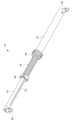
いくつかの実施形態では、図1~11に示されるように、支柱アセンブリ10はそれぞれ、軸方向に長尺状をなした管状の第1の端部部材又は支柱本体12、第2の軸方向に長尺状をなした管状の第1の端部部材又は支柱本体14、並びに、第1の端部部材12及び第2の端部部材14を連結して両部材の間を伸びる軸方向に長尺状をなした管状の中間部材支柱本体16、のアセンブリから形成される。以下にさらに説明されるように、支柱アセンブリ10は、中間部材16の内部に固定され、かつ第2の端部部材14の軸方向に伸びる空洞の内部に螺合されたねじ棒18をさらに備える。中間部材16はさらに、第1の端部の支柱本体12の軸方向に伸びる空洞の内部に軸方向に平行移動可能に連結される。支柱アセンブリ10は、図1、4及び5に示されるように、長手方向軸X‐Xを備える又は規定することが可能であり、軸X‐Xに沿った該アセンブリの全長は調整可能(粗調整又は微調整いずれも可能)である。第1及び第2の端部部材12、14によって形成された支柱アセンブリの軸方向端部は、図1~6、10及び11に示されるように、第1及び第2の継手又は接続機構22、24をそれぞれ備えることができる。第1及び第2の継手22、24は、図12~19に示されるように、外固定システム100の第1及び第2の土台又はベースプレート120、130のうちの一方に/一方と連結するように構成される。
In some embodiments, as shown in FIGS. 1-11, each
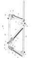
図12~19に示されるように、第1の継手22は第1の土台120に連結されることが可能であり、かつ第2の継手24は第2の土台130に連結されることが可能である。このように、第1の端部部材12の内部における/同部材12に沿った中間部材16の相対的な軸方向の配置、及び/又は、中間部材16の内部における/同部材16に沿った第2の端部部材14の相対的な軸方向の配置を、支柱アセンブリ10の軸X‐Xに沿って調整して、例えば図10~13に図14~17と比較して示されるように、比較的広い範囲の支柱アセンブリ10の長さ調整、かつその結果として第1及び第2の土台120、130の間の距離及び/又は配向を、提供することができる。
As shown in FIGS. 12-19, first joint 22 can be coupled to
第1及び第2の土台120、130は、開口部及び/又は軸の周囲に少なくとも部分的に(かつ潜在的には身体装着時に骨及び/又は組織の周囲に少なくとも部分的に)伸びるような、環形体又は部分環形体であってよい。複数の支柱アセンブリ10が、第1及び第2の土台120、130の軸及び/又は開口部の周りで該土台に連結されることができる。例えば、図12~19に示されるように、複数の支柱アセンブリ10が、第1及び第2の土台120、130に周方向に配置及び連結されてもよく、かつ各々の支柱アセンブリ110が、第1及び第2の土台120、130に対してそれぞれ第1及び第2の継手22、24を介して、土台の軸及び/又は開口部の周囲の様々な位置に、取り付けられてよい。そのため、支柱アセンブリ10は、第1及び第2の土台120、130の軸に対して傾斜していてもよい。
The first and
図12~19に示されるように、支柱アセンブリ10は、対をなして継手部材132を介し第1及び第2の土台120、130に対して配置構成及び連結されることが可能であり、そのような支柱アセンブリ10の対(及び継手部材132)は、第1及び第2の土台120、130に周方向に配置されてよい/間を空けて配置されてよい。支柱アセンブリ10の各々の対は、図12~19に示されるように、向きが交互になるように第1及び第2の土台120、130に連結されることが可能である。第1及び第2の土台120、130に連結された各対の支柱アセンブリ10は、相反する軸方向及び/又は角度方向をなして他方の土台120、130へと伸びることができる。例えば、図12~19に示されるように、ある対の一方の支柱アセンブリ10は、時計回りの角度(及び配置)で第1の土台120から第1の継手22を介して第2の土台130まで伸びて連結することが可能であり、かつその対の他方の支柱アセンブリ10は、反時計回りの角度(及び配置)で第1の土台120から第2の継手24を介して第2の土台130まで伸びて連結することが可能である。
As shown in FIGS. 12-19, the
中間部材16は、支柱アセンブリ10の軸方向長の粗調整を行うために、第1の端部部材12の空洞の内部で選択的に摺動自在に軸方向に調整されることができる。第2の端部部材14は、支柱アセンブリ10の軸方向長の比較的微細な調整を行うために、第1の端部部材12の空洞の内部で、かつ中間部材16の空洞内に固定されたねじ棒18の周りで/該ねじ棒に沿って、選択的に螺動式で軸方向に調整されることができる。このように、支柱アセンブリ10は、比較的広い調整範囲にわたり、図12~19に示されるように第1及び第2の土台120、130の部分間(並びに土台に連結された骨片又は組織片の間)の軸方向の距離を縮小又は伸延することができる。支柱アセンブリ10のこの比較的広い軸方向調整範囲は、支柱アセンブリ10の取替え又は追加の必要を伴わずに提供され、これにより好都合なことに外科医の手間が省けて整形外科的状態及び骨折や変形の整復に集中することが可能となり、さらには必要な在庫を低減することができる。
図1~7に示され、かつ上述されるように、支柱10は各々、第1の端部部材12、第2の端部部材14、及び第1の端部部材12と第2の端部部材14とを連結して両部材の間を伸びる中間部材16を備える。支柱10は、中間部材16の空洞の内部に固定され、かつ第2の端部部材14の空洞の内部に螺合された、ねじ棒18を備える。中間部材16は、図1~8に示されるように、第1の端部部材12の末端部分に提供された第1の調整機構を介して第1の端部部材12の空洞の内部に選択的に軸方向に平行移動可能に連結される。図1~7、10及び11に示されるように、第1及び第2の継手又は接続機構22、24が、第1の端部部材12及び第2の端部部材14の末端部分又は自由末端にそれぞれ提供されることが可能である。
As shown in FIGS. 1-7 and described above, the
図1~6に示されるように、第1の端部部材12は、第1の端部部材12の第1の継手22とは反対側の末端部分から軸方向に伸びる内部空洞を備えて又は画成している、管状又は円筒状の支柱本体を具備する。同じく図1~6に示されるように、第1の端部部材12は、その内部空洞と連通している軸方向に伸びるスロット40を、支柱本体に備えている。中間部材16も、図1~6に示されるように、第1の継手22の近くの(かつ第2の継手24から遠位にある)中間部材16の末端部分から軸方向に伸びる内部空洞を備えて又は画成している、管状又は円筒状の支柱本体を具備する。中間部材16は、図1~6に示されるように、第1の端部部材12の内部空洞内に軸方向に摺動自在又は平行移動可能に受承され、かつ第1の継手22とは反対側の第1の端部部材12の末端部分から出て/末端部分を通り越して、伸びている。図1~9に示されるように、中間部材16の支柱本体の外表面は、外表面の摩擦を増大させる表面テクスチャを備えてもよい。例えば、中間部材16の外表面は、軸方向に間を置いて配置された周方向の溝/鋸歯状切込み、摩擦コーティング、又は任意の他の粗さ若しくは摩擦を有する構成若しくは材料を備えてもよい。
As shown in FIGS. 1-6, the
図1及び5~7に示されるように、中間部材16は、第1の端部部材12の内部空洞の内側で該中間部材の一部分に連結される、径方向に伸びるピン部材/部分48に連結される(又はその他の方法で該ピン部材/部分を備える)ことができる。例えば、ピン部材48は、中間部材16の末端部分に固定連結されてもよい。ピン部材48は、中間部材16が第1の端部部材12の内部空洞に沿って/内部空洞の内部で軸方向に摺動自在に受承されるが回転方向には固定されるように、第1の端部部材12のスロット40の内部に配置/受承される。それにより中間部材16は、第1の端部部材12に対し、軸方向に入れ子式に連結されるが回転方向には固定されることが可能である。
As shown in FIGS. 1 and 5-7, the
図6及び7に示されるように、ピン部材48はねじ棒18にも連結されて、ねじ棒18及び中間部材16を回動自在かつ軸方向に固定連結することができる。例えば、ピン部材48は、中間部材16の末端部分に固定連結されてもよい。図6及び7に示されるように、中間部材16は、同部材の空洞内で径方向にねじ棒18と支柱本体の内表面(すなわち空洞の外周壁)との間に配置されるスリーブ、スペーサ、カラー又はその他同種のもの50を備えてもよい。その結果として該スリーブは、ねじ棒18を支柱本体/空洞の壁部から径方向に間隔を空けて配置する(かつ潜在的には中心に置く)ことが可能であり、これにより第2の端部部材14が、以下に説明されるように、ねじ棒18に螺合して該ねじ棒の周りで軸方向かつ回動自在に平行移動することが可能になる。その結果として第2の端部部材16の少なくとも末端部分は、中間部材16の軸方向空洞の内部に受承され、かつ径方向にねじ棒18と中間部材16の本体部分との間に配置されることが可能である。
As shown in FIGS. 6 and 7, the
上記に議論されるように、支柱アセンブリ10は、第1の端部部材12の末端部分、スリーブ又はブッシング42に、中間部材16が第1の端部部材12の軸方向空洞内を自由に軸方向に平行移動することを選択的に可能とし、かつ中間部材16を第1の端部部材12に対して選択的に軸方向に固定するように構成された、第1の調整機構を備えている。図1~8、10及び11に示されるように、支柱アセンブリ10の第1の調整機構には、第1の端部部材12の末端部分42に回動自在に螺合される、第1のカラー、リング、ノブ又は回動部材44が挙げられる。第1の端部部材12の末端部分42は、第1の端部部材12と一体的であってもよいし、第1の端部部材12に固定連結されてもよい。末端部分42は外側ねじを備えてもよく、かつカラー部材44は、カラー部材44が第2の末端部分42の周りで回動すると第1のカラー44が末端部分42に沿って軸方向に平行移動するように、末端部分42の外側ねじと螺合する内側ねじを備えてもよい。
As discussed above, the
図7及び8に示されるように、カラー部材44の締め付け部分は第1の端部部材12の末端部分42を軸方向に通り越して配置され、かつ支え面21を備えている。いくつかの実施形態では、図8に示されるように、支え面は、第1の継手22から軸方向に離れて第2の継手24に向かって伸びるにつれて中間部材16の本体部分の外表面に向かって傾斜する表面のような、テーパ面を具備してもよい。
As shown in FIGS. 7 and 8, the clamping portion of the
さらに図7及び8に示されるように、支柱アセンブリ10は、径方向に中間部材16の本体部分の外表面と支え面21との間に配置された摩擦部材又は支持部材46を備えてもよい。いくつかの実施形態では、摩擦部材46には、径方向に変形可能なリング部材のような、径方向に変形可能な部材が含まれうる。いくつかのそのような実施形態では、支持部材46には、分節リング、割リング又は同様の部材が含まれうる。
As further shown in FIGS. 7 and 8, the
図8に示されるように、第1の端部部材12、カラー部材44及び摩擦部材46は、カラー部材44が第1の端部部材12の末端部分42に沿って第1の継手22に向かって(例えば回転により)軸方向に前進することにより、カラー部材44の支え面21が、摩擦部材46に寄せていくように働きかつ摩擦部材46を中間部材16の外表面に対して径方向に押し付けるように、かつ中間部材に対して(すなわち中間部材16の外表面と摩擦部材46(及び支え面21)との間に)圧縮力/摩擦推力を加えるように、構成される。換言すれば、カラー部材44が第1の端部部材12の末端部分42に沿って第1の継手22(又は第1の継手22に連結された第1の端部部材12の末端部分)に向かって軸方向に平行移動することにより、摩擦部材46は、支え面21によって中間部材16の本体部分の外表面に対して径方向に押し付けられて、中間部材16を第1の端部部材12に対して軸方向に固定する。反対に、第1の端部部材12、カラー部材44及び摩擦部材46はさらに、カラー部材44が第1の端部部材12の末端部分42に沿って第2の端部部材14及び/又は第2の継手24に向かって(例えば回転により)軸方向に前進することにより、支え面21が摩擦部材46から離れるように平行移動して該摩擦部材を解放し、かつその結果として、摩擦部材46が、中間部材16の外表面から離れるように径方向に移動する即ち外表面と接触しないこと、及び/又は中間部材16の外表面に加わる圧縮力を適用しない(又は少なくとも低減する)ことを可能にして、中間部材16が第1の端部部材12の軸方向空洞の内部でほぼ自由に軸方向に平行移動することを選択的に可能にするようにも、構成される。このようにして、中間部材16及び第1の端部部材12の軸方向の配置構成、並びにその結果として支柱アセンブリ10の軸方向の全長は、カラー部材44(並びに潜在的には第1の端部部材及び/又は中間部材16(若しくは、例えば第2の端部部材14)の係合)を介して、ユーザにより容易かつ迅速に、粗く選択/構成/調整されることが可能であり、これは例えば、図12~16の固定システム100の支柱アセンブリ10の配置構成と、図16~19の固定システム100の支柱アセンブリ10の配置構成との対比で示されている。
As shown in FIG. 8,
上記に議論されるように、支柱アセンブリ10は、図1~7及び9に示されるように、第2の端部部材14を中間部材16に対して軸方向に平行移動させ、かつそれにより支柱アセンブリ10の軸方向の全長を微調整するために、第2の端部部材14を中間部材16及びねじ棒18に対して選択的に回動させるように構成された、第2の調整機構を具備する。図1~7及び9に示されるように、第2の調整機構は、第2の継手24に近い側の(かつ第1の継手22から遠位にある)中間部材16の末端部分に提供されうる。
As discussed above, the
さらに上記に議論されるように、かつ図6~9に示されるように、中間部材16の軸方向空洞の(すなわち中間部材16の内部空洞を形成している中間部材16の支柱本体部分の内側の表面又は壁の)少なくともロッド係合部分52は、ねじ棒と螺合することができる。いくつかの実施形態では、中間部材16の係合部分52は、図6~9に示されるように、中間部材16の内部空洞を形成している中間部材16の支柱本体部分の内側表面又は壁に連結されてもよい。他のいくつかの実施形態では、中間部材16の係合部分52は、中間部材16の内部空洞を形成している中間部材16の支柱本体部分の内側表面又は壁と一体であってよい、すなわち該内側表面又は壁の少なくとも一部分であってよい。
As further discussed above and as shown in FIGS. At least the rod-engaging portion 52 (of the surface or wall of the rod) is capable of being threadedly engaged with a threaded rod. In some embodiments, the
いくつかの実施形態では、図6~9に示されるように、中間部材16の係合部分52は内側ねじを備え、かつねじ棒は、中間部材16の係合部分52の内側ねじと螺合する外側ねじを備える。いくつかの代替実施形態(図示せず)では、中間部材16の係合部分52は外側ねじを備え、かつねじ棒は、中間部材16の係合部分52の外側ねじと螺合する内側ねじを備える。
In some embodiments, as shown in FIGS. 6-9, the
図1~7及び9に示されるように、第2の調整機構は、中間部材16の末端部分53に対して軸方向に固定されかつ回動自在に連結された第2のカラー部材54を具備する。図6、7及び9に示されるように、第2のカラー部材54の第1の部分は、中間部材16の末端部分53の上及び/又は周囲に伸び、かつ該末端部分に対して回動自在に連結されて軸方向に固定されていてよい。例えば、第2のカラー部材54の内側側面、及び中間部材16の末端部分53の外側側面は、図6、7及び9に示されるように、軸方向に同位置にある周方向スロット又は開口部と、該スロット又は開口部の中に延在する座金、割リング、Oリング又は同様の部材56とを備えることができる。その結果として座金又はリング部材56は、第2のカラー部材54の第1の部分が中間部材16の末端部分53の上で(軸X‐Xの周りで)回動することは可能とするが、第2のカラー部材54が中間部材16の末端部分53の上で軸方向に平行移動する(すなわち軸X‐Xに沿って平行移動する)ことを防止することができる。
As shown in FIGS. 1-7 and 9, the second adjustment mechanism includes a
図6、7及び9に示されるように、第2のカラー部材54の第2の部分は、第2の端部部材14の上及び/又は周囲に伸び、かつ第2の端部部材に対して回動自在に固定される(すなわち、該部材に対して固定連結される)ことが可能である。いくつかの実施形態では、図6、7及び9に示されるように、第2のカラー部材54の第2の部分は、径方向に伸びるピン部材/部分55に連結される(又は他の方法で該ピン部材/部分を備える)ことができる。図2、3及び6~9に示されるように、第2の端部部材14の支柱本体部分の外側表面は、ピン部材55を中に受容又は受承する、軸方向に伸びるスロット72を備えることができる。ピン部材55及びスロット72は、ピン部材55がスロット72の軸方向長に亘って/沿って軸方向に平行移動することができるように、構成される。その結果としてピン部材55(ピン部材55及び第2の端部部材のスロット72の中を伸びている)は、第2のカラー部材54及び第2の端部部材を共に回動自在に固定又は固定連結するが、第2の端部部材14がピン部材55に対して、かつその結果として中間部材16に対して、軸方向に平行移動することを可能にする。
As shown in FIGS. 6, 7 and 9, the second portion of the
その結果として、第2の端部部材14の上及び/又は周り(すなわち軸X‐Xの周り)で第2のカラー部材54が回動することにより、第2の端部部材14が中間部材16の空洞の内部及びねじ棒18の周りで回動する(すなわち該空洞内で中間部材16及びねじ棒18に対して軸周りを回動する)。第2の端部部材14の係合部分52とねじ棒18とは螺合するので、第2のカラー部材54の回動は第2の端部部材14をねじ棒18に対して回動させ、その結果として第2の端部部材14が中間部材16に対して軸方向に平行移動する。このようにして、中間部材16及び第2の端部部材14の軸方向の配置構成、並びにその結果として支柱アセンブリ10の軸方向の全長は、第2のカラー部材54を介して(すなわち軸X‐Xの周りで特定の角度方向に第2のカラー部材54を回動することにより)、ユーザによって容易かつ迅速に、微細に選択/構成/調整されることが可能であり、これは例えば、図12~16の固定システム100の支柱アセンブリ10の配置構成と、図16~19の固定システム100の支柱アセンブリ10の配置構成との対比で示されている。
As a result, rotation of the
上記の説明は例証であって、限定的ではないと意図されていることが理解されるべきである。数多くの変更及び改変が、当業者によって、以降の特許請求の範囲及びその均等物により定義されるような本発明の全体的な趣旨及び範囲から逸脱することなく、本明細書中で行なわれることが可能である。例えば、上記の実施形態(及び/又はその態様)は互いに組み合わせて使用されてもよい。加えて、様々な実施形態の教示内容に対し、その範囲から逸脱することなく、特定の状況又は材料を適応させるために多くの改変がなされることが可能である。本明細書中に記載された材料の寸法及び種類は、様々な実施形態のパラメータを規定するように意図されているが、それらは決して限定的ではなく例示にすぎない。他の多くの実施形態は、上記説明を検討すれば当業者には明白となろう。したがって、様々な実施形態の範囲は、添付の特許請求の範囲と、加えてそのような特許請求の範囲に当然付与される均等物の範囲全体とに関連して、決定されるべきである。添付の特許請求の範囲において、用語「備えている(including)」及び「~である(in which)」は、それぞれ用語「具備している、含んでいる(comprising)」及び「~である(wherein)」に相当する平易な英語として使用される。さらに、以降の特許請求の範囲において、用語「第1の」、「第2の」、及び「第3の」などは、単に名札として使用されており、該用語の対象物に数字上の要件を課するようには意図されていない。さらに、用語「作動可能に接続された」は、本明細書中では、分離した別個の構成部分が直接的又は間接的に連結されて生じる接続、及び一体的に形成されている(すなわちモノリシックな)構成部分群から生じる接続の両方を指すために使用される。さらに、以降の特許請求の範囲における限定はミーンズ・プラス・ファンクション形式で書かれておらず、かつ、そのような特許請求の範囲の限定が「のための手段」という語を明らかに使用した後にさらなる構造物を伴わず機能を述べるのでないならば、米国特許法第112条の第6段落に基づいて解釈されるようには意図されない。任意の特定の実施形態によって、上述されたような目的又は利点のうち必ずしも全ては達成されない場合があることが、理解されるべきである。よって、例えば、当業者は、本明細書中に記載されたシステム及び技法が、本明細書中に教示された1つの利点又は一群の利点を達成又は最適化する方法で具体化又は実行されて、本明細書中に教示又は示唆される他の目的又は利点を必ずしも達成しない場合があることを、認識するであろう。 It is to be understood that the above description is intended to be illustrative and not restrictive. Numerous changes and modifications may be made herein by those skilled in the art without departing from the general spirit and scope of the invention as defined by the following claims and their equivalents. is possible. For example, the embodiments (and/or aspects thereof) described above may be used in combination with each other. In addition, many modifications may be made to adapt a particular situation or material to the teachings of various embodiments without departing from the scope thereof. While the dimensions and types of materials described herein are intended to define the parameters of various embodiments, they are in no way limiting and merely illustrative. Many other embodiments will be apparent to those skilled in the art upon reviewing the above description. The scope of the various embodiments should, therefore, be determined with reference to the appended claims, along with the full scope of equivalents to which such claims are entitled. In the appended claims, the terms "including" and "in which" are used as substitutes for the terms "comprising" and "in which," respectively. used as the plain English equivalent of ``. Furthermore, in the claims that follow, the terms "first," "second," "third," etc. are used merely as name tags and do not require numerical requirements for the subject matter of the terms. It is not intended to impose Additionally, the term "operably connected" is used herein to refer to connections that result from the direct or indirect connection of separate and distinct components, as well as connections that are integrally formed (i.e., monolithic). ) is used to refer to both connections arising from constituent subgroups. Further, the limitations in the claims that follow are not written in means-plus-function form, and such claim limitations are not written in a means-plus-function format after the explicit use of the words "means for." It is not intended to be construed under paragraph 6 of 35 U.S.C. 112 unless it describes a function without additional structure. It is to be understood that not necessarily all of the objects or advantages described above may be achieved by any particular embodiment. Thus, for example, those skilled in the art will appreciate that the systems and techniques described herein can be implemented or practiced in a manner that achieves or optimizes an advantage or group of advantages taught herein. , it will be recognized that it may not necessarily achieve other objects or advantages taught or suggested herein.
本発明について、限られた数の実施形態のみに関して詳細に説明されてきたが、本発明がそのような開示された実施形態に限定されないことは容易に理解されるはずである。それどころか、本発明は、本明細書中に前述されていないが本発明の趣旨及び範囲に見合う、任意の数の変形、修正、代替又は等価な配置構成を組込むように改変されることが可能である。加えて、本発明の様々な実施形態について記載されてきたが、本開示の態様は記載された実施形態のうちの一部のみを備えうることが理解されるべきである。従って、本発明は先述の説明によって限定されると見なされるべきではなく、添付の特許請求の範囲の範囲によってのみ限定される。 Although the invention has been described in detail with respect to only a limited number of embodiments, it will be readily understood that the invention is not limited to such disclosed embodiments. On the contrary, the present invention can be modified to incorporate any number of variations, modifications, alternative or equivalent arrangements not previously described herein, but which are commensurate with the spirit and scope of the invention. be. Additionally, while various embodiments of the invention have been described, it is to be understood that aspects of the disclosure may comprise only some of the described embodiments. Accordingly, the invention should not be considered limited by the above description, but rather by the scope of the appended claims.
この書面による説明は、ベストモードを含めて本発明を開示するために、かつ同様に、任意のデバイス又はシステムを作製及び使用すること並びに任意の盛り込まれた方法を実施することを含めて、あらゆる当業者が本発明を実行することを可能にするために、実施例を使用している。本発明の特許可能な範囲は特許請求の範囲によって定義され、当業者が思いつく他の実施例を含むことができる。そのような他の実施例は、該実施例が特許請求の範囲の文字どおりの言葉と変わらない構造上の構成要素を有する場合、又は該実施例が特許請求の範囲の文字どおりの言葉と実質的な差がない等価な構造上の構成要素を備えている場合は、特許請求の範囲の範囲内にあると意図される。
This written description is provided to disclose the invention, including the best mode thereof, and to disclose all aspects of the invention, including the best mode thereof, and also to describe all aspects of making and using any devices or systems and carrying out any of the incorporated methods. The examples are provided to enable any person skilled in the art to practice the invention. The patentable scope of the invention is defined by the claims, and may include other examples that occur to those skilled in the art. Such other embodiments may include structural elements that do not differ from the literal language of the claims, or if the embodiments have structural elements that differ substantially from the literal language of the claims. Equivalent structural components with no differences are intended to be within the scope of the following claims.
Claims (40)
第1の末端部分、第2の末端部分(42)、及び第2の末端部分(42)から伸びる第1の軸方向空洞を具備している、長尺状の第1の端部部材(12)、
第3の末端部分、第4の末端部分(53)、第3の末端部分から伸びる第2の軸方向空洞、及び第2の軸方向空洞の内部に回動自在かつ軸方向に固定連結されたねじ棒(18)を具備している、長尺状の中間部材(16)であって、第1の端部部材(12)の第1の軸方向空洞の内部に回動自在に固定されて軸方向に平行移動可能であり、かつ第1の軸方向空洞から第2の末端部分(42)を通って伸びている、中間部材(16)、
第5の末端部分、第6の末端部分、及び第5の末端部分から伸びる第3の軸方向空洞を具備している、長尺状の第2の端部部材(14)であって、第2の端部部材(14)の少なくとも第5の末端部分は中間部材(16)の第2の軸方向空洞の内部に受承されており、かつ第3の軸方向空洞は中間部材(16)のねじ棒(18)と螺合しており、第2の端部部材は第2の軸方向空洞から第4の末端部分(53)を通って伸びている、第2の端部部材(14)、
第1の端部部材(12)の第2の末端部分(42)にある、第1のカラー部材(44)を具備する第1の調整機構であって、中間部材(16)が第1の軸方向空洞の内部で自由に軸方向に平行移動することを選択的に可能とするように、かつ中間部材(16)を第1の端部部材(12)に対して選択的に軸方向に固定するように構成された、第1の調整機構、並びに
中間部材(16)の第4の末端部分(53)にある、第2のカラー部材(54)を具備する第2の調整機構であって、第2の端部部材(14)を中間部材(16)に対して軸方向に平行移動するために第2の端部部材(14)を中間部材(16)及びねじ棒(18)に対して選択的に回動させるように構成された、第2の調整機構
を具備している支柱アセンブリ。 A strut assembly (10) for an external fixation system (100) , comprising:
An elongate first end member (12) comprising a first end portion, a second end portion (42) , and a first axial cavity extending from the second end portion (42) . ) ,
a third end portion, a fourth end portion (53) , a second axial cavity extending from the third end portion, and a second axial cavity pivotally and axially fixedly coupled within the second axial cavity; an elongate intermediate member (16 ) comprising a threaded rod (18) rotatably secured within the first axial cavity of the first end member (12); an intermediate member (16) axially translatable and extending from the first axial cavity through the second end portion (42);
an elongate second end member (14) comprising a fifth end portion, a sixth end portion, and a third axial cavity extending from the fifth end portion; At least a fifth end portion of the two end members (14) is received within a second axial cavity of the intermediate member (16) , and the third axial cavity is received within the second axial cavity of the intermediate member (16). A second end member (14) is threadedly engaged with a threaded rod ( 18 ) of ) ,
a first adjustment mechanism comprising a first collar member (44) on a second end portion (42) of the first end member (12) , the intermediate member (16) comprising a first collar member (44); the intermediate member (16) selectively axially relative to the first end member (12) to selectively allow free axial translation within the axial cavity; a first adjustment mechanism configured to lock; and a second adjustment mechanism comprising a second collar member (54 ) on the fourth end portion (53 ) of the intermediate member (16) . the second end member (14) to the intermediate member (16) and the threaded rod (18) to axially translate the second end member (14) relative to the intermediate member ( 16); a strut assembly comprising a second adjustment mechanism configured to selectively rotate relative to the strut assembly;
第1の土台(120)、
第2の土台(130)、並びに
第1及び第2の土台(120、130)の間に伸びる複数の支柱
を具備しており、
前記複数の支柱のうち少なくとも1つは請求項1に記載の支柱アセンブリ(10)を含む、システム(100)。 A bone and/or tissue external fixation system (100) comprising:
First foundation (120) ,
a second base (130) and a plurality of columns extending between the first and second bases (120, 130) ;
A system (100) , wherein at least one of the plurality of struts comprises a strut assembly ( 10) according to claim 1.
Priority Applications (1)
| Application Number | Priority Date | Filing Date | Title |
|---|---|---|---|
| JP2023220816A JP2024038162A (en) | 2018-08-29 | 2023-12-27 | Adjustable strut assembly for external fixation systems |
Applications Claiming Priority (3)
| Application Number | Priority Date | Filing Date | Title |
|---|---|---|---|
| US201862724462P | 2018-08-29 | 2018-08-29 | |
| US62/724,462 | 2018-08-29 | ||
| PCT/US2019/048931 WO2020047334A1 (en) | 2018-08-29 | 2019-08-29 | Adjustable strut assemblies for external fixation systems |
Related Child Applications (1)
| Application Number | Title | Priority Date | Filing Date |
|---|---|---|---|
| JP2023220816A Division JP2024038162A (en) | 2018-08-29 | 2023-12-27 | Adjustable strut assembly for external fixation systems |
Publications (3)
| Publication Number | Publication Date |
|---|---|
| JP2021536291A JP2021536291A (en) | 2021-12-27 |
| JPWO2020047334A5 JPWO2020047334A5 (en) | 2022-07-14 |
| JP7413361B2 true JP7413361B2 (en) | 2024-01-15 |
Family
ID=69643075
Family Applications (2)
| Application Number | Title | Priority Date | Filing Date |
|---|---|---|---|
| JP2021510910A Active JP7413361B2 (en) | 2018-08-29 | 2019-08-29 | Adjustable strut assembly for external fixation systems |
| JP2023220816A Pending JP2024038162A (en) | 2018-08-29 | 2023-12-27 | Adjustable strut assembly for external fixation systems |
Family Applications After (1)
| Application Number | Title | Priority Date | Filing Date |
|---|---|---|---|
| JP2023220816A Pending JP2024038162A (en) | 2018-08-29 | 2023-12-27 | Adjustable strut assembly for external fixation systems |
Country Status (8)
| Country | Link |
|---|---|
| US (2) | US11364054B2 (en) |
| EP (1) | EP3843646A4 (en) |
| JP (2) | JP7413361B2 (en) |
| CN (1) | CN112888388A (en) |
| AU (1) | AU2019331007B2 (en) |
| BR (1) | BR112021003874A2 (en) |
| CA (1) | CA3110684A1 (en) |
| WO (1) | WO2020047334A1 (en) |
Families Citing this family (5)
| Publication number | Priority date | Publication date | Assignee | Title |
|---|---|---|---|---|
| US11737786B2 (en) | 2019-12-31 | 2023-08-29 | Orthopediatrics Corp. | Multiple track system for positioning of bone segments |
| WO2023069376A1 (en) * | 2021-10-18 | 2023-04-27 | A-Fix Inc. | Bone fixator with removable portion |
| US20230193936A1 (en) * | 2021-12-20 | 2023-06-22 | Stryker European Operations Limited | Quick Release Mechanism for Strut |
| CN114366261A (en) * | 2022-01-21 | 2022-04-19 | 中国人民解放军总医院第四医学中心 | Iliofemoral traction separator |
| WO2024062361A1 (en) * | 2022-09-19 | 2024-03-28 | Mikai S.P.A. | External fixation device for bone fractures |
Citations (3)
| Publication number | Priority date | Publication date | Assignee | Title |
|---|---|---|---|---|
| JP2005523765A (en) | 2002-04-30 | 2005-08-11 | ジンテーズ アクチエンゲゼルシャフト クール | Minimax distractor |
| US20100312243A1 (en) | 2008-02-08 | 2010-12-09 | Texas Scottish Rite Hospital For Children | External fixator ring |
| US20130296857A1 (en) | 2012-05-04 | 2013-11-07 | Gary D. Barnett | Ratcheting strut |
Family Cites Families (15)
| Publication number | Priority date | Publication date | Assignee | Title |
|---|---|---|---|---|
| CA2093828A1 (en) * | 1992-04-16 | 1993-10-17 | Anthony Philip Pohl | External bone fixation device |
| US5702196A (en) * | 1996-06-21 | 1997-12-30 | Teleflex, Incorporated | Turnbuckle-type adjustable link |
| EP0933065A1 (en) * | 1998-02-02 | 1999-08-04 | Sulzer Orthopädie AG | Pivotable attachment system for a bone screw |
| US6423069B1 (en) * | 1999-03-23 | 2002-07-23 | Synthes (Usa) | Orthopedic system having detachable bone anchors |
| JP4490821B2 (en) * | 2002-09-17 | 2010-06-30 | エクストラオルト インコーポレイテッド | Unilateral bone anchor |
| EP2085037B1 (en) * | 2008-02-01 | 2013-07-24 | Stryker Trauma SA | Telescopic strut for an external fixator |
| JP5667882B2 (en) * | 2008-02-12 | 2015-02-12 | テキサス スコティッシュ ライト ホスピタル フォー チルドレン | Quick adjustment of connecting rod for external fixation |
| US8257353B2 (en) * | 2010-02-24 | 2012-09-04 | Wright Medical Technology, Inc. | Orthopedic external fixation device |
| EP2967669B1 (en) * | 2013-03-13 | 2017-09-13 | DePuy Synthes Products, Inc. | External bone fixation device |
| CN106413604A (en) * | 2014-03-12 | 2017-02-15 | 奥索斯平有限公司 | Preloaded medical struts |
| US9717528B2 (en) * | 2014-04-01 | 2017-08-01 | Stryker European Holdings I, Llc | External fixator with Y strut |
| TWM503210U (en) * | 2015-01-06 | 2015-06-21 | Univ Nat Yang Ming | Multiaxial jawbone tractor |
| US10010350B2 (en) * | 2016-06-14 | 2018-07-03 | Stryker European Holdings I, Llc | Gear mechanisms for fixation frame struts |
| EP4233748A3 (en) * | 2016-07-14 | 2024-01-17 | AMDT Holdings, Inc. | External bone fixation systems |
| GB2556099A (en) * | 2016-11-21 | 2018-05-23 | Caterpillar Energy Solutions Gmbh | Screw tensioning device |
-
2019
- 2019-08-29 CA CA3110684A patent/CA3110684A1/en active Pending
- 2019-08-29 BR BR112021003874-4A patent/BR112021003874A2/en unknown
- 2019-08-29 EP EP19856041.9A patent/EP3843646A4/en active Pending
- 2019-08-29 WO PCT/US2019/048931 patent/WO2020047334A1/en unknown
- 2019-08-29 AU AU2019331007A patent/AU2019331007B2/en active Active
- 2019-08-29 CN CN201980070260.7A patent/CN112888388A/en active Pending
- 2019-08-29 JP JP2021510910A patent/JP7413361B2/en active Active
-
2021
- 2021-02-25 US US17/185,460 patent/US11364054B2/en active Active
-
2022
- 2022-06-17 US US17/807,522 patent/US20220313316A1/en active Pending
-
2023
- 2023-12-27 JP JP2023220816A patent/JP2024038162A/en active Pending
Patent Citations (4)
| Publication number | Priority date | Publication date | Assignee | Title |
|---|---|---|---|---|
| JP2005523765A (en) | 2002-04-30 | 2005-08-11 | ジンテーズ アクチエンゲゼルシャフト クール | Minimax distractor |
| US20100312243A1 (en) | 2008-02-08 | 2010-12-09 | Texas Scottish Rite Hospital For Children | External fixator ring |
| JP2011511678A (en) | 2008-02-08 | 2011-04-14 | テキサス スコティッシュ ライト ホスピタル フォー チルドレン | External fixed support |
| US20130296857A1 (en) | 2012-05-04 | 2013-11-07 | Gary D. Barnett | Ratcheting strut |
Also Published As
| Publication number | Publication date |
|---|---|
| CN112888388A (en) | 2021-06-01 |
| CA3110684A1 (en) | 2020-03-05 |
| EP3843646A4 (en) | 2022-05-04 |
| US20210244442A1 (en) | 2021-08-12 |
| JP2021536291A (en) | 2021-12-27 |
| BR112021003874A2 (en) | 2021-05-18 |
| AU2019331007B2 (en) | 2023-02-16 |
| JP2024038162A (en) | 2024-03-19 |
| AU2019331007A1 (en) | 2021-04-08 |
| WO2020047334A1 (en) | 2020-03-05 |
| US20220313316A1 (en) | 2022-10-06 |
| EP3843646A1 (en) | 2021-07-07 |
| US11364054B2 (en) | 2022-06-21 |
Similar Documents
| Publication | Publication Date | Title |
|---|---|---|
| JP7413361B2 (en) | Adjustable strut assembly for external fixation systems | |
| AU2021286343B2 (en) | External bone fixation systems | |
| US11090086B2 (en) | Bone transport external fixation frame | |
| US9717528B2 (en) | External fixator with Y strut | |
| JP2003508108A (en) | Strut of 6-axis external fixture | |
| JP7430773B2 (en) | Strut assembly and external fixation system |
Legal Events
| Date | Code | Title | Description |
|---|---|---|---|
| A521 | Request for written amendment filed |
Free format text: JAPANESE INTERMEDIATE CODE: A523 Effective date: 20220706 |
|
| A621 | Written request for application examination |
Free format text: JAPANESE INTERMEDIATE CODE: A621 Effective date: 20220706 |
|
| A977 | Report on retrieval |
Free format text: JAPANESE INTERMEDIATE CODE: A971007 Effective date: 20230428 |
|
| A131 | Notification of reasons for refusal |
Free format text: JAPANESE INTERMEDIATE CODE: A131 Effective date: 20230516 |
|
| A601 | Written request for extension of time |
Free format text: JAPANESE INTERMEDIATE CODE: A601 Effective date: 20230810 |
|
| A521 | Request for written amendment filed |
Free format text: JAPANESE INTERMEDIATE CODE: A523 Effective date: 20231116 |
|
| TRDD | Decision of grant or rejection written | ||
| A01 | Written decision to grant a patent or to grant a registration (utility model) |
Free format text: JAPANESE INTERMEDIATE CODE: A01 Effective date: 20231205 |
|
| A61 | First payment of annual fees (during grant procedure) |
Free format text: JAPANESE INTERMEDIATE CODE: A61 Effective date: 20231227 |
|
| R150 | Certificate of patent or registration of utility model |
Ref document number: 7413361 Country of ref document: JP Free format text: JAPANESE INTERMEDIATE CODE: R150 |